PCAN-MicroMod - User Manual - phytools Hardware/CAN IO... · PCAN-MicroMod – User Manual 13 ......
27
PCAN-MicroMod Universal I/O Module with CAN Interface User Manual Document version 2.1.1 (2017-02-03)
Transcript of PCAN-MicroMod - User Manual - phytools Hardware/CAN IO... · PCAN-MicroMod – User Manual 13 ......

PCAN-MicroMod Universal I/O Module with CAN Interface
User Manual
Document version 2.1.1 (2017-02-03)
PCAN-MicroMod – User Manual
2
Relevant products
Product Name Part number Model
PCAN-MicroMod IPEH-002080 with firmware 2.12
CANopen® and CiA® are registered community trade marks of CAN in Automation e.V.
All other product names mentioned in this document may be the trademarks or registered trademarks of their respective companies. They are not explicitly marked by “™” and “®”.
© 2017 PEAK-System Technik GmbH
PEAK-System Technik GmbH Otto-Roehm-Strasse 69 64293 Darmstadt Germany
Phone: +49 (0)6151 8173-20 Fax: +49 (0)6151 8173-29
www.peak-system.com [email protected]
Document version 2.1.1 (2017-02-03)
PCAN-MicroMod – User Manual
3
Contents
1 Introduction 4 1.1 Properties at a Glance 4 1.2 Scope of Supply 5 1.3 Prerequisites for Operation 6
2 Hardware Settings 7 2.1 Setting the Module Number 7 2.2 Disconnecting the High-speed CAN Transceiver 8
3 Connectors 10
4 Installing the Configuration Program 13
5 Operation 15 5.1 Status LED 15 5.2 Reserved CAN ID 0x7E7 15 5.3 Overview of Existing Services 16
6 New/Alternative Firmware 18 6.1 CANopen® Support 18 6.2 Creating Own Firmware 18 6.3 Uploading Firmware to the MicroMod 19
7 Technical Specifications 24
Appendix A Frequency/Resolution Diagram 26
Appendix B Dimension Drawing 27

PCAN-MicroMod – User Manual
4
1 Introduction
The PCAN-MicroMod is designed for quick and easy access to distri-buted I/O systems. Its kernel is the microcontroller MB90F497 by Fujitsu/Spansion. With an integrated CAN bus controller and the analog and digital inputs and outputs it is an inexpensive solution for small, intelligent nodes.
At delivery the MicroMod has a standard firmware. The configura-tion is done by a Windows program transferring the configuration data to the module via CAN.
It is also possible to use an alternative firmware (e.g. for the opera-tion under CANopen®) or to create own programs for the integrated microcontroller.
Note: The functionality described in this manual refers to the standard firmware available with delivery. For the operation with an alternative firmware, please study the corresponding documentation. See also chapter 6 New/Alternative Firmware on page 18.
1.1 Properties at a Glance
PCAN-MicroMod
Strips for piggyback connection
8 digital inputs, CMOS levels
8 digital outputs, CMOS levels
8 analog inputs, reference voltage 5 V (resolution 10 bits, sampling rate 1 kHz)
4 frequency/PWM outputs (depending on firmware)

PCAN-MicroMod – User Manual
5
4 inputs for frequency measurement
CAN connection with NXP 82C251 transceiver
CAN bit rates from 10 kbit/s to 1 Mbit/s
Extended operating temperature range of -40 to +85 °C (-40 to +185 °F)
Standard firmware
Up to 32 MicroMods configurable on a single CAN bus
Transmission of CAN messages periodically or at level change of a digital input
Logic operations for digital inputs
Adaptation of analog quantities through characteristic curves
Direct transfer of analog quantities onto CAN IDs
Direct support of rotary encoders up to 100 Hz (e.g. rotary switch for manual operation)
4 PWM outputs, 8-bit, 32 Hz - 100 Hz and 4 - 10 kHz - or - 2 PWM outputs, 16-bit, 1 Hz - 10 kHz (from firmware 2.5) - or - 2 frequency outputs, 1 Hz - 10 kHz
1.2 Scope of Supply
PCAN-MicroMod
Configuration software for Windows 10, 8.1, 7 (32/64-bit)
Manual in PDF format

PCAN-MicroMod – User Manual
6
1.3 Prerequisites for Operation
Board with socket strips for holding the PCAN-MicroMod (Evaluation Board, motherboard by PEAK-System, or proprietary development)
For creating and transferring configurations: computer with Windows 10, 8.1, 7 and a CAN interface from the PCAN series
PCAN-MicroMod – User Manual
7
2 Hardware Settings
2.1 Setting the Module Number
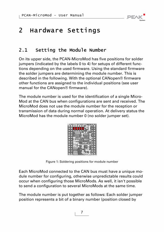
On its upper side, the PCAN-MicroMod has five positions for solder jumpers (indicated by the labels 0 to 4) for setups of different func-tions depending on the used firmware. Using the standard firmware the solder jumpers are determining the module number. This is described in the following. With the optional CANopen® firmware other functions are assigned to the individual positions (see user manual for the CANopen® firmware).
The module number is used for the identification of a single Micro-Mod at the CAN bus when configurations are sent and received. The MicroMod does not use the module number for the reception or transmission of data during normal operation. At delivery status the MicroMod has the module number 0 (no solder jumper set).
Figure 1: Soldering positions for module number
Each MicroMod connected to the CAN bus must have a unique mo-dule number for configuring, otherwise unpredictable results could occur when configuring those MicroMods. As well, it isn't possible to send a configuration to several MicroMods at the same time.
The module number is put together as follows: Each solder jumper position represents a bit of a binary number (position closed by

PCAN-MicroMod – User Manual
8
solder jumper = bit set). Position 0 is the LSB and position 4 the MSB of this number. Because there are 5 bits, module numbers between 0 and 31 can be set.
Solder jumper position
0 (LSB) 1 2 3 4 (MSB)
Binary digit 00001 00010 00100 01000 10000
Decimal equivalent 1 2 4 8 16
Example:
Solder jumpers are on positions 0, 1, and 3. The corresponding bi-nary number is 01011b (reversed order of positions) being equiva-lent to decimal 11, the module number.
To do it the other way around: If you like to assign the module num-ber 22 to a MicroMod, you would do following steps:
1. 22 = 1·16 + 0·8 + 1·4 + 1·2 + 0·1 = 10110b
2. MSB (position 4) 10110 LSB (position 0)
3. Solder jumpers to be set: 1, 2, 4 (0 and 3 stay open)
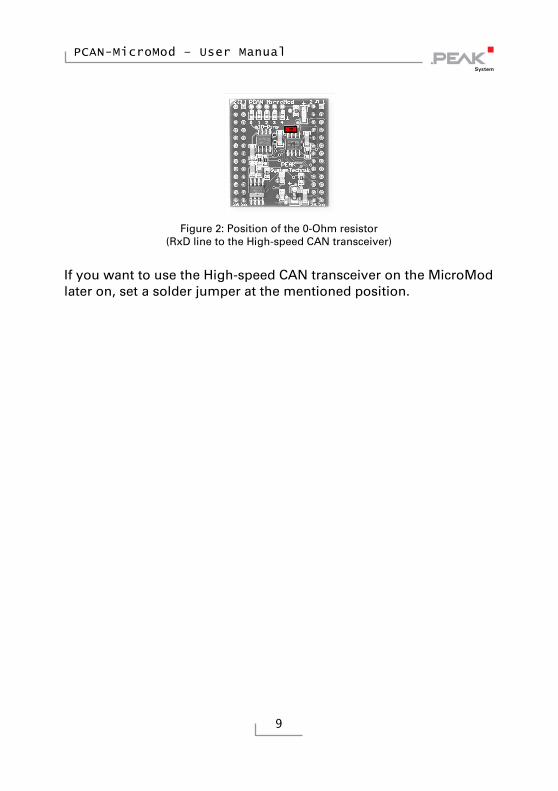
2.2 Disconnecting the High-speed CAN Transceiver
If you want to use another mode of CAN transmission but High-speed CAN (ISO 11898-2), the CAN signals CAN-RxD and CAN-TxD from the microcontroller or the MicroMod respectively can directly be lead to the desired CAN transceiver. The High-speed CAN tran-sceiver on the MicroMod must be disconnected from the data trans-fer in this case. This is done by interrupting the RxD line between the microcontroller and the CAN transceiver. For this you must unsolder the 0-Ohm resistor on the MicroMod (below and right to the label “4”).
PCAN-MicroMod – User Manual
9
Figure 2: Position of the 0-Ohm resistor
(RxD line to the High-speed CAN transceiver)
If you want to use the High-speed CAN transceiver on the MicroMod later on, set a solder jumper at the mentioned position.
PCAN-MicroMod – User Manual
10
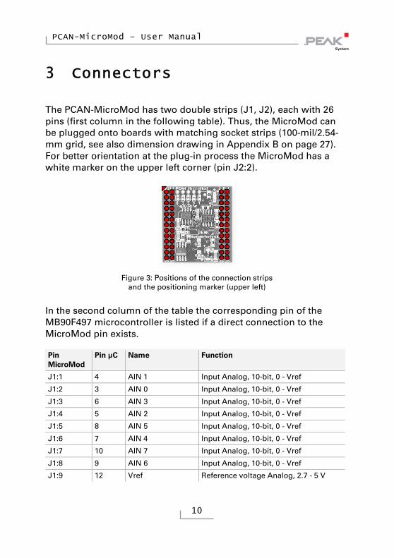
3 Connectors
The PCAN-MicroMod has two double strips (J1, J2), each with 26 pins (first column in the following table). Thus, the MicroMod can be plugged onto boards with matching socket strips (100-mil/2.54-mm grid, see also dimension drawing in Appendix B on page 27). For better orientation at the plug-in process the MicroMod has a white marker on the upper left corner (pin J2:2).
Figure 3: Positions of the connection strips
and the positioning marker (upper left)
In the second column of the table the corresponding pin of the MB90F497 microcontroller is listed if a direct connection to the MicroMod pin exists.
Pin MicroMod
Pin μC Name Function
J1:1 4 AIN 1 Input Analog, 10-bit, 0 - Vref
J1:2 3 AIN 0 Input Analog, 10-bit, 0 - Vref
J1:3 6 AIN 3 Input Analog, 10-bit, 0 - Vref
J1:4 5 AIN 2 Input Analog, 10-bit, 0 - Vref
J1:5 8 AIN 5 Input Analog, 10-bit, 0 - Vref
J1:6 7 AIN 4 Input Analog, 10-bit, 0 - Vref
J1:7 10 AIN 7 Input Analog, 10-bit, 0 - Vref
J1:8 9 AIN 6 Input Analog, 10-bit, 0 - Vref
J1:9 12 Vref Reference voltage Analog, 2.7 - 5 V

PCAN-MicroMod – User Manual
11
Pin MicroMod
Pin μC Name Function
J1:10 11 Avcc Supply Analog
J1:11 24, 49 GND Ground Digital
J1:12 13 AGND Ground Analog
J1:13 63 CAN-TxD CAN Transmit, CMOS
J1:14 64 CAN-RxD CAN Receive, CMOS
J1:15 CAN_H High-speed CAN signal CAN_H
J1:16 CAN_L High-speed CAN signal CAN_L
J1:17 62 TxD Serial Transmit, TTL
J1:18 60 RxD Serial Receive, TTL
J1:19 51 SCL (SPI or I2C) Serial clock, function depending on firmware
J1:20 50 SDO (SPI) or SDA (I2C)
Serial Data Out/Serial Data
J1:21 19 Reset_In Reset, Low-active
J1:22 52 SDI (SPI) Serial Data In
J1:23 18 M0 Run mode: 5 V (internal pull-up) Prog mode: 0 V
J1:24 21 M2 Run mode: 0 V Prog mode: 5 V (internal pull-up)
J1:25 56 Vcc Supply 5 V
J1:26 24, 49 GND Ground Digital
J2:1 48 DO 7 Output Digital, CMOS
J2:2 47 DO 6 Output Digital, CMOS
J2:3 46 DO 5 Output Digital, CMOS
J2:4 45 DO 4 Output Digital, CMOS
J2:5 44 DO 3 Output Digital, CMOS
J2:6 43 DO 2 Output Digital, CMOS
J2:7 42 DO 1 Output Digital, CMOS
J2:8 41 DO 0 Output Digital, CMOS
J2:9 40 FO 3 Output Frequency/PWM, CMOS
J2:10 39 FO 2 Output Frequency/PWM, CMOS
J2:11 38 FO 1 Output Frequency/PWM, CMOS
J2:12 37 FO 0 Output Frequency/PWM, CMOS
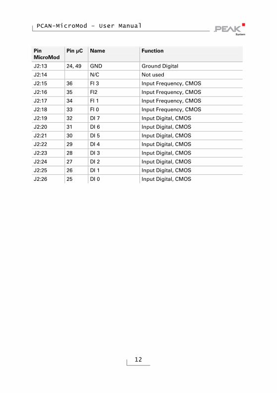
PCAN-MicroMod – User Manual
12
Pin MicroMod
Pin μC Name Function
J2:13 24, 49 GND Ground Digital
J2:14 N/C Not used
J2:15 36 FI 3 Input Frequency, CMOS
J2:16 35 FI2 Input Frequency, CMOS
J2:17 34 FI 1 Input Frequency, CMOS
J2:18 33 FI 0 Input Frequency, CMOS
J2:19 32 DI 7 Input Digital, CMOS
J2:20 31 DI 6 Input Digital, CMOS
J2:21 30 DI 5 Input Digital, CMOS
J2:22 29 DI 4 Input Digital, CMOS
J2:23 28 DI 3 Input Digital, CMOS
J2:24 27 DI 2 Input Digital, CMOS
J2:25 26 DI 1 Input Digital, CMOS
J2:26 25 DI 0 Input Digital, CMOS

PCAN-MicroMod – User Manual
13
4 Installing the Configuration Program
With the enclosed configuration program PCAN-MicroMod Configu-ration for Windows you can create, edit, and then transfer configu-rations to one or more MicroMods via CAN.
Figure 4: Configuration program PCAN-MicroMod Configuration for Windows
For transmission the program needs access to a CAN network. For this purpose the computer must have a CAN interface of the PCAN series (e.g. PCAN-USB). However, you can create and edit a configu-ration with the program on a computer without PCAN environment and transfer it with another computer to the corresponding Micro-Mod in a CAN network later.

PCAN-MicroMod – User Manual
14
Do the following to setup the software:
1. Insert the supplied CD into the appropriate drive of the com-puter. Usually a navigation program appears a few mo-ments later. If not, start the file Intro.exe from the root directory of the CD.
2. On the page English > Tools at the PCAN-MicroMod Configuration entry, click on Install.
3. Follow the instructions of the setup program.
You can find further information about the use of the program PCAN-MicroMod Configuration in the help which you can invoke in the program.

PCAN-MicroMod – User Manual
15
5 Operation
5.1 Status LED
LED Status Description
Blinking at 1 Hz Normal operation
Blinking at 2 Hz Invalid or no configuration
This may be the case after a firmware update because the new firmware is possibly expecting another data format. You can solve this problem by sending a new configuration.
Blinking at 5 Hz Configuration mode Occurs during sending or receiving a configuration via CAN.
Continuously on Internal MicroMod error
This may be the case after uploading a faulty or incompatible firmware.
Continuously off No voltage supply; MicroMod in programming mode
Whether the MicroMod is in normal or in programming mode (for the firmware upload) is determined by the status of the MicroMod pins M0 and M2 (see table in chapter 3 on page 10).
5.2 Reserved CAN ID 0x7E7
For configuring the MicroMod the CAN ID 0x7E7 is used. The pro-gram PCAN-MicroMod Configuration exchanges the according data with the MicroMod via the CAN bus.
When designing your CAN network, make sure not to use the CAN ID 0x7E7 in any way.

PCAN-MicroMod – User Manual
16
5.3 Overview of Existing Services
With the standard firmware, the PCAN-MicroMod provides various functions, called services.
Service Remark
Message Settings / Internal Variables
Internal variables are useful for communication between services (in principle corresponds to CAN messages)
Digital input For the event-controlled transmission of CAN messages it can be determined which kind of signal change is considered as trigger.
Digital output Power-up and timeout values can be defined (e.g. for problems with CAN communication).
Analog input The A/D value can be adjusted with scale and offset. Furthermore, a software low-pass can be activated.
Analog Output This service is only available with the appropriate connection of a D/A converter to the MicroMod (e.g. with the motherboard Analog 2).
Frequency input Frequencies between 1 Hz and about 10 kHz can be measured.
PWM and frequency output By the incoming CAN messages either the pulse width is influenced at a predefined frequency or the frequency is influenced at a fixed pulse width (50%).
Digital function All digital inputs may be logically connected. The result may either be passed on as a CAN message or to a digital output.
Constant values / statistical data
Constant values or statistical data generated by the MicroMod can be put into CAN messages.
Curve Analog input data can be converted with the help of a curve.
Rotary encoder The service interprets the signals from a manual rotary encoder (standard quadrature with 2 bits) connected to digital inputs. Input frequency max. 100 Hz.
Analog hysteresis For converting analog to digital signals (e.g. in order to avoid jitter).

PCAN-MicroMod – User Manual
17
Find more details about the functionality and the application of the services in the help of the configuration program PCAN-MicroMod Configuration.

PCAN-MicroMod – User Manual
18
6 New/Alternative Firmware
With its integrated microcontroller the PCAN-MicroMod is flexible at use, because the functionality may be adapted or changed through suitable controlling software, also called firmware. This chapter describes possible alternatives and the procedure for a firmware update.
6.1 CANopen® Support
As an alternative to the standard firmware we provide a CANopen firmware for the PCAN-MicroMod free of charge. With this the MicroMod falls into the category of off-the-shelf CANopen generic I/O devices. The whole CANopen software package implements the CANopen standard CiA® 301 “Application Layer and Communica-tion Profile” version 4.02 and specifically the device profile CiA® 401 “Device Profile for Generic I/O Modules” version 2.1. Therefore the correspondingly set up MicroMod can be directly used as standardized CANopen generic I/O module.
The CANopen firmware (incl. documentation) is on the supplied CD in the following directory:
/Tools/PCAN-MicroMod/CANopen-Firmware/
6.2 Creating Own Firmware
The PCAN-MicroMod contains the microcontroller MB90F497 by Fujitsu (now: Spansion). With the C development environment Softune Workbench (available separately) you can create own firmware for the PCAN-MicroMod.
Website of the microcontroller manufacturer: www.spansion.com

PCAN-MicroMod – User Manual
19
6.3 Uploading Firmware to the MicroMod
The standard firmware can change regarding functionality and error correction so that an update can be necessary. On the other hand perhaps you would like to use an alternative firmware for the Micro-Mod. In both cases you must transmit the desired firmware to the MicroMod via a serial RS-232 port (upload).
For a firmware upload you need:
a motherboard for the MicroMod with the following features:
an RS-232 connector (with a driver connected ahead)
MicroMod pin
Name Function
J1:17 TxD Serial transmit (TTL levels)
J1:18 RxD Serial receive (TTL levels)
a switch or jumper to set the MicroMod to programming mode
MicroMod pin
Name Programming mode Normal operation mode
J1:23 M0 0 V 5 V (internal pull-up)
J1:24 M2 5 V (internal pull-up) 0 V
a pushbutton to reset the MicroMod
MicroMod pin
Name Status for reset
J1:21 Reset_In 0 V
the possibility to set the digital inputs 0 and 1 to Low state
MicroMod pin
Name Status for firmware upload
J2:25 DI 1 0 V
J2:26 DI 0 0 V

PCAN-MicroMod – User Manual
20
Tip: An easy way to do a firmware upload is using the PCAN-MicroMod Evaluation Board (optionally available). It has the necessary connectors and switches.
a serial RS-232 port on a computer running Windows
a serial 1:1 cable with male D-Sub connectors
the Windows software FLASH MCU Programmer for the F²MC-16LX microcontroller family. You can download a setup program of the current version from the Spansion website (www.spansion.com). Search for “mcu programmer download” there.
the firmware file (*.mhx)
Do the following to upload a new firmware:
1. Make sure that the motherboard with the MicroMod is switched off.
2. Connect the motherboard and the serial port of your compu-ter with the serial cable.
3. Set the corresponding switch or jumper so that the Micro-Mod will start in programming mode.
4. Apply power.
The LED on the MicroMod stays off.
5. Make sure that a Low level is applied to digital inputs 0 and 1.
6. Reset the MicroMod.
7. Under Windows, start the FUJITSU FLASH MCU Program-mer (FMC16LX).

PCAN-MicroMod – User Manual
21
8. Select Set Environment in order to check that the indicated serial port is corresponding to the actually used one. Confirm with OK.
9. Do the following settings:
Target Microcontroller: MB90F497/G
Crystal Frequency: 4 MHz
10. Use the Open button behind the Hex File field to select the firmware file that shall be used for upload.
11. Start the transfer sequence by clicking on Full Operation (D+E+B+P+R).
The process takes approximately one minute. At its end a message is shown that confirms the proper sequence.

PCAN-MicroMod – User Manual
22
12. Disconnect the power from the motherboard.
13. Setup the normal operation mode (Run mode) for the MicroMod, before applying power again.
The upload procedure is finished and you can use the MicroMod normally now.
PCAN-MicroMod – User Manual
23
LED-Status After Updating the Standard Firmware
If after an update the LED on the MicroMod is blinking fast (2 Hz) in normal operation mode, the current configuration is not compatible to the new firmware version. In this case, transfer the configuration to the MicroMod again, with adaptation if needed.
If the LED stays off after the update, the firmware does not work. Repeat the upload procedure in this case or use another version of the standard firmware.

PCAN-MicroMod – User Manual
24
7 Technical Specifications
Power supply
Supply voltage +5 V DC
Current consumption max. 160 mA
Connectors
Connection strips 2 double strips, each with 26 pins
Grid 100 mil (2.54 mm)
Control and communication
Microcontroller Fujitsu/Spansion MB90F497G
Standard firmware Configuration via reserved CAN ID 0x7e7
CAN
Specification ISO 11898-2, High-speed CAN 2.0A (standard format) 2.0B (extended format) (from firmware 2.0)
Bit rates 10 kbit/s - 1 Mbit/s (see also “Properties with standard firmware” below)
Transceiver NXP PCA82C251 (disconnectable for use of an alternative transceiver on the motherboard)
Termination none
Inputs/outputs
Digital inputs 8, CMOS
Frequency inputs 4, CMOS
Analog inputs 8, reference voltage 5 V, resolution 10 bits, sample rate 1 kHz, input impedance 3.2 k
Digital outputs 8, CMOS
Frequency/PWM outputs 4 (depending on firmware)

PCAN-MicroMod – User Manual
25
Properties with standard firmware
Frequency inputs Measuring range 1 Hz – 10 kHz (maximum depends on work load, min. 4 kHz)
Frequency/PWM outputs 4 PWM (8-bit mode): 32 - 100 Hz, 4 - 10 kHz, frequency-dependent resolution 1.3 - 1.0 %
- or - 2 PWM (16-bit mode, from firmware 2.5):
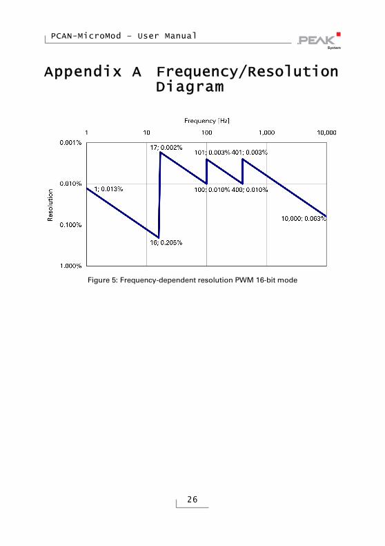
1 Hz - 10 kHz, frequency-dependent resolution 0.205 - 0.005 % (see also diagram in Appendix A on page 26)
- or - 2 frequency: 1 Hz - 10 kHz,
minimum step width 1 Hz
Configurable CAN bit rates (kbit/s)
10; 20; 33.3; 47.6; 50; 83.3; 95.2; 100; 125; 250; 500; 800; 1000
Measures
Size 32 x 35 x 13 mm (W x L x H) See also dimension drawing in Appendix B on
page 27
Weight 9 g
Environment
Operating temperature -40 - +85 °C (-40 - +185 °F)
Temperature for storage and transport
-40 - +100 °C (-40 - +212 °F)
Relative humidity 15 - 90 %, not condensing
PCAN-MicroMod – User Manual
26
Appendix A Frequency/Resolution Diagram
Figure 5: Frequency-dependent resolution PWM 16-bit mode

PCAN-MicroMod – User Manual
27
Appendix B Dimension Drawing
Figure 6: Top view and side view PCAN-MicroMod