Virtual PCAN-Gateway - User Manual - peak-system.com PCAN-Gateway... · Receive IP > PCAN-LAN: In a...
24
Connection of CAN Busses over PC and PCAN-Gateway User Manual Virtual PCAN-Gateway Document version 1.2.0 (2017-08-21)
Transcript of Virtual PCAN-Gateway - User Manual - peak-system.com PCAN-Gateway... · Receive IP > PCAN-LAN: In a...

Connection of CAN Busses over PC and PCAN-Gateway
User Manual
Virtual PCAN-Gateway
Document version 1.2.0 (2017-08-21)
Virtual PCAN-Gateway – User Manual
2
Relevant products
Product name Model Part Number
Virtual PCAN Gateway IPES-004100
PCAN® is a registered trademark of PEAK-System Technik GmbH. CANopen® and CiA® are registered community trade marks of CAN in Automation e.V.
All other product names mentioned in this document may be the trademarks or registered trademarks of their respective companies. They are not explicitly marked by “™” or “®”.
Copyright © 2017 PEAK-System Technik GmbH Duplication (copying, printing, or other forms) and the electronic distribution of this document is only allowed with explicit permission of PEAK-System Technik GmbH. PEAK-System Technik GmbH reserves the right to change technical data without prior announcement. The general business conditions and the regulations of the license agreement apply. All rights are reserved.
PEAK-System Technik GmbH Otto-Roehm-Straße 69 64293 Darmstadt Germany
Phone: +49 (0)6151 8173-20 Fax: +49 (0)6151 8173-29
www.peak-system.com [email protected]
Document version 1.2.0 (2017-08-21)

Virtual PCAN-Gateway – User Manual
3
Content
1 Introduction 4 1.1 Properties at a Glance 5 1.2 System Requirements 5 1.3 Scope of Supply 5
2 Installing 6
3 Configuration 7 3.1 Status 7 3.2 Routing 7
3.2.1 Manage Routes 8 3.2.2 Add Route 9
3.3 Device Configuration 12 3.4 Support 13
4 Application Examples 14 4.1 Creating the Routes on the Hardware 14 4.2 Creating the Routes on the Virtual PCAN-
Gateway (PC) 16 4.2.1 Creating the Routes Manually 16 4.2.2 Creating the Routes Automatically 17
5 Monitor Software PCAN-View 19 5.1 Receive/Transmit Tab 21 5.2 Trace Tab 23 5.3 PCAN-Gateway Tab 24 5.4 Status Bar 24

Virtual PCAN-Gateway – User Manual
4
1 Introduction
The Virtual PCAN-Gateway software package provides access for Windows computers to devices of the PCAN-Gateway product line over IP-based networks. Various LAN and WLAN network adapters can be used.
Analog to the bidirectional connection of two PCAN-Gateways, message forwarding with so-called routes must be set up between the hardware and the software.
At first, two routes have to be created on the configuration website of the hardware, one for sending and another for receiving. Then, the appropriate counterparts of these routes must be established within the configuration software.
Due to this connection, the PCAN-Gateways are being integrated in the established PCAN environment and can be used like a conventional PEAK CAN interface. For example, the traffic on the CAN channels can be displayed and traced by the PCAN-View CAN monitor.
Note: The software requires a PCAN-Gateway as a counterpart. It is not possible to establish a connection between two computers with the Virtual PCAN-Gateway.
Virtual PCAN-Gateway – User Manual
5
1.1 Properties at a Glance
Supports the operating systems Windows 10, 8.1, 7 (32/64-bit)
Connection of several PCAN-Gateways with a computer via IP-based networks
Optional use of different LAN and WLAN network adapters
Configuration software to set up and manage message forwarding
1.2 System Requirements
Windows 10, 8.1, 7 (32/64-bit)
At least 2 GB RAM and 1.5 GHz CPU
LAN- or WLAN network interface
1.3 Scope of Supply
Virtual PCAN-Gateway software package consisting of configuration software, Windows service, and driver
Documentation in PDF format
Virtual PCAN-Gateway – User Manual
6
2 Installing
This chapter covers the software setup for the Virtual PCAN-Gateway on Windows.
Do the following to install the Software:
1. Start Intro.exe from the supplied DVD.
The navigation program starts.
2. In the main menu, select Drivers and click on Install now.
3. Confirm the message of the User Account Control related to "Installer database of PEAK Drivers".
The driver setup starts.
4. Select the Virtual PCAN-Gateway option.
5. Follow the instructions of the program.

Virtual PCAN-Gateway – User Manual
7
3 Configuration
The configuration of the Virtual PAN-Gateway is done via a comfortable interface. Besides the current settings of the Virtual PCAN-Gateway additional information will be displayed.
3.1 Status
The Status page displays the current configuration.
Network Adapters:
Select from the drop-down list one of the available network adapters. Afterwards, information such as the IP address of the adapter is shown.
3.2 Routing
Routing displays basic information about the created message forwarding.
Defined Routes:
Here, each message forwarding is displayed with its basic information. For each of these, the status, used transmission protocol, as well as the source and destination are specified.
On the Routing > Manage Routes page, the routes can be managed, edited, and deleted
On the Routing > Add Route page new message forwarding instances can be created
Virtual PCAN-Gateway – User Manual
8
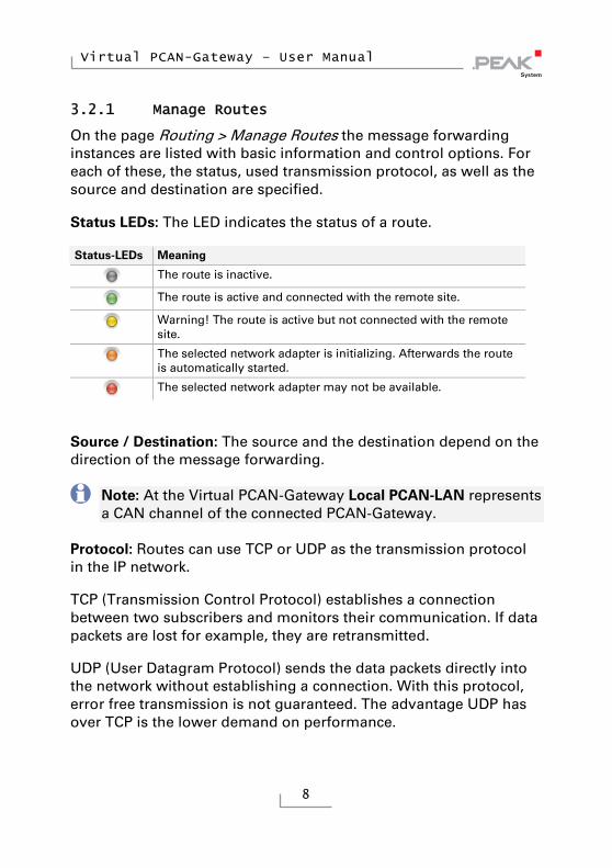
3.2.1 Manage Routes
On the page Routing > Manage Routes the message forwarding instances are listed with basic information and control options. For each of these, the status, used transmission protocol, as well as the source and destination are specified.
Status LEDs: The LED indicates the status of a route.
Status-LEDs Meaning
The route is inactive.
The route is active and connected with the remote site.
Warning! The route is active but not connected with the remote site.
The selected network adapter is initializing. Afterwards the route is automatically started.
The selected network adapter may not be available.
Source / Destination: The source and the destination depend on the direction of the message forwarding.
Note: At the Virtual PCAN-Gateway Local PCAN-LAN represents a CAN channel of the connected PCAN-Gateway.
Protocol: Routes can use TCP or UDP as the transmission protocol in the IP network.
TCP (Transmission Control Protocol) establishes a connection between two subscribers and monitors their communication. If data packets are lost for example, they are retransmitted.
UDP (User Datagram Protocol) sends the data packets directly into the network without establishing a connection. With this protocol, error free transmission is not guaranteed. The advantage UDP has over TCP is the lower demand on performance.
Virtual PCAN-Gateway – User Manual
9
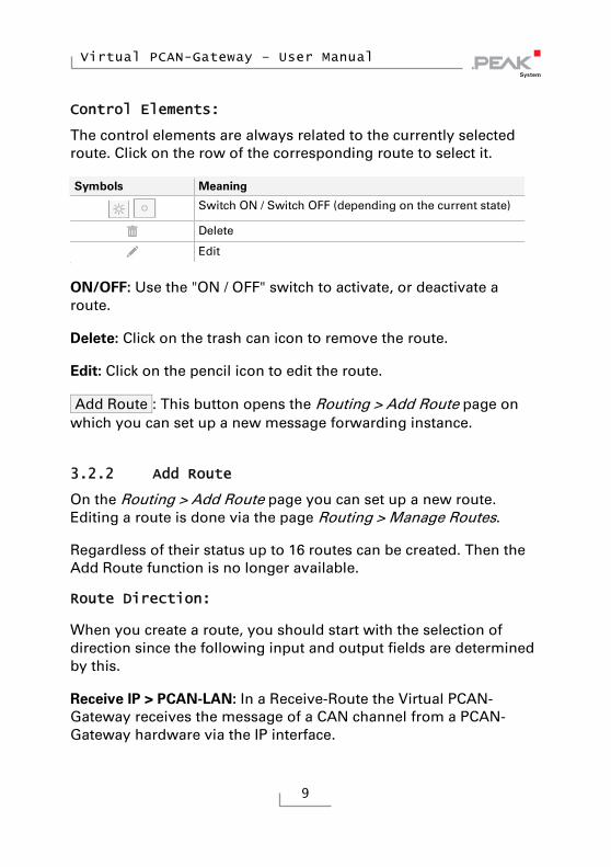
Control Elements:
The control elements are always related to the currently selected route. Click on the row of the corresponding route to select it.
Symbols Meaning
Switch ON / Switch OFF (depending on the current state)
Delete
Edit a
ON/OFF: Use the "ON / OFF" switch to activate, or deactivate a route.
Delete: Click on the trash can icon to remove the route.
Edit: Click on the pencil icon to edit the route.
Add Route : This button opens the Routing > Add Route page on which you can set up a new message forwarding instance.
3.2.2 Add Route
On the Routing > Add Route page you can set up a new route. Editing a route is done via the page Routing > Manage Routes.
Regardless of their status up to 16 routes can be created. Then the Add Route function is no longer available.
Route Direction:
When you create a route, you should start with the selection of direction since the following input and output fields are determined by this.
Receive IP > PCAN-LAN: In a Receive-Route the Virtual PCAN-Gateway receives the message of a CAN channel from a PCAN-Gateway hardware via the IP interface.
Virtual PCAN-Gateway – User Manual
10
Send PCAN-LAN > IP: In a Send route CAN messages are forwarded over the IP interface to a CAN channel on a PCAN-Gateway hardware.
Note: Here, Local PCAN-LAN represents a CAN channel of the connected PCAN-Gateway.
Status:
Use this setting to determine the state of the route after it is created. Ticking the checkbox will have the effect of immediately activating the route after the completed form is saved.
Network Adapter:
Select from the drop-down list one of the available network adapters. The adapter is used for the IP communication of this route.
IP Interface:
IP Address: Enter the IP address (IPv4) of the destination device. It should be noted that only values from 0 to 255 may be used and certain address ranges are reserved.
In the first field, enter a value less than 224, since addresses starting from this value are reserved for Multicast messages
Depending on the Subnet mask, the highest device address is reserved for broadcast messages. For the Subnet mask 255.255.255.0 and the network address 192.168.1.xxx, the reserved address would be: 192.168.1.255
Depending on the Subnet mask the lowest device address is reserved for messages that are addressed to the entire network. For the Subnet mask 255.255.255.0 and the network address 192.168.1.xxx, the reserved address would be: 192.168.1.0

Virtual PCAN-Gateway – User Manual
11
Note: For Receive routes the IP address is automatically set to the selected network adapter.
Port: Enter a port between 1024 and 65535. Values below 1024 are reserved for various system services and must therefore not be used. Port 45321 is reserved for the transmission of status information and to perform a handshake between PCAN-Gateways.
Protocol: Select which transmission protocol should be used by the route in the IP network.
TCP (Transmission Control Protocol) establishes a connection between two subscribers and monitors their communication. If data packets are lost for example, they are retransmitted.
UDP (User Datagram Protocol) sends the data packets directly into the network without establishing a connection. With this protocol, error free transmission is not guaranteed. The advantage UDP has over TCP is the lower demand on performance.
Note: Any combination of the IP address, port, and protocol can only be used once.
Finally, you can create a new route with the Add Route button.
Note: Transferring data between a Virtual PCAN-Gateway and a PCAN-Gateway always consists of a Send and a Receive route per CAN channel to be connected. Note that the Send and Receive route, which belong together, should use the same transmission protocol (TCP or UDP) and the same port.

Virtual PCAN-Gateway – User Manual
12
3.3 Device Configuration
On the Device > Configuration page different options are available for importing and exporting the Virtual PCAN-Gateway configura-tion.
Import Configuration: Importing or restoring of a saved Virtual PCAN-Gateway configuration. The current configuration will be overwritten and all defined routes of the Virtual PCAN-Gateway will be replaced. If the saved configuration contains unknown network adapters, you have to select a new one manually for the affected routes.
Click the Import button to import the configuration file (* .vpoi).
Export Configuration: With the Export button you can download the current Virtual PCAN-Gateway configuration and the defined routes in the form of a (*.vpoi) file. This file can be used to import or restore defined routes in this or any other Virtual PCAN-Gateway (other PC).
Complement Configuration: With the Join button you can import a configuration file (* .ini) of a PCAN-Gateway hardware. It automati-cally creates the counterparts of the routes, stored in the file, to establish a connection between the hardware and the Virtual PCAN-Gateway.
Reload Configuration: With the Reload button, you can reinitialize the current routes information. All routes will be deactivated, reloaded and activated again.
Note: It can take some time until all hardware connections are re-established. Existing software connections will be parked as “internal hardware”, until the hardware connection is restored.

Virtual PCAN-Gateway – User Manual
13
3.4 Support
On the Support > Overview page you will find links to PEAK-Hardware and Windows Service Control, as well as contact information of PEAK-System Technik GmbH.

Virtual PCAN-Gateway – User Manual
14
4 Application Examples
Aim is the direct access to a CAN channel of a PCAN-Gateway hardware by using the software Virtual PCAN-Gateway.
In this example the PCAN-Gateway hardware IP address is 192.168.1.203. The network adapter which is used by the Virtual-PCAN-Gateway has the IP address 192.168.1.5. Desired is the access to the CAN channel 1 of the PCAN-Gateway.
4.1 Creating the Routes on the Hardware
For bidirectional data transmission the message traffic between the PCAN-Gateway hardware and a Virtual PCAN-Gateway should be forwarded via the WLAN network. For this, a Virtual PCAN-Gateway and a PCAN-Gateway hardware are needed. On each a Send and a Receive route have to be created.
Creating the Send Route:
The PCAN-Gateway should transmit the incoming message traffic from the CAN channel into the WLAN network. For this, a Send route must be created on the device.
1. Add Route: Open the configuration website of the PCAN-Gateway and go to the page Routing > Manage Routes. Click the button Add Route.
2. Configure Route: Select Send: CAN > IP from the Choose the direction dropdown list. Complete the form with the values from the table below.

Virtual PCAN-Gateway – User Manual
15
Status Activate
CAN Channel 1
IP-Address 192.168.1.5 (address of the Virtual PCAN-Gateway)
Port 26000
IP Interface
Protocol TCP
3. Confirm: Click the Add Route button at the bottom of the page to complete the route creation process.
After saving, the route will be displayed in the overview on the page Routing > Manage Routes.
Creating the Receive Route:
The PCAN-Gateway should receive sent messages. For this, a Receive route must be created on the device.
1. Open the configuration website of PCAN-Gateway and go to the page Routing > Manage Routes. Click the Add Route button.
2. Configure Route: Select Receive: IP > CAN from the Choose the direction dropdown list. Complete the form with the values from the table below.
Status Activate
Port 27000 IP Interface
Protocol TCP
CAN Interface CAN Channel 1
3. Confirm: Click the Add Route button at the bottom of the page to complete the route creation process.
After saving, the route will be displayed in the overview on the page Routing > Manage Routes.
Virtual PCAN-Gateway – User Manual
16
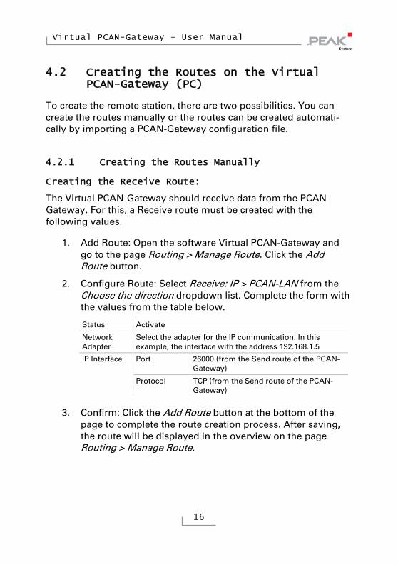
4.2 Creating the Routes on the Virtual PCAN-Gateway (PC)
To create the remote station, there are two possibilities. You can create the routes manually or the routes can be created automati-cally by importing a PCAN-Gateway configuration file.
4.2.1 Creating the Routes Manually
Creating the Receive Route:
The Virtual PCAN-Gateway should receive data from the PCAN-Gateway. For this, a Receive route must be created with the following values.
1. Add Route: Open the software Virtual PCAN-Gateway and go to the page Routing > Manage Route. Click the Add Route button.
2. Configure Route: Select Receive: IP > PCAN-LAN from the Choose the direction dropdown list. Complete the form with the values from the table below.
Status Activate
Network Adapter
Select the adapter for the IP communication. In this example, the interface with the address 192.168.1.5
Port 26000 (from the Send route of the PCAN-Gateway)
IP Interface
Protocol TCP (from the Send route of the PCAN-Gateway)
3. Confirm: Click the Add Route button at the bottom of the page to complete the route creation process. After saving, the route will be displayed in the overview on the page Routing > Manage Route.
Virtual PCAN-Gateway – User Manual
17
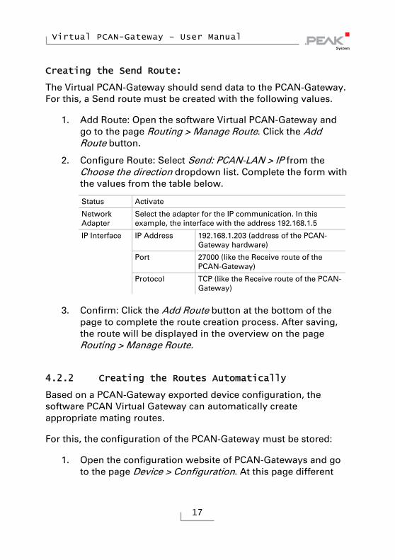
Creating the Send Route:
The Virtual PCAN-Gateway should send data to the PCAN-Gateway. For this, a Send route must be created with the following values.
1. Add Route: Open the software Virtual PCAN-Gateway and go to the page Routing > Manage Route. Click the Add Route button.
2. Configure Route: Select Send: PCAN-LAN > IP from the Choose the direction dropdown list. Complete the form with the values from the table below.
Status Activate
Network Adapter
Select the adapter for the IP communication. In this example, the interface with the address 192.168.1.5
IP Address 192.168.1.203 (address of the PCAN-Gateway hardware)
Port 27000 (like the Receive route of the PCAN-Gateway)
IP Interface
Protocol TCP (like the Receive route of the PCAN-Gateway)
3. Confirm: Click the Add Route button at the bottom of the page to complete the route creation process. After saving, the route will be displayed in the overview on the page Routing > Manage Route.
4.2.2 Creating the Routes Automatically
Based on a PCAN-Gateway exported device configuration, the software PCAN Virtual Gateway can automatically create appropriate mating routes.
For this, the configuration of the PCAN-Gateway must be stored:
1. Open the configuration website of PCAN-Gateways and go to the page Device > Configuration. At this page different
Virtual PCAN-Gateway – User Manual
18
import and export options for the device configuration are available.
2. Export: With the Export button you can download the current device configuration of the device and the defined routes in form of a (*.ini) file.
To create the corresponding mating routes automatically with the software, proceed as follows:
1. Open the software Virtual PCAN-Gateway and go to the page Device > Configuration.
At this page different import and export options of the software configuration are available. There is also an option for importing a configuration file of a PCAN-Gateway.
2. Importing a device configuration: With the Join button you can import the configuration file (*.ini). For each Send route stored in this file a appropriate Receive route will be created and vice versa.
After importing, the routes will be displayed in the overview on the page Routing > Manage Route of the Virtual PCAN-Gateway.
If all routes are created and active, you can access and use the connected CAN channel like a normal CAN interface from PEAK-System with your PC. In the following chapter, this is illustrated with the monitor software PCAN-View.
Virtual PCAN-Gateway – User Manual
19
5 Monitor Software PCAN-View
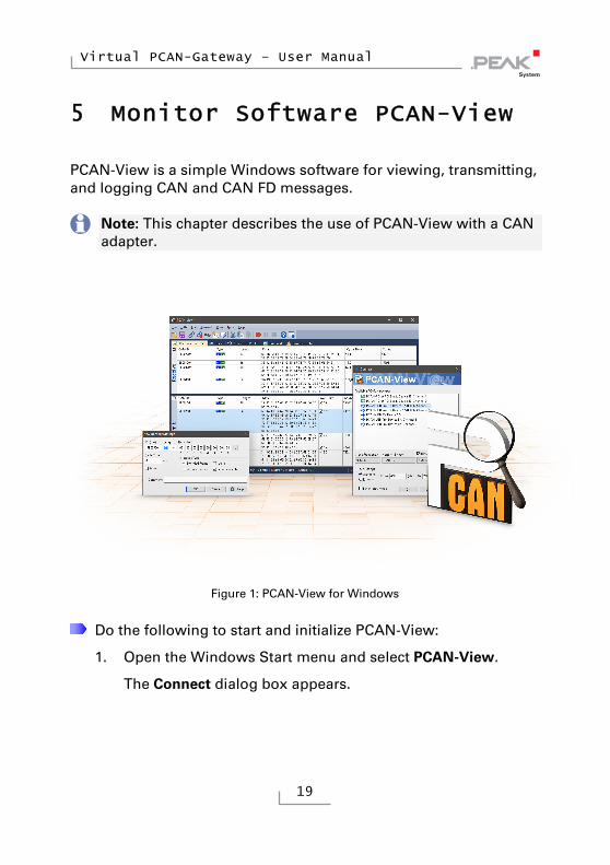
PCAN-View is a simple Windows software for viewing, transmitting, and logging CAN and CAN FD messages.
Note: This chapter describes the use of PCAN-View with a CAN adapter.
Figure 1: PCAN-View for Windows
Do the following to start and initialize PCAN-View:
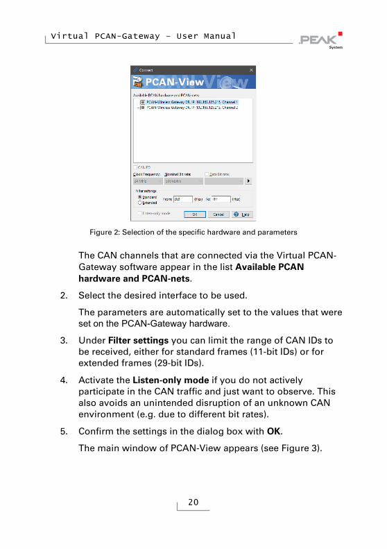
1. Open the Windows Start menu and select PCAN-View.
The Connect dialog box appears.
Virtual PCAN-Gateway – User Manual
20
Figure 2: Selection of the specific hardware and parameters
The CAN channels that are connected via the Virtual PCAN-Gateway software appear in the list Available PCAN hardware and PCAN-nets.
2. Select the desired interface to be used.
The parameters are automatically set to the values that were set on the PCAN-Gateway hardware.
3. Under Filter settings you can limit the range of CAN IDs to be received, either for standard frames (11-bit IDs) or for extended frames (29-bit IDs).
4. Activate the Listen-only mode if you do not actively participate in the CAN traffic and just want to observe. This also avoids an unintended disruption of an unknown CAN environment (e.g. due to different bit rates).
5. Confirm the settings in the dialog box with OK.
The main window of PCAN-View appears (see Figure 3).

Virtual PCAN-Gateway – User Manual
21
5.1 Receive/Transmit Tab
Figure 3: Receive/Transmit tab
The Receive/Transmit tab is the main element of PCAN-View. It contains two lists, one for received messages and one for the transmit messages. The CAN data format is hexadecimal by default.
Do the following to transmit a CAN message with PCAN-View:
1. Select the menu command Transmit > New Message (alternatively or Ins ).
The New Transmit Message dialog box appears.
Figure 4: Dialog box new transmit message
Virtual PCAN-Gateway – User Manual
22
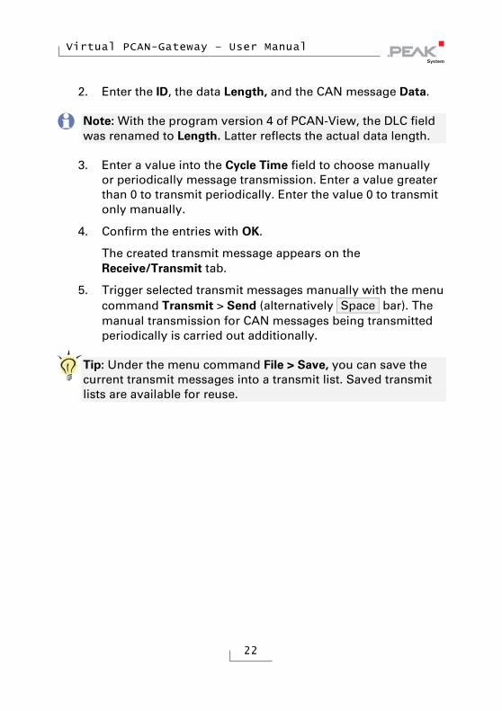
2. Enter the ID, the data Length, and the CAN message Data.
Note: With the program version 4 of PCAN-View, the DLC field was renamed to Length. Latter reflects the actual data length.
3. Enter a value into the Cycle Time field to choose manually or periodically message transmission. Enter a value greater than 0 to transmit periodically. Enter the value 0 to transmit only manually.
4. Confirm the entries with OK.
The created transmit message appears on the Receive/Transmit tab.
5. Trigger selected transmit messages manually with the menu command Transmit > Send (alternatively Space bar). The manual transmission for CAN messages being transmitted periodically is carried out additionally.
Tip: Under the menu command File > Save, you can save the current transmit messages into a transmit list. Saved transmit lists are available for reuse.

Virtual PCAN-Gateway – User Manual
23
5.2 Trace Tab
Figure 5: Trace tab
On the Trace tab, the data tracer (data logger) of PCAN-View is used for logging the communication on a CAN bus. During this process the messages are cached in the working memory of the PC. Afterwards they can be saved to a file.
The Tracer runs either in linear or in ring buffer mode. The linear buffer mode stops the Tracer as soon as the buffer is full. The ring buffer mode overwrites the oldest messages by new ones as soon as the buffer is full.
Virtual PCAN-Gateway – User Manual
24
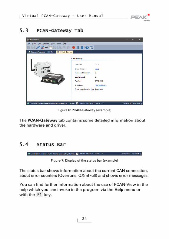
5.3 PCAN-Gateway Tab
Figure 6: PCAN-Gateway (example)
The PCAN-Gateway tab contains some detailed information about the hardware and driver.
5.4 Status Bar
Figure 7: Display of the status bar (example)
The status bar shows information about the current CAN connection, about error counters (Overruns, QXmtFull) and shows error messages.
You can find further information about the use of PCAN-View in the help which you can invoke in the program via the Help menu or with the F1 key.