PCAN-Flash - Operation Instructions · IPEH-002215 PCAN-Router DR IPEH-002213 PCAN-RS-232...
19
Windows-Software for Flashing Firmware via CAN Operation Instructions PCAN-Flash Document version 1.2.0 (2017-11-20)
Transcript of PCAN-Flash - Operation Instructions · IPEH-002215 PCAN-Router DR IPEH-002213 PCAN-RS-232...
Windows-Software for Flashing Firmware via CAN
Operation Instructions
PCAN-Flash
Document version 1.2.0 (2017-11-20)
PCAN-Flash – Operation Instructions
2
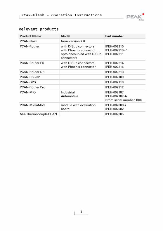
Relevant products
Product Name Model Part number
PCAN-Flash from version 2.0
PCAN-Router with D-Sub connectors with Phoenix connector opto-decoupled with D-Sub connectors
IPEH-002210 IPEH-002210-P IPEH-002211
PCAN-Router FD with D-Sub connectors with Phoenix connector
IPEH-002214 IPEH-002215
PCAN-Router DR IPEH-002213
PCAN-RS-232 IPEH-002100
PCAN-GPS IPEH-002110
PCAN-Router Pro IPEH-002212
PCAN-MIO Industrial Automotive
IPEH-002187 IPEH-002187-A (from serial number 100)
PCAN-MicroMod module with evaluation board
IPEH-002080 + IPEH-002082
MU-Thermocouple1 CAN IPEH-002205

PCAN-Flash – Operation Instructions
3
PCAN is a registered trademark of PEAK-System Technik GmbH. Other product names in this document may be the trademarks or registered trade-marks of their respective companies. They are not explicitly marked by “™” and “®”.
© 2017 PEAK-System Technik GmbH Duplication (copying, printing, or other forms) and the electronic distribution of this document is only allowed with explicit permission of PEAK-System Technik GmbH. PEAK-System Technik GmbH reserves the right to change technical data without prior announcement. The general business conditions and the regulations of the license agreement apply. All rights are reserved.
PEAK-System Technik GmbH Otto-Roehm-Strasse 69 64293 Darmstadt Germany
Phone: +49 (0)6151 8173-20 Fax: +49 (0)6151 8173-29
www.peak-system.com [email protected]
Document version 1.2.0 (2017-11-20)

PCAN-Flash – Operation Instructions
4
Contents
1 Introduction 5 1.1 System Requirements 6
2 Preparing the Microcontroller Hardware 7 2.1 PCAN-Router 9 2.2 PCAN-Router FD 10 2.3 PCAN-Router DR 11 2.4 PCAN-RS-232 and PCAN-GPS 11 2.5 PCAN-Router Pro 12 2.6 PCAN-MIO 13 2.7 PCAN-MicroMod 13 2.8 MU-Thermocouple1 CAN 14
3 Preparing the Software 15
4 Flashing the Firmware 16
PCAN-Flash – Operation Instructions
5
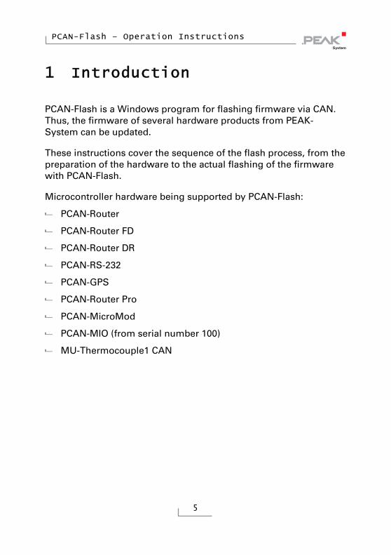
1 Introduction
PCAN-Flash is a Windows program for flashing firmware via CAN. Thus, the firmware of several hardware products from PEAK-System can be updated.
These instructions cover the sequence of the flash process, from the preparation of the hardware to the actual flashing of the firmware with PCAN-Flash.
Microcontroller hardware being supported by PCAN-Flash:
PCAN-Router
PCAN-Router FD
PCAN-Router DR
PCAN-RS-232
PCAN-GPS
PCAN-Router Pro
PCAN-MicroMod
PCAN-MIO (from serial number 100)
MU-Thermocouple1 CAN

PCAN-Flash – Operation Instructions
6
1.1 System Requirements
Besides the hardware that will be equipped with new firmware, you need the following:
Computer with Windows 10, 8.1, or 7 (32/64-bit)
CAN interface of the PCAN series installed in/attached to the computer
CAN cabling between the CAN interface and the hardware with proper termination (120 Ω on each end of the CAN bus)

PCAN-Flash – Operation Instructions
7
2 Preparing the Microcontroller Hardware
In order to equip the microcontroller hardware with new firmware via CAN, the CAN bootloader must be activated when powering on. Different preparations are necessary depending on the hardware.
Note: If your hardware works with configurations, those configurations that are currently on the hardware are going to be invalid after a firmware update and therefore will not be usable anymore. Make sure in advance that the configurations are available on your PC so that you are able to transfer them to your hardware again later on.
Perform the following steps for preparation of your hardware:
1. Switch the device off by disconnecting it from the power supply.
2. Perform the necessary modification of your hardware. It is described in the corresponding section (see table). Before the modification, remember the initial state, in order to be able to restore it after the firmware update.
Hardware Modification Section
PCAN-Router High level at Boot_CAN 2.1 on page 9
PCAN-Router FD High level at Boot 2.2 on page 10
PCAN-Router DR Rotary switch "Bitrate" on F 2.3 on page 11
PCAN-RS-232 High level at Boot_CAN 2.4 on page 11
PCAN-GPS High level at Boot_CAN 2.4 on page 11
PCAN-Router Pro ID rotary switch on F 2.5 on page 12
PCAN-MIO ID rotary switch on F 2.6 on page 13
PCAN-MicroMod (none) 2.7 on page 13
MU-Thermocouple1 CAN (none) 2.8 on page 14

PCAN-Flash – Operation Instructions
8
Tip: On some devices, the flash mode can alternatively be activated by software so that the hardware modification can be omitted. See corresponding notes in the section for the device.
3. Connect the CAN bus of the hardware with a CAN interface connected to the computer. Pay attention to the proper termination of the CAN cabling (2 x 120 Ω).
4. Switch on the hardware by applying a voltage supply.
PCAN-Flash – Operation Instructions
9
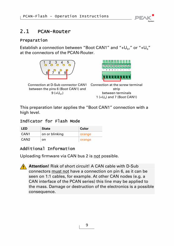
2.1 PCAN-Router
Preparation
Establish a connection between “Boot CAN1” and “+Ub1” or “+Ub” at the connectors of the PCAN-Router.
Connection at D-Sub connector CAN1 between the pins 6 (Boot CAN1) and
9 (+Ub1)
Connection at the screw terminal strip
between terminals 1 (+Ub) and 7 (Boot CAN1)
This preparation later applies the “Boot CAN1” connection with a high level.
Indicator for Flash Mode
LED State Color
CAN1 on or blinking orange
CAN2 on orange
Additional Information
Uploading firmware via CAN bus 2 is not possible.
Attention! Risk of short circuit! A CAN cable with D-Sub connectors must not have a connection on pin 6, as it can be seen on 1:1 cables, for example. At other CAN nodes (e.g. a CAN interface of the PCAN series) this line may be applied to the mass. Damage or destruction of the electronics is a possible consequence.
PCAN-Flash – Operation Instructions
10
2.2 PCAN-Router FD
Preparation
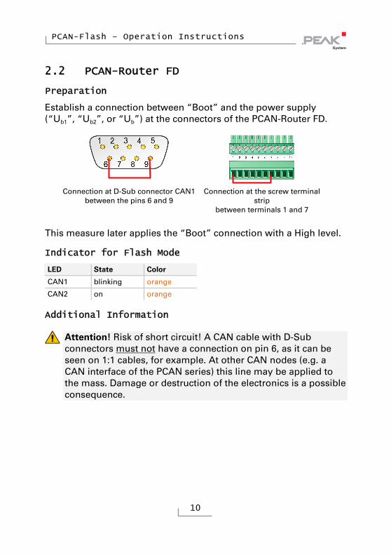
Establish a connection between “Boot” and the power supply (“Ub1”, “Ub2”, or “Ub”) at the connectors of the PCAN-Router FD.
Connection at D-Sub connector CAN1 between the pins 6 and 9
Connection at the screw terminal strip
between terminals 1 and 7
This measure later applies the “Boot” connection with a High level.
Indicator for Flash Mode
LED State Color
CAN1 blinking orange
CAN2 on orange
Additional Information
Attention! Risk of short circuit! A CAN cable with D-Sub connectors must not have a connection on pin 6, as it can be seen on 1:1 cables, for example. At other CAN nodes (e.g. a CAN interface of the PCAN series) this line may be applied to the mass. Damage or destruction of the electronics is a possible consequence.
PCAN-Flash – Operation Instructions
11
2.3 PCAN-Router DR
Preparation
On the front, turn the rotary switch „Bitrate“ to setting F.
Indicator for Flash Mode
LED State Color
Status off
CAN 1 blinking orange
CAN 2 on orange
2.4 PCAN-RS-232 and PCAN-GPS
Preparation
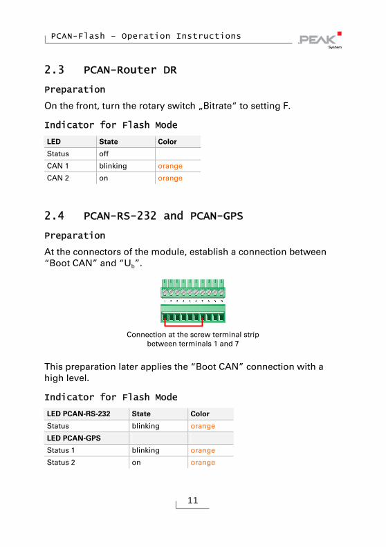
At the connectors of the module, establish a connection between “Boot CAN” and “Ub”.
Connection at the screw terminal strip
between terminals 1 and 7
This preparation later applies the “Boot CAN” connection with a high level.
Indicator for Flash Mode
LED PCAN-RS-232 State Color
Status blinking orange
LED PCAN-GPS
Status 1 blinking orange
Status 2 on orange

PCAN-Flash – Operation Instructions
12
2.5 PCAN-Router Pro
Tip: If the PCAN-Router Pro is operated with standard firmware1, you can alternatively activate the CAN bootloader by PCAN-Flash just before the flash process. In this case, you don't need to do the following preparation.
Preparation
Along the top edge of the casing remove two screws on each the front and the rear of the PCAN-Router Pro. Afterwards take off the upper casing part. Now you can access the circuit board.
Position of the rotary switch on the circuit board of the PCAN-Router Pro
Turn the rotary switch “Router-ID” to F.
Indicator for Flash Mode
LED State Color
μC Status off
LED 1 to LED 8 blinking red
1 Standard firmware is the firmware provided by PEAK-System at delivery. In
contrast, there may also be custom firmware on the PCAN-Router Pro.
PCAN-Flash – Operation Instructions
13
Additional Information
After an update of the standard firmware, the “μC Status” LED blinks with increased frequency (2 Hz) indicating that no configuration is available. Re-transfer your configuration(s) to the PCAN-Router Pro with the PPCAN-Editor.
2.6 PCAN-MIO
Preparation
Turn the rotary switch for the module ID to F.
Indicator for Flash Mode
LED State Color
Status blinking red and green alternating
Additional Information
A firmware update via CAN is only possible with PCAN-MIO modules from serial number 100. Older hardware can be provided with new firmware at PEAK-System on request.
2.7 PCAN-MicroMod
Preparation
The PCAN-MicroMod can only be set to flash mode by PCAN-Flash just before the flash process. A modification of the hardware is not needed.
Indicator for Flash Mode
LED State Color
Status blinking red

PCAN-Flash – Operation Instructions
14
Additional Information
After an update of the firmware, the LED on the PCAN-MicroMod blinks with increased frequency (2 Hz) indicating that no configuration is available. Re-transfer your configuration to the PCAN-MicroMod with the Windows program PCAN-MicroMod Configuration.
2.8 MU-Thermocouple1 CAN
Preparation
The measuring unit MU-Thermocouple1 CAN can only be set to flash mode by PCAN-Flash just before the flash process. A modification of the hardware is not needed.
Indicator for Flash Mode
LED State Color
Status blinking red

PCAN-Flash – Operation Instructions
15
3 Preparing the Software
PCAN-Flash must be started from a data carrier which is also writable, otherwise the program's configuration (PcanFlash.ini file) cannot be saved. The program doesn't work properly if it is run from a DVD. This is reflected, for example, by and error message when selecting a CAN connection.
Make sure that the PCAN-Flash directory is located on a local hard disk, for example, (if necessary, copy it from DVD) and that there are write permissions in the directory, and execute PCAN-Flash from there.
PCAN-Flash – Operation Instructions
16
4 Flashing the Firmware
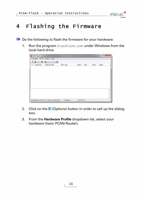
Do the following to flash the firmware for your hardware:
1. Run the program PcanFlash.exe under Windows from the local hard drive.
2. Click on the (Options) button in order to call up the dialog box.
3. From the Hardware Profile dropdown list, select your hardware (here: PCAN-Router).

PCAN-Flash – Operation Instructions
17
4. Click on the … button next to the File name field in order to select the desired firmware file (*.bin) to be flashed.
5. Click on the OK button.
6. Make sure that the PCAN-Flash program is connected with 500 kbit/s to the available CAN interface at the computer.
PCAN-Flash: Display of a connection in the status bar on the bottom.
If not, click the (Connect) button in order to change the selection in the according dialog box.

PCAN-Flash – Operation Instructions
18
7. Click the (Detect) button in order to detect the hardware connected to the CAN bus.
An entry for your hardware appears in the main window (here: PCAN-Router).
8. Select the entry for your hardware.
Tip: On some devices, here is the point where you can start the CAN bootloader alternatively with PCAN-Flash instead by hardware modification. To do so, click the (Activate module) button.

PCAN-Flash – Operation Instructions
19
9. Click the (Program) button in order to start uploading the new firmware to the PCAN-Router.
Observe the status indication at the bottom of the window. The process was successful if the last message to appear is “Flashing of module(s) finished!”.
10. Disconnect the power supply from your microcontroller hardware.
11. Undo the modification of the hardware that you've done before in chapter 2.
You can now use the hardware with the new firmware.