
Motoman NX100 Controller EP4000N Manipulator …...• Light curtains and/or safety mats • Door...
75
Motoman, Incorporated 805 Liberty Lane West Carrollton, OH 45449 TEL: (937) 847-6200 FAX: (937) 847-6277 24-Hour Service Hotline: (937) 847-3200 Motoman NX100 Controller EP4000N Manipulator Manual Part Number: 151530-1CD Revision: 0
Transcript of Motoman NX100 Controller EP4000N Manipulator …...• Light curtains and/or safety mats • Door...

Motoman NX100 Controller
EP4000N Manipulator Manual
Part Number: 151530-1CDRevision: 0
Motoman, Incorporated 805 Liberty LaneWest Carrollton, OH 45449TEL: (937) 847-6200FAX: (937) 847-627724-Hour Service Hotline: (937) 847-3200

The information contained within this document is the proprietary property of Motoman, Inc., and may not be copied, reproduced or transmitted to other parties without the expressed written authorization of Motoman,
Inc.
©2006 by MOTOMANAll Rights Reserved
Because we are constantly improving our products, we reserve the right to change specifications without notice. MOTOMAN is a registered trademark of YASKAWA Electric Manufacturing.

EP4000N151530-1
Chapter 1
Introduction
1.1 About This Document
This manual provides information for the EP4000N manipulator and contains the following sections:
CHAPTER 1 - INTRODUCTIONProvides general information about the structure of this manual, a list of reference documents, and customer service information.
CHAPTER 2 - SAFETYThis section provides information regarding the safe use and operation of Motoman products.
CHAPTER 3 - EP4000N INSTRUCTIONSProvides detailed instructions for the EP4000N.
1.2 Reference to Other Documentation
For additional information refer to the following:
• NX100 Controller Manual (P/N 149201-1)
• Concurrent I/O Manual (P/N 149230-1)
• Operator’s Manual for your application
• Vendor manuals for system components not manufactured by Motoman
1.3 Customer Service Information
If you are in need of technical assistance, contact the Motoman service staff at (937) 847-3200. Please have the following information ready before you call:
• Robot Type (EP4000N, HP50, etc.)
• Application Type (handling, welding, etc.)
• Robot Serial Number (located on back side of robot arm)
• Robot Sales Order Number (located on back of controller)
Final page 1

Manipulator Manual Chapter 1 Introduction
Notes
page 2 Final

EP4000N151530-1
Chapter 2
Safety
2.1 Introduction
It is the purchaser’s responsibility to ensure that all local, county, state, and national codes, regulations, rules, or laws relating to safety and safe operating conditions for each installation are met and followed.
We suggest that you obtain and review a copy of the ANSI/RIA National Safety Standard for Industrial Robots and Robot Systems. This information can be obtained from the Robotic Industries Association by requesting ANSI/RIA R15.06-1999. The address is as follows:
Robotic Industries Association900 Victors WayP.O. Box 3724
Ann Arbor, Michigan 48106TEL: (734) 994-6088FAX: (734) 994-3338
INTERNET: www.roboticsonline.com
Ultimately, the best safeguard is trained personnel. The user is responsible for providing personnel who are adequately trained to operate, program, and maintain the robot cell. The robot must not be operated by personnel who have not been trained!
We recommend that all personnel who intend to operate, program, repair, or use the robot system be trained in an approved Motoman training course and become familiar with the proper operation of the system.
Final page 3

Manipulator Manual Chapter 2 Safety
This safety section addresses the following:
• Standard Conventions (Section 2.2)
• General Safeguarding Tips (Section 2.3)
• Mechanical Safety Devices (Section 2.4)
• Installation Safety (Section 2.5)
• Programming, Operation, and Maintenance Safety (Section 2.6)
2.2 Standard Conventions
This manual includes the following alerts – in descending order of severity – that are essential to the safety of personnel and equipment. As you read this manual, pay close attention to these alerts to insure safety when installing, operating, programming, and maintaining this equipment.
DANGER!Information appearing in a DANGER concerns the protection of personnel from the immediate and imminent hazards that, if not avoided, will result in immediate, serious personal injury or loss of life in addition to equipment damage.
WARNING!Information appearing in a WARNING concerns the protection of personnel and equipment from potential hazards that can result in personal injury or loss of life in addition to equipment damage.
CAUTION!Information appearing in a CAUTION concerns the protection of personnel and equipment, software, and data from hazards that can result in minor personal injury or equipment damage.
Note: Information appearing in a Note provides additional information which is helpful in understanding the item being explained.
page 4 Final

EP4000N151530-1
2.3 General Safeguarding Tips
All operators, programmers, plant and tooling engineers, maintenance personnel, supervisors, and anyone working near the robot must become familiar with the operation of this equipment. All personnel involved with the operation of the equipment must understand potential dangers of operation. General safeguarding tips are as follows:
• Improper operation can result in personal injury and/or damage to the equipment. Only trained personnel familiar with the operation of this robot, the operator's manuals, the system equipment, and options and accessories should be permitted to operate this robot system.
• Do not enter the robot cell while it is in automatic operation. Programmers must have the teach pendant when they enter the robot cell.
• Improper connections can damage the robot. All connections must be made within the standard voltage and current ratings of the robot I/O (Inputs and Outputs).
• The robot must be placed in Emergency Stop (E-STOP) mode whenever it is not in use.
• In accordance with ANSI/RIA R15.06-1999, section 4.2.5, Sources of Energy, use lockout/tagout procedures during equipment maintenance. Refer also to Section 1910.147 (29CFR, Part 1910), Occupational Safety and Health Standards for General Industry (OSHA).
2.4 Mechanical Safety Devices
The safe operation of the robot, positioner, auxiliary equipment, and system is ultimately the user's responsibility. The conditions under which the equipment will be operated safely should be reviewed by the user. The user must be aware of the various national codes, ANSI/RIA R15.06-1999 safety standards, and other local codes that may pertain to the installation and use of industrial equipment. Additional safety measures for personnel and equipment may be required depending on system installation, operation, and/or location. The following safety equipment is provided as standard:
• Safety fences and barriers
• Light curtains and/or safety mats
• Door interlocks
• Emergency stop palm buttons located on operator station, robot controller, and programming pendant
Check all safety equipment frequently for proper operation. Repair or replace any non-functioning safety equipment immediately.
Final page 5

Manipulator Manual Chapter 2 Safety
2.5 Installation Safety
Safe installation is essential for protection of people and equipment. The following suggestions are intended to supplement, but not replace, existing federal, local, and state laws and regulations. Additional safety measures for personnel and equipment may be required depending on system installation, operation, and/or location. Installation tips are as follows:
• Be sure that only qualified personnel familiar with national codes, local codes, and ANSI/RIA R15.06-1999 safety standards are permitted to install the equipment.
• Identify the work envelope of each robot with floor markings, signs, and barriers.
• Position all controllers outside the robot work envelope.
• Whenever possible, install safety fences to protect against unauthorized entry into the work envelope.
• Eliminate areas where personnel might get trapped between a moving robot and other equipment (pinch points).
• Provide sufficient room inside the workcell to permit safe teaching and maintenance procedures.
2.6 Programming, Operation, and Maintenance Safety
All operators, programmers, plant and tooling engineers, maintenance personnel, supervisors, and anyone working near the robot must become familiar with the operation of this equipment. Improper operation can result in personal injury and/or damage to the equipment. Only trained personnel familiar with the operation, manuals, electrical design, and equipment interconnections of this robot should be permitted to program, operate, and maintain the system. All personnel involved with the operation of the equipment must understand potential dangers of operation.
• Inspect the robot and work envelope to be sure no potentially hazardous conditions exist. Be sure the area is clean and free of water, oil, debris, etc.
• Be sure that all safeguards are in place. Check all safety equipment for proper operation. Repair or replace any non-functioning safety equipment immediately.
• Do not enter the robot cell while it is in automatic operation. Be sure that only the person holding the programming pendant enters the workcell.
• Check the E-STOP button on the programming pendant for proper operation before programming. The robot must be placed in Emergency Stop (E-STOP) mode whenever it is not in use.
• Back up all programs and jobs onto suitable media before program changes are made. To avoid loss of information, programs, or jobs, a backup must always be made before any service procedures are done and before any changes are made to options, accessories, or equipment.
page 6 Final

EP4000N151530-1
• Any modifications to PART 1, System Section, of the robot controller concurrent I/O program can cause severe personal injury or death, as well as damage to the robot! Do not make any modifications to PART 1, System Section. Making any changes without the written permission of Motoman will VOID YOUR WARRANTY!
• Some operations require standard passwords and some require special passwords. Special passwords are for Motoman use only. YOUR WARRANTY WILL BE VOID if you use these special passwords.
• The robot controller allows modifications of PART 2, User Section, of the concurrent I/O program and modifications to controller parameters for maximum robot performance. Great care must be taken when making these modifications. All modifications made to the controller will change the way the robot operates and can cause severe personal injury or death, as well as damage the robot and other parts of the system. Double-check all modifications under every mode of robot operation to ensure that you have not created hazards or dangerous situations.
• Check and test any new or modified program at low speed for at least one full cycle.
• This equipment has multiple sources of electrical supply. Electrical interconnections are made between the controller and other equipment. Disconnect and lockout/tagout all electrical circuits before making any modifications or connections.
• Do not perform any maintenance procedures before reading and understanding the proper procedures in the appropriate manual.
• Use proper replacement parts.
• Improper connections can damage the robot. All connections must be made within the standard voltage and current ratings of the robot I/O (Inputs and Outputs).
Final page 7

Manipulator Manual Chapter 2 Safety
Notes
page 8 Final
YASKAWA
MOTOMAN-EP4000NINSTRUCTIONSFOR INTER-PRESS HANDLINGTYPE: YR-EP4000N-*0* (PARALLEL LINK HAND SPECIFICATION)TYPE: YR-EP4000N-*1* TYPE: YR-EP4000N-*3* (PARALLEL LINK HAND SPECIFICATION, TYPE: YR-EP4000N- *4* ALUMINUM LINK PART MOUNTED ON THE RIGHT SIDE)TYPE: YR-EP4000N-*4* (DIAGONAL-MOUNT PARALLEL LINK HAND SPEC: +45 DEGREE ANGLE)TYPE: YR-EP4000N-*5* (DIAGONAL-MOUNT PARALLEL LINK HAND SPEC: -45 DEGREE ANGLE)
Upon receipt of the product and prior to initial operation, read these instructions thoroughly, and retain for future reference.
MOTOMAN INSTRUCTIONSMOTOMAN-EP4000N INSTRUCTIONSNX100 INSTRUCTIONSNX100 OPERATOR’S MANUALNX100 MAINTENACE MANUAL
The NX100 operator’s manuals above correspond to specific usage. Be sure to use the appropriate manual.
YASKAWA MANUAL NO.
HW0482597

HW0482597
• This instruction manual explains operating instructions and mainte-nance procedures primarily for the MOTOMAN-EP4000N.
• General items related to safety are listed in Section 1: Safety of the NX100 Instructions. To ensure correct and safe operation, carefully read the NX100 instructions before reading this manual.
• Some drawings in this manual are shown with the protective covers or shields removed for clarity. Be sure all covers and shields are replaced before operating this product.
• The drawings and photos in this manual are representative examples and differences may exist between them and the delivered product.
• YASKAWA may modify this model without notice when necessary due to product improvements, modifications, or changes in specifications. If such modification is made, the manual number will also be revised.
• If your copy of the manual is damaged or lost, contact a YASKAWA rep-resentative to order a new copy. The representatives are listed on the back cover. Be sure to tell the representative the manual number listed on the front cover.
• YASKAWA is not responsible for incidents arising from unauthorized modification of its products. Unauthorized modification voids your prod-uct’s warranty.
MANDATORY
CAUTION
ii
HW0482597

HW0482597
Notes for Safe OperationRead this manual carefully before installation, operation, maintenance, or inspection of the NX100. In this manual, the notes for safe operation are classified as “WARNING”, “CAUTION”, “MAN-DATORY”, or “PROHIBITED”.
Even items described as “CAUTION” may result in a serious accident in some situations. At any rate, be sure to follow these important items.
Indicates a potentially hazardous situation which, if not avoided, could result in death or serious injury to personnel.
Indicates a potentially hazardous situation which, if not avoided, could result in minor or moderate injury to personnel and dam-age to equipment. It may also be used to alert against unsafe practices.
Always be sure to follow explicitly the items listed under this heading.
Must never be performed.
To ensure safe and efficient operation at all times, be sure to follow all instructions, even if not designated as “CAUTION” and “WARNING”.
WARNING
CAUTION
MANDATORY
PROHIBITED
NOTE
iii
HW0482597

HW0482597
• Before operating the manipulator, check that servo power is turned off when the emergency stop buttons on the front door of the NX100 and programming pendant are pressed.When the servo power is turned off, the SERVO ON LED on the program-ming pendant is turned off.
Injury or damage to machinery may result if the emergency stop circuit cannot stop the manipulator during an emergency. The manipulator should not be used if the emergency stop buttons do not function.
Emergency Stop Button
• Once the emergency stop button is released, clear the cell of all items which could interfere with the operation of the manipulator. Then turn the servo power ON.
Injury may result from unintentional or unexpected manipulator motion.
Release of Emergency Stop
• Observe the following precautions when performing teaching operations within the working envelope of the manipulator:- View the manipulator from the front whenever possible.- Always follow the predetermined operating procedure.- Ensure that you have a safe place to retreat in case of emergency.
Improper or unintended manipulator operation may result in injury.
• Confirm that no persons are present in the manipulator’s work envelope and that you are in a safe location before:- Turning on the NX100 power- Moving the manipulator with the programming pendant- Running check operations- Performing automatic operations
Injury may result if anyone enters the working envelope of the manipulator during opera-tion. Always press an emergency stop button immediately if there are problems. The emergency stop button is located on the right of the front door of the NX100 and the pro-gramming pendant.
WARNING
TURN
iv
HW0482597

HW0482597
Definition of Terms Used Often in This ManualThe MOTOMAN manipulator is the YASKAWA industrial robot product.The manipulator usually consists of the controller, the programming pendant, and manipulator cables.In this manual, the equipment is designated as follows:
• Perform the following inspection procedures prior to conducting manip-ulator teaching. If problems are found, repair them immediately, and be sure that all other necessary processing has been performed.-Check for problems in manipulator movement.-Check for damage to insulation and sheathing of external wires.
• Always return the programming pendant to the hook on the NX100 cabi-net after use.
The programming pendant can be damaged if it is left in the manipulator’s work area, on the floor, or near fixtures.
• Read and understand the Explanation of the Warning Labels in the NX100 instructions before operating the manipulator.
Equipment Manual Designation
NX100 Controller NX100
NX100 Programming Pendant Programming pendant
Cable between the manipulator and the controller Manipulator cable
CAUTION
v
HW0482597

HW0482597
Explanation of Warning LabelsThe following warning labels are attached to the manipulator.Always follow the warnings on the labels.Also, an identification label with important information is placed on the body of the manipula-tor. Prior to operating the manipulator, confirm the contents.
MOTOMANTYPE
PAYLOAD
ORDER NO.
SERIAL NO.
MASS
DATE
YASKAWA ELECTRIC CORPORAION JAPAN
kgkg
Warning Label A
Warning Label B
Nameplate
Warning label B
Warning label A
Nameplate
Warning label B
Warning label A
WARNING
Do not enterrobot work area.
WARNING
Moving partsmay causeinjury
vi
HW0482597

HW0482597
1 Product Confirmation1.1 Contents Confirmation . . . . . . . . . . . . . . . . . . . . . . . . . . . . . 1-11.2 Order Number Confirmation . . . . . . . . . . . . . . . . . . . . . . . 1-2
2 Transporting2.1 Transporting Method . . . . . . . . . . . . . . . . . . . . . . . . . . . . . . 2-1
2.1.1 Using a Crane . . . . . . . . . . . . . . . . . . . . . . . . . . . . . . . . . . . . . .2-12.2 Shipping Bolts and Brackets . . . . . . . . . . . . . . . . . . . . . . . 2-3
3 Installation3.1 Safeguarding Installation . . . . . . . . . . . . . . . . . . . . . . . . . . 3-23.2 Mounting Procedures for Manipulator Base . . . . . . . . 3-2
3.2.1 Manipulator Base Mount . . . . . . . . . . . . . . . . . . . . . . . . . . . . . .3-33.3 Location . . . . . . . . . . . . . . . . . . . . . . . . . . . . . . . . . . . . . . . . . . . 3-4
4 Wiring4.1 Grounding . . . . . . . . . . . . . . . . . . . . . . . . . . . . . . . . . . . . . . . . . 4-14.2 Manipulator Cable Connection . . . . . . . . . . . . . . . . . . . . . 4-2
4.2.1 Connection to the Manipulator. . . . . . . . . . . . . . . . . . . . . . . . . .4-24.2.2 Connection to the NX100 . . . . . . . . . . . . . . . . . . . . . . . . . . . . .4-2
5 Basic Specifications5.1 Basic Specifications . . . . . . . . . . . . . . . . . . . . . . . . . . . . . . . 5-15.2 Part Names and Working Axes . . . . . . . . . . . . . . . . . . . . 5-25.3 Manipulator Base Dimensions . . . . . . . . . . . . . . . . . . . . . 5-25.4 Dimensions and P-point Maximum Envelope. . . . . . . 5-35.5 JT5-Axis Operating Range. . . . . . . . . . . . . . . . . . . . . . . . . 5-45.6 Alterable Operating Range . . . . . . . . . . . . . . . . . . . . . . . . 5-4
6 Allowable Load for Wrist Axis and Wrist Flange6.1 Allowable Wrist Load . . . . . . . . . . . . . . . . . . . . . . . . . . . . . . 6-16.2 Wrist Flange. . . . . . . . . . . . . . . . . . . . . . . . . . . . . . . . . . . . . . . 6-2
vii
HW0482597

HW0482597
7 System Application7.1 Peripheral Equipment Mounts . . . . . . . . . . . . . . . . . . . . . . 7-17.2 Internal User I/O Wiring Harness and Air Line . . . . . . 7-2
8 Electrical Equipment Specifications8.1 Locations of Limit Switches. . . . . . . . . . . . . . . . . . . . . . . . . 8-18.2 Internal Connections. . . . . . . . . . . . . . . . . . . . . . . . . . . . . . . 8-3
9 Maintenance and Inspection9.1 Inspection Schedule
(Manipulator in the Home Position: Refer to “Fig. 19”) . . . . . . . . . . 9-19.2 Notes on Maintenance Procedures . . . . . . . . . . . . . . . . . 9-6
9.2.1 Battery Pack Replacement . . . . . . . . . . . . . . . . . . . . . . . . . . . . 9-69.2.2 Grease Replenishment/Exchange for JT1-Axis
Speed Reducer and Gear. . . . . . . . . . . . . . . . . . . . . . . . . . . . . 9-8 Grease Replenishment (Refer to "Fig. 22 JT1-Axis
Speed Reducer and Gear Diagram".). . . . . . . . . . . . . . . . . . 9-8 Grease Exchange (Refer to "Fig. 22 JT1-Axis
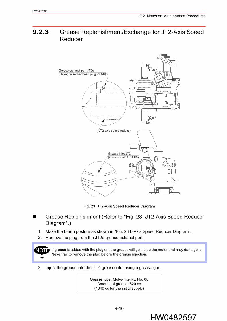
Speed Reducer and Gear Diagram".). . . . . . . . . . . . . . . . . . 9-99.2.3 Grease Replenishment/Exchange for JT2-Axis
Speed Reducer. . . . . . . . . . . . . . . . . . . . . . . . . . . . . . . . . . . . 9-10 Grease Replenishment (Refer to "Fig. 23 JT2-Axis
Speed Reducer Diagram".). . . . . . . . . . . . . . . . . . . . . . . . . 9-10 Grease Exchange (Refer to "Fig. 23 JT2-Axis
Speed Reducer Diagram".). . . . . . . . . . . . . . . . . . . . . . . . . 9-119.2.4 Grease Replenishment/Exchange for JT3-Axis
Speed Reducer. . . . . . . . . . . . . . . . . . . . . . . . . . . . . . . . . . . . 9-12 Grease Replenishment (Refer to "Fig. 24 JT3-Axis
Speed Reducer Diagram".). . . . . . . . . . . . . . . . . . . . . . . . . 9-12 Grease Exchange (Refer to "Fig. 24 JT3-Axis
Speed Reducer Diagram".). . . . . . . . . . . . . . . . . . . . . . . . . 9-139.2.5 Grease Replenishment/Exchange for JT4, JT5-,
JT6-Axis Gears . . . . . . . . . . . . . . . . . . . . . . . . . . . . . . . . . . . . 9-14 Grease Replenishment (Refer to "Fig. 25 JT4-, JT5-,
JT6-Axis Gear Diagram".). . . . . . . . . . . . . . . . . . . . . . . . . . 9-14 Grease Exchange (Refer to "Fig. 25 JT4-, JT5-,
JT6-Axis Gear Diagram".). . . . . . . . . . . . . . . . . . . . . . . . . . 9-159.2.6 Grease Replenishment/Exchange for JT4-Axis
Speed Reducer. . . . . . . . . . . . . . . . . . . . . . . . . . . . . . . . . . . . 9-16 Grease Replenishment (Refer to "Fig. 26 JT4-Axis
Speed Reducer Diagram".). . . . . . . . . . . . . . . . . . . . . . . . . 9-16 Grease Exchange (Refer to "Fig. 26 JT4-Axis
Speed Reducer Diagram".). . . . . . . . . . . . . . . . . . . . . . . . . 9-17
viii
HW0482597

HW0482597
9.2.7 Grease Replenishment/Exchange for JT5-Axis Speed Reducer and Gear . . . . . . . . . . . . . . . . . . . . . . . . . . . .9-18 Grease Replenishment (Refer to "Fig. 27 JT5-Axis
Speed Reducer and Gear Diagram".) . . . . . . . . . . . . . . . . .9-18 Grease Exchange (Refer to "Fig. 27 JT5-Axis
Speed Reducer and Gear Diagram".) . . . . . . . . . . . . . . . . .9-199.2.8 Grease Replenishment/Exchange for JT6-Axis
Speed Reducer and Gear . . . . . . . . . . . . . . . . . . . . . . . . . . . .9-20 Grease Replenishment (Refer to "Fig. 28 JT6-Axis
Speed Reducer and Gear Diagram".) . . . . . . . . . . . . . . . . .9-20 Grease Exchange (Refer to "Fig. 28 JT6-Axis
Speed Reducer and Gear Diagram".) . . . . . . . . . . . . . . . . .9-219.2.9 Grease Replenishment for JT2-Axis Cross Roller Bearing . . .9-229.2.10 Grease Replenishment for Tapered Roller Bearing
in the Link Part . . . . . . . . . . . . . . . . . . . . . . . . . . . . . . . . . . .9-239.2.11 Grease Replenishment for Balancer Link Part . . . . . . . . . . .9-249.2.12 Notes for Maintenance . . . . . . . . . . . . . . . . . . . . . . . . . . . . .9-25
Motors for JT1-, JT2-, JT3-, JT4-, JT5-, JT6-Axes . . . . . . .9-25
10 Recommended Spare Parts
ix
HW0482597

1.1 Contents ConfirmationHW0482597
1 Product Confirmation
1.1 Contents Confirmation
Confirm the contents of the delivery when the product arrives.Standard delivery includes the following four items (Information for the content of optional goods is given separately):
• Manipulator• NX100• Programming pendant• Manipulator cables (six cables, between manipulator and NX100)
• Confirm that the manipulator and the NX100 have the same order num-ber. Special care must be taken when more than one manipulator is to be installed.
If the numbers do not match, manipulators may not perform as expected and cause injury or damage.
Connectors for manipulator cables are located on different positions depending on manipu-lator types.
CAUTION
NOTE
EP4000N-B
Manipulator cableconnector
The left side of the front
The back side
The right side of the front
**
Manipulator cableconnector
EP4000N-K**
EP4000N-A**EP4000N-J **
EP4000N-C**EP4000N-L **
1-1
HW0482597

1.2 Order Number ConfirmationHW0482597
1.2 Order Number Confirmation
Check that the order number of the manipulator corresponds to the NX100. The order number is located on a label as shown below.
Fig. 1 Location of Order Number Labels
THE MANIPULATOR AND THE CONTROLLERSHOULD HAVE SAME ORDER NUMBER.
ORDER NO.
Check that the manipulator and the NX100 have the same order number.
Label (Enlarged View)
ORDER NO.NJ1529
THE MANIPULATOR AND THE CONTROLLERSHOULD HAVE SAME ORDER NUMBER.
WARNINGDo not open the door
RESETO
FFTR
IPPED
ON
(a) NX100 (Front View) (b) Manipulator (Top View)
1-2
HW0482597

2.1 Transporting MethodHW0482597
2 Transporting
2.1 Transporting Method
2.1.1 Using a Crane
As a rule, when removing the manipulator from the package and moving it, a crane should be used. The manipulator should be lifted using wire ropes threaded through shipping bolts and brackets. Be sure the manipulator is fixed with the shipping bolts and brackets before trans-portation, and lift it in the posture as shown in "Fig. 2 Transporting Position".
• Sling applications and crane or forklift operations must be performed by authorized personnel only.
Failure to observe this caution may result in injury or damage.
• Avoid excessive vibration or shock during transporting.
Failure to observe this caution may adversely affect the performance as the system con-sists of precision components.
• Check that the eyebolts are securely fastened.• The weight of the manipulator is approximately 3200 kg including the shipping bolts and
brackets. Use a wire rope strong enough to withstand the weight.• Attached eyebolts are designed to support the manipulator weight. Do not use them for
anything other than transporting the manipulator.• Mount the shipping bolts and brackets in transporting the manipulator.• Avoid exerting force on the arm or motor unit during transportation: use caution when
using transporting equipment other than a crane or forklift to avoid injury.
CAUTION
NOTE
2-1
HW0482597

2.1 Transporting MethodHW0482597
Fig. 2 Transporting Position
C B
A
2-2
HW0482597

2.2 Shipping Bolts and BracketsHW0482597
2.2 Shipping Bolts and Brackets
The manipulator is equipped with shipping bolts and brackets at points A, B, and C ("Fig. 2 Transporting Position").
• The shipping bolts and brackets are painted yellow.
Position Bolt Type Pcs
A Hexagon socket head cap screw: M12 (length: 30 mm) (Tensile strength: 1200 N/mm2 or more)
3
B Hexagon nut: M12 2
C Hexagon nut: M12 2
Before turning ON the power, check to be sure that the shipping bolts and brackets have been removed. The shipping bolts and brackets then must be stored for future use, in the event that the robot must be moved again.
NOTE
2-3
HW0482597

HW0482597
3 Installation
• Install the safeguarding.
Failure to observe this warning may result in injury or damage. • Install the manipulator in a location where the manipulator’s tool or the
workpiece held by the manipulator will not reach the wall, safeguarding, or NX100 when the arm is fully extended.
Failure to observe this warning may result in injury or damage.
• Do not start the manipulator or even turn on the power before it is firmly anchored.
The manipulator may overturn and cause injury or damage.
• Do not install or operate the manipulator which is damaged or lacks parts.
Failure to observe this caution may cause injury or damage.
• Before turning on the power, check to be sure that the shipping bolts and brackets explained in "2.2 Shipping Bolts and Brackets" are removed.
Failure to observe this caution may result in damage to the driving parts.
WARNING
CAUTION
3-1
HW0482597

3.1 Safeguarding InstallationHW0482597
3.1 Safeguarding Installation
To insure safety, be sure to install safeguarding. They prevent unforeseen accidents with per-sonnel and damage to equipment. The following term is quoted for your information and guid-ance. Responsibility for Safeguarding [ISO 10218]The user of a manipulator or robot system shall ensure that safeguards are provided and used in accordance with Sections 6, 7, and 8 of this standard. The means and degree of safeguard-ing, including any redundancies, shall correspond directly to the type and level of hazard pre-sented by the robot system consistent with the robot application. Safeguarding may include but not be limited to safeguarding devices, barriers, interlock barriers, perimeter guarding, awareness barriers, and awareness signals.
3.2 Mounting Procedures for Manipulator Base
The manipulator should be firmly mounted on a manipulator base mount strong enough to support the robot and withstand repulsion forces during acceleration and deceleration. Con-struct a solid foundation with the appropriate thickness to withstand maximum repulsion forces of the manipulator, referring to "Table 1 Maximum repulsion forces of the manipulator base mount".A base mount flatness must be kept at 0.5 mm or less: insufficient flatness of installation sur-face may deform the manipulator shape and affect its functional abilities.
Connectors for manipulator cables are located on different positions depending on manipu-lator types.Confirm the correct position of the manipulator cable before Installing the manipulator.
NOTE
EP4000N-B
Manipulator cableconnector
The left side of the front
The back side
The right side of the front
**
Manipulator cableconnector
EP4000N-K**
EP4000N-A**EP4000N-J **
EP4000N-C**EP4000N-L **
3-2
HW0482597

3.2 Mounting Procedures for Manipulator BaseHW0482597
3.2.1 Manipulator Base Mount
Design and construct the manipulator base mount so that it can bear the torque shown in the table below. The vibration in the manipulator base must be 4.9 m/s2 (0.5G) or less when the manipulator is individually operated. The manipulator base mount has 12 mounting holes. Mount the manipulator base firmly using the hexagon socket head cap screws M24 (tensile strength: 1000 N/mm2 or more, recom-mended length: 90 mm).
Fig. 3 Installation Base
Table 1 Maximum repulsion forces of the manipulator base mount
Maximum torque in horizontal rotation (JT1-axis moving direction)
88200 N·m or more(9000 kgf·m)
Maximum torque in vertical rotation (JT2-, JT3-axis moving directions)
68600 N·m or more(7000 kgf·m)
Washer
45
Hexagon socket head cap screw M24 (length: 90)
Spring washer
Manipulator Base
2 Torque
1 Torque
Manipulator base mount
Units: mm
3-3
HW0482597

3.3 LocationHW0482597
3.3 Location
When the manipulator is installed, it is necessary to satisfy the following environmental condi-tions:
• Ambient temperature: 0 to 45°C.• Humidity: 20 to 80%RH at constant temperature.• Free from exposure to water, oil, or dust.• Free from corrosive gas or liquid, or explosive gas.• Free from large electrical noise (plasma).• Shock or vibration from the press must be 9.8 m/s2 (1.0 G) or less.• Free from excessive shock or vibration: 4.9 m/s2 (0.5G) or less when the manipulator is
operated individually (with no vibration from other equipment such as the press). (Exces-sive vibration affects the mechanism.)
• Flatness for installation: 0.5 mm or less.
3-4
HW0482597

4.1 GroundingHW0482597
4 Wiring
4.1 Grounding
Follow local regulations for grounding line size. A line of 8.0 mm2 or more is recommended. Refer to "Fig. 4 Grounding Method" to connect the ground line directly to the manipulator.
• Ground resistance must be 100 Ω or less.
Failure to observe this warning may result in fire or electric shock.
• Before wiring, make sure to turn OFF the primary power supply, and put up a warning sign such as: “DO NOT TURN ON THE POWER.”
Failure to observe this warning may result in fire or electric shock.
• Wiring must be performed by authorized or certified personnel.
Failure to observe this caution may result in fire or electric shock.
• Do not cover the cable with heat insulating material, and avoid multiple cabling when laying manipulator cables from the manipulator to the NX100.
Failure to observe this caution may result in burn caused by cable heat emission failure.
• Never use this line sharing with other ground lines or grounding electrodes for other elec-tric power, motor power, welding devices, etc.
• Where metal ducts, metallic conduits, or distributing racks are used for cable laying, ground in accordance with Electric Equipment Technical Standards.
WARNING
CAUTION
NOTE
4-1
HW0482597

4.2 Manipulator Cable ConnectionHW0482597
Fig. 4 Grounding Method
4.2 Manipulator Cable Connection
As shown on "Fig. 5 Manipulator Cables", there are six cables for the power supply. Connect these cables to the connectors on the manipulator base and the NX100, referring to "Fig. 5 Manipulator Cables".
4.2.1 Connection to the Manipulator
Before connecting the cables to the manipulator, verify the numbers: there are 1BC, 2BC, 3BC, 4BC, 5BC, and 6BC on both manipulator cables and the manipulator base connectors. When connecting the cables, adjust the cable connector positions to the main key positions of the manipulator, and insert the cables in the order of 2BC, 3BC, 4BC, 5BC, 6BC, and 1BC, then set each lever downward until it clicks.
4.2.2 Connection to the NX100
Before connecting the cables to the NX100, verify the numbers: there are X11, X21, X22, X23, X24, and X25 on both manipulator cables and the connectors on the NX100. When con-necting the cables, adjust the cable connector positions to the main key positions of the NX100, and insert the cables in the order of X21, X22, X23, X24, X25, and X11, then set each lever downward until it clicks.
• Do not cover the cable with heat insulating material, and avoid multiple cabling when laying manipulator cables from the manipulator to the NX100.
Failure to observe this caution may result in burn caused by cable heat emission failure.
A(Delivered with manipulator)Bolt M8 (for grounding)
View A
CAUTION
4-2
HW0482597

4.2 Manipulator Cable ConnectionHW0482597
Fig. 5 Manipulator Cables
X11
X21
X22
X23
X24
X25
1BC6BC
4BC5BC
3BC2BC
X25 6BC
X24 5BC
X23 4BC
X22 3BC
X21 2BC
X11 1BC
1BC
Encoder cable
Manipulator sideNX100 side
2BC
Power cable
3BC
Power cable
4BC
Power cable
5BC
Power cable
6BC
Power cable
4-3
HW0482597

4.2 Manipulator Cable ConnectionHW0482597
Fig. 6 (a) Manipulator Cable Connectors (Manipulator Side)
AIR1 AIR27BC
6BC5BC4BC3BC2BC1BC
Main key positions
4-4
HW0482597

4.2 Manipulator Cable ConnectionHW0482597
Fig. 6 (b) Manipulator Cable Connectors (NX100 Side)
X22X21
X11
X23
X24
X25
4-5
HW0482597

5.1 Basic SpecificationsHW0482597
5 Basic Specifications
5.1 Basic Specifications
*1 SI units are used in this table. However, gravitational unit is used in ().*2 Conformed to ISO9283.
Table. 2 Basic Specifications*1
Item Model
MOTOMAN-EP4000N-*0*MOTOMAN-EP4000N-*3*MOTOMAN-EP4000N-*4*MOTOMAN-EP4000N-*5*
MOTOMAN-EP4000N-*1*
Configuration Vertically Articulated
Degree of Freedom 6
Payload 200 kg
Repeatability2 ±0.5 mm
MotionRange
JT1-Axis (turning) ±150°
JT2-Axis (lower arm) +25°, -122°
JT3-Axis (upper arm) +53°, -70°
JT4-Axis (wrist roll) ±360°
JT5-Axis (wrist pitch/yaw) +85°, -120° ±120°
JT6-Axis (wrist twist) ±70° ±360°
MaximumSpeed
JT1-Axis 1.57 rad/s, 90°/s
JT2-Axis 1.57 rad/s, 90°/s
JT3-Axis 1.57 rad/s, 90°/s
JT4-Axis 1.40 rad/s, 80°/s
JT5-Axis 1.40 rad/s, 80°/s
JT6-Axis 2.79 rad/s, 160°/s
Mass 3100 kg
AmbientConditions
Temperature 0 to 45C°
Humidity 20 to 80% RH (non-condensing)
Vibration 9.8 m/s2 (1.0 G) or less
Others• Free from corrosive gasses or liquids, or explosive gasses.• Free from exposure to water, oil, or dust.• Free from excessive electrical noise (plasma).
Power Requirements 22 kVA
5-1
HW0482597
5.2 Part Names and Working AxesHW0482597
5.2 Part Names and Working Axes
Fig. 7 Part Names and Working Axes
5.3 Manipulator Base Dimensions
Fig. 8 Baseplate Dimensions (mm)
JT4+
JT3+
Lower arm(L-arm)
Base
Rotary head(S-head)
Upper arm(U-arm)
Wrist flange
Wrist
JT4-
JT5+JT5-
JT6-
JT3-
JT2-
JT1-
JT6+
JT2+
JT1+
475
640
640
860
45
70
860
760
760A 350±0.2
410±
0.2
350±0.2
410±
0.2
12 dia. dowel hole
28 dia. hole (12 holes)+0.018
0
12 dia. dowel hole
+0.0180
Units: mm
5-2
HW0482597

5.4 Dimensions and P-Point Maximum Envelope
5-3
HW0482597
HW0482597
5.4 Dimensions and P-Point Maximum Envelope
Fig. 9 Dimensions and P-Point Maximum Envelope
152
300
1681
380
4411
0
A
R3505
803
2110
R1033
250550
122°
1100 210
150°
150°
755
53°
527
2135
25°
70°
3505
3878
1803542 1823
255
740
588
555
467
690
261
0
373
1874
53°
Servo ON/OFF indicating lamp (red)(Optional)
Tapped hole M10 (pitch: 1.5)(depth: 25)(4 holes)
View A
P-point maximum envelope
2500
(with
indi
catin
g la
mp)
2480
(with
out i
ndic
atin
g la
mp)
P-point
Units: mm
70 d
ia.
(Lam
p dim
ensio
n)
Hole M10 (pitch: 1.5)(depth: 15)(3 holes)
Hole M10 (pitch: 1.5)(depth: 15)(3 holes)
Hole M10 (pitch: 1.5)(depth: 15)(3 holes)
Hole M10 (pitch: 1.5)(depth: 15)(3 holes)
+0.01508 dia. hole
(depth: 8)(2 holes)
+0.01508 dia. hole
(depth: 8)(2 holes)
+0.01508 dia. hole
(depth: 8)(2 holes)
- 5* *
- 4* *
- 3* *
- 0* *- 1* *
+0.01508 dia. hole
(depth: 8)(2 holes)
- 4* *- 0* *- 1* *- 3* *- 5* *
180°
45°
45°
B
View B

5.5 JT5-Axis Operating RangeHW0482597
5.5 JT5-Axis Operating Range
The JT5-axis operates keeping the constant angle to the center of U-arm as shown in "Fig. 10 JT5-Axis Operating Range".
Fig. 10 JT5-Axis Operating Range
5.6 Alterable Operating Range
The operating range of the JT1-axis can be altered according to the operating conditions as shown in "Table 3 JT1-Axis Operating Range". If alteration is necessary, contact your Yaskawa representative in advance.
Table 3 JT1-Axis Operating Range
Item Specifications
JT1-AxisOperating
Range
±150° (standard)±120°±90°±60°±30°
Center of rotation:JT5-axis
Center of rotation: JT3-axis
Center of rotation: JT2-axis
Center of rotation: JT1-axis
120°120°
5-4
HW0482597

6.1 Allowable Wrist LoadHW0482597
6 Allowable Load for Wrist Axis and Wrist Flange
6.1 Allowable Wrist LoadThe allowable wrist load including the mass of the gripper is 200 kg.This section explains the allowable values and conditions.
As shown in "Table 4 Allowable Inertia and Moment of Inertia" below, there are limitations in moment and moment of inertia: fulfill the requirement in the table in operating the manipulator.
*1 ( ): Gravitational unit
• Allowable wrist load is based on an assumption that the robot is handling a workpiece horizontally by keeping its wrist flange downwards.
Table 4 Allowable Inertia and Moment of Inertia
Allowable Moment N•m (kgf·m)*1
Allowable Moment of Inertia (GD2/4) kg·m2
JT4-axis 1274 (130) 84.5
JT5-axis 2156 (220) 330
JT6-axis 0 (0) 80
6-1
HW0482597

6.2 Wrist FlangeHW0482597
6.2 Wrist Flange
It is recommended that the attachment be mounted inside the fitting to identify the alignment marks. Fitting depth of inside and outside fittings must be 8 mm or less.
Fig. 11 Wrist Flange
Wash off anti-corrosive paint (yellow) on the wrist flange surface with thinner or light oil before mounting the tools.
(Moving side)
(Fixed side)JT5-axis flange
JT6-axis flange
55°
45°
55°
12.5
°
12.5°
30°
30°
55°
30°
214
25°
55°
45°
90°
30°30°
30°
90°
227
from P
-poi
nt
8
PCD212
8
8 dia. hole (depth: 8) (2 holes)
40 dia.
170 dia.
255
from P
-poi
nt5
PCD58
PCD100PCD126
236 dia.
+0.0150
Hole M8 (pitch: 1.25)(depth: 15)(6 holes)
Hole M10 (pitch: 1.5)(depth: 18)(8 holes)
Hole M10 (pitch: 1.5)(depth: 15)(3 holes)
Hole M10 (pitch: 1.5)(depth: 15)(9 holes)
8 dia. hole (depth: 8) (2 holes)+0.015
0
0-0.016
0-0.025
0-0.029
Units: mm
NOTE
6-2
HW0482597

7.1 Peripheral Equipment MountsHW0482597
7 System Application
7.1 Peripheral Equipment Mounts
The peripheral equipment mounts and tapped holes are provided on the upper arm of the manipulator as shown in "Fig. 12 Tapped Holes for Peripheral Equipment Mounts", for easier installation of the user's system applications. Make efficient use of these mounts following the conditions in "Table 5 Condition for Attachment".
Fig. 12 Tapped Holes for Peripheral Equipment Mounts
Table 5 Condition for Attachment
Application Remarks
A Cabling Allowable load mass is 200 kg including wrist load.
B CablingValve mounting
10 kg or less.25 N·m (2.5 kgf·m) or less for increased moment amount of upper arm
100
794.
5
16.5
160
100
60
1495
.5
140
94
BTapped hole M8 (pitch 1.25)(depth: 15)(2 holes x 2 places)
ATapped hole M8 (pitch 1.25)(depth: 15)(2 holes x 2 places)
Units: mm
7-1
HW0482597

7.2 Internal User I/O Wiring Harness and Air LineHW0482597
7.2 Internal User I/O Wiring Harness and Air Line
34 wires (0.5 mm2) and 2 air lines are used in the manipulator for the drives of the peripheral devices mounted on the upper arm as described in "Fig. 13 Internal User I/O Wiring Harness and Air Line".The connector pins 1 to 34 are assigned as shown in the close-up drawing in Fig. 13.Wiring must be performed by user.
• The allowable current for wires: 6.6 A or less for each wire.(The total current value for pins 1 to 34 must be 60 A or less.)
• The maximum pressure for the air lines: 490 kPa (5 kgf/cm2) or less for each line.(The inside diameter: 8 mm.)
Fig. 13 Internal User I/O Wiring Harness and Air Line
The same pin number (1-34) of two connectors is connected in the lead line of single 0.5mm2.
3433323130292827262524
2726 28252423
222019 21181716
12
45
3
67
3 42
11
141312
109
1615
8
1
15
9
3231
36
14
87
13
33
21
2322
1918
20
10
29 30
34
5
11
6
35
12
17
7BCAIR1 AIR2
7BCAIR1 AIR2
Pins used
Internal user I/O wiring harness:0.5mm2 (34 wires)
Details on Connector Pin Numbers
Connectors for internal user I/O wiring harness: JL05-2A28-21SC (socket connector with a cap). Prepare pin connector JL05-6A28-21P.
Exhaust port B: tapped hole PT3/8 with a pipe plug
Exhaust port A: tapped hole PT3/8 with a pipe plug
Connectors for internal user I/O wiring harness: JL05-2A28-21PC (pinconnector with a cap). Prepare socket connector JL05-6A28-21S.
Air inlet B: tapped hole PT3/8 with a pipe plug
Air inlet A: tapped hole PT3/8 with a pipe plug
AIR
1AI
R2
AIR
1AI
R2
7-2
HW0482597

8.1 Locations of Limit SwitchesHW0482597
8 Electrical Equipment Specifications
8.1 Locations of Limit Switches
(1) "YR-EP4000N-**0"Equipped with an overrun limit switch for the JT1-axis.Refer to "Fig. 14 Locations of Limit Switches" for the location.
(2) "YR-EP4000N-**1"Equipped with overrun limit switches for the JT1- and JT2-axes, and an interference limit switch for the JT2- and JT3-axes. Refer to "Fig. 14 Locations of Limit Switches" for the locations.
Fig. 14 Locations of Limit Switches
(3) The JT2-axis overrun limit switch and the JT2-JT3-axis interference limit switch electrically restrict the ranges of each subject axis motion by adjusting the dog posi-tion. The mechanical stopper is effective at the P-point maximum envelope, and its position cannot be changed.
(4) The power supply to the manipulator will be cut off once the limit switch is activated, resulting in an emergency stop of the manipulator.Refer to “9.6 Overrun / Tool Shock Sensor Releasing” in “NX100 INSTRUCTIONS” to release the manipulator from the overrun status.
(5) The limit switches are set at the P-point maximum envelope before the shipment.
(6) Adjustable range of the JT2-axis overrun limit switchAs shown in "Fig. 15 JT2-axis Overrun Limit Switch Adjustable Range", JT2-axis is adjustable within the range between 26° to the plus (+) direction and 123° to the minus (-) direction. However, the least adjustable range of motion is 16°. The JT2-axis can be set at any degrees within the above mentioned range as long as it is set at 16° or more.
In case of re-adjusting the operating range of each subject axis, it is also required to change the dog location and limit values in software. Contact your Yaskawa representative if re-adjustment is required.
JT2-axis overrun limit switchFor YR-EP4000N- 1 only**
JT2-JT3-axis interference limit switchFor YR-EP4000N- 1 only**
JT1-axis overrun limit switch
NOTE
8-1
HW0482597

8.1 Locations of Limit SwitchesHW0482597
Fig. 15 JT2-axis Overrun Limit Switch Adjustable Range
(7) Adjustable range of the JT2-JT3-axis interference limit switchThe limit switch for the JT2- and JT3-axis interference is structured to check the interference angle between the JT2- and JT3-axes. Set the interference angle between the JT2- and JT3-axes within the range from 19° to 161° as shown in "Fig. 16 JT2-JT3-axes Interference Limit Switch Adjustable Range".
Fig. 16 JT2-JT3-axis Interference Limit Switch Adjustable Range
123°
[Example]
Setting possiblePlus(+) side
Setting impossibleMinus(-) side
123°
26°
Over
16°
Under 16°
JT2-axis rotationcenter
L-arm 26°
Plus
(+) s
ide
Minus (-) side
19°
JT3-axis rotationcenter
161°
U-arm
8-2
HW0482597

8.2 Internal ConnectionsHW0482597
8.2 Internal Connections
High reliability connectors which can be easily put on and removed are used with each con-nector part.For the numbers, types, and locations of the connectors, see "Fig. 17 Location and Numbers of Connectors" and "Table 6 List of Connector Types". As to the internal connections between the manipulator and the NX100, see connection diagrams in “Fig. 18 (a)” and “Fig. 18 (b)” on the following pages.
Fig. 17 Location and Numbers of Connectors
Table 6 List of Connector Types
Name Type of Connector
Connector base: Connector for internal user I/O wiring harness
JL05-2A28-21PC(JL05-6A28-21S: Optional)
U-arm: Connector for internal user I/O wiring harness
JL05-2A28-21SC(JL05-6A28-21P: Optional)
AIR
2AI
R1
7BCAIR2AIR1
Connector for internal user I/O wiring harness
7BC: Connector for internal userI/O wiring harness and air line
AIR
1AI
R2
7BCAIR2
8-3
HW0482597

8.2 Internal ConnectionsHW0482597
HW0482597
PG JT6-AXIS
OBTBAT
PG JT5-AXIS
BATOBT
JT4-AXISPG
OBTBAT
AL2AL3 AL2AL2AL1 AL1
ALM
23456
89
10
7
1
1213141516
18
192021
17
222324252627282930
31
11
3334
32
E
E7BC(28-21)
A
JT1-AXIS OVERRUN LIMIT SWITCH
ALM
FOR LAMP (OPTIONAL)
CASING
LA1LB1
FOR JT1-AXIS FAN
LC1 LC1
LA3LA3LA2
LA5 LA5LA4LB4
LB1
LB3 LB3
LB4LA4
JT2-AXIS OVERRUN LIMIT SWITCH
JT2-JT3-AXIS INTERFERENCE LIMIT SWITCH
JT1-AXIS OVERRUN LIMIT SWITCHLB5LA1
LB1LA1
A
For the limit switch specification of the JT2- and JT3-axes, the connection of the section A is changed as follows:
Note:
Limit switch specification of JT2-, JT3-axes (Optional)
IS FANS
8-4
Fig. 18 (a) Internal Connection Diagram
CN1-3
CN1-2CN1-1
CN2-2
CN2-3
CN2-1
CN1-4
CN3-2CN3-1
CN2-4
CN2-5
CN4-3
CN4-2CN4-1
CN3-4
CN3-3
+5V-4
DATA-4DATA+4
DATA-2
+5V-3
DATA-3DATA+3
0V-3
+5V-2
FG2
0V-2
1BC(6X6) TYPE A
DATA+2
DATA+1DATA-1
+5V-1
0V-1
CN5-2
CN5-3
CN5-1
CN4-4
CN6-2
CN6-3
CN6-1
CN5-4
CN6-4
CN6-5
CN2-6
CN4-6
CN6-6CN5-6
CN3-6
E
CN1-6CN1-5
+24V
AL2AL1
BC2
SS2
LB1
0V
DATA+6DATA-6
+5V-6
FG6
0V-6
DATA+5DATA-5
+5V-5
0V-5
0V-4
No.3CN
0V
-S-H
-G-J
-T-D
OBT+5V
FG6
BATDATA-6DATA+6CN3-C
P
P
P
P
P
P
PP 0V
CN2-CNo.2CN
-D-T
-J-G
-H-S
DATA-5DATA+5
BAT
FG5
+5VOBT
OBT+5V
0VFG4
BAT
CN1-C
-S-H
-G-J
-T-D
No.1CNDATA+4DATA-4
P
P
P
P
JT3-AXISPG
BATOBT
BAT
FG30V
+5VOBT
-D-T
CN-C
-J-G
-H-S
No.9CNDATA+3DATA-3P
PP
P
JT2-AXISPG
BATOBT
BAT
FG20V
+5VOBT
-D-T
CN-C
-J-G
-H-S
No.8CNDATA+2DATA-2P
PP
P
0V-1
+5V-1
DATA-1DATA+1
JT1-AXISPG
BATOBT
+5VOBTBAT
0VFG1
-H-S-T-D
CN-C
-G-J
No.7CN
DATA-1DATA+1
P
P
PP
R
BAT1
BAT1
P
K 0BT1
0BT1
AL3
ALM
AL2AL2 AL1AL1AL2
LB5LC1
LB4LA4
BC2BC1
7BC-34
247BC-2325
282726
32
3029
7BC-257BC-24
7BC-277BC-26
7BC-307BC-297BC-28
7BC-327BC-33
7BC-313334
31
E
AL1AL2
MANIPULATOR
DATA+2
CN1-1CN1-2
CN1-3
CN1-4
CN2-1
0V-2
FG2
+5V-2
0V-3
DATA+3DATA-3
+5V-3
CN2-5
CN2-3
CN2-4
CN3-1
CN3-3
CN3-4
CN3-2
DATA-2CN2-2
P
P
P
SS1B1
PR
BAT4
SS1BC1
B1-2-3
CN-1No.16CN
BAT40BT4
0BT4
BATTERY
SS2B2
LB1-5-6
EE EE
EEBASE
SP1SP2
BC2
-4 LA1
0V-4
DATA+4DATA-4
+5V-4
0V-5
+5V-5
DATA-5DATA+5
CN4-1CN4-2
CN4-4
CN4-3
CN5-1
CN5-3
CN5-4
CN5-2
0V-6
FG6
+5V-6
DATA-6DATA+6CN6-1
CN6-5
CN6-4
CN6-3
CN6-2
P
P
P
0V
LB1
SS2
BC2
AL1AL2
E
E
CN1-5CN1-6
CN3-6
CN5-6CN6-6
CN4-6
E7BC(28-21)
21
43
5
11109
78
6
1312
16
1415
1819
2120
17
7BC-27BC-1
7BC-47BC-3
7BC-9
7BC-11
7BC-77BC-8
7BC-6
7BC-10
7BC-5
7BC-137BC-12
7BC-187BC-197BC-207BC-21
7BC-167BC-17
7BC-147BC-15
+24VCN2-6
K
23227BC-22
NX100
POWER CABLE INTERNAL WIRE
1BC(6X6) TYPE A
FOR JT2-AX(2 FANS)

8.2 Internal ConnectionsHW0482597
HW0482597
AC1AC2
C1C2
C1C2 AC2
AC1
AC1AC2
C1C2
FAN
FAN
FANFOR FAN
SM
YB
YB
SM
SM
YB
AXIS
AXIS
AXIS
JT4-AXIS
JT5-AXIS
JT6-AXIS
JT2-AXIS
JT2-AXIS
JT1-AXIS
8-5
Fig. 18 (b) Internal Connection Diagram
CN1-1CN1-2CN1-3CN1-4
CN2-1CN2-2CN2-3CN2-4CN2-5CN2-6CN2-7CN2-8
CN6-1CN6-2
CN5-2CN5-1
CN4-2CN4-3CN4-4CN4-5CN4-6CN4-7
CN6-3CN4-8
CN6-6CN6-5
CN5-4
CN6-4
CN5-3
CN4-1
AC1AC2
E
MV6
MU6MV6
MU6
BA6
BB4BA4
MU4
ME5ME5
ME2ME5
BA5
MU5MV5
MU5
MU5MU5
MV5
MW5MV5MV5
MW5
MW5MW5
MV4MW4ME4
CN1-3
CN1-5CN1-4
CN1-1CN1-2
CN2-8CN3-1
CN2-1
CN2-3CN2-2
CN2-6CN2-5
CN2-7
CN2-4
CN1-7CN1-8
CN1-6
ME3
MU3
MW3
MV3
MU3MU3
MU3MU3MV3
MV3MV3MV3
MW3MW3MW3MW3
ME3
CN3-4CN3-3
CN4-1BA3
ME3ME3
CN3-2ME3
E4BC(8X4)
CN1-1
CN1-6CN1-7
CN1-5
CN1-3CN1-4
CN1-2
CN2-4
CN4-3CN4-2CN4-1CN2-8CN2-7CN2-6CN2-5
CN2-3CN2-2CN2-1CN1-8
CN6-1CN4-4
MW2
ME2
ME2ME2
BA2ME2
ME2
MW2MW2MW2
MU2
MV2
MW2
MV2MV2
MV2
MV2
MU2MU2MU2MU2
E
CN1-1CN1-2CN1-3CN1-4CN1-5CN1-6CN3-1CN3-2CN3-3
CN4-1
CN3-4CN3-5CN3-6
CN4-2CN4-3CN4-4CN4-5CN4-6CN5-1CN5-2
3BC(6X4)
ME1
MW1MW1MW1MW1MW1MW1MW1MW1MW1
ME1ME1ME1ME1ME1ME1ME1
ME1BA1BB1
E
CN1-6CN2-1
CN1-2
CN1-4CN1-3
CN1-1
CN1-5
CN2-2CN2-3
CN2-4CN2-5CN2-6
CN4-2CN4-3CN4-4CN4-5CN4-6
CN4-1
MV1
MU1
MV1MV1MV1MV1MV1MV1MV1MV1
MU1MU1MU1MU1MU1MU1MU1MU1
2BC(6X3) TYPE B
AA
AA
AA
AC2AC1
YB-BCN-ANo.15CN
BA3BB3
YBCN-A
-B
No.13CNBA2BB2
CN-ANo.11CN
BA1YB-B BB1
CN6-4
CN6-2CN6-1
CN4-8CN6-3
CN4-7CN4-6CN4-5CN4-4CN4-3CN4-2CN4-1CN2-8CN2-7CN2-6CN2-5CN2-4CN2-3
ME4MW4MV4
MW5MW5
MW5
MV5MV5MW5
MV5
MU5MU5
MU5
MV5MU5
BA5
ME5ME2
ME5ME5
-B-C
-F-E
-DCN1-3CN1-2CN1-1 MU4
CN2-2CN2-1
BA4BB4
CN1-4
-B
-D-C
-F-E
CN5-1
CN5-3CN5-4
CN5-2
BA6
MU6
MV6MU6
MV6
ME3ME3ME3ME3
MW3MW3MW3MW3
MV3MV3MV3
MV3MU3MU3
MU3MU3
CN1-2CN1-1
MV3
MW3
CN1-8CN1-7CN1-6
CN1-4CN1-5
CN2-4
CN2-7
CN2-5CN2-6
CN2-2CN2-3
CN2-1
CN1-3 MU3
BA3CN4-1
CN3-3CN3-4
CN3-1CN3-2
CN2-8 ME3
BB1BA1ME1
ME1ME1ME1ME1ME1ME1ME1
CN5-2CN5-1CN4-6CN4-5CN4-4CN4-3CN4-2
CN3-6CN3-5CN3-4
CN3-3CN3-2CN3-1CN1-6CN1-5CN1-4CN1-3CN1-2
MW1MW1MW1MW1MW1MW1MW1MW1MW1
3BC(6X4)
MU1MU1MU1MU1MU1MU1MU1MU1
MV1MV1MV1MV1MV1MV1MV1MV1
CN4-1
CN4-6CN4-5CN4-4CN4-3CN4-2
CN2-6CN2-5CN2-4
CN2-3CN2-2
E
ME1
CN4-1
SM
SM
SM
CN-ANo.10CN
-D-C-B
ME1
MV1MW1
MU1
CN-A-B
No.12CNMU2MV2
-D ME2
CN-A
-D-C-B
No.14CN
ME3
MV3MW3
MU3
MW2-C
AC2AC1
E
MU1
MV1
CN1-5
CN1-1
CN1-3CN1-4
CN1-2
CN2-1CN1-6
2BC(6X3)
E
MU2MU2MU2MU2
MV2
MV2
MV2MV2
MW2
MV2
MU2
CN1-1
CN1-2
CN1-4CN1-3
CN1-5
CN1-7CN1-8CN2-1CN2-2CN2-3
CN1-6
CN1-1
4BC(8X4)
MW2MW2MW2
ME2
ME2BA2
ME2ME2
ME2
CN2-5CN2-6CN2-7CN2-8CN4-1CN4-2CN4-3CN4-4CN6-1
E
CN2-4 MW2
AC2AC1CN6-5
CN6-6
6BC(8X5)
E5BC(8X4)
ME5BA5
MW5MV5MU5
-D-E
-B-C
No.5CNCN-A
BB5-F
MV4MU4
No.4CNCN-A
BB4
ME4
BA4
MW4
MW6ME6
MU6MV6
No.6CNCN-A
BB6BA6
6BC(8X5)
E5BC(8X4)
JT1-
JT2-
JT3-
GROUNDING WIRE
TYPE B
TYPE A
TYPE A
TYPE B
TYPE A
GROUNDING WIRE
GROUNDING WIRE
GROUNDING WIRE
GROUNDING WIRE
TYPE A
TYPE A
TYPE B
TYPE A

9.1 Inspection ScheduleHW0482597
9 Maintenance and Inspection
9.1 Inspection Schedule
Proper inspections are essential not only to assure that the mechanism will be able to function for a long period, but also to prevent malfunctions and assure safe operation. Inspection intervals are classified into six levels as shown in "Table 7 Inspection Items". Con-duct periodical inspections according to the inspection schedule in this table.In the table, the inspection items are categorized by three types of operations: operations which can be performed by personnel authorized by the user, operations which can be per-formed by personnel being trained, and operations which can be performed by service com-pany personnel. Only specified personnel are to do inspection work.
• Before maintenance or inspection, be sure to turn OFF the main power supply, and put up a warning sign. (ex. DO NOT TURN ON THE POWER.)
Failure to observe this warning may result in electric shock or injury.
• Maintenance and inspection must be performed by specified personnel.
Failure to observe this caution may result in electric shock or injury.
• For disassembly or repair, contact your Yaskawa representative.
• Do not remove the motor, and do not release the brake.
Failure to observe this caution may result in injury from unexpected turning of the manipu-lator’s arm.
• The battery pack must be connected before removing encoder connec-tor when maintenance and inspection.
Failure to observe this caution may result in the loss of home position data.
WARNING
CAUTION
9-1
HW0482597

9.1 Inspection ScheduleHW0482597
• The inspection interval depends on the total servo operation time.• For axes which are used very frequently (in handling applications, etc.), it is recom-
mended that inspections be conducted at shorter intervals. Contact your Yaskawa repre-sentative.
• The speed reducers for the JT1-, JT2-, and JT3-axes are recommended to be replaced in the secondary inspection (which is to be done in 18000-hour cycle) as a preventive main-tenance. The replacement should be made in less than 18000-hour cycle, depending upon the operation pattern.
Table 7 Inspection Items
Items*4Schedule
Method Operation
Inspection Charge
Daily 500HCycle
3000HCycle
9000HCycle
18000HCycle
Specified Person Licensee Service
Company
Alignment mark Visual
Check alignment mark accordance and damage at the home position.
External leads VisualCheck for damage and deterioration of leads.
Manipulator(whole exterior) Visual
Clean the work area if dust or spatter is present. Check for damage and outside cracks.
JT2, JT3-axis motors Visual
Check for grease leakage.*5
Manipulator base mounting screws
SpannerTighten loose screws. Replace if necessary.
Cover mount-ing screws
Screw-driver,
Wrench
Tighten loose screws. Replace if necessary.
JT1, JT2, JT3, JT4, JT5, JT6-axis motorconnectors
Manual
Check for loose con-nectors and tighten if necessary.
Connector base Manual Check for loose con-nectors.
Internal wiring harness in JT1-axis
VisualRemove the cover and check for wear.
Internal wiring harness protec-tive spring
VisualRemove the cover and check for wear.Apply grease.
JT2-axis balancer
Visual, Grease
Gun
Check for loose nuts or shafts, and tighten if necessary. Supply grease.
NOTE
9-2
HW0482597

9.1 Inspection ScheduleHW0482597
Internal wiring harness*2 Multimeter
Check for conduc-tion between the main connector of base and each con-nector with manually shaking the wiring harness. Check for wear of protective spring*1Replace the wire (18000H cycle).
Limit switch dog (JT1-axis)
Driver, Wrench, Multimeter
Check for dirt, dam-age, looseness. Tighten if neces-sary. Check the operation.
Limit switch(JT2-axis)
Driver, Wrench, Multimeter
Check for dirt, dam-age, looseness. Tighten if neces-sary. Check the operation.
JT2, JT3-axis interference limit switch
Driver, Wrench, Multimeter
Check for dirt, dam-age, looseness. Tighten if neces-sary. Check the operation.
JT2, JT3-axis arm connection parts
Visual, Manual
Check for backlash of bearings by moving the JT2, JT3-axes back and forth, and up and down. Supply grease.
Battery pack in manipulator Multimeter
Replace if the result of voltage check is 2.8 V or less.
JT1-axis speed reducer
Grease Gun
Check for malfunc-tion. (Replace if nec-essary.) Replenish grease*3 (3000H cycle). See Par. 9.2.2. Exchange grease*3(9000H cycle). See Par. 9.2.2.
JT2, JT3-axis speed reducers
Grease Gun
Check for malfunc-tion. (Replace if nec-essary.) Replenish grease*3 (3000H cycle). See Par. 9.2.3 and 9.2.4. Exchange grease*3 (9000H cycle). See Par. 9.2.3 and 9.2.4.
JT4, JT5, JT6-axis gears
Grease Gun
Check for malfunc-tion. (Replace if nec-essary.) Replenish grease*3 (3000H cycle). See Par. 9.2.5. Exchange grease*3 (9000H cycle). See Par. 9.2.5.
Table 7 Inspection Items
Items*4Schedule
Method Operation
Inspection Charge
Daily 500HCycle
3000HCycle
9000HCycle
18000HCycle
Specified Person Licensee Service
Company
9-3
HW0482597

9.1 Inspection ScheduleHW0482597
*1 When checking for conduction with a multimeter, remove connectors on encoder side for each axis from the motor.
*2 The internal wiring harness is to be replaced at 18000H inspection (at overhaul).*3 For the grease, refer to "Table 8 Inspection Parts and Grease Used".*4 Inspection numbers correspond to the numbers in "Fig. 19 Inspection Parts and Inspection Numbers".
The numbers in the above table correspond to the numbers in "Table 7 Inspection Items".
JT4-axis speed reducer
Grease Gun
Check for malfunc-tion. (Replace if nec-essary.) Replenish grease*3 (3000H cycle). See Par. 9.2.6. Exchange grease*3 (9000H cycle). See Par. 9.2.6.
JT5, JT6-axis speed reducers,JT5, JT6-axis gears
Grease Gun
Check for malfunc-tion. (Replace if nec-essary.) Replenish grease*3 (3000H cycle). See Par. 9.2.7 and 9.2.8.Exchange grease*3 (9000H cycle). See Par. 9.2.7 and 9.2.8.
JT2-axis cross roller bearing
Grease Gun
Check for malfunc-tion. (Replace if nec-essary.) Replenish grease*3 (3000H cycle). See Par. 9.2.9.Exchange grease *3 (9000H cycle). See Par. 9.2.8.
Overhaul
Table 8 Inspection Parts and Grease Used
No. Grease Used Inspected Parts
18, 19, 20,21,22 Molywhite RE No. 00 Speed reducers for all axes
JT5- and JT6-axis gears
11, 16, 23 Alvania EP Grease 2JT2-axis cross roller bearingTapered roller bearing in the link partJT2-axis balancer
Table 7 Inspection Items
Items*4Schedule
Method Operation
Inspection Charge
Daily 500HCycle
3000HCycle
9000HCycle
18000HCycle
Specified Person Licensee Service
Company
9-4
HW0482597

9.1 Inspection Schedule
9-5
HW0482597
HW0482597
Fig. 19 Inspection Parts and Inspection Numbers (Manipulator in Home Position)
16
7
6
AIR
2AI
R1
11
2
1
1
8
7219
1
6
2
152319
47
16
1710
9 1310 12
22
21
18
14
6 1
5
4
7
1
20
JT2-Axis
JT1-Axis
JT4-Axis
JT5-Axis
JT3-Axis
Note: The manipulator is in the home position.

9.2 Notes on Maintenance ProceduresHW0482597
9.2 Notes on Maintenance Procedures
9.2.1 Battery Pack Replacement
Two battery packs are installed in the position described in "Fig. 20 Battery Location". If a battery alarm shows up on the NX100, replace the battery according to the following proce-dure:
Fig. 20 Battery Location
Fig. 21 (a) Battery Connection for JT1-, JT2-, JT3-Axes
BAT4
OBT4BAT1
OBT1
5BC4BC 6BC
A
2BC
B
1BC 3BC
7BC
Battery pack on JT1-, JT2-, JT3-axis side(HW9470932-A)
Battery pack on JT4-, JT5-, JT6-axis side(HW9470932-B)
ab 0BT1
BAT1
0BT1BAT1a
b a
bBAT10BT1
b
a0BT1BAT1
See step 7
See step 6
See step 4See step 5
Internal wires for JT1-, JT2-, JT3-axes
New battery pack
Batterypack before replacement
a: Crimped contact-pin (pin)b: Crimped contact-pin (socket)
9-6
HW0482597

9.2 Notes on Maintenance ProceduresHW0482597
Fig. 21 (b) Battery Connection for JT4-, JT5-, JT6-Axes
1. Turn OFF the NX100 main power supply.2. Remove the plate from the connector base and pull out the battery pack to replace it
with a new battery pack.3. Unscrew the battery pack mounting screws on the battery holder, and remove the bat-
tery pack.4. Remove the electrical tape (insulation tape) protecting the connection part of the bat-
tery pack in the manipulator.5. Connect the new battery pack.6. Remove the old battery pack.
7. Protect the connection part of the battery pack in the manipulator with electrical tape (insulation tape).
8. Fix the battery pack with screws, and put the connector base back on the manipulator.
Remove the old battery pack after connecting the new one so that the encoder absolute data does not disappear.
Pay attention not to pinch the cable when the plate is being installed.
ab 0BT4
BAT4
0BT4BAT4a
b a
bBAT40BT4
b
a0BT4BAT4
See step 7
See step 6
See step 4See step 5
Internal wires for JT4-, JT5-, JT6-axes
New battery pack
Batterypack before replacement
a: Crimped contact-pin (pin)b: Crimped contact-pin (socket)
NOTE
NOTE
9-7
HW0482597

9.2 Notes on Maintenance ProceduresHW0482597
9.2.2 Grease Replenishment/Exchange for JT1-Axis Speed Reducer and Gear
Fig. 22 JT1-Axis Speed Reducer and Gear Diagram
Grease Replenishment (Refer to "Fig. 22 JT1-Axis Speed Reducer and Gear Diagram".)
1. Remove the plug from the JT1o grease exhaust port.
2. Inject the grease into the JT1i grease inlet using a grease gun.
3. Before putting the plug back on the JT1o grease exhaust port, move the JT1-axis for a few minutes to discharge the excess grease.
4. Wipe the discharged grease with a cloth and reinstall the plug on the JT1o grease exhaust port. Tighten the plug with a tightening torque of 5 N·m (0.51 kgf·m). (Apply Three Bond 1206C on the thread part of the plug.)
If grease is added with the plug on, the grease will go inside the motor and may damage it. Never fail to remove the plug before the grease injection.
Grease type: Molywhite RE No. 00Amount of grease: 2340 cc
(4680 cc for the initial supply)
Grease exhaust port JT1o(Hexagon socket head plug PT1/8)
Grease inlet JT1i(Grease zerk A-PT1/4)
JT1-axis speed reducer
JT1-axis gear unit
NOTE
9-8
HW0482597

9.2 Notes on Maintenance ProceduresHW0482597
Grease Exchange (Refer to "Fig. 22 JT1-Axis Speed Reducer and Gear Diagram".)
1. Remove the plug from the JT1o grease exhaust port.
2. Inject the grease into the JT1i grease inlet using a grease gun.
3. The grease exchange is completed when new grease appears in the JT1o grease exhaust port. The new grease can be distinguished from the old grease by its color.
4. Before putting the plug back on the JT1o grease exhaust port, move the JT1-axis for a few minutes to discharge the excess grease.
5. Wipe the discharged grease with a cloth and reinstall the plug on the JT1o grease exhaust port. Tighten the plug with a tightening torque of 5 N·m (0.51 kgf·m). (Apply Three Bond 1206C on the thread part of the plug.)
If grease is added with the plug on, the grease will go inside the motor and may damage it. Never fail to remove the plug before the grease injection.
Grease type: Molywhite RE No. 00Amount of grease: 11700 cc
NOTE
9-9
HW0482597
9.2 Notes on Maintenance ProceduresHW0482597
9.2.3 Grease Replenishment/Exchange for JT2-Axis Speed Reducer
Fig. 23 JT2-Axis Speed Reducer Diagram
Grease Replenishment (Refer to "Fig. 23 JT2-Axis Speed Reducer Diagram".)
1. Make the L-arm posture as shown in “Fig. 23 L-Axis Speed Reducer Diagram”.2. Remove the plug from the JT2o grease exhaust port.
3. Inject the grease into the JT2i grease inlet using a grease gun.
If grease is added with the plug on, the grease will go inside the motor and may damage it. Never fail to remove the plug before the grease injection.
Grease type: Molywhite RE No. 00Amount of grease: 520 cc
(1040 cc for the initial supply)
Grease exhaust port JT2o(Hexagon socket head plug PT1/8)
JT2-axis speed reducer
Grease inlet JT2i(Grease zerk A-PT1/8)
NOTE
9-10
HW0482597

9.2 Notes on Maintenance ProceduresHW0482597
4. Before putting the plug back on the JT2o grease exhaust port, move the JT2-axis for a few minutes to discharge the excess grease.
5. Wipe the discharged grease with a cloth and reinstall the plug on the JT2o grease exhaust port. Tighten the plug with a tightening torque of 5 N·m (0.51 kgf·m). (Apply Three Bond 1206C on the thread part of the plug.)
Grease Exchange (Refer to "Fig. 23 JT2-Axis Speed Reducer Dia-gram".)
1. Make the L-arm posture as shown in “Fig. 23 L-Axis Speed Reducer Diagram”.2. Remove the plug from the JT2o grease exhaust port.
3. Inject the grease into the JT2i grease inlet using a grease gun.
4. The grease exchange is completed when new grease appears in the JT2o grease exhaust port. The new grease can be distinguished from the old grease by its color.
5. Before putting the plug back on the JT2o grease exhaust port, move the JT2-axis for a few minutes to discharge the excess grease.
6. Wipe the discharged grease with a cloth and reinstall the plug on the JT2o grease exhaust port. Tighten the plug with a tightening torque of 5 N·m (0.51 kgf·m). (Apply Three Bond 1206C on the thread part of the plug.)
If grease is added with the plug on, the grease will go inside the motor and may damage it. Never fail to remove the plug before the grease injection.
Grease type: Molywhite RE No. 00Amount of grease: approx. 2600 cc
NOTE
9-11
HW0482597

9.2 Notes on Maintenance ProceduresHW0482597
9.2.4 Grease Replenishment/Exchange for JT3-Axis Speed Reducer
Fig. 24 JT3-Axis Speed Reducer Diagram
Grease Replenishment (Refer to "Fig. 24 JT3-Axis Speed Reducer Diagram".)
1. Make the L-arm posture as shown in “Fig. 23 U-Axis Speed Reducer Diagram”.2. Remove the plug from the JT3o grease exhaust port.
3. Inject the grease into the JT3i grease inlet using a grease gun.
If grease is added with the plug on, the grease will go inside the motor and may damage it. Never fail to remove the plug before the grease injection.
Grease type: Molywhite RE No. 00Amount of grease: 698 cc
(1396 cc for the initial supply)
AA
Section A-A
JT3-axis speedreducer
Grease inlet JT3i(Grease zerk A-PT1/8)
Grease exhaust port JT3o(Hexagon socket head plug PT1/8)
NOTE
9-12
HW0482597

9.2 Notes on Maintenance ProceduresHW0482597
4. Before putting the plug back on the JT3o grease exhaust port, move the JT3-axis for a few minutes to discharge the excess grease.
5. Wipe the discharged grease with a cloth and reinstall the plug on the JT3o grease exhaust port. Tighten the plug with a tightening torque of 5 N·m (0.51 kgf·m). (Apply Three Bond 1206C on the thread part of the plug.)
Grease Exchange (Refer to "Fig. 24 JT3-Axis Speed Reducer Dia-gram".)
1. Make the L-arm posture as shown in “Fig. 24 U-Axis Speed Reducer Diagram”.2. Remove the plug from the JT3o grease exhaust port.
3. Inject the grease into the JT3i grease inlet using a grease gun.
4. The grease exchange is completed when new grease appears in the JT3o grease exhaust port. The new grease can be distinguished from the old grease by its color.
5. Before putting the plug back on the JT3o grease exhaust port, move the JT3-axis for a few minutes to discharge the excess grease.
6. Wipe the discharged grease with a cloth and reinstall the plug on the JT3o grease exhaust port. Tighten the plug with a tightening torque of 5 N·m (0.51 kgf·m). (Apply Three Bond 1206C on the thread part of the plug.)
If grease is added with the plug on, the grease will go inside the motor and may damage it. Never fail to remove the plug before the grease injection.
Grease type: Molywhite RE No. 00Amount of grease: approx. 3490 cc
NOTE
9-13
HW0482597

9.2 Notes on Maintenance ProceduresHW0482597
9.2.5 Grease Replenishment/Exchange for JT4, JT5-, JT6-Axis Gears
Fig. 25 JT4-, JT5-, JT6-Axis Gear Diagram
Grease Replenishment (Refer to "Fig. 25 JT4-, JT5-, JT6-Axis Gear Diagram".)
1. Remove the plug from the Go grease exhaust port.
2. Inject the grease into the Gi grease inlet using a grease gun.
3. Before putting the plug back on the Go grease exhaust port, move the JT4-, JT5-, JT6-axes for a few minutes to discharge the excess grease.
4. Wipe the discharged grease with a cloth and reinstall the plug on the Go grease exhaust port. Tighten the plug with a tightening torque of 5 N·m (0.51 kgf·m). (Apply Three Bond 1206C on the thread part of the plug.)
If grease is injected with the plug on, the grease will go outside the grease box and may cause a damage. Never fail to remove the plug before the grease injection.
Grease type: Molywhite RE No. 00Amount of grease:1040 cc
(2080 cc for the initial supply)
Grease exhaust port Go(Hexagon socket head plug PT1/8)
Grease inlet Gi(Grease zerk A-PT1/8)
NOTE
9-14
HW0482597

9.2 Notes on Maintenance ProceduresHW0482597
Grease Exchange (Refer to "Fig. 25 JT4-, JT5-, JT6-Axis Gear Dia-gram".)
1. Remove the plug from the Go grease exhaust port.
2. Inject the grease into the Gi grease inlet using a grease gun.
3. The grease exchange is completed when new grease appears in the Go grease exhaust port. The new grease can be distinguished from the old grease by its color.
4. Before putting the plug back on the Go grease exhaust port, move the JT4-, JT5-, JT6-axis for a few minutes to discharge the excess grease.
5. Wipe the discharged grease with a cloth and reinstall the plug on the Go grease exhaust port. Tighten the plug with a tightening torque of 5 N·m (0.51 kgf·m). (Apply Three Bond 1206C on the thread part of the plug.)
If grease is injected with the plug on, the grease will go outside the grease box and may cause a damage. Never fail to remove the plug before the grease injection.
Grease type: Molywhite RE No. 00Amount of grease: approx. 5200 cc
NOTE
9-15
HW0482597

9.2 Notes on Maintenance ProceduresHW0482597
9.2.6 Grease Replenishment/Exchange for JT4-Axis Speed Reducer
Fig. 26 JT4-Axis Speed Reducer Diagram
Grease Replenishment (Refer to "Fig. 26 JT4-Axis Speed Reducer Diagram".)
1. Remove the plug from the JT4o grease exhaust port.
2. Inject the grease into the JT4i grease inlet using a grease gun.
3. Before putting the plug back on the JT4o grease exhaust port, move the JT4-axis for a few minutes to discharge the excess grease.
4. Wipe the discharged grease with a cloth and reinstall the plug on the JT4o grease exhaust port. Tighten the plug with a tightening torque of 5 N·m (0.51 kgf·m). (Apply Three Bond 1206C on the thread part of the plug.)
If grease is injected with the plug on, the grease will go outside the grease box and may cause a damage. Never fail to remove the plug before the grease injection.
Grease type: Molywhite RE No. 00Amount of grease: 466 cc
(932 cc for the initial supply)
JT4-axis speed reducer
Grease inlet JT4i(Grease zerk A-PT1/8)
Grease exhaust port JT4o(Hexagon socket head plug PT1/8)
NOTE
9-16
HW0482597

9.2 Notes on Maintenance ProceduresHW0482597
Grease Exchange (Refer to "Fig. 26 JT4-Axis Speed Reducer Dia-gram".)
1. Remove the plug from the JT4o grease exhaust port.
2. Inject the grease into the JT4i grease inlet using a grease gun.
3. The grease exchange is completed when new grease appears in the JT4o grease exhaust port. The new grease can be distinguished from the old grease by its color.
4. Before putting the plug back on the JT4o grease exhaust port, move the JT4-axis for a few minutes to discharge the excess grease.
5. Wipe the discharged grease with a cloth and reinstall the plug on the JT4o grease exhaust port. Tighten the plug with a tightening torque of 5 N·m (0.51 kgf·m). (Apply Three Bond 1206C on the thread part of the plug.)
If grease is injected with the plug on, the grease will go outside the grease box and may cause a damage. Never fail to remove the plug before the grease injection.
Grease type: Molywhite RE No. 00Amount of grease: approx. 2330 cc
NOTE
9-17
HW0482597

9.2 Notes on Maintenance ProceduresHW0482597
9.2.7 Grease Replenishment/Exchange for JT5-Axis Speed Reducer and Gear
Fig. 27 JT5-Axis Speed Reducer and Gear Diagram
Grease Replenishment (Refer to "Fig. 27 JT5-Axis Speed Reducer and Gear Diagram".)
1. Remove the plug from the JT5o grease exhaust port.
2. Inject the grease into the JT5i grease inlet using a grease gun.
3. Before putting the plug back on the JT5o grease exhaust port, move the JT5-axis for a few minutes to discharge the excess grease.
4. Wipe the discharged grease with a cloth and reinstall the plug on the JT5o grease exhaust port. Tighten the plug with a tightening torque of 5 N·m (0.51 kgf·m). (Apply Three Bond 1206C on the thread part of the plug.)
If grease is injected with the plug on, the grease will go outside the grease box and may cause a damage. Never fail to remove the plug before the grease injection.
Grease type: Molywhite RE No. 00Amount of grease: 260 cc
(520 cc for the initial supply)
JT5-axis speed reducer
Grease inlet JT5i(Hexagon socket head plug PT1/8)
Grease exhaust port JT5o(Hexagon socket head plug PT1/8)
NOTE
9-18
HW0482597

9.2 Notes on Maintenance ProceduresHW0482597
Grease Exchange (Refer to "Fig. 27 JT5-Axis Speed Reducer and Gear Diagram".)
1. Remove the plug from the JT5o grease exhaust port.
2. Inject the grease into the JT5i grease inlet using a grease gun.
3. The grease exchange is completed when new grease appears from the JT5o grease exhaust port. The new grease is distinguished from the old grease by its color.
4. Before putting the plug back on the JT5o grease exhaust port, move the JT5-axis for a few minutes to discharge the excess grease.
5. Wipe the discharged grease with a cloth and reinstall the plug on the JT5o grease exhaust port. Tighten the plug with a tightening torque of 5 N·m (0.51 kgf·m). (Apply Three Bond 1206C on the thread part of the plug.)
If grease is injected with the plug on, the grease will go outside the grease box and may cause a damage. Never fail to remove the plug before the grease injection.
Grease type: Molywhite RE No. 00Amount of grease: approx. 1300 cc
NOTE
9-19
HW0482597

9.2 Notes on Maintenance ProceduresHW0482597
9.2.8 Grease Replenishment/Exchange for JT6-Axis Speed Reducer and Gear
Fig. 28 JT6-Axis Speed Reducer and Gear Diagram
Grease Replenishment (Refer to "Fig. 28 JT6-Axis Speed Reducer and Gear Diagram".)
1. Remove the plug from the JT6o grease exhaust port.
2. Inject the grease into the JT6i grease inlet using a grease gun.
3. Before putting the plug back on the JT6o grease exhaust port, move the JT6-axis for a few minutes to discharge the excess grease.
4. Wipe the discharged grease with a cloth and reinstall the plug on the JT6o grease exhaust port. (Apply Three Bond 1206C on the thread part of the plug.)
If grease is injected with the plug on, the grease will go outside the grease box and may cause a damage. Never fail to remove the plug before the grease injection.
Grease type: Molywhite RE No. 00Amount of grease: 220 cc
(440 cc for the initial supply)
Grease inlet JT6i(Hexagon socket head plug PT1/8)
Grease exhaust port JT6o(Hexagon socket set screw M5: length: 6 mm)
JT6-axis speed reducer
NOTE
9-20
HW0482597

9.2 Notes on Maintenance ProceduresHW0482597
Grease Exchange (Refer to "Fig. 28 JT6-Axis Speed Reducer and Gear Diagram".)
1. Remove the plug from the JT6o grease exhaust port.
2. Inject the grease into the JT6i grease inlet using a grease gun.
3. The grease exchange is completed when new grease appears from the JT6o grease exhaust port. The new grease is distinguished from the old grease by its color.
4. Before putting the plug back on the JT6o grease exhaust port, move the JT6-axis for a few minutes to discharge the excess grease.
5. Wipe the discharged grease with a cloth and reinstall the plug on the JT6o grease exhaust port. (Apply Three Bond 1206C on the thread part of the plug.)
If grease is injected with the plug on, the grease will go outside the grease box and may cause a damage. Never fail to remove the plug before the grease injection.
Grease type: Molywhite RE No. 00Amount of grease: approx. 1100 cc
NOTE
9-21
HW0482597

9.2 Notes on Maintenance ProceduresHW0482597
9.2.9 Grease Replenishment for JT2-Axis Cross Roller Bearing
Fig. 29 L-Axis Cross Roller Bearing Diagram
1. Remove the plug from the exhaust port. (Refer to "Fig. 29 L-Axis Cross Roller Bearing Diagram".)
2. Inject the grease into the JT2c grease inlet using a grease gun.
3. Reinstall the plug on the exhaust port. Tighten the plug with a tightening torque of 5 N·m (0.51 kgf·m). (Apply Three Bond 1206C on the thread part of the plug.)
Grease type: Alvania EP Grease 2Amount of grease: 64 cc
The exhaust port is for AIR exhaust: the grease is not exhausted from the exhaust port.Do not inject excessive grease into the grease inlet.
JT2-axis cross roller bearing
L-arm
Exhaust port (Hexagon socket head plug PT1/8)
Grease inlet JT2c(Grease zerk A-PT1/8)
NOTE
9-22
HW0482597

9.2 Notes on Maintenance ProceduresHW0482597
9.2.10 Grease Replenishment for Tapered Roller Bearing in the Link Part
Fig. 30 Link Part
1. Remove the plugs from the exhaust ports on link parts (6 exhaust ports). (Refer to "Fig. 30 Link Part".)
2. Inject the grease into each Hc grease inlet on link part using a grease gun (6 inlets).
3. Reinstall the plug on each exhaust port. Tighten the plug with a tightening torque of 5 N·m (0.51 kgf·m). (Apply Three Bond 1206C on the thread part of the plug.)
Grease type: Alvania EP Grease 2Amount of grease: 9 cc
(18 cc for the initial supply)
The exhaust port is for AIR exhaust: the grease is not exhausted from the exhaust port.Do not inject excessive grease into the grease inlet.
Tapered roller bearing in the link part (2 bearings)
Exhaust port Ho (2 ports)(Hexagon socket head plug PT1/8)
Grease inlet Hi in the link part (2 inlets)(Grease zerk A-PT1/8)
Tapered roller bearing in the link part (2 bearings)
Grease inlet Hi in the linkpart (2 inlets)(Grease zerk A-PT1/8)
Exhaust port Ho (2 ports)(Hexagon socket head plug PT1/8)
Grease inlet Hi in the linkpart (2 inlets)(Grease zerk A-PT1/8)
Exhaust port Ho (2 ports)(Hexagon socket head plug PT1/8)
Tapered roller bearing in the link part (2 bearings)
NOTE
9-23
HW0482597
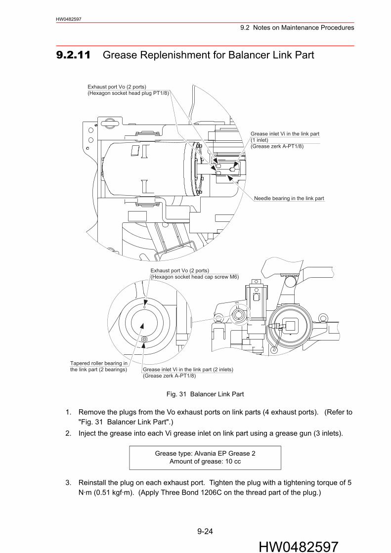
9.2 Notes on Maintenance ProceduresHW0482597
9.2.11 Grease Replenishment for Balancer Link Part
Fig. 31 Balancer Link Part
1. Remove the plugs from the Vo exhaust ports on link parts (4 exhaust ports). (Refer to "Fig. 31 Balancer Link Part".)
2. Inject the grease into each Vi grease inlet on link part using a grease gun (3 inlets).
3. Reinstall the plug on each exhaust port. Tighten the plug with a tightening torque of 5 N·m (0.51 kgf·m). (Apply Three Bond 1206C on the thread part of the plug.)
Grease type: Alvania EP Grease 2Amount of grease: 10 cc
Needle bearing in the link part
Grease inlet Vi in the link part(1 inlet)(Grease zerk A-PT1/8)
Exhaust port Vo (2 ports)(Hexagon socket head plug PT1/8)
Exhaust port Vo (2 ports)(Hexagon socket head cap screw M6)
Grease inlet Vi in the link part (2 inlets)(Grease zerk A-PT1/8)
Tapered roller bearing inthe link part (2 bearings)
9-24
HW0482597

9.2 Notes on Maintenance ProceduresHW0482597
9.2.12 Notes for Maintenance
Connecting the new battery pack before removing the old one so that the encoder absolute data will not disappear.
Motors for JT1-, JT2-, JT3-, JT4-, JT5-, JT6-AxesThe connectors for the battery pack connection of each motor are attached to the main body of respective motor. Connect the battery pack according to "Fig. 32 Backup Battery Pack Connection for Motor".
1. Remove a cap attached to the battery backup connector of the motor encoder by removing the cover mounting screws.
2. Connect the battery pack (HW9470932-A or HW9470932-B) to the battery backup con-nector (crimped contact-pin).
3. After the maintenance check, confirm all the connectors are connected properly, then remove the battery pack.
Fig. 32 Backup Battery Pack Connection for Motor
Do not remove the battery pack in the connector base.NOTE
Encoder
Encoder connector
ab
0BTBAT
ba
Battery (-)Battery (+)
Connection
Power connector
Motor
CAU
TION
Co
nn
ect b
atte
ry toencoder to save the data
before removing connector.
CAUTION label
Cap (cover for battery backup connectors)
Cover fixing screw
Battery pack
a: Crimped contact-pin (pin)b: Crimped contact-pin (socket)
9-25
HW0482597

9.2 Notes on Maintenance ProceduresHW0482597
Fig. 33 Battery Pack Connection
Fig. 34 Caution Label
ba
0BTBAT
a0BTbBAT
CAUTIONConnect battery to encoderto save the data BEFOREr e m o v i n g c o n n e c t o r .
9-26
HW0482597

HW0482597
10Recommended Spare Parts
It is recommended to keep the parts and components in the following table in stock as spare parts for the MOTOMAN-EP4000N.Product performance can not be guaranteed in case of using the spare parts other than the recommended parts listed below.
The spare parts are ranked as follows:• Rank A: Expendable and frequently replaced parts• Rank B: Parts for which replacement may be necessary as a result of frequent operation• Rank C: Drive Unit
To replace parts in Rank B or Rank C, contact your Yaskawa representative.
Table. 9 Spare Parts for the Motoman-EP4000N
Rank PartsNo. Name Type Manufacturer Qty
QtyperUnit
Remarks
A 1Battery Pack HW9470932-A Yaskawa
ElectricCorporation
1 1For JT1, JT2, JT3-axes
A 2Battery Pack HW9470932-B Yaskawa
ElectricCorporation
1 1For JT4, JT5, JT6-axes
A 3Grease Molywhite
RE No. 00YaskawaElectricCorporation
16kg -For all axes’ speed reducers and wrist unit
A 4 Grease Alvania EPGrease 2
Showa Shell Sekiyu K.K. 16kg - For tapered roller
bearings
B 5JT1-AxisSpeed Reducer
HW0280730-A YaskawaElectricCorporation
1 1
B 6JT2-, JT3-AxisSpeed Reducers
HW0280731-A YaskawaElectricCorporation
1 2
B 7JT4-AxisSpeed Reducer
HW0380393-B YaskawaElectricCorporation
1 1
B 8JT5-AxisSpeed Reducer
HW0381033-A YaskawaElectricCorporation
1 1
B 9JT6-axisSpeed Reducer
HW0380794-A YaskawaElectricCorporation
1 1
NOTE
10-1
HW0482597

HW0482597
B 10Wrist Unit HW0170875-A Yaskawa
ElectricCorporation
1 1
C 11AC Servomotor for JT1-Axis
HW0381330-A(SGMGH-1AA2A-YR3*)
YaskawaElectricCorporation
1 3
C 12AC Servomotor for L-and U-Axes
HW9381527-A(SGMGH-75A2A-YR3*)
YaskawaElectricCorporation
1 2
C 13AC Servomotor for JT4- and JT6-Axes
HW0380841-A(SGMGH-13A2A-YR7*)
YaskawaElectricCorporation
1 2
C 14AC Servomotor for JT5-Axis
HW9381261-A(SGMGH-44A2A-YR4*)
YaskawaElectricCorporation
1 1
C 15Wiring Harness in Manipulator
HW0171309-A YaskawaElectricCorporation
1 1
C 16Cooling Fan HW9370631-E Yaskawa
ElectricCorporation
1 3Completed with lead terminal treatment
Table. 9 Spare Parts for the Motoman-EP4000N
Rank PartsNo. Name Type Manufacturer Qty
QtyperUnit
Remarks
10-2
HW0482597

MOTOMAN-EP4000NINSTRUCTIONS
HEAD OFFICE2-1 Kurosaki-Shiroishi, Yahatanishi-ku, Kitakyusyu-shi, 806-0004, JapanPhone 81-93-645-7745 Fax 81-93-645-7746MOTOMAN INC. HEADQUARTERS805 Liberty Lane West Carrollton, OH 45449, U.S.A.Phone 1-937-847-6200 Fax 1-937-847-6277YASKAWA MOTOMAN CANADA LTD.3530 Laird Road, Unit 3, Mississauga, Ontario, L5L 5Z7, CanadaPhone 1-905-569-6686 Fax 1-905-813-5911MOTOMAN ROBOTICS EUROPE ABFranska Vagen 1039854, Kalmar, SwedenPhone 46-480-417800 Fax 46-480-417999MOTOMAN ROBOTEC GmbHKammerfeld strasse 1, DE-85391 Allershausen, GermanyPhone 49-8166-90100 Fax 49-8166-90103YASKAWA ELECTRIC KOREA CORPORATION1F Samyang Bldg. 89-1, Shinchun-dong, Donk-Ku, Daegu, KoreaPhone 82-53-745-7844 Fax 82-2-784-8495YASKAWA ELECTRIC (SINGAPORE) PTE. LTD.151 Lorong Chuan, #04-01, New Tech Park, Singapore 556741, SingaporePhone 65-6282-3003 Fax 65-6289-3003YASKAWA ELECTRIC (MALAYSIA) SDN. BHD.No.71, Jalan Bandar Rawang 2, 48000 Rawang, Selangor D.E., MalaysiaPhone 60-3-6092-1377 Fax 60-3-6092-6377YASKAWA ELECTRIC TAIWAN CORPORATION9F, 16 Nanking E. Rd., Sec. 3, Taipei, TaiwanPhone 886-2-2502-5003 Fax 886-2-2505-1280SHOUGANG MOTOMAN ROBOT CO., LTD.7,Yongchang-North Road, Beijing Economic & Technological Development Area, Beijing 100076, ChinaPhone 86-10-6788-0541 Fax 86-10-6788-2878
YASKAWA
YASKAWA ELECTRIC CORPORATION
Specifications are subject to change without noticefor ongoing product modifications and improvements. Printed in Japan February 2005 05-02C
HW0482597MANUAL NO.