MOTOMAN DX100 CONTROLLER WITH ROBOTIC ARC WELDING INSTRUCTIONS€¦ · Part Number: 166465-1CD...
56
Part Number: 166465-1CD Revision: 1 MOTOMAN DX100 CONTROLLER WITH ROBOTIC ARC WELDING INSTRUCTIONS FOR MILLER ® AUTO-AXCESS DI/E DIGITAL Upon receipt of the product and prior to initial operation, read these instructions thoroughly, and retain for future reference. MOTOMAN INSTRUCTIONS MOTOMAN-MANIPULATOR INSTRUCTIONS MOTOMAN OPERATORS MANUAL FOR ARC WELDING MOTOMAN CONCURRENT I/O MANUAL DX100 CONTROLLER MANUAL DX100 MAINTENANCE MANUAL The operator’s manual above corresponds to specific usage. Be sure to use the appropriate manual. Vendor manuals for system components not manufactured by Motoman 1/56
Transcript of MOTOMAN DX100 CONTROLLER WITH ROBOTIC ARC WELDING INSTRUCTIONS€¦ · Part Number: 166465-1CD...
MOTOMAN DX100 CONTROLLER WITH ROBOTIC ARC WELDING INSTRUCTIONS FOR MILLER® AUTO-AXCESS DI/E DIGITAL
Upon receipt of the product and prior to initial operation, read these instructions thoroughly, and retain for future reference.
Part Number: 166465-1CDRevision: 1
MOTOMAN INSTRUCTIONSMOTOMAN-MANIPULATOR INSTRUCTIONSMOTOMAN OPERATORS MANUAL FOR ARC WELDINGMOTOMAN CONCURRENT I/O MANUALDX100 CONTROLLER MANUALDX100 MAINTENANCE MANUAL
The operator’s manual above corresponds to specific usage. Be sure to use the appropriate manual.Vendor manuals for system components not manufactured by Motoman
1/56

166465-1CD
Auto-Axcess DI/E Digital
MANDATORY• This manual explains the starting point detecting function of the
DX100 system. Read this manual carefully and be sure to understand its contents before handling the DX100.
• General items related to safety are listed in Section 1 of the DX100 instructions. To ensure correct and safe operation, carefully read the section before reading this manual.
CAUTION• Some drawings in this manual are shown with the protective covers
or shields removed for clarity. Be sure all covers and shields are replaced before operating this product.
• The drawings and photos in this manual are representative examples and differences may exist between them and the delivered product.
• YASKAWA may modify this model without notice when necessary due to product improvements, modifications, or changes in specifications.
• If such modification is made, the manual number will also be revised.
• If your copy of the manual is damaged or lost, contact a YASKAWA representative to order a new copy. The representatives are listed on the back cover. Be sure to tell the representative the manual number listed on the front cover.
• YASKAWA is not responsible for incidents arising from unauthorized modification of its products. Unauthorized modification voids your product's warranty.
ii
166465-1CD 2/56
166465-1CD
Auto-Axcess DI/E Digital
Notes for Safe OperationRead this manual carefully before installation, operation, maintenance, or inspection of the Yaskawa Motoman robot.
In this manual, the Notes for Safe Operation are classified as “WARNING”, “CAUTION”, “MANDATORY”, or “PROHIBITED”.
Even items described as “CAUTION” may result in a serious accident in some situations.
At any rate, be sure to follow these important items.
WARNINGIndicates a potentially hazardous situation which, if not avoided, could result in death or serious injury to personnel.
CAUTIONIndicates a potentially hazardous situation which, if not avoided, could result in minor or moderate injury to personnel and damage to equipment. It may also be used to alert against unsafe practices.
MANDATORYAlways be sure to follow explicitly the items listed under this heading.
PROHIBITEDMust never be performed.
NOTETo ensure safe and efficient operation at all times, be sure to follow all instructions, even if not designated as "CAUTION" and "WARNING".
iii
166465-1CD 3/56

166465-1CD
Auto-Axcess DI/E Digital
WARNING• Before operating the manipulator, check that servo power is turned
OFF by pressing the emergency stop button on the programming pendant.When the servo power is turned OFF, the SERVO ON LED on the programming pendant is OFF.
Injury or damage to machinery may result if the emergency stop circuit cannot stop the manipulator during an emergency. The manipulator should not be used if the emergency stop button does not function.
Figure 1: Emergency Stop Button
• Once the emergency stop button is released, clear the cell of all items which could interfere with the operation of the manipulator.Then turn the servo power ON.
Injury may result from unintentional or unexpected manipulator motion.
Figure 2: Release of Emergency Stop
TURN
• Observe the following precautions when performing teaching operations within the P-point maximum envelope of the manipulator:
– View the manipulator from the front whenever possible.
– Always follow the predetermined operating procedure.
– Ensure that there is a safe place to retreat in case of emergency.
Improper or unintended manipulator operation may result in injury.
• Confirm that no person is present in the P-point maximum envelope of the manipulator and that you are in a safe location before:
– Turning on the power for the controller.
– Moving the manipulator with the programming pendant.
– Running the system in the check mode.
– Performing automatic operations.
Injury may result if anyone enters the P-point maximum envelope of the manipulator during operation. Always press an emergency stop button immediately if there is a problem.
The emergency stop button is located on the programming pendant.
iv
166465-1CD 4/56

166465-1CD
Auto-Axcess DI/E Digital
WARNING• Since detected voltage (200V), welding current, and welding
voltage are applied to the starting point detecting unit, install the unit securely so that it does not fall.
• Failure to observe this warning may result in an electric shock or damage to the unit.
• Before connecting the inter-unit cables and the welding cables, be sure to turn OFF the power supply to the controller and the welder.
• Failure to observe this warning may result in an electric shock.
• Special attention should be paid during starting point detection, since 200 VDC is applied across the wire and the workpiece (welding jig).
• Failure to observe this warning may result in an electric shock.
• Do not place any object directly on the cable of the starting point detecting unit.
• Failure to observe this warning may result in an injury or damage caused by the disconnection of the cable.
• Attach the cable of the starting point detecting unit for the wire feeder with the wire stand, to protect it from robot movement. If interference between the cable and the peripheral devices are unavoidable, cover the cable with a rubber plate or spiral tube, etc.
• Failure to observe this warning may result in an electric shock, an injury, or damage to the cable.
• Do not lay the cable of the starting point detecting unit directly on the floor, but install them in a pit or duct or shield the cable with a protective cover.
• Failure to observe this warning may result in an injury or damage to the cable.
• Since a high current flows through the welding cable, separate it from the cables of the control circuit system. If the cables cannot be separated, take preventative measures such as using metallic ducts or tubes on the cables of the control circuit system.
v
166465-1CD 5/56

166465-1CD
Auto-Axcess DI/E Digital
Definition of Terms Used Often in This ManualThe Yaskawa Motoman manipulator is an industrial robot product.
The manipulator usually consists of the controller, the programming pendant, and supply cables.
In this manual, the equipment is designated as follows:
CAUTION• Perform the following inspection procedures prior to conducting
manipulator teaching. If problems are found, repair them immediately, and be sure that all other necessary processing has been performed.
– Check for problems in manipulator movement.
– Check for damage to insulation and sheathing of external wires.
• Always return the programming pendant to the hook on the cabinet of the controller after use.
• The programming pendant can be damaged if it is left in the manipulator's work area, on the floor, or near fixtures.
• Read and understand the Explanation of Warning Labels in the DX100 Instructions before operating the manipulator.
Equipment Manual Designation
DX100 controller DX100
DX100 programming pendant Programming pendant
Cable between the manipulator and the controller
Manipulator cable
vi
166465-1CD 6/56
166465-1CD
Auto-Axcess DI/E Digital
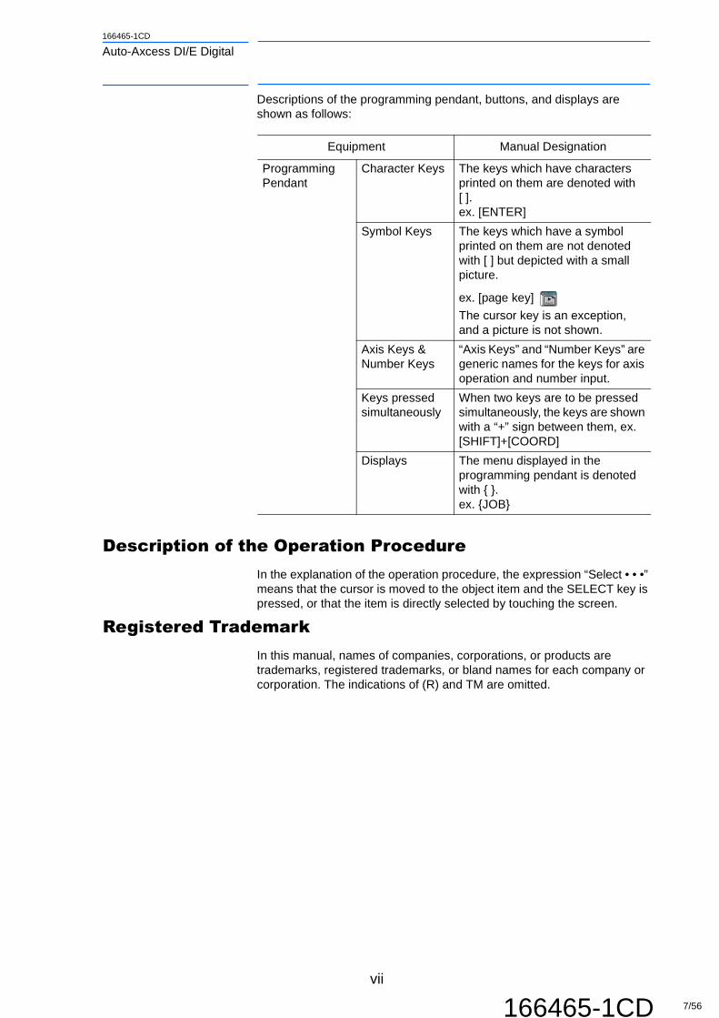
Descriptions of the programming pendant, buttons, and displays are shown as follows:
Description of the Operation ProcedureIn the explanation of the operation procedure, the expression “Select • • •” means that the cursor is moved to the object item and the SELECT key is pressed, or that the item is directly selected by touching the screen.
Registered TrademarkIn this manual, names of companies, corporations, or products are trademarks, registered trademarks, or bland names for each company or corporation. The indications of (R) and TM are omitted.
Equipment Manual Designation
Programming Pendant
Character Keys The keys which have characters printed on them are denoted with [ ].ex. [ENTER]
Symbol Keys The keys which have a symbol printed on them are not denoted with [ ] but depicted with a small picture.
ex. [page key] The cursor key is an exception, and a picture is not shown.
Axis Keys &Number Keys
“Axis Keys” and “Number Keys” are generic names for the keys for axis operation and number input.
Keys pressed simultaneously
When two keys are to be pressed simultaneously, the keys are shown with a “+” sign between them, ex. [SHIFT]+[COORD]
Displays The menu displayed in the programming pendant is denoted with { }.ex. {JOB}
GO BACK
PAGE
vii
166465-1CD 7/56

Table of Contents166645-1CD
Auto-Axcess DI/E Digital
Table of Contents
1 Introduction ..................................................................................................................................... 1-1
1.1 About This Document ........................................................................................................1-1
1.2 System Configuration.........................................................................................................1-2
1.2.1 Major Components ............................................................................................... 1-3
1.3 Reference Documentation .................................................................................................1-3
1.4 Customer Support Information...........................................................................................1-4
2 Safety ..............................................................................................................................................2-1
2.1 Introduction ........................................................................................................................2-1
2.2 Important Advisory Information ..........................................................................................2-2
2.3 General Safeguarding Tips ................................................................................................2-2
2.4 Mechanical Safety Devices................................................................................................2-3
2.5 Installation Safety...............................................................................................................2-3
2.6 Programming, Operation, and Maintenance Safety...........................................................2-4
3 Equipment Description ....................................................................................................................3-1
3.1 Robot and Controller..........................................................................................................3-1
3.2 Auto-Axcess DI/E Digital Power Supply.............................................................................3-1
3.3 Software.............................................................................................................................3-2
3.4 Miller AA-40G Wire Feeder................................................................................................3-2
3.5 Miller-Motoman Pendant Interface (HMI) Software............................................................3-2
3.5.1 Starting the HMI Software.....................................................................................3-3
3.5.2 Welcome Screen ..................................................................................................3-3
3.5.3 Home Screen .......................................................................................................3-5
3.5.4 Program Selection Screen....................................................................................3-5
3.5.5 Program Sequence Setup Screen........................................................................3-7
3.5.6 Live Weld Data Screen......................................................................................... 3-9
3.5.7 To Modify or Add a Welder .................................................................................3-10
3.5.8 Error Preferences ...............................................................................................3-11
3.5.9 Lock/Unlock Editing ............................................................................................3-12
3.5.10 Backup & Load Settings ...................................................................................3-13
viii
166645-1CD 8/56

166645-1CD
Auto-Axcess DI/E Digital Table of Contents
4 Theory of Operation........................................................................................................................ 4-1
4.1 Miller HMI........................................................................................................................... 4-2
4.2 Pulse Mode........................................................................................................................ 4-3
5 Operation ........................................................................................................................................ 5-1
5.1 Set-Up Overview................................................................................................................ 5-1
5.1.1 Welder Condition File ........................................................................................... 5-1
5.1.2 Arc Start Files ....................................................................................................... 5-2
5.1.3 Arc End Files ........................................................................................................ 5-2
5.1.4 Calibration Verification.......................................................................................... 5-3
5.1.5 Selecting Weld Programs..................................................................................... 5-4
5.2 Robot Job Programming.................................................................................................... 5-5
5.2.1 Weld Program Selection....................................................................................... 5-5
5.3 Welder Front Panel Display ............................................................................................... 5-5
5.4 Troubleshooting................................................................................................................. 5-6
6 Miller Auto-Axcess E Digital............................................................................................................ 6-1
6.1 Setting Proportional Speed Instruction .............................................................................. 6-1
6.1.1 The "R*-SET-PROPORTIONAL-SPD.JBI" ........................................................... 6-1
6.2 MACRO Job Settings......................................................................................................... 6-3
6.2.1 MILLER-PROG-SEL Macro.................................................................................. 6-4
6.2.2 MILLER-STRT-PART Macro ................................................................................ 6-5
6.2.3 MILLER-CHNG-WELD Macro .............................................................................. 6-7
6.2.4 MILLER-END-PART Macro .................................................................................. 6-8
6.2.5 Example Weld Job Structure ................................................................................ 6-9
6.3 Error Reporting ................................................................................................................ 6-10
6.3.1 Weld Error Reporting.......................................................................................... 6-10
6.3.2 Part Error Reporting ........................................................................................... 6-11
Revision History ................................................................................................................................A-1
ix
166645-1CD 9/56

1 Introduction1.1 About This Document
166465-1CD
Auto-Axcess DI/E Digital
1 Introduction
1.1 About This Document
This manual provides information about a Yaskawa Motoman's robotic arc welding system using the Miller® Auto-Axcess DI/E Digital power sources. The use of this manual is for welding personnel who have received operator training from Yaskawa Motoman, and are familiar with the operation of their Yaskawa Motoman robot. For more detailed information, refer to the manuals listed in Section 1.3 “Reference Documentation”. This manual contains the following sections:
CHAPTER 1 - INTRODUCTIONThis chapter provides general information about the Auto-Axcess DI/E Digital power source and its components, technical specifications, a list of reference documents, and customer service information.
CHAPTER 2 - SAFETYThis chapter describes the conventions used to identify precautionary text throughout this manual. This chapter also contains a list of general cautions and warnings that apply to many of the procedures described in this manual.
CHAPTER 3 - EQUIPMENT DESCRIPTIONThis chapter provides instructions for basic setup and integration of a Yaskawa Motoman welding system with a Auto-Axcess DI/E Digital power source. This chapter also provides procedures for start-up and calibration.
CHAPTER 4 - THEORY OF OPERATIONThis chapter describes general arc welding principles, how the welding system works, and identifies specific welding problems and requirements.
CHAPTER 5 - OPERATIONThis chapter provides instructions for basic operation of the Auto-Axcess arc welding system. This chapter also provides procedures for start-up. Sample robot programs are also included here.
CHAPTER 6 - MILLER AUTO-AXCESS E DIGITALThis chapter provides Miller AUTO-AXCESS E Digital instructions for macro jobs and error reporting.
1-1
166465-1CD 10/56

166465-1CD
Auto-Axcess DI/E Digital 1 Introduction1.2 System Configuration
1.2 System Configuration
The Auto-Axcess DI/E Digital arc welding system is an integrated package of tools and components designed for specific welding requirements. A typical system includes the following components and optional equipment.
Fig. 1-1: Typical Auto-Axcess Welding System
SERVO ON
READY
REMOTE
PLAY
(OFF)(ON)
TEACH MODE
EMERGENCY STOP
EDIT LOCK
ALARMHOLD
START
ON
TR
IP
OPEN/OFF
ROBOTCONTROLLER
GAS REGULATORAND TANK(CUSTOMER-SUPPLIED)
3
MILLERPOWERSOURCEWATER
CIRCULATOR(OPTIONAL)
ROBOT
DISTRIBUTION BOX(CUSTOMER SUPPLIED)
WORK PIECE
WIREFEEDER
1
2
5
4
6
7
Cable Chart1 Power Source Control Cable (DeviceNet/Ethernet)2 Feeder Control Cable3 Weld Positive4 Voltage Sense Cable5 Shock Sensor Cable6 Gas Hose7 Weld Negative
1-2
166465-1CD 11/56

1 Introduction1.3 Reference Documentation
166465-1CD
Auto-Axcess DI/E Digital
1.2.1 Major Components
A typical system includes the following major components:
• Yaskawa Motoman manipulator and controller
• Welding equipment, including the following:
• Auto-Axcess DI/E Digital power source
• Miller AA-40GB wire feeder
• Welding torch
• Optional welding equipment:
• Water circulator
• Program devices - Palm Pilot with a RS232 adaptor (DI only)
• Nozzle cleaner
• Bulk wire delivery package
• PC/Laptop/HMI for web-page access (E Digital only)
1.3 Reference Documentation
For additional information refer to the following:
• Yaskawa Motoman Manipulator Manual
• Yaskawa Motoman Operator's Manual for Arc Welding (P/N 155490-1CD)
• Yaskawa Motoman Concurrent I/O Manual (P/N 155491-1CD)
• Yaskawa Motoman DX100 Operators Manual (P/N 155494-1CD)
• Yaskawa Motoman DX100 Maintenance Manual (P/N 155492-1CD)
• DX100 Independent/Coordinated Control Manual (P/N 156431-1CD)
• DX100 INFORM User’s Manual (P/N 155493-1CD)
• Vendor manuals for system components not manufactured by Yas-kawa Motoman.
1-3
166465-1CD 12/56

166465-1CD
Auto-Axcess DI/E Digital 1 Introduction1.4 Customer Support Information
1.4 Customer Support Information
If you need assistance with any aspect of your Miller® Auto-Axcess DI/E Digital system, please contact Yaskawa Motoman Customer Support at the following 24-hour telephone number:
For routine technical inquiries, you can also contact Yaskawa Motoman Customer Support at the following e-mail address:
When using e-mail to contact Yaskawa Motoman Customer Support, please provide a detailed description of your issue, along with complete contact information. Please allow approximately 24 to 36 hours for a response to your inquiry.
Please have the following information ready before you call:
NOTEPlease use e-mail for routine inquiries only. If you have an urgent or emergency need for service, replacement parts, or information, you must contact Yaskawa Motoman Customer Support at the telephone number shown above.
• System Auto-Axcess DI/E Digital
• Robots MA1400/MA1900/MA3100...
• Power Supply Miller AAuto-Axcess DI/E Digital (300, 450, or 675)
• Primary Application Welding
• Controller DX100
• Software Version Access this information on the Programming Pendant’s LCD display screen by selecting {MAIN MENU} - {SYSTEM INFO} - {VERSION}
• Robot Serial Number Located on the robot data plate
• Robot Sales Order Number Located on the DX100 controller data plate
(937) 847-3200
1-4
166465-1CD 13/56

2 Safety2.1 Introduction
166465-1CD
Auto-Axcess DI/E Digital
2 Safety
2.1 Introduction
The purchaser is responsible for following all local, county, state, and national codes, regulations, rules, or laws relating to safety and safe operating conditions for each installation.
We suggest that you obtain and review a copy of the ANSI/RIA National Safety Standard for Industrial Robots and Robot Systems (ANSI/RIA R15.06-2012). You can obtain this document from the Robotic Industries Association (RIA) at the following address:
Robotic Industries Association
900 Victors WayP.O. Box 3724Ann Arbor, Michigan 48106TEL: (734) 994-6088FAX: (734) 994-3338www.roboticsonline.com
Ultimately, well-trained personnel are the best safeguard against accidents and damage that can result from improper operation of the robot system. The customer is responsible for providing adequately trained personnel to operate, program, and maintain the robot cell. NEVER ALLOW UNTRAINED PERSONNEL TO OPERATE, PROGRAM, OR REPAIR THE ROBOT SYSTEM!
We recommend approved Motoman training courses for all personnel involved with the operation, programming, or repair of the robot system. The training course familiarizes personnel with the safe and correct operation of the robot system.
This safety section addresses the following:
• Standard Conventions (Section 2.2)
• General Safeguarding Tips (Section 2.3)
• Mechanical Safety Devices (Section 2.4)
• Installation Safety (Section 2.5)
• Programming, Operation, and Maintenance Safety (Section 2.6)
2-1
166465-1CD 14/56

166465-1CD
Auto-Axcess DI/E Digital 2 Safety2.2 Important Advisory Information
2.2 Important Advisory Information
In this manual, the Notes for Safe Operation are classified as “WARNING”, “CAUTION”, “MANDATORY”, or “PROHIBITED”.
Even items described as “CAUTION” may result in a serious accident in some situations.
2.3 General Safeguarding Tips
All operators, programmers, plant and tooling engineers, maintenance personnel, supervisors, and anyone working near the robot must become familiar with the operation of this equipment. All personnel involved with the operation of the equipment must understand potential dangers of operation. General safeguarding tips are as follows:
• Improper operation can result in personal injury and/or damage to the equipment. Only trained personnel familiar with the operation of this robot, the operator's manuals, the system equipment, options, and accessories should operate this robot system.
• Do not enter the robot cell while it is in automatic operation. Programmers must have the teach pendant when they enter the robot cell.
• Improper connections can damage the robot. Make sure all connections are within the standard voltage and current ratings of the robot I/O (Inputs and Outputs).
• Place the robot in Emergency Stop (E-Stop) mode when not in use.
• In accordance with ANSI/RIA R15.06-1999, section 4.2.5, Sources of Energy, use lockout/tagout procedures during equipment maintenance. Refer also to Section 1910.147 (29CFR, Part 1910), Occupational Safety and Health Standards for General Industry (OSHA).
WARNINGIndicates a potentially hazardous situation which, if not avoided, could result in death or serious injury to personnel.
CAUTIONIndicates a potentially hazardous situation which, if not avoided, could result in minor or moderate injury to personnel and damage to equipment. It may also be used to alert against unsafe practices.
MANDATORYAlways be sure to follow explicitly the items listed under this heading.
PROHIBITEDMust never be performed.
2-2
166465-1CD 15/56

2 Safety2.4 Mechanical Safety Devices
166465-1CD
Auto-Axcess DI/E Digital
2.4 Mechanical Safety Devices
The safe operation of the robot, positioner, auxiliary equipment, and system is ultimately the user's responsibility. The user should review the conditions for safe operations of the equipment. The user must be aware of the various national codes, ANSI/RIA R15.06-2012 safety standards, and other local codes that may pertain to the installation and use of industrial equipment. Additional safety measures for personnel and equipment may be required depending on system installation, operation, and/or location. The following safety equipment is provided as standard:
• Safety fences and barriers
• Light curtains and/or safety mats
• Door interlocks
• Emergency stop palm buttons located on operator station, robot controller, and programming pendant
Check all safety equipment frequently for proper operation. Repair or replace any non-functioning safety equipment immediately.
2.5 Installation Safety
Safe installation is essential for protection of people and equipment. The following suggestions are intended to supplement, but not replace, existing federal, local, and state laws and regulations. Additional safety measures for personnel and equipment may be required depending on system installation, operation, and/or location. Installation tips are as follows:
• Be sure that only qualified personnel familiar with national codes, local codes, and ANSI/RIA R15.06-2012 safety standards are permitted to install the equipment.
• Identify the work envelope of each robot with floor markings, signs, and barriers.
• Position all controllers outside the robot work envelope.
• Whenever possible, install safety fences to protect against unauthorized entry into the work envelope.
• Eliminate areas where personnel might get trapped between a moving robot and other equipment (pinch points).
• Provide sufficient room inside the workcell to permit safe teaching and maintenance procedures.
2-3
166465-1CD 16/56

166465-1CD
Auto-Axcess DI/E Digital 2 Safety2.6 Programming, Operation, and Maintenance Safety
2.6 Programming, Operation, and Maintenance Safety
All operators, programmers, plant and tooling engineers, maintenance personnel, supervisors, and anyone working near the robot must become familiar with the operation of this equipment. Improper operation can result in personal injury and/or damage to the equipment. Only trained personnel familiar with the operation, manuals, electrical design, and equipment interconnections of this robot should program, operate, and maintain the system. All personnel involved with the operation of the equipment must understand potential dangers of operation.
• Inspect the robot and work envelope to be sure no potentially hazardous conditions exist. Be sure the area is clean and free of water, oil, debris, etc.
• Be sure that all safeguards are in place. Check all safety equipment for proper operation. Repair or replace any non-functioning safety equipment immediately.
• Do not enter the robot cell while it is in automatic operation. Be sure that only the person holding the programming pendant enters the workcell.
• Check the E-Stop button on the programming pendant for proper operation before programming. The robot must be placed in Emergency Stop (E-Stop) mode whenever it is not in use.
• Back up all programs and jobs onto suitable media before program changes are made. To avoid loss of information, programs, or jobs, a backup must always be made before any service procedures are done and before any changes are made to options, accessories, or equipment.
• Any modifications to PART 1, System Section, of the robot controller concurrent I/O program can cause severe personal injury or death, as well as damage to the robot! Do not make any modifications to PART 1, System Section. Making any changes without the written permission of Motoman will VOID YOUR WARRANTY!
• Some operations require standard passwords and some require special passwords. Special passwords are for Motoman use only. YOUR WARRANTY WILL BE VOID if you use these special passwords.
• The robot controller allows modifications of PART 2, User Section, of the concurrent I/O program and modifications to controller parameters for maximum robot performance. Great care must be taken when making these modifications. All modifications made to the controller will change the way the robot operates and can cause severe personal injury or death, as well as damage the robot and other parts of the system. Double-check all modifications under every mode of robot operation to ensure that you have not created hazards or dangerous situations.
• Check and test any new or modified program at low speed for at least one full cycle.
• This equipment has multiple sources of electrical supply. Electrical interconnections are made between the controller and other equipment. Disconnect and lockout/tagout all electrical circuits before making any modifications or connections.
2-4
166465-1CD 17/56

2 Safety2.6 Programming, Operation, and Maintenance Safety
166465-1CD
Auto-Axcess DI/E Digital
• Do not perform any maintenance procedures before reading and understanding the proper procedures in the appropriate manual.
• Use proper replacement parts.
• Improper connections can damage the robot. All connections must be made within the standard voltage and current ratings of the robot I/O (Inputs and Outputs).
2-5
166465-1CD 18/56

166465-1CD
Auto-Axcess DI/E Digital 3 Equipment Description3.1 Robot and Controller
3 Equipment Description
This chapter contains brief descriptions of The Miller® Auto-Axcess DI/E Digital welding system components.
3.1 Robot and Controller
The robot controller coordinates the operation of the various welding system components. The controller executes instruction sequences provided in a robot job file. As the controller steps through the series of instructions, it directs the movement of the torch, and operates the welding power supply. The robot moves the welding torch and supply lines through a series of programmed steps. The controller sets the speed, direction, and position of the robot as it moves from point to point. It communicates weld signals through a digital interface board mounted in the controller cabinet. The controller sends command values for wire feed speed, voltage/arc length, arcon and arcoff. The robot also selects one of eight weld programs by setting three outputs. The Auto-Axcess DI/E Digital power source communicates to the controller when the arc is established, when there is a fault condition, or when the wire is stuck to the puddle. The power source also communicates the fault type back to the DX100.
This enhanced interface also features a pendant application which allows weld data to be assigned to the eight weld programs. It also provides functionality similar to Millers’ File Manager Software.
3.2 Auto-Axcess DI/E Digital Power Supply
The Auto-Axcess DI/E Digital power source is a three-phase, high-frequency, multi-process inverter welder. The welder operates at either 50 or 60 Hz frequency and 190 to 630 volts AC or DC.
Auto-Line™ automatically adjusts to line voltage, so no external adjustments are necessary. The power source has multi-process MIG capability consisting of standard MIG (GMAW), standard pulse MIG (GMAW-P), Accu-Pulse (GMAW-P), Accu-Speed (GMAW-P), Accu-Curve (GMAW-P), as well as a RMD (GMAW-SC) mode. (RMD is a paid option on the DI welders and is standard on the Axcess E Digital welders)
Accu-Pulse reduces burn through problems, increases welding travel speeds, and is superior to pulse mode when welding with short arc lengths. For even shorter arc lengths on steel Accu-Speed is available. Accur-Curve has a softer pulse that can be used on aluminum. The optional RMD (Regulated Metal Deposition) process is a short circuit transfer process in which the power source alters the welding current to improve the droplet transfer while minimizing spatter levels. It is limited to use at wire speeds below 250 ipm (depending on electrode diameter) on thin gauge steel applications.
The Auto-Axcess DI uses a DeviceNet interface and is compatible with the DX100 controller.
The Auto-Axcess E Digital has the ability to use either a DeviceNet or EtherNetIP interface. The DeviceNet interface (on the E Digital machine) provides the same interface functionality and control as the Auto-Axcess DI/E Digital. The EtherNetIP implementation of the Axcess E Digital provides additional robot control for process monitoring control.
3-1
166465-1CD 19/56

3 Equipment Description3.3 Software
166465-1CD
Auto-Axcess DI/E Digital
Features: • Broad range of input power (190 to 630 VAC, single or 3-phase),
automatically selected by Auto-Line.
• Sharp Start™ feature provides consistent arc starts by assuring a ball is not left on the wire when welding stops
• Eight remote selectable programs from the robot
• 115 VAC, 10 Amp auxiliary duplex power receptacle
• Multiple MIG modes of operation
• World-class product support from Miller Electric
• Quick-change feed rolls
3.3 Software
The Auto-Axcess DI/E Digital comes standard with many programs for carbon steel, aluminum, and stainless welding, including Accu-Pulse, standard or adaptive pulse, Accu-Speed, Accu-Curce, conventional MIG, and RMD (included free-of charge on Auto-Axcess E Digital machines.) The standard Yaskawa interface provides an array of functionality including allowing the user to customize the arc starting and ending timing.
3.4 Miller AA-40G Wire Feeder
The AA-40G Wire Feeder is an open frame-type wire feeder equipped with four (4) geared (0.045 in.) feed rolls as standard. The feeder is rated at 650 amps 100 percent duty cycle and weighs 7.5 kg. The wire feed speed range is 50-1400 ipm, with a default maximum of 999 ipm. If a wire feed speed greater than 1000 ipm is necessary, the data in the welder condition file must be reset.
3.5 Miller-Motoman Pendant Interface (HMI) Software
This Interface Software connects the DX100 Controller to each of the welding units (up to 4) that are part of the system. The HMI software allows the operator to set the Auto-Axcess DI/E Digital parameters from the DX100 programming pendant.
This software is standard with the Auto-Axcess/DX100 system.
3-2
166465-1CD 20/56

166465-1CD
Auto-Axcess DI/E Digital 3 Equipment Description3.5 Miller-Motoman Pendant Interface (HMI) Software
3.5.1 Starting the HMI Software
To start the HMI program tap the {ARC WELDING} button, then the {Miller DI} button (Fig. 3-2).
The first time the program is launched the Welcome Screen appears (Fig. 3-3 Welcome Screen on page 3-4). Once configuration of the program is complete, touching the {MILLER DI} will bring up the Home screen shown in Fig. 3-4 Home Screen on page 3-5.
Fig. 3-2: Start Up Screen
3.5.2 Welcome Screen
The Welcome Screen appears the first time the Miller Human Machine Interface (HMI) application is loaded onto the DX100 programming pendant. This screen configures the system for the number of welders, type of communication, addressing, and passwords being used.
NOTE This screen is usually set up by Yaskawa Motoman.
3-3
166465-1CD 21/56

3 Equipment Description3.5 Miller-Motoman Pendant Interface (HMI) Software
166465-1CD
Auto-Axcess DI/E Digital
Fig. 3-3: Welcome Screen
1. Number of Welders: Enter the number of welders attached to the system (1- 4).
2. Manager Password: Factory Default is 99999999 (eight 9’s). Enter the password (up to eight characters) for management rights.
3. Type password again: Re-enter the password to verify.
4. Select Welder Size: Specify the size of the welders being connected.
5. Comm Selection: Select the applicable digital interface being used for welder communication.
6. Starting input address for first welder: (Only required if DeviceNet communication is selected). In the case of DeviceNet communication this textbox field specifies the starting input address of the DeviceNet board (excluding the status bits). In most cases the default address of 00050 (input#33) is correct. However if an expanded I/O board is used, this starting address may need to be adjusted.
7. Continue: When all the required fields above have been completed, push continue to {Continue} or press {Cancel Setup} if wanting to return to last settings.
1
23
4
5
6
7
NOTEIf other devices are added to the DX100 controller after the original DeviceNet installation, the starting address, as well as the ladder, may require changes.
3-4
166465-1CD 22/56

166465-1CD
Auto-Axcess DI/E Digital 3 Equipment Description3.5 Miller-Motoman Pendant Interface (HMI) Software
3.5.3 Home Screen
The Home Screen (Fig. 3-4) will take you to the various applications shown on each button. These screens are described in more detail later.
Fig. 3-4: Home Screen
1. View data for: If more than one welder is attached to the system, select the welder that you want to work with.
3. Quit: This button closes the application and returns the user to the pendant programming menus. To re-enter the program, passwords, etc. must be entered. During normal system operation, if the program is not needed, it should be closed.
3.5.4 Program Selection Screen
The Auto-Axcess DI/E Digital can have eight user definable weld programs (Fig.3-5 Program Selection Screen). Each program can be configured for the process, wire size and type, and shielding gas.
3
1
2
2
22
2
2
2
2. Program Selection: Prog Sequence Setup:Live Weld Data:Welder Memory Addr:Errors Config:Lock/Unlock Editing:Backup/Load Settings:
These buttons bring up additional screens for editting or viewing data functions.
NOTE Some of the set-up functions cannot be changed in Play mode.
3-5
166465-1CD 23/56

3 Equipment Description3.5 Miller-Motoman Pendant Interface (HMI) Software
166465-1CD
Auto-Axcess DI/E Digital
Fig. 3-5: Program Selection Screen
1. View data for: If more than one welder is connected to the system, select the welder you wish to view.
2. Program 1, 2, 3, 4, 5, 6, 7, 8: Select the required welding program. Only those programs that are used need to the configured. To specify a new process in a program:
• Using the stylus touch the down arrow button on the right of the Program Selection Screen (Fig. 3-5). The list of process options will be displayed.
• Scroll though the list to view the process options. They are listed in the following order: Mode, Material, Wire Size, Gas Mixture
• Select the desired process.
3. Save: After changing a program press this button to save the program changes to the welder. If {Save} is not pressed, any changes are lost when leaving this screen. After pressing the {Save} button, a prompted will appear to OK the changes. Press {Yes} to save or {No} to discard the changes.
1
2
3
NOTE The use of a stylus is recommended to ensure selection of the information you want to program.
NOTESave Disabled displays on the pendant if the Manager has not assigned the operator the rights to make process changes. To restore the SAVE function, go to the Lock/Unlock Edit Screen (Fig. 3-10) and log-in with the Manager’s password.
3-6
166465-1CD 24/56

166465-1CD
Auto-Axcess DI/E Digital 3 Equipment Description3.5 Miller-Motoman Pendant Interface (HMI) Software
3.5.5 Program Sequence Setup Screen
The Program Sequence Setup screen (Fig. 3-6) is used to configure each weld program. When making changes only the Welder # and Program # displayed are affected. The {ENABLED/DISABLED} buttons toggle back and forth between enabling and disabling the functions.
Fig. 3-6: Program Sequence Setup Screen
NOTE
These functions are controlled by the Auto-Axcess DI/E Digital. Pre-Flow, Run-in WFS, and Start power begin with an Arcon command. Crater Fill, Retract and Post flow start when the Arcoff command is issued. Yaskawa Motoman recommends the welding sequencing be done in AcrStart Files to ensure timing is coordinated with the robot motion.
1
2
3
4
5
6
7
8
1
9
1. View data for: View/modify sequence for:
Select the welder (if more than one is connected to the system) and program number to view or change. Only that program will be affected.
2. An Inductance/Arc Control is available on the DI interface only.
In the event of an EtherNet IP interface, the "Inductance / Arc Control" is set by the "Miller-Prog-Sel" macro job.When using a MIG program the desired Inductance is between 0 - 99.When using a Pulse, Accupulse, or RMD program set the Arc Control valve between 0 - 50.
3. Run-in WFS: This parameter sets the wire feed speed (WFS) during arc initiation. The wire feeds at the run-in speed when the arcon command is issued until an arc is established. Generally, the run-in speed is set lower than the WFS for the actual weld. This helps the arc start better. Once the arc is established, the WFS changes to the set value.
3-7
166465-1CD 25/56

3 Equipment Description3.5 Miller-Motoman Pendant Interface (HMI) Software
166465-1CD
Auto-Axcess DI/E Digital
4. Pre-Flow: Sets the shielding gas pre-flow time. If enabled, the gas will come on for the specified length of time before the wire will start to feed. This will add cycle time at the Arc Start. There is a purge output, which can be turned on in the robot job file that does not add this extra time.
5. Retract: This function retracts the wire at the end of the weld. A time in seconds and a WFS must be specified. Typical settings are 100 ipm and 0.3 seconds. This helps create separation between the wire and weld puddle for large fillets.
6. Start Power: This function is used to modify the default start sequence. When enabled, the specified Volts/Arc Adjust and WFS parameters are used for the time indicated during the start of the weld, then changed to those in the Job program. When the Ramp function is disabled, the WFS and Volts/Arc Adjust remain constant during the Start Power time. When Enabled, the WFS and Volts/Arc Adjust begin at the specified values and time, then ramp up to the Job values over the time set in the ramp box. Robot motion starts once the arc is initiated unless timers are inserted.
7. Post-Flow: Continues the gas flow for the set amount of time after the arc ending sequence.
8. Crater Fill: If a crater fill is desired at the end of the weld, enable the function and set a time, Volts/Arc Adjust and WFS. The Ramp function will slope the WFS and Volts/Arc. Adjust up or down to the crater fill parameters over the time specified. Use the Hyper Start function to set Welder Control if the robot is to wait for the welder crater fill.
9. Save: This button must be pushed to activate and save any changes. If the screen is left without saving, the changes will be lost. Save Disabled indicates the operator does not have rights to make changes to the screen.
3-8
166465-1CD 26/56

166465-1CD
Auto-Axcess DI/E Digital 3 Equipment Description3.5 Miller-Motoman Pendant Interface (HMI) Software
3.5.6 Live Weld Data Screen
The Live Weld Data screen (Fig. 3-7) displays Voltage, Current, Wire Feed Speed (WFS), Travel Speed1), and Heat Input1). It also displays the status (On/Off) of the wire feeder, gas solenoid, and weld contactor.
Fig. 3-7: Live Weld Data Screen
1. View data for: If more than one welder is connected to the system, select the desired welder # to view its data.
2. Current Program: Displays the weld program (1-8) selected on the Auto-Axcess DI/E Digital.
3. Volts: Actual welding voltage.
4. Amps: Actual welding Current, in Amps.
5. WFS: Actual welding Wire Feed Speed, in inches/minute.
6. TS (cm/min) (E Digital only): Travel Speed of the Robot's TCP.
7. Heat (J/cm) (E Digital only): Heat input calculated by the welder based on the travel speed of the Robot's TCP.
8. Wire Feed: Red=Wire Feeder is Off. Green=running in either forward (welding) or reverse (retracting wire).
1 Travel Speed and Heat Input are only shown on the E Digital interfaces. The DIinterface will not show these fields.
1 2
3
4
5
6
7
8
9
10
11
12
NOTE
The Miller Auto-Axcess updates the program number.prior to welding.
• Using the DI the program number being run is displayed while the Arc is on.
• Using the E Digitial the specified program number immediately shows and does not require an ArcOn.
3-9
166465-1CD 27/56

3 Equipment Description3.5 Miller-Motoman Pendant Interface (HMI) Software
166465-1CD
Auto-Axcess DI/E Digital
9. Gas: Red=Gas solenoid off. Green=Gas solenoid on.
10. Contactor: Red=welder in standby. Green=Gun Switch is on.
11. View All Welders: Displays the Viewing Weld Data for All Welders screen () on top of the Live Weld Data screen. When returning from the Viewing Weld Data for All Welders screen to the Live Weld Data screen, the Restart Data Read button must be pressed to display live weld data again.
Fig. 3-8: View All Welders
12. Restart Data Read: This button restarts the live weld data stream from the welder to the pendant. It must be pushed whenever the screen is left and returned to via the View All Welders or Back to Pendant buttons. Pushing it tells the welder to begin sending actual weld data again.
3.5.7 To Modify or Add a Welder
Only possible with the DeviceNet interface.
If a welder is to be added to a DeviceNet connected system or the starting input address has changed due to the addition of other options use the screen shown in Fig. 3-9. If an additional welder is added, the starting address will not change, but ladder modifications may be needed. Some options, such as an Expanded I /O pc board, will require address changes as well as updating the DX100 ladder for the new address locations. Changing information on this screen requires the user to be in Manager mode.
NOTE
• Changing the starting address location will make the system inoperable without also updating the User Section of the DX100 ladder to reflect the change.
• Adding a welder without also updating the DX100 System and User sections of the ladder will make the system inoperable.
3-10
166465-1CD 28/56

166465-1CD
Auto-Axcess DI/E Digital 3 Equipment Description3.5 Miller-Motoman Pendant Interface (HMI) Software
Fig. 3-9: Modify/Add Screen
1. Starting Input Address (DeviceNet interface only): Enter the new starting address location. The User section of the DX100 ladder will need to be modified with the address changes as well.
2. Add Welder: If a welder is added to the system use this button to update the number of welders and starting input addresses.
3. Remove Welder: If the number of welders connected to a system is reduced, use this button to remove it from the Miller HMI. After pressing Save Settings, no further action is required.
4. Save: Press this button to save any changes and make them active.
3.5.8 Error Preferences
The Miller Auto-Axcess DI/E Digital has several errors that can be enabled or disabled depending on user preferences (). Sometimes these errors will give “nuisance” trips, causing excessive downtime. If the actual error will not cause any safety issues or equipment damage, it can be turned off. When the errors are disabled, they will be ignored by the Auto-Axcess DI/E Digital and no error message will be sent to the robot controller.
These errors are global within the Auto-Axcess DI/E Digital. They affect all eight weld programs.
The Yaskawa/Miller interface includes a mapping of Miller error codes into the DX100 controller. Welder errors will generate a user alarm on the robot with the error message displayed. Welder alarm history can be viewed under user alarms (see chapter 5.4 “Troubleshooting” at page 5-6). The error code is recorded along with the date, time, program, and step number of the error.
1 2
3
4
3-11
166465-1CD 29/56

3 Equipment Description3.5 Miller-Motoman Pendant Interface (HMI) Software
166465-1CD
Auto-Axcess DI/E Digital
Fig. 3-10: Error preference Screen
3.5.9 Lock/Unlock Editing
The Lock/Unlock Editing screen (Fig. 3-11) is used to set various levels of security and lock the Miller Auto-Axcess DI front panel.
Fig. 3-11: Lock/Unlock Editting Screen
3-12
166465-1CD 30/56

166465-1CD
Auto-Axcess DI/E Digital 3 Equipment Description3.5 Miller-Motoman Pendant Interface (HMI) Software
1. Operator Mode Change: This button toggles the HMI between the Operator/Manager Mode - The default setting is “Operator Mode”. In the Operator Mode, all the screens can be viewed, but the “Save” buttons are disabled and no data can be changed.
• Pressing the Manager Mode button will prompt a dialog box to appear.
• Enter the managers password (default is 99999999 [eight 9’s]).
• Confirm change by selecting the yes box.
2. Editing Functions: These statements allow various editing functions to be activated while in Operator Mode. To activate any combination of the Editing Functions, go to “Management Mode” and select the desired boxes.
3. Lock front panel on welder power supplies: In Management Mode, selecting this box will lock the front panel of all Miller Auto-Axcess DI/E Digital connected to the system. The “Lock” symbol on the Auto-Axcess DI/E Digital will be lit when this feature is activated. Users will not be able to make changes from the front panel.
4. Select welder communication mode: The Miller Auto-Axcess DI/E DigitalI has 3 different levels of communication and is selected from this box:
• Shared Control (the default setting) - This is the preferred setting, it allows both the DX100 and the Miller Auto-Axcess DI/E Digital to control various features.
• Robot Control - This setting allows only the DX100 to control various weld settings, such as pre-flow, post-flow, etc. These functions will be locked out from the HMI.
• Power Source Control - This setting shifts all control to the power source. Only arc on and arc off are controlled by the Robot.
5. Password & ReType Password: To change the password select Manager Mode and create a new password in the Password window and confirm it in the ReType Password window. If the password does not need to be changed leave the windows blank.
3.5.10 Backup & Load Settings
The Backup & Load Settings Screen has several functions; backing up a welder HMI Settings, copying a configuration to another welder, or copying or resetting the ‘INI’ file. This function only serves the robot HMI. The data is not a replacement for the Miller File Manager PDA software that saves data directly from the welder.
NOTE A CompactFlash memory card or USB must be installed in the programming pendant in order to backup the welder.
3-13
166465-1CD 31/56

3 Equipment Description3.5 Miller-Motoman Pendant Interface (HMI) Software
166465-1CD
Auto-Axcess DI/E Digital
Fig. 3-12: Backup & Load Setting Screen
3.5.10.1 To Backup Settings
1. Memory Card Selection: Select when the Backup is to stored on either a CF or a USB.
2. Save settings from: Select the welder number (#) that will be backed up or downloaded to.
3. Select the functions that need to be backed up. Only those functions selected will be backed up.
4. Save settings as: A default file name is created, using the date and time, that the settings will be backed up to. The file name can be changed but do not change the extension (.wst).
5. Backup Settings: After selecting the welder #, items to be saved and file name, this button will save the information on the memory card in the file named in4..
3.5.10.2 To Load Settings:
6. Load Settings from file: Select the configuration file to be loaded into the welder. This file must be a *.wst file on the memory card.
7. Load settings to: Select the welder # you want the file to be loaded to.
8. Load Setting: Press this button to load the configuration file to the selected welder #.
1
2
3
4
5
6
7
8
9 10
NOTEThe INI file contains information used by the HMI program. It resides on the programming pendant and contains data such as the number of welders.
3-14
166465-1CD 32/56

166465-1CD
Auto-Axcess DI/E Digital 3 Equipment Description3.5 Miller-Motoman Pendant Interface (HMI) Software
9. Copy INI to CF/USB: To backup the INI file, insert a memory card and touch this button. This creates a copy of the INI file on the memory card.
10. Factory Reset: This resets the INI file to the factory default settings.
NOTEIn the case of the Ethernet IP interface, pressing the "Factory Reset" button is your only way of adding or removing welders to the system. When pressing the "Factory Reset" button, the next time the system starts and launches the start-up screen. (See Fig. 3-3)
3-15
166465-1CD 33/56

4 Theory of Operation
166465-1CD
Auto-Axcess DI/E Digital
4 Theory of Operation
The Auto-Axcess is a Gas Metal Arc Welding (GMAW) power supply capable of non-pulsed, or MIG, and pulsed (GMAW-P) modes of operation.The DX100 utilizes a DeviceNet interface to the Auto-Axcess. This interface provides two basic levels of controls:
• Real time display of weld data.
• Programming of welder set-up data from the teach pendant.
Operators will not be aware of any programming difference between Digital or Analog interfaces with the Auto-Axcess. Both interfaces function with the INFORM weld instructions utilized on the DX100 controller. The digital interface uses an application created by Motoman called the Miller HMI. This provides pendant screens with dialog boxes to allow Managers or Operators (if allowed by Managers) to make changes to programs in the welder.
The weld settings and sequence of operation are controlled by the robot. Traditionally, the current and voltage settings were communicated to the welder as a proportion of a 0-14 volt analog signal. The weld contactor, arc establish input, and error signals were discrete inputs and outputs. These basic signals were interfaced between the XEW01 board in the controller to the Auto-Axcess with a cable that had about a dozen wires.
These commands and signals are set and sequenced through the controller’s concurrent I/O (CIO) program. This program has a system section which can not be edited by Users because of Safety functionality. The User section is provided for users to add fixture and cell control logic. INFORM functions such as RETRY and ANTI-STICK use signals in the ladder to operate. Motoman developed the HyperStart function to allow users to set values used in the system section to optimize cycle time and arc alarm conditions to suit the application.
The standard Auto-Axcess interface addresses the welding input and output signals to the physical I/O points on the XEW01 board. Weld settings, current and voltage, are entered in the robot program as an INFORM command or Arc Start File. These settings (i.e. 200 amps, 18.0 volts) are converted to a proportional analog value by referencing the Welder Condition File. The Welder Condition File is a table of 8 settings that allows the robot to be scaled to different wire types and power supplies. In the case of the Auto-Axcess, the Welder Condition File is scaled to be 0-999 ipm wire feed speed (instead of amperage) and 0-50.0 volts.
When the Auto-Axcess is in a pulse mode, then the voltage value is 3/4 of the arc adjust setting (i.e. arc voltage setting of 22.5 provides an arc adjust setting of 45 on the welder). The arc adjust setting on the Auto-Axcess has a setting of 0-100 with a nominal setting of 50. The welder is synergic which means an arc adjust value of 50 will provide good welding conditions through the whole range of wire feed settings. Users may want to reduce the arc adjust setting to get a shorter arc length to suit a given application.
4-1
166465-1CD 34/56

166465-1CD
Auto-Axcess DI/E Digital 4 Theory of Operation4.1 Miller HMI
The Auto-Axcess has 8 program locations for different process settings. The process can be changed between welds or even during welding by setting I/O commands in the robot program to select a different program. There are 3 outputs from the robot to the welder for selecting schedules. These outputs should be labeled in the output display and programming instructions are provided in this manual.
The Auto-Axcess functions in exactly the same manor, but signals are addressed to a DeviceNet board inside the DX100. The settings in the Welder Condition file are still necessary to convert the INFORM settings to a 16 bit Mregister in the CIO. AutoCal is not necessary (and is not available) on the Auto-Axcess because the digital data is communicated as exact numbers.
4.1 Miller HMI
The key feature of the Auto-Axcess is the ability to perform set-up functions from the DX100 pendant. This is performed with a Motoman pendant application called the Miller HMI. When this button is pushed on the pendant, it starts an application which takes over the pendant display. This application provides much of the functionality of the Miller File Manager software used with a Palm PDA. The Auto-Axcess retains the User Interface display. This allows users to change processes from the welder or confirm weld settings on the LED meter display.
Most of the pendant application is used for set-up functions. Most of the functionality is only available in TEACH mode to ensure signals are not passed while the power source is welding. There is Management password protection to allow administrators to determine if they want to allow operators access to change program information in the power source. They can initiate edit lock on the welder to keep operators from being able to make program changes from the welders.
.
WARNINGDo not exchange Welder Condition Files (WELDER.DAT) or concurrent I/O programs (CIO.LST) between robots that have analog and digital interfaces. These files are different and will cause improper operation. Arc Start Files and Arc End Files can be transferred between robots regardless of digital or analog interface.
NOTE
The pendant application allows users to set functions for start power and crater fill in the power source. Motoman recommends that these functions be set in arc start files or enhanced arc start files. The settings in the welder are not synchronized with robot motion and adverse welding conditions could be created.
4-2
166465-1CD 35/56

4 Theory of Operation4.2 Pulse Mode
166465-1CD
Auto-Axcess DI/E Digital
The Auto-Axcess functions as a Master on the DeviceNet network. The robot is a slave and other devices should not be connected to this network, unless they are for monitoring purposes. The digital interface utilizes a total of 9 bytes and would have been addressed by Motoman for your exact cell configuration. Users should make back up copies of their I/O settings including the concurrent I/O (CIO.LST). The pendant HMI application also allows the settings made on the HMI to be saved to flash memory. This backup is only saving the selections made from the pendant and is not saving the welders memory. It is recommended that Users invest in the File Manager software from Miller to support maintenance functions (this is true whether Digital or Analog versions are in use).
With the Auto-Axcess, Motoman is able to log error messages from the welder. These can be viewed on the message display when the alarm occurs. The error messages are logged in the robot’s alarm history in the User Alarm section. The alarm is saved with date, time, job name, and step number when the alarm occurred.
4.2 Pulse Mode
Pulse Mode behaves identically to non-pulsed (MIG) mode except that spray current, (low/no-spatter) can be achieved for virtually the entire range of wire feed speeds. Spray transfer is accomplished by elevating the current above that required for globular transfer, holding the current while a droplet(s) is formed and detached from the electrode, and then dropping the current to a low background level. The amount of time at this background level is often based (inversely proportional) on the wire feed speed - higher wire feed speeds require more droplets per second and so shorter background times (higher frequencies) are often used. Pulse mode is recommended for welding conditions (wire feed speeds) wherein globular transfer would be achieved in non-pulsed mode. Pulse mode is typically used for all wire feeds speeds for aluminium GMA welding.
4-3
166465-1CD 36/56

166465-1CD
Auto-Axcess DI/E Digital 5 Operation5.1 Set-Up Overview
5 Operation
5.1 Set-Up Overview
This chapter covers set-up information that is unique to the DX100/Miller Auto-Axcess system. It covers:
• Setting the Welder Condition File
• Arc Start Files and Arc End Files
• Verifying the welder calibration
• Selecting weld programs
5.1.1 Welder Condition File
The Welder Condition file is set as follows (this has been preset by Yaskawa Motoman):
POWER SUPPLY: A/V
Table 5-1: Welder Output
<CURRENT OUTPUT CHARS.>
<WELDING VOLTAGE OUTPUT>
RANGE + +
ADJUST 1.00 1.00
NO. REF. (V) MEASURE (A) REF. (V) MEASURE (V)
01 0.52 40 0.26 1.0
02 1.16 90 1.30 5.0
03 2.57 200 2.60 10.1
04 3.85 300 3.86 15.0
05 5.12 399 5.14 20.0
06 6.39 498 6.45 25.1
07 8.71 679 7.70 30.0
08 12.81 999 11.29 44.0
NOTE
• Although the robot teach pendant displays “A”, “AC” or “amps” in Arc Start Files, ARCON commands, etc., when using the above calibration data, the values used are in units of INCHES/MIN., NOT AMPERAGE, and correspond to the actual WIRE FEED SPEED of the wire feeder.
• The Digital Interface uses direct settings, no special procedures like AutoCal are required.
5-1
166465-1CD 37/56

5 Operation5.1 Set-Up Overview
166465-1CD
Auto-Axcess DI/E Digital
5.1.2 Arc Start Files
VOLTAGE: In the welding modes that require an Arc Length value (Pulse, Accupulse, . . .) the Voltage parameter is set to 1/2 the required setting. That is:
Arc Length = 2 X Voltage Setting
Example:Arc Length value required is 50In the Arc Start File (ASF) and/or Arc End File (AEF) set Voltage to 25.0
Example:Arc Length value required is 47In the Arc Start File (ASF) and/or Arc End File (AEF) set Voltage to 23.5
In MIG mode, the voltage value is the actual reference value desired.
Example:Voltage required is 21.8 voltsIn the Arc Start File (ASF) and/or Arc End File (AEF) set Voltage to 21.8
CURRENT: The Current setting is actually Wire Feed Speed in inches per minute. A setting of 300 will give 300 ipm of wire.
BURN BACK: The Miller Auto-Axcess DI has a Sharp Start routine to reduce wire ball size. Do not set high voltage or low wire feed speed setting in the Arc End files, this can create adverse results.
RETRY: If RETRY is used (ON), set the Voltage and Current in the Arc Auxiliary Condition File to the same values as in the Arc Start Files.
5.1.3 Arc End Files
CURRENT and VOLTAGE: Arc End Files are used if a crater fill is required at the end of the weld sequence. If no crater fill is required, a simple ARCOF command can be used. If it is desired to use the Arc End files, but no crater fill is needed, set the CURRENT and VOLTAGE to the same values as used in the corresponding Arc Start File, and set the ROBOT PAUSE TIME to 0.0 sec.
BURN BACK: The Miller Auto-Axcess DI has a Sharp Start routine to reduce wire ball size. Do not set high voltage or low wire feed speed settings in the Arc End files, this can create adverse results.
ANTI-STICK: The Miller Auto-Axcess DI has a built-in anti-stick feature, so in general this function is not needed and should be set to OFF.
5-2
166465-1CD 38/56
166465-1CD
Auto-Axcess DI/E Digital 5 Operation5.1 Set-Up Overview
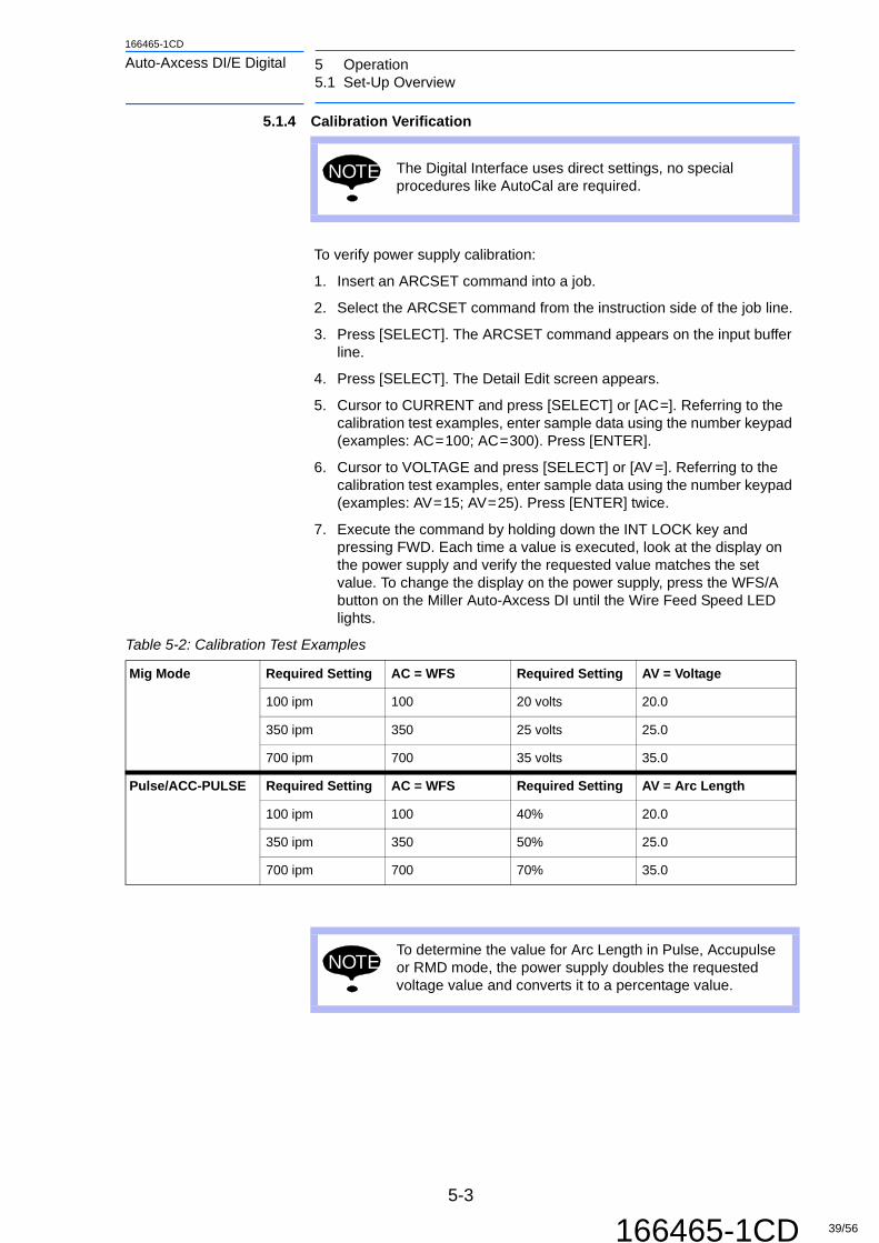
5.1.4 Calibration Verification
To verify power supply calibration:
1. Insert an ARCSET command into a job.
2. Select the ARCSET command from the instruction side of the job line.
3. Press [SELECT]. The ARCSET command appears on the input buffer line.
4. Press [SELECT]. The Detail Edit screen appears.
5. Cursor to CURRENT and press [SELECT] or [AC=]. Referring to the calibration test examples, enter sample data using the number keypad (examples: AC=100; AC=300). Press [ENTER].
6. Cursor to VOLTAGE and press [SELECT] or [AV =]. Referring to the calibration test examples, enter sample data using the number keypad (examples: AV=15; AV=25). Press [ENTER] twice.
7. Execute the command by holding down the INT LOCK key and pressing FWD. Each time a value is executed, look at the display on the power supply and verify the requested value matches the set value. To change the display on the power supply, press the WFS/A button on the Miller Auto-Axcess DI until the Wire Feed Speed LED lights.
NOTE The Digital Interface uses direct settings, no special procedures like AutoCal are required.
Table 5-2: Calibration Test Examples
Mig Mode Required Setting AC = WFS Required Setting AV = Voltage
100 ipm 100 20 volts 20.0
350 ipm 350 25 volts 25.0
700 ipm 700 35 volts 35.0
Pulse/ACC-PULSE Required Setting AC = WFS Required Setting AV = Arc Length
100 ipm 100 40% 20.0
350 ipm 350 50% 25.0
700 ipm 700 70% 35.0
NOTETo determine the value for Arc Length in Pulse, Accupulse or RMD mode, the power supply doubles the requested voltage value and converts it to a percentage value.
5-3
166465-1CD 39/56

5 Operation5.1 Set-Up Overview
166465-1CD
Auto-Axcess DI/E Digital
5.1.5 Selecting Weld Programs
Eight separate weld programs can be defined for the Miller Auto-Axcess DI. Each program can be configured for weld mode (MIG, Pulse, AccuPulse, Accu-Speed, Accu-Curve, RMD), wire type (Steel, Aluminium, etc.), diameter, and shield gas type. The programs can be selected by the robot using three outputs, as shown in Section 5.2.1 Weld Program Selection. These outputs are assigned by Motoman, and cannot be changed. Check the Motoman system prints to verify which outputs are used, since they can vary depending on the controller configuration.
Fig. 5-13: Universal Output Screen
The output status can be viewed by pressing the IN/OUT buttons then selecting Universal Outputs (see Fig. 5-13). The page key will index between different groups (8 bits). In this example, the Miller schedule select bits are labeled:
• OUT#0045 #10064 R1 PROGRAM 0
• OUT#0046 #10065 R1 PROGRAM 1
• OUT#0047 #10066 R1 PROGRAM 2
Table 5-3 "Universal Outputs" shows the values necessary to select weld programs 1-8 using Universal Outputs 45, 46, and 47 which are OGH#(12). The outputs may change depending on the system configuration.
5-4
166465-1CD 40/56

166465-1CD
Auto-Axcess DI/E Digital 5 Operation5.2 Robot Job Programming
5.2 Robot Job Programming
5.2.1 Weld Program Selection
The robot selects one of the eight weld programs by setting three outputs. Typically a binary value (0-7), referenced by a DOUT instruction, is programmed into the robot job. This binary value of 0-7 corresponds to programs 1-8 in the Miller Auto-Axcess DI.
In this example, the schedule select bits have been connected to Universal Outputs 45, 46, and 47. These three bits comprise the first three bits of Output Group Half (OGH) #12.
Sample Robot Job:
0000 NOP0001 MOVJ VJ=33.0 (Welding start position)0002 DOUT OGH#(12)5 (Selection of Schedule #6)0003 ARCON AC=285 AV=22.0 (ArcOn request)0004 MOVL0005 ARCOF0006 MOVJ VJ=33.0
The above job selects Program #6 with the DOUT instruction. It also sets wire feed speed to 285 in./min and sets either voltage to 22.0V (MIG mode) or trim to 44% (Pulse or AccuPulse) depending on the mode selected in Program #6.
5.3 Welder Front Panel Display
When the welder is powered on, “MOTO” will appear on the welder display. During normal operation, the welder display shows the following:
• Power Supply Idle (not welding): Displays the set Wire Feed Speed and Voltage or Arc Length values.
• Power Supply Welding: Displays the actual average Amperage (or the wire feed speed) and actual average Voltage.
• Immediately after Welding: Displays the actual average Amperage and actual average Voltage for five seconds.
Table 5-3: Universal Outputs
Auto Axcess Program#
Universal Outputs
OGH#(12) OUT#0045 OUT#0046 OUT#0047
1 0 Off Off Off
2 1 On Off Off
3 2 Off On Off
4 3 On On Off
5 4 Off Off On
6 5 On Off On
7 6 Off On On
8 7 On On On
5-5
166465-1CD 41/56

5 Operation5.4 Troubleshooting
166465-1CD
Auto-Axcess DI/E Digital
5.4 Troubleshooting
The Miller Auto-Axcess generates several error messages that are displayed on the front panel (see the Miller Auto-Axcess Manual for a complete list). Some of the more common errors are displayed and logged as User Alarms on the DX100 programming pendant. The less common errors are logged on the pendant as an Unknown Error, and the Miller Auto-Axcess must be checked to determine the exact error. For other service related problems, call Yaskawa Motoman Customer Service (937) 847-3200.
The following is a list of User Alarms and messages displayed for welder #1 on the programming pendant. These messages will repeat for welders #2, #3, #4.
Table 5-4: User Alarms
User Alarm Message Displayed
Auto-Axcess Display
Troubleshooting
9122 WELDER 1: ARC FAILED TO START
TOGGLE GAS TO CLEAR WELDER 1 ERR
ERR STRT
Arc did not start. Check/replace the tip and torch liner. Check the wire supply. Look for restrictions in the wire feeding system.
9123 WELDER 1: ROBOT COMMUNICATION
TOGGLE GAS TO CLEAR WELDER 1 ERR
ROBT COMM
1. Welder was turned on before the DX100 controller. Toggle gas to clear error.2. If this message only displays on the welder, check the Devicenet connection between the power source and the controller.
9124 WELDER 1: E-STOP
E STOP
Check the E-Stop connection on the Miller Auto-Axcess. It must be cleared before the unit will operate.
9125 WELDER 1: TACH ERROR
TOGGLE GAS TO CLEAR WELDER 1 ERR
ERR TACH
The welder did not receive a tach signal from the wire feeder. Check the cable and connection between the wire feeder and welder.
9126 WELDER 1: UNKNOWN ERROR
Varies, depending on error
See the Miller Auto-Axcess Manual.
5-6
166465-1CD 42/56

166465-1CD
Auto-Axcess DI/E Digital 6 Miller Auto-Axcess E Digital6.1 Setting Proportional Speed Instruction
6 Miller Auto-Axcess E Digital
The Miller Auto-Axcess welder combines the Miller Auto-Axcess welder with a powerful and feature packed process monitoring tool called "CenterPoint". "CenterPoint" is a PC application which is used to set-up weld processes and limits. These welding sequences and limts are then transferred to the welder where they reside during production (PC application can be disconnected/removed). During production the sequence and limits are monitored on a weld-to-weld and part-to-part basis to ensure that production parts stay within the predefined limits and sequence.
6.1 Setting Proportional Speed Instruction
With the AutoAxcess E Digital (EtherNetIP interface) the robot needs to transmit its TCP travel speed to the Auto-Axcess so that the power source can calculate the heat-input of the weld. This is accomplished by issuing a command contained in a pre-existing job. The "R*-SET-PROPORTIONAL-SPD" instruction set's an analog channel with a value pertaining the robot's actual speed while executing a linear, circular, or spline move. The scaling for the value is set by issuing a "ARATION" instruction. Each robot's job sets a predefined analog output register which is then rescaled in robot's CIO ladder program before being transmitted to the welder. Below are the jobs and the instructions that set the proper scaling.
6.1.1 The "R*-SET-PROPORTIONAL-SPD.JBI"
Only needs to be set once and should be called either in the start-up portion of the "Master" job or within the main weld job. It does not need to be shut-off of adjusted once it has been set.
• R1-SET-PROPORTIONAL-SPD.JBI ' ARATION A0#(36) BV=1.00 V=50 OF V=0.00
• R2-SET-PROPORTIONAL-SPD.JBI ' ARATION A0#(37) BV=1.00 V=50 OF V=0.00
• R3-SET-PROPORTIONAL-SPD.JBI ' ARATION A0#(38) BV=1.00 V=50 OF V=0.00
• R4-SET-PROPORTIONAL-SPD.JBI ' ARATION A0#(39) BV=1.00 V=50 OFV=0.00
NOTEThe "V=50" is setting the velocity to voltage ratio. The value of 50 is in cm/min. If another unit of travel speed is selected under the "SETUP" menu then the units may need to be entered so that they correlate/equal 50cm/min.
6-1
166465-1CD 43/56

6 Miller Auto-Axcess E Digital6.1 Setting Proportional Speed Instruction
166465-1CD
Auto-Axcess DI/E Digital
Fig. 6-1: Setting Proportional-Speed
6-2
166465-1CD 44/56

166465-1CD
Auto-Axcess DI/E Digital 6 Miller Auto-Axcess E Digital6.2 MACRO Job Settings
6.2 MACRO Job Settings
The Auto-Axcess EtherNetIP interface allows the robot to communicate the welder letting it know where the robot physically is within the welding sequence. The robot can also instruct the welder what the "Part ID" and "Weld ID" is for each weld. The robot is also able to indicate the start and end of a part which then calculates the complete part processing time. To do this, the following macro jobs are used and described detail.
The macro job instructions can be located on the pendant under the "Macro" button.
Fig. 6-2: Macro Button Location
6-3
166465-1CD 45/56

6 Miller Auto-Axcess E Digital6.2 MACRO Job Settings
166465-1CD
Auto-Axcess DI/E Digital
6.2.1 MILLER-PROG-SEL Macro
Use this macro routine to specify the weld program at the start of a weld or change the weld program mid-weld. It also allows adjustment of the arc characteristics for the specified program. These characteristics can be changed either at the beginning or mid-weld if desired
• Welder Number: Allows specification of the desired welder. Allowable values are 1 to 4.
• Program Number: Allows specification of program number. The number entered specifies which of the eight programs in the welder to execute. Allowable values are 1 to 8 (a value of 0 will allow weld settings to be specified from the front-panel of the welder)
• Inductance/Ctrl: Depending on the welding process selected this control has different meanings and acceptable ranges:
– MIG: In MIG processes this controls the welder's "Inductance" setting where the range is 0-99. The default inductance is a value of 30.
– Synergic (pulse): In synergic mode this controls the welder's "Arc Control" setting. The range is 1-50 with a default value of 25.
• Slope:
– MIG: In MIG processes this contols the welder's "Slope" setting where the range is 1-99. The default slope setting is a value of 50.
– Synergic (pulse): In synergic mode this control has no impact
Fig. 6-3: Miller-PROG-SEL Screent
6-4
166465-1CD 46/56

166465-1CD
Auto-Axcess DI/E Digital 6 Miller Auto-Axcess E Digital6.2 MACRO Job Settings
6.2.2 MILLER-STRT-PART Macro
Use this macro to signal the start of a new part. It starts the cycle timers within the welder and allows identification of the "Part ID" that's going to be welded. It also allows specification "Weld ID" which tells the welder what weld is being made next allowing out of sequence part processing. The last two settings allow the enabling or disabling of various weld errors.
• Welder Number: Allows specification of the desired welder. Allowable values are 1 to 4.
• Part ID: Identifies the "Part ID" of the upcoming part. The "Part ID" specified must be configured within the CenterPoint application with the appropriate number of welds and limits before being able to process the part and receive valid data regarding the result of the part following processing.
• Weld ID: The "Weld ID" settings allow specification of the upcoming weld. It allows a user to identify the weld before making it. An "Automatic Increment" function allows setting the "Weld ID" equal to "0" which will cause the welder to start at "Weld ID" number 1 and automatically increment the count without further intervention.
• Enable Weld Errs: This setting controls how the robot responds to individual welds which are outside of the predetermined acceptable window of operation.
– Enable Weld Errs = 1: will cause the robot to alarm following every weld that is outside of the acceptable limits. This occurs at the end of the weld and will cause an interruption in welding of other robots if they happen to welding at the same time.
– Enable Weld Errs = 0: will cause the robot to continue on its programmed path following the completion of a "bad" weld. There will be no interruption in the processing of the part.
• Enable Part Errs: This setting controls how the robot responds to a "Part" which is determined to be outside of the predetermined acceptable limits. A part error will be generated if any of the individual welds were outside of their specified limits, if the number of welds did not match the predetermined
– Enable Part Errs = 1: will cause the robot to alarm following the completion of the part during which any of the individual welds or the number of welds did not match the predetermined number of welds specified within initial setup
– Enable Part Errs = 0: will allow the robot to continue without alarming even if the part is flagged with an error.
6-5
166465-1CD 47/56

6 Miller Auto-Axcess E Digital6.2 MACRO Job Settings
166465-1CD
Auto-Axcess DI/E Digital
Fig. 6-4: MILLER-STRT-PART Screen
6-6
166465-1CD 48/56

166465-1CD
Auto-Axcess DI/E Digital 6 Miller Auto-Axcess E Digital6.2 MACRO Job Settings
6.2.3 MILLER-CHNG-WELD Macro
The "Miller-Chng-Weld" macro is used to ensure 100% synchronization between the robot's motion and the current weld's identifier or can be used to allow out-of-sequence welding. This may be needed when processing parts that are affected by heat-input and could warp because of heat-input.
• Welder Number: Allows specification of the desired welder. Allowable values are 1 to 4.
• Weld ID: Specifies the upcoming weld's ID# which correcelates to the ID and limits specified within the "CenterPoint" application.
Fig. 6-5: MILLER-CHNG-WELD Macro Screen
6-7
166465-1CD 49/56

6 Miller Auto-Axcess E Digital6.2 MACRO Job Settings
166465-1CD
Auto-Axcess DI/E Digital
6.2.4 MILLER-END-PART Macro
The "Miller-End-Part" macro is used to signal the completion of a part. This causes the robot to stop accumulating cycle time and display any "Part Errs" if they occurred during the course of the part.
• Welder Number: Allows specification of the desired welder. Allowable values are 1 to 4.
Fig. 6-6: MILLER-END-PART Macro Screen
6-8
166465-1CD 50/56

166465-1CD
Auto-Axcess DI/E Digital 6 Miller Auto-Axcess E Digital6.2 MACRO Job Settings
6.2.5 Example Weld Job Structure
See Fig.6-7 Example Weld Job Structure for an example of a weld job structure.
Fig. 6-7: Example Weld Job Structure
1. Starts the cycle timers and specifies Part ID:5 and Starting Weld ID:13 (Weld and Prt errors are set within the "Detail Edit" screen).
2. Specifies the program number that the next weld is to be made using (arc control parameters are set within the "Detail Edit" screen).
3. Sets the next Weld ID to 14.
4. Once the robot is back in the "Home" position, the "Miller-End-Part" command is issued stopping the accumulation of cycle time and reports part alarms (if "Enable Part Errs" = 1).
1
2
3
4
6-9
166465-1CD 51/56

6 Miller Auto-Axcess E Digital6.3 Error Reporting
166465-1CD
Auto-Axcess DI/E Digital
6.3 Error Reporting
6.3.1 Weld Error Reporting
Weld Error Reporting: Based on the "Enable Weld Errs" made in the "MILLER-PART-START" macro. The power source can alarm at the completion of a weld and trigger a robot-based user alarm notifying the user of the weld fault. The robot will present the user with a detailed explanation of what welding parameter was outside of limits. The robot's system job builds a "Dynamic" alarm based on what parameters the welder detects being out of limit. The system job build-up this alarm and presents it to the operator and logs the alarm in the alarm history. Below are the possible contents of the "dynamic" alarm:
• ALARM 8*99: Wld Err:*"
– V+ Welding voltage over limit
– V- Welding voltage below limit
– A+ Welding current over limit
– A- Welding current below limit
– G+ Gas flow over limit (requires gas flow sensor and sensor board within welder)
– G- Gas flow below limit (requires gas flow sensor and sensor board within welder)
– W+ Wirefeed speed over limit
– W- Wirefeed speed below limit
– D+ Weld duration (time) over limit
– D- Weld duration (time) below limit
Fig. 6-8: Over & below voltage, over current, below duration Weld Error Example
6-10
166465-1CD 52/56

166465-1CD
Auto-Axcess DI/E Digital 6 Miller Auto-Axcess E Digital6.3 Error Reporting
Fig. 6-9: Below voltage, over wirefeed speed, below duration Weld Error Example
6.3.2 Part Error Reporting
Based on the "Enable Part Errs" setting made in the "MILLER-PART-START" macro, the robot can stop production with an user alarm if one of the welds or the part processing chracteristics is outside of the predefined limits. Part errors are presented at the completion of a part which is specified with the "MILLER-END-PART" instruction being issues in the job. Once the "MILLER-END-PART" instruction is executed for the particular welder, the robot's system job builds a "dynamic" alarm based on what parameters the welder detects as being out of limit. The system job build-up this alarm and presents it to the operator and logs the alarm in the alarm history. Below are the possible contents of the "dynamic" alarm:
• ALARM 8*98: Part Err:*
– Missed Wld(s): Indicates that the part just completed had one or more missing welds
– Proc Flt(s): Indicates that one or more of the welds in the just completed part had one or more welds outside of the predetermined limits
– Time Flt(s): Indicates that one or more of the time characteristics being monitored by the welder was outside of its acceptable range
– Wld Cnt Flt(s): Indicates that the number of welds completed on the last part did not match the number of expected welds for the part type specified.
– Clamp Time Flt: The amount of part processing time was longer or shorter than the acceptable limit specified within the "CenterPoint" application.
– Arc Time Flt: The amount of actual arc welding time monitored during the duration of the last part exceeds or is below the allowable limit set within the "CenterPoint" application.
6-11
166465-1CD 53/56

6 Miller Auto-Axcess E Digital6.3 Error Reporting
166465-1CD
Auto-Axcess DI/E Digital
Fig. 6-10: Example of a Part Error Process Fault
6-12
166465-1CD 54/56

166465-1CD
Auto-Axcess DI/E Digital Revision History
Revision History
Date CEN / ECN
Revision No.
Reason For Revision Initials
9/10/2013 32748 0 Original Release JFC
7/31/2014 14-1014M 1 Revised part number on manual from 166645-1CD to 166465-1CD
JFC
A-1
166465-1CD 55/56

1166465-1CDMANUAL NO.
Specifications are subject to change without noticefor ongoing product modifications and improvements.
MOTOMAN DX100 CONTROLLER WITH ROBOTIC ARC WELDING INSTRUCTIONS FOR MILLER® AUTO-AXCESS DI/ E DIGITAL
56/56