MeyGen Section 36 Variation Report - simecatlantis.com · • TSS verticality within 2.5 degrees...
15
MeyGen Section 36 Variation Report Cara Donovan June 2018
-
Upload
phungkhanh -
Category
Documents
-
view
217 -
download
0
Transcript of MeyGen Section 36 Variation Report - simecatlantis.com · • TSS verticality within 2.5 degrees...

MeyGen Section 36 Variation Report Cara Donovan June 2018

MeyGen Section 36 Variation Report ii
Author: Cara Donovan
Document No: MEY-REP-001- Section 36 Variation
Revision: 1
Title : MeyGen Section 36 Variation Report
Document History and Status
Revision Approved by (internally)
Date approved Date issued Comment
1 David Taaffe
Distribution of Copies
4th floor, Edinburgh Quay 2, 139 Fountainbridge, Edinburgh, EH3 9QG www.meygen.com
Revision Media Issued to Company
MeyGen Section 36 Variation Report iii
Contents EXECUTIVE SUMMARY ........................................................................................................................................ 1 1 BACKGROUND ....................................................................................................................................... 2
1.1 Overview ................................................................................................................................. 2 2 PHASE 1 TURBINE DEPLOYMENT AREA .................................................................................................. 4
2.1 Turbine Deployment Area ....................................................................................................... 4 2.2 Initial turbine locations ........................................................................................................... 4 2.3 TSS Micrositing ........................................................................................................................ 4 2.4 Phase 1a Components Outside Turbine Deployment Area....................................................... 6 2.5 Turbine Support Structures ..................................................................................................... 6 2.6 Turbine Submarine Cables ....................................................................................................... 6 2.7 Rock Bags ................................................................................................................................ 6 2.8 Tidal Turbine Generators and their cable tails ......................................................................... 6
3 NAVIGATIONAL SAFETY ......................................................................................................................... 7 3.1 During installation ................................................................................................................... 7 3.2 Post installation ....................................................................................................................... 7
4 ENVIRONMENTAL IMPACTS .................................................................................................................. 8 4.1 Introduction ............................................................................................................................ 8 4.2 Harbour Seal ............................................................................................................................ 9 4.3 Grey Seals ................................................................................................................................ 9 4.4 Seabirds and Atlantic Salmon .................................................................................................. 9 4.5 Coastal Processes .................................................................................................................... 9 4.6 Benthic Impacts ....................................................................................................................... 9 4.7 EIA Summary ......................................................................................................................... 10 4.8 Documents prepared in accordance with s.36 consent .......................................................... 10
5 REQUESTED VARIATION TO SECTION 36 CONSENT .............................................................................. 11 5.1 Variation of Turbine Deployment Area specified in Annex 3 of s.36 consent ......................... 11
6 CONCLUSION ....................................................................................................................................... 11 Figure 1 Section 36 (2013) Annex 3 Location of Project ............................................................................................ 2 Figure 2 Marine Licence (2017) Boundary Variation ................................................................................................. 3 Figure 3 Marine Licence Variation (2017) ML 04577/17/1 ........................................................................................ 3 Figure 4 MeyGen As Built Map (July 2017) ................................................................................................................ 5 Figure 5 UKHO Chart 2162 showing the North of Scotland, focussed on the Inner Sound ....................................... 7 Figure 6 Screen shot of an electronic UKHO Chart showing the Inner Sound ........................................................... 8 Figure 7 MeyGen EIA Boat Survey Route ................................................................................................................... 9 Figure 8 Proposed amended Annex 3 s.36 consent ................................................................................................. 12 Table 1 Indicative Phase 1A turbine locations ........................................................................................................... 4 Table 2 As Built locations for Phase 1a TSS ................................................................................................................ 4 Table 3 Components deployed to the west of Turbine Deployment Area ................................................................ 6
1
EXECUTIVE SUMMARY
This report supports an application under Section 36C of the Electricity Act 1989 to vary the consent granted under Section 36 of the Electricity Act 1989 to MeyGen Limited on 9th October 2013. The Section 36 (s.36) consent authorises MeyGen to construct and operate Phase 1 of the MeyGen Tidal Energy Project Electricity Generating Station in the Inner Sound, Pentland Firth (the “Development”). The Development is a tidal-powered electricity generating station with a maximum permitted generating capacity of 86 MW and comprises a maximum of 61 three bladed, single rotor, horizontal axis turbines, all foundations and scour protection, inter array cabling and export cables to the shore. The ‘Phase 1 area for turbine deployment’ (the “Turbine Deployment Area”) and the ‘Potential area for cable deployment’ are both shown in Annex 3 of the s.36 consent. This variation application seeks to amend the boundary of the Turbine Deployment Area specified in Annex 3 of the s.36 consent. The s.36 consent is conditional upon the turbines being deployed in stages. During installation of the initial phase of the Development, referred to as ‘MeyGen Phase 1a’, components of the Phase 1a infrastructure were deployed to the west of the Turbine Deployment Area specified in Annex 3 of the s.36 consent by up to 50 metres. These components include turbine support structures (TSS), tidal turbine generators (TTG),turbine submarine cabling (TSC), and rock bags. Upon becoming aware of this situation MeyGen notified Marine Scotland (MS) who initiated a consultation process with Marine Scotland Science (MSS), Northern Lighthouse Board (NLB), Marine and Coastguard Agency (MCA), Scottish Natural Heritage (SNH), Scottish Environment Protection Agency (SEPA), Highland Council (HC) and Crown Estate Scotland (CES) to understand the implications of deployment of components infrastructure to the west of the Turbine Deployment Area. None of the consultees raised any concerns that the placement of components of the Phase 1a infrastructure to the west of the Turbine Deployment area would have an adverse effect on navigational safety or the environment. Following this consultation process, MSLOT varied MeyGen’s Marine Licence (ref: ML 04577/17/1) in September 2017. The variation amended the Marine Licence area (i.e. the Turbine Deployment Area) to include the area where the Phase 1a infrastructure has been deployed and included updated boundary coordinates. MeyGen request that the offshore Turbine Deployment Area specified in Annex 3 of the s.36 consent is varied so that it encompasses the area in which the Phase 1a infrastructure has been installed so that it is consistent with the Revised Phase 1 Marine Licence area shown in Part 4 of the Schedule to MeyGen’s Marine Licence (ref: ML 04577/17/1) granted by MSLOT in September 2017.
2
1 BACKGROUND
1.1 Overview
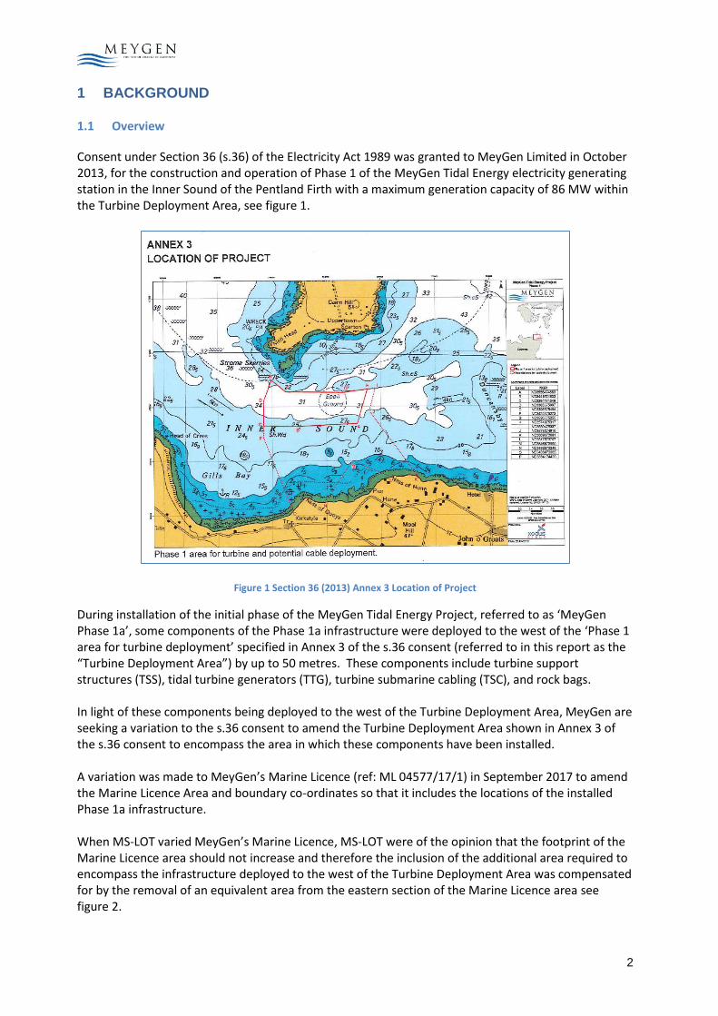
Consent under Section 36 (s.36) of the Electricity Act 1989 was granted to MeyGen Limited in October 2013, for the construction and operation of Phase 1 of the MeyGen Tidal Energy electricity generating station in the Inner Sound of the Pentland Firth with a maximum generation capacity of 86 MW within the Turbine Deployment Area, see figure 1.
Figure 1 Section 36 (2013) Annex 3 Location of Project
During installation of the initial phase of the MeyGen Tidal Energy Project, referred to as ‘MeyGen Phase 1a’, some components of the Phase 1a infrastructure were deployed to the west of the ‘Phase 1 area for turbine deployment’ specified in Annex 3 of the s.36 consent (referred to in this report as the “Turbine Deployment Area”) by up to 50 metres. These components include turbine support structures (TSS), tidal turbine generators (TTG), turbine submarine cabling (TSC), and rock bags. In light of these components being deployed to the west of the Turbine Deployment Area, MeyGen are seeking a variation to the s.36 consent to amend the Turbine Deployment Area shown in Annex 3 of the s.36 consent to encompass the area in which these components have been installed. A variation was made to MeyGen’s Marine Licence (ref: ML 04577/17/1) in September 2017 to amend the Marine Licence Area and boundary co-ordinates so that it includes the locations of the installed Phase 1a infrastructure. When MS-LOT varied MeyGen’s Marine Licence, MS-LOT were of the opinion that the footprint of the Marine Licence area should not increase and therefore the inclusion of the additional area required to encompass the infrastructure deployed to the west of the Turbine Deployment Area was compensated for by the removal of an equivalent area from the eastern section of the Marine Licence area see figure 2.

3
Figure 2 Marine Licence (2017) Boundary Variation
The variation of the s.36 consent, if granted, would ensure that the Turbine Deployment Area specified in Annex 3 of the s.36 consent is consistent with the Revised Phase 1 Marine Licence area shown in Part 4 of the Schedule to Marine Licence (ref: ML 04577/17/1), see figure 3.
Figure 3 Marine Licence Variation (2017) ML 04577/17/1

4
2 PHASE 1 TURBINE DEPLOYMENT AREA
2.1 Turbine Deployment Area
The Phase 1 Turbine Deployment Area specified in Annex 3 of the Section 36 Consent comprises the central part of the larger MeyGen Lease area for the Inner Sound Premises granted by Crown Estate Scotland (CES) as shown in Figure 4. The Phase 1 Turbine Deployment Area was selected on the basis of the following requirements:
• High flow velocities;
• Bidirectional flow between flood and ebb tide;
• Relatively flat and stable seabed;
• Protection from potential extreme wave climate;
• Access to suitable cable landing sites;
• Suitable cable corridor to shore.
2.2 Indicative turbine locations
The indicative locations of all Phase 1a Turbine Tidal Generators (turbines) were assessed based on potential yield, bathymetry, seabed suitability for installing gravity based structures and positioning to enable future build out are shown in Table 3 below. These indicative locations are all within the consented Phase 1 Turbine Deployment Area. The initial, indicative locations for TTG #1 and TTG #2 were close to the Turbine Deployment Area boundary.
TTG Eastings Northings Depth (m)
TTG #1 491818 6502212 33.1
TTG #2 491796 6502122 34.1
TTG #3 492025 6502150 33.1
TTG #4 492010 6502020 34.9
Table 1 Indicative Phase 1A turbine locations
2.3 TSS Micrositing
The turbines are mounted upon gravity based TSS tripods. A turbine micro siting study was conducted to confirm the final locations for the Phase 1a TSS focussing on a 50m x 50m area around each indicative turbine location. The purpose of micro siting was to define the final location for each TSS which complied with the following installation tolerances:
• TSS verticality within 2.5 degrees
• Bearing plates under each TSS foot with vertical angle not larger than 7 degrees
• Additional clearance greater than 0.1m
• The remaining TSS must not be in contact with seabed
• Installation orientation tolerance within 5 degrees
• TSS translational installation tolerance within 1m The net result of the micro-siting exercise and the installation process led to the deployment of the Phase 1a TSS’s at the following locations in Universal Transverse Mercator (UTM) coordinate system in eastings and northings, shown in Table 2 :
TSS Original Eastings Original Northings
1 491818.59 6502208.52
2 491776.6 6502123.85
3 492027.64 6502159.18
4 492037.85 6502002.53
Table 2 As Built locations for Phase 1a TSS

5
Figure 4 MeyGen As Built Map (July 2017)

6
2.4 Phase 1a Components Outside Turbine Deployment Area
The As built locations for the centre of TSS #1 is within the boundary of the Turbine Deployment Area however the TSS leg crosses the boundary. The centre of TSS #2 is 8.5m outside and to the west of the Turbine Deployment Area. The placement of these TSS then effects the placement of their associated infrastructure During the installation of Phase 1a the following components were deployed outside and to the west of the Turbine Deployment Area, see figure 4 :
2.5 Turbine Support Structures
The centre of TSS# 1 is within the boundary of the Turbine Deployment Area however one of the TSS#1 legs crosses the boundary. The centre of TSS # 2 is 8.5m to the west of the Turbine Deployment Area.
2.6 Turbine Submarine Cables
TSC#1 and TSC#2 (shown in red in figure 4) connect to TSS/TTG #1 and TSS/TTG #2 respectively. During installation sections of TSC#1 and TSC#2 cables were laid to the west of the Turbine Deployment Area
2.7 Rock Bags
Rock bags (shown as a,b and c in figure 4) were used to stabilise the cables. Rock bags were deployed on TSC#1 and TSC#2 which were laid to the west of the Turbine Deployment Area.
2.8 Tidal Turbine Generators and their cable tails
TTG#1 and TTG#2 and their associated cable tails (shown in black in figure 4) were deployed on TSS#1 and TSS#2 and therefore were also deployed outside the Turbine Deployment Area. Table 3 provides details of the distance of components of Phase 1a infrastructure deployed to the west of the Turbine Deployment Area. Infrastructure Distance to the Turbine Deployment Area
Centre of TSS 1 / TTG 1 Centre is within the boundary of the Turbine Deployment Area however the TSS leg crosses the boundary
Centre of TSS 2 / TTG 2 8.5m
TSC 1 31m
TSC 2 50m
Rockbag (a) on TSC1 34m
Rockbag (b) on TSC1 32m
Rockbag (c) on TCS2 13m
Table 3 Components deployed to the west of Turbine Deployment Area

7
3 NAVIGATIONAL SAFETY
This section considers the navigational impact of the deployment of components of the Phase 1a infrastructure TSSs, TTGs, TSCs and rock bags to the west of the Turbine Deployment Area (as shown in Table 4).
3.1 During installation
During installation “Notices to Mariners” for the works were circulated to appropriate recipients by the Principal Contractor and MeyGen. These notices inform mariners when construction and other works are being
undertaken on the MeyGen site. The notices were typically centred on a position of 80 39.5’ North 0030 08.5’
West, noting however that construction and support vessels may be encountered anywhere within the Inner Sound. MeyGen consider that the location of components to the west of the Turbine Deployment Area did not and does not contradict these notices and therefore did not and does not increase navigational safety risk.
3.2 Post installation
Other users of the Inner Sound are informed of the presence of the MeyGen turbines and infrastructure by navigational charts and digital maps. MeyGen sent a note to UKHO in March 2016 which identified both the Phase 1a Cable Deployment Area and the indicative locations of the Phase 1a turbines and cables.
Post TSS installation MeyGen sent as-built information to UKHO to allow the creation of chart corrections suitable for inclusion on UKHO and other suppliers’ charts. This data included the TSS As built locations in the form of an autocad (.DWG) file; and confirmation that the clearance over all Phase 1a turbines was greater than 8m. The resulting UKHO chart correction for chart number 2162 is shown below in figure 5.
Figure 5 UKHO Chart 2162 showing the North of Scotland, focussed on the Inner Sound
Chart number 2162 notes the presence of underwater tidal turbines with construction activities between 2017 and 2025. The chart does not include a date prior to 2017 as the chart was re-issued in December 2016. Electronic versions of chart 2162 are used by most construction vessels. Figure 6 shows a screen shot of the Inner Sound. It can be seen that the electronic version includes the locations of the installed Phase 1a turbines. The hazard boundary is extended westwards to encompass the as-built turbine locations.

8
Figure 6 Screen shot of an electronic UKHO Chart showing the Inner Sound
The as-built location of the TSS are on the dashed warning lines on the paper charts and within the warning lines on the electronic charts. MeyGen therefore considers that the deployment of components of the Phase 1a infrastructure (i.e. TSSs, TTGs cables and rock bags) to the west of the Turbine Deployment Area does not increase the navigational safety risk above that presented within the MeyGen Environmental Statement (ES).
MeyGen has also provided UKHO with details of future phases of marine works up to 2025 to limit the number of subsequent chart corrections that will be required in respect of the MeyGen Phase 1 works. In addition, MeyGen has provided UKHO with the bathymetry data obtained from MeyGen geophysical surveys so that the chart depth is updated with the newly acquitted bathymetric survey data and the true water depths across the Inner Sound.
4 ENVIRONMENTAL IMPACTS
4.1 Introduction
This section considers the environmental impact of the deployment of components of the Phase 1a infrastructure TSSs, TTGs, TSCs and rock bags to the west of the Turbine Deployment Area (as shown in Table 4).
The Environmental Impact Assessment (EIA) work to date has identified that the environmental impact of most concern is the collision risk affecting the harbour seal population of the Orkney and North Coast management unit. MeyGen was granted permission to install up to six turbines at the MeyGen site on the basis that collision risk modelling predicts that the deployment and operation of up to 6 turbines would have no significant impact on the harbour seal population.
To this end Condition 2 within Section 36 consent requires the Development to be built out in stages, with Stage One being limited to a maximum of six turbines and all Subsequent Stages of the development being subject to the prior written approval of the Scottish Ministers. Phase 1a comprised of four turbines and in June 2017 MeyGen were granted written approval in accordance with Condition 2(b)(ii) of the s.36 consent to proceed with Phase 1b of the Development , comprising a further four turbines.

9
4.2 Harbour Seal
Information on harbour seal use of the Turbine Deployment Area was derived from a number of sources, including site survey work for the MeyGen ES covering the larger MeyGen Inner Sound Premises area in figure 7. .
Figure 7 MeyGen EIA Boat Survey Route
As there are no further location parameters which feed into the harbour seal collision modelling, the deployment of components of Phase 1a infrastructure (i.e. TSS, TTG, cables and rock bags) to the west of the Turbine Deployment Area does not affect the density data used in the collision modelling within the MeyGen Environmental Statement (ES) nor does it alter the predictions presented within the MeyGen ES.
4.3 Grey Seals
For grey seals, collision risk modelling was based on data of a similar resolution to that used for harbour seals. Grey seal collision predictions are not changed due to the deployment of components of Phase 1a infrastructure to the west of the Turbine Deployment Area, above those presented within the MeyGen ES.
4.4 Seabirds and Atlantic Salmon
For seabirds and Atlantic salmon, the collision risk modelling runs were independent of turbine location. Therefore there is no increase in impact upon these receptors due to the deployment of components of Phase 1a infrastructure to the west of the Turbine Deployment Area, above those presented within the MeyGen ES due
4.5 Coastal Processes
The conclusions on the potential environmental impact upon coastal processes within the MeyGen ES remain unchanged by the deployment of components of Phase 1a infrastructure to the west of the turbine deployment area. The assessment of impact on coastal processes considered an area much wider than the Turbine Deployment Area.
4.6 Benthic Impacts
The benthic mapping conducted for the Turbine Deployment Area assessment presented in the MeyGen ES demonstrates similar substrate and biotopes throughout the Turbine Deployment Area. The conclusions on potential environmental impact on benthic habitat within the MeyGen ES remain unchanged by the deployment of components of Phase 1a infrastructure to the west of the Turbine Deployment Area.

10
4.7 EIA Summary
In summary the deployment of components of Phase 1a infrastructure to the west of the Turbine Deployment Area does not change the conclusions on potential environmental impact presented in the MeyGen ES.
4.8 Documents prepared in accordance with s.36 consent
A suite of documents required pursuant to the conditions of the s.36 consent (and the Marine Licence) has been prepared by MeyGen, as follows :
• Vessel Management Plan (VMP) and Navigational Safety Plan (NSP)
The VMP & NSP ensure that the Developments marine activities are conducted in a safe manner considerate of consent conditions and industry best practice. The document will be periodically reviewed during the execution of the Development to provide detailed information relevant to the key activities to be undertaken through the construction and operational phases of the Development.
• Environmental Management Plan (EMP) and Construction Method Statement (CMS)
The EMP details the construction related mitigation methods proposed for the Development, how these are to be delivered in the construction procedures and good working practices for installing the Development. The CMS details the construction methods proposed for the Development, the construction procedures and good working practices for installing the Development and how construction related mitigation detailed in the EMP is to be delivered.
• Operations and Maintenance Programme (OMP)
The purpose of the OMP is to provide details of the operational and maintenance activities that will be undertaken at the Turbine Deployment Area including vessel requirements, roles and responsibilities, planning, and safeguarding environmental interests at the offshore generating station.
It is considered that the deployment of components of Phase 1a infrastructure to the west of the Turbine Deployment Area, does not and will not affect the operations or procedures in any of the abovementioned documents.
• Project Environmental Monitoring Programme (PEMP)
The PEMP has been prepared by MeyGen to set out the proposed method for discharging Condition 12 of the Section 36 Consent for the Development. The PEMP details the monitoring methods proposed for the commissioning and operational phases of the Development and how communication will be maintained between MeyGen, the Advisory Group (established in accordance with Condition 13) and the Regulators. To ensure that the Development is appropriately constructed and operated, the PEMP must:
• Take into account mitigation measures to protect the environment and other users of the marine area;
• Protect the environment, and;
• Ensure appropriate and effective monitoring of the impacts of the Development.
It is considered that the deployment of components of Phase 1a infrastructure to the west of the turbine deployment area does not affect the ongoing environmental monitoring associated with the MeyGen Project. MeyGen continues to engage with Regulatory bodies through the Advisory Group.

11
5 REQUESTED VARIATION TO SECTION 36 CONSENT
5.1 Variation of Turbine Deployment Area specified in Annex 3 of s.36 consent
MeyGen request that the offshore Turbine Deployment Area specified in Annex 3 of the s.36 consent is varied so that it encompasses the area in which the Phase 1a infrastructure has been installed and so that it is consistent with the Revised Phase 1 Marine Licence area shown in Part 4 of the Schedule to MeyGen’s Marine Licence (ref: ML 04577/17/1) granted by MSLOT in September 2017. Should the variation be granted the Annex 3 of s.36 consent and associated co-ordinates will be as shown in Figure 8 on next page.
6 CONCLUSION
MeyGen has considered the implications upon navigational safety and the environment and have concluded that there are no additional impacts on navigational safety or the environment as a result of components of the Phase 1a infrastructure being deployed to the west of the Turbine Deployment Area . This view was supported by the consultees (MSS, NLB, MCA and SNH) during the Marine Licence variation process which led to the provision of the Marine Licence variation (ref: ML 04577/17/1). MeyGen now request that the offshore Turbine Deployment Area specified in Annex 3 of the s.36 consent is varied so that it encompasses the area in which the Phase 1a infrastructure has been installed so that is consistent with the Revised Phase 1 Marine Licence area shown in Part 4 of the Schedule to MeyGen’s Marine Licence (ref: ML 04577/17/1) granted by MSLOT in September 2017.
During the ML variation process MeyGen worked closely with MSLOT to review installation and internal design processes which have now been amended to ensure that future infrastructure is not deployed outside of consented areas in future marine works.

12
Figure 8 Proposed amended Annex 3 s.36 consent
----END----