TSS User Manual
494
Tactical Study Series HPS Simulations USER MANUAL This manual is applicable to all of the titles in the Tactical Study Series; it covers the full and complete range of the series capabilities, interfaces and options. Players should note that some se ctions of the manual may n ot be applicable to a specific title. For example, Energy Weapons were n ot available in World War II and thu s WWII players can skip the sections pertaining to them, or read them simply for general information. For the latest program upgrades, please visit the HPS web site: www.hpssims.com If you have questions, or are having problems, please email the HPS Simulations Technical Support Department: [email protected]. If you have a saved game file that exhib its the problem, please keep it handy as we may request that you send it to us to help recreate and identify the issue. The complete software package and documentation are Copyright © 2003-2011 by HPS Simulations. All rights reserved. HPS Simulations and the HPS logo are trademarks of HPS Simulations. All other trademarks and registered trademarks are the property of their respective owners.
-
Upload
sergio-diaz-guerrero -
Category
Documents
-
view
41 -
download
1
description
Manual del juegos Tigers Unleashed
Transcript of TSS User Manual

7/21/2019 TSS User Manual
http://slidepdf.com/reader/full/tss-user-manual 1/492
Tactical Study SeriesHPS Simulations
USER MANUAL
This manual is applicable to all of the titles in the Tactical Study Series; it covers the full and complete range of theseries capabilities, interfaces and options. Players should note that some sections of the manual may not be applicable toa specific title. For example, Energy Weapons were not available in World War II and thus WWII players can skip thesections pertaining to them, or read them simply for general information.
For the latest program upgrades, please visit the HPS web site:
www.hpssims.com
If you have questions, or are having problems, please email the HPS Simulations Technical Support Department:[email protected]. If you have a saved game file that exhibits the problem, please keep it handy as we may requestthat you send it to us to help recreate and identify the issue.
The complete software package and documentation are Copyright © 2003-2011 by HPS Simulations. All rights reserved.
HPS Simulations and the HPS logo are trademarks of HPS Simulations. All other trademarks and registered trademarksare the property of their respective owners.
7/21/2019 TSS User Manual
http://slidepdf.com/reader/full/tss-user-manual 2/492
Introduction
Point of Attack-2 (POA), the initial release in the TSS series, was developed in partnership with the United States AirForce Office of Scientific Research (AFOSR) and Air Force Research Laboratory (AFRL). Government users withquestions regarding the development process or objectives should contact AFOSR or AFRL directly:http://www.wpafb.af.mil . As of June 2011, the point of contact at AFRL is Dr. John Luginsland (Alexandria VA), the POCat AFRL is Mr. Dave Ross (Rome NY).
A special thanks is also extended to Dr. Bob Barker, who over more than ten years was instrumental in providing
resources, guidance, support and opportunities for the development of POA. His involvement and backing were critical inallowing the full development of the program.
No Nonsense License Agreement:
By installing the software, you are agreeing to these license terms.
You have a personal license that allows you to install the software on any computer you own, or on another computer aslong as you are an active participant in ALL games being played using the software installed on that machine. In caseswhere the software is installed temporarily on a computer you do not own, it must be completely removed from thecomputer at the conclusion of any active games being played.
If the software is installed on a non-commercial private network, at least one bona-fide owner of the software must be anactive participant in all games being played.
For commercial, professional (i.e., non-entertainment) or over-the-Internet use all players must own their own copy ofthe software or have a multiple instance license.
Players may create and freely distribute maps, scenarios, etc. that they build for the main program (as applicable to the
game). However, these items or any other types of derivatives may not be sold, or made available for sale in any mannerwithout the written consent of HPS Simulations.
This license is solely for non-commercial purposes. Any commercial use of this software whatsoever requires the expresswritten consent of HPS Simulations.
Any reports, analysis, or papers generated through any use of the program must include a reference for the full name ofthe software title as well as HPS Simulations and AFOSR. For example, the official citation of a project using POA shouldread: “Point of Attack by HPS Simulations, in association with the US Air Force Office of Scientific Research”.
Note: The US Government official-use version of the software may be subject to a time-limit on free usage. Pleasecontact HPS Simulations for more information, or if you get a “license expired” message.
Primary CreditsDesign and Programming: Scott Hamilton, Jeff Lapkoff Databases: John Kincaid, Wendy Kincaid, Nick Bell, Greg Smith, Joseph MirandaTerrain Analysis/Development: Nick Bell Artwork/Graphics: Nick Bell, Joe Amoral, and Jeff Lapkoff Maps: Nick Bell, John Kincaid Scenario Design: Greg Smith and Joseph MirandaPlaytesting: Arthur Florman, Brian Rock, Charles Belva, Don Maddox, Gary Bezant, Jim Johnson, John Kincaid, KevinPelz, Michael Andress, Peter Jackson, Peter von Kleinsmid, Tim Schultz, Tyler Philpott, Dustin Pearson, Mark ØrnebjergJensen.
DISCLAIMER: The Energy/Advanced Weapon information contained herein was gathered by the gameauthor through personal research in open-literature/internet sources. The Air Force Office of ScientificResearch neither confirms nor denies any particulars of that information.

7/21/2019 TSS User Manual
http://slidepdf.com/reader/full/tss-user-manual 3/492
7/21/2019 TSS User Manual
http://slidepdf.com/reader/full/tss-user-manual 4/492
2.1.1.10.1 Complete Manual....................................................................................................................................562.1.1.10.2 How Do I...?............................................................................................................................................562.1.1.10.3 Tutorial Slides.........................................................................................................................................562.1.1.10.4 Updates Online.......................................................................................................................................562.1.1.10.5 About.......................................................................................................................................................56
2.1.2 The Control Buttons...............................................................................................................................................572-1.2.1 File Actions Control Buttons............................................................................................................................57
2-1.2.1.1 Load Game File........................................................................................................................................572-1.2.1.2 Save Game To File...................................................................................................................................57
2-1.2.2 Map Display Control Buttons...........................................................................................................................582-1.2.2.1 Zoom In/Out..............................................................................................................................................592-1.2.2.2 Redraw Map.............................................................................................................................................592-1.2.2.3 Toggle Long-Range Map..........................................................................................................................60
2-1.2.3 Orders Mode Control Buttons (Targeting and Movement).............................................................................602-1.2.3.1 DF Targeting Mode...................................................................................................................................602-1.2.3.2 Unit Movement Mode...............................................................................................................................602-1.2.3.3 Cancel Operation......................................................................................................................................61
2-1.2.4 LOS Mode Control Buttons (Line of Sight)......................................................................................................612-1.2.4.1 Point to Point LOS....................................................................................................................................612-1.2.4.2 Area LOS..................................................................................................................................................63
2-1.2.5 Turn Control Buttons.......................................................................................................................................642-1.2.5.1 Replay Entire Combat Phase...................................................................................................................642-1.2.5.2 Show Combat Phase Summary...............................................................................................................65
2-1.2.5.3 End Turn...................................................................................................................................................652-1.3 The Force Tree......................................................................................................................................................66
2-1.3.1 Force Tree Icons.............................................................................................................................................662-1.3.2 Text Additions..................................................................................................................................................672-1.3.3 Force Tree Mouse Actions..............................................................................................................................682-1.3.4 Composite Unit Mode......................................................................................................................................69
2-1.4 Map/Location Information Panel............................................................................................................................70Section 2-2: The Location Information Form.................................................................................................................... .70Section 2-3: The Off-map Display........................................................................................................................... ..........72
2-3.1 Using a Background Map/Picture For the Offmap Display ...................................................................................73Section 2-4: The Load Scenario Form................................................................................................................................74Section 2-5: The Scenario Control Form............................................................................................................................75Section 2-6: The AI Settings Form.......................................................................................................................... ..........76
Section 2-7: Staff Officer Screens.....................................................................................................................................782-7.1 General Characteristics of Staff Officer Screens...................................................................................................792-7.2 S-1: Personnel Officer............................................................................................................................................802-7.3 S-2: Intelligence Officer.........................................................................................................................................802-7.4 S-3: Operations Officer (Movement)......................................................................................................................812-7.5 S-4: Supply Officer.................................................................................................................................................822-7.6 XO: Targeting Officer.............................................................................................................................................832-7.7 Engineering Officer................................................................................................................................................852-7.8 FSO: Fire Support Officer (Artillery).......................................................................................................................862-7.9 ALO: Air Liaison Officer (Close Air Support).........................................................................................................872-7.10 Commo: Communications Officer........................................................................................................................882-7.11 Passenger/Carrier Loading Status......................................................................................................................89
2-7.11.1 Loading Status (Complete) View..................................................................................................................892-7.11.2 Loading Status (By Carrier) View..................................................................................................................902-7.11.3 Loading Status (By Composite Unit) View....................................................................................................912-7.11.4 Loading Status (Cross-loading) View............................................................................................................92
Section 2-8: Preference Settings........................................................................................................................................93Section 2-9: Right Clicking (<RBM>) on the Map ...........................................................................................................100
2-9.1 <RMB> Pop-up: Terrain Info................................................................................................................................1012-9.2 <RMB> Pop-up: Unit Info.....................................................................................................................................1012-9.3 <RMB> Pop-up: Composite Units.......................................................................................................................1022-9.4 <RMB> Pop-up: Enemy Weapon Info.................................................................................................................1022-9.5 <RMB> Pop-up: Give Orders to Units.................................................................................................................1032-9.6 <RMB> Pop-up: Create a Detachment................................................................................................................1042-9.7 <RMB> Pop-up: Target this Location..................................................................................................................104

7/21/2019 TSS User Manual
http://slidepdf.com/reader/full/tss-user-manual 5/492
2-9.8 <RMB> Pop-up: Check Selected Unit Targeting to This Location......................................................................1052-9.9 <RMB> Pop-up: Place/Edit Objects....................................................................................................................1072-9.10 <RMB> Pop-up: Place/Edit Preplanned............................................................................................................1082-9.11 <RMB> Pop-up: Engineering.............................................................................................................................1092-9.12 <RMB> Pop-up: Bridge Demolition...................................................................................................................1102-9.2.13 <RMB> Pop-up: Map Notes............................................................................................................................1112-9.2.14 <RMB> Pop-up: Last Map Note This Loc.......................................................................................................112
Section 2-10 Creating a New Game ................................................................................................................................1122-10.1 The Game Creation Checklist............................................................................................................................1132-10.2 Expert Level.......................................................................................................................................................1142-10.3 Scenario Information..........................................................................................................................................1152-10.4 Select the Scenario Map....................................................................................................................................1172-10.5 Set Conditions/Data Tables...............................................................................................................................119
2-10.5.1 Using Custom Data Files............................................................................................................................1192-10.5.2 Setting the Environmental Conditions.........................................................................................................119
2-10.5.2.1 Set Current Time\Light and Non-Weather Meteorological Values.......................................................1202-10.5.2.2 Set LOS Special Values.......................................................................................................................1202-10.5.2.3 Set Turn Resolution..............................................................................................................................1212-10.5.2.4 Set Map Scale......................................................................................................................................121
2-10.5.3 Setting the Weather....................................................................................................................................1212-10.5.3.1 Setting the Weather Period Length......................................................................................................1222-10.5.3.2 Setting the Values For Each Weather Period......................................................................................1222-10.5.3.3 Adding or Deleting Days of Weather....................................................................................................123
2-10.6 Initial Set-up Conditions.....................................................................................................................................1242-10.6.1 Selecting Civilian Types..............................................................................................................................126
2-10.7 Fog of War (FOW).............................................................................................................................................1272-10.7.1 FOW Levels.................................................................................................................................................1272-10.7.2 Locking the FOW Levels.............................................................................................................................1272-10.7.3 Using Different FOW Levels For Each Player............................................................................................128
2-10.8 Default Force Values.........................................................................................................................................1282-10.8.1 Command and Control................................................................................................................................129
2-10.8.1.1 Command Radii....................................................................................................................................1292-10.8.1.2 Message Types....................................................................................................................................129
2-10.8.2 AI Aggressiveness Level.............................................................................................................................1312-10.8.3 General Force Values.................................................................................................................................1312-10.8.4 Default Unit Values.....................................................................................................................................133
2-10.8.5 Intelligence/Reconnaissance Values..........................................................................................................1342-10.8.6 Message Time-out .....................................................................................................................................1352-10.8.7 Live Feed Video..........................................................................................................................................1352-10.8.8 Pre-Planned (PPD) Artillery Target Defaults..............................................................................................1362-10.8.9 DF Target Reference Point (TRP) Defaults................................................................................................1362-10.8.10 Movement/Urban Operations SOP...........................................................................................................1362-10.8.11 Setting Radiation Alarm Levels.................................................................................................................1372-10.8.11.1 Background Radiation............................................................................................................................1382-10.8.11.2 Radiation Alarm Levels..........................................................................................................................1402-10.8.11.3 Radiation Alarm Form............................................................................................................................141
2-10.9 Selecting Main Force Units................................................................................................................................1422-10.9.1 Weapon System Model Selection Mode Panel...........................................................................................1422-10.9.2 TO&E Panel................................................................................................................................................1432-10.9.3 Current Forces Panel..................................................................................................................................143
2-10.9.3.1 Reassigning Sub-Formations/Units to Different HQ’s..........................................................................1432-10.9.3.2 Deleting Units.......................................................................................................................................1432-10.9.3.3 Changing the Unit Level.......................................................................................................................144
2-10.9.4 Editing/Changing Unit Information..............................................................................................................1442-10.9.5 Unit Names/Auto-Naming...........................................................................................................................1442-10.9.6 Changing Basic Unit Default Levels............................................................................................................1452-10.9.7 Random/Auto Force Selection....................................................................................................................1462-10.9.8 Satellites......................................................................................................................................................146
2-10.9.8.1 Satellite Availability Form.....................................................................................................................1482-10.9.8.2 Satellite Passes Form...........................................................................................................................149
2-10.10 Selecting Flank Force Units.............................................................................................................................149

7/21/2019 TSS User Manual
http://slidepdf.com/reader/full/tss-user-manual 6/492
2-10.11 Assigning Leaders to Units..............................................................................................................................1512-10.12 Ending a Scenario Early.................................................................................................................................152
2-10.12.1 Set the Scenario to Use Early End Conditions.........................................................................................1522-10.12.2 End Early Conditions Form ......................................................................................................................153
2-10.13 Two-Player Games..........................................................................................................................................1552.10.13.1 Passwords.................................................................................................................................................156
Section 2-11 AI and the Map............................................................................................................................................1572-11.1 CAI File..............................................................................................................................................................157
Section 2-12 Set Up Phase..............................................................................................................................................1572-12.1 Victory Objectives..............................................................................................................................................1582-12.1.1 Victory Objectives Form..................................................................................................................................1592-12.1.2 Selecting a Location as the Objective ...........................................................................................................1602-12.1.3 Selecting a Unit as the Objective....................................................................................................................1602-12.1.4 Enemy Knowledge of Objectives ...................................................................................................................1612-12.2 The Force Set Up Form (Place Units and Objects)..........................................................................................1612-12.3 Placing Units......................................................................................................................................................163
2-12.3.1 Placing Entire Formations...........................................................................................................................1642-12.3.2 Placing Composite Units.............................................................................................................................1642-12.3.3 Loading and Unloading Formations and/or the Entire Force......................................................................1642-12.3.4 Loading/Unloading Single Units..................................................................................................................1642-12.3.5 Removing Existing Move Orders................................................................................................................1652-12.3.6 “Un-placing” Units Already Placed..............................................................................................................1652-12.3.7 Designating Reinforcement Units...............................................................................................................165
2-12.3.8 Setting Up Paradrops..................................................................................................................................1652-12.4 Placing/Editing/Removing Improved Positions (IP’s)........................................................................................166
2-12.4.1 Dynamic IP's...............................................................................................................................................1692-12.4.1.1 Creating/Removing Dynamic IP's........................................................................................................1692-12.4.1.2 Dynamic IP Characteristics............................................................................................................ .....171
2-12.4.2 Editing/Removing Existing IP’s...................................................................................................................1712-12.5 Placing Obstacles..............................................................................................................................................171
2-12.5.1 Editing/Removing Existing Obstacles.........................................................................................................1732-12.6 Placing Mines.....................................................................................................................................................173
2-12.6.1 Editing/Removing Existing Minefields.........................................................................................................1752-12.7 Placing Sensors.................................................................................................................................................1752-12.8 Placing/Editing Bridges......................................................................................................................................176
2-12.8.1 Placing New Bridges Manually...................................................................................................................176
2-12.8.2 Editing/Deleting Existing Bridges................................................................................................................1772-12.9 Clearing/Removing Objects En-mass................................................................................................................1772-12.10 AI Placement Options......................................................................................................................................178
Section 2-13 DF Target Reference Points (TRP’s)..........................................................................................................1782-13.1 Placing DF TRP’s...............................................................................................................................................1782-13.2 Editing Existing TRP’s.......................................................................................................................................1802-13.3 Showing DF TRP’s On the Map........................................................................................................................1812-13.4 Using DF TRP’s.................................................................................................................................................182
Section 2-14 IF Pre-Planned (PPD) Targets....................................................................................................................1822-14.1 Placing IF PPD Targets.....................................................................................................................................1822-14.2 Editing Existing PPD Targets.............................................................................................................................1832-14.3 Showing IF PPD Targets On the Map ..............................................................................................................1852-14.4 Using IF PPD Targets........................................................................................................................................185
Section 2-15 Placing Units to Fire at a Specific Location.................................................................................................185Section 2-16 Loading/Unloading Units.............................................................................................................................188
2-16.1 Loading using the Unit Data Form.....................................................................................................................1882-16.2 Loading using the Map <Right Click> Menu......................................................................................................1882-16.3 Loading using Movement Commands...............................................................................................................1882-16.4 Load Units Form................................................................................................................................................1892-16.5 Unload Units Form.............................................................................................................................................190
2-16.5.1 Giving Debarking Units Movement Orders.................................................................................................191Section 2-17 Giving Units Movement Commands............................................................................................................192
2-17.1 Selecting Units for Orders .................................................................................................................................1932-17.1.1 Function Buttons.........................................................................................................................................193
2-17.2 AI Fidelity...........................................................................................................................................................194

7/21/2019 TSS User Manual
http://slidepdf.com/reader/full/tss-user-manual 7/492
2-17.3 Formation Move.................................................................................................................................................1942-17.4 Movement Orders..............................................................................................................................................196
2-17.4.1 Path Display................................................................................................................................................1962-17.4.2 Command Buttons......................................................................................................................................1962-17.4.3 Movement Path Editor.................................................................................................................................1972-17.4.5 Entering IP’s................................................................................................................................................1982-17.4.6 Moving Underground ..................................................................................................................................199
2-17.5 Setting Movement Waypoints............................................................................................................................2022-17.5.1 Showing All Friendly Move Paths...............................................................................................................202
2-17.6 Patrol Mode........................................................................................................................................................2032-16.6.1 Setting up a Patrol.......................................................................................................................................2042-17.6.2 Canceling a Patrol.......................................................................................................................................205
2-17.7 Maneuver Groups .............................................................................................................................................2052-17.7.1 Maneuver Groups Form..............................................................................................................................206
2-17.7.1.1 Intermediate Objective Panel:..............................................................................................................2102-17.7.2 Intermediate Objectives Form.....................................................................................................................211
2-17.7.2.1 Selecting Intermediate Objective Locations.........................................................................................2122-17.7.2.2 Intermediate Objective Options............................................................................................................2132-17.7.2.3 Intermediate Objective Actions.............................................................................................................2142-17.7.2.4 Intermediate Objective Example..........................................................................................................215
2-17.8 Reconnaissance/Radiation Detection Assignments..........................................................................................2212-17.8.1 Set Recon/Radiation Detection Assignments Form....................................................................................2222-17.8.2 Issuing a New Recon Assignment.............................................................................................................222
2-17.8.3 Recon Assignment Unit Selection..............................................................................................................2232-17.8.4 Recon Assignment Areas/Progression................................................................................................. .....2232-17.8.5 Progression to the Next Area.....................................................................................................................2252-17.8.6 Recon Search Area Limits/Conditions ......................................................................................................2252-17.8.7 Removing an Area From the Search Progression......................................................................................226
Section 2-18 Setting DF Targets......................................................................................................................................2262-18.1 Setting DF Targets for Specific Firing Units......................................................................................................226
2-18.1.1 The Targeting Form....................................................................................................................................2282-18.1.2 Selecting the Target....................................................................................................................................2282.18.1.3 Setting/Changing the Firing Group Info.......................................................................................................2292-18.1.4 Firing Parameters/Information....................................................................................................................230
2-18.1.4.1 Target ..................................................................................................................................................2302-18.1.4.2 ROF......................................................................................................................................................230
2-18.1.4.3 Pulses/Ammo.......................................................................................................................................2312-18.1.4.4 Kill/Dmg/Supn Probabilities..................................................................................................................2312-18.1.4.5 Clearing (Removing) Targets...............................................................................................................231
2-18.2 Setting DF Against A Specific Target................................................................................................................2312-18.2.1 Targeting Results........................................................................................................................................233
Section 2-19 Calling for Artillery/IF Fire............................................................................................................................2342-19.1 The Arty/Fire Support Mission form...................................................................................................................2342-19.2 Select the Target................................................................................................................................................2352-19.3 Select the Firing Unit/Ammo..............................................................................................................................2352-19.4 Mission Specs....................................................................................................................................................2362-19.5 Shift....................................................................................................................................................................2372-19.6 Calling Unit.........................................................................................................................................................237
2-19.6.1 Calling Unit Effects......................................................................................................................................2382-19.7 Targeting Results Box.......................................................................................................................................2382-19.8 Canceling a Support Mission.............................................................................................................................2392-19.9 Support Mission Priorities..................................................................................................................................239
Section 2-20 Calling for Close Air Support.......................................................................................................................2392-20.1 The Close Air Support Mission Form.................................................................................................................2402-20.2 Select the Target................................................................................................................................................2422-20.3 Select the Aircraft Unit.......................................................................................................................................2422-20.4 Set Up the Passes ............................................................................................................................................2422-20.5 Adding SEAD Missions......................................................................................................................................243
2-20.5.1 Picking an SEAD Target.............................................................................................................................2442-20.5.2 Setting SEAD Mission Start Time...............................................................................................................244
2-20.6 Assisting Units...................................................................................................................................................245

7/21/2019 TSS User Manual
http://slidepdf.com/reader/full/tss-user-manual 8/492
2-20.7 Flight Path Characteristics ................................................................................................................................2452-20.8 Check Mission Plan...........................................................................................................................................2462-20.9 Canceling a Support Mission.............................................................................................................................246
Section 2-21 Engineering Operations...............................................................................................................................2472-21.1 The Engineering Projects Form.........................................................................................................................2482-21.2 Start New Project...............................................................................................................................................249
2-21.2.1 Creating New Objects.................................................................................................................................2492-21.2.1.1 Placing Mines/Sensors.........................................................................................................................2502-21.2.1.2 Creating Obstacles...............................................................................................................................2512-21.2.1.3 Building Bridges....................................................................................................................................252
2-21.2.1.3.1 Spanning Hexsides........................................................................................................................2532-21.2.1.3.2 Spanning Full Locations/Hexes.....................................................................................................254
2-21.2.1.4 Constructing IP’s..................................................................................................................................2542-21.2.1.5 Building Roads.....................................................................................................................................255
2-21.2.2 Removing Objects.......................................................................................................................................2552-21.2.2.1 Removing Minefields/Obstacles...........................................................................................................2562-21.2.2.2 Priming Bridges for Demo....................................................................................................................2562-21.2.2.3 Blowing Primed Bridges.......................................................................................................................256
2-21.3 Active Operation Statistics.................................................................................................................................2572-21.4 Current Projects in Loc......................................................................................................................................2582-21.5 Available Units...................................................................................................................................................2592-21.6 Canceling a Project............................................................................................................................................259
Section 2-22 Airdrop Missions..........................................................................................................................................259
2-22.1 Loading the Aircraft............................................................................................................................................2592-22.1.1 Load Units Form (Paradrop).......................................................................................................................260
2-22.2 Setting the Airdrop ............................................................................................................................................2612-22.2.1 Airdrop Form...............................................................................................................................................261
2-22.2.1.1 Set the Drop Location...........................................................................................................................2622-22.2.1.2 Set the Units to Drop............................................................................................................................2622-22.2.1.3 Airdrop Mission Orders.........................................................................................................................2632-22.2.1.4 Airdrop Passes.....................................................................................................................................263
2-22.3 Viewing/Canceling Airdrops...............................................................................................................................265Section 2-23 Detailed Unit Information.............................................................................................................................265
2-23.1 General Tab.......................................................................................................................................................2662-23.2 Status Tab..........................................................................................................................................................2672-23.3 Movement Tab...................................................................................................................................................268
2-23.4 Firing Groups Tab..............................................................................................................................................2692-23.5 SOP Tabs..........................................................................................................................................................270
2-23.5.1 Combat SOP Tab........................................................................................................................................2702-23.5.2 General SOP Tab........................................................................................................................................271
2-23.6 Damage Tab......................................................................................................................................................2732-23.7 Special Tab........................................................................................................................................................2732-23.8 Apply SOP Orders to Other Units......................................................................................................................2742-23.9 Weapon Information Form.................................................................................................................................275
2-23.9.1 Ammunition Penetration/Properties Chart..................................................................................................276Section 2-24 Reaction Orders..........................................................................................................................................278
2-24.1 Reactions on Enemy Contact Form...................................................................................................................2782-24.2 Reaction Orders - Movement.............................................................................................................................2802-24.3 Reaction Orders - Targeting..............................................................................................................................2802-24.4 Reaction Orders - Return Fire...........................................................................................................................281
Section 2-25 Attach/Detach Elements..............................................................................................................................2812-25.1 Joining Units......................................................................................................................................................2812-25.2 Creating a Detachment......................................................................................................................................283
Section 2-26 Composite Units..........................................................................................................................................2862-26.1 Toggling Composite Unit Display Mode............................................................................................................2882-26.2 Composite Unit Controls....................................................................................................................................2892-26.3 Adjusting Composite Units.................................................................................................................................289
2-26.3.1 Composite Units Form ...............................................................................................................................2892-26.3.2 Adjusting Control Values.............................................................................................................................2902-26.3.3 Adding Subunits/Elements..........................................................................................................................2912-26.3.4 Removing Subunits/Elements.....................................................................................................................291
7/21/2019 TSS User Manual
http://slidepdf.com/reader/full/tss-user-manual 9/492
2-26.3.5 Changing the HQ........................................................................................................................................2922-26.4 Adding New Composite Units............................................................................................................................2922-26.5 Deleting Composite Units..................................................................................................................................292
Section 2-27 Communications Networks................................................................................................................... .....2932-27.1 Network Types...................................................................................................................................................2932-27.2 Equipment..........................................................................................................................................................2942-27.3 Networks Form...................................................................................................................................................2952-27.4 Adding a New Network......................................................................................................................................2962-27.5 Adjusting Network Characteristics.....................................................................................................................2962-27.6 Adding Units to a Network.................................................................................................................................2972-27.7 Deleting Units from a Network...........................................................................................................................2982-27.8 Deleting a Network............................................................................................................................................298
Section 2-28 Map Areas and Events................................................................................................................................2982-28.1 Map Area Types.................................................................................................................................................2982-28.2 Adding, Editing, and Deleting Map Areas..........................................................................................................299
2-18.2.1 Setting General Area Values......................................................................................................................3002-28.2.2 Setting Rectangular Areas..........................................................................................................................3002-28.2.3 Setting Circular Areas.................................................................................................................................3002-28.2.4 Setting Location Lists..................................................................................................................................3012-28.2.5 Map Area Tips............................................................................................................................................302
Section 2-29 Events..........................................................................................................................................................3022-29.1 Composition of Events.......................................................................................................................................3022-29.2 Creating, Editing, and Deleting Triggers............................................................................................................303
2-29.3 Creating, Editing, and Deleting Reactions.........................................................................................................3062-29.4 Creating, Editing, and Deleting Events..............................................................................................................309
Section 2-30 Ending the Turn...........................................................................................................................................313Section 2-31 Combat Reporting.......................................................................................................................................313
2-31.1 Graphical Map Displays.....................................................................................................................................3132-31.2 The Combat Phase Report Form......................................................................................................................3142-31.3 Saving the Report to a File ...............................................................................................................................316
Section 2-32 Viewing the Replay/Turn Summary.............................................................................................................317Section 2-33 Game Results (Victory) Screen ..................................................................................................................317Section 2-34 MOE Reports ..............................................................................................................................................318
2-34.1 MOE Summary Page.........................................................................................................................................3182-34.2 MOE Attacking/Defending Systems Page.........................................................................................................3192-34.3 MOE Weapons Systems Page..........................................................................................................................319
2-34.4 MOE Merger......................................................................................................................................................320Section 2-35 Full Game Replay .....................................................................................................................................323Section 2-36 Scenario Files..............................................................................................................................................325
2-36.1 Loading A Scenario...........................................................................................................................................3262-36.2 Creating a Scenario...........................................................................................................................................327
Section 2-37 Getting Help.................................................................................................................................................3282-37.1 The Main Form...................................................................................................................................................3292-37.2 Other Game Forms............................................................................................................................................3292-37.3 DataView Forms................................................................................................................................................329
Section 2-38 Information, Warning, and Error Messages................................................................................................3292-38.1 Firing/Targeting (DF, IF, CAS)...........................................................................................................................3292-38.2 CAS Mission Plan..............................................................................................................................................3312-38.3 Staff Officer Notes/Comments...........................................................................................................................331
Section 2-39: Keyboard Shortcut Keys.............................................................................................................................332Part Three: Modeling and Simulation..............................................................................................................................334
Section 3-1: The Turn/Pulse Sequence............................................................................................................................3343-1.1 The Turn Sequence.............................................................................................................................................3343-1.2 The Combat Pulse Sequence..............................................................................................................................3353-1.3 The Movement Phase..........................................................................................................................................335
Section 3-2: Firing Weapons............................................................................................................................................3353-2.1 Direct Fire (DF)....................................................................................................................................................3353-2.2 Indirect Fire (IF)...................................................................................................................................................337
3-2.2.1 Spotting Fire..................................................................................................................................................3373-2.3 Anti-Aircraft Fire (AA)...........................................................................................................................................3383-2.4 Opportunity Fire...................................................................................................................................................339

7/21/2019 TSS User Manual
http://slidepdf.com/reader/full/tss-user-manual 10/492
3-2.5 Flight paths .........................................................................................................................................................3393-2.5.1 Ballistic (un-powered) Projectile Flight Paths...............................................................................................3403-2.5.2 Powered/En-route Object Flight Paths..........................................................................................................3403-2.5.3 Firing Angles.................................................................................................................................................342
3-2.6 Actions at Firing/Launch......................................................................................................................................3443-2.7 Weapon/Round Accuracy....................................................................................................................................345
3-2.7.1 General..........................................................................................................................................................3453-2.7.2 En-route Unit (Missile) Initial Accuracy.........................................................................................................3453-2.7.3 Guided Munitions..........................................................................................................................................346
3-2.7.3.1 Internal....................................................................................................................................................3463-2.7.3.2 Controlling Unit.......................................................................................................................................3463-2.7.3.3 Painting Unit...........................................................................................................................................3463-2.7.3.4 Guidance System Damage....................................................................................................................3473-2.7.3.5 GPS (Global Positioning System)..........................................................................................................3473-2.7.3.6 Homing ..................................................................................................................................................3483-2.7.3.7 Jamming.................................................................................................................................................3483-2.7.3.8 Decoys....................................................................................................................................................3483-2.7.3.9 Summary of Guided Munition Characteristics........................................................................................3493-2.7.3.10 Seeking.................................................................................................................................................350
3-2.7.4 Target Size....................................................................................................................................................3503-2.7.5 Firing Unit Movement....................................................................................................................................3523-2.7.6 Target Apparent Movement..........................................................................................................................3523-2.7.7 Other Non-guided Accuracy Modifiers..........................................................................................................353
3-2.8 Weapon/Round Effects........................................................................................................................................3533-2.8.1 Effective Target Armor Thickness.................................................................................................................3533-2.8.2 Kinetic/Impact Effects....................................................................................................................................354
3-2.8.2.1 Projectile Air Drag and Impact Angle.....................................................................................................3553-2.8.2.2 Projectile Fracture and Deformation.......................................................................................................3553-2.8.2.3 Petalling/Plugging...................................................................................................................................3553-2.8.2.4 Spall........................................................................................................................................................3563-2.8.2.5 Target Damage/Destruction...................................................................................................................356
3-2.8.3 HE/HESH......................................................................................................................................................3563-2.8.3.1 HE: Blast Effects.....................................................................................................................................3563.2.8.3.2 HE: Shrapnel Creation/Damage.............................................................................................................3563-2.8.3.3 HE: Spall Creation..................................................................................................................................3573-2.8.3.4 HE: Cratering..........................................................................................................................................357
3-2.8.3.5 HE: Rubble Creation...............................................................................................................................3573-2.8.3.6 HE: Minefield/Sensorfield Damage.......................................................................................................358
3-2.8.4 APHE.............................................................................................................................................................3593-2.8.5 HEAT.............................................................................................................................................................3603-2.8.6 Flame/Incendiary...........................................................................................................................................361
3-2.8.6.1 Flame: Wide-Area Flammables.............................................................................................................3613-2.8.6.2 Flame: Terrain Fires...............................................................................................................................3623-2.8.6.3 Flame: Igniting Objects..........................................................................................................................362
3-2.8.7 Chemical Weapons.......................................................................................................................................3633-2.8.7.1 MOPP (Protection).................................................................................................................................363
3-2.8.8 Energy/Advanced Weapons..........................................................................................................................3633-2.8.8.1 Coupling..................................................................................................................................................366
3-2.8.8.1.1 Standard Target System Sizes For Coupling..................................................................................3683-2.8.8.2 Physical Destruction...............................................................................................................................3683-2.8.8.3 Degradation............................................................................................................................................369
3-2.8.8.3.1 Standard Dispersion Degradation...................................................................................................3693-2.8.8.3.2 Range Degradation..........................................................................................................................3693-2.8.8.3.3 Weapon-Specific LOS/Block Point Degradation.............................................................................3693-2.8.8.3.4 Terrain-Specific LOS/Block Point Degradation...............................................................................3703-2.8.8.3.5 Weapon-Specific Atmospheric Degradation....................................................................................3703-2.8.8.3.6 Weather-Specific Atmospheric Degradation....................................................................................3703-2.8.8.3.7 Cloud Degradation...........................................................................................................................3703-2.8.8.3.8 Incidence Angle Degradation...........................................................................................................3703-2.8.8.3.9 Armor/Protective Material Degradation...........................................................................................3703-2.8.8.3.10 Weapons-System Specific Degradation........................................................................................371

7/21/2019 TSS User Manual
http://slidepdf.com/reader/full/tss-user-manual 11/492
3-2.9 Ammunition/Weapon System Lethality Adjustments...........................................................................................3713-2.9.1 Ammunition Values.......................................................................................................................................3713-2.9.2 Weapons System Survivability......................................................................................................................3713-2.9.3 Special Non-Lethal Ammunition Types.........................................................................................................3713-2.9.4 Specific Optical System Damage..................................................................................................................372
3-2.10 Suppression.......................................................................................................................................................3723-2.10.1 Calculating Suppression Amounts..............................................................................................................3723-2.10.2 Buttoning-up From Suppression.................................................................................................................3733-2.10.3 Suppression Dissipation..............................................................................................................................373
3-2.11 Secondary Explosions/Collateral Effects...........................................................................................................3733-2.12 High Smoke/Flash/Noise/Backblast..................................................................................................................3743.2.13 Creating a new unit by “Firing” a Gun/Launcher................................................................................................374
3-2.13.1 Temporary En-route Units...........................................................................................................................3743-2.13.2 Standard Units............................................................................................................................................3753-2.13.3 Self-Homing Units.......................................................................................................................................3753-2.13.4 Data Table Flags and Summary.................................................................................................................376
Section 3-3: Close Combat..............................................................................................................................................3763-3.1 Initiating Close Combat........................................................................................................................................3763-3.2 Resolving Close Combat.....................................................................................................................................377
Section 3-4: Improved Positions......................................................................................................................................3773-4.1 Setting Up IP Types.............................................................................................................................................3783-4.2 Constructing IP’s..................................................................................................................................................3783-4.3 IP Effects .............................................................................................................................................................378
3-4.4 IP Access ..........................................................................................................................................................3803-4.4.1 IP Damage and Access ................................................................................................................................381
3-4.5 Underground IP’s ................................................................................................................................................3813-4.5.1 Special Underground IP Considerations.......................................................................................................3823-4.5.2 Underground IP Fog of War..........................................................................................................................3843-4.5.3 Underground IP Map Display........................................................................................................................3853-4.5.4 Tunnels..........................................................................................................................................................385
3-4.6 Moving Between Adjacent/Co-located IP’s..........................................................................................................3863-4.6.1 Moving Between Adjacent/Co-located IP’s...................................................................................................3863-4.6.2 Unit Orders: Above/Below Ground................................................................................................................3873-4.6.3 AI Movement Considerations .......................................................................................................................388
3-4.7 Sample Improved Position Diagrams..................................................................................................................388Section 3.5: Point Missile Defense Systems....................................................................................................................391
3-5.1 PMD Detection Systems......................................................................................................................................3923-5.2 PMD Damage Routines.......................................................................................................................................3933-5.3 PMD Ammunition Depletion.................................................................................................................................3943-5.4 PMD Vulnerability................................................................................................................................................394
Section 3-6: Fog Of War (FOW)......................................................................................................................................3943-6.1 Unit-specific FOW................................................................................................................................................3953-6.2 Known vs. Sighted Object Information................................................................................................................3953-6.3 Messages.............................................................................................................................................................3953-6.4 Enemy Units.........................................................................................................................................................3963-6.5 Friendly Units.......................................................................................................................................................3963-6.6 Flank Forces........................................................................................................................................................3973-6.7 Terrain/Objects....................................................................................................................................................3973-6.8 Bridges.................................................................................................................................................................3983-6.9 Minefields.............................................................................................................................................................3993-6.10 “Friendly Fire”.....................................................................................................................................................400
Section 3-7: Detection of Units/Objects............................................................................................................................4003-7.1 Visual...................................................................................................................................................................400
3-7.1.1 Illumination....................................................................................................................................................4023-7.2 IR (Infrared) Detection.........................................................................................................................................4023-7.3 Noise....................................................................................................................................................................4033-7.4 Light.....................................................................................................................................................................4033-7.5 Radio Transmissions...........................................................................................................................................4043-7.6 Radar...................................................................................................................................................................4043-7.7 Remote Sensors..................................................................................................................................................4043-7.8 Start of Scenario Detection..................................................................................................................................405

7/21/2019 TSS User Manual
http://slidepdf.com/reader/full/tss-user-manual 12/492
3-7.8.1 Signal Intercept.............................................................................................................................................4063-7.8.2 Pre-battle Satellite Monitoring.......................................................................................................................4063-7.8.3 Aerial Reconnaissance.................................................................................................................................4063-7.8.4 HUMINT........................................................................................................................................................4063-7.8.5 Patrols...........................................................................................................................................................407
Section 3-8: Movement....................................................................................................................................................4073-8.1 Time Required to Move Between Locations........................................................................................................4073-8.2 Obstacles.............................................................................................................................................................4093-8.3 Stacking...............................................................................................................................................................4103-8.4 Chemical Contamination Areas...........................................................................................................................4103-8.5 Bridges.................................................................................................................................................................4113-8.6 Mines....................................................................................................................................................................4113-8.7 Dust Generation...................................................................................................................................................4113-8.8 Camouflage Level Adjustments...........................................................................................................................4123-8.9 Join Units/Create Detachment.............................................................................................................................4123-8.10 Mechanical Breakdowns....................................................................................................................................4123-8.11 Transporting Passenger Units...........................................................................................................................413
3-8.11.1 Loading/Unloading Time.............................................................................................................................4133-8.11.2 Loading........................................................................................................................................................4133-8.11.3 Unloading....................................................................................................................................................414
3-8.12 Emplacing Units.................................................................................................................................................4143-8.13 Aircraft................................................................................................................................................................414
3-8-13.1 Fixed Wing vs. Hover-capable Aircraft ......................................................................................................414
3-8-13.2 Giving Aircraft Units Movement Orders......................................................................................................4153-8-13.3 Special Aircraft Missions.............................................................................................................................415
Section 3-9: Morale...........................................................................................................................................................4153-9.1 Morale Adjustments ............................................................................................................................................416
Section 3-10: Force Levels..............................................................................................................................................4173-10.1 Training..............................................................................................................................................................4183-10.2 Discipline Ratings..............................................................................................................................................4183-10.3 Camouflage........................................................................................................................................................4183-10.4 Communications (Orders Delay).......................................................................................................................4183-10.5 Friction...............................................................................................................................................................4183-10.6 Air Superiority....................................................................................................................................................4183-10.7 Electronic Warfare (EW)....................................................................................................................................4193-10.8 Supply and Strength..........................................................................................................................................419
Section 3-11: Command and Control..............................................................................................................................4193-11.1 The Chain of Command.....................................................................................................................................419
3-11.1.1 “Acting” HQ units.........................................................................................................................................4203-11.1.2 Command Radius.......................................................................................................................................4203-11.1.3 Internal Friction...........................................................................................................................................421
3-11.2 Messages/SITREP’s..........................................................................................................................................4213-11.2.1 Orders.........................................................................................................................................................4213-11.2.2 SITREP’s.....................................................................................................................................................4223-11.2.3 Transmitting Messages...............................................................................................................................422
3-11.2.3.1 Digital Transmission.............................................................................................................................4223-11.2.3.2 Analog Transmission............................................................................................................................4233-11.2.3.3 Live Feed .............................................................................................................................................4233-11.2.3.4 Networks...............................................................................................................................................4233-11.2.3.5 Degradation..........................................................................................................................................4243-11.2.3.6 Jamming ..............................................................................................................................................4243-11.2.3.7 Detection...............................................................................................................................................4243-11.2.3.8 Satellites...............................................................................................................................................424
3-11.3 TRP’s and DF Targets.......................................................................................................................................4253-11.3.1 TRP’s...........................................................................................................................................................4253-11.3.2 DF Targets..................................................................................................................................................4253-11.3.3 Opportunity Fire..........................................................................................................................................426
Section 3-12: Terrain Effects............................................................................................................................................4263-12.1 The Terrain Effects Chart (TEC)........................................................................................................................4263-12.2 Elevation............................................................................................................................................................4273-12.3 The LOS (Line of Sight).....................................................................................................................................427

7/21/2019 TSS User Manual
http://slidepdf.com/reader/full/tss-user-manual 13/492
3-12.4 Movement..........................................................................................................................................................4283-12.5 Bridges...............................................................................................................................................................428
3.12.5.1 The Effects of Bridges.................................................................................................................................4283.12.5.2 Bridge Restrictions......................................................................................................................................4293.12.5.3 Damaging and Destroying Bridges.............................................................................................................429
3-12.6 Cover/Concealment...........................................................................................................................................4303-12.7 Combat Effects on Terrain.................................................................................................................................430
3-12.7.1 Terrain Fires................................................................................................................................................4303-12.7.2 Craters.........................................................................................................................................................4313-12.7.3 Rubble.........................................................................................................................................................431
3-12.8 Off-map Areas....................................................................................................................................................431Section 3-13: Repairing Combat Damage........................................................................................................................432Section 3-14: Weather......................................................................................................................................................432
3-14.1 Ground Conditions.............................................................................................................................................4333-14.2 Atmospheric Conditions.....................................................................................................................................4333-14.3 Variable Weather...............................................................................................................................................433
Section 3-15: Illumination.................................................................................................................................................4333-15.1 Illumination Level ..............................................................................................................................................433
Section 3-16: Smoke and Dust.........................................................................................................................................4343-16.1 Smoke Generation.............................................................................................................................................434
3-16.1.1 Ammunition Smoke Types..........................................................................................................................4353-16.1.1.1 Modeling Characteristics......................................................................................................................4353-16.1.1.2 Burn Time.............................................................................................................................................435
3-16.1.2 Close/Point Defense (“Popped”) Smoke.....................................................................................................4353-16.1.2.1 Giving Weapons Popped Smoke.........................................................................................................4353-16.1.2.2 AI Smoke “Popping”.............................................................................................................................4363-16.1.2.3 Manual Smoke “Popping”.....................................................................................................................4363-16.1.2.4 Popped Smoke Effects.........................................................................................................................4363-16.1.2.5 Generation/“Burn” Duration..................................................................................................................436
3-16.3 Dust Generation.................................................................................................................................................4373-16.4 Dissipation and Drift...........................................................................................................................................437
Section 3-17: NBC (Nuclear, Biological, Chemical) Operations......................................................................................4383-17.1 Nuclear Bursts...................................................................................................................................................4383-17.2 Chemical Agents................................................................................................................................................438
3-17.2.1 Lethality of Chemical Agents......................................................................................................................4383-17.2.2 Initial Chemical Attacks/Applications..........................................................................................................439
3-17.2.3 Units Moving Through Contaminated Areas ..............................................................................................4393-17.3 MOPP Protective Levels....................................................................................................................................439
3-17.3.1 MOPP Protection Values............................................................................................................................4393-17.3.2 MOPP Degradation.....................................................................................................................................4393-17.3.3 MOPP Level Changing Time ....................................................................................................................440
3-17.4 Changing MOPP Levels....................................................................................................................................4403-17.4.1 AI-Issued MOPP Change Orders................................................................................................................4403-17.4.2 Player-Issued MOPP Change Orders.........................................................................................................440
Section 3-18: Radar.........................................................................................................................................................4403-18.1 Radar Detection.................................................................................................................................................4413-18.2 Blocking and Over the Horizon (OTH) Capabilities...........................................................................................4423-18.3 ECM/ECCM Effects on Radar...........................................................................................................................4433-18.4 Radar/EW Bands: Frequency Reference..........................................................................................................444
Section 3-19: Combat Engineering..................................................................................................................................4443-19.1 Mobility Operations............................................................................................................................................4443-19.2 Counter-Mobility Operations..............................................................................................................................4453-19.3 Survivability Operations.....................................................................................................................................4463-19.4 Adding In-place Engineering Items to the Map.................................................................................................4463-19.5 Mines and Minefields.........................................................................................................................................446
3-19.5.1 Types of Mines............................................................................................................................................4463-19.5.2 Types of Minefields.....................................................................................................................................4473-19.5.3 Minefield Combat Results...........................................................................................................................4483-19.5.4 Clearing Minefields......................................................................................................................................449
Section 3-20: Leaders......................................................................................................................................................4493-20.1 Assigning Leaders to Units................................................................................................................................449
7/21/2019 TSS User Manual
http://slidepdf.com/reader/full/tss-user-manual 14/492
3-20.2 Leader Effects....................................................................................................................................................4503-20.3 Leader Casualties..............................................................................................................................................451
Section 3-21: Air Operations...........................................................................................................................................4513-21.1 AI-Generated Aircraft Movement.......................................................................................................................451
3-21.1.1 Aircraft Turn Rates......................................................................................................................................4513-21.1.2 Orbiting........................................................................................................................................................4523-21.1.3 Aircraft Flight Path to Target.......................................................................................................................452
3-21.2 Close Air Support (CAS) Missions.....................................................................................................................4543-21.2.1 The CAS Flight Path...................................................................................................................................4543-21.2.2 CAS Altitude Restrictions............................................................................................................................4563-21.2.3 SEAD (Suppression of Enemy Air Defenses).............................................................................................4583-21.2.4 Executing the CAS Mission.........................................................................................................................458
3-21.3 Paradrop Operations.........................................................................................................................................4603-21.3.1 Preparing for the Drop.................................................................................................................................4603-21.3.2 Executing the Drop......................................................................................................................................4613-21.3.3 Dropping the Sticks.....................................................................................................................................4623-21.3.4 Units “In the Air”..........................................................................................................................................4633-21.3.5 Dispersion...................................................................................................................................................4633-21.3.6 Landing: Losses and Disorganization.........................................................................................................464
Section 3-22: AI Search Patterns....................................................................................................................................4653-22.1 Tactical Search Considerations........................................................................................................................4653-22.2 Pattern/Path Determination..............................................................................................................................467
Section 3-22: Civilians.....................................................................................................................................................470
3-22.1 Civilians Placed at the Start of a Scenario........................................................................................................4703-22.2 Civilians Placed During a Scenario...................................................................................................................4703-22.3 Civilian Actions...................................................................................................................................................4703-22.4 Attacking Civilians..............................................................................................................................................471
A Few Final Notes.................................................................................................................................................... ........471Appendices.........................................................................................................................................................................472
Appendix A: The Geomorphic Map Editor.......................................................................................................................472 A.1 Rapid Map Development........................................................................................................................................472 A.2 Choosing to Use a Geomorphic Map.....................................................................................................................472 A.3 Creating a New Geomorphic Map..........................................................................................................................474 A.4 Interface..................................................................................................................................................................477 A.5 Adding Tiles............................................................................................................................................................478 A.6 Completing a Map...................................................................................................................................................478
A.7 Seams Between Tiles.............................................................................................................................................478 A.8 Blank Hexes/Areas.................................................................................................................................................479
Appendix B: The Sandbox Form (“Combat Calculator” Utility)........................................................................................482B.1 Selecting the Weapons Systems............................................................................................................................483B.2 Results ..................................................................................................................................................................483B.3 Editing Values........................................................................................................................................................485
Appendix C: File Types and Extensions..........................................................................................................................491 Appendix D: Primary References....................................................................................................................................492
7/21/2019 TSS User Manual
http://slidepdf.com/reader/full/tss-user-manual 15/492
Part One: Getting Started
Section 1-1: Introduction
The Tactical Study Series (TSS) is a set of tactical level combat simulations. It is the most detailed, accurate, and overallrealistic combat simulation ever produced for the commercial market, and in some ways for the professional military aswell. It was partially developed under contracts from the US Air Force Office of Scientific Research (USAFOSR), the
Naval Postgraduate School, Center for Army Analysis, and Space Command.
While it is certainly an exacting simulation, the TSS are games as well. Each player, be they human or computer (knownas AI for Artificial Intelligence), commands one of the two opposing forces. The forces can be of any size, but aregenerally intended to be between a battalion and a brigade in strength. Human players assume the position of the TaskForce Commander of one of the forces, and by default issue orders and receive information based on that position inthe chain-of-command, rather than as someone on the “front line”. In other words, by default the player is thecolonel, not the gunner in a tank.
The TSS is a complex simulation, but playing it doesn’t have to be. It includes many extensive AI functions that canperform almost any task that a player doesn’t want to do, from determining movement paths, to targeting, to calling for firesupport missions.
Let the computer do as much as it can at the beginning, especially by using auto-targeting (the default) andmovement by formation until the system becomes comfortable.
The TSS uses a very straightforward system for issuing orders, as evidenced by the lack of buttons and menu choices onthe main form. In fact, most of the buttons and menu choices are for “housekeeping” functions, loading and savinggames, and changing the display.
To give orders or perform an action either <Right Click> on the map or bring up the Staff Officer screen.
The TSS is an extremely realistic combat simulation, in that events happen outside a player’s control, and often hisknowledge as well. Additionally, some events may not happen as quickly as might be expected and units may requiretime to execute orders.
When in doubt, check with your Staff Officers (Main Menu).
The TSS has great depth, and virtually anything that can be done in the real world can also be done in the game.Structures can be built and demolished, roads can be constructed and ripped up, bridges built and destroyed, terrain seton fire or cratered.
KEEP IT SIMPLE at first by using the “Novice Player” Expert Level setting to keep the options manageable.
Section 1-2: About This Manual
For ease of use, this manual is broken down into the following parts:
• Part 1: Getting Started - Basic information.
• Part 2: The Interface - Details on all aspects of the interface including menus and forms.
• Part 3: Technical Information - Details of the simulation algorithms and models.
• Appendices: Additional reference information on specific topics outside the scope of the regular manual.
While this manual may appear daunting at first, most of it is not required to play and enjoy the game. Instead, most of theinformation in the manual is of a “behind the scenes” nature, and is provided for advanced players or those with a highlevel of interest in the subject.
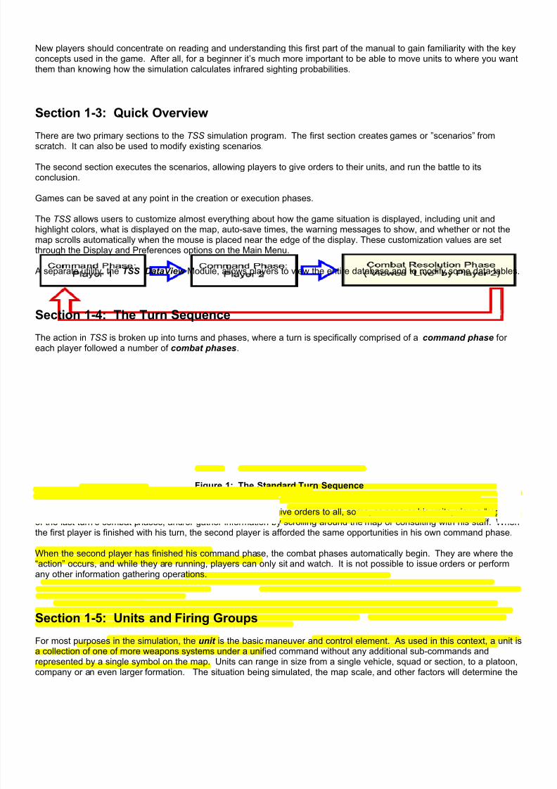
7/21/2019 TSS User Manual
http://slidepdf.com/reader/full/tss-user-manual 16/492
New players should concentrate on reading and understanding this first part of the manual to gain familiarity with the keyconcepts used in the game. After all, for a beginner it’s much more important to be able to move units to where you wantthem than knowing how the simulation calculates infrared sighting probabilities.
Section 1-3: Quick Overview
There are two primary sections to the TSS simulation program. The first section creates games or ”scenarios” fromscratch. It can also be used to modify existing scenarios.
The second section executes the scenarios, allowing players to give orders to their units, and run the battle to itsconclusion.
Games can be saved at any point in the creation or execution phases.
The TSS allows users to customize almost everything about how the game situation is displayed, including unit andhighlight colors, what is displayed on the map, auto-save times, the warning messages to show, and whether or not themap scrolls automatically when the mouse is placed near the edge of the display. These customization values are setthrough the Display and Preferences options on the Main Menu.
A separate utility, the TSS DataView Module, allows players to view the entire database and to modify some data tables.
Section 1-4: The Turn Sequence
The action in TSS is broken up into turns and phases, where a turn is specifically comprised of a command phase foreach player followed a number of combat phases.
Figure 1: The Standard Turn Sequence
During the command phase, a player has the opportunity to give orders to all, some, or none or his units, view a “replay”of the last turn’s combat phases, and/or gather information by scrolling around the map or consulting with his staff. Whenthe first player is finished with his turn, the second player is afforded the same opportunities in his own command phase.
When the second player has finished his command phase, the combat phases automatically begin. They are where the“action” occurs, and while they are running, players can only sit and watch. It is not possible to issue orders or performany other information gathering operations.
Section 1-5: Units and Firing Groups
For most purposes in the simulation, the unit is the basic maneuver and control element. As used in this context, a unit isa collection of one of more weapons systems under a unified command without any additional sub-commands andrepresented by a single symbol on the map. Units can range in size from a single vehicle, squad or section, to a platoon,company or an even larger formation. The situation being simulated, the map scale, and other factors will determine the
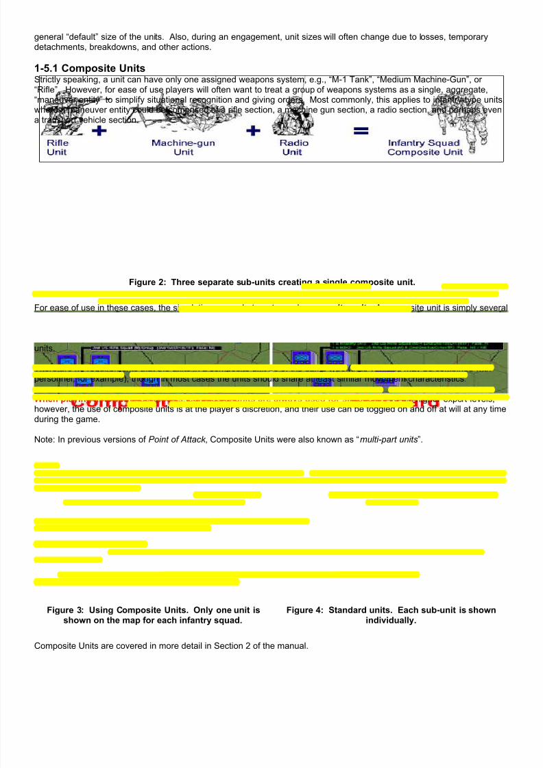
7/21/2019 TSS User Manual
http://slidepdf.com/reader/full/tss-user-manual 17/492
general “default” size of the units. Also, during an engagement, unit sizes will often change due to losses, temporarydetachments, breakdowns, and other actions.
1-5.1 Composite UnitsStrictly speaking, a unit can have only one assigned weapons system, e.g., “M-1 Tank”, “Medium Machine-Gun”, or“Rifle”. However, for ease of use players will often want to treat a group of weapons systems as a single, aggregate,“maneuver entity” to simplify situational recognition and giving orders. Most commonly, this applies to infantry-type units,where a maneuver entity could be comprised of a rifle section, a machine gun section, a radio section, and perhaps evena transport vehicle section.
Figure 2: Three separate sub-units creating a single composite unit.
For ease of use in these cases, the simulation uses what are termed composite units. A composite unit is simply severalunits that are treated as a single entity for display, command, and control purposes (principally movement and targeting).Composite units may be created automatically (using entries in the TO&E table), or by hand during the scenario. In theabove example, for instance, players would see and give orders to the Infantry Squad as a whole, not to the three sub-units.
There are no requirements that the units in a composite unit be of the same type (thus vehicles may be combined withpersonnel, for example), though in most cases the units should share at least similar movement characteristics.
When playing at lower expert levels, composite units are always used for simplicity. At the higher expert levels,however, the use of composite units is at the player’s discretion, and their use can be toggled on and off at will at any timeduring the game.
Note: In previous versions of Point of Attack , Composite Units were also known as “multi-part units”.
Figure 3: Using Composite Units. Only one unit isshown on the map for each infantry squad.
Figure 4: Standard units. Each sub-unit is shownindividually.
Composite Units are covered in more detail in Section 2 of the manual.

7/21/2019 TSS User Manual
http://slidepdf.com/reader/full/tss-user-manual 18/492
1-5.2 Firing GroupsUsing an indivisible unit for maneuver and command purposes is well in line with real world conditions. All of the systemswithin the unit will move to the same location, along the same route, and have the same general orders. However,additional flexibility is required for realistic sighting and target engagement, where a single unit may have systems/peoplefacing in different directions and firing at different targets. To recreate this, the simulation allows for a unit to be brokendown into a number of smaller “firing groups”, each of which may face and sight in a different direction and engage itsown targets.
When used, a unit may be broken down into a maximum of THREE firing groups. Each firing group may contain anynumber of weapons systems, although, obviously, the total number of weapons systems in all the firing groups cannotexceed the unit quantity. Example: A platoon of 4 tanks is broken down into 3 firing groups. Group #1 has 2 tanks andfaces east, Group # 2 has 1 tank and faces northeast, and Group #3 has 1 tank and faces southeast.
Each firing group can engage up to 3 different targets, so long as all those targets are within the firing arc and capability ofthe weapons systems. However, all of the firing systems within the firing group must use the same gun/launcher at thesame target. For example, a firing group of 3 tanks could engage up to 3 different enemy targets using their main gun,hull machine gun, and roof machine gun. However, all 3 tanks would have to fire their main gun at the same target, hullmachine gun at the same target, and so on. One tank couldn’t fire its main gun at one target, while another fired its maingun against something else.
Firing groups can also use multiple weapons to fire at the same target. In the above example, the three tanks could fire
both their main gun and hull machine gun at one target, and their roof machine gun at another.
This system allows a single unit to fire at up to 9 different targets simultaneously (3 firing groups per unit, and 3 targetsper firing group).
1-5.3 Coaxial WeaponsDue to design or situational limitations, in reality it is often not possible for a system to fire all of its weapons at the sametime. As an example, it is very common with armored vehicles that a turret machine gun is mounted “coaxial” with themain gun; the machine gun moves as part of the main gun, and can not be aimed separately, which, given the differentflight characteristics between the machine gun bullet and main gun round, means they can rarely be used at the sametime against the same target. Or, in another case, a tank main gun loader may also be responsible for firing the turretmachine gun. Obviously, he can’t do both at the same time. He’s either loading the main gun, or firing the machine gun.Therefore, only one of these two weapons can fire at a time.
In the simulation, these firing limits are set for each weapons system in the database editor by marking the appropriateweapons as “Coaxial ”. In this case, the term “coaxial” is used in a much broader sense than its strict definition, anddenotes a group of guns/launchers located in the hull or turret of which only one can be fired at a time. The “coaxial” limitis always applied separately to the hull and turret, so firing a “coaxial” hull machine gun wouldn’t prevent the “coaxial”main gun from firing too. Looking at the above example, both the turret machine gun and the main gun should be markedas “coaxial”. This will prevent both of them from firing at the same time. Whether or not the turret roof machine gunshould be marked as “coaxial” depends on the situation. If it could still be fired while either of the other turret weapons isfiring, it should not. If, however, it can’t, it should be flagged as “coaxial”.
Section 1-6: Formations and the Chain of Command
The chain of command is a critical concept in the TSS, and represents the path that orders and reports take betweenHQ’s and their subordinate units. Normally orders travel “down the chain”, that is from higher HQ’s to lower subordinateunits, while reports (SITREPS) travel both up and down the chain.
1-6.1 Headquarters (HQ) UnitsHeadquarters units contain the formation commander (of whatever rank), and any number of ancillary personnel andweapons. A headquarters unit may also be a composite unit (see above), although in this case the “commander” isalways assumed to be with the “first” unit (as given and displayed in the force structure).

7/21/2019 TSS User Manual
http://slidepdf.com/reader/full/tss-user-manual 19/492
1-6.2 Subordinate Units All of the units that report to a particular HQ unit are considered directly subordinate to that HQ. If a directly subordinateunit is also a HQ, any units that report to it are also indirectly subordinate to the first HQ. For example, a platoon isdirectly subordinate to a company HQ, and the company HQ is directly subordinate to the battalion HQ, which means thatthe platoon is indirectly subordinate to the battalion HQ.
Players may detach and assign subordinate units to different headquarters units as desired (known as “task organized”).The only stipulation is that a unit may never be assigned to a headquarters of a lower level (e.g., a company level unit cannot be assigned to a platoon level HQ).
Figure 5: Examples of the Chain of Command and Organizational structures. HQ units are at the top, with theirsubordinate units underneath. Note that the unit types may be different, and that units may be reassigned.
1-6.3 Nominal vs. Acting HQ’s A Nominal HQ is defined as the default or “paper” HQ based on the formation organization chart, before any combatlosses or disruptions have occurred. The Acting HQ , in contrast, is the unit that is actually operating in a specificheadquarters capacity at any given moment, taking into account the present combat situation.
In most cases a formation's Nominal HQ will also be its Acting HQ (and this is always true at the start of a scenario).However, as combat proceeds this can change rapidly as units become unable to “act” as a headquarters. For example,if a Nominal HQ unit has been destroyed, the next unit in the chain of command will take over for it and become the ActingHQ. The replacement HQ functions as a normal headquarters in all ways, although with less efficiency than the NominalHQ. The computer automatically determines the unit that “moves up” to become the replacement Acting HQ, using thestandard military hierarchy and current situation.

7/21/2019 TSS User Manual
http://slidepdf.com/reader/full/tss-user-manual 20/492
The most common reasons that a unit would not be able to perform as a headquarters are that it has been destroyed orhas surrendered, it is in a broken morale state of some type, or it has suffered damage or destruction of itscommunications capabilities.
A unit’s Nominal HQ never changes. If a Nominal HQ that has been “replaced” is once again able to perform itscommand functions, it will re-assume command over its subordinate units as before (as the Acting HQ). Acting HQ’s maybe replaced and restored in this way any number of times, so long as the units themselves are not destroyed. Destroyedunits are gone for good, and cannot perform any game functions.
1-6.4 Command/Report DelaysThe chain of command is vitally important to the accuracy of the simulation, and it is modeled in detail. As in real-life, itis the path by which orders and reports are passed between units. The player, as the Task Force Commander, occupiesthe top “rung” of the chain. Virtually every report he receives will have traveled at least some way “up the chain”, andevery order he gives must be transmitted “down the chain” to the line units that will perform them.
Information transmission though the chain of command is not instantaneous; time is required to transmit between units.This required time is defined as the command delay. The delay depends on the communications capabilities of the unitsin the chain of command, the unit’s condition, the relationship of the units and distances involved, as well as the generalcircumstances.
Therefore, units do not immediately act on orders the player gives them because the orders are not even received by theunit until the command delay has passed. Likewise, the human player will not know what his forward units “see” untilthose reports can be passed up the chain of command, subject to the same command delay.
NOTE: At the start of a scenario the command delay for a force can be set to “instantaneous” transmissions, if desired.
Command and control is covered in more detail in Section 3 of the manual.
Section 1-7: Units Created By Firing A Weapon
When set up properly in the data tables, firing a weapon can create a new unit in thescenario. This allows for the modeling of many real world situations such as an aircraftcarrier catapult launching an aircraft, a ship launching a cruise missile, landing craft exitinga larger transport, an aircraft launching an aerial RPV, or infantry launching a roboticvehicular reconnaissance probe.
This scheme is also used to model guided missiles, rockets, and other sizableprojectiles that normally require more than a few seconds to reach their target or that can be spotted and potentiallyintercepted or disrupted during their transit. For example, most ATGM’s (anti-tank guided missile) require 20 or 30seconds to travel to a target. During that time they may be spotted by the enemy, engaged with high ROF or energyweapon defenses, or suffer some kind of guidance malfunction (such as a broken wire). By turning the missile itself into aunit, all of these potential circumstances can be handled explicitly by the combat models.
In some cases, the units may be limited in their functioning as compared to normal units, as with “fire and forget” long-range missiles. Once they are fired, they are outside the control of the owning player and they are destroyed uponreaching their target. These are known variously as “en-route units”, “temporary units” or “in-flight units”.
Otherwise, the units being created are completely normal. They can sight and report on the enemy, use the force'scommunications grid, be given movement and targeting orders, follow an SOP, and fire weapons of their own. Some ofthese units will also “self-home”, which allows them to follow and home in on a designated target’s location, even if thetarget is moving.
These units are covered in more detail later in the manual.
Section 1-8: Fog of War (FOW)
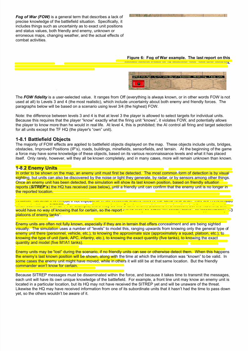
7/21/2019 TSS User Manual
http://slidepdf.com/reader/full/tss-user-manual 21/492
Fog of War (FOW) is a general term that describes a lack ofprecise knowledge of the battlefield situation. Specifically, itincludes things such as uncertainty as to exact unit positionsand status values, both friendly and enemy, unknown orerroneous maps, changing weather, and the actual effects ofcombat activities.
Figure 6: Fog of War example. The last report on this
enemy group came in 16 minutes ago, and was inexact.
In the simulation, the implementation of FOW results in players often receiving incomplete or even incorrect map displays,and other information. The degree of inaccuracy is variable, and depends on many different factors such as the terrainand weather, as well as a force’s various competence levels and reconnaissance efforts and capabilities and simply theamount of time it has spent on the battlefield.
The FOW fidelity is a user-selected value. It ranges from Off (everything is always known, or in other words FOW is notused at all) to Levels 3 and 4 (the most realistic), which include uncertainty about both enemy and friendly forces. Theparagraphs below will be based on a scenario using level 3/4 (the highest) FOW.
Note: the difference between levels 3 and 4 is that at level 3 the player is allowed to select targets for individual units.Because this requires that the player “know” exactly what the firing unit “knows”, it violates FOW, and potentially allowsthe player to know more than he would in real life. At level 4, this is prohibited; the AI control all firing and target selectionfor all units except the TF HQ (the player's “own” unit).
1-8.1 Battlefield ObjectsThe majority of FOW effects are applied to battlefield objects displayed on the map. These objects include units, bridges,obstacles, Improved Positions (IP’s), roads, buildings, minefields, sensorfields, and terrain. At the beginning of the gamea force may have some knowledge of these objects, based on its various reconnaissance levels and what it has placeditself. Only rarely, however, will they all be known completely, and in many cases, more will remain unknown than known.
1-8.2 Enemy UnitsIn order to be shown on the map, an enemy unit must first be detected. The most common form of detection is by visualsighting, but units can also be discovered by the noise or light they generate, by radar, or by sensors among other things.Once an enemy unit has been detected, the simulation will show its last known position, based on friendly situationreports (SITREP’s) the HQ has received (see below), until a friendly unit can confirm that the enemy unit is no longer inthe reported location.
However, because it is difficult if not impossible to tell individual enemy units of the same type apart, they are consolidatedwhen submitting a SITREP. For example, there may be two 5-tank enemy platoons in a location, but the reporting unitwould have no way of knowing that for certain, so the report would likely be either “10 enemy tanks”, or “approximately 2-3platoons of enemy tanks”.
Enemy units are often not fully known, especially if they are in terrain that offers concealment and are being sightedvisually. The simulation uses a number of “levels” to model this, ranging upwards from knowing only the general type ofenemy unit there (personnel, vehicle, etc.), to knowing the approximate size (approximately a squad, platoon, etc.), toknowing the type of unit (tank, APC, infantry, etc.), to knowing the exact quantity (five tanks), to knowing the exactquantity and model (five M1A1 tanks).
Enemy units may be “lost” during the scenario, if no friendly units can see or otherwise detect them. When this happensthe enemy’s last known position will be shown, along with the time at which the information was “known” to be valid. Insome cases the enemy unit might have moved, while in others it will still be at that same location. But the friendlycommander won’t know for certain.
Because SITREP messages must be disseminated within the force, and because it takes time to transmit the messages,each unit will have its own unique knowledge of the battlefield. For example, a front line unit may know an enemy unit islocated in a particular location, but its HQ may not have received the SITREP yet and will be unaware of the threat.Likewise the HQ may have received information from one of its subordinate units that it hasn’t had the time to pass downyet, so the others wouldn’t be aware of it.

7/21/2019 TSS User Manual
http://slidepdf.com/reader/full/tss-user-manual 22/492
1-8.3 Friendly UnitsIn general, friendly units are always known. While this is not entirely realistic, it is something imposed upon the simulationby the necessity of allowing a human player to issue commands to any and all of his subordinate units directly. Inparticular, when a human player selects a subordinate unit, the map needs to be updated for that particular unit’sperspective; otherwise the action would likely be arbitrarily limited and completely unrealistic. For example, it would beunrealistic for a human player to click on a unit to give it explicit targeting orders, without showing on the map what thatunit “knows” and can see (and thus target). Of course, once that line is crossed it is absurd to hide the friendly unit fromthe human player, even though in real life it’s status might be unknown to the overall TF Commander.
However, the simulation does use one facet of friendly FOW , which is that the position of moving units may not be knownexactly. The error in positioning is based on the command delay to the unit, the speed at which it is traveling, and thetime since it’s last precisely known position. The greater any of these values are, the greater the chances for an incorrectdisplay of the unit’s actual position, and the greater the amount of the error. For example, the displayed position of a fastmoving tank unit with a command delay of a minute or more could be 500 meters or more, while that for a infantry unit onfoot with a command delay of 30 seconds will be less than 50 meters.
The FOW level is set at the start of the scenario, or through Main Menu | Preferences | General. Note that when FOW is“locked”, as it is by default in two-player games to prevent cheating, the FOW can not be changed once the game isunderway.
1-8.4 Objects/TerrainMan-made objects (such as Improved Positions, obstacles, minefields, bridges, etc.) are treated in a fashion similar tounits. At the start of the scenario, a player will be aware of all the objects created by his force, along with some of thoseemplaced by the enemy. As the game progresses, unknown objects can be revealed though the normal detectionroutines. With the exception of bridges, objects are either known completely or not at all; unlike units they are not“partially” known. Bridge information, however, such as weight class, damage, and whether or not it is primed for democan be known in varying degrees based on the scenario situation.
Certain types of terrain, particularly buildings and roads, can also be unknown or incorrectly known to a player. Forexample, the player’s map may show open space when, in fact, the location has a building in it. Or, a building may havebeen turned to rubble without the change being reported to the player. In cases such as these, the terrain is treated as anobject, and needs to be detected using the standard sighting routines before it is shown correctly to the player.
The bottom line is to always remember the map shows the best information you have at the time, but its accuracy willdepend on your force’s capabilities, the actions it has taken, and the overall scenario situation and terrain.
1-8.5 SITREP MessagesOnce an enemy unit or object has been detected in some way, the information is disseminated to other units via SITREPreports. These reports are first sent by the detecting unit up to its HQ unit, which then disseminates the information ofother units in the formation. If the detecting unit is a HQ, it will also disseminate the report to its subordinate units.
The transmission of SITREP’s requires an amount of time determined by the force’s communications levels, adjusted forthe sending and receiving units’ capabilities and conditions. Additionally, a unit is limited in the number of reports it cansend concurrently, based on its communications capabilities, so it will take time for information to “percolate” back to youas the TF Commander and throughout the force.
If a unit is interrupted in the middle of sending a SITREP by enemy action or some loss of communications, the messageis also lost and will need to be started from scratch if the communications situation improves.
SITREP’s are sent whenever a unit discovers new information, be it a newly found enemy unit, or an object, or a combatreport. In some cases the unit receiving the SITREP will already know the information, in which case the report isignored. However, it is still sent nevertheless, because the sending unit may not know the higher unit already has theinformation from another source.
Fog of War is covered in more detail later in Section 3 of the manual.
Section 1-9: Play by Email (PbeM)

7/21/2019 TSS User Manual
http://slidepdf.com/reader/full/tss-user-manual 23/492
The TSS is designed to make Play by email (PbeM) easy. All that is required is that players set their passwords whenprompted at the start of the game, and that the second player emails the game file to the first player at the completion ofthe combat phase (select “Save and Exit”).
By default, games are stored in the “Saved Games” folder. However, players can select another location as desired. Thesaved game files will always have (and must have) the extension “.OPS”. Other than that, players may name themanything they like.
If you are starting a PBeM game from scratch, the first player will need to set up the basic scenario information such asthe map to use, starting locations, force nationalities, weather and civilian involvement. Once that has beenaccomplished, the first player will select his force, and assign leaders. At that point, he will save the game and send thefile to his opponent. The second player then selects his force, and proceeds through the steps up to and including placinghis force on the map. At that point, he saves the game, and sends it back to the first player, who sets up his force andissues orders for the first turn. From there the game proceeds as outlined above.
The game files can get relatively large, so the use of a compression program such as WinZip, PKZIP or IZArc is stronglyrecommended, although not required (and some of these utilities are available as “freeware”). Users should note thatstarting with Vista, however, by default Windows treats “.ZIP” files as compressed folders; this can make working withthem very difficult. Users are suggested to either change their Windows settings (not for novices), or use another fileformat (.RAR, .IZA, etc.). One final note on PbeM games is that both players must have the same map and database tables on their computer. Ifyou are using the default maps and table this will not be an issue, but advanced users who create their own maps will
need to insure that their opponent is given a copy before the game begins.
Section 1-10: Definitions/Abbreviations
• Above Ground Level (AGL): The height of an object above the ground.
• Acting Headquarters Unit : The headquarters unit a subordinate currently reports to, taking into account anysubstitutions made necessary from combat actions.
• Acquisition: The amount of time a firing unit has been engaging a specific target with the same weapons (orcoaxial ones).
• Aggressiveness Level : A measure of how “risky” the computer player will be in making decisions (including for aforce owned by a human player). The more aggressive, the more risky, and vice-versa.
• Ambient Illumination : The amount of light in a location from natural sources.
• Ambush: An attack planned to surprise the enemy.
• Ammunition: Any munition fired or launched from a weapons system.
• Anti-Aircraft (AA): Fire from the ground directed at enemy aircraft targets (surface to air).
• Anti-Personnel (AP): Munitions designed to damage personnel targets (i.e., troops).
• Anti-Tank (AT): Munitions designed to damage armored targets (i.e., tanks, APC’s).
• Armor : Any substance used to provide protection against physical projectiles, chemicals, or destructive energyincluding metals, composites, concrete, wood, and earth.
• Armored : A weapons system that includes full all-around protection by more than a trivial amount of armor.
• Armored Fighting Vehicle (AFV): An armed armored vehicle.
• Artificial Intelligence (AI): Computer decision-making ability, used as an aide to a human player, as a small unitleader (for units not under direct control), or as an opponent.
• Avenue of Advance (or Approach): A specific route used by an attacking force.• Airborne Warning and Control System (AWACS): Aircraft specially designed and equipped to detect enemy
units and objects and control friendly responses to them.
• Backblast : The exhaust created by a missile or rocket engine on firing.
• Basic Load : The amount of ammunition normally carried by a fully stocked unit.
• Beginning of Morning Nautical Twilight (BMNT): The time when the sun has risen to a point 12 degrees belowthe horizon. Objects are visible to a distance of about 350 meters.
• Block Points: The percentage degradation in a Line of Sight calculation (100% = 100 blocks points = completelyblocked: the spotter can not see the target visually).
• Breakdown: A mechanical malfunction, either in the movement system (i.e., immobilization), or in a gun/launcher(i.e., jam).

7/21/2019 TSS User Manual
http://slidepdf.com/reader/full/tss-user-manual 24/492
• Buttoned-Up: The condition when a fully armored system closes all of the hatches and openings to providemaximum protection from enemy fire.
• Caliber : The size (diameter) of a projectile. In the TSS calibers are specified in millimeters.
• Calling Unit : The unit actually requesting some sort of support, such as artillery fire or an airstrike.
• Camouflage: Synthetic attempts to disguise weapons and personnel by reducing distinguishing characteristicsand/or to make them appear more like the surrounding terrain.
• Chaff : Physical material, usually metal strips, used to reduce the effectiveness of radar detection and guidancesystems.
• Chain of Command : The unit reporting hierarchy structure. The superior unit is designated as the subordinate
unit’s headquarters. The Task Force HQ is the highest accessible HQ in a player’s force.• Close Air Support (CAS): Aircraft bombing or other missions designed to support nearby friendly ground forces.
• Close Combat : Combat involving personnel at essentially zero range. Also known as “hand to hand” or “melee”.
• Cluster Munition: A munition containing a number of smaller sub-munitions, which is designed to cover wideareas.
• Command Delay : The amount of time it takes for an order to travel down the chain of command to a destinationunit.
• Composite Unit : A construct used by the simulation that groups several individual units with different weaponssystems into a single unit for ease of use. Composite units are commonly used for infantry-type groups, whereseveral different types of sub-units are combined into a single maneuver unit.
• Concealment : Camouflage or other objects present in a location, which make a unit occupying that location hardeto spot (e.g., trees, shrubs, crops, buildings).
• Controlling Unit : The unit adjusting and controlling the flight path of a guided missile/projectile.
• Cover : Objects and other items in a location that provide physical protection from enemy fire (e.g., walls, trees,buildings, berms).
• Cratering : The effect of explosive detonations on or below the ground surface to create craters.
• Directed Energy (DE): Energy of any frequency created or intended primarily to incapacitate, kill or destroy enemyequipment and weapons systems.
• Decoy : A protective measure which confuses guided missiles by creating secondary targets that are perceived bythe guidance system as equally valid as the original.
• Detachment : A portion of a parent unit that is split off and operates independently.
• Direct Fire (DF): Fire that is aimed at a target.
• Direct Fire Targets: Fire control measures that are assigned to individual units in the defense. They are intendedto prevent overlap of fires or zones not covered by fire. Targets are often either primary or secondary based onimportance.
• Direct Support (DS or D/S): Units temporarily assigned to a different HQ for a specific duration or mission.
• Electronic Counter Measures (ECM): Active signals emitted in order to confuse radar detection and guidancesystems.
• Electronic Counter Counter Measures (ECCM): Active filtering and processing equipment used to reduce theeffects of ECM and chaff on degrading radar detection and guidance systems.
• Emplaced : A weapons system is in a configuration that allows it to fire (e.g., a towed gun is unlimbered and setup).
• En-route Unit : A “temporary” unit that is created for munitions that require significant time to reach their targets, orthat can be intercepted or destroyed while en-route. The flag for a munition to create an en-route unit, and whichspecific unit to use is specified in the Ammunition Data Table. Also sometimes known as “In-route” for missiles.
• End of Evening Nautical Twilight (EENT): The time when the sun has fallen to a point 12 degrees below thehorizon. Objects are visible to a distance of about 350 meters.
• Explosive-Formed Penetrator (EFP): A type of mine that uses a dense metal plate as the penetrator, propelledby an explosive charge, to impact the underside of a vehicle.
• Facing : The direction a unit, weapons system, gun, launcher or turret is facing.
• Fatigue: A measure of the physical exhaustion level of a unit, primarily from sleep deprivation and physical activity
• Fire Direction Center (FDC): The central coordinating agency for artillery support on the battlefield. The FDCmanages all pending and in-progress support missions and coordinates IF fire with friendly airstrikes.
• Fire For Effect (FFE): When artillery rounds are fired with the intent of saturating the target as opposed to usingindividual spotting rounds to achieve greater accuracy.
• Firing Arc : The width of the arc, in degrees, through which a weapon or unit in an Improved Position can firewithout requiring to be rotated (Fixed IP’s cannot rotate).
• Firing Group: A portion of a unit that faces in a specific direction and fires at a given target.
• Flank : The areas on either side of the Task Force’s zone of operations. Flank force units are under computercontrol, and may fire on friendly units that stray into the flank and out of the Task Force’s zone.
7/21/2019 TSS User Manual
http://slidepdf.com/reader/full/tss-user-manual 25/492
• Flight Path: The path through space traced by a missile, rocket or un-powered projectile.
• Forward Air Controller (FAC): A friendly unit which calls for and often guides/adjusts friendly airstrikes on groundtargets.
• Geomorphic Map: A single map used for scenario creation and execution that is comprised of two or more smallermaps arranged in some manner to form the final playing area.
• Global Positioning System (GPS): An extremely accurate location system based on orbiting satellites. GPS canbe used by units, as well as guided munitions, but can also be potentially jammed.
• Guided Munition: A munition with the capability of adjusting its course while in flight, using information andcommands from internal and/or external sources.
• Guidance Link : The manner in which a guided munition receives course adjustment commands (e.g., radio,beam, laser, wire).
• Guidance Type: The specific information gathering or guidance method used by a guided munition, either passiveor active (e.g., radar, thermal, optical).
• Gun/Launcher : A component of a weapons system that actually “fires” a munition of some type.
• High Explosive Anti-Tank (HEAT): A warhead type designed specifically to penetrate armor plate by creating a jet of high velocity plasma from an explosive detonation. Also known as “Shaped Charge”.
• High Powered Microwave (HPM): A specific type of energy pulse in the microwave band that can cause damageto a wide variety of electronic systems.
• Headquarters (HQ): The unit in overall command of a formation of subordinate units. The Task Force HQ is thehighest-level unit accessible in the game, and controls all of the units in a player’s force.
• Illumination: Flares and other munitions that produce high levels of synthetic light.
• Improved Position (IP): A man-made protective structure, including an excavation, earthwork or other
construction such as a building, bunker or pillbox.• Incendiary : A munition intended to ignite flammable materials within an area around itself.
• Indirect Fire (IF): Fire that is not directly aimed, and which does not require that the firing unit see the target.
• In-route Unit : See “En-route Unit”, above.
• Infrared (IR): Light in the wavelength just below the visible spectrum in the red direction. IR is emitted by objectsbased on their temperature, and is used to detect objects warmer or colder than their surroundings.
• Interdiction: Missions behind the enemy’s main line intended to disrupt the flow of reinforcements, materials andsupplies forward.
• Internal Unit Friction: A measure of how long it takes a specific unit to react to new commands or situations. Thisis separate from the command delay, which is based on the chain of command.
• Jammer : A device used to disrupt radio or other electromagnetic signals.
• Leader : A specific individual assigned to a unit who affects that’s unit’s performance in various ways, either goodor bad.
• Line of Sight (LOS): A three-dimensional straight-line path that extends from a spotter to a target. It correspondsto the path that would be followed by light. The LOS can be degraded or blocked by the surface of the earth,terrain, smoke and many other things.
• Location: A location is the smallest discrete amount of area, either on-map or off, which can be accessed by thesimulation for any purpose. In board games, as well as most other computer games, it is known as a “hex”. A unitis always assumed to “fit” completely within a location, although the position of its “center of mass” is calculated tothe nearest meter within that location. Terrain, other than linear features, is also considered evenly distributedthroughout a location.
• Marking Unit : A unit that marks a target location in some way, usually though smoke or flares, to help an attackingsupport unit recognize it. Marking, as opposed to “Painting”, merely identifies a general location, not a specificobject target.
• Maneuver Group: A number of related units that can be given general moment, combat, and reaction orders as asingle synchronized group. The AI coordinates and controls the individual units within the group in terms of
movement objectives and the overall group mission. • Maximum Sighting Range: The maximum extent of an LOS under any circumstances. This value is used to
reflect general degradation from atmospheric dust, precipitation, or other similar conditions.
• Mission Oriented Protective Posture (MOPP): A measure of a unit’s level of protection against NBC threats.Generally, the higher the MOPP level, the higher the protection but also the higher the degradation to the unit’sperformance.
• Morale: A measure of a unit’s willingness to accept orders and continue active combat operations in the face of theenemy.
• Multi-Part Unit : See “Composite Unit”, above.
• Non-armored : A weapons system without any appreciable level of armor protection, such as troops.

7/21/2019 TSS User Manual
http://slidepdf.com/reader/full/tss-user-manual 26/492
• Non-Persistent Agent : A chemical agent that disperses quickly after being placed, normally in gaseous or aerosolform.
• Nuclear/Biological/Chemical (NBC): Unconventional warfare and weapons of mass destruction using theseforms of munitions.
• Obstacles: Any man-made construction intended to slow an enemy force though a location. Also known as“Countermobility”.
• Objectives: Locations on or off the map that must be occupied, and if possible, consolidated with units nearby, fora player to successfully complete a mission and achieve victory.
• Off-map: A location off one of the edges of the visible map that can only be accessed through the Off-Map display.
• On-map: A location on the main map playing area. • Opportunity Fire: Direct Fire against a moving enemy unit in a DF Target area. Opportunity Fire occurs at theinstant the enemy unit moves into the target area, instead of during the normal Direct Fire combat phase.
• Overwatch Movement Mode: Movement spacing where a portion of a unit lags behind the lead element toprovide fire support in case the point is ambushed or engaged.
• Paradrop: Delivery from aircraft by parachute of units or supplies.
• Painting Unit : A unit that uses a device (often a laser) to mark specific target objects for guided munitions, whichguide-in on the marked spot.
• Persistent Agent : A chemical agent that does not disperse quickly after being placed, normally in a liquid orpowder form.
• Petalling : A result of an impact on solid armor where the armor is “bent back” on the interior surface away from thepoint of penetration due to internal failure. A good representation of it in common circumstances is pushing a pencithrough a piece of paper or thin cardboard.
• Point Missile Defense System: A defensive measure mounted on a weapons system intended to provide standof(i.e., before it hits) protection against incoming missiles.
• Powered Munition: Any munition that uses appreciable amount of thrust along its flight path so that the course isnot ballistic, such as rockets and missiles.
• Pulse: A segment of a game turn that encompasses a certain amount of simulated combat time.
• Pre-Planned IF Targets (PPD): Locations that are designated as artillery/IF targets in advance of the combatengagement. They can be fired more quickly and accurately that non-preplanned targets, and are often pre-rangedand “test fired” for greater accuracy.
• Rate of Fire (ROF): The number of rounds a weapons system can fire in a given time (usually per minute).
• Recon By Fire (RBF): A technique used to detect hidden enemy units by firing “blindly” into an area to see if theyfire back (and are thus “detected”).
• Reliability : A measure of how often a system breaks down mechanically.
• Road March Mode: A unit configuration in which all weapons systems are on a road, trail, or other linear feature
as opposed to being spread out.• Rubble: Debris created when certain buildings and other objects are destroyed (as set in the TEC).
• Scenario: A single combat action or situation.
• Self-Forming Fragmentation (SFF): A type of “shaped-charge” warhead that uses the Miznay-Shardin explosiveconfiguration effect to create a dense, high velocity molten metal “projectile” from a solid plate. It is most commonlyused in mines, where the charge is directed upwards at the underside of the target vehicle.
• Semi-Armored : A weapons system that is partially armored (as with “open top” vehicles).
• Sensors: Remote devices that are used to detect the presence of enemy forces, usually though sound but alsothough vibration or motion.
• Shaped Charge (SC): See High Explosive Anti-Tank.
• Shift Fire: A control measure used to shift a fire support mission target to a different location. Can be used to“walk” fire across an area.
• Shoot & Scoot : A technique used to minimize enemy exposure when firing by having a unit shoot a few rounds,and then move to a different location nearby.
• SITREP : Situation report. A standard message format used by one unit to send information to another concerningdetected enemy units, objects, or other combat conditions.
• Spall : Flakes of metal that fly off on the interior armor surface from an impact.
• Spotting Fire: A procedure using single rounds, fired one at a time, which insures the target is being hit beforebeginning to Fire For Effect.
• Spotting Unit : A unit that adjusts the accuracy of spotting rounds (see spotting fire).
• Stacking : The maximum number of weapons systems that can occupy a location at the same time.
• Standing Operating Procedures (SOP): Control measures consisting of a set of standard responses or posturesa unit will follow in specified circumstances.
• Standoff : The distance between a firing unit or exploding HEAT warhead and its target.

7/21/2019 TSS User Manual
http://slidepdf.com/reader/full/tss-user-manual 27/492
• Stick : Personnel or equipment delivered by parachute in one pass over the drop zone or in one helicopter lift.
• Suppression: An effect of incoming fire which causes target units to take cover and/or lose concentration of thebattlefield situation.
• Suppression of Enemy Air Defenses (SEAD): Friendly fire directed at known or suspected AA sites near thelocation of an intended airstrike that is intended to provide protection for the attacking aircraft.
• Survivability : The relative amount of damage a weapons system suffers after taking a hit, or engineeringoperations designed to protect friendly forces from enemy fire.
• Table of Organization & Equipment (TO&E): A list of the number and types of weapons systems and personnelthat comprise a full-strength unit and/or formation.
• Tactical Aircraft (TACAIR): Aircraft or air missions used to provide support to friendly ground forces.• Tactical March Mode: A unit configuration in which all weapons systems are spread out within a location, asopposed to being on a linear road or trail.
• Task Force (TF): A group of units organized to complete a mission. In the simulation, each force is under a TaskForce Headquarters, which is where the human or AI commander is located.
• Terrain Effects Chart (TEC): A list of all of the effects terrain features have in the simulation, including movementeffects, LOS blocking, cover and concealment.
• Terrain Fire: A situation where the terrain in a location catches fire, as in the case of dry grass or trees.
• Thermal Sight : An electronic sighting device that uses IR energy to detect objects warmer or colder than theirsurroundings.
• Turn: A game construct used to regulate the segments of orders and combat resolution.
• Victory Points: Relative “point” values given to each weapon system type, as well as for scenario objectives todetermine which player “wins”, and by what level.
• Weapons System: A Weapons System represents a single, indivisible, battlefield entity that can be controlled andgiven orders by the owning player. Examples of Weapons Systems include single tanks, guns, aircraft, missilelaunchers and infantrymen.
• Wreck : Remnants of destroyed vehicles, aircraft and other large objects that can affect movement rates or othersimulation functions.

7/21/2019 TSS User Manual
http://slidepdf.com/reader/full/tss-user-manual 28/492
Part Two: The Interface
Section 2-1: The Main Screen
When a TSS title starts up, by default it will search and load the most current (by creation date) game file it can find inyour game directory. Initially, this should be the tutorial or “Getting Started” game, but as you create and play othergames these will be loaded instead. Toggle this feature on/off using the ”Auto Load Most Current Game Found” settingfrom the Main Menu | Preferences | General box.
Once the game loads, you should see a screen similar to this:
Figure 7: The main screen showing major functional areas/items.
The map/playing area occupies the majority of the screen, with the main menu and command button panel on the top, andthe information panel with force structure (tree) and location information on the right. By using the buttons at the bottomof the information panel, its size can be adjusted using the [<<] and [>>] buttons, or clicking the [ X ] button will remove itentirely.
Select friendly units from this screen in two ways. The first is to click on the unit on map; the second is to select the unitfrom the force tree. When a unit is selected using the force tree, the map will scroll to its location and the unit will behighlighted. If one of the Command Mode buttons is depressed (targeting or movement), the unit will be automatically“opened up” for the appropriate orders to be given.

7/21/2019 TSS User Manual
http://slidepdf.com/reader/full/tss-user-manual 29/492
If the map does not completely fit in the display area, use the scroll bars to move the display in the desired direction. Or, ifthe auto-scroll feature is on (Main Menu | Preferences | Display), move your mouse close to the edge of the map in thedirection you want to go and hold it for a moment.
The currently selected unit or location appears on the map as a hollow colored square. The color of the square can be sefor each zoom level in Main Menu | Preferences | Map Colors as to best show up on the scenario’s map.
2-1.1 The Main Menu
The Main Menu provides information on, and control of, “high-level” (or “force-wide”) game functions and orders. Whilecertain options may allow access to individual units, normally unit actions happen by right/left-clicking on the Force Treewindow or right-clicking the map.
The following section will describe each of the Main Menu choices in general terms; where additional information orinstructions are necessary, specific sections later in the manual will provide further explanation.

7/21/2019 TSS User Manual
http://slidepdf.com/reader/full/tss-user-manual 30/492

7/21/2019 TSS User Manual
http://slidepdf.com/reader/full/tss-user-manual 31/492
After selecting either option, the Scenario Selection Window will be displayed (shown at right). This form provides playerswith information on the available saved game files and allows the selection of one to load and play.
2-1.1.1.2 Saving Games and Scenarios• Save Game: Save the current game without changing the existing current file name and folder (the existing file will
be overwritten).
• Save Game As: Save the current game with the option to change the file name or folder.
• Save Game As Scenario: This option will save the current game as a designated scenario file (as opposed to anormal saved game). Scenarios are covered in more detail in their own section later in the manual.
2-1.1.1.3 Creating New Games (from Scratch)• Create New Game From Scratch: A completely new game will be created, and the player will need to select the
map, conditions, forces, etc. Because new game creation involves a number of steps and forms, it is covered in itsown section later in the manual.
2-1.1.1.4 Batch Runs• Batch Scenario Run: This selection allows users interested in statistical fidelity to automatically execute the same
AI vs. AI scenario a set number of times without any human input required; a user can start a batch, and then walkaway only needing to return after all of the runs have finished to get the results.
The outcome and data for each of the single runs is saved individually, and an aggregate final report is alsogenerated automatically at the end of the batch.
After clicking the Batch Runcommand from Main Menu | File,select the desired savedgame/scenario from the standarddialog box (shown at near right).
Once the saved game file has beenloaded, the AI Settings Form willappear (shown at far right).
Both of these forms are covered inmore detail later in the manual.

7/21/2019 TSS User Manual
http://slidepdf.com/reader/full/tss-user-manual 32/492
The Batch Scenario Runform will then bedisplayed. It allows usersto create multiple “RunGroups”, which will beexecuted non-stop, in “un-attended mode” by the AI.
Run Groups are simply“mini-batches” of individualgame runs that share thesame conditions. Theyallow for changes to beapplied to the originalscenario to evaluate theresult of those changes.
For example, the originalscenario Run Group maytake place during the day,while a second Run Groupcould be instead set to
occur at night.
Figure 8: The Batch Scenario Run Form.
When the form is first displayed, it will contain a single Run Group. This default Run Group has no changes fromthe original scenario (hence “None” is shown in the Modifications List next to it). It is set to run once (the“Iterations” setting), before moving on to the next Run Group or exiting the Batch.
To change the number of times this Run Group should execute the scenario, set theIterations value at the lower right. For example, if you want to run the base scenarioten times before moving on, set the Iterations to 10.
Individual modifications to be made to the selected Run Group are added using thebuttons at the upper right. These changes will be applied to all of the individual runswithin the Run Group. For example, if the Run Group Iterations is set to 10, and the
start time is set to be 1:00 am, then all of those 10 games will start at 1:00 am.
After clicking each button, the appropriate set-up form for that set of values orconditions will appear. Make the desired changes, and then close the formnormally. After closing the form, the modification will be added to the ModificationsList Box for that Run Group.
Multiple modifications may be added to each Run Group. For example, a RunGroup can include a change in the start time, the Fog of War settings, the weather,both Red and Blue start settings and and weapons systems.
With the exception of changing Weapons Systems/Quantities (described below), all of the forms used to makethese modifications are covered in other sections of the manual.
Run Groups are added and deleted using the buttons at the bottom of the RunGroups List Box. There is no limit to the number of Run Groups that can beassigned to a Batch. However, in practice more than about five can proveunwieldy for analysis in spreadsheets.
To delete the selected modification, click the [Remove Modification] button under the Modifications List Box.
To assign a text/name identifier to the Batch (including all Run Groups), usethe Batch Code text box at the bottom of the form. Beside simply acting as anidentifier for single Batches, the Batch Code can act powerful tool in thatmakes it possible for batches of the same scenario to be run on different
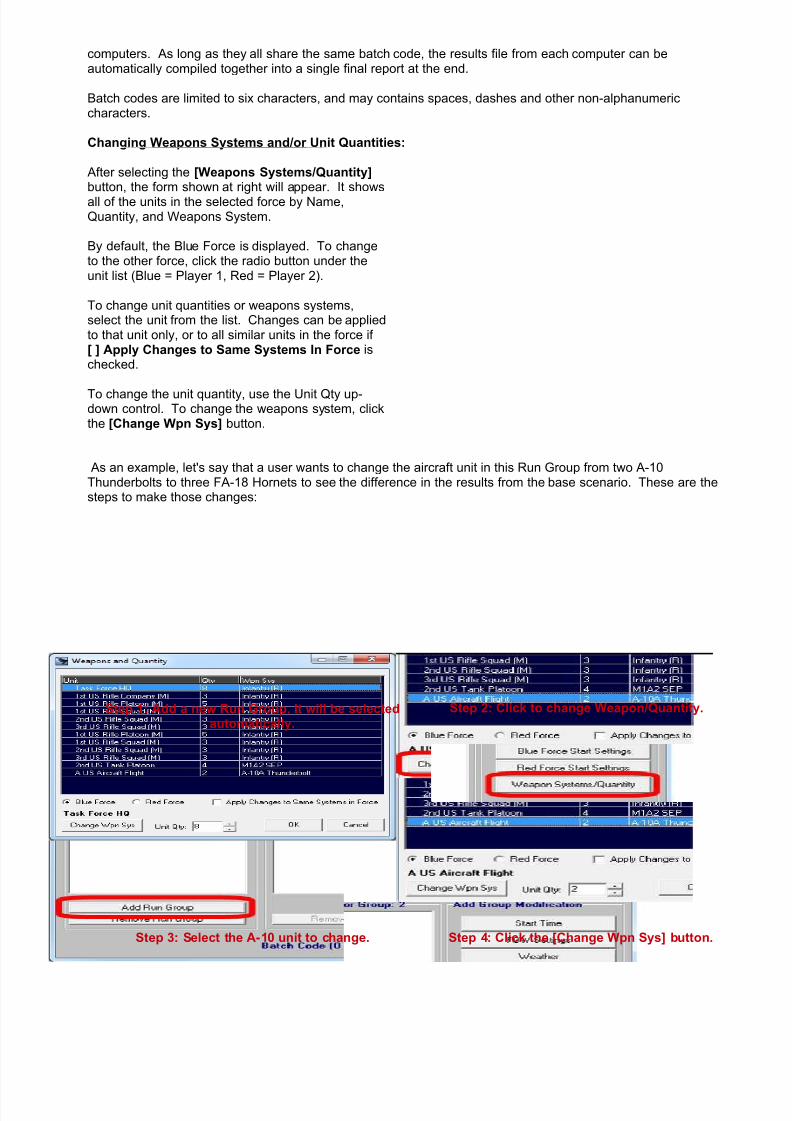
7/21/2019 TSS User Manual
http://slidepdf.com/reader/full/tss-user-manual 33/492
computers. As long as they all share the same batch code, the results file from each computer can beautomatically compiled together into a single final report at the end.
Batch codes are limited to six characters, and may contains spaces, dashes and other non-alphanumericcharacters.
Changing Weapons Systems and/or Unit Quantities:
After selecting the [Weapons Systems/Quantity]button, the form shown at right will appear. It showsall of the units in the selected force by Name,Quantity, and Weapons System.
By default, the Blue Force is displayed. To changeto the other force, click the radio button under theunit list (Blue = Player 1, Red = Player 2).
To change unit quantities or weapons systems,select the unit from the list. Changes can be appliedto that unit only, or to all similar units in the force if[ ] Apply Changes to Same Systems In Force ischecked.
To change the unit quantity, use the Unit Qty up-down control. To change the weapons system, clickthe [Change Wpn Sys] button.
As an example, let's say that a user wants to change the aircraft unit in this Run Group from two A-10Thunderbolts to three FA-18 Hornets to see the difference in the results from the base scenario. These are thesteps to make those changes:
Step 1: Add a new Run Group. It will be selectedautomatically.
Step 2: Click to change Weapon/Quantity.
Step 3: Select the A-10 unit to change. Step 4: Click the [Change Wpn Sys] button.

7/21/2019 TSS User Manual
http://slidepdf.com/reader/full/tss-user-manual 34/492
Step 5: Select the F/A 18 as the new WeaponsSystem for the unit.
Step 6: Adjust the quantity to 3. Note that the unitinfo is updated in the list for the changes.
Step 7: The modifications are shown in the center list box. Continue making modifications to this RunGroup, add more Run Groups, and/or click [OK] when done to save the Batch and begin the runs.
• Resume Batch Run: If a batch run is interrupted at any point (by a program or system crash, power outage, useraction, etc.) this option will allow it to continue running from the pint where it left off. All pertinent information for abatch run is stored in a file with the batch code name (above) and the extension “.BRI”.
2-1.1.1.5 Geomorphic Map Builder
• Geomorphic Map Builder: This menu option will bring up the Geomorphic Map Builder Utility (GB.EXE), whichwill allow the user to create new and edit existing Geomorphic maps that can then be used for scenarios. AGeomorphic map is a single playing map that is comprised of two or more smaller maps arranged to form the finalplaying area. The best examples of Geomorphic maps are found in some of the tactical board wargames, such asPanzer Leader , Panzer Blitz , Arab-Israeli Wars, Squad Leader , and many others. Normally the smaller individualmaps will be “generic” in nature, in that they do not represent any actual area on the Earth or in space. Any existingmaps may be combined together for the final Geomorphic map.
Use of the Geomorphic Map utility will be covered in more detail in Appendix C.

7/21/2019 TSS User Manual
http://slidepdf.com/reader/full/tss-user-manual 35/492
2-1.1.1.6 Other File Commands
• Exit: Exit the program completely. If you have a game loaded, you will be prompted to save it before quitting theprogram.
• <Game Names>: The bottom section of the drop down will list the last game files you have loaded. Clicking onany of the file names will load that game automatically. A maximum of ten files will be shown.
2-1.1.2 Main Menu | Command
2-1.1.2.1 Movement Orders• Set Movement Orders: This command is used to issue specific “location-by-
location” (i.e., “hex-by-hex”) movement orders to one or more units in the samelocation. After selecting this menu item, click on the map or the Force Tree toselect the primary unit to move. Once this unit is selected, the Unit MovementCommands Form will be displayed.
The use of this form in issuing orders is covered later in the manual, but it allows foradditional co-located units to be selected as well as for adding and editing a unit'scurrent movement commands.
Units may be given generalized movement orders though the Maneuver Group orders option, which is covered later in themanual. Maneuver Group orders, however, are not “location-by-location”. Instead they are “objective based”, and the AIdecides the specifics (the location-by-location” path) of how the units gets there.

7/21/2019 TSS User Manual
http://slidepdf.com/reader/full/tss-user-manual 36/492
2-1.1.2.2 Targeting• Target with Direct Fire: This option is
TARGET LOCATION-BASED; the location isselected from the map first, and then the AIshows what units can target that location.
After selecting this command, select (left-click)on the target location on the map. The targetcan be an enemy unit, an object of some type
(IP, bridge, obstacle, etc.) or the location itself(recon by fire against possible but unknownenemy units).
After selecting the location, the Set Direct FireForm will appear. This form allows for theselection of the individual firing unit, the exacttarget in the location (if there is more than one),as well as the ammunition and ROF (rate offire) to be used for the firing.
Direct Fire (DF) requires that the firing unit have a valid LOS to the target, i.e., it must be sighted in some manner. Additional information and specific instructions on using the form and setting DF targets is covered later in themanual.
• Target with Indirect Fire: This option is alsoTARGET LOCATION-BASED; the location isselected from the map first, and then the AIshows what units can target it.
This option is enabled only if the current forcecontains at least one unit that is capable ofindirect fire (fire that is not aimed, e.g.,artillery). Otherwise, it will appear “grayed-out”on the menu, and can not be selected.
After selecting this command, select (left-click)
on the desired target location on the map. Thetarget can be an enemy unit, an object of sometype (IP, bridge, obstacle, etc.) or the locationitself (recon by fire against possible butunknown enemy units).
After selecting the location, the Artillery/FireSupport Mission Form will appear. This formallows for the selection of the individual firingunit, the exact target in the location (if there ismore than one), plus other missioncharacteristics including the spotting unit,calling unit, ammunition/ROF, impact area,
shift, and a number of other values.
Indirect Fire (IF) does not require the firing unit to have a valid LOS to the target, i.e., it does not need to be visibleor sighted. However, there must be a valid flight path between the firing unit and the target based on theammunition selected to fire. Additional information and specific instructions on using the form and setting IF targetsis covered later in the manual.
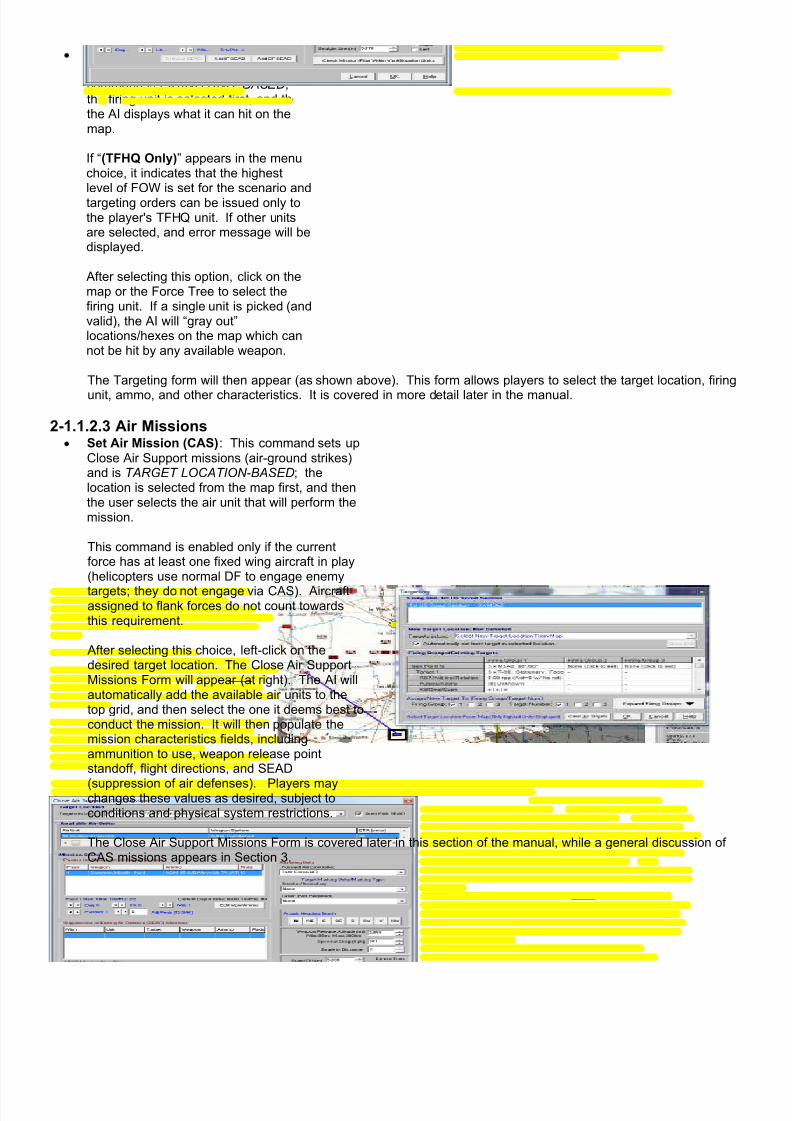
7/21/2019 TSS User Manual
http://slidepdf.com/reader/full/tss-user-manual 37/492
• Set Targeting Orders: Unlike theprevious targeting options, thiscommand is FIRING UNIT-BASED;the firing unit is selected first, and thenthe AI displays what it can hit on themap.
If “(TFHQ Only)” appears in the menuchoice, it indicates that the highestlevel of FOW is set for the scenario andtargeting orders can be issued only tothe player's TFHQ unit. If other unitsare selected, and error message will bedisplayed.
After selecting this option, click on themap or the Force Tree to select thefiring unit. If a single unit is picked (andvalid), the AI will “gray out”locations/hexes on the map which cannot be hit by any available weapon.
The Targeting form will then appear (as shown above). This form allows players to select the target location, firing
unit, ammo, and other characteristics. It is covered in more detail later in the manual.
2-1.1.2.3 Air Missions• Set Air Mission (CAS): This command sets up
Close Air Support missions (air-ground strikes)and is TARGET LOCATION-BASED; thelocation is selected from the map first, and thenthe user selects the air unit that will perform themission.
This command is enabled only if the currentforce has at least one fixed wing aircraft in play(helicopters use normal DF to engage enemy
targets; they do not engage via CAS). Aircraftassigned to flank forces do not count towardsthis requirement.
After selecting this choice, left-click on thedesired target location. The Close Air SupportMissions Form will appear (at right). The AI willautomatically add the available air units to thetop grid, and then select the one it deems best toconduct the mission. It will then populate themission characteristics fields, includingammunition to use, weapon release pointstandoff, flight directions, and SEAD
(suppression of air defenses). Players maychanges these values as desired, subject toconditions and physical system restrictions.
The Close Air Support Missions Form is covered later in this section of the manual, while a general discussion ofCAS missions appears in Section 3.

7/21/2019 TSS User Manual
http://slidepdf.com/reader/full/tss-user-manual 38/492
• Set Air Drop: This option is used to set upparachute air drops of combat units. It isenabled only if the current force has at least oneaircraft with loaded passengers in play (forflexibility, it does not check if those passengersare airdrop-capable, however).
After selecting the option, the Air Drops Form willappear. From it, users can set the aircraftparticipating in the drop, the drop zone location,the number and characteristics of each droppass, the aircraft's return/on-call position afterthe drop, and all of the other aspects of the dropoperation.
The Air Drops Form is covered later in this section ofthe manual, while a general discussion ofparadrop missions appears in Section 3.
2-1.1.2.4 Turn/Auto-Run Game• Turn Complete: Click this choice to end the current orders phase and advance the turn to the next
player's orders phase, or to the combat phase. Selecting this option is the same as clicking the“Advance Turn” button (see below).
• Turn Complete Auto-Advance: These options allow players to run through multiple turns without stopping. Theyare enabled only in one-player games (i.e., Human vs. AI). When selected, these menu choices override theexisting auto-advance settings (which are set in the Main Menu | Preferences form). When games are run in auto-advance mode, they execute without pause or an orders phase until the end condition is met. While neither playerwill be able to issue orders, the AI will still issue targets normally each turn. Auto-advancing always ends after thelast game turn is executed.
◦ Advance Until Contact: The game will run without a pause until some form of firing occurs (DF, IF, CAS, etc.)
◦ Advance 5 Turns: The AI will run five combat turns in a row, and then return to the human orders phase.
◦ Run to end of Game: Execution will not stop until after the last specified game turn is executed. The endgame turn is set at the start of the game/scenario.
2-1.1.2.5 End Scenario• End Scenario: Selecting this option will end the scenario immediately, even if the end game turn has not been
reached, and bring up the Game Results Form (Victory Conditions). After viewing this form, the game can not bedirectly continued; to run additional turns the file must be reloaded.
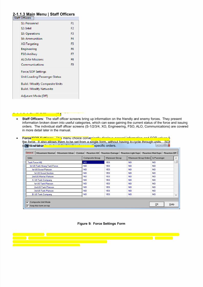
7/21/2019 TSS User Manual
http://slidepdf.com/reader/full/tss-user-manual 39/492
2-1.1.3 Main Menu | Staff Officers
2-1.1.3.1 Staff Officers (S1, S2, etc.)• Staff Officers: The staff officer screens bring up information on the friendly and enemy forces. They present
information broken down into useful categories, which can ease gaining the current status of the force and issuingorders. The individual staff officer screens (S-1/2/3/4, XO, Engineering, FSO, ALO, Communications) are coveredin more detail later in the manual.
• Force/SOP Settings: This menu choice conveniently displays general information and SOP values for all units inthe force. It also allows them to be set from a single form, without having to cycle through units. SOP orderscontrol what units do by default in the absence of specific orders.
Figure 9: Force Settings Form
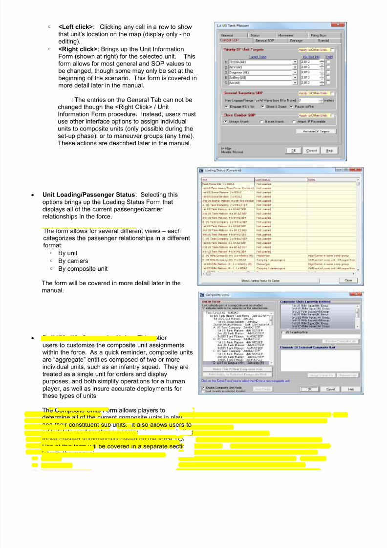
7/21/2019 TSS User Manual
http://slidepdf.com/reader/full/tss-user-manual 40/492
◦ <Left click>: Clicking any cell in a row to showthat unit's location on the map (display only - noediting).
◦ <Right click>: Brings up the Unit InformationForm (shown at right) for the selected unit. Thisform allows for most general and SOP values tobe changed, though some may only be set at thebeginning of the scenario. This form is covered inmore detail later in the manual.
Note: The entries on the General Tab can not bechanged though the <Right Click> / UnitInformation Form procedure. Instead, users mustuse other interface options to assign individualunits to composite units (only possible during theset-up phase), or to maneuver groups (any time).These actions are described later in the manual.
• Unit Loading/Passenger Status: Selecting thisoptions brings up the Loading Status Form thatdisplays all of the current passenger/carrierrelationships in the force.
The form allows for several different views – eachcategorizes the passenger relationships in a differentformat:
◦ By unit
◦ By carriers
◦ By composite unit
The form will be covered in more detail later in the
manual.
• Build/Modify Composite Units: This option allowsusers to customize the composite unit assignmentswithin the force. As a quick reminder, composite unitsare “aggregate” entities composed of two or moreindividual units, such as an infantry squad. They aretreated as a single unit for orders and display
purposes, and both simplify operations for a humanplayer, as well as insure accurate deployments forthese types of units.
The Composite Units Form allows players todetermine all of the current composite units in play,and their constituent sub-units. It also allows users toedit, delete, and create new composite units, includingthose created automatically based on the force TO&E.Use of this form will be covered in a separate sectionlater in the manual.

7/21/2019 TSS User Manual
http://slidepdf.com/reader/full/tss-user-manual 41/492
• Build / Modify Networks: Networks are dedicateddigital communications channels between units thatallow them to share information and resources. Theyoperate in the same fashion as computer LAN's,Intranets, and even the Internet/World Wide Web.Most commonly within the simulation they areradio/wireless, but this is not a restriction; networkscan use wire, fiber optics, or other formats for signaltransfer.
In order to join a network, a unit must possesscommunications equipment that is network-capable.This is defined in the Communications System DataTable. In addition, the equipment must be compatiblewith the other units in the network, in terms of bothhardware and software/protocol.
The Networks Form is covered in more detail later inthe manual.
• Adjutant Mode: If desired, the AI can act as a human player's assistant. In this mode, the AI will automaticallyperform many of the more advanced types of tasks, freeing the player from the effort and complications. To togglethe mode On/Off, click the menu item.
When enabled, the Adjutant will perform the following tasks:
◦ Direct Fire Targeting: The AI makes all determinations on actual targets and ammunition to fire. Userssimply select the firing unit and the target location. The normal Targeting Form never appears. NOTE:Instructions for what the program expects you to do next appear at the bottom of the Main Form.
◦ Indirect Fire Targeting: Essentially the same as DF, above, and the IF Targeting form will not appear. Userssimply select the target location, and the AI determines which unit will fire, what the target will be, what type ofammunition will be fired and with how many rounds, as well as all of the other mission parameters (callingunit, painting unit, priority, adjustments, etc.). If no unit can fire, a message will be shown.
◦ Close Air Support (CAS): As with DF and IF, users can only select the location of the target on the map. The AI will select the aircraft unit to perform the mission, decide what ammunition to use, and set all other missionparameters, including allocating SEAD (suppression of enemy air defenses).
2-1.1.4 Main Menu | Maneuver Groups/Recon
2-1.1.4.1 Set/Adjust Maneuver GroupsManeuver Groups allow players to give formations general, mission-based, orders. The AI then takes over, and, acting asthe group commander, it issues detailed and specific orders to the individual units in the group to accomplish theobjectives. This general concept is known as semi-autonomous command/AI.
For example, instead of issuing specific orders to each of the platoons in a infantry company, the human player can issueorders to the company as a whole to move to an general objective, pause to call for artillery and to provide “softening-up”fire, and then to finally unload the foot troops who then move on to the final objective as the assault unfolds.
Maneuver groups are extremely powerful and provide the following benefits:
• They simplify and speed-up the orders process : Orders for complicated operations plans can be given quickly, andto a formation instead of individual units.
• They help keep a player's plans coordinated : In giving fewer commands, and giving them at the same time, it'seasier for players to fulfill their maneuver plan by avoiding mistakes in moving units.

7/21/2019 TSS User Manual
http://slidepdf.com/reader/full/tss-user-manual 42/492
• They are extremely flexible : Players are afforded command options that are difficult to implement using the detailedindividual-unit orders process.
• They are more effective : As the situation changes the AI will automatically adjust its plans accordingly to achievethe objectives based on the latest intelligence.
• They eliminate “micro-management” : Since the AI handles all of the specifics, the player does not have to micro-manage the operation in detail; he is free to concentrate on higher-level considerations.
• They are realistic : Maneuver Group orders more closely model the player acting as the force commander asopposed to a small-unit leader.
To issue, view, or change Maneuver Group orders, click the“Set/Adjust Maneuver Group Orders” menu choice. TheManeuver Groups Form will pop up (shown at right).
This form is used to define the individual maneuver groups(which are always a normal formation), display their existingobjectives, and to edit/issue those objective orders.
The specifics of issuing orders to Maneuver Groups arecovered in more detail later in the manual.
Note: Due to their significant advantages, players arestrongly encouraged to use Maneuver Groups wheneverfeasible.
2-1.1.4.2 Set/Adjust Recon AssignmentsReconnaissance Assignments are similar to Maneuver Groups, in that the AI assumes control of the units to achievereconnaissance-type missions. Compared to Maneuver Group orders, Reconnaissance Assignments are much morelimited in their scope, and are only applicable to certain types of units, specifically those that:
• Have a Weapons System designated in the Data Table as a Reconnaissance type, e.g., "Recon: Armrd VehHeavy", or “Aircraft: Recon”.
• Have a Weapons Systems designated in the Data Table as an RPV (remotely piloted/controlled vehicle).
• Possess a radiation detection device (operational or not).
In addition, the unit can not be a passenger (it must be unloaded first). The unit can, however, be a reinforcement thathas not yet arrived.
Reconnaissance Assignments have three basic steps, where each step is handled automatically by the AI:
1. Move to a defined area.2. Search the area until a specified “level of quality” is reached.3. Move to the next area in the progression and repeat until all areas have been searched.

7/21/2019 TSS User Manual
http://slidepdf.com/reader/full/tss-user-manual 43/492
After selecting this option, the Recon Assignments form will appear, as shownat right. This form shows all of thecurrent units with Recon Assignments,and general information about thoseorders.
It also allows for editing existing orders,as well as selecting new units for reconassignments.
As stated previously, only units withweapons systems defined as a“Reconnaissance” type (in the WeaponsSystems Data Table), or those withradiological detectors are eligible to begiven recon assignments.
This form is covered in more detail in itsown section later in the manual.

7/21/2019 TSS User Manual
http://slidepdf.com/reader/full/tss-user-manual 44/492
2-1.1.5 Main Menu | Display
Because it is often difficult to discern information at a glance from topographical or other 2 dimensional maps, the TSShas a wide range of display toggles to enhance or limit the information shown. These toggles are set from Main Menu |Display.
Many of these display toggles have associated “Hot Keys”, which are shown on the drop-down menus, e.g., “Ctrl+G”. Afull list of hot keys is included at the end of this section.
Depending on what version of Aide De Camp (ADC) was used to create the map (either ADC-2 or ADC-3), some of theoptions may be “grayed-out” and unavailable. The options which are only applicable to one map version or the other willbe noted in the discussion sections below. However, it is important to note that aside from the concrete versiondifferences, what options are available will also depend on how the map was created. For example, if a map creatordidn’t specify a hex overlay symbol for an ADC-2 map, it will not be possible to select one for display within the simulation.

7/21/2019 TSS User Manual
http://slidepdf.com/reader/full/tss-user-manual 45/492
Likewise, if an “Overlay” layer was not created as part of an ADC-3 map, it will not be possible for a user to display thehex grid pattern.
The available display options are:
• Toggle Grid: (ADC-2 Maps Only) If the map was built in ADC-2 and also has a specified grid overlay symbol (eitherhexagonal or square) this option will be available. Toggling it will cause the grid overlay pattern to be displayed ornot. Each grid represents a single location.
• Toggle Elevation Shading: if the map was created using the default symbol set, this option will “shade” the maplocations based on their relative elevations (divided up into “levels” 1-20).
The effects of these two toggles appear as shown (Left: both off; Right: both on):
Figure 10: Map samples showing grid and elevation shading on (right), and off (left) with an ADC-2 map. Theoptions can be toggled separately from each other, but some maps may not have them available. These
options are not available for maps created with ADC-3.
• Toggle Force Tree/Info Panel: This option will open and close the right hand Information panel, which includes theForce Tree display.
The panel can also be re-sized using the lower left corner buttons (red highlight on the examples below):
[ << ]: Enlarge the panel by 50 pixels[ >> ]: Shrink the panel by 50 pixels[ X ]: Close the panel
[ -> ]: Re-open the panel (when completely closed).

7/21/2019 TSS User Manual
http://slidepdf.com/reader/full/tss-user-manual 46/492
Figure 11: Info Panel - open (right) and closed (left), showing re-sizing buttons.
• Toggle Off-Map Area Display: opens or closes the Off-map Display. Off-map areas surround all playing maps, and
represent additional space in which units can move, engage in combat, and perform other general operational tasks.However, some activities and objects are ignored or prohibited in off-map areas including ground elevation, terrain,and some engineering operations.
• Toggle Combat Report Display: opens or closes the Combat Reporting window. The window shows the results of
the last turn’s combat phase.
Figure 12: The Combat Reporting Window.
• Bring Current Location Info to Top: this command will bring the Current Location Information window to the top ofall other forms, opening it if necessary.

7/21/2019 TSS User Manual
http://slidepdf.com/reader/full/tss-user-manual 47/492
Figure 13: The Current Location Information window.
• Show Units / Unit Display: These settings control if the unit symbols are shown on the map, and if so, what symbolformat to use if multiple types (known as “Views”) have been defined. For example, the symbol type/view could be“Default”, or “NATO”, as shown here:
Figure 14: “Default” Symbol View. Figure 15: “NATO” Symbol View.
NOTE: Symbol Views are defined using the ADC Symbol Editor program, which is separate from the TSSprogram. Not all games contain multiple symbol views, and the available Views may differ between titles.
• Show Terrain / Smoke / Mines / Improved Positions / DF TRP’s / IF PPD Tgts / Engr Ops / Victory Locations /Map Notes / Land Communications Lines: These toggles turn the map symbols on and off for the object typespecified. Each of these object types will be covered in greater detail later in the manual.
Maps created in ADC-3 allow for greater display flexibility of map objects than those shown above. This adaptabilitystems from the fact that ADC-3 maps are based on “layers”, which group together symbols of a similar type allowing themto be turned on/off together. In addition, map makers may create and name the layers as desired or needed for specific
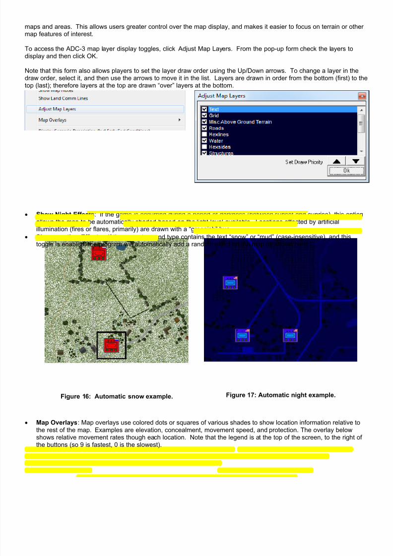
7/21/2019 TSS User Manual
http://slidepdf.com/reader/full/tss-user-manual 48/492
maps and areas. This allows users greater control over the map display, and makes it easier to focus on terrain or othermap features of interest.
To access the ADC-3 map layer display toggles, click Adjust Map Layers. From the pop-up form check the layers todisplay and then click OK.
Note that this form also allows players to set the layer draw order using the Up/Down arrows. To change a layer in thedraw order, select it, and then use the arrows to move it in the list. Layers are drawn in order from the bottom (first) to thetop (last); therefore layers at the top are drawn “over” layers at the bottom.
• Show Night Effects: If the game is occurring during a period of darkness (between sunset and sunrise), this optionallows the map to be automatically shaded based on the light level available. Locations affected by artificialillumination (fires or flares, primarily) are drawn with a “greenish” hue.
• Show weather Effects: If the current ground type contains the text “snow” or “mud” (case-insensitive), and thistoggle is enabled, the program will automatically add a random effect on the map as shown here:
Figure 16: Automatic snow example. Figure 17: Automatic night example.
• Map Overlays: Map overlays use colored dots or squares of various shades to show location information relative tothe rest of the map. Examples are elevation, concealment, movement speed, and protection. The overlay belowshows relative movement rates though each location. Note that the legend is at the top of the screen, to the right ofthe buttons (so 9 is fastest, 0 is the slowest).

7/21/2019 TSS User Manual
http://slidepdf.com/reader/full/tss-user-manual 49/492
Figure 18: Sample map overlay (speed). Note that the roads are marked as the fastest (9), while thewoods are the slowest (2).
The overlay toggles can also be accessed from the floating Location Information form, discussed below.
The size of the dots can be adjusted from Main Menu | Preferences | Display Tab for each zoom level.
• Scenario Description displays whatever text description accompanies the game. Normally this would include theplayer’s OPORDER (mission), and any notes the scenario designer wanted to add.
Figure 19: The mission statement (OPORD) for the current scenario (as entered by the designer). Some mayhave maps and other graphics included with them (click the upper right corner icon to see full-size).

7/21/2019 TSS User Manual
http://slidepdf.com/reader/full/tss-user-manual 50/492
• Display PBeM Messaging/Scenario Notes: this will display the PBeM Message form, which shows any notes or
comments added by the opposing player during his turn. While the form is visible, the active player can addcomments of his own, which will likewise be read by the opposing player during his next orders phase. Note:comments are never deleted automatically - they must be deleted manually, if desired.
Figure 20: PBeM Message form. This form transmits messages from one player to another during the game,often including taunts, laments, and general disrespect.
2-1.1.6 Main Menu | PreferencesPreferences allow users to customize many aspects of the program, including unit colors, AI fidelity, game displays, Fogof War and many other options. Selecting this option brings up the Preferences Form, which will be covered in moredetail later in the manual.

7/21/2019 TSS User Manual
http://slidepdf.com/reader/full/tss-user-manual 51/492
Figure 21: The Preferences Form (Example)
2-1.1.7 Main Menu | Map Areas/Events
Map Areas and Events are powerful tools that are used for both force control, and to allow for flexibility in scenario designand flow. Normally, they are defined either as part of the scenario creation process, or in the Set-up Phase. However,both options are available during the game.
2-1.1.7.1 Map AreasMap Areas are zones (or single/multiple specific locations), that are used for various force control purposes. Specifically,they are used for Maneuver Group objectives (covered previously), Reconnaissance Assignment search areas (coveredpreviously), and also possibly in Trigger definitions as part of Events (see below). They can also be used for“housekeeping” purposes, to assist players in defining areas of particular significance.
To add or edit Map Areas,select this menu option.The Map Areas Form willappear, and any definedareas will be shown on themap.
This form is covered in more detailed later in the manual, butit allows players to create, edit, and delete map areas. Mapareas may be designated using three methods:
Circular areas based on a central anchor locationand radius.
Rectangular areas defined by selecting the corner
locations. Lists of one or more individual locations selected
individually.
The areas may also be given specific names, colors, anddisplay “fill” patterns, as shown in the example above.

7/21/2019 TSS User Manual
http://slidepdf.com/reader/full/tss-user-manual 52/492
2-1.1.7.2 EventsSimply put, events are powerful options that allow players to set up situations where, “If a Trigger occurs, then a Reactionhappens as a response”. For example, if, “an enemy unit is observed in this area” (the Trigger), then “release the reactionforce” (the Reaction).
Clicking this menu option will bring upthe Events Form as shown at right.This form allows players to define new
Triggers and Reactions, and to usethem to create Events.
It is also used to edit or delete existingevents, or to check what triggers and/orreactions have already occurred.
Events and the use of this form arecovered in more detail later in themanual.
2-1.1.8 Main Menu | Reports
The Reports options allow players to get detailed information about the scenario results/play so far, as well as to check /verify terrain effects. To preserve Fog of War, not all of the options are available in two-player games; the reportsthemselves are 100% accurate – they completely ignore FOW restrictions.
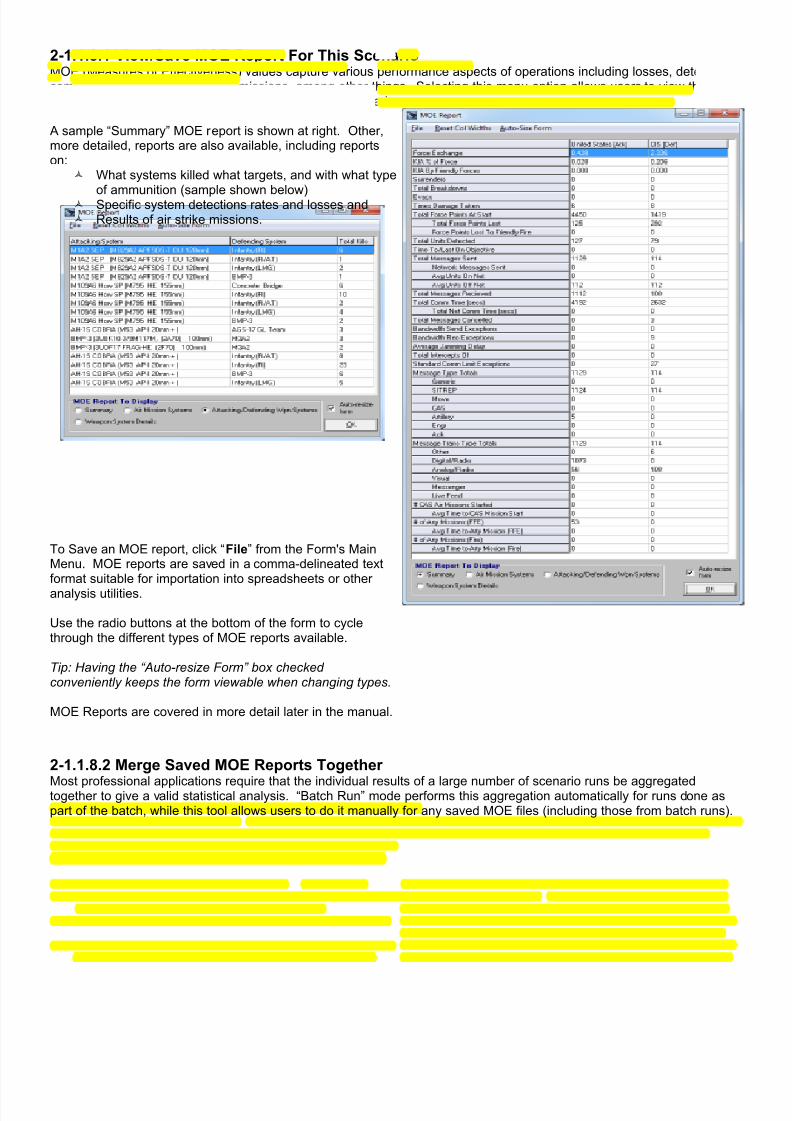
7/21/2019 TSS User Manual
http://slidepdf.com/reader/full/tss-user-manual 53/492
2-1.1.8.1 View/Save MOE Report For This ScenarioMOE (Measures of Effectiveness) values capture various performance aspects of operations including losses, detections,communications, and supporting missions, among other things. Selecting this menu option allows users to view theexisting MOE statistics up to the current point in the scenario.
A sample “Summary” MOE report is shown at right. Other,more detailed, reports are also available, including reportson:
What systems killed what targets, and with what type
of ammunition (sample shown below) Specific system detections rates and losses and Results of air strike missions.
To Save an MOE report, click “File” from the Form's MainMenu. MOE reports are saved in a comma-delineated textformat suitable for importation into spreadsheets or other
analysis utilities.
Use the radio buttons at the bottom of the form to cyclethrough the different types of MOE reports available.
Tip: Having the “Auto-resize Form” box checkedconveniently keeps the form viewable when changing types.
MOE Reports are covered in more detail later in the manual.
2-1.1.8.2 Merge Saved MOE Reports Together
Most professional applications require that the individual results of a large number of scenario runs be aggregatedtogether to give a valid statistical analysis. “Batch Run” mode performs this aggregation automatically for runs done aspart of the batch, while this tool allows users to do it manually for any saved MOE files (including those from batch runs).

7/21/2019 TSS User Manual
http://slidepdf.com/reader/full/tss-user-manual 54/492
Select this menu option to bring up the MOE Report MergerForm.
Use the [Add...] button below the left-hand box to select/addsaved MOE files to the merge list. As files are selected, theircontents will be displayed in the blue text box on the right.
To merge the reports, click [Merge Now]. The results will beshown in the blue text box. To save the merged compilation,click [Save Merged Report].
Merge files are saved in the same standard comma-delineated format as normal MOE files.
MOE Reports are covered in more detail in the own section,later in the manual.
2-1.1.9 Main Menu | Sandbox
The Sandbox is a very powerful tool that allowsusers to directly get base sighting, accuracy,damage, and other model results explicitly,without having to run through an actual combatphase or even to have “real” units in play.Utilities such as this are sometimes called“combat calculators”, in that they allow directaccess to the models and afford users theability to change parameters and conditions
and see the results.
Due to the complexity of the form, it is coveredin greater detail in its own section later in themanual.
There are two ways to access the form, either using “real” units, or by starting with something completely hypothetical.
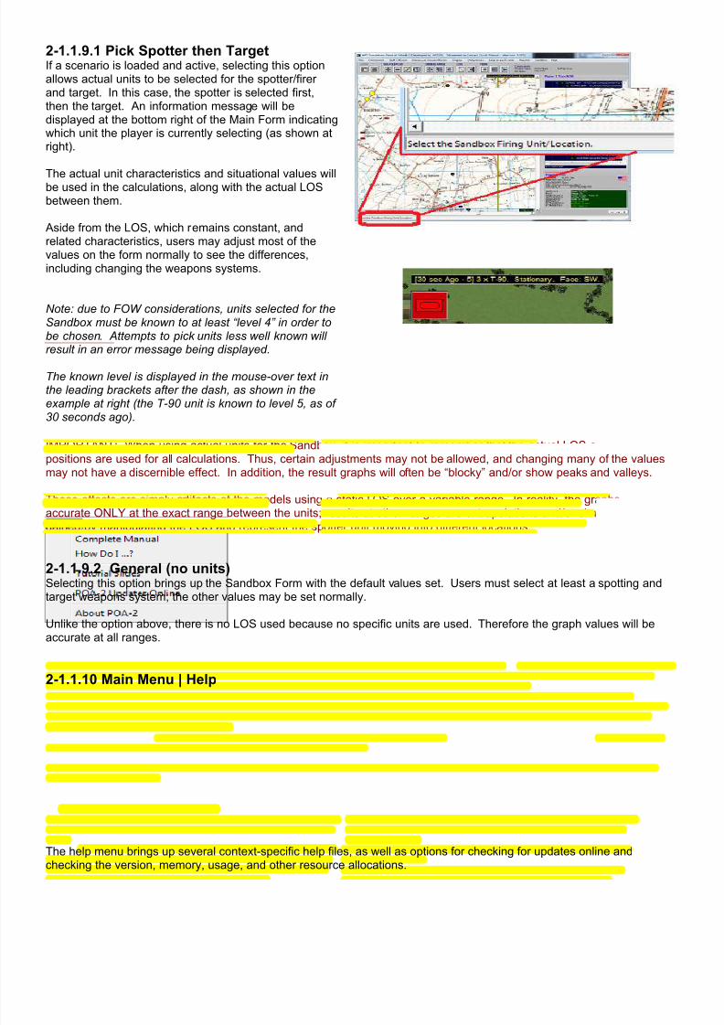
7/21/2019 TSS User Manual
http://slidepdf.com/reader/full/tss-user-manual 55/492
2-1.1.9.1 Pick Spotter then TargetIf a scenario is loaded and active, selecting this optionallows actual units to be selected for the spotter/firerand target. In this case, the spotter is selected first,then the target. An information message will bedisplayed at the bottom right of the Main Form indicatingwhich unit the player is currently selecting (as shown atright).
The actual unit characteristics and situational values willbe used in the calculations, along with the actual LOSbetween them.
Aside from the LOS, which remains constant, andrelated characteristics, users may adjust most of thevalues on the form normally to see the differences,including changing the weapons systems.
Note: due to FOW considerations, units selected for theSandbox must be known to at least “level 4” in order tobe chosen. Attempts to pick units less well known willresult in an error message being displayed.
The known level is displayed in the mouse-over text inthe leading brackets after the dash, as shown in theexample at right (the T-90 unit is known to level 5, as of30 seconds ago).
IMPORTANT: When using actual units for the Sandbox, it is important to remember that the actual LOS and unitpositions are used for all calculations. Thus, certain adjustments may not be allowed, and changing many of the valuesmay not have a discernible effect. In addition, the result graphs will often be “blocky” and/or show peaks and valleys.
These effects are simply artifacts of the models using a static LOS over a variable range. In reality, the graphs are 100%accurate ONLY at the exact range between the units; results at other ranges are extrapolations and/or simplificationsgained by manipulating the LOS and represent the spotter unit moving into different locations.
2-1.1.9.2 General (no units)Selecting this option brings up the Sandbox Form with the default values set. Users must select at least a spotting andtarget weapons system; the other values may be set normally.
Unlike the option above, there is no LOS used because no specific units are used. Therefore the graph values will beaccurate at all ranges.
2-1.1.10 Main Menu | Help
The help menu brings up several context-specific help files, as well as options for checking for updates online andchecking the version, memory, usage, and other resource allocations.

7/21/2019 TSS User Manual
http://slidepdf.com/reader/full/tss-user-manual 56/492
2-1.1.10.1 Complete ManualSelecting this option displays this manual in the system's default HTML/web browser window. The manual is local to theuser's computer; no internet access is required to view it.
Other formats (besides HTML) may be available. Please contact HPS Simulations for more information.
2-1.1.10.2 How Do I...?This option brings up specific, step-by-step instructions on how to perform common operations. For example:
How Do I Move Units? How Do I Load Passenger Units? How Do I Unload Passenger Units? How Do I Give Passengers Orders After Unloading? How Do I Load A Unit When There Is No Carrier In Its Location? How Do I Load Units, Move Them to a New Location, and Then Unload Them? How Do I Give Units DF Targets? How Do I Call In Artillery? How Do I Call In Air Support? How Do I Check A Specific LOS Between Locations? How Do I Check Area Visibility From A Location? How Do I Locate Valid IF/DF Firing Locations? How Do I Make A Scenario?
As with the manual, this document is also displayed in the system's default HTML/web browser window.
2-1.1.10.3 Tutorial SlidesThis menu choice displays the Tutorial “Slide Show”. This graphic presentation covers the basic aspects of thesimulation, without going into great detail, and is automatically shown when new users bring up the program for the firsttime.
2-1.1.10.4 Updates OnlineSelecting this option will open a link to the Series Updates page on the HPS web site in the system's default HTML/webbrowser window. This makes it easy for user to check if they have the latest version of the program, as well as to see ifany new optional add-on files are available (such as maps, scenarios, symbol sets, etc.).
2-1.1.10.5 AboutThis option brings up the “About” form. It contains general information about the program, including the version numberand release date, and specific details on the current system resources and files loaded.

7/21/2019 TSS User Manual
http://slidepdf.com/reader/full/tss-user-manual 57/492
The top section contains general information on theprogram. For Government or Professional users, yourversion type will be displayed.
The second section (navy blue background) lists all ofthe supporting files loaded as part of the currentscenario. These include the database files (top group),the OPS file (saved game), and MAP and SYM files(bottom group). The last line in this group displays theversion of the program executable that was used tocreate the saved game (OPS) file. This data is oftenextremely useful for diagnosing problems orinconsistencies, either locally or when contacting theHPS support department.
The bottom section displays the current total systemresource usage information (includes all runningprograms, not just the TSS one). If games are runningslowly, or if “strange” errors keep occurring, this datacan help determine if a lack of available systemresources might be the cause.
2-1.2 The Control ButtonsThe control buttons are located under the Main Menu on the Main Window. They allow the player to quickly perform
common tasks without having to open and search through multiple menu options.
2-1.2.1 File Actions Control Buttons
These buttons are used to load saved games, and to save the current game.
2-1.2.1.1 Load Game FileClicking this button will bring up the Load Saved Game Form, which allows users to select a game file to load. The formwill display ALL game files, including, but not limited to, games saved as scenarios. The specifics of scenarios vs.standard saved games was discussed in a previous section.
If a player wishes to load in a scenario, and only a scenario, then use the Main Menu | File | Load Scenario optioninstead.
2-1.2.1.2 Save Game To FileThis button automatically saves the game using the current file name. If the game was not initially loaded from a file, astandard file name selection box will appear. Otherwise, an “overwrite confirmation” box will pop-up alerting players to thefact the initial file will be overwritten with the new data.

7/21/2019 TSS User Manual
http://slidepdf.com/reader/full/tss-user-manual 58/492
To save the game to another file name, use the Main Menu | File | Save Game As option instead.
To save the game as a scenario, use the Main Menu | File | Save Game As Scenario option instead.
2-1.2.2 Map Display Control Buttons
The map display control buttons are used to perform basic viewing functions, such as zooming in and out of the map,redrawing the screen, and bringing up the off-map area display.

7/21/2019 TSS User Manual
http://slidepdf.com/reader/full/tss-user-manual 59/492
2-1.2.2.1 Zoom In/OutThe zoom display level controls the “magnification” of themap display on the screen. At low “zoom”, it allows formore map area to be shown at less detail, versus lessmap area at greater detail.
Zoom Level 1 is always set as the most “zoomed out”display available. It will show the maximum amount ofmap area, but with the fewest details. It is intended to
give a “big picture” overview of the battle, but notnecessarily to give orders (though it is appropriate forsome types of orders, particularly those involvingManeuver Groups, aircraft, and operations prior to enemycontact).
By default, there are two additional zoom levels:
Zoom 2 is a medium level magnification, and is generallysuitable for giving formation movement orders, assigningdirect fire targets, and checking command relationships.
Zoom 3 provides a detailed look at a small part of thebattlefield, and is geared towards short range activities
such as selecting specific locations for positioning, closecombat, and engineering operations.
To zoom in, click the “Zoom In” button, and position themap cursor (which will have changed shape) over thecenter of the area you wish to see enlarged.
To zoom out, click the “Zoom Out” button. The lowermagnified map will be centered on the same location asthe current screen.
Examples of the three zoom levels are shown to the right.
Note: Maps created with ADC-3 are not limited to havingthree zoom levels; the actual number is set by thedesigner when the map is created.
Figure 22: Zoom Levels
2-1.2.2.2 Redraw MapClicking this button redraws the map from “scratch”. This should rarely be necessary, but occasionally an operation willleave bits of graphics or other unwanted objects on the screen. Redrawing will remove these remnants and provide aclean display.

7/21/2019 TSS User Manual
http://slidepdf.com/reader/full/tss-user-manual 60/492
2-1.2.2.3 Toggle Long-Range MapClicking this button opens or closes the Long-Range Displaydepending on whether is it currently visible or not.
This toggle is also available under the Main Menu | Displayoption (the Main Menu is covered below).
The Long Range Display is used to show the “Off-map”areas, which surround the actual playing map. Off-map
areas represent additional space in which units can move,engage in combat, and perform other general operationaltasks. In basic respects, locations in the off-map areas arethe same as those on map. They are the same size, use thesame grid pattern, and can be occupied by units.
However, there are some important differences. Someactivities and objects are ignored or prohibited in off-mapareas including ground elevation, terrain, and someengineering operations. These restrictions are covered inmore detail later in the manual.
The Long-Range Display form itself is also covered in moredetail later in the manual.
Figure 23: The Off-map Display (half-size)
2-1.2.3 Orders Mode Control Buttons (Targeting and Movement)
The Orders Mode is used to allow players to easily issue targeting or movement orders to a number of units insuccession. In orders mode players do not have to go through the <Right Click> procedures outlined later in themanual, but instead just have to click on eligible units and then they “pop” right into the appropriate mode automatically.Units may be selected either by clicking them on the map, or on the Force Tree. The Force Tree is covered later in themanual.
2-1.2.3.1 DF Targeting ModeClick the button to toggle DF Targeting Mode. When the button is “pressed”, the mode in ON. Otherwise it is off.
When in the DF Targeting Mode, the player only has to select a friendly unit, and then a target location. The DF TargetingForm will automatically pop-up, allowing the player to set the targeting values.
The DF Targeting Form and issuing DF targeting orders is covered in more detail later in the manual.
2-1.2.3.2 Unit Movement ModeClick the button to toggle Unit Movement Mode. When the button is “pressed”, the mode in ON. Otherwise it is off.
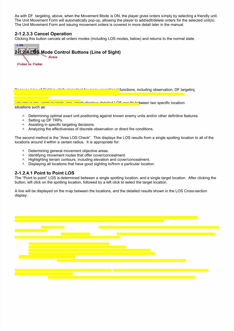
7/21/2019 TSS User Manual
http://slidepdf.com/reader/full/tss-user-manual 61/492
As with DF targeting, above, when the Movement Mode is ON, the player gives orders simply by selecting a friendly unit.The Unit Movement Form will automatically pop-up, allowing the player to add/edit/delete orders for the selected unit(s).The Unit Movement Form and issuing movement orders is covered in more detail later in the manual.
2-1.2.3.3 Cancel OperationClicking this button cancels all orders modes (including LOS modes, below) and returns to the normal state.
2-1.2.4 LOS Mode Control Buttons (Line of Sight)
Because Line of Sight is vitally important for many operational functions, including observation, DF targeting,communications, and cover/concealment, there are two easy to use tools provided for it.
The first is the “Point to Point” tool, which displays detailed LOS results between two specific locations. It is best used forsituations such as:
Determining optimal exact unit positioning against known enemy units and/or other definitive features. Setting up DF TRPs. Assisting in specific targeting decisions. Analyzing the effectiveness of discrete observation or direct fire conditions.
The second method is the “Area LOS Check”. This displays the LOS results from a single spotting location to all of thelocations around it within a certain radius. It is appropriate for:
Determining general movement objective areas. Identifying movement routes that offer cover/concealment. Highlighting terrain contours, including elevation and cover/concealment. Displaying all locations that have good sighting to/from a particular location.
2-1.2.4.1 Point to Point LOSThe “Point to point” LOS is determined between a single spotting location, and a single target location. After clicking thebutton, left click on the spotting location, followed by a left click to select the target location.
A line will be displayed on the map between the locations, and the detailed results shown in the LOS Cross-sectiondisplay:

7/21/2019 TSS User Manual
http://slidepdf.com/reader/full/tss-user-manual 62/492
Figure 24: The LOS Cross-section Display showing blockage, ground elevations and above- ground terrain.
The Cross Section panel shows the cross-section of the ground surface (in brown), along with any above ground terrain(in colors identified in the Legend panel below it). The spotting and target points are shown with the red and whitesquares (“S” = spotter, “T” = target), and the LOS line is drawn between them. The absolute and above-ground elevationof each point is shown in green at the bottom right. If a unit is not being used for either the spotter or target, by default an AGL elevation of 1 meter is used. Otherwise, the actual AGL of the unit, including its intrinsic height is used instead.
At the lower right of the cross-section panel the text will indicate if the target is silhouetted (making it easier to spot andtarget), and below that actual range in meters is shown along with the current maximum sighting distance. The maximumsighting distance is set at the start of the scenario.
Below the Legend panel, detailed information about the LOS is shown. On the left, both the outbound (from spotter totarget), and inbound (target to spotter) LOS results are shown. These will not always be the same, given that units areusually assumed to position themselves to take advantage of terrain as far as possible to maximize their sightingcapabilities out of their location, while making it as hard as possible for they themselves to be seen. These effects arecustomizable, and are set as the Spotter and Target LOS blocking Percentage Modifiers when a scenario is created. Next to the LOS results text, a series of values will be displayed when the mouse pointer is moved over the cross-sectiondisplay. These values correspond to the point in the LOS under the cursor, and include:
LOC (location number); Base Loc Elev (the nominal or “center of the location” elevation); Cx and Cy (the absolute coordinates of the point, in meters from the upper left corner of the map); [ ] (the interval); Ground Elev (the modified ground elevation - using smoothing and triangulation, if enabled); Interval in Hex (the distance the interval spends in the location, used for adding LOS blocking as a proportion of
total location size); LOS Elev (the absolute elevation of the LOS in meters); Bk Pts (LOS blocking points for the interval); Ter El (maximum terrain height in the location AGL, in meters); Rng (the range to the point from the spotter, in meters).
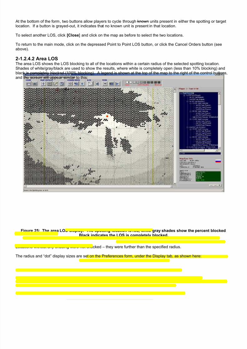
7/21/2019 TSS User Manual
http://slidepdf.com/reader/full/tss-user-manual 63/492
At the bottom of the form, two buttons allow players to cycle through known units present in either the spotting or targetlocation. If a button is grayed-out, it indicates that no known unit is present in that location.
To select another LOS, click [Close] and click on the map as before to select the two locations.
To return to the main mode, click on the depressed Point to Point LOS button, or click the Cancel Orders button (seeabove).
2-1.2.4.2 Area LOSThe area LOS shows the LOS blocking to all of the locations within a certain radius of the selected spotting location.Shades of white/gray/black are used to show the results, where white is completely open (less than 10% blocking) andblack is completely blocked (100% blocking). A legend is shown at the top of the map to the right of the control buttons,and the screen will appear similar to this:
Figure 25: The area LOS display. The spotting location is red, while gray shades show the percent blocked.Black indicates the LOS is completely blocked.
Locations without any shading were not checked – they were further than the specified radius.
The radius and “dot” display sizes are set on the Preferences form, under the Display tab, as shown here:
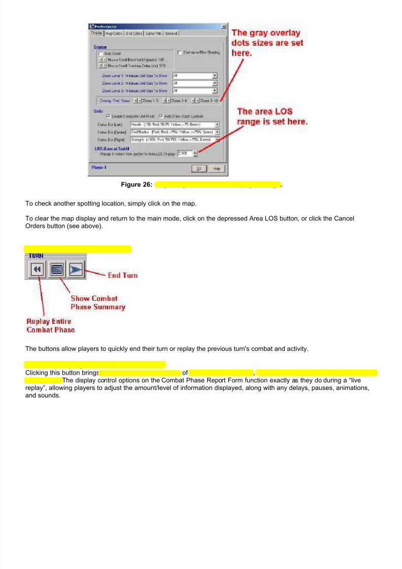
7/21/2019 TSS User Manual
http://slidepdf.com/reader/full/tss-user-manual 64/492
Figure 26: Adjusting the Area LOS display settings.
To check another spotting location, simply click on the map.
To clear the map display and return to the main mode, click on the depressed Area LOS button, or click the CancelOrders button (see above).
2-1.2.5 Turn Control Buttons
The buttons allow players to quickly end their turn or replay the previous turn's combat and activity.
2-1.2.5.1 Replay Entire Combat PhaseClicking this button brings up a complete visual replay of the last combat phase, exactly as if the player were watching it in“real time”. The display control options on the Combat Phase Report Form function exactly as they do during a “livereplay”, allowing players to adjust the amount/level of information displayed, along with any delays, pauses, animations,and sounds.
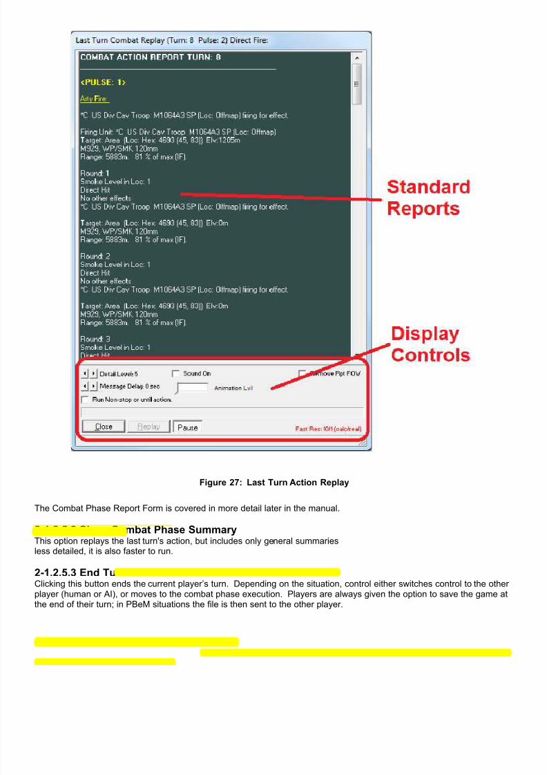
7/21/2019 TSS User Manual
http://slidepdf.com/reader/full/tss-user-manual 65/492
Figure 27: Last Turn Action Replay
The Combat Phase Report Form is covered in more detail later in the manual.
2-1.2.5.2 Show Combat Phase Summary
This option replays the last turn's action, but includes only general summaries of the phase activities. Because it is muchless detailed, it is also faster to run.
2-1.2.5.3 End TurnClicking this button ends the current player’s turn. Depending on the situation, control either switches control to the otherplayer (human or AI), or moves to the combat phase execution. Players are always given the option to save the game atthe end of their turn; in PBeM situations the file is then sent to the other player.

7/21/2019 TSS User Manual
http://slidepdf.com/reader/full/tss-user-manual 66/492
2-1.3 The Force TreeThe Force Tree shows all of the units in the Task Force, including those that have been destroyed. The Force Tree doesnot show flank units.
The units are arranged in the order set at the start of the scenario. Each indent represents one lower level and the linesshow the direct command assignments. The force tree may be condensed or expanded using the standard Windows “+”(expand) and “-“ (condense) icons to the left of the HQ units. The only exception is the TF HQ; it can never becondensed. By default, the tree view is drawn expanded.
Figure 28: The Tree View (Fully Expanded). Figure 29The Tree View (Fully Condensed).
As previously stated, the indents and lines are used to show the relationship of units within the force. Subordinate unitsare always indented from their higher HQ, and connected with a line. In the example (Expanded) above, for instance, the A US Rifle Company , B US Artillery Battery , and C Attack Helo Company are directly under the TF HQ . The 1st Rifle
Platoon is under the A Rifle Company, and so on.
2-1.3.1 Force Tree IconsSingle icons are used to show the status of the units. In most cases these icons represent the strength of the unit, butthey can also note morale status, paradrops, and missiles. The icons, in order of precedence are:
Unit has been auto-evacuated (removed from the game, but not destroyed).
Unit surrendered to the enemy.
Unit has been destroyed.
Unit is In-Flight/Missile.
Unit is in the air (paradrop).
Unit is a reinforcement that has not yet arrived.
Unit has not been placed or is not “in play” for some other reason.
Unit is Wavering.
Unit is Broken
Unit is Berserk.
Unit is Running For Cover.
Unit is Disrupted (after a paradrop landing).

7/21/2019 TSS User Manual
http://slidepdf.com/reader/full/tss-user-manual 67/492
Unit is at Full Strength.
Unit is at Medium Strength.
Unit is at Low Strength.
Only one icon is shown for each unit. If a unit would qualify for one or more icons, for example, full strength and broken,the icon shown will be the highest in order of precedence in the chart above.
2-1.3.2 Text AdditionsThe following text strings are added before or after the standard unit name to show status or command chain:
String Before/After Description
[Evacuated] Before The unit has been permanently damaged and has been evacuated from thegame. It is not considered destroyed, but it plays no further part in thescenario.
[Spt] Before The AI considers the unit to be in direct support and will not move it until eitherthe action moves out of range or the unit itself is threatened.
(Psgr) Before The unit is a passenger on another unit (not used for composite units).
(IP) Before The unit is in an IP, or for composite unit, all of the non-passenger typesubunits are in an IP.
(IP*) Before Composite unit only: Some of the composite unit’s non-passenger units are inan IP, while some aren’t.
(Det) Before The unit is a detachment (voluntarily or combat induced)
(?) After quantity The information is more than one pulse old (not completely current)
Group After The unit is a Composite Unit Group.
.../.../.../ TF After The unit’s chain of command, using first text “block” of the name in each unitin the chain separated by slashes.
<< Leader After Assigned leader name.
(Reinf [turn]) After The unit is a reinforcement. The entry turn is shown in brackets.
Face: h / t After The approximate cardinal hull (h) and turret (t) facing directions.
(Loaded) After The unit is carrying passengers. For composite units, this is shown if anysubunit is carrying a passenger unit that is not part of the composite unit.
(All Loaded) After Composite unit: all non-carrier type subunits are loaded within the compositeunit.
(Part Loaded) After Composite unit only: some, but not all, non-carrier type subunits are loadedwithin the composite unit.
(X Loaded) After Composite unit only: Cross-loaded - at least one non-carrier type subunit isloaded on a unit not within the composite unit.
NOTE: These strings are also used for the “mouse-over” text shown on the map.
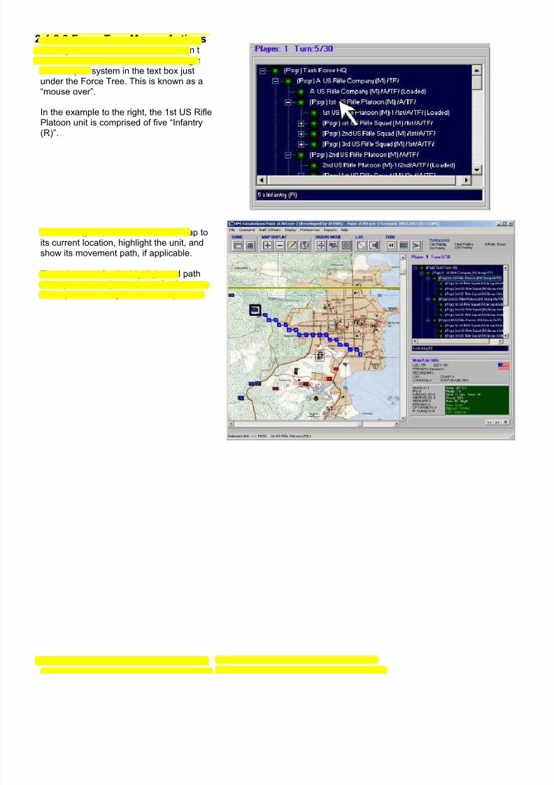
7/21/2019 TSS User Manual
http://slidepdf.com/reader/full/tss-user-manual 68/492
2-1.3.3 Force Tree Mouse ActionsMoving the mouse cursor over a unit in theTree View will shown its current strengthand weapon system in the text box justunder the Force Tree. This is known as a“mouse over”.
In the example to the right, the 1st US RiflePlatoon unit is comprised of five “Infantry
(R)”.
Left clicking on a unit will scroll the map toits current location, highlight the unit, andshow its movement path, if applicable.
The color used for the highlight and pathdisplay can be adjusted in the PreferencesForm (Main Menu | Preferences).

7/21/2019 TSS User Manual
http://slidepdf.com/reader/full/tss-user-manual 69/492
Right clicking on a unit will bring up the UnitData Form. This provides detailedinformation about the unit and its currentstatus. This form is covered in more detaillater in the manual.
The Unit Information form also allows for theunit name and some other values to bechanged, depending on the current turn andsituation.
2-1.3.4 Composite Unit ModeUnits are displayed on the Force Tree using the current Composite Unit Mode setting. If the Composite Units Mode is off,each subunit will be shown individually on the Force Tree. Otherwise, only one entry will appear for the group. In thiscase, the loaded status of the Composite Unit HQ subunit will be shown. Here are some examples:
Figure 30: Composite Unit Mode - ON. Figure 31: Composite Unit Mode - OFF.
Strength icons are averaged for the entire composite unit. Averaging does not apply to morale state, however, since allunits in a Composite Unit must have the same morale state.
To toggle the Composite Unit Mode setting, use Main Menu | Display | Composite Unit Mode.
Composite units were covered in brief previously in the manual, and will also be discussed in more detail in a latersection.

7/21/2019 TSS User Manual
http://slidepdf.com/reader/full/tss-user-manual 70/492
2-1.4 Map/Location Information PanelThis panel is located at the bottom right of the main form, andprovides information on the location under the mouse, pluscurrent general game conditions.
The top portion of this panel details the terrain in the locationunder the mouse:
LOC: the location ID number.
ELEV: the ground surface elevation, in meters above sealevel.TER: the terrain types in the location. Cosmetic types
(i.e. ones that have no effect), are not shown.LOS: the base LOS blocking % from terrain in the
location. Terrain LOS blocking values are set in the TECData Table.
CONCEAL: The amount of concealment provided byterrain. Terrain Concealment values are set in the TECData Table.
COVER: The amount of cover (protection) provided byterrain. Terrain Cover values are set in the TEC DataTable.
SCN FOLIAGE: The scenario foliage levelsetting, in percent (of full/normal summer foliage).This value is used to model seasonal or locationdifferences in leaf quantity/density and may bemore than 100%. It is set in the initial scenario set-up process.
The bottom section of the panel details other objects in the location, as well as the current conditions:
UNITS: the number of friendly / enemy units present.Objects and civilians are counted as “enemy”.
IPs: the number of known Improved Positions.MINEFIELDS: the number of known minefields (any
type).SENSORS: the number of known sensorfields (any
type).BRIDGES: the number of known bridges (any type).DF TARGETS: the number of pre-planned DF Targets
(reference points) in the location. IF TARGETS: the number of pre-planned IF Targets
(reference points) in the location.
Temp: The current temperature in °C.Precip: the precipitation (rain/snow/etc.) level, in %.Wind: the sustained wind speed in Kph and
meteorological direction (i.e., “from/out of”).Clouds: the cloud cover, in %Illum: the current ambient illumination level in %
where 100% = a bright sunny day).Time: the scenario time (hh:mm in 24 hour format).Elapsed: how many minutes the current scenario
has been underway. The “~” indicates approximate.LOS: The maximum LOS sighting range.
Note: All of these values (except elapsed time) are setas part of the scenario creation process.
Section 2-2: The Location Information Form
The Location Information Form provides detailed information about map locations, and the units and terrain features inthem. It is updated as the mouse moves across the screen.

7/21/2019 TSS User Manual
http://slidepdf.com/reader/full/tss-user-manual 71/492
Figure 32: The free-floating Location Information Form.
Additionally it has toggles for the various map overlay displays equal to the ones on the Main Menu | Display pull down.The overlays are broken down into categories, general and player specific:
General overlays are force neutral, and do not take into account a force’s composition or mission.
• Elevation - the ground elevation of a location.
• Concealment - the amount of terrain LOS blocking in a location.
• Ground Speed - how fast an “average” unit can move through a location.
• Chem/Dust/Smoke - the amount of chemical agents, smoke, and/or dust present in a location.
Player specific overlays take into account the force’s weapons, capabilities, mission and force arrangement on the map.For example, if a player is attacking East to West, a North-Sound road is much less valuable than an East-West one.
• Sighting - a combined measure of the quality and quantity of what can be seen visually from a location.
• Protection - the amount of cover, or protection from fire, afforded by the terrain in a location.
• Movement - the average speed of a force’s units though terrain in directions most likely to be used.
• Obstacle - the best places for the force to place movement obstacles (counter-mobility operations).
• Worth Seeing - a measure of how valuable a location is to see, for example a crossroads or bridge would be moreimportant to observe that an empty field.
The command and control toggles are used to turn off and on the formation overlay graphics:
• Formation pointers - lines drawn between a headquarters unit and both its higher headquarters and its subordinateunits. The colors of the lines are set in Main Menu | Preferences | Map Colors .
• Command Radius - a hatched circle showing the extent of the headquarters unit’s unimpaired command radius. Additional time is required to communicate with units outside of this area; for example, it will take longer to sendmovement orders or to receive SITREP’s. The command radius is determined from the HQ unit’s communicationsequipment, level, and the average terrain and roughness of the map area.

7/21/2019 TSS User Manual
http://slidepdf.com/reader/full/tss-user-manual 72/492
Figure 33: The command radius and formation pointers for the A US Tank Company HQ.
The Display Units/Objects settings are used to parse though the effects of FOW (fog of war). Specifically, they limit theunits and objects displayed by how long ago they were last sighted. The longer that time period, the more likely it is thatthe unit may have moved or changed its situation.
• Sighted - show only units and objects currently sighted (friendly and enemy)
• n Min - show only units and objects that were sighted within the last n minutes, and, if sighted by other units, thathave been reported via SITREP.
Section 2-3: The Off-map Display
The default available playing area for a TSS scenario measures approximately 6500 Km x 6500 Km (based on a scale of100 meters per location), with the map’s upper left corner centered within the total area. While it is not impossible for theplaying map to take up this entire area, it is extremely unlikely, and most maps will only occupy a small percentage of theavailable playing area. The rest of the playing area is known as “off-map”.
The Off-map Display is used to access off-map areas, which cannot be shown or selected from the Main Screen map. Atminimum zoom, the display covers the entire playing area, using labeled distance “rings” to show the range from the“center” point (the upper left corner of the visible map). All active units must be located within this area (or be on the mainmap).

7/21/2019 TSS User Manual
http://slidepdf.com/reader/full/tss-user-manual 73/492
Figure 34: The default Long-Range (off-map) display. The Main Screen map is the gray rectangle near the centerThe blue dots are friendly units. The light gray line shows the currently selected unit’s movement path (a KC-10
refueling aircraft orbiting the battle area).
Locations and units can be placed and selected from the off-map just as for the main map, by right or left clicking on themLikewise, “hot” units and off-map locations are identified by the colored square.
Off-map locations are similar to on-map ones, in that they can be occupied by units, and those units can perform most ofthe combat activities that they can on map such as moving, firing, and sighting. However, there are some differences:
• All off-map locations are all the same elevation - the average of the visible map.
• Off-map locations have only a single terrain - they use the first one defined in the TEC.
• Off-map locations have no hexlines or hexsides, or bridges.
• Obstacles, IP’s and other constructions can not be placed in off-map locations.
2-3.1 Using a Background Map/Picture For the Offmap DisplayIf desired, users can replace the green shaded background with maps or pictures. This allows for a quicker appreciationof where the offmap locations and units are in relation to the main battle area.

7/21/2019 TSS User Manual
http://slidepdf.com/reader/full/tss-user-manual 74/492
Figure 35: Using a larger-scale map for the Offmap Display background. The map scale is used to determine the
display size (so it matches with the location scale).
To add a picture, click the “Change Background” button on the Offmap Form. You can then select the picture or mapgraphic to use (in BMP or JPG format). The graphic must be scaled so that 1 pixel (on the graphic) equals 1000 meters(on the ground). You should also insure that the center point of the graphic coincides with the upper left corner of themain map area.
The following multiplier examples apply for map graphics scanned at 300 pixels per inch:
Original Map Scale Graphic Size Multiplier
1 : 36,000,000 168.96%
1: 12,000,000 56.31%
1 : 10,000,000 46.93%1 : 4,500,000 21.12%
1 : 2,250,000 10.56%
** Lower scales are not recommended
Section 2-4: The Load Scenario Form

7/21/2019 TSS User Manual
http://slidepdf.com/reader/full/tss-user-manual 75/492
After selecting to load either a standard savedgame file, or a scenario, the Load a ScenarioForm will be displayed (shown at right). This formprovides players with information on the availablesaved game files, and allows one to be selectedto load and play.
To change the search folder, click [ChangeFolder/Browse]. The current search folder pathappears under the button.
To get information for a particular game, select itfrom the Scenario Files (upper) list box. Thefollowing information is displayed:
• The game name (if it has one).
• A picture file associated with the file (if set bythe creator).
• The mission for each player/force.
• Whether a force is human or AI controlled bydefault.
• The current status – either the current turnnumber, or “set-up phase”.
• The map used.
• A text description (if entered by the creator).
• The end turn.Figure 36: Loading a saved game/scenario. The bottom left
section displays only when loading scenarios.
Files can be sorted alphabetically (by name), by the size (in terms of a combination of map area and number of units),difficulty (based on unit types present, missions, and the amount of terrain on the map), or CPU Demand (the amount ofcomputer resources needed to run the scenario, which also roughly translates into how fast it will execute).
When loading a scenario, as opposed to a standard saved game, players also have the option of setting the control ofeach force (AI vs. human), adjusting the ending turn (game length), and also resetting or modifying the Fog of War (FOW)level.
Section 2-5: The Scenario Control Form

7/21/2019 TSS User Manual
http://slidepdf.com/reader/full/tss-user-manual 76/492
After selecting the file to load (scenario or normal), the ScenarioControl Form will appear. This form allows players to set the controland Fog of War (FOW) levels of each force, as well as adjust theExpert Level setting.
Setting both forces to AI control will result in a game that runs itself tocompletion without any human intervention or actions (“unattendedmode”).
Setting both players to human control allows for either “hotseat” or“PBeM” games between two or more opponents, or allows a singleplayer to control both forces.
The FOW settings adjust the realism of intelligence and knowledge offriendly and enemy forces. Off is the least realistic (but simplest),while Level 4 is the most realistic (but most complicated).
The Expert Level determines how much information is shown to aplayer, and what command options he has. The “Novice” level actsas a limit to protect new players from being overwhelmed, while Level3 offers full access.
For additional information on these settings, please see the section
on setting up a new game, later in the manual. Figure 37: The Scenario Control Form allowsbasic game situation adjustments.
Section 2-6: The AI Settings Form
In games where at least one player is AI controlled,this form allows players to customize AI performanceas well what they can observe during the run. It willappear when the game is initially loaded, and also atthe start of the set-up phase.
The specific settings are:
Movement Default: The AI uses this setting to placepriority on terrain effects when determining movementpaths. “Direct” and “Semi-direct” paths focus on theshortest distance, “Speed” paths on the quickest time,and “Tactical” on the best cover and concealmentalong the route.
Fidelity Resolution Values: These adjustments allowusers to gain execution speed (i.e., the program willrun faster), at the expense of AI competence andmodel fidelity. The current settings are displayed on
the Main Form, to the right of the Command Buttons,as shown here:
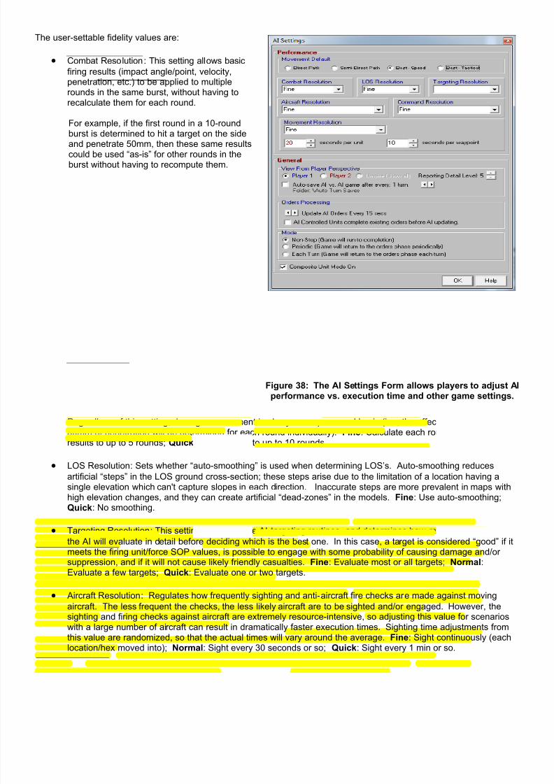
7/21/2019 TSS User Manual
http://slidepdf.com/reader/full/tss-user-manual 77/492
Figure 38: The AI Settings Form allows players to adjust AIperformance vs. execution time and other game settings.
The user-settable fidelity values are:
• Combat Resolution : This setting allows basic
firing results (impact angle/point, velocity,penetration, etc.) to be applied to multiplerounds in the same burst, without having torecalculate them for each round.
For example, if the first round in a 10-round
burst is determined to hit a target on the sideand penetrate 50mm, then these same resultscould be used “as-is” for other rounds in theburst without having to recompute them.
Regardless of this setting, damage assessment is always on a per round basis (i.e., the effects of the common50mm of penetration will be determined for each round individually). Fine: Calculate each round; Normal: Applyresults to up to 5 rounds; Quick: Apply results to up to 10 rounds.
• LOS Resolution : Sets whether “auto-smoothing” is used when determining LOS’s. Auto-smoothing reduces
artificial “steps” in the LOS ground cross-section; these steps arise due to the limitation of a location having asingle elevation which can't capture slopes in each direction. Inaccurate steps are more prevalent in maps withhigh elevation changes, and they can create artificial “dead-zones” in the models. Fine: Use auto-smoothing;Quick: No smoothing.
• Targeting Resolution : This setting applies to the AI targeting routines, and determines how many “good” targets
the AI will evaluate in detail before deciding which is the best one. In this case, a target is considered “good” if it
meets the firing unit/force SOP values, is possible to engage with some probability of causing damage and/orsuppression, and if it will not cause likely friendly casualties. Fine: Evaluate most or all targets; Normal:Evaluate a few targets; Quick: Evaluate one or two targets.
• Aircraft Resolution : Regulates how frequently sighting and anti-aircraft fire checks are made against moving
aircraft. The less frequent the checks, the less likely aircraft are to be sighted and/or engaged. However, thesighting and firing checks against aircraft are extremely resource-intensive, so adjusting this value for scenarioswith a large number of aircraft can result in dramatically faster execution times. Sighting time adjustments fromthis value are randomized, so that the actual times will vary around the average. Fine: Sight continuously (eachlocation/hex moved into); Normal: Sight every 30 seconds or so; Quick: Sight every 1 min or so.

7/21/2019 TSS User Manual
http://slidepdf.com/reader/full/tss-user-manual 78/492
• Command Resolution : This setting determines whether a unit's communications state/status is determined once,
at the beginning of the pulse (disregarding subsequent overloads or other effects of incoming and outgoingmessages), or if it is recalculated fresh each time a message is sent/received. Fine: Recalculate at the instanteach message is sent/received; Quick: Use the initial value for the entire pulse.
• Movement Resolution : Used by the movement AI routines, these settings determine how much time the AI
spends on analyzing potential objectives and paths for units.
1. Resolution: This value determines how many potential objective locations are considered before issuing a
unit with movement orders. The more objectives examined, the better the AI's tactical strategy, but eachobjective also requires that one (or more) movement paths be determined as part of the process. This can bea time-consuming process, especially on maps with limited general mobility. The value is also used in theairstrike routines to determine the best specific targets and weapon release points once a general target hasbeen selected. Fine: Evaluate most or all; Normal: Evaluate a few; Quick: Evaluate one or two.
2. Seconds per Unit : This is the absolute maximum time, in seconds, that the AI will spend trying to move asingle unit, including checking for alternate destinations if a path can not be found to the original (due to asingle path time out, above, or other condition). When this limit is imposed before a path is found, the unit isnot issued any orders.
3. Seconds per Waypoint : This is the maximum amount of time, in seconds, that the AI will spend attempting todetermine a movement path between any two points for a single unit. If a path is not found in this time, the AI
will move on and attempt to determine a path to a different destination or simply abandon the attempt,depending on how much time has already been spent with the unit (see above).
View From Player Perspective: These settings determines what users are shown during the combat phase:
• Player 1: The display will be that of the Player #1 (Blue) Force Commander’s perspective (including Fog of War(FOW)).
• Player 2: The display will be the Player #2 (Red) Force commander’s perspective (again, including FOW).
• Umpire. When viewing as an umpire, Fog of War is completely ignored, so everything is reported as it actuallyoccurs without regard to the player or force involved. However, normal FOW is maintained in the modeling; thissetting affects only the map display.
• Reporting Detail Level: This setting determines how much combat results information is shown to players. Atlevel 1, players are shown only general summaries, while at level 6 the information includes detailed penetrationvalues as well as the LOS cross-sectional display, among other things. The reporting level does not adjust any
applicable FOW considerations; information that is not known is not shown.• Auto-Save: Checking the box next to this option will save AI vs. AI games periodically after the entered number ofturns (where 1 means it is saved after each turn, 2 after every other turn, etc.). Games are saved automatically tothe folder “\Auto Turn Saves” under the main program folder. This option is only applicable to AI vs. AI games(where both layers are AI controlled).
Orders Processing: These settings control how often the AI issues new movement orders to units under its control.
• Update Orders Every N seconds: This setting controls how often the AI will check to issue movement orders to itsforce, in “game time”. For example, if this is set to 60 seconds, then after each minute of game time elapses(rounded to the combat pulse), the AI will issue movement orders. Lower values result in longer games, but givethe AI force better responsiveness and capability. Orders other than movement (DF, IF, CADS, etc) are notaffected by this setting, they are always given once per pulse.
• AI Units Complete Existing Orders Before Updating: When checked, the AI will not issue movement orders to a unituntil the unit has completely exhausted all previous orders (the unit’s movement command queue is empty). Usingthis option can make for faster running games, but also reduces the AI force’s responsiveness.
Mode: This value determines how often the game will return to the orders phase (allowing the human player to view thecurrent situation and/or issue orders):
• Non-Stop: The game will progress directly from one combat phase to another until the scenario is complete (theend turn is reached). The sequence will never be interrupted by an orders phase.
• Periodic: The game will run through 5 combat phases in a row, and then enter the orders phase.
• Each Turn: The game sequence will proceed normally; each turn will have an orders phase.

7/21/2019 TSS User Manual
http://slidepdf.com/reader/full/tss-user-manual 79/492
Note: A separate setting allows for a return to the orders phase on after any enemy contact occurs (temporarilyoverriding the values above). This value is set using the Main Menu | Preferences form, discussed later in themanual.
Composite Unit Mode On: If checked, composite units will be used for display and orders purposes. Otherwise, eachunit will be shown and accessed individually. Composite Units were mentioned previously at the start of this section, andare also covered in more detail later in the manual.
NOTE: As previously mentioned, during the game these settings can be viewed/edited at any time by using thePreferences Form ( Main Menu | Preferences ). The Preferences Form will be covered later in the manual.
Section 2-7: Staff Officer Screens
To help players sift through the available information and make good decisions, the TSS makes available a full set of StaffOfficer assistance screens. The staff is the equivalent of what you would find in a standard US Army combat unit, andeach staff officer provides the player with information and critical notices for a specific functional area.
2-7.1 General Characteristics of Staff Officer Screens
Figure 39: The functional areas common to all staff officer screens.
Each staff officer screen contains 4 major functional areas. The first is the Unit Information Window, which shows eitherfriendly or enemy units, limited by the staff officer’s specialty. For example, the S-1 (Personnel) Officer shows all friendlyunits in play, the S-2 (Intelligence Officer) shows only enemy units, while the ALO (Air Liaison Officer) display is limited to
friendly air units.
Units in the Unit Information Window are sorted and color-coded according to criteria set by the player in the Sort Criteriaand Status Indicator areas. This makes it easy to see the general condition of the force, and also to identify individualunits that are in a critical condition, and to take timely and appropriate actions.
Left clicking on units in the Unit Information Window will scroll the map to their current location, and highlight them.
Right clicking on units in the Unit Information Window will bring up the detailed Unit Information screen (friendly unitsonly).

7/21/2019 TSS User Manual
http://slidepdf.com/reader/full/tss-user-manual 80/492
The Sort Criteria allows players to pick some relevant unit condition, and have the units appear sorted by that criterion.For example, units could be sorted by morale, so that the best and the worst would be easily identified. Selecting“Formation” means the units will appear in the same order as the Force Tree.
Status Indicators are used to color-code the unit entries based on their current level of some relevant factor. Theavailable colors are red, yellow and green, and the user can set the “levels” for each. For example, the user could set redfor units with morale less than 50, yellow for morale levels between 50 and 75, and use green for all others.
Staff officers also provide relevant comments and suggestions, and will point out areas they feel need extra attention fromthe player.
Some staff officers have the ability to issue orders to a player’s force or perform some function automatically. If so, anaction button will appear at the bottom of the screen.
A slide-bar control allows the human player to set the aggressiveness level of the AI when giving orders to his force,affording some control over the choices the AI will make. More aggressive AI tends to favor speed over protection, andengaging as soon and as often as possible as opposed to conserving ammunition and remaining hidden until highobtaining good kill probabilities and/or value targets. The slide-bar control is at the bottom of each staff officer form,whether that staff officer can issue orders or not.
2-7.2 S-1: Personnel Officer
Figure 40: The S-1 (Personnel) Officer screen.
The S-1 officer provides information on friendly unit strength, morale, and leaders. As units lose strength and morale,they are less able to accomplish their mission.
The S-1 screen fields are:
Units: The name of each unit. Weapon: The weapon system assigned to that unit. An asterisk (*) denotes a composite unit - the weaponsystem of the group HQ is shown.
Qty: The number of weapons systems present in the unit. Strength: The ratio of the unit’s current strength to the starting strength. Morale Level: The current morale level of the unit 0 (Bad) to 100 (Good). Morale State: The current morale state (normal, wavering, broken, or berserk). Leader: If a leader is assigned to the unit, and able to perform leadership functions, the leader’s name is shown.
Leaders that have been killed or seriously wounded are removed from the scenario. Comments: Comments on the unit’s current status or other pertinent information.

7/21/2019 TSS User Manual
http://slidepdf.com/reader/full/tss-user-manual 81/492
2-7.3 S-2: Intelligence Officer
Figure 41: The S-2 (Intelligence) Officer screen.
The S-2 officer provides information on the known and estimate enemy force, as well as the current weather. As thescenario progresses and more of the enemy force becomes known, the estimates of the enemy’s force will become moreaccurate.
The S-2 screen fields are:
Units: The description of the enemy unit, as known through the scenario FOW (fog of war) level. Sector: The relative position of the enemy unit in relation to the friendly axis of advance/start line (left, right,
center). Note: the sector value is meaningless for “free set up” (no start line) scenarios.
Detection Unit/Method: this column that shows the original source of the information for the enemy unit. Sourcesof information include the pre-scenario disclosure activities, SITREP’s from friendly units, radio intercept, radar(including triangulation), and sensors.
Comments: Comments on the enemy unit’s current status or other pertinent information.
2-7.4 S-3: Operations Officer (Movement)

7/21/2019 TSS User Manual
http://slidepdf.com/reader/full/tss-user-manual 82/492
Figure 42: The S-3 (Operations) Officer screen.
The S-3 (Operations) officer provides information on friendly unit movement objectives, and comments on whether they
seem sufficient to accomplish the force’s mission in light of the known and estimated enemy forces. The S-3 will alsoissue move orders to a player’s force, if desired.
One-click movement orders can be given from the S-3 screen by double-clicking on a unit (which automatically enters thegame in movement mode), and then selecting waypoints from the map. If the “adjutant mode” is on, the AI will handle allof the path calculations, and speed settings without any further human input. Otherwise, the standard unit movementform will be displayed allowing players to set these characteristics. One the movement orders have been accepted (orcanceled) for the unit, control returns to the S-3 form.
The S-3 screen fields are:
Units: The name of each unit. Weapon: The weapon system assigned to that unit. An asterisk (*) denotes a composite unit - the weapon
system of the group HQ is shown. Orders: This field indicates if the unit has any movement orders in its queue (yes/no). It also indicates if the unitis loaded, or a passenger. Passenger units that have orders in their queue that will be executed upondisembarking are noted with an asterisk (*). Special Note: Units may experience a delay before they beginexecuting orders due to command and control lags or other factors; this is indicated by showing the text in orange(pending), as opposed to green (executing).
Speed: The unit’s current speed in Kph. Comments: Comments on the unit’s current movement status or other pertinent information.
2-7.5 S-4: Supply Officer

7/21/2019 TSS User Manual
http://slidepdf.com/reader/full/tss-user-manual 83/492
Figure 43: The S-4 (Supply) Officer screen.
The S-4 (Supply) officer provides information on the amount of ammunition units have on hand, and will assess the overal
force supply level. The S-4 will also issue orders for units low on ammunition to reduce their ROF (rate of fire) tominimum levels, if desired.
The S-4 screen fields are:
Units: The name of each unit. Weapon: The weapon system assigned to that unit. An asterisk (*) denotes a composite unit - the weapon
system of the group HQ is shown. Gun (1-6) Ammo: This field shows how much ammunition remains on hand for each gun launcher (1-6) for each
general type of ammunition. Ammunition remaining is shown in minutes of fire remaining at standard nominalweapon ROF. The general types of ammunition are: “AT” (anti-tank, including HEAT and large caliber/highvelocity solid projectiles), “AP” (anti-personnel, including high explosive, fragmentation or rapid fire small arms),and “Ot” (Other, including mines, sensors, NBC, etc).
Comments: Comments on the unit’s current supply status or other pertinent information.

7/21/2019 TSS User Manual
http://slidepdf.com/reader/full/tss-user-manual 84/492

7/21/2019 TSS User Manual
http://slidepdf.com/reader/full/tss-user-manual 85/492
[Show All Unit vs. Unit Targeting]: This report is a detailed description of DF possibilities for the entire force. It listsevery friendly unit, and then it cycles through every known enemy unit evaluating it as a potential DF target for thatfriendly unit. The results are then shown, either as ”OK!”, meaning that the enemy unit can be engaged, or “NO FIRE”,which indicates that it can't. Additional details are then provided as to why firing is blocked, or the best gun/ammocombination to use.
Figure 45: Complete force targeting results.
This analysis can take a while to complete, especially in large scenarios, so a progress bar is shown at the beginning ofthe operation.
[Have AI Issue DF Targets to All Units]: Clicking this button will cause the AI to issue DF targeting orders to all friendlyunits. In most cases, the AI will leave existing targeting orders unchanged, unless it determines that much betteropportunities are available.
2-7.7 Engineering Officer

7/21/2019 TSS User Manual
http://slidepdf.com/reader/full/tss-user-manual 86/492
Figure 46: The Engineering Officer screen.
The Engineering officer monitors all combat engineering operations undertaken by the force, whether specialized
engineer units are performing them or not. The Engineer also makes assessments of the most valuable types ofengineering operations within the force’s mission and the enemy situation.
The Engineering screen fields are:
Unit: The friendly unit performing the engineering operation. Engr Op: The type of engineering operation being performed. Sector: The sector and depth of the engineering operation location. Note: the sector value is meaningless for
“free set-up” (no start line) scenarios. % Complete: The current completion percentage of the project (0-100%). Mins to Complete: The estimate time to completion, in minutes, using currently allocated resources. Comments: Comments on the current project/unit status or other pertinent information.

7/21/2019 TSS User Manual
http://slidepdf.com/reader/full/tss-user-manual 87/492
2-7.8 FSO: Fire Support Officer (Artillery)
Figure 47: The FSO (Fire Support Officer) screen.
The FSO (Fire Support Officer) handles IF (Indirect Fire) support missions fired by artillery, mortars, and rockets. TheFSO will call for (i.e., “establish”) IF missions for the entire force based on the current situation, if so desired (or the FSOmay determine that no additional IF missions are warranted).
The FSO screen fields are:
Firing Unit: The unit assigned to fire the IF mission. The same unit may appear multiple times in the list, howeveronly on mission may be fired at a time. Once one mission has been completed, the unit will become eligible to fireothers (after a delay to realign and target the guns).
Target: The mission target, with the description limited by current FOW levels. Start Time: The time the mission will commence firing. The actual time (DAY HH:MM) is shown first, followed by
the game turn and pulse in parenthesis, e.g., (2/1) for turn 2, pulse 1. Note that this is the planned/earliest starttime. Because units can only fire one mission at a time, it is possible that high priority missions will delay the startof lower priority ones.
Location: The current target location, either a numbered on-map location or off-map. Rounds Fired/Left: This shows the total number of rounds already fired / remaining in the mission, followed by the
ammunition name. Status: The current status of the mission: Pending (waiting to be fired); Firing Spot (firing spotting rounds - one a
a time until accuracy increases enough to FFE); Firing FFE (firing for effect - rounds are being fired at the missionROF setting); Firing DF (the IF mission has been interrupted because the unit was required to fire defensive DF);OK to fire (the situation allows for firing as planned); Can’t Fire (the condition indicated prevents the mission frombeing fired as planned).
Comments: Comments on the current mission status or other pertinent information.
“Auto-Assign Artillery Missions during turn” checkbox: if checked, the AI will automatically allocate IF missions for the
human player’s force. Otherwise, the AI will never assign IF missions.
Left clicking a mission on the grid will cause the mission target and firing unit to be identified on the map.
Right clicking a mission on the grid will also bring up the Arty/Fire Support Mission screen, which will display all of themission values.
To delete a mission: Right-click on the mission line of the grid. Click [Remove] from the Arty/Fire Support Mission form.
To edit a mission: Right-click on the mission line of the grid. Change the mission values using the Arty/Fire SupportMission form. Click [OK] to save the changes (or [Cancel] to close the form without changing anything).

7/21/2019 TSS User Manual
http://slidepdf.com/reader/full/tss-user-manual 88/492
2-7.9 ALO: Air Liaison Officer (Close Air Support)
Figure 48: The ALO (Air Liaison Officer) screen.
The ALO (Air Liaison Officer) is concerned with CAS (close air support) missions being flown in support of the groundforces. The ALO will call for (i.e., “establish”) CAS missions for the entire force based on the current situation, if sodesired (or the ALO may determine that no additional missions are warranted).
The ALO also provides information on paradrops.
The ALO screen fields are:
Air Unit: The aircraft unit assigned to the CAS mission. The same unit may appear multiple times in the list,however only on mission may be executed at a time. Once one mission has been completed, the unit will becomeeligible to execute others.
Mission Type: Either Air Strike (CAS) or Air Drop (parachute delivery of units). Status: The current status of the mission: Pending (the mission has not yet started); n sec out / n Passes
Remaining (the aircraft is currently making a pass over the target/drop zone, the approximate next weaponrelease time and number of passes remaining in the mission are shown); Mission Aborted (the mission has beencanceled for the reason shown); Mission Complete (the mission has been completed); Inbound/Outbound (usedfor paradrops, indicates the relative aircraft position/flight path)
Target: The mission target, if CAS, with the description limited by current FOW levels. Otherwise, for airdropsthis indicates the center drop point.
Start Time: The time the mission will commence firing. The actual time (DAY HH:MM) is shown first, followed bythe game turn and pulse in parenthesis, e.g., (2/1) for turn 2, pulse 1. Note that this is the planned/earliest starttime. Because units can only fly one mission at a time, it is possible that high priority missions will delay the startof lower priority ones.
Comments: Comments on the current mission status or other pertinent information.
[ ] Auto-Assign Air Missions during turn checkbox: if checked, the AI will automatically allocate CAS missions for thehuman player’s force. Otherwise, the AI will never assign CAS missions. Note: the AI is not capable of and will neverassign airdrop missions, irrespective of this toggle setting. A human player must always set airdrops.
[ ] Show finished missions checkbox: if checked, air missions that have been completed will be shown in the grid.Otherwise, only active and pending missions will appear.
Left clicking a mission on the grid will cause the mission target to be identified on the map.
Right clicking a mission on the grid will also bring up the Close Air Support (CAS) Missions screen, which will display all ofthe mission values.

7/21/2019 TSS User Manual
http://slidepdf.com/reader/full/tss-user-manual 89/492
To delete a mission: Right-click on the mission line of the grid. Click [Remove] from the Close Air Support (CAS)Missions form.
CAS missions may not be edited (only deleted).
2-7.10 Commo: Communications Officer
Figure 49: The Commo (Communications) Officer screen.
The communications officer keeps track of how long it takes for order and reports to travel to and from the line units. Thelonger the times, the slower the force’s response to new orders, and the less information the commander will receive. TheCommo officer also reports on enemy jamming measures and general unit internal friction.
The Commo screen fields are:
Units: A complete list of all friendly units in the force.
In Command: Specifies whether the unit is within the Command Radius of its immediate acting HQ. Units outsidethe command radius experience increased delays to receive orders and transmit reports. Command Radii defaultsare preset in the databases for each nation, and may be modified during the scenario creation process.
Command Delay: the current command delay in minutes and seconds, followed by (turns pulses). The commanddelay is the time required to transmit orders to the unit, or receive reports from it.
Range to HQ: This is the range, in meters, between the unit and its current acting HQ. Above TF HQ indicatesthat the next higher HQ is the HQ to which the TF HQ reports; this unit is never present, it is simulated instead,and the command radius is assumed to be unlimited.
Delay % of Normal: This shows the current delay to the unit as a percent of “optimal”, to the fastest that istheoretically possible using radio transmissions (based on the force command delay value).
Jamming: This indicates the percent of the expected delay time that is due to enemy jamming. Mode: The current transmission method in use between the units: n/a (Start) (the command delay is ignored
during the set up phase); Data: (high speed data, including satellite linking, if available); Radio (standard LOS
dependent radio); Visual Signal (flags, arm/hand, smoke, or other visual signals); Messenger (a “runner” must bedispatched between the units).
Friction: The internal unit friction delay, in seconds. Internal friction represents the time it takes to disseminateand organize a unit to carry our received orders, and is often affected by leaders present with the unit.
Comments: Comments on the current communication status of the unit or other pertinent information.
If the force has satellites available, an additional button will be shown at the bottom of the form labeled: [ShowSatellite Availability]. Clicking this button brings up the Satellite Availability Form, described later in the manual.

7/21/2019 TSS User Manual
http://slidepdf.com/reader/full/tss-user-manual 90/492
2-7.11 Passenger/Carrier Loading StatusKeeping track of which units are loaded, and on what carriers can be a challenge, especially in scenarios with a lot ofpassenger units. This is especially true for units which are part of composite units (such as infantry squads); if componentunits become separated from the composite's HQ, they will be removed from the composite. This can greatly complicateforce management, and will cause disruption and fragmentation.
The Loading Status Form is invaluable in these situations, since it explicitly shows the loading relationships for the force inseveral different ways: basic/by units, by passengers, by composite units and by cross-loading between composite units.
Cycling between these modes is accomplished by clicking the action button at the bottom of the form. The button captionwill change so that it always properly identifies the next form in the series.
Loading status applies to all carrier/passenger situations, including units on aircraft, ships,, etc. as well as those onvehicles.
To display the Loading Status Form, use: Main Menu | Staff Officers | Unit Loading/Passenger Status.
2-7.11.1 Loading Status (Complete) ViewThis view shows the loading status of every unit in the force, listed in “formation” order (the same order as the ForceTree).
Figure 50: Loading Status Form: Complete View
The “Load Status” column indicates whether the unit is a carrier (i.e., loaded with other units), is a passenger, or is notloaded (neither a passenger or carrier).
The “Notes” section gives further information about the status, depending on whether the unit is a passenger or carrier.

7/21/2019 TSS User Manual
http://slidepdf.com/reader/full/tss-user-manual 91/492
Passenger Units: Carrier Units:
• Passenger not in a comp group : The unit is not partof any composite unit.
• Carrier not in a comp group : The unit's carrier is notpart of any composite unit.
• Neither unit in a comp group : Neither the unit or itscarrier are part of a composite unit.
• Psgr/Carrier in same comp group : Both the unit andits carrier are in the same composite unit.
• Psgr/Carrier in different comp groups : The unit andits carrier are in different composite units. This isknown as “cross-loading”, and may indicate thepotential for fragmentation.
• CAR part of comp uni t: The unit belongs to acomposite unit.
• All psgrs from same comp group : All of thepassengers loaded on the unit are from the samecomposite unit as the unit/carrier.
• All psgrs from another comp group : The loadedpassengers belong to composite units, but thiscomposite unit is different than the one the
unit/carrier belongs to.• No psgrs part of any comp group : None of theloaded passengers belongs to a composite unit
• N psgr same group : The quantity of passenger unitsthat belong to the same composite unit as theunit/carrier.
• N psgr another group : The quantity of passengerunits that belong to a different composite unit as theunit/carrier.
• N psgr no group : The quantity of passenger unitsthat do not belong to any composite unit.
Click [Show Loading Status By Carrier] to move to the next view/mode.
2-7.11.2 Loading Status (By Carrier) ViewThis view displays only currently-loaded carrier units; if a unit doesn't have at least one passenger, it will not be included.For each unit displayed, the carrier is shown first, and its passengers are listed underneath.
Figure 51: Loading Status Form: Carrier View
As with the previous view, the “Notes” section gives further information, in this case concerning the relationship of thepassenger unit to the carrier. The options are more limited, however:
• Passenger not in a comp group : The unit is not part of any composite unit.
• Carrier not in a comp group : The unit's carrier is not part of any composite unit.
• Neither unit in a comp group : Neither the unit or its carrier are part of a composite unit.

7/21/2019 TSS User Manual
http://slidepdf.com/reader/full/tss-user-manual 92/492
• In same comp group : Both the unit and its carrier are in the same composite unit.
• In different comp groups : The unit and its carrier are in different composite units. This is known as “cross-loading”, and may indicate the potential for fragmentation.
Click [Show Composite Group Loading Status] to move to the next view/mode.
2-7.11.3 Loading Status (By Composite Unit) ViewThis view displays all of the currently defined composite units active in the scenario; if a unit doesn't belong to a compositegroup, it will not be included. For each composite group displayed, the “Group” name shown first, with the constituent
units following in “Force Tree” order.
Figure 52: Loading Status Form: Carrier View
The “Carrier Unit/Passengers” column indicates if the unit is currently a passenger, carrier, or, if blank, neither. If the unitis a passenger, the carrier unit will be displayed following the identifier “CAR:”. If the unit is a carrier, the total number ofunits loaded on bard will be displayed as “N Passengers”.
The “Notes” section gives further information about the unit's status, depending on whether it is a passenger or carrier.
Passenger Units: Carrier Units:
• Carrier is not part of a comp group : The unit's carrieris not part of any composite unit.
• Same comp group : Both the unit and its carrier arein the same composite unit.
• Carrier in different comp group : The unit and itscarrier are in different composite units. This isknown as “cross-loading”, and may indicate thepotential for fragmentation.
• All from this comp group : All of the passengersloaded on the unit belong to the composite unit.
• All from another comp group : All of the loadedpassengers belong to composite units other than theone the unit/carrier belongs to.
• No psgrs part of any comp group : None of theloaded passengers belongs to a composite unit
• N psgr this group : The quantity of passenger unitsthat belong to the same composite unit as theunit/carrier.
• N psgr another group : The quantity of passengerunits that belong to a different composite unit as theunit/carrier.
• N psgr no group : The quantity of passenger unitsthat do not belong to any composite unit.

7/21/2019 TSS User Manual
http://slidepdf.com/reader/full/tss-user-manual 93/492
Click [Show Cross-loads...] to move to the next view/mode.
2-7.11.4 Loading Status (Cross-loading) ViewCross-loading is when a unit which belongs to one composite unit is loaded on a carrier which is a part of anothercomposite unit. This situations should be avoided unless absolutely necessary, since it becomes much more difficult tokeep all of the involved units together in the same location, and unplanned/unintended unloading can cause thecomposite units to break apart (which occurs when sub-units are in different locations than the HQ unit).
This view will display all current cross-loading situations, ignoring the current user “Use Composite Units” setting.
Note: Composite units are covered in detail in other sections of the manual.
Section 2-8: Preference Settings
The preference settings allow users to customize a wide range of display and game function values. Some are intended tomake the game easier as players become more advanced, while others are designed to improve the graphicalrepresentations and make them easier to see.
The Preferences menu is accessed though Main Menu | Preferences.

7/21/2019 TSS User Manual
http://slidepdf.com/reader/full/tss-user-manual 94/492
Figure 53: Preferences / Display Tab.
Display:
• Auto-Scroll : if checked, the map will automatically scroll when the mouse is placed near the map edge for a certainperiod of time.
• Mouse Auto-Scroll Band Width : the distance from the map edge the mouse must be placed to begin an auto-scrolloperation (in pixels).
• Mouse Auto-Scroll Tracking Delay : the time that the mouse must remain in the Auto-Scroll band to begin an auto-scroll operation (in milliseconds).
• Start-up with Elevation Shading : if checked, the elevation shading display toggle will initially be set to ON whenthe TSS program starts. Otherwise, it will be off. The toggle can be changed at any time during the game from theMain Menu | Display menu.
• Minimum Size to Show (per zoom level) : only units of this size or larger will be displayed on the map when viewedat the zoom level specified. For example, if this is set to “Platoon”, any unit lower than that, such as squads andsections, will not be shown on the map.
• Overlay Dot Sizes : this setting controls how large the colored dots used by the overlay, area sighting, and otherroutines appear on the map for each zoom level. If the value is set to zero, the dots will not be displayed at that
zoom level.
Units:
• [ ] Enable Composite Unit Mode : if checked, composite units will be displayed and listed as a single unit for sub-units of the same type and in the same location. For example, an infantry squad defined as a composite unit whichis comprised of 4 sections of personnel subunits will appear as a single entity if all 4 sections are in the samelocation.
• [ ] Auto-Draw Stack Symbols : if checked, the program will draw a “stack” symbol when multiple units are in thesame location. Otherwise, up to 4 discrete symbols will be drawn per location, overlapping as necessary.

7/21/2019 TSS User Manual
http://slidepdf.com/reader/full/tss-user-manual 95/492
• Status Dots : up to three status dots can be drawn on friendly unit symbols at zoom level 3 to reflect the unit’sstatus in various areas.
LOS (Line of Sight):
• When using the Area LOS check, this is the maximum range from the spotting location at which Lines of Sight willbe checked. By setting this value to something less than the maximum LOS range, but reasonable for the force’sweapons and situation, the time required to run the Area LOS can be greatly reduced.
Figure 54: Preferences / Map Colors Tab.Map Colors:
• Selected Unit/Location Indicator Colors : these colors are used to identify the currently selected unit and/or locationon the map (known as the “hot” unit or “hot” location). The colors should be selected for good contrast with theunderlying map and other graphics. These colors are also used on the Off-map Display.
• Formation Pointers : pointers are the lines drawn between a unit and its parent headquarters and subordinates.The lines have two parts, the primary color identifies what the line is pointing to, while the secondary part is a thinline drawn inside the primary one, and shows whether the link is within the command range or not.
• Movement Path : this color will be used to draw the movement path of the selected (hot) unit on the map.
• Map Unit Information Text : these are the colors that will be used in the unit and object information “pop-up boxes“
that appear on the map as the mouse is scrolled. The background of these boxes is always black. Map notes aretext strings and colored dots that can be placed on the map by players for reference purposes only. The [ ] ShowUnit Name, [ ] Show Weapons System and [ ] Show Unit Speed checkbox toggles control what information willbe shown on the map when the mouse cursor passes over friendly unit. If the box is checked, a text string with thattoggle’s information will be displayed.

7/21/2019 TSS User Manual
http://slidepdf.com/reader/full/tss-user-manual 96/492
Figure 55: Preferences / Unit Colors
Unit Colors:
• Player : select the player to which to assign the current unit color scheme. A player’s force, mission, and startingedge are set when creating a new scenario.
• Example Sym : one of the unit symbols from those available in the symbol set is shown as an example of how thecurrently selected color scheme will look on the map. To see a different symbol, click the [Show Prev Sym In List]or [Show Next Sym In List] button.
• Color 1 : click on the color swatch to select the “outside” color.
• Color 2 : click on the color swatch to select the “inside” color.
• Color 3 : click on the swatch to select the “line” color.
• Set to High-Contrast Default : clicking this button will reset the symbol color scheme to the default values ofmagenta, white and black.
• [ ] Add Nation Flag : this toggle causes a small flag of the unit’s nation to be displayed in the upper left corner oflarge symbols, if the selected player’s nation has been assigned one. Flags for each nation are set in the DataVieweditor.
• Reset : clicking this button returns the color scheme to its original value before any changes were made.

7/21/2019 TSS User Manual
http://slidepdf.com/reader/full/tss-user-manual 97/492
Figure 56: Preferences / Game Values
Game Values:
Note: Some of these settings were covered previously in the manual under the AI Settings Form; their descriptions arerepeated here for convenience.
• Current Expert Setting : the expert setting makes games easier for less-experienced players by performing manycommand functions automatically, as well as simplifying some of the more advanced aspects of the game system,such as FOW (fog of war).
• Auto Advance Mode : these toggles allow for the scenario to be run in a “hands-off” mode until some kind of actionoccurs. They are especially convenient at the beginning and ending phases of the scenario, when the forces areeither moving into or out of contact. The toggle settings are:
o [ ] Run Game Non-stop: if checked, the scenario will run to the set end turn without stopping or entering
a human orders phase (AI orders phases will still be executed normally, however).o [ ] Turn Auto Advance: when checked, the scenario will run without stopping for the specified number of
turns.o [ ] Stop Auto-Advance On Combat: when this setting is checked, it will terminate all auto-run processes
when any form of combat action occurs (DF, IF, CAS, etc.). It has no effect for games being run normally(turn by turn).
• [ ] Override AI Control When Manually Setting Targets : this toggle applies ONLY to composite units, and only when
the Composite Unit mode is ON. When it is checked, the user will be able to set targets for Composite Units;otherwise their targeting is completely in the hands of the AI (and can not be modified by a human player). Whenhuman-selected targets are applied to a composite unit, all sub-units within the composite unit share those targets;no modifications are made based on the ability of the various weapons in the sub-units to engage those targets.

7/21/2019 TSS User Manual
http://slidepdf.com/reader/full/tss-user-manual 98/492
Figure 57: Preferences / General
General:
Note: Some of these settings were covered previously in the manual under the AI Settings Form; their descriptions arerepeated here for convenience.
• [ ] Override Scenario Settings : Settings are stored in two places – “globally”, as part of the program, and “locally”,
as part of the scenario,.o Global settings are stored in a file named: “Poa2prefs.DAT”, and are used as initial values for all newly
created scenarios. This file is updated whenever changes are made, so that it effectively stores the lastsettings that a user selects.
o Local settings, by contrast are saved with the scenario file itself.
o By default, the settings saved with the scenario take precedence over those saved globally, unless this
box is checked. In that case, the preferences will be set to the global values – or whatever was “last set”.
• Auto Save : these settings enable the computer to automatically save the current game at set intervals for easyrecovery in case of a program crash or system failure, as well as asking if the user would like to load the mostcurrent game found in the main program directory the game initially starts up. Auto-saved games are saved in thestandard Saved Games sub-folder under the main program, with the name: Autosave.OPS, or Autosave(SetUp).OPS (depending on the current turn).
• Combat Action Reporting : the Game Message Delay setting determines how long most of the “pop-up” typemessages will be displayed before disappearing, as well as the combat reports.
o [ ] Use Sounds and [ ] Use Animations enable sound and animation effects in the player orders as well
as combat phase.o [ ] Write Combat Results to File enables users to save the text combat reports to a file (new reports are
appended to the end of the file, so make sure to use different file names between scenarios).
• Show These Dialogs : these toggles allow users to customize the error messages the program will show. All of themessages in the list also contain a “Do not show me this message again” type check box when they appear on thescreen, but even if a user “checks” the box on that form, the setting can be reset here.

7/21/2019 TSS User Manual
http://slidepdf.com/reader/full/tss-user-manual 99/492
• Force Tree Stats : if selected, the unit text shown in the force tree will include the unit’s current speed (in Kph),and/or strength (in percent).
• Fog Of War Settings : this allows users to change the scenario’s current FOW level for one or both players, as longas the FOW level hasn’t been “locked” (as for 2 player games). Once locked, the FOW setting can’t be changed.
Figure 58: Preferences / Performance
Performance:
Note: Some of these settings were covered previously in the manual under the AI Settings Form; their descriptions arerepeated here for convenience.
• Combat Resolution : This setting allows basic firing results (impact angle/point, velocity, penetration, etc.) to beapplied to multiple rounds in the same burst, without having to recalculate them for each round.
o For example, if the first round in a 10-round burst is determined to hit a target on the side and penetrate
50mm, then these same results could be used “as-is” for other rounds in the burst without having torecompute them.
o Regardless of this setting, damage assessment is always on a per round basis (i.e., the effects of the
common 50mm of penetration will be determined for each round individually).o Fine: Calculate each round; Normal: Apply results to up to 5 rounds; Quick: Apply results to up to 10
rounds.
• LOS Resolution : Sets whether “auto-smoothing” is used when determining LOS’s. Auto-smoothing reducesartificial “steps” in the LOS ground cross-section; these steps arise due to the limitation of a location having a singleelevation which can't capture slopes in each direction. Inaccurate steps are more prevalent in maps with highelevation changes, and they can create artificial “dead-zones” in the models.
o Fine: Use auto-smoothing; Quick: No smoothing.
• Targeting Resolution : This setting applies to the AI targeting routines, and determines how many “good” targets the AI will evaluate in detail before deciding which is the best one. In this case, a target is considered “good” if it meetsthe firing unit/force SOP values, is possible to engage with some probability of causing damage and/orsuppression, and if it will not cause likely friendly casualties.
7/21/2019 TSS User Manual
http://slidepdf.com/reader/full/tss-user-manual 100/492
o Fine: Evaluate most or all targets; Normal: Evaluate a few targets; Quick: Evaluate one or two targets.
• Aircraft Resolution : Regulates how frequently sighting and anti-aircraft fire checks are made against movingaircraft. The less frequent the checks, the less likely aircraft are to be sighted and/or engaged. However, thesighting and firing checks against aircraft are extremely resource-intensive, so adjusting this value for scenarioswith a large number of aircraft can result in dramatically faster execution times.
o Sighting time adjustments from this value are randomized, so that the actual times will vary around the
average.o Fine: Sight continuously (each location/hex moved into); Normal: Sight every 30 seconds or so; Quick:
Sight every 1 min or so.
• Command Resolution : This setting determines whether a unit's communications state/status is determined once, atthe beginning of the pulse (disregarding subsequent overloads or other effects of incoming and outgoingmessages), or if it is recalculated fresh each time a message is sent/received.
o Fine: Recalculate at the instant each message is sent/received; Quick: Use the initial value for the entire
pulse.
• Movement Resolution : Used by the movement AI routines, these settings determine how much time the AI spendson analyzing potential objectives and paths for units.
o Resolution: This value determines how many potential objective locations are considered before issuing
a unit with movement orders. The more objectives examined, the better the AI's tactical strategy, buteach objective also requires that one (or more) movement paths be determined as part of the process.
This can be a time-consuming process, especially on maps with limited general mobility. The value isalso used in the airstrike routines to determine the best specific targets and weapon release points once ageneral target has been selected.
o Fine: Evaluate most or all; Normal: Evaluate a few; Quick: Evaluate one or two.
o Seconds per Unit : This is the absolute maximum time, in seconds, that the AI will spend trying to move a
single unit, including checking for alternate destinations if a path can not be found to the original (due to asingle path time out, above, or other condition). When this limit is imposed before a path is found, the uniis not issued any orders.
o Seconds per Waypoint : This is the maximum amount of time, in seconds, that the AI will spend
attempting to determine a movement path between any two points for a single unit. If a path is not foundin this time, the AI will move on and attempt to determine a path to a different destination or simplyabandon the attempt, depending on how much time has already been spent with the unit (see above).
• Orders Resolution : These settings determine how often the AI checks and updates unit orders. The longer thedelay between checking, the less “flexible” the force will be, but longer times results in faster game runs and mayeven be more realistic (human commanders can't process the situation and react as fast as the AI can).
o Update Orders Every N seconds: This setting controls how often the AI will check to issue movement
orders to its force, in “game time”. For example, if this is set to 60 seconds, then after each minute ofgame time elapses (rounded to the combat pulse), the AI will issue movement orders. Lower valuesresult in longer games, but give the AI force better responsiveness and capability. Orders other thanmovement (DF, IF, CADS, etc) are not affected by this setting, they are always given once per pulse.
o [ ] AI Units Complete Existing Orders Before Updating: when checked, the AI will not issue movement
orders to a unit until the unit has completely exhausted all previous orders (the unit’s movementcommand queue is empty). Using this option can make for faster running games, but also reduces the AIforce’s responsiveness.
• Set All To : Provided for convenience, selecting a choice from this drop-down will automatically set all values to the
chosen value.
Section 2-9: Right Clicking (<RBM>) on the Map
The Right Click (<RBM>) is the principal and most complete interface with anything having to do with the map and theobjects on it. It works on both the Main Map and the Off-map Display.
Depending on the stage of the scenario and/or the situation, not all of the options may be available for selection.
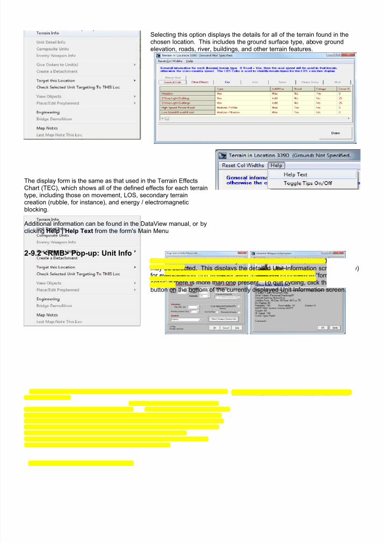
7/21/2019 TSS User Manual
http://slidepdf.com/reader/full/tss-user-manual 101/492
2-9.1 <RMB> Pop-up: Terrain InfoSelecting this option displays the details for all of the terrain found in thechosen location. This includes the ground surface type, above groundelevation, roads, river, buildings, and other terrain features.
The display form is the same as that used in the Terrain Effects
Chart (TEC), which shows all of the defined effects for each terraintype, including those on movement, LOS, secondary terraincreation (rubble, for instance), and energy / electromagneticblocking.
Additional information can be found in the DataView manual, or byclicking Help | Help Text from the form's Main Menu
2-9.2 <RMB> Pop-up: Unit InfoIf one or more non-flank friendly units are in the location, “Unit Detail Info”may be selected. This displays the detailed Unit Information screen (below)for every friendly unit in the location, cycling though them in “formation
order” if there is more than one present. To quit cycling, click the “Cancel”button on the bottom of the currently displayed Unit Information screen.

7/21/2019 TSS User Manual
http://slidepdf.com/reader/full/tss-user-manual 102/492
2-9.3 <RMB> Pop-up: Composite Units A composite unit is a user-defined collection of sub-units that are treated asa single entity to make the simulation easier to use. When composite unitmode is enabled, and one or more non-flank composite units are in thechosen location, this option may be selected from the menu. It will bring upthe Composite Unit information screen (below), which details the sub-unitsin each composite unit and allows for editing and changing composite unitcompositions and characteristics.
Composite units are covered in more detail in other manual sections.
2-9.4 <RMB> Pop-up: Enemy Weapon InfoIf there are known enemy units in the location, and their weapons systemshave been identified, clicking on this option will bring up general informationon the known weapon system(s).

7/21/2019 TSS User Manual
http://slidepdf.com/reader/full/tss-user-manual 103/492
2-9.5 <RMB> Pop-up: Give Orders to UnitsIf one or more non-flank friendly units are in thelocation, this option may be selected. From it,units may be given all of the standard combatorders, or at least the ones they are capable ofperforming.
This option is not available during the “placeunits on map” segment of the Set-up Phase, or if
no non-flank friendly units are in the selectedlocation. In addition, some options may bedisabled if those operations are not possible forthe force or for the specific units in the chosenlocation (for example, the location must containa friendly air unit in order to select “Show AirMissions”).
The orders are:
• Give Movement Orders : clicking this brings up the Unit Movement box, and allows the unit(s) in the location tobe given movement orders. The Unit Movement box allows for either individual or formation movement, and isdescribed later in this section.
• Set DF Targets : if the unit(s) in the location is/are capable of firing DF at enemy targets or objects, clicking thisoption will allow the user to click on another map location containing the desired target, and will thenautomatically bring up the DF fire selection box. The DF fire selection box allows players to set theammunition, ROF and other characteristics, and is described later in this section.
• Show Air Missions : if a unit in the selected location is an aircraft unit capable of flying CAS missions, clickingthis will allow a target location to be selected, and then will automatically bring up the CAS Missions box. TheCAS Missions box enables players to set all aspects of the CAS mission, including SEAD (suppression ofenemy air defense), flight path characteristics, ordinance to use, and the number of passes. The CASMissions box is described later in this section.
• Perform Engineer Op : if the unit(s) in the location is/are capable of performing any engineering operations,
clicking this will allow the user to click on the location for the engineering operation, and then bring up the UnitEngineering box. The Unit Engineering box allows the user to decide what engineering operations to conductin the location as well as assign extra units to speed up the completion time, and is described later in thissection.
• Load Units : this command allows units in the location to be loaded onto a carrier unit. If the carrier unit is in adifferent location, movement orders will be issued to bring the units to the same location.
• Unload Units : if any units in the location are currently loaded, clicking this will enable the passengers to begiven the command to unload. Passengers always unload in their carrier unit’s current location at the time ofunloading.
• Join Units : the units in this location may be given order to join with other units, either in the same location ornot. If the other unit is in a different location, it will be given movement commands to join with the selected unit
The follow-on forms and procedures for each of these commands are covered elsewhere in the manual.

7/21/2019 TSS User Manual
http://slidepdf.com/reader/full/tss-user-manual 104/492
2-9.6 <RMB> Pop-up: Create a DetachmentIf at least one friendly non-flank unit in the selected location has a quantitygreater than 1, clicking this will allow a detachment to be created in thislocation. Once created, detachments are normal units in all respects, andtheir original parent unit is their headquarters.
By default, newly created detachments are merged into a single compositeunit. If warranted, the owning player may override this setting at the time ofcreation.
The procedure for creating a detachment is covered later in the manual.
2-9.7 <RMB> Pop-up: Target this Location
All on and off map locations may be targeted,subject to the force having units capable of firinginto them. Other than airstrikes, units without adirect LOS (line of sight) must use IF (indirect fire).Otherwise, DF (direct fire) is used.
Depending on which selection is made from thismenu: IF, DF or Airstrike, the appropriate targetingbox will appear allowing players to set the firingunits and mission characteristics.
The follow-on forms and procedures for each ofthese commands are covered later in the manual.
This option is not available during the “place unitson map” portion of the Set-up Phase, and theindividual options are only enabled if units of theappropriate firing type are present in the currentforce.

7/21/2019 TSS User Manual
http://slidepdf.com/reader/full/tss-user-manual 105/492
2-9.8 <RMB> Pop-up: Check Selected Unit Targeting to This LocationThis utility answers the question: “Where must the currently selected unitbe placed in order to target/fire at this location?” .
This very useful in that it allows players to insure that key terrain points arecovered with effective fire after they are identified. For example, this will tella player where to place specific anti-tank weapons to be able to fire at amajor crossroads, or where to place a machine gun in order to cover theapproaches to a bridge.
It covers both DF and IF, based on the selected unit's capabilities. If the unithas both, then both will be shown. Otherwise the display will be limited toeither DF or IF.
Results are shown on the map as a Targeting Overlay:
Figure 59: Targeting Overlay results. “DF” indicates the selected unitcan fire into the target location using DF if located in that hex. “IF”
indicates it can use IF. Dark tinting indicates that it can use neither. Ifit can use both, only “DF” is shown.
To use this utility, follow these steps:

7/21/2019 TSS User Manual
http://slidepdf.com/reader/full/tss-user-manual 106/492
1. First select the firing unit by clicking on it from the PlaceUnits on Map Form, the Force Tree or directly from themap. Only one unit can be the “currently selected” unitat a time, and it will always be highlighted on the PlaceUnits On Map Form or the Force Tree. If there is no“currently selected” unit, this option will be disabled.
2. Next, move the mouse over the desired target location,<Right Click>, and pick “Check Selected UnitTargeting to THIS Loc”. The map will display all of thepotential firing positions for the unit, for both DF and IF(if the unit is DF/IF capable). The routine is not limitedby a specific gun/launcher in the firing unit - as long asat least one gun system can hit the target from a firinglocation, that location will be considered acceptable.
3. Perform any intended activities, such as moving,placing, editing units, and/or objects.
Note: some activities, such as checking LOS's, orissuing movement or targeting orders will cause themap overlay to be lost and the map reset. For thesesituations, it is suggested that Map Notes be placed onthe important locations for future reference (Map Notesare covered later in this section, below).
4. Click the [End Operation] button from the Main Formbutton bar to turn off the display and reset the map (if ithas not already been reset from starting an operation).
The specifics of the routine are covered in more detail in a separate section later in the manual.

7/21/2019 TSS User Manual
http://slidepdf.com/reader/full/tss-user-manual 107/492
2-9.9 <RMB> Pop-up: Place/Edit ObjectsObjects are physical entities constructed orplaced by humans, other than combat units, thatoccupy locations on the map. They include:
♦ Bridges (linear road-type spans overunderlying terrain).
♦ Improved Positions (protectivestructures occupied by units).
♦ Minefields (devices activated by the
presence of units).♦ Obstacles (constructions designed toimpede movement).
♦ Sensors (remote devices which detectthe presence of nearby units).
All objects can all suffer loss or damage fromcombat action; most can also be deliberatelytargeted, at least if their presence is known tothe enemy force.
In the Set-up Phase, the top portions of thismenu allow players to either place objects on
the map or to edit the information of objects(editing is limited to objects placed by thefriendly player).
Enemy-placed objects known to the friendly force cannot be edited. However, if the object is fully known, selecting one ofthe place/edit options will show detailed information about it.
In the placement/Set-up Phase, NON-BRIDGE type objects in a location can be cut, copied, and pasted using thestandard Windows-type utilities. Depending on what is in the selected location, up to four options may be available to theplayer:
• Cut Object(s) : This removes all of the non-bridge objects in the location, and places them on the Windows
clipboard.
• Copy Object(s) : This copies all non-bridge objects to the clipboard - leaving the objects in the locationuntouched.
• Paste Object(s) : This places whatever objects are currently on the clipboard into the current location. If there
are not enough placement points to complete the operation, the program will place what objects it can, andinform the player of the shortfall situation. This option is not enabled until one or more objects have been placedon the clipboard with previous a previous “Cut” or “Copy” command.
• Copy Type : The current placement mode is used to limit the copy
operation (as described above) to only the object type currently beingplaced. For example, if the current mode is to place obstacles, selectingthis will copy only the obstacles in the current location to the clipboard.
The selected radio button on the Force Set Up form (see right)determines the placement mode.
The follow-on forms and procedures for each of these placement actions are covered in other manual sections.
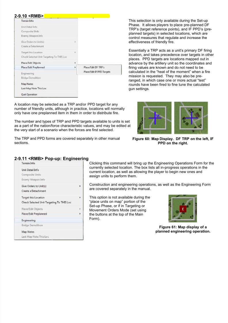
7/21/2019 TSS User Manual
http://slidepdf.com/reader/full/tss-user-manual 108/492
2-9.10 <RMB> Pop-up: Place/Edit PreplannedThis selection is only available during the Set-upPhase. It allows players to place pre-planned DFTRP’s (target reference points), and IF PPD’s (pre-planned targets) in selected locations, which arecontrol measures that regulate and increase theeffectiveness of friendly fire.
Essentially a TRP acts as a unit’s primary DF firing
location, and takes precedence over targets in otherplaces. PPD targets are locations mapped out inadvance by the artillery unit so the coordinates andfiring values are known and do not need to becalculated in the “heat of the moment” when a firemission is requested. They may also be pre-ranged, in which case one or more actual “test”rounds have been fired to fine tune the calculatedgun settings.
A location may be selected as a TRP and/or PPD target for anynumber of friendly units, although in practice, locations will normally
only have one preplanned item in them in order to distribute fire.
The number and types of TRP and PPD targets available to units is setas a part of the nation/force characteristic values, and may be edited atthe very start of a scenario when the forces are first selected.
The TRP and PPD forms are covered separately in other manualsections.
Figure 60: Map Display. DF TRP on the left, IFPPD on the right.
2-9.11 <RMB> Pop-up: EngineeringClicking this command will bring up the Engineering Operations Form for thecurrently selected location. The box lists all in-progress operations in thecurrent location, as well as allowing the player to begin new ones andassign units to perform them.
Construction and engineering operations, as well as the Engineering Formare covered separately in the manual.
This option is not available during the“place units on map” portion of theSet-up Phase, or if in Targeting orMovement Orders Mode (set usingthe buttons at the top of the MainForm).
Figure 61: Map display of aplanned engineering operation.

7/21/2019 TSS User Manual
http://slidepdf.com/reader/full/tss-user-manual 109/492
2-9.12 <RMB> Pop-up: Bridge DemolitionThis command brings up the Bridge Demolition box. It shows all the bridgesin the location that can be blown up, and allows the player to givecommands to do so. To be eligible for demolition, a bridge must be primed,i.e., have explosives placed and wired, and an unbroken friendly unit mustbe nearby.
Figure 62: Bridge Demolition Form. Bridges must be “primed” (with
explosives) before they can be selected for demolition.
Attempts at bridge demolition are not always successful. Sometimes the explosives detonate but the bridge is notdestroyed, or the explosives may fail to go off entirely. In the latter case, nearby units will attempt to re-prime the bridge,and if successful, another attempt can be made at demolition.
The follow-on procedure for bridge demolition is covered later in the manual.
IMPORTANT NOTE: Once a demolition order is given (the “OK” button is clicked), it may not be rescinded.
2-9.2.13 <RMB> Pop-up: Map NotesMap Notes are cosmetic (i.e., “display only”) objects that a player may place
on the map for reference. They have two components:
• A dot which appears onthe map, the color set bythe user.
• And a user defined textstring that will appear inthe pop-up info box whenthe mouse is moved overthe location.
Figure 63: Adding a Map Note.
Examples of map notes:

7/21/2019 TSS User Manual
http://slidepdf.com/reader/full/tss-user-manual 110/492
Figure 64: Example of a Map Note as it appears onthe map.
Figure 65: An example of map notes used to easily identify amovement route (ROUTE RED). Notes can be used to show
key areas, objectives, fire points, unit boundaries, waypoints,and many other control and reference objects.
2-9.2.14 <RMB> Pop-up: Last Map Note This LocSelecting this option places an exact copy (color, text, known-to settings) ofthe last-placed Map Note in the currently selected location.
It is designed to allow players to more quickly and easily add notes forroutes, areas, or lines where multiple Map Notes are required.
Figure 66: Using the “Last Map Note This Loc” menu option to outlinea unit's field-of-fire in seconds.
Section 2-10 Creating a New Game
To create a completely new game (from scratch), select Main Menu | File | Create New Game From Scratch . This willbring up the Game Creation Checklist form:
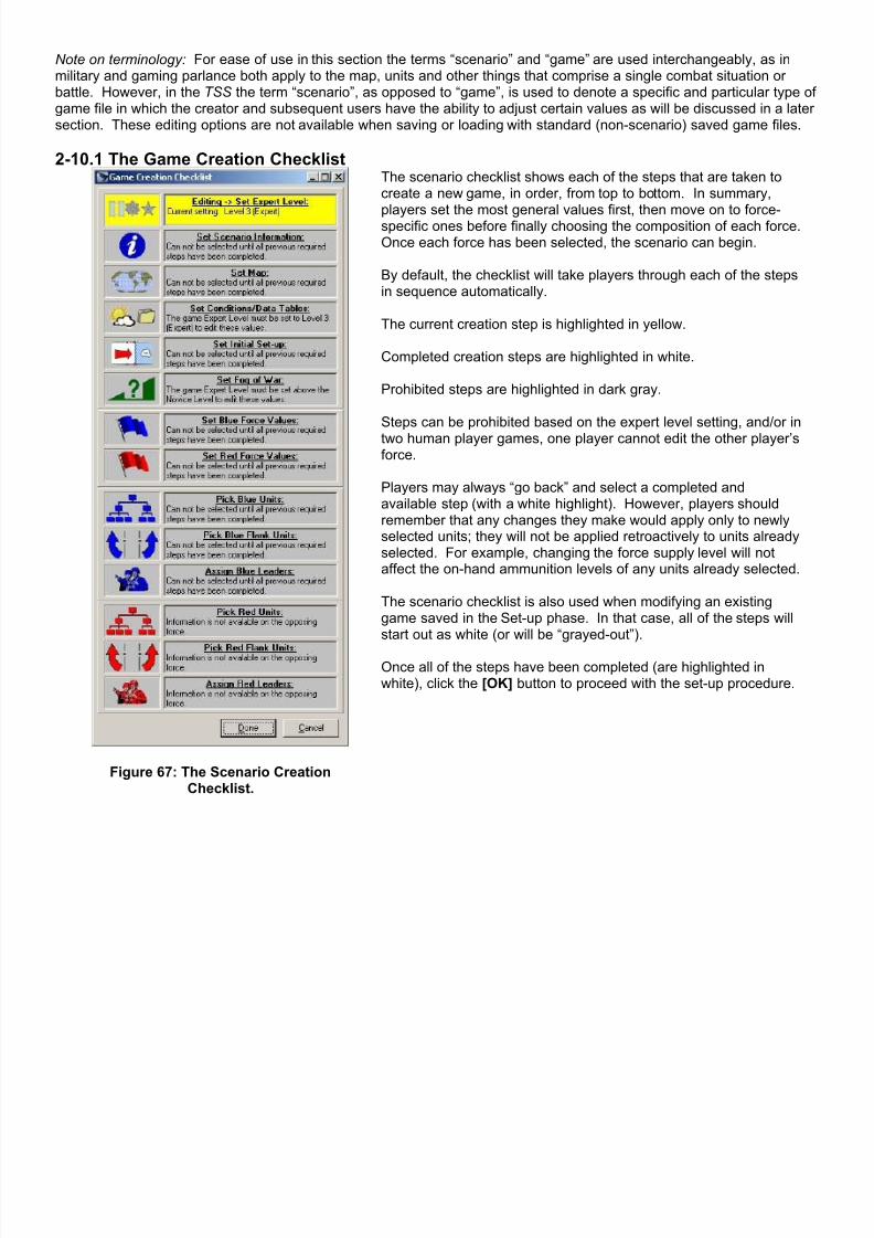
7/21/2019 TSS User Manual
http://slidepdf.com/reader/full/tss-user-manual 111/492
Note on terminology: For ease of use in this section the terms “scenario” and “game” are used interchangeably, as inmilitary and gaming parlance both apply to the map, units and other things that comprise a single combat situation orbattle. However, in the TSS the term “scenario”, as opposed to “game”, is used to denote a specific and particular type ofgame file in which the creator and subsequent users have the ability to adjust certain values as will be discussed in a latersection. These editing options are not available when saving or loading with standard (non-scenario) saved game files.
2-10.1 The Game Creation Checklist
Figure 67: The Scenario CreationChecklist.
The scenario checklist shows each of the steps that are taken tocreate a new game, in order, from top to bottom. In summary,
players set the most general values first, then move on to force-specific ones before finally choosing the composition of each force.Once each force has been selected, the scenario can begin.
By default, the checklist will take players through each of the stepsin sequence automatically.
The current creation step is highlighted in yellow.
Completed creation steps are highlighted in white.
Prohibited steps are highlighted in dark gray.
Steps can be prohibited based on the expert level setting, and/or in
two human player games, one player cannot edit the other player’sforce.
Players may always “go back” and select a completed andavailable step (with a white highlight). However, players shouldremember that any changes they make would apply only to newlyselected units; they will not be applied retroactively to units alreadyselected. For example, changing the force supply level will notaffect the on-hand ammunition levels of any units already selected.
The scenario checklist is also used when modifying an existinggame saved in the Set-up phase. In that case, all of the steps willstart out as white (or will be “grayed-out”).
Once all of the steps have been completed (are highlighted inwhite), click the [OK] button to proceed with the set-up procedure.

7/21/2019 TSS User Manual
http://slidepdf.com/reader/full/tss-user-manual 112/492
During the game creation phase, players maywant to more closely examine the map, which isvisible on the Main Form behind the GameCreation Checklist. To do this, click on the mainform. This will allow for normal zooming andscrolling.
At the same time, the Game Creation Checklistwill move behind the Main Form, and a “speedbutton” will appear on the Main Form at the upperright corner of the map display. This speed buttonresembles the Game Scenario Checklist Form,and clicking it will bring the Game ScenarioChecklist Form forward so that it is active and ontop of the Main Form.
Players may also click on any visible part of theGame Creation Checklist Form to re-activate it.
Figure 68: Click the speed button to re-activate the GameCreation Checklist Form.
2-10.2 Expert Level
The Expert Level is set first, since based on the level selected and its limitations some options may not be available forplayers to choose. Expert levels are designed to make the program easier to use for newer players by limiting the optionsavailable during the game (these are handled automatically by the AI “behind the scenes”).
Figure 69: Expert Level Settings.
The expert levels and their major limitations in the game are:
Novice: This level is designed for new players. It has the following effects: New games: load existing scenarios only. Close Air Support (CAS): Able to select location only. The AI selects everything else. Artillery: Able to select location only. The AI selects everything else. Fog Of War (FOW): Always OFF (all units fully known at all times). Composite Units: Always on, and cannot be edited by the human player. The local “Move Together” and “AI
Targeting Only” options are always enabled. Civilians: None.
Level 1 (Moderate): This level is for players who have played a few scenarios. New games: AI generated forces only; default start conditions (start lines, flanks, emplacement points); default
weather and files; CAI file used if it is found. The AI will auto-place the human player's force. CAS: Able to pick location and specific target. The AI selects everything else. Artillery: Able to pick location and specific target. The AI selects everything else. FOW: No restrictions. Composite Units: Always on, and can be edited by the human player. The local “Move Together” and “AI
Targeting Only” options are always enabled. Civilians: None.

7/21/2019 TSS User Manual
http://slidepdf.com/reader/full/tss-user-manual 113/492
Level 2 (Advanced): This level is for players who are comfortable with the system, but generally want to let the AI picksupport mission parameters.
New games: Nationality values cannot be edited. The cut/paste features are not available in the forceselection form (selecting units from the TO&E).
CAS: Able to pick location, specific target, air unit, and ordinance. The AI selects everything else. Artillery: Able to pick location, specific target, firing unit, and ammunition. The AI selects everything else. FOW: No restrictions. Composite Units: May be enabled or disabled and can be edited by the human player. When enabled, the
local “Move Together” local option is always enabled for all composite units. Civilians: None.
Level 3 (Expert): This level is for players comfortable with the system, and who want full control of all aspects of thesimulation.
New games: No restrictions. CAS: Full control - able to pick location, specific target, air unit, ordinance, SEAD, firing times/durations, and
calling/marking/painting units. Artillery: Full control - able to pick location, specific target, firing unit, ammunition, time on target, and
calling/spotting/painting units. FOW: No restrictions. Composite Units: No restrictions. Civilians: Available if desired.
To “go back” and change the settings, simply click on the“Set Expert Level” button on the Scenario Checklist Form.Note that if a “lower” Expert Level is selected, some currentsettings may be reset (FOW, for example), and not alloptions will be available for editing.
2-10.3 Scenario InformationThe Scenario Information form allows players to enter a name and general description of the scenario being constructed,as well as assigning a picture/graphic bitmap file to it.
Figure 70: New Scenario Information Form.
From the New Scenario Information Form, users can enter and edit the following values, if desired (all the entries areoptional):

7/21/2019 TSS User Manual
http://slidepdf.com/reader/full/tss-user-manual 114/492
Scenario Title : The name for the scenario, generally containing some description of where or what it is about.
Scenario Description : Up to three more detailed descriptions of the scenario. When new text is entered, the radio
buttons at the bottom determine which player can view the text. If “General”, it will be visible to both players,otherwise only Player 1 or Player 2 can access it. This feature is used primarily to allow for a general description,say a short history leading up to the battle, and then for specific orders to be given to each player without thoseorders being known to the other player. In the example above, Player 1 is attacking, and his orders specify hemust seize OBJECTIVE AXE. Player 2’s orders, however, would be different and would likely direct him to defenda certain area, or if attacking, to have a different objective. As long as the individual orders are entered with the
appropriate player’s radio button enabled, the players would not be able to view each others orders. Scenario Icon : By clicking the “Select BMP button”, players may assign any Windows Bitmap (.BMP) file to the
current description (as determined by the General, Player 1 and Player 2 radio buttons described above). Thisgraphic file can be anything the user desires, such as unit crest or an operational graphic of the map with thephase lines and objectives marked, as shown below. Clicking on the picture will bring it up at full-size in WindowsPaint (see below).
Figure 71: The Full-size graphic assigned to the scenario in the above example.
Many of the included scenarios in TSS games use a mission statement in the standard US Army OPORDER format,which is as follows (taken from FM 7-10, “The Infantry Rifle Company”):

7/21/2019 TSS User Manual
http://slidepdf.com/reader/full/tss-user-manual 115/492
US Army Company-Level Standard OPORDER Format
Task Organization (units assigned including those in Direct support)
1. SITUATION.(The company task organization for the mission is stated at the start of the OPORD so that the subordinates know what assets they will haveduring the operation.)
a. Enemy situation.(1) Composition, disposition, and strength.(2) Recent activities.(3) Capabilities.
(4) The enemy’s most probable COA. A sketch or enemy overlay is normally included to clarify the description.b. Friendly Situation.(1) Mission and concept for the battalion.(2) Mission for the unit on the left.(3) Mission for the unit on the right.(4) Mission for the unit to the front.(5) Mission for the unit to the rear or following.(6) Mission for the battalion reserve.(7) Mission for any units supporting battalion if they impact on the company mission.
c. Attachments and Detachments. Changes to the task organization during the operation. For example, if the task organizationchanges during the consolidation phase of an attack, it would be indicated here.
2. MISSION.The mission essential task(s) and purpose(s). It normally includes Who, What, When, Where, and Why. The where is described in terms ofterrain features/grid coordinates. If objective names are used. They are secondary references and placed in parentheses.3. EXECUTION.
a. Concept of the Operation. This paragraph describes how the: CO intends to accomplish his mission. At company level, amaneuver and 'fires subparagraph will always be included. When needed to clarify the concept to ensure synchronization,
additional subparagraphs, such as engineering, Intelligence, EW, and counterair operations, may be included. The operationoverlay/concept sketch is referenced here.
(1) Maneuver. The maneuver paragraph should be focused on the decisive action. At company level, a maneuverparagraph that assign the missions to each platoon and or section and identifies the main effort normally, requires noadditional clarification. If it should, the CO clarify it in the concept of the operation paragraph (paragraph 3a).(2) Fires. This paragraph describes how the CO intends for the fires: to support his maneuver. It normally state thepurpose to be achieved by the fires, the priority of fires for the company, and the allocation of any priority targets. AAtarget list, fires execution matrix, or target overlay may be referenced here.(3) Engineering. Often, especially in defensive operations, this paragraph is required to clarify the CO's concept forpreparing obstacles, mine and fortifications. When the company is supported by engineer equipment or units, the COstates his guidance for employing these assets here. He may do this by stating his priority for the engineer effort(survivability, countermobility, and mobility) and the priority for supporting his subordinates, 3d PLT, 1st PLT, Antiarmorsection, 2d PLT, mortar section, and the CP).
b. Tasks to maneuver units. This paragraph lists each of the platoon’s tasks/limitations. Each of these subordinate units will have aseparate paragraph.c. Tasks to Combat Support Units. This paragraph lists the tasks and limitations for the mortar and antiarmor sections and anyattached combat support units. Each unit will have a separate paragraph.d. Coordinating Instructions. These are the tasks and limitations that apply to two or more subordinate units. If they do not apply toall the subordinate units, then those units that must comply are clearly stated.
4. SERVICE SUPPORT.This paragraph provides the critical logistical information required to sustain the company during the operation.
a. General. It provides current and future trains locations.b. Materiel and Services. It may have a separate subparagraph for each class of supply, as required.c. Casualty Evacuation.d. Miscellaneous.
5. COMMAND AND SIGNALa. Command. This paragraph state where the c2 facilities and key personnel will be located during the operation and adjustments tothe unit sop, such as a change to the succession of command or the standard wire plan.b. Signal It provides critical communications requirements such as radio listening silence in effect forward of the LD, signals forspecific events or actions emergency/visual signals for critical actions, and SOI information.
To “go back” and change the settings, simply click on the“Set Scenario Information” button on the Scenario ChecklistForm.
2-10.4 Select the Scenario MapSelect any valid TSS map for use with the scenario. The larger the map, and in particular the more buildings it has, theslower games using it will run.
TSS maps come in two types:
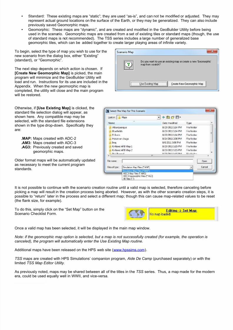
7/21/2019 TSS User Manual
http://slidepdf.com/reader/full/tss-user-manual 116/492
• Standard: These existing maps are “static”; they are used “as-is”, and can not be modified or adjusted. They mayrepresent actual ground locations on the surface of the Earth, or they may be generalized. They can also includepreviously saved Geomorphic maps.
• Geomorphic: These maps are “dynamic”, and are created and modified in the GeoBuilder Utility before beingused in the scenario. Geomorphic maps are created from a set of existing tiles or standard maps (though, the useof standard maps is not recommended). The TSS series includes a large number of generalized basegeomorphic tiles, which can be added together to create larger playing areas of infinite variety.
To begin, select the type of map you wish to use for thenew scenario from the dialog box, either “Existing”(standard), or “Geomorphic”.
The next step depends on which action is chosen. If[Create New Geomorphic Map] is picked, the mainprogram will minimize and the GeoBuilder Utility willload and run. Instructions for its use are included in the Appendix. When the new geomorphic map iscompleted, the utility will close and the main programwill be restored.
Otherwise, if [Use Existing Map] is clicked, thestandard file selection dialog will appear, as
shown here. Any compatible map may beselected, with the standard file extensionsshown in the type drop-down. Specifically theyare:
.MAP: Maps created with ADC-2
.AM3: Maps created with ADC-3
.AG3: Previously created and savedgeomorphic maps.
Older format maps will be automatically updatedas necessary to meet the current programstandards.
It is not possible to continue with the scenario creation routine until a valid map is selected, therefore canceling beforepicking a map will result in the creation process being aborted. However, as with the other scenario creation steps, it ispossible to “return” later in the process and select a different map; though this can cause map-related values to be reset(the flank size, for example).
To do this, simply click on the “Set Map” button on theScenario Checklist Form.
Once a valid map has been selected, it will be displayed in the main map window.
Note: if the geomorphic map option is selected, but a map is not successfully created (for example, the operation iscanceled), the program will automatically enter the Use Existing Map routine.
Additional maps have been released on the HPS web site (www.hpssims.com).
TSS maps are created with HPS Simulations’ companion program, Aide De Camp (purchased separately) or with thelimited TSS Map Editor Utility .
As previously noted, maps may be shared between all of the titles in the TSS series. Thus, a map made for the modernera, could be used equally well in WWII, and vice-versa.

7/21/2019 TSS User Manual
http://slidepdf.com/reader/full/tss-user-manual 117/492
2-10.5 Set Conditions/Data Tables
Figure 72: New Game Default Conditionsmaster form.
The game default conditions master form allows users to use oneor more non-standard data tables, to adjust the general initialconditions and values, to set the weather, including changes overtime, and to edit or change bridges.
To use a non-default file or value, uncheck the box next to thecondition. When the OK button is clicked on the main form, you
will be prompted to select the new file or values to use in place ofthe defaults.
In particular, for large or small scenarios players may want to usethe special Division or Company TO&E’s. These TO&E’s arespecially designed to keep the number of units in play atreasonable and manageable levels for scenarios at these scales.To select an alternate TO&E, uncheck the “Use DefaultOrganization Data” checkbox and then select either“Company.ORG” or “Division.ORG” (if available) when prompted.Use of the Divisional level TO&E should be limited to maps with ascale of 250 meters per location or greater so that the default unitsdon’t violate stacking limits. The Company level TO&E works beston maps around 50 meters per location.
This form and options are not available for games created at lowExpert Levels.
If “Edit Auto Placed Bridges” is checked, when the [OK] button is clicked, the program will automatically cycle througheach bridge that was auto-placed on the map, bringing up the Edit Bridge Information Form for each in turn. Players canedit the information as desired, clicking [Save/Next] to save any changes they made and move on to the next bridge,[Cancel/Next] to cancel the changes they made and move on to the next bridge, or [Quit] to stop cycling though thebridges and return to the main set-up sequence.
The Edit Bridge Information Form will be discussed in more detail in a later section on editing placed objects.
To “go back” and change any of the Conditions settings,
simply click on the “Set Conditions / Data Tables” button onthe Scenario Checklist Form.
2-10.5.1 Using Custom Data FilesTo use a non-standard data file (one with a file name other than “standard.NNN”), uncheck the box next to the category offile.
This option allows users to customize the data as desired, and to save the file to a new name so as not to overwrite anddestroy the standard data tables (which may be used by other saved games - including the scenarios, and havingmodified ones in their place would likely cause errors or crashes).
2-10.5.2 Setting the Environmental ConditionsThe Set Conditions Form allows users to change the time of day, lighting and non-weather meteorological vales, as wellas the LOS characteristics, turn resolution and map scale.
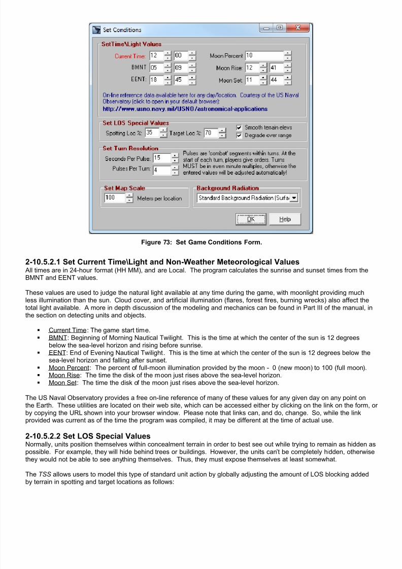
7/21/2019 TSS User Manual
http://slidepdf.com/reader/full/tss-user-manual 118/492
Figure 73: Set Game Conditions Form.
2-10.5.2.1 Set Current Time\Light and Non-Weather Meteorological Values All times are in 24-hour format (HH MM), and are Local. The program calculates the sunrise and sunset times from theBMNT and EENT values.
These values are used to judge the natural light available at any time during the game, with moonlight providing much
less illumination than the sun. Cloud cover, and artificial illumination (flares, forest fires, burning wrecks) also affect thetotal light available. A more in depth discussion of the modeling and mechanics can be found in Part III of the manual, inthe section on detecting units and objects.
Current Time : The game start time. BMNT : Beginning of Morning Nautical Twilight. This is the time at which the center of the sun is 12 degrees
below the sea-level horizon and rising before sunrise. EENT : End of Evening Nautical Twilight. This is the time at which the center of the sun is 12 degrees below the
sea-level horizon and falling after sunset. Moon Percent : The percent of full-moon illumination provided by the moon - 0 (new moon) to 100 (full moon). Moon Rise : The time the disk of the moon just rises above the sea-level horizon. Moon Set : The time the disk of the moon just rises above the sea-level horizon.
The US Naval Observatory provides a free on-line reference of many of these values for any given day on any point onthe Earth. These utilities are located on their web site, which can be accessed either by clicking on the link on the form, oby copying the URL shown into your browser window. Please note that links can, and do, change. So, while the linkprovided was current as of the time the program was compiled, it may be different at the time of actual use.
2-10.5.2.2 Set LOS Special ValuesNormally, units position themselves within concealment terrain in order to best see out while trying to remain as hidden aspossible. For example, they will hide behind trees or buildings. However, the units can’t be completely hidden, otherwisethey would not be able to see anything themselves. Thus, they must expose themselves at least somewhat.
The TSS allows users to model this type of standard unit action by globally adjusting the amount of LOS blocking addedby terrain in spotting and target locations as follows:

7/21/2019 TSS User Manual
http://slidepdf.com/reader/full/tss-user-manual 119/492
Spotting Loc % : This is the percent of LOS blocking that will be applied from terrain in a spotting unit’s location. Ifit is zero, it indicates that spotting units always position themselves so that the terrain in their location has noeffect on them seeing out in any direction. At 100%, the terrain has normal blocking capabilities, indicating thatunits never try to position themselves to better see out of their current location.
Target Loc % : This is the percent of LOS blocking that will be applied from terrain in a target object’s location. Ifit is zero, it indicates that target units always position themselves so that the terrain in their location has no effecton them being seen from any direction. At 100%, the terrain has normal blocking capabilities, indicating that unitshave not taken any steps to adjust their position within the current location.
Normally the spotting percentage will be lower than the target percentage, since units position themselves to maximizeclear outbound sighting lanes (represented by a lower spotting %), while using the terrain to mask as much of themselvesas possible from the enemy (represented by a higher target %). Two other LOS values may be changed from this form, to give designers additional control over how effective the spottingis:
LOS smoothing: When enabled, this routine removes “steps” in the ground surface cross sections by replacing them withmore natural smooth slopes. The steps are caused by the format of the map itself, where the map is comprised of alimited number of individual “hexes” or “locations”, each with a discrete elevation, but not interim elevations between themThis essentially makes each location a “step”. The larger the distance between the centers of the locations, the more“step like” the cross sections will be, and the more necessary smoothing becomes (at a cost in execution speed).Degrade Over Range: If enabled, this setting adds blocking points to the LOS based on the ratio of the actual range to
the maximum sighting range. The blocking points are added proportionally, so at 10% of the maximum range 10 pointsare added, at 60% of the max range 60 points are added, and so on (100 points blocks the LOS completely). Themaximum sighting range is set as part of the weather conditions, as described below. If this option is disabled, themaximum sighting range still applies as an ultimate limit, but blocking points are not added based on the range.
2-10.5.2.3 Set Turn Resolution As described elsewhere in this manual, combat action in the TSS is organized into turns which are themselves comprisedof pulses. The duration of the pulses, and number of pulses per turn, affect the overall accuracy of the simulation, theexecution run time, and the amount of flexibility players have in terms of controlling their forces.
Pulse duration is in seconds. Turn duration is in pulses. Therefore, if a pulse is 15 seconds, and there are 4 pulses to aturn, a turn will last 60 seconds.
All of the modeling in the TSS is done based on seconds of game time elapsed. However, these setting do affect theoverall accuracy of the simulation in that many activities occur only one per pulse or turn. For example, the AI strategyoperates only once per turn, the AI tactical routines occur once every other pulse (or two minutes, whichever is longer),while the SITREP processing and environmental change routines occur once per pulse. Therefore, it is true to say thatthe shorter the pulse duration, the more accurate the simulation.
However, the difference in accuracy also depends on the units involved and map scale. As a rule of thumb, the slowerthe units and the lower their rates or fire, the longer the pulses and turns can be. Likewise, but to a much lesser extent,the larger the map scale, the longer the pulses and turns.
2-10.5.2.4 Set Map ScaleThe map scale is the size of each location (hex or grid). Larger location sizes allow the on and off map areas to covermore ground, and allow for larger forces, but they also reduce the accuracy of the simulation modeling.
In general, the map scale should never be greater than about 25% of the standard main weapon ranges. For example, ina game comprised of mostly small arms equipped infantry, the map scale should be kept below 250 meters - assumingthe weapon ranges to be about 1000 meters. In a game with a significant number of M-1 tanks with a maximum weaponrange of about 4000 meters, however, the map scale could be up to 1000 meters.
The default scale for the TSS Series is 100 meters per location.
2-10.5.3 Setting the Weather The Current Weather Conditions Form allows players to adjust the atmospheric weather and ground conditions, and alsoallows them to change over the course of the game.

7/21/2019 TSS User Manual
http://slidepdf.com/reader/full/tss-user-manual 120/492
Figure 74: The Current Weather Conditions Form.
2-10.5.3.1 Setting the Weather Period Length
The weather period is the interval at which weather changes during the course of the game. It can be as little as 30minutes, or as great as 12 hours. While the conditions may change with each period, the duration of a period does not -the weather period is constant for the entire game.
As will be described below, weather and conditions do not instantly change suddenly from one state to another at the startof a new weather period. Instead, the program models the reality that conditions tend to change over time, although somechanges may be deemed to occur quickly, within the space of a few minutes.
2-10.5.3.2 Setting the Values For Each Weather PeriodUse the Time Period Display grid (with the bold red text entries) to set the weather conditions at the start of each weatherperiod. To change a value for a specific time period, click anywhere on the time period line in the grid. The currently setweather and ground conditions will appear in the Period Information Boxes just below the grid.
You can change the values individually, and/or select a new “default” weather/ground type from the drop down box. Toadd new default weather or ground types, or to change the values of the existing default types, use the TEC data tableeditor in the DataView module.
The weather/ground condition values are: Temperature : The ambient air temperature, in degrees C. Wind Speed : The average wind speed in Kph.
Wind Direction : The wind “from” direction, in compass degrees (0° North, 90° East, 180° South, 270° West). Precipitation % : This is the relative amount of precipitation falling, not the percent chance of precipitation
happening at all (which is calculated automatically by the program based on analyzing changes in the weatherperiod values). This value ranges from 0 (no precipitation), to 100 (very heavy rain or snow).

7/21/2019 TSS User Manual
http://slidepdf.com/reader/full/tss-user-manual 121/492
Cloud Cover % : The approximate amount of visible sky occupied by clouds, from zero (no clouds) to 100(completely overcast).
Cloud Bottom : The approximate height of the bottom of the clouds, in meters. Cloud Height : The approximate height of the clouds, in meters. Max Sight Range : The maximum extent of a visual LOS, irrespective of any other factors, in meters. Foliage % : The relative percentage of foliage present, in percent of “normal” (the value entered in the TEC).
Values less than 100% decrease the amount of foliage (making it easier to see through), while values of above100 increase it (and make it harder to see though). The foliage percent is used only for blocking visual LOS’s - ithas no other effects.
Dust % : This value modifies the amount of dust generated from moving units from “normal” (the value in theTEC). Values below 100% lower dust generation, while those above 100% increase it.
As was previously mentioned, the program automatically “transitions” between successive weather period conditions.Normally, these transitions are made gradually, for example, if the temperature is 20 degrees at 12:00 and 25 degrees at16:00, the scenario temperature will rise gradually between 12:00 and 16:00. It does not jump all of a sudden at 16:00.
However, in certain cases, the models may “decide” that the transition should proceed quickly, to represent the passageof a fast moving front, for example. The factors involved are the amount of difference in conditions between twoconsecutive weather periods (the greater the difference, the higher the chance of a quick transition), and the weatherperiod length (the shorter the period, the greater the probability of a quick transition).
Other than setting the conditions at each of the weather period intervals when the game is first set-up, players cannot set,change, or specify the weather conditions at any point in the game. The program’s weather models do it automatically.
The weather is always assumed to be the same everywhere, both on and off map.
2-10.5.3.3 Adding or Deleting Days of Weather To add or delete a day’s worth of weather periods use the buttons: [Add Day] and [Delete Day] at the bottom of the form.The program will automatically check that enough days of weather have been defined to cover the length of the game,and if necessary, will create them using the values already entered.

7/21/2019 TSS User Manual
http://slidepdf.com/reader/full/tss-user-manual 122/492
2-10.6 Initial Set-up ConditionsThe initial set-up conditions determine the general positioning, composition, mission and nationality of the forces that willbe participating in the scenario. It is also used to set up victory conditions and civilian involvement.
Figure 75: The Initial Conditions Set-up Form.
Blue tinted values apply to Player #1 (the “blue” force).
Red tinted values apply to Player #2 (the “red” force).
Light gray tinted values are not player specific and apply to the scenario as a whole.
Dark gray tinted values are not selectable due to the situation or the Expert Level setting.
The major sections of the form are:
♦ Mission : The force’s general combat assignment for the duration of the scenario.o Missions are “location oriented”, in that the force must either seize (if attacking) or hold (if defending)
portions of the map area. In most cases, one player is attacking and the other defending. However, bothplayers can also be attacking, which is known as a meeting engagement.
7/21/2019 TSS User Manual
http://slidepdf.com/reader/full/tss-user-manual 123/492
o The force’s mission is also used by the AI when placing unit and formulating strategy.
♦ Start Conditions : This section details the orientation and set up areas of each force.o Each force must either start from a friendly map edge, or in more fluid situations, use the “free-set” option.
One word of caution with the “free set up” option, though, is that the AI cannot effectively position forceson the map. As such, “free set up” games should always be designated as human vs. human, at leastinitially, so that the human player can place the forces appropriately.
o Hexes In From Edge: This is the width of the buffer area in which the player will be permitted to set up.
The distance is measured in “hexes” (or locations) towards the center of the map from the specifiedplayer’s friendly edge.
The actual distance, in meters, can be calculated using the “Hex Size” value shown below thepanel (note: “Hex Size” is the same as the Map Scale). The edge of the buffer area towards thecenter of the map is known as the player’s Start Line, and he will only be able to place forcesbehind it (towards his friendly edge).
Normally, player edges will be opposite of each other, e.g., East - West, or North - South, and agap, or “no man’s land”, will be left between the two start lines. To calculate the size of the gapadd the two “Hexes In From Edge” values, and compare them to the appropriate map dimensionvalue shown below the panel. For example, if the map is 100 hexes wide and the blue player is15 hexes in from the West edge and the red player is 70 hexes in from the East edge, the gap willbe 15 hexes wide, i.e., 100 - (15+70).
o Flank Size: Flanks represent areas that are occupied by and the responsibility of friendly formations
outside of the player’s control, but that belong to the same higher force and have the same generalmission of the player. While flank areas are not strictly “off limits”, main force units venturing into themare at higher risk of being engaged by friendly forces in the flank area or becoming involved in traffic jams.
The flank size is the width of these areas, as measured in from the map edge, to the left and rightof the player’s force based on its “facing” towards the enemy, i.e., perpendicular to the start edge.For example, if the start edge is to the west, the flank areas will be to the north and south.
Free set up forces do not have flanks. The AI will not move units into flank areas – therefore they can be used to limit the “effective” map
area in scenarios where this is appropriate.o Emplacement Levels: This is the number of “points” of Improved Positions (IP’s), Obstacles, and Mines
that the player will have available to place on the map in the set up phase. Normally a defending playerwill have more points that an attacker, but this depends on the overall situation.
Each object’s point cost is equal to its victory point value as specified in the data tables. VictoryPoint values can be edited in the DataView module.
Check the “Unlim” box to give the force an unlimited number of points.
♦ Control : Forces can be either human or AI (computer) controlled.o When creating games that will use free set-up, or that will eventually be saved as a true scenario, it is
recommended that both players be set to human controlled.
♦ Nation : Select the nationality of each force.o Nations are defined using the DataView module.
o Force Selection: This determines how the force’s units will be selected.
o Manual: The human player will manually select all of the force units. This option is not available at the
low Expert Level - force selection is automatic.o Generated: The program will select a force of the size and quantity selected below the radio button. For
example, if the size is set to “Bn/Sqdn/NTU” and the quantity is 3, the computer will automatically select aforce comprised of approximately 3 ground battalions plus support units (or 3 aircraft squadrons or 3naval task units, based on the formations available for the force’s nation). The actual auto-selection ofunits does not happen immediately, but occurs in the player’s force selection step, as will be described ina later section.
♦ Victory Conditions : The victory conditions specify what the force must accomplish to “win” the scenario, in termsof enemy forces destroyed and/or terrain objectives taken as well as the maximum permissible friendly losses.When determining loss percentages, victory point values are used to determine each weapons system’s “cost” as apercent of the force.
o Min: The minimum percentage of the enemy force that must be destroyed
o Max: The maximum permissible friendly losses
o Objective Radius: Attacking force objectives can be specified as either one or more physical map
locations, or the capture/destruction of a unit or object. If the selection is location-based, then thisdistance determines how far a unit can be from an objective location and still be considered to “occupy” itfor victory purposes. If this value is equal to, or less than, the map scale (i.e., how large each hex or

7/21/2019 TSS User Manual
http://slidepdf.com/reader/full/tss-user-manual 124/492
location is, in meters), then units will need to occupy the objective location itself in order to be considered“on it”. Otherwise, units may be multiple locations distant, and still considered “on” the objective, as longas they are within this radius. The Objective Radius value has no effect on unit/object based objectives.
o Extended Radius %: This value creates a “near the objective” victory zone which extends out a
percentage of the standard Objective Radius. For example, if this value is set to 200%, and the ObjectiveRadius is 300 meters, units within 600 meters of the actual objective (200% x 300 meters) will be countedas “near” the objective. Units “near” an objective have less worth towards victory than units “on” it,approximately 1/3 to 1/5th as much. The Extended Radius value has no effect on unit/object basedobjectives.Note: Objective values are set ONLY for attacking forces. Defending forces simply prevent the attackerfrom achieving his objectives. If it is desired to give both sides objectives, then the scenario should be seup as meeting engagement – where both forces are attacking.
♦ General : These values determine the level of civilian involvement and the length of the game.o Civilian units do not engage in combat and are controlled by the AI player. However, they can cause
movement issues, and wounding or killing civilians lowers a player’s final victory score. When created atthe start of the scenario civilian units are almost always placed in a location with a road or building. Whencreated during the battle itself, however, civilian units always appear in a location with buildings.
% Level: This determines the number of civilians present on the map at the start of the game. Ata level of 100% approximately one unit (family sized) is placed every square kilometer.
Probability: This determines how many and how often civilians will be created once the game isunder way. It is the expected increase in civilian units, based on those present at the start, in onehour. At 100%, for example, after the first hour the number of civilian units will have doubled, bythe end of the second it would have tripled, and so on (ignoring losses and those that move off
the map).o Scenario Duration: This is the length of the scenario in turns. The actual time in hours and minutes is
also shown. When this time has expired, victory will be established and the scenario consideredcompleted. If the game had been proceeding in auto-run mode, control will return to the human player.
o Add Other End Conditions: This option is intended principally for scenarios that will be run in unattended
(AI vs. AI) batch mode. Specifically, it prevents wasted time from having a scenario continue to run to it's“end turn”, even after victory has already been decided or a force force effectively destroyed.If checked, the End Scenario Early Conditions Form willappear when the [Done] button is pressed on theScenario Control Checklist Form (shown at right), beforeplacing units on the map. This form will be covered laterin the manual.

7/21/2019 TSS User Manual
http://slidepdf.com/reader/full/tss-user-manual 125/492
2-10.6.1 Selecting Civilian Types As was stated previously, the AI controls all aspects ofcivilian “units” and their actions. This includes selectingand placing them at the start of the scenario, and duringthe game turns. If civilians were selected to participate inthe scenario, either being present at the start or frombeing placed during the game, the scenario creator mustset the types of civilian “units” available to the AI.
To do so, the form shown at right will automatically pop-upwhen the Initial Conditions Form closes. It lists all of thecurrently defined civilian weapons system types, with acheck box next to each. When creating new civilian units(either at the start or during the scenario), the AI will onlyconsider the types that are checked (i.e., all civilian unitswill be of one of these types).
If no boxes are checked, the AI will select randomly fromall defined types.
Weapons systems are defined as “civilian” in theWeapons Systems Data Table.
Figure 76: Selecting available civilian types. These valuesare set during set-up and may not be changed afterward.
2-10.7 Fog of War (FOW)
Figure 77: Setting the Fog of War Level.
Fog of War is a term used to describe the lack ofcomplete and accurate information available to acommander and forces on the battlefield. Mostcommonly, it is applied to knowledge deficits of enemyunits, which must be sighted, analyzed and reported byother friendly units - a time consuming and not alwaysaccurate process.
However, FOW can also apply to friendly units, since itrepresents anything less than perfect and up to the
second knowledge - a condition rarely achieved withanything but the smallest units.
The TSS models FOW by having each unit, including thecommander, maintain “knowledge” on what it knowsabout every other unit currently in play. This knowledge,which is rated by “quality”, is gained either by directobservation or from reports by other units passed throughthe chain of command.
At higher Expert Level games, the TSS allows users to modify the FOW settings in order to provide a balance betweenplayability and realism. High FOW games are more accurate, and provide a more correct depiction of the commander’ssituation, but are also usually harder and more confusing to play.
2-10.7.1 FOW LevelsThe available FOW levels are:
OFF : Every unit in the game is always completely and fully known by every other unit in play, both friendly andenemy. This setting is ALWAYS used for low Expert Level games, and can not be modified.
7/21/2019 TSS User Manual
http://slidepdf.com/reader/full/tss-user-manual 126/492
Level 1 : Friendly units are always fully and completely known. Friendly units that sight enemy units gain perfectand complete knowledge of them. However, other friendly units do not automatically know this information; itmust be transmitted between units by SITREP’s (situation reports) using the chain of command.
Level 2 : The same as level 2, except that friendly units do not gain perfect knowledge of enemy units when theyare sighted. Instead the information gained will be rated for “quality” based on the circumstances (and possiblean element of chance), and will range from only knowing that an enemy unit of some type is present to knowingthe exact enemy weapons systems and numbers.
Level 3 : The same as Level 2, with the exception that the position of moving friendly units may not be exactlyknown. Instead, an estimated position will be calculated using the last known position report from the friendly unitcorrelated with its speed and movement orders.
Level 4 : Same as Level 3, with the added condition that the player's “viewing perspective” is locked to that of theTask Force HQ. Because targeting and certain other orders require that the human player “see” exactly what theselected unit “sees”, these operations are blocked. They may be given ONLY to the HQ unit where the player isconsidered “located” (normally the TF HQ).
Standard Game : The same as Level 1, with the exception that every friendly unit knows of every sighted enemyunit immediately. SITREP’s are not used.
2-10.7.2 Locking the FOW LevelsIn two-human player games, the Fog of War setting can be locked to prevent it being changed by either player during thegame without the others knowledge. To lock the FOW settings in their current levels, check the “Lock FOW” box.
2-10.7.3 Using Different FOW Levels For Each Player The FOW level is set individually for each force. While they will usually be the same, this is not required and they may beset to different levels if desired.
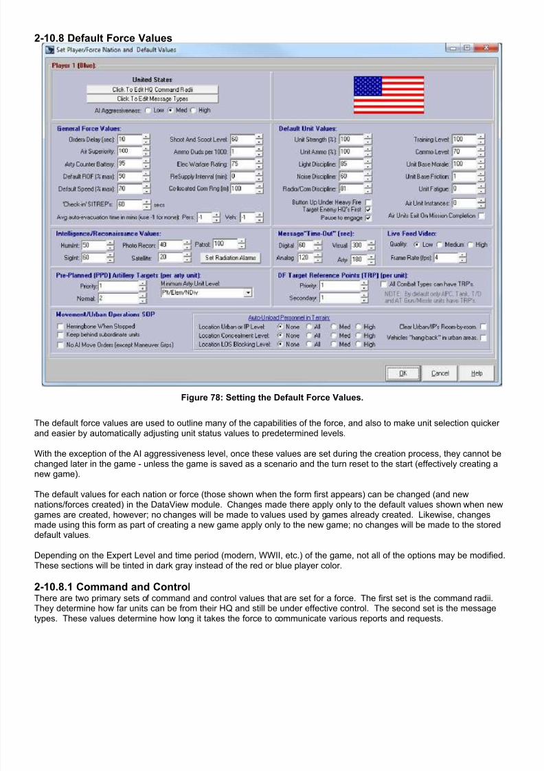
7/21/2019 TSS User Manual
http://slidepdf.com/reader/full/tss-user-manual 127/492
2-10.8 Default Force Values
Figure 78: Setting the Default Force Values.
The default force values are used to outline many of the capabilities of the force, and also to make unit selection quickerand easier by automatically adjusting unit status values to predetermined levels.
With the exception of the AI aggressiveness level, once these values are set during the creation process, they cannot bechanged later in the game - unless the game is saved as a scenario and the turn reset to the start (effectively creating anew game).
The default values for each nation or force (those shown when the form first appears) can be changed (and newnations/forces created) in the DataView module. Changes made there apply only to the default values shown when newgames are created, however; no changes will be made to values used by games already created. Likewise, changesmade using this form as part of creating a new game apply only to the new game; no changes will be made to the storeddefault values.
Depending on the Expert Level and time period (modern, WWII, etc.) of the game, not all of the options may be modified.These sections will be tinted in dark gray instead of the red or blue player color.
2-10.8.1 Command and ControlThere are two primary sets of command and control values that are set for a force. The first set is the command radii.They determine how far units can be from their HQ and still be under effective control. The second set is the messagetypes. These values determine how long it takes the force to communicate various reports and requests.

7/21/2019 TSS User Manual
http://slidepdf.com/reader/full/tss-user-manual 128/492
2-10.8.1.1 Command RadiiThe command radii values are used to determine how far units can be from their HQ and still be within effective commandand control. The radii primarily represent communications capabilities, but also the ability of the HQ to understand and beable to act upon the conditions and situations encountered by remote subordinate units. This also includes how accuratethe force’s maps and other intelligence information is, since if the HQ’s view of the unit’s area of operation does not matchreality, many more reports and adjustments to orders will be necessary to bring the HQ in line with the actual ground andsituation.
Units outside of a HQ’s maximum command radius require more time to receive orders and to transmit SITREP’s. The
further the unit is outside the radius, the greater the delays involved.
Figure 79: Edit Command Radii Form.
Command radii are measured in meters, and are defined by HQ size and general stacking type, as shown above. Forcomposite units, the nominal HQ unit is used. The maximum range is 32,000 meters (32 Km).
To edit a value, click on that cell in the grid.
Click [Reset] to return all values to the default values.
Click [Cancel] to quit editing without making any changes.
Click [Done/Save] to save the changes and exit.
2-10.8.1.2 Message Types A set of standard message types is used to transfer information, orders and requests for support. The general categoriesfor messages are:
Generic : Anything not specifically defined by another message type. SITREP (Situation Report) : Any report providing information on friendly or enemy forces, battlefield objects,
and/or terrain. Move Order : Movement commands of any type. Call for CAS : Request for a Close Air Support (CAS) mission.
Call for Artillery : Request for a fire support mission. Engineering : Orders to begin construction of an engineering project. Acknowledge : Simple acknowledgment of a received transmission. Live Feed : Continuous transmission (video/audio/etc.).
Message types are defined for both voice (radio) and data. This allows for different transmission times based on thesending method. For voice/radio, the sending rate is a standard 100 Bits per second. Thus, a message that is 3000 bitslong will take 30 seconds to send (under ideal conditions).

7/21/2019 TSS User Manual
http://slidepdf.com/reader/full/tss-user-manual 129/492
For data, the sending ratedepends on the capacity ofthe equipment, and whetheror not other messages arebeing transmitted andreceived at the same time.Capacity (or “bandwidth” asused in LAN/Internet lingo) isspecified in theCommunication JammerSystem Table.
Figure 80: DataView Communications System Data Table (capacity highlighted)
The standard message size and unit effects can be edited for each force by clicking the [Click to Edit Message Types]button, located just under the flag graphic.
Figure 81: Edit Message Characteristics for Force
Users can change the name of the message, which is purely cosmetic, for easier identification in the reports. However,the Type and Mode values can not be changed – these are used by the program to determine what form of messageshould be sent in a given situation. The Type value specifies what information the message contains (and thus when it is
issued), while the Mode value determines whether the message is sent using Analog or Digital signals.
The Size and Unit effects values can also be adjusted for each message type. Message size is used to determine howlong a message takes to transmit, and for digital transmissions, how much “bandwidth” the message will take up.
• For analog/voice transmissions, a standard transmission rate of 100 bytes per second is used. Thus, a voicemessage of 2500 bytes will take 25 seconds to transmit.
• For digital transmissions, the size is the actual all-inclusive size of the message, and including “sync” bits,“checksums”, block and message headers, TCP, IP addresses and other control/admin data bits. The actual timeto send the message will be determined by the speed of the connection and any bandwidth restrictions caused byother message traffic using the same connection.

7/21/2019 TSS User Manual
http://slidepdf.com/reader/full/tss-user-manual 130/492
The % Unit Effects is a measure of whether or not unit situation and conditions are taken into account when sending themessage. Examples of these unit conditions are morale, training, and suppression. If a value of 100% is used, the timewill be adjusted normally - no adjustment or deviation from the standard models. Otherwise, the adjustment time (eitherplus or minus) will be modified by the entered percent.
For more information on messages and processing, please see the section on Communications in Part 3 of the manual.
2-10.8.2 AI Aggressiveness LevelThe AI aggressiveness level determines how the AI will view the current situation, and what actions it will take. On
balance, more aggressive AI leads to more risk taking, and the to attempt to dominate the battle are as quickly aspossible, even if that means that control can not be sustained over the long term. Less aggressive AI, by contrast, takesfewer risks and prefers to wait for situations to develop in order to make sound decisions.
On the tactical level, forces with higher aggressiveness will tend to open fire at longer ranges and lower kill/damageprobabilities, be less likely to conserve ammunition, will favor speed over cover and concealment, and be more likely tocall for fire support and use it against less well defined targets. On the strategic level, aggressive AI tends to concentrateforces on what it perceives as the decisive point and to have minimal reserves. “Fast and furious” is this AI’s motto.
On the other hand, forces with low aggressiveness will tend to favor waiting to open fire until reasonable hit/kill/damageprobabilities can be achieved, will attempt to conserve ammunition so that it lasts, and will favor cover and concealmentover speed when moving. Strategically, the AI will spread forces out more evenly, and will keep units in reserve forunexpected situations. “Slow and steady” best describes this way this AI thinks and acts.
Forces with medium level aggressiveness attempt strike a balance between the other two, although at times they mayactually act as one or the other for a short time.
2-10.8.3 General Force ValuesThese values are used to model the capabilities of the force in general.
♦ Orders Delay : This is the average time, in seconds, required for an order or SITREP to be transmitted by radiobetween a HQ and subordinate unit. When a transmission method besides radio is used, for whatever reason, theprogram will automatically calculate the time based on the actual method. Actual orders transmission times alsotake into account the situation and state of the two units involved, if an leaders are present, and environmentalconditions.
♦ Air Superiority : The air superiority level represents air assets outside of the immediate battle that are assignedto prevent enemy air operations over it. These assets are not available for direct control by the player, but have
several effects in the game:o Initial enemy air unit reduction: At the start of the scenario, all enemy air units (those actually in play) will
be reduced randomly in strength by about four fifths of the friendly air superiority level. For example, ifthe friendly air superiority level were set to 50, on average each enemy air unit would be reduced byabout 40% (4/5ths times 50 = 40%) of its starting strength. This reduction is based solely on the friendlyair superiority level; the enemy level is ignored. Thus, in games where both players have high airsuperiority levels, both players will suffer high losses to their air units. And, in games where both levelsare low, both players will suffer minimal losses.
o Friendly air unit targeting: As the friendly air superiority level increases, friendly units are less likely to
erroneously target friendly air units, and if they do, will realize their error and cease fire more quickly.
♦ Arty Counter Battery : The counter battery (CB) level represents friendly assets outside of the scenario forcescapable of detecting and triangulating enemy artillery fire. Detection depends on the type and caliber of the enemyartillery unit firing, the rate of fire, and the duration of firing. In general, the greater any of these values, the greater
the detection probability. The CB level is used in two ways. First, it determines the base detection probability andthe quality of the report if detection occurs. Second, it determines the minimum caliber and flight time required fordetection. When enemy units are detected by counter-battery, they become known and visible on the map to thefriendly force.
♦ Shoot and Scoot Level : Shoot & Scoot (S&S) is a tactic in which a unit fires a round or two, and then moves intoa nearby covered and concealed position for protection against return fire and spotting. The Shoot and Scoot Leveis the probability, 0-100%, of a unit doing this when firing at enemy targets. At a value of zero, units will never enterS&S mode, while at 100% they always will. Using S&S has several effects:
o Units use a reduced ROF and do not acquire targets (since they spend less time firing).
o The ROF of incoming fire is decreased, since the unit rescues its exposure time.
o The firing unit is harder to spot by the enemy.

7/21/2019 TSS User Manual
http://slidepdf.com/reader/full/tss-user-manual 131/492
o NOTE: The protected position can be provided by above ground terrain or constructive features in the
location, but is often just a dip in the ground level. To model this effect, units in the TSS do not need tobe in any kind of special terrain to use shoot & scoot techniques, but if there is no terrain in the location,the effectiveness of the protection and concealment provided by it will depend on the “roughness” of themap.
♦ Ammo Duds per 1000 : This is the expected ammunition malfunction rate, from any cause, in rounds per 1000attempted firings. This rate is applied to all ammunition used by the force; it is not adjusted for specific types ofammunition. Dud rounds can cause weapon jams and malfunctions, although normally they merely result in theround being ignored and having no other effects once it is “fired”.
♦ Electronic Warfare Rating : This general rating represents the quality and quantity of electronic warfare (EW)assets available to EW units inside the force, as well as to those outside of it. It is also used as a measure of thetechnological level of the force’s electronics in general, including communications, ECM, and ECCM for ground, air,and naval units. The EW Rating is used in the following specific areas:
o Jamming: The EW level determines the amount, effectiveness, and range of friendly radio jamming
efforts, and reduces those of the enemy.o Guided Missile Launchers: The higher the EW level, the greater the reliability and lower the repair time of
guided missile launch systems.o Radar EECM: The EW level is used to quantify the ability of friendly ground, airborne, or guided missile
radars in to defeat enemy jamming and other countermeasures.o Radio Intercept: The EW level sets detection probability of radio intercept weapons systems or remote
sensors.
♦ Re-Supply Interval : This is the average time, in minutes, at which units will be re-supplied with ammunition.
The re-supply is automatic, in that it does not require specific ammunition carrier units to transport the ammunitionto the receiving units. The rate of ammunition transfer is based on the caliber and weight of the ammunition,among other things. The larger the caliber, and the heavier the weight, the longer it will take to transfer a round.Units receiving ammunition must be in the normal morale state to do so, and must not be under threatening enemyfire. If at any point during the transfer these conditions change, the transfer will be aborted. Ammunition transferwill cease once the weapon system basic load is reached, adjusted by the force supply level (described below).
♦ “Check-in SITREP Period : Units without digital and GPS systems will attempt to send SITREP’s to their HQ oftheir complete situation at the set interval over the duration of the scenario. For example, if this is set to 600seconds (10 minutes), every 10 minutes units will send a SITREP containing everything they know about, includingthemselves, to their HQ. This is in contrast to normal SITREP’s, which are sent only when something changes.
o The lower the check-in period, the more up to date the HQ’s information will normally appear, although it
should be noted that the information will usually not be any more accurate than it would without thecheck-in (since normal SITREP’s would still let the HQ know when anything changes). However, lowercheck-in times also create more radio traffic, which will tie up bandwidth and expose the units todetection.
o Units under heavy fire or moving will normally not make check-in reports, or if they do, they will almost
always be delayed.o Units that have an internal GPS system and digital communications capabilities do not send “check-in”
SITREP’s. Instead, their position and situation are automatically and continuously updated every combatpulse. This models the fact that these units do not need any human action or intervention to report totheir HQ – the communications systems do it all automatically in an integrated manner.
♦ Average auto-evacuation time : Auto-evacuation is a process that removes permanently (not temporarily)damaged personnel, gun, and vehicle units from the scenario. These units are not destroyed; however, once theyare evacuated they have no further effects of any kind (including sighting, reporting, firing, etc). At the end of thegame, their victory points may be added to the owning player’s total, as appropriate.
o To use auto-evacuation, set the value to a value greater than -1 (including zero). The value may be set
separately for personnel and gun/vehicle type units.o To disable auto-evacuation, set the value to -1.
o The auto-evacuation value is the average time (in minutes) required to evacuate the unit after it is
determined to be permanently damaged. The actual evacuation time is determined randomly based onthe average value. Therefore it is possible (although not likely) that units may be evacuated immediately,or even not at all.
o Auto-evacuation is principally intended to speed up larger games by limiting the number of detachment
units in play (since each damaged system creates a detachment). The more units in play – the longer theturn execution requires.

7/21/2019 TSS User Manual
http://slidepdf.com/reader/full/tss-user-manual 132/492
2-10.8.4 Default Unit ValuesThe default unit values model the overall condition of the force, and are used as the default “starting” levels for new unitsas they are created. Users can modify the values for the individual units as required, however, by bringing up the DetailedUnit Information Form.
The default unit values are:
♦ Unit Strength : The Unit Strength value is a global percent adjustment applied to the standard weapon system
quantity as defined in the TO&E. For example, if the Strength Level is 50, a unit that would normally have 30infantry will instead only start with about 15 (50% x 30 = 15). The application of the Strength Level percent isn’talways exact, however, it includes variation of up to 15%. So, in the previous example, the unit could beassigned anywhere from 12 to 18 infantry instead of exactly 15. The Unit Strength level cannot be set higherthan 100% (although units can be made larger on an individual basis from the Unit Detailed Information Form).TO&E strengths are defined in the TO&E table, and may be editing in the DataView module.
♦ Unit Ammo : The Unit Ammo value is a global percent adjustment applied to the starting “basic load” quantitiesof ammunition as defined in the Weapons Data Table in a manner similar to the Unit Strength Level, above. So,for example, a weapon that normally has 50 rounds of a type of ammo will only have 25 if the Ammo Level is setto 50. As with the Strength Level, the application of the ammo percentage is variable; the unit might haveanywhere from 20-30 rounds instead of exactly 25.
♦ Light Discipline : This is a measure of how good the units in the force are at not generating light during periods ofdarkness and limited visibility that could be detected by the enemy. It includes everything the unit does from
having specialized night driving devices, to the frequency in use of flashlights and cigarettes. The level rangesfrom 0 (poor) to 100 (no light ever).
♦ Radio/Communications Discipline : This level relates the amount of time units in the force spend on the radio totransmit reports and orders. It includes the use of short codes to convey complex information, and also theproclivity of radio operators to talk more than they need to or to key the mike unnecessarily. The higher theCommo Discipline rating, the less time is spent on the air, and thus the less effective enemy jamming anddetection will be. In general, compared to a unit with a rating of 50, a unit with a rating of 100 will spend half thetime on the air and a unit with a rating of zero will spend twice as much. The Commo Discipline rating is usedonly for radio transmissions; it has no effect on data, visual signaling or messengers.
♦ Training Level : The Training Level is a measure of the training quality and quantity units in the force havereceived in how to operate their equipment and perform battlefield missions. It impacts on units’ performance inalmost everything the units does, from trying to sight enemy units, to firing its weapons, to calling for support andcommunicating.
♦ Camouflage Level : The Camouflage Level represents how effective units are at camouflaging themselves in thefield to prevent detection by enemy units. The higher the level, the harder the unit is to spot and target.Camouflage modification is affected by the terrain in the unit’s location (camouflage is less effective in openareas), and also only applies to units moving less than 3 Kph.
♦ Unit Base Morale : Morale is a measure of a unit’s willingness to remain on the battlefield and perform itsassigned tasks. Units with low morale are less likely to engage the enemy (they have reduced accuracy andrates of fire), and once they start wavering, will not respond to orders or make reports. At some point they mayalso break and run or surrender. Morale, which is defined on a scale of 1 (poor) -100 (excellent), is adjustedduring the game both up and down based on circumstances. Units that begin the game with a level of 100 areimmune to morale decreases, and will maintain that level for the entire battle no matter what happens.
♦ Unit Base Friction : Friction represents the time required for units to process orders and information internally,and is a function of many things including leader and individual training, existing SOP’s, and the ability tocommunicate. In the simulation, it primarily affects how fast a unit can respond to orders, submit reports, and asa limit on a unit’s ROF when returning fire from a “new” enemy unit.o The Unit Friction value is the average delay, in seconds, expected for these things in a squad-level unit.
As an example, assume a platoon-sized unit has just received orders of some kind. Before the unit canexecute them, however, the platoon leader must process them himself, decide how to execute themtactically, and then issue his own orders to the squads and/or other elements under his command. Thesquad or teams leaders may then have to do the same. In another example, say the unit encountersunexpected incoming fire. In this case, the reverse happens. The initial team begins to deploy, andsends up a report, while the platoon leader makes and estimate of the situation, issues orders to his otherelements, and over time begins to build a base of return fire.
o The Unit Friction time increases with fatigue, and decreases with training and morale. Leaders assigned
to units can also affect the friction time, for either good or bad. The actual time is adjusted for the organicsize of the unit relative to a squad; units of size 1 do not experience friction.

7/21/2019 TSS User Manual
http://slidepdf.com/reader/full/tss-user-manual 133/492
♦ Unit Fatigue : Fatigue is used to model physical exhaustion and mental stress, which can greatly degradecombat performance in all areas for both units and leaders. It also increases the risk of adverse moralechanges; highly fatigued units are more likely to break surrender, or stop listening to orders. The effects offatigue are exponentially applied, so that as a unit becomes more fatigued, it's performance suffers more andmore per “point” of fatigue added. When a unit has greater than 50% fatigue, its performance will begin to suffernoticeably, and near 100 it will become almost useless. Fatigue is added during the scenario form movement,being under fire, or performing “stressful” tasks, such as room-by-room urban clearing. It is reduced by rest –where a unit does nothing, or is performing only light duty away from the enemy. A level of zero indicates nofatigue, while 100 is the maximum.
♦ Button-up Under Heavy Fire : Buttoning-up refers to the situation where all exposed personnel withdraw insideof an armored vehicle, and the hatches and other access points are closed. This protects the crew, especiallythe vehicle commander, from the effects of enemy fire but at a cost of reduced visibility and the leader'sawareness of the outside situation around the vehicle. When this SOP is set, the AI will automatically “button-up” applicable units when they come under fire it deems heavy enough to represent a threat to exposed crewmembers (the exact determination depends on the type of incoming fire, the conditions near the vehicle, and thecharacteristics vehicle itself). Units can also be manually ordered to button-up using the Unit Information Form.The ability to “button-up” is set in the Weapons System Data Table; this setting has no effect on weaponssystems without that ability.
♦ Target Enemy HQ's First : In certain situations, friendly forces may be able to identify enemy HQ elements fromwithin the total opposing force they see on the battlefield. This can be through the use of radio detection/EW(i.e. communications intercepts), identifiable weapons system characteristics (special command vehicles, radioaerials, etc.), or general observation (visual/hand signaling from the unit, its position in relation to other forces,etc). The intent of engaging known HQ units as a priority target is to degrade overall command and control, and
thus disrupt significant portions of the enemy force and his overall operations. The potential downside is that asthe enemy HQ's are engaged, the line units may not be – thus allowing them to survive longer and possiblyinflict more damage on the friendly forces. When checked, units will engage KNOWN enemy HQ's as a prioritytarget over all others, unless they are in imminent danger from another source.
♦ Pause to Engage : When set, units will stop moving when they engage enemy units. Being stationary oftenaffords a firing unit higher accuracy, and better target acquisition. Though, this is not always the case – itdepends on values in the Weapons System Data Table, specifically the gun stabilization and sighting valuereductions. When firing ceases (for whatever reason), the unit will begin moving again automatically, at itsprevious speed and formation characteristics.
♦ Air Unit Instances : This specialized setting “reconstitutes” air units back to their full strength and supply afterthey are destroyed, leave the battle area, or run out of fuel or ammo. This is done strictly for convenience andtime saving, in that it allows for scenarios encompassing long-term air operations without forcing the player tocreate and set up a large number of air units and designate them as reinforcements. It also reduces the
scenario execution duration, since air units can require a large amount of processing time (fewer air units makethe game run much faster). When this value is set other than zero, each air unit will be “reconstituted” theentered number of times. After that, it is removed normally. So, for example, if this value is set to “4”, each airunit in the game will be “brought back” 4 times before being allowed to be removed from the game.
♦ Air Units Exit on Mission Completion : This setting is similar to the option above, in that it is intended principallyfor convenience in speeding up scenario run execution times. When set, aircraft will be automatically removedfrom the game when they complete their assigned CAS mission, specifically when they return to their startinglocation. They are not considered destroyed in action, and the enemy does not get points from their removal.This simply removes them from all further consideration and speeds things up since they no longer participate insighting, targeting or other time-consuming operations. Note that because CAS missions can have multiple“runs” at the target, and may also receive in-progress AI adjustments, aircraft can remain in play for an extendedperiod and even engage multiple targets. Aircraft without CAS mission orders are not affected by this setting, atleast until they are issued such orders.
2-10.8.5 Intelligence/Reconnaissance ValuesThese values are used primarily for the detection of enemy units, civilians, and other objects on the battlefield. The AIand S-2 Staff Officer also use these levels when determining the completeness and reliability of the information knownabout the enemy force. The better the intelligence levels, the greater the confidence the player can have in theinformation.
The intelligence source levels are:
♦ HUMINT : Human Intelligence. This represents information gained from or by questioning or interrogatingpersons outside the force, including civilians, enemy prisoners and spies. HUMINT is above average atproviding information on bridges, and average for enemy units, IP’s, obstacles, and minefields.
7/21/2019 TSS User Manual
http://slidepdf.com/reader/full/tss-user-manual 134/492
♦ SIGINT : Signal Intelligence. This is information gained by intercepting enemy (or civilian) radio andcommunications traffic. SIGINT can be very good at detecting enemy units, especially HQ’s, if they use radiooften (determined by other force levels). Otherwise, it usually provides little other information.
♦ Photo Recon : Over flights by friendly reconnaissance aircraft and/or RPV’s. When the LOS is open, photorecon provides very good information for enemy units, IP’s, bridges and obstacles average detection ofdeliberate minefields, and no information of hasty or random minefields. The results of over flights are heavilydependent on the quality of the visual LOS into the location, however (adjusted for the foliage level). As theLOS into the location is degraded, the effectiveness quickly drops. Over flight areas normally cover 5-10 Kmtowards the enemy, starting at the friendly front line. The photo recon level is also used during the game todetermine the force’s “technology rating” for special detection routines.
♦ Satellite : Information provided from orbiting satellites. The capabilities of satellite intelligence is approximatelyequal to that for photo recon, above. However, satellites are a little better at detecting enemy units, andsomewhat less effective at wire type obstacles. As with Photo recon, any LOS blocking terrain in the targetobject’s location affects satellite intelligence. Satellite coverage is based on the center of the map, with a radiusof about 1 Km for each 10% of level. The satellite level is also used during the game to determine the force’s“technology rating” for special detection routines.
♦ Patrol : This value is a percent that directly modifies the number of patrols run by the AI in the initial disclosurephase. During this routine, the computer will run a number of discrete patrols aimed at detecting enemy unitsand other battlefield objects. These patrols are assumed to have been run in the time period directly precedingthe start of the scenario, up to about 24 hours prior. The base number of patrols depends on the force size, andalso the number of personnel (by stacking type) it contains. Patrol depth is not affected by this value, normallyset between 500-2500 meters past the enemy start line, although that can vary depending on the forcecomposition.
♦ Radiation Alarms : Radiation alarm settings are used for radiological detection efforts, to determine whatsituations likely represent “real” emission detections versus “false positives” or “false negatives”. This isnecessary because radiological decay/emission is random at the source level, and the aggregate count variesaround an average value over long time scales. Alarm levels are thus used to generate a “statistical confidence”analysis, based on comparing the raw counts of detected emission products with the standard “background”count. The longer the duration of the count, the higher the confidence that can be placed in it. Likewise withthe difference between the actual and background counts. But even so, there is always a level of uncertainty,which is reflected in the alarm report level. Clicking this button will bring up the Radiation Alarms Form, whichwill be discussed in more detail later in this section.
2-10.8.6 Message Time-outMessage “time-out” refers to the maximum length of time a unit will attempt to send a message. If the message is notreceived by then, the sending unit will discontinue all further attempts at sending it, effectively discarding the message
from its queue. This keeps old messages from building up over time, and also prevents the overloading of radio and/ordata channels.
The time-out values apply equally to all units and transmissions in the force, and can be set individually as follows:
• Digital: This value applies to messages sent digitally (data).
• Analog: This value applies to messages sent by analog (voice).
• Visual: This value applies to messages sent visually (hang signals, flags, lights, etc.).
2-10.8.7 Live Feed Video“Live feed” is a communications method where the sending unit constantly transmits information. The most commonexample is from a video camera. However, many other detection devices can use a live feed transmission to relay curreninformation to a receiving unit or network.
Whether or not a communication system has live feed capability, transmit and or receive, is determined for the system inthe Commo Systems Data Table. In order for a live feed transmission to be completed, both the sending and receivingunit(s) must have the appropriate capability. In addition, there must be sufficient available “bandwidth” between the unitsto carry the data traffic. In this case “bandwidth” is used as in computer networking to denote the maximum amount ofdata that can be transmitted in a given time period, normally expressed in bytes per second (Bps).
No allowance is currently made for the individual capabilities of differing detector (e.g., camera) systems in terms ofresolution and capture frame rate. Instead, all live feed systems use standards set for the entire force. These standardsare:

7/21/2019 TSS User Manual
http://slidepdf.com/reader/full/tss-user-manual 135/492
♦ Quality (the pixel resolution of each frame or “capture”). There are three levels: Low (320 x 200); Medium (640 x480); and High (800 x 600).
♦ Frame Rate: the number of frames (pictures or “captures”) transmitted per second.
The higher the resolution, the better the information gained by the system. Likewise, the higher the frame rate, the betterthe information, especially against moving units. However, higher resolutions and frame rates require more “bandwidth”(transfer capacity).
As a side note, live feed as currently implemented is oriented towards visual images that are transmitted digitally in aconstant stream. However, live feed can also be used with analog devices, or systems using a detection method othervisual, such as radar, acoustic, or magnetic detectors. However, in these cases, the user will need to adjust the framerate and resolution as best possible to model the actual data streams from these systems.
2-10.8.8 Pre-Planned (PPD) Artillery Target DefaultsPre-planed artillery targets are locations designated at the start of a scenario as either certain or likely to be used forartillery fire missions. As such, special preparations are made in advance to conduct fire on them, at the very least pre-calculating the mission parameters and affording a quick way for them to be called. Depending on the situation, theartillery unit “on-call” for the mission may register fire on it by firing a few rounds to verify that the gun settings are correct.In the TSS artillery missions on PPD targets are called in faster, and have higher initial accuracy than those called againstnon-PPD ones.
Additionally, some PPD targets may be designated as “Priority”, which means that missions on those targets will takeprecedence over missions against other targets, including non-priority PPD ones, even if it means switching in mid-mission.
The number of PPD artillery targets available to a force depends on the force settings:
♦ Priority : The number of priority PPD targets assignable to each artillery unit.
♦ Normal : The number of non-priority PPD targets assignable to each artillery unit.
♦ Minimum Artillery Unit Level : The smallest size unit that may have PPD targets. Only firing units of this leveland above can be assigned PPD targets.
2-10.8.9 DF Target Reference Point (TRP) DefaultsDF TRP’s are locations are fire control measures used by a defending force. Specifically, they are points of key, or easilyrecognizable terrain specifically assigned to be targeted by friendly units should the enemy appear there. They insure thaenemy units in the most threatening locations are always engaged, and that overlap of friendly fire is minimized. In amanner similar to PPD targets, they are often “ranged”, so that accurate and effective fire can be brought on them quickly.
Also resembling PPD targets, DF TRP’s can be designated as “Priority” targets, and the effect is similar. Units will alwaysengage enemy units on a primary TRP before anything else, and when not firing will turn and face their weapons at thepriority TRP.
By default, only the primary front line combat arms type units are eligible for TRPs: APC (armor personnel carrier), Tank,T/D (tank Destroyer), and ATG/ATGM (anti-tank gun/anti-tank guided missile).
The number of TRP’s available to a force depends on the force settings:
♦ Priority : The number of priority PPD targets assignable to each eligible unit unit.
♦ Normal : The number of non-priority PPD targets assignable to each eligible unit.
♦ All Combat Types can have TRP’s : In addition to the default types, AA (anti-aircraft), Reconnaissance, and RifleInfantry type units are also eligible to be assigned TRP’s.
2-10.8.10 Movement/Urban Operations SOPThese SOP values control what a unit will do by default when it is moving, or when it enters urban terrain (locationscontaining permanent IP's/buildings), or locations with limited visibility. These settings are very important towards forcepreservation, in that these situations represent times of maximum risk to the unit by enemy action, especially by ambush.
These settings are identical to the ones available from the Unit Information Form (used to give orders to individual units).The only difference is procedural; the SOP's that are set here will be issued to all new force units as they are selected and
7/21/2019 TSS User Manual
http://slidepdf.com/reader/full/tss-user-manual 136/492
added. Because these SOP's are covered in detail in a later section of the manual, they will be discussed only brieflyhere.
The Movement SOP settings are:
• Herringbone when stopped : If checked, the AI will automatically “break down” stopped units into two firing groups(if not already organized into firing groups), and face each +/- 45 degrees from the direction of travel. There is aslight time delay required to perform this maneuver, and also to realign before continuing to move.
• Keep behind subordinate units : Applies ONLY to HQ units. If checked, the HQ will attempt to stay “behind” (i.e.,farther from known enemy units) than its subordinate units in order to gain protection and/or a better view of theaction.
• No AI Move Orders (except Maneuver Groups) : If checked, the AI will never issue normal movement orders tothe unit, unless it is part of a Maneuver Group. Actions that are due to unit morale state changes (breaking, goingberserk, etc.) are not affected by this setting.
The Auto-Unload SOP settings are customized for the type of terrain that the carrier unit enters, and are invoked based onthe terrain “concentration” in the location: None, All (1% or more), Medium (~30% or more) or High (~50% or more):
• Urban or IP Level : The number of buildings or improved positions in the location.
• Concealment Level : The sum of the individual “concealment values” for each of the terrain types found in thelocation. Concealment values are set tin the TEC.
• LOS Blocking : The total LOS blocking percent of all the terrain found in the location. LOS blocking values are se
in the TEC.
When a carrier unit's auto-unload SOP is invoked, all internal passengers will immediately debark, if not prohibited fromdoing do. The AI will then analyze the carrier's continuing movement orders and will issue orders to reload thepassengers at the earliest possible time in the future when the carrier is out of the terrain.
The Urban Combat SOP settings are used to direct small scale deployment in terrain containing buildings. These settingsare:
• Clear Room-by- Room : If checked, dismounted personnel will spend extra time in the location searching thoughall of the rooms in each building. This insures that virtually no enemy escapes detection (though there is always achance a single person or two might remain hidden), but it requires much more time and effort (which causesfatigue) than simply moving though.
• Vehicles “hang-back” : If checked, vehicles will let personnel units move into the terrain before they do. The exactspacing will be determined by the AI based on the number and types of buildings, the number of personnel, andthe weapons systems involved. Normally, the vehicles will stay 50-100 meters behind the dismounted personnel – close enough to provide fire support with their heavy weapons, but far enough back to stay out of range ofclose-in anti-tank systems (grenades, short range anti-tank rockets, etc.).
2-10.8.11 Setting Radiation Alarm LevelsRadiation alarms are used to measure the likelihood that a given elevated radiation count is being produced by an outsidesource, above the normal background levels. While this may intuitively seem like an unnecessary complication, “after all iyou count more it must be from another source, right?”, the nature of radioactive decay prevents such straightforwarddeterminations. At best, all that can be said is that a certain elevated count level may be from an outside source, with acertain confidence level. For example, two out of three times this report will indicate an outside source. Which of coursealso means that there is a one in three chance that it doesn't (and is thereby classified as a “false positive”).
Without going into great detail, it is helpful to understand why this is so, with the caveat that the following discussion is ofa general nature, and somewhat simplified.
Radiation emission is what is known as a stochastic (or essentially random) process; at the atomic/source level it isimpossible to know exactly when decay will occur. An atom could decay 1 millisecond from now, 1 hour from now, or 100years from now, with the probability of decay in a given time period depending only on the quantum properties of theatom. So, for example, the probability of the atom decaying will be the same for each of those times (1 second from now,1 hour from now and 100 years from now), say 0.001% per second, though the probability of the atom lasting for 1 hour or100 years may be small (but given enough atoms in the starting sample, some will).
In most cases, it is reasonable to assume that the probability of decay for each atom remains constant over time, and isnot affected by the surrounding atoms. This then allows for the accurate prediction of overall (aggregate) decay rates in

7/21/2019 TSS User Manual
http://slidepdf.com/reader/full/tss-user-manual 137/492
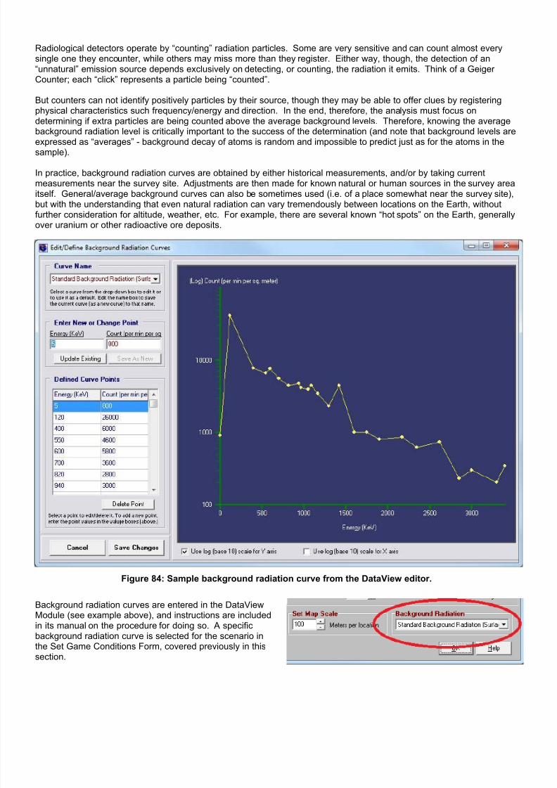
7/21/2019 TSS User Manual
http://slidepdf.com/reader/full/tss-user-manual 138/492
Radiological detectors operate by “counting” radiation particles. Some are very sensitive and can count almost everysingle one they encounter, while others may miss more than they register. Either way, though, the detection of an“unnatural” emission source depends exclusively on detecting, or counting, the radiation it emits. Think of a GeigerCounter; each “click” represents a particle being “counted”.
But counters can not identify positively particles by their source, though they may be able to offer clues by registeringphysical characteristics such frequency/energy and direction. In the end, therefore, the analysis must focus ondetermining if extra particles are being counted above the average background levels. Therefore, knowing the averagebackground radiation level is critically important to the success of the determination (and note that background levels areexpressed as “averages” - background decay of atoms is random and impossible to predict just as for the atoms in thesample).
In practice, background radiation curves are obtained by either historical measurements, and/or by taking currentmeasurements near the survey site. Adjustments are then made for known natural or human sources in the survey areaitself. General/average background curves can also be sometimes used (i.e. of a place somewhat near the survey site),but with the understanding that even natural radiation can vary tremendously between locations on the Earth, withoutfurther consideration for altitude, weather, etc. For example, there are several known “hot spots” on the Earth, generallyover uranium or other radioactive ore deposits.
Figure 84: Sample background radiation curve from the DataView editor.
Background radiation curves are entered in the DataViewModule (see example above), and instructions are includedin its manual on the procedure for doing so. A specificbackground radiation curve is selected for the scenario inthe Set Game Conditions Form, covered previously in thissection.

7/21/2019 TSS User Manual
http://slidepdf.com/reader/full/tss-user-manual 139/492
2-10.8.11.2 Radiation Alarm LevelsBecause there is no such thing as an “absolute” count, detecting radiation counts above the background is based on astatistical analysis of the raw data. The analysis first looks at the expected average background count, and compares it tothe actual count. Higher actual counts don't always mean an extra source is present, and lower counts don't always meanthat it isn't, as shown in the example below – where the second reading, taken on its own, would indicate that no extrasource is present.
Figure 85: Example of how actual radiation emissions and counts will vary randomly around an average value.The differences between the individual counts are relatively exaggerated for illustration purposes, and in most
practical cases, the counts from the outside source (red) will be much lower than the background counts (blue),making detection much more difficult.
To account for the uncertainty caused by the random nature of decay, results are expressed in terms of their probable
“confidence level”, which is a value between 0 and 100%. For example, confidence level of 75% indicates that the resultwill be correct 3 out of 4 times, but that once in four it will be “false” – meaning that its conclusion that is wrong. The trick,in real life as in the simulation, is to sift through the data and eliminate or mitigate the “false” results, either positive (whenthe observer thinks something is there that isn't) or negative (when the observer thinks nothing is there but it is).
Calculating the confidence level is based on the fact that the radiation curve follows a Poisson Distribution, which is a typeof “bell curve”. Specifically, it derived using the value of “Sigma” ( σ ), or the standard deviation, converted to a percent.Standard deviation is a measure of how far an actual count varies from an expected value. In this case, the expectedlevel is the average background spectrum and the actual count is what is recorded by the detector.
For example “1 Sigma” equals a confidence level of84.1%, as shown in the graph at right, while “3Sigma” converts to 97.7%.
The specifics of these calculations are beyond thescope of the discussion in this section, but it isimportant that users at least understand the basicsin order to set alarm levels, which are based onSigma values. The key points are:
• The higher the sigma value, the higher theconfidence level.
• The more data collected (i.e. the longer theobservation time), the higher the sigma.
• No report is ever 100% certain, though itmay be very close.
Figure 86: Example of the Standard Deviation, σ, as it relates tothe Confidence Level of a standard distribution.
Source: Wikipedia: Petter Strandmark , based an original graph by JeremyKemp, in 2005-02-09 [http://pbeirne.com/Programming/gaussian.ps].
Given the inherent uncertainty in radiological detection, the best that can be achieved is to define different radiation alarmlevels that are combinations of raw sigma values and data collection times. That way reports can be judged, and ranked,by the likelihood that they report the true situation, and are not false positives or negatives.
2-10.8.11.3 Radiation Alarm FormThe Radiation Alarm Form is used to define and modify alarm levels. Alarms have four components:

7/21/2019 TSS User Manual
http://slidepdf.com/reader/full/tss-user-manual 140/492
• Name : Identification of the alarmwith sufficient detail to describe itwhen it is reported. The defaultvalues include a short descriptionfollowed by the sigma value(converted to a percentconfidence level).
• Minimum Sigma : The calculatedSigma value must be greater thanor equal to this value.
• Minimum Seconds : Theminimum “continuous”observation duration period (seebelow).
• Map Text : The text to display onthe map in the location where thealarm was detected. This stringshould be kept relatively short toprevent clutter.
Values entered for the Sigma andSeconds fields must be valid decimalnumbers.
For the Sigma and Seconds fields must be valid decimal numbers
Figure 87: The Set Radiation Alarms Form. Users can add as many alarmlevels as desired, and also define separate alarm lists for each force.
The “Ignore raw counts older than....” setting determines what is considered “continuous”. Reports occurring within thistime period of each other are considered to be “continuous”, and are aggregated together to provide a higher Sigmalevel. This value is also useful when attempting to detect mobile targets, if it is set too high, the most significant alarmswill appear where the target was in the past instead of its current location.
Users may define as many levels as are deemed necessary by clicking the [Add New Alarm] button. However, a word ofcaution is in order. At some point too many alarms can become more confusing than helpful, especially if the differencesbetween them are minimal.
Radiation alarms may only be defined in the set-up phase. Once a scenario is underway, they can not be modifiedwithout saving the game “As a Scenario”, “Resetting the turn to 'Start'”, and then entering the set-up phase again.

7/21/2019 TSS User Manual
http://slidepdf.com/reader/full/tss-user-manual 141/492
2-10.9 Selecting Main Force Units
Figure 88: Selecting Main Force Units.
Players add units to their force using either pre-definedunits and/or formations (a group of units under a singleheadquarters), or in a custom fashion.
Pre-defined units are known as “TO&E”, which stands for“Tables of Organization and Equipment”, referring to theapproved standards that specify the composition andequipment of each unit. When a TO&E unit or formation
is selected from the TO&E Panel, all of the sub-units andsub-formations are automatically added to the force, withthe correct command relationships.
Custom units, on the other hand, are created on the fly -users select a weapon system and quantity after clickingthe [Add A Custom Unit] button.
By default, all new units and the HQ unit of formationsreport to the TF HQ. The TF HQ is the location of the“player”, and is the highest-level unit in the game. The TFHQ unit is created automatically by the computer whenthe first other unit is created, however once created it canbe edited normally by the player.
2-10.9.1 Weapon System Model Selection Mode PanelWhen a unit is created, the computer will initially assign a weapons system to it. Which specific weapons system itassigns depends on several factors:
♦ If the TO&E calls for a specific weapons system, that is the one that will be used.
♦ If the TO&E calls for a “default” weapons system (see the insert below from the TO&E Editor), the computer willselect one based on the weapons available and the currently selected mode:
o Best Selection : The computer will pick the weapon system of the appropriate type with the highest VP
(victory point) value. In the case of a tie, it will pick randomly from the highest ones.
o Manual Selection : The user will be prompted to select a weapon system model.o Random Selection : The computer will pick randomly from those available of the correct type.
o Equip similar follow-on selections with model selected for this unit : This option, which is on by default,
allows users to quickly create units equipped with a standard model. When checked, the computer willuse whatever model was selected for the current unit (either automatically or by the user) for all units ofthe same type that are subsequently selected that require the computer to assign a weapon system. Ifthis box is not checked, or if it is subsequently unchecked, the selection process will be repeated eachtime a unit with a default type is selected. Thus, this allows users to select a weapons system once, foreach type, and then have it automatically used for all follow-on units of the same type.

7/21/2019 TSS User Manual
http://slidepdf.com/reader/full/tss-user-manual 142/492
Figure 89: Defined vs. Default Weapons Systems in the TO&E Editor (DataView Module).
2-10.9.2 TO&E PanelThe TO&E Panel shows all of the pre-defined units and formations available to the player. These units and formations canbe changed and edited in the TO&E editor, which is part of the DataView module.
By default, only formations designated as belonging to the force’s nationality are shown. However, if desired ALL theentries for all countries can be shown by un-checking the “Limit TOE by nation” box at the bottom of the form.
2-10.9.3 Current Forces PanelThis panel shows all of the units selected so far. They are arranged in a force tree structure, which readily shows thecommand relationships. Each unit also has a generic unit symbol next to it using the standard NATO size indicators ofdots and lines.
Clicking a “+” next to a unit shows the next level of sub-units beneath it. Clicking the [+] button at the upper right shows
all units.
Clicking a “-” next to a unit hides all sub-units beneath it. Clicking the [-] button at the upper right hides all units notdirectly under the Task Force HQ.
2-10.9.3.1 Reassigning Sub-Formations/Units to Different HQ’sUnits and formations may be reassigned as desired. To do so, first <Right Click> on the unit or the formation HQ that wilbe reassigned. Then, from the pop-up menu, select “Reassign”. A list of all the units capable of acting as the unit’s newHQ will be displayed. Select the new HQ unit from the list, and click [OK].
Units must be reassigned to units of their own level or higher. For example, while it is possible to assign a company to abrigade, regiment, battalion, or even another company, it is not possible to assign it to a platoon. The unit level is anintrinsic property of the unit, and does not depend on how large it is, or how many units it has under its command. Unit
levels can also be changed manually during the unit selection process (see below).
2-10.9.3.2 Deleting UnitsFormations and single units can be deleted using the <Right Click> menu. Select either the formation HQ or the singleunit, <Right Click> and pick “Delete”.
It is not possible to delete a HQ unit without deleting all of the units under it; all subordinate units and formation must bereassigned to another HQ first (see above).
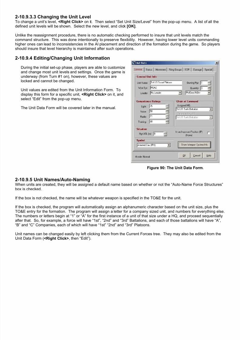
7/21/2019 TSS User Manual
http://slidepdf.com/reader/full/tss-user-manual 143/492
2-10.9.3.3 Changing the Unit LevelTo change a unit’s level, <Right Click> on it. Then select “Set Unit Size/Level” from the pop-up menu. A list of all thedefined unit levels will be shown. Select the new level, and click [OK].
Unlike the reassignment procedure, there is no automatic checking performed to insure that unit levels match thecommand structure. This was done intentionally to preserve flexibility. However, having lower level units commandinghigher ones can lead to inconsistencies in the AI placement and direction of the formation during the game. So playersshould insure that level hierarchy is maintained after such operations.
2-10.9.4 Editing/Changing Unit Information
During the initial set-up phase, players are able to customizeand change most unit levels and settings. Once the game isunderway (from Turn #1 on), however, these values arelocked and cannot be changed.
Unit values are edited from the Unit Information Form. Todisplay this form for a specific unit, <Right Click> on it, andselect “Edit” from the pop-up menu.
The Unit Data Form will be covered later in the manual.
Figure 90: The Unit Data Form.
2-10.9.5 Unit Names/Auto-NamingWhen units are created, they will be assigned a default name based on whether or not the “Auto-Name Force Structures”box is checked.
If the box is not checked, the name will be whatever weapon is specified in the TO&E for the unit.
If the box is checked, the program will automatically assign an alphanumeric character based on the unit size, plus theTO&E entry for the formation. The program will assign a letter for a company sized unit, and numbers for everything else.The numbers or letters begin at “1” or “A” for the first instance of a unit of that size under a HQ, and proceed sequentiallyafter that. So, for example, a force will have “1st”, “2nd” and “3rd” Battalions, and each of those battalions will have “A”,“B” and “C” Companies, each of which will have “1st” “2nd” and “3rd” Platoons.
Unit names can be changed easily by left clicking them from the Current Forces tree. They may also be edited from the
Unit Data Form (<Right Click>, then “Edit”).
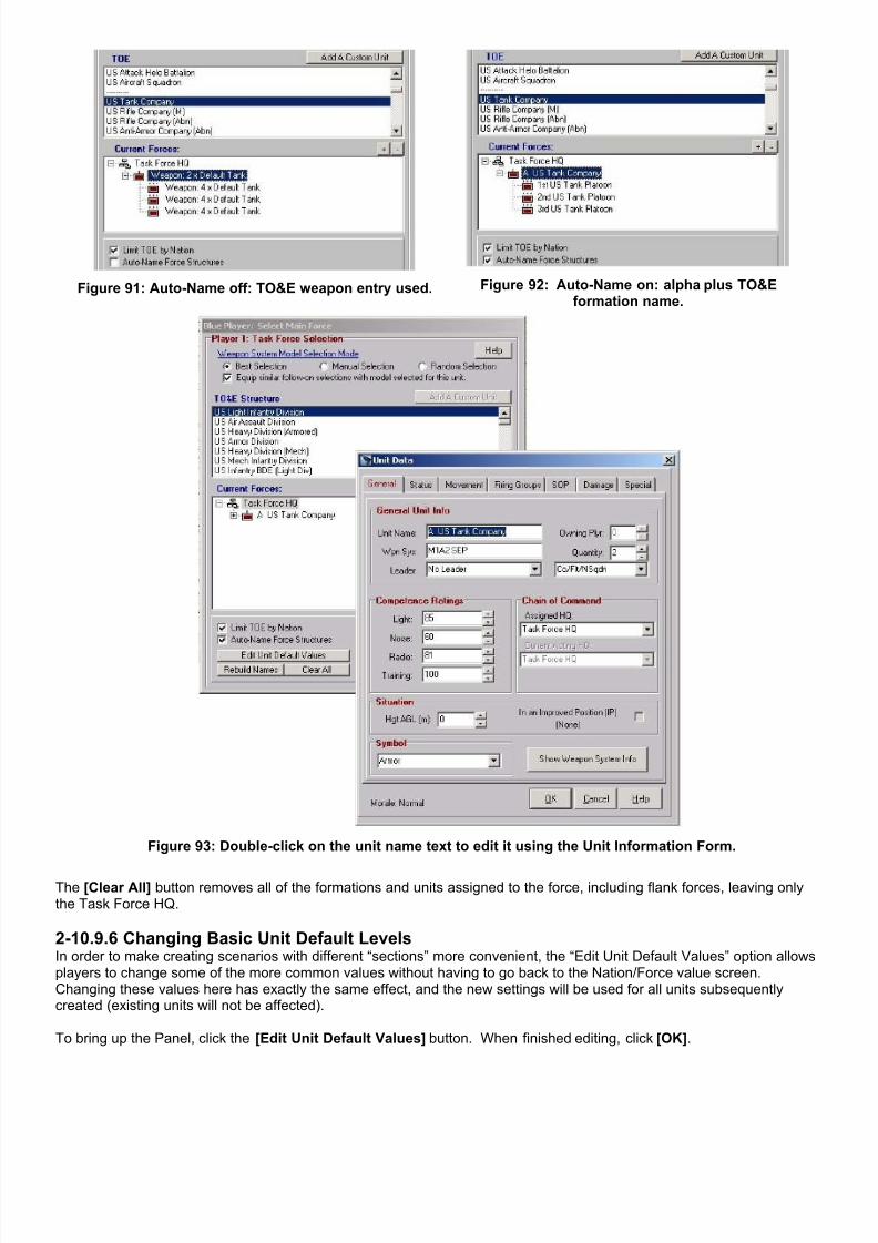
7/21/2019 TSS User Manual
http://slidepdf.com/reader/full/tss-user-manual 144/492

7/21/2019 TSS User Manual
http://slidepdf.com/reader/full/tss-user-manual 145/492
Figure 94: Set Default Unit Values Panel.
When finished selecting the main force units, click [OK].
2-10.9.7 Random/Auto Force SelectionWhen a force has been set to be Randomly Auto-Selected (from the Initial Set-up Form), the procedure for determiningthe force’s units is modified slightly. Instead of selecting individual formations and units from the TO&E display, playerssimply choose which formations can be added, and which can’t. The computer will only consider those formationschecked; formations and units not checked will never be added to the force.
Figure 95: Random Auto-Selection Settings/Limiting Picks to Specific TO&E Entries.
The formations shown in the window will be all those defined for the nation/force’s “highest level”, shown and set at thetop of the form. In the above example, for instance, the player has chosen to have an auto-generated US force of twobattalions; therefore all of the US battalion level formations are shown.
The computer will randomly select the force from the available choices. Once the high-level units have been chosen,support units will be added as appropriate, along with the flank forces.
The Weapons System Model Selection Mode panel is the same as for manually selected forces, as described above.
If “Edit Generated Forces” is checked, after the force’s units have been selected, the normal Select Force screen will bedisplayed, allowing the force to be modified manually.
Otherwise, players will be taken directly to the Assign Leaders screen upon clicking [OK] and having the force generated.
2-10.9.8 SatellitesSatellites are selected during the force set-up like any other type of unit (normally using the [Custom Unit] button sinceby default satellites are not defined in the TO&E’s). Unlike “normal” units, however, satellites are not directly placed orcontrolled by the owning player. Instead, the computer automatically makes them available during specified periods of
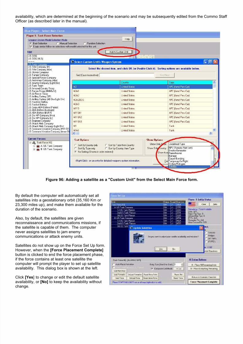
7/21/2019 TSS User Manual
http://slidepdf.com/reader/full/tss-user-manual 146/492
availability, which are determined at the beginning of the scenario and may be subsequently edited from the Commo StaffOfficer (as described later in the manual).
Figure 96: Adding a satellite as a "Custom Unit" from the Select Main Force form.
By default the computer will automatically set allsatellites into a geostationary orbit (35,160 Km or23,300 miles up), and make them available for theduration of the scenario.
Also, by default, the satellites are givenreconnaissance and communications missions, ifthe satellite is capable of them. The computernever assigns satellites to jam enemycommunications or attack enemy units.
Satellites do not show up on the Force Set Up form.However, when the [Force Placement Complete]button is clicked to end the force placement phase,if the force contains at least one satellite thecomputer will prompt the player to set up satelliteavailability. This dialog box is shown at the left.
Click [Yes] to change or edit the default satelliteavailability, or [No] to keep the availability withoutchange.

7/21/2019 TSS User Manual
http://slidepdf.com/reader/full/tss-user-manual 147/492
2-10.9.8.1 Satellite Availability FormFirst select the satellite from the top drop down box.The current information for that satellite will bedisplayed in the other sections.
The Mission Parameters Section details what missionsthe satellite will perform and its orbital characteristics:
Recon/sighting: the satellite will attempt to sight otherunits (including satellites). The satellite must possessan intrinsic visibility rating or detection system for thisoption to be enabled.Communications: The satellite will receive and transmitinformation based on its organic communicationssystems. Note that the other unit must have acommunication system capable of communicating withsatellites (set in the Commo System Data Table).Jamming: The satellite will attempt to jam enemytransmissions. The satellite must have a jammer forthis to be enabled. Attack: The satellite will attempt to attack other units
(including satellites. The satellite must be armed forthis to be enabled.
The orbital characteristics are the satellite’s height above the surface, in Kilometers, and its velocity in Kilometers per hourmeasured relative to a fixed point on the surface. Geostationary satellites will always have an orbital height of 35159 Km(due to orbital physics) and a relative speed of zero (they remain stationary over the same point on the surface).Geosynchronous and other orbits will have a different height above the ground (often much less), and a non-zero relativevelocity (depending on the satellite’s orbital period).
Orbits are controlled by international convention, although in a war it is possible that these conventions could and wouldbe ignored. However, the generally designated satellite orbits are:
Height Above the Ground in Km (Miles) Satellite/Spacecraft Types
150-450 Km (100-300 Miles) NavSats, SpySats, Gamiest, Shuttle, ISS
450-900 Km (300–600 Miles) Weather, Photo Satellites
900-1800 Km (600-1200 Miles) Military ComSats, SpySats
1800-9000 Km (1200-6000 Miles) Scientific Satellites
9000-18000 Km (6000-12000 Miles) NavSats
35160 Km (23,300 Miles) Geostationary: ComSat, Weather Satellites
375-75000 Km (250-50000) Elliptical: Molinya, ComSats, Early Warning, SpySats
A satellite pass is a period when the satellite is over the battlefield area and available to perform missions. ForGeostationary satellites, there will be only one pass, and it will last the entire scenario. Geosynchronous satellites, which
cross the same points on the Earth at regular intervals will have regular repeating passes. For other types the passesmust be set up by the player to conform to the orbital characteristics.
The currently defined passes are shown in the Set Available Times (Passes) Box. Each pass is defined by:o The start time, in either days : hours : minutes (absolute time) or in turns : pulses since the start of the scenario
(turn 1).o The pass duration (time the satellite stays available) in absolute time (days : hours: minutes) or in pulses.
To change either the starting time or duration of an existing pass, double-click the pass line in the grid box. This will bringup the Set Satellite Passes form showing the values for the selected pass.

7/21/2019 TSS User Manual
http://slidepdf.com/reader/full/tss-user-manual 148/492
To add a new pass, click the [Add New Pass] button. The Set Satellite Passes form will appear filled in with a new passusing default start time and duration based on the passes already there.
To delete a pass, select it on the grid and click the [Delete Current] button.
To repeat the currently selected pass, click [Repeat Current]. The computer will add a new pass of the same duration asthe selected one, with a start time offset from the last defined pass in the list as the selected pass is from the pass beforeit. For example, if the current pass starts 30 minutes after the pass before it, and lasts for 12 minutes, clicking this buttonwill create a new pass that starts 30 minutes after the last pass (in the list), and lasts for 12 minutes. This button allowsplayers to set up geosynchronous satellites easily (since their availability repeats at regular intervals).
The Satellite Availability Form can also be accessed through the Commo Staff Officer screen.
2-10.9.8.2 Satellite Passes FormThe Set Satellite Passes Form is used to edit the starting time and duration of a satellite’s assigned passes.
The pass starting time is set on the left side of the form, and theduration on the right.
Each side has two values: an “absolute time” (days : hours : minutes),and a “game time ” (turns and pulses). Players can set either value;the other one will be updated automatically.
Pass starting times are always from the start of the scenario. They arenot “clock time”. For example, in a scenario that starts at 14:00, if youwant a pass to begin at 14:30, you would enter 30 minutes in the starttime box.
After changing a value, click [Save] to save the changes and close theform.
For convenience, the scenario starting time (24-hour format) andlength is shown at the bottom of the form.
2-10.10 Selecting Flank Force UnitsOnce the main force has been selected, players are given the opportunity to select flank forces.
Flank forces are placed, and operate, in the designated flank areas on each side of the main force. They are AI-controlledand are completely outside of the player’s control. Flank forces will normally move, fire and call for (and provide) supportonly within the flank areas; there are times, however, when they must move or fire into the main force area, but will do itonly as a last resort.
NOTE: Flank forces are optional, and because they are AI controlled have the potential to greatly slow down game speedand overall program performance. Therefore, they should be used only when necessary to model a “front” type of situationwhere a player has related units on his sides, but out of his control. When used, players should also attempt to minimizethe number of units they contain.
Flanks include (and continue into) off-map areas.

7/21/2019 TSS User Manual
http://slidepdf.com/reader/full/tss-user-manual 149/492
Figure 97: Select Flank Forces.
The Select Flank Force form is the same as one used forselecting main force units. The only difference is thatany units selected in this mode will be assigned to oneflank or the other.
The form operates the same as for selecting main forceunits with one additional very convenient feature. That isthe [Gen Flank Forces] button at the lower center of theform. When clicked, this will cause the AI to generatethe flank forces based upon what has been already beenselected for the main force, and the relative sizes of theflanks.
Once the [Gen Flank Forces] routine has been run, thebutton will be grayed out and no longer selectable.
Whether or not a player has selected to [Gen FlankForces] additional flank units can be chosen individuallyfrom the TO&E structure window, created as a customunit. They can also be edited and have their valueschanges in the same manner as if they belonged to themain force.
By default, flank unit names are preceded by an asterisk, e.g., “ *A US Rifle Company ”. However, players may edit flankunits names the same as for those belonging to the main force.
Click [OK] when finished selecting flank forces.
Notes on AI Placement of Flank Forces : The AI will split the selected flank forces roughly equally between each of theflanks. However, in order to maintain command and control it will NEVER split up formations. For example, if a singlebattalion is selected for the flank forces, the AI will place the entire battalion on one flank while the other remainscompletely empty. If, however, four independent companies are selected instead (the same battalion, but broken downinto its company level constituents), then each flank will receive at least one of the companies, and in fact it is likely thateach will receive two (for an exact 50/50 split). This situation is shown here:
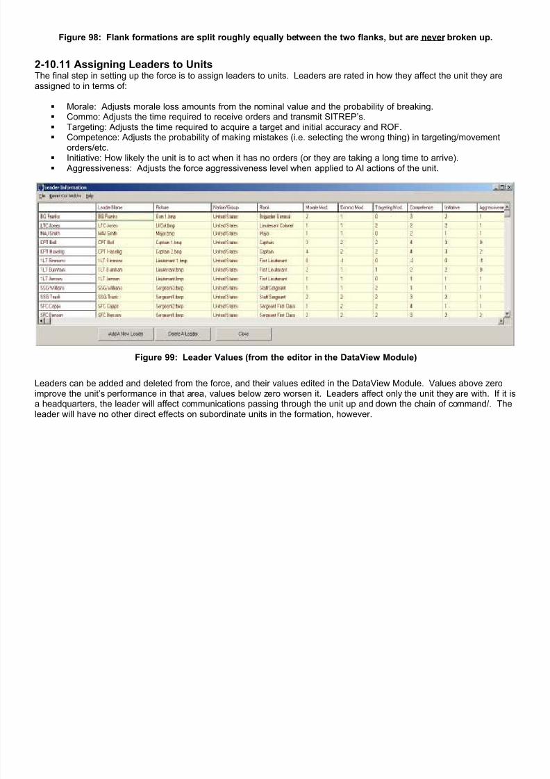
7/21/2019 TSS User Manual
http://slidepdf.com/reader/full/tss-user-manual 150/492
Figure 98: Flank formations are split roughly equally between the two flanks, but are never broken up.
2-10.11 Assigning Leaders to UnitsThe final step in setting up the force is to assign leaders to units. Leaders are rated in how they affect the unit they areassigned to in terms of:
Morale: Adjusts morale loss amounts from the nominal value and the probability of breaking. Commo: Adjusts the time required to receive orders and transmit SITREP’s. Targeting: Adjusts the time required to acquire a target and initial accuracy and ROF.
Competence: Adjusts the probability of making mistakes (i.e. selecting the wrong thing) in targeting/movementorders/etc.
Initiative: How likely the unit is to act when it has no orders (or they are taking a long time to arrive). Aggressiveness: Adjusts the force aggressiveness level when applied to AI actions of the unit.
Figure 99: Leader Values (from the editor in the DataView Module)
Leaders can be added and deleted from the force, and their values edited in the DataView Module. Values above zeroimprove the unit’s performance in that area, values below zero worsen it. Leaders affect only the unit they are with. If it isa headquarters, the leader will affect communications passing through the unit up and down the chain of command/. Theleader will have no other direct effects on subordinate units in the formation, however.

7/21/2019 TSS User Manual
http://slidepdf.com/reader/full/tss-user-manual 151/492
Figure 100: Assign Leaders To Individual Units.
To assign leaders, follow these steps:
1) Select an un-assigned leader from those shownin the Available Leaders Panel. The leadersinformation will be shown at the bottom of theform.
2) Click on the unit to which you want to assign theleader.
3) If the unit does not already have a leader, the[Assign] button at the bottom of the form will
become activated. Click it to complete theassignment.
4) If the unit already has a leader, the [Remove]button will become activated. If you click it theleader will be un-assigned and will return.
5) If neither button becomes activated, the leader isalready assigned to another unit. He must beunassigned from it and returned to the availablepool before he can be reassigned.
To un-assign a leader, select the unit to which is he isassigned from the Current Forces Panel. The[Remove] button will become activated. Click it to un-assign the leader and return him to the available pool.
When leaders are assigned to a unit, their name willappear after the unit name in the Current Forces Panel,e.g., “A US Tank Company Ldr: CPT Bell”.
When finished assigning leaders, click [OK] to save and close the form.
2-10.12 Ending a Scenario EarlyUnder the default conditions, scenarios will run until either their final end turn, as set in the initial set up, or until one forcehas no units left. This can result in a scenario running for many “empty” turns (turns with no appreciable action or changein the situation) after a force has achieved its objective or has crippled its adversary to the point where it can no longerhave an impact on the final result.
While running these empty turns has no detrimental effects on the final results, they can still consume a considerableamount of time to execute. This is especially true in situations where a scenario's end turn is set very high to insure thatthe last bit of action is always captured.
The effect is compounded in batch execution mode – where a scenario may run automatically for a hundred times insequence. Even if each run only “wastes” 5 minutes, by the end of a 100-run project the total wasted time would add upto almost 9 hours, or a full work day for a professional analyst.
2-10.12.1 Set the Scenario to Use Early End ConditionsIn order to prevent this time loss, scenarios can be set to end “early” - before the end turn is reached. This is done in twoplaces: when initially creating a scenario (on the Initial Set-Up Form), or when saving a game as a scenario (EditScenario Description Before Saving Form). Examples are shown below.

7/21/2019 TSS User Manual
http://slidepdf.com/reader/full/tss-user-manual 152/492
Figure 101: End Game Early checkbox during initial scenario set-up.
Figure 102: End Game Early checkbox when saving a game as a scenario.
2-10.12.2 End Early Conditions Form After selecting to set Early End Conditions, the form below will appear (either immediately, or after the set-up checklist iscompleted – depending on where it was set). For each early-end condition, the following information is entered:
1. The player/force the condition applies to.2. Minimum turn that the condition can be invoked.3. The situation that triggers the condition.
4. The name/description of the condition.
Multiple early-end conditions may be defined for a scenario; the scenario will automatically end when any of the definedconditions are met (i.e., “A or B or C or .... , not A and B and C and ...).
When the form first appears, no conditions will have been defined, and all of the fields will be inactive (grayed-out). Clickon the [Add New Condition] button in the top panel to begin adding conditions.

7/21/2019 TSS User Manual
http://slidepdf.com/reader/full/tss-user-manual 153/492
Figure 103: End Scenario Early Conditions Form. No conditions have been set yet.
For each early-end condition, the following characteristics must be specified:
• Minimum End Turn : the condition can not be invoked before this turn, even if the other characteristics are met. Inthat case, the condition is ignored.
• Applies to Force : The player/force that the condition applies to. Conditions apply to only one force; to apply thesame condition to both forces, it is necessary to create two separate entries (one for each force).
• Trigger : This sets the situation that is required to invoke the condition. It may be of three types:
◦ Unit Action: The specified unit (or any of the force's units) is destroyed, reaches the map edge, or reaches avictory location.
◦ Force Loss: The force's loss reaches a certain percentage (based on starting unit weapons systemquantities).
◦ Weapon Systems Left: The force has less than a specified number of weapons systems left. Weaponssystem types are ignored; five tanks are equal to five riflemen, for instance.
• Name : The end condition should be given a descriptive name so that it can identified when invoked, or lateredited.

7/21/2019 TSS User Manual
http://slidepdf.com/reader/full/tss-user-manual 154/492
Figure 104: End Scenario Early Conditions Form. A new end-early condition has been entered. The game will endas soon as any US unit reaches an objective location on or after turn 60.
Click [Save All & Close] to save the values and continue.
2-10.13 Two-Player GamesWhen there are two human players, the set up is modified slightly to keep each player from knowing what the other hasselected. To make things more convenient, the human vs. human games are classified as:
Hot-Seat: The players are both in the same location and only one computer will be used to play the game.Normally one player will leave the room while the other takes his turn to maintain secrecy.
PBeM: Play by email. The players are not in the same location, and are using different computers. Instead theywill be trading files after each operational step.
You will be prompted to select the type of gameafter Setting the Initial Conditions, using the form
shown at right.
Once selected, this value will be used for the rest ofthe set-up procedure, and will prompt players whento save and send files or change seats at thecomputer.
To change this setting later for some reason, youmust go back to the Set Initial Conditions step (clickon it in the Scenario Checklist Form)
Figure 105: Selecting the Two Player Game Situation.

7/21/2019 TSS User Manual
http://slidepdf.com/reader/full/tss-user-manual 155/492
Figure 106: Scenario Checklist note to save the set-up fileand send it to your opponent.
Figure 107: Follow-on instructions.
2.10.13.1 PasswordsPasswords prevent intentional or accidental access of one player’s force by the other. They are not required, but arerecommended.
Figure 108: Set Password Form.
The Set Password form will appear automatically in2-player games before the first player’s force isselected. It will also appear at the start of 2-playersaved scenarios when they are loaded in.
The text color will be the same as the primary unitcolor of the player. By default these are blue andred. The nationality flag will also be displayed.
To continue without a password, leave the text boxblank and click [OK]. Otherwise, enter yourpassword (case sensitive) in the text box and click
[OK]. Make sure to write down your password.There is no way to recover it later.
If a password is entered for a force, it must be entered correctly at the start of each of that player’s active phases, in boththe set-up sequence as well as the actual game turns. If the entered password is incorrect, access will be denied.

7/21/2019 TSS User Manual
http://slidepdf.com/reader/full/tss-user-manual 156/492
Section 2-11 AI and the Map
At the start of each new game, the AI analyzes the map in terms of the actual forces and missions. It uses real-world USmilitary fundamentals (known as “MET-T”) to determine good avenues of approach, high-speed movement routes, keyterrain, and likely places for ambushes and obstacles. The AI's results are then converted into the “overlays” available toeach player once the game starts.
Since the map analysis can be a lengthy process, it is done only once at the start of the game; the values are then savedas part of the saved game file and thus can be accessed quickly during the game itself.
2-11.1 CAI FileThe .CAI file is simply the saved results of a previous map analysis. If one exists for the map, using it with a new gamegreatly speeds ups the AI map analysis, reducing the time from as high as several hours to several minutes. This isbecause most of the values are used “as-is”, and those that are modified usually don’t need to be recalculated fromscratch.
Figure 109: If a .CAI file exists for the map, it may beused to save processing time.
The drawback to using an existing .CAI file is thatsome of the values might not be optimal for thespecific new force or mission. The greater thedifferences between the two scenarios in terms of unittypes present, the less applicable the CAI will be.
For example, a CAI file compiled from an all-aircraftscenario will be almost useless for one with all foottroops.
If no existing .CAI file is found, or if the scenario is relatively different, a new .CAI file should be created. The initial screenallows for the routines to be customized for the types of forces involved, the map size and the time available.
When creating a new .CAI file for future use (i.e., one thatwill be saved), it is best to follow these guidelines:
Use scenarios with at least a few of every movementtype (foot, wheeled, tracked, etc.) armored type(armored, semi-armored, non-armored) and stackingtype (personnel, gun, vehicle, aircraft, naval) presentin each force, if possible.
Use “Neutral” Aggressiveness for each player. Use the “Very High” AI Fidelity value.
Figure 110: AI Map Analysis Values.
.CAI files are considered to be part of the map, and are stored in the same folder as the map, and with the same filename. For example, the CAI values file “Iraq.CAI” will correspond to the map file “Iraq.MAP”.
Section 2-12 Set Up Phase
The Force Placement Phase, also known as “Turn Zero”, is when players (or the AI) place units and objects on the map,in off map areas, or designates them as reinforcements (the last two apply to units only).
The set up phase begins with the section/notification of force Victory Objectives, and is then followed by the unit/objectplacement phase and then the initial orders phase (a standard orders phase, but with zero orders/friction delays).

7/21/2019 TSS User Manual
http://slidepdf.com/reader/full/tss-user-manual 157/492
Figure 111: The General Set Up Phase Sequence. The set up order between players is based on which player isdefending – that force is placed first (in this example, the “blue player”). If both players are attacking (known as
a “meeting engagement”), the computer randomly selects the player order.
2-12.1 Victory ObjectivesVictory Objectives are locations or enemy units selected at the start of a scenario as potential goals for an attacking force(defending forces do not receive objectives). Of these locations/units, one will be designated as the actual objective. Theothers will become “dummies”, and are used to keep the defending player guessing as to which is the actual objective.
After the initial forces have been selected and the scenariochecklist form has been completed, the Victory Objective dialogwill appear for the attacker, as shown at right (if both are attacking,it will be shown for the “first” player, as determined by the AI).
The reason this box pops up at this point in the set-up sequence isthat the objectives must be determined before the other (“second”)force sets up. This allows the second player to at least be awareof the potential enemy objectives, and deploy his forceaccordingly.
For attacking players, this dialog allows for three options:
• Have AI Set : Allows the AI to automatically set a location objective for the attacking force.
◦ The AI will create a number of potential objectives and designate one as the actual objective. The others willbecome “dummies”, and are used to keep the defending player guessing as to which is the actual one. Thenumber of “dummies” created depends on the game situation, map size, and terrain.
◦ The defending player can only view the potential locations on the map. He cannot adjust them and cannot
identify the attacker’s actual objective from among the dummies. The attacking player, on the other hand,may add and delete potential objectives, and may also select which of the potential objectives will be hisactual objective.
• Adjust: Allows the attacking player to edit the current objective set or manually select a new objective (location orunit). This selection will display the Victory Objectives Form, which will be discussed separately, below.
• Continue : Leaves the existing objective set in place. If there are no objectives assigned, then no objectives will beused in the scenario.

7/21/2019 TSS User Manual
http://slidepdf.com/reader/full/tss-user-manual 158/492
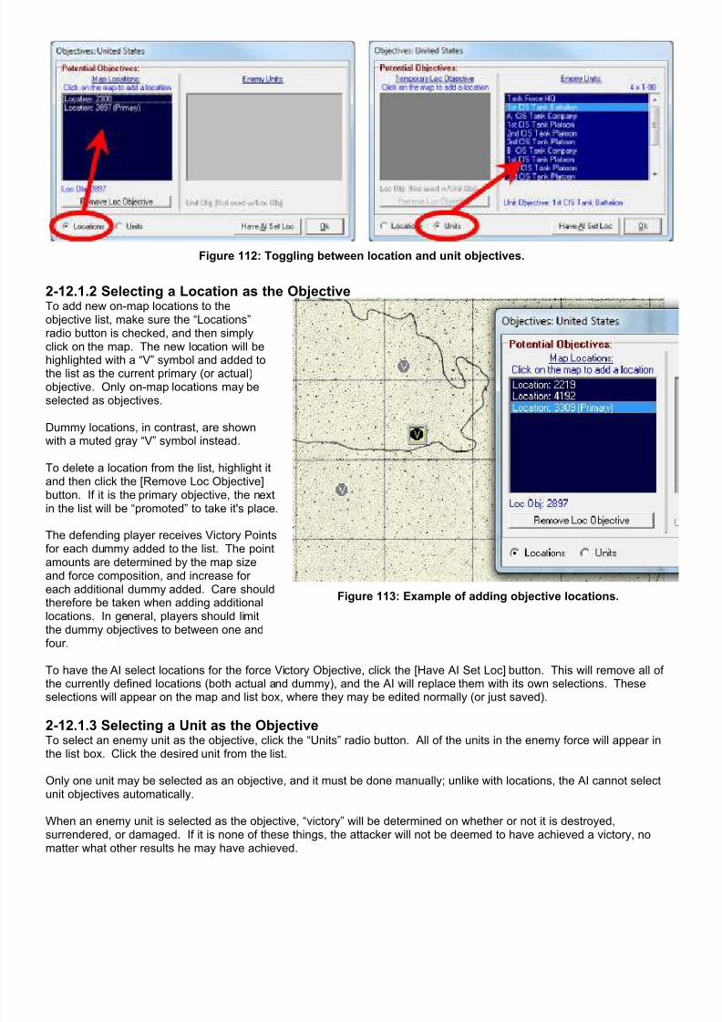
7/21/2019 TSS User Manual
http://slidepdf.com/reader/full/tss-user-manual 159/492
Figure 112: Toggling between location and unit objectives.
2-12.1.2 Selecting a Location as the ObjectiveTo add new on-map locations to theobjective list, make sure the “Locations”radio button is checked, and then simplyclick on the map. The new location will be
highlighted with a “V” symbol and added tothe list as the current primary (or actual)objective. Only on-map locations may beselected as objectives.
Dummy locations, in contrast, are shownwith a muted gray “V” symbol instead.
To delete a location from the list, highlight itand then click the [Remove Loc Objective]button. If it is the primary objective, the nextin the list will be “promoted” to take it's place.
The defending player receives Victory Pointsfor each dummy added to the list. The pointamounts are determined by the map sizeand force composition, and increase foreach additional dummy added. Care shouldtherefore be taken when adding additionallocations. In general, players should limitthe dummy objectives to between one andfour.
Figure 113: Example of adding objective locations.
To have the AI select locations for the force Victory Objective, click the [Have AI Set Loc] button. This will remove all ofthe currently defined locations (both actual and dummy), and the AI will replace them with its own selections. Theseselections will appear on the map and list box, where they may be edited normally (or just saved).
2-12.1.3 Selecting a Unit as the ObjectiveTo select an enemy unit as the objective, click the “Units” radio button. All of the units in the enemy force will appear inthe list box. Click the desired unit from the list.
Only one unit may be selected as an objective, and it must be done manually; unlike with locations, the AI cannot selectunit objectives automatically.
When an enemy unit is selected as the objective, “victory” will be determined on whether or not it is destroyed,surrendered, or damaged. If it is none of these things, the attacker will not be deemed to have achieved a victory, nomatter what other results he may have achieved.

7/21/2019 TSS User Manual
http://slidepdf.com/reader/full/tss-user-manual 160/492
2-12.1.4 Enemy Knowledge of Objectives As was previously stated, the enemy force is given only minimalinformation about the attacker's location objectives, and none atall if the objective is a unit. The enemy player can only view thepotential locations. He cannot adjust them, and cannot identify theattacker’s actual objective from “dummies”, if there is more thanone location defined.
The view at right shows what the CIS player sees on the map for
the United States victory locations set in the previous exampleabove. He knows that the blue player must take one of the threelocations displayed with a muted gray “V” symbol, but he does notknow that it is actually the one in the middle and the others are“dummies”.
In cases where there are no victory locations shown to a player, itmeans either that his opponent has no objectives (they are notrequired), or that his objective is a unit. However, there is no wayfor the player to tell which is the case, so he must planaccordingly.
2-12.2 The Force Set Up Form (Place Units and Objects)With the exception of map-based bridges, which are placed by automatically by the computer at locations whereappropriate hexlines cross hexsides, all unit and object placement is controlled with the Force Set-Up Form.
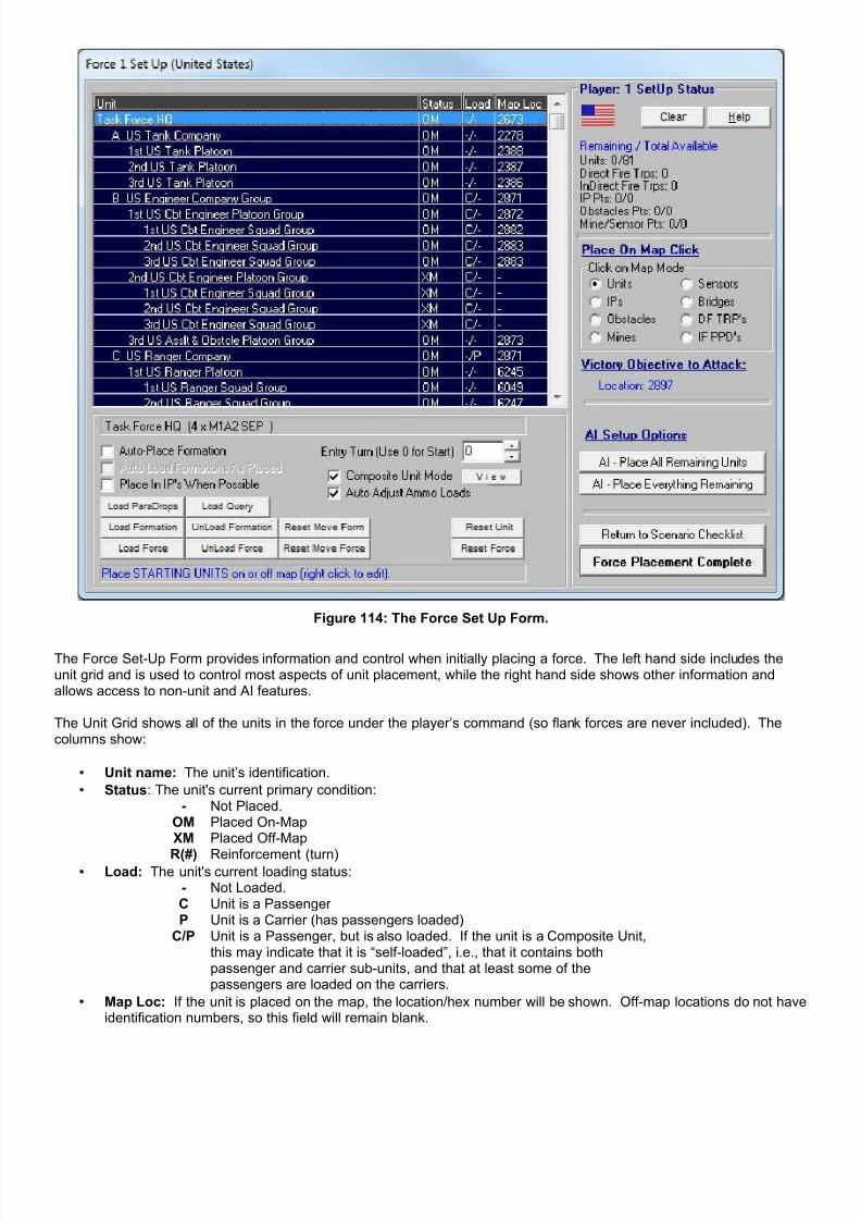
7/21/2019 TSS User Manual
http://slidepdf.com/reader/full/tss-user-manual 161/492
Figure 114: The Force Set Up Form.
The Force Set-Up Form provides information and control when initially placing a force. The left hand side includes theunit grid and is used to control most aspects of unit placement, while the right hand side shows other information andallows access to non-unit and AI features.
The Unit Grid shows all of the units in the force under the player’s command (so flank forces are never included). Thecolumns show:
• Unit name: The unit’s identification.
• Status: The unit's current primary condition:- Not Placed.
OM Placed On-MapXM Placed Off-Map
R(#) Reinforcement (turn)• Load: The unit's current loading status:
- Not Loaded.C Unit is a Passenger P Unit is a Carrier (has passengers loaded)
C/P Unit is a Passenger, but is also loaded. If the unit is a Composite Unit,this may indicate that it is “self-loaded”, i.e., that it contains bothpassenger and carrier sub-units, and that at least some of thepassengers are loaded on the carriers.
• Map Loc: If the unit is placed on the map, the location/hex number will be shown. Off-map locations do not haveidentification numbers, so this field will remain blank.

7/21/2019 TSS User Manual
http://slidepdf.com/reader/full/tss-user-manual 162/492
IMPORTANT NOTE: If “Entry Loc Not Set!” appears in the Map Loc column, it indicates that the unit has beenset as a reinforcement, but that it has no entry location defined (meaning that it can never come into play underany circumstances). To correct this situation, select/highlight the unit on the grid, and then click on a location (onor off map).
The “Setup Status” section (at the top right) shows how much of the force has been placed, both for units and for otherobject types. The first number is the quantity remaining to be placed, either the number of units or “points worth” of otherobjects. The second number shows the total quantity allotted to the force.
The “Place On Map Click” section determines what will be placed when the user left clicks on the map (or offmap display).If “Unit” is selected, the currently highlighted unit will be placed in that location. If the unit has already been placed in adifferent location, a confirmation message will pop up. Otherwise, the appropriate object placement form will be shown.
Figure 115: The “Place On Map” Click section is where users set the current object type being placed.
The “Victory Objective” section allows players to see the current victory objectives, both actual and “dummy”. Anattacking player will be able to distinguish between the two, a defender will not.
The “AI Setup Options” section allows players to use the AI to complete all or part of the force placement with a singleclick. These options will be discussed in more detail, below.
2-12.3 Placing UnitsUnits may be placed in any non-prohibited location on or off the map. To place a unit:1. Select the “Units” radio button from the “Place On Map Click” section.2. Select the unit from the unit grid on the left side of the form3. Left click on the desired map or off-map location.
At the time of placement, the AI will determine if the selected location is prohibited, based on the type and size of the unit,the terrain in the location, and any other units that are already in the location. If the unit cannot be successfully placed inthe selected location, the AI will show a message to that effect, and cancel the placement action.

7/21/2019 TSS User Manual
http://slidepdf.com/reader/full/tss-user-manual 163/492
The form shown at left is used to easily set the facing and other characteristics ofunits as they are placed on the map. It appears in conjunction with the Force SetUp Form. It is also a “floating” form, meaning that it will appear on top of all otherforms in the application, and that it can be moved around the screen at will.
For each checkbox, there is a value or operation associated with it. If the box ischecked, the associated value will be automatically assigned to each unit as it isplaced on the map. Otherwise, the values will not be changed from whatever theyare at the time of placement – either what they were set to by default or what theymay have been adjusted to at some previous point in the set up.
If the [ ] Place in IP box is not checked, units will not be placed into them if theyare in the placement location, whether they were previously occupying one or not.If it is, the AI will automatically select the IP for the unit to occupy, if there is morethan one appropriate and available IP in the placement location.
If the [ ] Display Unit Info Form For Each box is checked, the Detailed UnitInformation Form will be displayed for each unit as it is placed, allowing forcomplete control over all unit values (though at a cost in increased time and effort).
2-12.3.1 Placing Entire FormationsFor convenience, players may have the AI place an entire formation with a single click. In order to enable this feature,check the “Auto-Place Formation” box. Then select any HQ unit from the grid, followed by the HQ’s placement location
(on or off-map). The AI will automatically place all of the units in the HQ’s formation. Specific unit placement isdetermined from the player’s start line and mission, terrain, and HQ command radius values.
The selected unit may be the TF HQ, in which case the AI will place the entire force.
NOTE: Units in the formation that have already been placed by the human player will not be moved; they will remain in place. If a player wants to remove this restriction, the subordinate units must be reset (or “unplaced”) before the formationis placed. The procedure to do this is described below in the section “Un-placing Units Already Placed”.
2-12.3.2 Placing Composite UnitsIf the “Composite Units Mode” box is checked, the standard composite unit display will be used; each composite unit willbe shown as a single unit on the unit grid and map.
Additionally, when placing a composite unit, all of its subunits will be placed in the selected location. If for some reasonone or more sub-units cannot be placed in the location, a message to that effect will be shown.
Because at this stage it is essentially a cosmetic feature, the composite unit mode may be toggled on and off at will duringthe placement sequence. Changing the setting will have no effect on units and/or subunits already placed.
2-12.3.3 Loading and Unloading Formations and/or the Entire ForceTo load all of the units within a formation, select the HQ unit and click the [Load Formation] button. The AI will attempt toload all passenger-type units on the available carriers, within the formation, using the following priority:
1. Passengers try to load on a carrier in their composite unit (if applicable)2. Passengers try to load on a carrier in their direct chain of command (lower)3. Passengers try to load on a carrier in their direct chain of command (higher)4. Passengers try to load on a carrier not in their direct chain of command
To unload all of the passenger units in a formation, click [Unload Formation]. The passenger units will immediatelyunload from their current carriers. If the carriers have been placed, the passengers will be placed in their locations.Otherwise, the passengers remain unplaced.
Use the [Load Force] and [Unload Force] buttons to perform these operations with all of the units in the force (i.e., as aformation but with the TF HQ automatically selected as the formation HQ).
2-12.3.4 Loading/Unloading Single UnitsDuring the placement phase, loading and unloading single units is done through the Detailed Unit Information form. Thisform is accessed by right clicking on the unit, either on the unit grid, or on the map. Once the Unit Data form is up, clickthe “Movement” tab, and then check (or uncheck) the appropriate box in the Passenger/Loading section.
7/21/2019 TSS User Manual
http://slidepdf.com/reader/full/tss-user-manual 164/492
For more information, see the loading/unloading section in Unit Movement Orders, below.
2-12.3.5 Removing Existing Move OrdersFor new scenarios created from scratch, units will begin without any movement orders. However, in cases where anexisting scenario is being modified, units may start out with commands already in place from the original. To removethese commands for all of the units in a formation, click [Reset Move Form]. To remove movement commands for all ofthe units in the force, click [Reset Move Force].
These actions occur immediately; none of the standard command delay procedures apply.
2-12.3.6 “Un-placing” Units Already PlacedTo remove a unit from the map or off-map area and return it to the “unplaced pool”, highlight the desired unit on the unitgrid and click [Reset Unit]. The map and grid will update to show the unit being removed. To “un-place” the entire force,click the [Reset Force] button.
Once a unit has been “un-placed”, its formation location information is lost; it is not possible to undo the action.
2-12.3.7 Designating Reinforcement UnitsDesignating units as reinforcements allows a scenario creator to easily insure that they appear at a certain location at acertain time once the game is underway. At the start of the specified turn the reinforcement units will appear in thepredetermined locations, and will behave as normal units from that point on. Prior to their appearance, however,
reinforcement units are not present in the game at all; they cannot be selected in any operation, cannot move, acceptorders, sight, fire, be fired at, or be sighted.
To make a unit a reinforcement, set its “Entry Turn” value to the turn when it should first appear. The turn value must begreater than zero. After setting the entry turn, click on the location where the unit should appear. If the unit has alreadybeen placed, it will be removed from the map/off-map area.
To cancel a unit from being a reinforcement, set its Entry Turn to zero.
2-12.3.8 Setting Up ParadropsTo set up paradrops, a force must possess at least one paradrop capable surface unit, as well as at least one aircraft withtransport capability. If these conditions are met, click the [Load ParaDrops] button just under the unit grid. The standardLoad Units for will appear, but limited to paradrop capable units as potential passengers (the top box), and aircraft units as
carriers (the bottom box).

7/21/2019 TSS User Manual
http://slidepdf.com/reader/full/tss-user-manual 165/492
Figure 116: Loading paradrop units on an aircraft.
For potential passengers, the grid shows the following information:Unit: The unit nameLoc: The units’ current location, or “-“ for not yet placed.Carrier %Ld: If loaded, this field shows the unit’s current carrier and if the unit is a composite unit, the percent of theunit loaded on that carrier (composite units may have individual elements loaded on different carriers, or none at all).Required: The cargo capacity required to load the entire unit: P = Personnel Points, T = Towed Points, W = Weight(Kg x 10).
For the carriers, the grid gives the following:Carrier: The unit name.Loc: The units’ current location, or “-“ for “not yet placed”.Has Path: This is the path the carrier must travel to get to the passenger. In the setup phase, the passengers will beloaded automatically, already placed or not, so “n/a” will be shown.
Passenger units may be selected singly by left clicking them, or as a group by holding down the left button and draggingthe mouse up or down. If multiple passenger units are selected, the total personnel, towed, and weight values are shownat the bottom of the form.
Once the passenger unit(s) has been selected, all of the aircraft units with enough current free capacity to load the unit(s)will be shown in the bottom box. Select the desired carrier, and click the “Load Unit” button to load the selectedpassengers on the aircraft.
If no carrier aircraft appear in the bottom box after one or more passengers have been selected, it indicates that noaircraft has enough free capacity, in either the appropriate points or weight, to load the passenger selection.
2-12.4 Placing/Editing/Removing Improved Positions (IP’s)IP’s are placed on the map by selecting the “IP’s” radio button from the Force Set Up form, and then left clicking on themap where the IP’s should be placed (IP’s can not be placed off map). Or, <right click> on the map location, and selectPlace Edit Objects | Place/Edit Improved Positions from the pop-up menu.
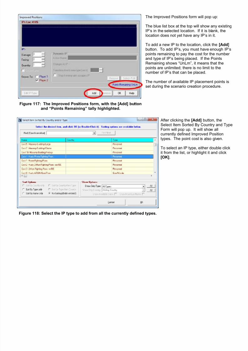
7/21/2019 TSS User Manual
http://slidepdf.com/reader/full/tss-user-manual 166/492
Figure 117: The Improved Positions form, with the [Add] buttonand “Points Remaining” tally highlighted.
The Improved Positions form will pop up:
The blue list box at the top will show any existingIP’s in the selected location. If it is blank, thelocation does not yet have any IP’s in it.
To add a new IP to the location, click the [Add]button. To add IP’s, you must have enough IP’spoints remaining to pay the cost for the numberand type of IP’s being placed. If the PointsRemaining shows “UnLm”, it means that thepoints are unlimited; there is no limit to thenumber of IP’s that can be placed.
The number of available IP placement points isset during the scenario creation procedure.
Figure 118: Select the IP type to add from all the currently defined types.
After clicking the [Add] button, theSelect Item Sorted By Country and TypeForm will pop up. It will show allcurrently defined Improved Positiontypes. The point cost is also given.
To select an IP type, either double clickit from the list, or highlight it and click[OK].
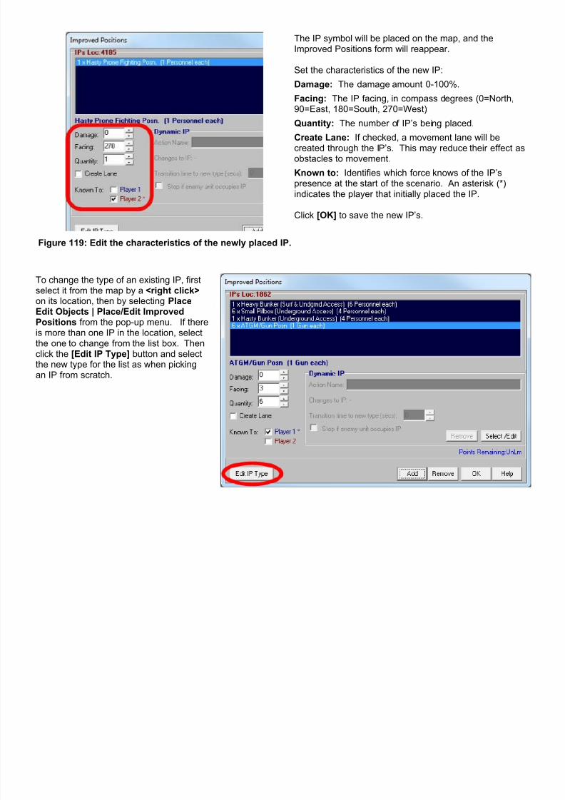
7/21/2019 TSS User Manual
http://slidepdf.com/reader/full/tss-user-manual 167/492
Figure 119: Edit the characteristics of the newly placed IP.
The IP symbol will be placed on the map, and theImproved Positions form will reappear.
Set the characteristics of the new IP:
Damage: The damage amount 0-100%.
Facing: The IP facing, in compass degrees (0=North,90=East, 180=South, 270=West)
Quantity: The number of IP’s being placed.
Create Lane: If checked, a movement lane will becreated through the IP’s. This may reduce their effect asobstacles to movement.
Known to: Identifies which force knows of the IP’spresence at the start of the scenario. An asterisk (*)indicates the player that initially placed the IP.
Click [OK] to save the new IP’s.
To change the type of an existing IP, firstselect it from the map by a <right click>on its location, then by selecting PlaceEdit Objects | Place/Edit ImprovedPositions from the pop-up menu. If thereis more than one IP in the location, selectthe one to change from the list box. Thenclick the [Edit IP Type] button and selectthe new type for the list as when pickingan IP from scratch.

7/21/2019 TSS User Manual
http://slidepdf.com/reader/full/tss-user-manual 168/492
To delete an existing IP from the locationcompletely, select the IP from the list box.Then click the [Remove] button.
Changes are immediate and permanent;there is no, “Are you sure?”, confirmationbox or undo option.
2-12.4.1 Dynamic IP'sDynamic IP's have the ability to change between different IP types during the course of the scenario.
For example, an IP could start out with it'saccess doors open, but then close themwhen the enemy approaches. In thissituation, the first IP type would be a “DoorsOpen” version, and the second type wouldbe “Doors Closed”.
In most cases the two IP types will bevirtually identical in terms of values, withonly one or two differences to reflect thedesired change. Figure 120: “Silo w/Doors Open” changing to “Silo w/Doors Closed”.
For instance, one IP type might have “surface access” and “top armor” while the other doesn't, with the size, capacity,armor and other values the same between the two. This is not required, however; any two IP types can be linkeddynamically. Users are cautioned against “drastic” changes, though, since they can lead to very unpredictable andunexpected results. For example, if units are occupying the initial IP but are prohibited in the “change-to” IP, they may beeliminated, or unable to move/fire/etc.
Both the initial and “change-to” IP types must be defined prior to the game being loaded (IP's are defined in the DataViewImproved Positions Data Table). If it becomes necessary to add new IP types after that, the game will first need to besaved, and then reloaded after the new IP's are defined.
There are no “transitional” states associated with Dynamic IP's; they are always of one type or the other. In the above“door closing” example, for instance, the doors are either open or they are closed. They are never “half-open”. As suchthe symbol on the map will always be that of the current state (if the graphics are different for each).
Dynamic IP's are limited to two states. However, they can switch freely between the two states without restriction, e.g.,the IP's doors can open and close as many times as needed.
2-12.4.1.1 Creating/Removing Dynamic IP'sDynamic IP's are created using the Improved Positions Form. They may be set either when the IP is initially placed on themap or when it is edited. To edit an existing IP, <right click> on its location on the map, then select Place Edit Objects |Place/Edit Improved Positions from the pop-up menu.

7/21/2019 TSS User Manual
http://slidepdf.com/reader/full/tss-user-manual 169/492
To create a Dynamic IP, follow thesesteps:
1. First, select the base IP from thelist box.
2. Then, click [Select/Add] buttonin the Dynamic IP section of theform, as shown at right.
3. The standard IP selection Formwill appear. Select the “change-to” IP type from the list. In thisexample, that would be the“ICBM Silo with closed doors”.
4. Set the values associated withthe change action (these valueswill be discussed in the nextsection.
Figure 121: Add a Dynamic (“change-to”) ability to the selected IP.
To modify the “change-to” IP, simply clickthe [Select/Edit] button again, and followthe steps exactly the same as whenadding a new Dynamic IP for scratch.
IP's may only have a single “change-to”IP; it is not possible to “chain” multipleDynamic definitions/changes together.
Figure 122: After adding the Dynamic action (“Doors open” to “Doorsclosed”). The “Change To” IP is shown under the Action Name field.
To remove the Dynamic IP definition, click the [Remove] button in the Dynamic IP section of the Form. Removing theDynamic IP action does not affect the existing IP in any other way.
It is important to note that Dynamic IP definitions are not global; they apply ONLY to the IP being edited. In other words,defining a “change-to” IP for for an existing IP on the map does not automatically add the same definition to any otherIP's, even if they are of the of the same type. If there are multiple IP's in play that require Dynamic abilities, they must beadjusted separately.
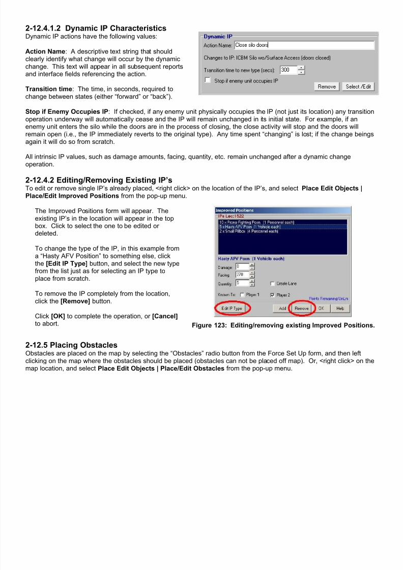
7/21/2019 TSS User Manual
http://slidepdf.com/reader/full/tss-user-manual 170/492
2-12.4.1.2 Dynamic IP CharacteristicsDynamic IP actions have the following values:
Action Name: A descriptive text string that shouldclearly identify what change will occur by the dynamicchange. This text will appear in all subsequent reportsand interface fields referencing the action.
Transition time: The time, in seconds, required to
change between states (either “forward” or “back”).
Stop if Enemy Occupies IP: If checked, if any enemy unit physically occupies the IP (not just its location) any transitionoperation underway will automatically cease and the IP will remain unchanged in its initial state. For example, if anenemy unit enters the silo while the doors are in the process of closing, the close activity will stop and the doors willremain open (i.e., the IP immediately reverts to the original type). Any time spent “changing” is lost; if the change beingsagain it will do so from scratch.
All intrinsic IP values, such as damage amounts, facing, quantity, etc. remain unchanged after a dynamic changeoperation.
2-12.4.2 Editing/Removing Existing IP’sTo edit or remove single IP’s already placed, <right click> on the location of the IP’s, and select Place Edit Objects |Place/Edit Improved Positions from the pop-up menu.
The Improved Positions form will appear. Theexisting IP’s in the location will appear in the topbox. Click to select the one to be edited ordeleted.
To change the type of the IP, in this example froma “Hasty AFV Position” to something else, clickthe [Edit IP Type] button, and select the new typefrom the list just as for selecting an IP type toplace from scratch.
To remove the IP completely from the location,
click the [Remove] button.
Click [OK] to complete the operation, or [Cancel]to abort. Figure 123: Editing/removing existing Improved Positions.
2-12.5 Placing ObstaclesObstacles are placed on the map by selecting the “Obstacles” radio button from the Force Set Up form, and then leftclicking on the map where the obstacles should be placed (obstacles can not be placed off map). Or, <right click> on themap location, and select Place Edit Objects | Place/Edit Obstacles from the pop-up menu.
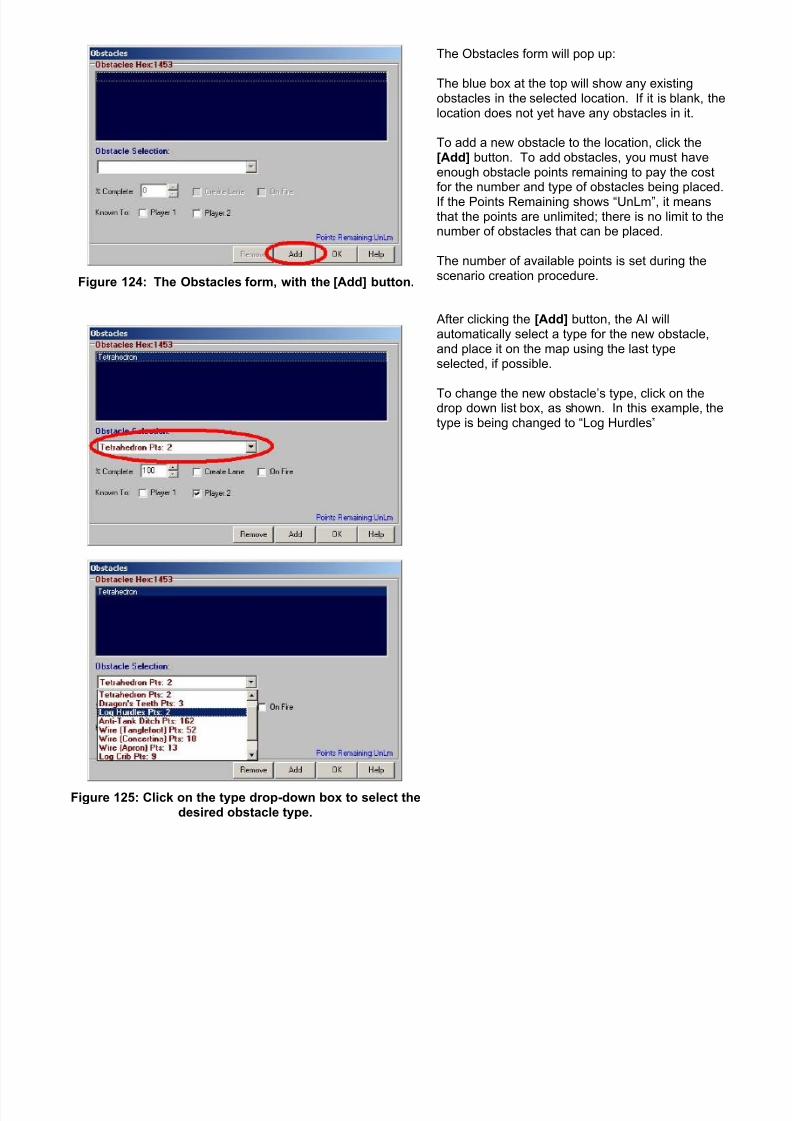
7/21/2019 TSS User Manual
http://slidepdf.com/reader/full/tss-user-manual 171/492
Figure 124: The Obstacles form, with the [Add] button.
The Obstacles form will pop up:
The blue box at the top will show any existingobstacles in the selected location. If it is blank, thelocation does not yet have any obstacles in it.
To add a new obstacle to the location, click the[Add] button. To add obstacles, you must haveenough obstacle points remaining to pay the costfor the number and type of obstacles being placed.If the Points Remaining shows “UnLm”, it meansthat the points are unlimited; there is no limit to thenumber of obstacles that can be placed.
The number of available points is set during thescenario creation procedure.
Figure 125: Click on the type drop-down box to select thedesired obstacle type.
After clicking the [Add] button, the AI willautomatically select a type for the new obstacle,and place it on the map using the last typeselected, if possible.
To change the new obstacle’s type, click on thedrop down list box, as shown. In this example, thetype is being changed to “Log Hurdles”
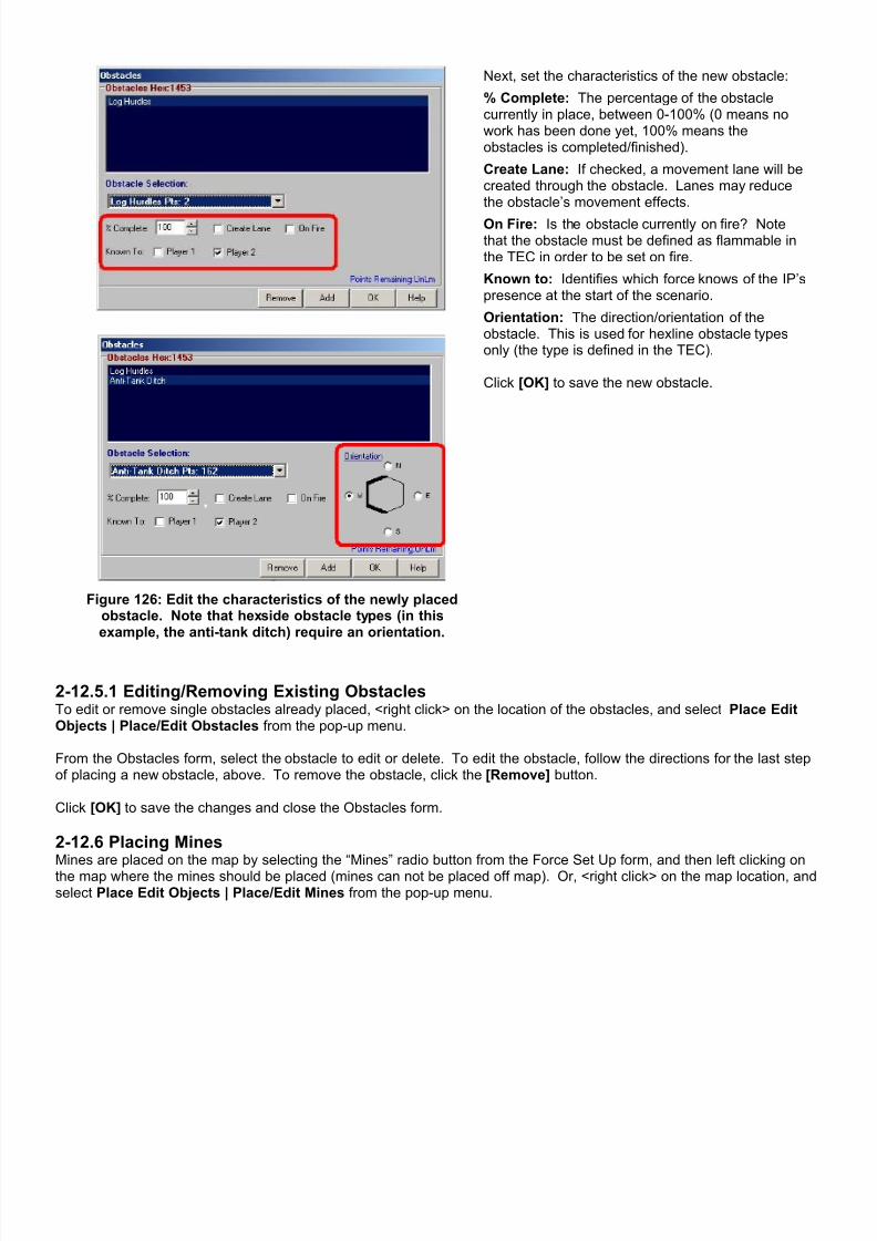
7/21/2019 TSS User Manual
http://slidepdf.com/reader/full/tss-user-manual 172/492
Figure 126: Edit the characteristics of the newly placedobstacle. Note that hexside obstacle types (in thisexample, the anti-tank ditch) require an orientation.
Next, set the characteristics of the new obstacle:
% Complete: The percentage of the obstaclecurrently in place, between 0-100% (0 means nowork has been done yet, 100% means theobstacles is completed/finished).
Create Lane: If checked, a movement lane will becreated through the obstacle. Lanes may reducethe obstacle’s movement effects.
On Fire: Is the obstacle currently on fire? Notethat the obstacle must be defined as flammable inthe TEC in order to be set on fire.
Known to: Identifies which force knows of the IP’spresence at the start of the scenario.
Orientation: The direction/orientation of theobstacle. This is used for hexline obstacle typesonly (the type is defined in the TEC).
Click [OK] to save the new obstacle.
2-12.5.1 Editing/Removing Existing ObstaclesTo edit or remove single obstacles already placed, <right click> on the location of the obstacles, and select Place EditObjects | Place/Edit Obstacles from the pop-up menu. From the Obstacles form, select the obstacle to edit or delete. To edit the obstacle, follow the directions for the last stepof placing a new obstacle, above. To remove the obstacle, click the [Remove] button.
Click [OK] to save the changes and close the Obstacles form.
2-12.6 Placing MinesMines are placed on the map by selecting the “Mines” radio button from the Force Set Up form, and then left clicking onthe map where the mines should be placed (mines can not be placed off map). Or, <right click> on the map location, andselect Place Edit Objects | Place/Edit Mines from the pop-up menu.
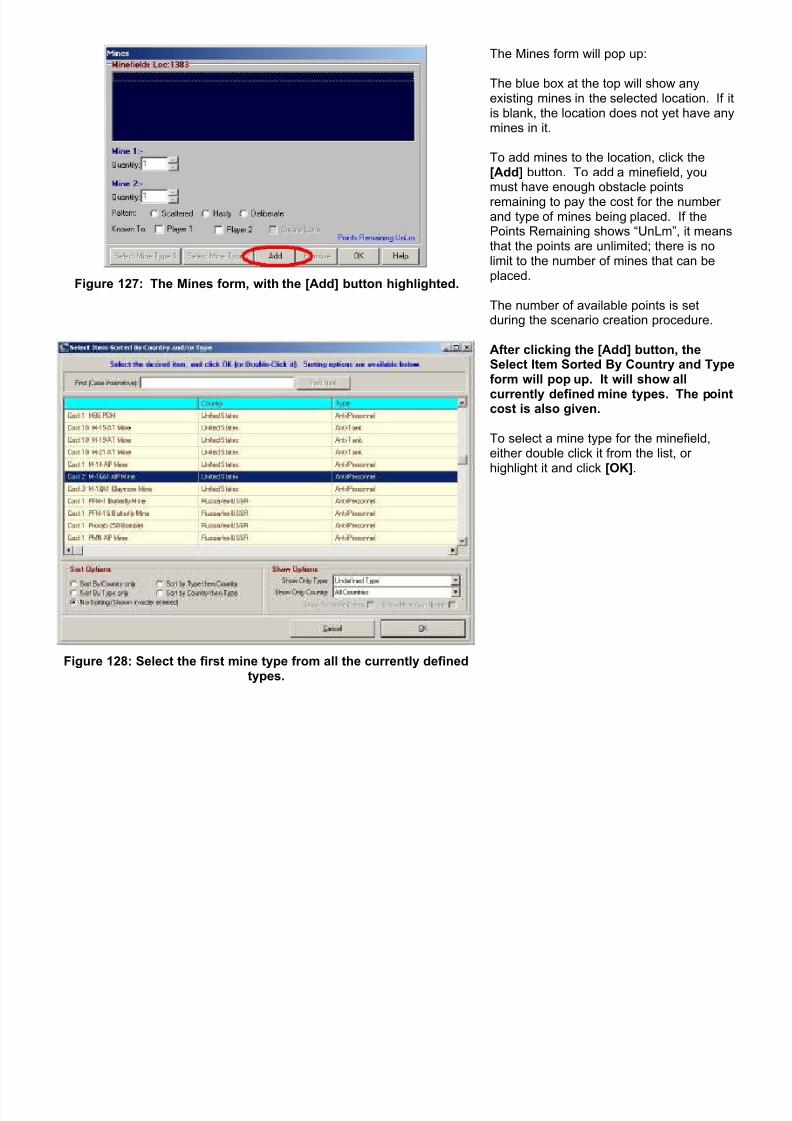
7/21/2019 TSS User Manual
http://slidepdf.com/reader/full/tss-user-manual 173/492
Figure 127: The Mines form, with the [Add] button highlighted.
The Mines form will pop up:
The blue box at the top will show anyexisting mines in the selected location. If itis blank, the location does not yet have anymines in it.
To add mines to the location, click the[Add] button. To add a minefield, youmust have enough obstacle pointsremaining to pay the cost for the numberand type of mines being placed. If thePoints Remaining shows “UnLm”, it meansthat the points are unlimited; there is nolimit to the number of mines that can beplaced.
The number of available points is setduring the scenario creation procedure.
Figure 128: Select the first mine type from all the currently definedtypes.
After clicking the [Add] button, theSelect Item Sorted By Country and Typeform will pop up. It will show all
currently defined mine types. The pointcost is also given.
To select a mine type for the minefield,either double click it from the list, orhighlight it and click [OK].
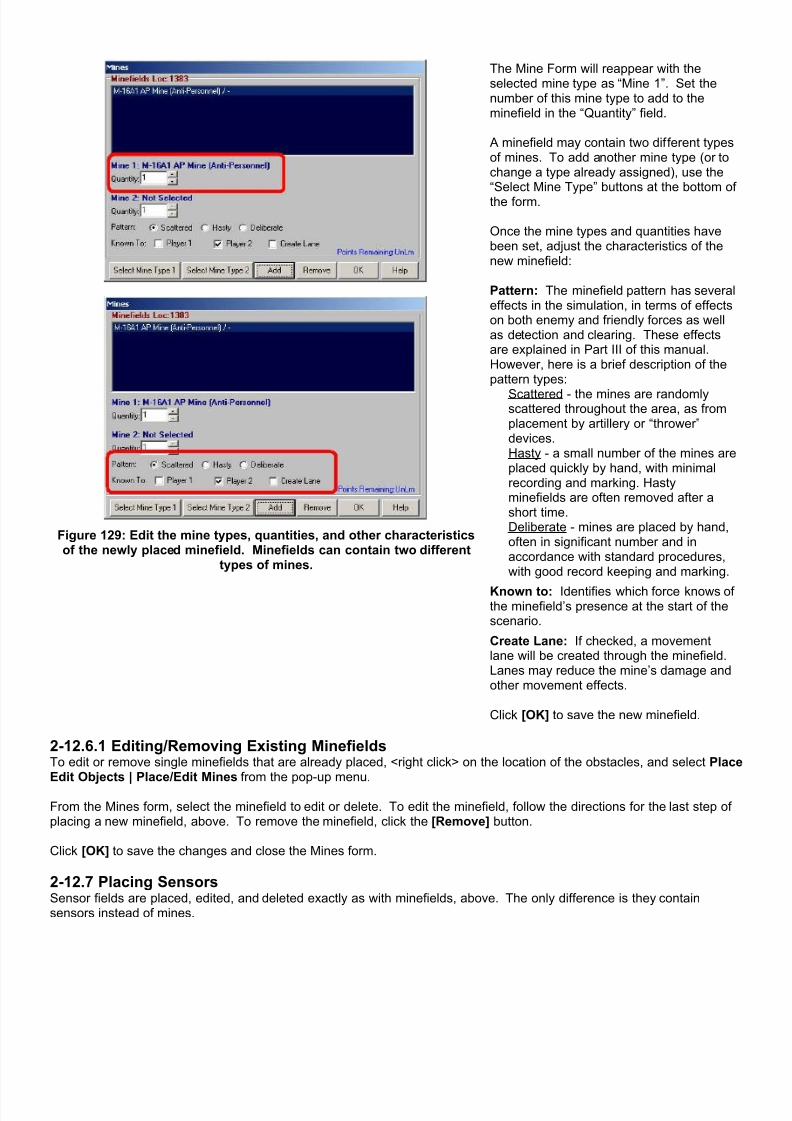
7/21/2019 TSS User Manual
http://slidepdf.com/reader/full/tss-user-manual 174/492
Figure 129: Edit the mine types, quantities, and other characteristicsof the newly placed minefield. Minefields can contain two different
types of mines.
The Mine Form will reappear with theselected mine type as “Mine 1”. Set thenumber of this mine type to add to theminefield in the “Quantity” field.
A minefield may contain two different typesof mines. To add another mine type (or tochange a type already assigned), use the“Select Mine Type” buttons at the bottom ofthe form.
Once the mine types and quantities havebeen set, adjust the characteristics of thenew minefield:
Pattern: The minefield pattern has severaleffects in the simulation, in terms of effectson both enemy and friendly forces as wellas detection and clearing. These effectsare explained in Part III of this manual.However, here is a brief description of thepattern types:
Scattered - the mines are randomlyscattered throughout the area, as fromplacement by artillery or “thrower”devices.Hasty - a small number of the mines areplaced quickly by hand, with minimalrecording and marking. Hastyminefields are often removed after ashort time.Deliberate - mines are placed by hand,often in significant number and inaccordance with standard procedures,with good record keeping and marking.
Known to: Identifies which force knows ofthe minefield’s presence at the start of thescenario.
Create Lane: If checked, a movementlane will be created through the minefield.Lanes may reduce the mine’s damage andother movement effects.
Click [OK] to save the new minefield.
2-12.6.1 Editing/Removing Existing MinefieldsTo edit or remove single minefields that are already placed, <right click> on the location of the obstacles, and select PlaceEdit Objects | Place/Edit Mines from the pop-up menu. From the Mines form, select the minefield to edit or delete. To edit the minefield, follow the directions for the last step ofplacing a new minefield, above. To remove the minefield, click the [Remove] button.
Click [OK] to save the changes and close the Mines form.
2-12.7 Placing SensorsSensor fields are placed, edited, and deleted exactly as with minefields, above. The only difference is they containsensors instead of mines.
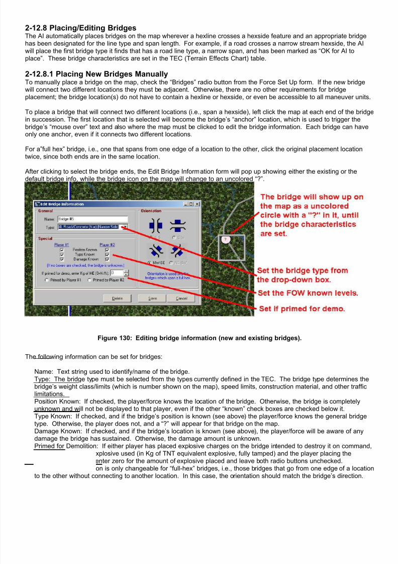
7/21/2019 TSS User Manual
http://slidepdf.com/reader/full/tss-user-manual 175/492
2-12.8 Placing/Editing BridgesThe AI automatically places bridges on the map wherever a hexline crosses a hexside feature and an appropriate bridgehas been designated for the line type and span length. For example, if a road crosses a narrow stream hexside, the AIwill place the first bridge type it finds that has a road line type, a narrow span, and has been marked as “OK for AI toplace”. These bridge characteristics are set in the TEC (Terrain Effects Chart) table.
2-12.8.1 Placing New Bridges ManuallyTo manually place a bridge on the map, check the “Bridges” radio button from the Force Set Up form. If the new bridgewill connect two different locations they must be adjacent. Otherwise, there are no other requirements for bridge
placement; the bridge location(s) do not have to contain a hexline or hexside, or even be accessible to all maneuver units.
To place a bridge that will connect two different locations (i.e., span a hexside), left click the map at each end of the bridgein succession. The first location that is selected will become the bridge’s “anchor” location, which is used to trigger thebridge’s “mouse over” text and also where the map must be clicked to edit the bridge information. Each bridge can haveonly one anchor, even if it connects two different locations.
For a”full hex” bridge, i.e., one that spans from one edge of a location to the other, click the original placement locationtwice, since both ends are in the same location.
After clicking to select the bridge ends, the Edit Bridge Information form will pop up showing either the existing or thedefault bridge info, while the bridge icon on the map will change to an uncolored “?”.
Figure 130: Editing bridge information (new and existing bridges).
The following information can be set for bridges:
Name: Text string used to identify/name of the bridge.Type: The bridge type must be selected from the types currently defined in the TEC. The bridge type determines thebridge’s weight class/limits (which is number shown on the map), speed limits, construction material, and other traffic
limitations.Position Known: If checked, the player/force knows the location of the bridge. Otherwise, the bridge is completelyunknown and will not be displayed to that player, even if the other “known” check boxes are checked below it.Type Known: If checked, and if the bridge’s position is known (see above) the player/force knows the general bridgetype. Otherwise, the player does not, and a “?” will appear for that bridge on the map.Damage Known: If checked, and if the bridge’s location is known (see above), the player/force will be aware of anydamage the bridge has sustained. Otherwise, the damage amount is unknown.Primed for Demolition: If either player has placed explosive charges on the bridge intended to destroy it on command,enter the amount of explosive used (in Kg of TNT equivalent explosive, fully tamped) and the player placing thecharges. Otherwise, enter zero for the amount of explosive placed and leave both radio buttons unchecked.Orientation: Orientation is only changeable for “full-hex” bridges, i.e., those bridges that go from one edge of a locationto the other without connecting to another location. In this case, the orientation should match the bridge’s direction.

7/21/2019 TSS User Manual
http://slidepdf.com/reader/full/tss-user-manual 176/492
Bridges that connect two different locations together have their orientation set as the direction between the twolocations.
Bridges cannot be placed off map, and can only be placed manually during the start phase of the scenario. Once thegame is under way, bridges must be constructed as combat engineering operations.
2-12.8.2 Editing/Deleting Existing BridgesTo edit an existing single bridge, scroll the mouse cursor over the bridge’s anchor location, which will be one end of thebridge. When the bridge information shows up in the mouse-over text/Current Location Information Form top window, the
cursor is over the anchor location. Note that bridges only have one anchor location, even if they connect two differentlocations.
Figure 131: Scroll the mouse over the map to find the “anchor location” of the bridge.
<Right click> on the map location, and then select Place Edit Objects | Place/Edit Bridges from the pop-up menu andfly-out. The Edit Bridge Information form will pop up, and the bridge information can be edited as described above.
Bridges cannot be deleted and bridge information cannot be changed once a scenario has begun and reached turn 1.From that point on, bridge status can only be changed through combat engineering operations.
2-12.9 Clearing/Removing Objects En-massTo remove ALL of a certain type ofobject, use the [Clear] button in theupper left of the Force Set-up form.
From the pop-up panel, select theobject type to remove. After aconfirmation message, ALL non-flank objects of that type will beremoved from the map.
Figure 132: Clearing objects from the map en-mass.
For example, to remove all of the mines that have been placed in the main playing area by the current player, click [Clear]followed by [Clear All Mines]. All of the mines will be removed from the map, and the points added back to the availabletotal. It does not matter how or when the mines (or other objects) were originally placed, for example if the player placedthe mines himself or through an AI action, or if they were placed as part of a previously saved scenario.
However, players may never clear objects originally placed by the opposing player, even if known, or those belonging to aflank force. Objects meeting either of these criteria are ignored by the removal routines.

7/21/2019 TSS User Manual
http://slidepdf.com/reader/full/tss-user-manual 177/492
2-12.10 AI Placement OptionsThe AI is fully capable of setting up all facets of a combat force including units, engineering items, and targeting controlpoints (TRP’s, DF Targets). This is true whether the force is attacking or defending and no matter what weapons systemsand other components the force has at its disposal.
For convenience, human players are afforded the opportunity to have the AI place all or part of their force. There are twooptions:[AI Place All Remaining Units]: When this button is clicked, the AI will place all units in the force that have not alreadybeen placed. The AI will not move any units that have been placed by a human player, but may adjust units that were
previously placed by the AI. If the “Auto-load Formations As Placed” check box is checked, the AI will load units itdetermines appropriate (however, the AI will never set up paradrop operations - those must always be set the by thehuman player).[AI Place Everything Remaining]: Clicking this button will have the AI to place everything remaining unplaced in theforce, including units, objects (IP’s, obstacles, and mines - but NOT bridges), and TRP’s and DF targets. Units are placedas described above, and the AI will likewise never change any objects placed by the human player.
NOTE: Scenarios without defined start lines (free set-up) limit the effectiveness of the AI placement routines. Playersshould always check any AI set up in these situations to make sure it is appropriate with their wishes.
Section 2-13 DF Target Reference Points (TRP’s)
DF TRP’s are control measures used by a defending force to automatically distribute and prioritize targets to units withinthe force. They also insure that key areas are always covered by fire, and also to increase the effectiveness of that fire.
Specifically, TRP’s are locations on the map that have one or more friendly units designated to fire at them if the enemyappears in their vicinity. If the unit is firing at something else at the time, it will usually immediately switch to the TRP,unless it is in danger of being overrun and/or in a degraded morale state.
Units can often have more than one DF TRP assigned to them. In these cases, each DF TRP is given a priority for theunit covering it, so that if the enemy appears the unit will know which one to cover if the enemy appears on multiple DFTRP’s at the same time.
The availability of DF TRP’s is limited to defending forces. Attackers generally do not use them in that they are notefficient or useful. It is difficult to accurately plan in advance exactly where the enemy will be, especially once the battlebegins and forces move out of their current positions. Instead, attacking forces use standard zones of fire, which aredynamic and adjust as the force advances and moves. Rather than burden the player with setting and updating these, the AI does it automatically “on the fly” as the scenario progresses.
By default, DF TRP’s are also limited to longer range/highpowered weapons systems, including tanks, tankdestroyers, and AT weapons. This is because there arenormally far fewer of them on the battlefield than infantryand other lighter weapons, so it is more important to makesure their fires are directed at the highest enemy threats.However, players can give DF TRP’s to other unit typeswhen setting up a new scenario from the Force Valuesform.
Figure 133: Adjust Force DF TRP’s available (SetForce/Nation Values Form).
2-13.1 Placing DF TRP’sDF TRP’s are placed on the map during the set up phase, usually after all the units have been deployed since units mustbe on the map in order to be assigned them. There are two ways of assigning TRP’s:
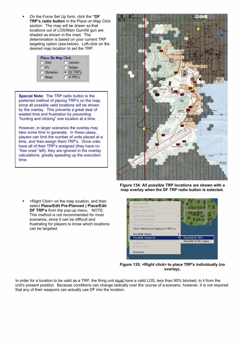
7/21/2019 TSS User Manual
http://slidepdf.com/reader/full/tss-user-manual 178/492
On the Force Set Up form, click the “DFTRP’s radio button in the Place on Map Clicksection. The map will be drawn so thatlocations out of LOS/Main Gun/All gun areshaded as shown in the inset. Thedetermination is based on your current TRPtargeting option (see below). Left-click on thedesired map location to set the TRP.
Special Note: The TRP radio button is thepreferred method of placing TRP’s on the map,since all possible valid locations will be shownby the overlay. This prevents a great deal ofwasted time and frustration by preventing“hunting and clicking” one location at a time.
However, in larger scenarios the overlay maytake some time to generate. In these cases,players can limit the number of units placed at atime, and then assign them TRP’s. Once unitshave all of their TRP’s assigned (they have no“free ones” left), they are ignored in the overlaycalculations, greatly speeding up the executiontime.
Figure 134: All possible TRP locations are shown with amap overlay when the DF TRP radio button is selected.
<Right Click> on the map location, and thenselect Place/Edit Pre-Planned | Place/EditDF TRP’s from the pop-up menu. NOTE:This method is not recommended for mostscenarios, since it can be difficult andfrustrating for players to know which locationscan be targeted.
Figure 135: <Right click> to place TRP's individually (nooverlay).
In order for a location to be valid as a TRP, the firing unit must have a valid LOS, less than 90% blocked, to it from theunit’s present position. Because conditions can change radically over the course of a scenario, however, it is not requiredthat any of their weapons can actually use DF into the location.

7/21/2019 TSS User Manual
http://slidepdf.com/reader/full/tss-user-manual 179/492
Although the player can, at his option, limit locations to those that can be actually engaged. In this case there are twooptions available:
Main Gun : The selected location must be able to be engaged by the unit’s primary gun system (shown as gun #1in the Weapons Information).
Any Gun : The selected location must be able to be engaged by at least one the unit’s gun systems (including themain gun).
When determining if the location can be engaged, the AI will make all of the standard firing checks for range, validprojectile flight paths, and ammunition types on hand. It does not check facing/rotation, missile command limits, orguidance considerations.
Figure 136: The Direct Fire TRP Form.
After selecting the location for the TRP, the Direct Fire TRP form willappear, as shown here. If any unit in the force already has the locationas a TRP, the unit will appear in the top box. In this example, no unitdoes, so a note to that effect is shown instead.
At least one friendly unit must be eligible to be assigned the location asa TRP. If that is not possible, based on the current limiting options(LOS only, Main Gun OK, or Any Gun OK). a note will be shown in the“Select Firing Unit” drop-down box. In order to set this location as aTRP, one or more units must be relocated as described elsewhere inthe manual.
Otherwise, Click [Add], and then select a firing unit from “Select FiringUnit” drop-down box.
A fire line will be drawn on the map between the unit’s current locationand the TRP, as shown below. To set the TRP values, follow thedirections for Editing Existing TRP’s, below, and then click [OK].
Figure 137: Adding a new TRP - the firing unit has been selected. Figure 138: TRP symbol on map.
2-13.2 Editing Existing TRP’sTo edit an existing TRP, <right click> on the map location containing the TRP and select Place/Edit Pre-Planned |Place/Edit DF TRP’s. The TRP form will appear as when adding a new TRP, except that any firing units that have thelocation as a TRP will be shown in the top box, followed by “[P]” for primary and “[S]’ for secondary.
The first unit in the list is selected by default. To select another, left click it. When the TRP is selected, its control settingswill be displayed on the panel beneath the “Select Firing Unit” drop down box. These vales are:
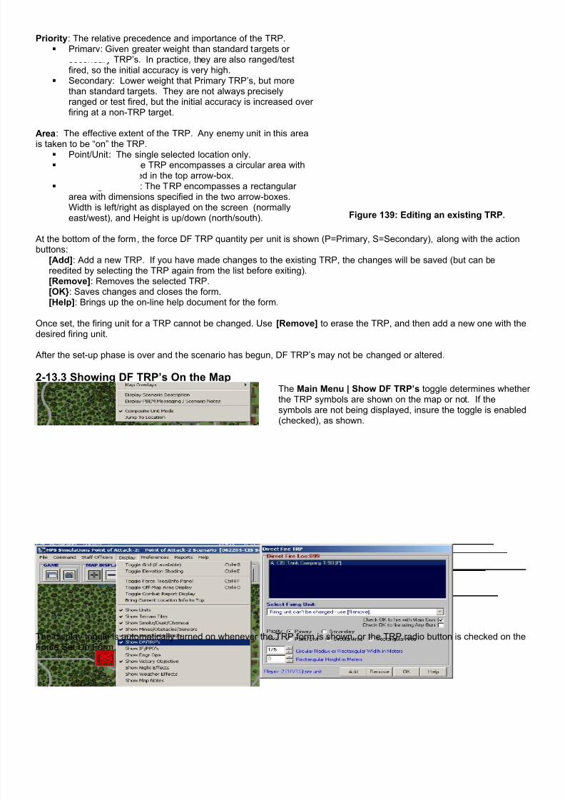
7/21/2019 TSS User Manual
http://slidepdf.com/reader/full/tss-user-manual 180/492
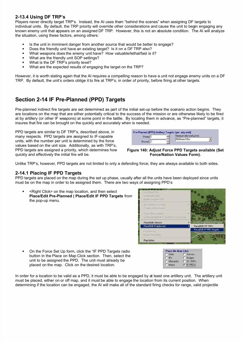
7/21/2019 TSS User Manual
http://slidepdf.com/reader/full/tss-user-manual 181/492
2-13.4 Using DF TRP’sPlayers never directly target TRP’s. Instead, the AI uses them “behind the scenes” when assigning DF targets toindividual units. By default, the TRP priority will override other considerations and cause the unit to begin engaging anyknown enemy unit that appears on an assigned DF TRP. However, this is not an absolute condition. The AI will analyzethe situation, using these factors, among others:
Is the unit in imminent danger from another source that would be better to engage? Does the friendly unit have an existing target? Is it on a DF TRP also? What weapons does the enemy unit have? How valuable/lethal/fast is it?
What are the friendly unit SOP settings? What is the DF TRP’s priority level? What are the expected results of engaging the target on the TRP?
However, it is worth stating again that the AI requires a compelling reason to have a unit not engage enemy units on a DFTRP. By default, the unit’s orders oblige it to fire at TRP’s, in order of priority, before firing at other targets.
Section 2-14 IF Pre-Planned (PPD) Targets
Pre-planned indirect fire targets are set determined as part of the initial set-up before the scenario action begins. Theyare locations on the map that are either potentially critical to the success of the mission or are otherwise likely to be fired
at by artillery (or other IF weapons) at some point in the battle. By locating them in advance, as “Pre-planned” targets, itinsures that fire can be brought on the quickly and accurately when is needed.
PPD targets are similar to DF TRP’s, described above, inmany respects. PPD targets are assigned to IF-capableunits, with the number per unit is determined by the forcevalues based on the unit size. Additionally, as with TRP’s,PPD targets are assigned a priority, which determines howquickly and effectively the initial fire will be.
Figure 140: Adjust Force PPD Targets available (SetForce/Nation Values Form).
Unlike TRP’s, however, PPD targets are not limited to only a defending force; they are always available to both sides.
2-14.1 Placing IF PPD Targets
PPD targets are placed on the map during the set up phase, usually after all the units have been deployed since unitsmust be on the map in order to be assigned them. There are two ways of assigning PPD’s:
<Right Click> on the map location, and then selectPlace/Edit Pre-Planned | Place/Edit IF PPD Targets fromthe pop-up menu.
On the Force Set Up form, click the “IF PPD Targets radiobutton in the Place on Map Click section. Then, select theunit to be assigned the PPD. The unit must already beplaced on the map. Click on the desired location.
In order for a location to be valid as a PPD, it must be able to be engaged by at least one artillery unit. The artillery unitmust be placed, either on or off map, and it must be able to engage the location from its current position. Whendetermining if the location can be engaged, the AI will make all of the standard firing checks for range, valid projectile
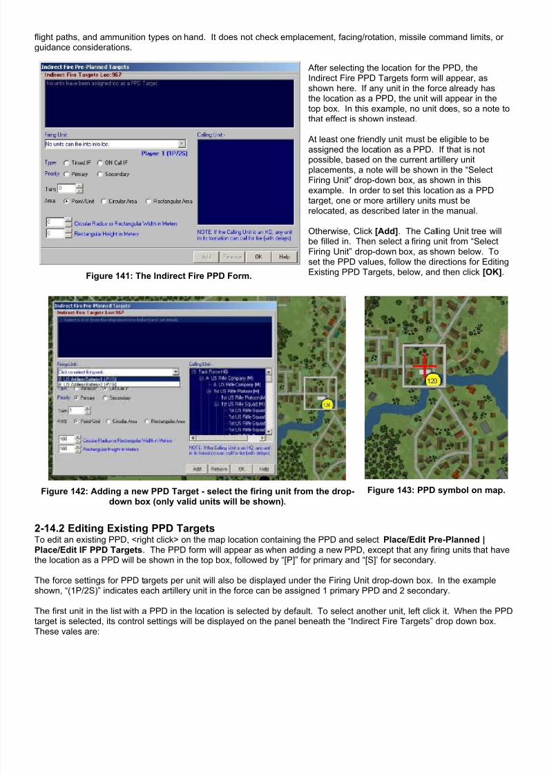
7/21/2019 TSS User Manual
http://slidepdf.com/reader/full/tss-user-manual 182/492

7/21/2019 TSS User Manual
http://slidepdf.com/reader/full/tss-user-manual 183/492

7/21/2019 TSS User Manual
http://slidepdf.com/reader/full/tss-user-manual 184/492
2-14.3 Showing IF PPD Targets On the MapThe Main Menu | Show IF PPD’s toggle determineswhether the PPD symbols are shown on the map or not.If the symbols are not being displayed, insure the toggleis enabled (checked), as shown.
The display toggle is automatically turned on wheneverthe IF PPD Targets form is shown, or the PPD radiobutton is checked on the Force Set Up form.
2-14.4 Using IF PPD TargetsHow a Pre-planned target is used during the scenario depends on its type.
“Timed” Preplanned timed missions are fired automatically when the scenario time matches the mission start time. If theartillery unit scheduled to fire the PPD mission is firing another at that time, the priorities of the missions will be compared,and whichever is greater will take precedence and be fired. If the priorities are the same, the in-progress mission will befired to completion, followed immediately by the timed PPD.
Otherwise, timed PPD missions are fired based on their priority.
“On-call” Preplanned targets, on the other hand, are used when calling for a new fire mission during the scenario. In thiscase, the PPD target allows these missions to be initially fired more quickly and accurately than for non-PPD targets.Calling for fire is covered later in the manual.
Section 2-15 Locating Units to Fire at a Specific Location
One of the more common questions during the set-up phase is,“Where do I need to place or move this unit so it can fire at thislocation?”
The TSS has an easy way to answer this question, by simplyselecting the desired firing unit from the force tree, and then <Right
Click> on the location you want the unit to be able to target. Fromthe drop down menu, select: Check Selected Unit Targeting ToTHIS Loc.
The program will automatically calculate every location on the map inwhich the unit can be placed to target the selected location. Circleswith “DF” inscribed indicate positions from which the unit can usedirect fire. “IF” designates firing locations where the unit can utilizeindirect fire, if it has that capability.

7/21/2019 TSS User Manual
http://slidepdf.com/reader/full/tss-user-manual 185/492

7/21/2019 TSS User Manual
http://slidepdf.com/reader/full/tss-user-manual 186/492
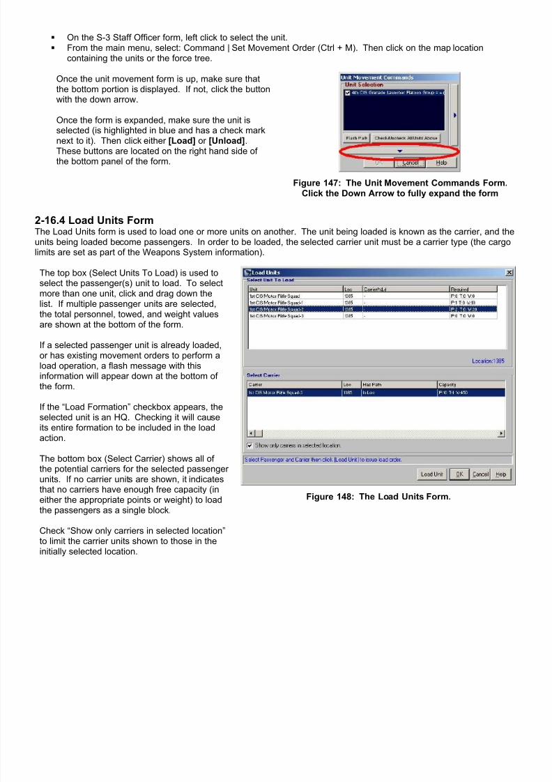
7/21/2019 TSS User Manual
http://slidepdf.com/reader/full/tss-user-manual 187/492
On the S-3 Staff Officer form, left click to select the unit. From the main menu, select: Command | Set Movement Order (Ctrl + M). Then click on the map location
containing the units or the force tree.
Once the unit movement form is up, make sure thatthe bottom portion is displayed. If not, click the buttonwith the down arrow.
Once the form is expanded, make sure the unit isselected (is highlighted in blue and has a check marknext to it). Then click either [Load] or [Unload].These buttons are located on the right hand side ofthe bottom panel of the form.
Figure 147: The Unit Movement Commands Form.Click the Down Arrow to fully expand the form
2-16.4 Load Units FormThe Load Units form is used to load one or more units on another. The unit being loaded is known as the carrier, and theunits being loaded become passengers. In order to be loaded, the selected carrier unit must be a carrier type (the cargolimits are set as part of the Weapons System information).
The top box (Select Units To Load) is used toselect the passenger(s) unit to load. To selectmore than one unit, click and drag down thelist. If multiple passenger units are selected,the total personnel, towed, and weight valuesare shown at the bottom of the form.
If a selected passenger unit is already loaded,or has existing movement orders to perform aload operation, a flash message with thisinformation will appear down at the bottom ofthe form.
If the “Load Formation” checkbox appears, theselected unit is an HQ. Checking it will causeits entire formation to be included in the loadaction.
The bottom box (Select Carrier) shows all ofthe potential carriers for the selected passengerunits. If no carrier units are shown, it indicatesthat no carriers have enough free capacity (ineither the appropriate points or weight) to loadthe passengers as a single block.
Check “Show only carriers in selected location”to limit the carrier units shown to those in the
initially selected location.
Figure 148: The Load Units Form.

7/21/2019 TSS User Manual
http://slidepdf.com/reader/full/tss-user-manual 188/492

7/21/2019 TSS User Manual
http://slidepdf.com/reader/full/tss-user-manual 189/492
If the selected carrier is part of a composite unit and composite unit mode is on, as in the above example, the actionbutton text will be changed to [UnLoad Grp], to indicate that ALL units of the composite group will be unloaded from thecarrier. This insures that composite units remain together.
If the operation cannot be completed for any reason, a flash message will appear briefly at the bottom of the form.
Click the [OK] button to issue the orders and close the form, or [Cancel] to close the form without issuing any orders. Ifthe orders are issued during the set-up phase they take effect immediately, there is no delay of any kind. Otherwise, thenormal command delay and order execution times apply.
2-16.5.1 Giving Debarking Units Movement OrdersBecause players will often wish to give passenger units movement orders to execute upon debarking, the interface allowsfor this to be done easily. For example, a player may want to truck troops to a woods location near an objective, and thenhave them debark and assault to position on foot. This protects the vulnerable trucks from enemy fire, and also reducesthe vulnerability of the infantry to being killed en mass if a truck is hit and explodes.
After clicking [UnloadUnit] or {Unload Grp], the interface will begin cycling through all of the debarking units, one by oneto allow them to be given orders. The current unit will be identified in green, as shown:
Movement orders are given by clicking on the map to create waypoints. Each time a new location is selected, the AI willautomatically generate a path to the new waypoint from the last (starting with the debarking location).
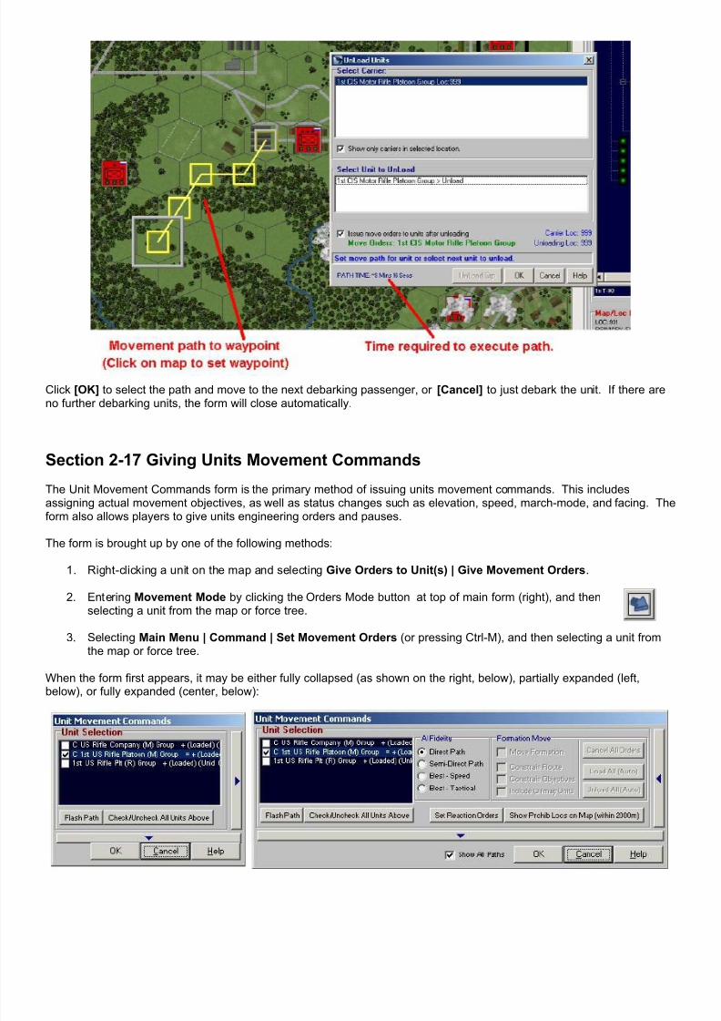
7/21/2019 TSS User Manual
http://slidepdf.com/reader/full/tss-user-manual 190/492
Click [OK] to select the path and move to the next debarking passenger, or [Cancel] to just debark the unit. If there areno further debarking units, the form will close automatically.
Section 2-17 Giving Units Movement Commands
The Unit Movement Commands form is the primary method of issuing units movement commands. This includesassigning actual movement objectives, as well as status changes such as elevation, speed, march-mode, and facing. Theform also allows players to give units engineering orders and pauses.
The form is brought up by one of the following methods:
1. Right-clicking a unit on the map and selecting Give Orders to Unit(s) | Give Movement Orders.
2. Entering Movement Mode by clicking the Orders Mode button at top of main form (right), and thenselecting a unit from the map or force tree.
3. Selecting Main Menu | Command | Set Movement Orders (or pressing Ctrl-M), and then selecting a unit fromthe map or force tree.
When the form first appears, it may be either fully collapsed (as shown on the right, below), partially expanded (left,below), or fully expanded (center, below):
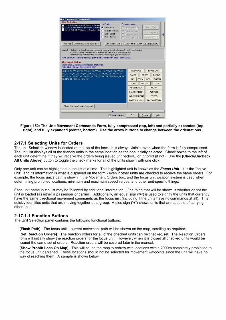
7/21/2019 TSS User Manual
http://slidepdf.com/reader/full/tss-user-manual 191/492
Figure 150: The Unit Movement Commands Form, fully compressed (top, left) and partially expanded (top,right), and fully expanded (center, bottom). Use the arrow buttons to change between the orientations.
2-17.1 Selecting Units for OrdersThe unit Selection window is located at the top of the form. It is always visible, even when the form is fully compressed.The unit list displays all of the friendly units in the same location as the one initially selected. Check boxes to the left ofeach unit determine if they will receive the orders being issued (if checked), or ignored (if not). Use the [Check/UncheckAll Units Above] button to toggle the check marks for all of the units shown with one click.
Only one unit can be highlighted in the list at a time. This highlighted unit is known as the Focus Unit . It is the “activeunit”, and its information is what is displayed on the form - even if other units are checked to receive the same orders. Forexample, the focus unit’s path is shown in the Movement Orders box, and the focus unit weapon system is used whendetermining prohibited locations, minimum and maximum speed values, and other unit-specific things.
Each unit name in the list may be followed by additional information. One thing that will be shown is whether or not theunit is loaded (as either a passenger or carrier). Additionally, an equal sign (“=”) is used to signify the units that currentlyhave the same directional movement commands as the focus unit (including if the units have no commands at all). Thisquickly identifies units that are moving together as a group. A plus sign (“+”) shows units that are capable of carryingother units.
2-17.1.1 Function ButtonsThe Unit Selection panel contains the following functional buttons:
[Flash Path]: The focus unit’s current movement path will be shown on the map, scrolling as required.
[Set Reaction Orders]: The reaction orders for all of the checked units can be checked/set. The Reaction Ordersform will initially show the reaction orders for the focus unit. However, when it is closed all checked units would beissued the same set of orders. Reaction orders will be covered later in the manual.
[Show Prohib Locs On Map]: This will cause the map to redraw with locations within 2000m completely prohibited tothe focus unit darkened. These locations should not be selected for movement waypoints since the unit will have noway of reaching them. A sample is shown below.

7/21/2019 TSS User Manual
http://slidepdf.com/reader/full/tss-user-manual 192/492
Figure 151: Locations with prohibited terrain are darkened.
2-17.2 AI FidelityThe AI Fidelity determines how the AI will determine a path to a new waypoint (assuming itisn’t adjacent to the end of the existing path), and what it should emphasize in doing so.
Note: this setting is saved and used for all AI movement operations, including for acomputer controlled opponent.
The AI Fidelity options are (with their relative “real time” processing time in parenthesis):
Direct Path: (Fastest) The AI will attempt to use as straight a path as possible, regardless of speed or concealment.The only time the path will vary from a straight line is if it encounters a location the unit is prohibited from entering.
Semi-Direct Path: (Fast) The AI will move to the new waypoint using roughly a straight line, but will allow somedeviation (a few hundred meters off “straight”) to produce the fastest execution time.
Best - Speed: (Slow) The AI will determine the fastest path to the new waypoint, without regard to how straight thepath is. If two paths have the same execution time, the one with the best cover and concealment will be selected.Roads will be used as appropriate, subject to the units’ current march mode settings (set in the unit SOP).
Best - Tactical: (Slow) The AI will determine the most covered and concealed path to the new waypoint, withoutregard to how straight the path is. If two paths have the same cover and concealment, the fastest will be selected.When this option is selected, roads are ignored unless necessary (units are assumed to remain in tactical march modeunless it becomes necessary to change temporarily).
The option may be changed at any time; a first method can be used for one waypoint, and a second method for another.The method used is always determined by the radio button setting when the waypoint is selected by clicking on a map/off-map location.
2-17.3 Formation MoveThe formation move utility allows players to move an entire formation with asingle click when its HQ unit is selected. For example, if a company HQ isselected, and a formation move is used, all of the units in the company will beissued appropriate movement orders automatically by the AI when an objectiveis picked for the HQ unit. The AI determines the final objectives for all of thesubordinate units, determines movement paths to get them there, and issues theorders.
To use the formation move utility, check the “Move Formation” box, if it is enabled (indicating a HQ has been selected).

7/21/2019 TSS User Manual
http://slidepdf.com/reader/full/tss-user-manual 193/492
For flexibility, the formation move affords players the following options:
Constrain Route: The subordinate units will converge on a point in the HQ’s movement path near the starting point.They will then follow the HQ’s path until the get near the final objective. This is used primarily to move a formationalong a road when the subordinate units begin spread out over a wide area.
Constrain Objectives: This will place all of the subordinate units’ final objectives near, or equal to, the HQ’s finalobjective. The actual objectives depend on prohibited terrain and other factors, but by default are within 100 meters ofthe HQ objective for a platoon, 300 meters for a company, and 500 meters for a battalion.
Include Offmap Units: If this is checked, units in the formation that are currently located offmap will be included in the
move. Otherwise, they will be ignored.[Cancel All Orders]: All units in the formation will have their current orders canceled. Note that some orders mayremain due to the command delay (it takes time for the cancellation order to reach the units - in the meantime they willexecute what orders they have).
[Load All (Auto)]: This auto-loads all of units within the formation to the greatest extent possible. The load orders areissued as normal commands, subject to the command delay and an execution time.
[Unload All (Auto)]: This unloads all passenger units from carriers in the formation. The unload orders are issued asnormal commands, subject to the command delay and an execution time.
Figure 152: Unconstrained. Theposition of the units and their
paths remain constant relative tothe HQ.
Figure 153: Constrained Path. Theunit paths converge on the HQ pathnear the start and follow it to near
the objective (constrained pathshown in red).
Figure 154: Constrained Objective.The final unit objectives are close
to, or the same as, the final HQobjective.
As stated previously, when issuing a formation move, constrained or not, the AI will determine the final movementobjectives and waypoints for all of the moving units. The AI will select these locations based on avoiding prohibitedterrain, while maximizing sighting toward the enemy. Additionally, the AI will weigh cover and concealment and mobility inthe location based on the force’s mission and aggressiveness level.
When using a formation move, the HQ’s movement path will be shown in the active move path color (by default this isyellow, but it can be changed from Preferences | Map Colors Tab | Selected Unit’s Path). The paths for the other unitsin the formation will flash on the screen momentarily, using shades of gray. Once they have all been drawn, only the HQ’spath will remain.
NOTE: Self-homing and en-route/in-flight units are never included in a formation movement order.

7/21/2019 TSS User Manual
http://slidepdf.com/reader/full/tss-user-manual 194/492
2-17.4 Movement Orders
Figure 155: The movement orders section.
The movement orders section is used to displayand edit the focus unit’s movement path. Thefocus unit is identified at the top of the section.
If it has current orders of any type, the approximatetime required to execute those orders will beshown immediately underneath. The time isalways approximate (and is preceded by a tilde “~”
to note this) because many things could occurduring the execution could affect the final time.Some examples would be morale changes,breakdowns, pausing to fire, and leader effects.
The location shown is the unit’s presently knownlocation. This may be different than the unit’sactual location if friendly Fog of War (FOW) isused.
2-17.4.1 Path DisplayThe Path Display shows all commands currently assigned to the unit, including directional, speed and status changes,and other operations. The commands are shown in the order they will be executed, separated by commas. Directionalcommands are based on the standard compass directions, and are in uppercase letters. Other commands will bedisplayed as a code, followed by the new value, if appropriate. For example, a speed change to 40 Kph is shown as“spd:40”.
Human player set codes are normally in lower case letters, while those imposed by the computer are in upper case. Forexample, “Dly:10” is a 10 second delay imposed by the computer (and not editable by the human player), while “ dly:10” isa 10 second delay ordered by a human player, and which may be edited/deleted if the command delay allows it.
Clicking the [Show Command Index/Legend] button will pop-up a list of all the codes.
A special note concerning the movement path is that if friendly Fog of War (FOW) is used, the path shown will be theexpected path from the unit’s currently known or estimated location. Because this estimated location may not matchwhere the unit really is, or because other status changes may not be completely known, the path may not match the unit’sactual orders.
When the FOW is set to include friendly units, “Showing Projected Friendly Positions” will be shown in the upper rightcorner of the map display. Otherwise, the label will read, “Showing Actual Friendly Positions”.
Figure 156: Map label when Friendly FOW enabled. Figure 157: Map label when Friendly FOW disabled.
2-17.4.2 Command ButtonsThe command buttons are located to the right of the path display. Clicking these buttons causes an order of theappropriate type to be added to the end of the unit’s current path. If there are multiple units checked in the Units Selectionbox, these orders will be given to them also.
Based on the focus unit’s situation and weapon system type, some of the commands may not be valid or possible toissue. In these cases, the command buttons will be disabled.
The Command Buttons are:

7/21/2019 TSS User Manual
http://slidepdf.com/reader/full/tss-user-manual 195/492
[Clear All]: Clicking this button erases the units’ movement path back to the command delay limit. Because thecommand delay limit is the time it takes for orders to reach the unit, nothing before this can be changed or edited.[Erase Last]: This erases the last command entered, as long as it is not before the command delay (see above).[Pause]: Click this to add a pause command. Pauses are in seconds. During pauses, units will not move, but willsight and fire normally.[Speed]: Clicking this button adds a speed change command onto the end of the current path. Speed is in Kph, andonce changed the unit will maintain this speed until changed (if the terrain allows it).[Facing]: Click this button to append a facing command. Facing is specified as a major compass point. When thiscommand is executed, the unit will face in the direction specified, including its turret if it has one. After that the unit willnot change facing until it either executes a directional movement command (directional movement always causes anautomatic facing change), the player changes the facing automatically, or the unit must change facing to engage aDF/IF target.[Up]: Used only by personnel-type ground units in buildings or structures, this order causes the unit to go up one storyin a multi-level building. Each story adds 3 meter in elevation. Multi-level terrain is a value set in the TEC. If the unitis not in a multi-story structure, is not a personnel unit, or is already at the top story, the command will be ignored.[Down]: As with the above command, this is used only by personnel-type ground units in buildings or structures, thisorder causes the unit to go down one story in a multi-level building. If the unit is not in a multi-story structure, is not apersonnel unit, or is already at the top story, the command will be ignored.[In Tnl]: Enter tunnel/underground IP (Improved Position) from the ground surface (IP must have surface access).[Out Tnl]: Exit a tunnel/underground IP to the ground surface (IP must have surface access).[Load]: Clicking this brings up the Load Units form, which allows carrier units to load passengers, or other units to beloaded as passengers. The Load Units form is described above.[Unload]: Clicking this brings up the Unload Units form, which allows loaded carrier to be issued with unloading
commands. The Unload Units form is described above.[In IP]: Enter an appropriate IP in the location.[Add Engr Ops]: This button brings up the Engineering form, which allows the player to assign the unit to a new orexisting combat engineering project such as laying mines, building obstacles, or clearing lanes. The Engineering formand how to use it will be described in more detail later in the manual. If the location of the engineering operation is notin the current movement path end point, the AI will automatically issue movement orders to get the unit to where itneeds to be.[MOPP]: Click this button to issue orders to change the units NBC protection (MOPP) level. MOPP Levels and theprotection/degradation they provide is set in the MOPP System Data table and linked to the Weapons System. Whenmultiple units are selected with differing MOPP structures, the level will be applied proportionally to all of them basedon the focus unit. For example, if the focus unit has a maximum MOPP level of 3 and is ordered to assume MOPPLevel 1, all of the other units will be ordered to assume 1/3 (33%) of their maximum MOPP level, rounded up to thenext highest level. Which means a unit with a maximum MOPP of 5 will go to level 2 (33% times 5 = 1.67, rounded up
to 2). Most MOPP changes require time to effect, based on the settings in the MOPP System Data table.[March Mode]: This will issues for a formation change, which will toggle the unit’s March Mode between road (linear)and tactical (spread out). This toggle will override any existing SOP orders for movement mode. However, the SOPvalues will take effect again after the formation change if the unit starts moving.[Altitude]: Click this button to set the altitude of an aircraft unit. Altitude is set in meters AGL (above ground level),and applies only to aircraft units.[Undo Waypoint]: When issuing directional movement commands by selecting waypoints on the map (see below),clicking this button will remove the last path segment added and the path will end at the previous waypoint. Waypointsare not saved beyond the current operation; once a movement path has been saved, the waypoints are lost.[Editor]: The editor button allows players direct access to the individual movement commands, but only for non-composite, non-aircraft units. Path editing will be covered in more depth below.[Start/End Patrol Mode]: Click this button to begin a cyclic (repeating) patrol path. Select desired path by clicking onthe map to select waypoints. When finished, click [End Patrol Mode] to have the AI close the loop by generating apath from the last position in the path back to the starting location. Patrols will be discussed in more detail below.
2-17.4.3 Movement Path Editor The Movement Path Editor allows players to edit the unit path command-by-command back to the command limit(remember, it is never possible to edit or change commands prior to the command limit since the orders to make thechange can’t arrive before they are executed). The editor allows for existing commands to be deleted and newcommands inserted without having to delete the entire movement path and rebuild it from scratch.
In some cases the editor option will not be available: The focus unit is a Composite Unit The focus unit is an aircraft

7/21/2019 TSS User Manual
http://slidepdf.com/reader/full/tss-user-manual 196/492

7/21/2019 TSS User Manual
http://slidepdf.com/reader/full/tss-user-manual 197/492
Orders to enter an IP aregiven from the UnitMovement Commands Form,which must be fullyexpanded (as explainedpreviously).
When a unit is given ordersto enter a location thatcontains one or more knownIP’s that are of the correcttype for the moving unit, the[IN IP] button will becomeenabled on the form (asshown highlighted in red atright). Click the button togive the unit orders to enterone of the IP’s in thelocation.
Figure 159: This unit’s path takes it into a location containing IP's. Click the [IN
IP] button to have the unit enter one of them in the current location.
If there is more than one applicable IP in the location,choose the one the unit should occupy from the pop-uplist box.
If the label “[OK to select]” appears after the IP name, itindicates that one or more of the moving units can occupythe IP, at least in the absence of other occupying units ordamage. If “[No unit can enter]” appears instead, it indicates that
the type or size of the IP is not sufficient to hold the unit isthe best of circumstances and therefore it is very unlikelythat the unit will be able to carry out the orders (althoughthe IP may still be selected).
Note: Only very basic checks of the IP type, overall capacity and size are made when giving orders. These checks donot take into account other units potentially or actually occupying the IP, combat damage or other factors. Therefore, justbecause a unit has orders to enter an IP, it does not mean that it will actually do so when it reaches the IP location; theIP will require enough excess capacity and size to hold the unit at the time it tries to enter, otherwise the occupation willbe prohibited.
During the execution phase, there is no cost or delay for units to enter/exit IP’s or tunnels. However, if the unit is thenmoving on, the normal movement routines are applied using the TEC values for the IP.
2-17.4.6 Moving UndergroundUnderground IP’s allow units to move below the ground surface. When several underground IP’s are linked together inadjacent locations, they form a tunnel. The capacity and characteristics of the tunnel depend on the IP Data Table andTEC (terrain effects chart) values:
• IP Valueso Size: height and width
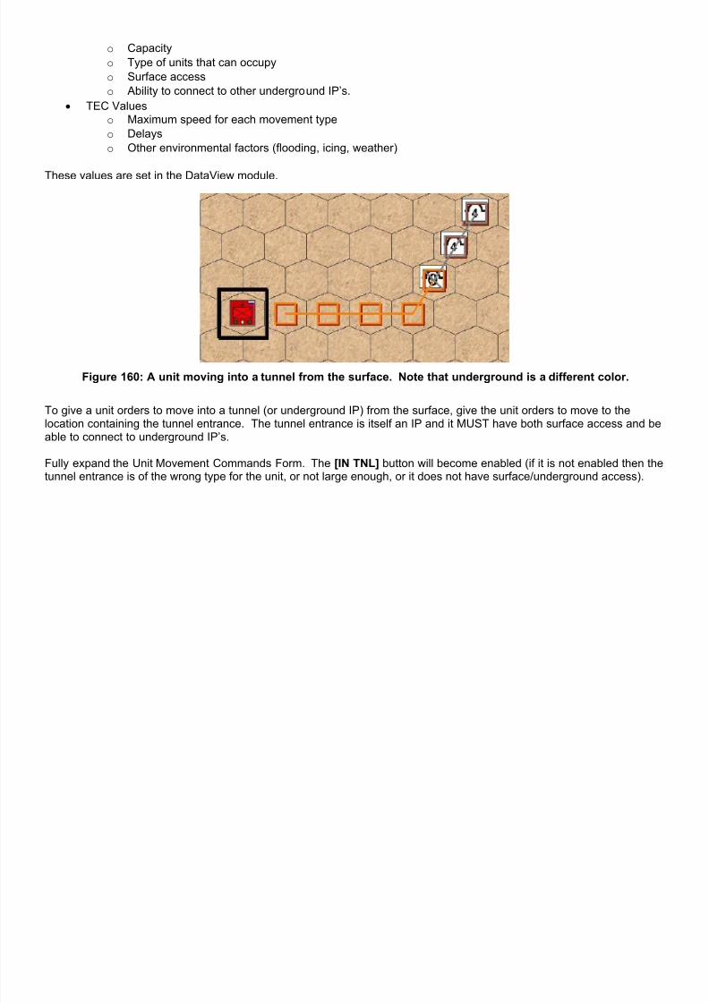
7/21/2019 TSS User Manual
http://slidepdf.com/reader/full/tss-user-manual 198/492

7/21/2019 TSS User Manual
http://slidepdf.com/reader/full/tss-user-manual 199/492
Figure 161: To enter a tunnel, click the [IN TNL] button (highlighted) on the Unit Movement Commands Form.
To move a unit out of a tunnel onto the surface, issue commands to the tunnel entrance, and then click the [OUT TNL]button on the Unit Movement Commands Form:
Figure 162: This unit starts in a tunnel and is given orders to move to the tunnel entrance and then to the surface.

7/21/2019 TSS User Manual
http://slidepdf.com/reader/full/tss-user-manual 200/492
2-17.5 Setting Movement Waypoints A waypoint is simply a movement objective, selected by clicking on an on or off map location. Waypoints are an easy andefficient way to give units movement orders. Each time a waypoint is selected, the AI will automatically determine thebest route for the unit to take between the new waypoint and the end of the unit's current path. In this case “best” isdefined by either player settings (speed versus protection), or for AI commanders, as a blend of both speed and protectionen-route with the relative weight of each based on the force aggressiveness level. Highly aggressive forces favor speedover protection, and vice-versa for those of low aggressiveness.
Waypoints also provide a convenient way to erase portions of a movement path while entering it. If the path to a newlyselected waypoint results in an odd or unwanted path, merely click the [Undo Waypoint] button. This will removes the lastentered waypoint and path segment from the command list, without affecting the commands entered to that point.
Figure 163: Selecting the next waypoint from the map. Figure 164: The AI determines the best path & adds it.
It is a good idea to keep waypoints fairly close together. Doing that minimizes the AI processing time, plus gives greatercontrol over the general path orientation. There is no hard and fast rule, since the relative movement and concealmentvalues of the map area can vary considerably. However, on highly cluttered and movement-difficult maps, such as forestor mountainous terrain 5 or 6 “locations” (i.e., “hexes) is a good range. On more open maps, such as the desert, theranges can go up to about 20 locations (hexes) or more. For comparison, in the above example, the new waypoint isabout 8 locations/hexes away from the last.
When issuing waypoints as part of a formation movement order, the AI will determine the waypoints of the subordinateunits based on their current orientation towards the HQ unit, and if the objective is selected as constrained. Movementpaths will then be determined to these waypoints and the orders issued to the units. Whether or not the AI considers thepath or objectives constrained is determined at the instant the waypoint is selected. In other words, when the maplocation is clicked, are the Constrain Route/Objective boxes in the Formation Move panel checked or not. Any settingsused for previous waypoints are ignored.
2-17.5.1 Showing All Friendly Move Paths At the bottom on the movement form is a checkbox labeled:Show All Paths. Checking this box marks out themovement path of every other friendly unit in dark red. Thismakes it easy to see where other units will be going so thatplayers can make sure the force’s units cover a desiredarea or stay out of each others way.
An example is shown below:

7/21/2019 TSS User Manual
http://slidepdf.com/reader/full/tss-user-manual 201/492
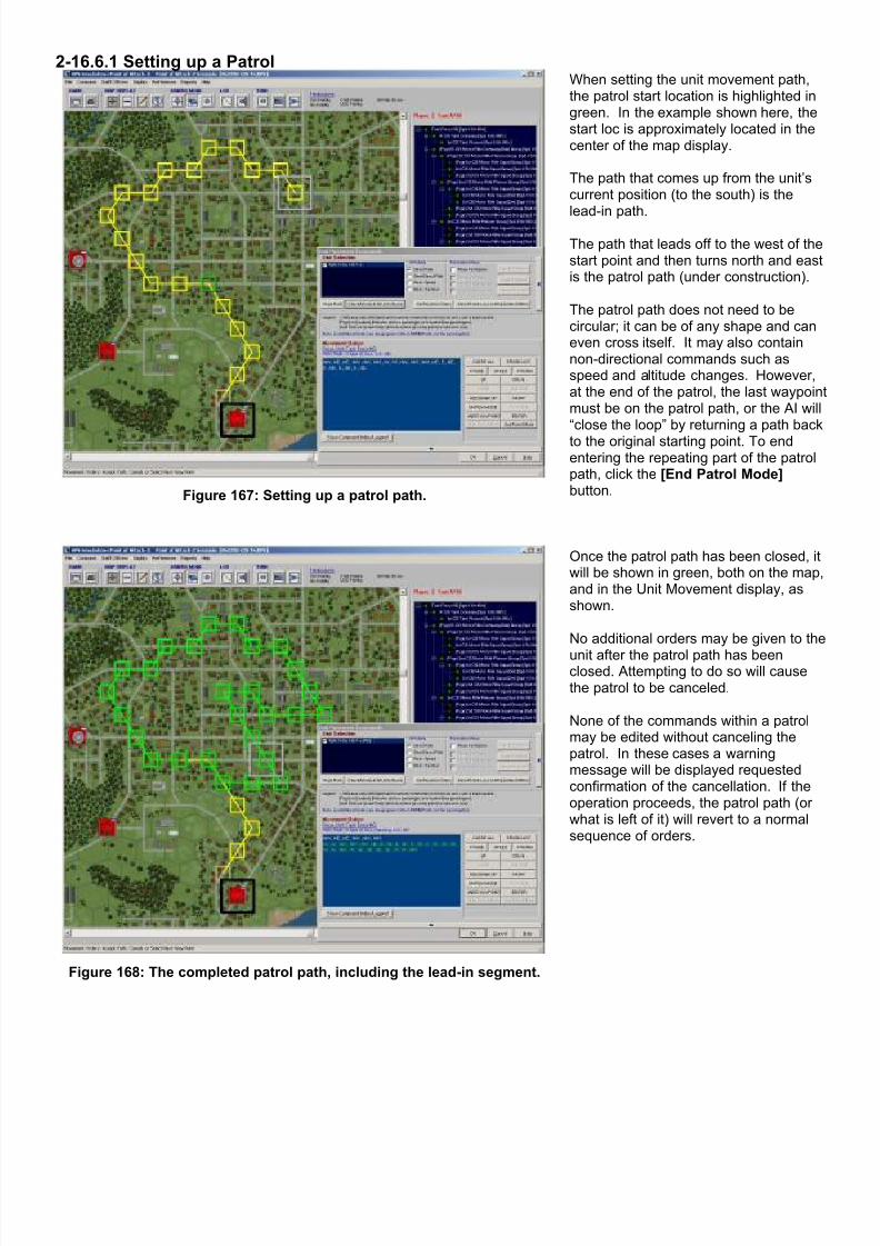
7/21/2019 TSS User Manual
http://slidepdf.com/reader/full/tss-user-manual 202/492
2-16.6.1 Setting up a Patrol
Figure 167: Setting up a patrol path.
When setting the unit movement path,the patrol start location is highlighted ingreen. In the example shown here, thestart loc is approximately located in thecenter of the map display.
The path that comes up from the unit’scurrent position (to the south) is the
lead-in path.
The path that leads off to the west of thestart point and then turns north and eastis the patrol path (under construction).
The patrol path does not need to becircular; it can be of any shape and caneven cross itself. It may also containnon-directional commands such asspeed and altitude changes. However,at the end of the patrol, the last waypoinmust be on the patrol path, or the AI will“close the loop” by returning a path back
to the original starting point. To endentering the repeating part of the patrolpath, click the [End Patrol Mode]button.
Figure 168: The completed patrol path, including the lead-in segment.
Once the patrol path has been closed, itwill be shown in green, both on the map,and in the Unit Movement display, asshown.
No additional orders may be given to the
unit after the patrol path has beenclosed. Attempting to do so will causethe patrol to be canceled.
None of the commands within a patrolmay be edited without canceling thepatrol. In these cases a warningmessage will be displayed requestedconfirmation of the cancellation. If theoperation proceeds, the patrol path (orwhat is left of it) will revert to a normalsequence of orders.
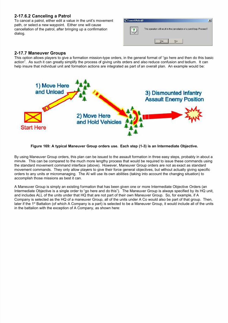
7/21/2019 TSS User Manual
http://slidepdf.com/reader/full/tss-user-manual 203/492

7/21/2019 TSS User Manual
http://slidepdf.com/reader/full/tss-user-manual 204/492
Figure 170: Maneuver Groups always contain all of the units under the selected HQ, with the exception of anysub-formations that are part of their own Maneuver Group (in this case, A Company, as shown on the right is not
part of the 1st Battalion Maneuver Group since it is its own group).
2-17.7.1 Maneuver Groups FormManeuver Groups are added, edited and deleted using the Maneuver Groups Form.
To display this form, click Main Menu | Maneuver Groups/Recon.

7/21/2019 TSS User Manual
http://slidepdf.com/reader/full/tss-user-manual 205/492
Figure 171: Maneuver Groups Form (no Groups defined).
Figure 172: Maneuver Groups defined. Each group isa shaded a different color.
The top panel of the form shows all of the existing ManeuverGroups. Each maneuver group is shaded a different colorand all units of the same group share the same color.
Note: in some cases, two or more Maneuver Groups may theshare the same shade if the number of groups exceeds the
number of discrete shading colors (about 25).
The bottom panel displays all of the intermediate objectiveorders for the group selected in the top pane. IntermediateObjectives are always executed in order – top to bottom asshown in this panel (i.e., the first objective is at the top, thesecond under it, and so on).
To define a new Maneuver Group, click on the formation HQunit in the top pane. If the selected unit is not part of anexisting group, the Set Intermediate Objectives Form willappear (see below). Otherwise, the existing orders will beshown in the bottom pane:
Figure 173: A Tank Company selected for newManeuver Group. All subordinate units are also
highlighted as part of the group.

7/21/2019 TSS User Manual
http://slidepdf.com/reader/full/tss-user-manual 206/492
To add a new set of Intermediate Objective Orders, click the [Add New Intermediate Objective] button. The SetIntermediate Objectives Form will appear (see below).
To edit or delete a set of existing intermediate orders for thecurrent Maneuver Group, select the orders set from the bottompane. Then select the action with one of the enabled buttons:
[Edit Set]: Edit the parameters of the orders, including boththe location(s) and actions to be taken.
[Delete Set]: Delete the set of objective orders completely.When a Maneuver Group has no Intermediate Objective ordersremaining, the Maneuver Group label is deleted as well (theactual units are not otherwise affected).
Figure 174: Select a set of Intermediate Objectiveorders (bottom pane) to edit or delete.
When an existing Maneuver Group is selected from the top panel, the units will be highlighted in yellow on the map andexisting Intermediate Objective locations will be displayed on the map. The currently selected objective set will be inbright red. Others will be in dark red.
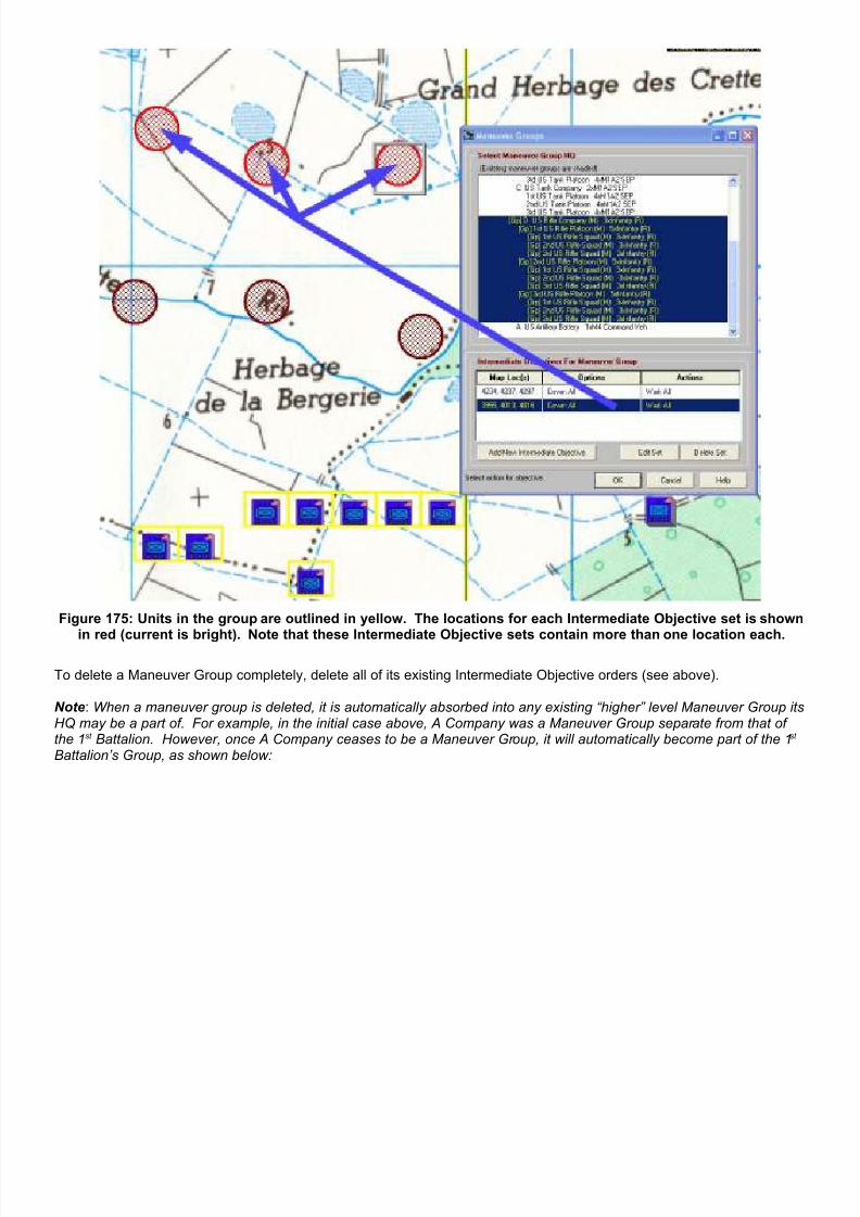
7/21/2019 TSS User Manual
http://slidepdf.com/reader/full/tss-user-manual 207/492
Figure 175: Units in the group are outlined in yellow. The locations for each Intermediate Objective set is shown
in red (current is bright). Note that these Intermediate Objective sets contain more than one location each.
To delete a Maneuver Group completely, delete all of its existing Intermediate Objective orders (see above).
Note: When a maneuver group is deleted, it is automatically absorbed into any existing “higher” level Maneuver Group itsHQ may be a part of. For example, in the initial case above, A Company was a Maneuver Group separate from that ofthe 1st Battalion. However, once A Company ceases to be a Maneuver Group, it will automatically become part of the 1st
Battalion’s Group, as shown below:

7/21/2019 TSS User Manual
http://slidepdf.com/reader/full/tss-user-manual 208/492
Figure 176: Deleting Maneuver Groups when a higher HQ's is also a Maneuver Group parent.
2-17.7.1.1 Intermediate Objective Panel:The bottom panel displays all of the currently defined Intermediate Objective orders for the current Maneuver Group. Theinformation is broken down into three columns as follows:
Map Loc(s): Options Actions
The locations making up the objectiveset. A set can contain multiplelocations, any number of which canbe designated to be “real” (seeoptions).
Modifications concerning the objectiveareas, including radius and numberthat are “real”
Actions that units will take uponreaching the objective.
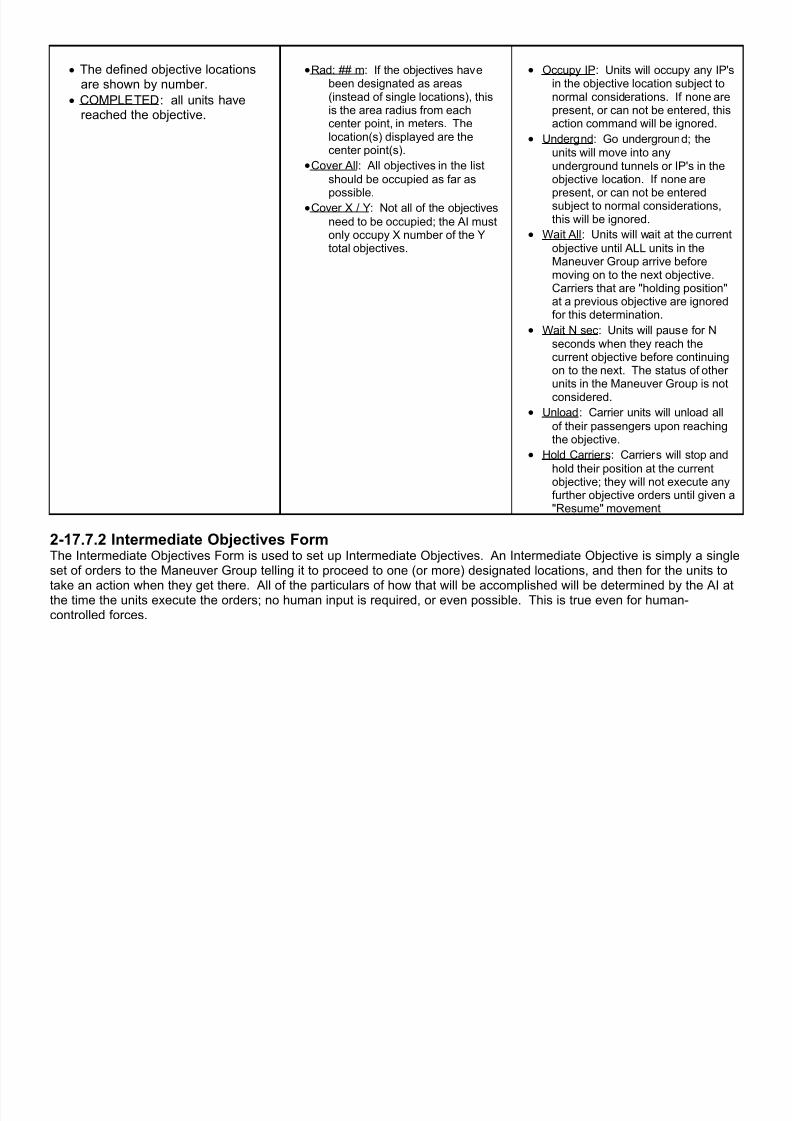
7/21/2019 TSS User Manual
http://slidepdf.com/reader/full/tss-user-manual 209/492
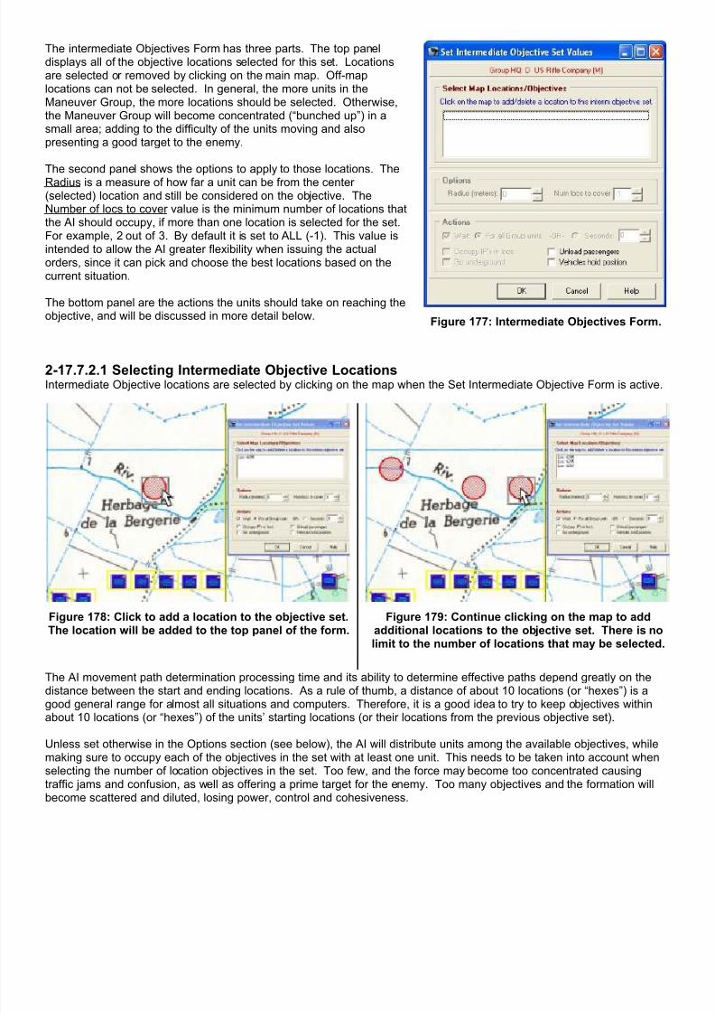
7/21/2019 TSS User Manual
http://slidepdf.com/reader/full/tss-user-manual 210/492
The intermediate Objectives Form has three parts. The top paneldisplays all of the objective locations selected for this set. Locationsare selected or removed by clicking on the main map. Off-maplocations can not be selected. In general, the more units in theManeuver Group, the more locations should be selected. Otherwise,the Maneuver Group will become concentrated (“bunched up”) in asmall area; adding to the difficulty of the units moving and alsopresenting a good target to the enemy.
The second panel shows the options to apply to those locations. TheRadius is a measure of how far a unit can be from the center(selected) location and still be considered on the objective. TheNumber of locs to cover value is the minimum number of locations thatthe AI should occupy, if more than one location is selected for the set.For example, 2 out of 3. By default it is set to ALL (-1). This value isintended to allow the AI greater flexibility when issuing the actualorders, since it can pick and choose the best locations based on thecurrent situation.
The bottom panel are the actions the units should take on reaching theobjective, and will be discussed in more detail below.
Figure 177: Intermediate Objectives Form.
2-17.7.2.1 Selecting Intermediate Objective LocationsIntermediate Objective locations are selected by clicking on the map when the Set Intermediate Objective Form is active.
Figure 178: Click to add a location to the objective set.The location will be added to the top panel of the form.
Figure 179: Continue clicking on the map to addadditional locations to the objective set. There is nolimit to the number of locations that may be selected.
The AI movement path determination processing time and its ability to determine effective paths depend greatly on thedistance between the start and ending locations. As a rule of thumb, a distance of about 10 locations (or “hexes”) is a
good general range for almost all situations and computers. Therefore, it is a good idea to try to keep objectives withinabout 10 locations (or “hexes”) of the units’ starting locations (or their locations from the previous objective set).
Unless set otherwise in the Options section (see below), the AI will distribute units among the available objectives, whilemaking sure to occupy each of the objectives in the set with at least one unit. This needs to be taken into account whenselecting the number of location objectives in the set. Too few, and the force may become too concentrated causingtraffic jams and confusion, as well as offering a prime target for the enemy. Too many objectives and the formation willbecome scattered and diluted, losing power, control and cohesiveness.
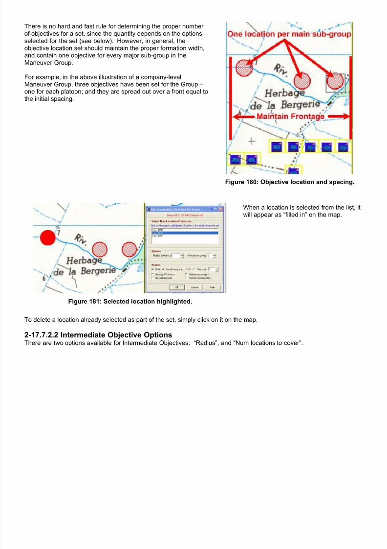
7/21/2019 TSS User Manual
http://slidepdf.com/reader/full/tss-user-manual 211/492
There is no hard and fast rule for determining the proper numberof objectives for a set, since the quantity depends on the optionsselected for the set (see below). However, in general, theobjective location set should maintain the proper formation width,and contain one objective for every major sub-group in theManeuver Group.
For example, in the above illustration of a company-levelManeuver Group, three objectives have been set for the Group –one for each platoon; and they are spread out over a front equal tothe initial spacing.
Figure 180: Objective location and spacing.
Figure 181: Selected location highlighted.
When a location is selected from the list, itwill appear as “filled in” on the map.
To delete a location already selected as part of the set, simply click on it on the map.
2-17.7.2.2 Intermediate Objective OptionsThere are two options available for Intermediate Objectives: “Radius”, and “Num locations to cover”.

7/21/2019 TSS User Manual
http://slidepdf.com/reader/full/tss-user-manual 212/492
The Radius option increasesthe “size” of each objective;each location within this circleis considered an acceptableobjective location. In otherwords, when the AI isdetermining where units will bemoved to achieve the objective,all locations within the Radiusdistance (in meters) of anactual objective location will beopen for use, giving the AImuch greater flexibility.
By default, the Radius is zero:only the selected location is theobjective. The locations(s)themselves must be occupiedby friendly units.
The shaded areas on the maprepresent the effects of theradius value, as shown by the
example to the right where theradius is 200 meters (andwhich may be compared to theprevious screen shots wherethe radius was zero).
Figure 182: Using the Radius option.
The “Num locations to cover” specifies the minimum number of objectives which must be occupied by units (accountingfor the radius value, above). By default the value is “-1”, which equals “ALL”. However, it may be set anywhere between1 and the total number of objective locations in the set.
By setting the value less that the number of objective locations, the AI gains flexibility at the time it determines which unitsshould move to what locations to fulfill its Intermediate Objective mission. For example, if 5 locations have been selected
for a set, but the “Num locations to cover” value has been set to 3, the AI can decide not to occupy up to two objectives ifit feels that doing so would not be advantageous. Otherwise, it would have to occupy all 5, which might be detrimentaland something that no human commander “on the spot” would decree.
2-17.7.2.3 Intermediate Objective Actions Actions are specified measures taken by units when they reach their objective locations. These actions are handledautomatically by the AI, and do not require any human input or intervention.
Actions are only performed by units when they are able todo so. For example, a Maneuver Group may have ordersto “occupy Improved Positions (IP’s)” in a location, but if thelocation only contains personnel-type IP’s only personnel-type units will execute the orders. Other types of units in
the Group will ignore the orders. Figure 183: Intermediate Objective Actions.
The available Actions are:
• Wait: All units in the group will wait upon reaching their assigned objective. The wait can be specified as either anumber of seconds or until all other units in the Maneuver Group have reached their assigned objectives for thisset. The “For All Group Units” option applies only to group units with movement orders. Therefore carriers“holding position” (see below) are ignored since they are not moving.
• Occupy IP's in locs: Units will attempt to occupy any appropriate IP (Improved Position) in their destinationlocations. Normal IP type and capacity limits apply; if no IP’s are present, or no IP’s can be entered subject to thenormal conditions and restrictions, this action command will be ignored.

7/21/2019 TSS User Manual
http://slidepdf.com/reader/full/tss-user-manual 213/492
• Go underground: If there is a tunnel/underground IP entrance in the location, the unit will enter it. Becausetunnels are also IP's, this box will automatically supersede the above IP checkbox, where applicable.
• Unload passengers: If the unit is a carrier, it will unload any current passengers (towed or internal) when itreaches the objective.
• Carriers hold position: Carrier type units (vehicles with a cargo capacity of type "APC", "Cargo" or "Supply") wilhold their position and cease executing Intermediate Objective orders when they reach the objective. They canstill be given orders normally, however. Carriers holding position can be given orders to resume moving at laterobjectives (see below). Carriers that are part of a Composite Unit Group may be temporarily broken out of theComposite Unit Group if other units in that Group move on without it. The carrier unit is not removed from the
Maneuver Group, however.• Carriers resume moving: Issuing this order will have all carriers holding their position (see above) resumemoving on the current objective once all other (non-carrier) units in the group are moving towards it. Whencarriers that were broken out of a Composite Unit Group occupy the same location and their original CompositeUnit Group's HQ, they will rejoin the Composite Group.
Actions may be changed at any time, even after units have begun executing their objective orders. However, normalcommand delay restrictions and limits apply.
2-17.7.2.4 Intermediate Objective Example As an example of how to use Intermediate objectives, the following illustration shows how to use them to perform acommon tactical maneuver: a deliberate infantry assault from the march:
1) The force starts out from the assembly area with the infantry loaded on their APC’s/carriers.2) The loaded carriers move to a covered and concealed position close to the enemy. The infantry dismounts.3) The troops proceed to the assault position on foot with the vehicles moving along side them to provide support.4) The vehicles stop outside of effective short range AT range of the enemy forces.5) The infantry proceeds on foot alone to assault and take the enemy position.
This can be accomplished using the standard movement interface; however, it would be complicated and rather timeconsuming process. It would also be inflexible, based on “pre-programmed” time schedules that are not responsive to thedeveloping situation as it actually occurs.
Instead, it is a simple matter using Intermediate objectives, as shown in this step-by-step example:

7/21/2019 TSS User Manual
http://slidepdf.com/reader/full/tss-user-manual 214/492
Start by clicking “Main Menu | Maneuver ”. Selectthe assault force. In this case, pick 2nd Battalion, ACompany.
The locations of each unit in the formation will behighlighted in yellow on the map:
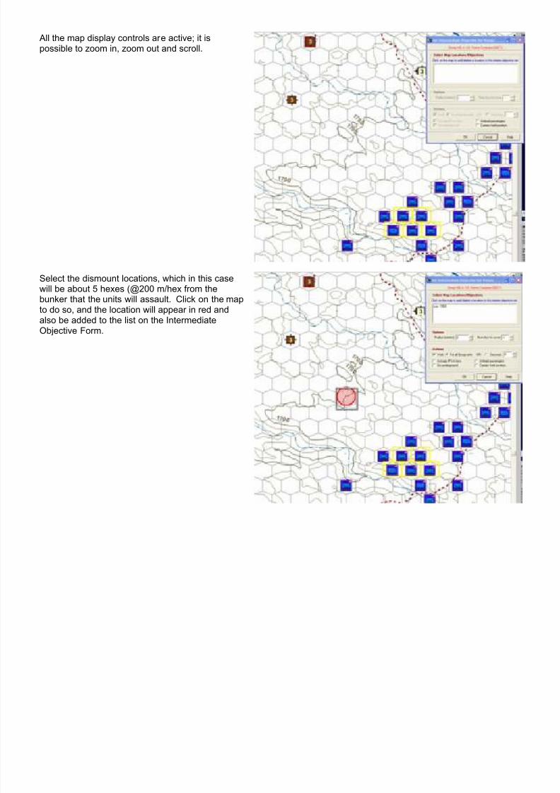
7/21/2019 TSS User Manual
http://slidepdf.com/reader/full/tss-user-manual 215/492

7/21/2019 TSS User Manual
http://slidepdf.com/reader/full/tss-user-manual 216/492
As per the “rule of thumb” more than one locationshould be selected for the objective set – the AIwill apportion out the individual units in theManeuver Group (in this case A Company) tooccupy as many as are specified. In this case, twolocations will be selected so that the formation isn’tcompletely “bunched up”.
Now that the locations have been selected, Actions are set to tell the AI what should be donewhen the units reach the objectives. This is doneusing the Set Intermediate Objectives Form.
In this example, the radius will remain at 0, and the“Num to cover” at -1 (all).
Because the passengers should dismount here,the action values should be set so that “UnloadPassengers” is checked. Since speed is of theessence, the “Wait” has also been unchecked sothat the Group will move as fast as possible.
Click [OK].

7/21/2019 TSS User Manual
http://slidepdf.com/reader/full/tss-user-manual 217/492
Control will return to the Maneuver Group Form. All of the units in the Maneuver Group will beshaded the same color in the top box. Theobjective just added appears in the lower panel. Inthis case it shows the 2 locations just added, alongwith a brief description of the options and actions.
The next step is to add the locations at which thecarriers (the Stryker vehicles) will stop and providecovering fire while the infantry continue theassault. Click [Add New Interim Objective Set]to add a new set of objectives.
The previously assigned objective locations nowappear in dark red.
As before, clicking the map will set the newobjective locations. In this case, the locations willbe about 400 meters (2 hexes) from the bunker.

7/21/2019 TSS User Manual
http://slidepdf.com/reader/full/tss-user-manual 218/492
The carriers will hold their position at this location(to provide fire for the advancing infantry), so thatbox is also checked.
As before, “Wait” has also been unchecked so thatthe Group will move as fast as possible.
Click [OK] to save the objective set.
Control will return to the Maneuver Group Form.
Click [Add New Interim Objective Set] to add anew set of objectives, in this case the actualassault on the bunker by the dismounted infantry.
Then click the IP location. Since there is only oneIP, it will be the only location in this Objective Set(all of the dismounted infantry will converge on it).
Because the assaulting units should enter thebunker and occupy it (and eliminate anydefenders), the “Occupy IP’s in loc” box should bechecked.
In this case the “Go underground” checkbox is alsochecked, in case the bunker is connected to atunnel system. In this case the infantry units willautomatically enter any tunnels, and proceedunderground to their next Intermediate Objective, ifthey can.
The mission is now complete. The AI will execute the orders as best it can once the scenario begins (or as soon as itcan if the scenario is already underway).

7/21/2019 TSS User Manual
http://slidepdf.com/reader/full/tss-user-manual 219/492
Helpful tip:In large scenarios, it can be confusing and difficultto remember which units are assaulting whichenemy positions, which units are providingsupport, and what forces are providing screeningor other activities.
Map notes are a quick an easy way to encapsulatethis information, using the color and textproperties.
It makes sense to place a map note on the on thebunker location so that it readily apparent that anassault force has been assigned to it. To do so, just right-click the location and select “Map Notes”.
Select the color and enter any desired text. In this
case, the text will be set to the attacking formation.
The map note will then appear on the map (if thedisplay setting for Map Notes is enabled), and thetext will be shown when the mouse is passed overthe location.
2-17.8 Reconnaissance/Radiation Detection AssignmentsThis option is similar to Maneuver Groups (above) in that it allows players to give “objective-based” reconnaissanceorders to units where the AI handles the details automatically. However, unlike Maneuver Groups, these assignmentsmay only be given to reconnaissance-type units, or those that have radiological detectors (these characteristics are set inthe weapons Systems Data Table).
A further difference with Maneuver Groups is that the available options are limited to those applicable to reconnaissanceassignments, namely actions associated with searching areas of the map and when to proceed to other areas. Thechoices do not include options for combat or organizational changes.
Specifically, recon assignments directed units to search defined areas, in a given order, leaving one area for the nextwhen a set of defined conditions are met.
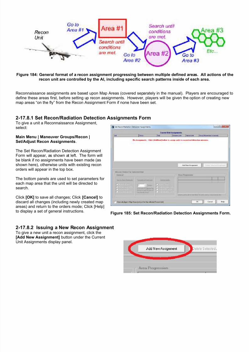
7/21/2019 TSS User Manual
http://slidepdf.com/reader/full/tss-user-manual 220/492
Figure 184: General format of a recon assignment progressing between multiple defined areas. All actions of therecon unit are controlled by the AI, including specific search patterns inside of each area.
Reconnaissance assignments are based upon Map Areas (covered separately in the manual). Players are encouraged todefine these areas first, before setting up recon assignments. However, players will be given the option of creating newmap areas “on the fly” from the Recon Assignment Form if none have been set.
2-17.8.1 Set Recon/Radiation Detection Assignments Form
To give a unit a Reconnaissance Assignment,select:
Main Menu | Maneuver Groups/Recon |Set/Adjust Recon Assignments.
The Set Recon/Radiation Detection AssignmentForm will appear, as shown at left. The form willbe blank if no assignments have been made (asshown here), otherwise units with existing reconorders will appear in the top box.
The bottom panels are used to set parameters for
each map area that the unit will be directed tosearch.
Click [OK] to save all changes; Click [Cancel] todiscard all changes (including newly created mapareas) and return to the orders mode; Click [Help]to display a set of general instructions.
Figure 185: Set Recon/Radiation Detection Assignments Form.
2-17.8.2 Issuing a New Recon AssignmentTo give a new unit a recon assignment, click the[Add New Assignment] button under the CurrentUnit Assignments display panel.

7/21/2019 TSS User Manual
http://slidepdf.com/reader/full/tss-user-manual 221/492
2-17.8.3 Recon Assignment Unit SelectionSelect the desired recon unit from the pop-up box. Unitsalready given recon assignments will not be shown in thelist.
“<RAD>” to the left of the unit name denotes that the unithas radiological detectors on board. The unit may also be areconnaissance type, but that is not required to be selected.
“<RECON>” to the left of the unit name indicates that theunit does not have radiation detectors, but it is an allowedreconnaissance type.
Note: the pop-up box will only display units with radiologicaldetection devices or of a “reconnaissance type” weaponssystem.
2-17.8.4 Recon Assignment Areas/Progression A unit must be assigned one or more map areas in whichto search. The unit will proceed between these areas inthe the order they are entered (known as the
“progression”). The AI will automatically issue orders for aunit to move from one area to the next when the exitconditions are met for the original area (see below).
To add a new map area to the progression, click the cellunder the “Area ID” column displaying the following text:“>> Click here to add a new area to progression.”
A drop-down will appear showing all of the currentlydefined map areas available to the player (right, lower). Ifno areas have been defined, the the drop-down list will beblank (as shown below).
Select the desired area from the list, or to create a new
map area from scratch, click:.“>> SELECT TO CREATE A NEW MAP AREA”
The panel will change to show the map area types (asshown below right). Click the button that best representsthe type of area you want to create. Then follow thestandard procedure for creating new map areas(described later in the manual).
Note: Map Areas are defined from: Main Menu | Map Areas/Events.
Figure 186: Click the cell under “Area ID” to add a newmap area to the progression.
Figure 187: Select an existing map area to add.
To define a new map area:

7/21/2019 TSS User Manual
http://slidepdf.com/reader/full/tss-user-manual 222/492
Figure 188: (Step #1) Click the highlighted drop-downentry to create a new map area.
Figure 189: (Step #2) Select the new map area type.
Hints on map areas:
• To display all of the available map areas,check the box labeled: “Show all player'sMap Areas...”, as shown to the right.Otherwise, map areas will only be shownif they are part of the unit's progression.
• Use map area types appropriate to theassignment. For example, if the reconmission should concentrate on a road,then the map area for that assignmentshould probably be a “Location List” type,with the locations corresponding to theroad. This keeps the recon units focusedon specific features of interest. Reconaround specific points should be circular,while area sweeps should generally berectangular.
• Keep area sizes to the minimum extentappropriate to the mission. Whennecessary, try to break larger areas upinto two or more smaller ones. Smallerareas preserve greater flexibility, and aremore efficient for the AI search routines.
• Try to minimize area overlap. This willoptimize the performance and speed ofthe AI search routines and also preventwasted effort between multiple reconunits and/or missions.
Figure 190: Existing map areas shown on the map after checking thedisplay box on the form. This example shows all three types of map
areas: Circular (left), Rectangular (top, right/center), and LocationList (bottom right/center).

7/21/2019 TSS User Manual
http://slidepdf.com/reader/full/tss-user-manual 223/492
2-17.8.5 Progression to the Next AreaUnits will search a given area until one of two things happen:
1. The unit is deemed to have “sufficiently observed” acertain percentage of the locations in the area(based on the the user-settable “Threshold value”,shown at right). What constitutes “sufficient” isdetermined by the AI Aggressiveness level andgeneral situation.
2. A radiological source is detected somewhere on themap (the detection can be by any unit). The sourcelocation is known as a “radiation hotspot”. Note: thiscondition only applies to recon units with radiologicaldetection capabilities.
When one of these conditions occurs, the AI will evaluatewhether the recon unit should “move on” based on itsmission orders (described in more detail below).
Figure 191: The Threshold Value determines howthoroughly an area must be searched before the recon
unit moves on to the next area (progresses).
Radiation hotspots may override some mission orders, specifically:
• If the Hotspot “Any area in list” or “Anywhere on map” options are selected then,
• The “Forward of front line” and “Sector Limits” will be ignored.
This override applies only to radiation hotspots, it is not used for unit detections.
Otherwise, all orders limits apply normally.
2-17.8.6 Recon Search Area Limits/Conditions
Mission orders allow users to customize how the unit reacts to new radiological detections, and also to “fine-tune” thesearch areas.
Radiation Hotspots Forward Of Front Line Sector Limits
The orders in this section are used to“converge” recon units on identified
radiation sources. The goal of thisconcentration of units is to betterpinpoint and identify the source, but itcomes at a cost of performingreconnaissance in other areas.
This limit is used to keep recon unitsfrom getting too far out in front of
friendly forces. The AI determines the“front line” position based on currentunit dispositions. If neither side has“friendly edge”, this setting may beignored when the AI can not define anobvious front.
Sectors define battlefield areaslaterally (i.e., perpendicular to the
friendly “front line”). They aredesigned to keep units from strayinginto areas “in front of” other friendlyunits, where they might interfere withtheir operations or even possibly beerroneously engaged by friendly fire.
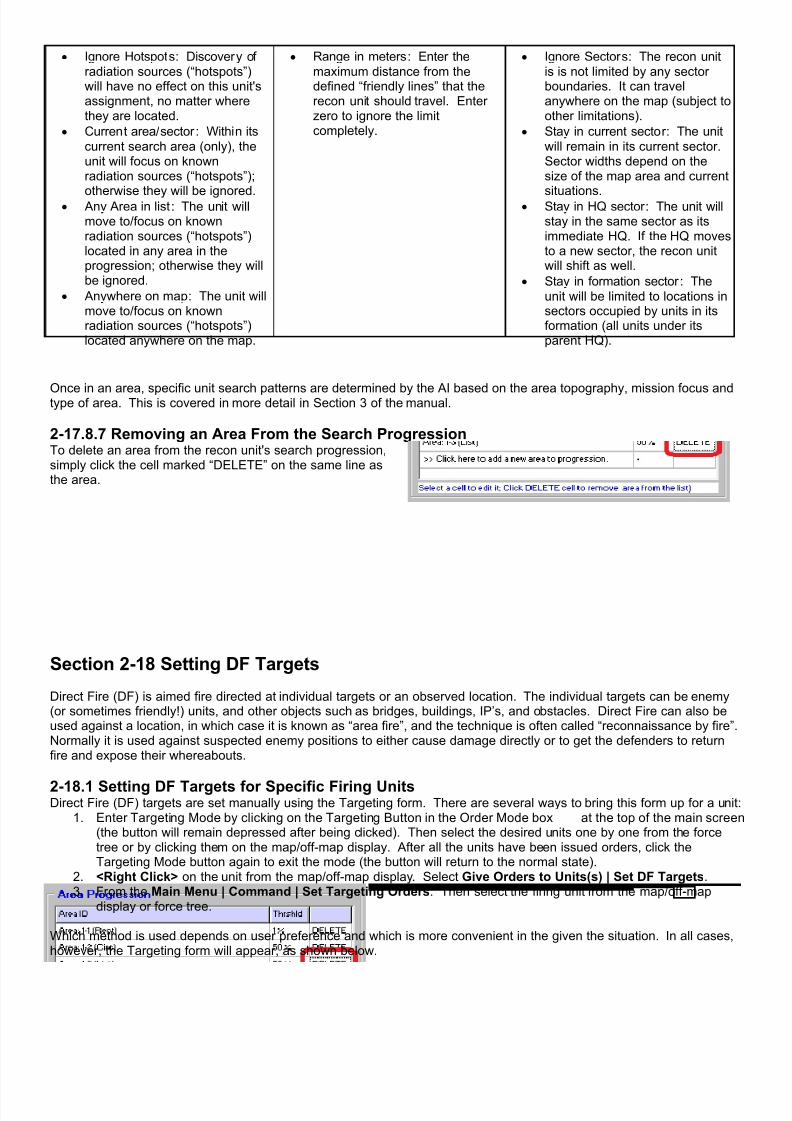
7/21/2019 TSS User Manual
http://slidepdf.com/reader/full/tss-user-manual 224/492
• Ignore Hotspots : Discovery ofradiation sources (“hotspots”)will have no effect on this unit'sassignment, no matter wherethey are located.
• Current area/sector : Within itscurrent search area (only), theunit will focus on knownradiation sources (“hotspots”);
otherwise they will be ignored.• Any Area in list : The unit willmove to/focus on knownradiation sources (“hotspots”)located in any area in theprogression; otherwise they willbe ignored.
• Anywhere on map : The unit willmove to/focus on knownradiation sources (“hotspots”)located anywhere on the map.
• Range in meters : Enter themaximum distance from thedefined “friendly lines” that therecon unit should travel. Enterzero to ignore the limitcompletely.
• Ignore Sectors : The recon unitis is not limited by any sectorboundaries. It can travelanywhere on the map (subject toother limitations).
• Stay in current sector : The unitwill remain in its current sector.Sector widths depend on thesize of the map area and current
situations.• Stay in HQ sector : The unit willstay in the same sector as itsimmediate HQ. If the HQ movesto a new sector, the recon unitwill shift as well.
• Stay in formation sector : Theunit will be limited to locations insectors occupied by units in itsformation (all units under itsparent HQ).
Once in an area, specific unit search patterns are determined by the AI based on the area topography, mission focus andtype of area. This is covered in more detail in Section 3 of the manual.
2-17.8.7 Removing an Area From the Search ProgressionTo delete an area from the recon unit's search progression,simply click the cell marked “DELETE” on the same line asthe area.
Section 2-18 Setting DF Targets
Direct Fire (DF) is aimed fire directed at individual targets or an observed location. The individual targets can be enemy(or sometimes friendly!) units, and other objects such as bridges, buildings, IP’s, and obstacles. Direct Fire can also beused against a location, in which case it is known as “area fire”, and the technique is often called “reconnaissance by fire”.Normally it is used against suspected enemy positions to either cause damage directly or to get the defenders to returnfire and expose their whereabouts.
2-18.1 Setting DF Targets for Specific Firing UnitsDirect Fire (DF) targets are set manually using the Targeting form. There are several ways to bring this form up for a unit:
1. Enter Targeting Mode by clicking on the Targeting Button in the Order Mode box at the top of the main screen(the button will remain depressed after being clicked). Then select the desired units one by one from the forcetree or by clicking them on the map/off-map display. After all the units have been issued orders, click theTargeting Mode button again to exit the mode (the button will return to the normal state).
2. <Right Click> on the unit from the map/off-map display. Select Give Orders to Units(s) | Set DF Targets.3. From the Main Menu | Command | Set Targeting Orders. Then select the firing unit from the map/off-map
display or force tree.
Which method is used depends on user preference and which is more convenient in the given the situation. In all cases,however, the Targeting form will appear, as shown below.
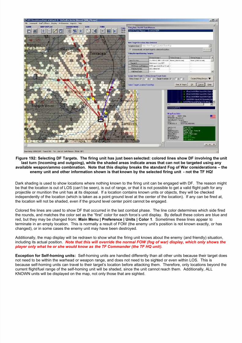
7/21/2019 TSS User Manual
http://slidepdf.com/reader/full/tss-user-manual 225/492
Figure 192: Selecting DF Targets. The firing unit has just been selected: colored lines show DF involving the unitlast turn (incoming and outgoing), while the shaded areas indicate areas that can not be targeted using any
available weapon/ammo combination. Note that this display breaks the standard Fog of War considerations – theenemy unit and other information shown is that known by the selected firing unit - not the TF HQ!
Dark shading is used to show locations where nothing known to the firing unit can be engaged with DF. The reason mightbe that the location is out of LOS (can’t be seen), is out of range, or that it is not possible to get a valid flight path for anyprojectile or munition the unit has at its disposal. If a location contains known units or objects, they will be checkedindependently of the location (which is taken as a point ground level at the center of the location). If any can be fired at,the location will not be shaded, even if the ground level center point cannot be engaged.
Colored fire lines are used to show DF that occurred in the last combat phase. The line color determines which side firedthe rounds, and matches the color set as the “first” color for each force’s unit display. By default these colors are blue andred, but they may be changed from: Main Menu | Preference | Units | Color 1. Sometimes these lines appear toterminate in an empty location. This is normally a result of FOW (the enemy unit’s position is not known exactly, or haschanged), or in some cases the enemy unit may have been destroyed.
Additionally, the map display will be redrawn to show what the firing unit knows about the enemy (and friendly) situation,including its actual position. Note that this will override the normal FOW (fog of war) display, which only shows the player only what he or she would know as the TF Commander (the TF HQ unit).
Exception for Self-homing units: Self-homing units are handled differently than all other units because their target doesnot need to be within the warhead or weapon range, and does not need to be sighted or even within LOS. This isbecause self-homing units can travel to their target’s location before attacking them. Therefore, only locations beyond thecurrent flight/fuel range of the self-homing unit will be shaded, since the unit cannot reach them. Additionally, ALLKNOWN units will be displayed on the map, not only those that are sighted.

7/21/2019 TSS User Manual
http://slidepdf.com/reader/full/tss-user-manual 226/492
2-18.1.1 The Targeting FormThe targeting form is used to determine the actual DF target in a location, including if it is the location itself, as well as theammunition and rate of fire to use. The form is divided into four major sections, as shown here:
Figure 193: The Targeting Form.
The top section is used to select the friendly firing unit. The box lists all of the friendly units co-located with theone selected, whether they are the same type or in the same formation or not. If the selected unit is alone in thelocation, it will be the only one shown, as with the example above. Otherwise, it will be highlighted (selected) bydefault.
To select another unit, click on it to highlight it. Only one unit may be highlighted/selected at a time.
Each time a different unit is selected, the map display will be updated for that unit’s weapon capabilities and availabletarget locations. Additionally, if the selected unit has existing targets, they will be shown in the Firing Groups/ExistingTargets grid.
2-18.1.2 Selecting the Target After the firing unit has been selected and the map updated, the target location needs to be selected by clicking on themap/off-map display.
Each unit can be assigned up to 9 different targets; although it is more correct to say that each unit can have up to 3 firinggroups, and each firing group can have up to 3 targets. As a rule, however, the use of firing groups and targets is foradvanced users. At first, players should limit themselves to one firing group per unit (the default), and one target for thatfiring group (also the default).
If the unit already has a target in the assigned firing group/target slot, aconfirmation dialog will pop up asking if the existing target should bereplaced. If [Yes] is selected, the new target will replace the existingone when the main [OK] button is clicked and the target accepted.
Otherwise, clicking [No] aborts the operation and provides anopportunity to select another firing group or target slot, pick anotherfiring unit, or to cancel the targeting operation entirely.

7/21/2019 TSS User Manual
http://slidepdf.com/reader/full/tss-user-manual 227/492
The current “slot” is selected using the check boxes at the bottomof the form; one for the firing group, and one for the targetnumber (1-3). It is possible to assign the same target to morethan one firing group by clicking more than one check box, oreven the same firing group multiple times (so it can be engagedby different weapons).
To display all of the targets on the form at once, click the[Expand Firing Groups] button.
Figure 194: Select the Firing Group and TargetNumber.
It is worth noting that it is possible to assign targets to firing groups that have not yet been defined. This allows formaximum flexibility, but if the firing group is not created before the combat phase, the target will be ignored. To divide aunit into firing groups, use the Unit Information form as described in more detail later in the manual.
Once the location and target slot has beenselected, the Targets drop down box will be filledin with all known targets in the selected location,including the location itself (as an area target).
If “Automatically set best target in selectedlocation” is checked, the AI will determine thebest target according to kill/damage probabilities,and the firing unit’s SOP settings and select it by
default. The AI will never select objects, onlyunits or area targets.
To select a different target, click on the dropdown list.
Figure 195: Current/Default Target. Open the drop-down list (asshown in lower picture) to select another target from those
known in the location.
Figure 196: Example of how to add a second target while keeping an existing one in place.
2.18.1.3 Setting/Changing the Firing Group InfoTo change the firing group information, click on the top line of boxes in the Firing Groups/Existing Targets grid labeled“Gen FG Info”. The Unit Information screen will pop up, with the Firing Groups tab selected. If the firing group does notyet exist, the quantity will be zero. Setting this value to 1 or greater will create the firing group automatically, with thequantity subtracted from any existing firing groups.

7/21/2019 TSS User Manual
http://slidepdf.com/reader/full/tss-user-manual 228/492
Figure 197: Edit the Firing Group Information by clicking on the top row of cells in the Firing Groups Grid.
2-18.1.4 Firing Parameters/InformationThe Firing Group/Existing Targets Grid shows the firing information for each target, including new ones as they areselected. This information is the “best known”, as experienced by the firing unit, including FOW (depending on the levelset for the game). Additionally, other uncertainties may creep in simply due to changing situations or the inability of the AIto “nail down” parameters for any number of reasons.
Each firing group may be assigned a maximum of 3 targets. This allows for great flexibility by allowing each firing groupto:
1. Engage the same target with multiple available guns2. Engage different targets with different guns3. Assign multiple targets to the same gun so that if the first target is destroyed or can no longer be engaged,
firing will automatically switch to the next assigned target.
The cells in the grid show information, but are also “selectable” by clicking on them to allow for editing or moreinformation. Each of the cell types will be described below.
2-18.1.4.1 TargetThe target cell gives information about a current target. If the target is a known unit or object (subject to the firing unit’sFOW), that information will be shown, including the target unit description (or “Area Tgt” for firing at a location in general),the current speed and facing, and the location ID.
Clicking on the “Target” cell will identify the location of the target shown in the cell, if it exists. If the target location is onmap, the main display will automatically scroll to it, if necessary. Otherwise, the Offmap form will appear. This locationwill always be the actual one fired at, there are no FOW effects applied.
There are no editing functions associated with this cell. To change an existing target, or to add a new one, use the Targetdrop down box and/or click on a location,
2-18.1.4.2 ROFThe ROF (rate of fire) grid cell shows the nominal ROF the unit has been ordered to maintain against the target, followedby the actual expected ROF for the next combat pulse taking into account any necessary rotation and aiming, which isalso shown. The ROF values are expressed in rounds per pulse, or “rpp” to the nearest tenth of a round, rounded up.Rotation and re-aiming is in seconds.
For example, the string: “1.3 rpp (Act=0 w/ 4s rot)” indicates that:
1. The unit has orders to fire approximately 1.3 rounds per pulse (about 5 rounds per minute or one round every 12seconds using the default 15 second pulses).
2. The unit will not fire any rounds at all in the next pulse (Act=0). In this case, the rotation does not leave enoughtime remaining in the pulse to fire a round. However, assuming the conditions don’t change, we would expect tosee a round fired in the pulse after that.

7/21/2019 TSS User Manual
http://slidepdf.com/reader/full/tss-user-manual 229/492
3. The unit must spend 4 seconds rotating/turning to the target and re-aiming.
Clicking on the ROF cell brings up the Unit Information form as described above in the section on Gen FG Info. This formallows the unit’s ROF orders to be set.
2-18.1.4.3 Pulses/AmmoThis cell shows the number of consecutive previous combat pulses in which this target was engaged and the current typeof ammunition being fired. The number of pulses is in parenthesis. For example, “(2)” indicates that the target wasengaged during the previous two pulses.
Clicking on this cell allows the gun/ammo combination to be selected from the pop-up form, shown below. Eachgun/ammunition combination is shown on a separate line. The quantity of rounds on hand is shown after the ammunitionname in square brackets.
Figure 198: Set the gun/ammo combination to be used for theselected target.
The Kill Prob. column shows the expectedprobability that a single round of that ammunitiontype will destroy the target, in percent. A dashindicates the probability is nil. An “X” indicatesthe ammunition type cannot be used against thetarget.
The Notes column will show if an ammunitiontype can be fired, and if not, why. If a round is
on-hand, but cannot be fired, the reason isnormally a firing path consideration (range,outbound/inbound angles) or has to do withguidance/target marking (see section below). Ifthe munition is guided, additional information onguiding/painting units may be shown in red at thebottom of the form.
The current target is shown in black at the bottom, with the firing group and target number in blue below it.
To select a new gun/ammo combination, highlight it on the grid, and click [OK].
Click the [Clear Target] button to remove the target completely. The form will close and values on the main grid will be
reset.
Click [Cancel] to close the form and keep the existing gun/ammo setting.
2-18.1.4.4 Kill/Dmg/Supn ProbabilitiesThe probability that a round will effect the target broken down into three distinct categories: Kill (the probability the targetwill be completely destroyed), Damage: the probability the target will suffer some form of major damage, and Suppression(non physical effects that prevent the unit from performing at peak effectiveness regarding moving, sighting, and firing).
The Kill and Damage probabilities are in percent, while Suppression is in “points”. Vertical lines ( | ) are used to separatethe values in the cell. For example, a value of “15% | 45% | 3 pts” indicates each round has a 15% kill probability, a 45%damage probability (if not killed first), and on average adds 3 points of suppression.
This field is read-only. Clicking on it has no effect.
2-18.1.4.5 Clearing (Removing) TargetsTo clear all of the unit’s existing targets (for all firing groups), click the [Clear All Targets] button.
To clear a single target, click its Pulses/Ammo cell. From the pop-up form, click the [Clear Target] button.
2-18.2 Setting DF Against A Specific Target A second way to order DF is to select the target first, and then select the firing units. This method is very convenientwhen a player wants to target an enemy unit, but doesn’t know which friendly units can engage it, and/or wants to makesure the one with best kill probability does.

7/21/2019 TSS User Manual
http://slidepdf.com/reader/full/tss-user-manual 230/492
To use this targeting method, either:1. From the Main Menu | Command | Target With Direct Fire <Ctrl D>. Then click on the target location from the
map/off-map display.2. <Right Click> on the map and from the pop-up menu select Target This Location | Target with DF, as shown
here:
Figure 199: Right-click on the target location to engage it with DF.
The Set Direct Fire form will appear. The AI will automatically select the best target known in the location, based on thetarget’s type, victory point value, and other factors (for example, tanks will normally take precedence over AFV’s, whichtake precedence over foot troops). The AI will also select the best friendly firing unit.

7/21/2019 TSS User Manual
http://slidepdf.com/reader/full/tss-user-manual 231/492
Figure 200: The Set Direct Fire form.
The top section of the Set Direct Fire Form isused to set specific targets within theselected location, including the location itself(area fire).
The middle grid shows all of the friendly unitsthat can use DF against the selected target:
Unit : The unit name Weapon : The AI gun selection. Ammo : The AI ammunition selection. ROF : The AI ROF setting, in rounds
per pulse, along with the number ofrounds to be fired next pulse and anyturret or hull rotation necessary (inseconds).
Rating : An AI assigned value basedon the kill probabilities, ammo onhand, firing unit SOP, and otherfactors. The higher the value, themore likely the target is to bedamaged efficiently.
Has Target : “Yes” if the unit alreadyhas a target, “No” if it doesn’t, or “AI
Ctrl” if the unit’s target is under AIcontrol (and not available to theplayer).
If the “Show Targeting Results” box ischecked, the bottom section shows an AIanalysis for every unit and gun/ammocombination in the force against thetarget.
To use this form, follow these steps:
1. Select the desired target in the location from the top drop down box.
2. Select the firing unit from the grid. If the grid is empty, it indicates that no friendly units can engage the selectedtarget with DF (see the Targeting Results box for more info).
3. Change the firing weapon and ammunition from the AI default, if desired. To do this click [Edit Weapon/Ammo].The pop-up form and its operation are described in the previous section.
4. Set the desired rate of fire using the edit box/arrows to the right underneath the Available Firing Units grid. TheROF is in rounds per 10 minutes (e.g., entering a value of “10” is the same as 1 round per minute, while a value of“1” indicates 0.1 rounds per minute).
5. Click [OK] to save the target information for the firing unit. Targets are always assigned to Firing Group #1, asTarget #1. If some other assignment is desired, the targeting will need to be accomplished by selecting the firingunit first, as described in the previous section.
6. Or, click [Cancel] to close the form without saving any changes.
2-18.2.1 Targeting Results
The targeting results list shows a summary of every unloaded unit in the force and why or why not it can target theselected object with its possible gun/ammunition combinations. The result information text, while normally self-explanatory, is described in detail later in the manual.
Each unit is shown by both its name and weapons system. Each available gun/launcher is also shown, followed by theavailable types of ammunition for it. The ammunition name is shown in parenthesis after the text string.
The process of determining this information can take some time to process, especially with larger scenarios. Users aretherefore afforded the option of having the AI skip displaying the list if they find it is slowing down the game. The “ShowTargeting Results” box is used to toggle the operation. To disable the list generation, uncheck the “Show TargetingResults” box. To enable it, check the box instead.

7/21/2019 TSS User Manual
http://slidepdf.com/reader/full/tss-user-manual 232/492
Section 2-19 Calling for Artillery/IF Fire
Unlike Direct Fire, which can be either firing unit or target based, Indirect Fire is always location-based, in that the targetlocation is selected first then the mission parameters are assigned. The methods for doing this are:
1. From the Main Menu | Command | Target With Indirect Fire. Then click on the target location from the map/off-map display.
2. <Right Click> on the map then select Target This Location | Target with IF/Arty, as shown here:
Figure 201: Right-click to call for Indirect Fire/Artillery.
2-19.1 The Arty/Fire Support Mission form After selecting the target location, the Arty/Fire Support Mission form will appear. This form allows for all aspects of thefire support mission to be set. As such, it is one of the more complicated forms in the simulation, and not all panels andoptions will be enabled at the lower Expert Levels, and in fact, only parts of the form may be visible. To change theExpert Level setting, go to Main Menu | Preferences | Game Vals tab .
The form is also used to edit existing mission info (from the FSO staff officer).

7/21/2019 TSS User Manual
http://slidepdf.com/reader/full/tss-user-manual 233/492
Figure 202: The Artillery/Fire Support Mission Form. Not all parts may be visible/active at lower Expert Levels.
To give a quick overview of the form:
Target Loc : The target location as selected before bringing up the form, or the existing mission target location. Available Firing Units : For new missions, this will show all of the IF-capable units in the force that can engage the
target, and from which the actual firing unit can be selected. For existing missions, this will be the selected firingunit (only one firing unit can be assigned to a mission).
Mission Specs : This panel shows the mission specifications, including the starting time, the number of rounds tofire (total), the rate of fire per gun, the priority, and whether the fire should be directed at an area or point.
Shift : This section determines if the target location changes over time, i.e., the fire “shifts”. Calling Units : This section displays the calling unit. The calling unit must be able to see the target unless the
mission is for a PPD or area target. The calling unit is also the painting unit, if one required by the ammunitionbeing fired.
Targeting Results : This shows the results of every available gun/ammo combination for the IF-capable units.
2-19.2 Select the TargetThe Target Loc drop-down box allows for the selection of specific
unit targets within the location as long as the firing unit knowsthem. In this case, an enemy BMP-3 unit is known and thereforeit may be targeted. However, unless the ammunition being firedis self-detecting or homing, an eligible friendly unit will need tospot and adjust the fire and possibly paint the target (usinglasers).
The location itself may always be targeted.
Figure 203: Select a known target from the dropdown box.
2-19.3 Select the Firing Unit/AmmoThe mission firing unit and ammunition are selected from the Available Firing Units box. For new missions, the AI willautomatically go through each available artillery/IF-capable unit in the force, and determine how effective it will be against

7/21/2019 TSS User Manual
http://slidepdf.com/reader/full/tss-user-manual 234/492
the selected target and the best ammunition to use (limited only to what is currently on hand). These units are then sortedby their “rating” value, which is a composite number determined by analyzing the target kill and damage probabilities, thesuppressive value, and how much “overkill” there is (which reduces the rating).
Figure 204: Selecting the firing unit.
Unit: The unit ID.Weapon: the IF-capable gun selected to fire. Ammo: The munition to be fired.Rating: A relative value for the firing unit/gun./ammo/targetcombination (higher is better).Has Target?: Is the unit assigned/firing another mission (yes/no)?
To select a unit for the mission, click it to highlight it.
Other functions:[Edit Weapon Ammo]: Click to manually select the gun/ammocombination or to see actual kill probabilities (see below).[Show Status of All Arty Units]: Click to show the general statusof all IF-capable units in the force (see below).
Clicking [Edit Weapon Ammo] brings up a form with the following information:
The Kill Prob. column shows theexpected probability that a singleround of that ammunition type willdestroy the target, in percent. Adash indicates the probability is nilor unknown. An “X” indicates theammunition type cannot be usedagainst the target.
The Notes column will show if anammunition type can be fired, andif not, why. If a round is on-hand,but cannot be fired, the reason isnormally a firing path consideration
(range, outbound/inbound angles)or has to do with guidance/targetmarking (see section below).
Figure 205: Gun/Ammo combination info for the selected firing unit. Noteadditional guidance/painting info at the bottom of the form.
For guided munitions, the AI will show a note if a separate guiding unit is required “(guidance dependent)”, and will alsoshow potential guiding/painting units at the bottom of the form - as in the above example for the Copperhead round.
Clicking [Show Status of All Arty Units] brings up the unitsummary shown here. All of the IF-capable units in the forcewill be listed, along with whether or not they can potentiallyfire the mission. The status values are:
No ammo on-hand: the unit has no ammunition on hand for
the IF-cable weapon(s).Not emplaced or moving: The unit is moving or needs to beemplaced, but is not.Potentially Available: the unit is not moving, is emplaced ifnecessary, and has ammunition on hand.
This form provides a quick overview of the force’s IF units.For more detailed information, use the Gun/Ammo formabove, or the Targeting Results (described below). Figure 206: IF-capable unit availability summary.
2-19.4 Mission SpecsThe specifications section contains the following information about the selected mission:

7/21/2019 TSS User Manual
http://slidepdf.com/reader/full/tss-user-manual 235/492
Mission ID: A user-editable text string used to identify themission.Use PPD: If the mission is going to be fired against locationassigned as a pre-planned (PPD) target for the firing unit, thisbox determines if the mission will be based on the PPD orfired as simple on-call. The box is checked by default, whichnormally provides the best performance in terms of delay,accuracy, and effect. Players should only turn off the use ofan existing PPD target is they have a compelling reason to doso.Status: The time the mission is scheduled to begin firing. Thevalue entered is the absolute (or “clock”) time, expressed aspart of a 24-hour day. The current scenario time is shown atthe bottom right of the main form. For reference, after a time has been entered it will also be displayed as a turn andpulse. NOTE: Missions do not always begin at their scheduled start time. Many factors can delay the mission,including if the unit is firing another mission, airstrikes have forced a check fire, or the unit is temporarily not able to firefor another reason. However, a mission will never begin BEFORE the scheduled start time.Priority: The relative precedence and importance of the mission: High, Medium, or Low. In general, if a unit has morethan one mission to fire at a time, the one with the highest priority takes precedence. Priority can get complex,however, so it is discussed in more detail below.Spotted (by calling unit): If this box is checked, the calling unit will also act as the spotter for the mission (as long as a
valid LOS exists between the unit and the target at the time the mission actually begins). Spotting is a method ofincreasing the accuracy by firing single spotting rounds to see where they land before firing the “real” mission (FFE orfire for effect). Spotting rounds are not deducted from the number of rounds to fire for the mission, although they dodeplete the firing unit’s on-hand stocks.Total Rounds: The total number of rounds to fire, not including those used for spotting (FFE Only). The total numberof rounds the firing unit has on hand is shown to the right, after the ROF entry box.ROF: The rate of fire for each gun, in rounds per minute. ROF values can be decimal numbers for fractional roundsper minute, e.g., enter “1.5” to fire one and a half rounds per minute, or 3 rounds per two minutes. Units will attempt tofire at the ROF specified to the best of their ability, but actual conditions at the time of firing may force the unit to fire a ta slower rate (they will never fire faster). The maximum ROF for the weapon is shown next to the text entry box. Area: The effective extent of the mission impact area. Rounds are fired so that they impact evenly with approximatelythe same number in each location in the area (if more than one). Point/Unit: Fire into the single selected location only.
Circular Area: Fire into a circular area with the radius specified in the top arrow-box. Rectangular Area: Fire into a rectangular area with dimensions specified in the two arrow-boxes. Width is
left/right as displayed on the screen (normally east/west), and Height is up/down (north/south).
2-19.5 ShiftShifting allows the mission’s target location to change over time. This is also often referred to as “walking” the fire.Shifting fire is set up using the following parameters:
Direction: A principal compass direction, which is set by clicking one of thedirectional buttons. Amount: The amount of each shift, in meters. Shifting is done in discrete jumps,separated by this distance.Period: The time between shift jumps, in game pulses. The actual duration of apulse depends on the scenario settings.
When fire is shifted, the primary target location will be offset in the direction specified by the shift distance. Shifting doesnot affect the impact area orientation, only its center point; the new impact areas will be determined based on the newprincipal (center) target location after the jump, and the rounds will be distributed into the new locations.
2-19.6 Calling UnitThe unit that contacts the FDC (fire direction center) to initiate the support mission is known as the “calling unit”.
In most real-life cases this unit can visually see the target, although that is not required. When it can see the target,however, the calling unit almost always observes the results of the fire and communicates adjustments to the FDC. In thiscapacity, the unit becomes the mission’s “spotting unit”.
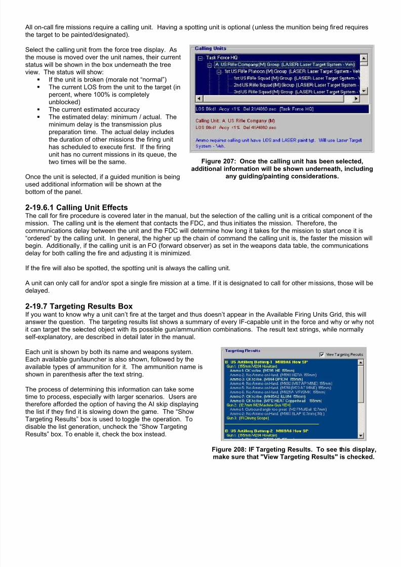
7/21/2019 TSS User Manual
http://slidepdf.com/reader/full/tss-user-manual 236/492
All on-call fire missions require a calling unit. Having a spotting unit is optional (unless the munition being fired requiresthe target to be painted/designated).
Select the calling unit from the force tree display. Asthe mouse is moved over the unit names, their currentstatus will be shown in the box underneath the treeview. The status will show:
If the unit is broken (morale not “normal”) The current LOS from the unit to the target (in
percent, where 100% is completelyunblocked)
The current estimated accuracy The estimated delay: minimum / actual. The
minimum delay is the transmission pluspreparation time. The actual delay includesthe duration of other missions the firing unithas scheduled to execute first. If the firingunit has no current missions in its queue, thetwo times will be the same.
Once the unit is selected, if a guided munition is beingused additional information will be shown at thebottom of the panel.
Figure 207: Once the calling unit has been selected,additional information will be shown underneath, including
any guiding/painting considerations.
2-19.6.1 Calling Unit EffectsThe call for fire procedure is covered later in the manual, but the selection of the calling unit is a critical component of themission. The calling unit is the element that contacts the FDC, and thus initiates the mission. Therefore, thecommunications delay between the unit and the FDC will determine how long it takes for the mission to start once it is“ordered” by the calling unit. In general, the higher up the chain of command the calling unit is, the faster the mission willbegin. Additionally, if the calling unit is an FO (forward observer) as set in the weapons data table, the communicationsdelay for both calling the fire and adjusting it is minimized.
If the fire will also be spotted, the spotting unit is always the calling unit.
A unit can only call for and/or spot a single fire mission at a time. If it is designated to call for other missions, those will bedelayed.
2-19.7 Targeting Results BoxIf you want to know why a unit can’t fire at the target and thus doesn’t appear in the Available Firing Units Grid, this willanswer the question. The targeting results list shows a summary of every IF-capable unit in the force and why or why notit can target the selected object with its possible gun/ammunition combinations. The result text strings, while normallyself-explanatory, are described in detail later in the manual.
Each unit is shown by both its name and weapons system.Each available gun/launcher is also shown, followed by theavailable types of ammunition for it. The ammunition name isshown in parenthesis after the text string.
The process of determining this information can take some
time to process, especially with larger scenarios. Users aretherefore afforded the option of having the AI skip displayingthe list if they find it is slowing down the game. The “ShowTargeting Results” box is used to toggle the operation. Todisable the list generation, uncheck the “Show TargetingResults” box. To enable it, check the box instead.
Figure 208: IF Targeting Results. To see this displaymake sure that "View Targeting Results" is checked.

7/21/2019 TSS User Manual
http://slidepdf.com/reader/full/tss-user-manual 237/492
2-19.8 Canceling a Support MissionTo cancel an existing support mission, bring up the FSO Staff Officer screen and <Right click> the mission line. From theIF/Mission form, click [Remove]. IF support missions may be canceled at any time, including once they have started.
2-19.9 Support Mission PrioritiesWhen an artillery unit is in a situation where it has more than one active fire mission, priority is determined using thefollowing sequence:
1. The mission priorities are compared, and the greatest takes precedence. SEAD missions are always given thehighest priority, followed by player (or AI) set priority.
2. For missions with the same priority, in-progress missions take precedence over those not yet begun.3. For missions with the same priority and in-progress status, PPD targets take precedence.
Section 2-20 Calling for Close Air Support
Like Indirect Fire, CAS is always location-based, in that the target location is selected first then the mission parametersare assigned. The methods for doing this are:
1. From the Main Menu | Command | Set Targeting Orders. Then click on the target location from the map/off-map display.
2. <Right Click> on the map then select Target This Location | Target with Airstrike.

7/21/2019 TSS User Manual
http://slidepdf.com/reader/full/tss-user-manual 238/492
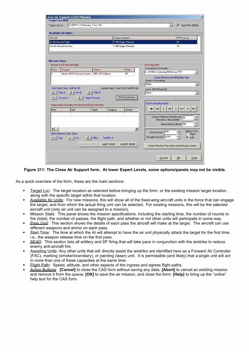
7/21/2019 TSS User Manual
http://slidepdf.com/reader/full/tss-user-manual 239/492
Figure 211: The Close Air Support form. At lower Expert Levels, some options/panels may not be visible.
As a quick overview of the form, these are the main sections:
Target Loc : The target location as selected before bringing up the form, or the existing mission target location,along with the specific target within that location.
Available Air Units : For new missions, this will show all of the fixed-wing aircraft units in the force that can engagethe target, and from which the actual firing unit can be selected. For existing missions, this will be the selectedaircraft unit (only air unit can be assigned to a mission).
Mission Stats : This panel shows the mission specifications, including the starting time, the number of rounds tofire (total), the number of passes, the flight path, and whether or not other units will participate in some way.
Pass Grid : This section shows the details of each pass the aircraft will make at the target. The aircraft can usedifferent weapons and ammo on each pass.
Start Time : The time at which the AI will attempt to have the air unit physically attack the target for the first time,i.e., the weapon release time on the first pass.
SEAD : This section lists all artillery and DF firing that will take pace in conjunction with the airstrike to reduce
enemy anti-aircraft fire. Assisting Units : Any other units that will directly assist the airstrike are identified here as a Forward Air Controller
(FAC), marking (smoke/incendiary), or painting (laser) unit. It is permissible (and likely) that a single unit will actin more than one of these capacities at the same time.
Flight Path : Speed, altitude, and other aspects of the ingress and egress flight paths. Action Buttons : [Cancel] to close the CAS form without saving any data; [Abort] to cancel an existing mission
and remove it from the queue; [OK] to save the air mission, and close the form; [Help] to bring up the “online”help text for the CAS form.
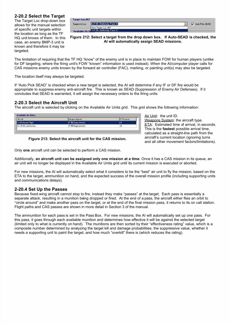
7/21/2019 TSS User Manual
http://slidepdf.com/reader/full/tss-user-manual 240/492
2-20.2 Select the TargetThe Target Loc drop-down boxallows for the manual selectionof specific unit targets withinthe location as long as the TFHQ unit knows of them. In thiscase, an enemy BMP-3 unit isknown and therefore it may betargeted.
Figure 212: Select a target from the drop down box. If Auto-SEAD is checked, theAI will automatically assign SEAD missions.
The limitation of requiring that the TF HQ “know” of the enemy unit is in place to maintain FOW for human players (unlikefor DF targeting, where the firing unit's FOW “known” information is used instead). When the AI/computer player calls forCAS missions enemy units known by the forward air controller (FAC), marking, or painting unit(s) may also be targeted.
The location itself may always be targeted.
If “Auto Pick SEAD” is checked when a new target is selected, the AI will determine if any IF or DF fire would beappropriate to suppress enemy anti-aircraft fire. This is known as SEAD (Suppression of Enemy Air Defenses). If itconcludes that SEAD is warranted, it will assign the necessary orders to the firing units.
2-20.3 Select the Aircraft UnitThe aircraft unit is selected by clicking on the Available Air Units grid. This grid shows the following information:
Figure 213: Select the aircraft unit for the CAS mission.
Air Unit: the unit ID.Weapons System: the aircraft type.ETA: Estimated time of arrival, in secondsThis is the fastest possible arrival time,calculated as a straight-line path from theaircraft’s current location (ignoring turnsand all other movement factors/limitations)
Only one aircraft unit can be selected to perform a CAS mission.
Additionally, an aircraft unit can be assigned only one mission at a time. Once it has a CAS mission in its queue, anair unit will no longer be displayed in the Available Air Units grid until its current mission is executed or aborted.
For new missions, the AI will automatically select what it considers to be the “best” air unit to fly the mission, based on theETA to the target, ammunition on hand, and the expected success of the overall mission profile (including supporting unitsand communications delays).
2-20.4 Set Up the PassesBecause fixed-wing aircraft cannot stop to fire, instead they make “passes” at the target. Each pass is essentially aseparate attack, resulting in a munition being dropped or fired. At the end of a pass, the aircraft either flies an orbit to“circle around” and make another pass on the target, or at the end of the final mission pass, it returns to its on call station.Flight paths and CAS passes are shown in more detail in Section 3 of the manual.
The ammunition for each pass is set in the Pass Box. For new missions, the AI will automatically set up one pass. Forthis pass, it goes through each available munition and determines how effective it will be against the selected target(limited only to what is currently on hand). The munitions are then sorted by their “effectiveness rating” value, which is a
composite number determined by analyzing the target kill and damage probabilities, the suppressive value, whether itneeds a supporting unit to paint the target, and how much “overkill” there is (which reduces the rating).
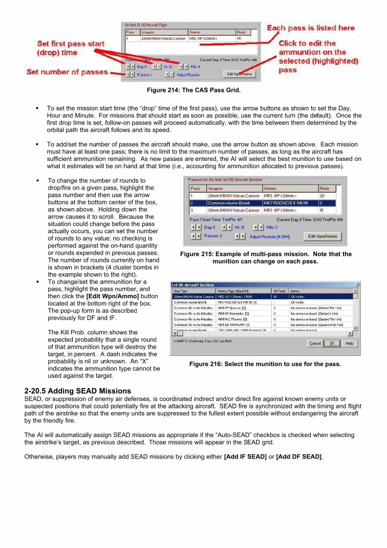
7/21/2019 TSS User Manual
http://slidepdf.com/reader/full/tss-user-manual 241/492
Figure 214: The CAS Pass Grid.
To set the mission start time (the “drop” time of the first pass), use the arrow buttons as shown to set the Day,Hour and Minute. For missions that should start as soon as possible, use the current turn (the default). Once thefirst drop time is set, follow-on passes will proceed automatically, with the time between them determined by theorbital path the aircraft follows and its speed.
To add/set the number of passes the aircraft should make, use the arrow button as shown above. Each missionmust have at least one pass; there is no limit to the maximum number of passes, as long as the aircraft hassufficient ammunition remaining. As new passes are entered, the AI will select the best munition to use based onwhat it estimates will be on hand at that time (i.e., accounting for ammunition allocated to previous passes).
To change the number of rounds todrop/fire on a given pass, highlight thepass number and then use the arrowbuttons at the bottom center of the box,as shown above. Holding down thearrow causes it to scroll. Because thesituation could change before the passactually occurs, you can set the numberof rounds to any value; no checking isperformed against the on-hand quantityor rounds expended in previous passes.The number of rounds currently on handis shown in brackets (4 cluster bombs inthe example shown to the right).
Figure 215: Example of multi-pass mission. Note that themunition can change on each pass.
To change/set the ammunition for a
pass, highlight the pass number, andthen click the [Edit Wpn/Ammo] buttonlocated at the bottom right of the box.The pop-up form is as describedpreviously for DF and IF.
The Kill Prob. column shows theexpected probability that a single roundof that ammunition type will destroy thetarget, in percent. A dash indicates theprobability is nil or unknown. An “X”indicates the ammunition type cannot beused against the target.
Figure 216: Select the munition to use for the pass.
2-20.5 Adding SEAD MissionsSEAD, or suppression of enemy air defenses, is coordinated indirect and/or direct fire against known enemy units orsuspected positions that could potentially fire at the attacking aircraft. SEAD fire is synchronized with the timing and flightpath of the airstrike so that the enemy units are suppressed to the fullest extent possible without endangering the aircraftby the friendly fire.
The AI will automatically assign SEAD missions as appropriate if the “Auto-SEAD” checkbox is checked when selectingthe airstrike’s target, as previous described. Those missions will appear in the SEAD grid.
Otherwise, players may manually add SEAD missions by clicking either [Add IF SEAD] or [Add DF SEAD].
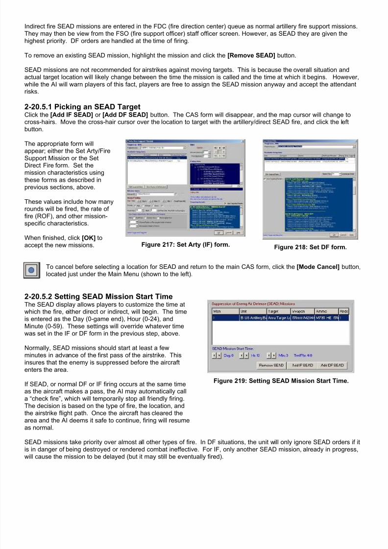
7/21/2019 TSS User Manual
http://slidepdf.com/reader/full/tss-user-manual 242/492
Indirect fire SEAD missions are entered in the FDC (fire direction center) queue as normal artillery fire support missions.They may then be view from the FSO (fire support officer) staff officer screen. However, as SEAD they are given thehighest priority. DF orders are handled at the time of firing.
To remove an existing SEAD mission, highlight the mission and click the [Remove SEAD] button.
SEAD missions are not recommended for airstrikes against moving targets. This is because the overall situation andactual target location will likely change between the time the mission is called and the time at which it begins. However,while the AI will warn players of this fact, players are free to assign the SEAD mission anyway and accept the attendantrisks.
2-20.5.1 Picking an SEAD TargetClick the [Add IF SEAD] or [Add DF SEAD] button. The CAS form will disappear, and the map cursor will change tocross-hairs. Move the cross-hair cursor over the location to target with the artillery/direct SEAD fire, and click the leftbutton.
The appropriate form willappear; either the Set Arty/FireSupport Mission or the SetDirect Fire form. Set themission characteristics usingthese forms as described inprevious sections, above.
These values include how manyrounds will be fired, the rate offire (ROF), and other mission-specific characteristics.
When finished, click [OK] toaccept the new missions. Figure 217: Set Arty (IF) form. Figure 218: Set DF form.
To cancel before selecting a location for SEAD and return to the main CAS form, click the [Mode Cancel] button,located just under the Main Menu (shown to the left).
2-20.5.2 Setting SEAD Mission Start TimeThe SEAD display allows players to customize the time atwhich the fire, either direct or indirect, will begin. The timeis entered as the Day (0-game end), Hour (0-24), andMinute (0-59). These settings will override whatever timewas set in the IF or DF form in the previous step, above.
Normally, SEAD missions should start at least a fewminutes in advance of the first pass of the airstrike. Thisinsures that the enemy is suppressed before the aircraftenters the area.
If SEAD, or normal DF or IF firing occurs at the same timeas the aircraft makes a pass, the AI may automatically calla “check fire”, which will temporarily stop all friendly firing.The decision is based on the type of fire, the location, andthe airstrike flight path. Once the aircraft has cleared thearea and the AI deems it safe to continue, firing will resumeas normal.
Figure 219: Setting SEAD Mission Start Time.
SEAD missions take priority over almost all other types of fire. In DF situations, the unit will only ignore SEAD orders if itis in danger of being destroyed or rendered combat ineffective. For IF, only another SEAD mission, already in progress,will cause the mission to be delayed (but it may still be eventually fired).

7/21/2019 TSS User Manual
http://slidepdf.com/reader/full/tss-user-manual 243/492
2-20.6 Assisting UnitsIn some cases, units other than the attacking aircraft may participate in the airstrike. These units may act in one of threeways:
Forward Air Controller (FAC): The FAC unit directs the aircraft unit to thetarget, making the strike more accurate. Normally the FAC will maintainLOS contact with the target through the mission, and will also attempt tomaintain contact with the attacking aircraft. In many cases, the FAC will alsoact as the marking or painting unit (see below). FAC-capable systems are
designated in the Weapons System Data table.
Smoke/Incendiary (Marking Unit): This unit creates and places a visualidentification mark on the ground near the target to help the aircraft identifythe location. This results in a more accurate airstrike and less chance offratricide, especially in dense terrain or close-in situations. In most cases,the unit will use smoke/incendiary, although only incendiary can be used atnight unless there is artificial illumination present. To be able to mark atarget, the unit must have smoke or incendiary munitions (of any type) onhand and must be able to “fire it” into the target location.
Laser: If the munition is laser-guided the target must be “painted” by afriendly unit to identify it to the munition. This is the unit that will do so. Tobe eligible to paint the target, the unit must be equipped with a laser
designator and have an unblocked LOS to the target.
Figure 220: Assisting Units panel.
Only (currently) eligible units will be shown in the drop down boxes. It is the responsibility of the player to insure that theymeet the requirements at the time of the actual airstrike, munition drop, and/or impact. If they do not, they will be ignored,possibly causing the mission pass to be re-run, or even for the entire mission to be aborted.
2-20.7 Flight Path CharacteristicsThe selection of the proper flight path minimizes the chances of the aircraft taking enemy fire, reduces the changes ofhitting friendly forces by mistake, increases the accuracy/effects of the munition being dropped, accounts for weatherconditions, and has the aircraft avoid friendly SEAD fire. When new targets or munitions are selected, the AI willautomatically select what it considers to the best flight path for the aircraft. However, this determination is based on thecurrent situation, and thus players may want to change this based on planned movements and forecast conditions.
Attack Heading: This will be the aircraft’s cardinal compassdirection/heading when the munitions are released.
Release Altitude: The aircraft’s altitude in meters at the release point/path.Depending on the munition characteristics, this altitude may be restricted toprevent damage to the aircraft or to insure proper guidance.
Speed at Drop: The aircraft speed in Kph at/during munition release. Thespeed affects target acquisition, accuracy and guidance.
Stand Off: The distance between the release point and the target in meters,discounting the forward inertial motion of the munition. Normally onlypowered and/or guided munitions are capable of having a standoff.
Straight Line: The distance before the release point (whether standoff ornot) during which the aircraft will fly a straight and level path, in meters.Longer paths generally increase target acquisition and accuracy, especiallyfor unguided munitions.
Egress Turn: The direction the aircraft will turn immediately after munitionsrelease. Depending on the situation, the aircraft may continue to circlearound for another pass, or it may return to either an on-call station or base.
Figure 221: Flight Path Characteristics.
More information on CAS flight paths can be found in Part 3 of the manual, including diagrams on each of the flight legsand their effects.

7/21/2019 TSS User Manual
http://slidepdf.com/reader/full/tss-user-manual 244/492
2-20.8 Check Mission PlanSetting up CAS missions is complicated, and it can be hard to tell if all of thepieces “fit together”. The [Check Mission Plan] button enables players tocheck all of the mission specifications once they have been entered, to insureeverything is valid. A full list of the messages is shown later in the manual in the section titled “Information, Warning andError Messages”.
2-20.9 Canceling a Support MissionTo cancel an existing support mission, bring up the FSO Staff Officer screen and <right click> the mission line. From theIF/Mission form, click [Remove]. IF support missions may be canceled at any time, including once they have started.
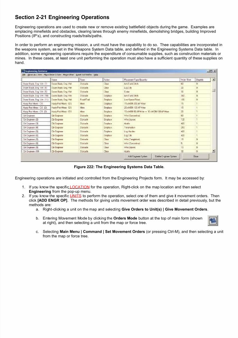
7/21/2019 TSS User Manual
http://slidepdf.com/reader/full/tss-user-manual 245/492
Section 2-21 Engineering Operations
Engineering operations are used to create new or remove existing battlefield objects during the game. Examples areemplacing minefields and obstacles, clearing lanes through enemy minefields, demolishing bridges, building ImprovedPositions (IP’s), and constructing roads/trails/paths.
In order to perform an engineering mission, a unit must have the capability to do so. Thee capabilities are incorporated inthe weapons system, as set in the Weapons System Data table, and defined in the Engineering Systems Data table. Inaddition, some engineering operations require the expenditure of consumable supplies, such as construction materials or
mines. In these cases, at least one unit performing the operation must also have a sufficient quantity of these supplies onhand.
Figure 222: The Engineering Systems Data Table.
Engineering operations are initiated and controlled from the Engineering Projects form. It may be accessed by:
1. If you know the specific LOCATION for the operation, Right-click on the map location and then selectEngineering from the pop-up menu.
2. If you know the specific UNITS to perform the operation, select one of them and give it movement orders. Thenclick [ADD ENGR OP]. The methods for giving units movement order was described in detail previously, but themethods are:
a. Right-clicking a unit on the map and selecting Give Orders to Unit(s) | Give Movement Orders.
b. Entering Movement Mode by clicking the Orders Mode button at the top of main form (shownat right), and then selecting a unit from the map or force tree.
c. Selecting Main Menu | Command | Set Movement Orders (or pressing Ctrl-M), and then selecting a unit
from the map or force tree.
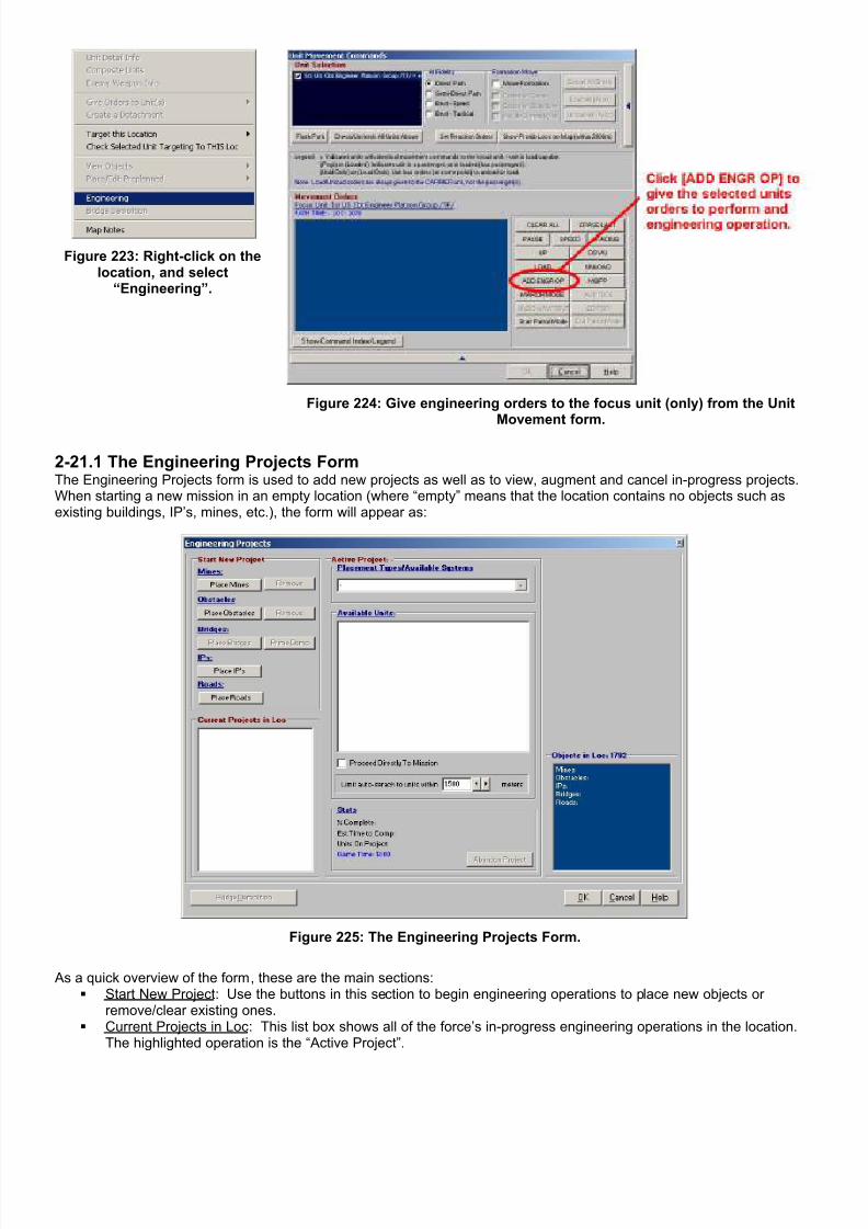
7/21/2019 TSS User Manual
http://slidepdf.com/reader/full/tss-user-manual 246/492
Figure 223: Right-click on thelocation, and select
“Engineering”.
Figure 224: Give engineering orders to the focus unit (only) from the UnitMovement form.
2-21.1 The Engineering Projects FormThe Engineering Projects form is used to add new projects as well as to view, augment and cancel in-progress projects.When starting a new mission in an empty location (where “empty” means that the location contains no objects such asexisting buildings, IP’s, mines, etc.), the form will appear as:
Figure 225: The Engineering Projects Form.
As a quick overview of the form, these are the main sections: Start New Project : Use the buttons in this section to begin engineering operations to place new objects or
remove/clear existing ones. Current Projects in Loc : This list box shows all of the force’s in-progress engineering operations in the location.
The highlighted operation is the “Active Project”.

7/21/2019 TSS User Manual
http://slidepdf.com/reader/full/tss-user-manual 247/492
Placement Types/Available Systems : These drop down boxes are used to set which specific type of object will becreated or placed, one a button has been clicked to begin a new operation.
Available Units : this window shows all of the friendly units capable of working on the Active Project (as selected inthe Current Projects in Loc box), as well as units that are assigned to it. Clicking on units in this box will assignthem to the project.
Limit Auto Search to Units Within X meters : this setting allows the user to limit potential units shown in the Available Units box to only those within a certain maximum distance of the location.
Stats : This shows the current status of the Active Project, and the estimated completion time. Objects in Loc : This list box shows all of the objects currently existing in the location, by primary type. Action Buttons : [Cancel] to close the form without saving any data; [OK] to save the project, and close the form;
[Help] to bring up the “online” help text for the Engineering Projects form.
2-21.2 Start New ProjectThis section is used to begin a new project, either to construct a new object or remove an existing one. The objectcategories are:
1. Mines (including sensors)2. Obstacles3. Bridges4. Improved Positions (IP’s)5. Roads (including trails and all other linear paths that connect adjacent locations).
This section is only available when entering the form from a right-click on the map or from the Unit Movement form. Youcannot begin new projects when viewing/editing an existing project from the Staff Officer page.
2-21.2.1 Creating New ObjectsTo create a new object on the map, click the [Place Object ] button for the category of object to be placed. Not all of thecategory buttons may be enabled; if the object category cannot be placed in the selected location or if no units in the forceare capable of placing any type of object in the category, the button will be grayed-out.
If a unit was “hot” coming into the form (i.e. it was entered from the Unit Movement form), only that unit and its capabilitieswill be used to determine what operations as possible. No other units can be added to the project.
Otherwise, the AI will automatically search through the force units to find those that are capable of performing theoperation, looking at capabilities, ammo remaining, and morale status. It will show these units in the Available Units box,where they can be selected to perform the operation.
IMPORTANT NOTE: In order to assist players in choosing thebest units, the AI will limit its search for capable units to onlythose within a user-specified distance of the work location.This distance is set underneath the Available Units box. If,after selecting to begin an project, you don’t get any unitsdisplayed in the box, try increasing the auto-search range.
Figure 226: The auto-search range.
As an example, after clicking the [Place Mines] button with no initial “hot” unit, the form will look similar to this:
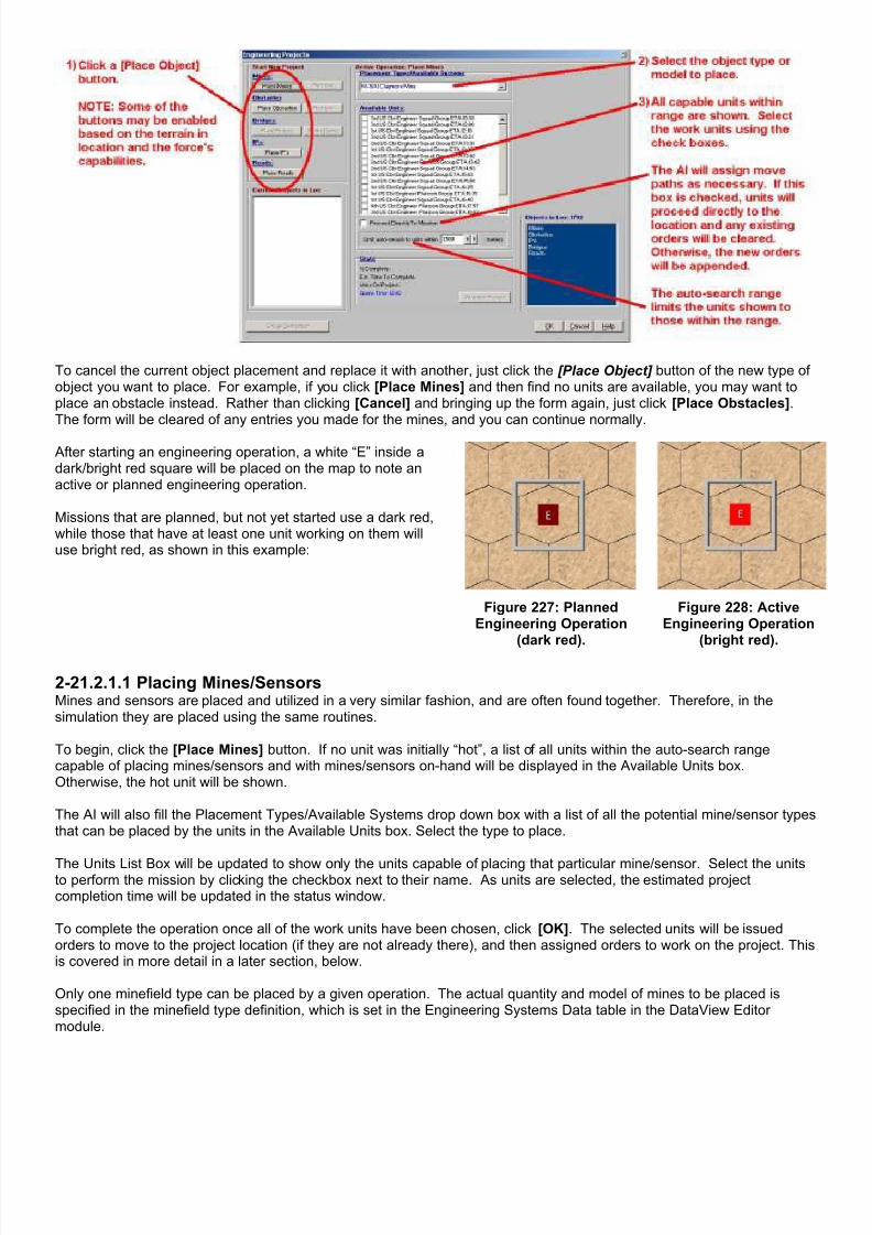
7/21/2019 TSS User Manual
http://slidepdf.com/reader/full/tss-user-manual 248/492

7/21/2019 TSS User Manual
http://slidepdf.com/reader/full/tss-user-manual 249/492
Figure 229: Sample Engineering Data Table entries for minefields showing mine quantities.
When the operation is completed, the minefield will contain the mines specified in the table. To place additional mines,either of a different type or a greater quantity of the same type, an additional placement is required; depending on thelocation size (in square meters) a number of multiple minefields may be placed in the same location.
2-21.2.1.2 Creating ObstaclesClick the [Place Obstacles] button. If no unit was initially “hot”, list of all units within the auto-search range capable ofplacing obstacles and with obstacles on-hand will be displayed in the Available Units box. Otherwise, the hot unit will beshown.
The AI will also fill the Placement Types/Available Systems drop down box with a list of all the potential obstacle typesthat can be placed by the units in the Available Units box. Select the type to place.
The Units List Box will be updated to show only the units capable of placing that particular obstacle type. Select the unitsto perform the mission by clicking the checkbox next to their name. As units are selected, the estimated projectcompletion time will be updated in the status window.
If the obstacle type is linear, for example a ditch or fence, theobstacle will create a hexside when placed. This means it will act asa movement barrier between two different locations (hexes), ratherthan affect movement though the entire location. In this case, adirectional panel will appear at the upper right of the form.
Select the cardinal direction the obstacle will cover using the radiobuttons. The actual sides will then be shown in gray on the display,as shown in this example.
Figure 230: This obstacle will cover the Northside of the hex (the NW and NE sides).
To complete the operation once all of the work units have been chosen, click [OK]. The selected units will be issuedorders to move to the project location (if they are not already there), and then assigned orders to work on the project. Thisis covered in more detail in a later section, below.

7/21/2019 TSS User Manual
http://slidepdf.com/reader/full/tss-user-manual 250/492
Obstacles are never placed as a set ofindividual components, for example, threeindividual log hurdles. Instead, an obstacleis considered a single entity that createscertain movement effects as specified inthe TEC.
For example, looking at the sample TECentries to the right, placing “log hurdles” ina location causes a 30 second delay forfoot troops when they are moving down aroad. “Log hurdles” also block (the“Prohibited” value) the road for sometracked and wheeled vehicles, whichmeans they have to use cross-countrymovement in that location to get aroundthem.
Exactly how many log hurdles are actuallyconstructed to create this effect is notrelevant here. Instead what matters is thatthe obstacle takes a certain work effort tocomplete, and that once placed, all
together it imposes the set delay ormaximum speed values.
Figure 231: Sample TEC entries for some obstacle types.
In some cases it may be possible to place additional obstacles into the location of different type. However, this dependson the location size (in square meters), and the obstacles already placed.
2-21.2.1.3 Building BridgesBridges are more complicated than other objects, because the bridge type span length must be equal to or greater thanthe width of the terrain feature that is being spanned. The basic span lengths are:
Short : the bridge can cross narrow features (creeks). Wide : the bridge can cross wide features (streams). Full Loc : the bridge can cross a full location (lakes, open water).
The span length of each bridge type is set in the Bridges Data table. The width of the terrain features is set in the TEC.Both of these tables are accessed in the DataView module.
Figure 232: Example of TEC width settings.
Figure 233: Example of bridge width settings.
Bridges can always cross features of a width less than then maximum span. So, for example, a full-location sized bridgecould span a Narrow or Wide feature.

7/21/2019 TSS User Manual
http://slidepdf.com/reader/full/tss-user-manual 251/492
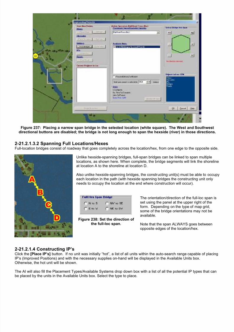
7/21/2019 TSS User Manual
http://slidepdf.com/reader/full/tss-user-manual 252/492
Figure 237: Placing a narrow span bridge in the selected location (white square). The West and Southwestdirectional buttons are disabled; the bridge is not long enough to span the hexside (river) in those directions.
2-21.2.1.3.2 Spanning Full Locations/HexesFull-location bridges consist of roadway that goes completely across the location/hex, from one edge to the opposite side.
Unlike hexside-spanning bridges, full-span bridges can be linked to span multiplelocations, as shown here. When complete, the bridge segments will link the shorelineat location A to the shoreline at location D.
Also unlike hexside-spanning bridges, the constructing unit(s) must be able to occupyeach location in the path (with hexside spanning bridges the constructing unit onlyneeds to occupy the location at the end where construction will occur).
Figure 238: Set the direction ofthe full-loc span.
The orientation/direction of the full-loc span isset using the panel at the upper right of theform. Depending on the type of map grid,some of the bridge orientations may not beavailable.
Note that the span ALWAYS goes betweenopposite edges of the location/hex.
2-21.2.1.4 Constructing IP’sClick the [Place IP’s] button. If no unit was initially “hot”, a list of all units within the auto-search range capable of placingIP’s (Improved Positions) and with the necessary supplies on-hand will be displayed in the Available Units box.Otherwise, the hot unit will be shown.
The AI will also fill the Placement Types/Available Systems drop down box with a list of all the potential IP types that canbe placed by the units in the Available Units box. Select the type to place.
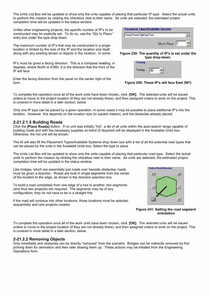
7/21/2019 TSS User Manual
http://slidepdf.com/reader/full/tss-user-manual 253/492
The Units List Box will be updated to show only the units capable of placing that particular IP type. Select the actual unitsto perform the mission by clicking the checkbox next to their name. As units are selected, the estimated projectcompletion time will be updated in the status window.
Unlike other engineering projects, the specific number of IP’s to beconstructed may be explicitly set. To do so, use the “Qty to Place:”entry box under the type drop-down.
The maximum number of IP’s that may be constructed in a singlelocation is limited by the size of the IP and the location size itself,along with any existing terrain or objects in the location. In some Figure 239: The quantity of IP's is set under the
type drop-down.
IP’s must be given a facing direction. This is a compass heading, indegrees, where North is 0/360. It is the direction that the front of theIP will face.
Enter the facing direction from the panel on the center right of theform. Figure 240: These IP’s will face East (90°°°°)
To complete the operation once all of the work units have been chosen, click [OK]. The selected units will be issuedorders to move to the project location (if they are not already there), and then assigned orders to work on the project. This
is covered in more detail in a later section, below.
Only one IP type can be placed by a given operation. In some cases it may be possible to place additional IP’s into thelocation. However, this depends on the location size (in square meters), and the obstacles already placed.
2-21.2.1.5 Building RoadsClick the [Place Roads] button. If no unit was initially “hot”, a list of all units within the auto-search range capable ofbuilding roads and with the necessary supplies on-hand (if required) will be displayed in the Available Units box.Otherwise, the hot unit will be shown.
The AI will also fill the Placement Types/Available Systems drop down box with a list of all the potential road types thatcan be placed by the units in the Available Units box. Select the type to place.
The Units List Box will be updated to show only the units capable of placing that particular road type. Select the actualunits to perform the mission by clicking the checkbox next to their name. As units are selected, the estimated projectcompletion time will be updated in the status window.
Like bridges, which are essentially just roads over hexside obstacles, roadsmust be given a direction. Roads are built in single segments from the centerof the location to the edge, as shown in the direction selection box.
To build a road completely from one edge of a hex to another, two segments(and thus two projects) are required. The segments may be of anyconfiguration; they do not have to be in a straight line.
If the road will continue into other locations, those locations must be selectedsequentially and new projects created.
Figure 241: Setting the road segmentorientation
To complete the operation once all of the work units have been chosen, click [OK]. The selected units will be issuedorders to move to the project location (if they are not already there), and then assigned orders to work on the project. Thisis covered in more detail in a later section, below.
2-21.2.2 Removing ObjectsOnly minefields and obstacles can be directly “removed” from the scenario. Bridges can be indirectly removed by firstpriming them for demolition and then later blowing them up. These actions may be initiated from the EngineeringOperations form.

7/21/2019 TSS User Manual
http://slidepdf.com/reader/full/tss-user-manual 254/492
IP’s and roads, on the other hand, cannot be removed once they are placed. IP’s (including buildings) can be damaged odestroyed by combat action, for example, explosive charges, fire, and bulldozing. In some cases, destroying buildings willcreate rubble. Roads may be cratered by explosive charges or combat engineer operations, or blocked by rubble or otherintended obstacles. However, even if they are rendered ineffective, the object remains on the map, where it couldpotentially be put back into serviceable condition.
2-21.2.2.1 Removing Minefields/ObstaclesTo remove an existing minefield or obstacle, click the [Remove] button in that category.
In some cases, the engineering operation will result in the destruction of the object, whilein others it will create a lane through it (leaving the minefield or obstacle “mostly” stillthere). The determination is based on the values in the TEC and Engineering Datatables.
2-21.2.2.2 Priming Bridges for DemoBridges are not removed from the map as with minefields or obstacles. Instead, they arefirst primed with explosive charges, as an engineering operation, and then destroyedwhen the charges are set off “on command” at a later time. To prime a bridge withexplosives so that it can be destroyed later, click the [Prime Demo] button. There must be an existing bridge in thelocation for the button to be enabled.
Note: To detonate the charges and demolish a primed bridge, use the Engineering Staff Officer screen or right-click onthe bridge location and select Bridge Demolition. A friendly engineer or personnel unit must be nearby the bridge toreceive the orders and set off the charges.
Depending on the current demo status of the bridge, the symbol will appear differently on the map (if the bridge is knownto the current player):
Figure 242: Normal. Figure 243: Primed. Figure 244: Demo thisturn.
Figure 245: Demo failed;re-priming now.
Either player may know that a bridge is primed for demo, whether the player placed the charges or not, as long as thebridge is known well enough (level 5). However, only the priming player knows when orders have been issued to blow thebridge, or when re-priming is necessary because the initial demolition attempt failed.
2-21.2.2.3 Blowing Primed BridgesTo attempt to blow a bridge, the bridge must meet two conditions:
1. The bridge must be primed.
2. There must be a friendly personnel unit within 50 meters of either bridge end. The unit does not need to be acombat engineer type.
When the selected location contains a bridge that meets these conditions, the [Bridge Demolition] button will appear atthe lower right. Click this button to issue orders to blow the bridge.
Here is an example:

7/21/2019 TSS User Manual
http://slidepdf.com/reader/full/tss-user-manual 255/492
Figure 246: Step 1 -Right-click the primedbridge location with apersonnel unit nearby.
Figure 247: Step 2 - Click the[Bridge Demolition] button.
Figure 248: Step 3 -Select the bridge to demo,and click [OK]. Once [OK]is clicked, the orders are
issued and cannot bechanged or rescinded.
Figure 249: Click [OK]on the Engineeringform. The bridge
color will change to“demo ordered”.
Bridge demolition orders are transmitted to the personnel unit on the end of the bridge, but are not subject to normalcommand delays to better model the decisions of the “man on the spot”. The demo orders will be executed immediatelyin the next combat phase.
Demolition is not always successful. In some cases the explosives detonate, but the amount is not sufficient or wellplaced enough to cause enough damage. In others, the charges fail to go off. In the first case, because the charges wentoff, the bridge must be primed again from scratch. In the second, the charges are still present, so the computer willautomatically have nearby personnel units attempt to find the cause of the malfunction and correct it.
This effort is identified as “re-priming the bridge”. When these efforts are completed, the units will automatically andimmediately attempt to demo the bridge again. The time necessary for re-priming depends on what the computerdetermines as the failure of the initial demo attempt, the number of personnel participating, and the environmental
conditions.
IMPORTANT NOTE: Orders to blow bridges, once given, cannot be rescinded or canceled.
2-21.3 Active Operation StatisticsThe Stats section of the Active Operation panel contains the following information about the Active Project:
% Complete : The percentage of the work that has been accomplished. A dash (“-“) indicates that the project hasnot yet been initiated.
Estimated Time To Complete : This is the estimated time, in minutes and seconds, at which the project will becomplete, including any required travel time for the units involved .
Units On Op : The number of personnel and vehicles currently assigned to the project. Game Time : The current scenario time in 24-hour format.
The Units On Op line also indicates the maximum number of personnel and vehicles that may be assigned to the project,and if this limit has been reached. In general, one vehicle equals 5 personnel for these limits. Once the maximumnumber of resources has been allocated, adding additional units will have no effect on the completion time. Although“extra” units may take over for working units that become fatigued or suffer combat losses.

7/21/2019 TSS User Manual
http://slidepdf.com/reader/full/tss-user-manual 256/492
Figure 250: Statistics Example #1. Additional assetscan be added to the project to speed the completion
time.
Figure 251: Statistics Example #2. The maximumallowed assets allowed are already present. Adding
more will not affect the completion time.
2-21.4 Current Projects in LocThe Current Projects in Loc box lists all of the scheduled engineering projects tobe performed in the selected location. It does not indicate that work has actuallybegun on a listed project in the list; the work units may be en-route or working onother projects.
Projects are listed in the order they were entered.
To view and/or edit the information for an existing project, select it from the box.The project’s information will be displayed on the form, as shown in the examplebelow. Players can add or delete units, or completely abandon an existingproject. However, the characteristics of the project itself cannot be modified.
Figure 252: Current Projects Box.

7/21/2019 TSS User Manual
http://slidepdf.com/reader/full/tss-user-manual 257/492
2-21.5 Available UnitsThe Available Units Box allows players to select the units to workon the engineering project. To select a unit, check the small boxto the left of its name. To de-select a unit, uncheck the box.
For each unit, an ETA (Estimated Time of Arrival) is shown. Thisis the time (in minutes: seconds) it will take for the unit to reachthe location under current conditions. This time can depend onhow the AI will issue orders to the unit using the “Proceed
Directly To Mission Box” check box. If this is not checked, the AI will append any necessary movement orders to the end of theunit’s current path, otherwise, the AI will cancel the unit’s currentmovement orders (subject to normal command delays) and orderthe unit directly to the location. In either case, the ETA is thetime required for the unit to arrive and begin the mission.
If the unit is a passenger, the orders will be issued to its carrier,and the carrier will be used for all time calculations. Figure 253: The Available Units Box.
As discussed in the “Stats” section, above, engineering projects have a maximum number of personnel and vehicles thatmay work on them at one time. This limit is determined the by number and size of each object being placed, as well asthe size of the location and other objects in it. After the limit is reached, assigning additional assets to the project will
have no effect on how quickly the project is completed; the additional units essential just wait idle and watch since there isno room for them to contribute.
The units shown in the Available Units box are limited in two ways. If the form was entered from the Unit Movement form,only the Movement Focus unit will be shown. Additionally, the operation buttons and project type drop down choices willbe limited to operations that that unit can perform. If the Engineering form was entered in any other fashion, the AvailableUnits box will be populated when a project type is selected, and will include only those units capable of performing theoperation.
When used, Composite Units are treated as a single entity. If any subunit in the composite unit can complete the missionthe composite unit will be listed and available for assignment. When a composite unit is selected to perform theoperation, the AI will likewise issue orders to move the entire unit to the location, even if other subunits can’t perform themission. This insures that the composite unit will stay together in one location.
2-21.6 Canceling a ProjectTo cancel a project either:
1. Right-click on it in the Engineering Staff Officer form2. <Right Click> on the map location, and select Engineering from the pop-up menu. Then select the project from
the Current Projects In Loc box.
Once the project has been selected, click the [Abandon Project] button.
Section 2-22 Airdrop Missions
Airdrops allow a player to deliver paradrop-capable surface units to the battlefield via aircraft. Unlike slung or internalcargo, which require the transporting aircraft to be stationary and at ground level in order to be unloaded, in a paradropthe aircraft can be at any altitude and moving. The drop altitude and speed may have effects on the drop in terms ofaccuracy and losses, however, as discussed in the Part III of the manual.
2-22.1 Loading the Aircraft Aircraft are normally loaded for paradrops at the beginning of the scenario, as described above in the section on initialplacing forces. This is not required, however. The only prerequisite is that an aircraft must be loaded with paradropcapable units before it can be selected to make a paradrop. When the units are loaded is immaterial. However, becausefixed wing aircraft can never stop moving it is impossible to load them once the scenario starts, as it is with helicopters.

7/21/2019 TSS User Manual
http://slidepdf.com/reader/full/tss-user-manual 258/492
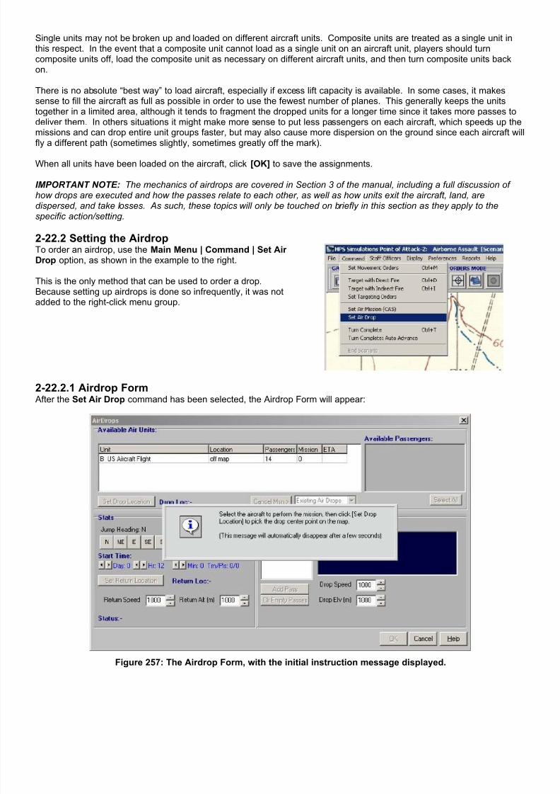
7/21/2019 TSS User Manual
http://slidepdf.com/reader/full/tss-user-manual 259/492
Single units may not be broken up and loaded on different aircraft units. Composite units are treated as a single unit inthis respect. In the event that a composite unit cannot load as a single unit on an aircraft unit, players should turncomposite units off, load the composite unit as necessary on different aircraft units, and then turn composite units backon.
There is no absolute “best way” to load aircraft, especially if excess lift capacity is available. In some cases, it makessense to fill the aircraft as full as possible in order to use the fewest number of planes. This generally keeps the unitstogether in a limited area, although it tends to fragment the dropped units for a longer time since it takes more passes todeliver them. In others situations it might make more sense to put less passengers on each aircraft, which speeds up themissions and can drop entire unit groups faster, but may also cause more dispersion on the ground since each aircraft wilfly a different path (sometimes slightly, sometimes greatly off the mark).
When all units have been loaded on the aircraft, click [OK] to save the assignments.
IMPORTANT NOTE: The mechanics of airdrops are covered in Section 3 of the manual, including a full discussion ofhow drops are executed and how the passes relate to each other, as well as how units exit the aircraft, land, aredispersed, and take losses. As such, these topics will only be touched on briefly in this section as they apply to thespecific action/setting.
2-22.2 Setting the AirdropTo order an airdrop, use the Main Menu | Command | Set AirDrop option, as shown in the example to the right.
This is the only method that can be used to order a drop.Because setting up airdrops is done so infrequently, it was notadded to the right-click menu group.
2-22.2.1 Airdrop Form After the Set Air Drop command has been selected, the Airdrop Form will appear:
Figure 257: The Airdrop Form, with the initial instruction message displayed.

7/21/2019 TSS User Manual
http://slidepdf.com/reader/full/tss-user-manual 260/492
Once the instruction message has disappeared, click on a loaded aircraft to begin issuing the airdrop orders. The Available Air Units box will l ist all of the aircraft units currently available to receive new airdrop orders (in order to qualify,an aircraft must have passengers on board that do not already have orders to jump).
After selecting the aircraft the remaining sections of the form will fill in as applicable:
Figure 258: Once the air unit is selected, the other form sections will be filled in and activated.
2-22.2.1.1 Set the Drop LocationTo select the center-point of the drop location, click [Set Drop Location]. The Airdrop Form will disappear. Click on anyon-map location. This will be the designated center point of the drop, which is actually the middle point of each run; anaircraft will spend an equal amount of time dropping units before it and after it on each pass.
Because airdrops are conducted as a series of one or more straight line passes, each following the same flight path asclosely as possible, units will tend to spread out in a line after being dropped. The dropped units may be further displacedby drift while in the air, or mistakes by the aircrew or other inaccuracies in the drop itself. The selected drop center pointis therefore only a control measure. When the units are actually assembled on the ground, their distribution may notcorrespond to the center point at all.
2-22.2.1.2 Set the Units to DropSelect the units to drop in the current pass by clicking the check box next to them in the Available Passengers Box. Themore units that are selected, the longer the drop run will be and the more spread out the units.
If you want all of the available units to drop as part of the current pass, click the [Select All] button.
As drop units are selected, they are automatically added to the current pass information in the Air Drop Passes box below
it. If you want to assign units to a new pass, click the [Add Pass] button in the Air Drop Passes section.

7/21/2019 TSS User Manual
http://slidepdf.com/reader/full/tss-user-manual 261/492
Figure 259: Select Drop Units.
2-22.2.1.3 Airdrop Mission OrdersThe main mission orders section allows players to set the following information:
Jump Heading : The cardinal heading of the aircraft duringthe drop passes. All passes are made at the same heading.Click a directional button to change.
Start time : The time at which the first jumper should exit theaircraft. Use the arrow keys to adjust.
Return Location : Where the aircraft should fly when the lastunit has jumped and the mission is complete. By default, itis the unit’s current location. Click [Set Return Location] toselect another location - either on or off the map.
Return Speed : the speed, in Kph, the aircraft shouldmaintain to the return location once the mission is
completed. Return Altitude : the altitude, in meters, the aircraft should
maintain to the return location once the mission iscompleted.
2-22.2.1.4 Airdrop PassesThe Airdrop Passes section allows players to set the number and information for each pass:
Pass Grid : This grid box shows the number of passesand the total number of units jumping on each pass.Clicking on a pass in the grid makes it the active pass.
Drop Units : This is a list of the individual units assignedto the selected/active pass.
[Add Pass] : Clicking this button adds a new pass to themission.
[Clear Empty Passes] : Clicking this button removes anypasses with no units assigned.
Drop Speed : the speed, in Kph, the aircraft shouldmaintain for the pass while units are jumping.
Drop Elv : the altitude, in meters, the aircraft shouldmaintain for the pass while units are jumping.

7/21/2019 TSS User Manual
http://slidepdf.com/reader/full/tss-user-manual 262/492
To add a new pass to the mission, click the [Add Pass] button. A new pass will be added, and made active. To selectdrop units for the new pass, click them from the Available units box. Here is an example where 5 units have been addedto the first pass, followed by the creation of a second pass, and then finally assignment of two units to the new pass.
Figure 260: First pass complete.Click [Add Pass] to a new pass.
Figure 261: The second pass isactive (highlighted). Units will be
assigned to it as they are selected.
Figure 262: Two units have beenadded to the second pass. Click
[OK] when all passes are complete.
As units are added to a pass, the AI will automatically adjust the pass altitude and speed settings based on that the jump/parachute characteristics of the units in the pass. Additionally, each pass may have its own settings; they do notneed to be the same for all passes. However, flight characteristics cannot change in mid-pass. Therefore it is a goodidea to try and keep all of the units in a pass of the same type. For example, if both vehicle and troops will be jumping aspart of the mission, the vehicles should go in one pass (or set of passes) by themselves, and the troops in another.
A unit assigned to jump in a pass may be removed from that pass at any time (whether it is the active pass or not) bysimply un-checking the box next to the unit name in the Available Units box. Checking the box again will assign the unit tothe active pass; this provides a quick and easy way to shift drop units among the passes. Using the above example, forinstance, to switch the 1st US Rifle Squad just added to pass #2 to pass #1, the sequence is:
Figure 263: Click pass #1 on the
grid to make it active.
Figure 264: Uncheck the box to
remove the unit from its currentpass.
Figure 265: Check the box again to
add the unit to the active pass (#1).
After all of the passes have been set, click [OK] at the bottom of the form to save the mission.

7/21/2019 TSS User Manual
http://slidepdf.com/reader/full/tss-user-manual 263/492
2-22.3 Viewing/Canceling Airdrops Airdrops can be viewed or canceledusing the same procedure as CASmissions. Bring up the ALO StaffOfficer screen, and <right click> on theairdrop mission line.
Like CAS missions, no aspects of aplanned airdrop can be changed or
edited, and for the same reasons. Airdrops require a great deal of planningand coordination and it is difficult, if notimpossible, to adjust those settings “onthe fly”.
To cancel a mission, Click the [CancelMsn] button, which will appear underthe Available Air Units grid. If theselected air unit has more than onemission scheduled, use the drop downbox next to the button to insure thecorrect mission is selected.
Section 2-23 Detailed Unit Information
The unit information form displays the current status and other values of an individual friendly unit. Right clicking on a unitfrom the force tree, map, or the set-up grid selects it.
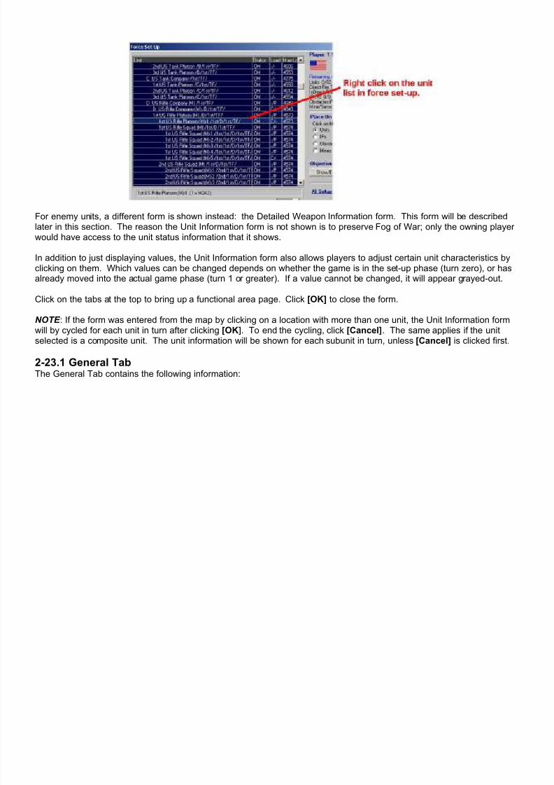
7/21/2019 TSS User Manual
http://slidepdf.com/reader/full/tss-user-manual 264/492
For enemy units, a different form is shown instead: the Detailed Weapon Information form. This form will be describedlater in this section. The reason the Unit Information form is not shown is to preserve Fog of War; only the owning playerwould have access to the unit status information that it shows.
In addition to just displaying values, the Unit Information form also allows players to adjust certain unit characteristics byclicking on them. Which values can be changed depends on whether the game is in the set-up phase (turn zero), or hasalready moved into the actual game phase (turn 1 or greater). If a value cannot be changed, it will appear grayed-out.
Click on the tabs at the top to bring up a functional area page. Click [OK] to close the form.
NOTE : If the form was entered from the map by clicking on a location with more than one unit, the Unit Information formwill by cycled for each unit in turn after clicking [OK]. To end the cycling, click [Cancel]. The same applies if the unitselected is a composite unit. The unit information will be shown for each subunit in turn, unless [Cancel] is clicked first.
2-23.1 General TabThe General Tab contains the following information:
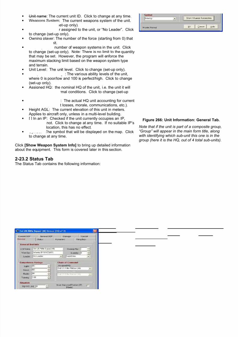
7/21/2019 TSS User Manual
http://slidepdf.com/reader/full/tss-user-manual 265/492
Unit name : The current unit ID. Click to change at any time. Weapons System : The current weapons system of the unit.
Click to change (set-up only). Leader : the leader assigned to the unit, or “No Leader”. Click
to change (set-up only). Owning player : The number of the force (starting from 0) that
controls the unit. Quantity : The number of weapon systems in the unit. Click
to change (set-up only). Note: There is no limit to the quantitythat may be set. However, the program will enforce themaximum stacking limit based on the weapon system typeand terrain.
Unit Level : The unit level. Click to change (set-up only). Competence Ratings : The various ability levels of the unit,
where 0 is poor/low and 100 is perfect/high. Click to change(set-up only).
Assigned HQ : the nominal HQ of the unit, i.e. the unit it willreport to under normal conditions. Click to change (set-uponly).
Current Acting HQ : The actual HQ unit accounting for currentconditions (combat losses, morale, communications, etc.).
Height AGL : The current elevation of this unit in meters. Applies to aircraft only, unless in a multi-level building.
[ ] In an IP : Checked if the unit currently occupies an IP,otherwise not. Click to change at any time. If no suitable IP’sare in the location, this has no effect.
Symbol : The symbol that will be displayed on the map. Clickto change at any time.
Click [Show Weapon System Info] to bring up detailed informationabout the equipment. This form is covered later in this section.
Figure 266: Unit Information: General Tab.
Note that if the unit is part of a composite group,“Group” will appear in the main form title, alongwith identifying which sub-unit this one is in thegroup (here it is the HQ, out of 4 total sub-units).
2-23.2 Status TabThe Status Tab contains the following information:
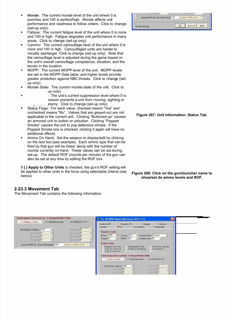
7/21/2019 TSS User Manual
http://slidepdf.com/reader/full/tss-user-manual 266/492
Morale : The current morale level of the unit where 0 ispoor/low and 100 is perfect/high. Morale affects unitperformance and readiness to follow orders. Click to change(set-up only).
Fatigue : The current fatigue level of the unit where 0 is noneand 100 is high. Fatigue degrades unit performance in manyareas. Click to change (set-up only).
Cammo: The current camouflage level of the unit where 0 isnone and 100 is high. Camouflaged units are harder tovisually see/target. Click to change (set-up only). Note thatthe camouflage level is adjusted during the game based onthe unit’s overall camouflage competence, situation, and theterrain in the location.
MOPP : The current MOPP level of the unit. MOPP levelsare set in the MOPP Data table, and higher levels providegreater protection against NBC threats. Click to change (set-up only).
Morale State : The current morale state of the unit. Click tochange (set-up only).
Suppression : The unit’s current suppression level where 0 isnone. Suppression prevents a unit from moving, sighting orfiring at the enemy. Click to change (set-up only).
Status Flags : For each value, checked means “Yes” and
unchecked means “No”. Values that are grayed-out are notapplicable to the current unit. Clicking “Buttoned-up” causesan armored unit to button or unbutton. Clicking “PoppedSmoke” causes the unit to pop defensive smoke. If thePopped Smoke box is checked, clicking it again will have noadditional effects.
Ammo On Hand : Set the weapon to display/edit by clickingon the text box (see example). Each ammo type that can befired by that gun will be listed, along with the number ofrounds currently on-hand. These values can be set duringset-up. The default ROF (rounds per minute) of the gun canalso be set at any time by editing the ROF box.
If [ ] Apply to Other Units is checked, the gun’s ROF setting willbe applied to other units in the force using selectable criteria (seebelow).
Figure 267: Unit Information: Status Tab.
Figure 268: Click on the gun/launcher name toshow/set its ammo levels and ROF.
2-23.3 Movement TabThe Movement Tab contains the following information:

7/21/2019 TSS User Manual
http://slidepdf.com/reader/full/tss-user-manual 267/492
Maintain Speed : The speed which the unit will attempt tomaintain, in Kph. Units will attempt to keep this speed in allterrain and conditions. In some situations the unit may notbe able to meet the specified rate, in which case it will go asfast as it can. Click to change at any time.
Actual Speed : The unit’s actual speed, in Kph. [ ] In Reverse Gear : If they unit is currently moving in
reverse, i.e., “backing up”, this checkbox will be marked.Units are ordered to move in reverse when given movementorders.
[ ] Overwatch/Pause : If the unit is paused to provideprotective spotting/fire as part of an AI formation-moveoverwatch scheme, this box will be checked.
[ ] Engineer Operation : If the unit is currently working on anengineer operation, this box will be checked.
Movement Commands : this shows the directional and othermovement commands the unit is executing. Click [ShowCommand Index/Legend] for a list of the command codes.
[ ] Is Passenger : If this unit is loaded on another this box willbe checked. Otherwise, it will show the unit’s carrying costand type. Clicking the box will cause the unit to beloaded or unloaded, depending on its current state.
[ ] Is Carrier : If this unit has passengers this box will be
checked and the carried units listed in the blue boxunderneath. It also shows the available capacity of the unit.Clicking the box will cause the unit to be loaded orunloaded, depending on its current state.
Figure 269: Unit Information: Movement Tab.
2-23.4 Firing Groups TabEach unit can be subdivided into three Firing Groups, where each Firing Group has its own facing, set of targets and firingcharacteristics. The Firing Groups Tab contains the following information:
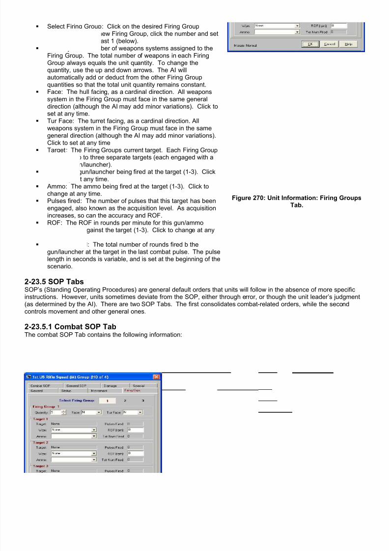
7/21/2019 TSS User Manual
http://slidepdf.com/reader/full/tss-user-manual 268/492
Select Firing Group : Click on the desired Firing Groupnumber. To add a new Firing Group, click the number and setthe quantity to at least 1 (below).
Quantity : The number of weapons systems assigned to theFiring Group. The total number of weapons in each FiringGroup always equals the unit quantity. To change thequantity, use the up and down arrows. The AI willautomatically add or deduct from the other Firing Groupquantities so that the total unit quantity remains constant.
Face : The hull facing, as a cardinal direction. All weaponssystem in the Firing Group must face in the same generaldirection (although the AI may add minor variations). Click toset at any time.
Tur Face : The turret facing, as a cardinal direction. Allweapons system in the Firing Group must face in the samegeneral direction (although the AI may add minor variations).Click to set at any time
Target : The Firing Groups current target. Each Firing Groupcan have up to three separate targets (each engaged with adifferent gun/launcher).
Wpn : The gun/launcher being fired at the target (1-3). Clickto change at any time.
Ammo : The ammo being fired at the target (1-3). Click to
change at any time. Pulses fired : The number of pulses that this target has been
engaged, also known as the acquisition level. As acquisitionincreases, so can the accuracy and ROF.
ROF : The ROF in rounds per minute for this gun/ammocombination against the target (1-3). Click to change at anytime.
Tot Num Fired : The total number of rounds fired b thegun/launcher at the target in the last combat pulse. The pulselength in seconds is variable, and is set at the beginning of thescenario.
Figure 270: Unit Information: Firing GroupsTab.
2-23.5 SOP Tabs
SOP’s (Standing Operating Procedures) are general default orders that units will follow in the absence of more specificinstructions. However, units sometimes deviate from the SOP, either through error, or though the unit leader’s judgment(as determined by the AI). There are two SOP Tabs. The first consolidates combat-related orders, while the secondcontrols movement and other general ones.
2-23.5.1 Combat SOP TabThe combat SOP Tab contains the following information:

7/21/2019 TSS User Manual
http://slidepdf.com/reader/full/tss-user-manual 269/492
Priority DF Targets : Up to 5 target types may be specifiedas a priority to target, in order from 1 to 5. When the unithas a choice between different targets, extra weight isassigned based on the target’s priority. While other factorsare also considered, in general targeting decisions made bythe AI will follow the SOP priority.
Target Type : Select each priority type, 1-5, from the dropdown boxes.
Mx Rng : The maximum range, in meters, at which toengage this type of target. This limit is intended to preventwasteful or ineffective long-range fire.
[ ] Hard : This checkbox determines if the range is “hard”,i.e., never to be exceeded under any circumstances.Otherwise, the AI uses the range as a guide, albeit animportant one, but not as an absolute limit.
Max Engage Range for All weapons : If this value is set toanything but zero, the AI will not voluntarily select targetsbeyond the set range, in meters. Although, in practicemistakes and other situations may cause it to occur beyondthe AI’s control. This setting is used principally to set upclose-in ambushes.
[ ] Engage HQ’s First : If this setting is checked, the unit will
engage KNOWN enemy HQ units as a priority. Whether ornot the unit can properly identify an enemy HQ depends onthe unit’s training and other levels, radio intercept and otherEW efforts, current conditions, the characteristics of theenemy unit itself.
Figure 271: Unit Information: Combat SOPTab.
[ ] Shoot & Scoot : If the force uses “shoot & scoot” tactics (where the unit moves to a hidden/defensive positionafter firing a few rounds), this checkbox determines whether the unit should use them or not. Shoot & scoottactics effects are handled by the AI
[ ] Pause to Fire : If checked, the unit will pause to fire when moving. Otherwise, it will fire on the move, but oftenwith reduced accuracy and/or ROF.
Close Combat SOP : This determines the unit’s action in a close combat situation (when an enemy unit occupiesthe same location as the friendly one). The first two options are self-explanatory, while the third leaves the
decision to attack or not up to the AI based on what it thinks will be the most successful. For more information onClose Combat, see the relevant section in Part 3 of the manual.
If [ ] Apply to Other Units is checked, the settings from that section will be applied to other units in the force usingselectable criteria (see below).
2-23.5.2 General SOP TabThe combat SOP Tab contains the following information:
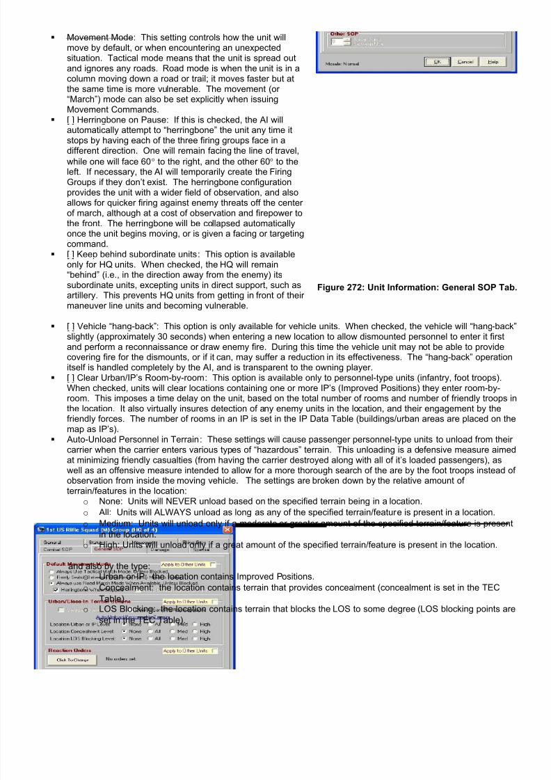
7/21/2019 TSS User Manual
http://slidepdf.com/reader/full/tss-user-manual 270/492

7/21/2019 TSS User Manual
http://slidepdf.com/reader/full/tss-user-manual 271/492
Reaction Orders: Reaction orders determine what a unit should do when detecting an enemy unit(s). They aredescribed in more detail in the next section, below. Click [Click to Change] to add or change the unit’s currentreaction orders.
Radar Turns Between Use : For Radar units, this is the duration between energy pulse emissions. By pulsing theemissions, instead of sending them out continuously, Radar units lower their exposure to being detected by theenemy and attacked with Radar-homing munitions. The cost, however is that pulsing reduces the Radars’effectiveness in terms of detection probability and fidelity. If the duration is set to zero, the force’s Radars willoperate in continuous mode.
If [ ] Apply to Other Units is checked, the settings from that section will be applied to other units in the force usingselectable criteria (see below).
2-23.6 Damage TabThe Damage Tab shows the damaged suffered by the unit so far. This includes damage from enemy fire, or othermishaps like weapon jams or malfunctions. In some cases damaged may be repaired during the course of the scenario.When this occurs, the status flags will be updated to note the change:
This page has two sections:
The top section shows the systems that are considereddamaged, but that are capable of potentially being repaired.
Repair attempts are conducted automatically by the unit, andmay take a varying amount of time depending on the systemand the type of damage. After a time without success, therepair effort may be considered as failed, in which case thedamage becomes permanent. It is also possible that due tohuman error the repair job may be bungled, which also leadsto the system being damaged permanently.
The bottom section shows the systems that are destroyed.They are damaged beyond repair.
At Set-up: The boxes may be manually checked to inflict damage. After that point, they are display-only to reflect the current unit status.
Systems Shown: The systems that may be damaged are the unit’sgun/launchers, special systems, mobility methods (tracks, tiresengines, legs), communications gear, NBC systems, comfort systems(air conditioning, heater), fire control (affects accuracy and ROF), andgeneral electronics (radar, detection equipment, etc).
Figure 273: Unit Information: Damage Tab.
2-23.7 Special TabIf the weapons system has special systems (as set in the Weapons Data Table), their status and “ammo” remaining willbe shown on this tab:

7/21/2019 TSS User Manual
http://slidepdf.com/reader/full/tss-user-manual 272/492
System Name : The name of the special system, or “NotUsed”.
Ammo : the amount of ammo (or expendable supplies)remaining on hand. Not all special systems requireammo/supplies to be used; the setting is in the appropriateData Table, e.g., the Engineering System Table, the PointMissile Defense Table, the Laser table, and so on. Click onthe arrow buttons to change the on-hand amounts (set-uponly).
Commo Systems : All organic communications systems willbe listed here. These systems are assigned as part of theWeapons System.
Figure 274: Unit Information: Special Tab.
2-23.8 Apply SOP Orders to Other UnitsIf the “Apply to Other Units” option was clicked on any of the Unit Information Tabs, the following panel will appear at thebottom of the Unit Information Form:
These settings allow users to customize which other units in the force, if any, should receive the same SOP orders.

7/21/2019 TSS User Manual
http://slidepdf.com/reader/full/tss-user-manual 273/492
The SOP values are applied when the form’s [OK] button is clicked. They are not applied if [Cancel] is clicked instead.
2-23.9 Weapon Information Form
The information form is accessed in one of two ways:
1. For friendly units, bring up the Unit Information Form (as described in the previous section, above). Click the[Show Weapon System Info] button on the General Tab.
2. For enemy units, right-clicking the unit on the map and select “Enemy Weapon Info“ from the pop-up menu.
Figure 275: Apply Settings to Other Units Panel. Only SOPsections checked on the individual tab pages are included.
The top checkbox is a “master” control. Un-checking it will uncheck all of the section boxeson the individual tab pages (no SOP values willbe applied to any other units).
The other radio buttons are filters that determine which other units in the force will receive the SOP orders (as set for thisunit). These filters are:
o Formation: Only units in the same formation are eligible to receive the SOP orders. For purposes of determining
which other units are in this unit’s formation, units are included if they are “under” (have in their higher chain ofcommand) the current unit’s HQ (i.e., up one level).
o Entire Force : All units in the force are eligible.
o This Weapons System Only : Only units with the same assigned weapons system are eligible to receive these
orders.
o All Units of the Same Type : Only units of the same general type (APC, Tank, Personnel, Artillery, etc.) are eligible
to receive these orders.
Note: Do the specificity of many of the SOP orders eligible units must be limited by either weapons system or type. Forexample, a vehicle can’t be given orders to clear a location room-by-room, and a personnel unit can’t be given the sameengagement ranges and targets as a tank.
The Detailed Weapon Information form shows a complete range ofinformation about the weapons system including its size, mobility,guns/launchers, munitions, cargo capacity, and special systems.
The form has five tabs, grouping the information by functional area.
After viewing the form, click [OK] to close it. Clicking [Help] bringsup some general information on the form operation and fields.
Figure 276: Detailed Weapon InformationForm.

7/21/2019 TSS User Manual
http://slidepdf.com/reader/full/tss-user-manual 274/492
Figure 277: Friendly Units (click the button on the UnitInformation Form - General Tab).
Figure 278: Enemy Units (right-click pop-up menu).
This form is “Read-Only”,and does not allow forchanging any of thevalues. These values arepart of the WeaponsSystem Data Table, whichcan be viewed using theDataView module.
Because the DataViewmodule contains acomplete list of these
values in the form’s “on-line help file, they will notbe covered again here.They are also described inparts of Part 3 of themanual.
Figure 279: Weapons System Data and Help (DataView module).
2-23.9.1 Ammunition Penetration/Properties ChartThe Penetration Analysis form shows detailed information about an individual munition model. Data includes the physicalproperties, the maximum and minimum ranges, the accuracy curve (accuracy vs. range), as well as the kill and damageprobabilities. A sample is shown here for the US 25mm APFSDS DU (Depleted Uranium) round:

7/21/2019 TSS User Manual
http://slidepdf.com/reader/full/tss-user-manual 275/492
Figure 280: The Penetration Analysis Form.
For a more detailed explanation of the terms and properties on the form, use Main Menu | Help at the top of the form.
There are two ways to access the form. The first is from the Ammunition Data Table Editor, by clicking the [ShowPenetration] button. The second is by right-clicking the ammunition type at the top of the Detailed Weapon Informationform’s Weapon’s tab, as highlighted below:
The Penetration Analysis Form is “Read-only” when accessed through the Detailed Weapon Information form. Click[Close] to close the Penetration Analysis form and return.
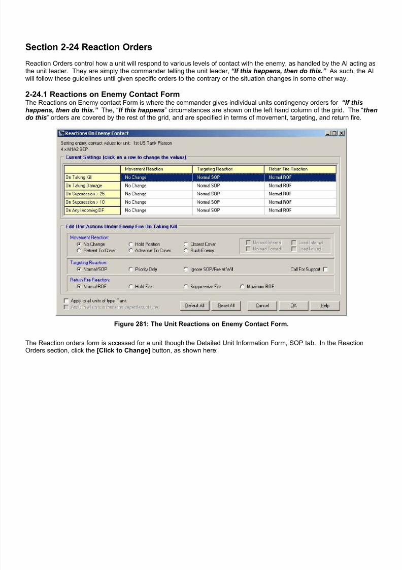
7/21/2019 TSS User Manual
http://slidepdf.com/reader/full/tss-user-manual 276/492
Section 2-24 Reaction Orders
Reaction Orders control how a unit will respond to various levels of contact with the enemy, as handled by the AI acting asthe unit leader. They are simply the commander telling the unit leader, “If this happens, then do this.” As such, the AIwill follow these guidelines until given specific orders to the contrary or the situation changes in some other way.
2-24.1 Reactions on Enemy Contact FormThe Reactions on Enemy contact Form is where the commander gives individual units contingency orders for “If thishappens, then do this.” The, “If this happens” circumstances are shown on the left hand column of the grid. The “thendo this” orders are covered by the rest of the grid, and are specified in terms of movement, targeting, and return fire.
Figure 281: The Unit Reactions on Enemy Contact Form.
The Reaction orders form is accessed for a unit though the Detailed Unit Information Form, SOP tab. In the ReactionOrders section, click the [Click to Change] button, as shown here:

7/21/2019 TSS User Manual
http://slidepdf.com/reader/full/tss-user-manual 277/492
To access the Detailed Unit Information form, <right click>on the unit on the map, Force Tree, or Force Set-up Formgrid. This procedure was covered in more detail in theprevious manual section.
Figure 282: Reaction Orders are set from the DetailedUnit Info Form, SOP Tab.
Click on the situation line to set the contingency orders for a given situation (i.e., “if this happens, then do this”). Thereare 5 situations defined, all of which must be the result of incoming enemy fire (i.e., not breakdowns, mines or othercauses):
1. On Taking Kil l : incoming fire has caused the total loss (kill) of a weapons system.2. On Taking Damage : incoming fires has caused damage to a weapon system.3. On Suppression > 25 : The unit’s suppression level reaches 26 points.4. On Suppression > 10 : The unit’s suppression level reaches 11 points.
5. On Any Incoming DF : The unit takes Direct Fire, disregarding any results.
After clicking the situation line, the contingency orders will be shown in the lower panels of the form, where they may beedited as specifically described in the sections below. To save the new orders, click [OK]. To cancel without saving, click[Cancel].

7/21/2019 TSS User Manual
http://slidepdf.com/reader/full/tss-user-manual 278/492
The form also offers several other options to make issuing reaction orders more convenient:
[Default All]: clicking this returns all contingency orders to the default settings.[Reset All]: clicking this returns all contingency orders to the settings when the form was opened, before any changeswere made. It is the same as clicking [Cancel], but without closing the form.[ ] Apply to all units of Type NNNN : If this check box is checked, clicking [OK] will assign these contingency orders toall units in the force with a weapon System of the type specified ( NNNN ).[ ] Apply to all units in formation: If this check box is checked, clicking [OK] will assign these contingency orders to allunits in the formation, whether their weapon system type matches the selected unit’s or not. This box is only enabled ifthe selected unit is a HQ.
2-24.2 Reaction Orders - MovementThe Movement Reaction Orders control whether the unit should move in a contingency situation, and also whether unitsshould be loaded/unloaded.
Figure 283: Set Movement Reaction Orders.
The options are:
No Change : The unit will continue executing its current movement orders. If it has no orders, it will hold position. Hold Position : The unit will stop in its current position. Any movement orders it has will remain viable, and will be
execute when the contingency situation is removed. Closest Cover : The unit will abandon its current movement orders, if it has any, and will move the closest covered
position within 500 meters. If no cover is found within that range, the unit will stop moving and hold position. Retreat to Cover : The unit will abandon its current movement orders, if it has any, and will move away from the
enemy to the best covered position within 750 meters. If no cover is found within that range, the unit will stopmoving and hold position.
Advance to Cover : The unit will continue to execute its current movement orders, if it has any, to the f irst coveredposition it enters. If no cover is found within the unit’s current orders, or if it does not have any current orders, theunit will stop moving and hold position.
Rush Enemy : The unit will abandon any current movement orders and immediately move at the fastest speed
possible toward the enemy firing unit. If confronted with multiple enemy firing units, the unit will tend to movetowards the closest.
Unload Internal : If checked, the unit will immediately unload any non-towed (internal) passenger units it iscarrying (applied to carrier units only). The normal unloading time requirements apply.
Load Internal : If checked, the unit will immediately attempt to internally load (non-towed) as many units aspossible that are located in the same location. The normal loading time requirements apply.
Unload Towed : If checked, the unit will immediately unload any towed passenger units it is carrying (applies tocarrier units only). The normal unloading time requirements apply.
Load Towed : If checked, the unit will immediately attempt to load as many towed units as possible that arelocated in the same location. The normal loading time requirements apply.
2-24.3 Reaction Orders - Targeting
Targeting Reaction Orders determine what the unit should fire at, and if it should call for fire support (if available).
Figure 284: Set Targeting Reaction Orders.
The options are:

7/21/2019 TSS User Manual
http://slidepdf.com/reader/full/tss-user-manual 279/492
Normal/SOP : The unit will continue to fire at targets according the to normal conventions and rankings, with the
“value” of the target adjusted for its standard SOP priorities. The unit may still fire at non-priority targets, though,if the AI feels the value is high enough to warrant the target being engaged.
Priority Only : The unit will fire only at targets of a type corresponding to an SOP priority types (up to 5 types may
be designated as priority). If no target of a priority type is available, the unit will not fire.
Ignore SOP/Fire at Will : The unit will rank targets based on the standard criteria, such as “value” and probability
of killing it, without any modification for it being an SOP priority type or not. Additional value is placed on returningfire at the enemy firing units to suppress, rout, or destroy them.
Call for support : If checked, the unit will attempt to call for fire support (artillery only, not CAS), if available.
Note: SOP target priorities are covered in more detail in the previous manual section.
2-24.4 Reaction Orders - Return FireThe Return fire setting determines how aggressive the unit should be in returning fire, once targets are selected using thecriteria in the targeting section, above. It does this by controlling the return fire rate of fire (ROF), which is the number ofrounds fired in a given time period.
Figure 285: Set Return Fire Reaction Orders.
The options are:
Normal ROF : The ROF will be whatever the unit or AI would normally use. No change will be made for thecontingency.
Hold Fire : The ROF will be set to zero; the unit will effectively not fire at all. Suppressive Fire : The unit will fire at a rate intended to suppress the enemy to prevent, or greatly reduce, the
incoming fire and/or its effectiveness. This amount may be less than the normal or maximum rates of fire. Maximum ROF : The unit will use its maximum Rates of Fire for all return fire. The maximum rate of fire is set for
each gun launcher in the Gun/Launcher Data Table, and is modified for the situation and unit conditions.
Section 2-25 Attach/Detach Elements
Attachments are the direct assignation of one element (unit) to another. If the unit that is being attached will remain fullyindependent, all that needs to be done is to set the subordinate unit’s HQ to that of the parent. This is done either at thevery start of the scenario in the TO&E/force editor, or by using the Detailed Unit Information form’s General Tab. Both ofthese procedures were covered in previous sections of the manual.
If the attachment will become an integral (organic) part of the parent unit, the Join procedure is used instead. This mergesthe two units together into one, and will be discussed below.
A third option, which falls in between the first two, is to make the subordinate unit part of a Composite Unit with the parentas its HQ. This allows the subordinate unit to remain an independent entity/unit in the scenario, but limits its freedom ofaction under the rules of composite units. Creating and editing Composite Units is covered later in this part of the manualand a technical discussion of how they operate is included in Part 3.
2-25.1 Joining UnitsWhen units are joined together, the units merge into one and the parent unit absorbs the subordinate element completely.From that point on, the sub-unit is no longer part of the scenario, and its weapons systems and equipment become anindistinguishable part of the parent unit. In practice, this means adding the subordinate unit’s setting the subordinateunit’s quantity to zero.

7/21/2019 TSS User Manual
http://slidepdf.com/reader/full/tss-user-manual 280/492
To join units together, right click on the location containing theunits. From the pop-up menu, select Give Orders to Unit(s) |Join Units, as shown to the right.
In order to be eligible to join together, both units must be in thesame location, and meet these general requirements:
The morale state of both must be Normal They must have the same Weapon System The incurred damage must be equal. They cannot be carrying passengers. If the parent is in an IP, the subordinate unit must be able
to fit in the IP as well.
When one or both of the units being joined together are composite units, the above requirements still apply to thecomposite unit as a whole, with the exception that the weapon system types of the two units do not need to be exactlyequal. In this case, new sub-units will be created in the final joined unit (which will also be a composite unit) for the “extra”weapon systems.
For example, a composite unit comprised of 8 infantry and 2 trucks is added to a unit with 2 infantry and 4 AFV’s. Thefinal unit would have three sub-units: 10 infantry, 2 trucks, and 4 AFV’s.
This same procedure is used even if the two units do not share even a single weapon system, as long as one of them is acomposite unit. In this case the all of the subunits are simply added to a new composite unit comprising them all. Forexample, if the composite unit of 8 infantry and 2 trucks is added to a non-composite unit of 4 tanks, the results will be acomposite unit of 5 tanks (the parent and Composite unit HQ), plus 8 infantry and 2 trucks.
The Join Units form is used to join two units together:
The top box shows all of the units in the location. Clickon one of the units to select it as the subordinate unit inthe join operation. Units with existing “Join” orders areshown by a “>>” after the unit name, followed by theirnew parent unit.
The AI will automatically cycle though the other units inthe location and identify possible parent units. To beconsidered as a parent, a unit must be the same level asthe subordinate unit or higher. For example, a platooncould act as a parent for another platoon or a squad; itcould not be a parent for a subordinate company.
The potential parent units will be shown in the bottombox, along with the time required to join the subordinatewith the parent, in seconds.
Figure 286: The Join Units Form.
After selecting the parent and subordinate units, click [Join Units] to complete the operation. If neither unit is acomposite unit, the subordinate unit will be issued a “Join” command in its movement orders. The parent unit will receivea “Pause” order so that it does not move out of the location before the Join command is executed.
If either unit is a composite unit, no “Join” commands are issued. Instead, the subordinate units are immediately assignedto the parent composite unit. If the parent is not a composite unit, one is created. Once this operation is completed, theonly way to undo the composite unit changes is to click the [Cancel] button. All unloaded units in the new/adjustedcomposite units are issued with the appropriate Pause amount required to join the units together.

7/21/2019 TSS User Manual
http://slidepdf.com/reader/full/tss-user-manual 281/492
Figure 287: Joining non-Composite units. Thesubordinate and parent are selected. Click [Join Units]
to issue “Join” orders to the subordinate.
Figure 288: The subordinate has been issued orders to join with the parent. This is noted in the top box usingthe ">>" followed by the parent (2nd US Tank Platoon).
Figure 289: Joining Composite Units. The subordinateand parent units are selected. Click [Join Units] to join
the 1st US Rifle Squad to the 2nd US Rifle Squad.
Figure 290: The subordinate unit has been joined withthe parent. It no longer appears in the upper box. The
only way to separate them again is to edit theComposite Unit (2nd US Rifle Squad).
2-25.2 Creating a DetachmentDetachments are sub-units broken off from a larger parent unit. They are used to perform a different mission or to provideextra coverage of the area around the parent. Examples are a small section detailed to provide observation of a potentialenemy route of advance (LP/OP - Listening Post/Observation Post), a heavy weapon posted to guard a crossroads, aradioman temporarily assigned to another unit, or a team left behind to blow a primed bridge.
Important Note: The “Pause” command, once issued by clicking [Done] to save the Join commands and close theform, can never be edited or changed. This is true even if the “Join” command is removed at some later time throughthe Unit Movement Form.

7/21/2019 TSS User Manual
http://slidepdf.com/reader/full/tss-user-manual 282/492
For the most part, detachments are relatively small units. However, in some cases the detachment may be as large, oreven larger, than the parent unit after the split. This is perfectly acceptable, as long as the parent’s quantity is not zero (inwhich case the parent just becomes the detachment).
Detachments may be created at any time during the scenario. Mostoften they are created from a single parent unit, but it is alsopossible to create detachments with several different weaponsystems from several different parents. For example, a detachmentcould contain a machine gun, a mortar, and a tank. The onlyrequirement is that all of the individual parent (or donor) units mustbe in the same location when the detachment is created.
The first step in creating a new detachment is to <Right Click> onthe parent unit’s map location. Then, from the pop-up menu, select“Create a Detachment”, as shown to the right.
The Detachments Form will appear, with all of the potential parentunits in the location shown. If one of the prospective parent units isa composite unit, all the sub-units will be displayed automatically, asin the example below.
Figure 291: <Right Click> pop-up menu.
Figure 292: The Detachment Form. Prospective parent/donor units are shown in the top window, along with theiroriginal size. Systems broken off and assigned to the new detachment are shown in the bottom window.
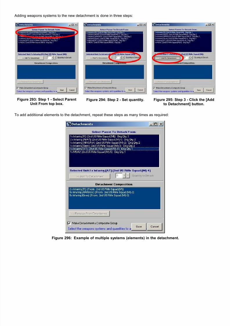
7/21/2019 TSS User Manual
http://slidepdf.com/reader/full/tss-user-manual 283/492
Adding weapons systems to the new detachment is done in three steps:
Figure 293: Step 1 - Select ParentUnit From top box.
Figure 294: Step 2 - Set quantity. Figure 295: Step 3 - Click the [Addto Detachment] button.
To add additional elements to the detachment, repeat these steps as many times as required:
Figure 296: Example of multiple systems (elements) in the detachment.

7/21/2019 TSS User Manual
http://slidepdf.com/reader/full/tss-user-manual 284/492
To remove an element from the detachment, select it fromthe bottom box and click [Remove From Detachment].
The same procedure is used to change the quantity of oneof the elements. The element is first removed, and thenadded anew with the desired quantity.
Click the [Save] button to create and save the new detachment. The new unit will be added to the current force, with theparent unit as its HQ. If there is more than one element (and thus parent unit) the parent of the first element becomes thedetachment’s HQ.
Additionally, the AI will attempt to maintain the current loading situation. Therefore, if a loaded carrier is selected as theparent unit, the AI will automatically transfer its passengers to the new detachment, proportional to the quantity loaded onthe parent unit. For example, if a unit of 4 AFV’s is carrying 8 troops, there are 2 troops on each vehicle. If one AFV isbroken off to form a detachment, 2 troops will also be broken off with it, and will remain loaded.
Multi-element detachments may also be automatically turned into Composite Units. To do this, check “[ ] MakeDetachment a Composite Group” before clicking the [Save] button. This is the default option. Composite Units arecovered in the next manual section (on editing/changing), and also in Part 3.
To close the form without saving or creating anything, click [Cancel].
Detachments are treated like any other unit; they are given orders, use the chain of command, move and fire, and reportenemy contracts the same as a non-detachment. The only difference is that the text string “[Det]” is added to their namefor easy identification.
Where a detachment is placed on the map depends on the current scenario time: In the Set-up Phase : The detachment is initially placed in the parent’s unit’s location. However, it is immediately
selected and put into “placement mode”. As such, <left click> on any other map location to place the detachmentin that location. In fact, every <left click> will move the unit to the selected location until some other operation isinitiated or the “Cancel Mode” button is pressed.
In Any Scenario Turn : The detachment is placed in the parent unit’s location; it cannot be moved without issuingmovement commands.
Section 2-26 Composite Units
Composite units allow players to consolidate several subunits into a single maneuver unit. This is done strictly as aninterface option in order to make the simulation easier to play and less confusing, since the subunits will be shown with asingle symbol on the map and may be given orders as one (as long as they remain in the same location).

7/21/2019 TSS User Manual
http://slidepdf.com/reader/full/tss-user-manual 285/492
Within the composite unit however, all of the subunits remain as separate entities. This maintains complete accuracy, aswell as flexibility; turning off the Composite Unit Display Mode allows the subunits to be accessed directly at any time.
Figure 297: Composite Unit mode OFF. All of the individual subunits are listed in the map mouse-over text, as was the force tree.
Figure 298: Composite Unit mode ON. The subunits have been combined together into a single line for both themouse-over text and force tree.
Composite units always use the name of their nominal HQ unit (the first in the list) with “Group” appended onto the end.For example, “1st US Rifle Squad Group”. This is the text that will be shown on the force tree, form grids and mouse-overtext.
Composite units are created automatically at the start of a scenario based on the TO&E entries of the units selected.Whenever a formation is added where the sub-units have the same level of the HQ, the unit will be added as a compositeunit by default. For example, an infantry squad might have a HQ element of squad level, a Machine-gun subsection ofsquad level, a Rifle section of squad level, and an APC section of squad level. Because all of the sub units are of thesame level as the HQ (squad), a composite unit will be created for the formation - a HQ and three sub-units (Machine-gun, Rifle and APC).

7/21/2019 TSS User Manual
http://slidepdf.com/reader/full/tss-user-manual 286/492
2-26.1 Toggling Composite Unit Display ModeThe Composite Unit Mode can be toggled off and on at any time from a number of menus and forms. The most commontoggle controls are:
Main Menu | Display | Composite Unit Mode. Force Set Up Form - Composite Unit Mode Checkbox. Staff Officers Form (any) - Composite Unit Mode Checkbox.
As previously stated, the display value can be toggled at any time without changing or affecting the units themselves. It ismerely a display/interface option and not a reassignment or restructuring tool.
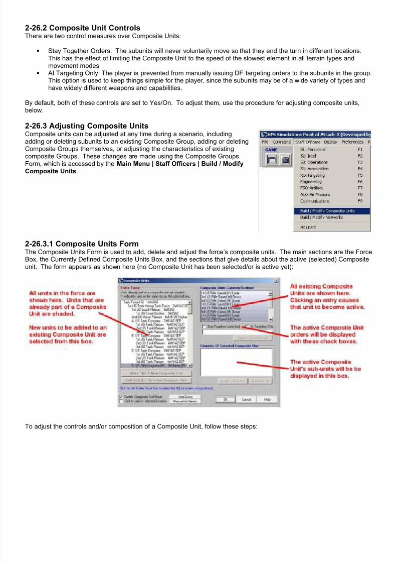
7/21/2019 TSS User Manual
http://slidepdf.com/reader/full/tss-user-manual 287/492
2-26.2 Composite Unit ControlsThere are two control measures over Composite Units:
Stay Together Orders: The subunits will never voluntarily move so that they end the turn in different locations.This has the effect of limiting the Composite Unit to the speed of the slowest element in all terrain types andmovement modes
AI Targeting Only: The player is prevented from manually issuing DF targeting orders to the subunits in the group.This option is used to keep things simple for the player, since the subunits may be of a wide variety of types andhave widely different weapons and capabilities.
By default, both of these controls are set to Yes/On. To adjust them, use the procedure for adjusting composite units,below.
2-26.3 Adjusting Composite UnitsComposite units can be adjusted at any time during a scenario, includingadding or deleting subunits to an existing Composite Group, adding or deletingComposite Groups themselves, or adjusting the characteristics of existingcomposite Groups. These changes are made using the Composite GroupsForm, which is accessed by the Main Menu | Staff Officers | Build / ModifyComposite Units.
2-26.3.1 Composite Units FormThe Composite Units Form is used to add, delete and adjust the force’s composite units. The main sections are the ForceBox, the Currently Defined Composite Units Box, and the sections that give details about the active (selected) Compositeunit. The form appears as shown here (no Composite Unit has been selected/or is active yet):
To adjust the controls and/or composition of a Composite Unit, follow these steps:

7/21/2019 TSS User Manual
http://slidepdf.com/reader/full/tss-user-manual 288/492
Activate the existing Composite Unit byselecting it from the Currently Defined Box atthe upper right of the form. The currentinformation for that Composite Unit will beshown in the boxes underneath the CurrentlyDefined Box
The Entire Force box will also scroll to the HQof the Composite unit. All of the elements ofthe Composite Unit will be shaded the samecolor in the Entire Force Box. However, onlyten shades are used for this identification, so itis possible that other Composite Units mayshare the same shade. If a “>” appears at thefar left of a unit line, it indicates that the unit isin the same location as the active CompositeUnit HQ.
The form will appear similar to that shown tothe right.
Figure 299: The Composite Units Form.
After making changes, click the [OK] button to save them and close the form. To discard the changes, click [Cancel]instead.
2-26.3.2 Adjusting Control ValuesTo adjust the control values, use the check boxes underneaththe Composite Units Currently Defined Box. These controlmeasures were discussed previously in this section.
Checking the box turns the control on, un-checking turns it off.The “Stay Together” control can only be turned on if all of theComposite Units subunits are currently in the same location.
To edit the Composite Unit name/ID string, use the text Boxunderneath the check boxes. The Composite Unit name/ID isseparate from all of the subunit name/ID’s; it may be set asdesired without regard for any other considerations.
Figure 300: The Control flags and name for theactive Composite Unit are changed underneath the
Currently Defined Box.

7/21/2019 TSS User Manual
http://slidepdf.com/reader/full/tss-user-manual 289/492

7/21/2019 TSS User Manual
http://slidepdf.com/reader/full/tss-user-manual 290/492
2-26.3.5 Changing the HQTo change the Composite Unit HQ element, select the new HQunit from the Elements of Selected Composite Unit Box.
When a subunit is selected, the [Assign Unit As HQ] buttonwill be enabled. Click this button to make the selected subunitthe new HQ.
No other changes are made to either of the affected subunits-
the previous or new HQ.
There are no restrictions on which subunit can become the newHQ. Any element in the group is eligible.
Figure 303: Select the new HQ from the Elements inComposite Unit Box then click the [Assign Unit as
HQ] button.
2-26.4 Adding New Composite UnitsNew Composite Units may be added at any time during a scenario. The only limitation is that a subunit element cannotbe in two Composite Units at the same time. To create a new Composite Unit, follow these steps:
1. Select the HQ unit from the Entire Force Box. If the unit is part of another Composite Group, it will be removedfrom that group.
2. Click [Make This A New Composite Unit]. The new group will be created, and selected (its information shownon the right hand side of the form).
3. Continue adding subunit elements as desired by selecting them from the Entire Force Box as described in thesection on Adding Subunits, above.
4. Adjust the control orders and name as desired using the checkboxes and edit box.
Figure 304: Select the New HQ unit from the EntireForce Box. Click [Make this a New Composite Unit] to
create the new unit.
Figure 305: The new Composite Unit will be activatedand its information displayed on the right hand side of
the form.
2-26.5 Deleting Composite UnitsComposite Units may be deleted at any time during the scenario. Because Composite Units are used only for interfacesimplification, deleting a Composite Unit has no effect on its subunits other than to remove any control restrictions theymight have been under. The chain of command and all other aspects of the unit remain unchanged.
To delete a composite unit, follow these steps:

7/21/2019 TSS User Manual
http://slidepdf.com/reader/full/tss-user-manual 291/492
1. Select the Composite Unit to remove by clicking itin the Composite Units Currently Defined Box, asshown in the example to the right.
2. Click the [Dissolve Unit] button.
The form will automatically update once the operation iscomplete.
Figure 306: Select the Composite Unit to delete, andclick the [Dissolve Unit] button.
2-26.6 Auto-Create Composite UnitsThe Auto-Create utility is intended primarily to “fix” situations that arise from over-customizing Composite Unit definitions(e.g., when so many edits have been made that the force structure has become unmanageable), or when the user losestrack of what is going on or his ultimate objective in editing them. It essentially provides a quick “reset”, and returns theComposite Units to their “original” condition from when the scenario was first created.
To accomplish this, the utility performs two modification steps. First, it removes all current Composite Units, whether theyare user-created or default. Then, it parses the unit list creating Composite Units based on the standard defaultcondition: that of a subordinate unit having the same level (size) as its HQ. This is what the AI does on its own after unitsare added to the force.
To run the utility, click the [Auto Create] button at the bottom of the form,as shown at right.
A confirmation dialog will appear (shown at right), withnotification that any existing Composite Units will bedeleted (even if none are presently defined).
To preserve the existing definitions, and cancel theoperation, select [Cancel] from the confirmation dialog.Otherwise, click [Proceed], and the Composite Units willbe rebuilt from scratch. The form displays will also beupdated.
If there is any uncertainty towards whether or not rebuilding the Composite Units from scratch is the desired action, savethe scenario prior to running the utility. That way a back-up is available in case the results are not as expected.
2-26.6 Restoring Unit NamesWhen Composite Units are created, the AI automatically renames the constituent units by adding “Group” to the HQelement, and a “-N” to the subordinates. In some cases this is not desired, or is not appropriate if the Composite Unit isimmediately removed.
This utility returns all unit names to their values when theform was initially loaded. Essentially, it “undoes” all namechanges enacted in the current editing session.
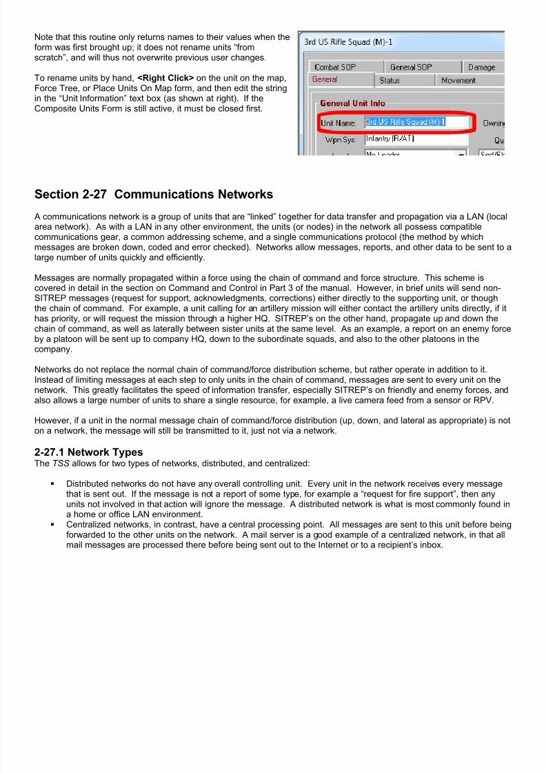
7/21/2019 TSS User Manual
http://slidepdf.com/reader/full/tss-user-manual 292/492
Note that this routine only returns names to their values when theform was first brought up; it does not rename units “fromscratch”, and will thus not overwrite previous user changes.
To rename units by hand, <Right Click> on the unit on the map,Force Tree, or Place Units On Map form, and then edit the stringin the “Unit Information” text box (as shown at right). If theComposite Units Form is still active, it must be closed first.
Section 2-27 Communications Networks
A communications network is a group of units that are “linked” together for data transfer and propagation via a LAN (localarea network). As with a LAN in any other environment, the units (or nodes) in the network all possess compatiblecommunications gear, a common addressing scheme, and a single communications protocol (the method by whichmessages are broken down, coded and error checked). Networks allow messages, reports, and other data to be sent to alarge number of units quickly and efficiently.
Messages are normally propagated within a force using the chain of command and force structure. This scheme iscovered in detail in the section on Command and Control in Part 3 of the manual. However, in brief units will send non-SITREP messages (request for support, acknowledgments, corrections) either directly to the supporting unit, or thoughthe chain of command. For example, a unit calling for an artillery mission will either contact the artillery units directly, if ithas priority, or will request the mission through a higher HQ. SITREP’s on the other hand, propagate up and down thechain of command, as well as laterally between sister units at the same level. As an example, a report on an enemy forceby a platoon will be sent up to company HQ, down to the subordinate squads, and also to the other platoons in thecompany.
Networks do not replace the normal chain of command/force distribution scheme, but rather operate in addition to it.Instead of limiting messages at each step to only units in the chain of command, messages are sent to every unit on thenetwork. This greatly facilitates the speed of information transfer, especially SITREP’s on friendly and enemy forces, andalso allows a large number of units to share a single resource, for example, a live camera feed from a sensor or RPV.
However, if a unit in the normal message chain of command/force distribution (up, down, and lateral as appropriate) is noton a network, the message will still be transmitted to it, just not via a network.
2-27.1 Network TypesThe TSS allows for two types of networks, distributed, and centralized:
Distributed networks do not have any overall controlling unit. Every unit in the network receives every messagethat is sent out. If the message is not a report of some type, for example a “request for fire support”, then anyunits not involved in that action will ignore the message. A distributed network is what is most commonly found ina home or office LAN environment.
Centralized networks, in contrast, have a central processing point. All messages are sent to this unit before beingforwarded to the other units on the network. A mail server is a good example of a centralized network, in that all
mail messages are processed there before being sent out to the Internet or to a recipient’s inbox.

7/21/2019 TSS User Manual
http://slidepdf.com/reader/full/tss-user-manual 293/492
Figure 307: Network types. The red (on the left) is a distributed network, the blue (right) centralized.
2-27.2 EquipmentIn order to assign a unit to a network, it must first have a network-capable communication system available.Communications systems are defined in the Communications/Jamming Data Table, which may be viewed with theDataView module. Each communications system has a flag for network interoperability, as shown in this example:
Figure 308: The Communications/Jamming Systems Data Table, with the Network Link flag highlighted.
Note that the flag is simply “Yes” or “None”; the communications system will either be able to be part of a network or not.It is up to players to insure that the networks are set up in a realistic fashion for the scenario. Once defined in the data table, communications systems are assigned to weapon systems. As long as at least oneassigned system is network capable, any unit with that weapons system may become part of a network. However, thisdoes not insure that the unit will always be able to use the network during a scenario. Data transmissions are subject todefined limitations of the communications system itself, for example bandwidth, as well as range or LOS requirements,damage, jamming, and other factors. These factors are assessed at the time of transmission.
For Composite Units, the communications systems of the HQ are used when communicating outside the Composite UnitGroup.
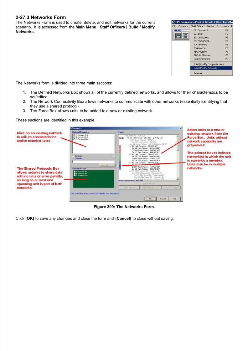
7/21/2019 TSS User Manual
http://slidepdf.com/reader/full/tss-user-manual 294/492
2-27.3 Networks FormThe Networks Form is used to create, delete, and edit networks for the currentscenario. It is accessed from the Main Menu | Staff Officers | Build / ModifyNetworks.
The Networks form is divided into three main sections:
1. The Defined Networks Box shows all of the currently defined networks, and allows for their characteristics to beset/edited.
2. The Network Connectivity Box allows networks to communicate with other networks (essentially identifying thatthey use a shared protocol).
3. The Force Box allows units to be added to a new or existing network.
These sections are identified in this example:
Figure 309: The Networks Form.
Click [OK] to save any changes and close the form and [Cancel] to close without saving.

7/21/2019 TSS User Manual
http://slidepdf.com/reader/full/tss-user-manual 295/492
2-27.4 Adding a New NetworkTo add a new network, select at least oneunit from the Force box. If desired, acontiguous range of units may also beselected by <Shift> clicking on a secondunit; the units in between will also beselected (see the example to the right).
Click the [Create Network] button to add
the selected units to the new network.
The first unit in the list will automaticallybecome the default name of the network.If the network is centralized, as opposedto distributed, this unit will also becomethe controller unit. In the example to theright, this unit is the “A US TankCompany”.
The computer will also assign anidentifying color to the network todistinguish it easily from the others.
The network name, color and distributedvalues may be changed at any time. Theprotocol of the network may also be setto inter-operate with other networks.
Setting the network characteristics iscovered in the next section, below.
Figure 310: Pick one or more units and click [Create Network].
Figure 311: The new network is added, and the form updated.
2-27.5 Adjusting Network CharacteristicsTo change a network’s characteristics, first select the network from the Defined Networks Box by clicking on it. Thecharacteristics information will be filled in, as well as the shared protocol settings.

7/21/2019 TSS User Manual
http://slidepdf.com/reader/full/tss-user-manual 296/492
The network characteristics are:
ID Color : This color identifies the network onthis form and throughout the simulation. Clickthe colored box to select another color from astandard color selection dialog box.
Mode : Check to make the network distributed,otherwise centralized.
Name : A text string used to identify thenetwork.
Shared Protoco l: Check the boxes next to allother networks that use the same protocol. Ifnetworks sharing a protocol, messagestransferred between them do so more quicklyand accurately (the message does not need tobe translated or re-entered).
To change the controller unit of a centralizednetwork, select the network from the DefinedNetworks Box, then select the new controller unitform the Force Box. The new controller mustalready be a member of the network (and will be
shaded in the Force Box).
Click the [Assign As Controller] button.
2-27.6 Adding Units To a NetworkUnits may be added to an existing network at any time. To do so, follow these steps:
1. Select the network from the DefinedNetworks Box.
2. Select the unit(s) from the Force Box.3. Click the [Add to Network] button to add
the selected units to the network.
Adding units will not change the name or thecontroller unit of a network, even if the units beingadded are “before” any other current units in theforce list. To change these values, use theprocedure outlined in the previous section.
Figure 312: Click the [Add to Network] button to add theselected unit(s) to the selected network.

7/21/2019 TSS User Manual
http://slidepdf.com/reader/full/tss-user-manual 297/492
2-27.7 Deleting Units From a NetworkTo delete a unit from a network, select thenetwork from the Defined Networks Box, and thenselect the unit from the Force Box. Member unitsof the network will be shaded in the Force Box.
Click the [Remove From Network] button.
If the unit being removed is the controller of acentralized network, the next unit in the list willbecome the controller in its place.
2-27.8 Deleting a NetworkTo delete a network completely, select it form the Defined
Networks Box. Then click the [Remove Network] buttonunderneath the network name box.
Section 2-28 Map Areas and EventsMap Areas allow users to identify and mark locations on the map as control measures for force operations, or simply forspecial attention. By themselves Map Areas are simply display entities - they have no intrinsic effects on any of themodeling or AI routines, or on combat activities. However, they can be linked to perform as objectives for ManeuverGroups, Reconnaissance Assignments, and as part of the triggers for Events.
Map Areas can only include “on-map” locations. They may not be created in the off-map display.
2-28.1 Map Area TypesThere are three types of map areas:
• Rectangular : This type of area is defined by an “upper-left corner” location, and a “lower-right” corner location.When used with hex-grid maps, “edge” locations are included in the area if their center point is within the exactrectangle (to the nearest meter), otherwise they are excluded.
• Circular : Circular areas are defined by a center location, and a radius (in meters) from the middle of that location. As with rectangular areas, “edge” locations are included in the area if their center point is within the circle tracedby the radius (to the nearest meter).

7/21/2019 TSS User Manual
http://slidepdf.com/reader/full/tss-user-manual 298/492
• Location List : This area is formed by selecting one or more individual locations/hexes to form a list. There are nolimits on what locations may be selected (other than they must be on-map); the locations do not need to beadjacent to one another, or do not need need to follow any pattern.
Figure 313: Map Area Types: Rectangle (red), Circular (blue), and Location List (pink); areas may overlap freely.
All Map Areas, regardless of type, share the user-settable attributes of a Name, Color, and Fill Pattern. Setting thesevalues is discussed in the next section.
2-28.2 Adding, Editing, and Deleting Map AreasTo access Map Areas, select the Main Menu |Map Areas/Events | Create/Edit Map Areasmenu choice form the Main Form.
If no map areas have been defined, the list boxportion of the form will be empty (as shown atright), otherwise the existing Map Areas will bedisplayed.
To create a new Map Area, click the [Add NewArea] button under the list box. A drop-downbox will appear (shown below). Select thedesired type for the new Area, or click <Esc> to
cancel.
Figure 314: The Map Areas Form, used to add, edit, or delete MapAreas. When no Areas have been defined, the list box will be blank.

7/21/2019 TSS User Manual
http://slidepdf.com/reader/full/tss-user-manual 299/492
2-18.2.1 Setting General Area Values All map areas share several general characteristics, namely their draw color, fill pattern, and one or more anchor locationson the map. Setting and editing these values is performed in the same manner no matter what type of map Area is underconsideration (Rectangular, Circular, or Location List). Changes will be shown immediately, both on the map and in thesample display box (center right).
Area Name/ID: A descriptive text string thatidentifies the Area. This string will be
displayed over the Area on the map (exceptfor Location Lists), and will be used whenselecting the area as a control measure(when used as part of a trigger, forexample).
Display: The pattern used to fill the Area.
[ ] Show to current player only: Ifchecked, this Map Area will only be visible tothe current player; the opposing player willnever have access to it or any knowledge itexists.
Sample Display Box: Click this box tochange the display color.
Map Location Grid: Clicking on the map willset the anchor location for the value with thehighlighted “MAP” cell (in red). Clicking onthe on the “MAP” cell makes it “current”.The other cells allow the location value to beedited by hand (not recommended).
Figure 315: Setting General Map Area Values. Note that the coloredtext underneath the location grid provides instructions and/or hints.
The Map Areas Form has three action buttons at the bottom:
[Cancel]: Exit without saving any additions or changes.
[Save]: Save the area and exit/return.[Help]: Display the Map Area help file.
2-28.2.2 Setting Rectangular AreasRectangular Areas are defined by two opposing (diagonal) cornerlocations. It doesn't matter which corner is set to which, i.e.,Corner #1 doesn't have to be the top or left corner, the computerwill automatically assign them as appropriate.
After the corner locations have been selected, they can be changed by selecting their “MAP” box (which becomeshighlighted in red) and then clicking on the map. In the example above, for instance, clicking on the map will set “Corner#1” (Corner #2 remains unchanged).
Or, users can edit the location values directly by clicking on the appropriate cell in the grid, which brings up a standardedit box. Hit [Return] to save the changes, or click on another grid cell.
2-28.2.3 Setting Circular AreasCircular Areas are defined by setting a center location, a radius,and starting and ending angles. The radius value is in meters, andthe angle values are in compass degrees:
• 0°/360°= North (straight up)
• 90° = East (straight right)
• 180° = South (straight down)
• 270° = West (straight left)
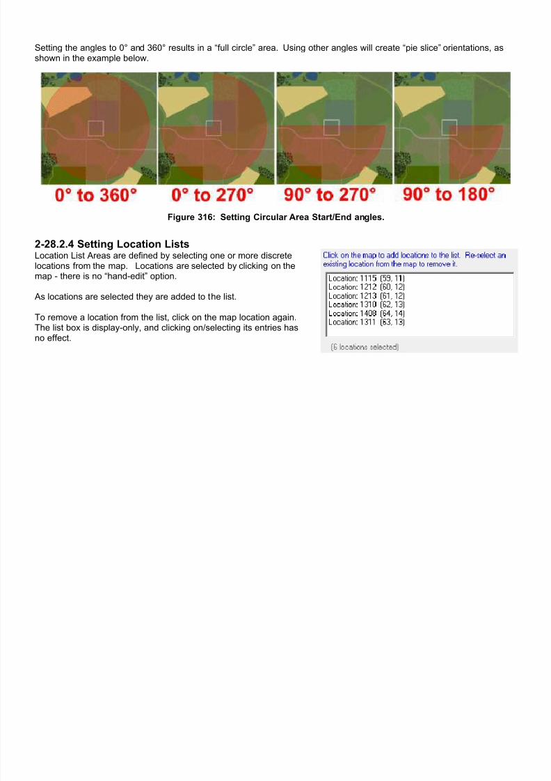
7/21/2019 TSS User Manual
http://slidepdf.com/reader/full/tss-user-manual 300/492
Setting the angles to 0° and 360° results in a “full circle” area. Using other angles will create “pie slice” orientations, asshown in the example below.
Figure 316: Setting Circular Area Start/End angles.
2-28.2.4 Setting Location ListsLocation List Areas are defined by selecting one or more discretelocations from the map. Locations are selected by clicking on the
map - there is no “hand-edit” option.
As locations are selected they are added to the list.
To remove a location from the list, click on the map location again.The list box is display-only, and clicking on/selecting its entries hasno effect.

7/21/2019 TSS User Manual
http://slidepdf.com/reader/full/tss-user-manual 301/492
2-28.2.5 Map Area TipsMap Areas should be given namesthat are succinct, yet descriptive, andcolor/fill patterns that enable them toshow up easily on the map.
They should also follow importantterrain or man-made features as faras possible. For example if a
“fenced-in” area has specialsignificance within the scenario, itshould be declared as its own area.If the area surrounding the fenced-inportion is also important, it can bedefined as well, but as a separateentity (Map Areas can overlap).
This configuration is shown in theexample at right, with the “Ultra-Secure” Zone Area inside of the“Ammunition Bunkers” Area.
Map Areas are drawn in the order
that they were defined/as they areshown in the list, with the last on top.So always define smaller areas last.
Important Note: Location Lists doNOT display the Area name on themap. Therefore, try to use the other Area types whenever possible.
Figure 317: Map Areas Example. “Aircraft Parking Area” (red), “Fuel StorageTanks” (blue), “Ammunition Bunkers” (purple), “Ultra-Secure Zone” (yellow).The “Ultra-Secure Zone” appears on top of the “Ammunition Bunkers” area
since it is defined later in the list (inset).
Section 2-29 EventsEvents are sets of predetermined actions that result from occurrences of specific conditions during the game. They allow
for automatic “reactions” to specified “triggers”, in the general format of “If A happens, then implement B”, where A and Bcan include more than one item. For example, “if an enemy unit is detected in the area around a missile silo” (the trigger, A), then “release the rapid-response team” (the reaction, B).
Events can be used as force control measures, recreations of real-world situations, or to add variability and interest to ascenario.
The triggering and reactions for Events are handled completely by the computer subject to the values entered for theevent; no human input is necessary, or even possible. When the computer AI has determined that the trigger conditionsare met subject to the Event options, it automatically implements the reactions.
2-29.1 Composition of EventsEvents are created and edited using the Events Form. This form is accessed by clicking: Main Menu | Map
Areas/Events | Events.
Events are comprised of two primary parts:
• The first part is a set of “Triggers”, which identify what must occur in the scenario to activate the Event (i.e., “if thishappens...”).
• The second part are the “Reactions”, which specify what happens when the triggers are activated (“.... then thisoccurs”).
Both Triggers and Reactions are defined using the Events Form, as described below. They must be defined first beforethey can be used to create an Event. Additionally, once defined, Triggers and Reactions can be used in any number ofEvents; users do not need to create multiple entries for the same Trigger of Reaction.
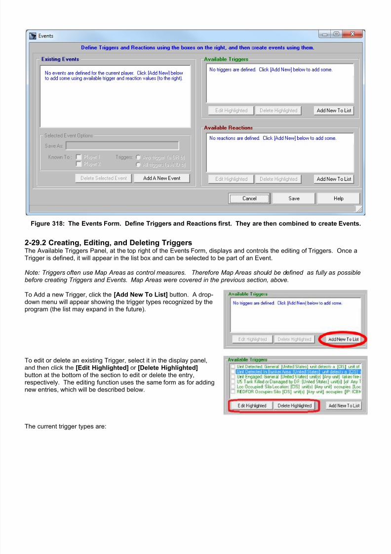
7/21/2019 TSS User Manual
http://slidepdf.com/reader/full/tss-user-manual 302/492
Figure 318: The Events Form. Define Triggers and Reactions first. They are then combined to create Events.
2-29.2 Creating, Editing, and Deleting TriggersThe Available Triggers Panel, at the top right of the Events Form, displays and controls the editing of Triggers. Once aTrigger is defined, it will appear in the list box and can be selected to be part of an Event.
Note: Triggers often use Map Areas as control measures. Therefore Map Areas should be defined as fully as possiblebefore creating Triggers and Events. Map Areas were covered in the previous section, above.
To Add a new Trigger, click the [Add New To List] button. A drop-down menu will appear showing the trigger types recognized by theprogram (the list may expand in the future).
To edit or delete an existing Trigger, select it in the display panel,and then click the [Edit Highlighted] or [Delete Highlighted]button at the bottom of the section to edit or delete the entry,respectively. The editing function uses the same form as for adding
new entries, which will be described below.
The current trigger types are:

7/21/2019 TSS User Manual
http://slidepdf.com/reader/full/tss-user-manual 303/492
Unit Detected Trigger: This trigger is activatedwhen a unit from the specified force detects aunit from the specified target force subject to theset conditions. Users can set:
• The sighting force and/or specificsighting unit (use “All” for any unit in theforce).
• The target unit's owning force, and itscharacteristics (type and size). Use “AnyType” for all units in the force beingdetected.
• The quality level of the sighting. Thehigher the level, the better/morecomplete the information (“known” levelsare covered in the section on detectionand FOW).
• The location/area of the target unit. Use“Entire Map” for any location on the map.
• A specific friendly unit that must receivethe report of the sighting (will normallyimpose additional delays while the reportworks through the chain of command tothe ultimate unit. For no restrictions, use“Any unit in force”.
To change any of the values, click on the editingor drop-down boxes.
Figure 319: Unit Detected Trigger (Example 1). This exampletrigger will be invoked whenever any US unit detects any enemy
(CIS) unit anywhere on the map. Detections can be from anysource, including maneuver units, aircraft, remote sensors,
electronic surveillance, satellites, etc.
Figure 320: Unit Detected Trigger (Example 2). This trigger willbe invoked when an enemy (CIS) personnel unit is detected to
Level 2 or better inside of the Ammunition Bunker Area, and thereport is received by the 806th AP Detachment (the TF HQ).
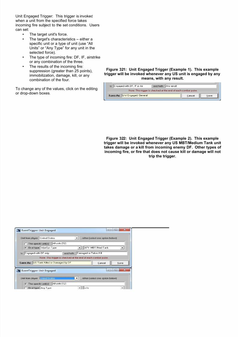
7/21/2019 TSS User Manual
http://slidepdf.com/reader/full/tss-user-manual 304/492
Unit Engaged Trigger: This trigger is invokedwhen a unit from the specified force takesincoming fire subject to the set conditions. Userscan set:
• The target unit's force.
• The target's characteristics – either aspecific unit or a type of unit (use “AllUnits” or “Any Type” for any unit in theselected force).
•
The type of incoming fire: DF, IF, airstrikeor any combination of the three.
• The results of the incoming fire:suppression (greater than 25 points),immobilization, damage, kill, or anycombination of the four.
To change any of the values, click on the editingor drop-down boxes.
Figure 321: Unit Engaged Trigger (Example 1). This exampletrigger will be invoked whenever any US unit is engaged by any
means, with any result.
Figure 322: Unit Engaged Trigger (Example 2). This exampletrigger will be invoked whenever any US MBT/Medium Tank unittakes damage or a kill from incoming enemy DF. Other types ofincoming fire, or fire that does not cause kill or damage will not
trip the trigger.

7/21/2019 TSS User Manual
http://slidepdf.com/reader/full/tss-user-manual 305/492
Location/Area/IP Occupied Trigger: This triggeris invoked when a unit from the specified forcephysically occupies a specified location/hex, alocation/hex with in a Map Area, or an ImprovedPosition (IP).
In this Trigger type, users can set:
• The moving/occupying unit's force.
• The occupying unit's characteristics –either a specific unit or a type of unit (use“All Units” or “Any Type” for any unit inthe selected force).
• The thing being occupied, either a singlelocation, a defined Map Area, or anImproved Position (IP). After clicking thedesired radio button, click on the map toset the single location/hex or IP, or selectthe Area from the pop-up dialog box.
To change any of the values, click on the editingor drop-down boxes.
Important Note 1: Unlike the previous “Detected”
Trigger, detection is not necessary here – thetrigger is invoked whether the occupying unit isknown or not.
Important Note 2: When an IP is designated tobe occupied, the unit must do exactly that. It isnot enough that the unit just move into thelocation of the IP; it must physically occupy(“move into”) the IP itself.
Figure 323: Loc/Area/IP Occupied Trigger (Example 1). Thisexample trigger will be invoked whenever any US unit is engaged
by any means, with any result.
Figure 324: Loc/Area/IP Occupied Trigger (Example 2). Thisexample trigger will be invoked whenever any CIS unit physicallyoccupies the ICBM silo. This is in contrast to the first example,where the CIS unit only needs to move into the silo's location.
2-29.3 Creating, Editing, and Deleting ReactionsThe Available Reactions Panel, at the bottom right of the Events Form, displays and controls the editing of Reactions.Once a Reaction is defined, it will appear in the list box and can be selected to be part of an Event.
Note: Reactions use Reinforcements and Dynamic (Active) IP's as control measures. Therefore these should be definedas fully as possible before creating Reactions and Events (setting these values were covered in previous sections).
To Add a new Reaction, click the [Add New To List] button in the Available Reactions section. A drop-down menu will appearshowing the trigger types recognized by the program (the list mayexpand in the future).
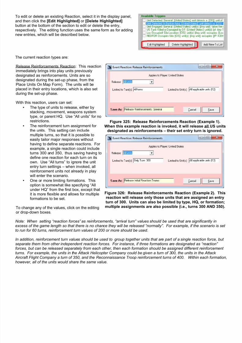
7/21/2019 TSS User Manual
http://slidepdf.com/reader/full/tss-user-manual 306/492
To edit or delete an existing Reaction, select it in the display panel,and then click the [Edit Highlighted] or [Delete Highlighted]button at the bottom of the section to edit or delete the entry,respectively. The editing function uses the same form as for addingnew entries, which will be described below.
The current reaction types are:
Release Reinforcements Reaction: This reactionimmediately brings into play units previouslydesignated as reinforcements. Units are sodesignated during the set-up phase, from thePlace Units On Map Form). The units will beplaced in their entry locations, which is also setduring the set-up phase.
With this reaction, users can set:
• The type of units to release, either bystacking, movement, weapons systemtype, or parent HQ. Use “All units” for no
restrictions.• The reinforcement turn assignment for
the units. This setting can includemultiple turns, so that it is possible toeasily tailor major responses withouthaving to define separate reactions. Forexample, a single reaction could includeturns 300 and 350, thus saving having todefine one reaction for each turn on itsown. Use “All turns” to ignore the unitentry turn settings – when invoked, allreinforcement units not already in playwill enter the scenario.
• One or more limiting formations. Thisoption is somewhat like specifying “Allunder HQ” from the first box, except thatit is more flexible and allows for multipleformations to be set.
To change any of the values, click on the editingor drop-down boxes.
Figure 325: Release Reinforcements Reaction (Example 1).When this example reaction is invoked, it will release all US units
designated as reinforcements – their set entry turn is ignored.
Figure 326: Release Reinforcements Reaction (Example 2). Thisreaction will release only those units that are assigned an entryturn of 300. Units can also be limited by type, HQ, or formation;multiple assignments are also possible (i.e., turns 300 AND 350).
Note: When setting “reaction forces” as reinforcements, “arrival turn” values should be used that are significantly inexcess of the game length so that there is no chance they will be released “normally”. For example, if the scenario is setto run for 60 turns, reinforcement turn values of 200 or more should be used.
In addition, reinforcement turn values should be used to group together units that are part of a single reaction force, butseparate them from other independent reaction forces. For instance, if three formations are designated as “reaction”forces, but can be released separately from each other, then each formation should be assigned different reinforcementturns. For example, the units in the Attack Helicopter Company could be given a turn of 300, the units in the Attack Aircraft Flight Company a turn of 350, and the Reconnaissance Troop reinforcement turns of 400. Within each formation,however, all of the units would share the same value.

7/21/2019 TSS User Manual
http://slidepdf.com/reader/full/tss-user-manual 307/492
Figure 327: Example of setting up three independent Base Reaction Groups (all the units sharing the samereinforcement turn): Group 1: turn 300; Group 2: turn 350; Group 3: turn 400. Actual deployment of the units
within each Group can be limited by additional settings in the Reaction definition.
Figure 328: Base Reaction Groups are not constrained by formations – only by entry turn. However, normalChain of Command requirements/effects will be imposed on units once they enter the scenario.

7/21/2019 TSS User Manual
http://slidepdf.com/reader/full/tss-user-manual 308/492
Initiate Active Object Reaction: This reactionstarts an Active Object change operation. ActiveObjects, which were covered in a previoussection, have the ability to change theircharacteristics while the scenario is underway.
With this reaction, users can set:
• The type of Active Object to change. Active Object types are currently limitedto Dynamic Improved Positions (IP's)).This value must be set before an actualobject can be selected (since it is used toset what objects are displayed in the list).
• The delay time, or “countdown”, beforethe active operation actually begins afterthe reaction is invoked. This delay,which is in seconds, can representsimple confusion as well as preparation,dissemination, confirmation, and otherprocedures that might be necessary priorto starting the change.
• The object to change. The object mustexist (i.e., be in play), and must have an
Dynamic Operation assigned. Anexample of setting an IP to have an Active (Dynamic) Operation is shown atright.
To change any of the values, click on the editingor drop-down boxes.
Figure 329: Initiate Active Object Reaction. When this examplereaction is invoked, it will start the “Open Silo Doors” action for
the specified IP. The time required to complete the operation (i.e.,open the doors), and its effects are set in the object's definition
(shown below).
2-29.4 Creating, Editing, and Deleting EventsEvents are combinations of Triggers and Reactions. These items must be defined before they can be assigned to anEvent, and must be displayed in the Available Triggers and Reactions boxes on the right hand side of the form.
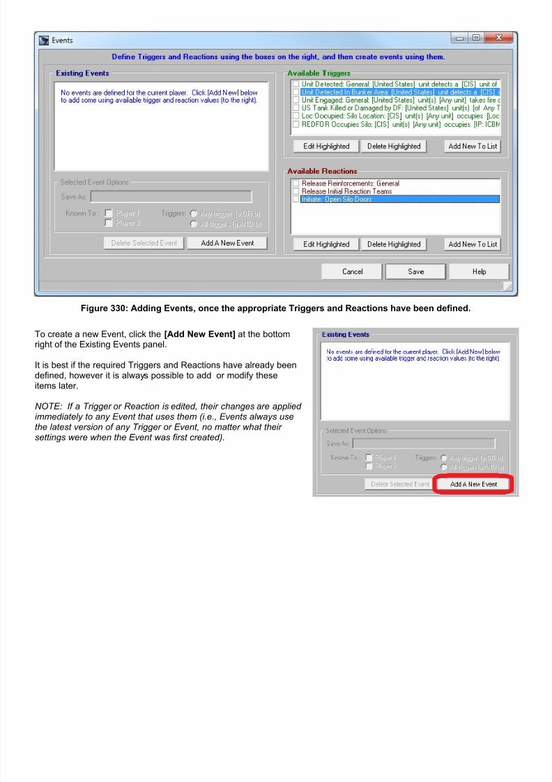
7/21/2019 TSS User Manual
http://slidepdf.com/reader/full/tss-user-manual 309/492
Figure 330: Adding Events, once the appropriate Triggers and Reactions have been defined.
To create a new Event, click the [Add New Event] at the bottomright of the Existing Events panel.
It is best if the required Triggers and Reactions have already beendefined, however it is always possible to add or modify theseitems later.
NOTE: If a Trigger or Reaction is edited, their changes are appliedimmediately to any Event that uses them (i.e., Events always usethe latest version of any Trigger or Event, no matter what theirsettings were when the Event was first created).
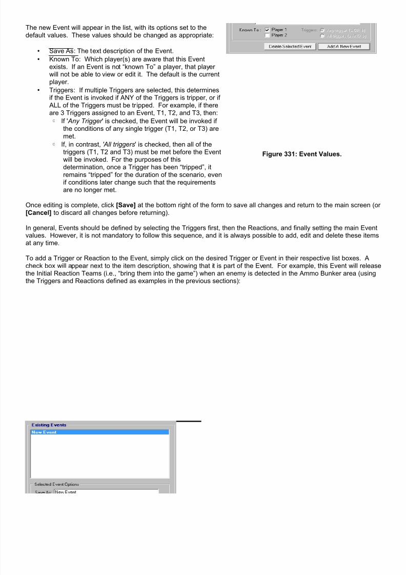
7/21/2019 TSS User Manual
http://slidepdf.com/reader/full/tss-user-manual 310/492
The new Event will appear in the list, with its options set to thedefault values. These values should be changed as appropriate:
• Save As : The text description of the Event.
• Known To : Which player(s) are aware that this Eventexists. If an Event is not “known To” a player, that playerwill not be able to view or edit it. The default is the currentplayer.
• Triggers : If multiple Triggers are selected, this determines
if the Event is invoked if ANY of the Triggers is tripper, or if ALL of the Triggers must be tripped. For example, if thereare 3 Triggers assigned to an Event, T1, T2, and T3, then:
◦ If ' Any Trigger ' is checked, the Event will be invoked ifthe conditions of any single trigger (T1, T2, or T3) aremet.
◦ If, in contrast, 'All triggers' is checked, then all of thetriggers (T1, T2 and T3) must be met before the Eventwill be invoked. For the purposes of thisdetermination, once a Trigger has been “tripped”, itremains “tripped” for the duration of the scenario, evenif conditions later change such that the requirementsare no longer met.
Figure 331: Event Values.
Once editing is complete, click [Save] at the bottom right of the form to save all changes and return to the main screen (or[Cancel] to discard all changes before returning).
In general, Events should be defined by selecting the Triggers first, then the Reactions, and finally setting the main Eventvalues. However, it is not mandatory to follow this sequence, and it is always possible to add, edit and delete these itemsat any time.
To add a Trigger or Reaction to the Event, simply click on the desired Trigger or Event in their respective list boxes. Acheck box will appear next to the item description, showing that it is part of the Event. For example, this Event will releasethe Initial Reaction Teams (i.e., “bring them into the game”) when an enemy is detected in the Ammo Bunker area (usingthe Triggers and Reactions defined as examples in the previous sections):

7/21/2019 TSS User Manual
http://slidepdf.com/reader/full/tss-user-manual 311/492
Figure 332: Example Event 1. This Event will be invoked when an enemy unit is detected in the Bunker area, andwill release all of the units designated as part of the Initial Reaction Team (reinforcement turn = 300).
Figure 333: Example Event 2. This Event will cause the silo doors to open (initiate Dynamic IP action) wheneither a US unit is engaged, or when an enemy unit occupies the IP location.

7/21/2019 TSS User Manual
http://slidepdf.com/reader/full/tss-user-manual 312/492
Section 2-30 Ending the Turn
When a human player has finished reviewing the previous combat action and issuing orders, the next step is to end theturn. The scenario will then proceed, either to the next player’s turn, or into the combat activity phase.
There are several ways to end the turn:
1. Click the End Turn Mode button (shown to the left).2. Select Main Menu | Turn Complete (shown at the far
left).3. Select Main Menu | Turn Complete Auto Advance. In
addition to ending the turn, it will put the game in auto-advance mode.
4. Hit <Ctrl> + T on the keyboard.
As was previously mentioned, the game proceeds in a cycle of repeating steps until the end turn is reached:
1. First player turn2. Second player turn3. Combat activity
The combat activity phase is always watched in real time by the last human player to have a turn before it occurs. In one-player games (vs. an AI player), this is always the human player. In a two human player game, this will be the secondplayer. The first player then watches the combat phase replay (which shows things from his perspective).
The defender is always the second player. In cases where both players are attacking (meeting engagement), players goin numerical sequence (1 then 2).
If the game is in auto-run mode, steps 1 and 2 are omitted, essentially resulting in a number of back-to-back combatphases. This helps move scenarios along quickly during periods of limited action, or in AI vs. AI situations. The auto-advance mode options allow players to customize the duration and extent of the auto-advance, either by a number ofturns, or when “action occurs” in the combat phase. The auto-advance setting can be adjusted on the Preferences Form,or the Action Reporting form, as discussed in previous sections.
For two human player games, at the end of each turn or combat phase, players will be asked to save the game to a file.This file should then be sent to the other player, if not playing “hot seat” on the same computer.
Section 2-31 Combat Reporting
The program uses both graphical and textual methods to show players what is occurring during the combat pulse (orreplay). The graphical methods are shown on the map, while the text messages are displayed on the action reportingform.
In all cases, the information shown is always subject to the Fog of War (FOW) level being used for the scenario. Displaysare thus limited for what each player actually “knows”, at least for the most part. In some situations additional information
is provided on friendly forces or actions to prevent confusion or doubt when actions do not happen as planned or as aplayer would expect them to.
2-31.1 Graphical Map DisplaysThe map display graphics are of three types:
1. Impact location highlight with a colored square. This is used for the location of artillery or missile impacts or closeair support strikes. It may not be the actual location, depending on FOW.
2. DF firing and target unit location with colored squares. As with impact locations, the location shown may not bethe actual units’ locations, depending on the FOW situation.
3. Fire lines representing direct fire are drawn between the firing unit and target. The line color is the firing force’sprimary color (set in the Preferences Form).

7/21/2019 TSS User Manual
http://slidepdf.com/reader/full/tss-user-manual 313/492
4. An “A” inside a circle shows moving aircraft. The color is the force’s primary color.
The actual graphics shown will depend on the animation level, which is set in Preferences during the player’s turn, or the Action Reporting form during the combat phase or replay. The higher the animation level, the more is shown. At thelowest animation level, only the location highlights are displayed.
2-31.2 The Combat Phase Report FormThe Combat Phase Report Form shows textual messages describing the occurrence and results of combat and otheractivities. The information is filtered for the FOW situation and the position of the player as the TF Commander, but as
previously stated, allowance is sometimes made to reduce confusion. For example, friendly weapon malfunctions arereported, even though it is unlikely that in real-life the TF Commander would know that at the instant it occurs.
Figure 334: The Combat Phase Report Form.
The above diagram covers all of the major settings of the form, and how they are used.
Making these changes speeds up the combat phase execution:
Turning off the sound
Lowering the animation level
Lowering the detail level
Lowering the message delay.
While these changes provide more information:
Turning on the sound Raising the animation level. Raising the detail level Increasing the message delay.
The text reports themselves are self-explanatory. Each pulse and phase is identified in turn with yellow labels (dependingon the detail level setting). The reports and summary values are in white.
The Detail Level Setting determines how much information/text is shown for each reported event. Detail Level 1 is themost succinct, and displays essentially only the highlights or summaries. Level 6 is the most detailed, and it list most ofthe parameters and calculated values associated with the action.
• Level 1: Aggregate Summary only.

7/21/2019 TSS User Manual
http://slidepdf.com/reader/full/tss-user-manual 314/492
• Level 2: Type Summary (IF, DF, etc) only.
• Level 3: Type Summary with basic firing reporting.
• Level 4: Aggregate Summary, with Detailed Firing Reporting.
• Level 5: Full Reporting (Firing, Detections, etc).
• Level 6: Full Reporting with Detailed Firing and LOS Information. Examples of the reports at Level 1 and Level 6 are:
Figure 335: Detail Level 1 report.
Figure 336: Same situation at Detail Level 6.

7/21/2019 TSS User Manual
http://slidepdf.com/reader/full/tss-user-manual 315/492
A final summary is always shown at the end of the report. Itdoes not depend on the Detail Level setting.
At the top of the summary, the number of AI timeouts isgiven. AI timeouts occur when the AI can not find amovement path between two locations within an allottedtime limit (the “timeout” value - which is user-customizablefrom the Preferences form). When a timeout occurs, theunit will not move at all; a high number of timeouts indicatethat the AI is having difficulties moving units on the map inthe current conditions. In that case, either raise the timeoutlevel (resulting in longer running games), or if that is notpossible, try to make movement easier for the AI (addbridges, reposition forces, etc.). Otherwise a force with ahigh number of timeouts will move sluggishly, if at all.
After the timeouts, the combat activity is summarized.This summary indicates the total number of units firing oneach side, the number of rounds fired, the number of hits,and the number of kills.
If a question mark appears as one of the values, it meansthat Fog of War prevented the player form having complete
and accurate knowledge of the value.
Figure 337: The Combat Report Summary.
2-31.3 Saving the Report to a FileThe turn report can be saved as a standard text file in zero-player (AI vs. AI) games.
The option to do this is presented at the start of the firstcombat pulse in a timed dialog box. To enable the file savefeature, click yes.
The text that is saved to the file is a direct copy of the textshown on the Combat Phase Report
The file is saved in a folder named “Action Reports”, directly under your main program folder. The file name will be thescenario name with the extension “.TXT”, for example “Operation Talon.TXT”. If the scenario does not have a name,“Unnamed Game” will be used, instead.
If a file with the default name already exists in the folder, bydefault the existing file will be renamed by the addition of atime-date indicator on the end of the file name. However,the existing file name may be used if desired (with new textappended onto the end of the existing report).
To disable the file save during a scenario, bring up the Preferences form ( Main Menu | Preferences). On the GeneralTab, uncheck the box labeled: [ ] Write Combat Reports to File.

7/21/2019 TSS User Manual
http://slidepdf.com/reader/full/tss-user-manual 316/492
Section 2-32 Viewing the Replay/Turn Summary
Players may view a replay or summary of the previous combat phase at any time during their orders phase.
Clicking the Turn Replay button causes a complete recap of the previous combat phase to be displayed,exactly as if the player were observing it in real-time. All of the map animations, sounds and graphics aredisplayed normally, using the detail level and message delay settings.
Clicking the Turn Summary button causes all of the text messages and summary from the previouscombat phase to be displayed at the current detail level. However, there are no accompanying sounds,animation, or map graphics. Therefore this is a much quicker alternative to get information than the TurnReplay option, above.
Section 2-33 Game Results (Victory) Screen
At the end of the scenario (the end turn is reached or an early end condition is met), the Game Results screen will bedisplayed. Because it identifies which player “won”, it is also called the “Victory” screen.
“Victory” comes in several levels, in increasing order:Draw, Marginal, Substantive, Decisive, andOverwhelming. The level is determined by determiningthe Victory Points for each player, and comparing thetotals.
Victory Points are gained by:
• Destroying enemy units
• Having enemy units surrender
• Having units on/near the objective
• Having a smaller force at the start (in terms oftotal weapon system Victory Points)
Victory Points are reduced by:• Inflicting civilian casualties
• Not having units on the objective (whenattacking)
• Adjusting the objective manually at the start ofthe scenario (attacker)
A further adjustment is made for each force’s mission.The more the force was supposed to hold or take theobjectives, the more emphasis is placed on doing so.For example, a force with the mission to “Hold at allcosts” will incur greater point values (plus and minus)for units in the objective area (defending/attacking) than
one assigned to “Delay”.
Additional detail and information can be accessed byclicking the buttons on the bottom of the form ([MOEReport] and [Show Replay]). These options will bediscussed in the sections on “Reports” and “Full GameReplay”, below.
Figure 338: Game Results Screen.
Click [Reveal All] to remove all Fog of War constraints. Units (both friendly and enemy) will be shown in their true statesand positions on the map. This option is available only at the end of a game to prevent FOW circumvention by players intwo-human player games.

7/21/2019 TSS User Manual
http://slidepdf.com/reader/full/tss-user-manual 317/492
Section 2-34 MOE Reports
The MOE Report (Measures of Effectiveness) was added in response to professional user requirements. The report isdesigned to provide detailed data on specific areas of interest. These areas were determined by the nature of eachproject. Therefore, as the TSS is used for other analysis opportunities, additional MOE values are likely to be added inthe future for those projects.
2-34.1 MOE Summary Page
The MOE report is accessed either from the Main Menu | Reports (as shown tothe right) or by clicking the button on the Game Results screen (see above). Whenactivated, the MOE Report will display the Summary Page.

7/21/2019 TSS User Manual
http://slidepdf.com/reader/full/tss-user-manual 318/492
The MOE Summary Page shows overall force performance.The categories/values are: (Note: VP = Victory Points)
Force Exchange: the KIA exchange ratio, using VP’s.KIA % of Force: percent KIA in VP’s.KIA by Friendly: Fratricide (friendly-fire) losses.Surrenders: Number of units that surrendered.Breakdowns: Number of mechanical breakdowns.Evacs: Number of systems auto-evacuated.Times Damage: Number of discrete damage events.Force Points: Raw VP totals.Units Detected: Total units detected by any means.Time on/to Objective: Time the first attacking unit reached theobjective or when last defending unit abandoned it (in secsince start).Messages Sent: The total number of messages sent, with subheadings for network messages and number of units on or offthe network.Messages Received: The number of sent messages actuallyreceived by the intended recipient.Comm Time: the total time taken by all messages to reachtheir recipient; includes network subset.Messages Canceled: Total canceled by sender.
Bandwidth Exceptions: Number of messages canceled due tobandwidth (capacity) limits. Broken down by limits for sendersand receivers.Jamming Delay: Average time increase from jamming.Intercepts: The number of (friendly) messages intercepted bythe enemy.Message Statistics Section: Total number and time bymessage type and sending method. Air Missions: The number of air missions actually started, andthe average time since being called. Arty Missions (FFE): The number of arty missions going toFFE, and the average time required to do so. Arty Missions (Fired): The number of arty call for fire missions
and the average time required.
Click the radio buttons to bring up additional reports, whichare discussed in the following sections.
Click [Generate Spreadsheet File] to send the results into adelimited file that can be easily imported by spreadsheetprograms or can be merged with the MOE results files fromother scenario runs (using the MOE Merger utility, below).
Figure 339: MOE Summary Page.
2-34.2 MOE Attacking/Defending Systems PageThis page is accessed by clicking the radio button at the bottom left of the MOE Report form.
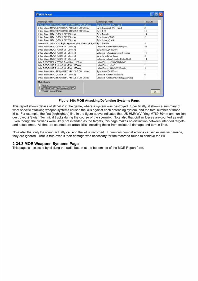
7/21/2019 TSS User Manual
http://slidepdf.com/reader/full/tss-user-manual 319/492
Figure 340: MOE Attacking/Defending Systems Page.
This report shows details of all “kills” in the game, where a system was destroyed. Specifically, it shows a summary ofwhat specific attacking weapon systems caused the kills against each defending system, and the total number of thosekills. For example, the first (highlighted) line in the figure above indicates that US HMMWV firing M789 30mm ammunitiondestroyed 2 Syrian Technical trucks during the course of the scenario. Note also that civilian losses are counted as well.Even though the civilians were likely not intended as the targets, this page makes no distinction between intended targetsand actual ones. All that are counted are actual kills, including those from collateral damage and terrain fires.
Note also that only the round actually causing the kill is recorded. If previous combat actions caused extensive damage,they are ignored. That is true even if their damage was necessary for the recorded round to achieve the kill.
2-34.3 MOE Weapons Systems Page
This page is accessed by clicking the radio button at the bottom left of the MOE Report form.
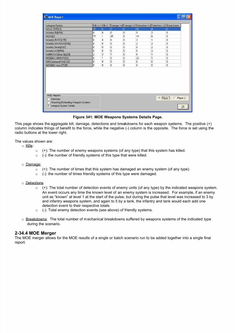
7/21/2019 TSS User Manual
http://slidepdf.com/reader/full/tss-user-manual 320/492
Figure 341: MOE Weapons Systems Details Page.
This page shows the aggregate kill, damage, detections and breakdowns for each weapon systems. The positive (+)column indicates things of benefit to the force, while the negative (-) column is the opposite. The force is set using theradio buttons at the lower right.
The values shown are:o Kills :
o (+): The number of enemy weapons systems (of any type) that this system has killed.
o (-): the number of friendly systems of this type that were killed.
o Damage:
o (+): The number of times that this system has damaged an enemy system (of any type).
o (-): the number of times friendly systems of this type were damaged.
o Detections
o (+): The total number of detection events of enemy units (of any type) by the indicated weapons system.
An event occurs any time the known level of an enemy system is increased. For example, if an enemyunit as “known” at level 1 at the start of the pulse, but during the pulse that level was increased to 3 byand infantry weapons system, and again to 5 by a tank, the infantry and tank would each add onedetection event to their respective totals.
o (-): Total enemy detection events (see above) of friendly systems.
o Breakdowns : The total number of mechanical breakdowns suffered by weapons systems of the indicated type
during the scenario.
2-34.4 MOE Merger The MOE merger allows for the MOE results of a single or batch scenario run to be added together into a single finalreport.
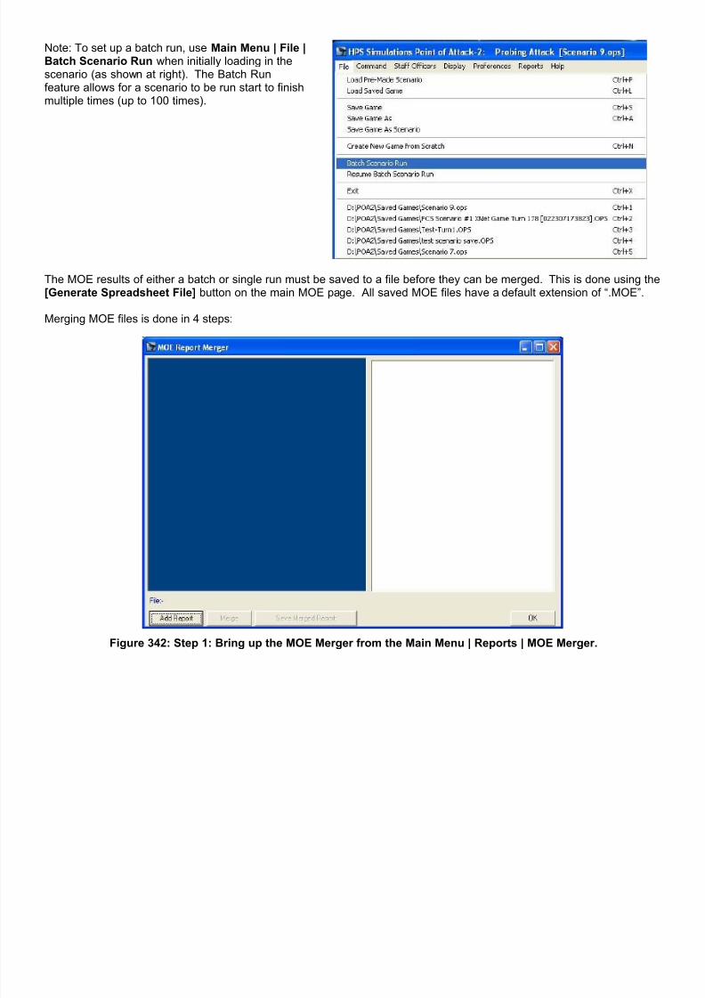
7/21/2019 TSS User Manual
http://slidepdf.com/reader/full/tss-user-manual 321/492
Note: To set up a batch run, use Main Menu | File |Batch Scenario Run when initially loading in thescenario (as shown at right). The Batch Runfeature allows for a scenario to be run start to finishmultiple times (up to 100 times).
The MOE results of either a batch or single run must be saved to a file before they can be merged. This is done using the[Generate Spreadsheet File] button on the main MOE page. All saved MOE files have a default extension of “.MOE”.
Merging MOE files is done in 4 steps:
Figure 342: Step 1: Bring up the MOE Merger from the Main Menu | Reports | MOE Merger.
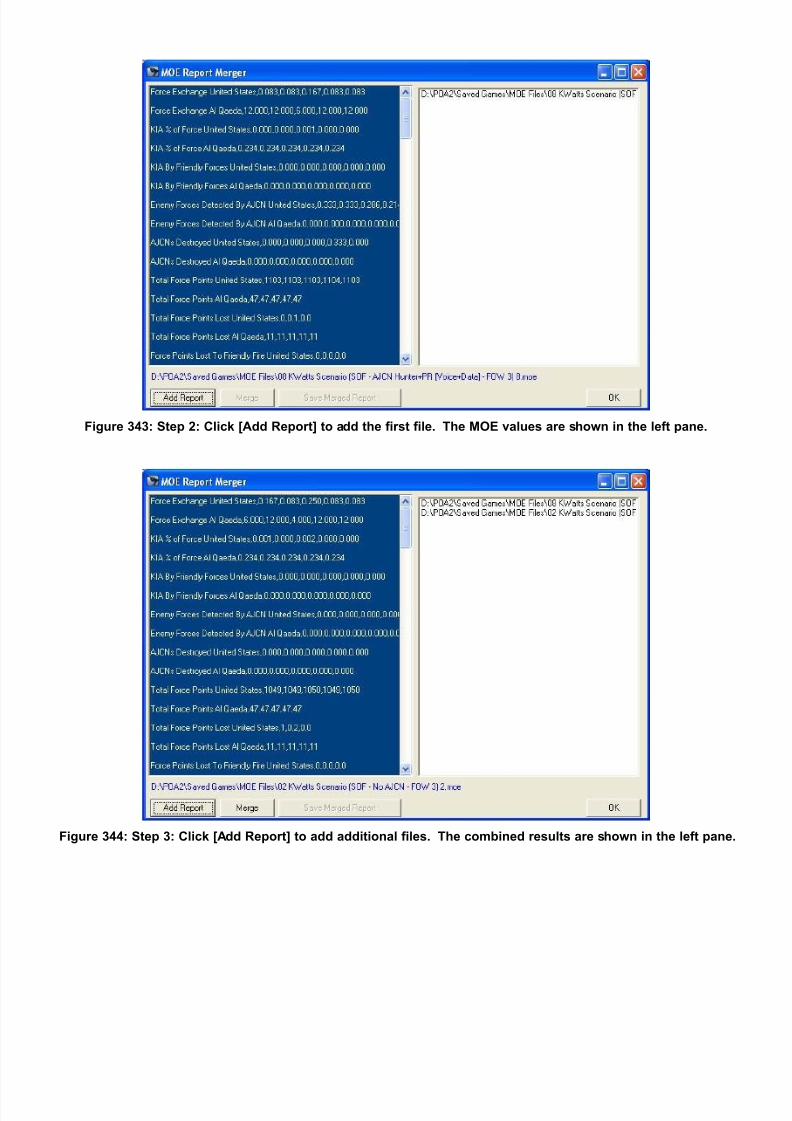
7/21/2019 TSS User Manual
http://slidepdf.com/reader/full/tss-user-manual 322/492
Figure 343: Step 2: Click [Add Report] to add the first file. The MOE values are shown in the left pane.
Figure 344: Step 3: Click [Add Report] to add additional files. The combined results are shown in the left pane.

7/21/2019 TSS User Manual
http://slidepdf.com/reader/full/tss-user-manual 323/492
Figure 345: Click [Merge] to save the merged results to a new file (which is delimited).
Section 2-35 Full Game Replay
At the conclusion of a scenario, a full-game replay may be viewed. This replay shows all major combat actions and unitpositions as they actually were – without any effect of Fog of War. The replay is only a general overview. It does notinclude the detailed combat reports from each phase/turn.

7/21/2019 TSS User Manual
http://slidepdf.com/reader/full/tss-user-manual 324/492
The replay is initiated by either clicking the [Show Replay] button onthe Game Results form, or from the Main Menu | Reports | ScenarioReplay.
To preserve FOW in competitive two-player games, if either playerhas a password defined there will be limitations on when the replaymay be viewed.
The Replay Control form (see below) will appear, and the replay willstart automatically.
If the Game Results Form (left) is visible, it will be minimized until thereplay is closed.
The Replay Control form is used to adjust the replay running characteristics, including the running speed, and allowsplayers to pause, forward or rewind the replay. The form uses standard buttons, as shown here:
Figure 346: Scenario Replay Control Form.
The current turn being shown, as well as general information is shown in blue text under the buttons.
The current combat action will be shown on the map. All of the standard display buttons work normally, including thezoom in and zoom out functions. General messages will also be shown on the map near the action.

7/21/2019 TSS User Manual
http://slidepdf.com/reader/full/tss-user-manual 325/492
Figure 347: Map display during the replay. Zoom in/out functions operate normally.
When viewing is complete, click the “X” in the upper right corner of the Replay Control Form to close the form and exit thereplay.
Section 2-36 Scenario Files
Scenarios are standard saved game files, with one exception. They are always considered to be at the “starting point”.This makes it easier for players to pick them out when they want to start a new game; they don’t have to search thoughthe in-progress save files in the same folder.
Designating a file as “Scenario” also helps creators that want to save their game set up for later use, especially formultiple runs/variability analysis, or for distribution to other players. By saving a game as a scenario, the maker gets morecontrol over many playability settings that are not available when games are saved normally.
Finally, because scenarios are always at the starting point, players have additional control over many values when thescenario is loaded. They can thus override what the creator entered, although the maker’s values will be set as thedefaults.

7/21/2019 TSS User Manual
http://slidepdf.com/reader/full/tss-user-manual 326/492
2-36.1 Loading A ScenarioTo load an existing scenario file, use Main Menu |File | Load Pre-Made Scenario.
Or hit <Ctrl> + P on the keyboard.
The Load Scenario Form will appear, as in this example:
Note: not all scenarios will have text descriptions or graphics associated with them, so these areas may appear blank.
Additionally, this form only shows text and graphics designated as “General” when the scenario was created. Text andgraphics entered specifically for Player 1 and/or Player 2 are never displayed on this form to preserve their contents frompotentially being wrongly disclosed to the player loading the game. For more information on text and graphics, see thenext section on creating scenarios.
After selecting the desired scenario file to load, set the Scenario Control values as desired at the bottom left of the form,and click [Start Game] to load the file and begin the game.
Scenarios can also be “quick-selected” by double-clicking on them in the Scenario Files box. However, the scenario willbe loaded with the default Scenario Control values.

7/21/2019 TSS User Manual
http://slidepdf.com/reader/full/tss-user-manual 327/492
2-36.2 Creating a Scenario Any game may be saved as a scenario file, at any time. This is true whether the game was just created from scratch, is inthe set-up phase, or is already in-progress. This allows for situations to be easily saved for “what-if” analysis.
The first step in making a scenario, therefore, is to get an in-progress game with the desired situation. In most cases, thiswill mean creating a game from scratch, picking the map missions, forces, and setting the nationality and unit levels. It isalso common for new scenarios to have the units placed on the map, loaded or emplaced, and even assigned initialmovement orders. This makes it easy for the creator or other uses to load the game and immediately jump into theaction. In these cases, the game is normally created as human vs. human, and then saved as a scenario on turn 1
(although as will be described below, the turn can be reset to the set-up phase if desired).
Additionally, one may find that the end of one game makes a good starting point for a new one. This is fine too, sincethere are no ultimate limits.
To save any existing game as a scenario, useMain Menu | File | Save Game As Scenario . All games are eligible to be saved as scenarios;their current turn, conditions, or forces areimmaterial.
The first special option players are given when saving as ascenario is to change the Victory Objective locations.Selecting [Yes] brings up the Victory Objectives box,covered in a previous manual section on setting up newgames. Selecting [No] leaves the objective(s) unchanged.
The next step is to select the file name. This is done using a standard “Save Current Game As” dialog box. Note that thisis used only for the file name on the hard disk. It does not set the scenario “title” (which is displayed at the top of the main
form for game identification). In case an existing file name is chosen, a warning box will alert players to the fact that ifthey continue, the original file will be overwritten.
After the file name has been selected, the Edit Scenario Description Form will be displayed, allowing the scenario creatorto add mission statements, historical background information, and other textual descriptions, as well as graphics. The textand graphics can be set to appear generally (visible at any time to either player) or can be limited to only one player or theother. This allows the creator to enter up to 3 different sets of text and graphics: a general set, a set for player 1 and a setfor player 2.
Here is an example of how the form is used:

7/21/2019 TSS User Manual
http://slidepdf.com/reader/full/tss-user-manual 328/492
When [ ] ReSet FOW is checked, all accumulated intelligence on units and objects will be removed. This process isapplied to all units equally; afterward no unit will have knowledge of any other unit or object, and all existing SITREPS willbe deleted. Note that this affects information on friendly as well as enemy units. However, knowledge of friendly forceswill be updated later as part of the normal scenario starting procedures (some enemy forces may be detected as well).
If this option is not selected, all intel remains intact; what units know about other units will remain unchanged, and allSITREPS remain active (including those in the process of being transmitted). If [ ] Reset Turn to Start is checked, the scenario will be saved with the turn reset to zero (the set-up phase). An optionwill also be offered to reset all of the “Last Known” information. When this happens, all knowledge each force has of theother will be lost. However, some knowledge may regained when the standard start of game detection routines are run;when loaded, the scenario will follow the normal new/set-up phase game sequence.
If the turn is not reset, the current turn will remain unchanged in the new scenario; when it is loaded players will beginfrom that point.
If [ ] Add End Conditions is checked, the Set End Conditions Form will appear after closing (clicking [Save Now]). Thisform allows players to set conditions that will end the game before the end turn is reached, with the intent of saving“wasted” time having to run a game to an arbitrary ending turn after all action has effectively ended or an objective hasbeen reached. The Set End Conditions Form and early ending conditions were covered in detail in a previous section ofthe manual.
If no alternate ending conditions are set, the scenario will always run until the set end turn (or until a force is completelywiped out and has no units left).
Click the [Save Now] button to save the new scenario and close the form.
Section 2-37 Getting Help
Most forms and screens in the game have instant help available for them. This type of help is sometimes called “on-line”because it is readily available and part of the program itself. While perhaps counter-intuitive, no Internet access isrequired.

7/21/2019 TSS User Manual
http://slidepdf.com/reader/full/tss-user-manual 329/492
2-37.1 The Main FormHelp is accessed from the Main Menu | Help. It has thefollowing options:
Complete Manual : Opens this document in an htmlformat using the default web browser.
How Do I ... ? : Displays a special set of step-by-step instructions for the most common operations.
Tutorial Slides : Displays the set of “slides” used
with the default tutorial game. Updates Online : Provides a link to the HPS website where updates/additional files are posted.
About : Displays the “About Box” with version andsystem information.
2-37.2 Other Game FormsMost forms have associated help, which is accessedthrough a [Help] button. In most cases, this button islocated at the bottom right of the form, although in a fewcases it is located elsewhere.
2-37.3 DataView Forms
Help is accessed on all of the forms from theMain Menu | Help option.
Section 2-38 Information, Warning, and Error Messages
2-38.1 Firing/Targeting (DF, IF, CAS)Whenever the computer, analyzes any kind of firing situation the following text stings may be displayed (along with theircomplete meaning):
Display String Notes
OK to fire. The analysis did not encounter any errors or other situations that would preventfiring.
OK to fire (guidance dependent). The munition being fired is guided. No errors were encountered by the analysis, butguidance must be checked at the time of actual firing.
Can't engage. The firing unit has no gun/launcher systems, or no ammo has been defined for theselected gun.
Wpn damaged/destd. The intended gun/launcher system has been damaged or destroyed and cannot fire.
Gun doesn't exist. The selected gun has not been defined in the data table.
Ammo doesn't exist. The selected ammunition has not been defined in the data table.
ROF=zero. The ROF (rate of fire) is zero - either as set in the data table, or from orders issuedto the firing unit.
No ammo on-hand. The firing unit does not have any of the selected ammunition on-hand.
Outbound angle too great. The required firing angle exceeds the gun’s maximum elevation. This could benecessary to achieve the required range or to clear obstacles.
Inbound angle too great. The incoming flight path to the target is too steep and cannot be achieved by thegun or munition. Normally this is a result of having to clear obstacles near thetarget.
Over command limit. The firing unit is already controlling the maximum number of guided munitionsallowed; no more can be fired until some are released.

7/21/2019 TSS User Manual
http://slidepdf.com/reader/full/tss-user-manual 330/492
Over range/no firing angle possible. The target is beyond a powered projectile’s maximum range as set in the data table,or for ballistic projectiles, a flight path to the target cannot be achieved using anyallowed gun/launcher elevation.
No valid target. The target cannot be engaged.
Weapon already fired. The gun/launcher is not available because it recently fired and the minimum timebetween rounds has not expired.
Can't rotate to target. The gun/launcher either cannot be rotated at all, or not far enough to engage thetarget with current facings/conditions.
Unit in IP, can't see target. The firing unit is in an IP (Improved Position), and the target is outside the IP’s firingarc.
Wpn can't engage ground (<10m elev)target.
The firing weapon can’t engage ground targets (those at 10m or less elevation AGL). This flag is set in the data table.
Wpn can't engage air (>10m elev) target. The firing weapon can’t engage air targets (those at more than 10m elevation AGL).This flag is set in the data table.
Under minimum range. The target is closer than the munition minimum range as set in the data table.
Over maximum range. The target is closer than the munition maximum range as set in the data table.
Target out of max gun range. The target is beyond all possible maximum gun/ammo ranges for the unit/weaponsystem.
LOS Blocked. DF (direct fire) is not possible because a valid LOS does not exist between the firingunit and the target.
Coax already fired in hull/tur. The selected weapon cannot engage because a gun mounted coaxially with it justfired. Coaxial links are set in the data table.
IP doesn't allow backblast. The firing unit is in an IP (Improved Position), and the munition to be fired generatesbackblast. However, weapons with backblast cannot be fired from inside the IP.The backblast flags are set in the data tables.
Must be fired IF. This indicates that intended DF is not possible because no valid LOS existsbetween the firing unit and target. However, the firing unit is capable of IF (indirectfire) which must be used instead.
Unit must be emplaced first. The firing weapons system must be emplaced before it can fire, and it is not.Orders to emplace are usually issued automatically when units stop moving (if theunit must emplace to fire). Orders may also be issued manually though the UnitMovement interface.
Target is not sighted. The firing unit must have the target sighted to use DF against it.
No ammo on hand. The firing unit does not have any of the selected ammunition remaining on-hand.
Ammo is not targetable. The selected ammunition cannot be manually targeted (e.g., passive mines, orweapon systems) or if the target is a personnel type, the ammunition is notsuitable/prohibited by convention (e.g., large caliber AP rounds being fired at singletroops).
Ammo has no DF effectiveness. The accuracy against the target is zero.
Missile Accuracy=0. The accuracy of the guided missile is zero; all tracking of the target is lost.
Controller Destroyed. The ammunition is a guided missile type, and the default controller has beendestroyed. In some cases, another controller may be able to take over. Otherwise,the missile is lost (and may detonate randomly in its current location).
Controller Broken. The ammunition is a guided missile type, and the default controller has suffered amorale change to a broken state (defined as any state except normal andwavering). In some cases, another controller may be able to take over. Otherwise,the missile may be lost (and may detonate randomly in its current location).
Controller Suppressed. The ammunition is a guided missile type, and the default controller has beensuppressed to the point that it can no longer control the missile. In some cases,another controller may be able to take over. Otherwise, the missile may be lost(and may detonate randomly in its current location).
Controller Fatigued/Un-Trained. The ammunition is a guided missile type, and the default controller unit is fatigued orun-trained to the point where the missile’s accuracy becomes almost zero. Themissile is often lost (and may detonate randomly in its current location).
Guidance Wire Broke. The ammunition is a wire-guided missile type, and the control wire has been broken.The missile is lost (and may detonate randomly in its current location).

7/21/2019 TSS User Manual
http://slidepdf.com/reader/full/tss-user-manual 331/492
No Controller Found. The ammunition is a guided missile type, and no units in the force were foundeligible to control it. The missile is lost (and may detonate randomly in its currentlocation).
Rate of Fire Delay. The firing is being delayed so that the gun’s maximum ROF is not exceeded.
Target Destroyed. The current target has been destroyed. Guided missiles may be eligible to re-targetotherwise they are lost. Firing of non-guided projectiles will cease, after possibly afew wasted rounds before the destruction is fully confirmed.
Internal/IR/Vis/Laser: Range beyond MaxLOS.
The guidance system (Infrared, Visible, or Laser) requires a valid LOS to the target.The current range is greater than the maximum LOS range.
Internal/IR/Vis/Laser: LOS Blocked. The guidance system (Infrared, Visible, or Laser) requires a valid LOS to the target.The LOS is completely blocked by the ground or terrain.
Radiation Homing: Tgt not emitting. A radiation-homing munition requires that the target at least periodically emit EMenergy. The target has not done so recently, and the homing system has nothing totrack.
Radiation Homing: Source blocked. Radiation-homing munitions must be able to detect and lock in on radiation emittedby their target. In this case, the radiation signature is blocked (by either the groundor the curvature of the Earth).
2-38.2 CAS Mission PlanThese error/warning messages are shown after clicking the [Check Mission Plan] button when setting up a CAS mission
Display String Notes
The air mission plan is within limits. The flight plan meets all munitions, guidance, safety and other requirements.
The selected air unit has already beenassigned a mission.
Aircraft units may only be assigned one CAS mission at a time, and the selected unitalready has one.
Stand-off distance prohibited (Min=n)Max=n). Change to AI Setting?
The standoff distance entered is outside of what is permissible for the munition(shown as “Min” and “Max”). Selecting [Change] will have the AI automaticallyassign a valid standoff distance.
Release altitude prohibited (Min=n)Max=n). Change to AI Setting?
The altitude at the munition release point is outside of what is permissible for themunition/aircraft (shown as “Min” and “Max”), based on current conditions, assistingunits and weather factors. Selecting [Change] will have the AI automatically assigna valid altitude.
The aircraft cannot begin the mission asscheduled; it requires more time. Changestart to earliest time?
Based on the selected aircraft unit’s current position, heading, maximum speed, andcommand delay, it cannot reach the designated start position by the entered missionstart time. Note: This is an information message only, and the value does not needto be changed. If it is left as is, the mission will begin immediately.
The mission start time is notpossible/invalid.
The Day-Hour-Minute entered for the mission to begin is outside the time range ofthe scenario (before starting time, or after the ending time).
The SEAD mission start time is notpossible/invalid.
The Day-Hour-Minute entered for an SEAD mission to begin is outside the timerange of the scenario (before starting time, or after the ending time).
2-38.3 Staff Officer Notes/CommentsThese error/warning messages are shown in the Notes/Comments column of some of the Staff Officer screens. If a
message begins with “(P#)”, it indicates the pulse during which the action took place.
Staff Officer: Display String Notes
S3: Reaction Order: Will stop in coveredposition on current path.
The unit has encountered the enemy, or taken fire, and is executing a ReactionOrder. It will continue on its current movement path until it reaches a coveredposition.
S3: Reaction Order: Running for nearestcover.
The unit has encountered the enemy, or taken fire, and is executing a ReactionOrder. It has abandoned its current movement orders, and is moving towards thenearest covered position.
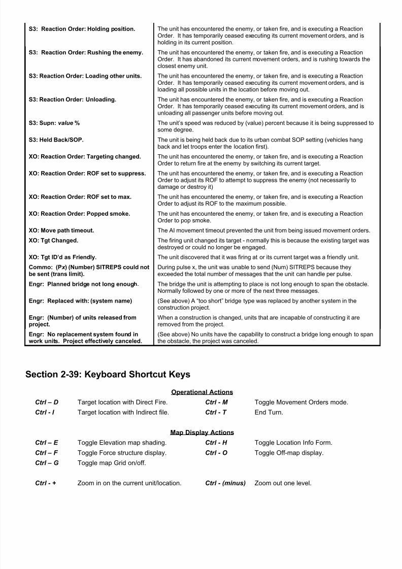
7/21/2019 TSS User Manual
http://slidepdf.com/reader/full/tss-user-manual 332/492
S3: Reaction Order: Holding position. The unit has encountered the enemy, or taken fire, and is executing a ReactionOrder. It has temporarily ceased executing its current movement orders, and isholding in its current position.
S3: Reaction Order: Rushing the enemy. The unit has encountered the enemy, or taken fire, and is executing a ReactionOrder. It has abandoned its current movement orders, and is rushing towards theclosest enemy unit.
S3: Reaction Order: Loading other units. The unit has encountered the enemy, or taken fire, and is executing a ReactionOrder. It has temporarily ceased executing its current movement orders, and isloading all possible units in the location before moving out.
S3: Reaction Order: Unloading. The unit has encountered the enemy, or taken fire, and is executing a ReactionOrder. It has temporarily ceased executing its current movement orders, and isunloading all passenger units before moving out.
S3: Supn: value % The unit’s speed was reduced by (value) percent because it is being suppressed tosome degree.
S3: Held Back/SOP. The unit is being held back due to its urban combat SOP setting (vehicles hangback and let troops enter the location first).
XO: Reaction Order: Targeting changed. The unit has encountered the enemy, or taken fire, and is executing a ReactionOrder to return fire at the enemy by switching its current target.
XO: Reaction Order: ROF set to suppress. The unit has encountered the enemy, or taken fire, and is executing a ReactionOrder to adjust its ROF to attempt to suppress the enemy (not necessarily todamage or destroy it)
XO: Reaction Order: ROF set to max. The unit has encountered the enemy, or taken fire, and is executing a ReactionOrder to adjust its ROF to the maximum possible.
XO: Reaction Order: Popped smoke. The unit has encountered the enemy, or taken fire, and is executing a ReactionOrder to pop smoke.
XO: Move path timeout. The AI movement timeout prevented the unit from being issued movement orders.
XO: Tgt Changed. The firing unit changed its target - normally this is because the existing target wasdestroyed or could no longer be engaged.
XO: Tgt ID’d as Friendly. The unit discovered that it was firing at or its current target was a friendly unit.
Commo: (P x ) (Number) SITREPS could notbe sent (trans limit).
During pulse x, the unit was unable to send (Num) SITREPS because theyexceeded the total number of messages that the unit can handle per pulse.
Engr: Planned bridge not long enough. The bridge the unit is attempting to place is not long enough to span the obstacle.Normally followed by one or more of the next three messages.
Engr: Replaced with: (system name) (See above) A “too short” bridge type was replaced by another system in theconstruction project.
Engr: (Number) of units released fromproject.
When a construction is changed, units that are incapable of constructing it areremoved from the project.
Engr: No replacement system found inwork units. Project effectively canceled.
(See above) No units have the capability to construct a bridge long enough to spanthe obstacle, the project was canceled.
Section 2-39: Keyboard Shortcut Keys
Operational Actions
Ctrl – D Target location with Direct Fire. Ctrl - M Toggle Movement Orders mode.
Ctrl - I Target location with Indirect file. Ctrl - T End Turn.
Map Display Actions
Ctrl – E Toggle Elevation map shading. Ctrl - H Toggle Location Info Form.
Ctrl – F Toggle Force structure display. Ctrl - O Toggle Off-map display.
Ctrl – G Toggle map Grid on/off.
Ctrl - + Zoom in on the current unit/location. Ctrl - (minus) Zoom out one level.

7/21/2019 TSS User Manual
http://slidepdf.com/reader/full/tss-user-manual 333/492
Game/File Actions
Ctrl - A Save file As. Ctrl - P Load pre-made Scenario.
Ctrl - L Load a game file. Ctrl - S Save current game.
Ctrl - N New game from scratch. Ctrl - X Exit.
Ctrl - 1 Load the “last loaded” file. Ctrl - 2,3,4,5 Load the “last loaded” files 2-5.
Staff Officers
F1 S-1 (Personnel). F6 Engineer
F2 S-2 (Intelligence). F7 Fire Support Officer (artillery).
F3 S-3 (Operations). F8 Air Liaison Officer (airstrikes).
F4 S-4 (Supply). F9 Communications
F5 XO (Targeting).

7/21/2019 TSS User Manual
http://slidepdf.com/reader/full/tss-user-manual 334/492
Part Three: Modeling and Simulation
This section of the manual will describe the modeling system and technical details incorporated into the simulation. Someof these topics may be referenced elsewhere in the manual; but they are presented here in greater detail.
If you want to know how or why something is working the way it is, this is the part to read.
Ed note: I’ve tried to keep the equations and math to a minimum and focus on how the routines operate in general. Onoccasion, however, I’ve included them just to illustrate the depth of the simulation.
Section 3-1: The Turn/Pulse Sequence
Within the simulation, actual time is broken down into a series of turns, each of which is comprised of a number ofcombat pulses. Turns are used to control how often users are given the opportunity to issue orders to their force, whilecombat pulses (or just pulses) are used to determine the time between situational “snapshots” in which combat andmovement take place.
These divisions allow the user to set a balance between the level of realism and accuracy and the length of time thesimulation needs to run to produce these results and how much effort is required of the player. The relationships are:
Short Turn: (Pro) Better player control over force actions
(Con) Longer games with more player interaction required.Short Pulse: (Pro) Higher resolution and accuracy
(Con) Increased scenario execution time.
Long Turn: (Pro) Shorter games with less player effort required.(Con) Reduced player control.
Long Pulse: (Pro) Quicker combat processing time.(Con) Reduced accuracy.
For example, if a turn is set to 2 pulses, the control over the force will be much greater than if a turn was set to 4 pulses.But the shorter turn setting will require twice as much player effort to complete the scenario. Likewise, if the pulseduration is set to 5 seconds, the combat accuracy and resolution will be very high, but the scenario will take much longerfor the user to complete than if the pulse duration were set to 30 seconds.
However, it is worth noting that the simulation keeps track of things down to the second when determining rounds fired,distance traveled, command delay elapsed or any of the other time-determined game functions, no matter what the turn orpulse settings are.
3-1.1 The Turn SequenceEach turn is comprised of a command phase for each force, followed by a number of combat pulses. The number ofpulses per turn is set at the start of the scenario, and is normally roughly based on the game scale.
During the command phase, a player (either human or AI) can view the known actions from the last turn (subject to Fog ofWar), consult with his staff, and/or issue orders to units within his force. There is no set sequence for these activities; theycan be done at any time, multiple times, or not at all. Thus a player could view the combat replay, issue some orders, andthen go back to the replay again and then end the command phase without checking with his staff.
The staff is used primarily to present information on the status of friendly and enemy forces, and provide an easy way toselect critical items such as fire missions or units for action. The staff also provides a basic level of commentary, and maysometimes offer suggestions.
Orders are commands given to units to perform some combat task or reconfiguration. Examples include giving movementobjectives, assigning DF targets, calling for fire support, or changing any part of a unit’s combat posture such as facing,speed, or NBC protective level. In some cases, a command delay will be imposed before the order is executed; thisrepresents the time it takes in real life to transmit the order down the chain of command and to complete it.

7/21/2019 TSS User Manual
http://slidepdf.com/reader/full/tss-user-manual 335/492
Additionally, at the start and end of each turn, the computer performs certain “housekeeping” operations such asassigning DF targets and IF missions when applicable, and updating the weather conditions. These routines are not runin each pulse due to the substantial length of time they often take to execute.
The actual sequence is as follows:
1. Player #1 command phase.2. Player #2 command phase.3. AI sets DF targets as applicable for both players.4. AI sets IF missions as applicable for both player.5. Combat Pulses (variable number determined at start of scenario).6. Turn replay saved for later viewing by either player.7. Weather conditions are adjusted.8. A check is made to determine if the scenario is over, and if so, the results are shown.
3-1.2 The Combat Pulse SequenceDuring the combat pulse, the computer takes complete control of the scenario and executes the movement and combatactions that are determined to occur during the “real-time” duration of the pulse.
The combat actions and activities within a pulse occur as follows:
1. IF/artillery missions are fired.2. Radar detection is attempted against enemy aircraft and en-route units.
3. DF is fired.4. The movement phase is executed, including engineering work and Opportunity Fire.5. Standard detection (visual/IR/acoustic) is performed for all enemy (and friendly) units.6. The effects of repair efforts against damaged radars and gun systems is judged and applied.7. Terrain fires are adjusted and spread.8. Illumination is adjusted (from flares, ambient illumination, terrain fires, etc.)9. Smoke is produced from wrecks and fires, and existing smoke drifts/dissipates.10. Chemical contamination is adjusted for location and conditions.11. Units are assigned as “acting” HQ’s when necessary to cover combat losses or other conditions.
3-1.3 The Movement PhaseThe movement phase is broken down into several steps, which determine when and in what order units move or performother tasks.
1. All units not En-route move first. This includes just about everything except missiles of one sort or another, andthis is also when these units will perform other operations such as engineering actions and MOPP level changes.
2. All En-route units that are not attempting to intercept another En-route unit move next. En-route units attemptingto intercept a normal unit, such as a SAM trying to intercept an aircraft, move during this step.
3. Lastly, En-route units trying to intercept other En-route units move.4. If an En-route unit moving in either step #2 or # 3 reaches its destination, or narrows the range to its target to near
zero, the missile will stop moving and attack. Attacks are made using the standard procedures for accuracy anddamage based on the “ammunition” values for the En-route unit.
Section 3-2: Firing Weapons
Weapon firing is dividing into two general categories, based on whether or not the firing unit can see its target. If thetarget can be seen and aimed at, it is classified as “Direct Fire” (DF), otherwise it is known as “Indirect Fire” (IF).
3-2.1 Direct Fire (DF)Direct Fire is used when the firing unit can directly aim at its intended target. As an example, a rifleman aiming and firingat an enemy target uses DF. Usually, a unit using DF will be able to visually see its target. However, there are timeswhen this will not be the case. An example would be engaging a target several hundred meters away in a dense fog. Thetarget will not be visible to the naked eye, but it could show up clearly with a thermal sight. Thus, the thermal sight allowsthe fire to be directly aimed, and thus DF.

7/21/2019 TSS User Manual
http://slidepdf.com/reader/full/tss-user-manual 336/492
DF can be used against any target type, including area/point locations, enemy units or weapons systems, or objects suchas buildings and obstacles. It can also be used as “area fire” against a general location, which may or may not containother “unknown” targets.
DF can be used by all munition types, powered or not, guided or not, or even physical or not (e.g., energy weapons).
All Gun/Launcher systems have the capability of using DF; no specific data settings are required.
DF is resolved in four basic steps:
• The firing parameters are calculated and checked to be both physically possible and within the firing unit’slimitations.
• The total number of rounds to be fired is determined, and the rounds are fired one at a time.
• The round either impacts immediately (as in the case of a tank main-gun round) or a temporary en-route unit iscreated (as in the case of a missile).
• If an impact or detonation is achieved, the results are assessed against all applicable targets.
The first step in the DF process is to determine the firing parameters. If any step in this sequence cannot be successfullyachieved, the firing is aborted. The steps are:
• The firing unit is checked to determine if it must be emplaced (the requirement and time to be emplaced are part ofthe Weapons System Data).
• The target is checked to make certain it exists and is valid.
•The firing weapons are checked for damage, including the firing control and target acquisition systems. In somecases the weapon may still fire, even with damage, but at reduced capabilities.
• The firing unit is checked that the correct ammunition is on-hand and available to fire.
• The range to the target is checked to be within the minimum and maximum values for the ammunition type (theseranges are part of the Ammunition Data).
• The firing unit is checked to make sure that the weapon, or one mounted coaxially with it, hasn’t already fired atanother target (coax weapons are set as part of the Weapons System Data).
• The weapon is checked for capability to engage either surface or air targets (capability is part of the WeaponsSystem Data).
• If the firing unit is in an IP (or building), the firing weapon is checked for back-blast production, and if so, that the IPallows for safe back-blast dissipation. Additionally, the open firing arc of the IP is checked to insure that it coversthe target’s location (back-blast is part of the Ammunition Data, safe back-blast dissipation and firing arcs are partof the IP Data).
• If the target occupies an IP, it cannot be engaged unless there is an opening in the IP wall in the direction of thefiring unit. However, the IP itself can still be engaged (and the unit inside can suffer collateral damage).
• The LOS (Line of Sight) between the firing unit and the target is checked to be valid. If the LOS is completelyblocked (by hitting the ground, terrain, etc.), the target cannot be engaged and the procedure is aborted. For long-range LOS determinations, the curvature of the earth may also block the LOS.
• The hull/turret facing is checked against the direction to the target. The target must be within the gun’s Firing Arc(part of the Weapon Systems Data), otherwise the hull or turret will require rotation before the weapon can be fired.Should rotation be required, however, a reduction will be made in the number of rounds actually fired tocompensate for the rotation action.
• If the object being fired is a physical entity, a Flight Path to the target is determined. The flight path must not hit theground, and must be free of all terrain obstacles (the height of terrain and obstacles is part of the TEC Data). Flightpaths are discussed in a separate section, but are calculated differently for ballistic (non-powered) projectiles, andthose with a means of propulsion (powered). Flight paths are not used for non-physical “ammunition” such as
lasers and energy weapons.• If the object being fired is guided, the firing unit is checked for potential command limits to make sure it never hasmore in the air than it can control (command limits are part of the Gun/Missile Launcher Data).
Once the firing parameters have been determined, and all aspects are acceptable, the rounds are fired. The exactnumber of rounds that will be fired in a combat pulse depends on a number of factors:
• The capabilities of the gun/launcher system (the maximum ROF in rounds per minute for each gun/launcher is partof the Weapons System Data).
• The firing unit’s SOP setting (part of Unit Data).
• The number of rounds remaining on-hand.
• If the firing unit must turn to face the target before firing, the number of rounds will be reduced to account for thetime used to make the facing change.

7/21/2019 TSS User Manual
http://slidepdf.com/reader/full/tss-user-manual 337/492
• If a CAS mission is in progress near the firing unit, the ROF will be reduced, even if the firing unit is not the target ofthe airstrike.
• If the firing unit has a firing-control system and it is destroyed, the number of rounds fired is decreased by 75-95%.If it is damaged, the number of rounds fired is decreased by 25-75%.
• If the firing unit is not an aircraft, the amount of acquisition (number of seconds this particular target has beenengaged by this gun/launcher) is compared to the firing unit’s internal friction time. If the ratio is less than 2.0, thenumber of rounds fired is reduced exponentially (i.e., the loss is much greater at smaller ratios than those closer to2.0) by up to 90%. Leaders assigned to the unit modify its friction time.
• The LOS blocking points reduce the number of rounds fired proportionally (i.e., 60% LOS blocking reduces the
number of rounds fired by 60%).• If the firing weapons system is co-located (“stacked”) with other weapons systems, its fire may be “masked”, whichhas the effect of lowering the ROF. The ROF decrease is proportional to the percentage “over stack” in thelocation. So, for example, if the normal stacking limit is 24 vehicles, and there are 30 in the location, ROF valueswill be reduced 25% (6 extra divided by the base of 24). The base “limits” based on 100 meters per location, areshown below. These limits are modified by the stacking factor for the terrain in the location as defined in the TEC.
o Personnel: 120
o Guns: 20
o Vehicles: 24
o Aircraft: 4
o Ships/Naval craft: 2
En-route and impact effects are described separately below.
3-2.2 Indirect Fire (IF)Indirect Fire is similar to Direct Fire (DF), but is used when the firing unit cannot see its intended target, and/or cannotdirectly aim at it. As an example, an artillery unit firing at a target out of sight behind a ridgeline must use IF. Indirect Firecan be used against any target type, including area/point locations, enemy units or weapons systems, or objects such asbuildings or obstacles. It can also be utilized by all munition types, be they powered or not, or guided or not, or evenphysical or not (e.g., energy weapons).
However, in order to fire IF a gun/launcher system must specifically be given that capability as part of the Gun/LauncherData.
IF is resolved almost exactly like DF, with the exception that LOS considerations are ignored. The firing unit does notneed to see its target, although accuracy may be increased if it does, but because of that, the firing is directed rather than
aimed.
3-2.2.1 Spotting FireIn practice, a common procedure known as “successive bracketing”, or simply “bracketing” is used to adjust the fire onto aspecific target. It begins when the firing unit fires a single round. The spotting unit observes the impact point, anddetermines its position relative to the actual target. The spotting unit then sends the firing unit a correction designed to“over-compensate” somewhat for the difference. The firing unit makes the necessary changes and fires another round.The spotting unit observes the impact, sends back a correction (usually much less than the first one), and the process isrepeated until the rounds are impacting on the target. At that point the spotting unit calls for FFE (fire for effect), and theactual mission commences.
There are several different methods to adjust fire, depending on the situation and the initial accuracy, but in all cases anobserver calls back adjustments to the firing unit, making the FFE more accurate than if it were fired without any
adjustments at all. Examples are shown below. In the simulation, the AI decides which method to use, based on thesituation.

7/21/2019 TSS User Manual
http://slidepdf.com/reader/full/tss-user-manual 338/492
Figure 348: Successive bracketing.
Figure 349: Hasty bracketing.
Figure 350: Creeping Fire.
In order for the calling unit to spot the fire, it must have a LOS to the target, be in a normal morale state, and havecommunications back to the FDC. If any of these conditions are “lost” during the adjustment phase, the AI will eitherimmediately begin FFE or cancel the mission depending on the current accuracy and whether or not the rounds requirethe target to be painted/designated.
In general, there are no benefits of spotting fire against area targets; the initial accuracy is going to be good enough tocover the intended impact area, even if some number of rounds may fall outside it. However, spotting is definitelynecessary to engage a point target, such as a unit, building, bridge, IP, obstacle or other object.
Spotting is also required for guided rounds. In this case the spotting unit becomes the painting unit and keeps thetargeted illuminated by a LASER or other designation device.
3-2.3 Anti-Aircraft Fire (AA) Anti-Aircraft Fire is fire directed from ground units against air targets such as aircraft, or En-route missiles and rockets.While AA fire is not a fundamental type, within the simulation it is handled in a separate phase, and has distinguishingcharacteristics from simple DF or IF.
AA fire can only be directed against targets “known” to the firing unit. However, the target does not have to be in the LOS,or currently spotted by the firing unit. Instead, it is enough that the firing unit’s radar may have detected the target (whichmay be possible even if the target is over the horizon or behind an object that would block the LOS), or that information onthe target has been reported to the firing unit by some other friendly unit using the report dissemination procedure.

7/21/2019 TSS User Manual
http://slidepdf.com/reader/full/tss-user-manual 339/492
Additionally, AA fire may be either DF or IF, subject to the capabilities of the firing weapons and the situation at the time offiring. In some cases, a guided weapon may require a controller unit with a visual or radar “lock” on the target, and/or apainting unit that can illuminate the target using a laser or similar device.
AA fire can occur either during the movement phase of the turn as aircraft units move from location to location, or as partof the normal firing phase if the target aircraft unit is hovering/stationary. When AA fire occurs in the movement phase, allaspects of the targeting procedure are computer controlled, although the unit’s SOP will be used if applicable. Thenumber of rounds to fire is generally set at 30% of the weapon maximum, so that the weapon can either engage this orother targets again in the same movement phase.
Additionally, when a unit fires AA fire as part of the movement phase, the firing gun/weapon system will be unavailableduring the normal firing phase.
3-2.4 Opportunity FireOpportunity Fire is a term used to describe a special situation where DF is used against a moving ground unit in themovement phase. It is used to prevent target units from “skirting through” defensive fire zones by being able to movecompletely though them in one movement pulse.
For example, Opportunity Fire can be used to engage a unit crossing a road cut through a forest, where the moving unitwill only be visible for a brief time. Without Opportunity Fire, the moving unit might well be able to move into the roadlocation, then also into the woods on the other side within one pulse. Thus, it would not be able to be engaged in theopen road location by the defending forces, even if they were placed to fire down the length of the road. With OpportunityFire, however, the unit can be engaged in “mid-move” as it enters the road, without the cover and concealment benefits
provided by the forest.
The use of Opportunity Fire is restricted, though, since it represents the situation where the defending unit is already setto fire on a specific location, and thus is watching and waiting for the enemy to first appear. The conditions are as follows:
1. The target unit must be moving between locations on the map, since Opportunity Fire is determined at the instanta unit moves into a new location. Units moving within the same map location are not subject to Opportunity Fire.Units moving offmap are also never subject to Opportunity Fire.
2. The firing unit must have an assigned DF Target that includes the moving unit’s location. DF Targets are firecontrol measures assigned at the beginning of the scenario to applicable forces and units.
3. The specific firing guns/launchers must not have been fired in the preceding IF, DF, or AA phases.4. The moving unit must be detectable and able to be engaged by DF by the firing unit. The detection does not have
to be by visual means, but a valid LOS must exist between the firing unit and target.5. All of the normal conditions applying to DF must be met.
3-2.5 Flight pathsThe flight path is a course (through the air) traced out by a moving object. In the case of DF or IF, it refers specifically tothe path along which a projectile or missile moves. The flight path begins at the instant of firing/launch, and ends whenthe projectile’s movement stops at an impact or detonation point. The flight path characteristics are calculated every1/1000th of a second, and provide the projectile’s velocity vector (speed plus direction) and 3-dimensional position.
The flight path calculations depend primarily on whether the projectile is powered, and to a lesser extent, whether it isguided.

7/21/2019 TSS User Manual
http://slidepdf.com/reader/full/tss-user-manual 340/492
Figure 351: Basic flight paths.
3-2.5.1 Ballistic (un-powered) Projectile Flight PathsThis classification includes all projectiles that do not receive significant thrust after the initial launch sequence. Exampleswould be small arms, most tank gun rounds, ballistic rockets and even rocket-assisted artillery. For the purposes of thisclassification, relatively small thrust amounts used only to guide the projectile are ignored.
After being fired, un-powered projectiles follow a standard ballistic trajectory; their path is determined from the constanteffects of air drag and gravity.
Note that there are often two unique firing elevation angles that will hit the target. When deciding which one to use, the
simulation first checks to see if they are within the firing weapon’s limits. If one of them is too high or low, the other isused by default. Otherwise, if both angles are valid and the resulting flight paths are clear, the higher angle is normallyused for IF and the lower for DF.
3-2.5.2 Powered/En-route Object Flight PathsPowered projectiles generate their own thrust for a majority of their flight path. As a result, they do not have to follow aballistic path, and in fact, rarely do. In most cases, powered projectiles are also guided. Examples of powered projectilesinclude most missiles, some rockets, and special systems like RPV’s or cruise missiles that are used to carry a payload.
Powered projectiles follow an “optimal” flight path, which is determined initially at the time of firing based on the projectile’scurrent position, the location of the target, and the weapon maximum/minimum firing elevation (up/down angle). If theprojectile is guided, the path is constantly reevaluated while it is in the air so it will attempt to compensate for target

7/21/2019 TSS User Manual
http://slidepdf.com/reader/full/tss-user-manual 341/492
movement, or otherwise changed conditions. The amount of compensation is based on the effectiveness of theprojectile’s guidance system under the conditions at the start of the movement phase.
Figure 352: Powered In-flight units follow simple flight paths. If the in-flight munition is guided, the flight path isperiodically adjusted to account for target movement.
7/21/2019 TSS User Manual
http://slidepdf.com/reader/full/tss-user-manual 342/492
Note that initially the flight path is calculated as one or two straight lines. This path represents the optimal combination ofthe missile’s climb and dive capabilities, which determines if the missile will be able to avoid obstacles. Should anobstacle block this initial (best) flight path, the target cannot be engaged.
In the case of a flight path with both up and down segments, the high altitude achieved at the “peak” also provides addedflexibility to respond to changed conditions. As the missile actually moves, however, it may level off at a reduced cruisealtitude (the cruise altitude is part of the missile data).
3-2.5.3 Firing Angles
For both powered and un-powered projectiles, the firing angle of the gun or launcher determines the initial flight path. Theangle must be set to a value that allows the target to be hit but which is also within the limits of the firing weapon. In orderto determine this angle, the program takes into account several factors:
• The absolute elevations of the firing unit and the target.
• The physical characteristics of the projectile (velocity, thrust, guidance, etc.).
• The type of flight path (ballistic, non-ballistic).
• The incline of the firing platform (from the ground only).
• Clearance of obstacles (hills, terrain, buildings, etc.).
• The maximum depression and elevation angles of the gun or launcher.
• At long ranges, the curvature of the Earth.
Based on these factors, the program calculates the “best” possible firing angle and subsequent flight path. If the flightpath cannot reach the target, or intersects the ground or an obstacle, the launch will be aborted.
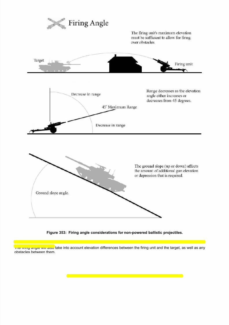
7/21/2019 TSS User Manual
http://slidepdf.com/reader/full/tss-user-manual 343/492
Figure 353: Firing angle considerations for non-powered ballistic projectiles.
The firing angle will also take into account elevation differences between the firing unit and the target, as well as anyobstacles between them.

7/21/2019 TSS User Manual
http://slidepdf.com/reader/full/tss-user-manual 344/492
Figure 354: Simple and complex ballistic paths for un-powered projectiles.
3-2.6 Actions at Firing/Launch At the instant a projectile is fired or launched, the following sequence of events is executed:
• A check is made for a malfunction in the gun or launcher. The probability of this occurring is the “reliability” value inthe gun launcher data. If a malfunction occurs, the firing is aborted at that point before the round is expended orany further results are applied. Gun/launcher reliability is part of the Gun/Launcher Data.
• Otherwise, firing occurs and the round (or burst) is subtracted from the on-hand ammunition quantity of the firingunit.

7/21/2019 TSS User Manual
http://slidepdf.com/reader/full/tss-user-manual 345/492
• If the munition creates an en-route unit, that temporary unit is created in the firing unit’s location. The en-routeunit’s speed will be equal to the ammunition muzzle velocity, its facing set to the facing of the firing weaponssystem, and its elevation to that of the firing unit plus one meter. At the moment the en-route unit is created, allenemy radars get a special chance to detect it using the standard radar detection sequence. En-route units thenuse the normal movement routines (with the computer controlling altitude and course), until they reach theirintended target.
• If the projectile does not create an en-route unit, it is assumed to arrive at its target in the same pulse as it is fired.
3-2.7 Weapon/Round Accuracy
Accuracy is the probability that a munition will hit its intended target. As described in this section, accuracy is meant asthe hit probability determined at the time the round will impact or otherwise affect its intended target. Thus, it is differentand separate from “accuracy” as used to determine how effective an En-route unit is in flying along a pre-determined flightpath, or homing in on its target. That aspect for guided munitions is covered later in its own section.
3-2.7.1 General All non en-route munitions are assigned an “accuracy curve”, which gives the absolute accuracy of hitting a standardsized target (5 square meters) at various ranges (expressed as a percent of the maximum range). An example of anaccuracy curve is shown below.
Figure 355: An example of a typical ammunition accuracy curve (accuracy vs. range). Note that accuracy values
can be greater than 100%; this indicates that a target smaller than the standard size (5 sq. meters) can beeffectively hit 100% of the time at that range.
Based on the range to the target, the initial accuracy value is determined from the graph plot. In the example above, if thetarget were at 55% of the ammunition’s maximum range, the initial accuracy would be 65% - meaning 65 rounds out ofevery 100 fired would hit a standard target, defined as measuring 5 square meters.
3-2.7.2 En-route Unit (Missile) Initial AccuracyThe initial accuracy of an En-route unit (at the time of launch) is determined as for a standard round, using the ammunitionaccuracy curve. This value is then modified for the gun/launcher and weapons system accuracies.

7/21/2019 TSS User Manual
http://slidepdf.com/reader/full/tss-user-manual 346/492
Guided En-route units can also use their accuracy rating during the movement pulse to determine how successful theyare at tracking on a moving target. In these cases the accuracy value will usually also change over time, as conditionschange. For example, the accuracy will be greatly lowered if a radar homing missile is jammed, or if the missile’s guidancesystem becomes damaged. Conversely, the missile’s accuracy will likely increase as the range to the target drops. Thiswill be discussed further in the sections on guided munitions, below.
3-2.7.3 Guided MunitionsGuided munitions are capable of making course corrections to improve their accuracy against either stationary or movingtargets. The guidance may be completely internal (e.g., a heat-seeking missile), completely external (e.g., an optically
tracked wire guided missile), or a combination of both (e.g., a missile that sends video pictures back to a controlling unit).
If the guidance system has an external component, it will also have at least one link back to a remote controller of sometype. Links are often radio or wire, and are used to transmit commands and other information between the missile and thecontrolling unit. If the link is broken, disrupted or jammed the missile will lose its guidance capability. The loss may bepermanent or not depending on the system, but it will always last at least until the link is restored.
Additionally the guidance may be passive or active. Passive types detect something emitted by the target and home in onthe signal (e.g., an “anti-radiation” missile that homes in on active radars). Active systems generate their own signals ofsome type, and use them to detect and guide in on the target (e.g., a “fire & forget” radar guided missile).
Guided munitions can change course along their flight path to track and home in on moving targets, and to make generalcorrections.
If a guided munition has several guidance systems available, the computer will automatically pick the best one based onthe current situation and conditions.
3-2.7.3.1 InternalInternal guidance systems are contained completely within the munition itself, and do not require any form ofcommunication link to an external controller. As a result, these systems are often known as “fire and forget”, since oncethe munition are launched the firing units do not need to further interact with them in any way.
3-2.7.3.2 Controlling UnitIf the en-route munition requires any type of external guidance, the unit that provides it is known as the controlling unit.Often times the controlling unit will be the firing unit, but that is not a requirement. For example, a fighter could fire a long-range missile that could then be guided by a friendly AWACS aircraft, in which case the AWACS is the controlling unit -
not the fighter.
However, the controlling unit must have a valid communications link to the munition, or the guidance will suffer. Additionally, if the controlling has a guidance command limit it will not be able to control more than that number ofmunitions at the same time.
The controlling unit must also be in a normal morale state (i.e., not running for cover, wavering, broken or berserk).
In some cases, the communications link for a particular munition is vulnerable to jamming. This will be specified in the Ammunition Types Data Table.
The computer automatically assigns the controller unit for an en-route munitions at launch, and may “pass off” control asnecessary to other eligible units, or to improve accuracy.
3-2.7.3.3 Painting Unit A painting unit uses some form of marking device, usually laser, to specifically identify the target to the incoming guidedmunition. The sensor in the munition “sees” the marking, and homes in on it. A common example of this type of weaponis a laser-guided bomb, but many other munitions are guided this way including missiles and artillery rounds.
If a munition requires the target to be painting but no unit is available with painting capability, the accuracy of the munitionbecomes almost zero and it will impact randomly within some distance of the intended target. The maximum distanceaway it can land, or offset radius, depends on how much painting the target received before impact, and when thatpainting occurred. For example, if the target was well painted until only a few seconds before impact, the offset radius willbe low, and the munition will still have a good chance of hitting the target or at least landing very close. However, if the
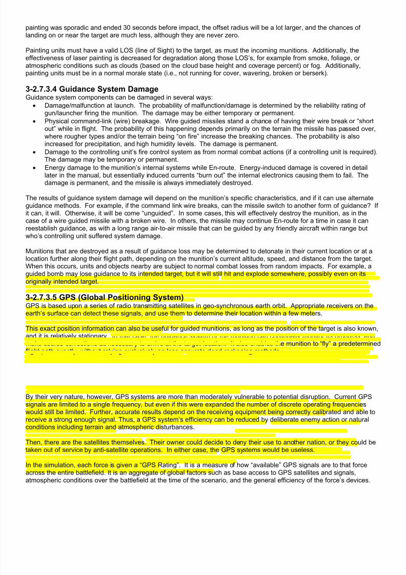
7/21/2019 TSS User Manual
http://slidepdf.com/reader/full/tss-user-manual 347/492
painting was sporadic and ended 30 seconds before impact, the offset radius will be a lot larger, and the chances oflanding on or near the target are much less, although they are never zero.
Painting units must have a valid LOS (line of Sight) to the target, as must the incoming munitions. Additionally, theeffectiveness of laser painting is decreased for degradation along those LOS’s, for example from smoke, foliage, oratmospheric conditions such as clouds (based on the cloud base height and coverage percent) or fog. Additionally,painting units must be in a normal morale state (i.e., not running for cover, wavering, broken or berserk).
3-2.7.3.4 Guidance System Damage
Guidance system components can be damaged in several ways:• Damage/malfunction at launch. The probability of malfunction/damage is determined by the reliability rating ofgun/launcher firing the munition. The damage may be either temporary or permanent.
• Physical command-link (wire) breakage. Wire guided missiles stand a chance of having their wire break or “shortout” while in flight. The probability of this happening depends primarily on the terrain the missile has passed over,where rougher types and/or the terrain being “on fire” increase the breaking chances. The probability is alsoincreased for precipitation, and high humidity levels. The damage is permanent.
• Damage to the controlling unit’s fire control system as from normal combat actions (if a controlling unit is required).The damage may be temporary or permanent.
• Energy damage to the munition’s internal systems while En-route. Energy-induced damage is covered in detaillater in the manual, but essentially induced currents “burn out” the internal electronics causing them to fail. Thedamage is permanent, and the missile is always immediately destroyed.
The results of guidance system damage will depend on the munition’s specific characteristics, and if it can use alternateguidance methods. For example, if the command link wire breaks, can the missile switch to another form of guidance? Ifit can, it will. Otherwise, it will be come “unguided”. In some cases, this will effectively destroy the munition, as in thecase of a wire guided missile with a broken wire. In others, the missile may continue En-route for a time in case it canreestablish guidance, as with a long range air-to-air missile that can be guided by any friendly aircraft within range butwho’s controlling unit suffered system damage.
Munitions that are destroyed as a result of guidance loss may be determined to detonate in their current location or at alocation further along their flight path, depending on the munition’s current altitude, speed, and distance from the target.When this occurs, units and objects nearby are subject to normal combat losses from random impacts. For example, aguided bomb may lose guidance to its intended target, but it will still hit and explode somewhere, possibly even on itsoriginally intended target.
3-2.7.3.5 GPS (Global Positioning System)GPS is based upon a series of radio transmitting satellites in geo-synchronous earth orbit. Appropriate receivers on theearth’s surface can detect these signals, and use them to determine their location within a few meters.
This exact position information can also be useful for guided munitions, as long as the position of the target is also known,and it is relatively stationary. In that case, the guidance system of the munition can continually monitor its progress, andmake course corrections as necessary to arrive at the target location. It also enables the munition to “fly” a predeterminedflight path exactly, without relying exclusively on less accurate dead-reckoning methods.
While GPS can be used as a sole guidance source, it is often used in conjunction with other guidance methods so thatcompensation can be made for moving targets, or imprecise original target position information. In these cases, the GPSis used to get the munition “close” to the target, where other, more accurate/appropriate guidance types take over.
By their very nature, however, GPS systems are more than moderately vulnerable to potential disruption. Current GPS
signals are limited to a single frequency, but even if this were expanded the number of discrete operating frequencieswould still be limited. Further, accurate results depend on the receiving equipment being correctly calibrated and able toreceive a strong enough signal. Thus, a GPS system’s efficiency can be reduced by deliberate enemy action or naturalconditions including terrain and atmospheric disturbances.
Then, there are the satellites themselves. Their owner could decide to deny their use to another nation, or they could betaken out of service by anti-satellite operations. In either case, the GPS systems would be useless.
In the simulation, each force is given a “GPS Rating”. It is a measure of how “available” GPS signals are to that forceacross the entire battlefield. It is an aggregate of global factors such as base access to GPS satellites and signals,atmospheric conditions over the battlefield at the time of the scenario, and the general efficiency of the force’s devices.

7/21/2019 TSS User Manual
http://slidepdf.com/reader/full/tss-user-manual 348/492
Additionally, jamming equipment can be used to disrupt the enemy’s use of GPS signals, as will be discussed in the nextsection.
3-2.7.3.6 HomingHoming munitions require their target to emit some form of energy. The munition detects the energy, and aims for thecenter of the source. The most common forms of energy used for homing are radar signals, heat (IR), radio, light, andsound.
Homing munitions can often successfully tolerate interruptions in the energy source, especially if the target is stationary or
if the interruptions are short enough that the munition doesn’t lose the target from its field of vision. A prime example is aHARM missile that guides in on energy pulses emitted by enemy radar stations. The station does not emit energycontinuously, but because it is stationary or slow moving, the missile can home in on the last known pulse location withrelatively good results.
The “pulse rate” for radar transmitters is set to a default value when a scenario starts, but can be adjusted by the owningplayer for each radar unit in his force. It is worth remembering, however, that the pulse rate setting is a balance betweeneffectiveness and protection. On the one hand, a low pulse rate will protect the radar from HARM missiles, but on theother, it will also mean that the radar is less effective at detecting enemy aircraft.
Interruptions in energy emission/detection have the greatest effects on accuracy when they happen as the munition nearsthe target, although the simulation makes checks every second over the flight path, and adjusts the accuracy accordingly.The longer the interruption continues, or the faster the target is moving across the munition’s field of vision, the greater theaccuracy loss. If the loss is great enough the target will be lost altogether, and the missile will cease operation.
NOTE: Target “movement” as used by these routines is not absolute. Rather, it is relative to the munition’s field of vision,or in other words, how fast the target “appears” to be moving. For example, a truck in the distance does not appear to bemoving very quickly, while one moving at the same speed a few meters away seems to “flash” by. Likewise, the relativedirection of movement is important. A truck driving directly towards or away from an observer hardly appears to move atall, especially compared to one moving directly from right to left.
3-2.7.3.7 JammingJamming is the deliberate interruption or degradation of communications by the enemy. In terms of guidance systems,the intent is to break the command link so that the missile misses its intended target.
Jamming takes many forms. The most common type involves disrupting radio transmissions by simply overwhelmingthem with a stronger signal. But jamming can (and is) also used against other forms of communications. In fact, there are
methods to jam virtually every form of communications used on the battlefield. Radio interference has already beenmentioned, but other examples are laser defeating smoke screens and lasers that emit “fake” pulses, energy pulses thatcan short out wire-guidance systems.
However, while it is true every communications method can potentially be jammed, some methods are much more securethan others and, within the operational limits of the battlefield, can be virtually “jam-proof”. The simulation allows for thiswith a “Not Jammable” flag in the Guidance System portion of the Ammunition Classes Data Table. In the simulation, jamming is accomplished at two levels. At the force level, the force’s EW Rating is used to measure jamming capabilities across the entire battlefield. It represents equipment and personnel possessed by the combatformations and units that are not specifically represented in the Data Tables, including laser jammers/decoys, smoke, andotherwise undefined radio jammers. It also includes unconventional interference capabilities such as “home-grown” jammers made from modified radar detectors, or even otherwise non-EW units breaking into/overriding enemy radio
transmissions on their own.
The second level involves specific pieces of jamming equipment, known appropriately enough, as “jammers”. The abilityof a jammer against a particular form of communications signal is defined in the Jammer Data Table, along with its range,power, and other capabilities. Jammers may be assigned to special EW units, carried by a weapons system, or evendeployed remotely, by artillery or dropped by air. All systems that move within an appropriate jammer’s range will besubjected to disruption, based on the standard jamming procedures covered later in the manual.
3-2.7.3.8 DecoysDecoys are used to “confuse” guided munitions by effectively creating alternate targets that the munition must distinguishbetween. They range from “dummies” that are released by a parent system, to flares and chaff (strips of metal foil).

7/21/2019 TSS User Manual
http://slidepdf.com/reader/full/tss-user-manual 349/492
Each decoy will only be effective against certain types of guidance systems. For example, chaff is effective only againstradar-guided munitions. It will have no effect on an incoming heat-seeking (IR guided) missile. Likewise, flares maydisrupt an incoming heat-seeking missile, but they will not affect ammunition homing in on sound. The simulation breaksdecoy effectiveness down into the categories: heat/IR defeating (flares), radar defeating (chaff) , radar defeating ECM (thedecoy provides an “electronic signature”, rather than a physical one as with chaff), and noise defeating.
The computer uses decoys automatically whenever a missile is about to hit a target equipped with them. Each decoysystem is given an effectiveness rating, which is compared to the incoming missile’s electronics rating (based on the forceEW and Commo ratings) and accuracy. A determination is then made if the decoy “distracts” the missile, and if so, byhow much. A “distracted” missile may still detonate near enough to its target to cause damage, especially if the decoy isonly marginally effective, or a “last possible” second measure.
Decoys are defined in the Decoy Data Table, and assigned to weapons systems as “special systems” in the WeaponsSystem Data Table. Decoys may also be consumed with use, and if so, the parent system may eventually run out over aperiod of time. The consumption rates and amount of decoys on-hand are also set as part of the weapons system data.

7/21/2019 TSS User Manual
http://slidepdf.com/reader/full/tss-user-manual 350/492
3-2.7.3.9 Summary of Guided Munition Characteristics
GuidanceType
Guidance Link
General (applies toall situations)
* Wire * Radio * Beam * Internal(F&F)
Firing Unit External GPS Jamming
Video Camera is alwaysassumed to be inthe missile. Accuracy degradedby the LOSbetween missile andtarget.
Accuracyreduced ifcontrollerdoesn’thave a LOSto the targetat any time
Accuracyreduced ifspotterdoesn’thave a LOSto the targetat firing
Accuracyreduced ifspotterdoesn’thave a LOSto the targetat firing
Missile mustmaintain aLOSthroughoutflight, unlessGPSpresent.
Noadditionalspecificeffects.
Noadditionalspecificeffects.
GPS low(0.5) butalso offsetsaccy lossesfromdegradedLOS (1/2norm).
Jammingharder thanavg (0.5).
IR IR cameras alwaysassumed to be inthe missile. Accuracy isdegraded for LOSbetween missile andtarget (2/3 normaldegradation).
Accuracyreduced ifcontrollerdoesn’thave a LOSto the targetat any time.
Accuracyreduced ifcontrollerdoesn’thave a LOSto the targetat firing
Accuracyreduced ifcontrollerdoesn’thave a LOSto the targetat firing
Missile mustmaintain aLOSthroughoutflight unlessGPSpresent.
Noadditionalspecificeffects.
Noadditionalspecificeffects.
GPS low(0.5), butalso offsetsaccy lossesfromdegradedLOS (1/3norm).
Jammingharder thanavg (0.5).
Radar RADAR in either themissile or controllingunit. RADAR mustmaintain lockthroughout flight.
Noadditionalspecificeffects.
Noadditionalspecificeffects.
Noadditionalspecificeffects.
Radar inmissile(missilemustmaintainlock)
Radar infiring unit(unit mustmaintainlock)
Radar inexternal unit(air orgrounddependingon launchlocation)
GPS avg(1.0).
Jammingeasier thanavg (1.5).
Laser Detector in themissile. Laser “spot”from firing unit oranother unit (needsan LOS to thetarget). Missileneeds LOS at anypoint within last200m of flight path.
Notavailable
Notavailable
Notavailable
Always Yes Notavailable
Notavailable
GPS muchhigher thanavg (1.75).
Jamminglittle easierthan avg(1.25).
Visual Firing unit’s sights(IR, thermal, etc.)are used to “spot”target.
Controller must havevalid LOS to boththe missile andtarget at all times.
Noadditionalspecificeffects
Noadditionalspecificeffects
Noadditionalspecificeffects
Cannotselect.
The firingunit is thedefaultcontroller,and cannotlater switchcontrol toanother unit.
At firing, anexternalcontrol cantake over forthe durationof themissile’sflight.
GPSnegligible(0.0).
Jammingmuch harderthan avg(.25).
Radiation Radiation detectorcan be in either themissile or thecontrolling unit.Detector mustmaintain an LOS totarget throughoutthe flight. If thetarget’s radar is “off”at the time of impact,the accy is lowered.
Noadditionalspecificeffects
Noadditionalspecificeffects
Noadditionalspecificeffects
Detector inmissile(missilemustmaintainlock)
Detector infiring unit(unit mustmaintainlock)
Detector inexternal unit(air orgrounddependingon launchlocation)
GPS avg(1.0).
Jamming alittle easierthan avg(1.25).
General - If a unit controlsthe missile, thatunit’s status (morale,suppression,training, etc.) affectsaccuracy. Brokenunits cannot control
guided missiles.
- Alwayscontrolledby firingunit. Cannot becontrolledby an
externalsource.
- The wirelink can bebroken byterrain, fire,etc.
- GPS lowerthan avg(0.5).
- Jammingmuchharder thanavg (0.25).
- If controllerunit doesnot have aLOS to themissile,accuracy isdecreased a
little.- GPS avg(1.0).
- Jammingeasier thanavg (1.5).
- Controllingunit mustalways havea LOS tothe missile.
- GPS avg(1.0).
- Jammingmuchharder thanavg (0.1).
- No otherlinks:completely“Fire &Forget”.
- GPS muchhigher than
avg (2.0).
- NoJamming(0.0). (ECMwill stillapply).
-If missilecontrol can’tbe shifted toan externalunit, it isaffected bycombat
actionsagainst thefiring unit.
-Must havea guidancelink otherthanInternal.
- GPS avg(1.0).
- Jammingavg (1.0).
- AnExternalcontroller isusedwheneverpossible.
- Must have
a non-internalguidancelink.
- GPS littlehigher thanavg (1.25).
- Jamminglittle easierthan avg(1.25).
- If GPS isnotavailable, ordegraded,theaccuracy islowered for
missiles thatuse it.
- Jammingis slightlyeasier thanavg if GPSused (0.9).
- Jammingcapabilitiesdepend on aforce’s EWrating, aswell asspecific
jammingsystemspossessedby the target.
* = Only one primary guidance link can be selected for each missile system. For Internal (F&F) guided systems, Firing Unit and Extern have no effect, even if selected

7/21/2019 TSS User Manual
http://slidepdf.com/reader/full/tss-user-manual 351/492
3-2.7.3.10 SeekingSeeking is a capability of a munition to search an area and identify targets within that area and attack them. For example,a primary munition may be fired by an artillery piece to a certain location, where it deploys by parachute some distanceabove the ground. While descending, it uses a camera or other senor to detect targets nearby, and if it finds one, aimsand directs a secondary munition at that target.
The seek radius and effectiveness for ammunition models is specified in the Ammunition Data Table. Once fired, thecomputer handles the seeking and targeting functions automatically. If it finds one or more targets, they are engaged
using the normal routines.
3-2.7.4 Target SizeTargets sizes are determined from the perspective of the unit or missile viewing them, and reflect how big the objectappears - not necessarily how big it is in reality. As such, objects appear smaller as they get further away and a smallobject close by may look larger (and be easier to hit) than a much larger target at a greater range. Target sizes aremeasured in square arc seconds. There are 3600 arc seconds in a degree, and for comparison the full moon measuresapproximately 1800 arc seconds across, or 5650 square arc seconds in total size.
The size determination routine initially builds a representation of the target object out of “blocks” based on the target’slength, width and height values that are defined in the Data Tables. If the target has a turret, it is superimposed on thehull, in a centered position, and the facing set accordingly in relation to the hull. The object is then rotated in 3 dimensionsto match the perspective of the viewer, and the silhouette values are applied to reduce the “blocks” to approximately theactual contours.
The actual dimensions are then adjusted for the range between the object and the viewer, giving the nominal apparentsize of each side, and the total object, in square arc seconds.
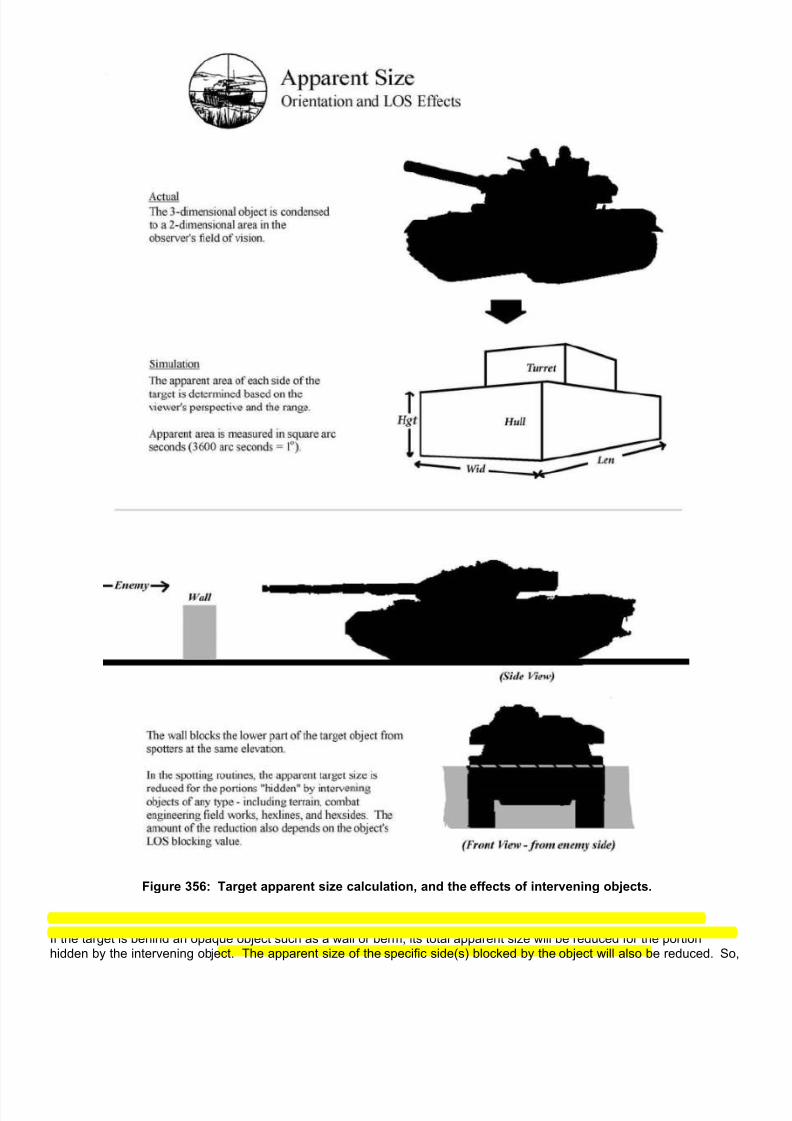
7/21/2019 TSS User Manual
http://slidepdf.com/reader/full/tss-user-manual 352/492
Figure 356: Target apparent size calculation, and the effects of intervening objects.
If the target is behind an opaque object such as a wall or berm, its total apparent size will be reduced for the portionhidden by the intervening object. The apparent size of the specific side(s) blocked by the object will also be reduced. So,

7/21/2019 TSS User Manual
http://slidepdf.com/reader/full/tss-user-manual 353/492
for example, the apparent size of a tank target’s hull might be very small if it moves behind a wall while the turret size isnot affected.
Initial weapon accuracy values are entered in the Data Tables as the probability of hitting a standard 5 square metertarget at a range of 1000 meters (2.1 x 10 8 sq. arc sec). The difference between this and the apparent target size isapplied to the accuracy determination proportionally, i.e., if the target appears twice the standard size the accuracy will betwice normal, if it appears half the standard size the accuracy will be halved.
A secondary factor is how “square” the target appears. The more “un-square” the appearance, the harder it is to hit. Forexample, a target 10 meters (~30 ft) long but only 0.25 meters high (~10 inches) is harder to hit than one 1.6 meters (~5ft) square. The reduction in accuracy for “non-square” orientation is applied exponentially; with the effects becomingsignificant only when one dimension is several times greater than the other.
3-2.7.5 Firing Unit Movement As weapons systems move, they often experience vibration changes in attitude and other conditions that detract fromoptimal firing conditions. As such, movement normally decreases the accuracy of unguided rounds being fired by itsweapons. The amount of reduction depends on several factors, including what sorts of stabilization equipment the firingunit has, the “roughness” of the terrain being traversed and how fast the firing unit is moving.
Each gun/launcher within a weapons system is given a base “movement accuracy” rating, which represents how effectivethe stabilization equipment is under normal operating conditions. This rating is then modified by the conditions of themovement. The first determination is simply what kind of terrain the unit is moving over. If the terrain’s maximum speedis 50 Kph or more it is considered a smooth road. If it is between 25 and 50 Kph, it is considered a trail or smooth cross-
country. Otherwise, it is rough.
The terrain type determines how the accuracy is reduced. On rough terrain, the relative accuracy falls off much morequickly at low speeds than it does on smoother surfaces. The following graphs show the relationship between relativeaccuracy reduction and relative speed (actual speed as a percent of the weapon system’s maximum speed) for each ofthe general terrain types:
Smooth Roads Trails/Smooth Terrain Rough Terrain 50 <= MAXSPEED 25 <= MAXSPEED < 50 MAXSPEED < 25
y = 2(val)(x2) y = 2(val)(x) y = 2 (val) (√x)
100 | x | x | x | x | x | x Rel | x | x | x
Accy | x | x | x Redtn | x | x | x
% | x | x | x
| x | x |x
0 |x___x_______________ |x_______________ |x__________________
0 1 0 1 0 1
Speed Ratio (actual speed/terrain MAXSPEED)
Firing unit movement affects only the accuracy of unguided rounds. It has no additional effect on guided munitions.
3-2.7.6 Target Apparent MovementTarget movement may also affect unguided fire accuracy. There are two components to target movement. The first is theapparent velocity, or how fast the target appears to be moving across the firing unit’s field of vision (apparent movementwas described in the section on missile “Homing”, above). This component forces the firing unit to track the target,rotating the firing weapon to always point in the correct direction, potentially causing a decrease in both the rate of fire(ROF) and accuracy since the weapon can not remain “set”.
The second component is the physical offset caused by the target’s velocity and direction of movement as compared tothe flight path of the projectile. Specifically, it measures how much adjustment must be made to the firing conditions toanticipate where the target will be when the round impacts, and the amount of uncertainty in that prediction. Greatertarget speeds and/or slower projectile velocities (longer flight times) result in higher accuracy loss. Likewise, lateral
7/21/2019 TSS User Manual
http://slidepdf.com/reader/full/tss-user-manual 354/492
movement (side to side rather than straight towards or away from the spotter) will result in more accuracy loss that non-lateral.
Accuracy is reduced proportionally for apparent movement (as a ratio of the apparent movement to the turret or systemrotation rate), and exponentially for target movement (the effects become more pronounced with higher actual speeds).
Target unit movement affects only the accuracy of un-guided rounds. It has no additional effect on guided munitions.
3-2.7.7 Other Non-guided Accuracy Modifiers
The accuracy of non-guided projectiles is also affected by a number of other factors:• How well the firing unit “knows” and can see the target. If the unit is not sighted completely, i.e., if the model andquantity are not correctly known, the accuracy is reduced based on how much information is known. “Known”levels are covered in more detail in the manual section on FOW (fog of war), but the accuracy decrease applieseven if the player is not using FOW for his display and force information.
• Firing unit suppression lowers accuracy exponentially.
• Accuracy is increased for target acquisition, which is measured as the length of time the target has beencontinuously engaged by the firing unit. The benefits of acquisition are maximized after about 30 seconds ofengagement. The amount of accuracy improvement varies between systems and guns, but is usually 45% orless.
• If the firing unit is using “shoot & scoot” tactics, target acquisition (above) is ignored, and the accuracy may bedecreased by up to 20% since set-up/preparation time is limited.
• The firing unit’s training level may decrease the accuracy by up to 25%.
• The firing unit’s fatigue level may decrease the accuracy by up to 20%.• If the target is an aircraft at a different elevation AGL than the firing unit, an adjustment is made based on thedifficulty involved in taking into account the ballistic trajectory. This effect is most pronounced at long ranges(above 40% of maximum), and at elevation angles within 20 degrees of 45. The effect is much less at low range,and if the aircraft is relatively “straight up”, or “straight out”.
• If the relative radial speed between the firing unit and target (towards or away from each other) is greater than 5meters per second, the accuracy will be reduced using a hyperbolic function. At speeds above about 100 metersper second, the accuracy will be only 1% of the unadjusted value.
3-2.8 Weapon/Round EffectsThis section discusses the various major destruction methods, and how various target types modify their effects.
Weapon effects are classified by their final result on the target, either a “kill”, “damage”, or “no effect”. A “kill” means thetarget is damaged to a degree where it is unable to perform any of its intended combat functions, or affect combatoperations in any meaningful way, and has no chance to be repaired within the scope of the scenario. For example, a tankthat has been almost completely wrecked, or an obstacle pulverized to dust would both be considered “killed”.
“Killed” targets are considered permanently destroyed and removed from the scenario.
“Damaged” targets suffer some form of debilitating loss, but it is limited in scope and they retain at least some combatfunctions. An example would be a tank that loses its radio, or an obstacle that has only been partially demolished.
Damage is normally permanent, but occasionally it may be judged as potentially repairable. The best example is a tankthat is judged to take a moderate hit to its treads. It immediately suffers mobility damage from the hit and loses the abilityto move. However, the tread can potentially be replaced and mobility restored, so the damage could be judged repairableas long as the damage was limited to the treads.
3-2.8.1 Effective Target Armor ThicknessWith the exception of personnel, virtually all weapons systems and other objects in the simulation are either made of, orinclude as protection, some form of physical armor material. This includes the obvious things like armored vehicles, butalso objects made of concrete or earth such as bridges, IP’s, and above-ground obstacles. To destroy or damage theobject, the armor must be damaged or destroyed first.
Armor will affect the results of every weapon and ammunition type fired in some way. It may block energy, preventpenetration, or keep out heat and poisonous chemicals. In all but a few cases, such as with chemical or flammableweapons, the armor needing to be overcome by the weapon or round will not be the same as the nominal armor thickness(which is measured from face to face by the shortest possible distance). Instead, it must penetrate a distance equal to
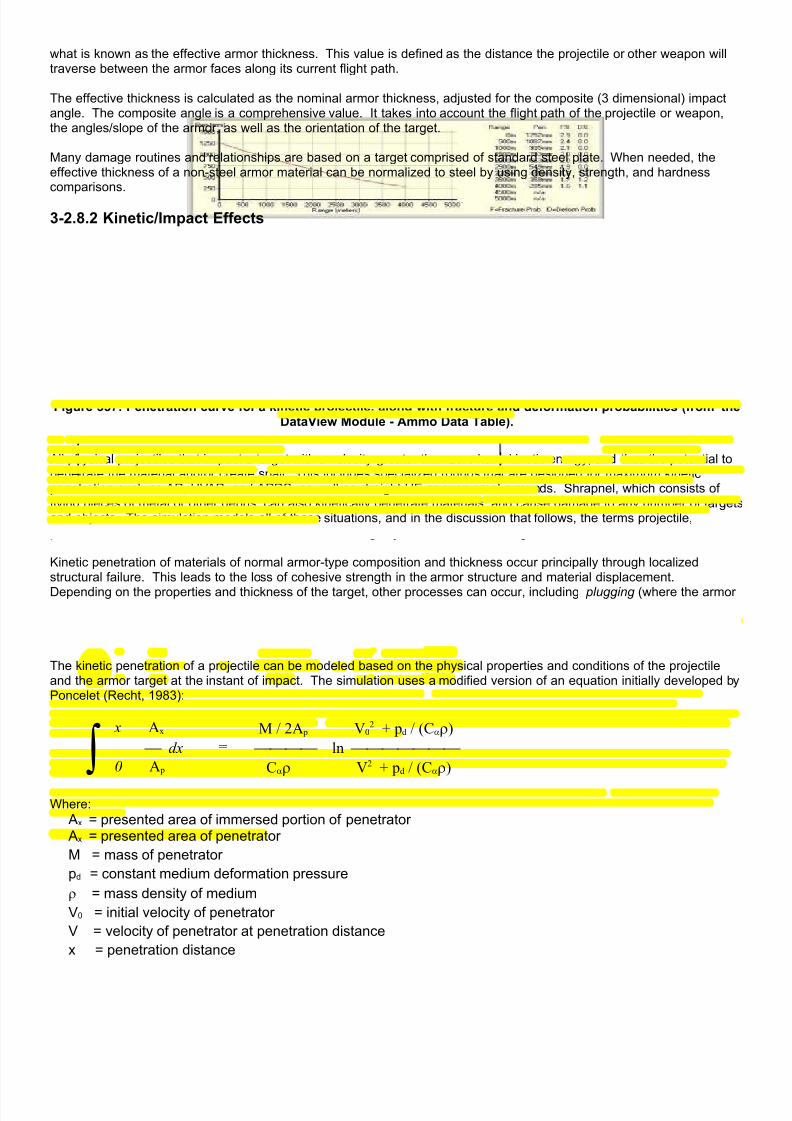
7/21/2019 TSS User Manual
http://slidepdf.com/reader/full/tss-user-manual 355/492
what is known as the effective armor thickness. This value is defined as the distance the projectile or other weapon willtraverse between the armor faces along its current flight path.
The effective thickness is calculated as the nominal armor thickness, adjusted for the composite (3 dimensional) impactangle. The composite angle is a comprehensive value. It takes into account the flight path of the projectile or weapon,the angles/slope of the armor, as well as the orientation of the target.
Many damage routines and relationships are based on a target comprised of standard steel plate. When needed, theeffective thickness of a non-steel armor material can be normalized to steel by using density, strength, and hardnesscomparisons.
3-2.8.2 Kinetic/Impact Effects
Figure 357: Penetration curve for a kinetic projectile, along with fracture and deformation probabilities (from theDataView Module - Ammo Data Table).
All physical projectiles that impact a target with a velocity greater than zero have kinetic energy, and thus the potential topenetrate the material and/or create spall. This includes specialized rounds that are designed for maximum kineticpenetration such as AP, HVAP, and APDS, as well as straight HE or even smoke rounds. Shrapnel, which consists offlying pieces of metal or other debris, can also kinetically penetrate materials, and cause damage to any number of targetsand objects. The simulation models all of these situations, and in the discussion that follows, the terms projectile,penetrator, and round are all used to describe the moving object that strikes the target.
Kinetic penetration of materials of normal armor-type composition and thickness occur principally through localizedstructural failure. This leads to the loss of cohesive strength in the armor structure and material displacement.
Depending on the properties and thickness of the target, other processes can occur, including plugging (where the armor“snaps” almost at once throughout it’s entire depth - ejecting a “plug” in front of the penetrator), petalling (where the armorfails along the axis of penetration and “bends back” similar to a pencil pushed though a piece of paper), melting, andvaporization of the armor or penetrator material.
The kinetic penetration of a projectile can be modeled based on the physical properties and conditions of the projectileand the armor target at the instant of impact. The simulation uses a modified version of an equation initially developed byPoncelet (Recht, 1983):
∫ x Ax M / 2A p V0
2 + pd / (Cαρ)
dx = ln 0 A p Cαρ V2 + pd / (Cαρ)
Where:
Ax = presented area of immersed portion of penetrator
Ax = presented area of penetrator
M = mass of penetrator
pd = constant medium deformation pressure
ρ = mass density of medium
V0 = initial velocity of penetrator
V = velocity of penetrator at penetration distance
x = penetration distance

7/21/2019 TSS User Manual
http://slidepdf.com/reader/full/tss-user-manual 356/492
Cα = empirical dimensionless constant (value is a function of the nose cone shape)
Solving this equation for V=0 gives the maximum penetration distance, or xmax. This value is then compared to the actualarmor thickness to determine if the armor is breached, and if so, how much of the penetrator remains to cause damage tothe target interior.
3-2.8.2.1 Projectile Air Drag and Impact AngleIn order to effectively use the Poncelet equation, the exact impact velocity must be known. Additionally, the actual impact
angle is required to calculate skip probabilities, as well as the total thickness of the armor to be penetrated.
Since the projectile’s initial muzzle velocity, size, ogive angle, and air drag coefficient are known, this is accomplished byapplying basic air drag calculations to the projectile every one-hundredth of a second it is in flight. The drag calculationstake into account the current velocity, the surface area of the projectile, as well as the air temperature and precipitation.
Once the air drag is known for each hundredth second interval, the projectile’s actual velocity and flight vector (path) isdetermined using the initial firing angle, the initial velocity, and the effects of gravity. Because of their conical shape,projectiles in flight tend to “line up” on their path vector. In other words, the projectile “points” along the flight path as ittraces out the standard ballistic arc. This is especially true for “long-rod” type penetrator and/or those with stabilizing fins(which can be visualized as high speed “darts”).
The flight path is traced up to the point at which the projectile impacts the target surface, and the final values are used bythe other equations.
3-2.8.2.2 Projectile Fracture and DeformationWhenever a projectile impacts with a solid target, there is a chance it will fracture or deform. The cause is the suddenstress generated by the rapid deceleration upon encountering the target material. Fracturing occurs when the projectilesuffers a large degree of internal cracking, breaks apart into pieces, or even shatters completely. Deformation, on theother hand, is when the projectile bends or changes shape, or breaks into two pieces.
The base fracture probability is determined by the projectile’s impact velocity and by comparing the hardness ratio of theprojectile to the target material. The greater the ratio, the lower the base probability (i.e., the fracture probability drops asthe projectile hardness value increases). The base probability is then lowered for the impact angle (maximum fractureprobability is achieved at 90 degrees), and finally for “Td ratios” of less than 10, where the in this case “Td ratio” is theratio of the thickness of the armor to the projectile diameter.
The deformation probability is primarily based on the impact velocity, the “Td” ratio, the “Ld ratio”, and the relativestrengths of the projectile and target materials. The “Td ratio” is as described above, and the “Ld ratio” is the ratio of theprojectile length divided by the projectile diameter. The deformation probability increases with velocity, Td ratio and Ldratio. It decreases with higher impact angles and higher relative projectile strengths.
In cases where fracture or deformation is determined to occur, the penetration of the projectile will be reduced. Theamount of the reduction will depend on the extent of the cracking or bending and in some cases it may become effectivelyzero, as for complete shatter.
3-2.8.2.3 Petalling/PluggingPetalling is a situation where the target material suffers a point catastrophic failure at the point of impact, followed byradial tearing produced by the pressure stress of the impact but otherwise remains intact. A common example is pushinga pencil through a piece of paper.
Plugging is when the target material suffers catastrophic failure in a pattern corresponding to the shape of the incomingprojectile, but otherwise remains intact. The distinguishing feature is that the target material is ejected as a single “plug”on the interior side.
In both cases, the primary value of consideration is the Td ratio. Petalling and plugging rarely occur above Td ratios of1.5. The probability is also dependent on a ratio of the target material’s strength vs. hardness.
When petalling or plugging is determined to occur, the energy required for the projectile to penetrate the target is loweredby up to 75%, which is the same as raising the effective penetration by up to 400%.

7/21/2019 TSS User Manual
http://slidepdf.com/reader/full/tss-user-manual 357/492
3-2.8.2.4 SpallSpall is comprised of flakes, droplets or small pieces of armor material that are ejected at speed from the armor’s interiorsurface. It is produced principally by shock waves, which in the case of penetrating projectiles are created by the originalimpact and travel though the armor.
The amount of spall is proportional to the penetration and mass density factor of the projectile, and inversely proportionalto the armor strength and anti-spall rating values. Additionally, each ammunition type is rated for the amount of spall itcreates.
The creation of spall will sometimes absorb some of the projectile’s energy that otherwise would have gone intopenetration. In these cases, the penetration of the projectile may be reduced by some amount to compensate. Theactual amount depends on the initial energy of the projectile, and the amount of penetration as compared to the armor’seffective thickness.
The effects of spall are greatly reduced if the armor has an anti-spall liner.
3-2.8.2.5 Target Damage/DestructionThe damage from penetrating-type rounds is caused by the destructive effects of fragments of armor and whateverremains of the projectile after penetrating the armor. These fragments and pieces are sprayed out from the point ofimpact, and tear into crew and relatively unprotected equipment causing physical damage and destruction. Additionally,the spray elements are also often very hot, sometimes even molten, which enables them to burn into things and igniteflammable or combustible items such as fuel, ammunition, and wood.
Damage from penetrating projectiles is initially based on the “excess penetration”, and the amount of spall.
Spall creation was described above. The damage probability from spall is directly proportional to the amount of spallcreated.
3-2.8.3 HE/HESHHigh Explosive detonations cause damage through blast effects, which include shock waves, overpressure, and heat. Additionally, HE explosions almost always create shrapnel, consisting of flying pieces of debris from the ammunitioncasing and whatever material is near the explosive charge when it detonates.
HESH (High Explosive Squash Head) type rounds are designed to create maximum amounts of spall on the interior ofhardened armor surfaces. They use a plastic type of explosive that “spreads out” on the armor surface from the force ofimpact before detonating. The “spreading” increases the surface area of the explosive compound in contact with thearmor, and thus the energy imparted into the armor by the explosion. Since spall creation depends on the energy, theHESH produces significantly more spall than a normal HE type round.
3-2.8.3.1 HE: Blast EffectsThe primary effects of an HE explosion are normally caused by blast. The program uses a standard calculation based on1% of kill probability at 1 dm for 10 g of TNT equivalent though 1 mm of steel-strength armor. For ranges other than 1 dmthe probability is adjusted by the square of the difference in distance. For materials other than steel, the probability isadjusted based on the relative material strength.
The damage probabilities against unarmored targets are approximately 3 times that for armored.
Against non-unit object types, such as obstacles, bridges, or IP’s (improved positions), the program uses the crateringroutines, described below, to determine how much material is displaced from the object, and thus the percent damage
inflicted. Objects can be damaged independently of whether or not they are occupied by a unit or a unit is nearby.
3.2.8.3.2 HE: Shrapnel Creation/DamageShrapnel is effectively a number of secondary kinetic projectiles created by an explosion. The ammunition AP Radiusrating, amount of explosive material, and target composition determine the relative number and velocity distribution of theindividual shrapnel pieces. Because shrapnel pieces are irregularly shaped, they have large air drag coefficients. Thiscauses their velocity, and thus potential to cause damage, to drop off relatively quickly with distance.
The simulation treats shrapnel as random kinetic projectiles with initially high velocities (based on material densities andstrengths, but usually greater than 200 m/sec), large drag coefficients (greater than 100,000) with the properties of eithersoft steel (the shell casing) and/or the target material.

7/21/2019 TSS User Manual
http://slidepdf.com/reader/full/tss-user-manual 358/492
Some rounds are specifically designed to produce shrapnel, as with anti-personnel munitions filled with ball bearings.These types of warheads are not handled separately, but rather are assigned high AP Radius values and Personnel Killpercentages in the Ammunition Table.
3-2.8.3.3 HE: Spall Creation All explosions impart energy into the target, and thus have the potential to create spall. The amount of spall created isproportional to the amount of energy imparted into the armor, based on the amount of explosive being detonated, andalso the armor properties. HESH rounds impart approximately 400% as much energy as non-HESH rounds of the same
mass.
3-2.8.3.4 HE: CrateringHE rounds are capable of cratering roads, terrain and bridges. Additionally, “craters”, i.e., displaced material, causesother objects such as obstacles and IP’s to suffer damage and degradation in their effectiveness. The amount of damageis proportional to the amount of material displaced and is determined by the strength and density properties of materialmaking up the object, and the amount of explosive.
Most HE rounds will penetrate into the target for some distance before exploding, based on the kinetic penetrationprincipals already described.. The amount of penetration can greatly increase the effect of the blast though the effects of“tamping”, or constraining the explosion so the energy is not expended into empty space.
By default craters proper are created only in terrain, roads and bridges. The detonation depth (penetration) and amountof material displaced determined the crater diameter. The exact position of a crater is determined though the accuracyroutines, where aimed fire is directed at the center of the road or bridge. Craters against terrain are always random.
As a single map location becomes cratered, designated “crater” terrain types will be added to the location for Low,Medium, and High crater area percentages. The crater terrains will normally reduce movement rates significantly, as wellas reduce stacking, along with other potential effects.
Figure 358: Some possible road/bridge cratering orientations from an impact.
Roads and bridges suffer incremental reductions in their effectiveness based on cumulative crater effects. However, a“crater” terrain type is not used. Instead, the effect of each crater is determined by the crater diameter and its position onthe road or bridge. In the example above, the crater in the center of the bridge would have the greatest effect on thebridge, followed by the one slightly off center and finally the one on the edge.
The individual crater damage percent is then added to the cumulative total. An adjustment is made for “overlap”, basedon accuracy, crater size, and how damaged the target already is to determine if the new crater is partially (or fully) in anexisting one. Once the cumulative damage total reaches 75%, the bridge or road is effectively destroyed.
Bridges are discussed more fully, including how they are damaged and the effects of the damage, in the section onMovement later in the manual.
3-2.8.3.5 HE: Rubble CreationTerrain types may create rubble as they are damaged or destroyed by HE bursts. This tendency is set in the TEC(Terrain Effects Chart), and consists of two parts. The first is the relative ease of rubble creation, and the second is therelative total amount of rubble that can be created when the structure is fully destroyed.
Rubble creation is based on the crater size created by an HE round, as described above, modified by the terrain type’srelative ease of rubble creation value. The larger the crater, the more rubble it creates. However, as with bridges, once alocation has rubble in it, the crater may be determined to hit in an spot already turned to rubble, in which case it will haveless, or even no, additional effect.
The total amount of rubble created by fully destroying a structure is equal to the volume of the structure (length x width xheight), modified for its relative rubble creation amount.

7/21/2019 TSS User Manual
http://slidepdf.com/reader/full/tss-user-manual 359/492
3-2.8.3.6 HE: Minefield/Sensorfield DamageHE explosions have the ability to destroy emplaced mines and sensors if they land nearby. The initial destructionprobability is 10% for every 0.5 Kg of explosive detonated at a range of 1 m, which is modified for the range the round isdetermined to land from the mine or sensor.
Single HE burst may destroy multiple mines or sensors, especially if very large explosions are involved, or the field isdensely packed.
Mines that are destroyed are assumed to detonate, which means they may damage units in their location. In this case,the standard mine attack routines are used for damage assessment.
3-2.8.3.7 HE/APHE Nominal vs. Effective PenetrationWhen an HE charge detonates, the shock wave radiates out through the armor material in a concentric pattern. Thus, theshock waves will never have to travel further than the actual armor thickness to reach the interior surface. This distance isknown as the Nominal Penetration, in that it the actual unmodified thickness of armor experienced by the HE waveregardless of the impact angle.
The Effective Penetration, by comparison, is the penetration that would be required by a solid penetrator to equal theeffect of the HE detonation. Because this value does depend on the impact and armor angles, it will always be at leastthe amount of the nominal penetration, and often times significantly greater.
Figure 359: Effective vs. Nominal Penetration for an explosive charge.
In the simulation models, all calculations are based on the effective armor thickness and the effective penetration. Forexample, in the above diagram the nominal penetration of the explosive is 10mm, which is also the thickness of the armorplate. However, the simulation would compare the effective armor thickness of 35mm to the effective penetration of theHE charge, also 35mm, to arrive at the final results.

7/21/2019 TSS User Manual
http://slidepdf.com/reader/full/tss-user-manual 360/492
3-2.8.4 APHE
Figure 360: APHE (Armor Piercing High Explosive) projectile fundamentals.
APHE rounds blend the best characteristics of both AP (armor-piercing) and HE (explosive) rounds into a single projectile.In a standard-use scenario, as pictured above, they penetrate a reasonable amount of armor before detonating, whichthen constrains the explosion and increases its applied energy - and damage capacity. Or the projectile may evencompletely penetrate the armor, in which case the energy of the explosion is applied completely to the vulnerable interiorof the target.
In the simulation, the effects of an APHE round are computed in two steps. The first is to determine the penetrationbefore detonation. This is done using the standard penetration routines.
The second step is to calculate the effects of the explosion. If the projectile only partially penetrated the armor (or if thetarget is very thick like a road or the ground), the effects of the explosion are increased. The amount of the increase in isproportional to the ratio of penetration to the round diameter, up to about 4 times the normal (unconstrained) energy.
If the round completely penetrates the armor, the damage calculations for the HE portion treat the target as completelyunarmored.

7/21/2019 TSS User Manual
http://slidepdf.com/reader/full/tss-user-manual 361/492
3-2.8.5 HEAT
Figure 361: Shaped charge/HEAT warhead fundamentals.

7/21/2019 TSS User Manual
http://slidepdf.com/reader/full/tss-user-manual 362/492
HEAT (High Explosive Anti-Tank) or “shaped charge” rounds use a narrow, high-speed jet of gas and molten metal topenetrate armor. The jet is created by the complex interactions of the shock waves produced by the conical shape of theexplosive charge, and a thin metal liner that is melted and vaporized.
The jet requires a certain distance to organize itself, stays coherent for a certain distance more, and then begins todeteriorate. Along this path, the maximum penetration work is done in the middle segment, where the jet is coherent.The distance at which this path begins (where the jet becomes organized) is known as the “standoff” distance. If the jet is just encountering the armor surface at this point, it will achieve maximum penetration. If the armor is encountered soonerit will break up the jet formation before it becomes fully coherent. Or, if the armor is encountered later the jet will alreadyhave begun to break up. Both of which will result in less penetration. This situation is represented graphically in thediagram above.
HEAT rounds are given a standard penetration amount in the Ammunition Data Table. This penetration is in millimeters ostandard steel armor. When a HEAT round impacts a target, this is the value that will be compared to the effectivethickness of the armor to see if the armor is breached. There are no shock wave effects or associated spall creation,although the round may have some blast effects on relatively unprotected objects near the detonation point.
The penetration value is reduced if the anti-HEAT rating of the armor type, which represents skirts and other measuresdesigned to prevent the detonation from occurring at the optimal standoff distance, as shown in the bottom of the diagramabove. However, if the HEAT round is a “tandem warhead” configuration, the effectiveness of the anti-HEAT rating isreduced. In a tandem- warhead, there are two charges; the first blasts away the skirt, so the second can detonate at theproper standoff.
The kill and damage probability of HEAT type rounds depends exponentially on the excess penetration (which representsthe amount of material that blasts though the armor), and the original warhead weight.
One variation on the standard design adds a thick metal plate at the opening of the cone. In this case, when the chargedetonates the Miznay-Shardin Effect turns the plate into a dense high-speed mass of molten metal. The physics areslightly different, but the characteristics within are essentially the same; the warhead has an optimal standoff distance,creates a certain amount of penetration, and spews molten metal and fragments once through the armor.
Another variation is the “Tandem Warhead”, which has two shaped charges in line. The purpose of this round is to defeatdefensive measures that prevent the warhead from initially detonating at the optimal standoff distance, such as skirts.With a tandem warhead, the first charge is intended to destroy or neutralizes the defensive measure, thus allowing thesecond one to bypass it and detonate at the optimal standoff distance. There are of course countermeasures to tandemwarheads, which have led to the introduction of triple warheads and defensive measures against them, but in both cases i
becomes prohibitively expensive to proceed much further than that.
3-2.8.6 Flame/IncendiaryFlame and incendiary rounds are treated the same by the simulation because they cause damage by heat and oxygenloss. As such, the primary factor in calculating damage is the amount of burning material.
The damage may be reduced for armor, but the relationship of additional armor thickness to additional protection providedis an inverse exponential. This means that the effects of each additional millimeter of armor provides less protection(about 0.7 as much) than the millimeter added before it.
The protection from armor is reduced for high levels of burning material, approximately 1% for each 2.5 Kg of incendiary(or about 2 liters of a liquid flammable).
Semi-armored (open-topped) targets receive protection from their armor, but only about 1/6th as much as if they were fullyarmored. Targets with reasonably large openings, such as some IP’s, may not receive any armor benefit at all on someportion of the flammable material applied if it is determined the flammable can enter the interior though the openings. Thedetermination of how much flammable would get through the opening is based on the size of the opening, what directionthe flammable material is placed on the target, and the quantity of flammable.
3-2.8.6.1 Flame: Wide-Area Flammables“Wide-area” flammables (as set in the Ammunition Data Table) containing over 50 Kg of material have the added effect ofremoving a large amount of oxygen from the atmosphere in their localized location. This has no effect on inanimateobjects but can cause asphyxiation and death to personnel. The basic death rate is about 1% per each person for each5Kg of wide-area flammable material.

7/21/2019 TSS User Manual
http://slidepdf.com/reader/full/tss-user-manual 363/492
3-2.8.6.2 Flame: Terrain FiresFlammables and incendiaries may ignite terrain in the location in which they are used. Terrain flammability is defined inthe TEC, and is characterized as High, Medium, Low, or Not Flammable. Additionally, flammable terrain has a maximumfire level, which represents how much of the terrain type is flammable and approximately how hot it will burn.
Certain objects, such as wooden bridges and obstacles, may also be set as flammable in the TEC. In these cases theyare treated exactly as any other flammable terrain.
Terrain flammability is modified globally by the flammability setting set as part of the scenario weather. It is used to
account for the effects of rain or drought specific to the scenario being played.
The probability that a terrain type will ignite is proportional to the amount of flammable material being used, and theterrain’s fire rating.
Wrecks and exploding ammunition may also start terrain fires.
3-2.8.6.3 Flame: Igniting ObjectsMan-made objects such as obstacles and IP’s can also be weakened or destroyed by flame or incendiary weapons. Additionally, objects constructed of wood or other flammable materials, may be set alight, resulting in illumination, smoke,and other effects. Users define the relative flammability of obstacles in the Obstacle Data Table. Flame weapons cannotdamage excavations, such as ditches, and pure earthworks, such as berms.
The base damage probability for igniting/damaging obstacles is:
Wood (log hurdles): Pdmg = 10.0Concrete (dragon’s teeth): Pdmg = 1.0Steel (tetrahedrons): Pdmg = 0.25Earth/Wood (log cribs): Pdmg = 2.0Wire (concertina): Pdmg = 1.0
Pdmg = Pdmg x (M / 7.0) x 1000 [increase for amount of flammable material]
If F > 0, then: [obstacle is flammable to some degree]
Pignite = (M / 14) F
Where:Pdmg = Damage Probability in %Pignite = Probability of Ignition in %M = Mass of flammable material in KgF = Flammability Value (Obstacle Data Table)
The corresponding equation for IP’s is:
Fdmg = 10000 x Mf / ρ x L
Actual damage is assessed in a semi-random fashion based on the IP Wall Damage Factor. On average, however,
the damage (in percent) will be equal to approximately the square of the IP Wall Damage Factor.
Example: 1 gallon of napalm placed on a 20 inch thick concrete wall results in an Fdmg of 7. This means there is, onaverage, approximately a 7 percent chance of causing 7 percent damage, but the actual damage will be determinedrandomly using a loop structure.
Where:ρ = Density of the wall material in Kg / m 3
Fdmg = IP Wall Damage Factor Mf = Napalm-equivalent Mass of flammable material on wall in gramsT = Thickness of the IP wall in mm

7/21/2019 TSS User Manual
http://slidepdf.com/reader/full/tss-user-manual 364/492
3-2.8.7 Chemical WeaponsChemical weapons are of two general types, persistent and non-persistent. Persistent types are commonly powders orliquids, and stay potent and localized after the initial application. They are also resistant to environmental breakdown. Inthe simulation, persistent chemicals remain in their initial location for the remainder of the scenario. However, exposure tosunlight/high temperatures and precipitation will reduce their concentration level over time.
Non-persistent agents, on the other hand, disperse or decompose relatively quickly after they are placed. Examples areaerosols, gasses/vapors, and quick-evaporating liquids. In the simulation, they are treated much like smoke or dust - theyare blown and dispersed by the wind.
Chemical weapons are only effective against human beings, be they civilians, ground troops, or crews. To suffer theeffects of chemicals, personnel must be exposed to the agent for a period of time. The exposure time and theconcentration level together determine the absorbed dose. Based on the absorbed dose, the person will have a chanceof being either temporarily or permanently incapacitated, or killed.
The flag for chemical munitions and the persistence type is in the Ammunition Type Data Table.
3-2.8.7.1 MOPP (Protection)MOPP stands for “Mission Oriented Protective Posture”, and represents varying levels of protection in NBC (nuclear,biological, chemical) environments. Because most NBC protective measures reduce effectiveness and degradeperformance, they are entered into only when necessary. The MOPP system is simply a number of discrete “steps”,leading from no protection to full protection, that allow a unit to tailor its protection level to the threat at hand without overlyreducing effectiveness.
For example, the US military uses 5 incremental MOPP levels for troops and personnel:
• Level 0: All gear is ready for use, but none is actually worn.
• Level 1: Over-garment and helmet cover worn.
• Level 2: Rubber over-boots worn.
• Level 3: Protective masks and hoods worn.
• Level 4: Rubber gloves are worn.
MOPP systems and levels are defined in the MOPP System Data Table, and are then assigned to weapons systems inthe Weapons Systems Data Table.
3-2.8.8 Energy/Advanced Weapons
The TSS models the effects of a wide range of energy and advanced weapons, including beam and dispersedelectromagnetic energy, as well as plasma and particle beams. Each of these weapons has unique propagation anddamage characteristics, as summarized in the table below:
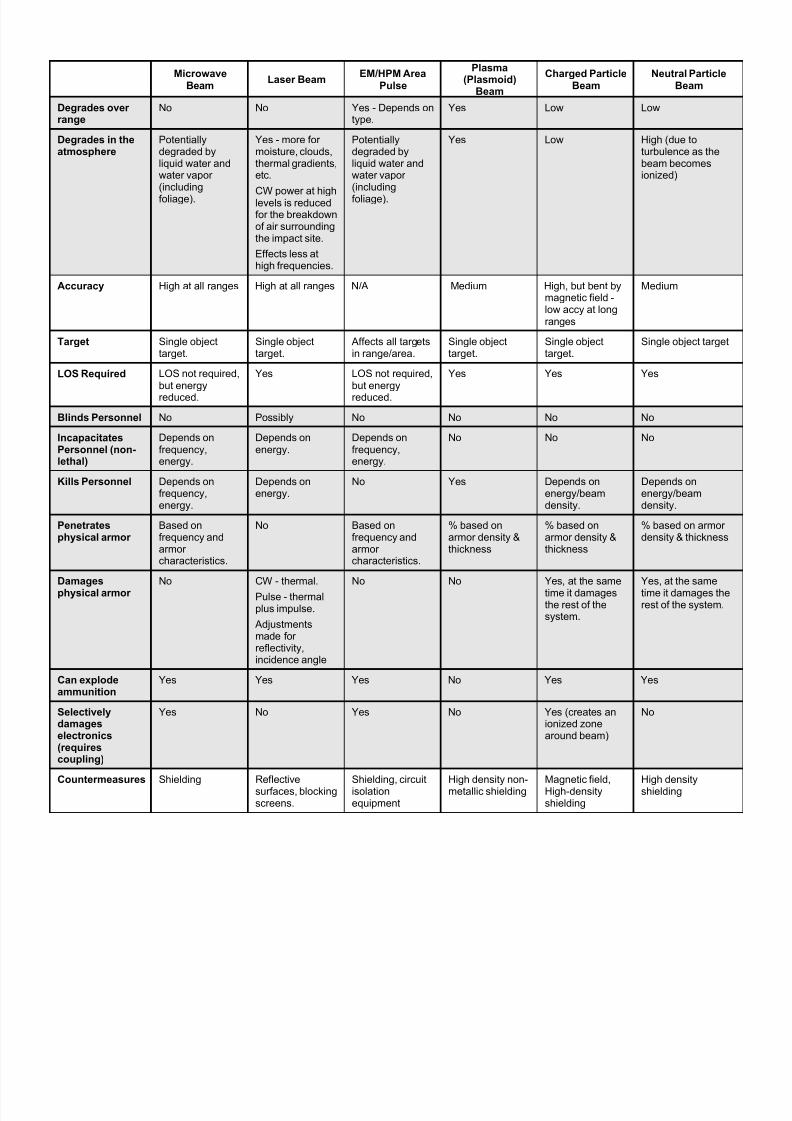
7/21/2019 TSS User Manual
http://slidepdf.com/reader/full/tss-user-manual 365/492
MicrowaveBeam
Laser BeamEM/HPM Area
Pulse
Plasma(Plasmoid)
Beam
Charged ParticleBeam
Neutral ParticleBeam
Degrades overrange
No No Yes - Depends ontype.
Yes Low Low
Degrades in theatmosphere
Potentiallydegraded byliquid water andwater vapor(including
foliage).
Yes - more formoisture, clouds,thermal gradients,etc.
CW power at highlevels is reducedfor the breakdownof air surroundingthe impact site.
Effects less athigh frequencies.
Potentiallydegraded byliquid water andwater vapor(including
foliage).
Yes Low High (due toturbulence as thebeam becomesionized)
Accuracy High at all ranges High at all ranges N/A Medium High, but bent bymagnetic field -low accy at longranges
Medium
Target Single objecttarget.
Single objecttarget.
Affects all targetsin range/area.
Single objecttarget.
Single objecttarget.
Single object target
LOS Required LOS not required,but energyreduced.
Yes LOS not required,but energyreduced.
Yes Yes Yes
Blinds Personnel No Possibly No No No No
IncapacitatesPersonnel (non-lethal)
Depends onfrequency,energy.
Depends onenergy.
Depends onfrequency,energy.
No No No
Kills Personnel Depends onfrequency,energy.
Depends onenergy.
No Yes Depends onenergy/beamdensity.
Depends onenergy/beamdensity.
Penetratesphysical armor
Based onfrequency andarmorcharacteristics.
No Based onfrequency andarmorcharacteristics.
% based onarmor density &thickness
% based onarmor density &thickness
% based on armordensity & thickness
Damages
physical armor
No CW - thermal.
Pulse - thermalplus impulse.
Adjustmentsmade forreflectivity,incidence angle
No No Yes, at the same
time it damagesthe rest of thesystem.
Yes, at the same
time it damages therest of the system.
Can explodeammunition
Yes Yes Yes No Yes Yes
Selectivelydamageselectronics(requirescoupling)
Yes No Yes No Yes (creates anionized zonearound beam)
No
Countermeasures Shielding Reflectivesurfaces, blockingscreens.
Shielding, circuitisolationequipment
High density non-metallic shielding
Magnetic field,High-densityshielding
High densityshielding
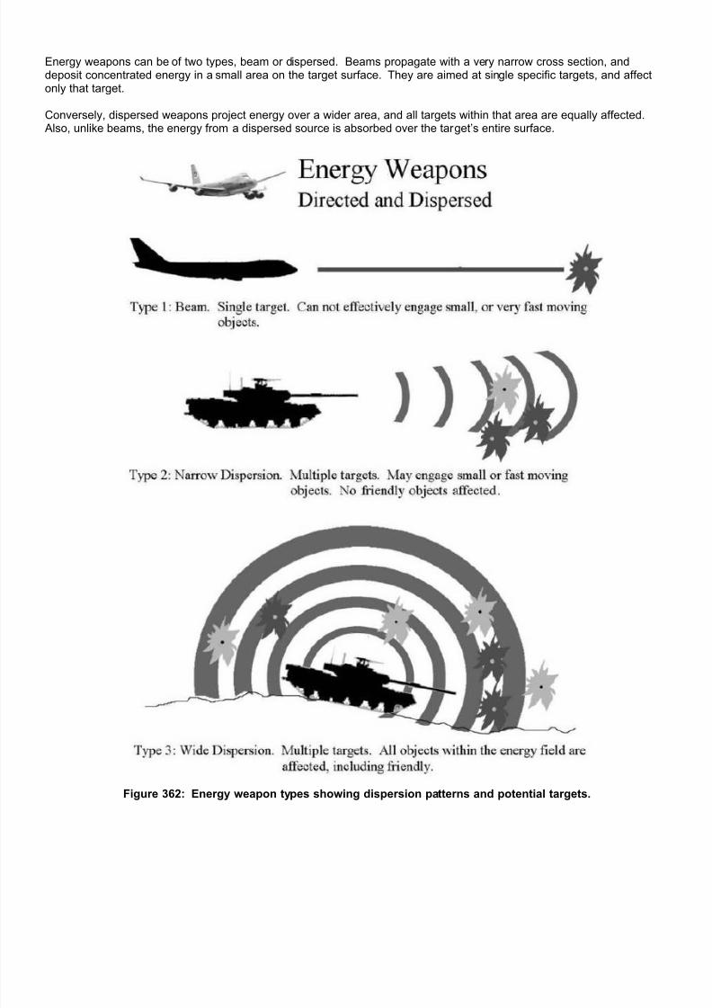
7/21/2019 TSS User Manual
http://slidepdf.com/reader/full/tss-user-manual 366/492
Energy weapons can be of two types, beam or dispersed. Beams propagate with a very narrow cross section, anddeposit concentrated energy in a small area on the target surface. They are aimed at single specific targets, and affectonly that target.
Conversely, dispersed weapons project energy over a wider area, and all targets within that area are equally affected. Also, unlike beams, the energy from a dispersed source is absorbed over the target’s entire surface.
Figure 362: Energy weapon types showing dispersion patterns and potential targets.

7/21/2019 TSS User Manual
http://slidepdf.com/reader/full/tss-user-manual 367/492
3-2.8.8.1 CouplingUnlike physical projectiles or explosive shock waves, metallic wires and other parts of the target system can absorbenergy and transmit it directly to sensitive electronic components. This is especially true if the target system contains anactual antenna of some sort, and even more so if it is “tuned” to the frequency of the incoming energy pulse.
When energy is absorbed by a component in this manner, it is known as “coupling”. In reality, a large number of factorsinfluence coupling, including the frequency of the incoming energy, the orientation and dimensions of the “acting antenna”the materials involved, and various potential types of shielding that may be present.
The simulation uses a simplified method for determining coupled energy based on the overlap of two energy curves - onefor the pulse and one for the target system. The curves themselves are specified by three values: the peak couplingfrequency, the peak energy level (for the pulse) or “100% kill” energy (for the target system), and the “spread” at which thecoupled energy drops to half the peak value. The energy at the point where the curves intersect is the coupled energythat will be absorbed by the target system.
= Absorption curve of target sub-system
= Pulse energy curve
= Intercept point – Power absorbed (Pa)
P
Pa
FrequencyAbsorption Peak Freq Pulse Peak Freq
(Fa) Intercept (Fb) (Fi)
Figure 363: Coupling calculation of energy transferred between an incoming energy pulse and a target system.
The probability of destroying the target system is determined by comparing the absorbed energy to the amount requiredfor a “100%” kill (the peak of the target system’s susceptibility curve). In the above example, by looking at the graph theabsorbed energy (Pa) is about 25% of the peak value (P) so the kill probability is also about 25%. If the system is not killed outright, it may be damaged. The difference is that damaged systems can potentially berepaired.
The curve values for the energy pulse are set in the Advanced/Energy Weapons Data Table. Susceptibility curve valuesfor individual target systems are set in the Weapons System Data Table, the Ammunition Data Table, the Radar SystemsData Table, and the Gun/Launcher Data Table, all of which can potentially suffer damage from coupling, as shown in thedrawing below:
P o w e r

7/21/2019 TSS User Manual
http://slidepdf.com/reader/full/tss-user-manual 368/492
Figure 364: Sample energy pulse effects against weapons system target types.
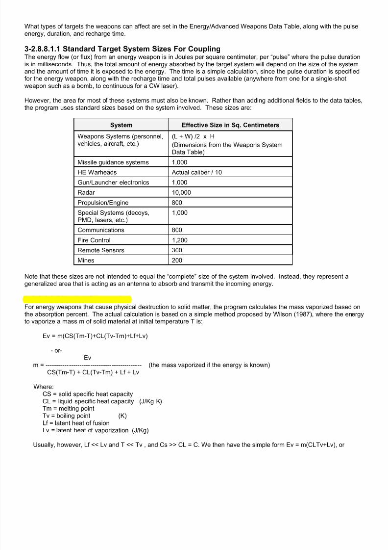
7/21/2019 TSS User Manual
http://slidepdf.com/reader/full/tss-user-manual 369/492
What types of targets the weapons can affect are set in the Energy/Advanced Weapons Data Table, along with the pulseenergy, duration, and recharge time.
3-2.8.8.1.1 Standard Target System Sizes For CouplingThe energy flow (or flux) from an energy weapon is in Joules per square centimeter, per “pulse” where the pulse durationis in milliseconds. Thus, the total amount of energy absorbed by the target system will depend on the size of the systemand the amount of time it is exposed to the energy. The time is a simple calculation, since the pulse duration is specifiedfor the energy weapon, along with the recharge time and total pulses available (anywhere from one for a single-shotweapon such as a bomb, to continuous for a CW laser).
However, the area for most of these systems must also be known. Rather than adding additional fields to the data tables,the program uses standard sizes based on the system involved. These sizes are:
System Effective Size in Sq. Centimeters
Weapons Systems (personnel,vehicles, aircraft, etc.)
(L + W) /2 x H
(Dimensions from the Weapons SystemData Table)
Missile guidance systems 1,000
HE Warheads Actual caliber / 10
Gun/Launcher electronics 1,000
Radar 10,000
Propulsion/Engine 800
Special Systems (decoys,PMD, lasers, etc.)
1,000
Communications 800
Fire Control 1,200
Remote Sensors 300
Mines 200
Note that these sizes are not intended to equal the “complete” size of the system involved. Instead, they represent ageneralized area that is acting as an antenna to absorb and transmit the incoming energy.
3-2.8.8.2 Physical DestructionFor energy weapons that cause physical destruction to solid matter, the program calculates the mass vaporized based onthe absorption percent. The actual calculation is based on a simple method proposed by Wilson (1987), where the energyto vaporize a mass m of solid material at initial temperature T is:
Ev = m(CS(Tm-T)+CL(Tv-Tm)+Lf+Lv)
- or- Ev m = --------------------------------------------- (the mass vaporized if the energy is known) CS(Tm-T) + CL(Tv-Tm) + Lf + Lv
Where: CS = solid specific heat capacity
CL = liquid specific heat capacity (J/Kg K)Tm = melting pointTv = boiling point (K)Lf = latent heat of fusionLv = latent heat of vaporization (J/Kg)
Usually, however, Lf << Lv and T << Tv , and Cs >> CL = C. We then have the simple form Ev = m(CLTv+Lv), or

7/21/2019 TSS User Manual
http://slidepdf.com/reader/full/tss-user-manual 370/492
Ev m = --------------- (C*Tv) + Lv
Sample amounts of mass (in grams) vaporized for 1 Joule of power: - Aluminum = 7.7 E-5 (C=903 Tv=2270 Lv=10,900,000) - Silicon = 8.0 E-5 (C=707 Tv=2628 Lv=10,600,000) - Iron = 13.1 E-5 (C=449 Tv=3160 Lv=6,800,000) - Steel = 12.5 E-5 (C=460 Tv=3280 Lv=6,500,000) A final transformation based on the Strength/Hardness ratio is applied to account for actual armor material as defined inthe Armor Data Table.
Once the amount of vaporized material is known, the result can be used to determine how deeply the borehole goes (ifpenetrating armor), or how much of the target system has been destroyed.
3-2.8.8.3 DegradationEnergy/advanced weapons are subject to several types of potential degradation, including being blocked/absorbed byarmor materials, atmospheric effects, magnetic fields, reflection, and dispersion (if not a beam with zero degree dispersionwidth). Additionally, the Earth’s surface blocks transmissions, although wide area energy can propagate on the “back” sideof ground obstacles (such as hills), but with reduced effectiveness due to the effects of diffraction wave cancellation.
For ease of use, many of the calculations use 13 standard “bands” to group energy/advanced weapons with similar
characteristics. These bands are:
1) Long Wave Radio: 1 to 1 x 10 6 Hz2) AM Radio: 1 x 10 6 to 1 x 10 7 Hz3) Short Wave Radio: 1 x 10 7 to 2.9 x 10 9 Hz4) Microwave Low: 2.9 x 10 9 to 1 x 10 10 Hz5) Microwave Medium: 1 x 10 10 to 7 x 10 10 Hz6) Microwave High: 7 x 10 10 to 3 x 10 11 Hz7) Infra-red: 3 x 10 11 to 4 x 10 15 Hz8) Visible Light: 4 x 10 15 to 8 x 10 15 Hz9) Ultra-Violet: 8 x 10 15 to 3 x 10 17 Hz10) X-Ray: 3 x 10 17 to 1 x 10 21 Hz11) Gamma-Ray: 1 x 10 21 and above Hz12) Plasma: Directed beam of ionized atoms.
13) Particle: Directed beam of particles (normally electrons if charged, atoms if neutral).
3-2.8.8.3.1 Standard Dispersion DegradationRadiation that propagates over a wide area, as opposed to a concentrated beam, is subject to standard degradationbased on range. The degradation function is based on the inverse square of the distance, so as the range doubles, thepower is reduced to 1/4th its original value. This degradation is automatically applied to all non-beam energy weapons.
Beams may also be reduced in power as they propagate, based on the beam width value. The beam width value is inhundredths of a degree, and measures how much the beam “spreads out” as it travels through space. It determines thebeam’s impact area, which is then compared to the beam’s width at a range of 1 meter (where full power is assumed).The ratio is then used to calculate the final energy density at the target. Beams with a width of 0 are not affected by thisdegradation.
3-2.8.8.3.2 Range DegradationThe simulation allows for degradation for range, above the standard range degradation, above. This degradation canapply to any form of energy, including beams. In fact, this type of degradation is probably most significant with particlebeams, which tend to lose coherence as the range increases. The type (log or straight-line) and amount of degradation isset in the Energy/Advanced Weapons Data Table.
3-2.8.8.3.3 Weapon-Specific LOS/Block Point DegradationSome types of weapons, most notably beams such as lasers, require an LOS to their target. However, in some cases allthat is required is that the LOS not intercept the ground; visible light-blocking terrain may have little or no effect on thebeam strength. For example, foliage would have only a minimal impact of a particle beam, while it might completely blocka laser. Both of these characteristics are defined in the Energy/Advanced Weapons Data Table.

7/21/2019 TSS User Manual
http://slidepdf.com/reader/full/tss-user-manual 371/492
3-2.8.8.3.4 Terrain-Specific LOS/Block Point DegradationEach terrain/object type can be given blocking properties in any or all of the 13 general “bands” of energy/advancedweapons. The blocking is expressed in millionths of a percent per 100 meters, assuming a “standard” distribution of theterrain type in that space. Any weapon of an appropriate band that requires a LOS and passes though that terrain will bedegraded by the specified percentage. The degradation percentage for each band is specified in the Terrain EffectsChart.
3-2.8.8.3.5 Weapon-Specific Atmospheric DegradationInteraction with the gas molecules and other particles in the atmosphere may affect some energy weapons; most notably
laser beams that are bent from thermal or other density gradients, and neutral particle beams that tend to lose coherencein the turbulence an ionization of collisions. This effect is in addition to any applicable range or LOS degradations, asnoted above. The type (log or straight-line) and amount of degradation is set in the Energy/Advanced Weapons DataTable.
3-2.8.8.3.6 Weather-Specific Atmospheric Degradation As with the LOS, the atmospheric conditions (weather) selected for the scenario can also affect energy/advanced weaponpropagation based on the general band of the propagating energy. The blocking is expressed in millionths of a percentper Kilometer, assuming a completely homogenous atmospheric composition over all distances. All weapons of theappropriate band will be degraded based on their range to the target. The weather-specific band degradation values areset in the Weather Data Table, and can also be adjusted at the start of a scenario.
3-2.8.8.3.7 Cloud Degradation
Clouds may diffract or reduce the effectiveness of certain types of energy, such as lasers. This effect is in addition to anyapplicable range, LOS, or atmospheric degradations, as noted above. The amount of degradation is set in theEnergy/Advanced Weapons Data Table, and is based on a one-to-one relationship between the cloud cover the energypasses though (taking into account the cloud base and height) and the degradation multiplier.
3-2.8.8.3.8 Incidence Angle DegradationThe incidence angle is the orientation of a beam impacting on the target surface, and is applicable only to beams. Theincidence angle of a beam hitting “straight on” is zero, and is said to be “normal” to the surface. A beam that just barelygrazes the surface would have an incidence angle of close to 90 degrees, and one with 90 exactly would miss the surfacecompletely - the beam would be exactly parallel to it.
As with solid projectiles, the armor’s effective thickness is increased to account for the angle of the beam though it.However, some beams suffer additional degradation depending on the incidence angle. The effect is almost always the
result of reflection or the beam interfering with itself in some way. The incidence angle degradation value is Yes/No, andset in the Energy/Advanced Weapons Data Table. If it is set to yes, the energy will be degraded 1.1% for each degree ofdifference from normal (100% at 90 degrees).
3-2.8.8.3.9 Armor/Protective Material Degradation Armor and other protective materials may block incoming energy using user-defined degradation multipliers in each of the13 standard bands. The values are in millionths of a percent, per millimeter of armor. For beam weapons, the straightline path though the armor is used, taking into account the relative angles of the beam and armor. For non-beamweapons, the thickness is equal to the weapon system’s minimum nominal thickness; no adjustments are made forangles.
Where weapons systems are concerned, only some systems are protected by armor. Others are considered “outside” thearmor, and thus fully exposed. Units inside IP’s (Improved Positions) are always protected by the IP armor.
Internal (Protected By Armor) External (no armor protection)
• Communications
• Fire control
• Gun/Launcher electronics
• Internally stored ammunition - bothguidance systems and HE warheads.
• Propulsion systems
• Physical system destruction
• PMD systems
• Radar systems
• Externally stored ammunition (principally onaircraft - bombs, rockets, etc.) - bothguidance systems and HE warheads.
• Optical systems
• Mines/sensors

7/21/2019 TSS User Manual
http://slidepdf.com/reader/full/tss-user-manual 372/492
Because an armor type is applied as a single item to a weapons system, it effectively “surrounds” the entire weaponssystem. Therefore, care must be taken to look at the complete system when defining the armor values. For example, asolid plate of steel armor may completely block microwaves. However, when steel plate is used in a “real” tank, it includesvision ports and other openings that allow them to pass through unimpeded. Therefore the armor degradation valuesshould not be set very high - otherwise the tank will be unrealistically impregnable. If the openings are “sealed” on acertain model of tank with the same armor, the weapons system values should be modified, instead, as described below.
Additionally, coupling can take place through any holes or gaps in the metallic envelope of a target, even if the hole is"plugged" by a nonmetallic solid. The "goodness" of such coupling depends upon the size of the hole relative to thewavelength of the radiation, which must be reflected in the armor’s protective values.
Specific energy/advanced weapons may be designated to ignore armor. This is set in the Advanced/Energy Data Table.These weapons completely ignore all physical armor types.
3-2.8.8.3.10 Weapons-System Specific DegradationWeapons systems can be assigned a unique susceptibility profile against advanced/energy weapons. The profile isdivided into 6 general energy “bands” and 7 general beam-weapon types. These bands and types are different than thestandard 13 bands used in the previous sections in order to more exactly model specific defensive measures andweaknesses. They are:
Energy Bands Beam Types
• Long wave
• Radio• Microwave
• Visible
• X-ray
• Gamma rays
• Pulsed Laser
• CW Laser (continuous)
• Pulsed Maser
• CW Maser (continuous)
• Plasma
• Charged Particle
• Neutral Particle
Profile values are in percent, and they multiply incoming energy amounts directly; values less than 100 reduce the energyand values above 100 increase it. The modifications are made after all other modifications for armor and degradationduring propagation. The values are set in the Weapons System Data Table.
3-2.9 Ammunition/Weapon System Lethality AdjustmentsThe simulations allows for a wide degree of customization concerning ammunition lethality against various types oftargets, as well as survivability measures employed by target weapons systems.
3-2.9.1 Ammunition Values Ammunition effectiveness is broken down by both kill and damage probabilities by target type: AFV’s and other fullyarmored targets, guns and semi-armored targets, and unarmored personnel and troops. Whenever a munition has beendetermined to hit and penetrate an armored target, or land near an unarmored one, these values are used as the basis fordetermining the results. The ammunition’s AFP (Anti-Personnel Factor) rating is used for near misses, and is the radiusat which unprotected personnel have a 50% chance of being killed.
Physical ammunition also has a probability of being a “dud”, where the ammunition malfunctions in some way and eithernever fires, or never detonates at the target. The dud rate is set as part of the Force Data. Rounds that are determined tobe “duds” have no combat effect, and are simply subtracted from the firing unit’s on-hand quantity.
3-2.9.2 Weapons System SurvivabilityEach weapons system has a survivability rating, which represents how hard the system is to kill or damage as comparedto an “average” system. In practice, it reflects things such as the overall design, internal fire suppression systems, andammunition/fuel storage. The value can range from -100, which means the system can’t be killed, to + 100, which meansit is 10 times more likely to be killed than an average system. Zero is used for no change from the standard.
3-2.9.3 Special Non-Lethal Ammunition Types Ammunition Classes can be designated as non-lethal to personnel. These types of munitions will never kill personnel.Instead, if a “kill” is achieved they immobilize the target unit, and damage all of its weapons so it cannot fire. The damageis not permanent, and the target unit may eventually regain mobility and weapon use once the fire is lifted. However, in

7/21/2019 TSS User Manual
http://slidepdf.com/reader/full/tss-user-manual 373/492
the meantime it is essentially helpless, and will readily surrender to nearby units (for more information on surrendering,see the section on Morale).
If a unit is immobilized in this fashion, it loses command of any en-route guided weapons it is controlling.
Non-lethality is set in the Ammunition Classes Data Editor.
3-2.9.4 Specific Optical System DamageCertain types of ammunition are intended to produce high flash or radiation that damage optical systems. The
ammunition, as used in this sense, may be either physical, such as an artillery round, or energy, as in lasers.
Two assumptions are made in determining how much damage the optical system suffers. The first is that the flash orlaser pulse acts in less time than the shutoff time of the optical system. The second is that optical systems can bedamaged if the incident energy is 0.01 J/cm2 or greater, or permanently destroyed at levels above 0.05 J/cm2. If theseassumptions are deemed invalid, the ammunition type should not be designated as able to damage optical systems.
The power reaching the optical system is determined by the standard laser routines described above, or for flash rounds,is based on the amount of filler it holds. Specifically, each Kilogram of filler produces 32 million candlepower at a range of1 meter. One candlepower is equal to 1/683 Watts per steradian, so the total power can be calculated at 1 meter, andthen decreased for the range to the target using the standard inverse square relationship between power and distance.
If the power levels calculated at the target are sufficient to cause damage, a further check is made to see if the target isfacing the burst. For this check, the optical equipment is assumed to be located in the target’s turret, if it has one;
otherwise the hull facing is used. The facing must be within 30 degrees of direction to the burst.
If the facing check is passed, the probability of damage being inflicted on the system is determined using the incidentpower level: Damage Probability (0-100) = 0.2 x Power (J/cm2).
3-2.10 SuppressionSuppression is an effect of fire on troops in or near the target area that distracts and forces them to take cover. It is mostpronounced against troops in the open, but also affects armored vehicles and other systems by forcing their crews toremain inside the vehicle with the hatches closed. This is known as being “buttoned-up”.
Suppression can prevent units from optimally sighting and engaging enemy units, and may also keep units from moving(pinned-down). The exact effects are dependent on the weapon system type, the amount of suppression, and the source.
Suppression is allocated in “points”, where generally speaking 100 points of suppression will prevent a unit from sightingor firing at all. The maximum suppression level depends on the type of weapons system being targeted:
Fully Armored: 20 points Semi-Armored: 40 points Non-armored: 150 points.
Additional points to be added above these levels are ignored.
3-2.10.1 Calculating Suppression AmountsThe base amount of suppression added from a specific ammunition type is based on the ammunition’s APF rating, whichis defined as the distance at which unprotected personnel have a 50% chance of being killed measured from the point ofimpact/detonation. The maximum suppression radius is 5 times this distance, meaning that there will be no suppression
effects on units farther away than this.
The APF rating is always at least 1 cm, although most ammunition types will have values greater than this. The APF isthen modified for the size damage type:
• APF = APF 1.15.
• APF = APF x 1.25 if the ammunition contains HE.
• APF = APF x 2.0 if the ammunition is a FRAG (fragmentation) type.
• APF = APF x 0.75 if the ammunition is solid.
The modified APF value is then used to calculate the suppression to all target units within range (5 times the base APFradius). The amount of suppression depends on the following factors:
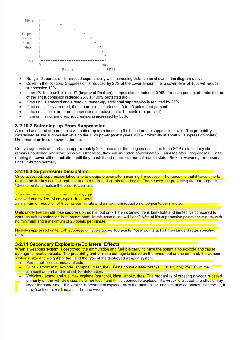
7/21/2019 TSS User Manual
http://slidepdf.com/reader/full/tss-user-manual 374/492
100% |*
| *
| * Supn | *
as a | *
% of | *
Max | *
| * | *
0% ---------------------------* 0 Max
Range (5 x APF)
• Range. Suppression is reduced exponentially with increasing distance as shown in the diagram above.
• Cover in the location. Suppression is reduced by 25% of the cover amount, i.e. a cover level of 40% will reducesuppression 10%.
• In an IP. If the unit is in an IP (Improved Position), suppression is reduced 0.95% for each percent of protected arcof the IP (suppression reduced 95% at 100% protected arc).
• If the unit is armored and already buttoned-up, additional suppression is reduced by 95%.
• If the unit is fully armored, the suppression is reduced 10 to 15 points (not percent).
• If the unit is semi-armored, suppression is reduced 5 to 10 points (not percent).
• If the unit is not armored, suppression is increased by 50%.
3-2.10.2 Buttoning-up From Suppression Armored and semi-armored units wil l button-up from incoming fire based on the suppression level. The probability isdetermined as the suppression level to the 1.5th power (which gives 100% probability at about 20 suppression points).Un-armored units can never button-up.
On average, units will un-button approximately 2 minutes after the firing ceases, if the force SOP dictates they shouldremain unbuttoned whenever possible. Otherwise, they will un-button approximately 5 minutes after firing ceases. Unitsrunning for cover will not unbutton until they reach it and return to a normal morale state. Broken, wavering, or berserkunits un-button normally.
3-2.10.3 Suppression DissipationOnce assessed, suppression takes time to dissipate even after incoming fire ceases. The reason is that it takes time torealize the fire has ceased, and that another barrage isn’t about to begin. The heavier the preceding fire, the longer ittakes for units to realize the coast is clear and return to an unsuppressed posture with hatches open and heads up.
The suppression reduction per combat pulse is based on the unit’s current suppression level, and whether or not it justreceived enemy fire (of any type). In general, a unit not under fire will “lose” 1/2 of its suppression points per minute, witha minimum of reduction of 5 points per minute and a maximum reduction of 50 points per minute.
Units under fire can still lose suppression points, but only if the incoming fire is fairly light and ineffective compared towhat the unit experienced in its recent past. In this case a unit will “lose” 1/5th of it’s suppression points per minute, withno minimum and a maximum of 25 points per minute.
Heavily suppressed units, with suppression levels above 100 points, “lose” points at half the standard rates specifiedabove.
3-2.11 Secondary Explosions/Collateral EffectsWhen a weapons system is destroyed, the ammunition and fuel it is carrying have the potential to explode and causedamage to nearby objects. The probability and ultimate damage is based on the amount of ammo on hand, the weaponsystems’ size and weight (for fuel) and the type of the destroyed weapon system:
• Personnel - no secondary effects.• Guns - ammo may explode (shrapnel, blast, fire). Guns do not create wrecks. Usually only 25-50% of the
ammunition on-hand is at risk for detonation.• Vehicles - ammo and fuel may explode (shrapnel, blast, smoke, fire). The probability of creating a wreck is based
primarily on the vehicle’s size, its armor level, and if it is deemed to explode. If a wreck is created, the effects maylinger for some time. If a vehicle is deemed to explode, all of the ammunition and fuel also detonates. Otherwise, itmay “cook off” over time as part of the wreck.
7/21/2019 TSS User Manual
http://slidepdf.com/reader/full/tss-user-manual 375/492
• Aircraft - ammo and fuel may explode (shrapnel, blast, smoke, fire). The destroyed craft will land some distancefrom its current location based on heading, altitude and speed. Wrecks are always created, and effects will lingerfor some time afterward. All on-hand ammunition and fuel detonates either along the flight path or in the final crashlocation.
Destroyed weapons systems are rated in terms of their ability to create blast, shrapnel, smoke, and fire. The ratings arebased on the explosive weight and types of the ammunition on-hand, corresponding explosive propellant charges, andany amount of liquid fuel or incendiary material.
The effects of these secondary explosions are calculated as random explosions within the location (e.g., exactly as if theywere unguided artillery). As such they can damage or kill other units nearby (friendly or enemy), set the terrain on fire,cause suppression and morale losses, and even set off “chain reactions” of secondary explosions in the weapons theydestroy.
3-2.12 High Smoke/Flash/Noise/BackblastSmoke, flash, noise and backblast are characteristics of many gun/launcher systems that affect how easy they are for theenemy to spot, and potentially limit how and where they are used. These values are set in the Gun/Launcher Data Table.
The effects can be summarized as follows:
• Smoke: If a gun produces high smoke, it is easier to visually spot in the daytime, and may add several smoke levelsto its map location when fired. Actual increases: +5% at night, +10% at twilight, +15% low sun angle, +25%daytime.
• Flash: Flash is categorized as high, or very high. Flash makes the gun easier for the enemy to visually spot ineither the day or especially night. Actual increases (high/very high): +150%/+250% at night, +100%/200% attwilight, +25%/+35% low sun angle, +50%/+100% daytime.
• Noise: Noise is also either high or very high. It improves the enemy’s chances of detecting the firing unit by sound,both at night and during the day. Actual increases (high/very high): +100%/+150% at night, +75%/100% at twilight,+50%/+75% low sun angle, +50%/+75% daytime.
• Backblast: Gun/launchers that produce backblast cannot be fired in enclosed areas without potentially killing theircrew or nearby units. Enclosed areas are defined as any IP (including buildings), where the “backblast OK” flag isset to No. Additionally, backblast produces smoke and flash making the firing unit easier to spot. Actual increases:+25% at night, +10% at twilight, +20% low sun angle, +25% daytime.
3.2.13 Creating a new unit by “Firing” a Gun/Launcher As stated previously, it is possible to create a new unit when a gun/launcher is fired. This capability is especially useful fosituations such as firing long-range/flight duration missiles, launching aircraft from a carrier, or sending out RPV’s(remotely piloted vehicles) from a parent craft.
The unit created from this “firing” is a “real” unit, although it can be either temporary, or permanent. Temporary units aredestroyed upon reaching their target (or maximum range) and have restricted player control. They are also known as “en-route” or “in-flight” units to reflect their nature and status.
Permanent units, on the other hand, remain in the scenario and can be controlled by the player as with any othermaneuver unit. They can be given orders, will move and fire normally (except for self-homing units), and are generallyindistinguishable from any other unit in the player’s force.
When the new unit is created, whether temporary or permanent, it will have a quantity of one, and the firing unit will beassigned as its headquarters. It will be assigned the default force competence levels (training, morale, supply etc.), thestandard ammunition basic load for the weapons system, and will be facing in the direction of the parent unit that fired it.
New permanent units are subject to the standard command delays from the moment they are created (does not apply totemporary units since they can not be controlled).
The links that tell the system to create a new unit upon firing, and what weapon system to assign to it, are set in the Ammunition and Weapons System Data Tables.
3-2.13.1 Temporary En-route Units As stated above, temporary or en-route units are used to model objects such as missiles, which have long flight times totheir target or can be intercepted or affected while they are in play. By turning these objects into units, it becomes easierfor both the program and human players to manage them, since they use all of the standard routines including those formovement, sighting and damage.
7/21/2019 TSS User Manual
http://slidepdf.com/reader/full/tss-user-manual 376/492
In some ways, en-route units are “real” units. For example, they are comprised of a weapons system, have a specificposition, heading, altitude and speed, and can be detected by enemy forces. They can also be damaged or destroyed bycombat action.
However, en-route units are always outside the direct control of the owning/firing force commander. Once the en-flightunit is created, it will be completely computer controlled, and cannot be accessed in any way or given orders. Examplesinclude most guided and ballistic missiles and rockets, as well as pre-programmed/targeted cruise missiles. These typesof en-route units also do not sight and/or report on the enemy, do not follow SOP directives, and are not affected by anykind of morale considerations.
They simply follow a path to their target, as determined by the computer, based on the missile’s guidance capabilities(including being controlled by a unit in the force, as with an ATGM), at which point they detonate or run out of fuel. It isbecause of this limited life span that en-route units are also known as “temporary” units; they are always removed fromthe game once the missile reaches its target (or is destroyed though some other combat action).
En-route units always have their firing unit as their nominal HQ, and will appear under it on the force tree. However, theyare never included in any kind of formation command or order (move, target, SOP, etc.). They may also not beincorporated into a Composite Unit.
3-2.13.2 Standard UnitsIn this case, the unit being created is completely “normal”. It can be given orders and controlled by the human player justlike any other maneuver unit. Examples are aircraft launched from an aircraft carrier, RPV’s, or cruise missiles with the
ability to change their targets or flight paths on command.
The firing unit is always assigned as the created unit’s HQ, and all communications and command relationships andorders apply normally to the new unit (formation move, targeting, SOP, etc.). They may also be incorporated intoComposite Units, although this is not recommended.
The location of the “firing” (launching) unit’s “target” will be set as the new standard unit’s movement objective, and thecomputer will automatically determine the best movement path to that location, as well as setting the speed and altitude (ifthe new unit is an aircraft).
Standard units are not automatically destroyed on firing unless the Weapons System Data Table flag for “Destroyed OnFiring” is set to “Yes”.
All values used for combat modeling are set in the Weapons System Data Table.
3-2.13.3 Self-Homing UnitsSelf-homing units are normal units with the added characteristic that they will always automatically insure their movementpath takes them to the last known location of their primary target (Target #1, Firing Group #1). This location is always judged by the unit “knows”, subject to Fog of War, and thus may not be completely accurate or up to date. The unit’starget may be a location, an enemy unit, or an object (IP, building, etc.). Players may freely change the primary target atwill, at least up until it is actually engaged.
Once a self-homing unit arrives at its target’s location, the target is immediately attacked using the self-homing unit’s mainweapon.
When a self-homing unit determines that its current movement commands will not take it to the currently known location of
the primary target, for example in the case of an enemy unit that has moved, the unit will immediately discard its currentorders, and formulate new ones based on the quickest known path to the target. However, players may at any time issuecommands on their own, which do not necessarily follow the quickest or shortest path. The unit will follow those orderswithout change as long as they eventually take the unit to the target location. Please note however, that if the target ismoving, it is likely that at some point its location will no longer be in the self-homing unit’s movement path, and the self-homing unit will immediately reformulate its orders to move the enemy units’ new position - erasing any orders that hadbeen previously issued by the player.
Self-homing units do not have to have a specific target, however. Instead, they can be given movement waypoints, aswith normal units. In these cases, the self-homing unit will always follow its current orders; because it does not have anactual target, it will never automatically reformulate the movement path.

7/21/2019 TSS User Manual
http://slidepdf.com/reader/full/tss-user-manual 377/492
While self-homing units can be issued with explicit communications and network equipment (Weapons System DataTable), they are also always given a standard radio (equal to checking “Radio” for the standard communication flag in theWeapons Systems Data Table). This is important, since self-homing units always move towards the last known locationof their target as they know it, and can be given orders to home in on and engage known targets that they can’t seedirectly. By having these units effectively integrated into the force’s communications grids and/or networks, the unit’sinformation on enemy forces and the situation can be kept current and complete.
Self-homing units always have their firing unit as their nominal HQ, and will appear under it on the force tree. In mostrespects they are treated as normal units, however they are never included in any kind of “formation-based” command ororder (e.g., formation move orders, targeting, SOP's, etc.). They may also not be incorporated into a Composite Unit.
All values used for combat modeling are set in the Weapons System Data Table.
3-2.13.4 Data Table Flags and SummaryTo create an en-route unit, in the Ammunition Data Table set the “Temp Unit When Fired” flag for the munition to “Yes”.Then, select the appropriate Temp Unit Type. This can be any entry in the Weapons System Data Table, but most likely itwill be a general system designated as an “in-flight” type. For example, to create a TOW ATGM using the default dataset, make “Temp Unit When Fired” equal to “Yes”, and then select “Temp: Medium Air (Pending)” from the WeaponsSystem list.
For combat modeling, en-route units use the size values from the Weapons System Data Table. All other values (speed,warhead, weight, etc.) are set in the Ammunition Data Table.
To create a normal unit, in the Ammunition Data Table insure that the munition “fired” by the launcher has the “Temp UnitWhen Fired” value set to “No”. Then, set the “Special Type” field to “Wpn Sys/Unit”, and select the Weapon System to be“fired” (for example, “FA-18 Hornet”, or “Predator RPV”). The “Self-Homing” field for that weapon system should be set to”No”.
To create a self-homing unit, in the Ammunition Data Table insure that the munition “fired” by the launcher has the “TempUnit When Fired” value set to “No”. Then, set the “Special Type” field to “Wpn Sys/Unit”, and select the Weapon Systemto be “fired” (for example, “NLOS-LS PAM”, or “Guidable Cruise Missile”). The “Self-Homing” field for that weapon systemshould be set to ”Yes”.
Type Characteristics Ammo/WpnSys Data Flags Examples
En-route / In-flight / TemporaryUnit
No player control. Always destroyed at target.
Easiest to set-up and use.
Temp Unit When Fired = “Yes”Special Type = “None”
WpnSys Table Self-Homing = n/a
ATGM, SAM’s, SSM’s, cruisemissiles, rockets.
Normal Unit Normal player control. Temp Unit When Fired = “No”
Special Type = “Wpn Sys/Unit”
WpnSys Table Self-Homing = “No”
Aircraft, RPV’s, controllable cruisemissiles.
Self-homing Unit Normal player control.
Automatically homes in on target.
Temp Unit When Fired = “No”
Special Type = “Wpn Sys/Unit”
WpnSys Table Self-Homing = “Yes”
NLOS-LS missiles, next generationrobotic craft.
Section 3-3: Close Combat
Close combat can occur when opposing ground units occupy the same location. It represents a wide variety of combatactions that happen at very close range and are outside the scope of the database values, such as vehicles colliding withand running over troops and other vehicles, bayonet actions, clubbing, stabbing, shoving objects into tank tracks, andhand to hand combat, to name a few.
While close combat can only occur between units in the same location, it is important to note that it is NOT mandatory andmay not always occur. Some examples of when it may not are:
• None of the units in the location are capable of engaging in close combat (due to weapons systems, moralelevels, etc).
7/21/2019 TSS User Manual
http://slidepdf.com/reader/full/tss-user-manual 378/492
• All unit SOP's and/or orders direct them not to engage in close combat.
• The location scale (meters per location/hex) is large enough that the units are not in direct contact even thoughthey occupy the same location.
• The location terrain, IP's, or other terrain prevent close combat.
3-3.1 Initiating Close Combat A close combat situation can be initiated when a unit moves into a location containing one or more enemy units. Whenthis occurs, all ground units in the location may immediately cease movement depending on SOP settings, exact positions
within the location, and other conditions. They retain any movement orders they might have, but they will stay in thelocation until the close combat situation is removed, e.g., until only one force or the other occupies the location.
Close combat is resolved at the end of the movement phase, so additional units from either side may move into thelocation during the current movement phase. As soon as they do, however, they can be involved in the ongoing closecombat and will not be able to move out of the location until it is completely resolved. The same applies if the closecombat lasts more than one turn. Units that move into a location already containing a close combat will join in, and willcease moving.
3-3.2 Resolving Close CombatThe units involved in close combat are broken down into attackers and defenders. A unit is considered to be attacking if itmoved into the location in the current phase. Otherwise, it is a defender. Note that this means it is possible for all of theunits to be attackers or defenders, or for a force to have units in both categories.
Close combat is resolved in steps:
1. The defending units are lumped together by owning force into aggregate numbers of personnel, vehicles, guns,naval craft, and miscellaneous.
2. The attacking units are “aligned” against the combined defenders by force and type. Defending personnel areattacked first, then vehicles, then guns, then naval craft, then whatever is left.
3. The attacker must achieve a ratio of at least 1.5:1 before being able to attack the next type. For example, against10 personnel and a tank, an attacker would need to have at least 15 personnel before being allowed to attack thetank. For this calculation, vehicles count as 5 personnel. Attacking units are aligned as a single entity - they arenot broken down between types.
4. The attacking force inflicts losses on the defenders. Losses are either immediate or deferred until the end of theclose combat round (e.g., after the defender has a chance to inflict losses back on the attackers).
• Attacking units that are wavering or broken are removed from the attack.
• Attacking units with low morale (less than 30, or less than 75 with a random factor) are removed from theattack.
• The standard Weapon System Close Combat Attack Factor (CCAF) is added for each attacking unit. CloseCombat factors are set in the Weapons System Data Table and are broken down against armored and non-armored targets, depending on what type of targets the attacking unit is aligned against.
• The value is adjusted by multiplying it by the defending units’ Weapons System Close Combat DefenseFactor (CCDF).
• The value is multiplied by the strength ratio strength.
• The value is multiplied by the average morale ratio (attacker over defender).
• The number of actual kills is a random amount up to the value. The number of immediate kills is determinedby the difference between the attacker’s average morale and the defender’s.
• Immediate kills are deducted from the defender’s force, and the morale reduction from these losses is
assessed. Units are also checked to see if they change morale states, e.g., break or go berserk.
The defending units then become the attackers and vice-versa, and steps 1-4 are run through again.
After the original defending units have attacked, the deferred losses are assessed to both sides - including morale effects.
Section 3-4: Improved Positions
Improved Positions (IP’s) are structures or excavations intended to protect friendly forces from the effects of enemy fire.There are many different types of IP’s, each of which is constructed to be occupied by specific types of friendly units and
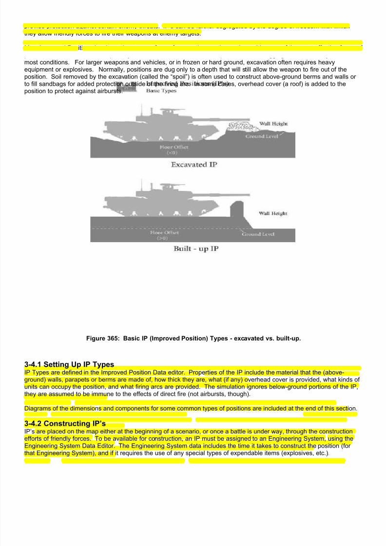
7/21/2019 TSS User Manual
http://slidepdf.com/reader/full/tss-user-manual 379/492
provide protection against certain enemy threats. IP’s can be further segregated by the degree of freedom with whichthey allow friendly forces to fire their weapons at enemy targets.
Most Improved Positions involve at least some form of excavation, as the earth provides one of the most effective forms ofprotection available. This is especially true for rifle or crew served weapons, since the digging can be done by hand undemost conditions. For larger weapons and vehicles, or in frozen or hard ground, excavation often requires heavyequipment or explosives. Normally, positions are dug only to a depth that will still allow the weapon to fire out of theposition. Soil removed by the excavation (called the “spoil”) is often used to construct above-ground berms and walls orto fill sandbags for added protection outside of the firing arc. In some cases, overhead cover (a roof) is added to theposition to protect against airbursts.
Figure 365: Basic IP (Improved Position) Types - excavated vs. built-up.
3-4.1 Setting Up IP TypesIP Types are defined in the Improved Position Data editor. Properties of the IP include the material that the (above-
ground) walls, parapets or berms are made of, how thick they are, what (if any) overhead cover is provided, what kinds ofunits can occupy the position, and what firing arcs are provided. The simulation ignores below-ground portions of the IP,they are assumed to be immune to the effects of direct fire (not airbursts, though).
Diagrams of the dimensions and components for some common types of positions are included at the end of this section.
3-4.2 Constructing IP’sIP’s are placed on the map either at the beginning of a scenario, or once a battle is under way, through the constructionefforts of friendly forces. To be available for construction, an IP must be assigned to an Engineering System, using theEngineering System Data Editor. The Engineering System data includes the time it takes to construct the position (forthat Engineering System), and if it requires the use of any special types of expendable items (explosives, etc.).
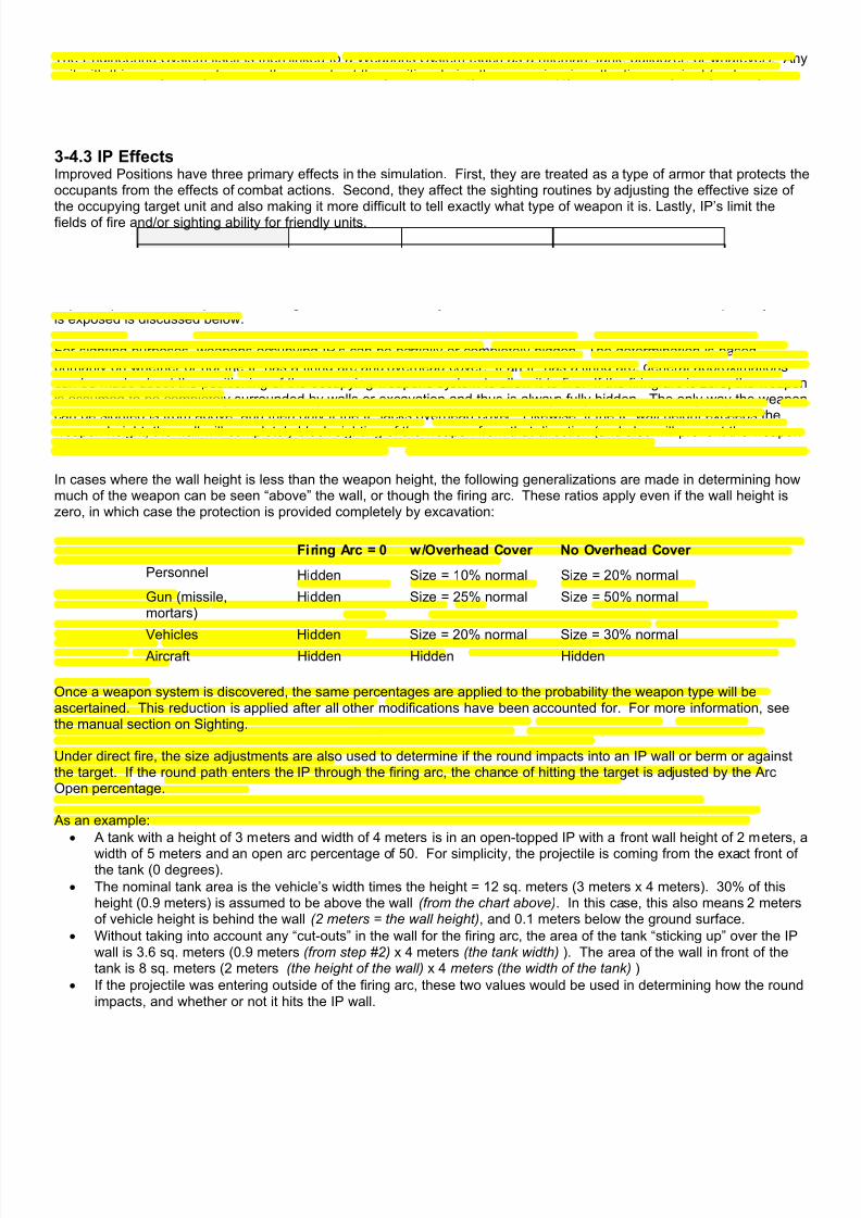
7/21/2019 TSS User Manual
http://slidepdf.com/reader/full/tss-user-manual 380/492
The Engineering System itself is then linked to a Weapons System (such as a rifleman, tank, bulldozer, or whatever). Anyunit with this weapons system can then construct the position during the scenario, given the time required (and anyexpendable items) as listed in the Engineering System Data. If the unit has more than one of the weapons systems onhand, it will be able to construct multiple positions concurrently. It is very important to keep this in mind when determiningthe relationships between these tables, since the final result will depend on each link in the chain.
3-4.3 IP EffectsImproved Positions have three primary effects in the simulation. First, they are treated as a type of armor that protects theoccupants from the effects of combat actions. Second, they affect the sighting routines by adjusting the effective size of
the occupying target unit and also making it more difficult to tell exactly what type of weapon it is. Lastly, IP’s limit thefields of fire and/or sighting ability for friendly units.
IP walls are treated exactly as any other type of armor. The walls will slow or stop penetrating projectiles, and will have althe normal effects on other ammunition types. Once the incoming round has achieved a hit on the weapon inside the IP,either by penetrating the IP wall (in which case the velocity and other characteristics are recalculated), or by hitting anexposed part of the weapon, the damage is calculated normally. The determination of how much of the weapons systemis exposed is discussed below.
For sighting purposes, weapons occupying IP’s can be partially or completely hidden. The determination is basedprimarily on whether or not the IP has a firing arc and overhead cover. If an IP has a firing arc, general approximationscan be made about the positioning of the occupying weapons system to allow it to fire. If the firing arc is zero, the weaponis assumed to be completely surrounded by walls or excavation and thus is always fully hidden. The only way the weaponcan be sighted is from above, and then only if the IP lacks overhead cover. Likewise, if the IP wall height exceeds the
weapon height, the wall will completely block sighting of the weapon from that direction (and also will prevent the weaponfrom firing in that direction).
In cases where the wall height is less than the weapon height, the following generalizations are made in determining howmuch of the weapon can be seen “above” the wall, or though the firing arc. These ratios apply even if the wall height iszero, in which case the protection is provided completely by excavation:
Firing Arc = 0 w/Overhead Cover No Overhead Cover
Personnel Hidden Size = 10% normal Size = 20% normal
Gun (missile,mortars)
Hidden Size = 25% normal Size = 50% normal
Vehicles Hidden Size = 20% normal Size = 30% normal Aircraft Hidden Hidden Hidden
Once a weapon system is discovered, the same percentages are applied to the probability the weapon type will beascertained. This reduction is applied after all other modifications have been accounted for. For more information, seethe manual section on Sighting.
Under direct fire, the size adjustments are also used to determine if the round impacts into an IP wall or berm or againstthe target. If the round path enters the IP through the firing arc, the chance of hitting the target is adjusted by the ArcOpen percentage.
As an example:
• A tank with a height of 3 meters and width of 4 meters is in an open-topped IP with a front wall height of 2 meters, a
width of 5 meters and an open arc percentage of 50. For simplicity, the projectile is coming from the exact front ofthe tank (0 degrees).
• The nominal tank area is the vehicle’s width times the height = 12 sq. meters (3 meters x 4 meters). 30% of thisheight (0.9 meters) is assumed to be above the wall (from the chart above). In this case, this also means 2 metersof vehicle height is behind the wall (2 meters = the wall height), and 0.1 meters below the ground surface.
• Without taking into account any “cut-outs” in the wall for the firing arc, the area of the tank “sticking up” over the IPwall is 3.6 sq. meters (0.9 meters (from step #2) x 4 meters (the tank width) ). The area of the wall in front of thetank is 8 sq. meters (2 meters (the height of the wall) x 4 meters (the width of the tank) )
• If the projectile was entering outside of the firing arc, these two values would be used in determining how the roundimpacts, and whether or not it hits the IP wall.

7/21/2019 TSS User Manual
http://slidepdf.com/reader/full/tss-user-manual 381/492
• However, in this case the projectile path is in the firing arc, and the arc openness is 50%. This reduces the wallarea to 4 sq. meters (50% x 8 sq. meters (the nominal wall area) ). The difference in area is added to that of thetank, which becomes 7.6 sq. meters (3.6 meters (the nominal tank area) + 4 sq. meters (the difference) ).
Finally, IP’s place limits on the ability of the units occupying them to see and fire out. In all cases units can see and fireonly in the firing arc. However, in cases where a unit of one type occupies an IP meant for another type, it can’t see or fireout very well. An example of this is when an infantry (personnel) unit occupies an IP meant for a tank (vehicle). Howeverthe advantage is that the personnel unit can’t be seen or hit by enemy direct fire very well either (except by air-bursts if theposition is open-topped). In this regard, “smaller” weapon types can always occupy vacant IP’s designed for “larger”types. However, an IP can only be occupied up to its normal capacity using the following cost equivalents:
Improved Position Type
Personnel Gun Vehicle Aircraft
Personnel 1 1/ 5 1/ 10 1 /20
Gun - 1 1 / 2 1 /4
Vehicle - - 1 1 /2
Aircraft - - - 1
Small units in larger positions have their ROF, and spotting probabilities reduced by 30-60%, depending on circumstancesand weapon size (personnel suffer the lowest degradation, guns and vehicles the most.
3-4.4 IP AccessUnits enter and exit IP’s based on the access it provides: either surface or underground. As the names imply, surfaceaccess allows units outside the IP on the ground surface to enter it (or to exit it to the ground surface). IP’s that “connectunderground”, on the other hand, allow entrance and exit from underground IP’s, such as tunnels. Underground IP’s willbe covered in more detail in a later section.
The IP must have access appropriate to the unit’s condition at the time it attempts to enter the position, including anylimitation imposed by damage to the IP.
A single IP type can have either, or both, surface and underground access. Examples of IP’s with both could be a tunnelentrance, an elevator into a subterranean complex, or bunkers and casemates connected to underground tunnel systems(signature features of much of the Maginot Line positions, for instance).
Access is not enforced during the set-up phase; units may be initially placed in any IP regardless of its access. However,capacity and other standard occupancy limitations sill apply.
An IP type can also have no access whatsoever. If so defined, units would not be able to enter or exit them during thescenario, short of having the IP sustain damage that “opens it up” (see below). Units could still be placed in the IP duringthe set-up phase, however, since there is no access check performed when initially placing units.
IP access values are set in the IP Data Table using the DataView module, as shown here:

7/21/2019 TSS User Manual
http://slidepdf.com/reader/full/tss-user-manual 382/492
Figure 366: IP Access settings. Surface access is not required.
3-4.4.1 IP Damage and AccessWhen an IP sustains damage, it may affect the access characteristics of the IP as well as the capacity and protectionvalues. Specifically, damage can “open up” surface access through previously impassible walls or it can “block”underground movement. The damage can be from any source, including combat actions, placed explosive charges,bombs, fire, or exploding stored ammo (secondary explosions/effects).
Vehicle wrecks can block or severely limit underground access; however, they have no effect on surface access.
The change in the “amount” of access (either more or less than normal) is proportional to the level of damage. This
means that in some cases, only certain types of units will be allowed to use the access while others will be blocked. Forexample, in a partial tunnel collapse from bombing, infantry may still be able to move through the tunnel, but vehicles maybe blocked. In these cases, the moving units will also often be penalized to some degree in terms of time and maximumspeed to account for the difficulties in navigating through the damage.
As another example, engineers may blow a hole in the side of an IP that has no surface access. In this case, the damagewill be such that only infantry will be able to pass through the breech, and they will be slowed in doing so. If additionaldemolition work is performed, at some point vehicles could enter as well (assuming that they are permitted to occupy theIP in terms of type and capacity).
As IP damage is repaired, access reverts to its normal “undamaged” state (either access allowed or not).
3-4.5 Underground IP’s
An “Underground” Improved Position (IP) is any IP that is wholly underground (below ground surface level). Units in anunderground IP can not sight or fire at units on the surface (and conversely, surface units can not directly sight or fire atunderground units). This includes underground IP’s with surface access.
Examples of underground IP’s include tunnels, bunkers, storage rooms, missile silos and command centers.
Examples of IP’s that are below the ground surface level but that are NOT underground include surface bunkers withunderground access, large tunnel entrances/exits, or deep open-air pits or excavations.

7/21/2019 TSS User Manual
http://slidepdf.com/reader/full/tss-user-manual 383/492
Figure 367: "UIP" indicates that a unit is in an Underground IP.
Underground IP’s are defined in the DataView module using the “Underground” value:
Figure 368: The "Underground" toggle determines whether an IP is underground. Other values such as floorelevation, overhead thickness, etc., are used for combat resolution.
3-4.5.1 Special Underground IP ConsiderationsIn the interests of user-convenience, Underground IP’s are given certain special characteristics that are applicable to mostsituations. These include communication, LOS, grade/slope and DF considerations effects. These effects are appliedautomatically, and can not be adjusted or removed by the user.
• Communications: All underground IP’s are assumed to contain land lines (communication cables). Units in theseIP’s can use land lines as a communication method if the recipient unit is also in a location with land lines.
• Underground IP’s use a modified version of the LOS routines:
o The LOS though a series of connected IP’s (tunnels) must be in a straight line, adjusted for the “offset”effects of the hex/grid pattern.
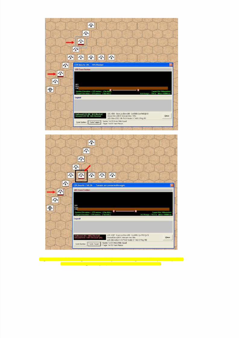
7/21/2019 TSS User Manual
http://slidepdf.com/reader/full/tss-user-manual 384/492
Figure 369: LOS through connected/adjacent underground IP's (tunnels). TheLOS on the right is open, the one of the left is blocked.

7/21/2019 TSS User Manual
http://slidepdf.com/reader/full/tss-user-manual 385/492
o The floor and ceiling of each IP is used to determine if the LOS is blocked by either. In cases where more
than one IP is in a location, the most favorable one for the LOS is used.o Aside from wrecks and occupant units, there are no terrain effects.
o The maximum range is determined based on the IP cross-sectional area (height x width). Larger IP’s,
such as vehicle tunnels, have longer sighting ranges than smaller ones such as” crawl spaces”.
• DF is not permitted in Underground IP’s.
• Close combat is adjusted for the width of the IP so that the number of attackers/defenders in direct contact isnever more than could fit across the width of the IP.
• Automatic placement on the map. In some cases, an underground IP may be placed on the map automatically by
the computer at the start of the scenario. This allows the underground IP to have surface access as is intended,and saves the player from having to do it. The IP is placed as follows:
o A surface IP with underground access must be located adjacent to an underground IP.
o The two adjacent IP’s (surface and underground) must allow the same types of units to occupy them.
o There must not be an underground IP in the location with the surface IP.
o When these conditions are met, the computer will automatically place an underground IP of the same
type as the adjacent one in the location with the surface IP. If more than one IP type is adjacent to thesurface IP, the largest underground IP type (in terms of capacity/size) will be selected.
3-4.5.2 Underground IP Fog of War Underground IP’s are known and detected like all other battlefield objects. At the start of the scenario, they will be knownto the defending/placing player, but usually unknown to the other force (unless set otherwise when the IP was placed).
Figure 370: Initial detection values are set on the Force Values Form.
During the initial detection phase, underground IP’s cannot be detected by signal, aerial or satellite reconnaissance. Theyhave a very slight chance of being detected by patrols, but realistically they can only be detected through HUMINT(interrogation of enemy soldiers or others in the area).
Units in underground IP’s have the same limitations on being detected, with the exception that they may be detected bySIGINT (detection of their radio and signal traffic). However, the initial detection probability is much reduced given thatthe units are more likely than not to be using other forms of communications besides radio, which are harder to detect orintercept. And, when they do use radio, the signal strength reaching friendly SIGINT units will be reduced over unitstransmitting from the surface.

7/21/2019 TSS User Manual
http://slidepdf.com/reader/full/tss-user-manual 386/492
Figure 371: Only HUMINT can realistically detect underground IP's at the start of the scenario. Signal interceptcan detect units in tunnels, but not the IP’s themselves.
During the scenario, units always detect adjacent underground IP’s whenever they occupy one. Additional IP’s may alsobe detected by visual, IR or other means during the standard sighting and detection phase. Newly detected undergroundIP’s are reported using the normal reporting and message procedure.
Radio communication from underground systems can be problematical, and all radio transmissions from undergroundunits are adjusted based on the LOS between the sender and recipient. Where the signal passes through the ground, thestrength is reduced according to the amount of earth it passes through and the frequency (if known). When the strength isreduced passed a threshold based on the radio maximum range, the transmission is blocked. For systems that require an
LOS, the reduction from passing though the earth is greatly increased over systems that do not require it
3-4.5.3 Underground IP Map DisplayOn the map, below-ground IP’s are shown underneath objects on the surface. As with IP’s in general, the icon for unitsoccupying the IP are shown underneath the IP symbol.
Figure 372: Underground IP map display.
3-4.5.4 TunnelsBecause tunnels are the most common use of underground IP’s it is worth discussing them in somewhat greater detail.
• Construction: Tunnels are constructed by placing a series of adjacent underground IP’s that have undergroundaccess.
• Units move though the adjacent IP’s based on their movement characteristics as set in the TEC (Terrain EffectsChart). For example, to create a rail tunnel, all of the IP types used to create the tunnel must allow for railmovement as defined in the TEC.
• Surface access is optional. However, if it is desired, it is achieved by placing an IP type that allows for it (i.e., hasboth surface and underground access). The IP should allow for the same type of units to move though it as theother IP’s making up the tunnel. For example, in a rail tunnel the “entrance” IP must also allow for rail movementin the TEC.
• There is no prohibition against creating a tunnel completely from IP types that have both surface and undergroundaccess. This configuration will allow units to enter and exit the tunnel at any point along its length. However, formost map scales this situation would not be realistic.

7/21/2019 TSS User Manual
http://slidepdf.com/reader/full/tss-user-manual 387/492
• There is also no prohibition against having certain “limited” access points along the length of the tunnel, using IP’swith surface and underground access but that do not allow as great a movement type as the tunnel. For examplea “Stairs” IP type could be defined and placed that allows access to the tunnel by personnel only, even though thetunnel itself can carry vehicles.
• Hexline features, such as roads, trails or rail lines are always assumed to be on the surface; they are completelyignored by units moving though tunnels. As such, hexlines should in general not be included on the map inlocation where the feature proceeds through a tunnel (i.e., a “gap” should be left by the map creator).
Figure 373: Tunnel “start” with a surface entrance. The computer has automatically added a "real" tunnel IP tothe location with the entrance to insure connectivity.
3-4.6 Moving Between Adjacent/Co-located IP’sIn order for a unit to enter an IP, these conditions must be met:
1) The IP type must permit the unit stacking type (personnel, gun, vehicle, etc.).
2) The IP must have enough free capacity to hold the unit, accounting for damage, wrecks, and other units alreadyinside it.
3) The IP must be large enough in each dimension (length, width and height) to allow the unit to physically occupy it.4) The IP must have appropriate access (as discussed above).
If these basic conditions are met, the unit may move between the IP’s. Except as specified, the moving units will use thestandard movement routines, and will be subject to delays and terrain effects.
3-4.6.1 Moving Between Adjacent/Co-located IP’sSurface to Surface: Units may move between co-located IP’s (the IP’s are in the same map location) without exposure orcost. When units move between adjacent surface IP’s they may do so in one of three ways, depending on the IPcharacteristics:
1) If the IP’s are discrete (buildings, bunkers, etc.) they must exit the first IP, move over the surface to the adjacent
location, and then enter the second IP.2) If the IP’s are “location sized” (i.e. one dimension equals the map location/hex scale), the unit moves directly fromone to the other. It is never exposed on the surface.
3) If the IP’s both have underground access, they are assumed to be connected by a tunnel, and the unit can begiven orders to use it instead of moving on the surface.
Underground to Underground: When units move between adjacent underground IP’s, they always move directly from oneIP to the other. The units never exit to the surface. Both IP’s must “connect underground”.
Surface to/from Underground: The IP’s must be co-located. There is no cost for the move.

7/21/2019 TSS User Manual
http://slidepdf.com/reader/full/tss-user-manual 388/492
Figure 374: Movement path of a unit moving into a tunnel. Movement though underground tunnels (IP’s) isindicated in a different color than surface movement.
3-4.6.2 Unit Orders: Above/Below GroundUnits must be given explicit orders to move underground from the surface or vice versa. This can be done in one of twoways:
1) Issue an explicit movement order though the standard movement orders interface. The unit will execute the orderas it would any other movement command.
Figure 375: The “Out Tunnel” command orders a unit in an underground IP to the surface.
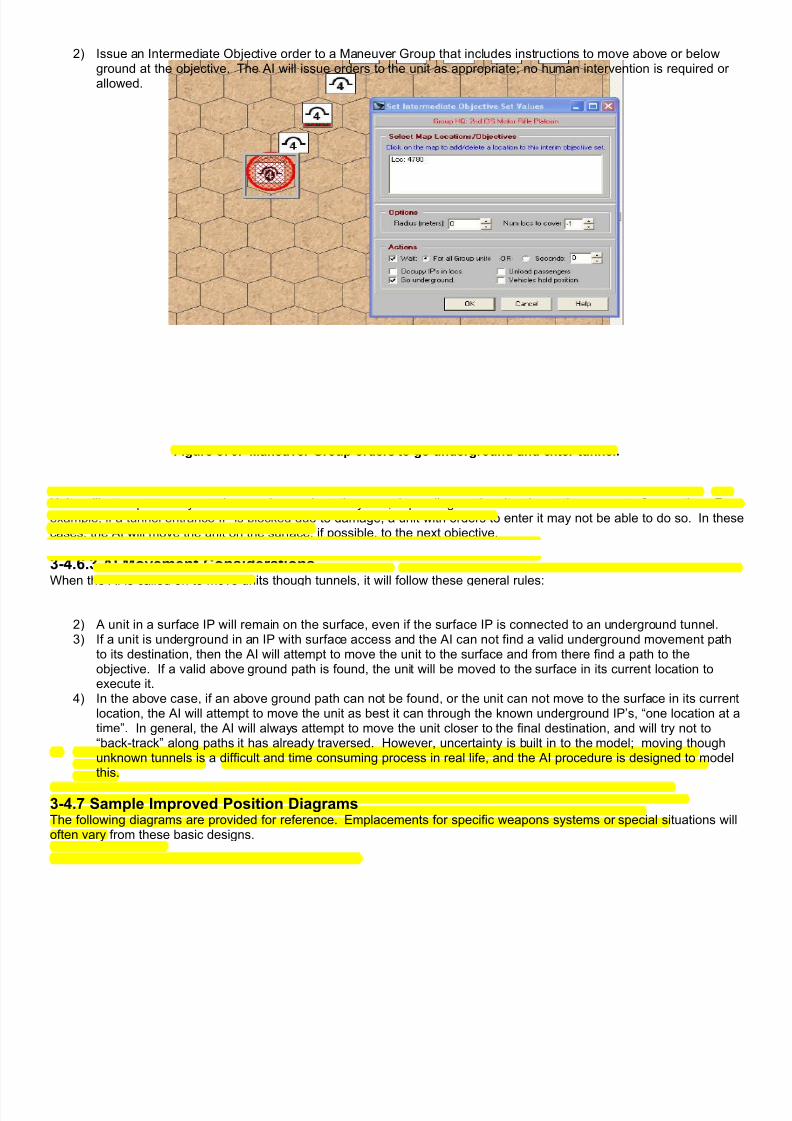
7/21/2019 TSS User Manual
http://slidepdf.com/reader/full/tss-user-manual 389/492
2) Issue an Intermediate Objective order to a Maneuver Group that includes instructions to move above or belowground at the objective. The AI will issue orders to the unit as appropriate; no human intervention is required orallowed.
Figure 376: Maneuver Group orders to go underground and enter tunnel.
Units will attempt to carry out these orders as best they can, depending on the situation at the moment of execution. Forexample, if a tunnel entrance IP is blocked due to damage, a unit with orders to enter it may not be able to do so. In thesecases, the AI will move the unit on the surface, if possible, to the next objective.
3-4.6.3 AI Movement ConsiderationsWhen the AI is called on to move units though tunnels, it will follow these general rules:
1) It will try to keep units above or below ground unless the unit is given a specific order to the contrary or a path cannot be found (see #3, below).
2) A unit in a surface IP will remain on the surface, even if the surface IP is connected to an underground tunnel.3) If a unit is underground in an IP with surface access and the AI can not find a valid underground movement path
to its destination, then the AI will attempt to move the unit to the surface and from there find a path to theobjective. If a valid above ground path is found, the unit will be moved to the surface in its current location toexecute it.
4) In the above case, if an above ground path can not be found, or the unit can not move to the surface in its currentlocation, the AI will attempt to move the unit as best it can through the known underground IP’s, “one location at atime”. In general, the AI will always attempt to move the unit closer to the final destination, and will try not to“back-track” along paths it has already traversed. However, uncertainty is built in to the model; moving thoughunknown tunnels is a difficult and time consuming process in real life, and the AI procedure is designed to modelthis.
3-4.7 Sample Improved Position DiagramsThe following diagrams are provided for reference. Emplacements for specific weapons systems or special situations willoften vary from these basic designs.

7/21/2019 TSS User Manual
http://slidepdf.com/reader/full/tss-user-manual 390/492

7/21/2019 TSS User Manual
http://slidepdf.com/reader/full/tss-user-manual 391/492

7/21/2019 TSS User Manual
http://slidepdf.com/reader/full/tss-user-manual 392/492
Section 3.5: Point Missile Defense Systems
Point Missile Defense (PMD) Systems interdict incoming enemy missiles as they near their target. Currently in thesimulation, intended targets “fire” the PMD only in their own defense. They will not try to intercept missiles aimed at othertargets. However, to provide flexibility, the simulation will allow Directed Energy weapons (PMD or not) to be used againstenemy missiles, even if the firing unit is not the target of the attack.
7/21/2019 TSS User Manual
http://slidepdf.com/reader/full/tss-user-manual 393/492
PMD weapons are designed to destroy or at least deflect the incoming missile before it impacts. PMD systems use anumber of methods to accomplish this, depending on their sophistication level. Smoke, anti-missile rockets and guidedmissiles, un-aimed “canister” type fragmentation charges, and aimed directed energy beams are the most commonoptions.
Whenever a unit with a PMD system comes under attack from a projectile moving at less than 500 meters per second, thesimulation automatically checks to see if the round can be detected by the PMD system. These checks are made at leasttwice, when the missile is launched/fired, and just before it impacts. In the second case, the detection probability is“averaged” over the flight of the projectile from the maximum detection range (or the actual range, if less) and a pointabout 10-25 meters from the target. The longer the time the missile spends in the detection area, the better its chances ofbeing detected. If the PMD system has a long-range weapon, it may engage the target out to the weapon’s maximumrange, once the incoming missile has been detected.
Once an incoming missile has been engaged by a PMD system, it may still cause damage to the target, or to other targetsnearby. This is true even if the PMD scores a “direct hit”. The reason is that the incoming missile is often either thrownoff course, in which case it still explodes on impact, or the “kill” from the PMD detonates the warhead anyway. Thesimulation will determine when these conditions occur, and apply any secondary effects as applicable. Normally,unprotected troops are at the greatest risk from these effects; however, other vehicles (or even the original target) mayalso be damaged or destroyed. In general, PMD systems are grouped along the following divisions:
• Detection System: The detector determines what targets the PMD system can see and track, as well as how
vulnerable it may be to countermeasures or conditions. Most PMD systems can defend against one or more types ofrelatively slow-flying missiles, including rocket-propelled grenades. However, advanced technology is required to beable to intercept very fast missiles, or small targets like artillery rounds. The best all-around detection system isprobably Active Radar since it has the potential to detect any solid object. However, in practice, radar systems alsorequire filters and other sophisticated controls to separate out “clutter” (i.e. flying debris, chunks of earth, etc.) fromactual threats. Most other detection systems are threat specific, in that they detect only one type of incoming missile.The detection system also often determines how far out the incoming missile can be engaged, which determinespotential secondary effects on the target and/or nearby units.
• Damage Routine: This is how the PDM system disables the incoming threat. These methods range from a simplethrowing up of smoke, to advanced guided interceptor missiles and directed energy beams. The method of damagehas two important effects in the simulation. It determines how far away the incoming missile can be engaged, andwhat secondary affects the PMD system may produce on nearby units. For example, a system that uses canisterrounds containing several hundred ball bearings will almost certainly cause casualties among any unprotected troops
in its firing arc.
3-5.1 PMD Detection SystemsIn the simulation, detection systems are rated for the types of targets they can pick up (slow missiles, fast missiles,RPG’s, artillery, etc.), the method they use to detect those threats (Radar, IR, sound, Laser, etc.), how far out they candetect targets, and how long they take to verify the flight path and engage the target.
Individual detectors types are only effective against specific targets. If the target is not of the appropriate type, it can notbe detected or engaged by the PMD system. The basic target types are broken down as follows: Slow missiles (<200m/sec); fast missiles (>=200 m/sec); rocket propelled grenades (RPG’s); small artillery/mortar rounds (<105mm); andlarge artillery rounds (>=105mm). These categories can be set for each PMD system.
There are two varieties of detectors: Passive and Active. Passive detectors register energy produced from external
sources, as when a LASER beam is shone on a target to “illuminate” it. In the absence of an energy source, the detectorremains quiescent Active detectors, on the other hand, produce their own energy, and actively seek out targets. Withinthese bounds, there are a few additional restrictions:
1) Passive Laser detectors are only effective against laser-guided missiles (which home in on laser light reflected fromthe target). Likewise, Passive Radar detectors are only effective against radar-homing missiles.
2) Passive Acoustic detectors can only detect incoming rounds that move at low sub-sonic speeds and generate noiseduring either firing and/or flight. They cannot detect artillery rounds fired from a distance of greater than 5 Km andfast missiles (>200 m/sec).
3) Passive Visual/IR detectors key in on launch backblast and heat produced during flight. Only missiles producethese signatures, and can thus be detected.

7/21/2019 TSS User Manual
http://slidepdf.com/reader/full/tss-user-manual 394/492
Each PMD system is given a “detection rating” which is a measure of its effectiveness. The detection rating is based on abenchmark of detecting the “average” incoming round at a range of 500 meters (or the maximum detection range, if lessthan 500 meters). The “average” is taken to be a projectile with the size and speed comparable to a US TOW-2 (speed~120 m/sec, diameter ~150mm). The actual detection probability is than adjusted for the relative missile/projectilecharacteristics. Larger and slower rounds are easier to detect than small fast ones. In the simulation, this is also true foracoustical detection systems, since it is assumed that faster and larger rounds are also louder.
The more time the incoming round spends in the “detection zone”, the better its chance of being detected. One it isdetected, the PMD will engage at the earliest opportunity within its maximum range.
3-5.2 PMD Damage RoutinesDamage by PMD systems is not resolved in the same way as other combat situations, since the conditions are verydifferent. Instead, the PMD system is given an effectiveness rating which represents the maximum average chance it hasto deflect or destroy the round once it is engaged. In most cases, a target will only be engaged a single time by the PMDsystem, so this rating effectively represents the lethality of the system. However, long range or directed energy systemsmay get multiple engagement opportunities, which will improve their overall performance. Whether or not a PMD systemgets to engage multiple times is a function of how fast the target missile is moving, as opposed to how long it stays in thedetection zone and how fast the PMD system takes to react.
Like the detection probability, the effectiveness rating is based on an “average” projectile, again the US TOW-2. Theactual probability adjustment depends on both the type of target and the damage method used:
DamageType
Target Type
Slow Missile Fast Missile RPG’s Small Arty Large Arty
Anti-MissileRockets
Normal Much Less Less - -
GuidedMissile
Normal Less Normal Much Less Less
Smoke (*) Normal Less - - -
Canister Normal Less Normal - -
Screen (**) Normal Normal - - -
Dir. Energy Normal Normal Less Less Normal
(*) - Smoke is effective only against laser-, IR- or visual-guided missiles.(**) - Multi-spectrum screen is effective against laser-, IR-, visual-, or radar-guided missiles.
In general, the effect of faster missiles is to decrease the reaction time of the PMD system. This most heavily affectssmoke, which may take several seconds to deploy, and unguided rockets, which have less of a “window” in which theycan damage the incoming missile.
PMD SystemDamage
Type
Incoming Target Type
Smaller Larger Slower Faster More Filler
Anti-MissileRockets
Much Less Much More Less Much Less More
GuidedMissile
Less More Normal Less More
Smoke (*) Normal Normal Normal Much Less Normal
Canister Less Slightly More Normal Normal Normal
Screen (**) Normal Normal Normal Much Less Normal
Dir. Energy Less Much More More Less Normal
(*) - Smoke is effective only against laser-, IR- or visual-guided missiles.(**) - Multi-spectrum screen is effective against laser-, IR-, visual-, or radar-guided missiles.

7/21/2019 TSS User Manual
http://slidepdf.com/reader/full/tss-user-manual 395/492
In comparing the actual size, speed, and filler weight (warhead size) to the TOW-2 average, in general most systems dobetter against larger and slower targets. In particular, the systems that send out a shower of shrapnel or ball-bearings(rockets and canister) are given more opportunity against these targets than those with single projectiles/warheads.Smoke types are once again heavily penalized against very fast moving targets.
Secondary effects may also be caused by the action of a PMD system. Shrapnel from rockets and canister will affectunprotected troops and other soft targets within their radius of action (35 meters for canister, 15 meters for rockets).Likewise, if the incoming missile detonates, it may create additional damage within a radius based on its filler weight (fromthe point it is determined to have detonated). Deflected missiles can also produce casualties either by hitting anothertarget in the same location, or less likely, another location along the flight path. The simulation takes all of these factorsinto consideration, and calculates the damage accordingly.
3-5.3 PMD Ammunition DepletionOne special topic concerns the way in which PMD ammunition depletion affects the efficiency of the system. In somecases, this will be straightforward, as in the case of rockets or missiles with 360-degree traverse. Once a missile is fired,one missile is removed from the available ammunition pool. Likewise, a burst of smoke or directed energy drains one unitfrom those available. As long as this type of system has at least one round remaining, it can engage any incoming missile(within the system’s covered arc).
However, in other situations, things are more complicated. Because the simulation does not keep track of how manyrounds remain for each area (or arc) of coverage, but instead lumps them all together, it might be unreasonable tosubtract exactly one round every time. For example, let’s say a tank has 12 canister rounds spaced evenly around its360-degree arc. Each canister covers an incoming arc of 30 degrees, and once a round has been expended in that arc
any missile that enters from that direction will be unopposed. If the driver can’t swivel the tank fast enough to bring anunexpended round to bear, the simulation needs to calculate the probability that the missile is coming in along a protectedvs. unprotected arc.
The equation used is:Prob. of protected = (rounds remaining) x (depletion factor)
For the first case, the depletion factor should be 100. As long as at least one round remains, any incoming missile willhave a 100% probability of entering through a protected arc. In the second case, the probability should be about 8 or 9percent. That way, once a few rounds are expended, the probability of a missile coming in a protected arc alsodecreases.
3-5.4 PMD Vulnerability Another consideration is the relative vulnerability of the detection system itself to damage and destruction. For example,most active radar systems include antenna arrays that are easily damaged, even by small arms fire. Thus, there is achance these systems may be damaged by the explosion (or impact) of the incoming missile even though it has beendetonated or knocked off course by the PMD system itself. Because there are so many components and potentialweakness in the PMD system, damage is assessed in the normal way (using burst radius values, penetration, and thelike) and then adjusted for the vulnerability factor.
Section 3-6: Fog Of War (FOW)
FOW of war is a term used to describe the lack of precise information commands posses on the battlefield once the actionstarts. It applies to lack of precise information on enemy positions and strengths, as well as the friendly situation. The
better a force’s communications and the more concentrated its units are, the better the information and the less FOW thecommander will experience.
The simulation models FOW as it applies to both friendly and enemy forces, although the level of each can be set by thehuman player(s) as follows:

7/21/2019 TSS User Manual
http://slidepdf.com/reader/full/tss-user-manual 396/492
FOW LevelEffects
Friendly Units Enemy Units
OFF All fully known. All fully known, even if not sighted.
1 All fully known. Units that are sighted are fully known (e.g.,the exact size and weapon system areknown). Unsighted units remain hidden, orshown with the best “last known” information.
2 All fully known. Units may be sighted to degrees, from barely
sighted to fully sighted, and the informationpresented corresponds to the level. Unsightedunits remain hidden, or shown with the best“last known” information.
3 Fully known if sighted or stationary.Otherwise, the latest SITREP and bestestimate of the unit’s position are shown.
Units may be sighted to degrees, from barelysighted to fully sighted, and the informationpresented corresponds to the level. Unsightedunits remain hidden, or shown with the best“last known” information.
3-6.1 Unit-specific FOW
Information is specific to each unit in the game. In other words, each unit “sees” and “knows of “ a unique set of friendlyand enemy units. This includes information about the unit itself; a unit always knows it own situation completely eventhough its HQ or sister units might not.
Additionally, units can only act using the information they posses at the time. For example, units can only fire at targetsthat they can see themselves, regardless if other friendly units can see it - even if they are in the same location. Likewise,if a unit doesn’t know an enemy unit is waiting at a certain location, it might get ambushed, even if other friendly unitsknow the enemy is there.
The game is intended to be played principally though the “eyes” of the Task Force (TF) Commander, as if the humanplayer were present in the TF Headquarters unit. With one exception, all of the staff reports and map displays will belimited to the information the player would know in that position. The single exception is direct fire (DF) targeting. If theplayer selects individual units in order to give them explicit DF targets (and thus bypasses his AI-subordinates), the mapwill display what that unit knows. Otherwise, it would be impossible to give any kind of meaningful orders.
Players wishing to preserve complete FOW, therefore, should never select units for targeting orders. Instead,they should avoid “micro-management”, and rely on the AI controllers to select targets for the individual units, as wouldoccur in real life.
3-6.2 Known vs. Sighted Object Information All units and objects that are not hidden are either sighted (the unit can actually “see” it in some way, including thoughradar or other sensors), or they are “known”. Known objects are not currently sighted, but a position and situation is“known” for them in some way - either though a past sighting, or from reports sent by other friendly units (see below).
Information from direct sighting, while not always complete, is always current. On the other hand, information that is“known” is often neither current nor accurate, and is instead simply the “best” or “last known” position and condition of theobject. In reality, the object may have moved or changed its condition in any number of ways, and thus “known”
information should be used with care when making plans.
Information is always displayed with the “as-of” time at which it was gained. Information from direct sighting will always beshown as “[Current]”, while “known” information can be “[Current]” or any duration since the start of the scenario, such as“[2 minutes Ago]”.
3-6.3 MessagesSITREP (Situation Report) messages are used to transmit information between units, so that target sightings and otherreports can be disseminated throughout the force as applicable. SITREP’s travel though the normal chain of command,both up and down. For more information, see the section on the Chain of Command, below.

7/21/2019 TSS User Manual
http://slidepdf.com/reader/full/tss-user-manual 397/492
As SITREP messages are received, information on the object of the message is updated, if it is more current than whatthe unit already knows. Otherwise, the SIPREP report is ignored. The SITREP is then always forwarded to the unit’shigher HQ. It may also be sent down to the unit’s subordinates, depending on how pertinent the AI determines it is.Therefore, while SITREP’s are not always disseminated to all of the line units, they are always sent up the complete chainof command to the TF HQ. SITREP’s can cover any aspect of what a unit knows, including the condition of friendly and enemy units, objects such asobstacles and bridges, and unknown or “wrongly” known terrain.
3-6.4 Enemy UnitsUsing all but the lowest level of FOW, enemy units begin the game completely unknown to the friendly player. During thestart of game set-up phase, a number of enemy units may be revealed as described in that section, below. After that,they will only become known if a friendly unit detects them. Detection can be by any method, such as visual, light, noise,radar, or other sensor.
Depending on the level of FOW in force, detection is rated by its quality, which in turn determines how much information itreveals. For example, a detecting unit will know a lot more about an enemy unit it sees in the clear a hundred metersaway than it will about one it hears making noise at night in the woods. The quality of detection is known as the “knownlevel”. There are five levels, which provide the following information about the target:
Level 1 Level 2 Level 3 Level 4 Level 5
Exact Quantity(Ex: 5 x M106A2)
No No No No Yes
Model
(Ex: M1A1 Abrams)No No No Yes Yes
General Type
(Ex: Tank, APC)No No Yes Yes Yes
Appropriate Unit Symbol
(Ex. Tank Unit)No No Yes Yes Yes
Facing
(Ex: Facing East)No No Yes Yes Yes
Unit Size(Ex: Platoon, Squad)
No Yes Yes Yes Yes
Movement
(Ex: All Moving, None Moving)No Yes Yes Yes Yes
Stacking Type
(Ex: Vehicle, Personnel) Yes Yes Yes Yes Yes
Enemy units are always reported in aggregate. In other words, individual units are not reported. Multiple enemy units ofthe same type are in the same location (and have the same known level), they will be reported as a single entity. So, forexample, a report would say “10 x M1A2 Bradley”, or “Company of Vehicles” rather than something like “3 Platoons ofTanks”.
In order to be aggregated together, enemy units must be known at the same level. They must also be of the same type,based on the known level. For example, if the units are known at level 1, they only have to be of the same generalstacking type in order to be aggregated together, so a tank unit and a truck unit would be put together since they are bothvehicles. If the units were both known at level 5, however, they would have to be the exact same model in order to beaggregated.
Aggregate enemy forces known at less than level 3 will only have a generic unit symbol displayed on the map. At level 3and above, a symbol appropriate to the weapon system type will be shown, along with a size indicator (based on theaggregate size).
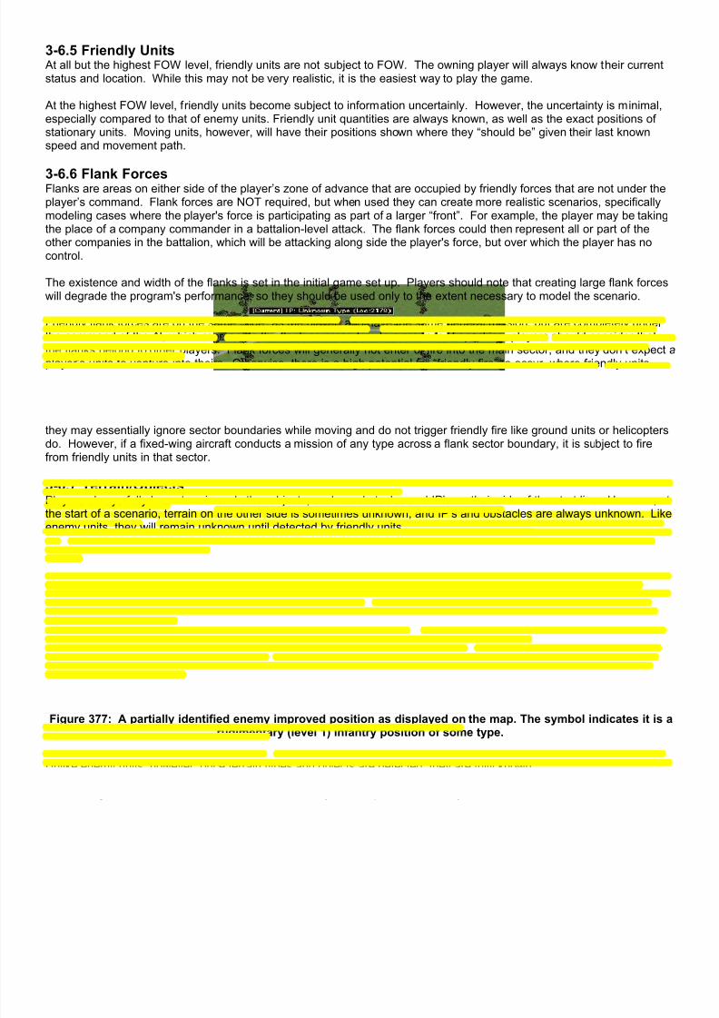
7/21/2019 TSS User Manual
http://slidepdf.com/reader/full/tss-user-manual 398/492
3-6.5 Friendly Units At all but the highest FOW level, friendly units are not subject to FOW. The owning player will always know their currentstatus and location. While this may not be very realistic, it is the easiest way to play the game.
At the highest FOW level, friendly units become subject to information uncertainly. However, the uncertainty is minimal,especially compared to that of enemy units. Friendly unit quantities are always known, as well as the exact positions ofstationary units. Moving units, however, will have their positions shown where they “should be” given their last knownspeed and movement path.
3-6.6 Flank ForcesFlanks are areas on either side of the player’s zone of advance that are occupied by friendly forces that are not under theplayer’s command. Flank forces are NOT required, but when used they can create more realistic scenarios, specificallymodeling cases where the player's force is participating as part of a larger “front”. For example, the player may be takingthe place of a company commander in a battalion-level attack. The flank forces could then represent all or part of theother companies in the battalion, which will be attacking along side the player's force, but over which the player has nocontrol.
The existence and width of the flanks is set in the initial game set up. Players should note that creating large flank forceswill degrade the program's performance, so they should be used only to the extent necessary to model the scenario.
Friendly flank forces are on the same “side” as the player, and have the same general mission, but are completely underthe command of the AI, which represents the flank commander. In a manner of speaking, players should consider thatthe flanks belong to other players. Flank forces will generally not enter or fire into the main sector, and they don’t expect aplayer’s units to venture into theirs. Otherwise, there is a high potential for “friendly fire” to occur, where friendly unitsshoot at units on their own side (see below).
Flank forces can contain fixed-wing aircraft. Because of the speed and characteristics of these air units, they often traceout long flight paths as part of their standard orbit or CAS mission. As such, the program makes an exception for them sothey may essentially ignore sector boundaries while moving and do not trigger friendly fire like ground units or helicoptersdo. However, if a fixed-wing aircraft conducts a mission of any type across a flank sector boundary, it is subject to firefrom friendly units in that sector.
3-6.7 Terrain/ObjectsPlayers always fully know terrain and other objects, such as obstacles and IP’s on their side of the start line. However, atthe start of a scenario, terrain on the other side is sometimes unknown, and IP’s and obstacles are always unknown. Likeenemy units, they will remain unknown until detected by friendly units.
Figure 377: A partially identified enemy improved position as displayed on the map. The symbol indicates it is arudimentary (level 1) infantry position of some type.
Unlike enemy units, however, once terrain types and objects are detected, they are fully known.
Concerning terrain, roads and towns are the most likely to be reported incorrectly.

7/21/2019 TSS User Manual
http://slidepdf.com/reader/full/tss-user-manual 399/492
3-6.8 Bridges
Figure 378: Bridge Information Form (can only be accessed during the scenario if the bridge is fully known)
Bridges have three unique FOW components as compared to other objects. Even if they are “known” to be present in alocation, their type, damage level and whether or not they are primed for demolition are not also automatically known.Like units, these characteristics must are revealed step-by-step based on the “quality” of the detection or the player’ssituation.
Players always have complete information for bridges on their side of the start line. They also have complete informationon bridges once a friendly unit has moved across or next to, or that they have primed for demolition.
Otherwise, bridges must be detected as for other objects. Bridge types and damage are relatively easy to determinethrough aerial reconnaissance and medium to long range ground spotting. Whether or not a bridge is primed for
demolition, however, requires closer inspection.
Once a player knows a bridge characteristic, it remains known for the remainder of the scenario, even if thespotting/detecting units move away from the bridge or lose a LOS to it.
Figure 379: Fully known bridge displayed on the map, including the weight class (150).

7/21/2019 TSS User Manual
http://slidepdf.com/reader/full/tss-user-manual 400/492
Figure 380: Partially known bridge displayed on the map. The weight class is not shown since the damage/typeis not currently known.
3-6.9 Minefields
Minefields may be detected the same as other objects, although short of having a unit explode a mine, they are oftenmuch harder to see since mines are normally buried or camouflaged. Deliberate minefields are easier to detect thanhasty ones because they are usually marked to protect friendly forces from inadvertently entering them.
Figure 381: Initial minefield placement screen. Only the owning player will be shown the quantity and type oncethe scenario is in progress.
Players always know the number of mines and types in a minefield they placed. The other player will never know thenumber of mines placed, although he may get general information on the size of the minefield and the types (AP/AT)placed. Unfortunately, this information often only comes after a unit or two has moved into a minefield and detonated
some.
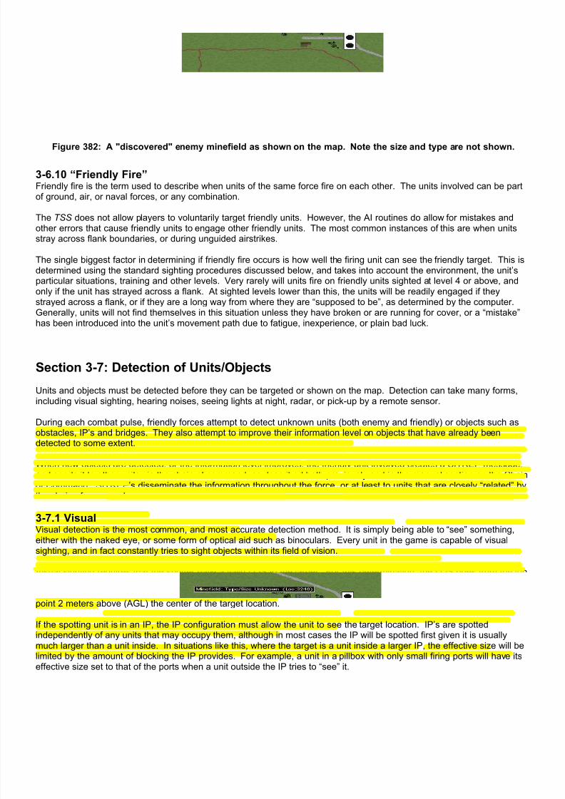
7/21/2019 TSS User Manual
http://slidepdf.com/reader/full/tss-user-manual 401/492
Figure 382: A "discovered" enemy minefield as shown on the map. Note the size and type are not shown.
3-6.10 “Friendly Fire”Friendly fire is the term used to describe when units of the same force fire on each other. The units involved can be partof ground, air, or naval forces, or any combination.
The TSS does not allow players to voluntarily target friendly units. However, the AI routines do allow for mistakes andother errors that cause friendly units to engage other friendly units. The most common instances of this are when unitsstray across flank boundaries, or during unguided airstrikes.
The single biggest factor in determining if friendly fire occurs is how well the firing unit can see the friendly target. This isdetermined using the standard sighting procedures discussed below, and takes into account the environment, the unit’s
particular situations, training and other levels. Very rarely will units fire on friendly units sighted at level 4 or above, andonly if the unit has strayed across a flank. At sighted levels lower than this, the units will be readily engaged if theystrayed across a flank, or if they are a long way from where they are “supposed to be”, as determined by the computer.Generally, units will not find themselves in this situation unless they have broken or are running for cover, or a “mistake”has been introduced into the unit’s movement path due to fatigue, inexperience, or plain bad luck.
Section 3-7: Detection of Units/Objects
Units and objects must be detected before they can be targeted or shown on the map. Detection can take many forms,including visual sighting, hearing noises, seeing lights at night, radar, or pick-up by a remote sensor.
During each combat pulse, friendly forces attempt to detect unknown units (both enemy and friendly) or objects such asobstacles, IP’s and bridges. They also attempt to improve their information level on objects that have already beendetected to some extent.
When new objects are detected, or the information level improves, the friendly unit involved creates a SITREP message,and sends it to other units via the chain of command, as described both previously and in the manual section on the Chainof Command. SITREP’s disseminate the information throughout the force, or at least to units that are closely “related” bythe chain of command.
3-7.1 VisualVisual detection is the most common, and most accurate detection method. It is simply being able to “see” something,either with the naked eye, or some form of optical aid such as binoculars. Every unit in the game is capable of visualsighting, and in fact constantly tries to sight objects within its field of vision.
Visual sighting requires that the spotter have a valid LOS to the target. For this determination, the LOS goes from the topof the spotting weapons system to the top of the target object. For example, if the spotter is a tank 2 meters high, and thetarget is a 3 meter-high building, the LOS goes from a point 2 meters above (AGL) the center of the spotting location to apoint 2 meters above (AGL) the center of the target location.
If the spotting unit is in an IP, the IP configuration must allow the unit to see the target location. IP’s are spottedindependently of any units that may occupy them, although in most cases the IP will be spotted first given it is usuallymuch larger than a unit inside. In situations like this, where the target is a unit inside a larger IP, the effective size will belimited by the amount of blocking the IP provides. For example, a unit in a pillbox with only small firing ports will have itseffective size set to that of the ports when a unit outside the IP tries to “see” it.

7/21/2019 TSS User Manual
http://slidepdf.com/reader/full/tss-user-manual 402/492
The visual sighting probability is based on apparent size, measured in square seconds of arc, as described in the priorsection on targeting. The baseline value is that a “truck sized” object has a 50% chance of being spotted at a range of700 meters (an apparent size of 2.5 million square arc seconds) in 15 seconds. The baseline value is modified asfollows:
• The probability is reduced proportionally for the LOS blocking value.
• If the range is greater than 700 m, the probability is multiplied by the 700/actual range.
• If the target is silhouetted, the probability is increased 300-500%.
• The probability is reduced proportionally for the concealment level in the target location.
• If the sun is low and behind the target (i.e., the spotter is looking into the rising or setting sun), the probability isreduced. The reduction depends on the angle of the sun above the horizon, the cloud cover, the sun positionrelative to the LOS, and ambient illumination level.
• The probability is reduced by 10%-20% for twilight conditions.
• If the spotter or target is an aircraft, the clouds will reduce the probability is the LOS passes through the cloud layer.The reduction is proportional to the cloud cover percent.
• If the target is an aircraft, and the spotter is at a lower elevation (AGL), the probability will be reduced somewhat ifthe cloud deck is not in the LOS, but “in the background”, i.e., higher than the target aircraft.
• If the illumination level in the location (ambient + artificial) is less than 20 points, the probability is reduced inverseexponentially (small losses near 20, much larger losses if under 10).
• If the target is already sighted to some level, the probability is increased by 150% - 500%, depending on the level.If the target is not sighted, but is known, the probability is increased 125%.
• If the target fired one or more of its weapons last turn, the probability is increased, depending on the weapon(s).
The minimum increase is 20%, but it is especially increased for weapons that create flash and smoke, as indicatedin the Gun Data Table. Flash is more relevant at lower light levels, while smoke is the opposite and requiresillumination of some type to be seen.
• If the target is broken or berserk, it is 4 times more likely to be spotted.
• If the target unit’s morale is less than 50, the spotting probability is increased by up to 20%
• If the target unit’s training level is less than 60, the probability is increased by up to 20%. If it is greater than 85, it isreduced by up to 10%.
• The probability is reduced for a ground target unit’s camouflage level - 0.2% per camouflage level for personnel,and 0.1% per level for all other target types. Naval and air units are not affected.
• If the target is moving, the probability is increased for the apparent speed. The adjustment is up to 250% of normalHowever, the probability is reduced for very fast targets with a relative velocity above 800 degrees per minute (13degrees per second).
• If the target unit is moving, and generating dust clouds, the probability is increased as long as the dust clouds
appear “behind” the target to the spotter.• If the spotting unit is moving, the probability is reduced based on the actual speed as a percent of the maximum
weapon speed. The value is then adjusted for the best gun stabilization value. The maximum reduction is 50%.
• The probability is adjusted (plus or minus) for the weapons system visibility rating. The rating values are set in theWeapons System Data editor.
• The probability is adjusted proportionally for the spotting and target unit quantities.
• If the range is greater than 500 meters, the probability is increased for spotted enemy units near the target (within300 meters).
• If the spotting unit is an aircraft, the probability is adjusted based on the aircraft’s altitude (AGL). Below 100 metersthe probability is adjusted anywhere from 75%-200% of normal. Above 100 meters, the probability is increased200%-400%.
• If the spotting unit and/or target unit are currently engaging in “shoot & scoot” techniques, and the range to thetarget is 500 meters or more, the probability is reduced up to 60% for each (firing unit/target unit), based on the
terrain in the location.• If the spotting unit is suppressed, the probability is decreased 1.5% for each suppression point, unless the unit is
armored and buttoned-up. In that case, the probability is reduced by the weapon system buttoned-up visibilityfactor, which is specified in the Weapons System Data Table.
• If the spotting unit has thermal sights that are “pointed” towards the target, the probability may be increased basedon the ambient temperature and illumination levels. Thermal sights are most effective at lower light levels andcolder temperatures with minimal wind.
• If the spotting unit has thermal sights that are “pointed” towards the target, the probability may be increaseddepending on the current conditions and the type of IR system (active vs. passive). The technical level of the IR isalso used, as well as the anti-IR rating of the target weapons system. Passive IR sensors require an active IRsource, which in addition to illuminating the area for friendly forces, will be easily detected by enemy IR sensors.

7/21/2019 TSS User Manual
http://slidepdf.com/reader/full/tss-user-manual 403/492
• If the unknown unit is friendly, the probability is increased greatly if the unit is “known” at all (but not spotted). Additionally, the probability is increased based on how close the units are in the “chain of command”, and howmany levels up the chain of command the first “shared” HQ is.
3-7.1.1 IlluminationIllumination is a measure of the light intensity at any given location. It is composed of two parts: the ambient illuminationfrom the sun or moon, and artificial light produced from any other source such as forest/terrain fires, flares, or burningwrecks.
Ambient illumination is applied equally to all locations based on the current ambient illumination level. Artificialillumination is applied to locations individually, based primarily on a their distance and LOS from the illumination source. Artificial illumination is calculated in “points”, where 2 million candlepower equals approximately 5 points at a range of 400meters. As with other forms of radiated energy discussed in a previous section, the light from an artificial source isassumed to radiate equally in all directions, and thus the intensity decreases as the square of the distance.
Artificial light levels are calculated as follows:
Source Illumination Generated (at 100 meters)
Wrecks:
• Light Vehicles
• Medium Vehicles
• Heavy Vehicles• Light Aircraft
• Medium Aircraft
• Heavy Aircraft
• Other
3 points per wreck
6 points per wreck
10 points per wreck5 points per wreck
15 points per wreck
25 points per wreck
1 points per wreck
Flares:
• Flares drop at a rate setthey burn out at a height(AGL) of 30 meters basedon their burn time andinitial ignition altitude.
One gram of incendiary filler produces approximately 32,000candles of light.
The burn time is set in the Ammunition Types Data Table.
The ignition altitude is set in the Ammunition Data table.
Terrain Fires:• The maximum fire level for
a terrain type is theTerrain flammability asdesignated in the TEC.
Each fire point is approximately 30 million candles, or the equivalentof 9000 grams (2.5 gallons) of flammable liquid (napalm).
As outlined above, illumination improves general visual sighting during periods of darkness or limited visibility. It may alsocause units to become blinded, if trying to sight, or silhouetted, if being sighted.
3-7.2 IR (Infrared) DetectionInfrared radiation, or IR, is energy at a wavelength just outside the visual range of humans (just below red). It is emittedby all objects with a temperature above absolute zero (-273K), and is sensed as heat. At relatively cool temperatures,objects will emit energy essentially only in the IR wavelengths. As they get hotter, however, the peak emitted energy
distribution moves towards (shorter) wavelengths in the visible band. This is why hot metal glows red, then yellow, thenblue-white in addition to the IR “heat” felt on the skin.
Thermal sensors use the relationship between temperature and the emitted energy wavelength to “see” objects in theabsence of visible light. Because warmer object glow “brighter” at shorter wavelengths, they can be detected against acooler background by selectively filtering those wavelengths. The greater the temperature difference between theambient and the object, the easier it is to see. That is why thermal sensors are most effective in detecting hightemperature objects (engines that have been running for a while, for example), and at lower ambient temperatures wherehumans can show up by virtue of being much warmer than the environment surrounding them.
While human eyes can’t see it, IR is a type of light, and it behaves very much like light in the visible part of the spectrum.In particular, it reflects from objects irrespective of their temperature, based on the object’s surface properties. As such, it
7/21/2019 TSS User Manual
http://slidepdf.com/reader/full/tss-user-manual 404/492
can be used just like visible light to illuminate objects, although with somewhat less resolution than visible light due to therelative monotone spectrum.
There are two types of IR devices, although both use reflected IR light to “see” object. The first type is “active”, sodesignated because it produces it’s own IR light, which it then uses to illuminate the target area. It’s just as if it had asearchlight, except the light produced by the searchlight is in the IR range and thus can’t be seen by humans. When anIR sensitive device views the IR-illuminated area, it produces a picture humans can see.
The second type of IR system is “passive”, and it is simply a detector. It does not have an IR source. Instead, it relies oneither an active system somewhere else emitting IR light, or on the ambient IR radiation (which, remember, is producedby any object above absolute zero - which is essentially everything on the Earth).
The simulation models both types of IR systems, and allows for higher resolutions based on the IR illumination level in thetarget location, along with the technology level of the detector (which is based on the Communications level as set in theForce/Nations Table). Additionally, units that use active IR are much easier for other IR systems to detect, subject to thenormal LOS and facing conditions that apply to visible light.
3-7.3 NoiseUnits may also be detected by the noise they make. For example, it is possible to detect a column of enemy tanksmoving up a road by the sound of their engines and treads, even though they can’t be seen directly.
The probability of detecting a unit by the noise it makes is based on the apparent sound level heard by the “spotting” unit.This is calculated based on the following:
• The base amount is based on the general type and weight. Personnel make the least noise, then vehicles, thenships and aircraft.
• Vehicles with no movement orders are assumed to have their engines shut off, and are treated as personnel.
• Helicopters make relatively more noise than their weight would otherwise generate, and slow fixed wing aircraftless.
• Jet aircraft moving at high speeds (>0.75 Mach) generate additional noise over what their weight would otherwisegenerate. Any object moving above Mach 1 generates a sonic boom, which increases the noise level dramatically.
• The probability is increased if the unit is moving, based on both the absolute and relative speed. This means a tankmoving up a slope as fast as it can, will still make a lot of noise, even though it has a low actual speed.
• The unit’s noise discipline can affect the level under certain conditions.
• The noise level is decreased 1% for each degree the ambient temperature exceeds 25 °C. It is increased 1% for
each degree under 5°C.
• The noise level is reduced 3% for each Kph of wind speed.• The sound level is reduced for distance using an inverse square relationship.
It is much more difficult to get “high quality” information (such as the exact model of the enemy equipment) from noise ascompared to visual detection. However, noise can often alert friendly units to the enemy’s presence, which in addition toallowing them to be targeted with supporting fires, also makes them more liable to be seen visually.
3-7.4 Light Units can also be detected from the light they generate. For example, it’s easy to see a column of vehicles moving downa road with their headlights on, especially from the air.
The computer determines whether vehicular units are using headlights or not based on their speed. If the unit is movingat the headlight threshold speed or above, it is assumed to be using headlights. At speeds slower than that, units are
using their blackout lights exclusively. The threshold speed is 15 Kph in total darkness and is increased 3 Kph for eachdegree of illumination, up to 20. Headlights are not needed if the illumination is greater than 20. The speed is alsoadjusted for the force’s night vision devices, 1/2 Kph for each point in the average of the force’s photo-reconnaissanceand satellite ratings.
Only vehicles use headlights.
Stationary or non-vehicular units can also generate light. Aside from jet aircraft however, the amounts are very small.
The nominal generated light levels are adjusted as follows:
• The LOS must not be completely blocked, and the light level is proportionally decreased for any LOS blockingpoints.
7/21/2019 TSS User Manual
http://slidepdf.com/reader/full/tss-user-manual 405/492
• The light level is reduced 1% for each level of illumination in the target location.
• Stealth technology reduces the signature from aircraft movement (jet exhaust). The stealth level is set in theWeapons Systems Data Table.
• The light from non-aircraft units is adjusted for the unit’s noise discipline rating, which can modify the level +/- 50%.
Like noise, light detection does not usually generate top-level information on weapon models. However, it does assist infurther visual and other detection efforts.
3-7.5 Radio Transmissions
Units can be detected by the radio transmissions they send, at least if the enemy force possess any level of radio findingequipment. In the simulation, radio detection devices are defined as sensors, in the Sensor Data Table, and assigned toweapons system in the Weapons System Data Table.
The chance of a sending unit being detected increases with more transmissions it makes, and also the longer themessage durations. The detection probability is based on:
• The transmitter’s power output, based on the command radius of the unit, or if it is an AWACS or naval craft.
• The signal strength is decremented for the range between the transmitting and detecting unit, using the inversesquare of the distance.
• The received power must be greater than the minimum power level (sensitivity) of the receiver.
• The average message duration is calculated. Message duration is based on the transmission method (data,radio/voice, satellite), and the message type (SITREP, moment orders, targeting orders, etc.).
• If the transmission method is anything but data, the transmission time is adjusted for the both sending and receivingunits’ communications level (and also the leaders’, if any is present).
• For durations less than 5 seconds, the probability is reduced to 1/3rd normal. For durations over 10 seconds, theprobability is increased 200% plus 5% per additional second.
• The probability is adjusted proportionally for the detecting unit’s training level, and the force SIGINT level.
Units detected from signal intercept are never known beyond level 1, or that “something” is in a certain location. Howevergiven that larger HQ's are often found though this method, that is often enough to call in air or artillery. But beware; if theHQ is stationary and has been for a while, and the force has a relatively high communications level, it is likely that theantenna is located away from the actual HQ itself. In this case, the reported position will not be the HQ’s actual position,but rather an “offset” location that represents the antenna’s location.
3-7.6 Radar
There are many types of radars, and each can detect a set number of target types. Virtually anything that has anelevation above the ground level can be detected, including aircraft, missiles, and artillery and mortar rounds.
Because radar has such a wide range of detection and identification functions, as well as guidance capabilities, it iscovered in a comprehensive special section below.
3-7.7 Remote SensorsRemote sensors are devices that detect enemy ground units and send that information to friendly forces without therequirement of having a friendly unit present in their locations. In a simple form they might be something as basic as amicrophone attached to a small transmitter. Friendly units could then simply “listen” for any noises that would indicateenemy movement - vehicle engines for example.
The simulation allows for a range of sensors, using sound, vibration, light, and radio as the detection medium. Each
sensor also has a sensitivity rating for personnel, vehicle, and radio energy, which is the range at which an “average” unitof that type can be detected. Sensors use the standard detection routines for their medium as described above, with afew exceptions. The first is that the adjustments for the “spotting unit” (morale, fatigue, etc.) are always completelyignored since sensors are not units. In addition, the following adjustments for each type are:
• AFV (Vehicles): The average is based on an M113 APC moving at 25 Kph.1. Sound: Adjusted proportionally for the weight and speed value. Reduced 50% for non-tracked vehicles.2. Vibration: Adjusted proportionally for the weight and speed value. Reduced 90% for non-tracked vehicles.3. Light: Headlights must be on (see section above for headlight discussion).4. Radio: Sender’s radio power is based on the command radius of target vehicle.5. Radar: Probability adjusted proportionally for actual size, and reduced for the weapons system stealth rating
and the terrain in unit’s location.

7/21/2019 TSS User Manual
http://slidepdf.com/reader/full/tss-user-manual 406/492
• Personnel: The average is a group of 4 troops walking in the clear.1. Sound: Reduced 50% if not moving, and 25% if moving less than 5 Kph.2. Vibration: The unit must be moving, but there are no other adjustments.3. Light: Reduced 75% if the unit is not moving.4. Radio: Sender’s radio power is based on the command radius of the target unit.5. Radar: Probability adjusted for terrain (cover/concealment) in location.
If a unit is detected, the sensor accuracy is used to determine how much information the sensor is able to gain, and howaccurate it is. For example, sensors with low accuracy might report only that “something” is there, while those with highaccuracy might be able to report an approximate number, movement direction and speed, and even the likely model of theunit detected.
Aside from sensors that detect EM emissions, only surface units (less than 10 meters AGL) can be detected.
When a remote sensor detects a unit, it must transmit that information back to friendly forces. Specifically, the informationmust be sent to either a friendly HQ or EW (electronic warfare) unit. Each sensor type has a maximum transmissionrange. If there is no friendly HQ or EW unit within that range, the detection will not be reported.
Remote sensor reports may also be degraded by enemy EW efforts, which may delay the report or cause the accuracy tobe reduced.
Integral sensors are assigned to a weapons system and are considered fully “part” of it, such as FLIR (forward-lookinginfrared) equipment mounted on a helicopter. They use the same basic detection routines and probabilities as remote
sensors, but have no need to transmit information back to friendly forces. The detecting unit always knows of thedetection immediately and without degradation.
3-7.8 Start of Scenario Detection At the start of the game, players “know” only what units and terrain are on the friendly side of the start line. However, inalmost all cases, additional information will be provided based on friendly reconnaissance efforts, including signalintercepts, satellite monitoring, aerial reconnaissance, HUMINT, and patrols. The amount of information provided by eachof these techniques is determined by the force levels in each of the areas (which can be adjusted when a scenario iscreated), as well as the situation on the ground.
In some cases, more than one type of detection system may detect an enemy unit or object. In that case, the seconddetection usually adds to the “known level” of the item, although sometimes it might not. So the number of items shownon the map will not always match the total number of items reported found at the beginning of the game.
The base probability of detecting an object for any method is equal to the force level in that area. For example, if thesatellite level is 100, then the base probability of detecting an “average” object is 100%. However, these values areadjusted depending on the type of object being detected, and also sometimes for conditions.
Unlike detection during an in-progress scenario, information found during this phase is known equally by all of the units inthe force. SITREP’s are only used once the scenario has started.
Figure 383: The results screen for "Start of Scenario" detection of enemy units and other objects.

7/21/2019 TSS User Manual
http://slidepdf.com/reader/full/tss-user-manual 407/492
3-7.8.1 Signal InterceptSignal intercept detection is the result of friendly radio detection and triangulation efforts prior to the start of the scenario.Units outside of your task force conduct these efforts, based on the force SIGINT level, and the results are completelyindependent of the size of composition of your task force.
Signal intercept can detect enemy units anywhere on the map, and is multiplied for the target object as follows:
• Bridges: 1%.
• Minefields: 1%.
• Obstacles: 1%.
• IP’s: 0% (they can not be detected).• Units: 30% (50% if HQ).
3-7.8.2 Pre-battle Satellite MonitoringSatellite monitoring represents satellite pictures and video taken of the battle area from space before the scenario begins.The pictures are sent to a processing center, and the deciphered intelligence is sent down the chain of command to thetask force. The satellite coverage area is centered on the center of the map, and it has a radius of 100 meters for eachpoint of the force’s satellite level.
Because the satellite data was obtained prior to the start of the scenario, the current weather is not used. Instead, thecomputer determines what the weather was like up to 48 hours in the past, and uses that in the routines. Cloud cover andprecipitation decrease satellite effectiveness.
The base detection probability is multiplied for the type of object being detected as follows:• Bridges: 50% (hard to tell if they are primed for demolition).
• Minefields: 10%.
• Obstacles: 30%.
• IP’s: 40%.
• Units: 35%.
Actual satellites may also be added to a force that will operate during the scenario. These satellites become quasi-unitscontrolled by the AI, and may be used for reconnaissance and communications purposes. The operation, capabilities andcharacteristics of these satellites are discussed in the section on Command and Control, later in the manual.
3-7.8.3 Aerial Reconnaissance Aerial reconnaissance includes photography and other sighting activities performed by friendly aircraft, including very high
altitude flights, and those by drones/UAV’s (unmanned aerial vehicles). The aircraft performing these flights are not partof the player’s task force, or even the echelon above the task force, but represent high-level assets owned by thecombined joint task force.
Reconnaissance over-flights cover the entire are of the map.
As with satellites, the current weather is not used, and instead the average weather over the last 12-24 hours is used.
The base detection probability is multiplied for the type of object being detected as follows:
• Bridges: 35% (hard to tell if they are mildly damaged or primed for demolition).
• Minefields: 10% of normal.
• Obstacles: 30%.
• IP’s: 30%.
• Units: 30%.
3-7.8.4 HUMINTHUMINT, or “human intelligence”, is information gleaned principally from the interrogation of enemy soldiers whosurrendered or defected, or were captured. It also includes information provided by civilians coming from the enemyareas.
HUMINT covers the entire map area, and the base detection probability is multiplied for the type of object being detectedas follows:
• Bridges: 40% (may be able to disclose if primed for demolition).
• Minefields: 30%.
• Obstacles: 35%.

7/21/2019 TSS User Manual
http://slidepdf.com/reader/full/tss-user-manual 408/492
• IP’s: 35%.
• Units: 25%.
3-7.8.5 PatrolsPatrols operate differently from the other reconnaissance activities, in that the computer actually sets a portion of aplayer’s force on the map to represent units that have been in place before the force moved into the line, and these unitsrun actual patrols across the front line. The number of units the computer places on the map, and where they are placeddepends on the situation. More units are placed for defending forces than attacking forces, and also for the greater“urgency” of the mission (e.g., more units are placed for “defend at all costs” or “major attack” missions than for “delay” or
“feint” ones).
Patrols are much more effective when performed by normally dismounted troops (infantry). On average, each companysends out four patrols, each to an objective at a depth between 1- 3 Km (although they can go deeper if enemy forces arelight). Once at their objective location, a patrol searches out to a distance of 300 meters. Only objects in this area, orwithin 100 meters of the patrol’s march route, or that can be seen form any location the patrol occupies, can potentially bedetected.
The base detection probability of patrols is determined using the standard detection routines for dismounted infantry,multiplied by the following:
• Bridges: 50% (may be able to disclose if primed for demolition).
• Minefields: 20%.
• Obstacles: 40%.
• IP’s: 40%.• Units: 50%.
Section 3-8: Movement
During the movement portion of the combat phase, units will move according to their current orders. Movement alwaysoccurs between adjacent locations, whether the locations are on the map or not.
Unit positions are represented by their hypothetical center of mass. This point is defined as the location around which theunit’s equipment and personnel are “ equally spaced”, either linearly (if in road march mode) or concentrically (if in tacticalmode).
The center of mass is determined to the nearest meter, and always lies within a single location. For stationary units, theunit’s center point is the center of the location. Moving units, however, will have their position updated exactly as theymove between locations. So, while the unit may appear to be in the center of that location, in reality it may be “off center”en route to its destination.
For example, a unit that started moving due east 15 seconds ago at a speed of 10 Kph, will be positioned 41 meters to theeast of its current location center. This is because as a stationary unit it was located in the center of the location, and 41meters is the distance it will travel in 15 seconds at its current speed. If a location measures 100 meters in size, it meansthe unit is almost to the next location, but not quite. It must travel half the location size (100 x 1/2=50 meters) to reach thenext location (so it has 9 more meters to go, or about 3 more seconds).
3-8.1 Time Required to Move Between Locations
For those familiar with standard wargames, the TSS does not use the concept of “movement points”. Instead, it uses asystem based on terrain having certain maximum speed limits or delay times based on the movement type. The reason issimple; a tank unit ordered to move forward with the infantry at 5 Kph does not slow to 2 Kph just because it hits somelight brush. Instead, the light brush only affects the tank if it is moving faster than some “maximum speed” through thebrush, say 40 Kph. Another example is infantry crawling to combat at 1 Kph. It really doesn’t matter if they are crawlingdown a road, though the grass, or even in a forest. At 1 Kph, the terrain has no discernible effect on their movement rate.
The system also allows for better and more realistic control of combined arms movements. Because disparate units canbe ordered to move at constant (and equal) speeds, the group will stay together along the march, rather than having thefaster units (such as the vehicles), speed off ahead and leave the slower units behind.

7/21/2019 TSS User Manual
http://slidepdf.com/reader/full/tss-user-manual 409/492
Figure 384: A portion of the TEC (Terrain Effects Chart) showing movement effects for ‘Clear’ ground conditionsThe same values are used for terrain as well as obstacles, hexlines (roads), and hexsides (rivers).
The time required for a unit to move between two locations is calculated in 3 steps. First, the unit must move to the edgeof its current location. Then, it must cross any terrain feature between the locations (hexsides). Finally, it must move to
the center of the destination location. Each step in the process follows a similar procedure:
• A check is made to determine if the portion of terrain the unit must traverse is prohibited. The check includesterrain and other permanent map features, as well as for wrecks, fires, and other combat related conditions. If theportion is prohibited, the unit cannot move into the location as ordered, and will automatically attempt to findanother path to its final destination.
• A check is made to see if road march-mode is either required or “called for” by the SOP. Road march-mode putsthe unit in a linear formation, so that it can move along a road or bridge. Otherwise, it is in “tactical” mode andmoves cross-country completely ignoring roads and other linear features. If a march-mode change is necessary,the orders will be automatically issued to the unit so they can be executed (and the time required accounted for)before the movement proceeds.
• If the unit is moving into a different location, the stacking limits are checked. If an “over-stack” condition will occur,the unit will either be assessed a delay, or if the location is crowded enough, will either be broken up into
“detachments” or prevented from entering it completely. Stacking is discussed in more detail below, but is set foreach terrain type by general weapon category (personnel, gun, vehicle, air, and naval).
• The “cost” of the movement segment is determined based on the terrain types in the location, as well as the unit’smarch mode. Terrain affects movement in one of two ways: It can either impose a maximum speed on the unit, orit can add a discrete delay, in seconds. In cases where several terrain types are present with different maximumspeeds, the “slowest” one is used for the entire segment. If more then one type of terrain is present that adds adiscrete delay, however, the combined sum of the delays is used. For example, if a location contains the followingterrain, the maximum speed will be 30 Kph, with a delay of 180 seconds:
o Woods with a max speed of 30 Kph.
o Clear with a max speed of 70 Kph.
o Earth berm obstacles that add 120 seconds.
o Concertina wire that adds 60 seconds.
• The slope to be traversed by the unit is determined using the ground elevations of the starting and ending locations.
If this slope exceeds the maximum grade of the weapons system, it will likely be prohibited from completing themove. Otherwise, the speed may be reduced based on the ratio of the actual grade to the maximum grade appliedto the maximum weapons data speed.
• A check is made to see if the unit suffers any mechanical breakdowns, and if so, an immobile detachment iscreated.
• If the terrain is on fire, the unit is checked for damage, based on how long it had been contact with the fire, howstrong the fire was, and the basic unit characteristics.
• If the unit is in contact with chemical agents, the effects are assessed, along with any automatic MOPP (protectivemeasures) adjustments.

7/21/2019 TSS User Manual
http://slidepdf.com/reader/full/tss-user-manual 410/492
• If the unit moves into a location containing enemy units a check is made to determine if a close combat situationexists. If so, the unit will stop moving until the close combat situation is resolved (or it suffers some adverse combaresult). Close combat was discussed previously in the manual.
• If the moving unit is in the same location as a minefield (whether enemy or friendly, known or unknown), thecomputer will determine if it hits a mine, and if so, assess the results. Mines are discussed in more detail below.
• If the unit is moving in conditions of darkness (illumination < 20 points in the location), the weapon system’smaximum speed may be decreased based on the “Maximum Night Speed” value in the Weapons System table.The maximum speed reduction is applied proportionally between the normal (daytime) and night values based onthe actual illumination level (use of the daytime value at 20+ points, use of the night value at zero illumination
points). For example, if the normal max speed is 50 Kph, and the night value is 10 Kph, at a illumination level of 10(ambient plus artificial), the maximum speed for the weapons system would be 30 Kph.
• If maximum unit speed is also potentially limited by the sighting range in the location based on the global MaximumSighting Range plus any dust or smoke present. In these cases, units will not move faster than the distance theycan see within a prescribed amount of time. For example, in fog a vehicle may move so that it can always see atleast 10 seconds of travel ahead of its current location. If the visual range in this case were 200 meters, it meansthat the vehicle could not travel faster than 20 meters per second (200 meters / 10 seconds) or 72 Kph. The actualseconds of “sighting” required varies for each unit based on its general stacking type and the type of movementbeing affected:
Stacking Type Road Visibility Cross-country Visibility
Personnel/Gun 10 seconds 15 seconds
Vehicle 15 seconds 30 secondsNaval 300 seconds 300 seconds
Aircraft (hoverable) No effect No effect
Aircraft (fixed-wing) No effect No effect
RPV No effect No effect
Smoke effects can be adjusted for IR or other visual enhancement equipment as described in the general sightingsection. No modifications are used for dust or the global Maximum Sighting Range value.
Disorganized units (from airdrops) with movement orders will not begin moving until they become organized. Waveringunits (from morale effects) may or may not move if they have orders to do so, depending on their situation.
Units that must emplace before firing, such as artillery, will automatically be given orders to do so whenever they completeexecuting their existing movement orders. Likewise, if an emplaced unit is given movement commands, it willautomatically un-emplace before executing the orders since emplaced units cannot move.
Units with SOP orders to “wishbone” will automatically arrange themselves in that configuration whenever they pause.There is no time delay for this maneuver, which merely entails breaking the unit into three firing groups and pointing eachin different direction for better protection. When units in a “wishbone” formation begin moving again, there is also no timedelay to resume the normal march configuration.
3-8.2 ObstaclesObstacles are man-made objects designed to impede or even stop the movement of enemy units. They include suchthings as log hurdles, log cribs, barbed/razor wire, ditches, and abatis. They are used to provide what are known as
“counter-mobility” operations.
In the simulation, obstacles are defined as terrain types and are included in the TEC. As such, they act as any other typeof terrain, and can either limit the maximum speed of a unit moving though them, or they can impose a discrete delay.They can also “break” a road, e.g., force units to go into tactical march-mode to get around them.
Obstacles can either be placed at the start of the scenario, or emplaced by appropriately equipped units once the scenariois underway. Likewise, they can be destroyed from engineer or combat operations during the scenario. Partial obstacles(either in the process of being built, or partly destroyed), may have either reduced effect or none at all, depending on theobstacle type, the amount of obstacle in place, the terrain, and the moving unit’s type.
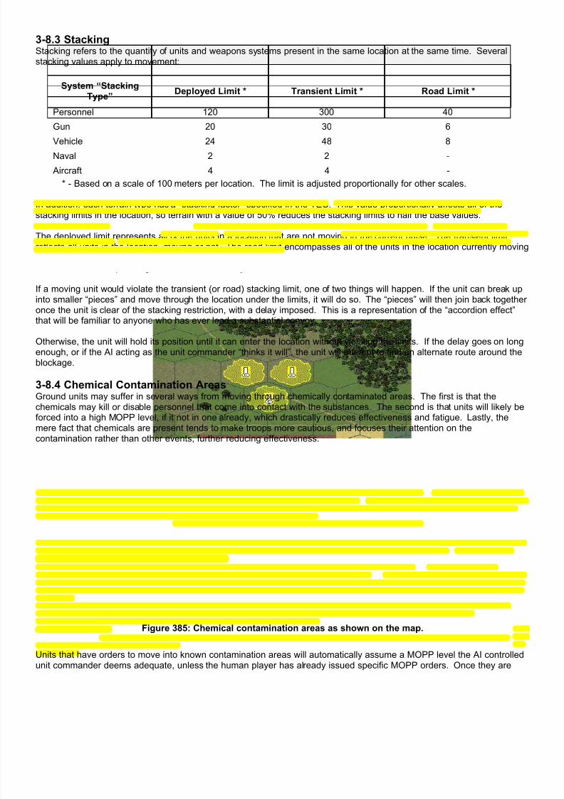
7/21/2019 TSS User Manual
http://slidepdf.com/reader/full/tss-user-manual 411/492
3-8.3 StackingStacking refers to the quantity of units and weapons systems present in the same location at the same time. Severalstacking values apply to movement:
System “StackingType”
Deployed Limit * Transient Limit * Road Limit *
Personnel 120 300 40
Gun 20 30 6
Vehicle 24 48 8
Naval 2 2 -
Aircraft 4 4 -
* - Based on a scale of 100 meters per location. The limit is adjusted proportionally for other scales. In addition, each terrain type has a “stacking factor” specified in the TEC. This value proportionally affects all of thestacking limits in the location, so terrain with a value of 50% reduces the stacking limits to half the base values.
The deployed limit represents all of the units in a location that are not moving in the current pulse. The transient limitreflects all units in the location, moving or not. The road limit encompasses all of the units in the location currently movingon a road (hexline). Under no circumstances can these limits be voluntarily violated, with the exception of emergencysituations, as when passengers bail out of a destroyed carrier.
If a moving unit would violate the transient (or road) stacking limit, one of two things will happen. If the unit can break upinto smaller “pieces” and move through the location under the limits, it will do so. The “pieces” will then join back togetheronce the unit is clear of the stacking restriction, with a delay imposed. This is a representation of the “accordion effect”that will be familiar to anyone who has ever lead a substantial convoy.
Otherwise, the unit will hold its position until it can enter the location without violating the limits. If the delay goes on longenough, or if the AI acting as the unit commander “thinks it will”, the unit will attempt to find an alternate route around theblockage.
3-8.4 Chemical Contamination AreasGround units may suffer in several ways from moving through chemically contaminated areas. The first is that thechemicals may kill or disable personnel that come into contact with the substances. The second is that units will likely be
forced into a high MOPP level, if it not in one already, which drastically reduces effectiveness and fatigue. Lastly, themere fact that chemicals are present tends to make troops more cautious, and focuses their attention on thecontamination rather than other events, further reducing effectiveness.
Figure 385: Chemical contamination areas as shown on the map.
Units that have orders to move into known contamination areas will automatically assume a MOPP level the AI controlledunit commander deems adequate, unless the human player has already issued specific MOPP orders. Once they are

7/21/2019 TSS User Manual
http://slidepdf.com/reader/full/tss-user-manual 412/492
past the area, they will return to their original level. Units that enter an area that was not previously known to containchemical agents, will take immediate MOPP protective measures, and will move out of the area on their own orders.
The destructive (kill and incapacitation) effects of chemical agents was discussed in detail previously, but essentially thelethality and other effects depend on the concentration of the agent in the area, the MOPP level of the exposed units, andthe time the units remain exposed. The higher the concentrations of agent that are absorbed into the body, the higher thecasualty/incapacitation rate.
3-8.5 Bridges
Bridges as objects are discussed in more detail in a later section of the manual pertaining to terrain. However, bridgeshave two important considerations as they pertain to unit movement. First, units must be in road-march mode to cross abridge. Secondly, the bridge must be able to support the unit in terms of weight capability and minimum width, both takinginto account damage the bridge may have sustained. Both of these conditions must be met, or the unit cannot cross thebridge.
A further effect of bridges is that they limit traffic flow across them. The computer takes into account each unit as itcrosses, including whether two-way traffic is possible based on the bridge width (accounting for damage), and the width ofthe weapons systems crossing. It also limits the number of weapons systems on the bridge based on each unit’s speedand the distance between weapons systems. It is worth noting that bridges can, and often will, become choke points ifthey are being used by a large number of units and that significant delays can result.
The stacking type of a weapons system is set in the Weapons Systems Data Table.
3-8.6 MinesMoving units may detonate mines, if their current location contains a minefield of any type. Only moving units willdetonate mines; stationary units, even if in a minefield, will not.
The probability that a moving unit will detonate a mine is determined principally by the density of mines of the appropriatetype in the location. There are three broad classifications of mines based on the types of targets that will cause them todetonate: anti-tank (AT), anti-personnel (AP), and anti-ship (AS). Mines are further classified by how they detect enemyunits. Passive mines are stationary and relatively inert, and require that the moving unit directly “trip” them, either thoughdirect pressure, magnetic flux, or some other stimulus. Active mines, on the other hand, have the capability to search fortargets and also usually a method of engaging them more effectively than a random detonation. These measures includethe ability to directly target an enemy unit, and/or the ability to move to a more favorable engagement location.
The result of a mine detonation depends on its filler material. By default, mines are filled with high explosive, and cause
damage though the effects of blast, shrapnel, or armor penetration. They can also contain lethal chemicals. In either ofthese cases, they use the standard combat results routines discussed previously.
Mines can also be a type that produces illumination, a common example of which is a “trip flare”. In these cases the mineitself doesn’t cause any damage, but it both alerts friendly forces of the enemy’s presence, and illuminates the area so theenemy can be engaged with direct and/or supporting fire.
Units moving though a cleared lane may still detonate a mine. However, the odds are much less than if moving outsidethe lane.
Mines are discussed in more detail as part of the section on Engineering.
3-8.7 Dust Generation
Ground units may create dust as they move across the map. The amount of dust they generate is determined by theunit’s speed, the size of the weapons system, the terrain dust creation factor, and the ground condition dust level. Thelarger and faster the weapons system, the more dust created. Dust can be reduced or increased for the type of terrain theunit is moving though (if there are multiple terrain types in a location, they are averaged together). It is also adjusted forthe ground condition value, which is a universal adjustment applied to every location on the map. It is designed tosimulate widespread conditions, such as reduced dust after heavy rains, for example. It can also be used to model snow“dust clouds”, which are usually much smaller than their counterparts made of soil.
Once placed, dust behaves like smoke and is subject to normal drift and dispersion. It will also degrade visual LOS’s, andmay both hide friendly units and mask their fires.
Dust is only placed in locations on the map. It is never created in locations off-map.

7/21/2019 TSS User Manual
http://slidepdf.com/reader/full/tss-user-manual 413/492
3-8.8 Camouflage Level AdjustmentsMoving units lose camouflage levels that they might have built up while remaining stationary. Guns, aircraft, and shipslose all of their camouflage once they start moving. Personnel and vehicles may retain some camouflage; at least if theyare not moving too fast, since their camouflage levels are based on their current speed. Generally, their best camouflagelevel will be approximately 1/8th of the level while stationary, minus 1 point for each 5 Kph of speed.
Camouflage, which makes the unit harder to spot visually, is only applicable if the unit is in a location containing terrainwith a concealment value greater than 10.
3-8.9 Join Units/Create DetachmentUnits represent a group of weapons system under a single command. For combat and most other purposes, they aretreated as single, and indivisible, entities. However, any unit larger than one weapons system can create a detachment,which is simply a part of the unit that is detached and operates on its own (and is shown as a separate unit). Thedetachment can be as large as the initial unit size, minus one, since otherwise there would be no point in creating thedetachment. Detachments are treated as normal units in all ways, and their initial parent unit is also their HQ.
Detachments may be created voluntarily by a player for operational purposes, for example, small detachments can beplaced forward of the main unit to act as LP/OP’s (Listening Post/Observation Posts). They may also be created by thecomputer to account for situations such as a unit having a weapons system sustain damage of some type, or to preventover-stack situations when moving.
Units may also be joined together, at the discretion of the owning player. However, in order to join, the units must be ofthe same weapons system type, must have similar damage values, and be in a normal morale state. The units must be inthe same location, and the combined unit must not be so large as to violate the stacking limit for its current location. If theparent unit is in an IP, the combined unit must fit in the IP, and if the parent unit is loaded, the combined unit must fit onthe carrier.
When units join together they pool their ammunition. However, the combined unit’s morale and other levels are based ona weighted average of the levels of the two units joining together. If either unit contains a leader, that leader takes overthe combined unit. If both units have leaders, the leader of the subordinate unit is effectively removed from the scenario.
Joining units requires a certain amount of time, depending primarily on how large the units are, the communications ratingof the force, any leaders present, and if either of the units is moving or suppressed.
The computer will only join units after they were broken up during movement to avoid an over-stack. All other joining
actions will be from orders issued by a human player. The larger unit is automatically the parent, unless they are ofroughly equal size, in which case the human player can specify the parent.
3-8.10 Mechanical BreakdownsUnits may suffer mechanical breakdowns from movement. The breakdowns can be caused by any number of thingsincluding flat tires, thrown treads, engine failures, or even leg muscle sprains or joint twists for troops on foot.
Weapons systems are given breakdown rates in the Weapons Data Table, or zero if the system never breaks down withinthe expected time frame of a standard scenario. The breakdown rating is in Kilometers, and is the “Mean DistanceBetween Failures”, e.g., the distance that the system will travel, on average, before experiencing a breakdown of somesort. Breakdowns occur randomly, however, so it is possible that one system will break down right away, while anothermay go many times the breakdown distance without a problem.
The probability of a breakdown for moving ground units is also modified for the terrain they are traversing. Each terraintype, including obstacles, has a breakdown adjustment in the TEC - which can range from 4 times to one half as likely tocause breakdowns as “standard”. These adjustments are applied only for the terrain the unit is actually moving over, notall of the terrain types in a location. For example, a unit moving down a road will ignore the other terrain types in thelocation, while a unit moving tactically will ignore the road. If an obstacle breaks a road and a moving unit is forced to goaround it tactically, a portion of each (road and the other terrain) will be used.
When one or more breakdowns have been determined to occur in a ground unit, the number is compared to the quantityof the moving unit. If the two quantities are equal, the unit is immobilized in its entirety. Otherwise, an immobilizeddetachment is created. The immobilization is also judged to be temporary, or permanent. The probability of thebreakdown being temporary and thus potentially repairable is about 4 times that of being permanent.

7/21/2019 TSS User Manual
http://slidepdf.com/reader/full/tss-user-manual 414/492
Air units that suffer breakdowns have their quantity reduced. They do not create detachments, and the stricken aircraftare assumed to either have crash landed, or attempted to return to their base.
3-8.11 Transporting Passenger UnitsFor portage purposes, weapons systems are classified as either “personnel”, or “other”. The personnel classificationrepresents rather small objects, such as troops and light guns and missile systems that are stowed internally. “Other”includes larger things such as guns, vehicles, and aircraft that are towed, slung, or mounted on some sort of flat bed(which can be internal).
Each weapons system is rated by a cargo cost, which is the number of “Cargo Points” the system occupies when loaded.Cargo “Points” represent limiting factors besides weight, such as volume, size, or awkwardness. Most systems take upone point, such as one infantryman, one AT gun, etc. However, crew-served weapons often have costs equal to thenumber of men in the crew, so that a mortar may have a cost of 5 points (3 for the crew, one for the mortar itself, and onefor the ammunition).
If the weapons system can potentially transport another unit, its transport capacities are also specified in “Cargo Points”,broken down for each type. For example, a truck might have 25 personnel “Cargo Points”, and 1 other “Cargo Point”.Thus, the truck could carry some number of troops (up to 25 “personnel Cargo Points”) plus tow another weapons systemwith a cost of 1 “other Cargo Point”. These capacities are ultimate limits, and under no circumstances can a weaponsystem exceed its Cargo Point capacity.
Transport-capable systems also have a maximum loaded weight. The total weight of its passengers, both personnel andother, can never exceed this limit.
If a unit is both loading and unloading passengers at the same time, unloading takes precedence over loading. Only afterthe unloading is complete will loading begin.
3-8.11.1 Loading/Unloading TimeLoading and unloading is not usually instantaneous, even for troops. The time required depends primarily on what isbeing loaded, and is different for each carrier system. These delays are specified in the Weapons System Data Table foreach carrier system, for bother personnel and other types. The delays are for a “full compliment”, and are adjusted forlower quantities. They are also adjusted for:
• Low morale - using the best value between the passenger and carrier.
• High fatigue - using the worst value between the passenger and carrier.
• Low training - using the best value between the passenger and carrier.
• Suppression - using the highest value between the passenger and carrier.
3-8.11.2 LoadingIn order for one unit to load on another, several conditions must be met:
• The units must be in the same location.
• The carrier unit must be stationary.
• The carrier must have enough spare Cargo Points of the appropriate type to accommodate the unit being loaded,after accounting for any other passengers already loaded.
• The weight of the passenger unit is added to that of any other passengers already loaded, and the total must notexceed the weight limit of the carrier.
If these conditions are met, the passenger unit will load onto the carrier. There will be a time delay before it isaccomplished, based on the carrier’s loading time value, the quantity of weapons systems being loaded, and if any other
units are loading/unloading at the same time.
Passengers are assumed to be loaded equally on all available weapons systems if the carrier unit is comprised of morethan one system. For example, if a platoon of 30 troops is loaded on a unit of 5 trucks, each truck will hold 6 troops. Ifthere are more carriers than passengers, for example 5 trucks towing 2 guns, the passengers are assigned to the carriersrandomly.
NOTE: During the player’s order phase, units may be given orders to load on each other even if they are not currently inthe same location. However, the AI will check to see if their current orders will eventually place them in the same location,and if not, will automatically issue orders to one or both units to accomplish this. In some situations, however, the carrierunit may be delayed or destroyed en-route to the meeting point. In this case, the AI takes over as the leader of the

7/21/2019 TSS User Manual
http://slidepdf.com/reader/full/tss-user-manual 415/492
potential passenger unit, and after waiting for a time past the expected meeting time, may decide the carrier is not comingand issue orders based on that realization.
3-8.11.3 UnloadingIn order for a unit to unload, several conditions must be met:
• When unloaded, the passenger unit must not cause an over-stack condition in the current location. The onlyexception is if the unloading is occurring from a combat action that damages or destroys the carrier, in which casestacking is ignored. This is known as involuntary unloading.
• The carrier unit must be stationary (except for paradrops), unless it has been damaged or destroyed from a combat
action of some type.
If these conditions are met, the passenger will unload from the carrier. There will be a time delay before it isaccomplished, based on the carrier’s loading time value, the quantity of weapons systems being loaded, and also if anyother units are loading/unloading at the same time.
The unloaded unit will initially face in the same direction as the carrier, and if the carrier is at all suppressed, will beassigned an equal or greater number of suppression points. The unloaded unit will initially have no speed; however, if ithas movement orders it will begin to execute them once the unloading delay has been accounted for.
If the unloading has been involuntary, e.g., a result of combat action destroying the carrier, the computer will check if theportion of the passenger unit unloaded could “fit” on the remaining systems in the carrier unit. If they can, they willnormally be loaded automatically. Otherwise, a detachment will be created for the newly unloaded passengers.
If the unit does not have movement orders, and caused an over-stack condition in the location by unloading, the computerwill automatically issue special movement orders to the unit out of the location to relieve the over-stack. In most casesthis means moving no farther than an adjacent location. However, the computer will issue orders as necessary until theunit reaches a location where it does not cause an over-stack.
3-8.12 Emplacing UnitsSome weapons systems have significantly different configurations between movement and their other combat operations.For example, towed guns cannot be fired in their normal travel mode; they must be set up first. This procedure mightinclude such things as opening the rails, positioning the gun, adjusting sights, setting up range stakes, and insuring thearea around the gun is flat and clear of objects to handle the recoil.
These procedures are collectively known as “emplacing” the weapon, and the time required to perform them is known asthe “emplacement time”. This time is set for each weapons system, and can be zero, which indicates the system does no
need to be emplaced in order to fire. This is appropriate for systems such as infantry.
Weapons systems that require emplacement cannot fire until they are emplaced.
The base emplacement time is modified as follows:
• Low morale.
• Low training.
• Suppression.
• Leaders present with the unit.
3-8.13 AircraftCompared to ground units, aircraft have unique movement and operational capabilities. These characteristics arereflected in the movement routines, as well as in the way they attack and can transport other units to the battlefield.
The biggest difference with air units is that they completely ignore the terrain over which they are flying. Essentially theycan fly over any location on or off the map, at their current speed, without being effected by maximum speeds, timedelays, or even LOS considerations.
3-8-13.1 Fixed Wing vs. Hover-capable AircraftThe simulation makes a distinction between “fixed wing” aircraft, which must maintain a certain minimum speed, andhover-capable aircraft that can reduce their speed to zero. The determination is based on the data entered for themaximum road and cross-country speeds in the Weapons System Data table. Aircraft with a maximum cross-countryspeed greater than zero are considered fixed wing, and those with a value of zero are considered hover-capable. One

7/21/2019 TSS User Manual
http://slidepdf.com/reader/full/tss-user-manual 416/492
point to note is that the term “fixed wing” is used in this context only for simplicity and in reality means “any non-hovercapable aircraft”.
Note: Also for simplicity, the database uses only two speed values: maximum cross country speed, and maximum roadspeed. For aircraft, the maximum road speed is the aircraft’s actual maximum speed, while the maximum cross-countryspeed is actually the minimum speed.
Because fixed wing aircraft cannot reduce their speed to zero, they must be constantly moving. Any air unit withoutspecific movement orders will be given orders by the computer. In most cases, the air unit will be ordered to orbit parallelto the front line, at a depth based upon its current location. However, if the air unit is performing a mission of some type,the computer will issue appropriate orders.
Hover-capable aircraft are not under this restriction. If they find themselves without movement orders, they will simplystay in their current location.
The current version of the simulation does not model fuel consumption, on the assumption that in real life air units willexhaust their ordinance before they run out of fuel, or that battles on the scale modeled by the simulation will end beforethen. As such, air units may circle or hover indefinitely.
3-8-13.2 Giving Aircraft Units Movement Orders Air units with current mission orders (to provide CAS or an airdrop) cannot be given movement orders by the humanplayer without first canceling the mission orders. Air units without mission orders, including those that are orbiting, may begiven orders freely. The procedure is the same as for ground units, with the exception that if the unit is a fixed-wing
aircraft, the speed may not be set lower than the minimum value (the maximum cross country speed value in thedatabase).
3-8-13.3 Special Aircraft MissionsDepending on its capabilities, an aircraft may have the ability to perform Close Air Support (CAS) or Paradrop missions.CAS missions engage enemy ground targets, and may be flown by any aircraft unit armed with the appropriate weaponsand with ammunition remaining. Paradrop missions are used to transport ground units to the battlefield, where they aredropped from the transport aircraft by parachute. Any aircraft with transport capabilities may fly paradrop missions aslong as it has at least one passenger on board. Passengers are normally loaded at the start of the game, although hover-capable aircraft may load units during the scenario.
Both of these mission types are controlled by the computer, once the player has selected the appropriate target or droplocation, and the general mission parameters. Because of the way these missions are set and executed is fairly detailed,
they will be discussed in their own section later in the manual.
Section 3-9: Morale
Morale represents the willingness of a unit to engage the enemy and to continue to perform its assigned combat missions.In the simulation, there are 5 unit morale states:
• Normal: the unit takes orders normally, and continues to perform assigned combat tasks.
• Wavering: The unit stops and holds its present position. It will continue to engage enemy forces, but will notaccept further orders.
• Run to Cover: The unit will retreat to the nearest cover that will protect it from enemy fire. It will continue to fire,and will continue to execute its current orders once it reaches cover or returns to normal morale status.
• Broken: The unit will no longer actively engage the enemy, and it will retreat as best it can some distance awayfrom nearby enemy units. The exact distance of the retreat varies, and depends on the situation, but can beanywhere from a few hundred meters, to more than a 2 or 3 Kilometers.
• Berserk: The unit will rush the nearest enemy unit. It will not accept new orders, and will ignore any orders it wasgiven before going berserk.
Each unit has a morale level, which is a value between 0 (Very low) and 99 (Very high) points. Units begin the scenariowith morale level point values in line with the overall force morale value, which is user adjustable. For average forces, themorale would be around 70 points. Highly motivated forces, such as Special Forces, Rangers, or Marines might havemorale values of 95 points or more.
7/21/2019 TSS User Manual
http://slidepdf.com/reader/full/tss-user-manual 417/492
Force morale values can never be less than 60 points.
A unit with a morale level of 100 will ignore morale considerations completely. If the force level is 100, all of the units inthe force will also initially have a level of 100 without any random variation.
At the start of a scenario, the morale level of a unit can be adjusted from the Unit Data screen (accessed by a <rightclick>).
3-9.1 Morale Adjustments
Morale is adjusted during the scenario from a number of combat activities.
Morale is Increased by: Morale is Decreased by:
• Destroying an enemy target. Aircraft andother high value targets increase moralemore than personnel and small vehicletargets.
• Resting in place. As units remain stationaryout of effective enemy fire, they gain moralepoints.
• Taking effective enemy fire. If the unit sufferslosses or damage, more morale is lost than if itonly takes fire.
• Seeing friendly targets destroyed. If the unit isin a position where it can observe other unitstaking kills it loses morale.
• Having a friendly HQ destroyed: If a friendlyHQ is destroyed, all of its subordinate unitslose morale.
Whenever a morale adjustment is made, the unit is also checked to see if it undergoes a status change. If the unit gainsmorale points, and is currently in a non-normal morale state, it is checked to return to normal. Otherwise, the unit ischecked to see which, if any, of the other than normal states it enters. The check takes into account both the currentmorale level of the unit, as well as how many points it lost or gained in the current turn.
Berserk units never have their morale affected by combat actions, either up or down. They revert to either Wavering orNormal status only after they have attacked and destroyed one or more enemy units.
The following table summarizes potential morale state changes, based on the unit’s current morale state:

7/21/2019 TSS User Manual
http://slidepdf.com/reader/full/tss-user-manual 418/492
Current MoraleState
Potential NewState
Considerations in Determining if the Change Occurs
Normal Wavering Does not need to be taking fire.
Morale must be less than 40 points.
Most likely in the morale point range 30-40.
Run to cover Unit must be taking fire.
Morale must be less than 80 points.
The unit must not already be under reasonable cover or in an IP.
Broken Unit must be taking fire.
Morale must be less than 30 points.Higher probability if base force morale is low (<70 points).
Most likely in the morale point range 0-20.
Berserk Unit must be taking fire.
Morale must be less than 35 points.
Higher probability if base force morale is high (>80).
Most likely in the morale point range 30-35.
Wavering Normal Must not be under fire.
Morale must be above 45 points.
The higher the morale level, the higher the probability.
Run to Cover Unit must be under fire.
Morale must be less than 85 points.
The unit must not already be under reasonable cover or in an IP.
The morale loss during the turn must be relatively small, otherwise the unit may become
Broken, instead (below).Broken The unit must be under fire.
Morale must be less than 40 points.
The higher the morale loss in the turn, the greater the probability of becoming Broken.
Higher probability if base force morale is low (<80 points).
Most likely in the morale point range 10-30.
Berserk Wavering units cannot become Berserk.
Run to Cover Normal Must not be under effective fire.
Morale must be above 40 points.
The higher the morale level, the higher the probability.
Wavering Must be taking fire.
Morale must be less than 45 points.
Most likely in the morale point range 30-40.
Broken Must be under fire.
Morale must be less than 35 points.The higher the morale loss in the turn, the greater the probability of becoming Broken.
Higher probability if base force morale is low (<80 points).
Most likely in the morale point range 10-25.
Berserk Units Running to Cover cannot become Berserk.
Broken Normal Must not be under fire.
Morale must be above 50 points.
The higher the morale level, the higher the probability.
The greater the cover in the location, the greater the probability.
Wavering Must not be under effective fire.
Morale must be above 40 points.
The higher the morale level, the higher the probability.
Run to Cover Broken Units cannot convert to Run to Cover.
Berserk Broken Units cannot become Berserk.
Berserk Normal Cannot be under effective enemy fire.Must have just destroyed an enemy unit within 150 meters.
Wavering Can be under fire.
Must have just destroyed an enemy weapons system, at any range.
Run to Cover Berserk units can not covert to Run to Cover
Broken Berserk units can not covert to Broken
Section 3-10: Force Levels

7/21/2019 TSS User Manual
http://slidepdf.com/reader/full/tss-user-manual 419/492
The force levels are used to quantify the capabilities of a force in the important aspects of combat operations. Somevalues, such as air superiority, are applicable only to the force as a whole. Others, such as morale, apply to each unitwithin the force. By default, the appropriate force levels are reflected closely in its component units, within a few percent tomodel random variation. However, at the start of a scenario, the values for individual units may be modified manuallyusing the Unit Information form.
3-10.1 TrainingTraining affects a wide range of combat functions in the simulation, including weapon accuracy, rate of fire, targetacquisition times, the amount of target overlap, and the ability to not “get lost” during long movements. Units with higher
training levels perform these tasks better, and thus should achieve better results than poorly trained forces. The forceTraining Level is set at the beginning of the scenario, and is applied equally to all units within the force. However, at thesame time, users can adjust the Training Level for individual units, so that differences between various units or branchescan be modeled correctly.
3-10.2 Discipline Ratings A force has three discipline ratings: light, noise, and communications. Each represents how effective units in the force areat preventing the enemy from detecting them by the specific method named. For example, at night, units with low lightdiscipline ratings are more likely to allow stray light to escape their area, which might be seen by enemy forces. Thesame applies to noise, while the communications rating measures how quickly a unit can transmit information so that thesignal doesn’t last long enough for the enemy to get an accurate bearing on it.
3-10.3 Camouflage
Each ground unit is rated for its ability to camouflage itself, in order to be more difficult for the enemy to spot. Normally,camouflage is most effective when a unit is stationary, and in some kind of terrain that offers cover and concealment.However, very high camouflage levels can also afford some benefit to units in other situations. Like the Training Level,above, the Camouflage Level is set at the beginning of the scenario for each unit based on the force level, and can beedited for each unit individually.
3-10.4 Communications (Orders Delay)The Communications/Orders Delay time determines how long it takes an HQ or any other unit to receive, transmit, anddisseminate information. In the simulation, under normal circumstances, orders are issued by a higher HQ and thentransmitted down to its subordinate line units. In cases where the Force Commander (either a human or computerplayer) issues orders, these orders begin at the Task Force (highest level) HQ. It is also possible that the computer AI(Artificial Intelligence) will issue its own orders, either in the absence of orders from the Task Force Commander, or underthe “stress” of combat. These orders will often be issued by HQ units, but sometimes line units will decided “on their own”
to perform some maneuver or targeting operation.
In the same vein, reports of enemy sightings and engagement results/damage must be transmitted up the chain ofcommand before the Force Commander knows of them.
In the simulation, orders and information flow through the normal chain of command, from the origination point up or downthrough subordinate HQ’s to their destination – either the line units or the Task Force HQ. The Communications Leveldetermines how fast the orders are processed by each HQ in the chain, and how fast the order is absorbed anddisseminated. In essence, The Communications Level determines how “flexible” the force will be, how fast it can adapt tochanging situations, and in the final measure, how much it is under the control of the Task Force Commander.
Communications are discussed in more detail in the section on Command and Control, below.
3-10.5 FrictionFriction is a measure of how long it takes units to process information internally, and to begin an action once the unitcommander decides to do so. It is discussed in more detail in the section on Command and Control below.
3-10.6 Air SuperiorityThe air superiority level is used at the start of a new scenario as a measure of how effective friendly forces are atinterdicting enemy air units en route to the battle area. The actual air engagements are abstracted, in that the computermakes a simple determination of losses and aborted aircraft, and applies those losses to enemy air units.
As a rough estimate, every 10 points of air superiority will cause the enemy to suffer 8% aircraft losses. Therefore,players should be careful when setting the level too high, since they may inadvertently wipe out all of the enemy’s airassets.
7/21/2019 TSS User Manual
http://slidepdf.com/reader/full/tss-user-manual 420/492
At the start of a scenario, the air superiority level for a force is set from the Player Information form (click the “Change/EditDefaults” in the Nation section of the main set-up form).
3-10.7 Electronic Warfare (EW)The force EW level represents the level of sophistication a force possesses in terms of electronic/radio equipment andtraining. It is used in the following ways:
• The ECCM rating of all radars in the force is set to 1.25 times the EW rating.
• The EW rating determines the time it takes to fix a damaged, but repairable, guided missile launcher.
• The EW rating determines how effective the force is at jamming and intercepting enemy communications.
3-10.8 Supply and StrengthThe supply and strength levels of the force are used only at the beginning of the game, and they provide a quick way toadjust a force to reflect degraded conditions. These levels are straight percentages that are applied to the startingstrength of a force’s units, and the basic load of ammunition they receive. The nominal strength of a force’s units are set inthe TO&E, while ammunition basic loads are set in the Weapons Systems Data Table.
Section 3-11: Command and Control
Command and control is a key concept in the simulation, because no matter how superior a force’s weapons, their
effectiveness will be much reduced if they can’t be brought to bear against the enemy in a timely and coordinated mannerWithin the simulation, command and control encompasses the transmission of orders and messages, as well as firecontrol measures such as targets and preplanned fires.
3-11.1 The Chain of CommandTo model command and control issues, the simulation uses a standard military chain of command, where a higherheadquarters unit controls each unit in the force. The human or computer player is assumed to be the Task Forcecommander, and therefore “present” in the Task Force HQ unit.
Units receive orders from higher HQ and transmit reports to higher HQ using the chain of command, with a delay imposedat each level. The delay represents the time it takes the unit to receive, process, and if not the ultimate recipient, re-transmit the message to and from other units in the chain. The relationships are shown for a simple situation below:

7/21/2019 TSS User Manual
http://slidepdf.com/reader/full/tss-user-manual 421/492
The delay at each step in the chain is determined by the situation and capabilities of that unit. In summary, these are:
• The unit will always use the fastest form of communication available to it. In order, these are:o Data (1/20th force communications delay time)
o Radio (normal force communication delay time)
o Visual (120 seconds or more, and requires an open LOS)
o Messenger (variable - depends on the distance, terrain, etc.)
• Radio and data transmissions may be affected by enemy jamming.
• Radio, visual, and messenger times are affected by the unit’s morale level.
• If not data, and the sending unit did not start the scenario as an HQ (e.g., is an “acting HQ”), the time is increasedup to 150%.
• The transmission time is adjusted for leaders in the sending and receiving unit.
• If the recipient unit is an aircraft, the time is reduced by 50%. ‘
• If either the sending or receiving unit is an AWACS, the time is reduced 50%
• Non-satellite based transmissions are adjusted for LOS, range and other conditions using the command radius of
the sending and receiving units (discussed below).
3-11.1.1 “Acting” HQ unitsIf a normal Headquarters unit is destroyed or incapacitated by combat, it will be replaced in the chain of command byanother unit. The new unit will then become the “acting” headquarters of the formation, and orders to and from the otherunits will go through it just as did they did the actual HQ.
The sequence in which units take over command functions is specified in advance by military doctrine. The simulationuses a standard sequence where command passes to the highest-level unit directly under the HQ. If there are two ormore units at the same level directly under the impaired HQ, the first one shown when viewing the force tree takes over.Should that unit also become impaired, the second in line will take its place and so on, down each level until the last unitin the formation is reached. For example, in a standard infantry company the chain of command would pass down fromthe company HQ to the 1st Platoon HQ, followed by the 2nd Platoon and so on. If all the platoon HQ’s are impaired,
command would pass down to the next level - the 1st Squad of the 1st Platoon, then the 2nd Squad of the 1st Platoon,and so on.
If a nominal (or “starting”) HQ unit that has been impaired and replaced in the chain of command regains the ability tocommand, it will return to its former position in the chain of command.
3-11.1.2 Command RadiusThe command radius is the maximum distance at which a particular headquarters can control its subordinate units withoutany loss in efficiency. The nominal radius is based on the level of the unit (generally higher level headquarters havelarger command radii), and the weapons system type (to differentiate between man-portable radio and those mounted invehicles or aircraft). Users can specify these values for the force when clicking the “Set Defaults” button under nations,and then “Edit Command Radii” on the Force Information form button when setting up a new scenario.

7/21/2019 TSS User Manual
http://slidepdf.com/reader/full/tss-user-manual 422/492
Command radii are also adjusted for the relative “roughness” of the map. In this case, roughness is measured by thevariability of ground elevation over the map area. Relatively flat areas will have low roughness, while mountain ranges wilbe very rough. Roughness also factors in above-ground LOS-blocking terrain, but with much less weight.
The command radius is used primarily to determine if degradation occurs in SITREP’s send by subordinate units. Whenthe range between the units is greater than the Command Radius, the “known level” of received SITREP’s is reduced. Additionally, the command delay for movement commands is increased.
3-11.1.3 Internal FrictionFriction describes the time required to disseminate information and orders internally within a single unit. For example,within a company it may take several minutes for the orders to be passed down from the commander, though the platoonsand squads until the troops are ready to move. Friction also results in lower ROF’s and less coordinated return fire whenthe unit is first engaged by the enemy, resulting in a building of fires until the friction period is overcome. A complete listof friction effects is:
• Friction delays the start of movement orders, and is effectively added to the command delay.
• Friction is applied to the disorganization period experienced by units after an airdrop.
• Friction lowers the initial ROF of units for new targets when those targets have not been previously spotted orengaged.
• Friction lowers the effectiveness of fire against new targets that have not been previously spotted or engaged, andresults in more target overlap (where a single target object is engaged multiple times while others might not betargeted at all).
The friction level is measured in seconds per weapons system equivalent. A weapon system equivalent is equal to sevenpersonnel or one of anything else (vehicle, gun, aircraft, or ship).
Actual total unit friction times are determined by multiplying the size of the unit in weapon system equivalents by thefriction level, and adjusting for suppression, fatigue, training, morale, and the capabilities of any leader present. Friction isapplied only to single maneuver units, and if the unit is a HQ, does not include its subordinate units or affect its ordertransmissions time. For example, if a company HQ is a unit comprised of 3 tanks, the HQ units’ friction is based only onthose 3 tanks. It does not include any of the company’s subordinate units, which will have friction times of their own, andit does not affect the command delay when issuing orders to those subordinate units.
3-11.2 Messages/SITREP’sMessages are used to transmit orders and information on friendly and enemy forces up the chain of command (also calledSITREP’s, for “Situation Reports”). Units send SITREP’s whenever they have something new to report on the enemysituation, as well as on a periodic basis. The periodic SITREP’s contain information on the friendly unit, as well as arecompilation of what the unit knows on the enemy.
The time between periodic SITREP’s depends on the situation. If the sending unit is using data and has a GPS system,the periodic SITREP’s are sent every turn. This is based on the fact the equipment always “knows” where it is and whathas been entered as the situation so it requires no human intervention (this is analogous to folks at HQ being able to see,essentially in real time, where each tank was during the 2003 battles in Iraq). If however, the sending unit does not haveGPS, or is not using data, the periodic SITREP’s are sent approximately every 10 minutes.
The GPS flag is set in the Weapons System Data table.
3-11.2.1 OrdersOrder messages are generated automatically every time a unit is given any kind of orders, either by the humancommander or the computer AI. For example, whenever a unit is given a new movement objective, a message containingthose orders is generated. Orders are also used when a unit requests support. With targeting and movement orders, inmost cases the originating unit will be the TFHQ (the “location” of the human player), although when the AI issues ordersthe originating unit may be determined to be lower in the chain of command. For support requests, the sending andrequesting units are determined by the situation at the time the request is sent in.
The “built-in” orders that create messages are:
♦ SITREP : A report on enemy forces and/or the environment.
♦ Move Order : The unit has been given new move orders, or had existing orders adjusted.
♦ Target : The unit has being given a DF target.
♦ Call for CAS : The unit has called for an air support.

7/21/2019 TSS User Manual
http://slidepdf.com/reader/full/tss-user-manual 423/492
♦ Call for Arty : The unit has requested a support mission.
♦ Call for Arty (PPD ): The unit has called for support on a PPD (preplanned) target.
♦ Engineering Order : The unit has been given an engineering mission.
♦ Arty Spot Correction : Adjustment/shot correction of a spotted arty mission.
♦ SOP : Any change to a unit’s SOP.
♦ Ack : The unit is acknowledging receipt of a previous transmission. ALL transmissions are acknowledged.
♦ Generic : All other messages.
3-11.2.2 SITREP’s
Because each unit in the scenario only knows what it can either see directly, or what has been reported to it, informationtransfer within the force is critical to duplicating what units would know in real life. SITREP’s are what the units use forthat information transfer.
SITREP’s can be used to report information on either friendly or enemy units, or objects such as IP’s, terrain, obstacles,minefields, etc. The general format of a SITREP is:
• The item being reported.
• The unit making the report.
• The information (the “known” level).
• The time the information was gained.
When a unit receives a SITREP from a subordinate unit, it checks the information and time of the report against what italready knows. If the report is more accurate than the existing information, the SITREP is accepted. If the SITREP is less
accurate but more current, it will be accepted if it is at least 10 minutes more current than the existing information.Otherwise, the SITREP is discarded.
When a SITREP is accepted, the receiving unit updates its information on the subject of the report. It also passes theSITREP up the chain of command to its HQ unit.
Depending on the level of the unit making the initial report, its relationship to the unit receiving the report, and the natureof the object being reported on, the unit receiving the SITREP may also pass it down the chain of command to itssubordinates. However, the AI makes the determination of when a SITREP is passed down, and players have no controlover the dissemination action.
3-11.2.3 Transmitting MessagesUnits may use the following methods to transmit a message:
• Radio : digital and analog; also network and live feed. Can be jammed and intercepted. May require LOSdepending on equipment characteristics. Range based on power and other factors.
• Wire/cable : digital and analog; also network and live feed. Difficult to jam or intercept. Requires a cable betweenthe sending and receiving units
• Visual Signaling : Analog only. Can be intercepted, but not jammed. Requires ambient light and a relativelyunobstructed LOS.
• Runner : Analog only. Can be intercepted or lost. Time based on distance and terrain between sending andreceiving units. May reduce the sending unit’s size by one.
Units will attempt to send an order or SITREP message using the fastest method possible. Which method this turns out tobe depends on the equipment both the sending and receiving unit have (they must be compatible), if equipment has beendamaged, and the overall situation, for example a unit in the open under heavy fire may not be able to send out a runner
or use the radio.
Additionally, whenever a unit is part of a network, it will attempt to use the network whenever possible to send SITREPS,and sometimes other orders as well.
3-11.2.3.1 Digital TransmissionDigital transmissions convert information into a series of “on” and “off” pulses, each of which is a “bit” of information (8 bits= 1 byte). Data is always transmitted in standard formats, so that the recipient’s communications system “knows” how toput the message back together once all of the pulses have been received. Additionally, for larger messages the data isbroken up into “chunks” of a standard size, each of which is known as a “packet”. Using packets makes it much easier forthe systems to detect faulty or missing bits of information and correct them since only the bad/missing packet has to beresent – not the entire message.

7/21/2019 TSS User Manual
http://slidepdf.com/reader/full/tss-user-manual 424/492
When a digital message is received, the recipient’s communications system processes the message an outputs theinformation in a variety of forms. For example, it could show a picture, or automatically update a video battle map, or playsounds over a speaker. In most cases, the information is provided in a processed, readily usable format; no furtherhuman action is required.
Digital messages can also be forwarded and copied to other users easily and quickly, or can use a network configurationto be sent to multiple users simultaneously. Digital messages are easily (and often) compressed to require lessbandwidth (as when you ZIP a file before emailing it to a friend).
The maximum number of digital messages that may be sent or received is limited by the available bandwidth of thecommunications system.
3-11.2.3.2 Analog Transmission All messages that are not digital are considered analog. Analog messages include voice radio broadcasts, writtencommunications, and signaling. Analog messages can not be interpreted by non-human resources. Instead, they requirea human to receive the message, determine what it means, and then register the information in a useful manner (e.g.,writing on a map with a grease pencil, or informing another person).
The number of analog messages that can be sent and received per pulse is limited by the level of the unit (reflecting thefact that the HQ’s of larger formations can handle more message traffic since they have more people assigned to “operatethe radios”). The maximum number of messages is the level of the unit times two.
3-11.2.3.3 Live Feed A live feed is a steady and constant stream of information sent out by a detector. The most common example is a videocamera, which is constantly transmitting pictures. Live feed systems only (and always) send SITREP reports. Becausethe live feed is always “on”, the SITREP reports are sent each and every pulse, whether the detector has anything new toreport of not.
Because live feed systems are always transmitting, they will automatically use up as much bandwidth as they need tosend information, based on their current frame rate and resolution settings. If insufficient bandwidth is available to supportthe traffic, the effective frame rate will be reduced to reflect this limit. For example, if a system requires 100 KBps to sendpictures at 5 frames per second, but only 20 KBps of bandwidth is available, the system will effectively only send 1 frameper second.
Live feed systems always have priority on the available bandwidth. Care should thus be taken to insure that a live feed
source doesn’t use up all of the available bandwidth on a network or though a communications node – in that case noother messages will ever get through.
The effective frame rate and resolution determine how well a live feed system will detect enemy units and other objects,as discussed in the section on detection.
3-11.2.3.4 NetworksNetworks are groups of units linked together for communications purposes. Whenever one unit on the network sends outa report, all units on the network receive it. Networks can be used with either digital or analog messages as long as theavailable communications equipment supports it. For digital communications, networking is accomplished though the useof TCP/IP type protocols in the message/packet format and automatic routers and switches in the hardware that detectthose protocols (just like a LAN or the Internet). For analog networks, the systems are all “tuned in” to the samefrequency (if radio) or on the same cable loop (if wire).
Networks may be centralized, in that every sending unit communicates to the other units in the network though a singlecentral controller. Messages are sent to this controller, which then resends the messages to the other units on thenetwork. In these configurations, the message processing time or limit is always determined by what is available betweenthe central and peripheral unit.
By contrast, in decentralized systems there is no central controller. Analog messages (voice) are sent out once, andreceived by any and all other units on the network with the appropriate capability. Digital messages are sent out androuted dynamically through one or more routing points, arriving at a destination in the shortest possible time (like theInternet). So for example, if units A, B, and C are on a network, and A sends out a message, that message may go from A-> B -> C if it is faster than A -> C.

7/21/2019 TSS User Manual
http://slidepdf.com/reader/full/tss-user-manual 425/492
Network details and how to create them were covered previously in Part II in the section on setting up a new scenario.Networks are also required to use communications satellites, described in a section below.
3-11.2.3.5 DegradationMessages may be degraded, meaning they take longer to send/receive than normal, or lost completely (never sent orreceived) based on the following general things:
• Communications system characteristics : The sending and receiving systems must be compatible, and mayrequire certain conditions to operate, such as a valid LOS. These characteristics are set in the CommunicationsSystems Data Table.
• Environment : Signal strength degrades with range, and may also be affected by weather and other conditions.Low received power makes the message harder to pick up and may make the message take longer (from havingto repeat parts of it).
• Unit conditions : If the message type is affect by unit conditions, the time required will be adjusted for the sendingand receiving units’ training level, commo level, suppression, morale level, and the abilities of any leader that ispresent.
• Damage : Damaged communications systems can not be used until they are repaired.
• Bandwidth : The total message traffic can never exceed the available bandwidth. Because messages are sentsequentially, this means that messages must wait for bandwidth to become available (to both the sender andreceiver) before they can be sent.
• Old messages : Messages that can’t be sent due to bandwidth or other limitations are deleted automatically by the AI after an appropriate amount of time has elapsed based on the communications system types and messagecharacteristics.
3-11.2.3.6 JammingJamming is deliberate enemy interference with normal signal propagation and transmission. In its simplest form jammingconsists of putting out a very strong signal on the same frequency as one being used for communications; the “bogus”generated signal then arrives at the receiver with more power then the original transmission, completely overwhelming it.
Countermeasures to this type of jamming include frequency switching and spread-frequency transmissions, but there arecounter-countermeasures to these efforts as well. To simplify the situation, the TSS models generalize jamming asdescribed in a previous section. The relative susceptibility of transmitters and receiver to jamming is set in the CommoSystems Data Table, as is the relative effectiveness of jammer systems.
In cases where other conditions apply to signal reception, such as a valid LOS or minimum power level, these conditionsalso apply to the jamming signal/attempt.
3-11.2.3.7 DetectionMessage transmissions may be detected by the enemy player if the communications equipment used to send themessage is susceptible to it. This value is set in the Commo Systems Data Table. The effectiveness of the detectionattempt determined by the nature of the transmission (e.g., radio, laser, signaling, etc.), the “power” level, and themessage duration. When a message is detected, it can have these effects:
o The sending unit may become known to the enemy player to some degree. At a minimum, however, its
general location will be known with an accuracy based on the interception capability of the detectingsystems.
o The message itself may be able to be decoded to give further information about the units involved.
Enemy units that are detected from message intercept are reported to the force from the detecting unit using the normalreporting procedures.
3-11.2.3.8 Satellites As opposed to the “satellite rating” used for general pre-scenario detection, individual satellites can be added to thescenario as special units that “appear” over the battlefield at specified times. These satellite units are almost identical tonormal units, in that they use a defined weapons system with the appropriate communications and other equipment, andparticipate normally in all of the sighting and communications models. Also like normal units, satellites can be engagedand damaged or destroyed.
Unlike normal units, however, they are not explicitly selected by the human player; they are created automatically by thecomputer whenever satellite coverage is set-up. Additionally, their elevation (AGL) and exact location is controlled by thecomputer, and their quantity is always either zero or one (the computer toggles the quantity based on whether the satelliteis over the battlefield or not).
7/21/2019 TSS User Manual
http://slidepdf.com/reader/full/tss-user-manual 426/492
When setting up satellite coverage, players can select the satellite’s weapon system (from the Weapons System DataTable) and coverage periods. For satellites with geo-stationary orbits, the coverage period will be continuous – the lengthof the scenario, start to finish. Otherwise, the coverage will be broken down into one or more discrete periods as thesatellite traverses the horizon in its orbit.
Satellites most often function as communications relay or repeater stations. Because they are above any terrain featureson the map, they can be used to bounce a signal from two units that do not have a valid LOS between them but that doeach have an LOS to the satellite in the sky above them. Note, however, that in order to provide communications, thesatellite must meet all of the requirements as with any other transmission. That may also include being part of a network(satellites are assigned to networks just as any other unit).
Satellites may also be used for reconnaissance purposes. In this case, the satellite weapons system must have sightingvalues set greater than zero. When using visual sighting, satellites detection probabilities are affected by clouds, dust,smoke, and other atmospheric conditions. However, the effects of the maximum sighting range on the LOS quality aregreatly reduced compared to “normal” LOS calculations. The reason for this is that the LOS to the satellite proceedsupwards through the atmosphere where it quickly clears the general haze and refraction near the surface that reflected inthe maximum sighting range value.
3-11.3 TRP’s and DF TargetsTRP’s and DF Targets are measures used to control the fires of the friendly force. While TRP’s apply to Indirect Fire, asopposed to Direct Fire Targets, they are both designed to provide fast and effective fire when and where it is needed, andwith a minimum of waste and risk.
3-11.3.1 TRP’sFor simplicity, the simulation uses a very liberal definition for TRP’s, or Target Reference Points. Whereas in real life theyare points of reference for which the firing data is known to the artillery units, in the simulation TRP’s represent specificlocations that have been designated in advance as likely spots on which the force will either definitely or probably wantartillery fire. As such, they have the following characteristics:
• An identifier/name.
• A specific location on the map.
• A priority, either primary or secondary. Primary missions are normally fired faster, since the tubes are pointed atthat TRP when the unit is not engaged firing another mission.
• A priority calling unit or formation. Only this unit, or a unit in the designated formation, can legally call in fire on theTRP.
• A type - either “on call” or “preplanned”. If a TRP is “on call”, it means that there are no actual missions scheduledfor it at the beginning of the game, and missions may be called in when and as needed. Preplanned missions, onthe other hand, are complete missions in place at the start of the game, which will be fired at a predetermined time.Preplanned missions also include the following information:
o Area to cover, measured in meters from the central impact point. The impacting rounds will be evenly
dispersed though this area.o Ammunition type to use.
o Number of rounds to fire.
o Rate of fire (rounds per minute per tube).
o Time to commence firing.
Missions fired using a TRP have several advantages over non-TRP missions. If not preplanned to fire at a certain time,they take less time than ordinary missions to be called in and begin. They are also more accurate from the beginning, and
do not require spotting rounds.
TRP’s and DF Targets are placed on the map at the beginning of a scenario. The number of TRP’s and DF Targets, andto which units they are available, is set in the Force Information form.
3-11.3.2 DF TargetsDF targets are used to control the fires of friendly units to insure that sensitive areas are always covered and that targetoverlap is minimized. Like IF TRP’s, they are often ranged and increase the initial accuracy and ROF of a firing unit whenan enemy unit in the DF Target area is engaged. They are also used for opportunity fire, described below.
The primary characteristics of DF Targets are as follows:

7/21/2019 TSS User Manual
http://slidepdf.com/reader/full/tss-user-manual 427/492
• They are assigned to specific firing units.
• Targets may be either primary or secondary. Enemy units in a primary target area will be engaged before those ina secondary area. The number of primary and secondary targets per unit is set as part of the Force Data. LikeTRP’s, targets in primary areas may be engaged faster if the unit is not firing at another target, since unitsautomatically train their weapons on the primary target when not otherwise engaged.
• The target area may be specified as either circular or rectangular, and the radius/side lengths set.
3-11.3.3 Opportunity FireOpportunity fire is a mechanism used by the program to minimize the effects of having a discrete combat pulse.
Specifically, opportunity fire prevents fast enemy units from “skirting” completely through a kill zone in a single pulse,before they can be engaged by friendly forces during the regular DF fire phase.
Opportunity fire occurs in the movement phase, when an enemy unit moves into the DF target area (either primary orsecondary) of a friendly unit. If the friendly unit has not already fired in the normal DF phase, it will attempt to engage theenemy unit “on the fly”. The fire follows all of the normal DF firing routines and procedures, so it is more likely that enemyunits in primary target areas will be engaged than those in secondary ones, since the friendly unit’s guns are normallytrained on the primary are and won’t require as much rotational adjustment.
The results of opportunity fire are assessed immediately, and once the fire has been completed, the enemy unit maycontinue moving (assuming it is still intact and capable of doing so after absorbing the combat results).
Section 3-12: Terrain Effects
Terrain includes all natural and man-made objects on the map that affect the simulation in some way. Examples includetrees, streams, roads, and buildings. Each map location must contain at least one type of terrain (known as the primaryterrain), and may contain many more (collectively known as secondary terrain). The Map Editor module is used to assignterrain, both primary and secondary, to the individual map locations.
Note: this section uses the term “hex” for a single location on the map, since that is the term used in the map editor - HPSSimulations’ program Aide De Camp - 2 (ADC-2). However, the terms “hex” and “location” are equivalent, and representthe minimum indivisible area that can be accessed on the map. For information on how to create maps using thatprogram, please see the Appendix.
There are three types of terrain: hex (location), hexside, and hexline:• Hex terrain is assumed to fill a hex uniformly, and it’s movement and LOS (Line of Sight) affects generally apply toanything that is either already in the hex, or that is trying to move into that hex (from any direction). Hex terrain canbe specified (in the TEC editor) to contain multiple levels, or floors, which can be occupied by combat units.
• Hexside terrain is a linear feature located along the edge of a hex boundary “between” two adjacent hexes. Itsaffects apply only when a unit or LOS “crosses” it.
• Hexline terrain is a linear feature completely inside the hex. Hexlines generally affect only movement - they neveraffect a LOS.
Hexsides and hexlines often “connect” though multiple hexes, as when a road or river runs for a distance across the map.
3-12.1 The Terrain Effects Chart (TEC)The Terrain Effects Chart (TEC) is used to “tell” the program what the effects of each terrain type should be. It includes
information such as each terrain’s effects on the LOS, the movement cost, and whether or not the terrain can becomecraters or rubble, or be set on fire. The specific values saved for each type of active terrain (as opposed to terrainsymbols that are purely cosmetic) are:
• Type: hex, hex multi-floor, hexline, hexside, IP, or permanent IP (buildings). Hexline and hexside types also have asize specified - either narrow or wide.
• Movement effects: either a maximum speed or a discrete delay in seconds for each movement type).
• A flag if the terrain is placed from destructive combat actions. The standard created terrain types are:o Craters - road plus high, medium and low hex.
o Rubble - high, medium and low hex.
• LOS blocking points, and the color to use for the terrain on the LOS cross-section display.
• Height of the terrain above ground (AGL).

7/21/2019 TSS User Manual
http://slidepdf.com/reader/full/tss-user-manual 428/492
• Cover and concealment values.
• Probability of creating craters and rubble from HE explosions in the hex, either none, high, medium or low.
• Flammability of the hex, either none, high, medium or low.
• Relative “ground softness”, either firm, medium, or soft.
• Mechanical breakdown multiplier.
• Relative amount of dust generated by moving ground units, 0-10.
• NBC multipliers, for persistent and non-persistent chemicals, and radiation.
• Stacking modifiers.
• If the terrain breaks any roads in the hex, such as for log crib obstacles.
• If the terrain is a foliage (deciduous) type. If so, it is affected by the relative foliage level of the game (which is usedto easily model bare vegetation in fall or winter vs. leafy in summer). Because they do not seasonally lose theirleaves, evergreens should generally not be made a foliage type.
• Advanced/Energy Weapons blocking effects.
Terrain type symbols (“Map/board symbols” as they are called in ADC-2 ) used in the map must be defined in the TEC inorder to have any effect in the simulation. Otherwise, the symbol will be treated as purely cosmetic terrain - added simplyto make the map more attractive.
3-12.2 ElevationEvery location both on and off the map has an elevation. This elevation is the height of the ground surface above meansea level, in meters. On map location elevations are entered as part of the map. Off-map locations are all set to theaverage elevation of the on-map area.
Elevation is used in all of the following routines:
• LOS determinations
• Flight paths
• Radio reception
• Movement
Units may also have a relative elevation above the ground, known as AGL (above ground level). Aircraft almost alwayshave an elevation AGL, but it also applies to units on the upper level of multi-story structures. In those cases, each storyin the building is 3 meters high.
3-12.3 The LOS (Line of Sight)The LOS is defined as the straight-line path between two points that would be traveled by a single beam of light. As such,it is used to determine what a unit can see, and conversely, what can see that unit in return. Aside from visual sighting, itis also applicable to certain kinds of communications transmissions, as well as radar detection and the engagementpotential of certain types of weapons.
The LOS is determined in 3 dimensions; it uses the exact map position and elevations of each the two end points - thespotter and the target. The ground always completely blocks the LOS. Otherwise, each terrain type it passes throughmay degrade the LOS to some extent based on the LOS value for the terrain in the TEC. Terrain blocking is specified inpercent, or “blocking points”. If the LOS reaches 100% blockage (100 blocking points), it is completely blocked even if itdoes not hit the ground.
Terrain blocking points are specified in the TEC, but may be adjusted based on the current conditions. If the terrain hasbeen designated as a foliage type, the nominal LOS blocking points will be adjusted for the game foliage level (set in
Scenario Weather). Additionally, the points will be adjusted for the actual distance the LOS passes through the terrain.LOS blocking points are based on the average amount of blocking present in 100 meters. If the actual distance is less,the LOS blocking points will be reduced accordingly.
Terrain blocking points are also adjusted if they are in the spotting or target unit locations. This models the tendency forunits to position themselves to “see out” of a location, relative to the terrain in it. The reduction is 65% in the spotter’slocation, and 30% in the target’s.
Blocking points may also be added to the visual LOS based on the maximum allowable sighting range. The number ofpoints added is proportional to the actual LOS range as a percent of the maximum range. At the maximum sightingrange, the LOS will have 100 blocking points, even if it didn’t pass though any terrain.

7/21/2019 TSS User Manual
http://slidepdf.com/reader/full/tss-user-manual 429/492
While not terrain per se, clouds may also affect any LOS passing though them based on the cloud base elevation, thecloud height, and the cloud cover percentage. The computer determines the actual effects at the instant the LOS is run.
For long range LOS’s, more than 10 Km or so, the curvature of the Earth must be taken into account. In this regard,LOS’s are always completely blocked if they go beneath the horizon, after taking into account the height (AGL) of thespotter and target objects.
3-12.4 MovementTerrain can have a significant impact on the movement of ground units by limiting speeds and adding delays, as well as
creating slopes. The effects were discussed in detail in the section on movement, previously.
3-12.5 BridgesBridges are physical structures that allow units to “pass over” terrain features or obstacles that would otherwise slow orprohibit their movement. Bridges are classified according to their capacity, length, and construction material. Thesevalues determine the types of units that can use the bridge (based on the unit’s weight, size, and other units crossing thebridge concurrently), what types of terrain features the bridge can cross (narrow hexsides, wide hexsides, or full hexes),and how the bridge is damaged due to demolition or combat action.
Bridges are not part of the map. Because bridges can be damaged, destroyed, or erected during a scenario, they cannotbe part of the static map. Instead, they are part of the game file, and must be placed individually for each newgame/battle. This is true even if the battle will be fought on an existing map. At the start of each new scenario, thecomputer will automatically place bridges at locations where hexlines (roads, trails, etc.) cross hexsides (rivers, streams,etc.). The type of bridge placed will be the first “match” in the bridge type table between the hexline type and the hexsidewidth. For more information on setting up default bridge types, see the Bridge Types Editor. Once default bridges areplaced, the first human player has the option of changing or removing the bridges placed by the computer, as well asadding additional bridges.
Bridge types must be defined in the Bridge Types Editor before they can be used in a scenario. To reduce confusion andmaximize flexibility, all of the appropriate bridge types should be created prior to starting the new scenario. Although, it ispossible to add new bridge types once a game is in progress; it may not be available when needed
Special bridge types that can be constructed during the battle, such as pontoon bridges, “Bailey” bridges, and the AVLBmust be defined in the bridge table and then linked to the Engineering Data table. The Engineering Data table alsoincludes the emplacement time and other values pertaining to the construction of the bridge. When construction iscompleted, the computer will use these links to automatically place the bridge.
3.12.5.1 The Effects of BridgesBridges are used to assist units moving though degrading terrain or obstacles. However, the bridge must be of theappropriate type and capacity for the given situation, or its beneficial effects will be degraded (or lost completely).
The basic bridge concepts are:
1. Hexside features (rivers, roads, etc.) ALWAYS break hexlines (roads, trails, etc.). This is true even if the hexlineappears to span the hexside on the map.
2. Bridges are the only feature that can cross a hexside.3. “Full-hex” type bridges (those that go from one edge of a hex to the other) take priority over any hexlines or terrain
that are “underneath” them. Short-span bridges (which cross only a single hexside) have no effect on hexfeatures on either side.
4. “Full Hex” bridges not only cross all terrain in the hex, they also cross all hexsides that may be present at either
end.5. “Short-span” bridges can only cross hexsides that are smaller than they are. For example, a bridge type that can
cross only “Narrow” hexsides will only be able to cross a hexside defined in the TEC as “Narrow”. A bridge typedefined to cross “Wide” hexsides can cross all hexsides (both “Narrow” and “Wide”). For more information, seethe TEC Editor.
6. When moving on a bridge, units will use the bridge’s maximum speed and delay rating as they cross the span.The values are applied only for the period the unit is actually on the bridge, which depends on the bridge’s length(narrow, wide, or full hex).
Bridge movement can be restricted or degraded by the physical characteristics of the bridge (maximum load, width, etc.),and the situation at the time the unit attempts to cross (damage, multiple units trying to use the bridge at the same time,etc.).

7/21/2019 TSS User Manual
http://slidepdf.com/reader/full/tss-user-manual 430/492
3.12.5.2 Bridge RestrictionsEach bridge on the map has a number of physical values that determine what kinds of units are able to cross the bridgeand how fast they can do it. These values are stored for each general class of bridge in the Bridge Types data table.Each bridge on the map must be linked to a valid entry in the Bridge Types data table when initially placed. The valuesare edited in the Bridge Types Editor. Based on these values, bridge use is subject to the following restrictions:
1) A unit may never move across a bridge if it is heavier than the bridge’s maximum load rating. The bridge loadrating can be reduced from normal by damage (see below).2) A unit may never move across a bridge if the hull width value of any of the unit’s weapon systems exceeds the
bridge width. The effective bridge width may be reduced by damage (see below).3) If two or more units try to cross the same bridge at the same time (usually this occurs when different types of units
are crossing, such as infantry and tanks, or the units are moving in opposite directions), their weight and widths areadded together and cannot exceed the bridge maximums. If any of the combination values exceeds the bridgelimit, some of the units will be prevented from crossing the bridge so the limits can be met.
4) Bridges are considered hexlines for movement purposes. To cross a bridge a unit must be in road-march mode. Ifa unit moving in tactical mode encounters a situation in which its standing orders dictate it should cross a bridge,the computer will automatically switch the unit to road march mode to cross the bridge and back to tactical mode onthe other side. Changing between movement modes incurs a time delay, which depends on the unit type, theterrain on each end of the bridge, and other factors (for more information, see the Using Movement section).
3.12.5.3 Damaging and Destroying BridgesBridges can be damaged and destroyed through deliberate demolition or though combat action. The calculations ofdamage suffered by the bridge depend on the type of explosive/munition used, the action type (deliberate demolition vs.impact), and the bridge construction/material.
Deliberate demolition, except in the case of misfires, are assumed to be accomplished by trained engineers with thenecessary amounts of explosives and thus always completely destroy the target bridge. Misfires are malfunctions in thepriming or detonation system, or in the explosive charges themselves, which prevent the explosives from detonating.The probability of a misfire in any given situation depends on the force training level, and varies from a minimum of 5% toa maximum of 40%. If a demolition does misfire, the engineer unit on location can often attempt to re-prime the charges,and once that has been successfully accomplished, try the demolition again. Re-primed demolition actions have triple thenormal misfire rate. The probability of a total failure (with no further re-priming attempts allowed) is determined randomlyafter each misfire, and depends primarily on the force supply level. Normally, however, at least one re-priming attempt
will be allowed. A random time delay is imposed on all re-priming action, as the engineers work on completing thecorrective repairs.
Damage by actions other than demolition (bombing, artillery, etc.) is assessed as a number of “damage points” basedprimarily on the size (diameter) of the crater created by the munition on impact. Single craters deemed to exceed 75% ofthe track width (or the cumulative number of damage points required to destroy the bridge) automatically destroy thebridge. Damage points from smaller craters are otherwise accumulated from multiple impacts. Bridges damaged abovecertain thresholds have their carrying capacity is reduced. Beyond that, once the number of damage points reaches thedestruction level of the bridge, it is completely destroyed.
In addition to the nominal crater size determination (which is calculated by the standard routines), the simulation makes adetermination of the actual impact spot to calculate the effective crater size to apply. For example, if the impact is on thebridge center-line, the full crater diameter will be used. If, however, the round just barely clips the bridge along its edge,
the crater will be much reduced. This effect is demonstrated in the figure below, where the gray area represents the tracksurface of the bridge. The crater on the left, which impacts near the center, has maximum effect. The other craters, beingcloser to the edge, cause less damage.
Figure 386: Relative crater damage vs. impact position.

7/21/2019 TSS User Manual
http://slidepdf.com/reader/full/tss-user-manual 431/492
When adding the damage from multiple hits, the total is not strictly cumulative. For example, using the example above,assume the craters (going from left to right) cause 10, 8, and 5 damage points respectively and that the bridge will bedestroyed at 15 damage points. If the damage points were simply added together, the bridge would have accumulated 22points and would be considered destroyed. In fact, it would be considered destroyed even if the middle impact wereeliminated and only the left and right craters were considered. In reality, however, the biggest crater causes most of thedamage with only a minor addition from the others. So, the actual damage total would only be 11 or 12 points, and thebridge would still be usable (although at a much reduced capacity).
Damage has the following effects on movement across bridges:
Threshold (%) Above Threshold Effects
Max Speed 30 % Reduced 2% for each additional 1% of damage.
Delay 50 % 20 seconds, plus 10 seconds for each additional 10% of damage.
Max Weight 35 % Reduced 15% for each additional 10% of damage.
Width 20 % Reduced 1% for each 1% of damage.
Note: The threshold is based on the total damage points required to destroy the bridge.
3-12.6 Cover/ConcealmentTerrain can provide both cover and concealment for units. Cover is defined as protection from enemy fire, including directfire, shrapnel, over spray, and secondary explosions. In practice, this is implemented by reducing the effective size of thetarget by the cover value when determining the hit probability and by reducing suppression amounts by one quarter of thevalue. For example, in terrain with 60% cover the effective target size will be 60% of normal and suppression will bereduced by 15% (1/4 of 60%).
Concealment is shielding that degrades visual sighting. Concealment is separate from the LOS blocking points, in that itapplies only to units in the target location. It does not apply to an LOS that merely passes through the location.Concealment, which is specified in percent, reduces the size of the target unit that is visible to the enemy by that amount.
3-12.7 Combat Effects on TerrainTerrain may be affected by combat operations in several ways:
• It can be set alight, for example brush, forest, or building fires.• It can be turned into rubble, as in building and other man-made structures.
• It can be cratered.
The susceptibility to these effects is specified in the TEC for each type of terrain.
3-12.7.1 Terrain FiresFlammable terrain and other flammable objects, such as wood bridges or obstacles, may be ignited during the scenario.The initial ignition can come from several sources, including impacting incendiary/flame/illumination and HE rounds,secondary ammunition and fuel explosions from destroyed weapons systems, and from other terrain already on fire. Theprobability of setting the terrain on fire is based on the flammability rating of the terrain (high, medium, or low), and thelevel of flame it is exposed to.
Terrain fires are rated based on the amount of material burning in the location, and the flame level. These levels arecalculated using the flammability and maximum fire levels in the TEC, which represent the “burn ability” and total amountof “burnable” material, respectively. Fires usually start at a relatively low level, unless subjected to a large ignitioninitiation, either from a single or multiple sources. From that point they may go out completely, or they may smolder,maintain their current level, or increase. The probability of these outcomes is based on the current fire level, the groundand weather conditions, the temperature, and the flammability levels of all the terrain types present in the location.
Fires tend to grow more rapidly when:
• The terrain has a high flammability and maximum fire level.
• The wind speed is above 10 Kph
• The temperature is above 30° C.
• The dust level is high (indicating dry conditions).
7/21/2019 TSS User Manual
http://slidepdf.com/reader/full/tss-user-manual 432/492
• The terrain is a foliage type, and the foliage level is high.
• The fire is young.
• The fire starts from multiple locations, or additional fire amounts arrive from other sources/locations.
The reverse conditions tend to make fires grow slowly, or go out.
Because the fuel available in a location is limited, it will eventually get completely used up. Based on the fuel availabilityconsiderations, then, terrain fires will generally tend to increase in strength to a certain maximum, burn there for a while,and then taper off until they go out. However, fires may smolder or burn at a low level for quite a while, and then suddenly
flare up. Likewise, fires may burn hot for a long time and then quickly die out. The exact nature of any fire isunpredictable.
Terrain fires may spread to adjacent locations. If the terrain is not already on fire, the standard ignition routines are usedbased on the fire level in the current location and the amount of fire spread to the new location. If the location is alreadyalight, the newly arrived fire will increase the fire level if the fuel is available. Otherwise it will have no additional effect.The amount of fire spread, and to what locations, is based primarily on the fire level in the current location and the windspeed and direction. However, the other weather conditions that affect fire are also taken in to consideration.
Terrain fires will produce smoke. The amount of smoke is based on the current flame level in the location. Fires may alsocause damage to units occupying their location. Personnel and other unarmored units are particularly susceptible to theeffects of fires, but they can damage or kill other units as well.
Terrain fires cannot be put out.
3-12.7.2 CratersCraters are produced by the detonations of high explosive, or the equivalent, at or under ground level in the appropriatetypes of terrain. They can be produced from the detonation of HE type rounds and bombs, land mines, and secondaryweapons system explosions for unit “kills” and crashes. The susceptibility of terrain to cratering is set in the TEC.
Craters are added to the scenario based on their diameter, which is calculated using the equivalent HE weight, the depthin the ground (or height above it), and the “softness” of the terrain as set in the TEC. Larger craters are created by higheramounts of HE, having optimum penetration distance into the ground, and softer terrain. If the crater is on a road, thediameter is used to determine if the road is blocked. In open terrain, the diameter determines the cratering “level” of thelocation. Cratering is cumulative; however, allowances are made for overlap, which is usually more common as morecraters are added.
3-12.7.3 RubbleRubble is comprised of chunks of concrete, wood and other materials created from blast effects on buildings andsusceptible terrain. The total amount of rubble a terrain type can create in a location is based upon the size of the featureThe higher and larger the structure is, the more rubble it will ultimately create when it is totally destroyed.
The amount of rubble created from a single blast event is based on the calculations used to determine crater size.Essentially, the volume of the crater is multiplied by 155 to 500 percent, based on the material involved. The base amountof rubble created is modified for destruction already present, so it becomes harder to create more rubble as the structureis destroyed.
3-12.8 Off-map AreasIn most scenarios, the map area represents the main area of action, and most of the units will be located there. However,the simulation allows for units to occupy locations off the edges of the map, up to 63,000 “locations” in any direction from
the top left corner of the visible map. If the scale is 100 meters per location, the total available playing area, includingboth on and off-map areas, will be 12,600 Km x 12,600 Km.
Off-map locations for the most part are identical to on-map ones. They may be occupied and moved through by units asthey would on the map, and they may be targeted with DF, IF, and airstrikes. They are also treated the same for sighting,and LOS’s can go between on-map and off-map locations without any special effects. Units may also move freelybetween on-map and off map locations.
However, off map locations are different in the following respects:
• Off map location elevations are all set to the average elevation of the visible map.
• The terrain in off-map locations is set to the first one entered in the TEC. Off-map locations never have any type ofsecondary terrain, including hexlines (roads) or hexsides.
7/21/2019 TSS User Manual
http://slidepdf.com/reader/full/tss-user-manual 433/492
• Obstacles and other engineering projects cannot be built in off-map locations.
• Off-map locations cannot be selected as DF Targets or IF TRP’s.
• Off-map locations are referenced only by their offset distance from the upper left corner of the map in terms of Xand Y coordinates, instead of having a location number.
Off-map areas are accessed using the Long Range display. The circular bands indicate distance (in Km) from the upperleft hand corner of the map.
Section 3-13: Repairing Combat Damage
Many combat actions can result in systems being damaged, including the results of enemy fire, mechanical breakdownsfrom movement, and other equipment malfunctions when firing or being used. In some cases the damage will bepermanent, and cannot be field expediently repaired within the scope of the scenario. In others, the damage will bedetermined to be of a type that can potentially be repaired. When repaired, the damaged subsystem will return tocompletely normal function. Until then, it cannot be used.
In some cases, temporary damage may become permanent. When that happens, repair work on the subsystem ceases,and it cannot be repaired within the time frame of the scenario.
The following repair routines are used for the various subsystems:
• Radar and Special Systems:
o The base probability is based on 50% of the unit’s training level.
o It is adjusted downwards for the range and detection characteristics of the radar (in order to model more
complex systems).o Leaders may have a small influence.
• Guns/Launchers:
o On average, aircraft systems will be repaired in 35-45 seconds, or they will be permanently disabled.
Approximately 35-50% of damaged systems can be repaired.o The expected repair time depends on the caliber of the weapon/launcher: 10-30 seconds for a small
caliber weapons, 30-60 sec for a MMG/HMG (10-20mm), 1 - 1.5 min for a light automatic cannon (20mm-
40mm), 1.5 - 2 min for light gun (40mm - 75mm), 2 - 3 min for medium gun (75mm - 120mm), 4 - 5 min forheavy gun (155mm-203mm), 5+ min for a super heavy gun. Guided missiles can be expected to takeabout 2 minutes longer.
o The time is adjusted for unit suppression.
o The probability of fixing the system is based on the unit’s training level.
o The probability is adjusted for any leaders present.
o The probability is increased for fatigue.
• Mobility Systems:o Aircraft mobility damage cannot be repaired. Instead, the weapons system is removed from the game.
o The probability and time required to repair the damage is determined at the time the damage is assessed.
If not permanent, mobility damage is always repairable, but the more significant the damage is judged,the longer it will take.
Due to accessibility considerations, damage to aircraft is much more often permanent than that to ground units.
Section 3-14: Weather
Weather, which includes both atmospheric and ground conditions, affects many aspects of the simulation. It affectssighting, weapon accuracy, movement, fatigue, the availability of support, the effects of toxic agents, and the spreading offires, among others. “Standard” atmospheric and ground conditions are defined in the appropriate Data tables.

7/21/2019 TSS User Manual
http://slidepdf.com/reader/full/tss-user-manual 434/492
Weather is set when a scenario is created. Users can enter the desired ground and atmospheric conditions, using eithera “standard” set, or customized values. If desired, the simulation can model variable weather; again based on values theuser enters, including how frequently the weather will “change”. When using variable weather, users specify theconditions at intervals of their choosing.
3-14.1 Ground ConditionsMovement rates are based upon the “standard” ground condition currently in force in the scenario, which is linked to theTEC. Users cannot change any of these values within the scenario module; making effective modifications requiresediting the TEC or creating a new ground condition (including movement values) in the TEC.
However, users can customize the following values:
• Maximum sighting range (used for visual sighting).
• Foliage percent.
• Dust generation level.
3-14.2 Atmospheric ConditionsUnlike the ground conditions, users can effectively edit all of the atmospheric values:
• Temperature.
• Wind speed and direction.
• Precipitation.
• Cloud cover, bottom elevation, and height.
3-14.3 Variable Weather If variable weather is used, the computer will automatically adjust the actual scenario weather. To accomplish this, usersenter a series of specific conditions that will be “in effect” at certain times based on a pattern of regular “change intervals”.For example, if the change interval is 6 hours, and the scenario starts at 12:00 hours, the user would enter the desiredspecific conditions for 12:00, 18:00, 24:00, 0600, and so on through the time period covered by the scenario. If thescenario lasts longer than the weather periods entered, the conditions last entered will remain in force for the remainder ofthe battle.
Users can also select the “change interval”, which can range from 30 minutes to 12 hours. The change interval isconstant for the scenario.
When using variable weather, conditions do not usually proceed directly from one state to another suddenly, e.g., in large“steps”. Instead, most conditions change gradually over the interval. However, if the change between two conditions is
large, it may come on relatively suddenly if the computer decides it is best modeled as something akin to the passage of afast-moving weather front. This is especially true for shorter interval times. As an example, if one interval calls for warm
and sunny temperatures, and the next has rain and drops 10° C degrees, the computer will likely compress the changeinto a short period, and the conditions will change very rapidly, perhaps even in a matter of minutes.
The weather is constant over the entire scenario area, including both on-map and off-map areas.
Section 3-15: Illumination
Illumination is a critical factor in visual sighting and observation activities. It affects the detection of units and objects, theaccuracy of weapons systems, and even the effectiveness of non-visual light based optical systems.
Illumination can be provided from several sources. Ambient illumination is present in every location in the playing area,both on and off map. It most often represents light from the sun or the moon, but may also be from other sources such aslight reflected off clouds from a lit urban area.
Spot illumination, on the other hand, affects only discrete area around the source. It is produced by artificial sources, forexample flares, terrain fires or burning wrecks.
3-15.1 Illumination LevelThe simulation uses light “levels” to measure the illumination level in a location, where the points include the ambient levelplus any spot illumination that might be present.

7/21/2019 TSS User Manual
http://slidepdf.com/reader/full/tss-user-manual 435/492
The ambient illumination is determined at the start of each turn. It is based the following factors:
• The time of day:o 100 for a clear day at noon.
o 80-100 for normal clear daytime conditions (minimum=50).
o 30-80 sunset/sunrise (minimum=20).
o 15-30 twilight (minimum=15).
o 0-15 night (depending on the moon percentage).
• Cloud cover percentage
• The cloud thickness (multiplier = actual cloud thickness/3000m).
Ambient illumination values may never go below the minimum specified for the time of day, even after accounting forclouds and other factors.
Spot illumination is determined for each location based on the sources nearby. The light level received in the actuallocation is adjusted for the LOS to the light source, and is also degraded using an inverse square relationship, so as thedistance doubles, its intensity is quartered.
The spot sources of illumination and their characteristics are:
• Flares:o The current height AGL of the flare is used for the LOS and range determination.
o The flare illumination level is based on the amount of material it “burns” per second.o Flares complete their burns at a height of 30m AGL.
• Terrain Fires:o Terrain fires have a height AGL of 3 meters.
o The illumination generated at a distance of 100m by a terrain fire is equal to the fire level.
• Wrecks:o Wrecks have a height of 1 meter AGL.
o The level per wreck depends on the type:
Light vehicle: 3 Medium vehicle: 6 Heavy vehicle: 10 Light aircraft: 5 Medium aircraft: 15
Heavy aircraft: 25 All others: 1
A location may be illuminated from any number of spot sources, in addition to any ambient light, and the illumination levelsare added together to arrive at the final value. However, the light level may never exceed 100.
Section 3-16: Smoke and Dust
Smoke and dust clouds are comprised of particles suspended in the air. Their primary effect in the simulation is to blockvisual and other types of lines of sight that pass through them. However, they can also pinpoint the location of movingforces, or unknown terrain fires and wrecks.
3-16.1 Smoke GenerationSmoke is generated from three sources: terrain/object fires, wrecks, and ammunition/smoke equipment. The smokeproduced from each is determined as follows:
♦ Terrain Fires :o Each fire level produces 2 levels of smoke.
o The base level is adjusted for the terrain flammability, and a random factor (up to +/- 20%).
♦ Wrecks :o The base level (per wreck) is set by the wreck type:
Light vehicle: 5.

7/21/2019 TSS User Manual
http://slidepdf.com/reader/full/tss-user-manual 436/492
Medium vehicle:10. Heavy vehicle: 15. Light aircraft: 10. Medium aircraft: 25. Heavy aircraft: 35.
o The level is adjusted for the amount of time the wreck has been “burning”, to see if it is merely
smoldering. The average burning and smoldering times are set by wreck type: Light vehicle: 15 min burn, 25 min smolder, Medium vehicle: 20 min burn, 25 min smolder. Heavy vehicle: 25 min burn, 30 min smolder. Light aircraft: 10 min burn, 30 min smolder. Medium aircraft: 20 min burn, 30 min smolder. Heavy aircraft: 25 min burn, 30 min smolder.
o The level is adjusted for a random factor (up to +/- 10%).
♦ Ammunition :o The smoke is based on weight of filler in the ammunition round, so that 1 Kg of material adds 10 smoke
levels to a 100m x 100m area.o The base level is adjusted for the map scale.
3-16.1.1 Ammunition Smoke TypesThe simulation models three types of smoke:
Visual Blocking : This is “standard” smoke, consisting of dense opaque particles suspended as a cloud in the air.
It degrades and may completely block all visual LOS’s that pass though the cloud. IR and Laser are much lessaffected, and the smoke has no effect on radar. Anti-IR/Laser : This type is usually referred to as a multi-purpose screen (as opposed to smoke), and includes
particulates of a particular size and opacity that highly scatter IR light and reflect laser beams. As such, visual, IRand laser are all blocked equally effectively. Radar is not affected.
Anti-Radar : This screen degrades radar, often through the use of specially designed metal compositions such as“chaff”. Only rarely will this screen completely block radar detection, but the degradation in positioning andtracking can be quite significant, especially against radar-guided missiles. It has minimal effects on visual, IR orlaser.
The type is set in the Ammunition Classes Data table in the “Extra Function” field.
3-16.1.1.1 Modeling Characteristics
The smoke or screen within a location is always considered evenly distributed, and unless the ammunition has a burstelevation, will have a cloud height of 100 meters AGL. If the ammunition has a burst elevation, which normally appliesonly to anti-radar chaff, the top of the smoke or screen will be set to that elevation and the cloud will descend up to 1000meters below that unless it hits the ground first.
LOS’s passing through this volume will be affected by the smoke based on the smoke level (density or amount of smoke)and the distance (in 3-dimensions). Smoke effects are cumulative, and will be added for each smoke volume the LOSpasses through.
3-16.1.1.2 Burn TimeThe burn time is the effective duration of smoke production for a single round of ammunition. During this time, the roundwill produce smoke at an even rate based on the amount of filler burned per second. Produced smoke is addedimmediately to the smoke level in the location, and will be subject to dispersion and being blown by the wind as describedbelow.
Once a round of ammunition has reached its production duration and burned out, it has no further effects.
3-16.1.2 Close/Point Defense (“Popped”) SmokeClose defensive smoke is intended to screen large individual weapon systems, such as vehicles, or small groups ofpersonnel. In common terms, when a unit or system generates defensive smoke it is said that it “pops smoke”. Thisreferring to the standard smoke grenades that were (and still are) commonly used for produce the smoke screen.
3-16.1.2.1 Giving Weapons Popped SmokeThe ability to “pop” smoke is specified as part of a Point Missile/Close Defense System (PMD). Specifically, the PMDSystem is given a flag indicating the ability is present, and it further links to an ammunition model representing the

7/21/2019 TSS User Manual
http://slidepdf.com/reader/full/tss-user-manual 437/492
individual smoke grenades/generators. The PMD system must then be assigned to the applicable weapons systems, withthe number of PMD systems being set to the number of individual launchers.
Normally, the weapons system will also be given a “basic load” quantity of ammunition for the system. Each level ofammunition represents a single burst of firing, i.e., each launcher fires once per level of ammunition.
Once a scenario has started units without ammunition remaining on hand for the smoke-PMD system will not be able topop smoke. A unit must have at least one unit of ammunition on hand, even if the system does not deplete ammo witheach use.
3-16.1.2.2 AI Smoke “Popping”In most scenarios, the majority of “popped” smoke will be done under the AI’s direction, as it represents the real-timedecisions of the front-line leaders of the individual units and weapons systems. In particular, the AI analyzes the followingsituations when deciding whether a unit should pop smoke:
At the end of each pulse, all enemy units in sight are checked for what they are doing and their relative ability tokill the friendly unit in question.
When the unit comes under fire, if that fire proves effective the unit may immediately pop smoke.
When determining whether or not to pop smoke, the AI also takes into account the force aggressiveness level; highaggressiveness tends to lower the probability, while low aggressiveness raises it. Similarly, the AI checks the unit’sreaction orders. If they are “cautious” in nature, the probability of popping smoke is increased.
The AI will never pop smoke for moving or berserk units.
3-16.1.2.3 Manual Smoke “Popping”During the orders phase, players may order any of their applicable units to immediately pop smoke. <Right click> on theunit to bring up the Unit Information form. Select the “Status” tab, and click the check box next to “Popped Smoke”. If thebox is not active, it indicates the unit is not eligible to pop smoke. Otherwise, the unit will pop smoke immediately, unlesssome other error occurs which will be shown in a message.
When the orders are being given to a composite unit, all of the eligible sub-units will pop smoke. If this is not the desiredeffect, the composite unit mode should be temporarily turned off before the command is given, and reinstated afterward.
3-16.1.2.4 Popped Smoke EffectsWhen a unit pops smoke, the command applies to all of the eligible weapons systems and firing groups in the unit. Forexample, if a unit is comprised of 5 vehicles, all 5 will pop smoke. It is not possible to limit the action to only certainsystems.
Popped smoke always covers the front 180 degrees of each weapon system. It also always completely blocks any LOSin that sector, whether incoming or outgoing. Thus, while the unit will not be able to be sighted from its front, neither will itbe able to sight in that direction.
Units may rotate their facing without affecting popped smoke. However, they will lose coverage (LOS blocking protection)if they move. The amount of loss depends on the direction of movement, the distance moved, and the direction of theLOS:
• Units that move forward lose all protection of the popped smoke.
• Units that move up to 50 meters backwards retain protection for LOS’s in the front 60 degrees, and gain noprotection from all others.
• Units moving more than 50 meters backwards lose all protection.
As with all other forms of ammunition-generated smoke, popped smoke may be visual only blocking, IR/Laser blocking, orradar blocking. It will have the same effects as those described above.
Aside from generating general location smoke (see below), popped smoke affects only the popping unit.
3-16.1.2.5 Generation/“Burn” DurationPopped smoke is generated continuously for the entire burn time duration as specified in the Ammunition Data table.During this time the smoke coverage will always provide complete protection to the popping unit (only) - it is not affectedby dissipation or wind dispersion.

7/21/2019 TSS User Manual
http://slidepdf.com/reader/full/tss-user-manual 438/492
While popped smoke is designed to remain concentrated at the source point, some will inevitably disperse in thesurrounding location. This amount is equal to 25% of the normal smoke level generated based on the weight of the filler,as described above, and will be added to any existing smoke in the location. Once added to the location smoke levels,the smoke will be subject to normal dispersion and dissipation.
3-16.3 Dust GenerationDust is generated from moving vehicles and other ground units. The amount (per weapons system) is determined by:
• The base amount is calculated using the vehicle weight. The relationship is an inverse power function; as theweight increases, relatively less dust is added for each increment.
• The base level is adjusted for the moving unit’s actual speed. The relationship is a power function; as the speedincreases, relatively more dust is added for each increment.
• The level is adjusted for the current ground condition dust factor.
• The level is adjusted for the dust modifiers for the terrain the unit is moving over. Modifier values are set in theTEC.
• The level is adjusted for the map scale.
The total amount of dust generated by a unit is calculated by multiplying the level per system by the unit quantity.
3-16.4 Dissipation and Drift At the end of each pulse in the combat phase, all types of smoke and dust will dissipate and may also drift, the exact
amounts depending on the conditions and initial amount of smoke or dust present.
Dissipation is determined as follows:
• The base dissipation factor is based on the temperature, where higher temperatures result in greater dissipation:
o Above 32° C (~90° F), factor=0.7.
o Above 15° C (~80° F), factor=0.5.
o Above 15° C (~60° F), factor=0.3.
o Below 0° C (~30° F), factor= -0.1.
o Below -10° C (~15° F), factor= -0.3.
o Below -20° C (~ -5° F), factor= -0.5.
o Below -30° C (~ -20° F), factor= -0.7.
• The base dissipation factor is adjusted for the wind speed, where higher speed result in greater dissipation:o Above 65 Kph (~40 mph), factor + 0.8.
o Above 40 Kph (~25 mph), factor + 0.6.
o Above 15 Kph (~10 mph), factor + 0.4.
o Above 10 Kph (~5 mph), factor + 0.2.
o Below 10 Kph (~5 mph), factor - 0.2.
• The dissipation factor is adjusted for the precipitation level. Heavier precipitation results in greater dissipation.
The smoke or dust level in the location is multiplied by the dissipation factor (which can never be less than 0 or greaterthan 1.0) to arrive at the new level.
Drift is caused by the wind blowing the existing smoke or dust clouds into new locations. Drift is determined usingessentially the same procedure as for dissipation to determine the percentage of levels that will leave the current location
for the new one.
When drift is determined to occur, the calculated number of smoke or dust levels are subtracted from the initial locationand added to the destination. The destination locations are based on the wind direction and speed. The stronger thewinds, the more “in line” with the wind direction the drift will be. Otherwise, in light wind conditions, the drift can be inalmost any direction, although there will always be a least a slight favoritism in the general direction of the wind.
Drift can also move smoke and dust long distances, which can equate to more the one “location” on the map (especially ifthe map scale is small). In those cases the maximum drift distance is determined by the wind speed, and the amount ofsmoke or dust “left” in each location will be determined using a series of calculations as described above.
Dissipation is always calculated before drift.

7/21/2019 TSS User Manual
http://slidepdf.com/reader/full/tss-user-manual 439/492
Section 3-17: NBC (Nuclear, Biological, Chemical) Operations
NBC operations include the effects of nuclear, biological and chemical weapons, and the protective measures used tomitigate these effects. Because of the relatively short time scale of the default scenarios, results within the simulation arelimited to those that would be expected to occur immediately, or very soon after exposure. For example, biologicalweapons other than fast-acting toxins are not modeled, since noticeable effects are not usually seen until a day or more
after the initial exposure to the contaminant.
3-17.1 Nuclear BurstsThere are three primary immediate effects of nuclear detonations: blast, EMP (electromagnetic pulse) and radiation. Thesimulation models all of these effects. Blast is handled with the standard damage routines, based on the “TNT” equivalenttonnage of the device and the other factors entered in the Ammunition Data Table. The EMP and radiation effects arehandled by also making the weapon produce radiation damage in the Ammunition Class Data Table, and linking thenuclear round to an Advanced/Energy Weapon of the appropriate type and power.
Radiation also has longer-term effects on living things. However, these effects are not modeled.
3-17.2 Chemical AgentsThe simulation uses two general classes of chemical weapons, persistent and non-persistent. The major difference
between the two is that persistent agents stay viable and in the location where they were placed for a period of time, whilenon-persistent agents degrade or dissipate relatively quickly. Persistent agents are normally in liquid or powder form,while non-persistent agents are aerosols or vapors.
Chemical agents affect units at two times: when the chemicals are initially placed, or when the unit moves through acontaminated location.
3-17.2.1 Lethality of Chemical AgentsThe simulation uses the nerve agent “Sarin” (NATO: “GB”) as the “base” for the lethality determinations. The lethality ofthe actual agent is accounted for by adjusting the quantity of the agent present. For example, if the agent were twice aslethal as Sarin, the amount per round or bomb would be doubled to reflect the “effective Sarin weight”.
Some of the more common agents and their approximate lethality ratios as compared to Sarin (less than 1.0 is less lethal,
greater than 1.0 is more lethal) are:
• Tabun (GA): 0.5
• Soman (GD): 1.3
• Cyclosarin: 1.7
• VX: 20.0
• Lewisite: 0.05
• Phosgene: 0.125
• Mustards (H/HD): 0.03
• Botulinum A: 0.0125
• Ricin, crystalline: 0.10
• Ricin, amorphous: 0.0067
The lethality of Sarin against unprotected personnel is set as:
• Persistent Agents:o 100% kill probability at 500 mg dose
o 100% incapacitation probability at 375 mg dose.
o Assume 1/2 sq. meter per person, if not moving. If moving, multiply by the distance moved.
• Non-Persistent Agents:o 100% kill probability at a dosage of 300 mg/min.
o 100% incapacitation probability at a dosage of 200 mg/min.
7/21/2019 TSS User Manual
http://slidepdf.com/reader/full/tss-user-manual 440/492
o Assume 1/2 sq. meter per person, and use the actual time of exposure whether moving or not.
3-17.2.2 Initial Chemical Attacks/ApplicationsInitial chemical attacks are resolved as follows:
• The chemicals affect all units in the target area, friendly and enemy, with the exception of aircraft. Air units in flightare never affected by chemical attacks.
• The density of the agent is calculated in kilograms per square meter.
• The lethality against unprotected personnel is determined using the calculations above, based on the agent type,
exposure time, and unit characteristics.• If the unit is in an IP, the lethality is adjusted for whatever protection the IP provides.
• The lethality is adjusted for the unit’s MOPP protective level (see below).
• The portion of the unit in the area of chemical impact is determined based on the quantity and initial radius of therounds, bombs, or other delivery system being used.
• The kill and incapacitation probabilities are used to determine casualties in the portion of the unit in the impact areao Incapacitation normally results in either a temporary or permanent immobilization, but might sometimes
also result in a “kill” result. The actual result is based on the dosage. The higher the dosage, the morelikely a kill or permanent immobilization will result.
o If the agent is flagged to be “non-lethal” kills are converted to incapacitation.
3-17.2.3 Units Moving Through Contaminated AreasUnits moving through contaminated areas may also suffer losses. The results are resolved using the same sequence as
the initial attack, with several modifications:
• The entire unit is exposed to the agent, not just a potion.
• The calculations use the actual movement times and “footprint” area of the affected unit.
• The lethality is adjusted for the protective values of the terrain in the location, as set in the TEC.
3-17.3 MOPP Protective LevelsMOPP, or “Mission Oriented Protective Posture”, represents a series of increasingly effective measures units can take toprotect themselves from NBC attacks. Each measure, however, also entails a reduction in the unit’s efficiency andcapability, as well as increasing fatigue, so they are entered into only when the risk is sufficient to warrant the degradationin combat effectiveness.
MOPP levels are designated in the MOPP Level Table, and assigned to weapons systems in the Weapons System Data
Table. As such, different MOPP sequences can be used for different types of units, for example, infantry and vehicles.
3-17.3.1 MOPP Protection ValuesEach MOPP level is rated to the protection it provides against persistent agents, non-persistent agents, and fallout. Thevalues are in percent, and represent how much the MOPP level will reduce the dosage from that received by anunprotected person in the open.
3-17.3.2 MOPP DegradationIn addition to protection, each MOPP level is rate for the effects it has on unit performance. The effects are broken downas follows:
• Passive fatigue is added based on the “Fatigue per 10 minute” value in the MOPP System Table. Passive fatigueis added based only on the time the unit has been in the MOPP level, and is irrespective of fatigue from otheractivities. Passive fatigue is added exponentially, so that after 20 minutes the fatigue added will be more than twicethe value at 10 minutes (at 10 minutes, the fatigue will always equal the standard value from the table).
• Active fatigue is fatigue generated from other activities, such as moving or engaging in combat. Each MOPP levelhas an associated active fatigue value, which directly adjusts the fatigue generated. For example, if the MOPPlevel has an active fatigue rating of 150%, and an activity would generate 10 fatigue points if the unit were not in aMOPP level, it will add 15 points to account for the MOPP factor.
• Visual sighting probabilities are adjusted directly for the MOPP level sighting reduction percent.
• The maximum Rates of Fire (ROF) for all of the unit’s weapons are reduced directly for the MOPP level ROFreduction percent.
• The communications delay for any radio transmission emanating from, or passing though, the unit is adjusteddirectly for the MOPP level communications time percent increase.

7/21/2019 TSS User Manual
http://slidepdf.com/reader/full/tss-user-manual 441/492
• The general MOPP efficiency factor increases the time required to accomplish repairs to damaged systems.
• The MOPP maximum speed percent reduces the unit’s maximum road and cross-country speeds.
3-17.3.3 MOPP Level Changing TimeEach MOPP level normally requires a certain amount of time to enter into, or exit from. For example, it may take severalminutes for troops to enter a MOPP level that requires them to put on (or take off) over-boots, but only a few seconds toput on (or take off) their masks. The time required for each level is specified in the MOPP System Data table.
In order to assume a new MOPP level, the unit must not be firing or moving (unless it is a passenger) for the required
amount of time. When that time has elapsed, the unit will automatically assume the new MOPP level.
3-17.4 Changing MOPP LevelsUnits can change MOPP levels any number of times during the scenario, based only upon the time required to effect eachchange. There is no additional fatigue or other penalties.
3-17.4.1 AI-Issued MOPP Change OrdersIn order to model the actions of the individual unit leaders and commanders with regards to MOPP level actions, the AIconstantly monitors units during the movement and combat phases. If the AI sees that a unit is going to enter a knowncontaminated area, it will insure the unit is at an appropriate MOPP level, and will issue orders to the unit as necessary. Ifthe unit inadvertently enters a previously unknown contamination area, the AI will either issue orders to increase theMOPP level (if necessary) or insure that the unit moves out of the area as quickly as possible.
The AI will make a similar determination when units come under an initial chemical attack. They will either assume anappropriate MOPP level, or they will vacate the area.
In either case, once the unit is clear of the contamination, the AI will issue orders for the unit to resume its original MOPPlevel.
Units executing AI MOPP change orders must still follow the normal MOPP changing routines, and must spend therequired amount of time in order to effect the change.
3-17.4.2 Player-Issued MOPP Change OrdersPlayers may also issue MOPP level change orders directly to units. However, the commands will use the standardcommunication procedure for orders, and thus will incur a delay before they are received and acted on by the unit.
MOPP level change orders are movement commands, and are issued using the movement order routines and theMovement Orders form.
Section 3-18: Radar
In the simulation, radar, an instrument that measures reflected radio waves, is used primarily for two purposes. The firstis to locate and track enemy objects such as aircraft, ships, vehicles, and artillery. The second is as a guidancemechanism for certain classes of missiles. Before the simulation can use a radar system, it must be assigned to aweapons system using the Weapons System Data Editor. This is true even if the weapons system itself is nothing morethan a radar transceiver, in which case it would have no weapons or equipment other than the radar system.
In general, the primary radar effects are:
• Detection: When used as a detection system, radar systems track and potentially identify enemy objects. In thesimulation, this has several effects:
o If the enemy object was previously unknown, it is identified. Normally, however, the identification is of a
general nature, and the exact enemy weapons system is not disclosed. For example, radar disclosurewould provide information such as “Two Enemy Fighters” instead of “Two US F-15C”. Radar, willhowever, generally be able to provide heading and speed data (depending on ECM and ECCM, seebelow). These reporting characteristics are true for all radar contacts, be they against air, ground or navaobjects.
o If the object is an en-route artillery shell or ballistic rocket (and the radar can detect such objects), in
addition to general information on the projectile, the firing location is identified. For example, the report
7/21/2019 TSS User Manual
http://slidepdf.com/reader/full/tss-user-manual 442/492
might look like, “Heavy artillery firing detected at location: HH123456”. No additional information will beprovided for the firing unit, including if is still in the launch location.
o Detection capabilities vary among radar systems. These abilities are set for each system by limiting the
types of targets it can detect. In general, only specialized systems should be given the ability to “see”ground targets. Anti-aircraft and aircraft radar systems should generally be limited to High, and Medium Air targets; Low Air abilities should be limited to advanced systems that can detect very low altitudetargets (helicopters) through ground clutter.
• Guidance: Radar systems can provide the guidance mechanism for missile types so designated. Missile guidancemethods are set in the Ammunition Class Data for the missile.
o If a missile’s guidance type is set to “Firing Unit”, and the parent unit firing the missile has a radar
guidance system, this system is then used to guide the missile. If the parent does not have a radarsystem, and an external controller is not present or applicable (see below), by default the missile is given”generic” radar. The “generic” radar values are an average of all the radar systems defined for thecountry that makes the missile, reduced by about 25%.
o If the missile type allows for an external controller, the computer will check if an AWACS is present (it is
currently the only valid external controller). If it is, the radar characteristics of the AWACS are comparedto those of the system presently being used by the missile. If the AWACS is superior, it takes control ofthe missile and guides it to the target. If not, the missile continues to use its current guidance system.For missiles that remain on their parent guidance radar, control may switch to an applicable AWACS if theparent is taken under fire, damaged, or destroyed.
o Radar guidance may be used against any valid target object for the radar system. For example, if the
radar can detect ground targets, it may also be used to guide missiles against those targets. This can bea crucial benefit to an AWACS, since its radar can often detect a wider range of targets than either theparent weapons system or the missile. Bearing this in mind, it is still almost impossible to achieve directhits against small or very fast moving targets such as missiles or artillery shells, even if the radar candetect them.
3-18.1 Radar DetectionIn the simulation, the computer automatically handles radar detection during the movement and combat phases. Everytime a weapon or missile moves or is fired, enemy radar systems are given an opportunity to detect it. Whether or not it isrevealed depends on a number of factors, including the type, range and effectiveness of the radar, and the targetcharacteristics. These procedures are followed:
• An initial check is made to see if the radar is capable of detecting the target. The target must be within themaximum range of the radar and within its covered arc, and also of a type that it can detect. The height of aircraft(helicopter and fixed wing) is determined based on their current conditions. Fixed-wing aircraft making groundstrikes follow a glide path determined by the computer based on their actual speed (the faster the speed, theshallower the dive), and the flight path to the target location. Otherwise, height is determined by the aircraft’scurrent orders (which can be set by the owning player). Normally, observation aircraft are at Medium altitude whilelevel bombers, fighter air cover, and all other aircraft are at High. Helicopters are almost always Low (<150meters) unless they are engaging a target for which the Line Of Sight requires them to be higher. The target objecttypes that may be detected are:
o Low altitude aircraft (25 - 149 meters AGL)
o Medium altitude aircraft (150 - 1000 meters AGL)
o High altitude aircraft (over 1000 meters AGL)
o Ground units/objects
o Artillery/mortar rounds (in flight)
o Missiles (in flight)• If the object is of an acceptable type and within range, a check is made to see if the radar is engaged. For thisdetermination, continuous radar is considered always active and looking. Pulse radar systems, on the other hand,have varying probabilities of being active, depending on their type (ground, air, etc.). In general, pulse radar isactive only every few minutes. While this may seem like a great disadvantage, it does prevent the radar itself frombeing detected and destroyed by radiation seeking missiles (like the US HARM).
• If the radar is engaged, the base detection probability is determined, based on the radar’s resolution value (theresolution values is the probability of detecting an average-sized target at maximum range, and is set in the RadarData Table). An adjustment is made for the actual range to the target, so the closer it is, the better the detectionprobability. Normally, about 10% is added for each increment of 5% of the maximum range. For example, if theresolution is 30%, and the target is at about half the maximum range, the detection probability will be increased to

7/21/2019 TSS User Manual
http://slidepdf.com/reader/full/tss-user-manual 443/492
60% (10% x 10 increments of 5% =100% x 30% = 30% added). For very long-range radar systems, the increasemay be slightly greater.
• The probability is then adjusted for the size and speed of the target as compared to “average” targets. Size is themost important of these characteristics, and affects the probability as a hyperbolic (cube) function. This makes verysmall targets (relative to the average) very hard to find, while having the opposite effect for larger ones. Theaverage objects are defined as:
o Aircraft target: US F-15C
o Ground Target: US M-2 Bradley APC
o Artillery: 105mm Standard HE projectile
o Missiles: US HAWK (AA); US AAMRAM (Air to Air); US TOW-2 (Ground)o Note that because the average object size may be small itself (as in the case of artillery detection radar),
this does not preclude small objects from being readily detected by the appropriate types of radar.Speed has less of an effect than size, but works in an opposite manner - the faster the object is moving(relative to the radar range), the harder it is for the radar to locate and track effectively.
• If the target is a weapons system (aircraft, vehicle, etc.) and has a stealth rating, this reduction is applied to theprobability directly. For example, if the current detection probability is 80%, and the target stealth rating is 40%, thefinal probability is reduced to 32% (80% x 40%).
• Ground clutter is factored in for all targets at a height of less than 150 meters (AGL). The base amount of clutter isdetermined from the “roughness” of the map near the target, and adjusted for the height of the target relative to theground heights nearby and if the unit is moving. If the radar has a ground clutter filter, the effects of the groundclutter are much less than radars without it. The general effect of ground clutter is determined by the height of thetarget relative to the area around it:
o If the radar does not have a ground clutter filter: Ground clutter loss is 100% at the average ground elevation minus 10 meters. Ground clutter loss is 90% at the average ground elevation. Ground clutter loss is 75% at the average terrain height (ground elevations plus above-ground
terrain such as trees, buildings, etc). Ground clutter loss is 50% at the maximum terrain height (ground elevations plus above-ground
terrain such as trees, buildings, etc). Ground clutter loss is 0 at 150m above the maximum terrain elevation. If the target speed is 10 Kph or more, the clutter loss is reduced by 30% plus 1% for each
additional 5 Kph of speed. If the target speed is greater than zero, but less than 10 Kph, the clutter loss is reduced 10% plus
2% for each Kph of speed.o If the radar has a ground clutter filter:
Ground clutter loss is 65% at the average ground elevation minus 50 meters or more. Ground clutter loss is 40% at the average ground elevation.
Ground clutter loss is 15% at the average terrain height (ground elevations plus above-groundterrain such as trees, buildings, etc).
Ground clutter loss is 0% at the maximum terrain height (ground elevations plus above-groundterrain such as trees, buildings, etc).
If the target speed is 10 Kph or more, the clutter loss is reduced by 60% plus 1% for eachadditional 5 Kph of speed.
If the target speed is greater than zero, but less than 10 Kph, the clutter loss is reduced 20% plus2% for each Kph of speed.
• A random determination based on the final probability from step 6 is made to see if the target is detected.
• If it is, a further adjustment is made for ECM and ECCM (see below) to arrive at the information level. The higherthis level is, the more accurate and complete the information on the contact will be.
3-18.2 Blocking and Over the Horizon (OTH) CapabilitiesBy default, radar is blocked by the ground. As such, hills and mountains will prevent radar from detecting targeted unitsbehind them. To determine if terrain blocks the radar, a simple LOS is run between the radar and the target, taking intoaccount their heights above the ground. If the ground (NOT INCLUDING TERRAIN) blocks the LOS, the radar cannotdetect the target.

7/21/2019 TSS User Manual
http://slidepdf.com/reader/full/tss-user-manual 444/492
Figure 387: The effects of elevated terrain on radar detection.
Terrain features, such as woods, buildings, or other structures are not included in the LOS determination, since they aretaken into account in the ground clutter adjustment routines.
The horizon of the earth also blocks radar without OTH (over the horizon) capabilities. If the radar is OTH-capable, therange “past the horizon” is extended by 50% of the maximum range at which the radar could detect a target at the sameheight taking into account the horizon. For example, if an OTH capable radar is attempting to detect an aircraft flying at10,000 meters but the direct LOS is blocked by the horizon, the routines will determine the maximum range at which anaircraft flying at 10,000 meters can be detected with the LOS just “grazing” the surface of the Earth. To model the OTHcapability, 50% will be added to the calculated range and if the intended target aircraft is this distance or less from theradar, it can be detected.
Figure 388: The Earth's horizon blocks radar. Radars without OTH capabilities would only be able to detectTarget 1. Those with OTH capability would be able to detect both. The horizon calculations include the radar and
target heights above ground level (AGL).
3-18.3 ECM/ECCM Effects on Radar
ECM (Electronic Counter Measures) and ECCM (Electronic Counter-Counter Measures) are used primarily in the routinesdealing with radar guided missiles. However, they also determine the amount and accuracy of detection information.
ECM are signals produced by the target to confuse or disable the tracking radar. ECCM are measures taken by the radarto eliminate the extraneous ECM signals produced by the target (and usually consist of computerized signal filters andsophisticated digital analysis systems). The target’s ECM rating is determined by its Decoy System. The radar ECCMrating is set as part of the radar’s characteristic values.
Once an enemy object has been detected, the computer checks if it has a decoy system that can produce ECM. If itdoes, the ECCM rating of the radar is subtracted from the ECM rating of the target. If the value is equal to or less thanzero, the ECM has no effect. Otherwise, the amount is subtracted from the detection probability to arrive at theinformation level. The higher the level, the better the information gained by the contact. Even at 100%, though, the exact

7/21/2019 TSS User Manual
http://slidepdf.com/reader/full/tss-user-manual 445/492
weapons system model of the contact will never be specified; only the type will be given (i.e. “Fighter Aircraft” not “US F-15E”).
The same basic procedure is used to modify the hit probability of radar guided missiles. The ECCM rating of the guidanceradar is subtracted from the target’s ECM, and if the resulting value is greater than zero, it is subtracted from the hitprobability.
3-18.4 Radar/EW Bands: Frequency ReferenceThe default radar systems in the Radar Data Table and the Advanced Energy Weapons Systems are pattered on the
standard NATO radar bands. These bands are labeled a to M and are defined as:
Band Frequency Range (GHz)
A 0.03 - 0.25
B 0.25 - 0.5
C 0.5 - 1.0
D 1.0 - 2.0
E 2.0 - 3.0
F 3.0 - 4.0
G 4.0 - 6.0
H 6.0 - 8.0
I 8.0 - 10
J 10 - 20
K 20 - 40
L 40 - 60
M 60 - 100
Section 3-19: Combat Engineering
Combat Engineering Systems allow units to perform a wide range of mobility, counter-mobility, and survivabilityoperations. In all cases, these operations end up changing the map and terrain in some way, even if the changes are notimmediately revealed to the enemy player.
To account for the on-map changes, engineering operations must be linked to a terrain type defined in the TEC (TerrainEffects Chart). The TEC values include changes in the movement point cost and breakdown probability of the hex (fromobstacles), any LOS or other height effects (from walls or berms), and the symbol to display on the map.
Work times of engineering operations are set based upon one squad (10 troops) or one vehicle. Once the scenario isunder way, if additional troops or vehicles are assigned to work on a project, the time will be reduced using a formula ofdiminishing returns (each additional squad or vehicle added to a project is less effective than the previous, as they tend toget in each others way, etc.). This means the time reduction by adding a fifth or sixth squad / vehicle is usually small.
3-19.1 Mobility OperationsMobility operations improve the ability of friendly forces to move across the battlefield. Common tasks included in mobilityoperations include obstacle clearance, breaching minefields, and the construction of roads, trails and bridges. The
simulation can model all of these activities, although the time required for the construction of roads and permanentbridges may extend beyond the length of a standard scenario.
Mobility operations are defined and conducted as:
• Obstacle Clearance: This is the ability to destroy or create a lane though various obstacles that renders themineffective. These obstacles include items specifically constructed as impediments to movement such as abatis,concrete obstructions (“dragon’s teeth”), steel obstructions (“tetrahedrons”), anti-tank ditches, log hurdles, log cribs,and barbed wire. Additionally, common terrain features such as walls, berms (including “bocage”), or thick hedgescan also act as obstacles. Finally, obstacles can be created as a result of combat actions, as in the case of rubbleand craters.

7/21/2019 TSS User Manual
http://slidepdf.com/reader/full/tss-user-manual 446/492
Once a scenario is underway, moving units with an appropriate engineering system will automatically try to clearany obstacles they encounter, unless given specific orders to the contrary. When the work is completed (based onthe size of the work party and the work time specified in the Engineering System table), the obstacle is removedfrom the map and has no further effects on movement or combat.
• Breaching Minefields: Because of the time required, minefields are not normally completely cleared during initialactive combat operations. Instead, relatively narrow lanes are created through the minefields that allow for thepassage of friendly forces. Later, when time permits, additional sweeps are made to remove mines outside of thelanes. For clearance purposes, all mine models are treated equally in the simulation. This means it takes the sameamount of time to clear a lane though a hand-placed anti-tank minefield as it does a scattered anti-personnel onedelivered by artillery.
Once a scenario is underway, moving units with an appropriate engineering system will automatically try to breachany minefields they encounter, unless given specific orders to the contrary. When the work is completed (based onthe size of the work party and the work time specified in the Engineering System table), the lane is placed in thehex. From that point, any moving unit (friendly or enemy) can use it to negotiate the minefield with a much-reducedchance of hitting a mine. Note that undetected and/or viable mines will remain in the hex and can be encounteredby units moving outside of the cleared lane. Additionally, a few may even remain in the lane itself, depending onthe original mine density, the force training levels and other factors.
• Road, Trail and Bridge Construction: Most large-scale operations of this type are outside the scope of thesimulation, as they take many hours or even days to complete. However, small-scale repairs and bridging can beaccomplished in relatively short periods.
Once a scenario is underway, units (with an appropriate engineering system) must be given specific orders forroad, trail and bridge repair or construction. Depending on the type, work begins when the unit moves adjacent tothe hexside (if it is placing a “bridge” feature) or into the hex (if it is placing a “hex” feature). The unit must be ableto move into the appropriate work hex in order to start the job. If the starting hex is prohibited to the unit, theconstruction mission will be abandoned. At the start of work, the orientation (facing) of the feature is determined,and cannot be changed once work is under way. When the work is completed (based on the size of the work party,the work time specified in the Engineering System table, and the relative movement cost of the hex), the feature isplaced on the map, in the orientation specified at the beginning of the job. From that point, any moving unit (friendlyor enemy) can use the feature as if it were a standard road or bridge.
3-19.2 Counter-Mobility OperationsCounter-Mobility operations reduce the ability of enemy forces to move on the battlefield. They are also often used to
“channel” the enemy into predetermined killing zones. Common counter-mobility tasks include obstacle construction,placing minefields, and the destruction/blockage of roads, trails and bridges. The simulation can model all of theseactivities.
Counter-mobility operations are defined and conducted as:
• Obstacle Construction: This is the ability to create one or more physical obstacles in a hex to slow or stopmoving units. Common obstacles include abatis (trees felled in a “herringbone” pattern across a road or trail),concrete obstructions (“dragon’s teeth”), steel obstructions (such as “tetrahedrons”), anti-tank ditches, log hurdles,log cribs, and barbed wire. Additional terrain types can also act as obstacles, including common terrain featureslike walls, berms (including “bocage”), and thick hedges. Obstacles can also be created by combat results as withrubble and craters. If desired, these types of terrain can also be “constructed” by engineering systems, with thesame effect as those occurring by other means.
Once a scenario is underway, units (with an appropriate engineering system) must be given specific orders toconstruct obstacles. If the obstacle is of a “Hexline” or “Hexside” type, the exact placement is determined whenwork starts. When the work is completed (based on the size of the work party and the work time specified in theEngineering System table), the obstacle is placed on the map and its effects on movement and combat applied asappropriate to both friendly and enemy forces.
• Placing Minefields: In the simulation, minefields are placed in two different ways, depending on whether theminefield is marked or not. If the minefield is not marked, it should be defined using the Ammunition Data tables.Otherwise, it is defined as an Engineering System. “Scatterable” type mines are normally placed by artillery oraircraft cluster-type rounds, and as they are unmarked, are defined in the Ammunition Data table, not theEngineering Systems Data table. Mines placed by systems mounted on trailers or vehicles, which also create a

7/21/2019 TSS User Manual
http://slidepdf.com/reader/full/tss-user-manual 447/492
random scatter pattern of placement, can be of either type. If the resulting minefield is not marked, the systemshould be treated like a cluster munition, and defined in the Ammunition Data table. If the minefield is marked, itshould be defined as an Engineer System. Mines placed by hand are always assumed to be marked, and aredefined as Engineering Systems.
Once a scenario is underway, units (with an appropriate engineering system) must be given specific orders to placeminefields. When the work is completed (based on the size of the work party and the work time specified in theEngineering System table), the mines are added to the hex in the quantity and type specified, and the TEC symbol(if any) is shown. From that point, any moving unit (friendly or enemy) must contend with the minefield whenmoving through the hex. The higher the mine density, the greater the chance the moving unit has of hitting one (ormore).
• Road, Trail and Bridge Destruction: As with construction, most large-scale operations of this type are outside thescope of the simulation. However, small-scale demolition can be accomplished in a relatively short period.
Once a scenario is underway, units (with an appropriate engineering system) must be given specific orders forroad, trail and bridge demolition. Depending on the type, work begins when the unit moves adjacent to the hexside(if it is a bridge demolition) or into the hex (if it is cratering a road or trail). The unit must be able to move into theappropriate work hex in order to start the job. If the starting hex is prohibited to the unit, the demolition mission willbe abandoned. When the work is completed, the road or bridge is considered primed for demolition. Theexplosives can then be set off at any time (including immediately) as long as the owning player has a unit adjacentto the hex (or hexside in the case of a bridge). In some cases, the explosives may not detonate, or the damagemay not be sufficient to block the roadway. In the first case, the charges can be “re-primed” and the demolition
attempt retried. In the second, the explosives will need to be placed from scratch. Primed hexes are “un-primed”whenever an enemy unit stops for at least one turn in their hex and there is no friendly unit adjacent.
3-19.3 Survivability OperationsSurvivability operations protect friendly forces from the effects of enemy actions. Trenches, bunkers, fighting positions,pillboxes and casemates are all examples of these types of constructions. In the simulation, the characteristics of theindividual fortification types are contained in the Improved Position Data table. However, the Engineer Systems Datatable is used when determining what types of equipment systems can construct which types of positions, and how long ittakes.
Once a scenario is under way, units must be given specific orders to construct IP’s. When work begins, if the IP has afiring arc of less than 360 degrees, the owning player must specify the IP facing. Once work has begun, the facing cannotbe changed. When the work is completed, the IP is placed on the map, and may be occupied by friendly forces. Multiple
IP’s can be placed in the same hex, as long as the total capacity does not violate the absolute stacking limit.
3-19.4 Adding In-place Engineering Items to the Map At the start of a scenario, players may be given the opportunity to place engineering items “in-place” on the map.Normally, the placement and quantity of engineering items is determined by the force’s “engineering level”, and is limitedto the defending force. Engineering items placed at the beginning of the scenario add to the opposing player’s VictoryPoint total. Those placed during the game do not.
3-19.5 Mines and MinefieldsMines are munitions intended to provide sudden and surprise damage to an unsuspecting enemy force, and to provide aprojection of combat power to areas not covered by friendly forces. Unlike most other forms of munitions, mines lieimmobile and dormant until they are activated and detonated by nearby enemy activities.
Activation and detonation can be accomplished in a number of different ways. The most common methods for AP (anti-personnel) and Chemical type mines are through direct pressure (a soldier steps on one), or by a tripwire. AT (anti-tank)mines are more commonly detonated by direct pressure (greater than that produced by a soldier), sound (engine andother noises), magnetic flux (produced by the large amount of metal in a vehicle), or “tilt-rods” (which stick up in the air likegrass or saplings, and articulate when a vehicle brushes against them). Naval mines, while often more complicated thanthose found on land, also normally key in on magnetic flux or sound to activate and find their targets.
The simulation keeps track of the individual quantities of each type of mine for each minefield.
3-19.5.1 Types of MinesThere are six primary types of mines:
7/21/2019 TSS User Manual
http://slidepdf.com/reader/full/tss-user-manual 448/492
• AP (Anti-Personnel): Anti-personnel mines come in a variety of sizes and configurations. Some explode in-place,while others fly (or “bound”) a meter or so into the air before exploding. In most cases, these types of mines send outshrapnel, ball bearings or other flying debris intended to kill or seriously injure unprotected personnel. AP type minesare often set up with tripwires to increase the probability of their being detonated by troops moving through the area.
• AT (Anti-Tank): Anti-Tank mines are intended to destroy vehicles, especially those that are heavy and/or armored.In many cases, these mines use selective fuses that let light vehicles pass untouched, as they wait for more lucrativetargets. AT type mines generally use either a shaped charge explosive, or a system that “fires” a dense metal plugdirectly upwards. However, simple mines of pure explosive are also widely used and they can damage or overturn avehicle even if they can’t penetrate its armor. Active AT mines always lie above ground and are armed with rocketshaving HEAT warheads.
• Chemical Persistent: These types of mines are generally filled with 4-10 liters (1-2 gal) of high viscosity/low vaporpressure liquid chemical agent. A small “burster” charge disperses the liquid upon detonation. Depending on climateconditions (wind, temperature, etc.) the chemical agent droplets can cover an area with a radius of up to 20-30 metersfrom the detonation point (depending on drift).
• Chemical Aerosol: These types of mines are generally filled with 4-10 liters (1-2 gal) of low viscosity/high vaporpressure liquid chemical agent. A small “burster” charge disperses the liquid upon detonation. The chemical agentforms a cloud that will drift across the area before dispersing. The actual rate of dispersion depends primarily on thewind and temperature, and whether precipitation is falling.
• Naval: Naval mines are intended to destroy ships and other large naval vessels. However, when placed closeoffshore, they will also attack smaller amphibious and landing craft. Normally, these types of mines are anchored tothe sea bottom with an adjustable tether, which enables them to float at various depths (which controls to some extentwhat targets they will attack and how much damage they cause). Active naval mines with self-propulsion guidethemselves to the target before detonating, while stationary ones fire a guided torpedo.
• Illumination: Illumination type mines provide artificial light to help identify and locate enemy units visually at night.These mines are also used for early warning, in that they alert friendly forces to the presence of the enemy, evenduring the day when the illumination effects are pointless. Illumination mines, often called “trip flares” are normallyattached to trip wires to increase their early warning effectiveness.
• Command Detonated: While a not a specific mine type, command detonation allows friendly units to remotelyexplode the mine when an enemy target is closely or most vulnerable. The link to the mine may be a wire if thedistance is relatively short, or by radio. Command detonated mines require that the friendly unit initiating thedetonation have an LOS to the target location, and be within the command range of the mine.
3-19.5.2 Types of MinefieldsThe simulation recognizes three general types of minefields: Deliberate, Hasty and Scattered. Each type has slightlydifferent properties and characteristics in the simulation. Note: these minefield types do not specifically correspond to thedoctrinal procedures or nomenclature of any armed forces - they are used only to help identify common minefieldcharacteristics.
• Deliberate minefields are placed by hand according to a pattern, and the location of each mine known and/orrecorded for reference. These types of minefields are placed by hand, and include defensive mines distributedaround a perimeter, as well as large barriers comprised of rows and clusters that stretch for several hundred metersor more. Significant deliberate minefields are normally marked, and the mines themselves buried and wellcamouflaged.
• Hasty minefields are placed within a known and well-defined area, and at a specific mine density, but the location ofeach individual mine is not usually known exactly or recorded. The minefield boundary is usually marked, dependingon the situation and if time permits. The most common example of this type of minefield is one placed by rapidmechanical means (“mine-throwers”). The mines in hasty minefields are not buried, but may be slightly camouflaged.
• Scattered minefields are placed by remote means in areas not normally closely observed by friendly forces. Theexact area and placement of each mine is not known, and the area is not marked unless it is readily accessible toavailable friendly forces. These types of minefields are placed though artillery or aircraft scattering, and the minesthemselves lie on the surface, without any deliberate camouflage.
With a few exceptions, mines are always evenly spaced throughout a location. The exceptions apply only to deliberateminefields, and only when they are placed in hexes with roads or obstacles. In the first case, when a deliberate minefieldis placed in a hex including a road or trail, the mines may be laid preferentially on the road. The result is units movingalong the road have a much greater chance of hitting a mine than if they were moving off to the side. The other exceptionis when a deliberate minefield is placed in a hex also containing an obstacle, such as a tank ditch or abatis. In thissituation, all of the mines are assumed to be entirely on the obstacle, and are not detonated until a unit tries to breach it.
7/21/2019 TSS User Manual
http://slidepdf.com/reader/full/tss-user-manual 449/492
3-19.5.3 Minefield Combat ResultsThe simulation uses several different routines to determine if moving units detonate mines in a hex through which they aremoving. However, all of the routines are based on determinations of the mine density in the location (of the appropriatetype) and the equipment density of the moving unit (number of vehicles, personnel, ships, etc.). As each of these densityvalues increase, so does the chance the unit will hit a mine. The density values can also be adjusted for roads, if theminefield is deliberate and the unit is currently in a road march mode, or if a unit is trying to breach an obstacle (seeabove).
By default, AT mines can be detonated only by vehicles; vehicles and personnel can detonate AP, Illumination and
Chemical mines; Naval mines can be detonated by ships and amphibious vehicles. Each mine is given a “radius ofaction” which represents how closely the target must come to the mine in order to detonate it. Mines in scattered or hastyminefields, as well as all Anti-Tank mines, have a radius of action of 1 meter or less. AP and Chemical mines indeliberate minefields have a radius of action of 5 meters, and illumination mines 15 meters (the increase in distancerepresents tripwires and other proximity triggers). Naval mines have a radius of action of 7 meters against non-shiptargets and 15 meters against ships (to account for the greater mass and other signatures of ships). Active AT mineshave a radius of action of 50 meters while active naval mines 100 meters due to their sensors and other relativelyadvanced detection equipment.
Mines may also be “command detonated” in situations where a dismounted personnel type unit is in a location adjacent tothe friendly minefield. This represents mines that are placed with electrical wires running back to friendly positions.Compared to the random detonations caused by simple unit movement, the command detonation situation causes ahigher number of mines to be detonated, and also increases the damage probabilities. Command detonations can alsooccur against stationary enemy units in the minefield. Command detonation does not apply to Illumination or naval type
mines.
Units moving through an unknown minefield may spot the mines before they are detonated. The probability is based onthe level of cover in the location (using the terrain TEC values), and adjusted upwards slightly for hasty minefields, orreduced significantly for deliberate ones. If the unit is moving down a road, the cover is always zero, meaning thatrandomly placed mines are almost always spotted, and hasty mines usually spotted. Deliberate mines, however, are stillharder to see since they are usually buried or installed just off the edge of the road with trip wires.
Mine detonations in unknown minefields usually cause the moving unit to pause and disrupt its normal flow of operations(which in the simulation causes a temporary additional delay in issuing commands to the unit). The probability of theseoccurrences is based on three determinations: First, did the unit realize a mine was detonated, second, what threat itposes, and third, does the current situation require it to keep moving?
Concerning the first condition, recognition of a mine detonation is based primarily on the target conditions at the time, thesize of the mine, and what damage it causes. For example, dismounted infantry will always know when a mine detonateswhereas the crew of a buttoned up tank roaring down the highway may never know they detonated a small trip-wiredantipersonnel mine 2 meters off its side. Similarly, units under heavy explosive fire may not recognize mine detonationsamid the confusion and noise. However, when a mine destroys a tank, normally everyone is going to know about it.Naval mines are also almost always recognized immediately, due to the prominent water plume they create. Illuminationflares are always recognized. In any case, once an unknown minefield has been identified by a detonation (other than anillumination type), the moving unit will suffer at least some degradation in receiving new commands during the currentturn, as it is assumed to be reporting the minefield location and other information to higher HQ.
The second condition is checked only after it is determined that the moving unit recognized the mine detonation. Ingeneral, units will normally pause to sort things out whenever a mine goes off. This is true even if the mine that detonatedwas harmless, because the minefield may contain deadlier mines as well (AP and AT mines are usually placed together).
The final determination looks at the current situation of the unit, and any orders it has to “press on at all costs”. If the unitcannot safely stop in the minefield location (due to enemy fire, or if the mine dispersed chemicals), it will usually keepmoving. Dismounted personnel, and other slow moving types, are less likely than vehicles to keep moving, and may tryto retreat out of the hex instead.
Mine damage is applied using either the penetration (against an armored target) or the burst radius (against personnel).When non-active AP mines are determined to explode under their target, the bottom armor value is used to determinedamage. Otherwise, the mine effects may be applied against the tires, tracks or sides of the vehicle (at a much reducedeffect). Active AT mines always hit either the front, side, or rear surfaces of their targets. Shrapnel effects from AP minesare always adjusted for the terrain in the hex.
7/21/2019 TSS User Manual
http://slidepdf.com/reader/full/tss-user-manual 450/492
3-19.5.4 Clearing MinefieldsMinefields may be cleared though direct actions, combat actions, or depletion and attrition.
Direct actions include clearing by hand (sweeping or prodding), clearing by mechanized equipment (bulldozers or flails)and clearing by specialized explosive charges (“bangalore torpedo” or line charges). In all cases, these actions create alane though the minefield though which friendly units can pass safely. However, (non-active) mines usually still remain inthe rest of the hex, and there is always a probability a few may still remain undetected in the lane as well. Active mines,because they rise above the ground and can be spotted easier, are always considered completely cleared.
The simulation recognizes two types of lanes, personnel (1.5 -2 meters wide) and vehicle (4-5 meters wide). Eachdeliberate clearing action has a work duration based on the clearing method and the type of lane created. Some types ofclearing can create only one type of lane, as in the case of a flail that always clears a vehicle lane. The clearance effortduration times are entered in the Engineering Duration Table.
Mines can also be cleared though combat actions which create pressure, ground shock waves, or high temperatures inthe minefield’s location. Pressure waves are created by above ground explosions, such as artillery airbursts and fuel airexplosives. Ground shock waves are caused by actual impacts. In both cases, the force on the mines is determined bythe power of the explosion (based on the projectile’s filler weight), and the distance between the explosion and the mine(based on random impact and mine placement within the hex). However, in general, the more explosive power impactinginto a hex, the greater the probability a mine will be detonated. Likewise, the greater the number of mines in a hex, themore likely an explosion will detonate at least one of them. High temperatures caused by forest fires can also causemines to detonate. The number of mines in the hex and the terrain fire level (which is a measure of how hot andwidespread the fire is) are used to determine the average detonation probability. Active mines, because they rise above
the ground and also because of the vulnerability of their control and acquisition systems, have a much higher probabilityof being destroyed by all methods.
Each mine detonated by a moving unit is removed from the minefield, a process known as depletion. Mines can also belost through planned attrition, which is when the mines themselves self-destruct (a feature found primarily in scatterablemines). While self-destruct times are classified, at least for US mines, in the simulation all scattered mines self-destructafter 6 hours.
Section 3-20: Leaders
Leaders are individuals occupying command positions within the force. When a leader is assigned directly to a base(indivisible) maneuver unit, such as a platoon, the leader affects only that unit. If, instead, the leader is assigned to aformation headquarters, the leader also affects all of the units assigned to that formation (in addition to directly affectingthe HQ unit itself). This would be the situation for a company commander, who would exert leadership over theconstituent platoons.
The actual effectiveness values of leaders are never revealed with complete accuracy to the human commander. In fact,the values are normally adjusted on an on-going basis while the battle is in progress. However, the longer the leaderserves with the force (in terms of the number of battles), the better the leader will be known, and the more accurate thereported information will be.
3-20.1 Assigning Leaders to UnitsThe unit to which a leader is assigned can be of any size, including a single tank, gun or soldier. Likewise, any number ofunits (or even all the units) in the game can be given a leader. However, in order to prevent an unmanageable
proliferation of leaders, for the most part they should be limited to the first two sub-echelons of the force. For example, ifthe force is a battalion, leaders should generally be assigned only to the company and platoon levels. However, a fewleaders can always be “sprinkled” among the squads or a few platoons left without an assigned leader to get a better“playing” game.
An example of company leadership assignments, including the constituent platoons and squads, might look like this:

7/21/2019 TSS User Manual
http://slidepdf.com/reader/full/tss-user-manual 451/492
A Co
CPT Bell
1st Plt 2nd Plt 3rd Plt
1LTBrown
2LTBrett
_
1 Sqd 2 Sqd 3 Sqd 1 Sqd 2 Sqd 3 Sqd 1 Sqd 2 Sqd 3 Sqd
SSGHolms
_ SSGRay
_ CPLMarks
_ SGTGlass
SSGClark
_
Note that this chart demonstrates that not every unit needs a leader, and that leaders can be assigned to units in anyechelon without restriction (including ranks: a captain could be assigned to a squad or a sergeant to a company HQ). Leaders are assigned to units at the beginning of a battle. In campaign situations, leaders not killed or wounded in theprevious engagement automatically begin the battle as part of the force. New replacement leaders may also be assigned
by the computer to offset losses (this is not a certainty, however). Otherwise, for non-campaign scenarios leaders can beselected from any defined in the leader table. A leader may only be assigned to a single unit in the force.
Units without live, unwounded leaders, either assigned directly or in their immediate chain of command, ignore the leaderroutines and use only the basic routines and force values.
3-20.2 Leader EffectsLeadership effects can be positive, negative, or neutral depending on the leader’s characteristics and the current situationFor example, a certain leader could be very good at rallying troops, but poor at targeting. In this case, under the leader’scommand the unit would be steady under fire and hard to break, but would also fire at sub-standard rates.
Leaders that are wounded or killed cease to have further effect in the current battle. In campaign games, woundedleaders may “recover” and reappear as a replacement in a later battle. In a single battle scenario, killed and wounded
leaders “heal” automatically at the conclusion of the battle and may be selected for all future battles, although killedleaders will have their leadership values reset to a default level (see Leader Experience, below).
Most leadership values have a range of between 0 and 200. In general, these values produce the following results:
0 -----------------> 50 ------------------> 100 --------------> 150 --------------- > 200 Very Bad Bad Neutral Good Very Good (Up to -100%) (Normal, + or - a little) (Up to + 100%)
The actual modification is always determined randomly, based on the maximum amount allowed. Values below 75always have negative effects, while values above 125 always have positive effects. Values between 75 and 125 canhave either positive or negative effects, although the farther the value is from 100, the greater the tendency will be toproduce an effect in line with that side of the graph. For example, a value of 80 has the potential to cause a good effect,
but most of the time it will produce a negative one instead.
The effects are calculated by:
• If the value is greater than 125, the value will be modified by a percentage up to an amount equal to the (value -100). For example, a value of 200 will decrease the normal morale loss by up to 100%. The change will always beto the benefit of the unit.
• A value of between 75 and 125 may either add to or decrease the actual amount. The probability of positive effectsis equal to: 2 x (value -75). So, using the example above, a value of 80 has only a 10% chance of causing apositive action. The remaining 90% of the time, it will cause a shift in a negative direction. The actual percentageamount will be a maximum of the absolute value of (value -100).

7/21/2019 TSS User Manual
http://slidepdf.com/reader/full/tss-user-manual 452/492
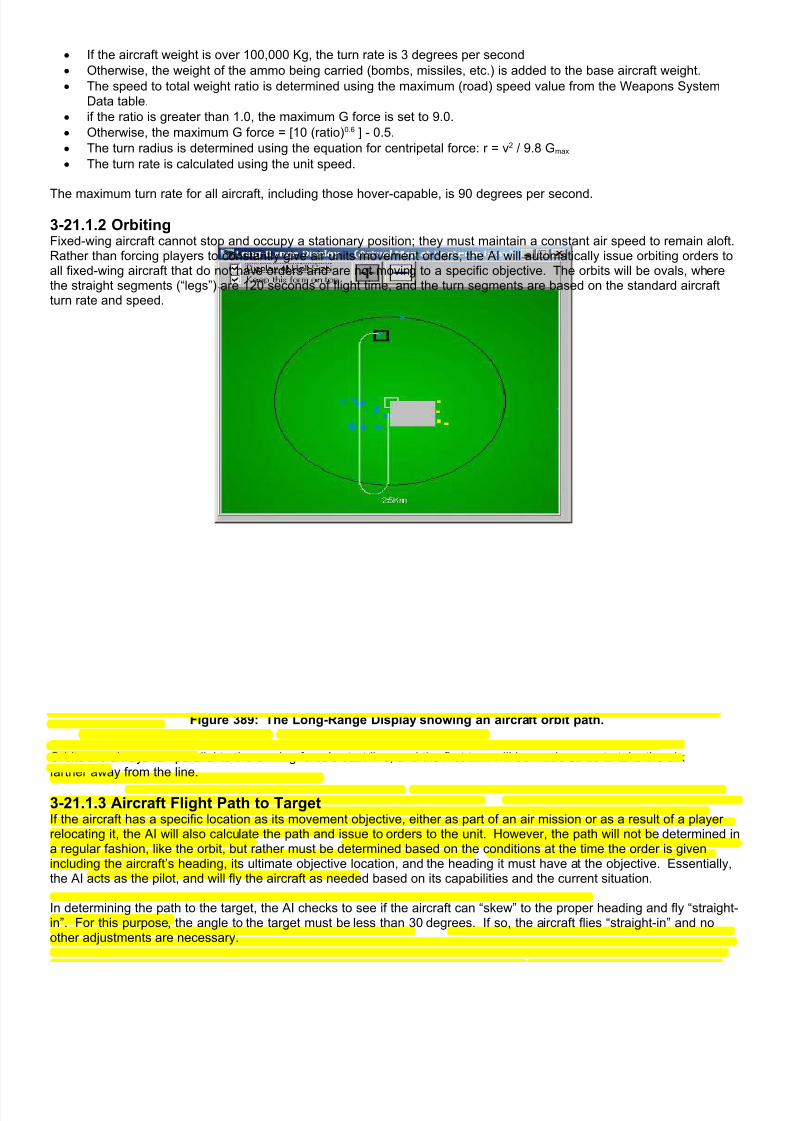
7/21/2019 TSS User Manual
http://slidepdf.com/reader/full/tss-user-manual 453/492
• If the aircraft weight is over 100,000 Kg, the turn rate is 3 degrees per second
• Otherwise, the weight of the ammo being carried (bombs, missiles, etc.) is added to the base aircraft weight.
• The speed to total weight ratio is determined using the maximum (road) speed value from the Weapons SystemData table.
• if the ratio is greater than 1.0, the maximum G force is set to 9.0.
• Otherwise, the maximum G force = [10 (ratio)0.6 ] - 0.5.
• The turn radius is determined using the equation for centripetal force: r = v2 / 9.8 Gmax
• The turn rate is calculated using the unit speed.
The maximum turn rate for all aircraft, including those hover-capable, is 90 degrees per second.
3-21.1.2 OrbitingFixed-wing aircraft cannot stop and occupy a stationary position; they must maintain a constant air speed to remain aloft.Rather than forcing players to constantly give air units movement orders, the AI will automatically issue orbiting orders toall fixed-wing aircraft that do not have orders and are not moving to a specific objective. The orbits will be ovals, wherethe straight segments (“legs”) are 120 seconds of flight time, and the turn segments are based on the standard aircraftturn rate and speed.
Figure 389: The Long-Range Display showing an aircraft orbit path.
Orbits are always run parallel to the owning force’s start line, and the first turn will be made so as to take the aircraftfarther away from the line.
3-21.1.3 Aircraft Flight Path to TargetIf the aircraft has a specific location as its movement objective, either as part of an air mission or as a result of a playerrelocating it, the AI will also calculate the path and issue to orders to the unit. However, the path will not be determined ina regular fashion, like the orbit, but rather must be determined based on the conditions at the time the order is givenincluding the aircraft’s heading, its ultimate objective location, and the heading it must have at the objective. Essentially,the AI acts as the pilot, and will fly the aircraft as needed based on its capabilities and the current situation.
In determining the path to the target, the AI checks to see if the aircraft can “skew” to the proper heading and fly “straight-in”. For this purpose, the angle to the target must be less than 30 degrees. If so, the aircraft flies “straight-in” and noother adjustments are necessary.

7/21/2019 TSS User Manual
http://slidepdf.com/reader/full/tss-user-manual 454/492
Otherwise, the aircraft must maneuver to achieve the proper objective. The AI will determine a set of turns and flightsegments to achieve the objective. Samples are shown in the illustration below.
Figure 390: Aircraft flight paths as set by the AI based on the relative target location and final heading required.

7/21/2019 TSS User Manual
http://slidepdf.com/reader/full/tss-user-manual 455/492
3-21.2 Close Air Support (CAS) MissionsClose Air Support missions are attacks by aircraft on ground targets in support of friendly land forces. In all but the mostisolated situations, they are relatively complicated affairs, since mistakes and miscommunications can endanger bothfriendly ground forces and the aircraft itself.
The complete CAS mission is broken into three major sections: the aircraft flight path, the SEAD (suppression of enemyair defenses) support, and support friendly ground or air units will provide in terms of marking, target designation and/orweapon control.
3-21.2.1 The CAS Flight PathThe CAS flight path is broken into segments, determined in the following order:
• The weapon release point is determined based on the target location, the direction chosen for the mission by the
force commander, and the standoff range of the munitions being used.
• The weapon drop run is determined. This leg is a straight and level path flown by the aircraft during which the
target is acquired, verified, and preparations made for the weapon drop/launch. Up to a point, the longer thestraight-line path is, the better the accuracy will be. However, the maximum accuracy is reached at a distancedetermined as follows:
o Guided munitions: 25 seconds flight time. Five seconds are subtracted each for a marking unit, painting
unit, and/or FAC. One half second is added for each Kilometer of munition standoff distance. Theminimum distance is 2 seconds of flight time, the maximum 25.
o Unguided munitions: 30 seconds flight time. Five seconds is subtracted each for a marking unit and/or
FAC. Two seconds are added for each Kilometer of munition standoff distance. The minimum distance is
6 seconds of flight time, the maximum 60.
• The maneuver path from the aircraft’s current position to the start of the drop run is determined using the routines
described in the previous section.
• The egress turn is added, using the egress turn direction set by the force commander.
• If the aircraft will make multiple passes, the aircraft will fly “mini-orbits”, returning to the start of the weapon drop run
each time until the mission is complete.
• Otherwise, the aircraft will either return to its starting “on-call” location or if completely out of ammunition, will exit
the operational area.

7/21/2019 TSS User Manual
http://slidepdf.com/reader/full/tss-user-manual 456/492
Figure 391: Standard CAS flight paths. The weapon drop run distance depends on the weapons being used.

7/21/2019 TSS User Manual
http://slidepdf.com/reader/full/tss-user-manual 457/492
Force commanders may specify many of these conditions, including the airstrike weapon drop direction and leg length,the egress turn direction, and the number of passes (ammunition permitting). However, the AI will “fly” the mission on itsown, based on these values, without allowing for adjustment by the human player.
3-21.2.2 CAS Altitude RestrictionsIn order to prevent friendly fire from accidentally hitting aircraft on strike missions, altitude restrictions are placed on theaircraft to keep it out of harm’s way. These restrictions are based on the target distance from the FEBA (forward edge ofthe battle area). In the simulation, the FEBA is set as the player’s initial start line for the duration of the scenario.

7/21/2019 TSS User Manual
http://slidepdf.com/reader/full/tss-user-manual 458/492
Figure 392: Altitude limits AGL (above ground level) for close air support missions.
There are four minimum altitude restriction zones. Whether or not they are in force depends on the current scenariosituation at the time the CAS mission is called. The zones are:
• Zone A: the area behind and up to 7.5 Km in front of the FEBA. If any friendly unit is using direct or indirect fire at atarget within 1000 meters of the intended CAS target or CAS flight path, or another CAS mission is being flown inthe same area, the minimum altitude is set at 1500m for heavy weapons (60mm and above) or 950m for all others.

7/21/2019 TSS User Manual
http://slidepdf.com/reader/full/tss-user-manual 459/492
• Zone B: the area 7.5 Km to 18 Km in front of the FEBA. If long-range friendly direct fire or another CAS mission isbeing used against a target within 1000m of the intended CAS target or the CAS flight path, the minimum altitude is300m.
• Zone C: the area 7.5 Km to 18 Km in front of the FEBA. If friendly indirect fire is being used against a target within1000m of the intended CAS target or the CAS flight path, the minimum altitude is 950m.
• Zone D: the area 18 Km to 30 Km in front of the FEBA. If friendly indirect fire is being used against a target within1000m of the intended CAS target or the CAS flight path, the minimum altitude is 950m.
In the absence of a zone restriction, the effects of the ordinance being dropped by the aircraft will be checked so that it
doesn’t “bring itself down”. The safety zone is determined by adding the detonation elevation of the munition to the APFrating of the munition, plus 1 meter per Kg of high explosive it contains. Twenty five percent is added for an extra marginof safety. Aircraft cannot fly within the safety zone, after accounting for standoff.
The minimum safe altitude is always at least 5 meters, even for helicopters.
The mission may also have a maximum altitude restriction, based on the mission characteristics and conditions. Theserestrictions are shown on the illustration above.
3-21.2.3 SEAD (Suppression of Enemy Air Defenses)SEAD is comprised of direct and indirect fire that is used to prevent nearby enemy units from engaging the aircraft on itspass over the battlefield. Except in rare circumstances, SEAD is not directed at the target itself so as not to interfere withthe actual airstrike.
The AI generates SEAD missions automatically during the initial call for CAS. These missions may be edited or deletedby the human player, and new ones added. In order not to potentially compromise the effectiveness of the ground force,the AI will only use IF (artillery) for SEAD. Players will need to set DF SEAD orders manually. Indirect fire SEAD missionsare added to the standard artillery mission queue at the FDC.
SEAD missions always have the highest priority, and other than a situation where a unit is about to be overrun, at thedesignated time the units will pause whatever mission they are currently firing and switch to the SEAD target.
3-21.2.4 Executing the CAS MissionCAS missions are assigned a “time on target” when they are initially set up. This is the time at which the first weaponrelease/firing should occur. Based on the time, the AI will determine when the aircraft breaks out of its orbit, and willdetermine the path it will follow to the beginning of the weapon release (“bomb drop”’) run.
Figure 393: Aircraft moving across the map on CAS missions are shown as a circle with an "A" inside.
As the aircraft approaches the target, it will attempt to identify and verify the target, using whatever marking or guidanceaids were specified in the CAS missions. Based on these conditions, the accuracy of the target identification will bedetermined. If the accuracy is off enough, wrong targets may be hit, including friendly forces. However, errors will belimited to a certain area, aligned along the axis of the flight path. The dimensions of the area are determined from theheight and speed of the attacking aircraft, but it will never exceed 1Km by 1Km.

7/21/2019 TSS User Manual
http://slidepdf.com/reader/full/tss-user-manual 460/492
Figure 394: The potential target area for an airstrike is centered on the intended target. The airstrike will hit atarget within this area, or will be aborted. The area allows for pilot error, and/or for better targets of opportunity
to be attacked if found.
If the target is an area (as opposed to a unit or object), the probability of error goes up for lower visibility and the range ofthe drop point from the target. Otherwise, the probability of correctly hitting a unit (or object) target is determined asfollows:
• If the target is painted (with a laser), the painting unit may make an error. If not, the correct target will be identifiedas long as the LOS meets the minimum requirements. The factors involved with the painting unit misidentifying thetarget are:
o Suppression.
o LOS quality.
o Number of similar enemy units in the same area.
o Range.

7/21/2019 TSS User Manual
http://slidepdf.com/reader/full/tss-user-manual 461/492
o Priority DF firing.
• If the munition is radiation homing, the time since the target last emitted a radiation pulse is used as the primaryconsideration. The longer the time, the less accurate the identification (and subsequent guidance) will be. If theradiation-homing munition has a low lock-on probability, the pilot may switch to another type, if one is available.Otherwise, the aircraft will either make another pass or abort the mission.
• For other munitions, the error probability is determined as follows:o The base probability is determined from the aircraft unit’s training and fatigue levels.
o The error probability is reduced if a FAC is present.
o The error probability is reduced is the target is marked.
o The error probability is reduced if the TF HQ can visually see the target.o The error probability is reduced if the aircraft unit can visually see the target.
o The error probability is adjusted for the aircraft speed; the faster it is going the more the higher error
probability.o The error probability is increased for fires and smoke near the target area, as well as a high level of direct
and indirect fire.
If the target is misidentified, the aircraft’s actual target will likely be of the same general type. For example, if the intendedtarget was a group of tanks, it is likely that the incorrect, but actually engaged, target would also be of a tank type, or atthe very least, vehicular.
3-21.3 Paradrop OperationsParadrop operations transport ground units onto the battlefield via fixed-wing aircraft using parachute delivery. As with
normal transporting operations, the paradrop capable units are loaded onto the aircraft carrier units, and “unload” over thedrop zone. But the nature of the aircraft and delivery method are very different.
Any type of aircraft with a cargo capacity can fly a paradrop mission, including helicopters. However, paradrop is requiredfor fixed-wing aircraft because they cannot stop moving to unload passenger units. Helicopters, on the other hand, havethe ability stop and either hover or land in a location to unload without the attendant risks and initial disorganization that ispart of an airdrop. Helicopters are rarely used for paradrop operations, and therefore the rest of this section will focus onfixed-wing aircraft.
3-21.3.1 Preparing for the DropThe first step in setting up a paradrop is to load the cargo aircraft. The units being loaded must be paradrop-capable,which is set in the Weapons System Data Table. All of the normal loading restrictions are in force, including “loadingpoint” and maximum loaded weight limits.
Fixed-wing cargo aircraft must be loaded at the start of the scenario during the set-up phase. There is no mechanism thatwill allow the aircraft to be loaded once the scenario is under way.
The second step is to identify the drop zone (DZ), and set the mission profile characteristics. The DZ is the area in whichthe dropped units will land. It should be generally free of terrain and other obstacles that could cause injury and damageto the landing force. It should also be large enough to accommodate the force to be dropped in a minimum number ofpasses.
The standard USAF drop zone sizes are set as follows:
• GMRS (ground marking release system): Minimum 275m by 275m.
• CARP (computed air release point): 550m by 550m for a single parachutist, plus 70 meters per additionalparachutist.
However, these are peacetime standards, and areas of this size may not be available in wartime. As such, a rule ofthumb is to use a minimum of 300 meters plus 50 meters per person or 500 meters per vehicle along the drop axis, perpass. Approximately 800 meters is the absolute minimum DZ length required for an infantry squad, and 1800m for aplatoon.
The DZ width is based upon the expected dispersion, which is principally a function of the wind and drop altitude.However, 300 meters is probably the bare minimum under good conditions.
Once the DZ has been selected (based on the player setting the center point), the following mission profile values are set:
• Time the drop should begin
• Drop speed (normally the minimum aircraft speed)

7/21/2019 TSS User Manual
http://slidepdf.com/reader/full/tss-user-manual 462/492
• Drop altitude (between 150-300meters)
• Drop heading (this will become the LZ axis).
• Number of passes/units to jump per pass.
• The location to which the aircraft should return after the mission is complete.
3-21.3.2 Executing the Drop As with airstrikes, the AI will determine when the aircraft will begin the execution of the mission, based upon the set starttime. The AI will also determine and fly a flight path to arrive at the beginning of the “run-in” leg on the correct heading,altitude, and airspeed.
The initial “run-in” leg is 60 seconds of flight time, during which time the pilots detect the DZ and line up on the propermarkings. By this time the troops and other items to be dropped are hooked up to the static lines, and awaiting the jumpcommand.
As the aircraft begins the run-in, the pilots will attempt to use the drop altitude specified for the mission. However, thisaltitude may be modified by any or all of the following conditions:
• Personnel require 20/25 seconds (day/night) in the air. Cargo requires 15 seconds (day or night). Time in the air isbased upon the descent rate, which is set for each type of item being dropped:
o Personnel: 6.0 m/sec
o Guns: 7.5 m/sec
o Vehicles: 8.5 m/sec
o Aircraft: 7.0 m/sec
o Other: 9.0 m/sec• Additionally, personnel can never be dropped below 250m, cargo from under 350m.
• The altitude can never be less than 150m above the highest obstacle along the flight path for 5Km in eitherdirection of the DZ (fixed-wing only).
• The altitude is lowered for the wind speed, if above 5 Kph (and not over the maximum - see below).
• The altitude is also lowered if known enemy units are in the area, so friendly units reduce their time in the air wherethey are helpless targets.
Conditions on the DZ may cause the mission to abort. These conditions are:
• Visibility of less than 1000m (maximum sighting range).
• Cloud cover 50% or more with a cloud base below 500m.
• Personnel drop with wind speed above 32 Kph, cargo drop with winds above 40 Kph.

7/21/2019 TSS User Manual
http://slidepdf.com/reader/full/tss-user-manual 463/492
Figure 395: The basic paradrop flight path and stick locations relative to the intended drop zone. Note the sticksbelonging to unit 1 jump first, followed by the sticks from the other units, even if the sticks are on different
aircraft or jump on different passes. The result is all of the jumpers from unit 1 will eventually land at the nearend of the DZ, those from unit 2 in the middle, and those from unit 3 at the far end.
3-21.3.3 Dropping the SticksIn order to control the jump, the jumping units are broken up into “sticks” of relatively equal size. The number of sticks iseither equal to, or an even multiple of, the number of aircraft flying the mission. Stick sizes are based on the maximumnumber of jumpers that can exit the aircraft in a single pass, divided equally among all of the units to be dropped. Longer
passes (in terms of time) result in larger sticks, since more jumpers can exit the aircraft before reaching the end of the DZ.By default, the sticks will be as large as possible, up to the unit quantity divided by the number of aircraft available.
The reason for using sticks is so that all of the elements in a single unit will jump essentially over the same point in theDZ, rather than being spread out over the flight path and intermingled with other units dropping from other aircraft or insubsequent passes. The reasoning is illustrated in the previous diagram, where all of the sticks belonging to unit 1 jumpover the near end of the LZ, those from unit 2 in the middle, and those from unit 3 at the far end. Without the use ofsticks, the units would be completely intermingled and confusion would reign.
Based on the stick lengths, the AI determines the start of the drop run. This is the point at which the first sticks beginexiting the aircraft. The start point is determined such that the center of the DZ (which is specified by the player) is

7/21/2019 TSS User Manual
http://slidepdf.com/reader/full/tss-user-manual 464/492
spaced equally between when the first and last jumpers exit the aircraft. The determination is based on the time requiredfor each jumper or object to exit the aircraft, the stick lengths, and the aircraft’s speed.
The default jumping/exiting times are determined as follows:
• Personnel: 0.5 seconds each.
• Guns: 10 seconds each
• Vehicles: 20 seconds each.
• Other: 45 seconds each.
There is no additional time delay between sticks. As soon as one stick finishes exiting the aircraft, the next immediatelystarts jumping, followed by the next and so on until all sticks scheduled to jump on that pass have exited the aircraft.
3-21.3.4 Units “In the Air”Once a stick has jumped from an aircraft it is considered “in the air” until it lands on the ground. The time required for aunit to land is based upon the drop altitude, and the descent rate for its type. The descent rates are:
• Personnel: 6.0 m/sec
• Guns: 7.5 m/sec
• Vehicles: 8.5 m/sec
• Aircraft: 7.0 m/sec
• Other: 9.0 m/sec
While a unit is in the air, it may not be given orders, fire, or perform any action at all including sighting. It may be sighted
and fired at by enemy units, however, in which case it will suffer losses. Damage (as opposed to kills) to a unit while it isin the air will be converted to immobilization once it hits the ground.
Units in the air may be subjected to drift, based on the wind speed and direction. When this occurs, the unit position willbe adjusted accordingly.
3-21.3.5 Dispersion After jumping, personnel and other objects will be subject to drift and dispersion by the wind. Under relatively calmconditions, personnel can compensate somewhat for the wind by “steering” their parachutes. However, other items suchas guns and vehicles do not have that ability, and will drift completely with the wind. The longer the jumpers remain in theair, the longer the wind affects them, and greater the chance for drift.
Unit dispersion is also caused from differences in the speed of individual aircraft, or even the same aircraft on separate
passes, and the fact that the aircraft paths over the DZ axis (relative to the ground) will not be exactly the same each time.

7/21/2019 TSS User Manual
http://slidepdf.com/reader/full/tss-user-manual 465/492
Figure 396: Jump unit landing area.
The minimum dispersion length per unit along the DZ axis is determined by the minimum time in seconds that all of thesticks can exit the aircraft times the aircraft speed in meters per second. This is then adjusted upwards by the number ofsticks in the unit to the 0.35 power (N 0.35) to model inefficiency and the fact that the correlation between the initial stick jump points will not be perfect between passes and aircraft.
The minimum dispersion area width is based on the number of passes required to drop all of the unit’s components.Initially each additional pass adds between 50 and 200 meters of dispersion, based on the force training level. However,as more and more passes are made, the additional dispersion tapers off as the aircraft passes more frequently lie withinthe area already traversed on previous passes.
3-21.3.6 Landing: Losses and DisorganizationThe actual dispersion area is known as the “landing area”. The center of the landing area will be directly under the centerof the unit position, after being adjusted for drift during its time in the air. Upon landing, the unit will be distributed evenlythroughout the landing area. At that time, the program checks for landing losses based on the following sequence:
• The base “kill” probability is based exponentially on the time in the air, and ranges from 28% at 10 seconds to 2%at 20 seconds.
• The probability is adjusted exponentially for the wind, if greater than 5 Kph, increasing by 100% at 15 Kph and400% at 40 Kph.
• The probability is increased exponentially if the ambient illumination level is 20 or less, increasing by 500% at anillumination level of 5, and 65% at an illumination level of 20.
• The average of the terrain cover and concealment values for the landing area are applied directly, after reducing itby 25% to account for personnel steering clear of objects.
• The incapacitation probability is equal to 3 times the kill probability.
• A special determination is made to see if any jumpers land in terrain that they are prohibited from moving though,for example water or cliffs. If so, those jumpers are automatically killed.
7/21/2019 TSS User Manual
http://slidepdf.com/reader/full/tss-user-manual 466/492
Landing units also experience a period of disorganization after landing, while they assess the situation and get groupedtogether. In general, the larger the landing area as compared to the unit, and the more terrain in it, the longer it will takeunits to get organized. The disorganization time is determined as follows:
• The base time is set based on the unit type:o Personnel: 240 seconds plus 12 seconds per soldier.
o Guns: 360 seconds plus 30 seconds per gun.
o Vehicles: 300 seconds plus 20 seconds per vehicle.
o Aircraft: 1200 seconds.
o Naval: 600 seconds.• The time is adjusted proportionally for the unit’s fatigue and training levels.
• The time is increased for the average cover and concealment levels in the area.
• The time is increased 10% for each 10 Kph of wind speed.
• The time is increased if the ambient illumination level is less than 20.
• If the area is larger than the “standard” area based on the “vehicle equivalent” size of the unit, the time is increasedproportionally. The “vehicle equivalent” size of personnel type units is the actual quantity divided by 6. Thestandard area size is the equivalent quantity times 50 meters, squared.
• The time is increased if the landing area overlaps that of another unit, which is also disorganized.
• If the landing unit creates an over-stack condition, the time is increased by 150% of the over-stacking percent.
• The unit’s standard internal friction time is added.
Disorganized units suffer significant combat degradation. They may sight and fire, but at much reduced ROF’s and
accuracy. They may also be given orders. However, they will not move or execute them until them they get organized.
Units and sticks that land in a location occupied by an enemy unit will immediately engage that unit in close combat.However, the unit just landed will suffer significant detrimental effects from disorganization, as well as a likely lack ofstrength.
Section 3-22: AI Search Patterns
The AI search/reconnaissance routines are handled on two levels: strategic and tactical. The strategic level routinesdetermine parameters including:
Search areas (if not specified by a human player). Area/location/potential target priorities. Unit assignments for each area (by total number and type) . “Thoroughness” levels for each area (how much time is spent/surface area covered in each area, including
multiple passes and “returns to previous locations”). Unit “area progression” schemes for multiple areas.
This strategic AI is used only for AI-controlled forces; it is never applied to human commanded units. Humancommanders must assign recon missions themselves through the interface.
The tactical level AI, however, applies equally to AI and human controlled units performing reconnaissance assignments.In this case, human-controlled units are effectively placed under AI command for the duration of the mission, unless theplayer specifically supersedes the mission orders. Because of this direct interaction of the AI with human-player forces,
it will be covered in more detail so that players will know what to expect.
3-22.1 Tactical Search Considerations At this tactical level, the AI is principally concerned with the specifics of unit deployment in order to accomplish thedetection mission objectives. In order to do this, the deployment is broken down into four principal sub-operations:
Selection of the next search-patter starting/center point. Setting the travel path to that location. Construction of a the appropriate search pattern. Execution of the individual search legs within the pattern.

7/21/2019 TSS User Manual
http://slidepdf.com/reader/full/tss-user-manual 467/492
These steps are then repeated as necessary to “cover” the search areas to the level specified by the human player orstrategic AI. Note that this “level” may specify more or less than “complete” coverage. At less than “complete” coverage,some locations may be left unsighted (or sighted only very briefly). Conversely, at a level of greater than “complete”coverage, some locations may be sighted more than once and/or for long durations.
To determine the location of the next search-pattern, the AI looks at a large number of factors, including:
What is (are) the expected target(s)?
º The AI selects one or more specific weapons systems based on current intelligence.
ºIf the AI force's objective is to capture or destroy a certain target, that system type is given absolute priority.
º Potential target systems are ranked on their Victory Point Values (thus more weight is given to high-value
systems). Will the targets be moving, or in covered terrain? This is based on the relative terrain on the map, the enemy
force's mission, the expect target types (from above) and current intelligence. Specifically:
º The higher the percentage of cover terrain on the map, the higher the probability of the target being in that
type of covered terrain.
º Attackers are more likely to be moving than defenders.
º If a large percentage of known enemy units are moving, the probability a target is moving is increased as well
º If the expected target system is a high-mobility weapons type, (vehicles, ships, aircraft), the movement
probability is increased.
º If the target has low offensive weapon power, it will likely be in covered terrain. If it has high power, it will
more likely be in open terrain so it can use those weapons.
º Attackers are more likely to be in open terrain than defenders.
º The likelihood of being in covered terrain is adjusted inversely to the square root of the probability that the
target is moving.
º If a target is expected to be moving, a determination of the likely speed is made. This is based on the average
speed for the system over the “fastest” 50% of the terrain present on the map. How far away will targets likely be?
º The effective range of the target weapons system against the platform are determined. For this calculation,
the enemy unit is assumed to have a full compliment of possible ammunition, and current meteorologicalconditions are used.
º The distance is reduced based on the positions of friendly units in relation to the edge of the map and
between the units themselves. Are there likely to be any smoke, dust, or other effects on the LOS? Only currently known smoke and dust clouds
are considered.
From these values, the locations comprising the parent search area are analyzed. Each location is rated for itscharacteristics, and how they relate to what the AI considers the primary targets. The AI is very flexible in formulatingsearch patterns/strategies. In making these determinations, the AI analyzes the area to be searched, the type of targetsexpected/desired, the time available, the equipment available, and the number of reconnaissance units involved.Specifically, the following are considered:
Cover/concealment:
º The ratio of the average cover value of the terrain in the area to the average map cover is applied to the
computed tendency for the unit to be in cover. The greater the congruency in these values, the higher theprobability the unit will be in that location.
º If the target is at least 50% likely to be seeking cover, based on the weapons system type and force posture,
additional emphasis is added for any IP's that the target can occupy in that sector. For targets that are moving, a second adjustment is made:
º Additional emphasis is added for high speed routes (roads, trails, etc) applicable to that unit. The effect is
based on the average speed of the feature, adjusted for its orientation/direction (less points are added forroutes that are primarily lateral).
º Obstacles, prohibited terrain, or potential bottlenecks have an opposite dampening effect.
If there are known enemy units in an area, or nearby, additional emphasis may be added based on their type andthe force's mission.
º If they are the same time, the effect is greater than if they are not.
º If the confidence level of the estimated enemy total force size is greater than 50%, additional emphasis is
added based on the confidence level and estimated enemy force percent in the sector.

7/21/2019 TSS User Manual
http://slidepdf.com/reader/full/tss-user-manual 468/492
º Emphasis is also added to adjacent sectors based on the sector size (the smaller the sector, the more points
are added). LOS out of the location:
º If the unit would not be above the highest point in the sector when occupying the hex, the points are
decreased.
º If the unit is on the surface, the relative “LOS value” of the hex is applied directly. This is a measure of how
much the unit will be able to see from the location.
º If the location contains known smoke or dust, the points are reduced for all units operating under 2500m AGL
(above ground level).
Movement values into/out of the location:º The location value will be adjusted based on the time it will take the unit to move from its current location to
the new hex. How long since last visit (by any unit):
º The value is adjusted for the duration since the last visit.
º Value is reduced for the proportion of locations never visited
º Value is subtracted are adjusted for the expected sighting range of the previous unit, the farther its expected
sighting range, the greater the reduction.
º The effect may be reduced if the target is expected to be moving, and its potential distance covered in the
time since the last visit is greater than the area dimensions.
º Current recon unit objectives are treated as if they were visited in the current turn (so two units will not go to
the same one at the same time), unless the hex (map) scale is less than a single hex.
Known enemy units nearby:º Value is added for units near the current location.
Friendly units nearby:
º Value is subtracted for friendly units near the current location. (This keeps the recon units from covering what
other units are already observing, or soon will be).
º
Once the points have been calculated the AI generally selects the best one as the next objective for the recon unit.Several final checks are made in this process, based on the force's aggressiveness level. The higher the aggressivenessthe longer a “jump” can be. Thus, less aggressive AI commanders will tend to be more methodical and search areas oneat a time, “in order”, whereas aggressive ones may jump all over the map hoping to “strike it big”. More aggressive AIalso tends to revisit high value locations more frequently than less aggressive ones.
Aggressiveness is also used to determine how often sectors and hex values are recalculated. Aggressive AI
commanders recalculate both more often, again following a more “hit it rich” gambling strategy.
3-22.2 Pattern/Path DeterminationOnce the starting point has been determined, the AI must decide how to conduct the search. Specifically, the AI mustchoose specific search patterns to use, and further specify its characteristics in terms of size/coverage, unit settings(speed, altitude, etc.), and where the unit should end up at the end of the run. The AI uses four basic search patterns, asshown below.

7/21/2019 TSS User Manual
http://slidepdf.com/reader/full/tss-user-manual 469/492
Figure 397: Basic Search Pattern Types used by the AI.

7/21/2019 TSS User Manual
http://slidepdf.com/reader/full/tss-user-manual 470/492
In making a route selection, the AI evaluates the size and type of area to be searched, the specific target type beingsearched for, if known/estimated (more common in radiological detection scenarios), the time allowed, the known orexpected enemy forces in the vicinity, and the severity of the consequences should the recon unit be detected by theenemy.
In general terms, the characteristics, strengths and weakness of each route type are:
“Flower” Pattern: The search paths extend out radially from a central point, with the unit making a U-turn at the endof the path and returning to the starting location. The number of “petals”, and their specific characteristics (width,length, etc.) are flexible, and depend on the circumstances.
º Area: This pattern is more likely to be selected for circular shaped areas, areas measuring less than 4 times
the recon units “average” effective sighting/detection distance, and in areas with restricted recon unitmovement, especially due to linear features such as rivers and streams.
º Terrain: More likely to be selected when the terrain offers moderate to high cover and concealment, due to
high coverage and multiple passes near the center point. The more cover in the area, the “longer” and“thinner” the petals.
º Target: More likely to be selected if the target is a discrete, point type target (or a cluster/concentration),
and/or if the AI has reason to believe the unit is located in a certain location (which is used as the center pointto maximize the time the recon unit spends in the nearby area). Also more likely to be selected againstmoving targets.
º Enemy: More likely to be selected when prevention of enemy reactions is a high priority (petal order is
randomized, making prediction harder for the enemy).
ºFriendly: More likely to be selected for aircraft units.
º Time: More likely to be selected if time is of the essence.
º Radiological Detection Effectiveness: High.
“Spiral” Pattern: The search path begins at a central point, with the unit following a continuous, generally circular,trace of increasing radius out from that point. The rate of radius distance increase depends on the circumstances.
º Area: This pattern is more likely to be selected for circular shaped areas, areas measuring less than 5 times
the recon units “average” effective sighting/detection distance, and in areas with relatively few movementrestrictions.
º Terrain: More likely to be selected in moderate cover and concealment.
º Target: More likely to be selected if the target is a discrete, point type target (or a cluster/concentration),
and/or if the AI has reason to believe the unit is located in a certain location (which is used as the center pointto speed up detection). Also somewhat more likely to be selected against moving targets.
º Enemy: Less likely to be selected when prevention of enemy reactions is a high priority (prediction is
relatively easy for the enemy).
º Friendly: More likely to be selected for aircraft and naval units.
º Time: More likely to be selected if time is of the essence.
º Radiological Detection Effectiveness: Moderate.
“Regular” Pattern: The search path begins at a central point, with the unit following a back and forth series ofstraight line paths progressively further away. The distance between legs depends the circumstances.
º Area: This pattern is more likely to be selected for rectangular shaped areas, areas measuring more than 10
times the recon units “average” effective sighting/detection distance, and in areas with relatively fewmovement restrictions.
º Terrain: More likely to be selected in low to moderate cover and concealment.
º Target: More likely to be selected if the target is unknown or dispersed.
º Enemy: Less likely to be selected when prevention of enemy reactions is a high priority (prediction is
relatively easy for the enemy).
º Friendly: More likely to be selected for ground units.
º Time: Less likely to be selected if time is of the essence.
º Radiological Detection Effectiveness: Moderate.
“Route” Pattern: As opposed to searching an area, this path follows a discrete linear feature on the map, often aroad, trail, or river.
º Area: Used only to search along defined linear terrain features.
º Terrain: More likely to be selected in moderate cover and concealment.
º Target: More likely to be selected in situations where off-road movement is very difficult, if not impossible.
Also more likely to be selected against expected moving targets.
7/21/2019 TSS User Manual
http://slidepdf.com/reader/full/tss-user-manual 471/492
º Enemy: Less likely to be selected when prevention of enemy reactions is a high priority (prediction is
relatively easy for the enemy).
º Friendly: More likely to be selected for ground units.
º Time: More likely to be selected if time is of the essence.
º Radiological Detection Effectiveness: Moderate.
Once the route type is selected, the specific parameters defining it are formulated (for example, leg length, offset, petaldistances, etc). From there, the AI decides explicitly how the recon unit should perform the mission (speed, altitude, etc.),and issues the appropriate orders.
Section 3-22: Civilians
Civilians may often be present in battle areas, either hiding until the action passes, or trying to escape. When they are,civilians hamper combat operations both by clogging roads and other avenues of movement, and by dampening outgoingfires so as to avoid casualties to them.
The simulation uses the weapons systems type of “Civilian” to tell if a unit is a civilian or not, instead of “Tank” or “APC”,etc. Only units with the type set to “Civilian” will be considered civilian, even if the unit otherwise uses a civilian symbol orhas “Civilian” in the name.
Civilian units are treated as normal units for all of the standard game functions, including movement, sighting, and morale. Although they cannot fire, when fired upon their losses are determined using the standard combat routines.
Civilian units, although neutral, will always appear as “enemy” units on the map display. A word of caution is in order onthis point, because if FOW in regards to enemy units is being used, civilians may also appear as “unknown” enemy unitsuntil they are sufficiently sighted.
Based on the scenario set-up settings, Civilian units are automatically created by the computer at the start of the scenarioand/or during the battle.
3-22.1 Civilians Placed at the Start of a Scenario At the start, a civilian rating of 100 will result in approximately one “family-group sized” unit placed every square KilometerHowever, this will be adjusted based on the level of urbanization in the area. The size of a family-group varies, but is
generally 5-25 personnel, or 2-4 vehicles.
Civilian units placed during the set-up phase are created on either a road (hexline) or in a location with buildings(permanent IP’s).
3-22.2 Civilians Placed During a ScenarioCivilians may also be created during the scenario, based upon the level set when the scenario was created. The quantityis based on creating a certain number of civilians every hour. The number of civilians is approximately 1 family-groupsized unit per Km, reduced for the civilian level.
Civilian units placed during the scenario are always created on a road (hexline), with a preference for locations containingbuildings (permanent IP’s).
3-22.3 Civilian ActionsCivilian units are completely controlled by the AI. However, their actions can usually be predicted to some degree in thatthey tend to move towards the defender’s side of the map. However, if they are close to the attacker’s edge, they maydecide to move that way instead. Only rarely will they move towards a “flank edge”, unless following a major highway orother significant movement route.
Civilians will normally stick to roads and other relatively fast movement routes.
When moving though a location containing civilians, the civilian units will be treated as if they are friendly units, with verylow training and morale levels. They will be counted against the stacking limits, and will have the same effect “jammingup” movement produced by a normal unit. Because they normally travel by road, they can cause significant traffic jams,especially at bottlenecks such as bridges and in towns and villages.

7/21/2019 TSS User Manual
http://slidepdf.com/reader/full/tss-user-manual 472/492
3-22.4 Attacking CiviliansMilitary forces may attack civilians with DF or IF, either deliberately or by accident. In these cases the civilian units aresighted, targeted, and affected just like military units. They can create wrecks, and may also run for cover. They never goberserk, or suffer any other morale effects.
However, if the fire results in any civilian casualties, the attacking force will pay a heavy price in victory points, even if theattack was unintentional.
Civilian units are never attacked with close combat.
A Few Final Notes
The TSS has been many years in the making, and it has involved the efforts and dedication of a large number of people. am very grateful for the opportunity that I was given to create a military simulation of this depth and cope. It is somethingthat I have been working towards since I played Kampfgruppe by Gary Grisby back on my Commodore-64. And I verymuch hope to continue to build on its foundation into the future.
As with any undertaking of this magnitude, there are a lot of people that contribute to it, even if in small ways they maynever realize. As such I want to thank everyone in, and associated with, HPS for their patience and understanding withme during the period this project was in development.
There are also a few specific people I want to single out for thanks:
I want to thank my dad for his efforts in proofreading, as well as all the free advice and support he’s given me over theyears to make it happen. He passed away in 2006, but he is still here in this manual and in everything that I do.
I want to thank my cat-dog Norman for guarding the FAX machine.
I want to thank John and Wendy Kincaid for their painstaking work on the databases, and their obsessive dedication togetting things right, no matter what it took.
I want to thank Nick Bell for the maps, especially the Albuquerque masterpiece. His attention to detail and perseveranceis amazing.
I want to thank Dr. Robert Barker for hanging with me, though thick and thin, and having faith that it would work out in theend.
I want to thank John Kincaid, Nick Bell, and Greg Smith for providing unstinting friendship, feedback ... and freecounseling. :-)
I want to thank Jeff Lapkoff for believing in the dream, even in the darkest moments, and helping me make it happen.
I want to thank Fluffy, who crossed the “rainbow bridge” many years ago, for without her I never would have gotten thisfar.
And, finally, I want to thank my wife, Elisa. I don’t know how she managed to put up with it all.
I hope you enjoy this program.
-Scott HamiltonNovember 2003Updated: November 2011

7/21/2019 TSS User Manual
http://slidepdf.com/reader/full/tss-user-manual 473/492
Appendices
Appendix A: The Geomorphic Map Editor
A.1 Rapid Map DevelopmentThe powerful Geomorphic Map Editor allows users to create comprehensive battlefield maps on the fly in a matter ofminutes. The geomorphic map creation system is based upon a set of existing map tiles which can quickly be placed,
flipped, mirrored, and combined with other tiles on a ‘map canvas’ allowing for the quick creation of a wide variety ofbattlefields.
The concept of geomorphic maps within the program is based on the system used by a number of tactical-level boardwargames, such as “Panzer Blitz ”, “Panzer Leader ”, and “Squad Leader ” by the Avalon-Hill Company, among others. Inthis system, players place one or more “generic” maps (known as “tiles” in the program) adjacent to each other to createlarger playing areas.
Figure 398: Geomorphic map example from a board wargame: Panzer Leader by Avalon-Hill. Note how roadsand streams line up on the map “tile” edges to allow for seamless connections. Each map board in the above
example is known as a “Tile” when used by the program editor.
In order to create seamless connections of terrain features between adjoining tiles, the individual tiles must be formattedso that roads, streams, etc. exit the map edge at specific predetermined locations (row/column). Alignments do not needto be exact, as the utility will join them from even several hexes away. However, the better the exit points match, thelower the chance for missed or “unintended” connections.
The tiles are created and edited using the Aide De Camp 3 based map editor for the Tactical Studies Series (TSS), andmay be used by all of the individual TSS titles.
A.2 Choosing to Use a Geomorphic Map
Users select to use a geomorphic map during the map selection step when creating a new game, or when editing a savedgame that was saved in the setup phase. Simply select the choice [Create New Geomorphic Map], as shown here:

7/21/2019 TSS User Manual
http://slidepdf.com/reader/full/tss-user-manual 474/492
Figure 399: Selection dialog box used to begin creating a new geomorphic map. To load an existing/savedgeomorphic map “as-is”, select [Use Existing Map] instead.
This selection will activate the Geomorphic Map Builder utility, which is a sub-set of the Aide De Camp 3 program. Theutility is included with every TSS game. Once it loads, select [Load Map] to load an existing geomorphic map or [CreateMap] to begin a new one.

7/21/2019 TSS User Manual
http://slidepdf.com/reader/full/tss-user-manual 475/492
Figure 400: Entering the Geomorphic Map Builder Utility. Either create a new map, or load an existing one.
A.3 Creating a New Geomorphic Map

7/21/2019 TSS User Manual
http://slidepdf.com/reader/full/tss-user-manual 476/492
After clicking [Create Map], the Add Geomorphic Map Tileselection form will appear, as shown at right.
The tiles are listed in the main grid by name, along with their size(Width, Height – in hexes), and any informational/descriptivecomments that the designer wanted to include.
A preview of the currently selected map tile is shown at the top.
To change the current search folder, click the button at the bottomnamed: [Change Folder/Browse]. The current folder is shown tothe right of the button. By default, TSS map tiles are located in thefolder: “..\HPS Shared\Geobuilder\Tiles”. This central storagemakes them easier to be shared between TSS titles.
To add the currently selected tile to the in-progress map, click the[Add Selected] button.
There is no limit to the number of individual geomap tiles that canbe combined into a final playing map. However, very large mapsrequire commensurately large amounts of system resources, soplayers should exercise caution creating maps with more than20,000 total hexes.
Added tiles are automatically placed in the topmost/leftmost position available in the in-progress playing map. The“actual” map appears on the main form, while a rectangular representation of the map tiles and their position appears onthe Control Form, as shown here:
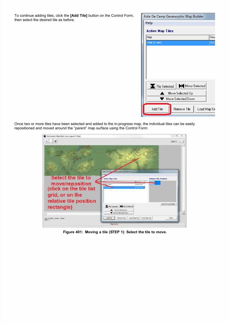
7/21/2019 TSS User Manual
http://slidepdf.com/reader/full/tss-user-manual 477/492
To continue adding tiles, click the [Add Tile] button on the Control Form,then select the desired tile as before.
Once two or more tiles have been selected and added to the in-progress map, the individual tiles can be easilyrepositioned and moved around the “parent” map surface using the Control Form:
Figure 401: Moving a tile (STEP 1): Select the tile to move.

7/21/2019 TSS User Manual
http://slidepdf.com/reader/full/tss-user-manual 478/492
Figure 402: Moving a tile (STEP 2): Click on the tile's rectangle in the relative position display box.
Figure 403: Moving a tile (STEP 3): Drag the tile to the new desired position (will snap into place).
A.4 InterfaceSelection Grid: Lists the tiles used in the current map, their (x,y) position, and draw order.
Relative Tile Position Mini Map: Shows the relative positions of the active tiles. Tiles can be selected from the mini-mapand quickly ‘dragged and dropped’ into a new position on the map. Tiles will always snap to the closest map edge orcorner. The currently selected tile is always highlighted in lime green.
7/21/2019 TSS User Manual
http://slidepdf.com/reader/full/tss-user-manual 479/492
[Flip Selected]Flips the tile along the vertical axis. The top of the tile becomes the bottom, and bottom becomes the top.
[Mirror Selected]Flips the selected tile along the horizontal axis. The left becomes the right and right becomes the left.
Note: The above rotations can be combined, creating a Flipped and Mirrored tile.
[Move Selected Up/Down]Moves the draw order of the selected tile up or down . Lower tiles will be displayed underneath upper tiles should anyoverlap occur.
A.5 Adding Tiles Additional tiles can be added to a map in progress by clicking the [Add Tile] button.
The tile selection form will be presented indicating tile name, size (columns, rows) along with a thumbnail picture of thetile. Click [Add Selected] to add the tile to the map in progress or [Cancel] to exit.
Note: The geomorphic map builder will automatically attempt to connect any line and side map types along the joinededges of tiles (see below).
A.6 Completing a Map[Save Map Set] saves the current map in progress[Load Map Set] loads an existing geomorphic map
Once a map has been completed and saved, select [Done] to return to the TSS program. If the Geobuilder was enteredduring scenario formation, the TSS will automatically load the map that was just made and continue on with the scenariocreation process.
A.7 Seams Between TilesThe seams between adjacent tiles may require special processing, depending on the individual tile orientations and othercharacteristics. In particular, the computer must be able to connect line-type terrain features (such as roads, and rivers)across the seam, and may also need to manipulate the underlying hex grid in order to maintain hex row/column geometry(this applies only to hex grids – it is not required when using square grids).
When connecting line types, the computer will search for instances of similar line types within a few hexes of each tile'sedge, identifying any “endpoints” it finds (“endpoints” are lines or sides that are open/not connected to another line orside). If matching endpoints are found for the same line type on each tile, the computer will connect them across theseam, as shown here:

7/21/2019 TSS User Manual
http://slidepdf.com/reader/full/tss-user-manual 480/492
Figure 404: Connecting lines across an adjoining tile edge seam (Tile #1 = yellow hexes, Tile #2 = tan hexes).The utility will automatically connect the rivers on the final map by adding new sides/lines (red lines).
Note: The white hexes are “empty” - created to maintain the hex row orientation after the tan tile was “flipped”.They will be filled in with elevation and terrain based on what is in nearby hexes (see below).
Flipping and/or mirroring hex-based tiles may change their basic orientation, depending on the tile and the operationperformed. In essence, the grid sequence can become reversed, for example “down-up, down-up”, becomes “up-down,up-down”), as shown here:
Figure 405: Normal tile hex pattern goes “Down->Up”from the upper-left hex.
Figure 406: “Mirrored” tile hex pattern is “Up->Down”from the upper-left hex.
When this occurs the utility will add/delete hexes as best it can to reestablish the pattern, while keeping the map size and“exit points” intact. These hexes will then get filled in, as described below.
A.8 Blank Hexes/AreasBlank hexes, whether created by the computer as part of a seam operation or in an area just never filled in by the player,can not be used by the TSS program and will cause errors. Therefore, the utility will “fill them in” as best it can, usingnearby locations as a guide. At a minimum, the utility will assign “blank” hexes an elevation and a ground/surface terraintype. In some cases, additional above-ground terrain may be added.
Players can not edit these “auto-set” values in the TSS program. However, once the “final” map is saved by the utility, itmay be edited and saved normally in the Map Editor, including the auto-set hexes.
“Auto-filling” of blank areas occurs “on the fly”, as the tiles are manipulated in the editor. If the results are not wanted,users should continue to juggle tile selections, orientation (flipped/mirrored) and positions to achieve the desired finaleffect.

7/21/2019 TSS User Manual
http://slidepdf.com/reader/full/tss-user-manual 481/492
Figure 407: A “final” map containing areas not covered by tiles (top right and bottom left). The “empty” areas
are filled in with “Open” terrain based on the existing tiles.

7/21/2019 TSS User Manual
http://slidepdf.com/reader/full/tss-user-manual 482/492
Figure 408: In this example, some of the empty areas are filled in with “Water” (upper right), and some with“Open” (lower left). The AI makes its selection based on nearby terrain in the existing/adjoining tiles.
Special Note: The Geomorphic editor can be accessed independently of the scenario creation process - directlyfrom the File Menu (as outlined in a previous section of the manual).
Use the direct Main Menu | File access option when you are interested in only creating a geomorphic map – notusing it in a new scenario. It should also be noted that once a geomorphic map has been created and saved, it
can be accessed directly from the TSS standard map selection form and used with ANY new scenario,independent of the Geomorphic Editor.

7/21/2019 TSS User Manual
http://slidepdf.com/reader/full/tss-user-manual 483/492
Appendix B: The Sandbox Form (“Combat Calculator” Utility)
The Sandbox Form is a powerful tool allowing players direct access to most combat modeling results, using onlycustomizable data values. It does not require a “real” game to be loaded or created, though an existing situation can beselected as the “base” for the analysis (saving the user from having to select the appropriate parameters by hand).
Using the Sandbox, players can experiment with, and get results for, all of the common combat probabilities, including:
Sighting/detection times.
Weapon Accuracy. Hit Probabilities. Kill and Damage Probabilities. Expected Suppression.
The best part is that it's simple and quick. Select the firing/spotting system, then select the target system, and that's it.You're off and running.
Note: The details of the individual fields and value on the form will not be covered here; they are fully explained in theform's associated Help file (which is accessed by clicking the form's Main Menu | Help option). Instead this discussionwill focus on the generalities of using the form and the results it provides.
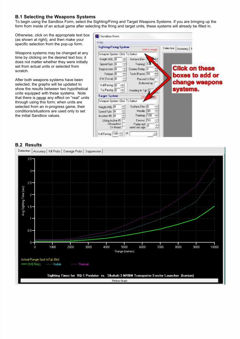
7/21/2019 TSS User Manual
http://slidepdf.com/reader/full/tss-user-manual 484/492
B.1 Selecting the Weapons SystemsTo begin using the Sandbox Form, select the Sighting/Firing and Target Weapons Systems. If you are bringing up theform from inside of an actual game after selecting the firing and target units, these systems will already be filled in.
Otherwise, click on the appropriate text box(as shown at right), and then make yourspecific selection from the pop-up form.
Weapons systems may be changed at any
time by clicking on the desired text box; itdoes not matter whether they were initiallyset from actual units or selected fromscratch.
After both weapons systems have beenselected, the graphs will be updated toshow the results between two hypotheticalunits equipped with these systems. Notethat there is never any effect on “real” unitsthrough using this form; when units areselected from an in-progress game, theirconditions/situations are used only to setthe initial Sandbox values.
B.2 Results

7/21/2019 TSS User Manual
http://slidepdf.com/reader/full/tss-user-manual 485/492
Once the firing/spotting and target weapons systems areset, the results will be displayed in graph form. Resultsare broken down into the major categories of Detection, Accuracy, Kill Probabilities, Damage Probabilities, andSuppression. To switch between them, simply click onthe appropriate tab at the top of the graph.
Most graphs will display several lines, each of adifferent color. The legend identifying the meaningof each color is provided at the bottom of the graph.In addition, if the Sandbox was initialized using realunits from within a scenario, the actual rangebetween those units will be shown as well in yellow(both at the bottom and on the graph, as shownhere).
The line designated “OVERALL” indicates theexpected values for the complete weapons system –it is what should be expected in “real life”. Note thatit is not usually simply the “sum of its parts”, becauseother considerations are applied that apply to theweapons system as a whole.
For example, there may not be personnel availableto use all of the individual component systems at thesame time, so only the best are chosen for the“OVERALL” value (though all will be shown asindividual lines).
For clarity, the Results display for Accuracy, Damage and Suppression are limited to one type of ammunition at a time, toprevent a jumble of lines. The specific ammunition type is set using the drop-down box in the bottom right hand panel, asshown here:
Individual sighting systems may also be chosen for the Detection Results, using the same drop-down box.

7/21/2019 TSS User Manual
http://slidepdf.com/reader/full/tss-user-manual 486/492
B.3 Editing ValuesMost of the environmental and situational values impacting the simulated setting between the units/systems can be editedto evaluate the effects of the changes. Note that the principal characteristics of the weapons systems can not be changedusing this form; it is not possible to change a tank's armor type or thickness, or the weapons that it has on-board forexample.
In some cases, the graph will automatically update after changing a value. However, this is not always the case;recalculating and redrawing every time an up/down button is clicked can be very frustrating and time consuming,
especially for larger changes. Therefore if you are not sure the graph has updated after a change, click the [RedrawGraph] button location under the graph Legend to be certain.
Sandbox values are grouped into distinct boxes and panels on the form, by their function and relation to the selectedactivity. The general panels are:
Sighting Firing System. All situational values connected with the unitdoing the sighting or firing. Changes to the facing and heading to targetvalues will also change the Facing Diagram (see below).
These values are not saved after the form is closed.
Target System. All situational values connected with the unit beingsighted or fired at. Changes to the facing values will also change theFacing Diagram (see below).
These values are not saved after the form is closed.
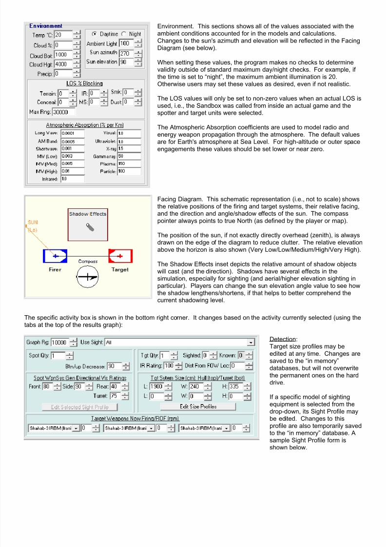
7/21/2019 TSS User Manual
http://slidepdf.com/reader/full/tss-user-manual 487/492
Environment. This sections shows all of the values associated with theambient conditions accounted for in the models and calculations.Changes to the sun's azimuth and elevation will be reflected in the FacingDiagram (see below).
When setting these values, the program makes no checks to determinevalidity outside of standard maximum day/night checks. For example, ifthe time is set to “night”, the maximum ambient illumination is 20.Otherwise users may set these values as desired, even if not realistic.
The LOS values will only be set to non-zero values when an actual LOS isused, i.e., the Sandbox was called from inside an actual game and thespotter and target units were selected.
The Atmospheric Absorption coefficients are used to model radio andenergy weapon propagation through the atmosphere. The default valuesare for Earth's atmosphere at Sea Level. For high-altitude or outer spaceengagements these values should be set lower or near zero.
Facing Diagram. This schematic representation (i.e., not to scale) showsthe relative positions of the firing and target systems, their relative facing,and the direction and angle/shadow effects of the sun. The compasspointer always points to true North (as defined by the player or map).
The position of the sun, if not exactly directly overhead (zenith), is alwaysdrawn on the edge of the diagram to reduce clutter. The relative elevationabove the horizon is also shown (Very Low/Low/Medium/High/Very High).
The Shadow Effects inset depicts the relative amount of shadow objectswill cast (and the direction). Shadows have several effects in thesimulation, especially for sighting (and aerial/higher elevation sighting in
particular). Players can change the sun elevation angle value to see howthe shadow lengthens/shortens, if that helps to better comprehend thecurrent shadowing level.
The specific activity box is shown in the bottom right corner. It changes based on the activity currently selected (using thetabs at the top of the results graph):
Detection:Target size profiles may beedited at any time. Changes aresaved to the “in memory”databases, but will not overwritethe permanent ones on the hard
drive.
If a specific model of sightingequipment is selected from thedrop-down, its Sight Profile maybe edited. Changes to thisprofile are also temporarily savedto the “in memory” database. Asample Sight Profile form isshown below.
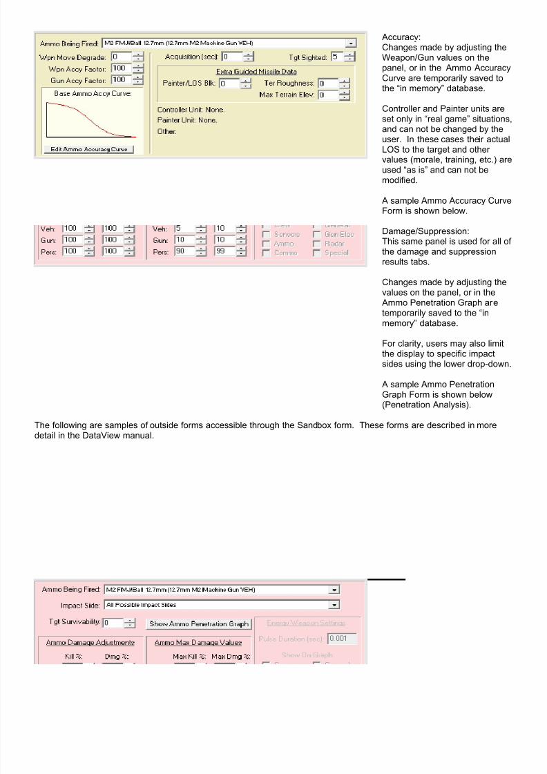
7/21/2019 TSS User Manual
http://slidepdf.com/reader/full/tss-user-manual 488/492
Accuracy:Changes made by adjusting theWeapon/Gun values on thepanel, or in the Ammo AccuracyCurve are temporarily saved tothe “in memory” database.
Controller and Painter units areset only in “real game” situations,and can not be changed by theuser. In these cases their actualLOS to the target and othervalues (morale, training, etc.) areused “as is” and can not bemodified.
A sample Ammo Accuracy CurveForm is shown below.
Damage/Suppression:This same panel is used for all ofthe damage and suppressionresults tabs.
Changes made by adjusting thevalues on the panel, or in the Ammo Penetration Graph aretemporarily saved to the “inmemory” database.
For clarity, users may also limitthe display to specific impactsides using the lower drop-down.
A sample Ammo PenetrationGraph Form is shown below
(Penetration Analysis).
The following are samples of outside forms accessible through the Sandbox form. These forms are described in moredetail in the DataView manual.

7/21/2019 TSS User Manual
http://slidepdf.com/reader/full/tss-user-manual 489/492
Figure 409: Sighting Profile Form. This form is used to set the capabilities and efficacy of sighting systems.Some systems are considered “default”, in that they apply to humans in general (naked eye, for example). All
other sighting systems must be assigned explicitly to a Weapons System in the Data Table.

7/21/2019 TSS User Manual
http://slidepdf.com/reader/full/tss-user-manual 490/492
Figure 410: The Ammunition Accuracy Curve Form. This form is used to set the base (i.e., “firing range”)accuracy of each type of ammunition. Accuracy is set as the average/expected probability of hitting a “standard
size” target (5 sq. meters) over the ammunition’s maximum range (in 10% range intervals).
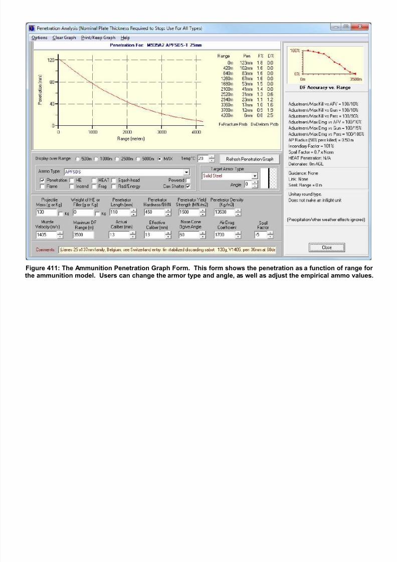
7/21/2019 TSS User Manual
http://slidepdf.com/reader/full/tss-user-manual 491/492
Figure 411: The Ammunition Penetration Graph Form. This form shows the penetration as a function of range forthe ammunition model. Users can change the armor type and angle, as well as adjust the empirical ammo values

7/21/2019 TSS User Manual
http://slidepdf.com/reader/full/tss-user-manual 492/492
Appendix C: TSS Series File Types and Extensions
Extension Description
.ACX Definitions used to “auto-place” symbols for hexline and hexsides.
.AEX Definitions used to “auto-place” symbols for hex elevations.
.AG3 Geomorphic map instruction set file (list of tiles and positions).
.AIR Data file containing Aircraft Performance Profiles..ALT Individual symbol rotation definitions for use in rotated (flipped/mirrored) geomorphic tiles
.AM3 ADC-3 format layer-based saved map file.
.BCF Control file for batch scenario executions.
.BRI Batch run scenario information file.
.ECX Definitions used to link map terrain types to a TEC file.
.GCF Data file containing curve information, incl. background radiation, and default accuracy values.
.GUN Data file storing the Gun/Launcher, Ammo, and Cluster Munitions tables.
.LDF This file links hexline and hexside definitions to a symbol set.
.MAP ADC-1 / ADC-2 hex-based saved map file.
.MOE Measures of Effectiveness data file.
.OPS Saved game/scenario file.
.ORG Data file storing the Nations, Leaders, TO&E, and Awards tables.
SET ADC symbol set master information file