MEADE LightBridge: Encoders Installation - Astro Devices … · 2017-06-26 · Azimuth encoder...
16
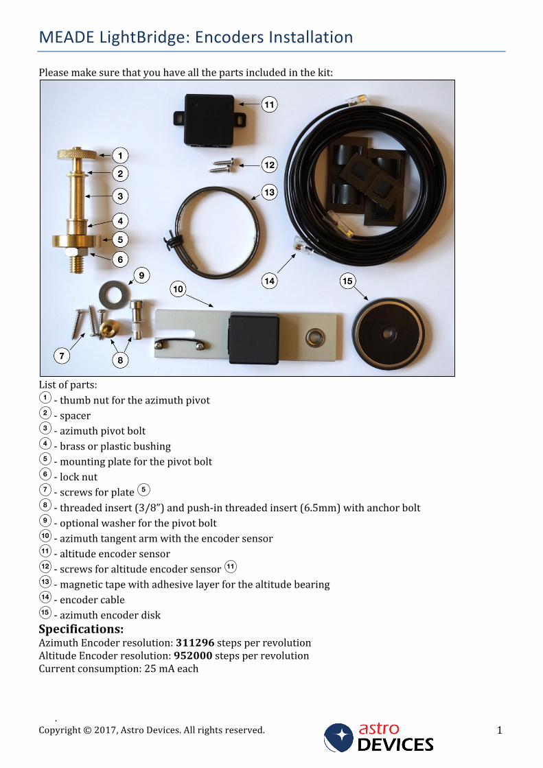
. Copyright © 2017, Astro Devices. All rights reserved. 1 MEADE LightBridge: Encoders Installation Please make sure that you have all the parts included in the kit: List of parts: - thumb nut for the azimuth pivot - spacer - azimuth pivot bolt - brass or plastic bushing - mounting plate for the pivot bolt - lock nut - screws for plate - threaded insert (3/8”) and push-in threaded insert (6.5mm) with anchor bolt - optional washer for the pivot bolt - azimuth tangent arm with the encoder sensor - altitude encoder sensor - screws for altitude encoder sensor - magnetic tape with adhesive layer for the altitude bearing - encoder cable - azimuth encoder disk Specifications: Azimuth Encoder resolution: 311296 steps per revolution Altitude Encoder resolution: 952000 steps per revolution Current consumption: 25 mA each 1 2 3 4 5 6 7 5 8 9 10 11 12 11 13 14 15
Transcript of MEADE LightBridge: Encoders Installation - Astro Devices … · 2017-06-26 · Azimuth encoder...
.Copyright©2017,AstroDevices.Allrightsreserved. 1
MEADELightBridge:EncodersInstallation
Pleasemakesurethatyouhaveallthepartsincludedinthekit:
Listofparts:-thumbnutfortheazimuthpivot-spacer-azimuthpivotbolt-brassorplasticbushing-mountingplateforthepivotbolt-locknut-screwsforplate -threadedinsert(3/8”)andpush-inthreadedinsert(6.5mm)withanchorbolt-optionalwasherforthepivotbolt-azimuthtangentarmwiththeencodersensor-altitudeencodersensor-screwsforaltitudeencodersensor -magnetictapewithadhesivelayerforthealtitudebearing-encodercable-azimuthencoderdisk
Specifications:AzimuthEncoderresolution:311296stepsperrevolutionAltitudeEncoderresolution:952000stepsperrevolutionCurrentconsumption:25mAeach
1
2
3
4
5
6
7 5
8
9
10
11
12 11
13
14
15
Copyright©2017,AstroDevices.Allrightsreserved.2
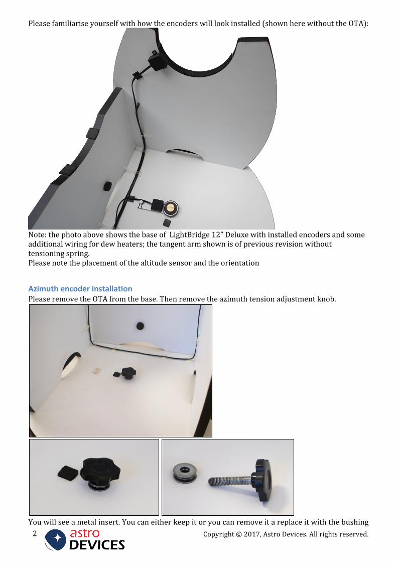
Pleasefamiliariseyourselfwithhowtheencoderswilllookinstalled(shownherewithouttheOTA):
Note:thephotoaboveshowsthebaseofLightBridge12”Deluxewithinstalledencodersandsomeadditionalwiringfordewheaters;thetangentarmshownisofpreviousrevisionwithouttensioningspring.Pleasenotetheplacementofthealtitudesensorandtheorientation
AzimuthencoderinstallationPleaseremovetheOTAfromthebase.Thenremovetheazimuthtensionadjustmentknob.
Youwillseeametalinsert.Youcaneitherkeepitoryoucanremoveitareplaceitwiththebushing
.Copyright©2017,AstroDevices.Allrightsreserved. 3
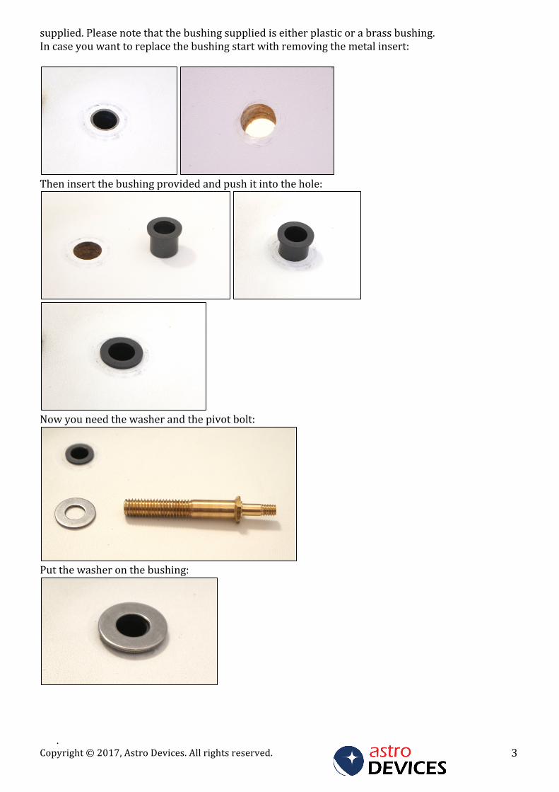
supplied.Pleasenotethatthebushingsuppliediseitherplasticorabrassbushing.Incaseyouwanttoreplacethebushingstartwithremovingthemetalinsert:
Theninsertthebushingprovidedandpushitintothehole:
Nowyouneedthewasherandthepivotbolt:
Putthewasheronthebushing:
Copyright©2017,AstroDevices.Allrightsreserved.4
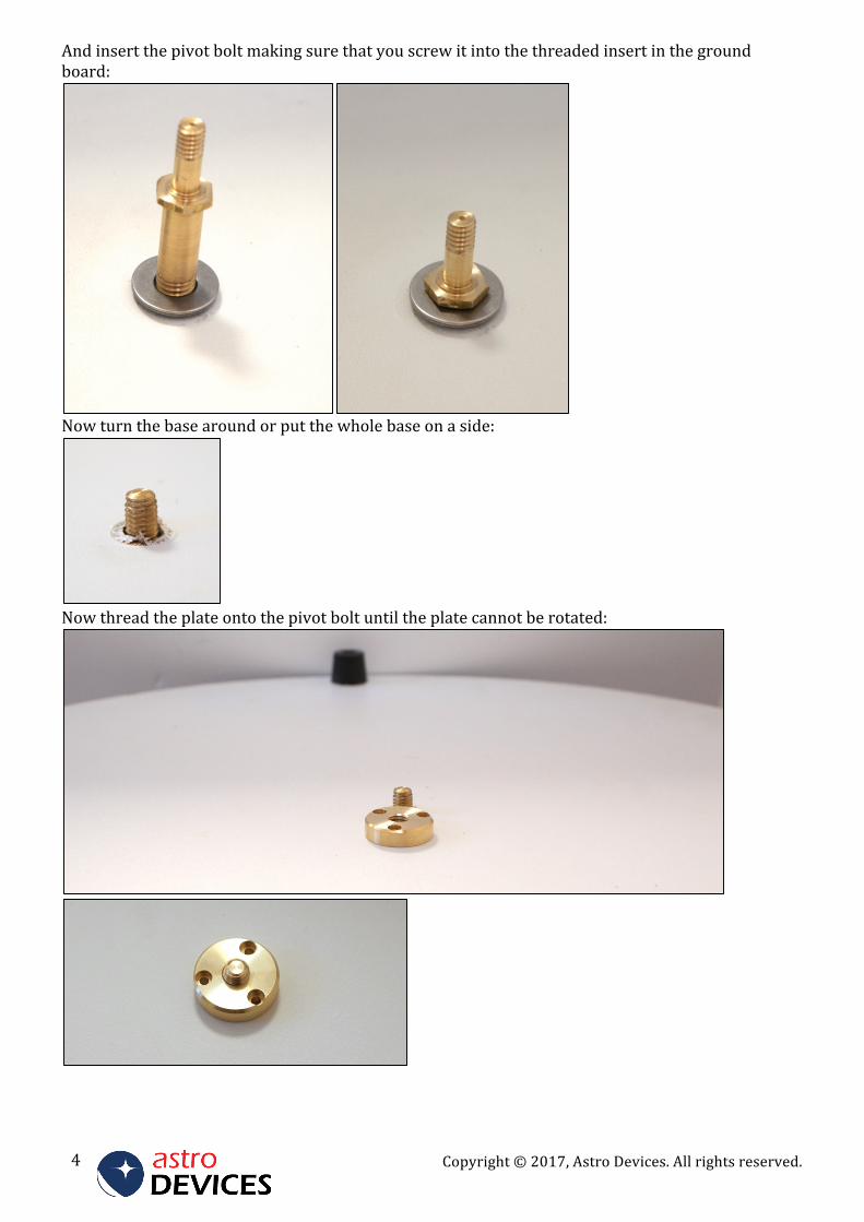
Andinsertthepivotboltmakingsurethatyouscrewitintothethreadedinsertinthegroundboard:
Nowturnthebasearoundorputthewholebaseonaside:
Nowthreadtheplateontothepivotboltuntiltheplatecannotberotated:
.Copyright©2017,AstroDevices.Allrightsreserved. 5
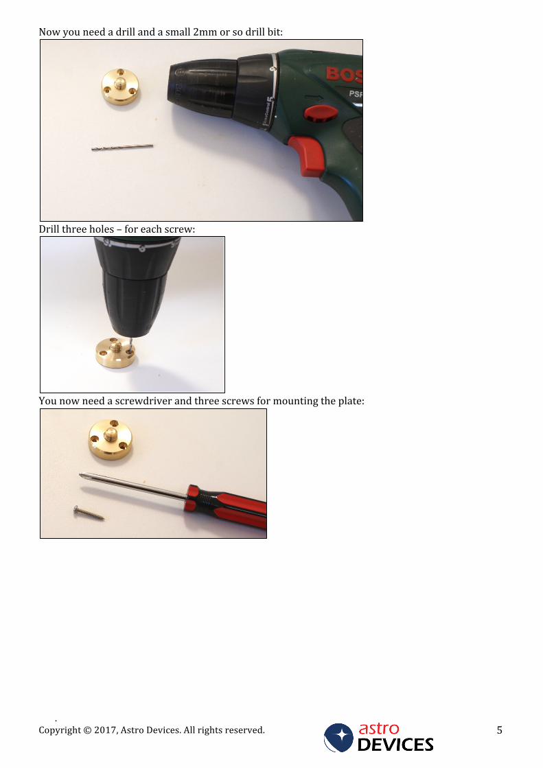
Nowyouneedadrillandasmall2mmorsodrillbit:
Drillthreeholes–foreachscrew:
Younowneedascrewdriverandthreescrewsformountingtheplate:
Copyright©2017,AstroDevices.Allrightsreserved.6
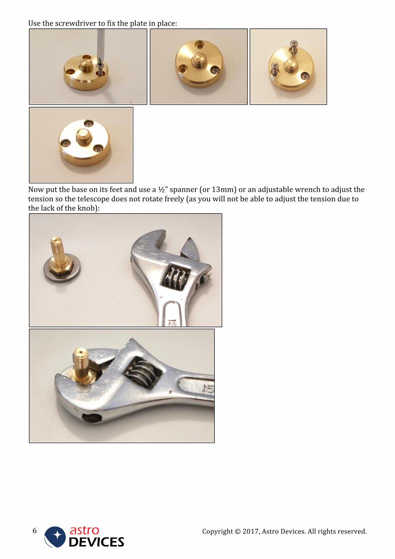
Usethescrewdrivertofixtheplateinplace:
Nowputthebaseonitsfeetandusea½”spanner(or13mm)oranadjustablewrenchtoadjustthetensionsothetelescopedoesnotrotatefreely(asyouwillnotbeabletoadjustthetensionduetothelackoftheknob):
.Copyright©2017,AstroDevices.Allrightsreserved. 7
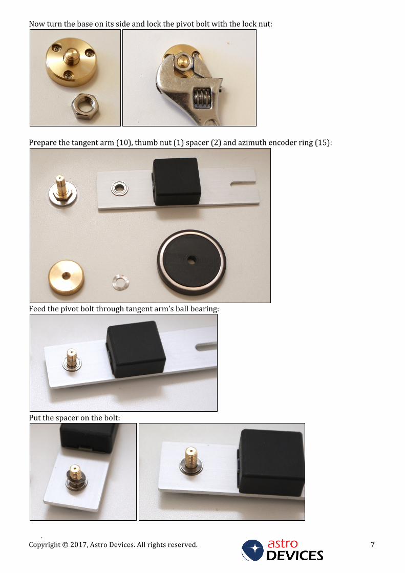
Nowturnthebaseonitssideandlockthepivotboltwiththelocknut:
Preparethetangentarm(10),thumbnut(1)spacer(2)andazimuthencoderring(15):
Feedthepivotboltthroughtangentarm’sballbearing:
Putthespaceronthebolt:
Copyright©2017,AstroDevices.Allrightsreserved.8
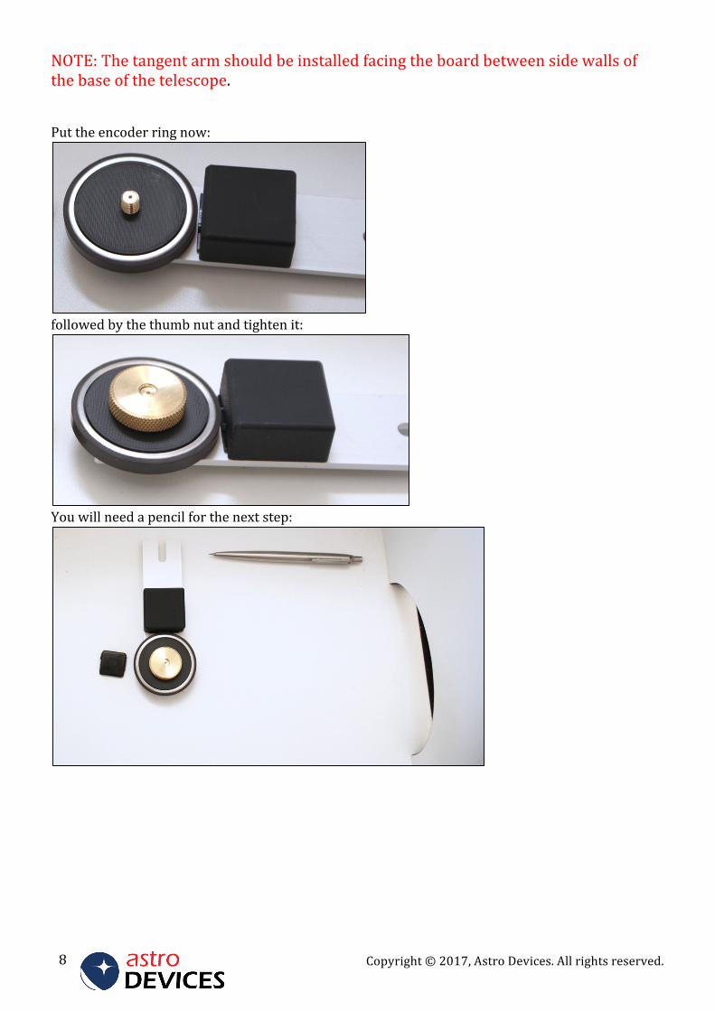
NOTE:Thetangentarmshouldbeinstalledfacingtheboardbetweensidewallsofthebaseofthetelescope.Puttheencoderringnow:
followedbythethumbnutandtightenit:
Youwillneedapencilforthenextstep:
.Copyright©2017,AstroDevices.Allrightsreserved. 9
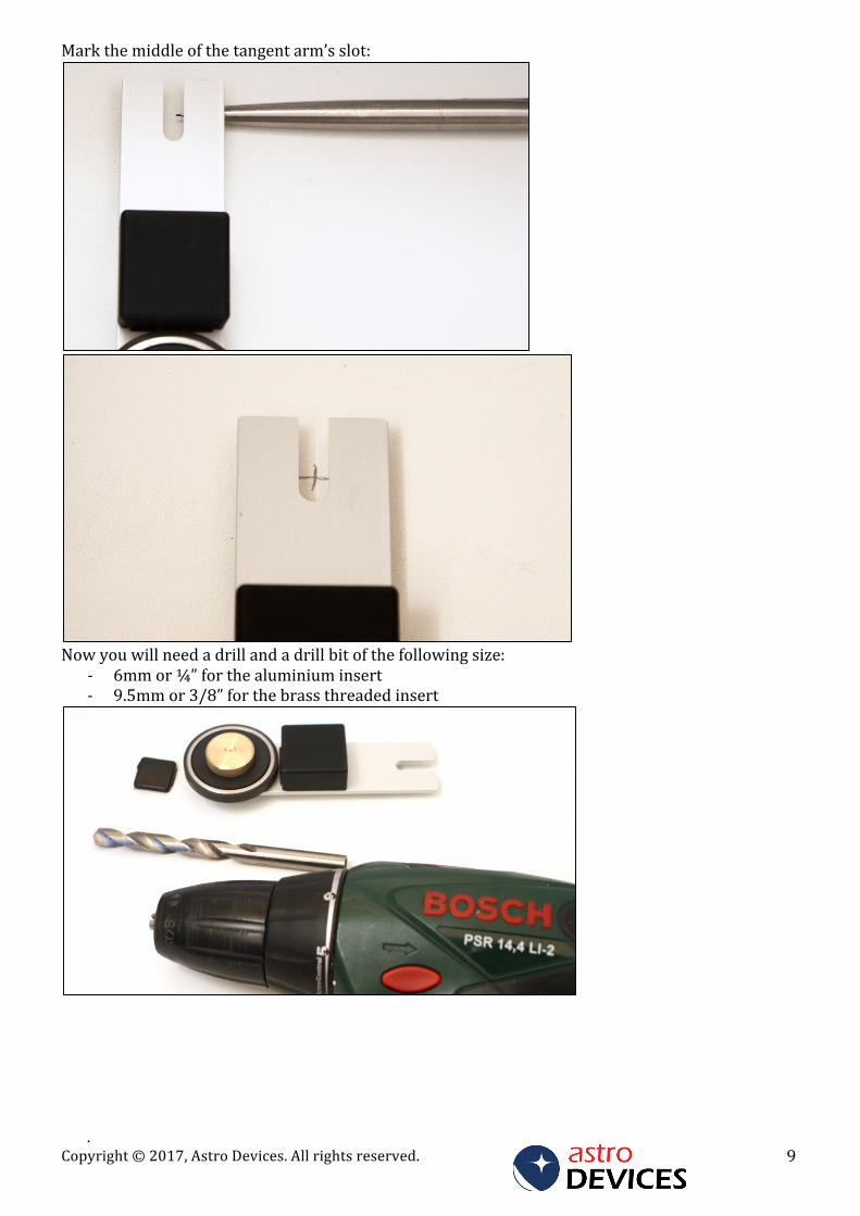
Markthemiddleofthetangentarm’sslot:
Nowyouwillneedadrillandadrillbitofthefollowingsize:
- 6mmor¼”forthealuminiuminsert- 9.5mmor3/8”forthebrassthreadedinsert
Copyright©2017,AstroDevices.Allrightsreserved.10
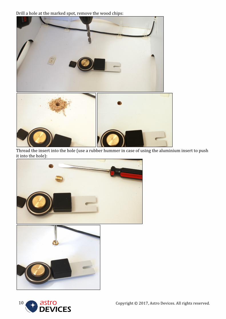
Drillaholeatthemarkedspot,removethewoodchips:
Threadtheinsertintothehole(usearubberhummerincaseofusingthealuminiuminserttopushitintothehole):
.Copyright©2017,AstroDevices.Allrightsreserved. 11
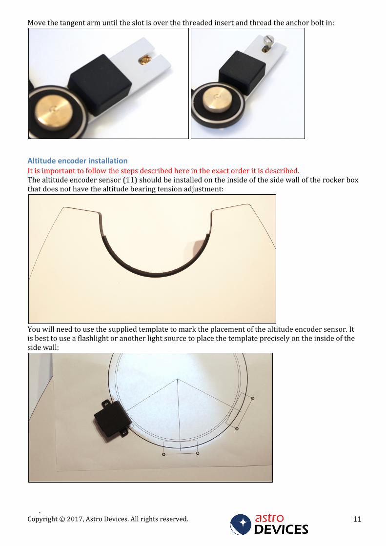
Movethetangentarmuntiltheslotisoverthethreadedinsertandthreadtheanchorboltin:
AltitudeencoderinstallationItisimportanttofollowthestepsdescribedhereintheexactorderitisdescribed.Thealtitudeencodersensor(11)shouldbeinstalledontheinsideofthesidewalloftherockerboxthatdoesnothavethealtitudebearingtensionadjustment:
Youwillneedtousethesuppliedtemplatetomarktheplacementofthealtitudeencodersensor.Itisbesttouseaflashlightoranotherlightsourcetoplacethetemplatepreciselyontheinsideofthesidewall:
Copyright©2017,AstroDevices.Allrightsreserved.12
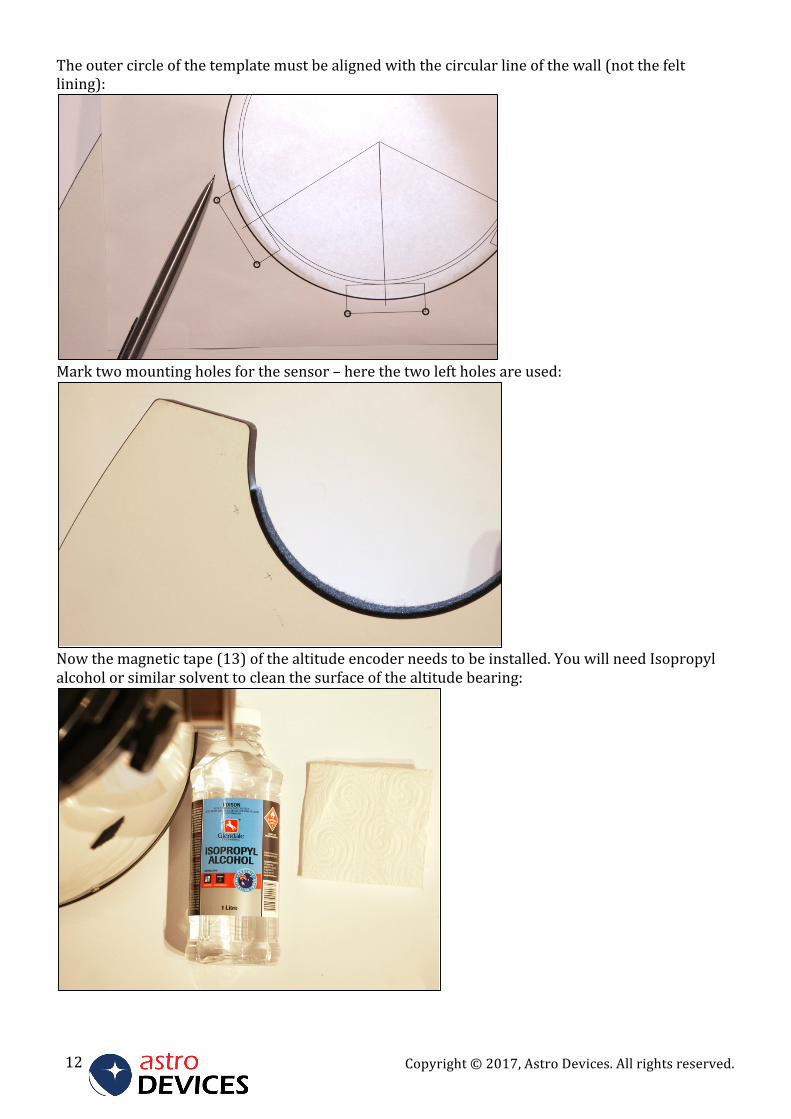
Theoutercircleofthetemplatemustbealignedwiththecircularlineofthewall(notthefeltlining):
Marktwomountingholesforthesensor–herethetwoleftholesareused:
Nowthemagnetictape(13)ofthealtitudeencoderneedstobeinstalled.YouwillneedIsopropylalcoholorsimilarsolventtocleanthesurfaceofthealtitudebearing:
.Copyright©2017,AstroDevices.Allrightsreserved. 13
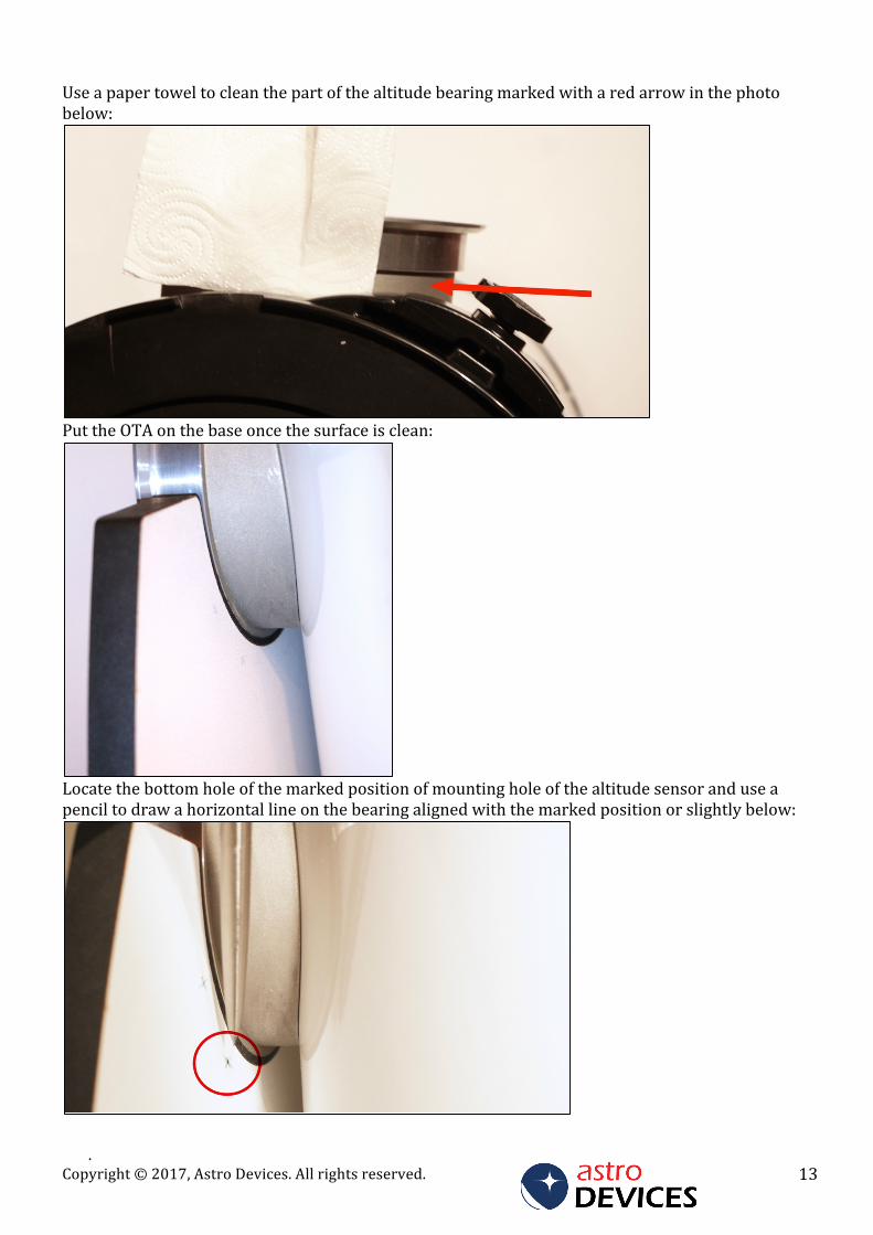
Useapapertoweltocleanthepartofthealtitudebearingmarkedwitharedarrowinthephotobelow:
PuttheOTAonthebaseoncethesurfaceisclean:
Locatethebottomholeofthemarkedpositionofmountingholeofthealtitudesensoranduseapenciltodrawahorizontallineonthebearingalignedwiththemarkedpositionorslightlybelow:
Copyright©2017,AstroDevices.Allrightsreserved.14
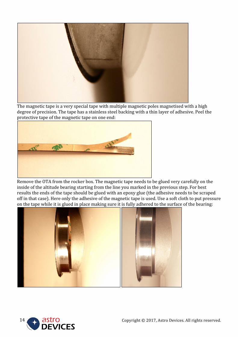
Themagnetictapeisaveryspecialtapewithmultiplemagneticpolesmagnetisedwithahighdegreeofprecision.Thetapehasastainlesssteelbackingwithathinlayerofadhesive.Peeltheprotectivetapeofthemagnetictapeononeend:
RemovetheOTAfromtherockerbox.Themagnetictapeneedstobegluedverycarefullyontheinsideofthealtitudebearingstartingfromthelineyoumarkedinthepreviousstep.Forbestresultstheendsofthetapeshouldbegluedwithanepoxyglue(theadhesiveneedstobescrapedoffinthatcase).Hereonlytheadhesiveofthemagnetictapeisused.Useasoftclothtoputpressureonthetapewhileitisgluedinplacemakingsureitisfullyadheredtothesurfaceofthebearing:
.Copyright©2017,AstroDevices.Allrightsreserved. 15
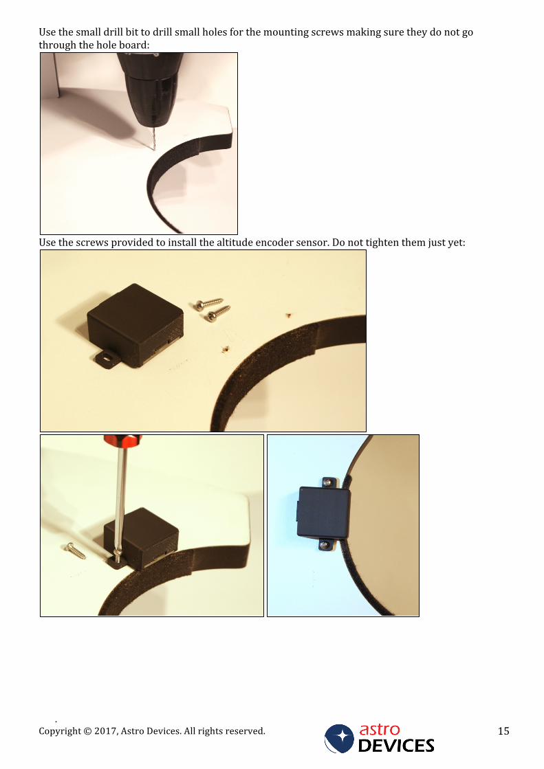
Usethesmalldrillbittodrillsmallholesforthemountingscrewsmakingsuretheydonotgothroughtheholeboard:
Usethescrewsprovidedtoinstallthealtitudeencodersensor.Donottightenthemjustyet:
Copyright©2017,AstroDevices.Allrightsreserved.16
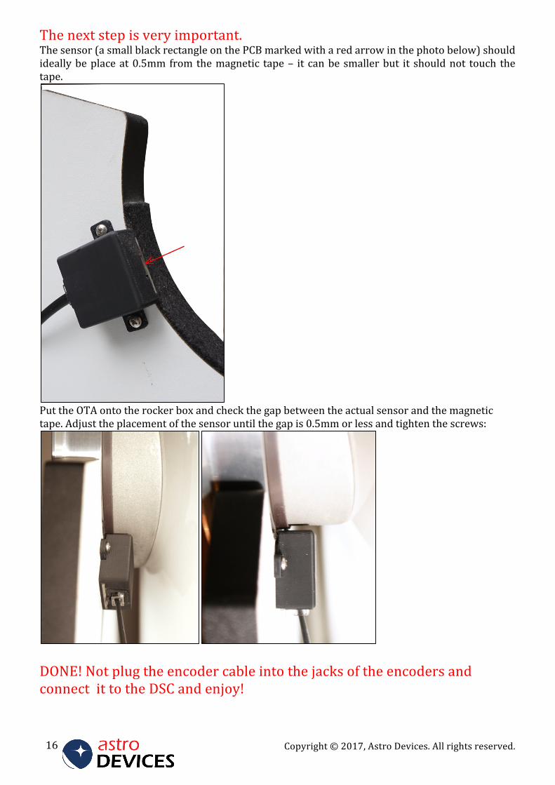
Thenextstepisveryimportant.Thesensor(asmallblackrectangleonthePCBmarkedwitharedarrowinthephotobelow)shouldideallybeplaceat0.5mmfromthemagnetic tape– it canbesmallerbut it shouldnot touch thetape.
PuttheOTAontotherockerboxandcheckthegapbetweentheactualsensorandthemagnetictape.Adjusttheplacementofthesensoruntilthegapis0.5mmorlessandtightenthescrews:
DONE!NotplugtheencodercableintothejacksoftheencodersandconnectittotheDSCandenjoy!