INSTALLATION INSTRUCTIONS PoE IP Encoder ( for SIP · PDF filePoE IP Encoder PIE-1...
4
PoE IP Encoder PIE-1 PoE IP Encoder PIE-1 INSTALLATION INSTRUCTIONS ( for SIP series and RLS series ) No.5919420 ▪ PIE-1 changes analog relay output signals (N.C.) to original ASCII code. ▪ PIE-1 can supply power to detector using a PoE hub or switch. ▪ Follow all cautions and instructions in this manual before installation. ▪ Keep this manual after installation so that you can read when necessary. ▪ Remember the meanings of “Warning” and “Caution” below to use the product safely. If you ignore a caution, the user or other people may be injured or the product or something around it may be damaged. If you ignore a warning, the user or other people may be injured or dead. ▪ Do not repair, dismantle or modify the product yourself. ▪ Do not touch the product with a wet hand. ▪ Be careful not to damage other interior wiring when installing or wiring the product. ▪ Power off the product immediately if smoke, odor or strange sound emits from the product. ▪ Do not install the product in an extremely moist place such as a bathroom or a place where the product may be wet. ▪ Insert the connectors securely when wiring. Caution ■ No. 6-32 UNC screw (5/8 inch), 6 pcs ■ Alarm 10-pin cable (26cm) ■ Power 2-pin cable (26cm) ■ Alarm 6-pin cable (10cm) ■ Alarm 4-pin cable (10cm) ■ Power 2-pin cable (10cm) ■ Main unit of PIE-1 SAFETY PRECAUTION FEATURES Connectors Warning Warning Warning: This is a class A product. In a domestic environment this product may cause radio interference in which case the user may be required to take adequate measures. (EN55022) CE Statement Warning Caution ■ SIP mounting plate for Gang Box ■ Gasket sheet for Gang Box PARTS IDENTIFICATION 1 Ethernet connector for PoE Ethernet connector for detector 24VDC Power output connector 12VDC Power output connector Alarm input connector ▪ Be sure to use the attached cables. ▪ Do not use 12V and 24V power sources at the same time. Caution
Transcript of INSTALLATION INSTRUCTIONS PoE IP Encoder ( for SIP · PDF filePoE IP Encoder PIE-1...

PoE IP Encoder
PIE-1PoE IP Encoder
PIE-1INSTALLATION INSTRUCTIONS
( for SIP series and RLS series )
No.5919420
▪ PIE-1 changes analog relay output signals (N.C.) to original ASCII code.
▪ PIE-1 can supply power to detector using a PoE hub or switch.
▪ Follow all cautions and instructions in this manual before installation.
▪ Keep this manual after installation so that you can read when necessary.
▪ Remember the meanings of “Warning” and “Caution” below to use the product safely.
If you ignore a caution, the user or other people may be injured or the product or something around it may be damaged.
If you ignore a warning, the user or other people may be injured or dead.
▪ Do not repair, dismantle or modify the product yourself.
▪ Do not touch the product with a wet hand.▪ Be careful not to damage other interior wiring when
installing or wiring the product.▪ Power off the product immediately if smoke, odor or
strange sound emits from the product.▪ Do not install the product in an extremely moist place
such as a bathroom or a place where the product may be wet.
▪ Insert the connectors securely when wiring.
Caution
■ No. 6-32 UNC screw (5/8 inch), 6 pcs
■ Alarm 10-pin cable (26cm)
■ Power 2-pin cable (26cm)
■ Alarm 6-pin cable (10cm)
■ Alarm 4-pin cable (10cm)
■ Power 2-pin cable (10cm)
■ Main unit of PIE-1SAFETY PRECAUTION
FEATURES
Connectors
WarningWarning
Warning: This is a class A product. In a domestic environment this product may cause radio interference in which case the user may be required to take adequate measures. (EN55022)
CE Statement
Warning
Caution
■ SIP mounting plate for Gang Box
■ Gasket sheetfor Gang Box
PARTS IDENTIFICATION1
Ethernet connector for PoE Ethernet connector for detector
24VDC Power output connector12VDC Power output connectorAlarm input connector
▪ Be sure to use the attached cables.▪ Do not use 12V and 24V power sources at the same time.
Caution
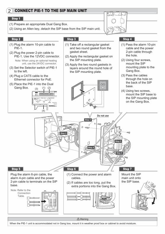
(1) Prepare an appropriate Dual Gang Box.(2) Using an Allen key, detach the SIP base from the SIP main unit.
(1) Plug the alarm 10-pin cable to PIE-1.
(2) Plug the power 2-pin cable to PIE-1. Use the 12VDC connector.Note: When using an optional heating
unit, use the 24VDC connector.
(3) Set the Selector switch of PIE-1 to the left.
(4) Plug a CAT5 cable to the Ethernet connector for PoE.
(5) Place the PIE-1 into the Dual Gang Box.
(1) Take off a rectangular gasket and two round gasket from the gasket sheet.
(2) Apply the rectangular gasket on the SIP mounting plate.
(3) Apply the two round gaskets in layers around the round hole of the SIP mounting plate.
(1) Pass the alarm 10-pin cable and the power 2-pin cable through the hole.
(2) Using four screws, mount the SIP mounting plate to the Gang Box.
(3) Pass the cables through the hole on the back of the SIP base.
(4) Using two screws, mount the SIP base to the SIP mounting plate on the Gang Box.
Step 1
Step 3Step 2 Step 4
Step 6Step 5 Step 7
Mount the SIP main unit onto the SIP base.
(1) Connect the power and alarm cables.
(2) If cables are too long, put the extra portions into the Gang Box.
When the PIE-1 unit is accommodated not in Gang box, mount it in weather proof box or cabinet to avoid moisture.
Plug the alarm 6-pin cable, the alarm 4-pin cable and the power 2-pin cable to terminals on the SIP base.
CONNECT PIE-1 TO THE SIP MAIN UNIT2
Warning
Note: Refer to the Connection Table.
Step 3
Step 4
Step 5
Step 6
Step 2
(1) (2)(3)
(4)
Do not use
An example of IP address settingsIP AddressSubnet Mask
: 192.168.0.1: 255.255.255.0
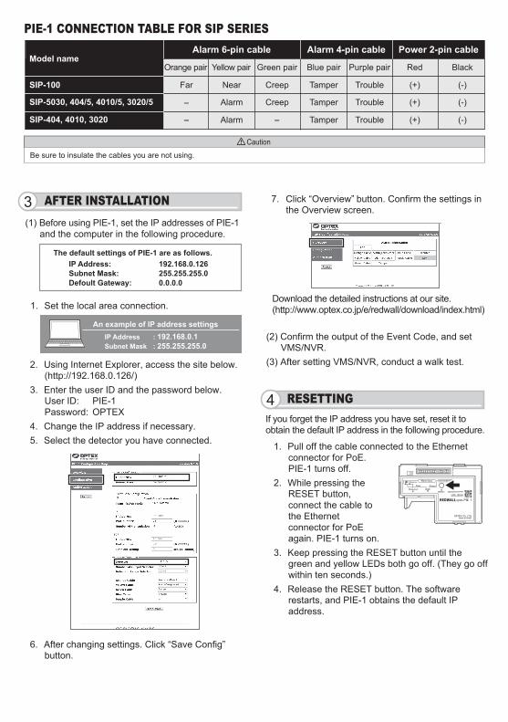
The default settings of PIE-1 are as follows. IP Address: 192.168.0.126 Subnet Mask: 255.255.255.0 Defoult Gateway: 0.0.0.0
(1) Before using PIE-1, set the IP addresses of PIE-1 and the computer in the following procedure.
1. Set the local area connection.
7. Click “Overview” button. Confirm the settings in the Overview screen.
6. After changing settings. Click “Save Config” button.
Download the detailed instructions at our site. (http://www.optex.co.jp/e/redwall/download/index.html)
If you forget the IP address you have set, reset it to obtain the default IP address in the following procedure.
2. Using Internet Explorer, access the site below. (http://192.168.0.126/)
3. Enter the user ID and the password below.User ID: PIE-1Password: OPTEX
4. Change the IP address if necessary.5. Select the detector you have connected.
(2) Confirm the output of the Event Code, and set VMS/NVR.
(3) After setting VMS/NVR, conduct a walk test.
AFTER INSTALLATION3
RESETTING4
1. Pull off the cable connected to the Ethernet connector for PoE. PIE-1 turns off.
2. While pressing the RESET button, connect the cable to the Ethernet connector for PoE again. PIE-1 turns on.
3. Keep pressing the RESET button until the green and yellow LEDs both go off. (They go off within ten seconds.)
4. Release the RESET button. The software restarts, and PIE-1 obtains the default IP address.
Alarm 6-pin cable
SIP-404, 4010, 3020
SIP-5030, 404/5, 4010/5, 3020/5
SIP-100
Model nameOrange pair Yellow pair Green pair Blue pair Purple pair Red Black
Far
-
- -
Near Creep Tamper Trouble (+) (-)
Alarm Creep Tamper Trouble (+) (-)
Alarm Tamper Trouble (+) (-)
Alarm 4-pin cable Power 2-pin cable
PIE-1 CONNECTION TABLE FOR SIP SERIES
Be sure to insulate the cables you are not using.
Caution
OPTEX CO., LTD. (JAPAN) (ISO 9001 Certified) (ISO 14001 Certified) URL:http://www.optex.co.jp/e/5-8-12 Ogoto Otsu Shiga 520-0101 JAPAN TEL:+81-77-579-8670 FAX:+81-77-579-8190
OPTEX INCORPORATED (USA) TEL:+1-909-993-5770 Tech:(800)966-7839 URL:http://www.optexamerica.com/OPTEX SECURITY SAS (FRANCE) TEL:+33-437-55-50-50 URL:http://www.optex-security.com/OPTEX (EUROPE) LTD. (UK) TEL:+44-1628-631000 URL:http://www.optexeurope.com/OPTEX SECURITY Sp. z o. o. (POLAND) TEL:+48-22-598-06-55 URL:http://www.optex.com.pl/
67.5
(2.6
6)
33.0
(1.3
0)
94.7 (3.73)
Step 2Step 3
Step 4
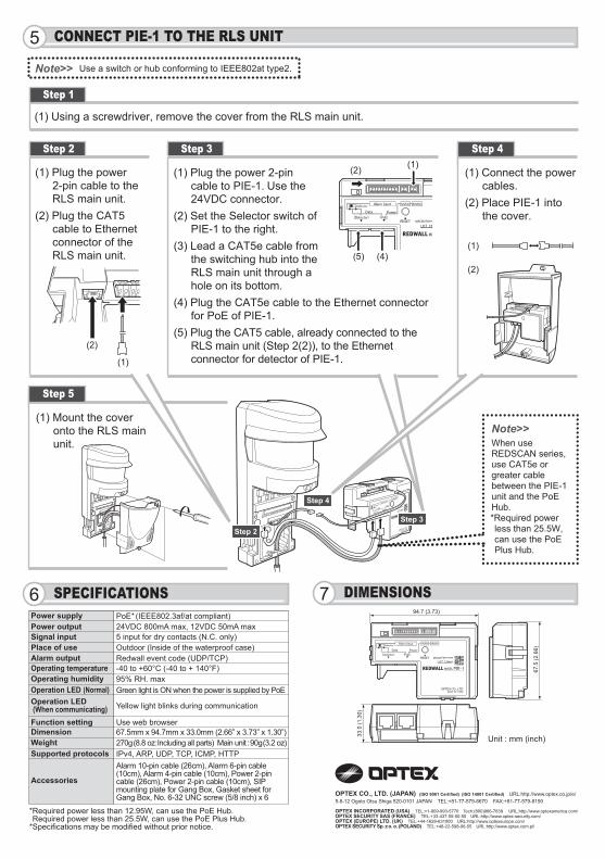
PoE (IEEE802.3af/at compliant)24VDC 800mA max, 12VDC 50mA max5 input for dry contacts (N.C. only)Outdoor (Inside of the waterproof case)Redwall event code (UDP/TCP)-40 to +60°C (-40 to + 140°F)95% RH. maxGreen light is ON when the power is supplied by PoE
Yellow light blinks during communication
Use web browser67.5mm x 94.7mm x 33.0mm (2.66” x 3.73” x 1.30”)270g (8.8 oz: Including all parts) Main unit : 90g (3.2 oz)IPv4, ARP, UDP, TCP, ICMP, HTTP
Power supply
Unit : mm (inch)
Power outputSignal inputPlace of useAlarm outputOperating temperatureOperating humidityOperation LED (Normal)Operation LED (When communicating)Function settingDimensionWeightSupported protocols
Accessories
SPECIFICATIONS6 DIMENSIONS7
Alarm 10-pin cable (26cm), Alarm 6-pin cable (10cm), Alarm 4-pin cable (10cm), Power 2-pin cable (26cm), Power 2-pin cable (10cm), SIP mounting plate for Gang Box, Gasket sheet for Gang Box, No. 6-32 UNC screw (5/8 inch) x 6
*Required power less than 12.95W, can use the PoE Hub. Required power less than 25.5W, can use the PoE Plus Hub.*Specifications may be modified without prior notice.
*
(1) Using a screwdriver, remove the cover from the RLS main unit.
(1) Plug the power 2-pin cable to the RLS main unit.
(2) Plug the CAT5 cable to Ethernet connector of the RLS main unit.
(1) Plug the power 2-pin cable to PIE-1. Use the 24VDC connector.
(2) Set the Selector switch of PIE-1 to the right.
(3) Lead a CAT5e cable from the switching hub into the RLS main unit through a hole on its bottom.
(4) Plug the CAT5e cable to the Ethernet connector for PoE of PIE-1.
(5) Plug the CAT5 cable, already connected to the RLS main unit (Step 2(2)), to the Ethernet connector for detector of PIE-1.
(1) Connect the power cables.
(2) Place PIE-1 into the cover.
Step 1
Step 3Step 2 Step 4
(1) Mount the cover onto the RLS main unit.
Step 5
CONNECT PIE-1 TO THE RLS UNIT5
Note>>When use REDSCAN series, use CAT5e or greater cable between the PIE-1 unit and the PoE Hub.*Required power less than 25.5W, can use the PoE Plus Hub.
Note>> Use a switch or hub conforming to IEEE802at type2.
(1)
(1)
(1)
(2)
(2)
(2)
(5) (4)