MAGNUM CONTROLS Centrifugal CompressorsMAGNUM CENTRIFUGAL MANUAL Version 17- Rev 1.1 3 ......
181
MCS Total Solution for all your Control Needs Energy Efficient and RoHS Compliant 5580 Enterprise Pkwy. Fort Myers, FL 33905 Office: 239-694-0089 Fax: 239-694-0031 www.mcscontrols.com MAGNUM CONTROLS Centrifugal Compressors Version 17 - Rev. 1.1 - 2017-06-30
Transcript of MAGNUM CONTROLS Centrifugal CompressorsMAGNUM CENTRIFUGAL MANUAL Version 17- Rev 1.1 3 ......

MCS TotalSolutionfor all yourControlNeeds Energy Efficient and
RoHS Compliant
5580 Enterprise Pkwy.Fort Myers, FL 33905
Office: 239-694-0089Fax: 239-694-0031
www.mcscontrols.com
MAGNUM CONTROLSCentrifugal Compressors
Version 17 - Rev. 1.1 - 2017-06-30
MAGNUM CENTRIFUGAL MANUAL Version 17- Rev 1.1
2
The MCS Commitment is to provide practical solutions for the industries needs and to be both a leader and partner in the effective use of
microprocessor controls.
Micro Control Systems, Inc.5580 Enterprise ParkwayFort Myers, Florida 33905
PH:(239) 694-0089 FAX:(239) 694-0031www.mcscontrols.com
All information contained within this document is considered to be proprietary information of Micro Control Systems, Inc. No information or data from this document shall be published, used, reproduced, transmitted, or disclosed to others outside your organization without the prior expressed written consent of Micro Control Systems, Inc. This document and the information contained herein shall be treated as proprietary. Reasonable provisions shall be provided to ensure that this information remains proprietary by your employees, agents, and other personnel that may have access to this document. Copyright ©2017
Date Author Description of Changes12-15-15 DEW Setup manual from Magnum HVAC Manual
1-28-16 DEW Changes made to chapters
2-12-16 DEW Added updated Condenser section to this manual, updated TOB
10-03-16 DEW Update Drawings
02-03-17 DEW Add Modbus Fault Sensors to manual
02-06-17 DEW Add Chiller Pump and Motor Amps from Bret
05-15-17 DEW Make changes to BMS control states
06-29-17 DEW Update setpoints to match HVAC update
Revision/Disclaimer Page
MAGNUM CENTRIFUGAL MANUAL Version 17- Rev 1.1
3
Table of ContentsChapter - 1. Introduction to the Magnum .........................................................................................9
Software ....................................................................................................................................................................9About the Magnum ....................................................................................................................................................9Magnum V17 Software Control Point Capacity .........................................................................................................9Magnum Hardware Supported by Magnum V17 Software ........................................................................................91.1. MCS-Magnum Revision 8.5 ........................................................................................................................101.2. Description MCS-Magnum Revision 8.5 .....................................................................................................111.3. SpecificationsMCS-MagnumRevision8.5 ................................................................................................111.4. MCS-SI16-AO4 ...........................................................................................................................................121.5. Description MCS-SI16-AO4 ........................................................................................................................131.6. SpecificationsMCS-SI16-AO4 ...................................................................................................................131.7. MCS-RO10 .................................................................................................................................................141.8. Description MCS-RO10 ..............................................................................................................................151.9. SpecificationsMCS-RO10 ..........................................................................................................................15
Chapter - 2. Network Connection–MCS-485 ................................................................................162.1. MCS 485 Network ......................................................................................................................................16
Chapter - 3. Network Connection–Ethernet ..................................................................................173.1. RJ45 using a Crossover Ethernet Cable ....................................................................................................17
Chapter - 4. Network Connection–Remote ....................................................................................184.1. Remote using Ethernet ...............................................................................................................................18
Chapter - 5. Centrifugal Compressor Control ...............................................................................195.1. Centrifugal Related Terminology ................................................................................................................19
5.1.1 Lift Pressure: .....................................................................................................................................195.1.2 Surge and Stall Protection: ...............................................................................................................195.1.3 Variable Geometry Diffuser (VGD) ...................................................................................................19
5.1.3.1. Table Lookup for VGD Support ............................................................................................22Chapter - 6. Centrifugal Compressor Config Setup ...................................................................25
6.1. CentrifugalBaseCompressorSetupMCS-Config .....................................................................................256.1.1 Modbus Fault Sensors ......................................................................................................................266.1.2 Typical Relay Output Setup ..............................................................................................................276.1.3 Compressor Speed Control ..............................................................................................................276.1.4 Compressor Vane Control .................................................................................................................27
Chapter - 7. Centrifugal Status Display ...........................................................................................287.1. MCS-Connect .............................................................................................................................................28
Chapter - 8. Authorization Function ..................................................................................................30Chapter - 9. Magnum Displays .............................................................................................................32
9.1. Magnum keypad and display ......................................................................................................................329.1.1 Menu Screen ....................................................................................................................................329.1.2 Introduction to Status Screens ..........................................................................................................329.1.3 Unit Status ........................................................................................................................................329.1.4 Unit Tonnage and KW Information ....................................................................................................329.1.5 Purge Status Screen (only if Purge cycles are active) ......................................................................339.1.6 Compressor status ............................................................................................................................339.1.7 Compressor status (only CENT) .......................................................................................................339.1.8 EXV status ........................................................................................................................................33
Chapter - 10. Magnum Control States ................................................................................................3410.1. UNIT IN POWER UP (0) .............................................................................................................................3410.2. NO RUN- I/O LOST (2) ...............................................................................................................................3410.3. UNIT IN LOCKOUT (3) ...............................................................................................................................3410.4. UNIT IS OFF (4) .........................................................................................................................................3410.5. UNIT IS HOLDING (5) ................................................................................................................................34
MAGNUM CENTRIFUGAL MANUAL Version 17- Rev 1.1
4
10.6. UNIT UNLDNG-VANE (6) ..........................................................................................................................3510.7. UNIT IS LOADNG-VANE (7) ......................................................................................................................3510.8. OFF-SMOKE ALARM (8) ............................................................................................................................3510.9. RUN/STOP SW OFF (9) .............................................................................................................................3510.10. SCHEDULED OFF (10) ..............................................................................................................................3510.11. OFF- NO FLOW (11) ..................................................................................................................................3510.12. AMBIENT OFF (13) ....................................................................................................................................3510.13. UNIT IS UNLOADED (15) ..........................................................................................................................3510.14. UNIT IS LOADED (16) ................................................................................................................................3510.15. OFF TMP-ICE MADE (17) ..........................................................................................................................3510.16. ECONOMIZER ONLY (18) .........................................................................................................................3610.17. SWITCHING MODES (19) .........................................................................................................................3610.18. VaneOpen-SpdHold (19) ...........................................................................................................................3610.19. UNIT SMOKE UNLDG (20) ........................................................................................................................3610.20. UNIT OFF UNLDING (21) ..........................................................................................................................3610.21. UNIT DMD UNLDING (22) .........................................................................................................................3610.22. UNIT HEAT UNLDING (23) ........................................................................................................................3610.23. UNIT UNLDNG-VFD (24) ..........................................................................................................................3610.24. UNIT LOADNG-VFD (25) ..........................................................................................................................3610.25. CMP SPD OPTIMIZE (33) .........................................................................................................................3710.26. UNIT IS OFF/TEMP (38) ...........................................................................................................................37
Chapter - 11. Compressor Control States (number) ....................................................................3811.1. LOST IO LOCKED (0) ................................................................................................................................3811.2. CMP LOCKED OUT (1) ..............................................................................................................................3811.3. SWITCHED OFF (2) ...................................................................................................................................3811.4. UNLD and PMPDWN (3) ............................................................................................................................3811.5. CMP ANTICYCE (4) ...................................................................................................................................3811.6. CMP OFF/READY (5) .................................................................................................................................3811.7. OIL PMP LUBING (6) .................................................................................................................................3811.8. NOT USED (7) ............................................................................................................................................3911.9. CMP UNLOADED (8) .................................................................................................................................3911.10. CMP DECR SPEED (9) .............................................................................................................................3911.11. CMP INCR SPEED (10) ............................................................................................................................3911.12. CMP IS HOLDING (11) ...............................................................................................................................3911.13. CMP OPEN VANES (12) ...........................................................................................................................3911.14. CMP CLOSE VANES (13) .........................................................................................................................4011.15. CMP IS RUNNING (14) ..............................................................................................................................4011.16. FAST UNLOADING (15) .............................................................................................................................4011.17. LO SUCT UNLOAD (16) .............................................................................................................................4011.18. LO SUCT HOLD (17) ..................................................................................................................................4011.19. HI DISC UNLOAD (18) ...............................................................................................................................4011.20. HI DISC HOLD (19) ....................................................................................................................................4011.21. SAFETY TRIPPED (20) ..............................................................................................................................4111.22. LO TMP UNLOAD (21) ...............................................................................................................................4111.23. LO TMP HOLD (22) ....................................................................................................................................4111.24. HI AMP HOLD (23) .....................................................................................................................................4111.25. HI DIS TMP HLD (24) .................................................................................................................................4111.26. SURGE SPD/VANE (25) ...........................................................................................................................4111.27. HI WATER HOLD (27) ................................................................................................................................4111.28. OFF-LO OIL TMP (29) ................................................................................................................................4111.29. HI AMP UNLDING (30) ...............................................................................................................................41
Chapter - 12. Lookup Tables ....................................................................................................................4212.1. Lookup tables used with MCS-MAGNUM controls .....................................................................................42
12.1.1 Setting up a Lookup table using MCS-CONFIG ...............................................................................4212.1.2 Setting up Lookup table #1 - see screen 3 below: ............................................................................4312.1.3 Viewing the Lookup Table in MCS-Connect .....................................................................................44
MAGNUM CENTRIFUGAL MANUAL Version 17- Rev 1.1
5
12.1.3.1. Using as Control Temperature Sensor..................................................................................44Chapter - 13. Ice Making Capabiliies ..................................................................................................45
13.1. HVAC/R unit using the cooling target reset ................................................................................................4513.1.1 Target (SP #1) Reset Sensor ............................................................................................................4513.1.2 Reset Sensor Type ‘Target Reset’ ....................................................................................................4513.1.3 Reset Sensor Type ‘Network Target Reset’ ......................................................................................45
13.2. Ice Making Mode ......................................................................................................................................4613.2.1 Terminating of ice making mode .......................................................................................................46
13.3. System as a pure ice making unit, Turbo Ice Machine ...............................................................................4613.3.1 The # Liquid Lind Solenoids .............................................................................................................4613.3.2 Required set points for defrost cycles ..............................................................................................47
13.4. Turbo Ice Machine Operation ....................................................................................................................47Chapter - 14. Centrifugal Purge Setup ...............................................................................................49
14.1. PurifierPurgeSystemInterface ..................................................................................................................4914.1.1 Purge Interface Setup .......................................................................................................................4914.1.2 Conditions to Run Purge Cycle .........................................................................................................5014.1.3 Purge States .....................................................................................................................................5014.1.4 Excess Purge Logic ..........................................................................................................................50
14.2. Special Pattern for Scroll Compressors ......................................................................................................5114.2.1 The following is a sample of the four-compressor setup: .................................................................5114.2.2 Pattern of the four-compressor setup: ..............................................................................................5214.2.3 The three-compressor type will be setup as follows: ........................................................................5214.2.4 Pattern of the three-compressor setup: ............................................................................................5214.2.5 Safeties are the same for both compressor types ............................................................................53
14.3. Custom Rotation .........................................................................................................................................5314.4. Compressor Anti-Cycle Logic .....................................................................................................................5414.5. Part Wind and Star Delta Starters ..............................................................................................................5414.6. Full Load Amp (FLA) calculation and slide positioning ...............................................................................5514.7. Chiller Barrel Heater ...................................................................................................................................5514.8. Hot Gas Bypass ..........................................................................................................................................5514.9. Chilled Water Reset ....................................................................................................................................5614.10. Oil Equalization Option ..............................................................................................................................5614.11. Liquid Injection Option ................................................................................................................................5614.12. Oil Cooler Option ........................................................................................................................................5614.13. Oil Pump Control Option .............................................................................................................................5614.14. Oil Differential Calculation ..........................................................................................................................5714.15. On/Off Switches ..........................................................................................................................................5714.16. Low Suction Unloading and Holding ...........................................................................................................5714.17. High Discharge Pressure Unloading and Holding ......................................................................................5814.18. High Discharge Temperature Unloading and Holding ................................................................................5814.19. High Ampere Unloading and Holding .........................................................................................................5914.20. Low Water Temperature Unloading and Holding ........................................................................................5914.21. EnergyEfficientCompressorStaging .........................................................................................................5914.22. Chilled Water Pump Control .......................................................................................................................60
14.22.1 Special Rotation for Chiller Pump Rotation ......................................................................................6014.22.2 Special Rotation For Process Pumps Rotation. ................................................................................60
14.23. Process Pump (Heat Exchanger) Control ..................................................................................................6114.24. Control Power Relay (No Stop) ..................................................................................................................6114.25. Low and High Ambient Shutdown ...............................................................................................................6214.26. Imperial, Metric, and Combined Unit sensor readings ................................................................................6214.27. Warning and Alarm Relay Outputs .............................................................................................................6214.28. Vi Port Control Logic (Open Drive Screw only) ..........................................................................................6214.29. Operating Schedules ..................................................................................................................................6314.30. Mod-Motor Limit Control for Flooded Chiller ...............................................................................................6314.31. Hot Gas Reheat (Humidity) Control ............................................................................................................6314.32. Extra Liquid Line Solenoid Control .............................................................................................................64
MAGNUM CENTRIFUGAL MANUAL Version 17- Rev 1.1
6
14.33. Outside Air Economizer/Fluid Cooler with Analog ......................................................................................6514.33.1 Output Control ..................................................................................................................................6514.33.2 Economizer Set up ...........................................................................................................................6514.33.3 Sequence of Operation .....................................................................................................................6514.33.4 Outside Air Supply Economizer ........................................................................................................6614.33.5 Mechanical Cooling Enabled ............................................................................................................6614.33.6 Example: Fluid Cooler with VFD condenser fan ...............................................................................67The economizer AO has been selected and there are no separate economizer fans. ....................................6714.33.7 Example: Fluid Cooler with condenser compressor fans ..................................................................68
14.34. High Suction Superheat Safety ..................................................................................................................7014.35. Low Temperature Safety and Unload (Low Saturated Suction Temperature).............................................70
Chapter - 15. VDF Controlled Compressors .....................................................................................7115.1. INTRODUCTION ........................................................................................................................................7115.2. STARTUP CONTROL .................................................................................................................................7115.3. OPERATING CONTROL ............................................................................................................................7115.4. COMPRESSOR LOADING / UNLOADING ................................................................................................7115.5. COMPRESSOR SHUTDOWN ...................................................................................................................7115.6. CONFIG CONSIDERATIONS ....................................................................................................................72
Chapter - 16. Centrifugal VDF Control Logic .................................................................................7316.1. Staging .......................................................................................................................................................7316.2. Control Logic – Surge Avoidance ...............................................................................................................7316.3. Control Logic – Surge Protection ................................................................................................................7316.4. VFD Interface - Hardwired ..........................................................................................................................7416.5. VFD Setting ................................................................................................................................................74
Chapter - 17. Magnum Centrifugal Setpoints .................................................................................7517.1. Setpoint Types ............................................................................................................................................75
17.1.1 SETPOINT ........................................................................................................................................7617.1.2 LOCKOUT .........................................................................................................................................7617.1.3 ALARM..............................................................................................................................................7617.1.4 Time ..................................................................................................................................................7617.1.5 Target ................................................................................................................................................7617.1.6 Delay .................................................................................................................................................76
17.2. Window/Safety extension ..........................................................................................................................7717.2.1 Time and seconds to ignore for setpoints .........................................................................................77
Chapter - 18. Condenser Control Logic ..............................................................................................9818.1. Descriptions of Condenser Types .............................................................................................................100
18.1.1 RO Step Condenser Cut In – Out Logic .........................................................................................10018.1.2 RO Step Condenser with Variable Speed Fan ................................................................................10018.1.3 Condenser Control ..........................................................................................................................100
18.1.3.1. Common Terms ..................................................................................................................10118.1.3.2. Control Discharge Pressure Calculation .............................................................................10118.1.3.3. Disc/Suct Ratio ...................................................................................................................10118.1.3.4. Other SI .............................................................................................................................10118.1.3.5. Condenser Reset ................................................................................................................10218.1.3.6. Newly Started Comp Controls Common Fan Bank ...........................................................10218.1.3.7. Condenser Low Ambient ....................................................................................................10218.1.3.8. Condenser Related Setpoints .............................................................................................102
18.2. No Condenser ..........................................................................................................................................10418.3. RO Step Common ....................................................................................................................................104
18.3.3.1. RO Step Common with a Fan AO and Condenser Faults ..................................................10518.4. RO Step Individual ....................................................................................................................................10618.5. RO Step Combined .................................................................................................................................10618.6. Modulating ................................................................................................................................................107
18.6.1 Modulating Common .......................................................................................................................10718.6.2 Modulating Common .......................................................................................................................109

MAGNUM CENTRIFUGAL MANUAL Version 17- Rev 1.1
7
18.6.3 Modulating Individual ......................................................................................................................10918.7. RO Shared ................................................................................................................................................11018.8. Evaporative types of Condenser Control ..................................................................................................11118.9. RO Adaptive Bank– Air cooled Condenser Fan Control ...........................................................................11118.10. RO Adaptive Common – Air Cooled Condenser Fan Control ...................................................................112
18.10.1 Adaptive Condenser Control Setpoints ...........................................................................................11218.10.2 Viewing on MCS-CONNECT and MCS-MAGNUM LCD KEYPAD .................................................113
18.10.2.1. MCS-Connect Display ........................................................................................................11318.10.2.2. MCS-MAGNUM LCD KEYPAD ...........................................................................................113
18.10.3 Adaptive Control Logic ....................................................................................................................11418.10.4 Adaptive Rotation Logic ..................................................................................................................114
Chapter - 19. Boiler/Pump Control ......................................................................................................11519.1. MCS-ConfigRequirements .......................................................................................................................115
19.1.1 Enable Boiler Logic? .......................................................................................................................11519.1.2 General ...........................................................................................................................................11519.1.3 Pumps .............................................................................................................................................11519.1.4 Boiler ...............................................................................................................................................116
19.1.4.1. The following set points are required by the Boiler Logic ...................................................11619.1.4.2. Status of Boiler Logic displayed by MCS Connect .............................................................11719.1.4.3. Status of Boiler Logic displayed by the Magnum ................................................................11819.1.4.4. Pump States .......................................................................................................................11919.1.4.5. Boiler States .......................................................................................................................120
19.2. Control for Second set of Evaporator Pumps/Fans ..................................................................................12019.2.1 MCS-ConfigSetup ..........................................................................................................................121
Chapter - 20. Condenser Liquid Level Control (CLLC) ..............................................................12220.1. ThefollowingitemsintheMCSConfigarerequired ................................................................................122
20.1.1 The following sensor inputs are required by the CLLC ...................................................................12320.1.2 The following Setpoints are required by the CLLC .........................................................................12320.1.3 CLLC States ...................................................................................................................................12420.1.4 CLLC Valve States ..........................................................................................................................12420.1.5 CLLC Status viewed from MCS Connect ........................................................................................12520.1.6 CLLC Status viewed from MCS Magnum ......................................................................................12620.1.7 CLLC Determining Stable/Unstable Condition ................................................................................12620.1.8 CLLC Control Logic ........................................................................................................................12720.1.9 Condenser liquid level positioning: ...............................................................................................12720.1.10 Condenser Liquid Level Adjustment .............................................................................................12820.1.11 Condenser Liquid Level Time Delay .............................................................................................128
Chapter - 21. Lockout per Compressor ............................................................................................12921.1. Magnum HVAC software only ...................................................................................................................129
Chapter - 22. Factory Authorized Startup & Run Hour Lockout .........................................13322.1. MCS-ConfigSetup:(requiresMCS-Config8.10Dorgreater) ..................................................................133
22.1.1 Factory Authorized Startup .............................................................................................................13322.1.2 Run Hour Lockout ...........................................................................................................................133
Chapter - 23. User Logic ..........................................................................................................................13423.1. Operands ..................................................................................................................................................13423.2. Operators .................................................................................................................................................13523.3. User Sensor Input .....................................................................................................................................136
23.3.1 Examples of User Logic Sensor Inputs ...........................................................................................13623.4. User Relay Output ....................................................................................................................................13723.5. User Analog Output ..................................................................................................................................138
Chapter - 24. Electronic Expansion Valve Control Logic (EXV) ..........................................13924.1. Electronic Expansion Valve Control Logic (EXV) .....................................................................................139
24.1.1 EXV Control States .........................................................................................................................14324.1.2 EXV Maximum Operating Pressure ................................................................................................144
MAGNUM CENTRIFUGAL MANUAL Version 17- Rev 1.1
8
24.1.3 Tandem EXV Setup ........................................................................................................................14424.1.4 Example: One Compressor with One Step and Tandem EXV’s .....................................................144
24.1.4.1. Example: Two Compressors with Four Steps and Tandem EXV’s .....................................14524.1.5 ‘Evaporator or Condenser Refrigerant Level Control ......................................................................145
24.1.5.1. Minimum Refrigerant Level target (HVAC ONLY) ...............................................................14524.1.5.2. Evaporator Level Control ....................................................................................................14624.1.5.3. Condenser Level Control ....................................................................................................146
24.1.6 EXV control methods for Step Loading Compressors ....................................................................146Chapter - 25. Sub Cooler EXV Control Logic .................................................................................148
25.1. New Sensor Inputs ..................................................................................................................................14825.2. New Analog Outputs ................................................................................................................................14825.3. Existing Relay Outputs ............................................................................................................................14825.4. Calculated Values .....................................................................................................................................14825.5. NewConfigParameters ...........................................................................................................................14925.6. Logic Requirements ..................................................................................................................................149
Chapter - 26. MODBUS RTU ...................................................................................................................15126.1. SetuptheModbusfromMCS-Config’sMagnumSetupScreen(seebelow): ............................................15126.2. From MCS-Connect’s Service Window RS485 tab(see below): ...............................................................15226.3. From MCS-Magnum LCD/Keypad(see below): ........................................................................................15226.4. In MCS-CONFIG you can see & print a list of the Modbus Registers (see below): ..................................153
Chapter - 27. BMS Communication Protocols ..............................................................................15427.1. MCS-Magnum to BMS Connections ........................................................................................................15427.2. Sensor Input Points ..................................................................................................................................15527.3. Relay Output Points ..................................................................................................................................15627.4. Setpoints ...................................................................................................................................................15727.5. Chiller/Compressor States ........................................................................................................................15727.6. Other Points ..............................................................................................................................................15827.7. Network inputs to MCS-Magnum ..............................................................................................................16027.8. MCS Capacity Control State Chart ...........................................................................................................16227.9. MCS Compressor Control State Chart .....................................................................................................16227.10. MCS-MAGNUM BMS PROTOCOLS ........................................................................................................163
27.10.1 BACNET OVER IP PROTOCOL .....................................................................................................16327.10.2 ETHERNET NETWORK PROTOCOL ............................................................................................16327.10.3 MODBUS RTU PROTOCOL ...........................................................................................................16427.10.4 MODBUS TCP/IP PROTOCOL .......................................................................................................164
27.11. PROTOCOLS USING MCS-BMS-GATEWAY ..........................................................................................164Chapter - 28. NETWORK PROTOCOLS ..............................................................................................165
28.1. Protocols MCS controllers support: ..........................................................................................................16528.2. MCS-MAGNUM USING RS-485 ..............................................................................................................16628.3. Wiring Multiple MCS Controllers ...............................................................................................................16728.4. MCS-MAGNUM USING ETHERNET .......................................................................................................16828.5. EXAMPLE NETWORK .............................................................................................................................169
28.5.1 Standalone MCS-Magnum .............................................................................................................16928.5.2 MULTIPLE MCS-MAGNUM ENCLOSURES ..................................................................................170
28.6. MULTIPLE MCS-MAGNUM BMS RS485 WIRING DIAGRAM ................................................................171
PAGE LEFT BLANK
MAGNUM CENTRIFUGAL MANUAL Version 17- Rev 1.1
9
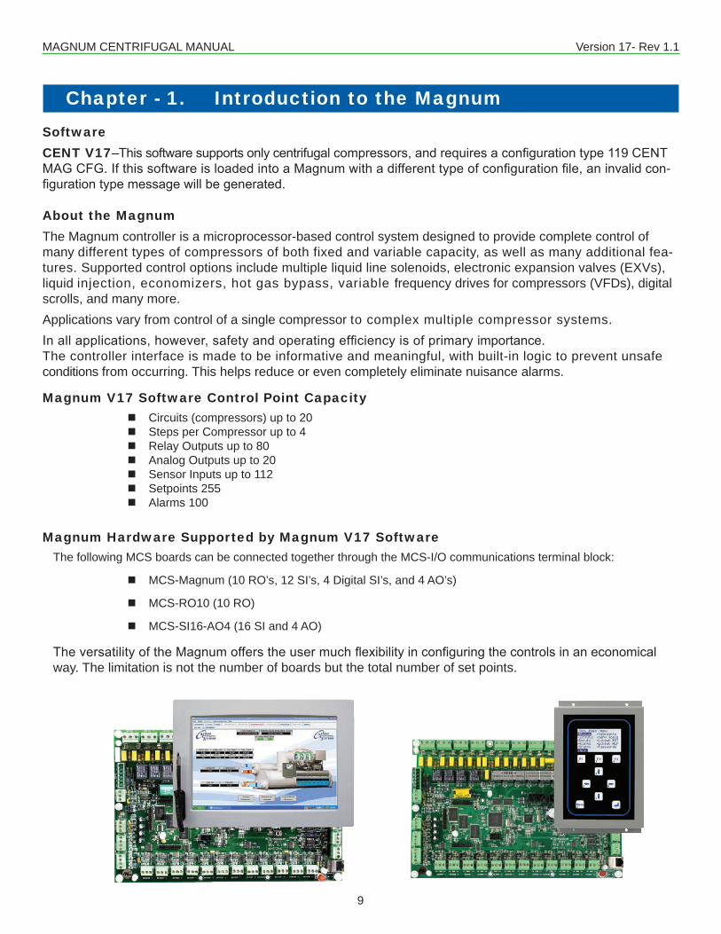
SoftwareCENT V17–Thissoftwaresupportsonlycentrifugalcompressors,andrequiresaconfigurationtype119CENTMAGCFG.IfthissoftwareisloadedintoaMagnumwithadifferenttypeofconfigurationfile,aninvalidcon-figurationtypemessagewillbegenerated.
About the MagnumThe Magnum controller is a microprocessor-based control system designed to provide complete control of many different types of compressors of both fixed and variable capacity, as well as many additional fea-tures. Supported control options include multiple liquid line solenoids, electronic expansion valves (EXVs), liquid injection, economizers, hot gas bypass, variable frequency drives for compressors (VFDs), digital scrolls, and many more.Applications vary from control of a single compressor to complex multiple compressor systems. Inallapplications,however,safetyandoperatingefficiencyisofprimaryimportance.The controller interface is made to be informative and meaningful, with built-in logic to prevent unsafe conditions from occurring. This helps reduce or even completely eliminate nuisance alarms.
Magnum V17 Software Control Point Capacity � Circuits (compressors) up to 20 � Steps per Compressor up to 4 � Relay Outputs up to 80 � Analog Outputs up to 20 � Sensor Inputs up to 112 � Setpoints 255 � Alarms 100
Magnum Hardware Supported by Magnum V17 SoftwareThe following MCS boards can be connected together through the MCS-I/O communications terminal block:
� MCS-Magnum (10 RO’s, 12 SI’s, 4 Digital SI’s, and 4 AO’s)
� MCS-RO10 (10 RO)
� MCS-SI16-AO4 (16 SI and 4 AO)
TheversatilityoftheMagnumofferstheusermuchflexibilityinconfiguringthecontrolsinaneconomicalway. The limitation is not the number of boards but the total number of set points.
Chapter - 1. Introduction to the Magnum
MAGNUM CENTRIFUGAL MANUAL Version 17- Rev 1.1
10
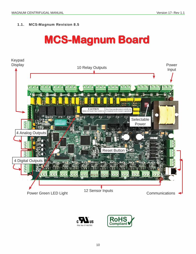
1.1. MCS-Magnum Revision 8.5
Power Input10 Relay Outputs
Power Green LED Light Communications12 Sensor Inputs
KeypadDisplay
4 Analog Outputs
4 Digital Outputs
Reset Button
SelectablePower
MCS-Magnum Board10 Relay Outputs
12 Sensor Inputs
Com
mun
icat
ions
4 Di
gita
lIn
puts
Keyp
ad/
Disp
lay
4 An
alog
Out
puts
Selectable Power
Power Input
Extra Power Fuse
Reset Button
Power Green LED Light
MAGNUM CENTRIFUGAL MANUAL Version 17- Rev 1.1
11
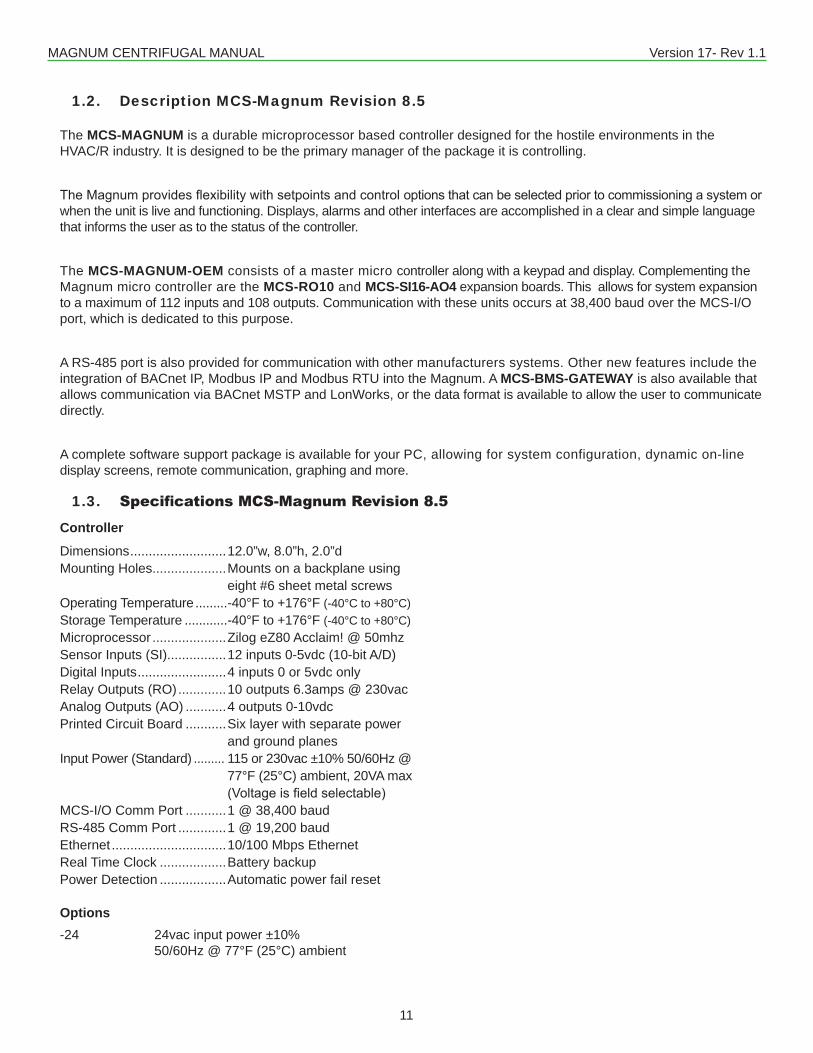
1.2. Description MCS-Magnum Revision 8.5
1.3. Specifications MCS-Magnum Revision 8.5
Controller
Dimensions ..........................12.0”w, 8.0”h, 2.0”dMounting Holes....................Mounts on a backplane using eight #6 sheet metal screws Operating Temperature .........-40°F to +176°F (-40°C to +80°C)Storage Temperature ............-40°F to +176°F (-40°C to +80°C)Microprocessor ....................Zilog eZ80 Acclaim! @ 50mhzSensor Inputs (SI)................12 inputs 0-5vdc (10-bit A/D)Digital Inputs ........................4 inputs 0 or 5vdc onlyRelay Outputs (RO) .............10 outputs 6.3amps @ 230vacAnalog Outputs (AO) ...........4 outputs 0-10vdcPrinted Circuit Board ...........Six layer with separate power and ground planesInput Power (Standard) ......... 115 or 230vac ±10% 50/60Hz @ 77°F (25°C) ambient, 20VA max (Voltageisfieldselectable)MCS-I/O Comm Port ...........1 @ 38,400 baudRS-485 Comm Port .............1 @ 19,200 baudEthernet ...............................10/100 Mbps EthernetReal Time Clock ..................Battery backupPower Detection ..................Automatic power fail reset
Options-24 24vac input power ±10% 50/60Hz @ 77°F (25°C) ambient
The MCS-MAGNUM is a durable microprocessor based controller designed for the hostile environments in the HVAC/R industry. It is designed to be the primary manager of the package it is controlling.
TheMagnumprovidesflexibilitywithsetpointsandcontroloptionsthatcanbeselectedpriortocommissioningasystemorwhen the unit is live and functioning. Displays, alarms and other interfaces are accomplished in a clear and simple language that informs the user as to the status of the controller.
The MCS-MAGNUM-OEM consists of a master micro controller along with a keypad and display. Complementing the Magnum micro controller are the MCS-RO10 and MCS-SI16-AO4 expansion boards. This allows for system expansion to a maximum of 112 inputs and 108 outputs. Communication with these units occurs at 38,400 baud over the MCS-I/O port, which is dedicated to this purpose.
A RS-485 port is also provided for communication with other manufacturers systems. Other new features include the integration of BACnet IP, Modbus IP and Modbus RTU into the Magnum. A MCS-BMS-GATEWAY is also available that allows communication via BACnet MSTP and LonWorks, or the data format is available to allow the user to communicate directly.
A complete software support package is available for your PC, allowing for system configuration, dynamic on-line display screens, remote communication, graphing and more.
MAGNUM CENTRIFUGAL MANUAL Version 17- Rev 1.1
12
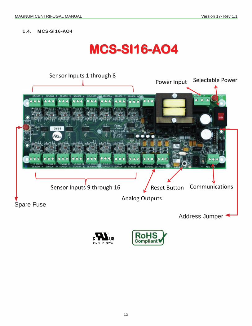
1.4. MCS-SI16-AO4
MCS-SI16-AO4
Sensor Inputs 9 through 16
Sensor Inputs 1 through 8Selectable Power
Reset Button
Spar
e Fu
se
Power Input
Communications
Analog Outputs
Addr
ess J
umpe
r
MCS-SI16-AO4
Sensor Inputs 9 through 16
Sensor Inputs 1 through 8Selectable Power
Reset Button
Spar
e Fu
se
Power Input
Communications
Analog Outputs
Addr
ess J
umpe
r
Spare Fuse
Address Jumper
MAGNUM CENTRIFUGAL MANUAL Version 17- Rev 1.1
13
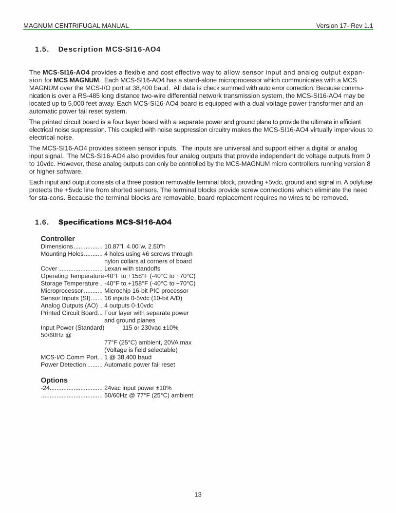
1.5. Description MCS-SI16-AO4
1.6. Specifications MCS-SI16-AO4
The MCS-SI16-AO4providesaflexibleandcosteffectivewaytoallowsensorinputandanalogoutputexpan-sion for MCS MAGNUM. Each MCS-SI16-AO4 has a stand-alone microprocessor which communicates with a MCS MAGNUM over the MCS-I/O port at 38,400 baud. All data is check summed with auto error correction. Because commu-nication is over a RS-485 long distance two-wire differential network transmission system, the MCS-SI16-AO4 may be located up to 5,000 feet away. Each MCS-SI16-AO4 board is equipped with a dual voltage power transformer and an automatic power fail reset system.Theprintedcircuitboardisafourlayerboardwithaseparatepowerandgroundplanetoprovidetheultimateinefficientelectrical noise suppression. This coupled with noise suppression circuitry makes the MCS-SI16-AO4 virtually impervious to electrical noise. The MCS-SI16-AO4 provides sixteen sensor inputs. The inputs are universal and support either a digital or analog input signal. The MCS-SI16-AO4 also provides four analog outputs that provide independent dc voltage outputs from 0 to 10vdc. However, these analog outputs can only be controlled by the MCS-MAGNUM micro controllers running version 8 or higher software.Each input and output consists of a three position removable terminal block, providing +5vdc, ground and signal in. A polyfuse protects the +5vdc line from shorted sensors. The terminal blocks provide screw connections which eliminate the need for sta-cons. Because the terminal blocks are removable, board replacement requires no wires to be removed.
Controller Dimensions ................. 10.87”l, 4.00”w, 2.50”hMounting Holes ........... 4 holes using #6 screws through nylon collars at corners of boardCover .......................... Lexan with standoffsOperating Temperature -40°F to +158°F (-40°C to +70°C)Storage Temperature .. -40°F to +158°F (-40°C to +70°C)Microprocessor ........... Microchip 16-bit PIC processorSensor Inputs (SI) ....... 16 inputs 0-5vdc (10-bit A/D)Analog Outputs (AO) .. 4 outputs 0-10vdcPrinted Circuit Board... Four layer with separate power and ground planesInput Power (Standard) 115 or 230vac ±10% 50/60Hz @ 77°F (25°C) ambient, 20VA max (Voltageisfieldselectable)MCS-I/O Comm Port... 1 @ 38,400 baudPower Detection ......... Automatic power fail reset
Options-24............................... 24vac input power ±10% .................................... 50/60Hz @ 77°F (25°C) ambient
MAGNUM CENTRIFUGAL MANUAL Version 17- Rev 1.1
14
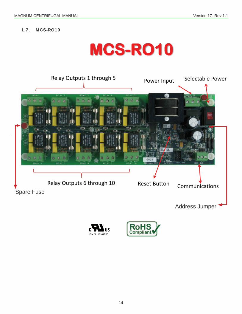
1.7. MCS-RO10
Relay Outputs 6 through 10
Relay Outputs 1 through 5
MCS-RO10Selectable PowerPower Input
Reset Button
Spar
e Fu
se
Communications
Addr
ess J
umpe
r
Relay Outputs 6 through 10
Relay Outputs 1 through 5
MCS-RO10Selectable PowerPower Input
Reset Button
Spar
e Fu
se
Communications
Addr
ess J
umpe
r
Spare Fuse
Address Jumper
MAGNUM CENTRIFUGAL MANUAL Version 17- Rev 1.1
15
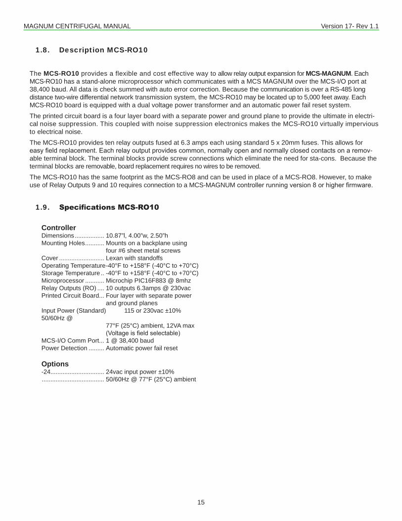
1.8. Description MCS-RO10
1.9. Specifications MCS-RO10
Controller Dimensions ................. 10.87”l, 4.00”w, 2.50”hMounting Holes ........... Mounts on a backplane using four #6 sheet metal screwsCover .......................... Lexan with standoffsOperating Temperature -40°F to +158°F (-40°C to +70°C)Storage Temperature .. -40°F to +158°F (-40°C to +70°C)Microprocessor ........... Microchip PIC16F883 @ 8mhzRelay Outputs (RO) .... 10 outputs 6.3amps @ 230vacPrinted Circuit Board... Four layer with separate power and ground planesInput Power (Standard) 115 or 230vac ±10% 50/60Hz @ 77°F (25°C) ambient, 12VA max (Voltageisfieldselectable)MCS-I/O Comm Port... 1 @ 38,400 baudPower Detection ......... Automatic power fail reset
Options-24............................... 24vac input power ±10% .................................... 50/60Hz @ 77°F (25°C) ambient
The MCS-RO10 provides a flexible and cost effective way to allow relay output expansion for MCS-MAGNUM. Each MCS-RO10 has a stand-alone microprocessor which communicates with a MCS MAGNUM over the MCS-I/O port at 38,400 baud. All data is check summed with auto error correction. Because the communication is over a RS-485 long distance two-wire differential network transmission system, the MCS-RO10 may be located up to 5,000 feet away. Each MCS-RO10 board is equipped with a dual voltage power transformer and an automatic power fail reset system.The printed circuit board is a four layer board with a separate power and ground plane to provide the ultimate in electri-cal noise suppression. This coupled with noise suppression electronics makes the MCS-RO10 virtually impervious to electrical noise.The MCS-RO10 provides ten relay outputs fused at 6.3 amps each using standard 5 x 20mm fuses. This allows for easyfieldreplacement.Eachrelayoutputprovidescommon,normallyopenandnormallyclosedcontactsonaremov-able terminal block. The terminal blocks provide screw connections which eliminate the need for sta-cons. Because the terminal blocks are removable, board replacement requires no wires to be removed.The MCS-RO10 has the same footprint as the MCS-RO8 and can be used in place of a MCS-RO8. However, to make use of Relay Outputs 9 and 10 requires connection to a MCS-MAGNUM controllerrunningversion8orhigherfirmware.
MAGNUM CENTRIFUGAL MANUAL Version 17- Rev 1.1
16
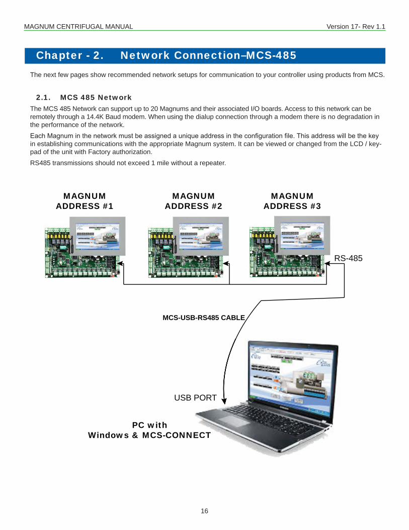
Chapter - 2. Network Connection–MCS-485 The next few pages show recommended network setups for communication to your controller using products from MCS.
2.1. MCS 485 NetworkThe MCS 485 Network can support up to 20 Magnums and their associated I/O boards. Access to this network can be remotely through a 14.4K Baud modem. When using the dialup connection through a modem there is no degradation in the performance of the network.EachMagnuminthenetworkmustbeassignedauniqueaddressintheconfigurationfile.Thisaddresswillbethekeyin establishing communications with the appropriate Magnum system. It can be viewed or changed from the LCD / key-pad of the unit with Factory authorization.RS485 transmissions should not exceed 1 mile without a repeater.
MAGNUMADDRESS #1
MAGNUMADDRESS #2
MAGNUMADDRESS #3
PC withWindows & MCS-CONNECT
MCS-USB-RS485 CABLE
NNECT
RS-485
USB PORT
MAGNUM CENTRIFUGAL MANUAL Version 17- Rev 1.1
17
Chapter - 3. Network Connection–Ethernet
MAGNUMADDRESS #1
MAGNUMADDRESS #2
MAGNUMADDRESS #3
Ethernet NetworkWindows & MCS-CONNECT
etworkS-CONNECT
MCS-Ethernet Switch
Ethernet Port
MCS-Ethernet-Cable
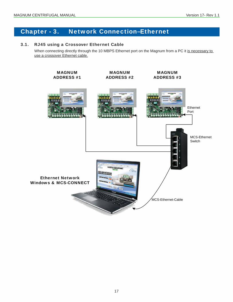
3.1. RJ45 using a Crossover Ethernet CableWhen connecting directly through the 10 MBPS Ethernet port on the Magnum from a PC it is necessary to use a crossover Ethernet cable.
MAGNUM CENTRIFUGAL MANUAL Version 17- Rev 1.1
18
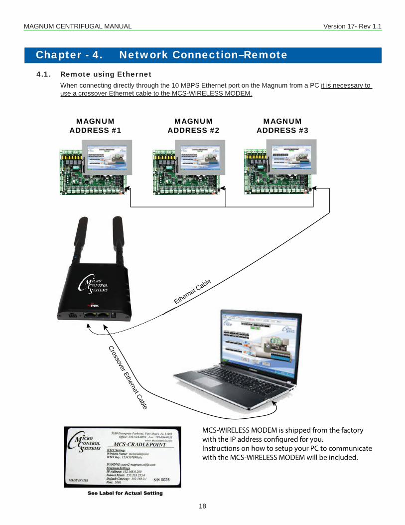
Chapter - 4. Network Connection–Remote4.1. Remote using Ethernet
When connecting directly through the 10 MBPS Ethernet port on the Magnum from a PC it is necessary to use a crossover Ethernet cable to the MCS-WIRELESS MODEM.
MAGNUMADDRESS #1
MAGNUMADDRESS #2
MAGNUMADDRESS #3
MCS-WIRELESS MODEM is shipped from the factorywith the IP address con�gured for you. Instructions on how to setup your PC to communicatewith the MCS-WIRELESS MODEM will be included.
Ethernet Cable
Crossover Ethernet Cable

MAGNUM CENTRIFUGAL MANUAL Version 17- Rev 1.1
19
Chapter - 5. Centrifugal Compressor ControlThere are many differences, in both concept and function, between centrifugal compressors and other types. For certain applications,centrifugalcompressorshavedistinctadvantagessuchashighenergyefficiency,highvolumeofairflow,and low maintenance due to the small number of moving parts. When combined with a Variable Frequency Drive (VFD) itbecomessimpleandefficienttovarythespeedofthecompressorandoperateatpartload.ToprovidecontrolforthisuniquetypeofcompressorMCShasdevelopedanewtypesoftwarespecifictocentrifugalunits: CENT V17. Much of the control logic is similar to that found in HVAC V17. A target value and control zone are calculated, and then compressor capacity is modulated to keep the control sensor within that zone. Input sensors are monitored constantly and preventative action is taken to protect the unit from any potentially unsafe or damaging condi-tions. Different from other types of units though, both compressor speed and vane position must be taken into consider-ation since both affect cooling capacity.
5.1. Centrifugal Related TerminologyThe following terms relate to the control of centrifugal compressors and how CENT V17 processes them.
5.1.1 Lift Pressure:Liftpressureequalscondenserpressureminusevaporatorpressure.Thelowertheliftpressureis,themoreefficientlythe system operates.
5.1.2 Surge and Stall Protection:Surgeisanunstableconditionthatoccursatlowmassflows.Surgesdecreasecompressorperformanceandefficiency,and could even cause permanent equipment damage.CENTV17definesasinglesurgeasalargedecreaseincompressorampsfollowedbyalargeincreaseintheampsora large decrease in lift pressure followed by large increase in lift pressure. The CENT V17 software will keep the last 60 seconds of samples for both amps and lift pressure. It will calculate the last ten 1 second Rate of Changes for both amps and lift pressure. If within these 10 Rate Of Changes there is a value less than (Setpoint #220 “AmpSurgeROC” x –1) or (Setpoint #221 “LiftSurgeROC” x –1) followed by a value greater than Setpoint #220 or #221, a compressor surge has occurred.The software will then count the number of compressor surges that occur. If the number of surges is more than the valueinSetpoint#219“ExcessSurges”within5minutes(valueofSetpoint#219‘Time(sec)’field)thesystemwillshutdown and generate an “ExcessSurges” alarm. This safety condition will automatically restart the compressor after the time in the Safety Down Time of the Setpoint #219. If a second “ExcessSurges” occurs within the time of the Lockout Delay Field, the compressor will be placed in “Cmp Locked Out” state and a manual reset is required to enable the com-pressor to restart again.
5.1.3 Variable Geometry Diffuser (VGD) The VGD is a system for preventing stall in a centrifugal compressor.Purpose of ChangeThe purpose of this change is to add a control logic Variable Geometry Diffuser used on Centrifugal compressors. This changeisonlyrequiredintheMCS-MagnumCentrifugalfirmware.Existing Sensor Inputs Vane % – Analog sensor input which indicates the inlet guide vane position. Typically it is a high precision potentiom-eter.This sensor was optional on non-Variable Frequency Drive centrifugal. It is now required for both VFD application and VGD applications.New Sensor InputsVGD % – Analog sensor input which indicates the Variable Geometry Diffuser position. Typically it is a high precision potentiometer.
MAGNUM CENTRIFUGAL MANUAL Version 17- Rev 1.1
20
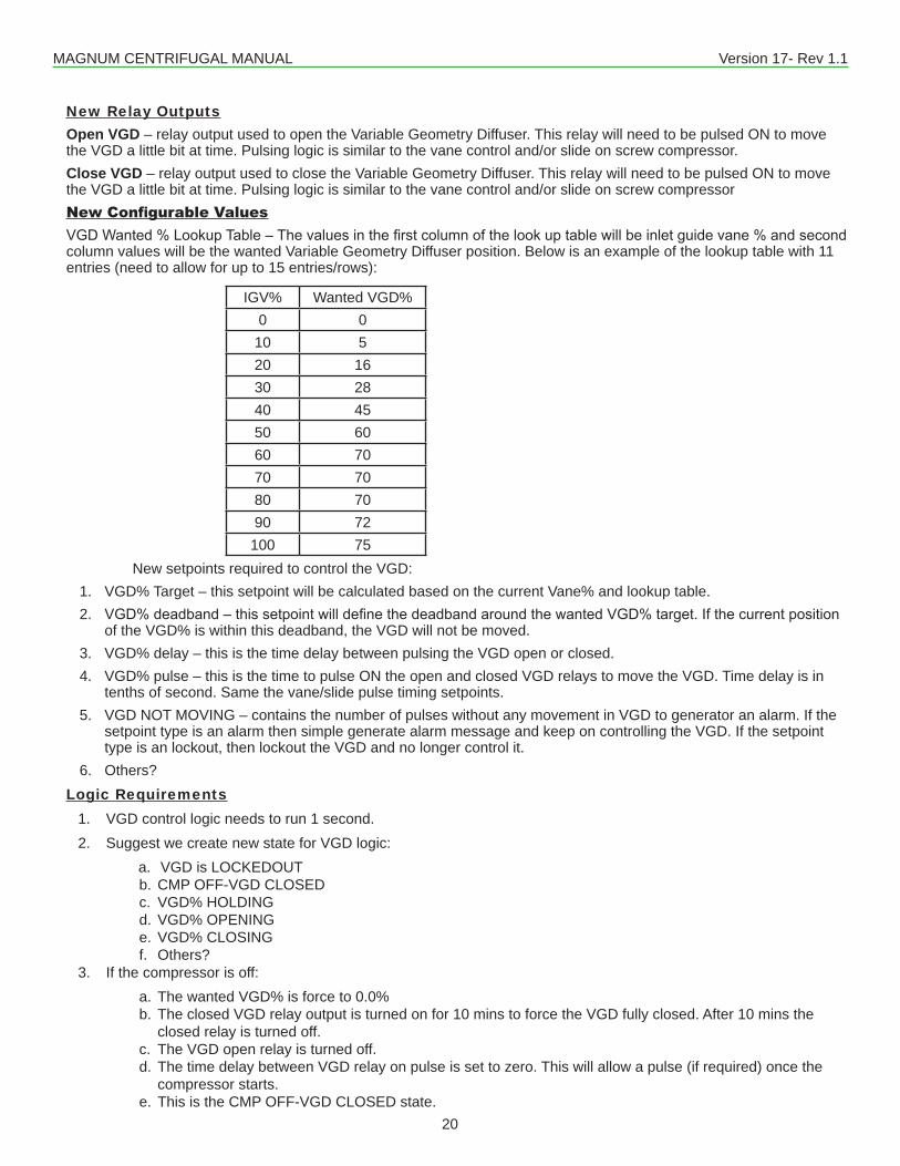
New Relay Outputs Open VGD – relay output used to open the Variable Geometry Diffuser. This relay will need to be pulsed ON to move the VGD a little bit at time. Pulsing logic is similar to the vane control and/or slide on screw compressor.Close VGD – relay output used to close the Variable Geometry Diffuser. This relay will need to be pulsed ON to move the VGD a little bit at time. Pulsing logic is similar to the vane control and/or slide on screw compressorNew Configurable ValuesVGDWanted%LookupTable–Thevaluesinthefirstcolumnofthelookuptablewillbeinletguidevane%andsecondcolumn values will be the wanted Variable Geometry Diffuser position. Below is an example of the lookup table with 11 entries (need to allow for up to 15 entries/rows):
IGV% Wanted VGD%0 010 520 1630 2840 4550 6060 7070 7080 7090 72100 75
New setpoints required to control the VGD:1. VGD% Target – this setpoint will be calculated based on the current Vane% and lookup table.2. VGD%deadband–thissetpointwilldefinethedeadbandaroundthewantedVGD%target.Ifthecurrentposition
of the VGD% is within this deadband, the VGD will not be moved.3. VGD% delay – this is the time delay between pulsing the VGD open or closed.4. VGD% pulse – this is the time to pulse ON the open and closed VGD relays to move the VGD. Time delay is in
tenths of second. Same the vane/slide pulse timing setpoints.5. VGD NOT MOVING – contains the number of pulses without any movement in VGD to generator an alarm. If the
setpoint type is an alarm then simple generate alarm message and keep on controlling the VGD. If the setpoint type is an lockout, then lockout the VGD and no longer control it.
6. Others?Logic Requirements
1. VGD control logic needs to run 1 second.2. Suggest we create new state for VGD logic:
a. VGD is LOCKEDOUT b. CMP OFF-VGD CLOSED c. VGD% HOLDING d. VGD% OPENING e. VGD% CLOSING f. Others?
3. If the compressor is off: a. The wanted VGD% is force to 0.0% b. The closed VGD relay output is turned on for 10 mins to force the VGD fully closed. After 10 mins the
closed relay is turned off. c. The VGD open relay is turned off. d. The time delay between VGD relay on pulse is set to zero. This will allow a pulse (if required) once the
compressor starts. e. This is the CMP OFF-VGD CLOSED state.
MAGNUM CENTRIFUGAL MANUAL Version 17- Rev 1.1
21
4. Once the compressor is running: a. When the compressor is started the VGD state is moved from CMP OFF-VGD CLOSED to VGD% HOLDING. b. The time delay needs to be decrement once every second until it reaches zero. Once it reaches zero, if
a VGD needs to be moved (current VGD% is outside the Wanted VGD% plus/minus the VGD% deadband) then the open or closed relay is pulsed and the time delay reset to the value in VGD% delay setpoint. Only when an ON pulse is given is the time delay reset. If no pulse is required the time delay is left at zero to allow a pulse once it is required.
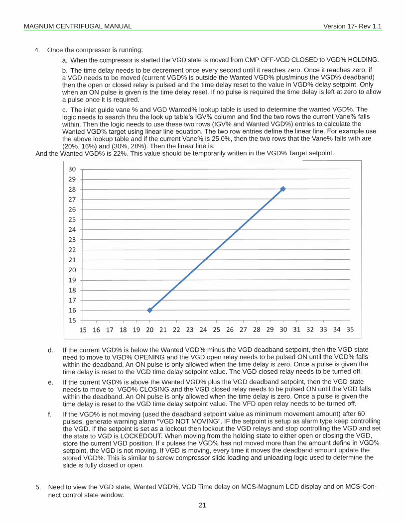
c. The inlet guide vane % and VGD Wanted% lookup table is used to determine the wanted VGD%. The logicneedstosearchthruthelookuptable’sIGV%columnandfindthetworowsthecurrentVane%fallswithin. Then the logic needs to use these two rows (IGV% and Wanted VGD%) entries to calculate the WantedVGD%targetusinglinearlineequation.Thetworowentriesdefinethelinearline.Forexampleusethe above lookup table and if the current Vane% is 25.0%, then the two rows that the Vane% falls with are (20%, 16%) and (30%, 28%). Then the linear line is:
And the Wanted VGD% is 22%. This value should be temporarily written in the VGD% Target setpoint.
d. If the current VGD% is below the Wanted VGD% minus the VGD deadband setpoint, then the VGD state need to move to VGD% OPENING and the VGD open relay needs to be pulsed ON until the VGD% falls within the deadband. An ON pulse is only allowed when the time delay is zero. Once a pulse is given the time delay is reset to the VGD time delay setpoint value. The VGD closed relay needs to be turned off.
e. If the current VGD% is above the Wanted VGD% plus the VGD deadband setpoint, then the VGD state needs to move to VGD% CLOSING and the VGD closed relay needs to be pulsed ON until the VGD falls within the deadband. An ON pulse is only allowed when the time delay is zero. Once a pulse is given the time delay is reset to the VGD time delay setpoint value. The VFD open relay needs to be turned off.
f. If the VGD% is not moving (used the deadband setpoint value as minimum movement amount) after 60 pulses, generate warning alarm “VGD NOT MOVING”. IF the setpoint is setup as alarm type keep controlling the VGD. If the setpoint is set as a lockout then lockout the VGD relays and stop controlling the VGD and set the state to VGD is LOCKEDOUT. When moving from the holding state to either open or closing the VGD, storethecurrentVGDposition.IfxpulsestheVGD%hasnotmovedmorethantheamountdefineinVGD%setpoint, the VGD is not moving. If VGD is moving, every time it moves the deadband amount update the stored VGD%. This is similar to screw compressor slide loading and unloading logic used to determine the slide is fully closed or open.
5. Need to view the VGD state, Wanted VGD%, VGD Time delay on MCS-Magnum LCD display and on MCS-Con-nect control state window.
15161718192021222324252627282930
15 16 17 18 19 20 21 22 23 24 25 26 27 28 29 30 31 32 33 34 35
MAGNUM CENTRIFUGAL MANUAL Version 17- Rev 1.1
22
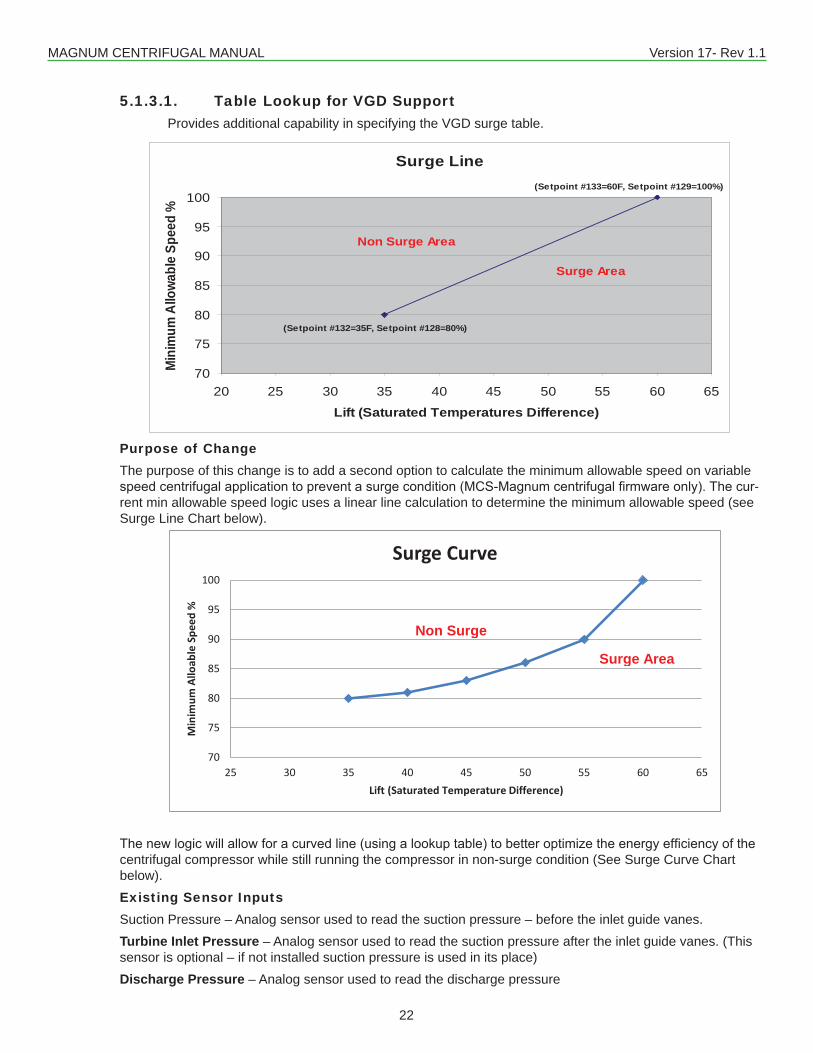
5.1.3.1. Table Lookup for VGD Support Provides additional capability in specifying the VGD surge table.
Purpose of ChangeThe purpose of this change is to add a second option to calculate the minimum allowable speed on variable speedcentrifugalapplicationtopreventasurgecondition(MCS-Magnumcentrifugalfirmwareonly).Thecur-rent min allowable speed logic uses a linear line calculation to determine the minimum allowable speed (see Surge Line Chart below).
Thenewlogicwillallowforacurvedline(usingalookuptable)tobetteroptimizetheenergyefficiencyofthecentrifugal compressor while still running the compressor in non-surge condition (See Surge Curve Chart below).Existing Sensor Inputs Suction Pressure – Analog sensor used to read the suction pressure – before the inlet guide vanes.Turbine Inlet Pressure – Analog sensor used to read the suction pressure after the inlet guide vanes. (This sensor is optional – if not installed suction pressure is used in its place)Discharge Pressure – Analog sensor used to read the discharge pressure
Surge Line
70
75
80
85
90
95
100
20 25 30 35 40 45 50 55 60 65
Lift (Saturated Temperatures Difference)
Min
imum
Allo
wabl
e Sp
eed
%
Non Surge Area
Surge Area
(Setpoint #132=35F, Setpoint #128=80%)
(Setpoint #133=60F, Setpoint #129=100%)
70
75
80
85
90
95
100
25 30 35 40 45 50 55 60 65
Min
imum
Allo
able
Spe
ed %
Lift (Saturated Temperature Difference)
Surge Curve
Non Surge
Surge Area
MAGNUM CENTRIFUGAL MANUAL Version 17- Rev 1.1
23
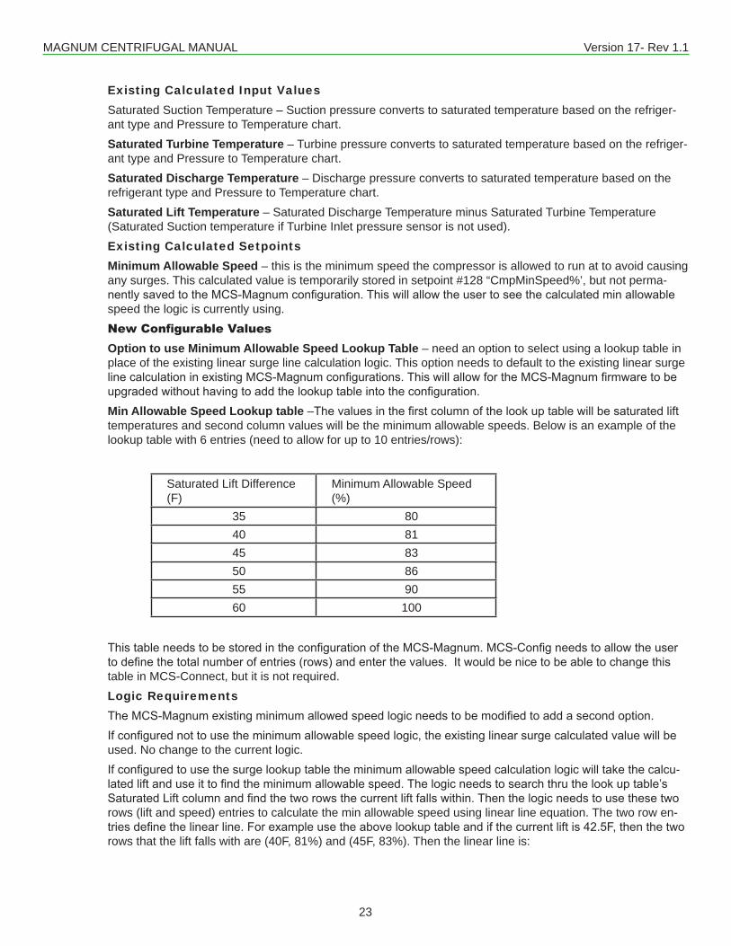
Existing Calculated Input ValuesSaturated Suction Temperature – Suction pressure converts to saturated temperature based on the refriger-ant type and Pressure to Temperature chart.Saturated Turbine Temperature – Turbine pressure converts to saturated temperature based on the refriger-ant type and Pressure to Temperature chart.Saturated Discharge Temperature – Discharge pressure converts to saturated temperature based on the refrigerant type and Pressure to Temperature chart.Saturated Lift Temperature – Saturated Discharge Temperature minus Saturated Turbine Temperature (Saturated Suction temperature if Turbine Inlet pressure sensor is not used).Existing Calculated SetpointsMinimum Allowable Speed – this is the minimum speed the compressor is allowed to run at to avoid causing any surges. This calculated value is temporarily stored in setpoint #128 “CmpMinSpeed%’, but not perma-nentlysavedtotheMCS-Magnumconfiguration.Thiswillallowtheusertoseethecalculatedminallowablespeed the logic is currently using. New Configurable ValuesOption to use Minimum Allowable Speed Lookup Table – need an option to select using a lookup table in place of the existing linear surge line calculation logic. This option needs to default to the existing linear surge linecalculationinexistingMCS-Magnumconfigurations.ThiswillallowfortheMCS-Magnumfirmwaretobeupgradedwithouthavingtoaddthelookuptableintotheconfiguration.Min Allowable Speed Lookup table–Thevaluesinthefirstcolumnofthelookuptablewillbesaturatedlifttemperatures and second column values will be the minimum allowable speeds. Below is an example of the lookup table with 6 entries (need to allow for up to 10 entries/rows):
Saturated Lift Difference (F)
Minimum Allowable Speed (%)
35 8040 8145 8350 8655 9060 100
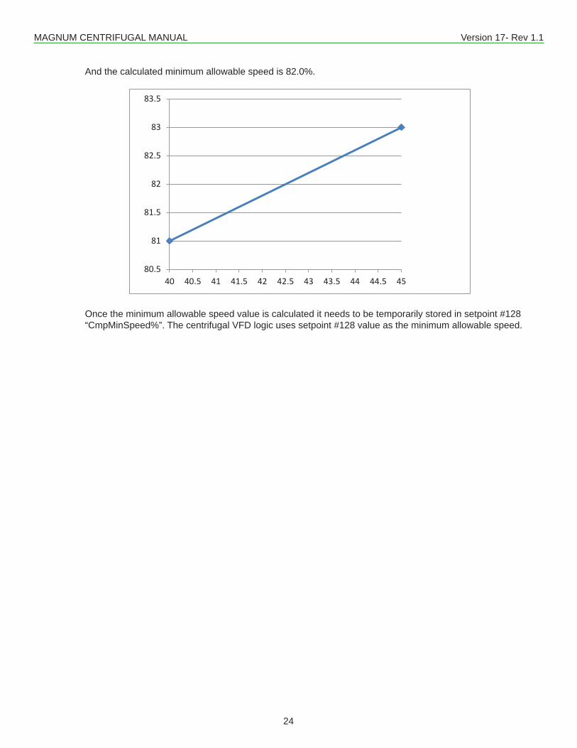
ThistableneedstobestoredintheconfigurationoftheMCS-Magnum.MCS-Configneedstoallowtheusertodefinethetotalnumberofentries(rows)andenterthevalues.Itwouldbenicetobeabletochangethistable in MCS-Connect, but it is not required.Logic RequirementsTheMCS-Magnumexistingminimumallowedspeedlogicneedstobemodifiedtoaddasecondoption.Ifconfigurednottousetheminimumallowablespeedlogic,theexistinglinearsurgecalculatedvaluewillbeused. No change to the current logic.Ifconfiguredtousethesurgelookuptabletheminimumallowablespeedcalculationlogicwilltakethecalcu-latedliftanduseittofindtheminimumallowablespeed.Thelogicneedstosearchthruthelookuptable’sSaturatedLiftcolumnandfindthetworowsthecurrentliftfallswithin.Thenthelogicneedstousethesetworows (lift and speed) entries to calculate the min allowable speed using linear line equation. The two row en-triesdefinethelinearline.Forexampleusetheabovelookuptableandifthecurrentliftis42.5F,thenthetworows that the lift falls with are (40F, 81%) and (45F, 83%). Then the linear line is:
MAGNUM CENTRIFUGAL MANUAL Version 17- Rev 1.1
24
And the calculated minimum allowable speed is 82.0%.
Once the minimum allowable speed value is calculated it needs to be temporarily stored in setpoint #128 “CmpMinSpeed%”. The centrifugal VFD logic uses setpoint #128 value as the minimum allowable speed.
80.5
81
81.5
82
82.5
83
83.5
40 40.5 41 41.5 42 42.5 43 43.5 44 44.5 45
MAGNUM CENTRIFUGAL MANUAL Version 17- Rev 1.1
25
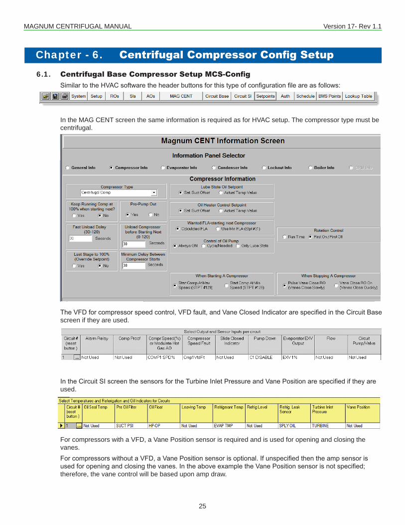
6.1. Centrifugal Base Compressor Setup MCS-ConfigSimilartotheHVACsoftwaretheheaderbuttonsforthistypeofconfigurationfileareasfollows:
In the MAG CENT screen the same information is required as for HVAC setup. The compressor type must be centrifugal.
TheVFDforcompressorspeedcontrol,VFDfault,andVaneClosedIndicatorarespecifiedintheCircuitBasescreen if they are used.
IntheCircuitSIscreenthesensorsfortheTurbineInletPressureandVanePositionarespecifiediftheyareused.
For compressors with a VFD, a Vane Position sensor is required and is used for opening and closing the vanes.ForcompressorswithoutaVFD,aVanePositionsensorisoptional.Ifunspecifiedthentheampsensorisusedforopeningandclosingthevanes.IntheaboveexampletheVanePositionsensorisnotspecified;therefore, the vane control will be based upon amp draw.
Chapter - 6. Centrifugal Compressor Config Setup
MAGNUM CENTRIFUGAL MANUAL Version 17- Rev 1.1
26
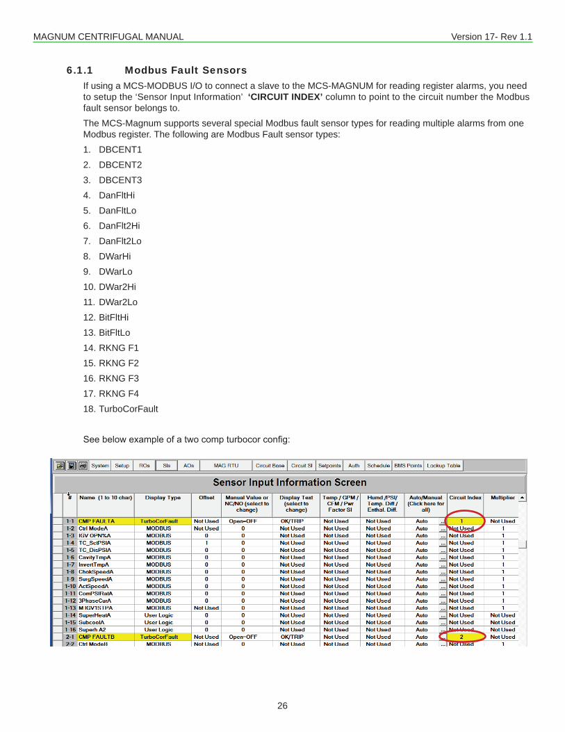
6.1.1 Modbus Fault SensorsIf using a MCS-MODBUS I/O to connect a slave to the MCS-MAGNUM for reading register alarms, you need to setup the ‘Sensor Input Information’ ‘CIRCUIT INDEX’ column to point to the circuit number the Modbus fault sensor belongs to.The MCS-Magnum supports several special Modbus fault sensor types for reading multiple alarms from one Modbus register. The following are Modbus Fault sensor types:1. DBCENT12. DBCENT23. DBCENT34. DanFltHi5. DanFltLo6. DanFlt2Hi7. DanFlt2Lo8. DWarHi9. DWarLo10. DWar2Hi11. DWar2Lo12. BitFltHi13. BitFltLo14. RKNG F115. RKNG F216. RKNG F317. RKNG F418. TurboCorFault
Seebelowexampleofatwocompturbocorconfig:
MAGNUM CENTRIFUGAL MANUAL Version 17- Rev 1.1
27
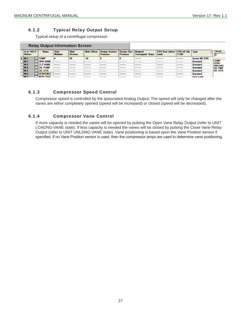
6.1.2 Typical Relay Output SetupTypical setup of a centrifugal compressor:
6.1.3 Compressor Speed ControlCompressor speed is controlled by the associated Analog Output. The speed will only be changed after the vanes are either completely opened (speed will be increased) or closed (speed will be decreased).
6.1.4 Compressor Vane ControlIf more capacity is needed the vanes will be opened by pulsing the Open Vane Relay Output (refer to UNIT LOADNG-VANE state). If less capacity is needed the vanes will be closed by pulsing the Close Vane Relay Output (refer to UNIT UNLDNG-VANE state). Vane positioning is based upon the Vane Position sensor if specified.IfnoVanePositionsensorisused,thenthecompressorampsareusedtodeterminevanepositioning.
MAGNUM CENTRIFUGAL MANUAL Version 17- Rev 1.1
28
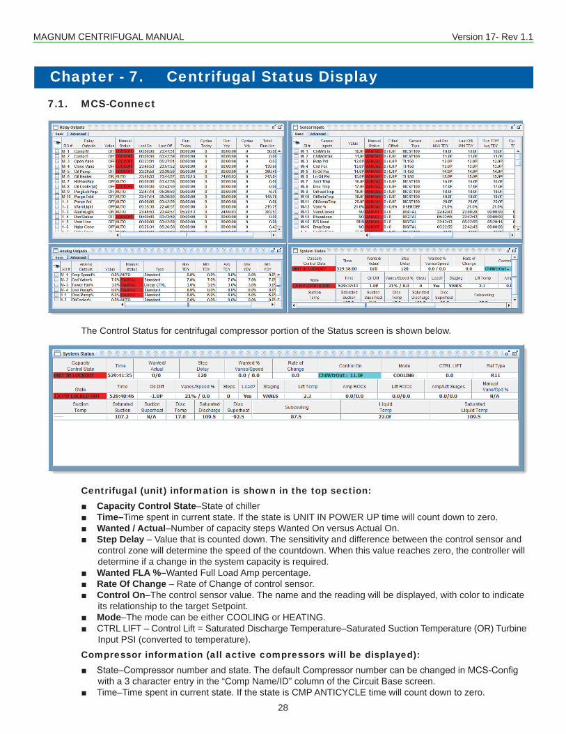
7.1. MCS-Connect
The Control Status for centrifugal compressor portion of the Status screen is shown below.
Centrifugal (unit) information is shown in the top section: ■ Capacity Control State–State of chiller ■ Time–Time spent in current state. If the state is UNIT IN POWER UP time will count down to zero. ■ Wanted / Actual–Number of capacity steps Wanted On versus Actual On. ■ Step Delay – Value that is counted down. The sensitivity and difference between the control sensor and
control zone will determine the speed of the countdown. When this value reaches zero, the controller will determine if a change in the system capacity is required.
■ Wanted FLA %–Wanted Full Load Amp percentage. ■ Rate Of Change – Rate of Change of control sensor. ■ Control On–The control sensor value. The name and the reading will be displayed, with color to indicate
its relationship to the target Setpoint. ■ Mode–The mode can be either COOLING or HEATING. ■ CTRL LIFT – Control Lift = Saturated Discharge Temperature–Saturated Suction Temperature (OR) Turbine
Input PSI (converted to temperature).Compressor information (all active compressors will be displayed):
■ State–Compressornumberandstate.ThedefaultCompressornumbercanbechangedinMCS-Configwith a 3 character entry in the “Comp Name/ID” column of the Circuit Base screen.
■ Time–Time spent in current state. If the state is CMP ANTICYCLE time will count down to zero.
Chapter - 7. Centrifugal Status Display
MAGNUM CENTRIFUGAL MANUAL Version 17- Rev 1.1
29
■ Oil Diff–Oil differential pressure. It is calculated as follows: ■ Centrifugal compressors: Oil Pressure – Pre-oil Filter Pressure ■ FLA %–Full Load Amps based on the compressor’s respective Setpoint. ■ Steps–Indicates number of steps associated with this compressor that are turned on. ■ Lead?–YES will be displayed for the lead compressor. ■ Staging–Thisfieldwilldisplay“VANES”forcentrifugalcompressors ■ LiftTemp–IfanInletPressuresensorisspecifiedintheconfiguration,thenthisvaluewillequalSaturated
Discharge Temperature – Inlet PSI (converted to temperature). If no Inlet Pressure sensor is present, this value will equal Saturated Discharge Temperature–Saturated Suction Temperature.
■ Lift ROC’s – Current lift Rate Of Change/ Last lift Rate Of Change ■ Amp/LiftSurges–Thisfieldisacounterforthenumberofampandliftsurgesrespectively.
Compressor Superheat information: ■ Suction Temp–Compressor number and Suction Temperature, if available. ■ Saturated Suction–Calculated Suction Saturated Temperature (R22, R134a, R407c, and R410a are
supported). ■ Suction Superheat–Calculated Suction Superheat, only available if both the Suction Temperature and the
Suction Pressure are used. Suction Superheat = Suction Temperature–Suction Saturated Temperature. ■ Disc Temp–Discharge Temperature, if available. ■ Saturated Discharge–Calculated Discharge Saturated Temperature (R22, R134a, R407c, and R410a are
supported). ■ Disc Superheat–Discharge Superheat is available only if both the Discharge Temperature and the
Discharge Pressure are used. Discharge Superheat = Discharge Temperature–Discharge Saturated Temperature.
■ Ref Type – Refrigerant type used.
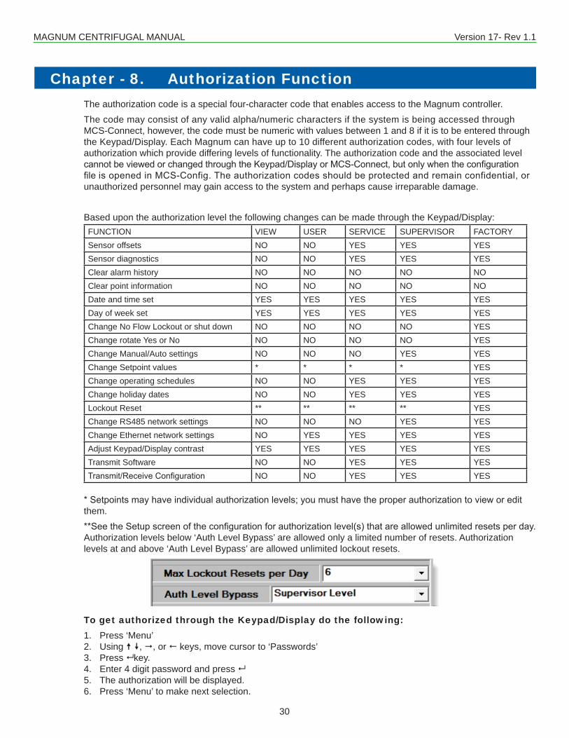
MAGNUM CENTRIFUGAL MANUAL Version 17- Rev 1.1
30
Chapter - 8. Authorization FunctionThe authorization code is a special four-character code that enables access to the Magnum controller.The code may consist of any valid alpha/numeric characters if the system is being accessed through MCS-Connect, however, the code must be numeric with values between 1 and 8 if it is to be entered through the Keypad/Display. Each Magnum can have up to 10 different authorization codes, with four levels of authorization which provide differing levels of functionality. The authorization code and the associated level cannotbeviewedorchangedthroughtheKeypad/DisplayorMCS-Connect,butonlywhentheconfigurationfileisopenedinMCS-Config.Theauthorizationcodesshouldbeprotectedandremainconfidential,orunauthorized personnel may gain access to the system and perhaps cause irreparable damage.
Based upon the authorization level the following changes can be made through the Keypad/Display:FUNCTION VIEW USER SERVICE SUPERVISOR FACTORYSensor offsets NO NO YES YES YESSensor diagnostics NO NO YES YES YESClear alarm history NO NO NO NO NOClear point information NO NO NO NO NODate and time set YES YES YES YES YESDay of week set YES YES YES YES YESChange No Flow Lockout or shut down NO NO NO NO YESChange rotate Yes or No NO NO NO NO YESChange Manual/Auto settings NO NO NO YES YESChange Setpoint values * * * * YESChange operating schedules NO NO YES YES YESChange holiday dates NO NO YES YES YESLockout Reset ** ** ** ** YESChange RS485 network settings NO NO NO YES YESChange Ethernet network settings NO YES YES YES YESAdjust Keypad/Display contrast YES YES YES YES YESTransmit Software NO NO YES YES YESTransmit/ReceiveConfiguration NO NO YES YES YES
*Setpointsmayhaveindividualauthorizationlevels;youmusthavetheproperauthorizationtovieworeditthem.**SeetheSetupscreenoftheconfigurationforauthorizationlevel(s)thatareallowedunlimitedresetsperday.Authorization levels below ‘Auth Level Bypass’ are allowed only a limited number of resets. Authorization levels at and above ‘Auth Level Bypass’ are allowed unlimited lockout resets.
To get authorized through the Keypad/Display do the following:1. Press ‘Menu’2. Using , , or keys, move cursor to ‘Passwords’3. Press key.4. Enter 4 digit password and press 5. The authorization will be displayed.6. Press ‘Menu’ to make next selection.
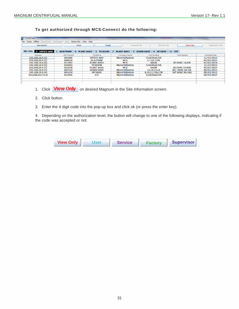
MAGNUM CENTRIFUGAL MANUAL Version 17- Rev 1.1
31
View Only User Service Factory Supervisor
To get authorized through MCS-Connect do the following:
1. Click on desired Magnum in the Site Information screen.
2. Click button.
3. Enter the 4 digit code into the pop-up box and click ok (or press the enter key).
4. Depending on the authorization level, the button will change to one of the following displays, indicating if the code was accepted or not.
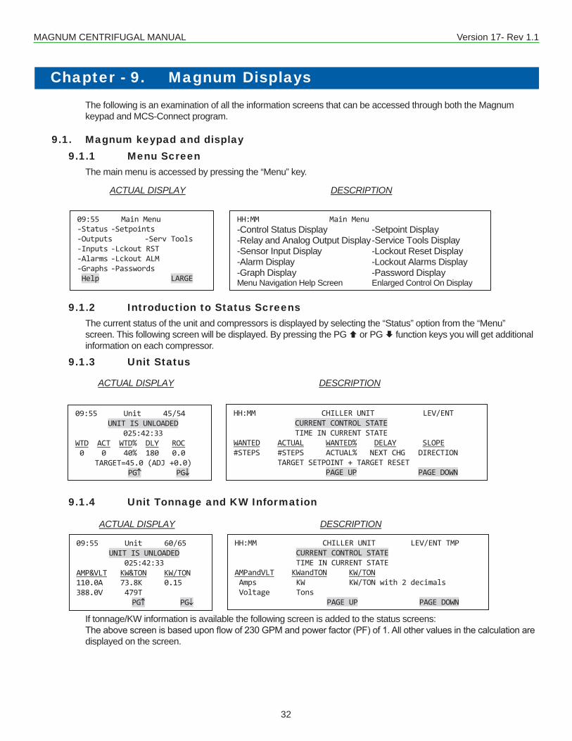
MAGNUM CENTRIFUGAL MANUAL Version 17- Rev 1.1
32
Chapter - 9. Magnum DisplaysThe following is an examination of all the information screens that can be accessed through both the Magnum keypad and MCS-Connect program.
9.1. Magnum keypad and display9.1.1 Menu Screen
The main menu is accessed by pressing the “Menu” key.
9.1.2 Introduction to Status ScreensThe current status of the unit and compressors is displayed by selecting the “Status” option from the “Menu” screen. This following screen will be displayed. By pressing the PG or PG function keys you will get additional information on each compressor.
9.1.3 Unit Status
9.1.4 Unit Tonnage and KW Information
If tonnage/KW information is available the following screen is added to the status screens:Theabovescreenisbaseduponflowof230GPMandpowerfactor(PF)of1.Allothervaluesinthecalculationaredisplayed on the screen.
ACTUAL DISPLAY DESCRIPTION
09:55 Main Menu -Status -Setpoints -Outputs -Serv Tools -Inputs -Lckout RST -Alarms -Lckout ALM -Graphs -Passwords Help LARGE
HH:MM Main Menu -Control Status Display -Setpoint Display-Relay and Analog Output Display -Service Tools Display-Sensor Input Display -Lockout Reset Display-Alarm Display -Lockout Alarms Display-Graph Display -Password DisplayMenu Navigation Help Screen Enlarged Control On Display
ACTUAL DISPLAY DESCRIPTION
09:55 Unit 45/54 UNIT IS UNLOADED
025:42:33 WTD ACT WTD% DLY ROC 0 0 40% 180 0.0
TARGET=45.0 (ADJ +0.0) PG↑ PG↓
HH:MM CHILLER UNIT LEV/ENT CURRENT CONTROL STATE TIME IN CURRENT STATE WANTED ACTUAL WANTED% DELAY SLOPE #STEPS #STEPS ACTUAL% NEXT CHG DIRECTION TARGET SETPOINT + TARGET RESET PAGE UP PAGE DOWN
ACTUAL DISPLAY DESCRIPTION
09:55 Unit 60/65 UNIT IS UNLOADED
025:42:33 AMP&VLT KW&TON KW/TON 110.0A 73.8K 0.15 388.0V 479T
PG↑ PG↓
HH:MM CHILLER UNIT LEV/ENT TMP CURRENT CONTROL STATE TIME IN CURRENT STATE AMPandVLT KWandTON KW/TON Amps KW KW/TON with 2 decimals Voltage Tons PAGE UP PAGE DOWN
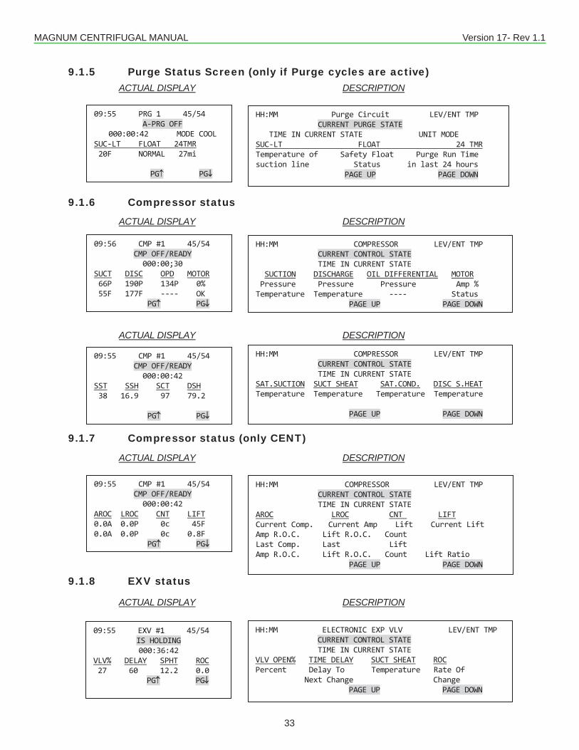
MAGNUM CENTRIFUGAL MANUAL Version 17- Rev 1.1
33
9.1.5 Purge Status Screen (only if Purge cycles are active)
9.1.6 Compressor status
9.1.7 Compressor status (only CENT)
9.1.8 EXV status
ACTUAL DISPLAY DESCRIPTION
ACTUAL DISPLAY DESCRIPTION
ACTUAL DISPLAY DESCRIPTION
ACTUAL DISPLAY DESCRIPTION
ACTUAL DISPLAY DESCRIPTION
09:56 CMP #1 45/54 CMP OFF/READY 000:00;30
SUCT DISC OPD MOTOR 66P 190P 134P 0% 55F 177F ---- OK PG↑ PG↓
09:55 CMP #1 45/54 CMP OFF/READY 000:00:42
SST SSH SCT DSH 38 16.9 97 79.2 PG↑ PG↓
HH:MM COMPRESSOR LEV/ENT TMP CURRENT CONTROL STATE TIME IN CURRENT STATE SUCTION DISCHARGE OIL DIFFERENTIAL MOTOR Pressure Pressure Pressure Amp % Temperature Temperature ---- Status PAGE UP PAGE DOWN
HH:MM COMPRESSOR LEV/ENT TMP CURRENT CONTROL STATE TIME IN CURRENT STATE SAT.SUCTION SUCT SHEAT SAT.COND. DISC S.HEAT Temperature Temperature Temperature Temperature PAGE UP PAGE DOWN
09:55 EXV #1 45/54 IS HOLDING 000:36:42
VLV% DELAY SPHT ROC 27 60 12.2 0.0 PG↑ PG↓
HH:MM ELECTRONIC EXP VLV LEV/ENT TMP CURRENT CONTROL STATE TIME IN CURRENT STATE VLV OPEN% TIME DELAY SUCT SHEAT ROC Percent Delay To Temperature Rate Of Next Change Change PAGE UP PAGE DOWN
09:55 CMP #1 45/54 CMP OFF/READY 000:00:42
AROC LROC CNT LIFT 0.0A 0.0P 0c 45F 0.0A 0.0P 0c 0.8F PG↑ PG↓
HH:MM COMPRESSOR LEV/ENT TMP CURRENT CONTROL STATE TIME IN CURRENT STATE AROC LROC CNT LIFT Current Comp. Current Amp Lift Current Lift Amp R.O.C. Lift R.O.C. Count Last Comp. Last Lift Amp R.O.C. Lift R.O.C. Count Lift Ratio PAGE UP PAGE DOWN
09:55 PRG 1 45/54 A-PRG OFF
000:00:42 MODE COOL SUC-LT FLOAT 24TMR 20F NORMAL 27mi
PG↑ PG↓
HH:MM Purge Circuit LEV/ENT TMP CURRENT PURGE STATE TIME IN CURRENT STATE UNIT MODE SUC-LT FLOAT 24 TMR Temperature of Safety Float Purge Run Time suction line Status in last 24 hours PAGE UP PAGE DOWN
MAGNUM CENTRIFUGAL MANUAL Version 17- Rev 1.1
34
The Magnum controller is a state computer, that is, decisions are made based upon Set points, timers and Sensor Inputs, the controller moves from one state to another. The controller will change states to ensure the proper functioning of the chiller package.As we review the various states, we must remember that a chiller package consists of a number of different parts or functions:thecompressorsandtheirrelateditemssuchasunloadershotgasbypasses,etc.;evaporator;andcondensingfunctions.Both the Capacity Control States and Compressor Control States are displayed in the Status screens on the Keypad Display. To view the state of the chiller, select the Status option from the menu on the Keypad. You can then view the entire status by using the page up / down function keys. The information can also be accessed through MCS-Connect under status screen by clicking on the CONTROL STATUS button.Unit Control States (number)Note: All User Logic points can now access the Unit Control State. The value accessed is the number listed in parenthesis in the following headings.
Chapter - 10. Magnum Control States
10.1. UNIT IN POWER UP (0)This state is entered when the Magnum is powered up or the system has been reset. The system will remain in this stateforthetimespecifiedinSetpoint#23“POWERDELAY”orfor60secondsifnotactive.InthisstateallRelayOutputs are turned off. This time delay is to insure the microprocessor has stable power before starting the algorithm.
10.2. NO RUN- I/O LOST (2)This state will be entered whenever the Magnum loses communications with any of the I/O boards that are connected throughtheMCSI/Onetwork.WhenthisstateisenteredtheMagnumwillgenerateanMCSI/Oofflinealarm,whichidentifieswhichI/OisofflineandalostI/Oshutdownalarmwhichlocksouttheunit.Oncelockedout,iftherearetenconsecutive successful I/O reads the Magnum will reset and attempt to run. When this occurs a “LOST I/O RESTART” will be generated. Or, the lockout-reset key can be pressed to reset the Magnum, after the lost I/O has been corrected. This will generate a “LOCKOUT RESET.” In this state all RO’s except ALARM and OIL HEATER are turned OFF.
10.3. UNIT IN LOCKOUT (3)This state is entered whenever a critical situation is encountered that could cause harm to the chiller package. Items such as freeze protect and emergency stop will force the system into this state. Lockouts can be reset without authorizationfromthekeypadorMCS-Connectprogram;howeverifthelockoutconditionhasnotbeencorrected,thesystem will again be forced into the LOCKOUT state. In this state, all RO’s except ALARM and OIL HEATER (for screws with an oil pump) are turned OFF and placed in the “LOCKOUT” state. Note: If the Lockout Reset is pressed more than the programmed allowable number of times in one day the unit cannot be reset during the current day except through MCS-Connect and requires Factory authorization. This number is selected from a drop down menu under the Setup Information button, with a range of 2 to12.In Cent Firmware only, Close Vane RO will stay energized for 5 minutes after compressor lockout.
10.4. UNIT IS OFF (4)ThisstateisenteredwhenthesystemhasfinishedaSTARTUP,DISABLE,LOCKOUT,orNORUN-I/OLOSTstate.The chiller is now ready to move into an active state to meet the capacity required.
10.5. UNIT IS HOLDING (5)This state is entered when one of three conditions exists:1. The control sensor reading is being maintained with in the control zone.2. Control sensor reading is above the control zone but the Rate of Change is less than the value in the (MAX ROC-,
#27) Setpoint. This indicates that the temperature is decreasing toward the target at an acceptable speed. There-fore, no additional cooling is needed at this time.
3. The temperature is below the control zone but the Rate of Change is greater than the (MAX ROC+, #28) Setpoint. This indicates that the temperature is increasing toward the target. Therefore, no reduction in cooling is needed at this time.This state indicates that there is no need to adjust the capacity of the chiller package. This state will end when more or less capacity is required.

MAGNUM CENTRIFUGAL MANUAL Version 17- Rev 1.1
35
10.6. UNIT UNLDNG-VANE (6) This state is entered when less capacity is required and the vanes are not completely closed. The close vane relay will be modulated. The compressor speed will not be reduced in this state. Control temperature can be below the control zone, or in the zone but the temperature is dropping too fast.
10.7. UNIT IS LOADNG-VANE (7) This state is entered when more capacity is required (control temperature above control zone) and the vanes are not 100% open. The open vane relay will be modulated. The compressor speed will not be changed in this state.
10.8. OFF-SMOKE ALARM (8)Thisstateisenteredwhenasmokealarmhasbeendetected.IntheMCS-ConfigurationfiletheSmokeAlarmIndicatormust be selected in the General Information panel under the MAGNUM screen. When this sensor is trips, an error message “OFF-SMOKE ALARM” is generated and the unit state is changed. In this state all RO’s except ALARM and OIL HEATER are turned OFF.
10.9. RUN/STOP SW OFF (9)This state is entered when the run stop switch is off, in the stop position. When the chiller is in this state, the individual compressor states if active are moved to the CMP IS OFF state through the normal states. One capacity STEP will be moved per second.
10.10. SCHEDULED OFF (10)This state is entered when the schedule is calling for the package to be off. When the chiller is in this state, the individu-al compressor states if active are moved to the CMP IS OFF state through the normal states. One capacity STEP will be moved per second.
10.11. OFF- NO FLOW (11)Thisstateisenteredwhentheevaporatorflowswitchisoff.Whenthechillerisinthisstate,theindividualcompressorstates if active are moved to the CMP IS OFF state through the normal states. One capacity STEP will be moved per second.IftheNOFLOWSetpointisactiveandsettoLockoutthechillerwilllockoutonnoflow.
10.12. AMBIENT OFF (13)This state is entered when the ambient temperature falls below Setpoint #24 “LOW AMB OFF” or is above Setpoint #26 “HIGH AMB OFF”. The system will remain in this state until the ambient temperature if low rises 5.0°F (2.5°C) above the “LOW AMB OFF” Setpoint value or if high drops 5.0°F (2.5°C) below the “HIGH AMB OFF” Setpoint value. When the chiller is in this state, the individual compressor states if active are moved to the CMP IS OFF state through the normal staging function. One capacity STEP will be moved per second.
10.13. UNIT IS UNLOADED (15)This state is entered when all of the systems available capacity steps are off. The package is providing no cooling ca-pacity, as none is required. The system is ready to react to cooling needs.
10.14. UNIT IS LOADED (16)This state is entered when all of the system’s available capacity steps are on and the package is providing the maximum amount of cooling capacity.
10.15. OFF TMP-ICE MADE (17)This state is only used in systems when the Ice Mode DI On/Off option has been selected. When the system is in the ICE MAKING mode and the control temperature sensor’s temperature is less than the target temperature, set point #1, This state is entered. In this state the mode will remain ICE MAKING, all stages of cooling will be staged off and remain off until the ice making mode is exited. Refer to section on ‘Ice Making Capabilities’.
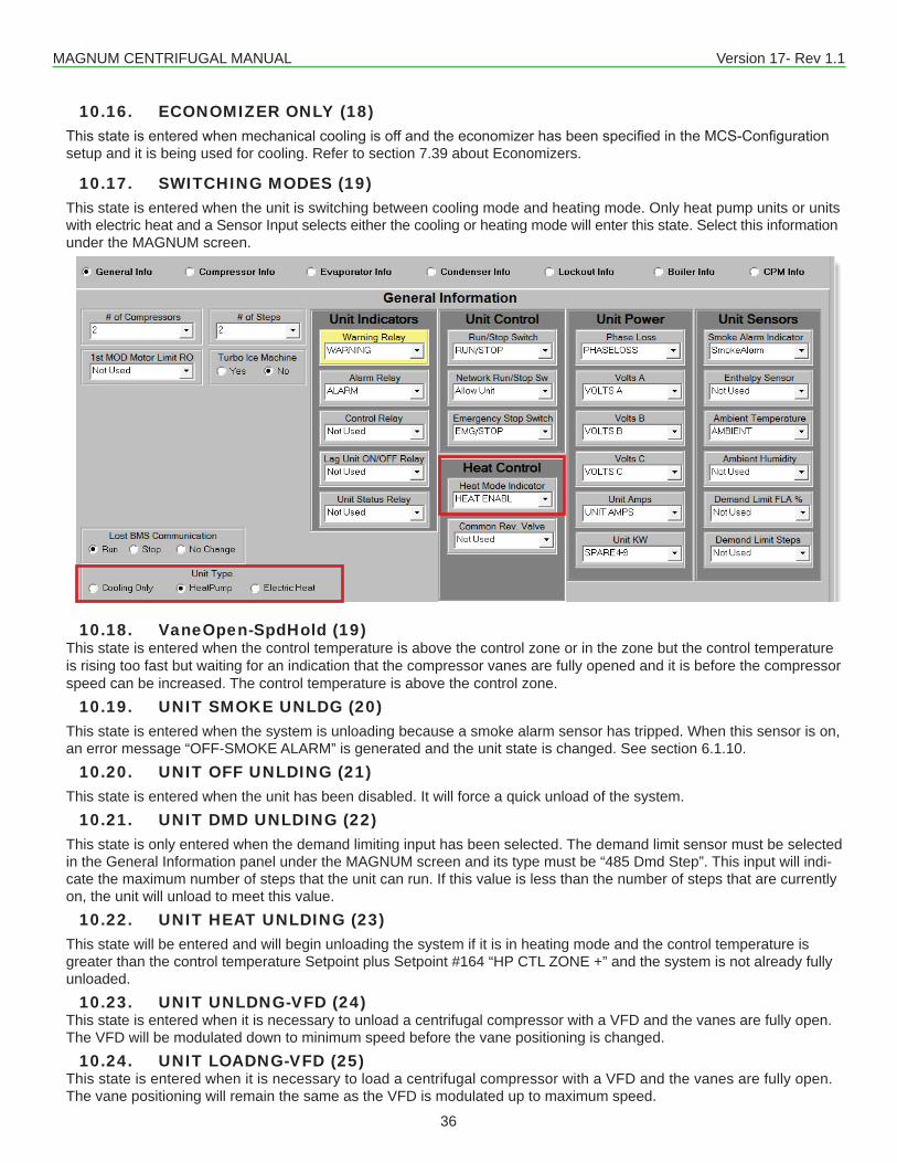
MAGNUM CENTRIFUGAL MANUAL Version 17- Rev 1.1
36
10.16. ECONOMIZER ONLY (18)ThisstateisenteredwhenmechanicalcoolingisoffandtheeconomizerhasbeenspecifiedintheMCS-Configurationsetup and it is being used for cooling. Refer to section 7.39 about Economizers.
10.17. SWITCHING MODES (19)This state is entered when the unit is switching between cooling mode and heating mode. Only heat pump units or units with electric heat and a Sensor Input selects either the cooling or heating mode will enter this state. Select this information under the MAGNUM screen.
10.18. VaneOpen-SpdHold (19) This state is entered when the control temperature is above the control zone or in the zone but the control temperature is rising too fast but waiting for an indication that the compressor vanes are fully opened and it is before the compressor speed can be increased. The control temperature is above the control zone.
10.19. UNIT SMOKE UNLDG (20)This state is entered when the system is unloading because a smoke alarm sensor has tripped. When this sensor is on, an error message “OFF-SMOKE ALARM” is generated and the unit state is changed. See section 6.1.10.
10.20. UNIT OFF UNLDING (21)This state is entered when the unit has been disabled. It will force a quick unload of the system.
10.21. UNIT DMD UNLDING (22)This state is only entered when the demand limiting input has been selected. The demand limit sensor must be selected in the General Information panel under the MAGNUM screen and its type must be “485 Dmd Step”. This input will indi-cate the maximum number of steps that the unit can run. If this value is less than the number of steps that are currently on, the unit will unload to meet this value.
10.22. UNIT HEAT UNLDING (23)This state will be entered and will begin unloading the system if it is in heating mode and the control temperature is greater than the control temperature Setpoint plus Setpoint #164 “HP CTL ZONE +” and the system is not already fully unloaded.
10.23. UNIT UNLDNG-VFD (24) This state is entered when it is necessary to unload a centrifugal compressor with a VFD and the vanes are fully open. The VFD will be modulated down to minimum speed before the vane positioning is changed.
10.24. UNIT LOADNG-VFD (25) This state is entered when it is necessary to load a centrifugal compressor with a VFD and the vanes are fully open. The vane positioning will remain the same as the VFD is modulated up to maximum speed.
MAGNUM CENTRIFUGAL MANUAL Version 17- Rev 1.1
37
10.25. CMP SPD OPTIMIZE (33)
OptimizeenergyefficientontheCentrifugalwithVFD.Theideaofthenewlogicistoopenthevanes(fullyifpossible)and reduce the speed of the compressor. By opening the vanes and reducing the speed we save more energy. The compressor is still started with vanes fully closed and speed at 100%. But once the comp going into holding state the optimization can occur. To use the MCS-Magnum requires CENT 14.00 Z or later and the config modified per this list.• Make setpoint #188 active and change it’s name to “CMP SPEED OPTIMZE DELAY”, this setpoint was used for
COMP#19FLAnotusedinCENTfirmware.1. Setpoint #188 type should be set as “DELAY” – so the time in sec2. column is adjustable via MCS-Connect.3. Setpoint #188 value contains the time delay before comp speed optimization is attempted (typically 300 to 900 seconds)4. Setpoint #188 time in sec column contains the delay between optimization adjust to the vane & speed. (typically 3 to 4 seconds)
For optimization to occur all of the following condition must occur:• Setpoint #188 is active• capacitycontrolstatehasbeenholdingformorethanthetimedelayspecifiedbysetpoint#188value• The comp vanes are less than the max vane setpoint #30• the comp speed is greater than the min speed setpoint #128• and the comp has VFD.Once Optimization state is entered:• The capacity control state is set to “CMP SPD OPTIMIZE” (new state, requires new MCS-Connect software on
touch screens and laptops).• Thecompvanesareopenedbysetpoint#32“minadjust%”valueeveryxsecwherexisdefinebythetimecolumn
in setpoint #188• Thecompspeedisreducedbysetpoint#32“minadjust%”valueeveryxsecwherexisdefinebythetimecolumnin
setpoint #188
Unit will stays in Optimization state until:• unit wants to load or unload based on water temp (above or below control zone) or• until the comp vanes are fully open (setpoint #30) or • until the comp speed is at min allowable (setpoint #128). Min speed is dynamic and calculated based on surge line.
10.26. UNIT IS OFF/TEMP (38)
Thisstateisonlyusedifthelowtemperatureoptionhasbeenspecified.Setpoint#151isactiveanditisaTARGETtype of set point. When the steps wanted is zero, no mechanical stages of cooling is on and the control temperature is below the off temperature this state will be entered. Once the control temperature is above this value the unit state will be loading.
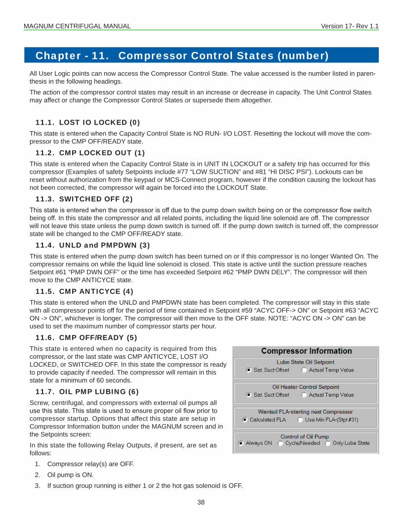
MAGNUM CENTRIFUGAL MANUAL Version 17- Rev 1.1
38
All User Logic points can now access the Compressor Control State. The value accessed is the number listed in paren-thesis in the following headings.The action of the compressor control states may result in an increase or decrease in capacity. The Unit Control States may affect or change the Compressor Control States or supersede them altogether.
11.1. LOST IO LOCKED (0)This state is entered when the Capacity Control State is NO RUN- I/O LOST. Resetting the lockout will move the com-pressor to the CMP OFF/READY state.
11.2. CMP LOCKED OUT (1)This state is entered when the Capacity Control State is in UNIT IN LOCKOUT or a safety trip has occurred for this compressor (Examples of safety Setpoints include #77 “LOW SUCTION” and #81 “HI DISC PSI”). Lockouts can be reset without authorization from the keypad or MCS-Connect program, however if the condition causing the lockout has not been corrected, the compressor will again be forced into the LOCKOUT State.
11.3. SWITCHED OFF (2)Thisstateisenteredwhenthecompressorisoffduetothepumpdownswitchbeingonorthecompressorflowswitchbeing off. In this state the compressor and all related points, including the liquid line solenoid are off. The compressor will not leave this state unless the pump down switch is turned off. If the pump down switch is turned off, the compressor state will be changed to the CMP OFF/READY state.
11.4. UNLD and PMPDWN (3)This state is entered when the pump down switch has been turned on or if this compressor is no longer Wanted On. The compressor remains on while the liquid line solenoid is closed. This state is active until the suction pressure reaches Setpoint #61 “PMP DWN OFF” or the time has exceeded Setpoint #62 “PMP DWN DELY”. The compressor will then move to the CMP ANTICYCE state.
11.5. CMP ANTICYCE (4)This state is entered when the UNLD and PMPDWN state has been completed. The compressor will stay in this state with all compressor points off for the period of time contained in Setpoint #59 “ACYC OFF-> ON” or Setpoint #63 “ACYC ON -> ON”, whichever is longer. The compressor will then move to the OFF state. NOTE: “ACYC ON -> ON” can be used to set the maximum number of compressor starts per hour.
11.6. CMP OFF/READY (5)This state is entered when no capacity is required from this compressor, or the last state was CMP ANTICYCE, LOST I/O LOCKED, or SWITCHED OFF. In this state the compressor is ready to provide capacity if needed. The compressor will remain in this state for a minimum of 60 seconds.
11.7. OIL PMP LUBING (6)Screw, centrifugal, and compressors with external oil pumps all usethisstate.Thisstateisusedtoensureproperoilflowpriortocompressor startup. Options that affect this state are setup in Compressor Information button under the MAGNUM screen and in the Setpoints screen:In this state the following Relay Outputs, if present, are set as follows:
1. Compressor relay(s) are OFF.2. Oil pump is ON.3. If suction group running is either 1 or 2 the hot gas solenoid is OFF.
Chapter - 11. Compressor Control States (number)
MAGNUM CENTRIFUGAL MANUAL Version 17- Rev 1.1
39
4. Fast unloader is ON.5. First 120 seconds or until the unload switch is ON the unloader is ON else it is OFF.6. Loader is OFF.7. VI increase and decrease are OFF.8. Start unloader is OFF.9. Low discharge superheat relay is OFF.10. All liquid line solenoids are OFF.11. Oil equalization relay is ON.12. All unloaders are OFF if they are load type else they are ON.13. All turbo ice relays are off.14. Oil heater is controlled to maintain oil temperature.
All of the following conditions must be met within the time allowed in Setpoint #41 “LUBE DELAY”. If the com-pressor type is centrifugal an additional 10 seconds will be allowed for these conditions to be met.
1. Oil differential must be equal to or greater than the value in Setpoint #40 “LUBE OIL PSI”. If this Setpoint is not active this test is bypassed.
2. Oil temperature must be equal to or greater than the calculated oil temperature target. If Setpoint #39 “LUBE OIL TEMP” is not active this test is bypassed. If the compressor type is centrifugal and the option to use the saturated temperature is indicated, then the value of the saturated temperature will be added to Setpoint #39 “LUBE OIL TEMP”, else the value of Setpoint #39 will be used by itself as the calculated oil temperature target.
3. The compressor must be unloaded. If there is an unloaded indicator it must be on. If it is a centrifugal compressor, it is forced to stay in this state for minimum of 15 seconds. If the compressor has no unloaded indicator it must stay in this state for a minimum of 10 seconds less than Setpoint #41 “LUBE DELAY”.
If all of these conditions are met within the allotted time, the compressor will move to another state.IfafixedstepcompressorwithanexternaloilpumpthestatewilleitherbeUNLOADEDorLOADED,dependingifthereare multiple compressor steps.If a variable step compressor, then the percentage wanted on will be checked. If it is less than Setpoint #31 “MIN SLIDE %”, or option “Use Min FLA” has been selected, the percentage wanted will be set to the value in Setpoint #31 “MIN SLIDE %” and the state will be set to HOLDING.Any associated EXV will be adjusted to allow for additional capacity.If the compressor does not meet all of the conditions it will be LOCKED OUT and an error message will be generated indicating the reason for the failure: pressure, temperature or time.
11.8. NOT USED (7)
11.9. CMP UNLOADED (8)For variable step compressors, this state occurs when the slide is fully unloaded (indicated by unloaded input or after theunloaderispulsedfor30secondswithnochange).Forfixedstepcompressors,thisstateoccurswhenthecompressoris on and fully unloaded. In this state the compressor is supplying its minimum cooling capacity.
11.10. CMP DECR SPEED (9) In this state the compressor speed will be decreased.
11.11. CMP INCR SPEED (10) In this state the compressor speed will be increased.
11.12. CMP IS HOLDING (11)This state only applies for variable step compressors. In this state, the required refrigeration capacity of system is being met;nomovementoftheslidevalveisrequired.
11.13. CMP OPEN VANES (12) In this state the vanes are being opened because more capacity is required.
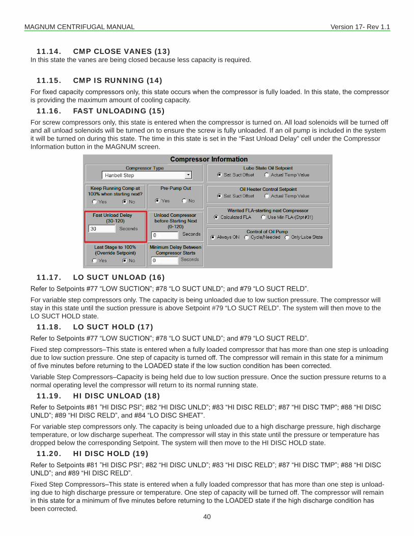
MAGNUM CENTRIFUGAL MANUAL Version 17- Rev 1.1
40
11.14. CMP CLOSE VANES (13) In this state the vanes are being closed because less capacity is required.
11.15. CMP IS RUNNING (14)Forfixedcapacitycompressorsonly,thisstateoccurswhenthecompressorisfullyloaded.Inthisstate,thecompressoris providing the maximum amount of cooling capacity.
11.16. FAST UNLOADING (15)For screw compressors only, this state is entered when the compressor is turned on. All load solenoids will be turned off and all unload solenoids will be turned on to ensure the screw is fully unloaded. If an oil pump is included in the system it will be turned on during this state. The time in this state is set in the “Fast Unload Delay” cell under the Compressor Information button in the MAGNUM screen.
11.17. LO SUCT UNLOAD (16)RefertoSetpoints#77“LOWSUCTION”;#78“LOSUCTUNLD”;and#79“LOSUCTRELD”.For variable step compressors only. The capacity is being unloaded due to low suction pressure. The compressor will stay in this state until the suction pressure is above Setpoint #79 “LO SUCT RELD”. The system will then move to the LO SUCT HOLD state.
11.18. LO SUCT HOLD (17)RefertoSetpoints#77“LOWSUCTION”;#78“LOSUCTUNLD”;and#79“LOSUCTRELD”.Fixed step compressors–This state is entered when a fully loaded compressor that has more than one step is unloading due to low suction pressure. One step of capacity is turned off. The compressor will remain in this state for a minimum offiveminutesbeforereturningtotheLOADEDstateifthelowsuctionconditionhasbeencorrected.Variable Step Compressors–Capacity is being held due to low suction pressure. Once the suction pressure returns to a normal operating level the compressor will return to its normal running state.
11.19. HI DISC UNLOAD (18)RefertoSetpoints#81”HIDISCPSI”;#82“HIDISCUNLD”;#83“HIDISCRELD”;#87“HIDISCTMP”;#88“HIDISCUNLD”;#89“HIDISCRELD”,and#84“LODISCSHEAT”.For variable step compressors only. The capacity is being unloaded due to a high discharge pressure, high discharge temperature, or low discharge superheat. The compressor will stay in this state until the pressure or temperature has dropped below the corresponding Setpoint. The system will then move to the HI DISC HOLD state.
11.20. HI DISC HOLD (19)RefertoSetpoints#81”HIDISCPSI”;#82“HIDISCUNLD”;#83“HIDISCRELD”;#87“HIDISCTMP”;#88“HIDISCUNLD”;and#89“HIDISCRELD”.Fixed Step Compressors–This state is entered when a fully loaded compressor that has more than one step is unload-ing due to high discharge pressure or temperature. One step of capacity will be turned off. The compressor will remain inthisstateforaminimumoffiveminutesbeforereturningtotheLOADEDstateifthehighdischargeconditionhasbeen corrected.
MAGNUM CENTRIFUGAL MANUAL Version 17- Rev 1.1
41
Variable Step Compressors–Capacity is being held due to high discharge temperature or pressure. Once the discharge returns to normal operating levels the compressor will return to its normal running state.
11.21. SAFETY TRIPPED (20)This state is entered when a safety trip occurs but a lockout is not generated. An alarm is generated but the system will automaticallyrestartafterthedelayspecifiedinthecorrespondingSetpoint.Ifasecondtripoccurswithinthetimespeci-fiedintheSetpoint,thecompressorwillbeplacedintheCMPLOCKEDOUTstate.
11.22. LO TMP UNLOAD (21)The following two conditions can cause this state to be entered and the system to begin unloading:1) The leaving liquid temperature is within 1.5°F of the Setpoint #111 “FREEZE “2) The refrigerant temperature is less than Setpoint #155 “LO REF TMP” if this Setpoint is active.
11.23. LO TMP HOLD (22)Reload from the “LO TMP UNLOAD” occurs when the leaving liquid temperature is 3.0° F above Setpoint #111 “FREEZE “and the refrigerant temperature sensor, if present, is greater than Setpoint #155 “LO REF TMP” plus twice the value of Setpoint #156 “LO REF TMP”. Until this temperature is reached the system will remain in the LO TMP HOLD State.
11.24. HI AMP HOLD (23)Fixed step compressors–This state occurs when a fully loaded compressor experiences an abnormally high amp draw. Refer to Setpoints #171-190 for FLA per compressor (compressors 1-20 respectively) and #75 “HI AMPS %”. In this state,onestepofcapacitywillbeturnedoff.Thecompressorwillremaininthisstateforaminimumoffiveminutesbefore returning to the LOADED state if the high amp draw condition has been corrected.VariableStepCompressors–ThisstateoccursafterHIAMPUNLDING.ItwillremaininthisstateforthetimespecifiedinSetpoint #101 “SAFETY HOLD DELAY”. If the amp draw is less than the FLA Setpoint for this compressor, it will return to the normal operating state and the compressor will be able to load if necessary. In this state the compressor will not load but it can be unloaded if needed.
11.25. HI DIS TMP HLD (24)RefertoSetpoints#87“HIDISCTMP”;#88“HIDISCUNLD”;and#89“HIDISCRELD”.This state is entered when a fully loaded compressor that has more than one step encounters a high discharge tem-perature.Onestepofcapacitywillbeturnedoff.Thecompressorwillthenremaininthisstateforaminimumoffiveminutes before returning to the LOADED state if the high discharge temperature has returned to normal.
11.26. SURGE SPD/VANE (25) This state is entered when the number of surges has exceeded Setpoint #212 “SurgingCount”. The Magnum will take preventive action to attempt to avoid a safety trip due to excess surges. The compressor speed will increase and the vanes closed.
11.27. HI WATER HOLD (27)When the compressor is running and Setpoint #86 “HI RETURN TEMP” is active, the Magnum will check for high water temperature.IfthecontroltemperatureisgreaterthanSetpoint#86forthetimespecifiedtheMagnumwillplacethecompressor in this state. The system will be unable to load when in this state.
11.28. OFF-LO OIL TMP (29)In this state the compressor is disabled. The oil temperature will be checked only if the compressor type is a centrifugal or screw.Centrifugal compressors–If the temperature is less than the Saturated Suction Temperature plus Setpoint #39 “LUBE OIL TEMP” this state will be entered.Screw compressors – If the temperature is less than the value in Setpoint #39 “LUBE OIL TEMP” this state will be entered.
11.29. HI AMP UNLDING (30)For variable step compressors this state is entered when the amp draw is greater than the respective FLA Setpoint plus half the value in Setpoint #75, “HI AMPS”. This action is to prevent a high amps safety trip from occurring. Once the amp draw has been reduced the system state will change to HI AMP HOLD.
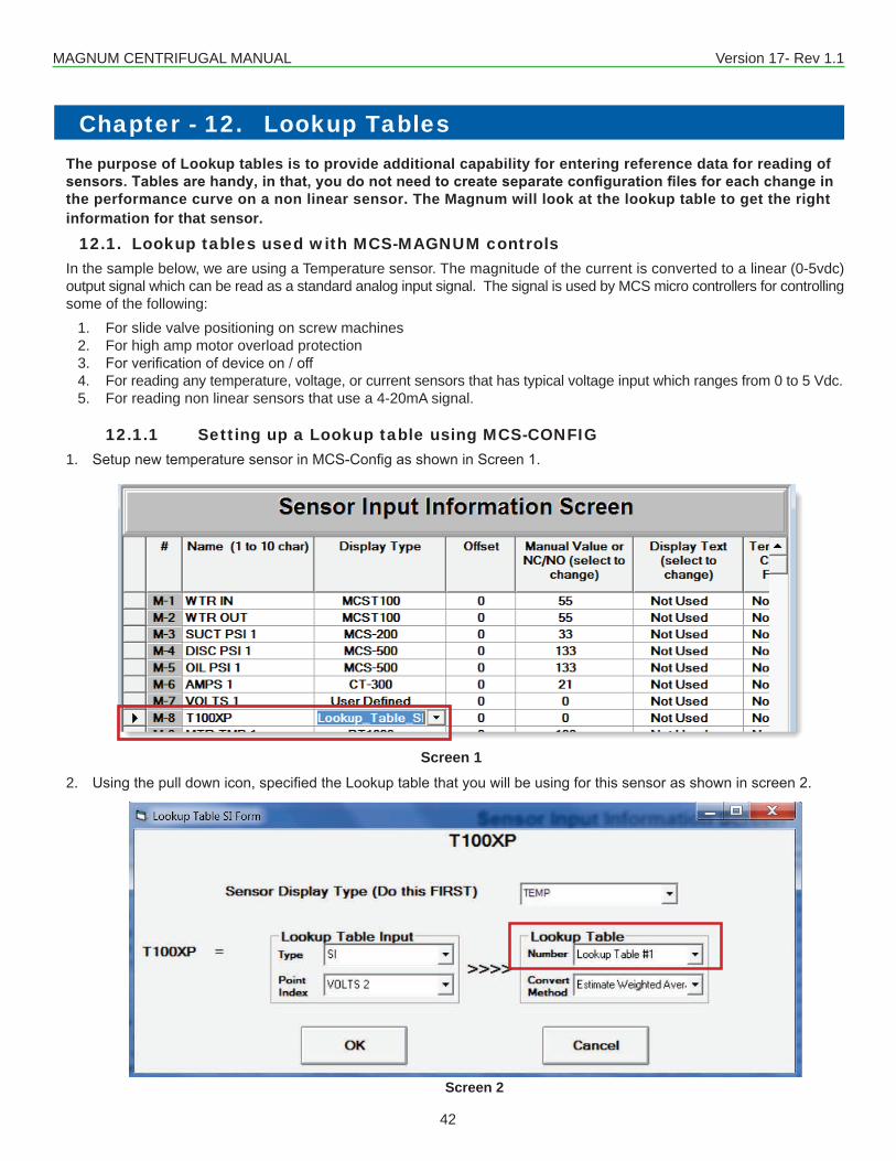
MAGNUM CENTRIFUGAL MANUAL Version 17- Rev 1.1
42
The purpose of Lookup tables is to provide additional capability for entering reference data for reading of sensors. Tables are handy, in that, you do not need to create separate configuration files for each change in the performance curve on a non linear sensor. The Magnum will look at the lookup table to get the right information for that sensor.
12.1. Lookup tables used with MCS-MAGNUM controlsIn the sample below, we are using a Temperature sensor. The magnitude of the current is converted to a linear (0-5vdc) output signal which can be read as a standard analog input signal. The signal is used by MCS micro controllers for controlling some of the following:
1. For slide valve positioning on screw machines2. For high amp motor overload protection3. Forverificationofdeviceon/off4. For reading any temperature, voltage, or current sensors that has typical voltage input which ranges from 0 to 5 Vdc.5. For reading non linear sensors that use a 4-20mA signal.
12.1.1 Setting up a Lookup table using MCS-CONFIG1. SetupnewtemperaturesensorinMCS-ConfigasshowninScreen1.
2. Usingthepulldownicon,specifiedtheLookuptablethatyouwillbeusingforthissensorasshowninscreen2.
Screen 1
Screen 2
Chapter - 12. Lookup Tables
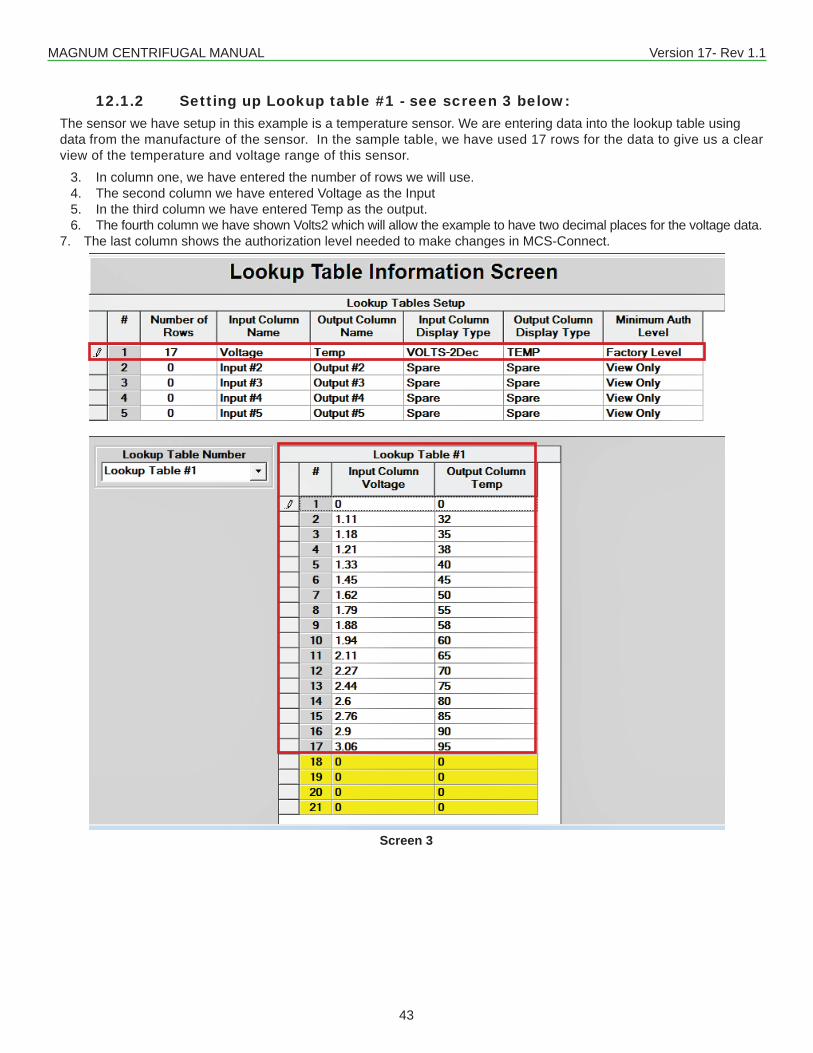
MAGNUM CENTRIFUGAL MANUAL Version 17- Rev 1.1
43
12.1.2 Setting up Lookup table #1 - see screen 3 below:The sensor we have setup in this example is a temperature sensor. We are entering data into the lookup table using data from the manufacture of the sensor. In the sample table, we have used 17 rows for the data to give us a clear view of the temperature and voltage range of this sensor.
3. In column one, we have entered the number of rows we will use.4. The second column we have entered Voltage as the Input 5. In the third column we have entered Temp as the output. 6. The fourth column we have shown Volts2 which will allow the example to have two decimal places for the voltage data.
7. The last column shows the authorization level needed to make changes in MCS-Connect.
Screen 3
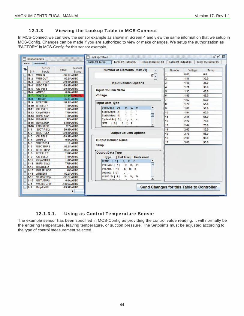
MAGNUM CENTRIFUGAL MANUAL Version 17- Rev 1.1
44
12.1.3 Viewing the Lookup Table in MCS-ConnectIn MCS-Connect we can view the sensor example as shown in Screen 4 and view the same information that we setup in MCS-Config.Changescanbemadeifyouareauthorizedtoviewormakechanges.Wesetuptheauthorizationas‘FACTORY’inMCS-Configforthissensorexample.
12.1.3.1. Using as Control Temperature SensorThe example sensor has been specified in MCS-Config as providing the control value reading. It will normally be the entering temperature, leaving temperature, or suction pressure. The Setpoints must be adjusted according to the type of control measurement selected.
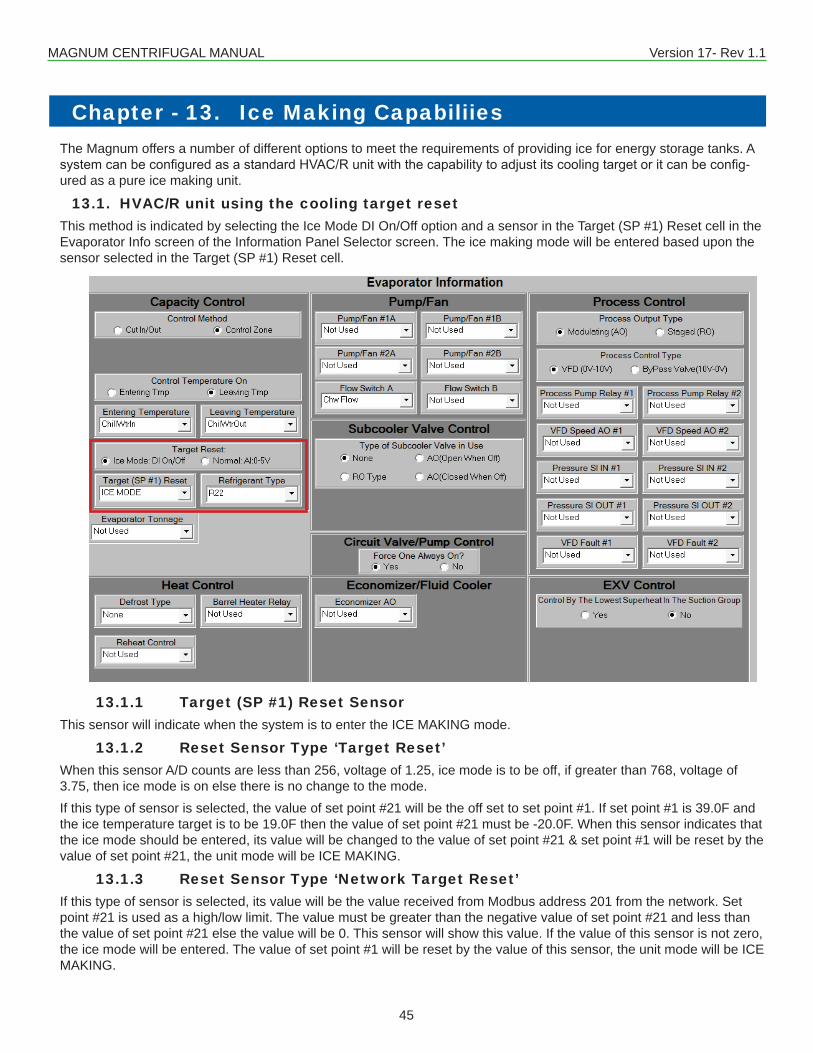
MAGNUM CENTRIFUGAL MANUAL Version 17- Rev 1.1
45
Chapter - 13. Ice Making CapabiliiesThe Magnum offers a number of different options to meet the requirements of providing ice for energy storage tanks. A systemcanbeconfiguredasastandardHVAC/Runitwiththecapabilitytoadjustitscoolingtargetoritcanbeconfig-ured as a pure ice making unit.
13.1. HVAC/R unit using the cooling target resetThis method is indicated by selecting the Ice Mode DI On/Off option and a sensor in the Target (SP #1) Reset cell in the Evaporator Info screen of the Information Panel Selector screen. The ice making mode will be entered based upon the sensor selected in the Target (SP #1) Reset cell.
13.1.1 Target (SP #1) Reset SensorThis sensor will indicate when the system is to enter the ICE MAKING mode.
13.1.2 Reset Sensor Type ‘Target Reset’When this sensor A/D counts are less than 256, voltage of 1.25, ice mode is to be off, if greater than 768, voltage of 3.75, then ice mode is on else there is no change to the mode.If this type of sensor is selected, the value of set point #21 will be the off set to set point #1. If set point #1 is 39.0F and the ice temperature target is to be 19.0F then the value of set point #21 must be -20.0F. When this sensor indicates that the ice mode should be entered, its value will be changed to the value of set point #21 & set point #1 will be reset by the value of set point #21, the unit mode will be ICE MAKING.
13.1.3 Reset Sensor Type ‘Network Target Reset’If this type of sensor is selected, its value will be the value received from Modbus address 201 from the network. Set point #21 is used as a high/low limit. The value must be greater than the negative value of set point #21 and less than the value of set point #21 else the value will be 0. This sensor will show this value. If the value of this sensor is not zero, the ice mode will be entered. The value of set point #1 will be reset by the value of this sensor, the unit mode will be ICE MAKING.
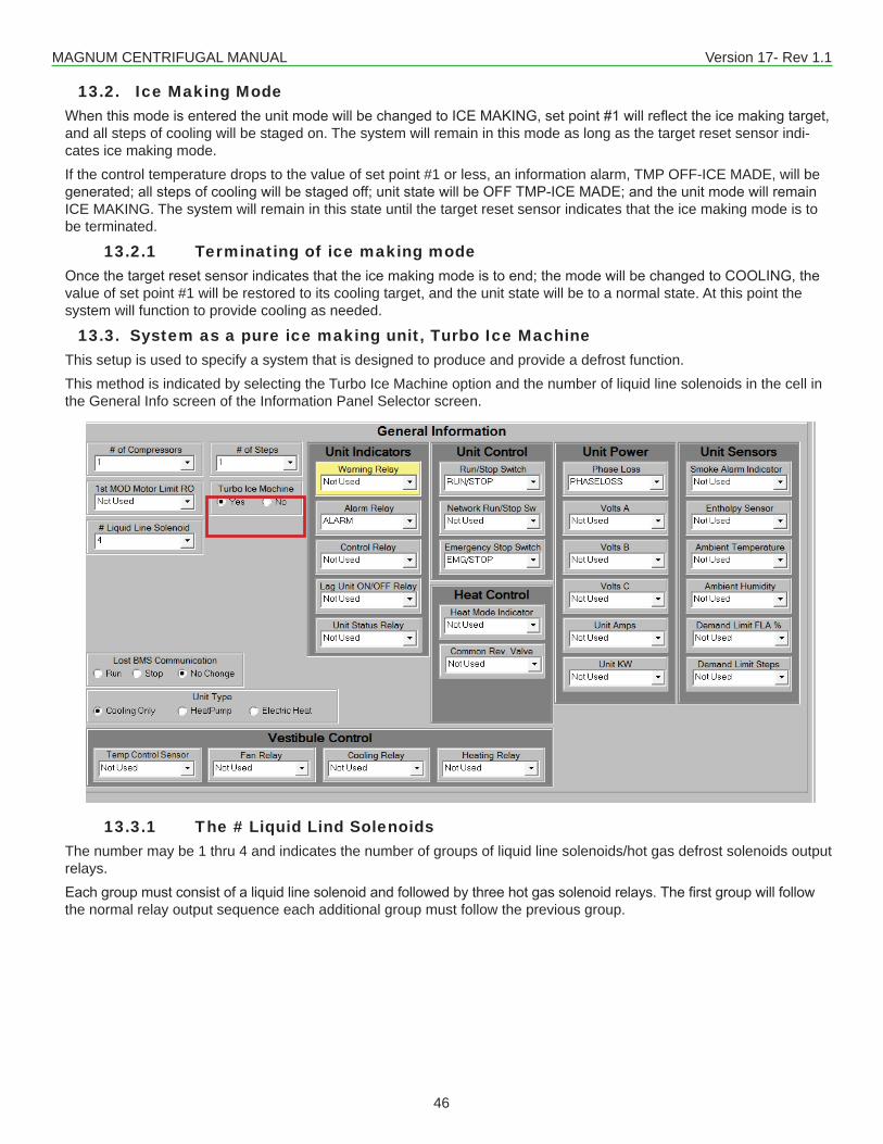
MAGNUM CENTRIFUGAL MANUAL Version 17- Rev 1.1
46
13.2. Ice Making Mode WhenthismodeisenteredtheunitmodewillbechangedtoICEMAKING,setpoint#1willreflecttheicemakingtarget,and all steps of cooling will be staged on. The system will remain in this mode as long as the target reset sensor indi-cates ice making mode.If the control temperature drops to the value of set point #1 or less, an information alarm, TMP OFF-ICE MADE, will be generated;allstepsofcoolingwillbestagedoff;unitstatewillbeOFFTMP-ICEMADE;andtheunitmodewillremainICE MAKING. The system will remain in this state until the target reset sensor indicates that the ice making mode is to be terminated.
13.2.1 Terminating of ice making modeOncethetargetresetsensorindicatesthattheicemakingmodeistoend;themodewillbechangedtoCOOLING,thevalue of set point #1 will be restored to its cooling target, and the unit state will be to a normal state. At this point the system will function to provide cooling as needed.
13.3. System as a pure ice making unit, Turbo Ice MachineThis setup is used to specify a system that is designed to produce and provide a defrost function.This method is indicated by selecting the Turbo Ice Machine option and the number of liquid line solenoids in the cell in the General Info screen of the Information Panel Selector screen.
13.3.1 The # Liquid Lind SolenoidsThe number may be 1 thru 4 and indicates the number of groups of liquid line solenoids/hot gas defrost solenoids output relays. Eachgroupmustconsistofaliquidlinesolenoidandfollowedbythreehotgassolenoidrelays.Thefirstgroupwillfollowthe normal relay output sequence each additional group must follow the previous group.
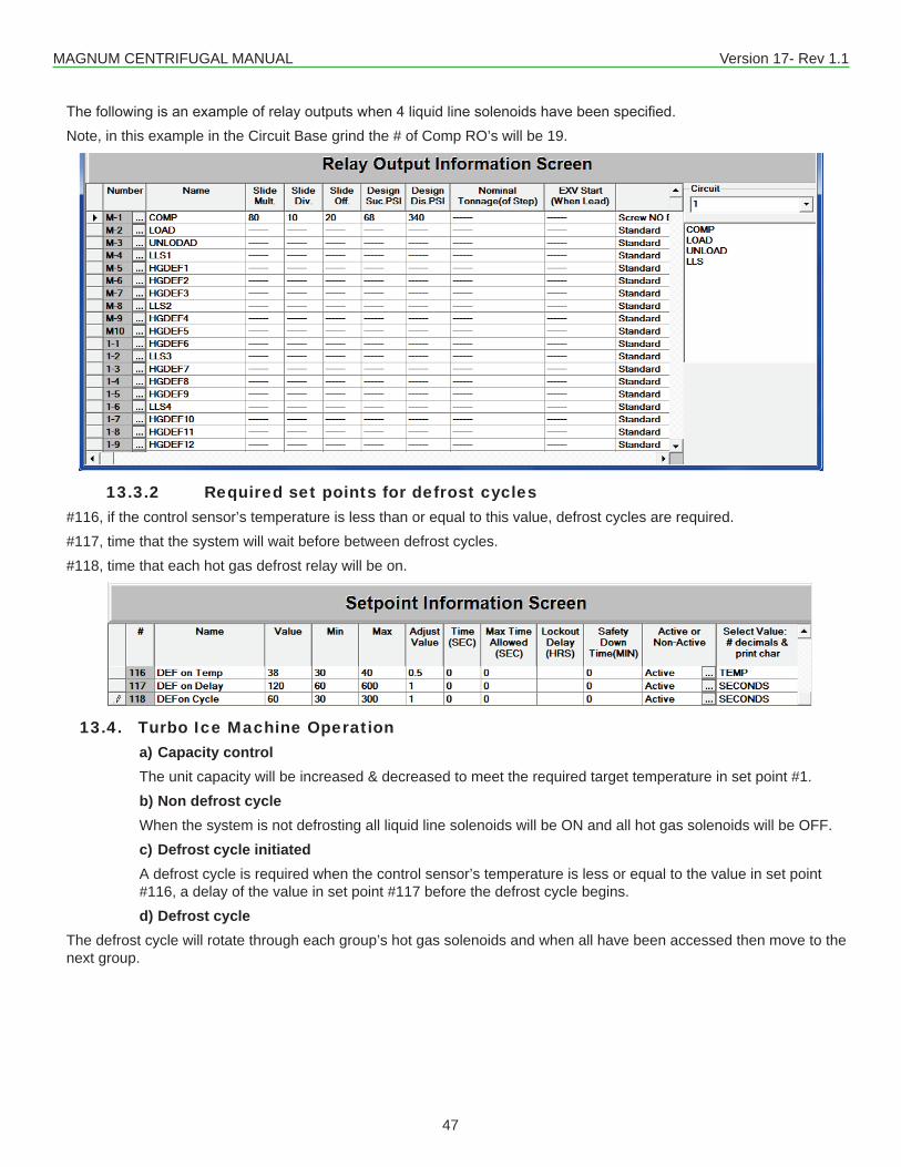
MAGNUM CENTRIFUGAL MANUAL Version 17- Rev 1.1
47
Thefollowingisanexampleofrelayoutputswhen4liquidlinesolenoidshavebeenspecified.Note, in this example in the Circuit Base grind the # of Comp RO’s will be 19.
13.3.2 Required set points for defrost cycles#116, if the control sensor’s temperature is less than or equal to this value, defrost cycles are required.#117, time that the system will wait before between defrost cycles.#118, time that each hot gas defrost relay will be on.
13.4. Turbo Ice Machine Operationa) Capacity controlThe unit capacity will be increased & decreased to meet the required target temperature in set point #1. b) Non defrost cycleWhen the system is not defrosting all liquid line solenoids will be ON and all hot gas solenoids will be OFF.c) Defrost cycle initiatedA defrost cycle is required when the control sensor’s temperature is less or equal to the value in set point #116, a delay of the value in set point #117 before the defrost cycle begins.d) Defrost cycle
The defrost cycle will rotate through each group’s hot gas solenoids and when all have been accessed then move to the next group.
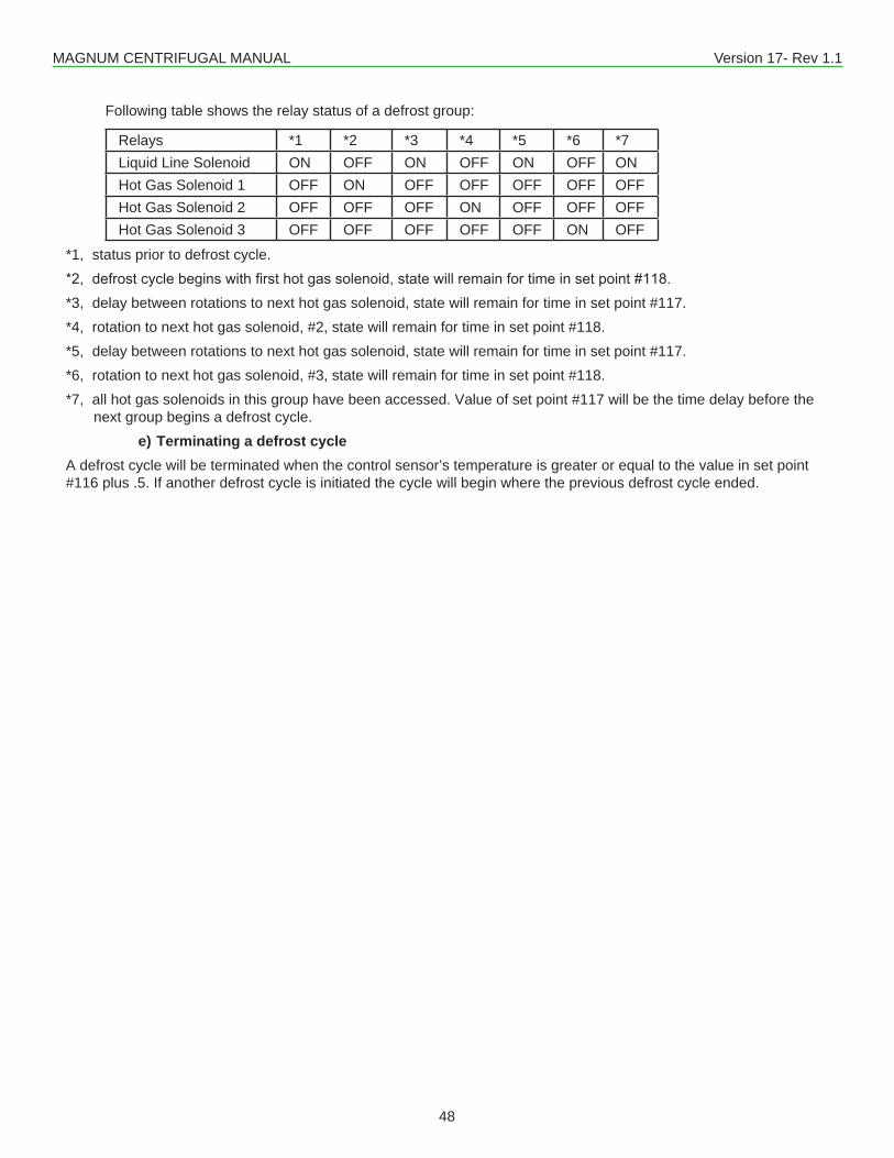
MAGNUM CENTRIFUGAL MANUAL Version 17- Rev 1.1
48
Following table shows the relay status of a defrost group:
Relays *1 *2 *3 *4 *5 *6 *7Liquid Line Solenoid ON OFF ON OFF ON OFF ONHot Gas Solenoid 1 OFF ON OFF OFF OFF OFF OFFHot Gas Solenoid 2 OFF OFF OFF ON OFF OFF OFFHot Gas Solenoid 3 OFF OFF OFF OFF OFF ON OFF
*1, status prior to defrost cycle.*2,defrostcyclebeginswithfirsthotgassolenoid,statewillremainfortimeinsetpoint#118.*3, delay between rotations to next hot gas solenoid, state will remain for time in set point #117.*4, rotation to next hot gas solenoid, #2, state will remain for time in set point #118.*5, delay between rotations to next hot gas solenoid, state will remain for time in set point #117.*6, rotation to next hot gas solenoid, #3, state will remain for time in set point #118.*7, all hot gas solenoids in this group have been accessed. Value of set point #117 will be the time delay before the
next group begins a defrost cycle.e) Terminating a defrost cycle
A defrost cycle will be terminated when the control sensor’s temperature is greater or equal to the value in set point #116 plus .5. If another defrost cycle is initiated the cycle will begin where the previous defrost cycle ended.
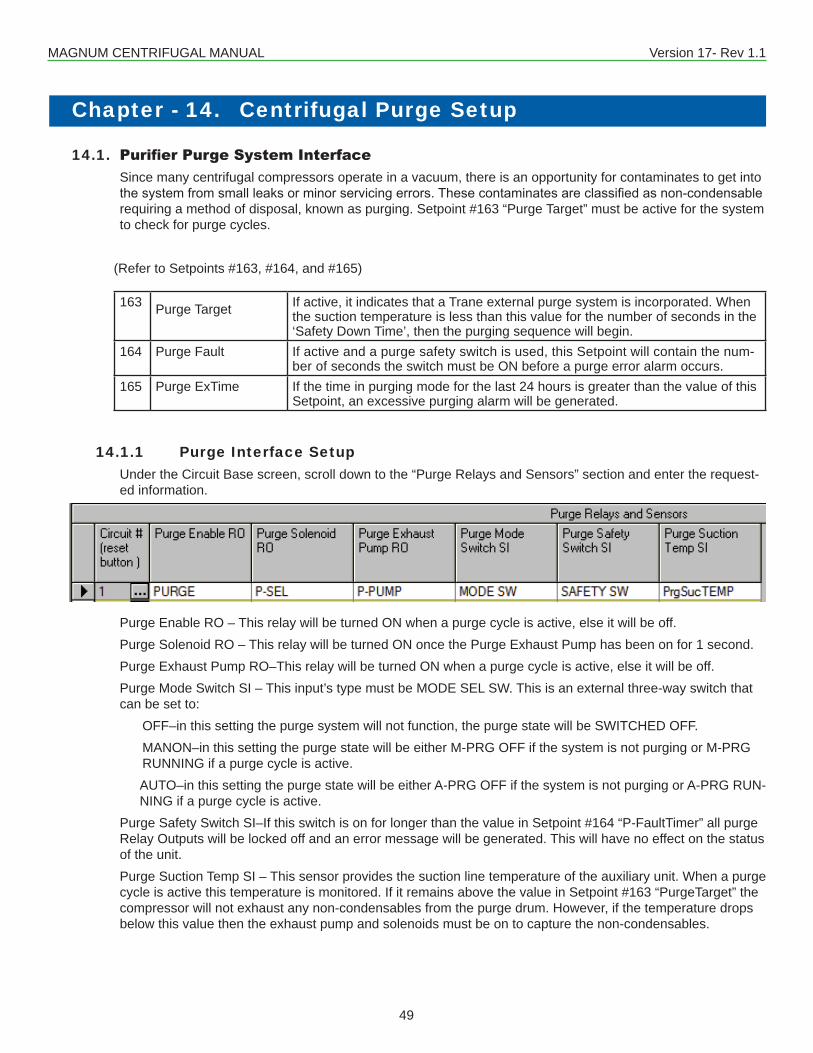
MAGNUM CENTRIFUGAL MANUAL Version 17- Rev 1.1
49
14.1. Purifier Purge System InterfaceSince many centrifugal compressors operate in a vacuum, there is an opportunity for contaminates to get into thesystemfromsmallleaksorminorservicingerrors.Thesecontaminatesareclassifiedasnon-condensablerequiring a method of disposal, known as purging. Setpoint #163 “Purge Target” must be active for the system to check for purge cycles.
(Refer to Setpoints #163, #164, and #165)
163 Purge Target If active, it indicates that a Trane external purge system is incorporated. When the suction temperature is less than this value for the number of seconds in the ‘Safety Down Time’, then the purging sequence will begin.
164 Purge Fault If active and a purge safety switch is used, this Setpoint will contain the num-ber of seconds the switch must be ON before a purge error alarm occurs.
165 Purge ExTime If the time in purging mode for the last 24 hours is greater than the value of this Setpoint, an excessive purging alarm will be generated.
14.1.1 Purge Interface SetupUnder the Circuit Base screen, scroll down to the “Purge Relays and Sensors” section and enter the request-ed information.
Purge Enable RO – This relay will be turned ON when a purge cycle is active, else it will be off.Purge Solenoid RO – This relay will be turned ON once the Purge Exhaust Pump has been on for 1 second.Purge Exhaust Pump RO–This relay will be turned ON when a purge cycle is active, else it will be off.Purge Mode Switch SI – This input’s type must be MODE SEL SW. This is an external three-way switch that can be set to:
OFF–in this setting the purge system will not function, the purge state will be SWITCHED OFF.MANON–in this setting the purge state will be either M-PRG OFF if the system is not purging or M-PRG RUNNING if a purge cycle is active.AUTO–in this setting the purge state will be either A-PRG OFF if the system is not purging or A-PRG RUN-NING if a purge cycle is active.
Purge Safety Switch SI–If this switch is on for longer than the value in Setpoint #164 “P-FaultTimer” all purge Relay Outputs will be locked off and an error message will be generated. This will have no effect on the status of the unit.Purge Suction Temp SI – This sensor provides the suction line temperature of the auxiliary unit. When a purge cycle is active this temperature is monitored. If it remains above the value in Setpoint #163 “PurgeTarget” the compressor will not exhaust any non-condensables from the purge drum. However, if the temperature drops below this value then the exhaust pump and solenoids must be on to capture the non-condensables.
Chapter - 14. Centrifugal Purge Setup
MAGNUM CENTRIFUGAL MANUAL Version 17- Rev 1.1
50
14.1.2 Conditions to Run Purge CycleMode selection switch in AUTO position: The compressor must be running and the suction line temperature of the auxiliary unit must be less than the value in Setpoint #163 “Purge Target”.Mode selection switch in MANUAL position: The suction line temperature of the auxiliary unit must be less than the value in Setpoint #163 “Purge Target”.Mode selection switch in OFF position: purge cycles will not run.
14.1.3 Purge StatesSWITCHED OFF – The mode selection switch is in the OFF position.FLOAT FAULT–The purge safety switch has been on longer than the value in Setpoint #164 “Purge Fault”. All purge Relay Outputs will be LOCKED OFF. When this switch returns to the normal off position, the purge Relay Outputs will be changed to AUTO and the purge state will be either M-PRG OFF or A-PRG OFF.M-PRG OFF – The mode selection switch is in the MANUAL position. All purge Relay Outputs are OFF. If the suction line temperature of the auxiliary unit drops below the value in Setpoint #163 “PurgeTarget” the state will be changed to M-PRG-RUNNING. Note, in this state the status of the compressor is not checked.M-PRG RUNNING – The purge relay enable and the purge pump are turned on. The purge solenoid will be turned on 1 second after the pump has started. If the suction line temperature of the auxiliary unit rises above the value in Setpoint #163 “PurgeTarget” the purge solenoid will be turned off. 1 second later the purge relay enable and the purge pump will be turned off and the state will be changed to M-PRG OFF,A-PRG OFF–The mode selection switch is in the AUTO position. All purge Relay Outputs are OFF. If the compressor is running and the suction line temperature of the auxiliary unit drops below the value in Setpoint #163 “PurgeTarget” the state will be changed to A-PRG-RUNNING. Note, in this state the status of the com-pressor is checked.A-PRG RUNNING–The purge relay enable and the purge pump will be turned on. The purge solenoid will be turned on 1 second after the pump has started. If the compressor goes off or the suction line temperature of the auxiliary unit rises above the value in Setpoint #163 “PurgeTarget” the purge solenoid will be turned off. 1 second later the purge relay enable and the purge pump will be turned off and the state will be changed to A-PRG OFF.
14.1.4 Excess Purge LogicSetpoint #165 “Excess Purge” typical Value = 20 Minutes
MIN = 1MAX = 120ADJ = 10Time = 0
The MCS-MAGNUM accumulates the amount of minutes a purge enable relay has been on for the last 24hrs (This is a rolling 24hrs window). If (purge enable accumulated on minutes) is greater than the value of Set-point #165 an “Excess Purge” alarm is generated and the Warning relay is turned on. The (purge enable accumulated on minutes) counter is set to zero when a lockout reset has been performed by the user. The Warning light is also turned off.

MAGNUM CENTRIFUGAL MANUAL Version 17- Rev 1.1
51
14.2. Special Pattern for Scroll CompressorsSpecial patterns have been developed for Trane Scroll 3-D compressors. CENT 14.0 software and newer isrequiredforthisfunction.Thesepatternsareforeithera3or4scrollunit.Theyarespecifiedbyselectingeither the Trane Trio or Trane Quad package in the Compressor Type selection under the MAGNUM screen. The sequencing will provide proper oil control for the Trane compressors.The compressors set will be treated as one compressor. There will be one common suction pressure, suction temperature, discharge pressure, and discharge temperature sensor for the package. Each compressor will have an individual amperage sensor. These must be consecutive inputs.Chiller states have been allocated for these patterns: “SCROLL STEP 1” through “SCROLL STEP 4”.
14.2.1 The following is a sample of the four-compressor setup:Select compressor type:
# of Compressors and # of steps:
Set up compressor:
Set up Relay Outputs:
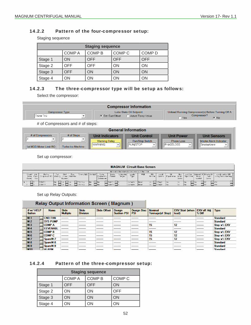
MAGNUM CENTRIFUGAL MANUAL Version 17- Rev 1.1
52
14.2.2 Pattern of the four-compressor setup:Staging sequence
Staging sequenceCOMP A COMP B COMP C COMP D
Stage 1 ON OFF OFF OFFStage 2 OFF OFF ON ONStage 3 OFF ON ON ONStage 4 ON ON ON ON
14.2.3 The three-compressor type will be setup as follows:Select the compressor:
# of Compressors and # of steps:
Set up compressor:
Set up Relay Outputs:
14.2.4 Pattern of the three-compressor setup:
Staging sequenceCOMP A COMP B COMP C
Stage 1 OFF OFF ONStage 2 ON ON OFFStage 3 ON ON ONStage 4 ON ON ON

MAGNUM CENTRIFUGAL MANUAL Version 17- Rev 1.1
53
14.2.5 Safeties are the same for both compressor typesThe standard unloading and holding logic has been incorporated with their compressor state names. When a step is unloaded it will go to the previous step pattern. For example if the compressor is in SCROLL STEP 3 andunloadingisrequiredtheRelayOutputforSCROLLSTEP2willbeused.Thestatenamewillreflectwhythe compressor has unloaded.The unloading and holding can result from high discharge and low suction pressure and high discharge temperature.Low and high amp drawn will be check for all compressors that are on. The standard amp safety checks will be made and if one occurs the compressor will be off on a safety or a lock out if the same safety reoccurs.Note, the standard Setpoints are used for all safety checks, unloading, and holding functions.Compressor Auto RotationThe auto rotation option is selected by setting the value in Setpoint #103 “LEAD COMP” to zero. If this value is nonzero, it will contain the number of the lead compressor and auto rotation will be disabled. Note this Setpoint can be manually changed to force a different compressor as the lead compressor or to enable auto rotation.When this option is enabled, the Magnum will rotate the compressors based upon the value in Setpoint # 104“CMP ROTATION”
If Setpoint # 104 is zero, rotation will occur with every complete capacity cycle and the next compressor will be selected as the lead compressor.
If Setpoint # 104 is nonzero, the value is the number of days between rotations. At midnight the Magnum will check if it is time to rotate compressors. If yes, the Magnum will check the run hours on each com-pressor and select the one with the least amount of run hours to be the lead compressor.If Setpoint # 104 is set up as an ALARM Setpoint type, a compressor rotation message will be generated each time a compressor is rotated.
14.3. Custom RotationTherequirementistoenablerotationonlyinthefirstbarrelanddonotturnONanycompressorsassociatedwiththesecondbarreluntilallcompressorsareONinthefirstbarrel.Whendecreasingrefrigerantcapacity,ifanycompressorsinthesecondbarrelareON,theymustfirstbeturnedOFFbeforeturningOFFanycom-pressorsinthefirstbarrel.OnlyfirstONandfirstOFFleadrotationstrategycanbeused.
To activate this option Setpoint #103 “LEAD COMP” must be set up as follows:Value: 0 (indicates auto rotation, must be 0)Time(SEC): 0(indicatesfirstonfirstoff,mustbe0)Select Value: DIGITAL/SWType of Setpoint: Target (must be Target type)HighZone: 1(thisisthestartingcompressorfollowingareset;usually1)Low Zone: 1 (number to rotate, will default to 1)NightSetback: 8(numberofcompressorsinthefirstbarrel)
If the Value, Time, and Type cells are not set as indicated, normal rotation using Setpoints #103 “LEAD COMP” and #104 “COMP ROTATION” will be used.
The following examples have 16 compressors, dual barrels with 8 compressors in each. Barrel 1 has com-pressors 1 through 8 and 9 through 16 are in barrel 2. The wanted/actual ON will function as usual only the rotation and the sequence of turning on the compressors have been changed.
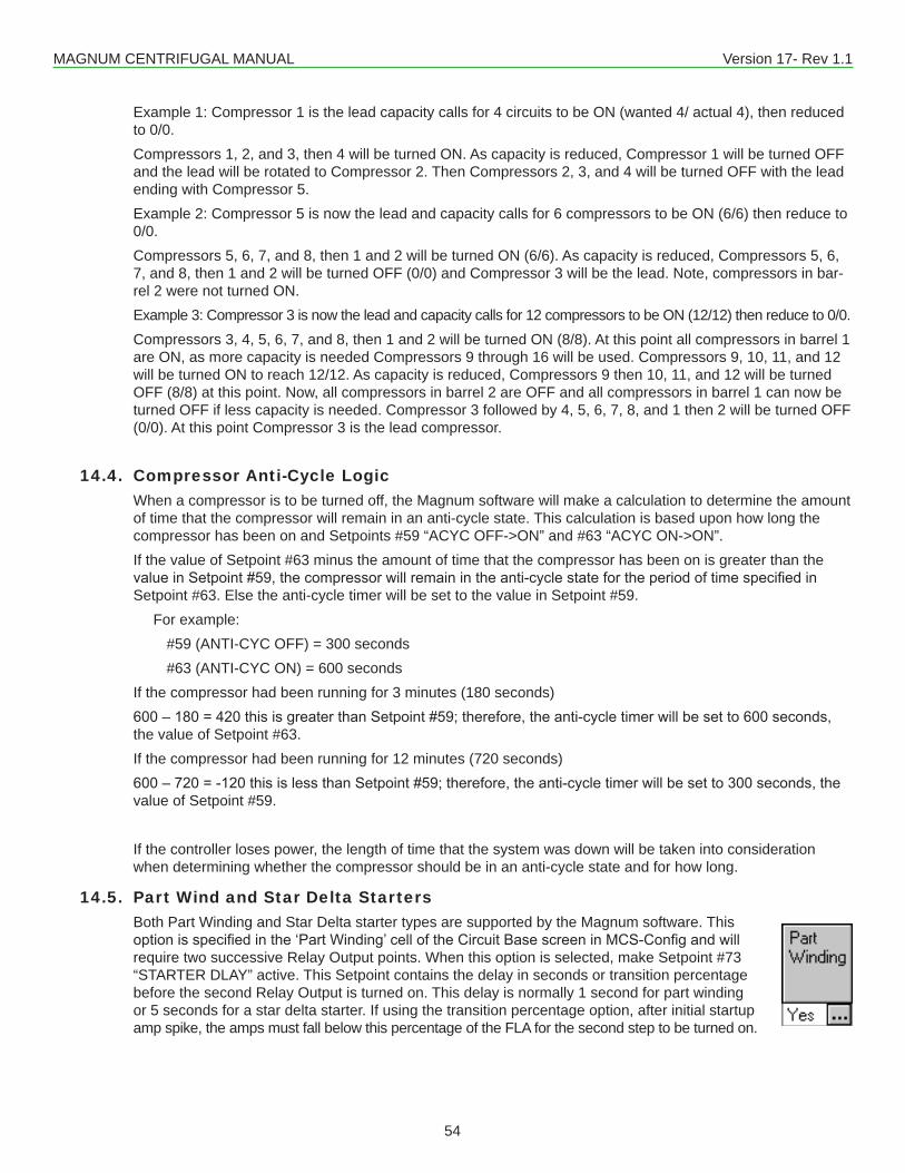
MAGNUM CENTRIFUGAL MANUAL Version 17- Rev 1.1
54
Example 1: Compressor 1 is the lead capacity calls for 4 circuits to be ON (wanted 4/ actual 4), then reduced to 0/0.Compressors 1, 2, and 3, then 4 will be turned ON. As capacity is reduced, Compressor 1 will be turned OFF and the lead will be rotated to Compressor 2. Then Compressors 2, 3, and 4 will be turned OFF with the lead ending with Compressor 5.Example 2: Compressor 5 is now the lead and capacity calls for 6 compressors to be ON (6/6) then reduce to 0/0.Compressors 5, 6, 7, and 8, then 1 and 2 will be turned ON (6/6). As capacity is reduced, Compressors 5, 6, 7, and 8, then 1 and 2 will be turned OFF (0/0) and Compressor 3 will be the lead. Note, compressors in bar-rel 2 were not turned ON.Example 3: Compressor 3 is now the lead and capacity calls for 12 compressors to be ON (12/12) then reduce to 0/0.Compressors 3, 4, 5, 6, 7, and 8, then 1 and 2 will be turned ON (8/8). At this point all compressors in barrel 1 are ON, as more capacity is needed Compressors 9 through 16 will be used. Compressors 9, 10, 11, and 12 will be turned ON to reach 12/12. As capacity is reduced, Compressors 9 then 10, 11, and 12 will be turned OFF (8/8) at this point. Now, all compressors in barrel 2 are OFF and all compressors in barrel 1 can now be turned OFF if less capacity is needed. Compressor 3 followed by 4, 5, 6, 7, 8, and 1 then 2 will be turned OFF (0/0). At this point Compressor 3 is the lead compressor.
14.4. Compressor Anti-Cycle LogicWhen a compressor is to be turned off, the Magnum software will make a calculation to determine the amount of time that the compressor will remain in an anti-cycle state. This calculation is based upon how long the compressor has been on and Setpoints #59 “ACYC OFF->ON” and #63 “ACYC ON->ON”.If the value of Setpoint #63 minus the amount of time that the compressor has been on is greater than the valueinSetpoint#59,thecompressorwillremainintheanti-cyclestatefortheperiodoftimespecifiedinSetpoint #63. Else the anti-cycle timer will be set to the value in Setpoint #59.
For example:#59 (ANTI-CYC OFF) = 300 seconds#63 (ANTI-CYC ON) = 600 seconds
If the compressor had been running for 3 minutes (180 seconds)600–180=420thisisgreaterthanSetpoint#59;therefore,theanti-cycletimerwillbesetto600seconds,the value of Setpoint #63.If the compressor had been running for 12 minutes (720 seconds)600–720=-120thisislessthanSetpoint#59;therefore,theanti-cycletimerwillbesetto300seconds,thevalue of Setpoint #59.
If the controller loses power, the length of time that the system was down will be taken into consideration when determining whether the compressor should be in an anti-cycle state and for how long.
14.5. Part Wind and Star Delta StartersBoth Part Winding and Star Delta starter types are supported by the Magnum software. This optionisspecifiedinthe‘PartWinding’celloftheCircuitBasescreeninMCS-Configandwillrequire two successive Relay Output points. When this option is selected, make Setpoint #73 “STARTER DLAY” active. This Setpoint contains the delay in seconds or transition percentage before the second Relay Output is turned on. This delay is normally 1 second for part winding or 5 seconds for a star delta starter. If using the transition percentage option, after initial startup amp spike, the amps must fall below this percentage of the FLA for the second step to be turned on.
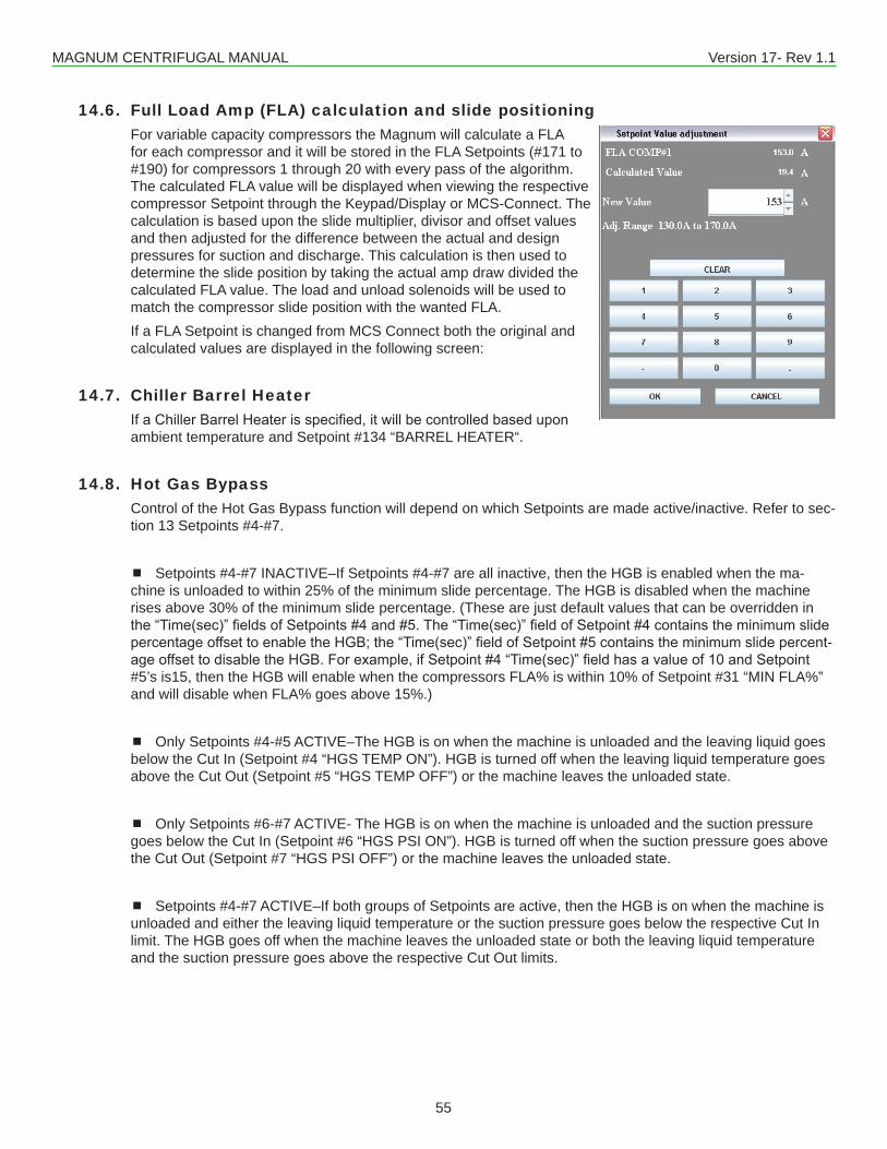
MAGNUM CENTRIFUGAL MANUAL Version 17- Rev 1.1
55
14.6. Full Load Amp (FLA) calculation and slide positioningFor variable capacity compressors the Magnum will calculate a FLA for each compressor and it will be stored in the FLA Setpoints (#171 to #190) for compressors 1 through 20 with every pass of the algorithm. The calculated FLA value will be displayed when viewing the respective compressor Setpoint through the Keypad/Display or MCS-Connect. The calculation is based upon the slide multiplier, divisor and offset values and then adjusted for the difference between the actual and design pressures for suction and discharge. This calculation is then used to determine the slide position by taking the actual amp draw divided the calculated FLA value. The load and unload solenoids will be used to match the compressor slide position with the wanted FLA.If a FLA Setpoint is changed from MCS Connect both the original and calculated values are displayed in the following screen:
14.7. Chiller Barrel HeaterIfaChillerBarrelHeaterisspecified,itwillbecontrolledbaseduponambient temperature and Setpoint #134 “BARREL HEATER“.
14.8. Hot Gas BypassControl of the Hot Gas Bypass function will depend on which Setpoints are made active/inactive. Refer to sec-tion 13 Setpoints #4-#7.
Setpoints #4-#7 INACTIVE–If Setpoints #4-#7 are all inactive, then the HGB is enabled when the ma-chine is unloaded to within 25% of the minimum slide percentage. The HGB is disabled when the machine rises above 30% of the minimum slide percentage. (These are just default values that can be overridden in the“Time(sec)”fieldsofSetpoints#4and#5.The“Time(sec)”fieldofSetpoint#4containstheminimumslidepercentageoffsettoenabletheHGB;the“Time(sec)”fieldofSetpoint#5containstheminimumslidepercent-ageoffsettodisabletheHGB.Forexample,ifSetpoint#4“Time(sec)”fieldhasavalueof10andSetpoint#5’s is15, then the HGB will enable when the compressors FLA% is within 10% of Setpoint #31 “MIN FLA%” and will disable when FLA% goes above 15%.)
Only Setpoints #4-#5 ACTIVE–The HGB is on when the machine is unloaded and the leaving liquid goes below the Cut In (Setpoint #4 “HGS TEMP ON”). HGB is turned off when the leaving liquid temperature goes above the Cut Out (Setpoint #5 “HGS TEMP OFF”) or the machine leaves the unloaded state.
Only Setpoints #6-#7 ACTIVE- The HGB is on when the machine is unloaded and the suction pressure goes below the Cut In (Setpoint #6 “HGS PSI ON”). HGB is turned off when the suction pressure goes above the Cut Out (Setpoint #7 “HGS PSI OFF”) or the machine leaves the unloaded state.
Setpoints #4-#7 ACTIVE–If both groups of Setpoints are active, then the HGB is on when the machine is unloaded and either the leaving liquid temperature or the suction pressure goes below the respective Cut In limit. The HGB goes off when the machine leaves the unloaded state or both the leaving liquid temperature and the suction pressure goes above the respective Cut Out limits.
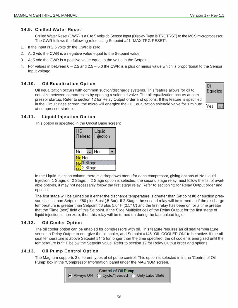
MAGNUM CENTRIFUGAL MANUAL Version 17- Rev 1.1
56
14.9. Chilled Water ResetChilled Water Reset (CWR) is a 0 to 5 volts dc Sensor Input (Display Type is TRGTRST) to the MCS microprocessor. The CWR follows the following rules using Setpoint #21 “MAX TRG RESET”:
1. If the input is 2.5 volts dc the CWR is zero.2. At 0 vdc the CWR is a negative value equal to the Setpoint value.3. At 5 vdc the CWR is a positive value equal to the value in the Setpoint.4. For values in between 0 – 2.5 and 2.5 – 5.0 the CWR is a plus or minus value which is proportional to the Sensor
Input voltage.
14.10. Oil Equalization Option Oil equalization occurs with common suction/discharge systems. This feature allows for oil to equalize between compressors by opening a solenoid valve. The oil equalization occurs at com-pressorstartup.Refertosection12forRelayOutputorderandoptions.Ifthisfeatureisspecifiedin the Circuit Base screen, the micro will energize the Oil Equalization solenoid valve for 1 minute at compressor startup.
14.11. Liquid Injection OptionThisoptionisspecifiedintheCircuitBasescreen:
In the Liquid Injection column there is a dropdown menu for each compressor, giving options of No Liquid Injection, 1 Stage, or 2 Stage. If 2 Stage option is selected, the second stage relay must follow the list of avail-ableoptions,itmaynotnecessarilyfollowthefirststagerelay.Refertosection12forRelayOutputorderandoptions.ThefirststagewillbeturnedonifeitherthedischargetemperatureisgreaterthanSetpoint#8orsuctionpres-sure is less than Setpoint #80 plus 5 psi (.5 Bar). If 2 Stage, the second relay will be turned on if the discharge temperatureisgreaterthanSetpoint#8plus5.0°F(2.5°C)andthefirstrelayhasbeenonforatimegreaterthatthe‘Time(sec)’fieldofthisSetpoint.IftheSlideMultipliercelloftheRelayOutputforthefirststageofliquid injection is non-zero, then this relay will be turned on during the fast unload logic.
14.12. Oil Cooler OptionThe oil cooler option can be enabled for compressors with oil. This feature requires an oil seal temperature sensor, a Relay Output to energize the oil cooler, and Setpoint #145 “OIL COOLER ON“ to be active. If the oil sealtemperatureisaboveSetpoint#145forlongerthanthetimespecified,theoilcoolerisenergizeduntilthetemperature is 5° F below the Setpoint value. Refer to section 12 for Relay Output order and options.
14.13. Oil Pump Control OptionThe Magnum supports 3 different types of oil pump control. This option is selected in in the ‘Control of Oil Pump’ box in the ‘Compressor Information’ panel under the MAGNUM screen.
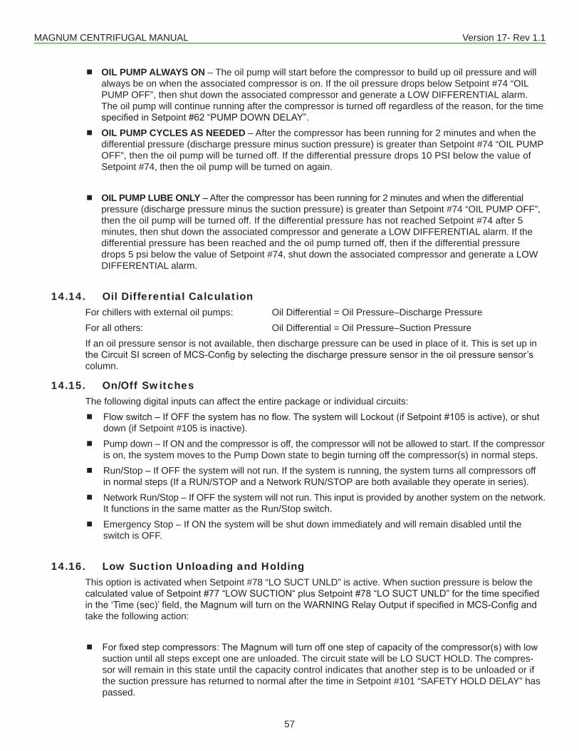
MAGNUM CENTRIFUGAL MANUAL Version 17- Rev 1.1
57
OIL PUMP ALWAYS ON – The oil pump will start before the compressor to build up oil pressure and will always be on when the associated compressor is on. If the oil pressure drops below Setpoint #74 “OIL PUMP OFF”, then shut down the associated compressor and generate a LOW DIFFERENTIAL alarm. The oil pump will continue running after the compressor is turned off regardless of the reason, for the time specifiedinSetpoint#62“PUMPDOWNDELAY”.
OIL PUMP CYCLES AS NEEDED – After the compressor has been running for 2 minutes and when the differential pressure (discharge pressure minus suction pressure) is greater than Setpoint #74 “OIL PUMP OFF”, then the oil pump will be turned off. If the differential pressure drops 10 PSI below the value of Setpoint #74, then the oil pump will be turned on again.
OIL PUMP LUBE ONLY – After the compressor has been running for 2 minutes and when the differential pressure (discharge pressure minus the suction pressure) is greater than Setpoint #74 “OIL PUMP OFF”, then the oil pump will be turned off. If the differential pressure has not reached Setpoint #74 after 5 minutes, then shut down the associated compressor and generate a LOW DIFFERENTIAL alarm. If the differential pressure has been reached and the oil pump turned off, then if the differential pressure drops 5 psi below the value of Setpoint #74, shut down the associated compressor and generate a LOW DIFFERENTIAL alarm.
14.14. Oil Differential CalculationFor chillers with external oil pumps: Oil Differential = Oil Pressure–Discharge PressureFor all others: Oil Differential = Oil Pressure–Suction PressureIf an oil pressure sensor is not available, then discharge pressure can be used in place of it. This is set up in theCircuitSIscreenofMCS-Configbyselectingthedischargepressuresensorintheoilpressuresensor’scolumn.
14.15. On/Off SwitchesThe following digital inputs can affect the entire package or individual circuits: Flowswitch–IfOFFthesystemhasnoflow.ThesystemwillLockout(ifSetpoint#105isactive),orshut
down (if Setpoint #105 is inactive). Pump down – If ON and the compressor is off, the compressor will not be allowed to start. If the compressor
is on, the system moves to the Pump Down state to begin turning off the compressor(s) in normal steps. Run/Stop – If OFF the system will not run. If the system is running, the system turns all compressors off
in normal steps (If a RUN/STOP and a Network RUN/STOP are both available they operate in series). Network Run/Stop – If OFF the system will not run. This input is provided by another system on the network.
It functions in the same matter as the Run/Stop switch. Emergency Stop – If ON the system will be shut down immediately and will remain disabled until the
switch is OFF.
14.16. Low Suction Unloading and HoldingThis option is activated when Setpoint #78 “LO SUCT UNLD” is active. When suction pressure is below the calculatedvalueofSetpoint#77“LOWSUCTION“plusSetpoint#78“LOSUCTUNLD”forthetimespecifiedinthe‘Time(sec)’field,theMagnumwillturnontheWARNINGRelayOutputifspecifiedinMCS-Configandtake the following action:
Forfixedstepcompressors:TheMagnumwillturnoffonestepofcapacityofthecompressor(s)withlowsuction until all steps except one are unloaded. The circuit state will be LO SUCT HOLD. The compres-sor will remain in this state until the capacity control indicates that another step is to be unloaded or if the suction pressure has returned to normal after the time in Setpoint #101 “SAFETY HOLD DELAY” has passed.
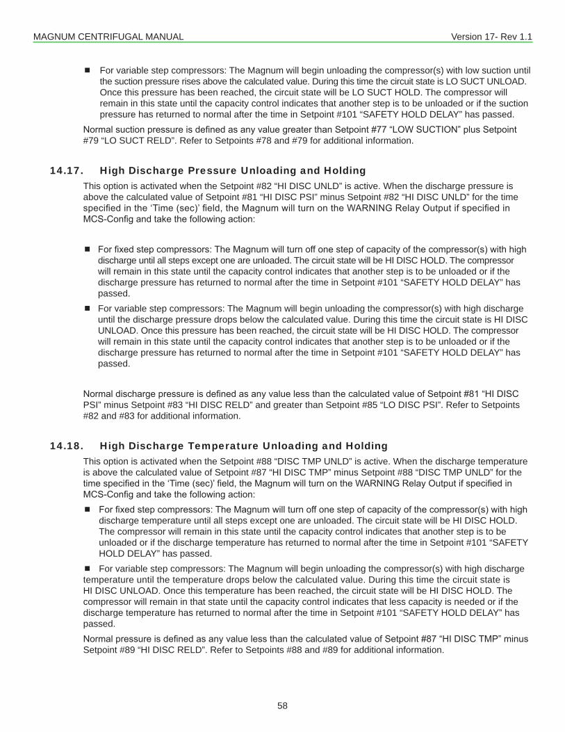
MAGNUM CENTRIFUGAL MANUAL Version 17- Rev 1.1
58
For variable step compressors: The Magnum will begin unloading the compressor(s) with low suction until the suction pressure rises above the calculated value. During this time the circuit state is LO SUCT UNLOAD. Once this pressure has been reached, the circuit state will be LO SUCT HOLD. The compressor will remain in this state until the capacity control indicates that another step is to be unloaded or if the suction pressure has returned to normal after the time in Setpoint #101 “SAFETY HOLD DELAY” has passed.
NormalsuctionpressureisdefinedasanyvaluegreaterthanSetpoint#77“LOWSUCTION”plusSetpoint#79 “LO SUCT RELD”. Refer to Setpoints #78 and #79 for additional information.
14.17. High Discharge Pressure Unloading and HoldingThis option is activated when the Setpoint #82 “HI DISC UNLD” is active. When the discharge pressure is above the calculated value of Setpoint #81 “HI DISC PSI” minus Setpoint #82 “HI DISC UNLD” for the time specifiedinthe‘Time(sec)’field,theMagnumwillturnontheWARNINGRelayOutputifspecifiedinMCS-Configandtakethefollowingaction:
Forfixedstepcompressors:TheMagnumwillturnoffonestepofcapacityofthecompressor(s)withhighdischarge until all steps except one are unloaded. The circuit state will be HI DISC HOLD. The compressor will remain in this state until the capacity control indicates that another step is to be unloaded or if the discharge pressure has returned to normal after the time in Setpoint #101 “SAFETY HOLD DELAY” has passed.
For variable step compressors: The Magnum will begin unloading the compressor(s) with high discharge until the discharge pressure drops below the calculated value. During this time the circuit state is HI DISC UNLOAD. Once this pressure has been reached, the circuit state will be HI DISC HOLD. The compressor will remain in this state until the capacity control indicates that another step is to be unloaded or if the discharge pressure has returned to normal after the time in Setpoint #101 “SAFETY HOLD DELAY” has passed.
NormaldischargepressureisdefinedasanyvaluelessthanthecalculatedvalueofSetpoint#81“HIDISCPSI” minus Setpoint #83 “HI DISC RELD” and greater than Setpoint #85 “LO DISC PSI”. Refer to Setpoints #82 and #83 for additional information.
14.18. High Discharge Temperature Unloading and HoldingThis option is activated when the Setpoint #88 “DISC TMP UNLD” is active. When the discharge temperature is above the calculated value of Setpoint #87 “HI DISC TMP” minus Setpoint #88 “DISC TMP UNLD” for the timespecifiedinthe‘Time(sec)’field,theMagnumwillturnontheWARNINGRelayOutputifspecifiedinMCS-Configandtakethefollowingaction: Forfixedstepcompressors:TheMagnumwillturnoffonestepofcapacityofthecompressor(s)withhigh
discharge temperature until all steps except one are unloaded. The circuit state will be HI DISC HOLD. The compressor will remain in this state until the capacity control indicates that another step is to be unloaded or if the discharge temperature has returned to normal after the time in Setpoint #101 “SAFETY HOLD DELAY” has passed.
For variable step compressors: The Magnum will begin unloading the compressor(s) with high discharge temperature until the temperature drops below the calculated value. During this time the circuit state is HI DISC UNLOAD. Once this temperature has been reached, the circuit state will be HI DISC HOLD. The compressor will remain in that state until the capacity control indicates that less capacity is needed or if the discharge temperature has returned to normal after the time in Setpoint #101 “SAFETY HOLD DELAY” has passed.NormalpressureisdefinedasanyvaluelessthanthecalculatedvalueofSetpoint#87“HIDISCTMP”minusSetpoint #89 “HI DISC RELD”. Refer to Setpoints #88 and #89 for additional information.

MAGNUM CENTRIFUGAL MANUAL Version 17- Rev 1.1
59
14.19. High Ampere Unloading and HoldingThis option is activated when the Setpoint #75 “HI AMPS %” is active. Note: This option can only be active forfixedstepcompressors.Whentheampdrawiswithinone-halfofthecalculatedHIAMPsafetyvalue,theMagnumwillturnontheWARNINGRelayOutputifspecifiedinMCS-Configandtakethefollowingaction: Forfixedstepcompressors:theMagnumwillturnoffonestepofcapacityassociatedwiththatcompressor
until that compressor is in an UNLOADED state that is all steps except one are unloaded. The circuit state will be HI AMP HOLD. The compressor will remain in that state until the capacity control indicates that another step is to be unloaded or if the amp draw has returned to normal after the time in Setpoint #101 “SAFETY HOLD DELAY” has passed.
14.20. Low Water Temperature Unloading and HoldingWhen the leaving liquid temperature is within 1.5° F (.8° C) of the freeze safety, the Magnum will turn on the WARNINGRelayOutputifspecifiedinMCS-Configandtakethefollowingaction: Forfixedstepcompressors:TheMagnumwillturnoffonestepofcapacityofthecompressor(s)withlow
water temperature until all steps except one are unloaded. The circuit state will be LO TMP HOLD. The compressor will remain in that state until the capacity control indicates that another step is to be unloaded or if after 5 minutes the leaving liquid temperature has turned to normal.
For variable step compressors: The Magnum will begin unloading the compressor(s) with low water temperature until the leaving liquid temperature rises above the calculated value. During this time the circuit state is LO TMP UNLOAD. Once the leaving liquid temperature rises above the calculated temperature the circuit state will change to LO TMP HOLD. The compressor will remain in that state until the capacity control indicates that less capacity is needed or if after 5 minutes the leaving liquid temperature has turned to normal.
Normalleavingliquidtemperatureisdefinedasanyvaluemorethan3.0F(1.6C)abovethefreezesafetytripvalue.
14.21. Energy Efficient Compressor StagingInamulti-screwsystem,itmaybemoreefficienttorunthescrewsatlessthan100%capacityuntilallcompressors have been turned on.The following Setpoints are used to control the screw compressor staging: Setpoint #30 “MAX SLIDE %” contains the maximum slide percentage, based upon amp draw, before the system will bring on the next compressor. Setpoint #31 “MIN SLIDE %” contains the minimum slide percentage, based upon amp draw, before the
system will reduce the number of compressors wanted on.For example if “MAX SLIDE %” is 80% and the “MIN SLIDE %“ is 40%, the two-screw compressor system would be ramped up as follows:The Lead compressor will be started at 40% and increased up to 80%. If more capacity is needed the next compressorwillbestartedat40%andthefirstcompressordecreasedto40%.Thetwocompressorswillthen have their slide positions changed together. Since there are only two compressors, they will be ramped together up to 100% if required. If both compressors are at 40% and less capacity is needed, one compressor will be turned off and the other increased to 80%.If running compressors at 100% is not desired, then the “Last Stage to 100% (Override Setpoint)” cell in the Compressor Information panel of the MAGNUM screen should be set to ‘No’. Then the maximum capacity allowed will be the value in Setpoint #30. If ‘Yes’, then all compressors will load to the value in Setpoint #30 until all compressors are on, then they will load to 100% together.
MAGNUM CENTRIFUGAL MANUAL Version 17- Rev 1.1
60
14.22. Chilled Water Pump ControlThe current Magnum software will support a chilled water pump plus a backup with rotation logic. These must besetupinMCS-Config.Setpoint #105 and Setpoint #106 are used with this control logic.
� If Setpoint #105 “PUMP FAILURE” is active,flowislostfortheperiodoftimecontainedinthe‘Time(sec)’field,andonlyonepumpispresent,thenthesystemwillmovetoaLOCKEDOUTstate.Ifthesystemhastwopumpsandflowislost,thenthebackuppumpwillstartandtheleadpumpwillbelocked out. A Lockout Reset will be required to restart the system or to reactive a locked out pump.
� If Setpoint #105 is inactiveandtheflowislost,thesystemwillmovetotheOFF-NOEVAPFLOWstate.Whenflowisreturnedthesystemwillautomaticallyrestart,noresetisrequired.
Setpoint #106 “LEAD PUMP” indicates whether the rotation option is active or which pump is the lead pump.
� If Setpoint #106 is zero, then rotation of the pumps will occur whenever the lead pump is turned off. If no rotation has occurred during the current day, a forced rotation at midnight will occur. This forces at least one rotation per day.
� If Setpoint #106 is non-zero, then rotation of the pumps is inactive and the value will specify the lead pump. This Setpoint can be changed in a live unit and the appropriate action will be taken.
14.22.1 Special Rotation for Chiller Pump RotationThisfeatureisdesignedtorotatethechillerpumpsatmidnightwithaminimumdisruptiontotheflow.
� Setpoint #238 must be active and contain the following information: Type: Delay Value: Not used Safety time: delay between states
� Set point #106 must be active and contain the following information: Type: Set point Value: Number of days between rotation
At mid-night when rotation is required both chiller pumps will be on for the time in the safety time cell of set point #238. Once this time has elapsed, the current lead chiller pump will be turned off and the lead switched to the other chiller pump.
Prior to rotation the system will verify that the next chiller pump is available. That chiller pump’s status must be AUTO and ifafaultisspecifieditmustbeoffortherotationwillnotbemade.Rotationisonlycheckedamid-night.Iftheleadpumpfails;normalrotationwilloccurtothenextchillerpump.
14.22.2 Special Rotation For Process Pumps Rotation.Thisfeatureisdesignedtorotatetheprocesspumpsatmidnightwithaminimumdisruptiontotheflow.Set point #239 must be active and contain the following information:
Select Value: HUMD or%Type: DelayValue: VFD setting of lead process pump during State 1Safety time: delay between states 3oMIN VFD Opening: setting of lead process pump during State 2 2.0MAX VFD Opening: setting of next process pump during State 2 5:,
Set point #197 must be active and contain the following information:Type: Set pointValue: Number of days between rotation 0
At mid-night when rotation is required the lead process pump’s VFD will be set to Value of set point #239, this is state 1, the next process pump is off. The process pumps will be in state 1 for the time in the safety time cell of set point #239.
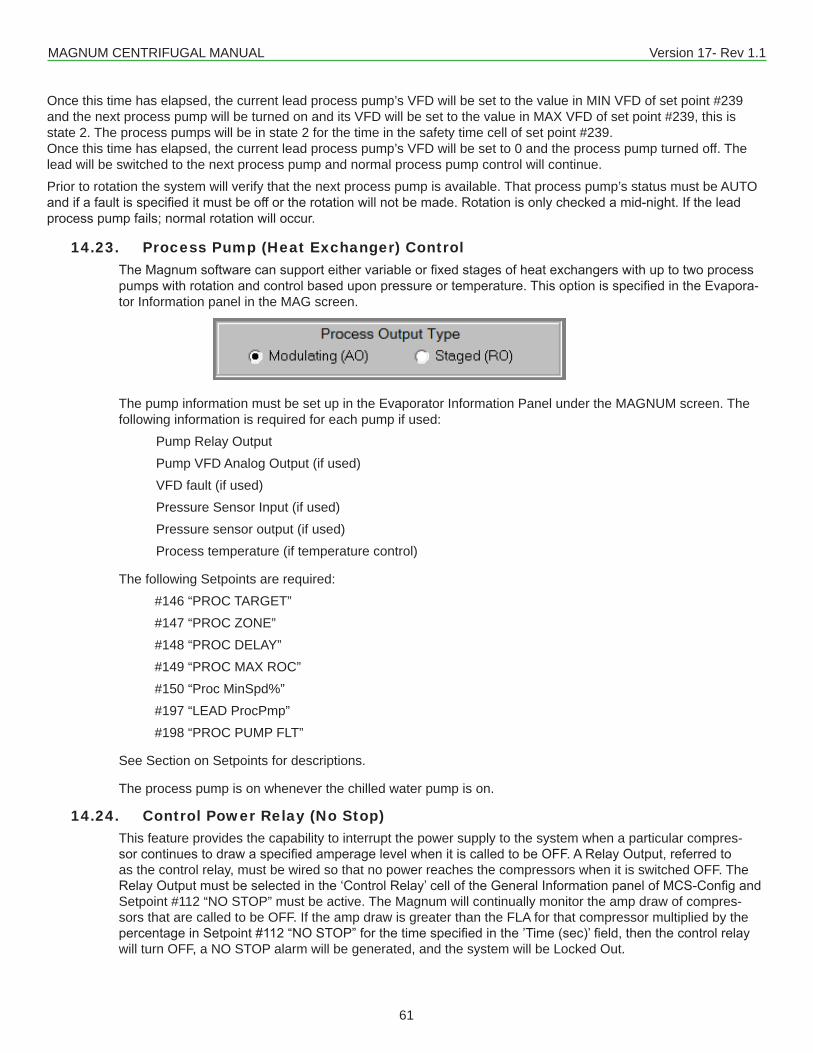
MAGNUM CENTRIFUGAL MANUAL Version 17- Rev 1.1
61
Once this time has elapsed, the current lead process pump’s VFD will be set to the value in MIN VFD of set point #239 and the next process pump will be turned on and its VFD will be set to the value in MAX VFD of set point #239, this is state 2. The process pumps will be in state 2 for the time in the safety time cell of set point #239.Once this time has elapsed, the current lead process pump’s VFD will be set to 0 and the process pump turned off. The lead will be switched to the next process pump and normal process pump control will continue.Prior to rotation the system will verify that the next process pump is available. That process pump’s status must be AUTO andifafaultisspecifieditmustbeoffortherotationwillnotbemade.Rotationisonlycheckedamid-night.Iftheleadprocesspumpfails;normalrotationwilloccur.
14.23. Process Pump (Heat Exchanger) ControlTheMagnumsoftwarecansupporteithervariableorfixedstagesofheatexchangerswithuptotwoprocesspumpswithrotationandcontrolbaseduponpressureortemperature.ThisoptionisspecifiedintheEvapora-tor Information panel in the MAG screen.
The pump information must be set up in the Evaporator Information Panel under the MAGNUM screen. The following information is required for each pump if used: Pump Relay Output Pump VFD Analog Output (if used) VFD fault (if used) Pressure Sensor Input (if used) Pressure sensor output (if used) Process temperature (if temperature control)
The following Setpoints are required: #146 “PROC TARGET” #147 “PROC ZONE” #148 “PROC DELAY” #149 “PROC MAX ROC” #150 “Proc MinSpd%” #197 “LEAD ProcPmp” #198 “PROC PUMP FLT”
See Section on Setpoints for descriptions.
The process pump is on whenever the chilled water pump is on.
14.24. Control Power Relay (No Stop)This feature provides the capability to interrupt the power supply to the system when a particular compres-sorcontinuestodrawaspecifiedamperagelevelwhenitiscalledtobeOFF.ARelayOutput,referredtoas the control relay, must be wired so that no power reaches the compressors when it is switched OFF. The RelayOutputmustbeselectedinthe‘ControlRelay’celloftheGeneralInformationpanelofMCS-ConfigandSetpoint #112 “NO STOP” must be active. The Magnum will continually monitor the amp draw of compres-sors that are called to be OFF. If the amp draw is greater than the FLA for that compressor multiplied by the percentageinSetpoint#112“NOSTOP”forthetimespecifiedinthe’Time(sec)’field,thenthecontrolrelaywill turn OFF, a NO STOP alarm will be generated, and the system will be Locked Out.
MAGNUM CENTRIFUGAL MANUAL Version 17- Rev 1.1
62
14.25. Low and High Ambient ShutdownThe Magnum software supports both low and high ambient temperature shut downs. This option requires an ambient temperature sensor and one or both of Setpoints #24 “LOW AMB OFF” and #26 “HIGH AMB OFF”. The AMBIENT OFF state is entered when the ambient temperature falls below the Setpoint #24 or above Setpoint #26. The system will remain in this state until the ambient temperature rises 5.0F (2.5C) above Setpoint #24 value or drops 5.0F (2.5C) below Setpoint #25. When the chiller is in this state, the individual compressor states are changed to the CMP IS OFF state through the normal staging function.
14.26. Imperial, Metric, and Combined Unit sensor readingsTheMagnumsoftwaresupportsImperial,Metric,andCombinedunitsensorreadings.ThissettingisspecifiedintheSetupscreenofMCS-Config.Allsensorvaluesandallsoftware-codedoffsetsareautomaticallycon-verted to the option selected and displayed with the appropriate character. The following table contains the display character:
SENSOR READING ENGLISHCHARACTER
METRICCHARACTER
MIXEDCHARACTER
Temperature F C CPressure – Gage Reading P B PPressure – Absolute Reading p b pHumidity % % %Digital or SwitchAmp or CT A A AVoltage V V VRefrigeration Level % % %
Iftheunittypeischanged,MCS-Configwillgiveyouanoptiontoautomaticallychangethevaluesofallitemsin the Setpoints to match the new type and will automatically adjust the display characters.
14.27. Warning and Alarm Relay OutputsThe Warning Relay Output will be turned on whenever the Magnum generates a warning message. These messages are:
■ LOW REFR TEMP UNLOAD ■ LOW SUCT PSI UNLOAD ■ HIGH DISC TEMP UNLOAD ■ LOW SUCT RELOAD ■ LOW DISC RELOAD ■ CICRUIT IS IN A SAFETY STATE
The system will continue to run since no safeties have tripped. The Warning Relay Output will also be turned on whenever a compressor is placed in a safety state.The Alarm Relay Output will be turned on whenever the Magnum generates an alarm message. This indicates that a safety trip or Lockout has occurred.
14.28. Vi Port Control Logic (Open Drive Screw only)Theinternalvolume(Vi)oftheopendrivescrewcanbedynamicallyadjustedtoachievemaximumefficiencymodulating the Vi control solenoids. The duration of each solenoid pulse is contained in Setpoint #114 “Vi PULSE”.The ratio of discharge pressure divided by suction pressure is calculated. This ratio is blocked between 50 and 22. The value of Setpoint #115 ”Vi DEADBAND” is added to and subtracted from this ratio to develop a control zone. The control zone will be recalculated based upon the time in Setpoint #116 ”Vi DELAY”. Refer to Setpoints #117, #118 and #119. The system will pulse the solenoids to keep the Vi reading within the calcu-lated control zone.
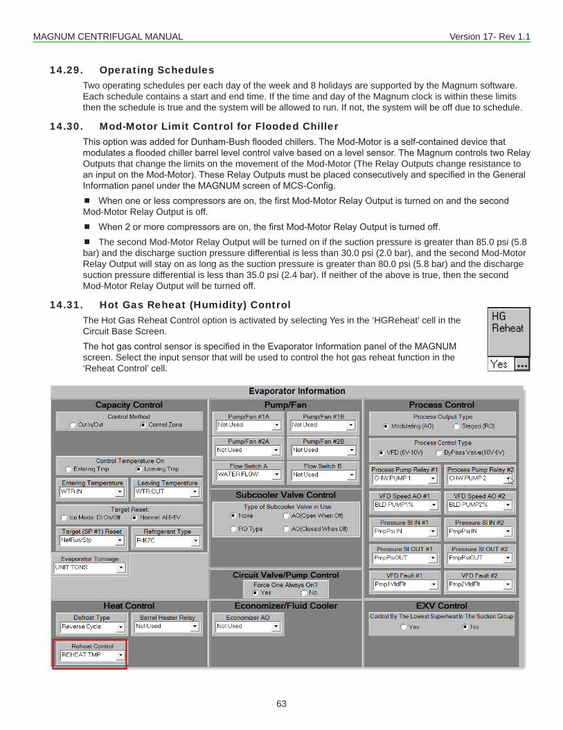
MAGNUM CENTRIFUGAL MANUAL Version 17- Rev 1.1
63
14.29. Operating SchedulesTwo operating schedules per each day of the week and 8 holidays are supported by the Magnum software. Each schedule contains a start and end time. If the time and day of the Magnum clock is within these limits then the schedule is true and the system will be allowed to run. If not, the system will be off due to schedule.
14.30. Mod-Motor Limit Control for Flooded ChillerThisoptionwasaddedforDunham-Bushfloodedchillers.TheMod-Motorisaself-containeddevicethatmodulatesafloodedchillerbarrellevelcontrolvalvebasedonalevelsensor.TheMagnumcontrolstwoRelayOutputs that change the limits on the movement of the Mod-Motor (The Relay Outputs change resistance to aninputontheMod-Motor).TheseRelayOutputsmustbeplacedconsecutivelyandspecifiedintheGeneralInformationpanelundertheMAGNUMscreenofMCS-Config. Whenoneorlesscompressorsareon,thefirstMod-MotorRelayOutputisturnedonandthesecondMod-Motor Relay Output is off. When2ormorecompressorsareon,thefirstMod-MotorRelayOutputisturnedoff. The second Mod-Motor Relay Output will be turned on if the suction pressure is greater than 85.0 psi (5.8 bar) and the discharge suction pressure differential is less than 30.0 psi (2.0 bar), and the second Mod-Motor Relay Output will stay on as long as the suction pressure is greater than 80.0 psi (5.8 bar) and the discharge suction pressure differential is less than 35.0 psi (2.4 bar). If neither of the above is true, then the second Mod-Motor Relay Output will be turned off.
14.31. Hot Gas Reheat (Humidity) ControlThe Hot Gas Reheat Control option is activated by selecting Yes in the ‘HGReheat’ cell in the Circuit Base Screen.ThehotgascontrolsensorisspecifiedintheEvaporatorInformationpaneloftheMAGNUMscreen. Select the input sensor that will be used to control the hot gas reheat function in the ‘Reheat Control’ cell.
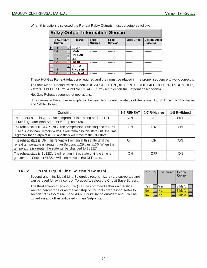
MAGNUM CENTRIFUGAL MANUAL Version 17- Rev 1.1
64
When this option is selected the Reheat Relay Outputs must be setup as follows:
These Hot Gas Reheat relays are required and they must be placed in the proper sequence to work correctly.The following Setpoints must be active: #129 “RH CUTIN”, #130 “RH CUTOUT ADJ”, #131 “RH START DLY”, #132 “RH BLEED DLY”, #133 “RH STAGE DLY”.(see Section full Setpoint descriptions).Hot Gas Reheat sequence of operations:(The names in the above example will be used to indicate the status of the relays: 1-6 REHEAT, 1-7 R-Hvalve, and 1-8 R-Hbleed)
Condition 1-6 REHEAT 1-7 R-Hvalve 1-8 R-HbleedThe reheat state is OFF. The compressor is running and the RH TEMP is greater than Setpoint #129 plus #130.
ON OFF OFF
The reheat state is STARTING. The compressor is running and the RH TEMP is less than Setpoint #129. It will remain in this state until the time is greater than Setpoint #131, and then will move to the ON state.
ON ON ON
The reheat state is ON. The reheat will remain in this state until the reheat temperature is greater than Setpoint #129 plus #130. When the temperature is greater the state will be changed to BLEED.
OFF ON ON
The reheat state is BLEED. It will remain in this state until the time is greater than Setpoint #132, it will then move to the OFF state.
ON OFF ON
14.32. Extra Liquid Line Solenoid ControlSecond and third Liquid Line Solenoids (economizers) are supported and can be used for extra control. To specify, select the Circuit Base Screen:The third solenoid (economizer) can be controlled either on the slide wanted percentage or as the last step on for that compressor (Refer to section 13 Setpoints #98 and #99). Liquid line solenoids 2 and 3 will be turned on and off as indicated in their Setpoints.
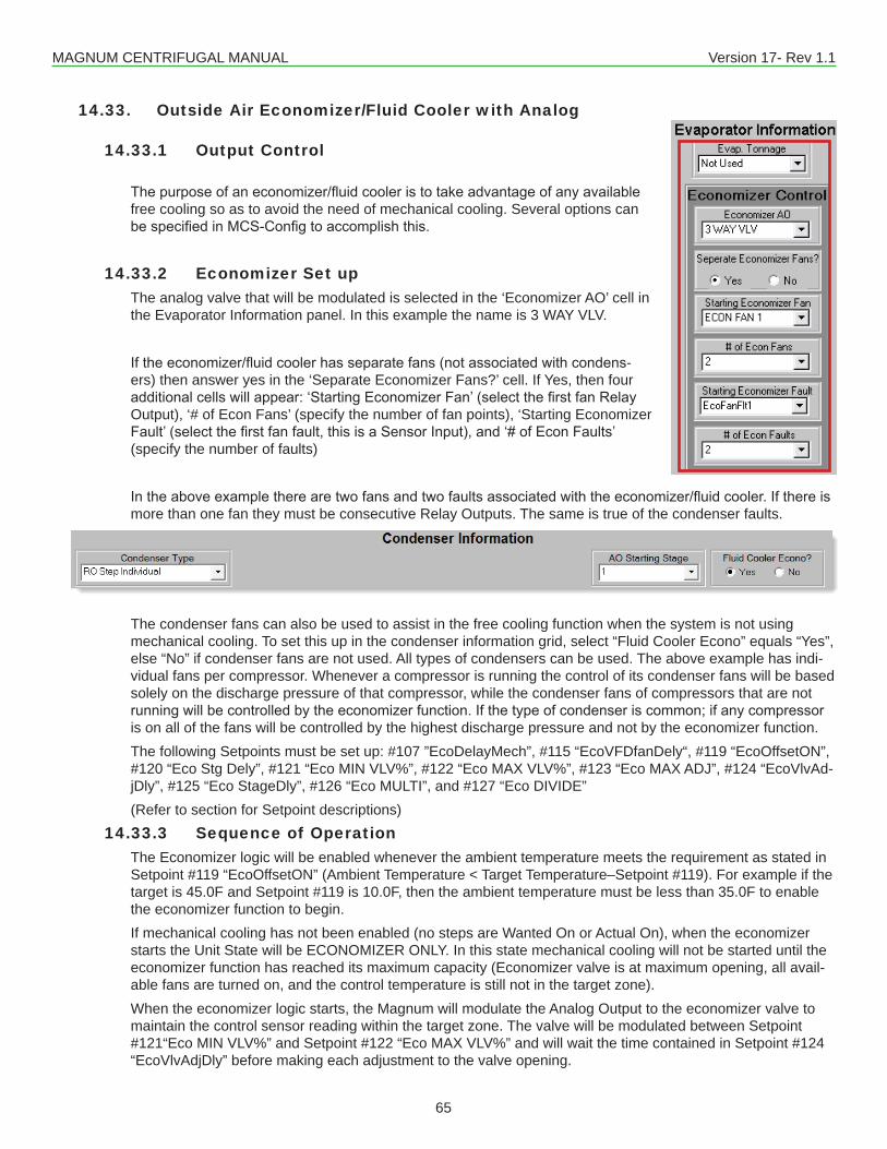
MAGNUM CENTRIFUGAL MANUAL Version 17- Rev 1.1
65
14.33. Outside Air Economizer/Fluid Cooler with Analog
14.33.1 Output Control
Thepurposeofaneconomizer/fluidcooleristotakeadvantageofanyavailablefree cooling so as to avoid the need of mechanical cooling. Several options can bespecifiedinMCS-Configtoaccomplishthis.
14.33.2 Economizer Set upThe analog valve that will be modulated is selected in the ‘Economizer AO’ cell in the Evaporator Information panel. In this example the name is 3 WAY VLV.
Iftheeconomizer/fluidcoolerhasseparatefans(notassociatedwithcondens-ers) then answer yes in the ‘Separate Economizer Fans?’ cell. If Yes, then four additionalcellswillappear:‘StartingEconomizerFan’(selectthefirstfanRelayOutput), ‘# of Econ Fans’ (specify the number of fan points), ‘Starting Economizer Fault’(selectthefirstfanfault,thisisaSensorInput),and‘#ofEconFaults’(specify the number of faults)
Intheaboveexampletherearetwofansandtwofaultsassociatedwiththeeconomizer/fluidcooler.Ifthereismore than one fan they must be consecutive Relay Outputs. The same is true of the condenser faults.
The condenser fans can also be used to assist in the free cooling function when the system is not using mechanical cooling. To set this up in the condenser information grid, select “Fluid Cooler Econo” equals “Yes”, else “No” if condenser fans are not used. All types of condensers can be used. The above example has indi-vidual fans per compressor. Whenever a compressor is running the control of its condenser fans will be based solely on the discharge pressure of that compressor, while the condenser fans of compressors that are not runningwillbecontrolledbytheeconomizerfunction.Ifthetypeofcondenseriscommon;ifanycompressoris on all of the fans will be controlled by the highest discharge pressure and not by the economizer function.The following Setpoints must be set up: #107 ”EcoDelayMech”, #115 “EcoVFDfanDely“, #119 “EcoOffsetON”, #120 “Eco Stg Dely”, #121 “Eco MIN VLV%”, #122 “Eco MAX VLV%”, #123 “Eco MAX ADJ”, #124 “EcoVlvAd-jDly”, #125 “Eco StageDly”, #126 “Eco MULTI”, and #127 “Eco DIVIDE”(Refer to section for Setpoint descriptions)
14.33.3 Sequence of OperationThe Economizer logic will be enabled whenever the ambient temperature meets the requirement as stated in Setpoint #119 “EcoOffsetON” (Ambient Temperature < Target Temperature–Setpoint #119). For example if the target is 45.0F and Setpoint #119 is 10.0F, then the ambient temperature must be less than 35.0F to enable the economizer function to begin.If mechanical cooling has not been enabled (no steps are Wanted On or Actual On), when the economizer starts the Unit State will be ECONOMIZER ONLY. In this state mechanical cooling will not be started until the economizer function has reached its maximum capacity (Economizer valve is at maximum opening, all avail-able fans are turned on, and the control temperature is still not in the target zone).When the economizer logic starts, the Magnum will modulate the Analog Output to the economizer valve to maintain the control sensor reading within the target zone. The valve will be modulated between Setpoint #121“Eco MIN VLV%” and Setpoint #122 “Eco MAX VLV%” and will wait the time contained in Setpoint #124 “EcoVlvAdjDly” before making each adjustment to the valve opening.
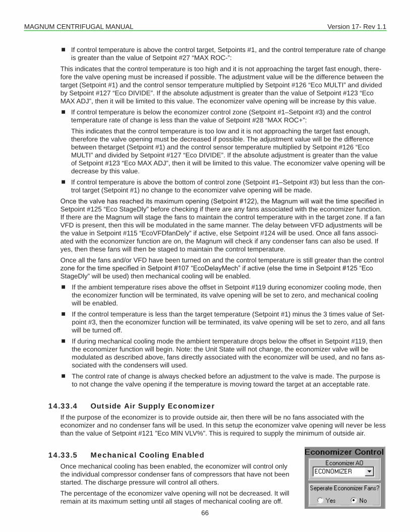
MAGNUM CENTRIFUGAL MANUAL Version 17- Rev 1.1
66
If control temperature is above the control target, Setpoints #1, and the control temperature rate of change is greater than the value of Setpoint #27 “MAX ROC-”:
This indicates that the control temperature is too high and it is not approaching the target fast enough, there-fore the valve opening must be increased if possible. The adjustment value will be the difference between the target (Setpoint #1) and the control sensor temperature multiplied by Setpoint #126 “Eco MULTI” and divided by Setpoint #127 “Eco DIVIDE”. If the absolute adjustment is greater than the value of Setpoint #123 “Eco MAX ADJ”, then it will be limited to this value. The economizer valve opening will be increase by this value. If control temperature is below the economizer control zone (Setpoint #1–Setpoint #3) and the control
temperature rate of change is less than the value of Setpoint #28 “MAX ROC+”:This indicates that the control temperature is too low and it is not approaching the target fast enough, therefore the valve opening must be decreased if possible. The adjustment value will be the difference between thetarget (Setpoint #1) and the control sensor temperature multiplied by Setpoint #126 “Eco MULTI” and divided by Setpoint #127 “Eco DIVIDE”. If the absolute adjustment is greater than the value of Setpoint #123 “Eco MAX ADJ”, then it will be limited to this value. The economizer valve opening will be decrease by this value.
If control temperature is above the bottom of control zone (Setpoint #1–Setpoint #3) but less than the con-trol target (Setpoint #1) no change to the economizer valve opening will be made.
Oncethevalvehasreacheditsmaximumopening(Setpoint#122),theMagnumwillwaitthetimespecifiedinSetpoint #125 “Eco StageDly” before checking if there are any fans associated with the economizer function. If there are the Magnum will stage the fans to maintain the control temperature with in the target zone. If a fan VFD is present, then this will be modulated in the same manner. The delay between VFD adjustments will be the value in Setpoint #115 “EcoVFDfanDely” if active, else Setpoint #124 will be used. Once all fans associ-ated with the economizer function are on, the Magnum will check if any condenser fans can also be used. If yes, then these fans will then be staged to maintain the control temperature.Once all the fans and/or VFD have been turned on and the control temperature is still greater than the control zoneforthetimespecifiedinSetpoint#107“EcoDelayMech”ifactive(elsethetimeinSetpoint#125“EcoStageDly” will be used) then mechanical cooling will be enabled. If the ambient temperature rises above the offset in Setpoint #119 during economizer cooling mode, then
the economizer function will be terminated, its valve opening will be set to zero, and mechanical cooling will be enabled.
If the control temperature is less than the target temperature (Setpoint #1) minus the 3 times value of Set-point #3, then the economizer function will be terminated, its valve opening will be set to zero, and all fans will be turned off.
If during mechanical cooling mode the ambient temperature drops below the offset in Setpoint #119, then the economizer function will begin. Note: the Unit State will not change, the economizer valve will be modulated as described above, fans directly associated with the economizer will be used, and no fans as-sociated with the condensers will used.
The control rate of change is always checked before an adjustment to the valve is made. The purpose is to not change the valve opening if the temperature is moving toward the target at an acceptable rate.
14.33.4 Outside Air Supply EconomizerIf the purpose of the economizer is to provide outside air, then there will be no fans associated with the economizer and no condenser fans will be used. In this setup the economizer valve opening will never be less than the value of Setpoint #121 ”Eco MIN VLV%”. This is required to supply the minimum of outside air.
14.33.5 Mechanical Cooling EnabledOnce mechanical cooling has been enabled, the economizer will control only the individual compressor condenser fans of compressors that have not been started. The discharge pressure will control all others.The percentage of the economizer valve opening will not be decreased. It will remain at its maximum setting until all stages of mechanical cooling are off.
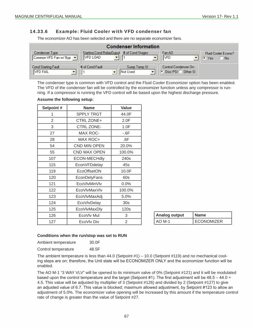
MAGNUM CENTRIFUGAL MANUAL Version 17- Rev 1.1
67
14.33.6 Example: Fluid Cooler with VFD condenser fanThe economizer AO has been selected and there are no separate economizer fans.
The condenser type is common with VFD control and the Fluid Cooler Economizer option has been enabled. The VFD of the condenser fan will be controlled by the economizer function unless any compressor is run-ning. If a compressor is running the VFD control will be based upon the highest discharge pressure.Assume the following setup:
Setpoint # Name Value1 SPPLY TRGT 44.0F2 CTRL ZONE+ 2.0F3 CTRL ZONE- 1.0F27 MAX ROC- -.6F28 MAX ROC+ .6F54 CND MIN OPEN 20.0%55 CND MAX OPEN 100.0%107 ECON-MECHdly 240s115 EconVFDdelay 45s119 EcoOffsetON 10.0F120 EconDelyFans 60s121 EcoVlvMinVlv 0.0%122 EcoVlvMaxVlv 100.0%123 EcoVlvMaxAdj 5.0%124 EcoVlvDelay 30s125 EcoVlvMaxDly 120s126 EcoVlv Mul 3127 EcoVlv Div 2
Conditions when the run/stop was set to RUNAmbient temperature 30.0FControl temperature 48.5FThe ambient temperature is less than 44.0 (Setpoint #1) – 10.0 (Setpoint #119) and no mechanical cool-ingstepsareon;therefore,theUnitstatewillbeECONOMIZERONLYandtheeconomizerfunctionwillbeenabled.The AO M-1 “3 WAY VLV” will be opened to its minimum valve of 0% (Setpoint #121) and it will be modulated baseduponthecontroltemperatureandthetarget(Setpoint#1).Thefirstadjustmentwillbe48.5–44.0=4.5. This value will be adjusted by multiplier of 3 (Setpoint #126) and divided by 2 (Setpoint #127) to give anadjustedvalueof6.7.Thisvalueisblocked;maximumallowedadjustment,bySetpoint#123toallowanadjustment of 5.0%. The economizer valve opening will be increased by this amount if the temperature control rate of change is greater than the value of Setpoint #27.
Analog output NameAO M-1 ECONOMIZER
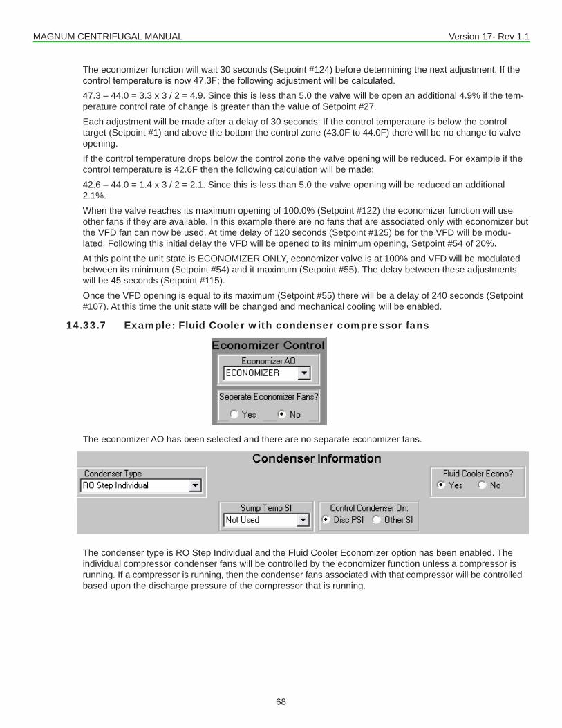
MAGNUM CENTRIFUGAL MANUAL Version 17- Rev 1.1
68
The economizer function will wait 30 seconds (Setpoint #124) before determining the next adjustment. If the controltemperatureisnow47.3F;thefollowingadjustmentwillbecalculated.47.3 – 44.0 = 3.3 x 3 / 2 = 4.9. Since this is less than 5.0 the valve will be open an additional 4.9% if the tem-perature control rate of change is greater than the value of Setpoint #27.Each adjustment will be made after a delay of 30 seconds. If the control temperature is below the control target (Setpoint #1) and above the bottom the control zone (43.0F to 44.0F) there will be no change to valve opening.If the control temperature drops below the control zone the valve opening will be reduced. For example if the control temperature is 42.6F then the following calculation will be made:42.6 – 44.0 = 1.4 x 3 / 2 = 2.1. Since this is less than 5.0 the valve opening will be reduced an additional 2.1%.When the valve reaches its maximum opening of 100.0% (Setpoint #122) the economizer function will use other fans if they are available. In this example there are no fans that are associated only with economizer but the VFD fan can now be used. At time delay of 120 seconds (Setpoint #125) be for the VFD will be modu-lated. Following this initial delay the VFD will be opened to its minimum opening, Setpoint #54 of 20%.At this point the unit state is ECONOMIZER ONLY, economizer valve is at 100% and VFD will be modulated between its minimum (Setpoint #54) and it maximum (Setpoint #55). The delay between these adjustments will be 45 seconds (Setpoint #115).Once the VFD opening is equal to its maximum (Setpoint #55) there will be a delay of 240 seconds (Setpoint #107). At this time the unit state will be changed and mechanical cooling will be enabled.
14.33.7 Example: Fluid Cooler with condenser compressor fans
The economizer AO has been selected and there are no separate economizer fans.
The condenser type is RO Step Individual and the Fluid Cooler Economizer option has been enabled. The individual compressor condenser fans will be controlled by the economizer function unless a compressor is running. If a compressor is running, then the condenser fans associated with that compressor will be controlled based upon the discharge pressure of the compressor that is running.
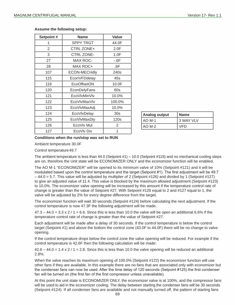
MAGNUM CENTRIFUGAL MANUAL Version 17- Rev 1.1
69
Assume the following setup:
Setpoint # Name Value1 SPPY TRGT 44.0F2 CTRL ZONE+ 2.0F3 CTRL ZONE- 1.0F27 MAX ROC- -.6F28 MAX ROC+ .6F107 ECON-MECHdly 240s115 EconVFDdelay 45s119 EcoOffsetON 10.0F120 EconDelyFans 60s121 EcoVlvMinVlv 10.0%122 EcoVlvMaxVlv 100.0%123 EcoVlvMaxAdj 10.0%124 EcoVlvDelay 30s125 EcoVlvMaxDly 120s126 EcoVlv Mul 2127 EcoVlv Div 1
Conditions when the run/stop was set to RUNAmbient temperature 30.0FControl temperature 49.7The ambient temperature is less than 44.0 (Setpoint #1) – 10.0 (Setpoint #119) and no mechanical cooling steps are on, therefore the Unit state will be ECONOMIZER ONLY and the economizer function will be enabled.The AO M-1 “ECONOMIZER” will be opened to its minimum valve of 10% (Setpoint #121) and it will be modulatedbaseduponthecontroltemperatureandthetarget(Setpoint#1).Thefirstadjustmentwillbe49.7– 44.0 = 5.7. This value will be adjusted by multiplier of 2 (Setpoint #126) and divided by 1 (Setpoint #127) to give an adjusted value of 11.4. This value is blocked by the maximum allowed adjustment (Setpoint #123) to 10.0%. The economizer valve opening will be increased by this amount if the temperature control rate of change is greater than the value of Setpoint #27. With Setpoint #126 equal to 2 and #127 equal to 1, the valve will be adjusted by 2% for every degree difference from the target.The economizer function will wait 30 seconds (Setpoint #124) before calculating the next adjustment. If the control temperature is now 47.3F the following adjustment will be made.47.3 – 44.0 = 3.3 x 2 / 1 = 6.6. Since this is less than 10.0 the valve will be open an additional 6.6% if the temperature control rate of change is greater than the value of Setpoint #27.Each adjustment will be made after a delay of 30 seconds. If the control temperature is below the control target (Setpoint #1) and above the bottom the control zone (43.0F to 44.0F) there will be no change to valve opening.If the control temperature drops below the control zone the valve opening will be reduced. For example if the control temperature is 42.6F then the following calculation will be made:42.6 – 44.0 = 1.4 x 2 / 1 = 2.8. Since this is less than 10.0 the valve opening will be reduced an additional 2.8%.When the valve reaches its maximum opening of 100.0% (Setpoint #122) the economizer function will use other fans if they are available. In this example there are no fans that are associated only with economizer but thecondenserfanscannowbeused.Afterthetimedelayof120seconds(Setpoint#125)thefirstcondenserfanwillbeturnedon(thefirstfanofthefirstcompressorunlessunavailable).At this point the unit state is ECONOMIZER ONLY, the economizer valve is at 100%, and the compressor fans will be used to aid in the economizer cooling. The delay between starting the condenser fans will be 30 seconds (Setpoint #124). If all condenser fans are available and not manually turned off, the pattern of starting fans
Analog output NameAO M-1 3 WAY VLVAO M-2 VFD
MAGNUM CENTRIFUGAL MANUAL Version 17- Rev 1.1
70
willbethefirstfanoncompressor1,afterthedelaythenthefirstfanofcompressor2,afterthedelaythenthesecond fan on compressor 1. This will continue until all available condenser fans have been turned on.Once all of the condenser fans have been turned on there will be a delay of 240 seconds (Setpoint #107). At this time the Unit State will be changed and mechanical cooling will be enabled. When a compressor is running, its associated condenser fans will be controlled by the discharge pressure of the running compressors.
14.34. High Suction Superheat SafetyTo add a high suction superheat safety, make Setpoint #203 “HiSuctSheat” active. If the suction superheat is greaterthanthevalueofthisSetpointforthe‘Time(sec)’field,analarmwillbegeneratedandthecompressorwill be shut down with a safety or Lockout state.
14.35. Low Temperature Safety and Unload (Low Saturated Suction Temperature)The Magnum is set up to check for low refrigerant temperature safety and unload functions. To enable this test make Setpoint #155 “LO REF TMP” active and point to the sensor in the ‘Refrigeration Temp’ column of theCompressorSIgridinMCS-Config.This safety will be checked only when the compressor is running. If the sensor value is less than Setpoint #155forthe‘Time(sec)’field,thenanalarmmessagewillbegeneratedandtheassociatedcompressorwilleither be placed in a safety or Lockout state.The Magnum will also determine if a low temperature condition occurs and to stop loading or unload if necessary. If the sensor value is less than the value of Setpoint #155 plus Setpoint #156 “LO REF UNLD”, then the compressor state will be LO TMP UNLOAD. Refer to state (21) in section 6.2.26.By using the User Logic type sensor, we can test any value for a low condition. For example point the refrigerant temperature index to a User Logic sensor that picks up the saturated suction temperature for that compressor. Make Setpoint #155 active with the low temperature value that will trigger the safety and unload action and you have a low saturated suction temperature condition.
MAGNUM CENTRIFUGAL MANUAL Version 17- Rev 1.1
71
15.1. INTRODUCTIONThe MCS Magnum controller is designed to control Variable Frequency Drive (VFD) centrifugal compressors. Its algorithmallowstheusertodefinespecificfunctionstomaximizestartupandrunningconditions.Ithandlesallofthefollowing:
1. Startup control2. DX chiller barrel3. DX remote coils4. Flooded chiller barrel5. Water cooled condenser6. Air cooled condenser7. Slide control for starting unloaded8. EXV startup control9. EXV Anticipatory loading10. EXV low suction Anticipatory control
15.2. STARTUP CONTROLWhen the compressor is started the state will be ‘CMP IN STARTUP’. During this phase the compressor’s Analog output willbeplacedatthepercentagespecifiedintheConfigforstartupandforthelengthoftimespecified.Ifthecompressorhas a slide valve it will be started unloaded. After a few seconds the slide is moved to the loaded position and all control isviatheVFD.IntheMCSConfigtheusercanspecifythefollowing:
1. The starting frequency of the compressor which is via the compressor’s Analog Output.2. The length of time the compressor is to remain in ‘CMP IN STARTUP’ state.3. The starting position of the Electric Expansion Valve (EXV).
15.3. OPERATING CONTROLWhen the compressor completes the startup phase it enters normal operating controls. In the normal operating phase the primary function is to maintain the target based on the controlling sensor. (Usually this is Leaving Water Temperature.) To do this the following control functions occur:
1. The compressor Analog output will be adjusted to match the current wanted capacity percent.2. The EXV position will be adjusted when the compressor speed is adjusted and depending on the current value
of its superheat.3. The compressor slide remains at 100% during normal operating control.
15.4. COMPRESSOR LOADING / UNLOADINGThe standard MCS algorithm applies. However for the VFD controlled screw additional set point capabilities have been expanded as follows:
1. On a standard slide operated screw SP 32 ‘MAX ADJUST %’ would usually be set to 4% to 5%. With the VFD it is typical to allow larger adjustments, when required, say to 10%. The loading/unloading algorithm can be set to increase/decrease slowly because the VFD allows exact positing of the capacity.
2. Controlling this adjustment is SP 56, ‘COMP ADJ DELAY’, which tells the Magnum the frequency to set. The EXV is adjusted at the same time allowing precise superheat control.
15.5. COMPRESSOR SHUTDOWNCompressorshutdownisafunctionofthesetpointvaluessetupatConfigtime.NormalfunctionwouldbetoshutofftheEXVandpumpdownbasedonsetpoints.Howeverifit’safloodedevaporatornopumpdownisdone.Whenthecompressoris off the MCS control system forces the slide vale to its minimum position so at the next start time the compressor is unloaded.
Chapter - 15. VDF Controlled Compressors
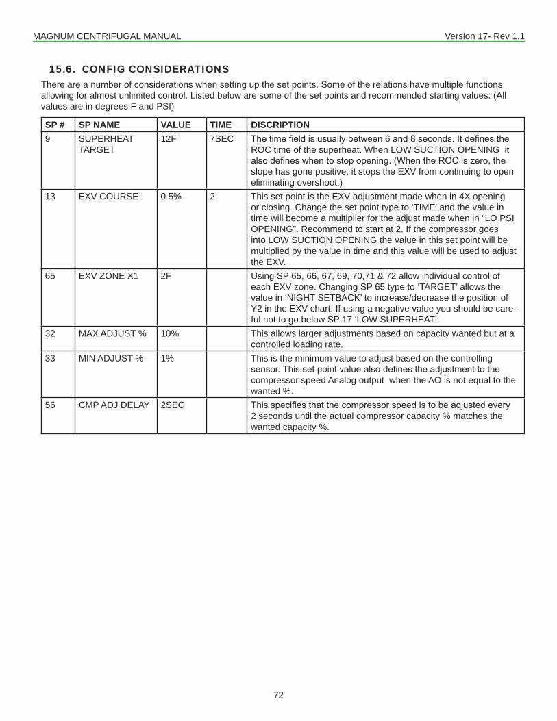
MAGNUM CENTRIFUGAL MANUAL Version 17- Rev 1.1
72
15.6. CONFIG CONSIDERATIONSThere are a number of considerations when setting up the set points. Some of the relations have multiple functions allowing for almost unlimited control. Listed below are some of the set points and recommended starting values: (All values are in degrees F and PSI)
SP # SP NAME VALUE TIME DISCRIPTION9 SUPERHEAT
TARGET12F 7SEC Thetimefieldisusuallybetween6and8seconds.Itdefinesthe
ROC time of the superheat. When LOW SUCTION OPENING it alsodefineswhentostopopening.(WhentheROCiszero,theslope has gone positive, it stops the EXV from continuing to open eliminating overshoot.)
13 EXV COURSE 0.5% 2 This set point is the EXV adjustment made when in 4X opening or closing. Change the set point type to ‘TIME’ and the value in time will become a multiplier for the adjust made when in “LO PSI OPENING”. Recommend to start at 2. If the compressor goes into LOW SUCTION OPENING the value in this set point will be multiplied by the value in time and this value will be used to adjust the EXV.
65 EXV ZONE X1 2F Using SP 65, 66, 67, 69, 70,71 & 72 allow individual control of each EXV zone. Changing SP 65 type to ’TARGET’ allows the value in ‘NIGHT SETBACK’ to increase/decrease the position of Y2 in the EXV chart. If using a negative value you should be care-ful not to go below SP 17 ‘LOW SUPERHEAT’.
32 MAX ADJUST % 10% This allows larger adjustments based on capacity wanted but at a controlled loading rate.
33 MIN ADJUST % 1% This is the minimum value to adjust based on the controlling sensor.Thissetpointvaluealsodefinestheadjustmenttothecompressor speed Analog output when the AO is not equal to the wanted %.
56 CMP ADJ DELAY 2SEC Thisspecifiesthatthecompressorspeedistobeadjustedevery2 seconds until the actual compressor capacity % matches the wanted capacity %.
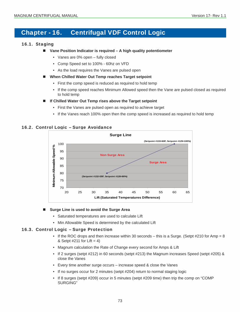
MAGNUM CENTRIFUGAL MANUAL Version 17- Rev 1.1
73
Chapter - 16. Centrifugal VDF Control Logic 16.1. Staging
� Vane Position Indicator is required – A high quality potentiometer• Vanes are 0% open – fully closed• Comp Speed set to 100% - 60hz on VFD• As the load requires the Vanes are pulsed open
� When Chilled Water Out Temp reaches Target setpoint• First the comp speed is reduced as required to hold temp• If the comp speed reaches Minimum Allowed speed then the Vane are pulsed closed as required
to hold temp � If Chilled Water Out Temp rises above the Target setpoint
• First the Vanes are pulsed open as required to achieve target• If the Vanes reach 100% open then the comp speed is increased as required to hold temp
16.2. Control Logic – Surge Avoidance
� Surge Line is used to avoid the Surge Area• Saturated temperatures are used to calculate Lift• Min Allowable Speed is determined by the calculated Lift
16.3. Control Logic – Surge Protection• If the ROC drops and then increase within 30 seconds – this is a Surge. (Setpt #210 for Amp = 8
& Setpt #211 for Lift = 4)• Magnum calculation the Rate of Change every second for Amps & Lift• If 2 surges (setpt #212) in 60 seconds (setpt #213) the Magnum increases Speed (setpt #205) &
close the Vanes• Every time another surge occurs – increase speed & close the Vanes• If no surges occur for 2 minutes (setpt #204) return to normal staging logic• If 8 surges (setpt #209) occur in 5 minutes (setpt #209 time) then trip the comp on “COMP
SURGING”
Control Logic – Surge AvoidanceSurge Line is used to avoid the Surge Area
Saturated temperatures are used to calculate LiftMin Allowable Speed is determined by the calculated Lift
Surge Line
70
75
80
85
90
95
100
20 25 30 35 40 45 50 55 60 65
Lift (Saturated Temperatures Difference)
Min
imum
Allo
wab
le S
peed
%
Non Surge Area
Surge Area
(Setpoint #132=35F, Setpoint #128=80%)
(Setpoint #133=60F, Setpoint #129=100%)
MAGNUM CENTRIFUGAL MANUAL Version 17- Rev 1.1
74
16.4. VFD Interface - Hardwired• MCS-Magnum relay output wired to run on VFD • MCS-Magnum Analog output wired to speed control on the VFD, 0-10Vdc equals 0-60Hz.• Min speed allowed is set in MCS-Magnum setpoint• VFD Fault wired to MCS-Magnum Sensor Input• Magnum can except 0-5vdc analog outputs from VFD for Hz, Amps, etc.
16.5. VFD Setting• Speed control by external 0-10Vdc signal, where 0Vdc = 0Hz and 10Vdc = 60Hz.• Min Freq=38Hz(2400 rpm) & Max Freq=60hz(3600rpm) • Accel Time & Decel Time = 30 seconds• Emergency Decel Time = 1 second• Break Point Freq = 35Hz• Stall Freq = 20Hz & Stall Time = 20 seconds• Torq Boost Current = 100%
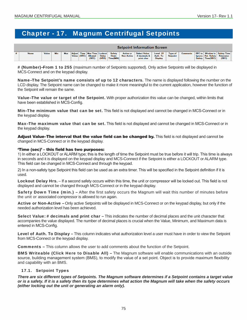
MAGNUM CENTRIFUGAL MANUAL Version 17- Rev 1.1
75
Chapter - 17. Magnum Centrifugal Setpoints
# (Number)–From 1 to 255 (maximum number of Setpoints supported). Only active Setpoints will be displayed inMCS-Connect and on the keypad display.
Name–The Setpoint’s name consists of up to 12 characters. The name is displayed following the number on the LCD display. The Setpoint name can be changed to make it more meaningful to the current application, however the function of the Setpoint will remain the same.
Value–The value or target of the Setpoint. With proper authorization this value can be changed, within limits thathavebeenestablishedinMCS-Config.
Min–The minimum value that can be set.ThisfieldisnotdisplayedandcannotbechangedinMCS-Connectorinthe keypad display.
Max–The maximum value that can be set.ThisfieldisnotdisplayedandcannotbechangedinMCS-Connectorinthe keypad display.
Adjust Value–The interval that the value field can be changed by. Thisfieldisnotdisplayedandcannotbechanged in MCS-Connect or in the keypad display.
‘Time (sec)’ – this field has two purposes: 1)IneitheraLOCKOUTorALARMtype;thisisthelengthoftimetheSetpointmustbetruebeforeitwilltrip.Thistimeisalwaysin seconds and it is displayed on the keypad display and MCS-Connect if the Setpoint is either a LOCKOUT or ALARM type. ThisfieldcanbechangedinMCS-Connectandthroughthekeypad.2)Inanon-safetytypeSetpointthisfieldcanbeusedasanextratimer.ThiswillbespecifiedintheSetpointdefinitionifitisused.Lockout Delay Hrs.–Ifasecondsafetyoccurswithinthistime,theunitorcompressorwillbelockedout.Thisfieldisnotdisplayed and cannot be changed through MCS-Connect or in the keypad display.Safety Down Time (min.) – After the first safety occurs the Magnum will wait this number of minutes before the unit or associated compressor is allowed to run again.Active or Non-Active – Only active Setpoints will be displayed in MCS-Connect or on the keypad display, but only if the needed authorization level has been achieved.
Select Value: # decimals and print char – This indicates the number of decimal places and the unit character that accompanies the value displayed. The number of decimal places is crucial when the Value, Minimum, and Maximum data is enteredinMCS-Config.
Level of Auth. To Display – This column indicates what authorization level a user must have in order to view the Setpoint from MCS-Connect or the keypad display.
Comments – This column allows the user to add comments about the function of the Setpoint.BMS Writeable (Click Here to Disable All) – The Magnum software will enable communications with an outside source,buildingmanagementsystem(BMS),tomodifythevalueofasetpoint.Objectistoprovidemaximumflexibilityand capability with an BMS.
17.1. Setpoint TypesThere are six different types of Setpoints. The Magnum software determines if a Setpoint contains a target value or is a safety. If it is a safety then its type determines what action the Magnum will take when the safety occurs (either locking out the unit or generating an alarm only).
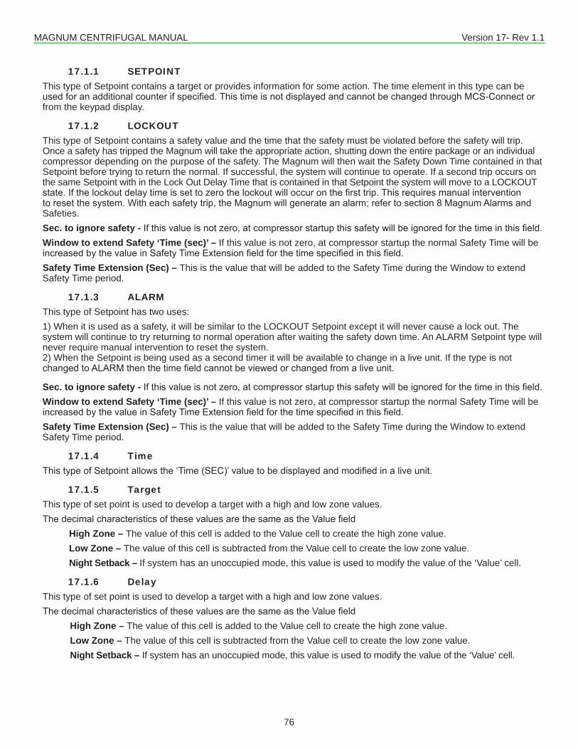
MAGNUM CENTRIFUGAL MANUAL Version 17- Rev 1.1
76
17.1.1 SETPOINTThis type of Setpoint contains a target or provides information for some action. The time element in this type can be usedforanadditionalcounterifspecified.ThistimeisnotdisplayedandcannotbechangedthroughMCS-Connectorfrom the keypad display.
17.1.2 LOCKOUTThis type of Setpoint contains a safety value and the time that the safety must be violated before the safety will trip. Once a safety has tripped the Magnum will take the appropriate action, shutting down the entire package or an individual compressor depending on the purpose of the safety. The Magnum will then wait the Safety Down Time contained in that Setpoint before trying to return the normal. If successful, the system will continue to operate. If a second trip occurs on the same Setpoint with in the Lock Out Delay Time that is contained in that Setpoint the system will move to a LOCKOUT state.Ifthelockoutdelaytimeissettozerothelockoutwilloccuronthefirsttrip.Thisrequiresmanualinterventiontoresetthesystem.Witheachsafetytrip,theMagnumwillgenerateanalarm;refertosection8MagnumAlarmsandSafeties.Sec. to ignore safety - Ifthisvalueisnotzero,atcompressorstartupthissafetywillbeignoredforthetimeinthisfield.Window to extend Safety ‘Time (sec)’ – If this value is not zero, at compressor startup the normal Safety Time will be increasedbythevalueinSafetyTimeExtensionfieldforthetimespecifiedinthisfield.Safety Time Extension (Sec) – This is the value that will be added to the Safety Time during the Window to extend Safety Time period.
17.1.3 ALARMThis type of Setpoint has two uses:1) When it is used as a safety, it will be similar to the LOCKOUT Setpoint except it will never cause a lock out. The system will continue to try returning to normal operation after waiting the safety down time. An ALARM Setpoint type will never require manual intervention to reset the system. 2) When the Setpoint is being used as a second timer it will be available to change in a live unit. If the type is not changedtoALARMthenthetimefieldcannotbeviewedorchangedfromaliveunit.
Sec. to ignore safety - Ifthisvalueisnotzero,atcompressorstartupthissafetywillbeignoredforthetimeinthisfield.Window to extend Safety ‘Time (sec)’ – If this value is not zero, at compressor startup the normal Safety Time will be increasedbythevalueinSafetyTimeExtensionfieldforthetimespecifiedinthisfield.Safety Time Extension (Sec) – This is the value that will be added to the Safety Time during the Window to extend Safety Time period.
17.1.4 TimeThistypeofSetpointallowsthe‘Time(SEC)’valuetobedisplayedandmodifiedinaliveunit.
17.1.5 TargetThis type of set point is used to develop a target with a high and low zone values.ThedecimalcharacteristicsofthesevaluesarethesameastheValuefield High Zone – The value of this cell is added to the Value cell to create the high zone value. Low Zone – The value of this cell is subtracted from the Value cell to create the low zone value. Night Setback – If system has an unoccupied mode, this value is used to modify the value of the ‘Value’ cell.
17.1.6 DelayThis type of set point is used to develop a target with a high and low zone values.ThedecimalcharacteristicsofthesevaluesarethesameastheValuefield High Zone – The value of this cell is added to the Value cell to create the high zone value. Low Zone – The value of this cell is subtracted from the Value cell to create the low zone value. Night Setback – If system has an unoccupied mode, this value is used to modify the value of the ‘Value’ cell.
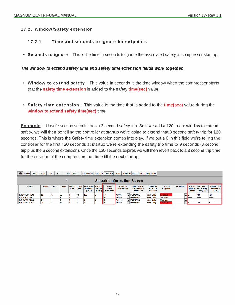
MAGNUM CENTRIFUGAL MANUAL Version 17- Rev 1.1
77
17.2. Window/Safety extension
17.2.1 Time and seconds to ignore for setpoints
• Seconds to ignore – This is the time in seconds to ignore the associated safety at compressor start up.
The window to extend safety time and safety time extension fields work together.
• Window to extend safety – This value in seconds is the time window when the compressor starts that the safety time extension is added to the safety time(sec) value.
• Safety time extension – This value is the time that is added to the time(sec) value during the window to extend safety time(sec) time.
Example – Unsafe suction setpoint has a 3 second safety trip. So if we add a 120 to our window to extend safety, we will then be telling the controller at startup we’re going to extend that 3 second safety trip for 120 seconds.ThisiswheretheSafetytimeextensioncomesintoplay.Ifweputa6inthisfieldwe’retellingthecontrollerforthefirst120secondsatstartupwe’reextendingthesafetytriptimeto9seconds(3secondtrip plus the 6 second extension). Once the 120 seconds expires we will then revert back to a 3 second trip time for the duration of the compressors run time till the next startup.
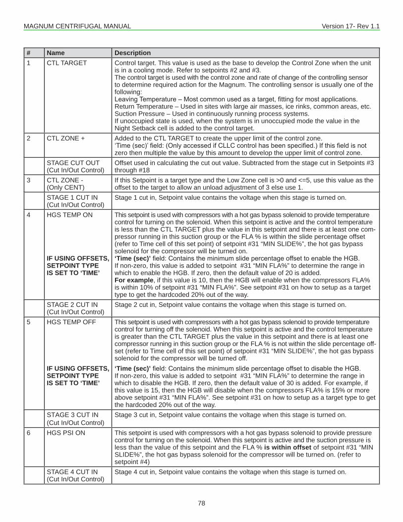
MAGNUM CENTRIFUGAL MANUAL Version 17- Rev 1.1
78
# Name Description1 CTL TARGET Control target. This value is used as the base to develop the Control Zone when the unit
is in a cooling mode. Refer to setpoints #2 and #3. The control target is used with the control zone and rate of change of the controlling sensor to determine required action for the Magnum. The controlling sensor is usually one of the following:LeavingTemperature–Mostcommonusedasatarget,fittingformostapplications.Return Temperature – Used in sites with large air masses, ice rinks, common areas, etc.Suction Pressure – Used in continuously running process systems.If unoccupied state is used, when the system is in unoccupied mode the value in the Night Setback cell is added to the control target.
2 CTL ZONE + Added to the CTL TARGET to create the upper limit of the control zone.‘Time(sec)’field:(OnlyaccessedifCLLCcontrolhasbeenspecified.)Ifthisfieldisnotzero then multiple the value by this amount to develop the upper limit of control zone.
STAGE CUT OUT (Cut In/Out Control)
Offset used in calculating the cut out value. Subtracted from the stage cut in Setpoints #3 through #18
3 CTL ZONE -(Only CENT)
If this Setpoint is a target type and the Low Zone cell is >0 and <=5, use this value as the offset to the target to allow an unload adjustment of 3 else use 1.
STAGE 1 CUT IN (Cut In/Out Control)
Stage 1 cut in, Setpoint value contains the voltage when this stage is turned on.
4 HGS TEMP ON
IF USING OFFSETS, SETPOINT TYPE IS SET TO ‘TIME’
This setpoint is used with compressors with a hot gas bypass solenoid to provide temperature control for turning on the solenoid. When this setpoint is active and the control temperature is less than the CTL TARGET plus the value in this setpoint and there is at least one com-pressor running in this suction group or the FLA % is within the slide percentage offset (refer to Time cell of this set point) of setpoint #31 “MIN SLIDE%”, the hot gas bypass solenoid for the compressor will be turned on.‘Time (sec)’field:ContainstheminimumslidepercentageoffsettoenabletheHGB.If non-zero, this value is added to setpoint #31 “MIN FLA%” to determine the range in which to enable the HGB. If zero, then the default value of 20 is added. For example, if this value is 10, then the HGB will enable when the compressors FLA% is within 10% of setpoint #31 “MIN FLA%”. See setpoint #31 on how to setup as a target type to get the hardcoded 20% out of the way.
STAGE 2 CUT IN(Cut In/Out Control)
Stage 2 cut in, Setpoint value contains the voltage when this stage is turned on.
5 HGS TEMP OFF
IF USING OFFSETS, SETPOINT TYPE IS SET TO ‘TIME’
This setpoint is used with compressors with a hot gas bypass solenoid to provide temperature control for turning off the solenoid. When this setpoint is active and the control temperature is greater than the CTL TARGET plus the value in this setpoint and there is at least one compressor running in this suction group or the FLA % is not within the slide percentage off-set (refer to Time cell of this set point) of setpoint #31 “MIN SLIDE%”, the hot gas bypass solenoid for the compressor will be turned off.‘Time (sec)’field:ContainstheminimumslidepercentageoffsettodisabletheHGB.If non-zero, this value is added to setpoint #31 “MIN FLA%” to determine the range in which to disable the HGB. If zero, then the default value of 30 is added. For example, if this value is 15, then the HGB will disable when the compressors FLA% is 15% or more above setpoint #31 “MIN FLA%”. See setpoint #31 on how to setup as a target type to get the hardcoded 20% out of the way.
STAGE 3 CUT IN (Cut In/Out Control)
Stage 3 cut in, Setpoint value contains the voltage when this stage is turned on.
6 HGS PSI ON This setpoint is used with compressors with a hot gas bypass solenoid to provide pressure control for turning on the solenoid. When this setpoint is active and the suction pressure is less than the value of this setpoint and the FLA % is within offset of setpoint #31 “MIN SLIDE%”, the hot gas bypass solenoid for the compressor will be turned on. (refer to setpoint #4)
STAGE 4 CUT IN (Cut In/Out Control)
Stage 4 cut in, Setpoint value contains the voltage when this stage is turned on.
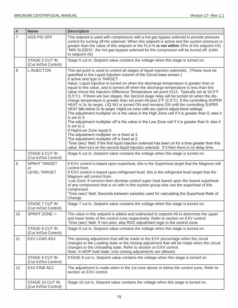
MAGNUM CENTRIFUGAL MANUAL Version 17- Rev 1.1
79
# Name Description7 HGS PSI OFF This setpoint is used with compressors with a hot gas bypass solenoid to provide pressure
control for turning off the solenoid. When this setpoint is active and the suction pressure is greater than the value of this setpoint or the FLA % is not within 25% of the setpoint #31 “MIN SLIDE%”, the hot gas bypass solenoid for the compressor will be turned off. (refer to setpoint #5)
STAGE 5 CUT IN (Cut In/Out Control)
Stage 5 cut in, Setpoint value contains the voltage when this stage is turned on.
8 L.INJECT.ON This set point is used to control all stages of liquid injection solenoids. (These must be specifiedintheLiquidInjectioncolumnoftheCircuitbasescreen.)If active and type is TARGET:Value: Liquid injection is turned on when the discharge temperature is greater than or equal to this value, and is turned off when the discharge temperature is less than this value minus the Injection Difference Temperature set point #113. Typically set at 10.0°F (5.5°C). If there are two stages, the Second stage relay will be turned on when the dis-charge temperature is greater than set point #8 plus 5°F (2.5°C). If the controlling SUPER HEAT is 3x its target, LIQ INJ is turned ON and remains ON until the controlling SUPER HEAT falls below 2x its target. High/Low zone cells are used to adjust these settings:TheadjustmentmultiplieronisthevalueintheHighZonecellifitisgreaterthan0;elseitis set to 3.TheadjustmentmultiplieroffisthevalueintheLowZonecellifitisgreaterthan0;elseitis set to 2.If High/Low Zone equal 0:Theadjustmentmultiplieronisfixedat3.Theadjustmentmultiplieroffisfixedat2.‘Time(sec)’field:Ifthefirstliquidinjectionsolenoidhasbeenonforatimegreaterthanthisvalue, then turn on the second liquid injection solenoid. If 0 then there is no delay time.
STAGE 6 CUT IN (Cut In/Out Control)
Stage 6 cut in, Setpoint value contains the voltage when this stage is turned on.
9 SPRHT TARGETorLEVEL TARGET
If EXV control is based upon superheat, this is the Superheat target that the Magnum will control from. If EXV control is based upon refrigerant level, this is the refrigerant level target that the Magnum will control from.‘Low Zone’ if nonzero then develop control super heat based upon the lowest superheat of any compressor that is on with in this suction group else use the superheat of this compressor. ‘Time(sec)’field:SecondsbetweensamplesusedforcalculatingtheSuperheatRateofChange.
STAGE 7 CUT IN (Cut In/Out Control)
Stage 7 cut in, Setpoint value contains the voltage when this stage is turned on.
10 SPRHT ZONE +- The value in this setpoint is added and subtracted to setpoint #9 to determine the upper and lower limits of the control zone respectively. Refer to section on EXV control.‘Time(sec)’field:Ifnon-zero,skipROCadjustmentlogicinthecontrolzone.
STAGE 8 CUT IN (Cut In/Out Control)
Stage 8 cut in, Setpoint value contains the voltage when this stage is turned on.
11 EXV LOAD ADJ The opening adjustment that will be made to the EXV percentage when the circuit changes to the Loading state or the closing adjustment that will be made when the circuit changes to the Unloading state. Refer to section on EXV control.Note: In MOP hold state, only closing adjustments are allowed.
STAGE 9 CUT IN (Cut In/Out Control)
STAGE 9 cut in, Setpoint value contains the voltage when this stage is turned on.
12 EXV FINE ADJ The adjustment is made when in the 1st zone above or below the control zone. Refer to section on EXV control.
STAGE 10 CUT IN (Cut In/Out Control)
Stage 10 cut in, Setpoint value contains the voltage when this stage is turned on.
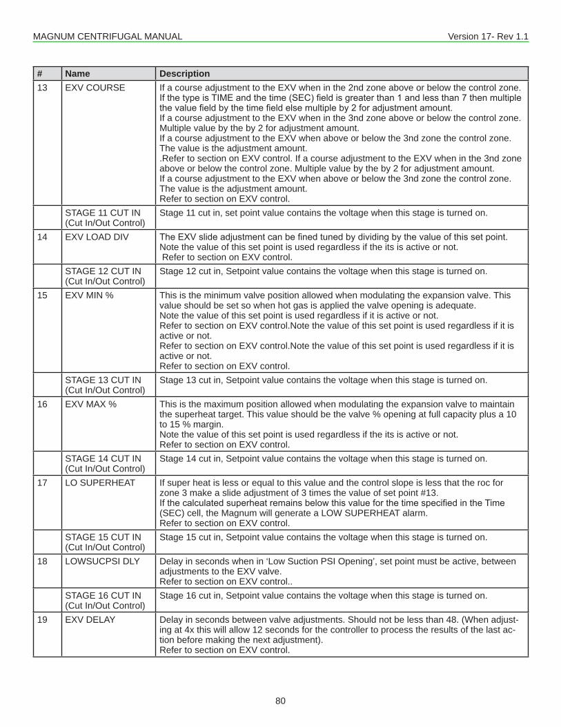
MAGNUM CENTRIFUGAL MANUAL Version 17- Rev 1.1
80
# Name Description13 EXV COURSE If a course adjustment to the EXV when in the 2nd zone above or below the control zone.
IfthetypeisTIMEandthetime(SEC)fieldisgreaterthan1andlessthan7thenmultiplethevaluefieldbythetimefieldelsemultipleby2foradjustmentamount.If a course adjustment to the EXV when in the 3nd zone above or below the control zone. Multiple value by the by 2 for adjustment amount.If a course adjustment to the EXV when above or below the 3nd zone the control zone. The value is the adjustment amount..Refer to section on EXV control. If a course adjustment to the EXV when in the 3nd zone above or below the control zone. Multiple value by the by 2 for adjustment amount.If a course adjustment to the EXV when above or below the 3nd zone the control zone. The value is the adjustment amount.Refer to section on EXV control.
STAGE 11 CUT IN (Cut In/Out Control)
Stage 11 cut in, set point value contains the voltage when this stage is turned on.
14 EXV LOAD DIV TheEXVslideadjustmentcanbefinedtunedbydividingbythevalueofthissetpoint.Note the value of this set point is used regardless if the its is active or not. Refer to section on EXV control.
STAGE 12 CUT IN (Cut In/Out Control)
Stage 12 cut in, Setpoint value contains the voltage when this stage is turned on.
15 EXV MIN % This is the minimum valve position allowed when modulating the expansion valve. This value should be set so when hot gas is applied the valve opening is adequate. Note the value of this set point is used regardless if it is active or not.Refer to section on EXV control.Note the value of this set point is used regardless if it is active or not.Refer to section on EXV control.Note the value of this set point is used regardless if it is active or not.Refer to section on EXV control.
STAGE 13 CUT IN (Cut In/Out Control)
Stage 13 cut in, Setpoint value contains the voltage when this stage is turned on.
16 EXV MAX % This is the maximum position allowed when modulating the expansion valve to maintain the superheat target. This value should be the valve % opening at full capacity plus a 10 to 15 % margin. Note the value of this set point is used regardless if the its is active or not.Refer to section on EXV control.
STAGE 14 CUT IN (Cut In/Out Control)
Stage 14 cut in, Setpoint value contains the voltage when this stage is turned on.
17 LO SUPERHEAT If super heat is less or equal to this value and the control slope is less that the roc for zone 3 make a slide adjustment of 3 times the value of set point #13. IfthecalculatedsuperheatremainsbelowthisvalueforthetimespecifiedintheTime(SEC) cell, the Magnum will generate a LOW SUPERHEAT alarm.Refer to section on EXV control.
STAGE 15 CUT IN (Cut In/Out Control)
Stage 15 cut in, Setpoint value contains the voltage when this stage is turned on.
18 LOWSUCPSI DLY Delay in seconds when in ‘Low Suction PSI Opening’, set point must be active, between adjustments to the EXV valve.Refer to section on EXV control..
STAGE 16 CUT IN (Cut In/Out Control)
Stage 16 cut in, Setpoint value contains the voltage when this stage is turned on.
19 EXV DELAY Delay in seconds between valve adjustments. Should not be less than 48. (When adjust-ing at 4x this will allow 12 seconds for the controller to process the results of the last ac-tion before making the next adjustment).Refer to section on EXV control.
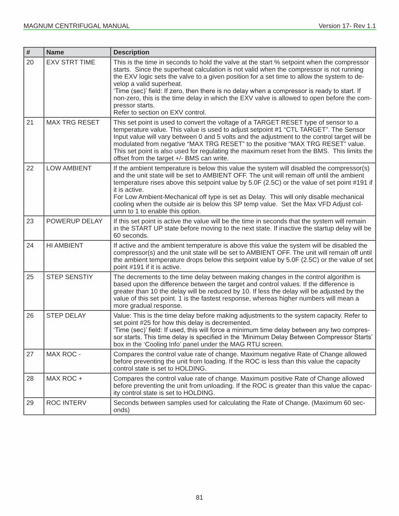
MAGNUM CENTRIFUGAL MANUAL Version 17- Rev 1.1
81
# Name Description20 EXV STRT TIME This is the time in seconds to hold the valve at the start % setpoint when the compressor
starts. Since the superheat calculation is not valid when the compressor is not running the EXV logic sets the valve to a given position for a set time to allow the system to de-velop a valid superheat. ‘Time(sec)’field:Ifzero,thenthereisnodelaywhenacompressorisreadytostart.Ifnon-zero, this is the time delay in which the EXV valve is allowed to open before the com-pressor starts. Refer to section on EXV control.
21 MAX TRG RESET This set point is used to convert the voltage of a TARGET RESET type of sensor to a temperature value. This value is used to adjust setpoint #1 “CTL TARGET”. The Sensor Input value will vary between 0 and 5 volts and the adjustment to the control target will be modulated from negative “MAX TRG RESET” to the positive “MAX TRG RESET” value.This set point is also used for regulating the maximum reset from the BMS. This limits the offset from the target +/- BMS can write.
22 LOW AMBIENT If the ambient temperature is below this value the system will disabled the compressor(s) and the unit state will be set to AMBIENT OFF. The unit will remain off until the ambient temperature rises above this setpoint value by 5.0F (2.5C) or the value of set point #191 if it is active.For Low Ambient-Mechanical off type is set as Delay. This will only disable mechanical cooling when the outside air is below this SP temp value. Set the Max VFD Adjust col-umn to 1 to enable this option.
23 POWERUP DELAY If this set point is active the value will be the time in seconds that the system will remain in the START UP state before moving to the next state. If inactive the startup delay will be 60 seconds.
24 HI AMBIENT If active and the ambient temperature is above this value the system will be disabled the compressor(s) and the unit state will be set to AMBIENT OFF. The unit will remain off until the ambient temperature drops below this setpoint value by 5.0F (2.5C) or the value of set point #191 if it is active.
25 STEP SENSTIY The decrements to the time delay between making changes in the control algorithm is based upon the difference between the target and control values. If the difference is greater than 10 the delay will be reduced by 10. If less the delay will be adjusted by the value of this set point. 1 is the fastest response, whereas higher numbers will mean a more gradual response.
26 STEP DELAY Value: This is the time delay before making adjustments to the system capacity. Refer to set point #25 for how this delay is decremented.‘Time(sec)’field:Ifused,thiswillforceaminimumtimedelaybetweenanytwocompres-sorstarts.Thistimedelayisspecifiedinthe‘MinimumDelayBetweenCompressorStarts’box in the ‘Cooling Info’ panel under the MAG RTU screen.
27 MAX ROC - Compares the control value rate of change. Maximum negative Rate of Change allowed before preventing the unit from loading. If the ROC is less than this value the capacity control state is set to HOLDING.
28 MAX ROC + Compares the control value rate of change. Maximum positive Rate of Change allowed before preventing the unit from unloading. If the ROC is greater than this value the capac-ity control state is set to HOLDING.
29 ROC INTERV Seconds between samples used for calculating the Rate of Change. (Maximum 60 sec-onds)
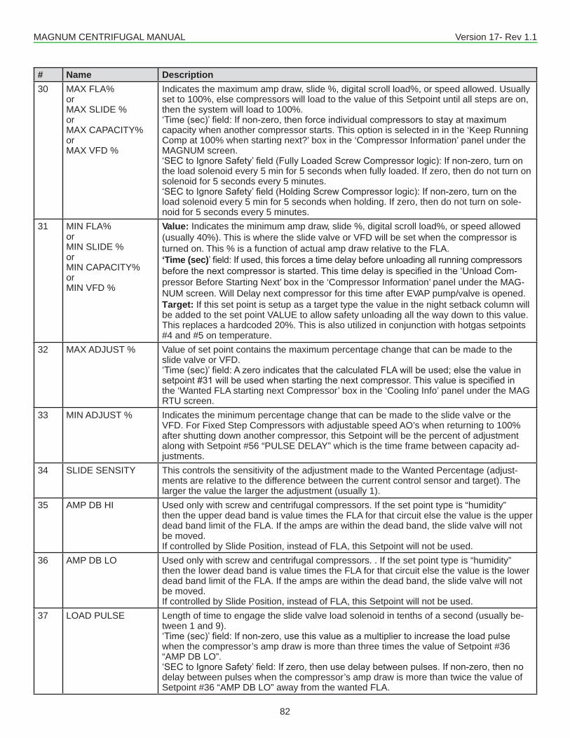
MAGNUM CENTRIFUGAL MANUAL Version 17- Rev 1.1
82
# Name Description30 MAX FLA%
orMAX SLIDE %orMAX CAPACITY%orMAX VFD %
Indicates the maximum amp draw, slide %, digital scroll load%, or speed allowed. Usually set to 100%, else compressors will load to the value of this Setpoint until all steps are on, then the system will load to 100%.‘Time(sec)’field:Ifnon-zero,thenforceindividualcompressorstostayatmaximumcapacity when another compressor starts. This option is selected in in the ‘Keep Running Comp at 100% when starting next?’ box in the ‘Compressor Information’ panel under the MAGNUM screen.‘SECtoIgnoreSafety’field(FullyLoadedScrewCompressorlogic):Ifnon-zero,turnonthe load solenoid every 5 min for 5 seconds when fully loaded. If zero, then do not turn on solenoid for 5 seconds every 5 minutes.‘SECtoIgnoreSafety’field(HoldingScrewCompressorlogic):Ifnon-zero,turnontheload solenoid every 5 min for 5 seconds when holding. If zero, then do not turn on sole-noid for 5 seconds every 5 minutes.
31 MIN FLA%orMIN SLIDE %orMIN CAPACITY%orMIN VFD %
Value: Indicates the minimum amp draw, slide %, digital scroll load%, or speed allowed (usually 40%). This is where the slide valve or VFD will be set when the compressor is turned on. This % is a function of actual amp draw relative to the FLA.‘Time (sec)’field:Ifused,thisforcesatimedelaybeforeunloadingallrunningcompressorsbeforethenextcompressorisstarted.Thistimedelayisspecifiedinthe‘UnloadCom-pressor Before Starting Next’ box in the ‘Compressor Information’ panel under the MAG-NUM screen. Will Delay next compressor for this time after EVAP pump/valve is opened.Target: If this set point is setup as a target type the value in the night setback column will be added to the set point VALUE to allow safety unloading all the way down to this value. This replaces a hardcoded 20%. This is also utilized in conjunction with hotgas setpoints #4 and #5 on temperature.
32 MAX ADJUST % Value of set point contains the maximum percentage change that can be made to the slide valve or VFD.‘Time(sec)’field:AzeroindicatesthatthecalculatedFLAwillbeused;elsethevalueinsetpoint#31willbeusedwhenstartingthenextcompressor.Thisvalueisspecifiedinthe ‘Wanted FLA starting next Compressor’ box in the ‘Cooling Info’ panel under the MAG RTU screen.
33 MIN ADJUST % Indicates the minimum percentage change that can be made to the slide valve or the VFD. For Fixed Step Compressors with adjustable speed AO’s when returning to 100% after shutting down another compressor, this Setpoint will be the percent of adjustment along with Setpoint #56 “PULSE DELAY” which is the time frame between capacity ad-justments.
34 SLIDE SENSITY This controls the sensitivity of the adjustment made to the Wanted Percentage (adjust- ments are relative to the difference between the current control sensor and target). The larger the value the larger the adjustment (usually 1).
35 AMP DB HI Used only with screw and centrifugal compressors. If the set point type is “humidity”then the upper dead band is value times the FLA for that circuit else the value is the upper dead band limit of the FLA. If the amps are within the dead band, the slide valve will not be moved.If controlled by Slide Position, instead of FLA, this Setpoint will not be used.
36 AMP DB LO Used only with screw and centrifugal compressors. . If the set point type is “humidity” then the lower dead band is value times the FLA for that circuit else the value is the lower dead band limit of the FLA. If the amps are within the dead band, the slide valve will not be moved.If controlled by Slide Position, instead of FLA, this Setpoint will not be used.
37 LOAD PULSE Length of time to engage the slide valve load solenoid in tenths of a second (usually be- tween 1 and 9).‘Time(sec)’field:Ifnon-zero,usethisvalueasamultipliertoincreasetheloadpulsewhen the compressor’s amp draw is more than three times the value of Setpoint #36 “AMP DB LO”.‘SECtoIgnoreSafety’field:Ifzero,thenusedelaybetweenpulses.Ifnon-zero,thennodelay between pulses when the compressor’s amp draw is more than twice the value of Setpoint #36 “AMP DB LO” away from the wanted FLA.
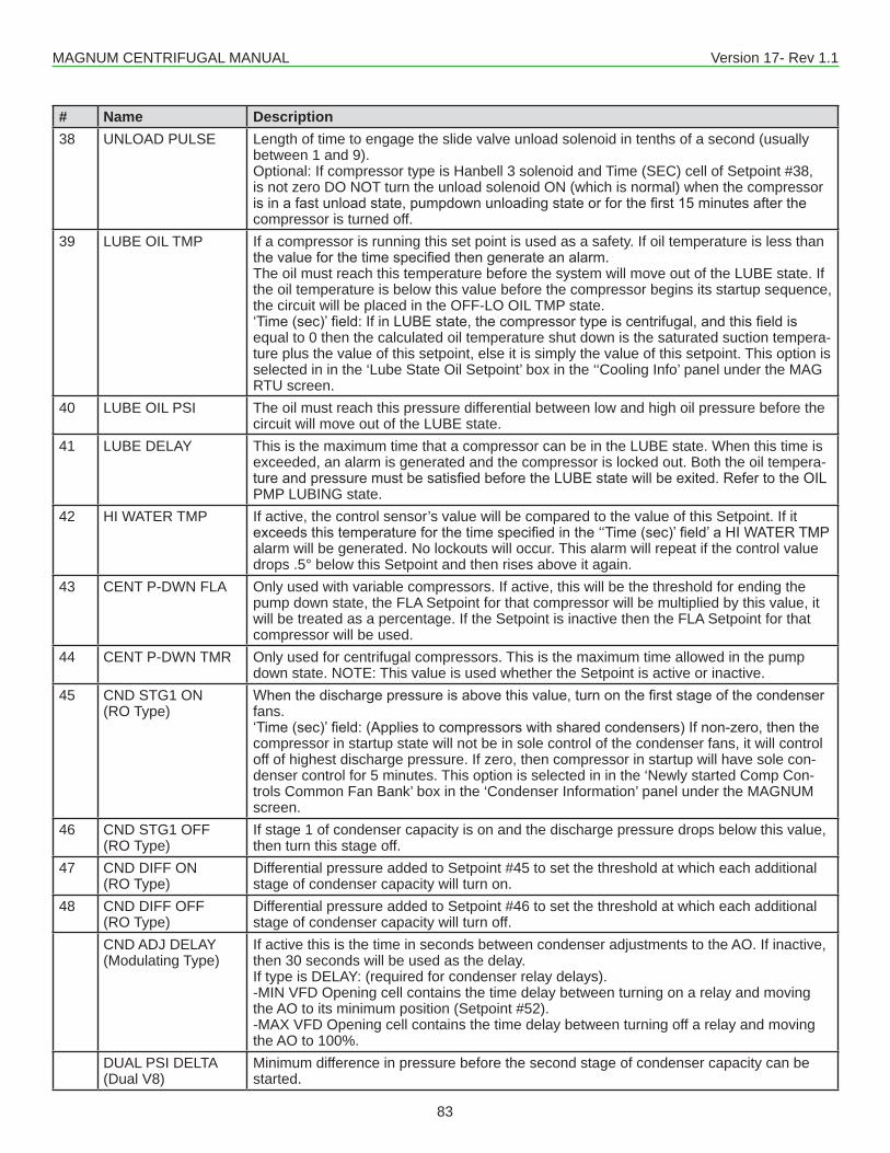
MAGNUM CENTRIFUGAL MANUAL Version 17- Rev 1.1
83
# Name Description38 UNLOAD PULSE Length of time to engage the slide valve unload solenoid in tenths of a second (usually
between 1 and 9).Optional: If compressor type is Hanbell 3 solenoid and Time (SEC) cell of Setpoint #38,is not zero DO NOT turn the unload solenoid ON (which is normal) when the compressor isinafastunloadstate,pumpdownunloadingstateorforthefirst15minutesafterthecompressor is turned off.
39 LUBE OIL TMP If a compressor is running this set point is used as a safety. If oil temperature is less than thevalueforthetimespecifiedthengenerateanalarm.The oil must reach this temperature before the system will move out of the LUBE state. If the oil temperature is below this value before the compressor begins its startup sequence, the circuit will be placed in the OFF-LO OIL TMP state. ‘Time(sec)’field:IfinLUBEstate,thecompressortypeiscentrifugal,andthisfieldisequal to 0 then the calculated oil temperature shut down is the saturated suction tempera-ture plus the value of this setpoint, else it is simply the value of this setpoint. This option is selected in in the ‘Lube State Oil Setpoint’ box in the ‘‘Cooling Info’ panel under the MAG RTU screen.
40 LUBE OIL PSI The oil must reach this pressure differential between low and high oil pressure before the circuit will move out of the LUBE state.
41 LUBE DELAY This is the maximum time that a compressor can be in the LUBE state. When this time is exceeded, an alarm is generated and the compressor is locked out. Both the oil tempera- tureandpressuremustbesatisfiedbeforetheLUBEstatewillbeexited.RefertotheOILPMP LUBING state.
42 HI WATER TMP If active, the control sensor’s value will be compared to the value of this Setpoint. If it exceedsthistemperatureforthetimespecifiedinthe‘‘Time(sec)’field’aHIWATERTMPalarm will be generated. No lockouts will occur. This alarm will repeat if the control value drops .5° below this Setpoint and then rises above it again.
43 CENT P-DWN FLA Only used with variable compressors. If active, this will be the threshold for ending the pump down state, the FLA Setpoint for that compressor will be multiplied by this value, it will be treated as a percentage. If the Setpoint is inactive then the FLA Setpoint for that compressor will be used.
44 CENT P-DWN TMR Only used for centrifugal compressors. This is the maximum time allowed in the pump down state. NOTE: This value is used whether the Setpoint is active or inactive.
45 CND STG1 ON (RO Type)
Whenthedischargepressureisabovethisvalue,turnonthefirststageofthecondenserfans.‘Time(sec)’field:(Appliestocompressorswithsharedcondensers)Ifnon-zero,thenthecompressor in startup state will not be in sole control of the condenser fans, it will control off of highest discharge pressure. If zero, then compressor in startup will have sole con- denser control for 5 minutes. This option is selected in in the ‘Newly started Comp Con- trols Common Fan Bank’ box in the ‘Condenser Information’ panel under the MAGNUM screen.
46 CND STG1 OFF (RO Type)
If stage 1 of condenser capacity is on and the discharge pressure drops below this value, then turn this stage off.
47 CND DIFF ON (RO Type)
Differential pressure added to Setpoint #45 to set the threshold at which each additional stage of condenser capacity will turn on.
48 CND DIFF OFF (RO Type)
Differential pressure added to Setpoint #46 to set the threshold at which each additional stage of condenser capacity will turn off.
CND ADJ DELAY (Modulating Type)
If active this is the time in seconds between condenser adjustments to the AO. If inactive, then 30 seconds will be used as the delay.If type is DELAY: (required for condenser relay delays).-MIN VFD Opening cell contains the time delay between turning on a relay and moving the AO to its minimum position (Setpoint #52).-MAX VFD Opening cell contains the time delay between turning off a relay and movingthe AO to 100%.
DUAL PSI DELTA(Dual V8)
Minimum difference in pressure before the second stage of condenser capacity can be started.
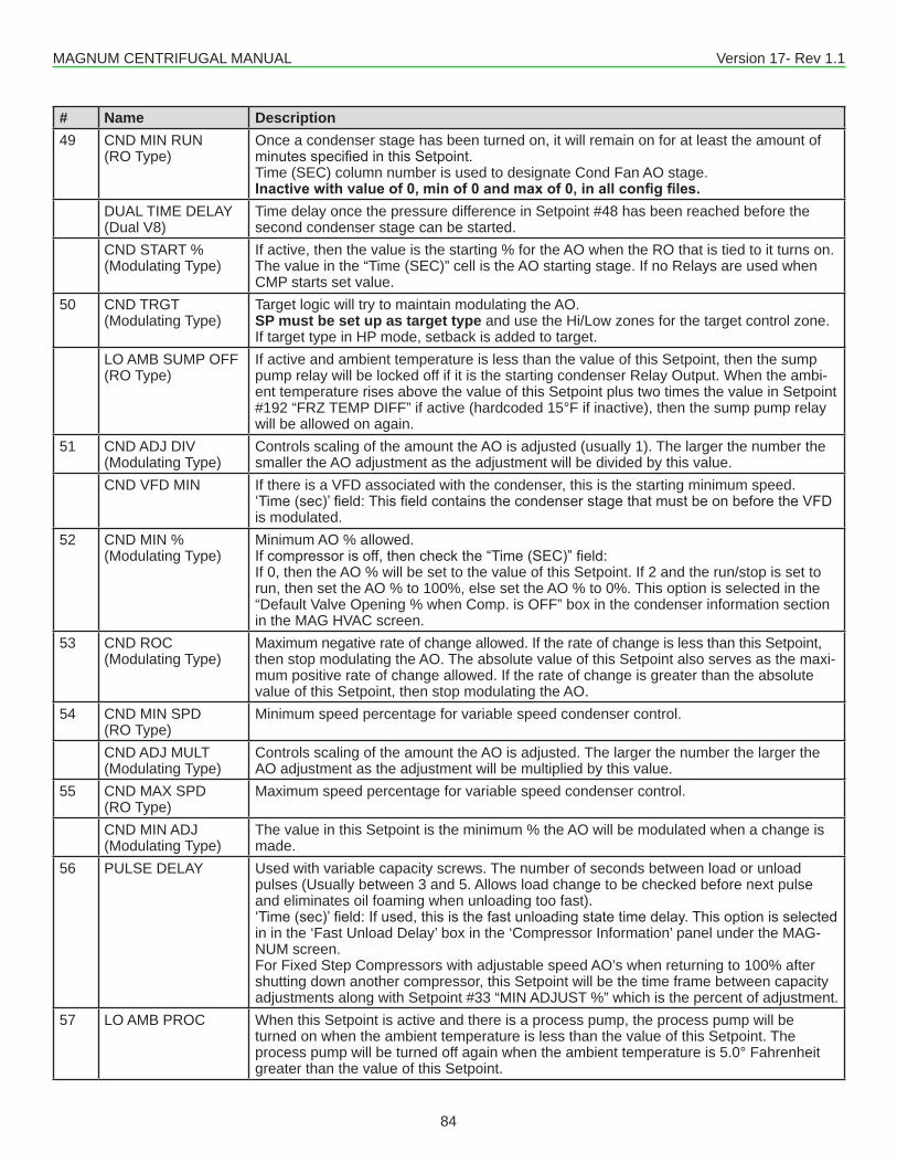
MAGNUM CENTRIFUGAL MANUAL Version 17- Rev 1.1
84
# Name Description49 CND MIN RUN
(RO Type)Once a condenser stage has been turned on, it will remain on for at least the amount ofminutesspecifiedinthisSetpoint.Time (SEC) column number is used to designate Cond Fan AO stage.Inactive with value of 0, min of 0 and max of 0, in all config files.
DUAL TIME DELAY(Dual V8)
Time delay once the pressure difference in Setpoint #48 has been reached before the second condenser stage can be started.
CND START % (Modulating Type)
If active, then the value is the starting % for the AO when the RO that is tied to it turns on. The value in the “Time (SEC)” cell is the AO starting stage. If no Relays are used when CMP starts set value.
50 CND TRGT (Modulating Type)
Target logic will try to maintain modulating the AO.SP must be set up as target type and use the Hi/Low zones for the target control zone.If target type in HP mode, setback is added to target.
LO AMB SUMP OFF (RO Type)
If active and ambient temperature is less than the value of this Setpoint, then the sump pump relay will be locked off if it is the starting condenser Relay Output. When the ambi- ent temperature rises above the value of this Setpoint plus two times the value in Setpoint #192 “FRZ TEMP DIFF” if active (hardcoded 15°F if inactive), then the sump pump relay will be allowed on again.
51 CND ADJ DIV(Modulating Type)
Controls scaling of the amount the AO is adjusted (usually 1). The larger the number the smaller the AO adjustment as the adjustment will be divided by this value.
CND VFD MIN If there is a VFD associated with the condenser, this is the starting minimum speed.‘Time(sec)’field:ThisfieldcontainsthecondenserstagethatmustbeonbeforetheVFDis modulated.
52 CND MIN % (Modulating Type)
Minimum AO % allowed.Ifcompressorisoff,thencheckthe“Time(SEC)”field:If 0, then the AO % will be set to the value of this Setpoint. If 2 and the run/stop is set to run, then set the AO % to 100%, else set the AO % to 0%. This option is selected in the “Default Valve Opening % when Comp. is OFF” box in the condenser information section in the MAG HVAC screen.
53 CND ROC (Modulating Type)
Maximum negative rate of change allowed. If the rate of change is less than this Setpoint, then stop modulating the AO. The absolute value of this Setpoint also serves as the maxi- mum positive rate of change allowed. If the rate of change is greater than the absolute value of this Setpoint, then stop modulating the AO.
54 CND MIN SPD (RO Type)
Minimum speed percentage for variable speed condenser control.
CND ADJ MULT (Modulating Type)
Controls scaling of the amount the AO is adjusted. The larger the number the larger theAO adjustment as the adjustment will be multiplied by this value.
55 CND MAX SPD (RO Type)
Maximum speed percentage for variable speed condenser control.
CND MIN ADJ (Modulating Type)
The value in this Setpoint is the minimum % the AO will be modulated when a change is made.
56 PULSE DELAY Used with variable capacity screws. The number of seconds between load or unloadpulses (Usually between 3 and 5. Allows load change to be checked before next pulse and eliminates oil foaming when unloading too fast).‘Time(sec)’field:Ifused,thisisthefastunloadingstatetimedelay.Thisoptionisselectedin in the ‘Fast Unload Delay’ box in the ‘Compressor Information’ panel under the MAG- NUM screen.For Fixed Step Compressors with adjustable speed AO’s when returning to 100% after shutting down another compressor, this Setpoint will be the time frame between capacity adjustments along with Setpoint #33 “MIN ADJUST %” which is the percent of adjustment.
57 LO AMB PROC When this Setpoint is active and there is a process pump, the process pump will be turned on when the ambient temperature is less than the value of this Setpoint. The process pump will be turned off again when the ambient temperature is 5.0° Fahrenheit greater than the value of this Setpoint.

MAGNUM CENTRIFUGAL MANUAL Version 17- Rev 1.1
85
# Name Description58 CFG TESTING This must be setup as ‘Not Used’. If active the system will not lockout when an I/O com-
munications signal is lost. This Setpoint should NOT be active in a live unit.59 ACYC OFF->ON This is the anti-cycle time delay (in seconds) from when the compressor was turned off.
This value is used in a calculation to determine how long a compressor should be in the anti-cycle state. Refer to the Standard Control Options in manual, Compressor Anti- Cycle Logic (OFF to ON).
60 MITSI P-DWN CUTIN If the compressor is a Mitsubishi, is being unloaded, and the suction pressure is greater than this Setpoint, then the compressor will be forced to pump down. NOTE: this value is used whether the Setpoint is active or inactive.
61 PMP DWN OFF This is the suction pressure value for turning off the compressor when in the PUMP DOWN or for opening the liquid line solenoid during the PRE-PUMP down state.
62 PMP DWN DELY(CENT only)
In CENT Firmware this SP value is the post lube delay. The oil pump will remain on for this amount of time after the compressor stops drawing amperage.
63 ACYC ON->ON This is the anti-cycle time delay (in seconds) from when the compressor was turned on. This value is used in a calculation to determine how long a compressor should be in the anti-cycle state. Refer to the Standard Control Options in manual, Compressor Anti- Cycle Logic (ON to ON).
64 COMP MIN RUN This is the minimum run time (in minutes) for a compressor once it is turned on. This mini- mum run time can be overridden by a safety condition, however.
65 EXV ZONE1 Temperature differential used to build the EXV Zone 1 both plus and minus.
66 EXV ZONE2 Temperature differential that is used to build the EXV Zone 2 both plus and minus. Tem-peratures above this zone are considered in zone 3.
67 EXV ROC ZONE 1 The EXV control logic will compare the value of this Setpoint to the temperature rate of change to determine the valve adjustment when the temperature is within the EXV control zone.‘SafetyDownTime(MIN)’field:TheminimumtimedelaybetweenEXVadjustmentswhenin the EXV control zone.
68 EXV ROC ZONE1 The EXV control logic will compare the value of this Setpoint to the temperature rate of change to determine the valve adjustment when the temperature is within zone 1.‘SafetyDownTime(MIN)’field:ThisistheminimumtimedelaybetweenEXVadjustmentswhen in the EXV control zone 1. If this Setpoint is inactive then the ROC for this zone is 0 and the delay is 15 seconds.
69 EXV ROC ZONE2 The EXV control logic will compare the value of this Setpoint to the temperature rate of change to determine the valve adjustment when the temperature is within zone 2.‘SafetyDownTime(MIN)’field:ThisistheminimumtimedelaybetweenEXVadjustmentswhen in the EXV control zone 2. If this Setpoint is inactive then the ROC for this zone is 0 and the delay is 15 seconds.
70 EXV ROC ZONE3 The EXV control logic will compare the value of this Setpoint to the temperature rate of change to determine the valve adjustment when the temperature is within zone 3.‘SafetyDownTime(MIN)’field:ThisistheminimumtimedelaybetweenEXVadjustmentswhen in the EXV control zone 3. If this Setpoint is inactive then the ROC for this zone is 0 and the delay is 15 seconds.
71 EXV TOO FAST When the superheat is with the control zone, the EXV control logic will compare the value of this Setpoint to the temperature rate of change to determine the valve adjustment when the temperature is within the zone and rising too fast.‘SafetyDownTime(MIN)’field:ThisistheminimumtimedelaybetweenEXVadjustmentsif the rate of change is too fast when in EXV control zones 1 or 2. If this Setpoint is inactive then the ROC for this zone is 0 and the delay is 15 seconds.
72 EXV CHANGING When the superheat is with the control zone, the EXV control logic will compare the value of this Setpoint to the temperature rate of change to determine the valve adjustment when the temperature is within the zone and rising.
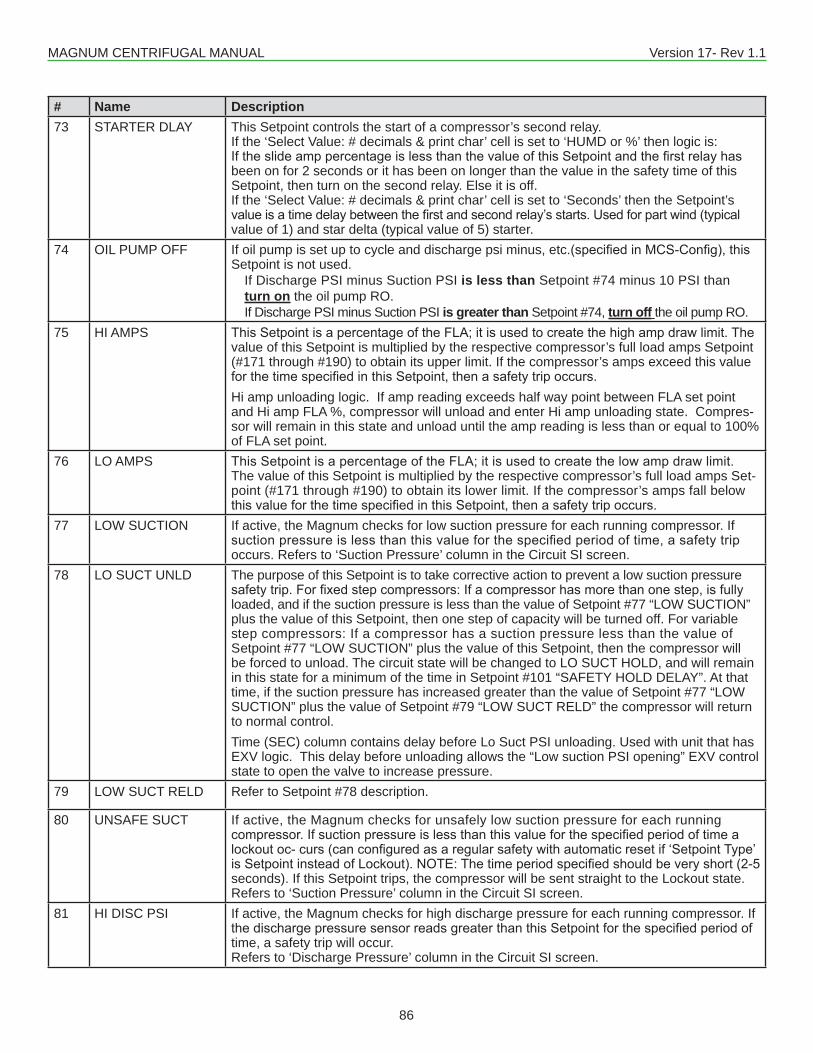
MAGNUM CENTRIFUGAL MANUAL Version 17- Rev 1.1
86
# Name Description73 STARTER DLAY This Setpoint controls the start of a compressor’s second relay.
If the ‘Select Value: # decimals & print char’ cell is set to ‘HUMD or %’ then logic is:IftheslideamppercentageislessthanthevalueofthisSetpointandthefirstrelayhasbeen on for 2 seconds or it has been on longer than the value in the safety time of this Setpoint, then turn on the second relay. Else it is off.If the ‘Select Value: # decimals & print char’ cell is set to ‘Seconds’ then the Setpoint’s valueisatimedelaybetweenthefirstandsecondrelay’sstarts.Usedforpartwind(typicalvalue of 1) and star delta (typical value of 5) starter.
74 OIL PUMP OFF If oil pump is set up to cycle and discharge psi minus, etc.(specifiedinMCS-Config),thisSetpoint is not used. If Discharge PSI minus Suction PSI is less than Setpoint #74 minus 10 PSI than turn on the oil pump RO.
If Discharge PSI minus Suction PSI is greater than Setpoint #74, turn off the oil pump RO. 75 HI AMPS ThisSetpointisapercentageoftheFLA;itisusedtocreatethehighampdrawlimit.The
value of this Setpoint is multiplied by the respective compressor’s full load amps Setpoint (#171 through #190) to obtain its upper limit. If the compressor’s amps exceed this value forthetimespecifiedinthisSetpoint,thenasafetytripoccurs.Hi amp unloading logic. If amp reading exceeds half way point between FLA set point and Hi amp FLA %, compressor will unload and enter Hi amp unloading state. Compres-sor will remain in this state and unload until the amp reading is less than or equal to 100% of FLA set point.
76 LO AMPS ThisSetpointisapercentageoftheFLA;itisusedtocreatethelowampdrawlimit.The value of this Setpoint is multiplied by the respective compressor’s full load amps Set-point (#171 through #190) to obtain its lower limit. If the compressor’s amps fall below thisvalueforthetimespecifiedinthisSetpoint,thenasafetytripoccurs.
77 LOW SUCTION If active, the Magnum checks for low suction pressure for each running compressor. If suctionpressureislessthanthisvalueforthespecifiedperiodoftime,asafetytripoccurs. Refers to ‘Suction Pressure’ column in the Circuit SI screen.
78 LO SUCT UNLD The purpose of this Setpoint is to take corrective action to prevent a low suction pressure safetytrip.Forfixedstepcompressors:Ifacompressorhasmorethanonestep,isfullyloaded, and if the suction pressure is less than the value of Setpoint #77 “LOW SUCTION” plus the value of this Setpoint, then one step of capacity will be turned off. For variable step compressors: If a compressor has a suction pressure less than the value of Setpoint #77 “LOW SUCTION” plus the value of this Setpoint, then the compressor will be forced to unload. The circuit state will be changed to LO SUCT HOLD, and will remain in this state for a minimum of the time in Setpoint #101 “SAFETY HOLD DELAY”. At that time, if the suction pressure has increased greater than the value of Setpoint #77 “LOW SUCTION” plus the value of Setpoint #79 “LOW SUCT RELD” the compressor will return to normal control.Time (SEC) column contains delay before Lo Suct PSI unloading. Used with unit that has EXV logic. This delay before unloading allows the “Low suction PSI opening” EXV control state to open the valve to increase pressure.
79 LOW SUCT RELD Refer to Setpoint #78 description.
80 UNSAFE SUCT If active, the Magnum checks for unsafely low suction pressure for each running compressor.Ifsuctionpressureislessthanthisvalueforthespecifiedperiodoftimealockoutoc-curs(canconfiguredasaregularsafetywithautomaticresetif‘SetpointType’isSetpointinsteadofLockout).NOTE:Thetimeperiodspecifiedshouldbeveryshort(2-5seconds). If this Setpoint trips, the compressor will be sent straight to the Lockout state.Refers to ‘Suction Pressure’ column in the Circuit SI screen.
81 HI DISC PSI If active, the Magnum checks for high discharge pressure for each running compressor. If thedischargepressuresensorreadsgreaterthanthisSetpointforthespecifiedperiodoftime, a safety trip will occur.Refers to ‘Discharge Pressure’ column in the Circuit SI screen.

MAGNUM CENTRIFUGAL MANUAL Version 17- Rev 1.1
87
# Name Description82 HI DISC UNLD The purpose of this Setpoint is to take corrective action to prevent a high discharge pres-
suresafetytrip.Forfixedstepcompressors:Ifacompressorhasmorethanonestep,is fully loaded, and if the discharge pressure is more than the value of Setpoint #81 “HI DISC PSI” minus the value of this Setpoint, then one step of capacity will be turned off. For variable step compressors: If a compressor has a discharge pressure more than the value of Setpoint #81 “HI DISC PSI” minus the value of this Setpoint, then the compres-sor will be forced to unload. The circuit state will be changed to HI DISC HOLD, and will remain in this state for a minimum of the time in Setpoint #101 “SAFETY HOLD DELAY”. At that time, if the discharge pressure has decreased below than the value of Setpoint #81 “HI DISC PSI” minus the value of Setpoint #83 “HI DISC RELD” the compressor will return to normal control.
83 HI DISC RELD Refer to Setpoint #82 description.
84 LO DISC SHEAT Ifthecalculateddischargesuperheatislessthanthisvalueforthespecifiedperiodoftime, a safety trip will occur. Also, there is an option in the Circuit Base screen to tie a Re-lay Output to this Setpoint that will activate whenever a low discharge superheat condition occurs. A Low Discharge Superheat condition can also put the circuit into a ‘HI DISC UN- LOAD’ state where the compressor will unload to try to raise the superheat.If economizer is being used, when the discharge superheat goes below the value for the safety time / 9 the economizer is turned off.
85 LO DISC PSI If active, the Magnum checks for low discharge pressure. If the discharge sensor readingislessthanthisvalueforthespecifiedperiodoftime,asafetytripoccurs.
86 HI RETURN TEMP Only active in Mitsubishi compressors. If active the Magnum will check for high enter-ing liquid temperature. If this temperature is greater than the value in this Setpoint, the circuit state will be HI WATER HOLD.
87 HI DISC TMP If active, the Magnum checks for high discharge temperature for each compressor. If the dischargetemperaturesensorreadingisgreaterthanthisSetpointforthespecifiedperiodof time, a safety trip will occur.Refers to ‘Discharge Temperature’ column in the Circuit SI screen.
88 DIS TMP UNLD The purpose of this Setpoint is to take corrective action to prevent a high discharge tem-peraturesafetytrip.Forfixedstepcompressors:Ifacompressorhasmorethanonestep,is fully loaded, and if the discharge temperature is more than the value of Setpoint #87“HI DISC TMP” minus the value of this Setpoint, then one step of capacity will be turned off. For variable step compressors: If a compressor has a discharge temperature more than the value of Setpoint #87 “HI DISC TMP” minus the value of this Setpoint, then the compressor will be forced to unload. The circuit state will be changed to HI DISC HOLD, and will remain in this state for a minimum of the time in Setpoint #101 “SAFETY HOLD DELAY”. At that time, if the discharge temperature has decreased below than the value of Setpoint #87 “HI DISC TMP” minus the value of Setpoint #89 “HDISC T RELD” the com- pressor will return to normal control.
89 DIS TMP RELD Refer to Setpoint #88 description.
90 COND FAULT For Condensers with Fault Indicators: If Setpoint is active, a condenser fault occurs, and the Setpoint type is Alarm, then an alarm message will be generated. If the type is Lock-out, and a condenser fault occurs, then all of the compressors associated with this fault will be locked off.For Common VFD Fan Condensers with Bypass: Time in seconds before the bypass can be used when a fault has occurred.
91 LOW OIL DIF If active, the Magnum checks for low differential oil pressure. If the calculated differential oilpressureislessthanthisvalueforthespecifiedperiodoftime,asafetytripoccurs.Refers to ‘Oil Pressure’ column in the Circuit SI screen.
92 UNSAFE OIL If active, the Magnum checks for unsafe differential oil pressure. If the calculated differ-entialoilpressureislessthanthisvalueforthespecifiedperiodoftime,alockoutoccurs.NOTE:Thetimeperiodspecifiedshouldbeveryshort(2-5seconds).IfthisSetpointtrips,the compressor will be sent straight to the Lockout state.Refers to ‘Oil Pressure’ column in the Circuit SI screen.
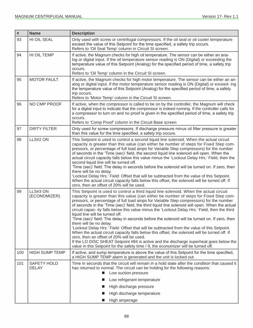
MAGNUM CENTRIFUGAL MANUAL Version 17- Rev 1.1
88
# Name Description93 HI OIL SEAL Only used with screw or centrifugal compressors. If the oil seal or oil cooler temperature
exceedthevalueofthisSetpointforthetimespecified,asafetytripoccurs.Refers to ‘Oil Seal Temp’ column in Circuit SI screen.
94 HI OIL TEMP If active, the Magnum checks for high oil temperature. The sensor can be either an ana-log or digital input. If the oil temperature sensor reading is ON (Digital) or exceeding the temperaturevalueofthisSetpoint(Analog)forthespecifiedperiodoftime,asafetytripoccurs.Refers to ‘Oil Temp’ column in the Circuit SI screen.
95 MOTOR FAULT If active, the Magnum checks for high motor temperature. The sensor can be either an an-alog or digital input. If the motor temperature sensor reading is ON (Digital) or exceed- ing thetemperaturevalueofthisSetpoint(Analog)forthespecifiedperiodoftime,asafetytrip occurs.Refers to ‘Motor Temp’ column in the Circuit SI screen.
96 NO CMP PROOF If active, when the compressor is called to be on by the controller, the Magnum will check for a digital input to indicate that the compressor is indeed running. If the controller calls for acompressortoturnonandnoproofisgiveninthespecifiedperiodoftime,asafetytripoccurs.Refers to ‘Comp Proof’ column in the Circuit Base screen
97 DIRTY FILTER Onlyusedforscrewcompressors.Ifdischargepressureminusoilfilterpressureisgreaterthanthisvalueforthetimespecified,asafetytripoccurs.
98 LLS#2 ON This Setpoint is used to control a second liquid line solenoid. When the actual circuit capacity is greater than this value (can either be number of steps for Fixed Step com-pressors, or percentage of full load amps for Variable Step compressors) for the number ofsecondsinthe‘Time(sec)’field,thesecondliquidlinesolenoidwillopen.Whentheactual circuit capacity falls below this value minus the ‘Lockout Delay Hrs.’ Field, then the second liquid line will be turned off.‘Time(sec)’field:Thedelayinsecondsbeforethesolenoidwillbeturnedon.Ifzero,thenthere will be no delay.‘Lockout Delay Hrs.’ Field: Offset that will be subtracted from the value of this Setpoint. When the actual circuit capacity falls below this offset, the solenoid will be turned off. If zero, then an offset of 20% will be used.
99 LLS#3 ON (ECONOMIZER)
This Setpoint is used to control a third liquid line solenoid. When the actual circuit capacity is greater than this value (can either be number of steps for Fixed Step com-pressors, or percentage of full load amps for Variable Step compressors) for the number ofsecondsinthe‘Time(sec)’field,thethirdliquidlinesolenoidwillopen.Whentheactualcircuit capac- ity falls below this value minus the ‘Lockout Delay Hrs.’ Field, then the third liquid line will be turned off.‘Time(sec)’field:Thedelayinsecondsbeforethesolenoidwillbeturnedon.Ifzero,thenthere will be no delay.‘Lockout Delay Hrs.’ Field: Offset that will be subtracted from the value of this Setpoint. When the actual circuit capacity falls below this offset, the solenoid will be turned off. If zero, then an offset of 20% will be used.If the LO DISC SHEAT Setpoint #84 is active and the discharge superheat goes below the value in this Setpoint for the safety time / 9, the economizer will be turned off.
100 HIGH SUMP TEMP Ifactive,andsumptemperatureisabovethevalueofthisSetpointforthetimespecified,a HIGH SUMP TEMP alarm is generated and the unit is locked out.
101 SAFETY HOLD DELAY
Time in seconds that the circuit will remain in a hold state after the condition that caused it has returned to normal. The circuit can be holding for the following reasons:
� Low suction pressure � Low refrigerant temperature � High discharge pressure � High discharge temperature � High amperage
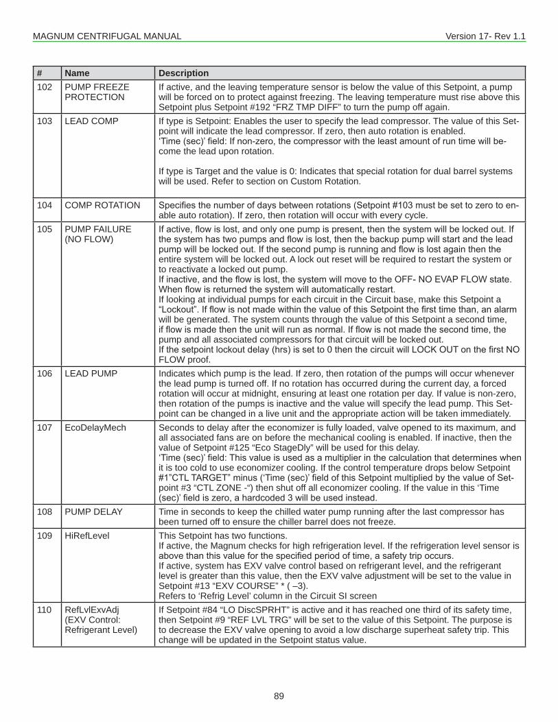
MAGNUM CENTRIFUGAL MANUAL Version 17- Rev 1.1
89
# Name Description102 PUMP FREEZE
PROTECTIONIf active, and the leaving temperature sensor is below the value of this Setpoint, a pump will be forced on to protect against freezing. The leaving temperature must rise above this Setpoint plus Setpoint #192 “FRZ TMP DIFF” to turn the pump off again.
103 LEAD COMP If type is Setpoint: Enables the user to specify the lead compressor. The value of this Set-point will indicate the lead compressor. If zero, then auto rotation is enabled.‘Time(sec)’field:Ifnon-zero,thecompressorwiththeleastamountofruntimewillbe-come the lead upon rotation.
If type is Target and the value is 0: Indicates that special rotation for dual barrel systems will be used. Refer to section on Custom Rotation.
104 COMP ROTATION Specifiesthenumberofdaysbetweenrotations(Setpoint#103mustbesettozerotoen-able auto rotation). If zero, then rotation will occur with every cycle.
105 PUMP FAILURE (NO FLOW)
Ifactive,flowislost,andonlyonepumpispresent,thenthesystemwillbelockedout.Ifthesystemhastwopumpsandflowislost,thenthebackuppumpwillstartandtheleadpumpwillbelockedout.Ifthesecondpumpisrunningandflowislostagainthentheentire system will be locked out. A lock out reset will be required to restart the system or to reactivate a locked out pump.Ifinactive,andtheflowislost,thesystemwillmovetotheOFF-NOEVAPFLOWstate.Whenflowisreturnedthesystemwillautomaticallyrestart.If looking at individual pumps for each circuit in the Circuit base, make this Setpoint a “Lockout”.IfflowisnotmadewithinthevalueofthisSetpointthefirsttimethan,analarmwill be generated. The system counts through the value of this Setpoint a second time, ifflowismadethentheunitwillrunasnormal.Ifflowisnotmadethesecondtime,thepump and all associated compressors for that circuit will be locked out. Ifthesetpointlockoutdelay(hrs)issetto0thenthecircuitwillLOCKOUTonthefirstNOFLOW proof.
106 LEAD PUMP Indicates which pump is the lead. If zero, then rotation of the pumps will occur whenever the lead pump is turned off. If no rotation has occurred during the current day, a forced rotation will occur at midnight, ensuring at least one rotation per day. If value is non-zero, then rotation of the pumps is inactive and the value will specify the lead pump. This Set- point can be changed in a live unit and the appropriate action will be taken immediately.
107 EcoDelayMech Seconds to delay after the economizer is fully loaded, valve opened to its maximum, and all associated fans are on before the mechanical cooling is enabled. If inactive, then the value of Setpoint #125 “Eco StageDly” will be used for this delay.‘Time(sec)’field:Thisvalueisusedasamultiplierinthecalculationthatdetermineswhenit is too cold to use economizer cooling. If the control temperature drops below Setpoint #1”CTLTARGET”minus(‘Time(sec)’fieldofthisSetpointmultipliedbythevalueofSet-point #3 “CTL ZONE -“) then shut off all economizer cooling. If the value in this ‘Time (sec)’fieldiszero,ahardcoded3willbeusedinstead.
108 PUMP DELAY Time in seconds to keep the chilled water pump running after the last compressor has been turned off to ensure the chiller barrel does not freeze.
109 HiRefLevel This Setpoint has two functions.If active, the Magnum checks for high refrigeration level. If the refrigeration level sensor is abovethanthisvalueforthespecifiedperiodoftime,asafetytripoccurs.If active, system has EXV valve control based on refrigerant level, and the refrigerant level is greater than this value, then the EXV valve adjustment will be set to the value in Setpoint #13 “EXV COURSE” * ( –3).Refers to ‘Refrig Level’ column in the Circuit SI screen
110 RefLvlExvAdj(EXV Control: Refrigerant Level)
If Setpoint #84 “LO DiscSPRHT” is active and it has reached one third of its safety time, then Setpoint #9 “REF LVL TRG” will be set to the value of this Setpoint. The purpose is to decrease the EXV valve opening to avoid a low discharge superheat safety trip. This change will be updated in the Setpoint status value.
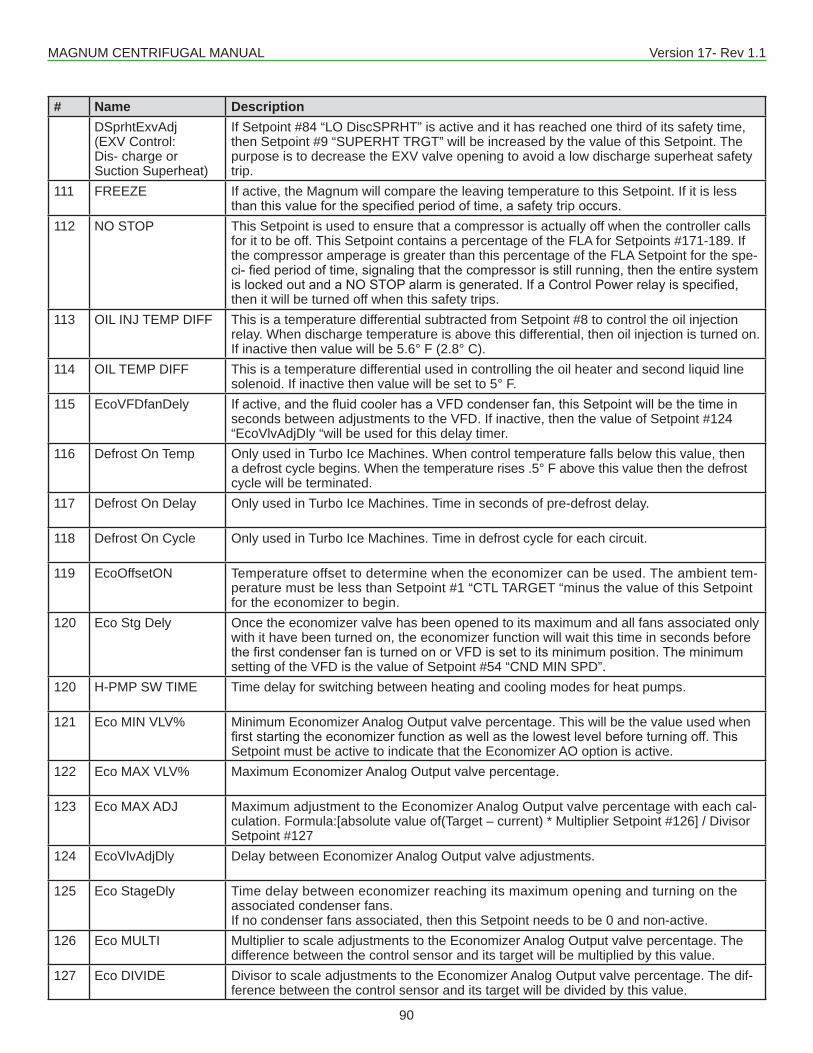
MAGNUM CENTRIFUGAL MANUAL Version 17- Rev 1.1
90
# Name DescriptionDSprhtExvAdj (EXV Control: Dis- charge or Suction Superheat)
If Setpoint #84 “LO DiscSPRHT” is active and it has reached one third of its safety time, then Setpoint #9 “SUPERHT TRGT” will be increased by the value of this Setpoint. The purpose is to decrease the EXV valve opening to avoid a low discharge superheat safety trip.
111 FREEZE If active, the Magnum will compare the leaving temperature to this Setpoint. If it is lessthanthisvalueforthespecifiedperiodoftime,asafetytripoccurs.
112 NO STOP This Setpoint is used to ensure that a compressor is actually off when the controller calls for it to be off. This Setpoint contains a percentage of the FLA for Setpoints #171-189. If the compressor amperage is greater than this percentage of the FLA Setpoint for the spe-ci-fiedperiodoftime,signalingthatthecompressorisstillrunning,thentheentiresystemislockedoutandaNOSTOPalarmisgenerated.IfaControlPowerrelayisspecified,then it will be turned off when this safety trips.
113 OIL INJ TEMP DIFF This is a temperature differential subtracted from Setpoint #8 to control the oil injection relay. When discharge temperature is above this differential, then oil injection is turned on. If inactive then value will be 5.6° F (2.8° C).
114 OIL TEMP DIFF This is a temperature differential used in controlling the oil heater and second liquid line solenoid. If inactive then value will be set to 5° F.
115 EcoVFDfanDely Ifactive,andthefluidcoolerhasaVFDcondenserfan,thisSetpointwillbethetimeinseconds between adjustments to the VFD. If inactive, then the value of Setpoint #124 “EcoVlvAdjDly “will be used for this delay timer.
116 Defrost On Temp Only used in Turbo Ice Machines. When control temperature falls below this value, then a defrost cycle begins. When the temperature rises .5° F above this value then the defrost cycle will be terminated.
117 Defrost On Delay Only used in Turbo Ice Machines. Time in seconds of pre-defrost delay.
118 Defrost On Cycle Only used in Turbo Ice Machines. Time in defrost cycle for each circuit.
119 EcoOffsetON Temperature offset to determine when the economizer can be used. The ambient tem-perature must be less than Setpoint #1 “CTL TARGET “minus the value of this Setpoint for the economizer to begin.
120 Eco Stg Dely Once the economizer valve has been opened to its maximum and all fans associated only with it have been turned on, the economizer function will wait this time in seconds before thefirstcondenserfanisturnedonorVFDissettoitsminimumposition.Theminimumsetting of the VFD is the value of Setpoint #54 “CND MIN SPD”.
120 H-PMP SW TIME Time delay for switching between heating and cooling modes for heat pumps.
121 Eco MIN VLV% Minimum Economizer Analog Output valve percentage. This will be the value used when firststartingtheeconomizerfunctionaswellasthelowestlevelbeforeturningoff.ThisSetpoint must be active to indicate that the Economizer AO option is active.
122 Eco MAX VLV% Maximum Economizer Analog Output valve percentage.
123 Eco MAX ADJ Maximum adjustment to the Economizer Analog Output valve percentage with each cal-culation. Formula:[absolute value of(Target – current) * Multiplier Setpoint #126] / Divisor Setpoint #127
124 EcoVlvAdjDly Delay between Economizer Analog Output valve adjustments.
125 Eco StageDly Time delay between economizer reaching its maximum opening and turning on the associated condenser fans.If no condenser fans associated, then this Setpoint needs to be 0 and non-active.
126 Eco MULTI Multiplier to scale adjustments to the Economizer Analog Output valve percentage. The difference between the control sensor and its target will be multiplied by this value.
127 Eco DIVIDE Divisor to scale adjustments to the Economizer Analog Output valve percentage. The dif-ference between the control sensor and its target will be divided by this value.
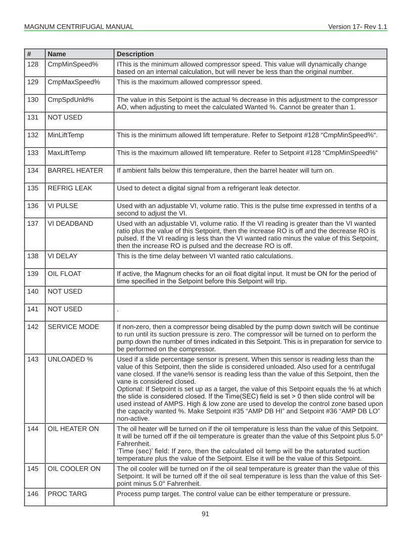
MAGNUM CENTRIFUGAL MANUAL Version 17- Rev 1.1
91
# Name Description128 CmpMinSpeed% IThis is the minimum allowed compressor speed. This value will dynamically change
based on an internal calculation, but will never be less than the original number.129 CmpMaxSpeed% This is the maximum allowed compressor speed.
130 CmpSpdUnld% The value in this Setpoint is the actual % decrease in this adjustment to the compressorAO, when adjusting to meet the calculated Wanted %. Cannot be greater than 1.
131 NOT USED
132 MinLiftTemp This is the minimum allowed lift temperature. Refer to Setpoint #128 “CmpMinSpeed%“.
133 MaxLiftTemp This is the maximum allowed lift temperature. Refer to Setpoint #128 “CmpMinSpeed%“
134 BARREL HEATER If ambient falls below this temperature, then the barrel heater will turn on.
135 REFRIG LEAK Used to detect a digital signal from a refrigerant leak detector.
136 VI PULSE Used with an adjustable VI, volume ratio. This is the pulse time expressed in tenths of a second to adjust the VI.
137 VI DEADBAND Used with an adjustable VI, volume ratio. If the VI reading is greater than the VI wanted ratio plus the value of this Setpoint, then the increase RO is off and the decrease RO is pulsed. If the VI reading is less than the VI wanted ratio minus the value of this Setpoint, then the increase RO is pulsed and the decrease RO is off.
138 VI DELAY This is the time delay between VI wanted ratio calculations.
139 OIL FLOAT Ifactive,theMagnumchecksforanoilfloatdigitalinput.ItmustbeONfortheperiodoftimespecifiedintheSetpointbeforethisSetpointwilltrip.
140 NOT USED
141 NOT USED .
142 SERVICE MODE If non-zero, then a compressor being disabled by the pump down switch will be continue to run until its suction pressure is zero. The compressor will be turned on to perform the pump down the number of times indicated in this Setpoint. This is in preparation for service to be performed on the compressor.
143 UNLOADED % Used if a slide percentage sensor is present. When this sensor is reading less than the value of this Setpoint, then the slide is considered unloaded. Also used for a centrifugal vane closed. If the vane% sensor is reading less than the value of this Setpoint, then the vane is considered closed.Optional: If Setpoint is set up as a target, the value of this Setpoint equals the % at which theslideisconsideredclosed.IftheTime(SEC)fieldisset>0thenslidecontrolwillbeused instead of AMPS. High & low zone are used to develop the control zone based upon the capacity wanted %. Make Setpoint #35 “AMP DB HI” and Setpoint #36 “AMP DB LO” non-active.
144 OIL HEATER ON The oil heater will be turned on if the oil temperature is less than the value of this Setpoint. It will be turned off if the oil temperature is greater than the value of this Setpoint plus 5.0° Fahrenheit.‘Time(sec)’field:Ifzero,thenthecalculatedoiltempwillbethesaturatedsuctiontemperature plus the value of the Setpoint. Else it will be the value of this Setpoint.
145 OIL COOLER ON The oil cooler will be turned on if the oil seal temperature is greater than the value of this Setpoint. It will be turned off if the oil seal temperature is less than the value of this Set-point minus 5.0° Fahrenheit.
146 PROC TARG Process pump target. The control value can be either temperature or pressure.
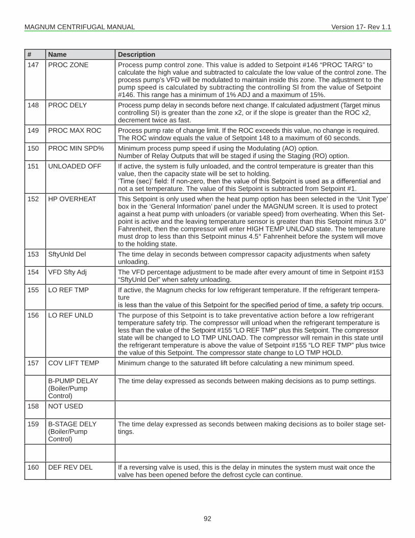
MAGNUM CENTRIFUGAL MANUAL Version 17- Rev 1.1
92
# Name Description147 PROC ZONE Process pump control zone. This value is added to Setpoint #146 “PROC TARG” to
calculate the high value and subtracted to calculate the low value of the control zone. The process pump’s VFD will be modulated to maintain inside this zone. The adjustment to the pump speed is calculated by subtracting the controlling SI from the value of Setpoint #146. This range has a minimum of 1% ADJ and a maximum of 15%.
148 PROC DELY Process pump delay in seconds before next change. If calculated adjustment (Target minus controlling SI) is greater than the zone x2, or if the slope is greater than the ROC x2, decrement twice as fast.
149 PROC MAX ROC Process pump rate of change limit. If the ROC exceeds this value, no change is required. The ROC window equals the value of Setpoint 148 to a maximum of 60 seconds.
150 PROC MIN SPD% Minimum process pump speed if using the Modulating (AO) option.Number of Relay Outputs that will be staged if using the Staging (RO) option.
151 UNLOADED OFF If active, the system is fully unloaded, and the control temperature is greater than this value, then the capacity state will be set to holding.‘Time(sec)’field:Ifnon-zero,thenthevalueofthisSetpointisusedasadifferentialandnot a set temperature. The value of this Setpoint is subtracted from Setpoint #1.
152 HP OVERHEAT This Setpoint is only used when the heat pump option has been selected in the ‘Unit Type’ box in the ‘General Information’ panel under the MAGNUM screen. It is used to protect against a heat pump with unloaders (or variable speed) from overheating. When this Set- point is active and the leaving temperature sensor is greater than this Setpoint minus 3.0° Fahrenheit, then the compressor will enter HIGH TEMP UNLOAD state. The temperature must drop to less than this Setpoint minus 4.5° Fahrenheit before the system will move to the holding state.
153 SftyUnld Del The time delay in seconds between compressor capacity adjustments when safety unloading.
154 VFD Sfty Adj The VFD percentage adjustment to be made after every amount of time in Setpoint #153“SftyUnld Del” when safety unloading.
155 LO REF TMP If active, the Magnum checks for low refrigerant temperature. If the refrigerant tempera-tureislessthanthevalueofthisSetpointforthespecifiedperiodoftime,asafetytripoccurs.
156 LO REF UNLD The purpose of this Setpoint is to take preventative action before a low refrigerant temperature safety trip. The compressor will unload when the refrigerant temperature is less than the value of the Setpoint #155 “LO REF TMP” plus this Setpoint. The compressor state will be changed to LO TMP UNLOAD. The compressor will remain in this state until the refrigerant temperature is above the value of Setpoint #155 “LO REF TMP” plus twice the value of this Setpoint. The compressor state change to LO TMP HOLD.
157 COV LIFT TEMP Minimum change to the saturated lift before calculating a new minimum speed.
B-PUMP DELAY (Boiler/Pump Control)
The time delay expressed as seconds between making decisions as to pump settings.
158 NOT USED
159 B-STAGE DELY (Boiler/Pump Control)
The time delay expressed as seconds between making decisions as to boiler stage set-tings.
160 DEF REV DEL If a reversing valve is used, this is the delay in minutes the system must wait once the valve has been opened before the defrost cycle can continue.
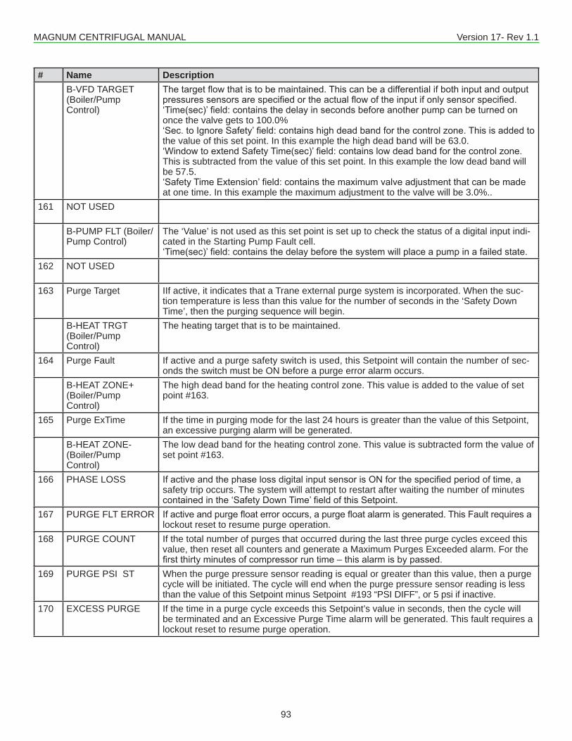
MAGNUM CENTRIFUGAL MANUAL Version 17- Rev 1.1
93
# Name DescriptionB-VFD TARGET (Boiler/Pump Control)
Thetargetflowthatistobemaintained.Thiscanbeadifferentialifbothinputandoutputpressuressensorsarespecifiedortheactualflowoftheinputifonlysensorspecified.‘Time(sec)’field:containsthedelayinsecondsbeforeanotherpumpcanbeturnedononce the valve gets to 100.0%‘Sec.toIgnoreSafety’field:containshighdeadbandforthecontrolzone.Thisisaddedtothe value of this set point. In this example the high dead band will be 63.0.‘WindowtoextendSafetyTime(sec)’field:containslowdeadbandforthecontrolzone.This is subtracted from the value of this set point. In this example the low dead band will be 57.5.‘SafetyTimeExtension’field:containsthemaximumvalveadjustmentthatcanbemadeat one time. In this example the maximum adjustment to the valve will be 3.0%..
161 NOT USED
B-PUMP FLT (Boiler/Pump Control)
The ‘Value’ is not used as this set point is set up to check the status of a digital input indi- cated in the Starting Pump Fault cell.‘Time(sec)’field:containsthedelaybeforethesystemwillplaceapumpinafailedstate.
162 NOT USED
163 Purge Target IIf active, it indicates that a Trane external purge system is incorporated. When the suc-tion temperature is less than this value for the number of seconds in the ‘Safety Down Time’, then the purging sequence will begin.
B-HEAT TRGT (Boiler/Pump Control)
The heating target that is to be maintained.
164 Purge Fault If active and a purge safety switch is used, this Setpoint will contain the number of sec-onds the switch must be ON before a purge error alarm occurs.
B-HEAT ZONE+ (Boiler/Pump Control)
The high dead band for the heating control zone. This value is added to the value of set point #163.
165 Purge ExTime If the time in purging mode for the last 24 hours is greater than the value of this Setpoint, an excessive purging alarm will be generated.
B-HEAT ZONE- (Boiler/PumpControl)
The low dead band for the heating control zone. This value is subtracted form the value of set point #163.
166 PHASE LOSS IfactiveandthephaselossdigitalinputsensorisONforthespecifiedperiodoftime,asafety trip occurs. The system will attempt to restart after waiting the number of minutes containedinthe‘SafetyDownTime’fieldofthisSetpoint.
167 PURGE FLT ERROR Ifactiveandpurgefloaterroroccurs,apurgefloatalarmisgenerated.ThisFaultrequiresalockout reset to resume purge operation.
168 PURGE COUNT If the total number of purges that occurred during the last three purge cycles exceed this value, then reset all counters and generate a Maximum Purges Exceeded alarm. For the firstthirtyminutesofcompressorruntime–thisalarmisbypassed.
169 PURGE PSI ST When the purge pressure sensor reading is equal or greater than this value, then a purge cycle will be initiated. The cycle will end when the purge pressure sensor reading is less than the value of this Setpoint minus Setpoint #193 “PSI DIFF”, or 5 psi if inactive.
170 EXCESS PURGE If the time in a purge cycle exceeds this Setpoint’s value in seconds, then the cycle will be terminated and an Excessive Purge Time alarm will be generated. This fault requires a lockout reset to resume purge operation.
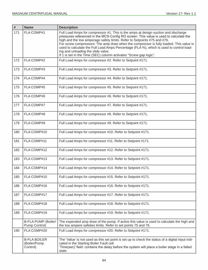
MAGNUM CENTRIFUGAL MANUAL Version 17- Rev 1.1
94
# Name Description171 FLA COMP#1 Full Load Amps for compressor #1. This is the amps at design suction and discharge
pressuresreferencedintheMCS-ConfigROscreen.Thisvalueisusedtocalculatethehigh and the low amperage safety limits. Refer to Setpoints #75 and #76.For screw compressors: The amp draw when the compressor is fully loaded. This value is used to calculate the Full Load Amps Percentage (FLA %), which is used to control load-ing and unloading the slide valve.If 1 is set in the Time (SEC) column activates “Screw gap logic”.
172 FLA COMP#2 Full Load Amps for compressor #2. Refer to Setpoint #171.
173 FLA COMP#3 Full Load Amps for compressor #3. Refer to Setpoint #171.
174 FLA COMP#4 Full Load Amps for compressor #4. Refer to Setpoint #171.
175 FLA COMP#5 Full Load Amps for compressor #5. Refer to Setpoint #171.
176 FLA COMP#6 Full Load Amps for compressor #6. Refer to Setpoint #171.
177 FLA COMP#7 Full Load Amps for compressor #7. Refer to Setpoint #171.
178 FLA COMP#8 Full Load Amps for compressor #8. Refer to Setpoint #171.
179 FLA COMP#9 Full Load Amps for compressor #9. Refer to Setpoint #171.
180 FLA COMP#10 Full Load Amps for compressor #10. Refer to Setpoint #171.
181 FLA COMP#11 Full Load Amps for compressor #11. Refer to Setpoint #171.
182 FLA COMP#12 Full Load Amps for compressor #12. Refer to Setpoint #171.
183 FLA COMP#13 Full Load Amps for compressor #13. Refer to Setpoint #171.
184 FLA COMP#14 Full Load Amps for compressor #14. Refer to Setpoint #171.
185 FLA COMP#15 Full Load Amps for compressor #15. Refer to Setpoint #171.
186 FLA COMP#16 Full Load Amps for compressor #16. Refer to Setpoint #171.
187 FLA COMP#17 Full Load Amps for compressor #17. Refer to Setpoint #171.
188 FLA COMP#18 Full Load Amps for compressor #18. Refer to Setpoint #171.
189 FLA COMP#19 Full Load Amps for compressor #19. Refer to Setpoint #171.
B-FLA PUMP (Boiler/Pump Control)
The expended amp draw of the pump. If active this value is used to calculate the high and the low ampere safeties limits. Refer to set points 75 and 76.
190 FLA COMP#20 Full Load Amps for compressor #20. Refer to Setpoint #171.
B-FLA BOILER (Boiler/Pump Control)
The ‘Value’ is not used as this set point is set up to check the status of a digital input indi-cated in the Starting Boiler Fault cell.‘Time(sec)’field:containsthedelaybeforethesystemwillplaceaboilerstageinafailedstate.
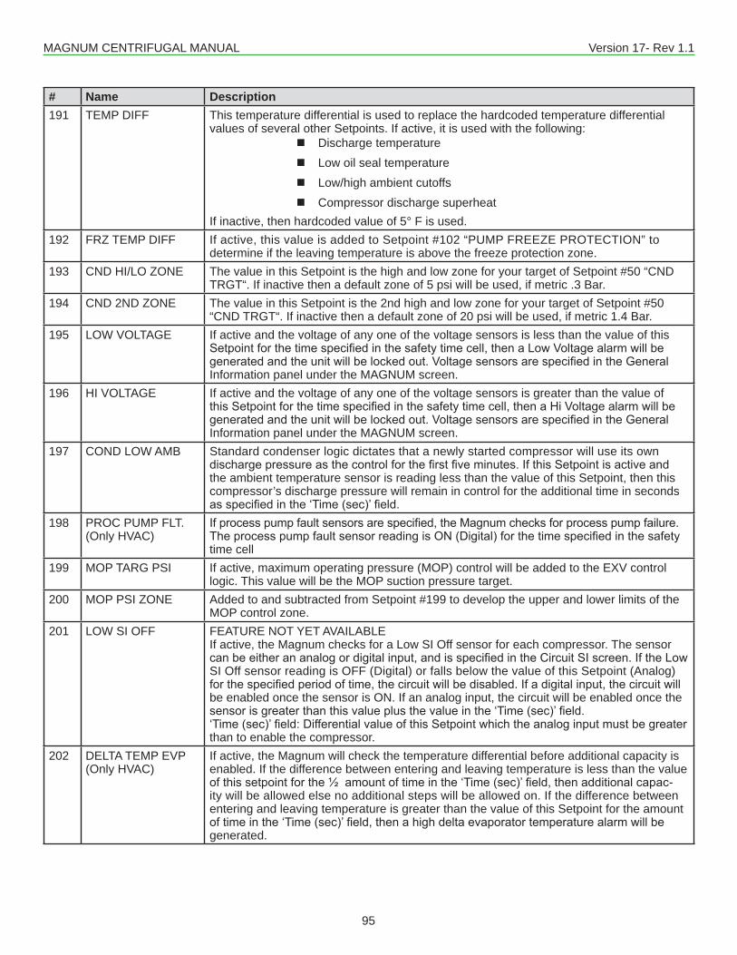
MAGNUM CENTRIFUGAL MANUAL Version 17- Rev 1.1
95
# Name Description191 TEMP DIFF This temperature differential is used to replace the hardcoded temperature differential
values of several other Setpoints. If active, it is used with the following: � Discharge temperature � Low oil seal temperature � Low/high ambient cutoffs � Compressor discharge superheat
If inactive, then hardcoded value of 5° F is used.192 FRZ TEMP DIFF If active, this value is added to Setpoint #102 “PUMP FREEZE PROTECTION” to
determine if the leaving temperature is above the freeze protection zone.193 CND HI/LO ZONE The value in this Setpoint is the high and low zone for your target of Setpoint #50 “CND
TRGT“. If inactive then a default zone of 5 psi will be used, if metric .3 Bar.194 CND 2ND ZONE The value in this Setpoint is the 2nd high and low zone for your target of Setpoint #50
“CND TRGT“. If inactive then a default zone of 20 psi will be used, if metric 1.4 Bar.195 LOW VOLTAGE If active and the voltage of any one of the voltage sensors is less than the value of this
Setpointforthetimespecifiedinthesafetytimecell,thenaLowVoltagealarmwillbegeneratedandtheunitwillbelockedout.VoltagesensorsarespecifiedintheGeneralInformation panel under the MAGNUM screen.
196 HI VOLTAGE If active and the voltage of any one of the voltage sensors is greater than the value of thisSetpointforthetimespecifiedinthesafetytimecell,thenaHiVoltagealarmwillbegeneratedandtheunitwillbelockedout.VoltagesensorsarespecifiedintheGeneralInformation panel under the MAGNUM screen.
197 COND LOW AMB Standard condenser logic dictates that a newly started compressor will use its own dischargepressureasthecontrolforthefirstfiveminutes.IfthisSetpointisactiveandthe ambient temperature sensor is reading less than the value of this Setpoint, then this compressor’s discharge pressure will remain in control for the additional time in seconds asspecifiedinthe‘Time(sec)’field.
198 PROC PUMP FLT.(Only HVAC)
Ifprocesspumpfaultsensorsarespecified,theMagnumchecksforprocesspumpfailure.TheprocesspumpfaultsensorreadingisON(Digital)forthetimespecifiedinthesafetytime cell
199 MOP TARG PSI If active, maximum operating pressure (MOP) control will be added to the EXV control logic. This value will be the MOP suction pressure target.
200 MOP PSI ZONE Added to and subtracted from Setpoint #199 to develop the upper and lower limits of theMOP control zone.
201 LOW SI OFF FEATURE NOT YET AVAILABLEIf active, the Magnum checks for a Low SI Off sensor for each compressor. The sensor canbeeitherananalogordigitalinput,andisspecifiedintheCircuitSIscreen.IftheLowSI Off sensor reading is OFF (Digital) or falls below the value of this Setpoint (Analog) forthespecifiedperiodoftime,thecircuitwillbedisabled.Ifadigitalinput,thecircuitwillbe enabled once the sensor is ON. If an analog input, the circuit will be enabled once the sensorisgreaterthanthisvalueplusthevalueinthe‘Time(sec)’field.‘Time(sec)’field:DifferentialvalueofthisSetpointwhichtheanaloginputmustbegreaterthan to enable the compressor.
202 DELTA TEMP EVP (Only HVAC)
If active, the Magnum will check the temperature differential before additional capacity is enabled. If the difference between entering and leaving temperature is less than the value ofthissetpointforthe½amountoftimeinthe‘Time(sec)’field,thenadditionalcapac-ity will be allowed else no additional steps will be allowed on. If the difference between entering and leaving temperature is greater than the value of this Setpoint for the amount oftimeinthe‘Time(sec)’field,thenahighdeltaevaporatortemperaturealarmwillbegenerated.
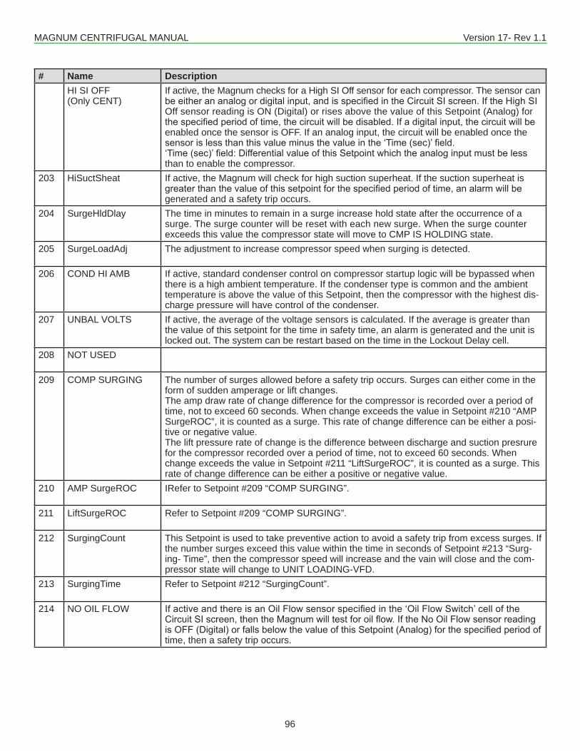
MAGNUM CENTRIFUGAL MANUAL Version 17- Rev 1.1
96
# Name DescriptionHI SI OFF (Only CENT)
If active, the Magnum checks for a High SI Off sensor for each compressor. The sensor can beeitherananalogordigitalinput,andisspecifiedintheCircuitSIscreen.IftheHighSIOff sensor reading is ON (Digital) or rises above the value of this Setpoint (Analog) for thespecifiedperiodoftime,thecircuitwillbedisabled.Ifadigitalinput,thecircuitwillbeenabled once the sensor is OFF. If an analog input, the circuit will be enabled once the sensorislessthanthisvalueminusthevalueinthe‘Time(sec)’field.‘Time(sec)’field:DifferentialvalueofthisSetpointwhichtheanaloginputmustbelessthan to enable the compressor.
203 HiSuctSheat If active, the Magnum will check for high suction superheat. If the suction superheat is greaterthanthevalueofthissetpointforthespecifiedperiodoftime,analarmwillbegenerated and a safety trip occurs.
204 SurgeHldDlay The time in minutes to remain in a surge increase hold state after the occurrence of a surge. The surge counter will be reset with each new surge. When the surge counter exceeds this value the compressor state will move to CMP IS HOLDING state.
205 SurgeLoadAdj The adjustment to increase compressor speed when surging is detected.
206 COND HI AMB If active, standard condenser control on compressor startup logic will be bypassed when there is a high ambient temperature. If the condenser type is common and the ambient temperature is above the value of this Setpoint, then the compressor with the highest dis- charge pressure will have control of the condenser.
207 UNBAL VOLTS If active, the average of the voltage sensors is calculated. If the average is greater than the value of this setpoint for the time in safety time, an alarm is generated and the unit is locked out. The system can be restart based on the time in the Lockout Delay cell.
208 NOT USED
209 COMP SURGING The number of surges allowed before a safety trip occurs. Surges can either come in the form of sudden amperage or lift changes.The amp draw rate of change difference for the compressor is recorded over a period of time, not to exceed 60 seconds. When change exceeds the value in Setpoint #210 “AMP SurgeROC”, it is counted as a surge. This rate of change difference can be either a posi-tive or negative value.The lift pressure rate of change is the difference between discharge and suction presrure for the compressor recorded over a period of time, not to exceed 60 seconds. When change exceeds the value in Setpoint #211 “LiftSurgeROC”, it is counted as a surge. This rate of change difference can be either a positive or negative value.
210 AMP SurgeROC IRefer to Setpoint #209 “COMP SURGING”.
211 LiftSurgeROC Refer to Setpoint #209 “COMP SURGING”.
212 SurgingCount This Setpoint is used to take preventive action to avoid a safety trip from excess surges. If the number surges exceed this value within the time in seconds of Setpoint #213 “Surg-ing- Time”, then the compressor speed will increase and the vain will close and the com-pressor state will change to UNIT LOADING-VFD.
213 SurgingTime Refer to Setpoint #212 “SurgingCount”.
214 NO OIL FLOW IfactiveandthereisanOilFlowsensorspecifiedinthe‘OilFlowSwitch’celloftheCircuitSIscreen,thentheMagnumwilltestforoilflow.IftheNoOilFlowsensorreadingisOFF(Digital)orfallsbelowthevalueofthisSetpoint(Analog)forthespecifiedperiodoftime, then a safety trip occurs.
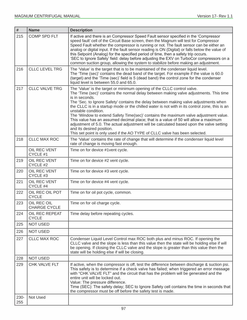
MAGNUM CENTRIFUGAL MANUAL Version 17- Rev 1.1
97
# Name Description215 COMP SPD FLT IfactiveandthereisanCompressorSpeedFaultsensorspecifiedinthe‘Compressor
speed fault’ cell of the Circuit Base screen, then the Magnum will test for Compressor Speed Fault whether the compressor is running or not. The fault sensor can be either an analog or digital input. If the fault sensor reading is ON (Digital) or falls below the value of thisSetpoint(Analog)forthespecifiedperiodoftime,thenasafetytripoccurs.‘SECtoIgnoreSafety’field:delaybeforeadjustingtheEXVonTurboCorcompressorsonacommon suction group, allowing the system to stabilize before making an adjustment.
216 CLLC LEVEL TRG The ‘Value’ is the target that is to be maintained of the condenser liquid level.The ‘Time (sec)’ contains the dead band of the target. For example if the value is 60.0 (target)andthe‘Time(sec)’fieldis5(deadband)thecontrolzoneforthecondenserliquid level is between 55.0 and 65.0.
217 CLLC VALVE TRG The ‘Value’ is the target or minimum opening of the CLLC control valve.The ‘Time (sec)’ contains the normal delay between making valve adjustments. This time is in seconds.The ‘Sec. to Ignore Safety’ contains the delay between making valve adjustments when the CLLC is in a startup mode or the chilled water is not with in its control zone, this is an unstable condition.The ‘Window to extend Safety Time(sec)’ contains the maximum valve adjustment value. Thisvaluehasanassumeddecimalplace;thatisavalueof50willallowamaximumadjustment of 5.0. The actual adjustment will be calculated based upon the valve setting and its desired position.This set point is only used if the AO TYPE of CLLC valve has been selected.
218 CLLC MAX ROC The ‘Value’ contains the rate of change that will determine if the condenser liquid level rate of change is moving fast enough.
OIL REC VENTCYCLE #1
Time on for device #1vent cycle.
219 OIL REC VENTCYCLE #2
Time on for device #2 vent cycle.
220 OIL REC VENTCYCLE #3
Time on for device #3 vent cycle.
221 OIL REC VENTCYCLE #4
Time on for device #4 vent cycle.
222 OIL REC OIL POT CYCLE
Time on for oil pot cycle, common.
223 OIL REC OIL CHARGE CYCLE
Time on for oil charge cycle.
224 OIL REC REPEAT CYCLE
Time delay before repeating cycles.
225 NOT USED
226 NOT USED
227 CLLC MAX ROC Condenser Liquid Level Control max ROC both plus and minus ROC. If opening the CLLC valve and the slope is less than this value then the state will be holding else if will be opening. If closing the CLLC valve and the slope is greater than this value then the state will be holding else if will be closing.
228 NOT USED229 CHK VALVE FLT If active, when the compressor is off, test the difference between discharge & suction psi.
Thissafetyistodetermineifacheckvalvehasfailed;whentriggeredanerrormessagewith “CHK VALVE FLT” and the circuit that has the problem will be generated and the entire unit will be locked out.Value: The pressure difference.Time(SEC):Thesafetydelay;SECtoIgnoreSafetycellcontainsthetimeinsecondsthatthe compressor must be off before the safety test is made.
230-255
Not Used
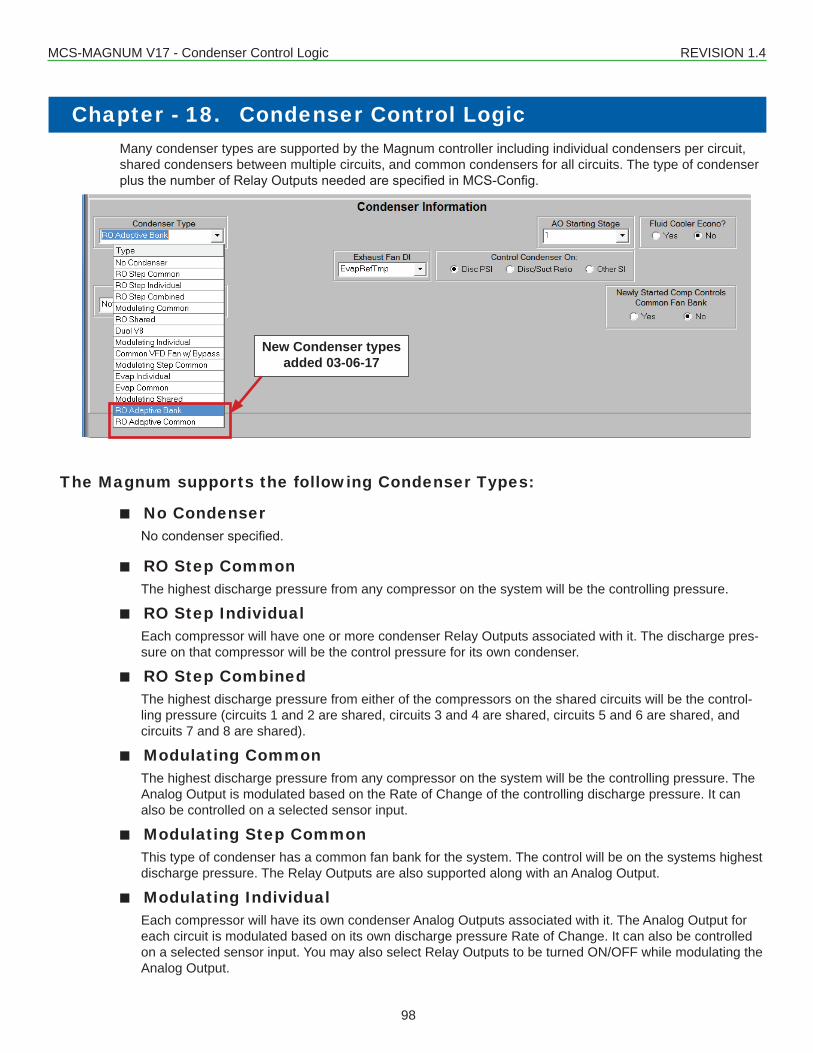
MCS-MAGNUM V17 - Condenser Control Logic REVISION 1.4
98
Many condenser types are supported by the Magnum controller including individual condensers per circuit, shared condensers between multiple circuits, and common condensers for all circuits. The type of condenser plusthenumberofRelayOutputsneededarespecifiedinMCS-Config.
The Magnum supports the following Condenser Types:
■■ No Condenser Nocondenserspecified.
■■ RO Step Common The highest discharge pressure from any compressor on the system will be the controlling pressure.
■■ RO Step Individual Each compressor will have one or more condenser Relay Outputs associated with it. The discharge pres-
sure on that compressor will be the control pressure for its own condenser.
■■ RO Step Combined The highest discharge pressure from either of the compressors on the shared circuits will be the control-
ling pressure (circuits 1 and 2 are shared, circuits 3 and 4 are shared, circuits 5 and 6 are shared, and circuits 7 and 8 are shared).
■■ Modulating Common The highest discharge pressure from any compressor on the system will be the controlling pressure. The
Analog Output is modulated based on the Rate of Change of the controlling discharge pressure. It can also be controlled on a selected sensor input.
■■ Modulating Step Common This type of condenser has a common fan bank for the system. The control will be on the systems highest
discharge pressure. The Relay Outputs are also supported along with an Analog Output.
■■ Modulating Individual Each compressor will have its own condenser Analog Outputs associated with it. The Analog Output for
each circuit is modulated based on its own discharge pressure Rate of Change. It can also be controlled on a selected sensor input. You may also select Relay Outputs to be turned ON/OFF while modulating the Analog Output.
New Condenser types added 03-06-17
Chapter - 18. Condenser Control Logic
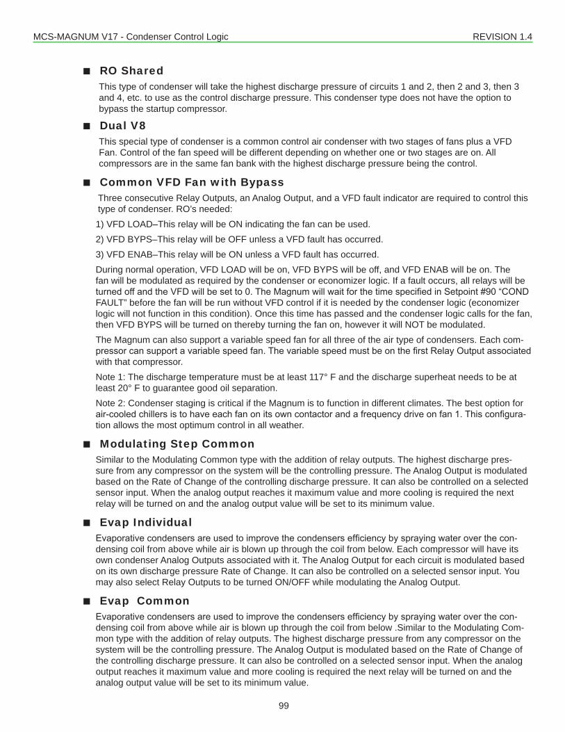
MCS-MAGNUM V17 - Condenser Control Logic REVISION 1.4
99
■■ RO Shared This type of condenser will take the highest discharge pressure of circuits 1 and 2, then 2 and 3, then 3 and 4, etc. to use as the control discharge pressure. This condenser type does not have the option to bypass the startup compressor.
■■ Dual V8 This special type of condenser is a common control air condenser with two stages of fans plus a VFD Fan. Control of the fan speed will be different depending on whether one or two stages are on. All compressors are in the same fan bank with the highest discharge pressure being the control.
■■ Common VFD Fan with Bypass Three consecutive Relay Outputs, an Analog Output, and a VFD fault indicator are required to control this
type of condenser. RO’s needed:1) VFD LOAD–This relay will be ON indicating the fan can be used.2) VFD BYPS–This relay will be OFF unless a VFD fault has occurred.3) VFD ENAB–This relay will be ON unless a VFD fault has occurred.During normal operation, VFD LOAD will be on, VFD BYPS will be off, and VFD ENAB will be on. The fan will be modulated as required by the condenser or economizer logic. If a fault occurs, all relays will be turnedoffandtheVFDwillbesetto0.TheMagnumwillwaitforthetimespecifiedinSetpoint#90“CONDFAULT” before the fan will be run without VFD control if it is needed by the condenser logic (economizer logic will not function in this condition). Once this time has passed and the condenser logic calls for the fan, then VFD BYPS will be turned on thereby turning the fan on, however it will NOT be modulated.The Magnum can also support a variable speed fan for all three of the air type of condensers. Each com-pressorcansupportavariablespeedfan.ThevariablespeedmustbeonthefirstRelayOutputassociatedwith that compressor.Note 1: The discharge temperature must be at least 117° F and the discharge superheat needs to be at least 20° F to guarantee good oil separation.Note 2: Condenser staging is critical if the Magnum is to function in different climates. The best option for air-cooledchillersistohaveeachfanonitsowncontactorandafrequencydriveonfan1.Thisconfigura-tion allows the most optimum control in all weather.
■■ Modulating Step CommonSimilar to the Modulating Common type with the addition of relay outputs. The highest discharge pres-sure from any compressor on the system will be the controlling pressure. The Analog Output is modulated based on the Rate of Change of the controlling discharge pressure. It can also be controlled on a selected sensor input. When the analog output reaches it maximum value and more cooling is required the next relay will be turned on and the analog output value will be set to its minimum value.
■■ Evap IndividualEvaporativecondensersareusedtoimprovethecondensersefficiencybysprayingwateroverthecon-densing coil from above while air is blown up through the coil from below. Each compressor will have its own condenser Analog Outputs associated with it. The Analog Output for each circuit is modulated based on its own discharge pressure Rate of Change. It can also be controlled on a selected sensor input. You may also select Relay Outputs to be turned ON/OFF while modulating the Analog Output.
■■ Evap CommonEvaporativecondensersareusedtoimprovethecondensersefficiencybysprayingwateroverthecon-densing coil from above while air is blown up through the coil from below .Similar to the Modulating Com-mon type with the addition of relay outputs. The highest discharge pressure from any compressor on the system will be the controlling pressure. The Analog Output is modulated based on the Rate of Change of the controlling discharge pressure. It can also be controlled on a selected sensor input. When the analog output reaches it maximum value and more cooling is required the next relay will be turned on and the analog output value will be set to its minimum value.
MCS-MAGNUM V17 - Condenser Control Logic REVISION 1.4
100
■■ RO Adaptive Bank– Air cooled Condenser Fan Control Used to control the condenser fan relay outputs for a single compressor, multiple compressors on the same
refrigerant circuit, or a bank of condenser fans for multiple refrigerant circuits. If single compressor the condenser fans are stage on/off based on the compressor discharge pressure. If multiple compressor or refrigerant circuit, then the high discharge of the running compressors is used to stage condenser fans.
■■ RO Adaptive Common – Air Cooled Condenser Fan Control Used to control the condenser fan relay outputs for all the refrigerant circuits on the unit. This control logic
findsthehighdischargepressureontherunningcompressorsandusesittostageon/offthecondenserfan relays.
18.1. Descriptions of Condenser Types
18.1.1 RO Step Condenser Cut In – Out LogicThe Cut In and Cut Out Logic Setpoints are as follows:
Setpoint #45 “CND STG1 ON” - Condenser stage 1 Cut In (ON).Setpoint #46 “CND STG1 OFF” - Condenser stage 1 Cut Out (OFF).Setpoint #47 “CND DIFF ON“ - Cut In differential for additional condenser stages for (ON).Setpoint #48 “CND DIFF OFF” - Cut Out differential for additional condenser stages (OFF).Setpoint #49 “CND MIN RUN” - Minimum run time for a condenser stage
Condenser Relay Outputs will be turned on based upon the value in Setpoint #45 “CND STG1 ON”. When dischargepressurereachesthisvalue,thefirstcondenserRelayOutputisturnedon.Ifadditionalcondenseroutputs are present, they will be turned on when the pressure exceeds the cut in value plus the value contained in Setpoint #47 “CND DIFF ON“. When discharge pressure falls, the condenser outputs will be turned off based upon the Setpoint #46 “CND STG1 OFF” plus the value contained in Setpoint #48 “CND DIFF OFF”. ThefirststepwillbeturnedoffwhendischargepressurefallsbelowSetpoint#46“CNDSTG1OFF”.Example: COND FAN 1 ON at 200 psi (Discharge)Setpoint #45 “CND STG1 ON” = 200 psi COND FAN 1 OFF at 170 psiSetpoint #46 “CND STG1 OFF” = 170 psiSetpoint #47 “CND DIFF ON” = 20 psi COND FAN 2 ON at 220 psi (200 + 20)Setpoint #48 “CND DIFF OFF” = 5 psi COND FAN 2 OFF at 175 psi (175 + 5)COND FAN 3 ON at 240 psi (220 + 20)COND FAN 3 OFF at 180 psi (175 + 5)
18.1.2 RO Step Condenser with Variable Speed FanThe Setpoints for variable speed fan control are as follows:Setpoint #54 “CND MIN SPD” - Minimum variable speed allowed.Setpoint #55 “CND MAX SPD“ - Maximum variable speed allowed.The purpose of the variable speed fan is to reduce the cycling of the fans by adjusting the speed of the variable fan point. This control works in conjunction with the Cut In and Cut Out logic of each compressor. When a fan is turned on, the speed of the variable point for that compressor is set to maximum allowed percentage. As the discharge pressure falls, the fan speed is adjusted proportionally. When the minimum is reached the fan will turn off.
18.1.3 Condenser ControlThe Condenser Control logic is run with every pass of the algorithm.
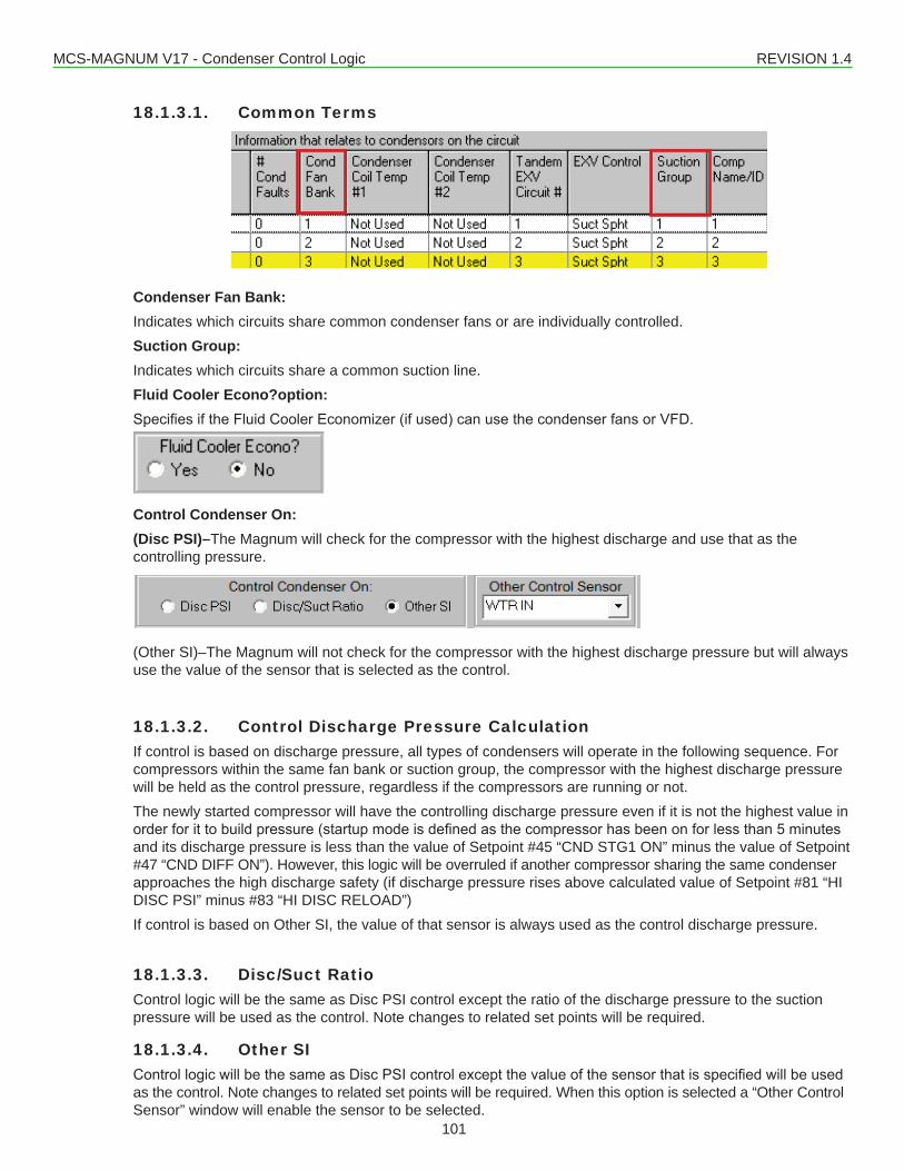
MCS-MAGNUM V17 - Condenser Control Logic REVISION 1.4
101
18.1.3.1. Common Terms
Condenser Fan Bank:Indicates which circuits share common condenser fans or are individually controlled.Suction Group:Indicates which circuits share a common suction line.Fluid Cooler Econo?option:SpecifiesiftheFluidCoolerEconomizer(ifused)canusethecondenserfansorVFD.
Control Condenser On:(Disc PSI)–The Magnum will check for the compressor with the highest discharge and use that as the controlling pressure.
(Other SI)–The Magnum will not check for the compressor with the highest discharge pressure but will always use the value of the sensor that is selected as the control.
18.1.3.2. Control Discharge Pressure CalculationIf control is based on discharge pressure, all types of condensers will operate in the following sequence. For compressors within the same fan bank or suction group, the compressor with the highest discharge pressure will be held as the control pressure, regardless if the compressors are running or not.The newly started compressor will have the controlling discharge pressure even if it is not the highest value in orderforittobuildpressure(startupmodeisdefinedasthecompressorhasbeenonforlessthan5minutesand its discharge pressure is less than the value of Setpoint #45 “CND STG1 ON” minus the value of Setpoint #47 “CND DIFF ON”). However, this logic will be overruled if another compressor sharing the same condenser approaches the high discharge safety (if discharge pressure rises above calculated value of Setpoint #81 “HI DISC PSI” minus #83 “HI DISC RELOAD”)If control is based on Other SI, the value of that sensor is always used as the control discharge pressure.
18.1.3.3. Disc/Suct RatioControl logic will be the same as Disc PSI control except the ratio of the discharge pressure to the suction pressure will be used as the control. Note changes to related set points will be required.
18.1.3.4. Other SI ControllogicwillbethesameasDiscPSIcontrolexceptthevalueofthesensorthatisspecifiedwillbeusedas the control. Note changes to related set points will be required. When this option is selected a “Other Control Sensor” window will enable the sensor to be selected.
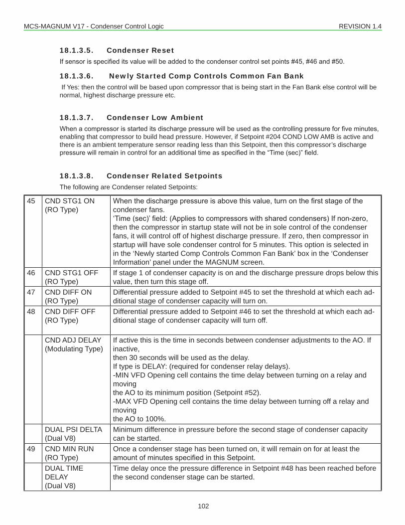
MCS-MAGNUM V17 - Condenser Control Logic REVISION 1.4
102
18.1.3.5. Condenser ResetIfsensorisspecifieditsvaluewillbeaddedtothecondensercontrolsetpoints#45,#46and#50.
18.1.3.6. Newly Started Comp Controls Common Fan Bank If Yes: then the control will be based upon compressor that is being start in the Fan Bank else control will be normal, highest discharge pressure etc.
18.1.3.7. Condenser Low AmbientWhenacompressorisstarteditsdischargepressurewillbeusedasthecontrollingpressureforfiveminutes,enabling that compressor to build head pressure. However, if Setpoint #204 COND LOW AMB is active and there is an ambient temperature sensor reading less than this Setpoint, then this compressor’s discharge pressurewillremainincontrolforanadditionaltimeasspecifiedinthe“Time(sec)”field.
18.1.3.8. Condenser Related SetpointsThe following are Condenser related Setpoints:
45 CND STG1 ON(RO Type)
Whenthedischargepressureisabovethisvalue,turnonthefirststageofthecondenser fans.‘Time(sec)’field:(Appliestocompressorswithsharedcondensers)Ifnon-zero,then the compressor in startup state will not be in sole control of the condenser fans, it will control off of highest discharge pressure. If zero, then compressor in startup will have sole condenser control for 5 minutes. This option is selected in in the ‘Newly started Comp Controls Common Fan Bank’ box in the ‘Condenser Information’ panel under the MAGNUM screen.
46 CND STG1 OFF(RO Type)
If stage 1 of condenser capacity is on and the discharge pressure drops below this value, then turn this stage off.
47 CND DIFF ON(RO Type)
Differential pressure added to Setpoint #45 to set the threshold at which each ad-ditional stage of condenser capacity will turn on.
48 CND DIFF OFF(RO Type)
Differential pressure added to Setpoint #46 to set the threshold at which each ad-ditional stage of condenser capacity will turn off.
CND ADJ DELAY(Modulating Type)
If active this is the time in seconds between condenser adjustments to the AO. If inactive,then 30 seconds will be used as the delay.If type is DELAY: (required for condenser relay delays).-MIN VFD Opening cell contains the time delay between turning on a relay and movingthe AO to its minimum position (Setpoint #52).-MAX VFD Opening cell contains the time delay between turning off a relay and movingthe AO to 100%.
DUAL PSI DELTA(Dual V8)
Minimum difference in pressure before the second stage of condenser capacity can be started.
49 CND MIN RUN(RO Type)
Once a condenser stage has been turned on, it will remain on for at least the amountofminutesspecifiedinthisSetpoint.
DUAL TIME DELAY(Dual V8)
Time delay once the pressure difference in Setpoint #48 has been reached before the second condenser stage can be started.
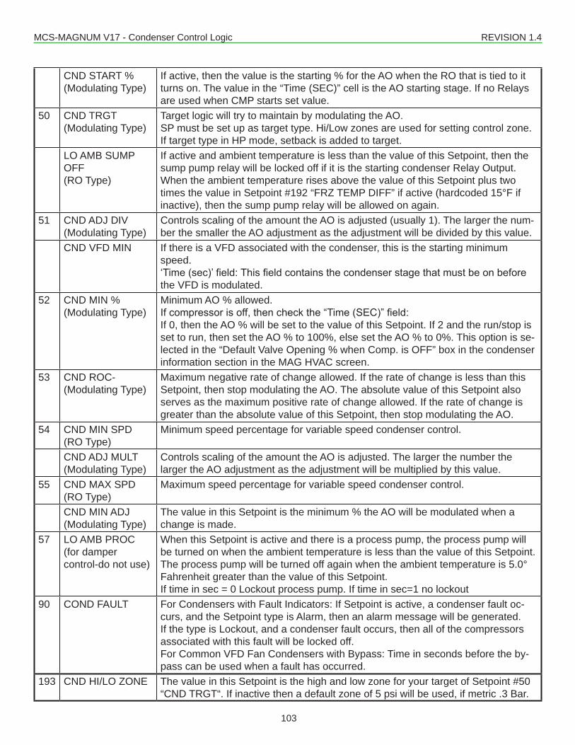
MCS-MAGNUM V17 - Condenser Control Logic REVISION 1.4
103
CND START %(Modulating Type)
If active, then the value is the starting % for the AO when the RO that is tied to it turns on. The value in the “Time (SEC)” cell is the AO starting stage. If no Relays are used when CMP starts set value.
50 CND TRGT(Modulating Type)
Target logic will try to maintain by modulating the AO.SP must be set up as target type. Hi/Low zones are used for setting control zone.If target type in HP mode, setback is added to target.
LO AMB SUMP OFF(RO Type)
If active and ambient temperature is less than the value of this Setpoint, then the sump pump relay will be locked off if it is the starting condenser Relay Output. When the ambient temperature rises above the value of this Setpoint plus two times the value in Setpoint #192 “FRZ TEMP DIFF” if active (hardcoded 15°F if inactive), then the sump pump relay will be allowed on again.
51 CND ADJ DIV(Modulating Type)
Controls scaling of the amount the AO is adjusted (usually 1). The larger the num-ber the smaller the AO adjustment as the adjustment will be divided by this value.
CND VFD MIN If there is a VFD associated with the condenser, this is the starting minimum speed.‘Time(sec)’field:Thisfieldcontainsthecondenserstagethatmustbeonbeforethe VFD is modulated.
52 CND MIN %(Modulating Type)
Minimum AO % allowed.Ifcompressorisoff,thencheckthe“Time(SEC)”field:If 0, then the AO % will be set to the value of this Setpoint. If 2 and the run/stop is set to run, then set the AO % to 100%, else set the AO % to 0%. This option is se-lected in the “Default Valve Opening % when Comp. is OFF” box in the condenser information section in the MAG HVAC screen.
53 CND ROC-(Modulating Type)
Maximum negative rate of change allowed. If the rate of change is less than this Setpoint, then stop modulating the AO. The absolute value of this Setpoint also serves as the maximum positive rate of change allowed. If the rate of change is greater than the absolute value of this Setpoint, then stop modulating the AO.
54 CND MIN SPD(RO Type)
Minimum speed percentage for variable speed condenser control.
CND ADJ MULT(Modulating Type)
Controls scaling of the amount the AO is adjusted. The larger the number the larger the AO adjustment as the adjustment will be multiplied by this value.
55 CND MAX SPD(RO Type)
Maximum speed percentage for variable speed condenser control.
CND MIN ADJ(Modulating Type)
The value in this Setpoint is the minimum % the AO will be modulated when a change is made.
57 LO AMB PROC(for dampercontrol-do not use)
When this Setpoint is active and there is a process pump, the process pump will be turned on when the ambient temperature is less than the value of this Setpoint. The process pump will be turned off again when the ambient temperature is 5.0° Fahrenheit greater than the value of this Setpoint.If time in sec = 0 Lockout process pump. If time in sec=1 no lockout
90 COND FAULT For Condensers with Fault Indicators: If Setpoint is active, a condenser fault oc-curs, and the Setpoint type is Alarm, then an alarm message will be generated. If the type is Lockout, and a condenser fault occurs, then all of the compressors associated with this fault will be locked off.For Common VFD Fan Condensers with Bypass: Time in seconds before the by-pass can be used when a fault has occurred.
193 CND HI/LO ZONE The value in this Setpoint is the high and low zone for your target of Setpoint #50 “CND TRGT“. If inactive then a default zone of 5 psi will be used, if metric .3 Bar.
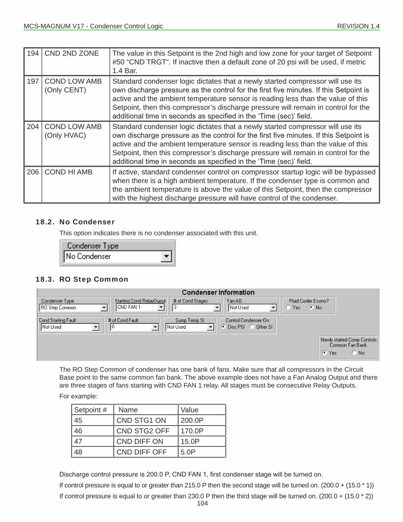
MCS-MAGNUM V17 - Condenser Control Logic REVISION 1.4
104
194 CND 2ND ZONE The value in this Setpoint is the 2nd high and low zone for your target of Setpoint #50 “CND TRGT“. If inactive then a default zone of 20 psi will be used, if metric 1.4 Bar.
197 COND LOW AMB(Only CENT)
Standard condenser logic dictates that a newly started compressor will use its owndischargepressureasthecontrolforthefirstfiveminutes.IfthisSetpointisactive and the ambient temperature sensor is reading less than the value of this Setpoint, then this compressor’s discharge pressure will remain in control for the additionaltimeinsecondsasspecifiedinthe‘Time(sec)’field.
204 COND LOW AMB(Only HVAC)
Standard condenser logic dictates that a newly started compressor will use its owndischargepressureasthecontrolforthefirstfiveminutes.IfthisSetpointisactive and the ambient temperature sensor is reading less than the value of this Setpoint, then this compressor’s discharge pressure will remain in control for the additionaltimeinsecondsasspecifiedinthe‘Time(sec)’field.
206 COND HI AMB If active, standard condenser control on compressor startup logic will be bypassed when there is a high ambient temperature. If the condenser type is common and the ambient temperature is above the value of this Setpoint, then the compressor with the highest discharge pressure will have control of the condenser.
18.2. No CondenserThis option indicates there is no condenser associated with this unit.
18.3. RO Step Common
The RO Step Common of condenser has one bank of fans. Make sure that all compressors in the Circuit Base point to the same common fan bank. The above example does not have a Fan Analog Output and there are three stages of fans starting with CND FAN 1 relay. All stages must be consecutive Relay Outputs.For example:
Setpoint # Name Value45 CND STG1 ON 200.0P46 CND STG2 OFF 170.0P47 CND DIFF ON 15.0P48 CND DIFF OFF 5.0P
Dischargecontrolpressureis200.0P,CNDFAN1,firstcondenserstagewillbeturnedon.If control pressure is equal to or greater than 215.0 P then the second stage will be turned on. (200.0 + (15.0 * 1))If control pressure is equal to or greater than 230.0 P then the third stage will be turned on. (200.0 + (15.0 * 2))
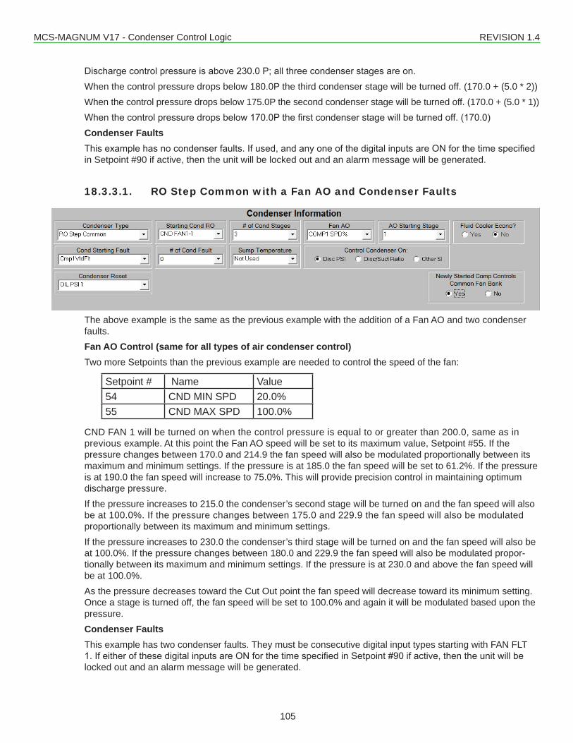
MCS-MAGNUM V17 - Condenser Control Logic REVISION 1.4
105
Dischargecontrolpressureisabove230.0P;allthreecondenserstagesareon.When the control pressure drops below 180.0P the third condenser stage will be turned off. (170.0 + (5.0 * 2))When the control pressure drops below 175.0P the second condenser stage will be turned off. (170.0 + (5.0 * 1))Whenthecontrolpressuredropsbelow170.0Pthefirstcondenserstagewillbeturnedoff.(170.0)Condenser FaultsThisexamplehasnocondenserfaults.Ifused,andanyoneofthedigitalinputsareONforthetimespecifiedin Setpoint #90 if active, then the unit will be locked out and an alarm message will be generated.
18.3.3.1. RO Step Common with a Fan AO and Condenser Faults
The above example is the same as the previous example with the addition of a Fan AO and two condenser faults.Fan AO Control (same for all types of air condenser control)Two more Setpoints than the previous example are needed to control the speed of the fan:
Setpoint # Name Value54 CND MIN SPD 20.0%55 CND MAX SPD 100.0%
CND FAN 1 will be turned on when the control pressure is equal to or greater than 200.0, same as in previous example. At this point the Fan AO speed will be set to its maximum value, Setpoint #55. If the pressure changes between 170.0 and 214.9 the fan speed will also be modulated proportionally between its maximum and minimum settings. If the pressure is at 185.0 the fan speed will be set to 61.2%. If the pressure is at 190.0 the fan speed will increase to 75.0%. This will provide precision control in maintaining optimum discharge pressure.If the pressure increases to 215.0 the condenser’s second stage will be turned on and the fan speed will also be at 100.0%. If the pressure changes between 175.0 and 229.9 the fan speed will also be modulated proportionally between its maximum and minimum settings.If the pressure increases to 230.0 the condenser’s third stage will be turned on and the fan speed will also be at 100.0%. If the pressure changes between 180.0 and 229.9 the fan speed will also be modulated propor-tionally between its maximum and minimum settings. If the pressure is at 230.0 and above the fan speed will be at 100.0%.As the pressure decreases toward the Cut Out point the fan speed will decrease toward its minimum setting. Once a stage is turned off, the fan speed will be set to 100.0% and again it will be modulated based upon the pressure.Condenser FaultsThis example has two condenser faults. They must be consecutive digital input types starting with FAN FLT 1.IfeitherofthesedigitalinputsareONforthetimespecifiedinSetpoint#90ifactive,thentheunitwillbelocked out and an alarm message will be generated.
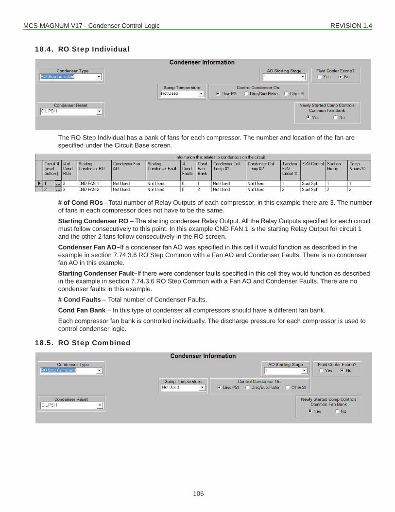
MCS-MAGNUM V17 - Condenser Control Logic REVISION 1.4
106
18.4. RO Step Individual
The RO Step Individual has a bank of fans for each compressor. The number and location of the fan are specifiedundertheCircuitBasescreen.
# of Cond ROs –Total number of Relay Outputs of each compressor, in this example there are 3. The number of fans in each compressor does not have to be the same.Starting Condenser RO–ThestartingcondenserRelayOutput.AlltheRelayOutputsspecifiedforeachcircuitmust follow consecutively to this point. In this example CND FAN 1 is the starting Relay Output for circuit 1 and the other 2 fans follow consecutively in the RO screen.Condenser Fan AO–IfacondenserfanAOwasspecifiedinthiscellitwouldfunctionasdescribedintheexample in section 7.74.3.6 RO Step Common with a Fan AO and Condenser Faults. There is no condenser fan AO in this example.Starting Condenser Fault–Iftherewerecondenserfaultsspecifiedinthiscelltheywouldfunctionasdescribedin the example in section 7.74.3.6 RO Step Common with a Fan AO and Condenser Faults. There are no condenser faults in this example.# Cond Faults – Total number of Condenser Faults.Cond Fan Bank – In this type of condenser all compressors should have a different fan bank.Each compressor fan bank is controlled individually. The discharge pressure for each compressor is used to control condenser logic.
18.5. RO Step Combined
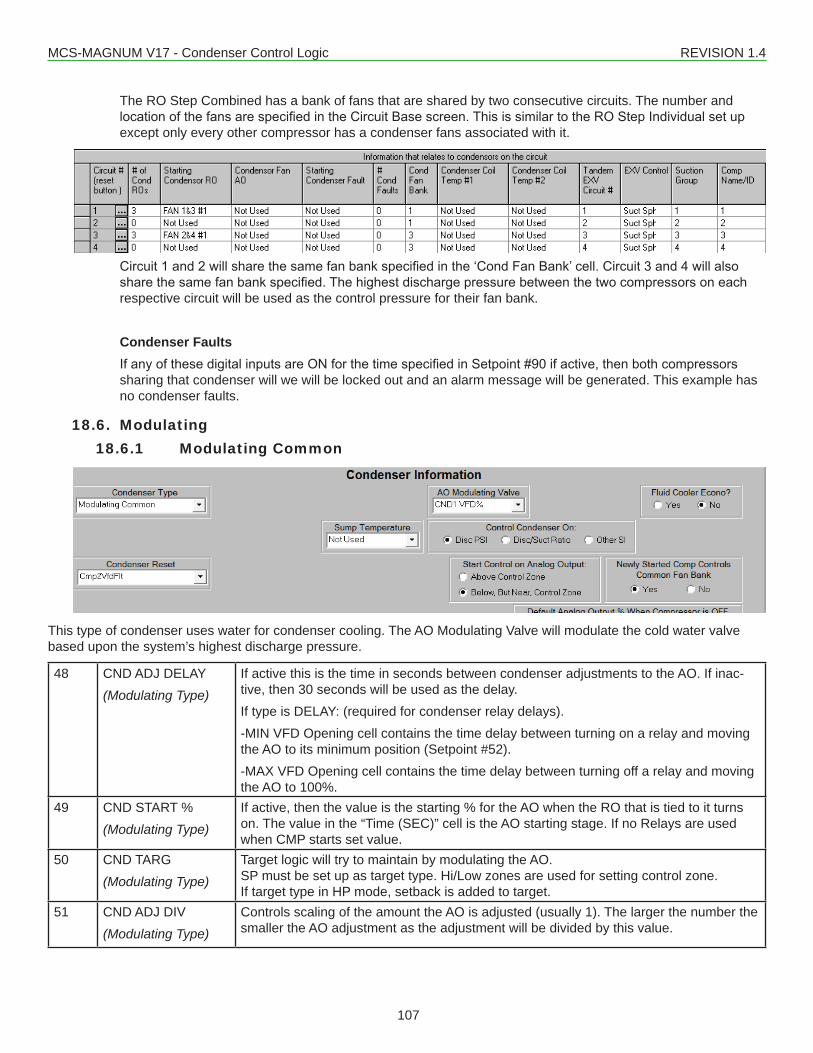
MCS-MAGNUM V17 - Condenser Control Logic REVISION 1.4
107
The RO Step Combined has a bank of fans that are shared by two consecutive circuits. The number and locationofthefansarespecifiedintheCircuitBasescreen.ThisissimilartotheROStepIndividualsetupexcept only every other compressor has a condenser fans associated with it.
Circuit1and2willsharethesamefanbankspecifiedinthe‘CondFanBank’cell.Circuit3and4willalsosharethesamefanbankspecified.Thehighestdischargepressurebetweenthetwocompressorsoneachrespective circuit will be used as the control pressure for their fan bank.
Condenser FaultsIfanyofthesedigitalinputsareONforthetimespecifiedinSetpoint#90ifactive,thenbothcompressorssharing that condenser will we will be locked out and an alarm message will be generated. This example has no condenser faults.
18.6. Modulating18.6.1 Modulating Common
This type of condenser uses water for condenser cooling. The AO Modulating Valve will modulate the cold water valve based upon the system’s highest discharge pressure.
48 CND ADJ DELAY(Modulating Type)
If active this is the time in seconds between condenser adjustments to the AO. If inac-tive, then 30 seconds will be used as the delay.If type is DELAY: (required for condenser relay delays).-MIN VFD Opening cell contains the time delay between turning on a relay and moving the AO to its minimum position (Setpoint #52).-MAX VFD Opening cell contains the time delay between turning off a relay and moving the AO to 100%.
49 CND START %(Modulating Type)
If active, then the value is the starting % for the AO when the RO that is tied to it turns on. The value in the “Time (SEC)” cell is the AO starting stage. If no Relays are used when CMP starts set value.
50 CND TARG(Modulating Type)
Target logic will try to maintain by modulating the AO.SP must be set up as target type. Hi/Low zones are used for setting control zone.If target type in HP mode, setback is added to target.
51 CND ADJ DIV(Modulating Type)
Controls scaling of the amount the AO is adjusted (usually 1). The larger the number the smaller the AO adjustment as the adjustment will be divided by this value.
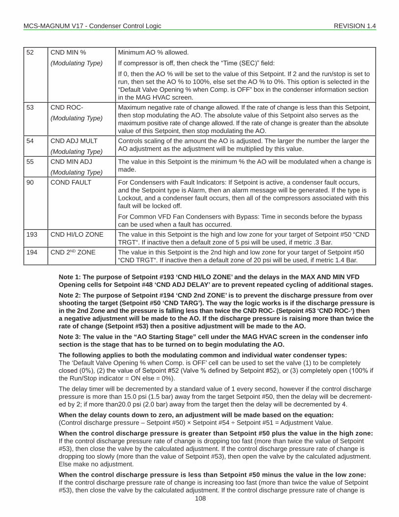
MCS-MAGNUM V17 - Condenser Control Logic REVISION 1.4
108
52 CND MIN %(Modulating Type)
Minimum AO % allowed.Ifcompressorisoff,thencheckthe“Time(SEC)”field:If 0, then the AO % will be set to the value of this Setpoint. If 2 and the run/stop is set to run, then set the AO % to 100%, else set the AO % to 0%. This option is selected in the “Default Valve Opening % when Comp. is OFF” box in the condenser information section in the MAG HVAC screen.
53 CND ROC-(Modulating Type)
Maximum negative rate of change allowed. If the rate of change is less than this Setpoint, then stop modulating the AO. The absolute value of this Setpoint also serves as the maximum positive rate of change allowed. If the rate of change is greater than the absolute value of this Setpoint, then stop modulating the AO.
54 CND ADJ MULT(Modulating Type)
Controls scaling of the amount the AO is adjusted. The larger the number the larger the AO adjustment as the adjustment will be multiplied by this value.
55 CND MIN ADJ(Modulating Type)
The value in this Setpoint is the minimum % the AO will be modulated when a change is made.
90 COND FAULT For Condensers with Fault Indicators: If Setpoint is active, a condenser fault occurs, and the Setpoint type is Alarm, then an alarm message will be generated. If the type is Lockout, and a condenser fault occurs, then all of the compressors associated with this fault will be locked off.For Common VFD Fan Condensers with Bypass: Time in seconds before the bypass can be used when a fault has occurred.
193 CND HI/LO ZONE The value in this Setpoint is the high and low zone for your target of Setpoint #50 “CND TRGT“. If inactive then a default zone of 5 psi will be used, if metric .3 Bar.
194 CND 2ND ZONE The value in this Setpoint is the 2nd high and low zone for your target of Setpoint #50 “CND TRGT“. If inactive then a default zone of 20 psi will be used, if metric 1.4 Bar.
Note 1: The purpose of Setpoint #193 ‘CND HI/LO ZONE’ and the delays in the MAX AND MIN VFD Opening cells for Setpoint #48 ‘CND ADJ DELAY’ are to prevent repeated cycling of additional stages.Note 2: The purpose of Setpoint #194 ‘CND 2nd ZONE’ is to prevent the discharge pressure from over shooting the target (Setpoint #50 ‘CND TARG’). The way the logic works is if the discharge pressure is in the 2nd Zone and the pressure is falling less than twice the CND ROC- (Setpoint #53 ‘CND ROC-‘) then a negative adjustment will be made to the AO. If the discharge pressure is raising more than twice the rate of change (Setpoint #53) then a positive adjustment will be made to the AO.Note 3: The value in the “AO Starting Stage” cell under the MAG HVAC screen in the condenser info section is the stage that has to be turned on to begin modulating the AO.The following applies to both the modulating common and individual water condenser types: The ‘Default Valve Opening % when Comp. is OFF’ cell can be used to set the valve (1) to be completely closed(0%),(2)thevalueofSetpoint#52(Valve%definedbySetpoint#52),or(3)completelyopen(100%ifthe Run/Stop indicator = ON else = 0%).The delay timer will be decremented by a standard value of 1 every second, however if the control discharge pressure is more than 15.0 psi (1.5 bar) away from the target Setpoint #50, then the delay will be decrement-edby2;ifmorethan20.0psi(2.0bar)awayfromthetargetthenthedelaywillbedecrementedby4.When the delay counts down to zero, an adjustment will be made based on the equation: (Control discharge pressure – Setpoint #50) × Setpoint #54 ÷ Setpoint #51 = Adjustment Value.When the control discharge pressure is greater than Setpoint #50 plus the value in the high zone: If the control discharge pressure rate of change is dropping too fast (more than twice the value of Setpoint #53), then close the valve by the calculated adjustment. If the control discharge pressure rate of change is dropping too slowly (more than the value of Setpoint #53), then open the valve by the calculated adjustment. Else make no adjustment.When the control discharge pressure is less than Setpoint #50 minus the value in the low zone: If the control discharge pressure rate of change is increasing too fast (more than twice the value of Setpoint #53), then close the valve by the calculated adjustment. If the control discharge pressure rate of change is
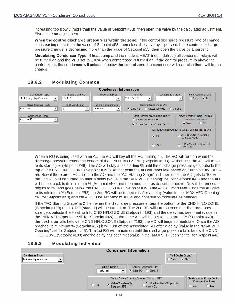
MCS-MAGNUM V17 - Condenser Control Logic REVISION 1.4
109
increasing too slowly (more than the value of Setpoint #53), then open the valve by the calculated adjustment. Else make no adjustment.When the control discharge pressure is within the zone: If the control discharge pressure rate of change is increasing more than the value of Setpoint #53, then close the valve by 1 percent. If the control discharge pressure change is decreasing more than the value of Setpoint #53, then open the valve by 1 percent.Modulating Condenser Type: If heat pump and the mode is HEAT (not in defrost) all condenser relays will be turned on and the VFD set to 100% when compressor is turned on. If the control pressure is above the controlzone,thecondenserwillunload;ifbelowthecontrolzonethecondenserwillloadelsetherewillbenochange.
18.6.2 Modulating Common
When a RO is being used with an AO the AO will key off the RO turning on. The RO will turn on when the discharge pressure enters the bottom of the CND HI/LO ZONE (Setpoint #193). At that time the AO will move to its starting % (Setpoint #49). The AO will stay at its starting % until the discharge pressure gets outside the top of the CND HI/LO ZONE (Setpoint #193). At that point the AO will modulate based on Setpoints #51, #53-55. Now if there are 2 RO’s tied to the AO and the “AO Starting Stage” is 1 then once the AO gets to 100% the 2nd RO will be turned on after a delay (value in the ”MIN VFD Opening“ cell for Setpoint #48) and the AO will be set back to its minimum % (Setpoint #52) and then modulate as described above. Now if the pressure begins to fall and goes below the CND HI/LO ZONE (Setpoint #193) the AO will modulate. Once the AO gets to its minimum % (Setpoint #52) the 2nd RO will be turned off after a delay (value in the “MAX VFD Opening” cell for Setpoint #48) and the AO will be set back to 100% and continue to modulate as needed.If the “AO Starting Stage” is 2 then when the discharge pressure enters the bottom of the CND HI/LO ZONE (Setpoint #193) the 1st RO (stage 1) will be turned on. The 2nd RO will turn on once the discharge pres-sure gets outside the Heating Info CND HI/LO ZONE (Setpoint #193) and the delay has been met (value in the “MIN VFD Opening cell” for Setpoint #48) at that time AO will be set to its starting % (Setpoint #49). If the discharge falls below the CND HI/LO ZONE (Setpoint #193) the AO will begin to modulate. Once the AO reaches its minimum % (Setpoint #52) it will turn off the associated RO after a delay (value in the “MAX VFD Opening” cell for Setpoint #48). The 1st RO will remain on until the discharge pressure falls below the CND HI/LO ZONE (Setpoint #193) and the delay has been met (value in the “MAX VFD Opening” cell for Setpoint #48).
18.6.3 Modulating Individual
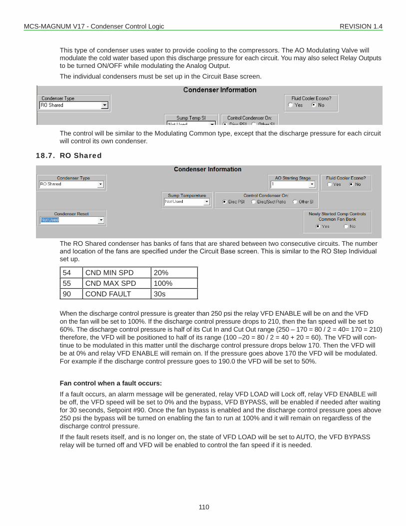
MCS-MAGNUM V17 - Condenser Control Logic REVISION 1.4
110
This type of condenser uses water to provide cooling to the compressors. The AO Modulating Valve will modulate the cold water based upon this discharge pressure for each circuit. You may also select Relay Outputs to be turned ON/OFF while modulating the Analog Output.The individual condensers must be set up in the Circuit Base screen.
The control will be similar to the Modulating Common type, except that the discharge pressure for each circuit will control its own condenser.
18.7. RO Shared
The RO Shared condenser has banks of fans that are shared between two consecutive circuits. The number andlocationofthefansarespecifiedundertheCircuitBasescreen.ThisissimilartotheROStepIndividualset up.
54 CND MIN SPD 20%55 CND MAX SPD 100%90 COND FAULT 30s
When the discharge control pressure is greater than 250 psi the relay VFD ENABLE will be on and the VFD on the fan will be set to 100%. If the discharge control pressure drops to 210, then the fan speed will be set to 60%. The discharge control pressure is half of its Cut In and Cut Out range (250 – 170 = 80 / 2 = 40= 170 = 210) therefore, the VFD will be positioned to half of its range (100 –20 = 80 / 2 = 40 + 20 = 60). The VFD will con-tinue to be modulated in this matter until the discharge control pressure drops below 170. Then the VFD will be at 0% and relay VFD ENABLE will remain on. If the pressure goes above 170 the VFD will be modulated. For example if the discharge control pressure goes to 190.0 the VFD will be set to 50%.
Fan control when a fault occurs:If a fault occurs, an alarm message will be generated, relay VFD LOAD will Lock off, relay VFD ENABLE will be off, the VFD speed will be set to 0% and the bypass, VFD BYPASS, will be enabled if needed after waiting for 30 seconds, Setpoint #90. Once the fan bypass is enabled and the discharge control pressure goes above 250 psi the bypass will be turned on enabling the fan to run at 100% and it will remain on regardless of the discharge control pressure.If the fault resets itself, and is no longer on, the state of VFD LOAD will be set to AUTO, the VFD BYPASS relay will be turned off and VFD will be enabled to control the fan speed if it is needed.
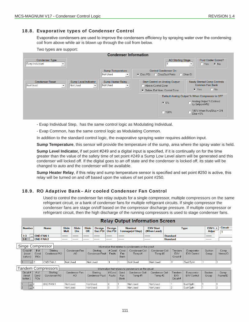
MCS-MAGNUM V17 - Condenser Control Logic REVISION 1.4
111
18.8. Evaporative types of Condenser ControlEvaporativecondensersareusedtoimprovethecondensersefficiencybysprayingwateroverthecondensingcoil from above while air is blown up through the coil from below. Two types are support:
- Evap Individual Step, has the same control logic as Modulating Individual.- Evap Common, has the same control logic as Modulating Common.In addition to the standard control logic, the evaporative spraying water requires addition input.Sump Temperature, this sensor will provide the temperature of the sump, area where the spray water is held.Sump Level Indicator,ifsetpoint#249andadigitalinputisspecified,ifitiscontinuallyonforthetimegreater than the value of the safety time of set point #249 a Sump Low Level alarm will be generated and this condenser will locked off. If the digital goes to an off state and the condenser is locked off, its state will be changed to auto and the condenser will be available.Sump Heater Relay,ifthisrelayandsumptemperaturesensorisspecifiedandsetpoint#250isactive,thisrelay will be turned on and off based upon the values of set point #250.
18.9. RO Adaptive Bank– Air cooled Condenser Fan Control Used to control the condenser fan relay outputs for a single compressor, multiple compressors on the same
refrigerant circuit, or a bank of condenser fans for multiple refrigerant circuits. If single compressor the condenser fans are stage on/off based on the compressor discharge pressure. If multiple compressor or refrigerant circuit, then the high discharge of the running compressors is used to stage condenser fans.
Singe Compressor
Tandem Compressors
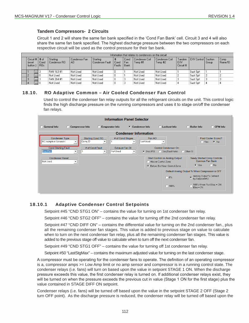
MCS-MAGNUM V17 - Condenser Control Logic REVISION 1.4
112
Tandem Compressors- 2 CircuitsCircuit1and2willsharethesamefanbankspecifiedinthe‘CondFanBank’cell.Circuit3and4willalsosharethesamefanbankspecified.Thehighestdischargepressurebetweenthetwocompressorsoneachrespective circuit will be used as the control pressure for their fan bank.
18.10. RO Adaptive Common – Air Cooled Condenser Fan Control Used to control the condenser fan relay outputs for all the refrigerant circuits on the unit. This control logic
findsthehighdischargepressureontherunningcompressorsandusesittostageon/offthecondenserfan relays.
18.10.1 Adaptive Condenser Control SetpointsSetpoint #45 “CND STG1 ON” – contains the value for turning on 1st condenser fan relay.Setpoint #46 “CND STG2 OFF” – contains the value for turning off the 2nd condenser fan relay.Setpoint #47 “CND DIFF ON” – contains the differential value for turning on the 2nd condenser fan., plus all the remaining condenser fan stages. This value is added to previous stage on value to calculate when to turn on the next condenser fan relay, plus all the remaining condenser fan stages. This value is added to the previous stage off value to calculate when to turn off the next condenser fan.Setpoint #49 “CND STG1 OFF” – contains the value for turning off 1st condenser fan relay.Setpoint #50 “LastStgMax” – contains the maximum adjusted value for turning on the last condenser stage.
Acompressormustbeoperatingforthecondenserfanstooperate.Thedefinitionofanoperatingcompressoris a, compressor amps >= Low Amp limit or no amp sensor and compressor is in a running control state. The condenser relays (i.e. fans) will turn on based upon the value in setpoint STAGE 1 ON. When the discharge pressureexceedsthisvalue,thefirstcondenserrelayisturnedon.Ifadditionalcondenserrelaysexist,theywillbeturnedonwhenthepressureexceedsthepreviouscutinvalue(Stage1ONforthefirststage)plusthevalue contained in STAGE DIFF ON setpoint. Condenser relays (i.e. fans) will be turned off based upon the value in the setpoint STAGE 2 OFF (Stage 2 turn OFF point). As the discharge pressure is reduced, the condenser relay will be turned off based upon the
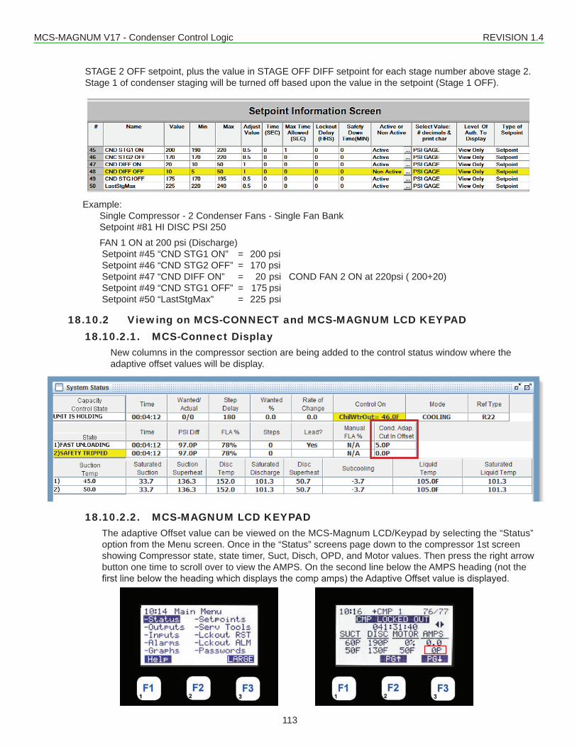
MCS-MAGNUM V17 - Condenser Control Logic REVISION 1.4
113
STAGE 2 OFF setpoint, plus the value in STAGE OFF DIFF setpoint for each stage number above stage 2. Stage 1 of condenser staging will be turned off based upon the value in the setpoint (Stage 1 OFF).
Example:Single Compressor - 2 Condenser Fans - Single Fan BankSetpoint #81 HI DISC PSI 250FAN 1 ON at 200 psi (Discharge)Setpoint #45 “CND STG1 ON” = 200 psi Setpoint #46 “CND STG2 OFF” = 170 psiSetpoint #47 “CND DIFF ON” = 20 psi COND FAN 2 ON at 220psi ( 200+20)Setpoint #49 “CND STG1 OFF” = 175 psi Setpoint #50 “LastStgMax” = 225 psi
18.10.2 Viewing on MCS-CONNECT and MCS-MAGNUM LCD KEYPAD18.10.2.1. MCS-Connect Display
New columns in the compressor section are being added to the control status window where the adaptive offset values will be display.
18.10.2.2. MCS-MAGNUM LCD KEYPADThe adaptive Offset value can be viewed on the MCS-Magnum LCD/Keypad by selecting the “Status” option from the Menu screen. Once in the “Status” screens page down to the compressor 1st screen showing Compressor state, state timer, Suct, Disch, OPD, and Motor values. Then press the right arrow button one time to scroll over to view the AMPS. On the second line below the AMPS heading (not the firstlinebelowtheheadingwhichdisplaysthecompamps)theAdaptiveOffsetvalueisdisplayed.
MCS-MAGNUM V17 - Condenser Control Logic REVISION 1.4
114
18.10.3 Adaptive Control LogicThe Adaptive Condenser logic is a self-learning fan control. The adaptive self-learning logic offers reduced fan cyclingandimprovedefficiency.TheAdaptiveCondenserControlLogicautomaticallyadjuststhefancut-inoffset based upon the following criteria:
1. If the last stage fan turned on (including stage 1) is cycled off in 10 minutes or less, then an Adaptive Offset value will be incriminated by 5 PSI. This increases the stage 1 turn on value (“CND STG1 ON” plus Adaptive Offset) which in turn increases all the remaining fan on values. The Adaptive Offset will continue to increase, until fan cycling ceases or the adjusted turn on value for the last fan stage is greater than setpoint #50 “LastStgMax”.
2. The Adaptive Offset value will be decreased by 5 PSI if the last fan to be turned on has not cycled off within 1 hour. The Adaptive Offset will continue to decrease by 5 PSI every 10 minutes unless fan cycling begins again.
The Adaptive Control Logic will only affect the condenser fan turn on logic, it will not affect the fan turn off logic.
18.10.4 Adaptive Rotation LogicTheadaptivecondenserlogiccanbesetuptorotatethecondenserfansbasedonfirston/firstoffortheleadcondenser fan can be forced to any one of the condenser fans. Setpoint #46 is used to setup/control the type of rotation.If setpoint #46 is not setup as “TIME” type of setpoint no rotation is done and lead condenser fan is forced to thefirstcondenserfanrelayoutput.If setpoint #46 is setup as a “TIME” type
• Andthevalueofthe“Time”columnisZero,thenfirston/firstoffrotationisperformed.Therotationoc-curs when a fan is required to cycle off by the pressure cut out value.
• And the value of the “Time” column is greater than zero and less than the max condenser stages, the leadcondenserfanissettothevalueinthe“Time”field.Forexample,ifthetimecolumncontainsa2,then the lead condenser fan is the second condenser fan in the relay output sequence.
• And if the value if the “Time” column is greater than the max condenser stages, the lead condenser fan isforcetofirstcondenserfanintherelayoutputsequence.
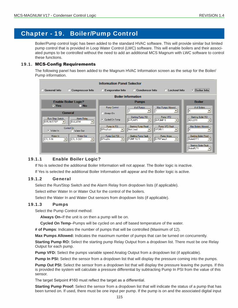
MCS-MAGNUM V17 - Condenser Control Logic REVISION 1.4
115
Boiler/Pump control logic has been added to the standard HVAC software. This will provide similar but limited pump control that is provided in Loop Water Control (LWC) software. This will enable boilers and their associ-ated pumps to be controlled without the need to add an additional MCS Magnum with LWC software to control these functions.
19.1. MCS-Config RequirementsThe following panel has been added to the Magnum HVAC Information screen as the setup for the Boiler/Pump information.
19.1.1 Enable Boiler Logic?If No is selected the additional Boiler Information will not appear. The Boiler logic is inactive.If Yes is selected the additional Boiler Information will appear and the Boiler logic is active.
19.1.2 GeneralSelect the Run/Stop Switch and the Alarm Relay from dropdown lists (if applicable).Select either Water In or Water Out for the control of the boilers.Select the Water In and Water Out sensors from dropdown lists (if applicable).
19.1.3 PumpsSelect the Pump Control method:
Always On–If the unit is on then a pump will be on.Cycled On Temp–Pumps will be cycled on and off based temperature of the water.
# of Pumps: Indicates the number of pumps that will be controlled (Maximum of 12).Max Pumps Allowed: Indicates the maximum number of pumps that can be turned on concurrently.Starting Pump RO: Select the starting pump Relay Output from a dropdown list. There must be one Relay Output for each pump.Pump VFD: Select the pumps variable speed Analog Output from a dropdown list (if applicable).Pump In PSI: Select the sensor from a dropdown list that will display the pressure coming into the pumps.Pump Out PSI: Select the sensor from a dropdown list that will display the pressure leaving the pumps. If this is provided the system will calculate a pressure differential by subtracting Pump In PSI from the value of this sensor.ThetargetSetpoint#160mustreflectthetargetasadifferential.Starting Pump Proof: Select the sensor from a dropdown list that will indicate the status of a pump that has been turned on. If used, there must be one input per pump. If the pump is on and the associated digital input
Chapter - 19. Boiler/Pump Control
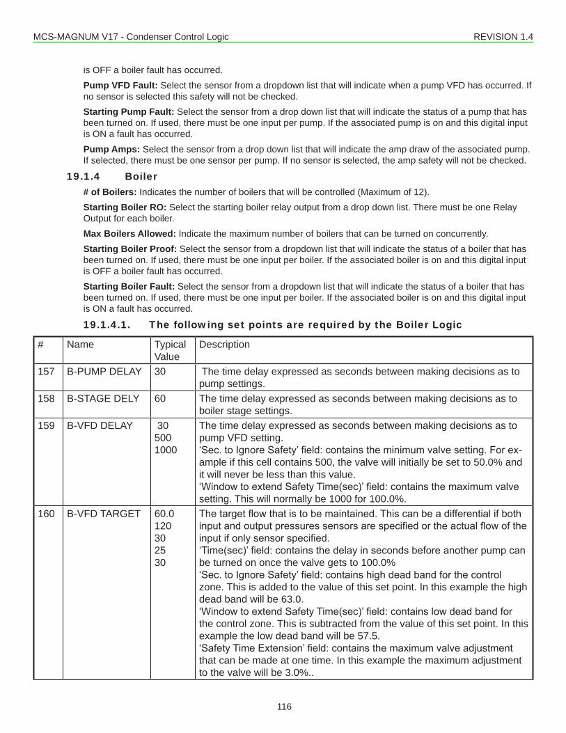
MCS-MAGNUM V17 - Condenser Control Logic REVISION 1.4
116
is OFF a boiler fault has occurred.Pump VFD Fault: Select the sensor from a dropdown list that will indicate when a pump VFD has occurred. If no sensor is selected this safety will not be checked.Starting Pump Fault: Select the sensor from a drop down list that will indicate the status of a pump that has been turned on. If used, there must be one input per pump. If the associated pump is on and this digital input is ON a fault has occurred.Pump Amps: Select the sensor from a drop down list that will indicate the amp draw of the associated pump. If selected, there must be one sensor per pump. If no sensor is selected, the amp safety will not be checked.
19.1.4 Boiler# of Boilers: Indicates the number of boilers that will be controlled (Maximum of 12).Starting Boiler RO: Select the starting boiler relay output from a drop down list. There must be one Relay Output for each boiler.Max Boilers Allowed: Indicate the maximum number of boilers that can be turned on concurrently.Starting Boiler Proof: Select the sensor from a dropdown list that will indicate the status of a boiler that has been turned on. If used, there must be one input per boiler. If the associated boiler is on and this digital input is OFF a boiler fault has occurred.Starting Boiler Fault: Select the sensor from a dropdown list that will indicate the status of a boiler that has been turned on. If used, there must be one input per boiler. If the associated boiler is on and this digital input is ON a fault has occurred.
19.1.4.1. The following set points are required by the Boiler Logic
# Name Typical Value
Description
157 B-PUMP DELAY 30 The time delay expressed as seconds between making decisions as to pump settings.
158 B-STAGE DELY 60 The time delay expressed as seconds between making decisions as to boiler stage settings.
159 B-VFD DELAY 305001000
The time delay expressed as seconds between making decisions as to pump VFD setting.‘Sec.toIgnoreSafety’field:containstheminimumvalvesetting.Forex-ample if this cell contains 500, the valve will initially be set to 50.0% and it will never be less than this value.‘WindowtoextendSafetyTime(sec)’field:containsthemaximumvalvesetting. This will normally be 1000 for 100.0%.
160 B-VFD TARGET 60.0120302530
Thetargetflowthatistobemaintained.Thiscanbeadifferentialifbothinputandoutputpressuressensorsarespecifiedortheactualflowoftheinputifonlysensorspecified.‘Time(sec)’field:containsthedelayinsecondsbeforeanotherpumpcanbe turned on once the valve gets to 100.0%‘Sec.toIgnoreSafety’field:containshighdeadbandforthecontrolzone. This is added to the value of this set point. In this example the high dead band will be 63.0.‘WindowtoextendSafetyTime(sec)’field:containslowdeadbandforthe control zone. This is subtracted from the value of this set point. In this example the low dead band will be 57.5.‘SafetyTimeExtension’field:containsthemaximumvalveadjustmentthat can be made at one time. In this example the maximum adjustment to the valve will be 3.0%..
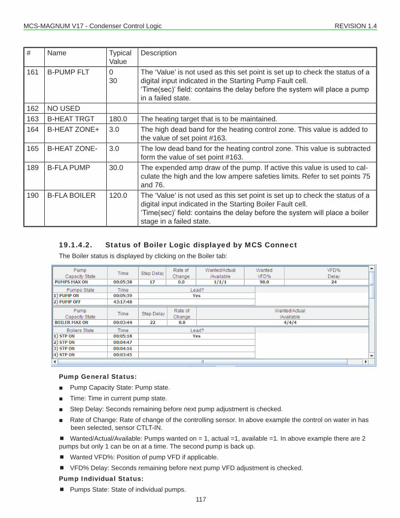
MCS-MAGNUM V17 - Condenser Control Logic REVISION 1.4
117
# Name Typical Value
Description
161 B-PUMP FLT 030
The ‘Value’ is not used as this set point is set up to check the status of a digital input indicated in the Starting Pump Fault cell.‘Time(sec)’field:containsthedelaybeforethesystemwillplaceapumpin a failed state.
162 NO USED 163 B-HEAT TRGT 180.0 The heating target that is to be maintained. 164 B-HEAT ZONE+ 3.0 The high dead band for the heating control zone. This value is added to
the value of set point #163.165 B-HEAT ZONE- 3.0 The low dead band for the heating control zone. This value is subtracted
form the value of set point #163.189 B-FLA PUMP 30.0 The expended amp draw of the pump. If active this value is used to cal-
culate the high and the low ampere safeties limits. Refer to set points 75 and 76.
190 B-FLA BOILER 120.0 The ‘Value’ is not used as this set point is set up to check the status of a digital input indicated in the Starting Boiler Fault cell.‘Time(sec)’field:containsthedelaybeforethesystemwillplaceaboilerstage in a failed state.
19.1.4.2. Status of Boiler Logic displayed by MCS ConnectThe Boiler status is displayed by clicking on the Boiler tab:
Pump General Status: ■ Pump Capacity State: Pump state. ■ Time: Time in current pump state. ■ Step Delay: Seconds remaining before next pump adjustment is checked. ■ Rate of Change: Rate of change of the controlling sensor. In above example the control on water in has
been selected, sensor CTLT-IN. Wanted/Actual/Available: Pumps wanted on = 1, actual =1, available =1. In above example there are 2 pumps but only 1 can be on at a time. The second pump is back up. Wanted VFD%: Position of pump VFD if applicable. VFD% Delay: Seconds remaining before next pump VFD adjustment is checked.Pump Individual Status: Pumps State: State of individual pumps.
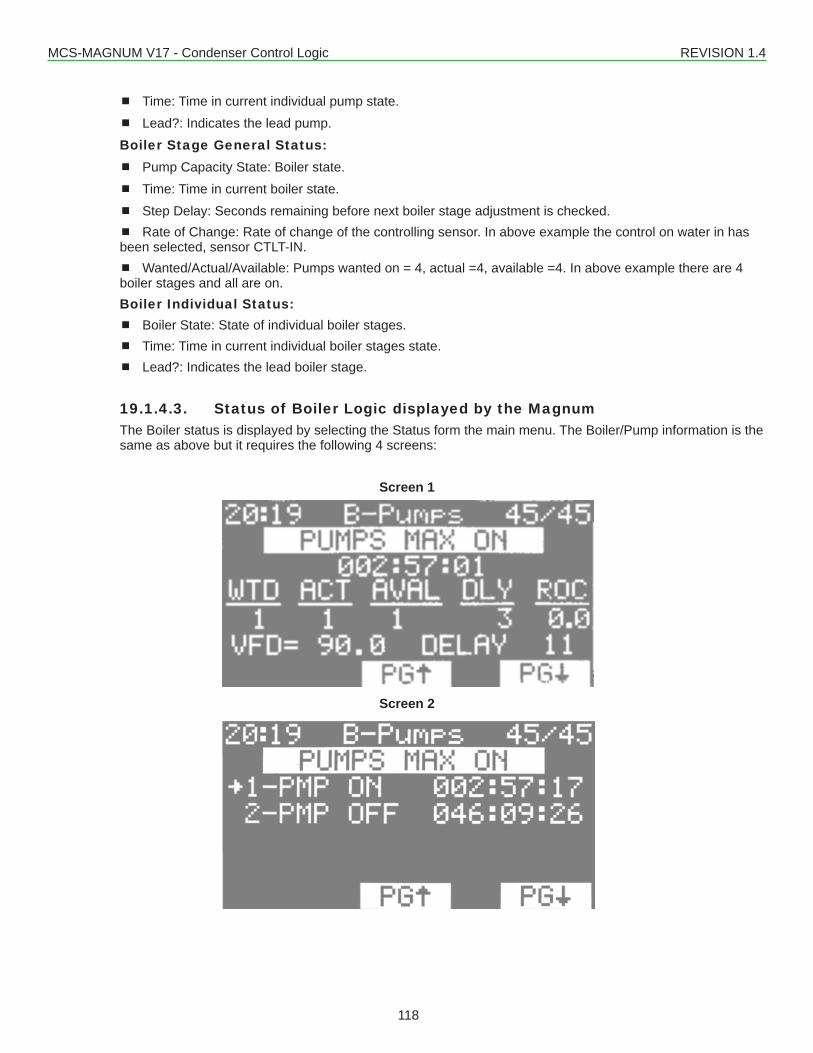
MCS-MAGNUM V17 - Condenser Control Logic REVISION 1.4
118
Time: Time in current individual pump state. Lead?: Indicates the lead pump.Boiler Stage General Status: Pump Capacity State: Boiler state. Time: Time in current boiler state. Step Delay: Seconds remaining before next boiler stage adjustment is checked. Rate of Change: Rate of change of the controlling sensor. In above example the control on water in has been selected, sensor CTLT-IN. Wanted/Actual/Available: Pumps wanted on = 4, actual =4, available =4. In above example there are 4 boiler stages and all are on.Boiler Individual Status: Boiler State: State of individual boiler stages. Time: Time in current individual boiler stages state. Lead?: Indicates the lead boiler stage.
19.1.4.3. Status of Boiler Logic displayed by the MagnumThe Boiler status is displayed by selecting the Status form the main menu. The Boiler/Pump information is the same as above but it requires the following 4 screens:
Screen 1
Screen 2
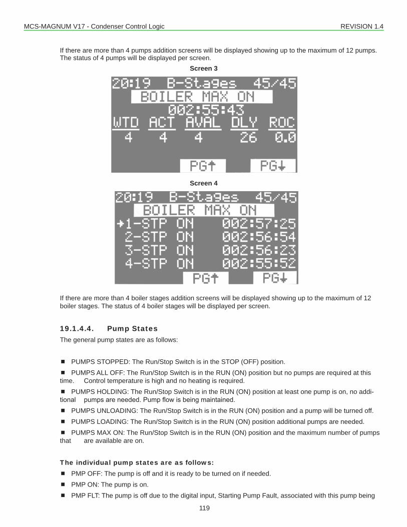
MCS-MAGNUM V17 - Condenser Control Logic REVISION 1.4
119
If there are more than 4 pumps addition screens will be displayed showing up to the maximum of 12 pumps. The status of 4 pumps will be displayed per screen.
Screen 3
Screen 4
If there are more than 4 boiler stages addition screens will be displayed showing up to the maximum of 12 boiler stages. The status of 4 boiler stages will be displayed per screen.
19.1.4.4. Pump StatesThe general pump states are as follows:
PUMPS STOPPED: The Run/Stop Switch is in the STOP (OFF) position. PUMPS ALL OFF: The Run/Stop Switch is in the RUN (ON) position but no pumps are required at this time. Control temperature is high and no heating is required. PUMPS HOLDING: The Run/Stop Switch is in the RUN (ON) position at least one pump is on, no addi-tional pumpsareneeded.Pumpflowisbeingmaintained. PUMPS UNLOADING: The Run/Stop Switch is in the RUN (ON) position and a pump will be turned off. PUMPS LOADING: The Run/Stop Switch is in the RUN (ON) position additional pumps are needed. PUMPS MAX ON: The Run/Stop Switch is in the RUN (ON) position and the maximum number of pumps that are available are on.
The individual pump states are as follows: PMP OFF: The pump is off and it is ready to be turned on if needed. PMP ON: The pump is on. PMP FLT: The pump is off due to the digital input, Starting Pump Fault, associated with this pump being
MCS-MAGNUM V17 - Condenser Control Logic REVISION 1.4
120
on for a time longer than the safety time in set point #161. PMP LOamp: The pump is off due to low amp draw. PMP HIamp: The pump is off due to high amp draw.
19.1.4.5. Boiler StatesThe general boiler states are as follows: BOILER STOPPED: The Run/Stop Switch is in the STOP (OFF) position. BOILER HOLDING: The Run/Stop Switch is in the RUN (ON) position at least one boiler stage is on, no additional boiler stage are needed. Control temperature is being maintained. BOILER UNLOADING: The Run/Stop Switch is in the RUN (ON) position and a boiler stage will be turned off as the control temperature is too high. BOILER LOADING: The Run/Stop Switch is in the RUN (ON) position additional boiler stages are needed as the control temperature is too low. BOILER MAX ON: The Run/Stop Switch is in the RUN (ON) position and the maximum number of boiler stages that are available are on.
The individual boiler states are as follows: STP OFF: The boiler stage is off and it is ready to be turned on if needed. STP ON: The boiler stage is on. STP FLT: The boiler stage is off due to the digital input, Starting Boiler Fault, associated with this boiler stage being on for a time longer than the safety time in set point #190.
19.2. Control for Second set of Evaporator Pumps/FansA second set (bank) of Pumps/Fans have been added to the HVAC software. The purpose is to support sys-temswithtwosetsofpumpswhichprovideflowtodifferentcircuits.
Whenthesystemisinaruncondition,bothleadpumpsofeachbankwillbeturnedontoprovideflow.Ifei-ther of the lead pumps fails, the running pump will be locked off and the backup pump for that respective bank willbestarted.Thecircuitsassociatedwiththefailedpumpwillbemovedtoanoflowstate(disabled)assoonasflowislost.Ifflowisrestoredthecircuitwillbeenabledagain.Ifbothpumpsonabankfail,thenthecircuitwill be in a safety off state.
The 2 pump banks function independently, however, they both use common Setpoints to determine pump rotation, pump lead, and safety times.
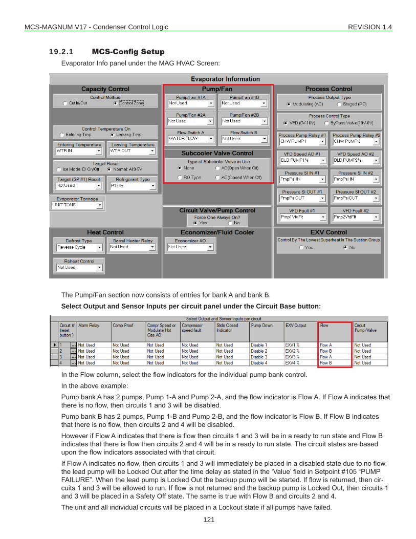
MCS-MAGNUM V17 - Condenser Control Logic REVISION 1.4
121
19.2.1 MCS-Config SetupEvaporator Info panel under the MAG HVAC Screen:
The Pump/Fan section now consists of entries for bank A and bank B.Select Output and Sensor Inputs per circuit panel under the Circuit Base button:
IntheFlowcolumn,selecttheflowindicatorsfortheindividualpumpbankcontrol.In the above example:PumpbankAhas2pumps,Pump1-AandPump2-A,andtheflowindicatorisFlowA.IfFlowAindicatesthatthereisnoflow,thencircuits1and3willbedisabled.PumpbankBhas2pumps,Pump1-BandPump2-B,andtheflowindicatorisFlowB.IfFlowBindicatesthatthereisnoflow,thencircuits2and4willbedisabled.HoweverifFlowAindicatesthatthereisflowthencircuits1and3willbeinareadytorunstateandFlowBindicatesthatthereisflowthencircuits2and4willbeinareadytorunstate.Thecircuitstatesarebasedupontheflowindicatorsassociatedwiththatcircuit.IfFlowAindicatesnoflow,thencircuits1and3willimmediatelybeplacedinadisabledstateduetonoflow,theleadpumpwillbeLockedOutafterthetimedelayasstatedinthe‘Value’fieldinSetpoint#105“PUMPFAILURE”.WhentheleadpumpisLockedOutthebackuppumpwillbestarted.Ifflowisreturned,thencir-cuits1and3willbeallowedtorun.IfflowisnotreturnedandthebackuppumpisLockedOut,thencircuits1and 3 will be placed in a Safety Off state. The same is true with Flow B and circuits 2 and 4.The unit and all individual circuits will be placed in a Lockout state if all pumps have failed.
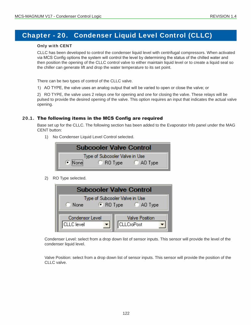
MCS-MAGNUM V17 - Condenser Control Logic REVISION 1.4
122
Only with CENTCLLC has been developed to control the condenser liquid level with centrifugal compressors. When activated viaMCSConfigoptionsthesystemwillcontrolthelevelbydeterminingthestatusofthechilledwaterandthen position the opening of the CLLC control valve to either maintain liquid level or to create a liquid seal so the chiller can generate lift and drop the water temperature to its set point.
There can be two types of control of the CLLC valve.1) AOTYPE,thevalveusesananalogoutputthatwillbevariedtoopenorclosethevalve;or2) RO TYPE, the valve uses 2 relays one for opening and one for closing the valve. These relays will be pulsed to provide the desired opening of the valve. This option requires an input that indicates the actual valve opening.
20.1. The following items in the MCS Config are requiredBase set up for the CLLC. The following section has been added to the Evaporator Info panel under the MAG CENT button:
1) No Condenser Liquid Level Control selected.
2) RO Type selected.
Condenser Level: select from a drop down list of sensor inputs. This sensor will provide the level of the condenser liquid level.
Valve Position: select from a drop down list of sensor inputs. This sensor will provide the position of the CLLC valve.
Chapter - 20. Condenser Liquid Level Control (CLLC)
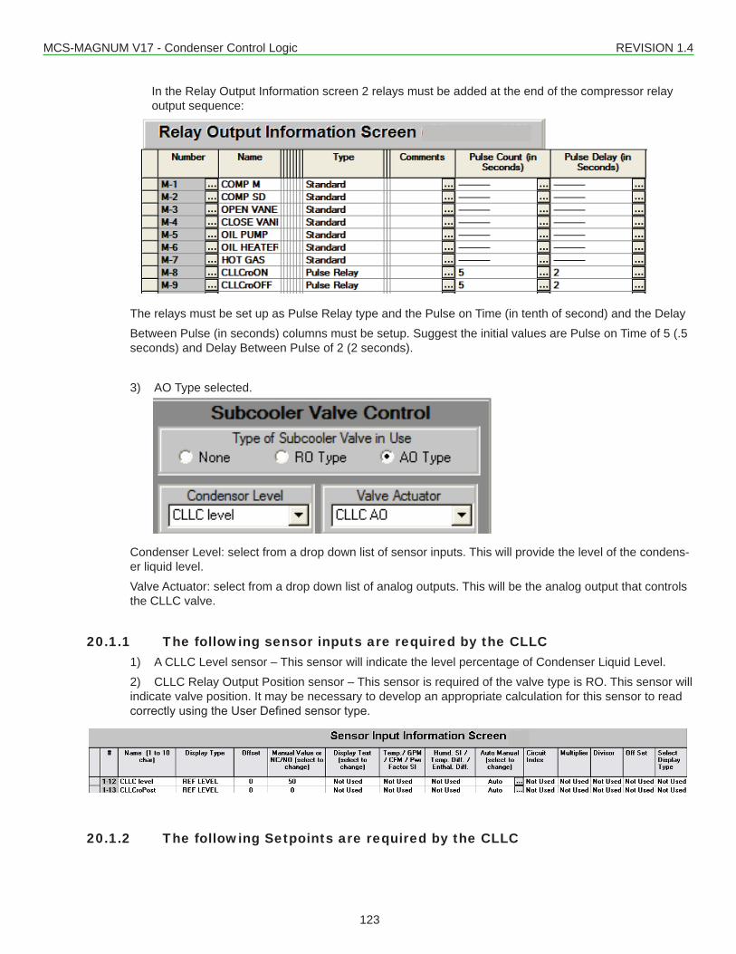
MCS-MAGNUM V17 - Condenser Control Logic REVISION 1.4
123
In the Relay Output Information screen 2 relays must be added at the end of the compressor relay output sequence:
The relays must be set up as Pulse Relay type and the Pulse on Time (in tenth of second) and the Delay Between Pulse (in seconds) columns must be setup. Suggest the initial values are Pulse on Time of 5 (.5 seconds) and Delay Between Pulse of 2 (2 seconds).
3) AO Type selected.
Condenser Level: select from a drop down list of sensor inputs. This will provide the level of the condens-er liquid level.Valve Actuator: select from a drop down list of analog outputs. This will be the analog output that controls the CLLC valve.
20.1.1 The following sensor inputs are required by the CLLC1) A CLLC Level sensor – This sensor will indicate the level percentage of Condenser Liquid Level.2) CLLC Relay Output Position sensor – This sensor is required of the valve type is RO. This sensor will indicate valve position. It may be necessary to develop an appropriate calculation for this sensor to read correctlyusingtheUserDefinedsensortype.
20.1.2 The following Setpoints are required by the CLLC
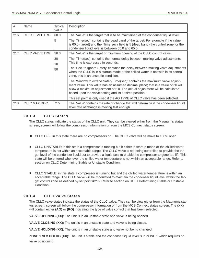
MCS-MAGNUM V17 - Condenser Control Logic REVISION 1.4
124
# Name Typical Value
Description
216 CLLC LEVEL TRG 60.05
The ‘Value’ is the target that is to be maintained of the condenser liquid level.The ‘Time(sec)’ contains the dead band of the target. For example if the value is60.0(target)andthe‘Time(sec)’fieldis5(deadband)thecontrolzoneforthecondenser liquid level is between 55.0 and 65.0.
217 CLLC VALVE TRG 50.0301050
The ‘Value’ is the target or minimum opening of the CLLC control valve.The ‘Time(sec)’ contains the normal delay between making valve adjustments. This time is expressed in seconds.The ‘Sec. to Ignore Safety’ contains the delay between making valve adjustments when the CLLC is in a startup mode or the chilled water is not with in its control zone, this is an unstable condition.The ‘Window to extend Safety Time(sec)’ contains the maximum valve adjust-mentvalue.Thisvaluehasanassumeddecimalplace;thatisavalueof50willallow a maximum adjustment of 5.0. The actual adjustment will be calculated based upon the valve setting and its desired position.This set point is only used if the AO TYPE of CLLC valve has been selected.
218 CLLC MAX ROC 2.5 The ‘Value’ contains the rate of change that will determine if the condenser liquid level rate of change is moving fast enough
20.1.3 CLLC StatesThe CLLC states indicate the status of the CLLC unit. They can be viewed either from the Magnum’s status screen, screen will follow the compressor information or from the MCS Connect status screen.
CLLC OFF: in this state there are no compressors on. The CLLC valve will be move to 100% open.
CLLC UNSTABLE: in this state a compressor is running but it either in startup mode or the chilled water temperature is not within an acceptable range. The CLLC valve is not being controlled to provide the tar-get level of the condenser liquid but to provide a liquid seal to enable the compressor to generate lift. This state will be entered whenever the chilled water temperature is not within an acceptable range. Refer to section on CLLC Determining Stable or Unstable Condition.
CLLC STABLE: in this state a compressor is running but and the chilled water temperature is within an acceptable range. The CLLC valve will be modulated to maintain the condenser liquid level within the tar-getcontrolzoneasdefinedbysetpoint#216.RefertosectiononCLLCDeterminingStableorUnstableCondition.
20.1.4 CLLC Valve StatesThe CLLC valve states indicate the status of the CLLC valve. They can be view either from the Magnums sta-tus screen, screen will follow the compressor information or from the MCS Connect status screen. The (XX) will contain either (AO) or (RO) indicating the type of valve control that has been selected.
VALVE OPENING (XX): The unit is in an unstable state and valve is being opened.
VALVE CLOSING (XX): The unit is in an unstable state and valve is being closed.
VALVE HOLDING (XX): The unit is in an unstable state and valve not being changed.
ZONE 1 VLV HOLDG (XX): The unit is stable and the condenser liquid level is in ZONE 1 which requires no valve positioning.
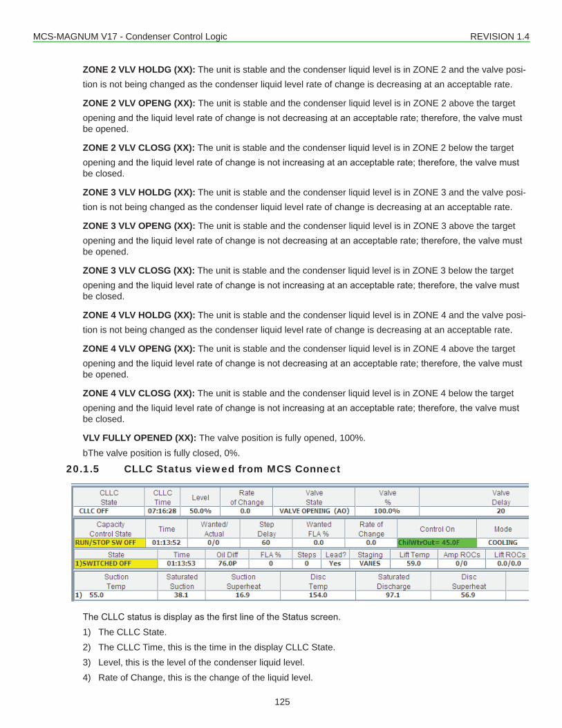
MCS-MAGNUM V17 - Condenser Control Logic REVISION 1.4
125
ZONE 2 VLV HOLDG (XX): The unit is stable and the condenser liquid level is in ZONE 2 and the valve posi-tion is not being changed as the condenser liquid level rate of change is decreasing at an acceptable rate.
ZONE 2 VLV OPENG (XX): The unit is stable and the condenser liquid level is in ZONE 2 above the target opening andtheliquidlevelrateofchangeisnotdecreasingatanacceptablerate;therefore,thevalvemustbe opened.
ZONE 2 VLV CLOSG (XX): The unit is stable and the condenser liquid level is in ZONE 2 below the target openingandtheliquidlevelrateofchangeisnotincreasingatanacceptablerate;therefore,thevalvemustbe closed.
ZONE 3 VLV HOLDG (XX): The unit is stable and the condenser liquid level is in ZONE 3 and the valve posi-tion is not being changed as the condenser liquid level rate of change is decreasing at an acceptable rate.
ZONE 3 VLV OPENG (XX): The unit is stable and the condenser liquid level is in ZONE 3 above the target openingandtheliquidlevelrateofchangeisnotdecreasingatanacceptablerate;therefore,thevalvemustbe opened.
ZONE 3 VLV CLOSG (XX): The unit is stable and the condenser liquid level is in ZONE 3 below the target openingandtheliquidlevelrateofchangeisnotincreasingatanacceptablerate;therefore,thevalvemustbe closed.
ZONE 4 VLV HOLDG (XX): The unit is stable and the condenser liquid level is in ZONE 4 and the valve posi-tion is not being changed as the condenser liquid level rate of change is decreasing at an acceptable rate.
ZONE 4 VLV OPENG (XX): The unit is stable and the condenser liquid level is in ZONE 4 above the target opening andtheliquidlevelrateofchangeisnotdecreasingatanacceptablerate;therefore,thevalvemustbe opened.
ZONE 4 VLV CLOSG (XX): The unit is stable and the condenser liquid level is in ZONE 4 below the target openingandtheliquidlevelrateofchangeisnotincreasingatanacceptablerate;therefore,thevalvemustbe closed.
VLV FULLY OPENED (XX): The valve position is fully opened, 100%.bThe valve position is fully closed, 0%.
20.1.5 CLLC Status viewed from MCS Connect
TheCLLCstatusisdisplayasthefirstlineoftheStatusscreen.1) The CLLC State.2) The CLLC Time, this is the time in the display CLLC State.3) Level, this is the level of the condenser liquid level.4) Rate of Change, this is the change of the liquid level.
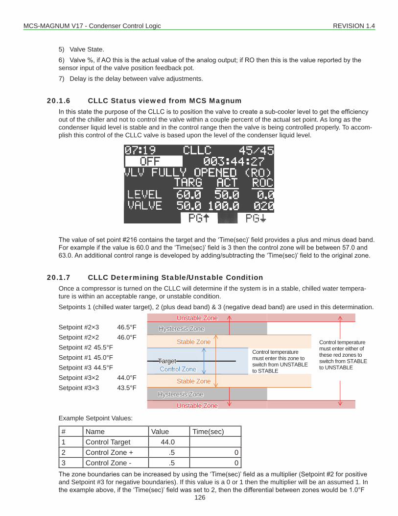
MCS-MAGNUM V17 - Condenser Control Logic REVISION 1.4
126
5) Valve State.6) Valve%,ifAOthisistheactualvalueoftheanalogoutput;ifROthenthisisthevaluereportedbythesensor input of the valve position feedback pot.7) Delay is the delay between valve adjustments.
20.1.6 CLLC Status viewed from MCS Magnum InthisstatethepurposeoftheCLLCistopositionthevalvetocreateasub-coolerleveltogettheefficiencyout of the chiller and not to control the valve within a couple percent of the actual set point. As long as the condenser liquid level is stable and in the control range then the valve is being controlled properly. To accom-plish this control of the CLLC valve is based upon the level of the condenser liquid level.
Thevalueofsetpoint#216containsthetargetandthe‘Time(sec)’fieldprovidesaplusandminusdeadband.Forexampleifthevalueis60.0andthe‘Time(sec)’fieldis3thenthecontrolzonewillbebetween57.0and63.0.Anadditionalcontrolrangeisdevelopedbyadding/subtractingthe‘Time(sec)’fieldtotheoriginalzone.
20.1.7 CLLC Determining Stable/Unstable ConditionOnce a compressor is turned on the CLLC will determine if the system is in a stable, chilled water tempera-ture is within an acceptable range, or unstable condition.Setpoints 1 (chilled water target), 2 (plus dead band) & 3 (negative dead band) are used in this determination.
Setpoint #2×3 46.5°FSetpoint #2×2 46.0°FSetpoint #2 45.5°FSetpoint #1 45.0°FSetpoint #3 44.5°FSetpoint #3×2 44.0°FSetpoint #3×3 43.5°F
Example Setpoint Values:
# Name Value Time(sec)1 Control Target 44.02 Control Zone + .5 03 Control Zone - .5 0Thezoneboundariescanbeincreasedbyusingthe‘Time(sec)’fieldasamultiplier(Setpoint#2forpositiveand Setpoint #3 for negative boundaries). If this value is a 0 or 1 then the multiplier will be an assumed 1. In theexampleabove,ifthe‘Time(sec)’fieldwassetto2,thenthedifferentialbetweenzoneswouldbe1.0°F
Control Zone
Stable Zone
Unstable Zone
Unstable Zone
Control temperature must enter this zone to switch from UNSTABLE to STABLE
Control temperature must enter either of these red zones to switch from STABLE to UNSTABLE
Target
Stable Zone
Hysteresis Zone
Hysteresis Zone
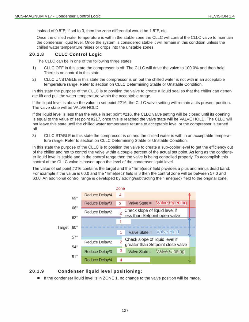
MCS-MAGNUM V17 - Condenser Control Logic REVISION 1.4
127
insteadof0.5°F;ifsetto3,thenthezonedifferentialwouldbe1.5°F,etc.Once the chilled water temperature is within the stable zone the CLLC will control the CLLC valve to maintain the condenser liquid level. Once the system is considered stable it will remain in this condition unless the chilled water temperature raises or drops into the unstable zones.
20.1.8 CLLC Control LogicThe CLLC can be in one of the following three states:
1) CLLC OFF in this state the compressor is off. The CLLC will drive the valve to 100.0% and then hold. There is no control in this state.
2) CLLC UNSTABLE in this state the compressor is on but the chilled water is not with in an acceptable temperature range. Refer to section on CLLC Determining Stable or Unstable Condition.
In this state the purpose of the CLLC is to position the valve to create a liquid seal so that the chiller can gener-ate lift and pull the water temperature within the acceptable range.If the liquid level is above the value in set point #216, the CLLC valve setting will remain at its present position. The valve state will be VALVE HOLD.If the liquid level is less than the value in set point #216, the CLLC valve setting will be closed until its opening is equal to the value of set point #217, once this is reached the valve state will be VALVE HOLD. The CLLC will not leave this state until the chilled water temperature returns to acceptable level or the compressor is turned off.3) CLLC STABLE in this state the compressor is on and the chilled water is with in an acceptable tempera-
ture range. Refer to section on CLLC Determining Stable or Unstable Condition.InthisstatethepurposeoftheCLLCistopositionthevalvetocreateasub-coolerleveltogettheefficiencyoutof the chiller and not to control the valve within a couple percent of the actual set point. As long as the condens-er liquid level is stable and in the control range then the valve is being controlled properly. To accomplish this control of the CLLC valve is based upon the level of the condenser liquid level.Thevalueofsetpoint#216containsthetargetandthe‘Time(sec)’fieldprovidesaplusandminusdeadband.Forexampleifthevalueis60.0andthe‘Time(sec)’fieldis3thenthecontrolzonewillbebetween57.0and63.0.Anadditionalcontrolrangeisdevelopedbyadding/subtractingthe‘Time(sec)’fieldtotheoriginalzone.
20.1.9 Condenser liquid level positioning: If the condenser liquid level is in ZONE 1, no change to the valve position will be made.
Zone
69°
66°
63°
Target 60°
57°
54°
51°
Valve Hold
Valve Closing
Valve Opening Reduce Delay/3 Valve State =
Reduce Delay/2 Check slope of liquid level if less than Setpoint open valve
Check slope of liquid level if greater than Setpoint close valveReduce Delay/2
Reduce Delay/3 Valve State =
Valve State =
3
1
1
2
3
4
2
4Reduce Delay/4
Reduce Delay/4
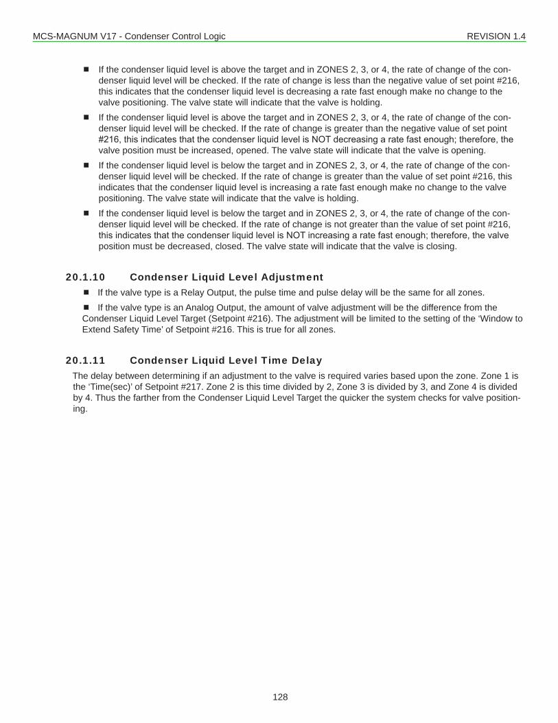
MCS-MAGNUM V17 - Condenser Control Logic REVISION 1.4
128
If the condenser liquid level is above the target and in ZONES 2, 3, or 4, the rate of change of the con-denser liquid level will be checked. If the rate of change is less than the negative value of set point #216, this indicates that the condenser liquid level is decreasing a rate fast enough make no change to the valve positioning. The valve state will indicate that the valve is holding.
If the condenser liquid level is above the target and in ZONES 2, 3, or 4, the rate of change of the con-denser liquid level will be checked. If the rate of change is greater than the negative value of set point #216,thisindicatesthatthecondenserliquidlevelisNOTdecreasingaratefastenough;therefore,thevalve position must be increased, opened. The valve state will indicate that the valve is opening.
If the condenser liquid level is below the target and in ZONES 2, 3, or 4, the rate of change of the con-denser liquid level will be checked. If the rate of change is greater than the value of set point #216, this indicates that the condenser liquid level is increasing a rate fast enough make no change to the valve positioning. The valve state will indicate that the valve is holding.
If the condenser liquid level is below the target and in ZONES 2, 3, or 4, the rate of change of the con-denser liquid level will be checked. If the rate of change is not greater than the value of set point #216, thisindicatesthatthecondenserliquidlevelisNOTincreasingaratefastenough;therefore,thevalveposition must be decreased, closed. The valve state will indicate that the valve is closing.
20.1.10 Condenser Liquid Level Adjustment If the valve type is a Relay Output, the pulse time and pulse delay will be the same for all zones. If the valve type is an Analog Output, the amount of valve adjustment will be the difference from the Condenser Liquid Level Target (Setpoint #216). The adjustment will be limited to the setting of the ‘Window to Extend Safety Time’ of Setpoint #216. This is true for all zones.
20.1.11 Condenser Liquid Level Time DelayThe delay between determining if an adjustment to the valve is required varies based upon the zone. Zone 1 is the ‘Time(sec)’ of Setpoint #217. Zone 2 is this time divided by 2, Zone 3 is divided by 3, and Zone 4 is divided by 4. Thus the farther from the Condenser Liquid Level Target the quicker the system checks for valve position-ing.
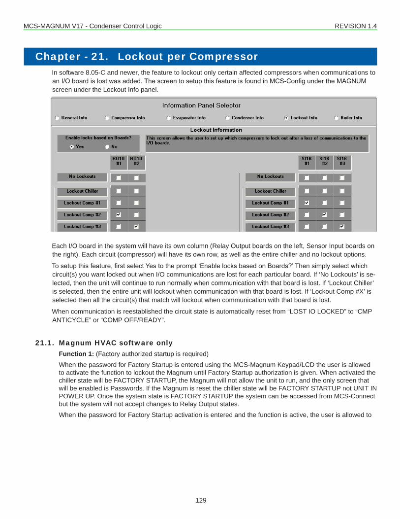
MCS-MAGNUM V17 - Condenser Control Logic REVISION 1.4
129
Chapter - 21. Lockout per CompressorIn software 8.05-C and newer, the feature to lockout only certain affected compressors when communications to anI/Oboardislostwasadded.ThescreentosetupthisfeatureisfoundinMCS-ConfigundertheMAGNUMscreen under the Lockout Info panel.
Each I/O board in the system will have its own column (Relay Output boards on the left, Sensor Input boards on the right). Each circuit (compressor) will have its own row, as well as the entire chiller and no lockout options.
Tosetupthisfeature,firstselectYestotheprompt‘EnablelocksbasedonBoards?’Thensimplyselectwhichcircuit(s) you want locked out when I/O communications are lost for each particular board. If ‘No Lockouts’ is se-lected, then the unit will continue to run normally when communication with that board is lost. If ‘Lockout Chiller’ is selected, then the entire unit will lockout when communication with that board is lost. If ‘Lockout Comp #X’ is selected then all the circuit(s) that match will lockout when communication with that board is lost.
When communication is reestablished the circuit state is automatically reset from “LOST IO LOCKED” to “CMP ANTICYCLE” or “COMP OFF/READY”.
21.1. Magnum HVAC software onlyFunction 1: (Factory authorized startup is required)When the password for Factory Startup is entered using the MCS-Magnum Keypad/LCD the user is allowed to activate the function to lockout the Magnum until Factory Startup authorization is given. When activated the chiller state will be FACTORY STARTUP, the Magnum will not allow the unit to run, and the only screen that will be enabled is Passwords. If the Magnum is reset the chiller state will be FACTORY STARTUP not UNIT IN POWER UP. Once the system state is FACTORY STARTUP the system can be accessed from MCS-Connect but the system will not accept changes to Relay Output states.When the password for Factory Startup activation is entered and the function is active, the user is allowed to
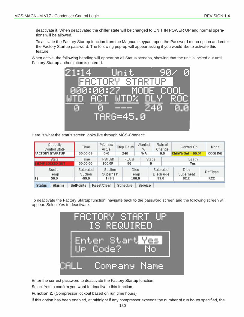
MCS-MAGNUM V17 - Condenser Control Logic REVISION 1.4
130
deactivate it. When deactivated the chiller state will be changed to UNIT IN POWER UP and normal opera-tions will be allowed.To activate the Factory Startup function from the Magnum keypad, open the Password menu option and enter the Factory Startup password. The following pop-up will appear asking if you would like to activate this feature.
When active, the following heading will appear on all Status screens, showing that the unit is locked out until Factory Startup authorization is entered.
Here is what the status screen looks like through MCS-Connect:
To deactivate the Factory Startup function, navigate back to the password screen and the following screen will appear. Select Yes to deactivate.
Enter the correct password to deactivate the Factory Startup function.SelectYestoconfirmyouwanttodeactivatethisfunction.Function 2: (Compressor lockout based on run time hours)Ifthisoptionhasbeenenabled,atmidnightifanycompressorexceedsthenumberofrunhoursspecified,the
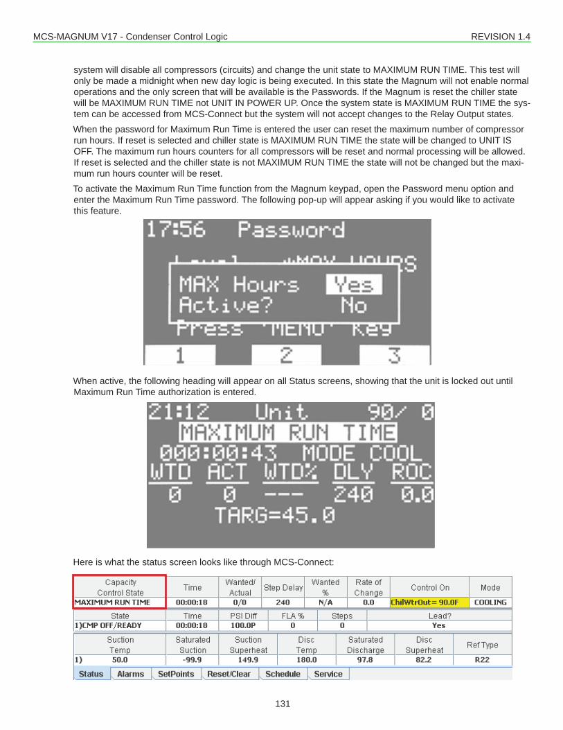
MCS-MAGNUM V17 - Condenser Control Logic REVISION 1.4
131
system will disable all compressors (circuits) and change the unit state to MAXIMUM RUN TIME. This test will only be made a midnight when new day logic is being executed. In this state the Magnum will not enable normal operations and the only screen that will be available is the Passwords. If the Magnum is reset the chiller state will be MAXIMUM RUN TIME not UNIT IN POWER UP. Once the system state is MAXIMUM RUN TIME the sys-tem can be accessed from MCS-Connect but the system will not accept changes to the Relay Output states.When the password for Maximum Run Time is entered the user can reset the maximum number of compressor run hours. If reset is selected and chiller state is MAXIMUM RUN TIME the state will be changed to UNIT IS OFF. The maximum run hours counters for all compressors will be reset and normal processing will be allowed. If reset is selected and the chiller state is not MAXIMUM RUN TIME the state will not be changed but the maxi-mum run hours counter will be reset.To activate the Maximum Run Time function from the Magnum keypad, open the Password menu option and enter the Maximum Run Time password. The following pop-up will appear asking if you would like to activate this feature.
When active, the following heading will appear on all Status screens, showing that the unit is locked out until Maximum Run Time authorization is entered.
Here is what the status screen looks like through MCS-Connect:
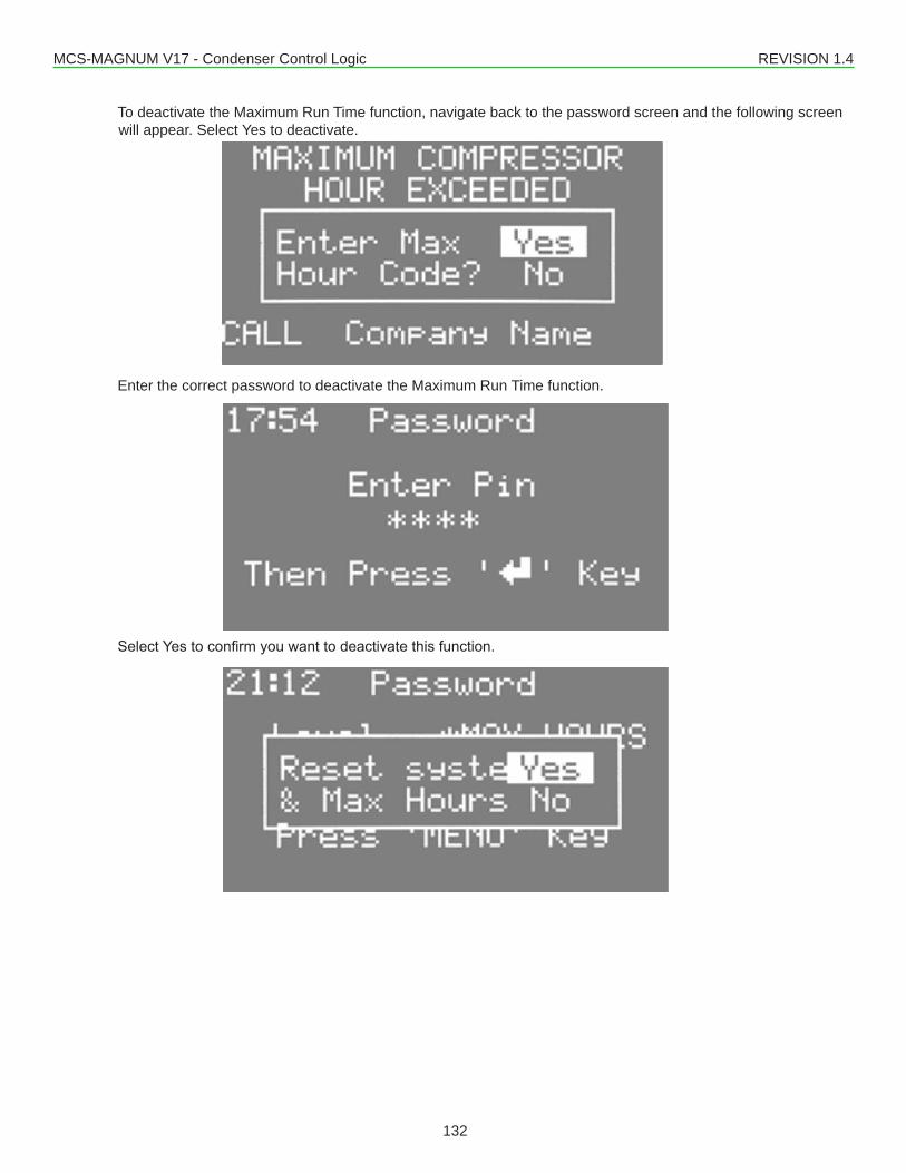
MCS-MAGNUM V17 - Condenser Control Logic REVISION 1.4
132
To deactivate the Maximum Run Time function, navigate back to the password screen and the following screen will appear. Select Yes to deactivate.
Enter the correct password to deactivate the Maximum Run Time function.
SelectYestoconfirmyouwanttodeactivatethisfunction.
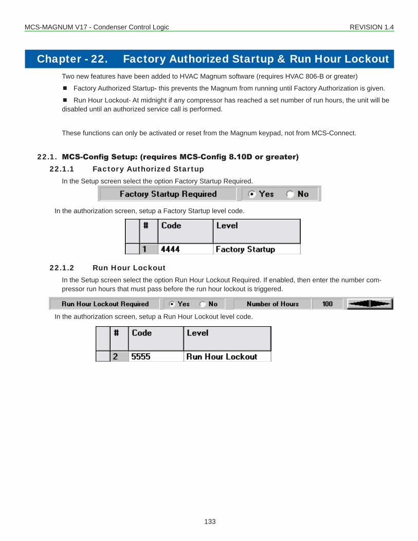
MCS-MAGNUM V17 - Condenser Control Logic REVISION 1.4
133
Chapter - 22. Factory Authorized Startup & Run Hour LockoutTwo new features have been added to HVAC Magnum software (requires HVAC 806-B or greater)
Factory Authorized Startup- this prevents the Magnum from running until Factory Authorization is given.
Run Hour Lockout- At midnight if any compressor has reached a set number of run hours, the unit will be disabled until an authorized service call is performed.
These functions can only be activated or reset from the Magnum keypad, not from MCS-Connect.
22.1. MCS-Config Setup: (requires MCS-Config 8.10D or greater)22.1.1 Factory Authorized Startup
In the Setup screen select the option Factory Startup Required.
In the authorization screen, setup a Factory Startup level code.
22.1.2 Run Hour LockoutIn the Setup screen select the option Run Hour Lockout Required. If enabled, then enter the number com-pressor run hours that must pass before the run hour lockout is triggered.
In the authorization screen, setup a Run Hour Lockout level code.
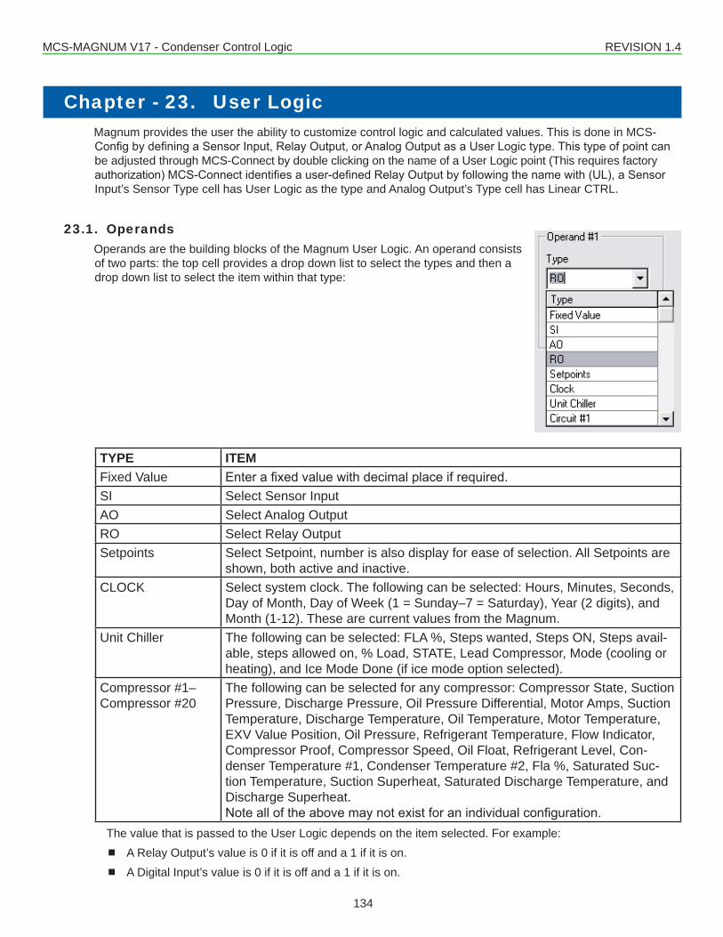
MCS-MAGNUM V17 - Condenser Control Logic REVISION 1.4
134
Chapter - 23. User LogicMagnum provides the user the ability to customize control logic and calculated values. This is done in MCS-ConfigbydefiningaSensorInput,RelayOutput,orAnalogOutputasaUserLogictype.Thistypeofpointcanbe adjusted through MCS-Connect by double clicking on the name of a User Logic point (This requires factory authorization)MCS-Connectidentifiesauser-definedRelayOutputbyfollowingthenamewith(UL),aSensorInput’s Sensor Type cell has User Logic as the type and Analog Output’s Type cell has Linear CTRL.
23.1. OperandsOperands are the building blocks of the Magnum User Logic. An operand consists of two parts: the top cell provides a drop down list to select the types and then a drop down list to select the item within that type:
TYPE ITEMFixed Value Enterafixedvaluewithdecimalplaceifrequired.SI Select Sensor InputAO Select Analog OutputRO Select Relay OutputSetpoints Select Setpoint, number is also display for ease of selection. All Setpoints are
shown, both active and inactive.CLOCK Select system clock. The following can be selected: Hours, Minutes, Seconds,
Day of Month, Day of Week (1 = Sunday–7 = Saturday), Year (2 digits), and Month (1-12). These are current values from the Magnum.
Unit Chiller The following can be selected: FLA %, Steps wanted, Steps ON, Steps avail-able, steps allowed on, % Load, STATE, Lead Compressor, Mode (cooling or heating), and Ice Mode Done (if ice mode option selected).
Compressor #1–Compressor #20
The following can be selected for any compressor: Compressor State, Suction Pressure, Discharge Pressure, Oil Pressure Differential, Motor Amps, Suction Temperature, Discharge Temperature, Oil Temperature, Motor Temperature, EXV Value Position, Oil Pressure, Refrigerant Temperature, Flow Indicator, Compressor Proof, Compressor Speed, Oil Float, Refrigerant Level, Con-denser Temperature #1, Condenser Temperature #2, Fla %, Saturated Suc-tion Temperature, Suction Superheat, Saturated Discharge Temperature, and Discharge Superheat.Notealloftheabovemaynotexistforanindividualconfiguration.
The value that is passed to the User Logic depends on the item selected. For example: A Relay Output’s value is 0 if it is off and a 1 if it is on. A Digital Input’s value is 0 if it is off and a 1 if it is on.
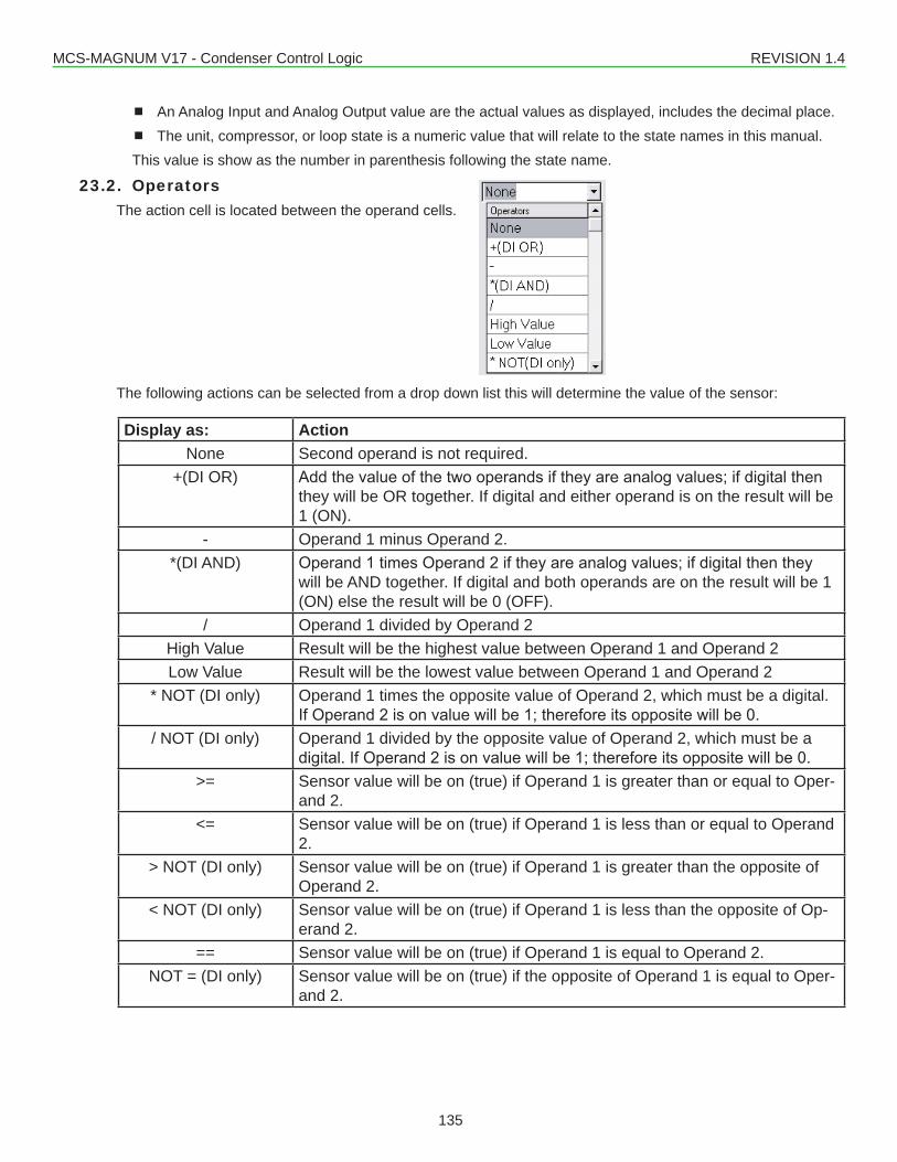
MCS-MAGNUM V17 - Condenser Control Logic REVISION 1.4
135
An Analog Input and Analog Output value are the actual values as displayed, includes the decimal place. The unit, compressor, or loop state is a numeric value that will relate to the state names in this manual. This value is show as the number in parenthesis following the state name.
23.2. Operators The action cell is located between the operand cells.
The following actions can be selected from a drop down list this will determine the value of the sensor:
Display as: ActionNone Second operand is not required.
+(DI OR) Addthevalueofthetwooperandsiftheyareanalogvalues;ifdigitalthenthey will be OR together. If digital and either operand is on the result will be 1 (ON).
- Operand 1 minus Operand 2. *(DI AND) Operand1timesOperand2iftheyareanalogvalues;ifdigitalthenthey
will be AND together. If digital and both operands are on the result will be 1 (ON) else the result will be 0 (OFF).
/ Operand 1 divided by Operand 2High Value Result will be the highest value between Operand 1 and Operand 2Low Value Result will be the lowest value between Operand 1 and Operand 2
* NOT (DI only) Operand 1 times the opposite value of Operand 2, which must be a digital. IfOperand2isonvaluewillbe1;thereforeitsoppositewillbe0.
/ NOT (DI only) Operand 1 divided by the opposite value of Operand 2, which must be a digital.IfOperand2isonvaluewillbe1;thereforeitsoppositewillbe0.
>= Sensor value will be on (true) if Operand 1 is greater than or equal to Oper-and 2.
<= Sensor value will be on (true) if Operand 1 is less than or equal to Operand 2.
> NOT (DI only) Sensor value will be on (true) if Operand 1 is greater than the opposite of Operand 2.
< NOT (DI only) Sensor value will be on (true) if Operand 1 is less than the opposite of Op-erand 2.
== Sensor value will be on (true) if Operand 1 is equal to Operand 2.NOT = (DI only) Sensor value will be on (true) if the opposite of Operand 1 is equal to Oper-
and 2.
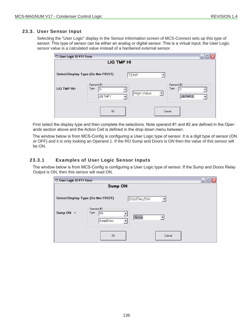
MCS-MAGNUM V17 - Condenser Control Logic REVISION 1.4
136
23.3. User Sensor InputSelecting the “User Logic” display in the Sensor Information screen of MCS-Connect sets up this type of sensor.Thistypeofsensorcanbeeitherananalogordigitalsensor.Thisisavirtualinput;theUserLogicsensor value is a calculated value instead of a hardwired external sensor.
First selectthedisplaytypeandthencompletetheselections.Noteoperand#1and#2aredefinedintheOper-andssectionaboveandtheActionCellisdefinedinthedropdownmenubetween.ThewindowbelowisfromMCS-ConfigisconfiguringaUserLogictypeofsensor.Itisadigittypeofsensor(ONor OFF) and it is only looking an Operand 1. If the RO Sump and Doors is ON then the value of this sensor will be ON.
23.3.1 Examples of User Logic Sensor InputsThewindowbelowisfromMCS-ConfigisconfiguringaUserLogictypeofsensor.IftheSumpandDoorsRelayOutput is ON, then this sensor will read ON.
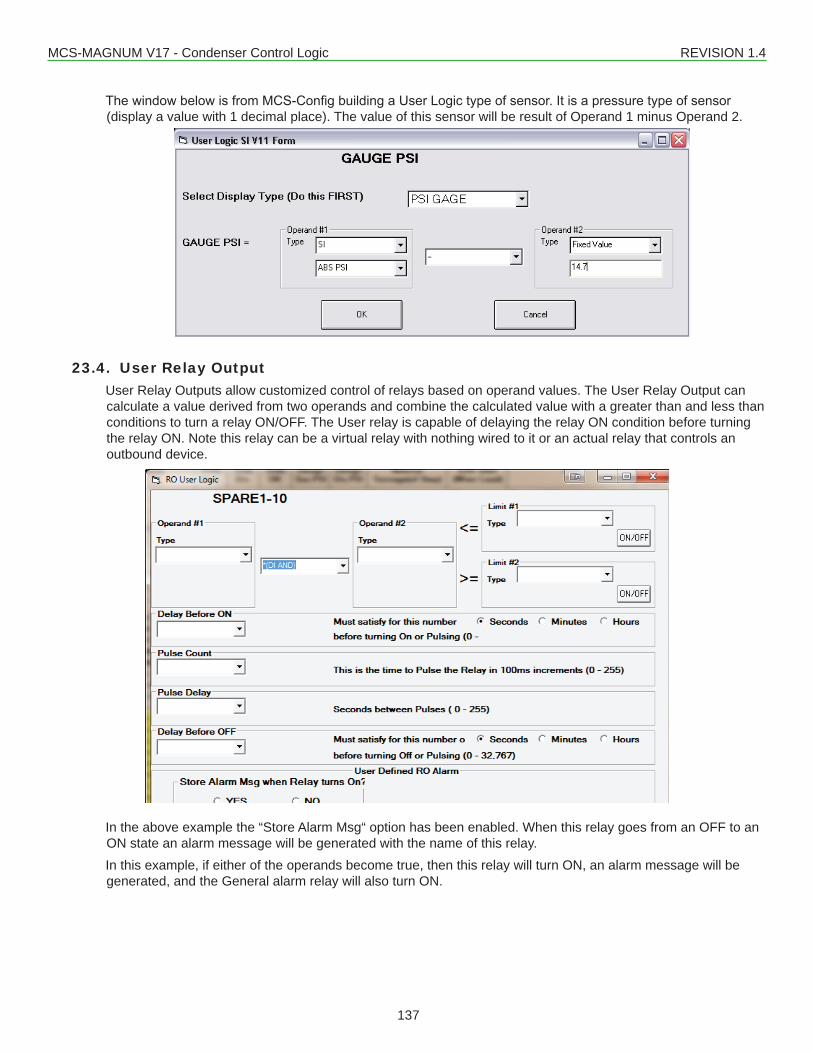
MCS-MAGNUM V17 - Condenser Control Logic REVISION 1.4
137
ThewindowbelowisfromMCS-ConfigbuildingaUserLogictypeofsensor.Itisapressuretypeofsensor(display a value with 1 decimal place). The value of this sensor will be result of Operand 1 minus Operand 2.
23.4. User Relay OutputUser Relay Outputs allow customized control of relays based on operand values. The User Relay Output can calculate a value derived from two operands and combine the calculated value with a greater than and less than conditions to turn a relay ON/OFF. The User relay is capable of delaying the relay ON condition before turning the relay ON. Note this relay can be a virtual relay with nothing wired to it or an actual relay that controls an outbound device.
In the above example the “Store Alarm Msg“ option has been enabled. When this relay goes from an OFF to an ON state an alarm message will be generated with the name of this relay.In this example, if either of the operands become true, then this relay will turn ON, an alarm message will be generated, and the General alarm relay will also turn ON.
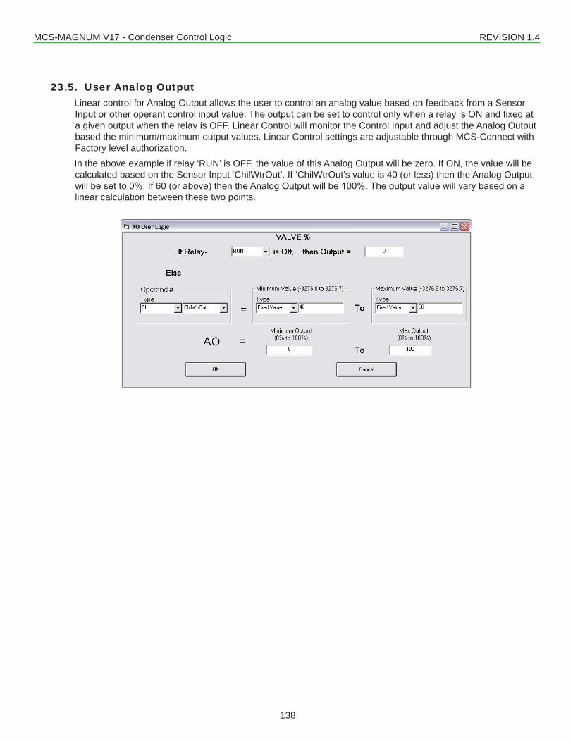
MCS-MAGNUM V17 - Condenser Control Logic REVISION 1.4
138
23.5. User Analog OutputLinear control for Analog Output allows the user to control an analog value based on feedback from a Sensor Inputorotheroperantcontrolinputvalue.TheoutputcanbesettocontrolonlywhenarelayisONandfixedata given output when the relay is OFF. Linear Control will monitor the Control Input and adjust the Analog Output based the minimum/maximum output values. Linear Control settings are adjustable through MCS-Connect with Factory level authorization.In the above example if relay ‘RUN’ is OFF, the value of this Analog Output will be zero. If ON, the value will be calculated based on the Sensor Input ‘ChilWtrOut’. If ‘ChilWtrOut’s value is 40 (or less) then the Analog Output willbesetto0%;If60(orabove)thentheAnalogOutputwillbe100%.Theoutputvaluewillvarybasedonalinear calculation between these two points.
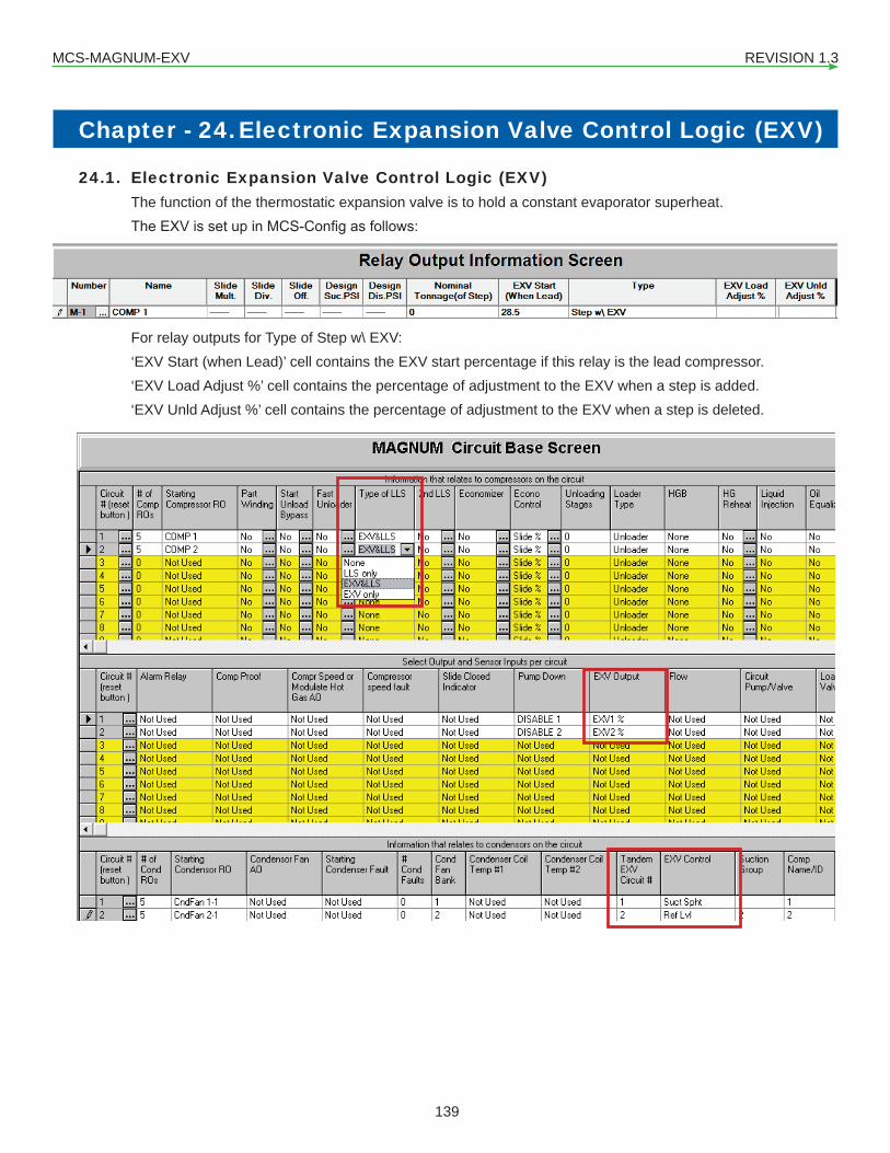
MCS-MAGNUM-EXV REVISION 1.3
139
Chapter - 24. Electronic Expansion Valve Control Logic (EXV)
24.1. Electronic Expansion Valve Control Logic (EXV)The function of the thermostatic expansion valve is to hold a constant evaporator superheat.TheEXVissetupinMCS-Configasfollows:
For relay outputs for Type of Step w\ EXV:‘EXV Start (when Lead)’ cell contains the EXV start percentage if this relay is the lead compressor.‘EXV Load Adjust %’ cell contains the percentage of adjustment to the EXV when a step is added.‘EXV Unld Adjust %’ cell contains the percentage of adjustment to the EXV when a step is deleted.
By clicking on the ‘Type of LLS’ cell under the Circuit Base screen, select either EXV&LLS or EXV Only for EXV control. By clicking on the ‘EXV Output cell under the Circuit Base screen, select the analog output for controlling this circuits EXV.
By clicking on the ‘EXV Control’ cell under the Circuit Base screen, the option will cycle between Suction Su-perheat, Discharge Superheat, and Refrigerant Level control.
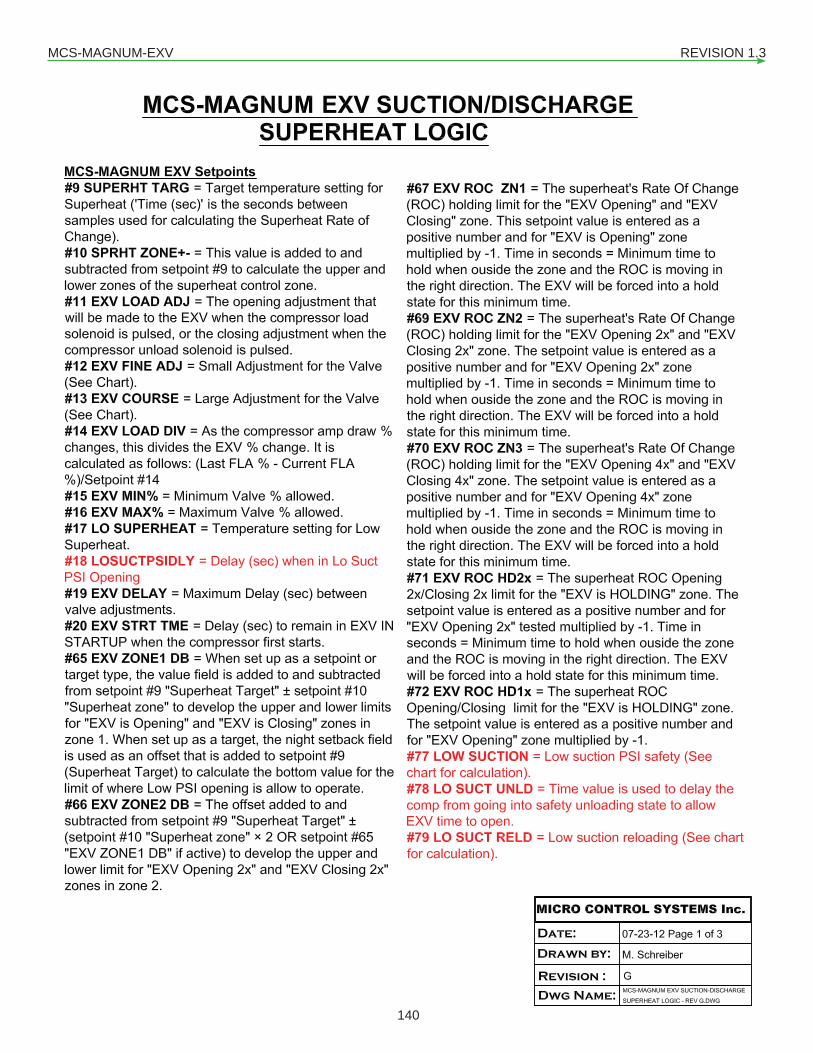
MCS-MAGNUM-EXV REVISION 1.3
140
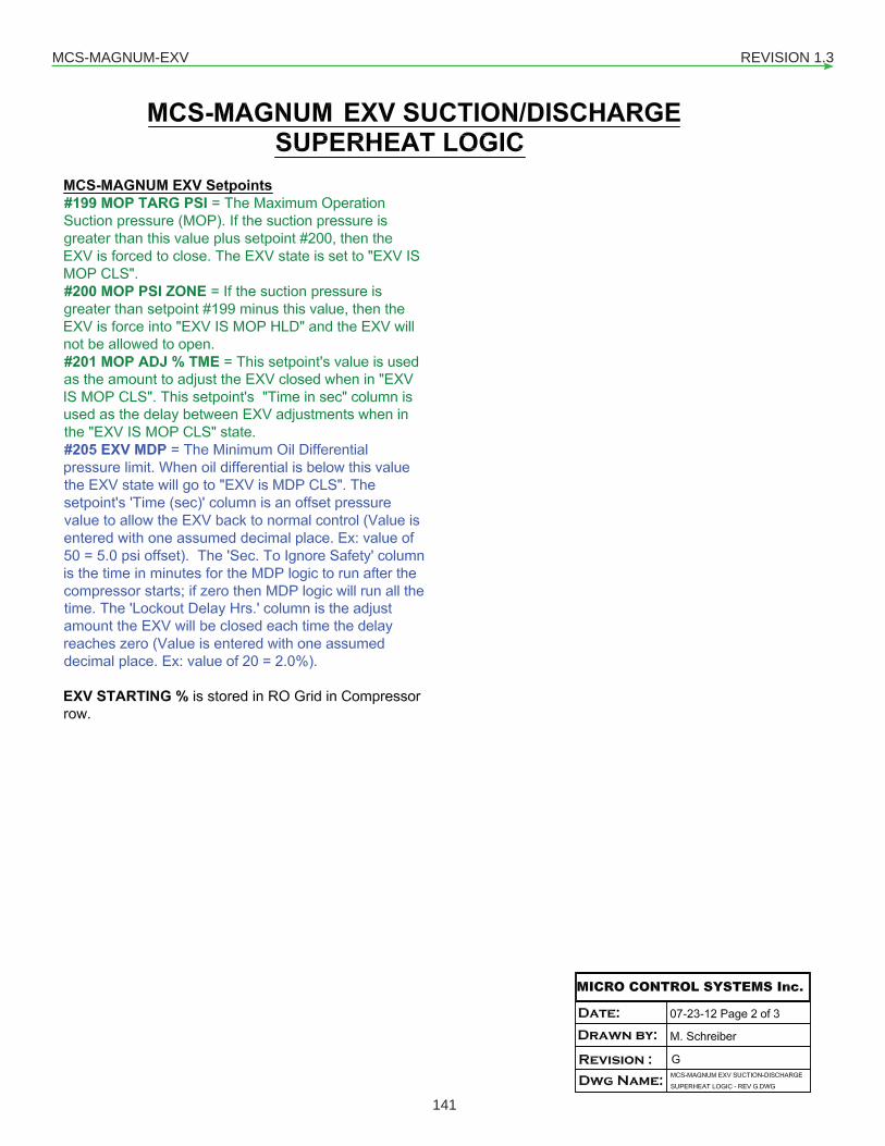
MCS-MAGNUM-EXV REVISION 1.3
141
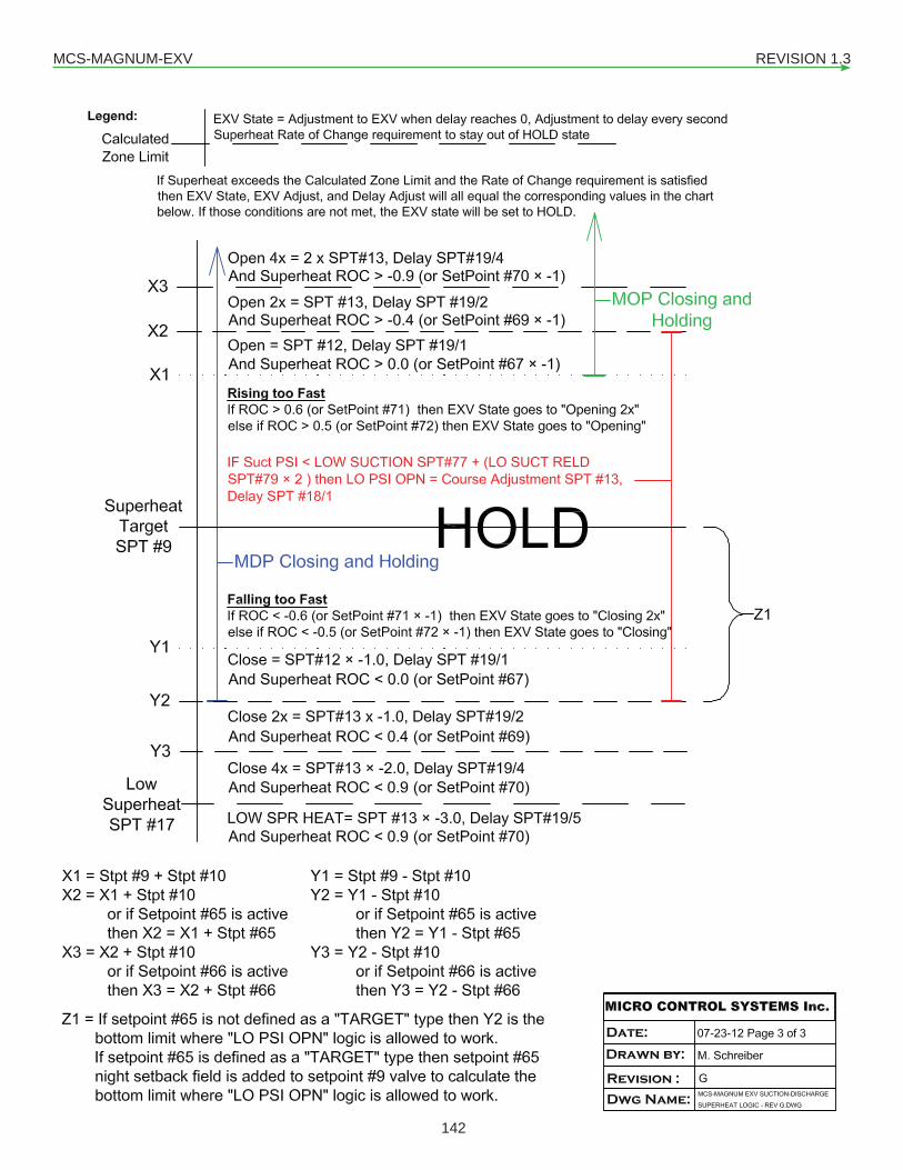
MCS-MAGNUM-EXV REVISION 1.3
142
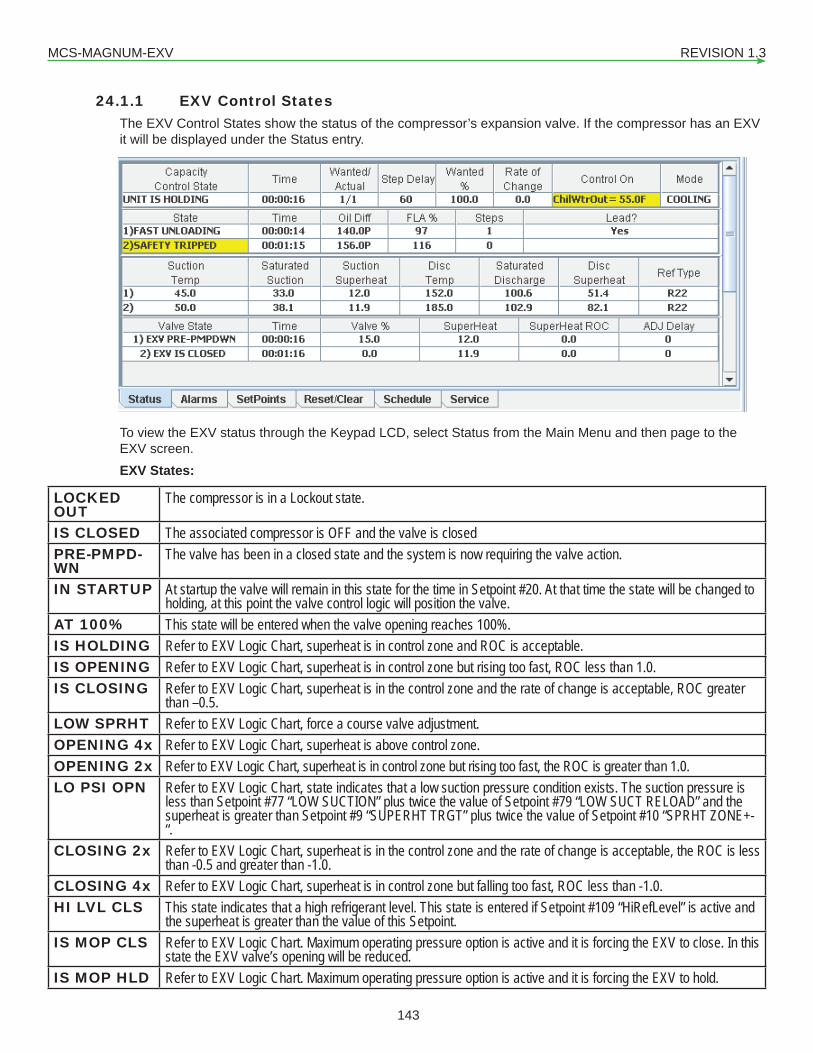
MCS-MAGNUM-EXV REVISION 1.3
143
24.1.1 EXV Control StatesThe EXV Control States show the status of the compressor’s expansion valve. If the compressor has an EXV it will be displayed under the Status entry.
To view the EXV status through the Keypad LCD, select Status from the Main Menu and then page to the EXV screen.EXV States:
LOCKED OUT
The compressor is in a Lockout state.
IS CLOSED The associated compressor is OFF and the valve is closedPRE-PMPD-WN
The valve has been in a closed state and the system is now requiring the valve action.
IN STARTUP At startup the valve will remain in this state for the time in Setpoint #20. At that time the state will be changed to holding, at this point the valve control logic will position the valve.
AT 100% This state will be entered when the valve opening reaches 100%.IS HOLDING Refer to EXV Logic Chart, superheat is in control zone and ROC is acceptable.IS OPENING Refer to EXV Logic Chart, superheat is in control zone but rising too fast, ROC less than 1.0.IS CLOSING Refer to EXV Logic Chart, superheat is in the control zone and the rate of change is acceptable, ROC greater
than –0.5.LOW SPRHT Refer to EXV Logic Chart, force a course valve adjustment.OPENING 4x Refer to EXV Logic Chart, superheat is above control zone.OPENING 2x Refer to EXV Logic Chart, superheat is in control zone but rising too fast, the ROC is greater than 1.0.LO PSI OPN Refer to EXV Logic Chart, state indicates that a low suction pressure condition exists. The suction pressure is
less than Setpoint #77 “LOW SUCTION” plus twice the value of Setpoint #79 “LOW SUCT RELOAD” and the superheat is greater than Setpoint #9 “SUPERHT TRGT” plus twice the value of Setpoint #10 “SPRHT ZONE+-“.
CLOSING 2x Refer to EXV Logic Chart, superheat is in the control zone and the rate of change is acceptable, the ROC is less than -0.5 and greater than -1.0.
CLOSING 4x Refer to EXV Logic Chart, superheat is in control zone but falling too fast, ROC less than -1.0.HI LVL CLS This state indicates that a high refrigerant level. This state is entered if Setpoint #109 “HiRefLevel” is active and
the superheat is greater than the value of this Setpoint.IS MOP CLS Refer to EXV Logic Chart. Maximum operating pressure option is active and it is forcing the EXV to close. In this
state the EXV valve’s opening will be reduced.IS MOP HLD Refer to EXV Logic Chart. Maximum operating pressure option is active and it is forcing the EXV to hold.
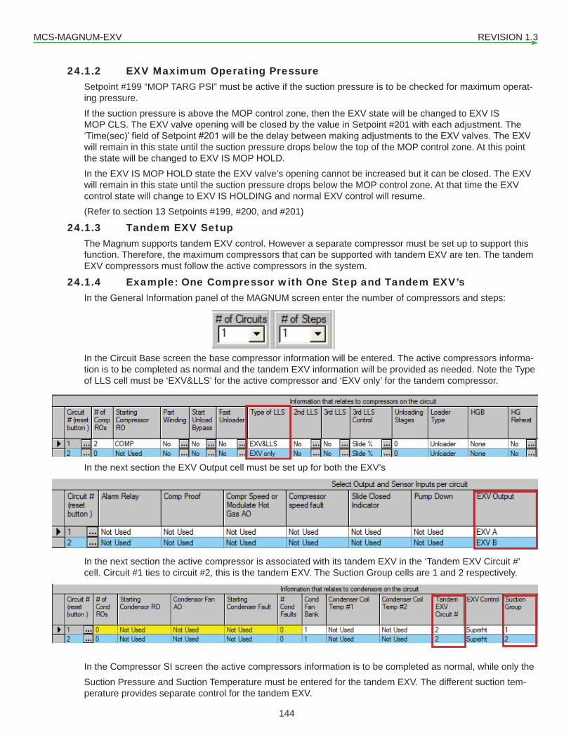
MCS-MAGNUM-EXV REVISION 1.3
144
24.1.2 EXV Maximum Operating PressureSetpoint #199 “MOP TARG PSI” must be active if the suction pressure is to be checked for maximum operat-ing pressure.If the suction pressure is above the MOP control zone, then the EXV state will be changed to EXV IS MOP CLS. The EXV valve opening will be closed by the value in Setpoint #201 with each adjustment. The ‘Time(sec)’fieldofSetpoint#201willbethedelaybetweenmakingadjustmentstotheEXVvalves.TheEXVwill remain in this state until the suction pressure drops below the top of the MOP control zone. At this point the state will be changed to EXV IS MOP HOLD.In the EXV IS MOP HOLD state the EXV valve’s opening cannot be increased but it can be closed. The EXV will remain in this state until the suction pressure drops below the MOP control zone. At that time the EXV control state will change to EXV IS HOLDING and normal EXV control will resume.(Refer to section 13 Setpoints #199, #200, and #201)
24.1.3 Tandem EXV SetupThe Magnum supports tandem EXV control. However a separate compressor must be set up to support this function. Therefore, the maximum compressors that can be supported with tandem EXV are ten. The tandem EXV compressors must follow the active compressors in the system.
24.1.4 Example: One Compressor with One Step and Tandem EXV’sIn the General Information panel of the MAGNUM screen enter the number of compressors and steps:
In the Circuit Base screen the base compressor information will be entered. The active compressors informa-tion is to be completed as normal and the tandem EXV information will be provided as needed. Note the Type of LLS cell must be ‘EXV&LLS’ for the active compressor and ‘EXV only’ for the tandem compressor.
In the next section the EXV Output cell must be set up for both the EXV’s
In the next section the active compressor is associated with its tandem EXV in the ‘Tandem EXV Circuit #’ cell. Circuit #1 ties to circuit #2, this is the tandem EXV. The Suction Group cells are 1 and 2 respectively.
In the Compressor SI screen the active compressors information is to be completed as normal, while only theSuction Pressure and Suction Temperature must be entered for the tandem EXV. The different suction tem-perature provides separate control for the tandem EXV.

MCS-MAGNUM-EXV REVISION 1.3
145
24.1.4.1. Example: Two Compressors with Four Steps and Tandem EXV’sIn the General Information panel of the MAGNUM screen enter the number of compressors and steps:
In the next section the EXV Output cell must be set up for all the EXV’s
In the next section the active compressor is associated with its tandem EXV in the ‘Tandem EXV Circuit #’ cell. Circuit #1 ties to circuit #3, and circuit #2 ties to circuit #4 (circuits #3 and #4 are the Tandem EXV’s). The Suction Group cells are 1, 2, 3, and 4 respectively.In the Compressor SI screen the active compressors information is to be completed as normal, while only the Suction Pressure and Suction Temperature must be entered for the tandem EXV’s. The different suction temperature provides separate control for the tandem EXV’s.
24.1.5 ‘Evaporator or Condenser Refrigerant Level ControlThere is an alternate method to control the EXV based on Ref Level.
24.1.5.1. Minimum Refrigerant Level target (HVAC ONLY)If active and the EXV is controlled by Refrigerant Level, then a new variable level target logic will be activated. As the unit capacity increases, the refrigerant level target will change according to a linear calculation be-tween Setpoint #9 “LEVEL TARGET” (the maximum target level) and Setpoint #217 “LOW EXV TARGET” (the minimum target level). This relationship is explained in the following graph:
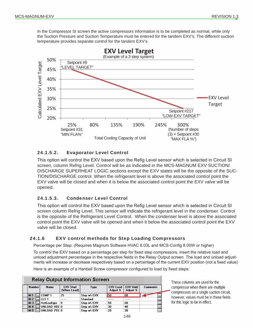
MCS-MAGNUM-EXV REVISION 1.3
146
In the Compressor SI screen the active compressors information is to be completed as normal, while only the Suction Pressure and Suction Temperature must be entered for the tandem EXV’s. The different suction temperature provides separate control for the tandem EXV’s.
20%
25%
30%
35%
40%
45%
50%
25% 80% 135% 190% 245% 300%
EXV Level Target
EXV LevelTarget
(Number of steps (3) × Setpoint #30
"MAX FLA %")
Setpoint #31 "MIN FLA%"
Cal
cula
ted
EXV
Leve
l Tar
get
Total Cooling Capacity of Unit
(Example of a 3 step system) Setpoint #9
“LEVEL TARGET”
Setpoint #217 “LOW EXV TARGET”
24.1.5.2. Evaporator Level ControlThisoptionwillcontroltheEXVbasedupontheRefigLevelsensorwhichisselectedinCircuitSIscreen, column Refrig Level. Control will be as indicated in the MCS-MAGNUM EXV SUCTION/DISCHARGE SUPERHEAT LOGIC sections except the EXV states will be the opposite of the SUC-TION/DISCHARGE control. When the refrigerant level is above the associated control point the EXV valve will be closed and when it is below the associated control point the EXV valve will be opened.
24.1.5.3. Condenser Level ControlThisoptionwillcontroltheEXVbasedupontheRefigLevelsensorwhichisselectedinCircuitSIscreen column Refrig Level. This sensor will indicate the refrigerant level in the condenser. Control is the opposite of the Refrigerant Level Control. When the condenser level is above the associated control point the EXV valve will be opened and when it below the associated control point the EXV valve will be closed.
24.1.6 EXV control methods for Step Loading CompressorsPercentageperStep:(RequiresMagnumSoftwareHVAC8.03LandMCS-Config8.00Worhigher)TocontroltheEXVbasedonapercentageperstepforfixedstepcompressors,inserttherelativeloadandunloadadjustmentpercentagesintherespectivefieldsintheRelayOutputscreen.Theloadandunloadadjust-mentswillincreaseordecreaserespectivelybasedonapercentageofthecurrentEXVposition(notafixedvalue)HereisanexampleofaHanbellScrewcompressorconfiguredtoloadbyfixedsteps:
These columns are used for the compressor when there are multiple compressors on a single suction circuit, however, values must be in these fields for this logic to be in effect.
MCS-MAGNUM-EXV REVISION 1.3
147
The logic will work as follows: When the compressor starts the EXV will go to the value in the ‘EXV Start (when lead)’ column, in this example it is 25%. The EXV will then modulate normally according to the control-ling superheat or refrigerant level, until the unit is ready to load another step of capacity. Assume the EXV has stayed at 35% when the second step of capacity is ready to engage (turning off the Hot Gas Bypass). The EXV adjustment will be 50% (the amount in the ‘EXV Load Adjust’ column of the current EXV position‘EXV Load Adjust’ column (50%) × current EXV position (35%) = EXV adjustment (17.5%)50% × 35% = 17.5%Current EXV position (35%) + EXV adjustment (17.5%) = New EXV position (42.5%)35% +17.5% = 42.5%ThereforethefinalEXVvalvepositionwouldbe42.5%This same calculation will be repeated every time a new stage of capacity is turned on. Conversely, when the unit is unloading, the EXV adjustment will be subtracted from the current EXV position for every step that turns off. Assume the EXV is at 40% and the compressor is at 100% and is ready to unload a step (turning on Unload 75% solenoid).‘EXV Unld Adjust’ column (30%)× current EXV position (40%)= EXV adjustment (12%)30% × 40% = 12%Current EXV position (40%)–EXV adjustment (12%) = New EXV position (28%)40%–12% = 28%ThereforethefinalEXVvalvepositionwouldbe28%The values given in the example are only start points. You will need to adjust the values for your system. The idea is to jump the EXV position so that the superheat would still be above the target slightly, and then the EXV control logic would then adjust the value to achieve the target superheat. We do not want to open the EXV valve too much when loading or close the valve too much when unloading so we do not cause low superheatorliquidfloodingtothecompressor.
MCS-MAGNUM-EXV REVISION 1.3
148
Chapter - 25. Sub Cooler EXV Control LogicPurpose of ChangeThe purpose of this change is to add Electronic Expansion Valve (EXV) control logic for Subcooler heat exchanger(s). There can be a subcooler for each refrigeration circuit. If there are multiple compressors on the refrigeration circuit the logic will need to control the EXV when any compressor on the refrigerant circuit is running.
25.1. New Sensor Inputs Subcooler Suction PSI – Analog sensor input which indicates the suction pressure on the subooler heat exchanger. This will be the refrigerant gas going to the compressor’s economizer port (vapor injection port). There will be one suction pressure per refrigerant circuit.
Subcooler Suction Temperture – Analog sensor input which indicates the suction temperature on the sub-ooler heat exchanger. This will be the refrigerant gas temperature going to compressor’s economizer port) vapor injection port). There will be one suction temperature per refrigerant circuit.
25.2. New Analog Outputs Subcooler Electronic Expansion Valve – analog output used to control the position of the electronic expansion valve. This must be connected to device (MCS-EXV-DRVIER) to move the EXV. There will be one analog output per refrigerant circuit.
25.3. Existing Relay Outputs Economizer Solenoid Valve –relayoutputusedtostoptherefrigerationgasflowtocompressoreconomizerport (vapor injection port). There will be one relay output per compressor. If there is only one compressor on the refrigerant circuit and the EXV is capable of closed upon loss of pow-ers, the economizer solenoid valve relay output is optional because the EXV can act as the solenoid valve.If there are multiple compressors on the refrigerant circuit, then solenoid valve is not optional, no matter what type of EXV. And each compressor will have its own relay output to control its own solenoid valve.
25.4. Calculated ValuesSubcooler Saturated Suction Temperature – This value is calculated using the subcooler suction pressure and refrigerant’s Pressure to Temperature chart. The subcooler suction pressure is used as the input into the refrigerant’spressuretotemperaturecharttofindthesaturatedtemperature.
Subcooler Superheat Temperature – This value is calculated by subtracting the Subcooler Saturated Suc-tion Temperature from the Subcooler Suction Temperature. Subcooler Superheat = Subcooler Suction Temperature – Subcooler Saturated Suction Temperature
Subcooler EXV State – This value is determined by the logic to control the EXV.
Subcooler Time Delay – This value is calculated by the control logic and is used to delay adjustments to the EXV position.Subcooler Wanted Position – This value is calculated by the control logic is the wanted position of the EXV.Subcooler Superheat ROC – This value is calculated by the control logic. It is the superheat Rate of Change. It is calculated by subtracting the current superheat value from a previous superheat value. The control logic will need to store the last 60 superheat values.
MCS-MAGNUM-EXV REVISION 1.3
149
25.5. New Config ParametersNew setpoints required to control the Subcooler EXV:
1. SubbcoolerSuperheatTarget–thissetpointdefinethesuperheattargetthecontrollogicwillmaintain.2. Subcoolerdeadband–thissetpointdefinethedeadbandaroundthesuperheattarget.Thissetpointwith
thetargetsetpointdefinesthecontrolzoneforsubcoolersuperheat.3. Subcooler delay – This is the delay between adjustments to the EXV position.4. SubcoolerEXVstarting%-ThisisthestartpositionfortheEXVwhenthesubcoolerisfirstturnedon.5. Subcooler EXV starting time – This is the time to remain at the starting EXV position to allow for the sub-
cooler superheat to develop to a real value to control the EXV.6. All the EXV setpoints? Fine, course, low superheat, MOP, low suction, min/max EXV allowed?7. MOP, Low suction psi, low suction control setpoints (delay, adjustment multipler), Others?
25.6. Logic Requirements1. Subcooler EXV control logic needs to run once a second.2. There can be only one subcooler heater exchanger per refrigerant circuit. The subcooler heat exchange is
an optional feature and maybe not be installed. a. If there is only one compressor on the refrigerant circuit then only when the one compressor is run-
ning does the subcooler control logic run to maintain the superheat. And there will be one EXV AO, one Suction Pressure SI, one Suction Temperature and one optional economizer solenoid valve RO. The economizer solenoid valve RO is optional only if the EXV driver can closed the valve on loss of power (EXV acts as solenoid valve – therefore a solenoid valve is not required).
b. If there are multiple compressors on the refrigerant circuit then when any compressor on the suction group is running the Subcooler EXV logic need maintain the superheat target. And there will be one EXV AO, one Suction Pressure SI, one Suction Temperature and multiple economizer solenoid valve ROs (one RO per compressor). And the RO is not optional, because we need to turn on solenoid valves for only the compressors that are running on the refrigerant circuit. Compressors not running will have the solenoid valves off.
3. Suggest similar Subcooler EXV state as Evaporator EXV statea. Subcooler EXV LOCKED OUTb. Subcooler EXV CLOSEDc. Subcooler EXV Holdingd. Subcooler EXV in Startupe. Subcooler EXV Opening 1xf. Subcooler EXV Opening 2xg. Subcooler EXV Opening 4xh. Subcooler EXV Closing 1xi. Subcooler EXV Closing 2xj. Subcooler EXV Closing 4xk. Low Superheat Closingl. MOP Closing, MOP Holding, Low Suction Opening?m. Others?
4. If all the compressors are off:a. The Subcooler EXV analog output is forced to 0.0%b. The Economizer solenoid valve RO is turned off.c. The subcooler control variables, step delay, etc are reset to defaults.d. The state is set to Subcooler EXV Closed.
5. Once any compressor is started and either it’s FLA% is greater than setpoint #?? Or the setpoint #?? Is inactive then::
a. The Subcooler state is moved from EXV CLOSED to Subcooler EXV in Startup. The subcooler will remaininthisstateforXseconds(Xdefinedbysetpointvalve)withtheEXVAOsettopercentage
MCS-MAGNUM-EXV REVISION 1.3
150
definedbysetpointvalue.AndthecompressorsolenoidROisturnedon(ifoneexists).b. OncetheStartuptimedelayissatisfiedtheEXVstatewillbechangetoSubcoolerHoldingandEXV
AO will be modulated to maintain the superheat within the control zone and the following logic run:i. If the Subcooler Suction pressure is greater than or equal to the MOP setpoint the state will
be set to MOP Closing.ii. If the Subcooler Suction pressure is less than low suction pressure setpoint and the subcooler
superheat is in or above control zone the state will be set to Low Suction Opening and the valve will be quickly open.
iii. IftheSubcoolersuperheatiswithinthecontrolzoneorROCissatisfiedthenstatewillremainin Subcooler Holding.
iv. If the subcooler superheat is above the control zone:1. And the ROC is above the ROC- setpoint, the will be set based upon how far above
the control zone, Opening 1x, Opening 2x, Opening 4x.2. Else if ROC is equal to or below ROC- setpoint then state is set to EXV HoLDING.
v. If the subcooler superheat is below the control zone1. And superheat ROC is greater than the ROC+ setpoint, the state will be set based
upon how far below the control zone, Closing 1x, Closing 2x, Closing 4x.2. Else if ROC is rqual to or greater than ROC+ setpoint, the state will be set to ECV
HOLDING.vi. The EXV time delay needs to be decrement each second by a variable amount determine by
subcooler state until the delay reaches zero. The further away from the target the bigger the adjustment to allow changes faster. Once the delay reaches zero:
1. If the superheat is inside the control:a. If ROC is between the ROC+ and ROC- setpoint values, then EXV state goes to
holding.b. If ROC less than ROC- setpoint then exv states goes to Closing 1x.c. If ROC greater than ROC+ setpoint value then exv state goes to Opening 1x.
2. if a superheat is outside the control zone then a variable adjustment will be made the Subcooler wanted position. The further away from the target the bigger the adjustment to move the valve faster. And if above the control zone the adjustment will be added to the current wanted % to open the value. If below the control zone the the adjustment will be subtracted to the current wanted % to close the valve. The wanted % is bound-edbyminandmaxlimitsdefinedbynewsetpointvaluesintheconfig.
3. Last comp on refrigertant circuit is turn off or last econo turn off? Then subcooler exv state goes to exv closed.
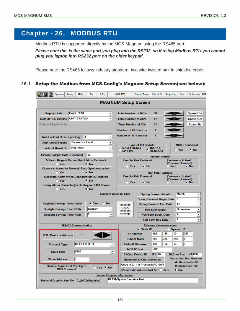
MCS-MAGNUM-BMS REVISION 1.3
151
Chapter - 26. MODBUS RTUModbus RTU is supported directly by the MCS-Magnum using the RS485 port. Please note this is the same port you plug into the RS232, so if using Modbus RTU you cannot plug you laptop into RS232 port on the older keypad.
Please note the RS485 follows industry standard, two wire twisted pair in shielded cable.
26.1. Setup the Modbus from MCS-Config’s Magnum Setup Screen(see below):
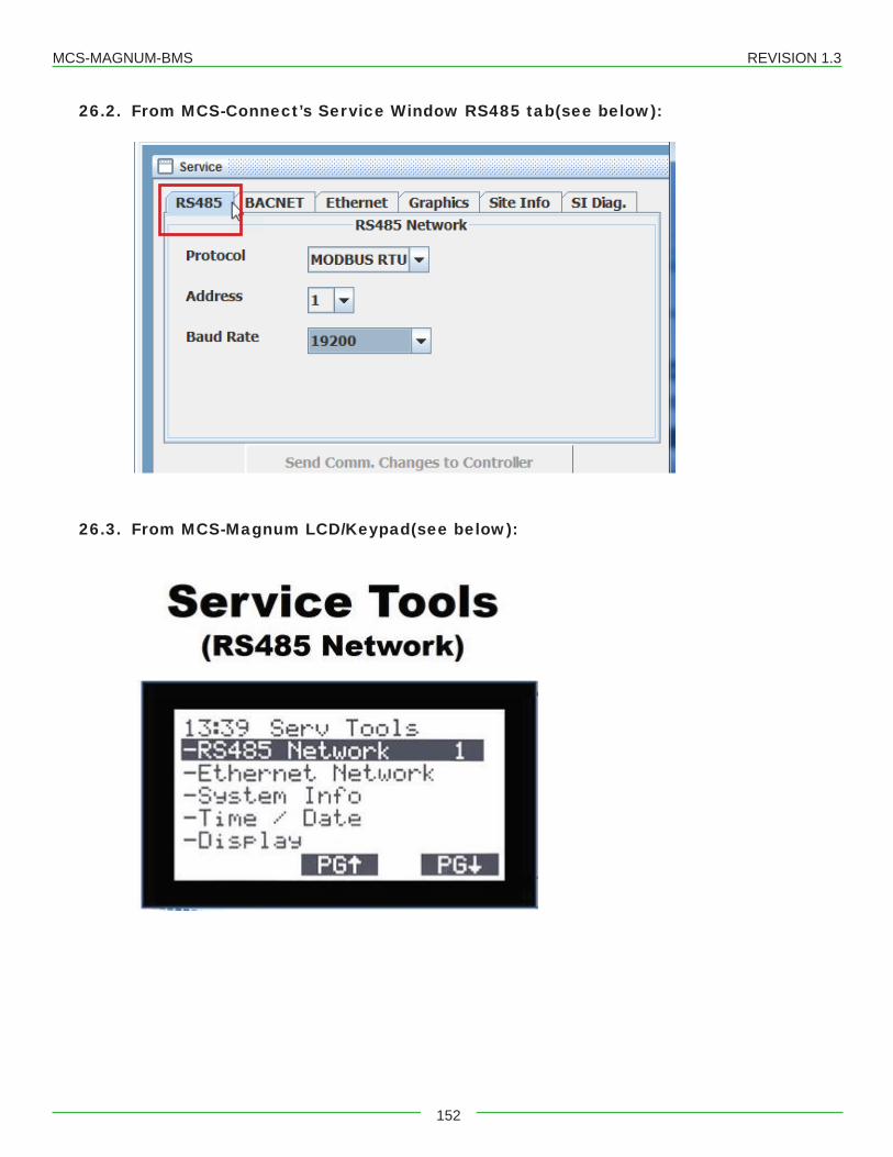
MCS-MAGNUM-BMS REVISION 1.3
152
26.2. From MCS-Connect’s Service Window RS485 tab(see below):
26.3. From MCS-Magnum LCD/Keypad(see below):
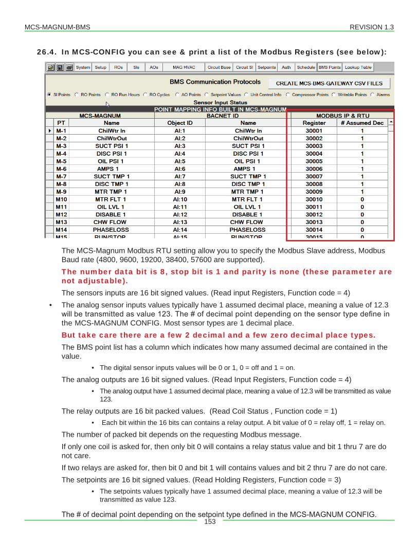
MCS-MAGNUM-BMS REVISION 1.3
153
26.4. In MCS-CONFIG you can see & print a list of the Modbus Registers (see below):
The MCS-Magnum Modbus RTU setting allow you to specify the Modbus Slave address, Modbus Baud rate (4800, 9600, 19200, 38400, 57600 are supported). The number data bit is 8, stop bit is 1 and parity is none (these parameter are not adjustable).The sensors inputs are 16 bit signed values. (Read input Registers, Function code = 4)
• The analog sensor inputs values typically have 1 assumed decimal place, meaning a value of 12.3 willbetransmittedasvalue123.The#ofdecimalpointdependingonthesensortypedefineinthe MCS-MAGNUM CONFIG. Most sensor types are 1 decimal place. But take care there are a few 2 decimal and a few zero decimal place types. The BMS point list has a column which indicates how many assumed decimal are contained in the value.
• The digital sensor inputs values will be 0 or 1, 0 = off and 1 = on.
The analog outputs are 16 bit signed values. (Read Input Registers, Function code = 4)• The analog output have 1 assumed decimal place, meaning a value of 12.3 will be transmitted as value
123.
The relay outputs are 16 bit packed values. (Read Coil Status , Function code = 1)• Each bit within the 16 bits can contains a relay output. A bit value of 0 = relay off, 1 = relay on.
The number of packed bit depends on the requesting Modbus message. If only one coil is asked for, then only bit 0 will contains a relay status value and bit 1 thru 7 are do not care.If two relays are asked for, then bit 0 and bit 1 will contains values and bit 2 thru 7 are do not care.The setpoints are 16 bit signed values. (Read Holding Registers, Function code = 3)
• The setpoints values typically have 1 assumed decimal place, meaning a value of 12.3 will be transmitted as value 123.
The#ofdecimalpointdependingonthesetpointtypedefinedintheMCS-MAGNUMCONFIG.
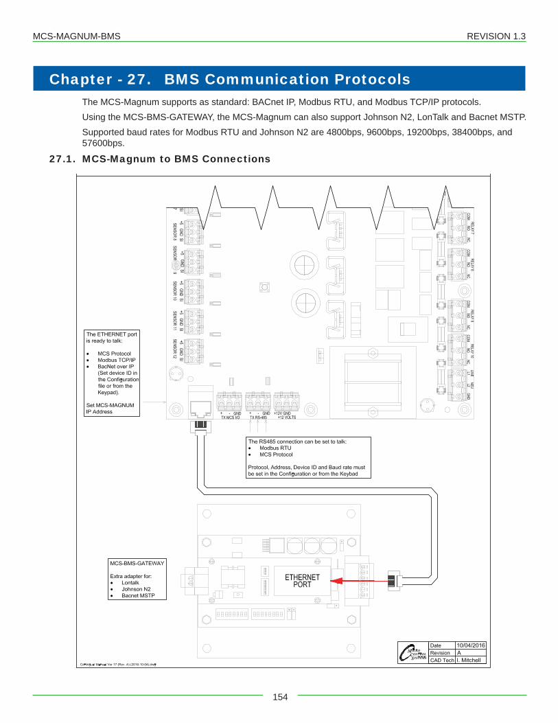
MCS-MAGNUM-BMS REVISION 1.3
154
Chapter - 27. BMS Communication ProtocolsThe MCS-Magnum supports as standard: BACnet IP, Modbus RTU, and Modbus TCP/IP protocols.Using the MCS-BMS-GATEWAY, the MCS-Magnum can also support Johnson N2, LonTalk and Bacnet MSTP.Supported baud rates for Modbus RTU and Johnson N2 are 4800bps, 9600bps, 19200bps, 38400bps, and 57600bps.
27.1. MCS-Magnum to BMS Connections
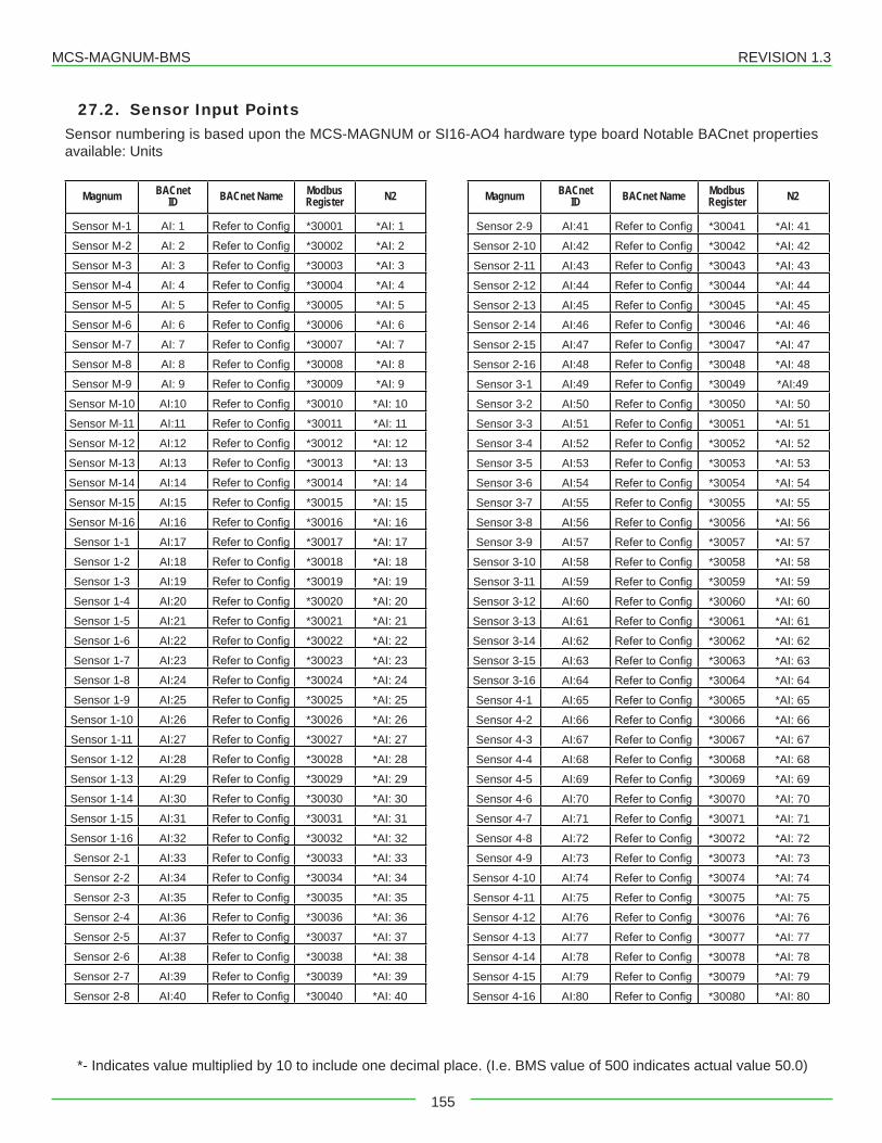
MCS-MAGNUM-BMS REVISION 1.3
155
27.2. Sensor Input PointsSensor numbering is based upon the MCS-MAGNUM or SI16-AO4 hardware type board Notable BACnet properties available: Units
Magnum BACnetID BACnet Name Modbus
Register N2
Sensor M-1 AI: 1 RefertoConfig *30001 *AI: 1
Sensor M-2 AI: 2 RefertoConfig *30002 *AI: 2
Sensor M-3 AI: 3 RefertoConfig *30003 *AI: 3
Sensor M-4 AI: 4 RefertoConfig *30004 *AI: 4
Sensor M-5 AI: 5 RefertoConfig *30005 *AI: 5
Sensor M-6 AI: 6 RefertoConfig *30006 *AI: 6
Sensor M-7 AI: 7 RefertoConfig *30007 *AI: 7
Sensor M-8 AI: 8 RefertoConfig *30008 *AI: 8
Sensor M-9 AI: 9 RefertoConfig *30009 *AI: 9
Sensor M-10 AI:10 RefertoConfig *30010 *AI: 10
Sensor M-11 AI:11 RefertoConfig *30011 *AI: 11
Sensor M-12 AI:12 RefertoConfig *30012 *AI: 12
Sensor M-13 AI:13 RefertoConfig *30013 *AI: 13
Sensor M-14 AI:14 RefertoConfig *30014 *AI: 14
Sensor M-15 AI:15 RefertoConfig *30015 *AI: 15
Sensor M-16 AI:16 RefertoConfig *30016 *AI: 16
Sensor 1-1 AI:17 RefertoConfig *30017 *AI: 17
Sensor 1-2 AI:18 RefertoConfig *30018 *AI: 18
Sensor 1-3 AI:19 RefertoConfig *30019 *AI: 19
Sensor 1-4 AI:20 RefertoConfig *30020 *AI: 20
Sensor 1-5 AI:21 RefertoConfig *30021 *AI: 21
Sensor 1-6 AI:22 RefertoConfig *30022 *AI: 22
Sensor 1-7 AI:23 RefertoConfig *30023 *AI: 23
Sensor 1-8 AI:24 RefertoConfig *30024 *AI: 24
Sensor 1-9 AI:25 RefertoConfig *30025 *AI: 25
Sensor 1-10 AI:26 RefertoConfig *30026 *AI: 26
Sensor 1-11 AI:27 RefertoConfig *30027 *AI: 27
Sensor 1-12 AI:28 RefertoConfig *30028 *AI: 28
Sensor 1-13 AI:29 RefertoConfig *30029 *AI: 29
Sensor 1-14 AI:30 RefertoConfig *30030 *AI: 30
Sensor 1-15 AI:31 RefertoConfig *30031 *AI: 31
Sensor 1-16 AI:32 RefertoConfig *30032 *AI: 32
Sensor 2-1 AI:33 RefertoConfig *30033 *AI: 33
Sensor 2-2 AI:34 RefertoConfig *30034 *AI: 34
Sensor 2-3 AI:35 RefertoConfig *30035 *AI: 35
Sensor 2-4 AI:36 RefertoConfig *30036 *AI: 36
Sensor 2-5 AI:37 RefertoConfig *30037 *AI: 37
Sensor 2-6 AI:38 RefertoConfig *30038 *AI: 38
Sensor 2-7 AI:39 RefertoConfig *30039 *AI: 39
Sensor 2-8 AI:40 RefertoConfig *30040 *AI: 40
Magnum BACnetID BACnet Name Modbus
Register N2
Sensor 2-9 AI:41 RefertoConfig *30041 *AI: 41
Sensor 2-10 AI:42 RefertoConfig *30042 *AI: 42
Sensor 2-11 AI:43 RefertoConfig *30043 *AI: 43
Sensor 2-12 AI:44 RefertoConfig *30044 *AI: 44
Sensor 2-13 AI:45 RefertoConfig *30045 *AI: 45
Sensor 2-14 AI:46 RefertoConfig *30046 *AI: 46
Sensor 2-15 AI:47 RefertoConfig *30047 *AI: 47
Sensor 2-16 AI:48 RefertoConfig *30048 *AI: 48
Sensor 3-1 AI:49 RefertoConfig *30049 *AI:49
Sensor 3-2 AI:50 RefertoConfig *30050 *AI: 50
Sensor 3-3 AI:51 RefertoConfig *30051 *AI: 51
Sensor 3-4 AI:52 RefertoConfig *30052 *AI: 52
Sensor 3-5 AI:53 RefertoConfig *30053 *AI: 53
Sensor 3-6 AI:54 RefertoConfig *30054 *AI: 54
Sensor 3-7 AI:55 RefertoConfig *30055 *AI: 55
Sensor 3-8 AI:56 RefertoConfig *30056 *AI: 56
Sensor 3-9 AI:57 RefertoConfig *30057 *AI: 57
Sensor 3-10 AI:58 RefertoConfig *30058 *AI: 58
Sensor 3-11 AI:59 RefertoConfig *30059 *AI: 59
Sensor 3-12 AI:60 RefertoConfig *30060 *AI: 60
Sensor 3-13 AI:61 RefertoConfig *30061 *AI: 61
Sensor 3-14 AI:62 RefertoConfig *30062 *AI: 62
Sensor 3-15 AI:63 RefertoConfig *30063 *AI: 63
Sensor 3-16 AI:64 RefertoConfig *30064 *AI: 64
Sensor 4-1 AI:65 RefertoConfig *30065 *AI: 65
Sensor 4-2 AI:66 RefertoConfig *30066 *AI: 66
Sensor 4-3 AI:67 RefertoConfig *30067 *AI: 67
Sensor 4-4 AI:68 RefertoConfig *30068 *AI: 68
Sensor 4-5 AI:69 RefertoConfig *30069 *AI: 69
Sensor 4-6 AI:70 RefertoConfig *30070 *AI: 70
Sensor 4-7 AI:71 RefertoConfig *30071 *AI: 71
Sensor 4-8 AI:72 RefertoConfig *30072 *AI: 72
Sensor 4-9 AI:73 RefertoConfig *30073 *AI: 73
Sensor 4-10 AI:74 RefertoConfig *30074 *AI: 74
Sensor 4-11 AI:75 RefertoConfig *30075 *AI: 75
Sensor 4-12 AI:76 RefertoConfig *30076 *AI: 76
Sensor 4-13 AI:77 RefertoConfig *30077 *AI: 77
Sensor 4-14 AI:78 RefertoConfig *30078 *AI: 78
Sensor 4-15 AI:79 RefertoConfig *30079 *AI: 79
Sensor 4-16 AI:80 RefertoConfig *30080 *AI: 80
*- Indicates value multiplied by 10 to include one decimal place. (I.e. BMS value of 500 indicates actual value 50.0)
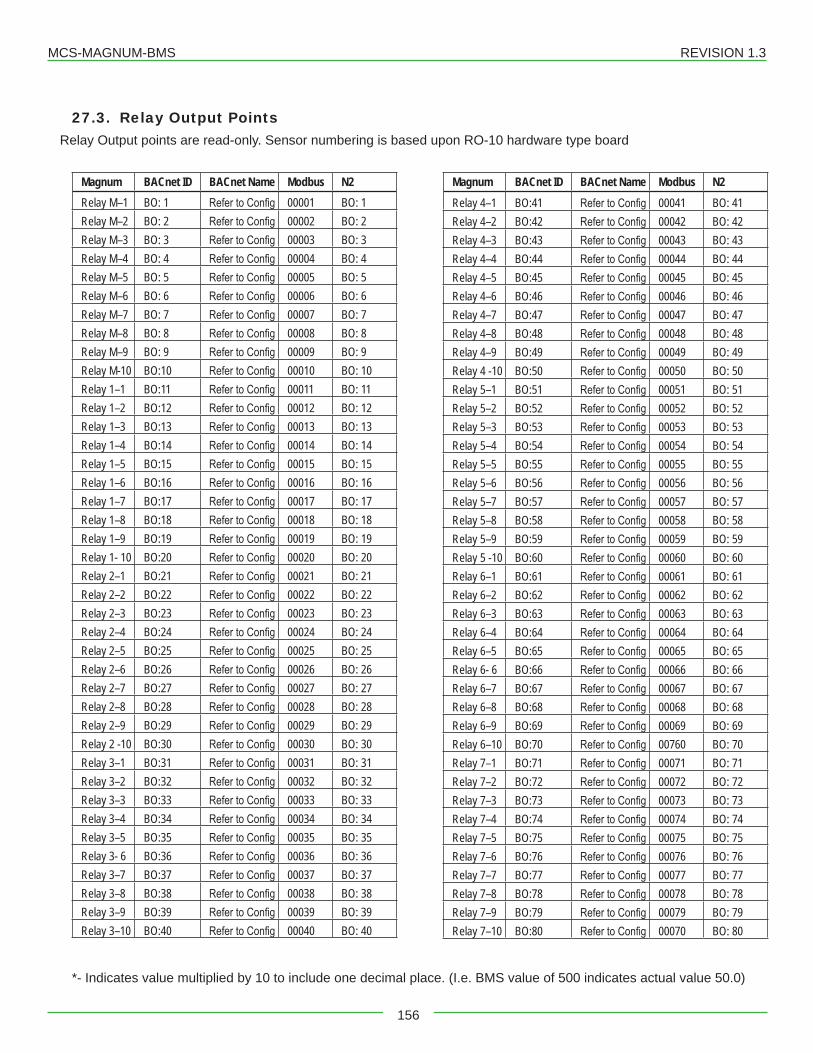
MCS-MAGNUM-BMS REVISION 1.3
156
27.3. Relay Output PointsRelay Output points are read-only. Sensor numbering is based upon RO-10 hardware type board
Magnum BACnet ID BACnet Name Modbus N2Relay M–1 BO: 1 Refer to Config 00001 BO: 1Relay M–2 BO: 2 Refer to Config 00002 BO: 2Relay M–3 BO: 3 Refer to Config 00003 BO: 3Relay M–4 BO: 4 Refer to Config 00004 BO: 4Relay M–5 BO: 5 Refer to Config 00005 BO: 5Relay M–6 BO: 6 Refer to Config 00006 BO: 6Relay M–7 BO: 7 Refer to Config 00007 BO: 7Relay M–8 BO: 8 Refer to Config 00008 BO: 8Relay M–9 BO: 9 Refer to Config 00009 BO: 9Relay M-10 BO:10 Refer to Config 00010 BO: 10Relay 1–1 BO:11 Refer to Config 00011 BO: 11Relay 1–2 BO:12 Refer to Config 00012 BO: 12Relay 1–3 BO:13 Refer to Config 00013 BO: 13Relay 1–4 BO:14 Refer to Config 00014 BO: 14Relay 1–5 BO:15 Refer to Config 00015 BO: 15Relay 1–6 BO:16 Refer to Config 00016 BO: 16Relay 1–7 BO:17 Refer to Config 00017 BO: 17Relay 1–8 BO:18 Refer to Config 00018 BO: 18Relay 1–9 BO:19 Refer to Config 00019 BO: 19Relay 1- 10 BO:20 Refer to Config 00020 BO: 20Relay 2–1 BO:21 Refer to Config 00021 BO: 21Relay 2–2 BO:22 Refer to Config 00022 BO: 22Relay 2–3 BO:23 Refer to Config 00023 BO: 23Relay 2–4 BO:24 Refer to Config 00024 BO: 24Relay 2–5 BO:25 Refer to Config 00025 BO: 25Relay 2–6 BO:26 Refer to Config 00026 BO: 26Relay 2–7 BO:27 Refer to Config 00027 BO: 27Relay 2–8 BO:28 Refer to Config 00028 BO: 28Relay 2–9 BO:29 Refer to Config 00029 BO: 29Relay 2 -10 BO:30 Refer to Config 00030 BO: 30Relay 3–1 BO:31 Refer to Config 00031 BO: 31Relay 3–2 BO:32 Refer to Config 00032 BO: 32Relay 3–3 BO:33 Refer to Config 00033 BO: 33Relay 3–4 BO:34 Refer to Config 00034 BO: 34Relay 3–5 BO:35 Refer to Config 00035 BO: 35Relay 3- 6 BO:36 Refer to Config 00036 BO: 36Relay 3–7 BO:37 Refer to Config 00037 BO: 37Relay 3–8 BO:38 Refer to Config 00038 BO: 38Relay 3–9 BO:39 Refer to Config 00039 BO: 39Relay 3–10 BO:40 Refer to Config 00040 BO: 40
Magnum BACnet ID BACnet Name Modbus N2Relay 4–1 BO:41 Refer to Config 00041 BO: 41Relay 4–2 BO:42 Refer to Config 00042 BO: 42Relay 4–3 BO:43 Refer to Config 00043 BO: 43Relay 4–4 BO:44 Refer to Config 00044 BO: 44Relay 4–5 BO:45 Refer to Config 00045 BO: 45Relay 4–6 BO:46 Refer to Config 00046 BO: 46Relay 4–7 BO:47 Refer to Config 00047 BO: 47Relay 4–8 BO:48 Refer to Config 00048 BO: 48Relay 4–9 BO:49 Refer to Config 00049 BO: 49Relay 4 -10 BO:50 Refer to Config 00050 BO: 50Relay 5–1 BO:51 Refer to Config 00051 BO: 51Relay 5–2 BO:52 Refer to Config 00052 BO: 52Relay 5–3 BO:53 Refer to Config 00053 BO: 53Relay 5–4 BO:54 Refer to Config 00054 BO: 54Relay 5–5 BO:55 Refer to Config 00055 BO: 55Relay 5–6 BO:56 Refer to Config 00056 BO: 56Relay 5–7 BO:57 Refer to Config 00057 BO: 57Relay 5–8 BO:58 Refer to Config 00058 BO: 58Relay 5–9 BO:59 Refer to Config 00059 BO: 59Relay 5 -10 BO:60 Refer to Config 00060 BO: 60Relay 6–1 BO:61 Refer to Config 00061 BO: 61Relay 6–2 BO:62 Refer to Config 00062 BO: 62Relay 6–3 BO:63 Refer to Config 00063 BO: 63Relay 6–4 BO:64 Refer to Config 00064 BO: 64Relay 6–5 BO:65 Refer to Config 00065 BO: 65Relay 6- 6 BO:66 Refer to Config 00066 BO: 66Relay 6–7 BO:67 Refer to Config 00067 BO: 67Relay 6–8 BO:68 Refer to Config 00068 BO: 68Relay 6–9 BO:69 Refer to Config 00069 BO: 69Relay 6–10 BO:70 Refer to Config 00760 BO: 70Relay 7–1 BO:71 Refer to Config 00071 BO: 71Relay 7–2 BO:72 Refer to Config 00072 BO: 72Relay 7–3 BO:73 Refer to Config 00073 BO: 73Relay 7–4 BO:74 Refer to Config 00074 BO: 74Relay 7–5 BO:75 Refer to Config 00075 BO: 75Relay 7–6 BO:76 Refer to Config 00076 BO: 76Relay 7–7 BO:77 Refer to Config 00077 BO: 77Relay 7–8 BO:78 Refer to Config 00078 BO: 78Relay 7–9 BO:79 Refer to Config 00079 BO: 79Relay 7–10 BO:80 Refer to Config 00070 BO: 80
*- Indicates value multiplied by 10 to include one decimal place. (I.e. BMS value of 500 indicates actual value 50.0)
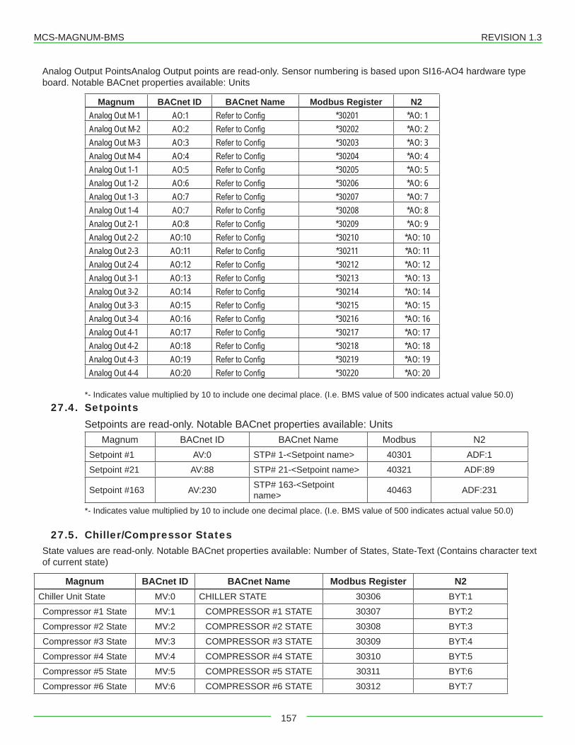
MCS-MAGNUM-BMS REVISION 1.3
157
Analog Output PointsAnalog Output points are read-only. Sensor numbering is based upon SI16-AO4 hardware type board. Notable BACnet properties available: Units
Magnum BACnet ID BACnet Name Modbus Register N2Analog Out M-1 AO:1 Refer to Config *30201 *AO: 1Analog Out M-2 AO:2 Refer to Config *30202 *AO: 2Analog Out M-3 AO:3 Refer to Config *30203 *AO: 3Analog Out M-4 AO:4 Refer to Config *30204 *AO: 4Analog Out 1-1 AO:5 Refer to Config *30205 *AO: 5Analog Out 1-2 AO:6 Refer to Config *30206 *AO: 6Analog Out 1-3 AO:7 Refer to Config *30207 *AO: 7Analog Out 1-4 AO:7 Refer to Config *30208 *AO: 8Analog Out 2-1 AO:8 Refer to Config *30209 *AO: 9Analog Out 2-2 AO:10 Refer to Config *30210 *AO: 10Analog Out 2-3 AO:11 Refer to Config *30211 *AO: 11Analog Out 2-4 AO:12 Refer to Config *30212 *AO: 12Analog Out 3-1 AO:13 Refer to Config *30213 *AO: 13Analog Out 3-2 AO:14 Refer to Config *30214 *AO: 14Analog Out 3-3 AO:15 Refer to Config *30215 *AO: 15Analog Out 3-4 AO:16 Refer to Config *30216 *AO: 16Analog Out 4-1 AO:17 Refer to Config *30217 *AO: 17Analog Out 4-2 AO:18 Refer to Config *30218 *AO: 18Analog Out 4-3 AO:19 Refer to Config *30219 *AO: 19Analog Out 4-4 AO:20 Refer to Config *30220 *AO: 20
*- Indicates value multiplied by 10 to include one decimal place. (I.e. BMS value of 500 indicates actual value 50.0)27.4. Setpoints
Setpoints are read-only. Notable BACnet properties available: UnitsMagnum BACnet ID BACnet Name Modbus N2
Setpoint #1 AV:0 STP# 1-<Setpoint name> 40301 ADF:1
Setpoint #21 AV:88 STP# 21-<Setpoint name> 40321 ADF:89
Setpoint #163 AV:230 STP# 163-<Setpoint name> 40463 ADF:231
*- Indicates value multiplied by 10 to include one decimal place. (I.e. BMS value of 500 indicates actual value 50.0)
27.5. Chiller/Compressor StatesState values are read-only. Notable BACnet properties available: Number of States, State-Text (Contains character text of current state)
Magnum BACnet ID BACnet Name Modbus Register N2Chiller Unit State MV:0 CHILLER STATE 30306 BYT:1
Compressor #1 State MV:1 COMPRESSOR #1 STATE 30307 BYT:2
Compressor #2 State MV:2 COMPRESSOR #2 STATE 30308 BYT:3
Compressor #3 State MV:3 COMPRESSOR #3 STATE 30309 BYT:4
Compressor #4 State MV:4 COMPRESSOR #4 STATE 30310 BYT:5
Compressor #5 State MV:5 COMPRESSOR #5 STATE 30311 BYT:6
Compressor #6 State MV:6 COMPRESSOR #6 STATE 30312 BYT:7
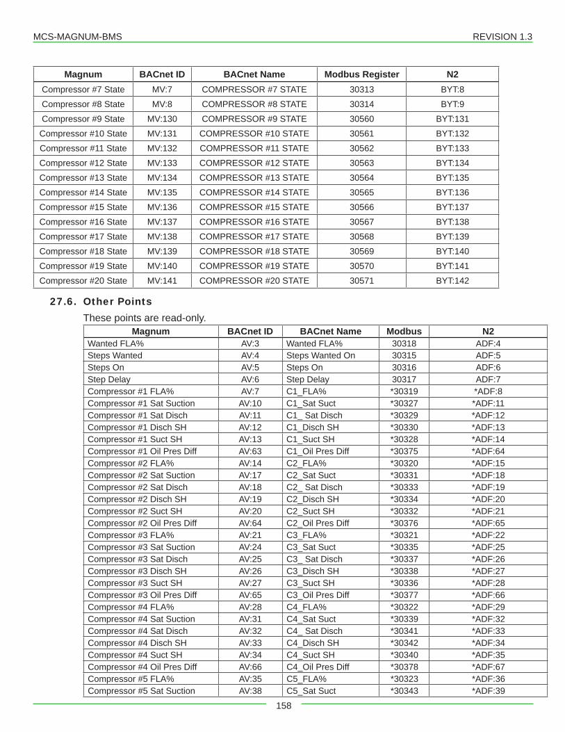
MCS-MAGNUM-BMS REVISION 1.3
158
Magnum BACnet ID BACnet Name Modbus Register N2Compressor #7 State MV:7 COMPRESSOR #7 STATE 30313 BYT:8
Compressor #8 State MV:8 COMPRESSOR #8 STATE 30314 BYT:9
Compressor #9 State MV:130 COMPRESSOR #9 STATE 30560 BYT:131
Compressor #10 State MV:131 COMPRESSOR #10 STATE 30561 BYT:132
Compressor #11 State MV:132 COMPRESSOR #11 STATE 30562 BYT:133
Compressor #12 State MV:133 COMPRESSOR #12 STATE 30563 BYT:134
Compressor #13 State MV:134 COMPRESSOR #13 STATE 30564 BYT:135
Compressor #14 State MV:135 COMPRESSOR #14 STATE 30565 BYT:136
Compressor #15 State MV:136 COMPRESSOR #15 STATE 30566 BYT:137
Compressor #16 State MV:137 COMPRESSOR #16 STATE 30567 BYT:138
Compressor #17 State MV:138 COMPRESSOR #17 STATE 30568 BYT:139
Compressor #18 State MV:139 COMPRESSOR #18 STATE 30569 BYT:140
Compressor #19 State MV:140 COMPRESSOR #19 STATE 30570 BYT:141
Compressor #20 State MV:141 COMPRESSOR #20 STATE 30571 BYT:142
27.6. Other PointsThese points are read-only.
Magnum BACnet ID BACnet Name Modbus N2Wanted FLA% AV:3 Wanted FLA% 30318 ADF:4Steps Wanted AV:4 Steps Wanted On 30315 ADF:5Steps On AV:5 Steps On 30316 ADF:6Step Delay AV:6 Step Delay 30317 ADF:7Compressor #1 FLA% AV:7 C1_FLA% *30319 *ADF:8Compressor #1 Sat Suction AV:10 C1_Sat Suct *30327 *ADF:11Compressor #1 Sat Disch AV:11 C1_ Sat Disch *30329 *ADF:12Compressor #1 Disch SH AV:12 C1_Disch SH *30330 *ADF:13Compressor #1 Suct SH AV:13 C1_Suct SH *30328 *ADF:14Compressor #1 Oil Pres Diff AV:63 C1_Oil Pres Diff *30375 *ADF:64Compressor #2 FLA% AV:14 C2_FLA% *30320 *ADF:15Compressor #2 Sat Suction AV:17 C2_Sat Suct *30331 *ADF:18Compressor #2 Sat Disch AV:18 C2_ Sat Disch *30333 *ADF:19Compressor #2 Disch SH AV:19 C2_Disch SH *30334 *ADF:20Compressor #2 Suct SH AV:20 C2_Suct SH *30332 *ADF:21Compressor #2 Oil Pres Diff AV:64 C2_Oil Pres Diff *30376 *ADF:65Compressor #3 FLA% AV:21 C3_FLA% *30321 *ADF:22Compressor #3 Sat Suction AV:24 C3_Sat Suct *30335 *ADF:25Compressor #3 Sat Disch AV:25 C3_ Sat Disch *30337 *ADF:26Compressor #3 Disch SH AV:26 C3_Disch SH *30338 *ADF:27Compressor #3 Suct SH AV:27 C3_Suct SH *30336 *ADF:28Compressor #3 Oil Pres Diff AV:65 C3_Oil Pres Diff *30377 *ADF:66Compressor #4 FLA% AV:28 C4_FLA% *30322 *ADF:29Compressor #4 Sat Suction AV:31 C4_Sat Suct *30339 *ADF:32Compressor #4 Sat Disch AV:32 C4_ Sat Disch *30341 *ADF:33Compressor #4 Disch SH AV:33 C4_Disch SH *30342 *ADF:34Compressor #4 Suct SH AV:34 C4_Suct SH *30340 *ADF:35Compressor #4 Oil Pres Diff AV:66 C4_Oil Pres Diff *30378 *ADF:67Compressor #5 FLA% AV:35 C5_FLA% *30323 *ADF:36Compressor #5 Sat Suction AV:38 C5_Sat Suct *30343 *ADF:39
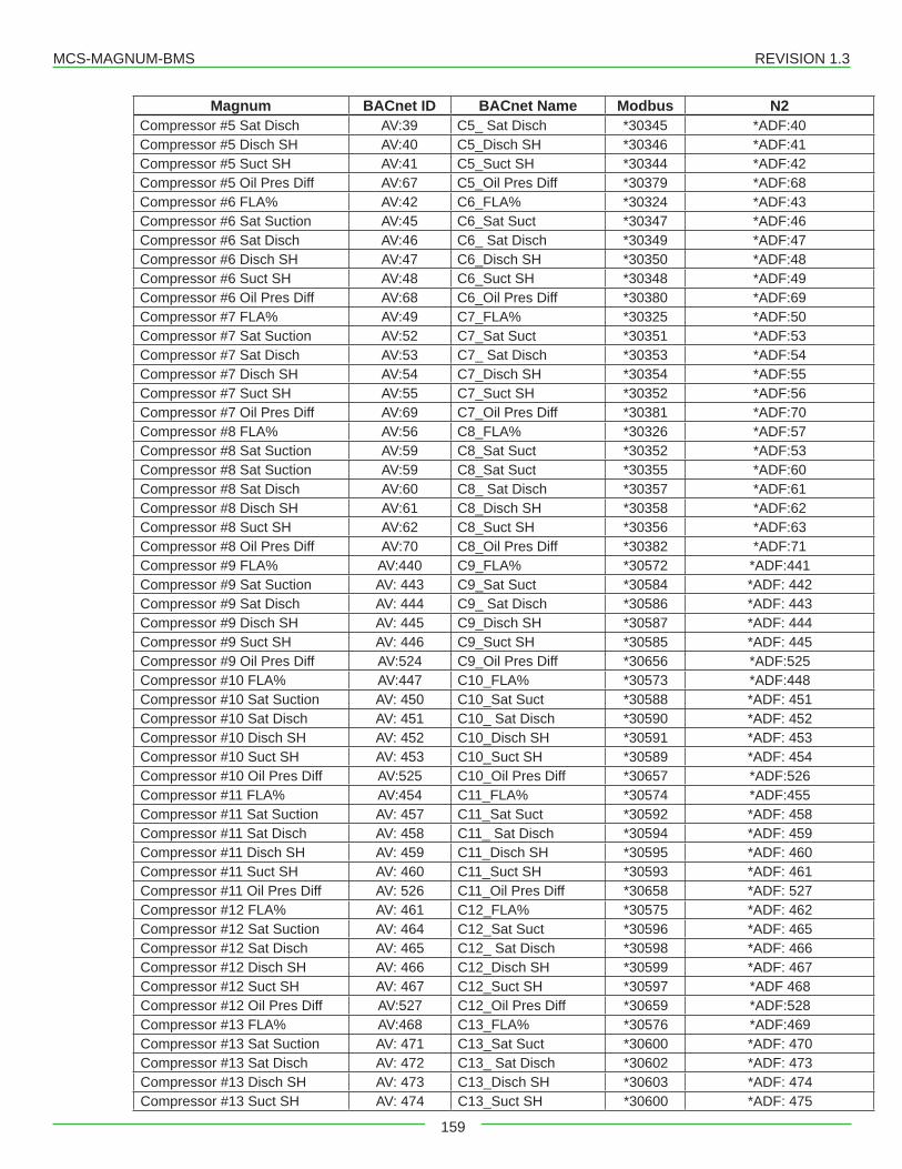
MCS-MAGNUM-BMS REVISION 1.3
159
Magnum BACnet ID BACnet Name Modbus N2Compressor #5 Sat Disch AV:39 C5_ Sat Disch *30345 *ADF:40Compressor #5 Disch SH AV:40 C5_Disch SH *30346 *ADF:41Compressor #5 Suct SH AV:41 C5_Suct SH *30344 *ADF:42Compressor #5 Oil Pres Diff AV:67 C5_Oil Pres Diff *30379 *ADF:68Compressor #6 FLA% AV:42 C6_FLA% *30324 *ADF:43Compressor #6 Sat Suction AV:45 C6_Sat Suct *30347 *ADF:46Compressor #6 Sat Disch AV:46 C6_ Sat Disch *30349 *ADF:47Compressor #6 Disch SH AV:47 C6_Disch SH *30350 *ADF:48Compressor #6 Suct SH AV:48 C6_Suct SH *30348 *ADF:49Compressor #6 Oil Pres Diff AV:68 C6_Oil Pres Diff *30380 *ADF:69Compressor #7 FLA% AV:49 C7_FLA% *30325 *ADF:50Compressor #7 Sat Suction AV:52 C7_Sat Suct *30351 *ADF:53Compressor #7 Sat Disch AV:53 C7_ Sat Disch *30353 *ADF:54Compressor #7 Disch SH AV:54 C7_Disch SH *30354 *ADF:55Compressor #7 Suct SH AV:55 C7_Suct SH *30352 *ADF:56Compressor #7 Oil Pres Diff AV:69 C7_Oil Pres Diff *30381 *ADF:70Compressor #8 FLA% AV:56 C8_FLA% *30326 *ADF:57Compressor #8 Sat Suction AV:59 C8_Sat Suct *30352 *ADF:53Compressor #8 Sat Suction AV:59 C8_Sat Suct *30355 *ADF:60Compressor #8 Sat Disch AV:60 C8_ Sat Disch *30357 *ADF:61Compressor #8 Disch SH AV:61 C8_Disch SH *30358 *ADF:62Compressor #8 Suct SH AV:62 C8_Suct SH *30356 *ADF:63Compressor #8 Oil Pres Diff AV:70 C8_Oil Pres Diff *30382 *ADF:71Compressor #9 FLA% AV:440 C9_FLA% *30572 *ADF:441Compressor #9 Sat Suction AV: 443 C9_Sat Suct *30584 *ADF: 442Compressor #9 Sat Disch AV: 444 C9_ Sat Disch *30586 *ADF: 443Compressor #9 Disch SH AV: 445 C9_Disch SH *30587 *ADF: 444Compressor #9 Suct SH AV: 446 C9_Suct SH *30585 *ADF: 445Compressor #9 Oil Pres Diff AV:524 C9_Oil Pres Diff *30656 *ADF:525Compressor #10 FLA% AV:447 C10_FLA% *30573 *ADF:448Compressor #10 Sat Suction AV: 450 C10_Sat Suct *30588 *ADF: 451Compressor #10 Sat Disch AV: 451 C10_ Sat Disch *30590 *ADF: 452Compressor #10 Disch SH AV: 452 C10_Disch SH *30591 *ADF: 453Compressor #10 Suct SH AV: 453 C10_Suct SH *30589 *ADF: 454Compressor #10 Oil Pres Diff AV:525 C10_Oil Pres Diff *30657 *ADF:526Compressor #11 FLA% AV:454 C11_FLA% *30574 *ADF:455Compressor #11 Sat Suction AV: 457 C11_Sat Suct *30592 *ADF: 458Compressor #11 Sat Disch AV: 458 C11_ Sat Disch *30594 *ADF: 459Compressor #11 Disch SH AV: 459 C11_Disch SH *30595 *ADF: 460Compressor #11 Suct SH AV: 460 C11_Suct SH *30593 *ADF: 461Compressor #11 Oil Pres Diff AV: 526 C11_Oil Pres Diff *30658 *ADF: 527Compressor #12 FLA% AV: 461 C12_FLA% *30575 *ADF: 462Compressor #12 Sat Suction AV: 464 C12_Sat Suct *30596 *ADF: 465Compressor #12 Sat Disch AV: 465 C12_ Sat Disch *30598 *ADF: 466Compressor #12 Disch SH AV: 466 C12_Disch SH *30599 *ADF: 467Compressor #12 Suct SH AV: 467 C12_Suct SH *30597 *ADF 468Compressor #12 Oil Pres Diff AV:527 C12_Oil Pres Diff *30659 *ADF:528Compressor #13 FLA% AV:468 C13_FLA% *30576 *ADF:469Compressor #13 Sat Suction AV: 471 C13_Sat Suct *30600 *ADF: 470Compressor #13 Sat Disch AV: 472 C13_ Sat Disch *30602 *ADF: 473Compressor #13 Disch SH AV: 473 C13_Disch SH *30603 *ADF: 474Compressor #13 Suct SH AV: 474 C13_Suct SH *30600 *ADF: 475
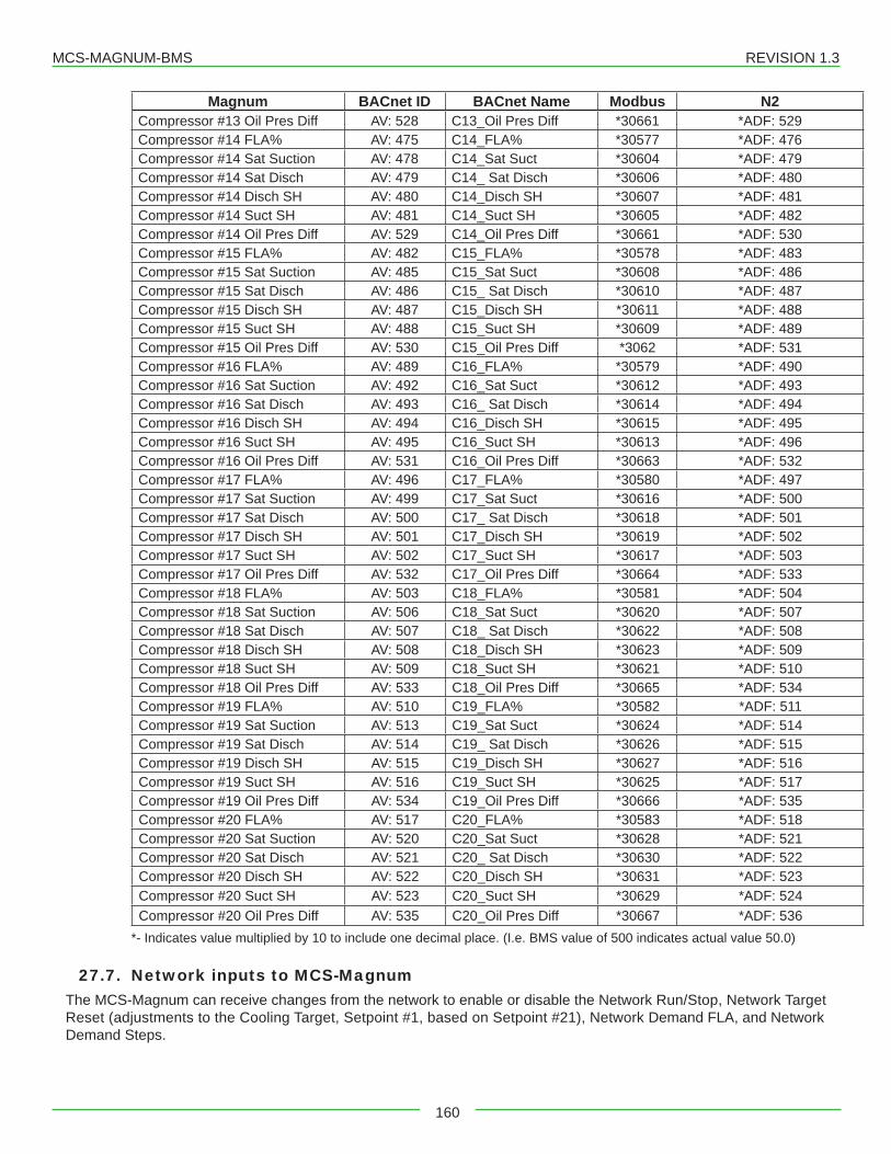
MCS-MAGNUM-BMS REVISION 1.3
160
Magnum BACnet ID BACnet Name Modbus N2Compressor #13 Oil Pres Diff AV: 528 C13_Oil Pres Diff *30661 *ADF: 529Compressor #14 FLA% AV: 475 C14_FLA% *30577 *ADF: 476Compressor #14 Sat Suction AV: 478 C14_Sat Suct *30604 *ADF: 479Compressor #14 Sat Disch AV: 479 C14_ Sat Disch *30606 *ADF: 480Compressor #14 Disch SH AV: 480 C14_Disch SH *30607 *ADF: 481Compressor #14 Suct SH AV: 481 C14_Suct SH *30605 *ADF: 482Compressor #14 Oil Pres Diff AV: 529 C14_Oil Pres Diff *30661 *ADF: 530Compressor #15 FLA% AV: 482 C15_FLA% *30578 *ADF: 483 Compressor #15 Sat Suction AV: 485 C15_Sat Suct *30608 *ADF: 486Compressor #15 Sat Disch AV: 486 C15_ Sat Disch *30610 *ADF: 487Compressor #15 Disch SH AV: 487 C15_Disch SH *30611 *ADF: 488Compressor #15 Suct SH AV: 488 C15_Suct SH *30609 *ADF: 489Compressor #15 Oil Pres Diff AV: 530 C15_Oil Pres Diff *3062 *ADF: 531Compressor #16 FLA% AV: 489 C16_FLA% *30579 *ADF: 490Compressor #16 Sat Suction AV: 492 C16_Sat Suct *30612 *ADF: 493Compressor #16 Sat Disch AV: 493 C16_ Sat Disch *30614 *ADF: 494Compressor #16 Disch SH AV: 494 C16_Disch SH *30615 *ADF: 495Compressor #16 Suct SH AV: 495 C16_Suct SH *30613 *ADF: 496Compressor #16 Oil Pres Diff AV: 531 C16_Oil Pres Diff *30663 *ADF: 532Compressor #17 FLA% AV: 496 C17_FLA% *30580 *ADF: 497Compressor #17 Sat Suction AV: 499 C17_Sat Suct *30616 *ADF: 500Compressor #17 Sat Disch AV: 500 C17_ Sat Disch *30618 *ADF: 501Compressor #17 Disch SH AV: 501 C17_Disch SH *30619 *ADF: 502Compressor #17 Suct SH AV: 502 C17_Suct SH *30617 *ADF: 503Compressor #17 Oil Pres Diff AV: 532 C17_Oil Pres Diff *30664 *ADF: 533Compressor #18 FLA% AV: 503 C18_FLA% *30581 *ADF: 504Compressor #18 Sat Suction AV: 506 C18_Sat Suct *30620 *ADF: 507Compressor #18 Sat Disch AV: 507 C18_ Sat Disch *30622 *ADF: 508Compressor #18 Disch SH AV: 508 C18_Disch SH *30623 *ADF: 509Compressor #18 Suct SH AV: 509 C18_Suct SH *30621 *ADF: 510Compressor #18 Oil Pres Diff AV: 533 C18_Oil Pres Diff *30665 *ADF: 534Compressor #19 FLA% AV: 510 C19_FLA% *30582 *ADF: 511Compressor #19 Sat Suction AV: 513 C19_Sat Suct *30624 *ADF: 514Compressor #19 Sat Disch AV: 514 C19_ Sat Disch *30626 *ADF: 515Compressor #19 Disch SH AV: 515 C19_Disch SH *30627 *ADF: 516Compressor #19 Suct SH AV: 516 C19_Suct SH *30625 *ADF: 517Compressor #19 Oil Pres Diff AV: 534 C19_Oil Pres Diff *30666 *ADF: 535Compressor #20 FLA% AV: 517 C20_FLA% *30583 *ADF: 518Compressor #20 Sat Suction AV: 520 C20_Sat Suct *30628 *ADF: 521Compressor #20 Sat Disch AV: 521 C20_ Sat Disch *30630 *ADF: 522Compressor #20 Disch SH AV: 522 C20_Disch SH *30631 *ADF: 523Compressor #20 Suct SH AV: 523 C20_Suct SH *30629 *ADF: 524Compressor #20 Oil Pres Diff AV: 535 C20_Oil Pres Diff *30667 *ADF: 536
*- Indicates value multiplied by 10 to include one decimal place. (I.e. BMS value of 500 indicates actual value 50.0)
27.7. Network inputs to MCS-MagnumThe MCS-Magnum can receive changes from the network to enable or disable the Network Run/Stop, Network Target Reset (adjustments to the Cooling Target, Setpoint #1, based on Setpoint #21), Network Demand FLA, and Network Demand Steps.
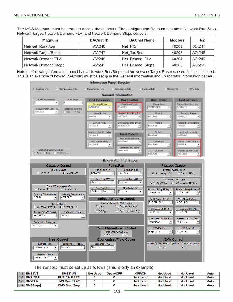
MCS-MAGNUM-BMS REVISION 1.3
161
TheMCS-Magnummustbesetuptoaccepttheseinputs.TheconfigurationfilemustcontainaNetworkRun/Stop,Network Target, Network Demand FLA, and Network Demand Steps sensors.
Magnum BACnet ID BACnet Name Modbus N2Network Run/Stop AV:246 Net_R/S 40201 BO:247Network Target/Reset AV:247 Net_Tar/Res 40202 AO:248Network Demand/FLA AV:248 Net_Demad_FLA 40204 AO:249Network Demand/Steps AV:249 Net_Demad_Steps 40205 AO:250
Note the following Information panel has a Network Run/Stop, and /or Network Target Reset sensors inputs indicated. ThisisanexampleofhowMCS-ConfigmustbesetupintheGeneralInformationandEvaporatorInformationpanels.
The sensors must be set up as follows (This is only an example)
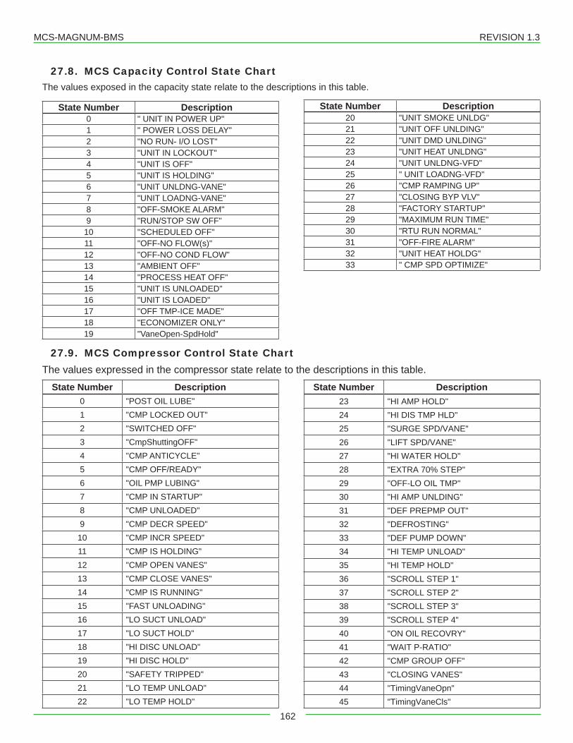
MCS-MAGNUM-BMS REVISION 1.3
162
27.8. MCS Capacity Control State ChartThe values exposed in the capacity state relate to the descriptions in this table.
State Number Description0 " UNIT IN POWER UP"1 " POWER LOSS DELAY"2 "NO RUN- I/O LOST"3 "UNIT IN LOCKOUT"4 "UNIT IS OFF"5 "UNIT IS HOLDING"6 "UNIT UNLDNG-VANE"7 "UNIT LOADNG-VANE"8 "OFF-SMOKE ALARM"9 "RUN/STOP SW OFF"
10 "SCHEDULED OFF"11 "OFF-NO FLOW(s)"12 "OFF-NO COND FLOW"13 "AMBIENT OFF"14 "PROCESS HEAT OFF"15 "UNIT IS UNLOADED"16 "UNIT IS LOADED"17 "OFF TMP-ICE MADE"18 "ECONOMIZER ONLY"19 "VaneOpen-SpdHold"
27.9. MCS Compressor Control State ChartThe values expressed in the compressor state relate to the descriptions in this table.
State Number Description0 "POST OIL LUBE"1 "CMP LOCKED OUT"2 "SWITCHED OFF"3 "CmpShuttingOFF"4 "CMP ANTICYCLE"5 "CMP OFF/READY"6 "OIL PMP LUBING"7 "CMP IN STARTUP"8 "CMP UNLOADED"9 "CMP DECR SPEED"10 "CMP INCR SPEED"11 "CMP IS HOLDING"12 "CMP OPEN VANES"13 "CMP CLOSE VANES"14 "CMP IS RUNNING"15 "FAST UNLOADING"16 "LO SUCT UNLOAD"17 "LO SUCT HOLD"18 "HI DISC UNLOAD"19 "HI DISC HOLD"20 "SAFETY TRIPPED"21 "LO TEMP UNLOAD"22 "LO TEMP HOLD"
State Number Description20 "UNIT SMOKE UNLDG"21 "UNIT OFF UNLDING"22 "UNIT DMD UNLDING"23 "UNIT HEAT UNLDNG"24 "UNIT UNLDNG-VFD"25 " UNIT LOADNG-VFD"26 "CMP RAMPING UP"27 "CLOSING BYP VLV"28 "FACTORY STARTUP"29 "MAXIMUM RUN TIME"30 "RTU RUN NORMAL"31 "OFF-FIRE ALARM"32 "UNIT HEAT HOLDG"33 " CMP SPD OPTIMIZE"
State Number Description23 "HI AMP HOLD"24 "HI DIS TMP HLD"25 "SURGE SPD/VANE"26 "LIFT SPD/VANE"27 "HI WATER HOLD"28 "EXTRA 70% STEP"29 "OFF-LO OIL TMP"30 "HI AMP UNLDING"31 "DEF PREPMP OUT"32 "DEFROSTING"33 "DEF PUMP DOWN"34 "HI TEMP UNLOAD"35 "HI TEMP HOLD"36 "SCROLL STEP 1"37 "SCROLL STEP 2"38 "SCROLL STEP 3"39 "SCROLL STEP 4"40 "ON OIL RECOVRY"41 "WAIT P-RATIO"42 "CMP GROUP OFF"43 "CLOSING VANES"44 "TimingVaneOpn"45 "TimingVaneCls"
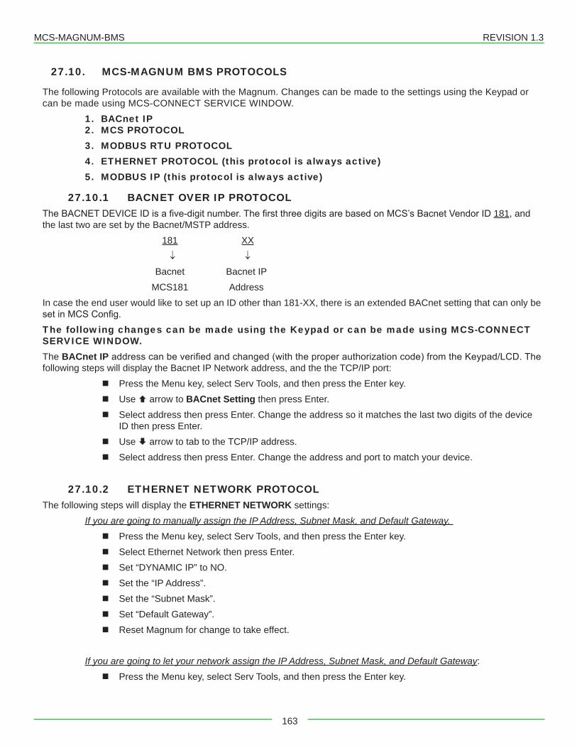
MCS-MAGNUM-BMS REVISION 1.3
163
27.10. MCS-MAGNUM BMS PROTOCOLS
The following Protocols are available with the Magnum. Changes can be made to the settings using the Keypad or can be made using MCS-CONNECT SERVICE WINDOW.
1. BACnet IP2. MCS PROTOCOL3. MODBUS RTU PROTOCOL4. ETHERNET PROTOCOL (this protocol is always active)5. MODBUS IP (this protocol is always active)
27.10.1 BACNET OVER IP PROTOCOLTheBACNETDEVICEIDisafive-digitnumber.ThefirstthreedigitsarebasedonMCS’sBacnetVendorID181, and the last two are set by the Bacnet/MSTP address.
181 XX ↓ ↓ Bacnet Bacnet IP MCS181 Address
In case the end user would like to set up an ID other than 181-XX, there is an extended BACnet setting that can only be setinMCSConfig.The following changes can be made using the Keypad or can be made using MCS-CONNECT SERVICE WINDOW.The BACnet IPaddresscanbeverifiedandchanged(withtheproperauthorizationcode)fromtheKeypad/LCD.Thefollowing steps will display the Bacnet IP Network address, and the the TCP/IP port:
� Press the Menu key, select Serv Tools, and then press the Enter key. � Use arrow to BACnet Setting then press Enter. � Select address then press Enter. Change the address so it matches the last two digits of the device
ID then press Enter. � Use arrow to tab to the TCP/IP address. � Select address then press Enter. Change the address and port to match your device.
27.10.2 ETHERNET NETWORK PROTOCOLThe following steps will display the ETHERNET NETWORK settings:
If you are going to manually assign the IP Address, Subnet Mask, and Default Gateway. � Press the Menu key, select Serv Tools, and then press the Enter key. � Select Ethernet Network then press Enter. � Set “DYNAMIC IP” to NO. � Set the “IP Address”. � Set the “Subnet Mask”. � Set “Default Gateway”. � Reset Magnum for change to take effect.
If you are going to let your network assign the IP Address, Subnet Mask, and Default Gateway: � Press the Menu key, select Serv Tools, and then press the Enter key.
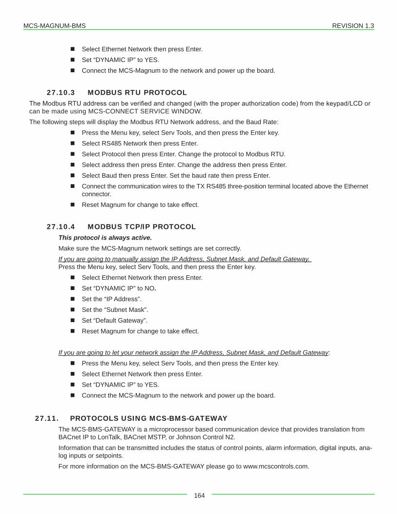
MCS-MAGNUM-BMS REVISION 1.3
164
� Select Ethernet Network then press Enter. � Set “DYNAMIC IP” to YES. � Connect the MCS-Magnum to the network and power up the board.
27.10.3 MODBUS RTU PROTOCOLTheModbusRTUaddresscanbeverifiedandchanged(withtheproperauthorizationcode)fromthekeypad/LCDorcan be made using MCS-CONNECT SERVICE WINDOW.The following steps will display the Modbus RTU Network address, and the Baud Rate:
� Press the Menu key, select Serv Tools, and then press the Enter key. � Select RS485 Network then press Enter. � Select Protocol then press Enter. Change the protocol to Modbus RTU. � Select address then press Enter. Change the address then press Enter. � Select Baud then press Enter. Set the baud rate then press Enter. � Connect the communication wires to the TX RS485 three-position terminal located above the Ethernet
connector. � Reset Magnum for change to take effect.
27.10.4 MODBUS TCP/IP PROTOCOLThis protocol is always active. Make sure the MCS-Magnum network settings are set correctly. If you are going to manually assign the IP Address, Subnet Mask, and Default Gateway. Press the Menu key, select Serv Tools, and then press the Enter key.
� Select Ethernet Network then press Enter. � Set “DYNAMIC IP” to NO. � Set the “IP Address”. � Set the “Subnet Mask”. � Set “Default Gateway”. � Reset Magnum for change to take effect.
If you are going to let your network assign the IP Address, Subnet Mask, and Default Gateway: � Press the Menu key, select Serv Tools, and then press the Enter key. � Select Ethernet Network then press Enter. � Set “DYNAMIC IP” to YES. � Connect the MCS-Magnum to the network and power up the board.
27.11. PROTOCOLS USING MCS-BMS-GATEWAYThe MCS-BMS-GATEWAY is a microprocessor based communication device that provides translation from BACnet IP to LonTalk, BACnet MSTP, or Johnson Control N2.Information that can be transmitted includes the status of control points, alarm information, digital inputs, ana-log inputs or setpoints.For more information on the MCS-BMS-GATEWAY please go to www.mcscontrols.com.
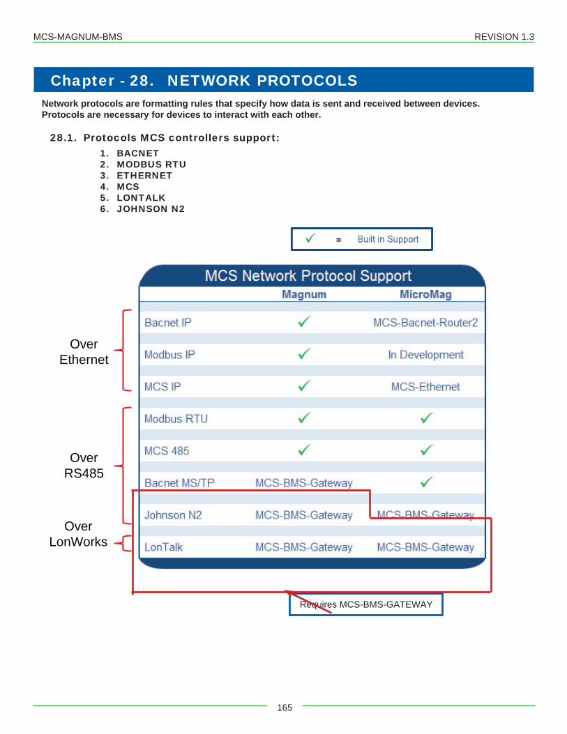
MCS-MAGNUM-BMS REVISION 1.3
165
Chapter - 28. NETWORK PROTOCOLSNetwork protocols are formatting rules that specify how data is sent and received between devices.Protocols are necessary for devices to interact with each other.
28.1. Protocols MCS controllers support:1. BACNET2. MODBUS RTU3. ETHERNET4. MCS5. LONTALK6. JOHNSON N2
Over Ethernet
Over RS485
Over LonWorks
Requires MCS-BMS-GATEWAY
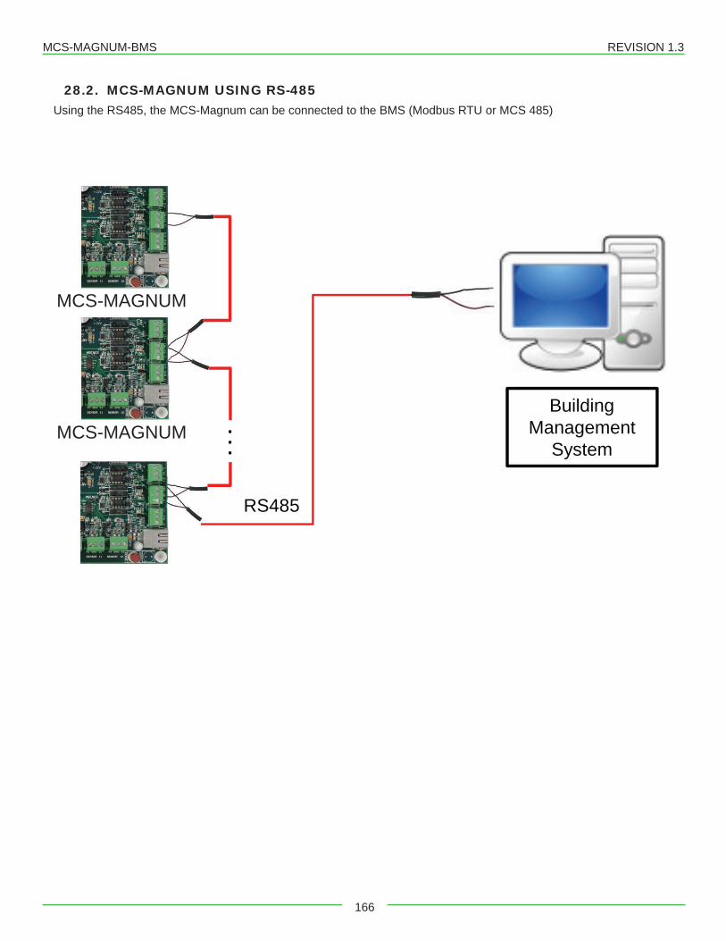
MCS-MAGNUM-BMS REVISION 1.3
166
28.2. MCS-MAGNUM USING RS-485Using the RS485, the MCS-Magnum can be connected to the BMS (Modbus RTU or MCS 485)
RS485
...
MCS-MAGNUM
MCS-MAGNUM
MCS-MAGNUM
Building Management
System
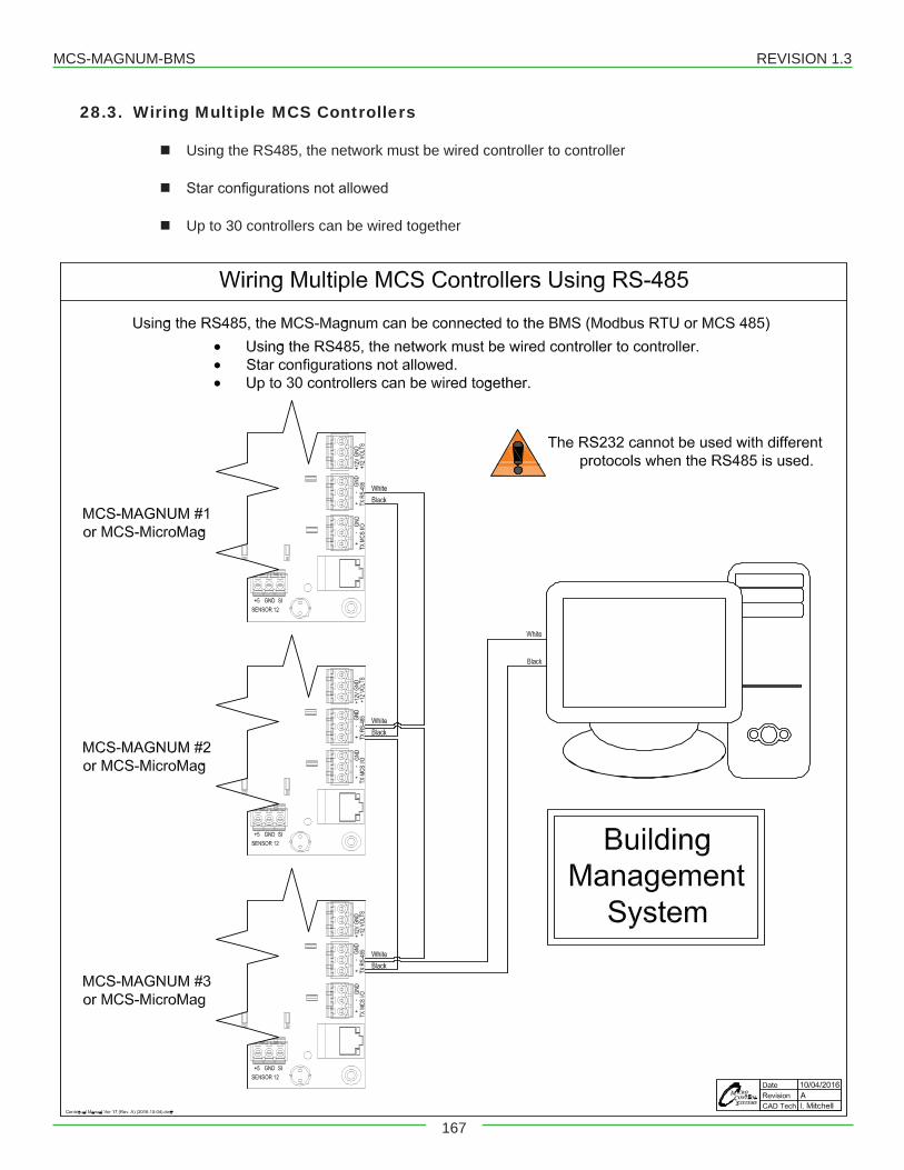
MCS-MAGNUM-BMS REVISION 1.3
167
28.3. Wiring Multiple MCS Controllers
� Using the RS485, the network must be wired controller to controller
� Starconfigurationsnotallowed
� Up to 30 controllers can be wired together
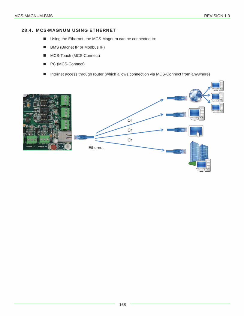
MCS-MAGNUM-BMS REVISION 1.3
168
28.4. MCS-MAGNUM USING ETHERNET
� Using the Ethernet, the MCS-Magnum can be connected to:
� BMS (Bacnet IP or Modbus IP)
� MCS-Touch (MCS-Connect)
� PC (MCS-Connect)
� Internet access through router (which allows connection via MCS-Connect from anywhere)
Ethernet
Or
Or
Or
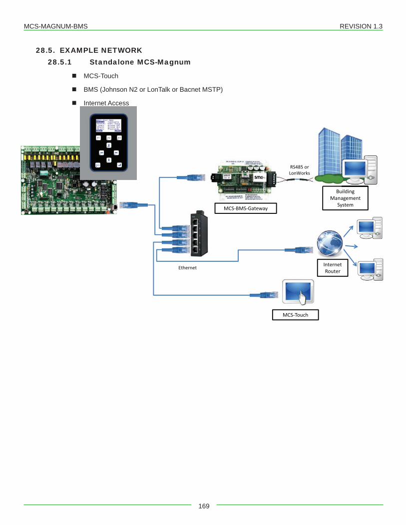
MCS-MAGNUM-BMS REVISION 1.3
169
28.5. EXAMPLE NETWORK28.5.1 Standalone MCS-Magnum
� MCS-Touch
� BMS (Johnson N2 or LonTalk or Bacnet MSTP)
� Internet Access
Ethernet
Building Management
System
MCS-Touch
Internet Router
MCS-BMS-Gateway
RS485 or LonWorks
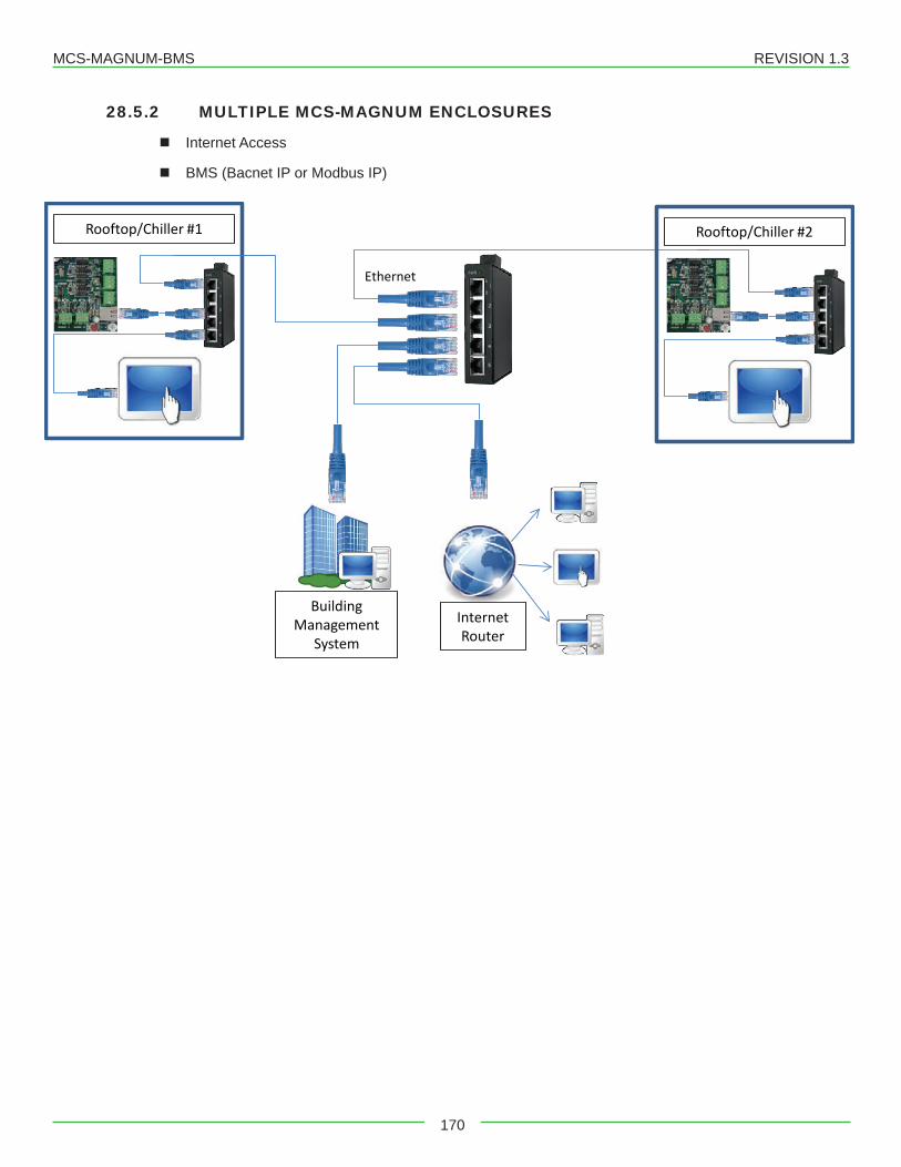
MCS-MAGNUM-BMS REVISION 1.3
170
28.5.2 MULTIPLE MCS-MAGNUM ENCLOSURES
� Internet Access
� BMS (Bacnet IP or Modbus IP)
Ethernet
Rooftop/Chiller #1
Building Management
System
Internet Router
Rooftop/Chiller #2
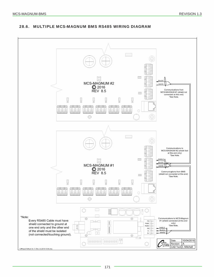
MCS-MAGNUM-BMS REVISION 1.3
171
28.6. MULTIPLE MCS-MAGNUM BMS RS485 WIRING DIAGRAM
MCS-MAGNUM V17- ALARMS - TROUBLESHOOTING REVISION 1.3
172
Chapter - 29. Magnum Alarms and SafetiesThere are three types of alarms that are generated by the Magnum control logic: Information only alarms, Magnum system alarms and Chiller Setpoint safety alarms.Allalarmshavethesameformat.Thealarmisidentifiedandisdate/timestamped.AlarmscanbeviewedfromtheMagnum keypad by selecting the ‘Alarms’ from the main menu, or through MCS-Connect.
29.1. Information Only Alarms29.1.1 System Generated Alarms
Thefollowingalarmsaregeneratedtoprovideinformation;theywillnotcauseachangeinthecontrolalgorithmsuch as a lock out condition or a Relay Output being forced off. POWER FAILED – Generated when power to the Magnum was lost. POWER RETURNED – Generated when power to the Magnum returned. HW DATE INVALID – The date contained/read from the hardware real time clock chip is not valid. Check
battery voltage, it should be > 2.0 vdc. HW TIME INVALID – The time contained/read from the hardware real time clock chip is not valid. Check battery
voltage, it should be > 2.0 vdc. SW DATE INVALID – The date contained/read from the software clock is not valid. SW TIME INVALID The time contained/read from the software clock is not valid. RAM INTEGRITY – the data contained in the battery-backed up RAM memory may be corrupted. This does
not stop the Magnum from running. It means the historical data may be incorrect (run times, cycles, min/max values, and trend/graph data).
WATCHDOG RESET – The Magnum has reset itself because of improper operator of the Magnum board. Please consult the manufacturer if this alarm has occurred.
LOST A/D CONVTR – The Magnum microprocessor has lost communications to the Analog to Digital converter chip (chip that converts sensor voltages to a digital number). Check for a shorted sensor that may cause
LOST DISPLAY – Generated when communication to the Keypad/Display is lost. CF INIT ERROR – The Compact Flash card that was installed cannot be initialized and therefore cannot be
used. Replace the Compact Flash card with one that works. BATTERY FAILED – Generated when Magnum is not getting power from the Battery.
29.1.2 User Initiated AlarmsThe following alarms indicate that an individual took action: (Most require proper authorization) LOCKOUT RESET – Generated when a user resets a compressor other unit from a locked condition. COMPUTER RESET – Generated when the manual reset button on the Magnum is pressed. ALARMS CLEARED – Generated when a user clears the alarm history. STPTCHANGED–GeneratedwhenausermakesachangetoaSetpoint;thenumberoftheSetpointwillalso
be displayed with the alarm. RO TO (Selected Condition) – Generated when a user manually changes the condition of a Relay Output
(either AUTO, MANON, or MANOFF). AO TO (Selected Condition) – Generated when a user changes the condition of an Analog Output (either AUTO
or MANUAL. If MANUAL, then a dialog box will appear to input the number value). SI TO (Selected Condition) – Generated when a user changes the condition of a Sensor Input (If a digital input,
then either AUTO, MANON, or MANOFF. If an analog input, then either AUTO or MANUAL. If MANUAL, then a dialog box will appear to input the number value).
POINT INFO CLEAR – Generated when a user clears all point information (run times, cycles, min/max values, etc.). CLOCK SET – Generated when a user makes a change to the Magnum real time clock. CFGDOWNLOADED–GeneratedwhenauseruploadsanewconfigurationfileintotheMagnum. ETHERNET CHANGE – Generated when a user makes a change to the Ethernet settings through the Keypad/
Display. RS485 CHANGED – Generated when a user makes changes to the RS485 address through the Keypad/
Display.
MCS-MAGNUM V17- ALARMS - TROUBLESHOOTING REVISION 1.3
173
CF CARD INSERTED – Generated when a user inserts a Compact Flash memory card into the Magnum. CF CARD REMOVED – Generated when a user removes a Compact Flash memory card from the Magnum.
29.1.3 Automatic AlarmsThe following alarms indicate an action that the Magnum made automatically: ROTATED LEAD – Generated when the Magnum automatically rotates the Lead Compressor. DAYLIGHT SAVINGS – Generated when the Magnum automatically changes the real time clock to adjust for
Daylight Savings Time.
29.2. Magnum System Alarms29.2.1 Configuration Alarms
Thesealarmsindicateaproblemwiththeconfigurationfileinthesystem.ThesystemisnotoperationalandanewconfigurationmustbetransmittedtotheunitthroughMCS-Connect. INVALID CONFIG – Checksums are incorrect. INVALIDCFGVER–Theversionnumberoftheconfigurationisinvalid. INVALIDCFGTYPE–Theconfigurationtypedoesnotmatchthesoftwaretype.
29.2.2 MCS Local Network AlarmsThese alarms indicate problems with the MCS local network: LOST SI COMM #_ / LOST RO COMM #_–Generated when communications to a Sensor Input or Relay
Output board is lost. The number of the board will be displayed with the alarm. The system can be accessed but will be in a NO RUN- I/O LOST state.
MCS-STAT OFFLINE – The Magnum has lost communications to the MCS-STAT. LOST IO SHUTDOWN – Generated when Magnum is running and there are no communications to one or
more of the I/O boards. The system can be accessed but will be in a NO RUN- I/O LOST state. LOST I/O RESTART – Generated when the Magnum does an automatic reset once I/O communications are
restored.
29.2.3 Key Sensors AlarmsThese alarms indicate a problem with a key sensor, it is either shorted or open. The alarm will contain ALARM followed by the 10-character name of the sensor. The following sensors related to the entire system are tested: Leaving temperature: If failed, then Lock Out the system. Returning temperature: If failed, then alarm only no Lock Out. Ambient temperature: If failed, then alarm only no Lock Out.The following compressor sensors are tested. If they fail, then that compressor only is locked out: Suction pressure and temperature Discharge pressure and temperature Oil pressure and temperature Motor temperature (if an analog input)
29.2.4 Emergency Stop Alarm EMERGENCY STOP – Generated when the emergency stop switch has been turned on. The system can be
accessed but is in a Lock Out state.
29.3. Setpoint safety alarmsThe Magnum algorithm incorporates a number of safety checks, based on Setpoints, preventing unsafe conditions that could potentially cause damage to the system. When a safety trips the circuit will be in a SAFETY TRIPPED state. The circuit will remain in this state for the time in the ‘Safety Down Time (min)’ cell and then move to the CMP ANTICYCLE or CMP IS OFF state where the compressor will be allowed to run again if required. If the same safetytripoccursagainwithinthetimeinthe‘LockoutDelayHrs’cellsincethefirsttrip,thecircuitwillbesettoCMPLOCKED OUT state, which requires a manual reset to restart the compressor. If the lockout delay time is set to zero, theMagnumwillgeneratealockoutconditionthefirsttimethatthesafetyoccurs.
MCS-MAGNUM V17- ALARMS - TROUBLESHOOTING REVISION 1.3
174
29.3.1 Sensor Inputs Used With Magnum Setpoint Safeties: Suction Pressure(Analog or Digital) Discharge Pressure (Analog or Digital) Oil Pressure (Analog or Digital) Oil Differential Pressure (Calculated value) Oil Temperature (Analog or Digital) Discharge Temperature (Analog or Digital) Motor Temperature (Analog or Digital) Motor Amps (Analog or Digital) Motor Fault (Analog or Digital) Liquid Temperature (Analog Only) Compress Proof (Digital Only) Flow Switch (Digital Only)
29.3.2 Setpoint safetiesFor a safety trip to occur, both the Sensor Input and the associated Setpoint must be active. If a safety trips, the alarm namewillconsistoftheSetpointnameplusadditionalidentificationsuchaspointnumber,compressornumber,or30second history leading up to the trip if applicable.Note: Most safeties are checked only if the compressor is running, however if the safety is always checked it will be noted.The following is a list of safeties that are incorporated in the standard chiller algorithm control. These safeties are checked every second. For a system with multiple circuits, each one is tested individually. If a safety trip occurs, only that respective compressor will be affected, the others will continue to function normally.
Freeze Protection (SAFETY IS ALWAYS CHECKED)If the leaving temperature drops below the Setpoint value then the entire system will Lock Out and a FREEZE alarm will be generated. There is also an option to have one freeze protect for each individual circuit. Refer to section 11 Setpoint #111.
No Flow ProtectionIfaflowswitchisused,thentheentiresystemwillbeLockedOutifSetpoint#105isactive.IftheSetpointisinactive,the Magnum will determine if there is a second pump, if so it will be started. Else, the system will shut down and automaticallyrestartwhentheflowswitchison,indicatingflowhasreturned.Thereisalsoanoptiontohaveaflowswitch for each individual circuit. Refer to section 11 Setpoint #105.
Phase Loss ProtectionPhase loss, as indicated by the phase loss monitor, will result in the entire system being Locked Off and a phase loss alarm will be generated. If Setpoint #166 is inactive the Magnum will wait for 2 seconds before the Lock Out occurs. The alarm will be PHASE LOSS and no restart will be attempted. If Setpoint #166 is active, the name of the Setpoint will be in the message. Refer to section 11 Setpoint #166.
Low Differential Oil PressureThissafetyisdesignedtomeetthecompressormanufacturerrequirementsonoilpressure.Forthefirst5secondsfollowing a compressor start (60 seconds if Hitachi screw compressor) this safety is NOT checked. For the next 30 seconds, if the oil differential pressure drops below ½ of the value of the Setpoint or the digital input turns ON for thetimespecifiedinthe‘Time(sec)’fieldofthatSetpoint,thenthecircuitwillbeLockedOutandaLOWOILalarmgenerated. After this time period, if the oil differential pressure drops below the value of the Setpoint and it remains thereforthetimespecifiedinthe‘Time(sec)’field,thenthecompressorwillbeLockedOutandalowoilalarmgenerated. This safety is checked for when the compressor is on and not in a Pump Down state. Refer to section 11 Setpoint #91.
Low Suction PressureIfthesuctionpressuredropsbelowthevalueoftheSetpointorthedigitalinputturnsONforthetimespecifiedinthe‘Time(sec)’field,thecompressorwillbelockedoutandaLOWSUCTIONalarmgenerated.Thissafetyisbypassedwhen the compressor is in a Pump Down state. This safety can also be used as a freeze protection based upon the suction pressure. When this safety trip occurs, all compressors in the same suction group will react in the same manner. Refer to section 11 Setpoint #77.
MCS-MAGNUM V17- ALARMS - TROUBLESHOOTING REVISION 1.3
175
Unsafe Suction PressureThis safety is similar to the low suction pressure safety, except it is often set up with a lower value and a shorter safety time.IfthesuctionpressuredropsbelowthevalueoftheSetpointorthedigitalinputturnsONforthetimespecifiedinthe‘Time(sec)’fieldofthatSetpoint,thenthecircuitwillbeLockedOutandaUNSAFESUCTIONalarmgenerated.ThissafetywillalwayscauseaLockOutonthefirsttrip,requiringamanualreset.Thissafetyisbypassedwhenthecompressor is in a Pump Down state. When this safety trip occurs, all compressors in the same suction group will react the same. Refer to section 11 Setpoint #80.High Discharge Pressure (SAFETY IS ALWAYS CHECKED)IfthedischargepressurerisesabovethevalueoftheSetpointorthedigitalinputturnsONforthetimespecifiedinthe‘Time(sec)’fieldofthatSetpoint,thenthecircuitwillbelockedoutandaHIGHDISCHARGEalarmgenerated.Referto section 11 Setpoint #81.Low Discharge PressureIfthedischargepressuredropsbelowthevalueoftheSetpointforthetimespecifiedinthe‘Time(sec)’field,thecompressor will be Locked Out and a LOW DISCHARGE alarm generated. Refer to section 11 Setpoint #85.High Discharge Temperature (SAFETY IS ALWAYS CHECKED)If the discharge temperature analog input rises above the value of the Setpoint or the digital input turns ON for the time specifiedinthe‘Time(sec)’field,thecompressorwillbeLockedOutandaHIGHTEMPERATUREalarmgenerated.Refer to section 11 Setpoint #87.High Motor Temperature or Motor Fault (SAFETY IS ALWAYS CHECKED)If the high motor temperature input rises above the value of the Setpoint or the digital input turns ON for the time specifiedinthe‘Time(sec)’field,thecircuitwillbeLockedOutandaHIGHMOTORTEMPERATUREorMOTORFAULT alarm generated. Refer to section 11 Setpoint #95.High Oil TemperatureIftheoiltemperaturerisesabovethevalueoftheSetpointorthedigitalinputturnsONforthetimespecifiedintheTime(sec)’field,thecompressorwillbelockedoutandaHIGHOILTEMPERATUREalarmgenerated.Refertosection11Setpoint #94.High Motor AmperageIf the amperage analog input rises above the value of the compressor’s respective FLA Setpoint #171 – 190 times the valueofSetpoint#75orthedigitalinputturnsONforthetimespecifiedintheTime(sec)’field,thenthecircuitwillbeLocked Out and a HIGH MOTOR AMP alarm generated. Refer to section 11 Setpoint #75.
Add an Amp Imbalance Safety Test to the existing Amp Safeties.All three Motor Amps (A, B, & C) sensors must be indicated and setpoint #241 must be active and be setup as a normal safety and contain: Type: Either Lockout or Alarm Select Value: HUMD or % Value: Maximum percentage of deviation Time: Normal safety Lockout Delay: Normal safety Safety Down Time: Normal safety
This safety will be run every second when the compressor is on and the split winding relay is on if one exists (same requirement as other amp safeties).
The three amp sensor values will be totaled and averaged. If any of the amp sensors are more than the percentage of the value of setpoint #241differencefromtheaverageformorethanthetimespecifiedinthetimecellofsetpoint #241 the compressor will be tripped and the error message will be the name of setpoint #241 plus the circuit number. The normal 2 trip logic will apply if the set point is a lockout type.
Low Motor AmperageIf the amperage analog input drops below the value of the compressor’s respective FLA Setpoint #171 – 190 times the valueofSetpoint#76orthedigitalinputturnsONforthetimespecifiedintheTime(sec)’field,thenthecircuitwillbeLocked Out and a LOW MOTOR AMP alarm will be generated. Refer to section 11 Setpoint #76.No Compressor ProofIf a compressor is called to be on and the compressor proof digital input is OFF, a NO COMP PROOF alarm will be generated. Refer to section 11 Setpoint #96.
MCS-MAGNUM V17- ALARMS - TROUBLESHOOTING REVISION 1.3
176
High Oil Seal Temperature (Screw Compressors only)IftheoilsealtemperatureanaloginputrisesabovethevalueoftheSetpointforthetimespecifiedintheTime(sec)’field,thenthecircuitwillbeLockedOutandaHIGHOILSEALalarmgenerated.Thissafetyisbypassedwhenthecompressor is in a Pump Down state. Refer to section 11 Setpoint #93.Dirty Oil Filter (Fixed Step Compressors only)If the difference between the discharge pressures minus the oil pressure is above the value of the Setpoint for the time specifiedintheTime(sec)’field,aDIRTYOILFILTERalarmwillgenerate.Refertosection11Setpoint#97.Low Discharge SuperheatIfthedischargesuperheatisbelowthevalueinSetpointforthetimespecifiedintheTime(sec)’field,thenthecircuitwill be Locked Out and a LOW DISCHARGE SUPERHEAT alarm will be generated. Refer to section 11 Setpoint #84.
29.4. TurboCor Compressor AlarmsInverter Temperature Fault (Hex code =0x0001)ThemeasuredInverterTemperaturehasexceededeithertheAlarmorFaultlimit,probablyduetoinsufficientinvertercooling.Discharge Temperature Fault (Hex code =0x0002)ThemeasuredDischargeTemperaturehasexceededeithertheAlarmorFaultlimit,probablyduetoinsufficientcharge(not enough gas).Suction Pressure Fault (Hex code =0x0004)ThemeasuredSuctionPressurehasexceededeithertheAlarmorFaultlimit,probablyduetoinsufficientchargeorinsufficientsystemload.Discharge Pressure Fault (Hex code =0x0008)The measured Discharge Pressure has exceeded either the Alarm or Fault limit, probably due to a faulty condenser. *Instantaneous lock out at fault level.3 Phase Over Current Fault (Hex code =0x0010)The estimated Mains Supply voltage has exceeded either the Alarm or Fault limit, probably due to excessive system load on mains supply (usually the compressor is pumping liquid). *Instantaneous lock out at fault level.Cavity Temperature Fault (Hex code =0x0020)ThemeasuredCavityTemperaturehasexceededeithertheAlarmorFaultlimit,probablyduetoinsufficientmotorcooling (shaft cavity).Leaving Fluid Temperature Fault (Hex code =0x0040)ThemeasuredAir/WaterTemperaturehasexceededeithertheAlarmorFaultlimit,probablyduetoinsufficientair/waterflow.Pressure Ratio Fault (Hex code =0x0080)The measured Compression Ratio of Discharge and Suction has exceeded either the Alarm or Fault limit, probably duetofaultycondenserorinsufficientloadontheevaporator.Generic Bearing/Motor/Compressor Fault (Hex code =0x0100)If the Motor Fault Word, 40106, or the Bearing Fault Word, 40098, is different from 0, then the Generic Compressor Fault is triggered.Sensor Fault (Hex code =0x0200)If the following measured degrees Celsius are surpassed, a Sensor Fault is triggered. The pressure values are in kPa:40105 Inverter Temperature>100 or < 040037 Cavity Temperature>100 or < -2040034 Suction Temperature>100 or < -3040036 Discharge Temperature>110 or < -3040046 Leaving Water Temperature>100 or < -2040031 Suction Pressure>1200 or < -3040033 Discharge Pressure>3500 or < -30SCR Temperature Fault (Hex code =0x0400)ThemeasuredSCRTemperaturehasexceededeithertheAlarmorFaultlimit.ProbablyduetoinsufficientSCRplatecooling.
MCS-MAGNUM V17- ALARMS - TROUBLESHOOTING REVISION 1.3
177
Lock Out Fault (Hex code =0x0800)If any (or a combination of) the Faults listed below occurs more than 3 times (reg. 40262) within 30 minutes (reg. 40263), a “Lock Out Fault” occurs:
• Inverter Temperature trip• SCR Temperature trip• Motor Current High trip• Inverter Error Signal Active trip• Rotor May Be Locked trip• Motor Back emf trip
*Instantaneous lock outs:•Discharge Pressure•3 Phase Over-Current
Winding Temperature Fault (Hex code =0x1000)The measured motor winding temperature has exceeded 155ºC.Superheat Fault (Hex code =0x2000)The Fault limit is based on the suction pressure and temperature values. There is no time delay on this fault or alarm. The difference between the fault limit and alarm limit is the dead band for the control.
Reserved (Hex code =0x4000)Reserved (Hex code =0x8000)
MCS-MAGNUM V17- ALARMS - TROUBLESHOOTING REVISION 1.3
178
(A more detailed troubleshooting guide is available on our website: www.MCScontrols.com)PROBLEM POTENTIAL SOLUTIONNo Sensor + 5 vdc or sensor +5 vdc output is less than 4.90 vdc.
Indicates a possible shorted input sensorRemove all sensor terminal blocks.Wait about 30 to 60 seconds. If + 5 vdc returns, replace one sensor wire at a time until the + 5 vdc is lost again. This will be the shorted sensor.
A Sensor Input reads -99.9 This indicates an open Sensor Input signal or 5 VDC problem.Check sensor wiring for missing wire or poor connection.Check for faulty sensor.Check + 5 vdc on Sensor Input to ground. If less than 5 VDC is on the sen-sor 5 VDC terminal block, the problem is with probably a shorted sensor. (A poly fuse protects the board)Remove all Sensor Input terminals.Wait about 1 minute or until 5 VDC restored at Sensor Input.Connectterminals1attimeuntilshortreappearsandfixbadsensor.
A Sensor Input reads +999.9 This indicates a shorted Sensor Input signal.Check sensor wiring for +5VDC shorted to signal etc.Check for faulty sensor.
A pressure sensor is reading more than 1 psi off(The temperature and humidity sensors do not require calibra-tion.)
This indicates the transducer Sensor Input needs to be calibrated through the offset capability in the software. (Transducers by design need to be calibrated based on construction and altitude.)You must use the MCS-Connect with a valid Authorization code to change sensor offsetsSee MCS-Connect Interactive section for instructions. (Change SI Status, Manual Value and / or offset.)
Invalid reading on one Sensor Input.
This indicates an input problem with 1 sensor.Verify jumper settings correct for that SI.
Lost I/O Indicates communications problem.Verify RS485 LED blinking.Verify termination jumper J6 only on at Magnum and last I/O.Verify Magnum and I/O address’s set correctly.Verify wiring from Magnum to each I/O correct.Check fuses/120 VAC on I/O units
MCS-Connect cannot make changes
This indicates you are not at a proper authorization level.Follow steps below for proper authorizationFrom either the SITE INFO or STATUS screen in MCS-Connect, click the ‘View Only’ button at the top of the screen, or click on the ‘Passwords’ menu option on the lower right of your Keypad/LCD display.Follow prompts and enter a valid 4-digit authorization number.Theauthorizationlevelisdisplayedatthetopofthedisplayandisreflect-ed by the color of the Authorization button.Red = View OnlyLight Blue = User levelPurple = Service levelDark Blue = Supervisor levelGreen = Factory levelGreen = Admin
Chapter - 30. Troubleshooting Quick Reference
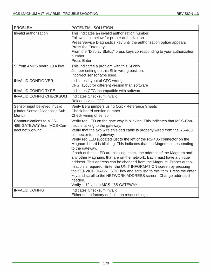
MCS-MAGNUM V17- ALARMS - TROUBLESHOOTING REVISION 1.3
179
PROBLEM POTENTIAL SOLUTIONInvalid authorization This indicates an invalid authorization number.
Follow steps below for proper authorizationPress Service Diagnostics key until the authorization option appearsPress the Enter keyFrom the “Display Status” press keys corresponding to your authorization number.Press Enter
SI from AMPS board 10 A low. This indicates a problem with this SI only.Jumper setting on this SI in wrong position.Incorrect sensor type used.
INVALID CONFIG VER Indicates layout of CFG wrong.CFG layout for different version than software
INVALID CONFIG TYPE Indicates CFG incompatible with software.INVALID CONFIG CHECKSUM Indicates Checksum invalid
Reload a valid CFGSensor input believed invalid (Under Sensor Diagnostic Sub Menu)
Verify Berg jumpers using Quick Reference SheetsCheck board version numberCheck wiring of sensor
Communications to MCS-485-GATEWAY from MCS-Con-nect not working.
Verify red LED on the gate way is blinking. This indicates that MCS-Con-nect is talking to the gateway.Verify that the two wire shielded cable is properly wired from the RS-485 connector to the gateway.Verify red LED (Located just to the left of the RS-485 connector on the Magnum board is blinking. This indicates that the Magnum is responding to the gateway.If both of these LED are blinking, check the address of the Magnum and any other Magnums that are on the network. Each must have a unique address. This address can be changed from the Magnum. Proper autho-rization is required. Enter the UNIT INFORMATION screen by pressing the SERVICE DIAGNOSTIC key and scrolling to this item. Press the enter key and scroll to the NETWORK ADDRESS screen. Change address if needed.Verify + 12 vdc to MCS-485-GATEWAY
INVALID CONFIG Indicates Checksum invalidEither set to factory defaults on reset settings.

MCS-MAGNUM V17- ALARMS - TROUBLESHOOTING REVISION 1.3
180

Providing HVAC/R Control Solutions Worldwide
5580 Enterprise Pkwy. Fort Myers, FL 33905Office:(239)694-0089Fax: (239) 694-0031
www.mcscontrols.com