Centrifugal Compressor Technology
33
Centrifugal Compressor Technology Ευάγγελος Θεοδοσάτος Μηχανολόγος Μηχανικός Ε.Μ.Π. Γενικός ∆ιευθυντής McQuay Hellas Α.Ε.
Transcript of Centrifugal Compressor Technology

Centrifugal Compressor Technology
Ευάγγελος ΘεοδοσάτοςΜηχανολόγος Μηχανικός Ε.Μ.Π.Γενικός ∆ιευθυντήςMcQuay Hellas Α.Ε.

Refrigeration Compressors
Centrifugal Chillers are mainly water cooled chillers

Refrigeration Compressors
There are two basic different compression technology:
Positive Displacement (or Volumetric): pressure is increased directly by reducing the volume where gas is contained.
Dynamic: gas velocity is increased and the velocity energy is then converted in pressure energy.

Refrigeration Compressors
REFRIGERATION CHILLER COMPRESSOR
POSITIVE DISPLACEMENT DYNAMIC
RECIPROCATING (Pistons) ROTARY CENTRIFUGALS
SCREW SCROLL

Positive Displacement (Volumetric) Compressors
Compressors used in HVAC industry are most commonly Volumetric compressors:
1) Reciprocating: the volume is reduced by a reciprocating movement of a piston inside cylinder

Positive Displacement (Volumetric) Compressors
2) Rotary: the volume is reduced by the rotation of two or more parts without reciprocating movement. Rotary compressors used in chiller industry are mainly:
a) Scroll: two interleaved spiral-like vanes to compress gas; usually one of the scrolls is fixed, while the other orbits eccentrically without rotating, thereby compressing pockets of fluid between the scrolls.

b) Screw: either a single screw element or two counter rotating intermeshed helical screw elements rotate within a specially shaped chamber. As the mechanism rotates, the rotation of the two helical rotors produces a series of volume-reducing cavities, thus increasing the pressure of the gas contained into the cavities.
Positive Displacement (Volumetric) Compressors

Positive Displacement (Volumetric) CompressorsSUCTION COMPRESSION DISCHARGE

Dynamic Compressors - Centrifugal compressors
Centrifugal compressors use an impeller (similar to the centrifugal water pump) which rotates at very high speed into a volute casing (diffuser)

Dynamic Compressors - Centrifugal compressors
How a centrifugal compressor works?
Centrifugal compressors use an impeller (a vaned rotating disk) in a shaped housing to force the gas to the exit of the impeller, increasing the velocity of the gas. A diffuser (divergent duct) section converts the velocity energy to pressure energy.Like in rotary volumetric compressor, the movement is only rotary.

Dynamic Compressors - Centrifugal compressors
How a centrifugal compressor works?In order to pass from the low pressure in impeller to the higher pressure of the diffuser, the refrigerant necessarily needs high velocity. In absence of sufficient velocity, the refrigerant will stuck in the impeller and the compressor will stall.

Therefore one of the fundamental parameter of centrifugal compressors design is the “tip speed”, which must be in the range of 204 to 213 m/sec.
This parameter determines the speed and the dimension of the impeller:
A centrifugal compressor must be specifically designed for the right pressure difference we want to achieve.
RPM =[TipSpeed(m / s)x1910]/ Diameter(cm.)
How a centrifugal compressor works?
Dynamic Compressors - Centrifugal compressors
Centrifugal compressor features
Part load conditions are the most critical for centrifugal compressors
Gas speed is even more critical in unloaded condition, when the gas flow decreases and therefore could not be able to overpass differential pressure to the diffuser. If this happens, the flow can go back into the impeller bringing compressor to stall
Impeller
Full Load Stall or Surge at Part Load
Gas Flow at Discharge ofImpeller with Fixed Geometry
Impeller

Part Load conditions for Centrifugal compressor
Engineered for flexibility and performance.™
Why when gas velocity decrease, the compressor may stall (surge)?
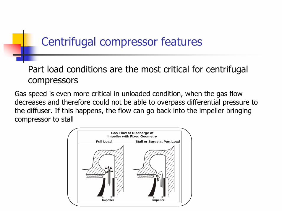
One of the most innovative technologies which allows to keep sufficient gas speed also in strongly unloaded conditions and extends unit working range, is the movable impeller discharge technology.
Compressor can work down to 10%, and dual compressors units down to 5%. In this way use of hot-gas bypass to unload capacity to low levels (energy waste), is eliminated.
Part Load
Gas Flow withMovable Geometry
Impeller
Reduced discharge area
Movable impeller discharge
Part Load conditions for Centrifugal compressor

Part Load conditions for Centrifugal compressor

Capacity Control

Capacity Control
Hot Gas Bypass
Hot gas bypass is a means of recirculating hot discharge refrigerant back into the evaporator applied at strongly unloaded conditions (below 20%). A disadvantage is that the work of compression on the recirculated refrigerant does not generate any refrigeration effect.
Careful selection of equipment size and using compressor that unload to a very low percentage of full load capacity (10%), can avoid the need for hot gas bypass in most HVAC applications.

Capacity Control
Inlet Guide Vanes
Inlet guide vanes are used to control the capacity of the compressor. As the inlet guide vanes start to close, they change the gas entry angle to the impeller and reduce gas flow and compressor capacity.

Capacity Control
Variable Frequency Drive
Changing the compressor speed can also control compressor capacity. Induction motors require a Variable Frequency Drive (VFD) to change their speed.

VFD – How does it work ??
This method is more efficient than guide vane by themselves !!!This method is more efficient than guide vane by themselves !!!
From 100% down to 70 % VFD slow down the impeller speed.
Below 70% impeller speed, the inlet guide vanes (traditional unloading way on centrifugal ) will be used together with VFD.
The controller processes the operating conditions and evaluates whether to use inlet guide vanes or the VFD.

Benefits of VFD application
What running conditions are the best for VFD applications ?
• Biggest part of chillers spend most of their operating time at part load
• Chillers operating during the winter in temperate climates, because of winter hours with lower condenser water temperature

Benefits of VFD application
Variable frequency drive offers outstanding part load performance opportunities for centrifugal chillers!!
Variable Frequency Drive allows an annual energy saving up to 35 % compared to a fixed speed chiller . For some particular part loads point energy saving can be up to 75% !!
The application of VFD can offset its cost in a couple of years !!
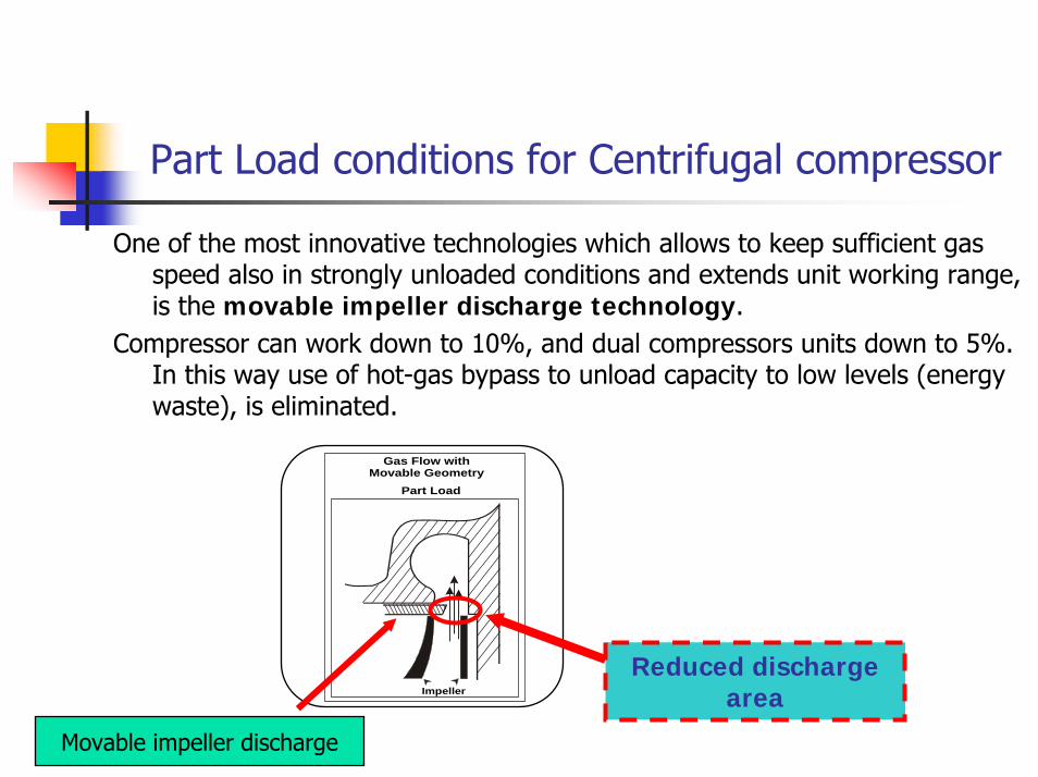
Constant Vs Variable speed
0
2
4
6
8
10
12
14
100 90 80 70 60 50 40 30 20 10
% of cooling capacity
CO
P ConstantSpeedVFD
• 2000 kW Unit• ARI partial load conditions
Variable Frequency Drive
Benefits of VFD application
Benefits of VFD application
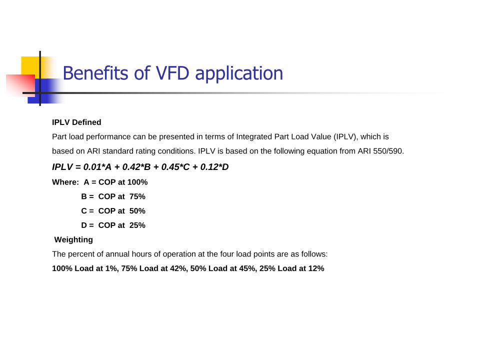
IPLV Defined
Part load performance can be presented in terms of Integrated Part Load Value (IPLV), which is
based on ARI standard rating conditions. IPLV is based on the following equation from ARI 550/590.
IPLV = 0.01*A + 0.42*B + 0.45*C + 0.12*DWhere: A = COP at 100%
B = COP at 75%
C = COP at 50%
D = COP at 25%
Weighting
The percent of annual hours of operation at the four load points are as follows:
100% Load at 1%, 75% Load at 42%, 50% Load at 45%, 25% Load at 12%

Integrated Part Load Value @ ARI
0
2
4
6
8
10
12
S.C T.C S.C+VFD T.C+VFD
UNIT TYPE
IPLV
Standard single
VFD single
Standard twin
VFD twin
Benefits of VFD application

Example of VFD Application
Load KW Hour COP1 COP2 IPLV1 IPLV2 KWh 1 KWh 225% 762,5 216 3,8 9,17 0,12 0,46 1,10 43342 17960,750% 1525 810 6 12 0,45 2,70 5,40 205875 10293875% 2287,5 756 6,18 8,6 0,42 2,60 3,61 279830 201087
100% 3050 18 4,8 6 0,01 0,05 0,06 11438 91501800 5,80 10,17 540485 331135
TOTAL CONSUMPTION CALCULATION (KWh)

Example of VFD Application
Type of centrifugal chiller VFD Standard
Hours of operation h 1800 1800Cost of electricity €/kWh 0,08715 0,08715Capacity kW 3050 3050IPLV 10,17 5,8Consumption kWh 331.135 540.485Operational Cost € 28.858 47.103
Operational Cost Difference € 18.245
Purchase cost of one unit € 200.000 150.000Initial cost difference € 50.000
Payback period years 2,74
RETURN OF INVESTMENT PERIOD

Example of VFD Application Total Expenditure Comparison
Total Expenditure Comparison
0 €
50.000 €
100.000 €
150.000 €
200.000 €
250.000 €
300.000 €
350.000 €
Acc
umul
ativ
e C
ost
Standard VFD
Standard 150.000 € 197.103 € 244.206 € 291.309 €
VFD 200.000 € 228.858 € 257.716 € 286.574 €
Purchase of chiller End of 1st Year End of 2nd Year End of 3rd Year
Srandard Unit
Srandard Unit
Srandard Unit
Srandard Unit
VFD unit
VFD unit
VFD unit
VFD unit

Example of VFD Application Additional initial cost / Accumulative Savings
VFD Application Additional initial cost / Accumulative Savings
0 €
10.000 €
20.000 €
30.000 €
40.000 €
50.000 €
60.000 €
Additional first costAccumulative savings
Additional first cost 50.000 € 50.000 € 50.000 €
Accumulative savings 18.245 € 36.490 € 54.735 €
End of 1st Year End of 2nd Year End of 3rd Year

Other benefits of VFD application
VFD also works as a “soft starter”
Reduced starting current :Inrush amps = RLAReduced torque = Less stress and longer motor lifeHigher Power factor = Reduced nominal current Lower quantity of electrical parts = Less maintenance
=Improved Performances and reliability !!

Other benefits of VFD application
Lower sound pressure levels
Centrifugal compressor noise is largely dependent on the impeller tip speed.
VFD reduces tip speed at part load and,of consequence,noise level decreases of about 5 dBA compared to traditional unloading method.
Results:Saved money for noise reduction equipment !!

END OF PRESENTATIONTHANK YOU