Lumber design values are in accordance with ANSI/TPI 1 ...
46
RE: 850106 - Design Code: FBC2014/TPI2007 Wind Code: ASCE 7-10 Wind Speed: 130 mph Roof Load: 32.0 psf Design Program: MiTek 20/20 7.6 1 of 1 This package includes 33 individual, dated Truss Design Drawings and 0 Additional Drawings. With my seal affixed to this sheet, I hereby certify that I am the Truss Design Engineer and this index sheet conforms to 61G15-31.003, section 5 of the Florida Board of Professional Engineers Rules. General Truss Engineering Criteria & Design Loads (Individual Truss Design Drawings Show Special Loading Conditions): Floor Load: 55.0 psf Site Information: Lot/Block: 4 Customer Info: Starr Custom Homes Project Name: 850106 Model: Custom Subdivision: Oceanside Park Address: 9th Ave. S. State: Florida City: Duval Name Address and License # of Structural Engineer of Record, If there is one, for the building. Name: Unknown at time of Seal License #: Unknown at time of Seal Address: Unknown at time of Seal City: Unknown at time of Seal State: Florida Albani, Thomas The truss drawing(s) referenced above have been prepared by MiTek USA, Inc. under my direct supervision based on the parameters provided by Builders FirstSource-Jacksonville. Truss Design Engineer’s Name: Albani, Thomas My license renewal date for the state of Florida is February 28, 2017. Lumber design values are in accordance with ANSI/TPI 1 section 6.3 These truss designs rely on lumber values established by others. The seal on these truss component designs is a certification that the engineer named is licensed in the jurisdiction(s) identified and that the designs comply with ANSI/TPI 1. These designs are based upon parameters shown (e.g., loads, supports, dimensions, shapes and design codes), which were given to MiTek. Any project specific information included is for MiTek’s customers file reference purpose only, and was not taken into account in the preparation of these designs. MiTek has not independently verified the applicability of the design parameters or the designs for any particular building. Before use, the building designer should verify applicability of design parameters and properly incorporate these designs into the overall building design per ANSI/TPI 1, Chapter 2. IMPORTANT NOTE: No. Seal# Truss Name 1 T9538323 F01 Date 9/23/16 2 T9538324 F02 9/23/16 3 T9538325 F03 9/23/16 4 T9538326 F04 9/23/16 5 T9538327 F05 9/23/16 6 T9538328 F06 9/23/16 7 T9538329 F07 9/23/16 8 T9538330 F09 9/23/16 9 T9538331 F10 9/23/16 10 T9538332 F11 9/23/16 11 T9538333 F11A 9/23/16 12 T9538334 F12 9/23/16 13 T9538335 T01 9/23/16 14 T9538336 T02 9/23/16 15 T9538337 T03 9/23/16 16 T9538338 T04 9/23/16 17 T9538339 T05 9/23/16 18 T9538340 T06 9/23/16 19 T9538341 T07 9/23/16 20 T9538342 T08 9/23/16 21 T9538343 T09 9/23/16 22 T9538344 T10 9/23/16 No. Seal# Truss Name 23 T9538345 T11 Date 9/23/16 24 T9538346 T12 9/23/16 25 T9538347 T13 9/23/16 26 T9538348 T14 9/23/16 27 T9538349 T15 9/23/16 28 T9538350 T16 9/23/16 29 T9538351 TG01 9/23/16 30 T9538352 TG02 9/23/16 31 T9538353 TG03 9/23/16 32 T9538354 TG04 9/23/16 33 T9538355 TG05 9/23/16 6904 Parke East Blvd. Tampa, FL 33610-4115 MiTek USA, Inc. September 23,2016
Transcript of Lumber design values are in accordance with ANSI/TPI 1 ...

RE: 850106 -
Design Code: FBC2014/TPI2007Wind Code: ASCE 7-10 Wind Speed: 130 mphRoof Load: 32.0 psf
Design Program: MiTek 20/20 7.6
1 of 1
This package includes 33 individual, dated Truss Design Drawings and 0 Additional Drawings.With my seal affixed to this sheet, I hereby certify that I am the Truss Design Engineer and this index sheetconforms to 61G15-31.003, section 5 of the Florida Board of Professional Engineers Rules.
General Truss Engineering Criteria & Design Loads (Individual Truss Design Drawings Show SpecialLoading Conditions):
Floor Load: 55.0 psf
Site Information:
Lot/Block: 4Customer Info: Starr Custom Homes Project Name: 850106 Model: Custom
Subdivision: Oceanside ParkAddress: 9th Ave. S.
State: FloridaCity: Duval
Name Address and License # of Structural Engineer of Record, If there is one, for the building.Name: Unknown at time of Seal License #: Unknown at time of SealAddress: Unknown at time of SealCity: Unknown at time of Seal State: Florida
Albani, Thomas
The truss drawing(s) referenced above have been prepared by MiTekUSA, Inc. under my direct supervision based on the parameters provided by Builders FirstSource-Jacksonville.
Truss Design Engineer's Name: Albani, ThomasMy license renewal date for the state of Florida is February 28, 2017.
Lumber design values are in accordance with ANSI/TPI 1 section 6.3These truss designs rely on lumber values established by others.
The seal on these truss component designs is a certification that the engineer named is licensed in the jurisdiction(s) identified and that the designs comply with ANSI/TPI 1. These designs are based upon parameters shown (e.g., loads, supports, dimensions, shapes and design codes), which were given to MiTek. Any project specific information included is for MiTek's customersfile reference purpose only, and was not taken into account in the preparation of these designs. MiTek has not independently verified the applicability of the designparameters or the designs for any particular building. Before use, the building designer should verify applicability of design parameters and properly incorporate these designs into the overall building design per ANSI/TPI 1, Chapter 2.
IMPORTANT NOTE:
No. Seal# Truss Name1 T9538323 F01
Date9/23/16
2 T9538324 F02 9/23/163 T9538325 F03 9/23/164 T9538326 F04 9/23/165 T9538327 F05 9/23/166 T9538328 F06 9/23/167 T9538329 F07 9/23/168 T9538330 F09 9/23/169 T9538331 F10 9/23/1610 T9538332 F11 9/23/1611 T9538333 F11A 9/23/1612 T9538334 F12 9/23/1613 T9538335 T01 9/23/1614 T9538336 T02 9/23/1615 T9538337 T03 9/23/1616 T9538338 T04 9/23/1617 T9538339 T05 9/23/1618 T9538340 T06 9/23/1619 T9538341 T07 9/23/1620 T9538342 T08 9/23/1621 T9538343 T09 9/23/1622 T9538344 T10 9/23/16
No. Seal# Truss Name23 T9538345 T11
Date9/23/16
24 T9538346 T12 9/23/1625 T9538347 T13 9/23/1626 T9538348 T14 9/23/1627 T9538349 T15 9/23/1628 T9538350 T16 9/23/1629 T9538351 TG01 9/23/1630 T9538352 TG02 9/23/1631 T9538353 TG03 9/23/1632 T9538354 TG04 9/23/1633 T9538355 TG05 9/23/16
6904 Parke East Blvd.Tampa, FL 33610-4115
MiTek USA, Inc.
September 23,2016

Job
850106
Truss
F01
Truss Type
GABLE
Qty
1
Ply
1Job Reference (optional)
T9538323
7.640 s Apr 19 2016 MiTek Industries, Inc. Fri Sep 23 11:30:24 2016 Page 1 Builders FirstSource, Jacksonville, Fl 32244ID:zoej3JKv11weiqJSJY?rqNyoIcg-kPAHLagC9avGKjFtsjjaGdXUfDKxFe4vmt2dCXyan1j
Scale = 1:25.4
1 2 3 4 5 6 7 8 9 10 11 12 13
26 25 24 23 22 21 20 19 18 17 16 15 14
27 28
3x3 3x3
3x3 3x3
3x3 3x3
1-6-121-6-12
2-10-121-4-0
4-2-121-4-0
5-6-121-4-0
6-10-121-4-0
7-5-80-6-12
8-0-40-6-12
9-4-41-4-0
10-8-41-4-0
12-0-41-4-0
13-4-41-4-0
14-11-01-6-12
0-1-8 0-1-8
1-8-
0
1-8-
0
LOADING (psf)TCLLTCDLBCLLBCDL
40.010.0
0.05.0
SPACING-Plate Grip DOLLumber DOL Rep Stress IncrCode
2-0-01.001.00YES
FBC2014/TPI2007
CSI.TCBCWB(Matrix)
0.100.010.04
DEFL.Vert(LL)Vert(TL)Horz(TL)
inn/an/a
-0.00
(loc) - - 15
l/defln/an/an/a
L/d999999n/a
PLATESMT20
Weight: 81 lb FT = 11%F, 11%E
GRIP244/190
LUMBER-TOP CHORD 2x4 SP No.2(flat)BOT CHORD 2x4 SP No.2(flat)WEBS 2x4 SP No.3(flat)OTHERS 2x4 SP No.3(flat)
BRACING-TOP CHORD Structural wood sheathing directly applied or 10-0-0 oc purlins, except
end verticals.BOT CHORD Rigid ceiling directly applied or 6-0-0 oc bracing, Except:
10-0-0 oc bracing: 25-26,14-15.
REACTIONS. All bearings 14-11-0.(lb) - Max Grav All reactions 250 lb or less at joint(s) 26, 14, 25, 15, 20, 16, 17, 18, 19, 24, 23, 22, 21
FORCES. (lb) - Max. Comp./Max. Ten. - All forces 250 (lb) or less except when shown.
NOTES- (7)1) All plates are 1.5x3 MT20 unless otherwise indicated.2) Gable requires continuous bottom chord bearing. 3) Truss to be fully sheathed from one face or securely braced against lateral movement (i.e. diagonal web).4) Gable studs spaced at 1-4-0 oc.5) "Semi-rigid pitchbreaks including heels" Member end fixity model was used in the analysis and design of this truss. 6) Recommend 2x6 strongbacks, on edge, spaced at 10-0-0 oc and fastened to each truss with 3-10d (0.131" X 3") nails. Strongbacks to
be attached to walls at their outer ends or restrained by other means.7) This manufactured product is designed as an individual building component. The suitability and use of this component for any particular
building is the responsibility of the building designer per ANSI TPI 1 as referenced by the building code.
Design valid for use only with MiTek® connectors. This design is based only upon parameters shown, and is for an individual building component, not a truss system. Before use, the building designer must verify the applicability of design parameters and properly incorporate this design into the overall building design. Bracing indicated is to prevent buckling of individual truss web and/or chord members only. Additional temporary and permanent bracing is always required for stability and to prevent collapse with possible personal injury and property damage. For general guidance regarding the fabrication, storage, delivery, erection and bracing of trusses and truss systems, see ANSI/TPI1 Quality Criteria, DSB-89 and BCSI Building Component
available from Truss Plate Institute, 218 N. Lee Street, Suite 312, Alexandria, VA 22314.Safety Information
WARNING - Verify design parameters and READ NOTES ON THIS AND INCLUDED MITEK REFERENCE PAGE MII-7473 rev. 10/03/2015 BEFORE USE.
6904 Parke East Blvd.Tampa, FL 36610

Job
850106
Truss
F02
Truss Type
Floor
Qty
7
Ply
1Job Reference (optional)
T9538324
7.640 s Apr 19 2016 MiTek Industries, Inc. Fri Sep 23 11:30:25 2016 Page 1 Builders FirstSource, Jacksonville, Fl 32244ID:zoej3JKv11weiqJSJY?rqNyoIcg-DckgZwhqwu17ytq4QREpoq3TfdQs_zj2?XnBlzyan1i
Scale = 1:25.8
1 2 3 4 5 6 7 8 9
19 18 17 16 15 14 13 12 11 10
20 21
1.5x3 1.5x3 4x6
4x4
4x4
4x4 1.5x3
1.5x3
4x4
1.5x3 1.5x3
1-6-01-6-0
4-0-02-6-0
9-6-85-6-8
10-10-41-3-12
10-11-00-0-12
14-11-04-0-0
1-3-0 1-6-8 1-0-0
0-1-8
0-1-8
1-8-
0
1-8-
0
Plate Offsets (X,Y)-- [12:0-1-8,Edge], [15:0-1-8,Edge]
LOADING (psf)TCLLTCDLBCLLBCDL
40.010.0
0.05.0
SPACING-Plate Grip DOLLumber DOL Rep Stress IncrCode
2-0-01.001.00NO
FBC2014/TPI2007
CSI.TCBCWB(Matrix)
0.850.990.52
DEFL.Vert(LL)Vert(TL)Horz(TL)
in-0.08-0.14-0.01
(loc)16-1716-17
13
l/defl>999>896
n/a
L/d360240n/a
PLATESMT20
Weight: 88 lb FT = 11%F, 11%E
GRIP244/190
LUMBER-TOP CHORD 2x4 SP No.1(flat)BOT CHORD 2x4 SP No.2(flat)WEBS 2x4 SP No.3(flat)
BRACING-TOP CHORD Structural wood sheathing directly applied or 6-0-0 oc purlins, except
end verticals.BOT CHORD Rigid ceiling directly applied or 6-0-0 oc bracing.
REACTIONS. (lb/size) 19=416/0-5-0, 13=1434/0-5-8Max Uplift19=-8(LC 4)Max Grav 19=472(LC 3), 13=1434(LC 1)
FORCES. (lb) - Max. Comp./Max. Ten. - All forces 250 (lb) or less except when shown.TOP CHORD 19-20=-464/15, 1-20=-464/15, 1-2=-334/25, 2-3=-644/170, 3-4=-567/379, 4-5=-567/379,
5-6=0/923, 6-7=0/450, 7-8=0/450, 8-9=0/450BOT CHORD 17-18=-56/627, 16-17=-379/567, 15-16=-379/567, 14-15=-672/189, 13-14=-1176/0,
12-13=-1176/0, 11-12=-450/0WEBS 6-13=-1512/0, 1-18=-37/487, 6-14=0/802, 2-18=-465/50, 5-14=-833/0, 5-15=0/791,
3-17=0/350, 3-16=-262/0, 4-15=-375/0, 9-11=-670/0, 6-12=0/1095, 7-12=-483/0
NOTES- (8)1) Unbalanced floor live loads have been considered for this design.2) All plates are 3x3 MT20 unless otherwise indicated.3) Provide mechanical connection (by others) of truss to bearing plate capable of withstanding 8 lb uplift at joint 19.4) Load case(s) 1, 2, 3, 4, 5, 6, 7, 8, 9, 10 has/have been modified. Building designer must review loads to verify that they are correct for
the intended use of this truss.5) "Semi-rigid pitchbreaks including heels" Member end fixity model was used in the analysis and design of this truss. 6) Recommend 2x6 strongbacks, on edge, spaced at 10-0-0 oc and fastened to each truss with 3-10d (0.131" X 3") nails. Strongbacks to
be attached to walls at their outer ends or restrained by other means.7) CAUTION, Do not erect truss backwards.8) This manufactured product is designed as an individual building component. The suitability and use of this component for any particular
building is the responsibility of the building designer per ANSI TPI 1 as referenced by the building code.
LOAD CASE(S) Standard1) Dead + Floor Live (balanced): Lumber Increase=1.00, Plate Increase=1.00
Uniform Loads (plf)Vert: 10-19=-10, 1-9=-100
Concentrated Loads (lb)Vert: 9=-250
2) Dead: Lumber Increase=1.00, Plate Increase=1.00Uniform Loads (plf)
Vert: 10-19=-10, 1-9=-100
Continued on page 2
Design valid for use only with MiTek® connectors. This design is based only upon parameters shown, and is for an individual building component, not a truss system. Before use, the building designer must verify the applicability of design parameters and properly incorporate this design into the overall building design. Bracing indicated is to prevent buckling of individual truss web and/or chord members only. Additional temporary and permanent bracing is always required for stability and to prevent collapse with possible personal injury and property damage. For general guidance regarding the fabrication, storage, delivery, erection and bracing of trusses and truss systems, see ANSI/TPI1 Quality Criteria, DSB-89 and BCSI Building Component
available from Truss Plate Institute, 218 N. Lee Street, Suite 312, Alexandria, VA 22314.Safety Information
WARNING - Verify design parameters and READ NOTES ON THIS AND INCLUDED MITEK REFERENCE PAGE MII-7473 rev. 10/03/2015 BEFORE USE.
6904 Parke East Blvd.Tampa, FL 36610

Job
850106
Truss
F02
Truss Type
Floor
Qty
7
Ply
1Job Reference (optional)
T9538324
7.640 s Apr 19 2016 MiTek Industries, Inc. Fri Sep 23 11:30:25 2016 Page 2 Builders FirstSource, Jacksonville, Fl 32244ID:zoej3JKv11weiqJSJY?rqNyoIcg-DckgZwhqwu17ytq4QREpoq3TfdQs_zj2?XnBlzyan1i
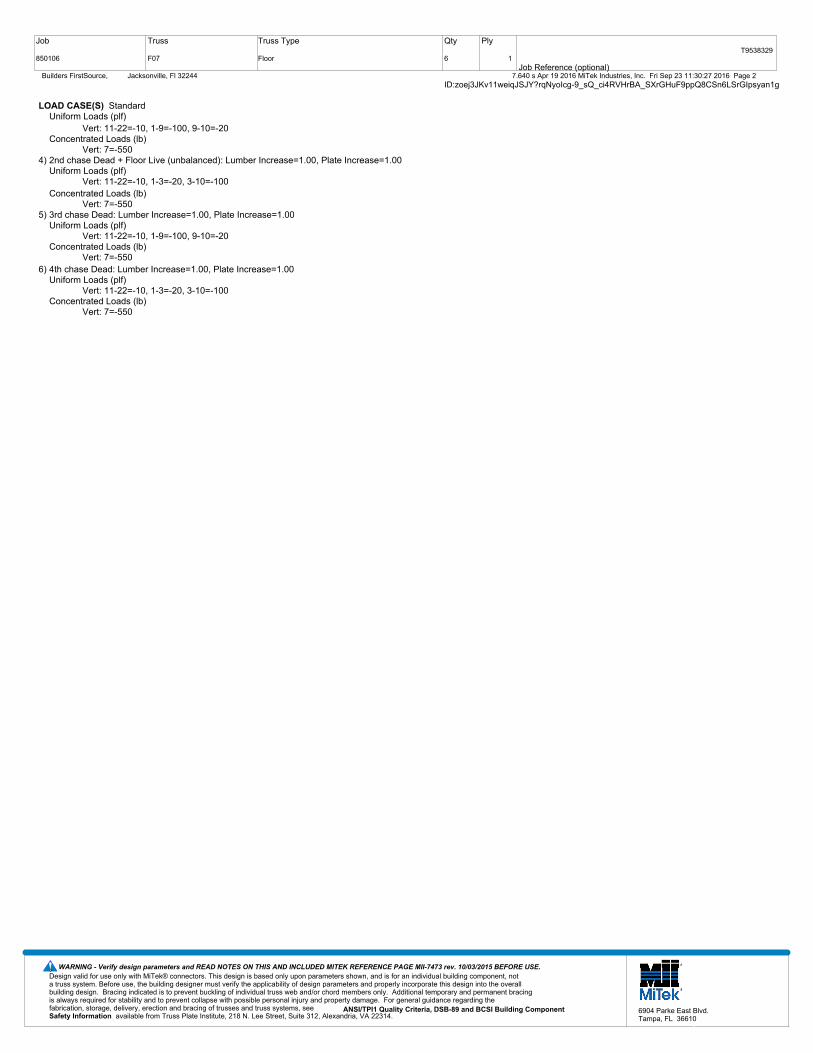
LOAD CASE(S) StandardConcentrated Loads (lb)
Vert: 9=-2503) 1st Dead + Floor Live (unbalanced): Lumber Increase=1.00, Plate Increase=1.00
Uniform Loads (plf)Vert: 10-19=-10, 1-6=-100, 6-9=-20
Concentrated Loads (lb)Vert: 9=-250
4) 2nd Dead + Floor Live (unbalanced): Lumber Increase=1.00, Plate Increase=1.00Uniform Loads (plf)
Vert: 10-19=-10, 1-6=-20, 6-9=-100Concentrated Loads (lb)
Vert: 9=-2505) 3rd unbalanced Dead: Lumber Increase=1.00, Plate Increase=1.00
Uniform Loads (plf)Vert: 10-19=-10, 1-6=-100, 6-9=-20
Concentrated Loads (lb)Vert: 9=-250
6) 4th unbalanced Dead: Lumber Increase=1.00, Plate Increase=1.00Uniform Loads (plf)
Vert: 10-19=-10, 1-6=-20, 6-9=-100Concentrated Loads (lb)
Vert: 9=-2507) 1st chase Dead + Floor Live (unbalanced): Lumber Increase=1.00, Plate Increase=1.00
Uniform Loads (plf)Vert: 10-19=-10, 1-4=-100, 4-6=-20, 6-9=-100
Concentrated Loads (lb)Vert: 9=-250
8) 2nd chase Dead + Floor Live (unbalanced): Lumber Increase=1.00, Plate Increase=1.00Uniform Loads (plf)
Vert: 10-19=-10, 1-3=-20, 3-6=-100, 6-9=-20Concentrated Loads (lb)
Vert: 9=-2509) 3rd chase Dead: Lumber Increase=1.00, Plate Increase=1.00
Uniform Loads (plf)Vert: 10-19=-10, 1-4=-100, 4-6=-20, 6-9=-100
Concentrated Loads (lb)Vert: 9=-250
10) 4th chase Dead: Lumber Increase=1.00, Plate Increase=1.00Uniform Loads (plf)
Vert: 10-19=-10, 1-3=-20, 3-6=-100, 6-9=-20Concentrated Loads (lb)
Vert: 9=-250
Design valid for use only with MiTek® connectors. This design is based only upon parameters shown, and is for an individual building component, not a truss system. Before use, the building designer must verify the applicability of design parameters and properly incorporate this design into the overall building design. Bracing indicated is to prevent buckling of individual truss web and/or chord members only. Additional temporary and permanent bracing is always required for stability and to prevent collapse with possible personal injury and property damage. For general guidance regarding the fabrication, storage, delivery, erection and bracing of trusses and truss systems, see ANSI/TPI1 Quality Criteria, DSB-89 and BCSI Building Component
available from Truss Plate Institute, 218 N. Lee Street, Suite 312, Alexandria, VA 22314.Safety Information
WARNING - Verify design parameters and READ NOTES ON THIS AND INCLUDED MITEK REFERENCE PAGE MII-7473 rev. 10/03/2015 BEFORE USE.
6904 Parke East Blvd.Tampa, FL 36610

Job
850106
Truss
F03
Truss Type
Floor
Qty
2
Ply
1Job Reference (optional)
T9538325
7.640 s Apr 19 2016 MiTek Industries, Inc. Fri Sep 23 11:30:25 2016 Page 1 Builders FirstSource, Jacksonville, Fl 32244ID:zoej3JKv11weiqJSJY?rqNyoIcg-DckgZwhqwu17ytq4QREpoq3aHdWu_1D2?XnBlzyan1i
Scale = 1:18.7
1 2 3 4 5 6
13 12 11 10 9 8 7
14 15
3x3 3x3
1.5x3 3x4
1.5x3
3x4
3x4 3x4
3x3 3x3
3x3 3x3
3x3 1.5x3
1.5x3
1-6-01-6-0
6-11-05-5-0
9-5-02-6-0
10-11-01-6-0
1-3-0 1-5-0
0-1-8
0-1-8
1-8-
0
1-8-
0
Plate Offsets (X,Y)-- [6:0-1-8,Edge]
LOADING (psf)TCLLTCDLBCLLBCDL
40.010.0
0.05.0
SPACING-Plate Grip DOLLumber DOL Rep Stress IncrCode
2-0-01.001.00YES
FBC2014/TPI2007
CSI.TCBCWB(Matrix)
0.430.610.30
DEFL.Vert(LL)Vert(TL)Horz(TL)
in-0.06-0.080.01
(loc)9-109-10
7
l/defl>999>999
n/a
L/d360240n/a
PLATESMT20
Weight: 64 lb FT = 11%F, 11%E
GRIP244/190
LUMBER-TOP CHORD 2x4 SP No.2(flat)BOT CHORD 2x4 SP No.2(flat)WEBS 2x4 SP No.3(flat)
BRACING-TOP CHORD Structural wood sheathing directly applied or 6-0-0 oc purlins, except
end verticals.BOT CHORD Rigid ceiling directly applied or 10-0-0 oc bracing.
REACTIONS. (lb/size) 13=580/0-5-0, 7=580/0-5-8
FORCES. (lb) - Max. Comp./Max. Ten. - All forces 250 (lb) or less except when shown.TOP CHORD 13-14=-569/0, 1-14=-569/0, 7-15=-574/0, 6-15=-574/0, 1-2=-416/0, 2-3=-992/0, 3-4=-992/0, 4-5=-920/0,
5-6=-429/0BOT CHORD 11-12=0/790, 10-11=0/992, 9-10=0/992, 8-9=0/802WEBS 6-8=0/625, 1-12=0/606, 5-8=-592/0, 2-12=-595/0, 2-11=0/411
NOTES- (4)1) Unbalanced floor live loads have been considered for this design.2) "Semi-rigid pitchbreaks including heels" Member end fixity model was used in the analysis and design of this truss. 3) Recommend 2x6 strongbacks, on edge, spaced at 10-0-0 oc and fastened to each truss with 3-10d (0.131" X 3") nails. Strongbacks to
be attached to walls at their outer ends or restrained by other means.4) This manufactured product is designed as an individual building component. The suitability and use of this component for any particular
building is the responsibility of the building designer per ANSI TPI 1 as referenced by the building code.
Design valid for use only with MiTek® connectors. This design is based only upon parameters shown, and is for an individual building component, not a truss system. Before use, the building designer must verify the applicability of design parameters and properly incorporate this design into the overall building design. Bracing indicated is to prevent buckling of individual truss web and/or chord members only. Additional temporary and permanent bracing is always required for stability and to prevent collapse with possible personal injury and property damage. For general guidance regarding the fabrication, storage, delivery, erection and bracing of trusses and truss systems, see ANSI/TPI1 Quality Criteria, DSB-89 and BCSI Building Component
available from Truss Plate Institute, 218 N. Lee Street, Suite 312, Alexandria, VA 22314.Safety Information
WARNING - Verify design parameters and READ NOTES ON THIS AND INCLUDED MITEK REFERENCE PAGE MII-7473 rev. 10/03/2015 BEFORE USE.
6904 Parke East Blvd.Tampa, FL 36610

Job
850106
Truss
F04
Truss Type
GABLE
Qty
1
Ply
1Job Reference (optional)
T9538326
7.640 s Apr 19 2016 MiTek Industries, Inc. Fri Sep 23 11:30:25 2016 Page 1 Builders FirstSource, Jacksonville, Fl 32244ID:zoej3JKv11weiqJSJY?rqNyoIcg-DckgZwhqwu17ytq4QREpoq3fUdfA_5L2?XnBlzyan1i
Scale = 1:11.41 2 3
6 5 4
7
3x3 1.5x3
1.5x3
3x3 1.5x3
3x3
1.5x3
1-6-121-6-12
2-5-80-10-12
0-1-8
1-8-
0
1-8-
0
LOADING (psf)TCLLTCDLBCLLBCDL
40.010.0
0.05.0
SPACING-Plate Grip DOLLumber DOL Rep Stress IncrCode
2-0-01.001.00YES
FBC2014/TPI2007
CSI.TCBCWB(Matrix)
0.090.010.03
DEFL.Vert(LL)Vert(TL)Horz(TL)
inn/an/a
0.00
(loc) - - 4
l/defln/an/an/a
L/d999999n/a
PLATESMT20
Weight: 18 lb FT = 11%F, 11%E
GRIP244/190
LUMBER-TOP CHORD 2x4 SP No.2(flat)BOT CHORD 2x4 SP No.2(flat)WEBS 2x4 SP No.3(flat)OTHERS 2x4 SP No.3(flat)
BRACING-TOP CHORD Structural wood sheathing directly applied or 2-5-8 oc purlins, except
end verticals.BOT CHORD Rigid ceiling directly applied or 10-0-0 oc bracing.
REACTIONS. (lb/size) 6=60/2-5-8, 4=23/2-5-8, 5=161/2-5-8
FORCES. (lb) - Max. Comp./Max. Ten. - All forces 250 (lb) or less except when shown.
NOTES- (7)1) Gable requires continuous bottom chord bearing. 2) Truss to be fully sheathed from one face or securely braced against lateral movement (i.e. diagonal web).3) Gable studs spaced at 1-4-0 oc.4) "Semi-rigid pitchbreaks including heels" Member end fixity model was used in the analysis and design of this truss. 5) Recommend 2x6 strongbacks, on edge, spaced at 10-0-0 oc and fastened to each truss with 3-10d (0.131" X 3") nails. Strongbacks to
be attached to walls at their outer ends or restrained by other means.6) CAUTION, Do not erect truss backwards.7) This manufactured product is designed as an individual building component. The suitability and use of this component for any particular
building is the responsibility of the building designer per ANSI TPI 1 as referenced by the building code.
Design valid for use only with MiTek® connectors. This design is based only upon parameters shown, and is for an individual building component, not a truss system. Before use, the building designer must verify the applicability of design parameters and properly incorporate this design into the overall building design. Bracing indicated is to prevent buckling of individual truss web and/or chord members only. Additional temporary and permanent bracing is always required for stability and to prevent collapse with possible personal injury and property damage. For general guidance regarding the fabrication, storage, delivery, erection and bracing of trusses and truss systems, see ANSI/TPI1 Quality Criteria, DSB-89 and BCSI Building Component
available from Truss Plate Institute, 218 N. Lee Street, Suite 312, Alexandria, VA 22314.Safety Information
WARNING - Verify design parameters and READ NOTES ON THIS AND INCLUDED MITEK REFERENCE PAGE MII-7473 rev. 10/03/2015 BEFORE USE.
6904 Parke East Blvd.Tampa, FL 36610

Job
850106
Truss
F05
Truss Type
GABLE
Qty
1
Ply
1Job Reference (optional)
T9538327
7.640 s Apr 19 2016 MiTek Industries, Inc. Fri Sep 23 11:30:26 2016 Page 1 Builders FirstSource, Jacksonville, Fl 32244ID:zoej3JKv11weiqJSJY?rqNyoIcg-hoI2mGhShC9_a1PGz8l2L2cq91?QjYZBEBXkHPyan1h
Scale = 1:12.6
1 2 3 4 5
10 9 8 7 6
1.5x3 1.5x3
3x3
3x3
3x3
1.5x3
3x3
1.5x3
1.5x3
1.5x3
1-5-41-5-4
2-7-151-2-11
3-10-101-2-11
5-3-141-5-4
1-8-
0
1-8-
0
LOADING (psf)TCLLTCDLBCLLBCDL
40.010.0
0.05.0
SPACING-Plate Grip DOLLumber DOL Rep Stress IncrCode
2-0-01.001.00YES
FBC2014/TPI2007
CSI.TCBCWB(Matrix)
0.100.010.04
DEFL.Vert(LL)Vert(TL)Horz(TL)
inn/an/a
-0.00
(loc) - - 6
l/defln/an/an/a
L/d999999n/a
PLATESMT20
Weight: 32 lb FT = 11%F, 11%E
GRIP244/190
LUMBER-TOP CHORD 2x4 SP No.2(flat)BOT CHORD 2x4 SP No.2(flat)WEBS 2x4 SP No.3(flat)OTHERS 2x4 SP No.3(flat)
BRACING-TOP CHORD Structural wood sheathing directly applied or 5-3-14 oc purlins, except
end verticals.BOT CHORD Rigid ceiling directly applied or 6-0-0 oc bracing.
REACTIONS. All bearings 5-3-14.(lb) - Max Grav All reactions 250 lb or less at joint(s) 10, 6, 9, 7, 8
FORCES. (lb) - Max. Comp./Max. Ten. - All forces 250 (lb) or less except when shown.
NOTES- (6)1) Gable requires continuous bottom chord bearing. 2) Truss to be fully sheathed from one face or securely braced against lateral movement (i.e. diagonal web).3) Gable studs spaced at 1-4-0 oc.4) "Semi-rigid pitchbreaks including heels" Member end fixity model was used in the analysis and design of this truss. 5) Recommend 2x6 strongbacks, on edge, spaced at 10-0-0 oc and fastened to each truss with 3-10d (0.131" X 3") nails. Strongbacks to
be attached to walls at their outer ends or restrained by other means.6) This manufactured product is designed as an individual building component. The suitability and use of this component for any particular
building is the responsibility of the building designer per ANSI TPI 1 as referenced by the building code.
Design valid for use only with MiTek® connectors. This design is based only upon parameters shown, and is for an individual building component, not a truss system. Before use, the building designer must verify the applicability of design parameters and properly incorporate this design into the overall building design. Bracing indicated is to prevent buckling of individual truss web and/or chord members only. Additional temporary and permanent bracing is always required for stability and to prevent collapse with possible personal injury and property damage. For general guidance regarding the fabrication, storage, delivery, erection and bracing of trusses and truss systems, see ANSI/TPI1 Quality Criteria, DSB-89 and BCSI Building Component
available from Truss Plate Institute, 218 N. Lee Street, Suite 312, Alexandria, VA 22314.Safety Information
WARNING - Verify design parameters and READ NOTES ON THIS AND INCLUDED MITEK REFERENCE PAGE MII-7473 rev. 10/03/2015 BEFORE USE.
6904 Parke East Blvd.Tampa, FL 36610

Job
850106
Truss
F06
Truss Type
Floor
Qty
7
Ply
1Job Reference (optional)
T9538328
7.640 s Apr 19 2016 MiTek Industries, Inc. Fri Sep 23 11:30:26 2016 Page 1 Builders FirstSource, Jacksonville, Fl 32244ID:zoej3JKv11weiqJSJY?rqNyoIcg-hoI2mGhShC9_a1PGz8l2L2cop1zajWjBEBXkHPyan1h
Scale = 1:12.6
1 2 3 4
8 7 6 5
1.5x3 1.5x3
3x3
3x3
3x6
3x3
3x6
3x3
5-3-145-3-14
1-3-0 2-0-14
1-8-
0
1-8-
0
LOADING (psf)TCLLTCDLBCLLBCDL
40.010.0
0.05.0
SPACING-Plate Grip DOLLumber DOL Rep Stress IncrCode
2-0-01.001.00YES
FBC2014/TPI2007
CSI.TCBCWB(Matrix)
0.250.130.15
DEFL.Vert(LL)Vert(TL)Horz(TL)
in-0.01-0.010.00
(loc)765
l/defl>999>999
n/a
L/d360240n/a
PLATESMT20
Weight: 34 lb FT = 11%F, 11%E
GRIP244/190
LUMBER-TOP CHORD 2x4 SP No.2(flat)BOT CHORD 2x4 SP No.2(flat)WEBS 2x4 SP No.3(flat)
BRACING-TOP CHORD Structural wood sheathing directly applied or 5-3-14 oc purlins, except
end verticals.BOT CHORD Rigid ceiling directly applied or 10-0-0 oc bracing.
REACTIONS. (lb/size) 8=286/Mechanical, 5=286/Mechanical
FORCES. (lb) - Max. Comp./Max. Ten. - All forces 250 (lb) or less except when shown.TOP CHORD 1-8=-281/0, 4-5=-281/0WEBS 1-7=0/322, 4-6=0/322
NOTES- (5)1) Unbalanced floor live loads have been considered for this design.2) Refer to girder(s) for truss to truss connections.3) "Semi-rigid pitchbreaks including heels" Member end fixity model was used in the analysis and design of this truss. 4) Recommend 2x6 strongbacks, on edge, spaced at 10-0-0 oc and fastened to each truss with 3-10d (0.131" X 3") nails. Strongbacks to
be attached to walls at their outer ends or restrained by other means.5) This manufactured product is designed as an individual building component. The suitability and use of this component for any particular
building is the responsibility of the building designer per ANSI TPI 1 as referenced by the building code.
Design valid for use only with MiTek® connectors. This design is based only upon parameters shown, and is for an individual building component, not a truss system. Before use, the building designer must verify the applicability of design parameters and properly incorporate this design into the overall building design. Bracing indicated is to prevent buckling of individual truss web and/or chord members only. Additional temporary and permanent bracing is always required for stability and to prevent collapse with possible personal injury and property damage. For general guidance regarding the fabrication, storage, delivery, erection and bracing of trusses and truss systems, see ANSI/TPI1 Quality Criteria, DSB-89 and BCSI Building Component
available from Truss Plate Institute, 218 N. Lee Street, Suite 312, Alexandria, VA 22314.Safety Information
WARNING - Verify design parameters and READ NOTES ON THIS AND INCLUDED MITEK REFERENCE PAGE MII-7473 rev. 10/03/2015 BEFORE USE.
6904 Parke East Blvd.Tampa, FL 36610

Job
850106
Truss
F07
Truss Type
Floor
Qty
6
Ply
1Job Reference (optional)
T9538329
7.640 s Apr 19 2016 MiTek Industries, Inc. Fri Sep 23 11:30:27 2016 Page 1 Builders FirstSource, Jacksonville, Fl 32244ID:zoej3JKv11weiqJSJY?rqNyoIcg-9_sQ_ci4RVHrBA_SXrGHuF9ppQ8CSn6LSrGIpsyan1g
Scale = 1:35.2
1 2 3 4 5 6 7 8 9 10
22 21 20 19 18 17 16 15 14 13 12 11
6x8 6x8
5x6
1.5x3
5x8
1.5x3
3x6 6x8
5x6
5x6
4x6
2x6 3x6
3x6
3x6
3x6
3x6
2x6
7x8
5x6
2x6 6x8
6x8 3x6
13-5-413-5-4
19-11-06-5-12
1-3-0 1-6-12 1-11-12
0-1-8
0-1-8
1-8-
0
0-1-
8
1-8-
0
Plate Offsets (X,Y)-- [1:0-1-8,0-0-8], [3:0-3-0,Edge], [4:0-3-0,0-0-0], [9:0-3-0,Edge], [10:0-1-8,0-1-8], [10:0-3-0,Edge], [13:0-3-0,0-0-0], [14:0-3-0,Edge], [19:0-3-0,Edge]
LOADING (psf)TCLLTCDLBCLLBCDL
40.010.0
0.05.0
SPACING-Plate Grip DOLLumber DOL Rep Stress IncrCode
2-0-01.001.00NO
FBC2014/TPI2007
CSI.TCBCWB(Matrix)
0.870.870.91
DEFL.Vert(LL)Vert(TL)Horz(TL)
in-0.25-0.470.05
(loc)161611
l/defl>960>505
n/a
L/d360240n/a
PLATESMT20
Weight: 167 lb FT = 11%F, 11%E
GRIP244/190
LUMBER-TOP CHORD 2x4 SP No.1(flat)BOT CHORD 2x4 SP M 31(flat)WEBS 2x4 SP No.3(flat)
BRACING-TOP CHORD Structural wood sheathing directly applied or 6-0-0 oc purlins, except
end verticals.BOT CHORD Rigid ceiling directly applied or 10-0-0 oc bracing.
REACTIONS. (lb/size) 22=1259/0-5-0, 11=1454/0-5-0
FORCES. (lb) - Max. Comp./Max. Ten. - All forces 250 (lb) or less except when shown.TOP CHORD 1-22=-1256/0, 10-11=-1344/0, 1-2=-1107/0, 2-3=-2848/0, 3-4=-3914/0, 4-5=-3914/0,
5-6=-4933/0, 6-7=-5011/0, 7-8=-3255/0, 8-9=-3255/0, 9-10=-1345/0BOT CHORD 20-21=0/2055, 19-20=0/3914, 18-19=0/3914, 17-18=0/4641, 16-17=0/5063, 15-16=0/5088,
14-15=0/5088, 13-14=0/3255, 12-13=0/3255WEBS 7-15=0/663, 1-21=0/1576, 2-21=-1435/0, 2-20=0/1198, 3-20=-1582/0, 3-19=0/645,
6-17=-263/0, 5-17=0/531, 5-18=-1191/0, 4-18=0/414, 10-12=0/1917, 9-12=-2810/0, 9-13=0/1279, 7-14=-2579/0, 8-14=0/636
NOTES- (6)1) Unbalanced floor live loads have been considered for this design.2) Load case(s) 1, 2, 3, 4, 5, 6 has/have been modified. Building designer must review loads to verify that they are correct for the intended
use of this truss.3) "Semi-rigid pitchbreaks including heels" Member end fixity model was used in the analysis and design of this truss. 4) Recommend 2x6 strongbacks, on edge, spaced at 10-0-0 oc and fastened to each truss with 3-10d (0.131" X 3") nails. Strongbacks to
be attached to walls at their outer ends or restrained by other means.5) CAUTION, Do not erect truss backwards.6) This manufactured product is designed as an individual building component. The suitability and use of this component for any particular
building is the responsibility of the building designer per ANSI TPI 1 as referenced by the building code.
LOAD CASE(S) Standard1) Dead + Floor Live (balanced): Lumber Increase=1.00, Plate Increase=1.00
Uniform Loads (plf)Vert: 11-22=-10, 1-10=-100
Concentrated Loads (lb)Vert: 7=-550
2) Dead: Lumber Increase=1.00, Plate Increase=1.00Uniform Loads (plf)
Vert: 11-22=-10, 1-10=-100Concentrated Loads (lb)
Vert: 7=-5503) 1st chase Dead + Floor Live (unbalanced): Lumber Increase=1.00, Plate Increase=1.00
Continued on page 2
Design valid for use only with MiTek® connectors. This design is based only upon parameters shown, and is for an individual building component, not a truss system. Before use, the building designer must verify the applicability of design parameters and properly incorporate this design into the overall building design. Bracing indicated is to prevent buckling of individual truss web and/or chord members only. Additional temporary and permanent bracing is always required for stability and to prevent collapse with possible personal injury and property damage. For general guidance regarding the fabrication, storage, delivery, erection and bracing of trusses and truss systems, see ANSI/TPI1 Quality Criteria, DSB-89 and BCSI Building Component
available from Truss Plate Institute, 218 N. Lee Street, Suite 312, Alexandria, VA 22314.Safety Information
WARNING - Verify design parameters and READ NOTES ON THIS AND INCLUDED MITEK REFERENCE PAGE MII-7473 rev. 10/03/2015 BEFORE USE.
6904 Parke East Blvd.Tampa, FL 36610
Job
850106
Truss
F07
Truss Type
Floor
Qty
6
Ply
1Job Reference (optional)
T9538329
7.640 s Apr 19 2016 MiTek Industries, Inc. Fri Sep 23 11:30:27 2016 Page 2 Builders FirstSource, Jacksonville, Fl 32244ID:zoej3JKv11weiqJSJY?rqNyoIcg-9_sQ_ci4RVHrBA_SXrGHuF9ppQ8CSn6LSrGIpsyan1g
LOAD CASE(S) StandardUniform Loads (plf)
Vert: 11-22=-10, 1-9=-100, 9-10=-20Concentrated Loads (lb)
Vert: 7=-5504) 2nd chase Dead + Floor Live (unbalanced): Lumber Increase=1.00, Plate Increase=1.00
Uniform Loads (plf)Vert: 11-22=-10, 1-3=-20, 3-10=-100
Concentrated Loads (lb)Vert: 7=-550
5) 3rd chase Dead: Lumber Increase=1.00, Plate Increase=1.00Uniform Loads (plf)
Vert: 11-22=-10, 1-9=-100, 9-10=-20Concentrated Loads (lb)
Vert: 7=-5506) 4th chase Dead: Lumber Increase=1.00, Plate Increase=1.00
Uniform Loads (plf)Vert: 11-22=-10, 1-3=-20, 3-10=-100
Concentrated Loads (lb)Vert: 7=-550
Design valid for use only with MiTek® connectors. This design is based only upon parameters shown, and is for an individual building component, not a truss system. Before use, the building designer must verify the applicability of design parameters and properly incorporate this design into the overall building design. Bracing indicated is to prevent buckling of individual truss web and/or chord members only. Additional temporary and permanent bracing is always required for stability and to prevent collapse with possible personal injury and property damage. For general guidance regarding the fabrication, storage, delivery, erection and bracing of trusses and truss systems, see ANSI/TPI1 Quality Criteria, DSB-89 and BCSI Building Component
available from Truss Plate Institute, 218 N. Lee Street, Suite 312, Alexandria, VA 22314.Safety Information
WARNING - Verify design parameters and READ NOTES ON THIS AND INCLUDED MITEK REFERENCE PAGE MII-7473 rev. 10/03/2015 BEFORE USE.
6904 Parke East Blvd.Tampa, FL 36610

Job
850106
Truss
F09
Truss Type
GABLE
Qty
1
Ply
1Job Reference (optional)
T9538330
7.640 s Apr 19 2016 MiTek Industries, Inc. Fri Sep 23 11:30:28 2016 Page 1 Builders FirstSource, Jacksonville, Fl 32244ID:zoej3JKv11weiqJSJY?rqNyoIcg-dBQoByjiCpPipKZe5ZnWQTh9eqhtBS3UhV0rLIyan1f
Scale = 1:28.9
1 2 3 4 5 6 7 8 9 10 11 12 13 14
28 27 26 25 24 23 22 21 20 19 18 17 16 15
29 30
3x3 3x3
3x3 3x3
3x3 3x3
1-6-121-6-12
2-10-121-4-0
4-2-121-4-0
5-6-121-4-0
6-10-121-4-0
8-2-121-4-0
8-5-120-3-0
8-8-12
0-3-0
10-0-121-4-0
11-4-121-4-0
12-8-121-4-0
14-0-121-4-0
15-4-121-4-0
16-11-81-6-12
0-1-8 0-1-8
1-8-
0
1-8-
0
LOADING (psf)TCLLTCDLBCLLBCDL
40.010.0
0.05.0
SPACING-Plate Grip DOLLumber DOL Rep Stress IncrCode
2-0-01.001.00YES
FBC2014/TPI2007
CSI.TCBCWB(Matrix)
0.100.010.04
DEFL.Vert(LL)Vert(TL)Horz(TL)
inn/an/a
-0.00
(loc) - - 16
l/defln/an/an/a
L/d999999n/a
PLATESMT20
Weight: 89 lb FT = 11%F, 11%E
GRIP244/190
LUMBER-TOP CHORD 2x4 SP No.2(flat)BOT CHORD 2x4 SP No.2(flat)WEBS 2x4 SP No.3(flat)OTHERS 2x4 SP No.3(flat)
BRACING-TOP CHORD Structural wood sheathing directly applied or 10-0-0 oc purlins, except
end verticals.BOT CHORD Rigid ceiling directly applied or 6-0-0 oc bracing, Except:
10-0-0 oc bracing: 27-28,15-16.
REACTIONS. All bearings 16-11-8.(lb) - Max Grav All reactions 250 lb or less at joint(s) 28, 15, 27, 16, 17, 18, 19, 20, 21, 26, 25, 24, 23, 22
FORCES. (lb) - Max. Comp./Max. Ten. - All forces 250 (lb) or less except when shown.
NOTES- (7)1) All plates are 1.5x3 MT20 unless otherwise indicated.2) Gable requires continuous bottom chord bearing. 3) Truss to be fully sheathed from one face or securely braced against lateral movement (i.e. diagonal web).4) Gable studs spaced at 1-4-0 oc.5) "Semi-rigid pitchbreaks including heels" Member end fixity model was used in the analysis and design of this truss. 6) Recommend 2x6 strongbacks, on edge, spaced at 10-0-0 oc and fastened to each truss with 3-10d (0.131" X 3") nails. Strongbacks to
be attached to walls at their outer ends or restrained by other means.7) This manufactured product is designed as an individual building component. The suitability and use of this component for any particular
building is the responsibility of the building designer per ANSI TPI 1 as referenced by the building code.
Design valid for use only with MiTek® connectors. This design is based only upon parameters shown, and is for an individual building component, not a truss system. Before use, the building designer must verify the applicability of design parameters and properly incorporate this design into the overall building design. Bracing indicated is to prevent buckling of individual truss web and/or chord members only. Additional temporary and permanent bracing is always required for stability and to prevent collapse with possible personal injury and property damage. For general guidance regarding the fabrication, storage, delivery, erection and bracing of trusses and truss systems, see ANSI/TPI1 Quality Criteria, DSB-89 and BCSI Building Component
available from Truss Plate Institute, 218 N. Lee Street, Suite 312, Alexandria, VA 22314.Safety Information
WARNING - Verify design parameters and READ NOTES ON THIS AND INCLUDED MITEK REFERENCE PAGE MII-7473 rev. 10/03/2015 BEFORE USE.
6904 Parke East Blvd.Tampa, FL 36610

Job
850106
Truss
F10
Truss Type
FLOOR
Qty
4
Ply
1Job Reference (optional)
T9538331
7.640 s Apr 19 2016 MiTek Industries, Inc. Fri Sep 23 11:30:28 2016 Page 1 Builders FirstSource, Jacksonville, Fl 32244ID:zoej3JKv11weiqJSJY?rqNyoIcg-dBQoByjiCpPipKZe5ZnWQThyGqXOBEoUhV0rLIyan1f
Scale = 1:29.3
1 2 3 4 5 6 7 8 9
19 18 17 16 15 14 13 12 11 10
20
3x3
1.5x3
4x4
4x4
8x12
1.5x3
4x6
3x4
3x4
4x4
4x4
1.5x3
4x4
3x3
3x3
3x3
3x3
3x3
1.5x3
7x8
16-1-416-1-4
16-11-80-10-4
1-3-0 1-8-12 0-5-12
0-1-8
0-1-8
1-8-
0
1-8-
0
Plate Offsets (X,Y)-- [1:Edge,0-1-8], [9:0-1-8,0-1-8], [9:0-1-12,Edge], [10:Edge,0-1-8], [16:0-1-8,Edge]
LOADING (psf)TCLLTCDLBCLLBCDL
40.010.0
0.05.0
SPACING-Plate Grip DOLLumber DOL Rep Stress IncrCode
2-0-01.001.00NO
FBC2014/TPI2007
CSI.TCBCWB(Matrix)
0.950.680.95
DEFL.Vert(LL)Vert(TL)Horz(TL)
in-0.18-0.290.04
(loc)14-1514-15
10
l/defl>999>701
n/a
L/d360240n/a
PLATESMT20
Weight: 100 lb FT = 11%F, 11%E
GRIP244/190
LUMBER-TOP CHORD 2x4 SP No.2(flat)BOT CHORD 2x4 SP M 31(flat)WEBS 2x4 SP No.3(flat)
BRACING-TOP CHORD Structural wood sheathing directly applied or 5-7-10 oc purlins, except
end verticals.BOT CHORD Rigid ceiling directly applied or 10-0-0 oc bracing.
REACTIONS. (lb/size) 19=953/0-5-0, 10=1804/0-5-8
FORCES. (lb) - Max. Comp./Max. Ten. - All forces 250 (lb) or less except when shown.TOP CHORD 19-20=-953/0, 1-20=-952/0, 9-10=-1782/0, 1-2=-764/0, 2-3=-1841/0, 3-4=-2630/0,
4-5=-2630/0, 5-6=-2659/0, 6-7=-2289/0, 7-8=-1454/0, 8-9=-851/0BOT CHORD 17-18=0/1426, 16-17=0/2275, 15-16=0/2630, 14-15=0/2630, 13-14=0/2592, 12-13=0/1975,
11-12=0/851WEBS 8-11=-1818/0, 1-18=0/1119, 2-18=-1051/0, 2-17=0/660, 3-17=-690/0, 3-16=0/717,
4-16=-308/0, 8-12=0/906, 7-12=-827/0, 7-13=0/499, 6-13=-480/0, 5-14=-227/267, 5-15=-283/36, 9-11=0/1991
NOTES- (5)1) Unbalanced floor live loads have been considered for this design.2) "Semi-rigid pitchbreaks including heels" Member end fixity model was used in the analysis and design of this truss. 3) Recommend 2x6 strongbacks, on edge, spaced at 10-0-0 oc and fastened to each truss with 3-10d (0.131" X 3") nails. Strongbacks to
be attached to walls at their outer ends or restrained by other means.4) CAUTION, Do not erect truss backwards.5) This manufactured product is designed as an individual building component. The suitability and use of this component for any particular
building is the responsibility of the building designer per ANSI TPI 1 as referenced by the building code.
LOAD CASE(S) Standard1) Dead + Floor Live (balanced): Lumber Increase=1.00, Plate Increase=1.00
Uniform Loads (plf)Vert: 10-19=-10, 1-9=-100
Concentrated Loads (lb)Vert: 8=-925
Design valid for use only with MiTek® connectors. This design is based only upon parameters shown, and is for an individual building component, not a truss system. Before use, the building designer must verify the applicability of design parameters and properly incorporate this design into the overall building design. Bracing indicated is to prevent buckling of individual truss web and/or chord members only. Additional temporary and permanent bracing is always required for stability and to prevent collapse with possible personal injury and property damage. For general guidance regarding the fabrication, storage, delivery, erection and bracing of trusses and truss systems, see ANSI/TPI1 Quality Criteria, DSB-89 and BCSI Building Component
available from Truss Plate Institute, 218 N. Lee Street, Suite 312, Alexandria, VA 22314.Safety Information
WARNING - Verify design parameters and READ NOTES ON THIS AND INCLUDED MITEK REFERENCE PAGE MII-7473 rev. 10/03/2015 BEFORE USE.
6904 Parke East Blvd.Tampa, FL 36610

Job
850106
Truss
F11
Truss Type
Floor
Qty
7
Ply
1Job Reference (optional)
T9538332
7.640 s Apr 19 2016 MiTek Industries, Inc. Fri Sep 23 11:30:29 2016 Page 1 Builders FirstSource, Jacksonville, Fl 32244ID:zoej3JKv11weiqJSJY?rqNyoIcg-5N_AOIkLz7XZRU7rfGIlzgEA9EuowmWew9lOukyan1e
Scale = 1:33.8
1 2 3 4 5 6 7 8 9 10 11
21 20 19 18 17 16 15 14 13 12
22
3x3 2x4
1.5x3
4x4
4x4
4x6
4x4
4x4
3x3
3x6
1.5x3 3x3
3x6
3x3
4x6
4x4
4x4
3x3
3x6
1.5x3 3x6
3x3
19-6-1419-6-14
1-3-0 2-2-6
0-1-8
1-8-
0
1-8-
0
Plate Offsets (X,Y)-- [1:Edge,0-1-8], [11:0-1-8,Edge], [12:0-1-8,Edge]
LOADING (psf)TCLLTCDLBCLLBCDL
40.010.0
0.05.0
SPACING-Plate Grip DOLLumber DOL Rep Stress IncrCode
2-0-01.001.00YES
FBC2014/TPI2007
CSI.TCBCWB(Matrix)
0.750.610.60
DEFL.Vert(LL)Vert(TL)Horz(TL)
in-0.26-0.380.06
(loc)17-1817-18
12
l/defl>905>609
n/a
L/d360240n/a
PLATESMT20
Weight: 113 lb FT = 11%F, 11%E
GRIP244/190
LUMBER-TOP CHORD 2x4 SP No.1(flat)BOT CHORD 2x4 SP M 31(flat)WEBS 2x4 SP No.3(flat)
BRACING-TOP CHORD Structural wood sheathing directly applied or 6-0-0 oc purlins, except
end verticals.BOT CHORD Rigid ceiling directly applied or 10-0-0 oc bracing.
REACTIONS. (lb/size) 21=1060/0-5-0, 12=1066/Mechanical
FORCES. (lb) - Max. Comp./Max. Ten. - All forces 250 (lb) or less except when shown.TOP CHORD 21-22=-1055/0, 1-22=-1054/0, 11-12=-1059/0, 1-2=-854/0, 2-3=-2124/0, 3-4=-2981/0,
4-5=-2981/0, 5-6=-3307/0, 6-7=-3307/0, 7-8=-2943/0, 8-9=-2943/0, 9-10=-2103/0, 10-11=-815/0
BOT CHORD 19-20=0/1609, 18-19=0/2624, 17-18=0/3213, 16-17=0/3307, 15-16=0/3307, 14-15=0/2600, 13-14=0/1578
WEBS 1-20=0/1252, 2-20=-1198/0, 2-19=0/818, 3-19=-794/0, 3-18=0/550, 5-18=-384/0, 5-17=-169/502, 6-17=-271/1, 11-13=0/1257, 10-13=-1212/0, 10-14=0/834, 9-14=-790/0, 9-15=0/528, 7-15=-821/0
NOTES- (6)1) Unbalanced floor live loads have been considered for this design.2) Refer to girder(s) for truss to truss connections.3) "Semi-rigid pitchbreaks including heels" Member end fixity model was used in the analysis and design of this truss. 4) Recommend 2x6 strongbacks, on edge, spaced at 10-0-0 oc and fastened to each truss with 3-10d (0.131" X 3") nails. Strongbacks to
be attached to walls at their outer ends or restrained by other means.5) CAUTION, Do not erect truss backwards.6) This manufactured product is designed as an individual building component. The suitability and use of this component for any particular
building is the responsibility of the building designer per ANSI TPI 1 as referenced by the building code.
Design valid for use only with MiTek® connectors. This design is based only upon parameters shown, and is for an individual building component, not a truss system. Before use, the building designer must verify the applicability of design parameters and properly incorporate this design into the overall building design. Bracing indicated is to prevent buckling of individual truss web and/or chord members only. Additional temporary and permanent bracing is always required for stability and to prevent collapse with possible personal injury and property damage. For general guidance regarding the fabrication, storage, delivery, erection and bracing of trusses and truss systems, see ANSI/TPI1 Quality Criteria, DSB-89 and BCSI Building Component
available from Truss Plate Institute, 218 N. Lee Street, Suite 312, Alexandria, VA 22314.Safety Information
WARNING - Verify design parameters and READ NOTES ON THIS AND INCLUDED MITEK REFERENCE PAGE MII-7473 rev. 10/03/2015 BEFORE USE.
6904 Parke East Blvd.Tampa, FL 36610

Job
850106
Truss
F11A
Truss Type
FLOOR
Qty
1
Ply
1Job Reference (optional)
T9538333
7.640 s Apr 19 2016 MiTek Industries, Inc. Fri Sep 23 11:30:29 2016 Page 1 Builders FirstSource, Jacksonville, Fl 32244ID:zoej3JKv11weiqJSJY?rqNyoIcg-5N_AOIkLz7XZRU7rfGIlzgEG3E1Swv6ew9lOukyan1e
Scale = 1:34.0
1 2 3 4 5 6 7 8 9 10 11
21 20 19 18 17 16 15 14 13 12
22
1.5x3
1.5x3
3x6
1.5x3
3x6 3x6
1.5x3 3x6
19-6-1419-6-14
0-1-8
1-8-
0
1-8-
0
LOADING (psf)TCLLTCDLBCLLBCDL
40.010.0
0.05.0
SPACING-Plate Grip DOLLumber DOL Rep Stress IncrCode
2-0-01.001.00YES
FBC2014/TPI2007
CSI.TCBCWB(Matrix)
0.380.050.05
DEFL.Vert(LL)Vert(TL)Horz(TL)
inn/an/a
0.00
(loc) - - 12
l/defln/an/an/a
L/d999999n/a
PLATESMT20
Weight: 113 lb FT = 11%F, 11%E
GRIP244/190
LUMBER-TOP CHORD 2x4 SP No.2(flat)BOT CHORD 2x4 SP No.2(flat)WEBS 2x4 SP No.3(flat)
BRACING-TOP CHORD Structural wood sheathing directly applied or 10-0-0 oc purlins, except
end verticals.BOT CHORD Rigid ceiling directly applied or 10-0-0 oc bracing, Except:
6-0-0 oc bracing: 16-17,15-16.REACTIONS. All bearings 19-6-14.
(lb) - Max Grav All reactions 250 lb or less at joint(s) 21, 12, 20, 13, 15, 16 except 19=288(LC 1), 18=297(LC 1), 17=282(LC 1), 14=288(LC 1)
FORCES. (lb) - Max. Comp./Max. Ten. - All forces 250 (lb) or less except when shown.
NOTES- (6)1) All plates are 3x3 MT20 unless otherwise indicated.2) Gable requires continuous bottom chord bearing. 3) "Semi-rigid pitchbreaks including heels" Member end fixity model was used in the analysis and design of this truss. 4) Recommend 2x6 strongbacks, on edge, spaced at 10-0-0 oc and fastened to each truss with 3-10d (0.131" X 3") nails. Strongbacks to
be attached to walls at their outer ends or restrained by other means.5) CAUTION, Do not erect truss backwards.6) This manufactured product is designed as an individual building component. The suitability and use of this component for any particular
building is the responsibility of the building designer per ANSI TPI 1 as referenced by the building code.
Design valid for use only with MiTek® connectors. This design is based only upon parameters shown, and is for an individual building component, not a truss system. Before use, the building designer must verify the applicability of design parameters and properly incorporate this design into the overall building design. Bracing indicated is to prevent buckling of individual truss web and/or chord members only. Additional temporary and permanent bracing is always required for stability and to prevent collapse with possible personal injury and property damage. For general guidance regarding the fabrication, storage, delivery, erection and bracing of trusses and truss systems, see ANSI/TPI1 Quality Criteria, DSB-89 and BCSI Building Component
available from Truss Plate Institute, 218 N. Lee Street, Suite 312, Alexandria, VA 22314.Safety Information
WARNING - Verify design parameters and READ NOTES ON THIS AND INCLUDED MITEK REFERENCE PAGE MII-7473 rev. 10/03/2015 BEFORE USE.
6904 Parke East Blvd.Tampa, FL 36610

Job
850106
Truss
F12
Truss Type
Floor
Qty
1
Ply
1Job Reference (optional)
T9538334
7.640 s Apr 19 2016 MiTek Industries, Inc. Fri Sep 23 11:30:30 2016 Page 1 Builders FirstSource, Jacksonville, Fl 32244ID:zoej3JKv11weiqJSJY?rqNyoIcg-ZZYZcelzkQfQ2ei1C_q_VunITeEyfAYn9pVyQAyan1d
Scale = 1:34.3
1 2 3 4 5 6 7 8 9 10
21 20 19 18 17 16 15 14 13 12 11
22
6x8 3x6
1.5x3
5x6
6x8 3x6
5x8
4x4
4x6
4x6
4x6
1.5x3
3x6
3x3
3x6
3x3
4x6
4x4
2x6 7x8
6x8
7x8
16-1-416-1-4
19-6-143-5-10
1-3-0 1-8-12 0-8-10
0-1-8
1-8-
0
0-1-
8
1-8-
0
Plate Offsets (X,Y)-- [1:Edge,0-1-8], [5:0-1-8,Edge], [10:0-1-8,Edge], [13:0-3-0,Edge], [17:0-3-0,0-0-0], [18:0-3-0,Edge]
LOADING (psf)TCLLTCDLBCLLBCDL
40.010.0
0.05.0
SPACING-Plate Grip DOLLumber DOL Rep Stress IncrCode
2-0-01.001.00NO
FBC2014/TPI2007
CSI.TCBCWB(Matrix)
0.910.610.80
DEFL.Vert(LL)Vert(TL)Horz(TL)
in-0.24-0.410.04
(loc)16-1716-17
11
l/defl>979>567
n/a
L/d360240n/a
PLATESMT20
Weight: 137 lb FT = 11%F, 11%E
GRIP244/190
LUMBER-TOP CHORD 2x4 SP No.1(flat)BOT CHORD 2x4 SP M 31(flat)WEBS 2x4 SP No.2(flat) *Except*
21-22,1-21,10-11,8-13,4-18,5-17,9-13: 2x4 SP No.3(flat)
BRACING-TOP CHORD Structural wood sheathing directly applied or 4-8-2 oc purlins, except
end verticals.BOT CHORD Rigid ceiling directly applied or 10-0-0 oc bracing.
REACTIONS. (lb/size) 21=1222/0-5-0, 11=1829/Mechanical
FORCES. (lb) - Max. Comp./Max. Ten. - All forces 250 (lb) or less except when shown.TOP CHORD 21-22=-1226/0, 1-22=-1225/0, 10-11=-1802/0, 1-2=-1050/0, 2-3=-2574/0, 3-4=-4048/0,
4-5=-4048/0, 5-6=-4522/0, 6-7=-4565/0, 7-8=-4146/0, 8-9=-3778/0, 9-10=-1506/0BOT CHORD 19-20=0/1940, 18-19=0/3347, 17-18=0/4048, 16-17=0/4048, 15-16=0/4664, 14-15=0/4466,
13-14=0/3778, 12-13=0/2941WEBS 8-13=-1447/0, 1-20=0/1504, 2-20=-1378/0, 2-19=0/982, 3-19=-1198/0, 3-18=0/1183,
4-18=-251/0, 8-14=0/540, 7-14=-496/0, 6-16=-330/0, 5-16=0/922, 5-17=-816/0, 10-12=0/2269, 9-12=-2224/0, 9-13=0/1690
NOTES- (7)1) Unbalanced floor live loads have been considered for this design.2) Refer to girder(s) for truss to truss connections.3) Load case(s) 1, 2, 3, 4, 5, 6 has/have been modified. Building designer must review loads to verify that they are correct for the intended
use of this truss.4) "Semi-rigid pitchbreaks including heels" Member end fixity model was used in the analysis and design of this truss. 5) Recommend 2x6 strongbacks, on edge, spaced at 10-0-0 oc and fastened to each truss with 3-10d (0.131" X 3") nails. Strongbacks to
be attached to walls at their outer ends or restrained by other means.6) CAUTION, Do not erect truss backwards.7) This manufactured product is designed as an individual building component. The suitability and use of this component for any particular
building is the responsibility of the building designer per ANSI TPI 1 as referenced by the building code.
LOAD CASE(S) Standard1) Dead + Floor Live (balanced): Lumber Increase=1.00, Plate Increase=1.00
Uniform Loads (plf)Vert: 11-21=-10, 1-10=-100
Concentrated Loads (lb)Vert: 8=-925
2) Dead: Lumber Increase=1.00, Plate Increase=1.00Uniform Loads (plf)
Vert: 11-21=-10, 1-10=-100Concentrated Loads (lb)
Vert: 8=-925
Continued on page 2
Design valid for use only with MiTek® connectors. This design is based only upon parameters shown, and is for an individual building component, not a truss system. Before use, the building designer must verify the applicability of design parameters and properly incorporate this design into the overall building design. Bracing indicated is to prevent buckling of individual truss web and/or chord members only. Additional temporary and permanent bracing is always required for stability and to prevent collapse with possible personal injury and property damage. For general guidance regarding the fabrication, storage, delivery, erection and bracing of trusses and truss systems, see ANSI/TPI1 Quality Criteria, DSB-89 and BCSI Building Component
available from Truss Plate Institute, 218 N. Lee Street, Suite 312, Alexandria, VA 22314.Safety Information
WARNING - Verify design parameters and READ NOTES ON THIS AND INCLUDED MITEK REFERENCE PAGE MII-7473 rev. 10/03/2015 BEFORE USE.
6904 Parke East Blvd.Tampa, FL 36610

Job
850106
Truss
F12
Truss Type
Floor
Qty
1
Ply
1Job Reference (optional)
T9538334
7.640 s Apr 19 2016 MiTek Industries, Inc. Fri Sep 23 11:30:30 2016 Page 2 Builders FirstSource, Jacksonville, Fl 32244ID:zoej3JKv11weiqJSJY?rqNyoIcg-ZZYZcelzkQfQ2ei1C_q_VunITeEyfAYn9pVyQAyan1d
LOAD CASE(S) Standard3) 1st chase Dead + Floor Live (unbalanced): Lumber Increase=1.00, Plate Increase=1.00
Uniform Loads (plf)Vert: 11-21=-10, 1-5=-100, 5-10=-20
Concentrated Loads (lb)Vert: 8=-925
4) 2nd chase Dead + Floor Live (unbalanced): Lumber Increase=1.00, Plate Increase=1.00Uniform Loads (plf)
Vert: 11-21=-10, 1-4=-20, 4-10=-100Concentrated Loads (lb)
Vert: 8=-9255) 3rd chase Dead: Lumber Increase=1.00, Plate Increase=1.00
Uniform Loads (plf)Vert: 11-21=-10, 1-5=-100, 5-10=-20
Concentrated Loads (lb)Vert: 8=-925
6) 4th chase Dead: Lumber Increase=1.00, Plate Increase=1.00Uniform Loads (plf)
Vert: 11-21=-10, 1-4=-20, 4-10=-100Concentrated Loads (lb)
Vert: 8=-925
Design valid for use only with MiTek® connectors. This design is based only upon parameters shown, and is for an individual building component, not a truss system. Before use, the building designer must verify the applicability of design parameters and properly incorporate this design into the overall building design. Bracing indicated is to prevent buckling of individual truss web and/or chord members only. Additional temporary and permanent bracing is always required for stability and to prevent collapse with possible personal injury and property damage. For general guidance regarding the fabrication, storage, delivery, erection and bracing of trusses and truss systems, see ANSI/TPI1 Quality Criteria, DSB-89 and BCSI Building Component
available from Truss Plate Institute, 218 N. Lee Street, Suite 312, Alexandria, VA 22314.Safety Information
WARNING - Verify design parameters and READ NOTES ON THIS AND INCLUDED MITEK REFERENCE PAGE MII-7473 rev. 10/03/2015 BEFORE USE.
6904 Parke East Blvd.Tampa, FL 36610

Job
850106
Truss
T01
Truss Type
GABLE
Qty
1
Ply
1Job Reference (optional)
T9538335
7.640 s Apr 19 2016 MiTek Industries, Inc. Fri Sep 23 11:30:31 2016 Page 1 Builders FirstSource, Jacksonville, Fl 32244ID:zoej3JKv11weiqJSJY?rqNyoIcg-1l5xpzlbVknGgoHDmhLD25JaF2ivOpaxNTEVydyan1c
Scale = 1:28.8
1
2
3
4
5
6
7
8 9
17 16 15 14 13 12 11 104x6
4x8
2x4
2x4 2x4
2x4
2x4
2x4
2x4
2x4
2x4
2x4
2x4
2x4
3x4
2x4
2x4
8-11-08-11-0
-1-4-8
1-4-8
8-11-0
8-11-0
10-3-8
1-4-8
1-4-
5
4-9-
1
5.00 12
LOADING (psf)TCLLTCDLBCLLBCDL
20.07.00.0 *5.0
SPACING-Plate Grip DOLLumber DOL Rep Stress IncrCode
2-0-01.251.25YES
FBC2014/TPI2007
CSI.TCBCWB(Matrix)
0.460.120.05
DEFL.Vert(LL)Vert(TL)Horz(TL)
in0.00
-0.00-0.00
(loc)12
10
l/defln/rn/rn/a
L/d120120n/a
PLATESMT20
Weight: 67 lb FT = 20%
GRIP244/190
LUMBER-TOP CHORD 2x4 SP No.2BOT CHORD 2x6 SP No.2WEBS 2x4 SP No.3OTHERS 2x4 SP No.3
BRACING-TOP CHORD Structural wood sheathing directly applied or 6-0-0 oc purlins, except
end verticals.BOT CHORD Rigid ceiling directly applied or 10-0-0 oc bracing.
REACTIONS. All bearings 8-11-0.(lb) - Max Horz 17=234(LC 11)
Max Uplift All uplift 100 lb or less at joint(s) 17, 10, 15, 14, 13, 12, 11 except 16=-110(LC 9)Max Grav All reactions 250 lb or less at joint(s) 17, 10, 16, 15, 14, 13, 12, 11
FORCES. (lb) - Max. Comp./Max. Ten. - All forces 250 (lb) or less except when shown.TOP CHORD 2-3=-273/144, 3-4=-282/159
NOTES- (10)1) Wind: ASCE 7-10; Vult=130mph (3-second gust) Vasd=101mph; TCDL=4.2psf; BCDL=3.0psf; h=18ft; Cat. II; Exp C; Encl., GCpi=0.18;
MWFRS (envelope) gable end zone and C-C Exterior(2) zone; end vertical left and right exposed;C-C for members and forces &MWFRS for reactions shown; Lumber DOL=1.60 plate grip DOL=1.60
2) Truss designed for wind loads in the plane of the truss only. For studs exposed to wind (normal to the face), see Standard IndustryGable End Details as applicable, or consult qualified building designer as per ANSI/TPI 1.
3) Gable requires continuous bottom chord bearing. 4) Truss to be fully sheathed from one face or securely braced against lateral movement (i.e. diagonal web).5) Gable studs spaced at 1-4-0 oc.6) This truss has been designed for a 10.0 psf bottom chord live load nonconcurrent with any other live loads.7) * This truss has been designed for a live load of 20.0psf on the bottom chord in all areas where a rectangle 3-6-0 tall by 2-0-0 wide will
fit between the bottom chord and any other members.8) Provide mechanical connection (by others) of truss to bearing plate capable of withstanding 100 lb uplift at joint(s) 17, 10, 15, 14, 13, 12,
11 except (jt=lb) 16=110.9) "Semi-rigid pitchbreaks including heels" Member end fixity model was used in the analysis and design of this truss. 10) This manufactured product is designed as an individual building component. The suitability and use of this component for any
particular building is the responsibility of the building designer per ANSI TPI 1 as referenced by the building code.
Design valid for use only with MiTek® connectors. This design is based only upon parameters shown, and is for an individual building component, not a truss system. Before use, the building designer must verify the applicability of design parameters and properly incorporate this design into the overall building design. Bracing indicated is to prevent buckling of individual truss web and/or chord members only. Additional temporary and permanent bracing is always required for stability and to prevent collapse with possible personal injury and property damage. For general guidance regarding the fabrication, storage, delivery, erection and bracing of trusses and truss systems, see ANSI/TPI1 Quality Criteria, DSB-89 and BCSI Building Component
available from Truss Plate Institute, 218 N. Lee Street, Suite 312, Alexandria, VA 22314.Safety Information
WARNING - Verify design parameters and READ NOTES ON THIS AND INCLUDED MITEK REFERENCE PAGE MII-7473 rev. 10/03/2015 BEFORE USE.
6904 Parke East Blvd.Tampa, FL 36610

Job
850106
Truss
T02
Truss Type
Monopitch
Qty
1
Ply
1Job Reference (optional)
T9538336
7.640 s Apr 19 2016 MiTek Industries, Inc. Fri Sep 23 11:30:31 2016 Page 1 Builders FirstSource, Jacksonville, Fl 32244ID:zoej3JKv11weiqJSJY?rqNyoIcg-1l5xpzlbVknGgoHDmhLD25Jcs2guOoXxNTEVydyan1c
Scale: 3/8"=1'
1
2
3
4
5
7 6
2x4
6x8
2x4
4x6
4x6
8-11-08-11-0
-1-4-8
1-4-8
4-5-8
4-5-8
8-11-0
4-5-8
10-3-8
1-4-8
1-4-
4
5-7-
3
5-0-
14
5.00 12
LOADING (psf)TCLLTCDLBCLLBCDL
20.07.00.0 *5.0
SPACING-Plate Grip DOLLumber DOL Rep Stress IncrCode
2-0-01.251.25YES
FBC2014/TPI2007
CSI.TCBCWB(Matrix-M)
0.360.250.12
DEFL.Vert(LL)Vert(TL)Horz(TL)
in-0.06-0.11-0.00
(loc)6-76-7
6
l/defl>999>986
n/a
L/d240180n/a
PLATESMT20
Weight: 62 lb FT = 20%
GRIP244/190
LUMBER-TOP CHORD 2x4 SP No.2BOT CHORD 2x6 SP No.2WEBS 2x4 SP No.3
BRACING-TOP CHORD Structural wood sheathing directly applied or 6-0-0 oc purlins, except
end verticals.BOT CHORD Rigid ceiling directly applied or 10-0-0 oc bracing.
REACTIONS. (lb/size) 6=354/0-3-0, 7=362/0-3-0Max Horz 7=218(LC 9)Max Uplift6=-162(LC 9), 7=-89(LC 8)
FORCES. (lb) - Max. Comp./Max. Ten. - All forces 250 (lb) or less except when shown.TOP CHORD 4-6=-192/250, 2-7=-217/275BOT CHORD 6-7=-385/277WEBS 3-6=-230/373
NOTES- (6)1) Wind: ASCE 7-10; Vult=130mph (3-second gust) Vasd=101mph; TCDL=4.2psf; BCDL=3.0psf; h=18ft; Cat. II; Exp C; Encl., GCpi=0.18;
MWFRS (envelope) and C-C Exterior(2) zone; end vertical left and right exposed;C-C for members and forces & MWFRS for reactionsshown; Lumber DOL=1.60 plate grip DOL=1.60
2) This truss has been designed for a 10.0 psf bottom chord live load nonconcurrent with any other live loads.3) * This truss has been designed for a live load of 20.0psf on the bottom chord in all areas where a rectangle 3-6-0 tall by 2-0-0 wide will
fit between the bottom chord and any other members.4) Provide mechanical connection (by others) of truss to bearing plate capable of withstanding 100 lb uplift at joint(s) 7 except (jt=lb)
6=162.5) "Semi-rigid pitchbreaks including heels" Member end fixity model was used in the analysis and design of this truss. 6) This manufactured product is designed as an individual building component. The suitability and use of this component for any particular
building is the responsibility of the building designer per ANSI TPI 1 as referenced by the building code.
Design valid for use only with MiTek® connectors. This design is based only upon parameters shown, and is for an individual building component, not a truss system. Before use, the building designer must verify the applicability of design parameters and properly incorporate this design into the overall building design. Bracing indicated is to prevent buckling of individual truss web and/or chord members only. Additional temporary and permanent bracing is always required for stability and to prevent collapse with possible personal injury and property damage. For general guidance regarding the fabrication, storage, delivery, erection and bracing of trusses and truss systems, see ANSI/TPI1 Quality Criteria, DSB-89 and BCSI Building Component
available from Truss Plate Institute, 218 N. Lee Street, Suite 312, Alexandria, VA 22314.Safety Information
WARNING - Verify design parameters and READ NOTES ON THIS AND INCLUDED MITEK REFERENCE PAGE MII-7473 rev. 10/03/2015 BEFORE USE.
6904 Parke East Blvd.Tampa, FL 36610
Job
850106
Truss
T03
Truss Type
Monopitch Structural Gable
Qty
1
Ply
1Job Reference (optional)
T9538337
7.640 s Apr 19 2016 MiTek Industries, Inc. Fri Sep 23 11:30:32 2016 Page 1 Builders FirstSource, Jacksonville, Fl 32244ID:zoej3JKv11weiqJSJY?rqNyoIcg-VyfJ1JmDG2v7IysQKPsSbJsh7R_X7Eg4c7_3U3yan1b
Scale = 1:44.8
1
2
3
4
5
6
14 13
11 10 9 8 712
3x4
4x6
4x6
3x4
4x12
2x4
2x4
2x4
2x4
2x4
2x4
2x4
2x4
2x4
2x4
2x4
2x4
2x4
2x4
2x4
2x4
5x6
2x4
2x4
2x4
2x4
2x4
2x4
2x4 2x4
2x4
2x4
2x4
3x4
2x6
7-8-87-8-8
8-11-81-3-0
15-5-06-5-8
-1-4-8
1-4-8
7-8-8
7-8-8
15-5-0
7-8-8
16-9-8
1-4-8
1-4-
5
0-8-
14
7-5-
9
5.00 12
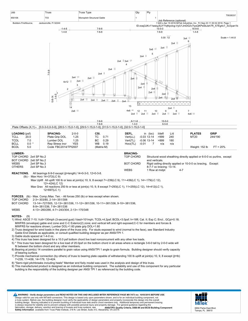
Plate Offsets (X,Y)-- [5:0-3-0,0-3-0], [28:0-1-15,0-1-0], [29:0-1-15,0-1-0], [31:0-1-15,0-1-0], [32:0-1-15,0-1-0]
LOADING (psf)TCLLTCDLBCLLBCDL
20.07.00.0 *5.0
SPACING-Plate Grip DOLLumber DOL Rep Stress IncrCode
2-0-01.251.25YES
FBC2014/TPI2007
CSI.TCBCWB(Matrix-M)
0.710.290.19
DEFL.Vert(LL)Vert(TL)Horz(TL)
in-0.03-0.06-0.01
(loc)13-1413-14
7
l/defl>999>999
n/a
L/d240180n/a
PLATESMT20
Weight: 152 lb FT = 20%
GRIP244/190
LUMBER-TOP CHORD 2x4 SP No.2BOT CHORD 2x6 SP No.2WEBS 2x4 SP No.3OTHERS 2x4 SP No.3
BRACING-TOP CHORD Structural wood sheathing directly applied or 6-0-0 oc purlins, except
end verticals.BOT CHORD Rigid ceiling directly applied or 10-0-0 oc bracing, Except:
8-7-7 oc bracing: 13-14.WEBS 1 Row at midpt 4-7
REACTIONS. All bearings 6-9-0 except (jt=length) 14=0-3-0, 12=0-3-8.(lb) - Max Horz 14=372(LC 9)
Max Uplift All uplift 100 lb or less at joint(s) 10, 9, 8 except 7=-239(LC 9), 11=-436(LC 1), 14=-179(LC 12), 12=-424(LC 12)
Max Grav All reactions 250 lb or less at joint(s) 10, 9, 8 except 7=293(LC 1), 11=255(LC 12), 14=412(LC 1), 12=697(LC 1)
FORCES. (lb) - Max. Comp./Max. Ten. - All forces 250 (lb) or less except when shown.TOP CHORD 2-3=-303/85, 2-14=-351/306BOT CHORD 13-14=-727/505, 12-13=-381/336, 11-12=-381/336, 10-11=-381/336, 9-10=-381/336,
8-9=-381/336, 7-8=-381/336WEBS 4-13=-260/266, 4-7=-243/304, 2-13=-170/348
NOTES- (9)1) Wind: ASCE 7-10; Vult=130mph (3-second gust) Vasd=101mph; TCDL=4.2psf; BCDL=3.0psf; h=18ft; Cat. II; Exp C; Encl., GCpi=0.18;
MWFRS (envelope) gable end zone and C-C Exterior(2) zone; end vertical left and right exposed;C-C for members and forces &MWFRS for reactions shown; Lumber DOL=1.60 plate grip DOL=1.60
2) Truss designed for wind loads in the plane of the truss only. For studs exposed to wind (normal to the face), see Standard IndustryGable End Details as applicable, or consult qualified building designer as per ANSI/TPI 1.
3) Gable studs spaced at 1-4-0 oc.4) This truss has been designed for a 10.0 psf bottom chord live load nonconcurrent with any other live loads.5) * This truss has been designed for a live load of 20.0psf on the bottom chord in all areas where a rectangle 3-6-0 tall by 2-0-0 wide will
fit between the bottom chord and any other members.6) Bearing at joint(s) 14 considers parallel to grain value using ANSI/TPI 1 angle to grain formula. Building designer should verify capacity
of bearing surface.7) Provide mechanical connection (by others) of truss to bearing plate capable of withstanding 100 lb uplift at joint(s) 10, 9, 8 except (jt=lb)
7=239, 11=436, 14=179, 12=424.8) "Semi-rigid pitchbreaks including heels" Member end fixity model was used in the analysis and design of this truss. 9) This manufactured product is designed as an individual building component. The suitability and use of this component for any particular
building is the responsibility of the building designer per ANSI TPI 1 as referenced by the building code.
Design valid for use only with MiTek® connectors. This design is based only upon parameters shown, and is for an individual building component, not a truss system. Before use, the building designer must verify the applicability of design parameters and properly incorporate this design into the overall building design. Bracing indicated is to prevent buckling of individual truss web and/or chord members only. Additional temporary and permanent bracing is always required for stability and to prevent collapse with possible personal injury and property damage. For general guidance regarding the fabrication, storage, delivery, erection and bracing of trusses and truss systems, see ANSI/TPI1 Quality Criteria, DSB-89 and BCSI Building Component
available from Truss Plate Institute, 218 N. Lee Street, Suite 312, Alexandria, VA 22314.Safety Information
WARNING - Verify design parameters and READ NOTES ON THIS AND INCLUDED MITEK REFERENCE PAGE MII-7473 rev. 10/03/2015 BEFORE USE.
6904 Parke East Blvd.Tampa, FL 36610

Job
850106
Truss
T04
Truss Type
Monopitch
Qty
5
Ply
1Job Reference (optional)
T9538338
7.640 s Apr 19 2016 MiTek Industries, Inc. Fri Sep 23 11:30:33 2016 Page 1 Builders FirstSource, Jacksonville, Fl 32244ID:zoej3JKv11weiqJSJY?rqNyoIcg-_8DhEfnr1L1_w5Rcu6Nh7WPsVrLxsgNDrnjc1Vyan1a
Scale = 1:46.2
1
2
3
4
5
6
9 8 7
3x6
4x6
2x6 4x6 6x8
3x4
7x8
7-8-87-8-8
15-5-07-8-8
-1-4-8
1-4-8
7-8-8
7-8-8
15-5-0
7-8-8
16-9-8
1-4-8
1-4-
4
8-3-
11
7-9-
6
5.00 12
Plate Offsets (X,Y)-- [2:0-2-5,Edge], [5:0-3-9,Edge]
LOADING (psf)TCLLTCDLBCLLBCDL
20.07.00.0 *5.0
SPACING-Plate Grip DOLLumber DOL Rep Stress IncrCode
2-0-01.251.25YES
FBC2014/TPI2007
CSI.TCBCWB(Matrix-M)
0.730.210.22
DEFL.Vert(LL)Vert(TL)Horz(TL)
in-0.03-0.05-0.01
(loc)7-87-8
7
l/defl>999>999
n/a
L/d240180n/a
PLATESMT20
Weight: 106 lb FT = 20%
GRIP244/190
LUMBER-TOP CHORD 2x4 SP No.2BOT CHORD 2x6 SP No.2WEBS 2x4 SP No.3
BRACING-TOP CHORD Structural wood sheathing directly applied or 6-0-0 oc purlins, except
end verticals.BOT CHORD Rigid ceiling directly applied or 8-6-9 oc bracing.WEBS 1 Row at midpt 3-7
REACTIONS. (lb/size) 9=570/0-3-0, 7=562/0-3-0Max Horz 9=326(LC 9)Max Uplift9=-141(LC 12), 7=-216(LC 9)
FORCES. (lb) - Max. Comp./Max. Ten. - All forces 250 (lb) or less except when shown.TOP CHORD 2-3=-618/296, 5-7=-256/285, 2-9=-531/406BOT CHORD 8-9=-744/485, 7-8=-558/515WEBS 3-7=-559/513, 2-8=-19/343
NOTES- (6)1) Wind: ASCE 7-10; Vult=130mph (3-second gust) Vasd=101mph; TCDL=4.2psf; BCDL=3.0psf; h=18ft; Cat. II; Exp C; Encl., GCpi=0.18;
MWFRS (envelope) and C-C Exterior(2) zone; end vertical left and right exposed;C-C for members and forces & MWFRS for reactionsshown; Lumber DOL=1.60 plate grip DOL=1.60
2) This truss has been designed for a 10.0 psf bottom chord live load nonconcurrent with any other live loads.3) * This truss has been designed for a live load of 20.0psf on the bottom chord in all areas where a rectangle 3-6-0 tall by 2-0-0 wide will
fit between the bottom chord and any other members.4) Provide mechanical connection (by others) of truss to bearing plate capable of withstanding 100 lb uplift at joint(s) except (jt=lb) 9=141,
7=216.5) "Semi-rigid pitchbreaks including heels" Member end fixity model was used in the analysis and design of this truss. 6) This manufactured product is designed as an individual building component. The suitability and use of this component for any particular
building is the responsibility of the building designer per ANSI TPI 1 as referenced by the building code.
Design valid for use only with MiTek® connectors. This design is based only upon parameters shown, and is for an individual building component, not a truss system. Before use, the building designer must verify the applicability of design parameters and properly incorporate this design into the overall building design. Bracing indicated is to prevent buckling of individual truss web and/or chord members only. Additional temporary and permanent bracing is always required for stability and to prevent collapse with possible personal injury and property damage. For general guidance regarding the fabrication, storage, delivery, erection and bracing of trusses and truss systems, see ANSI/TPI1 Quality Criteria, DSB-89 and BCSI Building Component
available from Truss Plate Institute, 218 N. Lee Street, Suite 312, Alexandria, VA 22314.Safety Information
WARNING - Verify design parameters and READ NOTES ON THIS AND INCLUDED MITEK REFERENCE PAGE MII-7473 rev. 10/03/2015 BEFORE USE.
6904 Parke East Blvd.Tampa, FL 36610

Job
850106
Truss
T05
Truss Type
Monopitch
Qty
10
Ply
1Job Reference (optional)
T9538339
7.640 s Apr 19 2016 MiTek Industries, Inc. Fri Sep 23 11:30:33 2016 Page 1 Builders FirstSource, Jacksonville, Fl 32244ID:zoej3JKv11weiqJSJY?rqNyoIcg-_8DhEfnr1L1_w5Rcu6Nh7WPvQrL2sbmDrnjc1Vyan1a
Scale = 1:43.6
1
2
3
4
5
6
9 8 7
10 11
3x6
2x4 4x6 3x4
3x4
8x10
4x8
4x6
4x6
7-8-87-8-8
15-5-07-8-8
-1-4-8
1-4-8
7-8-8
7-8-8
15-5-0
7-8-8
16-9-8
1-4-8
1-4-
4
8-3-
11
7-9-
6
2-0-
0
8-0-
7
5.00 12
Plate Offsets (X,Y)-- [2:0-2-5,Edge]
LOADING (psf)TCLLTCDLBCLLBCDL
20.07.00.0 *5.0
SPACING-Plate Grip DOLLumber DOL Rep Stress IncrCode
2-0-01.251.25YES
FBC2014/TPI2007
CSI.TCBCWB(Matrix-M)
0.540.200.52
DEFL.Vert(LL)Vert(TL)Horz(TL)
in-0.02-0.050.08
(loc)7-87-811
l/defl>999>999
n/a
L/d240180n/a
PLATESMT20
Weight: 116 lb FT = 20%
GRIP244/190
LUMBER-TOP CHORD 2x4 SP No.2BOT CHORD 2x6 SP No.2WEBS 2x4 SP No.3OTHERS 2x6 SP No.2
BRACING-TOP CHORD Structural wood sheathing directly applied or 6-0-0 oc purlins, except
end verticals.BOT CHORD Rigid ceiling directly applied or 9-8-7 oc bracing.WEBS 1 Row at midpt 3-7
REACTIONS. (lb/size) 9=570/0-3-0, 11=558/0-3-8Max Horz 9=237(LC 12)Max Uplift9=-109(LC 12), 11=-241(LC 12)
FORCES. (lb) - Max. Comp./Max. Ten. - All forces 250 (lb) or less except when shown.TOP CHORD 2-3=-611/174, 2-9=-531/325BOT CHORD 8-9=-582/292, 7-8=-444/493WEBS 3-7=-517/464, 2-8=0/300, 7-10=-221/293, 5-10=-221/293
NOTES- (7)1) Wind: ASCE 7-10; Vult=130mph (3-second gust) Vasd=101mph; TCDL=4.2psf; BCDL=3.0psf; h=18ft; Cat. II; Exp C; Encl., GCpi=0.18;
MWFRS (envelope) and C-C Exterior(2) zone; end vertical left and right exposed;C-C for members and forces & MWFRS for reactionsshown; Lumber DOL=1.60 plate grip DOL=1.60
2) This truss has been designed for a 10.0 psf bottom chord live load nonconcurrent with any other live loads.3) * This truss has been designed for a live load of 20.0psf on the bottom chord in all areas where a rectangle 3-6-0 tall by 2-0-0 wide will
fit between the bottom chord and any other members.4) Bearing at joint(s) 11 considers parallel to grain value using ANSI/TPI 1 angle to grain formula. Building designer should verify capacity
of bearing surface.5) Provide mechanical connection (by others) of truss to bearing plate capable of withstanding 100 lb uplift at joint(s) except (jt=lb) 9=109,
11=241.6) "Semi-rigid pitchbreaks including heels" Member end fixity model was used in the analysis and design of this truss. 7) This manufactured product is designed as an individual building component. The suitability and use of this component for any particular
building is the responsibility of the building designer per ANSI TPI 1 as referenced by the building code.
Design valid for use only with MiTek® connectors. This design is based only upon parameters shown, and is for an individual building component, not a truss system. Before use, the building designer must verify the applicability of design parameters and properly incorporate this design into the overall building design. Bracing indicated is to prevent buckling of individual truss web and/or chord members only. Additional temporary and permanent bracing is always required for stability and to prevent collapse with possible personal injury and property damage. For general guidance regarding the fabrication, storage, delivery, erection and bracing of trusses and truss systems, see ANSI/TPI1 Quality Criteria, DSB-89 and BCSI Building Component
available from Truss Plate Institute, 218 N. Lee Street, Suite 312, Alexandria, VA 22314.Safety Information
WARNING - Verify design parameters and READ NOTES ON THIS AND INCLUDED MITEK REFERENCE PAGE MII-7473 rev. 10/03/2015 BEFORE USE.
6904 Parke East Blvd.Tampa, FL 36610

Job
850106
Truss
T06
Truss Type
GABLE
Qty
1
Ply
1Job Reference (optional)
T9538340
7.640 s Apr 19 2016 MiTek Industries, Inc. Fri Sep 23 11:30:34 2016 Page 1 Builders FirstSource, Jacksonville, Fl 32244ID:zoej3JKv11weiqJSJY?rqNyoIcg-SKn3S?oTofArXF0oRquwgkx_UFhMb8aN3RT9Zyyan1Z
Scale = 1:53.6
1
2
3
4
5
6
7
8
9
10
11 12
13
14
15
16 17
33 32 31 30 29 28 27 26 25 24 23 22 21 20 19 18
4x6
5x6
3x6
3x6
4x6 7x8
2x4
2x4
2x4
2x4
2x4
2x4
2x4
2x4
2x4
2x4
2x4
2x4
2x4
2x4
2x4
2x4
2x4
2x4
2x4
2x4
2x4
2x4
2x4
2x4
2x4
3x4
18-11-018-11-0
-1-4-8
1-4-8
18-11-0
18-11-0
20-3-8
1-4-8
1-4-
5
8-11
-1
5.00 12
Plate Offsets (X,Y)-- [18:Edge,0-3-8], [23:0-4-0,0-0-4]
LOADING (psf)TCLLTCDLBCLLBCDL
20.07.00.0 *5.0
SPACING-Plate Grip DOLLumber DOL Rep Stress IncrCode
2-0-01.251.25YES
FBC2014/TPI2007
CSI.TCBCWB(Matrix)
0.910.200.16
DEFL.Vert(LL)Vert(TL)Horz(TL)
in0.000.00
-0.00
(loc)22
18
l/defln/rn/rn/a
L/d120120n/a
PLATESMT20
Weight: 174 lb FT = 20%
GRIP244/190
LUMBER-TOP CHORD 2x4 SP No.2BOT CHORD 2x6 SP No.2WEBS 2x4 SP No.3OTHERS 2x4 SP No.3
BRACING-TOP CHORD Structural wood sheathing directly applied or 6-0-0 oc purlins, except
end verticals.BOT CHORD Rigid ceiling directly applied or 10-0-0 oc bracing.WEBS 1 Row at midpt 17-18
REACTIONS. All bearings 18-11-0.(lb) - Max Horz 33=451(LC 11)
Max Uplift All uplift 100 lb or less at joint(s) 18, 31, 30, 29, 28, 27, 26, 25, 24, 22, 21, 20, 19 except 32=-228(LC 9)
Max Grav All reactions 250 lb or less at joint(s) 18, 32, 31, 30, 29, 28, 27, 26, 25, 24, 22, 21, 20, 19 except 33=321(LC 20)
FORCES. (lb) - Max. Comp./Max. Ten. - All forces 250 (lb) or less except when shown.TOP CHORD 2-3=-526/268, 3-4=-546/289, 4-5=-474/255, 5-6=-455/251, 6-7=-421/238, 7-8=-388/227,
8-9=-356/216, 9-10=-324/205, 10-11=-291/187, 11-12=-289/194, 12-13=-259/182
NOTES- (11)1) Wind: ASCE 7-10; Vult=130mph (3-second gust) Vasd=101mph; TCDL=4.2psf; BCDL=3.0psf; h=18ft; Cat. II; Exp C; Encl., GCpi=0.18;
MWFRS (envelope) gable end zone and C-C Exterior(2) zone; end vertical left and right exposed;C-C for members and forces &MWFRS for reactions shown; Lumber DOL=1.60 plate grip DOL=1.60
2) Truss designed for wind loads in the plane of the truss only. For studs exposed to wind (normal to the face), see Standard IndustryGable End Details as applicable, or consult qualified building designer as per ANSI/TPI 1.
3) Gable requires continuous bottom chord bearing. 4) Truss to be fully sheathed from one face or securely braced against lateral movement (i.e. diagonal web).5) Gable studs spaced at 1-4-0 oc.6) This truss has been designed for a 10.0 psf bottom chord live load nonconcurrent with any other live loads.7) * This truss has been designed for a live load of 20.0psf on the bottom chord in all areas where a rectangle 3-6-0 tall by 2-0-0 wide will
fit between the bottom chord and any other members.8) Bearing at joint(s) 33 considers parallel to grain value using ANSI/TPI 1 angle to grain formula. Building designer should verify capacity
of bearing surface.9) Provide mechanical connection (by others) of truss to bearing plate capable of withstanding 100 lb uplift at joint(s) 18, 31, 30, 29, 28, 27,
26, 25, 24, 22, 21, 20, 19 except (jt=lb) 32=228.10) "Semi-rigid pitchbreaks including heels" Member end fixity model was used in the analysis and design of this truss. 11) This manufactured product is designed as an individual building component. The suitability and use of this component for any
particular building is the responsibility of the building designer per ANSI TPI 1 as referenced by the building code.
Design valid for use only with MiTek® connectors. This design is based only upon parameters shown, and is for an individual building component, not a truss system. Before use, the building designer must verify the applicability of design parameters and properly incorporate this design into the overall building design. Bracing indicated is to prevent buckling of individual truss web and/or chord members only. Additional temporary and permanent bracing is always required for stability and to prevent collapse with possible personal injury and property damage. For general guidance regarding the fabrication, storage, delivery, erection and bracing of trusses and truss systems, see ANSI/TPI1 Quality Criteria, DSB-89 and BCSI Building Component
available from Truss Plate Institute, 218 N. Lee Street, Suite 312, Alexandria, VA 22314.Safety Information
WARNING - Verify design parameters and READ NOTES ON THIS AND INCLUDED MITEK REFERENCE PAGE MII-7473 rev. 10/03/2015 BEFORE USE.
6904 Parke East Blvd.Tampa, FL 36610

Job
850106
Truss
T07
Truss Type
Monopitch
Qty
5
Ply
1Job Reference (optional)
T9538341
7.640 s Apr 19 2016 MiTek Industries, Inc. Fri Sep 23 11:30:35 2016 Page 1 Builders FirstSource, Jacksonville, Fl 32244ID:zoej3JKv11weiqJSJY?rqNyoIcg-wXLSfLo5ZzIi9Pb??XP9CxUERf0iKTuWI5Cj5Oyan1Y
Scale = 1:52.1
1
2
3
4
5
6
7
1110 9
812 13
3x6
4x6
8x10 4x6 3x4
4x6
3x4
3x4
6x8
9-5-89-5-8
18-11-09-5-8
-1-4-8
1-4-8
6-4-13
6-4-13
12-6-3
6-1-5
18-11-0
6-4-13
20-3-8
1-4-8
1-4-
4
9-9-
3
9-2-
14
5.00 12
Plate Offsets (X,Y)-- [6:0-3-9,Edge]
LOADING (psf)TCLLTCDLBCLLBCDL
20.07.00.0 *5.0
SPACING-Plate Grip DOLLumber DOL Rep Stress IncrCode
2-0-01.251.25YES
FBC2014/TPI2007
CSI.TCBCWB(Matrix-M)
0.640.320.67
DEFL.Vert(LL)Vert(TL)Horz(TL)
in-0.08-0.130.01
(loc)8-108-10
8
l/defl>999>999
n/a
L/d240180n/a
PLATESMT20
Weight: 132 lb FT = 20%
GRIP244/190
LUMBER-TOP CHORD 2x4 SP No.2BOT CHORD 2x6 SP No.2WEBS 2x4 SP No.3 *Except*
6-8: 2x4 SP No.2
BRACING-TOP CHORD Structural wood sheathing directly applied or 6-0-0 oc purlins, except
end verticals.BOT CHORD Rigid ceiling directly applied or 8-4-4 oc bracing.WEBS 1 Row at midpt 6-8, 5-8
REACTIONS. (lb/size) 8=675/0-3-0, 11=682/0-3-0Max Horz 11=385(LC 9)Max Uplift8=-248(LC 12), 11=-171(LC 12)
FORCES. (lb) - Max. Comp./Max. Ten. - All forces 250 (lb) or less except when shown.TOP CHORD 3-4=-682/370, 4-5=-626/380, 2-11=-311/318BOT CHORD 10-11=-772/701, 10-12=-477/447, 9-12=-477/447, 9-13=-477/447, 8-13=-477/447WEBS 3-10=-228/327, 5-10=-197/387, 5-8=-576/511, 3-11=-692/291
NOTES- (6)1) Wind: ASCE 7-10; Vult=130mph (3-second gust) Vasd=101mph; TCDL=4.2psf; BCDL=3.0psf; h=18ft; Cat. II; Exp C; Encl., GCpi=0.18;
MWFRS (envelope) and C-C Exterior(2) zone; end vertical left and right exposed;C-C for members and forces & MWFRS for reactionsshown; Lumber DOL=1.60 plate grip DOL=1.60
2) This truss has been designed for a 10.0 psf bottom chord live load nonconcurrent with any other live loads.3) * This truss has been designed for a live load of 20.0psf on the bottom chord in all areas where a rectangle 3-6-0 tall by 2-0-0 wide will
fit between the bottom chord and any other members, with BCDL = 5.0psf.4) Provide mechanical connection (by others) of truss to bearing plate capable of withstanding 100 lb uplift at joint(s) except (jt=lb) 8=248,
11=171.5) "Semi-rigid pitchbreaks including heels" Member end fixity model was used in the analysis and design of this truss. 6) This manufactured product is designed as an individual building component. The suitability and use of this component for any particular
building is the responsibility of the building designer per ANSI TPI 1 as referenced by the building code.
Design valid for use only with MiTek® connectors. This design is based only upon parameters shown, and is for an individual building component, not a truss system. Before use, the building designer must verify the applicability of design parameters and properly incorporate this design into the overall building design. Bracing indicated is to prevent buckling of individual truss web and/or chord members only. Additional temporary and permanent bracing is always required for stability and to prevent collapse with possible personal injury and property damage. For general guidance regarding the fabrication, storage, delivery, erection and bracing of trusses and truss systems, see ANSI/TPI1 Quality Criteria, DSB-89 and BCSI Building Component
available from Truss Plate Institute, 218 N. Lee Street, Suite 312, Alexandria, VA 22314.Safety Information
WARNING - Verify design parameters and READ NOTES ON THIS AND INCLUDED MITEK REFERENCE PAGE MII-7473 rev. 10/03/2015 BEFORE USE.
6904 Parke East Blvd.Tampa, FL 36610

Job
850106
Truss
T08
Truss Type
Monopitch
Qty
2
Ply
1Job Reference (optional)
T9538342
7.640 s Apr 19 2016 MiTek Industries, Inc. Fri Sep 23 11:30:36 2016 Page 1 Builders FirstSource, Jacksonville, Fl 32244ID:zoej3JKv11weiqJSJY?rqNyoIcg-OjvqshpkKGQZnZABZEwOl91T33M43xdgXkyGeqyan1X
Scale = 1:51.7
1
2
3
4
5
6
7
1110 9
8
12 13
14 15
3x6
4x6 3x4
4x6
3x4
3x4
3x4
4x6
4x12
4x6
4x6
9-5-89-5-8
18-11-09-5-8
-1-4-8
1-4-8
6-4-13
6-4-13
12-6-3
6-1-5
18-11-0
6-4-13
20-3-8
1-4-8
1-4-
4
9-9-
3
9-2-
14
2-0-
0
9-5-
15
5.00 12
Plate Offsets (X,Y)-- [6:0-6-8,Edge]
LOADING (psf)TCLLTCDLBCLLBCDL
20.07.00.0 *5.0
SPACING-Plate Grip DOLLumber DOL Rep Stress IncrCode
2-0-01.251.25YES
FBC2014/TPI2007
CSI.TCBCWB(Matrix-M)
0.330.310.64
DEFL.Vert(LL)Vert(TL)Horz(TL)
in-0.07-0.120.09
(loc)8-108-10
13
l/defl>999>999
n/a
L/d240180n/a
PLATESMT20
Weight: 146 lb FT = 20%
GRIP244/190
LUMBER-TOP CHORD 2x4 SP No.2BOT CHORD 2x6 SP No.2WEBS 2x4 SP No.3OTHERS 2x6 SP No.2
BRACING-TOP CHORD Structural wood sheathing directly applied or 6-0-0 oc purlins, except
end verticals.BOT CHORD Rigid ceiling directly applied or 9-1-10 oc bracing.WEBS 1 Row at midpt 5-8
REACTIONS. (lb/size) 11=682/0-3-0, 13=670/0-3-8Max Horz 11=287(LC 12)Max Uplift11=-133(LC 12), 13=-285(LC 12)
FORCES. (lb) - Max. Comp./Max. Ten. - All forces 250 (lb) or less except when shown.TOP CHORD 3-4=-659/219, 4-5=-589/229, 2-11=-308/317BOT CHORD 10-11=-651/703, 10-14=-352/411, 9-14=-352/411, 9-15=-352/411, 8-15=-352/411WEBS 3-10=-235/323, 5-10=-195/383, 5-8=-545/466, 3-11=-653/107, 8-12=-321/436,
6-12=-321/436
NOTES- (7)1) Wind: ASCE 7-10; Vult=130mph (3-second gust) Vasd=101mph; TCDL=4.2psf; BCDL=3.0psf; h=18ft; Cat. II; Exp C; Encl., GCpi=0.18;
MWFRS (envelope) and C-C Exterior(2) zone; end vertical left and right exposed;C-C for members and forces & MWFRS for reactionsshown; Lumber DOL=1.60 plate grip DOL=1.60
2) This truss has been designed for a 10.0 psf bottom chord live load nonconcurrent with any other live loads.3) * This truss has been designed for a live load of 20.0psf on the bottom chord in all areas where a rectangle 3-6-0 tall by 2-0-0 wide will
fit between the bottom chord and any other members, with BCDL = 5.0psf.4) Bearing at joint(s) 13 considers parallel to grain value using ANSI/TPI 1 angle to grain formula. Building designer should verify capacity
of bearing surface.5) Provide mechanical connection (by others) of truss to bearing plate capable of withstanding 100 lb uplift at joint(s) except (jt=lb) 11=133,
13=285.6) "Semi-rigid pitchbreaks including heels" Member end fixity model was used in the analysis and design of this truss. 7) This manufactured product is designed as an individual building component. The suitability and use of this component for any particular
building is the responsibility of the building designer per ANSI TPI 1 as referenced by the building code.
Design valid for use only with MiTek® connectors. This design is based only upon parameters shown, and is for an individual building component, not a truss system. Before use, the building designer must verify the applicability of design parameters and properly incorporate this design into the overall building design. Bracing indicated is to prevent buckling of individual truss web and/or chord members only. Additional temporary and permanent bracing is always required for stability and to prevent collapse with possible personal injury and property damage. For general guidance regarding the fabrication, storage, delivery, erection and bracing of trusses and truss systems, see ANSI/TPI1 Quality Criteria, DSB-89 and BCSI Building Component
available from Truss Plate Institute, 218 N. Lee Street, Suite 312, Alexandria, VA 22314.Safety Information
WARNING - Verify design parameters and READ NOTES ON THIS AND INCLUDED MITEK REFERENCE PAGE MII-7473 rev. 10/03/2015 BEFORE USE.
6904 Parke East Blvd.Tampa, FL 36610

Job
850106
Truss
T09
Truss Type
Monopitch
Qty
4
Ply
1Job Reference (optional)
T9538343
7.640 s Apr 19 2016 MiTek Industries, Inc. Fri Sep 23 11:30:36 2016 Page 1 Builders FirstSource, Jacksonville, Fl 32244ID:zoej3JKv11weiqJSJY?rqNyoIcg-OjvqshpkKGQZnZABZEwOl91MR3PR33pgXkyGeqyan1X
Scale = 1:40.1
1
2
3
5 4
6
7 8
2x4
2x6
2x4
2x4
3x4 3x6
5-0-
8
6-5-86-5-8
6-5-8
6-5-8
4-9-
3
6-11
-1
6-11
-1
4.00 12
LOADING (psf)TCLLTCDLBCLLBCDL
20.07.00.0 *5.0
SPACING-Plate Grip DOLLumber DOL Rep Stress IncrCode
2-0-01.251.25YES
FBC2014/TPI2007
CSI.TCBCWB(Matrix-M)
0.810.100.11
DEFL.Vert(LL)Vert(TL)Horz(TL)
in-0.03-0.05-0.00
(loc)4-54-5
4
l/defl>999>999
n/a
L/d240180n/a
PLATESMT20
Weight: 45 lb FT = 20%
GRIP244/190
LUMBER-TOP CHORD 2x4 SP No.2BOT CHORD 2x6 SP M 26WEBS 2x4 SP No.3 *Except*
3-4: 2x4 SP No.2
BRACING-TOP CHORD Structural wood sheathing directly applied or 6-0-0 oc purlins, except
end verticals.BOT CHORD Rigid ceiling directly applied or 10-0-0 oc bracing.
REACTIONS. (lb/size) 5=227/0-3-8, 4=227/0-3-8Max Horz 5=70(LC 8)Max Uplift4=-92(LC 8)Max Grav 5=289(LC 2), 4=289(LC 2)
FORCES. (lb) - Max. Comp./Max. Ten. - All forces 250 (lb) or less except when shown.TOP CHORD 2-3=-361/160, 4-6=-166/263, 3-6=-166/263WEBS 2-6=-167/385
NOTES- (8)1) Wind: ASCE 7-10; Vult=130mph (3-second gust) Vasd=101mph; TCDL=4.2psf; BCDL=3.0psf; h=18ft; Cat. II; Exp C; Encl., GCpi=0.18;
MWFRS (envelope) and C-C Exterior(2) zone;C-C for members and forces & MWFRS for reactions shown; Lumber DOL=1.60 plategrip DOL=1.60
2) 60.0lb AC unit load placed on the bottom chord, 3-2-12 from left end, supported at two points, 3-0-0 apart.3) This truss has been designed for a 10.0 psf bottom chord live load nonconcurrent with any other live loads.4) * This truss has been designed for a live load of 20.0psf on the bottom chord in all areas where a rectangle 3-6-0 tall by 2-0-0 wide will
fit between the bottom chord and any other members, with BCDL = 5.0psf.5) Bearing at joint(s) 5, 4 considers parallel to grain value using ANSI/TPI 1 angle to grain formula. Building designer should verify
capacity of bearing surface.6) Provide mechanical connection (by others) of truss to bearing plate capable of withstanding 100 lb uplift at joint(s) 4.7) "Semi-rigid pitchbreaks including heels" Member end fixity model was used in the analysis and design of this truss. 8) This manufactured product is designed as an individual building component. The suitability and use of this component for any particular
building is the responsibility of the building designer per ANSI TPI 1 as referenced by the building code.
Design valid for use only with MiTek® connectors. This design is based only upon parameters shown, and is for an individual building component, not a truss system. Before use, the building designer must verify the applicability of design parameters and properly incorporate this design into the overall building design. Bracing indicated is to prevent buckling of individual truss web and/or chord members only. Additional temporary and permanent bracing is always required for stability and to prevent collapse with possible personal injury and property damage. For general guidance regarding the fabrication, storage, delivery, erection and bracing of trusses and truss systems, see ANSI/TPI1 Quality Criteria, DSB-89 and BCSI Building Component
available from Truss Plate Institute, 218 N. Lee Street, Suite 312, Alexandria, VA 22314.Safety Information
WARNING - Verify design parameters and READ NOTES ON THIS AND INCLUDED MITEK REFERENCE PAGE MII-7473 rev. 10/03/2015 BEFORE USE.
6904 Parke East Blvd.Tampa, FL 36610

Job
850106
Truss
T10
Truss Type
Monopitch
Qty
4
Ply
1Job Reference (optional)
T9538344
7.640 s Apr 19 2016 MiTek Industries, Inc. Fri Sep 23 11:30:37 2016 Page 1 Builders FirstSource, Jacksonville, Fl 32244ID:zoej3JKv11weiqJSJY?rqNyoIcg-svTC41qM5aYQOjlN7ySdIMZXsSlpoW0pmOhpAGyan1W
Scale = 1:39.6
1
2
3
5 4
6
7 8
2x4
2x6
2x4
2x4
3x4 3x6
5-0-
8
6-2-06-2-0
6-2-0
6-2-0
4-9-
3
6-9-
14
6-9-
14
4.00 12
LOADING (psf)TCLLTCDLBCLLBCDL
20.07.00.0 *5.0
SPACING-Plate Grip DOLLumber DOL Rep Stress IncrCode
2-0-01.251.25YES
FBC2014/TPI2007
CSI.TCBCWB(Matrix-M)
0.770.090.12
DEFL.Vert(LL)Vert(TL)Horz(TL)
in-0.02-0.04-0.00
(loc)4-54-5
4
l/defl>999>999
n/a
L/d240180n/a
PLATESMT20
Weight: 43 lb FT = 20%
GRIP244/190
LUMBER-TOP CHORD 2x4 SP No.2BOT CHORD 2x6 SP M 26WEBS 2x4 SP No.3 *Except*
3-4: 2x4 SP No.2
BRACING-TOP CHORD Structural wood sheathing directly applied or 6-0-0 oc purlins, except
end verticals.BOT CHORD Rigid ceiling directly applied or 10-0-0 oc bracing.
REACTIONS. (lb/size) 5=217/0-3-8, 4=219/MechanicalMax Horz 5=66(LC 8)Max Uplift4=-87(LC 8)Max Grav 5=275(LC 2), 4=278(LC 2)
FORCES. (lb) - Max. Comp./Max. Ten. - All forces 250 (lb) or less except when shown.TOP CHORD 2-3=-373/165, 4-6=-158/256, 3-6=-158/256WEBS 2-6=-170/396
NOTES- (9)1) Wind: ASCE 7-10; Vult=130mph (3-second gust) Vasd=101mph; TCDL=4.2psf; BCDL=3.0psf; h=18ft; Cat. II; Exp C; Encl., GCpi=0.18;
MWFRS (envelope) and C-C Exterior(2) zone;C-C for members and forces & MWFRS for reactions shown; Lumber DOL=1.60 plategrip DOL=1.60
2) 60.0lb AC unit load placed on the bottom chord, 3-2-12 from left end, supported at two points, 3-0-0 apart.3) This truss has been designed for a 10.0 psf bottom chord live load nonconcurrent with any other live loads.4) * This truss has been designed for a live load of 20.0psf on the bottom chord in all areas where a rectangle 3-6-0 tall by 2-0-0 wide will
fit between the bottom chord and any other members, with BCDL = 5.0psf.5) Refer to girder(s) for truss to truss connections.6) Bearing at joint(s) 5 considers parallel to grain value using ANSI/TPI 1 angle to grain formula. Building designer should verify capacity
of bearing surface.7) Provide mechanical connection (by others) of truss to bearing plate capable of withstanding 100 lb uplift at joint(s) 4.8) "Semi-rigid pitchbreaks including heels" Member end fixity model was used in the analysis and design of this truss. 9) This manufactured product is designed as an individual building component. The suitability and use of this component for any particular
building is the responsibility of the building designer per ANSI TPI 1 as referenced by the building code.
Design valid for use only with MiTek® connectors. This design is based only upon parameters shown, and is for an individual building component, not a truss system. Before use, the building designer must verify the applicability of design parameters and properly incorporate this design into the overall building design. Bracing indicated is to prevent buckling of individual truss web and/or chord members only. Additional temporary and permanent bracing is always required for stability and to prevent collapse with possible personal injury and property damage. For general guidance regarding the fabrication, storage, delivery, erection and bracing of trusses and truss systems, see ANSI/TPI1 Quality Criteria, DSB-89 and BCSI Building Component
available from Truss Plate Institute, 218 N. Lee Street, Suite 312, Alexandria, VA 22314.Safety Information
WARNING - Verify design parameters and READ NOTES ON THIS AND INCLUDED MITEK REFERENCE PAGE MII-7473 rev. 10/03/2015 BEFORE USE.
6904 Parke East Blvd.Tampa, FL 36610

Job
850106
Truss
T11
Truss Type
Flat Girder
Qty
1
Ply
2 Job Reference (optional)
T9538345
7.640 s Apr 19 2016 MiTek Industries, Inc. Fri Sep 23 11:30:38 2016 Page 1 Builders FirstSource, Jacksonville, Fl 32244ID:zoej3JKv11weiqJSJY?rqNyoIcg-K61aHNr_sugH0tJagfzsqa6f9syyXn4y_2RNijyan1V
Scale = 1:32.3
1 2 3 4 5 6 7
1413 12 11 10 9
8
15
16 17 18 19 20 21 22 23
24 25 26 27
5x12 5x12
6x12 MT20HS
2x4 5x8
7x14 MT20HS 3x8
2x4 7x8
2x4
2x4
10x14 2x6 3x6
3-3-03-3-0
6-4-43-1-4
9-5-83-1-4
12-6-123-1-4
15-8-03-1-4
18-11-03-3-0
3-3-0
3-3-0
6-4-4
3-1-4
9-5-8
3-1-4
12-6-12
3-1-4
15-8-0
3-1-4
18-11-0
3-3-0
2-0-
0
1-8-
8
2-0-
0
Plate Offsets (X,Y)-- [5:0-3-12,Edge], [12:0-7-0,0-4-8], [13:0-6-0,0-2-8]
LOADING (psf)TCLLTCDLBCLLBCDL
20.07.00.0 *5.0
SPACING-Plate Grip DOLLumber DOL Rep Stress IncrCode
2-0-01.251.25NO
FBC2014/TPI2007
CSI.TCBCWB(Matrix-M)
0.990.600.83
DEFL.Vert(LL)Vert(TL)Horz(TL)
in-0.33-0.620.09
(loc)11118
l/defl>686>362
n/a
L/d240180n/a
PLATESMT20MT20HS
Weight: 232 lb FT = 20%
GRIP244/190187/143
LUMBER-TOP CHORD 2x4 SP M 31 *Except*
5-7: 2x4 SP No.2BOT CHORD 2x6 SP M 26WEBS 2x4 SP No.3 *Except*
1-13,3-13,3-11,5-11,5-9,7-9: 2x4 SP No.1
BRACING-TOP CHORD Structural wood sheathing directly applied, except end verticals.BOT CHORD Rigid ceiling directly applied or 8-11-7 oc bracing.
REACTIONS. (lb/size) 14=6327/(0-3-8 + bearing block) (req. 0-3-12), 8=6557/0-3-8 (req. 0-3-14)Max Uplift14=-2281(LC 4), 8=-2384(LC 4)
FORCES. (lb) - Max. Comp./Max. Ten. - All forces 250 (lb) or less except when shown.TOP CHORD 14-15=-5996/2173, 1-15=-5996/2173, 1-16=-9788/3520, 16-17=-9788/3520,
2-17=-9788/3520, 2-18=-9788/3520, 18-19=-9788/3520, 3-19=-9788/3520, 3-20=-17411/6258, 4-20=-17411/6258, 4-21=-17411/6258, 5-21=-17411/6258, 5-22=-10030/3639, 6-22=-10030/3639, 6-23=-10030/3639, 7-23=-10030/3639, 7-8=-5957/2165
BOT CHORD 13-14=-141/380, 12-13=-5670/15795, 11-12=-5670/15795, 10-11=-5857/16217, 10-24=-5857/16217, 24-25=-5857/16217, 9-25=-5857/16217, 9-26=-129/352, 26-27=-129/352, 8-27=-129/352
WEBS 1-13=-3814/10620, 2-13=-2199/830, 3-13=-6780/2426, 3-12=-102/357, 3-11=-663/1824, 4-11=-1844/685, 5-11=-453/1347, 5-10=-238/698, 5-9=-6984/2503, 6-9=-1975/733, 7-9=-3962/10924
NOTES- (14)1) 2-ply truss to be connected together with 10d (0.131"x3") nails as follows:
Top chords connected as follows: 2x4 - 1 row at 0-7-0 oc.Bottom chords connected as follows: 2x6 - 2 rows staggered at 0-9-0 oc.Webs connected as follows: 2x4 - 1 row at 0-9-0 oc.
2) All loads are considered equally applied to all plies, except if noted as front (F) or back (B) face in the LOAD CASE(S) section. Ply to plyconnections have been provided to distribute only loads noted as (F) or (B), unless otherwise indicated.
3) 2x4 SP No.3 bearing block 12" long at jt. 14 attached to each face with 2 rows of 10d (0.131"x3") nails spaced 3" o.c. 8 Total fastenersper block. Bearing is assumed to be SP No.2.
4) Wind: ASCE 7-10; Vult=130mph (3-second gust) Vasd=101mph; TCDL=4.2psf; BCDL=3.0psf; h=18ft; Cat. II; Exp C; Encl., GCpi=0.18;MWFRS (envelope); Lumber DOL=1.60 plate grip DOL=1.60
5) Provide adequate drainage to prevent water ponding.6) All plates are MT20 plates unless otherwise indicated. 7) This truss has been designed for a 10.0 psf bottom chord live load nonconcurrent with any other live loads.8) * This truss has been designed for a live load of 20.0psf on the bottom chord in all areas where a rectangle 3-6-0 tall by 2-0-0 wide will
fit between the bottom chord and any other members.9) WARNING: Required bearing size at joint(s) 8 greater than input bearing size.10) Bearing at joint(s) 14, 8 considers parallel to grain value using ANSI/TPI 1 angle to grain formula. Building designer should verify
capacity of bearing surface.Continued on page 2
Design valid for use only with MiTek® connectors. This design is based only upon parameters shown, and is for an individual building component, not a truss system. Before use, the building designer must verify the applicability of design parameters and properly incorporate this design into the overall building design. Bracing indicated is to prevent buckling of individual truss web and/or chord members only. Additional temporary and permanent bracing is always required for stability and to prevent collapse with possible personal injury and property damage. For general guidance regarding the fabrication, storage, delivery, erection and bracing of trusses and truss systems, see ANSI/TPI1 Quality Criteria, DSB-89 and BCSI Building Component
available from Truss Plate Institute, 218 N. Lee Street, Suite 312, Alexandria, VA 22314.Safety Information
WARNING - Verify design parameters and READ NOTES ON THIS AND INCLUDED MITEK REFERENCE PAGE MII-7473 rev. 10/03/2015 BEFORE USE.
6904 Parke East Blvd.Tampa, FL 36610

Job
850106
Truss
T11
Truss Type
Flat Girder
Qty
1
Ply
2 Job Reference (optional)
T9538345
7.640 s Apr 19 2016 MiTek Industries, Inc. Fri Sep 23 11:30:38 2016 Page 2 Builders FirstSource, Jacksonville, Fl 32244ID:zoej3JKv11weiqJSJY?rqNyoIcg-K61aHNr_sugH0tJagfzsqa6f9syyXn4y_2RNijyan1V
NOTES- (14)11) Provide mechanical connection (by others) of truss to bearing plate capable of withstanding 100 lb uplift at joint(s) except (jt=lb) 14=2281, 8=2384.12) "Semi-rigid pitchbreaks including heels" Member end fixity model was used in the analysis and design of this truss. 13) Hanger(s) or other connection device(s) shall be provided sufficient to support concentrated load(s) 504 lb down and 236 lb up at 1-4-4, 504 lb down and 236 lb up at 1-8-12,
504 lb down and 236 lb up at 3-8-12, 504 lb down and 236 lb up at 5-8-12, 504 lb down and 236 lb up at 7-8-12, 504 lb down and 236 lb up at 9-8-12, 504 lb down and 236 lbup at 11-8-12, 504 lb down and 236 lb up at 13-8-12, and 504 lb down and 236 lb up at 15-8-12, and 504 lb down and 236 lb up at 17-8-12 on top chord, and 268 lb down and97 lb up at 13-0-4, 268 lb down and 97 lb up at 14-5-4, and 268 lb down and 97 lb up at 16-5-4, and 272 lb down and 93 lb up at 18-5-4 on bottom chord. Thedesign/selection of such connection device(s) is the responsibility of others.
14) This manufactured product is designed as an individual building component. The suitability and use of this component for any particular building is the responsibility of thebuilding designer per ANSI TPI 1 as referenced by the building code.
LOAD CASE(S) Standard1) Dead + Roof Live (balanced): Lumber Increase=1.25, Plate Increase=1.25
Uniform Loads (plf)Vert: 1-7=-366, 8-14=-10
Concentrated Loads (lb)Vert: 4=-504 6=-504 16=-504 17=-504 18=-504 19=-504 20=-504 21=-504 22=-504 23=-504 24=-209(F) 25=-209(F) 26=-209(F) 27=-213(F)
Design valid for use only with MiTek® connectors. This design is based only upon parameters shown, and is for an individual building component, not a truss system. Before use, the building designer must verify the applicability of design parameters and properly incorporate this design into the overall building design. Bracing indicated is to prevent buckling of individual truss web and/or chord members only. Additional temporary and permanent bracing is always required for stability and to prevent collapse with possible personal injury and property damage. For general guidance regarding the fabrication, storage, delivery, erection and bracing of trusses and truss systems, see ANSI/TPI1 Quality Criteria, DSB-89 and BCSI Building Component
available from Truss Plate Institute, 218 N. Lee Street, Suite 312, Alexandria, VA 22314.Safety Information
WARNING - Verify design parameters and READ NOTES ON THIS AND INCLUDED MITEK REFERENCE PAGE MII-7473 rev. 10/03/2015 BEFORE USE.
6904 Parke East Blvd.Tampa, FL 36610

Job
850106
Truss
T12
Truss Type
Flat Girder
Qty
1
Ply
2 Job Reference (optional)
T9538346
7.640 s Apr 19 2016 MiTek Industries, Inc. Fri Sep 23 11:30:39 2016 Page 1 Builders FirstSource, Jacksonville, Fl 32244ID:zoej3JKv11weiqJSJY?rqNyoIcg-oIayViscdBo8e0umENU5NnfweGR9GRK6DiAwE9yan1U
Scale = 1:13.01 2
4 3
5 6
2x4
2x4
4x6
4x6
4-1-124-1-12
4-1-12
4-1-12
2-0-
0
LOADING (psf)TCLLTCDLBCLLBCDL
20.07.00.0 *5.0
SPACING-Plate Grip DOLLumber DOL Rep Stress IncrCode
2-0-01.251.25NO
FBC2014/TPI2007
CSI.TCBCWB(Matrix-M)
0.620.030.00
DEFL.Vert(LL)Vert(TL)Horz(TL)
in-0.00-0.00-0.00
(loc)3-43-4
3
l/defl>999>999
n/a
L/d240180n/a
PLATESMT20
Weight: 56 lb FT = 20%
GRIP244/190
LUMBER-TOP CHORD 2x6 SP No.2BOT CHORD 2x6 SP No.2WEBS 2x4 SP No.3
BRACING-TOP CHORD Structural wood sheathing directly applied or 4-1-12 oc purlins, except
end verticals.BOT CHORD Rigid ceiling directly applied or 10-0-0 oc bracing.
REACTIONS. (lb/size) 4=1191/0-3-8, 3=1280/0-3-8Max Uplift4=-429(LC 4), 3=-467(LC 4)
FORCES. (lb) - Max. Comp./Max. Ten. - All forces 250 (lb) or less except when shown.TOP CHORD 1-4=-1171/441, 2-3=-1261/479
NOTES- (10)1) 2-ply truss to be connected together with 10d (0.131"x3") nails as follows:
Top chords connected as follows: 2x4 - 1 row at 0-9-0 oc, 2x6 - 2 rows staggered at 0-9-0 oc.Bottom chords connected as follows: 2x6 - 2 rows staggered at 0-9-0 oc.Webs connected as follows: 2x4 - 1 row at 0-9-0 oc.
2) All loads are considered equally applied to all plies, except if noted as front (F) or back (B) face in the LOAD CASE(S) section. Ply to plyconnections have been provided to distribute only loads noted as (F) or (B), unless otherwise indicated.
3) Wind: ASCE 7-10; Vult=130mph (3-second gust) Vasd=101mph; TCDL=4.2psf; BCDL=3.0psf; h=18ft; Cat. II; Exp C; Encl., GCpi=0.18;MWFRS (envelope); Lumber DOL=1.60 plate grip DOL=1.60
4) Provide adequate drainage to prevent water ponding.5) This truss has been designed for a 10.0 psf bottom chord live load nonconcurrent with any other live loads.6) * This truss has been designed for a live load of 20.0psf on the bottom chord in all areas where a rectangle 3-6-0 tall by 2-0-0 wide will
fit between the bottom chord and any other members.7) Provide mechanical connection (by others) of truss to bearing plate capable of withstanding 100 lb uplift at joint(s) except (jt=lb) 4=429,
3=467.8) "Semi-rigid pitchbreaks including heels" Member end fixity model was used in the analysis and design of this truss. 9) Hanger(s) or other connection device(s) shall be provided sufficient to support concentrated load(s) 616 lb down and 279 lb up at 1-2-8,
and 622 lb down and 280 lb up at 3-2-8 on top chord. The design/selection of such connection device(s) is the responsibility of others.10) This manufactured product is designed as an individual building component. The suitability and use of this component for any
particular building is the responsibility of the building designer per ANSI TPI 1 as referenced by the building code.
LOAD CASE(S) Standard1) Dead + Roof Live (balanced): Lumber Increase=1.25, Plate Increase=1.25
Uniform Loads (plf)Vert: 1-2=-310, 3-4=-10
Concentrated Loads (lb)Vert: 5=-616 6=-622
Design valid for use only with MiTek® connectors. This design is based only upon parameters shown, and is for an individual building component, not a truss system. Before use, the building designer must verify the applicability of design parameters and properly incorporate this design into the overall building design. Bracing indicated is to prevent buckling of individual truss web and/or chord members only. Additional temporary and permanent bracing is always required for stability and to prevent collapse with possible personal injury and property damage. For general guidance regarding the fabrication, storage, delivery, erection and bracing of trusses and truss systems, see ANSI/TPI1 Quality Criteria, DSB-89 and BCSI Building Component
available from Truss Plate Institute, 218 N. Lee Street, Suite 312, Alexandria, VA 22314.Safety Information
WARNING - Verify design parameters and READ NOTES ON THIS AND INCLUDED MITEK REFERENCE PAGE MII-7473 rev. 10/03/2015 BEFORE USE.
6904 Parke East Blvd.Tampa, FL 36610

Job
850106
Truss
T13
Truss Type
GABLE
Qty
1
Ply
1Job Reference (optional)
T9538347
7.640 s Apr 19 2016 MiTek Industries, Inc. Fri Sep 23 11:30:39 2016 Page 1 Builders FirstSource, Jacksonville, Fl 32244ID:zoej3JKv11weiqJSJY?rqNyoIcg-oIayViscdBo8e0umENU5Nnf1NGR8GRd6DiAwE9yan1U
Scale = 1:19.6
1
2
3
4
5
6
7 8
13 12 11 10 9
14
4x12
3x4
4x6
2x4 2x4
2x4
2x4
2x4
2x4
2x4
3x6
3x4
2x4
2x4
9-0-09-0-0
-1-4-0
1-4-0
9-0-0
9-0-0
0-3-
15
3-0-
4
4.00 12
Plate Offsets (X,Y)-- [2:0-6-0,0-2-5], [2:0-10-12,Edge]
LOADING (psf)TCLLTCDLBCLLBCDL
20.07.00.0 *5.0
SPACING-Plate Grip DOLLumber DOL Rep Stress IncrCode
2-0-01.251.25YES
FBC2014/TPI2007
CSI.TCBCWB(Matrix)
0.130.030.05
DEFL.Vert(LL)Vert(TL)Horz(TL)
in0.000.00
-0.00
(loc)119
l/defln/rn/rn/a
L/d120120n/a
PLATESMT20
Weight: 51 lb FT = 20%
GRIP244/190
LUMBER-TOP CHORD 2x4 SP No.2BOT CHORD 2x6 SP No.2WEBS 2x4 SP No.3OTHERS 2x4 SP No.3
BRACING-TOP CHORD Structural wood sheathing directly applied or 6-0-0 oc purlins, except
end verticals.BOT CHORD Rigid ceiling directly applied or 6-0-0 oc bracing.
REACTIONS. All bearings 9-0-0.(lb) - Max Horz 2=157(LC 8)
Max Uplift All uplift 100 lb or less at joint(s) 9, 10, 11, 12, 13 except 2=-130(LC 8)Max Grav All reactions 250 lb or less at joint(s) 2, 9, 10, 11, 12, 13
FORCES. (lb) - Max. Comp./Max. Ten. - All forces 250 (lb) or less except when shown.
NOTES- (9)1) Wind: ASCE 7-10; Vult=130mph (3-second gust) Vasd=101mph; TCDL=4.2psf; BCDL=3.0psf; h=18ft; Cat. II; Exp C; Encl., GCpi=0.18;
MWFRS (envelope) gable end zone and C-C Exterior(2) zone;C-C for members and forces & MWFRS for reactions shown; LumberDOL=1.60 plate grip DOL=1.60
2) Truss designed for wind loads in the plane of the truss only. For studs exposed to wind (normal to the face), see Standard IndustryGable End Details as applicable, or consult qualified building designer as per ANSI/TPI 1.
3) Gable requires continuous bottom chord bearing. 4) Gable studs spaced at 1-4-0 oc.5) This truss has been designed for a 10.0 psf bottom chord live load nonconcurrent with any other live loads.6) * This truss has been designed for a live load of 20.0psf on the bottom chord in all areas where a rectangle 3-6-0 tall by 2-0-0 wide will
fit between the bottom chord and any other members.7) Provide mechanical connection (by others) of truss to bearing plate capable of withstanding 100 lb uplift at joint(s) 9, 10, 11, 12, 13
except (jt=lb) 2=130.8) "Semi-rigid pitchbreaks including heels" Member end fixity model was used in the analysis and design of this truss. 9) This manufactured product is designed as an individual building component. The suitability and use of this component for any particular
building is the responsibility of the building designer per ANSI TPI 1 as referenced by the building code.
Design valid for use only with MiTek® connectors. This design is based only upon parameters shown, and is for an individual building component, not a truss system. Before use, the building designer must verify the applicability of design parameters and properly incorporate this design into the overall building design. Bracing indicated is to prevent buckling of individual truss web and/or chord members only. Additional temporary and permanent bracing is always required for stability and to prevent collapse with possible personal injury and property damage. For general guidance regarding the fabrication, storage, delivery, erection and bracing of trusses and truss systems, see ANSI/TPI1 Quality Criteria, DSB-89 and BCSI Building Component
available from Truss Plate Institute, 218 N. Lee Street, Suite 312, Alexandria, VA 22314.Safety Information
WARNING - Verify design parameters and READ NOTES ON THIS AND INCLUDED MITEK REFERENCE PAGE MII-7473 rev. 10/03/2015 BEFORE USE.
6904 Parke East Blvd.Tampa, FL 36610

Job
850106
Truss
T14
Truss Type
Monopitch
Qty
9
Ply
1Job Reference (optional)
T9538348
7.640 s Apr 19 2016 MiTek Industries, Inc. Fri Sep 23 11:30:40 2016 Page 1 Builders FirstSource, Jacksonville, Fl 32244ID:zoej3JKv11weiqJSJY?rqNyoIcg-GU8Li2sEOVw?FATyo4?Kv?BASgke?s3FSMwUnbyan1T
Scale = 1:20.9
1
2
3
4
5
6 10
4x6
3x6
3x4
4x6
2x4
3x6
1-0-01-0-0
1-2-120-2-12
9-0-07-9-4
-1-4-0
1-4-0
4-9-2
4-9-2
9-0-0
4-2-14
0-3-
15
3-3-
15
1-0-
0
3-3-
15
4.00 12
Plate Offsets (X,Y)-- [2:0-8-6,0-2-5], [2:0-0-0,0-0-4]
LOADING (psf)TCLLTCDLBCLLBCDL
20.07.00.0 *5.0
SPACING-Plate Grip DOLLumber DOL Rep Stress IncrCode
2-0-01.251.25YES
FBC2014/TPI2007
CSI.TCBCWB(Matrix-M)
0.300.210.10
DEFL.Vert(LL)Vert(TL)Horz(TL)
in-0.03-0.04-0.00
(loc)5-95-910
l/defl>999>999
n/a
L/d240180n/a
PLATESMT20
Weight: 49 lb FT = 20%
GRIP244/190
LUMBER-TOP CHORD 2x4 SP No.2BOT CHORD 2x6 SP No.2WEBS 2x4 SP No.3OTHERS 2x4 SP No.3
BRACING-TOP CHORD Structural wood sheathing directly applied or 6-0-0 oc purlins, except
end verticals.BOT CHORD Rigid ceiling directly applied or 10-0-0 oc bracing.
REACTIONS. (lb/size) 2=422/0-5-8, 10=201/MechanicalMax Horz 2=120(LC 8)Max Uplift2=-155(LC 8), 10=-77(LC 12)
FORCES. (lb) - Max. Comp./Max. Ten. - All forces 250 (lb) or less except when shown.TOP CHORD 2-3=-344/236BOT CHORD 2-5=-336/290WEBS 3-5=-272/328
NOTES- (7)1) Wind: ASCE 7-10; Vult=130mph (3-second gust) Vasd=101mph; TCDL=4.2psf; BCDL=3.0psf; h=18ft; Cat. II; Exp C; Encl., GCpi=0.18;
MWFRS (envelope) and C-C Exterior(2) zone; cantilever left exposed ;C-C for members and forces & MWFRS for reactions shown;Lumber DOL=1.60 plate grip DOL=1.60
2) This truss has been designed for a 10.0 psf bottom chord live load nonconcurrent with any other live loads.3) * This truss has been designed for a live load of 20.0psf on the bottom chord in all areas where a rectangle 3-6-0 tall by 2-0-0 wide will
fit between the bottom chord and any other members.4) Refer to girder(s) for truss to truss connections.5) Provide mechanical connection (by others) of truss to bearing plate capable of withstanding 100 lb uplift at joint(s) 10 except (jt=lb)
2=155.6) "Semi-rigid pitchbreaks including heels" Member end fixity model was used in the analysis and design of this truss. 7) This manufactured product is designed as an individual building component. The suitability and use of this component for any particular
building is the responsibility of the building designer per ANSI TPI 1 as referenced by the building code.
Design valid for use only with MiTek® connectors. This design is based only upon parameters shown, and is for an individual building component, not a truss system. Before use, the building designer must verify the applicability of design parameters and properly incorporate this design into the overall building design. Bracing indicated is to prevent buckling of individual truss web and/or chord members only. Additional temporary and permanent bracing is always required for stability and to prevent collapse with possible personal injury and property damage. For general guidance regarding the fabrication, storage, delivery, erection and bracing of trusses and truss systems, see ANSI/TPI1 Quality Criteria, DSB-89 and BCSI Building Component
available from Truss Plate Institute, 218 N. Lee Street, Suite 312, Alexandria, VA 22314.Safety Information
WARNING - Verify design parameters and READ NOTES ON THIS AND INCLUDED MITEK REFERENCE PAGE MII-7473 rev. 10/03/2015 BEFORE USE.
6904 Parke East Blvd.Tampa, FL 36610

Job
850106
Truss
T15
Truss Type
Monopitch Structural Gable
Qty
1
Ply
1Job Reference (optional)
T9538349
7.640 s Apr 19 2016 MiTek Industries, Inc. Fri Sep 23 11:30:40 2016 Page 1 Builders FirstSource, Jacksonville, Fl 32244ID:zoej3JKv11weiqJSJY?rqNyoIcg-GU8Li2sEOVw?FATyo4?Kv?BEkgnL?taFSMwUnbyan1T
Scale: 1.5"=1'
2
1
32x4
2x4
2x4
1-0-01-0-0
3-0-02-0-0
3-0-0
3-0-0
0-0-
4
1-0-
44.00 12
LOADING (psf)TCLLTCDLBCLLBCDL
20.07.00.0 *5.0
SPACING-Plate Grip DOLLumber DOL Rep Stress IncrCode
2-0-01.251.25YES
FBC2014/TPI2007
CSI.TCBCWB(Matrix-M)
0.030.030.00
DEFL.Vert(LL)Vert(TL)Horz(TL)
in-0.00-0.00-0.00
(loc)553
l/defl>999>999
n/a
L/d240180n/a
PLATESMT20
Weight: 9 lb FT = 20%
GRIP244/190
LUMBER-TOP CHORD 2x4 SP No.2BOT CHORD 2x4 SP No.2WEBS 2x4 SP No.3
BRACING-TOP CHORD Structural wood sheathing directly applied or 3-0-0 oc purlins, except
end verticals.BOT CHORD Rigid ceiling directly applied or 10-0-0 oc bracing.
REACTIONS. All bearings 2-0-0.(lb) - Max Horz 1=30(LC 8)
Max Uplift All uplift 100 lb or less at joint(s) 1, 3Max Grav All reactions 250 lb or less at joint(s) 1, 1, 3, 1
FORCES. (lb) - Max. Comp./Max. Ten. - All forces 250 (lb) or less except when shown.
NOTES- (8)1) Wind: ASCE 7-10; Vult=130mph (3-second gust) Vasd=101mph; TCDL=4.2psf; BCDL=3.0psf; h=18ft; Cat. II; Exp C; Encl., GCpi=0.18;
MWFRS (envelope) gable end zone and C-C Exterior(2) zone; cantilever left exposed ;C-C for members and forces & MWFRS forreactions shown; Lumber DOL=1.60 plate grip DOL=1.60
2) Truss designed for wind loads in the plane of the truss only. For studs exposed to wind (normal to the face), see Standard IndustryGable End Details as applicable, or consult qualified building designer as per ANSI/TPI 1.
3) Gable studs spaced at 1-4-0 oc.4) This truss has been designed for a 10.0 psf bottom chord live load nonconcurrent with any other live loads.5) * This truss has been designed for a live load of 20.0psf on the bottom chord in all areas where a rectangle 3-6-0 tall by 2-0-0 wide will
fit between the bottom chord and any other members.6) Provide mechanical connection (by others) of truss to bearing plate capable of withstanding 100 lb uplift at joint(s) 1, 3, 1.7) "Semi-rigid pitchbreaks including heels" Member end fixity model was used in the analysis and design of this truss. 8) This manufactured product is designed as an individual building component. The suitability and use of this component for any particular
building is the responsibility of the building designer per ANSI TPI 1 as referenced by the building code.
Design valid for use only with MiTek® connectors. This design is based only upon parameters shown, and is for an individual building component, not a truss system. Before use, the building designer must verify the applicability of design parameters and properly incorporate this design into the overall building design. Bracing indicated is to prevent buckling of individual truss web and/or chord members only. Additional temporary and permanent bracing is always required for stability and to prevent collapse with possible personal injury and property damage. For general guidance regarding the fabrication, storage, delivery, erection and bracing of trusses and truss systems, see ANSI/TPI1 Quality Criteria, DSB-89 and BCSI Building Component
available from Truss Plate Institute, 218 N. Lee Street, Suite 312, Alexandria, VA 22314.Safety Information
WARNING - Verify design parameters and READ NOTES ON THIS AND INCLUDED MITEK REFERENCE PAGE MII-7473 rev. 10/03/2015 BEFORE USE.
6904 Parke East Blvd.Tampa, FL 36610

Job
850106
Truss
T16
Truss Type
Monopitch
Qty
4
Ply
1Job Reference (optional)
T9538350
7.640 s Apr 19 2016 MiTek Industries, Inc. Fri Sep 23 11:30:41 2016 Page 1 Builders FirstSource, Jacksonville, Fl 32244ID:zoej3JKv11weiqJSJY?rqNyoIcg-lhijwOts8p2stK28MoWZSCkOx47CkKqPg0f1J2yan1S
Scale = 1:9.6
1
2
3
4
2x4
2x4 3x4
3x4
3-0-03-0-0
-1-4-0
1-4-0
3-0-0
3-0-0
0-3-
15
1-3-
15
4.00 12
Plate Offsets (X,Y)-- [2:0-2-2,Edge]
LOADING (psf)TCLLTCDLBCLLBCDL
20.07.00.0 *5.0
SPACING-Plate Grip DOLLumber DOL Rep Stress IncrCode
2-0-01.251.25YES
FBC2014/TPI2007
CSI.TCBCWB(Matrix-M)
0.130.060.00
DEFL.Vert(LL)Vert(TL)Horz(TL)
in0.00
-0.00-0.00
(loc)664
l/defl>999>999
n/a
L/d240180n/a
PLATESMT20
Weight: 15 lb FT = 20%
GRIP244/190
LUMBER-TOP CHORD 2x4 SP No.2BOT CHORD 2x6 SP No.2WEBS 2x4 SP No.3
BRACING-TOP CHORD Structural wood sheathing directly applied or 3-0-0 oc purlins, except
end verticals.BOT CHORD Rigid ceiling directly applied or 10-0-0 oc bracing.
REACTIONS. (lb/size) 4=73/Mechanical, 2=184/0-5-8Max Horz 2=56(LC 8)Max Uplift4=-50(LC 8), 2=-129(LC 8)
FORCES. (lb) - Max. Comp./Max. Ten. - All forces 250 (lb) or less except when shown.
NOTES- (7)1) Wind: ASCE 7-10; Vult=130mph (3-second gust) Vasd=101mph; TCDL=4.2psf; BCDL=3.0psf; h=18ft; Cat. II; Exp C; Encl., GCpi=0.18;
MWFRS (envelope) and C-C Exterior(2) zone; porch left and right exposed;C-C for members and forces & MWFRS for reactions shown;Lumber DOL=1.60 plate grip DOL=1.60
2) This truss has been designed for a 10.0 psf bottom chord live load nonconcurrent with any other live loads.3) * This truss has been designed for a live load of 20.0psf on the bottom chord in all areas where a rectangle 3-6-0 tall by 2-0-0 wide will
fit between the bottom chord and any other members.4) Refer to girder(s) for truss to truss connections.5) Provide mechanical connection (by others) of truss to bearing plate capable of withstanding 100 lb uplift at joint(s) 4 except (jt=lb)
2=129.6) "Semi-rigid pitchbreaks including heels" Member end fixity model was used in the analysis and design of this truss. 7) This manufactured product is designed as an individual building component. The suitability and use of this component for any particular
building is the responsibility of the building designer per ANSI TPI 1 as referenced by the building code.
Design valid for use only with MiTek® connectors. This design is based only upon parameters shown, and is for an individual building component, not a truss system. Before use, the building designer must verify the applicability of design parameters and properly incorporate this design into the overall building design. Bracing indicated is to prevent buckling of individual truss web and/or chord members only. Additional temporary and permanent bracing is always required for stability and to prevent collapse with possible personal injury and property damage. For general guidance regarding the fabrication, storage, delivery, erection and bracing of trusses and truss systems, see ANSI/TPI1 Quality Criteria, DSB-89 and BCSI Building Component
available from Truss Plate Institute, 218 N. Lee Street, Suite 312, Alexandria, VA 22314.Safety Information
WARNING - Verify design parameters and READ NOTES ON THIS AND INCLUDED MITEK REFERENCE PAGE MII-7473 rev. 10/03/2015 BEFORE USE.
6904 Parke East Blvd.Tampa, FL 36610
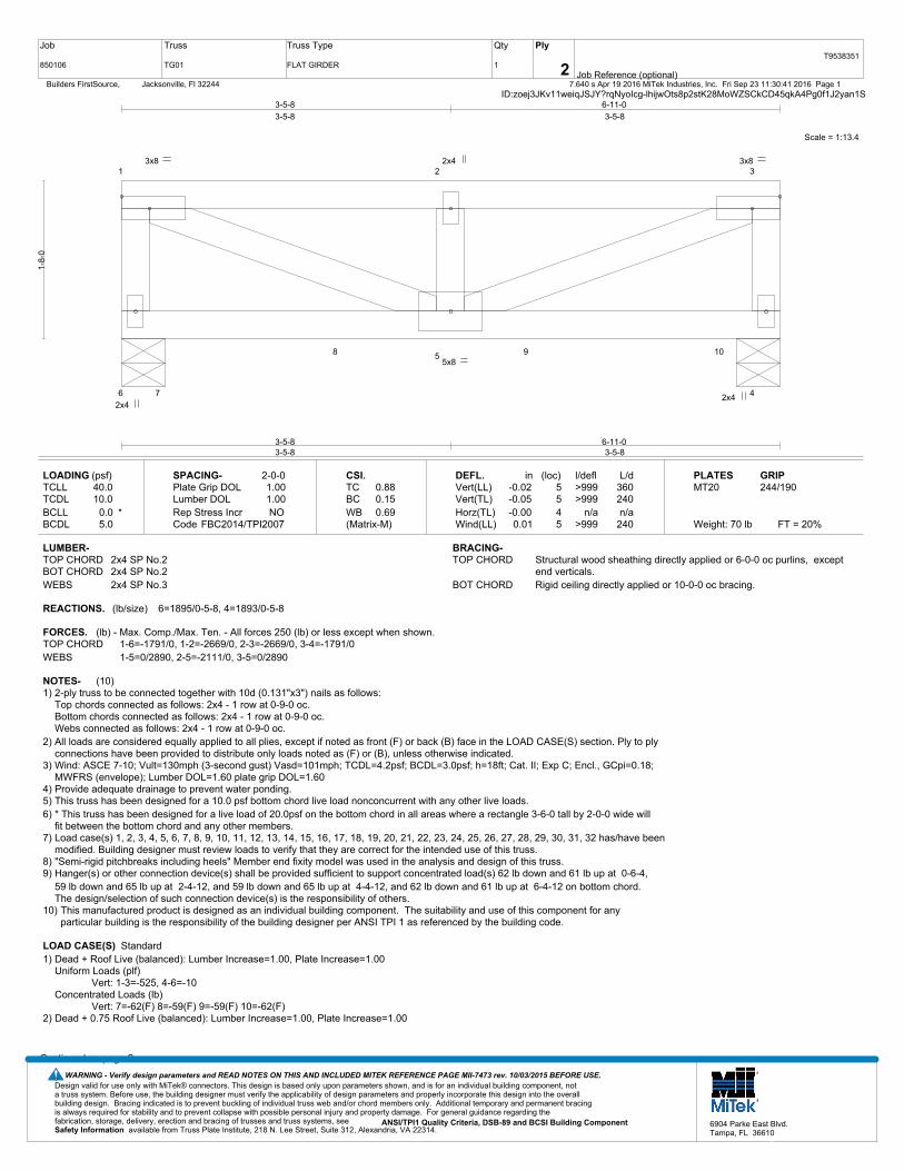
Job
850106
Truss
TG01
Truss Type
FLAT GIRDER
Qty
1
Ply
2 Job Reference (optional)
T9538351
7.640 s Apr 19 2016 MiTek Industries, Inc. Fri Sep 23 11:30:41 2016 Page 1 Builders FirstSource, Jacksonville, Fl 32244ID:zoej3JKv11weiqJSJY?rqNyoIcg-lhijwOts8p2stK28MoWZSCkCD45qkA4Pg0f1J2yan1S
Scale = 1:13.4
1 2 3
6
5
47
8 9 10
2x4 2x4
5x8
3x8 2x4 3x8
3-5-83-5-8
6-11-03-5-8
3-5-8
3-5-8
6-11-0
3-5-8
1-8-
0
LOADING (psf)TCLLTCDLBCLLBCDL
40.010.0
0.0 *5.0
SPACING-Plate Grip DOLLumber DOL Rep Stress IncrCode
2-0-01.001.00NO
FBC2014/TPI2007
CSI.TCBCWB(Matrix-M)
0.880.150.69
DEFL.Vert(LL)Vert(TL)Horz(TL)Wind(LL)
in-0.02-0.05-0.000.01
(loc)5545
l/defl>999>999
n/a>999
L/d360240n/a
240
PLATESMT20
Weight: 70 lb FT = 20%
GRIP244/190
LUMBER-TOP CHORD 2x4 SP No.2BOT CHORD 2x4 SP No.2WEBS 2x4 SP No.3
BRACING-TOP CHORD Structural wood sheathing directly applied or 6-0-0 oc purlins, except
end verticals.BOT CHORD Rigid ceiling directly applied or 10-0-0 oc bracing.
REACTIONS. (lb/size) 6=1895/0-5-8, 4=1893/0-5-8
FORCES. (lb) - Max. Comp./Max. Ten. - All forces 250 (lb) or less except when shown.TOP CHORD 1-6=-1791/0, 1-2=-2669/0, 2-3=-2669/0, 3-4=-1791/0WEBS 1-5=0/2890, 2-5=-2111/0, 3-5=0/2890
NOTES- (10)1) 2-ply truss to be connected together with 10d (0.131"x3") nails as follows:
Top chords connected as follows: 2x4 - 1 row at 0-9-0 oc.Bottom chords connected as follows: 2x4 - 1 row at 0-9-0 oc.Webs connected as follows: 2x4 - 1 row at 0-9-0 oc.
2) All loads are considered equally applied to all plies, except if noted as front (F) or back (B) face in the LOAD CASE(S) section. Ply to plyconnections have been provided to distribute only loads noted as (F) or (B), unless otherwise indicated.
3) Wind: ASCE 7-10; Vult=130mph (3-second gust) Vasd=101mph; TCDL=4.2psf; BCDL=3.0psf; h=18ft; Cat. II; Exp C; Encl., GCpi=0.18;MWFRS (envelope); Lumber DOL=1.60 plate grip DOL=1.60
4) Provide adequate drainage to prevent water ponding.5) This truss has been designed for a 10.0 psf bottom chord live load nonconcurrent with any other live loads.6) * This truss has been designed for a live load of 20.0psf on the bottom chord in all areas where a rectangle 3-6-0 tall by 2-0-0 wide will
fit between the bottom chord and any other members.7) Load case(s) 1, 2, 3, 4, 5, 6, 7, 8, 9, 10, 11, 12, 13, 14, 15, 16, 17, 18, 19, 20, 21, 22, 23, 24, 25, 26, 27, 28, 29, 30, 31, 32 has/have been
modified. Building designer must review loads to verify that they are correct for the intended use of this truss.8) "Semi-rigid pitchbreaks including heels" Member end fixity model was used in the analysis and design of this truss. 9) Hanger(s) or other connection device(s) shall be provided sufficient to support concentrated load(s) 62 lb down and 61 lb up at 0-6-4,
59 lb down and 65 lb up at 2-4-12, and 59 lb down and 65 lb up at 4-4-12, and 62 lb down and 61 lb up at 6-4-12 on bottom chord. The design/selection of such connection device(s) is the responsibility of others.
10) This manufactured product is designed as an individual building component. The suitability and use of this component for anyparticular building is the responsibility of the building designer per ANSI TPI 1 as referenced by the building code.
LOAD CASE(S) Standard1) Dead + Roof Live (balanced): Lumber Increase=1.00, Plate Increase=1.00
Uniform Loads (plf)Vert: 1-3=-525, 4-6=-10
Concentrated Loads (lb)Vert: 7=-62(F) 8=-59(F) 9=-59(F) 10=-62(F)
2) Dead + 0.75 Roof Live (balanced): Lumber Increase=1.00, Plate Increase=1.00
Continued on page 2
Design valid for use only with MiTek® connectors. This design is based only upon parameters shown, and is for an individual building component, not a truss system. Before use, the building designer must verify the applicability of design parameters and properly incorporate this design into the overall building design. Bracing indicated is to prevent buckling of individual truss web and/or chord members only. Additional temporary and permanent bracing is always required for stability and to prevent collapse with possible personal injury and property damage. For general guidance regarding the fabrication, storage, delivery, erection and bracing of trusses and truss systems, see ANSI/TPI1 Quality Criteria, DSB-89 and BCSI Building Component
available from Truss Plate Institute, 218 N. Lee Street, Suite 312, Alexandria, VA 22314.Safety Information
WARNING - Verify design parameters and READ NOTES ON THIS AND INCLUDED MITEK REFERENCE PAGE MII-7473 rev. 10/03/2015 BEFORE USE.
6904 Parke East Blvd.Tampa, FL 36610

Job
850106
Truss
TG01
Truss Type
FLAT GIRDER
Qty
1
Ply
2 Job Reference (optional)
T9538351
7.640 s Apr 19 2016 MiTek Industries, Inc. Fri Sep 23 11:30:41 2016 Page 2 Builders FirstSource, Jacksonville, Fl 32244ID:zoej3JKv11weiqJSJY?rqNyoIcg-lhijwOts8p2stK28MoWZSCkCD45qkA4Pg0f1J2yan1S
LOAD CASE(S) StandardUniform Loads (plf)
Vert: 1-3=-450, 4-6=-10Concentrated Loads (lb)
Vert: 7=-52(F) 8=-49(F) 9=-49(F) 10=-52(F)3) Dead + Uninhabitable Attic Without Storage: Lumber Increase=1.25, Plate Increase=1.25
Uniform Loads (plf)Vert: 1-3=-281, 4-6=-30
Concentrated Loads (lb)Vert: 7=-31(F) 8=-22(F) 9=-22(F) 10=-31(F)
4) Dead + 0.6 MWFRS Wind (Pos. Internal) Left: Lumber Increase=1.60, Plate Increase=1.60Uniform Loads (plf)
Vert: 1-3=-46, 4-6=-6Concentrated Loads (lb)
Vert: 7=59(F) 8=61(F) 9=61(F) 10=59(F)5) Dead + 0.6 MWFRS Wind (Pos. Internal) Right: Lumber Increase=1.60, Plate Increase=1.60
Uniform Loads (plf)Vert: 1-3=-46, 4-6=-6
Concentrated Loads (lb)Vert: 7=59(F) 8=61(F) 9=61(F) 10=59(F)
6) Dead + 0.6 MWFRS Wind (Neg. Internal) Left: Lumber Increase=1.60, Plate Increase=1.60Uniform Loads (plf)
Vert: 1-3=-226, 4-6=-10Concentrated Loads (lb)
Vert: 7=61(F) 8=65(F) 9=65(F) 10=61(F)7) Dead + 0.6 MWFRS Wind (Neg. Internal) Right: Lumber Increase=1.60, Plate Increase=1.60
Uniform Loads (plf)Vert: 1-3=-226, 4-6=-10
Concentrated Loads (lb)Vert: 7=61(F) 8=65(F) 9=65(F) 10=61(F)
8) Dead + 0.6 MWFRS Wind (Pos. Internal) 1st Parallel: Lumber Increase=1.60, Plate Increase=1.60Uniform Loads (plf)
Vert: 1-3=-46, 4-6=-6Concentrated Loads (lb)
Vert: 7=59(F) 8=61(F) 9=61(F) 10=59(F)9) Dead + 0.6 MWFRS Wind (Pos. Internal) 2nd Parallel: Lumber Increase=1.60, Plate Increase=1.60
Uniform Loads (plf)Vert: 1-3=-46, 4-6=-6
Concentrated Loads (lb)Vert: 7=59(F) 8=61(F) 9=61(F) 10=59(F)
10) Dead + 0.6 MWFRS Wind (Pos. Internal) 3rd Parallel: Lumber Increase=1.60, Plate Increase=1.60Uniform Loads (plf)
Vert: 1-3=-46, 4-6=-6Concentrated Loads (lb)
Vert: 7=59(F) 8=61(F) 9=61(F) 10=59(F)11) Dead + 0.6 MWFRS Wind (Pos. Internal) 4th Parallel: Lumber Increase=1.60, Plate Increase=1.60
Uniform Loads (plf)Vert: 1-3=-46, 4-6=-6
Concentrated Loads (lb)Vert: 7=59(F) 8=61(F) 9=61(F) 10=59(F)
12) Dead + 0.6 MWFRS Wind (Neg. Internal) 1st Parallel: Lumber Increase=1.60, Plate Increase=1.60Uniform Loads (plf)
Vert: 1-3=-226, 4-6=-10Concentrated Loads (lb)
Vert: 7=61(F) 8=65(F) 9=65(F) 10=61(F)13) Dead + 0.6 MWFRS Wind (Neg. Internal) 2nd Parallel: Lumber Increase=1.60, Plate Increase=1.60
Uniform Loads (plf)Vert: 1-3=-226, 4-6=-10
Concentrated Loads (lb)Vert: 7=61(F) 8=65(F) 9=65(F) 10=61(F)
14) Dead: Lumber Increase=0.90, Plate Increase=0.90 Plt. metal=0.90Uniform Loads (plf)
Vert: 1-3=-227, 4-6=-10Concentrated Loads (lb)
Vert: 7=-20(F) 8=-17(F) 9=-17(F) 10=-20(F)15) Dead + 0.75 Roof Live (bal.) + 0.75(0.6 MWFRS Wind (Neg. Int) Left): Lumber Increase=1.60, Plate Increase=1.60
Uniform Loads (plf)Vert: 1-3=-450, 4-6=-10
Concentrated Loads (lb)Vert: 7=44(F) 8=47(F) 9=47(F) 10=44(F)
16) Dead + 0.75 Roof Live (bal.) + 0.75(0.6 MWFRS Wind (Neg. Int) Right): Lumber Increase=1.60, Plate Increase=1.60Uniform Loads (plf)
Vert: 1-3=-450, 4-6=-10Concentrated Loads (lb)
Vert: 7=44(F) 8=47(F) 9=47(F) 10=44(F)
Continued on page 3
Design valid for use only with MiTek® connectors. This design is based only upon parameters shown, and is for an individual building component, not a truss system. Before use, the building designer must verify the applicability of design parameters and properly incorporate this design into the overall building design. Bracing indicated is to prevent buckling of individual truss web and/or chord members only. Additional temporary and permanent bracing is always required for stability and to prevent collapse with possible personal injury and property damage. For general guidance regarding the fabrication, storage, delivery, erection and bracing of trusses and truss systems, see ANSI/TPI1 Quality Criteria, DSB-89 and BCSI Building Component
available from Truss Plate Institute, 218 N. Lee Street, Suite 312, Alexandria, VA 22314.Safety Information
WARNING - Verify design parameters and READ NOTES ON THIS AND INCLUDED MITEK REFERENCE PAGE MII-7473 rev. 10/03/2015 BEFORE USE.
6904 Parke East Blvd.Tampa, FL 36610

Job
850106
Truss
TG01
Truss Type
FLAT GIRDER
Qty
1
Ply
2 Job Reference (optional)
T9538351
7.640 s Apr 19 2016 MiTek Industries, Inc. Fri Sep 23 11:30:41 2016 Page 3 Builders FirstSource, Jacksonville, Fl 32244ID:zoej3JKv11weiqJSJY?rqNyoIcg-lhijwOts8p2stK28MoWZSCkCD45qkA4Pg0f1J2yan1S
LOAD CASE(S) Standard17) Dead + 0.75 Roof Live (bal.) + 0.75(0.6 MWFRS Wind (Neg. Int) 1st Parallel): Lumber Increase=1.60, Plate Increase=1.60
Uniform Loads (plf)Vert: 1-3=-450, 4-6=-10
Concentrated Loads (lb)Vert: 7=44(F) 8=47(F) 9=47(F) 10=44(F)
18) Dead + 0.75 Roof Live (bal.) + 0.75(0.6 MWFRS Wind (Neg. Int) 2nd Parallel): Lumber Increase=1.60, Plate Increase=1.60Uniform Loads (plf)
Vert: 1-3=-450, 4-6=-10Concentrated Loads (lb)
Vert: 7=44(F) 8=47(F) 9=47(F) 10=44(F)19) Reversal: Dead + 0.6 MWFRS Wind (Pos. Internal) Left: Lumber Increase=1.60, Plate Increase=1.60
Uniform Loads (plf)Vert: 1-3=-46, 4-6=-6
Concentrated Loads (lb)Vert: 7=-20(F) 8=-18(F) 9=-18(F) 10=-20(F)
20) Reversal: Dead + 0.6 MWFRS Wind (Pos. Internal) Right: Lumber Increase=1.60, Plate Increase=1.60Uniform Loads (plf)
Vert: 1-3=-46, 4-6=-6Concentrated Loads (lb)
Vert: 7=-20(F) 8=-18(F) 9=-18(F) 10=-20(F)21) Reversal: Dead + 0.6 MWFRS Wind (Neg. Internal) Left: Lumber Increase=1.60, Plate Increase=1.60
Uniform Loads (plf)Vert: 1-3=-226, 4-6=-10
Concentrated Loads (lb)Vert: 7=-17(F) 8=-14(F) 9=-14(F) 10=-17(F)
22) Reversal: Dead + 0.6 MWFRS Wind (Neg. Internal) Right: Lumber Increase=1.60, Plate Increase=1.60Uniform Loads (plf)
Vert: 1-3=-226, 4-6=-10Concentrated Loads (lb)
Vert: 7=-17(F) 8=-14(F) 9=-14(F) 10=-17(F)23) Reversal: Dead + 0.6 MWFRS Wind (Pos. Internal) 1st Parallel: Lumber Increase=1.60, Plate Increase=1.60
Uniform Loads (plf)Vert: 1-3=-46, 4-6=-6
Concentrated Loads (lb)Vert: 7=-20(F) 8=-18(F) 9=-18(F) 10=-20(F)
24) Reversal: Dead + 0.6 MWFRS Wind (Pos. Internal) 2nd Parallel: Lumber Increase=1.60, Plate Increase=1.60Uniform Loads (plf)
Vert: 1-3=-46, 4-6=-6Concentrated Loads (lb)
Vert: 7=-20(F) 8=-18(F) 9=-18(F) 10=-20(F)25) Reversal: Dead + 0.6 MWFRS Wind (Pos. Internal) 3rd Parallel: Lumber Increase=1.60, Plate Increase=1.60
Uniform Loads (plf)Vert: 1-3=-46, 4-6=-6
Concentrated Loads (lb)Vert: 7=-20(F) 8=-18(F) 9=-18(F) 10=-20(F)
26) Reversal: Dead + 0.6 MWFRS Wind (Pos. Internal) 4th Parallel: Lumber Increase=1.60, Plate Increase=1.60Uniform Loads (plf)
Vert: 1-3=-46, 4-6=-6Concentrated Loads (lb)
Vert: 7=-20(F) 8=-18(F) 9=-18(F) 10=-20(F)27) Reversal: Dead + 0.6 MWFRS Wind (Neg. Internal) 1st Parallel: Lumber Increase=1.60, Plate Increase=1.60
Uniform Loads (plf)Vert: 1-3=-226, 4-6=-10
Concentrated Loads (lb)Vert: 7=-17(F) 8=-14(F) 9=-14(F) 10=-17(F)
28) Reversal: Dead + 0.6 MWFRS Wind (Neg. Internal) 2nd Parallel: Lumber Increase=1.60, Plate Increase=1.60Uniform Loads (plf)
Vert: 1-3=-226, 4-6=-10Concentrated Loads (lb)
Vert: 7=-17(F) 8=-14(F) 9=-14(F) 10=-17(F)29) Reversal: Dead + 0.75 Roof Live (bal.) + 0.75(0.6 MWFRS Wind (Neg. Int) Left): Lumber Increase=1.60, Plate Increase=1.60
Uniform Loads (plf)Vert: 1-3=-450, 4-6=-10
Concentrated Loads (lb)Vert: 7=-42(F) 8=-38(F) 9=-38(F) 10=-42(F)
30) Reversal: Dead + 0.75 Roof Live (bal.) + 0.75(0.6 MWFRS Wind (Neg. Int) Right): Lumber Increase=1.60, Plate Increase=1.60Uniform Loads (plf)
Vert: 1-3=-450, 4-6=-10Concentrated Loads (lb)
Vert: 7=-42(F) 8=-38(F) 9=-38(F) 10=-42(F)31) Reversal: Dead + 0.75 Roof Live (bal.) + 0.75(0.6 MWFRS Wind (Neg. Int) 1st Parallel): Lumber Increase=1.60, Plate Increase=1.60
Uniform Loads (plf)Vert: 1-3=-450, 4-6=-10
Concentrated Loads (lb)Vert: 7=-42(F) 8=-38(F) 9=-38(F) 10=-42(F)
Continued on page 4
Design valid for use only with MiTek® connectors. This design is based only upon parameters shown, and is for an individual building component, not a truss system. Before use, the building designer must verify the applicability of design parameters and properly incorporate this design into the overall building design. Bracing indicated is to prevent buckling of individual truss web and/or chord members only. Additional temporary and permanent bracing is always required for stability and to prevent collapse with possible personal injury and property damage. For general guidance regarding the fabrication, storage, delivery, erection and bracing of trusses and truss systems, see ANSI/TPI1 Quality Criteria, DSB-89 and BCSI Building Component
available from Truss Plate Institute, 218 N. Lee Street, Suite 312, Alexandria, VA 22314.Safety Information
WARNING - Verify design parameters and READ NOTES ON THIS AND INCLUDED MITEK REFERENCE PAGE MII-7473 rev. 10/03/2015 BEFORE USE.
6904 Parke East Blvd.Tampa, FL 36610

Job
850106
Truss
TG01
Truss Type
FLAT GIRDER
Qty
1
Ply
2 Job Reference (optional)
T9538351
7.640 s Apr 19 2016 MiTek Industries, Inc. Fri Sep 23 11:30:41 2016 Page 4 Builders FirstSource, Jacksonville, Fl 32244ID:zoej3JKv11weiqJSJY?rqNyoIcg-lhijwOts8p2stK28MoWZSCkCD45qkA4Pg0f1J2yan1S
LOAD CASE(S) Standard32) Reversal: Dead + 0.75 Roof Live (bal.) + 0.75(0.6 MWFRS Wind (Neg. Int) 2nd Parallel): Lumber Increase=1.60, Plate Increase=1.60
Uniform Loads (plf)Vert: 1-3=-450, 4-6=-10
Concentrated Loads (lb)Vert: 7=-42(F) 8=-38(F) 9=-38(F) 10=-42(F)
Design valid for use only with MiTek® connectors. This design is based only upon parameters shown, and is for an individual building component, not a truss system. Before use, the building designer must verify the applicability of design parameters and properly incorporate this design into the overall building design. Bracing indicated is to prevent buckling of individual truss web and/or chord members only. Additional temporary and permanent bracing is always required for stability and to prevent collapse with possible personal injury and property damage. For general guidance regarding the fabrication, storage, delivery, erection and bracing of trusses and truss systems, see ANSI/TPI1 Quality Criteria, DSB-89 and BCSI Building Component
available from Truss Plate Institute, 218 N. Lee Street, Suite 312, Alexandria, VA 22314.Safety Information
WARNING - Verify design parameters and READ NOTES ON THIS AND INCLUDED MITEK REFERENCE PAGE MII-7473 rev. 10/03/2015 BEFORE USE.
6904 Parke East Blvd.Tampa, FL 36610

Job
850106
Truss
TG02
Truss Type
FLAT GIRDER
Qty
1
Ply
2 Job Reference (optional)
T9538352
7.640 s Apr 19 2016 MiTek Industries, Inc. Fri Sep 23 11:30:42 2016 Page 1 Builders FirstSource, Jacksonville, Fl 32244ID:zoej3JKv11weiqJSJY?rqNyoIcg-DtG57kuUv6AjVUdLvV1o_QHXETLZTePYvgParUyan1R
Scale = 1:26.7
1 2 3 4 5 6 7
14
13 12 11 10 9
815 16 17 18 19 20
2x4
3x8
2x4 5x8
2x4 3x8
2x4 3x8
2x4
2x4
3x8 2x4
5x8
3x8
2-8-12-8-1
5-2-72-6-5
7-8-122-6-5
10-3-12-6-5
12-9-72-6-5
15-5-82-8-1
2-8-1
2-8-1
5-2-7
2-6-5
7-8-12
2-6-5
10-3-1
2-6-5
12-9-7
2-6-5
15-5-8
2-8-1
1-8-
0
LOADING (psf)TCLLTCDLBCLLBCDL
40.010.0
0.0 *5.0
SPACING-Plate Grip DOLLumber DOL Rep Stress IncrCode
2-0-01.001.00NO
FBC2014/TPI2007
CSI.TCBCWB(Matrix-M)
0.220.560.62
DEFL.Vert(LL)Vert(TL)Horz(TL)Wind(LL)
in-0.10-0.160.020.02
(loc)11118
11
l/defl>999>999
n/a>999
L/d360240n/a
240
PLATESMT20
Weight: 180 lb FT = 20%
GRIP244/190
LUMBER-TOP CHORD 2x4 SP No.2BOT CHORD 2x6 SP No.2WEBS 2x4 SP No.3
BRACING-TOP CHORD Structural wood sheathing directly applied or 5-11-3 oc purlins, except
end verticals.BOT CHORD Rigid ceiling directly applied or 10-0-0 oc bracing.
REACTIONS. (lb/size) 14=1058/0-5-8, 8=1086/0-5-8Max Uplift14=-148(LC 4), 8=-148(LC 4)Max Grav 14=1421(LC 2), 8=1511(LC 2)
FORCES. (lb) - Max. Comp./Max. Ten. - All forces 250 (lb) or less except when shown.TOP CHORD 1-14=-1290/143, 1-2=-2383/231, 2-3=-2383/231, 3-4=-4317/417, 4-5=-4317/417,
5-6=-2423/231, 6-7=-2423/231, 7-8=-1307/143BOT CHORD 13-16=-383/3944, 12-16=-383/3944, 12-17=-383/3944, 11-17=-383/3944,
11-18=-383/3962, 10-18=-383/3962, 10-19=-383/3962, 9-19=-383/3962WEBS 1-13=-246/2565, 3-13=-1753/170, 3-12=0/429, 3-11=-38/419, 5-11=-38/399, 5-10=0/425,
5-9=-1728/170, 7-9=-246/2600
NOTES- (11)1) 2-ply truss to be connected together with 10d (0.131"x3") nails as follows:
Top chords connected as follows: 2x4 - 1 row at 0-9-0 oc.Bottom chords connected as follows: 2x6 - 2 rows staggered at 0-9-0 oc.Webs connected as follows: 2x4 - 1 row at 0-9-0 oc.
2) All loads are considered equally applied to all plies, except if noted as front (F) or back (B) face in the LOAD CASE(S) section. Ply to plyconnections have been provided to distribute only loads noted as (F) or (B), unless otherwise indicated.
3) Wind: ASCE 7-10; Vult=130mph (3-second gust) Vasd=101mph; TCDL=4.2psf; BCDL=3.0psf; h=18ft; Cat. II; Exp C; Encl., GCpi=0.18;MWFRS (envelope); Lumber DOL=1.60 plate grip DOL=1.60
4) Provide adequate drainage to prevent water ponding.5) Concentrated loads from layout are not present in Load Case(s): #3 Dead + Uninhabitable Attic Without Storage; #4 Dead + 0.6
MWFRS Wind (Pos. Internal) Left; #5 Dead + 0.6 MWFRS Wind (Pos. Internal) Right; #6 Dead + 0.6 MWFRS Wind (Neg. Internal) Left;#7 Dead + 0.6 MWFRS Wind (Neg. Internal) Right; #8 Dead + 0.6 MWFRS Wind (Pos. Internal) 1st Parallel; #9 Dead + 0.6 MWFRSWind (Pos. Internal) 2nd Parallel; #10 Dead + 0.6 MWFRS Wind (Pos. Internal) 3rd Parallel; #11 Dead + 0.6 MWFRS Wind (Pos.Internal) 4th Parallel; #12 Dead + 0.6 MWFRS Wind (Neg. Internal) 1st Parallel; #13 Dead + 0.6 MWFRS Wind (Neg. Internal) 2ndParallel; #18 Dead + 0.75 Roof Live (bal.) + 0.75(0.6 MWFRS Wind (Neg. Int) Left); #19 Dead + 0.75 Roof Live (bal.) + 0.75(0.6MWFRS Wind (Neg. Int) Right); #20 Dead + 0.75 Roof Live (bal.) + 0.75(0.6 MWFRS Wind (Neg. Int) 1st Parallel); #21 Dead + 0.75Roof Live (bal.) + 0.75(0.6 MWFRS Wind (Neg. Int) 2nd Parallel).
6) This truss has been designed for a 10.0 psf bottom chord live load nonconcurrent with any other live loads.7) * This truss has been designed for a live load of 20.0psf on the bottom chord in all areas where a rectangle 3-6-0 tall by 2-0-0 wide will
fit between the bottom chord and any other members.8) Provide mechanical connection (by others) of truss to bearing plate capable of withstanding 100 lb uplift at joint(s) except (jt=lb) 14=148,
8=148.9) "Semi-rigid pitchbreaks including heels" Member end fixity model was used in the analysis and design of this truss.
Continued on page 2
Design valid for use only with MiTek® connectors. This design is based only upon parameters shown, and is for an individual building component, not a truss system. Before use, the building designer must verify the applicability of design parameters and properly incorporate this design into the overall building design. Bracing indicated is to prevent buckling of individual truss web and/or chord members only. Additional temporary and permanent bracing is always required for stability and to prevent collapse with possible personal injury and property damage. For general guidance regarding the fabrication, storage, delivery, erection and bracing of trusses and truss systems, see ANSI/TPI1 Quality Criteria, DSB-89 and BCSI Building Component
available from Truss Plate Institute, 218 N. Lee Street, Suite 312, Alexandria, VA 22314.Safety Information
WARNING - Verify design parameters and READ NOTES ON THIS AND INCLUDED MITEK REFERENCE PAGE MII-7473 rev. 10/03/2015 BEFORE USE.
6904 Parke East Blvd.Tampa, FL 36610

Job
850106
Truss
TG02
Truss Type
FLAT GIRDER
Qty
1
Ply
2 Job Reference (optional)
T9538352
7.640 s Apr 19 2016 MiTek Industries, Inc. Fri Sep 23 11:30:42 2016 Page 2 Builders FirstSource, Jacksonville, Fl 32244ID:zoej3JKv11weiqJSJY?rqNyoIcg-DtG57kuUv6AjVUdLvV1o_QHXETLZTePYvgParUyan1R
NOTES- (11)10) Hanger(s) or other connection device(s) shall be provided sufficient to support concentrated load(s) 276 lb down at 2-1-12, 276 lb down at 4-1-12, 276 lb down at 6-1-12, 276
lb down at 8-1-12, 276 lb down at 10-1-12, and 276 lb down at 12-1-12, and 276 lb down at 14-1-12 on bottom chord. The design/selection of such connection device(s) isthe responsibility of others.
11) This manufactured product is designed as an individual building component. The suitability and use of this component for any particular building is the responsibility of thebuilding designer per ANSI TPI 1 as referenced by the building code.
LOAD CASE(S) Standard1) Dead + Roof Live (balanced): Lumber Increase=1.00, Plate Increase=1.00
Uniform Loads (plf)Vert: 1-7=-100, 8-14=-10
Concentrated Loads (lb)Vert: 10=-68(F) 15=-68(F) 16=-68(F) 17=-68(F) 18=-68(F) 19=-68(F) 20=-68(F)
Design valid for use only with MiTek® connectors. This design is based only upon parameters shown, and is for an individual building component, not a truss system. Before use, the building designer must verify the applicability of design parameters and properly incorporate this design into the overall building design. Bracing indicated is to prevent buckling of individual truss web and/or chord members only. Additional temporary and permanent bracing is always required for stability and to prevent collapse with possible personal injury and property damage. For general guidance regarding the fabrication, storage, delivery, erection and bracing of trusses and truss systems, see ANSI/TPI1 Quality Criteria, DSB-89 and BCSI Building Component
available from Truss Plate Institute, 218 N. Lee Street, Suite 312, Alexandria, VA 22314.Safety Information
WARNING - Verify design parameters and READ NOTES ON THIS AND INCLUDED MITEK REFERENCE PAGE MII-7473 rev. 10/03/2015 BEFORE USE.
6904 Parke East Blvd.Tampa, FL 36610
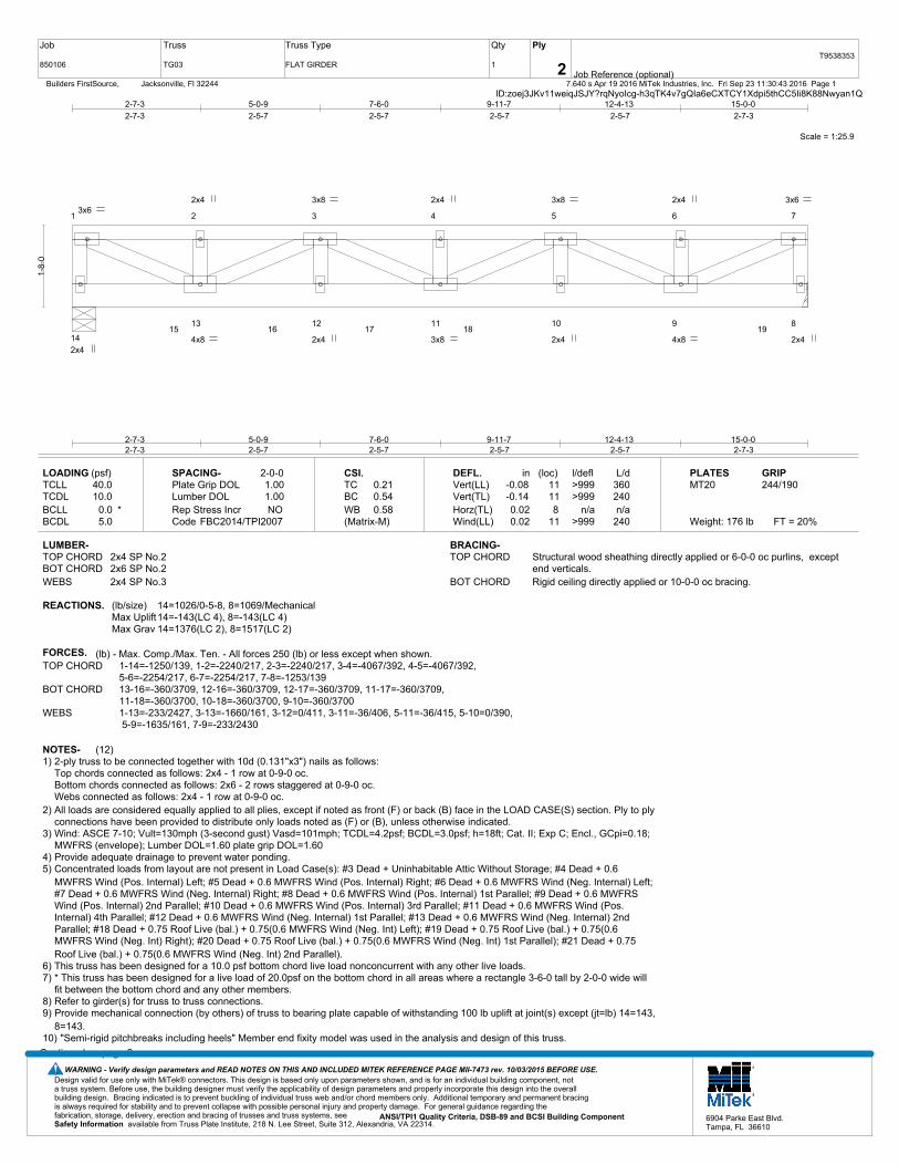
Job
850106
Truss
TG03
Truss Type
FLAT GIRDER
Qty
1
Ply
2 Job Reference (optional)
T9538353
7.640 s Apr 19 2016 MiTek Industries, Inc. Fri Sep 23 11:30:43 2016 Page 1 Builders FirstSource, Jacksonville, Fl 32244ID:zoej3JKv11weiqJSJY?rqNyoIcg-h3qTK4v7gQIa6eCXTCY1Xdpi5thCC5Ii8K88Nwyan1Q
Scale = 1:25.9
1 2 3 4 5 6 7
14
13 12 11 10 9 815 16 17 18 19
2x4
3x6
2x4 4x8
2x4 3x8
2x4 3x8
2x4
2x4
3x8 2x4
4x8
3x6
2-7-32-7-3
5-0-92-5-7
7-6-02-5-7
9-11-72-5-7
12-4-132-5-7
15-0-02-7-3
2-7-3
2-7-3
5-0-9
2-5-7
7-6-0
2-5-7
9-11-7
2-5-7
12-4-13
2-5-7
15-0-0
2-7-3
1-8-
0
LOADING (psf)TCLLTCDLBCLLBCDL
40.010.0
0.0 *5.0
SPACING-Plate Grip DOLLumber DOL Rep Stress IncrCode
2-0-01.001.00NO
FBC2014/TPI2007
CSI.TCBCWB(Matrix-M)
0.210.540.58
DEFL.Vert(LL)Vert(TL)Horz(TL)Wind(LL)
in-0.08-0.140.020.02
(loc)11118
11
l/defl>999>999
n/a>999
L/d360240n/a
240
PLATESMT20
Weight: 176 lb FT = 20%
GRIP244/190
LUMBER-TOP CHORD 2x4 SP No.2BOT CHORD 2x6 SP No.2WEBS 2x4 SP No.3
BRACING-TOP CHORD Structural wood sheathing directly applied or 6-0-0 oc purlins, except
end verticals.BOT CHORD Rigid ceiling directly applied or 10-0-0 oc bracing.
REACTIONS. (lb/size) 14=1026/0-5-8, 8=1069/MechanicalMax Uplift14=-143(LC 4), 8=-143(LC 4)Max Grav 14=1376(LC 2), 8=1517(LC 2)
FORCES. (lb) - Max. Comp./Max. Ten. - All forces 250 (lb) or less except when shown.TOP CHORD 1-14=-1250/139, 1-2=-2240/217, 2-3=-2240/217, 3-4=-4067/392, 4-5=-4067/392,
5-6=-2254/217, 6-7=-2254/217, 7-8=-1253/139BOT CHORD 13-16=-360/3709, 12-16=-360/3709, 12-17=-360/3709, 11-17=-360/3709,
11-18=-360/3700, 10-18=-360/3700, 9-10=-360/3700WEBS 1-13=-233/2427, 3-13=-1660/161, 3-12=0/411, 3-11=-36/406, 5-11=-36/415, 5-10=0/390,
5-9=-1635/161, 7-9=-233/2430
NOTES- (12)1) 2-ply truss to be connected together with 10d (0.131"x3") nails as follows:
Top chords connected as follows: 2x4 - 1 row at 0-9-0 oc.Bottom chords connected as follows: 2x6 - 2 rows staggered at 0-9-0 oc.Webs connected as follows: 2x4 - 1 row at 0-9-0 oc.
2) All loads are considered equally applied to all plies, except if noted as front (F) or back (B) face in the LOAD CASE(S) section. Ply to plyconnections have been provided to distribute only loads noted as (F) or (B), unless otherwise indicated.
3) Wind: ASCE 7-10; Vult=130mph (3-second gust) Vasd=101mph; TCDL=4.2psf; BCDL=3.0psf; h=18ft; Cat. II; Exp C; Encl., GCpi=0.18;MWFRS (envelope); Lumber DOL=1.60 plate grip DOL=1.60
4) Provide adequate drainage to prevent water ponding.5) Concentrated loads from layout are not present in Load Case(s): #3 Dead + Uninhabitable Attic Without Storage; #4 Dead + 0.6
MWFRS Wind (Pos. Internal) Left; #5 Dead + 0.6 MWFRS Wind (Pos. Internal) Right; #6 Dead + 0.6 MWFRS Wind (Neg. Internal) Left;#7 Dead + 0.6 MWFRS Wind (Neg. Internal) Right; #8 Dead + 0.6 MWFRS Wind (Pos. Internal) 1st Parallel; #9 Dead + 0.6 MWFRSWind (Pos. Internal) 2nd Parallel; #10 Dead + 0.6 MWFRS Wind (Pos. Internal) 3rd Parallel; #11 Dead + 0.6 MWFRS Wind (Pos.Internal) 4th Parallel; #12 Dead + 0.6 MWFRS Wind (Neg. Internal) 1st Parallel; #13 Dead + 0.6 MWFRS Wind (Neg. Internal) 2ndParallel; #18 Dead + 0.75 Roof Live (bal.) + 0.75(0.6 MWFRS Wind (Neg. Int) Left); #19 Dead + 0.75 Roof Live (bal.) + 0.75(0.6MWFRS Wind (Neg. Int) Right); #20 Dead + 0.75 Roof Live (bal.) + 0.75(0.6 MWFRS Wind (Neg. Int) 1st Parallel); #21 Dead + 0.75Roof Live (bal.) + 0.75(0.6 MWFRS Wind (Neg. Int) 2nd Parallel).
6) This truss has been designed for a 10.0 psf bottom chord live load nonconcurrent with any other live loads.7) * This truss has been designed for a live load of 20.0psf on the bottom chord in all areas where a rectangle 3-6-0 tall by 2-0-0 wide will
fit between the bottom chord and any other members.8) Refer to girder(s) for truss to truss connections.9) Provide mechanical connection (by others) of truss to bearing plate capable of withstanding 100 lb uplift at joint(s) except (jt=lb) 14=143,
8=143.10) "Semi-rigid pitchbreaks including heels" Member end fixity model was used in the analysis and design of this truss.
Continued on page 2
Design valid for use only with MiTek® connectors. This design is based only upon parameters shown, and is for an individual building component, not a truss system. Before use, the building designer must verify the applicability of design parameters and properly incorporate this design into the overall building design. Bracing indicated is to prevent buckling of individual truss web and/or chord members only. Additional temporary and permanent bracing is always required for stability and to prevent collapse with possible personal injury and property damage. For general guidance regarding the fabrication, storage, delivery, erection and bracing of trusses and truss systems, see ANSI/TPI1 Quality Criteria, DSB-89 and BCSI Building Component
available from Truss Plate Institute, 218 N. Lee Street, Suite 312, Alexandria, VA 22314.Safety Information
WARNING - Verify design parameters and READ NOTES ON THIS AND INCLUDED MITEK REFERENCE PAGE MII-7473 rev. 10/03/2015 BEFORE USE.
6904 Parke East Blvd.Tampa, FL 36610

Job
850106
Truss
TG03
Truss Type
FLAT GIRDER
Qty
1
Ply
2 Job Reference (optional)
T9538353
7.640 s Apr 19 2016 MiTek Industries, Inc. Fri Sep 23 11:30:43 2016 Page 2 Builders FirstSource, Jacksonville, Fl 32244ID:zoej3JKv11weiqJSJY?rqNyoIcg-h3qTK4v7gQIa6eCXTCY1Xdpi5thCC5Ii8K88Nwyan1Q
NOTES- (12)11) Hanger(s) or other connection device(s) shall be provided sufficient to support concentrated load(s) 276 lb down at 2-1-12, 276 lb down at 4-1-12, 276 lb down at 6-1-12, 276
lb down at 8-1-12, 276 lb down at 10-1-12, and 276 lb down at 12-1-12, and 277 lb down at 14-1-12 on bottom chord. The design/selection of such connection device(s) isthe responsibility of others.
12) This manufactured product is designed as an individual building component. The suitability and use of this component for any particular building is the responsibility of thebuilding designer per ANSI TPI 1 as referenced by the building code.
LOAD CASE(S) Standard1) Dead + Roof Live (balanced): Lumber Increase=1.00, Plate Increase=1.00
Uniform Loads (plf)Vert: 1-7=-100, 8-14=-10
Concentrated Loads (lb)Vert: 10=-68(B) 9=-68(B) 15=-68(B) 16=-68(B) 17=-68(B) 18=-68(B) 19=-69(B)
Design valid for use only with MiTek® connectors. This design is based only upon parameters shown, and is for an individual building component, not a truss system. Before use, the building designer must verify the applicability of design parameters and properly incorporate this design into the overall building design. Bracing indicated is to prevent buckling of individual truss web and/or chord members only. Additional temporary and permanent bracing is always required for stability and to prevent collapse with possible personal injury and property damage. For general guidance regarding the fabrication, storage, delivery, erection and bracing of trusses and truss systems, see ANSI/TPI1 Quality Criteria, DSB-89 and BCSI Building Component
available from Truss Plate Institute, 218 N. Lee Street, Suite 312, Alexandria, VA 22314.Safety Information
WARNING - Verify design parameters and READ NOTES ON THIS AND INCLUDED MITEK REFERENCE PAGE MII-7473 rev. 10/03/2015 BEFORE USE.
6904 Parke East Blvd.Tampa, FL 36610

Job
850106
Truss
TG04
Truss Type
FLAT GIRDER
Qty
1
Ply
2 Job Reference (optional)
T9538354
7.640 s Apr 19 2016 MiTek Industries, Inc. Fri Sep 23 11:30:44 2016 Page 1 Builders FirstSource, Jacksonville, Fl 32244ID:zoej3JKv11weiqJSJY?rqNyoIcg-9GOrYQvlRkQQkonj1w4G4rMiwHyFxYPrN_uhwMyan1P
Scale = 1:34.3
1 2 3 4 5 6 7 8
1615 14 13 12 11 10 9
176x8
4x6
4x8
2x4 3x8
5x6 3x8
2x4
2x4
3x8 5x6
3x8 2x4
4x8
2x4 4x8
2-10-132-10-13
5-7-142-9-1
8-4-152-9-1
11-1-152-9-1
13-11-02-9-1
16-8-12-9-1
19-6-142-10-13
2-10-13
2-10-13
5-7-14
2-9-1
8-4-15
2-9-1
11-1-15
2-9-1
13-11-0
2-9-1
16-8-1
2-9-1
19-6-14
2-10-13
1-8-
0
1-8-
0
Plate Offsets (X,Y)-- [6:0-3-0,0-3-0], [8:Edge,0-3-8], [9:0-4-8,0-2-0], [14:0-3-0,0-3-0]
LOADING (psf)TCLLTCDLBCLLBCDL
40.010.0
0.0 *5.0
SPACING-Plate Grip DOLLumber DOL Rep Stress IncrCode
2-0-01.001.00NO
FBC2014/TPI2007
CSI.TCBCWB(Matrix-M)
0.850.870.59
DEFL.Vert(LL)Vert(TL)Horz(TL)Wind(LL)
in-0.21-0.330.070.11
(loc)12-1312-13
912
l/defl>999>693
n/a>999
L/d360240n/a
240
PLATESMT20
Weight: 198 lb FT = 20%
GRIP244/190
LUMBER-TOP CHORD 2x4 SP No.2BOT CHORD 2x4 SP No.2WEBS 2x4 SP No.3OTHERS 2x4 SP No.3
BRACING-TOP CHORD Structural wood sheathing directly applied or 3-7-9 oc purlins.BOT CHORD Rigid ceiling directly applied or 9-9-13 oc bracing.
REACTIONS. (lb/size) 16=1282/0-5-0, 9=8445/MechanicalMax Uplift16=-227(LC 8), 9=-1495(LC 8)
FORCES. (lb) - Max. Comp./Max. Ten. - All forces 250 (lb) or less except when shown.TOP CHORD 1-16=-1243/411, 1-2=-2266/730, 2-3=-2266/730, 3-4=-4947/1593, 4-5=-4947/1593,
5-6=-5310/1710, 6-17=-5309/1710, 7-17=-5309/1710, 8-9=-6383/2067BOT CHORD 14-15=-1259/3910, 13-14=-1259/3910, 12-13=-1728/5364, 11-12=-1728/5364,
10-11=-1306/4055, 9-10=-1306/4055WEBS 1-15=-793/2462, 2-15=-276/117, 3-15=-1837/592, 3-13=-373/1159, 4-13=-287/118,
5-13=-465/150, 6-11=-558/204, 7-11=-451/1401, 7-9=-4471/1440
NOTES- (14)1) Ply to ply nailing inadequate2) 2-ply truss to be connected together with 10d (0.131"x3") nails as follows:
Top chords connected as follows: 2x4 - 1 row at 0-9-0 oc.Bottom chords connected as follows: 2x4 - 1 row at 0-9-0 oc.Webs connected as follows: 2x4 - 1 row at 0-9-0 oc.
3) All loads are considered equally applied to all plies, except if noted as front (F) or back (B) face in the LOAD CASE(S) section. Ply to plyconnections have been provided to distribute only loads noted as (F) or (B), unless otherwise indicated.
4) Wind: ASCE 7-10; Vult=130mph (3-second gust) Vasd=101mph; TCDL=4.2psf; BCDL=3.0psf; h=18ft; Cat. II; Exp C; Encl., GCpi=0.18;MWFRS (envelope) and C-C Exterior(2) zone;C-C for members and forces & MWFRS for reactions shown; Lumber DOL=1.60 plategrip DOL=1.60
5) Provide adequate drainage to prevent water ponding.6) This truss has been designed for a 10.0 psf bottom chord live load nonconcurrent with any other live loads.7) * This truss has been designed for a live load of 20.0psf on the bottom chord in all areas where a rectangle 3-6-0 tall by 2-0-0 wide will
fit between the bottom chord and any other members.8) Refer to girder(s) for truss to truss connections.9) Bearing at joint(s) 16 considers parallel to grain value using ANSI/TPI 1 angle to grain formula. Building designer should verify capacity
of bearing surface.10) Provide metal plate or equivalent at bearing(s) 9 to support reaction shown.11) Provide mechanical connection (by others) of truss to bearing plate capable of withstanding 100 lb uplift at joint(s) except (jt=lb)
16=227, 9=1495.12) "Semi-rigid pitchbreaks including heels" Member end fixity model was used in the analysis and design of this truss. 13) Hanger(s) or other connection device(s) shall be provided sufficient to support concentrated load(s) 1280 lb down and 412 lb up at
16-1-0, and 6327 lb down and 2038 lb up at 19-5-2 on top chord. The design/selection of such connection device(s) is theresponsibility of others.Continued on page 2
Design valid for use only with MiTek® connectors. This design is based only upon parameters shown, and is for an individual building component, not a truss system. Before use, the building designer must verify the applicability of design parameters and properly incorporate this design into the overall building design. Bracing indicated is to prevent buckling of individual truss web and/or chord members only. Additional temporary and permanent bracing is always required for stability and to prevent collapse with possible personal injury and property damage. For general guidance regarding the fabrication, storage, delivery, erection and bracing of trusses and truss systems, see ANSI/TPI1 Quality Criteria, DSB-89 and BCSI Building Component
available from Truss Plate Institute, 218 N. Lee Street, Suite 312, Alexandria, VA 22314.Safety Information
WARNING - Verify design parameters and READ NOTES ON THIS AND INCLUDED MITEK REFERENCE PAGE MII-7473 rev. 10/03/2015 BEFORE USE.
6904 Parke East Blvd.Tampa, FL 36610

Job
850106
Truss
TG04
Truss Type
FLAT GIRDER
Qty
1
Ply
2 Job Reference (optional)
T9538354
7.640 s Apr 19 2016 MiTek Industries, Inc. Fri Sep 23 11:30:44 2016 Page 2 Builders FirstSource, Jacksonville, Fl 32244ID:zoej3JKv11weiqJSJY?rqNyoIcg-9GOrYQvlRkQQkonj1w4G4rMiwHyFxYPrN_uhwMyan1P
14) This manufactured product is designed as an individual building component. The suitability and use of this component for any particular building is the responsibility of thebuilding designer per ANSI TPI 1 as referenced by the building code.
LOAD CASE(S) Standard1) Dead + Roof Live (balanced): Lumber Increase=1.00, Plate Increase=1.00
Uniform Loads (plf)Vert: 1-8=-100, 9-16=-10
Concentrated Loads (lb)Vert: 8=-6327 17=-1280
Design valid for use only with MiTek® connectors. This design is based only upon parameters shown, and is for an individual building component, not a truss system. Before use, the building designer must verify the applicability of design parameters and properly incorporate this design into the overall building design. Bracing indicated is to prevent buckling of individual truss web and/or chord members only. Additional temporary and permanent bracing is always required for stability and to prevent collapse with possible personal injury and property damage. For general guidance regarding the fabrication, storage, delivery, erection and bracing of trusses and truss systems, see ANSI/TPI1 Quality Criteria, DSB-89 and BCSI Building Component
available from Truss Plate Institute, 218 N. Lee Street, Suite 312, Alexandria, VA 22314.Safety Information
WARNING - Verify design parameters and READ NOTES ON THIS AND INCLUDED MITEK REFERENCE PAGE MII-7473 rev. 10/03/2015 BEFORE USE.
6904 Parke East Blvd.Tampa, FL 36610

Job
850106
Truss
TG05
Truss Type
FLAT GIRDER
Qty
1
Ply
3 Job Reference (optional)
T9538355
7.640 s Apr 19 2016 MiTek Industries, Inc. Fri Sep 23 11:30:45 2016 Page 1 Builders FirstSource, Jacksonville, Fl 32244ID:zoej3JKv11weiqJSJY?rqNyoIcg-dSyElmwNC1YHMxMwbdbVc2uv_hJHgvR_bedFSpyan1O
Scale = 1:31.4
1 2 3 4 5 6 7 8 9
1817 16 15 14 13 12 11
1019 20 21 22 23 24 25 26
4x10 MT20HS
5x12 5x8
3x6 10x16 MT20HS
2x4 12x20
10x16 MT20HS
2x4
2x6
3x10 2x4
4x12
6x10
2x6
2x4
8x12
2-4-02-4-0
4-4-82-0-8
6-6-102-2-2
8-8-122-2-2
10-10-142-2-2
13-1-02-2-2
15-1-82-0-8
17-5-82-4-0
2-4-0
2-4-0
4-4-8
2-0-8
6-6-10
2-2-2
8-8-12
2-2-2
10-10-14
2-2-2
13-1-0
2-2-2
15-1-8
2-0-8
17-5-8
2-4-0
1-8-
0
Plate Offsets (X,Y)-- [3:0-3-8,Edge], [15:0-8-0,0-6-12], [17:0-8-0,0-5-8]
LOADING (psf)TCLLTCDLBCLLBCDL
40.010.0
0.0 *5.0
SPACING-Plate Grip DOLLumber DOL Rep Stress IncrCode
2-0-01.001.00NO
FBC2014/TPI2007
CSI.TCBCWB(Matrix-M)
0.760.750.98
DEFL.Vert(LL)Vert(TL)Horz(TL)Wind(LL)
in-0.31-0.540.060.10
(loc)14-1514-15
1015
l/defl>660>380
n/a>999
L/d360240n/a
240
PLATESMT20MT20HS
Weight: 344 lb FT = 20%
GRIP244/190187/143
LUMBER-TOP CHORD 2x4 SP No.2 *Except*
1-7: 2x4 SP M 31BOT CHORD 2x8 SP 2400F 2.0EWEBS 2x4 SP No.3 *Except*
1-18,9-10,3-17: 2x4 SP No.2, 1-17,5-15,5-13,7-13,9-11: 2x4 SP No.13-16: 2x8 SP 2400F 2.0E
BRACING-TOP CHORD Structural wood sheathing directly applied or 4-4-1 oc purlins, except
end verticals.BOT CHORD Rigid ceiling directly applied or 10-0-0 oc bracing.
REACTIONS. (lb/size) 18=9894/0-5-8, 10=5259/0-5-8Max Uplift18=-1607(LC 4), 10=-693(LC 4)Max Grav 18=9998(LC 2), 10=7467(LC 2)
FORCES. (lb) - Max. Comp./Max. Ten. - All forces 250 (lb) or less except when shown.TOP CHORD 1-18=-7845/1222, 1-2=-14136/2183, 2-3=-14136/2183, 3-4=-25899/3559,
4-5=-25899/3559, 5-6=-20787/2297, 6-7=-20787/2297, 7-8=-8593/821, 8-9=-8593/821, 9-10=-4792/474
BOT CHORD 18-19=-93/588, 17-19=-93/588, 17-20=-3970/25843, 16-20=-3970/25843, 16-21=-3970/25843, 15-21=-3970/25843, 15-22=-3135/25698, 14-22=-3135/25698, 14-23=-3135/25698, 13-23=-3135/25698, 13-24=-1678/16359, 12-24=-1678/16359, 12-25=-1678/16359, 11-25=-1678/16359, 11-26=-35/358, 10-26=-35/358
WEBS 1-17=-2392/15509, 3-17=-13634/2081, 3-16=-1255/7439, 3-15=-1918/2009, 5-15=-1714/2081, 5-14=-153/2257, 5-13=-5789/961, 7-13=-710/5076, 7-12=-97/1843, 7-11=-9044/998, 9-11=-900/9428
NOTES- (13)1) Special connection required to distribute web loads equally between all plies.2) 3-ply truss to be connected together with 10d (0.131"x3") nails as follows:
Top chords connected as follows: 2x4 - 1 row at 0-4-0 oc.Bottom chords connected as follows: 2x8 - 4 rows staggered at 0-4-0 oc.Webs connected as follows: 2x4 - 1 row at 0-9-0 oc, 2x8 - 4 rows staggered at 0-4-0 oc.
3) All loads are considered equally applied to all plies, except if noted as front (F) or back (B) face in the LOAD CASE(S) section. Ply to plyconnections have been provided to distribute only loads noted as (F) or (B), unless otherwise indicated.
4) Wind: ASCE 7-10; Vult=130mph (3-second gust) Vasd=101mph; TCDL=4.2psf; BCDL=3.0psf; h=18ft; Cat. II; Exp C; Encl., GCpi=0.18;MWFRS (envelope); Lumber DOL=1.60 plate grip DOL=1.60
5) Provide adequate drainage to prevent water ponding.6) All plates are MT20 plates unless otherwise indicated. 7) The Fabrication Tolerance at joint 3 = 4%8) This truss has been designed for a 10.0 psf bottom chord live load nonconcurrent with any other live loads.9) * This truss has been designed for a live load of 20.0psf on the bottom chord in all areas where a rectangle 3-6-0 tall by 2-0-0 wide will
fit between the bottom chord and any other members.10) Provide mechanical connection (by others) of truss to bearing plate capable of withstanding 100 lb uplift at joint(s) except (jt=lb)
18=1607, 10=693.Continued on page 2
Design valid for use only with MiTek® connectors. This design is based only upon parameters shown, and is for an individual building component, not a truss system. Before use, the building designer must verify the applicability of design parameters and properly incorporate this design into the overall building design. Bracing indicated is to prevent buckling of individual truss web and/or chord members only. Additional temporary and permanent bracing is always required for stability and to prevent collapse with possible personal injury and property damage. For general guidance regarding the fabrication, storage, delivery, erection and bracing of trusses and truss systems, see ANSI/TPI1 Quality Criteria, DSB-89 and BCSI Building Component
available from Truss Plate Institute, 218 N. Lee Street, Suite 312, Alexandria, VA 22314.Safety Information
WARNING - Verify design parameters and READ NOTES ON THIS AND INCLUDED MITEK REFERENCE PAGE MII-7473 rev. 10/03/2015 BEFORE USE.
6904 Parke East Blvd.Tampa, FL 36610

Job
850106
Truss
TG05
Truss Type
FLAT GIRDER
Qty
1
Ply
3 Job Reference (optional)
T9538355
7.640 s Apr 19 2016 MiTek Industries, Inc. Fri Sep 23 11:30:45 2016 Page 2 Builders FirstSource, Jacksonville, Fl 32244ID:zoej3JKv11weiqJSJY?rqNyoIcg-dSyElmwNC1YHMxMwbdbVc2uv_hJHgvR_bedFSpyan1O
NOTES- (13)11) "Semi-rigid pitchbreaks including heels" Member end fixity model was used in the analysis and design of this truss. 12) Hanger(s) or other connection device(s) shall be provided sufficient to support concentrated load(s) 1056 lb down at 2-7-12, 8435 lb down and 1505 lb up at 4-4-7, 1056 lb
down at 6-1-12, 1056 lb down at 8-1-12, 1056 lb down at 10-1-12, 1056 lb down at 12-1-12, 1056 lb down at 14-1-12, 1056 lb down at 16-1-12, and 1511 lb down and 149 lbup at 17-3-12, and 1800 lb down and 319 lb up at 0-7-12 on bottom chord. The design/selection of such connection device(s) is the responsibility of others.
13) This manufactured product is designed as an individual building component. The suitability and use of this component for any particular building is the responsibility of thebuilding designer per ANSI TPI 1 as referenced by the building code.
LOAD CASE(S) Standard1) Dead + Roof Live (balanced): Lumber Increase=1.00, Plate Increase=1.00
Uniform Loads (plf)Vert: 1-9=-100, 10-18=-10
Concentrated Loads (lb)Vert: 10=-1063(B) 16=-8435(F) 19=-1800(F) 20=-281(F) 21=-281(F) 22=-281(F) 23=-281(F) 24=-281(F) 25=-281(F) 26=-281(F)
Design valid for use only with MiTek® connectors. This design is based only upon parameters shown, and is for an individual building component, not a truss system. Before use, the building designer must verify the applicability of design parameters and properly incorporate this design into the overall building design. Bracing indicated is to prevent buckling of individual truss web and/or chord members only. Additional temporary and permanent bracing is always required for stability and to prevent collapse with possible personal injury and property damage. For general guidance regarding the fabrication, storage, delivery, erection and bracing of trusses and truss systems, see ANSI/TPI1 Quality Criteria, DSB-89 and BCSI Building Component
available from Truss Plate Institute, 218 N. Lee Street, Suite 312, Alexandria, VA 22314.Safety Information
WARNING - Verify design parameters and READ NOTES ON THIS AND INCLUDED MITEK REFERENCE PAGE MII-7473 rev. 10/03/2015 BEFORE USE.
6904 Parke East Blvd.Tampa, FL 36610
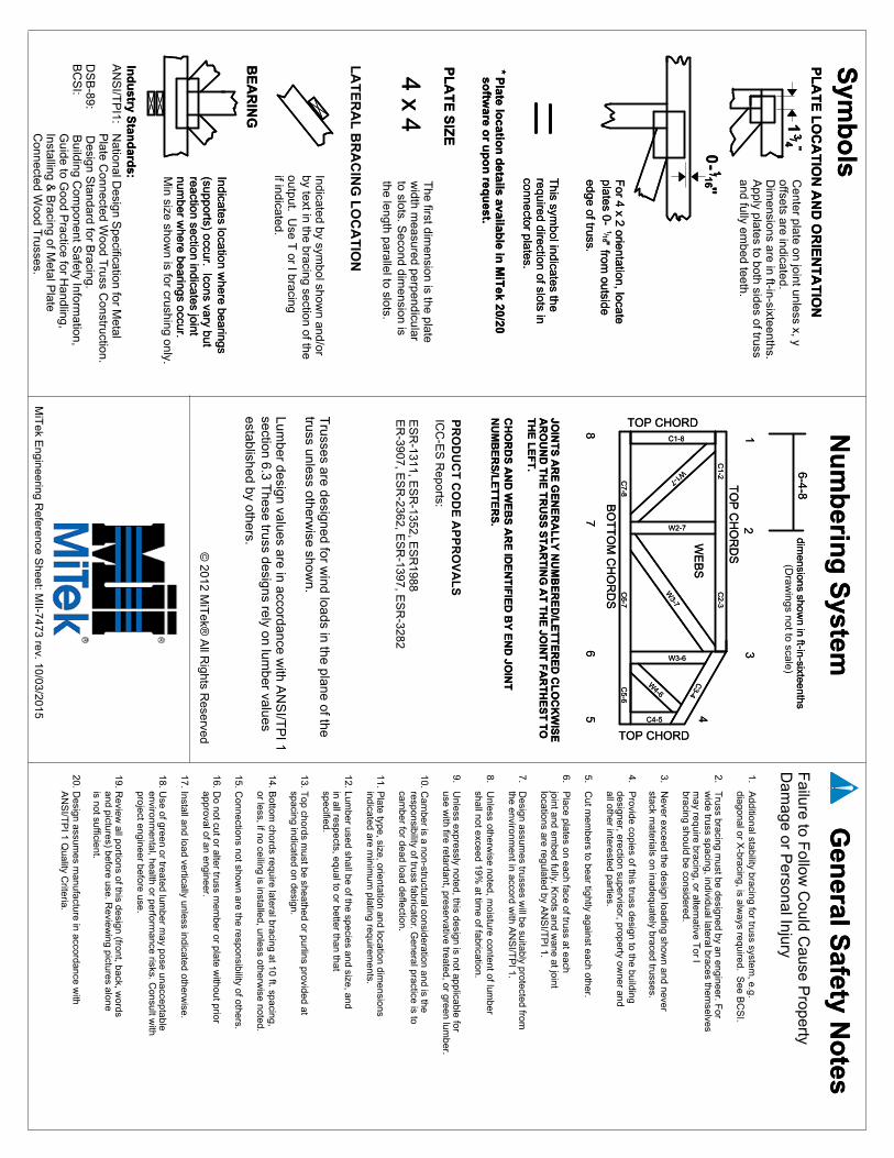
edge of truss. from outside
" 16/ 1
-0
PR
OD
UC
T C
OD
E A
PP
RO
VA
LS
JOIN
TS
AR
E G
EN
ER
AL
LY
NU
MB
ER
ED
/LE
TT
ER
ED
CL
OC
KW
ISE
AR
OU
ND
TH
E T
RU
SS
ST
AR
TIN
G A
T T
HE
JOIN
T F
AR
TH
ES
T T
OT
HE
LE
FT
.
CH
OR
DS
AN
D W
EB
S A
RE
IDE
NT
IFIE
D B
Y E
ND
JOIN
TN
UM
BE
RS
/LE
TT
ER
S.
W4-6
W3-6
W3-7
W2-7
W1-7
C1-8
C5-6
C6-7
C7-8
C4-5
C3-4
C2-3
C1-2
TOP CHORD
TOP CHORD87
65 4
32
1
BO
TT
OM
CH
OR
DS
TO
P C
HO
RD
S
BE
AR
ING
LA
TE
RA
L B
RA
CIN
G L
OC
AT
ION
Indicates location where bearings
(supports) occur. Icons vary butreaction section indicates jointnum
ber where bearings occur.
Min size show
n is for crushing only.
Indicated by symbol show
n and/orby text in the bracing section of theoutput. U
se T or I bracing
if indicated.
The first dim
ension is the plate w
idth measured perpendicular
to slots. Second dim
ension isthe length parallel to slots.
4 x 4
PL
AT
E S
IZE
This sym
bol indicates the required direction of slots inconnector plates.
"16
/ 1
For 4 x 2 orientation, locate
plates 0-
Center plate on joint unless x, y
offsets are indicated.D
imensions are in ft-in-sixteenths.
Apply plates to both sides of truss
and fully embed teeth.
1"4 / 3
PL
AT
E L
OC
AT
ION
AN
D O
RIE
NT
AT
ION
Sym
bo
lsN
um
berin
g S
ystem
1. Additional stability bracing for truss system
, e.g. diagonal or X
-bracing, is always required. S
ee BC
SI.
2. Truss bracing m
ust be designed by an engineer. For
wide truss spacing, individual lateral braces them
selves m
ay require bracing, or alternative Tor I
bracing should be considered.
3. Never exceed the design loading show
n and never stack m
aterials on inadequately braced trusses.
4. Provide copies of this truss design to the building
designer, erection supervisor, property owner and
all other interested parties.
5. Cut m
embers to bear tightly against each other.
6. Place plates on each face of truss at each
joint and embed fully. K
nots and wane at joint
locations are regulated by AN
SI/T
PI 1.
7. Design assum
es trusses will be suitably protected from
the environment in accord w
ith AN
SI/T
PI 1.
8. Unless otherw
ise noted, moisture content of lum
ber shall not exceed 19%
at time of fabrication.
9. Unless expressly noted, this design is not applicable for
use with fire retardant, preservative treated, or green lum
ber.
10. Cam
ber is a non-structural consideration and is the responsibility of truss fabricator. G
eneral practice is to cam
ber for dead load deflection.
11. Plate type, size, orientation and location dim
ensions indicated are m
inimum
plating requirements.
12. Lumber used shall be of the species and size, and
in all respects, equal to or better than that specified.
13. Top chords m
ust be sheathed or purlins provided at spacing indicated on design.
14. Bottom
chords require lateral bracing at 10 ft. spacing, or less, if no ceiling is installed, unless otherw
ise noted.
15. Connections not show
n are the responsibility of others.
16. Do not cut or alter truss m
ember or plate w
ithout prior approval of an engineer.
17. Install and load vertically unless indicated otherwise.
18. Use of green or treated lum
ber may pose unacceptable
environmental, health or perform
ance risks. Consult w
ith project engineer before use.
19. Review
all portions of this design (front, back, words
and pictures) before use. Review
ing pictures alone is not sufficient.
20. Design assum
es manufacture in accordance w
ith A
NS
I/TP
I 1 Quality C
riteria.
Failure to F
ollow C
ould Cause P
ropertyD
amage or P
ersonal Injury
Gen
eral Safety N
otes
*P
late locatio
n d
etails available in
MiT
ek 20/20so
ftware o
r up
on
requ
est.
Ind
ustry S
tand
ards:
6-4-8dim
ensions shown in ft-in-sixteenths
(Draw
ings not to scale)
© 2012 M
iTek®
All R
ights Reserved
MiT
ek Engineering R
eference Sheet: M
II-7473 rev. 10/03/2015
WE
BS
edge of truss. from outside
" 16/ 1
-0
ICC
-ES
Reports:
ES
R-1311, E
SR
-1352, ES
R1988
ER
-3907, ES
R-2362, E
SR
-1397, ES
R-3282
JOIN
TS
AR
E G
EN
ER
AL
LY
NU
MB
ER
ED
/LE
TT
ER
ED
CL
OC
KW
ISE
AR
OU
ND
TH
E T
RU
SS
ST
AR
TIN
G A
T T
HE
JOIN
T F
AR
TH
ES
T T
OT
HE
LE
FT
.
CH
OR
DS
AN
D W
EB
S A
RE
IDE
NT
IFIE
D B
Y E
ND
JOIN
TN
UM
BE
RS
/LE
TT
ER
S.
W4-6
W3-6
W3-7
W2-7
W1-7
C1-8
C5-6
C6-7
C7-8
C4-5
C3-4
C2-3
C1-2
TOP CHORD
TOP CHORD87
65 4
32
1
BO
TT
OM
CH
OR
DS
TO
P C
HO
RD
S
BE
AR
ING
Indicates location where bearings
(supports) occur. Icons vary butreaction section indicates jointnum
ber where bearings occur.
4 x 4
PL
AT
E S
IZE
This sym
bol indicates the required direction of slots inconnector plates.
"16
/ 1
For 4 x 2 orientation, locate
plates 0-
1"4 / 3
PL
AT
E L
OC
AT
ION
AN
D O
RIE
NT
AT
ION
Sym
bo
lsN
um
berin
g S
ystemG
eneral S
afety No
tes
*P
late locatio
n d
etails available in
MiT
ek 20/20so
ftware o
r up
on
requ
est.
Ind
ustry S
tand
ards:
AN
SI/T
PI1: N
ational Design S
pecification for Metal
Plate C
onnected Wood T
russ Construction.
DS
B-89: D
esign Standard for B
racing.B
CS
I: Building C
omponent S
afety Information,
Guide to G
ood Practice for H
andling, Installing &
Bracing of M
etal Plate
Connected W
ood Trusses.
6-4-8dim
ensions shown in ft-in-sixteenths
WE
BS
Trusses are designed for w
ind loads in the plane of the truss unless otherw
ise shown.
Lumber design values are in accordance w
ith AN
SI/T
PI 1
section 6.3 These truss designs rely on lum
ber values established by others.