iVu Plus TG Gen2 Image Sensor - Banner...
219
iVu Plus TG and Color Gen2 Image Sensors Instruction Manual Original Instructions 179042 Rev. D 24 April 2018 © Banner Engineering Corp. All rights reserved 179042
Transcript of iVu Plus TG Gen2 Image Sensor - Banner...

iVu Plus TG and Color Gen2 Image Sensors
Instruction Manual
Original Instructions179042 Rev. D24 April 2018© Banner Engineering Corp. All rights reserved
179042

Contents
1 Product Description .................................................................................................................................................61.1 Models ................................................................................................................................................................................6
2 Overview .................................................................................................................................................................82.1 Features and Indicators .....................................................................................................................................................82.2 Demo Mode .......................................................................................................................................................................82.3 Sensor Types ..................................................................................................................................................................... 92.4 Multiple Sensors ................................................................................................................................................................92.5 Multiple Inspections .......................................................................................................................................................... 92.6 Imager Resolution (Grayscale Models only) .......................................................................................................................92.7 Communication Channels ................................................................................................................................................. 9
3 Specifications and Requirements .........................................................................................................................103.1 Specifications ..................................................................................................................................................................103.2 Dimensions ......................................................................................................................................................................113.3 Using iVu Gen1 and Gen2 Devices in the Same Application ........................................................................................... 14
4 Installation Instructions .........................................................................................................................................154.1 Mount the iVu .................................................................................................................................................................. 154.2 Cable Connections ..........................................................................................................................................................154.3 Installing a Filter on an iVu ............................................................................................................................................... 16
5 Getting Started ..................................................................................................................................................... 185.1 Setting up an Inspection .................................................................................................................................................. 18
5.1.1 Acquiring a Good Image ...................................................................................................................................... 185.2 Add a New Inspection ..................................................................................................................................................... 205.3 Trigger Modes ................................................................................................................................................................. 215.4 Change the Running Inspection ......................................................................................................................................21
6 Home Screen .........................................................................................................................................................236.1 Display Mode .................................................................................................................................................................. 23
6.1.1 Image with Annotations .......................................................................................................................................236.1.2 Image without Annotations ..................................................................................................................................236.1.3 Inspection Statistics ............................................................................................................................................. 24
7 Main Menu ............................................................................................................................................................267.1 Icon Reference ................................................................................................................................................................. 27
7.1.1 Action Icons ..........................................................................................................................................................277.1.2 Display Icons ........................................................................................................................................................ 287.1.3 Communications Log Icons ................................................................................................................................ 29
8 Inspection Menu .................................................................................................................................................... 308.1 Sensors Menu ................................................................................................................................................................. 30
8.1.1 Area Menu ............................................................................................................................................................ 308.1.2 Blemish Menu .......................................................................................................................................................318.1.3 Match Menu ......................................................................................................................................................... 328.1.4 Sort Menu ............................................................................................................................................................348.1.5 Average Color Menu .............................................................................................................................................358.1.6 Color Compare Menu ...........................................................................................................................................368.1.7 Color Area Menu .................................................................................................................................................. 37
8.2 Motion Menu .................................................................................................................................................................... 388.2.1 Number of Edges ................................................................................................................................................. 388.2.2 Sensitivity ............................................................................................................................................................. 388.2.3 Rotation ................................................................................................................................................................ 38
8.3 Properties Menu .............................................................................................................................................................. 398.3.1 Inspection Name ................................................................................................................................................. 398.3.2 Inspection ID ....................................................................................................................................................... 39
8.4 Stored Inspections Menu ................................................................................................................................................. 398.4.1 Select .................................................................................................................................................................. 398.4.2 Add New ..............................................................................................................................................................398.4.3 Startup .................................................................................................................................................................408.4.4 Delete Inspections ...............................................................................................................................................408.4.5 Set Name/ID ........................................................................................................................................................ 40
9 Imager Menu ..........................................................................................................................................................419.1 Auto Exposure ..................................................................................................................................................................419.2 Exposure .......................................................................................................................................................................... 419.3 Gain .................................................................................................................................................................................. 419.4 Trigger .............................................................................................................................................................................. 429.5 Focus ................................................................................................................................................................................429.6 Strobe Menu .....................................................................................................................................................................43
iVu Plus TG and Color Gen2 Image Sensors

9.6.1 External .................................................................................................................................................................439.6.2 Internal ..................................................................................................................................................................43
9.7 FOV (Field of View) ........................................................................................................................................................... 439.7.1 Adjust the Field of View (Grayscale Models only) ................................................................................................ 43
9.8 Resolution ....................................................................................................................................................................... 449.9 White Balance ................................................................................................................................................................. 45
10 System Menu .......................................................................................................................................................4610.1 Mode ............................................................................................................................................................................. 4610.2 System Configuration Menu ...........................................................................................................................................46
10.2.1 Save to USB ....................................................................................................................................................... 4610.2.2 Load from USB ...................................................................................................................................................4710.2.3 Reset to Defaults ................................................................................................................................................47
10.3 System Information ........................................................................................................................................................ 4710.4 Lock Device ...................................................................................................................................................................4710.5 Communications Menu .................................................................................................................................................. 48
10.5.1 Ethernet I/O ........................................................................................................................................................ 4810.5.2 Serial I/O .............................................................................................................................................................4910.5.3 Industrial Ethernet .............................................................................................................................................. 4910.5.4 Command Channel ........................................................................................................................................... 5310.5.5 Data Export Menu ............................................................................................................................................. 5410.5.6 Image Export ..................................................................................................................................................... 56
10.6 Discrete I/O Menu .......................................................................................................................................................... 5710.6.1 Input Polarity ...................................................................................................................................................... 5710.6.2 Input Pullup ........................................................................................................................................................ 5810.6.3 Output Type ...................................................................................................................................................... 5810.6.4 Output 1, 2, and 3 .............................................................................................................................................. 58
10.7 Display Settings ..............................................................................................................................................................5910.7.1 Fail Hold Time .....................................................................................................................................................6010.7.2 LCD Timeout ...................................................................................................................................................... 6010.7.3 Touch Calibration ............................................................................................................................................... 6010.7.4 Advanced ........................................................................................................................................................... 60
10.8 Reboot Sensor ............................................................................................................................................................... 6010.9 Firmware Update ............................................................................................................................................................6010.10 iVu Trigger, Remote Teach, and I/O Waveforms .........................................................................................................61
10.10.1 PNP (Low-to-High) Trigger and Remote Teach Input Waveforms ................................................................... 6110.10.2 NPN (High-to-Low) Trigger and Remote Teach Input Waveforms ...................................................................6110.10.3 iVu Output Waveforms .................................................................................................................................... 62
11 Logs Menu ...........................................................................................................................................................6411.1 Inspection Logs Menu ....................................................................................................................................................64
11.1.1 View Logs ........................................................................................................................................................... 6411.1.2 Setup .................................................................................................................................................................. 65
11.2 System Logs ...................................................................................................................................................................6511.3 Communication Logs Menu ........................................................................................................................................... 65
11.3.1 Industrial Ethernet Log ...................................................................................................................................... 6611.3.2 Command Channel Log .................................................................................................................................... 6611.3.3 Image Export Log ..............................................................................................................................................66
12 Configuring Sensors ........................................................................................................................................... 6712.1 Setting the Trigger ..........................................................................................................................................................6712.2 Configuring an Area Sensor ........................................................................................................................................... 6712.3 Configuring a Blemish Sensor ........................................................................................................................................6912.4 Configuring a Match Sensor ...........................................................................................................................................71
12.4.1 Remote Teach .................................................................................................................................................... 7412.5 Configuring a Sort Sensor ..............................................................................................................................................7412.6 Configuring Motion ........................................................................................................................................................76
12.6.1 Number of Edges ............................................................................................................................................... 7612.6.2 Sensitivity ........................................................................................................................................................... 7612.6.3 Rotation .............................................................................................................................................................. 76
12.7 Configuring an Average Color Sensor ...........................................................................................................................7612.8 Configuring a Color Compare Sensor ........................................................................................................................... 7812.9 Configuring a Color Area Sensor ...................................................................................................................................7912.10 Configuring Multiple Sensors in the Inspection .......................................................................................................... 8112.11 Configuring a Mask ..................................................................................................................................................... 82
13 iVu Emulator ........................................................................................................................................................ 8413.1 How to Use Bitmap Image Files with the iVu Emulator ..................................................................................................84
14 Communications Guide ......................................................................................................................................8514.1 iVu Plus Communication Summary of Ethernet and Serial ........................................................................................... 85
14.1.1 Communication Channels ................................................................................................................................. 8514.1.2 Industrial Ethernet .............................................................................................................................................. 8514.1.3 Command Channel ............................................................................................................................................ 8514.1.4 Data Export ........................................................................................................................................................ 86
iVu Plus TG and Color Gen2 Image Sensors

14.1.5 Image Export ..................................................................................................................................................... 8714.2 Enabling Communications ............................................................................................................................................ 88
14.2.1 Setting Up Ethernet Communications ...............................................................................................................8814.2.2 Setting Up Serial Communications .................................................................................................................... 93
14.3 Testing and Troubleshooting iVu Communications ....................................................................................................... 9514.3.1 Understanding the Communication Log ............................................................................................................ 9514.3.2 Ethernet I/O ....................................................................................................................................................... 9614.3.3 Serial I/O ............................................................................................................................................................96
14.4 Command Channel Primer ............................................................................................................................................9714.4.1 Command Channel Commands .........................................................................................................................9714.4.2 Conventions Used for Examples ........................................................................................................................9914.4.3 Examples ...........................................................................................................................................................9914.4.4 Command Channel Reference ........................................................................................................................ 10014.4.5 Multiple Sensors in an Inspection ................................................................................................................... 11014.4.6 Command Channel Command Status Register ...............................................................................................11014.4.7 Command Channel Error Codes ...................................................................................................................... 110
14.5 iVu Discovery Protocol ................................................................................................................................................. 11114.5.1 UDP Usage ......................................................................................................................................................11214.5.2 Packet Format ................................................................................................................................................. 11214.5.3 Message Flow ................................................................................................................................................. 115
15 Industrial Ethernet Overview .............................................................................................................................11815.1 Device Setup ............................................................................................................................................................... 118
15.1.1 Set IP Address .................................................................................................................................................11815.1.2 Set the Industrial Ethernet Protocol (Ethernet/IP™/Modbus/PCCC/PROFINET®) ..........................................11815.1.3 Set Trigger Mode .............................................................................................................................................118
15.2 Supported Functions ....................................................................................................................................................11815.2.1 iVu Input Values ................................................................................................................................................11815.2.2 iVu Output Values .............................................................................................................................................118
15.3 iVu Operation ................................................................................................................................................................11915.3.1 General Command Execution ......................................................................................................................... 120
15.4 EtherNet/IP™ ................................................................................................................................................................ 12015.4.1 Inputs to the iVu (Outputs from the PLC) ......................................................................................................... 12115.4.2 Outputs from the iVu (Inputs to the PLC) ......................................................................................................... 12115.4.3 Multiple Sensors Mapping Options ..................................................................................................................12215.4.4 Input and Output Flags Bits ............................................................................................................................. 12715.4.5 Configuration Assembly Object ........................................................................................................................12715.4.6 Data Formats ....................................................................................................................................................12715.4.7 Minimum Requested Packet Interval (RPI) Value ............................................................................................12715.4.8 iVu Plus TG and Color Gen2 Image Sensors EDS File Installation in ControlLogix Software ..........................12815.4.9 RSLogix5000 Configuration ............................................................................................................................. 133
15.5 Modbus/TCP ................................................................................................................................................................ 13915.5.1 iVu Input Values ................................................................................................................................................14115.5.2 iVu Output Values .............................................................................................................................................14115.5.3 Multiple Sensors Mapping Options ..................................................................................................................14115.5.4 Input and Output Bits ....................................................................................................................................... 147
15.6 PLC5 and SLC 5 (PCCC) ..............................................................................................................................................14715.6.1 Configuration ...................................................................................................................................................14715.6.2 Inputs to iVu (Outputs from PLC) ..................................................................................................................... 15115.6.3 Outputs from iVu (Inputs to PLC) ..................................................................................................................... 15115.6.4 Multiple Sensors Mapping Options ..................................................................................................................15215.6.5 Input and Output Flags .....................................................................................................................................156
15.7 PROFINET® ..................................................................................................................................................................15715.7.1 General Station Description (GSD) File ............................................................................................................ 15715.7.2 iVu PROFINET IO Data Model ..........................................................................................................................15715.7.3 Configuration Instructions ............................................................................................................................... 170
15.8 Sample Timing Diagrams ............................................................................................................................................ 19115.9 Command Channel Command Status Register ...........................................................................................................19315.10 Diagnostic Guide ........................................................................................................................................................193
15.10.1 Ethernet Diagnostics ..................................................................................................................................... 19315.10.2 Networking and TCP/IP Diagnostics .............................................................................................................19415.10.3 Industrial Protocols Troubleshooting ............................................................................................................ 196
15.11 Additional Information ............................................................................................................................................... 20115.11.1 iVu Command Channel Commands (iVu Command Channel over Industrial Ethernet) .................................201
16 Troubleshooting ................................................................................................................................................20616.1 LED Indicator Troubleshooting .....................................................................................................................................206
16.1.1 Errors ................................................................................................................................................................20616.1.2 Warnings .......................................................................................................................................................... 206
16.2 Debugging Inspections ............................................................................................................................................... 20616.2.1 How to Round-Trip Debug Using the Emulator ............................................................................................... 206
17 Accessories ....................................................................................................................................................... 209
iVu Plus TG and Color Gen2 Image Sensors

17.1 Power Cable — Required .............................................................................................................................................20917.2 Remote Display—Required for Setup (Remote Display Models Only) .........................................................................209
17.2.1 RDM35 Remote Display Accessory Kit ...........................................................................................................20917.3 Ethernet Cable Options ............................................................................................................................................... 21017.4 USB Cable — Optional .................................................................................................................................................21017.5 USB Flash Drive — Optional ........................................................................................................................................ 21017.6 Brackets ....................................................................................................................................................................... 21117.7 Micro Video Lens Accessories .................................................................................................................................... 212
17.7.1 Micro Video Lens Models .................................................................................................................................21217.7.2 Micro Video Lens Filters — Optional ................................................................................................................212
17.8 C-Mount Lens Accessories ......................................................................................................................................... 21217.8.1 C-Mount Lens Models .....................................................................................................................................21217.8.2 C-Mount Lens Enclosure Models ....................................................................................................................21217.8.3 C-Mount Lens Filters — Optional ....................................................................................................................213
18 Product Support and Maintenance ................................................................................................................... 21418.1 Product Support ...........................................................................................................................................................21418.2 Maintenance .................................................................................................................................................................214
18.2.1 Clean the iVu .................................................................................................................................................... 21418.2.2 Update the iVu firmware ..................................................................................................................................21418.2.3 How to Set or Modify a Device Name using the Emulator ...............................................................................21518.2.4 How to Reset the Device Password .................................................................................................................216
18.3 Contact Us ................................................................................................................................................................... 21618.4 Banner Engineering Corp Limited Warranty ................................................................................................................217
iVu Plus TG and Color Gen2 Image Sensors

1 Product DescriptionThe iVu Plus TG and Color Gen2 Image Sensors are used to monitor parts for type, size, orientation, shape, location, andcolor or color variations. The device can be set up and monitored using an integrated or remote touchscreen display with noPC required. The following features are available:
• All-in-one solution with camera, controller, lens, and light included in one package• Inspect multiple points with a wide variety of grayscale or color tools, depending on
your application• Configure in minutes through the onboard touchscreen display found on the device,
or use a remote touchscreen display to allow for easy access and monitoring• Compact, rugged, IP67 housing available with or without a variety of integrated ring
lights - red, blue, green, white, infrared or UV - and C-mount models are alsoavailable for purchase
• Factory communications (EtherNet/IP™1, Modbus/TCP, PROFINET®2, PCCC andSerial RS-232) for integration on the manufacturing floor
• Ability to change parameters on the fly with full runtime editing to reduce costlydowntime
WARNING: Not To Be Used for Personnel Protection
Never use this device as a sensing device for personnel protection. Doing so could lead to serious injuryor death. This device does not include the self-checking redundant circuitry necessary to allow its use inpersonnel safety applications. A sensor failure or malfunction can cause either an energized or de-energized sensor output condition.
CAUTION: Electrostatic Discharge
Avoid the damage that electrostatic discharge (ESD) can cause to the Sensor.
Always use a proven method for preventing electrostatic discharge when installing a lens or attaching acable.
1.1 ModelsTable 1: iVu Models with an Integrated Display
RingLight
Options
Micro Video Lens Options (Focal Length) C-MountLens
Options4.3 mm 6 mm 8 mm 12 mm 16 mm 25 mm
None IVU2PTGX04 IVU2PTGX06 IVU2PTGX08 IVU2PTGX12 IVU2PTGX16 IVU2PTGX25 IVU2PTGXC
Red IVU2PTGR04 IVU2PTGR06 IVU2PTGR08 IVU2PTGR12 IVU2PTGR16 IVU2PTGR25 N/A
Blue IVU2PTGB04 IVU2PTGB06 IVU2PTGB08 IVU2PTGB12 IVU2PTGB16 IVU2PTGB25 N/A
Green IVU2PTGG04 IVU2PTGG06 IVU2PTGG08 IVU2PTGG12 IVU2PTGG16 IVU2PTGG25 N/A
IR IVU2PTGI04 IVU2PTGI06 IVU2PTGI08 IVU2PTGI12 IVU2PTGI16 IVU2PTGI25 N/A
White IVU2PTGW04 IVU2PTGW06 IVU2PTGW08 IVU2PTGW12 IVU2PTGW16 IVU2PTGW25 N/A
UV 365 3 IVU2PTG604 IVU2PTG606 IVU2PTG608 IVU2PTG612 IVU2PTG616 IVU2PTG625 N/A
UV 395 3 IVU2PTG904 IVU2PTG906 IVU2PTG908 IVU2PTG912 IVU2PTG916 IVU2PTG925 N/A
1 EtherNet/IP™ is a trademark of ODVA, Inc.2 PROFINET® is a registered trademark of PROFIBUS Nutzerorganisation e.V.3 Blue Filter Kit (FLTMB) is included with ultraviolet (UV) models.
iVu Plus TG and Color Gen2 Image Sensors
6 www.bannerengineering.com - Tel: +1.763.544.3164

Table 2: iVu Models with a Remote Display
RingLight
Options
Micro Video Lens Options (Focal Length) C-MountLens
Options4.3 mm 6 mm 8 mm 12 mm 16 mm 25 mm
None IVU2PRGX04 IVU2PRGX06 IVU2PRGX08 IVU2PRGX12 IVU2PRGX16 IVU2PRGX25 IVU2PRGXC
Red IVU2PRGR04 IVU2PRGR06 IVU2PRGR08 IVU2PRGR12 IVU2PRGR16 IVU2PRGR25 N/A
Blue IVU2PRGB04 IVU2PRGB06 IVU2PRGB08 IVU2PRGB12 IVU2PRGB16 IVU2PRGB25 N/A
Green IVU2PRGG04 IVU2PRGG06 IVU2PRGG08 IVU2PRGG12 IVU2PRGG16 IVU2PRGG25 N/A
IR IVU2PRGI04 IVU2PRGI06 IVU2PRGI08 IVU2PRGI12 IVU2PRGI16 IVU2PRGI25 N/A
White IVU2PRGW04 IVU2PRGW06 IVU2PRGW08 IVU2PRGW12 IVU2PRGW16 IVU2PRGW25 N/A
UV 365 4 IVU2PRG604 IVU2PRG606 IVU2PRG608 IVU2PRG612 IVU2PRG616 IVU2PRG625 N/A
UV 395 4 IVU2PRG904 IVU2PRG906 IVU2PRG908 IVU2PRG912 IVU2PRG916 IVU2PRG925 N/A
Table 3: iVu Color Models with an Integrated Display5
RingLight
Options
Micro Video Lens Options (Focal Length) C-MountLens
Options4.3 mm 6 mm 8 mm 12 mm 16 mm 25 mm
None IVU2PTCX04 IVU2PTCX06 IVU2PTCX08 IVU2PTCX12 IVU2PTCX16 IVU2PTCX25 IVU2PTGXC
White IVU2PTCW04 IVU2PTCW06 IVU2PTCW08 IVU2PTCW12 IVU2PTCW16 IVU2PTCW25 N/A
Table 4: iVu Color Models with a Remote Display5
RingLight
Options
Micro Video Lens Options (Focal Length) C-MountLens
Options4.3 mm 6 mm 8 mm 12 mm 16 mm 25 mm
None IVU2PRCX04 IVU2PRCX06 IVU2PRCX08 IVU2PRCX12 IVU2PRCX16 IVU2PRCX25 IVU2PRGXC
White IVU2PRCW04 IVU2PRCW06 IVU2PRCW08 IVU2PRCW12 IVU2PRCW16 IVU2PRCW25 N/A
Note: This product emits UV light. Exempt Risk Group (RG 0) product. No optical hazard is consideredreasonably foreseeable, even for continuous, unrestricted use (IEC 62471).
4 Blue Filter Kit (FLTMB) is included with ultraviolet (UV) models.5 iVu Color models include a pre-installed infrared filter.
iVu Plus TG and Color Gen2 Image Sensors
www.bannerengineering.com - Tel: +1.763.544.3164 7

2 OverviewThe iVu Vision Sensor can be configured in just minutes with a few simple steps. No PC is required and programming isdone using the integrated or remote touchscreen display. Use the grayscale, color, or barcode versions to solve a widevariety of factory automation applications.
2.1 Features and IndicatorsThe iVu comes fully assembled with the lens and an integrated ring light (optional).
Integrated display models: The touchscreen display has a plastic cover to protect the display. Remove this cover whenconfiguring the device. When the display is not in use, keep the display covered to protect it.
Remote display models: The remote touchscreen display is not required for normal device operation, however, it is neededto configure the device and to monitor inspections.
If an integrated ring light is not used, another light source is needed. Various lights are available from Banner Engineering.Operating in external trigger mode requires a triggering source.
Figure 1. Features
1. Power LED
Green: Ready/PowerRed (blinking or steady): Error
2. Pass/Fail LED
Green (steady): PassGreen (blinking): ErrorRed: Fail
3. Ethernet I/O LED
Green: ConnectedOff: Disconnected
4. Focusing Window5. Focusing Window Locking Clip6. Integrated Display (integrated display
models only)
2.2 Demo ModeThe first time the iVu is powered up, it starts in Demo Mode. You can choose whether to stay in Demo Mode or exit to LiveMode. Demo Mode uses stored images and inspection parameters that demonstrate how the iVu is set up, without havingto worry about focus, lighting, or triggers. In this mode, practice making adjustments while working with the different sensortypes and observing how the adjustments affect the results. To exit Demo Mode, go to Main Menu > System > Mode andselect Exit Demo Mode. Upon exit, the iVu restarts in the normal operating mode with the default settings.
Figure 2. Select Type Screen Figure 3. System Menu
Note: Switch between Live Mode and Demo Mode any time by going to Main Menu > System > Mode.
iVu Plus TG and Color Gen2 Image Sensors
8 www.bannerengineering.com - Tel: +1.763.544.3164

2.3 Sensor TypesThe iVu includes the following types:
Sensor Type Description
Area Sensor Use an Area sensor to ensure that a feature, or multiple features, are present on a part. See Area Menuon page 30.
Blemish Sensor Use a Blemish sensor to find flaws on a part, or to make sure that a feature exists on a part. See Blemish Menu on page 31.
Match Sensor Use a Match sensor to verify that a pattern, shape, or part in any orientation matches a referencepattern. See Match Menu on page 32.
Sort Sensor Use a Sort sensor to recognize and sort up to ten different patterns within the same inspection. See Sort Menu on page 34.
Average Color Use an Average Color sensor to calculate the average color (RGB or HSI) within the area of interest ona part (color models only). See Average Color Menu on page 35.
Color Compare Use a Color Compare sensor to verify whether a part's color matches a reference color (color modelsonly). See Color Compare Menu on page 36.
Color Area Use a Color Area sensor to ensure that a feature, or multiple features, are the correct color and arepresent on a part (color models only). See Color Area Menu on page 37.
2.4 Multiple SensorsFirmware versions 1.2.0 and newer include multiple sensor functionality. Use multiple sensors to inspect more than onefeature on each part being inspected. Create and store up to 30 such inspections on the iVu.
2.5 Multiple InspectionsThe iVu supports multiple inspections that facilitate storing and controlling up to 30 inspections of different sensor types.
2.6 Imager Resolution (Grayscale Models only)The iVu includes an adjustable resolution up to 752×480 pixels.
2.7 Communication ChannelsThe iVu supports up to four communications channels:
• Command Channel—A bi-directional communication protocol that currently supports ASCII and enables otherdevices to remotely control the iVu and access device information and inspection results
• Industrial Ethernet—A bi-directional communication channel that allows the user to control the device and accessdevice results using Ethernet/IP™, Modbus/TCP, PCCC, or PROFINET® protocol
• Data Export—Used to export selected inspection data to a remote device• Image Export—Used to export inspection images to a remote device
iVu Plus TG and Color Gen2 Image Sensors
www.bannerengineering.com - Tel: +1.763.544.3164 9

3 Specifications and Requirements
3.1 Specifications
Power Connection12-pin M12/Euro-style male connector; accessory cablerequired for operation
USB 2.0 Host4-pin M8/Pico female connector; optional USB cable requiredfor operation of USB flash drive
Ethernet Connection4-pin M8/Pico male connector
Remote Display Connection8-pin M12/Euro-style female connector; accessory cablerequired for remote display
Power RequirementsVoltage: 10 V dc to 30 V dcCurrent: 1 A maximum (exclusive of I/O load)
Output ConfigurationNPN or PNP, software selectable
Demo ModeFull tool functionality on canned images
Sensor LockOptional password protection
Integrated Ring LightModels with red, blue, green, infrared, white, ultraviolet or nointegrated ring light
Output Rating150 mA
External Strobe Output+ 5 V dc
Acquisition60 fps (frames per second) maximum, with full FOV
Exposure Time0.1 ms to 1.049 s
Imager1/3 inch CMOS 752 × 480 pixels; color or grayscale, dependingon modelAdjustable Field of View (FOV)
Lens MountMicro Video Lens models: M12 × 1 mm thread; micro video lens4.3 mm, 6 mm, 8 mm, 12 mm, 16 mm, 25 mmC-Mount models: Standard C-mount (1 inch-32 UN)
ConstructionBlack PBT sensor housing; die cast zinc back cover; acrylicwindowIntegrated Display Weight: 0.36 kg (0.80 lbs)Remote Display Weight: 0.41 kg (0.90 lbs)
Environmental RatingIEC IP67, micro video lens models only
Operating ConditionsIntegrated Display Stable Ambient Temperature: 0 °C to +45 °C(+32 °F to +113 °F)Remote Display Stable Ambient Temperature: 0 °C to +40 °C(+32 °F to +104 °F)
Certifications
iVu Plus TG and Color Gen2 Image Sensors
10 www.bannerengineering.com - Tel: +1.763.544.3164

3.2 Dimensions
Micro Video Lens Dimensions
81,2[3.20]
79,2[3.12]
95,3[3.75]
33,5[1.32]
19,5[.77]
35[1.38]
14[.55] 6,5
[.26]
51,5[2.03]
15[.59]
18,4[.73]
q
q
q
Figure 4. Micro Video Lens, Remote Display Models
iVu Plus TG and Color Gen2 Image Sensors
www.bannerengineering.com - Tel: +1.763.544.3164 11

81,2[3.20]
79,2[3.12]
95,3[3.75]
19,5[.77]
35[1.38]
14[.55] 6,5
[.26]
51,5[2.03]
57,9[2.28]
43,7[1.72]
15[.59]
18,4[.73]
q
q
q
Figure 5. Micro Video Lens, Integrated Display Models
All measurements are listed in millimeters [inches], unless noted otherwise.
iVu Plus TG and Color Gen2 Image Sensors
12 www.bannerengineering.com - Tel: +1.763.544.3164

C-Mount Lens Dimensions
C-Mount Lens Covers
Figure 6. C-Mount Lens, Remote Display Models
iVu Plus TG and Color Gen2 Image Sensors
www.bannerengineering.com - Tel: +1.763.544.3164 13

C-Mount Lens Covers
Figure 7. C-Mount Lens, Integrated Display Models
All measurements are listed in millimeters [inches], unless noted otherwise.
3.3 Using iVu Gen1 and Gen2 Devices in the Same ApplicationGeneration 1 and Generation 2 iVu devices can be used in the same application, however steps must be taken to ensurecompatibility. Gen2 output files, such as configuration and log files, are not compatible with Gen1 devices. In order to haveone configuration file that applies to both Gen1 and Gen2 devices, configure inspections using a Gen1 device or the Gen1Emulator. Settings from Gen1 are automatically converted to Gen2 when they are loaded onto a Gen2 device. Confirm allinspections after loading to ensure that they are correct.
Note: New features available on Gen2 devices will not be available when creating the inspection on Gen1software.
iVu Plus TG and Color Gen2 Image Sensors
14 www.bannerengineering.com - Tel: +1.763.544.3164

4 Installation Instructions
4.1 Mount the iVuThe iVu requires a bracket for mounting. Brackets are available from Banner Engineering. See www.bannerengineering.com.The brackets allow the iVu to be mounted either perpendicular to the part or at an adjustable angle.
1. Position the iVu on the bracket.2. Thread three M4 x 4 mm screws (supplied) through the bracket into the mounting holes in the bottom of the iVu.
Figure 8. Mounting Bracket Mounting Holes3. Tighten all three screws.4. Mount the iVu and bracket to the machine or equipment at the desired location. Do not tighten the mounting screws
at this time.5. Check the iVu alignment.6. Tighten the mounting screws to secure the iVu and the bracket in the aligned position.
4.2 Cable ConnectionsThe cable connections on the iVu are shown below, and power I/O connections (B) are defined in the Power I/OConnections table below.
CAUTION: Electrostatic Discharge
Avoid the damage that electrostatic discharge (ESD) can cause to the Sensor.
Always use a proven method for preventing electrostatic discharge when installing a lens or attaching acable.
A B
C DFigure 9. iVu Cable Connections—Micro Video Lens Model
A Remote Display Connector (remote display models only)
B Power and I/O Cable Connector
C USB Connector
D Ethernet Connector
Note: Micro video lens model shown, C-Mountmodel connections are identical.
Table 5: Power I/O Connections
Pin # Wire Color Description Direction
1 White Output 1 Output
2 Brown 10 V dc to 30 V dc Input
3 Green Output 2 Output
4 Yellow Strobe Out (5 V dc only) Output
5 Gray Remote Teach Input
6 Pink External Trigger Input
7 Blue Common (Signal Ground) Input
iVu Plus TG and Color Gen2 Image Sensors
www.bannerengineering.com - Tel: +1.763.544.3164 15

Pin # Wire Color Description Direction
8 Red Ready Output
9 Orange Output 3 Output
10 Light Blue RS-232 TX Output
11 Black RS-232 Signal Ground Output
12 Violet RS-232 Rx Input
4.3 Installing a Filter on an iVu
Installing a Filter on the Micro Video Lens ModelTo install a filter on the iVu with Micro Video Lens, use the illustration as a guide and follow the steps listed below.
CAUTION: Failure to follow these instructions may cause damage to your iVu.
CAUTION: Electrostatic Discharge
Avoid the damage that electrostatic discharge (ESD) can cause to the Sensor.
Always use a proven method for preventing electrostatic discharge when installing a lens or attaching acable.
A Lens
B Focusing Window
C Locking Clip
D Locking Screw
E Filter Cap
F Filter
Figure 10. Micro Video Lens Model Components
Note: Filter kits are available separately.
1. Remove the locking screw (D) using the 1/16-inch hex key.
Note: The locking clip (C) inserts in a groove near the top of the focusing window (B). Whenremoving the window, the locking clip will be loose. Do not to lose the clip while removing thewindow.
2. Unscrew the focusing window by turning it clockwise approximately 5 complete turns or until the focusing windowdisengages from the light/lens assembly.
Note: The light/lens assembly may include an integrated ring light or a blank disk if an integratedring light is not used. Be careful that the light/lens assembly does not pull out when removing thefocusing window. Pull gently on the focusing window. If the lens assembly moves with the window,continue to rotate the window clockwise until the lens assembly does not move.
3. Set the focusing window aside. Do not to get any debris on the window's O-ring.4. If present, remove the protective covering on the filter.5. Place the filter into the filter cap and press the cap onto the lens.6. After the filter is installed, place the focusing window back into the housing while inserting the locking clip into the
groove as shown.
iVu Plus TG and Color Gen2 Image Sensors
16 www.bannerengineering.com - Tel: +1.763.544.3164

CB
Groove
Figure 11. Locking Clip in the Groove7. Press the focusing window onto the housing to make sure that there is no gap between the window and the
housing. Rotate the window counter-clockwise at least two turns.8. Replace the locking tab screw but do not tighten it until you have set up and focused the iVu again.
Installing a Filter on the C-Mount Lens ModelTo install a filter on the iVu with C-Mount lens, use the illustration as a guide and follow the steps listed below.
CAUTION: Failure to follow these instructions may cause damage to your iVu.
D CA
BEC
A C-Mount Lens
B Lens Enclosure
C Retainer Ring
D Filter
E Filter Retainer Ring Tool
Figure 12. C-Mount Lens Model Components
Note: Filter kits are available separately.
1. Remove the lens enclosure and C-mount lens.2. Install filter behind the retainer ring. Make sure it is fully seated.3. Using the provided retainer ring tool, thread the retainer ring into the iVu until it firmly seats the filter.4. Replace the lens and lens enclosure on the iVu.
iVu Plus TG and Color Gen2 Image Sensors
www.bannerengineering.com - Tel: +1.763.544.3164 17

5 Getting StartedPower up the iVu, and verify that the Power LED is ON green.
5.1 Setting up an InspectionThe device holds up to 30 inspections. Inspections may hold multiple sensors.
To set up an inspection:
1. Acquire a good image.2. Configure the sensor(s) in the inspection.3. Configure multiple sensors in the inspection.
5.1.1 Acquiring a Good ImageThe iVu needs to capture a good image of each part to ensure that it correctly passes good parts and fails bad parts.
1. Go to Main Menu > Imager > Auto Exposure to run the Auto Exposure routine.2. Check the lighting.
• Make sure that the lighting is constant and consistent (unchanging over time, no shadows or hot spots).• Capture the shape and form of the target object with lighting that optimizes its contrast and separates it
from the background. Depending on the target, this may mean the integral ring light is not the best choiceand other Banner lights should be considered.
• Adjust the mounting angle to provide the clearest image of the part features you are monitoring. Themounting bracket lets you easily position and adjust the iVu.
3. If needed, go to Main Menu > Imager > Auto Exposure to run the Auto Exposure routine a second time or adjustGain and Exposure manually:
• Main Menu > Imager > Gain
Figure 13. Gain Screen
• Main Menu > Imager > Exposure
Figure 14. Exposure Screen4. Go to Main Menu > Imager > Focus to adjust the focus while monitoring the Focus Number:
iVu Plus TG and Color Gen2 Image Sensors
18 www.bannerengineering.com - Tel: +1.763.544.3164

Figure 15. Focus Screen5. If you have an iVu color model, perform the white balance procedure to adjust the intensities of the color in the
image so that the colors most closely match the actual objects.
a. Go to Imager > White Balance.b. Move and adjust the white balance Region of Interest (ROI) to surround a white or gray object in the Field of
View (FOV). If there is none, place a piece of white paper in front of the iVu to use for the white balanceprocedure.
c. Click Start. The device moves through a series of triggers. If the sensor is not set to automatically trigger,
you must manually click .
Adjust the Focus on a Micro Video Lens Model
1. Use the supplied 1/16 inch hex key to loosen the focusing window locking screw (D), then adjust focus on the iVuusing the clear focusing window (B).
2. Adjust focus while monitoring the focus number. To ensure the best image, adjust thefocus until the focus number peaks.
Note: Turning the focusing window counter-clockwise focuses oncloser objects, while turning the focusing window clockwise focuseson more distant objects.
Figure 16. Adjust the Focus
3. After the best image has been acquired, lock the focusing window.
A Lens
B Focusing Window
C Locking Clip
D Locking Screw
E Filter Cap
F Filter
Figure 17. Micro Video Lens Model Components
Note: The filter cap (E) and filter (F) are optional. Filter kits are available separately.
Adjust the Focus on a C-Mount Lens Model
1. Remove the lens enclosure.2. Adjust the focus while monitoring the focus number. To ensure the best image, adjust the focus until the focus
number peaks.3. Replace the lens enclosure on the camera.
iVu Plus TG and Color Gen2 Image Sensors
www.bannerengineering.com - Tel: +1.763.544.3164 19

D CA
BEC
A C-Mount Lens
B Lens Enclosure
C Retainer Ring
D Filter
E Filter Retainer Ring Tool
Figure 18. C-Mount Lens Model Components
Note: The retainer ring (C) and filter (D) are optional. Filter kits are available separately.
5.2 Add a New Inspection
Note: The iVu supports multiple inspections that facilitate storing and controlling up to 30 inspections ofdifferent sensor types.
To add a new stored inspection:
1. Go to Main Menu > Inspection > Stored Inspections and click Add New.
Figure 19. Add New Screen (TG models shown)
2. Select the Sensor Type for the new inspection, and click Next.
Sensor Type Description
Area Sensor Use an Area sensor to ensure that a feature, or multiple features, are present on a part. See Area Menu on page 30.
Blemish Sensor Use a Blemish sensor to find flaws on a part, or to make sure that a feature exists on a part. See Blemish Menu on page 31.
Match Sensor Use a Match sensor to verify that a pattern, shape, or part in any orientation matches areference pattern. See Match Menu on page 32.
Sort Sensor Use a Sort sensor to recognize and sort up to ten different patterns within the same inspection.See Sort Menu on page 34.
Average Color Use an Average Color sensor to calculate the average color (RGB or HSI) within the area ofinterest on a part (color models only) . See Average Color Menu on page 35.
Color Compare Use a Color Compare sensor to verify whether a part's color matches a reference color (colormodels only) . See Color Compare Menu on page 36.
Color Area Use a Color Area sensor to ensure that a feature, or multiple features, are the correct color andare present on a part (color models only). See Color Area Menu on page 37.
3. Click the yellow arrow to enter a custom inspection name, if desired.
iVu Plus TG and Color Gen2 Image Sensors
20 www.bannerengineering.com - Tel: +1.763.544.3164

Figure 20. New Inspection Screen
4. Click Done. The newly created inspection will now be the currently running inspection.
5.3 Trigger ModesThe iVu has five trigger modes that determine how the device captures and processes images:
• External• Internal• Free Run• Industrial Ethernet Only• Command
Select one of the trigger modes by accessing Main Menu > Imager > Trigger on the display. Trigger on page 42 describesthese trigger modes in more detail.
Figure 21. Trigger Screen
5.4 Change the Running InspectionTo change the currently running inspection:
1. From the Home screen, click [Inspection name] in the top center of the screen to display all of the storedinspections.
Figure 22. Home Screen2. Select the desired inspection and click Start Running.
iVu Plus TG and Color Gen2 Image Sensors
www.bannerengineering.com - Tel: +1.763.544.3164 21

Figure 23. Running [Inspection Name] Screen
iVu Plus TG and Color Gen2 Image Sensors
22 www.bannerengineering.com - Tel: +1.763.544.3164

6 Home ScreenUse the Home screen on the iVu display to monitor inspections and to configure the iVu. Typically, the part being inspectedis centered on the screen with the feature of interest bounded by the Region of Interest (ROI), a rectangle as shown below.The ROI can be rotated and resized, and is highlighted when selected for adjustment.
In following figure, there are two ROI because it is a multi sensor inspection. The green annotations indicate the objectpasses, and the red annotations indicate a failure. This sample inspection failed as shown by the red X next to the Displaymode button.
Region of Interest (ROI)
Help Button
Zoom In
Zoom Out
Manual Trigger
Field of View (FOV)
Main Menu
Display Modes
Inspection Name/Sensor Name Button
Figure 24. Home Screen
6.1 Display ModeMain Menu > Home > Display Mode (icon)
Use the display mode button on the upper left corner of the display to cycle through all three display modes. The threedisplay modes include: Image with Annotations, Image without Annotations, and Inspection Statistics.
6.1.1 Image with Annotations
Click Display Mode to show the image with the annotations on. The green or red areas indicate sensors that pass orfail in the ROI.
Figure 25. Home Screen with Annotations
6.1.2 Image without Annotations
Click Display Mode to see the image without the annotations from the sensors.
iVu Plus TG and Color Gen2 Image Sensors
www.bannerengineering.com - Tel: +1.763.544.3164 23

Figure 26. Home Screen Without Annotations
6.1.3 Inspection Statistics
Click Display Mode to access the Inspection Statistics.
The Inspection Statistic mode has three screens:• History• Inspection Result• Inspection Inputs
Click the arrows to access the other screens.
Inspection Results
The Inspection Result screen shows data about the current inspection being viewed.
The table contains the results of each sensor in the inspection. To view details of each sensor, click +. If a sensor fails, thebox is red. An icon beside the sensor name indicates the reason it failed.
Figure 27. Inspection Result
History
The History screen shows inspection history from the last iVu reboot, or from the last time the statistics were reset. Thehistory includes:
• Total Frames—Total number of inspections executed• Passed—Running total of parts that passed inspection• Failed—Running total of parts that failed inspection• Missed triggers—Running total of missed triggers• Time Range—Minimum and maximum inspection times observed
Click Reset to reset the statistics.
The table contains history of each sensor in the inspection. Expand or collapse data of each sensor as required using + and–. The green area indicates that the sensor passed. Red indicates that the sensor failed. If a sensor fails, an icon beside thesensor name indicates the reason for the failure.
iVu Plus TG and Color Gen2 Image Sensors
24 www.bannerengineering.com - Tel: +1.763.544.3164

Figure 28. History Screen
Inspection Inputs
The Inspection Input screen lists the sensor settings. Use this screen to verify what inspection input settings were used onthe latest inspection. Click + to expand the inspection information, or – to collapse the inspection information. Use the rightarrows as a shortcut go to a sensor setting screen.
Figure 29. Inspection Inputs Screen
iVu Plus TG and Color Gen2 Image Sensors
www.bannerengineering.com - Tel: +1.763.544.3164 25

7 Main MenuThe Main Menu has four sections:
• Inspection—Modify inspection settings
• Imager—Run the Auto Exposure routine and adjust functions such as exposure, gain, and strobe
• Logs—Configure and view System and Inspection Logs
• System—Select the mode and manage the device
2 Visible when Motion = Enabled
Add New
Startup
Delete
Stored Inspections
Sensors
PropertiesInspection ID
Motion 3
Motion 2 Number of Edges
Sensitivity
Rotation
Area ROI TypeIntensity Range
Area Range
Pass Count
Blemish ROI Type
Sensitivity
Edge Length Range
Pass Count
Match ROI TypePercent MatchRotation Range
Pass Count
Sort Saved Patterns
Percent Match
Rotation Range
Pass Criteria
Inspection Name
Set Name / ID
3 Not available in Match and Sort
Inspection
Timeout
Select
Timeout
Average Color 1 ROI and MaskIntensity Range
Color Compare 1 ROI and MaskColor Tolerance
Color Area 1
Color SelectArea Range
Pass Count
Tolerance
Color Space
Intensity Tolerance
ROI and Mask
1 Color models only
continued
Figure 30. Menu Map - Part 1
iVu Plus TG and Color Gen2 Image Sensors
26 www.bannerengineering.com - Tel: +1.763.544.3164

Strobe
Auto Exposure
Exposure
Gain
Trigger
FocusExternal
Internal
FOV 4
4 Grayscale models only
5 Color models only
Resolution 4
White Balance 5
Live Demo
Information
Mode
Save to USB
Load from USB
Reset to Defaults
Configuration
Lock Device
Serial I/O
Data Export
Image Export
Communications
Connection
Data to Export
Output Format
Input PolarityInput Pullup
Output Type
Output 1
Discrete I/O
Command Channel
Connection
Connection
Delimiters
Fail Hold Time
LCD Timeout
Touch Calibration
Advanced
Display Settings
Output 2
Output 3
Reboot Sensor
Firmware Update
Language
Ethernet I/O
Advanced
Image Type
Advanced
Industrial Ethernet
Connection
Status
View Logs
Map
SystemImager
Locked Inspection Logs
System Logs
Communication Logs
Unlock Sensor
Locked iVu Menus
Logs Inspection Logs
System Logs
Communication Logs
Command Channel
Data Export
Image Export
Industrial Ethernet
Setup
View Logs
Setup
View Logs
Figure 31. Menu Map - Part 2
7.1 Icon Reference
7.1.1 Action Icons
Icon Description
The Main Menu icon is on the bottom-left corner of the display on the Home screen. Click this icon toaccess sub-menus that are used to set up the iVu.
The Inspection menu icon is located on the Main Menu. Click this icon to access parameters that need tobe set for the current and all stored inspections.
The Imager menu icon is located on the Main Menu. Click this icon to adjust parameters that affect thecharacteristics of the captured image.
The System menu icon is located on the Main Menu. Click this icon to manage the device.
The Logs menu icon is located on the Main Menu. Click this icon to set up, view, and save Inspection,Communications, and System Logs.
The Home Screen icon is in the upper-left corner of the display when viewing menus and parameterscreens in the Main Menu. Click this icon to quickly return to the Home screen.
The Display Annotations icon is one of three icons in the upper-left corner of the display while monitoringinspections on the Home screen. Click this icon to highlight features that the sensor finds.
iVu Plus TG and Color Gen2 Image Sensors
www.bannerengineering.com - Tel: +1.763.544.3164 27

Icon Description
The Hide Annotations icon is one of three icons in the upper-left corner of the display while monitoringinspections on the Home screen. Click this icon to disable highlighting.
The Show Statistics icon is one of three icons in the upper-left corner of the display while monitoringinspections. Click this icon to show inspection results and input parameters.
The Hide Log Timestamps icon is one of the icons in the upper-left corner of the Logs screen. Click thisicon to hide the time stamp for the logs.
The Show Log Timestamps icon is one of the icons in the upper-left corner of the Logs screen. Click thisicon to show the time stamp for the logs.
The Go Back icon is located on the lower-left of the display while working in the Main Menu. Click this iconto return to the previous screen or menu.
The Help icon is located in the upper-right corner of the display. Click this icon to view context-sensitivehelp for each screen.
The Manual Trigger icon is located on the lower-right of the display on the Home screen. Click this icon tomanually capture a new image.
The Save icon is available at the bottom of screens such as the Logs screen. Click this icon to save data toa USB flash drive.
The Touch Calibration screen displays the Touch Calibration point at various locations on the display.Every time the point displays, tap the center of the point to calibrate the touchscreen display.
The Zoom Out icon is located on the right of the display. Click this icon to reduce the magnification of theimage being displayed.
The Zoom In icon is located on the right of the display. Click this icon to magnify the image beingdisplayed.
The Intensity Selector is located on the left of the of the Intensity Range screen. Click this icon to select theshade of one of the objects of interest.
The Color Selector is located on the left side of the Color screen for the Color Area sensor. Click this iconto select the color of one of the objects of interest. (Color models only.)
The Decrement icon decreases the currently displayed parameter value by one interval. Click and hold theicon to quickly decrement the value.
The Increment icon increases the currently displayed parameter value by one interval. Click and hold theicon to quickly increment the value. In the Sort tool, this icon is used to indicate one of the ten storagelocations for patterns.
The Add Mask icon is on the left side of the display when masking is enabled. Click this icon to add amask to the currently selected sensor.
The Delete Mask icon is on the left side of the display when a mask is selected. Click this icon to delete amask from the currently selected sensor.
The Circular Mask icon is on the left side of the display when a mask is selected. Click this icon to cyclethrough and select a circular, elliptical, or rectangular-shaped mask.
The Elliptical Mask icon is on the left side of the display when a mask is selected. Click this icon to cyclethrough and select a circular, elliptical, or rectangular-shaped mask.
The Rectangular Mask icon is on the left side of the display when a mask is selected. Click this icon tocycle through and select a circular, elliptical, or rectangular-shaped mask.
7.1.2 Display Icons
Icon Description
The Inspection Passed icon is located in the upper-left of the display. This icon indicates that the lastinspection passed the test conditions.
One of the possible Inspection Failed icons located in the upper-left of the display. This icon indicates thatthe last inspection failed.
iVu Plus TG and Color Gen2 Image Sensors
28 www.bannerengineering.com - Tel: +1.763.544.3164

Icon Description
One of the possible Sensor Failed icons located in the Inspection Statistic table. This icon indicates thatthe sensor failed because the number of objects exceeded the test count.
One of the possible Sensor Failed icons located in the Inspection Statistic table. This icon indicates thatthe sensor failed because there were fewer objects than specified by the test count.
One of the possible Sensor Failed icons located in the Inspection Statistic table. This icon indicates thatthe sensor failed because the inspection timed out.
One of the possible Inspection Failed icons located in the upper-left of the display. This icon indicates thatthe sensor is in fail hold mode.
The Device Locked icon is located in the upper-left of the display. This icon indicates that the device is in alocked state. If no icon is displayed, the device is unlocked.
7.1.3 Communications Log Icons
Icon Description
Port open.
Port closed.
Indicates that the command has been processed without errors.
Indicates that the incoming entry is stalled (no new bytes), or end-of-frame delimiter was not received, orclient is not reading data on Ethernet.
Indicates whether the response frame contains an error or is dropped, the log entry icons for the requestand the response frames are red, and the displayed error count increments by one.
If the command takes a long time to process, the last long entry changes to an hourglass (for example,during trigger of long inspections).
iVu Plus TG and Color Gen2 Image Sensors
www.bannerengineering.com - Tel: +1.763.544.3164 29

8 Inspection MenuMain Menu > Inspection
Adjust settings for an inspection using the Inspection menu icon, located on the Main Menu. Each type of sensor hasspecific settings that are available. The Inspection Menu is also where stored inspections can be managed.
Figure 32. Inspection Menu
8.1 Sensors MenuMain Menu > Inspection > Sensors
The Sensors Menu shows the list of sensor(s) that are included in the current inspection. Click Add Sensor to add a newsensor into the current inspection.
Figure 33. Sensors Menu
8.1.1 Area MenuMain Menu > Inspection > Sensors > Area
Use an Area sensor to ensure that a feature, or multiple features, are present on a part. When setting up the iVu for an Areainspection, a feature, such as a drilled hole, is identified as well as the size (area) expected. If there is more than one of theidentified features on a part, the number expected can be set as well. During the inspection, the sensor verifies that eachpart or package includes the specified number of features.
Example applications include:• Inspections that check for drilled holes on a part• Inspections that check for correctly stamped parts• Inspections that ensure proper packaging (for example, check that a packing slip exists in or on a box; test whether
a vial is properly capped)• Inspections of blister packs
To configure as an Area sensor, set the following parameters:• ROI and Mask (rectangle, elliptical, or circle)• Intensity Range (range of grayscale values) of a feature of interest• Area Range, or size range of a feature of interest• Pass Count
To see a working example of the sensor configured as an Area sensor, see Demo Mode.
iVu Plus TG and Color Gen2 Image Sensors
30 www.bannerengineering.com - Tel: +1.763.544.3164

Figure 34. Area Menu
ROI and Mask
Main Menu > Inspection > Sensors > [Sensor Type] > ROI and Mask
Note: Sensor Type in the menu path above refers to the sensor you are configuring or updating.
The Region of Interest (ROI) is the user-defined area on the screen that the sensor analyzes. The ROI type can berectangular, elliptical, or circular. From the drop-down list, select the ROI type to use for the inspection. Adjust the ROI asappropriate for the inspection. An ROI can be as large as the entire Field of View (FOV).
Select the Enable Mask checkbox to allow mask ROIs to be used with the inspection ROI.
Intensity Range
Main Menu > Inspection > Sensors > Area > Intensity Range
Intensity Range is the range of grayscale values the sensor should look for. To set the Intensity Range, use the eye dropperto select the target feature. Use the slider to fine tune the selection. As the slider is moved, green highlighted areas indicatethe objects the sensor finds.
Note: Objects that are colored yellow are found, but filtered out. This is because these objects fall outsideof the Area Range. See Area Range on page 31 to adjust this setting.
Area Range
Main Menu > Inspection > Sensors > [Sensor Type] > Area Range
Use Area Range to set the size limits of a feature of interest. Move the slider to select the range. Areas are measured bycounting pixels. For example, a rectangular feature that is 100 pixels wide by 200 pixels tall has an area of roughly 20,000pixels.
Pass Count
Main Menu > Inspection > Sensors > [Sensor Type] > Pass Count
The Minimum Pass Count is the minimum number of parts, labels, or features expected to fall within the specified criteria.The Maximum Pass Count is the maximum number expected to fall within the specified criteria. These settings are used todetermine the pass or fail result of the inspection.
8.1.2 Blemish MenuMain Menu > Inspection > Sensor > Blemish
Use a Blemish sensor to find flaws on a part (for example, scratches on a disc), or to make sure that a feature exists on apart. Although verifying whether a feature is present on a part is more commonly an Area sensor application, a Blemishsensor may be a better option when dealing with variable materials or uneven lighting.
Example applications include:• Inspections that check for scratches on a part, and reject parts where the scratches are too numerous or larger than
acceptable• Inspections that check for the presence of a label or marking on a part that may vary in color
To configure as a Blemish sensor, set the following parameters:• ROI and Mask
iVu Plus TG and Color Gen2 Image Sensors
www.bannerengineering.com - Tel: +1.763.544.3164 31

• Sensitivity• Edge Length Range• Pass Count
Figure 35. Blemish Menu
ROI and Mask
Main Menu > Inspection > Sensors > [Sensor Type] > ROI and Mask
Note: Sensor Type in the menu path above refers to the sensor you are configuring or updating.
The Region of Interest (ROI) is the user-defined area on the screen that the sensor analyzes. The ROI type can berectangular, elliptical, or circular. From the drop-down list, select the ROI type to use for the inspection. Adjust the ROI asappropriate for the inspection. An ROI can be as large as the entire Field of View (FOV).
Select the Enable Mask checkbox to allow mask ROIs to be used with the inspection ROI.
Sensitivity
Main Menu > Inspection > Sensors > Blemish > Sensitivity
Use Sensitivity to fine-tune how sensitive the sensor is to finding blemish or other edges within the ROI.
The sensitivity value helps account for light variations that might affect how well the sensor detects edges on inspectedparts. The sensitivity scale is from 0 to 100, where 0 means least sensitive and 100 means most sensitive. If set near 0, thesensor only finds very sharp edges with strong contrast. If set near 100, the sensor finds very dim or blurry edges, and maybe unstable due to noise within the image.
Edge Length Range
Main Menu > Inspection > Sensors > Blemish > Edge Length Range
The sensor counts all the edge pixels it detects in the ROI. The bar at the bottom of the Edge Length Range screen showsall the different contiguous edge segments found. Use the slider brackets to specify the edge length range in pixels. Edgesfound within this range are considered to calculate the Pass Count. Edge segments within the two brackets [ ] arehighlighted in green and those outside the brackets are ignored and colored yellow. Move each bracket to add or removemore of the edge segments from consideration. Zoom in to refine the range.
Pass Count (Pixels)
Main Menu > Inspection > Sensors > Blemish > Pass Count
The sensor aggregates all of the edge pixels that fall within the Edge Length Range and indicates the value with a smallcolored bar at the bottom of the screen. If the result is within the range brackets, the bar is green, otherwise it is yellow.
The Minimum Pass Count is the minimum number of pixels expected to fall within the specified criteria. The Maximum PassCount is the maximum number of pixels expected to fall within the specified criteria. These settings are used to determinethe pass or fail result of the inspection.
8.1.3 Match MenuMain Menu > Inspection > Sensors > Match
Use a Match sensor to verify that a pattern, shape, or part in any orientation matches a reference pattern. Teach thereference pattern during setup. A reference pattern might include alphanumeric characters, logos, or any other shapes.During an inspection, the sensor checks that each part or package being inspected matches the reference pattern. If thereis more than one of the identified pattern, set the number of expected matches.
iVu Plus TG and Color Gen2 Image Sensors
32 www.bannerengineering.com - Tel: +1.763.544.3164

Example applications include:• Date/Lot code inspections• Label inspections• Part etching inspections• Part orientation inspections• Part shape inspections
To configure a Match sensor, set the following parameters:• ROI Type• Percent Match• Rotation Range• Pass Count• Timeout
To see a working example of the sensor configured as a Match sensor, see Demo Mode.
Figure 36. Match Menu
ROI Type
Main Menu > Inspection > Sensors > Match > ROI Type
The Region of Interest (ROI) is the user-defined area on the screen that the sensor analyzes. The ROI type can berectangular, elliptical, or circular. From the drop-down list, select the ROI type to use for the inspection. Adjust the ROI asappropriate for the inspection. An ROI can be as large as the entire Field of View (FOV).
Percent Match
Main Menu > Inspection > Sensors > [Sensor Type] > Percent Match
Percent Match adjusts how closely the inspected part or label must match the reference part or label. The Percent Matchscale is from 0 to 100, where 0 is the most tolerant and 100 is the least tolerant. Move the slider to adjust the tolerance.
Rotation Range
Main Menu > Inspection > Sensors > [Sensor Type] > Rotation Range
Rotation Range sets the expected rotation of parts or labels during an inspection. For example, a value of 45 means that thepart may rotate 45 degrees in either direction from the reference part and still pass. Move the slider from 0 to 180 degrees.
Note: The smaller the rotation range, the faster the inspection will run.
Pass Count
Main Menu > Inspection > Sensors > [Sensor Type] > Pass Count
The Minimum Pass Count is the minimum number of parts, labels, or features expected to fall within the specified criteria.The Maximum Pass Count is the maximum number expected to fall within the specified criteria. These settings are used todetermine the pass or fail result of the inspection.
Timeout
Main Menu > Inspection > Sensors > [Sensor Type] > Timeout
When the sensor type is set as Match or Sort, use the Timeout screen to adjust the maximum time the inspection is allowedto execute. A timeout error is reported in the case inspection runs out of time. If this value is set too high, the sensor canmiss triggers while trying to detect a bad pattern.
iVu Plus TG and Color Gen2 Image Sensors
www.bannerengineering.com - Tel: +1.763.544.3164 33
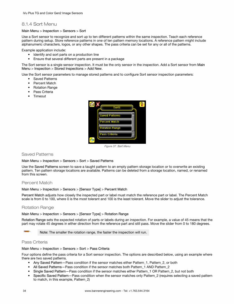
8.1.4 Sort MenuMain Menu > Inspection > Sensors > Sort
Use a Sort sensor to recognize and sort up to ten different patterns within the same inspection. Teach each referencepattern during setup. Store reference patterns in one of ten pattern memory locations. A reference pattern might includealphanumeric characters, logos, or any other shapes. The pass criteria can be set for any or all of the patterns.
Example application include:• Identify and sort parts on a production line• Ensure that several different parts are present in a package
The Sort sensor is a single sensor inspection. It must be the only sensor in the inspection. Add a Sort sensor from MainMenu > Inspection > Stored Inspections > Add New.
Use the Sort sensor parameters to manage stored patterns and to configure Sort sensor inspection parameters:• Saved Patterns• Percent Match• Rotation Range• Pass Criteria• Timeout
Figure 37. Sort Menu
Saved Patterns
Main Menu > Inspection > Sensors > Sort > Saved Patterns
Use the Saved Patterns screen to save a taught pattern to an empty pattern storage location or to overwrite an existingpattern. Ten pattern storage locations are available. Patterns can be deleted from a storage location, named, or renamedfrom this screen.
Percent Match
Main Menu > Inspection > Sensors > [Sensor Type] > Percent Match
Percent Match adjusts how closely the inspected part or label must match the reference part or label. The Percent Matchscale is from 0 to 100, where 0 is the most tolerant and 100 is the least tolerant. Move the slider to adjust the tolerance.
Rotation Range
Main Menu > Inspection > Sensors > [Sensor Type] > Rotation Range
Rotation Range sets the expected rotation of parts or labels during an inspection. For example, a value of 45 means that thepart may rotate 45 degrees in either direction from the reference part and still pass. Move the slider from 0 to 180 degrees.
Note: The smaller the rotation range, the faster the inspection will run.
Pass Criteria
Main Menu > Inspection > Sensors > Sort > Pass Criteria
Four options define the pass criteria for a Sort sensor inspection. The options are described below, using an example wherethere are two saved patterns.
• Any Saved Pattern—Pass condition if the sensor matches either Pattern_1, Pattern_2, or both• All Saved Patterns—Pass condition if the sensor matches both Pattern_1 AND Pattern_2• Single Saved Pattern—Pass condition if the sensor matches either Pattern_1 OR Pattern_2, but not both• Specific Saved Pattern—Pass condition when the sensor matches only Pattern_2 (requires selecting a saved pattern
to match, in this example, Pattern_2)
iVu Plus TG and Color Gen2 Image Sensors
34 www.bannerengineering.com - Tel: +1.763.544.3164

Timeout
Main Menu > Inspection > Sensors > [Sensor Type] > Timeout
When the sensor type is set as Match or Sort, use the Timeout screen to adjust the maximum time the inspection is allowedto execute. A timeout error is reported in the case inspection runs out of time. If this value is set too high, the sensor canmiss triggers while trying to detect a bad pattern.
8.1.5 Average Color MenuAvailable on iVu Color models only.
Main Menu > Inspection > Sensors > AvgColor
Use an Average Color sensor to visually inspect a part by analyzing all colors in the Region of Interest (ROI) and reducingthem to a single set of color values, the average of the combined colors in the ROI. The Average Color sensor is used toreport which color, on average, is being seen by the sensor.
Example applications include:• Differentiating between the colors of caps on bottles• Sorting between dark blue and light blue items on an assembly line• Matching burgundy trim pieces in automotive assembly
To configure as an Average Color sensor, set the following parameters:• ROI and Mask• Intensity Range• Color Space
Figure 38. Average Color Menu
ROI and Mask
Main Menu > Inspection > Sensors > [Sensor Type] > ROI and Mask
Note: Sensor Type in the menu path above refers to the sensor you are configuring or updating.
The Region of Interest (ROI) is the user-defined area on the screen that the sensor analyzes. The ROI type can berectangular, elliptical, or circular. From the drop-down list, select the ROI type to use for the inspection. Adjust the ROI asappropriate for the inspection. An ROI can be as large as the entire Field of View (FOV).
Select the Enable Mask checkbox to allow mask ROIs to be used with the inspection ROI.
Intensity Range
Main Menu > Inspection > Sensors > AvgColor > Intensity Range
Intensity Range allows a range of brightness in the image. In the other words, it can be used to exclude image that is toodark, too bright, or both.
To set the Intensity Range, adjust the bracket sliders.
Color Space
Main Menu > Inspection > Sensors > AvgColor > Color Space
Two color space options are available:• HSI—The average and standard deviation values for each of Hue, Saturation, and Intensity within the ROI are
calculated
iVu Plus TG and Color Gen2 Image Sensors
www.bannerengineering.com - Tel: +1.763.544.3164 35

• RGBI—The average and standard deviation values for each of Red, Green, Blue, and Intensity within the ROI arecalculated
Hue, Saturation, and Intensity (HSI) is a representation of color space that is closer to human perception of color dynamics.The greater the range of colors of the pixels within the ROI, the higher the standard deviation will be. If all pixels areuniformly the same color, the standard deviation is zero.
For Red, Green, Blue, and Intensity (RGBI):• Red—The average of the red color component, represented as a number from 0 to 255. Fully saturated red is a
[255, 0, 0].• Green—The average of the green color component, represented as a number from 0 to 255. Fully saturated green is
a [0, 255, 0].• Blue—The average of the blue color component, represented as a number from 0 to 255. Fully saturated blue is a [0,
0, 255].• Intensity—The average brightness of a color, represented in a number from 0 (black) to 255 (white).
8.1.6 Color Compare MenuAvailable on iVu Color models only.
Main Menu > Inspection > Sensors > ColorCmp
Use a Color Compare sensor to verify that a part's color matches a reference color. The Color Compare sensor looks for astatistical match for both the specific hue(s) and relative abundance of colors seen within the ROI.
Example applications include:• Verify healthy fruit color and ripeness• Verify stain color on wood• Verify product color in packaging applications
To configure as a Color Compare sensor, set the following parameters:• ROI and Mask• Color Tolerance• Intensity Tolerance
Figure 39. Color Compare Menu
ROI and Mask
Main Menu > Inspection > Sensors > [Sensor Type] > ROI and Mask
Note: Sensor Type in the menu path above refers to the sensor you are configuring or updating.
The Region of Interest (ROI) is the user-defined area on the screen that the sensor analyzes. The ROI type can berectangular, elliptical, or circular. From the drop-down list, select the ROI type to use for the inspection. Adjust the ROI asappropriate for the inspection. An ROI can be as large as the entire Field of View (FOV).
Select the Enable Mask checkbox to allow mask ROIs to be used with the inspection ROI.
Color Tolerance
Main Menu > Inspection > Sensors > ColorCmp > Color Tolerance
Use Color Tolerance to adjust the maximum acceptable difference (in %) between the taught color and the color detected inthe live image.
The live value drawn inside the slider indicates the color difference for the current image. Move the slider to the right toincrease the maximum acceptable difference.
iVu Plus TG and Color Gen2 Image Sensors
36 www.bannerengineering.com - Tel: +1.763.544.3164

Intensity Tolerance
Main Menu > Inspection > Sensors > ColorCmp > Intensity Tolerance
Intensity Tolerance defines the grayscale brightness level necessary to constitute a match. This value ranges from 0 to 255.
As the Intensity Tolerance value is changed, the acceptable minimum and maximum limits on either side of the Referenceare calculated. When this tolerance is set to 0, only the taught intensity of each color is acceptable; that is, no change inintensity is allowed. Or, to say it another way, the intensity of illumination for a given color target cannot change.
8.1.7 Color Area MenuAvailable on iVu Color models only.
Main Menu > Inspection > Sensors > ColorArea
Use a Color Area sensor to separate same color blobs, or Binary Large Objects, from the larger scene and to analyze partswith color variations that cannot accurately be detected by gray scale sensors. Use an Color Area sensor to ensure that aspecific color feature, or multiple features, are present on a part. If there is more than one of the identified features on apart, the number expected can be set as well. During the inspection, the sensor verifies that each part or package includesthe correct color and specified number of features.
Example applications include:• Verify a fuse and its color, such as dark blue or light blue• Check how many red parts are present• Verify the color and correct number of objects in a case
To configure as a Color Area sensor, set the following parameters:• ROI and Mask• Color Select• Area Range• Pass Count• Tolerance
Figure 40. Color Area Menu
ROI and Mask
Main Menu > Inspection > Sensors > [Sensor Type] > ROI and Mask
Note: Sensor Type in the menu path above refers to the sensor you are configuring or updating.
The Region of Interest (ROI) is the user-defined area on the screen that the sensor analyzes. The ROI type can berectangular, elliptical, or circular. From the drop-down list, select the ROI type to use for the inspection. Adjust the ROI asappropriate for the inspection. An ROI can be as large as the entire Field of View (FOV).
Select the Enable Mask checkbox to allow mask ROIs to be used with the inspection ROI.
Color Select
Main Menu > Inspection > Sensors > ColorArea > Color Select
Use Color Select to select the color the Color Area sensor looks for. Click Color Selector then click the desired color inthe ROI. Adjust the color tolerance using + and -.
Note: You can select a color that is outside of the ROI, but a BLOB of that color will only be detectedwithin the ROI.
iVu Plus TG and Color Gen2 Image Sensors
www.bannerengineering.com - Tel: +1.763.544.3164 37

Area Range
Main Menu > Inspection > Sensors > [Sensor Type] > Area Range
Use Area Range to set the size limits of a feature of interest. Move the slider to select the range. Areas are measured bycounting pixels. For example, a rectangular feature that is 100 pixels wide by 200 pixels tall has an area of roughly 20,000pixels.
Pass Count
Main Menu > Inspection > Sensors > [Sensor Type] > Pass Count
The Minimum Pass Count is the minimum number of parts, labels, or features expected to fall within the specified criteria.The Maximum Pass Count is the maximum number expected to fall within the specified criteria. These settings are used todetermine the pass or fail result of the inspection.
Tolerance
Main Menu > Inspection > Sensors > ColorArea > Tolerance
Adjust the tolerance for the color the sensor is looking for. Adjustments are made individually for hue, saturation, andintensity.
8.2 Motion MenuMain Menu > Inspection > Motion
Enable Motion when the part being inspected is expected to move or rotate. Motion settings involve selecting the number ofedges to locate, adjusting sensitivity, and selecting whether rotation is enabled. These settings are available on theInspection Menu after Motion is set to Enabled. Motion is not available for Match or Sort sensors.
Figure 41. Motion Menu
8.2.1 Number of EdgesMain Menu > Inspection > Motion > Number of Edges
On the Number of Edges screen, use the option buttons to select One Edge or Two Edges. If One Edge is selected, motionis tracked in one direction (by default, horizontally). If Two Edges is selected, motion can be tracked horizontally andvertically.
8.2.2 SensitivityMain Menu > Inspection > Motion > Sensitivity
Use Sensitivity to fine-tune how sensitive the sensor is to finding a reference edge.
The sensitivity value helps account for light variations that might affect how well the sensor detects edges on inspectedparts. The sensitivity scale is from 0 to 100, where 0 means least sensitive and 100 means most sensitive. If set near 0, thesensor only finds very sharp edges with strong contrast. If set near 100, the sensor finds very dim or blurry edges, and maybe unstable due to noise within the image.
8.2.3 RotationMain Menu > Inspection > Motion > Rotation
Rotation can be enabled or disabled. Select Enabled if the part can be expected to rotate during the inspection.
iVu Plus TG and Color Gen2 Image Sensors
38 www.bannerengineering.com - Tel: +1.763.544.3164
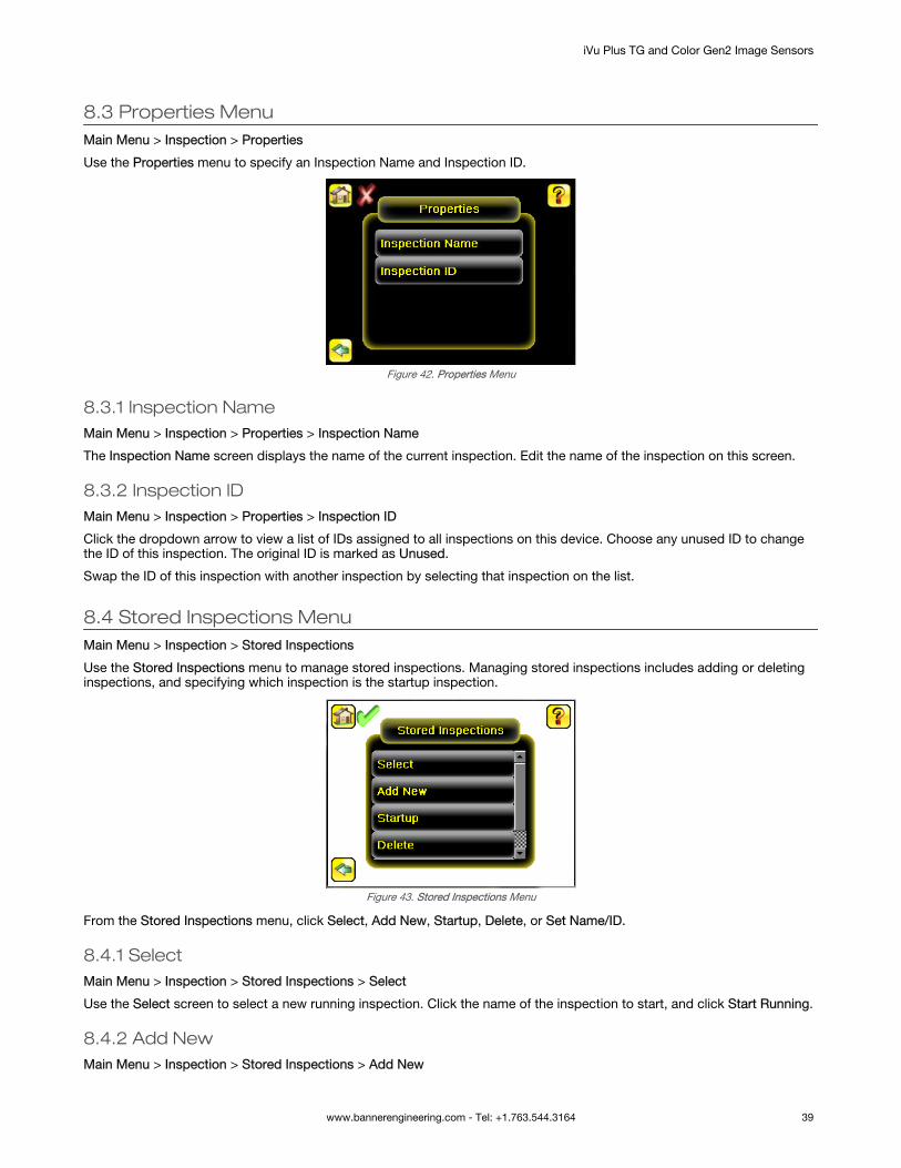
8.3 Properties MenuMain Menu > Inspection > Properties
Use the Properties menu to specify an Inspection Name and Inspection ID.
Figure 42. Properties Menu
8.3.1 Inspection NameMain Menu > Inspection > Properties > Inspection Name
The Inspection Name screen displays the name of the current inspection. Edit the name of the inspection on this screen.
8.3.2 Inspection IDMain Menu > Inspection > Properties > Inspection ID
Click the dropdown arrow to view a list of IDs assigned to all inspections on this device. Choose any unused ID to changethe ID of this inspection. The original ID is marked as Unused.
Swap the ID of this inspection with another inspection by selecting that inspection on the list.
8.4 Stored Inspections MenuMain Menu > Inspection > Stored Inspections
Use the Stored Inspections menu to manage stored inspections. Managing stored inspections includes adding or deletinginspections, and specifying which inspection is the startup inspection.
Figure 43. Stored Inspections Menu
From the Stored Inspections menu, click Select, Add New, Startup, Delete, or Set Name/ID.
8.4.1 SelectMain Menu > Inspection > Stored Inspections > Select
Use the Select screen to select a new running inspection. Click the name of the inspection to start, and click Start Running.
8.4.2 Add NewMain Menu > Inspection > Stored Inspections > Add New
iVu Plus TG and Color Gen2 Image Sensors
www.bannerengineering.com - Tel: +1.763.544.3164 39

Use Add New to add a new inspection. The iVu can store up to 30 inspections. When you add a new inspection, it beginsrunning. Set the Sensor Type and the inspection name when adding a new inspection.
Figure 44. Add New Screen
Figure 45. New Inspection Screen
8.4.3 StartupMain Menu > Inspection > Stored Inspections > Startup
Click Startup to select the inspection to use as the startup inspection. The selected inspection automatically starts after theiVu powers up.
8.4.4 Delete InspectionsMain Menu > Inspection > Stored Inspections > Delete
Click Delete to delete stored inspections. Note that any running inspection, or the inspection marked as the Startupinspection, cannot be deleted.
8.4.5 Set Name/IDMain Menu > Inspection > Stored Inspections > Set Name/ID
Use Set Name/ID to change the name or ID of an inspection. Sort the inspections in numeric or alphabetical order byclicking on the icon beside the Help icon. Click Name to edit the name of the inspection. Click ID to change the ID of theinspection.
iVu Plus TG and Color Gen2 Image Sensors
40 www.bannerengineering.com - Tel: +1.763.544.3164

9 Imager MenuMain Menu > Imager
The Imager menu icon is on the Main Menu, and lists parameters that affect the characteristics of the captured image. UseImager menu to access the auto exposure routine, manually adjust exposure and gain, set trigger and strobe options, aswell as set the size of the Field of View (FOV).
Figure 46. Imager Menu
9.1 Auto ExposureMain Menu > Imager > Auto Exposure
Auto Exposure optimizes the exposure time and gain for the current lighting conditions. Multiple triggers are required tocomplete this function.
Note: The Auto Exposure option is not available on the Emulator.
9.2 ExposureMain Menu > Imager > Exposure
Exposure is the amount of time the iVu allows light to energize the imager. Increasing the exposure time by moving theslider to the right allows more light to energize the imager, which brightens the image.
Figure 47. Exposure Screen
Note: This feature is not effective on the emulator.
9.3 GainMain Menu > Imager > Gain
Gain is an electronic boost to the image signal. Increasing Gain by using the '-' and '+' buttons or moving the slider to theright increases image brightness without increasing exposure time. Note that Gain brightens both the light pixels and darkpixels and may reduce the image quality.
iVu Plus TG and Color Gen2 Image Sensors
www.bannerengineering.com - Tel: +1.763.544.3164 41

Figure 48. Gain Screen
Note: This feature is not effective on the emulator.
9.4 TriggerMain Menu > Imager > Trigger
A trigger is a signal that tells the iVu to capture an image and inspect it.
Five trigger options are available:• External Trigger—inspections are triggered in response to an electrical signal on the Trigger input line• Internal Trigger (default)—triggers are based on timed intervals. Select a trigger interval between 10 and 10000
milliseconds
Note: If the interval is less than the inspection time, missed triggers will occur.
• Free Run—the iVu automatically runs continuous inspections• Industrial Ethernet Only— only Trigger commands from the Industrial Ethernet communications channel are
accepted.• Command—the command channel triggers the iVu from a remote device
Figure 49. Trigger Screen
9.5 FocusMain Menu > Imager > Focus
The Focus Number displayed at the bottom of this screen is used to fine-tune image focus. Loosen the lock on the lenscover, turn the focus ring on the iVu until the Focus Number peaks (or the image appears sharp), then lock the focus ring.
Note: For the Focus Number to work, the iVu must be triggering and the images must be similar over time.
iVu Plus TG and Color Gen2 Image Sensors
42 www.bannerengineering.com - Tel: +1.763.544.3164

Figure 50. Focus Screen
9.6 Strobe MenuMain Menu > Imager > Strobe
The Internal Strobe configures the operation of the integrated ring light. The External Strobe configures the operation of anexternal light.
Figure 51. Strobe Menu
9.6.1 ExternalMain Menu > Imager > Strobe > External
The External Strobe is a 5 V dc output used for an external light. Setting options are Always ON, Always OFF, or ExposureBased. If Exposure Based is selected, the external light is on during the time the iVu is capturing an image.
This setting affects all inspections.
9.6.2 InternalMain Menu > Imager > Strobe > Internal
The Internal Strobe setting configures the operation of the integrated ring light. Strobe options are Always ON, Always OFF,or Exposure Based. If Exposure Based is selected, the ring light is on during the time the iVu is capturing an image. Forultraviolet (UV) models, the Always ON option is not available.
This setting affects all inspections.
9.7 FOV (Field of View)Main Menu > Imager > FOV
The Field of View (FOV) is the area that the iVu can see at a given working distance. The working distance is the distancefrom the lens cover to the part being inspected. The effective FOV can be reduced to speed up the processing time of aninspection or to decrease background noise.
9.7.1 Adjust the Field of View (Grayscale Models only)Select the resize icons to adjust the FOV. After pressing the back button, the Imager menu FOV button updates to say"Custom" to indicate that a custom FOV is in use.
iVu Plus TG and Color Gen2 Image Sensors
www.bannerengineering.com - Tel: +1.763.544.3164 43

Figure 52. Imager Menu
If the FOV has been modified and you want to return to the default, click Set Default. The green box representing the FOVmoves and the button changes to Set Max. The default for Fine resolution is 640×480 pixels and the default for Coarseresolution is 320×240 pixels.
Figure 53. Set Maximum FOV
The maximum FOV is 752×480 for Fine resolution and 376×240 for Coarse resolution. To set the FOV to the maximum, clickSet Max. The green box representing the FOV expands to fill the screen and the button changes to Set Default.
Figure 54. Set Default FOV
9.8 ResolutionSystem > Imager > Resolution
Resolution is available for iVu TG models. It is not available on iVu color models.
Two resolution options are available on the iVu: Fine and Coarse.
iVu Plus TG and Color Gen2 Image Sensors
44 www.bannerengineering.com - Tel: +1.763.544.3164

Figure 55. Resolution Screen
Coarse resolution has a maximum FOV of 376×240 pixels, and Fine resolution has a maximum FOV of 752×480 pixels. Fineresolution has four times more pixels than Coarse resolution. Inspection performance may be affected when using Fineresolution, depending on the application. By default, the FOV is set to the default FOV size (320×240) in Coarse resolutionmode.
When a new resolution is selected, Match and Sort patterns must be taught again. A trigger is required before any on-screen data is updated.
Any sensor within the inspection will use the selected resolution. Only one resolution is used per inspection.
9.9 White BalanceUse White Balance to adjust the intensities of the colors in the image so that the colors most closely match the actualobjects. The White Balance setting is stored with each inspection. White Balance is an automatic process that is onlyavailable on color models.
Figure 56. White Balance Screen
iVu Plus TG and Color Gen2 Image Sensors
www.bannerengineering.com - Tel: +1.763.544.3164 45

10 System MenuMain Menu > System
The System menu icon is on the Main Menu, and is used to manage the iVu device. From the System menu, select theMode, update the device firmware, back up or restore the device configuration, and perform other general system leveloperations.
Figure 57. System Menu
10.1 ModeMain Menu > System > Mode
The iVu has two operating modes:• Live Mode, which is the normal operating mode where the iVu captures live images, scans, and verifies inspections• Demo Mode, where inspections are run on stored images and inspection parameters
The first time the iVu is powered up, it starts in Demo Mode. You can choose whether to stay in Demo Mode or exit to LiveMode. Demo Mode uses stored images and inspection parameters that demonstrate how the iVu is set up, without havingto worry about focus, lighting, or triggers. In this mode, practice making adjustments while working with the different sensortypes and observing how the adjustments affect the results. To exit Demo Mode, go to Main Menu > System > Mode andselect Exit Demo Mode. Upon exit, the iVu restarts in the normal operating mode with the default settings.
Note: Switch between Live Mode and Demo Mode any time by going to Main Menu > System > Mode.
10.2 System Configuration MenuMain Menu > System > Configuration
The Configuration screen allows users to save configurations, load new configurations, or reset the device to default values.
The configuration options are:• Save to USB—Save the device configuration to a USB flash drive• Load from USB—Load the device configuration from the USB flash drive• Reset to Defaults—Reset the device configuration to defaults
Figure 58. Configuration Menu
10.2.1 Save to USBMain Menu > System > Configuration > Save to USB
iVu Plus TG and Color Gen2 Image Sensors
46 www.bannerengineering.com - Tel: +1.763.544.3164

The Save to USB screen allows the device configuration to be saved to a USB flash drive. The saved configurationinformation can be used as a backup or to clone configuration information for other devices.
Note: On the Emulator, this option is Save Configuration.
10.2.2 Load from USBMain Menu > System > Configuration > Load from USB
The Load from USB screen allows the device configuration to be restored from a USB flash drive. This operation removesall existing inspections and replaces them with inspections contained in the configuration file on the USB flash drive.
Note: On the Emulator, this option is Load Configuration.
10.2.3 Reset to DefaultsMain Menu > System > Configuration > Reset to Defaults
Resets the device to factory default state:• All existing inspections are deleted• All imager and system settings are reset to factory defaults• For color models, white balance settings are reset to the factory defaults• Device-specific information such as the sensor name and Ethernet settings are not changed• System Log information is retained
The device reboots after this operation is complete.
Figure 59. Reset to Defaults Screen
10.3 System InformationMain Menu > System > Information
The Information screen displays device information:• Serial Number• Firmware Version• Boot Number• Up Timer—the time elapsed since last boot up of the device• Hour Count—the total hours of operation in the device's lifetime• Model Number• Device Name
Click the right-arrow next to Device Name to display a keyboard that allows you to change the name of the device. You mayset the device name in English on the device. To set the device name in any other language, use the Emulator.
10.4 Lock DeviceMain Menu > System > Lock Device
Lock the device to prevent accidental modification of settings. When locked, the device only provides access to pass/failstatistics, as well as the ability to view logs and to save them to a USB device. A lock icon in the upper left corner of thedisplay indicates that the device is locked.
iVu Plus TG and Color Gen2 Image Sensors
www.bannerengineering.com - Tel: +1.763.544.3164 47

The device can be locked with or without a password. If a password is not used, click Unlock Device to unlock the device.When a password is used, it must be 4 digits entered using the keypad. If the password is lost, contact Banner Engineeringto obtain a Reset Key.
Note: This menu option is not available in the Emulator.
10.5 Communications MenuMain Menu > System > Communications
Use the Communications menu to configure the serial I/O channel. There are six menu options:
• Ethernet I/O for configuring the Ethernet port• Serial I/O for configuring the Serial port• Industrial Ethernet settings• Command Channel for sending commands to get specific data through Serial or Ethernet channels.• Data Export Channel for enabling or disabling the channel for data export only• Image Export Channel for enabling or disabling the channel for image export only
Note: Serial I/O can be configured either for Data Export or Command Channel. Image Export is onlyavailable on Ethernet.
Figure 60. Communications Menu
10.5.1 Ethernet I/OMain Menu > System > Communications > Ethernet I/O
Use Ethernet communications to send data out the Ethernet port as part of an inspection, and so that remote devices cancommunicate with the iVu. Configure the IP Address, Subnet Mask, and Gateway settings from the Ethernet I/O screen. Usethe expand arrow next to each field to display a keypad to enter values for each field. Click Status to verify communicationsas you connect to remote devices.
Figure 61. Ethernet I/O Screen
Ethernet I/O Status
Main Menu > System > Communications > Ethernet I/O > Status
Use the Ethernet I/O Status screen to verify that the Ethernet wiring is correct. In addition to determining whether the linkhas been established, incoming and outgoing traffic can be monitored.
iVu Plus TG and Color Gen2 Image Sensors
48 www.bannerengineering.com - Tel: +1.763.544.3164
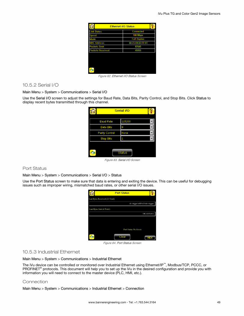
Figure 62. Ethernet I/O Status Screen
10.5.2 Serial I/OMain Menu > System > Communications > Serial I/O
Use the Serial I/O screen to adjust the settings for Baud Rate, Data Bits, Parity Control, and Stop Bits. Click Status todisplay recent bytes transmitted through this channel.
Figure 63. Serial I/O Screen
Port Status
Main Menu > System > Communications > Serial I/O > Status
Use the Port Status screen to make sure that data is entering and exiting the device. This can be useful for debuggingissues such as improper wiring, mismatched baud rates, or other serial I/O issues.
Figure 64. Port Status Screen
10.5.3 Industrial EthernetMain Menu > System > Communications > Industrial Ethernet
The iVu device can be controlled or monitored over Industrial Ethernet using Ethernet/IP™, Modbus/TCP, PCCC, orPROFINET® protocols. This document will help you to set up the iVu in the desired configuration and provide you withinformation you will need to connect to the master device (PLC, HMI, etc.).
Connection
Main Menu > System > Communications > Industrial Ethernet > Connection
iVu Plus TG and Color Gen2 Image Sensors
www.bannerengineering.com - Tel: +1.763.544.3164 49

Use the Connection to enable Ethernet/IP, PROFINET, Modbus or or PCCC protocols on the Industrial Ethernet channel.Select Disable to completely disable the Industrial Ethernet channel.
Map
Main Menu > System > Communications > Industrial Ethernet > Map
The Map setting (Default/Custom) affects only I/O Assembly 0×65 or MODBUS/PCCC registers 30001 to 30240 at offset55-166.
Default Map
Main Menu > System > Communications > Industrial Ethernet > Map > Default
The default map automatically maps sensor data for each inspection and is recommended when the execution order ofsensor types is the same across inspections. When an inspection includes multiple sensors, the first five sensor results areshown starting at offset 55. Each sensor result occupies 20 words.
Table 6: I/O Assembly Instance 101 (0×65): DEFAULT MAP
WORD # WORD NAME Data Type
0 Input Bits ACK Register (see Input and Output Flags Bits on page 127) 16-bit integer
1 Output Bits Register (see Input and Output Flags Bits on page 127) 16-bit integer
2-3 Error Code 32-bit integer
4-5 Inspection Number 32-bit integer
6-7 Iteration Count 32-bit integer
8-9 Pass Count 32-bit integer
10-11 Fail Count 32-bit integer
12-13 Missed Triggers 32-bit integer
14-15 Current Inspection Time Float
16 Sensor Pass/Fail Coil 16-bit integer
17-29 reserved 16-bit integer
30-52 Inspection Name 2-Word Length + 20-Unicode characters
53-54 Frame Number 32-bit integer
55 Sensor Type ID (Sensor 1) 16-bit integer
56-74 Sensor 1 Specific Data 16-bit integer
75 Sensor Type ID (Sensor 2) 16-bit integer
76-94 Sensor 2 Specific Data 16-bit integer
95 Sensor Type ID (Sensor 3) 16-bit integer
96-114 Sensor 3 Specific Data 16-bit integer
115 Sensor Type ID (Sensor 4) 16-bit integer
116-134 Sensor 4 Specific Data 16-bit integer
135 Sensor Type ID (Sensor 5) 16-bit integer
136-154 Sensor 5 Specific Data 16-bit integer
155-170 reserved 16-bit integer
171 Command Status 16-bit integer
172 Command Response Int16 16-bit integer
173-174 Command Response Int32 32-bit integer
175-176 Command Response Float Float
177-178 Command Response Length 32-bit integer
iVu Plus TG and Color Gen2 Image Sensors
50 www.bannerengineering.com - Tel: +1.763.544.3164

WORD # WORD NAME Data Type
179-228 Command Response Data 100-Byte Array
229-239 reserved 16-bit integer
Note: If the inspection contains more than five sensors, any sensors after the fifth sensor are not includedon the map.
Table 7: Area Sensor ID = 2
Sensor Specific Data Data Size
Area Count 32-bit integer
Area Range Minimum 32-bit integer
Area Range Maximum 32-bit integer
Table 8: Blemish Sensor ID = 3
Sensor Specific Data Sensor Location
Blemish Count 32-bit integer
Blemish Minimum Edge Length 32-bit integer
Blemish Maximum Edge Length 32-bit integer
Table 9: Match Sensor ID = 4
Sensor Specific Data Sensor Location
Match Count 32-bit integer
Match Minimum Percent 16-bit integer
Match Maximum Percent 16-bit integer
Table 10: Sort Sensor ID = 5
Sensor Specific Data Sensor Location
Sort Pattern Map 16-bit integer
Sort Pattern Count 16-bit integer
Sort Pattern 1 Count 16-bit integer
Sort Pattern 2 Count 16-bit integer
Sort Pattern 3 Count 16-bit integer
Sort Pattern 4 Count 16-bit integer
Sort Pattern 5 Count 16-bit integer
Sort Pattern 6 Count 16-bit integer
Sort Pattern 7 Count 16-bit integer
Sort Pattern 8 Count 16-bit integer
Sort Pattern 9 Count 16-bit integer
Sort Pattern 10 Count 16-bit integer
Sort Minimum Percent Match 16-bit integer
Sort Maximum Percent Match 16-bit integer
iVu Plus TG and Color Gen2 Image Sensors
www.bannerengineering.com - Tel: +1.763.544.3164 51

Table 11: Average Color Sensor ID = 6
Sensor-Specific Data Data Size
Average Red 16‐bit Integer
Average Green 16‐bit Integer
Average Blue 16‐bit Integer
Average Hue 16‐bit Integer
Average Saturation 16‐bit Integer
Average Intensity 16‐bit Integer
Standard Deviation Red 32-bit float
Standard Deviation Green 32-bit float
Standard Deviation Blue 32-bit float
Standard Deviation Hue 32-bit float
Standard Deviation Saturation 32-bit float
Standard Deviation Intensity 32-bit float
Note: Average Color Sensor data that does not apply to the selected color space has a result of 0. Forexample, if the HSI color space is selected, the Red, Green, and Blue data will have a result of 0.
Table 12: Color Compare Sensor ID = 7
Sensor-Specific Data Data Size
Color Difference 16‐bit Integer
Intensity Difference 16‐bit Integer
Table 13: Color Area Sensor ID = 8
Sensor-Specific Data Data Size
Area Count 32‐bit Integer
Area Range Minimum 32‐bit Integer
Area Range Maximum 32‐bit Integer
Custom Map
Main Menu > System > Communications > Industrial Ethernet > Map > Custom
The custom map allows for the customization of sensor data on the map. The user selects data items of interest for eachsensor type. This is recommended when the execution order of sensor types varies across inspections or when using morethan five sensors.
A system-level custom map is supported for additional flexibility. When Custom map is selected, a customizable space isused in the offset range (55 to 166) on I/O Assembly 101 (0×65) registers.
Table 14: I/O Assembly Instance 101 (0×65): CUSTOM MAP
WORD # WORD NAME Data Type
0 Input Bits ACK Register (see Input and Output Flags Bits on page 127) 16-bit integer
1 Output Bits Register (see Input and Output Flags Bits on page 127) 16-bit integer
2-3 Error Code 32-bit integer
4-5 Inspection Number 32-bit integer
6-7 Iteration Count 32-bit integer
iVu Plus TG and Color Gen2 Image Sensors
52 www.bannerengineering.com - Tel: +1.763.544.3164

WORD # WORD NAME Data Type
8-9 Pass Count 32-bit integer
10-11 Fail Count 32-bit integer
12-13 Missed Triggers 32-bit integer
14-15 Current Inspection Time Float
16 Sensor Pass/Fail Coil 16-bit integer
17-29 reserved 16-bit integer
30-52 Inspection Name 2-Word Length + 20-unicode characters
53-54 Frame Number 32-bit integer
55-166 Customizable Space (112 reg) 16-bit integer
167-170 reserved 16-bit integer
171 Command Status 16-bit integer
172 Command Response Int16 16-bit integer
173-174 Command Response Int32 32-bit integer
175-176 Command Response Float Float
177-178 Command Response Length 32-bit integer
179-228 Command Response Data 100-Byte Array
229-239 reserved 16-bit integer
Custom Map Export
Main Menu > System > Communications > Industrial Ethernet > Map > Custom > (Save icon)
To export the custom map, click to save a text listing of the map to an attached USB flash drive (Filename:iVuIEMap.csv). The Emulator also supports this operation. iVuIEMap.csv will be saved on the application folder.
Status
Main Menu > System > Communications > Industrial Ethernet > Status
The Status screen displays information about the current connection. This information is protocol specific.
View Logs
Main Menu > System > Communications > Industrial Ethernet > View Logs
The View Logs screen displays the list of recent events on Industrial Ethernet channel. When troubleshooting, selectdetailed logs under Setup.
10.5.4 Command ChannelMain Menu > System > Communications > Command Channel
The iVu command channel is a bi-directional communication protocol that currently supports ASCII via the RS-232 serialinterface or Ethernet interface, and enables other devices to remotely control the iVu and to access device information andinspection results.
iVu Plus TG and Color Gen2 Image Sensors
www.bannerengineering.com - Tel: +1.763.544.3164 53

Figure 65. Command Channel Menu
Connection
Main Menu > System > Communications > Command Channel > Connection
Use the Connection screen to enable or disable the Command Channel.
Figure 66. Connection Screen
Delimiters
Main Menu > System > Communications > Command Channel > Delimiters
Three delimiter options are available from the Delimiters screen:• Field Delimiter—Determines what is used to separate data that the iVu is sending out to a remote device.• End of Frame—Determines the delimiter used to indicate the end of a frame.• String Delimiter—Determines what is used to enclose a string field during both input and output operations.
Use the drop-down lists to select the appropriate delimiter. The example at the lower part of the screen displays how thedata will look in the output or input streams.
Figure 67. Delimiters Screen
10.5.5 Data Export MenuMain Menu > System > Communications > Data Export
When Data Export is enabled, the iVu transmits selected inspection data when triggered.
iVu Plus TG and Color Gen2 Image Sensors
54 www.bannerengineering.com - Tel: +1.763.544.3164

Figure 68. Data Export Menu
Connection
Main Menu > System > Communications > Data Export > Connection
Use the Connection screen to enable or disable the Data Export.
Data To Export
Main Menu > System > Communications > Data Export > Data To Export
Use the Data To Export screen to determine the information included in a data export. Data outputs in the order displayedon the screen.
Note: Grab the edge of the Data To Export screen and pull down to allow all information to show.
Figure 69. Data to Export Screen
Output Format
Main Menu > System > Communications > Data Export > Output Format
In the Output Format screen, use the drop-down lists to select Start and End Strings as well as Delimiter. The Example fieldshows how the data will look when it is output.
iVu Plus TG and Color Gen2 Image Sensors
www.bannerengineering.com - Tel: +1.763.544.3164 55

Figure 70. Output Format Screen
Data Export Advanced
Main Menu > System > Communications > Data Export > Advanced
During the Data and Image export operation, the iVu output channels might become full. This can occur if the iVu isproducing export data (frames) faster than the data can be exported from the device or faster than the client is reading thechannel export data (due to bandwidth limitations).
The Advanced setting affects how the iVu behaves in this situation.
Select Hold READY to ensure that all frames are transmitted. In this case, the READY signal remains inactive (iVu is busy)until the new frame has been added to the channel for transmission. Triggers might be missed during this time.
Select Do not hold READY to cause the iVu to discard the new frame if the channel is full and thus activate the READYsignal immediately after the current inspection is complete. In this case, the discarded frames are not transmitted.
Figure 71. Advanced Screen
Note: This setting affects both the Data Export Channel and Image Export Channel.
10.5.6 Image ExportMain Menu > System > Communications > Image Export
When the Image Export Channel is enabled, the iVu transmits the acquired image on every trigger. The image is transmittedas a bitmap (.bmp) file. This operation is only available over Ethernet I/O.
Connection
Main Menu > Communications > Image Export > Connection
Use the Connection screen to enable or disable the Image Export.
Image Type
Main Menu > System > Image Export > Image Type
On the Image Type screen, choose between .jpg or .bmp format for the exporting image file.
Image Export Advanced
Main Menu > System > Communications > Image Export > Advanced
iVu Plus TG and Color Gen2 Image Sensors
56 www.bannerengineering.com - Tel: +1.763.544.3164

During the Data and Image export operation, the iVu output channels might become full. This can occur if the iVu isproducing export data (frames) faster than the data can be exported from the device or faster than the client is reading thechannel export data (due to bandwidth limitations).
The Advanced setting affects how the iVu behaves in this situation.
Select Hold READY to ensure that all frames are transmitted. In this case, the READY signal remains inactive (iVu is busy)until the new frame has been added to the channel for transmission. Triggers might be missed during this time.
Select Do not hold READY to cause the iVu to discard the new frame if the channel is full and thus activate the READYsignal immediately after the current inspection is complete. In this case, the discarded frames are not transmitted.
Figure 72. Advanced Screen
Note: This setting affects both the Data Export Channel and Image Export Channel.
10.6 Discrete I/O MenuMain Menu > System > Discrete I/O
Use the Discrete I/O menu to adjust iVu input and output settings.
Figure 73. Discrete I/O Menu
10.6.1 Input PolarityMain Menu > System > Discrete I/O > Input Polarity
The iVu has two input signals—Trigger and Remote Teach. Both of these signals are edge sensitive. The operation of thesesignals is dependent on the Input Polarity setting.
• Low-To-High—The Trigger and Remote Teach are detected on a low to high transition of the signal• High-To-Low—The Trigger and Remote Teach are detected on a high to low transition of the signal
The default setting for a PNP device is Low-To-High, and for an NPN device it is High-To-Low. Change the setting on theInput Polarity screen.
iVu Plus TG and Color Gen2 Image Sensors
www.bannerengineering.com - Tel: +1.763.544.3164 57

Figure 74. Input Polarity Screen
10.6.2 Input PullupMain Menu > System > Discrete I/O > Input Pullup
By default, the Input Pullup is disabled. If the device used to trigger and remote teach the iVu is a NPN device, enable InputPullup here if that device does not have its own pullup resistor. Otherwise, this should be disabled.
10.6.3 Output TypeMain Menu > System > Discrete I/O > Output Type
Select NPN to configure the device's outputs to sink current. Select PNP to configure the device's output for sourcecurrent.
10.6.4 Output 1, 2, and 3Main Menu > System > Discrete I/O > Output (#)
Figure 75. Discrete I/O Menu
Output 1, 2, and 3 are set up separately to improve flexibility and simplicity.
Output can be configured for Inspection Pass, Inspection Fail, Sensor Pass, Sensor Fail, Sort Pattern #1, Missed Trigger orSystem Error.
A Missed Trigger condition occurs when a trigger is received while the iVu is busy inspecting the previous image. Thisoutput signal is set to active state. This signal will be reset up on resetting the History on the statistics screen.
A System Error condition occurs when a fatal error is detected on the device. This output signal will be set to active state.This signal can be reset upon resetting the History on the statistics screen, or executing a ClearSystemError commandthrough command channel.
The default setting is Inspection Pass and Latched for Output 1. If Pulsed is selected, the default Pulse width is 50 ms.
Note: For Latched, the signal is active until the results of an inspection cause a change in the signaloutput.
iVu Plus TG and Color Gen2 Image Sensors
58 www.bannerengineering.com - Tel: +1.763.544.3164

Figure 76. Output # Screen
When either Sensor Pass or Sensor Fail is selected, additional settings become available as shown in Figure 77 on page59.
Figure 77. Output # Screen with Additional Settings
Click the yellow arrow to access the Select Sensor screen.
Figure 78. Select Sensor(s) Screen
On the Select Sensor screen, the check box allows sensor position to be part of the logic that activates the output. One ormore sensor positions can be added. The right column shows the sensor name(s) and their respective position from thecurrent inspection for reference.
The drop-drop list has two settings:
• All Selected—All checked sensor positions must meet the setting criteria (Pass/Fail) to activate the output• Any Selected—Any checked sensor position that meets the setting criteria (Pass/Fail) will activate the output
When a selected sensor position is missing on the current inspection, the missing sensor(s) will not be part of the logic toactivate the output. For example, when only 2 sensors are included on the current inspection and the Output > SelectSensor(s) has Sensor #1, Sensor #2, and Sensor #3 checked, only Sensor #1 and Sensor #2 are used to determine theoutput state. This is because Sensor #3 is not defined by the current inspection.
10.7 Display SettingsMain Menu > System > Display Settings
iVu Plus TG and Color Gen2 Image Sensors
www.bannerengineering.com - Tel: +1.763.544.3164 59

Use the Display Settings menu to set the Fail Hold Time, LCD Timeout, and to perform a Touch Calibration for thetouchscreen display. Enable display optimization from the Advanced menu.
10.7.1 Fail Hold TimeMain Menu > System > Display Settings > Fail Hold Time
The Fail Hold Time determines how long a failed image is shown on the display so that you can see what failed. The iVucontinues to process any triggers and the inspection continues normally. This time delay is only for the touchscreen display.Set this parameter from 0 seconds to 3600 seconds using the slider.
Figure 79. Fail Hold Time Screen
10.7.2 LCD TimeoutMain Menu > System > Display Settings > LCD Timeout
When the device is not being used, the display dims after a user-selectable period of time. Use the arrow keys or the sliderto set the display time out.
Note: This screen is not available in the Emulator.
10.7.3 Touch CalibrationMain Menu > System > Display Settings > Touch Calibration
Touchscreen calibration may be necessary if the software does not correctly respond when an icon on the screen ispressed. The calibration routine aligns the touchscreen's coordinates to the display behind it. Follow the prompts on thescreen when executing the touchscreen calibration function.
Note: This screen is not available in the Emulator.
10.7.4 AdvancedMain Menu > System > Display Settings > Advanced
The Advanced Display screen allows you to enable the Optimize Display Response option. This feature helps make thedisplay more responsive when the iVu is busy (either inspection times are long and/or no idle time exists betweeninspections). Disable this feature if missed triggers occur due to touchscreen presses. With this setting disabled, the displaymay become sluggish when the iVu is busy.
10.8 Reboot SensorMain Menu > System > Reboot Sensor
The Reboot Sensor screen allows you to force a reboot of the device.
Note: This option is not available on the Emulator.
10.9 Firmware UpdateMain Menu > System > Firmware Update
iVu Plus TG and Color Gen2 Image Sensors
60 www.bannerengineering.com - Tel: +1.763.544.3164

Use the Firmware Update screen to load the latest device firmware. The Firmware Update screen lists the firmware versionsit finds in the BANNER\FIRMWARE folder on the USB flash drive. When you receive a firmware update from BannerEngineering, be sure to put it in the BANNER\FIRMWARE folder on the USB flash drive.
Note: The Firmware Update menu is not available in the Emulator.
10.10 iVu Trigger, Remote Teach, and I/O WaveformsThe iVu has two input signals—Trigger and Remote Teach. The default setting is to detect the low to high transition. Tochange this setting, go to Main Menu > System > Discrete I/O > Input Polarity on the iVu.
10.10.1 PNP (Low-to-High) Trigger and Remote Teach Input Waveforms
Power up
Trigger
RemoteTeach
Pink
Wire Color Function
Gray
The iVu triggers from low to high, and Remote Teach behaves electrically like trigger.
Note:
Table 15: Required iVu Input Signal Voltage
ON OFF
PNP +10 V dc to 30 V dc < 2 V dc
10.10.2 NPN (High-to-Low) Trigger and Remote Teach Input Waveforms
Trigger
RemoteTeach
Pink
Wire Color Function
Gray
Power up
The iVu triggers from high to low, and Remote Teach behaves electrically like trigger.
Note:
Table 16: Required iVu Input Signal Voltage
ON OFF
NPN < 2 V dc +10 V dc to 30 V dc
iVu Plus TG and Color Gen2 Image Sensors
www.bannerengineering.com - Tel: +1.763.544.3164 61

Note: If the device used to trigger or remote teach the iVu is a sinking device, these are the optionsregarding the use of a pull-up resistor:
Option 1: Put a pull-up resistor, rated approximately 1 kΩ, between the device's positive (+) voltage andthe device's input as shown below.
Trigger Input
Remote Teach Input
iVu
Pullup Resistor 1k ohm
NPN
VCC
Sinking
Option 2: Enable the Input Pullup. Go to iVu Main Menu > System > Discrete I/O > Input Pullup.
10.10.3 iVu Output Waveforms
Ready
(Pass) (Fail) (Pass)
(Pass) (Fail) (Pass)
Function
Strobe Out(Configure as External
& Expose Based)
Outputs 1,2, and 3(Set as Active Pass)
Outputs 1, 2, and 3(Set as Active Fail)
Figure 80. PNP Outputs
Ready
(Pass) (Fail) (Pass)
(Pass) (Fail) (Pass)
Strobe Out(Configure as External
& Expose Based)
Outputs 1, 2, and 3(Set as Active Pass)
Outputs 1, 2, and 3(Set as Active Fail)
Function
Figure 81. NPN Outputs
iVu Plus TG and Color Gen2 Image Sensors
62 www.bannerengineering.com - Tel: +1.763.544.3164

Note:
Table 17: Expected iVu Output Signal Voltage
ON OFF
PNP + V 0 V
NPN +1 V +V
iVu Plus TG and Color Gen2 Image Sensors
www.bannerengineering.com - Tel: +1.763.544.3164 63

11 Logs MenuMain Menu > Logs
The Logs menu icon is on the Main Menu, and is used to set up, view, and save Inspection Logs, Communication Logs, andSystem Logs.
Figure 82. Logs Menu
11.1 Inspection Logs MenuMain Menu > Logs > Inspection Logs
Configure and view inspection logs from the Inspection Logs menu. Inspection Logs are stored inspection records thatinclude a captured image, the parameters used to inspect it, and the results of that inspection. Up to ten Inspection Logscan be held in memory on the device. The next ten logs overwrite the previous ten logs. Save Inspection Logs to the USBflash drive so that the logs can be imported to the emulator.
Figure 83. Inspection Logs Menu
11.1.1 View LogsMain Menu > Logs > Inspection Logs > View Logs
Inspection Logs appear as a strip of film. Select a frame to view a specific image in the Frame screen. Click Save to savethe logs to the USB flash drive. Logs saved to the USB flash drive can be imported into the emulator. Click Clear to clearInspection Logs.
Figure 84. View Logs Screen
iVu Plus TG and Color Gen2 Image Sensors
64 www.bannerengineering.com - Tel: +1.763.544.3164

Use the Frame screen to debug an inspection. The screen shows one inspection in read-only mode. Click the upper-lefticon to cycle through views: image with annotations, image without annotations, and inspection statistics. When in theStatistics view, the table title has arrows to switch between the Inputs and the Results of the inspection.
Use the left and right arrow keys at the bottom of the screen to navigate through all of the stored inspection logs.
Figure 85. Frame Screen
11.1.2 SetupMain Menu > Logs > Inspection Logs > Setup
On the Setup menu, use the option buttons to Disable Logging, or to log Passed Inspections, Failed Inspections, or AllInspections.
Figure 86. Setup Screen
11.2 System LogsMain Menu > Logs > System Logs
The System Log contains configuration change information, other notifications, and any errors or warnings that wereencountered. The list is sorted in descending order with respect to time. The time associated with each event consists ofthe Hour Count (lifetime hours of operation) and the Up Timer (time elapsed since last boot).
Click the icon in the upper left corner of the screen to show/hide the time column.
Click Clear Log at the bottom of the screen to clear the System Log.
Click Save to save the System Log to the USB flash drive.
Note: System log will not log changes while in Demo mode. Additionally, the Emulator does not logchanges.
11.3 Communication Logs MenuMain Menu > Logs > Communication Logs
The Communication Log contains logs for the four communications channels: Industrial Ethernet, Command Channel, DataExport, and Image Export.
The following features are available for each of the logs:• Click the icon in the upper left corner of the screen to show/hide the time column
iVu Plus TG and Color Gen2 Image Sensors
www.bannerengineering.com - Tel: +1.763.544.3164 65
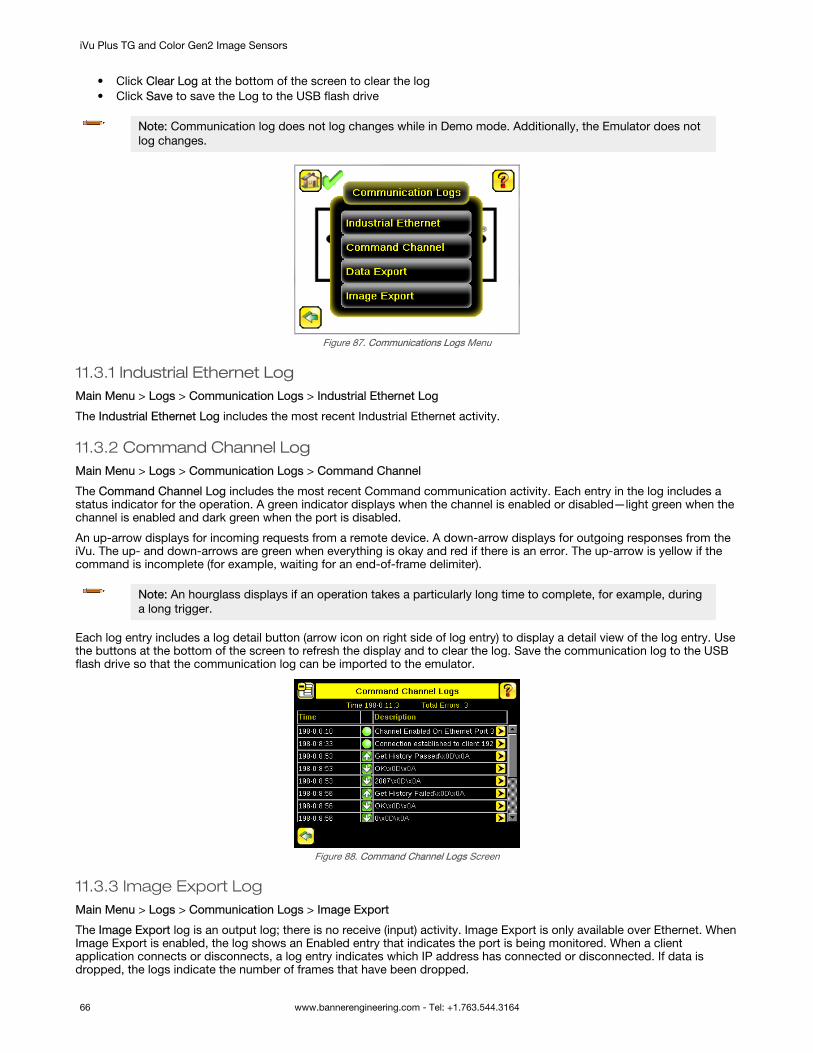
• Click Clear Log at the bottom of the screen to clear the log• Click Save to save the Log to the USB flash drive
Note: Communication log does not log changes while in Demo mode. Additionally, the Emulator does notlog changes.
Figure 87. Communications Logs Menu
11.3.1 Industrial Ethernet LogMain Menu > Logs > Communication Logs > Industrial Ethernet Log
The Industrial Ethernet Log includes the most recent Industrial Ethernet activity.
11.3.2 Command Channel LogMain Menu > Logs > Communication Logs > Command Channel
The Command Channel Log includes the most recent Command communication activity. Each entry in the log includes astatus indicator for the operation. A green indicator displays when the channel is enabled or disabled—light green when thechannel is enabled and dark green when the port is disabled.
An up-arrow displays for incoming requests from a remote device. A down-arrow displays for outgoing responses from theiVu. The up- and down-arrows are green when everything is okay and red if there is an error. The up-arrow is yellow if thecommand is incomplete (for example, waiting for an end-of-frame delimiter).
Note: An hourglass displays if an operation takes a particularly long time to complete, for example, duringa long trigger.
Each log entry includes a log detail button (arrow icon on right side of log entry) to display a detail view of the log entry. Usethe buttons at the bottom of the screen to refresh the display and to clear the log. Save the communication log to the USBflash drive so that the communication log can be imported to the emulator.
Figure 88. Command Channel Logs Screen
11.3.3 Image Export LogMain Menu > Logs > Communication Logs > Image Export
The Image Export log is an output log; there is no receive (input) activity. Image Export is only available over Ethernet. WhenImage Export is enabled, the log shows an Enabled entry that indicates the port is being monitored. When a clientapplication connects or disconnects, a log entry indicates which IP address has connected or disconnected. If data isdropped, the logs indicate the number of frames that have been dropped.
iVu Plus TG and Color Gen2 Image Sensors
66 www.bannerengineering.com - Tel: +1.763.544.3164

12 Configuring SensorsEach sensor type has a parameters shortcut menu available from the inspection menu.
From the Home screen, click inside the Region of Interest (ROI). The ROI is the visual area indicated by a dotted line on theinspection. In the Demo mode this is the Banner Engineering logo. The dotted line becomes bold and has rotation and sizeicons in the corners. At the top of the display Inspection Name changes to a black button called Sensor Name. Click SensorName and a dropdown list displays.
Area Sensor Blemish Sensor Match Sensor Sort Application
Average Color Color Compare Color Area
No matter what parameter you are setting, if you click inside the ROI it will highlight into a bold dotted line that can beresized.
12.1 Setting the TriggerBy default, the Trigger is set to Internal, and will continuously trigger based on a time interval setting. This may make it moredifficult to make adjustments while setting up the iVu. The best practice is:
1. Go to Main Menu > Imager > Trigger menu and select External.
Figure 89. Trigger Screen2. Make sure there is no external trigger input.3. Use the Trigger icon in the lower-right of the display to manually trigger the iVu to capture an image as you set up
and test.4. Capture images of a range of samples to set up from the "worst" good part to the "best" bad part.
12.2 Configuring an Area Sensor1. Begin the setup with a good part.2. Center the part to be tested in the Field of View (FOV).3. Adjust the Region of Interest (ROI) so that it surrounds the feature of interest. In the Demo example, the feature of
interest is the Banner logo. The ROI is red because the parameters need to be set.
iVu Plus TG and Color Gen2 Image Sensors
www.bannerengineering.com - Tel: +1.763.544.3164 67

Figure 90. Adjust the ROI
Note: When running an Area inspection, the sensor finds objects only within the ROI.
4. Click the [Sensor Name] to open the sensor parameters menu.
Figure 91. Open the Parameters Menu
5. Set the sensor parameters.• Adjust the Intensity Range.
Intensity Range is the range of grayscale values the sensor should look for. To set the Intensity Range, usethe eye dropper to select the target feature. Use the slider to fine tune the selection. As the slider is moved,green highlighted areas indicate the objects the sensor finds.
Figure 92. Intensity Range Screen
• Adjust the Area Range.
Use Area Range to set the size limits of a feature of interest. Move the slider to select the range. Areas aremeasured by counting pixels. For example, a rectangular feature that is 100 pixels wide by 200 pixels tallhas an area of roughly 20,000 pixels.Figure 93 on page 69 indicates that the areas that are white are now within range of the inspection. As therange narrows, the highlighted area turns yellow. In the Demo example, the Area Range is adjusted so thateach letter is identified as a found object (indicated by the red highlight and the blue +).
iVu Plus TG and Color Gen2 Image Sensors
68 www.bannerengineering.com - Tel: +1.763.544.3164

Figure 93. Area Range Screen
• Set the Pass Count parameter.
The Minimum Pass Count is the minimum number of parts, labels, or features expected to fall within thespecified criteria. The Maximum Pass Count is the maximum number expected to fall within the specifiedcriteria. These settings are used to determine the pass or fail result of the inspection.
In the Demo, both the Minimum Pass Count and the Maximum Pass Count are set to 6, because theinspection should find six letters. The letters turn green to indicate that the inspection passed.
Figure 94. Pass Count Screen
6. Test a complete range of good and bad samples to make sure that the sensor accepts good parts and rejects badparts.
7. To complete the Area application setup, adjust the trigger setting as appropriate for the application.
Note: Remote Teach does not work with the Area sensor.
12.3 Configuring a Blemish SensorThe Demo Mode application shows how the sensor, when configured as a Blemish sensor, can accept or reject parts basedon the range of edge pixels the sensor detects in the ROI.
1. Begin the setup with a good part.2. Center the part to be tested in the Field of View (FOV).3. Adjust the Region of Interest (ROI) so that it surrounds the feature of interest. In the Demo example, the feature of
interest includes the two irregular shapes below the Banner logo.
Figure 95. Adjust the ROI
iVu Plus TG and Color Gen2 Image Sensors
www.bannerengineering.com - Tel: +1.763.544.3164 69

4. Click the [Sensor Name] to open the sensor parameters menu.
Figure 96. Parameters Menu
5. Set the sensor parameters.• Adjust the Sensitivity parameter.
Use Sensitivity to fine-tune how sensitive the sensor is to finding blemish or other edges within the ROI.
The sensitivity value helps account for light variations that might affect how well the sensor detects edges oninspected parts. The sensitivity scale is from 0 to 100, where 0 means least sensitive and 100 means mostsensitive. If set near 0, the sensor only finds very sharp edges with strong contrast. If set near 100, thesensor finds very dim or blurry edges, and may be unstable due to noise within the image.
Use the slider to adjust the sensitivity, watching as the sensor detects more or fewer edges.
Figure 97. Sensitivity Screen
• Adjust the Edge Length Range.
The sensor counts all the edge pixels it detects in the ROI. The bar at the bottom of the Edge Length Rangescreen shows all the different contiguous edge segments found. Use the slider brackets to specify the edgelength range in pixels. Edges found within this range are considered to calculate the Pass Count. Edgesegments within the two brackets [ ] are highlighted in green and those outside the brackets are ignored andcolored yellow. Move each bracket to add or remove more of the edge segments from consideration. Zoomin to refine the range.
Figure 98. Segments in Yellow are Ignored Figure 99. Segments in Green are Included
• Set the Pass Count parameter.
iVu Plus TG and Color Gen2 Image Sensors
70 www.bannerengineering.com - Tel: +1.763.544.3164
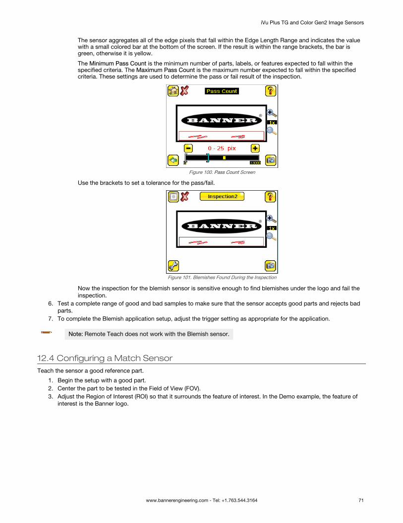
The sensor aggregates all of the edge pixels that fall within the Edge Length Range and indicates the valuewith a small colored bar at the bottom of the screen. If the result is within the range brackets, the bar isgreen, otherwise it is yellow.
The Minimum Pass Count is the minimum number of parts, labels, or features expected to fall within thespecified criteria. The Maximum Pass Count is the maximum number expected to fall within the specifiedcriteria. These settings are used to determine the pass or fail result of the inspection.
Figure 100. Pass Count Screen
Use the brackets to set a tolerance for the pass/fail.
Figure 101. Blemishes Found During the Inspection
Now the inspection for the blemish sensor is sensitive enough to find blemishes under the logo and fail theinspection.
6. Test a complete range of good and bad samples to make sure that the sensor accepts good parts and rejects badparts.
7. To complete the Blemish application setup, adjust the trigger setting as appropriate for the application.
Note: Remote Teach does not work with the Blemish sensor.
12.4 Configuring a Match SensorTeach the sensor a good reference part.
1. Begin the setup with a good part.2. Center the part to be tested in the Field of View (FOV).3. Adjust the Region of Interest (ROI) so that it surrounds the feature of interest. In the Demo example, the feature of
interest is the Banner logo.
iVu Plus TG and Color Gen2 Image Sensors
www.bannerengineering.com - Tel: +1.763.544.3164 71

Figure 102. Adjust the ROI
4. Click Teach to teach the sensor this good reference part.
Figure 103. Teach the Reference Part
5. Click [Sensor Name] to open the sensor parameters menu.
Figure 104. Parameters Menu
6. Set the sensor parameters.• Adjust the Percent Match parameter.
Percent Match adjusts how closely the inspected part or label must match the reference part or label. ThePercent Match scale is from 0 to 100, where 0 is the most tolerant and 100 is the least tolerant. Move theslider to adjust the tolerance.
Figure 105. Percent Match Screen
iVu Plus TG and Color Gen2 Image Sensors
72 www.bannerengineering.com - Tel: +1.763.544.3164

Note: When running a Match inspection with annotations enabled, the sensor highlights ingreen any pattern matches that meet or exceed the value specified for Percent Match.Patterns that are below the specified value for Percent Match (down to approximately20%), or out of the Rotation Range (see below), are colored yellow.
1. Using a bad part, click Manual Trigger to capture an image. For this example, one of the storedimages is missing the letter "N," yet the sensor initially sees this as a good label.
Figure 106. Percent Match Screen
2. On the adjustment at the bottom of the display, move the slider and click Manual Trigger. Whenadjusted correctly, the annotations turn yellow, and the icon in the upper-left of the display indicatesthat the inspection failed.
Figure 107. Failed Inspection
• Adjust the Rotation Range.
Rotation Range sets the expected rotation of parts or labels during an inspection. For example, a value of 45means that the part may rotate 45 degrees in either direction from the reference part and still pass. Move theslider from 0 to 180 degrees.
Note: The smaller the rotation range, the faster the inspection will run.
To verify that a label is correctly applied to a container (that is, on straight), set a small rotation. To verify thatthe correct label is present no matter how the part is oriented in the Field of View, set the rotation range tothe maximum (180°, which is the setting for Demo Mode).
Note: Rotations Range and Percent Match work together. The higher the Percent Match,the lower the Rotation Range to pass. In the previous example a 99% match is too high forany rotation. In the next graphic the Percent Match has been lowered to 92% which stillfails a missing letter.
iVu Plus TG and Color Gen2 Image Sensors
www.bannerengineering.com - Tel: +1.763.544.3164 73

Figure 108. Rotation Range Screen
• Set the Pass Count parameter as appropriate.
The Minimum Pass Count is the minimum number of parts, labels, or features expected to fall within thespecified criteria. The Maximum Pass Count is the maximum number expected to fall within the specifiedcriteria. These settings are used to determine the pass or fail result of the inspection.
In the Demo, both the Minimum Pass Count and Maximum Pass Count are set 1. If the count is more than 1or less than 1, the sensor will fail.
Figure 109. Pass Count Screen
7. Test a complete range of good and bad samples to make sure that the sensor accepts good parts and rejects badparts.
8. To complete the Match application setup, adjust the trigger setting as appropriate for the application.
Note: When running a Match inspection, the sensor looks for any possible patterns to match anywherewithin the Field of View.
12.4.1 Remote TeachThe Remote Teach function is a method of remotely updating inspection parameters while the iVu is running. Remote Teachis only available when the iVu is configured as a Match sensor. The sequence of events for executing a Remote Teach are:
1. With the device Ready (see Installation Instructions on page 15), pulse the Remote Teach line.2. The iVu recognizes that the Remote Teach line has been pulsed and waits for the next valid trigger.3. At the next valid trigger, Ready goes inactive (the Green Ready LED shuts OFF), and the iVu acquires a new image.4. The iVu learns the new pattern and performs the analysis.
12.5 Configuring a Sort SensorWhen running a Sort inspection, the sensor looks for any possible patterns to match anywhere within the field of view.
1. Begin the setup with good parts.2. Center the first part to be tested in the Field of View (FOV).3. For the first part, adjust the Region of Interest (ROI) so that it surrounds the feature of interest.
iVu Plus TG and Color Gen2 Image Sensors
74 www.bannerengineering.com - Tel: +1.763.544.3164

Figure 110. Adjust the ROI
Tip: For better results, make sure that the ROI bounds the image of the pattern as tightly aspossible.
4. Click Teach. The feature is highlighted in green.5. Click Save to save the pattern to the first empty pattern storage slot.
Figure 111. Saved Patterns Screen6. Click the sensor name to open the sensor parameters menu.
Figure 112. Parameters Menu7. Set the sensor parameters:
• Adjust the Percent Match. This setting adjusts how closely the inspected part or label needs to match any ofthe ten stored patterns. The Percent Match scale is from 0 to 100, where 0 is the most tolerant and 100 isthe least tolerant. Move the slider to adjust the setting. For the best results, use a value from 50 to 90.
Note: When running a Sort inspection, the sensor highlights in green any pattern matchesthat are within the specified Rotation Range and meet or exceed the value specified forPercent Match. Patterns that are within the specified Rotation Range and withinapproximately 20% below the specified value for Percent Match are colored yellow.
• Adjust the Rotation Range. This sets the expected rotation of parts or labels during an inspection. Forexample, a value of 45 means that the part may rotate 45 degrees in either direction from the reference partand still pass. Move the slider from 0 to 180 degrees. Note that the smaller the rotation range, the faster theinspection will run.
8. Repeat these steps for subsequent patterns and store each pattern in an empty pattern storage slot.9. Set the Pass Criteria. This example uses only two stored patterns:
• Any Saved Pattern—Pass condition if the sensor matches either Pattern_1, Pattern_2, or both• All Saved Patterns—Pass condition if the sensor matches both Pattern_1 AND Pattern_2• Single Saved Pattern—Pass condition if the sensor matches either Pattern_1 OR Pattern_2, but NOT both• Specific Save Pattern (Must also select the saved pattern to match, for example, select Pattern_2)—Pass
condition any time the sensor matches Pattern_210. Test a complete range of good and bad samples to make sure that the sensor accepts good parts and rejects bad
parts.
iVu Plus TG and Color Gen2 Image Sensors
www.bannerengineering.com - Tel: +1.763.544.3164 75

11. To complete the Sort application setup, adjust the trigger setting as appropriate for the application.
12.6 Configuring MotionMain Menu > Inspection > Motion
The Motion menu is available when Motion is enabled under the Inspection Properties menu.
Enable Motion when the part being inspected is expected to move or rotate. Motion settings involve selecting the number ofedges to locate, adjusting sensitivity, and selecting whether rotation is enabled. These settings are available on theInspection Menu after Motion is set to Enabled. Motion is not available for Match or Sort sensors.
Figure 113. Motion Menu
12.6.1 Number of EdgesMain Menu > Inspection > Motion > Number of Edges
On the Number of Edges screen, use the option buttons to select One Edge or Two Edges. If One Edge is selected, motionis tracked in one direction (by default, horizontally). If Two Edges is selected, motion can be tracked horizontally andvertically.
12.6.2 SensitivityMain Menu > Inspection > Motion > Sensitivity
Use Sensitivity to fine-tune how sensitive the sensor is to finding a reference edge.
The sensitivity value helps account for light variations that might affect how well the sensor detects edges on inspectedparts. The sensitivity scale is from 0 to 100, where 0 means least sensitive and 100 means most sensitive. If set near 0, thesensor only finds very sharp edges with strong contrast. If set near 100, the sensor finds very dim or blurry edges, and maybe unstable due to noise within the image.
12.6.3 RotationMain Menu > Inspection > Motion > Rotation
Rotation can be enabled or disabled. Select Enabled if the part can be expected to rotate during the inspection.
12.7 Configuring an Average Color Sensor1. Begin the setup with a good part.2. Center the part to be tested in the Field of View (FOV).3. Adjust the Region of Interest (ROI) so that it surrounds the feature of interest. In the Demo example, the ROI covers
the Banner logo, even when the logo is rotated.4. Click the [Sensor Name] to open the sensor parameters menu.
iVu Plus TG and Color Gen2 Image Sensors
76 www.bannerengineering.com - Tel: +1.763.544.3164

Figure 114. Open the Parameters Menu5. Set the sensor parameters.
• Adjust the Intensity Range.
Intensity Range allows a range of brightness in the image. In the other words, it can be used to excludeimage that is too dark, too bright, or both.
Figure 115. Intensity Range Screen
In the Demo example, the Intensity Range is 0 – 255.• Set the Color Space.
Two color space options are available: HSI—The average and standard deviation values for each of Hue, Saturation, and Intensity within the
ROI are calculated RGBI—The average and standard deviation values for each of Red, Green, Blue, and Intensity within
the ROI are calculated
Figure 116. Color Space Screen
In the Demo example, the Color Space is HSI.
6. Click Display Mode to access the Inspection Statistics and view the Average Color.
Figure 117. Color Space Screen7. To complete the Average Color application setup, adjust the trigger setting as appropriate for the application.
iVu Plus TG and Color Gen2 Image Sensors
www.bannerengineering.com - Tel: +1.763.544.3164 77

Note: Remote Teach does not work with the Average Color sensor.
12.8 Configuring a Color Compare Sensor1. Begin the setup with a good part.2. Center the part to be tested in the Field of VIew (FOV).3. Adjust the Region of Interest (ROI) so that it surrounds the feature of interest. In the Demo example, the ROI covers
the Banner logo, even when the logo is rotated.4. Click Teach. The sensor learns the color.
Figure 118. Teach Successful5. Click the [Sensor Name] to open the sensor parameters menu.
Figure 119. Open the Parameters Menu6. Set the sensor parameters.
• Adjust the Color Tolerance parameter.
Use Color Tolerance to adjust the maximum acceptable difference (in %) between the taught color and thecolor detected in the live image.
Figure 120. Color Tolerance Screen
In the Demo example, the Color Tolerance is 20.• Adjust the Intensity Tolerance.
Intensity Tolerance defines the grayscale brightness level necessary to constitute a match. This value rangesfrom 0 to 255.
iVu Plus TG and Color Gen2 Image Sensors
78 www.bannerengineering.com - Tel: +1.763.544.3164

Figure 121. Intensity Tolerance Screen
In the Demo example, the Intensity Tolerance is set to 30.7. Test a complete range of good and bad samples to make sure that the sensor accepts good parts and rejects bad
parts.8. To complete the Color Compare application setup, adjust the trigger setting as appropriate for the application.
Note: Remote Teach does not work with the Color Compare sensor.
12.9 Configuring a Color Area Sensor1. Begin the setup with a good part.2. Center the part to be tested in the Field of View (FOV).3. Adjust the Region of Interest (ROI) so that it surrounds the feature of interest. In the Demo example, the feature of
interest is the pink text, "iVu Color".4. Click the [Sensor Name] to open the sensor parameters menu.
Figure 122. Open the Parameters Menu5. Set the sensor parameters.
• Select the Color Select.
Use Color Select to select the color the Color Area sensor looks for. Click Color Selector then click thedesired color in the ROI. Adjust the color tolerance using + and -.
Note: You can select a color that is outside of the ROI, but a BLOB of that color will only bedetected within the ROI.
In the Demo example, the desired color is pink.
If needed, zoom in to better select the desired color.
Figure 123. Color Select Screen Figure 124. Color Select Screen—Color Selected
iVu Plus TG and Color Gen2 Image Sensors
www.bannerengineering.com - Tel: +1.763.544.3164 79

After the color is selected, + and - buttons display. Click these buttons to fine-tune the selection.• Adjust the Area Range.
Use Area Range to set the size limits of a feature of interest. Move the slider to select the range. Areas aremeasured by counting pixels. For example, a rectangular feature that is 100 pixels wide by 200 pixels tallhas an area of roughly 20,000 pixels.
Figure 125. Area Range Screen
In the Demo example, the Area Range is 29 – 782.• Set the Pass Count parameter.
The Minimum Pass Count is the minimum number of parts, labels, or features expected to fall within thespecified criteria. The Maximum Pass Count is the maximum number expected to fall within the specifiedcriteria. These settings are used to determine the pass or fail result of the inspection.
Note: Start with the Maximum Pass Count—the Minimum will not allow it to be more thanthe maximum.
Figure 126. Pass Count Screen
In the Demo, set the Minimum Pass Count and Maximum Pass Count to 9. If the count is more than 9 or lessthan 9, the sensor will fail.
• Adjust the Tolerance.
Adjust the tolerance for the color the sensor is looking for. Adjustments are made individually for hue,saturation, and intensity.
Figure 127. Tolerance ScreenIn the Demo example, the Tolerance is set to 10.
6. Test a complete range of good and bad samples to make sure that the sensor accepts good parts and rejects badparts.
7. To complete the Color Area application setup, adjust the trigger setting as appropriate for the application.
Note: Remote Teach does not work with the Color Area sensor.
iVu Plus TG and Color Gen2 Image Sensors
80 www.bannerengineering.com - Tel: +1.763.544.3164

12.10 Configuring Multiple Sensors in the InspectionMain > Inspection > Sensors > Add Sensor
Some applications require more than one sensor. New sensors can be added after an inspection has been created. Inputparameters for each sensor can be configured individually.
Figure 128. Sensors Screen
1. Click Add a Sensor to display the list of sensor types that can be added into the inspection.
Figure 129. Add a Sensor Screen2. Click Add to add the selected sensor.
Figure 130. The New Sensor is Added to the Inspection3. Click in the Sensor Setup area (black button) to display the input parameter menu for that sensor.
iVu Plus TG and Color Gen2 Image Sensors
www.bannerengineering.com - Tel: +1.763.544.3164 81

Figure 131. Input Parameter Menu4. Click the yellow down-arrow to access sensor management functions.
Icon Function
Move the selected sensor up in the execution order
Move the selected sensor down in the execution order
Edit the name of the selected sensor
Delete the selected sensor
After all of the sensors are configured as required for the application, the inspection Pass/Fail criteria is determined byconsidering the results of the individual sensors. An inspection is considered as PASS if all sensors in the inspection pass. Ifany sensor fails, the inspection is marked as FAIL.
12.11 Configuring a MaskA mask created for a sensor does not apply to any other sensors in the inspection. The mask ROI type can be rectangular,elliptical, or circular. Use up to ten masks per sensor.
1. Select the desired ROI. When selected, the ROI has resize and rotation icons in the corners.2. Click [Sensor Name] to open the sensor parameters menu.
Figure 132. Parameters Menu3. Select ROI and Mask.4. Select the Enable Mask checkbox.
iVu Plus TG and Color Gen2 Image Sensors
82 www.bannerengineering.com - Tel: +1.763.544.3164

Figure 133. ROI and Mask Screen
5. Click to return to the Home screen.6. Re-select the ROI from step 1.
7. Click to insert the mask. The mask displays in blue with a diagonal line pattern in the region.
Figure 134. Mask (in blue)
8. To change the shape of the mask ROI, click , , and to cycle through the shape options.9. Adjust the mask ROI as appropriate for the application.
10. To delete a mask, select it and click .
iVu Plus TG and Color Gen2 Image Sensors
www.bannerengineering.com - Tel: +1.763.544.3164 83

13 iVu EmulatorThe iVu Emulator is a Windows®6 application that allows you to operate in a Windows® environment similar to the iVu deviceitself. In general, the Emulator is an inspection debugging tool where you can:
• Import stored inspections and a configuration from an iVu device• Modify inspection parameters• Restore the updated configuration back to the iVu device
By default, the iVu Emulator installs in the following folder: C:\Program Files (x86)\Banner EngineeringYou can run the Emulator from this folder, but you will need to move files between the USB flash drive and PC. To avoidmoving files, copy the Emulator executable to the USB flash drive, and run the Emulator directly from the USB flash drive.
13.1 How to Use Bitmap Image Files with the iVu EmulatorYou can use bitmap (.bmp) image files with the iVu Emulator for developing and simulating iVu inspections. The iVuEmulator only accepts image files in .bmp format. If you have other image file formats, use an image viewer/editor programto convert the files to 8-bit grayscale .bmp format for iVu TG models and to 24-bit color .bmp for iVu color models.
Note: Images smaller than the FOV are black-filled starting in the upper-right. Images larger than the FOVare cropped starting in the upper-left.
1. Copy the .bmp files into the InspLog folder in the iVu Emulator install folder.
For example, copy .bmp files to C:\Program Files\Banner Engineering\iVu Series\InsLog.
Note: Remove any existing .bmp or Log files in that folder to avoid confusion. The iVu Emulatorautomatically runs all .bmp/Log files sequentially according to filename.
2. Start the iVu Emulator.3. Set the Trigger option to Internal.
a. Go to Main Menu > Image > Trigger.b. Set the Trigger Interval as desired.
The iVu Emulator runs using the .bmp files from Step 1.
Note: Banner does not recommend setting up inspections using these 8-bit grayscale images becauseyou will need to modify the configuration after loading it on the iVu on the line. A better choice is to set upthe inspection on the iVu Emulator using the Inspection Logs from the iVu.
6 Microsoft and Windows are registered trademarks of Microsoft Corporation in the United States and/or other countries.
iVu Plus TG and Color Gen2 Image Sensors
84 www.bannerengineering.com - Tel: +1.763.544.3164

14 Communications Guide
14.1 iVu Plus Communication Summary of Ethernet and SerialThe iVu communicates with other devices via Ethernet or a UART serial communications port (RS-232). To establish anEthernet connection to the iVu, configure the external device with the correct IP address and TCP port. To use the serialcommunications connection, configure the port settings for baud rate, data bits, parity, and stop bits on the iVu to matchthe settings of the external device.
14.1.1 Communication ChannelsThe iVu supports up to four communications channels. To access the channels, go to Main Menu > System >Communications.
Figure 135. Communications Menu
• Command Channel—A bi-directional communication protocol that currently supports ASCII and enables otherdevices to remotely control the iVu and access device information and inspection results
• Industrial Ethernet—A bi-directional communication channel that allows the user to control the device and accessdevice results using Ethernet/IP™, Modbus/TCP, PCCC, or PROFINET® protocol
• Data Export—Used to export selected inspection data to a remote device• Image Export—Used to export inspection images to a remote device
Data export and command channel can be configured for either Ethernet or Serial I/O, but not both. Image export is onlyavailable over Ethernet. The following table summarizes valid communication channel configuration options.
Command ChannelsScenario #1 Scenario #2 Scenario #3
Ethernet Serial I/O Ethernet Serial I/O Ethernet Serial I/O
Command Channel Yes No No Yes Yes No
Industrial Ethernet Yes No Yes No Yes No
Data Export Yes No Yes No No Yes
Image Export Yes No Yes No Yes No
14.1.2 Industrial EthernetMain Menu > System > Communications > Industrial Ethernet
The iVu device can be controlled or monitored over Industrial Ethernet using Ethernet/IP™, Modbus/TCP, PCCC, orPROFINET® protocols. This document will help you to set up the iVu in the desired configuration and provide you withinformation you will need to connect to the master device (PLC, HMI, etc.).
14.1.3 Command ChannelThe iVu command channel is a bi-directional communication protocol that currently supports ASCII via either Ethernet orthe RS-232 serial interface, and enables other devices to remotely control the iVu sensor and access sensor results.
iVu Plus TG and Color Gen2 Image Sensors
www.bannerengineering.com - Tel: +1.763.544.3164 85

A B
CD
do trigger\x0D\x0A
OK\x0D\x0A
A Control Device, such as a PLC, PC program, or a terminal C Response Frame
B Request Frame D iVu Device
The following are some of the functionality available via the command channel:
• Get device information (such as version and device name)• Control discrete I/O (such as trigger and teach)• Get sensor results (such as sensor status)• Change the running inspection
Command Channel Sample Application
The iVu installation package has a Command Channel sample application that provides an easy interface to executecommands. In a production environment, you will need to create your own application for bi-directional communication withthe iVu.
Figure 136. Command Channel Sample Application
14.1.4 Data ExportExport user-selected inspection data via either Ethernet or the RS-232 serial interface. Inspection data that can be exportedincludes:
• Pass/Fail Output
iVu Plus TG and Color Gen2 Image Sensors
86 www.bannerengineering.com - Tel: +1.763.544.3164

• Inspection Name• Sensor Result
Name Pass/Fail Sensor Result (see Table 18 on page 87 for additional information)
• Inspection Time (ms)
Table 18: Sensor Results
Sensor Type Data to Export Sensor Type Data to Export
AreaCount
Average Color
(Color modelsonly)
Average Red (RGBI color space)
Area Range Average Green (RGBI color space)
BlemishCount Average Blue (RGBI color space)
Edge Length Range Average Hue (HSI color space only)
MatchCount Average Saturation (HSI color space only)
Percent Match Average Intensity
Sort
Count Standard Deviation Red (RGBI color space)
Percent Match Standard Deviation Green (RGBI color space)
All Found Pattern Numbers Standard Deviation Blue (RGBI color space)
All Found Pattern Names Standard Deviation Hue (HSI color space only)
Color Compare
(Color modelsonly)
Percent Match Standard Deviation Saturation (HSI color space only)
Intensity
Standard Deviation IntensityColor Area
(Color modelsonly)
Count
Area Range
Data export settings apply to all inspections on the device. If items are selected that are not part of the current inspection,those items are ignored.
Data Export Sample Application
The iVu installation package has a Data Export sample application that allows you to view exported data while setting upthe sensor, etc. In a production environment, you need to create your own application to process data exported from theinspection.
Figure 137. Data Export Sample Application
14.1.5 Image ExportImage export is only supported on Ethernet ports. Inspection images are in bitmap (.bmp) format and are the same size asthe current Field of View (FOV) setting. The images represent all the data in a full FOV.
iVu Plus TG and Color Gen2 Image Sensors
www.bannerengineering.com - Tel: +1.763.544.3164 87

Each exported image is comprised of a header (64 bytes) followed by the image data (approximately 78K). All 16- and 32-bitnumeric entries are little endian.
The header includes the following information:
Byte Offset Field Size in Bytes Data Type Description
0-15 Header Prefix 16 char "IVU PLUS IMAGE"
16-19 Header Version 4 UInt32 1
20-23 Image Size 4 UInt32 Number of bytes (.bmp image)
24-27 Image Frame Number 4 UInt32 Most recently captured image frame number
28-29 Image Width 2 UInt16 320 (maximum)
30-31 Image Height 2 UInt16 240 (maximum)
32-33 Image Format 2 UInt16 0: Bitmap, 1: JPEG
34-63 Reserved 32 byte Reserved for future use
Note: If FOV's are adjusted so that they are smaller, the bitmaps will also be smaller.
Image Export Sample Application
The iVu installation package has an Image Export sample application that provides a way to save exported images. In aproduction environment, you need to write your own application to process exported images, for example to display themon an HMI or to save them to disk.
Figure 138. Image Export Sample Application
14.2 Enabling Communications
14.2.1 Setting Up Ethernet CommunicationsConfigure both the PC and the iVu using the following instructions.
Windows XP
1. Open Network Properties on the Windows XP7 PC (right-click on the Network Neighborhood icon).2. On the Local Area Connection, right-click on Properties.3. In the dialog, click Internet Protocol (TCP/IP) and click Properties.
7 Microsoft and Windows are registered trademarks of Microsoft Corporation in the United States and/or other countries.
iVu Plus TG and Color Gen2 Image Sensors
88 www.bannerengineering.com - Tel: +1.763.544.3164

Figure 139. Local Area Connection Properties Screen4. In the Internet Protocol (TCP/IP) Properties dialog, select Use the following IP address and make sure that the IP
address is 192.168.0.2, and the subnet mask is 255.255.255.0.
Figure 140. Internet Protocol (TCP/IP) Properties Screen
Windows 7
1. On the Windows 78 PC, click the Start button, then on the Start menu, click Control Panel.2. In Control Panel, click Network and Internet, then click Network and Sharing Center, and then click Change adapter
settings.3. Right-click on the connection that you want to change, then click Properties.
If you are prompted for an administrator password or confirmation, enter the password or provide confirmation.4. In the connection properties, click Internet Protocol Version 4 (TCP/IPv4), and then click Properties.
8 Microsoft and Windows are registered trademarks of Microsoft Corporation in the United States and/or other countries.
iVu Plus TG and Color Gen2 Image Sensors
www.bannerengineering.com - Tel: +1.763.544.3164 89

Figure 141. Local Area Connection Properties Screen5. In Internet Protocol (TCP/IPv4) Properties, select Use the following IP address.6. Make sure that the IP address is 192.168.0.2, and the subnet mask is 255.255.255.0.
Figure 142. Internet Protocol (TCP/IPv4) Properties Screen
iVu Setup for Ethernet Communications
1. Go to Main Menu > System > Communications > Ethernet I/O and make sure that the iVu is configured as shown.
Figure 143. Ethernet I/O Screen2. Enable the command channel over Ethernet.
a. Go to Main Menu > System > Communications > Command Channel > Connection, and select Ethernet [IPPort # 32000].
iVu Plus TG and Color Gen2 Image Sensors
90 www.bannerengineering.com - Tel: +1.763.544.3164

Figure 144. Connection Screenb. Configure the field and end-of-frame delimiters. Go to Main Menu > System > Communications > Command
Channel > Delimiters.
Figure 145. Delimiters Screen
Valid end-of-frame delimiters are: <comma>, <colon>, <semicolon>, <CR>, <CR><LF>, <LF><CR>, or<ETX>.
c. Verify that the iVu receives and transmits data correctly.3. Enable Data Export over Ethernet.
a. Go to Main Menu > System > Communications > Data Export > Connection and select Serial I/O from thedrop-down.
Figure 146. Connection Screenb. Go to Main Menu > System > Communications > Data Export > Data To Export and select the inspection
data to export.
iVu Plus TG and Color Gen2 Image Sensors
www.bannerengineering.com - Tel: +1.763.544.3164 91

Figure 147. Data to Export Screenc. Go to Main Menu > System > Communications > Data Export > Output Format and select the Start String,
Delimiter, and End String.
Figure 148. Output Format Screend. Go to Main Menu > System > Communications > Data Export > Advanced.
Figure 149. Advanced Screen
During the Data and Image export operation the sensor's output channels might become full. This can occurif the sensor is producing export data (frames) faster than the data can be exported from the device (due tobandwidth limitations) or faster than the client is reading the channel export data.
This setting affects how the sensor will behave in this situation.• Select Hold READY to ensure that all frames are transmitted. In this case, the READY signal remains
inactive (sensor is busy) until the new frame has been added to the channel for transmission.Triggers might be missed during this time.
• Select Do not hold READY to cause the sensor to discard the new frame if the channel is full andactivate the READY signal immediately after the current inspection is complete. In this case, thediscarded frames are not transmitted.
Communications Channel Ports
The following are the default Ethernet port settings for the communications channels:• Command Channel — 32200• Data Export — 32100• Image Export — 32000
iVu Plus TG and Color Gen2 Image Sensors
92 www.bannerengineering.com - Tel: +1.763.544.3164

14.2.2 Setting Up Serial Communications1. Electrically connect the control device and the iVu device. On the iVu, the pins/wire colors used for serial
communications via RS-232 are shown in the following table.Table 19: iVu RS-232 Connections
Pin # Wire Color Description
10 Light-Blue TX
11 Black Signal Ground
12 Violet RX
2. Configure the port settings (baud rate, data bits, parity, and stop bits) on the iVu to match the settings on the controldevice. Go to Main Menu > System > Communications > Serial I/O.
Figure 150. Serial I/O Screen3. Enable the command channel over the serial connection.
a. Go to Main Menu > System > Communications > Command Channel > Connection and select Serial I/O.b. Configure the field and end-of-frame delimiters. Go to Main Menu > System > Communications > Command
Channel > Delimiters.
Figure 151. Delimiters Screen
Valid end-of-frame delimiters are: <comma>, <colon>, <semicolon>, <CR>, <CR><LF>, <LF><CR>, or<ETX>.
c. If you want to trigger the iVu from the control device, set the trigger mode to Command. Go to Main Menu >Imager > Trigger and select Command from the drop-down list.
Figure 152. Trigger Screen
iVu Plus TG and Color Gen2 Image Sensors
www.bannerengineering.com - Tel: +1.763.544.3164 93

d. Verify that the iVu receives and transmits data correctly.4. Enable Data Export over the serial connection.
a. Go to Main Menu > System > Communications > Data Export > Connection and select Serial I/O from thedrop-down.
Figure 153. Connection Screenb. Go to Main Menu > System > Communications > Data Export > Data To Export and select the inspection
data to export.
Figure 154. Data to Export Screenc. Go to Main Menu > System > Communications > Data Export > Output Format and select the Start String,
Delimiter, and End String.
Figure 155. Output Format Screend. Go to Main Menu > System > Communications > Data Export > Advanced.
Figure 156. Advanced Screen
iVu Plus TG and Color Gen2 Image Sensors
94 www.bannerengineering.com - Tel: +1.763.544.3164

During the Data and Image export operation the sensor's output channels might become full. This can occurif the sensor is producing export data (frames) faster than the data can be exported from the device (due tobandwidth limitations) or faster than the client is reading the channel export data.
This setting affects how the sensor will behave in this situation.
• Select Hold READY to ensure that all frames are transmitted. In this case, the READY signal remainsinactive (sensor is busy) until the new frame has been added to the channel for transmission.Triggers might be missed during this time.
• Select Do not hold READY to cause the sensor to discard the new frame if the channel is full andactivate the READY signal immediately after the current inspection is complete. In this case, thediscarded frames are not transmitted.
14.3 Testing and Troubleshooting iVu Communications
14.3.1 Understanding the Communication LogThe iVu includes the following Communication Logs:
• Command Channel Log—Ensures that commands are properly formed (syntax is correct), and provides a history ofcommands issued along with responses to these commands. To access the Command Channel Log, go to MainMenu > Logs > Communication Logs > Command Channel
• Data Export and Image Output logs—These logs are purely output logs (that is, there is no receive activity to log)
Figure 157. Command Channel Logs Screen
Some notes about the logs:
• To see an expanded view of each entry, click the small right-triangle control on each entry• To save the log, click the save icon. The saved communication log can be loaded into the emulator for
troubleshooting offline
The following table describes the icons used in the Communication Log. The up-arrow indicates an incoming request to theiVu from the control device. The down-arrow indicates an outgoing response from the iVu to the control device.
Icon Description
Port open.
Port closed.
Indicates that the command has been processed without errors.
Indicates that the incoming entry is stalled (no new bytes), or end-of-frame delimiter was not received, orclient is not reading data on Ethernet.
Indicates whether the response frame contains an error or is dropped, the log entry icons for the requestand the response frames are red, and the displayed error count increments by one.
If the command takes a long time to process, the last long entry changes to an hourglass (for example,during trigger of long inspections).
For Ethernet channels:• The channel's log shows an Enabled entry that indicates which port is being listened to• When a client connects, a log entry is added that indicates which IP address connected• When a client closes the connection, a log entry indicates that the channel is no longer being listened to
iVu Plus TG and Color Gen2 Image Sensors
www.bannerengineering.com - Tel: +1.763.544.3164 95

14.3.2 Ethernet I/O
Ethernet I/O Status
Use the Ethernet I/O Status screen to verify that the Ethernet wiring was correctly set up. In addition to determining if thelink has been established, incoming and outgoing traffic can be monitored.
Figure 158. Ethernet I/O Status Screen
14.3.3 Serial I/O
Using the Port Status Screen for Testing RS-232 Communications
Use Port Status screen to ensure data is entering and exiting the iVu. This can be useful for debugging issues such asimproper wiring, mismatched baud rates, or other serial I/O issues. To access the Port Status screen, go to Main Menu >System > Communications > Serial I/O and click Status.
• The upper field shows the bytes received (request frame) on the iVu from the control device• The lower field shows the bytes sent (response frame) from the iVu to the control device
Figure 159. Port Status Screen
Port Errors
The Port Errors screen can help to debug communications channel issues: Parity, Break, and Framing indicate mismatchedport settings or, in the case of Break, incorrect cabling.
Using the iVu Command Channel Sample Application or a Terminal Program for Testing
The easiest way to test that the iVu command channel is correctly receiving and transmitting data is to use either the iVuCommand Channel Sample App (available in the iVu installation package) or to use a terminal program running on a PC.
If you are using a terminal program, in the terminal program's configuration:• Set new-line transmit to <CR><LF> (and set the end-of-frame delimiters on the iVu to match)• Enable local echo• Set the Serial port so that the PC port number's baud rate, data, parity, and stop bits match those set up on the iVu
Verifying Basic Receive Functionality
Use the following instructions to verify that the iVu can receive request frames from the requesting device:
1. On the iVu, go to Main Menu > System > Communications > Serial I/O > Port Status .
iVu Plus TG and Color Gen2 Image Sensors
96 www.bannerengineering.com - Tel: +1.763.544.3164

Figure 160. Port Status Screen2. On the requesting device, transmit one or more bytes to the iVu.
• If the data byte values appear correct and the number sent by the requesting device matches the numberreceived by the iVu, then the transmit/receive functionality is working properly.
• If the connection is incorrect (electrically) or if the baud rate is mismatched, no bytes will appear in the upperfield on the Port Status screen.
• If the connection is correct (electrically), bytes will appear in the upper field of the Port Status screen in theorder they were received.
• If the Port Status: Errors at the bottom of the Port Status screen highlights red, then the connection iscorrect electrically but there is likely a settings mismatch between the iVu and the requesting device. Verifythe settings on both devices.
• If the bytes appear with no errors but appear incorrect or there are too many or too few, then the portsettings (for example, baud rate) are likely mismatched in a way that does not generate serial hardwareerrors. Verify the settings on both devices match exactly.
Verifying Basic Transmit Functionality
The iVu command channel only sends response frames to the requesting device if it receives a valid end-of-frame delimiterfrom the requesting device. To verify transmit functionality:
1. Transmit an end-of-frame delimiter sequence from the requesting device to the iVu. For example, in a terminalprogram, press Enter.
If a valid end-of-frame delimiter is received, the iVu immediately transmits a short error message back to therequesting device (for example, ERROR 10000_COMMAND_MISSING).
2. Verify that the number of bytes sent by the requesting device are the same as the number shown in the lower field ofthe Port Status screen on the iVu. Go to Main Menu > System > Communications > Serial I/O > Port Status .
Figure 161. Port Status Screen3. If the byte count does not match, re-verify that the settings on both devices match exactly. If no bytes are received,
re-check the wiring.
If the correct response frame is received, then basic electrical and port settings are correct.
14.4 Command Channel Primer
14.4.1 Command Channel CommandsAll iVu command channel request command frames use the following syntax:
>> command group item value<EOF>
iVu Plus TG and Color Gen2 Image Sensors
www.bannerengineering.com - Tel: +1.763.544.3164 97

Notes
<EOF> is the end-of-frame delimiter. See below for a description.
All commands are in ASCII and are case-insensitive.
command
An action to be performed on an iVu group. For example, get, set, do, login, or logout.
group
Identifies the iVu group that the command should act upon. For example, info, system, or trigger.
item
Further qualifies the action by specifying an item within the identified group. For example, comparedata or status.
value
For set commands, this identifies the data that must be set for the specified group item.
Note: Item is not used with get commands.
<EOF>
Identifies the end-of-frame for the command so that the iVu knows to begin processing. The iVu will return aresponse that includes the end-of-frame delimiter. The options for the <EOF> are set in the iVu Serial I/O screen,and are:
• <comma>• <colon>• <semicolon>• <CR>• <CR><LF>• <LF><CR>• <ETX>
Note: When data displays on iVu screens, such as the Port Status screen, printabledelimiters display as expected. Non-printable characters, such as <CR> are displayed inhex notation (\x0D).
Command Flow
The command flow should be such that a new command request should not be issued until the iVu command channelacknowledges the previous command request.
For example, the following is a series of command requests and responses. The first request sets the trigger mode tocommand and, once the iVu responds with an "OK," the next command request is issued to do (or execute) the trigger.
>> set trigger mode command\x0D\x0A<< OK\x0D\x0A>> do trigger\x0D\x0A<< OK\x0D\x0A
String Delimiters and Escaping
By default, all strings used in commands are enclosed in quotation marks (""). All text in quotes is part of the command.Quotes (") or back-slashes (\) that are part of the string must be escapted with a back-slash. For example:
"abc\"def\"ghi\\jkl"
Set the String Delimiter parameters to 'None' if strings should not be enclosed in quotation marks.
Command Channel Command Synopsis
There are a number of general types of commands to do, set, and get sensor data.
Command Channel Response Frames
The iVu responds to all request frames with one or two responses, depending on the type of command.
iVu Plus TG and Color Gen2 Image Sensors
98 www.bannerengineering.com - Tel: +1.763.544.3164

Do commands
All do commands are followed by one response that identifies the command status. For example:
>> do trigger\x0D\x0A<< OK\x0D\x0A
Get commands
All get commands are followed by two responses: the first identifies the status of the command, and the secondcontains the retrieved information. For example:
>> get info serialnumber\x0D\x0A<< OK\x0D\x0A<< "012345ABCDEF"\x0D\x0A
Set commands
All set commands are followed by one response that identifies the command status. For example:
>> set imager gain 20\x0D\x0A<< OK\x0D\x0A
Command Channel Command Status
The command status is either OK or ERROR. If OK, then the command has fully and successfully completed. If an error isreturned it is in the form ERROR nnnnn_ERROR_IDENTIFIER (for example ERROR10001_COMMAND_NOT_RECOGNIZED). Refer to Command Channel Error Codes on page 110 for a list of errors.
14.4.2 Conventions Used for ExamplesSome command channel examples are included here. The following are the conventions used in the examples:
• All examples use <CR><LF> for the end-of-frame delimiter, and this delimiter is always denoted in hex (\x0D\x0A)because that is what is displayed in the iVu logs and, for example, the Port Status screen
• All commands are in bold text• For each example, a command request to the iVu device is prefaced with a >>, and a command response frame
from the iVu device is prefaced by a << as shown below. These are only used to make the documentation clearer
>> get info companyname\x0D\x0A<< OK\x0D\x0A<< "Banner Engineering Corp."\x0D\x0A
14.4.3 Examples
How to Trigger the iVu and Retrieve Inspection Data using the Command Channel
This example is based on a sort inspection. To trigger the iVu and retrieve inspection data, do the following:
1. Make sure that the Command Channel is enabled using either Ethernet or Serial I/O ( Main Menu > System >Communications > Command Channel > Connection ).
2. Set Trigger to Command. Go to Main Menu > Imager > Trigger , and from the drop-down list select Command.3. Issue a trigger command as follows:
>> do trigger\x0D\x0A<< OK\x0D\x0A
4. Check that the inspection passed.
>> get inspection status\x0D\x0A<< OK\x0D\x0A<< Pass\x0D\x0A
5. Get the pattern names that are stored in the iVu device.
>> get sort_result patternnames\x0D\x0A<< OK\x0D\x0A<< "pattern_1","pattern_2"x0D\x0A
How to Execute a Product Change Using the Command Channel
1. Make sure that the Command Channel is enabled using either Ethernet or Serial I/O ( Main Menu > System >Communications > Command Channel > Connection ).
iVu Plus TG and Color Gen2 Image Sensors
www.bannerengineering.com - Tel: +1.763.544.3164 99

2. Get all the stored inspection names.
>> get productchange inspectionnames\x0D\x0A<< OK\x0D\x0A<< "Inspection 1", "Inspection 2", "Inspection 3"\x0D\x0A
3. Execute a product change.
>> do productchange "inspection2"\x0D\x0A<< OK\x0D\x0A
4. Check that the inspection passed.
>> get inspection status\x0D\x0A<< OK\x0D\x0A<< Pass\x0D\x0A
How to Reboot the iVu Using the Command Channel
1. Make sure that the Command Channel is enabled using either Ethernet or Serial I/O ( Main Menu > System >Communications > Command Channel > Connection ).
2. Issue a reboot command as follows:
>> do system reboot\x0D\x0A<< (No response received)
Note: It is normal to not get a response in this case. If the command was issued incorrectly, the responsewould be an error.
14.4.4 Command Channel Reference
Info Command Group
Command Group Item Description
Get Info CompanyName The company name as a string.
Get Info ModelNumber The device model number as a string.
Get Info FirmwareVersion The device firmware version as a string.
Get Info SerialNumber The device serial number as a string.
Get Info Name The device name as a string.
Get Info BootNumber The number of device bootups.
Get Info UpTimer The elapsed time the device has been running. The format ishh:mm:ss:msec.
Get Info HourCount The number of hours the device has been running.
Get Info RemoteConnected The remote display connected status as a Boolean value (true or false).
Get Info RemoteModelNumber The model number of the remote display as a string.
Get Info RemoteSerialNumber The serial number of the remote display as a string.
Examples>> get info companyname\x0D\x0A<< OK\x0D\x0A<< "Banner Engineering Corp."\x0D\x0A
>> get info bootnumber\x0D\x0A<< OK\x0D\x0A<< 42\x0D\x0A
>> get info uptimer\x0D\x0A<< OK\x0D\x0A<< 4:42:42:324\x0D\x0A
iVu Plus TG and Color Gen2 Image Sensors
100 www.bannerengineering.com - Tel: +1.763.544.3164

System Command Group
Command Group Item Description
Do System Reboot Reboots the device. Pre-empts other commands except Save.
Do System Save Saves inspection and configuration parameters. Blocks until finished.Should be used sparingly.
Get Ethernet IPAddress Get the current active IP address of the device as a string.
Get Ethernet SubnetMask Get the current active subnet mask of the device as a string.
Get Ethernet Gateway Get the current active Gateway address of the device as a string.
Set Ethernet IPAddress Set the IP address of the device. A valid IP address must be supplied asa string (for example: 192.168.0.1). A Reboot command from thecommand channel must follow to make the new IP address effective.You may also set new Subnet Mask and Gateway address as requiredbefore a Reboot command is sent to the device.
Set Ethernet SubnetMask Set a new subnet mask. A Reboot command is required to be sent fromthe command channel to make the new mask effective.
Set Ethernet Gateway Set a new Gateway IP address. A Reboot command is required to besent from the command channel to make the new address effective.
Examples>> Do System Reboot\x0D\x0A<< (No response received)
>> Get Ethernet IP Address\x0D\x0A<< OK\x0D\x0A<< "192.168.0.115"\x0D\x0A
>> Set Ethernet IPAddress 192.168.0.114\x0D\x0A<< OK\x0D\x0A
Status Command Group
Command Group Item Description
Get Status Ready Flag indicating whether the system is ready to trigger (true) or busy(false).
Get Status SystemError Flag indicating whether a system error is active (true) or cleared (false).
Do Status ClearSystemError Clears the system error LED and sets the internal flag to false.
Examples>> get status ready\x0D\x0A<< OK\x0D\x0A<< True\x0D\x0A
>> get status systemerror\x0D\x0A<< OK\x0D\x0A<< False\x0D\x0A
>> do status clearsystemerror\x0D\x0A<< OK\x0D\x0A
Trigger Command Group
Command Group Item Description
Get Trigger Mode Get the trigger mode.
Set Trigger Mode Sets the trigger mode to one of the valid trigger modes for the device.
iVu Plus TG and Color Gen2 Image Sensors
www.bannerengineering.com - Tel: +1.763.544.3164 101

Command Group Item Description
Do Trigger Initiates a single trigger. The device does not transmit a response untilthe device has completed the action.
Examples>> get trigger mode\x0D\x0A<< OK\x0D\x0A<< Command\x0D\x0A
>> set trigger mode command\x0D\x0A<< OK\x0D\x0A
>> do trigger\x0D\x0A<< OK\x0D\x0A
Imager Command Group
Command Group Item Description
Get Imager Gain Get the device's value used to electronically brighten all image pixels.This remotely modified value is not persisted to the device's permanentmemory. The Save command is required to persist this value.
Set Imager Gain The device's value used to electronically brighten all image pixels. Thisremotely modified value is not persisted to the device's permanentmemory. The Save command is required to persist this value.
Get Imager Exposure Get the device's value used to control the amount of time the imagergathers light for the image. This remotely modified value is not persistedto the device's permanent memory. The Save command is required topersist this value.
Set Imager Exposure The device's value used to control the amount of time the imagergathers light for the image.This remotely modified value is not persistedto the device's permanent memory. The Save command is required topersist this value.
Examples>> get imager exposure\x0D\x0A<< OK\x0D\x0A<< Command\x0D\x0A
>> set imager exposure"11900"\x0D\x0A<< OK\x0D\x0A
Teach Command Group
Command Group Item Description
Do Teach NextTrigger Forces the device to perform the Remote Teach operation on the nexttrigger. This command can be performed using the device's display.
Examples>> do teach\x0D\x0A<< OK\x0D\x0A
iVu Plus TG and Color Gen2 Image Sensors
102 www.bannerengineering.com - Tel: +1.763.544.3164

ProductChange Command Group
Command Group Item Description
Do ProductChange [Name] Forces the device to switch to the specified inspection. The device doesnot transmit a response until it has completed the action. Inspectionsresults will be invalid until the next trigger.
Get ProductChange InspectionNames List of all inspections stored in the device.
Examples>> get productchange inspectionnames\x0D\x0A<< OK\x0D\x0A
>> do productchange "inspection2"\x0D\x0A<< OK\x0D\x0A
History Command Group
Command Group Item Description
Get History Passed The number of passed inspections.
Get History Failed The number of failed inspections.
Get History MissedTriggers The number of missed triggers.
Get History TotalFrames The total number of inspections since the history was last cleared.
Get History MinInspectionTime The minimum elapsed time (ms) of the inspection.
Get History MaxInspectionTime The maximum elapsed time (ms) of the inspection.
Do History Clear Clears all history fields (for example pass, fail, sensor history, etc.).
Examples>> get history passed\x0D\x0A<< OK\x0D\x0A<< 13\x0D\x0A
>> get history startframenumber\x0D\x0A<< OK\x0D\x0A<< 3\x0D\x0A
>> do history clear\x0D\x0A<< OK\x0D\x0A
Inspection Command Group
Command Group Item Description
Get Inspection Status The status of the most recent inspection either Pass, Fail, or Idle (notriggers).
Get Inspection Name The name of the active inspection.
Get Inspection FrameNumber The most recent inspection frame number.
Get Inspection ExecutionTime The most recent inspection execution time in milliseconds.
iVu Plus TG and Color Gen2 Image Sensors
www.bannerengineering.com - Tel: +1.763.544.3164 103

Examples>> get inspection status\x0D\x0A<< OK\x0D\x0A<< Fail\x0D\x0A
>> get inspection executiontime\x0D\x0A<< OK\x0D\x0A<< 37.739\x0D\x0A
AREA_RESULT Command Group
Command Group Item Description
Get AREA_RESULT Count The number of detected areas.
Get AREA_RESULT MinArea The size of the smallest detected area.
Get AREA_RESULT MaxArea The size of the largest detected area.
Examples>> get area_result count\x0D\x0A<< OK\x0D\x0A<< 2\x0D\x0A
>> get area_result minarea\x0D\x0A<< OK\x0D\x0A<< 7665\x0D\x0A
AREA_HISTORY Command Group
Command Group Item Description
Get AREA_HISTORY MinCount The minimum number of detected areas since the history was lastcleared.
Get AREA_HISTORY MaxCount The maximum number of detected areas since the history was lastcleared.
Get AREA_HISTORY MinArea The minimum detected area value since the history was last cleared.
Get AREA_HISTORY MaxArea The maximum detected area value since the history was last cleared.
Examples>> get area_history mincount\x0D\x0A<< OK\x0D\x0A<< 1\x0D\x0A
>> get area_history minarea\x0D\x0A<< OK\x0D\x0A<< 7665\x0D\x0A
BLEMISH_RESULT Command Group
Command Group Item Description
Get BLEMISH_RESULT Count The number of detected blemishes.
Get BLEMISH_RESULT MinEdgeLength The minimum detected blemish edge length.
Get BLEMISH_RESULT MaxEdgeLength The maximum detected blemish edge length.
iVu Plus TG and Color Gen2 Image Sensors
104 www.bannerengineering.com - Tel: +1.763.544.3164

Examples>> get blemish_result count\x0D\x0A<< OK\x0D\x0A<< 4\x0D\x0A
>> get blemish_result minedgelength\x0D\x0A<< OK\x0D\x0A<< 22\x0D\x0A
BLEMISH_HISTORY Command Group
Command Group Item Description
Get BLEMISH_HISTORY MinCount The minimum number of detected blemishes since the history was lastcleared.
Get BLEMISH_HISTORY MaxCount The maximum number of detected blemishes since the history was lastcleared.
Get BLEMISH_HISTORY MinEdgeLength The minimum detected blemish edge length since the history was lastcleared.
Get BLEMISH_HISTORY MaxEdgeLength The maximum detected blemish edge length since the history was lastcleared.
Examples>> get blemish_history count\x0D\x0A<< OK\x0D\x0A<< 1\x0D\x0A
>> get blemish_history maxcount\x0D\x0A<< OK\x0D\x0A<< 6\x0D\x0A
MATCH_RESULT Command Group
Command Group Item Description
Get MATCH_RESULT Count The number of detected matches.
Get MATCH_RESULT MinPercentMatch The minimum detected match percentage.
Get MATCH_RESULT MaxPercentMatch The maximum detected match percentage.
Examples>> get match_result count\x0D\x0A<< OK\x0D\x0A<< 1\x0D\x0A
>> get match_result maxpercentmatch\x0D\x0A<< OK\x0D\x0A<< 6\x0D\x0A
MATCH_HISTORY Command Group
Command Group Item Description
Get MATCH_HISTORY MinCount The minimum number of detected matches since the history was lastcleared.
Get MATCH_HISTORY MaxCount The maximum number of detected matches since the history was lastcleared.
Get MATCH_HISTORY MinPercent The minimum detected match percentage since the history was lastcleared.
Get MATCH_HISTORY MaxPercent The maximum detected match percentage since the history was lastcleared.
iVu Plus TG and Color Gen2 Image Sensors
www.bannerengineering.com - Tel: +1.763.544.3164 105

Examples>> get match_history count\x0D\x0A<< OK\x0D\x0A<< 1\x0D\x0A
>> get match_history maxcount\x0D\x0A<< OK\x0D\x0A<< 6\x0D\x0A
SORT_RESULT Command Group
Command Group Item Description
Get SORT_RESULT Count The number of detected sort patterns.
Get SORT_RESULT MinPercentMatch The minimum detected sort pattern match percentage.
Get SORT_RESULT MaxPercentMatch The maximum detected sort pattern match percentage.
Get SORT_RESULT PatternNumbers Listing of detected patterns by pattern number.
Get SORT_RESULT PatternNames Listing of detected patterns by pattern name.
SORT_HISTORY Command Group
Command Group Item Description
Get SORT_HISTORY MinCount The minimum number of detected sort patterns since the history waslast cleared.
Get SORT_HISTORY MaxCount The maximum number of detected sort patterns since the history waslast cleared.
Get SORT_HISTORY MinPercent The minimum detected sort pattern match percentage since the historywas last cleared.
Get SORT_HISTORY MaxPercent The maximum detected sort pattern match percentage since the historywas last cleared.
Examples>> get sort_history mincount\x0D\x0A<< OK\x0D\x0A<< 1\x0D\x0A
>> get sort_history maxcount\x0D\x0A<< OK\x0D\x0A<< 6\x0D\x0A
AVERAGE_COLOR_RESULT Command Group
Command Group Item Description
Get AVERAGE_COLOR_RESULT
RedAverage The average of the red color component, represented as a number from0 to 255. Fully saturated red is a [255, 0, 0].
Get AVERAGE_COLOR_RESULT
RedStdDeviation The variance of the red component of each pixel inside the ROI.
Get AVERAGE_COLOR_RESULT
GreenAverage The average of the green color component, represented as a numberfrom 0 to 255. Fully saturated green is a [0, 255, 0].
Get AVERAGE_COLOR_RESULT
GreenStdDeviation The variance of the green component of each pixel inside the ROI.
Get AVERAGE_COLOR_RESULT
BlueAverage The average of the blue color component, represented as a numberfrom 0 to 255. Fully saturated blue is a [0, 0, 255].
Get AVERAGE_COLOR_RESULT
BlueStdDeviation The variance of the blue component of each pixel inside the ROI.
iVu Plus TG and Color Gen2 Image Sensors
106 www.bannerengineering.com - Tel: +1.763.544.3164

Command Group Item Description
Get AVERAGE_COLOR_RESULT
HueAverage The average of the hue component, represented as a number from 0 to359.
Get AVERAGE_COLOR_RESULT
HueStdDeviation The variance of the hue component of each pixel inside the ROI.
Get AVERAGE_COLOR_RESULT
SaturationAverage The average of the saturation component, represented as a numberfrom 0 to 100.
Get AVERAGE_COLOR_RESULT
SaturationStdDeviation The variance of the saturation component of each pixel inside the ROI.
Get AVERAGE_COLOR_RESULT
IntensityAverage The average brightness of a color, represented in a number from 0(black) to 255 (white).
Get AVERAGE_COLOR_RESULT
IntensityStdDeviation The variance of the hue component of each pixel inside the ROI.
Examples>> get average_color_result <AvgColor1> redaverage\x0D\x0A<< OK\x0D\x0A<< 206\x0D\x0A
>> get average_color_result <AvgColor1> bluestddeviation\x0D\x0A<< OK\x0D\x0A<< 63.423\x0D\x0A
AVERAGE_COLOR_HISTORY Command Group
Command Group Item Description
Get AVERAGE_COLOR_HISTORY
MinRedAverage The minimum average of the red color component since thehistory was last cleared.
Get AVERAGE_COLOR_HISTORY
MaxRedAverage The maximum average of the red color component since thehistory was last cleared.
Get AVERAGE_COLOR_HISTORY
MinRedStdDeviation The smallest variance of the red component.
Get AVERAGE_COLOR_HISTORY
MaxRedStdDeviation The largest variance of the red component.
Get AVERAGE_COLOR_HISTORY
MinGreenAverage The minimum average of the green color component since thehistory was last cleared.
Get AVERAGE_COLOR_HISTORY
MaxGreenAverage The maximum average of the green color component since thehistory was last cleared.
Get AVERAGE_COLOR_HISTORY
MinGreenStdDeviation The smallest variance of the green component.
Get AVERAGE_COLOR_HISTORY
MaxGreenStdDeviation The largest variance of the green component.
Get AVERAGE_COLOR_HISTORY
MinBlueAverage The minimum average of the blue color component since thehistory was last cleared.
Get AVERAGE_COLOR_HISTORY
MaxBlueAverage The maximum average of the blue color component since thehistory was last cleared.
Get AVERAGE_COLOR_HISTORY
MinBlueStdDeviation The smallest variance of the blue component.
Get AVERAGE_COLOR_HISTORY
MaxBlueStdDeviation The largest variance of the blue component.
Get AVERAGE_COLOR_HISTORY
MinHueAverage The minimum average of the hue component since the history waslast cleared.
iVu Plus TG and Color Gen2 Image Sensors
www.bannerengineering.com - Tel: +1.763.544.3164 107

Command Group Item Description
Get AVERAGE_COLOR_HISTORY
MaxHueAverage The maximum average of the hue component since the historywas last cleared.
Get AVERAGE_COLOR_HISTORY
MinHueStdDeviation The smallest variance of the hue component.
Get AVERAGE_COLOR_HISTORY
MaxHueStdDeviation The largest variance of the hue component.
Get AVERAGE_COLOR_HISTORY
MinSaturationAverage The minimum average of saturation component since the historywas last cleared.
Get AVERAGE_COLOR_HISTORY
MaxSaturationAverage The maximum average of saturation component since the historywas last cleared.
Get AVERAGE_COLOR_HISTORY
MinSaturationStdDeviation The smallest variance of the saturation component.
Get AVERAGE_COLOR_HISTORY
MaxSaturationStdDeviation The largest variance of the saturation component.
Get AVERAGE_COLOR_HISTORY
MinIntensityAverage The minimum average of the brightness of a color since the historywas last cleared.
Get AVERAGE_COLOR_HISTORY
MaxIntensityAverage The maximum average of the brightness of a color since thehistory was last cleared.
Get AVERAGE_COLOR_HISTORY
MinIntensityStdDeviation The smallest variance of the intensity component.
Get AVERAGE_COLOR_HISTORY
MaxIntensityStdDeviation The largest variance of the intensity component.
Examples>> get average_color_history <AvgColor1> minredaverage\x0D\x0A<< OK\x0D\x0A<< 187\x0D\x0A
>> get average_color_history <AvgColor1> minbluestddeviation\x0D\x0A<< OK\x0D\x0A<< 65\x0D\x0A
COLOR_COMPARE_RESULT Command Group
Command Group Item Description
Get COLOR_COMPARE_RESULT
ColorDifference The found percent difference in color.
Get COLOR_COMPARE_RESULT
IntensityDifference The found difference of the brightness of the color.
Examples>> get color_compare_result <ColorCmp1> colordifference\x0D\x0A<< OK\x0D\x0A<< 7\x0D\x0A
>> get color_compare_result <ColorCmp1> intensitydifference\x0D\x0A<< OK\x0D\x0A<< 26\x0D\x0A
iVu Plus TG and Color Gen2 Image Sensors
108 www.bannerengineering.com - Tel: +1.763.544.3164

COLOR_COMPARE_HISTORY Command Group
Command Group Item Description
Get COLOR_COMPARE_HISTORY
MinColorDifference The minimum found percent difference in color since the history was lastcleared.
Get COLOR_COMPARE_HISTORY
MaxColorDifference The maximum found percent difference in color since the history waslast cleared.
Get COLOR_COMPARE_HISTORY
MinIntensityDifference The minimum brightness of a color since the history was last cleared.
Get COLOR_COMPARE_HISTORY
MaxIntensityDifference The maximum brightness of a color since the history was last cleared.
Examples>> get color_compare_history <ColorCmp1> mincolordifference \x0D\x0A<< OK\x0D\x0A<< 7\x0D\x0A
>> get color_compare_history <ColorCmp1> maxintensitydifference\x0D\x0A<< OK\x0D\x0A<< 47\x0D\x0A
COLOR_AREA_RESULT Command Group
Command Group Item Description
Get COLOR_AREA_RESULT
Count The number of detected areas of a specific color.
Get COLOR_AREA_RESULT
MinArea The size of the smallest detected area of a specific color.
Get COLOR_AREA_RESULT
MaxArea The size of the largest detected area of a specific color.
Examples>> get color_area_result <ColorArea2> count\x0D\x0A<< OK\x0D\x0A<< 14\x0D\x0A
>> get color_area_result <ColorArea2> minarea\x0D\x0A<< OK\x0D\x0A<< 10\x0D\x0A
COLOR_AREA_HISTORY Command Group
Command Group Item Description
Get COLOR_AREA_HISTORY
MinCount The minimum number of detected areas of a specific color since thehistory was last cleared.
Get COLOR_AREA_HISTORY
MaxCount The maximum number of detected areas of a specific color since thehistory was last cleared.
Get COLOR_AREA_HISTORY
MinArea The minimum detected area value of a specific color since the historywas last cleared.
Get COLOR_AREA_HISTORY
MaxArea The maximum detected area value of a specific color since the historywas last cleared.
iVu Plus TG and Color Gen2 Image Sensors
www.bannerengineering.com - Tel: +1.763.544.3164 109

Examples>> get color_area_history <ColorArea2> mincount\x0D\x0A<< OK\x0D\x0A<< 14\x0D\x0A
>> get color_area_history <ColorArea2> minarea\x0D\x0A<< OK\x0D\x0A<< 10\x0D\x0A
14.4.5 Multiple Sensors in an InspectionIf there is more than one sensor in the inspection, all SensorType_Result and SensorType_History related commands mustinclude the Sensor Name in "< >" brackets.
Examples>> get area_result <Area1> count\x0D\x0A<< OK\x0D\x0A<< 7665\x0D\x0A
Notice that <Area1> is the sensor name of an Area sensor in the current inspection.
>> get blemish_history <Blemish1> minedgelength\x0D\x0A<< OK\x0D\x0A<< 22\x0D\x0A
Notice that <Blemish1> is the sensor name of a Blemish sensor in the current inspection.
14.4.6 Command Channel Command Status RegisterThe command status is a verification of the command type.
Command Status Value (16-bit integer)
Unknown 0
Read 1
Write 2
Execute 3
14.4.7 Command Channel Error CodesTable 20: iVu Command Channel Error Codes
Numeric ID Text ID Description
00000 SUCCESS Command processed successfully
10000 EMPTY_FRAME_RECEIVED Indicates that the request was empty. The command channelrequires a command, any arguments, and an end-of-framedelimiter.
10001 COMMAND_NOT_RECOGNIZED The command specified is not recognized
10100 GROUP_MISSING A Group ID must be specified immediately after the command
10101 GROUP_NOT_FOUND The specified Group ID is invalid / unknown
10102 GROUP_ITEM_MISSING A Group Item ID must be specified immediately after the Group ID
10103 GROUP_ITEM_NOT_FOUND The specified Group Item ID is invalid / unknown
10152 NOT_READABLE Attempt to get a value that is not readable
10153 NOT_WRITEABLE Attempt to set a value that is not writeable
10250 NOT_A_METHOD Method ID specified is not a method
10251 WRONG_ARGUMENT_COUNT Total method arguments specified do not match method
iVu Plus TG and Color Gen2 Image Sensors
110 www.bannerengineering.com - Tel: +1.763.544.3164

Numeric ID Text ID Description
10252 COMMAND_NOT_FINISHED Attempt to issue command when a previous command has notfinished
10300 SET_WITH_ARGUMENT_TYPE_INVALID Item ID specified must be an item (not a group or method)
10301 DATA_VALUE_MISSING Command missing item's data value
10340 MINIMUM_VALUE_EXCEEDED New item value is below the minimum
10341 MAXIMUM_VALUE_EXCEEDED New items value is above the maximum
10350 ARGUMENTS_DETECTED Get command received with unneeded arguments
10351 GET_WITH_ARGUMENT_TYPE_INVALID Item ID specified must be an item (not a group or method)
10500 DATA_SET_EMPTY Data export operation returned no results
10900 SENSOR_NOT_READY Command specified requires the iVu to be in the READY state
10920 SENSOR_TYPE_NOT_ACTIVE Command specified belongs to a different sensor type
15000 VALUE_INVALID Text value is invalid / unknown
15050 VALUE_INVALID Text value is invalid - expecting True or False
15100 STRING_TOO_LONG String value specified exceeds maximum allowable length
20200 NO_AREAS_FOUND Attempt to obtain value when no areas were found
20600 NO_MATCHES_FOUND Attempt to obtain value when no matches were found
20800 NO_MATCHES_FOUND Attempt to obtain value when no sort patterns were found
80000 REMOTE_DISPLAY_NOT_CONNECTED Remote Display must be connected to obtain this value
80001 REMOTE_DISPLAY_NOT_SUPPORTED This device does not have Remote Display capability
80100 COMMAND_MODE_EXPECTED The Trigger Mode must be set to Command perform this operation
80101 COMMAND_TIMED_OUT The command timed out before finishing
80102 TRIGGER_REQUIRED Access to the specified data requires a triggered inspection
80150 COMMAND_TIMED_OUT The command timed out before finishing
80200 SYSTEM_ERROR_NOT_ACTIVE A System Error must be active to execute this command
80300 TEACH_SENSOR_TYPE_INVALID Teach requires Match sensor
80350 MULTIPLE_INSPECTIONS_DISABLED Requires multiple inspections to be enabled
80351 MULTIPLE_INSPECTIONS_EMPTY No inspections are available in multiple inspection mode
80400 PRODUCT_CHANGE_WHEN_NOT_READY The iVu must be in the READY state to perform a product change
80401 PRODUCT_CHANGE_INVALID_INSPECTION Attempt to product change to an unknown or invalid inspection
80402 PRODUCT_CHANGE_TIMEOUT The Product Change operation timed out
80403 PRODUCT_CHANGE_TO_SAME_INSPECTION Attempt to product change to the same inspection
80404 SENSOR_NAME_NOT_FOUND Attempt to use a command without a sensor name in a multi-sensor inspection
14.5 iVu Discovery ProtocolThe iVu Discovery Protocol is a method to dynamically discover Banner iVu devices on an Ethernet network.
The goal is to both be able to find a device and, if necessary, change the IP address of that device so that it is on the samesubnet as the controlling PC. This is done without requiring the PC to change its IP address or using anything more than anEthernet cable connected to the device.
The iVu Discovery Protocol is implemented using UDP broadcast packets that are mapped to Ethernet Broadcast packetsby the TCP/IP stack. Broadcast packets are the only mechanism that ensures delivery of the data if the device andcontrolling PC are configured for different subnets and on the same bridged Ethernet network. The contents of the packetsused for Banner’s iVu devices are proprietary.
iVu Plus TG and Color Gen2 Image Sensors
www.bannerengineering.com - Tel: +1.763.544.3164 111

The iVu Discovery Protocol is supported by iVu devices from the 2012R1 or later releases.
14.5.1 UDP UsageAll packets are sent with the source and destination port number set to 19995.
The destination IP address is always set to a broadcast value of 255.255.255.255.
14.5.2 Packet FormatThe packets used by the Discovery Protocol follow the same general format. The packets have a short header and a largerbody area with ASCII text.
Header Format
The header of the packets is as follows:
Name OffsetLength(bytes)
Description
Protocol ID 0 4The number that identifies this as a Discovery Protocol Packet.
Always set to 0x6956752b. This appears as “iVu+” when viewed with packetdump software.
Message Type 4 4
Identifies the type of message:
DISCOVER = 0x44495343, ASCII translates as “DISC”
DISCOVER_REPLY = 0x52504c59, ASCII translates as “RPLY”
DISCOVER_SETIP = 0x53455449, ASCII translates as “SETI”
See the following for a detailed description of each of these messages:• DISCOVER Message on page 113• DISCOVER_REPLY Message on page 113• DISCOVER_SETIP Message on page 114
Correlation Tag 8 4A number chosen by the sender of a DISCOVER packet. The value sent in aDISCOVER packet is returned in the DISCOVER_REPLY packet. This allowsthe sender to match its requests with responses it receives.
Body Format
The Body of the packet follows the header and consists of a long string of ASCII text. The ASCII text section contains somestrings in the format of “<name>=<value>,” Those names and values are detailed in the following table. Note that thecomma is required, and is used as a string separator.
Name Values Description
SerialNumber String Device serial number
Version String Firmware version string
Name StringName of the device as an ASCII string. This field is filled inonly if the device is configured for English. For all otherlanguages, this field is omitted.
MACxx:xx:xx:xx:xx:xx – Each 'x' is ahexadecimal character.
Ethernet MAC address of this device
IP String in decimal dot notation IP address of the device
NetMask String in decimal dot notation Network mask of the device
Gateway String in decimal dot notation IP address of the device's default gateway
iVu Plus TG and Color Gen2 Image Sensors
112 www.bannerengineering.com - Tel: +1.763.544.3164
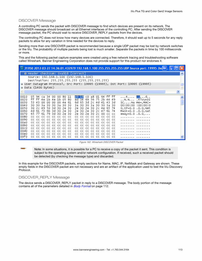
DISCOVER Message
A controlling PC sends the packet with DISCOVER message to find which devices are present on its network. TheDISCOVER message should broadcast on all Ethernet interfaces of the controlling PC. After sending the DISCOVERmessage packet, the PC should wait to receive DISCOVER_REPLY packets from the devices.
The controlling PC does not know how many devices are connected. Therefore, it should wait up to 5 seconds for any replypackets to allow for any variation in time needed for the devices to reply.
Sending more than one DISCOVER packet is recommended because a single UDP packet may be lost by network switchesor the iVu. The probability of multiple packets being lost is much smaller. Separate the packets in time by 100 millisecondsor more.
This and the following packet capture examples were created using a free network tracing and troubleshooting softwarecalled Wireshark. Banner Engineering Corporation does not provide support for this product nor endorses it.
Figure 162. Wireshark DISCOVER Packet
Note: In some situations, it is possible for a PC to receive a copy of the packet it sent. This condition issubject to the operating system and/or network configuration. If received, such a received packet shouldbe detected (by checking the message type) and discarded.
In this example for the DISCOVER packets, empty sections for Name, MAC, IP, NetMask and Gateway are shown. Theseempty fields in the DISCOVER packet are not necessary and are an artifact of the application used to test the iVu DiscoveryProtocol.
DISCOVER_REPLY Message
The device sends a DISCOVER_REPLY packet in reply to a DISCOVER message. The body portion of the messagecontains all of the parameters detailed in Body Format on page 112.
iVu Plus TG and Color Gen2 Image Sensors
www.bannerengineering.com - Tel: +1.763.544.3164 113

Figure 163. Wireshark DISOVER_REPLY Packet
Note: In some situations, a network switch/router receives a broadcast packet and duplicates it. Thisresults in the controlling PC receiving multiple responses that are completely identical. Discard multiplereplies that have the same correlation tag.
DISCOVER_SETIP Message
The controlling PC sends the DISCOVER_SETIP message to instruct a device to change its IP address, subnet mask, anddefault gateway. The message sent by the PC must always have the following parameters in the body portion:
• Either MAC or SerialNumber or both. If both are present, the match will be performed on both fields.• IP• NetMask• Gateway
Any other parameters in the body are ignored by the device.
Figure 164. Wireshark DISCOVER_SETIP Packet
When the device receives a DISCOVER_SETIP message, the following actions are performed:
1. The device compares the specified MAC address, the SerialNumber, or both, if both are present, with its own.2. If the above field(s) does not match the device's equivalent, the device discards the packet and no replay is
generated.
iVu Plus TG and Color Gen2 Image Sensors
114 www.bannerengineering.com - Tel: +1.763.544.3164

3. If the above field(s) match the device's equivalent:
a. The device compares the new values with the current values.b. If the new values are the same as the current values, the device discards the packet and no further reply is
generated.c. If the new values are different from the current values, the device set its IP address, subnet mask, and
default gateway to match what is in the packet.• The device performs only syntactic checks on the supplied data. It will not perform gateway
presence or duplicate IP address checks.• The change is logged in iVu system log as a success• A DISCOVER_REPLY packet is sent by the device back to the request originator• The device reboots after approximately 1 second
Figure 165. Wireshark DISOVER_REPLY with New IP Address
14.5.3 Message FlowThe following are examples of typical message flows for various interactions with the device.
Discovery of a Device
1. The PC broadcasts as DISCOVER message.
Only the header values need to be filled:• The Protocol ID field should be set to 0x6956752b, “iVu+"• The Message Type field should be set to 0x44495343, “DISC”• The Correlation tag should be set by the sender to the non-zero value that will allow the sender to identify
the response.The packet with the header values is sent using the broadcast address of 255.255.255.255.
Note: Not all the switches are configured to pass broadcast packets by default. A switchconfiguration change may be necessary to enable the passing of broadcast packets.
2. Upon receipt of the broadcast message the device verifies that the message is addressed to it by comparing theProtocol ID field to value 0x6956752b.
• If the value matches, the device examines the Message Type field.• If the value does not match any of the commands, the device discards the packet.• If the Message Type field matches 0x44495343, “DISC”, the device prepares the response in the form of
DISCOVER_REPLY packet: The Protocol ID field is set to 0x6956752b, “iVu+” The Message Type field is set to 0x52504c59, “RPLY” The Correlation Tag is copied from the received message The body of the message is populated with the following fields, separated by a comma:
SerialNumber (“SerialNumber=P01238710163241048”)
iVu Plus TG and Color Gen2 Image Sensors
www.bannerengineering.com - Tel: +1.763.544.3164 115

Version (“Version=TB_v1.1.4”) Name (“Name=Sensor1”) MAC (“MAC=00:11:22:33:44:55”) IP (“IP=192.168.0.1”) NetMask (“NetMask=255.255.255.0”) Gateway (“Gateway=0.0.0.0”)
The body of the message looks like the following:SerialNumber=P01238710163241048,Version=TB_v1.1.4,Name=Sensor1,MAC=00:11:22:33:44:55,IP=192.168.0.1,NetMask=255.255.255.0,Gateway=0.0.0.0
• The packet is broadcast on the network to port 19995. The device uses a pseudo-random back-off time tominimize collisions with other devices.
Change the IP Address of a Device Using the MAC
1. The PC broadcasts a DISCOVER_SETIP message.
The header values are filled as follows:• Protocol ID field must be set to 0x6956752b, “iVu+”• Message Type field should be set to 0x53455449, “SETI”• Correlation tag must be set by the sender to a non-zero value that will allow the originator to identify the
response
The body of the message must be filled as follows:• MAC (“MAC=00:11:22:33:44:55”)• IP (“IP=192.168.0.1”)• NetMask (“NetMask=255.255.255.0”)• Gateway (“Gateway=0.0.0.0”)
The body of the message looks like the following:MAC=00:11:22:33:44:55,IP=192.168.0.1,NetMask=255.255.255.0,Gateway=0.0.0.0The packet must be sent out using the broadcast address of 255.255.255.255
Note: Not all the switches are configured to pass broadcast packets by default. A switchconfiguration change may be necessary to enable the passing of broadcast packets.
2. Upon receipt of the broadcast message, the device verifies that the message is addressed to it by comparing theProtocol ID field to value 0x6956752b, “iVu+”.
• If the value matches, the device examines the Message Type field.• If the Message Type field matches 0x53455449, “SETI”, the received MAC address is compared with the
MAC address of the device.• If the MAC address does not match, the packet is discarded and no further replies or logs are generated.• If the received MAC address matches that of the device, the device performs the following actions:
IP, NetMask, and Gateway addresses are extracted from the body of the message. Values are verified to be syntactically correct.
For example, Gateway address of 255.255.255.255 is not allowed. IP address of 0.0.0.0 or 255.255.255.255 is not allowed. The check for duplicate IP address is not performed.
If the values do not pass the syntax check: The packet is discarded. The attempt is logged in the System Log. A DISCOVER_REPLY (RPLY) reply with current values is generated and sent (see Discovery
of a Device on page 115 for details). If the values pass the syntax check:
The new values are stored in the device. The change is logged in the System Log. A DISCOVER_REPLY (“RPLY) reply with new values is generated and sent (see Discovery of
a Device on page 115 for details). The device restarts.
Change the IP Address of a Device Using the Serial Number
1. The PC broadcasts a DISCOVER_SETIP message.
The header values are filled as follows:
iVu Plus TG and Color Gen2 Image Sensors
116 www.bannerengineering.com - Tel: +1.763.544.3164

• Protocol ID field must be set to 0x6956752b, “iVu+”• Message Type field should be set to 0x53455449, “SETI”• Correlation tag must be set by the sender to a non-zero value that will allow the originator to identify the
response
The body of the message must be filled as follows:• SerialNumber (“SerialNumber=P01238710163241048”)• IP (“IP=192.168.0.1”)• NetMask (“NetMask=255.255.255.0”)• Gateway (“Gateway=0.0.0.0”)
The body of the message looks like the following:SerialNumber=P01238710163241048,IP=192.168.0.1,NetMask=255.255.255.0,Gateway=0.0.0.0The packet must be sent using the broadcast address of 255.255.255.255.
Note: Not all the switches are configured to pass broadcast packets by default. A switchconfiguration change may be necessary to enable the passing of broadcast packets.
2. Upon receipt of the broadcast message the device verifies that the message is addressed to it by comparingProtocol ID field to value 0x6956752b, “iVu+”.
• If the value matches, the device examines the Message Type field.• If the Message Type field matches 0x53455449, “SETI”, the received SerialNumber is compared with the
SerialNumber of the device.• If the received serial number does not match, the packet is discarded and no further replies or logs are
generated.• If the received serial number matches that of the device, the device performs the following actions:
IP, NetMask, and Gateway addresses are extracted from the body of the message. Values are verified to be syntactically correct.
For example, Gateway address of 255.255.255.255 is not allowed IP address of 0.0.0.0 or 255.255.255.255 is not allowed The check for duplicate IP address will not be performed
If the values do not pass the syntax check: The packet is discarded. The failed attempt is logged in the System Log. A DISCOVER_REPLY (RPLY) reply with current values is generated and sent (see Discovery
of a Device on page 115 for details). If the values pass the syntax check:
The new values are stored in the device. The change is logged in the System Log. A DISCOVER_REPLY (“RPLY) reply with new values is generated and sent (see Discovery of
a Device on page 115 for details). The device restarts.
iVu Plus TG and Color Gen2 Image Sensors
www.bannerengineering.com - Tel: +1.763.544.3164 117

15 Industrial Ethernet Overview
15.1 Device Setup
15.1.1 Set IP AddressWhen shipped, the device is assigned a default IP address of 192.168.0.1, a default Subnet Mask of 255.255.255.0, and adefault Gateway of 0.0.0.0. To change these defaults, go to Main Menu > System > Communications > Ethernet I/O.
15.1.2 Set the Industrial Ethernet Protocol (Ethernet/IP™/Modbus/PCCC/PROFINET®)The Industrial Ethernet communication channel is disabled by default. To enable this channel, go to Main Menu > System >Communications > Industrial Ethernet > Connection. Select the desired channel: Ethernet/IP, MODBUS, PCCC, orPROFINET. Only one type of connection can be established at a time.
View information about an established connection from Main Menu > System > Communications > Industrial Ethernet >Status. Click the desired connection to view details.
This device provides extensive logging for the communication that occurs over the Industrial Ethernet connection. View logsfrom either Main Menu > System > Communications > Industrial Ethernet > View Logs or Main Menu > Logs >Communication Logs > Industrial Ethernet.
15.1.3 Set Trigger ModeTrigger the iVu using the hardware trigger input line or an internally supplied software trigger, or by toggling a bit overIndustrial Ethernet. To only accept triggers generated through the Industrial Ethernet communication channel, go to MainMenu > Imager > Trigger, and select Industrial Ethernet Only from the drop-down list.
15.2 Supported FunctionsControl the iVu over EtherNet/IP, PCCC, Modbus/TCP, or PROFINET using the input and output data the iVu makesavailable as a slave device for those protocols.
The following are some of the device operations that can be performed using input and output values:• Product Change• Teach Enable• Trigger the iVu• Read output indicators (pass, fail, ready, error)• Read counters (pass, fail, system error, missed trigger, frame count, iteration count)• Read sensor results
15.2.1 iVu Input ValuesThe operation of the iVu can be controlled through input bits and commands.
Register/Input Coil Bits
The following commands can only be executed using bits:
Input Coil Bit Command Description
0 Product Change Execute a product change (inspection number specified in the "Product ChangeNumber" 32-bit integer register)
1 Teach Latch Latch a teach flag. The Teach is executed on the next trigger
2 Trigger Causes the iVu to run the current inspection
15 Command Set this bit to 1 to execute the command entered in the Command ID Register
15.2.2 iVu Output ValuesUsing output values, the following information can be obtained:
• ACK bits (acknowledgement bits) for input commands, including error codes• System indicators (Ready, Pass/Fail, Read/No Read, Output signals, Command Error, etc.)• Inspection History (Iteration Count, Pass Count, Fail Count, etc.)
iVu Plus TG and Color Gen2 Image Sensors
118 www.bannerengineering.com - Tel: +1.763.544.3164

• Current Inspection Results (data of the sensor type contained in the inspection)• Command Responses
Refer to the sections on protocols for more information.
ACK Bits
For each of the Command bits there is a corresponding ACK bit. The iVu sets the ACK bit when the corresponding action iscomplete. Command bits cause actions to occur on the low-to-high transition of that bit. You must clear the command bitafter the corresponding ACK bit has been observed to be high.
As an example, to use the Trigger ACK bit, the programming steps for triggering an inspection are:
1. Wait for ready.2. Set Trigger command bit to 1.3. Wait for Trigger ACK to go to 1.4. Set Trigger command bit to 0.
Command Responses
iVu Command Channel commands executed using command IDs may have a response value. Depending on the Data Type,the response value is contained in one or multiple registers. Refer to iVu Command Channel Commands (iVu CommandChannel over Industrial Ethernet) on page 201 and Communications Guide on page 85for more information about the iVuCommand Channel.
15.3 iVu OperationAny Industrial Ethernet protocol can be used to trigger inspections, remote teach, and perform command functions.
iVu Plus TG and Color Gen2 Image Sensors
www.bannerengineering.com - Tel: +1.763.544.3164 119

15.3.1 General Command Execution
Point of View of the PLC
Start
(Optional)If using Command
ID, set it and its Parameter value
as required
Done
Read Error Code. Handle error
condition.
Clear allOutput Flags
Is Execution Error flag set?
Command execution successful. Read value
and input status flags as required
ACK Flag set?
Set Command Output Flag
Yes
No
Yes
No
The following rules apply for the use of input bit commands:• Only one iVu input bit can be set at a time• Corresponding ACK bits are set high only on completion of
the command (if the iVu input bit is still high)• Corresponding ACK bits are cleared when the iVu input bit
is cleared• When multiple iVu input bits are set simultaneously, the
Execution Error input bit is set and an Error Code value isreported in the Error Code register
• The Execution Error iVu output bit is cleared when all ACKbits are cleared, or a new valid command is received
15.4 EtherNet/IP™
The iVu can be controlled via EtherNet/IP™9 using assembly objects. From the point of view of a PLC, there are three inputassemblies and two output assemblies.
The Originator of the EtherNet/IP connection is the PLC. The Target of the EtherNet/IP connection is the iVu. The directionof communication can be described as T > O or O > T (sometimes also shown as T2O or O2T).
9 EtherNet/IP™ is a trademark of ODVA, Inc.
iVu Plus TG and Color Gen2 Image Sensors
120 www.bannerengineering.com - Tel: +1.763.544.3164
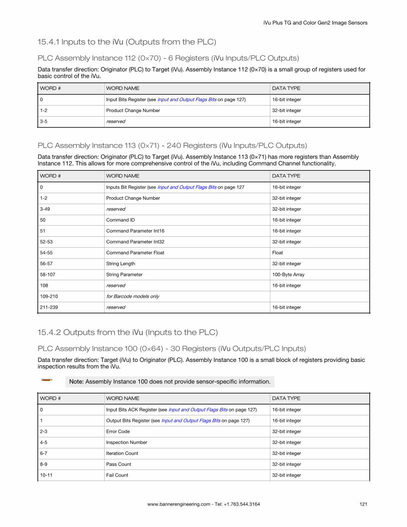
15.4.1 Inputs to the iVu (Outputs from the PLC)
PLC Assembly Instance 112 (0×70) - 6 Registers (iVu Inputs/PLC Outputs)
Data transfer direction: Originator (PLC) to Target (iVu). Assembly Instance 112 (0×70) is a small group of registers used forbasic control of the iVu.
WORD # WORD NAME DATA TYPE
0 Input Bits Register (see Input and Output Flags Bits on page 127) 16-bit integer
1-2 Product Change Number 32-bit integer
3-5 reserved 16-bit integer
PLC Assembly Instance 113 (0×71) - 240 Registers (iVu Inputs/PLC Outputs)
Data transfer direction: Originator (PLC) to Target (iVu). Assembly Instance 113 (0×71) has more registers than AssemblyInstance 112. This allows for more comprehensive control of the iVu, including Command Channel functionality.
WORD # WORD NAME DATA TYPE
0 Inputs Bit Register (see Input and Output Flags Bits on page 127 16-bit integer
1-2 Product Change Number 32-bit integer
3-49 reserved 32-bit integer
50 Command ID 16-bit integer
51 Command Parameter Int16 16-bit integer
52-53 Command Parameter Int32 32-bit integer
54-55 Command Parameter Float Float
56-57 String Length 32-bit integer
58-107 String Parameter 100-Byte Array
108 reserved 16-bit integer
109-210 for Barcode models only
211-239 reserved 16-bit integer
15.4.2 Outputs from the iVu (Inputs to the PLC)
PLC Assembly Instance 100 (0×64) - 30 Registers (iVu Outputs/PLC Inputs)
Data transfer direction: Target (iVu) to Originator (PLC). Assembly Instance 100 is a small block of registers providing basicinspection results from the iVu.
Note: Assembly Instance 100 does not provide sensor-specific information.
WORD # WORD NAME DATA TYPE
0 Input Bits ACK Register (see Input and Output Flags Bits on page 127) 16-bit integer
1 Output Bits Register (see Input and Output Flags Bits on page 127) 16-bit integer
2-3 Error Code 32-bit integer
4-5 Inspection Number 32-bit integer
6-7 Iteration Count 32-bit integer
8-9 Pass Count 32-bit integer
10-11 Fail Count 32-bit integer
iVu Plus TG and Color Gen2 Image Sensors
www.bannerengineering.com - Tel: +1.763.544.3164 121

WORD # WORD NAME DATA TYPE
12-13 Missed Triggers 32-bit integer
14-15 Current Inspection Time Float
16 Sensor P/F Coil 16-bit integer
17-29 reserved 16-bit integer
PLC Assembly Instance 101 (0×65) - 240 Registers (iVu Outputs/PLC Inputs)
Assembly Instance 101 provides space for sensor-specific information. See Multiple Sensors Mapping Options on page122.
15.4.3 Multiple Sensors Mapping OptionsWhen using an iVu with multiple sensors in an inspection, there are two mapping options: Default and Custom.
Default Map
Main Menu > System > Communications > Industrial Ethernet > Map > Default
The default map automatically maps sensor data for each inspection and is recommended when the execution order ofsensor types is the same across inspections. When an inspection includes multiple sensors, the first five sensor results areshown starting at offset 55. Each sensor result occupies 20 words.
Table 21: I/O Assembly Instance 101 (0×65): DEFAULT MAP
WORD # WORD NAME Data Type
0 Input Bits ACK Register (see Input and Output Flags Bits on page 127) 16-bit integer
1 Output Bits Register (see Input and Output Flags Bits on page 127) 16-bit integer
2-3 Error Code 32-bit integer
4-5 Inspection Number 32-bit integer
6-7 Iteration Count 32-bit integer
8-9 Pass Count 32-bit integer
10-11 Fail Count 32-bit integer
12-13 Missed Triggers 32-bit integer
14-15 Current Inspection Time Float
16 Sensor Pass/Fail Coil 16-bit integer
17-29 reserved 16-bit integer
30-52 Inspection Name 2-Word Length + 20-Unicode characters
53-54 Frame Number 32-bit integer
55 Sensor Type ID (Sensor 1) 16-bit integer
56-74 Sensor 1 Specific Data 16-bit integer
75 Sensor Type ID (Sensor 2) 16-bit integer
76-94 Sensor 2 Specific Data 16-bit integer
95 Sensor Type ID (Sensor 3) 16-bit integer
96-114 Sensor 3 Specific Data 16-bit integer
115 Sensor Type ID (Sensor 4) 16-bit integer
116-134 Sensor 4 Specific Data 16-bit integer
135 Sensor Type ID (Sensor 5) 16-bit integer
136-154 Sensor 5 Specific Data 16-bit integer
iVu Plus TG and Color Gen2 Image Sensors
122 www.bannerengineering.com - Tel: +1.763.544.3164

WORD # WORD NAME Data Type
155-170 reserved 16-bit integer
171 Command Status 16-bit integer
172 Command Response Int16 16-bit integer
173-174 Command Response Int32 32-bit integer
175-176 Command Response Float Float
177-178 Command Response Length 32-bit integer
179-228 Command Response Data 100-Byte Array
229-239 reserved 16-bit integer
Note: If the inspection contains more than five sensors, any sensors after the fifth sensor are not includedon the map.
Table 22: Area Sensor ID = 2
Sensor Specific Data Data Size
Area Count 32-bit integer
Area Range Minimum 32-bit integer
Area Range Maximum 32-bit integer
Table 23: Blemish Sensor ID = 3
Sensor Specific Data Sensor Location
Blemish Count 32-bit integer
Blemish Minimum Edge Length 32-bit integer
Blemish Maximum Edge Length 32-bit integer
Table 24: Match Sensor ID = 4
Sensor Specific Data Sensor Location
Match Count 32-bit integer
Match Minimum Percent 16-bit integer
Match Maximum Percent 16-bit integer
Table 25: Sort Sensor ID = 5
Sensor Specific Data Sensor Location
Sort Pattern Map 16-bit integer
Sort Pattern Count 16-bit integer
Sort Pattern 1 Count 16-bit integer
Sort Pattern 2 Count 16-bit integer
Sort Pattern 3 Count 16-bit integer
Sort Pattern 4 Count 16-bit integer
Sort Pattern 5 Count 16-bit integer
Sort Pattern 6 Count 16-bit integer
iVu Plus TG and Color Gen2 Image Sensors
www.bannerengineering.com - Tel: +1.763.544.3164 123

Sensor Specific Data Sensor Location
Sort Pattern 7 Count 16-bit integer
Sort Pattern 8 Count 16-bit integer
Sort Pattern 9 Count 16-bit integer
Sort Pattern 10 Count 16-bit integer
Sort Minimum Percent Match 16-bit integer
Sort Maximum Percent Match 16-bit integer
Table 26: Average Color Sensor ID = 6
Sensor-Specific Data Data Size
Average Red 16‐bit Integer
Average Green 16‐bit Integer
Average Blue 16‐bit Integer
Average Hue 16‐bit Integer
Average Saturation 16‐bit Integer
Average Intensity 16‐bit Integer
Standard Deviation Red 32-bit float
Standard Deviation Green 32-bit float
Standard Deviation Blue 32-bit float
Standard Deviation Hue 32-bit float
Standard Deviation Saturation 32-bit float
Standard Deviation Intensity 32-bit float
Note: Average Color Sensor data that does not apply to the selected color space has a result of 0. Forexample, if the HSI color space is selected, the Red, Green, and Blue data will have a result of 0.
Table 27: Color Compare Sensor ID = 7
Sensor-Specific Data Data Size
Color Difference 16‐bit Integer
Intensity Difference 16‐bit Integer
Table 28: Color Area Sensor ID = 8
Sensor-Specific Data Data Size
Area Count 32‐bit Integer
Area Range Minimum 32‐bit Integer
Area Range Maximum 32‐bit Integer
Custom Map
Main Menu > System > Communications > Industrial Ethernet > Map > Custom
The custom map allows for the customization of sensor data on the map. The user selects data items of interest for eachsensor type. This is recommended when the execution order of sensor types varies across inspections or when using morethan five sensors.
iVu Plus TG and Color Gen2 Image Sensors
124 www.bannerengineering.com - Tel: +1.763.544.3164

A system-level custom map is supported for additional flexibility. When Custom map is selected, a customizable space isused in the offset range (55 to 166) on I/O Assembly 101 (0×65) registers.
Table 29: I/O Assembly Instance 101 (0×65): CUSTOM MAP
WORD # WORD NAME Data Type
0 Input Bits ACK Register (see Input and Output Flags Bits on page 127) 16-bit integer
1 Output Bits Register (see Input and Output Flags Bits on page 127) 16-bit integer
2-3 Error Code 32-bit integer
4-5 Inspection Number 32-bit integer
6-7 Iteration Count 32-bit integer
8-9 Pass Count 32-bit integer
10-11 Fail Count 32-bit integer
12-13 Missed Triggers 32-bit integer
14-15 Current Inspection Time Float
16 Sensor Pass/Fail Coil 16-bit integer
17-29 reserved 16-bit integer
30-52 Inspection Name 2-Word Length + 20-unicode characters
53-54 Frame Number 32-bit integer
55-166 Customizable Space (112 reg) 16-bit integer
167-170 reserved 16-bit integer
171 Command Status 16-bit integer
172 Command Response Int16 16-bit integer
173-174 Command Response Int32 32-bit integer
175-176 Command Response Float Float
177-178 Command Response Length 32-bit integer
179-228 Command Response Data 100-Byte Array
229-239 reserved 16-bit integer
Configure a Custom Industrial Ethernet (IE) Map
1. Enable the Custom Map by selecting Custom on the drop-down list.
Figure 166. Map Screen—Custom Map Selected2. Click the yellow arrow to access the Custom IE Map screen.3. On the Custom IE Map screen, choose the sensor result data that will appear on the customizable space.
iVu Plus TG and Color Gen2 Image Sensors
www.bannerengineering.com - Tel: +1.763.544.3164 125

Figure 167. Custom IE Map Summary Screen
The bottom of the screen shows the word use on the customizable space. In the image above, seven words havebeen used for one Area sensor "Area (1)".
4. Click the yellow arrow next to the Area sensor row to go to the Area Sensor Data.
Figure 168. Custom IE Map Screen—Area Sensor Data
On the Area Sensor Data screen shown above, Area Count, Area Range Min and Area Range Max are available toadd to the customizable space. The number to the right of each item shows how many words are required to displaythe data. The bottom reservation count shows the number of Area sensors that have space reserved for them on thecustomizable map.
Because only one Area sensor's worth of data is reserved on the image above, the selected data will be collectedfrom the first Area sensor in the current inspection. When multiple Area sensors have been reserved, the data will bearranged in the sequential manner of the sensor type in the current inspection.
5. Click the green arrow (Back) to return to the Custom IE Map summary.6. Continue to add more data from any sensor type as required or reserve more sensors into the customizable space.
Sensor Name and Sensor Type ID are global settings that are part of any individual sensor reservation. When they arechecked, they are inserted into each sensor reservation.
The following is an example of a multiple sensors inspection and its output location on the customizable space.
iVu Plus TG and Color Gen2 Image Sensors
126 www.bannerengineering.com - Tel: +1.763.544.3164

In this example, there are only two Blemish sensors in the current inspection. The Blemish3 location will be all zero on thecustomizable space. The customizable map had not reserved space for a Match sensor, so Match1 from the inspection willnot be outputted on the custom map.
15.4.4 Input and Output Flags BitsThe Input Bits are used to command execution of basic functions. The Output Bits are used to push single bit outputs fromthe iVu device to the PLC. The 32 bits of iVu output can also be accessed using the bits of the first two Output Registers(Input Bits ACK Register(word 0) and Output Bits Register (word1)).Table 30: Inputs Bits Register (Command Flag Bits)
Bit Position
15 14 13 12 11 10 9 8 7 6 5 4 3 2 1 0
Command TriggerTeach
Latch
Product
Change
Table 31: Input Bits ACK Register (ACK Flag Bits)
Bit Position
15 14 13 12 11 10 9 8 7 6 5 4 3 2 1 0
Command
ACK
Trigger
ACK
Teach
Latch
ACK
Product
Change
ACK
Table 32: Output Bits Register (iVu Status Flag Bits)
Bit Position
15 14 13 12 11 10 9 8 7 6 5 4 3 2 1 0
Execution
Error
System
Error
Teach
Error
Missed
TriggerOutput 3 Output 2 Output 1
Ready to
Latch
Read/No
ReadPass/Fail Ready
15.4.5 Configuration Assembly ObjectThe iVu EtherNet/IP implementation does not support an assembly object Configuration instance. However, one is requiredfor the creation of implicit Class 1 connections on a ControlLogix®10 family PLC. Therefore, a configuration instance isdefined as instance number 128 (0×80). Its size is zero.
15.4.6 Data FormatsThe iVu EtherNet/IP implementation supports 32-bit Integers in LSW_MSW data format. The LSW_MSW data format is suchthat the least significant word is stored first, then the most significant word. This format is used for Allen-BradleyControlLogix PLCs.
The string format is compatible with the Allen-Bradley ControlLogix built-in string data type. This format is a 32-bit (DINT)length followed by character bytes (SINT). This results in the following string format as viewed from the iVu:
Word
0 1 2 3 4
LengthLSW
LengthMSW
byte 1 byte 0 byte 3 byte 2 byte 5 byte 4 ... ...
15.4.7 Minimum Requested Packet Interval (RPI) ValueThe iVu can operate with input and output Requested Packet Intervals (RPIs) as low as 50 milliseconds. The device may notoperate reliably if a lower RPI value is selected.
10 ControlLogix® is a trademark of Rockwell Automation, Inc.
iVu Plus TG and Color Gen2 Image Sensors
www.bannerengineering.com - Tel: +1.763.544.3164 127

15.4.8 iVu Plus TG and Color Gen2 Image Sensors EDS File Installation in ControlLogixSoftwareUse the EDS Hardware Installation Tool to register the Electronic Data Sheet (EDS) file.
1. On the Tools menu, click EDS Hardware Installation Tool.The Rockwell Automation's EDS Wizard dialog displays.
Figure 169. Tools—EDS Hardware Installation Tool
2. Click Next.3. Select the Register an EDS file(s) option.
Figure 170. Rockwell Automation's EDS Wizard—Options
iVu Plus TG and Color Gen2 Image Sensors
128 www.bannerengineering.com - Tel: +1.763.544.3164

4. Browse to locate the EDS file and click Next.
Figure 171. Select File to Register
5. Click Next to register the tested file.
Figure 172. Register the Tested File
iVu Plus TG and Color Gen2 Image Sensors
www.bannerengineering.com - Tel: +1.763.544.3164 129

6. Click Next when you see the icon associated with the EDS file.
Figure 173. Rockwell Automation's EDS Wizard
7. Click Next to register the EDS file.
Figure 174. Register the EDS File
8. Click Finish to close the EDS Wizard .9. Right-click on the PLC's Ethernet adapter and select New Module...
Figure 175. New Module
iVu Plus TG and Color Gen2 Image Sensors
130 www.bannerengineering.com - Tel: +1.763.544.3164
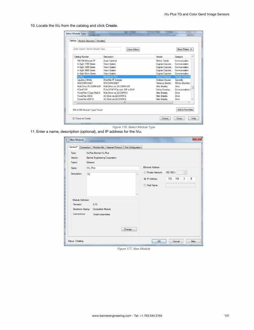
10. Locate the iVu from the catalog and click Create.
Figure 176. Select Module Type
11. Enter a name, description (optional), and IP address for the iVu.
Figure 177. New Module
iVu Plus TG and Color Gen2 Image Sensors
www.bannerengineering.com - Tel: +1.763.544.3164 131

12. Click Change in the Module Definition field.
Figure 178. Module Definition
13. Select the desired connection in the Module Definition window. Each of the items in the Name list represents a fixedgrouping of input and output assembly instances:
Small Assemblies • O>T PLC Input/iVu Plus Output Assembly 112 (0x70)• T>O PLC Output/iVu Plus Input Assembly 100 (0x64)
Large Assemblies • O>T PLC Input/iVu Plus Output Assembly 113 (0x71)• T>O PLC Output/iVu Plus Input Assembly 101 (0x65)
14. Select INT as the data type.
Figure 179. Module Definition—Data Type
iVu Plus TG and Color Gen2 Image Sensors
132 www.bannerengineering.com - Tel: +1.763.544.3164

15. Click OK twice and download the program to the PLC.
Figure 180. Download to the PLC
The connection looks like the one in Figure 180 on page 133.
15.4.9 RSLogix5000 ConfigurationTo create an implicit Class 1 configuration to the iVu using EtherNet/IP when using a ControlLogix family PLC, configure theiVu as a “Generic Ethernet Module” under the ENET_MODULE. The following is a sample setup of a Banner device:
1. Add a generic Ethernet module to the PLC's Ethernet card.
a. Click New Module.
Figure 181. Add Ethernet Module
b. Click Communications, then Generic Ethernet Module.
iVu Plus TG and Color Gen2 Image Sensors
www.bannerengineering.com - Tel: +1.763.544.3164 133

Figure 182. Select Module
2. Configure the Module Properties.
Note: The data type in the Comm Format must be changed to an INT.
See Inputs to the iVu (Outputs from the PLC) on page 121 and Outputs from the iVu (Inputs to the PLC) on page 121for more information on each specific assembly instance.
iVu Plus TG and Color Gen2 Image Sensors
134 www.bannerengineering.com - Tel: +1.763.544.3164
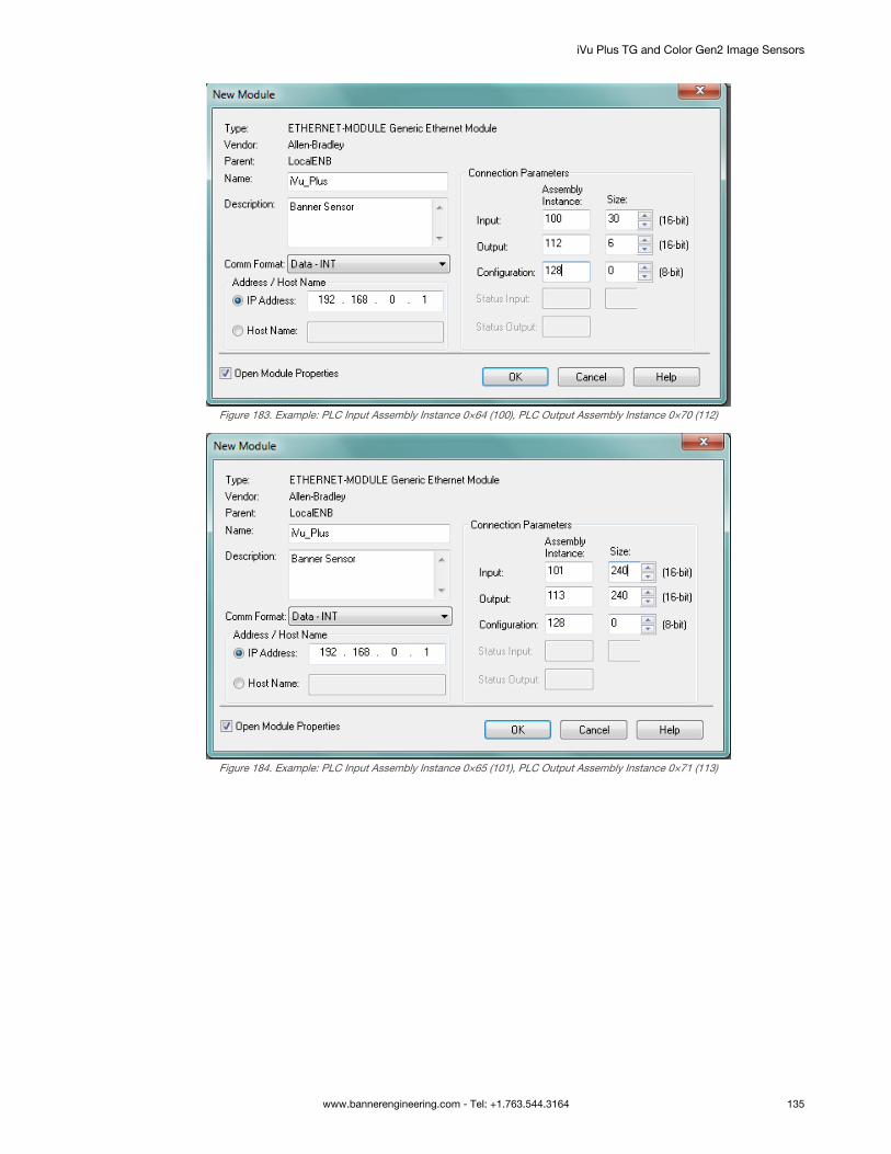
Figure 183. Example: PLC Input Assembly Instance 0×64 (100), PLC Output Assembly Instance 0×70 (112)
Figure 184. Example: PLC Input Assembly Instance 0×65 (101), PLC Output Assembly Instance 0×71 (113)
iVu Plus TG and Color Gen2 Image Sensors
www.bannerengineering.com - Tel: +1.763.544.3164 135

Figure 185. Select or clear the Unicast Connection checkbox as desired
Note: The minimum allowed RPI is 50 ms.
3. If the module configuration was successful, the following information displays:
Figure 186. Successful Configuration
If the module configuration was not successful, the RSLogix 5000 software will indicate errors similar to thefollowing figures:
Figure 187. ERROR: Assembly Instance Number and/or Size Incorrect
Figure 188. ERROR: iVu Not Powered Up or Ethernet Cable Not Attached
iVu Plus TG and Color Gen2 Image Sensors
136 www.bannerengineering.com - Tel: +1.763.544.3164

4. Locate the memory map setup from the Banner module to the PLC memory map.
C = Configuration (not used)I = Inputs to PLC (outputs from the device)O = Outputs from PLC (inputs to the device)
Figure 189. Memory Map
iVu Plus TG and Color Gen2 Image Sensors
www.bannerengineering.com - Tel: +1.763.544.3164 137

The iVu memory map expanded. I = Inputs to PLC (outputs from the device).Figure 190. Memory Map Expanded
Sample map demonstrating string values:
Figure 191. Memory Map: Default
Note: ControlLogix string format. "iVu Plus Image Sensor"
iVu Plus TG and Color Gen2 Image Sensors
138 www.bannerengineering.com - Tel: +1.763.544.3164

All data is initially transferred as "INT" data type. An ASCII string looks like gibberish in this format. Changing the"style" to ASCII instead of "Decimal" reveals the correct string data.
Figure 192. Memory Map: "Style" changed to ASCII
15.5 Modbus/TCPThe Modbus/TCP protocol provides device information using register and coil banks defined by the slave device. Thissection defines the register and coil banks. By specification, Modbus/TCP uses TCP port 502.
The following registers are used to send values back and forth from the iVu to the PLC. iVu read-only output data can beread as Input Registers (30000) using Modbus function code 04 (Read Input Registers). Because some devices like theModicon family of PLCs cannot access data using the 30000 range of registers, the same values can also be read fromHolding Registers (40000) using Modbus function code 03 (Read Holding Registers).
The Input Bits can be set as Coils using Modbus function code 05 (Force Single Coil). The state of the Input ACK Bits andStatus Bits can be read as Inputs (10000) using Modbus function code 02 (Read Input Status).
Modbus Function Codes Supported
01: Read Coil Status02: Read Input Status03: Read Holding Registers04: Read Input Registers05: Force Single Coil06: Preset Single Register07: Read Exception Status16: Preset Multiple Registers
Table 33: Input Bits (Coils 00001-00016)
05: Force Single Coil
Register Bit Position WORD Name
00001 0 Product Change
00002 1 Teach Latch
00003 2 Trigger
00004 3 Barcode models only
00005 4 reserved
00006 5 reserved
00007 6 reserved
00008 7 reserved
00009 8 reserved
iVu Plus TG and Color Gen2 Image Sensors
www.bannerengineering.com - Tel: +1.763.544.3164 139

05: Force Single Coil
Register Bit Position WORD Name
00010 9 reserved
00011 10 reserved
00012 11 reserved
00013 12 reserved
00014 13 reserved
00015 14 reserved
00016 15 Command
Table 34: Input ACK Bits (Inputs 10001-10016)
02: Read Input Status
Register Bit Position WORD Name
10001 0 Product Change ACK
10002 1 Teach Latch ACK
10003 2 Trigger ACK
10004 3 Barcode models only
10005 4 reserved
10006 5 reserved
10007 6 reserved
10008 7 reserved
10009 8 reserved
10010 9 reserved
10011 10 reserved
10012 11 reserved
10013 12 reserved
10014 13 reserved
10015 14 reserved
10016 15 Command ACK
Table 35: Status Bits (Inputs 10017-10032)
02: Read Input Status
Register Bit Position WORD Name
10017 0 Ready
10018 1 Pass/Fail
10019 2 Read/No Read
10020 3 Ready Latch
10021 4 reserved
10022 5 Output 1
10023 6 Output 2
iVu Plus TG and Color Gen2 Image Sensors
140 www.bannerengineering.com - Tel: +1.763.544.3164

02: Read Input Status
Register Bit Position WORD Name
10024 7 Output 3
10025 8 reserved
10026 9 reserved
10027 10 reserved
10028 11 reserved
10029 12 Missed Trigger
10030 13 Teach Error
10031 14 System Error
10032 15 Execution Error
15.5.1 iVu Input ValuesHolding Registers (40000) are used by the PLC or HMI to write values to the iVu device. To write, use function codes 6(Preset Single Register) or 16 (Preset Multiple Registers).
Table 36: iVu Input Values (Modbus/TCP Holding Registers)
06: Preset Single Register or 16: Preset Multiple Registers
REG # WORD NAME DATA TYPE
1 Input Bits (See Input and Output Bits onpage 147 and Coils 00001-16)
16-bit integer
2-3 Product Change Number 32-bit integer
4-50 reserved 16-bit integer
51 Command ID 16-bit integer
52 Command Parameter Int16 16-bit integer
53-54 Command Parameter Int32 32-bit integer
55-56 Command Parameter Float
57-58 Command Parameter ASCII String Length 32-bit integer
59-108 Command Parameter ASCII String 100-byte Unicode character array
109-240 reserved 16-bit integer
15.5.2 iVu Output ValuesThe iVu sends output data to the PLC or HMI via a bank of Input Registers (30000). Some devices, like the Modicon familyof PLCs, cannot access data using the 30000 range of register addresses. For these devices, the iVu output data is alsomade available as Holding Registers (40000). To access this data, use either function code 04 (Read Input Registers) orfunction code 03 (Read Holding Registers).
15.5.3 Multiple Sensors Mapping OptionsWhen using an iVu with multiple sensors in an inspection, there are two mapping options: Default and Custom.
Default Map
Main Menu > System > Communications > Industrial Ethernet > Map > Default
The default map automatically maps sensor data for each inspection and is recommended when the execution order ofsensor types is the same across inspections. When an inspection has multiple sensors, the first five sensor results areshown, starting at offset 55. Each sensor result occupies 20 words.
iVu Plus TG and Color Gen2 Image Sensors
www.bannerengineering.com - Tel: +1.763.544.3164 141

Table 37: iVu Output Values (Modbus/TCP Input or Holding Registers): DEFAULT MAP
04: Read Input Registers or 03: Read Holding Registers
Input REG # Holding REG # WORD NAME DATA TYPE
1 1001 Input ACK Bits (see Input andOutput Bits on page 147 Flags, andInputs 10001-16).
16-bit Integer
2 1002 Status Bits (see Input and OutputBits on page 147, and Inputs10017-32).
16-bit Integer
3-4 1003-4 Error Code 32-bit Integer
5-6 1005-6 Inspection Number 32-bit Integer
7-8 1007-8 Iteration Count 32-bit Integer
9-10 1009-10 Pass Count 32-bit Integer
11-12 1011-12 Fail Count 32-bit Integer
13-14 1013-14 Missed Triggers 32-bit Integer
15-16 1015-16 Current Inspection Time Float
17 1017 Sensor Pass/Fail Bits 16-bit Integer
18-30 1018-30 reserved 16-bit Integer
31-53 1031-53 Inspection Name 2-word Length + 20 Unicodecharacters
54-55 1054-55 Frame Number 32-bit Integer
56 1056 Sensor Type ID (Sensor 1) 16-bit Integer
57-75 1057-75 Sensor 1 Specific Data 16-bit Integer
76 1076 Sensor Type ID (Sensor 2) 16-bit Integer
77-95 1077-95 Sensor 2 Specific Data 16-bit Integer
96 1096 Sensor Type ID (Sensor 3) 16-bit Integer
97-115 1097-115 Sensor 3 Specific Data 16-bit Integer
116 1116 Sensor Type ID (Sensor 4) 16-bit Integer
117-135 1117-135 Sensor 4 Specific Data 16-bit Integer
136 1136 Sensor Type ID (Sensor 5) 16-bit Integer
137-155 1137-155 Sensor 5 Specific Data 16-bit Integer
156-171 1156-71 reserved 16-bit Integer
172 1172 Command Status 16-bit Integer
173 1173 Command Response Int16 16-bit Integer
174-75 1174-75 Command Response Int32 32-bit Integer
176-77 1176-77 Command Response Float
178-79 1178-79 Command Response ASCII StringLength
16-bit Integer
180-229 1180-229 Command Response ASCII StringData
100-byte Unicode character array
230-40 1230-40 reserved 16-bit Integer
Note: If the inspection contains more than five sensors, any sensors after the fifth sensor are not includedon the map.
iVu Plus TG and Color Gen2 Image Sensors
142 www.bannerengineering.com - Tel: +1.763.544.3164

Table 38: Area Sensor ID = 2
Sensor Specific Data Data Size
Area Count 32-bit Integer
Area Range Minimum 32-bit Integer
Area Range Maximum 32-bit Integer
Table 39: Blemish Sensor ID = 3
Sensor Specific Data Sensor Location
Blemish Count 32-bit Integer
Blemish Minimum Edge Length 32-bit Integer
Blemish Minimum Edge Length 32-bit Integer
Table 40: Match Sensor ID = 4
Sensor Specific Data Sensor Location
Match Count 32-bit Integer
Match Minimum Percent 16-bit Integer
Match Maximum Percent 16-bit Integer
Table 41: Sort Sensor ID = 5
Sensor Specific Data Sensor Location
Sort Pattern Map 16-bit Integer
Sort Pattern Count 16-bit Integer
Sort Pattern 1 Count 16-bit Integer
Sort Pattern 2 Count 16-bit Integer
Sort Pattern 3 Count 16-bit Integer
Sort Pattern 4 Count 16-bit Integer
Sort Pattern 5 Count 16-bit Integer
Sort Pattern 6 Count 16-bit Integer
Sort Pattern 7 Count 16-bit Integer
Sort Pattern 8 Count 16-bit Integer
Sort Pattern 9 Count 16-bit Integer
Sort Pattern 10 Count 16-bit Integer
Sort Minimum Percent Match 16-bit Integer
Sort Maximum Percent Match 16-bit Integer
Table 42: Average Color Sensor ID = 6
Sensor-Specific Data Data Size
Average Red 16‐bit Integer
Average Green 16‐bit Integer
Average Blue 16‐bit Integer
Average Hue 16‐bit Integer
iVu Plus TG and Color Gen2 Image Sensors
www.bannerengineering.com - Tel: +1.763.544.3164 143

Sensor-Specific Data Data Size
Average Saturation 16‐bit Integer
Average Intensity 16‐bit Integer
Standard Deviation Red 32-bit float
Standard Deviation Green 32-bit float
Standard Deviation Blue 32-bit float
Standard Deviation Hue 32-bit float
Standard Deviation Saturation 32-bit float
Standard Deviation Intensity 32-bit float
Note: Average Color Sensor data that does not apply to the selected color space has a result of 0. Forexample, if the HSI color space is selected, the Red, Green, and Blue data will have a result of 0.
Table 43: Color Compare Sensor ID = 7
Sensor-Specific Data Data Size
Color Difference 16‐bit Integer
Intensity Difference 16‐bit Integer
Table 44: Color Area Sensor ID = 8
Sensor-Specific Data Data Size
Area Count 32‐bit Integer
Area Range Minimum 32‐bit Integer
Area Range Maximum 32‐bit Integer
iVu Output Values (Modbus/TCP Input or Holding Registers)- Custom Map
The Custom Map option allows for more flexibility regarding iVu Output Values. The Custom Map option allows the user tochoose which pieces of Sensor Specific Data are given space in the register map.
Table 45: iVu Output Values (Modbus/TCP Input or Holding Registers): CUSTOM MAP
04: Read Input Registers or 03: Read Holding Registers
Input REG # Holding REG # WORD NAME DATA TYPE
1 1001 Input ACK Bits (see Input andOutput Bits on page 147) seealso Inputs 10001-16
16-bit Integer
2 1002 Status Bits (see Input andOutput Bits on page 147) seealso Inputs 10017-32
16-bit Integer
3-4 1003-4 Error Code 32-bit Integer
5-6 1005-6 Inspection Number 32-bit Integer
7-8 1007-8 Iteration Count 32-bit Integer
9-10 1009-10 Pass Count 32-bit Integer
11-12 1011-12 Fail Count 32-bit Integer
13-14 1013-14 Missed Triggers 32-bit Integer
15-16 1015-16 Current Inspection Time Float
iVu Plus TG and Color Gen2 Image Sensors
144 www.bannerengineering.com - Tel: +1.763.544.3164

04: Read Input Registers or 03: Read Holding Registers
Input REG # Holding REG # WORD NAME DATA TYPE
17 1017 Sensor Pass/Fail Bits 16-bit Integer
18-30 1018-30 reserved 16-bit Integer
31-53 1031-53 Inspection Name 2-word Length + 20 Unicodecharacters
54-55 1054-55 Frame Number 32-bit Integer
56-167 1056-167 Customizable Space (112registers)
varies by sensor
168-171 1168-71 reserved 16-bit Integer
172 1172 Command Status 16-bit Integer
173 1173 Command Response Int16 16-bit Integer
174-75 1174-75 Command Response Int32 32-bit Integer
176-77 1176-77 Command Response Float
178-79 1178-79 Command Response ASCIIString Length
16-bit Integer
180-229 1180-229 Command Response ASCIIString Data
100-byte Unicode characterarray
230-40 1230-40 reserved 16-bit Integer
Configure a Custom Industrial Ethernet (IE) Map
1. Enable the Custom Map by selecting Custom on the drop-down list.
Figure 193. Map Screen—Custom Map Selected2. Click the yellow arrow to access the Custom IE Map screen.3. On the Custom IE Map screen, choose the sensor result data that will appear on the customizable space.
iVu Plus TG and Color Gen2 Image Sensors
www.bannerengineering.com - Tel: +1.763.544.3164 145

Figure 194. Custom IE Map Summary Screen
The bottom of the screen shows the word use on the customizable space. In the image above, seven words havebeen used for one Area sensor "Area (1)".
4. Click the yellow arrow next to the Area sensor row to go to the Area Sensor Data.
Figure 195. Custom IE Map Screen—Area Sensor Data
On the Area Sensor Data screen shown above, Area Count, Area Range Min and Area Range Max are available toadd to the customizable space. The number to the right of each item shows how many words are required to displaythe data. The bottom reservation count shows the number of Area sensors that have space reserved for them on thecustomizable map.
Because only one Area sensor's worth of data is reserved on the image above, the selected data will be collectedfrom the first Area sensor in the current inspection. When multiple Area sensors have been reserved, the data will bearranged in the sequential manner of the sensor type in the current inspection.
5. Click the green arrow (Back) to return to the Custom IE Map summary.6. Continue to add more data from any sensor type as required or reserve more sensors into the customizable space.
Sensor Name and Sensor Type ID are global settings that are part of any individual sensor reservation. When they arechecked, they are inserted into each sensor reservation.
The following is an example of a multiple sensors inspection and its output location on the customizable space.
iVu Plus TG and Color Gen2 Image Sensors
146 www.bannerengineering.com - Tel: +1.763.544.3164

In this example, there are only two Blemish sensors in the current inspection. The Blemish3 location will be all zero on thecustomizable space. The customizable map had not reserved space for a Match sensor, so Match1 from the inspection willnot be outputted on the custom map.
15.5.4 Input and Output BitsWriteable Input Bits are inputs to the iVu (outputs from the PLC or HMI). They are used for basic control of the iVu. They areaccessible using function code 6 (Preset Single Register). The same control is also possible using Coils 00001-16, functioncode 05 (Force Single Coil).Table 46: Input Bits: PLC Holding Register 1, also Coils 00001-16
Coil 16 Coil 15 Coil 14 Coil 13 Coil 12 Coil 11 Coil 10 Coil 9 Coil 8 Coil 7 Coil 6 Coil 5 Coil 4 Coil 3 Coil 2 Coil 1
Bit 15 Bit 14 Bit 13 Bit 12 Bit 11 Bit 10 Bit 9 Bit 8 Bit 7 Bit 6 Bit 5 Bit 4 Bit 3 Bit 2 Bit 1 Bit 0
Command reserved reserved reserved reserved reserved reserved reserved reserved reserved reserved reserved Barcode
models
only
Trigger Teach
Latch
Product
Change
Read-only Input ACK Bits are outputs from the iVu (inputs to the PLC or HMI). They are used to acknowledge each of theinput bits sent from the PLC. For example, if the PLC changes the Trigger bit (from Input Bits, above) from a 0 to a 1, the iVuchanges the Trigger ACK bit from a 0 to a 1 in response. This information is available as Input Registers or HoldingRegisters. Use either function code 04 (Read Input Registers) or function code 03 (Read Holding Registers). The same datacan also be read from Inputs (10000) using Modbus function code 02 (Read Input Status).Table 47: Input ACK Bits: PLC Input Register 1 or Holding Register 1001, also Inputs 10001-16
Input 16 Input 15 Input 14 Input 13 Input 12 Input 11 Input 10 Input 9 Input 8 Input 7 Input 6 Input 5 Input 4 Input 3 Input 2 Input 1
Bit 15 Bit 14 Bit 13 Bit 12 Bit 11 Bit 10 Bit 9 Bit 8 Bit 7 Bit 6 Bit 5 Bit 4 Bit 3 Bit 2 Bit 1 Bit 0
Command
ACK
reserved reserved reserved reserved reserved reserved reserved reserved reserved reserved reserved Barcode
models
only
Trigger
ACK
Teach
Latch
ACK
Product
Change
ACK
Read-only Status Bits are outputs from the iVu (inputs to the PLC or HMI). They are used to report the basic status of theiVu and the last inspection run. This information is available as Input Registers or Holding Registers. Use either functioncode 04 (Read Input Registers) or function code 03 (Read Holding Registers). The same data can also be read from Inputs(10000) using Modbus function code 02 (Read Input Status).Table 48: Status Bits: PLC Input Register 2 or Holding Register 1002, also Inputs 10017-32
Input 32 Input 31 Input 30 Input 29 Input 28 Input 27 Input 26 Input 25 Input 24 Input 23 Input 22 Input 21 Input 20 Input 19 Input 18 Input 17
Bit 15 Bit 14 Bit 13 Bit 12 Bit 11 Bit 10 Bit 9 Bit 8 Bit 7 Bit 6 Bit 5 Bit 4 Bit 3 Bit 2 Bit 1 Bit 0
Execution
Error
System
Error
Teach
Error
Missed
Trigger
reserved reserved reserved reserved Output 3 Output 2 Output 1 reserved Ready
Latch
Read/No
Read
Pass/Fail Ready
15.6 PLC5 and SLC 5 (PCCC)Allen-Bradley’s PLC5 and SLC 500 family of devices use PCCC communications protocol. The iVu supports these PLCsusing input and output register arrays.
The Output bits, ACK bits and Input bits bit definitions are the same as defined in Input and Output Bits on page 147. Theterms “Input” and “Output” are from the point of view of the PLC.
15.6.1 ConfigurationThe following images represent a typical configuration.
iVu Plus TG and Color Gen2 Image Sensors
www.bannerengineering.com - Tel: +1.763.544.3164 147

PLC Read Message Command
This Controller
Communications Command = PLC5 Read
Data Table Address = Integer table "Nx"
Target Device
Data Table Address = N7:x
Figure 196. General tab: Example message command reading from N7 table on the iVu and sending the data to the N7 table on the PLC
iVu Plus TG and Color Gen2 Image Sensors
148 www.bannerengineering.com - Tel: +1.763.544.3164

To Address = IP address of the iVu
Figure 197. MultiHop tab: IP Address of the iVu is entered here
iVu Plus TG and Color Gen2 Image Sensors
www.bannerengineering.com - Tel: +1.763.544.3164 149
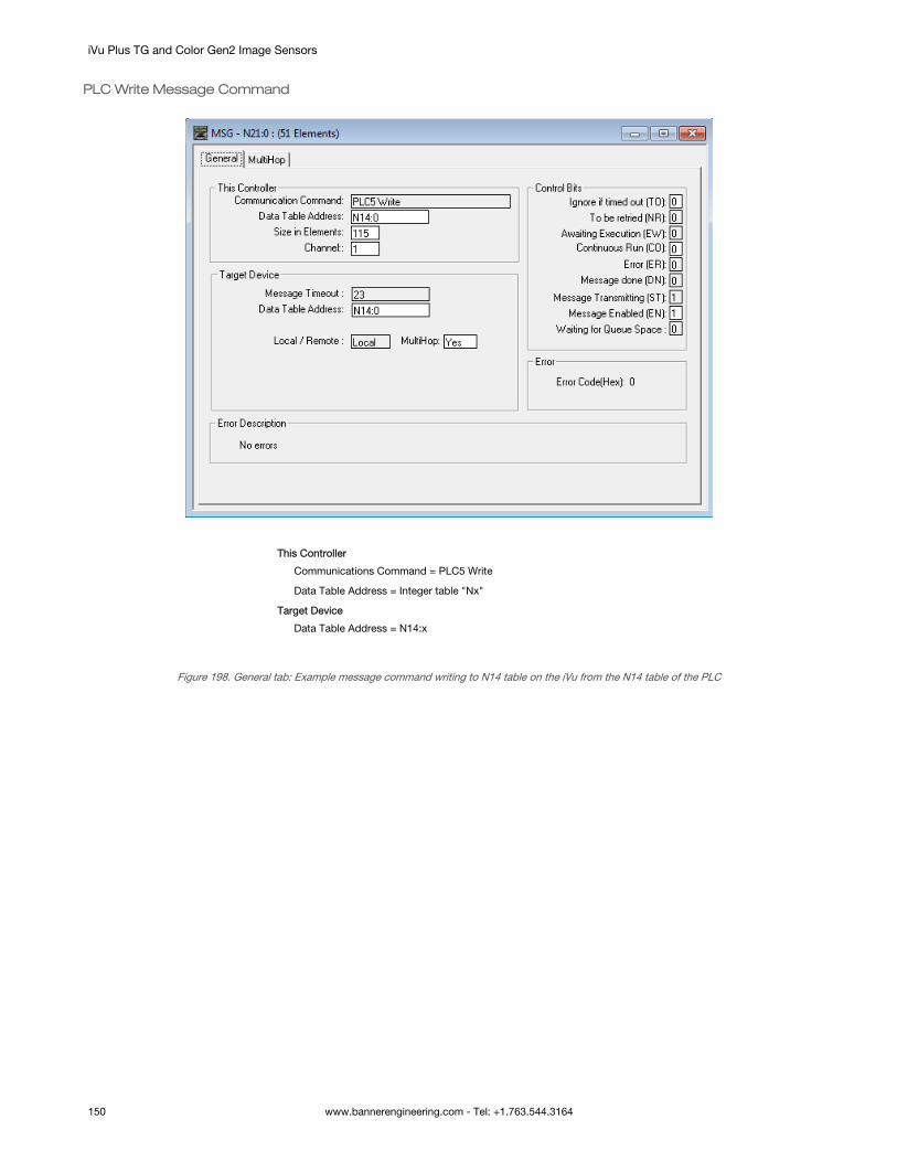
PLC Write Message Command
This Controller
Communications Command = PLC5 Write
Data Table Address = Integer table "Nx"
Target Device
Data Table Address = N14:x
Figure 198. General tab: Example message command writing to N14 table on the iVu from the N14 table of the PLC
iVu Plus TG and Color Gen2 Image Sensors
150 www.bannerengineering.com - Tel: +1.763.544.3164

To Address = IP address of the iVu
Figure 199. MultiHop tab: IP address of the iVu is entered here
15.6.2 Inputs to iVu (Outputs from PLC)The registers below are used by the PLC to push values to the iVu device. MSG (message) commands are used to write(N14) to the iVu.
Table 49: PCCC PLC Output Registers (iVu Inputs, N14 Table)
WORD # WORD NAME DATA TYPE
0 Input Bits Register (see Input and Output Flags on page 156) 16-bit integer
1-2 Product Change Number 32-bit integer
3-49 reserved 32-bit integer
50 Command ID 16-bit integer
51 Command Parameter Int16 16-bit integer
52-53 Command Parameter Int 32 32-bit integer
54-55 Command Parameter Float
56-57 Command Parameter String Length 32-bit integer
58-107 Command Parameter String 100-Byte Array
108 reserved 16-bit integer
109-120 for Barcode models only
211-239 reserved 16-bit integer
15.6.3 Outputs from iVu (Inputs to PLC)The registers below are used to send output values from the iVu device to the PLC. MSG (message) commands are used toread (N7) from the iVu.
iVu Plus TG and Color Gen2 Image Sensors
www.bannerengineering.com - Tel: +1.763.544.3164 151

15.6.4 Multiple Sensors Mapping OptionsWhen using an iVu with multiple sensors in an inspection, there are two mapping options: Default and Custom.
Default Map
Main Menu > System > Communications > Industrial Ethernet > Map > Default
Automatically maps sensor data for each inspection. Recommended when the execution order of the sensor types is thesame across inspections. When an inspection has multiple sensors, the first 5 sensor results are shown starting at offset 55.Each sensor result occupies 20 words.
Table 50: PCCC PLC Input Registers (iVu Outputs, N7 Table): DEFAULT MAP
WORD # WORD NAME Data Type
0 Input Bits ACK Register (see Input and Output Flags on page 156) 16-bit integer
1 Output Bits Register (see Input and Output Flags on page 156) 16-bit integer
2-3 Error Code 32-bit integer
4-5 Inspection Number 32-bit integer
6-7 Iteration Count 32-bit integer
8-9 Pass Count 32-bit integer
10-11 Fail Count 32-bit integer
12-13 Missed Triggers 32-bit integer
14-15 Current Inspection Time Float
16 Sensor Pass/Fail Coil 16-bit integer
17-29 reserved 16-bit integer
30-52 Inspection Name 2-Word Length + 20-Unicode characters
53-54 Frame Number 32-bit integer
55 Sensor Type ID (Sensor 1) 16-bit integer
56-74 Sensor 1 Specific Data 16-bit integer
75 Sensor Type ID (Sensor 2) 16-bit integer
76-89 Sensor 2 Specific Data 16-bit integer
95 Sensor Type ID (Sensor 3) 16-bit integer
95-114 Sensor 3 Specific Data 16-bit integer
115 Sensor Type ID (Sensor 4) 16-bit integer
116-134 Sensor 4 Specific Data 16-bit integer
135 Sensor Type ID (Sensor 5) 16-bit integer
136-154 Sensor 5 Specific Data 16-bit integer
155-170 reserved 16-bit integer
171 Command Status 16-bit integer
172 Command Response Int16 16-bit integer
173-174 Command Response Int32 32-bit integer
175-176 Command Response Float Float
177-178 Command Response Length 32-bit integer
179-228 Command Response Data 100-Byte Array
229-239 reserved 16-bit integer
iVu Plus TG and Color Gen2 Image Sensors
152 www.bannerengineering.com - Tel: +1.763.544.3164

Note: If the inspection contains more than 5 sensors, the sensor after the 5th one will not be included onthe map.
Table 51: Area Sensor ID = 2
Sensor Specific Data Data Size
Area Count 32-bit integer
Area Range Minimum 32-bit integer
Area Range Maximum 32-bit integer
Table 52: Blemish Sensor ID = 3
Sensor Specific Data Sensor Location
Blemish Count 32-bit integer
Blemish Minimum Edge Length 32-bit integer
Blemish Maximum Edge Length 32-bit integer
Table 53: Match Sensor ID = 4
Sensor Specific Data Sensor Location
Match Count 32-bit integer
Match Minimum Percent 16-bit integer
Match Maximum Percent 16-bit integer
Table 54: Sort Sensor ID = 5
Sensor Specific Data Sensor Location
Sort Pattern Map 16-bit integer
Sort Pattern Count 16-bit integer
Sort Pattern 1 Count 16-bit integer
Sort Pattern 2 Count 16-bit integer
Sort Pattern 3 Count 16-bit integer
Sort Pattern 4 Count 16-bit integer
Sort Pattern 5 Count 16-bit integer
Sort Pattern 6 Count 16-bit integer
Sort Pattern 7 Count 16-bit integer
Sort Pattern 8 Count 16-bit integer
Sort Pattern 9 Count 16-bit integer
Sort Pattern 10 Count 16-bit integer
Sort Minimum Percent Match 16-bit integer
Sort Maximum Percent Match 16-bit integer
Table 55: Average Color Sensor ID = 6
Sensor-Specific Data Data Size
Average Red 16‐bit Integer
iVu Plus TG and Color Gen2 Image Sensors
www.bannerengineering.com - Tel: +1.763.544.3164 153

Sensor-Specific Data Data Size
Average Green 16‐bit Integer
Average Blue 16‐bit Integer
Average Hue 16‐bit Integer
Average Saturation 16‐bit Integer
Average Intensity 16‐bit Integer
Standard Deviation Red 32-bit float
Standard Deviation Green 32-bit float
Standard Deviation Blue 32-bit float
Standard Deviation Hue 32-bit float
Standard Deviation Saturation 32-bit float
Standard Deviation Intensity 32-bit float
Note: Average Color Sensor data that does not apply to the selected color space has a result of 0. Forexample, if the HSI color space is selected, the Red, Green, and Blue data will have a result of 0.
Table 56: Color Compare Sensor ID = 7
Sensor-Specific Data Data Size
Color Difference 16‐bit Integer
Intensity Difference 16‐bit Integer
Table 57: Color Area Sensor ID = 8
Sensor-Specific Data Data Size
Area Count 32‐bit Integer
Area Range Minimum 32‐bit Integer
Area Range Maximum 32‐bit Integer
Custom Map
Main Menu > System > Communications > Industrial Ethernet > Map > Custom
The custom map allows for customization of fixed sensor data on the map. The user selects data items of interest for eachsensor type. This is recommended when the execution order of the sensor types varies across inspections or when usingmore than five sensors.
A system-level custom map is supported for additional flexibility. When Custom map is selected, a customizable space isused in the offset range (55 to 166) on PCCC registers.
Table 58: PCCC PLC Input Registers (iVu Outputs, N7 Table): CUSTOM MAP
WORD # WORD NAME Data Type
0 Input Bits ACK Register (see Input and Output Flags on page 156) 16-bit integer
1 Output Bits Register (see Input and Output Flags on page 156) 16-bit integer
2-3 Error Code 32-bit integer
4-5 Inspection Number 32-bit integer
6-7 Iteration Count 32-bit integer
8-9 Pass Count 32-bit integer
10-11 Fail Count 32-bit integer
iVu Plus TG and Color Gen2 Image Sensors
154 www.bannerengineering.com - Tel: +1.763.544.3164

WORD # WORD NAME Data Type
12-13 Missed Triggers 32-bit integer
14-15 Current Inspection Time Float
16 Sensor Pass/Fail Coil 16-bit integer
17-29 reserved 16-bit integer
30-52 Inspection Name 2-Word Length + 20-unicode characters
53-54 Frame Number 32-bit integer
55-166 Customizable Space (112 reg) 16-bit integer
167-170 reserved 16-bit integer
171 Command Status 16-bit integer
172 Command Response Int16 16-bit integer
173-174 Command Response Int32 32-bit integer
175-176 Command Response Float Float
177-178 Command Response Length 32-bit integer
179-228 Command Response Data 100-Byte Array
229-239 reserved 16-bit integer
Configure a Custom Industrial Ethernet (IE) Map
1. Enable the Custom Map by selecting Custom on the drop-down list.
Figure 200. Map Screen—Custom Map Selected2. Click the yellow arrow to access the Custom IE Map screen.3. On the Custom IE Map screen, choose the sensor result data that will appear on the customizable space.
Figure 201. Custom IE Map Summary Screen
iVu Plus TG and Color Gen2 Image Sensors
www.bannerengineering.com - Tel: +1.763.544.3164 155

The bottom of the screen shows the word use on the customizable space. In the image above, seven words havebeen used for one Area sensor "Area (1)".
4. Click the yellow arrow next to the Area sensor row to go to the Area Sensor Data.
Figure 202. Custom IE Map Screen—Area Sensor Data
On the Area Sensor Data screen shown above, Area Count, Area Range Min and Area Range Max are available toadd to the customizable space. The number to the right of each item shows how many words are required to displaythe data. The bottom reservation count shows the number of Area sensors that have space reserved for them on thecustomizable map.
Because only one Area sensor's worth of data is reserved on the image above, the selected data will be collectedfrom the first Area sensor in the current inspection. When multiple Area sensors have been reserved, the data will bearranged in the sequential manner of the sensor type in the current inspection.
5. Click the green arrow (Back) to return to the Custom IE Map summary.6. Continue to add more data from any sensor type as required or reserve more sensors into the customizable space.
Sensor Name and Sensor Type ID are global settings that are part of any individual sensor reservation. When they arechecked, they are inserted into each sensor reservation.
The following is an example of a multiple sensors inspection and its output location on the customizable space.
In this example, there are only two Blemish sensors in the current inspection. The Blemish3 location will be all zero on thecustomizable space. The customizable map had not reserved space for a Match sensor, so Match1 from the inspection willnot be outputted on the custom map.
15.6.5 Input and Output FlagsThe Input Bits are used to command execution of basic functions. The Output Bits are used to push single bit outputs fromthe iVu device to the PLC. The 32 bits of iVu output can also be accessed using the bits of the first two Output Registers(Input Bits ACK Register(word 0) and Output Bits Register (word1)).Table 59: Inputs Bits Register
Bit Position
15 14 13 12 11 10 9 8 7 6 5 4 3 2 1 0
Command TriggerTeach
Latch
Product
Change
iVu Plus TG and Color Gen2 Image Sensors
156 www.bannerengineering.com - Tel: +1.763.544.3164

Table 60: Bit Position
Bit Position
15 14 13 12 11 10 9 8 7 6 5 4 3 2 1 0
Command
ACK
Trigger
ACK
Teach
Latch
ACK
Product
Change
ACK
Table 61: Output Bits Register
Bit Position
15 14 13 12 11 10 9 8 7 6 5 4 3 2 1 0
Execution
Error
System
Error
Teach
Error
Missed
TriggerOutput 3 Output 2 Output 1
Ready
Latch
Read/No
ReadPass/Fail Ready
15.7 PROFINET®
PROFINET®11 is a data communication protocol for industrial automation and processes. PROFINET IO defines howcontrollers (IO controllers) and peripheral devices (IO devices) exchange data in real time.
The image sensor, iVu, supports PROFINET IO. The data communication protocol is TCP/IP; the data transmission mediumis copper wire; the PROFINET conformance class is CC-A.12
Note: In this document, outputs from the iVu device are referred to as "inputs" to the controller (PLC).Outputs from the controller (PLC) are referred to as "inputs" to the iVu device.
15.7.1 General Station Description (GSD) FileThe General Station Description (GSD) file contains module information, such as:
• Configuration data• Data information (pass count, inspection status, etc.)• Diagnostics
Note: A single iVu Plus GSD file describes iVu Plus TG, iVu Plus BCR, and iVu Color models.
15.7.2 iVu PROFINET IO Data ModelThe PROFINET IO data model is based on the typical, expandable field device that has a backplane with slots. Modules andsubmodules have different functionalities.
Modules are plugged into slots; submodules are plugged into subslots. In the PROFINET IO data model, Slot 0 Subslot 1 isreserved for the Device Access Point (DAP) or network interface.
Both modules and submodules are used to control the type and volume of data that is sent to the controller (PLC).• A submodule is typically designated as input type, output type, or combined input/output type• An input submodule is used to send data to the controller (PLC)• An output submodule is used to receive data from the controller (PLC)• The combined input/output submodule simultaneously receives and sends data in both directions
Configuring the iVu for a PROFINET IO Connection
The iVu device and the controller (PLC) must be configured for PROFINET® .
11 PROFINET® is a registered trademark of PROFIBUS Nutzerorganisation e.V.12 CC-A ensures that the device has the minimum properties regarding functionality and interoperability.
iVu Plus TG and Color Gen2 Image Sensors
www.bannerengineering.com - Tel: +1.763.544.3164 157

1. Go to Main Menu > System > Communications > Industrial Ethernet > Connection.
Figure 203. Industrial Ethernet Menu
Note: The default Industrial Ethernet Connection setting is Disabled.
2. Click PROFINET in the drop-down menu.
Figure 204. Connection Screen
3. Click (only one time) on the Arrow button on the bottom left to return to the Industrial Ethernet window.
Figure 205. Industrial Ethernet Menu
iVu Plus TG and Color Gen2 Image Sensors
158 www.bannerengineering.com - Tel: +1.763.544.3164

4. Click Map to configure the PROFINET module map.
Figure 206. PROFINET Module Map Screen
Note: The PROFINET module map displays S1 SS1 and S1 SS2 by default. S1 represents Slot 1,SS1 represents SubSlot 1; S2 represents Slot 2, SS2 represents SubSlot 2. The other slots are notconfigured by default.
The default PROFINET configuration consists of a single module plugged into Slot 1. This module, called the DeviceControl and Status Module, accepts two submodules: the Inspection Result Submodule, plugged into Subslot 1,and the Device Control Submodule, plugged into Subslot 2.
The Inspection Result Submodule provides the inspection results from the iVu, including Pass Count, Fail Count,and Current Inspection Time. See Table 67 on page 161.
Note: The Inspection Result Submodule does not provide any sensor-specific output data.
The Device Control Submodule allows you to issue commands to the iVu, such as Trigger, TEACH, and ProductChange. This submodule also provides command feedback. See Table 68 on page 162.
Adding sensor-specific output data requires the use of a sensor output submodule, plugged into Slot 2 Subslot 1.The iVu provides different options for configuring this submodule, based on the complexity of the inspection. Theselection of sensor output submodules is based on size, allowing the user to control network bandwidth use.
The Command Channel Module can be plugged into Slot 3. The selection of Command Channel Submodules isbased on the required length of the data output string. See Description of Submodules on page 160.
Follow Step 5 and Step 6 to add a submodule to the configuration (optional).5. Click S2 to go to the configuration window and add a submodule.
Figure 207. PROFINET Module Map Screen—Add Submodule
6. Click the Drop-Down Arrow next to Disabled to open the list of submodule slots.7. Select a submodule and hit enter.
The submodule slot now shows an icon, which means that it has been configured.
iVu Plus TG and Color Gen2 Image Sensors
www.bannerengineering.com - Tel: +1.763.544.3164 159

8. Set up all submodules for your application.
Figure 208. PROFINET Module Map Screen—With a Submodule Added
The iVu PROFINET configuration is complete. The PLC can now be configured to complete the PROFINETconnection.
Description of ModulesTable 62: Assignment of Slots and Subslots
Slot 1 - TG/Color Control and StatusModule
Slot 2 - TG/Color Sensor OutputModule
Slot 3 - Command Channel Module
Subslot 1 TG/Color Inspection Result Submodule sensor output submodules Command Channel Commandsubmodules
Subslot 2 TG/Color Device Control Submodule — Command Channel Response submodules
Table 63: TG (Ident 0x00000010) / Color (Ident 0x00000012) Control and Status Module
Number of Physical Subslots Subslot Label Subslot Number
1 1.1 TG Inspection Result Submodule 1 (0x1)
1 1.2 TG Device Control Submodule 2 (0x2)
Table 64: TG (Ident 0x00000040) / Color (Ident 0x00000042) Sensor Output Module
Number of Physical Subslots Subslot Label Subslot Number
1 2.1 sensor output submodules 1 (0x1)
Table 65: Command Channel Module (Ident 0x00000030)
Number of Physical Subslots Subslot Label Subslot Number
1 3.1 Command Channel Command submodules 1 (0x1)
1 3.2 Command Channel Response submodules 2 (0x2)
Description of SubmodulesTable 66: Supported Submodules and Locations
Submodules Location Notes
TG Inspection Result Submodule Slot 1, Subslot 1 Always present.
TG Device Control Submodule Slot 1, Subslot 2 Present by default, but can be removed.
iVu Plus TG and Color Gen2 Image Sensors
160 www.bannerengineering.com - Tel: +1.763.544.3164

Submodules Location Notes
Sensor Output – Default Map Submodule Slot 2, Subslot 1 This is a default sensor output submodule.
Sensor Output – Custom Map Submodules Slot 2, Subslot 1 There are six versions of this submodule supportingpayloads of 16, 32, 64, 128, 256, and 512 bytes.
Command Channel Command Submodule Slot 3, Subslot 1 There are four versions of this submodule supportingcommand strings of 0, 32, 64, and 128 bytes.
Command Channel Response Submodule Slot 3, Subslot 2 There are four versions of this submodule supportingcommand strings of 0, 32, 64, and 128 bytes.
Inspection Result Submodule
The Inspection Result Submodule contains inspection results and sends input data to the controller (PLC). This submoduleis plugged into Slot 1 Subslot 2 and cannot be removed.
Table 67: TG (Ident 0x101) / Color (Ident 0x103) Inspection Result Submodule
PLC Input Data Name Input Data Type
Inspection Status Word Unsigned16
Inspection Number Unsigned32
Sensor Pass/Fail Status Unsigned32
Iteration Count Unsigned32
Pass Count Unsigned32
Fail Count Unsigned32
Missed Trigger Count Unsigned32
Current Inspection Time Unsigned32
Inspection Status Word
Bit Position for Cyclic InputData
Function
Bit 0 System Ready
Bit 1 Inspection Pass/Fail
Bit 3 Ready Signal Latch
Bit 5 Output 1 ON/OFF
Bit 6 Output 2 ON/OFF
Bit 7 Output 3 ON/OFF
Bit 8 Missed Trigger Occurrence
PLC Output Data Name Output Data Type
Not applicable Not applicable
Device Control Submodule
The Device Control Submodule contains controller (PLC) input and output data, including device controls for the iVu. Theuser-enabled Device Control Submodule is optional and plugged into Slot 1 Subslot 2 by default. The user can remove it.
iVu Plus TG and Color Gen2 Image Sensors
www.bannerengineering.com - Tel: +1.763.544.3164 161

Table 68: TG (Ident 0x1) / Color (Ident 0x3) Device Control Submodule
PLC Input Data Name Input Data Type
Device Control ACK Word Unsigned16
Return Error Code Unsigned32
Device Control ACK Word
Bit Position for Cyclic InputData
Function
Bit 0 Product ChangeAcknowledgement
Bit 1 Teach Latch Acknowledgement
Bit 2 Trigger Acknowledgement
Bit 13 Teach Error
Bit 14 System Error
Bit 15 Command Execution Error
PLC Output Data Name Output Data Type
Device Control Command Word Unsigned16
Product Change Number Unsigned32
Device Control Command Word
Bit Position for Cyclic OutputData
Function
Bit 0 Product Change Request
Bit 1 Teach Latch Request
Bit 2 Trigger Request
Sensor Output Submodules
The Default Map Submodule contains sensor output data. This user-enabled submodule is optional and plugged into Slot 2Subslot 1.Table 69: Default Map Submodule (Ident 0x00027)
PLC Input Data Name Input Data Type
Frame Number Unsigned32
Sensor Type Unsigned16
38-byte Sensor-specific Data Block 38-byte OctetString
Sensor Type Unsigned16
38-byte Sensor-specific Data Block 38-byte OctetString
Sensor Type Unsigned16
38-byte Sensor-specific Data Block 38-byte OctetString
Sensor Type Unsigned16
38-byte Sensor-specific Data Block 38-byte OctetString
Sensor Type Unsigned16
38-byte Sensor-specific Data Block 38-byte OctetString
PLC Output Data Name Output Data Type
Not applicable Not applicable
The 38-byte sensor-specific Data Block for each sensor type is shown below.Table 70: Area Sensor ID = 2
Sensor-Specific Data Data Size
Area Count 32‐bit Integer
Area Range Minimum 32‐bit Integer
Area Range Maximum 32‐bit Integer
iVu Plus TG and Color Gen2 Image Sensors
162 www.bannerengineering.com - Tel: +1.763.544.3164

Table 71: Blemish Sensor ID = 3
Sensor-Specific Data Data Size
Blemish Count 32‐bit Integer
Blemish Minimum Edge Length 32‐bit Integer
Blemish Maximum Edge Length 32‐bit Integer
Table 72: Match Sensor ID = 4
Sensor-Specific Data Data Size
Match Count 32‐bit Integer
Match Minimum Percent 8‐bit Integer
Match Maximum Percent 8‐bit Integer
Table 73: Sort Sensor ID = 5
Sensor-Specific Data Data Size
Sort Pattern Map 16‐bit Integer
Sort Pattern Count 16‐bit Integer
Sort Pattern 1 Count 16‐bit Integer
Sort Pattern 2 Count 16‐bit Integer
Sort Pattern 3 Count 16‐bit Integer
Sort Pattern 4 Count 16‐bit Integer
Sort Pattern 5 Count 16‐bit Integer
Sort Pattern 6 Count 16‐bit Integer
Sort Pattern 7 Count 16‐bit Integer
Sort Pattern 8 Count 16‐bit Integer
Sort Pattern 9 Count 16‐bit Integer
Sort Pattern 10 Count 16‐bit Integer
Sort Minimum Percent Match 8‐bit Integer
Sort Maximum Percent Match 8‐bit Integer
Table 74: Average Color Sensor ID = 6
Sensor-Specific Data Data Size
Average Red 16‐bit Integer
Average Green 16‐bit Integer
Average Blue 16‐bit Integer
Average Hue 16‐bit Integer
Average Saturation 16‐bit Integer
Average Intensity 16‐bit Integer
Standard Deviation Red 32-bit float
Standard Deviation Green 32-bit float
Standard Deviation Blue 32-bit float
Standard Deviation Hue 32-bit float
iVu Plus TG and Color Gen2 Image Sensors
www.bannerengineering.com - Tel: +1.763.544.3164 163

Sensor-Specific Data Data Size
Standard Deviation Saturation 32-bit float
Standard Deviation Intensity 32-bit float
Note: Average Color Sensor data that does not apply to the selected color space has a result of 0. Forexample, if the HSI color space is selected, the Red, Green, and Blue data will have a result of 0.
Table 75: Color Compare Sensor ID = 7
Sensor-Specific Data Data Size
Color Difference 16‐bit Integer
Intensity Difference 16‐bit Integer
Table 76: Color Area Sensor ID = 8
Sensor-Specific Data Data Size
Area Count 32‐bit Integer
Area Range Minimum 32‐bit Integer
Area Range Maximum 32‐bit Integer
The Custom Map Submodule contains a user-defined map of sensor output data. There are six versions with 16, 32, 64,128, 256, and 512 bytes, depending on the size of the output data.Table 77: Custom Map Submodule
Submodule PLC Input Data PLC Output Data
Name Ident No. Name Type Name Type
16-Byte Custom Map 0x00028Frame number Unsigned32
Not applicable Not applicableUser-mapped Sensor Result Data Block 16-byte OctetString
32-Byte Custom Map 0x00029Frame number Unsigned32
Not applicable Not applicableUser-mapped Sensor Result Data Block 32-byte OctetString
64-Byte Custom Map 0x00030Frame number Unsigned32
Not applicable Not applicableUser-mapped Sensor Result Data Block 64-byte OctetString
128-Byte Custom Map 0x00031Frame number Unsigned32
Not applicable Not applicableUser-mapped Sensor Result Data Block 128-byte OctetString
256-Byte Custom Map 0x00032Frame number Unsigned32
Not applicable Not applicableUser-mapped Sensor Result Data Block 256-byte OctetString
512-Byte Custom Map 0x00033Frame number Unsigned32
Not applicable Not applicableUser-mapped Sensor Result Data Block 512-byte OctetString
Configure a Custom Industrial Ethernet (IE) Map
1. Enable the Custom Map by selecting Custom on the drop-down list.
iVu Plus TG and Color Gen2 Image Sensors
164 www.bannerengineering.com - Tel: +1.763.544.3164

Figure 209. Map Screen—Custom Map Selected2. Click the yellow arrow to access the Custom IE Map screen.3. On the Custom IE Map screen, choose the sensor result data that will appear on the customizable space.
Figure 210. Custom IE Map Summary Screen
The bottom of the screen shows the word use on the customizable space. In the image above, seven words havebeen used for one Area sensor "Area (1)".
4. Click the yellow arrow next to the Area sensor row to go to the Area Sensor Data.
Figure 211. Custom IE Map Screen—Area Sensor Data
On the Area Sensor Data screen shown above, Area Count, Area Range Min and Area Range Max are available toadd to the customizable space. The number to the right of each item shows how many words are required to displaythe data. The bottom reservation count shows the number of Area sensors that have space reserved for them on thecustomizable map.
Because only one Area sensor's worth of data is reserved on the image above, the selected data will be collectedfrom the first Area sensor in the current inspection. When multiple Area sensors have been reserved, the data will bearranged in the sequential manner of the sensor type in the current inspection.
5. Click the green arrow (Back) to return to the Custom IE Map summary.6. Continue to add more data from any sensor type as required or reserve more sensors into the customizable space.
Sensor Name and Sensor Type ID are global settings that are part of any individual sensor reservation. When they arechecked, they are inserted into each sensor reservation.
The following is an example of a multiple sensors inspection and its output location on the customizable space.
iVu Plus TG and Color Gen2 Image Sensors
www.bannerengineering.com - Tel: +1.763.544.3164 165

In this example, there are only two Blemish sensors in the current inspection. The Blemish3 location will be all zero on thecustomizable space. The customizable map had not reserved space for a Match sensor, so Match1 from the inspection willnot be outputted on the custom map.
Command Channel Command Submodules
The Command Channel Command Submodules contain controller (PLC) output data and command channel request data.The user-enabled submodules are optional. On the iVu device the submodule is plugged into Slot 3 Subslot 1.
The Command Channel Command Submodule has four versions with 16, 32, 64, or 128 bytes, depending on the requiredlength of the input string.Table 78: Numeric Command Submodule (Ident 0x00012)
PLC Output Data Name Output Data Type
Flag indicates when to apply the command Unsigned16
Numeric ID of the command Unsigned16
16-bit integer command argument Unsigned16
32-bit integer command argument Unsigned32
Floating-point command argument Float32
Flag indicates when to apply the command
Bit Position for Cyclic OutputData
Function
Bit 0 Command Channel CommandRequest
PLC Input Data Name Input Data Type
Not applicable Not applicable
iVu Plus TG and Color Gen2 Image Sensors
166 www.bannerengineering.com - Tel: +1.763.544.3164
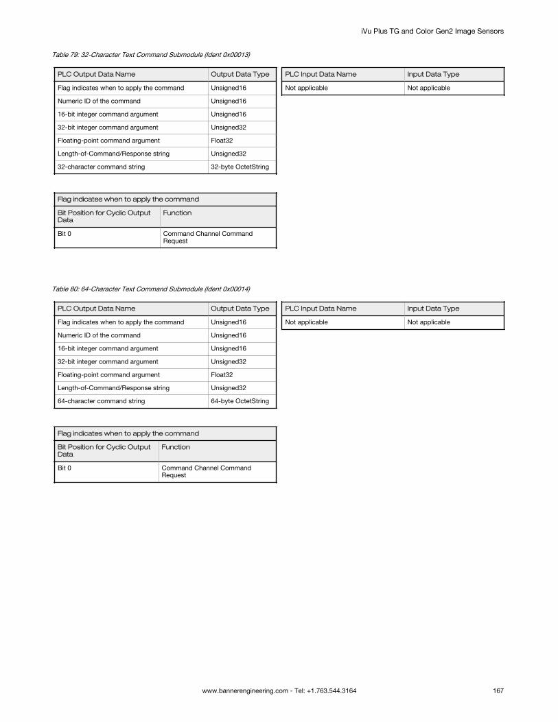
Table 79: 32-Character Text Command Submodule (Ident 0x00013)
PLC Output Data Name Output Data Type
Flag indicates when to apply the command Unsigned16
Numeric ID of the command Unsigned16
16-bit integer command argument Unsigned16
32-bit integer command argument Unsigned32
Floating-point command argument Float32
Length-of-Command/Response string Unsigned32
32-character command string 32-byte OctetString
Flag indicates when to apply the command
Bit Position for Cyclic OutputData
Function
Bit 0 Command Channel CommandRequest
PLC Input Data Name Input Data Type
Not applicable Not applicable
Table 80: 64-Character Text Command Submodule (Ident 0x00014)
PLC Output Data Name Output Data Type
Flag indicates when to apply the command Unsigned16
Numeric ID of the command Unsigned16
16-bit integer command argument Unsigned16
32-bit integer command argument Unsigned32
Floating-point command argument Float32
Length-of-Command/Response string Unsigned32
64-character command string 64-byte OctetString
Flag indicates when to apply the command
Bit Position for Cyclic OutputData
Function
Bit 0 Command Channel CommandRequest
PLC Input Data Name Input Data Type
Not applicable Not applicable
iVu Plus TG and Color Gen2 Image Sensors
www.bannerengineering.com - Tel: +1.763.544.3164 167

Table 81: 128-Character Text Command Submodule (Ident 0x00015)
PLC Output Data Name Output Data Type
Flag indicates when to apply the command Unsigned16
Numeric ID of the command Unsigned16
16-bit integer command argument Unsigned16
32-bit integer command argument Unsigned32
Floating-point command argument Float32
Length-of-Command/Response string Unsigned32
128-character command string 128-byteOctetString
Flag indicates when to apply the command
Bit Position for Cyclic OutputData
Function
Bit 0 Command Channel CommandRequest
PLC Input Data Name Input Data Type
Not applicable Not applicable
Command Channel Response Submodules
The Command Channel Response Submodules contain only controller (PLC) input data and command channel responsedata. The user-enabled submodules are optional. On the iVu model the submodule is plugged into Slot 3 Subslot 2.
The Command Channel Response Submodule has four versions with 16, 32, 64, or 128 bytes, depending on the requiredlength of the data output string.Table 82: Numeric Response Submodule (Ident 0x00050)
PLC Input Data Name Input Data Type
Numeric Command Status Unsigned16
16-bit integer command response Unsigned16
32-bit integer command response Unsigned32
Floating-point command argument Float32
Numeric Command Status
Bit Position for Cyclic InputData
Function
Bit 0 Command Channel CommandAcceptance Acknowledgement
Bit 15 Command Execution Error
PLC Output Data Name Output Data Type
Not applicable Not applicable
iVu Plus TG and Color Gen2 Image Sensors
168 www.bannerengineering.com - Tel: +1.763.544.3164

Table 83: 32-Character Text Response Submodule (Ident 0x00051)
PLC Input Data Name Input Data Type
Numeric Command Status Unsigned16
16-bit integer command response Unsigned16
32-bit integer command response Unsigned32
Floating-point command argument Float32
Length-of-Command/Response string Unsigned32
32-character command response string 32-byte OctetString
Numeric Command Status
Bit Position for Cyclic InputData
Function
Bit 0 Command Channel CommandAcceptance Acknowledgement
Bit 15 Command Execution Error
PLC Output Data Name Output Data Type
Not applicable Not applicable
Table 84: 64-Character Text Response Submodule (Ident 0x00052)
PLC Input Data Name Input Data Type
Numeric Command Status Unsigned16
16-bit integer command response Unsigned16
32-bit integer command response Unsigned32
Floating-point command argument Float32
Length-of-Command/Response string Unsigned32
64-character command response string 64-byte OctetString
Numeric Command Status
Bit Position for Cyclic InputData
Function
Bit 0 Command Channel CommandAcceptance Acknowledgement
Bit 15 Command Execution Error
PLC Output Data Name Output Data Type
Not applicable Not applicable
iVu Plus TG and Color Gen2 Image Sensors
www.bannerengineering.com - Tel: +1.763.544.3164 169

Table 85: 128-Character Text Response Submodule (Ident 0x00053)
PLC Input Data Name Input Data Type
Numeric Command Status Unsigned16
16-bit integer command response Unsigned16
32-bit integer command response Unsigned32
Floating-point command argument Float32
Length-of-Command/Response string Unsigned32
128-character command response string 128-byteOctetString
Numeric Command Status
Bit Position for Cyclic InputData
Function
Bit 0 Command Channel CommandAcceptance Acknowledgement
Bit 15 Command Execution Error
PLC Output Data Name Output Data Type
Not applicable Not applicable
15.7.3 Configuration Instructions
Using Siemens TIA Portal (v13) Software
Installing the Banner iVu GSD File
Use these instructions to install the Banner iVu GSD file in the Siemens TIA Portal (v13) software. Use these instructions asa basis for installing the Banner iVu GSD file in another controller (PLC).
1. Download the Banner iVu GSD file from www.bannerengineering.com.2. Start the Siemens TIA Portal (v13) software.3. Click Open existing project.4. Select a project and open it.
iVu Plus TG and Color Gen2 Image Sensors
170 www.bannerengineering.com - Tel: +1.763.544.3164

5. Click Devices & networks after the project has been uploaded.
Figure 212. Devices and Networks
6. Click Configure networks.
Figure 213. Configure Networks
Network view displays.
iVu Plus TG and Color Gen2 Image Sensors
www.bannerengineering.com - Tel: +1.763.544.3164 171

7. Click Options and select Install general station description file (GSD).
Figure 214. Options—Install the GSD
The Install general station description file window opens.8. Click the browse button (...) to the right of the Source path field.
Figure 215. Manage GSD Files
9. Navigate to the location the iVu GSD file was downloaded to.10. Select the iVu GSD file.
iVu Plus TG and Color Gen2 Image Sensors
172 www.bannerengineering.com - Tel: +1.763.544.3164

11. Click Install.
Figure 216. Hardware Catalog
The system installs the iVu GSD file and places it in the Hardware catalog. In the above example, the iVu GSD file islocated under Other field devices > PROFINET IO > Sensors > Banner Engineering Corp. > Banner Vision Sensors >iVu Series .
Note: If the iVu GSD file does not install properly, save the log and contact Banner EngineeringCorp.
Adding a Device to a Project
Use these instructions to add a iVu device to a Siemens TIA Portal (v13) project, and to configure the device. Use theseinstructions as a basis for adding a iVu device to another controller (PLC).
1. Start the Siemens TIA Portal (v13) software.2. Click Open existing project.
iVu Plus TG and Color Gen2 Image Sensors
www.bannerengineering.com - Tel: +1.763.544.3164 173

3. Select a project and open it.4. Click Devices & networks after the project has been uploaded.
Figure 217. Devices and Networks
5. Click Configure networks.
Figure 218. Configure Networks
Network view displays.
Note: For Step 6 through Step 10, Network view must be open.
iVu Plus TG and Color Gen2 Image Sensors
174 www.bannerengineering.com - Tel: +1.763.544.3164
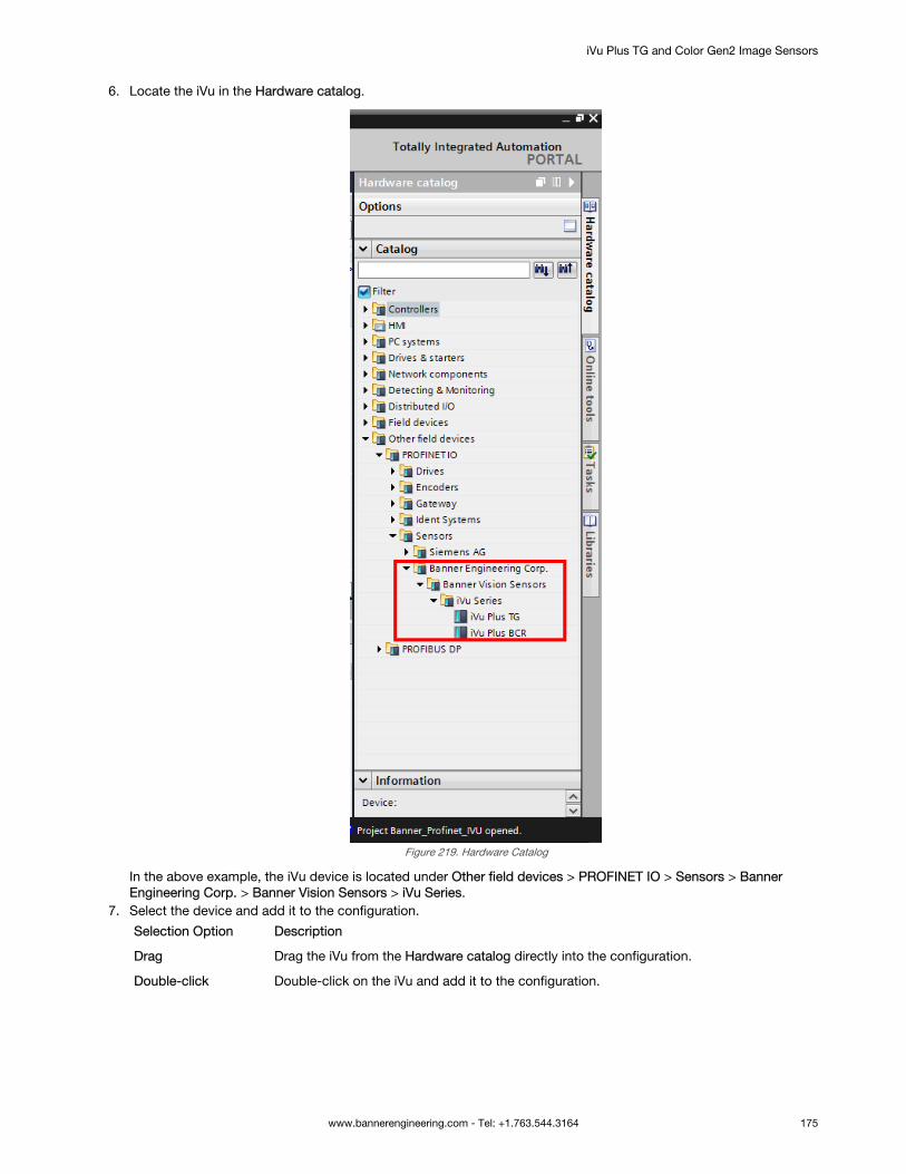
6. Locate the iVu in the Hardware catalog.
Figure 219. Hardware Catalog
In the above example, the iVu device is located under Other field devices > PROFINET IO > Sensors > BannerEngineering Corp. > Banner Vision Sensors > iVu Series.
7. Select the device and add it to the configuration.
Selection Option Description
Drag Drag the iVu from the Hardware catalog directly into the configuration.
Double-click Double-click on the iVu and add it to the configuration.
iVu Plus TG and Color Gen2 Image Sensors
www.bannerengineering.com - Tel: +1.763.544.3164 175

8. Click the green square on the iVu icon. Drag the pointer to the green square on the PLC_1 icon to connect thedevice to the controller (PLC).
Figure 220. Drag to Connect
The connection is made.9. Double-click the iVu icon to open the Device window.10. Select the desired modules or submodules from the Hardware catalog and drag them onto the Device overview tab
on the Device view tab.The iVu device is configured.
Changing the Device IP Address
Use these instructions to change the IP address of the iVu device, using the Siemens TIA Portal (v13) software. Use theseinstructions as a basis if you are using another controller (PLC).
1. Start the Siemens TIA Portal (v13) software.2. Click Open existing project.3. Select a project an open it.4. Click Devices & networks after the project has been uploaded to go to Network view.
Figure 221. Network View
Network View displays.5. Double-click on the iVu icon to open the Device view.6. Click on the iVu icon in the graphic area of the Device view to open the Module properties window.
The module can now be configured.7. Click Properties.8. Click General.9. Select PROFINET interface > Ethernet addresses.
Figure 222. Ethernet Addresses
iVu Plus TG and Color Gen2 Image Sensors
176 www.bannerengineering.com - Tel: +1.763.544.3164

10. Select Set IP address in the project.
Figure 223. Set IP Address
The project sets the IP address of the device.11. Enter the IP address.12. Right-click on the device icon and select Online & diagnostics.
Figure 224. Select Online & Diagnostics
Figure 225. Online & Diagnostics
The Online & diagnostics window displays.13. Select Assign IP address under Functions.
iVu Plus TG and Color Gen2 Image Sensors
www.bannerengineering.com - Tel: +1.763.544.3164 177

14. Click Accessible devices.
Figure 226. Assign IP Address—Accessible Devices
The Select device window searches the network for available devices.15. Determine the device to be adjusted via the MAC address and select it.
Note: Use the display to find the MAC address. Main Menu > System > Communications >Ethernet IO > Status
16. Click Apply.
Figure 227. Select the Device and Apply Changes
The IP address for the device is updated.17. Click Assign IP address to complete the step.
This step is completed for every device.
Changing the Device Name
Use these instructions to change the name of the iVu device, using the Siemens TIA Portal (v13) software. Use theseinstructions as a basis if you are using another controller (PLC).
1. Open a project and click on Devices & networks to go to the Network view.
Figure 228. Network View
Network view displays.
iVu Plus TG and Color Gen2 Image Sensors
178 www.bannerengineering.com - Tel: +1.763.544.3164

2. Double-click on the iVu icon to open Device view.3. Click on the iVu icon in the graphic area of Device view to open the Module properties window.4. Click General.5. Select PROFINET interface [X1] > Ethernet addresses.
Figure 229. Ethernet Addresses
6. Deselect Generate PROFINET device name automatically.
Figure 230. PROFINET Device Name
7. Enter a unique name in the PROFINET device name field.8. Enter a unique device number in the Device number field.
Note: Each device number is used only once.
iVu Plus TG and Color Gen2 Image Sensors
www.bannerengineering.com - Tel: +1.763.544.3164 179

9. Right-click on the device icon and select Online & diagnostics.
Figure 231. Select Online & Diagnostics
Figure 232. Online & Diagnostics
The Online & diagnostics window displays.10. Select Assign name under Functions.
Figure 233. Assign Name
The Assign name window displays. The devices in the network are discovered. The Name column is blank.11. Select the device that will have a name assigned to it.
iVu Plus TG and Color Gen2 Image Sensors
180 www.bannerengineering.com - Tel: +1.763.544.3164

12. Click Assign name to start the process.The name is assigned.
Figure 234. Assign Name
Using Siemens SIMATIC STEP 7 (v5.5) Software
Installing the Banner iVu GSD File
Use these instructions to install the Banner iVu GSD file in the Siemens SIMATIC STEP 7 (v5.5) software.
1. Start Siemens SIMATIC Manager.2. Select an existing project and open it.3. Select the Station (PLC) from the Object Hierarchy list.
Figure 235. Object Hierarchy List
iVu Plus TG and Color Gen2 Image Sensors
www.bannerengineering.com - Tel: +1.763.544.3164 181

4. Double-click the Hardware icon in the Station level window.
Figure 236. Double-Click the Hardware Icon
The Hardware configuration window opens.5. In the Hardware configuration window, click Options > Install GSD File....
Figure 237. Options Menu—Select Install GSD File...
Figure 238. Install GSD Files Screen
The Install GSD Files window displays.6. Browse to the location of the saved Banner iVu GSD file.
iVu Plus TG and Color Gen2 Image Sensors
182 www.bannerengineering.com - Tel: +1.763.544.3164

7. Select the version of the file you want to add and click Install to add the GSD file to the Hardware catalog.8. Go to the View menu in the Hardware configuration window.9. Check the Catalog option.
The Hardware catalog appears on the right side of the Hardware configuration window.
Figure 239. Hardware Catalog
The location in the Hardware catalog is PROFINET IO > Additional Field Devices > Sensors > Banner Vision Sensors> iVu Series
Creating a PROFINET® Connection
Use these instructions to create a PROFINET Connection in Hardware configuration with the Siemens SIMATIC STEP 7(v5.5) software.
1. Start Siemens SIMATIC Manager.2. Select an existing project and open it.3. Select the Station (PLC) from the Object Hierarchy list.
Figure 240. Object Hierarchy List
iVu Plus TG and Color Gen2 Image Sensors
www.bannerengineering.com - Tel: +1.763.544.3164 183

4. Double-click the Hardware icon in the Station level window to open the Hardware configuration window.
Figure 241. Double-click the Hardware Icon
5. Right-click on the PN-IO line in the CPU module of the Station window and select Insert PROFINET IO System.6. In the Parameters tab of the Ethernet interface properties window type in the IP Address and Subnet Mask of the
PLC.7. Select the Ethernet subnetwork from the box at the bottom of the Ethernet interface properties window. If no
suitable network is shown, click the New button to add one, then click OK.
Figure 242. Add New Network
8. Click iVu in the Hardware catalog and drag and drop onto the PROFINET IO system connection.
Figure 243. Add iVu to the PROFINET IO System Connection
The device is connected to the system.9. Add modules and submodules.
Changing the Device IP Address
Use these instructions for the Siemens SIMATIC STEP 7 (v5.5) software.
1. Start Siemens SIMATIC Manager.2. Select an existing project and open it.
iVu Plus TG and Color Gen2 Image Sensors
184 www.bannerengineering.com - Tel: +1.763.544.3164

3. Select the Station (PLC) from the Object Hierarchy list.
Figure 244. Object Hierarchy List
4. Double-click the Hardware icon in the Station level window to open the Hardware configuration window.
Figure 245. Double-click the Hardware Icon
5. Select PLC > Ethernet > Edit Ethernet Node.
Figure 246. Select Edit Ethernet Note
iVu Plus TG and Color Gen2 Image Sensors
www.bannerengineering.com - Tel: +1.763.544.3164 185

6. Click Browse... under Nodes accessible online in the Edit Ethernet Node window.
Figure 247. Edit Ethernet Node Screen
This starts a search for all PROFINET devices on the network and shows the found devices.7. Select the device to be modified.
Figure 248. Browse Network Screen
iVu Plus TG and Color Gen2 Image Sensors
186 www.bannerengineering.com - Tel: +1.763.544.3164

8. Click OK.
Figure 249. Edit Ethernet Note Screen
The Edit Ethernet Node window is updated.9. Set the IP address to the desired value.10. Click Assign IP Configuration at the bottom left of the Set IP configuration section.
The parameters are transferred.11. Click OK to acknowledge the message of a successful transfer.
Figure 250. Edit Ethernet Node Message
The IP address adjustment is complete.
Changing the Device Name
Use these instructions for the Siemens SIMATIC STEP 7 (v5.5) software.
1. Start Siemens SIMATIC Manager.2. Select an existing project and open it.
iVu Plus TG and Color Gen2 Image Sensors
www.bannerengineering.com - Tel: +1.763.544.3164 187

3. Select a Station (PLC) from the Object Hierarchy list.
Figure 251. Object Hierarchy List
4. Double-click the Hardware icon in the Station level window to open the Hardware configuration window.
Figure 252. Double-click the Hardware Icon
5. Select PLC > Ethernet > Edit Ethernet Node.
Figure 253. Select Edit Ethernet Node
iVu Plus TG and Color Gen2 Image Sensors
188 www.bannerengineering.com - Tel: +1.763.544.3164

6. Click Browse... under Nodes accessible online in the Edit Ethernet Node window.
Figure 254. Edit Ethernet Node Screen
This starts a search for all PROFINET® devices on the network and shows the found devices.7. Select the device to be modified.
Figure 255. Browse Network Screen
iVu Plus TG and Color Gen2 Image Sensors
www.bannerengineering.com - Tel: +1.763.544.3164 189

8. Click OK.
Figure 256. Edit Ethernet Node Screen
The Edit Ethernet Node window is updated.9. Enter a name with lower case letters in the Device name field.10. Click Assign Name.
Figure 257. Edit Ethernet Node Message
The Device name is updated. If a failed update message is returned, the new name did not meet the namingrequirements. Reference the Siemens PLC naming convention.
iVu Plus TG and Color Gen2 Image Sensors
190 www.bannerengineering.com - Tel: +1.763.544.3164

15.8 Sample Timing Diagrams
X, Y, Z: Represent snapshot in time
Verify :Ready = 1ProductChange ACK = 0
Ready
Product Change
ProductChange ACK = ‘1 ’
New inspection is loaded
RPI 0 1 X X+Y X+Y+Z
Product Change
ACK
Set ProductChange
= 1
Verify :Ready = 1ProductChangeACK = 0
Set ProductChange
= 0
Product Change
Figure 258. Product Change Timing Diagram
iVu Plus TG and Color Gen2 Image Sensors
www.bannerengineering.com - Tel: +1.763.544.3164 191

Verify :Ready = 1TeachLatch ACK = 0
Ready
Teach Latch
TeachLatch ACK = ‘1 ’
Teach will execute on next
trigger
RPI 0 1 X X +Y X +Y +Z
Teach Latch ACK
Set TeachLatch = 1
Verify :Ready = 1TeachLatchACK = 0
Set TeachLatch = 0
Teach Latch
Figure 259. Teach Latch Timing Diagram
iVu Plus TG and Color Gen2 Image Sensors
192 www.bannerengineering.com - Tel: +1.763.544.3164

Verify :Ready = 1TriggerACK = 0
Ready
Trigger
TriggerACK = ‘1 ’Read Results
Set Trigger = 0
RPI 0 1 X X +Y X +Y +Z
TriggerACK
Set Trigger = 1
Verify :Ready = 1TriggerACK = 0
Trigger
Figure 260. Trigger Timing Diagram
15.9 Command Channel Command Status RegisterThe command status is a verification of the command type.
Command Status Value (16-bit integer)
Unknown 0
Read 1
Write 2
Execute 3
15.10 Diagnostic GuideiVu devices provide several methods to help diagnose communication issues when using Ethernet communications.
15.10.1 Ethernet DiagnosticsTo verify Ethernet connectivity, follow these steps:
1. Verify that all of the cables are connected and properly seated.2. Examine the Ethernet I/O LED located on the top of the iVu, between the Pass/Fail and System Status LEDs. The
light should be either on or blinking.
iVu Plus TG and Color Gen2 Image Sensors
www.bannerengineering.com - Tel: +1.763.544.3164 193
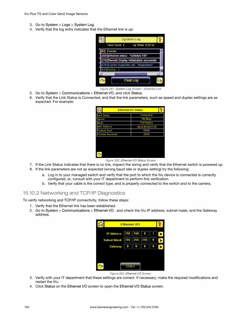
3. Go to System > Logs > System Log.4. Verify that the log entry indicates that the Ethernet link is up:
Figure 261. System Log Screen—Ethernet Link5. Go to System > Communications > Ethernet I/O, and click Status.6. Verify that the Link Status is Connected, and that the link parameters, such as speed and duplex settings are as
expected. For example:
Figure 262. Ethernet I/O Status Screen7. If the Link Status indicates that there is no link, inspect the wiring and verify that the Ethernet switch is powered up.8. If the link parameters are not as expected (wrong baud rate or duplex setting) try the following:
a. Log in to your managed switch and verify that the port to which the iVu device is connected is correctlyconfigured, or, consult with your IT department to perform this verification.
b. Verify that your cable is the correct type, and is properly connected to the switch and to the camera.
15.10.2 Networking and TCP/IP DiagnosticsTo verify networking and TCP/IP connectivity, follow these steps:
1. Verify that the Ethernet link has been established.2. Go to System > Communications > Ethernet I/O , and check the iVu IP address, subnet mask, and the Gateway
address.
Figure 263. Ethernet I/O Screen3. Verify with your IT department that these settings are correct. If necessary, make the required modifications and
restart the iVu.4. Click Status on the Ethernet I/O screen to open the Ethernet I/O Status screen.
iVu Plus TG and Color Gen2 Image Sensors
194 www.bannerengineering.com - Tel: +1.763.544.3164

Figure 264. Ethernet I/O Status Screen5. On the PC attached to your LAN, open the Command window. To do this, click Start > Run, enter cmd, and click
OK. A command window displays.
Figure 265. Command Window6. Enter a ping command specifying the iVu IP address as an argument. You should see a series of responses from the
iVu.
Figure 266. Command Window with Responses from the iVu
You should also see the Packets Received and Packets Sent count on the Ethernet I/O Status screen in the cameraincrement by at least 4.
7. If the output of the ping command shows request timeouts, try the following:• Verify that the camera is located on the correct subnet, has the correct IP address, and is connected to the
correct switch or router
iVu Plus TG and Color Gen2 Image Sensors
www.bannerengineering.com - Tel: +1.763.544.3164 195

• If you are running several overlapping subnets, you may want to consult your IT department to ensure thatthe routing for the network is configured correctly
• If you are trying to access the camera through a gateway or a VPN router, verify that these devices areconfigured such that they allow traffic from the iVu device to reach the destination device
15.10.3 Industrial Protocols Troubleshooting
Modbus/TCP Protocol
Modbus/TCP protocol relies on the fundamental TCP/IP connectivity to establish connections and transport data. After youhave verified Networking and TCP/IP connectivity, you should have little or no problems establishing a Modbus/TCPconnection.
iVu supports one Modbus/TCP connection from a single client, and will reject additional connection requests.
Prior to attempting to establish the Modbus/TCP connection, configure your device and teach it about the iVu device. Tellthe device the IP address of the iVu device that you have previously configured. Configuration steps vary for each device.Consult the appropriate device manual for these steps.
The iVu Modbus/TCP port is fixed at port number 502.
After you have established a Modbus/TCP connection, verify that the iVu has accepted. Go to System > Communications >Industrial Ethernet > Status , and view the connection status.
Figure 267. Industrial Ethernet Status Screen
If you experience issues accessing data, see Modbus/TCP on page 139 for the Modbus/TCP register maps supported bythe iVu, and consult the Industrial Protocols Log. The log, when configured to Detailed Logging mode, provides a record ofthe individual register access sequences and records any errors.
Figure 268. Industrial Ethernet Screen
EtherNet/IP™ and PCCC Protocols
EtherNet/IP and PCCC protocols rely on Common Industrial Protocol (CIP™)13 protocol to establish communications andexchange data. CIP protocol, in turn, utilizes TCP/IP.
EtherNet/IP implements Input/Output (I/O) messaging. I/O messaging allows two devices, the iVu and the PLC, tocontinuously synchronize data sets between each other. These data sets are called Input and Output Assemblies. The iVudevice consumes PLC output assemblies, and produces PLC input assemblies. This exchange occurs continuously, at therate specified by the RPI (Requested Packet Interval) value.
I/O messaging is based on UDP/IP, and utilizes Multicast addressing when sending PLC input assemblies. It is the defaultmode of operation for I/O messages in PLCs. Many PLCs also support Unicast (direct) addressing for PLC inputassemblies, but need to be specially configured.
13 EtherNet/IP™ and CIP™ are trademarks of ODVA, Inc.
iVu Plus TG and Color Gen2 Image Sensors
196 www.bannerengineering.com - Tel: +1.763.544.3164

Because I/O messaging uses UDP/IP and Multicast, it requires special, managed switches, and customized switchconfiguration. Managed switches, when properly configured, prevent multicast devices from flooding the network with data.Consult with your IT department to make sure that you have the correct switch type, and that these switches have InternetGroup Management Protocol (IGMP) snooping enabled to allow them to manage multicast groups.
Some switches with built-in firewalls block UDP traffic by default. If this is the case, and if the path between your devicesinvolves several switches or routers, it is possible that some of them might block the UDP traffic necessary for I/Omessages. Consult with your IT department to verify that your network is configured correctly.
Establishing CIP and EtherNet/IP I/O communications is a complicated process. There are several steps during which anerror can occur. Industrial Protocols log contains a detail description of the communications process, and should beconsulted if any errors are suspected.
Figure 269. Communication Log Detail Screen
A great level of detail is also provided in the log when the I/O connection is established.
Figure 270. Industrial Ethernet Screen Figure 271. Communication Log Detail Screen
After the CIP and I/O connections are established, the Industrial Protocols Status screen shows the details of theconnection.
Figure 272. Industrial Ethernet Status Screen
Most of the errors in establishing the CIP and I/O connections have to do with specifying the proper Input and OutputAssembly Instance IDs and sizes. Refer to the appropriate sections of this manual for this information.
iVu Plus TG and Color Gen2 Image Sensors
www.bannerengineering.com - Tel: +1.763.544.3164 197

PROFINET
Discovering iVu Devices
The Siemens TIA Portal (v13) software discovery and configuration protocols are used to discover iVu devices on a network.
1. Start the Siemens TIA Portal (v13) software.2. Click Open an existing project.3. Select a project and open it.4. Click Devices & networks after the project has been uploaded.5. Click Configure networks.6.
Click the Accessible devices icon.The Accessible devices window opens.
7. Select an interface connection in the Type of the PG/PC interface list.8. Select an interface connection in the PG/PC interface list.
Figure 273. PG/PC Interface
The PC scans the network for PROFINET® devices. If the device you are looking for is not present, check thecabling.
Example of Scanning ResultsUnder Online status information, the scan shows that three devices were found.
Figure 274. Select Device—Online Status Information
Accessing the iVu Device's Communication Logs
PROFINET® communication activity is recorded in the iVu device's communication logs. Use these instructions to accessthe iVu device's communication logs via the display.
iVu Plus TG and Color Gen2 Image Sensors
198 www.bannerengineering.com - Tel: +1.763.544.3164

1. Go to Main Menu > Logs > Communication Logs > Industrial Ethernet > View Logs.
Figure 275. Industrial Ethernet Screen
Note: Green communication log icons mean flawless communication. Red communication iconsmean communication errors.
iVu Plus TG and Color Gen2 Image Sensors
www.bannerengineering.com - Tel: +1.763.544.3164 199

2. Click the Arrow button on any log entry in the communication log to access the Communication Log Detail window.
Note: An expanded description of the communication supports better diagnostics.
iVu Plus TG and Color Gen2 Image Sensors
200 www.bannerengineering.com - Tel: +1.763.544.3164

Diagnosing Errors
The Siemens TIA Portal (v13) software includes numerous diagnostic tools. When a computer is connected to the controller(PLC), diagnostic information is available. The controller (PLC) generates a message that displays in the Diagnosticswindow. A flashing red light on the CPU module of the controller (PLC) indicates an error.
1. Click on the text in the Details column to request detailed information about the device that caused the error.
Figure 276. Diagnostics
All system and device messages are displayed in the Diagnostics buffer window under Events and Details on event.2. Select a message in the table, Display CPU Time Stamps in PG/PC local time.
Figure 277. Diagnostics Buffer
The respective information displays in the Description field under Details on event.3. Read the message to learn about the error and resolve it. When the error is resolved, the icon that corresponds to
the displayed message is green.
15.11 Additional Information
15.11.1 iVu Command Channel Commands (iVu Command Channel over IndustrialEthernet)This section describes how to use the iVu Command Channel over Industrial Ethernet. See for more information on the iVuCommand Channel protocol. The following commands are executed using the Command ID register and the CommandInput bit/Input Coil bit.
Command Channel Primer on page 97
iVu Plus TG and Color Gen2 Image Sensors
www.bannerengineering.com - Tel: +1.763.544.3164 201

Command Command ID Description Data Type
Do Set Get
Trigger
Trigger Mode 1 10001 The iVu triggering mode. This value must match themodes supported by the iVu.
Int16
Product Change
Product Change ByName
21 This command forces the iVu to switch to the specifiedinspection. The iVu does not transmit a response untilthe iVu has completed the action. Inspection resultsimmediately after a product change are invalid until anew trigger is received.
Byte Array
Imager
Gain 51 10051 The iVu value used to electronically brighten all imagepixels.
Int32
Exposure 52 10052 The iVu value used to control the amount of time theimager is allowed to gather light for the image.
Int32
Status
Clear System Error 81 This command clears the system error LED and resetsthe internal system error flag to false.
N/A
System
Reboot Sensor 101 This command restarts the iVu. If the iVu configurationdata is currently being saved, this command is blockeduntil the save operation completes.
N/A
Save Configuration 102 This command saves all modified inspection andconfiguration parameters. This command blocks all othercommands until all values have been persisted.
N/A
Info
Sensor Name 10151 User-assigned device name. Byte Array
Model Number 10152 Device model number. Byte Array
Serial Number 10153 Device serial number. Byte Array
Firmware Version 10154 Device firmware (software) version. Byte Array
Hour Counter 10155 The total number of hours the device has beenenergized.
Byte Array
History
Clear History 301 This command clears all history fields for the activeinspection. History values include pass count, fail count,execution times and sensor-specific history values.
N/A
Inspection
Inspection Name 10501 The name of the active inspection. Byte Array
Trigger Mode 1000 Description
External 1 Inspections are initiated via the electrical trigger wire.
Internal 2 Inspections run continuously at the specified period (electrical trigger inputs areignored).
Free Run 3 Inspections run continuously (electrical trigger inputs are ignored).
Industrial Ethernet 10 Inspections are only trigged by Industrial Ethernet coils and commands.
Command 20 Inspections are only trigged by the Command Channel trigger commands.
iVu Plus TG and Color Gen2 Image Sensors
202 www.bannerengineering.com - Tel: +1.763.544.3164

Error Codes
The iVu device provides error codes in cases when commands failed to execute successfully. If such an error occurs, theExecution Error flag is set in the Output Bits/Status Register. When this bit is set, read the Error Code register to know thereason for the failure. The following table lists the error codes:
Numeric ID Text ID Description
0 SUCCESS Command processed successfully.
500 IE_TRIGGER_MODE_EXPECTED The Trigger Mode must be set to Industrial Ethernet to perform thisoperation.
510 IE_COMMAND_NOT_FOUND The numeric Command ID specified was not found.
520 IE_COIL_ACTION_FAILED The coil action resulted in a failure.
521 IE_COIL_ALREADY_BUSY The coil was asserted before the previous execution completed.
522 IE_COIL_NOT_FINISHED The coil was de-asserted prior to the execution completing.
523 IE_COIL_ANOTHER_ACTION_PENDING The coil was asserted prior to another coil execution completing.
524 IE_COIL_MULTIPLES_DETECTED Multiple coils were asserted simultaneously.
525 IE_COIL_ACK_INHIBITED The coil action's output ACK was inhibited because the input coilwas no longer set.
10000 EMPTY_FRAME_RECEIVED Indicates that the request was empty. The command channelrequires a command, any arguments, and an end-of-framedelimiter.
10001 COMMAND_NOT_RECOGNIZED The command specified is not recognized
10100 GROUP_MISSING A Group ID must be specified immediately after the command
10101 GROUP_NOT_FOUND The specified Group ID is invalid / unknown
10102 GROUP_ITEM_MISSING A Group Item ID must be specified immediately after the Group ID
10103 GROUP_ITEM_NOT_FOUND The specified Group Item ID is invalid / unknown
10152 NOT_READABLE Attempt to get a value that is not readable
10153 NOT_WRITEABLE Attempt to set a value that is not writeable
10250 NOT_A_METHOD Method ID specified is not a method
10251 WRONG_ARGUMENT_COUNT Total method arguments specified do not match method
10252 COMMAND_NOT_FINISHED Attempt to issue command when a previous command has notfinished
10300 INVALID_ARGUMENT_TYPE Item ID specified must be an item (not a group or method)
10301 DATA_VALUE_MISSING Command missing item's data value
10340 MINIMUM_VALUE_EXCEEDED New item value is below the minimum
10341 MAXIMUM_VALUE_EXCEEDED New items value is above the maximum
10350 ARGUMENTS_DETECTED Get command received with unneeded arguments
10351 INVALID_ARGUMENT_TYPE Item ID specified must be an item (not a group or method)
10500 DATA_SET_EMPTY Data export operation returned no results.
10900 SENSOR_NOT_READY Command specified requires iVu to be in the READY state.
10920 SENSOR_TYPE_NOT_ACTIVE Command specified belongs to a different sensor type.
10950 DEVICE_TYPE_INVALID Command not supported on this device type.
15000 VALUE_INVALID Text value is invalid / unknown
15050 VALUE_INVALID Text value is invalid - expecting True or False
15100 STRING_TOO_LONG String value specified exceeds maximum allowable length
20200 NO_AREAS_FOUND Attempt to obtain value when no areas were found.
iVu Plus TG and Color Gen2 Image Sensors
www.bannerengineering.com - Tel: +1.763.544.3164 203

Numeric ID Text ID Description
20600 NO_MATCHES_FOUND Attempt to obtain value when no matches were found.
20800 NO_MATCHES_FOUND Attempt to obtain value when no sort patterns were found.
80000 REMOTE_DISPLAY_NOT_CONNECTED Remote Display must be connected to obtain this value
80001 REMOTE_DISPLAY_NOT_SUPPORTED This device does not have Remote Display capability
80100 COMMAND_MODE_EXPECTED The Trigger Mode must be set to "Command" perform thisoperation
80101 COMMAND_TIMED_OUT The command timed out before finishing
80102 TRIGGER_REQUIRED Access to the specified data requires a triggered inspection
80150 COMMAND_TIMED_OUT The command timed out before finishing
80200 SYSTEM_ERROR_NOT_ACTIVE The System Error must be active to execute this command
80300 TEACH_SENSOR_TYPE_INVALID Teach requires Match sensor.
80350 MULTIPLE_INSPECTIONS_DISABLED Requires multiple inspections to be enabled
80351 MULTIPLE_INSPECTIONS_EMPTY No inspections are available in multiple inspection mode.
80400 PRODUCT_CHANGE_WHEN_NOT_READY Sensor must be in the READY state to perform a product change.
80401 PRODUCT_CHANGE_INVALID_INSPECTION Attempt to product change to an unknown or invalid inspection.
80402 PRODUCT_CHANGE_TIMEOUT The Product Change operation timed out.
80403 PRODUCT_CHANGE_TO_SAME_INSPECTION Attempt to product change to the same inspection.
80404 SENSOR_NAME_NOT_FOUND Attempt to use a command without a sensor name in a multi-sensor inspection
Examples of Operation
The following examples show how to utilize the iVu Command Channel via the Industrial Ethernet connection.
Clear System Error
1. Write the number 81 as a 16-bit integer into the Command ID register.2. Toggle the Command bit from 0 to 1 (bit 15 in the Input Bits/Input Coil Bits register).3. Wait for the Command ACK flag to go from 0 to 1 (bit 15 in the Input Bits ACK/Input Coil Bits ACK register).4. Verify that the Execution Error flag is not set (that is, the value should be 0). This is bit 15 in the Output Bits/Status
Coil Bits register. If the value is 1, read the Error Code register for more information.5. Task Complete. Toggle the Command bit back to 0 (bit 15 in the Input Bits/Input Coil Bits register).
Get/Set Trigger Mode
Get the current Trigger Mode from the iVu.
1. Write the number 10001 as a 16-bit integer into the Command ID register.2. Toggle the Command bit from 0 to 1 (bit 15 in the Input Bits/Input Coil Bits register).3. Wait for the Command ACK flag to go from 0 to 1 (bit 15 in the Input Bits ACK/Input Coil Bits ACK register).4. Verify that the Execution Error flag is not set (that is, the value should be 0). This is bit 15 in the Output Bits/Status
Coil Bits register. If the value is 1, read the Error Code register for more information.5. Task Complete. Toggle the Command bit back to 0 (bit 15 in the Input Bits/Input Coil Bits register). Read the current
Trigger Mode value in the Command Response Int16 register.
iVu model Trigger Mode Int16 value
TG/Color/Color, BCR External 1
TG/Color Internal 2
TG/Color Free Run 3
TG/Color, BCR Industrial Ethernet Only 10
iVu Plus TG and Color Gen2 Image Sensors
204 www.bannerengineering.com - Tel: +1.763.544.3164

iVu model Trigger Mode Int16 value
TG/Color, BCR Command 20
BCR Continuous Scan 5
BCR External Gated 4
Set the desired Trigger Mode for the iVu.
1. Write the number 1 as a 16-bit integer into the Command ID register.2. Write the desired Trigger Mode's Int16 value from the table above into the Command Parameter Int16 register.3. Toggle the Command bit from 0 to 1 (bit 15 in the Input Bits/Input Coil Bits register).4. Wait for the Command ACK flag to go from 0 to 1 (bit 15 in the Input Bits ACK/Input Coil Bits ACK register).5. Verify that the Execution Error flag is not set (that is, the value should be 0). This is bit 15 in the Output Bits/Status
Coil Bits register. If the value is 1, read the Error Code register for more information.6. Task Complete. Toggle the Command bit back to 0 (bit 15 in the Input Bits/Input Coil Bits register).
Get/Set Exposure Time
Get the current Exposure Time from the iVu.
1. Write the number 10052 as a 16-bit integer into the Command ID register.2. Toggle the Command bit from 0 to 1 (bit 15 in the Input Bits/Input Coil Bits register).3. Wait for the Command ACK flag to go from 0 to 1 (bit 15 in the Input Bits ACK/Input Coil Bits ACK register).4. Verify that the Execution Error flag is not set (that is, the value should be 0). This is bit 15 in the Output Bits/Status
Coil Bits register. If the value is 1, read the Error Code register for more information.5. Task Complete. Toggle the Command bit back to 0 (bit 15 in the Input Bits/Input Coil Bits register). Read the current
Exposure Time value (in microseconds) in the Command Response Int32 register.
Set the desired Exposure Time for the iVu.
1. Write the number 52 as a 16-bit integer into the Command ID register.2. Write the desired Exposure Time (in microseconds) as a 32-bit integer value into the Command Parameter Int32
register. The minimum acceptable value is 117 µsec and the maximum value is 1,000,000 µsec.3. Toggle the Command bit from 0 to 1 (bit 15 in the Input Bits/Input Coil Bits register).4. Wait for the Command ACK flag to go from 0 to 1 (bit 15 in the Input Bits ACK/Input Coil Bits ACK register).5. Verify that the Execution Error flag is not set (that is, the value should be 0). This is bit 15 in the Output Bits/Status
Coil Bits register. If the value is 1, read the Error Code register for more information.6. Task Complete. Toggle the Command bit back to 0 (bit 15 in the Input Bits/Input Coil Bits register). The new
exposure time will be used for the next inspection. Note that this value is not saved to the iVu device's permanentmemory unless the Save Configuration task is completed.
Save iVu Configuration
This command saves all modified inspection and configuration parameters to the iVu, including Command Channel changesto exposure time and gain, trigger mode, and Remote Teach sessions.
1. Write the number 102 as a 16-bit integer into the Command ID register.2. Toggle the Command bit from 0 to 1 (bit 15 in the Input Bits/Input Coil Bits register).3. Wait for the Command ACK flag to go from 0 to 1 (bit 15 in the Input Bits ACK/Input Coil Bits ACK register).4. Verify that the Execution Error flag is not set (that is, the value should be 0). This is bit 15 in the Output Bits/Status
Coil Bits register. If the value is 1, read the Error Code register for more information.5. Task Complete. Toggle the Command bit back to 0 (bit 15 in the Input Bits/Input Coil Bits register).
iVu Plus TG and Color Gen2 Image Sensors
www.bannerengineering.com - Tel: +1.763.544.3164 205

16 Troubleshooting
16.1 LED Indicator TroubleshootingIn normal operation, the Power LED is green, and the Pass/Fail is green or red depending on the triggered inspection. TheEthernet I/O LED is on or off depending on connection status.
Figure 278. iVu LEDs
1. Power LED
Green: Ready/PowerRed (blinking or steady): Error
2. Pass/Fail LED
Green (steady): PassGreen (blinking): ErrorRed: Fail
3. Ethernet I/O LED
Green: ConnectedOff: Disconnected
The iVu LEDs also indicate abnormal conditions as described in Errors on page 206.
16.1.1 Errors
Indicator Solution
The Pass/Fail LED blinks green deveral times,separated by an LED red blink, and the iVurepeats this pattern over and over. Thisindicates that no inspections are occurring.
Reboot the iVu device.
The Power LED is on steady red. Errorsindicated by the Power LED are reported in theSystem log and appear highlighted in red.
1. Look at the System Log to see the error.2. Clear the LED.
a. Go to Main Menu > Logs > System Logs .b. Click Clear System Error. A device reboot is not required.
3. If the error occurs again, try rebooting the iVu to see if that fixesthe problem. If the problem persists, contact Banner Engineering.
16.1.2 WarningsWarnings are atypical conditions that the iVu detects and fixes. Warnings are highlighted in yellow in the System Log, andcan typically be ignored.
16.2 Debugging Inspections
16.2.1 How to Round-Trip Debug Using the EmulatorThis section describes the procedures for performing round-trip debugging using either the iVu Emulator installed on a PCor using the Emulator directly from a USB flash drive.
Note: This document refers to saving configuration and inspection logs in folders based on the devicename. If you have not yet named the device, folders will be named using the first 8-characters of thedevice serial number.
How to Debug Using the Emulator from a PC
This procedure requires a USB flash drive and a USB cable, PSG-4M-4xx-USB (see Accessories on page 209).
iVu Plus TG and Color Gen2 Image Sensors
206 www.bannerengineering.com - Tel: +1.763.544.3164

1. Connect a USB cable to the iVu device.2. Connect a USB flash drive to the USB cable.3. Save the Inspection Logs to the USB flash drive.
a. Go to Main Menu > Inspection Logs > View Logs, and click the Save button to save the inspection logs.b. When prompted, click Yes to save device configuration along with the Inspection Logs.
The location of these files on the USB flash drive displays after the operation is completed. The InspectionLogs are saved in [USB:]\BANNER\[SENSOR_NAME]\InspLog and the device configuration is saved in[USB:]\BANNER\[SENSOR_NAME]. For example, if the device name is myName:
• Configuration File (CONFIG.CFG) path: [USB:]\BANNER\myName• Inspection Logs path: [USB:]\BANNER\myName\InspLog
Note: If the device has no name, the folder name is the first 8-characters of the deviceserial number.
4. Disconnect the USB flash drive from the iVu device.5. Connect the USB flash drive to a Windows PC that has the iVu Emulator installed.
Important: Make sure the iVu Emulator is NOT running before proceeding to the next step.
6. Copy the device configuration from the USB flash drive to the folder where the Emulator is installed on the PC.
For example, if the device name is myName and the iVu Emulator is installed in the default location on the PC, copythe file [USB:]\BANNER\myName\CONFIG.CFG to C:\Program Files\Banner Engineering\iVu Series.
7. Copy the Inspection Logs from the USB flash drive to the InspLog folder on the PC.
For example, copy the file [USB:]\BANNER\myName\InspLog to C:\Program Files\Banner Engineering\iVu Series\InspLogs.
8. Start the Emulator.9. Set the Trigger option to Internal.
a. Go to Main Menu > Imager > Trigger, and select Internal.b. Set the Trigger Interval as desired.
The iVu Emulator runs with the saved configuration from Step 6 using the saved Inspection Logs from Step 2as images.
10. Make the desired adjustments.11. Close the iVu Emulator program. All configuration changes are automatically saved to the CONFIG.CFG file.12. Copy the device configuration (that is, CONFIG.CFG) from the PC working directory to the USB flash drive.
For example [USB:]\BANNER\myName\CONFIG.CFG.13. Disconnect the USB flash drive from the PC.14. Connect the USB flash drive to the iVu device.15. Restore the configuration to the iVu device.
a. Go to Main Menu > System > Configuration > Load Configuration.b. Select the configuration to restore.c. Click Load to start the restore device configuration.d. Restart the device when the restore is complete.
How to Debug Using the Emulator from the USB Flash Drive
This procedure requires a USB flash drive and a USB cable, PSG-4M-4xx-USB (see Accessories on page 209).
1. Connect a USB cable to the iVu device.2. Connect a USB flash drive to the USB cable.3. Save the Inspection Logs to the USB flash drive.
a. Go to Main Menu > Inspection Logs > View Logs, and click the Save button to save the inspection logs.b. When prompted, click Yes to save the device configuration along with the Inspection Logs.
The location of these files on the USB flash drive displays after the operation is completed. The InspectionLogs are saved in [USB:]\BANNER\[SENSOR_NAME]\InspLog and the device configuration is saved in[USB:]\BANNER\[SENSOR_NAME]. For example, if the device name is myName:
• Configuration File (CONFIG.CFG) path: [USB:]\BANNER\myName• Inspection Logs path: [USB:]\BANNER\myName\InspLog
iVu Plus TG and Color Gen2 Image Sensors
www.bannerengineering.com - Tel: +1.763.544.3164 207

Note: If the device has no name, the folder name is the first 8-characters of the deviceserial number.
4. Disconnect the USB flash drive from the iVu device.5. Connect the USB flash drive to a Windows PC that has the iVu Emulator installed.6. Copy the iVuEmulator.exe program file to the USB flash drive in the same location as the CONFIG.CFG file. For
example, [USB:]\BANNER\myName.7. Start the [USB:]\BANNER\myName\iVuEmulator.exe program.8. Set the Trigger option to Internal.
a. Go to Main Menu > Imager > Trigger, and select Internal.b. Set the Trigger Interval as desired.
The iVu Emulator runs with the saved configuration using the saved Inspection Logs as images.9. Make the desired adjustments.10. Close the iVu Emulator program. All configuration changes are automatically saved to the CONFIG.CFG file.11. Disconnect the USB flash drive from the PC.12. Connect the USB flash drive to the iVu device.13. Restore the configuration to the device.
a. Go to Main Menu > System > Configuration > Load Configuration.b. Select the configuration to restore.c. Click Load to start the restore device configuration.d. Restart the device when the restore is complete.
iVu Plus TG and Color Gen2 Image Sensors
208 www.bannerengineering.com - Tel: +1.763.544.3164

17 Accessories
17.1 Power Cable — Required
12-Pin M12/Euro-Style Cordsets with Open Shield
Model Length Style Dimensions Pinout (Female)
MQDC2S-1206 1.83 m (6 ft)
Straight
44 Typ.
ø 14.5M12 x 1 8
12
7
65
114
9
1
10
23
1 = White2 = Brown3 = Green4 = Yellow5 = Gray6 = Pink7 = Blue8 = Red9 = Orange10 = Light Blue11 = Black12 = Violet
MQDC2S-1215 4.57 m (15 ft)
MQDC2S-1230 9.14 m (30 ft)
MQDC2S-1250 15.2 m (50 ft)
MQDC2S-1275 22.9 m (75 ft)
MQDC2S-1206RA 1.83 m (6 ft)
Right Angle
32 Typ.[1.26"]
30 Typ.[1.18"]
ø 14.5 [0.57"]M12 x 1
MQDC2S-1215RA 4.57 m (15 ft)
MQDC2S-1230RA 9.14 m (30 ft)
MQDC2S-1250RA 15.2 m (50 ft)
Note: The cables listed above must be used to meet .
17.2 Remote Display—Required for Setup (Remote Display Models Only)
Model Description Data Sheet
RDM35 89 mm (3.5 in) Diagonal Machine-Mountable RemoteTouchscreen Display
p/n 166096
17.2.1 RDM35 Remote Display Accessory KitTable 86: Cordset Kits
Model Length Description
IVURDM-QDK-803 0.91 m (3 ft)
8-pin cable, straight, M12-M12
Mounting bracket (SMBRDM35)
Stylus
IVURDM-QDK-806 1.83 m (6 ft)
IVURDM-QDK-815 4.57 m (15 ft)
IVURDM-QDK-830 9.14 m (30 ft)
IVURDM-QDK-850 15.2 m (50 ft)
IVURDM-QDK-803RA 0.91 m (3 ft)
8-pin cable, right-angle, M12-M12
Mounting bracket (SMBRDM35)
Stylus
IVURDM-QDK-806RA 1.83 m (6 ft)
IVURDM-QDK-815RA 4.57 m (15 ft)
IVURDM-QDK-830RA 9.14 m (30 ft)
IVURDM-QDK-850RA 15.2 m (50 ft)
iVu Plus TG and Color Gen2 Image Sensors
www.bannerengineering.com - Tel: +1.763.544.3164 209
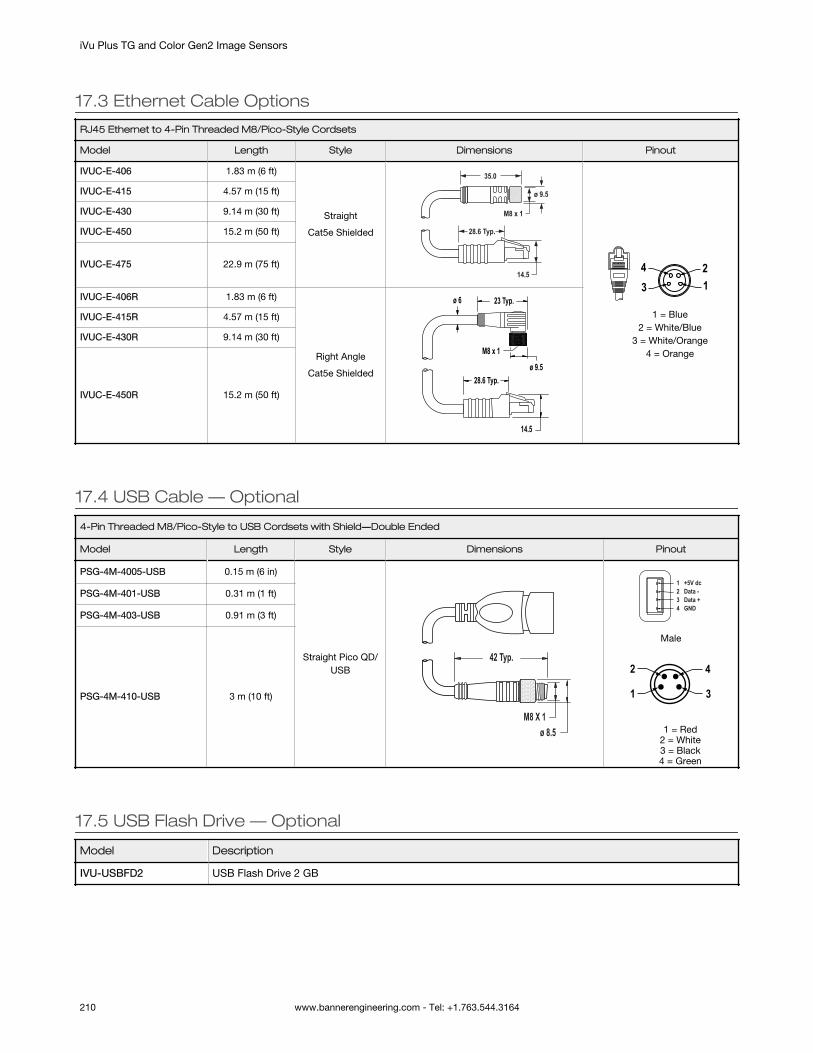
17.3 Ethernet Cable Options
RJ45 Ethernet to 4-Pin Threaded M8/Pico-Style Cordsets
Model Length Style Dimensions Pinout
IVUC-E-406 1.83 m (6 ft)
Straight
Cat5e Shielded
ø 9.5
14.5
28.6 Typ.
M8 x 1
35.0
43 1
2
1 = Blue2 = White/Blue
3 = White/Orange4 = Orange
IVUC-E-415 4.57 m (15 ft)
IVUC-E-430 9.14 m (30 ft)
IVUC-E-450 15.2 m (50 ft)
IVUC-E-475 22.9 m (75 ft)
IVUC-E-406R 1.83 m (6 ft)
Right Angle
Cat5e Shieldedø 9.5
23 Typ.
M8 x 1
14.5
28.6 Typ.
ø 6
IVUC-E-415R 4.57 m (15 ft)
IVUC-E-430R 9.14 m (30 ft)
IVUC-E-450R 15.2 m (50 ft)
17.4 USB Cable — Optional
4-Pin Threaded M8/Pico-Style to USB Cordsets with Shield―Double Ended
Model Length Style Dimensions Pinout
PSG-4M-4005-USB 0.15 m (6 in)
Straight Pico QD/USB
42 Typ.
ø 8.5M8 X 1
1 +5V dc2 Data -3 Data +4 GND
Male
3
2
1
4
1 = Red
2 = White3 = Black4 = Green
PSG-4M-401-USB 0.31 m (1 ft)
PSG-4M-403-USB 0.91 m (3 ft)
PSG-4M-410-USB 3 m (10 ft)
17.5 USB Flash Drive — Optional
Model Description
IVU-USBFD2 USB Flash Drive 2 GB
iVu Plus TG and Color Gen2 Image Sensors
210 www.bannerengineering.com - Tel: +1.763.544.3164

17.6 Brackets
For Use with Integrated Display Models
SMBIVUB• Bottom mounting bracket• Black anodized aluminum• Hardware included
5733
9.5
3 X Ø4.352 X M5 X 0.8
SMBIVURAL• Right-angle bracket for
mounting the device from theleft
• 12-ga. stainless steel• Hardware included
Ø6.6
Ø22.5Ø4.4
78
49
46
SMBIVURAR• Right-angle bracket for
mounting the device from theright
• 12-ga. stainless steel• Hardware included
Ø6.6
Ø22.5 Ø4.4
78
49
46
SMBIVUU• U-shaped swivel bracket kit• 14-ga. stainless steel• Hardware included• Bottom mounting bracket,
SMBIVUBP, can be orderedseparately
61 58
40
3 X M4- 0.7X12 BHCS
4 X Ø7
Note: Use cables with right-angle connectorswith this bracket kit.
For Use with Remote Display Models
SMBIVURAL• Right-angle bracket for
mounting the device from theleft
• 12-ga. stainless steel• Hardware included
Ø6.6
Ø22.5Ø4.4
78
49
46
SMBIVURAR• Right-angle bracket for
mounting the device from theright
• 12-ga. stainless steel• Hardware included
Ø6.6
Ø22.5 Ø4.4
78
49
46
SMBIVUU• U-shaped swivel bracket kit• 14-ga. stainless steel• Hardware included• Bottom mounting bracket,
SMBIVUBP, can be orderedseparately
61 58
40
3 X M4- 0.7X12 BHCS
4 X Ø7
Note: Use cables with right-angle connectorswith this bracket kit.
iVu Plus TG and Color Gen2 Image Sensors
www.bannerengineering.com - Tel: +1.763.544.3164 211

17.7 Micro Video Lens Accessories
17.7.1 Micro Video Lens Models
Model Lens Description
LMF04 14 4.3 mm lens
LMF06 6 mm lens
LMF08 8 mm lens
LMF12 12 mm lens
LMF16 16 mm lens
LMF25 25 mm lens
17.7.2 Micro Video Lens Filters — Optional
Model Description
FLTMR2 Red and dark red filter kit
FLTMI Infrared filter kit
FLTMB Blue filter kit
FLTMG Green filter kit
17.8 C-Mount Lens Accessories
17.8.1 C-Mount Lens Models
Model Lens Description
LCF04 4 mm Lens - no threads for filter
LCF08 8 mm Lens - no threads for filter
LCF12 12 mm Lens - no threads for filter
LCF16 16 mm Lens, aperture lock - no threads for filter
LCF25R 25mm lens
LCF25LR 25mm lens with focus locking
LCF50L1R 50mm lens with focus locking, plastic
LCF50L2R 50mm lens with focus locking, metal (will not fit ring)
LCF75LR 75mm lens with focus locking, metal (will not fit ring)
17.8.2 C-Mount Lens Enclosure Models
Model Description
IVUSLC50-P Sealed C-mount lens enclosure
14 Due to the flexibility of the replaceable lenses, focus mechanism, and imager field-of-view settings, it is possible with the 4.3 mmlens to experience reflections from the internal strobe on the inspection image. To eliminate this effect, the field-of-view can belimited to the system default of 320×240 (or 640×480 for fine), the working distance to the object should be no more than about 8inches, or an external strobe should be used instead of the internal ring light.
iVu Plus TG and Color Gen2 Image Sensors
212 www.bannerengineering.com - Tel: +1.763.544.3164

Model Description
IVUSLC75-P
17.8.3 C-Mount Lens Filters — Optional
Model Description
FLTR Red filter kit
FLTB Blue filter kit
FLTG Green filter kit
FLTI IR Filter kit
iVu Plus TG and Color Gen2 Image Sensors
www.bannerengineering.com - Tel: +1.763.544.3164 213

18 Product Support and MaintenanceThis section provides general Banner resources and specific documentation for installers and operators of this iVu.
18.1 Product SupportBanner provides the following resources for quickly setting up and operating the device.
Online HelpWhen setting up or monitoring inspections using the iVu device's display, view online help on any screen by clicking theHelp icon in the upper-right corner of the display.
PDF DocumentationThe product documentation is available in a convenient printable format (PDF) in the iVu installation package or at www.bannerengineering.com.
Banner WebsiteThe most current product information, documentation, and software updates are available on the Banner website: www.bannerengineering.com.
Warranty ServiceContact Banner Engineering for troubleshooting of this device. Do not attempt any repairs to this Banner device; it containsno field-replaceable parts or components. If the device, device part, or device component is determined to be defective bya Banner Applications Engineer, they will advise you of Banner's RMA (Return Merchandise Authorization) procedure.
Important: If instructed to return the device, pack it with care. Damage that occurs in return shipping isnot covered by warranty.
Factory SupportTo help Banner better assist you, be ready to provide the following information:
• iVu firmware version (to find the version number, go to Main Menu > System > Sensor Information )• Device model number and date code, which are found on the bottom of the device.• Exact wording of any messages that appeared on your screen• A description of what you were doing and what happened• A description of how you tried to solve the problem• Error Codes (see LED Indicator Troubleshooting on page 206)
18.2 MaintenanceMaintenance tasks include keeping the hardware free of dust and dirt and updating the iVu firmware as needed.
18.2.1 Clean the iVuRegularly remove any dust or dirt from the sensor using a soft cloth.
If needed, slightly dampen the cloth with a weak solution of neutral detergent. Avoid getting dirt on the imager (the areabehind the lens). If the imager is dirty, use anti-static compressed air to blow off the dust.
18.2.2 Update the iVu firmwareThe current version of iVu firmware is available for download from www.bannerengineering.com. Use the following steps toupdate the iVu firmware.
This procedure requires a USB flash drive and a USB cable, PSG-4M-4xx-USB (see Accessories on page 209).
1. Go to http://www.bannerengineering.com.2. Browse to the Vision Products page and select the iVu device you are using.3. Click Software to view program releases and release notes.4. Determine which version you want to download. The current version is recommended.5. Download the file. Depending on your browser settings, you may be asked to confirm or provide a location to save
the file. Choose to download on your desktop. Note the file name.6. Start the iVu program.
iVu Plus TG and Color Gen2 Image Sensors
214 www.bannerengineering.com - Tel: +1.763.544.3164

7. In the program, select the product you are using and click Firmware Update Wizard. The program starts.8. Connect a USB flash drive to the PC.9. Follow the on-screen instructions to save the firmware to the USB flash drive. The file is automatically saved to a
folder called BANNER\Firmware.10. Disconnect the USB flash drive from the PC.11. Connect the USB cable to the iVu.12. Connect the US flash drive to the USB cable.13. On the iVu, go to System > Firmware Update. The name of the firmware file you copied to the USB flash drive
displays.14. Select the correct file and click Load.15. Follow the on-screen instructions to update the firmware.
18.2.3 How to Set or Modify a Device Name using the EmulatorYou can set a device name for your iVu device or modify an existing name on the device using the keypad. You can alsochange the device name this using the iVu Emulator as described below.
Note: If you are in a language other than English, you cannot modify the device name using the keypad.Use the procedure described below.
Note: If you have not set the device name previously, folders are named using the first 8-characters of thedevice serial number.
This procedure requires a USB flash drive and a USB cable, PSG-4M-4xx-USB (see Accessories on page 209).
1. Connect a USB cable to the device.2. Connect a USB flash drive to the USB cable.3. Save the Device Configuration to the USB flash drive. Go to Main Menu > System > Configuration > Save to USB.
The location of these files on the USB flash drive displays after the operation is complete. The device configurationis saved in [USB:]\BANNER\[DEVICE_NAME]. For example, if the device name is myName, the path is [USB:]\BANNER\myName.
4. Disconnect the USB flash drive from the device.5. Connect the USB flash drive to a Windows PC.6. If you are running the Emulator installed on a PC, make sure the Emulator is not running, and copy the Device
Configuration from the USB flash drive to the folder where the Emulator is installed on the PC.
For example, if the device name is myName and the iVu Emulator is installed in the default location on the PC, copythe file [USB:]\BANNER\myName\CONFIG.CFG to C:\Program Files\Banner Engineering\iVu Series.
7. Launch the iVuEmulator.exe program (either from the USB flash drive or from the Windows PC, depending on whichone you are using).
8. Go to Main Menu > System > Information.9. Click inside the Device Name field, and enter the desired name.10. Click the Back button on the lower-left corner of the display to save the device name.11. Close the Emulator program. The device name is automatically saved to the CONFIG.CFG file.12. If you are running the Emulator on the PC, copy the CONFIG.CFG file back to the original folder on the USB flash
drive, [USB:]\BANNER\[DEVICE_NAME]. For example [USB:]\BANNER\myName.
Note: The device looks in the original folder (for example, myName) for the CONFIG.CFG file.
13. Remove the USB flash drive from the PC, and connect it to the device.14. Restore the configuration to the device.
a. Go to Main Menu > System > Configuration > Load from USB.b. Select the configuration to restore.c. Click Load to start the restore device configuration.
Note: After the new device name is restored in the device, all files saved to USB flash drivewill now reside in the folder corresponding to the new device name.
d. Restart the device when the restore is complete.
Note: If a device configuration from one device is loaded onto another device, the device name from thedevice configuration is not be stored in the device.
iVu Plus TG and Color Gen2 Image Sensors
www.bannerengineering.com - Tel: +1.763.544.3164 215

18.2.4 How to Reset the Device PasswordIf you forget the password for your device, contact Banner Engineering for assistance.
18.3 Contact Us
Corporate Headquarters
Address:Banner Engineering Corporate9714 Tenth Avenue NorthMinneapolis, Minnesota 55441, USA
Phone: +1 763 544 3164Website: www.bannerengineering.com
Europe
Address:Banner Engineering EMEAPark Lane, Culliganlaan 2F, bus 31831 Diegem, Belgium
Phone: +32 (0)2 456 0780Website: www.bannerengineering.comEmail: [email protected]
Turkey
Address:Banner Engineering Elk. San. Ve Tic. Ltd. Şti.Şerifali Mah. Münevver Sok. Ekomed Plaza No:10 Kat:4Ümraniye / İstanbul, Türkiye
Phone: +90 216 688 8282Website: www.bannerengineering.comEmail: [email protected]
India
Address:Banner Engineering India Pune Head QuartersOffice No. 1001, 10th Floor Sai Capital, Opp. ICC Senapati Bapat RoadPune 411016, India
Phone: +91 (0) 206 640 5624Website: www.bannerengineering.comEmail: [email protected]
Mexico
Address:Banner Engineering de Mexico Monterrey Head OfficeEdificio VAO Av. David Alfaro Siqueiros No.103 Col. Valle Oriente C.P.66269San Pedro Garza Garcia, Nuevo Leon, Mexico
Phone: +52 81 8363 2714 or 01 800 BANNERE (toll free)Website: www.bannerengineering.comEmail: [email protected]
Brazil
Address:Banner do BrasilRua Barão de Teffé nº 1000, sala 54Campos Elíseos, Jundiaí - SP, CEP.: 13208-761, Brasil
Phone: +55 11 2709 9880Website: www.bannerengineering.comEmail: [email protected]
China
Address:Banner Engineering Shanghai Rep OfficeXinlian Scientific Research Building Level 12, Building 21535 Hongmei Road, Shanghai 200233, China
Phone: +86 212 422 6888Website: www.bannerengineering.comEmail: [email protected]
Japan
Address:Banner Engineering JapanCent-Urban Building 305 3-23-15 Nishi-Nakajima Yodogawa-KuOsaka 532-0011, Japan
Phone: +81 (0)6 6309 0411Website: www.bannerengineering.comEmail: [email protected]
iVu Plus TG and Color Gen2 Image Sensors
216 www.bannerengineering.com - Tel: +1.763.544.3164
Taiwan
Address:Banner Engineering Taiwan8F-2, No. 308 Section 1, Neihu RoadTaipei 114, Taiwan
Phone: +886 (0)2 8751 9966Website: www.bannerengineering.comEmail: [email protected]
18.4 Banner Engineering Corp Limited WarrantyBanner Engineering Corp. warrants its products to be free from defects in material and workmanship for one year followingthe date of shipment. Banner Engineering Corp. will repair or replace, free of charge, any product of its manufacture which,at the time it is returned to the factory, is found to have been defective during the warranty period. This warranty does notcover damage or liability for misuse, abuse, or the improper application or installation of the Banner product.
THIS LIMITED WARRANTY IS EXCLUSIVE AND IN LIEU OF ALL OTHER WARRANTIES WHETHER EXPRESS OR IMPLIED(INCLUDING, WITHOUT LIMITATION, ANY WARRANTY OF MERCHANTABILITY OR FITNESS FOR A PARTICULARPURPOSE), AND WHETHER ARISING UNDER COURSE OF PERFORMANCE, COURSE OF DEALING OR TRADE USAGE.
This Warranty is exclusive and limited to repair or, at the discretion of Banner Engineering Corp., replacement. IN NOEVENT SHALL BANNER ENGINEERING CORP. BE LIABLE TO BUYER OR ANY OTHER PERSON OR ENTITY FOR ANYEXTRA COSTS, EXPENSES, LOSSES, LOSS OF PROFITS, OR ANY INCIDENTAL, CONSEQUENTIAL OR SPECIALDAMAGES RESULTING FROM ANY PRODUCT DEFECT OR FROM THE USE OR INABILITY TO USE THE PRODUCT,WHETHER ARISING IN CONTRACT OR WARRANTY, STATUTE, TORT, STRICT LIABILITY, NEGLIGENCE, OROTHERWISE.
Banner Engineering Corp. reserves the right to change, modify or improve the design of the product without assuming anyobligations or liabilities relating to any product previously manufactured by Banner Engineering Corp. Any misuse, abuse, orimproper application or installation of this product or use of the product for personal protection applications when theproduct is identified as not intended for such purposes will void the product warranty. Any modifications to this productwithout prior express approval by Banner Engineering Corp will void the product warranties. All specifications published inthis document are subject to change; Banner reserves the right to modify product specifications or update documentationat any time. Specifications and product information in English supersede that which is provided in any other language. Forthe most recent version of any documentation, refer to: www.bannerengineering.com.
iVu Plus TG and Color Gen2 Image Sensors
www.bannerengineering.com - Tel: +1.763.544.3164 217

IndexA
Advanced Display screen 60Area menu 30, 31area range 31, 38Area sensor
area range 31, 38intensity range 31sensor-specific data
(PROFINET) 162area_history command group 104area_result command group 104auto exposure 41Average Color menu 35Average Color sensor
color space 35intensity range 35sensor-specific data
(PROFINET) 163, 164average_color_history command
group 107average_color_result command
group 106
B
Blemish menu 31, 32Blemish sensor
edge length range 32sensitivity 32sensor-specific data
(PROFINET) 163blemish_history command group
105blemish_result command group 104
C
calibrationtouchscreen 60
color 37Color Area menu 37, 38Color Area sensor
area range 31, 38color 37sensor-specific data
(PROFINET) 164tolerance 38
Color Compare menu 36, 37Color Compare sensor
color tolerance 36intensity tolerance 37percent match 33, 34sensor-specific data
(PROFINET) 164color space 35color tolerance 36color_area_history command group
109
color_area_result command group109
color_command_result commandgroup 108
color_compare_history commandgroup 109
command channelimage export 87data export 86
command channel log 66, 95command channel sample
application 86command group
area_history 104area_result 104average_color_history 107average_color_result 106blemish_history 105blemish_result 104color_area_history 109color_area_result 109color_compare_history 109color_compare_result 108history 103info 100inspection 103match_history 105match_result 105productchange 103sort_history 106sort_result 106status 101system 101trigger 101imager 102teach 102
communication channelcommand channel 85data export 85, 86image export 85, 87command channel 85data export 85, 86image export 85, 87Industrial Ethernet 49, 50, 52,
53, 85communication logs 65, 66communications channels 85Communications menu 48–50,
52–56Configuration menu 46, 47
D
DAP 157, 160–162, 164, 166, 168data export 54–56, 85, 86data export log 95data export sample application 87data model 157, 160–162, 164, 166,
168
debugging 206, 207Demo mode 8Device Access Point
, See DAPdevice control 161Discrete I/O menu 57, 58Display Settings menu 59, 60
E
edge length range 32emulator 84, 206, 207Ethernet
communications 88–90, 92Ethernet I/O 48Ethernet/IP 120–122, 124, 125, 127,
128, 133exposure 41external strobe 43
F
fail hold time 60field of view
, See FOVfirmware update 60focus number 42FOV
adjust 43
G
gain 41Generic Station Description
, See GSDGSD
Install 170
H
history command group 103Home screen 23–25HSI 35
I
image export 56, 85, 87image export log 66image export sample application 88imager
auto exposure 41exposure 41focus 42FOV 43gain 41resolution 44strobe 43trigger 42white balance 45
imager command group 102

Imager menu 41–45Industrial Ethernet 49, 50, 52, 53,
85Industrial Ethernet log 66info command group 100Information 47inspection command group 103inspection ID 39Inspection Logs 64, 65inspection menu 30–40Inspection menu
Properties menu 39Sort menu 34, 35
inspection name 39inspection results 161intensity range 31, 35intensity tolerance 37internal strobe 43
L
LCD display timeout 60Load from USB 47lock device 47logs
command channel 66, 95data export 95command channel 66, 95communication 65, 66image export 66Industrial Ethernet 66inspection 64, 65system 65
Logs menu 64–66
M
Main menu 26–29mask 31, 32, 35–37, 82Match menu 32, 33Match sensor
percent match 33, 34rotation range 33, 34sensor-specific data
(PROFINET) 163timeout 33, 35
match_history command group 105match_result command group 105maximum pass count 31–33, 38menu
Display Settings 59, 60Area 30, 31Average Color 35Blemish 31, 32Color Area 37, 38Color Compare 36, 37Communications 48–50, 52–56Configuration 46, 47Discrete I/O 57, 58
Imager 41–45Logs 64–66Main 26–29Match 32, 33Mode 46Motion 38Properties 39Sensors 30–38Sort 34, 35Stored Inspections 39, 40System 46–50, 52–62
minimum pass count 31–33, 38Modbus/TCP 139, 141, 144, 145,
147mode
Demo 8, 46Live 46
Mode menu 46module 160Motion menu 38motion parameters
number of edges 38, 76rotation 38, 76sensitivity 38, 76
N
number of edges 38, 76
P
pass count 31, 33, 38pass count parameter 32pass criteria 34patterns 34, 35PCCC 147, 151, 152, 154–156percent match 33, 34PLC5 147, 151, 152, 154–156productchange command group
103PROFINET 157, 160–162, 164, 166,
168, 170, 173, 176, 178,181, 183, 184, 187
propertiesinspection ID 39inspection name 39
Properties menu 39
R
RBGI 35reboot 60Region of Interest
, See ROIresolution 44ROI 31–33, 35–37rotation parameter 38, 76rotation range 33, 34RS-232 85–87
S
sample applicationcommand channel 86image export 88data export 87
Save to USB 46saved patterns 34sensitivity 32, 38, 76sensor display 23–25Sensors menu 30–38serial communications 93serial I/O 49SLC 5 147, 151, 152, 154–156slot 160Sort menu 34, 35Sort sensor
pass criteria 34percent match 33, 34rotation range 33, 34saved patterns 34sensor-specific data
(PROFINET) 163timeout 33, 35
sort_history command group 106sort_result command group 106status command group 101Stored Inspections menu 39, 40strobe
external 43internal 43
submodule 160–162, 164, 166, 168subslot 160system command group 101System Logs 65System menu 46–50, 52–62
T
teach command group 102timeout
LCD display 60tolerance 38touchscreen calibration 60trigger 42, 67trigger command group 101
U
USBloading from 47saving to 46
W
waveforms 61, 62white balance 45
219