iVu Plus BCR Gen2 Series Sensor - Banner...
179
iVu Plus BCR Gen2 Series Sensor Instruction Manual Original Instructions 179047 Rev. C 21 April 2015 179047
-
Upload
truongphuc -
Category
Documents
-
view
230 -
download
0
Transcript of iVu Plus BCR Gen2 Series Sensor - Banner...
iVu Plus BCR Gen2 Series Sensor
Instruction Manual
Original Instructions179047 Rev. C21 April 2015
179047
Contents1 Overview of the Sensor ...................................................................................................5
1.1 Live Mode Overview .................................................................................................................. 51.1.1 Read/No Read, Pass/Fail, Match/No Match .......................................................................... 51.1.2 Trigger Modes .................................................................................................................51.1.3 Compare Data .................................................................................................................61.1.4 Output 1, Output 2, and Output 3 .....................................................................................61.1.5 Serial and Ethernet Output ............................................................................................... 6
1.2 Imager Resolution ....................................................................................................................72 Installation .....................................................................................................................8
2.1 Components .............................................................................................................................82.1.1 iVu with Integrated Display ...............................................................................................82.1.2 iVu with Remote Display ...................................................................................................8
2.2 Cable Connections .....................................................................................................................92.2.1 Cable Connections for Integrated Display ...........................................................................92.2.2 Cable Connections for Remote Display .............................................................................102.2.3 iVu Trigger, Remote Teach, and I/O Waveforms ................................................................11
2.3 Installing and Connecting the Sensor ........................................................................................ 132.3.1 Installing a Filter on iVu Series Sensors ............................................................................ 13
3 Home Screen ................................................................................................................ 163.1 Display Modes .........................................................................................................................16
3.1.1 Display/Hide Annotations ................................................................................................163.1.2 Inspection Statistics .......................................................................................................16
4 Main Menu Reference ....................................................................................................194.1 Main Menu .............................................................................................................................19
4.1.1 Icon Reference .............................................................................................................. 194.2 System Menu ..........................................................................................................................21
4.2.1 Mode ........................................................................................................................... 224.2.2 System Configuration .....................................................................................................224.2.3 System Information ....................................................................................................... 234.2.4 Lock device ..................................................................................................................244.2.5 Communications ............................................................................................................244.2.6 Discrete I/O ..................................................................................................................294.2.7 Display Settings ............................................................................................................ 314.2.8 Reboot Sensor ...............................................................................................................324.2.9 Firmware Update ........................................................................................................... 32
4.3 Imager Menu ..........................................................................................................................334.3.1 Auto Exposure ...............................................................................................................334.3.2 Exposure ...................................................................................................................... 334.3.3 Gain ............................................................................................................................ 344.3.4 Trigger .........................................................................................................................344.3.5 Focus ...........................................................................................................................354.3.6 Strobe ..........................................................................................................................354.3.7 FOV (Field of View) ........................................................................................................ 364.3.8 Resolution ................................................................................................................... 37
4.4 Inspection Menu ......................................................................................................................384.4.1 Barcode Menu ............................................................................................................... 384.4.2 Properties .....................................................................................................................434.4.3 Stored Inspections .........................................................................................................44
4.5 Logs Menu ..............................................................................................................................454.5.1 Inspection Logs ............................................................................................................. 454.5.2 System Logs ................................................................................................................. 474.5.3 Communication Logs ......................................................................................................47
5 Setting up an Inspection ...............................................................................................485.1 Acquiring a Good Image ...........................................................................................................48
5.1.1 Adjust the Focus on a Micro Video Lens Model .................................................................. 495.1.2 Adjust the Focus on a C-Mount Lens Model .......................................................................49
5.2 Using iVu Gen1 and Gen2 Devices in the Same Application ........................................................... 505.3 Setting Up a Barcode Application ...............................................................................................505.4 Setting up for Data Compare .................................................................................................... 51
5.4.1 Remote Teach ............................................................................................................... 526 Communications Guide ................................................................................................ 53
6.1 Introduction .......................................................................................................................... 536.2 iVu Plus Communication Summary of Ethernet and Serial ............................................................ 53
iVu Plus BCR Gen2 Series Sensor
6.2.1 Communication Channels ...............................................................................................536.2.2 Industrial Ethernet ........................................................................................................536.2.3 Command Channel .........................................................................................................546.2.4 Data Export .................................................................................................................. 556.2.5 Image Export ...............................................................................................................55
6.3 Enabling Communications ........................................................................................................566.3.1 Setting Up Ethernet Communications ...............................................................................566.3.2 Setting Up Serial Communications ................................................................................... 60
6.4 Testing and Troubleshooting iVu Plus Communications ................................................................. 636.4.1 Understanding the Communication Log .............................................................................636.4.2 Ethernet I/O ................................................................................................................ 646.4.3 Serial I/O .................................................................................................................... 64
6.5 Command Channel Primer ....................................................................................................... 666.5.1 Command Channel Commands ........................................................................................ 666.5.2 Conventions Used for Examples ....................................................................................... 676.5.3 Examples .....................................................................................................................676.5.4 Command Channel Reference .........................................................................................696.5.5 Command Channel Command Status Register ................................................................... 746.5.6 Command Channel Error Codes ....................................................................................... 74
6.6 iVu Discovery Protocol ............................................................................................................. 756.6.1 Overview .....................................................................................................................756.6.2 UDP Usage ...................................................................................................................756.6.3 Packet Format ..............................................................................................................756.6.4 Message Flow ...............................................................................................................79
7 Industrial Ethernet Overview .......................................................................................837.1 Device Setup ......................................................................................................................... 83
7.1.1 Set IP Address ............................................................................................................. 837.1.2 Set Industrial Ethernet Protocol (EIP/Modbus/TCP/PCCC/PROFINET®) ..................................837.1.3 Set Trigger Mode .......................................................................................................... 83
7.2 Supported Functions ................................................................................................................837.2.1 iVu Input Values ............................................................................................................837.2.2 iVu Output Values ..........................................................................................................84
7.3 Sensor Operation .................................................................................................................... 847.3.1 General Command Execution ..........................................................................................85
7.4 EtherNet/IP ............................................................................................................................ 857.4.1 Inputs to iVu (Outputs from PLC) .....................................................................................867.4.2 Outputs from the iVu (Inputs to the PLC) .......................................................................... 867.4.3 Input and Output Flags Bits .............................................................................................897.4.4 Configuration Assembly Object ........................................................................................ 897.4.5 Data Formats ................................................................................................................ 897.4.6 Minimum Requested Packet Inverval (RPI) Value .............................................................. 907.4.7 iVu Plus EDS File Installation in ControlLogix Software ........................................................ 907.4.8 RSLogix5000 Configuration ............................................................................................. 96
7.5 Modbus/TCP ..........................................................................................................................1037.5.1 iVu Plus Input Values ....................................................................................................1057.5.2 iVu Plus Output Values ..................................................................................................1057.5.3 Flags ..........................................................................................................................107
7.6 PLC5 and SLC 5 (PCCC) ..........................................................................................................1087.6.1 Configuration ............................................................................................................. 1087.6.2 Inputs to iVu (Outputs from PLC) ................................................................................... 1107.6.3 Outputs from iVu (Inputs to PLC) ................................................................................... 1107.6.4 Input and Output Flags .................................................................................................112
7.7 PROFINET .............................................................................................................................1137.7.1 General Station Description (GSD) File ............................................................................1137.7.2 iVu PROFINET IO Data Model .........................................................................................1137.7.3 Configuration Instructions ............................................................................................ 129
7.8 Sample Timing Diagram ........................................................................................................ 1517.9 Command Channel Command Status Register ........................................................................... 1547.10 Diagnostic Guide ..................................................................................................................154
7.10.1 Ethernet Diagnostics ..................................................................................................1547.10.2 Networking and TCP/IP Diagnostics ............................................................................. 1557.10.3 Industrial Protocols Troubleshooting ............................................................................ 157
7.11 Additional Information .........................................................................................................1657.11.1 iVu Command Channel Commands (iVu Command Channel over Industrial EtherNet) .......... 165
8 Debugging Inspections .............................................................................................. 1708.1 iVu Emulator .........................................................................................................................1708.2 How to Round-Trip Debug Using the Emulator ........................................................................... 170
8.2.1 How to Debug Using the Emulator from a PC ................................................................... 1708.2.2 How to Debug Using the Emulator from the USB Flash Drive .............................................171
9 Updating the Sensor .................................................................................................. 172
iVu Plus BCR Gen2 Series Sensor

9.1 Update Process ..................................................................................................................... 1729.2 How to Set or Modify a Device Name using the Emulator .............................................................1729.3 How to Reset the Sensor Password .......................................................................................... 1739.4 How to Use Bitmap Image Files with the iVu Emulator ................................................................ 173
10 LED Indicator Troubleshooting ................................................................................. 17510.1 Errors .................................................................................................................................17510.2 Warnings ............................................................................................................................175
11 Product Support and Maintenance ............................................................................ 17611.1 Product Support .................................................................................................................. 17611.2 Maintenance ....................................................................................................................... 17611.3 Contact Us .........................................................................................................................17711.4 Banner Engineering Corp Limited Warranty ............................................................................ 178
iVu Plus BCR Gen2 Series Sensor
1 Overview of the SensorThe iVu Plus BCR sensor reads a wide variety of barcodes. The package consists of sensor, lighting, lens, and display.Cables and mounting brackets can be ordered for each application. Additionally, other lenses, filters, and external lightsare available. Installation, setup, and configuration can be done quickly without requiring a PC.
• No PC required to configure the sensor• USB port for uploading and downloading of inspections and log files for easy updating and diagnostics• Image processing expertise is not required• Integrated or remote color touch screen display• High speed processing
The iVu Plus BCR reads the following barcode types:• DataMatrix (ECC 200) barcodes• QR Code (QR and Micro QR)• Linear barcodes: Code128, Code39, CODABAR, Interleaved 2 of 5, EAN13, EAN8, UPCE, Postnet, IMB, and
Pharmacode
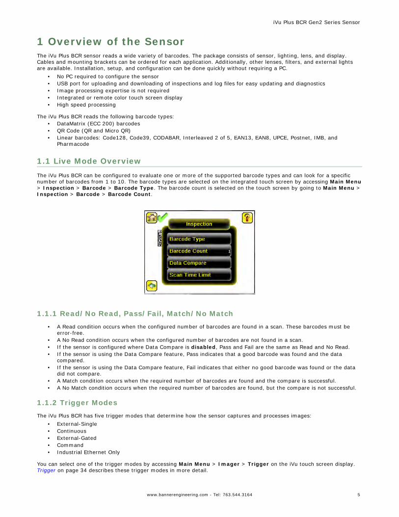
1.1 Live Mode OverviewThe iVu Plus BCR can be configured to evaluate one or more of the supported barcode types and can look for a specificnumber of barcodes from 1 to 10. The barcode types are selected on the integrated touch screen by accessing Main Menu> Inspection > Barcode > Barcode Type. The barcode count is selected on the touch screen by going to Main Menu >Inspection > Barcode > Barcode Count.
1.1.1 Read/No Read, Pass/Fail, Match/No Match
• A Read condition occurs when the configured number of barcodes are found in a scan. These barcodes must beerror-free.
• A No Read condition occurs when the configured number of barcodes are not found in a scan.• If the sensor is configured where Data Compare is disabled, Pass and Fail are the same as Read and No Read.• If the sensor is using the Data Compare feature, Pass indicates that a good barcode was found and the data
compared.• If the sensor is using the Data Compare feature, Fail indicates that either no good barcode was found or the data
did not compare.• A Match condition occurs when the required number of barcodes are found and the compare is successful.• A No Match condition occurs when the required number of barcodes are found, but the compare is not successful.
1.1.2 Trigger Modes
The iVu Plus BCR has five trigger modes that determine how the sensor captures and processes images:• External-Single• Continuous• External-Gated• Command• Industrial Ethernet Only
You can select one of the trigger modes by accessing Main Menu > Imager > Trigger on the iVu touch screen display. Trigger on page 34 describes these trigger modes in more detail.
iVu Plus BCR Gen2 Series Sensor
www.bannerengineering.com - Tel: 763.544.3164 5
1.1.3 Compare Data
The iVu Plus BCR has a data compare feature for comparing read barcode data against reference data. Data can bemanually entered by navigating to the Main Menu > Inspection > Barcode > Data Compare > Set Data screen. Dataof up to 3200 characters can be entered. Additionally, the data compare feature provides for masking characters within thedata.
There are two other ways to enter compare data:• Importing the last read data while viewing the Set Data screen. The new data is effective on the first trigger that
occurs after this action.• Using Remote Teach.
When a Remote Teach occurs, the data of the first read barcode is saved as Data Compare input. Inspectionsexecuted on the next trigger uses the new data for comparison with subsequently read barcodes. If the previousinput data contained any masked characters, Remote Teach retains the masked characters only if the new data isof the same length as the previous input data. If the length does not match, masking is removed.
The sensor tries to compare full length of this string with the data read from the barcode. If not equal, the inspection ismarked as Fail.
NOTE: If the sensor reads more than one barcode in the field of view, only the first barcode data thatthe sensor reads can be compared.
1.1.4 Output 1, Output 2, and Output 3
The sensor has three output signals that you can configure for Pass, Fail, Read, No Read, Match, No Match, System Error,and Missed Trigger. The default settings are Pass for Output 1, Fail for Output 2, and Pass for Output 3.
NOTE: For all outputs, the default setting is Latched, which means that the signal is active until theresults of an inspection cause a change in the signal output. If Pulsed is selected, the default pulsewidth is 50 ms.
1.1.5 Serial and Ethernet Output
The iVu Plus communicates with other devices via Ethernet or a UART serial communications port (RS-232). In order toestablish an Ethernet connection to the sensor, the external device must be configured with the correct IP address and TCPport to communicate. To use the serial communications connection, port settings for baud rate, data bits, parity, and stopbits must be configured on the iVu Plus to match the settings of the external device.
The iVu Plus BCR RS-232 port or ethernet port can be used to output barcode data to other applications. To access theData Export screen, go to Main Menu > System > Communications > Data Export. The user can enable or disable thisfeature. When enabled:
• if the sensor is configured for either External-Single or External-Gated trigger modes, every trigger results in thetransmission of output data (if the sensor does not successfully read a barcode, the output will be NO_READ).
• if the sensor is configured for Continuous trigger mode, the sensor transmits output barcode data only upon asuccessful read.
To access the Serial Output screen, go to Main Menu > System > Communications > Serial I/O.
When RS-232 serial output is enabled, the user can configure:• Serial Port Settings (listed below)• Type of Data to Export (listed below)
iVu Plus BCR Gen2 Series Sensor
6 www.bannerengineering.com - Tel: 763.544.3164
• Output Format (listed below)
To access the Ethernet Output screen, go to Main Menu > System > Communications > Ethernet I/O.
When ethernet output is enabled, the user can configure:• IP Address, Port number, Subnet Mask, and Gateway• Type of Data to Export (listed below)• Output Format (listed below)
Type of Data to Export:• Pass/Fail Output• Inspection Name• Barcode Count• Data Length• Symbol Type• Barcode Data• Frame Number• Inspection Time (ms)
Serial Port Settings:• Baud Rates• Start Bits• Stop Bits• Data Bits• Parity Control
Output Format:• Start String• Delimiter• End String
1.2 Imager ResolutionThe iVu Plus Barcode Reader (BCR) Gen2 Series Sensor includes an adjustable resolution up to 752×480 pixels.
iVu Plus BCR Gen2 Series Sensor
www.bannerengineering.com - Tel: 763.544.3164 7
2 Installation2.1 Components
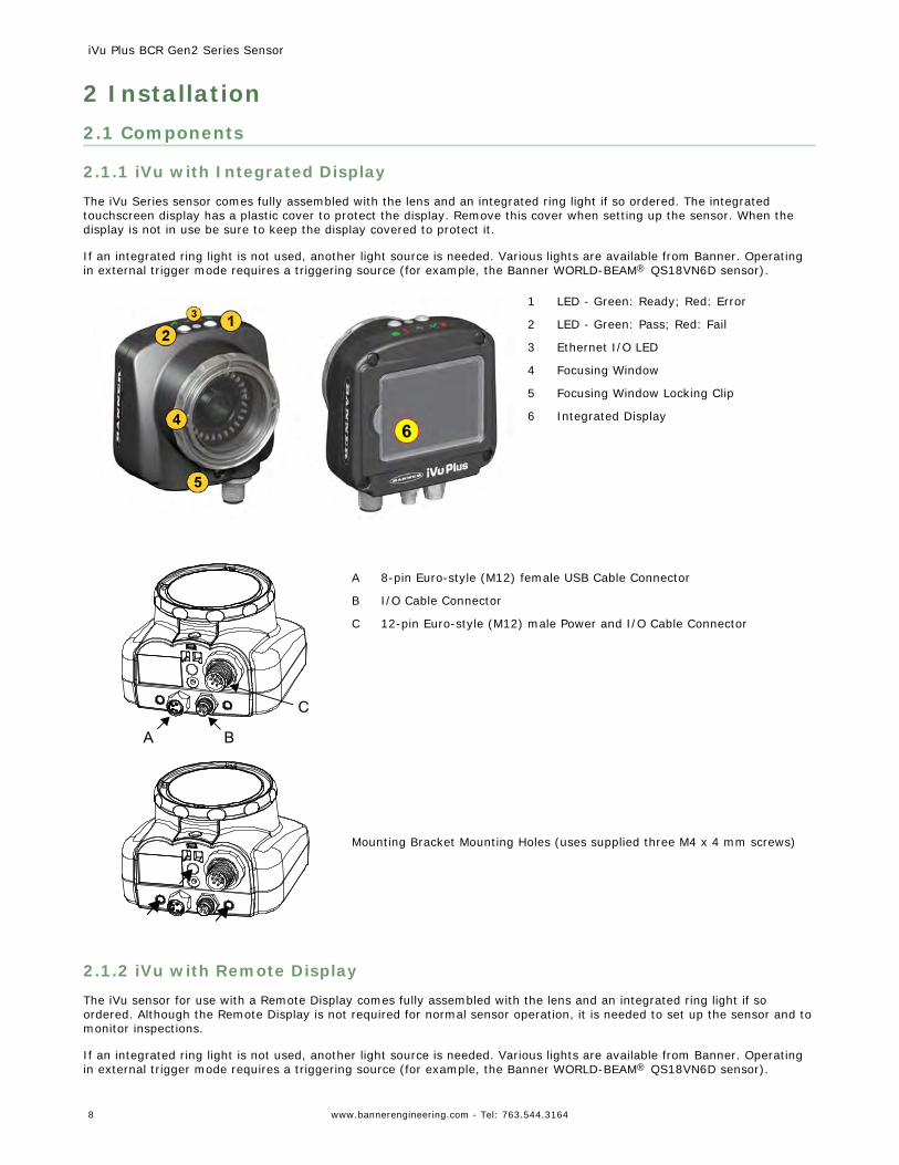
2.1.1 iVu with Integrated Display
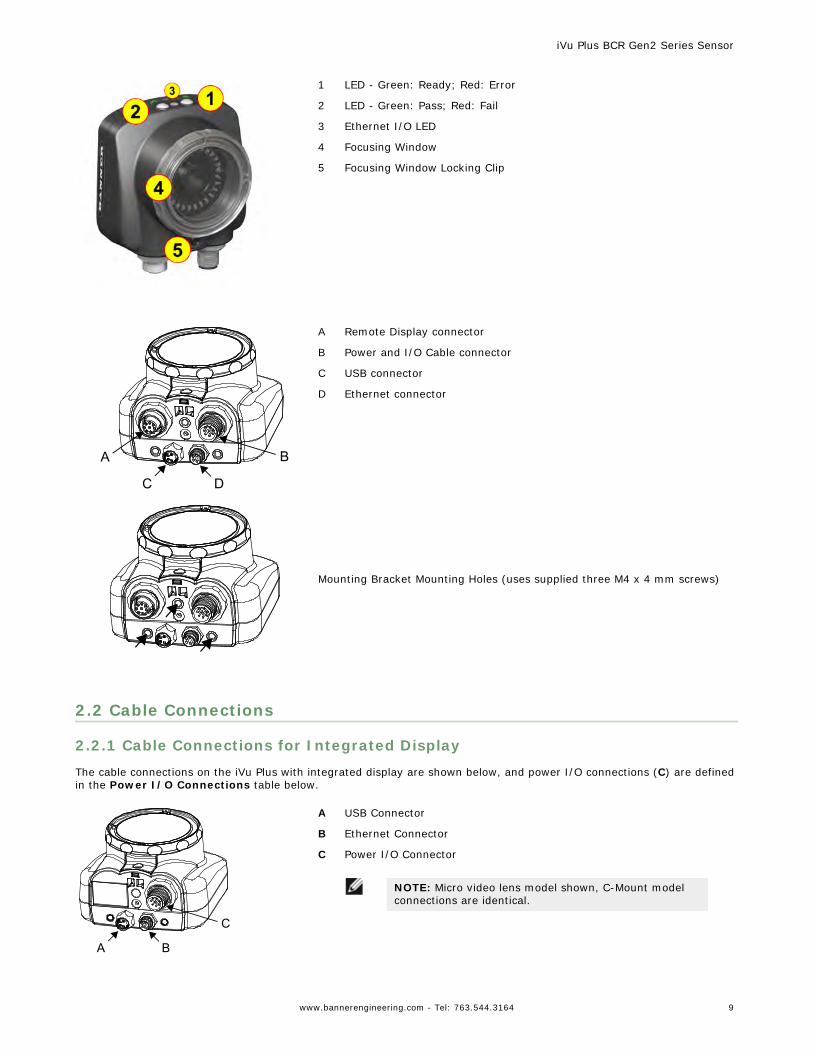
The iVu Series sensor comes fully assembled with the lens and an integrated ring light if so ordered. The integratedtouchscreen display has a plastic cover to protect the display. Remove this cover when setting up the sensor. When thedisplay is not in use be sure to keep the display covered to protect it.
If an integrated ring light is not used, another light source is needed. Various lights are available from Banner. Operatingin external trigger mode requires a triggering source (for example, the Banner WORLD-BEAM® QS18VN6D sensor).
1 LED - Green: Ready; Red: Error
2 LED - Green: Pass; Red: Fail
3 Ethernet I/O LED
4 Focusing Window
5 Focusing Window Locking Clip
6 Integrated Display
C
A B
A 8-pin Euro-style (M12) female USB Cable Connector
B I/O Cable Connector
C 12-pin Euro-style (M12) male Power and I/O Cable Connector
Mounting Bracket Mounting Holes (uses supplied three M4 x 4 mm screws)
2.1.2 iVu with Remote Display
The iVu sensor for use with a Remote Display comes fully assembled with the lens and an integrated ring light if soordered. Although the Remote Display is not required for normal sensor operation, it is needed to set up the sensor and tomonitor inspections.
If an integrated ring light is not used, another light source is needed. Various lights are available from Banner. Operatingin external trigger mode requires a triggering source (for example, the Banner WORLD-BEAM® QS18VN6D sensor).
iVu Plus BCR Gen2 Series Sensor
8 www.bannerengineering.com - Tel: 763.544.3164
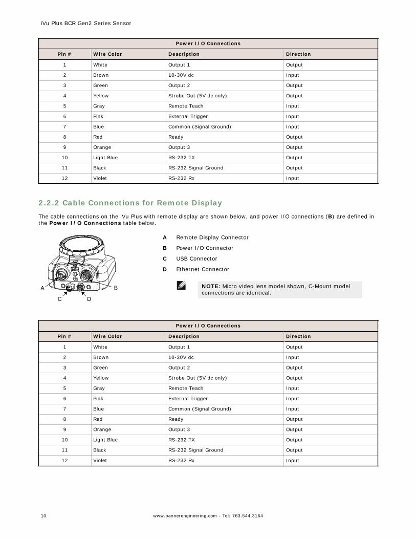
1 LED - Green: Ready; Red: Error
2 LED - Green: Pass; Red: Fail
3 Ethernet I/O LED
4 Focusing Window
5 Focusing Window Locking Clip
A B
C D
A Remote Display connector
B Power and I/O Cable connector
C USB connector
D Ethernet connector
Mounting Bracket Mounting Holes (uses supplied three M4 x 4 mm screws)
2.2 Cable Connections
2.2.1 Cable Connections for Integrated Display
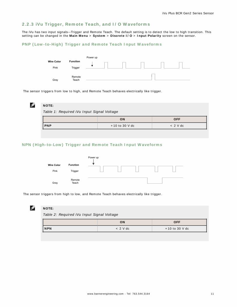
The cable connections on the iVu Plus with integrated display are shown below, and power I/O connections (C) are definedin the Power I/O Connections table below.
C
A B
A USB Connector
B Ethernet Connector
C Power I/O Connector
NOTE: Micro video lens model shown, C-Mount modelconnections are identical.
iVu Plus BCR Gen2 Series Sensor
www.bannerengineering.com - Tel: 763.544.3164 9
Power I/O Connections
Pin # Wire Color Description Direction
1 White Output 1 Output
2 Brown 10-30V dc Input
3 Green Output 2 Output
4 Yellow Strobe Out (5V dc only) Output
5 Gray Remote Teach Input
6 Pink External Trigger Input
7 Blue Common (Signal Ground) Input
8 Red Ready Output
9 Orange Output 3 Output
10 Light Blue RS-232 TX Output
11 Black RS-232 Signal Ground Output
12 Violet RS-232 Rx Input
2.2.2 Cable Connections for Remote Display
The cable connections on the iVu Plus with remote display are shown below, and power I/O connections (B) are defined inthe Power I/O Connections table below.
A B
C D
A Remote Display Connector
B Power I/O Connector
C USB Connector
D Ethernet Connector
NOTE: Micro video lens model shown, C-Mount modelconnections are identical.
Power I/O Connections
Pin # Wire Color Description Direction
1 White Output 1 Output
2 Brown 10-30V dc Input
3 Green Output 2 Output
4 Yellow Strobe Out (5V dc only) Output
5 Gray Remote Teach Input
6 Pink External Trigger Input
7 Blue Common (Signal Ground) Input
8 Red Ready Output
9 Orange Output 3 Output
10 Light Blue RS-232 TX Output
11 Black RS-232 Signal Ground Output
12 Violet RS-232 Rx Input
iVu Plus BCR Gen2 Series Sensor
10 www.bannerengineering.com - Tel: 763.544.3164
2.2.3 iVu Trigger, Remote Teach, and I/O Waveforms
The iVu has two input signals—Trigger and Remote Teach. The default setting is to detect the low to high transition. Thissetting can be changed in the Main Menu > System > Discrete I/O > Input Polarity screen on the sensor.
PNP (Low-to-High) Trigger and Remote Teach Input Waveforms
Power up
Trigger
RemoteTeach
Pink
Wire Color Function
Gray
The sensor triggers from low to high, and Remote Teach behaves electrically like trigger.
NOTE:
Table 1: Required iVu Input Signal Voltage
ON OFF
PNP +10 to 30 V dc < 2 V dc
NPN (High-to-Low) Trigger and Remote Teach Input Waveforms
Trigger
RemoteTeach
Pink
Wire Color Function
Gray
Power up
The sensor triggers from high to low, and Remote Teach behaves electrically like trigger.
NOTE:
Table 2: Required iVu Input Signal Voltage
ON OFF
NPN < 2 V dc +10 to 30 V dc
iVu Plus BCR Gen2 Series Sensor
www.bannerengineering.com - Tel: 763.544.3164 11
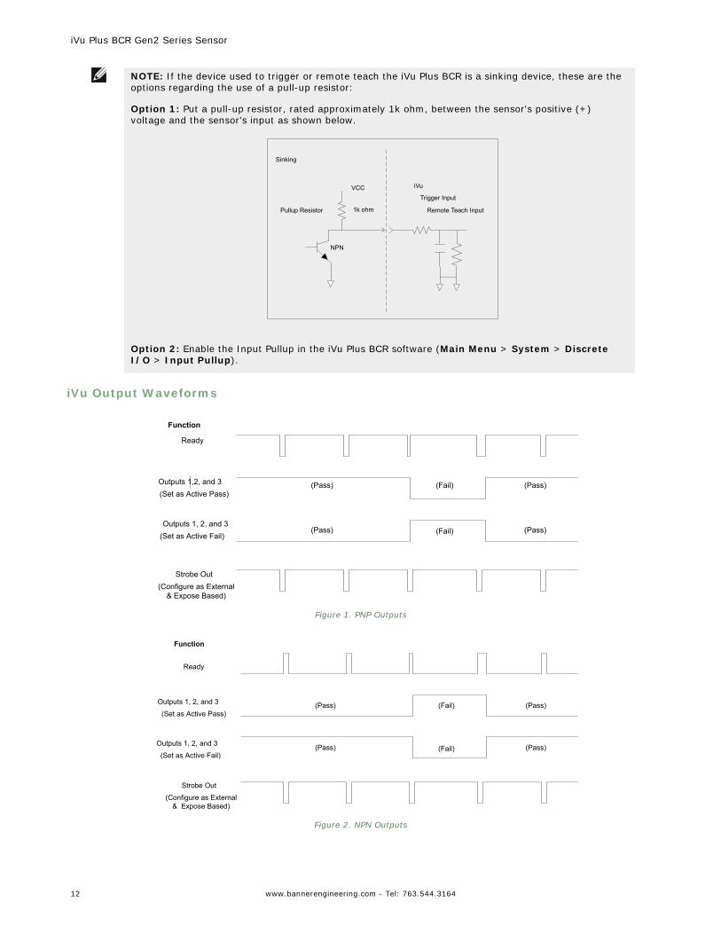
NOTE: If the device used to trigger or remote teach the iVu Plus BCR is a sinking device, these are theoptions regarding the use of a pull-up resistor:
Option 1: Put a pull-up resistor, rated approximately 1k ohm, between the sensor's positive (+)voltage and the sensor's input as shown below.
Trigger Input
Remote Teach Input
iVu
Pullup Resistor 1k ohm
NPN
VCC
Sinking
Option 2: Enable the Input Pullup in the iVu Plus BCR software (Main Menu > System > DiscreteI/O > Input Pullup).
iVu Output Waveforms
Ready
(Pass) (Fail) (Pass)
(Pass) (Fail) (Pass)
Function
Strobe Out(Configure as External
& Expose Based)
Outputs 1,2, and 3(Set as Active Pass)
Outputs 1, 2, and 3(Set as Active Fail)
Figure 1. PNP Outputs
Ready
(Pass) (Fail) (Pass)
(Pass) (Fail) (Pass)
Strobe Out
(Configure as External& Expose Based)
Outputs 1, 2, and 3
(Set as Active Pass)
Outputs 1, 2, and 3
(Set as Active Fail)
Function
Figure 2. NPN Outputs
iVu Plus BCR Gen2 Series Sensor
12 www.bannerengineering.com - Tel: 763.544.3164
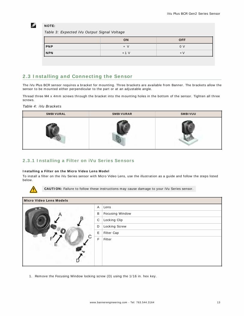
NOTE:
Table 3: Expected iVu Output Signal Voltage
ON OFF
PNP + V 0 V
NPN +1 V +V
2.3 Installing and Connecting the SensorThe iVu Plus BCR sensor requires a bracket for mounting. Three brackets are available from Banner. The brackets allow thesensor to be mounted either perpendicular to the part or at an adjustable angle.
Thread three M4 x 4mm screws through the bracket into the mounting holes in the bottom of the sensor. Tighten all threescrews.
Table 4: iVu Brackets
SMBIVURAL SMBIVURAR SMBIVUU
2.3.1 Installing a Filter on iVu Series Sensors
Installing a Filter on the Micro Video Lens ModelTo install a filter on the iVu Series sensor with Micro Video Lens, use the illustration as a guide and follow the steps listedbelow.
CAUTION: Failure to follow these instructions may cause damage to your iVu Series sensor.
Micro Video Lens Models
A Lens
B Focusing Window
C Locking Clip
D Locking Screw
E Filter Cap
F Filter
1. Remove the Focusing Window locking screw (D) using the 1/16 in. hex key.
iVu Plus BCR Gen2 Series Sensor
www.bannerengineering.com - Tel: 763.544.3164 13
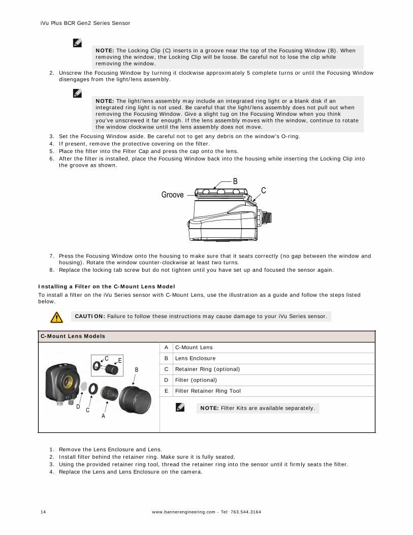
NOTE: The Locking Clip (C) inserts in a groove near the top of the Focusing Window (B). Whenremoving the window, the Locking Clip will be loose. Be careful not to lose the clip whileremoving the window.
2. Unscrew the Focusing Window by turning it clockwise approximately 5 complete turns or until the Focusing Windowdisengages from the light/lens assembly.
NOTE: The light/lens assembly may include an integrated ring light or a blank disk if anintegrated ring light is not used. Be careful that the light/lens assembly does not pull out whenremoving the Focusing Window. Give a slight tug on the Focusing Window when you thinkyou've unscrewed it far enough. If the lens assembly moves with the window, continue to rotatethe window clockwise until the lens assembly does not move.
3. Set the Focusing Window aside. Be careful not to get any debris on the window's O-ring.4. If present, remove the protective covering on the filter.5. Place the filter into the Filter Cap and press the cap onto the lens.6. After the filter is installed, place the Focusing Window back into the housing while inserting the Locking Clip into
the groove as shown.
CB
Groove
7. Press the Focusing Window onto the housing to make sure that it seats correctly (no gap between the window and
housing). Rotate the window counter-clockwise at least two turns.8. Replace the locking tab screw but do not tighten until you have set up and focused the sensor again.
Installing a Filter on the C-Mount Lens ModelTo install a filter on the iVu Series sensor with C-Mount Lens, use the illustration as a guide and follow the steps listedbelow.
CAUTION: Failure to follow these instructions may cause damage to your iVu Series sensor.
C-Mount Lens Models
D CA
BEC
A C-Mount Lens
B Lens Enclosure
C Retainer Ring (optional)
D Filter (optional)
E Filter Retainer Ring Tool
NOTE: Filter Kits are available separately.
1. Remove the Lens Enclosure and Lens.2. Install filter behind the retainer ring. Make sure it is fully seated.3. Using the provided retainer ring tool, thread the retainer ring into the sensor until it firmly seats the filter.4. Replace the Lens and Lens Enclosure on the camera.
iVu Plus BCR Gen2 Series Sensor
14 www.bannerengineering.com - Tel: 763.544.3164

CAUTION: Electrostatic Discharge
Avoid the damage that electrostatic discharge (ESD) can cause to the Sensor.
Always use a proven method for preventing electrostatic discharge when installing a lens or attaching acable.
iVu Plus BCR Gen2 Series Sensor
www.bannerengineering.com - Tel: 763.544.3164 15
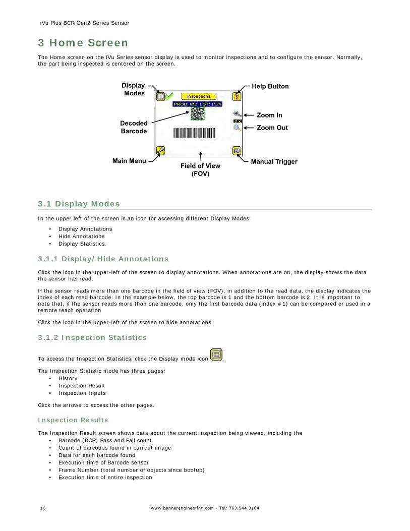
3 Home ScreenThe Home screen on the iVu Series sensor display is used to monitor inspections and to configure the sensor. Normally,the part being inspected is centered on the screen.
Decoded Barcode
Field of View(FOV)
Help Button
Manual TriggerMain Menu
Display Modes
Zoom In
Zoom Out
3.1 Display ModesIn the upper left of the screen is an icon for accessing different Display Modes:
• Display Annotations• Hide Annotations• Display Statistics.
3.1.1 Display/Hide Annotations
Click the icon in the upper-left of the screen to display annotations. When annotations are on, the display shows the datathe sensor has read.
If the sensor reads more than one barcode in the field of view (FOV), in addition to the read data, the display indicates theindex of each read barcode. In the example below, the top barcode is 1 and the bottom barcode is 2. It is important tonote that, if the sensor reads more than one barcode, only the first barcode data (index #1) can be compared or used in aremote teach operation
Click the icon in the upper-left of the screen to hide annotations.
3.1.2 Inspection Statistics
To access the Inspection Statistics, click the Display mode icon .
The Inspection Statistic mode has three pages:• History• Inspection Result• Inspection Inputs
Click the arrows to access the other pages.
Inspection Results
The Inspection Result screen shows data about the current inspection being viewed, including the• Barcode (BCR) Pass and Fail count• Count of barcodes found in current image• Data for each barcode found• Execution time of Barcode sensor• Frame Number (total number of objects since bootup)• Execution time of entire inspection
iVu Plus BCR Gen2 Series Sensor
16 www.bannerengineering.com - Tel: 763.544.3164
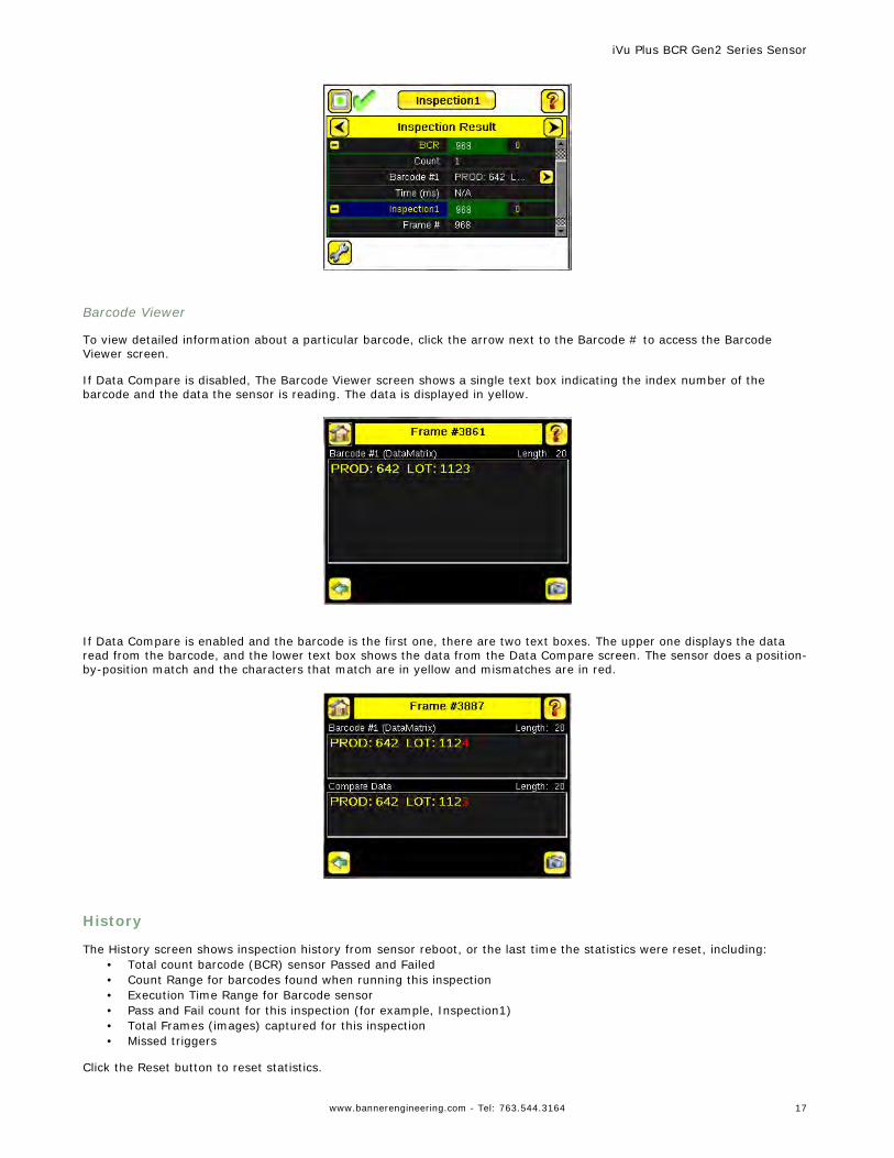
Barcode Viewer
To view detailed information about a particular barcode, click the arrow next to the Barcode # to access the BarcodeViewer screen.
If Data Compare is disabled, The Barcode Viewer screen shows a single text box indicating the index number of thebarcode and the data the sensor is reading. The data is displayed in yellow.
If Data Compare is enabled and the barcode is the first one, there are two text boxes. The upper one displays the dataread from the barcode, and the lower text box shows the data from the Data Compare screen. The sensor does a position-by-position match and the characters that match are in yellow and mismatches are in red.
History
The History screen shows inspection history from sensor reboot, or the last time the statistics were reset, including:• Total count barcode (BCR) sensor Passed and Failed• Count Range for barcodes found when running this inspection• Execution Time Range for Barcode sensor• Pass and Fail count for this inspection (for example, Inspection1)• Total Frames (images) captured for this inspection• Missed triggers
Click the Reset button to reset statistics.
iVu Plus BCR Gen2 Series Sensor
www.bannerengineering.com - Tel: 763.544.3164 17
The table contains history of each sensor in the inspection. Data of each sensor can be expanded or collapsed as requiredusing the +/–. The green area indicates the sensor passed, red indicates fail. If a sensor fails, an icon besides the sensorname will indicate the reason of failure.
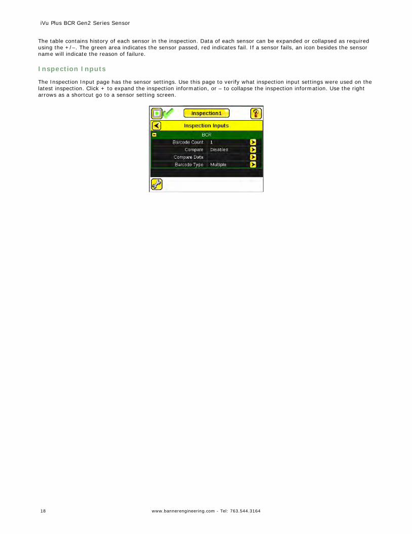
Inspection Inputs
The Inspection Input page has the sensor settings. Use this page to verify what inspection input settings were used on thelatest inspection. Click + to expand the inspection information, or – to collapse the inspection information. Use the rightarrows as a shortcut go to a sensor setting screen.
iVu Plus BCR Gen2 Series Sensor
18 www.bannerengineering.com - Tel: 763.544.3164
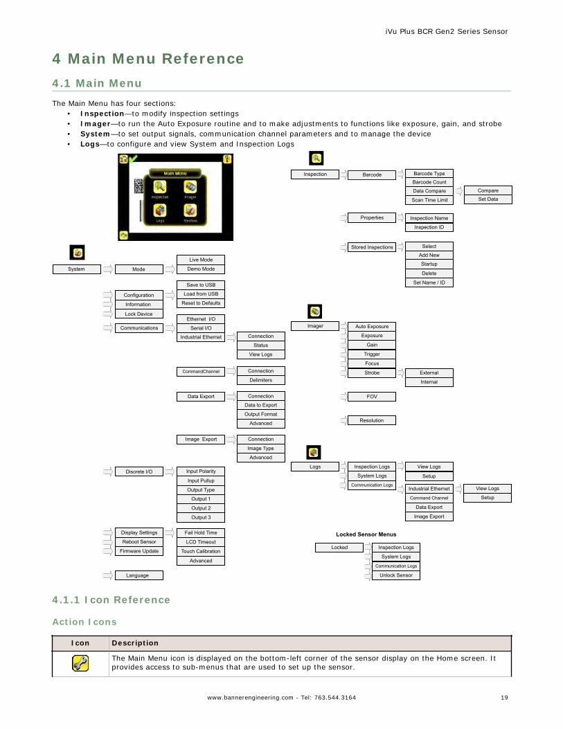
4 Main Menu Reference4.1 Main MenuThe Main Menu has four sections:
• Inspection—to modify inspection settings• Imager—to run the Auto Exposure routine and to make adjustments to functions like exposure, gain, and strobe• System—to set output signals, communication channel parameters and to manage the device• Logs—to configure and view System and Inspection Logs
Imager
Strobe
Auto Exposure
Exposure
Gain
Trigger
Focus
External
Internal
FOV
Resolution
Locked Inspection Logs
System Logs
Communication Logs
Unlock Sensor
Logs Inspection Logs
System Logs
Communication LogsIndustrial Ethernet
Data Export
Image Export
Locked Sensor Menus
View Logs
Setup
Command Channel
View Logs
Setup
Select
Add New
Startup
Delete
Stored Inspections
Inspection
Properties Inspection Name
Barcode Barcode Type
Barcode Count
Data Compare
Scan Time Limit
Compare
Set Data
Inspection ID
Set Name / ID
System
Live Mode
Demo Mode
Information
Mode
Save to USB
Load from USB
Reset to DefaultsConfiguration
Lock DeviceEthernet I/O
Serial I/O
CommandChannel
Communications
Connection
Delimiters
Input Polarity
Input Pullup
Output Type
Output 1
Discrete I/O
Language
Fail Hold Time
LCD Timeout
Touch Calibration
Advanced
Display Settings
Output 2
Output 3
Reboot Sensor
Firmware Update
Data Export
Image Export
Connection
Data to Export
Output Format
Advanced
Connection
Image Type
Industrial Ethernet Connection
Status
View Logs
Advanced
4.1.1 Icon Reference
Action Icons
Icon Description
The Main Menu icon is displayed on the bottom-left corner of the sensor display on the Home screen. Itprovides access to sub-menus that are used to set up the sensor.
iVu Plus BCR Gen2 Series Sensor
www.bannerengineering.com - Tel: 763.544.3164 19
Icon Description
The Inspection menu icon is located on the the Main Menu, and provides access to parameters that needto be set for an inspection.
The Imager menu icon is on the Main Menu, and lists parameters that affect the characteristics of thecaptured image.
The System menu icon is on the Main Menu, and is used to manage the sensor.
The Logs menu icon is on the Main Menu, and is used to set up, view, and save Inspection and SystemLogs.
The Home Screen icon is displayed in the upper-left corner of the sensor display when viewing menus andparameter screens in the Main Menu. It is used to quickly return to the Home Screen.
The Display Annotations icon is one of three icons displayed in the upper-left corner of the sensor whilemonitoring inspections on the Home Screen. Click this icon to highlight features that the sensor finds.
The Hide Annotations icon is one of three icons displayed in the upper-left corner of the sensor whilemonitoring inspections on the Home Screen. Click this icon to disable highlighting.
The Show Statistics icon is one of three icons displayed in the upper-left corner of the sensor whilemonitoring inspections. Click this icon to show inspection results and input parameters.
The Hide System Log Details icon is one of the icons displayed in the upper-left corner of the System Logsscreen. Click this icon to hide the time stamp for the System Logs.
The Show System Log Details icon is one of the icons displayed in the upper-left corner of the SystemLogs screen. Click this icon to show the time stamp for the System Logs.
The Go Back icon is located on the lower-left of the screen while working in the Main Menu. The Go Backicon is used to return to the previous screen or menu.
The Help button is located in the upper-right of the screen and provides context-sensitive help for eachscreen.
The Manual Trigger icon is located on the lower-right of the sensor display on the Home screen and isused to manually capture a new image.
The Save icon is used to save data to USB drive, and is available at the bottom of screens such as theView Logs and System Logs screens.
The Touch Calibration screen displays the Touch Calibration point at various locations on the screen.Every time the icon displays, the user taps the center of the icon to calibrate the screen.
The Zoom Out icon is located on the right of the screen and is used to reduce magnification of the imagebeing displayed.
The Zoom In icon is located on the right of the screen and is used to magnify the image being displayed.
The Decrement icon decreases the currently displayed parameter value by one interval. To quicklydecrement the value, keep pressing the icon.
The Increment icon increases the currently displayed parameter value by one interval. To quicklyincrement the value, keep pressing the icon.
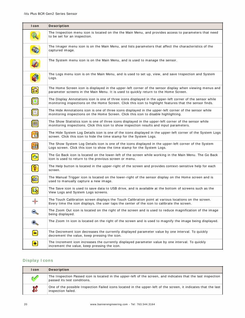
Display Icons
Icon Description
The Inspection Passed icon is located in the upper-left of the screen, and indicates that the last inspectionpassed its test conditions.
One of the possible Inspection Failed icons located in the upper-left of the screen, it indicates that the lastinspection failed.
iVu Plus BCR Gen2 Series Sensor
20 www.bannerengineering.com - Tel: 763.544.3164
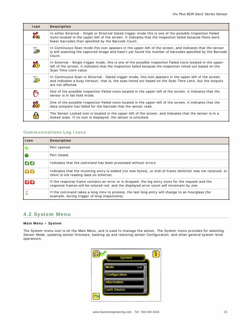
Icon Description
In either External - Single or External Gated trigger mode this is one of the possible Inspection Failedicons located in the upper-left of the screen. It indicates that the inspection failed because there werefewer barcodes than specified by the Barcode Count.
In Continuous Scan mode this icon appears in the upper-left of the screen, and indicates that the sensoris still scanning the captured image and hasn't yet found the number of barcodes specified by the BarcodeCount.
In External - Single trigger mode, this is one of the possible Inspection Failed icons located in the upper-left of the screen, it indicates that the inspection failed because the inspection timed out based on theScan Time Limit value.
In Continuous Scan or External - Gated trigger mode, this icon appears in the upper-left of the screen,and indicates a busy timeout; that is, the scan timed out based on the Scan Time Limit, but the outputsare not affected.
One of the possible Inspection Failed icons located in the upper-left of the screen, it indicates that thesensor is in fail hold mode.
One of the possible Inspection Failed icons located in the upper-left of the screen, it indicates that thedata compare has failed for the barcode that the sensor read.
The Sensor Locked icon is located in the upper-left of the screen, and indicates that the sensor is in alocked state. If no icon is displayed, the sensor is unlocked.
Communications Log Icons
Icon Description
Port opened.
Port closed.
Indicates that the command has been processed without errors.
Indicates that the incoming entry is stalled (no new bytes), or end-of-frame delimiter was not received, orclient is not reading data on ethernet.
If the response frame contains an error or is dropped, the log entry icons for the request and theresponse frames will be colored red, and the displayed error count will increment by one.
If the command takes a long time to process, the last long entry will change to an hourglass (forexample, during trigger of long inspections).
4.2 System MenuMain Menu > System
The System menu icon is on the Main Menu, and is used to manage the sensor. The System menu provides for selectingSensor Mode, updating sensor firmware, backing up and restoring sensor Configuration, and other general system-leveloperations.
iVu Plus BCR Gen2 Series Sensor
www.bannerengineering.com - Tel: 763.544.3164 21
4.2.1 Mode
Main Menu > System > Mode
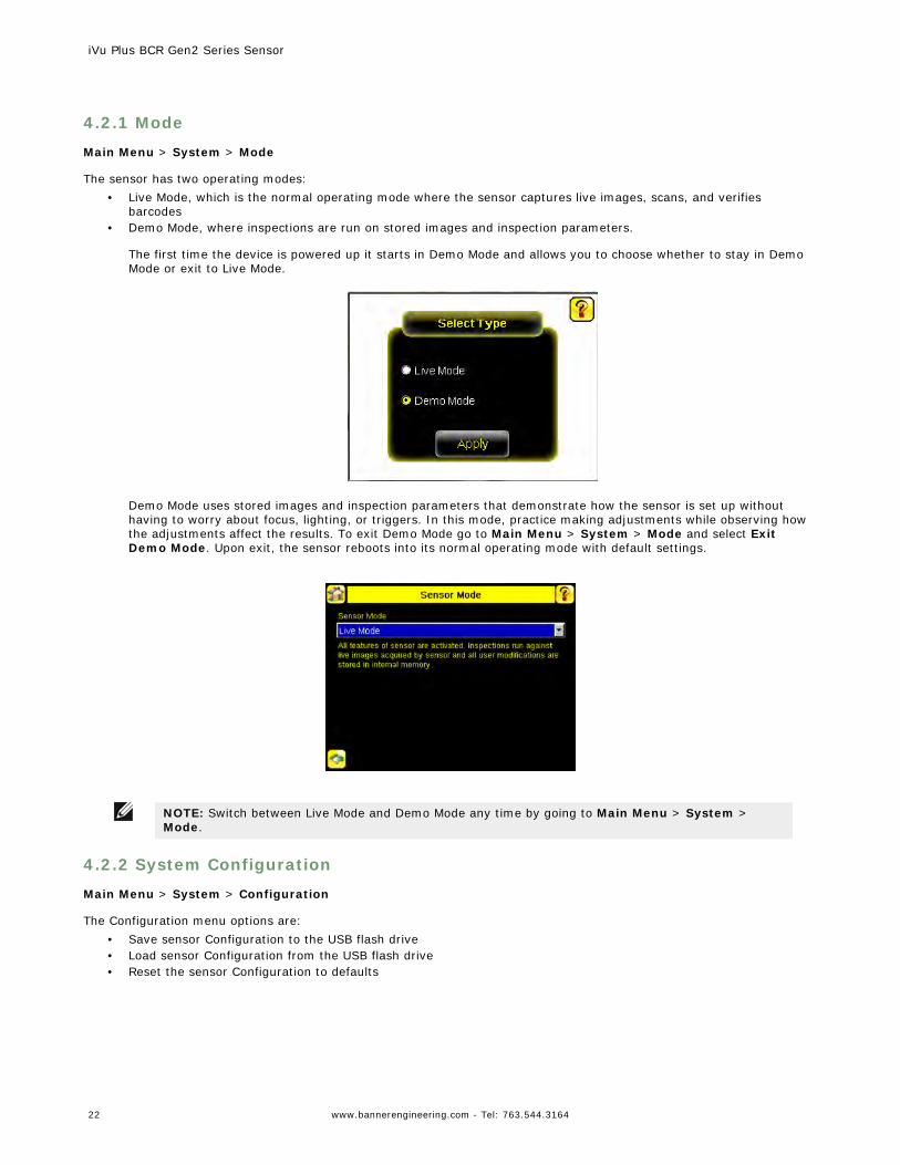
The sensor has two operating modes:• Live Mode, which is the normal operating mode where the sensor captures live images, scans, and verifies
barcodes• Demo Mode, where inspections are run on stored images and inspection parameters.
The first time the device is powered up it starts in Demo Mode and allows you to choose whether to stay in DemoMode or exit to Live Mode.
Demo Mode uses stored images and inspection parameters that demonstrate how the sensor is set up withouthaving to worry about focus, lighting, or triggers. In this mode, practice making adjustments while observing howthe adjustments affect the results. To exit Demo Mode go to Main Menu > System > Mode and select ExitDemo Mode. Upon exit, the sensor reboots into its normal operating mode with default settings.
NOTE: Switch between Live Mode and Demo Mode any time by going to Main Menu > System >Mode.
4.2.2 System Configuration
Main Menu > System > Configuration
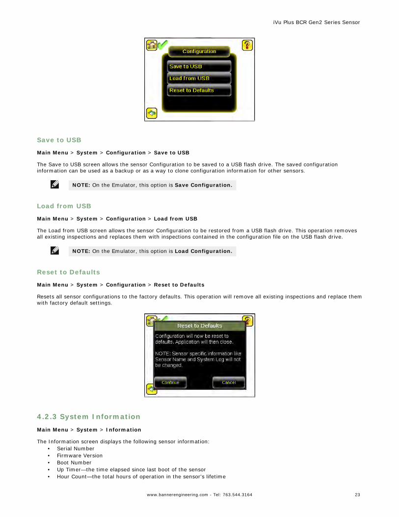
The Configuration menu options are:• Save sensor Configuration to the USB flash drive• Load sensor Configuration from the USB flash drive• Reset the sensor Configuration to defaults
iVu Plus BCR Gen2 Series Sensor
22 www.bannerengineering.com - Tel: 763.544.3164
Save to USB
Main Menu > System > Configuration > Save to USB
The Save to USB screen allows the sensor Configuration to be saved to a USB flash drive. The saved configurationinformation can be used as a backup or as a way to clone configuration information for other sensors.
NOTE: On the Emulator, this option is Save Configuration.
Load from USB
Main Menu > System > Configuration > Load from USB
The Load from USB screen allows the sensor Configuration to be restored from a USB flash drive. This operation removesall existing inspections and replaces them with inspections contained in the configuration file on the USB flash drive.
NOTE: On the Emulator, this option is Load Configuration.
Reset to Defaults
Main Menu > System > Configuration > Reset to Defaults
Resets all sensor configurations to the factory defaults. This operation will remove all existing inspections and replace themwith factory default settings.
4.2.3 System Information
Main Menu > System > Information
The Information screen displays the following sensor information:• Serial Number• Firmware Version• Boot Number• Up Timer—the time elapsed since last boot of the sensor• Hour Count—the total hours of operation in the sensor's lifetime
iVu Plus BCR Gen2 Series Sensor
www.bannerengineering.com - Tel: 763.544.3164 23
• Model Number• Device Name
Click the right-arrow next to the Sensor Name field to display a software keyboard that allows you to change the SensorName.
4.2.4 Lock device
Main Menu > System > Lock device
This option provides for locking the sensor to prevent accidental modification of settings. When locked, the sensor onlyprovides access to pass/fail statistics, as well as the ability to view logs and to save them to a USB device. A lock icon inthe upper left corner of the sensor display indicates that the sensor is locked. Note that the sensor can be locked with orwithout a password. If a password is not used, unlock the sensor by clicking on the Unlock device menu. When a passwordis used, it must be 4 digits entered using the software keypad. If the password is lost, use the Password Reset Utilitysoftware provided on the CD to obtain a Reset Key.
NOTE: This menu option is not available in the Emulator.
4.2.5 Communications
Main Menu > System > Communications
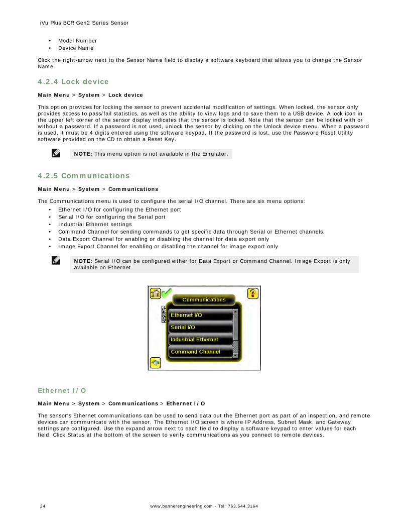
The Communications menu is used to configure the serial I/O channel. There are six menu options:• Ethernet I/O for configuring the Ethernet port• Serial I/O for configuring the Serial port• Industrial Ethernet settings• Command Channel for sending commands to get specific data through Serial or Ethernet channels.• Data Export Channel for enabling or disabling the channel for data export only• Image Export Channel for enabling or disabling the channel for image export only
NOTE: Serial I/O can be configured either for Data Export or Command Channel. Image Export is onlyavailable on Ethernet.
Ethernet I/O
Main Menu > System > Communications > Ethernet I/O
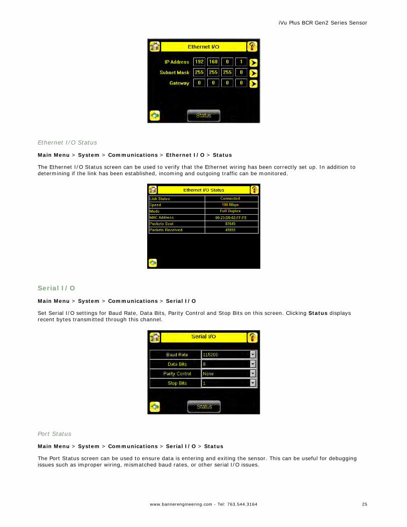
The sensor's Ethernet communications can be used to send data out the Ethernet port as part of an inspection, and remotedevices can communicate with the sensor. The Ethernet I/O screen is where IP Address, Subnet Mask, and Gatewaysettings are configured. Use the expand arrow next to each field to display a software keypad to enter values for eachfield. Click Status at the bottom of the screen to verify communications as you connect to remote devices.
iVu Plus BCR Gen2 Series Sensor
24 www.bannerengineering.com - Tel: 763.544.3164
Ethernet I/O Status
Main Menu > System > Communications > Ethernet I/O > Status
The Ethernet I/O Status screen can be used to verify that the Ethernet wiring has been correctly set up. In addition todetermining if the link has been established, incoming and outgoing traffic can be monitored.
Serial I/O
Main Menu > System > Communications > Serial I/O
Set Serial I/O settings for Baud Rate, Data Bits, Parity Control and Stop Bits on this screen. Clicking Status displaysrecent bytes transmitted through this channel.
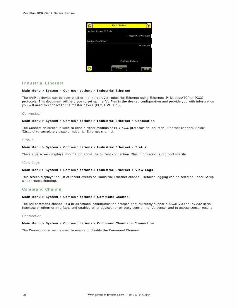
Port Status
Main Menu > System > Communications > Serial I/O > Status
The Port Status screen can be used to ensure data is entering and exiting the sensor. This can be useful for debuggingissues such as improper wiring, mismatched baud rates, or other serial I/O issues.
iVu Plus BCR Gen2 Series Sensor
www.bannerengineering.com - Tel: 763.544.3164 25
Industrial Ethernet
Main Menu > System > Communications > Industrial Ethernet
The iVuPlus device can be controlled or monitored over Industrial Ethernet using Ethernet/IP, Modbus/TCP or PCCCprotocols. This document will help you to set up the iVu Plus in the desired configuration and provide you with informationyou will need to connect to the master device (PLC, HMI, etc.).
Connection
Main Menu > System > Communications > Industrial Ethernet > Connection
The Connection screen is used to enable either Modbus or EIP/PCCC protocols on Industrial Ethernet channel. Select'Disable' to completely disable Industrial Ethernet channel.
Status
Main Menu > System > Communications > Industrial Ethernet > Status
The status screen displays information about the current connection. This information is protocol specific.
View Logs
Main Menu > System > Communications > Industrial Ethernet > View Logs
This screen displays the list of recent events on Industrial Ethernet channel. Detailed logging can be selected under Setupwhen troubleshooting.
Command Channel
Main Menu > System > Communications > Command Channel
The iVu command channel is a bi-directional communication protocol that currently supports ASCII via the RS-232 serialinterface or ethernet interface, and enables other devices to remotely control the iVu sensor and to access sensor results.
Connection
Main Menu > System > Communications > Command Channel > Connection
The Connection screen is used to enable or disable the Command Channel.
iVu Plus BCR Gen2 Series Sensor
26 www.bannerengineering.com - Tel: 763.544.3164
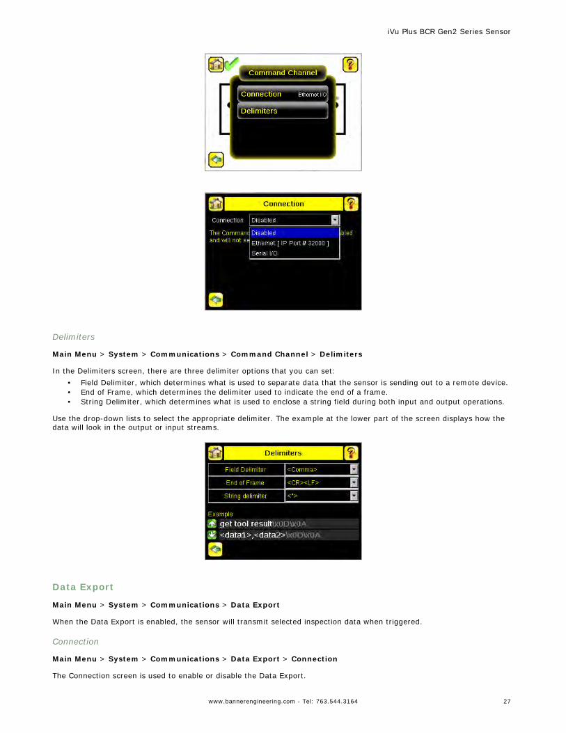
Delimiters
Main Menu > System > Communications > Command Channel > Delimiters
In the Delimiters screen, there are three delimiter options that you can set:• Field Delimiter, which determines what is used to separate data that the sensor is sending out to a remote device.• End of Frame, which determines the delimiter used to indicate the end of a frame.• String Delimiter, which determines what is used to enclose a string field during both input and output operations.
Use the drop-down lists to select the appropriate delimiter. The example at the lower part of the screen displays how thedata will look in the output or input streams.
Data Export
Main Menu > System > Communications > Data Export
When the Data Export is enabled, the sensor will transmit selected inspection data when triggered.
Connection
Main Menu > System > Communications > Data Export > Connection
The Connection screen is used to enable or disable the Data Export.
iVu Plus BCR Gen2 Series Sensor
www.bannerengineering.com - Tel: 763.544.3164 27
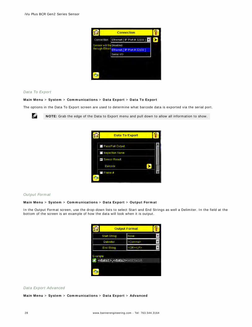
Data To Export
Main Menu > System > Communications > Data Export > Data To Export
The options in the Data To Export screen are used to determine what barcode data is exported via the serial port.
NOTE: Grab the edge of the Data to Export menu and pull down to allow all information to show.
Output Format
Main Menu > System > Communications > Data Export > Output Format
In the Output Format screen, use the drop-down lists to select Start and End Strings as well a Delimiter. In the field at thebottom of the screen is an example of how the data will look when it is output.
Data Export Advanced
Main Menu > System > Communications > Data Export > Advanced
iVu Plus BCR Gen2 Series Sensor
28 www.bannerengineering.com - Tel: 763.544.3164
During the Data and Image export operation, the sensor's output channels might become full. This can occur if the sensoris producing export data (frames) faster than the data can be exported from the device or faster than the client is readingthe channel export data (due to bandwidth limitations).
This setting affects how the sensor will behave in this situation.
Select 'Hold READY' to ensure that all frames are transmitted. In this case, the READY signal will remain inactive (sensor isbusy) until the new frame has been added to the channel for transmission. Triggers might be missed during this time.
Select 'Do not hold READY' to cause the sensor to discard the new frame if the channel is full and thus activate the READYsignal immediately after the current inspection is complete. In this case, the discarded frames will not be transmitted.
NOTE: This setting affects both the Data Export Channel and Image Export Channel.
Image Export
Main Menu > System > Communications > Image Export
When the Image Export Channel is enabled, the sensor will transmit the acquired image on every trigger. The image istransmitted as a bitmap (BMP) file. This operation is only available over Ethernet I/O.
Connection
Main Menu > Communications > Image Export > Connection
The Connection screen is used to enable or disable the Image Export.
Image Type
Main Menu > System > Image Export > Image Type
Choose between JPEG or BMP format for the exporting image file.
Image Export Advanced
Main Menu > System > Communications > Image Export > Advanced
During the Data and Image Export operation, the sensor's output channels might become full. This can occur if the sensoris producing export data (frames) faster than the data can be exported from the device or faster than the client is readingthe channel export data (due to bandwidth limitations).
This setting affects how the sensor will behave in this situation.
Select 'Hold READY' to ensure that all frames are transmitted. In this case, the READY signal will remain inactive (sensor isbusy) until the new frame has been added to the channel for transmission. Triggers might be missed during this time.
Select 'Do not hold READY' to cause the sensor to discard the new frame if the channel is full and thus activate the READYsignal immediately after the current inspection is complete. In this case, the discarded frames will not be transmitted.
NOTE: This setting affects both the Data Export Channel and Image Export Channel.
4.2.6 Discrete I/O
Main Menu > System > Discrete I/O
The Discrete I/O options are used to adjust iVu input and output settings.
iVu Plus BCR Gen2 Series Sensor
www.bannerengineering.com - Tel: 763.544.3164 29
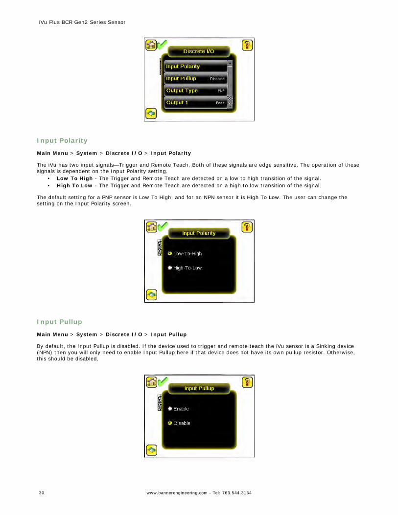
Input Polarity
Main Menu > System > Discrete I/O > Input Polarity
The iVu has two input signals—Trigger and Remote Teach. Both of these signals are edge sensitive. The operation of thesesignals is dependent on the Input Polarity setting.
• Low To High - The Trigger and Remote Teach are detected on a low to high transition of the signal.• High To Low - The Trigger and Remote Teach are detected on a high to low transition of the signal.
The default setting for a PNP sensor is Low To High, and for an NPN sensor it is High To Low. The user can change thesetting on the Input Polarity screen.
Input Pullup
Main Menu > System > Discrete I/O > Input Pullup
By default, the Input Pullup is disabled. If the device used to trigger and remote teach the iVu sensor is a Sinking device(NPN) then you will only need to enable Input Pullup here if that device does not have its own pullup resistor. Otherwise,this should be disabled.
iVu Plus BCR Gen2 Series Sensor
30 www.bannerengineering.com - Tel: 763.544.3164
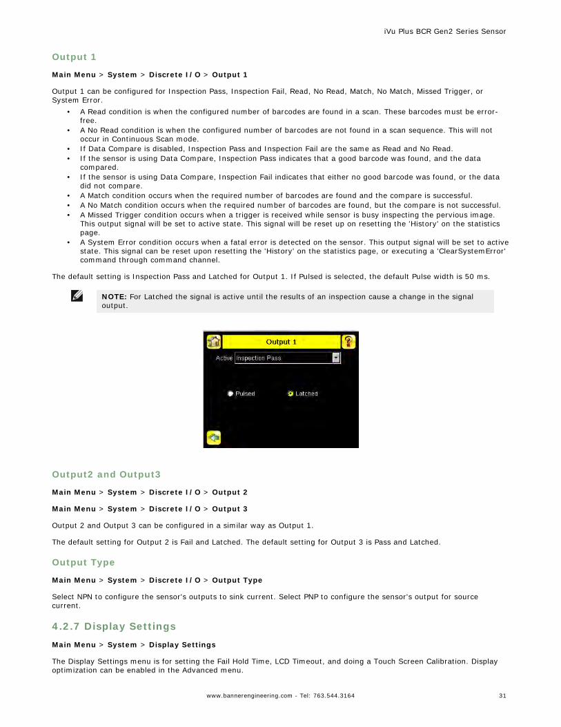
Output 1
Main Menu > System > Discrete I/O > Output 1
Output 1 can be configured for Inspection Pass, Inspection Fail, Read, No Read, Match, No Match, Missed Trigger, orSystem Error.
• A Read condition is when the configured number of barcodes are found in a scan. These barcodes must be error-free.
• A No Read condition is when the configured number of barcodes are not found in a scan sequence. This will notoccur in Continuous Scan mode.
• If Data Compare is disabled, Inspection Pass and Inspection Fail are the same as Read and No Read.• If the sensor is using Data Compare, Inspection Pass indicates that a good barcode was found, and the data
compared.• If the sensor is using Data Compare, Inspection Fail indicates that either no good barcode was found, or the data
did not compare.• A Match condition occurs when the required number of barcodes are found and the compare is successful.• A No Match condition occurs when the required number of barcodes are found, but the compare is not successful.• A Missed Trigger condition occurs when a trigger is received while sensor is busy inspecting the pervious image.
This output signal will be set to active state. This signal will be reset up on resetting the 'History' on the statisticspage.
• A System Error condition occurs when a fatal error is detected on the sensor. This output signal will be set to activestate. This signal can be reset upon resetting the 'History' on the statistics page, or executing a 'ClearSystemError'command through command channel.
The default setting is Inspection Pass and Latched for Output 1. If Pulsed is selected, the default Pulse width is 50 ms.
NOTE: For Latched the signal is active until the results of an inspection cause a change in the signaloutput.
Output2 and Output3
Main Menu > System > Discrete I/O > Output 2
Main Menu > System > Discrete I/O > Output 3
Output 2 and Output 3 can be configured in a similar way as Output 1.
The default setting for Output 2 is Fail and Latched. The default setting for Output 3 is Pass and Latched.
Output Type
Main Menu > System > Discrete I/O > Output Type
Select NPN to configure the sensor's outputs to sink current. Select PNP to configure the sensor's output for sourcecurrent.
4.2.7 Display Settings
Main Menu > System > Display Settings
The Display Settings menu is for setting the Fail Hold Time, LCD Timeout, and doing a Touch Screen Calibration. Displayoptimization can be enabled in the Advanced menu.
iVu Plus BCR Gen2 Series Sensor
www.bannerengineering.com - Tel: 763.544.3164 31
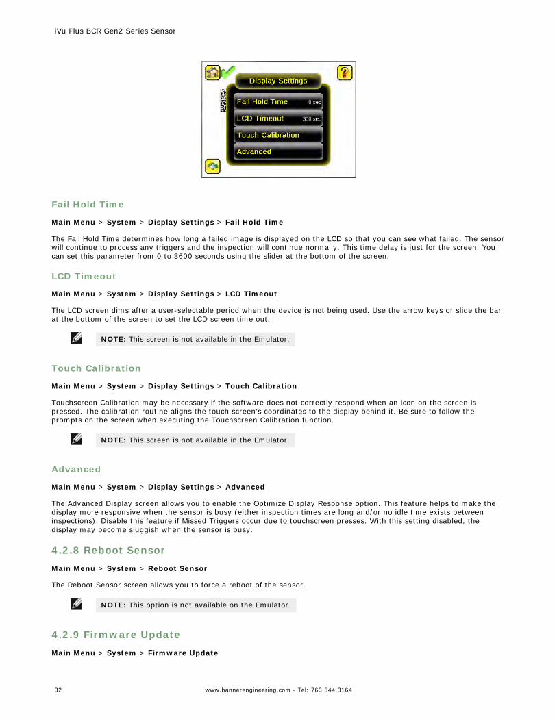
Fail Hold Time
Main Menu > System > Display Settings > Fail Hold Time
The Fail Hold Time determines how long a failed image is displayed on the LCD so that you can see what failed. The sensorwill continue to process any triggers and the inspection will continue normally. This time delay is just for the screen. Youcan set this parameter from 0 to 3600 seconds using the slider at the bottom of the screen.
LCD Timeout
Main Menu > System > Display Settings > LCD Timeout
The LCD screen dims after a user-selectable period when the device is not being used. Use the arrow keys or slide the barat the bottom of the screen to set the LCD screen time out.
NOTE: This screen is not available in the Emulator.
Touch Calibration
Main Menu > System > Display Settings > Touch Calibration
Touchscreen Calibration may be necessary if the software does not correctly respond when an icon on the screen ispressed. The calibration routine aligns the touch screen's coordinates to the display behind it. Be sure to follow theprompts on the screen when executing the Touchscreen Calibration function.
NOTE: This screen is not available in the Emulator.
Advanced
Main Menu > System > Display Settings > Advanced
The Advanced Display screen allows you to enable the Optimize Display Response option. This feature helps to make thedisplay more responsive when the sensor is busy (either inspection times are long and/or no idle time exists betweeninspections). Disable this feature if Missed Triggers occur due to touchscreen presses. With this setting disabled, thedisplay may become sluggish when the sensor is busy.
4.2.8 Reboot Sensor
Main Menu > System > Reboot Sensor
The Reboot Sensor screen allows you to force a reboot of the sensor.
NOTE: This option is not available on the Emulator.
4.2.9 Firmware Update
Main Menu > System > Firmware Update
iVu Plus BCR Gen2 Series Sensor
32 www.bannerengineering.com - Tel: 763.544.3164
The Firmware Update screen is used to load the latest sensor firmware. The Firmware Update screen lists the firmwareversions it finds in the BANNER\FIRMWARE folder on the USB flash drive. When you receive a firmware update fromBanner Engineering, be sure to put it in the BANNER\FIRMWARE folder on the USB flash drive.
NOTE: The Firmware Update menu is not available in the Emulator.
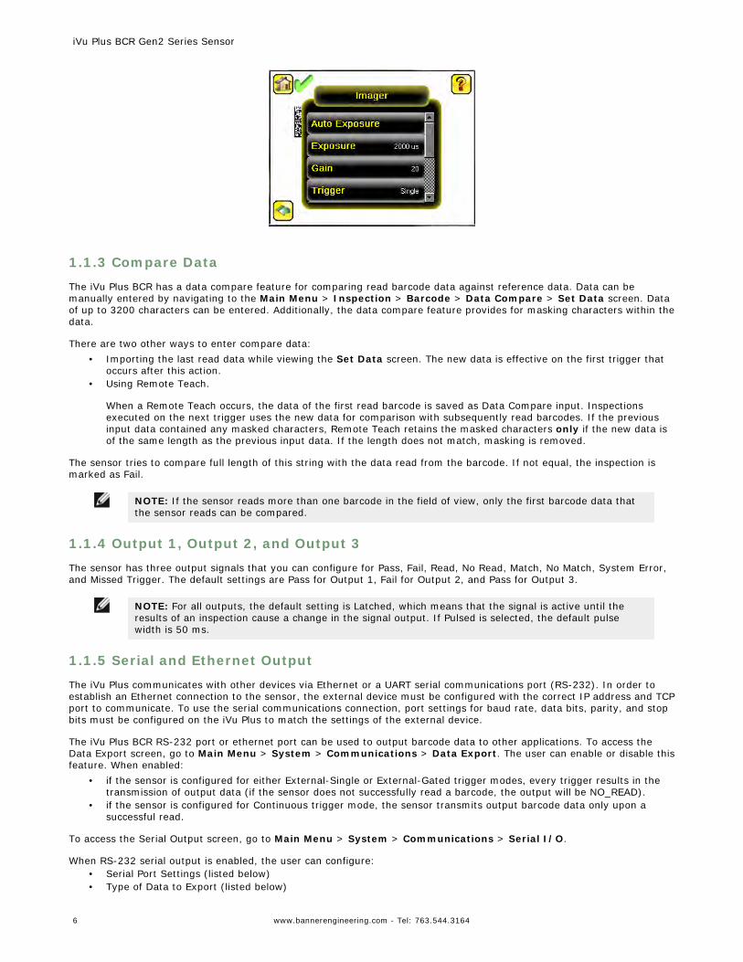
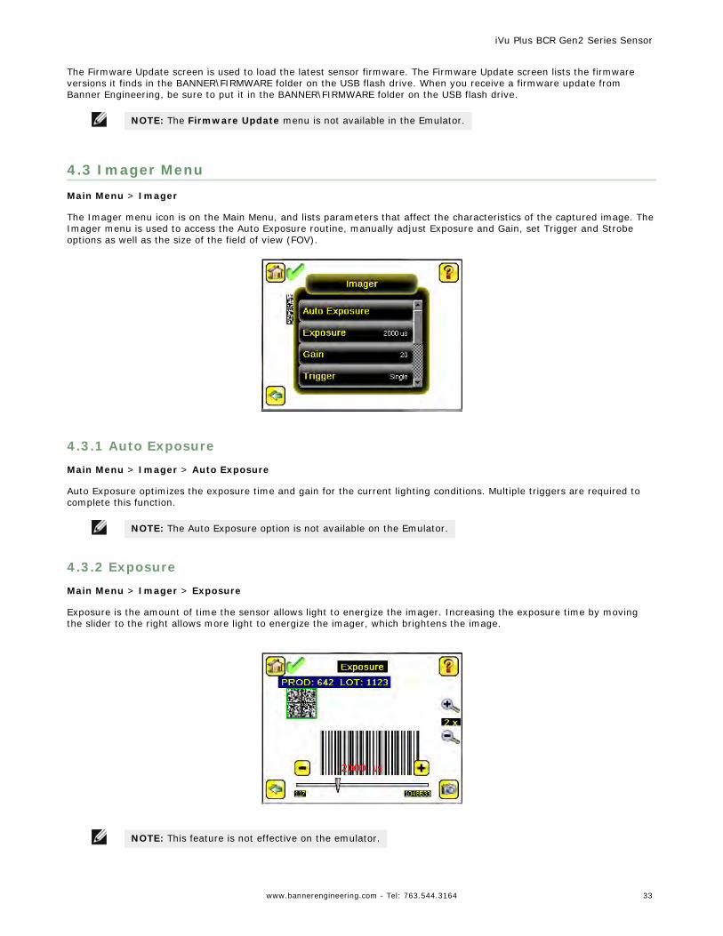
4.3 Imager MenuMain Menu > Imager
The Imager menu icon is on the Main Menu, and lists parameters that affect the characteristics of the captured image. TheImager menu is used to access the Auto Exposure routine, manually adjust Exposure and Gain, set Trigger and Strobeoptions as well as the size of the field of view (FOV).
4.3.1 Auto Exposure
Main Menu > Imager > Auto Exposure
Auto Exposure optimizes the exposure time and gain for the current lighting conditions. Multiple triggers are required tocomplete this function.
NOTE: The Auto Exposure option is not available on the Emulator.
4.3.2 Exposure
Main Menu > Imager > Exposure
Exposure is the amount of time the sensor allows light to energize the imager. Increasing the exposure time by movingthe slider to the right allows more light to energize the imager, which brightens the image.
NOTE: This feature is not effective on the emulator.
iVu Plus BCR Gen2 Series Sensor
www.bannerengineering.com - Tel: 763.544.3164 33
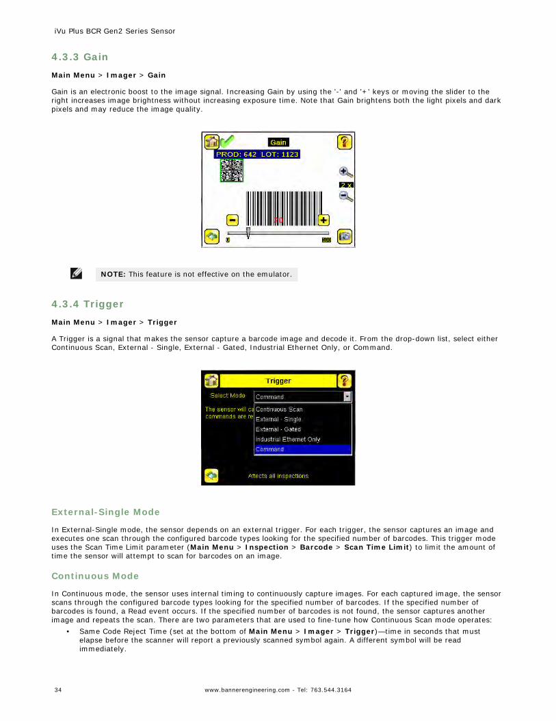
4.3.3 Gain
Main Menu > Imager > Gain
Gain is an electronic boost to the image signal. Increasing Gain by using the '-' and '+' keys or moving the slider to theright increases image brightness without increasing exposure time. Note that Gain brightens both the light pixels and darkpixels and may reduce the image quality.
NOTE: This feature is not effective on the emulator.
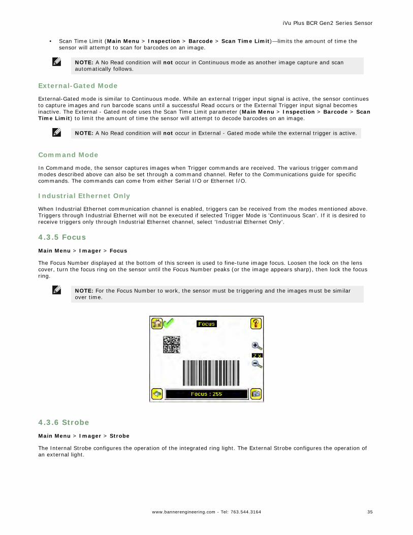
4.3.4 Trigger
Main Menu > Imager > Trigger
A Trigger is a signal that makes the sensor capture a barcode image and decode it. From the drop-down list, select eitherContinuous Scan, External - Single, External - Gated, Industrial Ethernet Only, or Command.
External-Single Mode
In External-Single mode, the sensor depends on an external trigger. For each trigger, the sensor captures an image andexecutes one scan through the configured barcode types looking for the specified number of barcodes. This trigger modeuses the Scan Time Limit parameter (Main Menu > Inspection > Barcode > Scan Time Limit) to limit the amount oftime the sensor will attempt to scan for barcodes on an image.
Continuous Mode
In Continuous mode, the sensor uses internal timing to continuously capture images. For each captured image, the sensorscans through the configured barcode types looking for the specified number of barcodes. If the specified number ofbarcodes is found, a Read event occurs. If the specified number of barcodes is not found, the sensor captures anotherimage and repeats the scan. There are two parameters that are used to fine-tune how Continuous Scan mode operates:
• Same Code Reject Time (set at the bottom of Main Menu > Imager > Trigger)—time in seconds that mustelapse before the scanner will report a previously scanned symbol again. A different symbol will be readimmediately.
iVu Plus BCR Gen2 Series Sensor
34 www.bannerengineering.com - Tel: 763.544.3164
• Scan Time Limit (Main Menu > Inspection > Barcode > Scan Time Limit)—limits the amount of time thesensor will attempt to scan for barcodes on an image.
NOTE: A No Read condition will not occur in Continuous mode as another image capture and scanautomatically follows.
External-Gated Mode
External-Gated mode is similar to Continuous mode. While an external trigger input signal is active, the sensor continuesto capture images and run barcode scans until a successful Read occurs or the External Trigger input signal becomesinactive. The External - Gated mode uses the Scan Time Limit parameter (Main Menu > Inspection > Barcode > ScanTime Limit) to limit the amount of time the sensor will attempt to decode barcodes on an image.
NOTE: A No Read condition will not occur in External - Gated mode while the external trigger is active.
Command Mode
In Command mode, the sensor captures images when Trigger commands are received. The various trigger commandmodes described above can also be set through a command channel. Refer to the Communications guide for specificcommands. The commands can come from either Serial I/O or Ethernet I/O.
Industrial Ethernet Only
When Industrial Ethernet communication channel is enabled, triggers can be received from the modes mentioned above.Triggers through Industrial Ethernet will not be executed if selected Trigger Mode is 'Continuous Scan'. If it is desired toreceive triggers only through Industrial Ethernet channel, select 'Industrial Ethernet Only'.
4.3.5 Focus
Main Menu > Imager > Focus
The Focus Number displayed at the bottom of this screen is used to fine-tune image focus. Loosen the lock on the lenscover, turn the focus ring on the sensor until the Focus Number peaks (or the image appears sharp), then lock the focusring.
NOTE: For the Focus Number to work, the sensor must be triggering and the images must be similarover time.
4.3.6 Strobe
Main Menu > Imager > Strobe
The Internal Strobe configures the operation of the integrated ring light. The External Strobe configures the operation ofan external light.
iVu Plus BCR Gen2 Series Sensor
www.bannerengineering.com - Tel: 763.544.3164 35
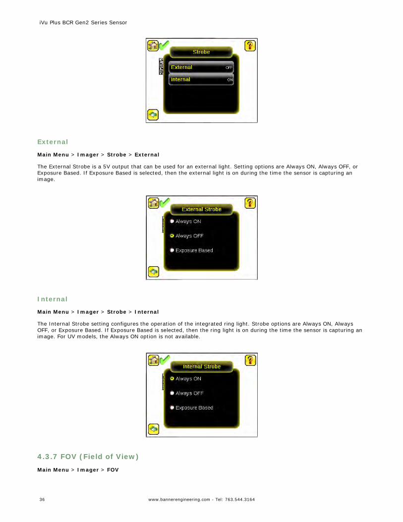
External
Main Menu > Imager > Strobe > External
The External Strobe is a 5V output that can be used for an external light. Setting options are Always ON, Always OFF, orExposure Based. If Exposure Based is selected, then the external light is on during the time the sensor is capturing animage.
Internal
Main Menu > Imager > Strobe > Internal
The Internal Strobe setting configures the operation of the integrated ring light. Strobe options are Always ON, AlwaysOFF, or Exposure Based. If Exposure Based is selected, then the ring light is on during the time the sensor is capturing animage. For UV models, the Always ON option is not available.
4.3.7 FOV (Field of View)
Main Menu > Imager > FOV
iVu Plus BCR Gen2 Series Sensor
36 www.bannerengineering.com - Tel: 763.544.3164
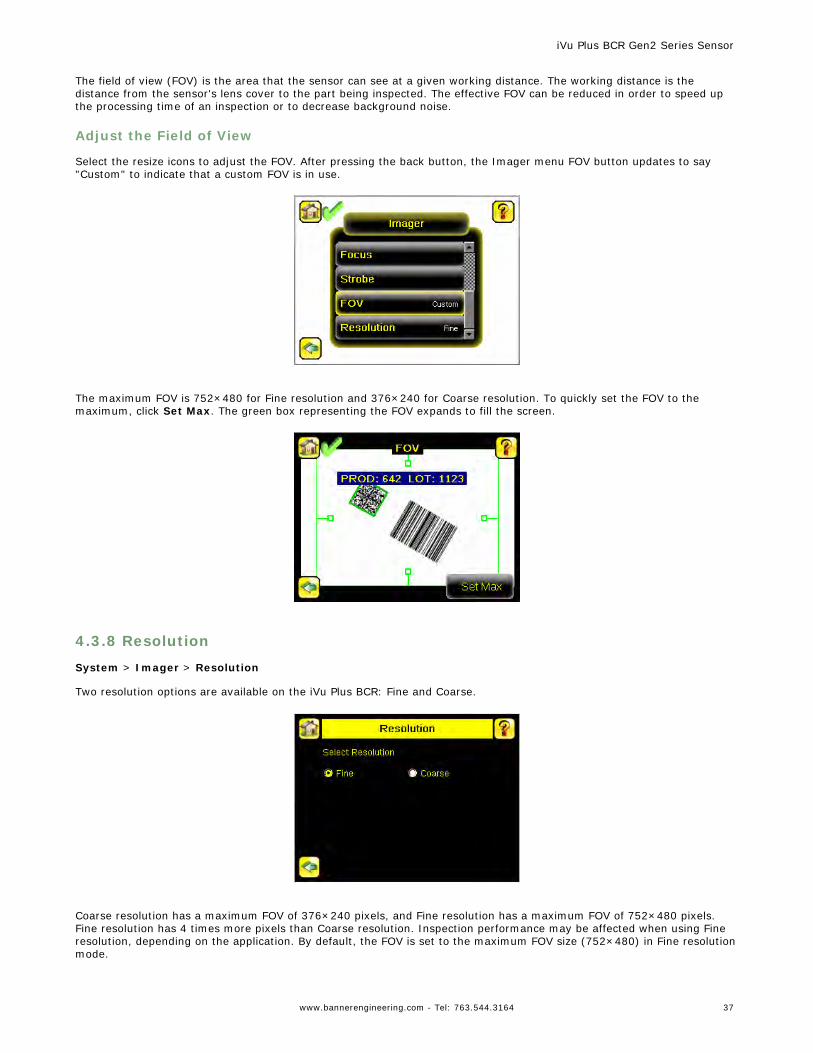
The field of view (FOV) is the area that the sensor can see at a given working distance. The working distance is thedistance from the sensor's lens cover to the part being inspected. The effective FOV can be reduced in order to speed upthe processing time of an inspection or to decrease background noise.
Adjust the Field of View
Select the resize icons to adjust the FOV. After pressing the back button, the Imager menu FOV button updates to say"Custom" to indicate that a custom FOV is in use.
The maximum FOV is 752×480 for Fine resolution and 376×240 for Coarse resolution. To quickly set the FOV to themaximum, click Set Max. The green box representing the FOV expands to fill the screen.
4.3.8 Resolution
System > Imager > Resolution
Two resolution options are available on the iVu Plus BCR: Fine and Coarse.
Coarse resolution has a maximum FOV of 376×240 pixels, and Fine resolution has a maximum FOV of 752×480 pixels.Fine resolution has 4 times more pixels than Coarse resolution. Inspection performance may be affected when using Fineresolution, depending on the application. By default, the FOV is set to the maximum FOV size (752×480) in Fine resolutionmode.
iVu Plus BCR Gen2 Series Sensor
www.bannerengineering.com - Tel: 763.544.3164 37
4.4 Inspection MenuMain Menu > Inspection
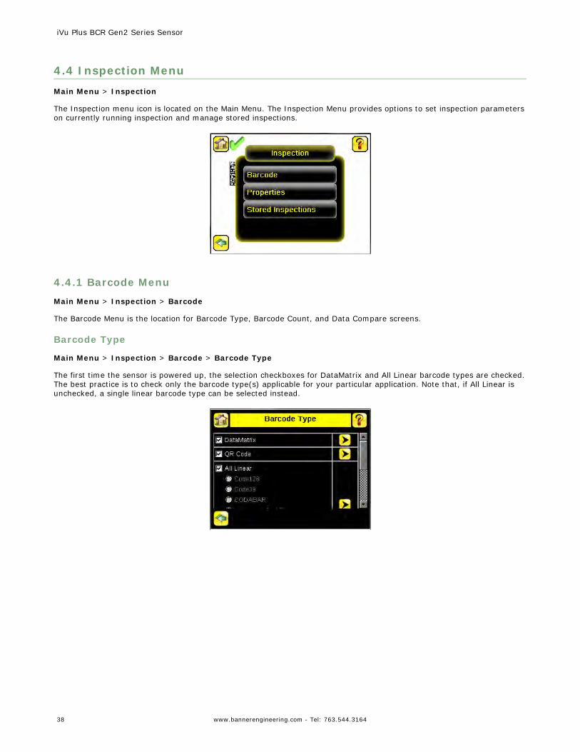
The Inspection menu icon is located on the Main Menu. The Inspection Menu provides options to set inspection parameterson currently running inspection and manage stored inspections.
4.4.1 Barcode Menu
Main Menu > Inspection > Barcode
The Barcode Menu is the location for Barcode Type, Barcode Count, and Data Compare screens.
Barcode Type
Main Menu > Inspection > Barcode > Barcode Type
The first time the sensor is powered up, the selection checkboxes for DataMatrix and All Linear barcode types are checked.The best practice is to check only the barcode type(s) applicable for your particular application. Note that, if All Linear isunchecked, a single linear barcode type can be selected instead.
iVu Plus BCR Gen2 Series Sensor
38 www.bannerengineering.com - Tel: 763.544.3164
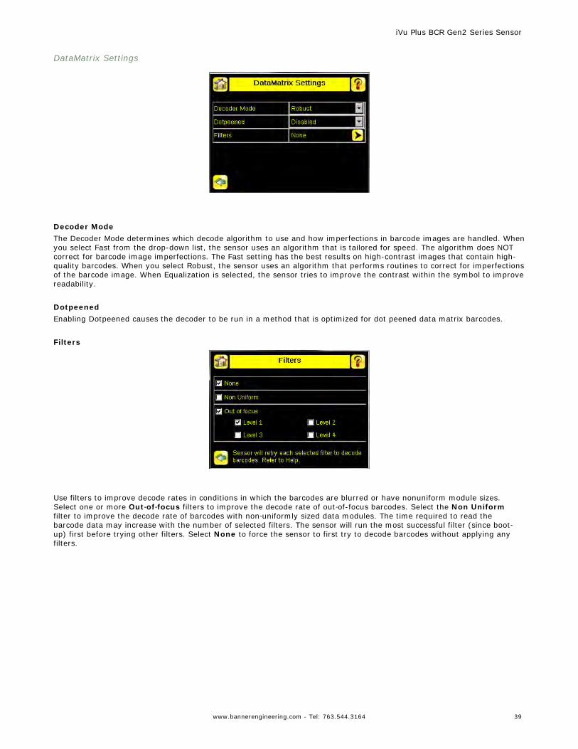
DataMatrix Settings
Decoder ModeThe Decoder Mode determines which decode algorithm to use and how imperfections in barcode images are handled. Whenyou select Fast from the drop-down list, the sensor uses an algorithm that is tailored for speed. The algorithm does NOTcorrect for barcode image imperfections. The Fast setting has the best results on high-contrast images that contain high-quality barcodes. When you select Robust, the sensor uses an algorithm that performs routines to correct for imperfectionsof the barcode image. When Equalization is selected, the sensor tries to improve the contrast within the symbol to improvereadability.
DotpeenedEnabling Dotpeened causes the decoder to be run in a method that is optimized for dot peened data matrix barcodes.
Filters
Use filters to improve decode rates in conditions in which the barcodes are blurred or have nonuniform module sizes.Select one or more Out‐of‐focus filters to improve the decode rate of out‐of-focus barcodes. Select the Non Uniformfilter to improve the decode rate of barcodes with non‐uniformly sized data modules. The time required to read thebarcode data may increase with the number of selected filters. The sensor will run the most successful filter (since boot‐up) first before trying other filters. Select None to force the sensor to first try to decode barcodes without applying anyfilters.
iVu Plus BCR Gen2 Series Sensor
www.bannerengineering.com - Tel: 763.544.3164 39

QR Code Settings
QR Code TypeThe QR Code Type determines whether the device should decode a QR Code, Micro QR code, or both.
UnicodeThe device is capable of decoding Kanji characters embedded in a QR Code. In order for the device to display the decodeddata correctly, and be able to export the decoded data in Unicode format (2 byte), this setting should be enabled. Decodeddata sent out on Communication Channels will also be in unicode format. The Compare Data will also be stored in unicodeformat. Enabling this feature affects data decoded from all barcodes in the inspection, irrespective to their symbology.
All Linear Settings
The All Linear settings described below apply to the following barcode types:• Code 128• Code 39• CODABAR• Interleaved 2 of 5• EAN13• EAN8• UPCE• Postnet• IMB
Checksum VerifyWhen checksum is enabled, the sensor uses a checksum to verify the integrity of the barcode being read.
Relaxed QuietzoneThe Quietzone is a blank margin on either side of a barcode that indicates where the barcode begins and ends. If thisQuietzone isn't big enough, the sensor can have trouble decoding the barcode. By enabling Relaxed Quietzone there is agreater tolerance with respect to the quiet zone required before and after the barcode.
iVu Plus BCR Gen2 Series Sensor
40 www.bannerengineering.com - Tel: 763.544.3164
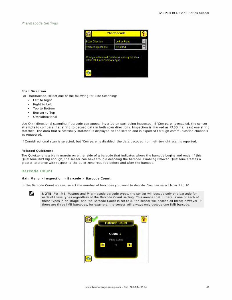
Pharmacode Settings
Scan DirectionFor Pharmacode, select one of the following for Line Scanning:
• Left to Right• Right to Left• Top to Bottom• Bottom to Top• Omnidirectional
Use Omnidirectional scanning if barcode can appear inverted on part being inspected. If 'Compare' is enabled, the sensorattempts to compare that string to decoed data in both scan directions. Inspection is marked as PASS if at least one stringmatches. The data that successfully matched is displayed on the screen and is exported through communication channelsas requested.
If Omnidirectional scan is selected, but 'Compare' is disabled, the data decoded from left-to-right scan is reported.
Relaxed QuietzoneThe Quietzone is a blank margin on either side of a barcode that indicates where the barcode begins and ends. If thisQuietzone isn't big enough, the sensor can have trouble decoding the barcode. Enabling Relaxed Quietzone creates agreater tolerance with respect to the quiet zone required before and after the barcode.
Barcode Count
Main Menu > Inspection > Barcode > Barcode Count
In the Barcode Count screen, select the number of barcodes you want to decode. You can select from 1 to 10.
NOTE: For IMB, Postnet and Pharmacode barcode types, the sensor will decode only one barcode foreach of these types regardless of the Barcode Count setting. This means that if there is one of each ofthese types in an image, and the Barcode Count is set to 3, the sensor will decode all three; however, ifthere are three IMB barcodes, for example, the sensor will always only decode one IMB barcode.
iVu Plus BCR Gen2 Series Sensor
www.bannerengineering.com - Tel: 763.544.3164 41
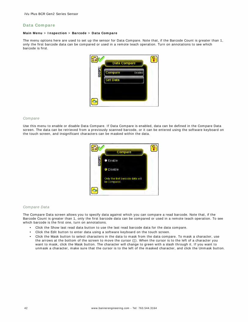
Data Compare
Main Menu > Inspection > Barcode > Data Compare
The menu options here are used to set up the sensor for Data Compare. Note that, if the Barcode Count is greater than 1,only the first barcode data can be compared or used in a remote teach operation. Turn on annotations to see whichbarcode is first.
Compare
Use this menu to enable or disable Data Compare. If Data Compare is enabled, data can be defined in the Compare Datascreen. The data can be retrieved from a previously scanned barcode, or it can be entered using the software keyboard onthe touch screen, and insignificant characters can be masked within the data.
Compare Data
The Compare Data screen allows you to specify data against which you can compare a read barcode. Note that, if theBarcode Count is greater than 1, only the first barcode data can be compared or used in a remote teach operation. To seewhich barcode is the first one, turn on annotations.
• Click the Show last read data button to use the last read barcode data for the data compare.• Click the Edit button to enter data using a software keyboard on the touch screen.• Click the Mask button to select characters in the data to mask from the data compare. To mask a character, use
the arrows at the bottom of the screen to move the cursor ([). When the cursor is to the left of a character youwant to mask, click the Mask button. The character will change to green with a slash through it. If you want tounmask a character, make sure that the cursor is to the left of the masked character, and click the Unmask button.
iVu Plus BCR Gen2 Series Sensor
42 www.bannerengineering.com - Tel: 763.544.3164
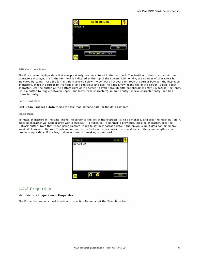
Edit Compare Data
The Edit screen displays data that was previously read or entered in the text field. The Position of the cursor within thecharacters displayed ([) in the text field is indicated at the top of the screen. Additionally, the number of characters isindicated by Length. Use the left and right arrows below the software keyboard to move the cursor between the displayedcharacters. Place the cursor to the right of any character and use the back-arrow at the top of the screen to delete thatcharacter. Use the button at the bottom right of the screen to cycle through different character entry keyboards: text entry(with a button to toggle between upper- and lower-case characters), numeric entry, special character entry, and hexcharacter entry.
Last Read Data
Click Show last read data to use the last read barcode data for the data compare.
Mask Data
To mask characters in the data, move the cursor to the left of the character(s) to be masked, and click the Mask button. Amasked character will appear gray with a strikeout (\) indicator. To unmask a previously masked character, click theUnMask button. Note that, when using Remote Teach to set new barcode data, if the previous input data contained anymasked characters, Remote Teach will retain the masked characters only if the new data is of the same length as theprevious input data. If the length does not match, masking is removed.
4.4.2 Properties
Main Menu > Inspection > Properties
The Properties menu is used to edit an Inspection Name or set the Scan Time Limit.
iVu Plus BCR Gen2 Series Sensor
www.bannerengineering.com - Tel: 763.544.3164 43
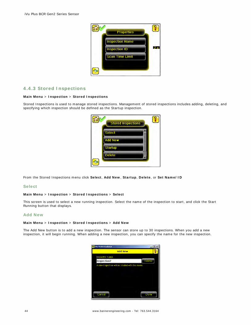
4.4.3 Stored Inspections
Main Menu > Inspection > Stored Inspections
Stored Inspections is used to manage stored inspections. Management of stored inspections includes adding, deleting, andspecifying which inspection should be defined as the Startup inspection.
From the Stored Inspections menu click Select, Add New, Startup, Delete, or Set Name/ID
Select
Main Menu > Inspection > Stored Inspections > Select
This screen is used to select a new running inspection. Select the name of the inspection to start, and click the StartRunning button that displays.
Add New
Main Menu > Inspection > Stored Inspections > Add New
The Add New button is to add a new inspection. The sensor can store up to 30 inspections. When you add a newinspection, it will begin running. When adding a new inspection, you can specify the name for the new inspection.
iVu Plus BCR Gen2 Series Sensor
44 www.bannerengineering.com - Tel: 763.544.3164
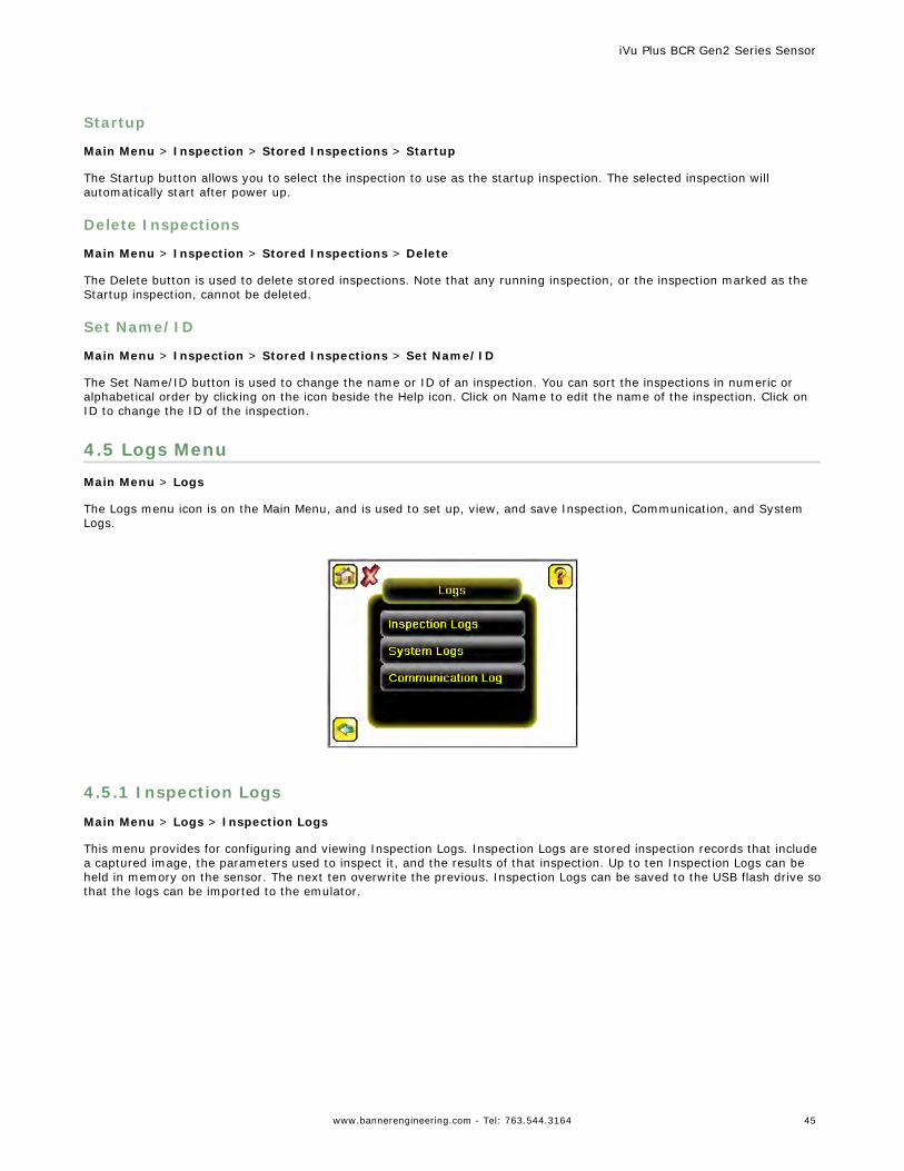
Startup
Main Menu > Inspection > Stored Inspections > Startup
The Startup button allows you to select the inspection to use as the startup inspection. The selected inspection willautomatically start after power up.
Delete Inspections
Main Menu > Inspection > Stored Inspections > Delete
The Delete button is used to delete stored inspections. Note that any running inspection, or the inspection marked as theStartup inspection, cannot be deleted.
Set Name/ID
Main Menu > Inspection > Stored Inspections > Set Name/ID
The Set Name/ID button is used to change the name or ID of an inspection. You can sort the inspections in numeric oralphabetical order by clicking on the icon beside the Help icon. Click on Name to edit the name of the inspection. Click onID to change the ID of the inspection.
4.5 Logs MenuMain Menu > Logs
The Logs menu icon is on the Main Menu, and is used to set up, view, and save Inspection, Communication, and SystemLogs.
4.5.1 Inspection Logs
Main Menu > Logs > Inspection Logs
This menu provides for configuring and viewing Inspection Logs. Inspection Logs are stored inspection records that includea captured image, the parameters used to inspect it, and the results of that inspection. Up to ten Inspection Logs can beheld in memory on the sensor. The next ten overwrite the previous. Inspection Logs can be saved to the USB flash drive sothat the logs can be imported to the emulator.
iVu Plus BCR Gen2 Series Sensor
www.bannerengineering.com - Tel: 763.544.3164 45
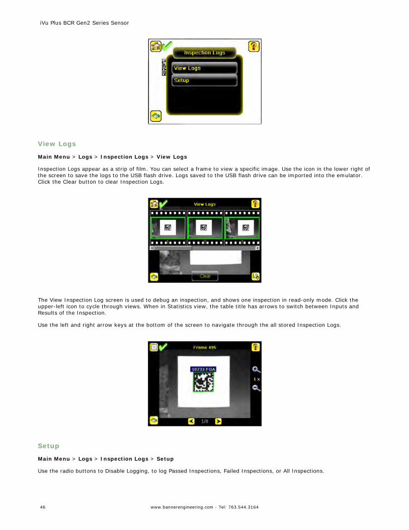
View Logs
Main Menu > Logs > Inspection Logs > View Logs
Inspection Logs appear as a strip of film. You can select a frame to view a specific image. Use the icon in the lower right ofthe screen to save the logs to the USB flash drive. Logs saved to the USB flash drive can be imported into the emulator.Click the Clear button to clear Inspection Logs.
The View Inspection Log screen is used to debug an inspection, and shows one inspection in read-only mode. Click theupper-left icon to cycle through views. When in Statistics view, the table title has arrows to switch between Inputs andResults of the Inspection.
Use the left and right arrow keys at the bottom of the screen to navigate through the all stored Inspection Logs.
Setup
Main Menu > Logs > Inspection Logs > Setup
Use the radio buttons to Disable Logging, to log Passed Inspections, Failed Inspections, or All Inspections.
iVu Plus BCR Gen2 Series Sensor
46 www.bannerengineering.com - Tel: 763.544.3164
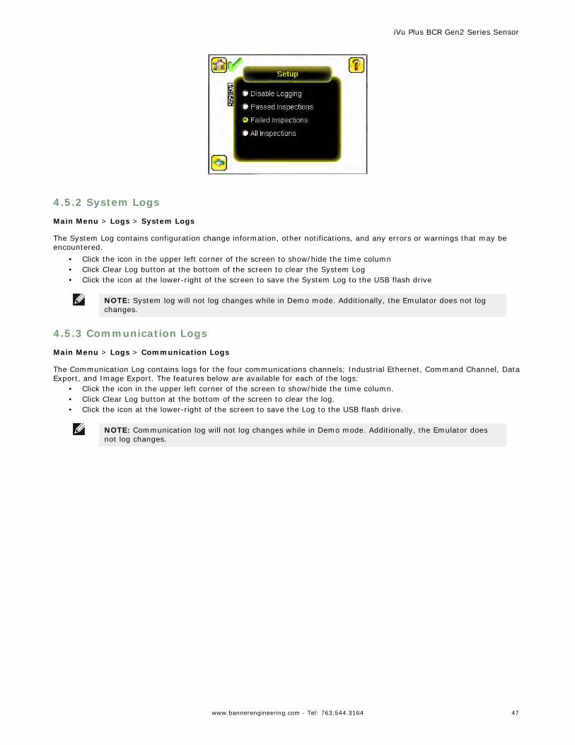
4.5.2 System Logs
Main Menu > Logs > System Logs
The System Log contains configuration change information, other notifications, and any errors or warnings that may beencountered.
• Click the icon in the upper left corner of the screen to show/hide the time column• Click Clear Log button at the bottom of the screen to clear the System Log• Click the icon at the lower-right of the screen to save the System Log to the USB flash drive
NOTE: System log will not log changes while in Demo mode. Additionally, the Emulator does not logchanges.
4.5.3 Communication Logs
Main Menu > Logs > Communication Logs
The Communication Log contains logs for the four communications channels; Industrial Ethernet, Command Channel, DataExport, and Image Export. The features below are available for each of the logs:
• Click the icon in the upper left corner of the screen to show/hide the time column.• Click Clear Log button at the bottom of the screen to clear the log.• Click the icon at the lower-right of the screen to save the Log to the USB flash drive.
NOTE: Communication log will not log changes while in Demo mode. Additionally, the Emulator doesnot log changes.
iVu Plus BCR Gen2 Series Sensor
www.bannerengineering.com - Tel: 763.544.3164 47
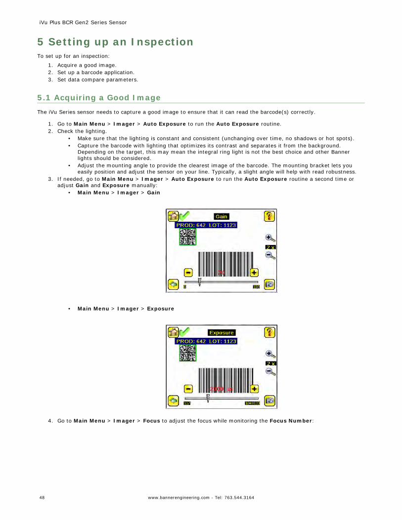
5 Setting up an InspectionTo set up for an inspection:
1. Acquire a good image.2. Set up a barcode application.3. Set data compare parameters.
5.1 Acquiring a Good ImageThe iVu Series sensor needs to capture a good image to ensure that it can read the barcode(s) correctly.
1. Go to Main Menu > Imager > Auto Exposure to run the Auto Exposure routine.2. Check the lighting.
• Make sure that the lighting is constant and consistent (unchanging over time, no shadows or hot spots).• Capture the barcode with lighting that optimizes its contrast and separates it from the background.
Depending on the target, this may mean the integral ring light is not the best choice and other Bannerlights should be considered.
• Adjust the mounting angle to provide the clearest image of the barcode. The mounting bracket lets youeasily position and adjust the sensor on your line. Typically, a slight angle will help with read robustness.
3. If needed, go to Main Menu > Imager > Auto Exposure to run the Auto Exposure routine a second time oradjust Gain and Exposure manually:
• Main Menu > Imager > Gain
• Main Menu > Imager > Exposure
4. Go to Main Menu > Imager > Focus to adjust the focus while monitoring the Focus Number:
iVu Plus BCR Gen2 Series Sensor
48 www.bannerengineering.com - Tel: 763.544.3164
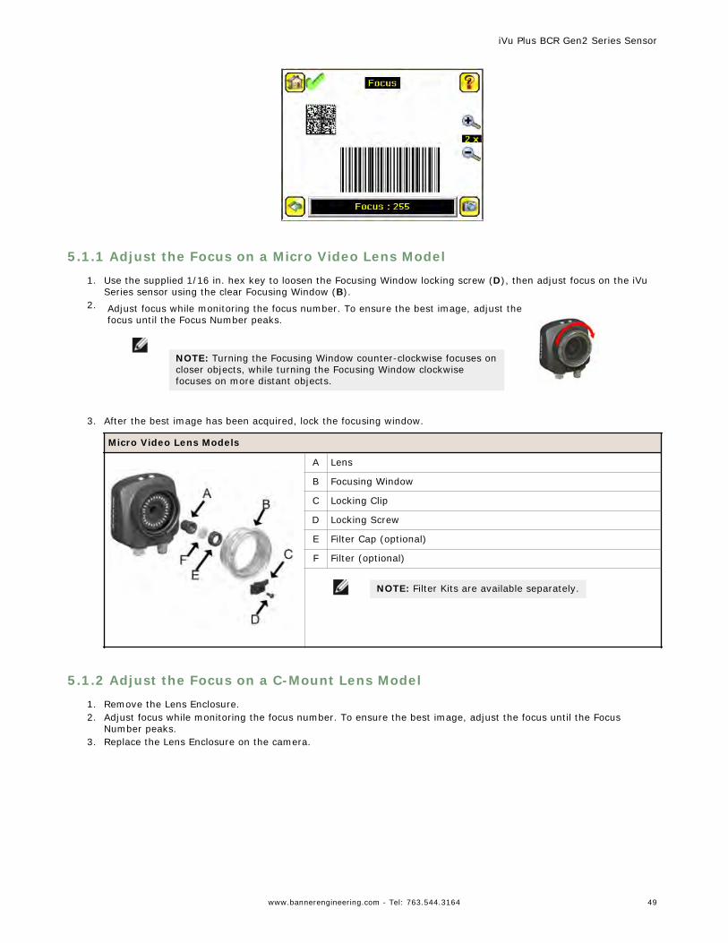
5.1.1 Adjust the Focus on a Micro Video Lens Model
1. Use the supplied 1/16 in. hex key to loosen the Focusing Window locking screw (D), then adjust focus on the iVuSeries sensor using the clear Focusing Window (B).
2. Adjust focus while monitoring the focus number. To ensure the best image, adjust thefocus until the Focus Number peaks.
NOTE: Turning the Focusing Window counter-clockwise focuses oncloser objects, while turning the Focusing Window clockwisefocuses on more distant objects.
3. After the best image has been acquired, lock the focusing window.
Micro Video Lens Models
A Lens
B Focusing Window
C Locking Clip
D Locking Screw
E Filter Cap (optional)
F Filter (optional)
NOTE: Filter Kits are available separately.
5.1.2 Adjust the Focus on a C-Mount Lens Model
1. Remove the Lens Enclosure.2. Adjust focus while monitoring the focus number. To ensure the best image, adjust the focus until the Focus
Number peaks.3. Replace the Lens Enclosure on the camera.
iVu Plus BCR Gen2 Series Sensor
www.bannerengineering.com - Tel: 763.544.3164 49
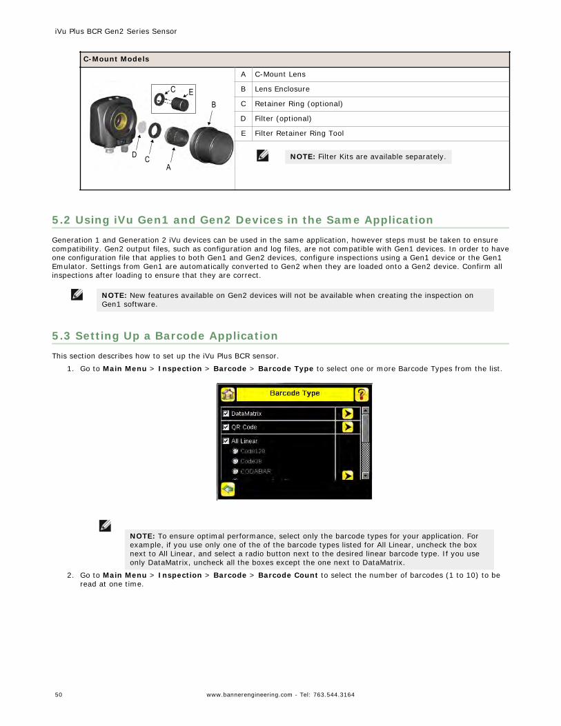
C-Mount Models
D CA
BEC
A C-Mount Lens
B Lens Enclosure
C Retainer Ring (optional)
D Filter (optional)
E Filter Retainer Ring Tool
NOTE: Filter Kits are available separately.
5.2 Using iVu Gen1 and Gen2 Devices in the Same ApplicationGeneration 1 and Generation 2 iVu devices can be used in the same application, however steps must be taken to ensurecompatibility. Gen2 output files, such as configuration and log files, are not compatible with Gen1 devices. In order to haveone configuration file that applies to both Gen1 and Gen2 devices, configure inspections using a Gen1 device or the Gen1Emulator. Settings from Gen1 are automatically converted to Gen2 when they are loaded onto a Gen2 device. Confirm allinspections after loading to ensure that they are correct.
NOTE: New features available on Gen2 devices will not be available when creating the inspection onGen1 software.
5.3 Setting Up a Barcode ApplicationThis section describes how to set up the iVu Plus BCR sensor.
1. Go to Main Menu > Inspection > Barcode > Barcode Type to select one or more Barcode Types from the list.
NOTE: To ensure optimal performance, select only the barcode types for your application. Forexample, if you use only one of the of the barcode types listed for All Linear, uncheck the boxnext to All Linear, and select a radio button next to the desired linear barcode type. If you useonly DataMatrix, uncheck all the boxes except the one next to DataMatrix.
2. Go to Main Menu > Inspection > Barcode > Barcode Count to select the number of barcodes (1 to 10) to beread at one time.
iVu Plus BCR Gen2 Series Sensor
50 www.bannerengineering.com - Tel: 763.544.3164
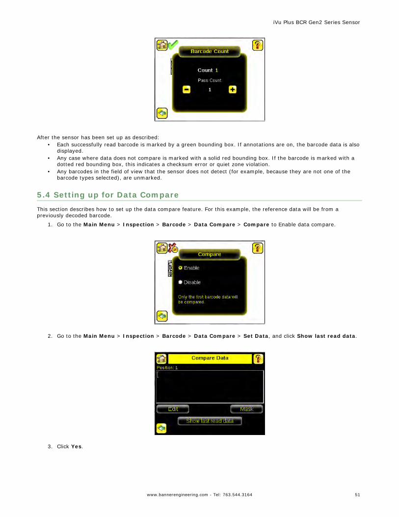
After the sensor has been set up as described:• Each successfully read barcode is marked by a green bounding box. If annotations are on, the barcode data is also
displayed.• Any case where data does not compare is marked with a solid red bounding box. If the barcode is marked with a
dotted red bounding box, this indicates a checksum error or quiet zone violation.• Any barcodes in the field of view that the sensor does not detect (for example, because they are not one of the
barcode types selected), are unmarked.
5.4 Setting up for Data CompareThis section describes how to set up the data compare feature. For this example, the reference data will be from apreviously decoded barcode.
1. Go to the Main Menu > Inspection > Barcode > Data Compare > Compare to Enable data compare.
2. Go to the Main Menu > Inspection > Barcode > Data Compare > Set Data, and click Show last read data.
3. Click Yes.
iVu Plus BCR Gen2 Series Sensor
www.bannerengineering.com - Tel: 763.544.3164 51
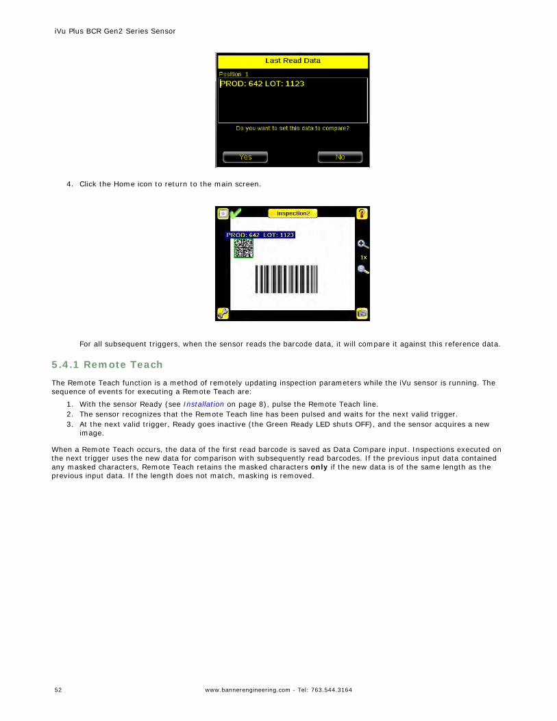
4. Click the Home icon to return to the main screen.
For all subsequent triggers, when the sensor reads the barcode data, it will compare it against this reference data.
5.4.1 Remote Teach
The Remote Teach function is a method of remotely updating inspection parameters while the iVu sensor is running. Thesequence of events for executing a Remote Teach are:
1. With the sensor Ready (see Installation on page 8), pulse the Remote Teach line.2. The sensor recognizes that the Remote Teach line has been pulsed and waits for the next valid trigger.3. At the next valid trigger, Ready goes inactive (the Green Ready LED shuts OFF), and the sensor acquires a new
image.
When a Remote Teach occurs, the data of the first read barcode is saved as Data Compare input. Inspections executed onthe next trigger uses the new data for comparison with subsequently read barcodes. If the previous input data containedany masked characters, Remote Teach retains the masked characters only if the new data is of the same length as theprevious input data. If the length does not match, masking is removed.
iVu Plus BCR Gen2 Series Sensor
52 www.bannerengineering.com - Tel: 763.544.3164
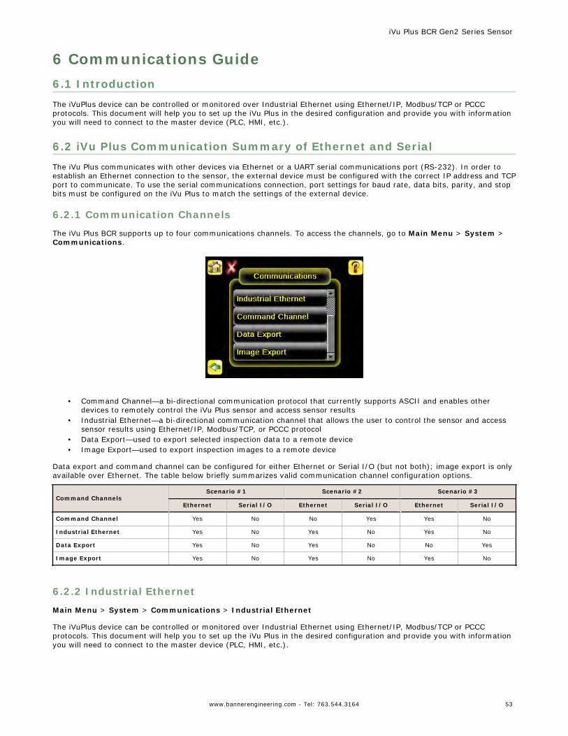
6 Communications Guide6.1 IntroductionThe iVuPlus device can be controlled or monitored over Industrial Ethernet using Ethernet/IP, Modbus/TCP or PCCCprotocols. This document will help you to set up the iVu Plus in the desired configuration and provide you with informationyou will need to connect to the master device (PLC, HMI, etc.).
6.2 iVu Plus Communication Summary of Ethernet and SerialThe iVu Plus communicates with other devices via Ethernet or a UART serial communications port (RS-232). In order toestablish an Ethernet connection to the sensor, the external device must be configured with the correct IP address and TCPport to communicate. To use the serial communications connection, port settings for baud rate, data bits, parity, and stopbits must be configured on the iVu Plus to match the settings of the external device.
6.2.1 Communication Channels
The iVu Plus BCR supports up to four communications channels. To access the channels, go to Main Menu > System >Communications.
• Command Channel—a bi-directional communication protocol that currently supports ASCII and enables otherdevices to remotely control the iVu Plus sensor and access sensor results
• Industrial Ethernet—a bi-directional communication channel that allows the user to control the sensor and accesssensor results using Ethernet/IP, Modbus/TCP, or PCCC protocol
• Data Export—used to export selected inspection data to a remote device• Image Export—used to export inspection images to a remote device
Data export and command channel can be configured for either Ethernet or Serial I/O (but not both); image export is onlyavailable over Ethernet. The table below briefly summarizes valid communication channel configuration options.
Command ChannelsScenario #1 Scenario #2 Scenario #3
Ethernet Serial I/O Ethernet Serial I/O Ethernet Serial I/O
Command Channel Yes No No Yes Yes No
Industrial Ethernet Yes No Yes No Yes No
Data Export Yes No Yes No No Yes
Image Export Yes No Yes No Yes No
6.2.2 Industrial Ethernet
Main Menu > System > Communications > Industrial Ethernet
The iVuPlus device can be controlled or monitored over Industrial Ethernet using Ethernet/IP, Modbus/TCP or PCCCprotocols. This document will help you to set up the iVu Plus in the desired configuration and provide you with informationyou will need to connect to the master device (PLC, HMI, etc.).
iVu Plus BCR Gen2 Series Sensor
www.bannerengineering.com - Tel: 763.544.3164 53
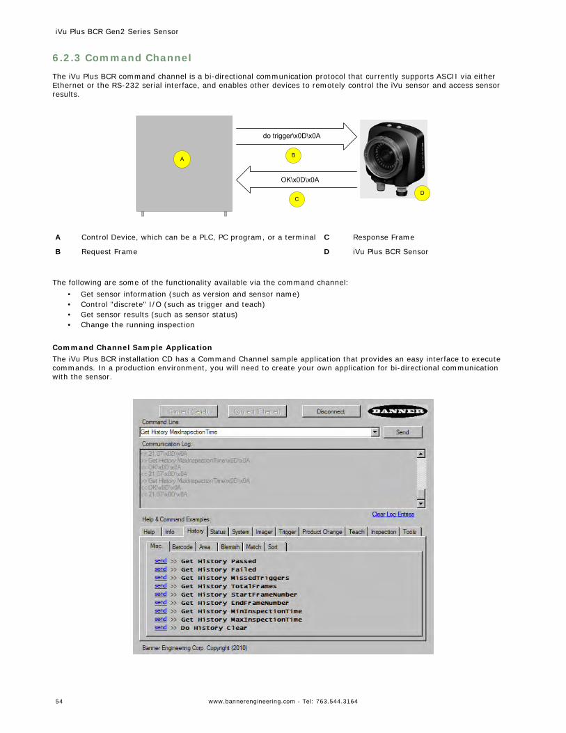
6.2.3 Command Channel
The iVu Plus BCR command channel is a bi-directional communication protocol that currently supports ASCII via eitherEthernet or the RS-232 serial interface, and enables other devices to remotely control the iVu sensor and access sensorresults.
AB
CD
do trigger\x0D\x0A
OK\x0D\x0A
A Control Device, which can be a PLC, PC program, or a terminal C Response Frame
B Request Frame D iVu Plus BCR Sensor
The following are some of the functionality available via the command channel:• Get sensor information (such as version and sensor name)• Control "discrete" I/O (such as trigger and teach)• Get sensor results (such as sensor status)• Change the running inspection
Command Channel Sample ApplicationThe iVu Plus BCR installation CD has a Command Channel sample application that provides an easy interface to executecommands. In a production environment, you will need to create your own application for bi-directional communicationwith the sensor.
iVu Plus BCR Gen2 Series Sensor
54 www.bannerengineering.com - Tel: 763.544.3164
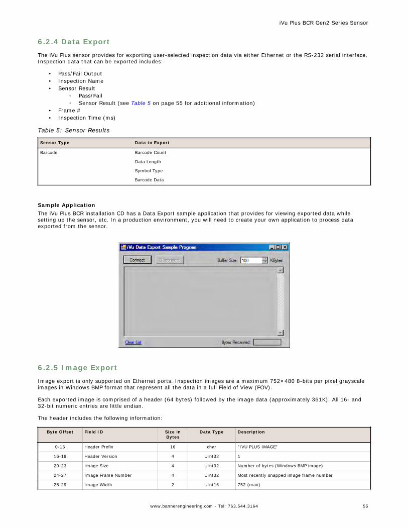
6.2.4 Data Export
The iVu Plus sensor provides for exporting user-selected inspection data via either Ethernet or the RS-232 serial interface.Inspection data that can be exported includes:
• Pass/Fail Output• Inspection Name• Sensor Result
◦ Pass/Fail◦ Sensor Result (see Table 5 on page 55 for additional information)
• Frame #• Inspection Time (ms)
Table 5: Sensor Results
Sensor Type Data to Export
Barcode Barcode Count
Data Length
Symbol Type
Barcode Data
Sample ApplicationThe iVu Plus BCR installation CD has a Data Export sample application that provides for viewing exported data whilesetting up the sensor, etc. In a production environment, you will need to create your own application to process dataexported from the sensor.
6.2.5 Image Export
Image export is only supported on Ethernet ports. Inspection images are a maximum 752×480 8-bits per pixel grayscaleimages in Windows BMP format that represent all the data in a full Field of View (FOV).
Each exported image is comprised of a header (64 bytes) followed by the image data (approximately 361K). All 16- and32-bit numeric entries are little endian.
The header includes the following information:
Byte Offset Field ID Size inBytes
Data Type Description
0-15 Header Prefix 16 char "IVU PLUS IMAGE"
16-19 Header Version 4 UInt32 1
20-23 Image Size 4 UInt32 Number of bytes (Windows BMP image)
24-27 Image Frame Number 4 UInt32 Most recently snapped image frame number
28-29 Image Width 2 UInt16 752 (max)
iVu Plus BCR Gen2 Series Sensor
www.bannerengineering.com - Tel: 763.544.3164 55
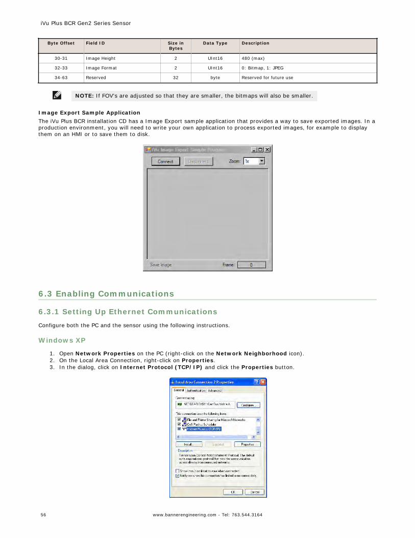
Byte Offset Field ID Size inBytes
Data Type Description
30-31 Image Height 2 UInt16 480 (max)
32-33 Image Format 2 UInt16 0: Bitmap, 1: JPEG
34-63 Reserved 32 byte Reserved for future use
NOTE: If FOV's are adjusted so that they are smaller, the bitmaps will also be smaller.
Image Export Sample ApplicationThe iVu Plus BCR installation CD has a Image Export sample application that provides a way to save exported images. In aproduction environment, you will need to write your own application to process exported images, for example to displaythem on an HMI or to save them to disk.
6.3 Enabling Communications
6.3.1 Setting Up Ethernet Communications
Configure both the PC and the sensor using the following instructions.
Windows XP
1. Open Network Properties on the PC (right-click on the Network Neighborhood icon).2. On the Local Area Connection, right-click on Properties.3. In the dialog, click on Internet Protocol (TCP/IP) and click the Properties button.
iVu Plus BCR Gen2 Series Sensor
56 www.bannerengineering.com - Tel: 763.544.3164
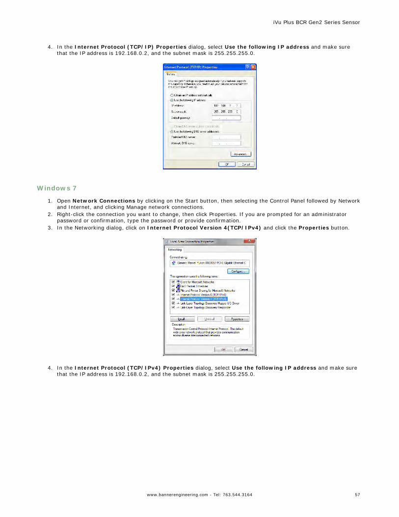
4. In the Internet Protocol (TCP/IP) Properties dialog, select Use the following IP address and make sure
that the IP address is 192.168.0.2, and the subnet mask is 255.255.255.0.
Windows 7
1. Open Network Connections by clicking on the Start button, then selecting the Control Panel followed by Networkand Internet, and clicking Manage network connections.
2. Right-click the connection you want to change, then click Properties. If you are prompted for an administratorpassword or confirmation, type the password or provide confirmation.
3. In the Networking dialog, click on Internet Protocol Version 4(TCP/IPv4) and click the Properties button.
4. In the Internet Protocol (TCP/IPv4) Properties dialog, select Use the following IP address and make sure
that the IP address is 192.168.0.2, and the subnet mask is 255.255.255.0.
iVu Plus BCR Gen2 Series Sensor
www.bannerengineering.com - Tel: 763.544.3164 57
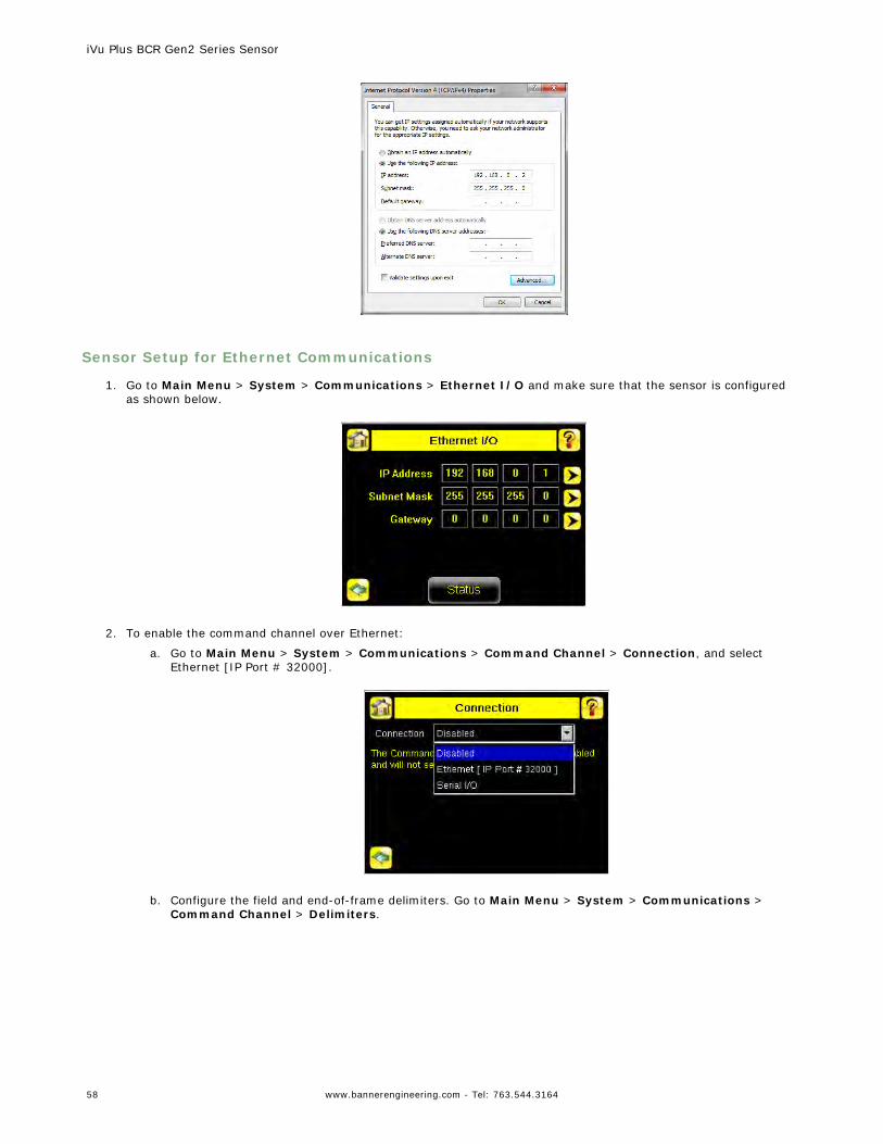
Sensor Setup for Ethernet Communications
1. Go to Main Menu > System > Communications > Ethernet I/O and make sure that the sensor is configuredas shown below.
2. To enable the command channel over Ethernet:
a. Go to Main Menu > System > Communications > Command Channel > Connection, and selectEthernet [IP Port # 32000].
b. Configure the field and end-of-frame delimiters. Go to Main Menu > System > Communications >
Command Channel > Delimiters.
iVu Plus BCR Gen2 Series Sensor
58 www.bannerengineering.com - Tel: 763.544.3164
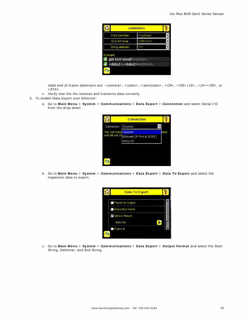
Valid end-of-frame delimiters are: <comma>, <colon>, <semicolon>, <CR>, <CR><LF>, <LF><CR>, or<ETX>.
c. Verify that the iVu receives and transmits data correctly.3. To enable Data Export over Ethernet:
a. Go to Main Menu > System > Communications > Data Export > Connection and select Serial I/Ofrom the drop-down.
b. Go to Main Menu > System > Communications > Data Export > Data To Export and select the
inspection data to export.
c. Go to Main Menu > System > Communications > Data Export > Output Format and select the Start
String, Delimiter, and End String.
iVu Plus BCR Gen2 Series Sensor
www.bannerengineering.com - Tel: 763.544.3164 59
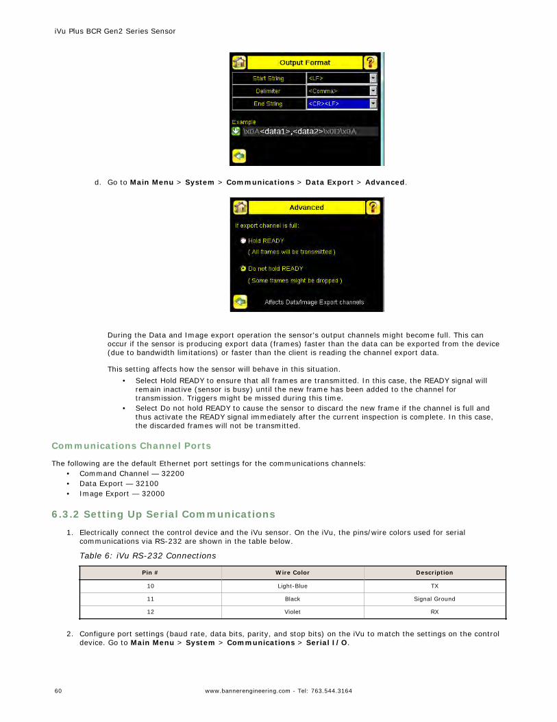
d. Go to Main Menu > System > Communications > Data Export > Advanced.
During the Data and Image export operation the sensor's output channels might become full. This canoccur if the sensor is producing export data (frames) faster than the data can be exported from the device(due to bandwidth limitations) or faster than the client is reading the channel export data.
This setting affects how the sensor will behave in this situation.• Select Hold READY to ensure that all frames are transmitted. In this case, the READY signal will
remain inactive (sensor is busy) until the new frame has been added to the channel fortransmission. Triggers might be missed during this time.
• Select Do not hold READY to cause the sensor to discard the new frame if the channel is full andthus activate the READY signal immediately after the current inspection is complete. In this case,the discarded frames will not be transmitted.
Communications Channel Ports
The following are the default Ethernet port settings for the communications channels:• Command Channel — 32200• Data Export — 32100• Image Export — 32000
6.3.2 Setting Up Serial Communications
1. Electrically connect the control device and the iVu sensor. On the iVu, the pins/wire colors used for serialcommunications via RS-232 are shown in the table below.
Table 6: iVu RS-232 Connections
Pin # Wire Color Description
10 Light-Blue TX
11 Black Signal Ground
12 Violet RX
2. Configure port settings (baud rate, data bits, parity, and stop bits) on the iVu to match the settings on the controldevice. Go to Main Menu > System > Communications > Serial I/O.
iVu Plus BCR Gen2 Series Sensor
60 www.bannerengineering.com - Tel: 763.544.3164
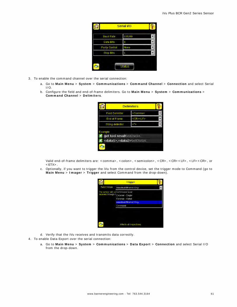
3. To enable the command channel over the serial connection:
a. Go to Main Menu > System > Communications > Command Channel > Connection and select SerialI/O.
b. Configure the field and end-of-frame delimiters. Go to Main Menu > System > Communications >Command Channel > Delimiters.
Valid end-of-frame delimiters are: <comma>, <colon>, <semicolon>, <CR>, <CR><LF>, <LF><CR>, or<ETX>.
c. Optionally, if you want to trigger the iVu from the control device, set the trigger mode to Command (go toMain Menu > Imager > Trigger and select Command from the drop-down).
d. Verify that the iVu receives and transmits data correctly.
4. To enable Data Export over the serial connection:
a. Go to Main Menu > System > Communications > Data Export > Connection and select Serial I/Ofrom the drop-down.
iVu Plus BCR Gen2 Series Sensor
www.bannerengineering.com - Tel: 763.544.3164 61
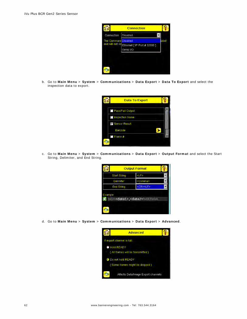
b. Go to Main Menu > System > Communications > Data Export > Data To Export and select the
inspection data to export.
c. Go to Main Menu > System > Communications > Data Export > Output Format and select the Start
String, Delimiter, and End String.
d. Go to Main Menu > System > Communications > Data Export > Advanced.
iVu Plus BCR Gen2 Series Sensor
62 www.bannerengineering.com - Tel: 763.544.3164
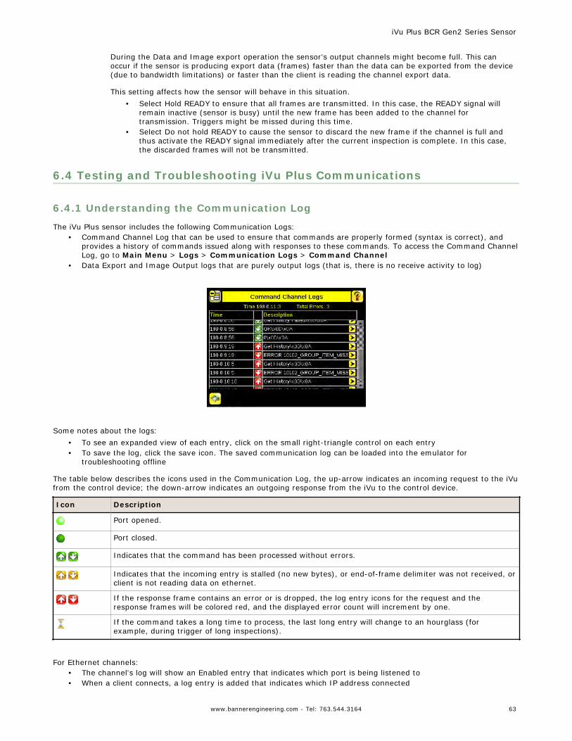
During the Data and Image export operation the sensor's output channels might become full. This canoccur if the sensor is producing export data (frames) faster than the data can be exported from the device(due to bandwidth limitations) or faster than the client is reading the channel export data.
This setting affects how the sensor will behave in this situation.• Select Hold READY to ensure that all frames are transmitted. In this case, the READY signal will
remain inactive (sensor is busy) until the new frame has been added to the channel fortransmission. Triggers might be missed during this time.
• Select Do not hold READY to cause the sensor to discard the new frame if the channel is full andthus activate the READY signal immediately after the current inspection is complete. In this case,the discarded frames will not be transmitted.
6.4 Testing and Troubleshooting iVu Plus Communications
6.4.1 Understanding the Communication Log
The iVu Plus sensor includes the following Communication Logs:• Command Channel Log that can be used to ensure that commands are properly formed (syntax is correct), and
provides a history of commands issued along with responses to these commands. To access the Command ChannelLog, go to Main Menu > Logs > Communication Logs > Command Channel
• Data Export and Image Output logs that are purely output logs (that is, there is no receive activity to log)
Some notes about the logs:• To see an expanded view of each entry, click on the small right-triangle control on each entry• To save the log, click the save icon. The saved communication log can be loaded into the emulator for
troubleshooting offline
The table below describes the icons used in the Communication Log, the up-arrow indicates an incoming request to the iVufrom the control device; the down-arrow indicates an outgoing response from the iVu to the control device.
Icon Description
Port opened.
Port closed.
Indicates that the command has been processed without errors.
Indicates that the incoming entry is stalled (no new bytes), or end-of-frame delimiter was not received, orclient is not reading data on ethernet.
If the response frame contains an error or is dropped, the log entry icons for the request and theresponse frames will be colored red, and the displayed error count will increment by one.
If the command takes a long time to process, the last long entry will change to an hourglass (forexample, during trigger of long inspections).
For Ethernet channels:• The channel's log will show an Enabled entry that indicates which port is being listened to• When a client connects, a log entry is added that indicates which IP address connected
iVu Plus BCR Gen2 Series Sensor
www.bannerengineering.com - Tel: 763.544.3164 63
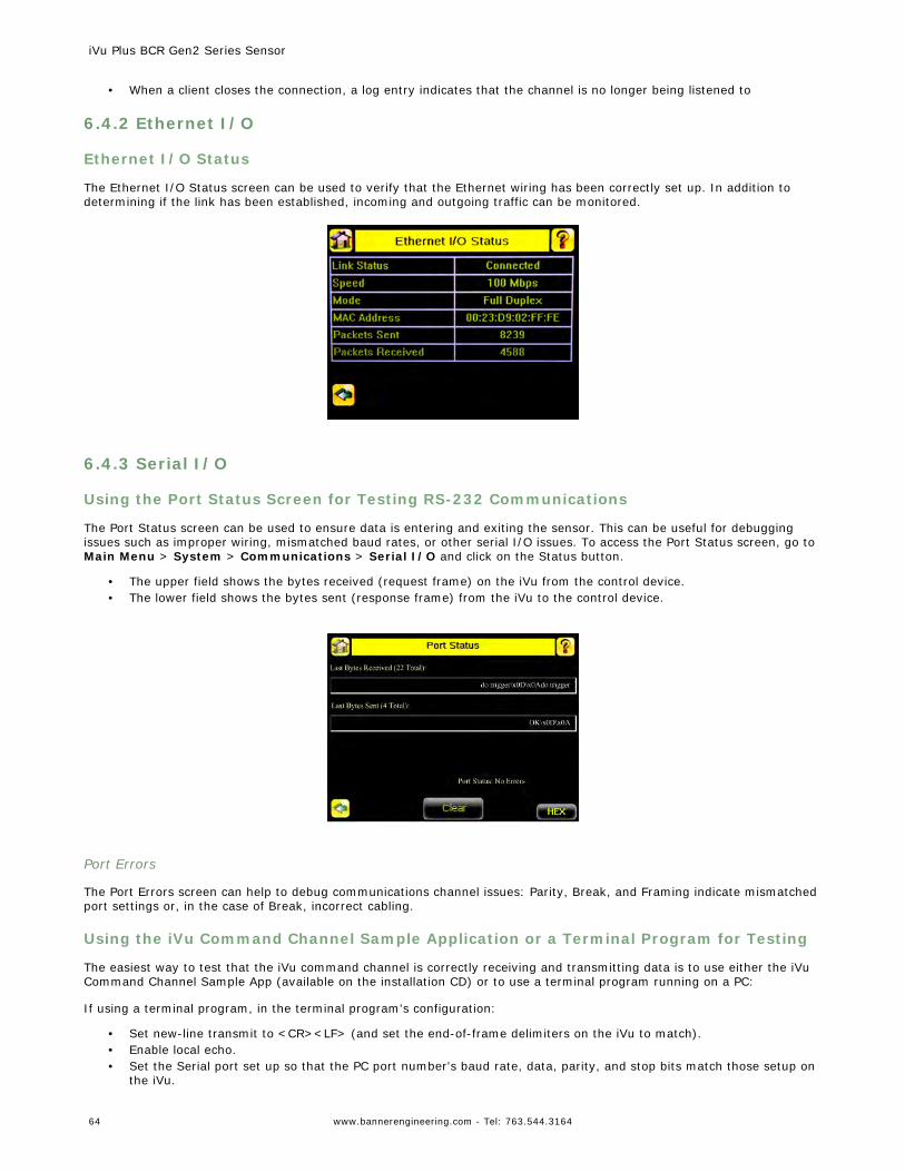
• When a client closes the connection, a log entry indicates that the channel is no longer being listened to
6.4.2 Ethernet I/O
Ethernet I/O Status
The Ethernet I/O Status screen can be used to verify that the Ethernet wiring has been correctly set up. In addition todetermining if the link has been established, incoming and outgoing traffic can be monitored.
6.4.3 Serial I/O
Using the Port Status Screen for Testing RS-232 Communications
The Port Status screen can be used to ensure data is entering and exiting the sensor. This can be useful for debuggingissues such as improper wiring, mismatched baud rates, or other serial I/O issues. To access the Port Status screen, go toMain Menu > System > Communications > Serial I/O and click on the Status button.
• The upper field shows the bytes received (request frame) on the iVu from the control device.• The lower field shows the bytes sent (response frame) from the iVu to the control device.
Port Errors
The Port Errors screen can help to debug communications channel issues: Parity, Break, and Framing indicate mismatchedport settings or, in the case of Break, incorrect cabling.
Using the iVu Command Channel Sample Application or a Terminal Program for Testing
The easiest way to test that the iVu command channel is correctly receiving and transmitting data is to use either the iVuCommand Channel Sample App (available on the installation CD) or to use a terminal program running on a PC:
If using a terminal program, in the terminal program's configuration:
• Set new-line transmit to <CR><LF> (and set the end-of-frame delimiters on the iVu to match).• Enable local echo.• Set the Serial port set up so that the PC port number's baud rate, data, parity, and stop bits match those setup on
the iVu.
iVu Plus BCR Gen2 Series Sensor
64 www.bannerengineering.com - Tel: 763.544.3164
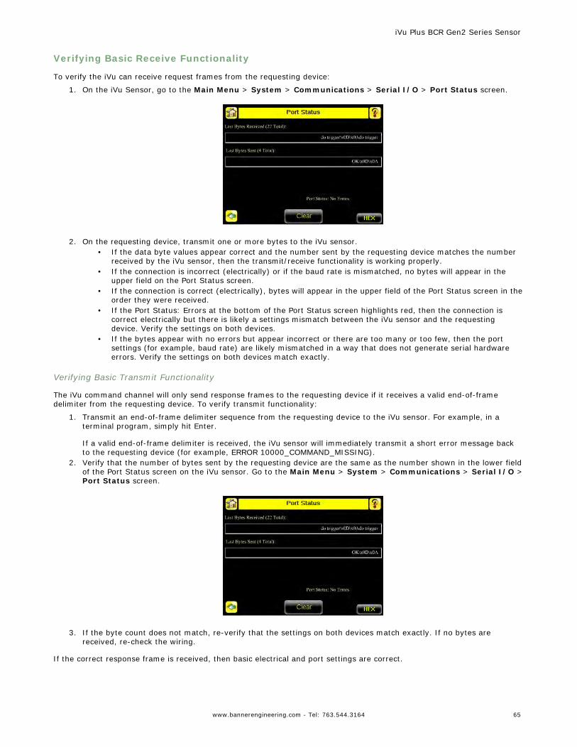
Verifying Basic Receive Functionality
To verify the iVu can receive request frames from the requesting device:
1. On the iVu Sensor, go to the Main Menu > System > Communications > Serial I/O > Port Status screen.
2. On the requesting device, transmit one or more bytes to the iVu sensor.
• If the data byte values appear correct and the number sent by the requesting device matches the numberreceived by the iVu sensor, then the transmit/receive functionality is working properly.
• If the connection is incorrect (electrically) or if the baud rate is mismatched, no bytes will appear in theupper field on the Port Status screen.
• If the connection is correct (electrically), bytes will appear in the upper field of the Port Status screen in theorder they were received.
• If the Port Status: Errors at the bottom of the Port Status screen highlights red, then the connection iscorrect electrically but there is likely a settings mismatch between the iVu sensor and the requestingdevice. Verify the settings on both devices.
• If the bytes appear with no errors but appear incorrect or there are too many or too few, then the portsettings (for example, baud rate) are likely mismatched in a way that does not generate serial hardwareerrors. Verify the settings on both devices match exactly.
Verifying Basic Transmit Functionality
The iVu command channel will only send response frames to the requesting device if it receives a valid end-of-framedelimiter from the requesting device. To verify transmit functionality:
1. Transmit an end-of-frame delimiter sequence from the requesting device to the iVu sensor. For example, in aterminal program, simply hit Enter.
If a valid end-of-frame delimiter is received, the iVu sensor will immediately transmit a short error message backto the requesting device (for example, ERROR 10000_COMMAND_MISSING).
2. Verify that the number of bytes sent by the requesting device are the same as the number shown in the lower fieldof the Port Status screen on the iVu sensor. Go to the Main Menu > System > Communications > Serial I/O >Port Status screen.
3. If the byte count does not match, re-verify that the settings on both devices match exactly. If no bytes are
received, re-check the wiring.
If the correct response frame is received, then basic electrical and port settings are correct.
iVu Plus BCR Gen2 Series Sensor
www.bannerengineering.com - Tel: 763.544.3164 65
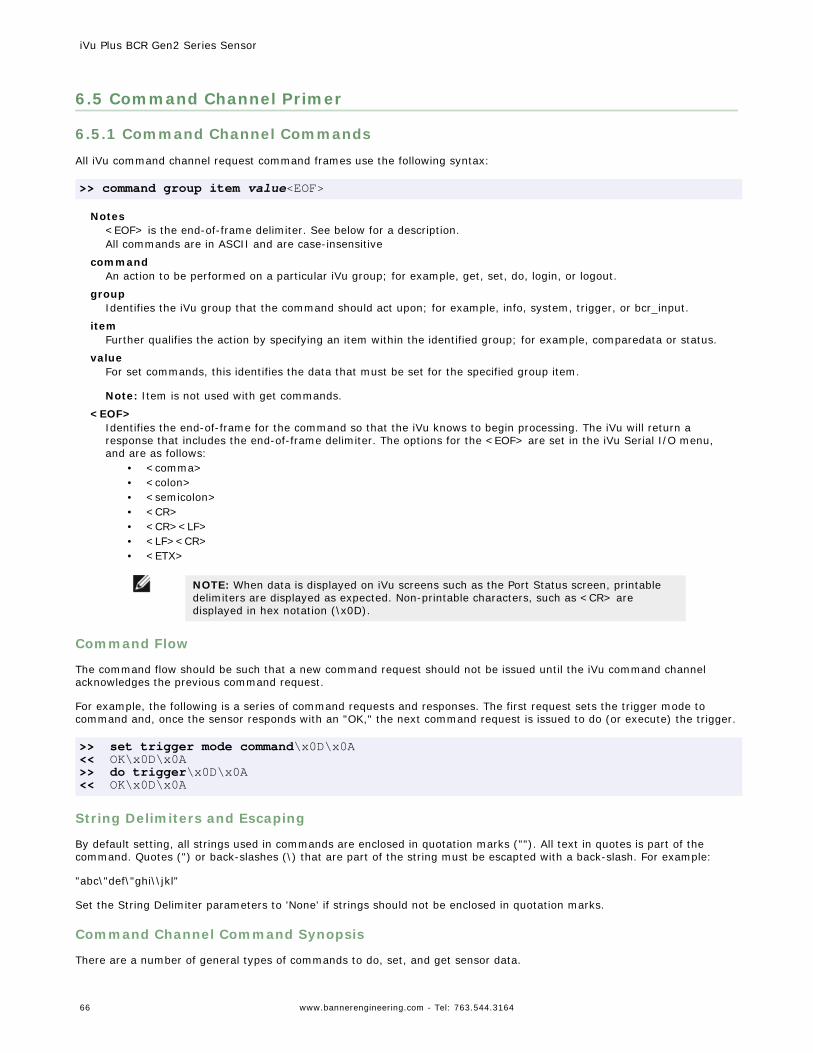
6.5 Command Channel Primer
6.5.1 Command Channel Commands
All iVu command channel request command frames use the following syntax:
>> command group item value<EOF>
Notes<EOF> is the end-of-frame delimiter. See below for a description.All commands are in ASCII and are case-insensitive
commandAn action to be performed on a particular iVu group; for example, get, set, do, login, or logout.
groupIdentifies the iVu group that the command should act upon; for example, info, system, trigger, or bcr_input.
itemFurther qualifies the action by specifying an item within the identified group; for example, comparedata or status.
valueFor set commands, this identifies the data that must be set for the specified group item.
Note: Item is not used with get commands.
<EOF>Identifies the end-of-frame for the command so that the iVu knows to begin processing. The iVu will return aresponse that includes the end-of-frame delimiter. The options for the <EOF> are set in the iVu Serial I/O menu,and are as follows:
• <comma>• <colon>• <semicolon>• <CR>• <CR><LF>• <LF><CR>• <ETX>
NOTE: When data is displayed on iVu screens such as the Port Status screen, printabledelimiters are displayed as expected. Non-printable characters, such as <CR> aredisplayed in hex notation (\x0D).
Command Flow
The command flow should be such that a new command request should not be issued until the iVu command channelacknowledges the previous command request.
For example, the following is a series of command requests and responses. The first request sets the trigger mode tocommand and, once the sensor responds with an "OK," the next command request is issued to do (or execute) the trigger.
>> set trigger mode command\x0D\x0A<< OK\x0D\x0A>> do trigger\x0D\x0A<< OK\x0D\x0A
String Delimiters and Escaping
By default setting, all strings used in commands are enclosed in quotation marks (""). All text in quotes is part of thecommand. Quotes (") or back-slashes (\) that are part of the string must be escapted with a back-slash. For example:
"abc\"def\"ghi\\jkl"
Set the String Delimiter parameters to 'None' if strings should not be enclosed in quotation marks.
Command Channel Command Synopsis
There are a number of general types of commands to do, set, and get sensor data.
iVu Plus BCR Gen2 Series Sensor
66 www.bannerengineering.com - Tel: 763.544.3164
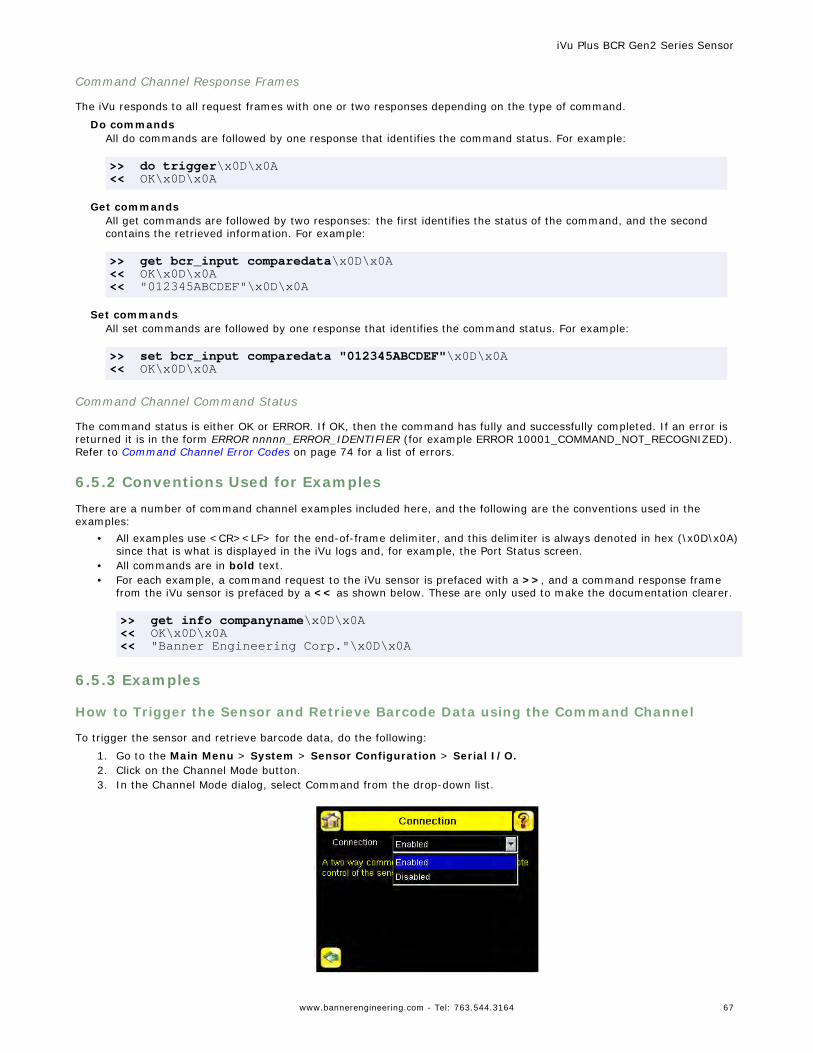
Command Channel Response Frames
The iVu responds to all request frames with one or two responses depending on the type of command.
Do commandsAll do commands are followed by one response that identifies the command status. For example:
>> do trigger\x0D\x0A<< OK\x0D\x0A
Get commandsAll get commands are followed by two responses: the first identifies the status of the command, and the secondcontains the retrieved information. For example:
>> get bcr_input comparedata\x0D\x0A<< OK\x0D\x0A<< "012345ABCDEF"\x0D\x0A
Set commandsAll set commands are followed by one response that identifies the command status. For example:
>> set bcr_input comparedata "012345ABCDEF"\x0D\x0A<< OK\x0D\x0A
Command Channel Command Status
The command status is either OK or ERROR. If OK, then the command has fully and successfully completed. If an error isreturned it is in the form ERROR nnnnn_ERROR_IDENTIFIER (for example ERROR 10001_COMMAND_NOT_RECOGNIZED).Refer to Command Channel Error Codes on page 74 for a list of errors.
6.5.2 Conventions Used for Examples
There are a number of command channel examples included here, and the following are the conventions used in theexamples:
• All examples use <CR><LF> for the end-of-frame delimiter, and this delimiter is always denoted in hex (\x0D\x0A)since that is what is displayed in the iVu logs and, for example, the Port Status screen.
• All commands are in bold text.• For each example, a command request to the iVu sensor is prefaced with a >>, and a command response frame
from the iVu sensor is prefaced by a << as shown below. These are only used to make the documentation clearer.
>> get info companyname\x0D\x0A<< OK\x0D\x0A<< "Banner Engineering Corp."\x0D\x0A
6.5.3 Examples
How to Trigger the Sensor and Retrieve Barcode Data using the Command Channel
To trigger the sensor and retrieve barcode data, do the following:
1. Go to the Main Menu > System > Sensor Configuration > Serial I/O.2. Click on the Channel Mode button.3. In the Channel Mode dialog, select Command from the drop-down list.
iVu Plus BCR Gen2 Series Sensor
www.bannerengineering.com - Tel: 763.544.3164 67
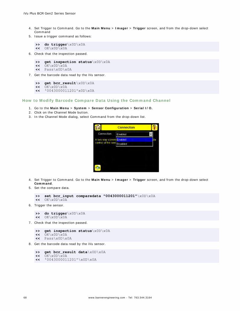
4. Set Trigger to Command. Go to the Main Menu > Imager > Trigger screen, and from the drop-down select
Command5. Issue a trigger command as follows:
>> do trigger\x0D\x0A<< OK\x0D\x0A
6. Check that the inspection passed.
>> get inspection status\x0D\x0A<< OK\x0D\x0A<< Pass\x0D\x0A
7. Get the barcode data read by the iVu sensor.
>> get bcr_result\x0D\x0A<< OK\x0D\x0A<< "0043000011201"x0D\x0A
How to Modify Barcode Compare Data Using the Command Channel
1. Go to the Main Menu > System > Sensor Configuration > Serial I/O.2. Click on the Channel Mode button.3. In the Channel Mode dialog, select Command from the drop-down list.
4. Set Trigger to Command. Go to the Main Menu > Imager > Trigger screen, and from the drop-down select
Command.5. Set the compare data.
>> set bcr_input comparedata "0043000011201"\x0D\x0A<< OK\x0D\x0A
6. Trigger the sensor.
>> do trigger\x0D\x0A<< OK\x0D\x0A
7. Check that the inspection passed.
>> get inspection status\x0D\x0A<< OK\x0D\x0A<< Pass\x0D\x0A
8. Get the barcode data read by the iVu sensor.
>> get bcr_result data\x0D\x0A<< OK\x0D\x0A<< "0043000011201"\x0D\x0A
iVu Plus BCR Gen2 Series Sensor
68 www.bannerengineering.com - Tel: 763.544.3164
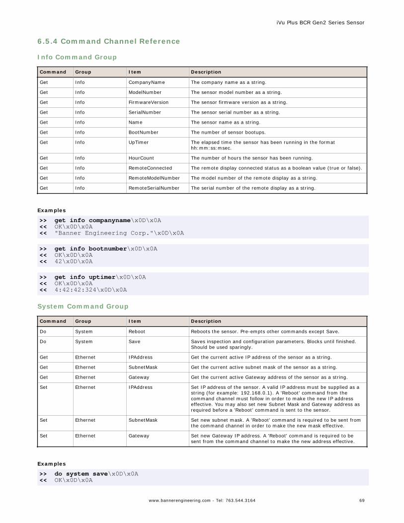
6.5.4 Command Channel Reference
Info Command Group
Command Group Item Description
Get Info CompanyName The company name as a string.
Get Info ModelNumber The sensor model number as a string.
Get Info FirmwareVersion The sensor firmware version as a string.
Get Info SerialNumber The sensor serial number as a string.
Get Info Name The sensor name as a string.
Get Info BootNumber The number of sensor bootups.
Get Info UpTimer The elapsed time the sensor has been running in the formathh:mm:ss:msec.
Get Info HourCount The number of hours the sensor has been running.
Get Info RemoteConnected The remote display connected status as a boolean value (true or false).
Get Info RemoteModelNumber The model number of the remote display as a string.
Get Info RemoteSerialNumber The serial number of the remote display as a string.
Examples
>> get info companyname\x0D\x0A<< OK\x0D\x0A<< "Banner Engineering Corp."\x0D\x0A
>> get info bootnumber\x0D\x0A<< OK\x0D\x0A<< 42\x0D\x0A
>> get info uptimer\x0D\x0A<< OK\x0D\x0A<< 4:42:42:324\x0D\x0A
System Command Group
Command Group Item Description
Do System Reboot Reboots the sensor. Pre-empts other commands except Save.
Do System Save Saves inspection and configuration parameters. Blocks until finished.Should be used sparingly.
Get Ethernet IPAddress Get the current active IP address of the sensor as a string.
Get Ethernet SubnetMask Get the current active subnet mask of the sensor as a string.
Get Ethernet Gateway Get the current active Gateway address of the sensor as a string.
Set Ethernet IPAddress Set IP address of the sensor. A valid IP address must be supplied as astring (for example: 192.168.0.1). A 'Reboot' command from thecommand channel must follow in order to make the new IP addresseffective. You may also set new Subnet Mask and Gateway address asrequired before a 'Reboot' command is sent to the sensor.
Set Ethernet SubnetMask Set new subnet mask. A 'Reboot' command is required to be sent fromthe command channel in order to make the new mask effective.
Set Ethernet Gateway Set new Gateway IP address. A 'Reboot' command is required to besent from the command channel to make the new address effective.
Examples
>> do system save\x0D\x0A<< OK\x0D\x0A
iVu Plus BCR Gen2 Series Sensor
www.bannerengineering.com - Tel: 763.544.3164 69
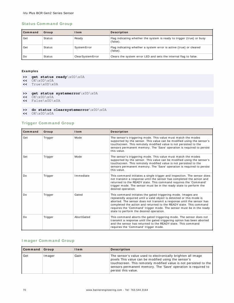
Status Command Group
Command Group Item Description
Get Status Ready Flag indicating whether the system is ready to trigger (true) or busy(false).
Get Status SystemError Flag indicating whether a system error is active (true) or cleared(false).
Do Status ClearSystemError Clears the system error LED and sets the internal flag to false.
Examples
>> get status ready\x0D\x0A<< OK\x0D\x0A<< True\x0D\x0A
>> get status systemerror\x0D\x0A<< OK\x0D\x0A<< False\x0D\x0A
>> do status clearsystemerror\x0D\x0A<< OK\x0D\x0A
Trigger Command Group
Command Group Item Description
Get Trigger Mode The sensor's triggering mode. This value must match the modessupported by the sensor. This value can be modified using the sensor'stouchscreen. This remotely modified value is not persisted to thesensors permanent memory. The 'Save' operation is required to persistthis value.
Set Trigger Mode The sensor's triggering mode. This value must match the modessupported by the sensor. This value can be modified using the sensor'stouchscreen. This remotely modified value is not persisted to thesensors permanent memory. The 'Save' operation is required to persistthis value.
Do Trigger Immediate This command initiates a single trigger and inspection. The sensor doesnot transmit a response until the sensor has completed the action andreturned to the READY state. This command requires the 'Command'trigger mode. The sensor must be in the ready state to perform thedesired operation.
Do Trigger Gated This command initiates the gated triggering mode. Images arerepeatedly acquired until a valid object is detected or this mode isaborted. The sensor does not transmit a response until the sensor hascompleted the action and returned to the READY state. This commandrequires the 'Command' trigger mode. The sensor must be in the readystate to perform the desired operation.
Do Trigger AbortGated This command aborts the gated triggering mode. The sensor does nottransmit a response until the gated triggering option has been abortedand the sensor has returned to the READY state. This commandrequires the 'Command' trigger mode.
Imager Command Group
Command Group Item Description
Get Imager Gain The sensor's value used to electronically brighten all imagepixels This value can be modified using the sensor'stouchscreen. This remotely modified value is not persisted to thesensors permanent memory. The 'Save' operation is required topersist this value.
iVu Plus BCR Gen2 Series Sensor
70 www.bannerengineering.com - Tel: 763.544.3164
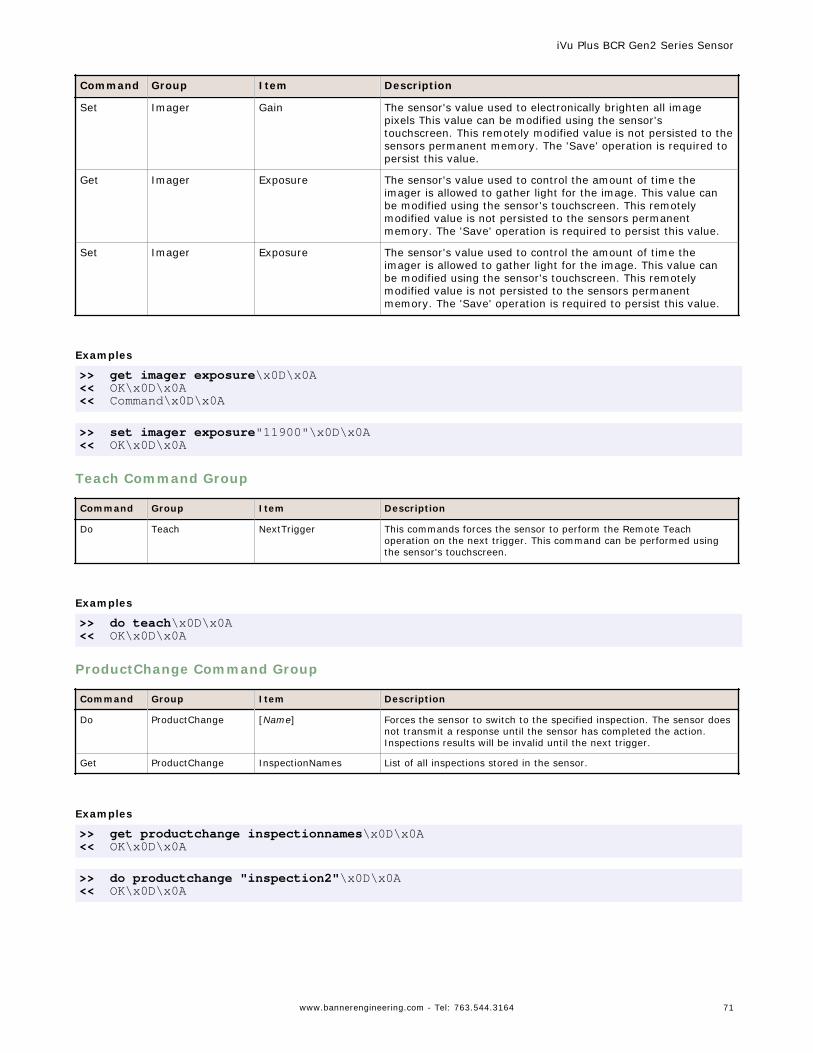
Command Group Item Description
Set Imager Gain The sensor's value used to electronically brighten all imagepixels This value can be modified using the sensor'stouchscreen. This remotely modified value is not persisted to thesensors permanent memory. The 'Save' operation is required topersist this value.
Get Imager Exposure The sensor's value used to control the amount of time theimager is allowed to gather light for the image. This value canbe modified using the sensor's touchscreen. This remotelymodified value is not persisted to the sensors permanentmemory. The 'Save' operation is required to persist this value.
Set Imager Exposure The sensor's value used to control the amount of time theimager is allowed to gather light for the image. This value canbe modified using the sensor's touchscreen. This remotelymodified value is not persisted to the sensors permanentmemory. The 'Save' operation is required to persist this value.
Examples
>> get imager exposure\x0D\x0A<< OK\x0D\x0A<< Command\x0D\x0A
>> set imager exposure"11900"\x0D\x0A<< OK\x0D\x0A
Teach Command Group
Command Group Item Description
Do Teach NextTrigger This commands forces the sensor to perform the Remote Teachoperation on the next trigger. This command can be performed usingthe sensor's touchscreen.
Examples
>> do teach\x0D\x0A<< OK\x0D\x0A
ProductChange Command Group
Command Group Item Description
Do ProductChange [Name] Forces the sensor to switch to the specified inspection. The sensor doesnot transmit a response until the sensor has completed the action.Inspections results will be invalid until the next trigger.
Get ProductChange InspectionNames List of all inspections stored in the sensor.
Examples
>> get productchange inspectionnames\x0D\x0A<< OK\x0D\x0A
>> do productchange "inspection2"\x0D\x0A<< OK\x0D\x0A
iVu Plus BCR Gen2 Series Sensor
www.bannerengineering.com - Tel: 763.544.3164 71
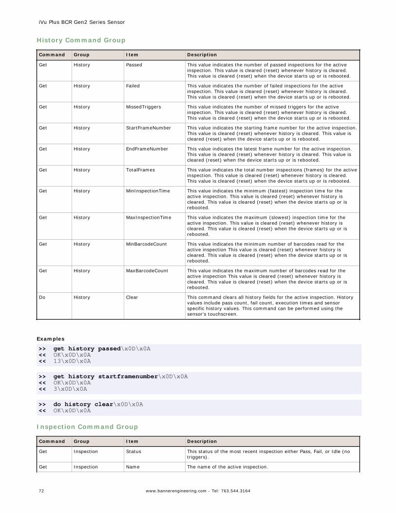
History Command Group
Command Group Item Description
Get History Passed This value indicates the number of passed inspections for the activeinspection. This value is cleared (reset) whenever history is cleared.This value is cleared (reset) when the device starts up or is rebooted.
Get History Failed This value indicates the number of failed inspections for the activeinspection. This value is cleared (reset) whenever history is cleared.This value is cleared (reset) when the device starts up or is rebooted.
Get History MissedTriggers This value indicates the number of missed triggers for the activeinspection. This value is cleared (reset) whenever history is cleared.This value is cleared (reset) when the device starts up or is rebooted.
Get History StartFrameNumber This value indicates the starting frame number for the active inspection.This value is cleared (reset) whenever history is cleared. This value iscleared (reset) when the device starts up or is rebooted.
Get History EndFrameNumber This value indicates the latest frame number for the active inspection.This value is cleared (reset) whenever history is cleared. This value iscleared (reset) when the device starts up or is rebooted.
Get History TotalFrames This value indicates the total number inspections (frames) for the activeinspection. This value is cleared (reset) whenever history is cleared.This value is cleared (reset) when the device starts up or is rebooted.
Get History MinInspectionTime This value indicates the minimum (fastest) inspection time for theactive inspection. This value is cleared (reset) whenever history iscleared. This value is cleared (reset) when the device starts up or isrebooted.
Get History MaxInspectionTime This value indicates the maximum (slowest) inspection time for theactive inspection. This value is cleared (reset) whenever history iscleared. This value is cleared (reset) when the device starts up or isrebooted.
Get History MinBarcodeCount This value indicates the minimum number of barcodes read for theactive inspection This value is cleared (reset) whenever history iscleared. This value is cleared (reset) when the device starts up or isrebooted.
Get History MaxBarcodeCount This value indicates the maximum number of barcodes read for theactive inspection This value is cleared (reset) whenever history iscleared. This value is cleared (reset) when the device starts up or isrebooted.
Do History Clear This command clears all history fields for the active inspection. Historyvalues include pass count, fail count, execution times and sensorspecific history values. This command can be performed using thesensor's touchscreen.
Examples
>> get history passed\x0D\x0A<< OK\x0D\x0A<< 13\x0D\x0A
>> get history startframenumber\x0D\x0A<< OK\x0D\x0A<< 3\x0D\x0A
>> do history clear\x0D\x0A<< OK\x0D\x0A
Inspection Command Group
Command Group Item Description
Get Inspection Status This status of the most recent inspection either Pass, Fail, or Idle (notriggers).
Get Inspection Name The name of the active inspection.
iVu Plus BCR Gen2 Series Sensor
72 www.bannerengineering.com - Tel: 763.544.3164
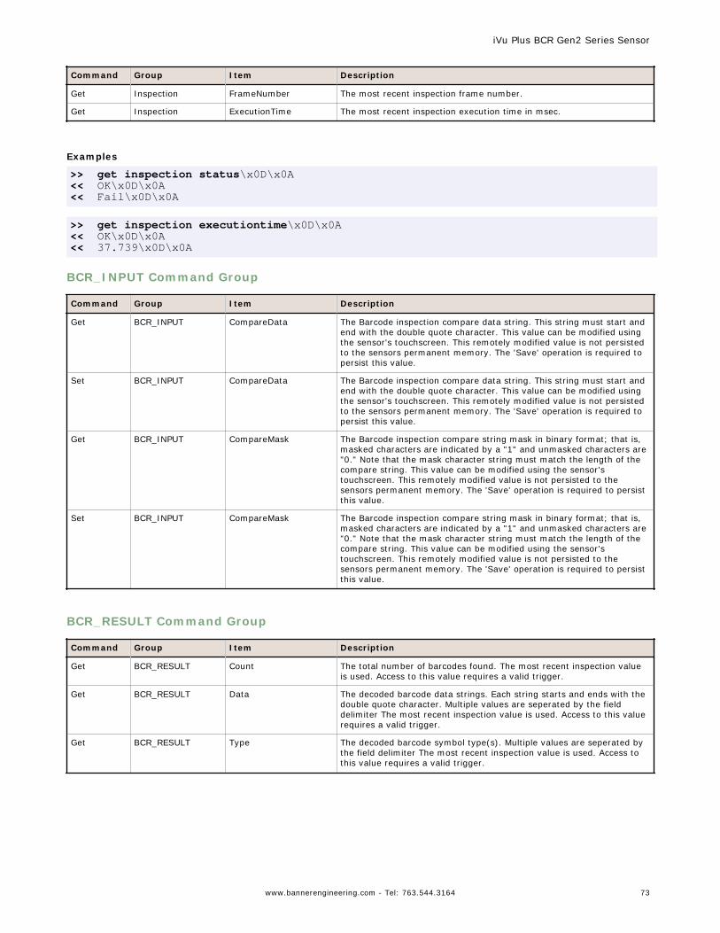
Command Group Item Description
Get Inspection FrameNumber The most recent inspection frame number.
Get Inspection ExecutionTime The most recent inspection execution time in msec.
Examples
>> get inspection status\x0D\x0A<< OK\x0D\x0A<< Fail\x0D\x0A
>> get inspection executiontime\x0D\x0A<< OK\x0D\x0A<< 37.739\x0D\x0A
BCR_INPUT Command Group
Command Group Item Description
Get BCR_INPUT CompareData The Barcode inspection compare data string. This string must start andend with the double quote character. This value can be modified usingthe sensor's touchscreen. This remotely modified value is not persistedto the sensors permanent memory. The 'Save' operation is required topersist this value.
Set BCR_INPUT CompareData The Barcode inspection compare data string. This string must start andend with the double quote character. This value can be modified usingthe sensor's touchscreen. This remotely modified value is not persistedto the sensors permanent memory. The 'Save' operation is required topersist this value.
Get BCR_INPUT CompareMask The Barcode inspection compare string mask in binary format; that is,masked characters are indicated by a "1" and unmasked characters are"0." Note that the mask character string must match the length of thecompare string. This value can be modified using the sensor'stouchscreen. This remotely modified value is not persisted to thesensors permanent memory. The 'Save' operation is required to persistthis value.
Set BCR_INPUT CompareMask The Barcode inspection compare string mask in binary format; that is,masked characters are indicated by a "1" and unmasked characters are"0." Note that the mask character string must match the length of thecompare string. This value can be modified using the sensor'stouchscreen. This remotely modified value is not persisted to thesensors permanent memory. The 'Save' operation is required to persistthis value.
BCR_RESULT Command Group
Command Group Item Description
Get BCR_RESULT Count The total number of barcodes found. The most recent inspection valueis used. Access to this value requires a valid trigger.
Get BCR_RESULT Data The decoded barcode data strings. Each string starts and ends with thedouble quote character. Multiple values are seperated by the fielddelimiter The most recent inspection value is used. Access to this valuerequires a valid trigger.
Get BCR_RESULT Type The decoded barcode symbol type(s). Multiple values are seperated bythe field delimiter The most recent inspection value is used. Access tothis value requires a valid trigger.
iVu Plus BCR Gen2 Series Sensor
www.bannerengineering.com - Tel: 763.544.3164 73
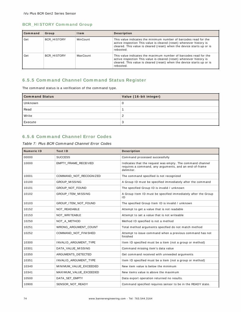
BCR_HISTORY Command Group
Command Group Item Description
Get BCR_HISTORY MinCount This value indicates the minimum number of barcodes read for theactive inspection This value is cleared (reset) whenever history iscleared. This value is cleared (reset) when the device starts up or isrebooted.
Get BCR_HISTORY MaxCount This value indicates the maximum number of barcodes read for theactive inspection This value is cleared (reset) whenever history iscleared. This value is cleared (reset) when the device starts up or isrebooted.
6.5.5 Command Channel Command Status Register
The command status is a verification of the command type.
Command Status Value (16-bit integer)
Unknown 0
Read 1
Write 2
Execute 3
6.5.6 Command Channel Error CodesTable 7: Plus BCR Command Channel Error Codes
Numeric ID Text ID Description
00000 SUCCESS Command processed successfully
10000 EMPTY_FRAME_RECEIVED Indicates that the request was empty. The command channelrequires a command, any arguments, and an end-of-framedelimiter.
10001 COMMAND_NOT_RECOGNIZED The command specified is not recognized
10100 GROUP_MISSING A Group ID must be specified immediately after the command
10101 GROUP_NOT_FOUND The specified Group ID is invalid / unknown
10102 GROUP_ITEM_MISSING A Group Item ID must be specified immediately after the GroupID
10103 GROUP_ITEM_NOT_FOUND The specified Group Item ID is invalid / unknown
10152 NOT_READABLE Attempt to get a value that is not readable
10153 NOT_WRITEABLE Attempt to set a value that is not writeable
10250 NOT_A_METHOD Method ID specified is not a method
10251 WRONG_ARGUMENT_COUNT Total method arguments specified do not match method
10252 COMMAND_NOT_FINISHED Attempt to issue command when a previous command has notfinished
10300 INVALID_ARGUMENT_TYPE Item ID specified must be a item (not a group or method)
10301 DATA_VALUE_MISSING Command missing item's data value
10350 ARGUMENTS_DETECTED Get command received with unneeded arguments
10351 INVALID_ARGUMENT_TYPE Item ID specified must be a item (not a group or method)
10340 MINIMUM_VALUE_EXCEEDED New item value is below the minimum
10341 MAXIMUM_VALUE_EXCEEDED New items value is above the maximum
10500 DATA_SET_EMPTY Data export operation returned no results.
10900 SENSOR_NOT_READY Command specified requires sensor to be in the READY state.
iVu Plus BCR Gen2 Series Sensor
74 www.bannerengineering.com - Tel: 763.544.3164

Numeric ID Text ID Description
10920 SENSOR_TYPE_NOT_ACTIVE Command specified belongs to a different sensor type.
15000 VALUE_INVALID Text value is invalid / unknown
15050 VALUE_INVALID Text value is invalid - expecting True or False
15100 STRING_TOO_LONG String value specified exceeds maximum allowable length
20000 BARCODE_TIMEOUT Attempt to obtain Barcode result data when decoder has timedout
20001 NO_BARCODES_FOUND Attempt to obtain Barcode result data when no barcodes werefound
20002 COMPARE_DATA_DISABLED Operation requires Barcode compare to be enabled
20003 COMPARE_MASK_INVALID Compare mask invalid. Expecting string of 1's and 0's with lengthequal to compare data string
20004 NUMBER_TO_FIND_NOT_ONE Barcode number to find must be set to one for this operation.
80000 REMOTE_DISPLAY_NOT_CONNECTED Remote Display must be connected to obtain this value
80001 REMOTE_DISPLAY_NOT_SUPPORTED This sensor does not have Remote Display capability
80100 COMMAND_MODE_EXPECTED The Trigger Mode must be set to "Command" perform thisoperation
80101 COMMAND_TIMED_OUT The command timed out before finishing
80102 TRIGGER_REQUIRED Access to the specified data requires a triggered inspection
80103 TRIGGER_NOT_GATED Command requires a active Gated Trigger
80150 COMMAND_TIMED_OUT The command timed out before finishing
80200 SYSTEM_ERROR_NOT_ACTIVE The System Error must be active to execute this command
6.6 iVu Discovery ProtocolThe iVu Discovery Protocol is a method by which Banner's iVu Vision sensors can be dynamically discovered on an Ethernetnetwork.
6.6.1 Overview
The iVu Discovery Protocol is a method to dynamically discover Banner's iVu Vision sensors on an Ethernet network. Thegoal is to both be able to find a sensor and then if necessary change the IP address of that sensor so that it is on the samesubnet as the controlling PC. This is done without requiring the PC to change its IP address or using anything more than anEthernet cable connected to the sensor.
The iVu Discovery Protocol is implemented using UDP broadcast packets that are mapped to Ethernet Broadcast packets bythe TCP/IP stack. Broadcast packets are the only mechanism that ensures delivery of the data if the sensor and controllingPC are configured for different subnets and on the same bridged Ethernet network. The contents of the packets used forBanner’s iVu Vision systems are proprietary.
The iVu Discovery Protocol is supported by iVu Vision sensors from the 2012R1 or later releases.
6.6.2 UDP Usage
The packets are all sent with the source and destination port number set to 19995.
The destination IP address is always set to a broadcast value of 255.255.255.255.
6.6.3 Packet Format
The packets used by the Discovery Protocol all follow the same general format. The packets have a short header and alarger body area with ASCII text.
Header Format
The header of the packets is as follows:
iVu Plus BCR Gen2 Series Sensor
www.bannerengineering.com - Tel: 763.544.3164 75
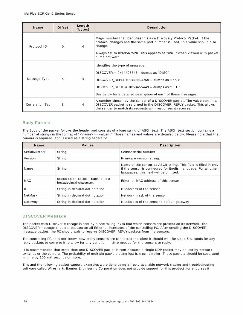
Name Offset Length(bytes) Description
Protocol ID 0 4
Magic number that identifies this as a Discovery Protocol Packet. If theprotocol changes and the same port number is used, this value should alsochange.
Always set to 0x6956752b. This appears as “iVu+” when viewed with packetdump software.
Message Type 4 4
Identifies the type of message:
DISCOVER = 0x44495343 - dumps as “DISC”
DISCOVER_REPLY = 0x52504c59 – dumps as “RPLY”
DISCOVER_SETIP = 0x53455449 – dumps as “SETI”
See below for a detailed description of each of these messages.
Correlation Tag 8 4A number chosen by the sender of a DISCOVER packet. The value sent in aDISCOVER packet is returned in the DISCOVER_REPLY packet. This allowsthe sender to match its requests with responses it receives.
Body Format
The Body of the packet follows the header and consists of a long string of ASCII text. The ASCII text section contains anumber of strings in the format of “<name>=<value>,” Those names and values are detailed below. Please note that thecomma is required, and is used as a string separator.
Name Values Description
SerialNumber String Sensor serial number
Version String Firmware version string.
Name StringName of the sensor as ASCII string. This field is filled in onlyif the sensor is configured for English language. For all otherlanguages, this field will be omitted.
MAC xx:xx:xx:xx:xx:xx – Each 'x' is ahexadecimal character. Ethernet MAC address of this sensor
IP String in decimal dot notation IP address of the sensor
NetMask String in decimal dot notation Network mask of the sensor
Gateway String in decimal dot notation IP address of the sensor's default gateway
DISCOVER Message
The packet with Discover message is sent by a controlling PC to find which sensors are present on its network. TheDISCOVER message should broadcast on all Ethernet interfaces of the controlling PC. After sending the DISCOVERmessage packet, the PC should wait to receive DISCOVER_REPLY packets from the sensors.
The controlling PC does not 'know' how many sensors are connected therefore it should wait for up to 5 seconds for anyreply packets to come to it to allow for any variation in time needed for the sensors to reply.
It is recommended that more than one DISCOVER packet is sent because a single UDP packet may be lost by networkswitches or the camera. The probability of multiple packets being lost is much smaller. These packets should be separatedin time by 100 milliseconds or more.
This and the following packet capture examples were done using a freely-available network tracing and troubleshootingsoftware called Wireshark. Banner Engineering Corporation does not provide support for this product nor endorses it.
iVu Plus BCR Gen2 Series Sensor
76 www.bannerengineering.com - Tel: 763.544.3164
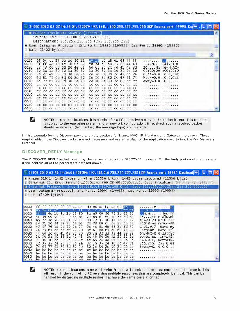
NOTE: – In some situations, it is possible for a PC to receive a copy of the packet it sent. This conditionis subject to the operating system and/or network configuration. If received, such a received packetshould be detected (by checking the message type) and discarded.
In this example for the Discover packets, empty sections for Name, MAC, IP, NetMask and Gateway are shown. Theseempty fields in the Discover packet are not necessary and are an artifact of the application used to test the iVu DiscoveryProtocol
DISCOVER_REPLY Message
The DISCOVER_REPLY packet is sent by the sensor in reply to a DISCOVER message. For the body portion of the messageit will contain all of the parameters detailed above.
NOTE: In some situations, a network switch/router will receive a broadcast packet and duplicate it. Thiswill result in the controlling PC receiving multiple responses that are completely identical. This can behandled by discarding multiple replies that have the same correlation tag.
iVu Plus BCR Gen2 Series Sensor
www.bannerengineering.com - Tel: 763.544.3164 77
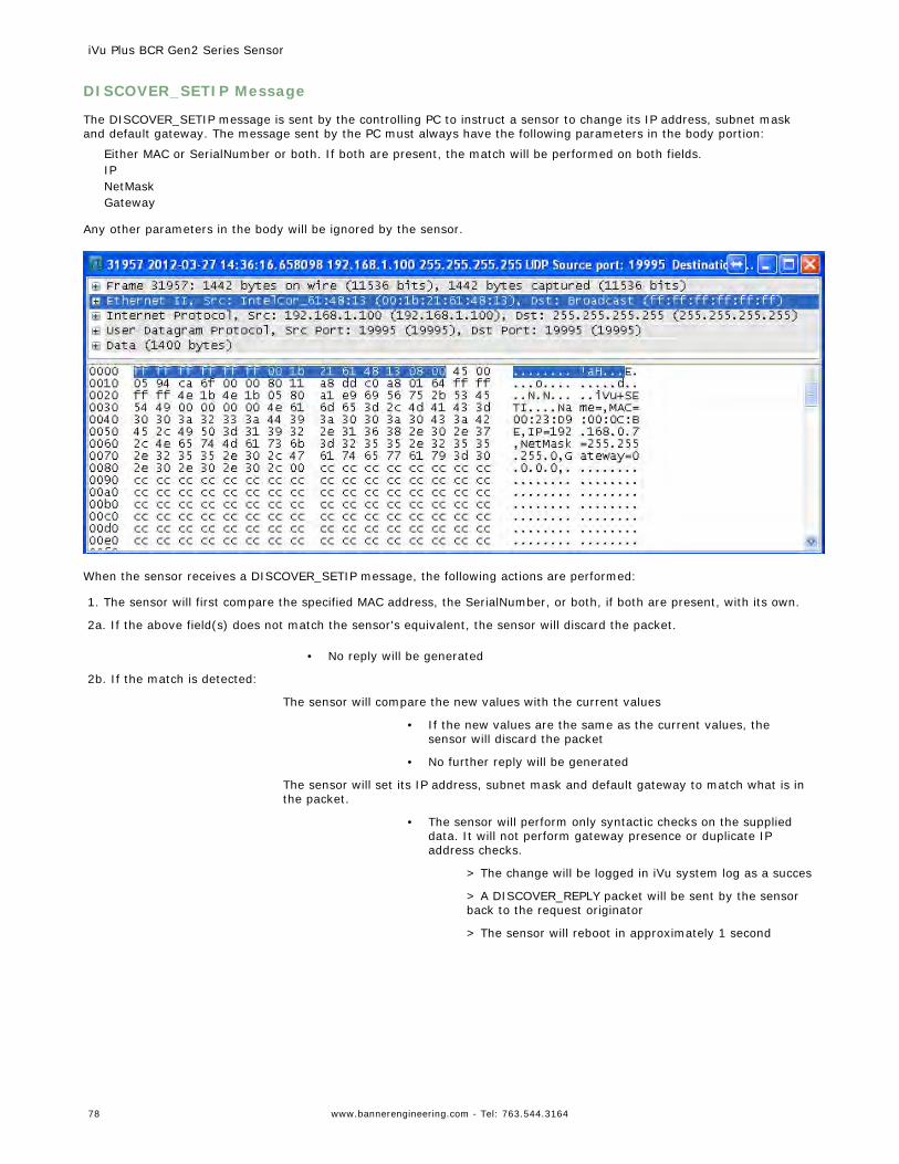
DISCOVER_SETIP Message
The DISCOVER_SETIP message is sent by the controlling PC to instruct a sensor to change its IP address, subnet maskand default gateway. The message sent by the PC must always have the following parameters in the body portion:
Either MAC or SerialNumber or both. If both are present, the match will be performed on both fields.IPNetMaskGateway
Any other parameters in the body will be ignored by the sensor.
When the sensor receives a DISCOVER_SETIP message, the following actions are performed:
1. The sensor will first compare the specified MAC address, the SerialNumber, or both, if both are present, with its own.
2a. If the above field(s) does not match the sensor's equivalent, the sensor will discard the packet.
• No reply will be generated
2b. If the match is detected:
The sensor will compare the new values with the current values
• If the new values are the same as the current values, thesensor will discard the packet
• No further reply will be generated
The sensor will set its IP address, subnet mask and default gateway to match what is inthe packet.
• The sensor will perform only syntactic checks on the supplieddata. It will not perform gateway presence or duplicate IPaddress checks.
> The change will be logged in iVu system log as a succes
> A DISCOVER_REPLY packet will be sent by the sensorback to the request originator
> The sensor will reboot in approximately 1 second
iVu Plus BCR Gen2 Series Sensor
78 www.bannerengineering.com - Tel: 763.544.3164
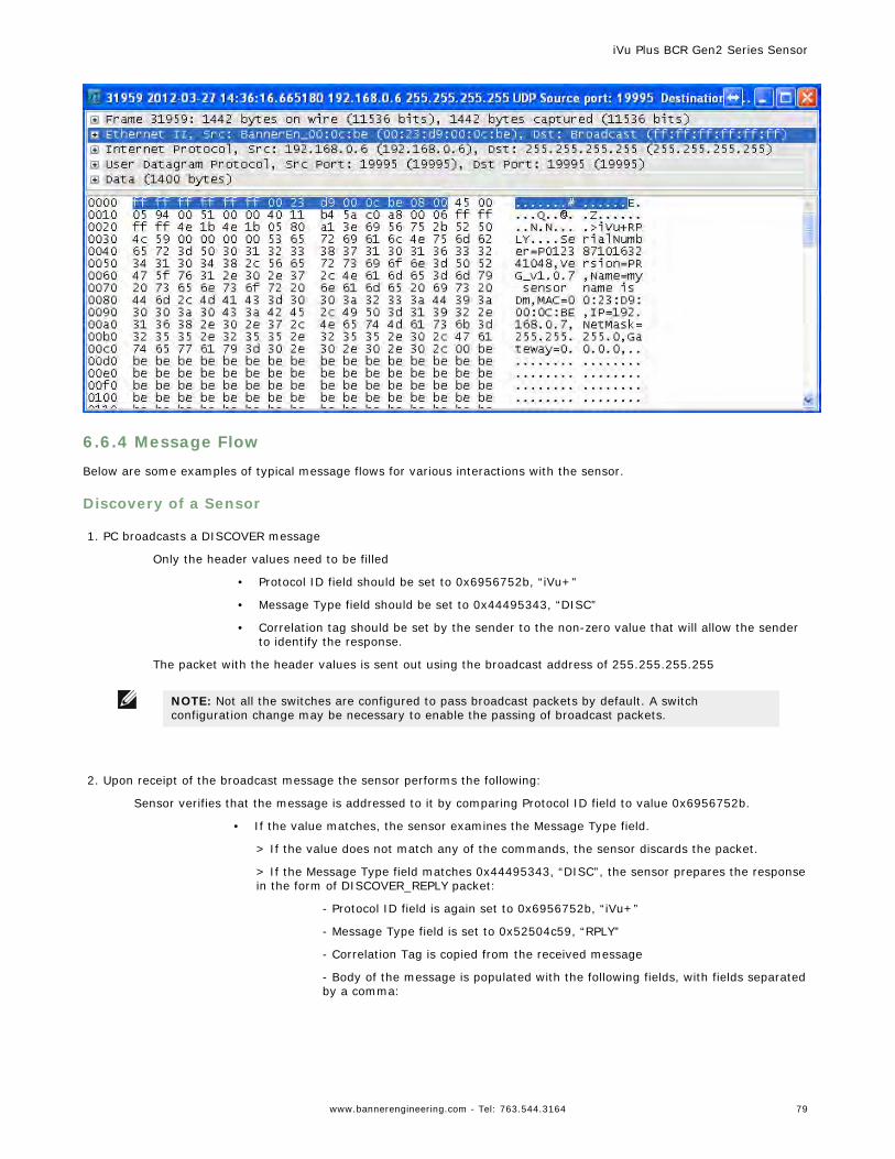
6.6.4 Message Flow
Below are some examples of typical message flows for various interactions with the sensor.
Discovery of a Sensor
1. PC broadcasts a DISCOVER message
Only the header values need to be filled
• Protocol ID field should be set to 0x6956752b, “iVu+"
• Message Type field should be set to 0x44495343, “DISC”
• Correlation tag should be set by the sender to the non-zero value that will allow the senderto identify the response.
The packet with the header values is sent out using the broadcast address of 255.255.255.255
NOTE: Not all the switches are configured to pass broadcast packets by default. A switchconfiguration change may be necessary to enable the passing of broadcast packets.
2. Upon receipt of the broadcast message the sensor performs the following:
Sensor verifies that the message is addressed to it by comparing Protocol ID field to value 0x6956752b.
• If the value matches, the sensor examines the Message Type field.
> If the value does not match any of the commands, the sensor discards the packet.
> If the Message Type field matches 0x44495343, “DISC”, the sensor prepares the responsein the form of DISCOVER_REPLY packet:
- Protocol ID field is again set to 0x6956752b, “iVu+”
- Message Type field is set to 0x52504c59, “RPLY”
- Correlation Tag is copied from the received message
- Body of the message is populated with the following fields, with fields separatedby a comma:
iVu Plus BCR Gen2 Series Sensor
www.bannerengineering.com - Tel: 763.544.3164 79
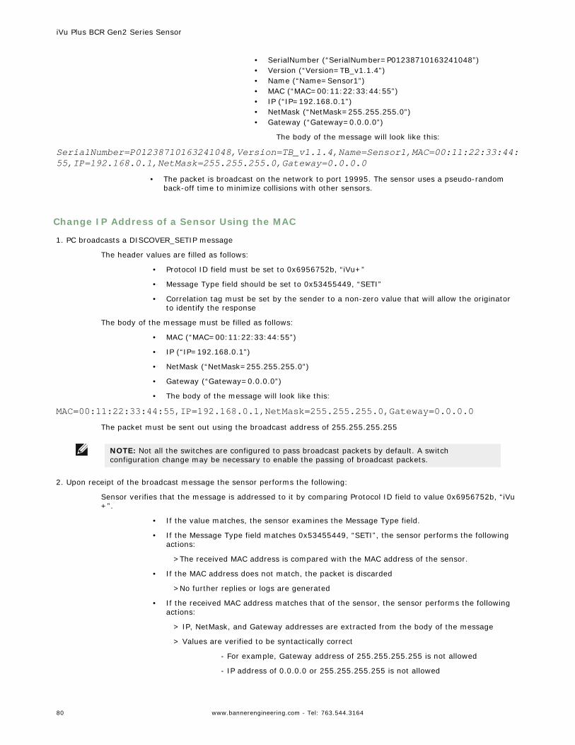
• SerialNumber (“SerialNumber=P01238710163241048”)• Version (“Version=TB_v1.1.4”)• Name (“Name=Sensor1”)• MAC (“MAC=00:11:22:33:44:55”)• IP (“IP=192.168.0.1”)• NetMask (“NetMask=255.255.255.0”)• Gateway (“Gateway=0.0.0.0”)
The body of the message will look like this:
SerialNumber=P01238710163241048,Version=TB_v1.1.4,Name=Sensor1,MAC=00:11:22:33:44:55,IP=192.168.0.1,NetMask=255.255.255.0,Gateway=0.0.0.0
• The packet is broadcast on the network to port 19995. The sensor uses a pseudo-randomback-off time to minimize collisions with other sensors.
Change IP Address of a Sensor Using the MAC
1. PC broadcasts a DISCOVER_SETIP message
The header values are filled as follows:
• Protocol ID field must be set to 0x6956752b, “iVu+”
• Message Type field should be set to 0x53455449, “SETI”
• Correlation tag must be set by the sender to a non-zero value that will allow the originatorto identify the response
The body of the message must be filled as follows:
• MAC (“MAC=00:11:22:33:44:55”)
• IP (“IP=192.168.0.1”)
• NetMask (“NetMask=255.255.255.0”)
• Gateway (“Gateway=0.0.0.0”)
• The body of the message will look like this:
MAC=00:11:22:33:44:55,IP=192.168.0.1,NetMask=255.255.255.0,Gateway=0.0.0.0The packet must be sent out using the broadcast address of 255.255.255.255
NOTE: Not all the switches are configured to pass broadcast packets by default. A switchconfiguration change may be necessary to enable the passing of broadcast packets.
2. Upon receipt of the broadcast message the sensor performs the following:
Sensor verifies that the message is addressed to it by comparing Protocol ID field to value 0x6956752b, “iVu+”.
• If the value matches, the sensor examines the Message Type field.
• If the Message Type field matches 0x53455449, “SETI”, the sensor performs the followingactions:
>The received MAC address is compared with the MAC address of the sensor.
• If the MAC address does not match, the packet is discarded
>No further replies or logs are generated
• If the received MAC address matches that of the sensor, the sensor performs the followingactions:
> IP, NetMask, and Gateway addresses are extracted from the body of the message
> Values are verified to be syntactically correct
- For example, Gateway address of 255.255.255.255 is not allowed
- IP address of 0.0.0.0 or 255.255.255.255 is not allowed
iVu Plus BCR Gen2 Series Sensor
80 www.bannerengineering.com - Tel: 763.544.3164
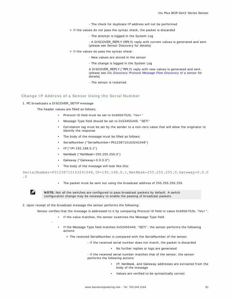
- The check for duplicate IP address will not be performed
> If the values do not pass the syntax check, the packet is discarded
- The attempt is logged in the System Log
- A DISCOVER_REPLY (RPLY) reply with current values is generated and sent.(please see Sensor Discovery for details)
> If the values do pass the syntax check:
- New values are stored in the sensor
- The change is logged in the System Log
A DISCOVER_REPLY (“RPLY) reply with new values is generated and sent.(please see iVu Discovery Protocol Message Flow Discovery of a sensor fordetails)
- The sensor is restarted.
Change IP Address of a Sensor Using the Serial Number
1. PC broadcasts a DISCOVER_SETIP message
The header values are filled as follows:
• Protocol ID field must be set to 0x6956752b, “iVu+”
• Message Type field should be set to 0x53455449, “SETI”
• Correlation tag must be set by the sender to a non-zero value that will allow the originator toidentify the response
• The body of the message must be filled as follows:
• SerialNumber (“SerialNumber=P01238710163241048”)
• IP (“IP=192.168.0.1”)
• NetMask (“NetMask=255.255.255.0”)
• Gateway (“Gateway=0.0.0.0”)
• The body of the message will look like this:
SerialNumber=P01238710163241048,IP=192.168.0.1,NetMask=255.255.255.0,Gateway=0.0.0.0
• The packet must be sent out using the broadcast address of 255.255.255.255
NOTE: Not all the switches are configured to pass broadcast packets by default. A switchconfiguration change may be necessary to enable the passing of broadcast packets.
2. Upon receipt of the broadcast message the sensor performs the following:
Sensor verifies that the message is addressed to it by comparing Protocol ID field to value 0x6956752b, “iVu+”.
• If the value matches, the sensor examines the Message Type field.
• If the Message Type field matches 0x53455449, “SETI”, the sensor performs the followingactions:
> The received SerialNumber is compared with the SerialNumber of the sensor.
- If the received serial number does not match, the packet is discarded
• No further replies or logs are generated
- If the received serial number matches that of the sensor, the sensorperforms the following actions:
• IP, NetMask, and Gateway addresses are extracted from thebody of the message
• Values are verified to be syntactically correct
iVu Plus BCR Gen2 Series Sensor
www.bannerengineering.com - Tel: 763.544.3164 81
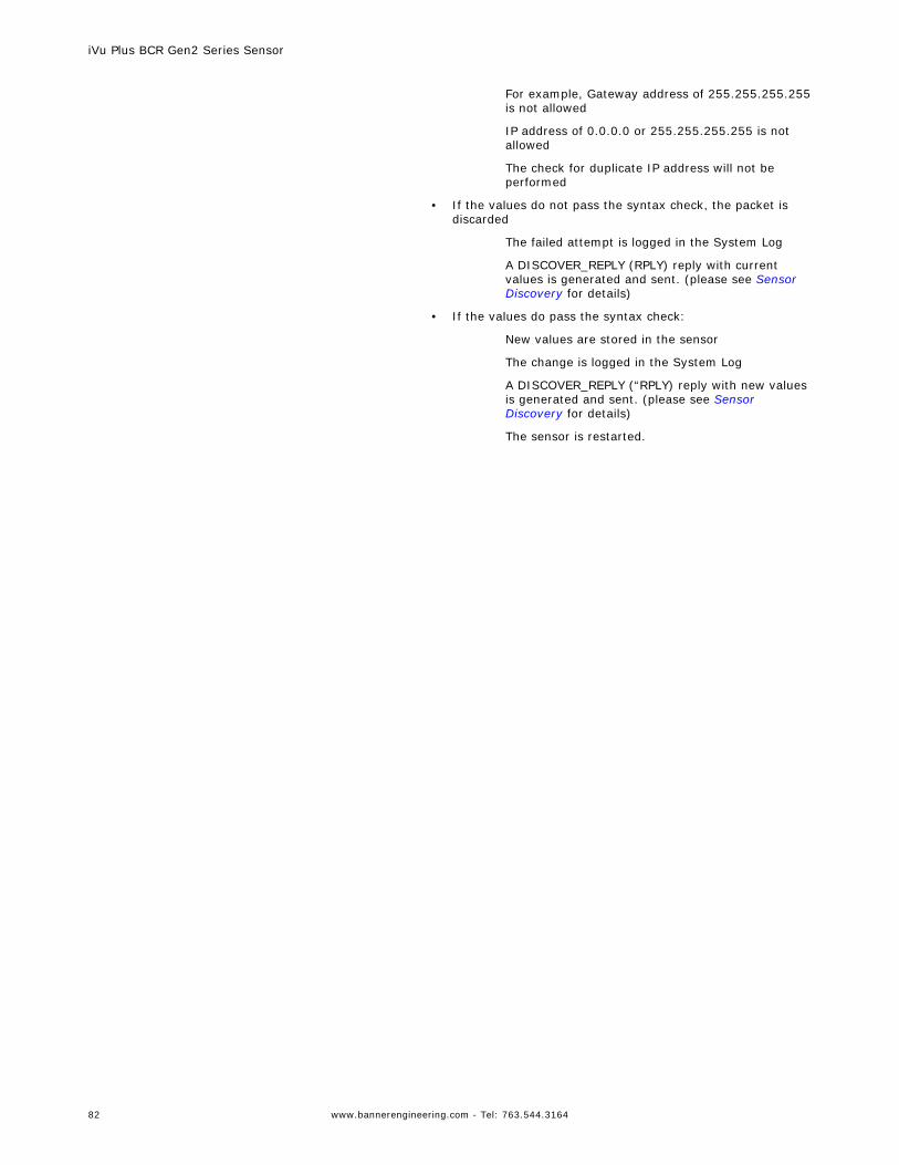
For example, Gateway address of 255.255.255.255is not allowed
IP address of 0.0.0.0 or 255.255.255.255 is notallowed
The check for duplicate IP address will not beperformed
• If the values do not pass the syntax check, the packet isdiscarded
The failed attempt is logged in the System Log
A DISCOVER_REPLY (RPLY) reply with currentvalues is generated and sent. (please see SensorDiscovery for details)
• If the values do pass the syntax check:
New values are stored in the sensor
The change is logged in the System Log
A DISCOVER_REPLY (“RPLY) reply with new valuesis generated and sent. (please see SensorDiscovery for details)
The sensor is restarted.
iVu Plus BCR Gen2 Series Sensor
82 www.bannerengineering.com - Tel: 763.544.3164
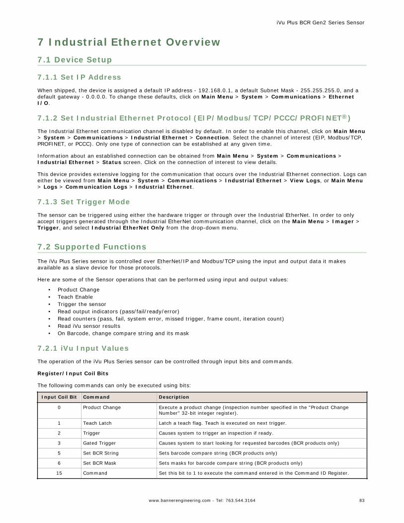
7 Industrial Ethernet Overview7.1 Device Setup
7.1.1 Set IP Address
When shipped, the device is assigned a default IP address - 192.168.0.1, a default Subnet Mask - 255.255.255.0, and adefault gateway - 0.0.0.0. To change these defaults, click on Main Menu > System > Communications > EthernetI/O.
7.1.2 Set Industrial Ethernet Protocol (EIP/Modbus/TCP/PCCC/PROFINET®)
The Industrial Ethernet communication channel is disabled by default. In order to enable this channel, click on Main Menu> System > Communications > Industrial Ethernet > Connection. Select the channel of interest (EIP, Modbus/TCP,PROFINET, or PCCC). Only one type of connection can be established at any given time.
Information about an established connection can be obtained from Main Menu > System > Communications >Industrial Ethernet > Status screen. Click on the connection of interest to view details.
This device provides extensive logging for the communication that occurs over the Industrial Ethernet connection. Logs caneither be viewed from Main Menu > System > Communications > Industrial Ethernet > View Logs, or Main Menu> Logs > Communication Logs > Industrial Ethernet.
7.1.3 Set Trigger Mode
The sensor can be triggered using either the hardware trigger or through over the Industrial EtherNet. In order to onlyaccept triggers generated through the Industrial EtherNet communication channel, click on the Main Menu > Imager >Trigger, and select Industrial EtherNet Only from the drop-down menu.
7.2 Supported FunctionsThe iVu Plus Series sensor is controlled over EtherNet/IP and Modbus/TCP using the input and output data it makesavailable as a slave device for those protocols.
Here are some of the Sensor operations that can be performed using input and output values:
• Product Change• Teach Enable• Trigger the sensor• Read output indicators (pass/fail/ready/error)• Read counters (pass, fail, system error, missed trigger, frame count, iteration count)• Read iVu sensor results• On Barcode, change compare string and its mask
7.2.1 iVu Input Values
The operation of the iVu Plus Series sensor can be controlled through input bits and commands.
Register/Input Coil Bits
The following commands can only be executed using bits:
Input Coil Bit Command Description
0 Product Change Execute a product change (inspection number specified in the "Product ChangeNumber" 32-bit integer register).
1 Teach Latch Latch a teach flag. Teach is executed on next trigger.
2 Trigger Causes system to trigger an inspection if ready.
3 Gated Trigger Causes system to start looking for requested barcodes (BCR products only)
5 Set BCR String Sets barcode compare string (BCR products only)
6 Set BCR Mask Sets masks for barcode compare string (BCR products only)
15 Command Set this bit to 1 to execute the command entered in the Command ID Register.
iVu Plus BCR Gen2 Series Sensor
www.bannerengineering.com - Tel: 763.544.3164 83
7.2.2 iVu Output Values
Using output values, the following information can be obtained:• ACK bits (acknowledgement bits) for input commands, including error codes• System indicators (Ready, Pass/Fail, Read/No Read, Output signals, Command Error, etc.)• Inspection History (Iteration Count, Pass Count, Fail Count, etc.)• Current Inspection Results (data of the sensor type contained in the inspection)• Command Responses
Refer to the sections on protocols for more information.
ACK Flags
For each of the Command Flags there is a corresponding ACK flag. The Vision Sensor sets the ACK flag when thecorresponding action is complete. Command flags cause actions to occur on the low-to-high transition of that flag. Youmust clear the command flag after the corresponding ACK flag has been observed to be high.
As an example, to use the Trigger ACK flag, the programming steps for triggering an inspection would be:
1. Wait for ready.2. Set Trigger command flag to 1.3. Wait for Trigger ACK to go to 1.4. Set Trigger command flag to 0.
Command Responses
iVu Plus Series Command Channel commands executed using command IDs may have a response value. Depending on theData Type, the response value will be contained in one or multiple registers. Refer to iVu Command Channel Commandssection of this document and the iVu Plus Communication's Users Guide for more information about the iVu CommandChannel.
7.3 Sensor OperationAny Industrial Ethernet protocol can be used to trigger inspections, remote teach and perform command functions. OniVuPlus BCR models, compare strings can also be set.
iVu Plus BCR Gen2 Series Sensor
84 www.bannerengineering.com - Tel: 763.544.3164
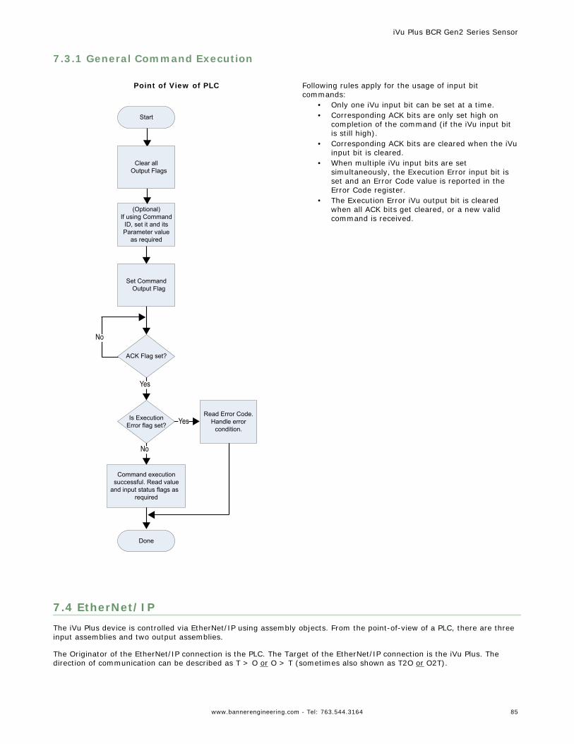
7.3.1 General Command Execution
Point of View of PLC
Start
(Optional)If using Command
ID, set it and its Parameter value
as required
Done
Read Error Code. Handle error
condition.
Clear allOutput Flags
Is Execution Error flag set?
Command execution successful. Read value
and input status flags as required
ACK Flag set?
Set Command Output Flag
Yes
No
Yes
No
Following rules apply for the usage of input bitcommands:
• Only one iVu input bit can be set at a time.• Corresponding ACK bits are only set high on
completion of the command (if the iVu input bitis still high).
• Corresponding ACK bits are cleared when the iVuinput bit is cleared.
• When multiple iVu input bits are setsimultaneously, the Execution Error input bit isset and an Error Code value is reported in theError Code register.
• The Execution Error iVu output bit is clearedwhen all ACK bits get cleared, or a new validcommand is received.
7.4 EtherNet/IPThe iVu Plus device is controlled via EtherNet/IP using assembly objects. From the point-of-view of a PLC, there are threeinput assemblies and two output assemblies.
The Originator of the EtherNet/IP connection is the PLC. The Target of the EtherNet/IP connection is the iVu Plus. Thedirection of communication can be described as T > O or O > T (sometimes also shown as T2O or O2T).
iVu Plus BCR Gen2 Series Sensor
www.bannerengineering.com - Tel: 763.544.3164 85
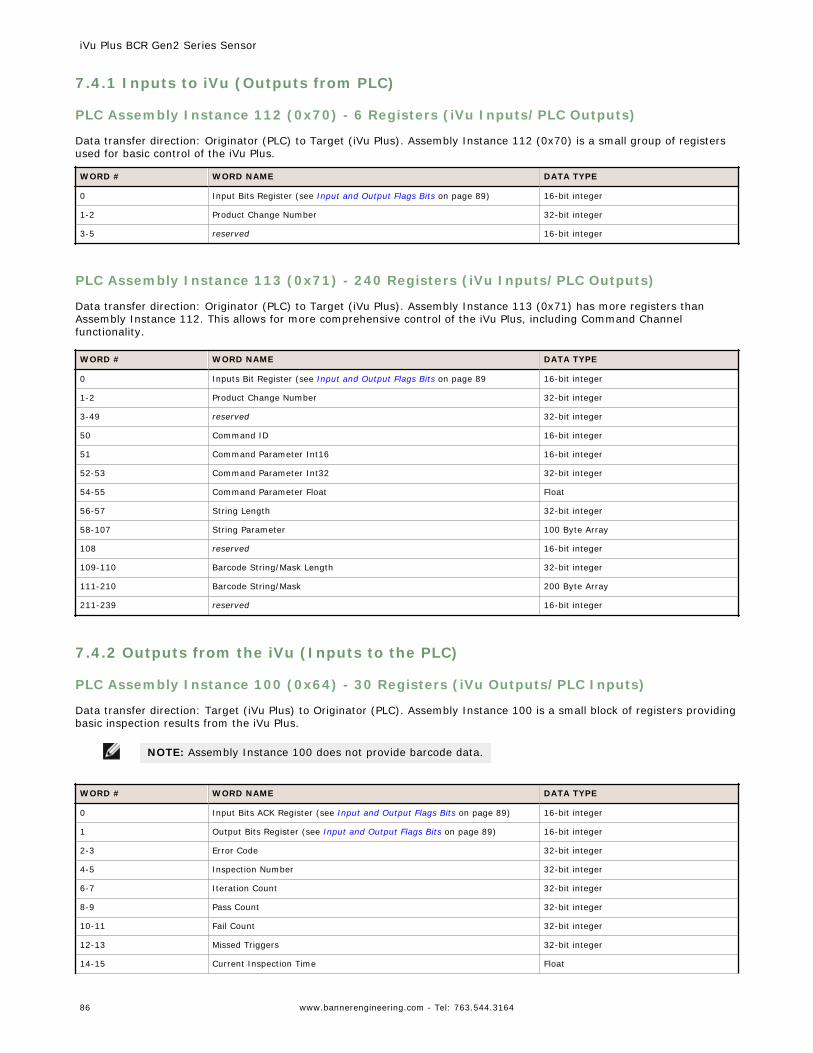
7.4.1 Inputs to iVu (Outputs from PLC)
PLC Assembly Instance 112 (0x70) - 6 Registers (iVu Inputs/PLC Outputs)
Data transfer direction: Originator (PLC) to Target (iVu Plus). Assembly Instance 112 (0x70) is a small group of registersused for basic control of the iVu Plus.
WORD # WORD NAME DATA TYPE
0 Input Bits Register (see Input and Output Flags Bits on page 89) 16-bit integer
1-2 Product Change Number 32-bit integer
3-5 reserved 16-bit integer
PLC Assembly Instance 113 (0x71) - 240 Registers (iVu Inputs/PLC Outputs)
Data transfer direction: Originator (PLC) to Target (iVu Plus). Assembly Instance 113 (0x71) has more registers thanAssembly Instance 112. This allows for more comprehensive control of the iVu Plus, including Command Channelfunctionality.
WORD # WORD NAME DATA TYPE
0 Inputs Bit Register (see Input and Output Flags Bits on page 89 16-bit integer
1-2 Product Change Number 32-bit integer
3-49 reserved 32-bit integer
50 Command ID 16-bit integer
51 Command Parameter Int16 16-bit integer
52-53 Command Parameter Int32 32-bit integer
54-55 Command Parameter Float Float
56-57 String Length 32-bit integer
58-107 String Parameter 100 Byte Array
108 reserved 16-bit integer
109-110 Barcode String/Mask Length 32-bit integer
111-210 Barcode String/Mask 200 Byte Array
211-239 reserved 16-bit integer
7.4.2 Outputs from the iVu (Inputs to the PLC)
PLC Assembly Instance 100 (0x64) - 30 Registers (iVu Outputs/PLC Inputs)
Data transfer direction: Target (iVu Plus) to Originator (PLC). Assembly Instance 100 is a small block of registers providingbasic inspection results from the iVu Plus.
NOTE: Assembly Instance 100 does not provide barcode data.
WORD # WORD NAME DATA TYPE
0 Input Bits ACK Register (see Input and Output Flags Bits on page 89) 16-bit integer
1 Output Bits Register (see Input and Output Flags Bits on page 89) 16-bit integer
2-3 Error Code 32-bit integer
4-5 Inspection Number 32-bit integer
6-7 Iteration Count 32-bit integer
8-9 Pass Count 32-bit integer
10-11 Fail Count 32-bit integer
12-13 Missed Triggers 32-bit integer
14-15 Current Inspection Time Float
iVu Plus BCR Gen2 Series Sensor
86 www.bannerengineering.com - Tel: 763.544.3164
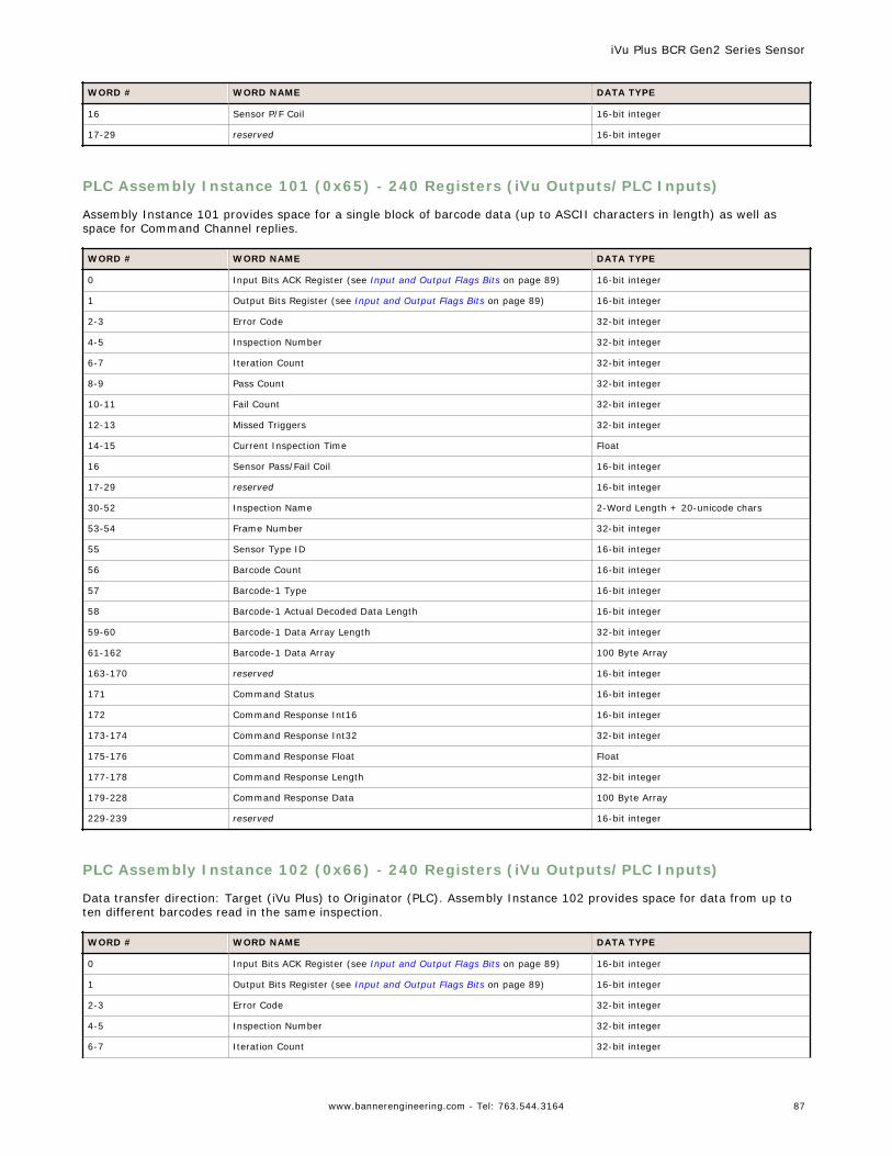
WORD # WORD NAME DATA TYPE
16 Sensor P/F Coil 16-bit integer
17-29 reserved 16-bit integer
PLC Assembly Instance 101 (0x65) - 240 Registers (iVu Outputs/PLC Inputs)
Assembly Instance 101 provides space for a single block of barcode data (up to ASCII characters in length) as well asspace for Command Channel replies.
WORD # WORD NAME DATA TYPE
0 Input Bits ACK Register (see Input and Output Flags Bits on page 89) 16-bit integer
1 Output Bits Register (see Input and Output Flags Bits on page 89) 16-bit integer
2-3 Error Code 32-bit integer
4-5 Inspection Number 32-bit integer
6-7 Iteration Count 32-bit integer
8-9 Pass Count 32-bit integer
10-11 Fail Count 32-bit integer
12-13 Missed Triggers 32-bit integer
14-15 Current Inspection Time Float
16 Sensor Pass/Fail Coil 16-bit integer
17-29 reserved 16-bit integer
30-52 Inspection Name 2-Word Length + 20-unicode chars
53-54 Frame Number 32-bit integer
55 Sensor Type ID 16-bit integer
56 Barcode Count 16-bit integer
57 Barcode-1 Type 16-bit integer
58 Barcode-1 Actual Decoded Data Length 16-bit integer
59-60 Barcode-1 Data Array Length 32-bit integer
61-162 Barcode-1 Data Array 100 Byte Array
163-170 reserved 16-bit integer
171 Command Status 16-bit integer
172 Command Response Int16 16-bit integer
173-174 Command Response Int32 32-bit integer
175-176 Command Response Float Float
177-178 Command Response Length 32-bit integer
179-228 Command Response Data 100 Byte Array
229-239 reserved 16-bit integer
PLC Assembly Instance 102 (0x66) - 240 Registers (iVu Outputs/PLC Inputs)
Data transfer direction: Target (iVu Plus) to Originator (PLC). Assembly Instance 102 provides space for data from up toten different barcodes read in the same inspection.
WORD # WORD NAME DATA TYPE
0 Input Bits ACK Register (see Input and Output Flags Bits on page 89) 16-bit integer
1 Output Bits Register (see Input and Output Flags Bits on page 89) 16-bit integer
2-3 Error Code 32-bit integer
4-5 Inspection Number 32-bit integer
6-7 Iteration Count 32-bit integer
iVu Plus BCR Gen2 Series Sensor
www.bannerengineering.com - Tel: 763.544.3164 87
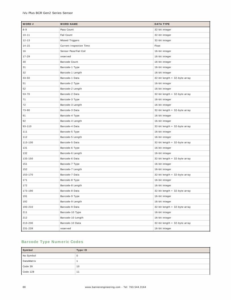
WORD # WORD NAME DATA TYPE
8-9 Pass Count 32-bit integer
10-11 Fail Count 32-bit integer
12-13 Missed Triggers 32-bit integer
14-15 Current Inspection Time Float
16 Sensor Pass/Fail Coil 16-bit integer
17-29 reserved 16-bit integer
30 Barcode Count 16-bit integer
31 Barcode-1 Type 16-bit integer
32 Barcode-1 Length 16-bit integer
33-50 Barcode-1 Data 32-bit length + 32-byte array
51 Barcode-2 Type 16-bit integer
52 Barcode-2 Length 16-bit integer
53-70 Barcode-2 Data 32-bit length + 32-byte array
71 Barcode-3 Type 16-bit integer
72 Barcode-3 Length 16-bit integer
73-90 Barcode-3 Data 32-bit length + 32-byte array
91 Barcode-4 Type 16-bit integer
92 Barcode-4 Length 16-bit integer
93-110 Barcode-4 Data 32-bit length + 32-byte array
111 Barcode-5 Type 16-bit integer
112 Barcode-5 Length 16-bit integer
113-130 Barcode-5 Data 32-bit length + 32-byte array
131 Barcode-6 Type 16-bit integer
132 Barcode-6 Length 16-bit integer
133-150 Barcode-6 Data 32-bit length + 32-byte array
151 Barcode-7 Type 16-bit integer
152 Barcode-7 Length 16-bit integer
153-170 Barcode-7 Data 32-bit length + 32-byte array
171 Barcode-8 Type 16-bit integer
172 Barcode-8 Length 16-bit integer
173-190 Barcode-8 Data 32-bit length + 32-byte array
191 Barcode-9 Type 16-bit integer
192 Barcode-9 Length 16-bit integer
193-210 Barcode-9 Data 32-bit length + 32-byte array
211 Barcode-10 Type 16-bit integer
212 Barcode-10 Length 16-bit integer
213-230 Barcode-10 Data 32-bit length + 32-byte array
231-239 reserved 16-bit integer
Barcode Type Numeric Codes
Symbol Type ID
No Symbol 0
DataMatrix 1
Code 39 10
Code 128 11
iVu Plus BCR Gen2 Series Sensor
88 www.bannerengineering.com - Tel: 763.544.3164
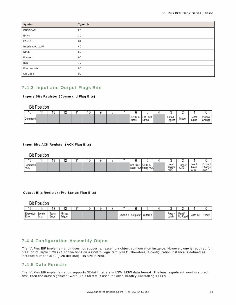
Symbol Type ID
CODABAR 20
EAN8 30
EAN13 31
Interleaved 2of5 40
UPCE 50
Postnet 60
IMB 70
Pharmacode 80
QR Code 90
7.4.3 Input and Output Flags Bits
Inputs Bits Register (Command Flag Bits)
Command Set BCRMask
Set BCRString Trigger Teach
LatchProductChange
GatedTrigger
Bit Position123456789101112131415 0
Input Bits ACK Register (ACK Flag Bits)
CommandACK
Set BCRMask ACK
Set BCRString ACK
TriggerACK
TeachLatchACK
ProductChangeACK
GatedTriggerACK
Bit Position123456789101112131415 0
Output Bits Register (iVu Status Flag Bits)
ExecutionError
SystemError
TeachError
MissedTrigger Output 3 Output 2 Output 1 Read/
No Read Pass/FailReadyLatch Ready
Bit Position123456789101112131415 0
7.4.4 Configuration Assembly Object
The iVuPlus EIP implementation does not support an assembly object configuration instance. However, one is required forcreation of implicit Class 1 connections on a ControlLogix family PLC. Therefore, a configuration instance is defined asinstance number 0x80 (128 decimal). Its size is zero.
7.4.5 Data Formats
The iVuPlus EIP implementation supports 32-bit Integers in LSW_MSW data format. The least significant word is storedfirst, then the most significant word. This format is used for Allen-Bradley ControlLogix PLCs.
iVu Plus BCR Gen2 Series Sensor
www.bannerengineering.com - Tel: 763.544.3164 89
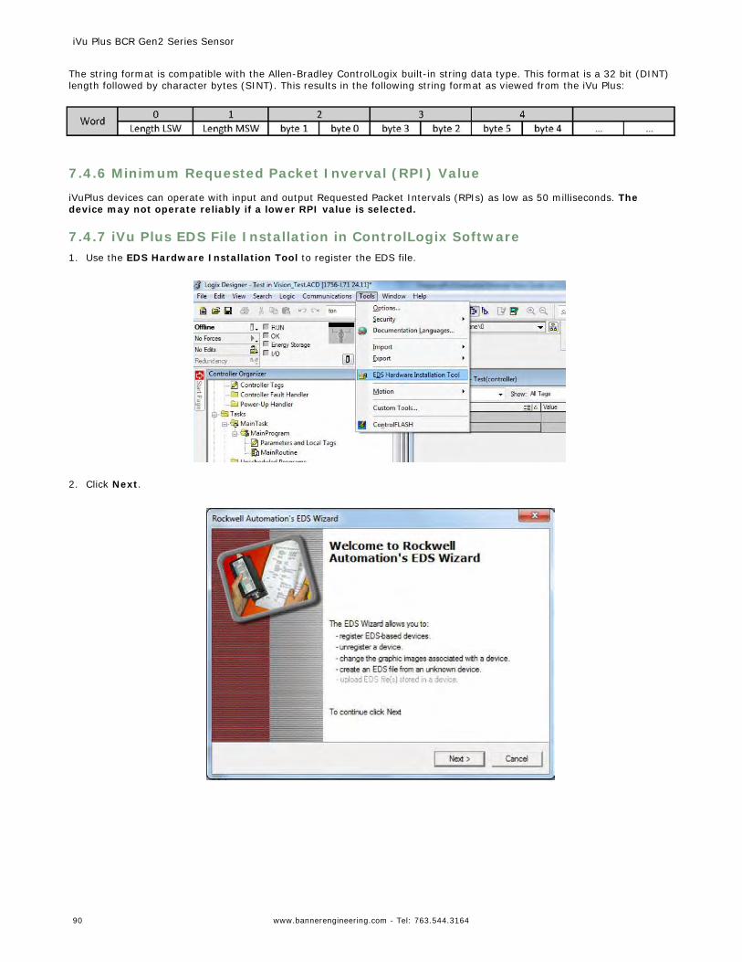
The string format is compatible with the Allen-Bradley ControlLogix built-in string data type. This format is a 32 bit (DINT)length followed by character bytes (SINT). This results in the following string format as viewed from the iVu Plus:
7.4.6 Minimum Requested Packet Inverval (RPI) Value
iVuPlus devices can operate with input and output Requested Packet Intervals (RPIs) as low as 50 milliseconds. Thedevice may not operate reliably if a lower RPI value is selected.
7.4.7 iVu Plus EDS File Installation in ControlLogix Software1. Use the EDS Hardware Installation Tool to register the EDS file.
2. Click Next.
iVu Plus BCR Gen2 Series Sensor
90 www.bannerengineering.com - Tel: 763.544.3164
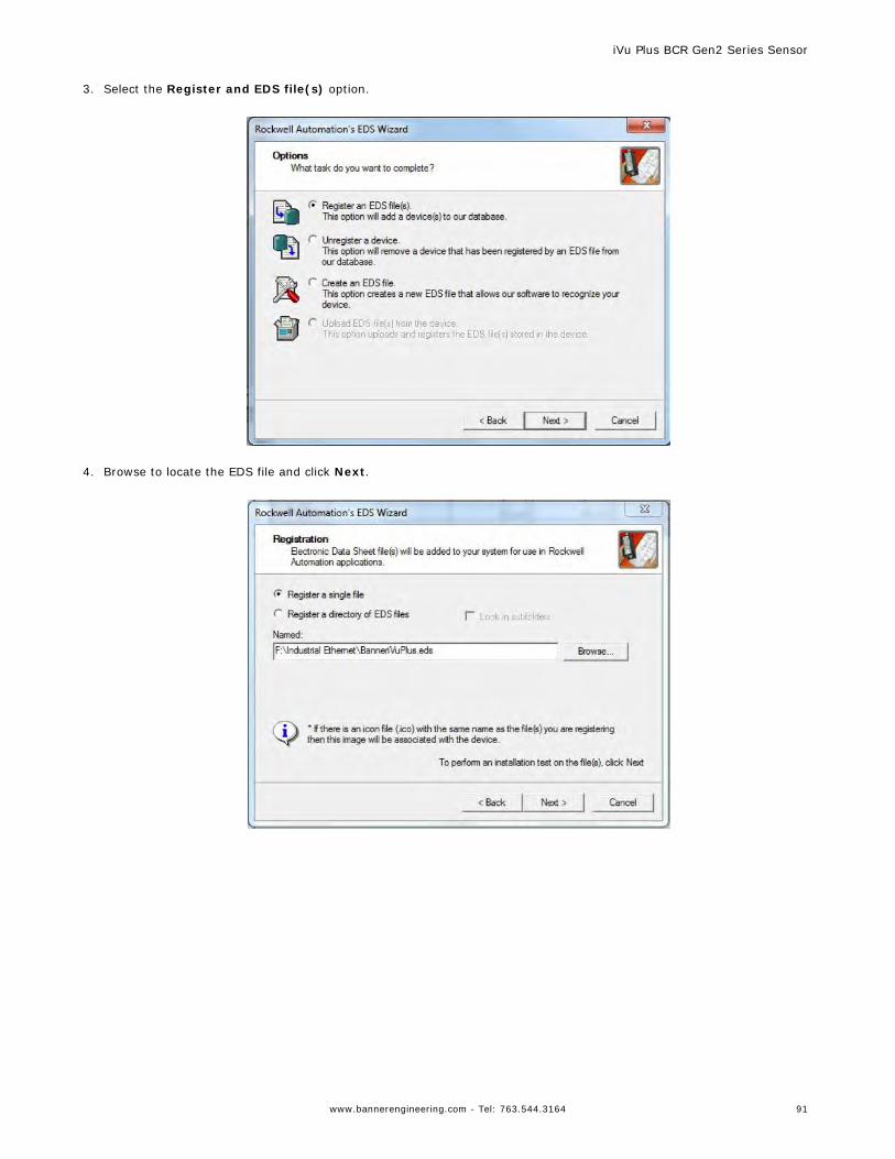
3. Select the Register and EDS file(s) option.
4. Browse to locate the EDS file and click Next.
iVu Plus BCR Gen2 Series Sensor
www.bannerengineering.com - Tel: 763.544.3164 91
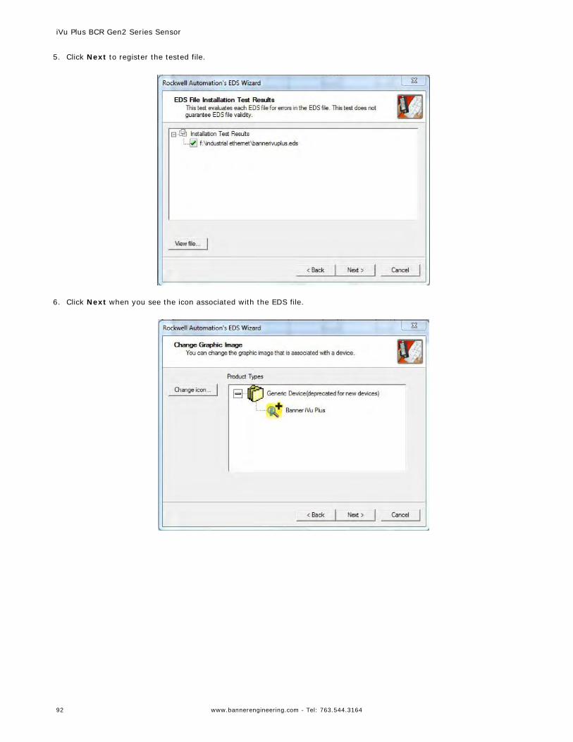
5. Click Next to register the tested file.
6. Click Next when you see the icon associated with the EDS file.
iVu Plus BCR Gen2 Series Sensor
92 www.bannerengineering.com - Tel: 763.544.3164
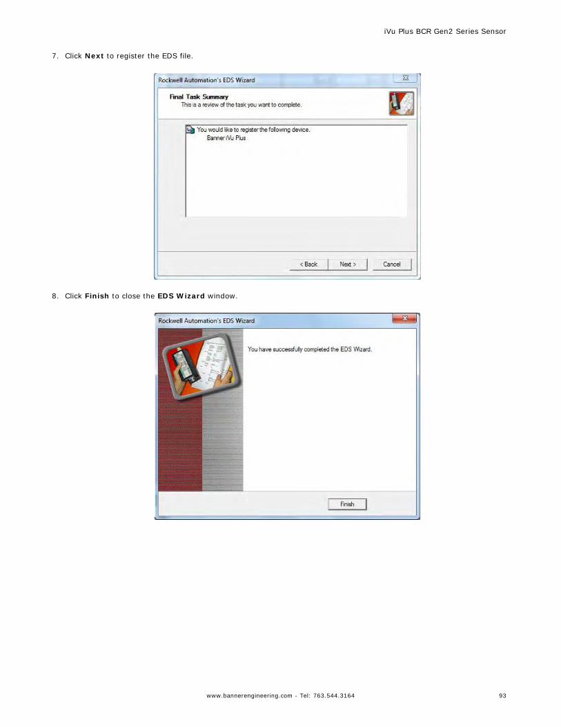
7. Click Next to register the EDS file.
8. Click Finish to close the EDS Wizard window.
iVu Plus BCR Gen2 Series Sensor
www.bannerengineering.com - Tel: 763.544.3164 93
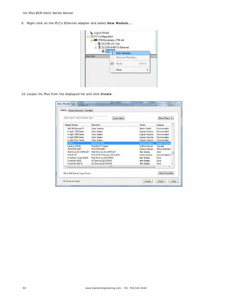
9. Right-click on the PLC's Ethernet adapter and select New Module...
10.Locate iVu Plus from the displayed list and click Create.
iVu Plus BCR Gen2 Series Sensor
94 www.bannerengineering.com - Tel: 763.544.3164
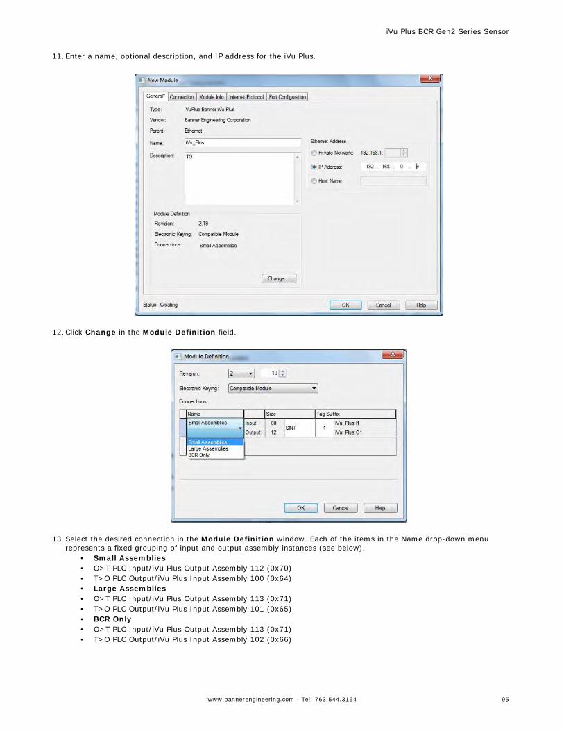
11.Enter a name, optional description, and IP address for the iVu Plus.
12.Click Change in the Module Definition field.
13.Select the desired connection in the Module Definition window. Each of the items in the Name drop-down menu
represents a fixed grouping of input and output assembly instances (see below).• Small Assemblies• O>T PLC Input/iVu Plus Output Assembly 112 (0x70)• T>O PLC Output/iVu Plus Input Assembly 100 (0x64)• Large Assemblies• O>T PLC Input/iVu Plus Output Assembly 113 (0x71)• T>O PLC Output/iVu Plus Input Assembly 101 (0x65)• BCR Only• O>T PLC Input/iVu Plus Output Assembly 113 (0x71)• T>O PLC Output/iVu Plus Input Assembly 102 (0x66)
iVu Plus BCR Gen2 Series Sensor
www.bannerengineering.com - Tel: 763.544.3164 95
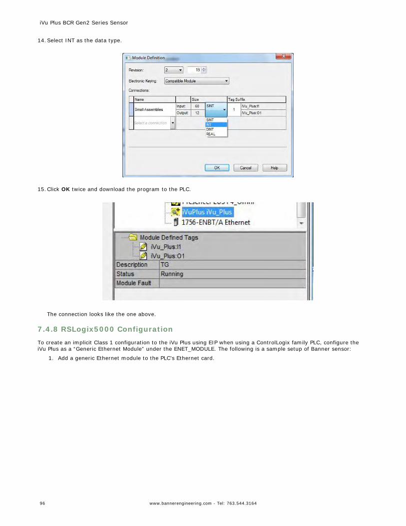
14.Select INT as the data type.
15.Click OK twice and download the program to the PLC.
The connection looks like the one above.
7.4.8 RSLogix5000 Configuration
To create an implicit Class 1 configuration to the iVu Plus using EIP when using a ControlLogix family PLC, configure theiVu Plus as a “Generic Ethernet Module” under the ENET_MODULE. The following is a sample setup of Banner sensor:
1. Add a generic Ethernet module to the PLC's Ethernet card.
iVu Plus BCR Gen2 Series Sensor
96 www.bannerengineering.com - Tel: 763.544.3164
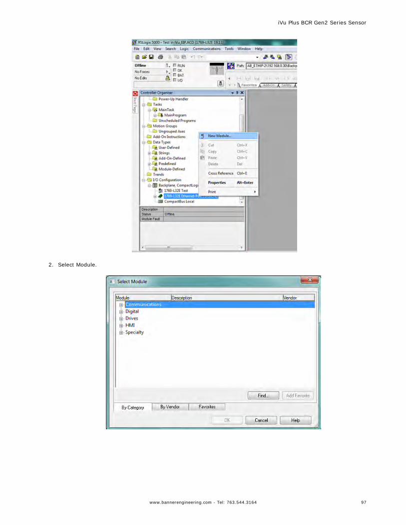
2. Select Module.
iVu Plus BCR Gen2 Series Sensor
www.bannerengineering.com - Tel: 763.544.3164 97
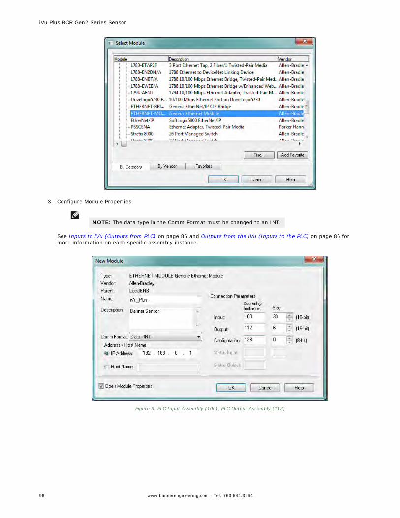
3. Configure Module Properties.
NOTE: The data type in the Comm Format must be changed to an INT.
See Inputs to iVu (Outputs from PLC) on page 86 and Outputs from the iVu (Inputs to the PLC) on page 86 formore information on each specific assembly instance.
Figure 3. PLC Input Assembly (100), PLC Output Assembly (112)
iVu Plus BCR Gen2 Series Sensor
98 www.bannerengineering.com - Tel: 763.544.3164
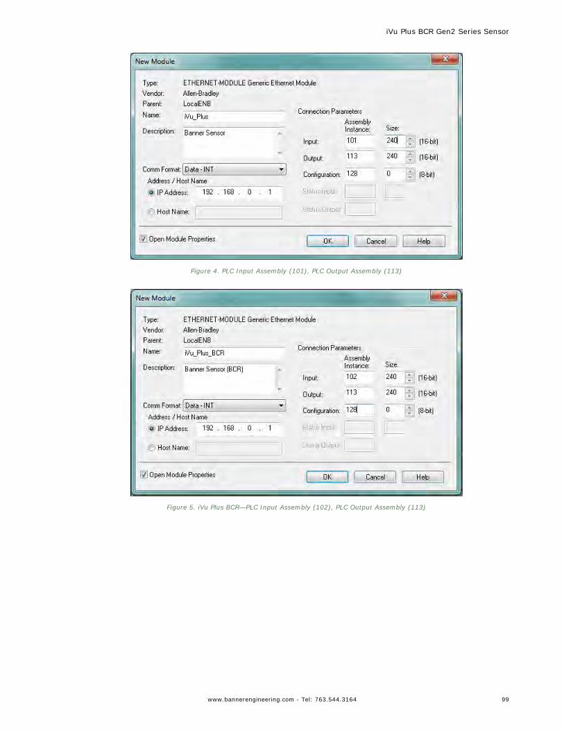
Figure 4. PLC Input Assembly (101), PLC Output Assembly (113)
Figure 5. iVu Plus BCR—PLC Input Assembly (102), PLC Output Assembly (113)
iVu Plus BCR Gen2 Series Sensor
www.bannerengineering.com - Tel: 763.544.3164 99
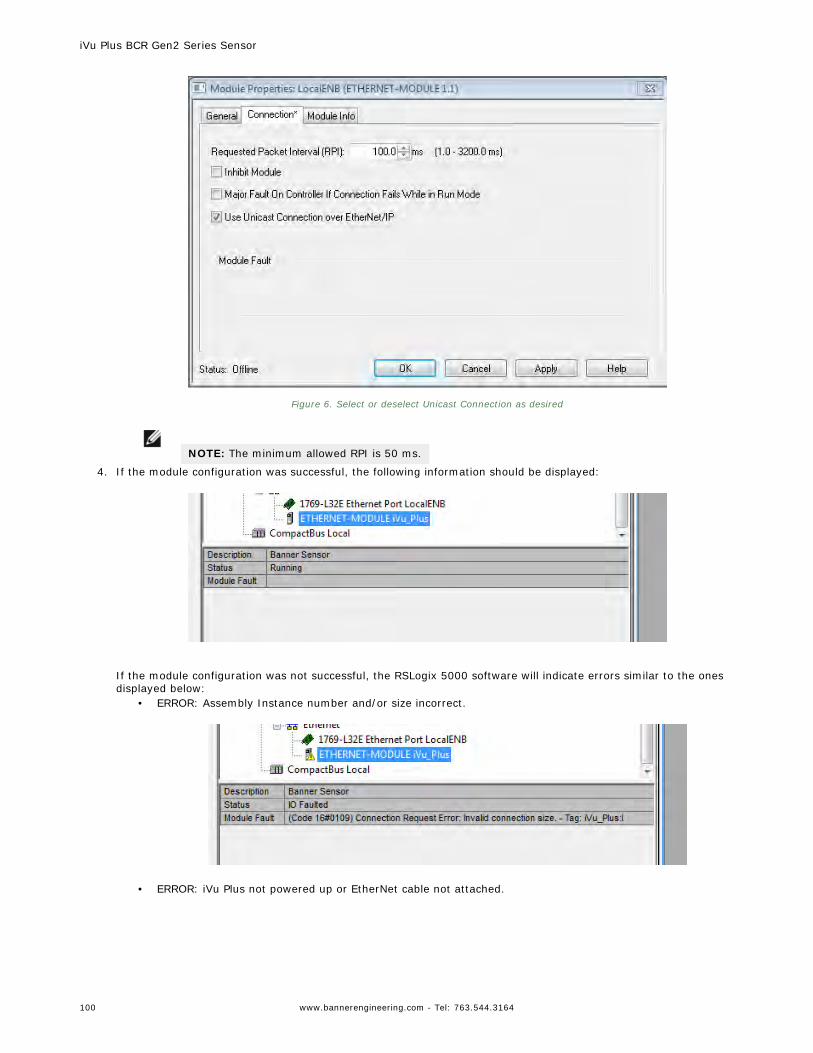
Figure 6. Select or deselect Unicast Connection as desired
NOTE: The minimum allowed RPI is 50 ms.
4. If the module configuration was successful, the following information should be displayed:
If the module configuration was not successful, the RSLogix 5000 software will indicate errors similar to the onesdisplayed below:
• ERROR: Assembly Instance number and/or size incorrect.
• ERROR: iVu Plus not powered up or EtherNet cable not attached.
iVu Plus BCR Gen2 Series Sensor
100 www.bannerengineering.com - Tel: 763.544.3164
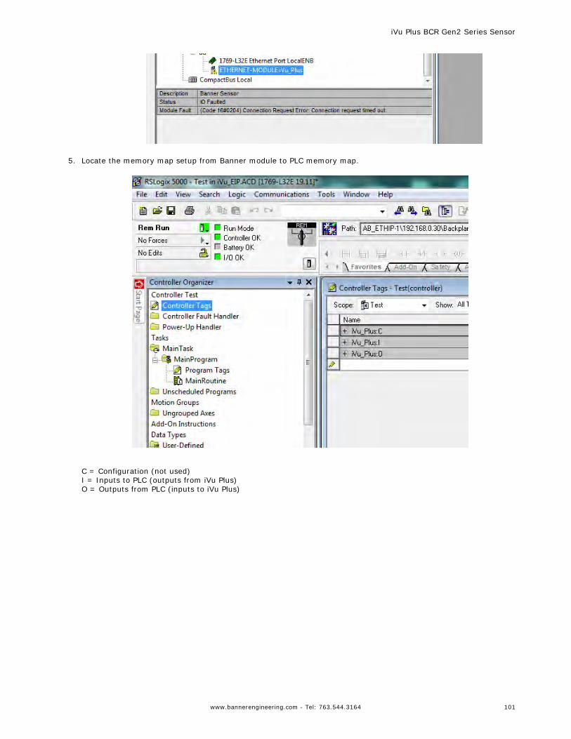
5. Locate the memory map setup from Banner module to PLC memory map.
C = Configuration (not used)I = Inputs to PLC (outputs from iVu Plus)O = Outputs from PLC (inputs to iVu Plus)
iVu Plus BCR Gen2 Series Sensor
www.bannerengineering.com - Tel: 763.544.3164 101
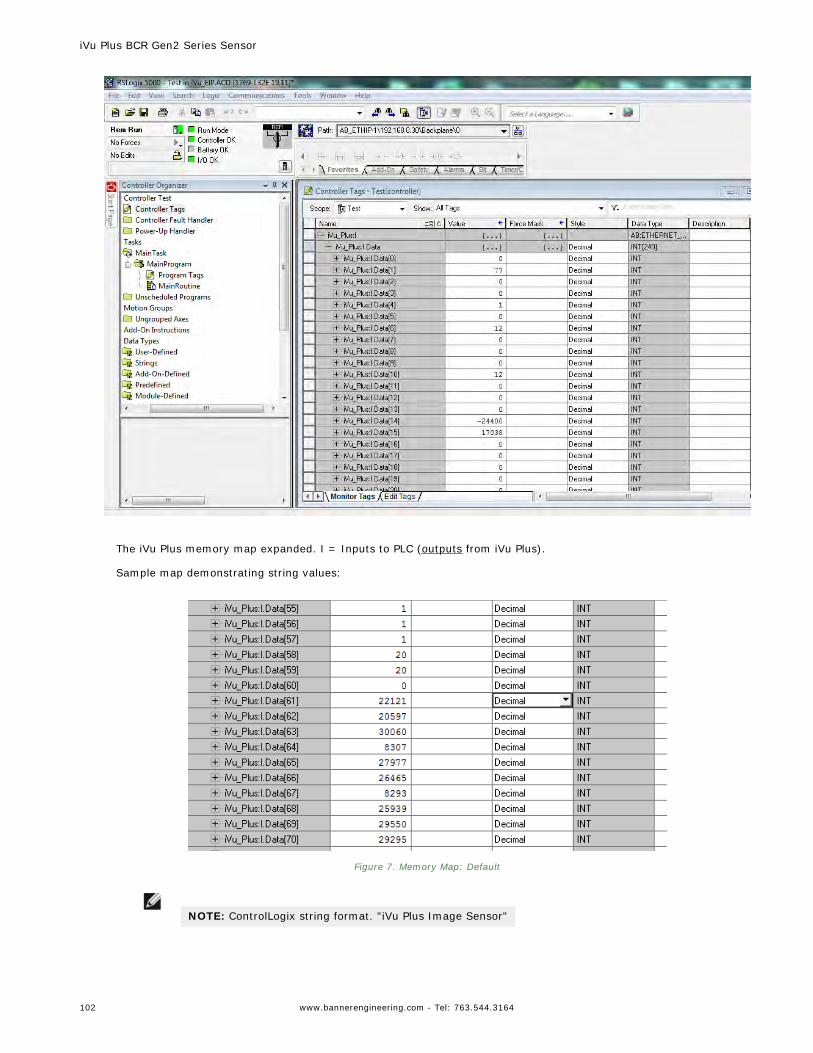
The iVu Plus memory map expanded. I = Inputs to PLC (outputs from iVu Plus).
Sample map demonstrating string values:
Figure 7. Memory Map: Default
NOTE: ControlLogix string format. "iVu Plus Image Sensor"
iVu Plus BCR Gen2 Series Sensor
102 www.bannerengineering.com - Tel: 763.544.3164
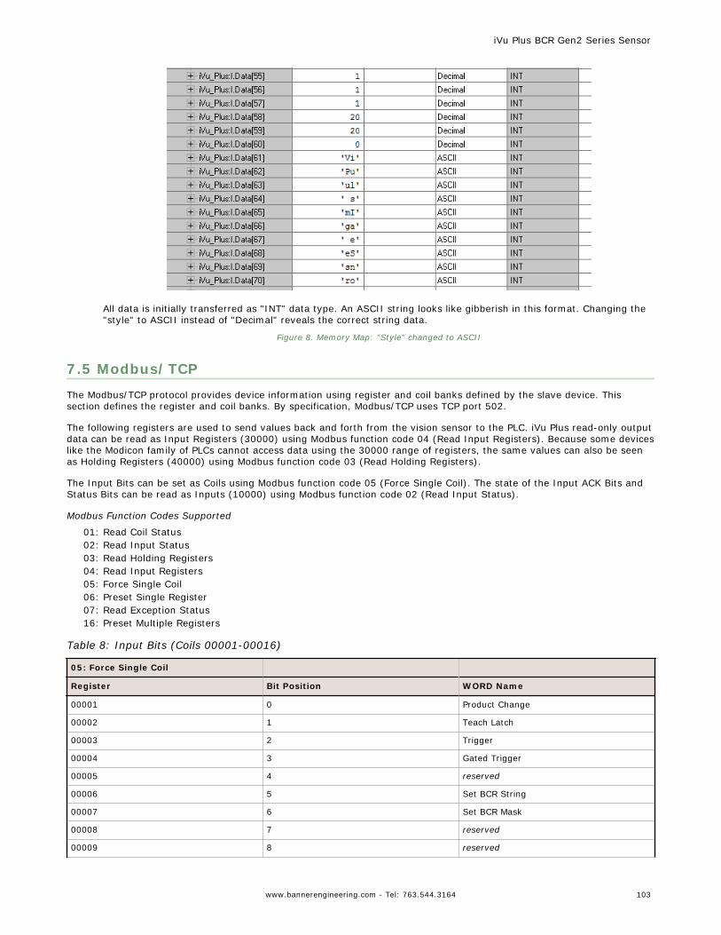
All data is initially transferred as "INT" data type. An ASCII string looks like gibberish in this format. Changing the"style" to ASCII instead of "Decimal" reveals the correct string data.
Figure 8. Memory Map: "Style" changed to ASCII
7.5 Modbus/TCPThe Modbus/TCP protocol provides device information using register and coil banks defined by the slave device. Thissection defines the register and coil banks. By specification, Modbus/TCP uses TCP port 502.
The following registers are used to send values back and forth from the vision sensor to the PLC. iVu Plus read-only outputdata can be read as Input Registers (30000) using Modbus function code 04 (Read Input Registers). Because some deviceslike the Modicon family of PLCs cannot access data using the 30000 range of registers, the same values can also be seenas Holding Registers (40000) using Modbus function code 03 (Read Holding Registers).
The Input Bits can be set as Coils using Modbus function code 05 (Force Single Coil). The state of the Input ACK Bits andStatus Bits can be read as Inputs (10000) using Modbus function code 02 (Read Input Status).
Modbus Function Codes Supported
01: Read Coil Status02: Read Input Status03: Read Holding Registers04: Read Input Registers05: Force Single Coil06: Preset Single Register07: Read Exception Status16: Preset Multiple Registers
Table 8: Input Bits (Coils 00001-00016)
05: Force Single Coil
Register Bit Position WORD Name
00001 0 Product Change
00002 1 Teach Latch
00003 2 Trigger
00004 3 Gated Trigger
00005 4 reserved
00006 5 Set BCR String
00007 6 Set BCR Mask
00008 7 reserved
00009 8 reserved
iVu Plus BCR Gen2 Series Sensor
www.bannerengineering.com - Tel: 763.544.3164 103
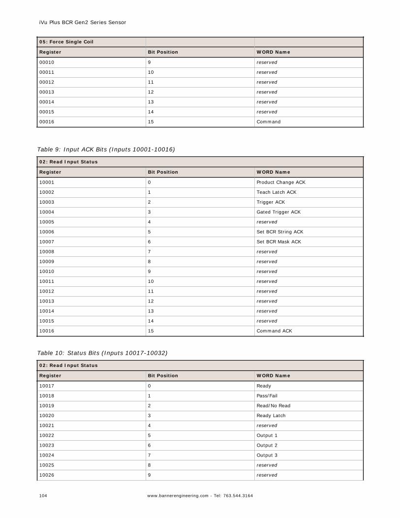
05: Force Single Coil
Register Bit Position WORD Name
00010 9 reserved
00011 10 reserved
00012 11 reserved
00013 12 reserved
00014 13 reserved
00015 14 reserved
00016 15 Command
Table 9: Input ACK Bits (Inputs 10001-10016)
02: Read Input Status
Register Bit Position WORD Name
10001 0 Product Change ACK
10002 1 Teach Latch ACK
10003 2 Trigger ACK
10004 3 Gated Trigger ACK
10005 4 reserved
10006 5 Set BCR String ACK
10007 6 Set BCR Mask ACK
10008 7 reserved
10009 8 reserved
10010 9 reserved
10011 10 reserved
10012 11 reserved
10013 12 reserved
10014 13 reserved
10015 14 reserved
10016 15 Command ACK
Table 10: Status Bits (Inputs 10017-10032)
02: Read Input Status
Register Bit Position WORD Name
10017 0 Ready
10018 1 Pass/Fail
10019 2 Read/No Read
10020 3 Ready Latch
10021 4 reserved
10022 5 Output 1
10023 6 Output 2
10024 7 Output 3
10025 8 reserved
10026 9 reserved
iVu Plus BCR Gen2 Series Sensor
104 www.bannerengineering.com - Tel: 763.544.3164
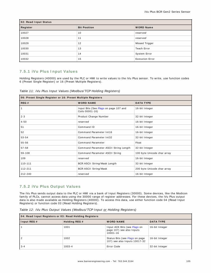
02: Read Input Status
Register Bit Position WORD Name
10027 10 reserved
10028 11 reserved
10029 12 Missed Trigger
10030 13 Teach Error
10031 14 System Error
10032 15 Execution Error
7.5.1 iVu Plus Input Values
Holding Registers (40000) are used by the PLC or HMI to write values to the iVu Plus sensor. To write, use function codes6 (Preset Single Register) or 16 (Preset Multiple Registers).
Table 11: iVu Plus Input Values (Modbus/TCP Holding Registers)
06: Preset Single Register or 16: Preset Multiple Registers
REG # WORD NAME DATA TYPE
1 Input Bits (See Flags on page 107 andCoils 00001-16)
16-bit Integer
2-3 Product Change Number 32-bit Integer
4-50 reserved 16-bit Integer
51 Command ID 16-bit Integer
52 Command Parameter Int16 16-bit Integer
53-54 Command Parameter Int32 32-bit Integer
55-56 Command Parameter Float
57-58 Command Parameter ASCII String Length 32-bit Integer
59-108 Command Parameter ASCII String 100 byte Unicode char array
109 reserved 16-bit Integer
110-111 BCR ASCII String/Mask Length 32-bit Integer
112-211 BCR ASCII String/Mask 200 byte Unicode char array
212-240 reserved 16-bit Integer
7.5.2 iVu Plus Output Values
The iVu Plus sends output data to the PLC or HMI via a bank of Input Registers (30000). Some devices, like the Modiconfamily of PLCs, cannot access data using the 30000 range of register addresses. For these devices, the iVu Plus outputdata is also made available as Holding Registers (40000). To access this data, use either function code 04 (Read InputRegisters) or function code 03 (Read Holding Registers).
Table 12: iVu Plus Output Values (Modbus/TCP Input or Holding Registers)
04: Read Input Registers or 03: Read Holding Registers
Input REG # Holding REG # WORD NAME DATA TYPE
1 1001 Input ACK Bits (see Flags onpage 107) see also Inputs10001-16
16-bit Integer
2 1002 Status Bits (see Flags on page107) see also Inputs 10017-32
16-bit Integer
3-4 1003-4 Error Code 32-bit Integer
iVu Plus BCR Gen2 Series Sensor
www.bannerengineering.com - Tel: 763.544.3164 105
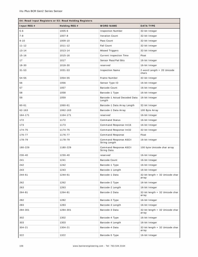
04: Read Input Registers or 03: Read Holding Registers
Input REG # Holding REG # WORD NAME DATA TYPE
5-6 1005-6 Inspection Number 32-bit Integer
7-8 1007-8 Iteration Count 32-bit Integer
9-10 1009-10 Pass Count 32-bit Integer
11-12 1011-12 Fail Count 32-bit Integer
13-14 1013-14 Missed Triggers 32-bit Integer
15-16 1015-16 Current Inspection Time Float
17 1017 Sensor Pass/Fail Bits 16-bit Integer
18-30 1018-30 reserved 16-bit Integer
31-53 1031-53 Inspection Name 2-word Length + 20 Unicodechars
54-55 1054-55 Frame Number 32-bit Integer
56 1056 Sensor Type ID 16-bit Integer
57 1057 Barcode Count 16-bit Integer
58 1058 Barcode-1 Type 16-bit Integer
59 1059 Barcode-1 Actual Decoded DataLength
16-bit Integer
60-61 1060-61 Barcode-1 Data Array Length 32-bit Integer
62-163 1062-163 Barcode-1 Data Array 100 Byte Array
164-171 1164-171 reserved 16-bit Integer
172 1172 Command Status 16-bit Integer
173 1173 Command Response Int16 16-bit Integer
174-75 1174-75 Command Response Int32 32-bit Integer
176-77 1176-77 Command Response Float
178-79 1178-79 Command Response ASCIIString Length
16-bit Integer
180-229 1180-229 Command Response ASCIIString Data
100 byte Unicode char array
230-40 1230-40 reserved 16-bit Integer
241 1241 Barcode Count 16-bit Integer
242 1242 Barcode-1 Type 16-bit Integer
243 1243 Barcode-1 Length 16-bit Integer
244-61 1244-61 Barcode-1 Data 32-bit length + 32 Unicode chararray
262 1262 Barcode-2 Type 16-bit Integer
263 1263 Barcode-2 Length 16-bit Integer
264-81 1264-81 Barcode-2 Data 32-bit length + 32 Unicode chararray
282 1282 Barcode-3 Type 16-bit Integer
283 1283 Barcode-3 Length 16-bit Integer
284-301 1284-301 Barcode-3 Data 32-bit length + 32 Unicode chararray
302 1302 Barcode-4 Type 16-bit Integer
303 1303 Barcode-4 Length 16-bit Integer
304-21 1304-21 Barcode-4 Data 32-bit length + 32 Unicode chararray
322 1322 Barcode-5 Type 16-bit Integer
iVu Plus BCR Gen2 Series Sensor
106 www.bannerengineering.com - Tel: 763.544.3164
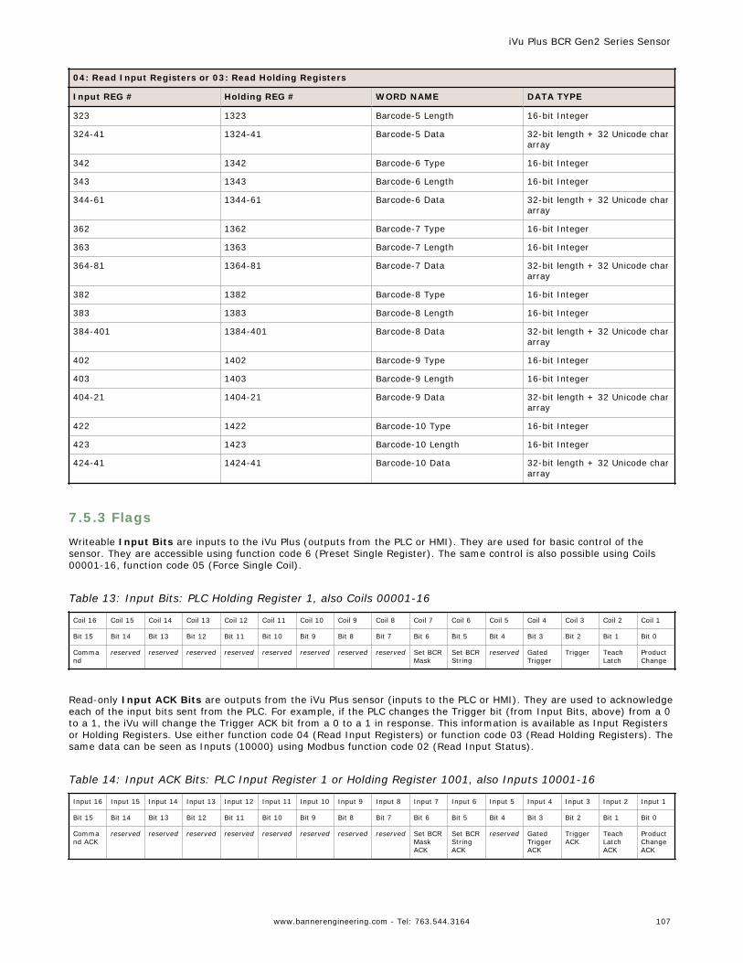
04: Read Input Registers or 03: Read Holding Registers
Input REG # Holding REG # WORD NAME DATA TYPE
323 1323 Barcode-5 Length 16-bit Integer
324-41 1324-41 Barcode-5 Data 32-bit length + 32 Unicode chararray
342 1342 Barcode-6 Type 16-bit Integer
343 1343 Barcode-6 Length 16-bit Integer
344-61 1344-61 Barcode-6 Data 32-bit length + 32 Unicode chararray
362 1362 Barcode-7 Type 16-bit Integer
363 1363 Barcode-7 Length 16-bit Integer
364-81 1364-81 Barcode-7 Data 32-bit length + 32 Unicode chararray
382 1382 Barcode-8 Type 16-bit Integer
383 1383 Barcode-8 Length 16-bit Integer
384-401 1384-401 Barcode-8 Data 32-bit length + 32 Unicode chararray
402 1402 Barcode-9 Type 16-bit Integer
403 1403 Barcode-9 Length 16-bit Integer
404-21 1404-21 Barcode-9 Data 32-bit length + 32 Unicode chararray
422 1422 Barcode-10 Type 16-bit Integer
423 1423 Barcode-10 Length 16-bit Integer
424-41 1424-41 Barcode-10 Data 32-bit length + 32 Unicode chararray
7.5.3 Flags
Writeable Input Bits are inputs to the iVu Plus (outputs from the PLC or HMI). They are used for basic control of thesensor. They are accessible using function code 6 (Preset Single Register). The same control is also possible using Coils00001-16, function code 05 (Force Single Coil).
Table 13: Input Bits: PLC Holding Register 1, also Coils 00001-16
Coil 16 Coil 15 Coil 14 Coil 13 Coil 12 Coil 11 Coil 10 Coil 9 Coil 8 Coil 7 Coil 6 Coil 5 Coil 4 Coil 3 Coil 2 Coil 1
Bit 15 Bit 14 Bit 13 Bit 12 Bit 11 Bit 10 Bit 9 Bit 8 Bit 7 Bit 6 Bit 5 Bit 4 Bit 3 Bit 2 Bit 1 Bit 0
Command
reserved reserved reserved reserved reserved reserved reserved reserved Set BCRMask
Set BCRString
reserved GatedTrigger
Trigger TeachLatch
ProductChange
Read-only Input ACK Bits are outputs from the iVu Plus sensor (inputs to the PLC or HMI). They are used to acknowledgeeach of the input bits sent from the PLC. For example, if the PLC changes the Trigger bit (from Input Bits, above) from a 0to a 1, the iVu will change the Trigger ACK bit from a 0 to a 1 in response. This information is available as Input Registersor Holding Registers. Use either function code 04 (Read Input Registers) or function code 03 (Read Holding Registers). Thesame data can be seen as Inputs (10000) using Modbus function code 02 (Read Input Status).
Table 14: Input ACK Bits: PLC Input Register 1 or Holding Register 1001, also Inputs 10001-16
Input 16 Input 15 Input 14 Input 13 Input 12 Input 11 Input 10 Input 9 Input 8 Input 7 Input 6 Input 5 Input 4 Input 3 Input 2 Input 1
Bit 15 Bit 14 Bit 13 Bit 12 Bit 11 Bit 10 Bit 9 Bit 8 Bit 7 Bit 6 Bit 5 Bit 4 Bit 3 Bit 2 Bit 1 Bit 0
Command ACK
reserved reserved reserved reserved reserved reserved reserved reserved Set BCRMaskACK
Set BCRStringACK
reserved GatedTriggerACK
TriggerACK
TeachLatchACK
ProductChangeACK
iVu Plus BCR Gen2 Series Sensor
www.bannerengineering.com - Tel: 763.544.3164 107
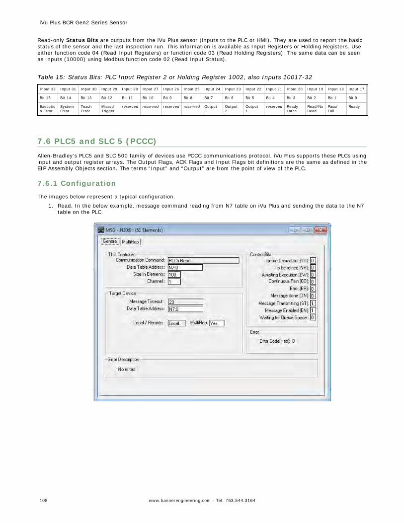
Read-only Status Bits are outputs from the iVu Plus sensor (inputs to the PLC or HMI). They are used to report the basicstatus of the sensor and the last inspection run. This information is available as Input Registers or Holding Registers. Useeither function code 04 (Read Input Registers) or function code 03 (Read Holding Registers). The same data can be seenas Inputs (10000) using Modbus function code 02 (Read Input Status).
Table 15: Status Bits: PLC Input Register 2 or Holding Register 1002, also Inputs 10017-32
Input 32 Input 31 Input 30 Input 29 Input 28 Input 27 Input 26 Input 25 Input 24 Input 23 Input 22 Input 21 Input 20 Input 19 Input 18 Input 17
Bit 15 Bit 14 Bit 13 Bit 12 Bit 11 Bit 10 Bit 9 Bit 8 Bit 7 Bit 6 Bit 5 Bit 4 Bit 3 Bit 2 Bit 1 Bit 0
Execution Error
SystemError
TeachError
MissedTrigger
reserved reserved reserved reserved Output3
Output2
Output1
reserved ReadyLatch
Read/NoRead
Pass/Fail
Ready
7.6 PLC5 and SLC 5 (PCCC)Allen-Bradley’s PLC5 and SLC 500 family of devices use PCCC communications protocol. iVu Plus supports these PLCs usinginput and output register arrays. The Output Flags, ACK Flags and Input Flags bit definitions are the same as defined in theEIP Assembly Objects section. The terms “Input” and “Output” are from the point of view of the PLC.
7.6.1 Configuration
The images below represent a typical configuration.
1. Read. In the below example, message command reading from N7 table on iVu Plus and sending the data to the N7table on the PLC.
iVu Plus BCR Gen2 Series Sensor
108 www.bannerengineering.com - Tel: 763.544.3164
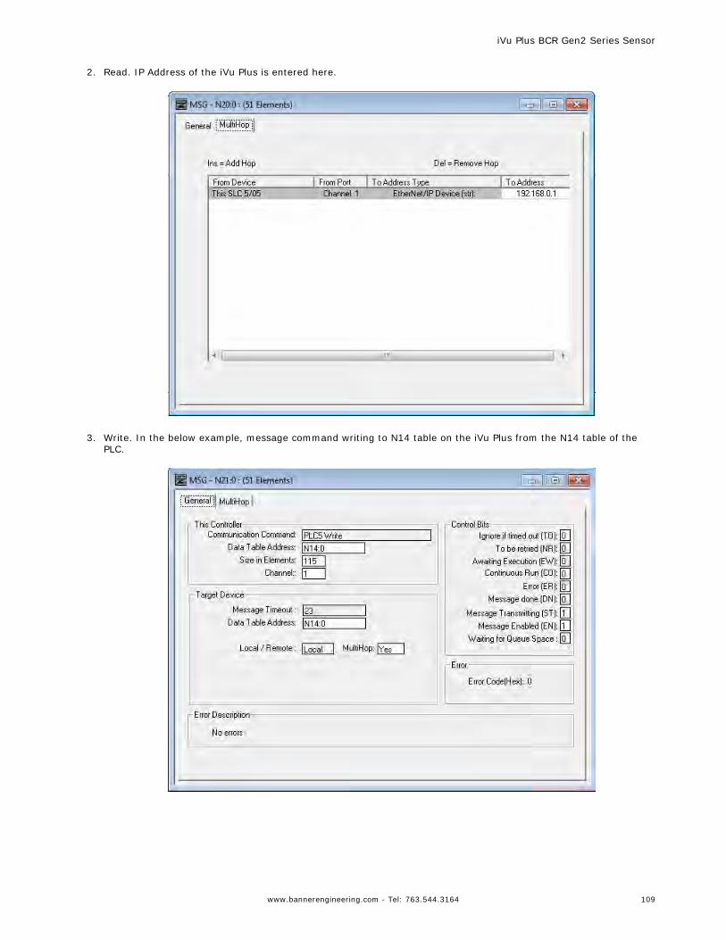
2. Read. IP Address of the iVu Plus is entered here.
3. Write. In the below example, message command writing to N14 table on the iVu Plus from the N14 table of the
PLC.
iVu Plus BCR Gen2 Series Sensor
www.bannerengineering.com - Tel: 763.544.3164 109
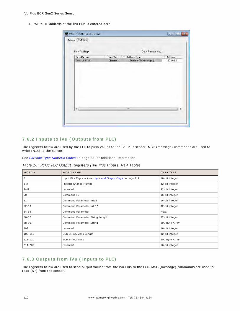
4. Write. IP address of the iVu Plus is entered here.
7.6.2 Inputs to iVu (Outputs from PLC)
The registers below are used by the PLC to push values to the iVu Plus sensor. MSG (message) commands are used towrite (N14) to the sensor.
See Barcode Type Numeric Codes on page 88 for additional information.
Table 16: PCCC PLC Output Registers (iVu Plus Inputs, N14 Table)
WORD # WORD NAME DATA TYPE
0 Input Bits Register (see Input and Output Flags on page 112) 16-bit integer
1-2 Product Change Number 32-bit integer
3-49 reserved 32-bit integer
50 Command ID 16-bit integer
51 Command Parameter Int16 16-bit integer
52-53 Command Parameter Int 32 32-bit integer
54-55 Command Parameter Float
56-57 Command Parameter String Length 32-bit integer
58-107 Command Parameter String 100 Byte Array
108 reserved 16-bit integer
109-110 BCR String/Mask Length 32-bit integer
111-120 BCR String/Mask 200 Byte Array
211-239 reserved 16-bit integer
7.6.3 Outputs from iVu (Inputs to PLC)
The registers below are used to send output values from the iVu Plus to the PLC. MSG (message) commands are used toread (N7) from the sensor.
iVu Plus BCR Gen2 Series Sensor
110 www.bannerengineering.com - Tel: 763.544.3164
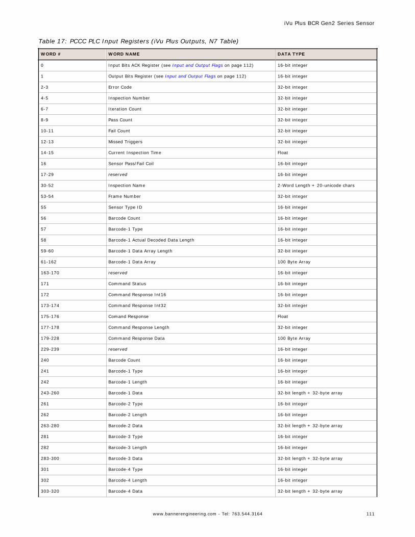
Table 17: PCCC PLC Input Registers (iVu Plus Outputs, N7 Table)
WORD # WORD NAME DATA TYPE
0 Input Bits ACK Register (see Input and Output Flags on page 112) 16-bit integer
1 Output Bits Register (see Input and Output Flags on page 112) 16-bit integer
2-3 Error Code 32-bit integer
4-5 Inspection Number 32-bit integer
6-7 Iteration Count 32-bit integer
8-9 Pass Count 32-bit integer
10-11 Fail Count 32-bit integer
12-13 Missed Triggers 32-bit integer
14-15 Current Inspection Time Float
16 Sensor Pass/Fail Coil 16-bit integer
17-29 reserved 16-bit integer
30-52 Inspection Name 2-Word Length + 20-unicode chars
53-54 Frame Number 32-bit integer
55 Sensor Type ID 16-bit integer
56 Barcode Count 16-bit integer
57 Barcode-1 Type 16-bit integer
58 Barcode-1 Actual Decoded Data Length 16-bit integer
59-60 Barcode-1 Data Array Length 32-bit integer
61-162 Barcode-1 Data Array 100 Byte Array
163-170 reserved 16-bit integer
171 Command Status 16-bit integer
172 Command Response Int16 16-bit integer
173-174 Command Response Int32 32-bit integer
175-176 Comand Response Float
177-178 Command Response Length 32-bit integer
179-228 Command Response Data 100 Byte Array
229-239 reserved 16-bit integer
240 Barcode Count 16-bit integer
241 Barcode-1 Type 16-bit integer
242 Barcode-1 Length 16-bit integer
243-260 Barcode-1 Data 32-bit length + 32-byte array
261 Barcode-2 Type 16-bit integer
262 Barcode-2 Length 16-bit integer
263-280 Barcode-2 Data 32-bit length + 32-byte array
281 Barcode-3 Type 16-bit integer
282 Barcode-3 Length 16-bit integer
283-300 Barcode-3 Data 32-bit length + 32-byte array
301 Barcode-4 Type 16-bit integer
302 Barcode-4 Length 16-bit integer
303-320 Barcode-4 Data 32-bit length + 32-byte array
iVu Plus BCR Gen2 Series Sensor
www.bannerengineering.com - Tel: 763.544.3164 111
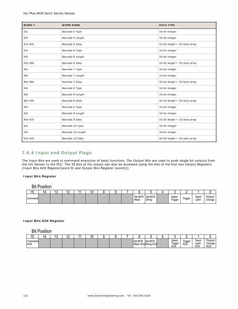
WORD # WORD NAME DATA TYPE
321 Barcode-5 Type 16-bit integer
322 Barcode-5 Length 16-bit integer
323-340 Barcode-5 Data 32-bit length + 32-byte array
341 Barcode-6 Type 16-bit integer
342 Barcode-6 Length 16-bit integer
343-360 Barcode-6 Data 32-bit length + 32-byte array
361 Barcode-7 Type 16-bit integer
362 Barcode-7 Length 16-bit integer
363-380 Barcode-7 Data 32-bit length + 32-byte array
381 Barcode-8 Type 16-bit integer
382 Barcode-8 Length 16-bit integer
383-400 Barcode-8 Data 32-bit length + 32-byte array
401 Barcode-9 Type 16-bit integer
402 Barcode-9 Length 16-bit integer
403-420 Barcode-9 Data 32-bit length + 32-byte array
421 Barcode-10 Type 16-bit integer
422 Barcode-10 Length 16-bit integer
423-440 Barcode-10 Data 32-bit length + 32-byte array
7.6.4 Input and Output Flags
The Input Bits are used to command execution of basic functions. The Output Bits are used to push single bit outputs fromthe iVu Sensor to the PLC. The 32 bits of iVu output can also be accessed using the bits of the first two Output Registers(Input Bits ACK Register(word 0) and Output Bits Register (word1)).
Input Bits Register
Command Set BCRMask
Set BCRString Trigger Teach
LatchProductChange
GatedTrigger
Bit Position123456789101112131415 0
Input Bits ACK Register
CommandACK
Set BCRMask ACK
Set BCRString ACK
TriggerACK
TeachLatchACK
ProductChangeACK
GatedTriggerACK
Bit Position123456789101112131415 0
iVu Plus BCR Gen2 Series Sensor
112 www.bannerengineering.com - Tel: 763.544.3164
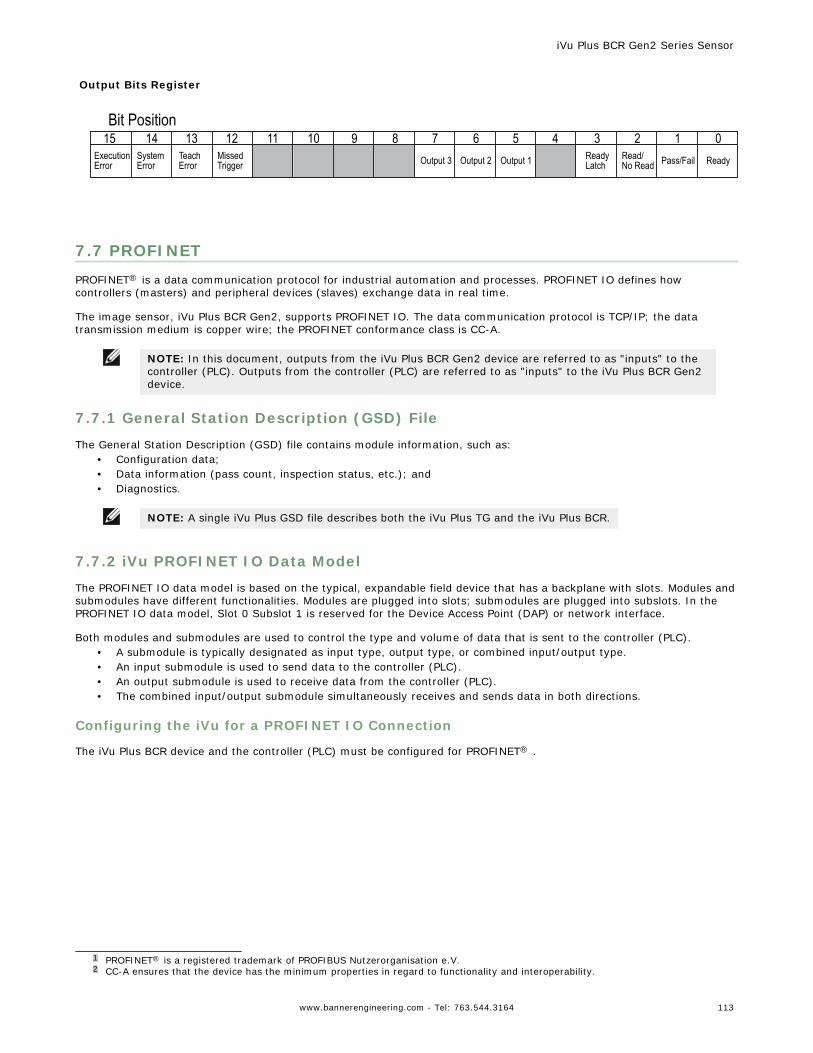
Output Bits Register
ExecutionError
SystemError
TeachError
MissedTrigger Output 3 Output 2 Output 1 Read/
No Read Pass/FailReadyLatch Ready
Bit Position123456789101112131415 0
7.7 PROFINETPROFINET® is a data communication protocol for industrial automation and processes. PROFINET IO defines howcontrollers (masters) and peripheral devices (slaves) exchange data in real time.
The image sensor, iVu Plus BCR Gen2, supports PROFINET IO. The data communication protocol is TCP/IP; the datatransmission medium is copper wire; the PROFINET conformance class is CC-A.
NOTE: In this document, outputs from the iVu Plus BCR Gen2 device are referred to as "inputs" to thecontroller (PLC). Outputs from the controller (PLC) are referred to as "inputs" to the iVu Plus BCR Gen2device.
7.7.1 General Station Description (GSD) File
The General Station Description (GSD) file contains module information, such as:• Configuration data;• Data information (pass count, inspection status, etc.); and• Diagnostics.
NOTE: A single iVu Plus GSD file describes both the iVu Plus TG and the iVu Plus BCR.
7.7.2 iVu PROFINET IO Data Model
The PROFINET IO data model is based on the typical, expandable field device that has a backplane with slots. Modules andsubmodules have different functionalities. Modules are plugged into slots; submodules are plugged into subslots. In thePROFINET IO data model, Slot 0 Subslot 1 is reserved for the Device Access Point (DAP) or network interface.
Both modules and submodules are used to control the type and volume of data that is sent to the controller (PLC).• A submodule is typically designated as input type, output type, or combined input/output type.• An input submodule is used to send data to the controller (PLC).• An output submodule is used to receive data from the controller (PLC).• The combined input/output submodule simultaneously receives and sends data in both directions.
Configuring the iVu for a PROFINET IO Connection
The iVu Plus BCR device and the controller (PLC) must be configured for PROFINET® .
1 PROFINET® is a registered trademark of PROFIBUS Nutzerorganisation e.V.2 CC-A ensures that the device has the minimum properties in regard to functionality and interoperability.
iVu Plus BCR Gen2 Series Sensor
www.bannerengineering.com - Tel: 763.544.3164 113
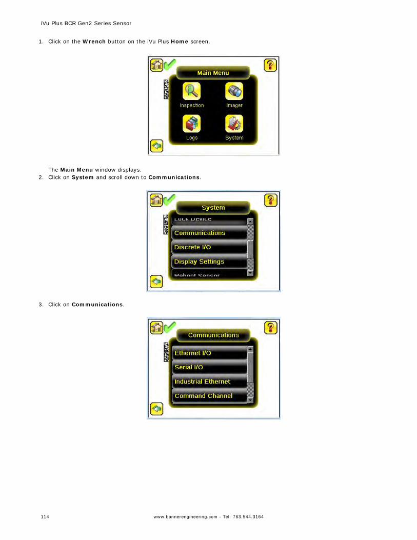
1. Click on the Wrench button on the iVu Plus Home screen.
The Main Menu window displays.
2. Click on System and scroll down to Communications.
3. Click on Communications.
iVu Plus BCR Gen2 Series Sensor
114 www.bannerengineering.com - Tel: 763.544.3164
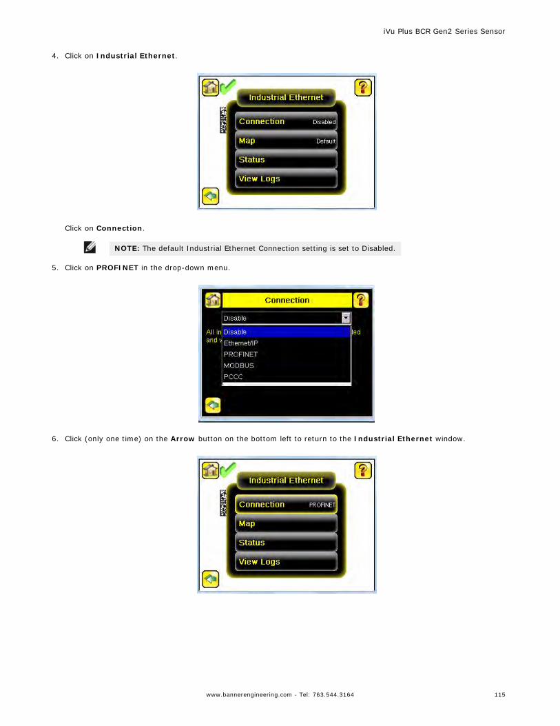
4. Click on Industrial Ethernet.
Click on Connection.
NOTE: The default Industrial Ethernet Connection setting is set to Disabled.
5. Click on PROFINET in the drop-down menu.
6. Click (only one time) on the Arrow button on the bottom left to return to the Industrial Ethernet window.
iVu Plus BCR Gen2 Series Sensor
www.bannerengineering.com - Tel: 763.544.3164 115
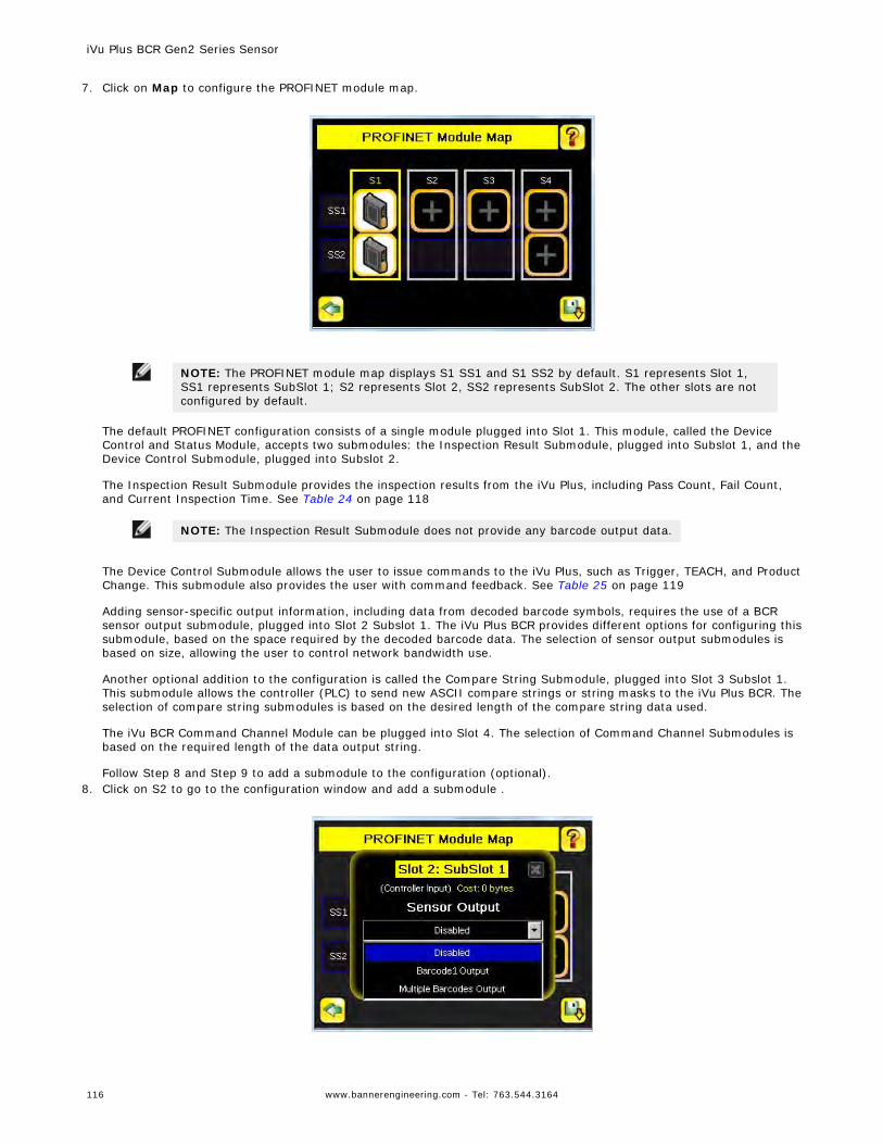
7. Click on Map to configure the PROFINET module map.
NOTE: The PROFINET module map displays S1 SS1 and S1 SS2 by default. S1 represents Slot 1,SS1 represents SubSlot 1; S2 represents Slot 2, SS2 represents SubSlot 2. The other slots are notconfigured by default.
The default PROFINET configuration consists of a single module plugged into Slot 1. This module, called the DeviceControl and Status Module, accepts two submodules: the Inspection Result Submodule, plugged into Subslot 1, and theDevice Control Submodule, plugged into Subslot 2.
The Inspection Result Submodule provides the inspection results from the iVu Plus, including Pass Count, Fail Count,and Current Inspection Time. See Table 24 on page 118
NOTE: The Inspection Result Submodule does not provide any barcode output data.
The Device Control Submodule allows the user to issue commands to the iVu Plus, such as Trigger, TEACH, and ProductChange. This submodule also provides the user with command feedback. See Table 25 on page 119
Adding sensor-specific output information, including data from decoded barcode symbols, requires the use of a BCRsensor output submodule, plugged into Slot 2 Subslot 1. The iVu Plus BCR provides different options for configuring thissubmodule, based on the space required by the decoded barcode data. The selection of sensor output submodules isbased on size, allowing the user to control network bandwidth use.
Another optional addition to the configuration is called the Compare String Submodule, plugged into Slot 3 Subslot 1.This submodule allows the controller (PLC) to send new ASCII compare strings or string masks to the iVu Plus BCR. Theselection of compare string submodules is based on the desired length of the compare string data used.
The iVu BCR Command Channel Module can be plugged into Slot 4. The selection of Command Channel Submodules isbased on the required length of the data output string.
Follow Step 8 and Step 9 to add a submodule to the configuration (optional).8. Click on S2 to go to the configuration window and add a submodule .
iVu Plus BCR Gen2 Series Sensor
116 www.bannerengineering.com - Tel: 763.544.3164
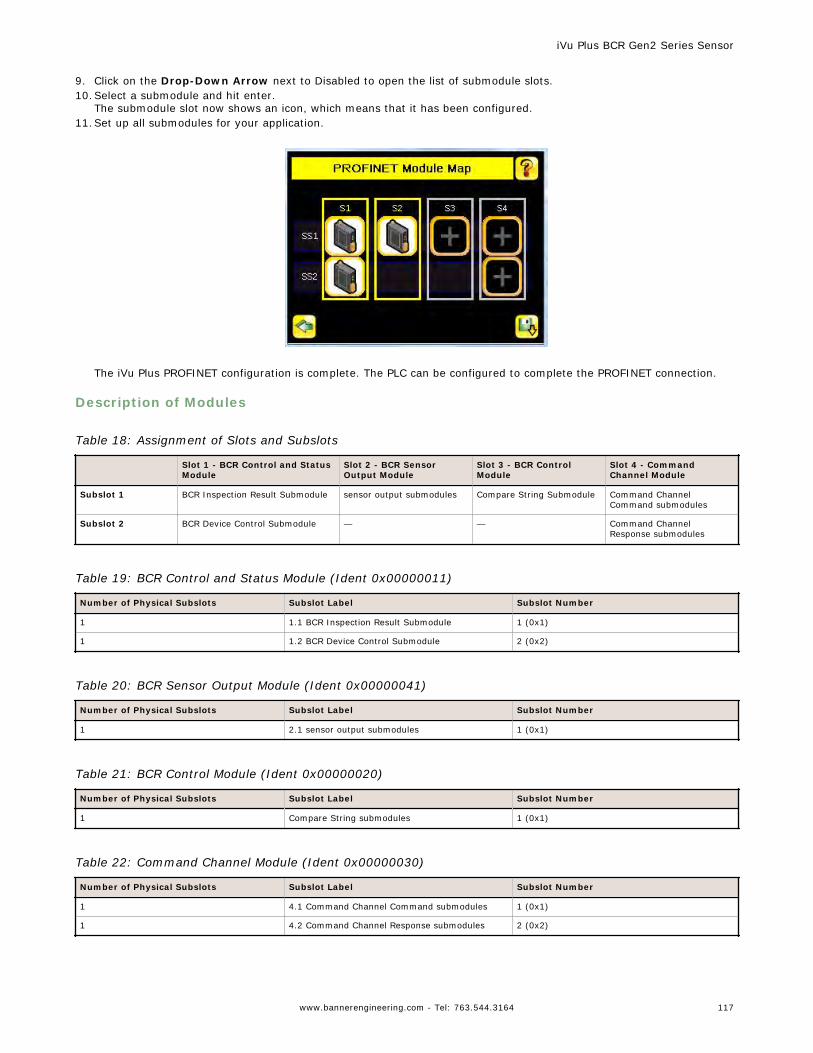
9. Click on the Drop-Down Arrow next to Disabled to open the list of submodule slots.10.Select a submodule and hit enter.
The submodule slot now shows an icon, which means that it has been configured.11.Set up all submodules for your application.
The iVu Plus PROFINET configuration is complete. The PLC can be configured to complete the PROFINET connection.
Description of Modules
Table 18: Assignment of Slots and Subslots
Slot 1 - BCR Control and StatusModule
Slot 2 - BCR SensorOutput Module
Slot 3 - BCR ControlModule
Slot 4 - CommandChannel Module
Subslot 1 BCR Inspection Result Submodule sensor output submodules Compare String Submodule Command ChannelCommand submodules
Subslot 2 BCR Device Control Submodule — — Command ChannelResponse submodules
Table 19: BCR Control and Status Module (Ident 0x00000011)
Number of Physical Subslots Subslot Label Subslot Number
1 1.1 BCR Inspection Result Submodule 1 (0x1)
1 1.2 BCR Device Control Submodule 2 (0x2)
Table 20: BCR Sensor Output Module (Ident 0x00000041)
Number of Physical Subslots Subslot Label Subslot Number
1 2.1 sensor output submodules 1 (0x1)
Table 21: BCR Control Module (Ident 0x00000020)
Number of Physical Subslots Subslot Label Subslot Number
1 Compare String submodules 1 (0x1)
Table 22: Command Channel Module (Ident 0x00000030)
Number of Physical Subslots Subslot Label Subslot Number
1 4.1 Command Channel Command submodules 1 (0x1)
1 4.2 Command Channel Response submodules 2 (0x2)
iVu Plus BCR Gen2 Series Sensor
www.bannerengineering.com - Tel: 763.544.3164 117
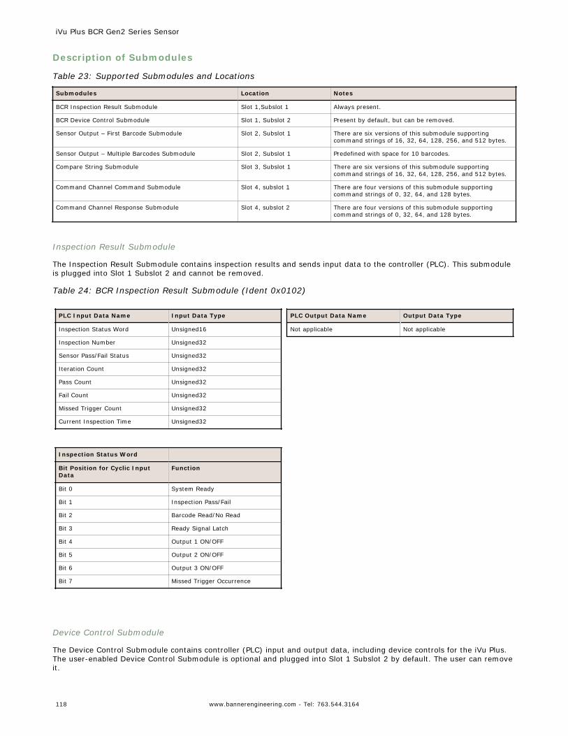
Description of Submodules
Table 23: Supported Submodules and Locations
Submodules Location Notes
BCR Inspection Result Submodule Slot 1,Subslot 1 Always present.
BCR Device Control Submodule Slot 1, Subslot 2 Present by default, but can be removed.
Sensor Output – First Barcode Submodule Slot 2, Subslot 1 There are six versions of this submodule supportingcommand strings of 16, 32, 64, 128, 256, and 512 bytes.
Sensor Output – Multiple Barcodes Submodule Slot 2, Subslot 1 Predefined with space for 10 barcodes.
Compare String Submodule Slot 3, Subslot 1 There are six versions of this submodule supportingcommand strings of 16, 32, 64, 128, 256, and 512 bytes.
Command Channel Command Submodule Slot 4, subslot 1 There are four versions of this submodule supportingcommand strings of 0, 32, 64, and 128 bytes.
Command Channel Response Submodule Slot 4, subslot 2 There are four versions of this submodule supportingcommand strings of 0, 32, 64, and 128 bytes.
Inspection Result Submodule
The Inspection Result Submodule contains inspection results and sends input data to the controller (PLC). This submoduleis plugged into Slot 1 Subslot 2 and cannot be removed.
Table 24: BCR Inspection Result Submodule (Ident 0x0102)
PLC Input Data Name Input Data Type
Inspection Status Word Unsigned16
Inspection Number Unsigned32
Sensor Pass/Fail Status Unsigned32
Iteration Count Unsigned32
Pass Count Unsigned32
Fail Count Unsigned32
Missed Trigger Count Unsigned32
Current Inspection Time Unsigned32
Inspection Status Word
Bit Position for Cyclic InputData
Function
Bit 0 System Ready
Bit 1 Inspection Pass/Fail
Bit 2 Barcode Read/No Read
Bit 3 Ready Signal Latch
Bit 4 Output 1 ON/OFF
Bit 5 Output 2 ON/OFF
Bit 6 Output 3 ON/OFF
Bit 7 Missed Trigger Occurrence
PLC Output Data Name Output Data Type
Not applicable Not applicable
Device Control Submodule
The Device Control Submodule contains controller (PLC) input and output data, including device controls for the iVu Plus.The user-enabled Device Control Submodule is optional and plugged into Slot 1 Subslot 2 by default. The user can removeit.
iVu Plus BCR Gen2 Series Sensor
118 www.bannerengineering.com - Tel: 763.544.3164
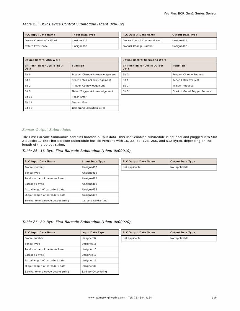
Table 25: BCR Device Control Submodule (Ident 0x0002)
PLC Input Data Name Input Data Type
Device Control ACK Word Unsigned16
Return Error Code Unsigned32
Device Control ACK Word
Bit Position for Cyclic InputData
Function
Bit 0 Product Change Acknowledgement
Bit 1 Teach Latch Acknowledgement
Bit 2 Trigger Acknowledgement
Bit 3 Gated Trigger Acknowledgement
Bit 13 Teach Error
Bit 14 System Error
Bit 15 Command Execution Error
PLC Output Data Name Output Data Type
Device Control Command Word Unsigned16
Product Change Number Unsigned32
Device Control Command Word
Bit Position for Cyclic OutputData
Function
Bit 0 Product Change Request
Bit 1 Teach Latch Request
Bit 2 Trigger Request
Bit 3 Start of Gated Trigger Request
Sensor Output Submodules
The First Barcode Submodule contains barcode output data. This user-enabled submodule is optional and plugged into Slot2 Subslot 1. The First Barcode Submodule has six versions with 16, 32, 64, 128, 256, and 512 bytes, depending on thelength of the output string.
Table 26: 16-Byte First Barcode Submodule (Ident 0x00019)
PLC Input Data Name Input Data Type
Frame Number Unsigned32
Sensor type Unsigned16
Total number of barcodes found Unsigned16
Barcode 1 type Unsigned16
Actual length of barcode 1 data Unsigned32
Output length of barcode 1 data Unsigned32
16-character barcode output string 16-byte OctetString
PLC Output Data Name Output Data Type
Not applicable Not applicable
Table 27: 32-Byte First Barcode Submodule (Ident 0x00020)
PLC Input Data Name Input Data Type
Frame number Unsigned32
Sensor type Unsigned16
Total number of barcodes found Unsigned16
Barcode 1 type Unsigned16
Actual length of barcode 1 data Unsigned16
Output length of barcode 1 data Unsigned32
32-character barcode output string 32-byte OctetString
PLC Output Data Name Output Data Type
Not applicable Not applicable
iVu Plus BCR Gen2 Series Sensor
www.bannerengineering.com - Tel: 763.544.3164 119
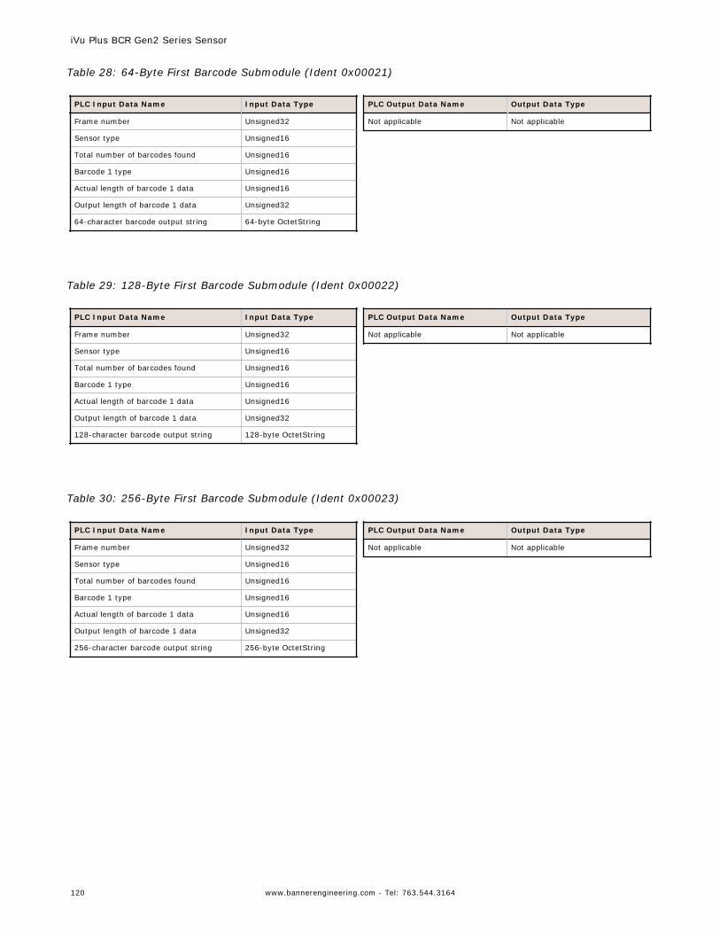
Table 28: 64-Byte First Barcode Submodule (Ident 0x00021)
PLC Input Data Name Input Data Type
Frame number Unsigned32
Sensor type Unsigned16
Total number of barcodes found Unsigned16
Barcode 1 type Unsigned16
Actual length of barcode 1 data Unsigned16
Output length of barcode 1 data Unsigned32
64-character barcode output string 64-byte OctetString
PLC Output Data Name Output Data Type
Not applicable Not applicable
Table 29: 128-Byte First Barcode Submodule (Ident 0x00022)
PLC Input Data Name Input Data Type
Frame number Unsigned32
Sensor type Unsigned16
Total number of barcodes found Unsigned16
Barcode 1 type Unsigned16
Actual length of barcode 1 data Unsigned16
Output length of barcode 1 data Unsigned32
128-character barcode output string 128-byte OctetString
PLC Output Data Name Output Data Type
Not applicable Not applicable
Table 30: 256-Byte First Barcode Submodule (Ident 0x00023)
PLC Input Data Name Input Data Type
Frame number Unsigned32
Sensor type Unsigned16
Total number of barcodes found Unsigned16
Barcode 1 type Unsigned16
Actual length of barcode 1 data Unsigned16
Output length of barcode 1 data Unsigned32
256-character barcode output string 256-byte OctetString
PLC Output Data Name Output Data Type
Not applicable Not applicable
iVu Plus BCR Gen2 Series Sensor
120 www.bannerengineering.com - Tel: 763.544.3164
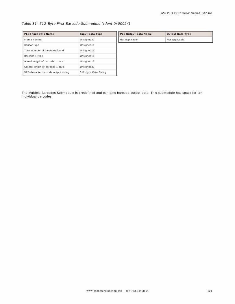
Table 31: 512-Byte First Barcode Submodule (Ident 0x00024)
PLC Input Data Name Input Data Type
Frame number Unsigned32
Sensor type Unsigned16
Total number of barcodes found Unsigned16
Barcode 1 type Unsigned16
Actual length of barcode 1 data Unsigned16
Output length of barcode 1 data Unsigned32
512-character barcode output string 512-byte OctetString
PLC Output Data Name Output Data Type
Not applicable Not applicable
The Multiple Barcodes Submodule is predefined and contains barcode output data. This submodule has space for tenindividual barcodes.
iVu Plus BCR Gen2 Series Sensor
www.bannerengineering.com - Tel: 763.544.3164 121
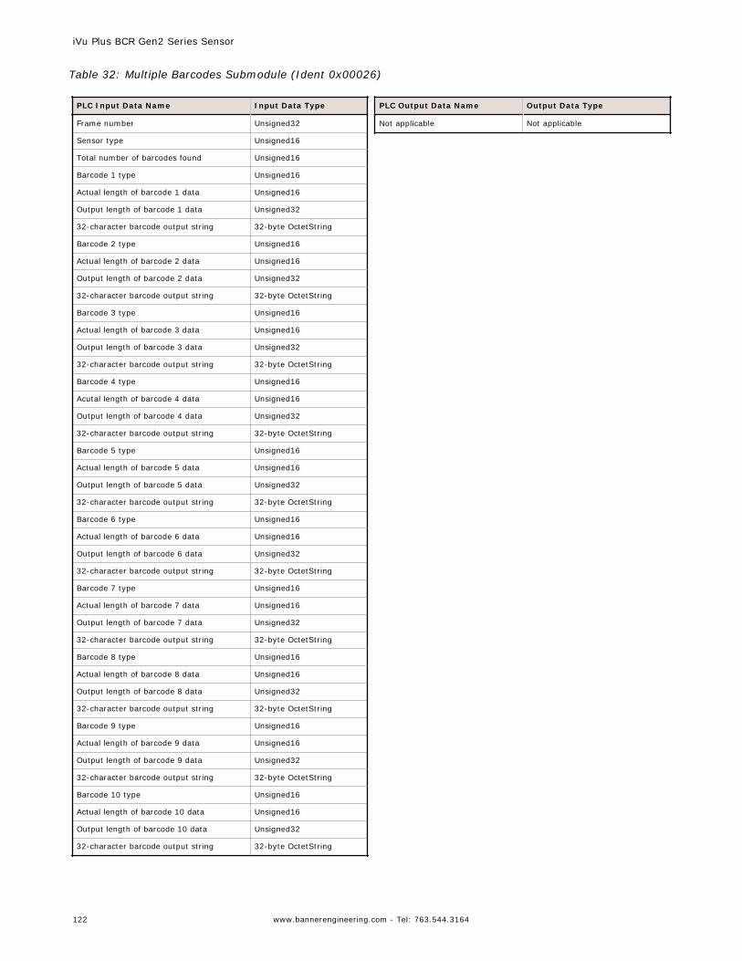
Table 32: Multiple Barcodes Submodule (Ident 0x00026)
PLC Input Data Name Input Data Type
Frame number Unsigned32
Sensor type Unsigned16
Total number of barcodes found Unsigned16
Barcode 1 type Unsigned16
Actual length of barcode 1 data Unsigned16
Output length of barcode 1 data Unsigned32
32-character barcode output string 32-byte OctetString
Barcode 2 type Unsigned16
Actual length of barcode 2 data Unsigned16
Output length of barcode 2 data Unsigned32
32-character barcode output string 32-byte OctetString
Barcode 3 type Unsigned16
Actual length of barcode 3 data Unsigned16
Output length of barcode 3 data Unsigned32
32-character barcode output string 32-byte OctetString
Barcode 4 type Unsigned16
Acutal length of barcode 4 data Unsigned16
Output length of barcode 4 data Unsigned32
32-character barcode output string 32-byte OctetString
Barcode 5 type Unsigned16
Actual length of barcode 5 data Unsigned16
Output length of barcode 5 data Unsigned32
32-character barcode output string 32-byte OctetString
Barcode 6 type Unsigned16
Actual length of barcode 6 data Unsigned16
Output length of barcode 6 data Unsigned32
32-character barcode output string 32-byte OctetString
Barcode 7 type Unsigned16
Actual length of barcode 7 data Unsigned16
Output length of barcode 7 data Unsigned32
32-character barcode output string 32-byte OctetString
Barcode 8 type Unsigned16
Actual length of barcode 8 data Unsigned16
Output length of barcode 8 data Unsigned32
32-character barcode output string 32-byte OctetString
Barcode 9 type Unsigned16
Actual length of barcode 9 data Unsigned16
Output length of barcode 9 data Unsigned32
32-character barcode output string 32-byte OctetString
Barcode 10 type Unsigned16
Actual length of barcode 10 data Unsigned16
Output length of barcode 10 data Unsigned32
32-character barcode output string 32-byte OctetString
PLC Output Data Name Output Data Type
Not applicable Not applicable
iVu Plus BCR Gen2 Series Sensor
122 www.bannerengineering.com - Tel: 763.544.3164
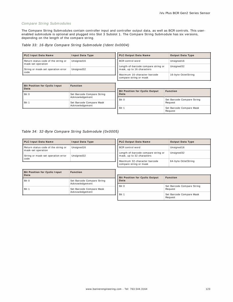
Compare String Submodules
The Compare String Submodules contain controller input and controller output data, as well as BCR controls. This user-enabled submodule is optional and plugged into Slot 3 Subslot 1. The Compare String Submodule has six versions,depending on the length of the compare string.
Table 33: 16-Byte Compare String Submodule (Ident 0x0004)
PLC Input Data Name Input Data Type
Return status code of the string ormask-set operation
Unsigned16
String or mask-set operation errorcode
Unsigned32
Bit Position for Cyclic InputData
Function
Bit 0 Set Barcode Compare StringAcknowledgement
Bit 1 Set Barcode Compare MaskAcknowledgement
PLC Output Data Name Output Data Type
BCR control word Unsigned16
Length-of-barcode compare string ormask, up to 16 characters
Unsigned32
Maximum 16-character barcodecompare string or mask
16-byte OctetString
Bit Position for Cyclic OutputData
Function
Bit 0 Set Barcode Compare StringRequest
Bit 1 Set Barcode Compare MaskRequest
Table 34: 32-Byte Compare String Submodule (0x0005)
PLC Input Data Name Input Data Type
Return status code of the string ormask-set operation
Unsigned16
String or mask-set operation errorcode
Unsigned32
Bit Position for Cyclic InputData
Function
Bit 0 Set Barcode Compare StringAcknowledgement
Bit 1 Set Barcode Compare MaskAcknowledgement
PLC Output Data Name Output Data Type
BCR control word Unsigned16
Length-of-barcode compare string ormask, up to 32 characters
Unsigned32
Maximum 32-character barcodecompare string or mask
64-byte OctetString
Bit Position for Cyclic OutputData
Function
Bit 0 Set Barcode Compare StringRequest
Bit 1 Set Barcode Compare MaskRequest
iVu Plus BCR Gen2 Series Sensor
www.bannerengineering.com - Tel: 763.544.3164 123
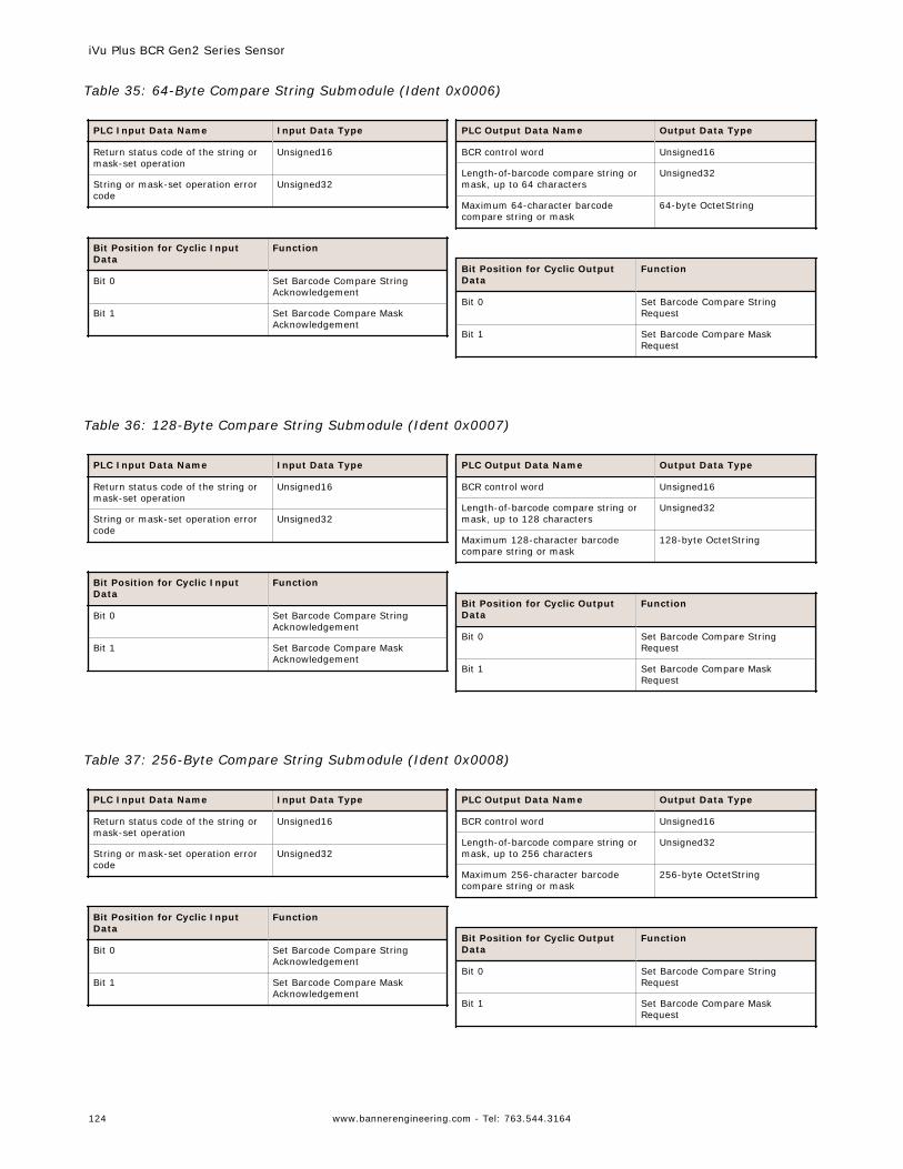
Table 35: 64-Byte Compare String Submodule (Ident 0x0006)
PLC Input Data Name Input Data Type
Return status code of the string ormask-set operation
Unsigned16
String or mask-set operation errorcode
Unsigned32
Bit Position for Cyclic InputData
Function
Bit 0 Set Barcode Compare StringAcknowledgement
Bit 1 Set Barcode Compare MaskAcknowledgement
PLC Output Data Name Output Data Type
BCR control word Unsigned16
Length-of-barcode compare string ormask, up to 64 characters
Unsigned32
Maximum 64-character barcodecompare string or mask
64-byte OctetString
Bit Position for Cyclic OutputData
Function
Bit 0 Set Barcode Compare StringRequest
Bit 1 Set Barcode Compare MaskRequest
Table 36: 128-Byte Compare String Submodule (Ident 0x0007)
PLC Input Data Name Input Data Type
Return status code of the string ormask-set operation
Unsigned16
String or mask-set operation errorcode
Unsigned32
Bit Position for Cyclic InputData
Function
Bit 0 Set Barcode Compare StringAcknowledgement
Bit 1 Set Barcode Compare MaskAcknowledgement
PLC Output Data Name Output Data Type
BCR control word Unsigned16
Length-of-barcode compare string ormask, up to 128 characters
Unsigned32
Maximum 128-character barcodecompare string or mask
128-byte OctetString
Bit Position for Cyclic OutputData
Function
Bit 0 Set Barcode Compare StringRequest
Bit 1 Set Barcode Compare MaskRequest
Table 37: 256-Byte Compare String Submodule (Ident 0x0008)
PLC Input Data Name Input Data Type
Return status code of the string ormask-set operation
Unsigned16
String or mask-set operation errorcode
Unsigned32
Bit Position for Cyclic InputData
Function
Bit 0 Set Barcode Compare StringAcknowledgement
Bit 1 Set Barcode Compare MaskAcknowledgement
PLC Output Data Name Output Data Type
BCR control word Unsigned16
Length-of-barcode compare string ormask, up to 256 characters
Unsigned32
Maximum 256-character barcodecompare string or mask
256-byte OctetString
Bit Position for Cyclic OutputData
Function
Bit 0 Set Barcode Compare StringRequest
Bit 1 Set Barcode Compare MaskRequest
iVu Plus BCR Gen2 Series Sensor
124 www.bannerengineering.com - Tel: 763.544.3164
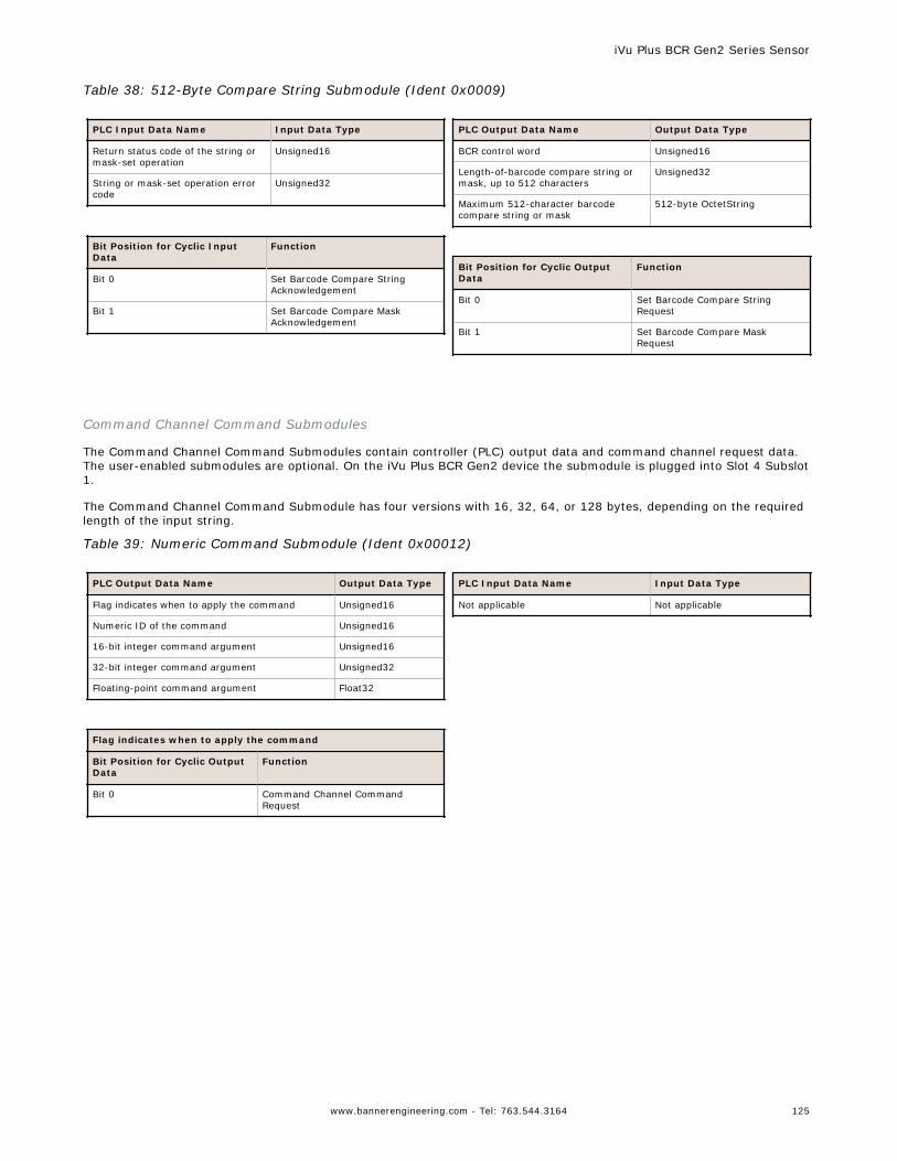
Table 38: 512-Byte Compare String Submodule (Ident 0x0009)
PLC Input Data Name Input Data Type
Return status code of the string ormask-set operation
Unsigned16
String or mask-set operation errorcode
Unsigned32
Bit Position for Cyclic InputData
Function
Bit 0 Set Barcode Compare StringAcknowledgement
Bit 1 Set Barcode Compare MaskAcknowledgement
PLC Output Data Name Output Data Type
BCR control word Unsigned16
Length-of-barcode compare string ormask, up to 512 characters
Unsigned32
Maximum 512-character barcodecompare string or mask
512-byte OctetString
Bit Position for Cyclic OutputData
Function
Bit 0 Set Barcode Compare StringRequest
Bit 1 Set Barcode Compare MaskRequest
Command Channel Command Submodules
The Command Channel Command Submodules contain controller (PLC) output data and command channel request data.The user-enabled submodules are optional. On the iVu Plus BCR Gen2 device the submodule is plugged into Slot 4 Subslot1.
The Command Channel Command Submodule has four versions with 16, 32, 64, or 128 bytes, depending on the requiredlength of the input string.
Table 39: Numeric Command Submodule (Ident 0x00012)
PLC Output Data Name Output Data Type
Flag indicates when to apply the command Unsigned16
Numeric ID of the command Unsigned16
16-bit integer command argument Unsigned16
32-bit integer command argument Unsigned32
Floating-point command argument Float32
Flag indicates when to apply the command
Bit Position for Cyclic OutputData
Function
Bit 0 Command Channel CommandRequest
PLC Input Data Name Input Data Type
Not applicable Not applicable
iVu Plus BCR Gen2 Series Sensor
www.bannerengineering.com - Tel: 763.544.3164 125
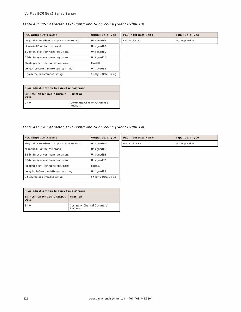
Table 40: 32-Character Text Command Submodule (Ident 0x00013)
PLC Output Data Name Output Data Type
Flag indicates when to apply the command Unsigned16
Numeric ID of the command Unsigned16
16-bit integer command argument Unsigned16
32-bit integer command argument Unsigned32
Floating-point command argument Float32
Length-of-Command/Response string Unsigned32
32-character command string 32-byte OctetString
Flag indicates when to apply the command
Bit Position for Cyclic OutputData
Function
Bit 0 Command Channel CommandRequest
PLC Input Data Name Input Data Type
Not applicable Not applicable
Table 41: 64-Character Text Command Submodule (Ident 0x00014)
PLC Output Data Name Output Data Type
Flag indicates when to apply the command Unsigned16
Numeric ID of the command Unsigned16
16-bit integer command argument Unsigned16
32-bit integer command argument Unsigned32
Floating-point command argument Float32
Length-of-Command/Response string Unsigned32
64-character command string 64-byte OctetString
Flag indicates when to apply the command
Bit Position for Cyclic OutputData
Function
Bit 0 Command Channel CommandRequest
PLC Input Data Name Input Data Type
Not applicable Not applicable
iVu Plus BCR Gen2 Series Sensor
126 www.bannerengineering.com - Tel: 763.544.3164
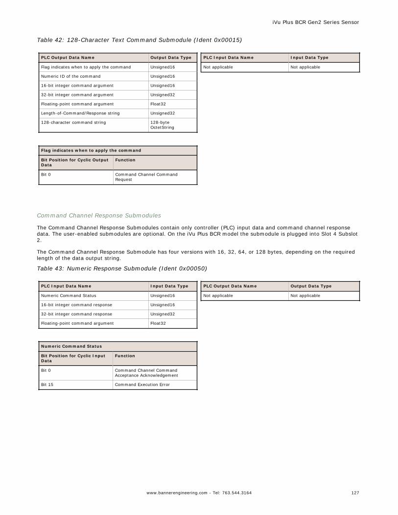
Table 42: 128-Character Text Command Submodule (Ident 0x00015)
PLC Output Data Name Output Data Type
Flag indicates when to apply the command Unsigned16
Numeric ID of the command Unsigned16
16-bit integer command argument Unsigned16
32-bit integer command argument Unsigned32
Floating-point command argument Float32
Length-of-Command/Response string Unsigned32
128-character command string 128-byteOctetString
Flag indicates when to apply the command
Bit Position for Cyclic OutputData
Function
Bit 0 Command Channel CommandRequest
PLC Input Data Name Input Data Type
Not applicable Not applicable
Command Channel Response Submodules
The Command Channel Response Submodules contain only controller (PLC) input data and command channel responsedata. The user-enabled submodules are optional. On the iVu Plus BCR model the submodule is plugged into Slot 4 Subslot2.
The Command Channel Response Submodule has four versions with 16, 32, 64, or 128 bytes, depending on the requiredlength of the data output string.
Table 43: Numeric Response Submodule (Ident 0x00050)
PLC Input Data Name Input Data Type
Numeric Command Status Unsigned16
16-bit integer command response Unsigned16
32-bit integer command response Unsigned32
Floating-point command argument Float32
Numeric Command Status
Bit Position for Cyclic InputData
Function
Bit 0 Command Channel CommandAcceptance Acknowledgement
Bit 15 Command Execution Error
PLC Output Data Name Output Data Type
Not applicable Not applicable
iVu Plus BCR Gen2 Series Sensor
www.bannerengineering.com - Tel: 763.544.3164 127
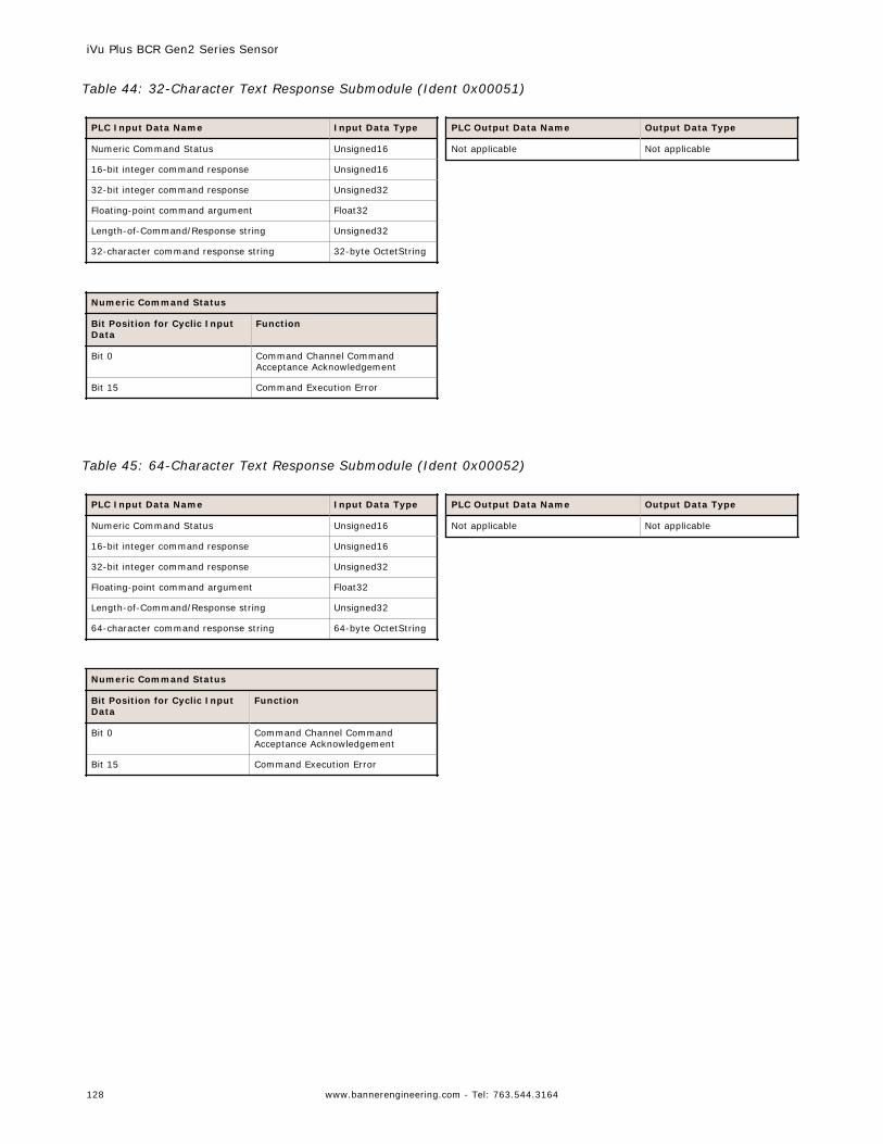
Table 44: 32-Character Text Response Submodule (Ident 0x00051)
PLC Input Data Name Input Data Type
Numeric Command Status Unsigned16
16-bit integer command response Unsigned16
32-bit integer command response Unsigned32
Floating-point command argument Float32
Length-of-Command/Response string Unsigned32
32-character command response string 32-byte OctetString
Numeric Command Status
Bit Position for Cyclic InputData
Function
Bit 0 Command Channel CommandAcceptance Acknowledgement
Bit 15 Command Execution Error
PLC Output Data Name Output Data Type
Not applicable Not applicable
Table 45: 64-Character Text Response Submodule (Ident 0x00052)
PLC Input Data Name Input Data Type
Numeric Command Status Unsigned16
16-bit integer command response Unsigned16
32-bit integer command response Unsigned32
Floating-point command argument Float32
Length-of-Command/Response string Unsigned32
64-character command response string 64-byte OctetString
Numeric Command Status
Bit Position for Cyclic InputData
Function
Bit 0 Command Channel CommandAcceptance Acknowledgement
Bit 15 Command Execution Error
PLC Output Data Name Output Data Type
Not applicable Not applicable
iVu Plus BCR Gen2 Series Sensor
128 www.bannerengineering.com - Tel: 763.544.3164
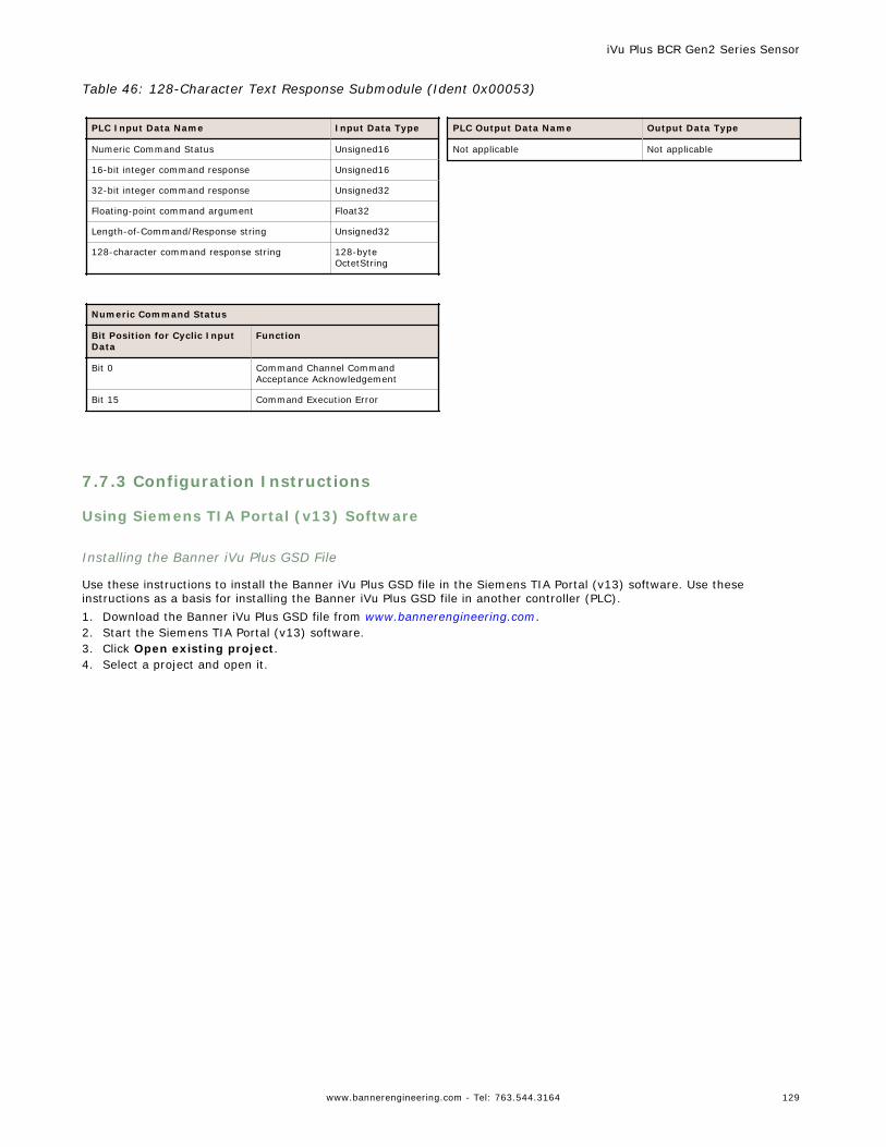
Table 46: 128-Character Text Response Submodule (Ident 0x00053)
PLC Input Data Name Input Data Type
Numeric Command Status Unsigned16
16-bit integer command response Unsigned16
32-bit integer command response Unsigned32
Floating-point command argument Float32
Length-of-Command/Response string Unsigned32
128-character command response string 128-byteOctetString
Numeric Command Status
Bit Position for Cyclic InputData
Function
Bit 0 Command Channel CommandAcceptance Acknowledgement
Bit 15 Command Execution Error
PLC Output Data Name Output Data Type
Not applicable Not applicable
7.7.3 Configuration Instructions
Using Siemens TIA Portal (v13) Software
Installing the Banner iVu Plus GSD File
Use these instructions to install the Banner iVu Plus GSD file in the Siemens TIA Portal (v13) software. Use theseinstructions as a basis for installing the Banner iVu Plus GSD file in another controller (PLC).1. Download the Banner iVu Plus GSD file from www.bannerengineering.com.2. Start the Siemens TIA Portal (v13) software.3. Click Open existing project.4. Select a project and open it.
iVu Plus BCR Gen2 Series Sensor
www.bannerengineering.com - Tel: 763.544.3164 129
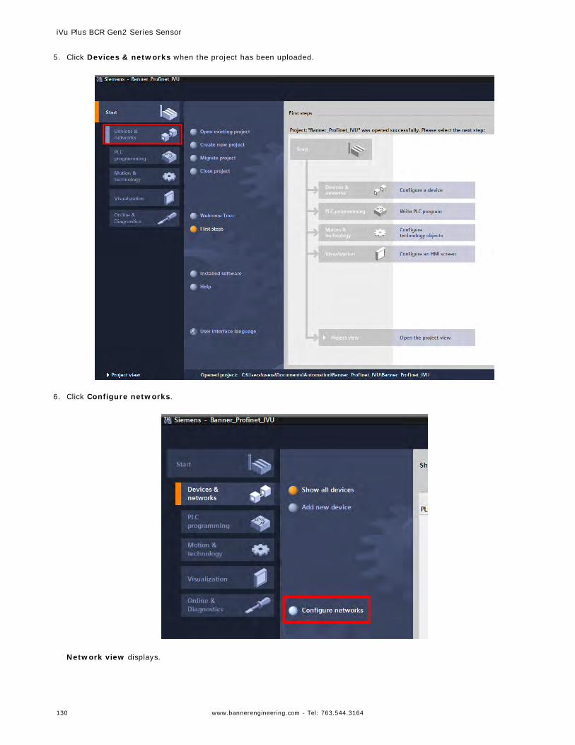
5. Click Devices & networks when the project has been uploaded.
6. Click Configure networks.
Network view displays.
iVu Plus BCR Gen2 Series Sensor
130 www.bannerengineering.com - Tel: 763.544.3164
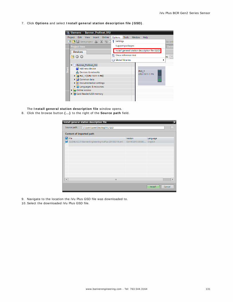
7. Click Options and select Install general station description file (GSD).
The Install general station description file window opens.
8. Click the browse button (...) to the right of the Source path field.
9. Navigate to the location the iVu Plus GSD file was downloaded to.10.Select the downloaded iVu Plus GSD file.
iVu Plus BCR Gen2 Series Sensor
www.bannerengineering.com - Tel: 763.544.3164 131
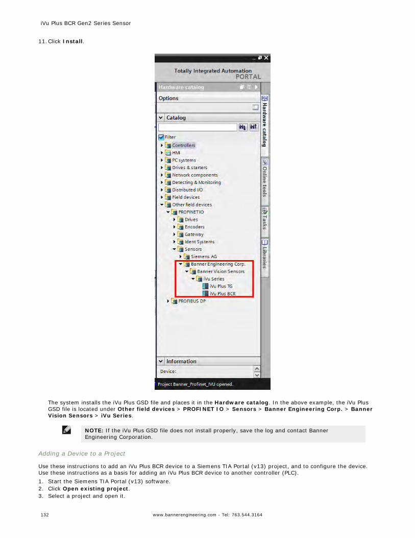
11.Click Install.
The system installs the iVu Plus GSD file and places it in the Hardware catalog. In the above example, the iVu PlusGSD file is located under Other field devices > PROFINET IO > Sensors > Banner Engineering Corp. > BannerVision Sensors > iVu Series.
NOTE: If the iVu Plus GSD file does not install properly, save the log and contact BannerEngineering Corporation.
Adding a Device to a Project
Use these instructions to add an iVu Plus BCR device to a Siemens TIA Portal (v13) project, and to configure the device.Use these instructions as a basis for adding an iVu Plus BCR device to another controller (PLC).1. Start the Siemens TIA Portal (v13) software.2. Click Open existing project.3. Select a project and open it.
iVu Plus BCR Gen2 Series Sensor
132 www.bannerengineering.com - Tel: 763.544.3164
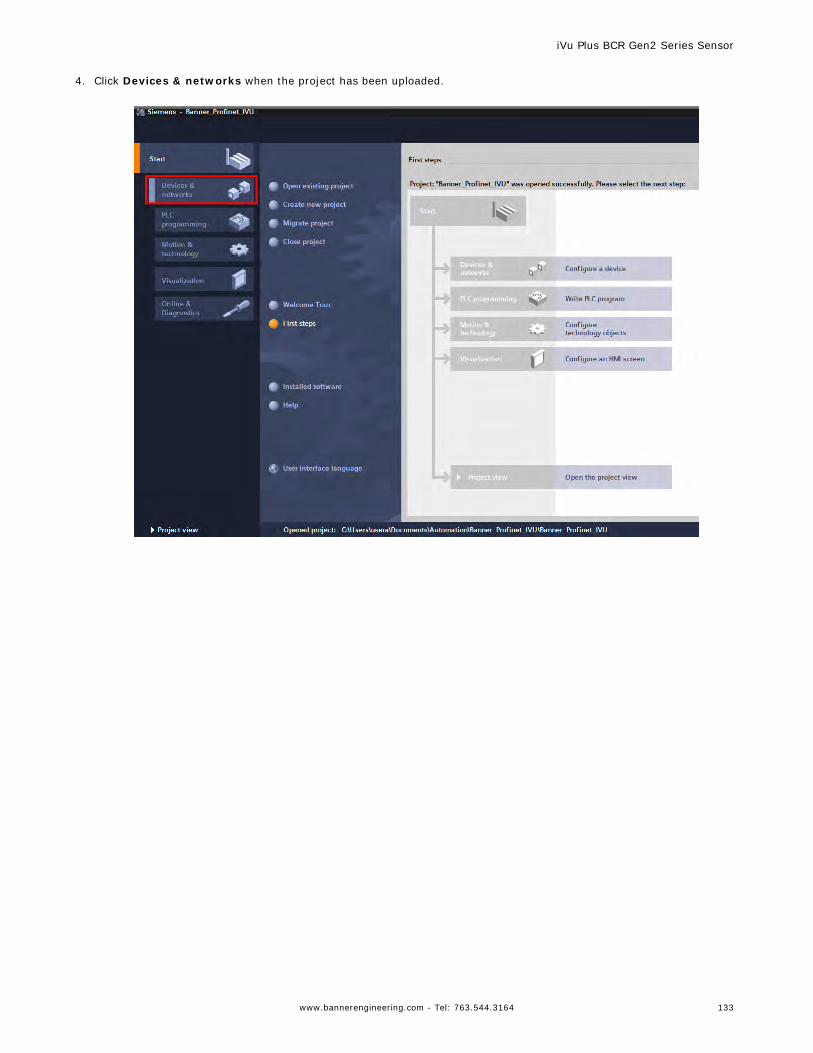
4. Click Devices & networks when the project has been uploaded.
iVu Plus BCR Gen2 Series Sensor
www.bannerengineering.com - Tel: 763.544.3164 133
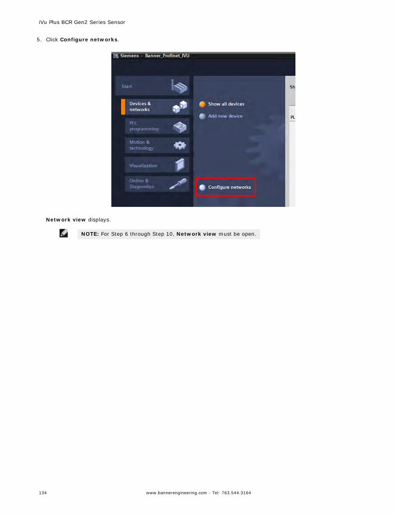
5. Click Configure networks.
Network view displays.
NOTE: For Step 6 through Step 10, Network view must be open.
iVu Plus BCR Gen2 Series Sensor
134 www.bannerengineering.com - Tel: 763.544.3164
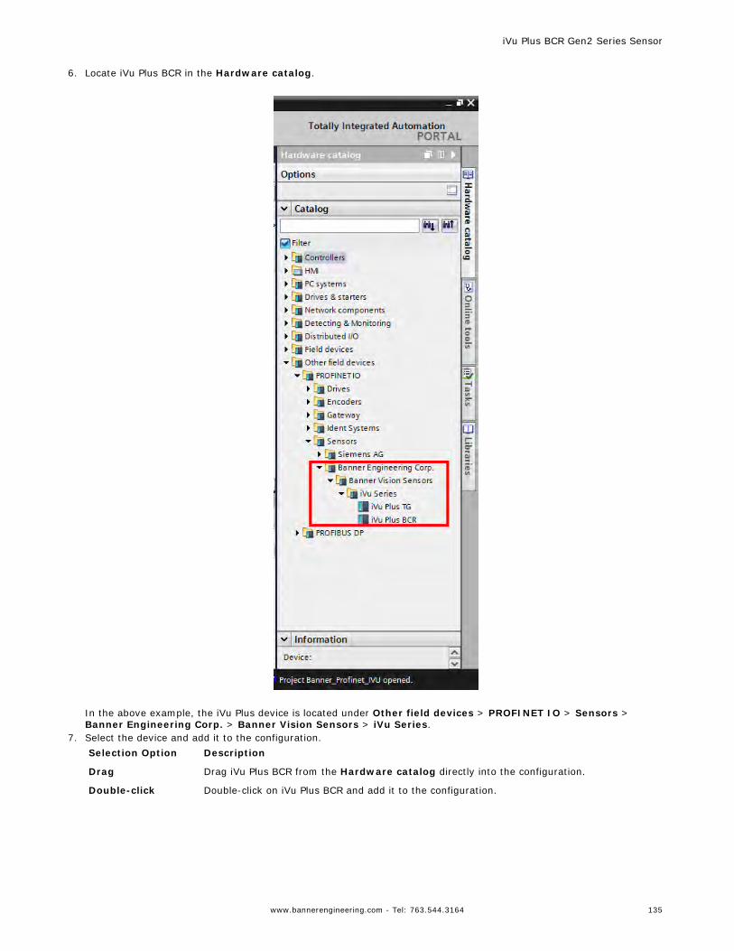
6. Locate iVu Plus BCR in the Hardware catalog.
In the above example, the iVu Plus device is located under Other field devices > PROFINET IO > Sensors >Banner Engineering Corp. > Banner Vision Sensors > iVu Series.
7. Select the device and add it to the configuration.Selection Option Description
Drag Drag iVu Plus BCR from the Hardware catalog directly into the configuration.
Double-click Double-click on iVu Plus BCR and add it to the configuration.
iVu Plus BCR Gen2 Series Sensor
www.bannerengineering.com - Tel: 763.544.3164 135
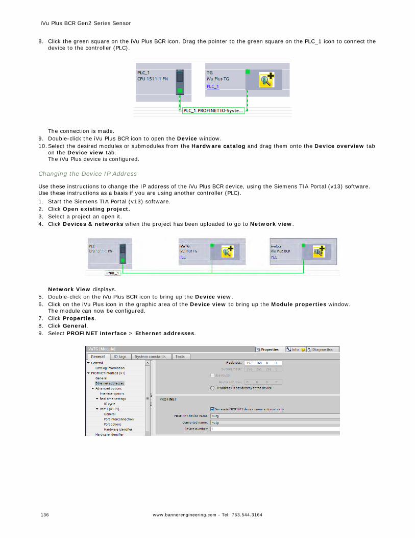
8. Click the green square on the iVu Plus BCR icon. Drag the pointer to the green square on the PLC_1 icon to connect thedevice to the controller (PLC).
The connection is made.
9. Double-click the iVu Plus BCR icon to open the Device window.10.Select the desired modules or submodules from the Hardware catalog and drag them onto the Device overview tab
on the Device view tab.The iVu Plus device is configured.
Changing the Device IP Address
Use these instructions to change the IP address of the iVu Plus BCR device, using the Siemens TIA Portal (v13) software.Use these instructions as a basis if you are using another controller (PLC).1. Start the Siemens TIA Portal (v13) software.2. Click Open existing project.3. Select a project an open it.4. Click Devices & networks when the project has been uploaded to go to Network view.
Network View displays.
5. Double-click on the iVu Plus BCR icon to bring up the Device view.6. Click on the iVu Plus icon in the graphic area of the Device view to bring up the Module properties window.
The module can now be configured.7. Click Properties.8. Click General.9. Select PROFINET interface > Ethernet addresses.
iVu Plus BCR Gen2 Series Sensor
136 www.bannerengineering.com - Tel: 763.544.3164
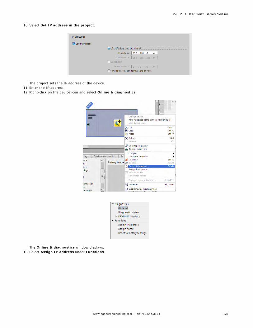
10.Select Set IP address in the project.
The project sets the IP address of the device.
11.Enter the IP address.12.Right-click on the device icon and select Online & diagnostics.
The Online & diagnostics window displays.
13.Select Assign IP address under Functions.
iVu Plus BCR Gen2 Series Sensor
www.bannerengineering.com - Tel: 763.544.3164 137
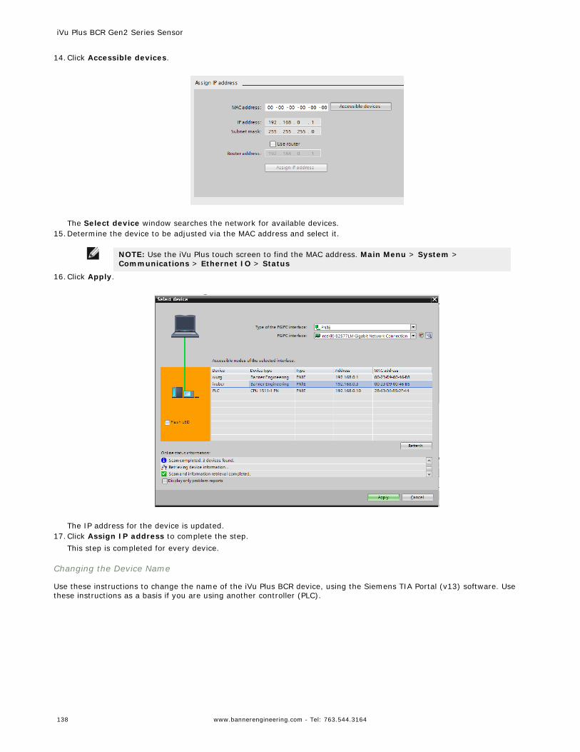
14.Click Accessible devices.
The Select device window searches the network for available devices.
15.Determine the device to be adjusted via the MAC address and select it.
NOTE: Use the iVu Plus touch screen to find the MAC address. Main Menu > System >Communications > Ethernet IO > Status
16.Click Apply.
The IP address for the device is updated.
17.Click Assign IP address to complete the step.This step is completed for every device.
Changing the Device Name
Use these instructions to change the name of the iVu Plus BCR device, using the Siemens TIA Portal (v13) software. Usethese instructions as a basis if you are using another controller (PLC).
iVu Plus BCR Gen2 Series Sensor
138 www.bannerengineering.com - Tel: 763.544.3164
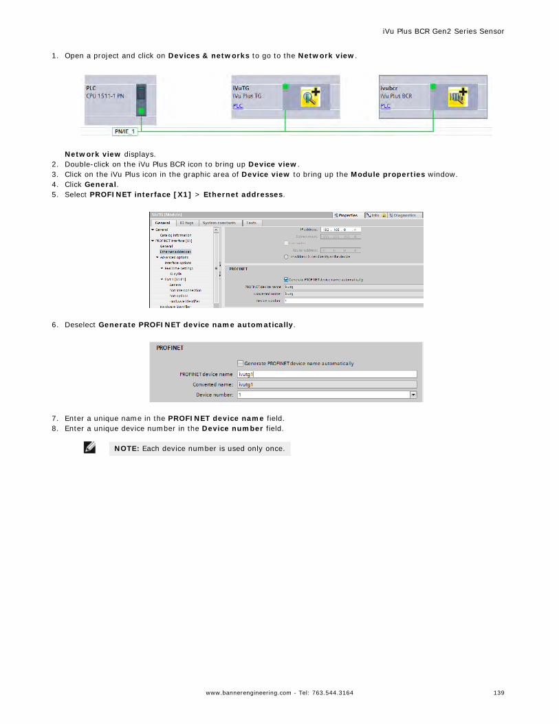
1. Open a project and click on Devices & networks to go to the Network view.
Network view displays.
2. Double-click on the iVu Plus BCR icon to bring up Device view.3. Click on the iVu Plus icon in the graphic area of Device view to bring up the Module properties window.4. Click General.5. Select PROFINET interface [X1] > Ethernet addresses.
6. Deselect Generate PROFINET device name automatically.
7. Enter a unique name in the PROFINET device name field.8. Enter a unique device number in the Device number field.
NOTE: Each device number is used only once.
iVu Plus BCR Gen2 Series Sensor
www.bannerengineering.com - Tel: 763.544.3164 139
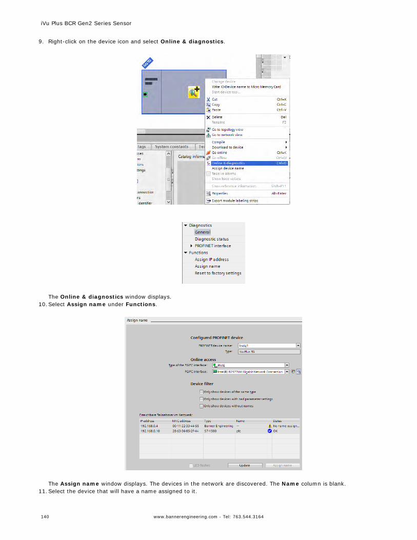
9. Right-click on the device icon and select Online & diagnostics.
The Online & diagnostics window displays.
10.Select Assign name under Functions.
The Assign name window displays. The devices in the network are discovered. The Name column is blank.
11.Select the device that will have a name assigned to it.
iVu Plus BCR Gen2 Series Sensor
140 www.bannerengineering.com - Tel: 763.544.3164
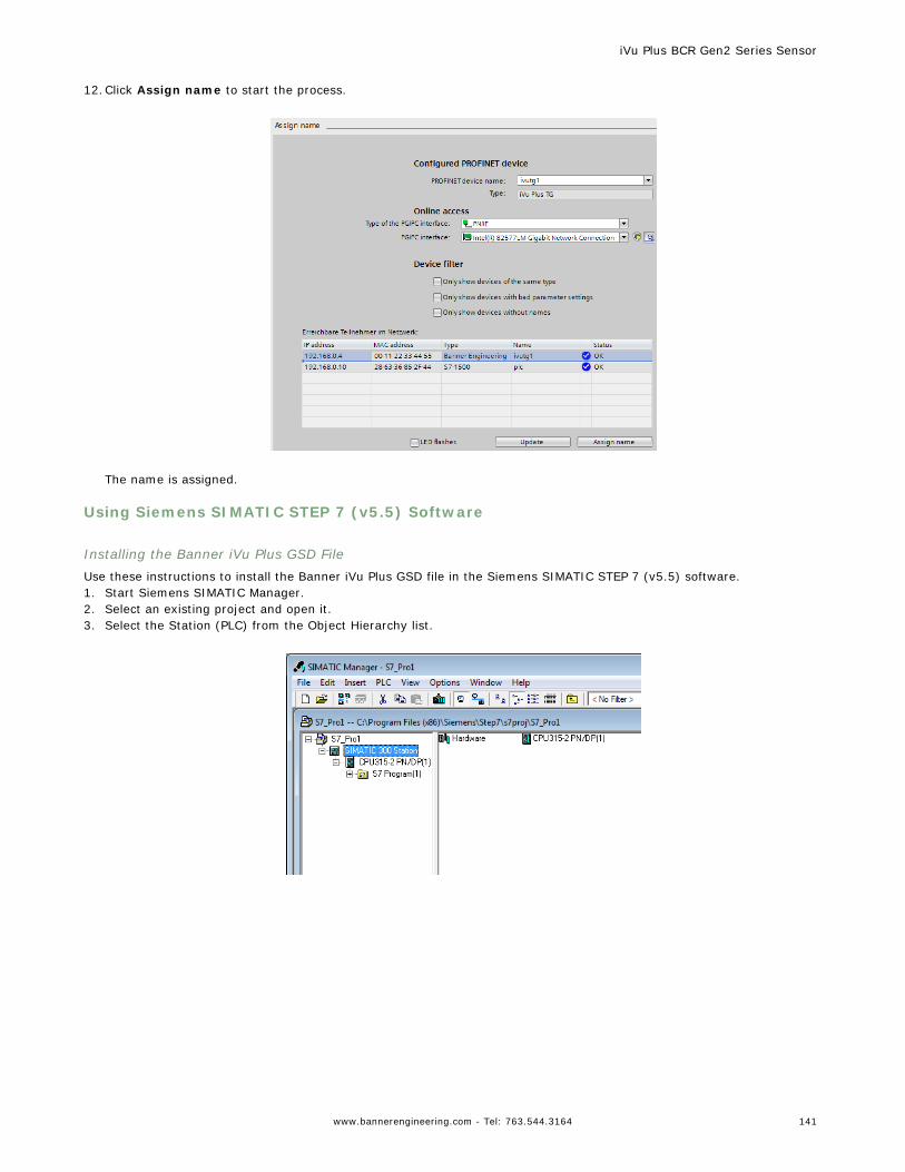
12.Click Assign name to start the process.
The name is assigned.
Using Siemens SIMATIC STEP 7 (v5.5) Software
Installing the Banner iVu Plus GSD FileUse these instructions to install the Banner iVu Plus GSD file in the Siemens SIMATIC STEP 7 (v5.5) software.1. Start Siemens SIMATIC Manager.2. Select an existing project and open it.3. Select the Station (PLC) from the Object Hierarchy list.
iVu Plus BCR Gen2 Series Sensor
www.bannerengineering.com - Tel: 763.544.3164 141
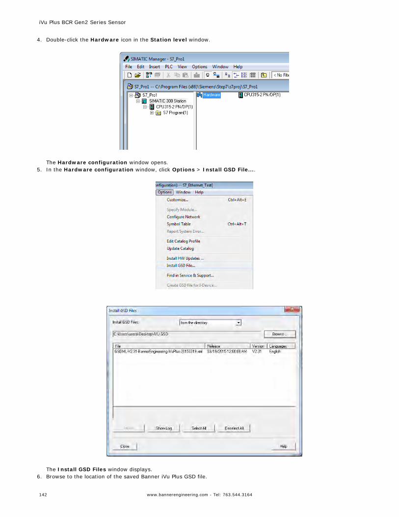
4. Double-click the Hardware icon in the Station level window.
The Hardware configuration window opens.
5. In the Hardware configuration window, click Options > Install GSD File....
The Install GSD Files window displays.
6. Browse to the location of the saved Banner iVu Plus GSD file.
iVu Plus BCR Gen2 Series Sensor
142 www.bannerengineering.com - Tel: 763.544.3164
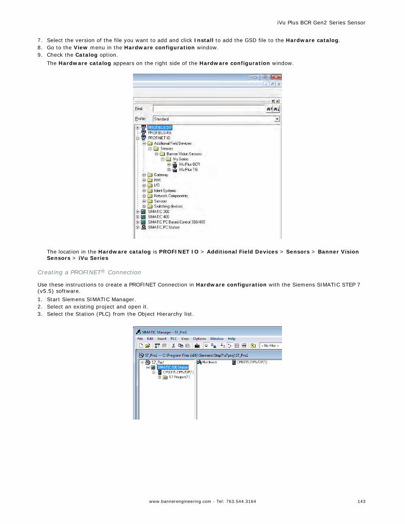
7. Select the version of the file you want to add and click Install to add the GSD file to the Hardware catalog.8. Go to the View menu in the Hardware configuration window.9. Check the Catalog option.
The Hardware catalog appears on the right side of the Hardware configuration window.
The location in the Hardware catalog is PROFINET IO > Additional Field Devices > Sensors > Banner VisionSensors > iVu Series
Creating a PROFINET® Connection
Use these instructions to create a PROFINET Connection in Hardware configuration with the Siemens SIMATIC STEP 7(v5.5) software.1. Start Siemens SIMATIC Manager.2. Select an existing project and open it.3. Select the Station (PLC) from the Object Hierarchy list.
iVu Plus BCR Gen2 Series Sensor
www.bannerengineering.com - Tel: 763.544.3164 143
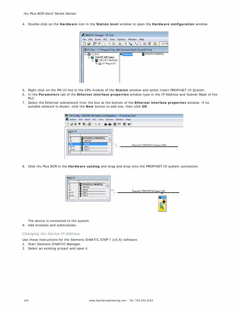
4. Double-click on the Hardware icon in the Station level window to open the Hardware configuration window.
5. Right-click on the PN-IO line in the CPU module of the Station window and select Insert PROFINET IO System.6. In the Parameters tab of the Ethernet interface properties window type in the IP Address and Subnet Mask of the
PLC.7. Select the Ethernet subnetwork from the box at the bottom of the Ethernet interface properties window. If no
suitable network is shown, click the New button to add one, then click OK.
8. Click iVu Plus BCR in the Hardware catalog and drag and drop onto the PROFINET IO system connection.
The device is connected to the system.
9. Add modules and submodules.
Changing the Device IP AddressUse these instructions for the Siemens SIMATIC STEP 7 (v5.5) software.1. Start Siemens SIMATIC Manager.2. Select an existing project and open it.
iVu Plus BCR Gen2 Series Sensor
144 www.bannerengineering.com - Tel: 763.544.3164
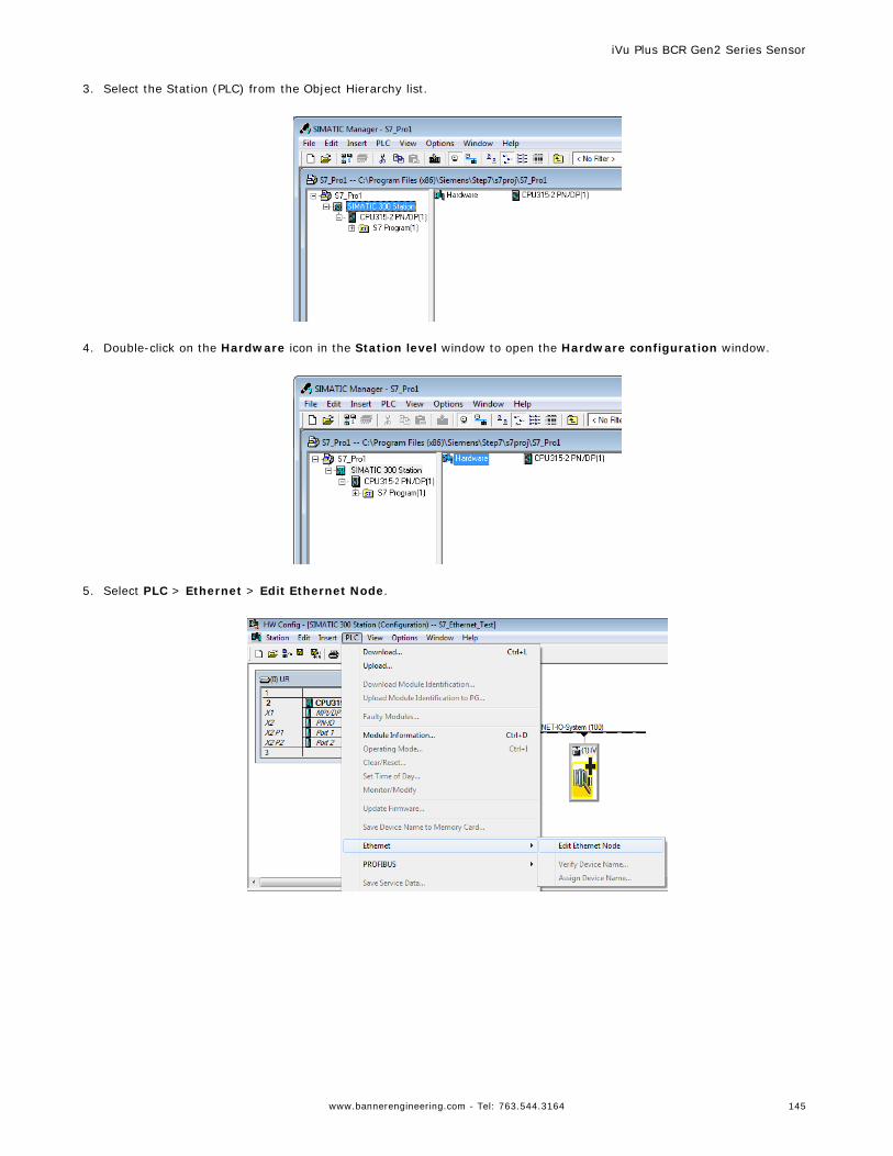
3. Select the Station (PLC) from the Object Hierarchy list.
4. Double-click on the Hardware icon in the Station level window to open the Hardware configuration window.
5. Select PLC > Ethernet > Edit Ethernet Node.
iVu Plus BCR Gen2 Series Sensor
www.bannerengineering.com - Tel: 763.544.3164 145
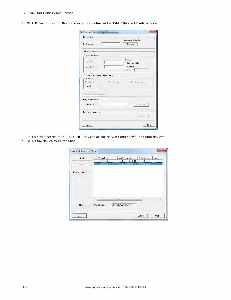
6. Click Browse... under Nodes accessible online in the Edit Ethernet Node window.
This starts a search for all PROFINET devices on the network and shows the found devices.
7. Select the device to be modified.
iVu Plus BCR Gen2 Series Sensor
146 www.bannerengineering.com - Tel: 763.544.3164
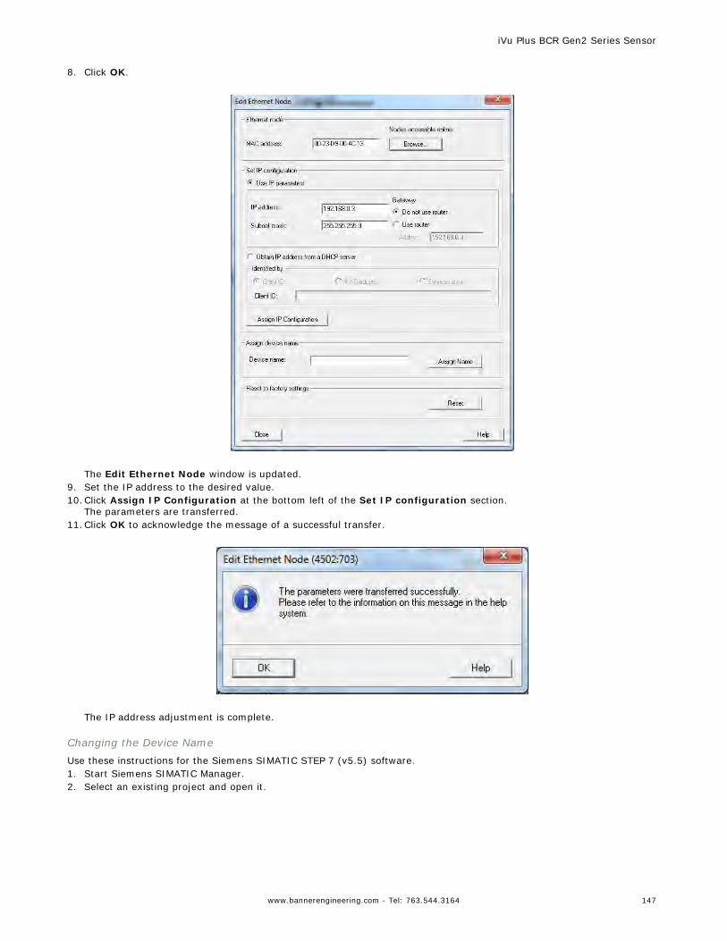
8. Click OK.
The Edit Ethernet Node window is updated.
9. Set the IP address to the desired value.10.Click Assign IP Configuration at the bottom left of the Set IP configuration section.
The parameters are transferred.11.Click OK to acknowledge the message of a successful transfer.
The IP address adjustment is complete.
Changing the Device NameUse these instructions for the Siemens SIMATIC STEP 7 (v5.5) software.1. Start Siemens SIMATIC Manager.2. Select an existing project and open it.
iVu Plus BCR Gen2 Series Sensor
www.bannerengineering.com - Tel: 763.544.3164 147
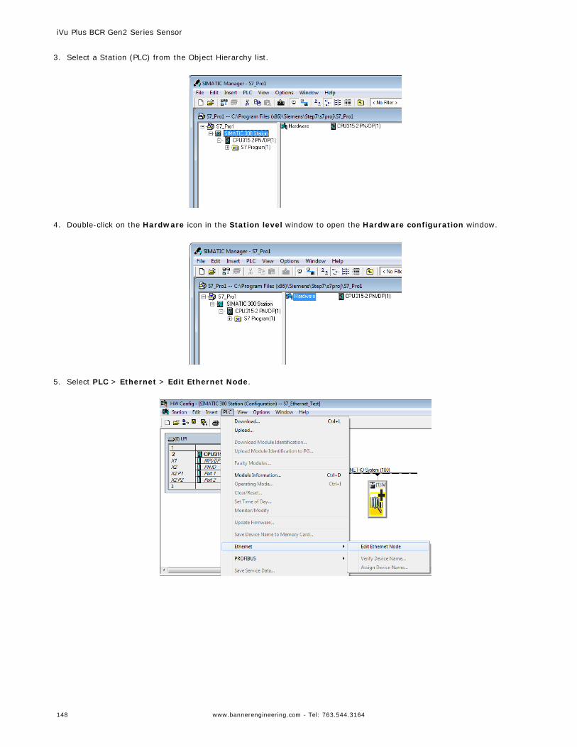
3. Select a Station (PLC) from the Object Hierarchy list.
4. Double-click on the Hardware icon in the Station level window to open the Hardware configuration window.
5. Select PLC > Ethernet > Edit Ethernet Node.
iVu Plus BCR Gen2 Series Sensor
148 www.bannerengineering.com - Tel: 763.544.3164
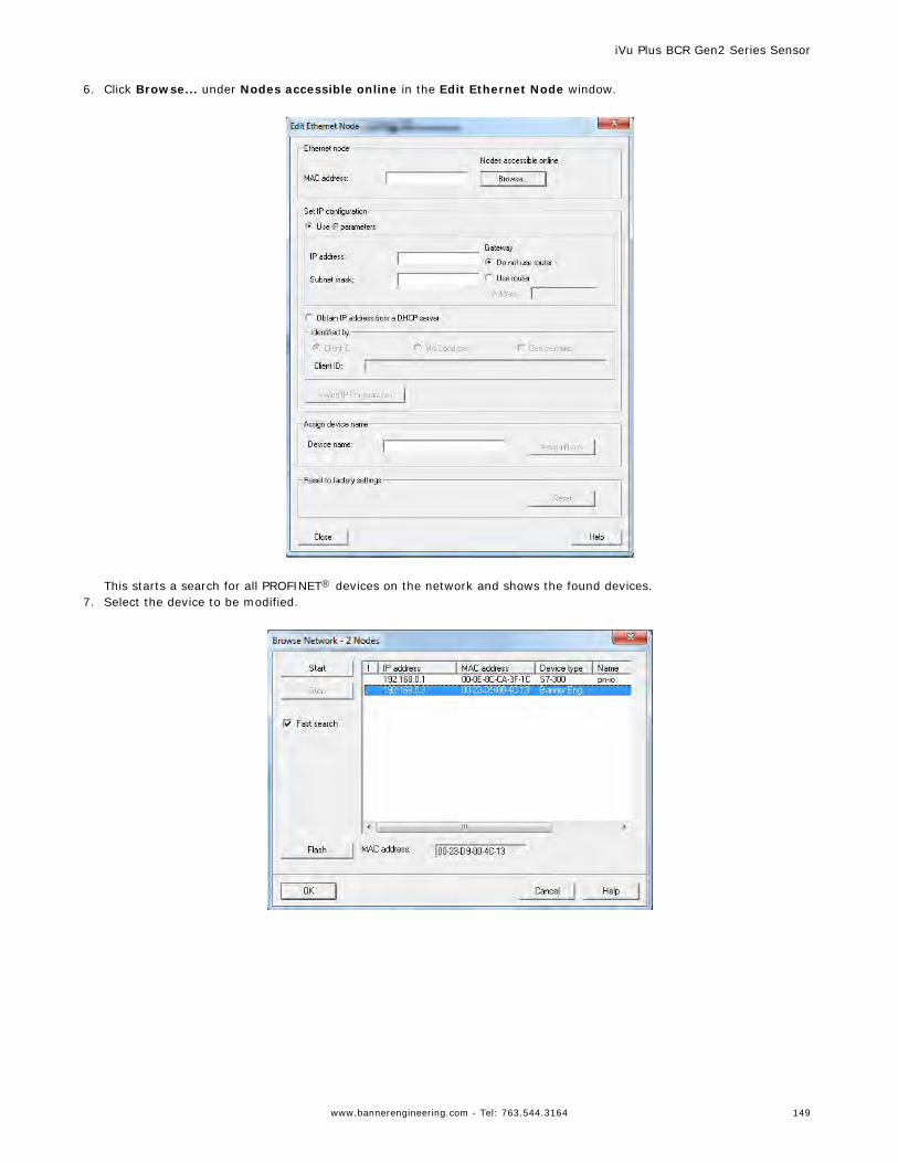
6. Click Browse... under Nodes accessible online in the Edit Ethernet Node window.
This starts a search for all PROFINET® devices on the network and shows the found devices.
7. Select the device to be modified.
iVu Plus BCR Gen2 Series Sensor
www.bannerengineering.com - Tel: 763.544.3164 149
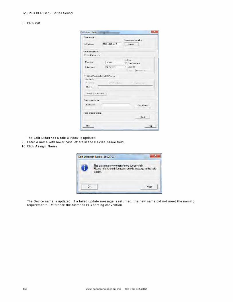
8. Click OK.
The Edit Ethernet Node window is updated.
9. Enter a name with lower case letters in the Device name field.10.Click Assign Name.
The Device name is updated. If a failed update message is returned, the new name did not meet the namingrequirements. Reference the Siemens PLC naming convention.
iVu Plus BCR Gen2 Series Sensor
150 www.bannerengineering.com - Tel: 763.544.3164
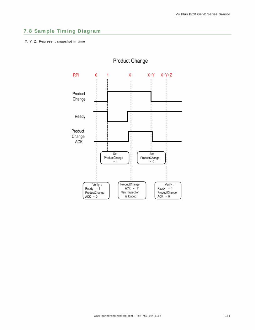
7.8 Sample Timing Diagram
X, Y, Z: Represent snapshot in time
Verify :Ready = 1ProductChange ACK = 0
Ready
Product Change
ProductChange ACK = ‘1 ’
New inspection is loaded
RPI 0 1 X X+Y X+Y+Z
Product Change
ACK
Set ProductChange
= 1
Verify :Ready = 1ProductChangeACK = 0
Set ProductChange
= 0
Product Change
iVu Plus BCR Gen2 Series Sensor
www.bannerengineering.com - Tel: 763.544.3164 151
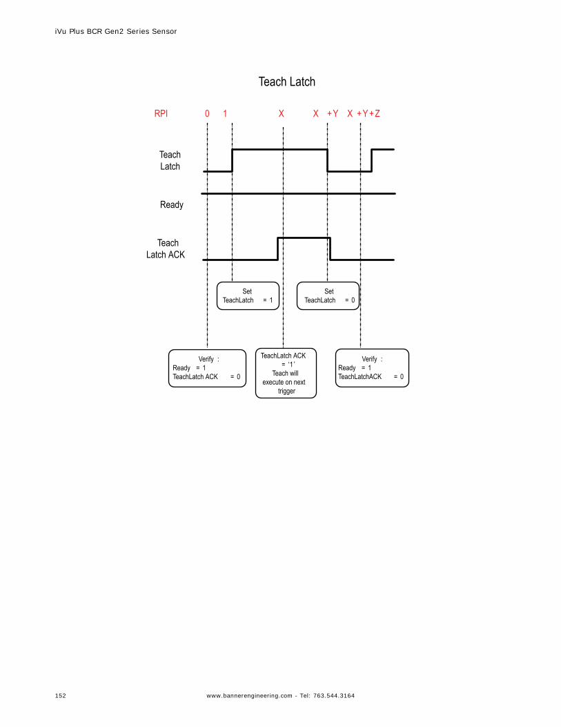
Verify :Ready = 1TeachLatch ACK = 0
Ready
Teach Latch
TeachLatch ACK = ‘1 ’
Teach will execute on next
trigger
RPI 0 1 X X +Y X +Y +Z
Teach Latch ACK
Set TeachLatch = 1
Verify :Ready = 1TeachLatchACK = 0
Set TeachLatch = 0
Teach Latch
iVu Plus BCR Gen2 Series Sensor
152 www.bannerengineering.com - Tel: 763.544.3164
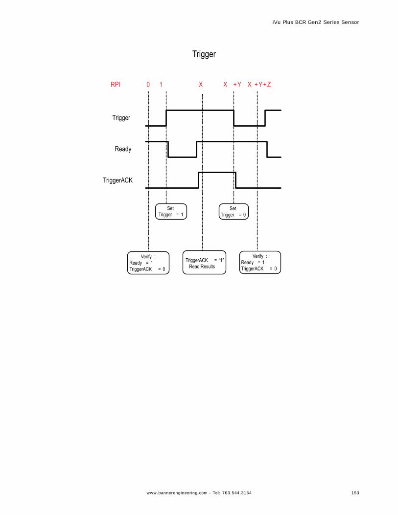
Verify :Ready = 1TriggerACK = 0
Ready
Trigger
TriggerACK = ‘1 ’Read Results
Set Trigger = 0
RPI 0 1 X X +Y X +Y +Z
TriggerACK
Set Trigger = 1
Verify :Ready = 1TriggerACK = 0
Trigger
iVu Plus BCR Gen2 Series Sensor
www.bannerengineering.com - Tel: 763.544.3164 153
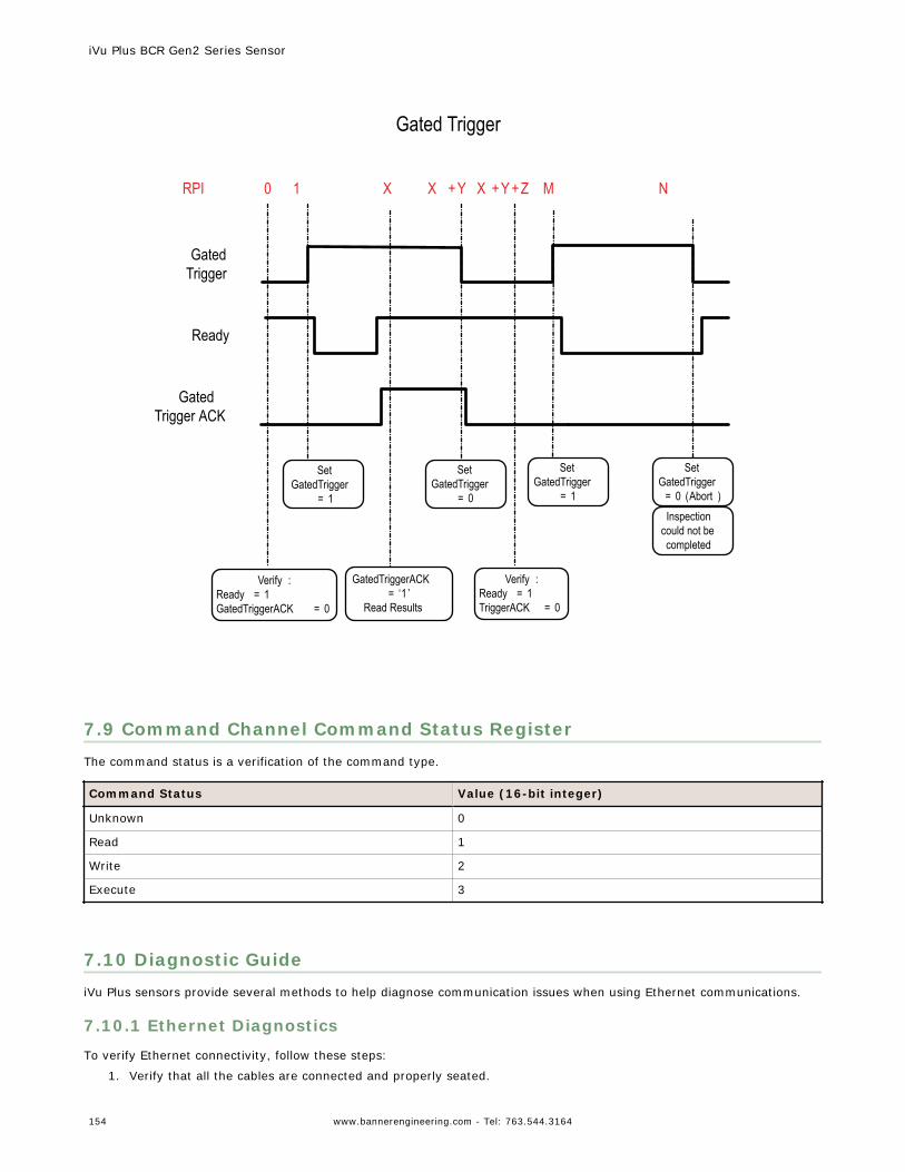
Verify :Ready = 1GatedTriggerACK = 0
Ready
Gated Trigger
GatedTriggerACK = ‘1 ’
Read Results
RPI 0 1 X X +Y X +Y +Z M N
Gated Trigger ACK
Set GatedTrigger
= 1
Verify :Ready = 1TriggerACK = 0
Set GatedTrigger
= 0
Set GatedTrigger
= 1
Set GatedTrigger
= 0 (Abort )Inspection
could not be completed
Gated Trigger
7.9 Command Channel Command Status RegisterThe command status is a verification of the command type.
Command Status Value (16-bit integer)
Unknown 0
Read 1
Write 2
Execute 3
7.10 Diagnostic GuideiVu Plus sensors provide several methods to help diagnose communication issues when using Ethernet communications.
7.10.1 Ethernet Diagnostics
To verify Ethernet connectivity, follow these steps:
1. Verify that all the cables are connected and properly seated.
iVu Plus BCR Gen2 Series Sensor
154 www.bannerengineering.com - Tel: 763.544.3164
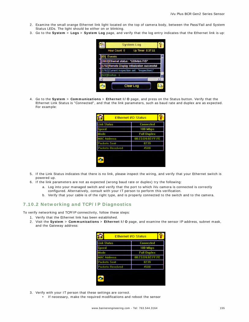
2. Examine the small orange Ethernet link light located on the top of camera body, between the Pass/Fail and SystemStatus LEDs. The light should be either on or blinking.
3. Go to the System > Logs > System Log page, and verify that the log entry indicates that the Ethernet link is up:
4. Go to the System > Communications > Ethernet I/O page, and press on the Status button. Verify that the
Ethernet Link Status is "Connected", and that the link parameters, such as baud rate and duplex are as expected.For example:
5. If the Link Status indicates that there is no link, please inspect the wiring, and verify that your Ethernet switch is
powered up.6. If the link parameters are not as expected (wrong baud rate or duplex) try the following:
a. Log into your managed switch and verify that the port to which iVu camera is connected is correctlyconfigured. Alternatively, consult with your IT person to perform this verification.
b. Verify that your cable is of the right type, and is properly connected to the switch and to the camera.
7.10.2 Networking and TCP/IP Diagnostics
To verify networking and TCP/IP connectivity, follow these steps:1. Verify that the Ethernet link has been established.2. Visit the System > Communications > Ethernet I/O page, and examine the sensor IP address, subnet mask,
and the Gateway address:
3. Verify with your IT person that these settings are correct.
• If necessary, make the required modifications and reboot the sensor
iVu Plus BCR Gen2 Series Sensor
www.bannerengineering.com - Tel: 763.544.3164 155
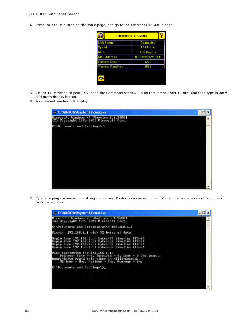
4. Press the Status button on the same page, and go to the Ethernet I/O Status page:
5. On the PC attached to your LAN, open the Command window. To do this, press Start > Run, and then type in cmd
and press the OK button.6. A command window will display:
7. Type in a ping command, specifying the sensor IP address as an argument. You should see a series of responses
from the camera:
iVu Plus BCR Gen2 Series Sensor
156 www.bannerengineering.com - Tel: 763.544.3164
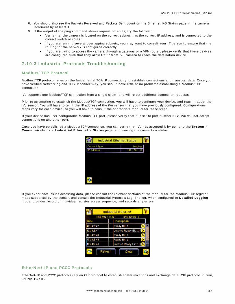
8. You should also see the Packets Received and Packets Sent count on the Ethernet I/O Status page in the cameraincrement by at least 4.
9. If the output of the ping command shows request timeouts, try the following:• Verify that the camera is located on the correct subnet, has the correct IP address, and is connected to the
correct switch or router.• If you are running several overlapping subnets, you may want to consult your IT person to ensure that the
routing for the network is configured correctly.• If you are trying to access the camera through a gateway or a VPN router, please verify that these devices
are configured such that they allow traffic from iVu camera to reach the destination device.
7.10.3 Industrial Protocols Troubleshooting
Modbus/TCP Protocol
Modbus/TCP protocol relies on the fundamental TCP/IP connectivity to establish connections and transport data. Once youhave verified Networking and TCP/IP connectivity, you should have little or no problems establishing a Modbus/TCPconnection.
iVu supports one Modbus/TCP connection from a single client, and will reject additional connection requests.
Prior to attempting to establish the Modbus/TCP connection, you will have to configure your device, and teach it about theiVu sensor. You will have to tell it the IP address of the iVu sensor that you have previously configured. Configurationssteps vary for each device, so you will have to consult the appropriate manual for these steps.
If your device has user-configurable Modbus/TCP port, please verify that it is set to port number 502. iVu will not acceptconnections on any other port.
Once you have established a Modbus/TCP connection, you can verify that iVu has accepted it by going to the System >Communications > Industrial Ethernet > Status page, and viewing the connection status:
If you experience issues accessing data, please consult the relevant sections of the manual for the Modbus/TCP registermaps supported by the sensor, and consult the Industrial Protocols Log. The log, when configured to Detailed Loggingmode, provides record of individual register access sequence, and records any errors:
EtherNet/IP and PCCC Protocols
EtherNet/IP and PCCC protocols rely on CIP protocol to establish communications and exchange data. CIP protocol, in turn,utilizes TCP/IP.
iVu Plus BCR Gen2 Series Sensor
www.bannerengineering.com - Tel: 763.544.3164 157
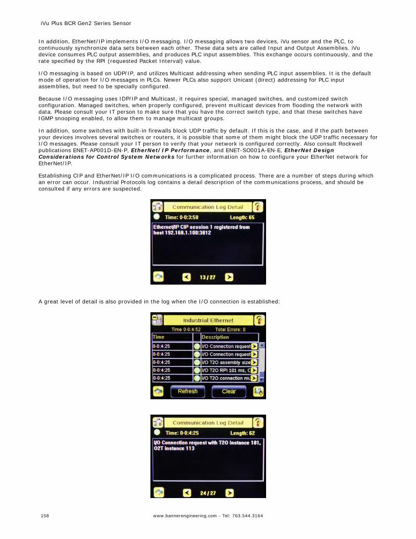
In addition, EtherNet/IP implements I/O messaging. I/O messaging allows two devices, iVu sensor and the PLC, tocontinuously synchronize data sets between each other. These data sets are called Input and Output Assemblies. iVudevice consumes PLC output assemblies, and produces PLC input assemblies. This exchange occurs continuously, and therate specified by the RPI (requested Packet Interval) value.
I/O messaging is based on UDP/IP, and utilizes Multicast addressing when sending PLC input assemblies. It is the defaultmode of operation for I/O messages in PLCs. Newer PLCs also support Unicast (direct) addressing for PLC inputassemblies, but need to be specially configured.
Because I/O messaging uses IDP/IP and Multicast, it requires special, managed switches, and customized switchconfiguration. Managed switches, when properly configured, prevent multicast devices from flooding the network withdata. Please consult your IT person to make sure that you have the correct switch type, and that these switches haveIGMP snooping enabled, to allow them to manage multicast groups.
In addition, some switches with built-in firewalls block UDP traffic by default. If this is the case, and if the path betweenyour devices involves several switches or routers, it is possible that some of them might block the UDP traffic necessary forI/O messages. Please consult your IT person to verify that your network is configured correctly. Also consult Rockwellpublications ENET-AP001D-EN-P, EtherNet/IP Performance, and ENET-SO001A-EN-E, EtherNet DesignConsiderations for Control System Networks for further information on how to configure your EtherNet network forEtherNet/IP.
Establishing CIP and EtherNet/IP I/O communications is a complicated process. There are a number of steps during whichan error can occur. Industrial Protocols log contains a detail description of the communications process, and should beconsulted if any errors are suspected.
A great level of detail is also provided in the log when the I/O connection is established:
iVu Plus BCR Gen2 Series Sensor
158 www.bannerengineering.com - Tel: 763.544.3164
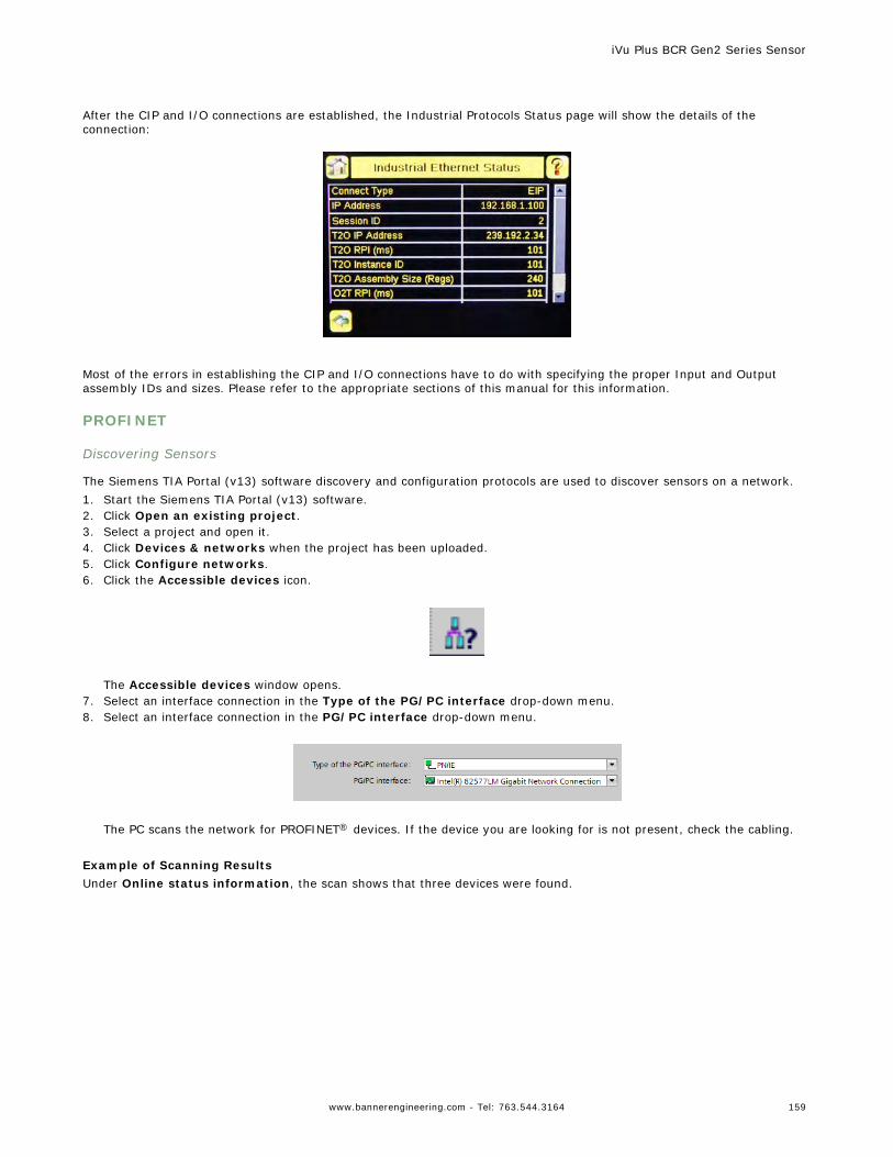
After the CIP and I/O connections are established, the Industrial Protocols Status page will show the details of theconnection:
Most of the errors in establishing the CIP and I/O connections have to do with specifying the proper Input and Outputassembly IDs and sizes. Please refer to the appropriate sections of this manual for this information.
PROFINET
Discovering Sensors
The Siemens TIA Portal (v13) software discovery and configuration protocols are used to discover sensors on a network.1. Start the Siemens TIA Portal (v13) software.2. Click Open an existing project.3. Select a project and open it.4. Click Devices & networks when the project has been uploaded.5. Click Configure networks.6. Click the Accessible devices icon.
The Accessible devices window opens.
7. Select an interface connection in the Type of the PG/PC interface drop-down menu.8. Select an interface connection in the PG/PC interface drop-down menu.
The PC scans the network for PROFINET® devices. If the device you are looking for is not present, check the cabling.
Example of Scanning ResultsUnder Online status information, the scan shows that three devices were found.
iVu Plus BCR Gen2 Series Sensor
www.bannerengineering.com - Tel: 763.544.3164 159
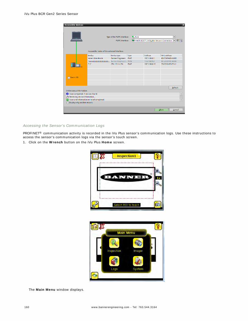
Accessing the Sensor's Communication Logs
PROFINET® communication activity is recorded in the iVu Plus sensor's communication logs. Use these instructions toaccess the sensor's communication logs via the sensor's touch screen.1. Click on the Wrench button on the iVu Plus Home screen.
The Main Menu window displays.
iVu Plus BCR Gen2 Series Sensor
160 www.bannerengineering.com - Tel: 763.544.3164
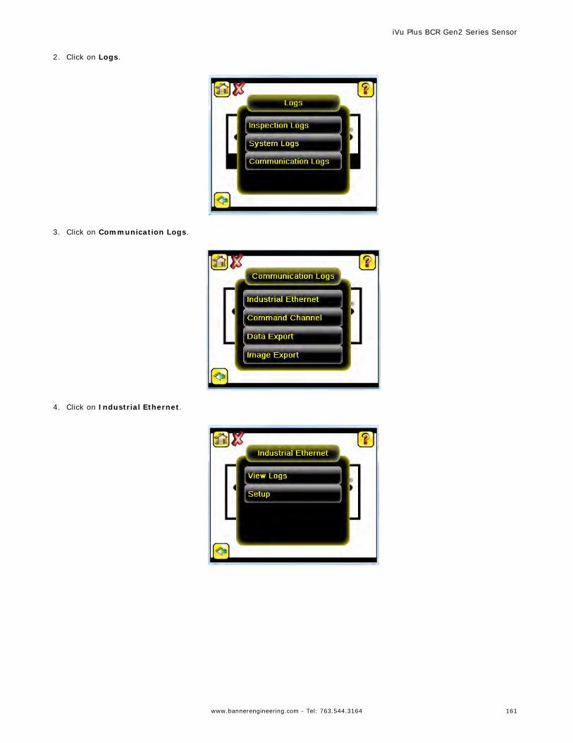
2. Click on Logs.
3. Click on Communication Logs.
4. Click on Industrial Ethernet.
iVu Plus BCR Gen2 Series Sensor
www.bannerengineering.com - Tel: 763.544.3164 161
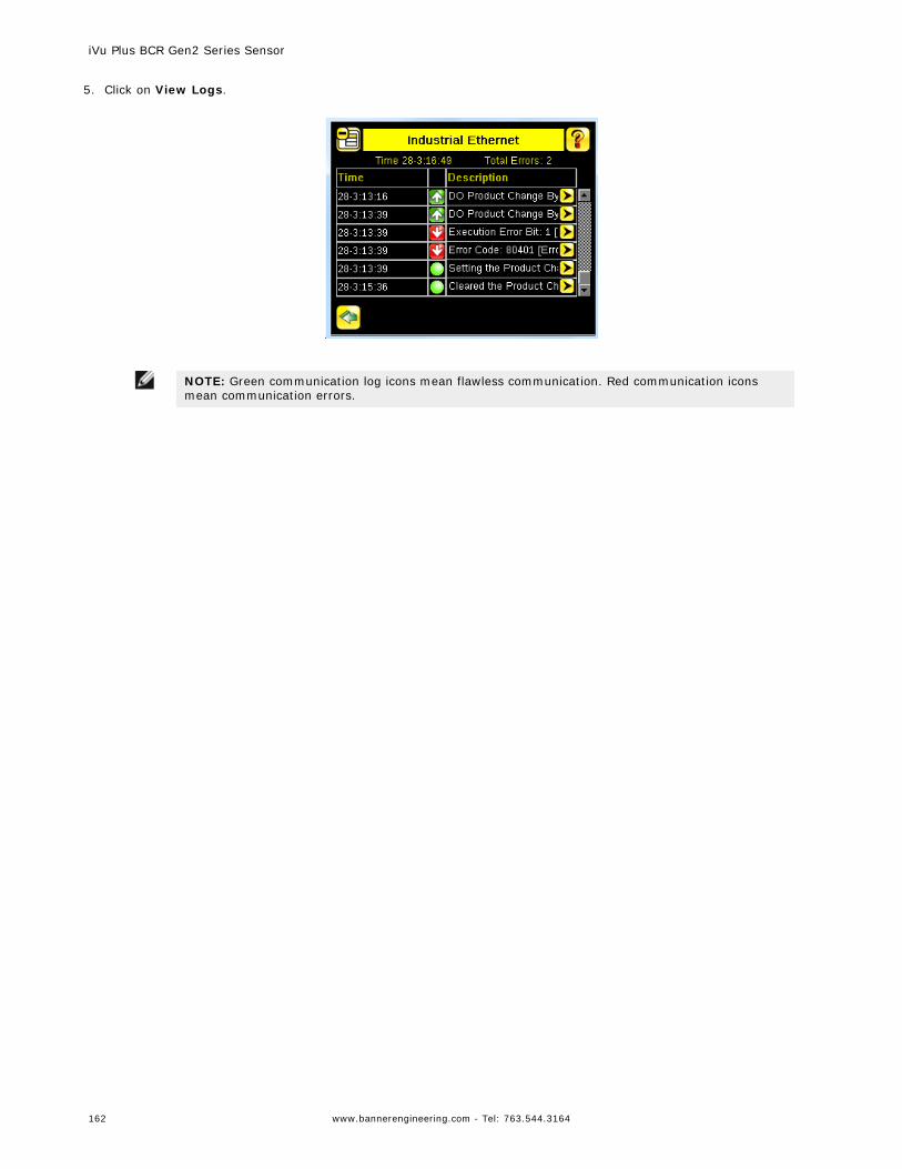
5. Click on View Logs.
NOTE: Green communication log icons mean flawless communication. Red communication iconsmean communication errors.
iVu Plus BCR Gen2 Series Sensor
162 www.bannerengineering.com - Tel: 763.544.3164
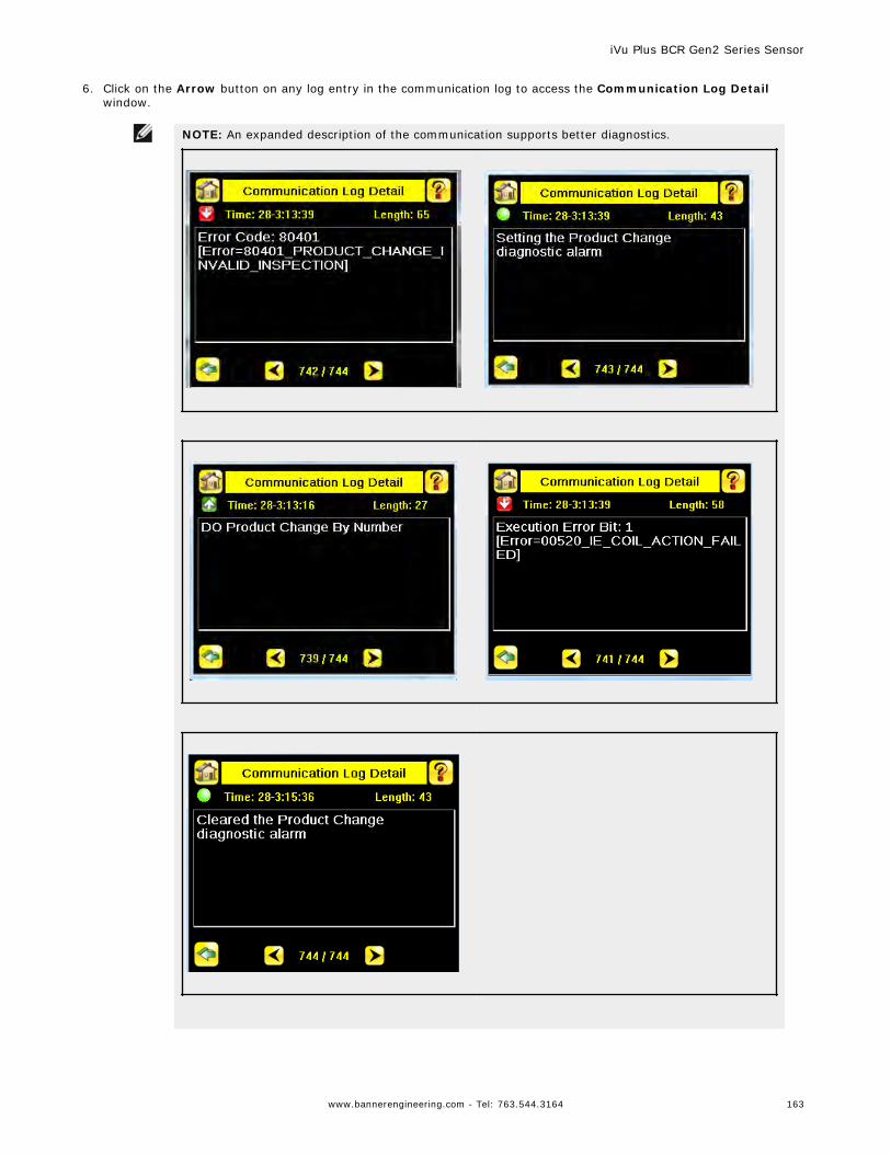
6. Click on the Arrow button on any log entry in the communication log to access the Communication Log Detailwindow.
NOTE: An expanded description of the communication supports better diagnostics.
iVu Plus BCR Gen2 Series Sensor
www.bannerengineering.com - Tel: 763.544.3164 163
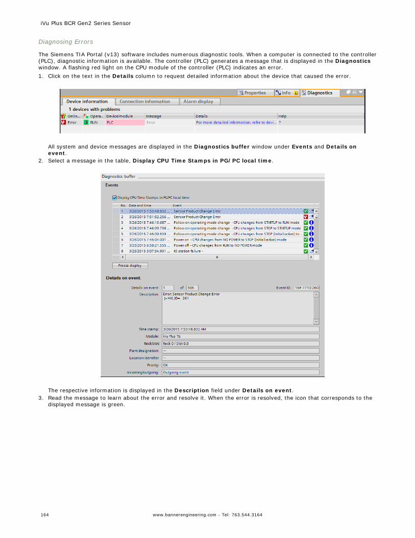
Diagnosing Errors
The Siemens TIA Portal (v13) software includes numerous diagnostic tools. When a computer is connected to the controller(PLC), diagnostic information is available. The controller (PLC) generates a message that is displayed in the Diagnosticswindow. A flashing red light on the CPU module of the controller (PLC) indicates an error.1. Click on the text in the Details column to request detailed information about the device that caused the error.
All system and device messages are displayed in the Diagnostics buffer window under Events and Details onevent.
2. Select a message in the table, Display CPU Time Stamps in PG/PC local time.
The respective information is displayed in the Description field under Details on event.
3. Read the message to learn about the error and resolve it. When the error is resolved, the icon that corresponds to thedisplayed message is green.
iVu Plus BCR Gen2 Series Sensor
164 www.bannerengineering.com - Tel: 763.544.3164
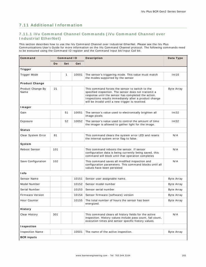
7.11 Additional Information
7.11.1 iVu Command Channel Commands (iVu Command Channel overIndustrial EtherNet)This section describes how to use the iVu Command Channel over Industrial EtherNet. Please see the iVu PlusCommunications User's Guide for more information on the iVu Command Channel protocol. The following commands needto be executed using the Command ID register and the Command Input bit/Input Coil bit.
Command Command ID Description Data Type
Do Set Get
Trigger
Trigger Mode 1 10001 The sensor's triggering mode. This value must matchthe modes supported by the sensor
Int16
Product Change
Product Change ByName
21 This command forces the sensor to switch to thespecified inspection. The sensor does not transmit aresponse until the sensor has completed the action.Inspections results immediately after a product changewill be invalid until a new trigger is received.
Byte Array
Imager
Gain 51 10051 The sensor's value used to electronically brighten allimage pixels
Int32
Exposure 52 10052 The sensor's value used to control the amount of timethe imager is allowed to gather light for the image.
Int32
Status
Clear System Error 81 This command clears the system error LED and resetsthe internal system error flag to false.
N/A
System
Reboot Sensor 101 This command reboots the sensor. If sensorconfiguration data is being currently being saved, thiscommand will block until that operation completes
N/A
Save Configuration 102 This command saves all modified inspection andconfiguration parameters. This command blocks until allvalues have been persisted
N/A
Info
Sensor Name 10151 Sensor user assignable name. Byte Array
Model Number 10152 Sensor model number Byte Array
Serial Number 10153 Sensor serial number Byte Array
Firmware Version 10154 Sensor firmware (software) version Byte Array
Hour Counter 10155 The total number of hours the sensor has beenenergized.
Byte Array
History
Clear History 301 This command clears all history fields for the activeinspection. History values include pass count, fail count,execution times and sensor specific history values.
N/A
Inspection
Inspection Name 10501 The name of the active inspection. Byte Array
BCR inputs
iVu Plus BCR Gen2 Series Sensor
www.bannerengineering.com - Tel: 763.544.3164 165
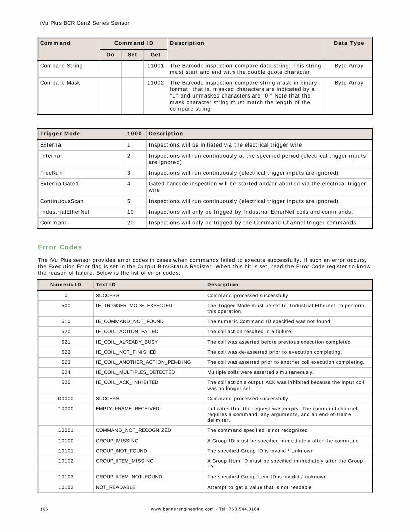
Command Command ID Description Data Type
Do Set Get
Compare String 11001 The Barcode inspection compare data string. This stringmust start and end with the double quote character
Byte Array
Compare Mask 11002 The Barcode inspection compare string mask in binaryformat; that is, masked characters are indicated by a"1" and unmasked characters are "0." Note that themask character string must match the length of thecompare string
Byte Array
Trigger Mode 1000 Description
External 1 Inspections will be initiated via the electrical trigger wire
Internal 2 Inspections will run continuously at the specified period (electrical trigger inputsare ignored)
FreeRun 3 Inspections will run continuously (electrical trigger inputs are ignored)
ExternalGated 4 Gated barcode inspection will be started and/or aborted via the electrical triggerwire
ContinuousScan 5 Inspections will run continuously (electrical trigger inputs are ignored)
IndustrialEtherNet 10 Inspections will only be trigged by Industrial EtherNet coils and commands.
Command 20 Inspections will only be trigged by the Command Channel trigger commands.
Error Codes
The iVu Plus sensor provides error codes in cases when commands failed to execute successfully. If such an error occurs,the Execution Error flag is set in the Output Bits/Status Register. When this bit is set, read the Error Code register to knowthe reason of failure. Below is the list of error codes:
Numeric ID Text ID Description
0 SUCCESS Command processed successfully.
500 IE_TRIGGER_MODE_EXPECTED The Trigger Mode must be set to 'Industrial Ethernet' to performthis operation.
510 IE_COMMAND_NOT_FOUND The numeric Command ID specified was not found.
520 IE_COIL_ACTION_FAILED The coil action resulted in a failure.
521 IE_COIL_ALREADY_BUSY The coil was asserted before previous execution completed.
522 IE_COIL_NOT_FINISHED The coil was de-asserted prior to execution completing.
523 IE_COIL_ANOTHER_ACTION_PENDING The coil was asserted prior to another coil execution completing.
524 IE_COIL_MULTIPLES_DETECTED Multiple coils were asserted simultaneously.
525 IE_COIL_ACK_INHIBITED The coil action's output ACK was inhibited because the input coilwas no longer set.
00000 SUCCESS Command processed successfully
10000 EMPTY_FRAME_RECEIVED Indicates that the request was empty. The command channelrequires a command, any arguments, and an end-of-framedelimiter.
10001 COMMAND_NOT_RECOGNIZED The command specified is not recognized
10100 GROUP_MISSING A Group ID must be specified immediately after the command
10101 GROUP_NOT_FOUND The specified Group ID is invalid / unknown
10102 GROUP_ITEM_MISSING A Group Item ID must be specified immediately after the GroupID
10103 GROUP_ITEM_NOT_FOUND The specified Group Item ID is invalid / unknown
10152 NOT_READABLE Attempt to get a value that is not readable
iVu Plus BCR Gen2 Series Sensor
166 www.bannerengineering.com - Tel: 763.544.3164
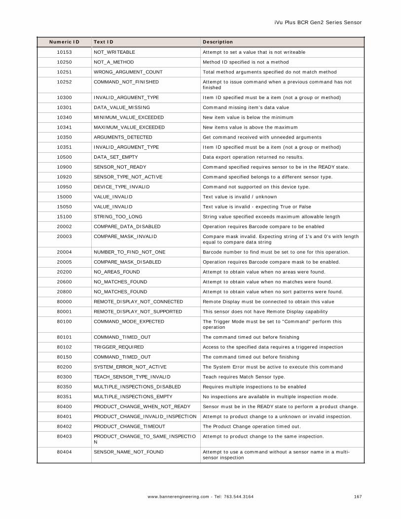
Numeric ID Text ID Description
10153 NOT_WRITEABLE Attempt to set a value that is not writeable
10250 NOT_A_METHOD Method ID specified is not a method
10251 WRONG_ARGUMENT_COUNT Total method arguments specified do not match method
10252 COMMAND_NOT_FINISHED Attempt to issue command when a previous command has notfinished
10300 INVALID_ARGUMENT_TYPE Item ID specified must be a item (not a group or method)
10301 DATA_VALUE_MISSING Command missing item's data value
10340 MINIMUM_VALUE_EXCEEDED New item value is below the minimum
10341 MAXIMUM_VALUE_EXCEEDED New items value is above the maximum
10350 ARGUMENTS_DETECTED Get command received with unneeded arguments
10351 INVALID_ARGUMENT_TYPE Item ID specified must be a item (not a group or method)
10500 DATA_SET_EMPTY Data export operation returned no results.
10900 SENSOR_NOT_READY Command specified requires sensor to be in the READY state.
10920 SENSOR_TYPE_NOT_ACTIVE Command specified belongs to a different sensor type.
10950 DEVICE_TYPE_INVALID Command not supported on this device type.
15000 VALUE_INVALID Text value is invalid / unknown
15050 VALUE_INVALID Text value is invalid - expecting True or False
15100 STRING_TOO_LONG String value specified exceeds maximum allowable length
20002 COMPARE_DATA_DISABLED Operation requires Barcode compare to be enabled
20003 COMPARE_MASK_INVALID Compare mask invalid. Expecting string of 1's and 0's with lengthequal to compare data string
20004 NUMBER_TO_FIND_NOT_ONE Barcode number to find must be set to one for this operation.
20005 COMPARE_MASK_DISABLED Operation requires Barcode compare mask to be enabled.
20200 NO_AREAS_FOUND Attempt to obtain value when no areas were found.
20600 NO_MATCHES_FOUND Attempt to obtain value when no matches were found.
20800 NO_MATCHES_FOUND Attempt to obtain value when no sort patterns were found.
80000 REMOTE_DISPLAY_NOT_CONNECTED Remote Display must be connected to obtain this value
80001 REMOTE_DISPLAY_NOT_SUPPORTED This sensor does not have Remote Display capability
80100 COMMAND_MODE_EXPECTED The Trigger Mode must be set to "Command" perform thisoperation
80101 COMMAND_TIMED_OUT The command timed out before finishing
80102 TRIGGER_REQUIRED Access to the specified data requires a triggered inspection
80150 COMMAND_TIMED_OUT The command timed out before finishing
80200 SYSTEM_ERROR_NOT_ACTIVE The System Error must be active to execute this command
80300 TEACH_SENSOR_TYPE_INVALID Teach requires Match Sensor type.
80350 MULTIPLE_INSPECTIONS_DISABLED Requires multiple inspections to be enabled
80351 MULTIPLE_INSPECTIONS_EMPTY No inspections are available in multiple inspection mode.
80400 PRODUCT_CHANGE_WHEN_NOT_READY Sensor must be in the READY state to perform a product change.
80401 PRODUCT_CHANGE_INVALID_INSPECTION Attempt to product change to a unknown or invalid inspection.
80402 PRODUCT_CHANGE_TIMEOUT The Product Change operation timed out.
80403 PRODUCT_CHANGE_TO_SAME_INSPECTION
Attempt to product change to the same inspection.
80404 SENSOR_NAME_NOT_FOUND Attempt to use a command without a sensor name in a multi-sensor inspection
iVu Plus BCR Gen2 Series Sensor
www.bannerengineering.com - Tel: 763.544.3164 167
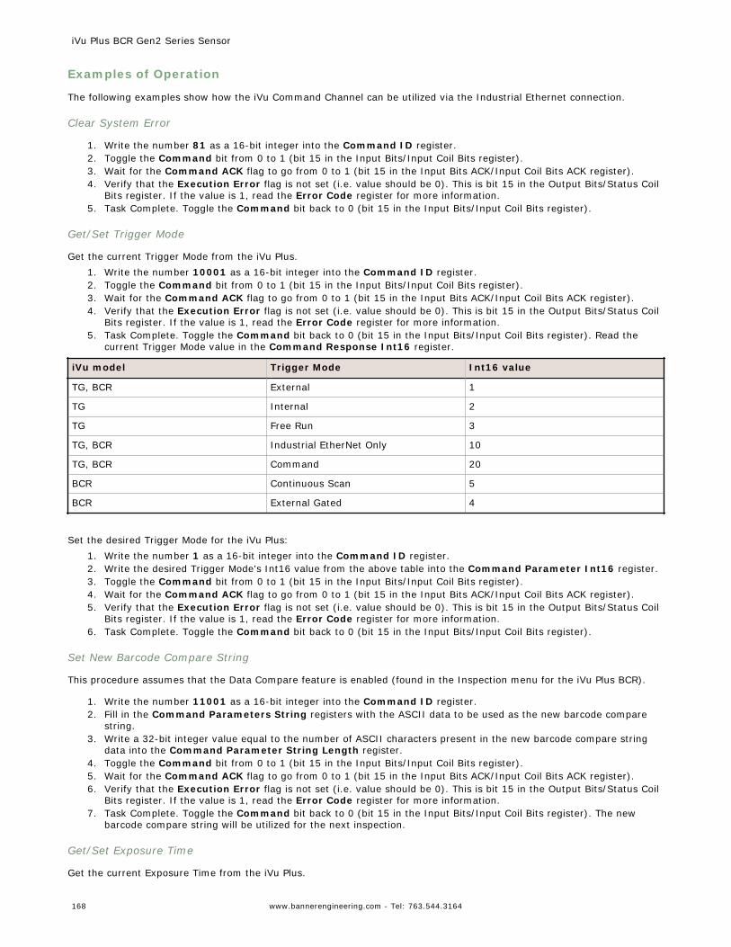
Examples of Operation
The following examples show how the iVu Command Channel can be utilized via the Industrial Ethernet connection.
Clear System Error
1. Write the number 81 as a 16-bit integer into the Command ID register.2. Toggle the Command bit from 0 to 1 (bit 15 in the Input Bits/Input Coil Bits register).3. Wait for the Command ACK flag to go from 0 to 1 (bit 15 in the Input Bits ACK/Input Coil Bits ACK register).4. Verify that the Execution Error flag is not set (i.e. value should be 0). This is bit 15 in the Output Bits/Status Coil
Bits register. If the value is 1, read the Error Code register for more information.5. Task Complete. Toggle the Command bit back to 0 (bit 15 in the Input Bits/Input Coil Bits register).
Get/Set Trigger Mode
Get the current Trigger Mode from the iVu Plus.1. Write the number 10001 as a 16-bit integer into the Command ID register.2. Toggle the Command bit from 0 to 1 (bit 15 in the Input Bits/Input Coil Bits register).3. Wait for the Command ACK flag to go from 0 to 1 (bit 15 in the Input Bits ACK/Input Coil Bits ACK register).4. Verify that the Execution Error flag is not set (i.e. value should be 0). This is bit 15 in the Output Bits/Status Coil
Bits register. If the value is 1, read the Error Code register for more information.5. Task Complete. Toggle the Command bit back to 0 (bit 15 in the Input Bits/Input Coil Bits register). Read the
current Trigger Mode value in the Command Response Int16 register.
iVu model Trigger Mode Int16 value
TG, BCR External 1
TG Internal 2
TG Free Run 3
TG, BCR Industrial EtherNet Only 10
TG, BCR Command 20
BCR Continuous Scan 5
BCR External Gated 4
Set the desired Trigger Mode for the iVu Plus:1. Write the number 1 as a 16-bit integer into the Command ID register.2. Write the desired Trigger Mode's Int16 value from the above table into the Command Parameter Int16 register.3. Toggle the Command bit from 0 to 1 (bit 15 in the Input Bits/Input Coil Bits register).4. Wait for the Command ACK flag to go from 0 to 1 (bit 15 in the Input Bits ACK/Input Coil Bits ACK register).5. Verify that the Execution Error flag is not set (i.e. value should be 0). This is bit 15 in the Output Bits/Status Coil
Bits register. If the value is 1, read the Error Code register for more information.6. Task Complete. Toggle the Command bit back to 0 (bit 15 in the Input Bits/Input Coil Bits register).
Set New Barcode Compare String
This procedure assumes that the Data Compare feature is enabled (found in the Inspection menu for the iVu Plus BCR).
1. Write the number 11001 as a 16-bit integer into the Command ID register.2. Fill in the Command Parameters String registers with the ASCII data to be used as the new barcode compare
string.3. Write a 32-bit integer value equal to the number of ASCII characters present in the new barcode compare string
data into the Command Parameter String Length register.4. Toggle the Command bit from 0 to 1 (bit 15 in the Input Bits/Input Coil Bits register).5. Wait for the Command ACK flag to go from 0 to 1 (bit 15 in the Input Bits ACK/Input Coil Bits ACK register).6. Verify that the Execution Error flag is not set (i.e. value should be 0). This is bit 15 in the Output Bits/Status Coil
Bits register. If the value is 1, read the Error Code register for more information.7. Task Complete. Toggle the Command bit back to 0 (bit 15 in the Input Bits/Input Coil Bits register). The new
barcode compare string will be utilized for the next inspection.
Get/Set Exposure Time
Get the current Exposure Time from the iVu Plus.
iVu Plus BCR Gen2 Series Sensor
168 www.bannerengineering.com - Tel: 763.544.3164

1. Write the number 10052 as a 16-bit integer into the Command ID register.2. Toggle the Command bit from 0 to 1 (bit 15 in the Input Bits/Input Coil Bits register).3. Wait for the Command ACK flag to go from 0 to 1 (bit 15 in the Input Bits ACK/Input Coil Bits ACK register).4. Verify that the Execution Error flag is not set (i.e. value should be 0). This is bit 15 in the Output Bits/Status Coil
Bits register. If the value is 1, read the Error Code register for more information.5. Task Complete. Toggle the Command bit back to 0 (bit 15 in the Input Bits/Input Coil Bits register). Read the
current Exposure Time value (in microseconds) in the Command Response Int32 register.
Set the desired Exposure Time for the iVu Plus.
1. Write the number 52 as a 16-bit integer into the Command ID register.2. Write the desired Exposure Time (in microseconds) as a 32-bit integer value into the Command Parameter Int32
register. The minimum acceptable value is 117 usec and the maximum value is 1,000,000 usec.3. Toggle the Command bit from 0 to 1 (bit 15 in the Input Bits/Input Coil Bits register).4. Wait for the Command ACK flag to go from 0 to 1 (bit 15 in the Input Bits ACK/Input Coil Bits ACK register).5. Verify that the Execution Error flag is not set (i.e. value should be 0). This is bit 15 in the Output Bits/Status Coil
Bits register. If the value is 1, read the Error Code register for more information.6. Task Complete. Toggle the Command bit back to 0 (bit 15 in the Input Bits/Input Coil Bits register). The new
exposure time will be used for the next inspection. Please note that this value is not saved to the iVu's permanentmemory unless the Save Configuration task is completed.
Save iVu Configuration
This command saves all modified inspection and configuration parameters to the iVu Plus, including Command Channelchanges to exposure time and gain, trigger mode, barcode compare string and/or mask, and Remote Teach sessions.
1. Write the number 102 as a 16-bit integer into the Command ID register.2. Toggle the Command bit from 0 to 1 (bit 15 in the Input Bits/Input Coil Bits register).3. Wait for the Command ACK flag to go from 0 to 1 (bit 15 in the Input Bits ACK/Input Coil Bits ACK register).4. Verify that the Execution Error flag is not set (i.e. value should be 0). This is bit 15 in the Output Bits/Status Coil
Bits register. If the value is 1, read the Error Code register for more information.5. Task Complete. Toggle the Command bit back to 0 (bit 15 in the Input Bits/Input Coil Bits register).
iVu Plus BCR Gen2 Series Sensor
www.bannerengineering.com - Tel: 763.544.3164 169
8 Debugging Inspections8.1 iVu EmulatorThe iVu Emulator is a Windows application that allows you to operate in a Windows environment exactly as you would onthe iVu Series sensor itself. In general, the Emulator is an inspection debugging tool where you can:
• Import stored inspections and configuration from an iVu Plus BCR sensor.• Modify inspection parameters on the emulator.• Restore the updated configuration back to the sensor.
8.2 How to Round-Trip Debug Using the EmulatorThe iVu Emulator is a Windows application that allows you to operate in a Windows environment exactly as you would onthe sensor itself. In general, the Emulator is an inspection debugging tool: you can import stored inspections and aconfiguration from an iVu sensor, then modify its parameters on the emulator, and restore the updated configuration backto the sensor. When you install the iVu Emulator, by default, it is installed in the following folder:
C:\Program Files\Banner Engineering\iVu Series
You can run the Emulator from this folder, but you will need to move files between the USB flash drive and PC. To avoidmoving files, copy the Emulator executable to the USB flash drive, and run the Emulator directly from the USB flash drive.
This "how-to" describes the procedures for doing round-trip debugging either using the iVu Emulator installed on a PC orusing it directly from the USB flash drive.
NOTE: This document refers to saving configuration and inspection logs in folders based on the sensorname. If you have not yet named the sensor, then folders will be named using the first 8-characters ofthe sensor serial number.
8.2.1 How to Debug Using the Emulator from a PC
1. Plug a USB flash drive into the sensor.2. Save the Inspection Logs to the USB flash drive.
a. On the Main Menu > Inspection Logs > View Logs screen, click the Save icon to save the inspectionlogs.
b. When prompted, select Yes to save sensor configuration along with the Inspection Logs. The location ofthese files on the USB flash drive displays after the operation is completed. The Inspection Logs are savedin <USB>:\BANNER\<SENSOR_NAME>\InspLog and the sensor configuration is saved in <USB>:\BANNER\<SENSOR_NAME>. For example, if the sensor name is myName:
• Configuration File (CONFIG.CFG) path: <USB>:\BANNER\myName• Inspection Logs path: <USB>:\BANNER\myName\InspLog
NOTE: If the sensor has no name, then the folder name is the first 8-characters of theserial number.
3. Remove the USB flash drive from the sensor and insert it into an available USB port on a Windows PC that has theiVu Emulator installed.
Important: Make sure the iVu Emulator is NOT running before proceeding to the next step.
4. Copy the Sensor Configuration from the USB flash drive to the folder where the Emulator is installed on the PC. Forexample, if the sensor name is myName and the iVu Emulator is installed in the default location on the PC, copythe file <USB>:\BANNER\myName\CONFIG.CFG to C:\Program Files\Banner Engineering\iVu Series.
5. Copy the Inspection Logs from the USB flash drive (for example, <USB>:\BANNER\myName\InspLog) to theInspLog folder on the PC (for example, C:\Program Files\Banner Engineering\iVu Series\InspLogs).
6. Start the Emulator.7. Set the Trigger option to Internal—
a. Go to Main Menu > Imager > Trigger, and select Internal.b. Set the Trigger Interval as desired.
The iVu Emulator runs with the saved configuration from Step 6 using the saved Inspection Logs from Step7 as images.
8. Make the desired adjustments.9. Close the iVu Emulator program. All configuration changes are saved to the CONFIG.CFG file.
iVu Plus BCR Gen2 Series Sensor
170 www.bannerengineering.com - Tel: 763.544.3164
10.Copy the sensor configuration (that is, CONFIG.CFG) from the PC working directory to the USB flash drive (forexample <USB>:\BANNER\myName\CONFIG.CFG).
11.Remove the USB flash drive from the PC, and connect it to the sensor.12.Restore the configuration to the sensor.
a. Go to Main Menu > System > Configuration > Load Configuration.b. Select the Configuration to restore.c. Click the Load button to start the restore sensor configuration.d. Reboot the sensor when the restore is complete.
8.2.2 How to Debug Using the Emulator from the USB Flash Drive
1. Plug a USB flash drive into the sensor.2. Save the Inspection Logs to the sensor.
a. On the Main Menu > Inspection Logs > View Logs screen, click the Save icon to save the inspectionlogs.
b. When prompted, select Yes to save sensor configuration along with the Inspection Logs. The location ofthese files on the USB flash drive displays after the operation is completed—the Inspection Logs are savedin <USB>:\BANNER\<SENSOR_NAME>\InspLog and the sensor configuration is saved in <USB>:\BANNER\<SENSOR_NAME>. For example, if the sensor name is myName:
• Configuration File (CONFIG.CFG) path: <USB>:\BANNER\myName• Inspection Logs path: <USB>:\BANNER\myName\InspLog
NOTE: If the sensor has no name, the folder name is the first 8-characters of the serialnumber.
3. Remove the USB flash drive from the sensor and insert it into an available USB port on a Windows PC that has theiVu Emulator installed.
4. Copy the iVuEmulator.exe program file to the USB flash drive in the same location as the CONFIG.CFG file (forexample, <USB>:\BANNER\myName).
5. Launch the <USB>:\BANNER\myName\iVuEmulator.exe program.6. Set the Trigger option to Internal—
a. Go to Main Menu > Imager > Trigger, and select Internal.b. Set the Trigger Interval as desired.
The iVu Emulator runs with the saved configuration using the saved Inspection Logs as images.7. Make the desired adjustments.8. Close the iVu Emulator program. All configuration changes are saved to the CONFIG.CFG file.9. Remove the USB flash drive from the PC, and connect it to the sensor.10.Restore the configuration to the sensor.
a. Go to Main Menu > System > Configuration > Load Configuration.b. Select the Configuration to restore.c. Click the Load button to start the restore sensor configuration.d. Reboot the sensor when the restore is complete.
iVu Plus BCR Gen2 Series Sensor
www.bannerengineering.com - Tel: 763.544.3164 171
9 Updating the Sensor9.1 Update ProcessBanner Engineering may release new versions of the sensor firmware in the future. New firmware releases can bedownloaded from Banner's website or can be obtained by ordering the latest Product CD. The following steps will guide youthrough the process of updating the iVu firmware.
Step 1: Copy firmware of the desired product to USB flash drive.
1. Launch the iVu Series software.
From the Product CD:• Place the latest Product CD into your CD ROM drive. The iVu Series Software automatically starts.• If your computer is not set for Auto-Play, start the iVu Series Software by browsing to the CD drive from the My
Computer screen and double-clicking on 'iVuSeries.exe'.
From the Banner Website:1. Visit Banner's Website: http://www.bannerengineering.com.2. Browse to the Vision Products page and select the iVu product you are using.3. Click on the Software tab to view software releases.4. Determine which version you want to download (the Current Version is recommended, for example "iVu Series
Software Version 2010R4").5. Click on the circular Download button. This initiates the download process. Depending on your browser settings,
you may be asked to confirm or provide a location to save the file. Choose to download on your desktop. Note thefile name.
6. Double-click the file to start extracting the files and run the iVu Series Software.
2. Select the product you are using and browse to the Firmware Update page.
3. Click on the 'Run Firmware Update Wizard' and the program starts.
4. Follow the on-screen instructions. Clicking on 'Copy firmware to USB' copies the selected firmware to the USB flashdrive.
Step 2: Install the firmware on the iVu.
1. Remove the USB flash drive from the PC, and plug it into the sensor.
2. On the sensor, select System > Firmware Update. The name of the firmware file you copied on the USB flash drivedisplays.
3. Choose the correct file and click on the Load button.
4. Follow the on-screen instructions to update the firmware.
9.2 How to Set or Modify a Device Name using the EmulatorYou can set a Device Name for your iVu Series sensor or modify an existing name on the sensor using the softwarekeypad. You can also change the device name this using the iVu Emulator as described below.
NOTE: If you are in a language other than English, you cannot modify the device name using thesoftware keypad. Use the procedure described below.
NOTE: If you have not set the device name previously, then folders will be named using the first 8-characters of the device serial number.
1. Plug a USB flash drive into the device.2. Save the Device Configuration to the USB flash drive (Main Menu > System > Configuration > Save to USB).
The location of these files on the USB flash drive displays after the operation is complete—the device configurationis saved in <USB>:\BANNER\<DEVICE_NAME>. For example, if the device name is myName:, the path will be<USB>:\BANNER\myName).
3. Remove the USB flash drive from the device and insert it into an available USB port on a Windows PC.4. If you are running the Emulator from the USB flash drive, launch the iVuEmulator.exe program. If you are running
the Emulator installed on a PC, make sure the Emulator is not running, and copy the Device Configuration from theUSB flash drive to the folder where the Emulator is installed on the PC. For example, if the device name is myName
iVu Plus BCR Gen2 Series Sensor
172 www.bannerengineering.com - Tel: 763.544.3164
and the iVu Emulator is installed in the default location on the PC, copy the file <USB>:\BANNER\myName\CONFIG.CFG to C:\Program Files\Banner Engineering\iVu Series.
5. Launch the iVuEmulator.exe program.6. Go to the Information screen (Main Menu > System > Information).7. Click the white box next to the Device Name label, and enter the desired Device Name.8. Click the Back button on the lower-left corner of the screen to save the Device Name.9. Close the Emulator program and the Device Name is saved to the CONFIG.CFG file.10. If you are running the Emulator on the PC, copy the CONFIG.CFG file back to the original folder on the USB flash
drive—<USB>:\BANNER\<DEVICE_NAME> (for example <USB>:\BANNER\myName).
NOTE: The device looks in the original folder (for example, myName) for the CONFIG.CFG file.
11.Remove the USB flash drive from the PC, and connect it to the device.12.Restore the configuration to the device.
a. Go to Main Menu > System > Configuration > Load from USB.b. Select the Configuration to restore.c. Click the Load button to start the restore device configuration.
NOTE: After the new device name is restored in the device, all files saved to USB flashdrive will now reside in the folder corresponding to the new device name.
d. Reboot the device when the restore is complete.
NOTE: If a Device Configuration from one device is loaded onto another device, the Device Name fromthe Device Configuration will not be stored in the device.
9.3 How to Reset the Sensor PasswordIf you forget the password for your sensor, you can remove the current password using a reset key that is generated bythe Password Reset Utility, which is located on the Product CD. The following steps will guide you through the specificsteps to reset the password:
1. On your iVu Series sensor, click the Forgot? button located on the bottom of the Enter Current Passwordscreen.
2. Write down the 6-digit Device Key.3. On a Windows PC, insert the iVu product CD into the CD ROM drive.4. From the product CD menu (started upon inserting the CD), launch the Password Reset Utility.5. Enter the Device Key into the text box in the Utility—identified as Step 1 in the Password Reset Utility.6. Click the Generate Reset Key button.7. Write down the four-digit Password Reset Key—identified as Step 2 in the Password Reset Utility.8. On the iVu Series sensor, check the Next button on the Password Reset screen.9. Enter the 4-digit reset key on the Enter Reset Key screen.10.Click Apply.
The password is now cleared.
9.4 How to Use Bitmap Image Files with the iVu EmulatorYou can use bitmap (.bmp) image files with the iVu Emulator for developing and simulating iVu inspections. The iVuEmulator only accepts image files in .bmp format. If you have other image file formats, use an image viewer/editorprogram, such as PhotoShop, Gimp, or Paint, to convert the files to 8-bit grayscale .bmp format.
NOTE: Images smaller than 640 × 480 are black-filled starting in the upper-right. Images larger than640 × 480 are cropped starting in the upper-left.
1. Copy the .bmp files into the InspLog folder in the iVu Emulator install folder.
For example, copy .bmp files into the C:\Program Files\Banner Engineering\iVu Series\InsLog folder.
NOTE: Remove any existing .bmp or Log files in that folder to avoid confusion because the iVuEmulator automatically runs all .bmp/Log files sequentially according to filename.
2. Launch the iVu Emulator program.
iVu Plus BCR Gen2 Series Sensor
www.bannerengineering.com - Tel: 763.544.3164 173
3. Select Internal Trigger on the Trigger Selection screen (Main Menu > Image > Trigger).4. Set the Trigger Interval as desired.
The iVu Emulator runs using the .bmp files from Step 1.
NOTE: Banner does not recommend setting up inspections using these 8-bit grayscale images becauseyou will always end up modifying the configuration after loading it on the sensor on the line. A betterchoice is to set up the inspection on the iVu Emulator using the Inspection Logs from the sensor.
iVu Plus BCR Gen2 Series Sensor
174 www.bannerengineering.com - Tel: 763.544.3164
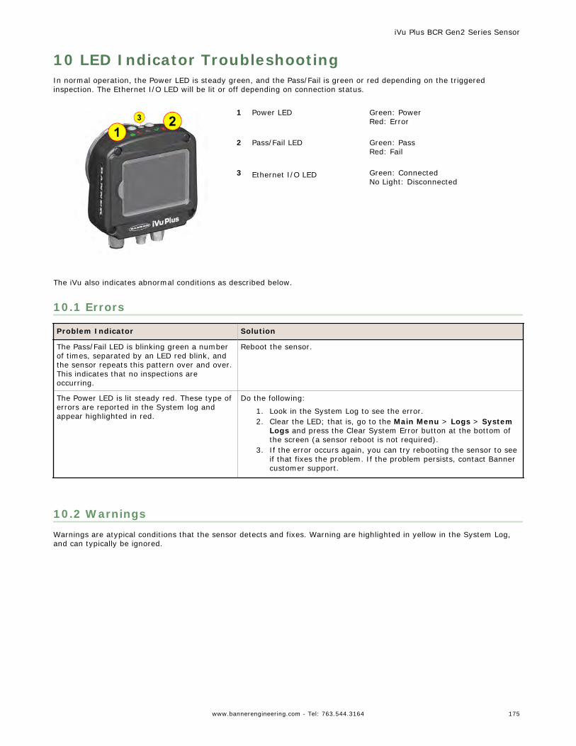
10 LED Indicator TroubleshootingIn normal operation, the Power LED is steady green, and the Pass/Fail is green or red depending on the triggeredinspection. The Ethernet I/O LED will be lit or off depending on connection status.
1 Power LED Green: PowerRed: Error
2 Pass/Fail LED Green: PassRed: Fail
3 Ethernet I/O LED Green: ConnectedNo Light: Disconnected
The iVu also indicates abnormal conditions as described below.
10.1 Errors
Problem Indicator Solution
The Pass/Fail LED is blinking green a numberof times, separated by an LED red blink, andthe sensor repeats this pattern over and over.This indicates that no inspections areoccurring.
Reboot the sensor.
The Power LED is lit steady red. These type oferrors are reported in the System log andappear highlighted in red.
Do the following:
1. Look in the System Log to see the error.2. Clear the LED; that is, go to the Main Menu > Logs > System
Logs and press the Clear System Error button at the bottom ofthe screen (a sensor reboot is not required).
3. If the error occurs again, you can try rebooting the sensor to seeif that fixes the problem. If the problem persists, contact Bannercustomer support.
10.2 WarningsWarnings are atypical conditions that the sensor detects and fixes. Warning are highlighted in yellow in the System Log,and can typically be ignored.
iVu Plus BCR Gen2 Series Sensor
www.bannerengineering.com - Tel: 763.544.3164 175
11 Product Support and MaintenanceThis section provides general Banner resources and specific documentation for installers and operators of this iVu Plus BCRVision Sensor.
WARNING: Not To Be Used for Personnel Protection
Never use this device as a sensing device for personnel protection. Doing so could lead toserious injury or death. This device does not include the self-checking redundant circuitry necessaryto allow its use in personnel safety applications. A sensor failure or malfunction can cause either anenergized or de-energized sensor output condition.
11.1 Product SupportBanner provides the following resources for quickly setting up and operating the device.
Documentation
Online Help
When setting up or monitoring inspections using the iVu sensor's integrated display, you can get online help on any screenby clicking the Help icon in the upper-right of the screen.
PDF Documentation
The product documentation is available in a convenient printable format (PDF) on the installation CD or at www.bannerengineering.com.
Banner Website
The most current product information, documentation, and software updates are available on the Banner website: www.bannerengineering.com.
Warranty Service
Contact Banner Engineering for troubleshooting of this device. Do not attempt any repairs to this Banner device; itcontains no field-replaceable parts or components. If the device, device part, or device component is determined tobe defective by a Banner Applications Engineer, they will advise you of Banner's RMA (Return Merchandise Authorization)procedure.
Important: If instructed to return the device, pack it with care. Damage that occurs in return shippingis not covered by warranty.
Factory Support
To help Banner better assist you, be ready to provide the following information:• iVu firmware version (to find the version number, click Main Menu > System > Sensor Information• Device Model Number and Date Code, which are found on the bottom of the device.• Exact wording of any messages that appeared on your screen• A description of what you were doing and what happened• A description of how you tried to solve the problem• Error Codes (see LED Indicator Troubleshooting on page 175)
11.2 MaintenanceMaintenance tasks include keeping the hardware free of dust and dirt and possibly updating the iVu firmware as newversions become available.
Cleaning the SensorRegularly remove any dust or dirt from the device using a soft cloth. If needed, slightly dampen the cloth with a weaksolution of neutral detergent. Avoid getting dirt on the imager (the area behind the lens). If the imager is dirty, use anti-static compressed air to blow off the dust.
iVu Plus BCR Gen2 Series Sensor
176 www.bannerengineering.com - Tel: 763.544.3164
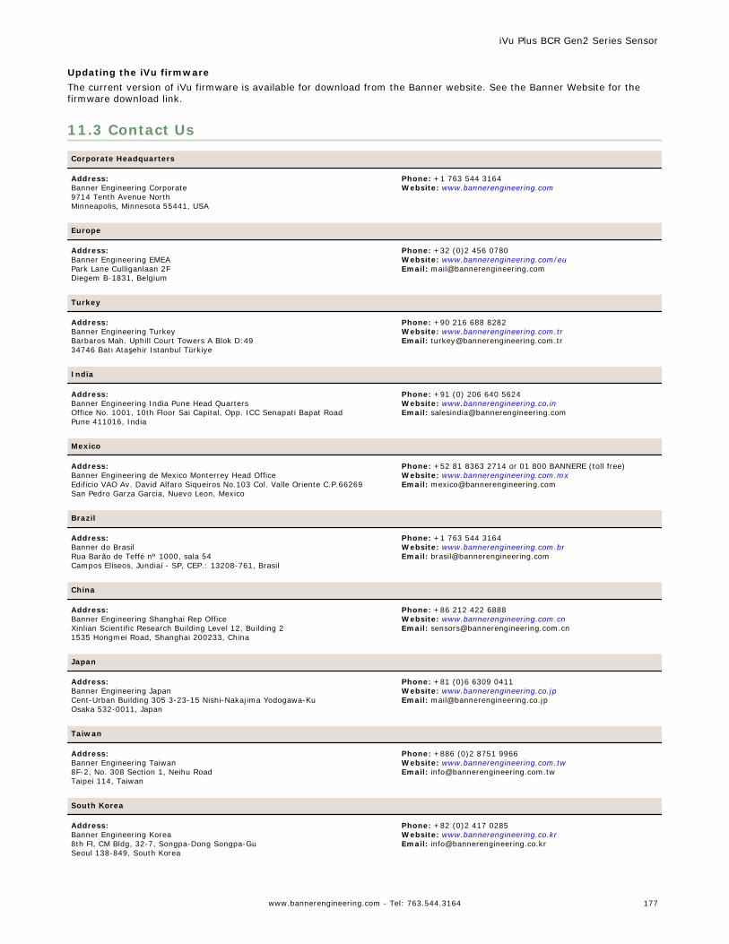
Updating the iVu firmwareThe current version of iVu firmware is available for download from the Banner website. See the Banner Website for thefirmware download link.
11.3 Contact Us
Corporate Headquarters
Address:Banner Engineering Corporate9714 Tenth Avenue NorthMinneapolis, Minnesota 55441, USA
Phone: +1 763 544 3164Website: www.bannerengineering.com
Europe
Address:Banner Engineering EMEAPark Lane Culliganlaan 2FDiegem B-1831, Belgium
Phone: +32 (0)2 456 0780Website: www.bannerengineering.com/euEmail: [email protected]
Turkey
Address:Banner Engineering TurkeyBarbaros Mah. Uphill Court Towers A Blok D:4934746 Batı Ataşehir Istanbul Türkiye
Phone: +90 216 688 8282Website: www.bannerengineering.com.trEmail: [email protected]
India
Address:Banner Engineering India Pune Head QuartersOffice No. 1001, 10th Floor Sai Capital, Opp. ICC Senapati Bapat RoadPune 411016, India
Phone: +91 (0) 206 640 5624Website: www.bannerengineering.co.inEmail: [email protected]
Mexico
Address:Banner Engineering de Mexico Monterrey Head OfficeEdificio VAO Av. David Alfaro Siqueiros No.103 Col. Valle Oriente C.P.66269San Pedro Garza Garcia, Nuevo Leon, Mexico
Phone: +52 81 8363 2714 or 01 800 BANNERE (toll free)Website: www.bannerengineering.com.mxEmail: [email protected]
Brazil
Address:Banner do BrasilRua Barão de Teffé nº 1000, sala 54Campos Elíseos, Jundiaí - SP, CEP.: 13208-761, Brasil
Phone: +1 763 544 3164Website: www.bannerengineering.com.brEmail: [email protected]
China
Address:Banner Engineering Shanghai Rep OfficeXinlian Scientific Research Building Level 12, Building 21535 Hongmei Road, Shanghai 200233, China
Phone: +86 212 422 6888Website: www.bannerengineering.com.cnEmail: [email protected]
Japan
Address:Banner Engineering JapanCent-Urban Building 305 3-23-15 Nishi-Nakajima Yodogawa-KuOsaka 532-0011, Japan
Phone: +81 (0)6 6309 0411Website: www.bannerengineering.co.jpEmail: [email protected]
Taiwan
Address:Banner Engineering Taiwan8F-2, No. 308 Section 1, Neihu RoadTaipei 114, Taiwan
Phone: +886 (0)2 8751 9966Website: www.bannerengineering.com.twEmail: [email protected]
South Korea
Address:Banner Engineering Korea8th Fl, CM Bldg, 32-7, Songpa-Dong Songpa-GuSeoul 138-849, South Korea
Phone: +82 (0)2 417 0285Website: www.bannerengineering.co.krEmail: [email protected]
iVu Plus BCR Gen2 Series Sensor
www.bannerengineering.com - Tel: 763.544.3164 177
11.4 Banner Engineering Corp Limited WarrantyBanner Engineering Corp. warrants its products to be free from defects in material and workmanship for one year followingthe date of shipment. Banner Engineering Corp. will repair or replace, free of charge, any product of its manufacturewhich, at the time it is returned to the factory, is found to have been defective during the warranty period. This warrantydoes not cover damage or liability for misuse, abuse, or the improper application or installation of the Banner product.
THIS LIMITED WARRANTY IS EXCLUSIVE AND IN LIEU OF ALL OTHER WARRANTIES WHETHER EXPRESS ORIMPLIED (INCLUDING, WITHOUT LIMITATION, ANY WARRANTY OF MERCHANTABILITY OR FITNESS FOR APARTICULAR PURPOSE), AND WHETHER ARISING UNDER COURSE OF PERFORMANCE, COURSE OF DEALING ORTRADE USAGE.
This Warranty is exclusive and limited to repair or, at the discretion of Banner Engineering Corp., replacement. IN NOEVENT SHALL BANNER ENGINEERING CORP. BE LIABLE TO BUYER OR ANY OTHER PERSON OR ENTITY FORANY EXTRA COSTS, EXPENSES, LOSSES, LOSS OF PROFITS, OR ANY INCIDENTAL, CONSEQUENTIAL ORSPECIAL DAMAGES RESULTING FROM ANY PRODUCT DEFECT OR FROM THE USE OR INABILITY TO USE THEPRODUCT, WHETHER ARISING IN CONTRACT OR WARRANTY, STATUTE, TORT, STRICT LIABILITY,NEGLIGENCE, OR OTHERWISE.
Banner Engineering Corp. reserves the right to change, modify or improve the design of the product without assuming anyobligations or liabilities relating to any product previously manufactured by Banner Engineering Corp.
iVu Plus BCR Gen2 Series Sensor
178 www.bannerengineering.com - Tel: 763.544.3164
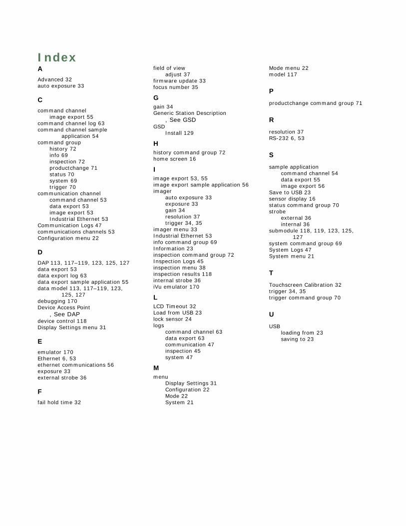
IndexAAdvanced 32auto exposure 33
Ccommand channel
image export 55command channel log 63command channel sample
application 54command group
history 72info 69inspection 72productchange 71status 70system 69trigger 70
communication channelcommand channel 53data export 53image export 53Industrial Ethernet 53
Communication Logs 47communications channels 53Configuration menu 22
DDAP 113, 117–119, 123, 125, 127data export 53data export log 63data export sample application 55data model 113, 117–119, 123,
125, 127debugging 170Device Access Point
, See DAPdevice control 118Display Settings menu 31
Eemulator 170Ethernet 6, 53ethernet communications 56exposure 33external strobe 36
Ffail hold time 32
field of viewadjust 37
firmware update 33focus number 35
Ggain 34Generic Station Description
, See GSDGSD
Install 129
Hhistory command group 72home screen 16
Iimage export 53, 55image export sample application 56imager
auto exposure 33exposure 33gain 34resolution 37trigger 34, 35
imager menu 33Industrial Ethernet 53info command group 69Information 23inspection command group 72Inspection Logs 45inspection menu 38inspection results 118internal strobe 36iVu emulator 170
LLCD Timeout 32Load from USB 23lock sensor 24logs
command channel 63data export 63communication 47inspection 45system 47
Mmenu
Display Settings 31Configuration 22Mode 22System 21
Mode menu 22model 117
P
productchange command group 71
R
resolution 37RS-232 6, 53
S
sample applicationcommand channel 54data export 55image export 56
Save to USB 23sensor display 16status command group 70strobe
external 36internal 36
submodule 118, 119, 123, 125,127
system command group 69System Logs 47System menu 21
T
Touchscreen Calibration 32trigger 34, 35trigger command group 70
U
USBloading from 23saving to 23