ISE 311 Rolling lab - UNAMdepa.fquim.unam.mx/amyd/archivero/ROLLING_LAB_23829.pdf · rolling mill....
35
ISE 311 Rolling lab in conjunction with Chapters 18 and 19 in the text book “Fundamentals of Modern Manufacturing” Third Edition Mikell P. Groover Prepared by: Amin Naser and Tom Yelich May 22 nd , 2008
Transcript of ISE 311 Rolling lab - UNAMdepa.fquim.unam.mx/amyd/archivero/ROLLING_LAB_23829.pdf · rolling mill....
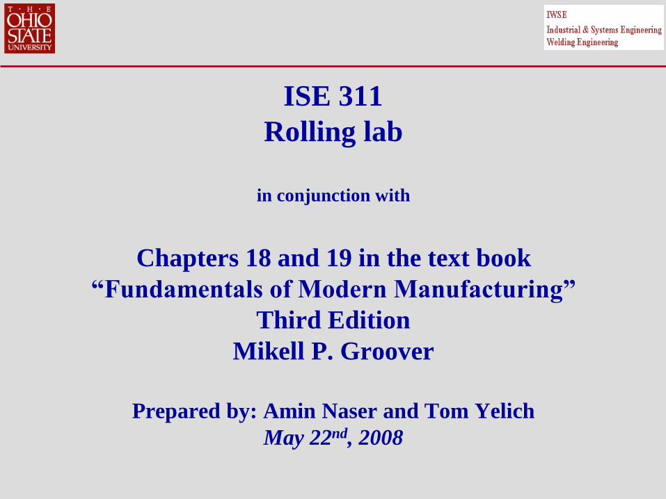
ISE 311
Rolling lab
in conjunction with
Chapters 18 and 19 in the text book
“Fundamentals of Modern Manufacturing”
Third Edition
Mikell P. Groover
Prepared by: Amin Naser and Tom Yelich
May 22nd, 2008
2
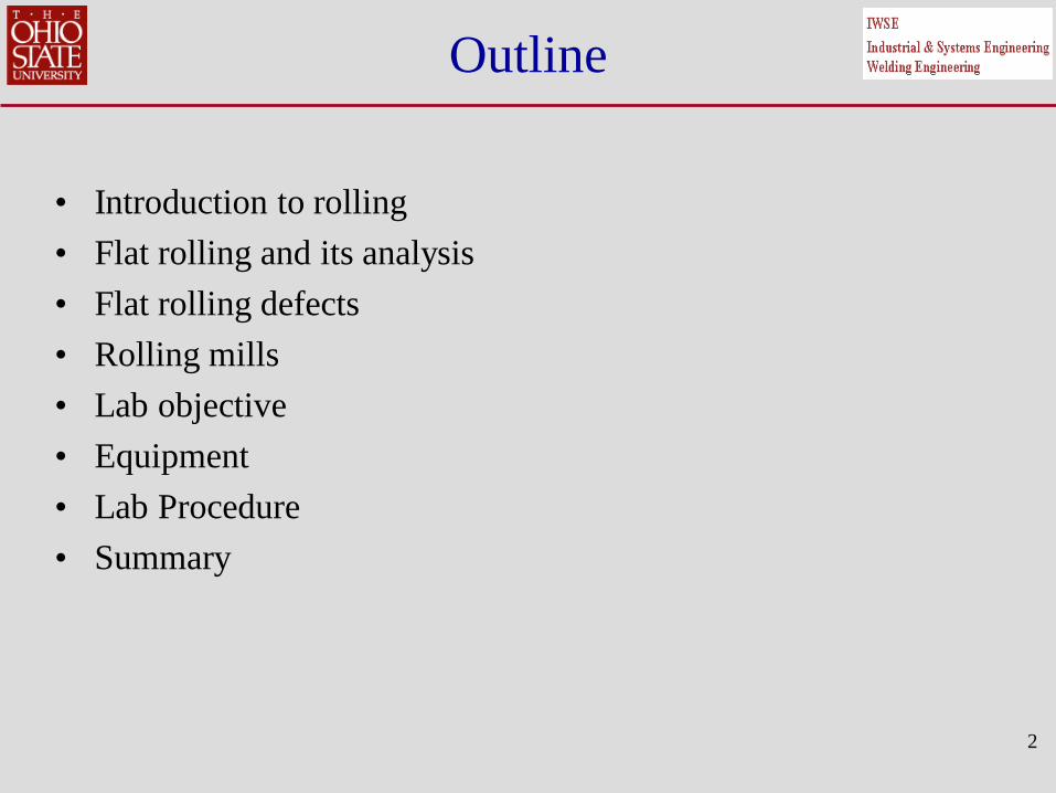
Outline
• Introduction to rolling
• Flat rolling and its analysis
• Flat rolling defects
• Rolling mills
• Lab objective
• Equipment
• Lab Procedure
• Summary

Introduction to Rolling
Rolling is a bulk deformation process in which the thickness of the
work is reduced by compressive forces exerted by two opposing
rolls. The rolls rotate to pull and simultaneously squeeze the work
between them.
The rolling process (specifically: flat rolling)
3

Introduction to Rolling
The basic process shown in the previous figure is “Flat Rolling”,
used to reduce the thickness of a rectangular cross section. A
closely related process is “shape rolling”, in which a square cross
section is formed into a shape such as an I-beam. (in this lab, you
will only do flat rolling)
Shape Rolling
Flat Rolling
Shape Rolling
Raw material and final product both in flat and shape rolling
4

Introduction to Rolling
After casting, ingots are rolled into one of three intermediate
shapes called blooms, billets, and slabs:
1. Blooms have square cross section 6” x 6” or larger. They are
rolled into structural shapes.
2. Billets have square cross section 1.5” x 1.5” or larger. they are
rolled into bars and rods.
3. Slabs have rectangular cross section 10” x 1.5” or larger. They
are rolled into plates, sheets and strips.
5

Introduction to Rolling
• As any other metal forming process, rolling can be performed
hot (hot rolling) or cold (cold rolling).
• Most rolling is carried out by hot rolling, owing to the large
amount of deformation required.
• Hot-rolled metal is generally free of residual stresses, and has
isotropic properties. On the other hand, it does not have close
dimentional tolerances, and the surface has a characteristic
oxide scale. Moreover, cold rolled metals are stronger.
In this lab, you will only do cold rolling (at room temperature).
6

Flat rolling and its analysis
• In flat rolling, the work is squeezed between two rolls so that its
thickness is reduced by an amount called the draft:
d = to - tf where
d: draft
to: starting thickness
tf : final thickness
• As a fraction of the starting thickness:
% reduction = % r = (d/ to) * 100%
7

Flat rolling and its analysis
• Rolling increases work width. This is called “spreading”.
• Spreading is expected because of the volume constancy in
plastic deformation. Since the material is compressed in the
thickness direction, both the length and width will increase
provided that the material is not constrained in the width
direction.
• Spreading is more pronounced with low width-to-thickness
ratios and low coefficients of friction, since there is small
resistance to flow in the width direction.
8
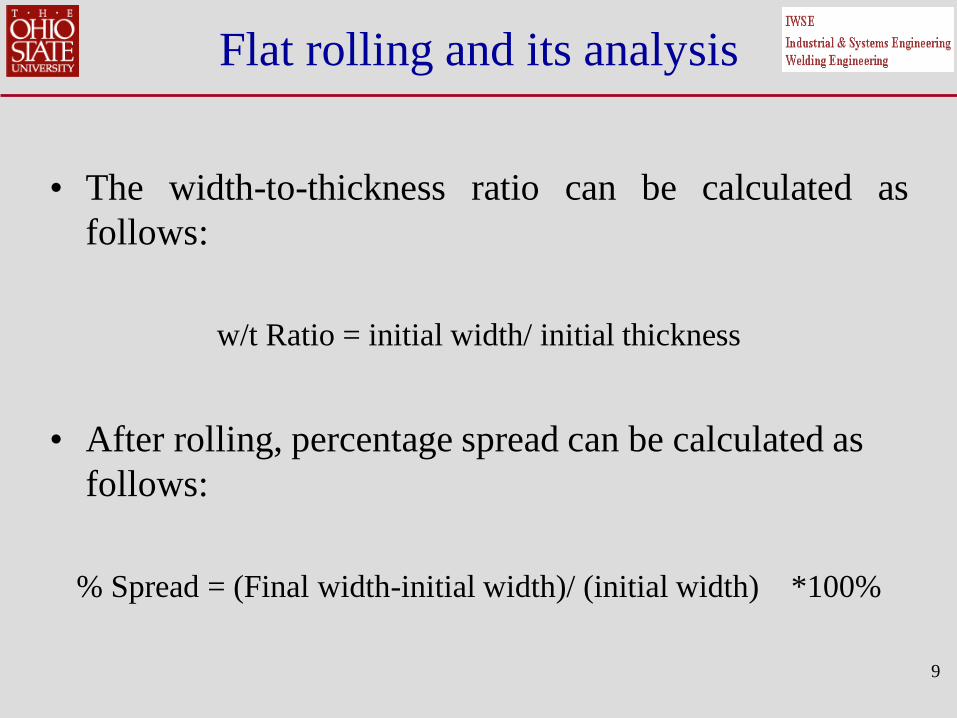
Flat rolling and its analysis
• The width-to-thickness ratio can be calculated as
follows:
w/t Ratio = initial width/ initial thickness
• After rolling, percentage spread can be calculated as
follows:
% Spread = (Final width-initial width)/ (initial width) *100%
9

Flat rolling and its analysis
• The work contacts the rolls along a contact arc. To calculate the
arc length, you can use the following approximate formula:
L = (R * d)0.5
Where
L: approximate contact length, R: roll radius, d: draft
(See the next figure)
• If the width-to-thickness ratio is large, then the spread will be
negligible and a “plane-strain” condition may be assumed.
Plane strain means that deformation occurs only in two
directions (in a plane); the longitudinal (rolling) direction and
the transverse direction.
10

Flat rolling and its analysis
This figure shows the contact
length between the work and
the rolls, the initial and final
work velocities, in addition to
the velocity of the rolls:
11

Flat rolling and its analysis
• The work enters the gap between the rolls at a velocity vo and
exits at a velocity vf. Because the volume flow rate is constant
and the thickness is decreasing, vf should be larger than vo.
• The roll surface velocity vr is larger than vo and smaller than vf.
This means that slipping occurs between the work and the rolls.
• Only at one point along the contact length, there is no slipping
(relative motion) between the work and the roll. This point is
called the “Neutral Point” or the “No Slip Point”.
12
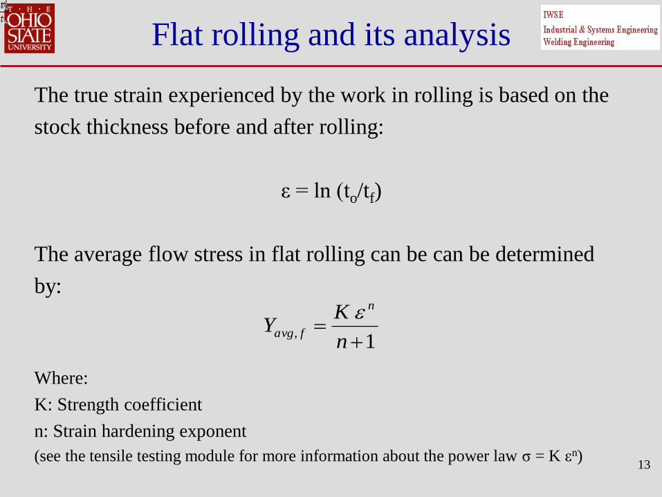
Flat rolling and its analysis
The true strain experienced by the work in rolling is based on the
stock thickness before and after rolling:
ε = ln (to/tf)
The average flow stress in flat rolling can be can be determined
by:
Where:
K: Strength coefficient
n: Strain hardening exponent
(see the tensile testing module for more information about the power law σ = K εn)
13
1
,
n
KY
n
favg

Flat rolling and its analysis
• In this experiment, a sheet will be rolled on 4 stages (4 passes).
• In each pass, the average flow stress can be determined using
the following formula:
where
Yavg, i : the average flow stress in the ith pass
: the strain after the i-1th (before the ith pass)= ln (to/ti-1)
: the strain after the ith pass = ε = ln (to/ti)
K : Strength coefficient
n : Strain hardening exponent
14
)1)(( 1
1
1
1
,
nKY
ii
n
i
n
iiavg
i1i

Flat rolling and its analysis
To calculate the roll force required to maintain separation
between the two rolls:
F = 1.15 * Yavg, i * Li * wi
where:
F : roll force
Yavg, i : the average flow stress in the ith pass
Li : the approximate contact length in the ith pass
wi : the width of the sheet in the ith pass
15

Flat rolling and its analysis
The torque in rolling can be estimated by:
T = 0.5 * F * L Where:
T: Torque (lb.in or N.m)
F: Roll Force
L: Contact length
The Power required to drive the two rolls is calculated as follows:
P = 2π*N*F*L Where:
P: Power (in J/s =Watt or in-lb/min)
N: Rolls rotational speed (RPM)
F: Roll Force
L: Contact length
16

Flat rolling and its analysis
From the previous equations we can conclude the following:
1. The contact length decreases by decreasing the roll radius.
2. The roll force depends on the contact length, and therefore, reducing
the roll radius will reduce the roll force.
3. The torque and power depend on the roll force and contact length,
and therefore, reducing the roll radius will reduce both the torque
and power.
4. The power also depends on the rotational speed of the rolls, and
therefore, reducing the rolls RPM will reduce the power.
17

Flat rolling and its analysis
• On the entrance-side of the no slip point, the roll is faster than
the sheet and therefore the friction force is in the rolling
direction.
• On the exit-side of the no slip point, the roll is slower than the
sheet and therefore the friction force is opposite to the rolling
direction.
• The compression force on the rolls multiplied by the friction
coefficient equals to the friction force.
• Increasing the friction coefficient will shift the neutral point
toward the entrance.
18

Flat rolling and its analysis
• In rolling, friction force is important because it is responsible
for pulling the sheet between the rolls.
• Rolling may not be possible (the sheet will not be pulled) if the
draft is large. The maximum draft for successful rolling is:
dmax = μ2 R
Where:
dmax : maximum draft for successful rolling
μ : coefficient of friction
R : roll radius
• As can be seen from the equation, if μ is zero, then dmax is also
zero (rolling is not possible)
19
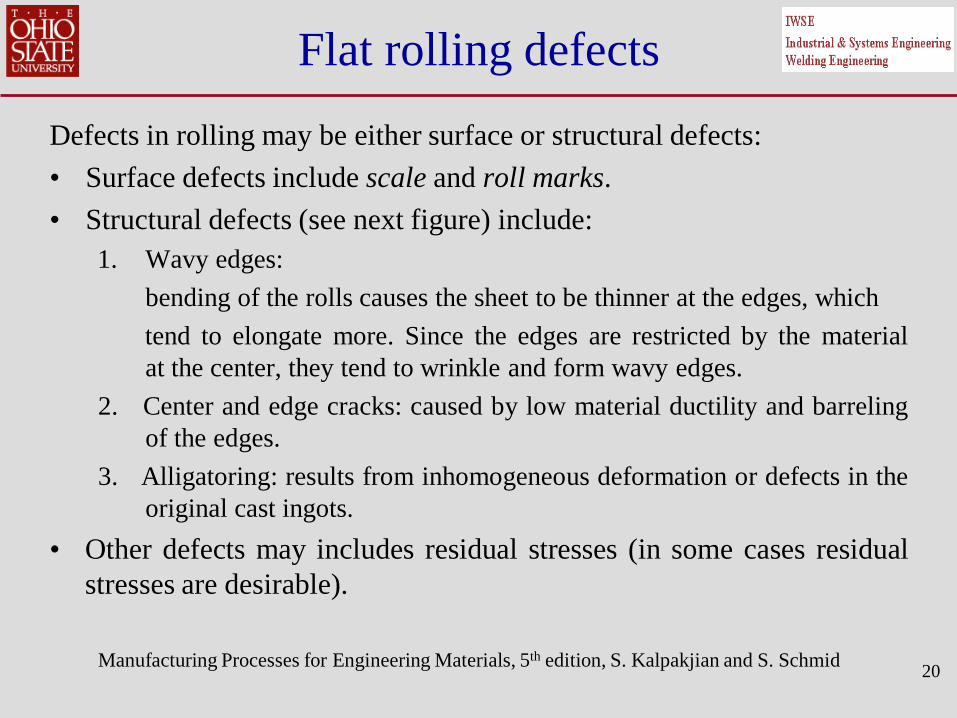
Flat rolling defects
Defects in rolling may be either surface or structural defects:
• Surface defects include scale and roll marks.
• Structural defects (see next figure) include:
1. Wavy edges:
bending of the rolls causes the sheet to be thinner at the edges, which
tend to elongate more. Since the edges are restricted by the material
at the center, they tend to wrinkle and form wavy edges.
2. Center and edge cracks: caused by low material ductility and barreling
of the edges.
3. Alligatoring: results from inhomogeneous deformation or defects in the
original cast ingots.
• Other defects may includes residual stresses (in some cases residual
stresses are desirable).
Manufacturing Processes for Engineering Materials, 5th edition, S. Kalpakjian and S. Schmid
20
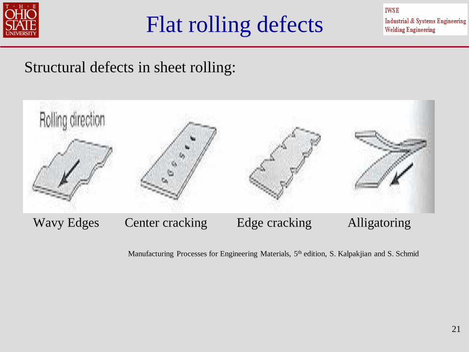
Flat rolling defects
Structural defects in sheet rolling:
Wavy Edges Center cracking Edge cracking Alligatoring
Manufacturing Processes for Engineering Materials, 5th edition, S. Kalpakjian and S. Schmid
21

Rolling mills
Various rolling mill configurations are available (see next figure):
1. Two-high rolling mill: consists of two opposing rolls. These rolls may
rotate only in one direction (nonreversing) or in two directions (reversing).
2. Three-high rolling mill: allows a series of reductions without the need to
change the rotational direction of the rolls.
3. Four-high rolling mill:
Using small rolls reduces power consumption but increases the roll
deflection. In this configuration, two small rolls, called working rolls, are
used to reduce the power and another two, called backing rolls, are used to
provide support to the working rolls.
4. Cluster rolling mill: another configuration that allows smaller working rolls
to be used.
5. Tandem rolling mill: series of rolling stands .
22

Rolling mills
Various configurations of rolling mills:
23
Two-high
Three-high Four-high
Cluster tandem
Lab Objectives
This lab has the following objectives:
• Introduce basic rolling parameters and some of the fundamental
principles in rolling.
• Calculate the roll forces required to reduce the thickness of a
given aluminum strip.
• Verify plane strain assumptions used in rolling analyses.
• Identify where plane strain assumptions are not valid and to
calculate the percentage spread in such cases.
• Evaluate the strain hardening phenomena in rolling processes.
• Identify some defects involved in rolling processes.
24

Equipment
• In this lab, you will use a scale-down model of an industrial
rolling mill. The rolling mill has two rolls powered by an
electric motor.
• The distance between the rolls, which is the roll gap, can be
adjusted by rotating a pair of rotationally calibrated screws at
the top of the roll stand (housing).
• To keep the roll gap constant, you should ensure that the two
adjusting screws have been adjusted to the same calibration
number. There is a mark on each roll housing used to align the
calibration marks on the adjusting screws.
25

Equipment
A picture of the scale-down rolling mill used in the lab:
26
Rolls Rolls Housing/
Stand
Adjusting
Screw

Equipment
27
Adjusting screw
Calibration numbers
Procedure
Part I: Rolling
1- Obtain the material data (K, n) from your lab instructor and record it
in your datasheet.
2- Record the following initial conditions of your sample strip in the
table provided:
a) Thickness
b) Length
c) Width
d) Hardness (HRC); average of three measurement
3- Set the roll gap for the first pass (set the adjusting screw to 5)
4- Start the rolling mill
28
Procedure
Part I: Rolling (continued)
5- Feed the strip through the mill (make sure not to feed the strip at an
angle into the rolls).
6- In the table provided, record the:
a) Thickness
b) Length
c) Width
d) Hardness (HRC); average of three measurement
7- Reduce the roll gap by one unit per pass and repeat steps 3-6 for the
remaining four passes.
29

Procedure
Part II: Estimating the coefficient of friction
1- With a new sample, record the initial thickness.
2- Measure the roll radius.
3- Set the roll gap to 1 on the adjusting screw.
4- Start the rolling mill.
5- Very gently attempt to feed the strip through the mill, but do not force
the strip into the mill. Hold the strip as level as possible and let
friction between the rolls and the strip pull it in (this must be the case
to get accurate data regarding the friction force). Note: the strip will
not be pulled in on this first attempt.
30

Procedure
Part II: Estimating the coefficient of friction (Continued)
6- Open the roll gap by steps on one-half units on the roll set screw and
repeat step 5 until the mill just pulls in the strip. The number on
which the roll is set is not important and only the initial and final
thickness of the specimen are needed.
7- Record the final thickness and complete the calculations with the
formulas provided.
31

Procedure
Part III: Transverse strains in rolling (Spread)
In this section of the lab, we will use a strip of aluminum that has lower
width to thickness ratio. This section highlights the fact that plane strain
assumptions in rolling must be used carefully and only for particular
cross-sections.
1- Record the specimen initial width and thickness.
2- The lab instructor will set the roll gap to 3
3- Roll the strip and then record the final width and thickness.
You will notice that there is a change in all dimensions.
32

Pictures
A picture showing the strips to be used in the lab:
33
High w/t ratio
Low w/t ratio

Pictures
34
Picture showing the sheet rolling process:
Plane strain condition expected Spread expected

Summary-Rolling
This lab preparation material introduced:
• Basic principles of rolling
• Analysis for flat rolling operations
• Flat rolling defects
• Rolling defects
• Lab objectives, Equipment and procedures
• Pictures
35