InRoads Tutorial Guide
25
InRoads Tutorial Guide Version 1.0 October 2, 2007 1
-
Upload
carlos-andres -
Category
Documents
-
view
46 -
download
5
Transcript of InRoads Tutorial Guide

InRoads Tutorial Guide
Version 1.0
October 2, 2007
1

Table of Contents
Chapter 1 Extracting faults file and points data from LDD project 1. Generating the fault (.flt) file. 2. Generating the Points file (symbols).
Chapter 2 Generating the OG surface in InRoads.
1. General Set up. 2. Importing the Fault File. 3. Assigning the Proper Styles in the Surface. 4. Importing the Points File. 5. Assigning the Proper Style for each point type. 6. Combing Features and Points data into one Surface.
2

Chapter 1
Extracting faults file and points data from LDD project
1. Generating the fault (.flt) file.
1. Click on terrain menu in LDD as shown below:
2. Click on Terrain model explorer, click on the plus sign of the surface that includes the breaklines, then right click on the breaklines and select export to file as shown below:
3

3. Type the file name of the fault line file to be created by LDD as shown below:
4

4. Select all breaklines and click OK as shown below:
The file will be generated in the directory that you have specified.
If the fault file has zero elevations, rebuild the og surface by right click on the og (without expanding it i.e with the plus sign in front of og) and select build. In the following window select “Convert Proximity breaklines to standards” as shown below then repeat steps 2-4.
5

The build og function may take sometime and you may see AutoCAD as if it is not responding. Just let it continue until you get a window saying surface done. 2. Generating the Points file (symbols).
10. Select Points menu, Point Management, Point Group Manager… as shown below:
6
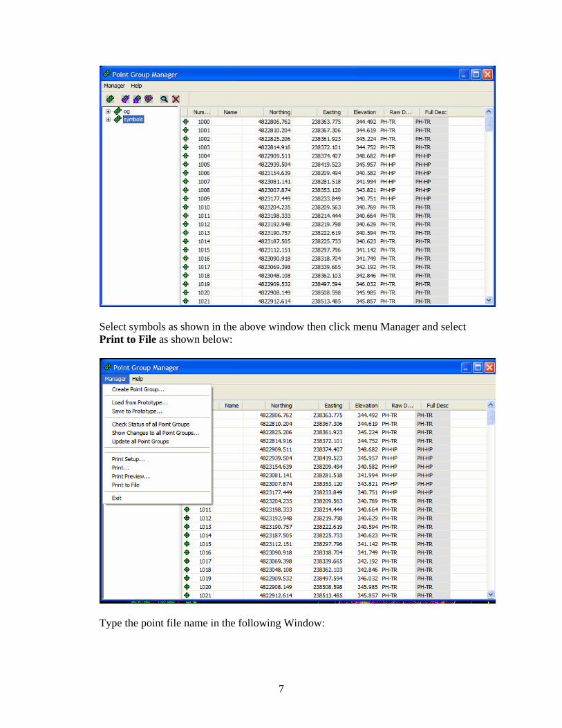
Select symbols as shown in the above window then click menu Manager and select Print to File as shown below:
Type the point file name in the following Window:
7

A sample of this file is shown below:
The above points represent Trees (TR) and Hydro Pole (HP). If the identification of each type of data points is required in the DTM then separate files to be created one for each i.e file for trees (TR) and another for Hydro Poles (HP) in this case. These files to be imported into the DTM created from the fault file using the Text Import Wizard using random features as described in chapter 2.
8

Chapter 2
Generating the OG surface in InRoads.
1. General Set up
1. Copy the InRoads Tutorial Guide directory to C:\Documents and Setting\your user ID.
2. Open InRoads with AutoCAD as shown below:
3. In AutoCAD select file open MTO standard Drawing template from the standard
sub directory of the InRoads Tutorial Guide directory as shown below:
9

4. In InRoads click on file, open the MTO_xin file from the standards sub directory of the tutorial directory as shown below:
This file contains most of the symbology and styles as per IESCAD standards as well as other preferences that will be used through out this tutorial.
5. In InRoads right click on surfaces as shown below to create a new surface:
10

6. Click on New menu item to obtain the following window:
Select existing for the type. Type the name feature for 104001. Select MTO for the preference. Repeat steps 5 and 6 to create two new more surfaces. These are Points data for 104001 and Complete OG 104001 as shown in the following:
7. Click on feature for 104001 and right click and select set active. 8. In InRoads click on file and select Text Import Wizard as shown below:
11

2. Importing the Fault File 9. In the Text Import Wizard window shown below:
In Wizard Name select Import Fault File then click on the square in the lower right corner to select the fault file in the surfaces sub directory of this tutorial as shown below:
12
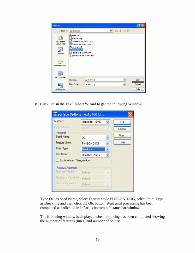
10. Click OK in the Text Import Wizard to get the following Window:
Type OG as Seed Name, select Feature Style PH-E-GND-OG, select Point Type as Breakline and then click the OK button. Wait until processing has been completed as indicated in InRoads bottom left status bar window. The following window is displayed when importing has been completed showing the number of features (lines) and number of points:
13
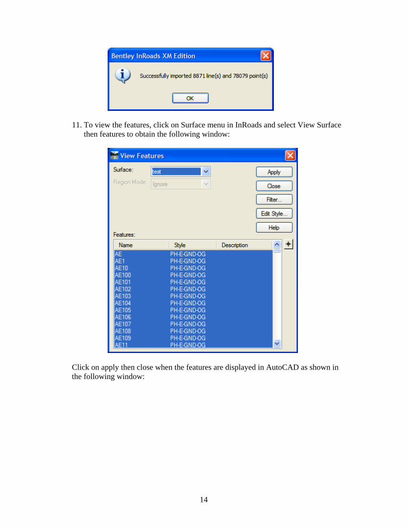
11. To view the features, click on Surface menu in InRoads and select View Surface then features to obtain the following window:
Click on apply then close when the features are displayed in AutoCAD as shown in the following window:
14

It is important to point out that all features are currently using PH-E-GND-OG style. The style of all features should be changed to use its corresponding style as described below.
15

3. Assigning the Proper Styles in the Surface
1. Click on surface menu, Features, Features Properties as shown below:
2. Click on the first of each feature and click shift key and scroll to the end of this
feature type to select all occurrences of this feature. Click on the Primary drop down box to select the corresponding style and then click Apply button as shown below:
16
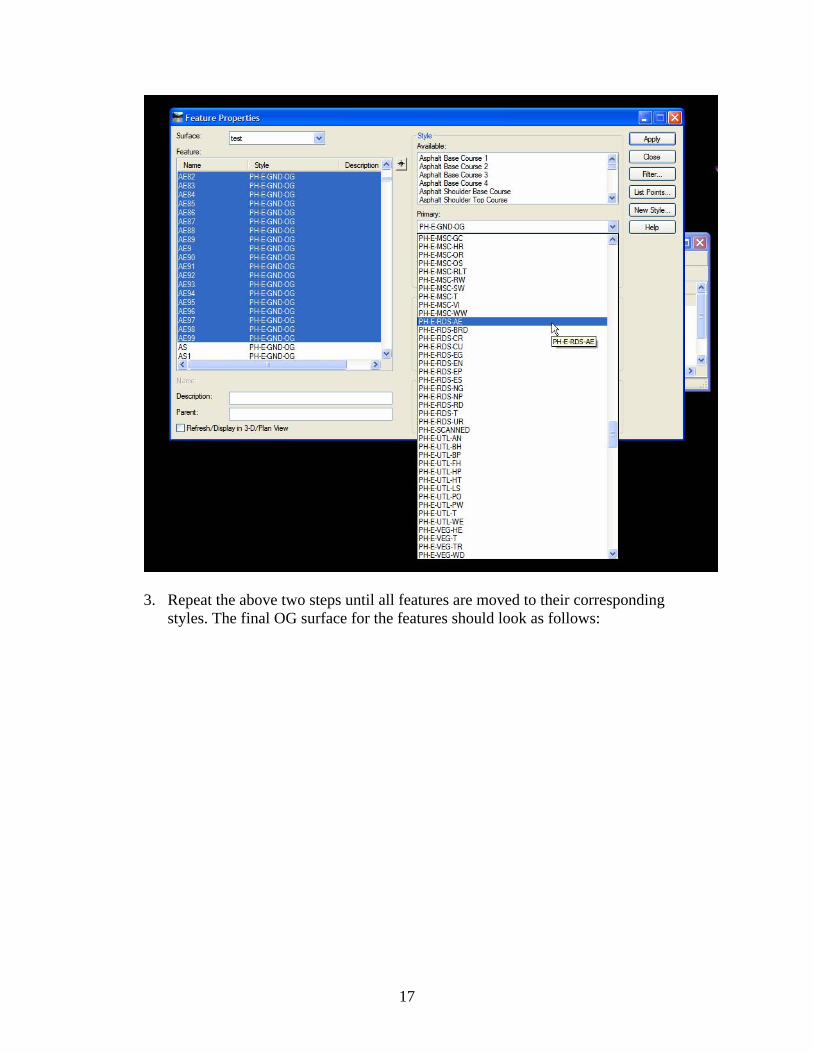
3. Repeat the above two steps until all features are moved to their corresponding
styles. The final OG surface for the features should look as follows:
17

18

4. Importing the Points File
1. In InRoads right click on Points Data 104001 surface. 2. Click File and select Text Import Wizard. 3. Click on the Wizard name and select Importing Random Points as shown
below:
4. In Data Type select Import Fault File then click on the square in the lower right corner to select the fault file in the surfaces sub directory of this tutorial as shown below:
19

5. Click Open then click OK in the Text Import Wizard to start importing the points data.
6. In the surface options window type TR as the seed name, select style PH-E-VEG-TR (style for trees) and Random for the points and check off the Exclude from Triangulation option as shown below:
7. View the random features by clicking on Surface, View Surface and select Features, Repeat for annotate feature using MTO preferences as shown below:
20

5. Assigning the Proper Style for each point type Click on surface menu, Features, Features Properties. Click on the first of each feature and click shift key and scroll to the end of this feature type to select all occurrences of this feature. Click on the Primary drop down box to select the corresponding style and then click Apply button. This is similar to section 3, Assigning the Proper Styles in the Surface. The final drawing for the points data is as follow:
21

6 Combing Features and Points data into one Surface
1. Select the surface Feature for 104001 then right click and select copy surface as shown below:
22

2. Enter Name of complete surface and select MTO preference and then click apply.
3. Select Surface, Edit Surface, Copy Portion of Suraface as shown below:
4. Select the point data surface and complete OG surface and then click
Apply as shown below:
23

5. The complete surface looks as follows:
24

Hanna Hanna, P.Eng. Head, Highway Engineering Systems Design and Contracts Standards Office Email: [email protected] Tel: 905-704-2272
25