IndraWorks 14VRS IndraLogic 2G - Bosch Rexroth
96
IndraWorks 14VRS IndraLogic 2G SFC with Operation Modes Application Description R911344490 Edition 02
Transcript of IndraWorks 14VRS IndraLogic 2G - Bosch Rexroth

IndraWorks 14VRSIndraLogic 2GSFC with Operation Modes
Application DescriptionR911344490
Edition 02

IndraWorks 14VRSIndraLogic 2GSFC with Operation Modes
Application Description
DOK-IL*2G*-SFC*OPM*V14-AP02-EN-P
RS-60ebeb9937bf81160a6846a50128eb56-2-en-US-8
Change Record Edition ReleaseDate
Note
01 2014-07 First edition
02 2015-11 Update of the "Variables supported for the ProVi SFC diag‐nostics"
Copyright © Bosch Rexroth AG 2015This document, as well as the data, specifications and other information setforth in it, are the exclusive property of Bosch Rexroth AG. It may not be re‐produced or given to third parties without its consent.
Liability The specified data is intended for product description purposes only and shallnot be deemed to be a guaranteed characteristic unless expressly stipulatedin the contract. All rights are reserved with respect to the content of this docu‐mentation and the availability of the product.
Editorial Department Engineering Automation Systems PLC Programming Interface VG (KaWa/MePe)
Title
Type of Documentation
Document Typecode
Internal File Reference
Bosch Rexroth AG DOK-IL*2G*-SFC*OPM*V14-AP02-EN-PIndraWorks 14VRS IndraLogic 2G SFC with Operation Modes

Table of ContentsPage
1 About this documentation.............................................................................................. 31.1 Validity of the documentation.................................................................................................................. 31.2 Required and supplementing documentation IndraWorks...................................................................... 31.2.1 Engineering......................................................................................................................................... 31.2.2 Engineering & visualization................................................................................................................. 51.2.3 Visualization........................................................................................................................................ 51.3 Use of the safety instructions.................................................................................................................. 51.3.1 Structure of the safety instructions...................................................................................................... 51.3.2 Explaining signal words and safety alert symbol................................................................................. 51.3.3 Symbols used...................................................................................................................................... 71.3.4 Signal graphic explanation on the device............................................................................................ 71.4 Names an abbreviations......................................................................................................................... 71.5 Customer feedback................................................................................................................................. 7
2 SFC with operation modes............................................................................................. 92.1 General information................................................................................................................................ 92.2 What is an SFC with operation modes?................................................................................................. 9
3 Sequence description of the SFC................................................................................ 133.1 General information.............................................................................................................................. 133.2 Signal-time diagram qualifiers.............................................................................................................. 21
4 Programming............................................................................................................... 294.1 General information.............................................................................................................................. 294.2 Definition of the supported variables for the ProVi SFC diagnostics.................................................... 294.3 Basic settings........................................................................................................................................ 344.4 Configuring the SFC............................................................................................................................. 364.5 Action transition "ActionTrans"............................................................................................................. 384.6 Automatic, manual, and homing branch............................................................................................... 404.7 HomePosition & StartCondition............................................................................................................ 414.8 Transition properties............................................................................................................................. 424.9 Diagnostics........................................................................................................................................... 454.10 Module assignment editor..................................................................................................................... 48
5 SFC types.................................................................................................................... 515.1 General information.............................................................................................................................. 515.2 SFC types ILDSfc01............................................................................................................................. 515.3 SFC types ILDSfc02............................................................................................................................. 51
6 SFC diagnostics........................................................................................................... 636.1 General information.............................................................................................................................. 636.2 Diagnostic overview in IndraWorks Operation...................................................................................... 63
DOK-IL*2G*-SFC*OPM*V14-AP02-EN-P Bosch Rexroth AG I/93IndraWorks 14VRS IndraLogic 2G SFC with Operation Modes
Table of Contents

Page
6.3 Diagnostic overview in IndraWorks Engineering.................................................................................. 68
7 Operating screens........................................................................................................ 71
8 Application example..................................................................................................... 778.1 General information.............................................................................................................................. 778.2 Additional examples.............................................................................................................................. 848.3 System variables of the SFC................................................................................................................ 86
9 Service and support..................................................................................................... 89
Index............................................................................................................................ 91
Bosch Rexroth AG DOK-IL*2G*-SFC*OPM*V14-AP02-EN-PII/93IndraWorks 14VRS IndraLogic 2G SFC with Operation Modes
Table of Contents

1 About this documentation1.1 Validity of the documentation
Target group In the following illustration, the framed activities, product phases and targetgroups refer to this documentation.Example: In the product phase "Engineering", the target group "programmer"can execute the activities "parameterize", "program" and "configure" usingthis documentation.
Presales Aftersales
Selection Mounting(assembly/installation) Engineering Commissioning Operation De-
commissioningProduct-phases
Targetgroups
Activities
Design engineer
Programmer
Technologist
Processspecialist
Select
Prepare
Design
Construct
Mechanic/electrician
Unpack
Mount
Install
Programmer
Commissioning engineer
Parameterize
Program
Configure
Simulate
Technologist
Process specialist
Optimize
Test
Machineoperator
Maintenancetechnician
Service
Operate
Maintain
Removefaults
Createthe NC program
Mechanic/electrician
Disposal company
Dismount
Dispose
Fig. 1-1: Assigning this documentation to the target groups, product phasesand target group activities
1.2 Required and supplementing documentation IndraWorks1.2.1 Engineering
Documentation titles with type codes and part numbers
Rexroth IndraWorks 14VRS Software InstallationDOK-IWORKS-SOFTINS*V14-CORS-EN-P, R911344286This documentation describes the IndraWorks installation.Rexroth IndraWorks 14VRS EngineeringDOK-IWORKS-ENGINEE*V14-APRS-EN-P, R911343566This documentation describes the application of IndraWorks in which the Rexroth Engineering tools are integrated. It in‐cludes instructions on how to work with IndraWorks and how to operate the oscilloscope function.Rexroth IndraWorks 14VRS IndraLogic 2G PLC Programming SystemDOK-IWORKS-IL2GPRO*V14-APRS-EN-P, R911343571This documentation describes the PLC programming tool IndraLogic 2G and its use. It includes the basic use, first steps,visualization, menu items and editors.Rexroth IndraWorks 14VRS Basic Libraries IndraLogic 2GDOK-IL*2G*-BASLIB**V14-LIRS-EN-P, R911343920This documentation describes the system-comprehensive PLC libraries.
DOK-IL*2G*-SFC*OPM*V14-AP02-EN-P Bosch Rexroth AG 3/93IndraWorks 14VRS IndraLogic 2G SFC with Operation Modes
About this documentation

Rexroth IndraWorks 14VRS WinStudioDOK-IWORKS-WINSTUD*V14-APRS-EN-P, R911341585This "User Manual and Technical Reference Book" facilitates working with the "Rexroth WinStudio"™ software for optimalresults. This document provides technical information and step-by-step instructions to create web-enabled HMI/SCADAprograms.Rexroth IndraWorks 13VRS CamBuilderDOK-IWORKS-CAMBUIL*V13-APRS-EN-P, R911336291This documentation describes the basic principles and operation of the CamBuilder, the cam editing tool.Rexroth IndraWorks 14VRS Field BusesDOK-IWORKS-FB******V14-APRS-EN-P, R911341485This documentation describes the field bus and local periphery connections supported by the IndraLogic XLC, IndraMotionMLC and IndraMotion MTX systems. The focus of this documentation is on the configuration, parameterization, commis‐sioning and the diagnostics of the different periphery connections.Rexroth IndraWorks IndraMotion Service ToolDOK-IWORKS-IMST*******-APRS-DE-P, R911341383This documentation describes the IndraMotion Service Tool (IMST). IMST is a web-based diagnostic tool used to access acontrol system via an Ethernet high-speed connection. The IMST allows OEMs, end users and service engineers to accessand remotely diagnose a system. The PC has to use at least Internet Explorer 8, Firefox 3.5 or a higher version.The following control variants are supported:● IndraMotion MLC L25/L45/L65● IndraLogic XLC L25/L45/L65/VEPRexroth IndraDrive Service Tools IMST/IDSTDOK-IM*MLD-IMSTIDSTV13-RERS-EN-P, R911342652This documentation describes the IndraMotion Service Tools (IMST and IDST). It is a web-based diagnostic tool used toaccess a drive system via a high-speed Ethernet connection. Using these service tools OEMs, end users and service engi‐neers can access and remotely diagnose a system from anywhere.Rexroth IndraWorks 14VRS SafeLogic First StepsDOK-IWORKS-SL*STEP*V14-CORS-EN-P, R911341520This documentation provides information to facilitate an easy start in the safety control engineering SafeLogic. By usingproject examples, information about the installation, configuration, commissioning, troubleshooting and diagnostics is provi‐ded to the user.Rexroth IndraWorks 12VRS FDT ContainerDOK-IWORKS-FDT*CON*V12-APRS-EN-P, R911334398This documentation describes the IndraWorks FDT Container functionality. It includes the activation of the functionality inthe project and working with DTMs.Rexroth IndraWorks 14VRS Field Buses LibrariesDOK-IWORKS-FB*LIB**V14-LIRS-EN-P, R911343575This documentation describes field bus libraries for the IndraLogic XLC, IndraMotion MLC and IndraMotion MTX systems.Rexroth IndraWorks Remote Condition Monitoring RMB_TechRCM 14VRSDOK-IWORKS-TEC*RCM*V14-LIRS-EN-E, R911343671This documentation describes the individual functions of the "Remote Condition Monitoring" systems as well as the mostimportant use cases for a quick status assessment of the connected machines/systems.Rexroth IndraWorks 14VRS SafeLogic Project ConfigurationDOK-IWORKS-SL**PRJ*V14-APRS-EN-P, R911341694This documentation describes the creation and programming of SafeLogic projects in IndraWorks Engineering.
Tab. 1-1: IndraWorks documentation overview - Engineering
Bosch Rexroth AG DOK-IL*2G*-SFC*OPM*V14-AP02-EN-P4/93IndraWorks 14VRS IndraLogic 2G SFC with Operation Modes
About this documentation

1.2.2 Engineering & visualizationDocumentation titles with type codes and part numbers
Rexroth IndraWorks 14VRS Energy Efficiency ManagementDOK-IWORKS-4EE*****V14-APRS-EN-P, R911339229This document describes the use of the Energy Efficiency Management function within the MLC, XLC and MTX systems.Using example applications, this documentation provides information about the project planning, configuration and visuali‐zation of the system.
Tab. 1-2: IndraWorks documentation overview - Engineering & visualization
1.2.3 VisualizationDocumentation titles with type codes and part numbers
Rexroth IndraWorks 14VRS HMIDOK-IWORKS-HMI*****V14-APRS-EN-P, R911343569This documentation describes the HMI operating interface IndraWorks Operation, its operation and functions as well as theconfiguration in IndraWorks Engineering.
Tab. 1-3: IndraWorks documentation overview - Visualization
1.3 Use of the safety instructions1.3.1 Structure of the safety instructions
The safety instructions are structured as follows:
Burns and chemical burns due to wrong battery treatment!
CAUTION
Safety alert symbolSignal word
Consequences andsource of danger
Avoiding danger
Do not open the batteries and do not heat them over 80 °C.
Fig. 1-2: Structure of the safety instructions
1.3.2 Explaining signal words and safety alert symbolThe safety instructions in this documentation contain specific signal words(danger, warning, caution, notice) and, if necessary, a safety alert symbol(according to ANSI Z535.6-2006).The signal word is used to draw attention to the safety instruction and alsoprovides information on the severity of the hazard.The safety alert symbol (a triangle with an exclamation point), which pre‐cedes the signal words danger,warning and caution is used to alert the read‐er to personal injury hazards.
DANGER
In the event of non-compliance with this safety instruction, death or seriousinjury will occur.
DOK-IL*2G*-SFC*OPM*V14-AP02-EN-P Bosch Rexroth AG 5/93IndraWorks 14VRS IndraLogic 2G SFC with Operation Modes
About this documentation

WARNING
In the event of non-compliance with this safety instruction, death or seriousinjury will occur.
CAUTION
In the event of non-compliance with this safety instruction, minor or moderateinjury can occur.
NOTICE
In the event of non-compliance with this safety instruction, material damagecan occur.
Bosch Rexroth AG DOK-IL*2G*-SFC*OPM*V14-AP02-EN-P6/93IndraWorks 14VRS IndraLogic 2G SFC with Operation Modes
About this documentation
1.3.3 Symbols usedHints are represented as follows:
This is an information.
Tips are represented as follows:
This is a tip.
1.3.4 Signal graphic explanation on the device
krax
Prior to the installation and commissioning of the device,refer to the device documentation.
1.4 Names an abbreviationsTerm Explanation
CANopen Field bus
DeviceNet Field bus
Ethernet Communication interface
IWE IndraWorks Engineering
IWO IndraWorks Operation
NC Numerical Control
OEM Original Equipment Manufacturer
Profibus DP Field bus
Sercos Sercos (Serial Realtime Communication System) interfaceis a world-wide standardized interface for the communica‐tion between controls and drives
Tab. 1-4: Names and abbreviations used
1.5 Customer feedbackCustomer requests, comments or suggestions for improvement are of greatimportance to us. Please email your feedback on the documentations [email protected]. Directly insert comments in theelectronic PDF document and send the PDF file to Bosch Rexroth.
DOK-IL*2G*-SFC*OPM*V14-AP02-EN-P Bosch Rexroth AG 7/93IndraWorks 14VRS IndraLogic 2G SFC with Operation Modes
About this documentation

Bosch Rexroth AG DOK-IL*2G*-SFC*OPM*V14-AP02-EN-P8/93IndraWorks 14VRS IndraLogic 2G SFC with Operation Modes

2 SFC with operation modes2.1 General information
IndraLogic provides IEC 61131 SFCs with automatic operation mode and di‐agnostics.
Operation modes The SFC knows and manages operation modes such as automatic mode,manual mode, jog mode, semi-automatic mode and homing.The operation modes of the SFC can be controlled using input and outputsignals of the SFC.The engineer does not have to take care of the programming of the operationmodes. He only has to apply the respective signals at the inputs and outputsof the SFC.
Diagnostics The SFC automatically supports different diagnostics. These include SFCstatus, time errors, monitor errors, missing starting condition, missing homeposition as well as a feasibility display.The engineer only has to assign the relevant conditions.
Different SFC types If available, different SFC types can be used at the same time. The differentSFCs can differ in their response as well as in their input and output signals.The standard IndraLogic SFC, with or without IEC steps, can still be used.
● All SFCs with diagnostics have to be programmed in onetask
● The maximum number of steps per POU (Program Organi‐zation Unit) is 65,000 or it is limited by the available memoryin the control
2.2 What is an SFC with operation modes?In case of an SFC with operation modes, proceeding the steps is controlleddepending on the operation mode set.The operation mode of an SFC can be controlled via the SFC input signals:
Automatic As soon as the transition condition is fulfilled during error-free op‐eration, the SFC switches to the next step, analog to the standardIEC SFC
Manual mode Individual steps and/or actions can be activated specifically. Thetransition conditions are analyzed, but there is no block transition
Jog mode The steps are processed until the transition condition is fulfilled. Anew starting signal is required for transition to the next step
Semi-automatic For normal transitions, the SFC advances to the next step whenthe transition condition is fulfilled. If the transition is defined as astop point for the semi-automatic mode, the system does not au‐tomatically advance to the next steps. It requires a new startingsignal
Tab. 2-1: Operation modesSFC diagnostics For an SFC with operation modes, there is a diagnostics automatically deriv‐
ing from the programmed logic.The response of the SFC to corresponding states occurs automatically. Themessages are displayed in IndraWorks.
DOK-IL*2G*-SFC*OPM*V14-AP02-EN-P Bosch Rexroth AG 9/93IndraWorks 14VRS IndraLogic 2G SFC with Operation Modes
SFC with operation modes

Module An SFC can be assigned to a certain module. The messages are set for thismodule. Up to 99 modules are possible.The module serves to logically assign an SFC to a specified machine compo‐nent.Example: The PLC controls several logically separated machine components.The diagnostic messages of one component should be separated from thoseof the other component.
Criteria analysis Represents the contacts which have caused the message or the error. Thisdetermination is executed automatically, considers only Boolean logic and isgenerated without further programming effort.
Diagnostic messages There are eight different types of diagnostic messages in the SFC:1. Active steps2. Home position reached3. Homing4. Missing home position with criteria analysis5. Monitor error with criteria analysis6. Time error with criteria analysis7. Missing starting condition with criteria analysis8. Wait for transition
Diagnostic message Description
Active steps The active steps are reported as status message on the IndraWorks diagnostic screen
Home position reached The SFC reports that it is in the Init step and the machine/SFC is in home position
Homing The SFC reports that the home position branch is currently being processed
Monitor error For this diagnostic type, the user has to program.The current result (CR) can be monitored by individual networks. If the CR has an incorrectstate, the SFC automatically switches to the error state.Example: An error is triggered if the CR is to be monitored for FALSE and if the CR of the net‐work is FALSE during processing of the action.If the CR is used to set a coil with storing properties (set coil) monitoring of the RLO continuesafter setting. An error is triggered in spite of the set coil if the CR of the network turns to FALSEduring processing.The networks to be monitored have to be defined manually.For this diagnostic type, the criteria analysis is also available. The criteria analysis reportswhich contact in the network triggered the error. The criteria analysis calculates only Booleanvariables that are directly related to the CR
Time error For the diagnostic type "TimeError", the user has to program.The duration of the steps being active are monitored. A maximum time can be set for everystep. If the step is active for a longer period, the SFC automatically switches to the error state.Monitoring the maximum step time applies to all operation modes except the manual mode. Inthe jog mode, monitoring the step time stops when the transition condition is fulfilled.The criteria analysis is available for this diagnostic type. A time error can only have one cause:The transition condition was not achieved, since a required signal has not come in.In this case, the missing transition condition is displayed with the responsible variables
Bosch Rexroth AG DOK-IL*2G*-SFC*OPM*V14-AP02-EN-P10/93IndraWorks 14VRS IndraLogic 2G SFC with Operation Modes
SFC with operation modes

Diagnostic message Description
Start condition The diagnostic type "starting condition" requires that the engineer defines the parameters forthe starting condition of the SFC. This diagnostic type applies to the operation modes: Automat‐ic, semi-automatic and jog mode. Further analysis is then automatically performed by the SFC.For error-free processing, the starting conditions should to be assigned in the action "aUserIn"in the step "Init".If the starting condition is missing, the SFC stops immediately and switches to the error state.If the SFC is stopped and starting conditions are missing, this is displayed as message of thetype "starting condition". If the user now tries to start the SFC, it switches immediately to theerror state and the message is output as an error.The criteria analysis is available for this diagnostic type and shows the responsible variables
Setup diagnostics The setup diagnostics corresponds to the diagnostic type "starting condition" in manual mode.The criteria analysis is available for this diagnostic type and shows the responsible variables
Home position The diagnostic type "HomePosition" requires that the engineer defines the conditions for thehome position of the SFC. Further analysis is then automatically performed by the SFC. Forerror-free processing, the conditions should be assigned in the action "aUserIn" in the step"Init".If the SFC stopped in the Init step and home position conditions are missing, this is displayedas a message of the type "starting condition". If the user now tries to exit the Init step, the SFCimmediately switches to the error state and the message is output as an error.No error is triggered if the Init step is branched to the home position branch.The criteria analysis is available for this diagnostic type and shows the responsible variables
Wait for transition This diagnostic type is only available for the jog and semi-automatic operation modes.There is no criteria analysis available for this message typeThe diagnostic message describes the sequence state in which the SFC waits for the respec‐tive starting signal (Enable or Start) with the transition condition fulfilled
Tab. 2-2: Diagnostic messages
The starting condition has a higher priority than the home posi‐tion, i.e. as long as a starting condition message is pending, thehome position conditions are not analyzed.
Cascaded machine states The parameters for the starting condition and home position of several SFCscan be cascaded.Conditions that apply to all SFCs of the control, only have to be defined oncefor the control (still without criteria analysis).Conditions that apply to all SFCs of a module have to be defined only oncefor this module (still without criteria analysis).Conditions that only apply to one SFC, are only defined for this SFC (with cri‐teria analysis).
DOK-IL*2G*-SFC*OPM*V14-AP02-EN-P Bosch Rexroth AG 11/93IndraWorks 14VRS IndraLogic 2G SFC with Operation Modes
SFC with operation modes

Bosch Rexroth AG DOK-IL*2G*-SFC*OPM*V14-AP02-EN-P12/93IndraWorks 14VRS IndraLogic 2G SFC with Operation Modes

3 Sequence description of the SFC3.1 General information
IEC 61131 The basis for an SFC with operation modes is the IEC 61131 SFC. However,since the IEC 61131 standard does not know any operation modes and diag‐nostics, the SFC is extended by further elements.Basic programming still complies with the IEC 61131 standard.
Steps/transitions The sequence of an SFC is programmed using steps and transitions. Thesteps execute the corresponding code and the transitions define the switch‐ing point to the next step.
Fig. 3-1: Sequence of an SFC with steps and transitionsTransition condition A transition switches to the next step if the previous step is active and the
condition for the transition is met. For parallel branches, the last previoussteps of the relevant branches and their transitions have to be met, see "Par‐allel branching" on page 15.
The step transition conditions may only be implemented in ST(Structured Text). Using other programming languages such asLD, FUP (FBs) and IL cause errors when creating diagnostic da‐ta. The error includes the note that the code for the transitioncould not be determined.
DOK-IL*2G*-SFC*OPM*V14-AP02-EN-P Bosch Rexroth AG 13/93IndraWorks 14VRS IndraLogic 2G SFC with Operation Modes
Sequence description of the SFC

Step – Minimum time If a step is programmed with a minimum time, the fulfilled transition onlyswitches to the next step after the minimum time for this step has elapsed,i.e. the step is active for at least this period.
The minimum step time can be used to process a step with ac‐tion/s over a certain period of time even if the transition conditionis met.Example: A predetermined number of products is supplied forprocessing via a flap mechanism. Even when the flap is open(transition met) there has to be a certain waiting time (minimumtime) before the flap closes again. This ensures that no productsremain in the flap mechanism.
Transition delay If the conditions for the advancing a transition with a transition delay are met,the system waits until the programmed delay time has elapsed before ad‐vancing to the next step.
When using transition delay, no assignment of "ActionQ" (or anAND operation with "ActionQ") may not be carried out on "Action‐Trans".A fulfilled transition results in post-processing the "ActionQ" =FALSE and thus also the "ActionTrans" = FALSE. The action re‐turns to processing before the transition delay time has elapsed. Itis not possible to exit the step anymore.
The transition delay can be used to debounce input signals, e.g. amechanical limit switch.
Alternative branching
Fig. 3-2: Alternative branchingFor alternative branching, it is possible to switch to different steps.The following applies for this example: If the condition for "Trans5" is met,step "Step6" is activated next. If the condition for "Trans6" is met instead,step "Step7" is activated next.
Bosch Rexroth AG DOK-IL*2G*-SFC*OPM*V14-AP02-EN-P14/93IndraWorks 14VRS IndraLogic 2G SFC with Operation Modes
Sequence description of the SFC

If both transitions are met, it is switched in the first branch from the left side.In this example "Step6".
Parallel branching
Fig. 3-3: Parallel branchingFor a parallel branching, the system is advanced in several steps. Thismeans for this example: If "Trans9" is met, the steps "Step1" and "Step2" areactivated.Transition "Trans10" only advances if the steps "Step3" and "Step4" are ac‐tive.
Action processing Actions are attached to the steps. In these actions, the code executed for anactive step can be programmed in the programming languages FBS, LD, ILand ST.
Fig. 3-4: Actions at a stepAn action can be used at any number of steps.If a step becomes active, all actions associated with this step are processedaccording to the qualifier used.If several steps are active, all actions are processed at the active steps.
DOK-IL*2G*-SFC*OPM*V14-AP02-EN-P Bosch Rexroth AG 15/93IndraWorks 14VRS IndraLogic 2G SFC with Operation Modes
Sequence description of the SFC

● It is not possible to process Boolean flags instead of actionswhen using SFC with diagnostics!
● If a certain action is processed at several steps which are si‐multaneously active, the status of the action processing isnot clearly defined. Such constellations are to be avoided
● It is not permitted to call an action within a second action fora POU of the type "SFC", e.g. having the call of an actionassociated to a step and at the same time in the "aUserIn"
Action Sequence The actions are processed in alphabetical order. In the example in fig. 3-4"Actions at a step" on page 15, this means that, if "Step9" and "Step3" areenabled, first "Action_3" and then "Action_4" is processed.
aUserIn The "aUserIn" action is a specific action. The "aUserIn" should also containthe "StartCondition" as well as the "HomePosition" assignments and called inthe Init step.If an action with this name is used, it is always processed cyclically. Thatmeans this action is also processed even if the Init step is no longer active.This applies to all operation modes.
Post-processing of actions If an action is no longer to be processed, it is nevertheless processed for onemore cycle. This post-processing disables outputs activated during the actionor prepare an function block for a new call. Post-processing can be identifiedby the flags "ActionA" and "ActionQ".
ActionA, ActionQ State ActionA ActionQ
Processing TRUE TRUE
Post-processing TRUE FALSE
No processing FALSE FALSE
Tab. 3-1: "ActionA" and "ActionQ" flagsThe flags "ActionA" and "ActionQ" are global flags provided by the ILDSFC ofthe SFC.The status of these flags is only defined within the action processing.During action processing, the two flags are provided with a matching state forthis action. The state may differ when processing the next action.Since the flags "ActionA" and "ActionQ" are global flags, they cannot be ob‐served network-/action-dependent while they are logged in. The displayedstate of these two global flags is always "TRUE".The flag "ActionA" seems to have no function, since it is always TRUE whileprocessing the action and it has no defined state beyond processing. Howev‐er, under the specific circumstances described below, an action is processedcyclically irrespective of the related step. In this case, flag "ActionA" is alsoFALSE during cyclic action processing.
The action "aUserIn" is processed cyclically.However, the characteristic feature is the fact that flags "ActionA"and "ActionQ" are always FALSE.
Bosch Rexroth AG DOK-IL*2G*-SFC*OPM*V14-AP02-EN-P16/93IndraWorks 14VRS IndraLogic 2G SFC with Operation Modes
Sequence description of the SFC

Post-processing examples
Fig. 3-5: Disabling outputs during post-processingThe output is disabled while processing the action depending on the inputs. Ifthe action without post-processing is now no longer processed, the output isstill TRUE. Post-processing, however, resets the output to FALSE due to theAND operation of the "ActionQ" flag. For an example, refer to "Signal-time di‐agram: Post-processing with N-qualifier" on page 21.
Action qualifier The action qualifier used determines when an action is processed at an ac‐tive step. These qualifiers are indicated during use of actions and thus controlthe enabling of actions. Additional values can be specified for different qualifi‐ers. If an action is disabled, it is still post-processed for one action. unless theaction is described differently in the following table.
Qualifier Description
N Non-saving.This action is processed as long as the step is active. In the cycle in whichthe step is disabled, the action is disabled as well
S Set saving.The action is processed from the point in time when the step becomes ac‐tive, even if the step is then no longer active. The action can be disabledwith the R-qualifier
R Dominant reset.If an action was activated with the qualifier S, SD, DS, or SL, it is disabledwhen the step is active
L Non-saving, time-limited.For this qualifier, a time period is indicated as additional information.The action is processed as long as the step is active. If the step requireslonger than the time specified, the action is disabled after the time haselapsed
D Non-saving, with time delay.For this qualifier, a time period is indicated as additional information, e.g."D T#2s500ms".Time starts running when the step is activated. After time-out and if thestep is still active, the action is processed. If this step is disables, the ac‐tion is also disabled again
P Pulse.If the step is active, the action is processed for two cycles and then disa‐bled again. Using the flag "ActionQ" ensures that there is always a posi‐tive edge or a pulse to be evaluated (see "Signal-time diagram qualifiersP/P0/P1" on page 26)
DOK-IL*2G*-SFC*OPM*V14-AP02-EN-P Bosch Rexroth AG 17/93IndraWorks 14VRS IndraLogic 2G SFC with Operation Modes
Sequence description of the SFC

Qualifier Description
P0 Post-processing upon disabling the step.If the step is disabled, the action is post-processed for one cycle. A pro‐cessing does not take place (refer to "Signal-time diagram qualifiersP/P0/P1" on page 26)
P1 Post-processing upon enabling the step.When the step becomes active, the action is post-processed for one cy‐cle. A processing does not take place (refer to "Signal-time diagram quali‐fiers P/P0/P1" on page 26)
SD Saving, with time delay.For this qualifier, a time period is indicated as additional information, e.g."SD T#2s500ms".Time starts running when the step is activated. The action is only pro‐cessed after time-out irrespective of the step being active or not being ac‐tive. It is disabled with the R-qualifier
DS With time delay, saving.For this qualifier, a time period is indicated as additional information, e.g."DS T#2s500ms".Time starts running when the step is activated. The action is only pro‐cessed after time-out and if the step is still active. The action is disabledwith the R-qualifier
SL Saving, with time limit.For this qualifier, a time period is indicated as additional information, e.g."SL T#2s500ms".The action is processed as soon as this step is activated. It is even pro‐cessed if the step is disabled. The action is disabled again after time-out.Even when the time has elapsed, saving with the R-qualifier has to be re‐set
ON Cyclic processing, enabling.The action receives two additional states: "Enable" and "Disable". If thestep is enabled, the action is processed in the "Enable" state (refer to"Signal-time diagram ON-/OFF-qualifiers" on page 28 and "ON- andOFF-qualifier" on page 19)
OFF Cyclic processing, disable.The action receives two additional states: "Enable" and "Disable". If thestep is enabled, the action is processed in the "Disable" status (refer to"Signal-time diagram ON-/OFF-qualifiers" on page 28 and "ON- andOFF-qualifier" on page 19)
Bosch Rexroth AG DOK-IL*2G*-SFC*OPM*V14-AP02-EN-P18/93IndraWorks 14VRS IndraLogic 2G SFC with Operation Modes
Sequence description of the SFC

Qualifier Description
GO Cyclic processing, value transfer.For this qualifier, a REAL value is indicated as additional information.This action receives an additional "transfer value" state. If the step is ena‐bled, the action is processed in the "Transmission of value" state (refer to"Signal-time diagramGO-qualifiers" on page 27)
GOdi Cyclic processing, value transfer.For this qualifier, a DINT value is indicated as additional information.This action receives an additional "transfer value" state. If the step is ena‐bled, the action is processed in the "Transmission of value" state (refer to"Signal-time diagramGO-qualifiers" on page 27)
Tab. 3-2: Describing the action qualifiersCyclic action processing Actions used with the qualifiers ON, OFF, GO and GOdi have a different be‐
havior than other actions.
Actions used with ON, OFF, GO and GOdi cannot be used withany other qualifier.Since the flags "ActionON" and "ActionOFF" and "Action GO" areglobal flags, they cannot be observed network-/action-dependentwhile logged in. The state displayed of these global flags is al‐ways "TRUE".
These actions are always processed cyclically irrespective of thestate the SFC or the related steps are in.
Regarding the processing and post-processing, these actions respond like anaction with N-qualifier, except that these actions are still processed when anN-action is not processed. "ActionA" and "ActionQ" are then FALSE.In this case, processing and post-processing are not relevant. The additionalstates are the decisive factor.
ON- and OFF-qualifier The "ON"- and "OFF"-qualifiers provide two additional states to the action inaddition to the state "cyclic processing": "Enable" and "Disable". These statescan be identified by the global flags "ActionON" and "ActionOFF".As long as the step with the ON-qualifier is active, the action is processed inthe "Enable" state. During this processing, the "ActionON" flag is TRUE for atleast one PLC cycle. If the action transition "ActionTransON" is met, the flag"ActionON" is FALSE.As long as the step with the OFF-qualifier is active, the action is processed inthe "Disable" status. During this processing, the "ActionOFF" flag is TRUE forat least one PLC cycle. If the action transition "ActionTransOFF" is met, theflag "ActionOFF" is FALSE.
DOK-IL*2G*-SFC*OPM*V14-AP02-EN-P Bosch Rexroth AG 19/93IndraWorks 14VRS IndraLogic 2G SFC with Operation Modes
Sequence description of the SFC

Fig. 3-6: Call of an action with ON- and OFF-qualifier
Fig. 3-7: Use of the "ActionON" flag in an action
This qualifier allows for instance to enable or disable hydraulicvalves in an SFC or the cyclic processing of the output wiring.
GO- and GOdi-qualifier "GO" and "GOdi" provide the action with the additional state "transfer value".This state can be identified by the global flag "ActionGO".As soon as the step with the GO- or GOdi qualifier is enabled, the action isprocessed in the transfer value state for one cycle (ActionGO becomesTRUE for one PLC cycle). The variable value at the action qualifier is copiedto the global variable “ActionValueREAL”, or, in case of GOdi to the “Action‐ValueDINT” during the complete active processing of the action (ActionQ =TRUE). The validity of the value is only given within the action.
Bosch Rexroth AG DOK-IL*2G*-SFC*OPM*V14-AP02-EN-P20/93IndraWorks 14VRS IndraLogic 2G SFC with Operation Modes
Sequence description of the SFC

Steps in which actions with GO or GOdi-qualifiers are used, areactive for at least two cycles, even if the transition has alreadybeen met. It is thus made sure that there is always a positiveedge of the "ActionGO" flag (refer to "Signal-time diagramGO-qualifiers" on page 27).
Fig. 3-8: Using the GO-qualifier
Fig. 3-9: Using the "ActionGO" and "ActionValueREAL" flags in an action
This qualifier allows for instance the transfer of target positions inan SFC to PLCopen function blocks to control field bus drives.
Processing the SFC The SFC is processed in each cycle.The individual parts of the SFC are processed in the following order:● Processing of the "aUserIn" action● Determining SFC transition conditions and disabling or enabling steps
when the transition condition is met● Determining which actions have to be processed or post-processed in
this cycle● Processing and post-processing of actions (except "aUserIn") in alpha‐
betical order: This means that possibly after enabling a subsequentstep, an action on the subsequent step is processed first and an actionon a previous step is post-processed afterwards
3.2 Signal-time diagram qualifiersSignal-time diagram: Post-pro‐
cessing with N-qualifierThe following signal-time diagrams are schematic circuit diagrams for theSFC representation.
DOK-IL*2G*-SFC*OPM*V14-AP02-EN-P Bosch Rexroth AG 21/93IndraWorks 14VRS IndraLogic 2G SFC with Operation Modes
Sequence description of the SFC

Signal-time diagram: Post-processing with N-qualifier:
Fig. 3-10: Post-processing with N-qualifier
Event Mode Cause Effect on Note
A JogSemiAuto
Step A enabled by se‐lection
ActionA/Q Execution Action_1
B JogSemiAuto
Step A deselected bymeeting transition A
ActionQ SFC switches fromstep A to step B, post-processing of Action_1
Tab. 3-3: Table for signal-time diagram: Post-processing with N-qualifier Signal-time diagram: Calling an action with transition met when enablingstep:
Fig. 3-11: Signal-time diagram: Calling an action with transition met when ena‐bling step
Bosch Rexroth AG DOK-IL*2G*-SFC*OPM*V14-AP02-EN-P22/93IndraWorks 14VRS IndraLogic 2G SFC with Operation Modes
Sequence description of the SFC

Event Mode Cause Effect on Note
A JogSemiAuto
Step A enabled by se‐lection
ActionA/Q Execution Action_1 fortwo cycles
B JogSemiAuto
Step A deselected bymeeting transition A,continue processing ofAction_1
ActionQ SFC switches fromstep A to step B, post-processing of Action_1
Tab. 3-4: Table for signal-time diagram: Calling an action with transition metwhen enabling step
Signal-time diagram: Calling the same action in consecutive steps:
Fig. 3-12: Signal-time diagram: Calling the same action in consecutive steps
Event Mode Cause Effect on Note
A JogSemiAuto
Step A enabled by se‐lection
ActionA/Q Execution Action_1
B JogSemiAuto
Step A deselected bymeeting transition A
Continued processingof Action_1
C JogSemiAuto
Step B deselected bymeeting transition B
ActionQ SFC switches fromstep B to step C, post-processing of Action_1
Tab. 3-5: Table for signal-time diagram: Calling the same action in consecutivesteps
DOK-IL*2G*-SFC*OPM*V14-AP02-EN-P Bosch Rexroth AG 23/93IndraWorks 14VRS IndraLogic 2G SFC with Operation Modes
Sequence description of the SFC

Signal-time diagram: Calling the same action in consecutive steps with thetransition already met and the assignment "ActionQ" → "ActionTrans" (assign‐ment of "ActionQ" or linked AND conditions to "ActionTrans"):
Fig. 3-13: Calling the same action in consecutive steps with the transition al‐ready met and the assignment "ActionQ" → "ActionTrans"
Event Mode Cause Effect on Note
A JogSemiAuto
Step A enabled by se‐lection
ActionA/Q Execution Action_1"ActionQ" assignsTRUE to "ActionTrans"in "Action_1" )
B JogSemiAuto
Step A → B by existingtransition met uponstep activation
ActionQ Continued processingof Action_1 (in post-processing)
C JogSemiAuto
Step B → C by existingtransition met uponstep activation
ActionQ Continued processingof Action_1
D JogSemiAuto
Step C-->D by existingtransition met uponstep activation
ActionQ Continued processingof Action_1 (in post-processing)
Tab. 3-6: Table for signal-time diagram: Calling the same action in consecutivesteps with transition already met when enabling the step and assign‐ment "ActionQ" → "ActionTrans"
Bosch Rexroth AG DOK-IL*2G*-SFC*OPM*V14-AP02-EN-P24/93IndraWorks 14VRS IndraLogic 2G SFC with Operation Modes
Sequence description of the SFC

Signal-time diagram: Calling the same action in consecutive steps with transi‐tion already met on step activation without assignment "ActionQ" → "Action‐Trans":
Fig. 3-14: Signal-time diagram: Calling the same action in consecutive stepswith transition already met on step activation without assignment "Ac‐tionQ" → "ActionTrans"
Event Mode Cause Effect on Note
A JogSemiAuto
Step A enabled by se‐lection
ActionA/Q Processing Action_1
B JogSemiAuto
Step A → B by existingtransition met uponstep activation
ActionQ Continued processingof Action_1 (in post-processing)
C JogSemiAuto
Step B → C by existingtransition met uponstep activation
Continued processingof Action_1 (in post-processing)
Tab. 3-7: Table for signal-time diagram: Calling the same action in consecutivesteps with transition already met on step activation
Signal-time diagram R-qualifiers Signal-Time response for the R-qualifiers:
Fig. 3-15: Signal-Time response: R-qualifiers
DOK-IL*2G*-SFC*OPM*V14-AP02-EN-P Bosch Rexroth AG 25/93IndraWorks 14VRS IndraLogic 2G SFC with Operation Modes
Sequence description of the SFC

Event Mode Cause Effect on Note
A JogSemiAuto
Step A enabled by se‐lection
ActionA/Q Permanent processingof Action_1 set
B JogSemiAuto
Step X enabled ActionQ Resetting permanentprocessing, post-pro‐cessing of Action_1
Tab. 3-8: Table for signal-time diagram: R-qualifiersSignal-time diagram
qualifiers P/P0/P1Signal-Time response for the qualifiers P/P0/P1:
Fig. 3-16: Signal-time diagram: P-qualifiers
Fig. 3-17: Signal-time diagram: P0-qualifiers
Bosch Rexroth AG DOK-IL*2G*-SFC*OPM*V14-AP02-EN-P26/93IndraWorks 14VRS IndraLogic 2G SFC with Operation Modes
Sequence description of the SFC

Fig. 3-18: Signal-time diagram: P1-qualifierSignal-time diagramGO-qualifiers Signal-time response for the GO- and GOdi-qualifiers:
Fig. 3-19: Signal-time diagram: GO-qualifiers
Event Mode Cause Effect on Note
A JogSemiAuto
Step A enabled by se‐lection
ActionA/QActionGO
Flag "ActionGO" onTRUE for one cycle,processing of the ac‐tion with GO- or GOdiqualifier for at least twocycles
B JogSemiAuto
Transition conditionmet
ActionQ "Post-processing re‐sponse" for one cyclefor the evaluation inconnection with Ac‐tionQ
Tab. 3-9: Table for signal-time diagram: GO-qualifiersA positive edge on iSFC.Enable always creates a positive edge on the sys‐tem flag "ActionGO". The same applies when calling an action in "manualmode". The system flag "ActionGO" receives one positive edge per call inconsecutive steps with the call of the same GO- or GOdi action.
DOK-IL*2G*-SFC*OPM*V14-AP02-EN-P Bosch Rexroth AG 27/93IndraWorks 14VRS IndraLogic 2G SFC with Operation Modes
Sequence description of the SFC

Signal-time diagramON-/OFF-qualifiers
Signal-time response for ON-/OFF-qualifiers:
Fig. 3-20: Signal-time diagram: ON-/OFF-qualifiers
Event Mode Cause Effect on Note
A JogSemiAuto
Step A enabled by se‐lection
ActionON/OFFActionQActionA
B JogSemiAuto
Transition conditionmet
ActionQ "Post-processing re‐sponse" for one cyclefor the analysis in con‐nection withActionON/OFF
Tab. 3-10: Table for signal-time diagram: ON-/OFF-qualifiers
Bosch Rexroth AG DOK-IL*2G*-SFC*OPM*V14-AP02-EN-P28/93IndraWorks 14VRS IndraLogic 2G SFC with Operation Modes
Sequence description of the SFC

4 Programming4.1 General information
This chapter describes the general SFC programming. The input and outputsignals as well as the behavior of the SFC are described in chapter 5 "SFCtypes" on page 51.
4.2 Definition of the supported variables for the ProVi SFC diag‐nostics
Declarable variable types The ProVi SFC diagnostics supports the following variable types:1. Standard types: BOOL DINT LREAL BYTE LINT DT WORD USINT TOD DWORD UINT TIME LWORD UDINT POINTER SINT ULINT STRING INT REAL STRING[8] (with length specification)
To issue messages, only Boolean operations may be used irrespective of theprogramming code.E.g. Boolean variables in ST:{ProVi Error, Module: 1, Not: FALSE, Set: FALSE, CA:TRUE, Indicate: FALSE, No: 123}bMyBool := bMyBool_1 OR bMyBool_2;or different integer variables with the point operator:{ProVi Warning, Module: 1, Not: FALSE, Set: FALSE, CA:TRUE, Indicate: FALSE, No: 456}iMyInt.5 := dwMyDWord.6 AND byMyByte.7 OR bMyBool; All standard types mentioned above can use variables as placeholders inmessage texts. However, these placeholders had to be declared in the proj‐ect.2. Arrays:
● ARRAY[from .. to] OF XXXor ARRAY[from .. to] OF ARRAY[from .. to] OF XXX(XXX = standard types, function blocks or structures) "from" "to" -have to be standard types.
DOK-IL*2G*-SFC*OPM*V14-AP02-EN-P Bosch Rexroth AG 29/93IndraWorks 14VRS IndraLogic 2G SFC with Operation Modes
Programming

Multi-dimensional arrays are only supported up to the third dimen‐sion:● ARRAY[from.. to, from .. to] OF (standard types, function
blocks or structures)● ARRAY[from.. to, from .. to, from .. to] OF (standard types,
function blocks or structures)The array elements have to be addressed directly or via enum forthe feasibility display and the online criteria analysis:● sMy_Struct.Array[5, 5].Struct.bMyBool● sMy_Struct.Array[five, 5].Struct.bMyBoolIndirect addressing is not supported:● sMy_Struct.Array[iMyInt].Struct.bMyBool
Function blocks, in which messages are issued, may be instantiated us‐ing arrays. When declaring these arrays, only decimal specifications, lo‐cal or global project constants from the project are permitted. The usedconstants have to be initialized with a decimal value. Example of a supported declaration:aMy_FB_Array: ARRAY[1..17] OF My_FBaMy_FB_Array: ARRAY[1..Constant_local] OF MY_FB; aMy_FB_Array: ARRAY[Glob_ConstMin..Glob_ConstMax] OFMY_FB; Example of unsupported declarations:aMy_FB_Array: ARRAY[OtherProg.ConstMin..Li-brary.GVL.ConstMax] OF MY_FB;Constants from other POUs or libraries are not supported. Example of the implementation or calling of such declared functionblocks:Array_1[Array_2[Int]] -"Array_2" has to be globally declaredArray[Standard_Type].Array[Standard_Type]
3. Structures:Example of a supported definition:TYPE MyStruct :Struct● Standard types● Struct● Array[Standard_Type..Standard_Type,
Standard_Type..Standard_Type] OF ...End_StructEND_TYPE Example of supported declarations:
Bosch Rexroth AG DOK-IL*2G*-SFC*OPM*V14-AP02-EN-P30/93IndraWorks 14VRS IndraLogic 2G SFC with Operation Modes
Programming

sMy_Struct : MyStruct; Example of the implementation:sMy_Struct.Array[5, five].Struct.Standard_Typ
Instantiation Example:Program.InstanceFB.BOOLProgram.InstanceFB.InstanceFB_2.BOOLProgram.InstanceFB.InstanceFB_2.InstanceFB_3.BOOLGVL.InstanceFB.BOOLProgram.InstanceFB[Index,Index2,Index3].bool - "Index" has tobe a number or an enum if this variable is used for the feasibility display orthe criteria analysis.
Using the criteria analysis (CA) and the feasibility display, the fol‐lowing applies to all variables involved:● Only operations of Boolean variables can be analyzed● The logic to be diagnosed has to be as simple as possible● The variables have to be declared in the project● Complex calculations, comprehensive and nested function
block calls should be outsourced to the function blocks ifpossible
● Complex or indexed structure or array elements should bereplaced by simple Boolean variables
● The deeper the nesting and the higher the number of ele‐ments, the longer the diagnostic data generation. Saving thestates in case of a diagnostic issue requires longer accord‐ingly
Restrictions The following restrictions apply to the criteria analysis (CA) and the feasibilitydisplay:● VAR_IN_OUT, VAR_TEMP variables, bit access and array variables
with indirect addressing can be used to issue the ProVi or SFC messag‐es. These messages are not supported by the criteria analysis. The fro‐zen variable states are not determined and no criteria analysis is calcu‐lated. If the states of these VAR_IN_OUT, VAR_TEMP variables, bit ac‐cess and array variables with indirect addressing should be used, thesevariables have to be projected via the intermediate flag.When these variables are used, a warning is output during compilation.If this warning is ignored, an error message is displayed in the visualiza‐tion device under CA. This error message reports that the criteria analy‐sis could not be calculated due to missing variables. In operatingscreens, a question mark signals this problem in the feasibility display.
● Non-Boolean variable types do not have an effect on the criteria analy‐sis
● Box with "EN" (also with Boolean output) must not be used in diagnosticnetworks. Optionally, function blocks or functions can be used. The firstinput and the first output are considered by the diagnostics as if the in‐put and the output would be connected internally
DOK-IL*2G*-SFC*OPM*V14-AP02-EN-P Bosch Rexroth AG 31/93IndraWorks 14VRS IndraLogic 2G SFC with Operation Modes
Programming

● POUs for the feasibility display created in the programming code "ST"may not contain any multi-line assignments, since the feasibility can oth‐erwise not be calculated
● Using function blocks, functions and line branching:– The ProVi SFC diagnostics does not support any derived function
blocks and may not be programmed as such– Only one function block may be used per network– Only the first input and the last output are considered (short-circuit‐
ed). The current result of the input and output has to be assignedto a Boolean variable
– The logic of the first input may only consist of Boolean variables– The first output has to be assigned– The function block may be provided with an unlimited number n of
inputs/outputs– There may be no further logic at the inputs / outputs 2 to n– The inputs and outputs 2 to n may also remain unassigned– To ensure a unique network limit identification, the inputs/outputs
may not be used at the first place in the subsequent network– Each function block output can be used to create a transition con‐
dition (last network in the screen)
Bosch Rexroth AG DOK-IL*2G*-SFC*OPM*V14-AP02-EN-P32/93IndraWorks 14VRS IndraLogic 2G SFC with Operation Modes
Programming

Network 2 is not supportedFig. 4-1: Example the supported and unsupported function block usage● When using line branching in diagnostic networks, note that only the up‐
permost branch is responsible for issuing the message. The criteriaanalysis is only calculated for this branch. Do not confuse line branchingwith multiple assignments. The diagnostics supports multiple assign‐ments. All assigned variables are displayed for the criteria analysis
Excluding from ProVi SFC diag‐nostics
When using assignments not supported by the ProVi SFC diagnostics, thesenetworks or assignments can be completely excluded from the diagnostics.Open this functionality via the menu item "Diagnostics" or via the contextmenu in the relevant editors. The following pragma {ProVi SFC diag:Exclude} is inserted as response and for identification.
DOK-IL*2G*-SFC*OPM*V14-AP02-EN-P Bosch Rexroth AG 33/93IndraWorks 14VRS IndraLogic 2G SFC with Operation Modes
Programming

Fig. 4-2: Excluding ProVi SFC diagnostics from the network
If a network or an assignment is excluded from the ProVi SFC di‐agnostics like this, this exclusion applies to all diagnostic messag‐es.
Diagnostic limit values Do not exceed the following limits when using the ProVi SFC diagnostics:
● Maximum number of POUs with diagnostics = 2048● Maximum number of instances that can be created by a diagnostics
POU = 512● Maximum number of messages in one POU = 4096● Maximum number of SFCs with operation modes including instances =
256● Maximum number of instances that can be created by an SFC with op‐
eration modes = 32● Maximum number of steps in an SFC with operation modes = 512● Maximum number of networks with diagnostics in an SFC with operation
modes = 131072● Maximum number of transitions in an SFC with operation modes = there
is currently no limitIf the specified limits are exceeded, an error is output.
4.3 Basic settingsCreating the SFC To program a machine in the sequential function chart with operation modes
and diagnostics, a program or a function block is defined in the sequentialfunction chart.
Bosch Rexroth AG DOK-IL*2G*-SFC*OPM*V14-AP02-EN-P34/93IndraWorks 14VRS IndraLogic 2G SFC with Operation Modes
Programming

Fig. 4-3: Add object wizard (SFC definition)After clicking on Finish, a basic SFC structure is automatically created.This basic structure looks as follows:
Fig. 4-4: SFC basic structure
DOK-IL*2G*-SFC*OPM*V14-AP02-EN-P Bosch Rexroth AG 35/93IndraWorks 14VRS IndraLogic 2G SFC with Operation Modes
Programming

Condition for SFC diagnostics The diagnostics is enabled via the menu items Diagnostics ▶ ProVi SFC di‐agnostics.
Fig. 4-5: Enabling diagnostics
4.4 Configuring the SFCAfter enabling the diagnostics, the SFC can be configured. Under Diagnos‐tics ▶ SFC configuration editor, the created SFC can be selected and config‐ured in the SFC configuration editor. In the default configuration, "With opera‐tion modes and diagnostics" is not selected.Selecting this option allows making further settings:
Fig. 4-6: SFC configuration editorUnder "SFC type", only "ILDSfc02" can be selected. The next setting is "De‐fault network diagnostics" (is preset to "VKE=FALSE").Depending on the diagnostic concept, it may also be changed
Selecting standard network di‐agnostics for monitor errors(MonError)
Note
No error No network diagnostics in the SFC
Error in CR=TRUE Diagnostics to CR=TRUE in all networks
Error at CR=FALSE Diagnostics to CR=FALSE in all networks
Error at CR=TRUE (ON execu‐tion)
Diagnostics at CR=TRUE in all networks of an ac‐tion which is actively executed with ON-qualifier
Error at CR=FALSE (ON execu‐tion)
Diagnostics to CR=FALSE in all networks of anaction actively processed with ON-qualifier
Bosch Rexroth AG DOK-IL*2G*-SFC*OPM*V14-AP02-EN-P36/93IndraWorks 14VRS IndraLogic 2G SFC with Operation Modes
Programming

Error at CR=TRUE (OFF execu‐tion)
Diagnostics at CR=TRUE in all networks of an ac‐tion actively processed with OFF-qualifier
Error at CR=FALSE (OFF pro‐cessing)
Diagnostics at CR=FALSE in all networks of anaction actively processed with OFF-qualifier
Error at CR=TRUE (in automaticmode)
Diagnostics at CR=TRUE in all networks whenthe SFC is in automatic mode
Error at CR=FALSE (in automat‐ic mode)
Diagnostics at CR=FALSE in all networks whenthe SFC is in automatic mode
Error at CR=TRUE (ON pro‐cessed in automatic mode)
Diagnostics at CR=TRUE in all networks of an ac‐tion actively processed with ON-qualifier in auto‐matic mode
Error at CR=FALSE (ON pro‐cessing in automatic mode)
Diagnostics at CR=FALSE in all networks of anaction actively processed with ON-qualifier in au‐tomatic mode
Error at CR=TRUE (OFF pro‐cessing in automatic mode)
Diagnostics at CR=TRUE in all networks of an ac‐tion actively processed with OFF-qualifier in auto‐matic mode
Error at CR=FALSE (OFF pro‐cessing in automatic mode)
Diagnostics at CR=FALSE in all networks of anaction actively processed with OFF-qualifier in au‐tomatic mode
Tab. 4-1: Table: Selection of the network diagnosticsIn the input field "Module number", the SFC is assigned to a module. Anothersetting option is the setting of the "Default maximum step time". The time for‐mat entry depends on the standard and looks as follows: "T#5s". The settingsselected in this editor are valid for the entire SFC to the extent that the indi‐vidual networks and steps do not provide otherwise.
In order to completely exclude an individual step from time moni‐toring despite having entered a default maximum step time in theSFC configuration editor, enter "T#0s" in the step attributes of therelevant step as maximum time (see "Time errors" on page 45).
After confirming the configuration settings in fig. 4-6 "SFC configuration edi‐tor" on page 36 with OK, the settings in the curly brackets are automaticallyinserted in the configured SFC, in the first line of the declaration. The varia‐bles for the SFC control are also created.
DOK-IL*2G*-SFC*OPM*V14-AP02-EN-P Bosch Rexroth AG 37/93IndraWorks 14VRS IndraLogic 2G SFC with Operation Modes
Programming

Fig. 4-7: Configuration settings in the SFCIf the SFC is configured, the individual actions can now be created if not yetdone. The subsequent sequence as well as the connections are not relevantat this stage. First, the actions are to be determined.As a rule, the creation of a PLC program in the SFC should begin with pro‐gramming individual actions. The actions should be complete units that alsofulfill the transition condition in chapter 4.5 "Action transition ActionTrans" onpage 38. If the actions are created according to this principle, it is guaran‐teed that they can be used in different places within the SFC later on (in dif‐ferent steps or by copying to different SFCs).
4.5 Action transition "ActionTrans"The following figure shows a possible structure for a self-contained action:
Fig. 4-8: Self-contained action with transition conditionThe variables "bo_Input_1", "bo_Input_2" as well as "bo_Input_End_Position"are user bits. The "ActionQ" bit is an action-internal bit which is further descri‐bed in the table "ActionA, ActionQ" on page 16. The "ActionTrans" flag is an‐other action-internal flag that can be used for the transition. In this transition,this flag or these flags - if several actions are used - can be queried with"ActionName.Trans". The "ActionTrans" flag allows the programming of ac‐tions as self-contained units which can be called from several locations in theprogram with an implemented transition condition. This simplifies "program‐ming" and "readability" of the program. Since the flag "ActionTrans" is definedglobally and used depending on the action/network, trailing is not possiblewith this flag.
Bosch Rexroth AG DOK-IL*2G*-SFC*OPM*V14-AP02-EN-P38/93IndraWorks 14VRS IndraLogic 2G SFC with Operation Modes
Programming

The "ActionTrans" flag furthermore provides the possibility to comfortably re‐merge two parallel SFC branches.The following figure shows an example of such a connection:
Fig. 4-9: Merging of two parallel SFCs with the "ActionTrans" flagThe actions "aHeating" and "aPressure" contain each one network diagnos‐tics to the CR=FALSE. Switching from Step12/Step9 to Step3 is only carriedout when "bPressureReached" and "bTemperatureReached" or their Action‐Trans assignments are TRUE.If the transition condition in the action "aHeating" or "aPressure" is met withActionTrans, the network diagnostics in this action is masked in the networkswhich are provided with a logic connection to "ActionQ" (in the example al‐ways network 1). In case of an invalid transition condition, "ActionQ" is usedto select the outputs "bHeaterOn" or "bOpenValve" and to enable the networkdiagnostics. In the example given above, this might result in mutual oscilla‐tion.
● The "ActionTrans" flag acts only locally in the relevant ac‐tion. If "ActionTrans"=TRUE, the flag "ActionQ" = FALSE. Toachieve step advancing, the "Actionname.Trans" must beused in the transition and can be linked with other conditionsif necessary
● In actions with ON-/OFF-qualifiers, the transition assignmentin the action is not carried out on "ActionTrans" but on "Ac‐tionTransON"; for OFF-qualifiers on "ActionTransOFF"
● If a condition is linked to an output control and if this condi‐tion is at the same time assigned to "ActionTrans" with nega‐tion, a monitor error is generated when monitoring is activeand the condition is met
Redundant links such as these (see following figure) are not re‐quired and to be avoided:
Fig. 4-10: Redundant links
DOK-IL*2G*-SFC*OPM*V14-AP02-EN-P Bosch Rexroth AG 39/93IndraWorks 14VRS IndraLogic 2G SFC with Operation Modes
Programming

When all inputs and outputs are wired and all required actions are implemen‐ted, the actual sequence can be programmed. To reasonably use the SFCwith operation modes and diagnostics with all its functions provided, only twobranches are to be realized:The "Automatic" and the "Homing" branch.
Fig. 4-11: Definition of automatic and homing branch
4.6 Automatic, manual, and homing branch"Homing" branch The "Homing" branch describes a defined movement to the "Home position".
After reaching the home position, a return to the "Init" step is absolutely im‐perative in order to finalize the home request. The branch is only executedwhen the operation mode "Homing" was preselected. In addition, a transitioncondition has to be specified. The simplest case being "TRUE". It is also pos‐sible to create several "homing branches."
"Automatic" branch The "Automatic" branch defines the sequence for the automatic mode.Manual mode There are different methods and possibilities to manually traverse the SFC.
Each step and each action is provided with flags which allow the activation ofthe SFC irrespective of the current position. By assigning "TRUE" to the "Ac‐tionName.F" or "StepName.F" flag, the action or step is enabled or executedif the signals "iSfc.Manual" and "iSfc.Enable" are applied to the input of theSFC. The corresponding actions or steps in the SFC are enabled and pro‐cessed.
● When controlling steps in manual mode, the transition condi‐tions are taken into account and when they are met, the stepis disabled (even if the signal from flag "StepName.F" is stillactive). A positive edge at the "StepName.F" flag enablesthe step again
● Even when the step transition is already fulfilled, the linkedactions with N-qualifier are processed for at least one cycleand post-processed (pulse for one cycle on ActionQ)
● If a minimum step time was programmed, the step can beenabled for at least this period of time irrespective of thestep transition state. Upon activation, the linked actions areprocessed for at least the duration of the minimum step time
Bosch Rexroth AG DOK-IL*2G*-SFC*OPM*V14-AP02-EN-P40/93IndraWorks 14VRS IndraLogic 2G SFC with Operation Modes
Programming

For manual operations, it is also useful to create a "manual"branch in addition to the "automatic" and the "homing" branch. Inthis branch, the corresponding steps or actions can be enabledusing the flags "ActionName.F" or "StepName.F" or the M-panelkeys:● that are not used in the automatic branch● Steps linked to actions in the automatic branch, which are
partially not processed in manual mode● Steps not linked to required actionsThe assignment of "TRUE" to flags "ActionName.F" or "Step‐Name.F" can for instance be carried out in the cyclically called ac‐tion "aUserIn". If an action is to be called with On or OFF process‐ing, the assignment is made to "ActionName.FON" or "Action‐Name.FOFF".
4.7 HomePosition & StartConditionAs already mentioned in "Diagnostic messages" on page 10, errors such as"HomePosition", "StartCondition" and "TimeOut" are automatically generatedand displayed in IndraWorks Operation without the user configuring themseparately. The errors "HomePosition" and "StartCondition" are graded, i.e.the local variables "SfcMaschineState.HomePosition" and "SfcMaschineS‐tate.StartCondition" are available for every SFC. These local variables areautomatically created in the corresponding SFC when the diagnostic data isgenerated (initial value on TRUE) and can be used directly in the SFC (e.g.by calling from the action "aUserIn")."StartCondition" and "HomePosition" can also be defined for modules and/orfor the entire machine. When "StartCondition" and "HomePosition" are de‐fined for a module and for the entire machine, then both conditions (moduleand machine) have to be fulfilled to meet the SFC HomePosition/StartCondi‐tion.The variables have to be declared globally according to the following specifi‐cation:● For the entire machine:
MachineStateControl : SFCMachineState;● For the modules:
MachineStateModule + INDEX : SFCMachineState;A value between 1 and 99 is to be selected for "INDEX"For example: MachineStateModule13
The criteria analysis of "HomePosition" or "StartCondition" is onlyavailable for the local variables of "SFCMachineState".
DOK-IL*2G*-SFC*OPM*V14-AP02-EN-P Bosch Rexroth AG 41/93IndraWorks 14VRS IndraLogic 2G SFC with Operation Modes
Programming

Fig. 4-12: Global declaration of machine or module state variablesThe following figure shows an example of such assignments:
Fig. 4-13: Evaluation and assignment of state signals
If a machine or module state error is present for which severalSFCs are used, the error is indicated for every SFC. This meansthat if three SFCs are used in module 1 and a "HomePosition"error is present, that is "MachineStateModule1.HomePosi‐tion"=FALSE, three error messages are displayed on the HMI de‐vice.
4.8 Transition propertiesTransition for semi-automatic The breakpoints for semi-automatic can be defined via Diagnostics ▶ SFC
Transition Editor or via the context menu in the transition.
Bosch Rexroth AG DOK-IL*2G*-SFC*OPM*V14-AP02-EN-P42/93IndraWorks 14VRS IndraLogic 2G SFC with Operation Modes
Programming

Fig. 4-14: SFC transition editor (transition stops in semi-automatic)After selecting "Transition stops in semi-automatic" and subsequently exitingthe editor with OK, the selection is placed in the volatile memory and can beadded to the desired transition with <Ctrl> + <V>.
Fig. 4-15: Adding the selection to the transitionTransition for
home position branchThe homing branch can be defined via Diagnostics ▶ SFC Transition Editoror via the context menu in the transition.
Fig. 4-16: SFC transition editor (transition to home position branch)After selecting "Transition stops in home position branch" and subsequentlyexiting the editor with OK, the selection is placed in the volatile memory andcan be added to the desired transition with <Ctrl> + <V>.
Fig. 4-17: Adding the selection to the transition
Several home position branches can exist. The transition condi‐tions given in each case determine which branch it is jumped to.
DOK-IL*2G*-SFC*OPM*V14-AP02-EN-P Bosch Rexroth AG 43/93IndraWorks 14VRS IndraLogic 2G SFC with Operation Modes
Programming

Configuring transition delay The configuration of the transition delay can be defined via Diagnos‐tics ▶ SFC transition editor or via the context menu in the transition.
Fig. 4-18: SFC transition editor (transition switches with time delay)After selecting "Transition switches with delay" and entering the desired timeand subsequently exiting the editor with OK, the selection is placed in the vol‐atile memory and can be added to the desired transition with <Ctrl> + <V>.
Fig. 4-19: Adding the selection to the transitionSignal-time diagram: Transition delay
Fig. 4-20: Signal-time diagram transition delay
Bosch Rexroth AG DOK-IL*2G*-SFC*OPM*V14-AP02-EN-P44/93IndraWorks 14VRS IndraLogic 2G SFC with Operation Modes
Programming

Event Mode Cause Effecton
Note
A JogSemiAuto
Transition conditionmet: 0-1
Transition delay time started
B JogSemiAuto
Transition delay timeelapsed
ActionQ Action A moves to post-pro‐cessing
C JogSemiAuto
Transition condition nolonger met: 1-0
The transition delay time isreset
D JogSemiAuto
Transition conditionmet: 0-1
Transition delay time startsagain
E JogSemiAuto
iSFC.Enable: 1-0, Tran‐sition condition met
The transition delay time isreset
F JogSemiAuto
iSFC.Enable: 0-1, Tran‐sition condition met
Transition delay time startsagain
Tab. 4-2: Table transition delay
The transition delay runs independent of the "iSFC.Stop" input.
4.9 DiagnosticsTime errors The maximum step time set in the SFC configuration editor is valid for all
steps in the respective SFC, unless otherwise defined in the individual steps.In the individual steps, the maximum step time and the minimum time stepcan be set. Click on the respective text with the left mouse button. On theright under "Properties" tab, the times can also be entered in the known for‐mat "T#5s" next to the comment.
DOK-IL*2G*-SFC*OPM*V14-AP02-EN-P Bosch Rexroth AG 45/93IndraWorks 14VRS IndraLogic 2G SFC with Operation Modes
Programming

Fig. 4-21: Step attributes (editor)Please enter comments to step names in this field only (for this, see alsochapter "Incorrectly configured M-key" on page 73).
If a minimum step time is entered in a step, processing this stephas to take least this long irrespective of the subsequent transi‐tion. If, however, the default maximum step time is smaller thanthe minimum step time and if the maximum step time was not en‐tered in the step attribute editor, a TimeOut error is always trig‐gered after the minimum step time has elapsed. The indicatedstep name appears in the diagnostic message.If the step transition is met but the minimum time has not yetelapsed, the actions with the linked step are processed. In thiscase, e.g. "ActionQ" and "ActionA" of an action with N-qualifier re‐main on "TRUE". If the transition assignment in an action with N-qualifier is met with "ActionTrans", "ActionQ" = FALSE and "Actio‐nA" = TRUE for the processing in the minimum time.The step processing time can be read out in the PLC program us‐ing "StepName.T".
The times set for the individual steps can be checked via the context menu(right mouse button) in the "Time Schedule". These values overwrite the de‐fault maximum step time.
If the maximum standard step period was entered in the SFC con‐figuration editor and if a step is to be completely excluded fromtime monitoring, this can be done by entering zero seconds in thestep attribute editor in the format "T#0s" for the maximum timestep. The minimum step time, however, can be maintained.
Monitor errors The monitor error is processed similar to the time error. The condition set un‐der Diagnostics ▶ SFC configuration editor applies to the entire SFC, i.e. forall networks in the SFC, unless otherwise defined in the individual networks.The individual networks can be defined via Diagnostics ▶ SFC network editoror via the context menu or the respective network.
Bosch Rexroth AG DOK-IL*2G*-SFC*OPM*V14-AP02-EN-P46/93IndraWorks 14VRS IndraLogic 2G SFC with Operation Modes
Programming

Fig. 4-22: SFC network editor (editing properties)In addition to the configuration of monitor errors, this dialog also allows theentry of the relevance of this network for the feasibility display. Please notethat all networks are not relevant to the feasibility by default. To enable a net‐work for the feasibility, select this explicitly via this dialog.There are four options:● "Deactivated" - For explicit deactivation● "Activated" - For operation mode-independent activation● "Activated for: ON processing " - Activate for ON processing● "Activated for: OFF processing " - Activate for OFF processingAfter selecting the desired network diagnostics and exiting the editor with OK,the selection is saved to the volatile memory and can be added to the desirednetworks using <CTRL> + <V>. If a network is to be excluded from the diag‐nostics, the property "No Error" can be selected in the editor.The following figure shows a possible structure of an action after editing thedifferent network settings:
Fig. 4-23: Manual editing of the network diagnosticsIf no explicit diagnostic properties has been edited for a network or the SFCdefault (see fig. 4-22 "SFC network editor (editing properties)" on page 47) isretained, the diagnostic type selected in the SFC configuration editor is re‐tained.
DOK-IL*2G*-SFC*OPM*V14-AP02-EN-P Bosch Rexroth AG 47/93IndraWorks 14VRS IndraLogic 2G SFC with Operation Modes
Programming

After the SFC has been completed and configured, the diagnostic data canbe created. Diagnostic data is created automatically. This creates diagnosticdata for the entire project.The library for the diagnostics "RIL_Diagnosis" is opened and updated auto‐matically.
4.10 Module assignment editorConsider the following section only if you have divided your PLCproject into different modules or if you use several instances of afunction block with ProVi or SFC diagnostics.
If a function block with diagnostics is declared several times, this leads to thequestion in which module the diagnostics of the individual instances is to beshown. A unique module number can be assigned for each use of a diagnos‐tics in the module assignment editor. Thus, the messages programmed for aspecific module can also be assigned with a different module number lateron.
Opening module assignmenteditor
Open the module assignment editor via the node Diagnostic text data ▶ Mod‐ule assignments in the Project Explorer.Enter the module assignments into the table considering the syntax.
Module assignment syntax POU[.Instance][.Diagnostictype][.Messagetype][.OrgModulNo=NewModule‐NoThe specifications in square brackets are optional (from left to right). Exam‐ple: If no "Diagnostic type" is selected, no selection can be made for the pa‐rameters "Message type" and "Module number" located next to the right (forfurther examples see tab. 4-3 "Examples of the module number assignment"on page 49).For the syntax of module assignments with the diagnostic type SFC, note thatthe parameters "Message type" and "Module number" located on the right,cannot be selected.It is mandatory to enter the new module number to provide a purpose for themodule assignment. If the column of the new module number remains empty,the respective line is lost when closing. Valid entries of the module numbersare between 0 and 99!
Entering the instance POU can be entered either manually or via drag&drop using the process vari‐able browser.● Manually: The complete instance name has to be specified for the POU,
e.g. "Station_01.Drilling_Module1"● Process variable browser: Drag the instance from the “Process Varia‐
bles” window to the previously selected cell of the “POU/Instance” col‐umn
Please ensure a correct spelling of the instance names. Instancenames are not checked automatically.
Example:
ProVi messages
There is a function block (FB_Drilling) that controls a drill completely and alsocontains the diagnostic messages of the drill. The control should contain twomodules, each controlling one drill. For both drills, instances of the samefunction block are used.
Bosch Rexroth AG DOK-IL*2G*-SFC*OPM*V14-AP02-EN-P48/93IndraWorks 14VRS IndraLogic 2G SFC with Operation Modes
Programming

The program, in which both drills are declared, is called Station_01.
Fig. 4-24: Declaring two FB_Drilling instancesThe ProVi messages (error and information) are programmed in the functionblock.When programming, module number 1 was specified for these diagnostics(see "Module assignment syntax" on page 48). However, the diagnostics forthe first drill is to be displayed in module 1 and the diagnostics for the seconddrill is to be displayed in module 2.
Fig. 4-25: Diagnostic module assignmentIn the module assignment editor, module number 2 is assigned to all diag‐nostics from Drilling_Modul2; in this case, the two ProVi messages “Error”and “Note”.If no entry is made in this editor, the original module number 1 is used.
Examples of module assignments:
Character string Description
Station_01.Drilling_Module2.PROVI.Error.1=3 The ProVi error with the module number 1 of this instance is displayed inmodule 3
Station_01.Drilling_Module2.PROVI.Error=3 All ProVi errors in this instance are displayed in module 3
Station_01.Drilling_Module2.PROVI=3 All ProVi messages in this instance are displayed in module 3
Station_01.Drilling_Module2=5 All diagnostics in this POU instance are displayed in module 5. This alsoapplies to all instances of the POUs declared in this POU
Station_01=5 All diagnostics in this program are displayed in module 5. This also ap‐plies to all instances of the POUs declared in this POU (in this examplee.g. Drilling_Module1 and Drilling_Module2)
Tab. 4-3: Examples of the module number assignmentThe last, i.e. the most accurate module assignment is always applied to aninstance path.The following assignments are assumed:● Station_01.Drilling_Module2.PROVI.Error.1 =4● Station_01.Drilling_Module2=3● Station_01=2The exemplary diagnostics is displayed in the following modules:● Instance Station_01.Drilling_Module1
ProVi note 1 in module 2ProVi note 1 in module 2
DOK-IL*2G*-SFC*OPM*V14-AP02-EN-P Bosch Rexroth AG 49/93IndraWorks 14VRS IndraLogic 2G SFC with Operation Modes
Programming

● Instance Station_01.Drilling_Module2ProVi note 1 in module 4ProVi note 1 in module 3
Bosch Rexroth AG DOK-IL*2G*-SFC*OPM*V14-AP02-EN-P50/93IndraWorks 14VRS IndraLogic 2G SFC with Operation Modes
Programming

5 SFC types5.1 General information
This chapter describes the input and output signals as well as the behavior ofdifferent SFC types.Apart from the standard IEC SFC without operation modes and diagnosticscurrently SFC types "ILDSfc01" and "ILDSfc02" with operation modes and di‐agnostics are available.
5.2 SFC types ILDSfc01SFC ILDSfc01 The SFC of type "ILDSfc01" is not supported anymore by the di‐
agnostics under IndraLogic 2G.
5.3 SFC types ILDSfc02SFC ILDSfc02 The SFC of the "ILDSfc02" type has the input and output signals listed in tab.
5-1 "Input control signals of the ILDSfc02 SFC" on page 51.The group of input signals in this SFC can be accessed via the input variable"iSFC". It is an automatically declared entity with the data structure"ILDSfc02Input".
In contrast to the SFC type "ILDSfc01", the input "Enable" of theSFC type "ILDSfc02" is a static input signal for process enablingof the SFC (refer to the description of the “Enable” input in the fol‐lowing table).
Input Type Initial value Description
Enable BOOL FALSE SFC is actively executed when "Enable" is pending. If "Enable" is missing, theSFC is in stopped state
Start BOOL FALSE A positive edge at "Start" starts the SFC processing, allows step switching atwaiting transition in jog and semi-automatic mode or enables an operationmode change
Halt BOOL FALSE All times except the transition delay are stopped. The actions continue to beprocessed, see "Signal-time diagram SFC type ILDSfc02" on page 54
Reset BOOL FALSE Reset SFC and set initialization step, see "Signal-time diagram SFC typeILDSfc02" on page 54
Manual BOOL FALSE SFC operation mode manual (automatic mode = no manual mode, no semi-automatic mode and no jog mode), see "Signal-time diagram SFC typeILDSfc02" on page 54
SemiAuto BOOL FALSE SFC operation mode semi-automatic (automatic mode = no manual mode, nosemi-automatic mode and no jog mode), see "Signal-time diagram SFC typeILDSfc02" on page 54
Jog BOOL FALSE SFC operation mode jog (automatic mode = no manual mode, no semi-auto‐matic and no jog mode), see "Signal-time diagram SFC type ILDSfc02" onpage 54
Synchronize BOOL FALSE Synchronizing SFC. A step is enabled depending on a fulfilled transition. Theinput has no effect on the manual mode, see "iSFC.Synchronize ILDSfc02" onpage 62
DOK-IL*2G*-SFC*OPM*V14-AP02-EN-P Bosch Rexroth AG 51/93IndraWorks 14VRS IndraLogic 2G SFC with Operation Modes
SFC types

Input Type Initial value Description
Home BOOL FALSE Set SFC to the Init step and move to the branch marked as "Home" branch ifa positive edge is pending at "Enable", see "Signal-time diagram SFC typeILDSfc02" on page 54
ClearError BOOL FALSE SFC deletes pending errors, see "Signal-time diagram SFC type ILDSfc02" onpage 54
SettingPulse BOOL FALSE SFC generates an pulse to initialize independent of the operation mode, see"Signal-time diagram SFC type ILDSfc02" on page 54
ManualForcing BOOL FALSE SFC sets the flag "ManualForcing" to TRUE when the manual mode is selec‐ted (e.g. used as acknowledgement button in manual mode), see "Signal-timediagram SFC type ILDSfc02" on page 54
StopOnError BOOL TRUE SFC stops in case of time errors, FALSE = no stopping in case of time errors;the pending time error is deleted upon exiting the step, see "Signal-time dia‐gram SFC type ILDSfc02" on page 54. Does not affect monitor errors orstarting condition. These errors still stop the SFC
DisableHomeEr‐ror
BOOL FALSE SFC does not require home position to be reached (SFCState.Home) in orderto move to the "Auto" branch
EnableExecuting‐Diag
BOOL TRUE SFC reports actively processed steps to display in IndraWorks Operation
EnableWaitOn‐TransitionDiag
BOOL TRUE SFC reports in IndraWorks Operation when the SFC waits for advancing bythe starting signal in jog or semi-automatic mode at fulfilled transition condi‐tion
Tab. 5-1: Input control signals of the ILDSfc02 SFCThe group of output signals in this SFC can be reached via the output varia‐ble qSFC. It is an automatically declared instance of the data structure"ILDSfc02Output".
Output Type Description
InOperation BOOL SFC is enabled (not in the Init step; manual mode "iSFC.Manual" not selected)
Run BOOL SFC is processing (not in the Init step) and "Enable" is present. Actions are actively pro‐cessed
Halt BOOL SFC has stopped
Reset BOOL iSFC.Reset is controlled and SFC is in the Init step
Manual BOOL SFC manual mode is active
SemiAuto BOOL SFC is in semi-automatic mode
Jog BOOL SFC is in jog mode
Home BOOL SFC homing branch is processed
HomeOk BOOL SFC is in home position ("ILDSfc02MachineState.HomePosition"=TRUE)
ManualForced BOOL SFC was actively executed in manual mode, i.e. steps or actions were operated manually
StartConditionOk BOOL SFC starting conditions are met ("ILDSfc02MachineState.StartCondition"=TRUE)
WaitOnTransition BOOL SFC waits at fulfilled transition for edge at "Enable" in jog and semi-automatic mode
Error BOOL SFC reports error at the "Message" output
Info BOOL SFC reports information at the "Message" output
Bosch Rexroth AG DOK-IL*2G*-SFC*OPM*V14-AP02-EN-P52/93IndraWorks 14VRS IndraLogic 2G SFC with Operation Modes
SFC types

Output Type Description
Startup BOOL SFC reports missing starting condition at the "Message" output
Setup BOOL SFC reports missing starting conditions at the "Message" output.The output is TRUE● if the SFC is in stop or in the INIT step ("qSFC.RUN"=FALSE) and the SFCMachineS‐
tate "starting condition" is set to FALSE and/or● if the SFC in the INIT step and the "HomePosition" is set to FALSEThe evaluation is carried out irrespective of the "iSFC.Enable" state
Message STRING[255]
SFC message text
Tab. 5-2: Output status signals of the ILDSfc02 SFCFurther status signals of the SFC for internal use (read-only) are "SFCState"and "SFCMaschineState". These status signals are only valid for the respec‐tive SFC.
Variables of SFCState Type Description
Enable BOOL SFC - "Enable" is present
Started BOOL SFC - Rising edge at "iSFC.Start" is present
Halt BOOL SFC - Stop is present
Home BOOL SFC - Homing request is present
SettingPulse BOOL SFC - Initializing pulse: This pulse can be used to trigger a trailing edgein the SFC again for example
Synchronize BOOL SFC - Synchronization request was executed
ManualForcing BOOL SFC - Manual forcing present in manual mode
Tab. 5-3: Internal SFCState variables of the ILDSfc02 SFCThe signals and variables listed in the following table are only valid for the re‐spective SFC and have to be defined in the cyclically called action "aUserIn"for the criteria analysis of "StartCondition" and "Homing". The status signalsfor the module and the machine as a whole have to be declared and as‐signed globally (see chapter 4.7 "HomePosition & StartCondition" on page41).
Variables of the SFCMachineState Type Initial value Description
HomePosition BOOL TRUE SFC - HomePosition reached. The signals required haveto be defined by the user
StartCondition BOOL TRUE SFC StartCondition is met. The signals required have tobe defined by the user
EnMotionSignal BOOL TRUE SFC - Enabling of motion signal
Tab. 5-4: Internal SFCMachineState variables of the ILDSfc02 SFCThe general behavior and programming of SFCs with operation modes aredescribed in chapter 4 "Programming" on page 29.
DOK-IL*2G*-SFC*OPM*V14-AP02-EN-P Bosch Rexroth AG 53/93IndraWorks 14VRS IndraLogic 2G SFC with Operation Modes
SFC types

Signal-time diagram SFC typeILDSfc02
Signal-time diagram:
Fig. 5-1: Error case in SFC
Event Mode Cause Effect on Note
A JogSemiAuto
Error, e.g. missingtransition conditionwhen exceeding themaximum step time
qSFC.Error SFC remains in activeprocessing
B JogSemiAuto
Transition conditionmet: 0-1
qSFC.Error SFC switches fromstep A to step B
C JogSemiAuto
Error, e.g. missingtransition conditionwhen exceeding themaximum step time
qSFC.ErrorqSFC.RunActionQ/ON/OFF
SFC - processing setto inactive; post-pro‐cessing of the actioncarried out upon stop
D JogSemiAuto
Positive edgeiSFC.ClearError: 0-1
qSFC.Error Acknowledge with pos‐itive edge
E JogSemiAuto
iSFC.Start: 0-1 qSFC.RunActionQ/ON/OFF
There has to be onePLC cycle between"iSFC.ClearError" and"iSFC.Start"
Tab. 5-5: Table for signal-time diagram: Error case in SFC
Bosch Rexroth AG DOK-IL*2G*-SFC*OPM*V14-AP02-EN-P54/93IndraWorks 14VRS IndraLogic 2G SFC with Operation Modes
SFC types

Signal-time diagram:
Fig. 5-2: Reset of SFC
Event Mode Cause Effect on Note
A JogSemiAuto
iSFC.Reset: 0-1 qSFC.InOpera‐tion
There has to be atleast one PLC cyclebetween "iSFC.Reset"0-1 and "iSFC.Start"1-0
B JogSemiAuto
iSFC.Reset: 1-0
C JogSemiAuto
Positive edgeiSFC.Start: 0-1
qSFC.RunqSFC.InOpera‐tion
There has to be atleast one PLC cyclebetween "iSFC.Reset"1-0 and "iSFC.Start"0-1
Tab. 5-6: Table for signal-time diagram: Reset of SFC
DOK-IL*2G*-SFC*OPM*V14-AP02-EN-P Bosch Rexroth AG 55/93IndraWorks 14VRS IndraLogic 2G SFC with Operation Modes
SFC types

Signal-time diagram:
Fig. 5-3: ManualForcing of SFC
Event Mode Cause Effect on Note
A JogSemiAuto
iSFC.Manual: 0-1 qSFC.Manual SFC in manual mode
B JogSemiAuto
iSFC.ManualForcing:0-1
SFCState.Man‐ualForcing
The signal change"iSFC.ManualForcing"1-0 can be carried outin the same cycle asthe signal change"iSFC.Manual" 1-0
C JogSemiAuto
iSFC.Manual: 1-0 SFCState.Man‐ualForcing
Tab. 5-7: Table for signal-time diagram: ManualForcing of SFC Signal-time diagram:
Fig. 5-4: SettingPulse of SFC
Bosch Rexroth AG DOK-IL*2G*-SFC*OPM*V14-AP02-EN-P56/93IndraWorks 14VRS IndraLogic 2G SFC with Operation Modes
SFC types

Event Mode Cause Effect on Note
A JogSemiAuto
iSFC.SettingPulse: 0-1 SFCState.Set‐tingPulse
Pulse for one cycle
B JogSemiAuto
iSFC.SettingPulse: 0-1 SFCState.Set‐tingPulse
Pulse for one cycle
Tab. 5-8: Table for signal-time diagram: SettingPulse of SFC Signal-time diagram:
Fig. 5-5: Operation mode change Auto-Jog of the SFC
Event Mode Cause Effect on Note
A Auto tojog
iSFC.Tip: 0-1 qSFC.Tip SFC remains in activeprocessing
B Jog Transition conditionmet: 0-1
qSFC.WaitOn‐Transition
SFC waiting for posi‐tive edge "iSFC.Start"
C+D Jog Pos. edge iSFC.Start qSFC.WaitOn‐Transition
E Jog toauto
iSFC.Tip: 1-0 qSFC .Tip Operation modechange to AUTO
DOK-IL*2G*-SFC*OPM*V14-AP02-EN-P Bosch Rexroth AG 57/93IndraWorks 14VRS IndraLogic 2G SFC with Operation Modes
SFC types

Event Mode Cause Effect on Note
F Jog toauto
iSFC.Tip: 1-0 When the condition"qSFC.WaitOnTransi‐tion" is present, directswitching to AUTO notpossible: "qSFC.Tip"=1
G Auto iSFC.Start: 0-1 To change the opera‐tion mode, a positiveedge is required at"iSFC.Start". The sig‐nal "iSFC.Jog" has tochange to FALSE atthe start of the samecycle or before
Tab. 5-9: Table for signal-time diagram: Operation mode change Auto-Jog ofthe SFC
Signal-time diagram:
Fig. 5-6: Operation mode change Auto-Manual of SFC
During active SFC processing in manual mode and assignment of"TRUE" to the flag "ActionName.F" or "StepName.F", the SFCoutputs "qSFC.InOperation" and "qSFC.Run" change to TRUE.
Bosch Rexroth AG DOK-IL*2G*-SFC*OPM*V14-AP02-EN-P58/93IndraWorks 14VRS IndraLogic 2G SFC with Operation Modes
SFC types

Event Mode Cause Effect on Note
A Auto toManual
iSFC.Manual: 0-1 qSFC.ManualqSFC.InOpera‐tionqSFC.Run
Selecting manualmode
B Manual iSFC.Manual: 1-0 qSFC.InOpera‐tionqSFC.Manual
Deselecting manualmode
C Manualto Auto
Pos. edge iSFC.Start qSFC.Run
Tab. 5-10: Table for signal-time diagram: Operation mode change Auto-Manualof SFC
Signal-time diagram:
Fig. 5-7: Operation mode change Auto-SemiAuto of SFC
Event Mode Cause Effect on Note
A Auto toSemi‐Auto
iSFC.SemiAuto: 0-1 qSFC.SemiAuto SFC remains in activeprocessing
B Semi‐Auto
Transition conditionmet: 0-1
qSFC.WaitOn‐Transition
SFC waiting for posi‐tive edge "iSFC.Start"
C+D Semi‐Auto
Pos. edge iSFC.Start qSFC.WaitOn‐Transition
E Semi‐Autoto Auto
iSFC.SemiAuto: 1-0 qSFC.SemiAuto Operation modechange to AUTO
DOK-IL*2G*-SFC*OPM*V14-AP02-EN-P Bosch Rexroth AG 59/93IndraWorks 14VRS IndraLogic 2G SFC with Operation Modes
SFC types

Event Mode Cause Effect on Note
F Semi‐Autoto Auto
iSFC.SemiAuto: 1-0 When the condition"qSFC.WaitOnTransi‐tion" is present, directswitching to Auto notpossible: "qSFC.Semi‐Auto": 1-0
G Auto iSFC.Start: 0-1 qSFC.Run To change to the oper‐ation mode AUTO, apositive edge is re‐quired at "iSFC.Start"
Tab. 5-11: Table for signal-time diagram: Operation mode change Auto-SemiAu‐to of SFC
Signal-time diagram:
Fig. 5-8: Homing of SFC
Event Mode Cause Effect on Note
A iSFC.Home: 0-1 Request homing
B Homing Transition condition forhoming branch met,iSFC.Enable: 0-1
qSFC.RunqSFC.InOpera‐tionqSFC.Home
SFC jumps to homingbranch
C Homing HomeCondition met qSFC.RunqSFC.InOpera‐tionqSFC.HomeOK
Jump back to Init step
Bosch Rexroth AG DOK-IL*2G*-SFC*OPM*V14-AP02-EN-P60/93IndraWorks 14VRS IndraLogic 2G SFC with Operation Modes
SFC types

Event Mode Cause Effect on Note
D iSFC.Home: 1-0 Deselect homing re‐quest
E to Auto iSFC.Start: 1-0 qSFC.RunqSFC.InOpera‐tion
Tab. 5-12: Table for signal-time diagram: Homing of SFC Signal-time diagram:
Fig. 5-9: Stop with transition delay of SFC
Event Mode Cause Effect on Note
A+D JogSemiAuto
iSFC.Halt: 0-1 SFC stopped, actionscontinue to be pro‐cessed
B+E JogSemiAuto
Transition conditionmet, delay timeelapsed
ActionQ SFC stopped, actionscontinue to be pro‐cessed
C JogSemiAuto
iSFC.Halt: 1-0 Advancing to step B
F JogSemiAuto
iSFC.Halt: 1-0 ActionQ "ActionQ" is selectedagain only after"iSFC.Halt" has beendeselected when thetransition had alreadybeen met once at"iSFC.Halt"=TRUE
Tab. 5-13: Stop with transition delay of SFC
DOK-IL*2G*-SFC*OPM*V14-AP02-EN-P Bosch Rexroth AG 61/93IndraWorks 14VRS IndraLogic 2G SFC with Operation Modes
SFC types
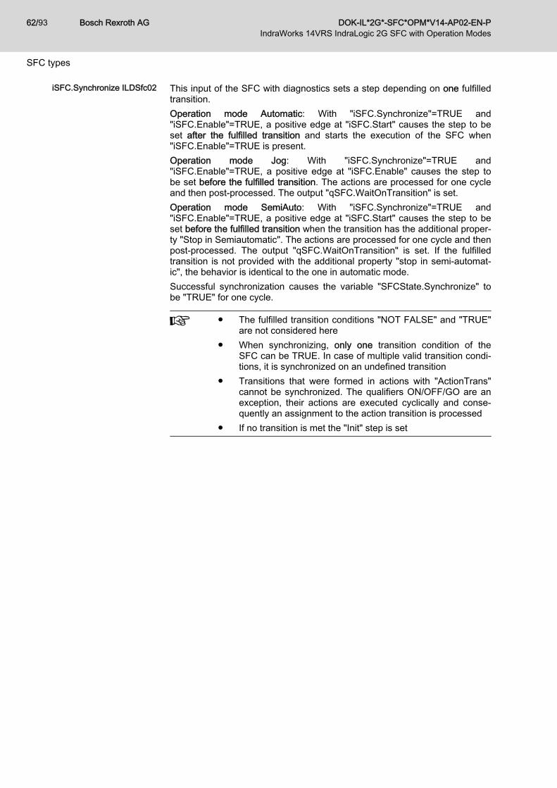
iSFC.Synchronize ILDSfc02 This input of the SFC with diagnostics sets a step depending on one fulfilledtransition.Operation mode Automatic: With "iSFC.Synchronize"=TRUE and"iSFC.Enable"=TRUE, a positive edge at "iSFC.Start" causes the step to beset after the fulfilled transition and starts the execution of the SFC when"iSFC.Enable"=TRUE is present.Operation mode Jog: With "iSFC.Synchronize"=TRUE and"iSFC.Enable"=TRUE, a positive edge at "iSFC.Enable" causes the step tobe set before the fulfilled transition. The actions are processed for one cycleand then post-processed. The output "qSFC.WaitOnTransition" is set.Operation mode SemiAuto: With "iSFC.Synchronize"=TRUE and"iSFC.Enable"=TRUE, a positive edge at "iSFC.Start" causes the step to beset before the fulfilled transition when the transition has the additional proper‐ty "Stop in Semiautomatic". The actions are processed for one cycle and thenpost-processed. The output "qSFC.WaitOnTransition" is set. If the fulfilledtransition is not provided with the additional property "stop in semi-automat‐ic", the behavior is identical to the one in automatic mode.Successful synchronization causes the variable "SFCState.Synchronize" tobe "TRUE" for one cycle.
● The fulfilled transition conditions "NOT FALSE" and "TRUE"are not considered here
● When synchronizing, only one transition condition of theSFC can be TRUE. In case of multiple valid transition condi‐tions, it is synchronized on an undefined transition
● Transitions that were formed in actions with "ActionTrans"cannot be synchronized. The qualifiers ON/OFF/GO are anexception, their actions are executed cyclically and conse‐quently an assignment to the action transition is processed
● If no transition is met the "Init" step is set
Bosch Rexroth AG DOK-IL*2G*-SFC*OPM*V14-AP02-EN-P62/93IndraWorks 14VRS IndraLogic 2G SFC with Operation Modes
SFC types

6 SFC diagnostics6.1 General information
SFCs of the type ILDSfc support automatically generated types of diagnos‐tics. Additional message types can be triggered directly in the SFC program.
6.2 Diagnostic overview in IndraWorks OperationDiagnostic overview The diagnostic overview in IndraWorks Operation lists the pending messages
as shown in the following example:● Number: ProVi error number● CA: Criteria analysis● Date: Date when the message occurred● Time: Time when the message occurred● Description: Describes the messageThe message highlighted in blue was selected using the mouse or the cursorkeys. For this message, additional information is displayed in the lower sec‐tion of the window.
Fig. 6-1: Diagnostic overviewDetailed view Press <F4> "Details" for further information on this message.
DOK-IL*2G*-SFC*OPM*V14-AP02-EN-P Bosch Rexroth AG 63/93IndraWorks 14VRS IndraLogic 2G SFC with Operation Modes
SFC diagnostics

Fig. 6-2: Detailed viewThe following additional information is shown in the "Selected info" window:● Type: There are four different types of diagnostics
1. MTX2. ProVi3. SFC messages:
– Active steps– Home position reached– Homing– Missing home position– Monitor error– Time error– Missing starting condition– Wait for transition
4. MLC● Class: Name of the Program Organization Unit in which the message
was programmed. The type of the POU is given behind it in brackets(PRG = program, FM = function module)
Bosch Rexroth AG DOK-IL*2G*-SFC*OPM*V14-AP02-EN-P64/93IndraWorks 14VRS IndraLogic 2G SFC with Operation Modes
SFC diagnostics

● POU instance: Instance name of the POU in which the message wasprogrammed
● Action: In case of time errors, the name of the step in which the erroroccurs is indicated. The identifier changes from "Action" to "Step". Forall other message types, the action causing the message is indicated
● Network/line: In case of monitor errors, the line in the action causing theerror is indicated. Otherwise, this line contains the network number
Criteria analysis In detailed view, press <F6> "Criteria analysis" to switch to the criteria analy‐sis.The criteria causing the error are identified for the selected error. These aredisplayed in IL view in a new window. A reduced view is selected when open‐ing the criteria analysis window. Reduced means that only those criteria thatcaused the error are displayed.
Fig. 6-3: Criteria analysis window - Reduced viewThe criteria analysis window is divided into three sections:● The upper part displays basic information on the message already avail‐
able in the detailed view. This facilitates keeping an overview on themessage the criteria analysis belongs to
● The centered section displays the relevant criteria (variables) of thepending message.
DOK-IL*2G*-SFC*OPM*V14-AP02-EN-P Bosch Rexroth AG 65/93IndraWorks 14VRS IndraLogic 2G SFC with Operation Modes
SFC diagnostics

The operator is displayed in IL syntax. The state of the variables can beTRUE or FALSE. The state when the message occurs is shown (snap‐shot).Press <F2> "Reduced/All contacts" to switch between the reduced view(displays only relevant network criteria) and full view (displays all net‐work criteria).
Fig. 6-4: Criteria analysis window - Full view● The lower section displays additional information on the variables used.
This additional information refers to the highlighted line in the centeredsection of the criteria analysis window and is obtained from the variabledeclaration.In this view, relevant criteria are highlighted in red and provided with anicon. The icon emphasizes the relevant lines
Exit the criteria analysis window with <F9> "Close".Additional information on the message types "Home position" and "Startingcondition":For criteria analysis of the home position and starting condition messages,the online status is always displayed. That means that the variable state isupdated on the display when it changes.
Bosch Rexroth AG DOK-IL*2G*-SFC*OPM*V14-AP02-EN-P66/93IndraWorks 14VRS IndraLogic 2G SFC with Operation Modes
SFC diagnostics

Fig. 6-5: Criteria analysis window - Display of causesFor easier identification purposes, a blue bar is displayed above the criteriaanalysis window during online status.Home position and start condition errors can be defined locally, globally or re‐lated to a module. The cause for a home position/start condition error can belocal and/or module-related and/or global.The criteria analysis displays all causes. It displays the global cause first,then the modular and finally the local cause. These causes are displayed onebelow the other. In full view, every cause is preceded by a header with thefollowing structure:Type: POU name (line number)Type = Global, module, localPOU name = Name of the POU in which the message was triggered(line number) = Line number in which the message was triggeredReplacing the scratch flagScratch flags are partial results in logic operations that are used again in sub‐sequent networks. Thus, the PLC program is more clearly structured andeasier to maintain. Often, many partial results are merged again in a separatenetwork at a later point.
DOK-IL*2G*-SFC*OPM*V14-AP02-EN-P Bosch Rexroth AG 67/93IndraWorks 14VRS IndraLogic 2G SFC with Operation Modes
SFC diagnostics

The criteria analysis calculation has previously not considered the scratchflags. Only the flags directly in the network line were taken into considerationfor the analysis.Now, also those flags composed of the scratch flags are considered duringthe analysis.
Fig. 6-6: Scratch flags in the networkNetwork2 causes a monitor error if the state of the assignment is "False".
Fig. 6-7: Criteria analysis scratch flagThe scratch flag causing the monitor error was replaced by the logic generat‐ing the scratch flag. The states of this logic caused the monitor error. Thenesting depth of the scratch flag is not limited. The scratch flags are only de‐termined within the POU, but not beyond the POU limits.The scratch flags are always automatically replaced. If no scratch flags areavailable, the criteria analysis corresponds to the previous analysis. Replac‐ing these scratch flags is identically calculated as for the ProVi messagesand for the diagnostics of non-executable operating screensThe scratch flags are replaced in frozen state as well as during the online cri‐teria analysis.
6.3 Diagnostic overview in IndraWorks EngineeringDiagnostic overview SFC messages can be displayed in IndraWorks Engineering. This facilitates
commissioning and optimization on the PLC program without using an HMI.The conditions are:1. A message is output by the SFC2. The control is switched to "Online" in IndraWorks Engineering3. The device diagnostics is switched on in IndraWorks Engineering under
Diagnostics ▶ Device diagnosticsThe diagnostic overview in IndraWorks Engineering lists the pending mes‐sages as shown in the following example:
Bosch Rexroth AG DOK-IL*2G*-SFC*OPM*V14-AP02-EN-P68/93IndraWorks 14VRS IndraLogic 2G SFC with Operation Modes
SFC diagnostics

Fig. 6-8: List of pending messages
DOK-IL*2G*-SFC*OPM*V14-AP02-EN-P Bosch Rexroth AG 69/93IndraWorks 14VRS IndraLogic 2G SFC with Operation Modes
SFC diagnostics

Bosch Rexroth AG DOK-IL*2G*-SFC*OPM*V14-AP02-EN-P70/93IndraWorks 14VRS IndraLogic 2G SFC with Operation Modes

7 Operating screensOperating screens can be freely configured. They are used to manually oper‐ate machines. Machine motions can be carried out via the machine functionkeys - short: M-keys - on the left and right side on the screen of the visualiza‐tion device. The current position of the moving axis as well as the states offreely configurable PLC variables can be displayed. The meaning of individu‐al states is determined while configuring the operating screen.The executability of a machine function - also referred to as motion signal -can be displayed with the corresponding status display.
Configuring operating screens The operating screens are configured in IndraWorks Engineering. New ope‐rating screens are created in the node of the selected visualization device.These operating screens contain one or more operating lines. Two motionscan be configured for each operating line and then activated using the corre‐sponding right or left M-key. Behind every motion there is an action or a stepwith several actions in which the motion is programmed.
Fig. 7-1: Configuration of a line from the motion screenThe previous example shows the configuration of a line from the operatingscreen. The action "AXISBQUP" was assigned to the M-key <UP>. At run‐time, this action state is analyzed and it is calculated whether this action is"executable". "Executable" means that at least one network whose logic isfulfilled exists within the networks of this action.
DOK-IL*2G*-SFC*OPM*V14-AP02-EN-P Bosch Rexroth AG 71/93IndraWorks 14VRS IndraLogic 2G SFC with Operation Modes
Operating screens

The executability display can be set for the PLC flag type "SFC flags" as wellas for the type "free flags". For free flags, a variable to display the executabili‐ty can be specified.Pressing the Action key switches to the option "Step".When executing an action, it has to be selected whether this action is calledby default ("Force") as processing with "ON-qualifier property" ("Force on") or"OFF-qualifier property" ("Force off").When using "ON"- and "OFF-" qualifier properties, the "Action" option has tobe selected. With the "Step" option, the calculation of the motion signal andthe corresponding diagnostics are not guaranteed.No optional variable can be assigned for SFC flags. The diagnostic magnifiercan be activated for "All modes", "Manual mode", "SFC" and "None" (see"EnMotionSignal" on page 75).
Fig. 7-2: Setting executability display for SFC flagsIn the operating screen line, the executability is displayed as a vertical bar incolor. The default colors are "blue" (executable) and "white" (non-executable)and can be configured by the user.
Fig. 7-3: Illustration of executabilityThe previous example shows an operating screen line with executability dis‐play. In this example, the executability is specified. Pressing the M-key <Left>executes the action or step linked with this step.
Bosch Rexroth AG DOK-IL*2G*-SFC*OPM*V14-AP02-EN-P72/93IndraWorks 14VRS IndraLogic 2G SFC with Operation Modes
Operating screens

● Even when executability is not given, this still has to belocked in the implementation, as otherwise undesired ma‐chine motion is possible
● Non-calculable executability is always displayed as TRUE ir‐respective of its actual executability. This can be caused bye.g. deactivating the motion signal or implementation of non-supported variables (see chapter 4.2 "Definition of the sup‐ported variables for the ProVi SFC diagnostics" on page 29)
Fig. 7-4: Operating screen in the IndraWorks Operation DesktopThe previous example shows several operating screen lines. Apart from thecentered operating line "Move HBQ4 vertically" (left M-key <Up>), all motionsare executable.
Incorrectly configured M-key Incorrectly configured M-keys are directly displayed on the button with the fol‐lowing symbol.
Fig. 7-5: Incorrectly configured M-keyThis error type is for example caused by a step/action that does not existanymore. In order to avoid incorrectly configured M-keys, use the "Validate"function in the context menu of the visualization device.
DOK-IL*2G*-SFC*OPM*V14-AP02-EN-P Bosch Rexroth AG 73/93IndraWorks 14VRS IndraLogic 2G SFC with Operation Modes
Operating screens

Diagnostic magnifier If motions are not executable or if the user releases the corresponding M-keyafter pressing it, the "diagnostic magnifier" opens. This window contains de‐tailed information for the user about the non-executable action (or step).
Fig. 7-6: Display of the diagnostic magnifier from an operating screenThe three-section structure of the diagnostic magnifier corresponds to the di‐agnostic display for the criteria analysis:● The upper section shows basic information on the action for which the
analysis is shown● The centered section shows the relevant criteria (variables) of the action
which prevent execution of the action.The operator is displayed in IL syntax. The state of the variables can beTRUE or FALSE. The current state is shown.Pressing <F2> "Reduced/All contacts" switches between reduced andfull display. The full view shows all lines which were not excluded fromthe analysis by the corresponding pragma (see "Monitor errors" on page46). The relevant lines are marked by a preceding icon.Note: By default, all networks are excluded from the executability dis‐play. To activate the relevant networks for executability, they have to beexplicitly configured in IndraLogic using the dialog Diagnostics -> SFC -Network Editor
Bosch Rexroth AG DOK-IL*2G*-SFC*OPM*V14-AP02-EN-P74/93IndraWorks 14VRS IndraLogic 2G SFC with Operation Modes
Operating screens

● The lower section displays additional information on the variables used.This additional information refers to the highlighted line in the centeredsection of the criteria analysis window.Exit the criteria analysis window with <F9> "Close"
EnMotionSignal The state of "EnMotionSignal" is only relevant in the "SFC" mode. In "SFC"mode, the signal "EnMotionSignal=TRUE/FALSE" enables/disables the diag‐nostic magnifier:
Operation mode EnMotionSignal Diagnostic magnifier
SFC TRUE(Default) Appears
SFC FALSE Does not appear
All operation modes Any Appears
Manual mode Any Appears only in manual mode
None Any Does not appear
Tab. 7-1: Overview on EnMotionSignal
DOK-IL*2G*-SFC*OPM*V14-AP02-EN-P Bosch Rexroth AG 75/93IndraWorks 14VRS IndraLogic 2G SFC with Operation Modes
Operating screens

Bosch Rexroth AG DOK-IL*2G*-SFC*OPM*V14-AP02-EN-P76/93IndraWorks 14VRS IndraLogic 2G SFC with Operation Modes

8 Application example8.1 General information
This chapter describes a use case for an SFC with diagnostics and operationmodes. In this example, a workpiece is to be moved on a rectangular path(from bottom to right, from right to top, from top to left and from left to bot‐tom). Proceed as follows:
Creating a new project Create a new project in IndraWorks and the desired control.Enabling diagnostics Enabling the ProVi SFC diagnostics in IndraWorks in the menu under Diag‐
nostics ▶ ProVi SFC diagnostics.
Fig. 8-1: Enabling diagnostic messagesCreating an SFC function block Select a new function block under Application ▶ Add ▶ POU... and configure
it in sequential function chart.
DOK-IL*2G*-SFC*OPM*V14-AP02-EN-P Bosch Rexroth AG 77/93IndraWorks 14VRS IndraLogic 2G SFC with Operation Modes
Application example

Fig. 8-2: New function block (set function block type and language)Calling an SFC function block Call the SFC function block from the main program "PlcProg".
Providing a function block with di‐agnostics
Provide a function block with diagnostics and operation modes via Diagnos‐tics ▶ SFC configuration editor... or via the context menu of the function blockSFC configuration editor.... Internal variables are automatically created in thedeclaration.
Bosch Rexroth AG DOK-IL*2G*-SFC*OPM*V14-AP02-EN-P78/93IndraWorks 14VRS IndraLogic 2G SFC with Operation Modes
Application example

Fig. 8-3: SFC Configuration EditorAfter the conversion, the program looks as follows:
Fig. 8-4: Converted SFCProgramming the "aUserIn" action Create a new action in the SFC function block with the name "aUserIn".
Program the "aUserIn" action now. The starting condition is a high signal atthe E-STOP switch. The home position is defined as "Stop Position Left" and"Stop Position Bottom".
DOK-IL*2G*-SFC*OPM*V14-AP02-EN-P Bosch Rexroth AG 79/93IndraWorks 14VRS IndraLogic 2G SFC with Operation Modes
Application example

Fig. 8-5: Programming the "aUserIn" actionCreating actions In addition, four additional actions are required to move the workpiece along
the rectangular path:● "aRight" moves the workpiece to the right● "aLeft" moves the workpiece to the left● "aUp" moves the workpiece upwards● "aDown" moves the workpiece downwardsAll actions are programmed according to the same scheme, variables withthe suffix "_i" being Boolean inputs (limit switches) and variables with the suf‐fix "_q" representing actuators.
Fig. 8-6: Creating actionsEditing an SFC function block Now, all required actions have been created. The SFC is at first programmed
for automatic mode. The flag "bStart_i" is used to start the SFC.
The comment in the step attributes should be used, since it is dis‐played in the visualization and thus increases the information con‐tained in the messages.
Bosch Rexroth AG DOK-IL*2G*-SFC*OPM*V14-AP02-EN-P80/93IndraWorks 14VRS IndraLogic 2G SFC with Operation Modes
Application example

Fig. 8-7: Editing an SFC function blockEditing transitions In this example, the transitions were edited in the programming language
"Structured Text".The transition conditions can be used either directly on the transition node(single variable) or as individual transition in ST.
Fig. 8-8: Editing a transitionEditing an SFC function block in
homingThe automatic branch is now complete. The homing branch is still missing.The workpiece is to be moved to the starting position "Bottom left" on theshortest way. This results in a homing branch for which the workpiece is firstmoved to the bottom and then to the left to the home position as well as asecond branch at which the workpiece is first moved to the left and then tothe bottom.
DOK-IL*2G*-SFC*OPM*V14-AP02-EN-P Bosch Rexroth AG 81/93IndraWorks 14VRS IndraLogic 2G SFC with Operation Modes
Application example
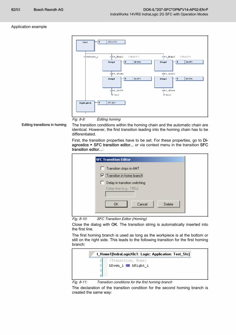
Fig. 8-9: Editing homingEditing transitions in homing The transition conditions within the homing chain and the automatic chain are
identical. However, the first transition leading into the homing chain has to bedifferentiated.First, the transition properties have to be set. For these properties, go to Di‐agnostics ▶ SFC transition editor... or via context menu in the transition SFCtransition editor...:
Fig. 8-10: SFC Transition Editor (Homing)Close the dialog with OK. The transition string is automatically inserted intothe first line.The first homing branch is used as long as the workpiece is at the bottom orstill on the right side. This leads to the following transition for the first homingbranch:
Fig. 8-11: Transition conditions for the first homing branchThe declaration of the transition condition for the second homing branch iscreated the same way:
Bosch Rexroth AG DOK-IL*2G*-SFC*OPM*V14-AP02-EN-P82/93IndraWorks 14VRS IndraLogic 2G SFC with Operation Modes
Application example

Fig. 8-12: Transition conditions for the second homing branchCreating a tool for tests To facilitate testing the SFC, a small program is created in the "PlcProg"
function module simulating the procedure.
Fig. 8-13: Test program for the SFCCompiling and loading a project The project can be compiled with Create ▶ Build. The compilation should not
output any error messages. If the project has not already been saved, save itnow. Load the project to the control and start the control.
Starting an SFC The forcing of inputs can now be used to control the SFC.Set the following inputs successively to "TRUE":● bEmergencyStop_i● bStart_i● Test_Sfc.iSFC.Enable● Test_Sfc.iSFC.StartThe SFC runs exactly one cycle and then returns to the Init step. The SFCcan be stopped and restarted at any given point in time via theTest_Sfc.iSFC.Start input.
Testing an SFC If an error occurs (e.g. input bEmergencyStop_i drops to "Low"), a mes‐sage appears in the variable Test_Sfc.qSFC.Message. Reset the mal‐function via the Test_Sfc.iSFC.Reset input.
Testing manual mode Manual mode is now tested. Switch the SFC to manual mode via theTest_Sfc.iSFC.Manual input. It is now possible to force either steps oractions. Step and action are only edited until the transition switches. Thismeans that no further programming is required for manual mode. All con‐
DOK-IL*2G*-SFC*OPM*V14-AP02-EN-P Bosch Rexroth AG 83/93IndraWorks 14VRS IndraLogic 2G SFC with Operation Modes
Application example

straints entered while creating the actions remain valid. The easiest way toforce is via the visualization of IndraLogic. However, it is also implemented inthe M-keys of the operator devices.
Fig. 8-14: Testing manual modeTesting homing mode Afterwards, the "Home position" has to be reached via "Homing". To do this,
set the Test_Sfc.iSFC.Home input to "TRUE" and theTest_Sfc.iSFC.Start input back to "HIGH". Then, the SFC returns to the"home position".
8.2 Additional examplesON and OFF qualifier If the ON or OFF qualifier is used, certain functions and network properties
are required within the action.Example:
Bosch Rexroth AG DOK-IL*2G*-SFC*OPM*V14-AP02-EN-P84/93IndraWorks 14VRS IndraLogic 2G SFC with Operation Modes
Application example

Fig. 8-15: Example: On/Off qualifier in the SFC
DOK-IL*2G*-SFC*OPM*V14-AP02-EN-P Bosch Rexroth AG 85/93IndraWorks 14VRS IndraLogic 2G SFC with Operation Modes
Application example

Fig. 8-16: Example: On/Off qualifier in the actionGO-qualifier With the GO-qualifier, REAL values can be transferred to an action.
Example:
Fig. 8-17: Example: GO-qualifier
8.3 System variables of the SFCThere are internal SFC variables which can be used within the chain.
Variable Description
ActionQ Active processing of this action without post-processing
ActionA Active processing of this action including post-processing
ActionON Enabling processing of this action
ActionOFF Disabling processing of this action
ActionGO Activating this action (only for action qualifier GO)
ActionValueReal Transfer value (REAL) of this action (only for GO)
Bosch Rexroth AG DOK-IL*2G*-SFC*OPM*V14-AP02-EN-P86/93IndraWorks 14VRS IndraLogic 2G SFC with Operation Modes
Application example

Variable Description
ActionTrans Transition condition of this action
ActionTransON Enabling transition condition of this action
ActionTransOFF Disabling transition condition of this action
ManualForcing Bypassing conditions in manual mode
SFCStateManual SFC is in "manual" mode
SFCStateAuto SFC is in "automatic" mode
Tab. 8-1: System variables of the SFC
The states are always only valid within the currently active action.The states are invalid in other actions or outside the SFC.IndraLogic always displays the variable state of the end of thePLC cycle. The online status display in an action can therefore bedifferent from the actual state.
Each step contains a data structure. The most important elements of thestructure are listed in the following:
Structure element Type Property Description
StepName.X BOOL Read-only Indicates whether the step is active(TRUE)
StepName.T TIME Read-only Returns the time since activation ofthe step
StepName.F BOOL Read and write In manual mode, the step can beactivated with TRUE
Tab. 8-2: SFC step data Each action contains a data structure. The most important elements of thestructure are listed in the following:
Structure element Type Property Description
ActionName.F BOOL Read and write In manual mode, the step can beactivated with TRUE
ActionName.FON TIME Read and write In manual mode ,the action can beactivated for ON processing withTRUE
ActionName.FOFF BOOL Read and write In manual mode, the action can beactivated for OFF processing withTRUE
ActionName.Trans BOOL Read-only Result of the action transition (Ac‐tionTrans) used as step transition
Tab. 8-3: SFC action data
DOK-IL*2G*-SFC*OPM*V14-AP02-EN-P Bosch Rexroth AG 87/93IndraWorks 14VRS IndraLogic 2G SFC with Operation Modes
Application example

Bosch Rexroth AG DOK-IL*2G*-SFC*OPM*V14-AP02-EN-P88/93IndraWorks 14VRS IndraLogic 2G SFC with Operation Modes

9 Service and supportOur worldwide service network provides an optimized and efficient support.Our experts offer you advice and assistance should you have any queries.You can contact us 24/7.
Service Germany Our technology-oriented Competence Center in Lohr, Germany, is responsi‐ble for all your service-related queries for electric drive and controls.Contact the Service Hotline and Service Helpdesk under:
Phone: +49 9352 40 5060Fax: +49 9352 18 4941E-mail: [email protected]: http://www.boschrexroth.com/
Additional information on service, repair (e.g. delivery addresses) and trainingcan be found on our internet sites.
Service worldwide Outside Germany, please contact your local service office first. For hotlinenumbers, refer to the sales office addresses on the internet.
Preparing information To be able to help you more quickly and efficiently, please have the followinginformation ready:● Detailed description of malfunction and circumstances● Type plate specifications of the affected products, in particular type co‐
des and serial numbers● Your contact data (phone and fax number as well as your e-mail ad‐
dress)
DOK-IL*2G*-SFC*OPM*V14-AP02-EN-P Bosch Rexroth AG 89/93IndraWorks 14VRS IndraLogic 2G SFC with Operation Modes
Service and support

Bosch Rexroth AG DOK-IL*2G*-SFC*OPM*V14-AP02-EN-P90/93IndraWorks 14VRS IndraLogic 2G SFC with Operation Modes
IndexAAbbreviations........................................................ 7About this documentation..................................... 3
Validity of the documentation........................... 3ANSI Z535.6-2006................................................ 5Application example SFC
Additional examples....................................... 84General information....................................... 77System variables of the SFC......................... 86
Application example SFC - Additional examplesGO-qualifier.................................................... 86
Application example: SFCCall SFC function block.................................. 78Compile and load project............................... 83Create actions................................................ 80Create new project......................................... 77Create SFC function block............................. 77Create tool for tests........................................ 83Edit SFC function block.................................. 80Edit SFC function block in homing................. 81Edit transitions............................................... 81Edit transitions in homing............................... 82Enable diagnostics......................................... 77Program "aUserIn" action.............................. 79provide function block with diagnostics.......... 78Start SFC....................................................... 83Test homing mode......................................... 84Test manual mode......................................... 83Test SFC........................................................ 83
Application example: SFC - Additional examplesON and OFF qualifier..................................... 84
BBasic settings
Condition for SFC diagnostics....................... 36Creating an SFC............................................ 34
CComplaints............................................................ 7Configure operating screens............................... 71Criticism................................................................ 7Customer Feedback.............................................. 7
DDiagnostics......................................................... 33
Module assignment editor.............................. 48Monitor errors................................................. 46Time errors..................................................... 45
FFeedback.............................................................. 7
HHazard warning..................................................... 5
Helpdesk............................................................. 89Hotline................................................................. 89
IInformation representation
Names and abbreviations................................ 7
OOpen module assignment editor......................... 48Operating screens............................................... 71
Diagnostic magnifier...................................... 74EnMotionSignal.............................................. 75
PPOU Program Organization Unit........................... 9Programming...................................................... 29
"Automatic" branch........................................ 40"Homing" branch............................................ 40Action transition ActionTrans......................... 38Basic settings................................................. 34Configure SFC............................................... 36Diagnostics.................................................... 45General information....................................... 29HomePosition & StartCondition..................... 41Incorrectly configured M-key.......................... 73Manual mode................................................. 40Transition properties...................................... 42
ProVi SFC diagnosticsExclude from ProVi SFC diagnostics............. 33
ProVi SFC diagnostics, definition........................ 29Declarable variable types............................... 29Diagnostic limit values................................... 34Instantiation.................................................... 31Restrictions.................................................... 31
SSafety alert symbol............................................... 5Safety instructions................................................. 5Sequence description of the SFC....................... 13
Action processing........................................... 15Action qualifier............................................... 17Action sequence............................................ 16ActionA, ActionQ............................................ 16Alternative branching..................................... 14Cyclic action processing................................ 19General information....................................... 13GO- and GOdi-qualifier.................................. 20ON- and OFF-qualifier............................. 19, 25Parallel branching.......................................... 15Post-processing examples............................. 17Post-processing of actions............................. 16Process SFC.................................................. 21Signal-time diagram GO- and GOdi-quali‐fiers................................................................ 27Signal-time diagram ON-/OFF-qualifiers........ 28
DOK-IL*2G*-SFC*OPM*V14-AP02-EN-P Bosch Rexroth AG 91/93IndraWorks 14VRS IndraLogic 2G SFC with Operation Modes
Index

Signal-time diagram qualifiers........................ 21Signal-time diagram qualifiers P/P0/P1......... 26Signal-time diagram: Post-processingwith N-qualifier............................................... 21Step - Minimum time...................................... 14Transition condition........................................ 13Transition delay.............................................. 14
Sequential description of the SFCSteps/transitions............................................ 13
Service hotline.................................................... 89SFC diagnostics.................................................. 63
Criteria analysis............................................. 65Detailed view.................................................. 63Diagnostic overview in IndraWorks Engi‐neering........................................................... 68Diagnostic overview in IndraWorks Oper‐ation............................................................... 63General information....................................... 63
SFC types........................................................... 51General information....................................... 51iSFC.Synchronize ILDSfc02.......................... 62SFC types ILDSfc01...................................... 51SFC types ILDSfc02...................................... 51Signal-time diagram SFC type ILDSfc02....... 54
SFC with operation modes.................................... 9Cascaded machine states.............................. 11Criteria analysis............................................. 10Diagnostic messages..................................... 10Diagnostics...................................................... 9Different SFC types.......................................... 9Module........................................................... 10Operation modes............................................. 9SFC diagnostics............................................... 9What is an SFC with operation modes?........... 9
Signal words......................................................... 5Suggestions.......................................................... 7Support............................................................... 89Symbols used....................................................... 7Syntax of module assignment............................. 48
TTransition properties
Configure transition delay.............................. 44Transition for home position branch............... 43Transition for semi-automatic......................... 42
WWarnings............................................................... 5
Bosch Rexroth AG DOK-IL*2G*-SFC*OPM*V14-AP02-EN-P92/93IndraWorks 14VRS IndraLogic 2G SFC with Operation Modes
Index

Notes
DOK-IL*2G*-SFC*OPM*V14-AP02-EN-P Bosch Rexroth AG 93/93IndraWorks 14VRS IndraLogic 2G SFC with Operation Modes

Bosch Rexroth AGElectric Drives and ControlsP.O. Box 13 5797803 Lohr, GermanyBgm.-Dr.-Nebel-Str. 297816 Lohr, GermanyPhone +49 9352 18 0Fax +49 9352 18 8400www.boschrexroth.com/electrics
*R911344490*R911344490
DOK-IL*2G*-SFC*OPM*V14-AP02-EN-P


![IndraLogic XLC – the powerful PLC system for efficient ... · the powerful PLC system for efficient automation &RPHUFLDO$QGDOX]DGH7pFQLFDV\6XPLQLVWURV 6 / &$76 6 / 0iODJD ... ·](https://static.fdocuments.in/doc/165x107/5b0d8da47f8b9a2c3b8d5ff5/indralogic-xlc-the-powerful-plc-system-for-efficient-powerful-plc-system.jpg)