Edition 01 Engineering 07VRS - Bosch Rexroth · PDF fileRexroth IndraWorks Engineering 07VRS...
222
Rexroth IndraWorks Engineering 07VRS R911320741 Edition 01 Electric Drives and Controls Pneumatics Service Linear Motion and Assembly Technologies Hydraulics
Transcript of Edition 01 Engineering 07VRS - Bosch Rexroth · PDF fileRexroth IndraWorks Engineering 07VRS...
Rexroth IndraWorksEngineering 07VRS
R911320741Edition 01
Operation and Programming Guide
Electric Drivesand Controls Pneumatics Service
Linear Motion and Assembly TechnologiesHydraulics

Rexroth IndraWorksEngineering 07VRS
Operation and Programming Guide
DOK-IWORKS-ENGINEE*V07-AW01-EN-P
RS-f6aae24c7173a3640a6846a001e2db63-1-en-US-3
Edition Release Date Notes
120-2700-B310-01/EN 06/2007 First Issue V07
Copyright © 2006 Bosch Rexroth AGCopying this document, giving it to others and the use or communication of thecontents thereof without express authourity, are forbidden. Offenders are liablefor the payment of damages. All rights are reserved in the event of the grant ofa patent or the registration of a utility model or design (DIN 34-1).
Validity The specified data is for product description purposes only and may not bedeemed to be guaranteed unless expressly confirmed in the contract. All rightsare reserved with respect to the content of this documentation and the availa‐bility of the product.
Published by Bosch Rexroth AGBgm.-Dr.-Nebel-Str. 2 ■ D-97816 Lohr a. MainTelefon +49 (0)93 52/ 40-0 ■ Fax +49 (0)93 52/ 40-48 85http://www.boschrexroth.com/Dept. BRC/EAC4 (JaWa)
Note This document has been printed on chlorine-free bleached paper.
Title
Type of Documentation
Document Typecode
Internal File Reference
Record of Revision
Bosch Rexroth AG | Electric Drivesand Controls
Rexroth IndraWorks | Operation and Programming Guide

Table of ContentsPage
1 Basics............................................................................................................................ 11.1 General Information ............................................................................................................................... 11.2 About this Manual................................................................................................................................... 11.2.1 General Information ............................................................................................................................ 11.2.2 Elements of the IndraWorks User Interface ........................................................................................ 21.2.3 Title, Menu and Status Bar ................................................................................................................. 21.2.4 Toolbars .............................................................................................................................................. 21.2.5 working Area........................................................................................................................................ 3
General Information ......................................................................................................................... 3Document Windows ......................................................................................................................... 3Tool Windows .................................................................................................................................. 4Arranging the Windows ................................................................................................................... 4
1.2.6 Project Explorer................................................................................................................................... 5General Information ......................................................................................................................... 5Project ............................................................................................................................................. 5Decvice ............................................................................................................................................ 5
1.2.7 Library Explorer .................................................................................................................................. 51.3 Getting Started........................................................................................................................................ 51.3.1 General Information ............................................................................................................................ 51.3.2 Starting IndraWorks ............................................................................................................................ 51.3.3 Creating a New Project ....................................................................................................................... 51.3.4 Opening a Project ............................................................................................................................... 61.3.5 Adding a New Device to a Project ...................................................................................................... 71.3.6 Exiting IndraWorks ............................................................................................................................. 8
2 Working with IndraWorks............................................................................................... 92.1 General Information ............................................................................................................................... 92.2 Working with Projects and Devices ....................................................................................................... 92.2.1 Projects and Project Data.................................................................................................................... 92.2.2 Startup Picture .................................................................................................................................. 172.2.3 Devices.............................................................................................................................................. 18
Inserting Devices From the Library ................................................................................................ 18Devices in the Project Explorer ..................................................................................................... 20
2.2.4 Using the Library............................................................................................................................... 23General Information ....................................................................................................................... 23Function Areas .............................................................................................................................. 24Operation ....................................................................................................................................... 25
2.2.5 Archiving and Restoring Projects...................................................................................................... 25General Information ....................................................................................................................... 25Archiving Projects .......................................................................................................................... 25Archiving a Project on a File System ............................................................................................. 25Archiving a Project on a Device ..................................................................................................... 27Restoring Projects ......................................................................................................................... 30Restoring a Project from a File System ......................................................................................... 30
Operation and Programming Guide | Rexroth IndraWorks Electric Drivesand Controls
| Bosch Rexroth AG I/VI
Table of Contents

Page
Restoring a Project from a Device ................................................................................................. 332.2.6 Archiving and Restoring Workspaces................................................................................................ 36
General Information........................................................................................................................ 36Archiving a Workspace .................................................................................................................. 36Restoring a Workspace ................................................................................................................. 38
2.2.7 Activating the Project for the Operation Desktop .............................................................................. 392.2.8 Scan for Devices............................................................................................................................... 40
General Information ....................................................................................................................... 40Operation ....................................................................................................................................... 41
2.2.9 Offline and Online Mode.................................................................................................................... 47Offline Mode .................................................................................................................................. 47Online Mode .................................................................................................................................. 47
2.2.10 Switching Between Offline and Online.............................................................................................. 47What Happens During the Switch .................................................................................................. 47How to Proceed.............................................................................................................................. 48Communication Adjustment ........................................................................................................... 48Structure Adjustment ..................................................................................................................... 49Configuration Adjustment .............................................................................................................. 50Data Adjustment ............................................................................................................................ 50
2.3 Adding Files to an IndraWorks Project ................................................................................................ 502.3.1 General Information .......................................................................................................................... 502.3.2 Adding a File ..................................................................................................................................... 512.3.3 Editing a File ..................................................................................................................................... 522.3.4 Adding a New Element from the Templates to the Project ............................................................... 562.3.5 Removing a File from the Project ..................................................................................................... 572.4 Working with the Workspace ............................................................................................................... 572.4.1 General Information .......................................................................................................................... 572.4.2 Workspace Structure ........................................................................................................................ 572.4.3 Workspace......................................................................................................................................... 58
Creating a Workspace ................................................................................................................... 58Opening a Workspace ................................................................................................................... 58Deleting a Workspace ................................................................................................................... 59
2.4.4 Projects in the Workspace................................................................................................................. 59Adding Projects ............................................................................................................................. 59Opening a Project .......................................................................................................................... 59Deleting a Project .......................................................................................................................... 59
2.4.5 Properties ......................................................................................................................................... 602.4.6 Devices in Projects ........................................................................................................................... 602.5 Persistence .......................................................................................................................................... 602.6 Multilingual Projects ............................................................................................................................. 602.6.1 General Information .......................................................................................................................... 602.6.2 Defining the Master Language of a Project ...................................................................................... 612.6.3 Managing Project Languages ........................................................................................................... 612.6.4 External Project Translation ............................................................................................................. 63
General Information ....................................................................................................................... 63Exporting the Translation File from IndraWorks ............................................................................ 64
II/VI Bosch Rexroth AG | Electric Drivesand Controls
Rexroth IndraWorks | Operation and Programming Guide
Table of Contents

Page
Importing the Translation File to OpenOffice.org Calc .................................................................. 65Translating the Texts in OpenOffice.org Calc ................................................................................ 66Exporting the Translation File from OpenOffice.org Calc .............................................................. 67Importing the Translation File in IndraWorks ................................................................................. 68
2.7 Printing ................................................................................................................................................. 702.7.1 General Information .......................................................................................................................... 702.7.2 Print Settings .................................................................................................................................... 70
General........................................................................................................................................... 70Basic Buttons.................................................................................................................................. 70Table of Contents........................................................................................................................... 70Header, Footer............................................................................................................................... 71
2.7.3 Printing Project Data or Device Data................................................................................................. 72Overview ........................................................................................................................................ 72Print and Print Preview - Operating Mode...................................................................................... 77
2.8 User Management................................................................................................................................ 822.8.1 General Information .......................................................................................................................... 822.8.2 Activating the User Management ..................................................................................................... 832.8.3 Login and Logout, Change a Password ........................................................................................... 83
First Login as Administrator............................................................................................................ 83User Login...................................................................................................................................... 84User Logout.................................................................................................................................... 85Change Password dialog box......................................................................................................... 85Login with Reference Code and Key Code.................................................................................... 85
2.8.4 Configuring the User Management ................................................................................................... 86User List and Group List................................................................................................................. 86Creating a User.............................................................................................................................. 87Editing a User................................................................................................................................. 90Copying a User............................................................................................................................... 90Deleting a User............................................................................................................................... 90Locking or Unlocking a User........................................................................................................... 91Resetting the Password of a User.................................................................................................. 91Creating a Group............................................................................................................................ 91Editing a Group............................................................................................................................... 92Copying a Group............................................................................................................................ 92Deleting a Group............................................................................................................................ 92Editing the Permissions of a Group................................................................................................ 93
2.8.5 Settings ............................................................................................................................................. 932.8.6 Export and Import ............................................................................................................................. 94
Exporting a User Data Base........................................................................................................... 94Importing a User Data Base........................................................................................................... 94Import ACC001.DAT....................................................................................................................... 95
2.9 Login with EKS-Keys............................................................................................................................ 952.9.1 General.............................................................................................................................................. 952.9.2 Activating the EKS System in IndraWorks......................................................................................... 952.9.3 Installing the EKS USB Driver........................................................................................................... 962.9.4 Creating Users and Groups............................................................................................................. 103
Operation and Programming Guide | Rexroth IndraWorks Electric Drivesand Controls
| Bosch Rexroth AG III/VI
Table of Contents

Page
2.9.5 Reading the EKS Key Data in the PLC Program............................................................................. 1052.10 PLC Interface of the User Management............................................................................................. 1062.10.1 General Information......................................................................................................................... 1062.10.2 Activating the PLC Interface............................................................................................................ 1062.10.3 Login and Logout Users via a PLC Program................................................................................... 1072.10.4 Reading the Current User in the PLC Program............................................................................... 1072.10.5 Example: Changing Permission Levels via Key Switch................................................................... 108
Task.............................................................................................................................................. 108Configuration of the User Management........................................................................................ 109PLC program................................................................................................................................ 110
2.11 Firmware Management ...................................................................................................................... 1112.12 License Management ........................................................................................................................ 1122.12.1 Licensing of IndraWorks Components............................................................................................. 112
General Information ..................................................................................................................... 112Installing a License ...................................................................................................................... 112Deleting a License ....................................................................................................................... 114
2.12.2 Licensing Firmware Functions......................................................................................................... 114General Information ..................................................................................................................... 114Enabling Firmware Functions ...................................................................................................... 116Deleting Firmware Licenses ........................................................................................................ 116
2.13 Network Connection........................................................................................................................... 1172.13.1 General Information......................................................................................................................... 1172.13.2 Creating a Network Configuration................................................................................................... 117
General Information...................................................................................................................... 117Adding Devices to the Network Configuration.............................................................................. 117Editing Device Properties............................................................................................................. 118Changing the Order...................................................................................................................... 119Removing a Device...................................................................................................................... 119Saving a Network Configuration................................................................................................... 119Closing the Editor......................................................................................................................... 120
2.13.3 Opening an Existing Network Configuration.................................................................................... 1202.13.4 Inserting a Network Configuration in a Project................................................................................ 1212.14 Remote Engineering........................................................................................................................... 1222.14.1 General Information......................................................................................................................... 1222.14.2 Enabling and Disabling the “Remote Engineering” on the Operation Station ................................. 123
Enabling........................................................................................................................................ 123Disabling....................................................................................................................................... 125
2.14.3 Operations at the Projection Station................................................................................................ 127Connecting to the Operation Station............................................................................................ 127Remote Engineering..................................................................................................................... 127Disconnect from Operation Station............................................................................................... 128Disconnecting Existing Network Drives........................................................................................ 128
2.15 Remote Service ................................................................................................................................. 1282.15.1 General Information ........................................................................................................................ 1282.15.2 I-Remote Client Software ............................................................................................................... 1292.16 External Applications ......................................................................................................................... 130
IV/VI Bosch Rexroth AG | Electric Drivesand Controls
Rexroth IndraWorks | Operation and Programming Guide
Table of Contents

Page
2.16.1 General Information ........................................................................................................................ 1302.16.2 Adding an Application or HTML Page ............................................................................................ 1312.16.3 Changing the Properties of an Application ..................................................................................... 1322.16.4 Changing the Properties of an HTML Page .................................................................................... 1322.16.5 Removing an Application or HTML Page ....................................................................................... 1332.17 Options Dialog ................................................................................................................................... 1332.17.1 General Information ........................................................................................................................ 1332.17.2 Function Areas ............................................................................................................................... 1332.17.3 Operation ........................................................................................................................................ 1342.17.4 General Options ............................................................................................................................. 134
Language Settings ....................................................................................................................... 134Software Licenses ....................................................................................................................... 134Keyboard (Shortcuts) ................................................................................................................... 134Projects ........................................................................................................................................ 135
2.18 Customizing Dialog ............................................................................................................................ 1362.19 Info ..................................................................................................................................................... 1362.20 Message Box ..................................................................................................................................... 1372.21 Help.................................................................................................................................................... 1382.21.1 IndraWorks Online Help ................................................................................................................. 138
3 Operation of the Oscilloscope Function..................................................................... 1433.1 General Information............................................................................................................................ 1433.2 Starting the Oscilloscope Function .................................................................................................... 1433.3 Online and Offline Modes................................................................................................................... 1433.3.1 Starting in the Offline Mode ............................................................................................................ 1433.3.2 Starting in the Online Mode / Switching to the Online Mode .......................................................... 1443.4 Operation Areas ................................................................................................................................. 1463.4.1 General Information......................................................................................................................... 1463.4.2 Measure........................................................................................................................................... 1463.4.3 Analysis........................................................................................................................................... 1473.4.4 Bit Analysis...................................................................................................................................... 1483.4.5 Frequency Response...................................................................................................................... 1493.4.6 Contour Error................................................................................................................................... 1503.4.7 Contour Diagram............................................................................................................................. 1513.4.8 Circle Test....................................................................................................................................... 1523.5 Recording a New Measurement ........................................................................................................ 1533.5.1 General Information ........................................................................................................................ 1533.5.2 Connecting Devices and Selecting Signals .................................................................................... 1533.5.3 Configuring the Current Measurement ........................................................................................... 1553.5.4 Configuring the Trigger ................................................................................................................... 156
General Information ..................................................................................................................... 156Manual Trigger............................................................................................................................. 157Signal Trigger .............................................................................................................................. 159Triggering with Binary Signals ..................................................................................................... 160
3.6 Starting the Measurement ................................................................................................................. 1623.7 Graphical Display................................................................................................................................ 163
Operation and Programming Guide | Rexroth IndraWorks Electric Drivesand Controls
| Bosch Rexroth AG V/VI
Table of Contents

Page
3.7.1 Signal Overview .............................................................................................................................. 1633.7.2 Graphic ........................................................................................................................................... 1643.7.3 Zoom............................................................................................................................................... 166
Zooming in an Area ..................................................................................................................... 166Zoom Levels ................................................................................................................................ 167Show Line Cursor ........................................................................................................................ 168Zooming between the Line Cursors ............................................................................................. 168
3.7.4 Moving Active Signal in Y Direction ................................................................................................ 1683.7.5 Scaling Active Signal in Y Direction ................................................................................................ 1683.7.6 Automatic support for scaling,......................................................................................................... 169
Absolute and Full Scaling ............................................................................................................ 169Enlarging the Active Signal in Y Direction ................................................................................... 170Manual Scaling ............................................................................................................................ 170Fixed Scaling ............................................................................................................................... 171
3.7.7 Changing the Graphic Mode............................................................................................................ 171Interpolated Measurement Curve ................................................................................................ 171Real Measurement Curve ............................................................................................................ 172Display of the Single Measured Points ........................................................................................ 173
3.8 Logic Analyzer ................................................................................................................................... 1743.9 Computations ..................................................................................................................................... 1793.9.1 General Information ........................................................................................................................ 1793.9.2 General Computation Formula ....................................................................................................... 1793.9.3 Summation ..................................................................................................................................... 1873.9.4 Options for the Computation............................................................................................................ 188
Selecting Computations ............................................................................................................... 188Fast Fourier Transformation FFT ................................................................................................ 189Frequency Response .................................................................................................................. 191Contour Deviation ........................................................................................................................ 196Contour Diagram ......................................................................................................................... 200Circle Test ................................................................................................................................... 204
3.10 Loading and Saving a Measurement ................................................................................................. 2053.10.1 General Information ........................................................................................................................ 2053.10.2 Import Configuration, Export Configuration .................................................................................... 2063.10.3 Import Measurement, Export Measurement ................................................................................... 2063.10.4 Measurement in the Project Submenu............................................................................................ 206
General Information ..................................................................................................................... 206Load Measurement ...................................................................................................................... 206Save Measurement ..................................................................................................................... 207Import Measurement into the Project .......................................................................................... 207Export Measurement from Current Project .................................................................................. 207
3.11 Document Window in Clipboard ........................................................................................................ 2083.12 Exporting a Measurement as Text File .............................................................................................. 2083.13 References ........................................................................................................................................ 208
Index.......................................................................................................................... 209
VI/VI Bosch Rexroth AG | Electric Drivesand Controls
Rexroth IndraWorks | Operation and Programming Guide
Table of Contents

1 Basics1.1 General Information
IndraWorks is the carrier system for integration of the Bosch Rexrothengineering tools.Cross-sectional functions, such as project navigation and project administrationas well as the generation of project and configuration data, are executed in acentralized manner.Basically, there are two types of integration:● When full integration is used, all operator actions are performed in the
main window of IndraWorks.Examples include parameterization of units in an IndraWorks project orconfiguration of HMI control elements for visualization panels.
● The connection to IndraWorks allows comfortable integration of 3rd partytools. 3rd party tools can be called directly from the IndraWorks projectmanagement in their own display format.This type of integration is, for example, used for PLC programming andHMI image configuration.
1.2 About this Manual1.2.1 General Information
This manual contains information about:chapter 1.2.2 "Elements of the IndraWorks User Interface " on page 2provides an overview of the visual components of IndraWorks and explains theirfunctions.chapter 1.3 "Getting Started" on page 5provides instructions and templates for facilitating the use of IndraWorks.chapter 2.1 "General Information " on page 9contains a detailed description of the most important parts of IndraWorks.
Operation and Programming Guide | Rexroth IndraWorks Electric Drivesand Controls
| Bosch Rexroth AG 1/212
Basics

1.2.2 Elements of the IndraWorks User Interface
1 Workspace2 Project3 Device4 Project Explorer5 Menu6 Toolbars7 Library8 Library info9 Working area10 Output window and diagnoses11 Status barFig.1-1: IndraWorks user interface
1.2.3 Title, Menu and Status Bar The main window of IndraWorks is enclosed by the title bar and menu bar aswell as the status bar.The title bar shows the name of the window that is active in the working area.The menu bar contains the menu entries with the corresponding commands.Select a command to execute an action.The status bar provides information on the current project and on the menucommands.
1.2.4 Toolbars Toolbars permit quick access to frequently used menu entries and buttons.
2/212 Bosch Rexroth AG | Electric Drivesand Controls
Rexroth IndraWorks | Operation and Programming Guide
Basics

You can create your own toolbars and add menus and buttons. The new tool‐bars will then appear in View ▶ Toolbars, where you can activate or deactivatethem.If you exit IndraWorks, the modifications to the toolbars and all new toolbarswill be saved. The last settings will be activated when IndraWorks is started thenext time.
Standard Toolbar When IndraWorks is started, the “Standard” toolbar will be shown below themain menu. If necessary, you can move this toolbar with the mouse or hide itby View ▶ Toolbars.
Fig.1-2: Standard toolbarIt provides the following commands:● Create new project (see main menu File ▶ New ▶ Project)● Open project (see main menu File ▶ Open ▶ Project)● Cut (see main menu Edit ▶ Cut)● Copy (see main menu Edit ▶ Copy)● Paste (see main menu Edit ▶ Paste)● Undo (see main menu Edit ▶ Undo)● Redo (see main menu Edit ▶ Redo)● Synchronize active project● Toolbars (see main menu Tools ▶ Customizing ▶ Toolbars)
1.2.5 working AreaGeneral Information
IndraWorks provides various options and tools supporting you with the man‐agement of the windows opened in the working area.There are two window types in IndraWorks: document windows and toolwindows.
Document Windows IndraWorks supports two types of displaying document windows – tabs and subwindows (MDI - Multiple Documents Interface).In the sub-window mode, all document windows are arranged in the workingarea. Several windows can be displayed at the same time (e. g. overlapping).In the tab mode, only one document window is displayed. It occupies the entireworking area. The other open document windows are represented as tabs atthe upper edge of the working area. To show such a window, just click on itstab.To switch between the two modes, select Windows ▶ Windows as Tabs.
Windows in the Working Area Double-click on an object in the project explorer to open a window in the workingarea. There, you can edit the data or properties of that object. Depending onthe object type, the window is a dialog box or an editor. All open documentwindows are listed in the Windows menu. To put a window to the foreground,select the corresponding menu item or click on a visible part of the window inthe working area.Select Windows ▶ Windows to open the “Window List” dialog where you canmanage the open windows in the working area.
Operation and Programming Guide | Rexroth IndraWorks Electric Drivesand Controls
| Bosch Rexroth AG 3/212
Basics

Fig.1-3: Window List dialog box
Tool Windows Tool windows are listed in View or in View ▶ Other Windows. To change thebehavior of the tool windows, either use the system menu (right-click on the titlebar of the tool window) or the Windows menu.
Dockable Tool windows are “dockable” by default. A tool window is opened either in thefloating mode or it is docked to the edge of the working area. To dock a floatingtool window to the edge of the working area, just deselect the “dockable” prop‐erty. The window will be arranged as an additional tab in the working area. Ifyou reselect the “dockable” property, the window will return to the position ithad taken before you arranged it in the working area.
Hide This command hides the active window. You can show the window again usingView menu.
Floating This command changes the window from floating mode to docked mode andvice versa.
Auto Hide This setting hides the tool windows at the edge of the border such that they areonly indicated by a tab displaying the window title. To maximize the windowagain, just move the mouse pointer over the tab. In this manner, the workingarea can be enlarged.
Arranging the Windows Overlapping, Cascading, Tiled In the sub-window mode, the windows in the working area can be arranged in
the overlapping, cascading and tiled modes. To achieve this, select the appro‐priate command from the Window menu.
Grouping Document Windows In the tab mode, document windows can be grouped. To achieve this, use thecommands of the system menu of the document windows. You can arrangedocument windows in vertical and horizontal groups and easily move them fromone group to the other.
In the tab mode, you can drag and drop document windows withinthe document window area.
System Menu of DocumentWindows
Using the system menu of the document windows in the sub-window mode, youcan minimize, restore, close and move these windows as well as zoom themin and out. Using the system menu in the tab mode, you can create new hori‐zontal and vertical groups, move document windows from one group to theother and close document windows. To activate the document windows oneafter the other, press <Ctrl>+<F6>.
4/212 Bosch Rexroth AG | Electric Drivesand Controls
Rexroth IndraWorks | Operation and Programming Guide
Basics

Full Screen To display as large an area of your document as possible on the screen, activatethe full-screen mode by selecting View ▶ Full Screen. All tool windows are hid‐den, and the working area occupies the entire remaining area. The menu baris still shown. The “Customizing” dialog allows you to add any toolbars. TheView menu allows you to display any tool window in the full-frame mode. Theconfiguration selected will be stored on exiting the full screen mode and will berestored when it is called the next time. To return to the normal display mode,click on the “Full Screen” button of the “Full Screen” toolbar. Alternatively, youcan also press<Ctrl>+<Alt>+<F> or use the menu.
1.2.6 Project ExplorerGeneral Information
The project explorer is arranged to the left of the working area in the IndraWorksmain window. The project explorer represents the projects and their compo‐nents in a structured manner.
ProjectA project contains all devices, communication connections and other compo‐nents required for operating a machine or system. The tree structure of thesecomponents reflects the device topology of the automation solution.
DecviceA device is a component of a project, e. g. a control or a drive. Usually, a deviceconsists of a hardware section and a software section.In IndraWorks, devices are selected from a library and added to a project. Thenthe functions available in the devices are called or lower-level devices are pro‐jected.
1.2.7 Library Explorer The library explorer is on the right of the working area in the IndraWorks mainwindow. It represents all libraries available for your projects in a structuredmanner. Libraries can contain hardware components, i. e. devices, and soft‐ware components, e. g. function blocks.
1.3 Getting Started1.3.1 General Information
This section describes some of the typical operating sequences in IndraWorks.Follow these descriptions, and you will become familiar with the use ofIndraWorks and recognize how the various components are cooperating witheach other.
1.3.2 Starting IndraWorksStart IndraWorks via Start ▶ All Programms ▶ Rexroth ▶ IndraWorks (Versionxxx) ▶ Engineering.
1.3.3 Creating a New Project To create a new IndraWorks project, select File ▶ New ▶ Project....The “Create New IndraWorks Project” dialog box will appear. Enter a name forthe project and select the directory where the project will be filed.
Operation and Programming Guide | Rexroth IndraWorks Electric Drivesand Controls
| Bosch Rexroth AG 5/212
Basics
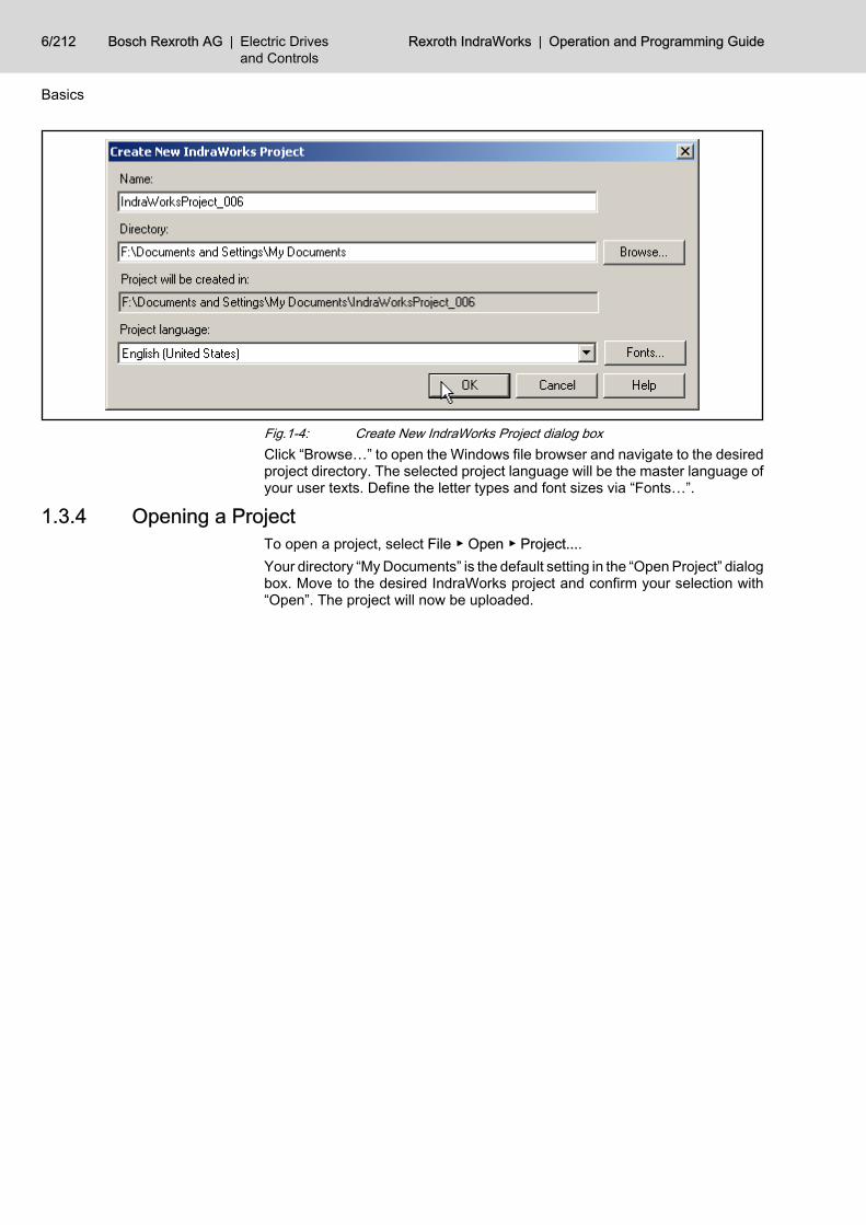
Fig.1-4: Create New IndraWorks Project dialog boxClick “Browse…” to open the Windows file browser and navigate to the desiredproject directory. The selected project language will be the master language ofyour user texts. Define the letter types and font sizes via “Fonts…”.
1.3.4 Opening a Project To open a project, select File ▶ Open ▶ Project....Your directory “My Documents” is the default setting in the “Open Project” dialogbox. Move to the desired IndraWorks project and confirm your selection with“Open”. The project will now be uploaded.
6/212 Bosch Rexroth AG | Electric Drivesand Controls
Rexroth IndraWorks | Operation and Programming Guide
Basics

Fig.1-5: Open Project dialog box
1.3.5 Adding a New Device to a Project The library explorer displays all available devices of the libraries installed.To add a device to the current project, drag the device from the library to theproject. You can drag the device only directly to the project folder or to devicesof the project which accept the currently selected device type as a subdevice.
Operation and Programming Guide | Rexroth IndraWorks Electric Drivesand Controls
| Bosch Rexroth AG 7/212
Basics
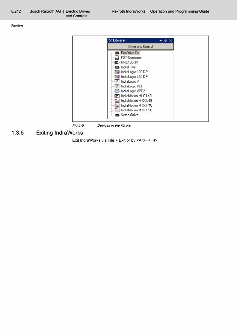
Fig.1-6: Devices in the library
1.3.6 Exiting IndraWorksExit IndraWorks via File ▶ Exit or by <Alt>+<F4>.
8/212 Bosch Rexroth AG | Electric Drivesand Controls
Rexroth IndraWorks | Operation and Programming Guide
Basics

2 Working with IndraWorks2.1 General Information
In IndraWorks, you will work with objects with various contents, called applica‐tion data. These objects can be created, managed, edited and filed in astructured manner, as files in an IndraWorks project. The workspace inIndraWorks consists of a top-level project. Each project can, in turn, contain acollection of folders and files. These objects are also called resources.
2.2 Working with Projects and Devices2.2.1 Projects and Project Data
In IndraWorks, devices and objects (resources) are compiled to projects whichare represented in a tree structure in the project explorer. A project is alwaysat the uppermost hierarchy level. Only one project can be processed at a time.All further nodes in the tree represent devices, communication connections,functions or merely structuring elements, e. g. folders, which are comparablewith directories in a file system. The figure below is an example of a project witha drive.
Operation and Programming Guide | Rexroth IndraWorks Electric Drivesand Controls
| Bosch Rexroth AG 9/212
Working with IndraWorks
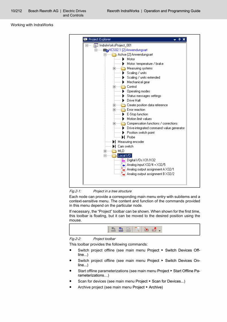
Fig.2-1: Project in a tree structureEach node can provide a corresponding main menu entry with subitems and acontext-sensitive menu. The content and function of the commands providedin this menu depend on the particular node.If necessary, the “Project” toolbar can be shown. When shown for the first time,this toolbar is floating, but it can be moved to the desired position using themouse.
Fig.2-2: Project toolbarThis toolbar provides the following commands:● Switch project offline (see main menu Project ▶ Switch Devices Off‐
line...)● Switch project offline (see main menu Project ▶ Switch Devices On‐
line...)● Start offline parameterizations (see main menu Project ▶ Start Offline Pa‐
rameterizations…)● Scan for devices (see main menu Project ▶ Scan for Devices...)● Archive project (see main menu Project ▶ Archive)
10/212 Bosch Rexroth AG | Electric Drivesand Controls
Rexroth IndraWorks | Operation and Programming Guide
Working with IndraWorks

● Restore project (see main menu Project ▶ Restore)Creating a New Project To create a new project, select File ▶ New ▶ Project... or press <Ctrl>+<Shift>
+<N>.Enter a project name in the “Create New IndraWorks Project” dialog box, andselect the directory where you wish to save the project. In the dialog box, selectthe master language for the project, i. e. the language used for creating theproject.You can also define the fonts for the text display, both for proportional fonts andfor monospace fonts. This is particularly recommended for languages requiringspecific fonts for displaying the text, e. g. Asiatic languages.
Fig.2-3: Create New IndraWorks Project dialog box, define master languageOpening an Existing Project You can load existing projects via File ▶ Open ▶ Project... or <Ctrl>+<Shift>
+<O>. The “Open Project” dialog shows all projects of the preset project path.First select the folder of the project desired and then the project file. The fileextension of project files is always “iwp”. The project is now uploaded.
Operation and Programming Guide | Rexroth IndraWorks Electric Drivesand Controls
| Bosch Rexroth AG 11/212
Working with IndraWorks

Fig.2-4: Open Project dialog boxRecent Projects The menu item File ▶ Recent Projects provides a list of the projects you have
processed recently. You can open a project by double-clicking on the respectiveentry in this list.
12/212 Bosch Rexroth AG | Electric Drivesand Controls
Rexroth IndraWorks | Operation and Programming Guide
Working with IndraWorks

Fig.2-5: Recent Projects menu itemClosing a Project Close an open project via File ▶ Close ▶ Project. All changes will be saved
automatically.Renaming a Project You can change the project name by clicking on the activated project, by using
the context-sensitive menu or by pressing <F2>.
Only the name of the project file “*.iwp” will be modified. The nameof the path or directory where the project name is stored remainsunchanged.
Properties To open the properties dialog, select a project and choose the item Proper‐ties in the context-sensitive menu. The properties dialog box displays theessential settings of the current project. In the selection window to the left, youcan move back and forth between path settings, modification times, states andversion control.
Operation and Programming Guide | Rexroth IndraWorks Electric Drivesand Controls
| Bosch Rexroth AG 13/212
Working with IndraWorks

Fig.2-6: Properties dialog box, Path SettingsSelecting “Path Settings” will provide information on the name and the memorylocation of the project.
Fig.2-7: Properties dialog box, TimesSelecting “Times” will display the creation time and the time of the last writeaccess and of the last read access.
14/212 Bosch Rexroth AG | Electric Drivesand Controls
Rexroth IndraWorks | Operation and Programming Guide
Working with IndraWorks

Fig.2-8: Properties dialog box, StatesSelecting “States” will display the current state (offline, online) and the projectlanguage selected.
Fig.2-9: Properties dialog box, version controlSelecting “Version Control” will display information on the project managementin the version control.
Save the project An edited project is identified by an asterisk following the project name in thetitle bar of the project explorer. To save an edited or new project, select the itemSave in the context-sensitive menu. When you close a project, all changes aresaved automatically.
Saving a Project As To save the open project to a different memory location with a different name,select File ▶ Save As.
Operation and Programming Guide | Rexroth IndraWorks Electric Drivesand Controls
| Bosch Rexroth AG 15/212
Working with IndraWorks

Fig.2-10: Save Project As dialog boxEnter a destination directory and a name for the project. After the dialog hasbeen exited with “OK”, IndraWorks saves and closes the current project andcreates a copy with the selected name in the specified destination directory.
All changes in the project structure and in the project data made upto that point will also be saved in the original project.The project information file “*.iwp” is not stored in the specified des‐tination directory, but in a new directory with the same name.
If the selected destination directory already exists, the process will be stoppedand a corresponding message is displayed
16/212 Bosch Rexroth AG | Electric Drivesand Controls
Rexroth IndraWorks | Operation and Programming Guide
Working with IndraWorks

Fig.2-11: Save Project As, error message
2.2.2 Startup Picture Unless a project has been uploaded, the startup picture will be displayed au‐tomatically when the Engineering Desktop is started.This occurs in the follwing cases:● IndraWorks has been installed anew.● The project was closed before IndraWorks was exited the last time.● The setting causing the previous project to be uploaded on start has not
been activated.The startup picture provides various options of creating or opening a project.To activate an option, click on it or select it with <Tab> and <Enter>.Once a project is uploaded, the startup picture is closed. You can show thestartup picture at any time via View ▶ Show Startup Picture.
Fig.2-12: Startup Picture
Operation and Programming Guide | Rexroth IndraWorks Electric Drivesand Controls
| Bosch Rexroth AG 17/212
Working with IndraWorks

Create an Empty Project This function opens the “Create New IndraWorks Project” dialog box. It is equalto File ▶ New ▶ Project.
Scan for Devices This function creates an empty project with a defined name and starts thescanner to search for devices. Simultaneously, the view “Configure” will be ac‐tivated (see chapter 2.2.8 "Scan for Devices" on page 40).
Open Project This function opens a project which is filed to a local drive or a network drive.It is equal to File ▶ Open ▶ Project.
Restore Project This function restores a project from an archive on a local drive, a network driveor a removable disk. It is equal to Project ▶ Restore ▶ From File System.
Recent Projects The list of recently opened projects displays the project names and the chang‐ing date. To open a project, click on the project name. This function is equal toFile ▶ Recent Projects.
Hide on Next Startup If you activate this option, the startup picture will not be displayed automaticallywhen the Engineering Desktop is started.
2.2.3 DevicesInserting Devices From the Library
Add devices to a project by drag-and-drop or via the context-sensitive menu.context-sensitive menu The context-sensitive menu provides the commands available in the particular
context. The commands for editing devices, such as Cut, Delete, Copy andPaste, are also provided in the Edit menu. In contrast to the context-sensitivemenu, inactive items are visible in the main menu. They are displayed in gray.
Insert by Drag-and-Drop from theLibrary
Select a device from the library and drag it to the project explorer.
The form of the mouse pointer indicates possible insertion positions.An arrow with a plus sign on a destination device with blue background (in‐cluding the project itself) signals that the device can be inserted at this position.
Fig.2-13: Insert by Drag-and-Drop from the LibraryThe new device is added behind all devices of this element.A circle with a backslash signals that it is not possible to insert a device at thisposition.
18/212 Bosch Rexroth AG | Electric Drivesand Controls
Rexroth IndraWorks | Operation and Programming Guide
Working with IndraWorks

Fig.2-14: Insertion by drag-and-drop not allowedYou can also insert new devices in the project at certain selected positions.Move the mouse to the desired destination position. This position is representedby a line. The background color of the associated destination element changesto blue.In the first example, the new device is inserted below the SERCOS node.
Fig.2-15: Insertion at the desired destination positionIn the second example, the new device is inserted below the project node cret‐aed before.
Operation and Programming Guide | Rexroth IndraWorks Electric Drivesand Controls
| Bosch Rexroth AG 19/212
Working with IndraWorks

Fig.2-16: Insertion at the project nodeInsert via Clipboard You can also use the clipboard to add devices to a project.
Fig.2-17: Pasting devices from the clipboard
You can also paste devices from foreign components to the projectexplorer via the clipboard. This requires a complete description ofthe device as XML text in the clipboard .
Devices in the Project ExplorerDeleting Devices Delete devices by <Del> or use Delete.Cutting Devices Cut files a reference to the selected device to the clipboard.
The device prepared for cutting is identified by a special icon (arrow to the upperright) and by a gray font as long as the device information is in the clipboard.You can stop this process with <Esc>.
20/212 Bosch Rexroth AG | Electric Drivesand Controls
Rexroth IndraWorks | Operation and Programming Guide
Working with IndraWorks

If you paste the device at a new position, it will be removed from its originalposition.
Copying Devices Copy applies a copy of the selected element to the clipboard. You can nowpaste the element to the destination position.It is possible to paste the device directly to an element or to positions betweenelements.
Copying, Cutting and Pasting withthe Mouse
You can copy, cut and paste devices by drag-and-drop. Drag a device to an‐other possible position and it will be moved to that position. If you hold <Ctrl>while dragging, a copy of the device is created at the destination position.
Renaming Devices You can change the device name by clicking on the activated element, by thecontext-sensitive menu or by <F2>.The name of the element is displayed in the input mode. You can stop theediting process at any time with <Esc>. If the entered name is not accepted,the original name is automatically re-entered.
Opening Node Specific Dialogs andEditors
To open a dialog or editor associated to a project node, double-click on thatproject node or press <Enter>.
Tool Tips To show brief information on a device, place the mouse pointer on that devicefor more than one second.
Fig.2-18: Displaying tool tips for devicesDisplaying Error States If the device-specific software signals an error, the device in question is shown
with red letters. If this device is in a non-expanded part of the tree, the devicethat is visible at the next higher level in the hierarchy is shown in red. The in‐correct element itself is identified by a white cross on a red background in theicon. Additionally, an error text is provided.
Operation and Programming Guide | Rexroth IndraWorks Electric Drivesand Controls
| Bosch Rexroth AG 21/212
Working with IndraWorks

Fig.2-19: Displaying error states at devicesThis shows incorrect elements immediately in the tree structure.
Fig.2-20: Displaying error states at device nodesLocked Elements An element can be locked if, e. g., it cannot be reached in the particular context.
Locked elements are displayed in light-gray in the tree structure; the icon of thedevice is lightened. Such elements cannot be reached or modified by com‐mands any longer.
22/212 Bosch Rexroth AG | Electric Drivesand Controls
Rexroth IndraWorks | Operation and Programming Guide
Working with IndraWorks
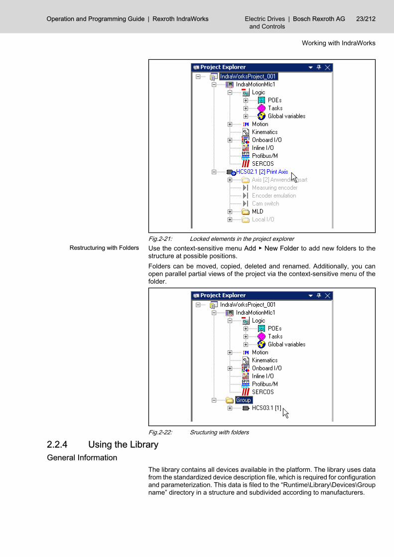
Fig.2-21: Locked elements in the project explorerRestructuring with Folders Use the context-sensitive menu Add ▶ New Folder to add new folders to the
structure at possible positions.Folders can be moved, copied, deleted and renamed. Additionally, you canopen parallel partial views of the project via the context-sensitive menu of thefolder.
Fig.2-22: Sructuring with folders
2.2.4 Using the LibraryGeneral Information
The library contains all devices available in the platform. The library uses datafrom the standardized device description file, which is required for configurationand parameterization. This data is filed to the “Runtime\Library\Devices\Groupname” directory in a structure and subdivided according to manufacturers.
Operation and Programming Guide | Rexroth IndraWorks Electric Drivesand Controls
| Bosch Rexroth AG 23/212
Working with IndraWorks
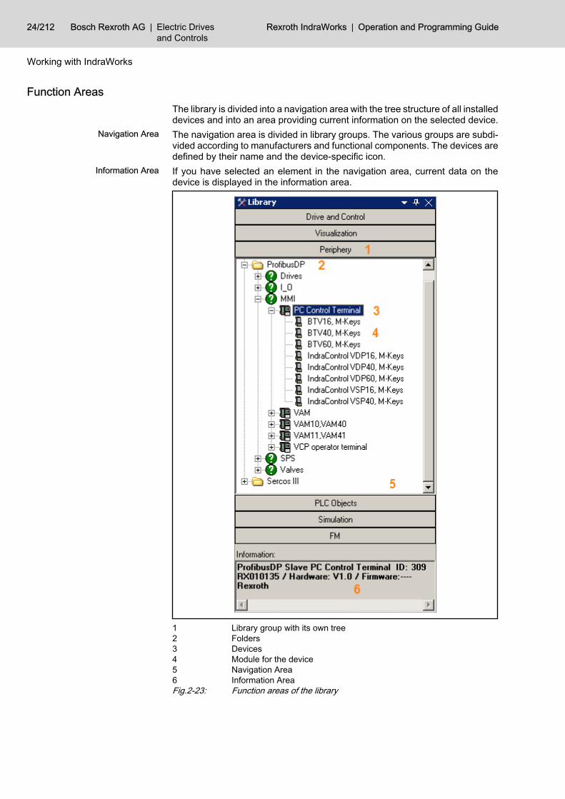
Function Areas The library is divided into a navigation area with the tree structure of all installeddevices and into an area providing current information on the selected device.
Navigation Area The navigation area is divided in library groups. The various groups are subdi‐vided according to manufacturers and functional components. The devices aredefined by their name and the device-specific icon.
Information Area If you have selected an element in the navigation area, current data on thedevice is displayed in the information area.
1 Library group with its own tree2 Folders3 Devices4 Module for the device5 Navigation Area6 Information AreaFig.2-23: Function areas of the library
24/212 Bosch Rexroth AG | Electric Drivesand Controls
Rexroth IndraWorks | Operation and Programming Guide
Working with IndraWorks

Operation Navigation You can navigate in the tree structure of the devices with the cursor keys and
with the mouse.To expand nodes at the “plus” sign, press <cursor right> or double-click; to closethe nodes at the “minus” sign, press <cursor left> or double-click.
Adding Devices to the Project Use drag-and-drop to add devices from the library to the project navigator. (seechapter "Inserting Devices From the Library " on page 18) After insertion, thesoftware package of the device is started.You can also use the clipboard by Copy and Paste to add devices.
Expanding the Library Devices are added by copying new device description files or complete struc‐tures to the “Runtime\Library\Devices\Group name” directory. These data willbe automatically applied to the graphical display when the platform is startedthe next time. Copying data on the level of library groups is not allowed.
2.2.5 Archiving and Restoring ProjectsGeneral Information
IndraWorks provides the option of archiving projects on the local file system oron an FTP server (device or computer) connected through a network. Thesearchives can be restored on the file system of the local computer.A wizard supports the working with project archives. If the entered values arecorrect, you can move between the pages of the wizard by “<<Back” and“Next>>”. When a page is opened for the first time, the input boxes containdefault values. Otherwise, your last entries will be displayed. You can exit thewizard at any time with “Cancel”. Values entered up to that point will not besaved; the archiving process is stopped.
Archiving ProjectsTo archive a project, select it in the project explorer and choose Archive… fromthe context-sensitive menu, Project ▶ Archive in the main menu, or the followingbutton from the toolbar:
Fig.2-24: Project toolbar
Archiving a Project on a File System Selecting the Archiving Type The first page of the wizard prompts you to select whether you wish to save the
archive on a local file system or on an FTP server (device or computer) con‐nected through a network. Select here “Archive on file system”.
Settings for Destination Archive On the next page you can define the filing location, the name of the archive anda comment. Enter a directory of the local file system for the filing location orselect it via “…”.Optionally, the archive can be protected by a password. Enter the password asecond time in “Confirm password” to verify your entry.
Operation and Programming Guide | Rexroth IndraWorks Electric Drivesand Controls
| Bosch Rexroth AG 25/212
Working with IndraWorks

Fig.2-25: Archiving a project on a file system; destination archive settingsChecking the User Entries This page allows to check your settings. Start the creation of the archive via the
“Finish” button.
Fig.2-26: Archiving a project on a file system; check of entriesProgress Bar “Create Archive” The archive is created in the destination directory of the local computer. This
process is displayed in a progress bar.
26/212 Bosch Rexroth AG | Electric Drivesand Controls
Rexroth IndraWorks | Operation and Programming Guide
Working with IndraWorks

Summary After the archiving the settings and results are displayed.
To avoid inconsistencies during archiving, the active project isclosed before archiving and re-opened afterwards.
Fig.2-27: Archiving a project on a file system; archiving results
Archiving a Project on a Device Selecting the Archiving Type The first page of the wizard prompts you to select whether you wish to save the
archive on a local file system or on an FTP server (device or computer) con‐nected through a network. Select here “Archiving on FTP server (device orcomputer)”.
Settings for Destination Archive On this page, you can define the destination device, the name of the archiveand a comment.
Operation and Programming Guide | Rexroth IndraWorks Electric Drivesand Controls
| Bosch Rexroth AG 27/212
Working with IndraWorks

Fig.2-28: Archiving a project on a device; settings for destination archiveDevice Name, Host Name or IP Ad‐
dressEnter the destination device for saving the archive in the “Device name, hostname or IP address” input box. You can do this in four ways:● Enter the IP address (nnn.nnn.nnn.nnn)● Enter the computer name of the destination device● Select the destination device via a drop-down list. This list box contains
all FTP capable devices of the active project as well as the five destinationdevices (device name, host name or IP address) last used in archiving.
● Select a device via the “…” browser button. Apply the destination devicefrom the list of all FTP capable devices of the active project.
Archive Name, Comment, Pass‐word
Enter a name for filing the archive to the destination device. You can also entera comment related to the archive.Optionally, the archive can be protected by a password. Enter the password asecond time in “Confirm password” to verify your entry.
Establishing the Connection Confirm with “Next>>”. The wizard will automatically establish a connection tothe destination device. Disturbances in the connection to the destination deviceare displayed in error messages.
Checking the User Entries This page allows to check your settings. Start the creation of the archive via the“Finish” button.
28/212 Bosch Rexroth AG | Electric Drivesand Controls
Rexroth IndraWorks | Operation and Programming Guide
Working with IndraWorks

Fig.2-29: Arcive a project on a device; check of entries1. Progress Bar “Create Temporary
Archive”On archiving, a temporary archive will be created on the local computer first.This process is shown in a progress bar.
2. Progress Bar “Copy Archive toDestination Device”
Then, the archive is copied to the destination device. This process is shown inanother progress bar.
Summary After archiving has been completed, settings and results are displayed in asummary.
To avoid inconsistencies during archiving, the active project isclosed before archiving and re-opened afterwards.
Operation and Programming Guide | Rexroth IndraWorks Electric Drivesand Controls
| Bosch Rexroth AG 29/212
Working with IndraWorks
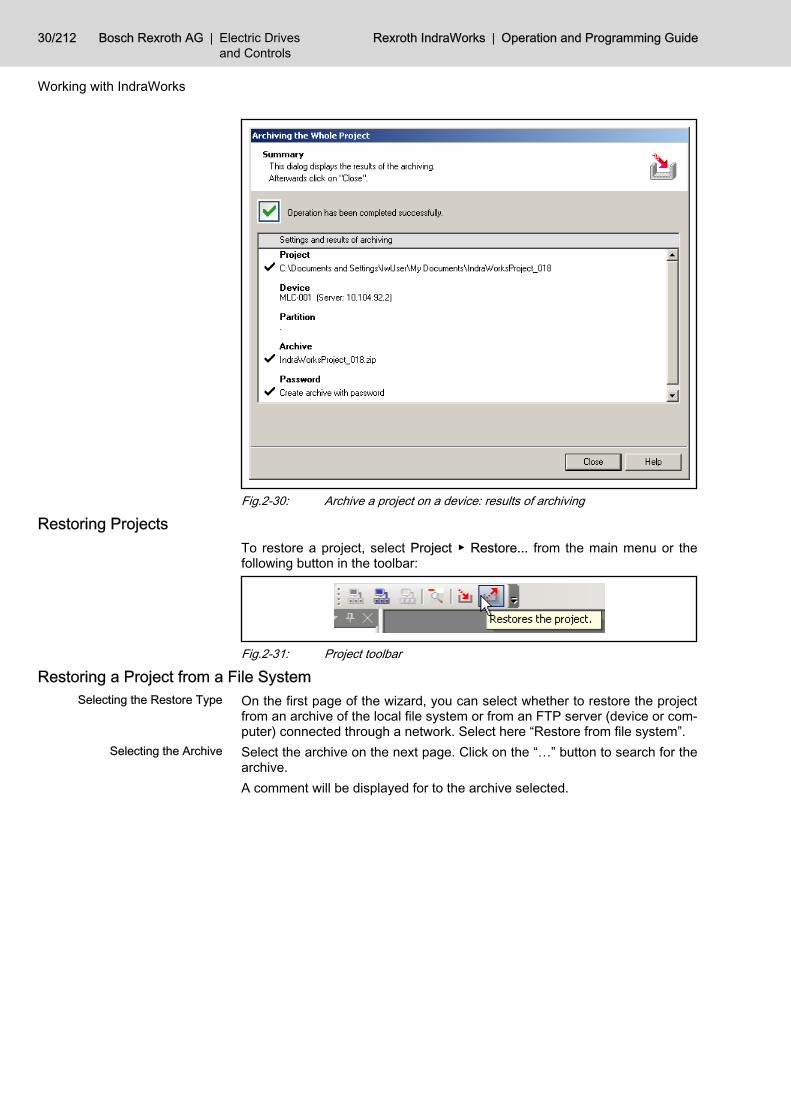
Fig.2-30: Archive a project on a device: results of archiving
Restoring ProjectsTo restore a project, select Project ▶ Restore... from the main menu or thefollowing button in the toolbar:
Fig.2-31: Project toolbar
Restoring a Project from a File System Selecting the Restore Type On the first page of the wizard, you can select whether to restore the project
from an archive of the local file system or from an FTP server (device or com‐puter) connected through a network. Select here “Restore from file system”.
Selecting the Archive Select the archive on the next page. Click on the “…” button to search for thearchive.A comment will be displayed for to the archive selected.
30/212 Bosch Rexroth AG | Electric Drivesand Controls
Rexroth IndraWorks | Operation and Programming Guide
Working with IndraWorks

Fig.2-32: Restoring a project from a file system; selecting the archive
If the archive type is unknown, the comment area will display themessage “***ATTENTION! The selected archive is not anIndraWorks project archive ***”. In this case, you can continue therestore process after having confirmed a safety prompt.
Selecting the Destination Directory On the next page, select the directory to which you wish to restore the project.
Operation and Programming Guide | Rexroth IndraWorks Electric Drivesand Controls
| Bosch Rexroth AG 31/212
Working with IndraWorks

Fig.2-33: Restoring a project from a file system; select destination directoryChecking the User Entries Here you can check your settings. Start the restore of the project from the ar‐
chive by “Finish”.
Fig.2-34: Restoring a project from a file system; check of entriesEntering the Password If you have protected the archive with a password, you will now be prompted
to enter that password.
32/212 Bosch Rexroth AG | Electric Drivesand Controls
Rexroth IndraWorks | Operation and Programming Guide
Working with IndraWorks

Progress Bar “Restore on Tempo‐rary Directory”
First the project is restored from the archive to a temporary directory of the localdrive. This process is displayed in a progress bar. After restore, the project iscopied to the destination directory.If a project folder already exists in the specified destination directory, you willbe prompted to rename the project folder.
Fig.2-35: Restoring a project from a file system; renaming the project folderSummary After restoration, settings and results are displayed.
Fig.2-36: Restoring a project from a file system; results
Restoring a Project from a Device Selecting the Restore Type On the first page of the wizard, you can select whether to restore the project
from an archive of the local file system or from an FTP server (device or com‐puter) connected through a network. Select here “Restore from FTP server(device or computer)”.
Selecting the Archive Select the device and the archive name on this page.
Operation and Programming Guide | Rexroth IndraWorks Electric Drivesand Controls
| Bosch Rexroth AG 33/212
Working with IndraWorks

Fig.2-37: Restoring a project from a device; selecting the archiveDevice Name, Host Name or IP Ad‐
dressEnter the device containing the archive to be restored in the “Device name, hostname or IP address” input box. You can do this in four ways:● Enter the IP address (nnn.nnn.nnn.nnn)● Enter the computer name of the destination device● Select the destination device via a drop-down list. This list box contains
all FTP capable devices of the active project as well as the five destinationdevices (device name, host name or IP address) last used in restoring.
● Select a device via the “…” browser button.If you select the device from the drop-down list or the device browser, the con‐nection to the selected device is established automatically.If you enter the IP address or the computer name, establish the connection tothe destination device by “Connect”.After the connection has been established, all archives available on the deviceare displayed in the “Archive overview” list. Select the archive to be restoredand click “Next>>”.
Selecting the Destination Directory Select here a directory of the local drive, where you want to restore the projectfrom the archive.
34/212 Bosch Rexroth AG | Electric Drivesand Controls
Rexroth IndraWorks | Operation and Programming Guide
Working with IndraWorks

Fig.2-38: Restoring a project from a device; selecting the destination directoryChecking the User Entries Here you can check your settings. Start restore by the “Finish” button.
Fig.2-39: Restoring a project from a device; check of entries1. Progress Bar “Get Archive from
Destination Device”During restore, the archive is copied from the device to the local drive first. Thisprocess is shown in a progress bar.
Entering the Password If you have protected the archive with a password, you will now be promptedto enter that password.
Operation and Programming Guide | Rexroth IndraWorks Electric Drivesand Controls
| Bosch Rexroth AG 35/212
Working with IndraWorks

2. Progress Bar “Restore on Tem‐porary Directory”
Then the project is restored from the archive to a temporary directory of thelocal drive. This process is shown in a progress bar. After restore, the projectis copied to the destination directory.If the selected destination directory already exists, you will be prompted to entera new one.
Summary After restoration has been completed, settings and results are displayed.
Fig.2-40: Restoring a project from a device; results
2.2.6 Archiving and Restoring WorkspacesGeneral Information
In IndraWorks you can archive the open workspace together with all its projectsand restore it later. Just like when archiving projects, you can use archives onthe file system or on an FTP server.
Archiving a Workspace To start the archiving wizard use the Archive… entry in the context-sensitivemenu of the workspace node.
Fig.2-41: Archive a workspace, context-sensitive menuSelect the settings for the archive and click on “Next>>” till the wizard displaysthe page for checking these settings. The section “Project” contains the work‐space file as well as all of the included projects to be archived:
36/212 Bosch Rexroth AG | Electric Drivesand Controls
Rexroth IndraWorks | Operation and Programming Guide
Working with IndraWorks

Fig.2-42: Archiving the Complete Workspace dialog boxTo create the archive select “Finish”. The summary displays the result of thearchiving:
Fig.2-43: Result of the archiving
If the workspace or a project could not be archived, an error symbolwill be displayed.
Operation and Programming Guide | Rexroth IndraWorks Electric Drivesand Controls
| Bosch Rexroth AG 37/212
Working with IndraWorks

Restoring a Workspace To restore a workspace and its projects from an archive, use Project ▶ Re‐store… and select the desired archive on the file system or on an FTP server.
Fig.2-44: Restore Project from Archive dialog boxSelect the destination directory and click on “Next>>” and “Finish”. Now thearchive will be restored in the destination directory.If the workspace or projects of the archive already exist in the destination di‐rectory, you can define whether they will be overwritten.
Fig.2-45: Overwrite projectsIf a project to be overwritten is open, IndraWorks displays an error messagewhen “OK” is pressed:
38/212 Bosch Rexroth AG | Electric Drivesand Controls
Rexroth IndraWorks | Operation and Programming Guide
Working with IndraWorks

Fig.2-46: Overwirte error messageIn this case deselect the corresponding project and press “OK” again, or cancelthe operation and close the open project.Select “OK” to display the result of the restore.
Fig.2-47: Result of the restoreThe section “Project directory” displays the restored data. If you select the op‐tion “Open project when closing the wizard”, the workspace will be opened anddisplayed in the project explorer.
2.2.7 Activating the Project for the Operation DesktopIndraWorks Operation can only be started with an activated project.
Operation and Programming Guide | Rexroth IndraWorks Electric Drivesand Controls
| Bosch Rexroth AG 39/212
Working with IndraWorks

Fig.2-48: Rexroth IndraWorks Operation message windowTo activate the project, proceed as follows:1. Start the Engineering Desktop and open the project you want to activate
for the Operation Desktop.2. Execute an HMI download for the HMI device (e. g. BTV 40) available in
the project.3. Activate the project via Project ▶ Activate for IndraWorks Operation.4. Exit the Engineering Desktop.5. Start the Operation Desktop.The Operation Desktop will now visualize the activated project.
This function is available, only if you have installed the IndraWorksLOGIC system or the IndraMotion MTX system.
2.2.8 Scan for DevicesGeneral Information
In IndraWorks you can scan for available devices of the installed libraries. Thisoption is supported by a wizard.Depending on the device type selected, you can scan the devices via the serialinterface or the Ethernet, PCI or Profibus interface.To call the scan wizard, select an empty project, switch to the online mode andselect Scan for devices… from the context-sensitive menu.The device is switched to the online mode automatically, if you selectProject ▶ Scan for Devices... or the following button from the toolbar:
Fig.2-49: Project toolbar, scan for devicesIf you open a page of the wizard for the first time, the input boxes will containdefault values. Otherwise, those values will be displayed that you have enteredlast for a successful scan for a device and for an application to a project.If the entered values are correct, you can move between the pages of the wizardby “<<Back” and “Next>>”.The last page, the scan dialog, provides the “Finish” button which is active oncea device has been found. This button stops the scan process; the found devicesare applied to the project. Any values you have entered on the wizard pageswill be saved for future scanning.
40/212 Bosch Rexroth AG | Electric Drivesand Controls
Rexroth IndraWorks | Operation and Programming Guide
Working with IndraWorks
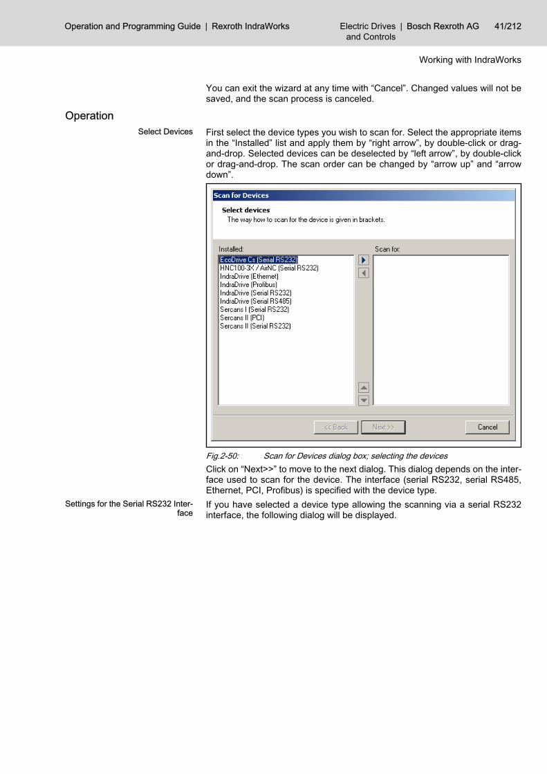
You can exit the wizard at any time with “Cancel”. Changed values will not besaved, and the scan process is canceled.
Operation Select Devices First select the device types you wish to scan for. Select the appropriate items
in the “Installed” list and apply them by “right arrow”, by double-click or drag-and-drop. Selected devices can be deselected by “left arrow”, by double-clickor drag-and-drop. The scan order can be changed by “arrow up” and “arrowdown”.
Fig.2-50: Scan for Devices dialog box; selecting the devicesClick on “Next>>” to move to the next dialog. This dialog depends on the inter‐face used to scan for the device. The interface (serial RS232, serial RS485,Ethernet, PCI, Profibus) is specified with the device type.
Settings for the Serial RS232 Inter‐face
If you have selected a device type allowing the scanning via a serial RS232interface, the following dialog will be displayed.
Operation and Programming Guide | Rexroth IndraWorks Electric Drivesand Controls
| Bosch Rexroth AG 41/212
Working with IndraWorks

Fig.2-51: Scan for Devices dialog box, serial RS232 device dataTo define the COM ports to be used for scanning for a device, apply the ap‐propriate items of the “Available” list by “right arrow”, double-click or drag-and-drop. Selected COM ports can also be deselected. The order can be changedby “arrow up” and “arrow down”.In addition, the parity and the baudrate must be selected for the scanning. Ifthe check button “Adjust Baudrate” is activated, the scanner will try and adjustdevices connected at this interface to the selected baudrate.
Adjusting the baudrate can change the baudrate of devices alreadyconfigured. Thus the communication with those devices may bedisturbed. Please adjust the configuration of those devices toenable a communication!
Click “Advanced...” to open a dialog box where you can enter the timeout forthe device type used by the scanner.
The scanner attempts to establish a communication connection tothe devices to be scanned. The timeout is the time interval availableto the connected devices for responding to a request of the scanner,thus identifying themselves. The scan process is decelerated by ahigh timeout and accelerated by a low timeout. If the timeout is toolow, the scanner might fail to detect all devices.
We recommend to use the default timeout value.
To reset the changed values to the default values of the library, click on “De‐fault”.If you have selected COM port, baudrate and parity, the “Next>>” button isactivated. Use this button to move to the next setting dialog or to the scan dialog.
42/212 Bosch Rexroth AG | Electric Drivesand Controls
Rexroth IndraWorks | Operation and Programming Guide
Working with IndraWorks

Settings for the Serial R485 Inter‐face
In order to address several devices via a serial interface, it is possible to con‐struct a RS485 bus by RS232/RS485 converters.Basically, the scanner settings for the serial RS485 interface correspond to thesettings for the serial RS232 interface. Only the differences between RS485interface and RS232 interface will be explained here.If you have selected a device type allowing the scanning via a serial RS485interface, the following dialog will be displayed.
Fig.2-52: Scan for devices, serial RS485 device dataIn contrast to the RS232 interface you have to enter here a scan area for thedevice addresses. The allowed area ranges from 1 to 127. If you enter singleaddresses, separate them by semicolon. To specify address areas enter a startaddress, a hyphen and an end address. Use “Advanced...” to open a dialog forfurther settings.
Fig.2-53: Scan for devices, serial RS485 device data“Automatic switch between send and receive”
Operation and Programming Guide | Rexroth IndraWorks Electric Drivesand Controls
| Bosch Rexroth AG 43/212
Working with IndraWorks

If RS232/RS485 converters with automatic switch between send and receive(recommended) are used, the settings for “Delay of sending, PC” and “Delayof answer, drive” are irrelevant and thus disabled.If a converter is used, that needs signals to switch between send and receive,you have to enter a delay time for sending in the PC and a delay time for answerin the drive, which ensure a reliable communication connection.
If converters without automatic switch between send and receiveare used, the FIFO buffer of the according serial interface must bedisabled. For information on this, please refer to the documentationof the operating system.
You can get further information on RS485 in the documentation ofthe drive setup.
Settings for the Ethernet Interface If you have selected a device type allowing the scanning via an Ethernet inter‐face, the following dialog box will be displayed.
Fig.2-54: Scan for Devices dialog box, Ethernet device dataYou must enter at least one IP address and one IP port. But you can also enterranges. In this case, the IP addresses may only differ from each other in thefinal numerical area. The input boxes for the IP addresses contain a drop-downlist with the recent ten valid IP addresses. Open this list by <F4> or click on“down arrow” and select an IP address.If you enter invalid characters, a red circle with a white exclamation mark willbe displayed when you exit the input box. The tool tip for this icon shows thecause of the message.Click “Advanced…” to open a dialog where you can enter the timeout for thedevice type.
44/212 Bosch Rexroth AG | Electric Drivesand Controls
Rexroth IndraWorks | Operation and Programming Guide
Working with IndraWorks

The scanner attempts to establish a communication connection tothe devices to be scanned. The timeout is the time interval availableto the connected devices for responding to a request of the scanner,thus identifying themselves. The scan process is decelerated by ahigh timeout and accelerated by a low timeout. If the timeout is toolow, the scanner might fail to detect all devices.
We recommend to use the default timeout value.
To reset the changed values to the default values of the library, click on “De‐fault”.When you have selected an IP address and an IP port, click on “Next>>” tomove to the next setting dialog or to the scan dialog.
Settings for PCI If you have selected a device type allowing the scanning via a PCI interface,you do not have to enter any further data. The next setting dialog or the scandialog will be opened directly.
Settings for Profibus If you have selected a device type allowing the scanning via a Profibus, thefollowing dialog will be displayed.
Fig.2-55: Scan for Devices dialog box, Profibus device dataEnter a baudrate and an address for the Profibus master.The ident number of the device type is displayed, but cannot be edited.If you enter invalid characters or a number outside the range of value, a redcircle with a white exclamation mark will be displayed when you exit the inputbox. The tool tip for this icon shows the cause of the message.Click “Advanced...” to open a dialog box where you can enter the timeout forthe device type used by the scanner.
Operation and Programming Guide | Rexroth IndraWorks Electric Drivesand Controls
| Bosch Rexroth AG 45/212
Working with IndraWorks

The scanner attempts to establish a communication connection tothe devices to be scanned. The timeout is the time interval availableto the connected devices for responding to a request of the scanner,thus identifying themselves. The scan process is decelerated by ahigh timeout and accelerated by a low timeout. If the timeout is toolow, the scanner might fail to detect all devices.
We recommend to use the default timeout value.
To reset the changed values to the default values of the library, click on “De‐fault”.If you have selected an address and a baudrate for the bus master, click on“Next>>” to move to the next setting dialog or to the scan dialog.
Scan Dialog When you have edited the setting dialog for each selected interface, the scandialog will open. This also starts the scan process automatically. You can stopthis process at any time by “Stop scanning for devices” and restart it by “Startscanning for devices”.
Fig.2-56: Scan for Devices dialog box, Found devicesEditing and Applying Found Devi‐
cesOnce a device has been found, it will be displayed in the list and the “Finish”button will be activated.To display additional information, just click on a device in the list.Activate the check box to define that a device is to be added to the project.Click on “Finish” to exit the scan process and to apply the found devices se‐lected to the project. Depending on the device type, another wizard allowingthe entry of further parameters may be started when the devices are applied tothe project.To rename a found device, press <F2> or use the mouse.
46/212 Bosch Rexroth AG | Electric Drivesand Controls
Rexroth IndraWorks | Operation and Programming Guide
Working with IndraWorks

2.2.9 Offline and Online ModeOffline Mode
When a new project is created or when an existing project is opened, the con‐nected devices are in the offline mode. Any changes of project data will besaved to the project, but they will not have any effect on the data in the desti‐nation devices.
Offline Mode Display The offline mode of a device can be recognized in the display of its node in theproject tree:● no mode symbol on the icon
Fig.2-57: Device node, offline mode
Online ModeIn the online mode, your changes will be saved to the project and simultane‐ously be transferred to the data memory of the destination device.
CAUTION
CautionMaterial damage may be caused by failures in the activation of motors andmoving elements!⇒ In the online mode, considerable material damage or personal injury may becaused by an inadvertent transfer of data to the destination device. Before youchange any project data, please make absolutely sure, that this change will notcause any damage or injury.
Online Mode Display The online mode of a device can be recognized in the display of its node in theproject tree:● blue mode symbol on the icon● blue font
Fig.2-58: Device node, online mode
2.2.10 Switching Between Offline and OnlineWhat Happens During the Switch
Four Switching Steps Once you switch a device to the online mode, IndraWorks performs the follow‐ing steps:● First, IndraWorks attempts to establish a communication connection to all
devices in the project (communication adjustment).● Then, IndraWorks checks whether the projected device structure is equal
to the existing device structure (structure adjustment).● In the third step, IndraWorks checks whether the projected device config‐
uration is equal to the existing configuration (configuration adjustment).● In the final step, IndraWorks compares the data of each device in the
project with the appropriate data in the destination device (data adjust‐ment).
A device will not be switched to the online mode before all the above steps havebeen completed successfully.The sections below will provide a detailed description of these steps.
Operation and Programming Guide | Rexroth IndraWorks Electric Drivesand Controls
| Bosch Rexroth AG 47/212
Working with IndraWorks

How to ProceedSwitch a project to the online mode by Project ▶ Switch Devices Online.... Youcan also use Switch Online in the context-sensitive menu of the device node.
Fig.2-59: Switching to the online modeIf several devices are connected, you will be prompted to select the devices forthe online edit:
Fig.2-60: Remote Engineering Select devices for online switch
Communication Adjustment Checking the Communication Con‐
nectionFirst, the communication connection to the devices of the project is verified. IfIndraWorks can communicate with all devices, the structure adjustment is au‐tomatically carried out in the next step. Otherwise, you can● scan for a device,● or retry switching this device to the online mode,● or stop switching this device to the online mode.
Fig.2-61: Switching to the online mode, communication connection messageScanning for a Device The scanner is used for searching a device (see chapter 2.2.8 "Scan for De‐
vices" on page 40 )
48/212 Bosch Rexroth AG | Electric Drivesand Controls
Rexroth IndraWorks | Operation and Programming Guide
Working with IndraWorks

If the scanning is successful, the communication settings of the device are ap‐plied. If the scanning is not successful, switching the device to the online modeis stopped.
Structure Adjustment In the structure adjustment step, IndraWorks checks whether the projected de‐vice structure is equal to the existing structure. E. g., the device peripherals fora control are checked as follows:● number and type of the drives connected,● number and type of the connected I/O bus devices.
The structure adjustment depends on the device type. You can finddetails on switching a device to the online mode in its documenta‐tion.
If the projected structure is equal to the existing structure, the configurationadjustment is carried out in the next step.
Eliminating Structure Inconsisten‐cies
If the data in the project differ from the data in the destination device, they willbe shown in a tool window. The tool window provides the following information:● overview of structure inconsistencies,● data set in the project,● data existing in the destination device,● reason for the problem,● possible solution to the problem.
Fig.2-62: Online switch, information on structure inconsistencies
Operation and Programming Guide | Rexroth IndraWorks Electric Drivesand Controls
| Bosch Rexroth AG 49/212
Working with IndraWorks

Once you have eliminated the inconsistencies, you can restart the switch. IfIndraWorks does not detect any inconsistencies in the structures any longer,the configuration adjustment is carried out as the next step.
Configuration Adjustment The configuration of the various devices must be adjusted (e. g. the projecteddrive number may differ from the actually set drive number in a Sercos ring).
The configuration adjustment depends on the device type. You canfind details on switching a device to the online mode in its docu‐mentation.
If the projected configuration is equal to the existing configuration, the dataadjustment is carried out in the next step.
Eliminating Configuration Inconsis‐tencies
If the data in the project differ from the data in the destination device, they willbe shown in a tool window. The tool window provides the following information:● overview of configuration inconsistencies,● data set in the project,● data existing in the destination device,● reason for the problem,● possible solution to the problem.Once you have eliminated the inconsistencies, you can restart the switch. IfIndraWorks does not detect any configurations inconsistencies any longer, thedata adjustment is carried out in the next step.
Data Adjustment The data of the various devices must be adjusted, e. g.:● motion program of a control,● velocity limitation of a drive.
The data adjustment depends on the device type. You can find de‐tails on switching a device to the online mode in its documentation.
Eliminating Data Inconsistencies If the data in the project differ from the data in the destination device, they willbe shown in a tool window. The tool window provides the following information:● overview of data inconsistencies,● data set in the project,● data existing in the destination device,● reason for the problem,● possible solution to the problem.Once you have eliminated the inconsistencies, you can restart the switch. IfIndraWorks does not detect any data inconsistencies any longer, switching tothe online mode is completed.
2.3 Adding Files to an IndraWorks Project 2.3.1 General Information
Existing files can be added to an IndraWorks project, so that documentations,data sheets or additional information will be transferred with the project.
50/212 Bosch Rexroth AG | Electric Drivesand Controls
Rexroth IndraWorks | Operation and Programming Guide
Working with IndraWorks

The embedded file is displayed in the project. To edit the file, call the currentlyregistered application in IndraWorks.
If Automation Interface is used, you can add or run HTML sites withembedded script code, providing the access functionality to the Au‐tomation Interface, in an IndraWorks project.
2.3.2 Adding a File If a project node allows the insertion of files, its context-sensitive menu providesAdd ▶ File.
Fig.2-63: Adding files to a projectSelecting this menu item opens the “Open” dialog box.
Operation and Programming Guide | Rexroth IndraWorks Electric Drivesand Controls
| Bosch Rexroth AG 51/212
Working with IndraWorks

Fig.2-64: Open dialog boxSelect a file and insert a copy of this file in your project by clicking on the“Open” button. The file can then be edited in your project.
Fig.2-65: File added to the projectThe icon used is the default icon of this file type. The name is equal to the filename without filename extension.
2.3.3 Editing a File Open To open the embedded file, double-click on it, press <Enter> or use the context-
sensitive menu. IndraWorks will start the application registered for editing in theWindows operating system.
52/212 Bosch Rexroth AG | Electric Drivesand Controls
Rexroth IndraWorks | Operation and Programming Guide
Working with IndraWorks

Fig.2-66: Editing an embedded fileIn the case shown above, Acrobat Reader (PDF) will be started.
IndraWorks can start the editing application when the file is openedand exit it when the project is closed or the user interface is shutdown.All other actions, such as printing or saving a file, are executed bythe editing application.
Open with… If there is no registered application or if you wish to register a different appli‐cation, select Open with… from the context-sensitive menu.
Fig.2-67: Embedded file, Open with…Select an application for editing your file in the “Open with” dialog box. If youactivate the check box “Always use the selected program to open this kind offile”, this application will be used for all further editing actions.
Operation and Programming Guide | Rexroth IndraWorks Electric Drivesand Controls
| Bosch Rexroth AG 53/212
Working with IndraWorks

Fig.2-68: Open with dialog box
This dialog does not start modally, i. e. if you click on the IndraWorksdesktop while this dialog box is open, it will disappear to the back‐ground. To put it to the foreground again, press <Alt>-<Tab>.
Automation Script... Having added an HTML page with embedded Automation Script to the project,the context-sensitive menu will provide Automation Script... Use this menu en‐try to obtain access to the properties of the Automation Script.
54/212 Bosch Rexroth AG | Electric Drivesand Controls
Rexroth IndraWorks | Operation and Programming Guide
Working with IndraWorks

Fig.2-69: Embedded file, Automation Script...Selecting this menu item opens the “Automation Script Configuration” dialogbox.
Fig.2-70: Automation Script Configuration dialog boxThe “Automation Script Configuration” dialog box displays the file name and thefiling location of the HTML file. In the Window mode list, you can define whetherthe HTML page is to be started integrated in IndraWorks or externally.The current version starts HTML pages only integrated in IndraWorks.
Cutting, Copying, Pasting To move the file into the project, select Cut and Paste . You can also use drag-and-drop.Use Copy and Paste to create a copy of the file at a different position in theproject.
Operation and Programming Guide | Rexroth IndraWorks Electric Drivesand Controls
| Bosch Rexroth AG 55/212
Working with IndraWorks

Delete To remove the file from the project, select Delete. If started, the editing programwill be exited.
Rename To rename the file, press <F2> or use the context-sensitive menu.Properties Open the “Properties” dialog box via the context-sensitive menu. The dialog
box depends on the type of the embedded file.
Fig.2-71: Properties dialog box
2.3.4 Adding a New Element from the Templates to the ProjectTo add a new element to a project select Add ▶ New Element in the context-sensitive menu. In the following dialog, first select the category, that containsthe desired template. The right part of the dialog box displays the templatesavailable in that category. If you select a template it will be opened by its defaulteditor.
56/212 Bosch Rexroth AG | Electric Drivesand Controls
Rexroth IndraWorks | Operation and Programming Guide
Working with IndraWorks

Fig.2-72: Add New Element dialog boxUse the command Open with to select another editor for opening this program.You can define this editor as new default editor.
Fig.2-73: Open with another editor
2.3.5 Removing a File from the Project To remove embedded files from the project, select Delete. The subdirectorycontaining the file will be moved to the Windows recycle bin, together with thefile.
2.4 Working with the Workspace2.4.1 General Information
You can combine and manage several projects in a workspace. It will be dis‐played in the project explorer and shows the tree structure of the projects anddevices.
2.4.2 Workspace Structure The workspace will be displayed as the root of the tree structure in the projectexplorer.The projects desired can be inserted, created and deleted at the levels belowthe workspace.
Operation and Programming Guide | Rexroth IndraWorks Electric Drivesand Controls
| Bosch Rexroth AG 57/212
Working with IndraWorks

Fig.2-74: Workspace in IndraWorks
2.4.3 WorkspaceCreating a Workspace
Projects can only be inserted if a workspace has been created or loaded.To create a new workspace, select File ▶ New ▶ Workspace.
Fig.2-75: Workspace, creating a new workspaceThe following dialog box appears:
Fig.2-76: New IndraWorks Workspace dialog boxEnter any name and directory for the workspace you wish.
Opening a WorkspaceTo load existing workspaces, select File ▶ Open ▶ Workspace.
Fig.2-77: Workspace, open a workspaceYou can then select a workspace from the following dialog box. The filenameextension of the corresponding files is “.iww”.
58/212 Bosch Rexroth AG | Electric Drivesand Controls
Rexroth IndraWorks | Operation and Programming Guide
Working with IndraWorks

Deleting a WorkspaceThe workspace can be deleted via the context-sensitive menu of its node.
Fig.2-78: Workspace, delete a workspace
This command only deletes the workspace from the data medium,not the projects it contains.
2.4.4 Projects in the WorkspaceAdding Projects
The workspace is intended to comprise and manage several projects. Thereare various ways of adding projects to the workspace:Integrate an existing project via the context-sensitive menu of the workspace.Select Add ▶ Existing Project... The options in the following dialog box are thesame as those when projects are opened.
Fig.2-79: Workspace, adding projectsTo add a new project to the workspace, select in its context-sensitive menu:Add ▶ New Project.
Only one project can be opened in a workspace. If you open anotherproject, the project opened before will be closed automatically.
Opening a Project Open a project via its context-sensitive menu.The status of the project is indicated by the icon in the tree structure.
Icon Description
Project available but not opened
Project deleted or no connection to source computer
Project opened in the project explorer
Fig.2-80: Project status, icons
Deleting a Project A project can be removed from the workspace by using its context-sensitivemenu.
Operation and Programming Guide | Rexroth IndraWorks Electric Drivesand Controls
| Bosch Rexroth AG 59/212
Working with IndraWorks

The project will not be deleted, only its reference is removed fromthe workspace.
2.4.5 Properties The context-sensitive menu of a project can be used to display the propertiesof that project.
Fig.2-81: Properties dialog boxThis dialog box displays the times when the project has been created and edi‐ted, the path and the state of the project as well as information on the projectmanagement in the version control.The output can be specifically expanded by the devices inserted in the project.
2.4.6 Devices in Projects “Top-level” devices are also displayed in the explorer of the workspace belowtheir associated project. Use the context-sensitive menu to address functionsfor these devices and view properties of these devices. Devices which do notbelong to the “top level” are not displayed in the explorer of the workspace.
2.5 Persistence IndraWorks opens the previously opened project on the next start.Windows arranged in the workspace before IndraWorks has been exited willbe provided there after restart.If the workspace is empty after start, you can create a new project or open anexisting project.
2.6 Multilingual Projects 2.6.1 General Information
Creating and Editing MultilingualProjects
The language and text management integrated in IndraWorks allows to createand edit multilingual projects. The multilingual function relates to the languageof the user texts (e. g. projectable messages, texts in HMI screens, programcomments). Do not mistake this multilingual function for the language of theuser interface.We recommend to proceed as follows:
60/212 Bosch Rexroth AG | Electric Drivesand Controls
Rexroth IndraWorks | Operation and Programming Guide
Working with IndraWorks

● Create the project and select the master language.● Plan the project, all texts are entered in the master language.● Add the desired additional languages to the project.● Export the user texts of the project to one translation file per additional
language.● Translate the texts, i. e. edit the translation files.● Import the translated texts to the project.
2.6.2 Defining the Master Language of a Project The language used for creating an IndraWorks project is called the master lan‐guage. Later, any number of further languages can be added to the project, inaddition to the master language.Define the master language in the “Project language” list box of the “CreateNew IndraWorks Project” dialog box while you create a new project.
Fig.2-82: Create New IndraWorks Project dialog box, define master languageUse the “Fonts” button to define the fonts for the text display. This is particularlyrecommended for languages requiring specific fonts for displaying the text, e. g.Asiatic languages.The default setting for the fonts of the master language is as follows:Proportional font: Arial, 10 points
2.6.3 Managing Project Languages Adding a New Language to the
ProjectTo add a new language to the project, select Project ▶ Language ▶ ManageProject Languages.
Operation and Programming Guide | Rexroth IndraWorks Electric Drivesand Controls
| Bosch Rexroth AG 61/212
Working with IndraWorks

Fig.2-83: Manage Project Languages dialog boxTo open the “Add Project Language” dialog box, click on “Add…” in the “ManageProject Languages” dialog box.
Fig.2-84: Add Project Language dialog boxSelect the language you wish to add to the project.
62/212 Bosch Rexroth AG | Electric Drivesand Controls
Rexroth IndraWorks | Operation and Programming Guide
Working with IndraWorks

Fig.2-85: Manage Project Languages dialog boxRepeat this process until you have added all necessary languages to the proj‐ect.To change the font of an additional language, select the language from the“Additional languages” list and click on “Fonts…”.Click on “Close” to return to the IndraWorks main window.
When a new language is added, the internal text memories areprepared to incorporate and manage texts in this language. Trans‐lations to this language are, however, not made.
Any added language can be selected as the active language. As aresult, all language-specific user texts entered after this point arefiled to the text memories of that language.Editing in an additional language is only suitable for correcting a textor for making minor changes to a project.For actual engineering, we explicitly recommend to use the masterlanguage only. Do not add other languages and do not translateuser texts until the project has been completed technically.If you wish to expand or revise a project, we also recommend to usethe master language and translate the new user texts only there‐after.
Deleting an Additional Languagefrom the Project
To delete a language from the project, select Project ▶ Language ▶ ManageProject Languages. Select the language to be deleted from the “Additional lan‐guages” list and click on “Delete…” Confirm the safety prompt.
2.6.4 External Project TranslationGeneral Information
IndraWorks has got an export/import interface for the texts of a project. Thisdata interface allows to export texts to a translation file which can then betranslated outside of IndraWorks.To do this, you need a spreadsheet program which is able to read and write*.csv files and which supports UNICODE.
Operation and Programming Guide | Rexroth IndraWorks Electric Drivesand Controls
| Bosch Rexroth AG 63/212
Working with IndraWorks

For example, Microsoft Excel 2003 or OpenOffice.org Calc are suitable for ed‐iting translation files. The operation of these two programs differs only in thesetting of text export and text import filters for opening and saving the translationfiles.After the translation is completed, import the translation file. IndraWorks as‐signs the appropriate translations from the translation file to the original textsin the project.The sections below describes the translation of the texts of a translation file bythe example of OpenOffice.org Calc.The following steps are required:1. Export the translation file from IndraWorks.2. Import the translation file to OpenOffice.org Calc.3. Translate the texts. The translated texts are inserted in the translation file.4. Export the translation file from OpenOffice.org Calc.5. Import the translation file to IndraWorks.
Exporting the Translation File from IndraWorksOpen the “Export Translation File” dialog box via Project ▶ Language ▶ ExportTranslation File.
Fig.2-86: Export Translation File dialog boxSource Language Select in this list box, which language version of the texts will be written to the
translation file as original text.The master language is preset in this field after opening the dialog box. How‐ever, you can also select any other language of the project as the sourcelanguage.
Target Language Select in this list box, which language will be the target language in the trans‐lation file. This entry will later be evaluated during import, so that the importedtexts can be properly assigned to the correct text memories in the project.
Export Only Texts That are not YetTranslated
This check box allows you to define whether all texts are exported to the trans‐lation file or only those that do not have a translation in the target language yet.Check this option if you have revised an already translated project and wish toexport the new texts only. When they will be imported, the texts of the translationfile are merged with the already translated texts in the project.Click on “OK” to open a dialog box where you can define the directory and thename of the translation file.
64/212 Bosch Rexroth AG | Electric Drivesand Controls
Rexroth IndraWorks | Operation and Programming Guide
Working with IndraWorks

Fig.2-87: Export translation file dialog box, saving the fileThe name proposed by IndraWorks has the following format:TranslationFile.SourceLanguage.TargetLanguage.csvFor example, a translation file from German to US English:TranslationFile.de-DE.en-US.csvYou can edit the name; but we recommend you not to change the name ex‐tension (e. g. .de-DE.en-US.csv).
Importing the Translation File to OpenOffice.org CalcDownload a translation file to OpenOffice.org Calc by File ▶ Open. Select thefile to be opened and click on “Open”.This opens the “Text Import” dialog box.
Fig.2-88: OpenOffice.org Calc: Text Import dialog box
Operation and Programming Guide | Rexroth IndraWorks Electric Drivesand Controls
| Bosch Rexroth AG 65/212
Working with IndraWorks

Character Set “Unicode” must be set in this list box. This should already be preset becauseOpenOffice.org Calc automatically detects the character set used in the file.
Separator Options Select the separator option “Separated by” and “Tab” as separator.Text Delimiter Text delimiters are not used in the translation file. Delete the suggested sepa‐
rator.Click on “OK” to download the translation file to OpenOffice.org Calc.
Translating the Texts in OpenOffice.org CalcAfter having downloaded the translation file to OpenOffice.org Calc, a spread‐sheet is opened. It contains five columns and a number of lines depending onthe number of texts.
Fig.2-89: OpenOffice.org Calc: translating textsThe first line of the spreadsheet is a header which describes the column con‐tents.
Column 1: Source Language Column 1 contains the texts of the source language. The header contains theISO code for this language.
Column 2: Target Language Column 2 contains the texts of the target language. The header contains theISO code for this language. Depending on the settings in the export dialog, theother lines of this column are empty or display already existing translations.
Columns 3, 4, 5: Management Data Columns 3 to 5 contain management data which will be used to assign thetranslated texts properly when they are imported to IndraWorks.
Do not change the header or the management data. Otherwise, thetranslation file cannot be imported.
During the translation, the translated texts are entered in column 2. While beingimported, these texts are read in IndraWorks.
66/212 Bosch Rexroth AG | Electric Drivesand Controls
Rexroth IndraWorks | Operation and Programming Guide
Working with IndraWorks

Please note the following character strings for the translation: “{%tab%}”, “{%lf%}”, “{%crlf%}”During the export, these character strings are inserted in texts whichcontain tabulator and end-of-line characters. Do not change thesecharacter strings in the translation.Example:Source text: Hallo{%tab%}Welt!!!Translation: Hello{%tab%}World!!!When the translation file is imported to IndraWorks, the characterstrings are reconverted into the original characters.
Exporting the Translation File from OpenOffice.org CalcAfter the translation is completed, save the translation file. We recommend tosave the edited file under a different name with Datei ▶ Speichern unter (FileSave As).
Fig.2-90: OpenOffice.org Calc: Datei Speichern unter (Save File As) dialog box,exporting the translation file
Dateityp (File type) Select “Text CSV” from the “Dateityp” (File type) list box.Editing Filter Settings The “Edit filter settings” check box allows you to select the filter settings before
saving the file in the “Export of text files” dialog box.To open the “Export of text files” dialog box, click on “Speichern” (Save).
Operation and Programming Guide | Rexroth IndraWorks Electric Drivesand Controls
| Bosch Rexroth AG 67/212
Working with IndraWorks

Fig.2-91: OpenOffice.org Calc: Export of text files dialog boxCharacter Set Select “Unicode” from this list box.Field Delimiter Select “{Tab}” as “Field Delimiter”.Text Delimiter Delete the character in the “Text delimiter” field.
The export filter must be set exactly as described above because, otherwise,the translation file cannot be imported to IndraWorks.
Importing the Translation File in IndraWorksTo import the texts of a translation file to the current project, selectProject ▶ Language ▶ Import translation file. From the file selection dialog box,select the translation file to be imported.
Fig.2-92: Import translation file dialog box, selecting the fileYou can now set the import options in the “Import translation file” dialog box.
68/212 Bosch Rexroth AG | Electric Drivesand Controls
Rexroth IndraWorks | Operation and Programming Guide
Working with IndraWorks
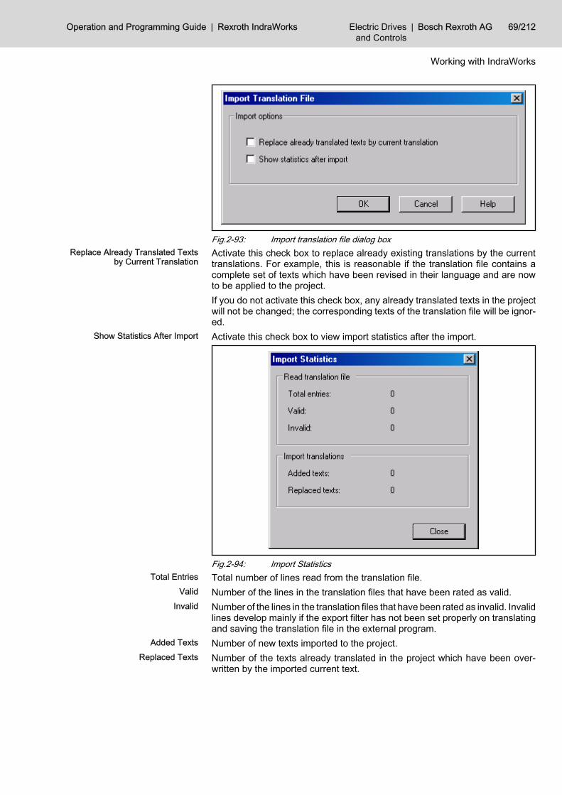
Fig.2-93: Import translation file dialog boxReplace Already Translated Texts
by Current TranslationActivate this check box to replace already existing translations by the currenttranslations. For example, this is reasonable if the translation file contains acomplete set of texts which have been revised in their language and are nowto be applied to the project.If you do not activate this check box, any already translated texts in the projectwill not be changed; the corresponding texts of the translation file will be ignor‐ed.
Show Statistics After Import Activate this check box to view import statistics after the import.
Fig.2-94: Import StatisticsTotal Entries Total number of lines read from the translation file.
Valid Number of the lines in the translation files that have been rated as valid.Invalid Number of the lines in the translation files that have been rated as invalid. Invalid
lines develop mainly if the export filter has not been set properly on translatingand saving the translation file in the external program.
Added Texts Number of new texts imported to the project.Replaced Texts Number of the texts already translated in the project which have been over‐
written by the imported current text.
Operation and Programming Guide | Rexroth IndraWorks Electric Drivesand Controls
| Bosch Rexroth AG 69/212
Working with IndraWorks

2.7 Printing 2.7.1 General Information
This IndraWorks version provides the functionalities Print, Print Preview andConfiguration of Print Settings to document your data.You can print● Device Data● Project data
It depends on your current working context, which menu entries forprinting are available. The entries can be selected only if a printableelement (area or node) has been selected.
2.7.2 Print SettingsGeneral
Use File ▶ Print Settings... or Print Settings... in the context-sensitive menu ofthe project node to configure the printing in IndraWorks. You can configure thelayout of the printed document as well as the header and footer. The settingsapply for the current project. They can be used for other projects via the export/import functionality.
Basic ButtonsOK Use “OK” to save all changes and to close the dialog box.
Cancel Use “Cancel” to discard all changes including those resulting from import andto close the dialog box.
Default Settings Use “Default Settings” to reset all settings to the default values.Page Settings Use “Page Settings” to open the dialog box “Page Settings”. Here you can de‐
fine your settings for borders, orientation, paper size and you can select aprinter.
Export The menu entry “Export” enables you to export the print settings of the currentproject and to apply them to another project. Use the button “Export” to openthe dialog box “Export Print Settings”. Here you can enter a name and the des‐tination directory for the export file, confirm by “OK”.
Import The menu entry “Import”enables you to import the print settings exported be‐fore. Use the button “Import” and select in the appearing dialog box “Import PrintSettings” a file exported before. Confirm by “OK”. Thus the import will be doneand the imported print settings will be displayed.
Help Use “Help” to start the IndraWorks online help.
Table of ContentsOn the tab “Table of Contents” you can configure the layout of the table ofcontents and the cover page. These pages will be created automatically whenproject data or device data are printed.
70/212 Bosch Rexroth AG | Electric Drivesand Controls
Rexroth IndraWorks | Operation and Programming Guide
Working with IndraWorks
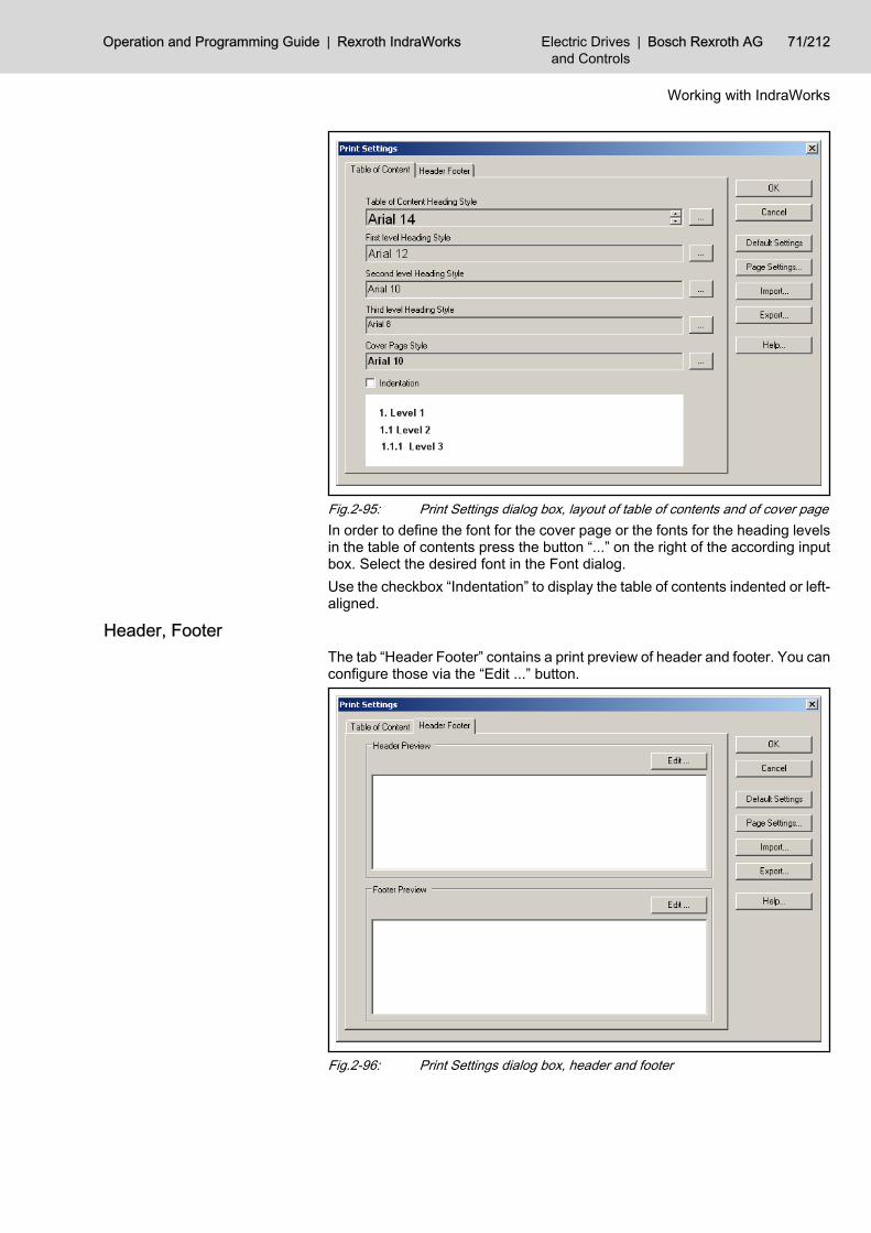
Fig.2-95: Print Settings dialog box, layout of table of contents and of cover pageIn order to define the font for the cover page or the fonts for the heading levelsin the table of contents press the button “...” on the right of the according inputbox. Select the desired font in the Font dialog.Use the checkbox “Indentation” to display the table of contents indented or left-aligned.
Header, FooterThe tab “Header Footer” contains a print preview of header and footer. You canconfigure those via the “Edit ...” button.
Fig.2-96: Print Settings dialog box, header and footer
Operation and Programming Guide | Rexroth IndraWorks Electric Drivesand Controls
| Bosch Rexroth AG 71/212
Working with IndraWorks

Open the edit dialog for header and footer by the “Edit ...” button. It will bedescribed how to edit the header in the following section. The footer can beedited in the same way.
Fig.2-97: Print settings, edit headerThis dialog box contains six sections, which can be filled with text or graphics.The three upper sections are used to configure the upper part of the header,the three lower sections are used for the lower part. Activate the “Header Bor‐der” checkbox to separate these two parts of the header by a line. Then youcan show separation lines between the various sections by the “Border” check‐boxes.The font can be separately set for each section by using the “Font...” button.You can add variables, such as page number or date, via the “Variable...” but‐ton. Use the “Image...” button to add graphics.
If you insert a graphic into a section, you cannot insert additionaltext. Graphics cannot be displayed together with text in the samesection.
Switch back to the print preview for header and footer by “OK” and check yoursettings. Header and footer will not be printed, unless data have been enteredin the edit dialog box.
2.7.3 Printing Project Data or Device DataOverview
To print IndraWorks project data select Print in the context-sensitive menu ofthe project node or in File of the main menu.
Independent of the project node you can start the printing byProject ▶ Printing Global Documentation....
To print data of single devices use Print in the context-sensitive menu of thedevice node or in the main menu under the entry of the selected device.The menu entries Print and Print Preview provide the following pages:
Cover Page The cover page contains all project related information: project name, projectdescription, date of creation and date of last modification.
72/212 Bosch Rexroth AG | Electric Drivesand Controls
Rexroth IndraWorks | Operation and Programming Guide
Working with IndraWorks

You can change the font of the cover page via File ▶ Print Settings.
Fig.2-98: Printing, print preview of projects - cover pageTable of Contents This page contains the following information:
1. The first heading level displays the device name.1.1. The second heading level displays the data categories of the device.1.1.1. The third heading level displays the file name of the printed data category.You can change the fonts of the table of contents via File ▶ Print Settings.
Operation and Programming Guide | Rexroth IndraWorks Electric Drivesand Controls
| Bosch Rexroth AG 73/212
Working with IndraWorks

Fig.2-99: Printing, print preview of projects - table of contentsSeparator Sheet - Device This page contains the name and the description (optional) of the selected de‐
vice.Separator sheet and cover page have the same font. You can change this fontvia File ▶ Print Settings.
74/212 Bosch Rexroth AG | Electric Drivesand Controls
Rexroth IndraWorks | Operation and Programming Guide
Working with IndraWorks

Fig.2-100: Printing, print preview of projects - separator sheet - deviceSeparator Sheet - Device Data This page contains the name of the device data.
Separator sheet and cover page have the same font. You can change this fontvia File ▶ Print Settings.
Operation and Programming Guide | Rexroth IndraWorks Electric Drivesand Controls
| Bosch Rexroth AG 75/212
Working with IndraWorks

Fig.2-101: Printing, print preview of projects - separator sheet - device dataDevice Data This page contains device data and device specific information.
76/212 Bosch Rexroth AG | Electric Drivesand Controls
Rexroth IndraWorks | Operation and Programming Guide
Working with IndraWorks

Fig.2-102: Printing, print preview of projects - device data
Print and Print Preview - Operating ModePrinting and Print Preview of Project Data To print or preview IndraWorks project data proceed as follows:
Step 1 Select a project with printable devices.Step 2 Open the context-sensitive menu of the project node. Select Print or Print Pre‐
view. Or select File Print or Print Preview in the main menu, if the project nodeis selected.Independent of the project node you can select Project ▶ Printing Global Doc‐umentation... or Project ▶ Print Preview Global Documentation....
Operation and Programming Guide | Rexroth IndraWorks Electric Drivesand Controls
| Bosch Rexroth AG 77/212
Working with IndraWorks

Fig.2-103: Print, print preview of projects – select commandStep 3: Selecting the Printable Data The following dialog box displays all printable devices and nodes of the project.
If you select a device or printable node in this tree structure, the according datacategories will be displayed in the right list, if available. The data categoriesdisplay the printable data of the selected node. Select the devices and nodesand their data categories to be printed.
If you select a node in the project tree, then you can use its context-sensitive menu to select or deselect all printable data of this nodeand of its attached nodes.
Press “Next>>”.
78/212 Bosch Rexroth AG | Electric Drivesand Controls
Rexroth IndraWorks | Operation and Programming Guide
Working with IndraWorks

Fig.2-104: Print Project and Device Data dialog box – device selectionStep 4: Checking You can check your settings in the next dialog box.
Fig.2-105: Print Project and Device Data dialog box – check settings1. The dialog box displays the selected devices and nodes and their data
categories with a check mark.2. The “Name” field in the “Printer” section displays the currently selected
printer. If necessary, select a different printer via “Page Setup”.3. The “Settings” field contains the values for page orientation and paper
size.
Operation and Programming Guide | Rexroth IndraWorks Electric Drivesand Controls
| Bosch Rexroth AG 79/212
Working with IndraWorks

● If you want to change the settings for margins, orientation, paper sizeor the printer use the “PageSetup” button. The new settings will bedisplayed in the “Printer” section and are persisten for theIndraWorks session.
Fig.2-106: Page Setup dialog box4. Click on “Finish” to start the printing or preview.
Step 5: Progress Bar A progress bar will be dispalyed till all the pages have been prepared for printingor preview.You can stop this process by “Stop”. However, the already prepared pages willbe printed or previewed.
Printing and Print Preview of Device Data To print or preview device data proceed as follows:
Step 1 Select a project with printable devices.Step 2 Open the context-sensitive menu of the device node. Select Print or Print Pre‐
view.Step 3: Device Selection The following dialog box displays the selected device and all attached printable
nodes of this device. If you select the device or a printable node in this treestructure, the according data categories will be displayed in the right list, ifavailable. The data categories display the printable data of the selected node.Select the nodes and their data categories to be printed.
If you select a node in the project tree, then you can use its context-sensitive menu to select or deselect all printable data of this nodeand of its attached nodes.
80/212 Bosch Rexroth AG | Electric Drivesand Controls
Rexroth IndraWorks | Operation and Programming Guide
Working with IndraWorks

Press “Next>>”.
Fig.2-107: Print Project and Device Data dialog box, select device dataStep 4: Checking You can check your settings in the next dialog box.
Fig.2-108: Print Project and Device Data dialog box, check settings1. The dialog displays the selected data of the device.2. The “Name” field in the “Printer” section displays the currently selected
printer. If necessary, select a different printer via “Page Setup”.3. The “Settings” filed contains the values for page orientation and paper
size.● If you want to change the settings for margins, orientation, paper size
or the printer use the “PageSetup” button. The new settings will be
Operation and Programming Guide | Rexroth IndraWorks Electric Drivesand Controls
| Bosch Rexroth AG 81/212
Working with IndraWorks

displayed in the “Printer” section and are persisten for theIndraWorks session.
Fig.2-109: Page Setup dialog box4. Click on Finish to start the printing or preview.
2.8 User Management2.8.1 General Information
Functioning of the User Manage‐ment
The user management makes sure, that only authorized persons can accessprotected functionalities in IndraWorks. To access such a protected function‐ality, a user has to login in the user management with his user name andpassword. After that, the privilege system of the user management checks thepermissions of the user and declines to execute the function unless the userhas got the necessary permissions.
User Management in theIndraWorks Project
User management data are components of an IndraWorks project. They will beloaded when the project is opened. Different IndraWorks projects have got dif‐ferent user data bases. The user management will not become active until anIndraWorks poject has been opened, since the information on users or permis‐sions will not be available before.When a new IndraWorks project is created or when a project created by anolder IndraWorks version is opened, an initial user data base with exactly oneuser will be created. This user is the administrator (user name “Admin”). Onprinciple, the administrator has got all permissions and thus can access all pro‐tected functions. The user account of the administrator should be used only foradministrative tasks, e. g. to configure the user data base (create users andgroups, assign permissions, etc.).
82/212 Bosch Rexroth AG | Electric Drivesand Controls
Rexroth IndraWorks | Operation and Programming Guide
Working with IndraWorks

Users, Groups, Permissions A user represents a person, which has to work with IndraWorks and thus needscertain permissions. Users are identified by a unique user name. They possessfurther properties, such as first name, last name, description, settings, etc.Users in IndraWorks do not get permissions directly, but they get the permis‐sions of the group they are members of.Groups allow to define permission profiles and to assign them to users. Per‐missions are assigned to groups, and users are added to groups. A userpossesses all permissions of all groups he is added to.A permission allows to access a certain protected functionality in IndraWorks.
Administrator The administrator (user name “Admin”) is the super user in IndraWorks. Theadministrator already exists in an initialized user data base, immediately aftercreating a new IndraWorks project. He possesses all permissions, without anyexceptions. The user data of the administrator cannot be changed, except somesettings. The administrator cannot be deleted.
Default Groups The user management provides predefined default groups with characteristicalpermission profiles of frequently found user groups. This simplifies the config‐uration and the assignment of permissions. Add users to the default groups, inorder to assign typical permission profiles. Thus the configuration effort will beminimalized.Default groups cannot be edited or deleted. But you can copy a default groupand modify this copy as you want. The copy of a default group is a “normal”group, i. e. it can be edited and deleted.
Initial Password If you create a new user, it will get an empty password. To login a user the firsttime, only the user name must be entered. The user management recognizesthis first login and asks the user to define a password.
2.8.2 Activating the User ManagementThe user management is disabled when you create a new IndraWorks pojector open a project created by a former IndraWorks version. You can run allIndraWorks functions without being logged in, even protected functions.To monitor protected functionalities, you have to activate the user management.For this purpose select Project ▶ User Management ▶ User Management Ac‐tive.Once you have enabled this option, only privileged users can run protectedfunctions. A login will be necessary.
To disable the user management deselect Project ▶ UserManagement ▶ User Management Active. However, unless you arelogged in as administrator you cannot disable the user manage‐ment .
2.8.3 Login and Logout, Change a PasswordFirst Login as Administrator
If you activate the user management in an IndraWorks project for the first time,an initial user data base is created with just one user, the administrator. Thisdata base is a component of the IndraWorks project data.To login as administrator in IndraWorks proceed as follows:
1. Select Project ▶ User Management ▶ Login User2. Enter only the user name “Admin” in the login dialog, enter no password.
Confirm with “OK”.
Operation and Programming Guide | Rexroth IndraWorks Electric Drivesand Controls
| Bosch Rexroth AG 83/212
Working with IndraWorks

Fig.2-110: Login User dialog box, first login of "Admin"3. The user management recognizes this first login as administrator and asks
you to enter an administrator password. Confirm the following messageby “OK”.
Fig.2-111: User Management, recognizes first login4. Enter and confirm the new password for the administrator now. Finish the
entry by “OK”. From now on you will have to enter the user name “Ad‐min” and the defined password, if you login as administrator.
Fig.2-112: Enter Password dialog box, enter and confirm new passwordYou are logged in as the administrator in IndraWorks now and can configurethe user management, i. e., create the necessary users and groups and assignpermissions. To logout select Project ▶ User Management ▶ Logout User
User Login1. To login in IndraWorks select Project ▶ User Management ▶ Login User2. Enter your user name and password in the login dialog and click on
“OK”.
84/212 Bosch Rexroth AG | Electric Drivesand Controls
Rexroth IndraWorks | Operation and Programming Guide
Working with IndraWorks

If the user name and the password are correct, you will be logged in. Otherwiseyou will get an error message.
If you log in for the first time in IndraWorks or if your password hasbeen reset by the administrator, IndraWorks will ask you to enter anew password.
User Logout1. To logout in IndraWorks select Project ▶ User Management ▶ Logout User2. A message confirms the logout.
Change Password dialog box1. Login in Indra Works first, to change your password.2. Select Project ▶ User Management ▶ Change Password.3. In the “Change Password” dialog box, enter the old and the new password,
confirm the new one and click on “OK”.
Fig.2-113: Change Password dialog box
Login with Reference Code and Key CodeThe login with reference code and key code allows a login in IndraWorks withadministrator permissions. This login is meant for emergencies, e. g., if theadministrator cannot remember his password or if no login is possible for otherreasons. To login with reference code and key code proceed as follows:
1. Select Project ▶ User Management ▶ Login with Reference Code and KeyCode.
2. The “RefCode” field of the login dialog displays an eight-digit referencecode. Send this reference code to the Bosch Rexroth service. Do not closethe login dialog.
Operation and Programming Guide | Rexroth IndraWorks Electric Drivesand Controls
| Bosch Rexroth AG 85/212
Working with IndraWorks

Fig.2-114: Login User dialog box, with reference code and key code3. You will get a key code belonging to your reference code from the Bosch
Rexroth service. Enter this code in the “KeyCode” input box of the logindialog and click on “OK”. Now you are logged in as administrator.
A key code works only together with the according reference code. Each loginprovides a new reference code. You cannot use old key codes.
All functions can be executed (administrator permissions) after thelogin with reference code and key code. Please, be very careful andlogout when you have finished working in IndraWorks.
2.8.4 Configuring the User ManagementUser List and Group List
To display the user list or the group list of an IndraWorks project open thisproject and select Project ▶ User Management ▶ Configure. The “ConfigureUser Management” dialog box will be opened. This dialog box consists of twotab pages, one containing the user list, the other one containing the group list.Click on the tabs “Users” or “Groups” to display the according list.
Fig.2-115: Configure User Management dialog box, user list
86/212 Bosch Rexroth AG | Electric Drivesand Controls
Rexroth IndraWorks | Operation and Programming Guide
Working with IndraWorks

User name The user name is the name being entered in the login dialog, together with the password.
Full Name This column displays the full name of the user, in the form <last name>, <first name>.
Description This column contains a short description of the user.
State The status of the user is displayed here. Status “unlocked” means, the user can belogged in in IndraWorks. If the status is “locked”, IndraWorks does not allow to login thisuser.
Below the user list, there are the buttons “New”, “Properties”, “Copy”, “De‐lete”, “Lock” and “Reset Password”. To select one of those functions click onthe according button. The functions are described in detail later in this section.
Fig.2-116: Configure User Management dialog box, group listThe group list consists of the columns “Group Name” and “Description”.Below the group list, there are the buttons “New”, “Properties”, “Copy”, “De‐lete” and “Permissions”. To select one of those functions click on the accordingbutton. The functions are described in detail later in this section.
Creating a User1. To call the “New User” dialog box open the “Configure User Manage‐
ment” dialog box, go to the “User” tab, and click on the “New” button.
Operation and Programming Guide | Rexroth IndraWorks Electric Drivesand Controls
| Bosch Rexroth AG 87/212
Working with IndraWorks

Fig.2-117: New Group dialog box, data entry
User name The user logs in under this name in IndraWorks. It must not contain blanks and it mustbe unique in the IndraWorks project.
First name First name of the user (optional)
Last name Last name of the user (optional)
Description Brief description of the user (optional)
Code If working with external login procedures, the code assigned to the user must be enteredhere, e. g. the EKS key. Entered codes must be unique in the project. This field canremain empty.
Enter a user name in the “General” tab. The user name must be uniquein the IndraWorks project. You will obtain an error message if the username has already been assigned to another user. The other input boxesof this tab page are optional and can remain empty.
2. Click on the “Settings” tab and adjust here the settings for the new user.
88/212 Bosch Rexroth AG | Electric Drivesand Controls
Rexroth IndraWorks | Operation and Programming Guide
Working with IndraWorks

Fig.2-118: New Group dialog box, adjust the settings
Password expires Select this option, if the password of the user is to expire after a defined time. The userwill have to enter a new password. You can select a number of days for the expirationtime.
Ask to change the pass‐word
You can select this option if the “Passwor expires” option is selected. If you select “Askto change the password” the user will be asked to change his password some daysbefore the password expires. You can define the number of days.
Logout user automatical‐ly
Select this option, to logout the user automatically if he does not perform any actions(keyboard, mouse) for some time. Define a number of minutes for the time from the lastaction to the automatic logout of the user.
Lock user automaticallyfrom
Select this option, to lock the user from a defined date on. After this locking the usercannot login in IndraWorks.
3. Click on the “Membership in Groups” tab and assign the new user to oneor several groups.
Operation and Programming Guide | Rexroth IndraWorks Electric Drivesand Controls
| Bosch Rexroth AG 89/212
Working with IndraWorks

Fig.2-119: New User dialog box, assign new user to groups4. Click on “OK” to confirm the settings and to close the New User dialog
box. The new user appears in the user list now.
Editing a User1. Open the “Configure User Management” dialog box and select the user to
be edited in the user list.2. Click on the “Properties” button or use <Return> to open the Edit User
dialog box. You can also double-click on the user to be edited. The inputboxes of the Edit User dialog box contain the current data of the user.
3. Change the data of the user and apply these changes via “OK”.
Copying a User1. Open the “Configure User Management” dialog box and select the user to
be copied in the user list.2. Click on the “Copy” button to open the Edit User dialog box. The input
boxes of the Edit User dialog box contain the data of the original user. Butthe input boxes for user name and code are empty, because those datahave to be unique for every user in an IndraWorks poject.
3. Enter a new user name and, if necessary, change the predefined settings.Confirm these changes via “OK”. The copied user appears in the user listnow.
Deleting a User1. Open the “Configure User Management” dialog box and select the user to
be deleted in the user list.2. Click on the “Delete” button or press <Del>.3. Click on “Yes” to confirm the following safety prompt. The user will be
deleted and the according entry will be removed from the user list.
90/212 Bosch Rexroth AG | Electric Drivesand Controls
Rexroth IndraWorks | Operation and Programming Guide
Working with IndraWorks

Locking or Unlocking a UserYou can lock a user in order to disable a user account temporarily. The usermanagement declines to login locked users. To enable a user account, you canunlock a locked user anytime. The status locked or unlocked is displayed foreach user in the “Status” column of the user list.To lock or unlock a user proceed as follows:
1. Open the “Configure User Management” dialog box and select the user tobe locked or unlocked in the user list. Depending on the state of the se‐lected user the according button below the user list is named “Lock” or“Unlock”.
2. Click on “Lock” or “Unlock” to change the status of the user. You can alsochange the status using the space bar. The changed status will be dis‐played immediately in the user list.
Resetting the Password of a UserThe Reset Password function changes the password of a user to its initial state.On the next login, the user will be prompted to enter a new password. Thisfunction is useful, if a user cannot remember his password and thus cannotlogin.
1. To reset the password of a user open the “Configure User Management”dialog box and select the user in the user list.
2. Click on the “Reset Password” button. Now, the password of the user isreset. The user will be prompted to enter a new password on the next login.
Creating a Group1. To call the Edit Group dialog box open the “Configure User Manage‐
ment” dialog box, go to the “Groups” tab, and click on the “New” button.
Fig.2-120: New Group dialog box, data entry
Group name Name of the group
Description Brief description of the group (optional)
Operation and Programming Guide | Rexroth IndraWorks Electric Drivesand Controls
| Bosch Rexroth AG 91/212
Working with IndraWorks

Enter a group name in the “General” tab. The “Description” input box ofthis tab is optional and can remain empty.
2. Click on the “Members” tab and assign users to the new group by checkingthe appropriate check boxes.
Fig.2-121: New Group dialog box, select members3. Click on “OK” to confirm the settings and to close the New Group dialog
box. The new group appears in the group list now.
Editing a Group1. Open the “Configure User Management” dialog box and select the group
to be edited in the group list.2. Click on the “Properties” button to open the Edit Group dialog box. The
input boxes of this dialog box contain the current data of the group.3. Change the data of the group and apply these changes via “OK”.
Copying a Group1. Open the “Configure User Management” dialog box and select the group
to be copied in the group list.2. Click on the “Copy” button to open the Edit Group dialog box. The input
boxes of this dialog box contain the data of the original group, except thegroup name. A new name must be entered.
3. Enter a new group name and, if necessary, change the predefined set‐tings. Confirm these changes via “OK”. The copied group appears in thegroup list now.
Deleting a Group1. Open the “Configure User Management” dialog box and select the group
to be deleted in the group list.2. Click on the “Delete” button or press <Del>.3. Click on “Yes” to confirm the following safety prompt. The group will be
deleted and the according entry will be removed from the group list.
92/212 Bosch Rexroth AG | Electric Drivesand Controls
Rexroth IndraWorks | Operation and Programming Guide
Working with IndraWorks

Editing the Permissions of a Group1. Open the “Configure User Management” dialog box and select the group
whose permissions you want to edit.2. Click on the “Permissions” button or use <Enter> to open the Edit Per‐
missions dialog box.3. Change the permissions of the group by selecting or deselecting the
checkboxes on the different tabs.4. Click on “OK” to confirm the settings and to close the Edit Permissions
dialog box.
2.8.5 SettingsOpen the “Configure User Management” dialog box and click on the “Set‐tings” button. Now you can define the settings for login, network passwords,network user locking, external login, and logging in the dialog.
Fig.2-122: Settings dialog boxLogin In the section “Login”, adjust the settings for the login procedure and for the
auto login.Select “Login with name and password” if the users are to enter their user nameand their password on login. If users call protected functions without being log‐ged in or without the necessary permissions, the login dialog will be openedautomatically.If an external login procedure is to be used select “External login”. External loginapplies to all login procedures, that need, e. g., a key switch or an Euchner EKSkey, instead of a user name and a password. This enables a login on operationstations without keyboard, simply by inserting a key or an EKS key.Use the “Login user automatically” option to define a default user. If this optionis enabled and a user is selected, the user management causes the login ofthis default user immediately after the start of IndraWorks or if no other user islogged in.
Operation and Programming Guide | Rexroth IndraWorks Electric Drivesand Controls
| Bosch Rexroth AG 93/212
Working with IndraWorks

Network Passwords and UserLocking
Select this option, if your IndraWorks project comprises several operation sta‐tions and if password changes and user lockings are to be valid for all operationstations of the project.Select a directory that is enabled for network sharing. This directory is used tosynchronize the passwords and the list of locked users in the operation stations.The selected interval defines the time, after that the synchronzation takes place.The shorter this time, the earlier a change in one operation station effects theother operation stations. However, too short intervals may stress the systemunnecessary. Thus a shortest interval of 2 minutes is defined. Select the intervalas long as possible and as short as necessary.
External Login This section only applies to you, if you are using external login procedures andEuchner EKS keys and the Euchner EKM software. The EKM software gener‐ates the EKS keys unlock files from the serial number. These files are used bythe user management to recognize whether an EKS key is unlocked for a userlogin.Select whether the unlocking of the EKS keys is to be checked and which di‐rectory contains the unlock files. This directory must be accessible via a networkshare. Please, enter an interval, after that the unlock files will be updated. Notefor this interval: as long as possible, as short as necessary.
Logging The user management possesses a logging function, that writes all login andlogout procedures and all permission enquiries into a log file. Select the “Enablelogging” checkbox to switch on the logging function.The log file is located in the IndraWorks project (...projectdirectory\db\IndraWorks.Userman.Log.csv) and is a unicode CSV text file. It can be openedand analyzed, e. g. by MS-Excel or OpenOffice-Calc. The column separator isa semicolon.To avoid an uncontrollable growing of the log file, its size will be checked. If thefile exceeds a maximum size it will be reduced to a minimum line number. Thefirst entries of the log file will be removed, and the current logging entries willbe preserved.Define via “Maximum size of log file” which size the log file can reach before itis reduced. Use “Length of log file after reduction” to define how many lines willbe preserved in the reduced log file.
2.8.6 Export and ImportExporting a User Data Base
To use the user data base of one IndraWorks project in other IndraWorks proj‐ects, export this user data base into a zip file. Then, load the other IndraWorksproject(s) and import the zip file with the user data.
1. Open the “Configure User Management” dialog box and click on the “Ex‐port” button to export the user data base.
2. Now select the directory, where the user data base is to be exported toand enter the name of the zip file.
3. Start the export via “OK”.
Importing a User Data Base1. Open the “Configure User Management” dialog box and click on the “Im‐
port” button to import an exported user data base into an IndraWorksproject.
2. Select the according zip file, containing the data to be imported, in the fileselection dialog, and click on “OK” to start the import.
94/212 Bosch Rexroth AG | Electric Drivesand Controls
Rexroth IndraWorks | Operation and Programming Guide
Working with IndraWorks

On import the data of the current user data base will be replaced bythe data imported. You cannot undo this process. Please, be carefulto avoid data loss.
Import ACC001.DATUsing the import function, you can load user data bases, created with olderIndraWorks versions (file ACC001.DAT).
1. Open the “Configure User Management” dialog box and click on the “Im‐port” button to import an ACC001.DAT file into an IndraWorks project.
2. Select the “Acc001.DAT” file type and the file.3. Start the import via “OK”.
On import the users of the ACC001.DAT file will be loaded. The dataof the current user data base will be replaced by the data imported.You cannot undo this process. Please, be careful to avoid data loss.
2.9 Login with EKS-Keys2.9.1 General
The following sections describe the login using EKS keys.
2.9.2 Activating the EKS System in IndraWorksOnce IndraWorks has been installed, all files and drivers, necessary to operatethe EKS system, are available on your PC or control panel, but they are notactivated.To activate the EKS system in IndraWorks proceed as follows:
1. Scan for the “_DDP.OPDLoadingSequenceForEksLoginDC.xml” file in the“Config” sub-directory of the IndraWorks installation directory and deletethe underline in front of the file name.
2. If you are using the USB version of the EKS terminals, install the EKS USBdriver as described in the following section. If you are using only EKSterminals with serial interface this step is not necessary.
You can operate several EKS terminals simultaneously with‐out difficulty; also a mixed operation serial/USB is possible.
3. Restart IndraWorks.4. Select the external login in the user management.
Operation and Programming Guide | Rexroth IndraWorks Electric Drivesand Controls
| Bosch Rexroth AG 95/212
Working with IndraWorks

Fig.2-123: Settings, select external login
After selecting the external login you can still login via nameand password (Project ▶ Login User). Additionally, the usermanagement allows now to login by inserting an EKS keys ina connected EKS terminal. Removing the EKS key from theEKS terminal logs out the user automatically.
2.9.3 Installing the EKS USB DriverThe installation program for the EKS USB driver has been stored on your PCor control panel during the IndraWorks installation. Hence no further data car‐riers are necessary to install the driver. On control panels you will find theinstallation program for the driver in the C:\Programme\IndraWorks\Re-dist\EuchnerEksUsbDriver directory.To install the Euchner EKS USB driver, proceed as follows:
1. Connect the EKS terminal to a free USB port.Afterwards, the following message box appears:
Fig.2-124: Windows recognizes the newly connected EKS terminalThe Windows hardware wizard will be started.
96/212 Bosch Rexroth AG | Electric Drivesand Controls
Rexroth IndraWorks | Operation and Programming Guide
Working with IndraWorks

Fig.2-125: Windows hardware wizard
2. Press “Next>>”.
Fig.2-126: Install hardware driver for new virtual serial port
3. Press “Next>>”.
Operation and Programming Guide | Rexroth IndraWorks Electric Drivesand Controls
| Bosch Rexroth AG 97/212
Working with IndraWorks
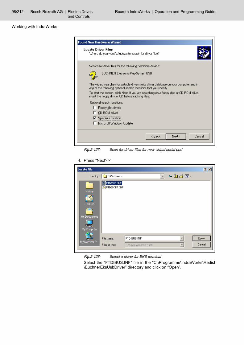
Fig.2-127: Scan for driver files for new virtual serial port
4. Press “Next>>”.
Fig.2-128: Select a driver for EKS terminalSelect the “FTDIBUS.INF” file in the “C:\Programme\IndraWorks\Redist\EuchnerEksUsbDriver” directory and click on “Open”.
98/212 Bosch Rexroth AG | Electric Drivesand Controls
Rexroth IndraWorks | Operation and Programming Guide
Working with IndraWorks

Fig.2-129: Confirm driver selection for new virtual serial port
5. Press “Next>>”.The EKS USB driver will be installed now.
Fig.2-130: Windows hardware wizard, complete the installation of the EKSUSB driver
6. Click on “Finish” to finish the installation of the EKS USB driver. Immedi‐ately after the installation of the EKS USB driver, a virtual serial port willbe installed for the newly connected EKS terminal.
Operation and Programming Guide | Rexroth IndraWorks Electric Drivesand Controls
| Bosch Rexroth AG 99/212
Working with IndraWorks

Fig.2-131: Windows recognizes a new virtual serial portHaving recognized the new virtual serial port, Windows starts the hard‐ware wizard again.
Fig.2-132: Windows hardware wizard
7. Press “Next>>”.
100/212 Bosch Rexroth AG | Electric Drivesand Controls
Rexroth IndraWorks | Operation and Programming Guide
Working with IndraWorks

Fig.2-133: Install hardware driver for new virtual serial port
8. Press “Next>>”.
Fig.2-134: Scan for driver files for new virtual serial port
9. Press “Next>>”.
Operation and Programming Guide | Rexroth IndraWorks Electric Drivesand Controls
| Bosch Rexroth AG 101/212
Working with IndraWorks

Fig.2-135: Confirm driver selection for new virtual serial port
10. Press “Next>>”.
Fig.2-136: Finish the installation of the virtual serial port
11. Press “Finish”. Now the installation of the driver is completed and the EKSterminal is ready.
102/212 Bosch Rexroth AG | Electric Drivesand Controls
Rexroth IndraWorks | Operation and Programming Guide
Working with IndraWorks

2.9.4 Creating Users and GroupsThe IndraWorks user management analyzes the protection level stored in theEKS key as well as the special function “Rework” and logs in a user, dependingon these data. The user to be logged in will be defined via a code given by theadministrator.
Fig.2-137: Properties dialog box, Code defines the user to be logged in with a cer‐tain EKS key
The user management forms the code from the EKS key data, according to thefollowing scheme:Pattern: eks_level_<protectionlevel>[_[r][o]]The protection level is a 3-digit decimal number. The user management sup‐ports protection levels from 000 to 099. _r or _o will be added if the specialfunction Rework or OperatingSystem is set on the EKS key.Here you will find some examples of codes, formed from EKS key data:● eks_level_001 : EKS key with protection level 1, no special function● eks_level_002 : EKS key with protection level 2, no special function● eks_level_001_r : EKS key with protection level 1, special function Rework● eks_level_001_o : EKS key with protection level 1, special function Oper‐
atingSystem● eks_level_001_ro : EKS key with protection level 1, special functions Re‐
work and OperatingSystemWe recommend the following user configuration and group configuration whenusing the EKS system in IndraWorks:
1. Create users for any protection level and users for necessary protectionlevels with special functions. Assign a code to the users, according to theprotection level and special functions.
Operation and Programming Guide | Rexroth IndraWorks Electric Drivesand Controls
| Bosch Rexroth AG 103/212
Working with IndraWorks

Fig.2-138: User scheme according to EKS protection levels
2. Create a group for any protection level and for both special functions. As‐sign the necessary permissions to these groups. If the permission profilesof the groups are based on each other, assign only the additional permis‐sions to the higher groups.
Fig.2-139: Group scheme according to EKS protection levels and specialfunktions
3. Assign all the new users to the appropriate groups.
104/212 Bosch Rexroth AG | Electric Drivesand Controls
Rexroth IndraWorks | Operation and Programming Guide
Working with IndraWorks

Fig.2-140: Properties dialog box, users of an EKS protection level are mem‐bers in the according groups. Here EKS protection level 4 withspecial funktions Rework and OperatingSystem.
2.9.5 Reading the EKS Key Data in the PLC ProgramIn order to evaluate EKS key data or information on the current protection levelin an PLC program, define the following global PLC variables:Program:
VAR_GLOBAL EKS_SerialNo:STRING(16); (*key serial number*) EKS_ProtectionLevel:INT; (*protection level*) EKS_WorkerIdent:STRING(7); (*worker ident*) EKS_SafetyOperationMode:BYTE; (*safety mode*) EKS_So1:BYTE; (*special functions*) EKS_So2:BYTE; (*special functions*) EKS_So3:BYTE; (*special functions*) EKS_So4:BYTE; (*special functions*) EKS_So5:BYTE; (*special functions*) EKS_So6:BYTE; (*special functions*) EKS_So7:BYTE; (*special functions*) EKS_So8:BYTE; (*special functions*) EKS_So9:BYTE; (*special functions*) EKS_KeyIn:BYTE; (*FFhex if key inserted, 00hex if no key*) END_VAR
As soon as an EKS key has been inserted into the EKS terminal and the ac‐cording user has been logged in, IndraWorks will write the following data in allPLC devices belonging to the current project, if the variables above have beendeclared.EKS_SerialNo Serial number of the EKS key, as string. If the EKS key will be
removed, this variable is an empty string.EKS_Protec‐tionLevel
Protection level, stored on the EKS key. Protection levels from00 to 99 are allowed. If the EKS key will be removed, this var‐iable will be -1.
Operation and Programming Guide | Rexroth IndraWorks Electric Drivesand Controls
| Bosch Rexroth AG 105/212
Working with IndraWorks
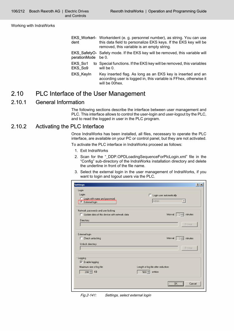
EKS_WorkerI‐dent
Workerident (e. g. personnel number), as string. You can usethis data field to personalize EKS keys. If the EKS key will beremoved, this variable is an empty string.
EKS_SafetyO‐perationMode
Safety mode. If the EKS key will be removed, this variable willbe 0.
EKS_So1 toEKS_So9
Special functions. If the EKS key will be removed, this variableswill be 0.
EKS_KeyIn Key inserted flag. As long as an EKS key is inserted and anaccording user is logged in, this variable is FFhex, otherwise itwill be 00hex.
2.10 PLC Interface of the User Management2.10.1 General Information
The following sections describe the interface between user management andPLC. This interface allows to control the user-login and user-logout by the PLC,and to read the logged in user in the PLC program.
2.10.2 Activating the PLC InterfaceOnce IndraWorks has been installed, all files, necessary to operate the PLCinterface, are available on your PC or control panel, but they are not activated.To activate the PLC interface in IndraWorks proceed as follows:
1. Exit IndraWorks2. Scan for the “_DDP.OPDLoadingSequenceForPlcLogin.xml” file in the
“Config” sub-directory of the IndraWorks installation directory and deletethe underline in front of the file name.
3. Select the external login in the user management of IndraWorks, if youwant to login and logout users via the PLC.
Fig.2-141: Settings, select external login
106/212 Bosch Rexroth AG | Electric Drivesand Controls
Rexroth IndraWorks | Operation and Programming Guide
Working with IndraWorks

After selecting the external login you can still login via nameand password (Project ▶ Login User). Additionally, the usermanagement allows to login and logout users by programmingcertain PLC variables.
4. Restart IndraWorks.
2.10.3 Login and Logout Users via a PLC ProgramThe user login and user logout is controlled by three PLC variables. Define thefollowing global PLC variables:Program:
VAR_GLOBAL UM_LoginCmd:BYTE; (* command, 00hex = logout, FFhex = login *) UM_LoginCode:STRING; (* code of the user to be logged in *) UM_MediaId:DWORD; (* release code, can be set to 0 *) END_VAR
To login a user, the PLC program has to perform the following steps:1. Set PLC variable UM_MediaId to 02. Write the code of the user to be logged in in the PLC variable UM_Logi‐
nCode3. Set PLC variable UM_LoginCmd to FFhex
Fig.2-142: Properties dialog box, defined code must be written in PLC variableUM_LoginCode, to login the user
In order to logout a user, the PLC program must set the PLC variable UM_Log‐inCmd to 0. This causes the logout of the current user, independent of thevalues of the other two PLC variables.
2.10.4 Reading the Current User in the PLC ProgramThe state of the user management is represented by three PLC variables. De‐fine the following global PLC variables:
Operation and Programming Guide | Rexroth IndraWorks Electric Drivesand Controls
| Bosch Rexroth AG 107/212
Working with IndraWorks

Program:
VAR_GLOBAL UM_UsermanEnabled:BYTE; (*indicates, whether the user management is enabled*) UM_UserLoggedIn:BYTE; (*indicates, whether a user is logged in*) UM_CurrentUserName:STRING; (*login name of the user *) END_VAR
The values of these PLC variables are written by the user manage‐ment. Only reading access to the PLC variables is allowed withinthe PLC program.
The PLC variable UM_UsermanEnabled indicates, whether the user manage‐ment is enabled (FFhex) or disabled (00hex). If the user management isdisabled, no permissions are asked for in the user interface and all functionsare available.The PLC variable UM_UserLoggedIn indicates, whether a user is logged in(FFhex) or not (00hex).The PLC variable UM_CurrentUserName contains the user name of the userlogged in or an empty string, if no user is logged in.
Fig.2-143: Properties dialog box, user management writes the user name in PLCvariable UM_CurrentUserName after login
2.10.5 Example: Changing Permission Levels via Key SwitchTask
A key switch connected to the control panel is to be used to switch betweenseveral permission levels. The key switch can adopt four positions:Position 1: Permission level "Operator" In this position the key can be removed,i. e., this permission level is active, even without the key.Position 2: Permission level "Maintainer"Position 3: Permission level "Programmer"Position 4: Permission level "Machine vendor"
108/212 Bosch Rexroth AG | Electric Drivesand Controls
Rexroth IndraWorks | Operation and Programming Guide
Working with IndraWorks

Configuration of the User ManagementIn the user management, one user will be defined for each of these four per‐mission levels. The users will be assigned to one or more groups, according tothe necessary permission profile.
Fig.2-144: Example of a configuration: one user per permission levelThe external login will be selected in the settings of the user management.Additionally, the user "key_switch_level_1" is defined here to be logged in au‐tomatically. This ensures the availability of at least this permission level .
Fig.2-145: Settings, external login
Operation and Programming Guide | Rexroth IndraWorks Electric Drivesand Controls
| Bosch Rexroth AG 109/212
Working with IndraWorks

PLC programThe key switch position will be assigned to a user via a PLC program. Thisprogram checks the key switch position and logs in the appropriate user.Program:
VAR_GLOBAL UM_UsermanEnabled:BYTE; UM_UserLoggedIn:BYTE; UM_CurrentUserName:STRING; UM_LoginCmd:BYTE; UM_LoginCode:STRING; UM_MediaId:DWORD; END_VAR
Program:
PROGRAM PLC_PRG VAR KeySwitch:BYTE; (*key switch*) END_VAR
Program:
(* ** Example: ** PLC controlled switching of permission levels by key switch *)(* actual key inquiry The inputs used by the key switch will be copied to the variable keyswitch Key switch position 1: 16#01 Key switch position 2: 16#02 Key switch position 3: 16#04 Key switch position 4: 16#08 *)UM_MediaId := 0; (*release control not used*)(*Key switch position 4, Bit 4 set*) IF KeySwitch = 16#08 THEN UM_LoginCode := 'keyswitch4'; UM_LoginCmd := 16#FF;(*Key switch position 3, Bit 3 set*) ELSIF KeySwitch = 16#04 THEN UM_LoginCode := 'keyswitch3'; UM_LoginCmd := 16#FF;(*Key switch position 2, Bit 2 set*) ELSIF KeySwitch = 16#02 THEN UM_LoginCode := 'keyswitch2'; UM_LoginCmd := 16#FF;(*Key switch position 1 or key removed, Bit 1 set*) ELSIF KeySwitch = 16#01 THEN UM_LoginCode := 'keyswitch1'; UM_LoginCmd := 16#FF;(*other values: logout current user*)
110/212 Bosch Rexroth AG | Electric Drivesand Controls
Rexroth IndraWorks | Operation and Programming Guide
Working with IndraWorks

ELSE UM_LoginCmd := 16#00; UM_LoginCode := '';END_IFRETURN;
2.11 Firmware Management The firmware management in IndraWorks provides the following functions:● Downloading a firmware to a device● Displaying the current firmware in a device● Displaying the firmware available for a download
Starting the Firmware Management To start the firmware management, use the context-sensitive menu of a deviceor the device-specific entries in the main menu. Select the Firmware Manage‐ment item.
Description of the Dialog Elements The left selection window of the dialog box displays the firmware available fora download. Depending on the used device it may be possible to select a di‐rectory containing firmware files, above this selection window.The right window of the dialog box displays the firmware of the device.Below these windows, the current state is displayed, e. g. “Ready for down‐load”.
Operation Select the firmware you want to load into the device in the left selection window.Depending on the used device further options, e. g., “Reboot after download”may be offered below this window. Start the download via the “Download” but‐ton. A progress bar will be displayed, informing on the current state andprogress of the download.
Fig.2-146: Firmware Management dialog box
Operation and Programming Guide | Rexroth IndraWorks Electric Drivesand Controls
| Bosch Rexroth AG 111/212
Working with IndraWorks

2.12 License Management2.12.1 Licensing of IndraWorks ComponentsGeneral Information
The licenses of IndraWorks software components are managed via the Optionsdialog box. Open the Options dialog box via Tools-Options and then select the“Software Licenses” page in “General”.
Fig.2-147: Options dialog box, software licensesThe page displays all available software components requiring a license andtheir license state. The scope of the entries depends on the system installed.
License state Description
- No license has been installed on this computer. The com‐ponent cannot be used.
Licensed A full license has been installed on this computer. Thecomponent can be used without any restrictions.
Demo license, 30-days A limited demo license has been installed on this com‐puter. The component can still be used for evaluation forthe number of days specified (no more than 30 days).
Fig.2-148: License stateTo view a description of a license, place the mouse pointer on the license entry.
Installing a License To license a software component, select it from the list and click on “Li‐cense...”.
If a full license is already installed, the “License...” button is deac‐tivated.
112/212 Bosch Rexroth AG | Electric Drivesand Controls
Rexroth IndraWorks | Operation and Programming Guide
Working with IndraWorks

Fig.2-149: Install Licenses dialog box, enter the license typeDecide whether you wish to install an unrestricted full license or a demo license.The demo license allows you to test the selected software components for 30days.
If “Demo license” is deactivated, a demo license has either alreadybeen installed or the component selected does not support a demolicense.
For installing a full license, enter the license key and, if displayed, the serialnumber. You have obtained the necessary data togehter with the license.Click on “Next>>”.
Operation and Programming Guide | Rexroth IndraWorks Electric Drivesand Controls
| Bosch Rexroth AG 113/212
Working with IndraWorks

Fig.2-150: Install Licenses dialog box, license conditionsThoroughly read the license conditions from beginning to end.To accept the license conditions, select “I accept the license conditions” andclick on “Finish”.If you do not accept the license conditions, click on “Cancel”. In this case, thelicense will not be installed.
Deleting a License To delete a license, select it from the list and click on “Delete”.
Fig.2-151: Deleting licensesTo confirm the safety prompt, click on “Yes”.
2.12.2 Licensing Firmware FunctionsGeneral Information
Firmware functions requiring a license are enabled via the context-sensitivemenu of the particular device in the project explorer. If a device supports func‐tions that can be enabled, it provides the menu item Firmware Licenses….
114/212 Bosch Rexroth AG | Electric Drivesand Controls
Rexroth IndraWorks | Operation and Programming Guide
Working with IndraWorks

Fig.2-152: Firmware Licenses, menu entry
Fig.2-153: Licenses for ... dialog boxThe “Firmware Licenses” dialog box displays all functions that can be enabled,together with their license state. The scope of the entries depends on the devicetype.
License state Description
- Function disabled
Licensed Function enabled
Fig.2-154: License stateTo view a description of a function, place the mouse pointer on the correspond‐ing entry.
Operation and Programming Guide | Rexroth IndraWorks Electric Drivesand Controls
| Bosch Rexroth AG 115/212
Working with IndraWorks

Enabling Firmware Functions
A license key is not required for enabling firmware functions. How‐ever, the functions provided in the “Firmware licenses” dialog boxmust be paid. You can enable and use those functions, if you havepurchased the according licenses.
To enable the functions, select them and click on “License...”.
Fig.2-155: Install Licenses dialog box, accept license conditionsThoroughly read the license conditions from beginning to end.To accept the license conditions, select “I accept the license conditions” andclick on “Finish”.If you do not accept the license conditions, click on “Cancel”. The functionsselected are not enabled.
Deleting Firmware Licenses To cancel the enabling of functions, select the functions desired and click on“Delete”.
Fig.2-156: Deleting licensesTo confirm the safety prompt, click on “Yes”.
116/212 Bosch Rexroth AG | Electric Drivesand Controls
Rexroth IndraWorks | Operation and Programming Guide
Working with IndraWorks

2.13 Network Connection2.13.1 General Information
To operate several machines in a network with access to data and diagnosticsof neighboring machines, the following steps are required:● A network configuration must be created, that lists all visualization devices
and controls of the machines of the network.● The network configuration must be added to the machine projects.The data access to a network control is always established via the visualizationdevice to which this control is assigned to. Thus the network configuration mustcontain the visualization devices as well as the controls.
2.13.2 Creating a Network ConfigurationGeneral Information
Create a new network configuration via File ▶ New ▶ Network Configuration.IndraWorks opens an editor, which you can use to edit and save this emptynetwork configuration.
Fig.2-157: Network configuration editorYou can specify a name for the network, and define the network devices in thenetwork configuration editor.
Adding Devices to the Network ConfigurationThe following devices can be added to a network configuration:
Family Device Types
Visualization devices BTV/Vxx
IndraLogic IndraLogic L20, IndraLogic L40, IndraLogic V, IndraLogicVPP21
MTX IndraMotion MTX L40, IndraMotion MTX P40,IndraMotion MTX P60
Fig.2-158: Available device typesTo add a device to the network configuration, right-click on the device list in theeditor and select in Add the desired device type.You can also drag the desired device from the library to the device list (“drag-and-drop”).If you add a device to the network configuration, a dialog box for editing thedevice properties will be opened. The device will not be added to the device listunless you have closed this properties dialog box via OK.Tip: It is recommended to define a visualization device for a control, before youadd this control (IndraLogic or MTX).
Operation and Programming Guide | Rexroth IndraWorks Electric Drivesand Controls
| Bosch Rexroth AG 117/212
Working with IndraWorks
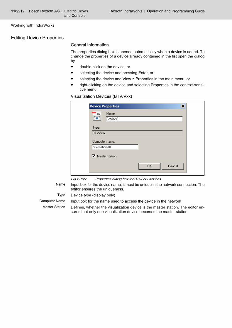
Editing Device PropertiesGeneral InformationThe properties dialog box is opened automatically when a device is added. Tochange the properties of a device already contained in the list open the dialogby● double-click on the device, or● selecting the device and pressing Enter, or● selecting the device and View ▶ Properties in the main menu, or● right-clicking on the device and selecting Properties in the context-sensi‐
tive menu.
Visualization Devices (BTV/Vxx)
Fig.2-159: Properties dialog box for BTV/Vxx devicesName Input box for the device name, it must be unique in the network connection. The
editor ensures the uniqueness.Type Device type (display only)
Computer Name Input box for the name used to access the device in the networkMaster Station Defines, whether the visualization device is the master station. The editor en‐
sures that only one visualization device becomes the master station.
118/212 Bosch Rexroth AG | Electric Drivesand Controls
Rexroth IndraWorks | Operation and Programming Guide
Working with IndraWorks

Controls (IndraLogic, MTX)
Fig.2-160: Properties dialog for IndraLogic devices and MTX devicesName Input box for the device name, it must be unique in the network connection. The
editor ensures the uniqueness.Type Device type (display only)
Assigned Visualization Device Defines the visualization device, the control is assigned to. The check box listsall visualization devices defined in the network configuration.
Control Name in the Project Enter the name of the control here, exactly as it has been defined in the originalproject.
Changing the OrderYou can change the order of the devices in the network configuration by● right-clicking on a device and selecting Up or Down in the context-sensitive
menu, or● dragging a device to a different position
Removing a DeviceYou can remove a device from the network configuration by● right-clicking on the device and selecting Remove in the context-sensitive
menu, or● selecting the device and pressing <Entf>, or● selecting the device and Edit ▶ Remove in the main menu.If you are sure you want to remove the device confirm the following note.
Fig.2-161: Note when removing devices
Saving a Network ConfigurationSave a network configuration via File ▶ Save.
Operation and Programming Guide | Rexroth IndraWorks Electric Drivesand Controls
| Bosch Rexroth AG 119/212
Working with IndraWorks

If it is a new network configuration, a dialog for defining the file name will beopened.
Fig.2-162: Save Network Configuration dialog boxIf the network configuration has been saved already or an existing networkconfiguration has been opened, the existing file will be overwritten.If you want to save the network configuration under a different name, selectFile ▶ Save As in the main menu.
When saving, make sure that the window of the network configu‐ration editor is active, otherwise other data may be saved.
Closing the EditorTo close the network configuration editor, click on the x in the upper right of thewindow or press <Ctrl> + <F4>.If there are unsaved changes in the network configuration, you will be askedhow to proceed.
Fig.2-163: Prompt when closing the editorYes Saves the network configuration and closes the editor. If the network configu‐
ration has not been saved before, the dialog for selecting a file name will beopened.
No Discards the changes and closes the editor.Cancel The editor will not be closed.
2.13.3 Opening an Existing Network ConfigurationOpen an existing network configuration via File ▶ Open ▶ Network Configura‐tion. IndraWorks opens a dialog box to select the file.
120/212 Bosch Rexroth AG | Electric Drivesand Controls
Rexroth IndraWorks | Operation and Programming Guide
Working with IndraWorks
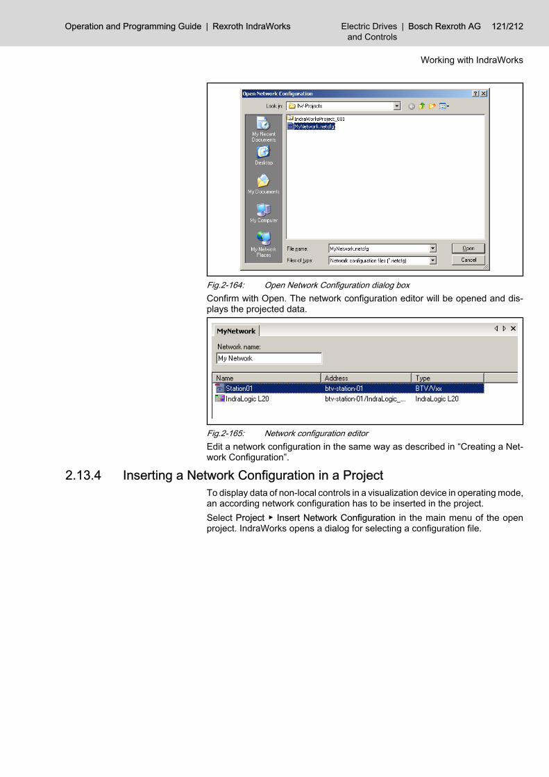
Fig.2-164: Open Network Configuration dialog boxConfirm with Open. The network configuration editor will be opened and dis‐plays the projected data.
Fig.2-165: Network configuration editorEdit a network configuration in the same way as described in “Creating a Net‐work Configuration”.
2.13.4 Inserting a Network Configuration in a ProjectTo display data of non-local controls in a visualization device in operating mode,an according network configuration has to be inserted in the project.Select Project ▶ Insert Network Configuration in the main menu of the openproject. IndraWorks opens a dialog for selecting a configuration file.
Operation and Programming Guide | Rexroth IndraWorks Electric Drivesand Controls
| Bosch Rexroth AG 121/212
Working with IndraWorks

Fig.2-166: Open Network Configuration dialog boxSelect a file and press Open. The network configuration will be inserted in theproject and displayed in the project explorer.
Fig.2-167: Project with network configurationIf you are trying to insert a network configuration into a project that alreadycontains one, you will get the following note.
Fig.2-168: Warning when inserting a network configuration into a project
2.14 Remote Engineering2.14.1 General Information
A project contains all devices, communication connections and other compo‐nents required for operating a machine or system. A project is operated via theIndraWorks interface of the der operation station.The “Remote Engineering” allows to run IndraWorks on a separate computer(control station), connected to the operation station via network.To work in the Remote Engineering proceed as follows:1. Enable the “Remote Engineering” on the operation station2. On the projecting station:
● Connect to the operation station● Open and edit project on operation station● Save the project● Disconnect from operation station
122/212 Bosch Rexroth AG | Electric Drivesand Controls
Rexroth IndraWorks | Operation and Programming Guide
Working with IndraWorks

3. Now, you can disable the “Remote Engineering” on the operation station,if no more accesses of the projecting station are necessary.
2.14.2 Enabling and Disabling the “Remote Engineering” on the OperationStation
EnablingOn an IndraWorks operation station you must explicitly enable or disable theRemote Engineering.You can do this via the “Remote Engineering Configuration” application in thestart menu.
Fig.2-169: Remote Engineering Configuration, startThe dialog box of the “Remote Engineering Configuration” application displaysthe current state (here: disabled).
Fig.2-170: Remote Engineering disabledPress “OK” or “Cancel” to close the dialog box. The remote engineering remainsdisabled.Select “Enable Remote Engineering” and define the share folder for IndraWorksprojects in an input box or selection dialog. Now, projection stations can accessIndraWorks projects via this directory.
Operation and Programming Guide | Rexroth IndraWorks Electric Drivesand Controls
| Bosch Rexroth AG 123/212
Working with IndraWorks

Fig.2-171: Define the share folderThe dialog box displays the current mode and the according settings. Validsettings have got a check mark. Invalid settings are marked by a white X on ared circle. Use the “Repair” button to correct the setting; this can take sometime.
Fig.2-172: Errors in the current settings“Cancel” closes the dialog box without any changes.Use “OK” and “Apply” to start the following procedure:
124/212 Bosch Rexroth AG | Electric Drivesand Controls
Rexroth IndraWorks | Operation and Programming Guide
Working with IndraWorks

● A user, internally used by IndraWorks, will be created or its account willbe activated.
● The connected projecting station will get full access to the following di‐rectories, using the Windows security settings:– IndraWorks projects directory– IndraWorks installation directory– IndraLogic installation directory
● Share folders for these three directories will be created.As long as the procedure is running, the dialog cannot be edited and the cursorappears as an hourglass.
Fig.2-173: Remote Engineering will be enabled.“OK” closes the application.
DisablingIf you want to disable the Remote Engineering, start the “Remote EngineeringConfiguration” via the start menu. This dialog box displays the current state(here: enabled).
Operation and Programming Guide | Rexroth IndraWorks Electric Drivesand Controls
| Bosch Rexroth AG 125/212
Working with IndraWorks

Fig.2-174: Enabled Remote EngineeringDisable the Remote Engineering by “Disable Remote Engineering” and “Ap‐ply” or “OK”. The steps described above will be performed in reverse order.
Fig.2-175: Disable Remote Engineering“OK” stops the Remote Engineering.
126/212 Bosch Rexroth AG | Electric Drivesand Controls
Rexroth IndraWorks | Operation and Programming Guide
Working with IndraWorks

2.14.3 Operations at the Projection StationConnecting to the Operation Station
This function is available, only if you have installed the IndraWorksLOGIC system or the IndraMotion MTX system.
First the according operation station must be enabled for the RemoteEngineering (see above).To connect to the operation station select the according menu entry inIndraWorks.
Fig.2-176: Connect to Operating Station, menu entryIf a project is open, it will be closed automatically after the confirmation of amessage box.Now you are asked to enter the host name or IP address of the operation station.
Fig.2-177: Connect to Operating Station dialog box, input of host name“Cancel” closes the dialog box without any changes.“OK” starts the following procedure:● Three network connections to the specified host will be established.
– \\<Host Name>\IW IndraLogic installation directory.– \\<Host Name>\IW IndraWorks installation directory.– \\<Host Name>\IWP IndraWorks project directory.
● The Remote Engineering will be enabled.
Fig.2-178: Release the connection
Remote EngineeringIf Remote Engineering is enabled, the working with IndraWorks will be changedas follows:● Three network drives are available to access directories of the connected
operation station.
Operation and Programming Guide | Rexroth IndraWorks Electric Drivesand Controls
| Bosch Rexroth AG 127/212
Working with IndraWorks

● The dialogs “Open Project”, “Create New IndraWorks Project” and “SaveProject As” refer to the project directory of the operation station.
● Use Project ▶ Active for IndraWorks Operation to open the “Activate Proj‐ect” dialog box and to define the project to be loaded for the operationinterface of the connected operation station.
● The communication servers of the operation station will be used.
Disconnect from Operation StationAn existing connection to an operating station can be closed by Project ▶ Re‐mote Engineering ▶ Disconnect from Operating Station....
Fig.2-179: Disconnect from Operating Station, menu entryIf a project is open, you will be prompted to close it.The disconnection from the operation station causes● the network connections to be closed.● the disconnecting from the communication servers of the operation sta‐
tion.The state will be displayed in the status bar.
Fig.2-180: Connection closed
Disconnecting Existing Network DrivesYou have to close all existing network connections to the operation station inorder to connect to this operation station, because Windows does not allow toestablish network connections to one host using different user names.Open the Disconnect Network Drives Windows dialog box via the accordingmenu entry and close all existing network connections to the operation stationyou want to connect to via the IndraWorks projection interface.
2.15 Remote Service 2.15.1 General Information
General With I-Remote, an efficient teleservice software is available in IndraWorks forthe remote control of PC systems. The use of I-Remote allows you to accessremote machines and to perform diagnostics or maintenance steps.
Software Components The I-Remote teleservice software consists of two software components.
128/212 Bosch Rexroth AG | Electric Drivesand Controls
Rexroth IndraWorks | Operation and Programming Guide
Working with IndraWorks

Software Component Description
Client Software component installed on the PC to be remote-controlled. After completed installation, the client PCcan be remote-controlled from a service PC.
Control Software component installed on the remote-control‐ling PC. After completed installation, the control PCcan remote-control PCs on which a client is installed.
Fig.2-181: I-Remote teleservice softwareDelivery The client installation is an integral part of IndraWorks and can be enabled by
acquiring a valid license.The control installation is delivered as a separate data carrier. Enabling of thiscomponent also requires a valid license. For detailed help on the installationand operation of the I-Remote control software, please refer to the data carrierof the control installation.
2.15.2 I-Remote Client Software The sections following below refer exclusively to the I-Remote client software.
Installation While IndraWorks is installed, the I-Remote setup for the client software is filedto each control PC.To install the software, please proceed as follows:● Select Setup in the Start ▶ Programs ▶ Rexroth ▶ IndraWorks ▶ I-Re‐
mote menu.● Select the language and accept the license conditions.● Enter the license information which you received when you purchased
IndraWorks I-Remote in the “General” tab and click on “Generate”.
Fig.2-182: NetSupport License Manager dialog box
Operation and Programming Guide | Rexroth IndraWorks Electric Drivesand Controls
| Bosch Rexroth AG 129/212
Working with IndraWorks

Enter the information precisely, considering upper and lower cases.
● Click on “Install”.● Close all applications and restart the computer. This completes the instal‐
lation of IndraWorks I-Remote.IndraWorks Integration After successful installation, the Tools menu of the IndraWorks Engineering
desktop contains I-Remote with the Activate, Deactivate and Configurationmenu items.
Authorization The use of the I-Remote functions requires the following authorizations:● You must be logged in as main user or administrator in Windows.● The user logged in IndraWorks must have the privilege “I-Remote” or he
must be a member of a group with this privilege (see chapter 2.8 "UserManagement" on page 82).
Activate This menu entry activates the I-Remote software. You can now access this PCfrom a service PC with the I-Remote control software. For safety reasons, theuser must confirm a connection request of the service PC in the default con‐figuration.
Deactivate Deactivates the I-Remote software. The PC cannot be accessed via I-Remoteany longer.
Configure The I-Remote session between the service PC and the client PC can be con‐figured as desired with regard to important configuration parameters, e. g.:● Safety (user management, access rights)● Transport protocol● Functionality available during access● WEB interfaceWhile an I-Remote session is being established, the configuration is valid forboth users of the session, i. e. for the service PC and for the client PC.Please, use the supplied documentation and online help of the NetSupportManager to make adjustments to the configuration.
2.16 External Applications2.16.1 General Information
IndraWorks provides the option of calling any external applications and HTMLpages. Once they have been configured appropriately, these programs andpages are displayed in the Tools menu and can be started by selecting theassociated entry.To configure and manage external applications, select Tools ▶ External Appli‐cations.
When you are using Automation Interface, create an HTML pagewith embedded script code containing the access functionality tothe Automation Interface. Add this functionality to the Tools menuas described in the following chapter.
130/212 Bosch Rexroth AG | Electric Drivesand Controls
Rexroth IndraWorks | Operation and Programming Guide
Working with IndraWorks

Fig.2-183: External Applications dialog box
2.16.2 Adding an Application or HTML Page Use “Add” to open a dialog box and to select an application or HTML page. Toselect HTML pages enter "All Files" in the file type field.
Fig.2-184: Select File dialog boxConfirm the file selected with “Open”. The application or HTML page will bedisplayed in the Properties dialog box . There you can define the properties(see chapter 2.16.3 "Changing the Properties of an Application " on page132).After you have confirmed all dialogs, the application or HTML page is displayedand can be called in Tools ▶ External Applications....
Operation and Programming Guide | Rexroth IndraWorks Electric Drivesand Controls
| Bosch Rexroth AG 131/212
Working with IndraWorks
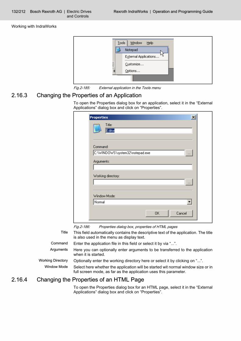
Fig.2-185: External application in the Tools menu
2.16.3 Changing the Properties of an Application To open the Properties dialog box for an application, select it in the “ExternalApplications” dialog box and click on “Properties”.
Fig.2-186: Properties dialog box, properties of HTML pagesTitle This field automatically contains the descriptive text of the application. The title
is also used in the menu as display text.Command Enter the application file in this field or select it by via “...”.Arguments Here you can optionally enter arguments to be transferred to the application
when it is started.Working Directory Optionally enter the working directory here or select it by clicking on “...”.
Window Mode Select here whether the application will be started wit normal window size or infull screen mode, as far as the application uses this parameter.
2.16.4 Changing the Properties of an HTML Page To open the Properties dialog box for an HTML page, select it in the “ExternalApplications” dialog box and click on “Properties”.
132/212 Bosch Rexroth AG | Electric Drivesand Controls
Rexroth IndraWorks | Operation and Programming Guide
Working with IndraWorks

Fig.2-187: Properties dialog box, properties of HTML pagesTitle This field contains automatically the descriptive text of the HTML page. The title
is also used in the menu as display text.Command Enter the file name of the HTML page in this field or select it via “...”.Arguments This field is locked when adding HTML pages.
Working Directory This field is locked when adding HTML pages.Window Mode Here, you can define whether the HTML page is to be started integrated in
IndraWorks or externally. The current version starts HTML pages only integra‐ted in IndraWorks.
2.16.5 Removing an Application or HTML Page To remove an application or HTML page from IndraWorks, select the appro‐priate entry from the “External Applications” dialog box and click on “Re‐move”.
2.17 Options Dialog 2.17.1 General Information
The options dialog box provides comprehensive setting options allowing you tocustomize IndraWorks.These setting options cover the appearance and the behavior of the user in‐terface as well as specific settings of various program parts.The setting options are organized on options pages. A single page containscoherent or related settings.Select Tools ▶ Options to open to the Options dialog box.
2.17.2 Function Areas The Options dialog box is divided in a navigation area and an area for displayingthe options pages.
Operation and Programming Guide | Rexroth IndraWorks Electric Drivesand Controls
| Bosch Rexroth AG 133/212
Working with IndraWorks

Navigation Area The navigation area contains the tree-like hierarchy of the options pages. Thehighest level only comprises folders. Folders can contain options pages andsubfolders.
Options Pages Select an element from the navigation area to display the appropriate optionspage. Here you can view and edit the particular settings.Select a folder from the navigation area to open an overview of its availableoptions pages and a brief description.
2.17.3 Operation Changing Settings Select an element from the navigation area of the Options dialog box to display
the corresponding options page.Make the desired settings on that options page. Several options pages can beedited one after the other. These changes are preserved as long as the Optionsdialog box is open.
Making Changed Settings Effective Changes will become effective only after you have clicked on “Apply” or “OK”.Restoring Settings to Default Val‐
uesTo restore the default values on the current options page, click on “Reset”. Thenclick on “Apply” or “OK” so that the default settings will become effective.
Using Help Click on “Help” to open the online help for the current options page.Exiting the Options Dialog Box Click “OK” to exit the Options dialog box. The changes will now become effec‐
tive.To discard all changes and to close the Options dialog box, click on “Cancel”.
2.17.4 General Options Language Settings
Use the “Language settings” options page to select the user interface languagefor IndraWorks.As soon as the language selected has become effective by clicking on “OK” or“Apply”, the display of the user interface is updated, i. e. the user interface isdisplayed in the language desired immediately.
Software Licenses Use this page to manage the licenses of software components. (see chapter2.12 "License Management " on page 112)
Keyboard (Shortcuts) Use the “Keyboard” options page to assign shortcuts to commands.
134/212 Bosch Rexroth AG | Electric Drivesand Controls
Rexroth IndraWorks | Operation and Programming Guide
Working with IndraWorks

Fig.2-188: Options dialog box, keyboardCategories Select a category to list the commands of that category in the “Commands”
column.Description This field provides a brief description of the command selected.
Shortcut for Selected Command If assigned to a selected command, a shortcut is shown in this field. Click on“Delete” to remove the shortcut. If a shortcut does not exist, this field shows“None”.
Enter New Shortcut Use this field to define a new shortcut for the command selected by pressing akey or a combination of keys. If the shortcut is already assigned to a differentcommand, this is displayed in the “Shortcut is already used by” field.
A shortcut can be assigned to one command only. If you assign analready used shortcut to a new command, that shortcut cannot beused for the previous command any longer.
Projects Use this options page to change the settings for the project explorer.These changes will not become effective before the next restart.
Operation and Programming Guide | Rexroth IndraWorks Electric Drivesand Controls
| Bosch Rexroth AG 135/212
Working with IndraWorks

Fig.2-189: Options dialog box, Project explorer
2.18 Customizing Dialog The “Customizing” dialog box provides the option of editing the menu and thetoolbars.To open this dialog box, select Tools ▶ Customizing….
Adding a Command to the Menu orto a Toolbar
To add a command to a toolbar, activate that toolbar. Afterwards, selectTools ▶ Customizing… and the “Commands” page. Select the category for thecommand. Drag the command to be added from the “Commands” field to theappropriate point in the menu or the toolbar.
Showing and Hiding Toolbars Toolbars can be shown or hidden. To do this, select Tools ▶ Customizing… andthe “Toolbars” page. Make the appropriate settings in the “Toolbars” field.
Creating a New Toolbar To create your own toolbar, click the “New…” button on the “Toolbars” page.This will open the “Create New Toolbar” dialog box where you enter a name forthe new toolbar. Click “OK” to create the toolbar, which will be floating. Thetoolbar name will be entered in the toolbar list.
Renaming a Toolbar Select the user-defined toolbar to be renamed from the “Toolbars” field on the“Toolbars” page. Click on “Rename”.
Only user-defined toolbars can be renamed.
Deleting a Toolbar Select the user-defined toolbar to be deleted from the “Toolbars” field on the“Toolbars” page. Click on “Delete” and confirm the “Delete Toolbar” message.
Only user-defined toolbars can be deleted.
2.19 Info Use Help ▶ Info to call the information dialog box of IndraWorks. This dialogbox provides detailed information on the various components. The upper partof the dialog box shows the precise version and the build number of the basicinstallation. The lower part of the dialog box displays the license conditions.
136/212 Bosch Rexroth AG | Electric Drivesand Controls
Rexroth IndraWorks | Operation and Programming Guide
Working with IndraWorks

Fig.2-190: Info dialog boxInstalled Products This list displays the products installed.
You can display the installed products only, or the installed productstogether with their basic components (see Advanced Information).
Product Details Select a product from the list to view detailed information (type code and copy‐right) in the “Product details” field.
Advanced Information Click on the “Advanced>>” button to show the basic components of the installedsoftware packages in the “Installed products” list. To hide this information again,click on “Advanced<<”.
Copy Info Click on “Copy Info” to copy the information displayed. IndraWorks copies notonly the build and version information on IndraWorks itself, but also the infor‐mation on assemblies, such as file size, creation date and the importantinformation on the particular computer, processor and operating system. Afterthe copying is completed, an editor is started for processing that information .
Calling Extra Info To obtain extra info on the product selected, click on the “Extra Info” button.
2.20 Message Box IndraWorks provides a mechanism for recording errors and messages.The message box is divided in three tabs each of which assumes one singlefunction. In the normal operating mode, only two tabs are visible. The third tabis intended for diagnostic purposes during startup and can only be activated byan additional start parameter.
Operation and Programming Guide | Rexroth IndraWorks Electric Drivesand Controls
| Bosch Rexroth AG 137/212
Working with IndraWorks

Fig.2-191: Output windowOutput The “Output” window records processes such as a download or the compilation
of a program.Task List The “Task list” window lists failures and errors necessitating a reaction. If, for
example, program errors are recorded here, these errors must be eliminatedbefore the compilation process can be repeated without any errors. The windowalso displays the level and, thus, the error class and the origin of the respectiveerror message.
Parameterizing the Message Box Use the “Logging Manager” page of the Options dialog box to parameterize themessage box in IndraWorks.
Device Diagnostics You can show and hide the device diagnostics via Diagnostics ▶ Device Diag‐nostics. The device diagnostics shows a list of the current diagnostics of adevice if● this device or one of its sub-items is selected in the project explorer,● the device supports diagnostic messages, and● the device is in the “online” mode.In all other cases, the list is empty.Each diagnostic message shows the diagnostic number, the diagnostic source(module in case of ProVi messages, channel number in case of MTX), the dateand time of occurrence as well as a descriptive text.
Fig.2-192: Device Diagnostics window
2.21 Help2.21.1 IndraWorks Online Help
Help Use the Help ▶ First Steps command to start the online user documentation.
Fig.2-193: Help menu, first steps
138/212 Bosch Rexroth AG | Electric Drivesand Controls
Rexroth IndraWorks | Operation and Programming Guide
Working with IndraWorks

Fig.2-194: Online information on first steps with IndraWorksSelect Help ▶ Help to start the online user documentation of IndraWorks.
Fig.2-195: Help menu, start online help
Fig.2-196: Online information on IndraWorksContent You can reach all topics of the IndraWorks online help, sorted by headings, via
“Content”.
Operation and Programming Guide | Rexroth IndraWorks Electric Drivesand Controls
| Bosch Rexroth AG 139/212
Working with IndraWorks

Fig.2-197: Contents of the IndraWorks online helpIndex You can reach all topics of the IndraWorks online help, sorted by keywords, via
“Index”.
Fig.2-198: Help, IndexSearch You can scan the IndraWorks online help for keywords via “Search”. The results
are displayed in a list containing all associated topics.
140/212 Bosch Rexroth AG | Electric Drivesand Controls
Rexroth IndraWorks | Operation and Programming Guide
Working with IndraWorks

Fig.2-199: Help, search for topicsRexroth Homepage Select Help ▶ Rexroth Homepage to move to the Bosch Rexroth homepage,
provided you are connected to the network.
Operation and Programming Guide | Rexroth IndraWorks Electric Drivesand Controls
| Bosch Rexroth AG 141/212
Working with IndraWorks

Bosch Rexroth AG | Electric Drivesand Controls
Rexroth IndraWorks | Operation and Programming Guide

3 Operation of the Oscilloscope Function3.1 General Information
The oscilloscope function is used to display and evaluate measured values;that result, e. g., from the transient response of a motor.Its main field of application is for commissioning of drives and controls (MTX),for test and service.
Requirements The device connected must support the oscilloscope function.
3.2 Starting the Oscilloscope Function To activate the oscilloscope function select Diagnostics ▶ Oscilloscope... in themain menu.
Fig.3-1: Start the oscilloscopeOffline Mode If no device is selected or if the online mode is not activated, the oscilloscope
starts in the offline mode. This mode does not allow any measurements. How‐ever, already saved measurements resulting from other measuring processescan be read and displayed.
Online Mode If a device is selected and the online mode is activated, the oscilloscope startsin the online mode.
You can also switch to the online mode subsequently.
3.3 Online and Offline Modes3.3.1 Starting in the Offline Mode
If you start the oscilloscope in the offline mode, you cannot perform a meas‐urement.
State The “State” field in the “Active measurement” area indicates that you are notconnected to a device.
Operation and Programming Guide | Rexroth IndraWorks Electric Drivesand Controls
| Bosch Rexroth AG 143/212
Operation of the Oscilloscope Function

Fig.3-2: Oscilloscope, started in the offline mode
In the offline mode you can read and analyze any measurementsvia the Load Signal Data or Add Signal Data menu items.
After having connected the project and the oscilloscope to a device, you canselect the signals for the measurement. After that, you can configure the triggerand the measurement.
3.3.2 Starting in the Online Mode / Switching to the Online Mode Active Measurement After the switch to the online mode the oscilloscope reads the configuration of
the device connected and displays an empty graph.If the device contains a measurement, you can display it in the graph by clickingon the “Read Signal Data” button.
The message displayed is called the current or active measure‐ment.
144/212 Bosch Rexroth AG | Electric Drivesand Controls
Rexroth IndraWorks | Operation and Programming Guide
Operation of the Oscilloscope Function

A measurement contains the measured data and the configurationdata.
State The state of the measurement is displayed in the “State” field in the “Activemeasurement” area. If a measurement can be performed, its state is “ready”.Further states are “disconnected”, “not configured”, “not triggered”, “triggered”and “storing”.Furthermore, the state field informs you on the progress of the reading processof the measurement data after the measurement. See the following example:
Fig.3-3: Progress when reading the measurement dataSignal overview The signal overview shows the selected signals of the last measurement.
Fig.3-4: Display of the last configurationIf there are no signal data, you have to configure and start a measurement, seechapter 3.5 "Recording a New Measurement " on page 153.
Update If the device contains not only the configuration but also signal data, e. g. aftera long-term measurement, you can display them via “Update”. See the followingexample:
Operation and Programming Guide | Rexroth IndraWorks Electric Drivesand Controls
| Bosch Rexroth AG 145/212
Operation of the Oscilloscope Function

Fig.3-5: Display measurement dataTo show or hide the separate signals set or delete the according checkmark.
Active Signal The display is always scaled according to the active signal. Active signals havea gray background in the signal overview and a greater width in the graph. Toactivate a signal, click on it in the graph or in the signal overview.
3.4 Operation Areas3.4.1 General Information
For a better clearness, the operation tasks of the oscilloscope are arranged onseveral tab pages.Every tab page represents a specific topic.
3.4.2 MeasureSelect the configuration or operation of a measurement on this tab page:
146/212 Bosch Rexroth AG | Electric Drivesand Controls
Rexroth IndraWorks | Operation and Programming Guide
Operation of the Oscilloscope Function

1 Graphical result2 Measured signals3 Display and modification of measurement configuration4 Display and modification of trigger configuration5 Selection of measurement signals, start and state of measurementFig.3-6: Configuration and measurement
3.4.3 AnalysisUse this tab page to adjust the graphical display:
Operation and Programming Guide | Rexroth IndraWorks Electric Drivesand Controls
| Bosch Rexroth AG 147/212
Operation of the Oscilloscope Function

1 Graphical result2 Measured and computed signals3 Selection of Y scaling, zoom, curve display and computation4 Switch signal filter on or off5 Repeat measurement and state displayFig.3-7: Analysis of measurement results
3.4.4 Bit AnalysisUse this tab page to display single bits of a signal, if possible.
148/212 Bosch Rexroth AG | Electric Drivesand Controls
Rexroth IndraWorks | Operation and Programming Guide
Operation of the Oscilloscope Function

1 Graphical result2 Computed signals3 Y scaling and zoom4 Bit selection via signal filter5 Repeat measurement and state displayFig.3-8: Extracting single bits
3.4.5 Frequency ResponseTo compute the frequency response after the measurement, select this tabpage:
Operation and Programming Guide | Rexroth IndraWorks Electric Drivesand Controls
| Bosch Rexroth AG 149/212
Operation of the Oscilloscope Function

1 Graphical result2 Computed signals3 Y scaling and zoom4 Selection of signals for computation and smoothing the result5 Repeat measurement and state displayFig.3-9: Computing the frequency response after the measurement
3.4.6 Contour ErrorThis tab page displays the contour deviation between command value and ac‐tual value after a measurement:
150/212 Bosch Rexroth AG | Electric Drivesand Controls
Rexroth IndraWorks | Operation and Programming Guide
Operation of the Oscilloscope Function

1 Graphical result2 X or Y scaling and zoom3 Operation with signal selection and cursor display4 Repeat measurement and state displayFig.3-10: Display of contour deviation
3.4.7 Contour DiagramSelect this tab page, to view a contour diagram after the measurement:
Operation and Programming Guide | Rexroth IndraWorks Electric Drivesand Controls
| Bosch Rexroth AG 151/212
Operation of the Oscilloscope Function

1 Graphical result2 X or Y scaling and zoom3 Operation with signal selection and cursor display4 Repeat measurement and state displayFig.3-11: Display of contour diagram
3.4.8 Circle TestTo view a circle test after a measurement select the following tab page:
152/212 Bosch Rexroth AG | Electric Drivesand Controls
Rexroth IndraWorks | Operation and Programming Guide
Operation of the Oscilloscope Function

1 Graphical result2 X or Y scaling and zoom3 Operation with signal selection and cursor display4 Repeat measurement and state displayFig.3-12: Display of circle test
3.5 Recording a New Measurement 3.5.1 General Information
You can perform a new measurement when you are connected to a device thatsupports the oscilloscope function.Select the device and the signals, configure the measurement and the trigger,and start the measurement via the “Start” button. The measurement can berepeated.
3.5.2 Connecting Devices and Selecting Signals Use the “Signals” button on the “Measure” tab page to open the “ConfigureSignals” dialog box.
Operation and Programming Guide | Rexroth IndraWorks Electric Drivesand Controls
| Bosch Rexroth AG 153/212
Operation of the Oscilloscope Function

Fig.3-13: Configure Signals dialog boxDevice Selection Select the device to be connected and click on “Connect”.
Fig.3-14: Configure Signals dialog box, select device
The text of the “Connect” button now changes into “Disconnect”.
Existing Signals The list on the left contains all existing signals of the connected device. Selectthe signals whose measurement values you wish to record.
Fig.3-15: Configure Signals dialog box, select existing signalsAdd Use the “Arrow right” button or double-click to apply the selected signals to the
list on the right (selected signals).
154/212 Bosch Rexroth AG | Electric Drivesand Controls
Rexroth IndraWorks | Operation and Programming Guide
Operation of the Oscilloscope Function

The number of signals allowed for measurement does not exceedthe number of signals which can be processed by the connecteddevice simultaneously (see fields “Max. number of channels” and“Free channels”).
Remove To remove a signal from the right list (selected signals), select it and click onthe “Arrow left” button or press <Del>.
Fig.3-16: Configure Signals dialog box, remove selected signalsEnd of the Dialog If you exit the dialog box with “OK”, the selected signals are applied to the signal
overview.
As long as there are no measured data for these signals, the signalsare inactive, i. e. they are displayed in gray font.
To discard your settings, click on “Cancel”.
The device selected remains connected after “Cancel”. To connectthe oscilloscope to a different device, click on “Disconnect” and se‐lect the different device.
3.5.3 Configuring the Current Measurement To change the memory depth and the time period of the measurement, click onthe “Configure…” button in the “Configure measurement” area on the “Meas‐ure” tab page.
Fig.3-17: Configuring the MeasurementThe “Configure Measurement” dialog box contains the default values for thedevice selected or displays the values saved last.
Operation and Programming Guide | Rexroth IndraWorks Electric Drivesand Controls
| Bosch Rexroth AG 155/212
Operation of the Oscilloscope Function

Fig.3-18: Configure Measurement dialog boxRecording Time This field displays the product from memory depth and time period. It is always
recalculated after a change.Memory Depth Enter the number of measurement points here.
The device provides the maximum memory depth. The lower limit is 1 % of themaximum memory depth. If your entry exceeds or falls below these limits, it willbe corrected.
Time Period The device provides the possible time period values. If your entry differs fromthese values, it will be automatically corrected to the nearest value.To save your changes, click on “OK”. Before saving, the limits will be checkedand the values entered will be corrected, if necessary. The new measurementis completly configured now.
If a measurement had been recorded or imported before, its signaldata will be removed in the display.
To discard your changes, click on the “Cancel” button.
3.5.4 Configuring the Trigger General Information
To customize the trigger settings, click on the “Configure” button in the “Trig‐ger” area on the “Measure” tab page.
Fig.3-19: Configure Trigger buttonThis opens the “Configure Trigger” dialog box.
156/212 Bosch Rexroth AG | Electric Drivesand Controls
Rexroth IndraWorks | Operation and Programming Guide
Operation of the Oscilloscope Function

Fig.3-20: Configure Trigger dialog box
Manual TriggerSelecting the Trigger Type The trigger types supported by the connected device will be displayed in thisdialog box.In the following example the device connected supports the manual trigger andthe signal trigger.Further trigger types, supported by the current version, are:● Automatic trigger● Program trigger (only with MTX)Select the “Manual Trigger” option in the “Trigger types” area and confirm via“OK”.
Operation and Programming Guide | Rexroth IndraWorks Electric Drivesand Controls
| Bosch Rexroth AG 157/212
Operation of the Oscilloscope Function

Fig.3-21: Remote Engineering Configuring the TriggerNow the “Active Measurement” area will offer the “Trigger” button, as soon asthe measurement has been started. Enable the trigger via this button. Themeasurement time is calculated from the memory depth and the time period.The data is displayed with the pretrigger taken into consideration.
Fig.3-22: Trigger Manually button
It depends on the device and its configuration, what trigger typeswill be offered. E. g., the manual trigger can be offered withIndraDrive, if the parameter P-0-0031 is configured non-cyclic.
Setting the Pretrigger The pretrigger defines the percentage of the measurement to be called beforethe actual trigger signal. You can select a pretrigger value between 0 % and100 %.
Fig.3-23: Select the pretrigger
If the trigger is enabled before the time defined for the pretrigger isover, only a part of the desired pretrigger will be shown.
Example pretrigger You have selected a pretrigger of 50%.A memory depth (number of measurement points) of 4000 is defined.According to these settings, 2000 values will be measured after the trigger hasbeen enabled.
158/212 Bosch Rexroth AG | Electric Drivesand Controls
Rexroth IndraWorks | Operation and Programming Guide
Operation of the Oscilloscope Function

Result 1:If the trigger is enabled after 2000 values have been measured at least, then4000 values will be measured and displayed altogether (2000 values pretrigger+ 2000 values after trigger).Result 2:If the trigger is already enabled after 1000 values have been measured, thenonly 3000 values will be measured and displayed altogether (1000 values pre‐trigger + 2000 values after trigger).
Signal Trigger Trigger Type “Signal Trigger” If you intend to start recording a measurement depending on a signal, select
the “Signal trigger” type. If the signal configured as trigger has exceeded orfallen below the set value, the trigger is enabled. The measurement time iscalculated from the memory depth and the time period. The data is displayedwith the pretrigger taken into consideration.To select the trigger signal, click on the “Select” button in the “Configure Trig‐ger” dialog box.
Fig.3-24: Configure Trigger dialog box, select signal triggerNow all signals provided by the device for the signal trigger are displayed:
Fig.3-25: Select Trigger Signal dialog boxSelect Signal Select a signal from the list. To apply the signal, click on the “OK” button or
double-click on the signal.Cancel If you do not wish to select a signal trigger, click on the “Cancel” button.
If you have selected a trigger signal, it will be displayed in the “Configure Trig‐ger” dialog box.
Operation and Programming Guide | Rexroth IndraWorks Electric Drivesand Controls
| Bosch Rexroth AG 159/212
Operation of the Oscilloscope Function
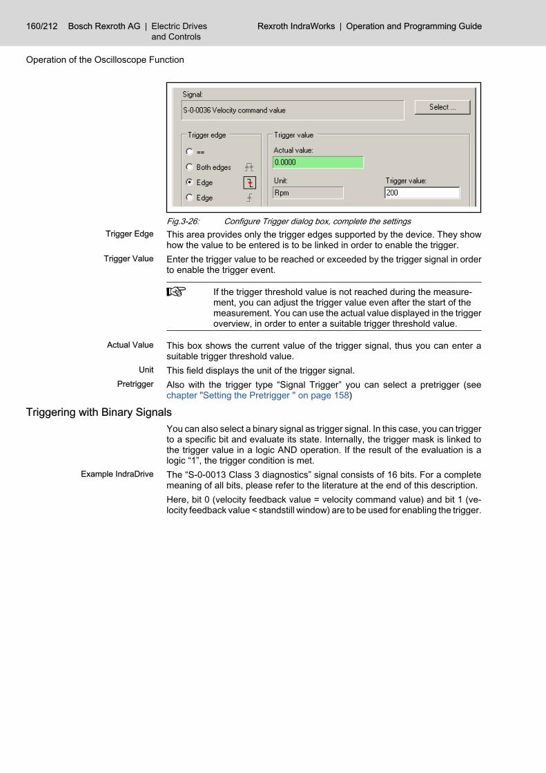
Fig.3-26: Configure Trigger dialog box, complete the settingsTrigger Edge This area provides only the trigger edges supported by the device. They show
how the value to be entered is to be linked in order to enable the trigger.Trigger Value Enter the trigger value to be reached or exceeded by the trigger signal in order
to enable the trigger event.
If the trigger threshold value is not reached during the measure‐ment, you can adjust the trigger value even after the start of themeasurement. You can use the actual value displayed in the triggeroverview, in order to enter a suitable trigger threshold value.
Actual Value This box shows the current value of the trigger signal, thus you can enter asuitable trigger threshold value.
Unit This field displays the unit of the trigger signal.Pretrigger Also with the trigger type “Signal Trigger” you can select a pretrigger (see
chapter "Setting the Pretrigger " on page 158)
Triggering with Binary Signals You can also select a binary signal as trigger signal. In this case, you can triggerto a specific bit and evaluate its state. Internally, the trigger mask is linked tothe trigger value in a logic AND operation. If the result of the evaluation is alogic “1”, the trigger condition is met.
Example IndraDrive The “S-0-0013 Class 3 diagnostics” signal consists of 16 bits. For a completemeaning of all bits, please refer to the literature at the end of this description.Here, bit 0 (velocity feedback value = velocity command value) and bit 1 (ve‐locity feedback value < standstill window) are to be used for enabling the trigger.
160/212 Bosch Rexroth AG | Electric Drivesand Controls
Rexroth IndraWorks | Operation and Programming Guide
Operation of the Oscilloscope Function

Fig.3-27: Configure Trigger dialog box, bit signal as signal triggerYou can define the mask bitwise by checking the individual check boxes or bydirectly entering the bits in the “Trigger mask (bin)” field.
Set Bits Click on this button to set all bits.Delete Bits Click on this button to delete all bits.
If you click on the individual bits, both the trigger mask and the trig‐ger threshold value are adjusted for the logic AND operation. Youcan also change the trigger value manually, independently of thetrigger mask.
If several bits are selected, with a rising trigger edge, the triggerthreshold value is 0 and cannot be changed. Thus any of the se‐lected bits can start the trigger at a rising trigger edge.
Bit Trigger If you check this check box, the bit selection is limited to a single bit. In thiscase, the trigger mask and the trigger value are identical and will not be dis‐played. You can only trigger to falling or rising edges. The figure below showsthe selection of a bit trigger.
Operation and Programming Guide | Rexroth IndraWorks Electric Drivesand Controls
| Bosch Rexroth AG 161/212
Operation of the Oscilloscope Function

Fig.3-28: Configure Trigger dialog box, bit signal, bit trigger
The number of the selection points depends on the bit width of theselected trigger signal. It ranges from 8 bits to 32 bits.
3.6 Starting the Measurement
Fig.3-29: Start the measurementClick on the “Start” button to start the measurement with the previously definedconditions. The field “State” shows the current state of the measurement.If possible, the measurement lasts until the recording time defined in the “Con‐figure Measurement” dialog box is reached.
The actual recording time can be shorter than the defined recordingtime. This occurs when the trigger value is reached before the timedefined for the pretrigger ends.
After a successful measurement, the state is “ready” again and the measuredvalues will be shown in the graphical display.
162/212 Bosch Rexroth AG | Electric Drivesand Controls
Rexroth IndraWorks | Operation and Programming Guide
Operation of the Oscilloscope Function

Fig.3-30: Oscilloscope, successfully completed measurement
If you start a measurement again, the last measured values will bereplaced. In order to keep a measurement for documentation pur‐poses, you have to save it via the Oscilloscope menu. See alsochapter 3.10 "Loading and Saving a Measurement " on page205.
3.7 Graphical Display3.7.1 Signal Overview
Fig.3-31: Signal overview
Operation and Programming Guide | Rexroth IndraWorks Electric Drivesand Controls
| Bosch Rexroth AG 163/212
Operation of the Oscilloscope Function

The check boxes allow you to show and hide signals.The active signal has got a gray background. To activate a signal, click on it inthe graph or in the signal overview.
In the graph, an active signal is displayed with a width of two pixels;an inactive signal has a width of one pixel only.
Fig.3-32: Context-sensitive menu of the signal overviewThe context-sensitive menu offers further options to process signals.
Delete Signal You can delete signals, which you have added before by Diagnostics ▶ LoadSignal Data or Add Signal Data or computations.
Currently measured signals cannot be deleted.
Delete Measurement / Computa‐tion
You can delete measurements, which you have added before byDiagnostics ▶ Load Signal Data or Add Signal Data. In this case, all signalsbelonging to the selected measurement will be deleted, measured signals aswell as computed signals.
You cannot delete a current measurement.
Change Signal Color Use this menu entry to change the signal color of a signal. A dialog box for thecolor selection appears.
Selection of Several Signals To select several signals in the signal overview, press the <Ctrl> key whenclicking with the left mouse button. So several signals can be● shown or hidden,● deleted,● get a different color.
3.7.2 GraphicThe graphic visualizes the measured values.
Cursor Display The cursor has different appearances on a signal, on a line cursor or whenzooming. See the following examples:
Fig.3-33: Default cursor
164/212 Bosch Rexroth AG | Electric Drivesand Controls
Rexroth IndraWorks | Operation and Programming Guide
Operation of the Oscilloscope Function

Fig.3-34: Cursor on a signal
Fig.3-35: Cursor on a line cursor
Fig.3-36: Cursor with zooming areaTrigger time The interrupted red line in the graph indicates the time when the trigger has
been enabled.
Fig.3-37: Trigger timeLine Cursor The two continuous black vertical lines are the two line cursors. They can be
moved horizontally with the mouse. The number next to the line cursor corre‐
Operation and Programming Guide | Rexroth IndraWorks Electric Drivesand Controls
| Bosch Rexroth AG 165/212
Operation of the Oscilloscope Function

sponds to the value in the abscissa. The intersection point between the linecursor and the active signal is enlarged.
Fig.3-38: Display of the two line cursorsThe line cursors can be moved with the mouse or with the arrow keys. Theincrement size depends on the defined time period.
To move the active (wider) cursor in single increments, press theleft or right arrow keys. Use <Ctrl> <Alt> together with the <ArrowKeys> to move it in steps of ten.
Use <Ctrl> <Alt> <C> or click on a cursor in the graphic in order toselect one of the two cursors.
3.7.3 ZoomZooming in an Area
To zoom in an area, left-click on the graph, hold the button and move the mouse.A rectangle will appear the size of which changes with the mouse movements.Once you release the mouse button, the zooming-in area is defined. It will beautomatically sized to the entire graphical area.
To start drawing the rectangle you have to select a free area on thegraph. If the signals are so close to each other, that it is hard to finda free area, press <Ctrl> before clicking.
The figures below show the definition of an area and its result.
166/212 Bosch Rexroth AG | Electric Drivesand Controls
Rexroth IndraWorks | Operation and Programming Guide
Operation of the Oscilloscope Function

Fig.3-39: Display with zooming area
Fig.3-40: Display zoomed inTo further zoom in the area, repeat the steps above.
Zoom LevelsEach new definition of a zoom area is managed as a zoom level. To switch backand forth between these levels, click on the “+” and “–” buttons in the “Zoom”field.
Operation and Programming Guide | Rexroth IndraWorks Electric Drivesand Controls
| Bosch Rexroth AG 167/212
Operation of the Oscilloscope Function

Fig.3-41: Zoom level down buttonTo return to the original graph, click on the “1:1” button.Pressing the following shortcuts will also change the zoom levels:● <Ctrl> <Alt> <P> corresponds to the “-” button● <Ctrl> <Alt> <N> corresponds to the “+” button● <Ctrl> <Alt> <Q> corresponds to the “1:1” button
Show Line CursorIf one or both cursors are not in the zoomed area, they will not be positionedthere automatically. To display the cursors in the current zoom area, use “ShowCursor”.
Fig.3-42: Show Cursor button
Zooming between the Line CursorsClick on this button or press <Ctrl> <Alt> <Z> to enlarge the area between thetwo line cursors.
Fig.3-43: Zoom Between Both Cursors button
3.7.4 Moving Active Signal in Y Direction You can move the active signal in Y direction by clicking on the “up arrow” and“down arrow” buttons in the “Y scaling” area.
Fig.3-44: Move the active signal in Y direction button
3.7.5 Scaling Active Signal in Y Direction Scale up the ordinate of the active signal in fixed steps by using the “+” buttonand scale it down by the “-” button in the area of the Y scaling .
168/212 Bosch Rexroth AG | Electric Drivesand Controls
Rexroth IndraWorks | Operation and Programming Guide
Operation of the Oscilloscope Function

3.7.6 Automatic support for scaling,Absolute and Full Scaling
In absolute scaling, the signals shown depend on the largest signal.
Fig.3-45: Absolute scaling
Use the button above the one for absolute scaling to scale up allsignals to the full display area.
Example IndraDrive: Step Re‐sponse with Current Profile
The figures below illustrate two different display types, with an example of threesignals. The first figure shows the signals with absolute scaling.
Fig.3-46: Display with absolute scalingThe next figure shows the signals with full scaling. All signals use the entiredisplay area.
Operation and Programming Guide | Rexroth IndraWorks Electric Drivesand Controls
| Bosch Rexroth AG 169/212
Operation of the Oscilloscope Function

Fig.3-47: Display with full scaling
Enlarging the Active Signal in Y DirectionUse the “SF” button to enlarge the active signal to the entire display area.
Fig.3-48: Enlarge the signalUse this facility, if you want to enlarge a small signal to the entire display areain absolute scaling mode.
Manual ScalingBeside the automatic scaling you can perform a manual scaling by “MS”.
Fig.3-49: Start manual scaling
170/212 Bosch Rexroth AG | Electric Drivesand Controls
Rexroth IndraWorks | Operation and Programming Guide
Operation of the Oscilloscope Function

Fig.3-50: Manual Scaling dialog boxHaving opened the dialog box, you can see the active values for Y scaling andY shifting of the active signal.To change these values click on the according input box and enter the desiredvalues.
The changes will be displayed in the graph immediately after leav‐ing the input box. The dialog box will not be closed, thus you cancorrect errors, if necessary.
Close the dialog box and apply the changed scaling by “OK”.“Cancel” closes the dialog box and discards the changes.Use “Reset” to get the original values.“Maximize” causes the full scaling of the active signal.
Fixed ScalingThe scaling of a measurement can be stored by “FS” for fixed scaling.
Fig.3-51: Fixed scalingIf you repeat a measurement, the scaling selected before is used.
This also refers to a scaling obtained by zooming. That will optimizethe process of performing several measurements consecutively.
3.7.7 Changing the Graphic ModeInterpolated Measurement Curve
The single measured points are connected by lines, thus forming a measure‐ment curve.
Fig.3-52: Display interpolated measurement curve button
Operation and Programming Guide | Rexroth IndraWorks Electric Drivesand Controls
| Bosch Rexroth AG 171/212
Operation of the Oscilloscope Function

Fig.3-53: Connected measured points
Real Measurement CurveThe single measured points are connected by lines, thus forming a real meas‐urement curve.
Fig.3-54: Display real measurement curve button
172/212 Bosch Rexroth AG | Electric Drivesand Controls
Rexroth IndraWorks | Operation and Programming Guide
Operation of the Oscilloscope Function

Fig.3-55: Real measurement curve
Display of the Single Measured PointsThe single measured points are displayed and connected by lines, thus formingan interpolated measurement curve.
Fig.3-56: Display single measured points button
Operation and Programming Guide | Rexroth IndraWorks Electric Drivesand Controls
| Bosch Rexroth AG 173/212
Operation of the Oscilloscope Function
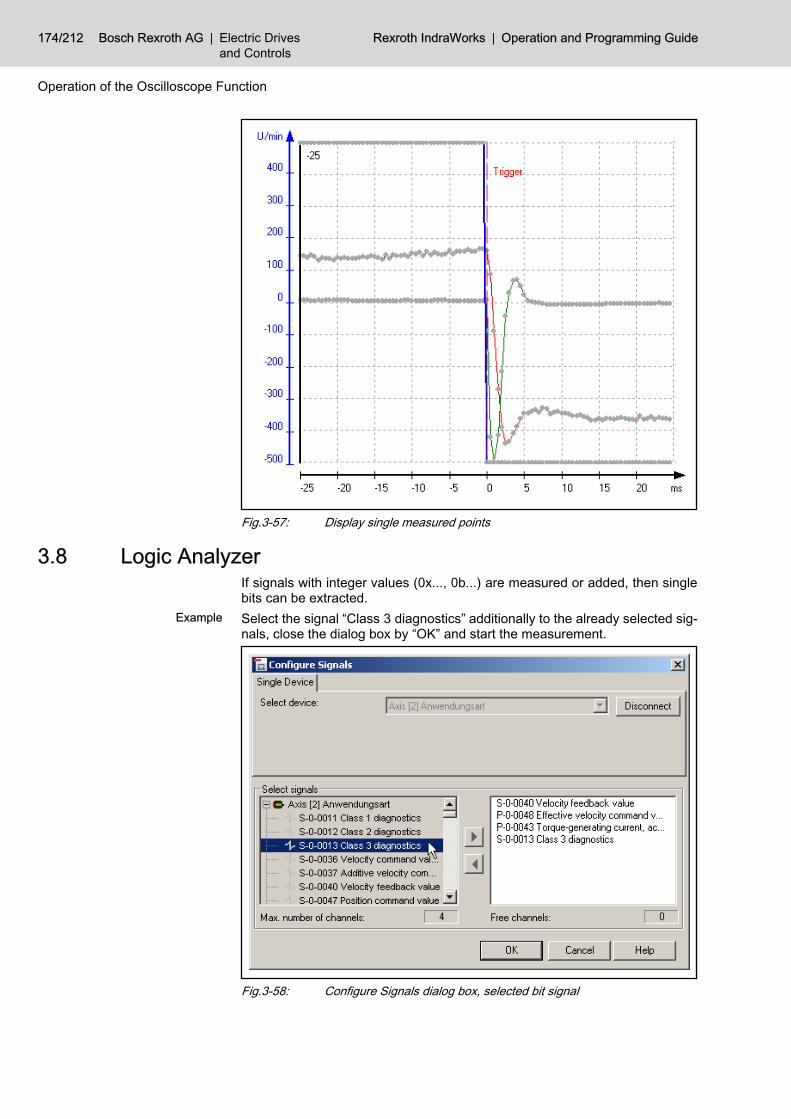
Fig.3-57: Display single measured points
3.8 Logic Analyzer If signals with integer values (0x..., 0b...) are measured or added, then singlebits can be extracted.
Example Select the signal “Class 3 diagnostics” additionally to the already selected sig‐nals, close the dialog box by “OK” and start the measurement.
Fig.3-58: Configure Signals dialog box, selected bit signal
174/212 Bosch Rexroth AG | Electric Drivesand Controls
Rexroth IndraWorks | Operation and Programming Guide
Operation of the Oscilloscope Function

Go to the “Bit Analysis” tab and press “Select”. In the following dialog box selectthe “Class 3 diagnostics” signal and select the three lowest bits for display.
Fig.3-59: Configure Signals dialog box, selection of the bitsOn each bit selection, the free and the used bits are counted. Close the dialogbox by OK. Now the selected bits will be displayed.
The maximum number of selectable bits refers to all selected bitsignals. You can select 32 bits.
Example IndraDrive This example will show a measurement with bit signals.Configuring the Trigger For the example, select a signal trigger with the “S-0-0040 Velocity feedback
value” signal, with falling edge, and with a trigger value of –200 rpm.Configuring the Measurement Select the memory depth of 100 measurement values within a time period of
0,5 ms.The figure below shows the measurement result, with the bit signals not yetdivided.
Operation and Programming Guide | Rexroth IndraWorks Electric Drivesand Controls
| Bosch Rexroth AG 175/212
Operation of the Oscilloscope Function

Fig.3-60: Display with comprised bit signalGo to the “Bit Analysis” tab and press “Select”. In the following dialog box selectthe “Class 3 diagnostics” signal and select the three lowest bits for display.The figure below shows the result of the bit computation.
176/212 Bosch Rexroth AG | Electric Drivesand Controls
Rexroth IndraWorks | Operation and Programming Guide
Operation of the Oscilloscope Function

Fig.3-61: Display of single bit signals
Only the computed bit signals are displayed. The other signals havebeen hidden by setting the check mark and thus activating the filterfunction.
Fig.3-62: Activated filter function for bit signalsGraphical Interpolation The rising edge of the lowest signal is not a vertical line. This is caused by the
fact that the values are linearly interpolated and represented as a curve. Thisis reasonable for “analog” signals, but not for bit signals.
Fig.3-63: Display of bit signals with inclined edgeTo obtain a digital graph, go to the “Analysis” tab page. Select the display ofthe real measurement curve by “R” in the “Curve display” area.
Operation and Programming Guide | Rexroth IndraWorks Electric Drivesand Controls
| Bosch Rexroth AG 177/212
Operation of the Oscilloscope Function

Fig.3-64: Display of real measurement pointsThe figure below shows the result:
Fig.3-65: Display of real measurement points with rectangular edgeDisplay of all signals Use the checkbox to disable the filter function of the display of bit signals.
Fig.3-66: Display of all signals
178/212 Bosch Rexroth AG | Electric Drivesand Controls
Rexroth IndraWorks | Operation and Programming Guide
Operation of the Oscilloscope Function

3.9 Computations 3.9.1 General Information
Measured signals can be combined with each other mathematically, in order toobtain further results. Select the desired computation and then the signals tobe combined. The signal overview and the graph will display the signals com‐puted.
If a measurement is started again, the computations will be repea‐ted automatically.
Having configured a computation and started the measurement,you will obtain the signal data as well as the computation data.These data can be saved together. The configuration of the com‐putation will be saved, too.
To change an already configured computation, press the <Ctrl> keywhen clicking on the “Define Computation ...” button on the “Anal‐ysis” tab page.
The examples below will show possible computations with the oscilloscope.
3.9.2 General Computation Formula Example with Position Feedback
Value S-0-0051This example with IndraDrive shows, how to compute the velocity using theposition feedback value.The following settings have been specified:● 4000 measurement points● Time grid of 0.5 ms● Signals S-0-0036, S-0-0040 and P-0-0043● Further signal S-0-0051 position feedback 1 value● Signal trigger with S-0-0040 velocity feedback valueFurthermore, the command value has been activated by a periodical square-wave signal of the drive internal command value generator:
Operation and Programming Guide | Rexroth IndraWorks Electric Drivesand Controls
| Bosch Rexroth AG 179/212
Operation of the Oscilloscope Function

Fig.3-67: Defined command value
You can change the settings only in the de-activated state. Theywill be sent to the drive immediately after the generator, e. g. thesquare-wave generator, has been activated.
After the measurement you will see the following curves:
180/212 Bosch Rexroth AG | Electric Drivesand Controls
Rexroth IndraWorks | Operation and Programming Guide
Operation of the Oscilloscope Function

Fig.3-68: Result of the measurementComputing Start the computation in the “Analysis” tab page.
Fig.3-69: Define Computation buttonThe “Configure Computations” dialog box will be opened.
Operation and Programming Guide | Rexroth IndraWorks Electric Drivesand Controls
| Bosch Rexroth AG 181/212
Operation of the Oscilloscope Function

Fig.3-70: Configure Computation dialog box1. The parameter S-0-0051 position feedback 1 value is given in degrees.
To obtain the number of rounds define the constant c2 = 360, and thusdivide the result by 360.
2. Select the derivation d/dt (1/s) as function 1.3. Select signal S-0-0051.4. Start the computation by “OK”.
182/212 Bosch Rexroth AG | Electric Drivesand Controls
Rexroth IndraWorks | Operation and Programming Guide
Operation of the Oscilloscope Function
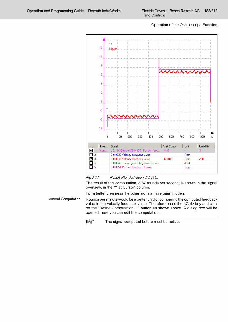
Fig.3-71: Result after derivation d/dt (1/s)The result of this computation, 8.87 rounds per second, is shown in the signaloverview, in the “Y at Cursor” column.For a better clearness the other signals have been hidden.
Amend Computation Rounds per minute would be a better unit for comparing the computed feedbackvalue to the velocity feedback value. Therefore press the <Ctrl> key and clickon the “Define Computation ...” button as shown above. A dialog box will beopened, here you can edit the computation.
The signal computed before must be active.
Operation and Programming Guide | Rexroth IndraWorks Electric Drivesand Controls
| Bosch Rexroth AG 183/212
Operation of the Oscilloscope Function

Fig.3-72: Change the settings for a computationSelect d/dt (1/min) as function 1 and repeat the computation via “OK”.
184/212 Bosch Rexroth AG | Electric Drivesand Controls
Rexroth IndraWorks | Operation and Programming Guide
Operation of the Oscilloscope Function

Fig.3-73: Result after derivation d/dt (1/min)How to estimate the velocity feed‐
back valueYou can also manually obtain the velocity feedback value from the positionfeedback value using the two line cursors:
Operation and Programming Guide | Rexroth IndraWorks Electric Drivesand Controls
| Bosch Rexroth AG 185/212
Operation of the Oscilloscope Function

Fig.3-74: Estimation of the velocity feedback valueThe curve of “S-0-0051 position feedback 1 value” has an intersection with eachof the two line cursor. Place the two cursors, so that the Y-values of theseintersections differ by 360° (here 1600° and 1960°). Define now the differencebetween the x-values of the cursors (here 236 ms - 116 ms = 120 ms).Thus the velocity feedback value is 1 round in 120 ms, i. e., 8,333 rps or 500rpm. This is consistent with the computed signal value in the graph.
Pre-defined Functions The Configure Computation dialog box contains further pre-defined functionsfor function 1 and function 2. The figures below show the possibilities for thetwo functions:
Fig.3-75: Possible selections for function 1
186/212 Bosch Rexroth AG | Electric Drivesand Controls
Rexroth IndraWorks | Operation and Programming Guide
Operation of the Oscilloscope Function
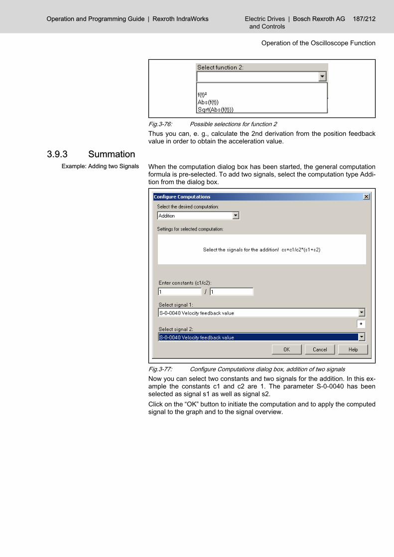
Fig.3-76: Possible selections for function 2Thus you can, e. g., calculate the 2nd derivation from the position feedbackvalue in order to obtain the acceleration value.
3.9.3 Summation Example: Adding two Signals When the computation dialog box has been started, the general computation
formula is pre-selected. To add two signals, select the computation type Addi‐tion from the dialog box.
Fig.3-77: Configure Computations dialog box, addition of two signalsNow you can select two constants and two signals for the addition. In this ex‐ample the constants c1 and c2 are 1. The parameter S-0-0040 has beenselected as signal s1 as well as signal s2.Click on the “OK” button to initiate the computation and to apply the computedsignal to the graph and to the signal overview.
Operation and Programming Guide | Rexroth IndraWorks Electric Drivesand Controls
| Bosch Rexroth AG 187/212
Operation of the Oscilloscope Function
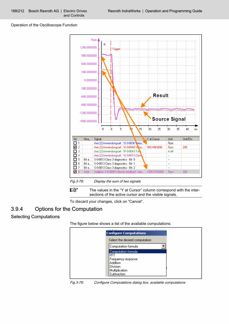
Fig.3-78: Display the sum of two signals
The values in the “Y at Cursor” column correspond with the inter‐sections of the active cursor and the visible signals.
To discard your changes, click on “Cancel”.
3.9.4 Options for the ComputationSelecting Computations
The figure below shows a list of the available computations:
Fig.3-79: Configure Computations dialog box, available computations
188/212 Bosch Rexroth AG | Electric Drivesand Controls
Rexroth IndraWorks | Operation and Programming Guide
Operation of the Oscilloscope Function

Depending on the computation selected, the necessary fields are provided inthe dialog box.
Fast Fourier Transformation FFT Preparing the FFT Computation The computation algorithm works best, if the number of measurement points is
a power of 2. The following values have been selected in the example:● 4096 measurement points● Time grid of 0.5 ms● 0% Pretrigger● You have to measure the signal a full period long, at least.After having opened the computation dialog box via “Define Computation...”,start the computation of the Fast Fourier Transformation for the selected signalby “OK”.
Fig.3-80: Configure Computations dialog box, FFTYou will obtain the following result, the amplitude in dB:
Operation and Programming Guide | Rexroth IndraWorks Electric Drivesand Controls
| Bosch Rexroth AG 189/212
Operation of the Oscilloscope Function

Fig.3-81: Result FFT: display in dBNormally the amplitude of the FFT is displayed in dB, but you can also selectthe display according to the amplitude size. To do this, start the computationdialog box again and uncheck the “Amplitude in dB” checkbox. The figure belowshows the result:
190/212 Bosch Rexroth AG | Electric Drivesand Controls
Rexroth IndraWorks | Operation and Programming Guide
Operation of the Oscilloscope Function

Fig.3-82: Result FFT: Display of the amplitude size
Using “Ctrl” and left click on “Define Computation...” you can editthe computation selected in the signal overview.
When you start the measurement again, the computation will berepeated automatically.
Frequency Response If the frequency response computation is selected, the frequency response iscomputed by means of the command signal and actual signal selected.You can compute the frequency response via the known computation dialogbox or you can go to the “Frequency Response” tab page and select “DefineComputation...” there.
Operation and Programming Guide | Rexroth IndraWorks Electric Drivesand Controls
| Bosch Rexroth AG 191/212
Operation of the Oscilloscope Function

Fig.3-83: Computation dialog box: Frequency ResponseThe following settings were made for this example with IndraDrive:● 4096 measurement points● Time grid of 0.25 ms● 0% Pretrigger● Sending a noise signal by the drive internal noise generator to the drive● Perform measurement● Start the computation dialog and confirm by “OK”.
Fig.3-84: Set noise signal via drive internal command value generator
192/212 Bosch Rexroth AG | Electric Drivesand Controls
Rexroth IndraWorks | Operation and Programming Guide
Operation of the Oscilloscope Function

The figure below shows the result of the frequency response computation.
Fig.3-85: Amplitude and phase of the frequency response computationThe manual scaling has been used to enlarge the amplitude and to place thetwo cursors:
Operation and Programming Guide | Rexroth IndraWorks Electric Drivesand Controls
| Bosch Rexroth AG 193/212
Operation of the Oscilloscope Function
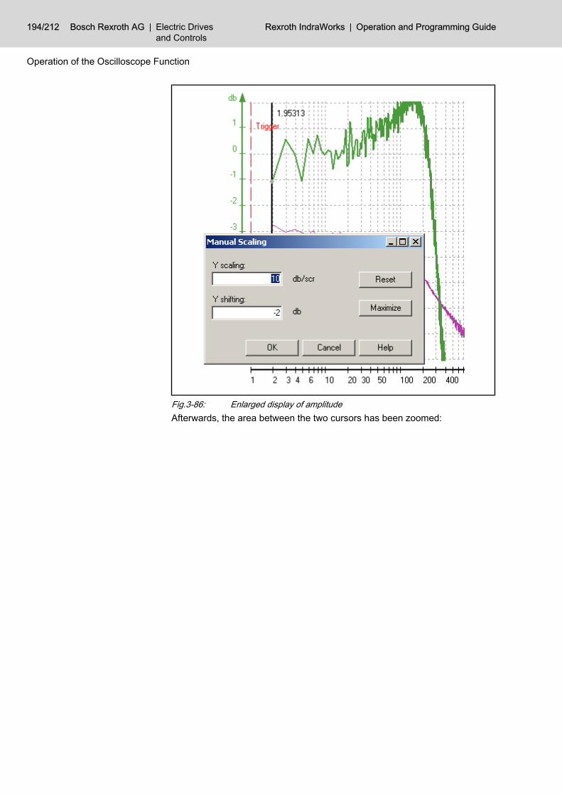
Fig.3-86: Enlarged display of amplitudeAfterwards, the area between the two cursors has been zoomed:
194/212 Bosch Rexroth AG | Electric Drivesand Controls
Rexroth IndraWorks | Operation and Programming Guide
Operation of the Oscilloscope Function

Fig.3-87: Read the -3dB limitExample for optimization 1. Place cursor 1 at that position, where the value falls below the -3db limit
for the first time.2. Read the phase at this position( here approx. -160) and calculate the dif‐
ference to -180°. The difference should be as large as possible (hereapprox. 20°).
3. Place cursor 2 at that position, where the value is above the -3db limit forthe last time.
4. Read the phase at this position, too, and calculate the difference to -180°.The difference should be as large as possible (here approx. 5°, withoutillustration).
The larger the difference between the phase values and -180°, the less thesystem tends to natural frequencies. An optimum has to be found here.
Improving the Computation For an improved display you can compute a moving average for each signal ofthe frequency response computation. To do this, use the button “SignalSmoothing” on the “Frequency Response” tab page.
Operation and Programming Guide | Rexroth IndraWorks Electric Drivesand Controls
| Bosch Rexroth AG 195/212
Operation of the Oscilloscope Function

Fig.3-88: Define signal smoothingSelect the signal to be smoothed and the smoothing factor in this dialog box.
A smoothing factor of 10 is preset. That means: ten consecutivevalues form one mean value, according to the following formula:Y11 new=(Y1+ .. +Y10) / 10. To compute the next mean values movethe start point step by step. This procedure will provide mean valuestill the end of the measurement curve. The first ten values of theoriginal measurement curve are not replaced by mean values andthe original values remain in the display.
Contour Deviation To display the contour deviation you have to measure the command positionsand actual positions of the axes (only possible in MTX). The deviation will beexcessively displayed in every point of the contour.
Even if the display area of the graph is not a square, the contourwill be displayed in a way, that the expansion in X is the same asin Y. Thus a circle will be preserved, as shown in the following ex‐ample.
196/212 Bosch Rexroth AG | Electric Drivesand Controls
Rexroth IndraWorks | Operation and Programming Guide
Operation of the Oscilloscope Function

Fig.3-89: Display of contour deviationThe example shows a typical application:The deviation when going a circle is displayed. You can see the typical errorsat the quadrant crossings, caused by frictional resistance. The effect of thefriction can be reduced in IndraDrive by parameters. You can check the opti‐mization with this display.The figure below shows an enlarged area, making the deviation clearer.
Operation and Programming Guide | Rexroth IndraWorks Electric Drivesand Controls
| Bosch Rexroth AG 197/212
Operation of the Oscilloscope Function

Fig.3-90: Enlarged areaAdditionally, you can see the two cursors, each one at the command contourand at the actual contour.
The cursor at the command contour is directly coupled to the cursorat the actual contour. For an easier understanding the contour errorhas been neglected.
You can show and set further options for the contour deviation:
198/212 Bosch Rexroth AG | Electric Drivesand Controls
Rexroth IndraWorks | Operation and Programming Guide
Operation of the Oscilloscope Function

Fig.3-91: Settings for the contour deviationSelect Diagram If you have defined several diagrams, you can select one here.Show Diagram Use this checkbox to show or hide a diagram.
Cursor1 This field displays the deviation between command contour and actual contourin µm at cursor 1.
Cursor2 This field displays the deviation between command contour and actual contourin µm at cursor 2.
Maximum Distance This field shows the maximum deviation between command contour and actualcontour in µm.
Scaling This field shows the current scaling factor used to compute the amplification. Itcomplies to the distance of two auxiliary lines.
Button “...” Set the scaling factor used to compute the amplification. The current value isdisplayed in the field “Scaling”.
Fig.3-92: Scaling factorButton “New” Use this button to open the computation dialog box and to select the signals for
the contour display:
Operation and Programming Guide | Rexroth IndraWorks Electric Drivesand Controls
| Bosch Rexroth AG 199/212
Operation of the Oscilloscope Function

Fig.3-93: Configure Computation dialog box, select signals for contour displayButton “Delete” This button deletes the selected diagram.Button “Colors” The colors will be assigned to the signals and subsidiary lines.
Fig.3-94: Assign the colorsFurther options for editing the contour deviation:● Scaling and moving the graph in X and Y,● Using the zoom options,● Automatic support for scaling,● Repeat current measurement.
Contour Diagram The contour diagram can combine and display two or four signals. This makesit possible to display the command contour and actual contour together as wellas separately.
Even if the display area of the graph is not a square, the contourwill be displayed in a way, that the expansion in X is the same asin Y. Thus a circle will be preserved, as shown in the following ex‐ample.
200/212 Bosch Rexroth AG | Electric Drivesand Controls
Rexroth IndraWorks | Operation and Programming Guide
Operation of the Oscilloscope Function

Fig.3-95: Display of the command contourHere you can see the command contour and actual contour with the samescaling:
Operation and Programming Guide | Rexroth IndraWorks Electric Drivesand Controls
| Bosch Rexroth AG 201/212
Operation of the Oscilloscope Function

Fig.3-96: Command contour and actual contour with the same scalingBoth cursors show the x value and the y value of the command contour and ofthe actual contour. The values in the “Diagram” area, now representing cursor1, correspond to the values at the cursor. If you switch to cursor 2, the currentvalues of cursor 2 will be displayed.
202/212 Bosch Rexroth AG | Electric Drivesand Controls
Rexroth IndraWorks | Operation and Programming Guide
Operation of the Oscilloscope Function
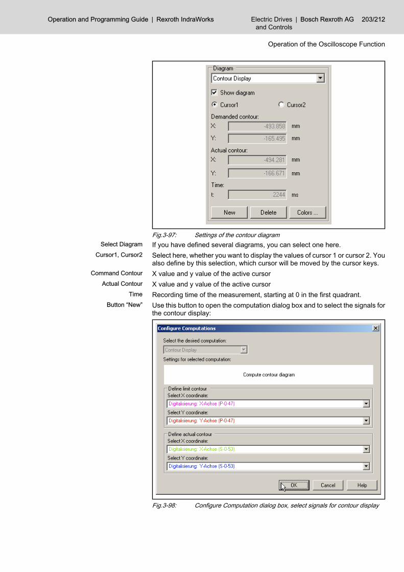
Fig.3-97: Settings of the contour diagramSelect Diagram If you have defined several diagrams, you can select one here.
Cursor1, Cursor2 Select here, whether you want to display the values of cursor 1 or cursor 2. Youalso define by this selection, which cursor will be moved by the cursor keys.
Command Contour X value and y value of the active cursorActual Contour X value and y value of the active cursor
Time Recording time of the measurement, starting at 0 in the first quadrant.Button “New” Use this button to open the computation dialog box and to select the signals for
the contour display:
Fig.3-98: Configure Computation dialog box, select signals for contour display
Operation and Programming Guide | Rexroth IndraWorks Electric Drivesand Controls
| Bosch Rexroth AG 203/212
Operation of the Oscilloscope Function
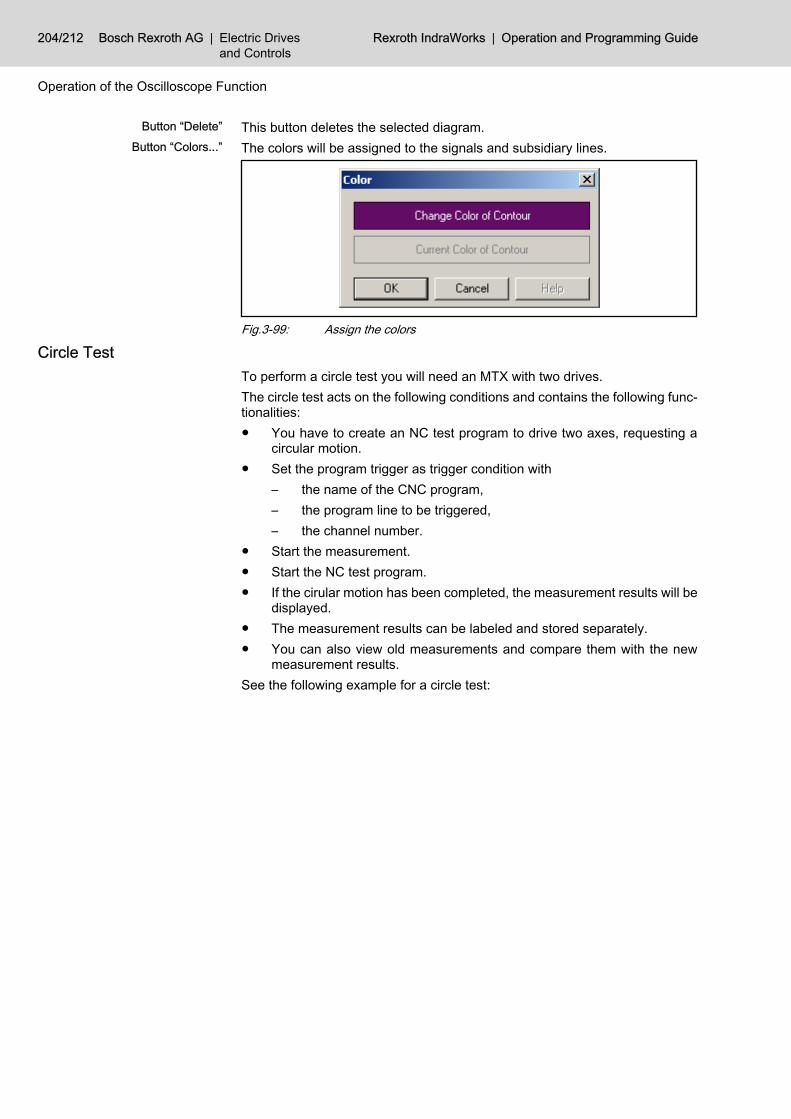
Button “Delete” This button deletes the selected diagram.Button “Colors...” The colors will be assigned to the signals and subsidiary lines.
Fig.3-99: Assign the colors
Circle Test To perform a circle test you will need an MTX with two drives.The circle test acts on the following conditions and contains the following func‐tionalities:● You have to create an NC test program to drive two axes, requesting a
circular motion.● Set the program trigger as trigger condition with
– the name of the CNC program,– the program line to be triggered,– the channel number.
● Start the measurement.● Start the NC test program.● If the cirular motion has been completed, the measurement results will be
displayed.● The measurement results can be labeled and stored separately.● You can also view old measurements and compare them with the new
measurement results.See the following example for a circle test:
204/212 Bosch Rexroth AG | Electric Drivesand Controls
Rexroth IndraWorks | Operation and Programming Guide
Operation of the Oscilloscope Function

Fig.3-100: Result of the circle test
The circle test assumes, that a circle contour has been measured.It uses the contour deviation formula to compute the actual contourdeviation.
3.10 Loading and Saving a Measurement3.10.1 General Information
Use the Oscilloscope menu to load configuration data and measurement datavia import, and to save them via export.Depending on the menu item the following file formats are supported:
ZIP Compressed file in ZIP format, containing a complete measurement.XML Text file in XML format, containing a complete measurement.OCD Text file in XML format, containing the configuration of a measurement.TXT Output of the measured data as text file which can be read in Excel.
The following menu items are provided:
Operation and Programming Guide | Rexroth IndraWorks Electric Drivesand Controls
| Bosch Rexroth AG 205/212
Operation of the Oscilloscope Function

Fig.3-101: Menu items for the oscilloscope
3.10.2 Import Configuration, Export ConfigurationOnly the configuration of a measurement will be read or saved in a separatefile. The file extension is OCD.
3.10.3 Import Measurement, Export MeasurementA measurement will be loaded from an arbitrary directory or stored in an arbi‐trary directory. The files with the extension ZIP, XML and OCD can be loadedThe files with the extension ZIP, XML and TXT can be stored.
3.10.4 Measurement in the Project SubmenuGeneral Information
The Measurement in the Project sub menu offers items for the management ofthe measured data in the IndraWorks project directory. Only zip files will besupported.
Fig.3-102: Measurement in Project Submenu
Load MeasurementLoad Measurement loads a measurement into the oscilloscope. This meas‐urement consists of the measurement configuration, possible computationconfigurations, and the signal data. The signal data will be shown in the graph.The configuration data will be saved internally. These data can be displayed,changed and sent to the device for a restart of the measurement, using theaccording dialogs (for signals, measurement, trigger, computations).Use this menu entry to load and display a measurement stored in the currentproject. A previously displayed measurement will be removed from the display.Select a measurement in the following dialog box:
206/212 Bosch Rexroth AG | Electric Drivesand Controls
Rexroth IndraWorks | Operation and Programming Guide
Operation of the Oscilloscope Function

Fig.3-103: Load Measurement from Current Project dialog box
Save MeasurementSave Measurement stores a measurement together with its measurement con‐figuration, a possible computation configuration and its signal data.Use this menu entry to save the current measurement in the current projectdirectory. Specify the new name of the measurement in the following dialogbox:
Fig.3-104: Save Measurement in Current Project dialog box
Import Measurement into the ProjectUse this menu entry to copy a measurement from an arbitrary directory into theproject without displaying it automatically. If you want to display the measure‐ment use Load Measurement.
Export Measurement from Current ProjectUse this menu entry to copy measurements from the project directory into anarbitrary directory. The following dialog box will be opened:
Operation and Programming Guide | Rexroth IndraWorks Electric Drivesand Controls
| Bosch Rexroth AG 207/212
Operation of the Oscilloscope Function

Fig.3-105: Export Measurement from Current Project dialog boxSelect the measurement to be copied and click on “Next”. Select the destinationdirectory for the measurements or create a new one in the following dialog box.
3.11 Document Window in Clipboard Press <Ctrl> <Alt> <J> to copy the entire workspace of the oscilloscope (graphwith control elements) as screenshot to the clipboard. Thus the displayedmeasurement can be applied to other programs for documentation purposes.
3.12 Exporting a Measurement as Text File Press <Ctrl> <Alt> <R> to copy a measurement as text to the clipboard. Thisallows you to apply the values directly to Excel, without having to use a separatefile of the Export Measurement menu.
3.13 References Please use the following references for support on signals which are suitablefor being recorded graphically.● Rexroth IndraDrive Drive Controllers, Parameter Description; DOK-
INDRV*-GEN-**VRS**-PA02-EN-P● Rexroth IndraDrive, Firmware for Drive Controllers MPH-02, MPB‑02,
MPD-02 Functional Description DOK-INDRV*-MP*-**VRS**-FK01-EN-P● Rexroth IndraDrive Firmware for Drive Controllers MPx02, MPx02 and
HMV, Troubleshooting Guide; DOK-INDRV*-DEN-**VRS**-WA02-EN-P
208/212 Bosch Rexroth AG | Electric Drivesand Controls
Rexroth IndraWorks | Operation and Programming Guide
Operation of the Oscilloscope Function

IndexAAbout this Manual
Elements of the IndraWorks user interface 2General 1Library explorer 5Title, menu and status bar 2Toolbars 2
AddingTemplates into the project 56
Adding a device to a project 7Adding a file 51Adding files to an project 50Application
add, external - 131Remove, external - 133
ArchivingArchiving a project on a device 27Archiving a project on a file system 25General 25Restoring a project from a device 33Restoring a project from a file system 30Symbol: Archiving 25Workspace 36
Archiving a projectOn a device 27On a file system 25
Arranging the windows 4
CChange properties
External applications 132Circle test
Oscilloscope 204Client Software
Remote Service 129Communication adjustment
Switching to online 48Computations
Oscilloscope, circle test 204Oscilloscope, contour deviation 196Oscilloscope, contour diagram 200Oscilloscope, Fast Fourier Transformation FFT189Oscilloscope, frequency response 191Oscilloscope, general formula 179Oscilloscope, overview 179Oscilloscope, selection 188Oscilloscope, summation 187
Configuration adjustmentSwitching to online 50
Configure measurementOscilloscope 155
Configure triggerOscilloscope 156
Connect devices and select signalsOscilloscope 153
Contour deviationOscilloscope 196
Contour diagramOscilloscope 200
Creating a new project 5Customizing dialog 136
DData adjustment
Switching to online 50Defining the master language
Multilingual projects 61Deleting a license 114Deleting firmware functions 116Devices
Inserting from the library 18In the project explorer 20
Devices in projectsWorking with the workspace 60
Document windows 3
EEditing a file 52Elements of the IndraWorks user interface 2Enabling firmware functions 116Export measurement
Oscilloscope 208External applications
add 131Change properties 132General 130Remove 133
External project translation1. Export from IndraWorks 642. Import in OpenOffice.org Calc 653. translate in OpenOffice.org Calc 664. Export from OpenOffice.org Calc 675. Import in IndraWorks 68General 63
FFast Fourier Transformation FFT
Oscilloscope 189Firmware management 111Frequency response
Oscilloscope 191Function areas
Options dialog 133Using the library 24
GGeneral
About this Manual 1
Operation and Programming Guide | Rexroth IndraWorks Electric Drivesand Controls
| Bosch Rexroth AG 209/212
Index

Archiving 25External applications 130External project translation 63IndraWorks 1IndraWorks project 50Licensing: Firmware functions 114Licensing: IndraWorks components 112Load and save measurement 205Multilingual projects 60Options dialog 133Printing 70Project explorer 5Remote Service 128Scan for devices 40Using the library 23Working area 3Working with IndraWorks 9Working with the workspace 57
General options 134Keyboard 134Language settings 134Project explorer 135Software licenses 134
Getting startedAdding a device to a project 7Creating a new project 5Exiting IndraWorks 8Opening a project 6Starting IndraWorks 5
Getting StartedGeneral 5
Graph in clipboardOscilloscope 208
IIndraWorks project
Adding a file 51Editing a file 52General 50Removing a file 57
InfoWorking with IndraWorks 136
Inserting devices from the library 18Installing a license 112
KKeyboard (Shortcuts) 134
LLanguage settings 134Library explorer 5Licensing: Firmware functions
General 114Licensing: Firmware Functions
Deleting 116Enabling 116
Licensing: IndraWorks componentsDeleting a license 114General 112Installing a license 112
Logic analyzerOscilloscope 174
MManaging project languages
Multilingual projects 61Manual trigger 157Message box 137Move signals
Oscilloscope 168Multilingual projects 60
Defining the master language 61External translation 63General 60Managing project languages 61
OOnline-, offline mode
Offline 47Online 47
Online, switching toCommunication adjustment 48Configuration adjustment 50Data adjustment 50Structure adjustment 49What happens during the switch 47
Online helpIndraWorks 138
Opening a project 6Operation
Options dialog 134Scan for devices 41Using the library 25
Operation areasOscilloscope 146
Operation desktopActivate project 39
Options dialog 133Function areas 133General 133General options 134Operation 134
OscilloscopeReferences 208Signal overview 163Start 143
Oscilloscope computationsCircle test 204Computations 179Contour deviation 196Contour diagram 200Fast Fourier Transformation FFT 189Frequency response 191
210/212 Bosch Rexroth AG | Electric Drivesand Controls
Rexroth IndraWorks | Operation and Programming Guide
Index

General 179General formula 179Selection 188Summation 187
Oscilloscope configurationImport, export 206
Oscilloscope devicesConnect 153
Oscilloscope measurementConfigure 155Export to Excel 208General 153, 205Import, export 206Load and save 205Record new measurement 153Start 162
Oscilloscope measurement in projectExport from project 207General 206Import into project 207Load measurement 206Save measurement 207
Oscilloscope operationLogic analyzer 174
Oscilloscope OperationGraph in clipboard 208
Oscilloscope signalsAbsolute scaling 169Configure 153Enlarge 170Fixed scaling 171Full scaling 169Graphic 164Interpolated measurement curve 171Measured points 173Move 168Real measurement curve 172Scale 168Scale manually 170Show line cursor 168Zoom between line cursors 168Zoom in an area 166Zoom levels 167
Oscilloscope StartOffline 143Online 144
Oscilloscope triggerBinary signals 160Configure 156General 156Manual 157Signal trigger 159
Oscilloscope TriggerPretrigger 158
PPersistence 60
Pretrigger 158Printing 70
General 70Overview 72Settings 70
Printing ofDevice data 80Project data 77
Printing of device data 80Print project data 77Project
Opening from the workspace 59Project explorer
Decvice 5General 5Project 5Root directory 135
ProjectsAdding to the workspace 59Deleting from the workspace 59
PropertiesWorking with the workspace 60
RRecord new measurement
Oscilloscope 153References
Oscilloscope 208Remote Engineering 123Remote Service 128
Client Software 129General 128
Removing a file from the project 57Restoring
Symbol: Restoring 30Workspace 38
Restoring a projectFrom a device 33From a file system 30
SScale signals
Oscilloscope 168Scan for devices
Operation 41Select computations
Oscilloscope 188Signal overview
Oscilloscope 163Signal trigger
Oscilloscope 159Software licenses 134Start measurement
Oscilloscope 162Start offline
Oscilloscope 143
Operation and Programming Guide | Rexroth IndraWorks Electric Drivesand Controls
| Bosch Rexroth AG 211/212
Index

Start onlineOscilloscope 144
Start oscilloscope 143Startup picture 17Structure adjustment
Switching to online 49Switch to online
Oscilloscope 144
TTitle, menu and status bar 2Toolbars 2Tool window 4Trigger with binary signals
Oscilloscope 160
UUser management
activate 83Configure 86Export and import 94General 82Login, logout, change password 83Settings 93
Using the libraryFunction areas 24General 23Operation 25
WWorking area
Arranging the windows 4Document windows 3General 3
Tool window 4Working with IndraWorks
Adding files to an project 50Customizing dialog 136External applications 130Firmware management 111General 9Info 136License management 112Message box 137Multilingual projects 60Options dialog 133Persistence 60Printing 70Remote Service 128With projects and devices 9with the Workspace 57
Working with Projects and DevicesStartup picture 17
WorkspaceAdding Projects 59Archiving 36Creating 58Deleting 59Deleting projects 59Opening 58Opening project 59Restoring 38
Workspace, working withDevices in projects 60General 57Properties 60Workspace structure 57
Workspace structure 57
212/212 Bosch Rexroth AG | Electric Drivesand Controls
Rexroth IndraWorks | Operation and Programming Guide
Index

Notes
Operation and Programming Guide | Rexroth IndraWorks Electric Drivesand Controls
| Bosch Rexroth AG

Bosch Rexroth AGElectric Drives and ControlsP.O. Box 13 5797803 Lohr, GermanyBgm.-Dr.-Nebel-Str. 297816 Lohr, GermanyPhone +49 (0)93 52-40-50 60Fax +49 (0)93 52-40-49 [email protected]
Printed in GermanyDOK-IWORKS-ENGINEE*V07-AW01-EN-PR911320741


![Power Supply Energy Storage Automation Industry · PDF fileRexroth, Daimler, Danfoss, Eaton, KHS, ... und Energie (BMWi)] and has a term of ... wind power, this structure has changed](https://static.fdocuments.in/doc/165x107/5aa61d647f8b9afa758e1883/power-supply-energy-storage-automation-industry-daimler-danfoss-eaton-khs-.jpg)