Rexroth IndraWorks · PDF fileRexroth IndraWorks Simulation R911320258 Edition 01 Application...
86
Rexroth IndraWorks Simulation R911320258 Edition 01 Electric Drives and Controls Pneumatics Service Linear Motion and Assembly Technologies Hydraulics
Transcript of Rexroth IndraWorks · PDF fileRexroth IndraWorks Simulation R911320258 Edition 01 Application...
Rexroth IndraWorksSimulation
R911320258Edition 01
Application Description
Electric Drivesand Controls Pneumatics Service
Linear Motion and Assembly TechnologiesHydraulics
Rexroth IndraWorksSimulation
Application Description
DOK-IWORKS-SIMU****V07-AW01-EN-P
RS-748816b0390f57aa0a6846a0002a1fc0-1-en-US-2
This documentation describes the functions of simulation component View3D,virtual control panel, virtual control and its operation in IndraWorks.
Edition Release Date Notes
120-2700-B309-01/EN 04.2007 First edition for V07
Copyright © 2007 Bosch Rexroth AGCopying this document, giving it to others and the use or communication of thecontents thereof without express authority, are forbidden. Offenders are liablefor the payment of damages. All rights are reserved in the event of the grant ofa patent or the registration of a utility model or design (DIN 34-1).
Validity The specified data is for product description purposes only and may not bedeemed to be guaranteed unless expressly confirmed in the contract. All rightsare reserved with respect to the content of this documentation and the availa‐bility of the product.
Published by Bosch Rexroth AGBgm.-Dr.-Nebel-Str. 2 ■ D-97816 Lohr a. MainPhone +49 (0)93 52/ 40-0 ■ Fax +49 (0)93 52/ 40-48 85http://www.boschrexroth.com/System Development Machine Tools M. Brohm (DiLe)
Note This document has been printed on chlorine-free bleached paper.
Title
Type of Documentation
Document Typecode
Internal File Reference
Purpose of Documentation
Record of Revision
Bosch Rexroth AG | Electric Drivesand Controls
Rexroth IndraWorks | Application Description
Table of ContentsPage
1 General.......................................................................................................................... 11.1 Why Simulation?..................................................................................................................................... 11.2 What is Simulated?................................................................................................................................. 11.3 Goals of Simulation in IndraWorks......................................................................................................... 1
2 Important Instructions on Use........................................................................................ 32.1 Intended Use.......................................................................................................................................... 32.1.1 Introduction.......................................................................................................................................... 32.1.2 Area of Use and Application ............................................................................................................... 32.2 Improper Use.......................................................................................................................................... 3
3 Safety Instructions for Electric Drives and Controls ...................................................... 53.1 Safety Instructions - General Information............................................................................................... 53.1.1 Using the Safety Instructions and Passing them on to Others............................................................ 53.1.2 How to Employ the Safety Instructions................................................................................................ 53.1.3 Explanation of Warning Symbols and Degrees of Hazard Seriousness.............................................. 63.1.4 Hazards by Improper Use.................................................................................................................... 73.2 Instructions with Regard to Specific Dangers......................................................................................... 83.2.1 Protection Against Contact with Electrical Parts and Housings........................................................... 83.2.2 Protection Against Electric Shock by Protective Extra-Low Voltage................................................... 93.2.3 Protection Against Dangerous Movements......................................................................................... 93.2.4 Protection Against Magnetic and Electromagnetic Fields During Operation and Mounting.............. 123.2.5 Protection Against Contact with Hot Parts......................................................................................... 123.2.6 Protection During Handling and Mounting......................................................................................... 123.2.7 Battery Safety.................................................................................................................................... 133.2.8 Protection Against Pressurized Systems........................................................................................... 13
4 Quick Start................................................................................................................... 15
5 Components of the Simulation .................................................................................... 175.1 Project Explorer ................................................................................................................................... 175.2 3D Visualization ................................................................................................................................... 185.2.1 General Description........................................................................................................................... 185.2.2 Model Visualization ........................................................................................................................... 20
Basic functions............................................................................................................................... 20Functions for manipulating 3D objects .......................................................................................... 21
5.2.3 Scene Tree ....................................................................................................................................... 22General........................................................................................................................................... 22Object properties ........................................................................................................................... 23
5.2.4 Assignment list for process variables ............................................................................................... 235.2.5 Properties of the View3D Model ....................................................................................................... 245.3 VAM simulator...................................................................................................................................... 265.3.1 General Description........................................................................................................................... 26
Application Description | Rexroth IndraWorks Electric Drivesand Controls
| Bosch Rexroth AG I/III
Table of Contents

Page
5.3.2 Configurator ...................................................................................................................................... 265.3.3 The Application.................................................................................................................................. 285.4 Virtual Control ...................................................................................................................................... 285.4.1 General Description........................................................................................................................... 285.5 Process Connection ............................................................................................................................. 285.6 Library .................................................................................................................................................. 305.6.1 Simulation Components ................................................................................................................... 305.6.2 3D Models ........................................................................................................................................ 315.6.3 Virtual control panels......................................................................................................................... 32
6 Operation in IndraWorks.............................................................................................. 336.1 Creating a Model.................................................................................................................................. 336.1.1 General.............................................................................................................................................. 336.1.2 Creating a Simple 3D Model ............................................................................................................. 336.1.3 Importing eM-RealNC Models .......................................................................................................... 336.2 Using the Virtual Control Panel ............................................................................................................ 336.2.1 Configuration in IndraWorks.............................................................................................................. 33
Configuring the Virtual Control Panel............................................................................................. 33VAM 40-specific configuration pages ............................................................................................ 40VAM 41-specific configuration pages............................................................................................. 41Configuring the tab......................................................................................................................... 43Contextual menu of the virtual control panel in the Project Explorer ............................................. 43
6.2.2 Connection to Virtual Control ............................................................................................................ 446.2.3 Start and operate .............................................................................................................................. 456.2.4 Context menu in VAM simulator ....................................................................................................... 466.2.5 Error Messages and Remedies......................................................................................................... 466.3 Using 3D Visualization ......................................................................................................................... 476.3.1 3D Models in IndraWorks.................................................................................................................. 47
Adding 3D Models ......................................................................................................................... 47Opening, renaming and deleting 3D models ................................................................................. 50Export/Import ................................................................................................................................. 51Scaling a 3D model ....................................................................................................................... 52
6.3.2 Process Connection ......................................................................................................................... 54Connecting 3D objects with IndraMotion MTX axis values ............................................................ 54Configuring the process connection .............................................................................................. 54Establishing a connection to the control ........................................................................................ 55
6.3.3 Operating 3D Visualization ............................................................................................................... 55Basic 3D visualization functions .................................................................................................... 55Manipulating 3D objects ................................................................................................................ 55Changing settings of the View3D model ........................................................................................ 56Changing object properties ............................................................................................................ 56
6.3.4 Licensing of IndraWorks components............................................................................................... 57General .......................................................................................................................................... 57Installing a license ......................................................................................................................... 58
6.4 Using the Virtual Control....................................................................................................................... 596.4.1 Installation of the MTX Emulation ..................................................................................................... 59
II/III Bosch Rexroth AG | Electric Drivesand Controls
Rexroth IndraWorks | Application Description
Table of Contents
Page
General........................................................................................................................................... 596.4.2 Designing the Emulation ................................................................................................................... 60
Restoring an existing project ......................................................................................................... 606.4.3 Designing the HMI ............................................................................................................................ 60
General........................................................................................................................................... 606.4.4 Designing the NC Core ..................................................................................................................... 63
General........................................................................................................................................... 636.4.5 Designing the PLC ............................................................................................................................ 67
General........................................................................................................................................... 676.4.6 Starting and Exiting the MTX Emulation ........................................................................................... 69
General........................................................................................................................................... 696.4.7 Starting Operation Desktop .............................................................................................................. 71
7 Communication - SCP ................................................................................................ 73
8 Service and Support.................................................................................................... 758.1 Helpdesk............................................................................................................................................... 758.2 Service Hotline...................................................................................................................................... 758.3 Internet.................................................................................................................................................. 758.4 Helpful Information................................................................................................................................ 75
Index............................................................................................................................ 77
Application Description | Rexroth IndraWorks Electric Drivesand Controls
| Bosch Rexroth AG III/III
Table of Contents

Bosch Rexroth AG | Electric Drivesand Controls
Rexroth IndraWorks | Application Description
1 General1.1 Why Simulation?
Due to the ever-increasing competitive pressure among the manufacturers ofmachines, we are always looking for new ways of minimizing the costs for amachine project. This includes every phase of the machine life cycle (construc‐tion, commissioning, production). Due to more and more powerful computersystems, simulation is becoming more and more important: in the future, theremay even be virtual factories in which all the processes of a production plantcan be reproduced virtually. One component of this virtual factory is the virtualmachine, which can be used, with the help of suitable simulation tools, to sup‐port the individual phases of the machine life cycle.
1.2 What is Simulated?There are suitable simulation techniques for every phase of the machine lifecycle. These simulation techniques are clearly delimited from one another, butalso have shared points of intersection, such as the transfer of construction datafor the machine from the CAD system to the 3D visualization system.In the construction phase of a machine, for example, the FEM (Finite ElementMethod) analysis or the MBS (MultipleBodySimulation) analysis is used, whilebehavioral simulation is used more in the commissioning phase. For production,on the other hand, process optimization (e.g. cycle time optimization) is in theforeground.If we examine now the simulation techniques during the commissioning phase,we can make a further distinction. On the one hand, there is the so-called hard‐ware-in-the-loop simulation; on the other, there is software-in-the-loop simula‐tion.Hardware-in-the-loop In this simulation technique, a real control is a component of the simulationsetup. All other components are simulated on one or more computers. Com‐munication between the real control and the simulation components is imple‐mented using, for example, Profibus slave cards.Software-in-the-loop In this simulation technique, all the components are simulated on one or morecomputers.
1.3 Goals of Simulation in IndraWorksThe emphasis for applying simulation techniques at Bosch Rexroth in the areaof system development for Motion Control lies on optimizing the commissioningof controls and machine tools. This involves mainly behavioral simulation, suchas tests of the PLC program or of the NC program.Components such as a virtual control (NC and PLC), a virtual control panel,virtual drives, a 3D viewer and a peripherals simulation (I/O simulation) arerequired to attain this goal. Only the interplay of all these components permitseffective behavioral simulation.In addition to the shortening of commissioning times, however, there are otherareas of application for simulation that result in cost and time savings for theuser.● Demonstrator for sales at the customer location● Testing program procedures (both CNC and PLC)
Application Description | Rexroth IndraWorks Electric Drivesand Controls
| Bosch Rexroth AG 1/78
General

● Setting the parameters of the control and the drives● Application for training purposes● Reproduction of problems (trouble-shooting)● Validation of error solutions
2/78 Bosch Rexroth AG | Electric Drivesand Controls
Rexroth IndraWorks | Application Description
General
2 Important Instructions on Use2.1 Intended Use2.1.1 Introduction
The Bosch Rexroth products are developed and manufactured according to thelatest state of the art. Before delivery, they are checked for operational safety.The products may only be used in the proper manner. When they are not usedas intended, situations may arise which result in damage to person or material.
Bosch Rexroth, as the manufacturer of the products, will not as‐sume any warranty, liability or payment of damages in case ofdamage resulting from a non-intended use of the products. If hefails to use the products as intended, the user will be solely respon‐sible for any resulting risks.
Before using the Bosch Rexroth products, the following prerequisites must befulfilled to ensure that they are used as intended:● Everyone who in any way deals with one of our products must read and
understand the corresponding notes regarding safety and regarding prop‐er use.
● If the products are hardware, they must be kept in their original state, i.e.no constructional modifications may be made. Software products may notbe decompiled; their source codes may not be modified.
● Damaged or improperly working products must not be installed or put intooperation.
● It must be ensured that the products are installed according to the regu‐lations mentioned in the documentation.
2.1.2 Area of Use and Application In IndraWorks, simulation tools are used to● Shorten the response times● verify the application programs● visualize the machine cinematics
The simulation consists of several components which must be com‐patible to each other.
The virtual control panel is used in connection with the control emulation. Duringutilizing the virtual control panel of the real control it has to be considered thatthe signals can not arrive between virtual control panel and control because ofcommunication errors. Therefore a PLC program and a producing machine canno longer be stopped via control.
2.2 Improper UseUsing the devices outside of the above-referenced areas of application or underoperating conditions other than described in the document and the technicaldata specified is defined as "inappropriate use".The Rexroth simulation tools may not be used if
Application Description | Rexroth IndraWorks Electric Drivesand Controls
| Bosch Rexroth AG 3/78
Important Instructions on Use

● Bosch Rexroth has not specifically released them for that intended pur‐pose. In this connection, observance of the statements in the GeneralSafety Notes is imperative!
4/78 Bosch Rexroth AG | Electric Drivesand Controls
Rexroth IndraWorks | Application Description
Important Instructions on Use

3 Safety Instructions for Electric Drives and Controls3.1 Safety Instructions - General Information3.1.1 Using the Safety Instructions and Passing them on to Others
Do not attempt to install or commission this device without first reading all doc‐umentation provided with the product. Read and understand these safetyinstructions and all user documentation prior to working with the device. If youdo not have the user documentation for the device, contact your responsibleBosch Rexroth sales representative. Ask for these documents to be sent im‐mediately to the person or persons responsible for the safe operation of thedevice.If the device is resold, rented and/or passed on to others in any other form,these safety instructions must be delivered with the device in the official lan‐guage of the user's country.
WARNING
Improper use of these devices, failure to follow the safety instructions inthis document or tampering with the product, including disabling of safe‐ty devices, may result in material damage, bodily harm, electric shockor even death!Observe the safety instructions!
3.1.2 How to Employ the Safety InstructionsRead these instructions before initial commissioning of the equipment in orderto eliminate the risk of bodily harm and/or material damage. Follow these safetyinstructions at all times.● Bosch Rexroth AG is not liable for damages resulting from failure to ob‐
serve the warnings provided in this documentation.● Read the operating, maintenance and safety instructions in your language
before commissioning the machine. If you find that you cannot completelyunderstand the documentation for your product, please ask your supplierto clarify.
● Proper and correct transport, storage, assembly and installation, as wellas care in operation and maintenance, are prerequisites for optimal andsafe operation of this device.
● Only assign trained and qualified persons to work with electrical installa‐tions:– Only persons who are trained and qualified for the use and operation
of the device may work on this device or within its proximity. Thepersons are qualified if they have sufficient knowledge of the assem‐bly, installation and operation of the product, as well as an under‐standing of all warnings and precautionary measures noted in theseinstructions.
– Furthermore, they must be trained, instructed and qualified to switchelectrical circuits and devices on and off in accordance with technicalsafety regulations, to ground them and to mark them according to therequirements of safe work practices. They must have adequate safe‐ty equipment and be trained in first aid.
● Only use spare parts and accessories approved by the manufacturer.
Application Description | Rexroth IndraWorks Electric Drivesand Controls
| Bosch Rexroth AG 5/78
Safety Instructions for Electric Drives and Controls
● Follow all safety regulations and requirements for the specific applicationas practiced in the country of use.
● The devices have been designed for installation in industrial machinery.● The ambient conditions given in the product documentation must be ob‐
served.● Only use safety-relevant applications that are clearly and explicitly ap‐
proved in the Project Planning Manual. If this is not the case, they areexcluded. Safety-relevant are all such applications which can cause dan‐ger to persons and material damage.
● The information given in the documentation of the product with regard tothe use of the delivered components contains only examples of applica‐tions and suggestions.The machine and installation manufacturer must– make sure that the delivered components are suited for his individual
application and check the information given in this documentationwith regard to the use of the components,
– make sure that his application complies with the applicable safetyregulations and standards and carry out the required measures,modifications and complements.
● Commissioning of the delivered components is only permitted once it issure that the machine or installation in which they are installed complieswith the national regulations, safety specifications and standards of theapplication.
● Operation is only permitted if the national EMC regulations for the appli‐cation are met.
● The instructions for installation in accordance with EMC requirements canbe found in the section on EMC in the respective documentation (ProjectPlanning Manuals of components and system).The machine or installation manufacturer is responsible for compliancewith the limiting values as prescribed in the national regulations.
● Technical data, connection and installation conditions are specified in theproduct documentation and must be followed at all times.
National regulations which the user must take into account● European countries: according to European EN standards● United States of America (USA):
– National Electrical Code (NEC)– National Electrical Manufacturers Association (NEMA), as well as
local engineering regulations– regulations of the National Fire Protection Association (NFPA)
● Canada: Canadian Standards Association (CSA)● Other countries:
– International Organization for Standardization (ISO)– International Electrotechnical Commission (IEC)
3.1.3 Explanation of Warning Symbols and Degrees of Hazard SeriousnessThe safety instructions describe the following degrees of hazard seriousness.The degree of hazard seriousness informs about the consequences resultingfrom non-compliance with the safety instructions:
6/78 Bosch Rexroth AG | Electric Drivesand Controls
Rexroth IndraWorks | Application Description
Safety Instructions for Electric Drives and Controls
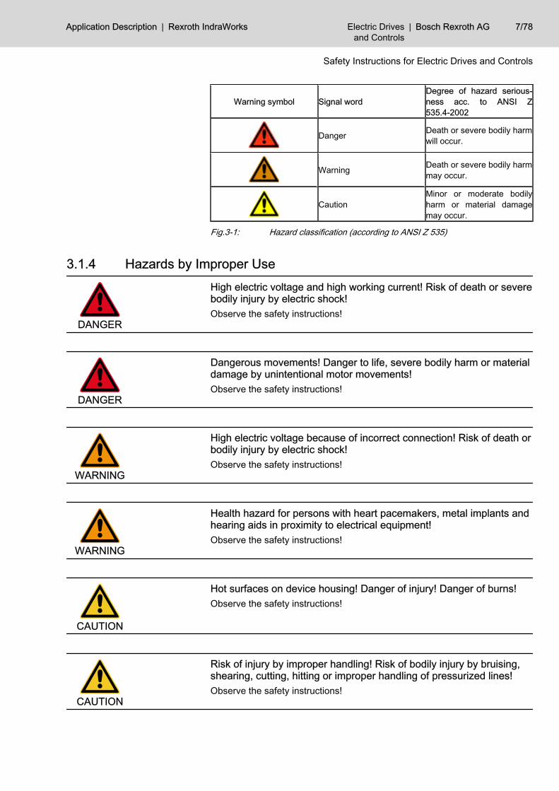
Warning symbol Signal wordDegree of hazard serious‐ness acc. to ANSI Z535.4-2002
Danger Death or severe bodily harmwill occur.
Warning Death or severe bodily harmmay occur.
CautionMinor or moderate bodilyharm or material damagemay occur.
Fig.3-1: Hazard classification (according to ANSI Z 535)
3.1.4 Hazards by Improper Use
DANGER
High electric voltage and high working current! Risk of death or severebodily injury by electric shock!Observe the safety instructions!
DANGER
Dangerous movements! Danger to life, severe bodily harm or materialdamage by unintentional motor movements!Observe the safety instructions!
WARNING
High electric voltage because of incorrect connection! Risk of death orbodily injury by electric shock!Observe the safety instructions!
WARNING
Health hazard for persons with heart pacemakers, metal implants andhearing aids in proximity to electrical equipment!Observe the safety instructions!
CAUTION
Hot surfaces on device housing! Danger of injury! Danger of burns!Observe the safety instructions!
CAUTION
Risk of injury by improper handling! Risk of bodily injury by bruising,shearing, cutting, hitting or improper handling of pressurized lines!Observe the safety instructions!
Application Description | Rexroth IndraWorks Electric Drivesand Controls
| Bosch Rexroth AG 7/78
Safety Instructions for Electric Drives and Controls
CAUTION
Risk of injury by improper handling of batteries!Observe the safety instructions!
3.2 Instructions with Regard to Specific Dangers3.2.1 Protection Against Contact with Electrical Parts and Housings
This section concerns devices and drive components with voltagesof more than 50 Volt.
Contact with parts conducting voltages above 50 Volts can cause personaldanger and electric shock. When operating electrical equipment, it is unavoid‐able that some parts of the devices conduct dangerous voltage.
DANGER
High electrical voltage! Danger to life, electric shock and severe bodilyinjury!● Only those trained and qualified to work with or on electrical equipment
are permitted to operate, maintain and repair this equipment.● Follow general construction and safety regulations when working on pow‐
er installations.● Before switching on the device, the equipment grounding conductor must
have been non-detachably connected to all electrical equipment in ac‐cordance with the connection diagram.
● Do not operate electrical equipment at any time, even for brief measure‐ments or tests, if the equipment grounding conductor is not permanentlyconnected to the mounting points of the components provided for thispurpose.
● Before working with electrical parts with voltage potentials higher than50 V, the device must be disconnected from the mains voltage or powersupply unit. Provide a safeguard to prevent reconnection.
● With electrical drive and filter components, observe the following:Wait 30 minutes after switching off power to allow capacitors to dischargebefore beginning to work. Measure the electric voltage on the capacitorsbefore beginning to work to make sure that the equipment is safe to touch.
● Never touch the electrical connection points of a component while poweris turned on. Do not remove or plug in connectors when the componenthas been powered.
● Install the covers and guards provided with the equipment properly beforeswitching the device on. Before switching the equipment on, cover andsafeguard live parts safely to prevent contact with those parts.
● A residual-current-operated circuit-breaker or r.c.d. cannot be used forelectric drives! Indirect contact must be prevented by other means, forexample, by an overcurrent protective device according to the relevantstandards.
● Secure built-in devices from direct touching of electrical parts by providingan external housing, for example a control cabinet.
8/78 Bosch Rexroth AG | Electric Drivesand Controls
Rexroth IndraWorks | Application Description
Safety Instructions for Electric Drives and Controls
For electrical drive and filter components with voltages of more than50 volts, observe the following additional safety instructions.
DANGER
High housing voltage and high leakage current! Risk of death or bodilyinjury by electric shock!● Before switching on, the housings of all electrical equipment and motors
must be connected or grounded with the equipment grounding conductorto the grounding points. This is also applicable before short tests.
● The equipment grounding conductor of the electrical equipment and thedevices must be non-detachably and permanently connected to the powersupply unit at all times. The leakage current is greater than 3.5 mA.
● Over the total length, use copper wire of a cross section of a minimum of10 mm2 for this equipment grounding connection!
● Before commissioning, also in trial runs, always attach the equipmentgrounding conductor or connect to the ground wire. Otherwise, high vol‐tages may occur at the housing causing electric shock.
3.2.2 Protection Against Electric Shock by Protective Extra-Low VoltageProtective extra-low voltage is used to allow connecting devices with basic in‐sulation to extra-low voltage circuits.All connections and terminals with voltages between 5 and 50 volts at Rexrothproducts are PELV systems. 1) It is therefore allowed to connect devicesequipped with basic insulation (such as programming devices, PCs, notebooks,display units) to these connections and terminals.
WARNING
High electric voltage by incorrect connection! Risk of death or bodilyinjury by electric shock!If extra-low voltage circuits of devices containing voltages and circuits of morethan 50 volts (e.g. the mains connection) are connected to Rexroth products,the connected extra-low voltage circuits must comply with the requirements forPELV. 2)
3.2.3 Protection Against Dangerous MovementsDangerous movements can be caused by faulty control of connected motors.Some common examples are:● improper or wrong wiring of cable connections● incorrect operation of the equipment components● wrong input of parameters before operation● malfunction of sensors, encoders and monitoring devices● defective components● software or firmware errorsDangerous movements can occur immediately after equipment is switched onor even after an unspecified time of trouble-free operation.
1) “Protective Extra-Low Voltage”2) “Protective Extra-Low Voltage”
Application Description | Rexroth IndraWorks Electric Drivesand Controls
| Bosch Rexroth AG 9/78
Safety Instructions for Electric Drives and Controls

The monitoring in the drive components will normally be sufficient to avoid faultyoperation in the connected drives. Regarding personal safety, especially thedanger of bodily harm and material damage, this alone cannot be relied uponto ensure complete safety. Until the integrated monitoring functions becomeeffective, it must be assumed in any case that faulty drive movements will occur.The extent of faulty drive movements depends upon the type of control and thestate of operation.
10/78 Bosch Rexroth AG | Electric Drivesand Controls
Rexroth IndraWorks | Application Description
Safety Instructions for Electric Drives and Controls

DANGER
Dangerous movements! Danger to life, risk of injury, severe bodily harmor material damage!● Ensure personal safety by means of qualified and tested higher-level
monitoring devices or measures integrated in the installation.These measures have to be provided for by the user according to thespecific conditions within the installation and a hazard and fault analysis.The safety regulations applicable for the installation have to be taken intoconsideration. Unintended machine motion or other malfunction is possi‐ble if safety devices are disabled, bypassed or not activated.
To avoid accidents, bodily harm and/or material damage:● Keep free and clear of the machine’s range of motion and moving parts.
Possible measures to prevent people from accidentally entering themachine’s range of motion:– use safety fences– use safety guards– use protective coverings– install light curtains or light barriers
● Fences and coverings must be strong enough to resist maximum possiblemomentum.
● Mount the emergency stop switch in the immediate reach of the operator.Verify that the emergency stop works before startup. Don’t operate thedevice if the emergency stop is not working.
● Isolate the drive power connection by means of an emergency stop circuitor use a safety related starting lockout to prevent unintentional start.
● Make sure that the drives are brought to a safe standstill before accessingor entering the danger zone.
● Additionally secure vertical axes against falling or dropping after switchingoff the motor power by, for example:– mechanically securing the vertical axes,– adding an external braking/ arrester/ clamping mechanism or– ensuring sufficient equilibration of the vertical axes.
● The standard equipment motor brake or an external brake controlled di‐rectly by the drive controller are not sufficient to guarantee personalsafety!
● Disconnect electrical power to the equipment using a master switch andsecure the switch against reconnection for:– maintenance and repair work– cleaning of equipment– long periods of discontinued equipment use
● Prevent the operation of high-frequency, remote control and radio equip‐ment near electronics circuits and supply leads. If the use of such devicescannot be avoided, verify the system and the installation for possible mal‐functions in all possible positions of normal use before initial startup. Ifnecessary, perform a special electromagnetic compatibility (EMC) test onthe installation.
Application Description | Rexroth IndraWorks Electric Drivesand Controls
| Bosch Rexroth AG 11/78
Safety Instructions for Electric Drives and Controls
3.2.4 Protection Against Magnetic and Electromagnetic Fields During Oper‐ation and Mounting
Magnetic and electromagnetic fields generated by current-carrying conductorsand permanent magnets in motors represent a serious personal danger tothose with heart pacemakers, metal implants and hearing aids.
WARNING
Health hazard for persons with heart pacemakers, metal implants andhearing aids in proximity to electrical equipment!● Persons with heart pacemakers and metal implants are not permitted to
enter following areas:– Areas in which electrical equipment and parts are mounted, being
operated or commissioned.– Areas in which parts of motors with permanent magnets are being
stored, repaired or mounted.● If it is necessary for somebody with a pacemaker to enter such an area,
a doctor must be consulted prior to doing so. The noise immunity of pres‐ent or future implanted heart pacemakers differs greatly so that no generalrules can be given.
● Those with metal implants or metal pieces, as well as with hearing aids,must consult a doctor before they enter the areas described above. Oth‐erwise health hazards may occur.
3.2.5 Protection Against Contact with Hot Parts
CAUTION
Hot surfaces at motor housings, on drive controllers or chokes! Dangerof injury! Danger of burns!● Do not touch surfaces of device housings and chokes in the proximity of
heat sources! Danger of burns!● Do not touch housing surfaces of motors! Danger of burns!● According to the operating conditions, temperatures can be higher than
60 °C, 140°F during or after operation.● Before accessing motors after having switched them off, let them cool
down for a sufficiently long time. Cooling down can require up to 140 mi‐nutes! Roughly estimated, the time required for cooling down is five timesthe thermal time constant specified in the Technical Data.
● After switching drive controllers or chokes off, wait 15 minutes to allowthem to cool down before touching them.
● Wear safety gloves or do not work at hot surfaces.● For certain applications, the manufacturer of the end product, machine or
installation, according to the respective safety regulations, has to takemeasures to avoid injuries caused by burns in the end application. Thesemeasures can be, for example: warnings, guards (shielding or barrier),technical documentation.
3.2.6 Protection During Handling and MountingIn unfavorable conditions, handling and mounting certain parts and compo‐nents in an improper way can cause injuries.
12/78 Bosch Rexroth AG | Electric Drivesand Controls
Rexroth IndraWorks | Application Description
Safety Instructions for Electric Drives and Controls

CAUTION
Risk of injury by improper handling! Bodily injury by bruising, shearing,cutting, hitting!● Observe the general construction and safety regulations on handling and
mounting.● Use suitable devices for mounting and transport.● Avoid jamming and bruising by appropriate measures.● Always use suitable tools. Use special tools if specified.● Use lifting equipment and tools in the correct manner.● If necessary, use suitable protective equipment (for example safety gog‐
gles, safety shoes, safety gloves).● Do not stand under hanging loads.● Immediately clean up any spilled liquids because of the danger of skidding.
3.2.7 Battery SafetyBatteries consist of active chemicals enclosed in a solid housing. Therefore,improper handling can cause injury or material damage.
CAUTION
Risk of injury by improper handling!● Do not attempt to reactivate low batteries by heating or other methods (risk
of explosion and cauterization).● Do not recharge the batteries as this may cause leakage or explosion.● Do not throw batteries into open flames.● Do not dismantle batteries.● When replacing the battery/batteries do not damage electrical parts in‐
stalled in the devices.● Only use the battery types specified by the manufacturer.
Environmental protection and disposal! The batteries contained inthe product are considered dangerous goods during land, air, andsea transport (risk of explosion) in the sense of the legal regulations.Dispose of used batteries separate from other waste. Observe thelocal regulations in the country of assembly.
3.2.8 Protection Against Pressurized SystemsAccording to the information given in the Project Planning Manuals, motorscooled with liquid and compressed air, as well as drive controllers, can be par‐tially supplied with externally fed, pressurized media, such as compressed air,hydraulics oil, cooling liquids and cooling lubricating agents. Improper handlingof the connected supply systems, supply lines or connections can cause injuriesor material damage.
Application Description | Rexroth IndraWorks Electric Drivesand Controls
| Bosch Rexroth AG 13/78
Safety Instructions for Electric Drives and Controls

CAUTION
Risk of injury by improper handling of pressurized lines!● Do not attempt to disconnect, open or cut pressurized lines (risk of explo‐
sion).● Observe the respective manufacturer's operating instructions.● Before dismounting lines, relieve pressure and empty medium.● Use suitable protective equipment (for example safety goggles, safety
shoes, safety gloves).● Immediately clean up any spilled liquids from the floor.
Environmental protection and disposal! The agents used to operatethe product might not be economically friendly. Dispose of ecolog‐ically harmful agents separately from other waste. Observe the localregulations in the country of assembly.
14/78 Bosch Rexroth AG | Electric Drivesand Controls
Rexroth IndraWorks | Application Description
Safety Instructions for Electric Drives and Controls
4 Quick StartIn the following, the execution sequence that makes it possible to sensibly op‐erate the various simulation components of IndraWorks is described for anIndraMotion MTX project. It is not suitable for a user who has no prior knowledgeof the simulation components. The inexperienced user must first read the entiredocumentation to become familiar with the subject matter.Execute the following steps to be able to simulate an IndraMotion MTX projecton a PC:1. Start IndraWorks using the link on the desktop2. Load the desired IndraMotion MTX project into IndraWorks3. Start the IndraMotion MTX emulation (also see chapter 6.4.6 "Starting
and Exiting the MTX Emulation " on page 69)4. Set the communication settings for the IndraMotion MTX and the PLC to
“localhost”5. The PLC must be stopped.6. The NC kernel data must be restored (also see chapter 6.4.4 "Designing
the NC Core " on page 63).7. The PLC program must be loaded and started (also see chapter 6.4.5
"Designing the PLC " on page 67)8. Activate the IndraWorks project for Operation Desktop (also see chapter
6.4.3 "Designing the HMI " on page 60)9. Create the VAM simulator (e.g. VAM 40) in IndraWorks Engineering (also
see chapter 6.2.1 "Configuration in IndraWorks" on page 33) and con‐figure it (also see chapter 6.2 "Using the Virtual Control Panel " on page33)
10. Start the Windows program “IndraWorks VAM simulator” (also see chapter6.2.2 "Connection to Virtual Control " on page 44)
You can find detailed information about IndraMotion MTX emulationin the “Virtual Commissioning of the MTX” chapter of the documen‐tation “IndraMotion MTX Commissioning”.
If a machine model exists, it can be loaded into the 3D viewer and controlledusing data from the emulation using process variables. To do this, proceed asfollows:1. Add a new model to the project (also see chapter 6.3 "Using 3D Visuali‐
zation " on page 47).2. Link the process variables to the objects of the model (also see chapter
6.3.2 "Process Connection " on page 54).3. Start the simulation of the model in IndraWorks.
Application Description | Rexroth IndraWorks Electric Drivesand Controls
| Bosch Rexroth AG 15/78
Quick Start

Bosch Rexroth AG | Electric Drivesand Controls
Rexroth IndraWorks | Application Description
5 Components of the Simulation5.1 Project Explorer
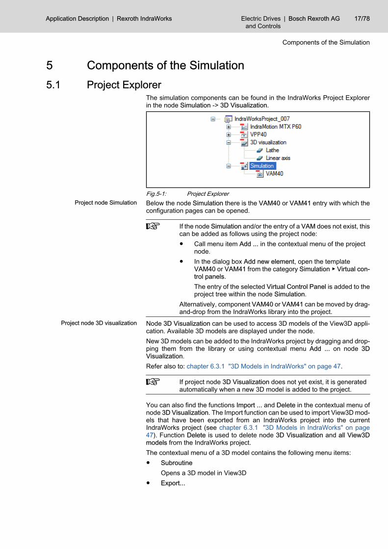
The simulation components can be found in the IndraWorks Project Explorerin the node Simulation -> 3D Visualization.
Fig.5-1: Project ExplorerProject node Simulation Below the node Simulation there is the VAM40 or VAM41 entry with which the
configuration pages can be opened.
If the node Simulation and/or the entry of a VAM does not exist, thiscan be added as follows using the project node:● Call menu item Add ... in the contextual menu of the project
node.● In the dialog box Add new element, open the template
VAM40 or VAM41 from the category Simulation ▶ Virtual con‐trol panels.The entry of the selected Virtual Control Panel is added to theproject tree within the node Simulation.
Alternatively, component VAM40 or VAM41 can be moved by drag-and-drop from the IndraWorks library into the project.
Project node 3D visualization Node 3D Visualization can be used to access 3D models of the View3D appli‐cation. Available 3D models are displayed under the node.New 3D models can be added to the IndraWorks project by dragging and drop‐ping them from the library or using contextual menu Add ... on node 3DVisualization.Refer also to: chapter 6.3.1 "3D Models in IndraWorks" on page 47.
If project node 3D Visualization does not yet exist, it is generatedautomatically when a new 3D model is added to the project.
You can also find the functions Import ... and Delete in the contextual menu ofnode 3D Visualization. The Import function can be used to import View3D mod‐els that have been exported from an IndraWorks project into the currentIndraWorks project (see chapter 6.3.1 "3D Models in IndraWorks" on page47). Function Delete is used to delete node 3D Visualization and all View3Dmodels from the IndraWorks project.The contextual menu of a 3D model contains the following menu items:● Subroutine
Opens a 3D model in View3D● Export...
Application Description | Rexroth IndraWorks Electric Drivesand Controls
| Bosch Rexroth AG 17/78
Components of the Simulation
Exports a 3D model from the IndraWorks project● Delete
Deletes the 3D model from the IndraWorks project● Rename
Renaming a 3D modelSee also chapter 6.3.1 "3D Models in IndraWorks" on page 47.
5.2 3D Visualization5.2.1 General Description
The View3D visualization system is used to represent a machine model as athree-dimensional volume model (3D scene).Individual objects in the 3D scene can be combined with process values of theIndraMotion MTX within View3D. If the NC program of the machine is executedusing the virtual control (also see chapter 5.4 "Virtual Control " on page 28),the axis movements of the machine can be traced in the three-dimensionalmachine model.Additional functions in View3D include among others:● Rotating a 3D scene● Zoom function● Wireframe representation● Saving of camera positions (viewpoints)
18/78 Bosch Rexroth AG | Electric Drivesand Controls
Rexroth IndraWorks | Application Description
Components of the Simulation
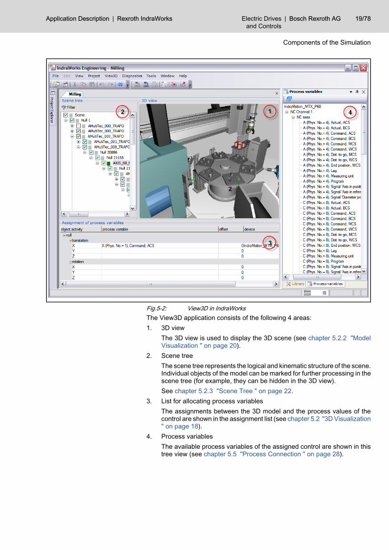
Fig.5-2: View3D in IndraWorksThe View3D application consists of the following 4 areas:1. 3D view
The 3D view is used to display the 3D scene (see chapter 5.2.2 "ModelVisualization " on page 20).
2. Scene treeThe scene tree represents the logical and kinematic structure of the scene.Individual objects of the model can be marked for further processing in thescene tree (for example, they can be hidden in the 3D view).See chapter 5.2.3 "Scene Tree " on page 22.
3. List for allocating process variablesThe assignments between the 3D model and the process values of thecontrol are shown in the assignment list (see chapter 5.2 "3D Visualization" on page 18).
4. Process variablesThe available process variables of the assigned control are shown in thistree view (see chapter 5.5 "Process Connection " on page 28).
Application Description | Rexroth IndraWorks Electric Drivesand Controls
| Bosch Rexroth AG 19/78
Components of the Simulation
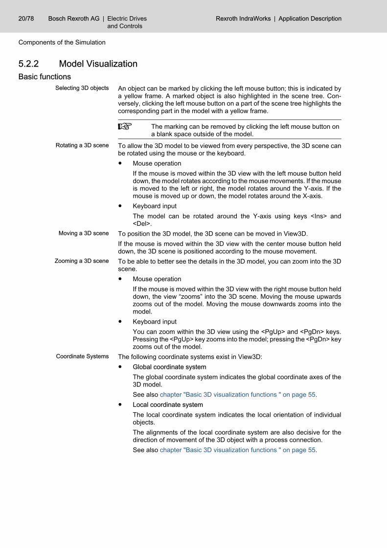
5.2.2 Model VisualizationBasic functions
Selecting 3D objects An object can be marked by clicking the left mouse button; this is indicated bya yellow frame. A marked object is also highlighted in the scene tree. Con‐versely, clicking the left mouse button on a part of the scene tree highlights thecorresponding part in the model with a yellow frame.
The marking can be removed by clicking the left mouse button ona blank space outside of the model.
Rotating a 3D scene To allow the 3D model to be viewed from every perspective, the 3D scene canbe rotated using the mouse or the keyboard.● Mouse operation
If the mouse is moved within the 3D view with the left mouse button helddown, the model rotates according to the mouse movements. If the mouseis moved to the left or right, the model rotates around the Y-axis. If themouse is moved up or down, the model rotates around the X-axis.
● Keyboard inputThe model can be rotated around the Y-axis using keys <Ins> and<Del>.
Moving a 3D scene To position the 3D model, the 3D scene can be moved in View3D.If the mouse is moved within the 3D view with the center mouse button helddown, the 3D scene is positioned according to the mouse movement.
Zooming a 3D scene To be able to better see the details in the 3D model, you can zoom into the 3Dscene.● Mouse operation
If the mouse is moved within the 3D view with the right mouse button helddown, the view “zooms” into the 3D scene. Moving the mouse upwardszooms out of the model. Moving the mouse downwards zooms into themodel.
● Keyboard inputYou can zoom within the 3D view using the <PgUp> and <PgDn> keys.Pressing the <PgUp> key zooms into the model; pressing the <PgDn> keyzooms out of the model.
Coordinate Systems The following coordinate systems exist in View3D:● Global coordinate system
The global coordinate system indicates the global coordinate axes of the3D model.See also chapter "Basic 3D visualization functions " on page 55.
● Local coordinate system The local coordinate system indicates the local orientation of individualobjects.The alignments of the local coordinate system are also decisive for thedirection of movement of the 3D object with a process connection.See also chapter "Basic 3D visualization functions " on page 55.
20/78 Bosch Rexroth AG | Electric Drivesand Controls
Rexroth IndraWorks | Application Description
Components of the Simulation
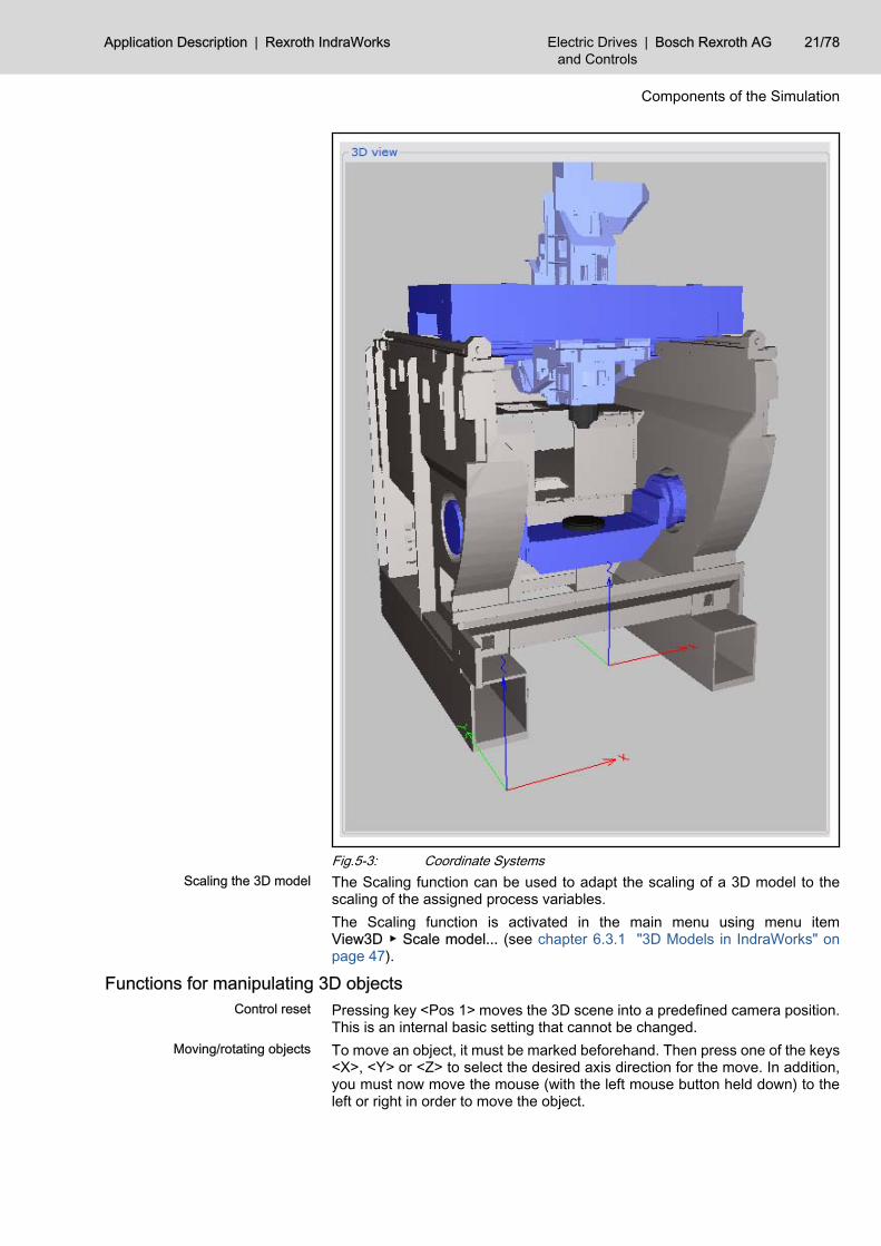
Fig.5-3: Coordinate SystemsScaling the 3D model The Scaling function can be used to adapt the scaling of a 3D model to the
scaling of the assigned process variables.The Scaling function is activated in the main menu using menu itemView3D ▶ Scale model... (see chapter 6.3.1 "3D Models in IndraWorks" onpage 47).
Functions for manipulating 3D objectsControl reset Pressing key <Pos 1> moves the 3D scene into a predefined camera position.
This is an internal basic setting that cannot be changed.Moving/rotating objects To move an object, it must be marked beforehand. Then press one of the keys
<X>, <Y> or <Z> to select the desired axis direction for the move. In addition,you must now move the mouse (with the left mouse button held down) to theleft or right in order to move the object.
Application Description | Rexroth IndraWorks Electric Drivesand Controls
| Bosch Rexroth AG 21/78
Components of the Simulation
If you press and hold the right mouse button instead of the left one, the objectis rotated around the selected axis.
Saving camera positions Keys <0> to <9> can be used to save and call 10 different camera positions.To do this - see the explanation in chapter "Basic functions" on page 20 - thecamera position is changed and then saved using key combination <Ctrl+num‐ber>.A camera position (viewpoint) can be called again by pressing one of the keys<0> to <9>.
Explosion/implosion Pressing the <End> key brings manipulated objects back to the basic position(implosion).If you then press the <E> key, the objects move back to the manipulated posi‐tion (explosion).
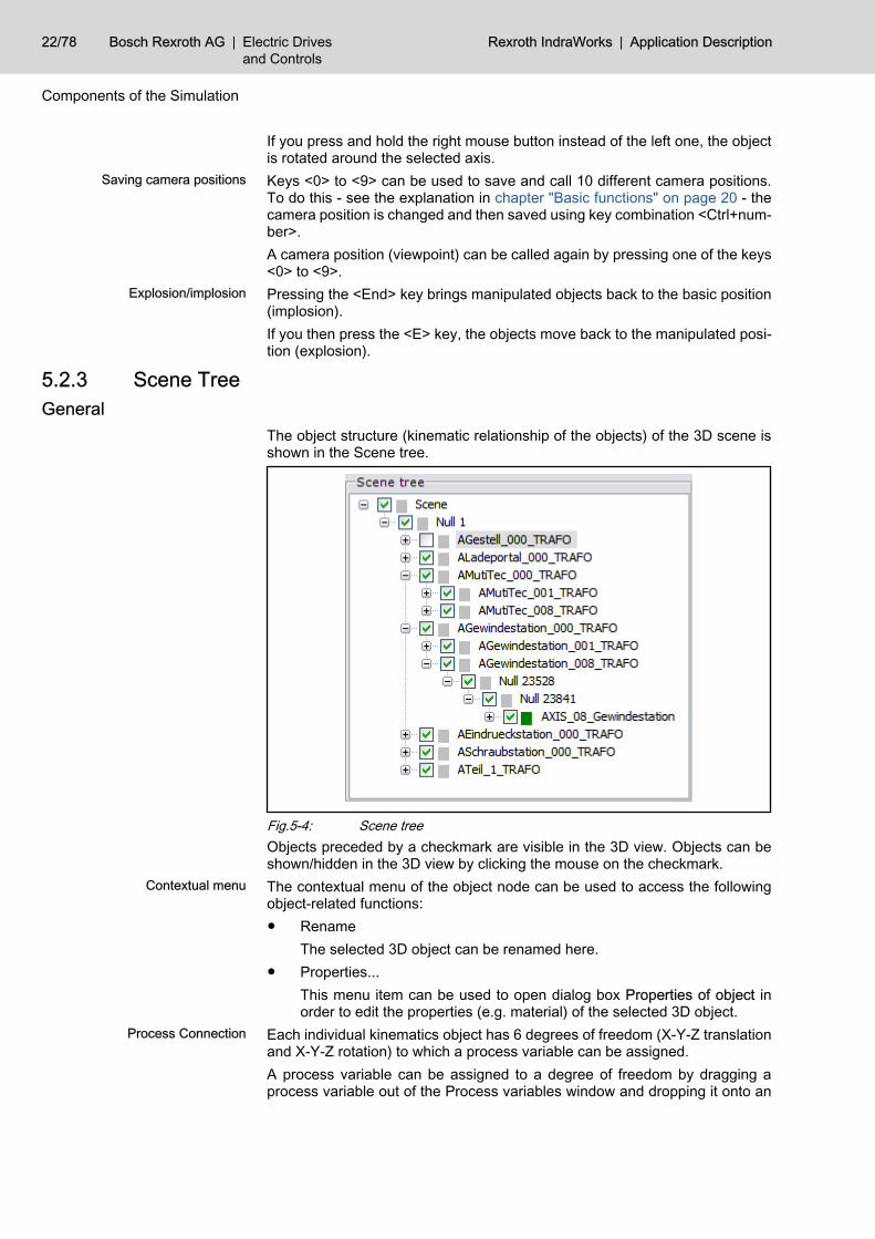
5.2.3 Scene TreeGeneral
The object structure (kinematic relationship of the objects) of the 3D scene isshown in the Scene tree.
Fig.5-4: Scene treeObjects preceded by a checkmark are visible in the 3D view. Objects can beshown/hidden in the 3D view by clicking the mouse on the checkmark.
Contextual menu The contextual menu of the object node can be used to access the followingobject-related functions:● Rename
The selected 3D object can be renamed here.● Properties...
This menu item can be used to open dialog box Properties of object inorder to edit the properties (e.g. material) of the selected 3D object.
Process Connection Each individual kinematics object has 6 degrees of freedom (X-Y-Z translationand X-Y-Z rotation) to which a process variable can be assigned.A process variable can be assigned to a degree of freedom by dragging aprocess variable out of the Process variables window and dropping it onto an
22/78 Bosch Rexroth AG | Electric Drivesand Controls
Rexroth IndraWorks | Application Description
Components of the Simulation
object in the Scene tree (see chapter 6.3 "Using 3D Visualization " on page47).
Objects that have been assigned a process variable can be recog‐nized by a green square.The assignment of process variables to the degrees of freedom ofthe selected object can be seen in the assignment list.
Filter function Press the <Filter> button to filter the Scene tree according to assigned objects.To do this, at least one object with a process connection must exist.
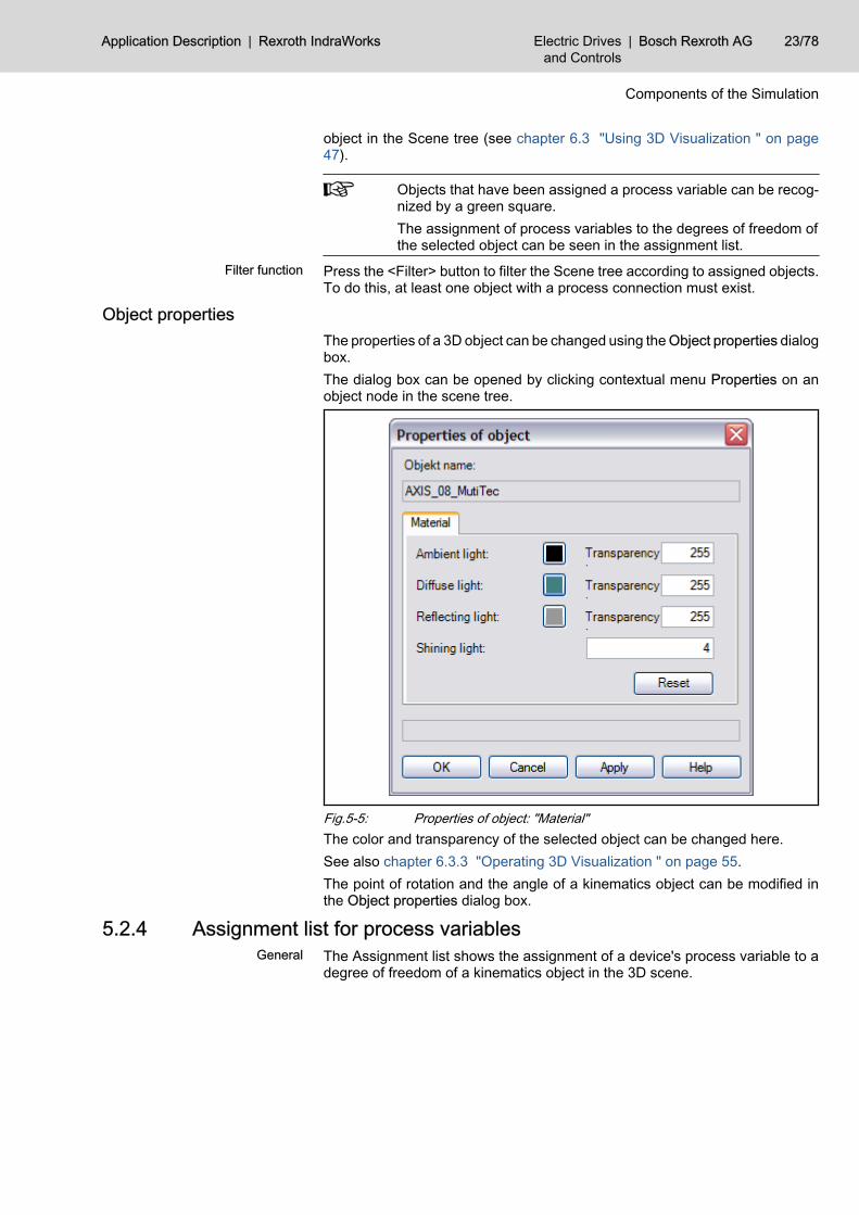
Object propertiesThe properties of a 3D object can be changed using the Object properties dialogbox.The dialog box can be opened by clicking contextual menu Properties on anobject node in the scene tree.
Fig.5-5: Properties of object: "Material"The color and transparency of the selected object can be changed here.See also chapter 6.3.3 "Operating 3D Visualization " on page 55.The point of rotation and the angle of a kinematics object can be modified inthe Object properties dialog box.
5.2.4 Assignment list for process variablesGeneral The Assignment list shows the assignment of a device's process variable to a
degree of freedom of a kinematics object in the 3D scene.
Application Description | Rexroth IndraWorks Electric Drivesand Controls
| Bosch Rexroth AG 23/78
Components of the Simulation
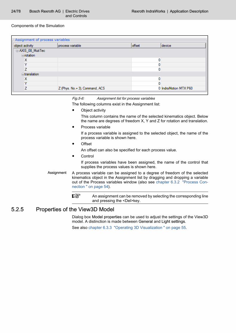
Fig.5-6: Assignment list for process variablesThe following columns exist in the Assignment list:● Object activity
This column contains the name of the selected kinematics object. Belowthe name are degrees of freedom X, Y and Z for rotation and translation.
● Process variableIf a process variable is assigned to the selected object, the name of theprocess variable is shown here.
● OffsetAn offset can also be specified for each process value.
● ControlIf process variables have been assigned, the name of the control thatsupplies the process values is shown here.
Assignment A process variable can be assigned to a degree of freedom of the selectedkinematics object in the Assignment list by dragging and dropping a variableout of the Process variables window (also see chapter 6.3.2 "Process Con‐nection " on page 54).
An assignment can be removed by selecting the corresponding lineand pressing the <Del>key.
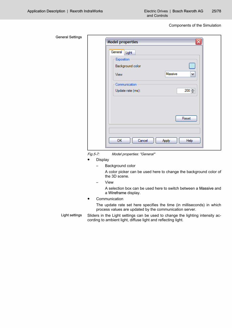
5.2.5 Properties of the View3D ModelDialog box Model properties can be used to adjust the settings of the View3Dmodel. A distinction is made between General and Light settings.See also chapter 6.3.3 "Operating 3D Visualization " on page 55.
24/78 Bosch Rexroth AG | Electric Drivesand Controls
Rexroth IndraWorks | Application Description
Components of the Simulation
General Settings
Fig.5-7: Model properties: "General"● Display
– Background colorA color picker can be used here to change the background color ofthe 3D scene.
– ViewA selection box can be used here to switch between a Massive anda Wireframe display.
● CommunicationThe update rate set here specifies the time (in milliseconds) in whichprocess values are updated by the communication server.
Light settings Sliders in the Light settings can be used to change the lighting intensity ac‐cording to ambient light, diffuse light and reflecting light.
Application Description | Rexroth IndraWorks Electric Drivesand Controls
| Bosch Rexroth AG 25/78
Components of the Simulation
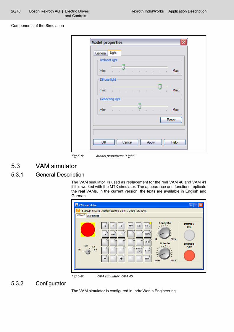
Fig.5-8: Model properties: "Light"
5.3 VAM simulator5.3.1 General Description
The VAM simulator is used as replacement for the real VAM 40 and VAM 41if it is worked with the MTX simulator. The appearance and functions replicatethe real VAMs. In the current version, the texts are available in English andGerman.
Fig.5-9: VAM simulator VAM 40
5.3.2 ConfiguratorThe VAM simulator is configured in IndraWorks Engineering.
26/78 Bosch Rexroth AG | Electric Drivesand Controls
Rexroth IndraWorks | Application Description
Components of the Simulation
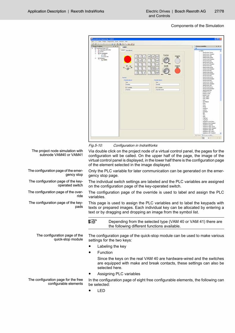
Fig.5-10: Configuration in IndraWorksThe project node simulation with
subnode VAM40 or VAM41Via double click on the project node of a virtual control panel, the pages for theconfiguration will be called. On the upper half of the page, the image of thevirtual control panel is displayed, in the lower half there is the configuration pageof the element selected in the image displayed.
The configuration page of the emer‐gency stop
Only the PLC variable for later communication can be generated on the emer‐gency stop page.
The configuration page of the key-operated switch
The individual switch settings are labeled and the PLC variables are assignedon the configuration page of the key-operated switch.
The configuration page of the over‐ride
The configuration page of the override is used to label and assign the PLCvariables.
The configuration page of the key‐pads
This page is used to assign the PLC variables and to label the keypads withtexts or prepared images. Each individual key can be allocated by entering atext or by dragging and dropping an image from the symbol list.
Depending from the selected type (VAM 40 or VAM 41) there arethe following different functions available.
The configuration page of thequick-stop module
The configuration page of the quick-stop module can be used to make varioussettings for the two keys:● Labeling the key● Function
Since the keys on the real VAM 40 are hardware-wired and the switchesare equipped with make and break contacts, these settings can also beselected here.
● Assigning PLC variablesThe configuration page for the free
configurable elementsIn the configuration page of eight free configurable elements, the following canbe selected:● LED
Application Description | Rexroth IndraWorks Electric Drivesand Controls
| Bosch Rexroth AG 27/78
Components of the Simulation
● Button with LED● Button without LED● Switch with 2 positions● Switch with 3 positions
Position in the middle has no function.This elements can be labelled and assigned with PLC variables.
Since the keys on the real VAM 41 are hardware-wired and theswitches are equipped with make and break contacts, these set‐tings can also be selected here.
5.3.3 The ApplicationThe application is separate; it is used to control the PLC program in IndraMotionMTX emulation. This can be started independently of IndraWorks Engineeringor IndraWorks Operation. When the VAM simulator is started, the configurationis read out from the currently active project.
The VAM simulator communicates directly with the emulation.IndraWorks Operation or IndraWorks Engineering do not need tobe started.
5.4 Virtual Control5.4.1 General Description
A virtual control is the most important simulation component because it regu‐lates the entire process - just like the real control. It contains the same functionsas the real control and is identically parameterized, programmed and operated.Therefore, the method of operation does not change for the user if he switchesbetween a virtual control and a real one; only the communication parametersof the Engineering interface must be reset. However, since the virtual controlruns under Windows, its only limitation is that it is not real-time-capable.With the emulation of the IndraMotion MTX machine tool control, Bosch Rexrothhas such a virtual control.For further information regarding IndraMotion MTX emulation, see chapter 6.4 "Using the Virtual Control" on page 59.
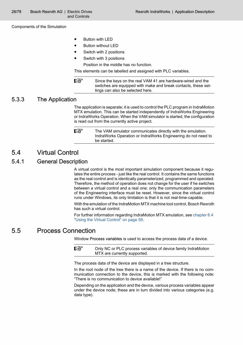
5.5 Process ConnectionWindow Process variables is used to access the process data of a device.
Only NC or PLC process variables of device family IndraMotionMTX are currently supported.
The process data of the device are displayed in a tree structure.In the root node of the tree there is a name of the device. If there is no com‐munication connection to the device, this is marked with the following note:“There is no communication to device available!”Depending on the application and the device, various process variables appearunder the device node; these are in turn divided into various categories (e.g.data type).
28/78 Bosch Rexroth AG | Electric Drivesand Controls
Rexroth IndraWorks | Application Description
Components of the Simulation
With the button “Reload process variable” the displayed variables can beupdated. This is necessary if e.g. global variables are modified in the PLC pro‐gram.If an error occurs, the device node is shown in red. If you position the mousecursor over the device node, additional information about the error appears inan info box.
Process variable window inIndraWorks Engineering
The process variable window is displayed in the IndraWorks Engineering asdockable window.A process variable is assigned to an element of the corresponding applicationusing drag-and-drop.
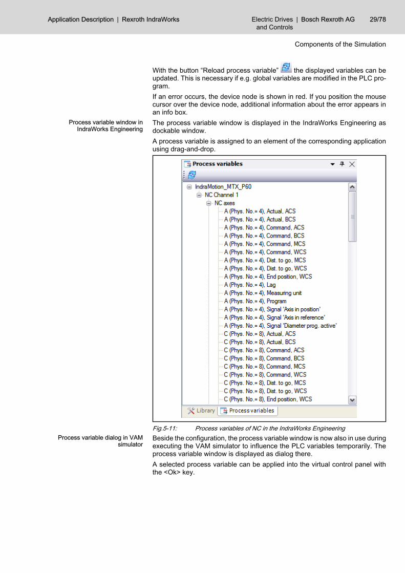
Fig.5-11: Process variables of NC in the IndraWorks EngineeringProcess variable dialog in VAM
simulatorBeside the configuration, the process variable window is now also in use duringexecuting the VAM simulator to influence the PLC variables temporarily. Theprocess variable window is displayed as dialog there.A selected process variable can be applied into the virtual control panel withthe <Ok> key.
Application Description | Rexroth IndraWorks Electric Drivesand Controls
| Bosch Rexroth AG 29/78
Components of the Simulation
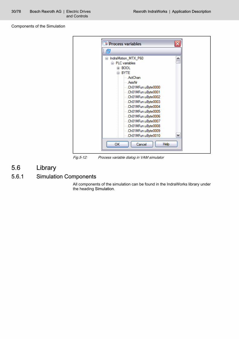
Fig.5-12: Process variable dialog in VAM simulator
5.6 Library5.6.1 Simulation Components
All components of the simulation can be found in the IndraWorks library underthe heading Simulation.
30/78 Bosch Rexroth AG | Electric Drivesand Controls
Rexroth IndraWorks | Application Description
Components of the Simulation
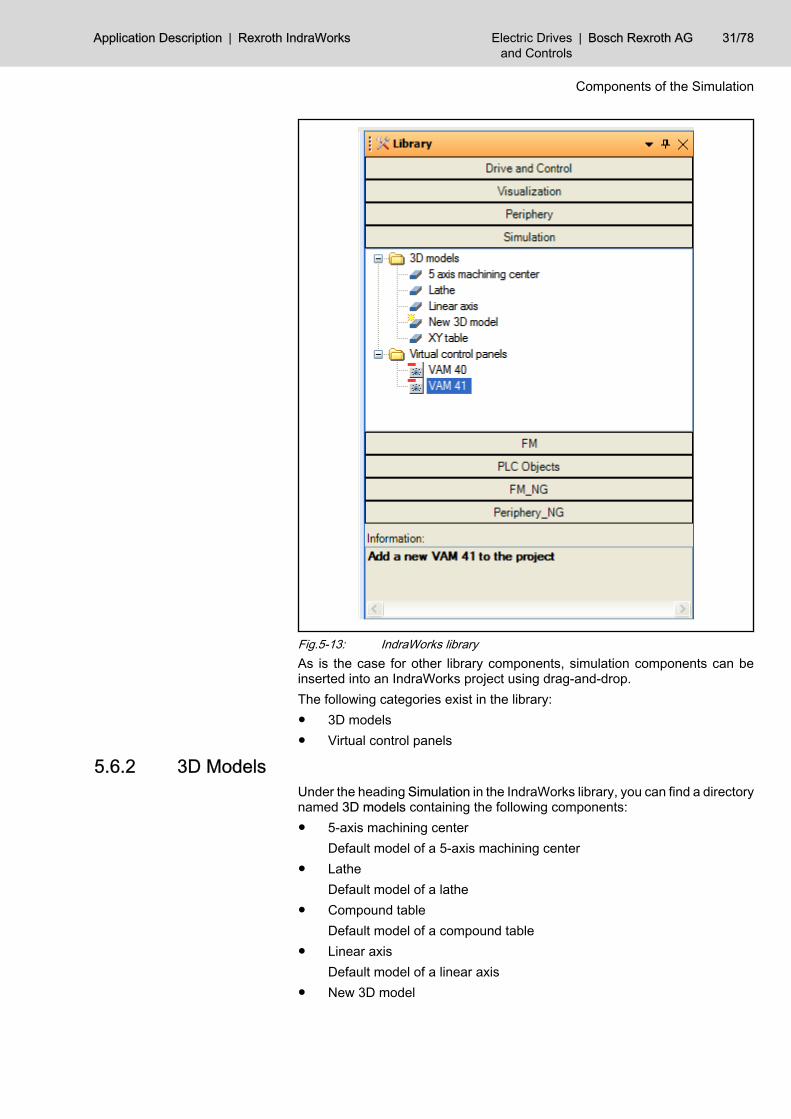
Fig.5-13: IndraWorks libraryAs is the case for other library components, simulation components can beinserted into an IndraWorks project using drag-and-drop.The following categories exist in the library:● 3D models● Virtual control panels
5.6.2 3D ModelsUnder the heading Simulation in the IndraWorks library, you can find a directorynamed 3D models containing the following components:● 5-axis machining center
Default model of a 5-axis machining center● Lathe
Default model of a lathe● Compound table
Default model of a compound table● Linear axis
Default model of a linear axis● New 3D model
Application Description | Rexroth IndraWorks Electric Drivesand Controls
| Bosch Rexroth AG 31/78
Components of the Simulation

This component can be used to create a new 3D model.
5.6.3 Virtual control panelsUnder the heading Simulation in the IndraWorks library, you can find a directorynamed Virtual Control Panels containing the following components:● VAM 40
A virtual control panel based on the real VAM 40.● VAM 41
A virtual control panel based on the real VAM 41.
32/78 Bosch Rexroth AG | Electric Drivesand Controls
Rexroth IndraWorks | Application Description
Components of the Simulation
6 Operation in IndraWorks6.1 Creating a Model6.1.1 General
The import format for 3D scenes into View3D is VRML (Virtual Reality ModelingLanguage). Files in the format VRML 2.0 (or VRML97) are supported.VRML files are recognized by the file extension “.wrl” (world).Most 3D modeling tools can export 3D scenes in VRML format.
The import of compressed VRML files (the file extension is also“.wrl”) is not supported by View3D.
6.1.2 Creating a Simple 3D ModelAs a rule, any 3D modeling tool with VRML export can be used to create 3Dmodels. However, not all modeling tools can be used to create kinematic rela‐tionships between individual 3D objects.Kinematic relationships have a fundamental significance for machine models.In a compound table, for example, the X-axis also moves when the Y-axis ismoved.The following rules must be considered during creating a 3D model in VRML2.0 format:● There is just one root node in the tree structure of model allowed, all further
nodes on this level will be ignored.● No VRML primitives are allowed in the model (the export must be executed
with the option “Indexed Phase Set”)● Translation / rotation to the object is not allowed on the end node in the
tree structure. Either this is moved to a group of a higher level or a meshalgorithm is executed on the object.
● Sensors (animation) are not supported.● Textures that are content of a model will be displayed in View3D.
6.1.3 Importing eM-RealNC ModelsView3D can also import VRML models that have been created using the NCsimulation software “Tecnomatix eM-RealNC” from Unigraphics SolutionsGmbH (http://www.tecnomatix.de). Tecnomatix eM-RealNC has provided aVRML export interface for this purpose.
6.2 Using the Virtual Control Panel6.2.1 Configuration in IndraWorksConfiguring the Virtual Control Panel
Creating a Virtual Control PanelIn order to be able to configure a Virtual Control Panel, a project must havebeen created in IndraWorks.A virtual control panel is created in an existing IndraWorks project via Projectnode ▶ right mouse button ▶ Add new element ▶ Virtual control panel or usingthe library via tab Simulation ▶ Virtual control panels; then the panel is draggedto the project node and dropped there.
Application Description | Rexroth IndraWorks Electric Drivesand Controls
| Bosch Rexroth AG 33/78
Operation in IndraWorks
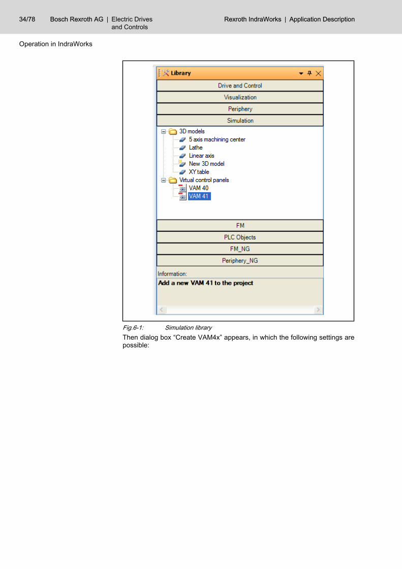
Fig.6-1: Simulation libraryThen dialog box “Create VAM4x” appears, in which the following settings arepossible:
34/78 Bosch Rexroth AG | Electric Drivesand Controls
Rexroth IndraWorks | Application Description
Operation in IndraWorks
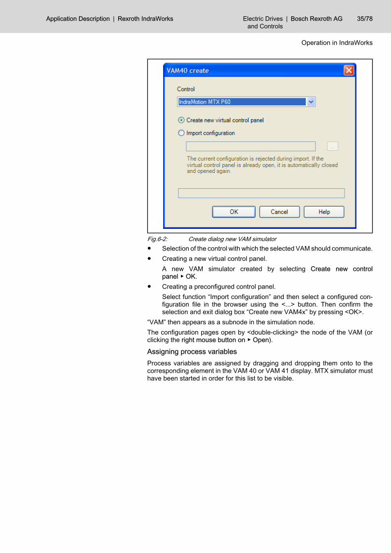
Fig.6-2: Create dialog new VAM simulator● Selection of the control with which the selected VAM should communicate.● Creating a new virtual control panel.
A new VAM simulator created by selecting Create new controlpanel ▶ OK.
● Creating a preconfigured control panel.Select function “Import configuration” and then select a configured con‐figuration file in the browser using the <...> button. Then confirm theselection and exit dialog box “Create new VAM4x” by pressing <OK>.
“VAM” then appears as a subnode in the simulation node.The configuration pages open by <double-clicking> the node of the VAM (orclicking the right mouse button on ▶ Open).
Assigning process variablesProcess variables are assigned by dragging and dropping them onto to thecorresponding element in the VAM 40 or VAM 41 display. MTX simulator musthave been started in order for this list to be visible.
Application Description | Rexroth IndraWorks Electric Drivesand Controls
| Bosch Rexroth AG 35/78
Operation in IndraWorks
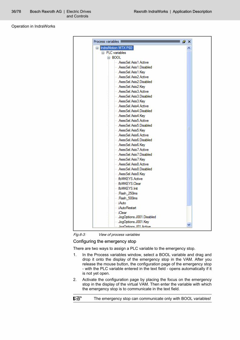
Fig.6-3: View of process variables
Configuring the emergency stopThere are two ways to assign a PLC variable to the emergency stop.1. In the Process variables window, select a BOOL variable and drag and
drop it onto the display of the emergency stop in the VAM. After yourelease the mouse button, the configuration page of the emergency stop- with the PLC variable entered in the text field - opens automatically if itis not yet open.
2. Activate the configuration page by placing the focus on the emergencystop in the display of the virtual VAM. Then enter the variable with whichthe emergency stop is to communicate in the text field.
The emergency stop can communicate only with BOOL variables!
36/78 Bosch Rexroth AG | Electric Drivesand Controls
Rexroth IndraWorks | Application Description
Operation in IndraWorks
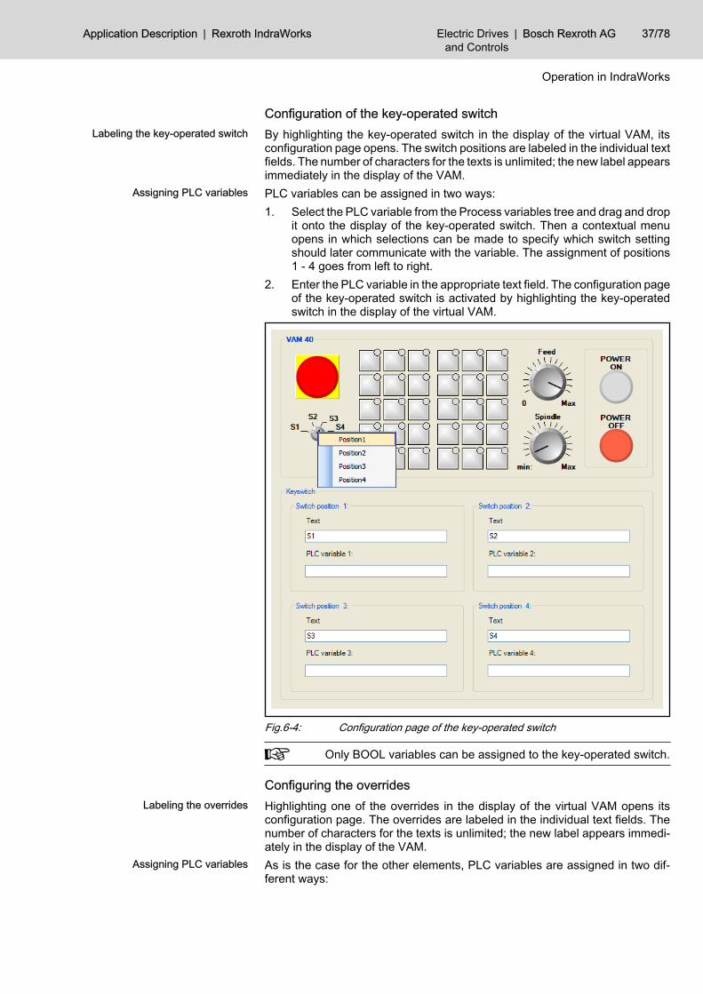
Configuration of the key-operated switchLabeling the key-operated switch By highlighting the key-operated switch in the display of the virtual VAM, its
configuration page opens. The switch positions are labeled in the individual textfields. The number of characters for the texts is unlimited; the new label appearsimmediately in the display of the VAM.
Assigning PLC variables PLC variables can be assigned in two ways:1. Select the PLC variable from the Process variables tree and drag and drop
it onto the display of the key-operated switch. Then a contextual menuopens in which selections can be made to specify which switch settingshould later communicate with the variable. The assignment of positions1 - 4 goes from left to right.
2. Enter the PLC variable in the appropriate text field. The configuration pageof the key-operated switch is activated by highlighting the key-operatedswitch in the display of the virtual VAM.
Fig.6-4: Configuration page of the key-operated switch
Only BOOL variables can be assigned to the key-operated switch.
Configuring the overridesLabeling the overrides Highlighting one of the overrides in the display of the virtual VAM opens its
configuration page. The overrides are labeled in the individual text fields. Thenumber of characters for the texts is unlimited; the new label appears immedi‐ately in the display of the VAM.
Assigning PLC variables As is the case for the other elements, PLC variables are assigned in two dif‐ferent ways:
Application Description | Rexroth IndraWorks Electric Drivesand Controls
| Bosch Rexroth AG 37/78
Operation in IndraWorks
1. Select the PLC variable from the Process variables tree and drag and dropit onto the display of the override with which the variable is to be activated.The name of the variable can then be seen in the appropriate text field onthe configuration page.
2. When you “go” to the display of an override, the configuration page of theoverride opens. The PLC variable can now be written in one of the textfields.
The overrides are activated using BYTE variables.
Configuring the keypadsThe configuration page of the keypads is opened by highlighting a key on thekeypad.
Assigning text to the keys When labeling an individual key, first highlight the desired key on the keypad.Then switch to the text field of “Labeling the key” and enter the text.
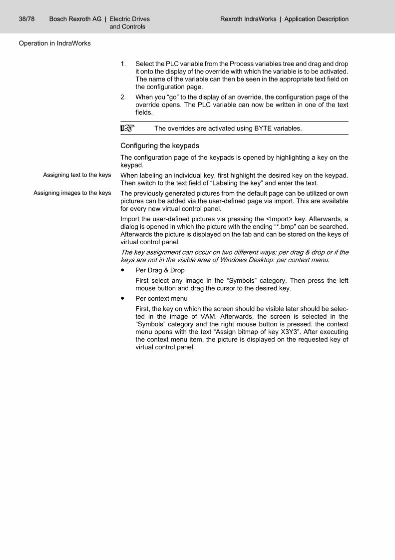
Assigning images to the keys The previously generated pictures from the default page can be utilized or ownpictures can be added via the user-defined page via import. This are availablefor every new virtual control panel.Import the user-defined pictures via pressing the <Import> key. Afterwards, adialog is opened in which the picture with the ending “*.bmp” can be searched.Afterwards the picture is displayed on the tab and can be stored on the keys ofvirtual control panel.The key assignment can occur on two different ways: per drag & drop or if thekeys are not in the visible area of Windows Desktop: per context menu.● Per Drag & Drop
First select any image in the “Symbols” category. Then press the leftmouse button and drag the cursor to the desired key.
● Per context menuFirst, the key on which the screen should be visible later should be selec‐ted in the image of VAM. Afterwards, the screen is selected in the“Symbols” category and the right mouse button is pressed. the contextmenu opens with the text “Assign bitmap of key X3Y3”. After executingthe context menu item, the picture is displayed on the requested key ofvirtual control panel.
38/78 Bosch Rexroth AG | Electric Drivesand Controls
Rexroth IndraWorks | Application Description
Operation in IndraWorks
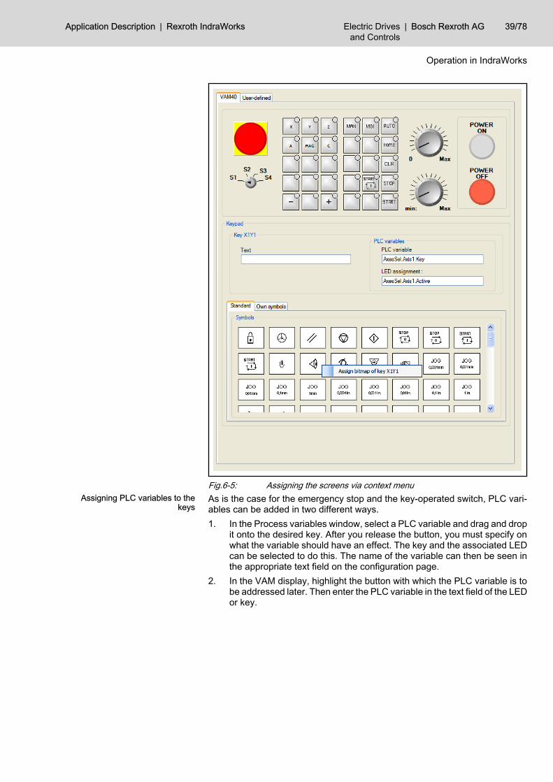
Fig.6-5: Assigning the screens via context menuAssigning PLC variables to the
keysAs is the case for the emergency stop and the key-operated switch, PLC vari‐ables can be added in two different ways.1. In the Process variables window, select a PLC variable and drag and drop
it onto the desired key. After you release the button, you must specify onwhat the variable should have an effect. The key and the associated LEDcan be selected to do this. The name of the variable can then be seen inthe appropriate text field on the configuration page.
2. In the VAM display, highlight the button with which the PLC variable is tobe addressed later. Then enter the PLC variable in the text field of the LEDor key.
Application Description | Rexroth IndraWorks Electric Drivesand Controls
| Bosch Rexroth AG 39/78
Operation in IndraWorks
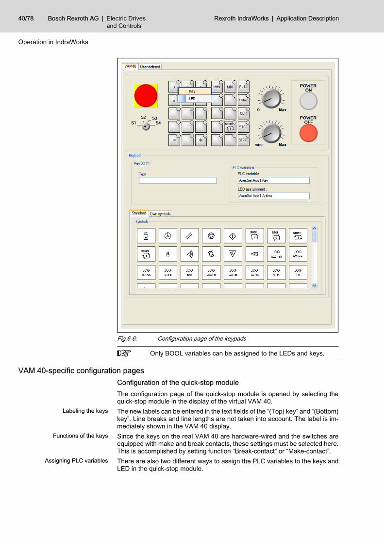
Fig.6-6: Configuration page of the keypads
Only BOOL variables can be assigned to the LEDs and keys.
VAM 40-specific configuration pages Configuration of the quick-stop moduleThe configuration page of the quick-stop module is opened by selecting thequick-stop module in the display of the virtual VAM 40.
Labeling the keys The new labels can be entered in the text fields of the “(Top) key” and “(Bottom)key”. Line breaks and line lengths are not taken into account. The label is im‐mediately shown in the VAM 40 display.
Functions of the keys Since the keys on the real VAM 40 are hardware-wired and the switches areequipped with make and break contacts, these settings must be selected here.This is accomplished by setting function “Break-contact” or “Make-contact”.
Assigning PLC variables There are also two different ways to assign the PLC variables to the keys andLED in the quick-stop module.
40/78 Bosch Rexroth AG | Electric Drivesand Controls
Rexroth IndraWorks | Application Description
Operation in IndraWorks
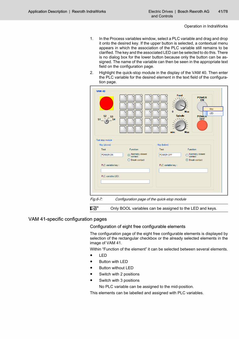
1. In the Process variables window, select a PLC variable and drag and dropit onto the desired key. If the upper button is selected, a contextual menuappears in which the association of the PLC variable still remains to beclarified. The key and the associated LED can be selected to do this. Thereis no dialog box for the lower button because only the button can be as‐signed. The name of the variable can then be seen in the appropriate textfield on the configuration page.
2. Highlight the quick-stop module in the display of the VAM 40. Then enterthe PLC variable for the desired element in the text field of the configura‐tion page.
Fig.6-7: Configuration page of the quick-stop module
Only BOOL variables can be assigned to the LED and keys.
VAM 41-specific configuration pagesConfiguration of eight free configurable elementsThe configuration page of the eight free configurable elements is displayed byselection of the rectangular checkbox or the already selected elements in theimage of VAM 41.Within “Function of the element” it can be selected between several elements.● LED● Button with LED● Button without LED● Switch with 2 positions● Switch with 3 positions
No PLC variable can be assigned to the mid-position.This elements can be labelled and assigned with PLC variables.
Application Description | Rexroth IndraWorks Electric Drivesand Controls
| Bosch Rexroth AG 41/78
Operation in IndraWorks
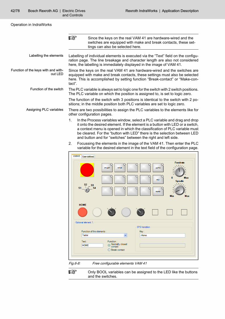
Since the keys on the real VAM 41 are hardware-wired and theswitches are equipped with make and break contacts, these set‐tings can also be selected here.
Labelling the elements Labelling of individual elements is executed via the “Text” field on the configu‐ration page. The line breakage and character length are also not consideredhere, the labelling is immediately displayed in the image of VAM 41.
Function of the keys with and with‐out LED
Since the keys on the real VAM 41 are hardware-wired and the switches areequipped with make and break contacts, these settings must also be selectedhere. This is accomplished by setting function “Break-contact” or “Make-con‐tact”.
Function of the switch The PLC variable is always set to logic one for the switch with 2 switch positions.The PLC variable on which the position is assigned to, is set to logic zero.The function of the switch with 3 positions is identical to the switch with 2 po‐sitions; in the middle position both PLC variables are set to logic zero.
Assigning PLC variables There are two possibilities to assign the PLC variables to the elements like forother configuration pages.1. In the Process variables window, select a PLC variable and drag and drop
it onto the desired element. If the element is a button with LED or a switch,a context menu is opened in which the classification of PLC variable mustbe cleared. For the “button with LED” there is the selection between LEDand button and for “switches” between the right and left side.
2. Focussing the elements in the image of the VAM 41. Then enter the PLCvariable for the desired element in the text field of the configuration page.
Fig.6-8: Free configurable elements VAM 41
Only BOOL variables can be assigned to the LED like the buttonsand the switches.
42/78 Bosch Rexroth AG | Electric Drivesand Controls
Rexroth IndraWorks | Application Description
Operation in IndraWorks
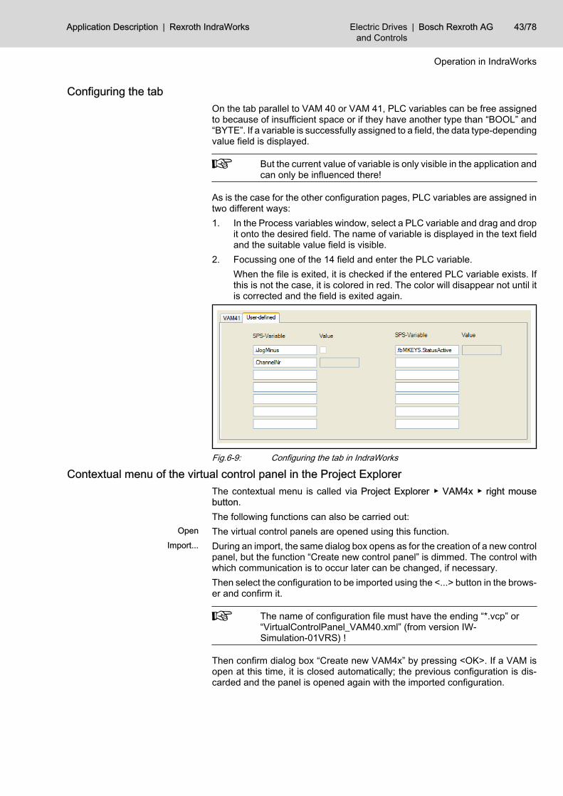
Configuring the tabOn the tab parallel to VAM 40 or VAM 41, PLC variables can be free assignedto because of insufficient space or if they have another type than “BOOL” and“BYTE”. If a variable is successfully assigned to a field, the data type-dependingvalue field is displayed.
But the current value of variable is only visible in the application andcan only be influenced there!
As is the case for the other configuration pages, PLC variables are assigned intwo different ways:1. In the Process variables window, select a PLC variable and drag and drop
it onto the desired field. The name of variable is displayed in the text fieldand the suitable value field is visible.
2. Focussing one of the 14 field and enter the PLC variable.When the file is exited, it is checked if the entered PLC variable exists. Ifthis is not the case, it is colored in red. The color will disappear not until itis corrected and the field is exited again.
Fig.6-9: Configuring the tab in IndraWorks
Contextual menu of the virtual control panel in the Project Explorer The contextual menu is called via Project Explorer ▶ VAM4x ▶ right mousebutton.The following functions can also be carried out:
Open The virtual control panels are opened using this function.Import... During an import, the same dialog box opens as for the creation of a new control
panel, but the function “Create new control panel” is dimmed. The control withwhich communication is to occur later can be changed, if necessary.Then select the configuration to be imported using the <...> button in the brows‐er and confirm it.
The name of configuration file must have the ending “*.vcp” or“VirtualControlPanel_VAM40.xml” (from version IW-Simulation-01VRS) !
Then confirm dialog box “Create new VAM4x” by pressing <OK>. If a VAM isopen at this time, it is closed automatically; the previous configuration is dis‐carded and the panel is opened again with the imported configuration.
Application Description | Rexroth IndraWorks Electric Drivesand Controls
| Bosch Rexroth AG 43/78
Operation in IndraWorks
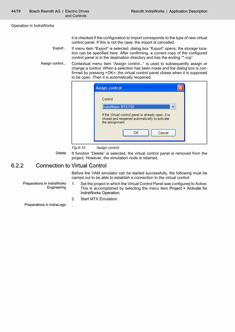
it is checked if the configuration to import corresponds to the type of new virtualcontrol panel. If this is not the case, the import is cancelled.
Export... If menu item “Export” is selected, dialog box “Export” opens; the storage loca‐tion can be specified here. After confirming, a current copy of the configuredcontrol panel is in the destination directory and has the ending “*.vcp”.
Assign control... Contextual menu item “Assign control...” is used to subsequently assign orchange a control. When a selection has been made and the dialog box is con‐firmed by pressing <OK>, the virtual control panel closes when it is supposedto be open. Then it is automatically reopened.
Fig.6-10: Assign controlDelete If function “Delete” is selected, the virtual control panel is removed from the
project. However, the simulation node is retained.
6.2.2 Connection to Virtual ControlBefore the VAM simulator can be started successfully, the following must becarried out to be able to establish a connection to the virtual control:
Preparations in IndraWorksEngineering
1. Set the project in which the Virtual Control Panel was configured to Active.This is accomplished by selecting the menu item Project ▶ Activate forIndraWorks Operation.
2. Start MTX Emulation.Preparations in IndraLogic .
44/78 Bosch Rexroth AG | Electric Drivesand Controls
Rexroth IndraWorks | Application Description
Operation in IndraWorks
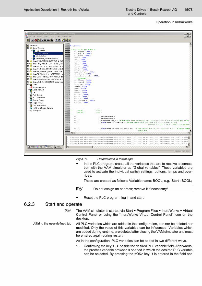
Fig.6-11: Preparations in IndraLogic● In the PLC program, create all the variables that are to receive a connec‐
tion with the VAM simulator as “Global variables”. These variables areused to activate the individual switch settings, buttons, lamps and over‐rides.These are created as follows: Variable name: BOOL, e.g. iStart : BOOL;
Do not assign an address; remove it if necessary!
● Reset the PLC program, log in and start.
6.2.3 Start and operateStart The VAM simulator is started via Start ▶ Program Files ▶ IndraWorks ▶ Virtual
Control Panel or using the “IndraWorks Virtual Control Panel” icon on thedesktop.
Utilizing the user-defined tab All PLC variables which are added in the configuration, can nor be deleted normodified. Only the value of this variables can be influenced. Variables whichare added during runtime, are deleted after closing the VAM simulator and mustbe entered again during restart.As in the configuration, PLC variables can be added in two different ways.1. Confirming the key <...> beside the desired PLC variable field. Afterwards,
the process variable browser is opened in which the desired PLC variablecan be selected. By pressing the <OK> key, it is entered in the field and
Application Description | Rexroth IndraWorks Electric Drivesand Controls
| Bosch Rexroth AG 45/78
Operation in IndraWorks
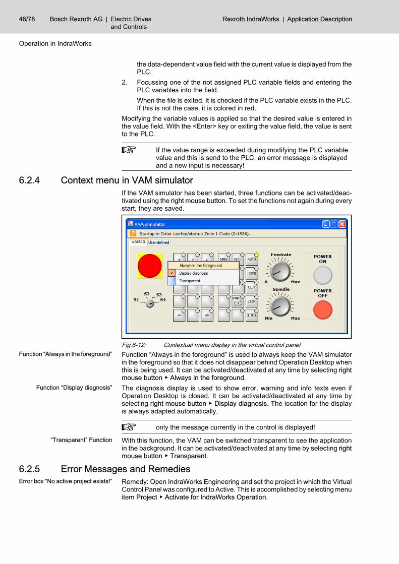
the data-dependent value field with the current value is displayed from thePLC.
2. Focussing one of the not assigned PLC variable fields and entering thePLC variables into the field.When the file is exited, it is checked if the PLC variable exists in the PLC.If this is not the case, it is colored in red.
Modifying the variable values is applied so that the desired value is entered inthe value field. With the <Enter> key or exiting the value field, the value is sentto the PLC.
If the value range is exceeded during modifying the PLC variablevalue and this is send to the PLC, an error message is displayedand a new input is necessary!
6.2.4 Context menu in VAM simulatorIf the VAM simulator has been started, three functions can be activated/deac‐tivated using the right mouse button. To set the functions not again during everystart, they are saved.
Fig.6-12: Contextual menu display in the virtual control panelFunction “Always in the foreground” Function “Always in the foreground” is used to always keep the VAM simulator
in the foreground so that it does not disappear behind Operation Desktop whenthis is being used. It can be activated/deactivated at any time by selecting rightmouse button ▶ Always in the foreground.
Function “Display diagnosis” The diagnosis display is used to show error, warning and info texts even ifOperation Desktop is closed. It can be activated/deactivated at any time byselecting right mouse button ▶ Display diagnosis. The location for the displayis always adapted automatically.
only the message currently in the control is displayed!
“Transparent” Function With this function, the VAM can be switched transparent to see the applicationin the background. It can be activated/deactivated at any time by selecting rightmouse button ▶ Transparent.
6.2.5 Error Messages and RemediesError box “No active project exists!” Remedy: Open IndraWorks Engineering and set the project in which the Virtual
Control Panel was configured to Active. This is accomplished by selecting menuitem Project ▶ Activate for IndraWorks Operation.
46/78 Bosch Rexroth AG | Electric Drivesand Controls
Rexroth IndraWorks | Application Description
Operation in IndraWorks
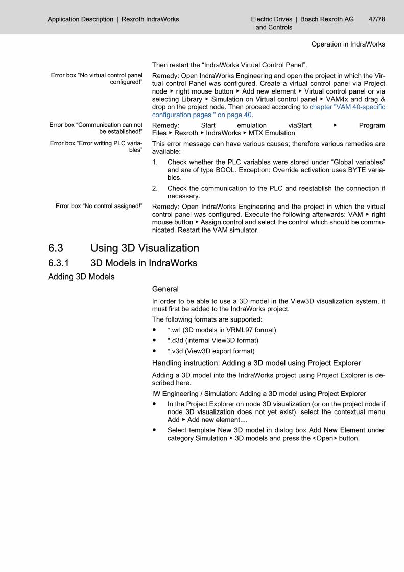
Then restart the “IndraWorks Virtual Control Panel”.Error box “No virtual control panel
configured!”Remedy: Open IndraWorks Engineering and open the project in which the Vir‐tual control Panel was configured. Create a virtual control panel via Projectnode ▶ right mouse button ▶ Add new element ▶ Virtual control panel or viaselecting Library ▶ Simulation on Virtual control panel ▶ VAM4x and drag &drop on the project node. Then proceed according to chapter "VAM 40-specificconfiguration pages " on page 40.
Error box “Communication can notbe established!”
Remedy: Start emulation viaStart ▶ ProgramFiles ▶ Rexroth ▶ IndraWorks ▶ MTX Emulation
Error box “Error writing PLC varia‐bles”
This error message can have various causes; therefore various remedies areavailable:1. Check whether the PLC variables were stored under “Global variables”
and are of type BOOL. Exception: Override activation uses BYTE varia‐bles.
2. Check the communication to the PLC and reestablish the connection ifnecessary.
Error box “No control assigned!” Remedy: Open IndraWorks Engineering and the project in which the virtualcontrol panel was configured. Execute the following afterwards: VAM ▶ rightmouse button ▶ Assign control and select the control which should be commu‐nicated. Restart the VAM simulator.
6.3 Using 3D Visualization6.3.1 3D Models in IndraWorksAdding 3D Models
GeneralIn order to be able to use a 3D model in the View3D visualization system, itmust first be added to the IndraWorks project.The following formats are supported:● *.wrl (3D models in VRML97 format)● *.d3d (internal View3D format)● *.v3d (View3D export format)
Handling instruction: Adding a 3D model using Project ExplorerAdding a 3D model into the IndraWorks project using Project Explorer is de‐scribed here.IW Engineering / Simulation: Adding a 3D model using Project Explorer● In the Project Explorer on node 3D visualization (or on the project node if
node 3D visualization does not yet exist), select the contextual menuAdd ▶ Add new element....
● Select template New 3D model in dialog box Add New Element undercategory Simulation ▶ 3D models and press the <Open> button.
Application Description | Rexroth IndraWorks Electric Drivesand Controls
| Bosch Rexroth AG 47/78
Operation in IndraWorks
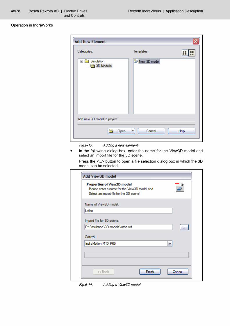
Fig.6-13: Adding a new element● In the following dialog box, enter the name for the View3D model and
select an import file for the 3D scene.Press the <...> button to open a file selection dialog box in which the 3Dmodel can be selected.
Fig.6-14: Adding a View3D model
48/78 Bosch Rexroth AG | Electric Drivesand Controls
Rexroth IndraWorks | Application Description
Operation in IndraWorks
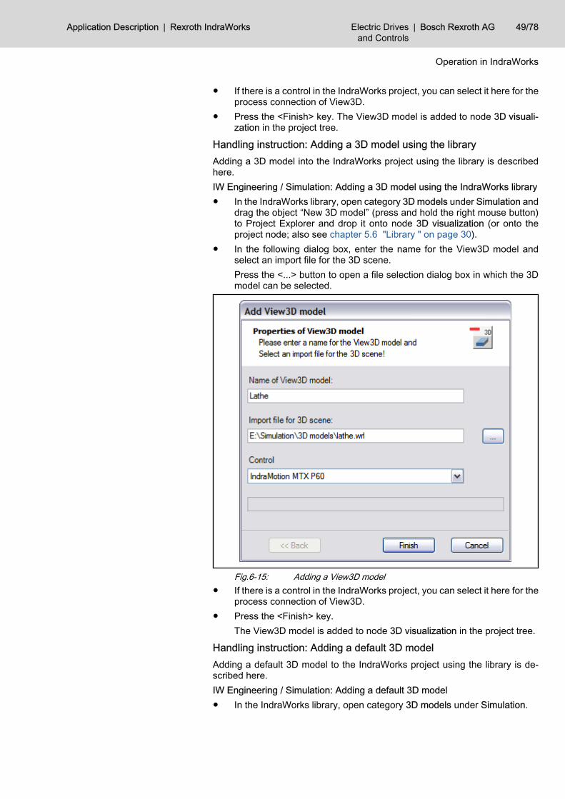
● If there is a control in the IndraWorks project, you can select it here for theprocess connection of View3D.
● Press the <Finish> key. The View3D model is added to node 3D visuali‐zation in the project tree.
Handling instruction: Adding a 3D model using the libraryAdding a 3D model into the IndraWorks project using the library is describedhere.IW Engineering / Simulation: Adding a 3D model using the IndraWorks library● In the IndraWorks library, open category 3D models under Simulation and
drag the object “New 3D model” (press and hold the right mouse button)to Project Explorer and drop it onto node 3D visualization (or onto theproject node; also see chapter 5.6 "Library " on page 30).
● In the following dialog box, enter the name for the View3D model andselect an import file for the 3D scene.Press the <...> button to open a file selection dialog box in which the 3Dmodel can be selected.
Fig.6-15: Adding a View3D model● If there is a control in the IndraWorks project, you can select it here for the
process connection of View3D.● Press the <Finish> key.
The View3D model is added to node 3D visualization in the project tree.
Handling instruction: Adding a default 3D modelAdding a default 3D model to the IndraWorks project using the library is de‐scribed here.IW Engineering / Simulation: Adding a default 3D model● In the IndraWorks library, open category 3D models under Simulation.
Application Description | Rexroth IndraWorks Electric Drivesand Controls
| Bosch Rexroth AG 49/78
Operation in IndraWorks
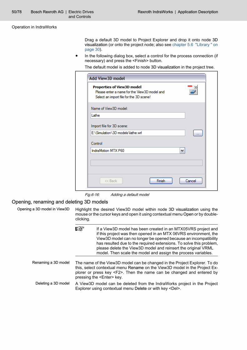
Drag a default 3D model to Project Explorer and drop it onto node 3Dvisualization (or onto the project node; also see chapter 5.6 "Library " onpage 30).
● In the following dialog box, select a control for the process connection (ifnecessary) and press the <Finish> button.The default model is added to node 3D visualization in the project tree.
Fig.6-16: Adding a default model
Opening, renaming and deleting 3D modelsOpening a 3D model in View3D Highlight the desired View3D model within node 3D visualization using the
mouse or the cursor keys and open it using contextual menu Open or by double-clicking.
If a View3D model has been created in an MTX05VRS project andif this project was then opened in an MTX 06VRS environment, theView3D model can no longer be opened because an incompatibilityhas resulted due to the required extensions. To solve this problem,please delete the View3D model and reinsert the original VRMLmodel. Then scale the model and assign the process variables.
Renaming a 3D model The name of the View3D model can be changed in the Project Explorer. To dothis, select contextual menu Rename on the View3D model in the Project Ex‐plorer or press key <F2>. Then the name can be changed and entered bypressing the <Enter> key.
Deleting a 3D model A View3D model can be deleted from the IndraWorks project in the ProjectExplorer using contextual menu Delete or with key <Del>.
50/78 Bosch Rexroth AG | Electric Drivesand Controls
Rexroth IndraWorks | Application Description
Operation in IndraWorks
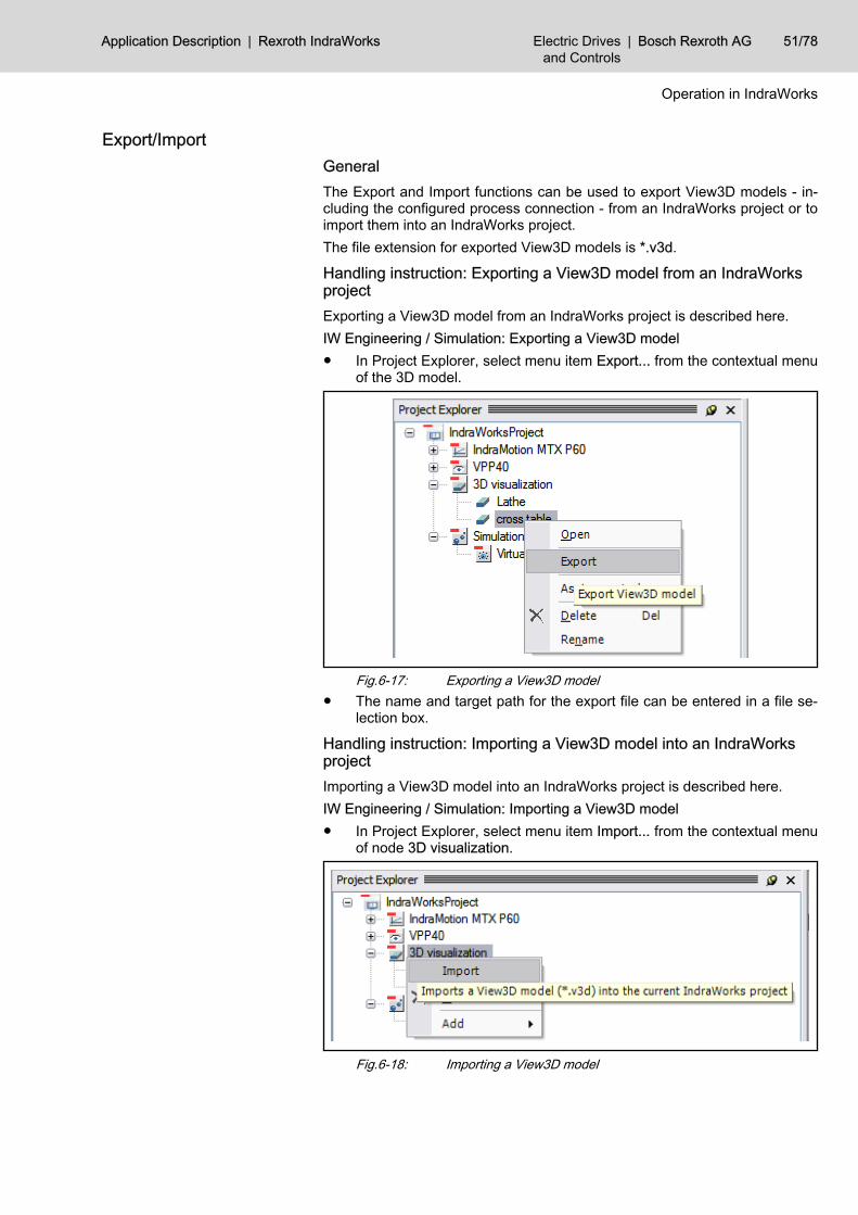
Export/Import GeneralThe Export and Import functions can be used to export View3D models - in‐cluding the configured process connection - from an IndraWorks project or toimport them into an IndraWorks project.The file extension for exported View3D models is *.v3d.
Handling instruction: Exporting a View3D model from an IndraWorksprojectExporting a View3D model from an IndraWorks project is described here.IW Engineering / Simulation: Exporting a View3D model● In Project Explorer, select menu item Export... from the contextual menu
of the 3D model.
Fig.6-17: Exporting a View3D model● The name and target path for the export file can be entered in a file se‐
lection box.
Handling instruction: Importing a View3D model into an IndraWorksprojectImporting a View3D model into an IndraWorks project is described here.IW Engineering / Simulation: Importing a View3D model● In Project Explorer, select menu item Import... from the contextual menu
of node 3D visualization.
Fig.6-18: Importing a View3D model
Application Description | Rexroth IndraWorks Electric Drivesand Controls
| Bosch Rexroth AG 51/78
Operation in IndraWorks
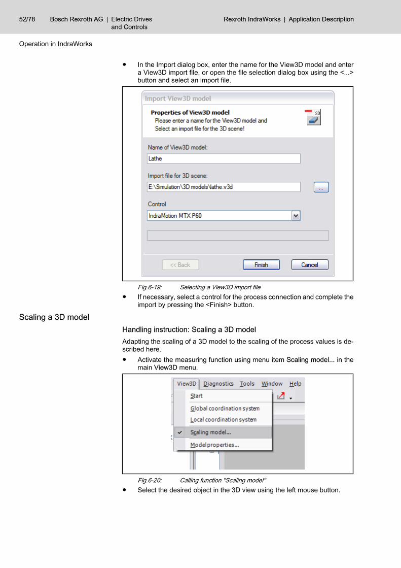
● In the Import dialog box, enter the name for the View3D model and entera View3D import file, or open the file selection dialog box using the <...>button and select an import file.
Fig.6-19: Selecting a View3D import file● If necessary, select a control for the process connection and complete the
import by pressing the <Finish> button.
Scaling a 3D modelHandling instruction: Scaling a 3D modelAdapting the scaling of a 3D model to the scaling of the process values is de‐scribed here.● Activate the measuring function using menu item Scaling model... in the
main View3D menu.
Fig.6-20: Calling function "Scaling model"● Select the desired object in the 3D view using the left mouse button.
52/78 Bosch Rexroth AG | Electric Drivesand Controls
Rexroth IndraWorks | Application Description
Operation in IndraWorks
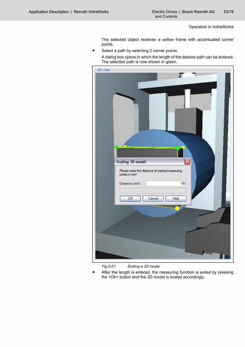
The selected object receives a yellow frame with accentuated cornerpoints.
● Select a path by selecting 2 corner points.A dialog box opens in which the length of the desired path can be entered.The selected path is now shown in green.
Fig.6-21: Scaling a 3D model● After the length is entered, the measuring function is exited by pressing
the <Ok> button and the 3D model is scaled accordingly.
Application Description | Rexroth IndraWorks Electric Drivesand Controls
| Bosch Rexroth AG 53/78
Operation in IndraWorks
The scaling function can also be called while a process connectionis active. In this way, the 3D model can be used to immediatelycheck the changes.● If the value for the length is set too low, the 3D objects move
beyond the end position (they may even be moved out of thevisible area of the 3D Viewer).
● If the distance is too high, it may be impossible to detect themovement of the 3D objects.
6.3.2 Process ConnectionConnecting 3D objects with IndraMotion MTX axis values
Handling instruction: Assigning a process value to a 3D objectThis handling instruction describes how a 3D object can be linked to a processvariable.IW Engineering / Simulation: Assigning a process value to a 3D objectA 3D object can be connected to a process variable in 2 ways:1. Process assignment using the Assignment list
● Select a 3D object in the scene tree or the 3D view.The entries Offset (X,Y,Z) and Rotation (X,Y,Z) for the selected ob‐ject appear in the Assignment list.
● Select a process variable in window Process variables and - with theright mouse button held down - drag it to the Assignment list, thendrop it over the desired entry (e.g. offset in X axis direction).
2. Assigning process variables using the scene tree● In window Process variables, drag a variable - with the right mouse
button held down - to the scene tree and drop it over the desired 3Dobject.A contextual menu on the 3D object opens with the available actionsOffset (X,Y,Z) / Rotation (X,Y,Z).
● Select the desired action from the contextual menu of the object.The 3D object receives a green highlight and is transferred to theAssignment list.
If window Process variables cannot be seen, it can be shown usingmenu item View ▶ Process variables in the main menu.
Configuring the process connectionHandling instruction: Changing the offset for process valuesAn offset can be added to every process value.The entry of offset values is described in this handling instruction.IW Engineering / Simulation: Adding an offset to the process value of a View3Dobject● Select a 3D object with a configured process connection from the scene
tree (can be recognized by the green marking).● Change the offset value of the process variables in the Assignment list.
54/78 Bosch Rexroth AG | Electric Drivesand Controls
Rexroth IndraWorks | Application Description
Operation in IndraWorks
Establishing a connection to the controlHandling instruction: Starting a View3D process connectionThis handling instruction describes how to activate the View3D process con‐nection in order to control 3D objects using process values.IW Engineering / Simulation: Establishing a View3D process connection forcontrolIn the main menu, select menu item View3D ▶ Start.The following actions are now carried out:● Window Assignment for process variables disappears.● The process connection is started and the 3D objects are supplied with
the process values of the control.
Handling instruction: Stopping a View3D process connectionAn active process connection in View3D can be stopped using this handlinginstruction.
Boundary condition The process connection must be active (this can be recognized by the check‐mark on menu item Start in the main View3D menu).IW Engineering / Simulation: Terminating a View3D process connection forcontrolIn the main menu, select menu item View3D ▶ Start.The following actions are now carried out:● The process connection is stopped.● Window Assignment for process variables appears.
6.3.3 Operating 3D VisualizationBasic 3D visualization functions
Coordinate systemsGlobal coordinate system The global coordinate system of the 3D scene can be shown/hidden in the main
menu using menu item View3D ▶ Global coordinate system (also see chapter5 "Components of the Simulation " on page 17).
Local coordinate system The local coordinate system indicates the local orientation of individual objects.To do this, the local coordinate system must be activated using the main menuView3D ▶ Locale coordinate system and an object must be selected (also seechapter "Basic functions" on page 20).
Manipulating 3D objectsHandling instruction: Moving a View3D objectThis handling instruction describes how a single View3D object in the 3D modelcan be moved.IW Engineering / Simulation: Moving a View3D object● Select the 3D object using the left mouse button.● Press the <X>, <Y> or <Z> key while simultaneously pressing the left
mouse button. The object can now be moved in the X, Y or Z coordinatedirection by moving the mouse to the left or right.
Handling instruction: Rotating a View3D objectThe procedure for rotating a View3D object in the 3D scene is described here.IW Engineering / Simulation: Rotating a View3D object
Application Description | Rexroth IndraWorks Electric Drivesand Controls
| Bosch Rexroth AG 55/78
Operation in IndraWorks
● Select the 3D object using the left mouse button.● Press the <X>, <Y> or <Z> key while simultaneously pressing the right
mouse button. The object can now be rotated around the X, Y or Z coor‐dinate axis by moving the mouse to the left or right.
Changing settings of the View3D model"Model properties" dialog boxSettings of the View3D model are changed in the Properties of the View3Dmodeldialog box (also see chapter 5.2 "3D Visualization " on page 18).The dialog box is called in the main menu using menu item View3D ▶ Modelproperties....The dialog box is divided into General and Light settings.
General SettingsChange background color. The background color of the 3D model can be changed as follows:
After the <Background color> button is pressed, a color picker appears in whichthe new background color can be selected.
The setting of the background color is shown immediately in the 3Dmodel.
Changing the model view Selection box View can be used to switch the model view between Massive andWireframe.
The setting of the view is shown immediately in the 3D model.
Changing the process communica‐tion update rate
The update time (in milliseconds) for the process communication can be en‐tered in entry field Update rate.
The update rate can be changed only if the process connection isinactive.
The settings can be transferred by pressing the <Ok> or <Apply> button.Pressing the <Cancel> button closes the dialog box and leaves the settingsunchanged.
Light settingsThe lighting of the 3D scene can be set using the 3 following sliders:● Ambient light● Diffuse light● Reflecting lightThe settings are immediately shown in the 3D scene.If the light setting is as desired, it can be retained by pressing <Ok> or <Ap‐ply>.Pressing the <Cancel> button closes the dialog box and leaves the lightingsettings unchanged.
Changing object propertiesDialog box Properties of object can be used to change object-based properties(such as the material).The dialog box Object Propertiescan be opened by opening contextual menuProperties... on the desired 3D object in the scene tree.The material of a 3D object can be manipulated using the following settings:
56/78 Bosch Rexroth AG | Electric Drivesand Controls
Rexroth IndraWorks | Application Description
Operation in IndraWorks
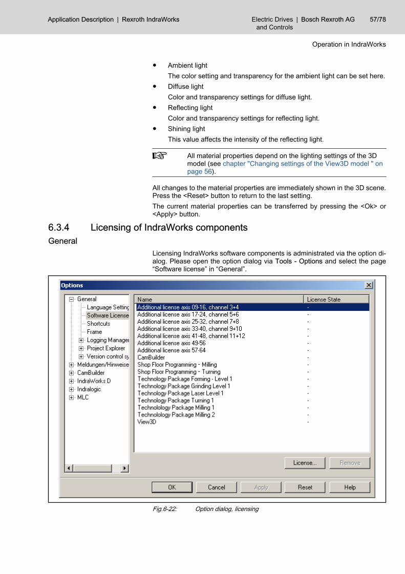
● Ambient lightThe color setting and transparency for the ambient light can be set here.
● Diffuse lightColor and transparency settings for diffuse light.
● Reflecting lightColor and transparency settings for reflecting light.
● Shining lightThis value affects the intensity of the reflecting light.
All material properties depend on the lighting settings of the 3Dmodel (see chapter "Changing settings of the View3D model " onpage 56).
All changes to the material properties are immediately shown in the 3D scene.Press the <Reset> button to return to the last setting.The current material properties can be transferred by pressing the <Ok> or<Apply> button.
6.3.4 Licensing of IndraWorks componentsGeneral
Licensing IndraWorks software components is administrated via the option di‐alog. Please open the option dialog via Tools - Options and select the page“Software license” in “General”.
Fig.6-22: Option dialog, licensing
Application Description | Rexroth IndraWorks Electric Drivesand Controls
| Bosch Rexroth AG 57/78
Operation in IndraWorks
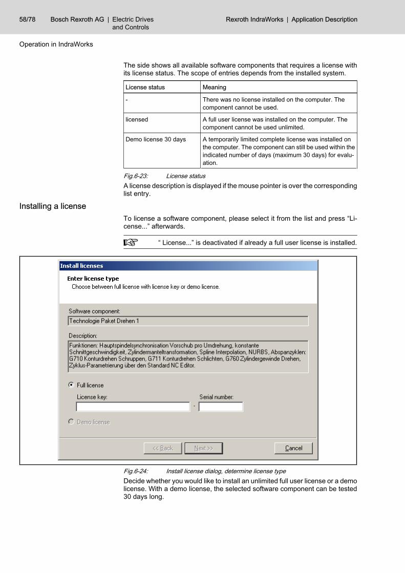
The side shows all available software components that requires a license withits license status. The scope of entries depends from the installed system.
License status Meaning
- There was no license installed on the computer. Thecomponent cannot be used.
licensed A full user license was installed on the computer. Thecomponent cannot be used unlimited.
Demo license 30 days A temporarily limited complete license was installed onthe computer. The component can still be used within theindicated number of days (maximum 30 days) for evalu‐ation.
Fig.6-23: License statusA license description is displayed if the mouse pointer is over the correspondinglist entry.
Installing a license To license a software component, please select it from the list and press “Li‐cense...” afterwards.
“ License...” is deactivated if already a full user license is installed.
Fig.6-24: Install license dialog, determine license typeDecide whether you would like to install an unlimited full user license or a demolicense. With a demo license, the selected software component can be tested30 days long.
58/78 Bosch Rexroth AG | Electric Drivesand Controls
Rexroth IndraWorks | Application Description
Operation in IndraWorks
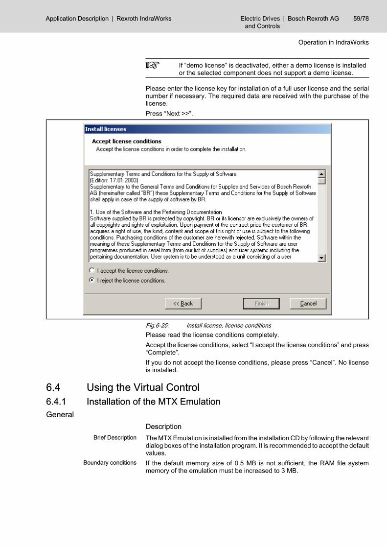
If “demo license” is deactivated, either a demo license is installedor the selected component does not support a demo license.
Please enter the license key for installation of a full user license and the serialnumber if necessary. The required data are received with the purchase of thelicense.Press “Next >>”.
Fig.6-25: Install license, license conditionsPlease read the license conditions completely.Accept the license conditions, select “I accept the license conditions” and press“Complete”.If you do not accept the license conditions, please press “Cancel”. No licenseis installed.
6.4 Using the Virtual Control6.4.1 Installation of the MTX EmulationGeneral
DescriptionBrief Description The MTX Emulation is installed from the installation CD by following the relevant
dialog boxes of the installation program. It is recommended to accept the defaultvalues.
Boundary conditions If the default memory size of 0.5 MB is not sufficient, the RAM file systemmemory of the emulation must be increased to 3 MB.
Application Description | Rexroth IndraWorks Electric Drivesand Controls
| Bosch Rexroth AG 59/78
Operation in IndraWorks
Handling Instruction: Extend the RAM File System Memory of the Em‐ulationIf more memory space is necessary for the application, it can be extended asfollows:Windows / Windows Explorer: Change file designations● In the folder “D:\Program Files\Rexroth\IndraWorks\mtx\emu”
– rename the file “t3usrfep.pxf” to “t3usrfep.pxf.1MB” and– rename the file “t3usrfep.pxf.3MB” to “t3usrfep.pxf”.
Figure Flowchart Example Instruction Documentation
Documentation: IndraWorks Commissioning In‐structions MTX Emulation
Fig.6-26: Link
6.4.2 Designing the EmulationRestoring an existing project
GeneralBrief Description With IndraWorks Engineering, existing projects can be restored which have
been created earlier or on a different computer for real systems or the MTXEmulation.
Description In the following, you will find a description of how to transfer (=restore) anIndraWorks project from a real control to the emulation. Among other things,the IndraWorks project storage contains the control parameters, the Profibusconfiguration, the PLC program, the definition files for the M- and F-keys, thelogbooks and the user-defined screens.Restoring of the project is carried out by using the function “restore” in the menu“project”.
Handling Instruction: Restoration of an existing Project for the MTX Em‐ulationIn the following, you will find a description of how to transfer (=restore) anIndraWorks project from a real control to the emulation.IW Engineering / Motion: Restore control data
Figure Flowchart Example Instruction DocumentationInstruction: Restore data
Documentation: IndraWorks Commissioning In‐structions Data backup
Fig.6-27: Link
6.4.3 Designing the HMIGeneral
DescriptionBrief Description The designed HMI data can only have an effect on the user interface if down‐
loaded to the runtime folder of the user interface.Boundary conditions The runtime folder can only be set if the installation path of the target control
(emulation) is different to the installation path of the source control on which theproject has been created.
60/78 Bosch Rexroth AG | Electric Drivesand Controls
Rexroth IndraWorks | Application Description
Operation in IndraWorks
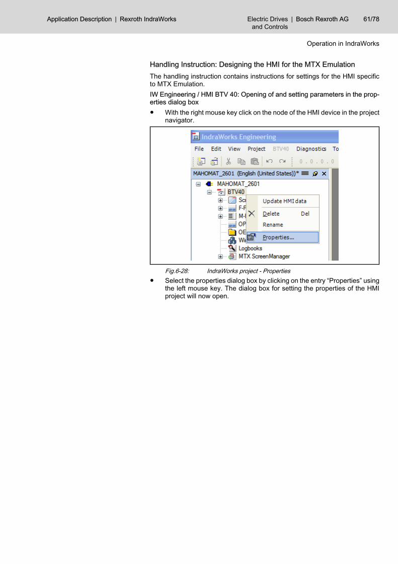
Handling Instruction: Designing the HMI for the MTX EmulationThe handling instruction contains instructions for settings for the HMI specificto MTX Emulation.IW Engineering / HMI BTV 40: Opening of and setting parameters in the prop‐erties dialog box● With the right mouse key click on the node of the HMI device in the project
navigator.
Fig.6-28: IndraWorks project - Properties● Select the properties dialog box by clicking on the entry “Properties” using
the left mouse key. The dialog box for setting the properties of the HMIproject will now open.
Application Description | Rexroth IndraWorks Electric Drivesand Controls
| Bosch Rexroth AG 61/78
Operation in IndraWorks
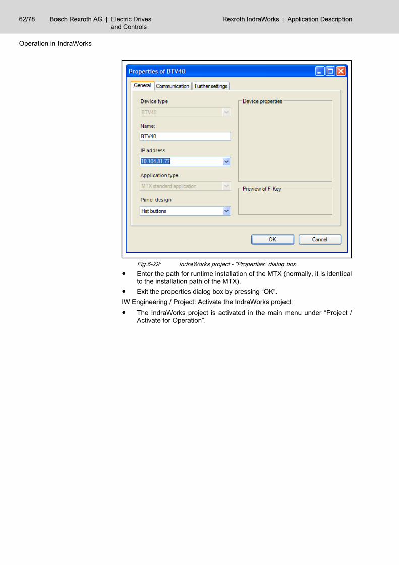
Fig.6-29: IndraWorks project - “Properties” dialog box● Enter the path for runtime installation of the MTX (normally, it is identical
to the installation path of the MTX).● Exit the properties dialog box by pressing “OK”.IW Engineering / Project: Activate the IndraWorks project● The IndraWorks project is activated in the main menu under “Project /
Activate for Operation”.
62/78 Bosch Rexroth AG | Electric Drivesand Controls
Rexroth IndraWorks | Application Description
Operation in IndraWorks
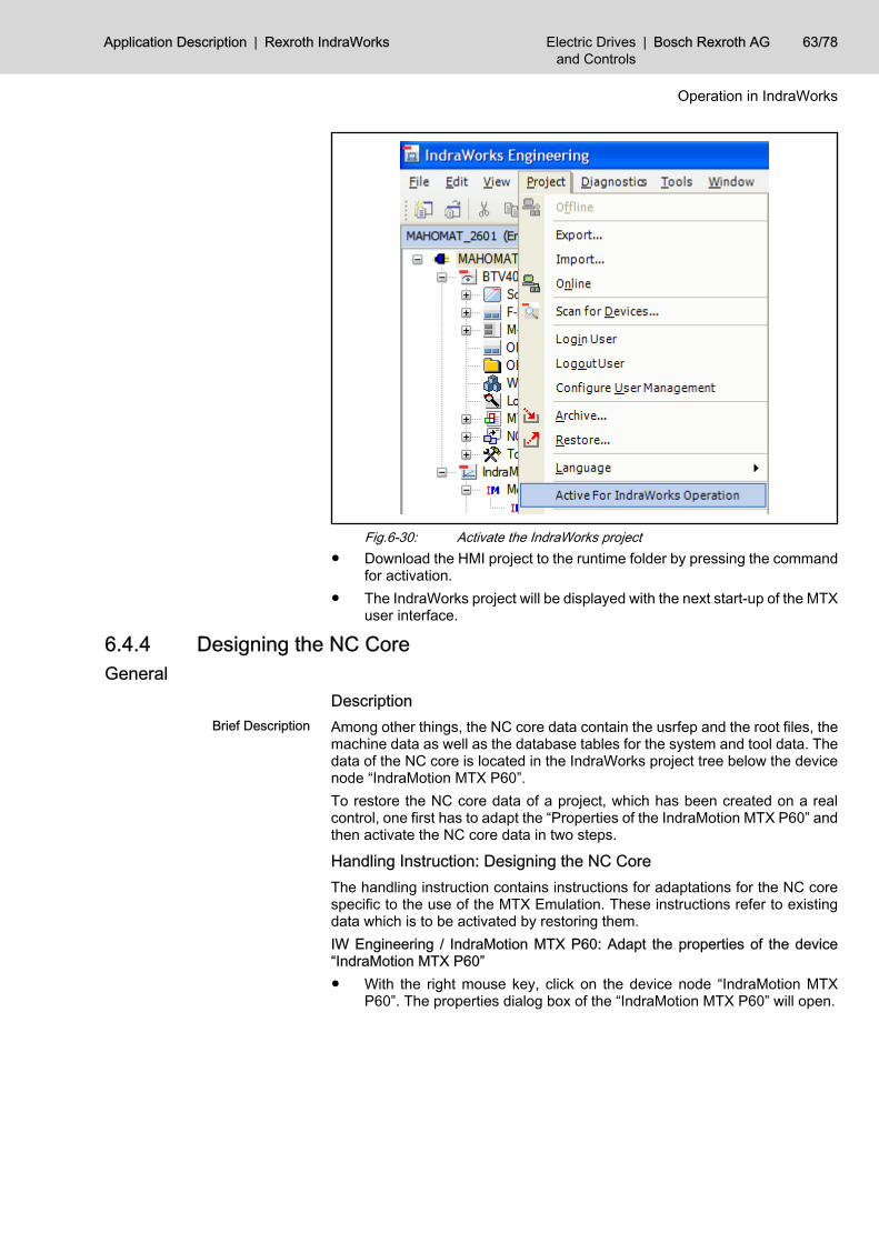
Fig.6-30: Activate the IndraWorks project● Download the HMI project to the runtime folder by pressing the command
for activation.● The IndraWorks project will be displayed with the next start-up of the MTX
user interface.
6.4.4 Designing the NC CoreGeneral
DescriptionBrief Description Among other things, the NC core data contain the usrfep and the root files, the
machine data as well as the database tables for the system and tool data. Thedata of the NC core is located in the IndraWorks project tree below the devicenode “IndraMotion MTX P60”.To restore the NC core data of a project, which has been created on a realcontrol, one first has to adapt the “Properties of the IndraMotion MTX P60” andthen activate the NC core data in two steps.
Handling Instruction: Designing the NC CoreThe handling instruction contains instructions for adaptations for the NC corespecific to the use of the MTX Emulation. These instructions refer to existingdata which is to be activated by restoring them.IW Engineering / IndraMotion MTX P60: Adapt the properties of the device“IndraMotion MTX P60”● With the right mouse key, click on the device node “IndraMotion MTX
P60”. The properties dialog box of the “IndraMotion MTX P60” will open.
Application Description | Rexroth IndraWorks Electric Drivesand Controls
| Bosch Rexroth AG 63/78
Operation in IndraWorks
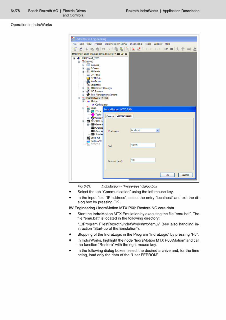
Fig.6-31: IndraMotion - “Properties” dialog box● Select the tab “Communication” using the left mouse key.● In the input field “IP address”, select the entry “localhost” and exit the di‐
alog box by pressing OK.IW Engineering / IndraMotion MTX P60: Restore NC core data● Start the IndraMotion MTX Emulation by executing the file “emu.bat”. The
file “emu.bat” is located in the following directory:“...\Program Files\Rexroth\IndraWorks\mtx\emu\” (see also handling in‐struction “Start-up of the Emulation”).
● Stopping of the IndraLogic in the Program “IndraLogic” by pressing “F5”.● In IndraWorks, highlight the node “IndraMotion MTX P60\Motion” and call
the function “Restore” with the right mouse key.● In the following dialog boxes, select the desired archive and, for the time
being, load only the data of the “User FEPROM”.
64/78 Bosch Rexroth AG | Electric Drivesand Controls
Rexroth IndraWorks | Application Description
Operation in IndraWorks
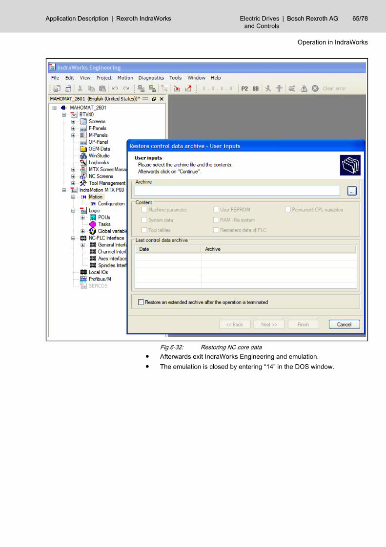
Fig.6-32: Restoring NC core data● Afterwards exit IndraWorks Engineering and emulation.● The emulation is closed by entering “14” in the DOS window.
Application Description | Rexroth IndraWorks Electric Drivesand Controls
| Bosch Rexroth AG 65/78
Operation in IndraWorks
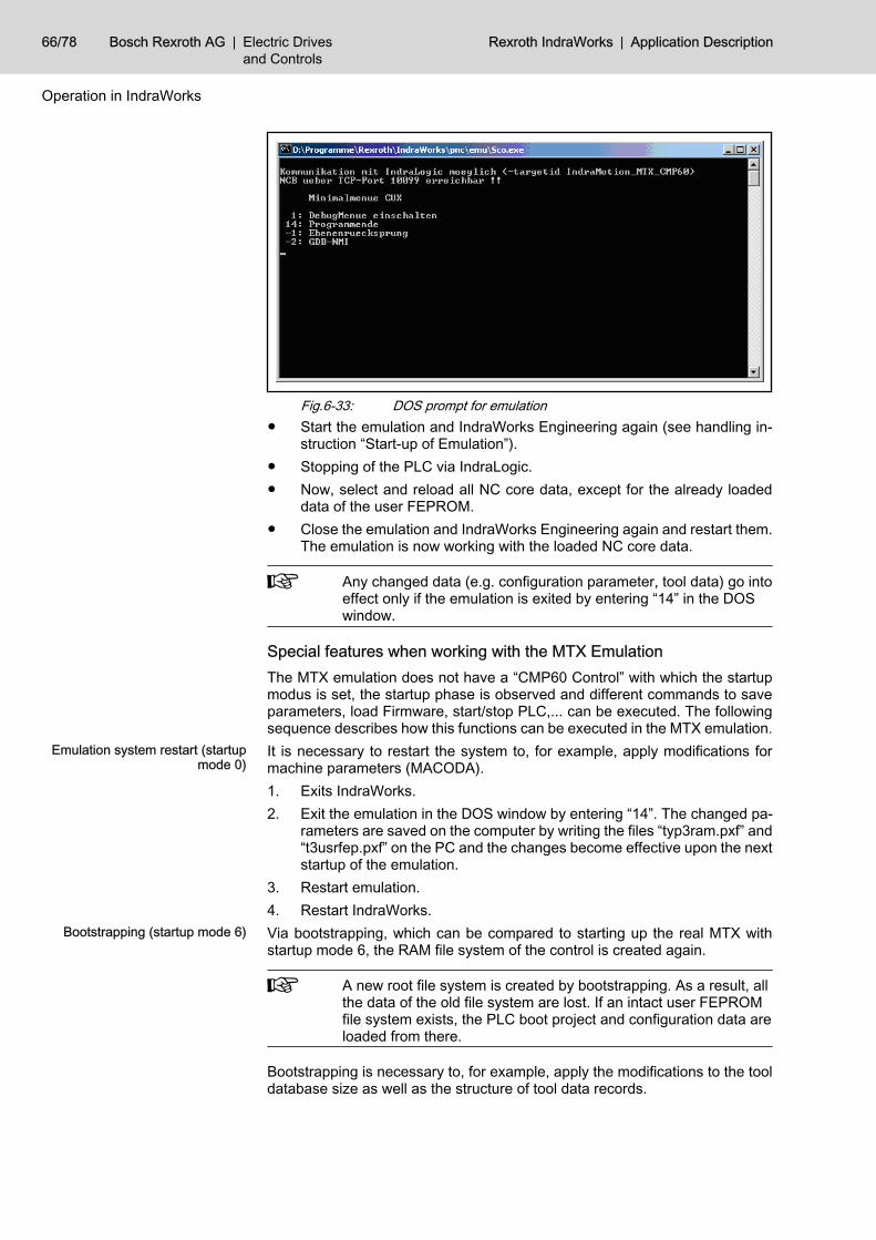
Fig.6-33: DOS prompt for emulation● Start the emulation and IndraWorks Engineering again (see handling in‐
struction “Start-up of Emulation”).● Stopping of the PLC via IndraLogic.● Now, select and reload all NC core data, except for the already loaded
data of the user FEPROM.● Close the emulation and IndraWorks Engineering again and restart them.
The emulation is now working with the loaded NC core data.
Any changed data (e.g. configuration parameter, tool data) go intoeffect only if the emulation is exited by entering “14” in the DOSwindow.
Special features when working with the MTX EmulationThe MTX emulation does not have a “CMP60 Control” with which the startupmodus is set, the startup phase is observed and different commands to saveparameters, load Firmware, start/stop PLC,... can be executed. The followingsequence describes how this functions can be executed in the MTX emulation.
Emulation system restart (startupmode 0)
It is necessary to restart the system to, for example, apply modifications formachine parameters (MACODA).1. Exits IndraWorks.2. Exit the emulation in the DOS window by entering “14”. The changed pa‐
rameters are saved on the computer by writing the files “typ3ram.pxf” and“t3usrfep.pxf” on the PC and the changes become effective upon the nextstartup of the emulation.
3. Restart emulation.4. Restart IndraWorks.
Bootstrapping (startup mode 6) Via bootstrapping, which can be compared to starting up the real MTX withstartup mode 6, the RAM file system of the control is created again.
A new root file system is created by bootstrapping. As a result, allthe data of the old file system are lost. If an intact user FEPROMfile system exists, the PLC boot project and configuration data areloaded from there.
Bootstrapping is necessary to, for example, apply the modifications to the tooldatabase size as well as the structure of tool data records.
66/78 Bosch Rexroth AG | Electric Drivesand Controls
Rexroth IndraWorks | Application Description
Operation in IndraWorks
1. Copy modifications on tool data record into usrfep.2. Exits IndraWorks.3. Exit the emulation in the DOS window by entering “14”.4. Delete the RamFileSystem, i.e. delete the file “...\Program Files\Rexroth
\IndraWorks\mtx\emu\typ3ram.pxf”.5. Restart emulation.6. Restart IndraWorks.
Creating the user FEPROM file sys‐tem (startup mode 7)
Creating a user FEPROM file system, which can be compared to execution ofstartup mode 7 of the real MTX, is necessary if all project-specific data can bedeleted on a control or if the user FEPROM file system is damaged.
The user FEPROM is recreated by creating the user FEPROM filesystem. As a result, all the data of the old file system are lost. Theroot file system remains. The permanent CPL variables will be de‐leted.
1. Exits IndraWorks.2. Exit the emulation in the DOS window by entering “14”.3. Delete the user FEPROM file system, i.e. delete the file “...\Program Files
\Rexroth\IndraWorks\mtx\emu\typ3ram.pxf”.4. Restart emulation.5. Restart IndraWorks.
6.4.5 Designing the PLCGeneral
DescriptionBrief Description First, the communication settings of the PLC project have to be changed if the
IndraWorks PLC project comes from a real control or if the IndraWorks hadbeen installed previously in a directory other than the directory of active version.After that, the PLC project can be activated.
Handling Instruction: Restoring the PLC projectThis handling instruction described the steps for starting up the PLC projectwhich had already been running on a real control.IW Engineering / Logic: Restoring the PLC project● Highlight the node “IndraMotion MTX P90\Logic” and start the “Proper‐
ties” dialog box by means of the right mouse key.● In the “Properties” dialog box, select the tab “Communication Settings”.
Application Description | Rexroth IndraWorks Electric Drivesand Controls
| Bosch Rexroth AG 67/78
Operation in IndraWorks
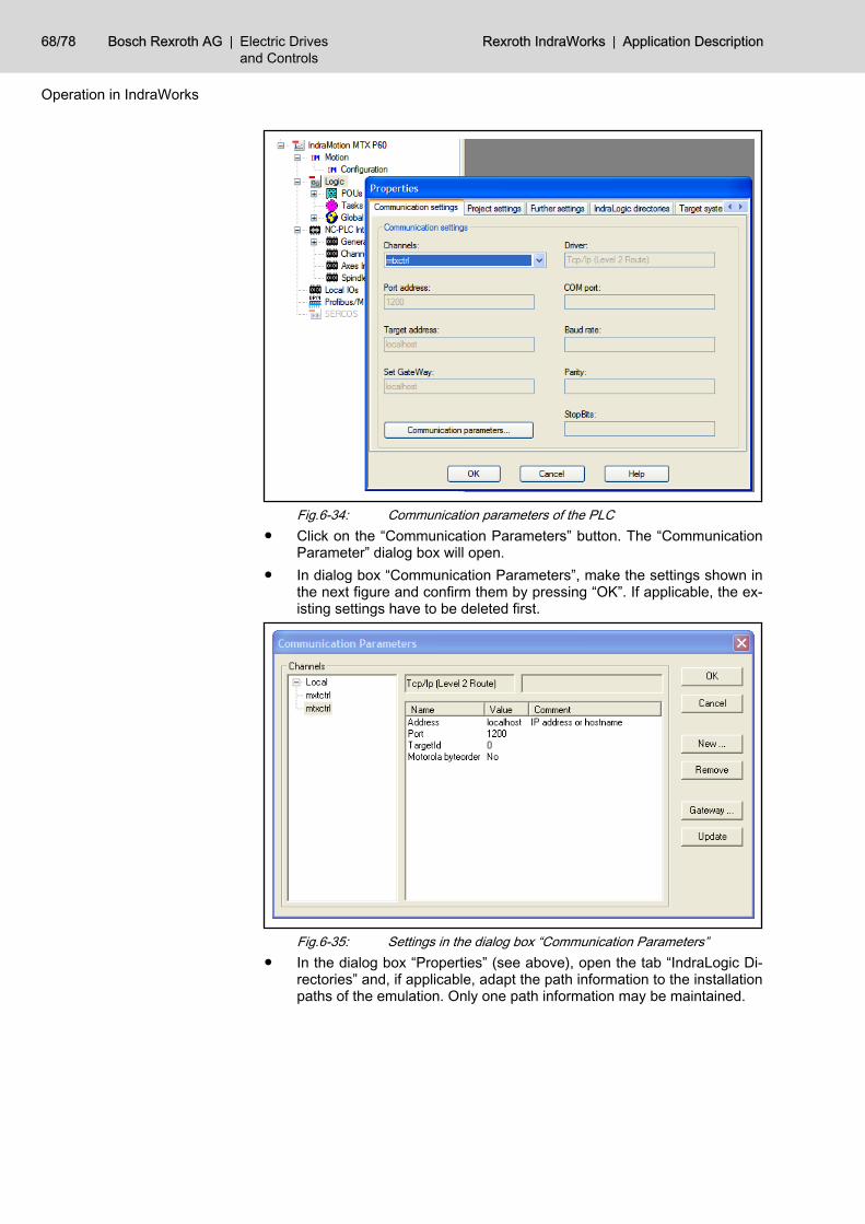
Fig.6-34: Communication parameters of the PLC● Click on the “Communication Parameters” button. The “Communication
Parameter” dialog box will open.● In dialog box “Communication Parameters”, make the settings shown in
the next figure and confirm them by pressing “OK”. If applicable, the ex‐isting settings have to be deleted first.
Fig.6-35: Settings in the dialog box “Communication Parameters”● In the dialog box “Properties” (see above), open the tab “IndraLogic Di‐
rectories” and, if applicable, adapt the path information to the installationpaths of the emulation. Only one path information may be maintained.
68/78 Bosch Rexroth AG | Electric Drivesand Controls
Rexroth IndraWorks | Application Description
Operation in IndraWorks
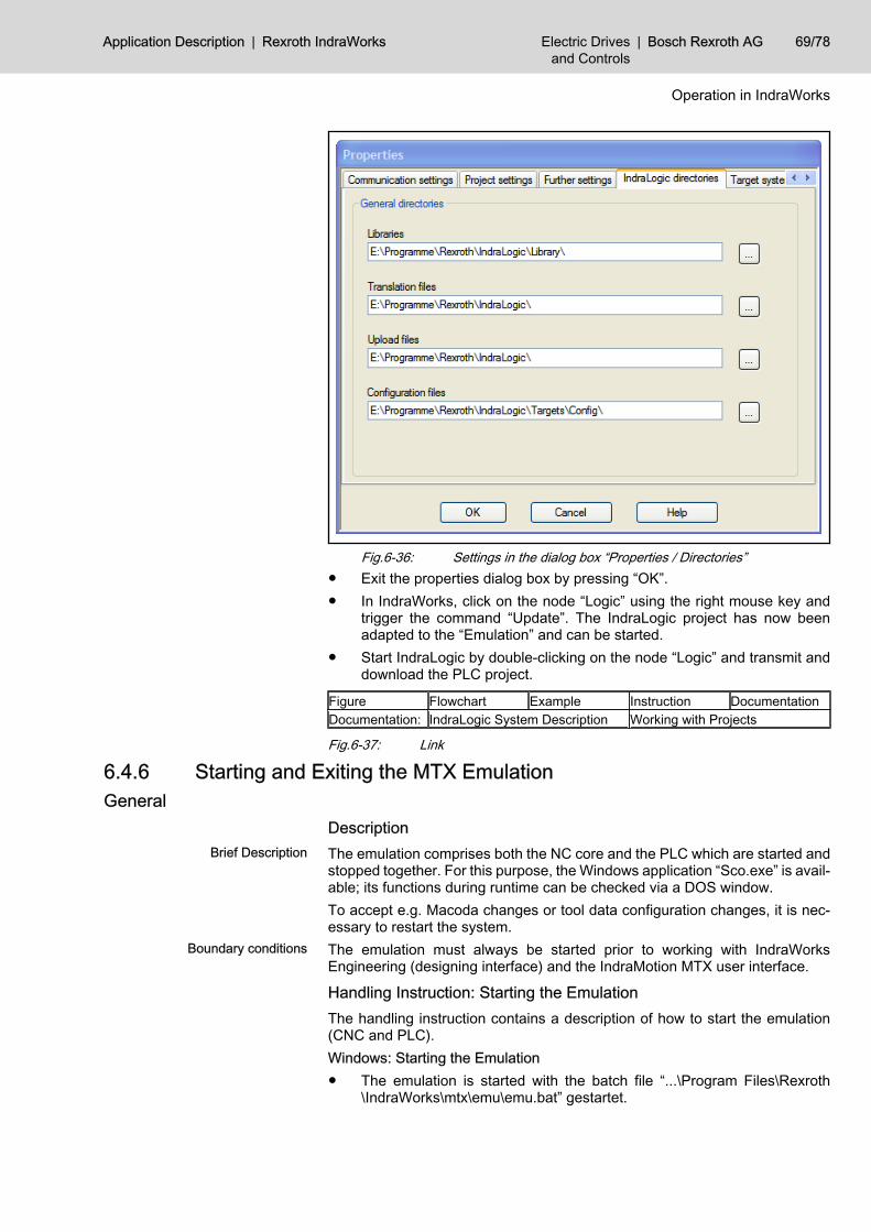
Fig.6-36: Settings in the dialog box “Properties / Directories”● Exit the properties dialog box by pressing “OK”.● In IndraWorks, click on the node “Logic” using the right mouse key and
trigger the command “Update”. The IndraLogic project has now beenadapted to the “Emulation” and can be started.
● Start IndraLogic by double-clicking on the node “Logic” and transmit anddownload the PLC project.
Figure Flowchart Example Instruction DocumentationDocumentation: IndraLogic System Description Working with Projects
Fig.6-37: Link
6.4.6 Starting and Exiting the MTX EmulationGeneral
DescriptionBrief Description The emulation comprises both the NC core and the PLC which are started and
stopped together. For this purpose, the Windows application “Sco.exe” is avail‐able; its functions during runtime can be checked via a DOS window.To accept e.g. Macoda changes or tool data configuration changes, it is nec‐essary to restart the system.
Boundary conditions The emulation must always be started prior to working with IndraWorksEngineering (designing interface) and the IndraMotion MTX user interface.
Handling Instruction: Starting the EmulationThe handling instruction contains a description of how to start the emulation(CNC and PLC).Windows: Starting the Emulation● The emulation is started with the batch file “...\Program Files\Rexroth
\IndraWorks\mtx\emu\emu.bat” gestartet.
Application Description | Rexroth IndraWorks Electric Drivesand Controls
| Bosch Rexroth AG 69/78
Operation in IndraWorks
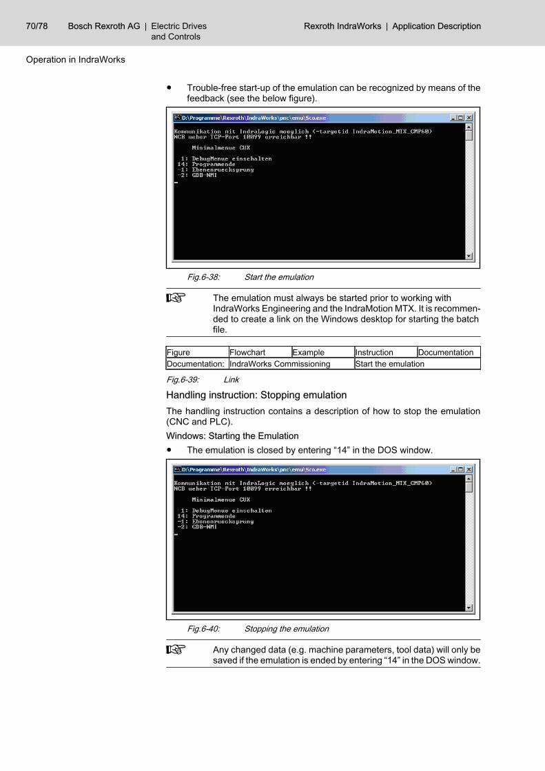
● Trouble-free start-up of the emulation can be recognized by means of thefeedback (see the below figure).
Fig.6-38: Start the emulation
The emulation must always be started prior to working withIndraWorks Engineering and the IndraMotion MTX. It is recommen‐ded to create a link on the Windows desktop for starting the batchfile.
Figure Flowchart Example Instruction DocumentationDocumentation: IndraWorks Commissioning Start the emulation
Fig.6-39: Link
Handling instruction: Stopping emulationThe handling instruction contains a description of how to stop the emulation(CNC and PLC).Windows: Starting the Emulation● The emulation is closed by entering “14” in the DOS window.
Fig.6-40: Stopping the emulation
Any changed data (e.g. machine parameters, tool data) will only besaved if the emulation is ended by entering “14” in the DOS window.
70/78 Bosch Rexroth AG | Electric Drivesand Controls
Rexroth IndraWorks | Application Description
Operation in IndraWorks
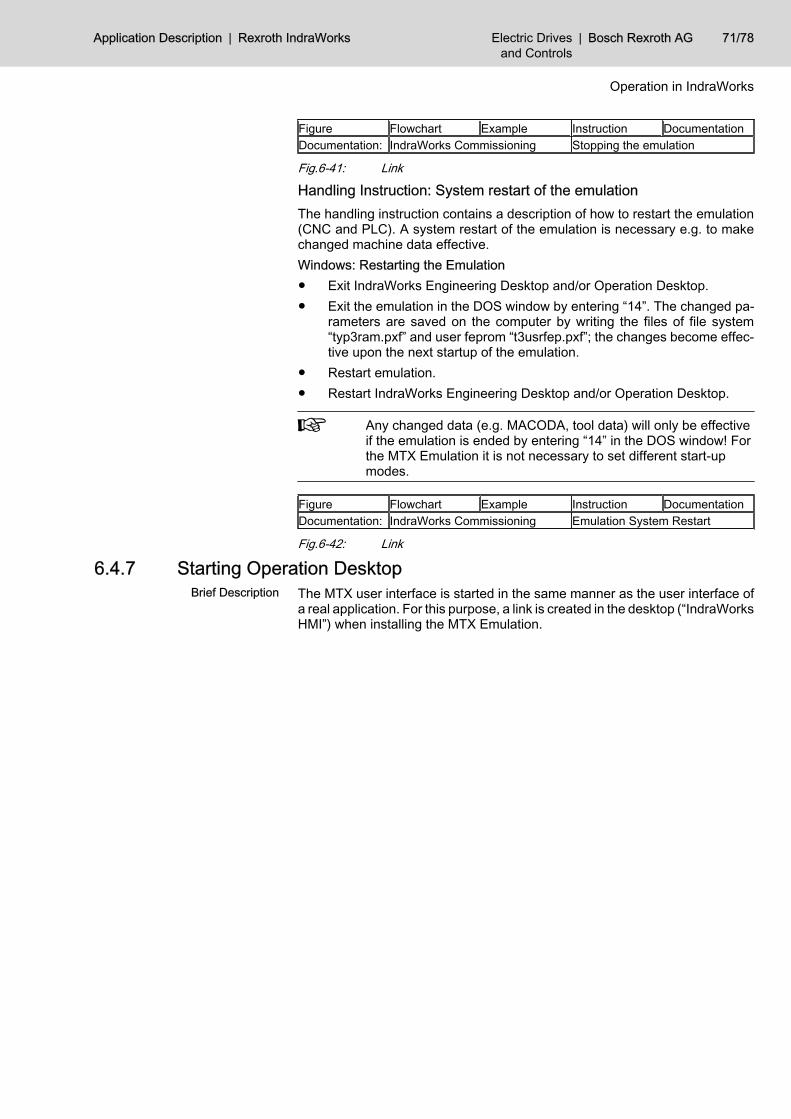
Figure Flowchart Example Instruction DocumentationDocumentation: IndraWorks Commissioning Stopping the emulation
Fig.6-41: Link
Handling Instruction: System restart of the emulationThe handling instruction contains a description of how to restart the emulation(CNC and PLC). A system restart of the emulation is necessary e.g. to makechanged machine data effective.Windows: Restarting the Emulation● Exit IndraWorks Engineering Desktop and/or Operation Desktop.● Exit the emulation in the DOS window by entering “14”. The changed pa‐
rameters are saved on the computer by writing the files of file system“typ3ram.pxf” and user feprom “t3usrfep.pxf”; the changes become effec‐tive upon the next startup of the emulation.
● Restart emulation.● Restart IndraWorks Engineering Desktop and/or Operation Desktop.
Any changed data (e.g. MACODA, tool data) will only be effectiveif the emulation is ended by entering “14” in the DOS window! Forthe MTX Emulation it is not necessary to set different start-upmodes.
Figure Flowchart Example Instruction DocumentationDocumentation: IndraWorks Commissioning Emulation System Restart
Fig.6-42: Link
6.4.7 Starting Operation DesktopBrief Description The MTX user interface is started in the same manner as the user interface of
a real application. For this purpose, a link is created in the desktop (“IndraWorksHMI”) when installing the MTX Emulation.
Application Description | Rexroth IndraWorks Electric Drivesand Controls
| Bosch Rexroth AG 71/78
Operation in IndraWorks

Bosch Rexroth AG | Electric Drivesand Controls
Rexroth IndraWorks | Application Description

7 Communication - SCPSCP (Scalable Communication Platform) is the standardized IndraWorks com‐munication platform. All communication between Bosch Rexroth products, suchas the VAM simulator and the PLC, is carried out using SCP.Data are exchanged between VAM simulator and the PLC using SCP items,which consist of the names of PLC variables, starting with PLC.Pvl,.PLC vari‐able name.You can find additional information in the SCP documentation.
Application Description | Rexroth IndraWorks Electric Drivesand Controls
| Bosch Rexroth AG 73/78
Communication - SCP

Bosch Rexroth AG | Electric Drivesand Controls
Rexroth IndraWorks | Application Description
8 Service and Support8.1 Helpdesk
Our service helpdesk at our headquarters in Lohr, Germany, will assist you withall kinds of inquiries.Contact us:● By phone through the Service Call Entry Center,
Monday to Friday 7:00 am - 6:00 pm CET+49 (0) 9352 40 50 60
● By fax+49 (0) 9352 40 49 41
● By e-mail: [email protected]
8.2 Service HotlineOut of helpdesk hours please contact our German service department directly:+49 (0) 171 333 88 26or+49 (0) 172 660 04 06Hotline numbers for other countries can be found in the addresses of eachregion (see below).
8.3 InternetAdditional notes regarding service, maintenance and training, as well as thecurrent addresses of our sales and service offices can be found onhttp://www.boschrexroth.comOutwith Germany please contact our sales/service office in your area first.
8.4 Helpful InformationFor quick and efficient help please have the following information ready:● Detailed description of the fault and the circumstances● Information on the type plate of the affected products, especially type co‐
des and serial numbers● Your phone and fax numbers as well as your e-mail address so we can
contact you in case of questions
Application Description | Rexroth IndraWorks Electric Drivesand Controls
| Bosch Rexroth AG 75/78
Service and Support

Bosch Rexroth AG | Electric Drivesand Controls
Rexroth IndraWorks | Application Description
IndexSymbols3D visualization
Adding 3D models 47Assignment list for process variables 23Basic 3D visualization functions 55changing object properties 56Changing settings of the View3D model 56Configuring the process connection 54Connecting 3D objects with IndraMotion MTX ax‐is values 54coordinate systems 55creating a 3D model 33Establishing a connection to the control 55exporting View3D models 51Functions for manipulating 3D objects 21Importing eM-RealNC models 33importing View3D models 51Manipulating 3D objects 55Model visualization 20Object properties 23Opening, renaming and deleting 3D models 50operation 55process connection 54Properties of the View3D model 24scaling a 3D model 52Scene tree 22
3D Visualization 18
AAssigning process variables 35
BBehavioral simulation 1
CCommunication 73Configuration of the quick-stop module 40Configuring the emergency stop 36Configuring the key-operated switch 37Configuring the keypads 38Configuring the overrides 37Context menu of VAM simulator
Open 43Contextual menu 43Contextual menu of the VAM simulator
Assign control 44Export 44Import 43
DDesigning the emulation 60
restoring an existing project 60Designing the HMI 60Designing the NC core 63Designing the PLC 67
EExplosion/implosion 22
FFEM 1
GGeneral
Licensing: IndraWorks Components 57Global coordinate system 20
HHandling instruction
adding a 3D model using Project Explorer 47adding a 3D model using the library 49adding a default 3D model 49assigning a process value to a 3D object 54Changing the offset for process values 54Exporting a View3D model from an IndraWorksproject 51Importing a View3D model into an IndraWorksproject 51Moving a View3D object 55Rotating a View3D object 55scaling a 3D model 52Starting a View3D process connection 55Stopping a View3D process connection 55stopping emulation 70
Handling InstructionDesigning the HMI for the MTX Emulation 61Designing the NC Core 63Extend the RAM File System Memory of the Em‐ulation 60Restoration of an existing Project for the MTXEmulation 60Restoring the PLC Project 67Starting the Emulation 69System Restart of the Emulation 71
Hardware-in-the-loop 1
IInappropriate use 3Installing a license 58Intended Use
Applications 3Cases of Application 3Introduction 3
LLibrary 30
3D models 31Simulation components 30
Licensing: IndraWorks componentsInstalling a license 58
Application Description | Rexroth IndraWorks Electric Drivesand Controls
| Bosch Rexroth AG 77/78
Index
Licensing: IndraWorks ComponentsGeneral 57
Local coordinate system 20
MMachine model 15MBS 1Moving/rotating objects 21Moving a 3D scene 20MTX emulation - installation 59MTX emulation - special features 66
Bootstrapping (startup mode 6) 66creating the user FEPROM file system (startupmode 7) 67Emulation system restart (startup mode 0) 66
MTX emulation - starting and exiting 69
NNon-Intended Use
Consequences, Exclusion of Liability 3
PProcess connection 28Process variables 28
Process variable dialog in virtual control panel29Process variable window in IndraWorksEngineering 29
Project explorer 17Project node 3D visualization 17Project node Simulation 17
RRestore - Project 60
Rotating a 3D scene 20
SSafety instructions for electric drives 5Saving camera positions 22Scaling the 3D model 21SCP 73Selecting 3D objects 20Software-in-the-loop 1Starting Operation Desktop 71
UUsing 3D visualization 47
VVAM simulator 26, 43
Configuration in IndraWorks 40Configurator 26Context menu 46Start 45
View3D 18Virtual control 28Virtual control panel
connection to virtual control 44error messages 46
Virtual Control panel 33Virtual factory 1Virtual machine 1VRML files 33
ZZooming a 3D scene 20
78/78 Bosch Rexroth AG | Electric Drivesand Controls
Rexroth IndraWorks | Application Description
Index

Notes
Application Description | Rexroth IndraWorks Electric Drivesand Controls
| Bosch Rexroth AG

Bosch Rexroth AGElectric Drives and ControlsP.O. Box 13 5797803 Lohr, GermanyBgm.-Dr.-Nebel-Str. 297816 Lohr, GermanyPhone +49 (0)93 52-40-50 60Fax +49 (0)93 52-40-49 [email protected]
Printed in GermanyDOK-IWORKS-SIMU****V07-AW01-EN-PR911320258