IColor™ 650 Digital Color + White Transfer Media Printer ...
75
1 IColor™ 650 Digital Color + White Transfer Media Printer User Manual
Transcript of IColor™ 650 Digital Color + White Transfer Media Printer ...

1
IColor™ 650 Digital Color + White Transfer Media Printer
User Manual

2
Table of Contents
IColor™ 650 Model Summary Page 3 Installation Environment Page 4 Printer Guide Page 5 - 8 How to use the Numeric Keypad Page 8 - 9 Changing the Administrator Password Page 9 Warnings Page 9 Unpacking and Installing Consumables Page 10 - 13 Wireless Setup Page 14 - 17 Connecting via USB Cable Page 17 Connecting via Network (LAN) Cable Page 18 Setting a Static IP Page 19 - 20 Loading Media Page 21 - 22 Printing from the MP Tray Page 23 - 24 Paper Output Page 24 - 25 Cancelling Printing Page 25 Energy Saving Modes Page 26 - 27 IColor™ ProRIP Software Introduction Page 28 - 30 IColor™ ProRIP Software Installation Page 30 - 33 IColor™ ProRIP First Time Setup Page 33 - 38 Using the IColor™ ProRIP Software Page 39 - 43 Driver Installation (Optional) Page 44 Toner / Drum Cartridge Replacement Guide Page 45 Use Genuine UNINET IColor™ Consumables Page 46 Replacing Toner Cartridges Page 46 - 49 Replacing Image Drum Cartridges Page 50 - 53 Replacing the Transfer Belt Page 53 - 55 Replacing the Fuser Unit Page 55 - 57 When Paper Jams Occur Page 57 - 64 Cleaning the LED Heads Page 65 Cleaning the Light-shielding film Page 66 Cleaning the Paper Feed Rollers Page 66 - 69 Cleaning the Resist Roller Page 69 Printing with Fluorescent and Dye Sublimation Toner Page 70 IColor™ SmartCUT Information Page 71 Color Registration Procedure Page 72 Printing Built In Test Pages Page 72 IColor™ 650 Printing Tips Page 73 IColor™ Transfer Paper and Media Options Page 74 IColor™ 650 Printer Specifications Page 75
October 2021 Edition – A newer version of this manual may be available at www.icolorprint.com/support

3
Important note about USB Drives shipped with your system: Do not lose your RIP dongle! This is your license key and if lost or damaged, a cost for replacement will be incurred. UNINET suggests that you limit the physical handling of RIP dongles and use powered external USB hubs (as an example).
IColor™ 650 Tabloid Digital Color + White Transfer Media Printer The IColor™ 650 printer has been developed to produce high-quality, conventional color prints with the out-of-the- box functionality of printing in white.
Please follow the enclosed quick setup guide, as well as this manual, to get started. The IColor™ 650 comes complete with 4 toner/drum cartridges for full color with white printing (CMYW), as well as a true black toner/drum combination. Simply swap the white for black when white is not needed, for true black printing. With the white cartridge installed, black is produced using composite black (made from CMY), or if true black and white is needed at the same time, just pass the print through the printer a second time.
You will also have the option to add the fluorescent toner or dye sublimation toner upgrade kits, as well as the exclusive IColor™ security, gold, silver and clear toner options at any time.
Please note that vector and line art images, including text, are likely to produce the best results. For exciting design ideas and suggestions for using the IColor™ 650 for maximum effect, please visit our website at www.icolorprint.com.
IColor™ Premium Transfer media has been optimized to provide quality results when used with the printer, enabling the user to produce eye-catching designs which may be applied to a variety of textiles and surfaces.
What’s so unique about the IColor™ 650 Digital Color + White Transfer Media Printer?
• The smallest form factor and lightest weight printer available for tabloid sized printing.
• The ability to print white as an underprint AND an overprint in the same printer, in one pass, using the IColor™ ProRIP software.
• The white opacity of UNINET’s unique blend of toner is double that of any other brand, giving you the brightest whites and solid background to bring out the vibrancy of your colors.
• The true black cartridge is included with the printer, allowing you to switch to CMYK mode to print items such as brochures and menus when white is not needed.
• Optional dye sublimation, fluorescent, security, clear, gold and silver toner cartridge options.
• Lowest cost and most flexible printer available.
• No maintenance associated with ink based printer is necessary. The IColor™ 650 is a toner based system.
• Large array of media available for virtually any project.
• Global sales, support and service direct from UNINET or its dealer network.

4
Installation Environment
Install the printer on a flat surface that is wide enough to accommodate the legs of the printer.
Allow for enough room around the printer as shown in the following figures:
Install the printer in the following environment. • Optimal Humidity Level: 45% - 65% • Optimal Temperature Range: 50°F / 10°C - 75°F / 24°C
Operation outside of these recommend parameters may lead to poor results.
The use of a dedicated circuit of at least 15 amps is required to avoid potential fusing issues.
Power consumption (max): 8 amps (120v models) or 5 amps (230v models)
• Do not install the printer in a location subject to high temperatures or in a location near fire.
• Do not install the printer in a location where chemical reactions may occur (such as a laboratory).
• Do not install the printer near alcohol, thinners, or other flammable solvents.
• Do not install the printer in a location within the reach of small children.
• Do not install the printer in an unstable location (such as on an unsteady stand or slanted location).
• Do not install the printer in a location with high level of humidity or dust, or in a location where the printer is exposed to direct sunlight.
• Do not install the printer in an environment where it is exposed to salty air, NOx, SOx or corrosive gas.
• Do not install the printer in a location where it is exposed to a high level of vibration.
• Do not install the printer in a location where its vent hole is blocked.
• Do not install this printer directly on a thick rug or carpet.
• Do not install this printer in a closed room or other locations with bad circulation and ventilation.
• If you use this printer in a small room continuously for an extended period of time, make sure to ventilate the room.
• Install this printer away from a source that emits strong magnetic fields or noise.
• Install this printer away from a monitor or television.
• Moving the printer requires that two people stand in front and back of the printer respectively, hold the handles at the bottom of the printer, and move it.

5
Printer Guide
Exterior: Front View

6
Interior and Exterior: Rear View

7
Control Panel

8
How to use the Numeric Keypad
• Use to enter numbers and characters. Press the key consecutively to switch between numbers and characters. Press the key until the desired character is displayed, and then press the «ENTER» button.
• Available characters and how to switch types of characters are shown below.
• Alphabetic characters do not appear on the menu which accepts only numbers.

9
For example, to enter ‘abc’:
• Press «2» «2» «ENTER», «2» «2» «2» «ENTER», «2» «2» «2» «2» «ENTER». • The functions of «Fn» and «CLEAR» keys are the followings:
«Fn» key
• Shortcut button when displaying the device setting menu. By pressing numeric keys after pressing the « » key, the « » key functions as «Fn» key. (Only available while the stand-by screen is displayed.)
«CLEAR» key
• Deletes a character when entering a password.
Uninet does not suggest altering any settings hard corded into the printer. Undesirable results may occur.
Changing the Administrator Password
• The factory default password is ‘123456’. It is not necessary to change the password unless there are security risks to be considered. Changing the password is NOT RECOMMENDED.
1) Press the down scroll button several times to select [Admin Setup] and press the «ENTER» button.
2) Enter the administrator password using the numeric (0-9) keys, and then press «ENTER» button. • Press «1»→«2»→«3»→«4»→«5»→«6»→«ENTER» in that order. The password is displayed as "******".
3) Press the down scroll button several times to select [Change Password] and press the «ENTER» button.
4) Enter a new administrator password and press the «ENTER» button. Enter the new password again and press the
«ENTER» button.
WARNINGS
Your IColor™ 650 printer has been preconfigured from the factory for optimal performance. UNINET strongly advises that you do not change any settings on the printer itself (through the control panel), unless specifically directed by a certified UNINET technician. Otherwise, poor or inconsistent results could arise.
Avoid setting custom administrator passwords or changing security settings on the printer control panel, as hardware changes cannot be overridden or changed by UNINET if the password is forgotten and could lead to possible irrevocable, catastrophic modifications that may result in rendering your printer inoperable. This is not covered by your warranty.
All print commands are dictated and transmitted solely by the IColor™ ProRIP software. Any required updates or modification would occur in the software and not hardware. It is always best not make any changes to preset data (hardware of software) unless specifically directed by a certified UNINET technician.
To ensure trouble free operation of the IColor™ ProRIP software, please uninstall any third party virus scan software before proceeding. Virus scan software often views RIP software as an invasive program and invariably deletes important files which can cause issues in the quality of the print or the overall operation of the software. Windows Defender is the only known virus scan software which does not conflict with the RIP.
10
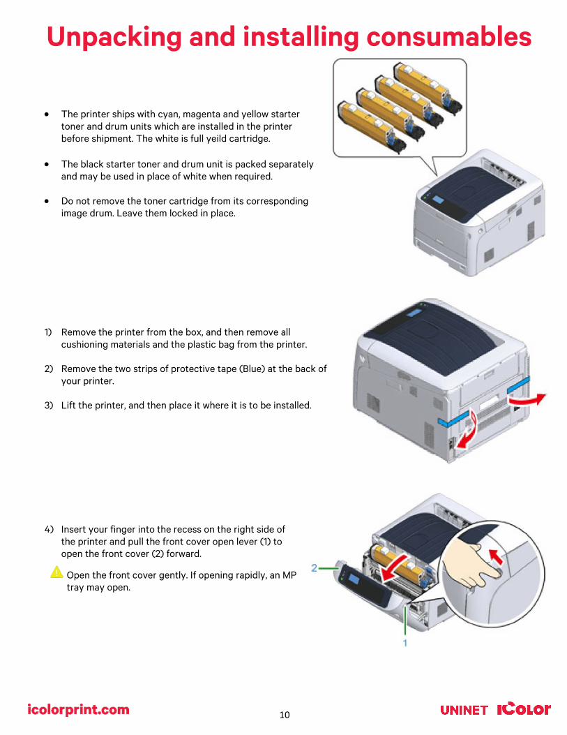
Unpacking and installing consumables
• The printer ships with cyan, magenta and yellow starter
toner and drum units which are installed in the printer before shipment. The white is full yeild cartridge.
• The black starter toner and drum unit is packed separately and may be used in place of white when required.
• Do not remove the toner cartridge from its corresponding
image drum. Leave them locked in place.
1) Remove the printer from the box, and then remove all cushioning materials and the plastic bag from the printer.
2) Remove the two strips of protective tape (Blue) at the back of your printer.
3) Lift the printer, and then place it where it is to be installed.
4) Insert your finger into the recess on the right side of the printer and pull the front cover open lever (1) to open the front cover (2) forward.
Open the front cover gently. If opening rapidly, an MP tray may open.

11
5) Press the open button (3) and open the output tray (4).
6) Prepare flat surface covered with sheets of newspaper, etc. to remove protective sheets from the image drums set in the printer.
7) Firmly hold the top of the ‘C: Cyan’ toner/drum cartridge located in the
front the printer and lift it out. Place it on a protective surface.
8) Remove the protective sheet (5) that is wrapped around the toner/drum cartridge.
Draw the protective sheet (5) in the direction of the arrow.
12
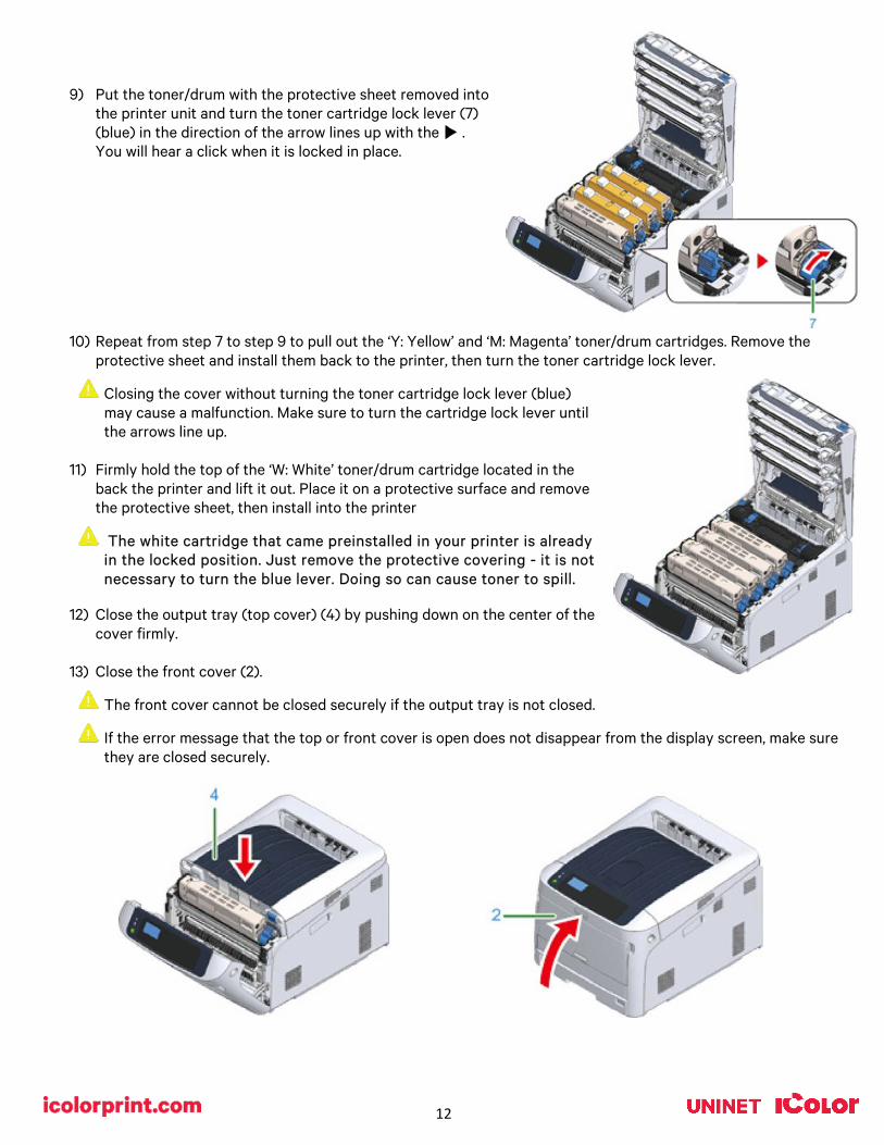
9) Put the toner/drum with the protective sheet removed into the printer unit and turn the toner cartridge lock lever (7) (blue) in the direction of the arrow lines up with the . You will hear a click when it is locked in place.
10) Repeat from step 7 to step 9 to pull out the ‘Y: Yellow’ and ‘M: Magenta’ toner/drum cartridges. Remove the protective sheet and install them back to the printer, then turn the toner cartridge lock lever.
Closing the cover without turning the toner cartridge lock lever (blue) may cause a malfunction. Make sure to turn the cartridge lock lever until the arrows line up.
11) Firmly hold the top of the ‘W: White’ toner/drum cartridge located in the
back the printer and lift it out. Place it on a protective surface and remove the protective sheet, then install into the printer
The white cartridge that came preinstalled in your printer is already in the locked position. Just remove the protective covering - it is not necessary to turn the blue lever. Doing so can cause toner to spill.
12) Close the output tray (top cover) (4) by pushing down on the center of the
cover firmly.
13) Close the front cover (2).
The front cover cannot be closed securely if the output tray is not closed.
If the error message that the top or front cover is open does not disappear from the display screen, make sure they are closed securely.

13
14) Plug the power cord into the power connector and plug the power cord into the outlet.
15) Hold down the power switch for about 1 second to turn on the power.
The Power switch LED indicator lights up when the printer turns on. The message “Ready To Print” is displayed in the operator panel once printer is ready.
16) To turn off the power, repeat step 15.
The message ‘Shutting down. Please wait. Printer will turn off automatically appears’ in the display, and the power switch indicator blinks every 1 second until the printer turns off.
It may take about 5 minutes to turn off the power. Wait until it turns off.
Holding down the power switch for more than 5 seconds turns off printer forcibly. Only perform this procedure when a problem occurs.
Worldwide Models only (Part # ICP650WS):
• Your system is designed to operate worldwide and ships with a high quality power transformer that is required if operating in a 110v environment.
a) Using the supplied power cord, plug the 3 prong female end into the back of the printer and the 2 prong male end into the ‘OUTPUT AC 220V’ receptacle on the transformer.
b) Plug the transformer into a standard 110v outlet. Ensure the outlet is a dedicated 15a circuit to avoid potential fusing issues. If a dedicated circuit is not possible, ensure all other devices that share that circuit are powered off whenever using the printer.
c) Ensure the input voltage on the back of the transformer is set to ‘115’ using the red switch.
d) Power on the transformer first, then power on the printer.
Always properly power off the printer completely before powering off the transformer.

14
If you do not use this printer for an extended period of time due to holidays, trips, or other reasons, unplug the power cord from the outlet.
The use of a dedicated circuit of at least 15 amps is required to avoid potential fusing issues.
Wireless Setup
Enabling Wireless LAN (Infrastructure)
• Wireless (Infrastructure) and Wireless (AP Mode) cannot be enabled at the same time.
• A router (access point) is necessary to set up a wireless connection.
• Do not place any electric products that emit weak radio waves (such as microwaves or digital cordless telephones) close to the printer.
• The communication speed of the wireless LAN connection may be slower than that of a wired LAN or USB connection depending on the environment.
• This printer can use a wired LAN and wireless LAN simultaneously. If the wired LAN and wireless LAN are connected to the same subnet, communications may become unstable.
Confirm the SSID and Encryption key, and write them down on the blank space as shown below. SSID: _________________________ Encryption key: _________________ Connecting with WPS
• If the wireless LAN access point supports WPS, you can easily connect to the wireless LAN with the easy setup button (WPS button).
1) Check the position of the WPS button by referring to the instruction manual that is included in a wireless LAN
access point or other document.
2) Check that the wireless LAN access point starts and is operating properly.
3) Turn on the printer.
4) Press the down scroll button several times to select [Wireless(Infrastructure) Setting], and press the «ENTER» button.
5) Enter the administrator password using the numeric (0-9) keys, and press the «ENTER» button (see page 9).
6) As [Wireless(Infrastructure)] is [Disable], press the scroll button to select [Enable] and press the «ENTER» button.
15
7) Press the down scroll button several times to select [Automatic setup(WPS)] and press the «ENTER» button.
8) Select [WPS-PBC], and press the «ENTER» button.
9) When [Pushbutton method] is displayed, select [Yes] and press the «ENTER» button. • The printer starts searching for wireless LAN access points. The "Running push button method..." message is
displayed on the screen.
10) Press and hold WPS button on the wireless LAN access point for a few seconds while the message is displayed.
11) When [WPS connection successful.] is displayed, it indicates that the wireless LAN setup has completed.
12) If the antenna mark is displayed at the top right of the display screen, the connection is established correctly.
• If [Connection failed. Timeout] is displayed, repeat the procedure from step 6.
Configuring Settings Using the Operator Panel
• If the wireless LAN access point does not support WPS, you can specify a wireless LAN access point you want to use from the wireless LAN access points that the printer detects to establish a connection. In such a case, you must enter an encryption key.
1) Follow steps 1 – 6 as indicated in the above Connecting with WPS section.
2) Press the scroll button several times to select [Wireless Network Selection] and press the «ENTER» button.
• The printer will search for available wireless LAN access points. This may take a minute or two.
3) A list of available wireless LAN access point SSIDs are displayed. Press the up or down scroll button and select a wireless LAN access point to connect, and then press the «ENTER» button.
• If only [Manual Setup] is displayed, or the SSID of the wireless LAN access point you want to use is not included in the list, set it by following the procedure in the next section ‘Connecting by Manual Setup from Operator Panel’.
4) Enter the encryption key, and then press the «ENTER» button.
5) When ‘Connection successful.’ is displayed, select [Close], and then press the «ENTER» button.
• If ‘Connection failed.’ is displayed, repeat the procedure from step 2.
• If the antenna mark is displayed at the top right of the display screen, the connection is established correctly.
Configuring Settings Using the Operator Panel
• Set the wireless LAN access point information (the SSID, encryption method and encryption key) manually to connect to the wireless LAN.
1) Check the SSID, encryption key, and encryption method by referring to the instruction manual that is included in a
wireless LAN access point or other documents, and write the information down.
2) Follow steps 1 – 6 as indicated in the above Connecting with WPS.
3) Press the scroll button several times to select [Wireless Network Selection] and press the «ENTER» button.

16
• The printer will search for available wireless LAN access points. This may take a minute or two.
4) A list of available wireless LAN access point SSIDs are displayed. Press the scroll button or, select [Manual Setup] at the end of the list, and then press the «ENTER» button.
5) Enter the SSID you checked in step 1, and then press the «ENTER» button.
6) Select the encryption method you checked in step 1, and then press the «ENTER» button.
7) The procedure depends on the encryption method you selected in step 5:
• If you selected [WPA/WPA2-PSK], select [TKIP/AES], and then press the «ENTER» button. Enter the Pre-shared Key afterward and select [Next].
• If you selected [WPA2-PSK], select [AES], and then press the «ENTER» button. Enter the Pre-shared Key afterward and select [Next].
• If you selected [WEP], enter the WEP Key, and press [Next].
8) If the displayed value is the same as the value that you checked in step 1, press the «ENTER» button.
• It takes approximately 30 seconds for the printer to detect the wireless LAN access point.
9) When the screen indicates that connection is established, select [Close] and press the «ENTER» button.
Connecting the Printer Directly (AP Mode)
Automatic Connection (Push-button)
• Wireless LAN (AP mode) directly connects wireless devices (computers, tablets, smartphones, etc.) to the printer without using a wireless LAN access point.
• You cannot enable wireless LAN (infrastructure) and wireless LAN (AP mode) at the same time.
1) Confirm the position of the WPS button on your wireless device by the manual attached to the device.
2) Turn on the printer.
• If the "Do you want to Set-up wireless?" message appears, select [No (Do not show next time)].
3) Press the scroll button several times to select [Wireless(AP Mode) Setting] and press the «ENTER» button.
4) Enter the administrator password using the numeric (0-9) keys, and then press the «ENTER» button.
5) Press the up or down scroll button to select [Enable] and then press the «ENTER» button.
6) Press the down scroll button to select [Automatic Setup (PushButton)] and press the «ENTER» button.
7) Select [Yes], and then press the «ENTER» button.
8) Start the WPS-PBC (push button) operation on your wireless device to connect to the printer. • When [Connection successful] is displayed, the setup of the wireless LAN is completed.
• If [Connection failed] is displayed, follow the steps in "Manual Setup" to try again.

17
Manual Setup
• Wireless LAN (AP mode) directly connects wireless devices (computers, tablets, smartphones, etc.) to the printer without using a wireless LAN access point.
1) Turn on the printer.
2) Press the down scroll button several times to select [Wireless(AP Mode) Setting] and press the «ENTER» button.
3) Enter the administrator password using the numeric (0-9) keys, and then press the «ENTER» button.
4) Press the up scroll button to select [Enable] and then press the «ENTER» button.
5) Press the scroll button several times to select [Manual Setup] and press the «ENTER» button.
6) Check the [SSID] and [Password] of the printer.
7) Input the printer’s [SSID] and [Password] that were confirmed in step 6 for your wireless device.
Connecting via USB Cable
1) With the printer off, insert the square end of the USB cable into the back of the printer.
• A USB 2.0 cable is included with your printer. USB 3.0 is not supported.
• Do not insert the USB cable into the network interface connector. This may cause a malfunction.
2) Plug the flat end of the USB cable into your computer to complete the connection.

18
Connecting via Network (LAN) Cable
1) Prepare the LAN cable (1) and hub, switch or router (2).
2) With the printer off, insert one end of the LAN cable into the back of the printer.
• A LAN cable is included with your printer.
• Do not insert the LAN cable into the USB connector. This may cause a malfunction.
• Do not connect both the LAN and the USB cable at the same time. This may cause a malfunction.
3) Plug the other end of the LAN cable into your hub, switch or router to complete the connection.
• Do not plug this into the LAN connection of your computer. Doing so will not establish a connection.
If you are connecting via Wi-Fi, it is not necessary to connect either the USB or LAN cable.

19
Setting a Static IP
It is recommended to set a static IP to avoid other devices on your network from ‘stealing’ the printer’s IP address when it is powered down.
1) With the printer on, press the down arrow several times to select [Admin Setup] and press the «ENTER» button.
2) Enter the administrator password, using the numeric (0-9) keys and press the «ENTER» button.
• The factory default administrator password is "123456". If the administrator password is changed, enter the updated password.
3) Check that [Network Setup] is selected, press the «ENTER» button.
4) Press the down scroll button several times to select [IP Address Set], and press the «ENTER» button.
• If setting the IP address manually, press the down scroll button and select [Manual], and press the «ENTER» button. Proceed to the step 5.
• If obtaining the IP address automatically, check that [Auto] is selected, and press the «ENTER» button. Proceed to the step 11.
5) Press the «BACK» button until [Network Setup] is displayed. Press the down scroll button several times to select [IPv4 Address], and press the «ENTER» button.
6) Enter the IP address using the numeric (0-9) keys, and press the «ENTER» button.
• In the same way, enter the next 3 digits. To move to the next box, press the «ENTER» button.
7) Press the down scroll button to select [Subnet Mask], and press the «ENTER» button.

20
8) Enter the subnet mask in the same manner as the IP address. When complete, press the «BACK» button.
9) Press the down scroll button to select [Gateway Address], and press the «ENTER» button.
10) Enter the Gateway Address in the same manner of IP address. All input was completed, then press the «BACK»
button.
11) Press the «ON LINE» button to complete the network settings.
21
Loading Media
1) Uninet suggests using the MP Tray when printing transfers.
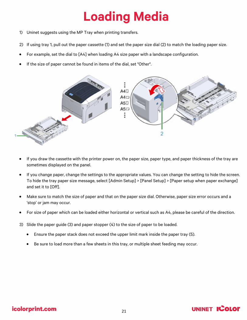
2) If using tray 1, pull out the paper cassette (1) and set the paper size dial (2) to match the loading paper size.
• For example, set the dial to [A4] when loading A4 size paper with a landscape configuration.
• If the size of paper cannot be found in items of the dial, set "Other".
• If you draw the cassette with the printer power on, the paper size, paper type, and paper thickness of the tray are sometimes displayed on the panel.
• If you change paper, change the settings to the appropriate values. You can change the setting to hide the screen. To hide the tray paper size message, select [Admin Setup] > [Panel Setup] > [Paper setup when paper exchange] and set it to [Off].
• Make sure to match the size of paper and that on the paper size dial. Otherwise, paper size error occurs and a ‘stop’ or jam may occur.
• For size of paper which can be loaded either horizontal or vertical such as A4, please be careful of the direction.
3) Slide the paper guide (3) and paper stopper (4) to the size of paper to be loaded.
• Ensure the paper stack does not exceed the upper limit mark inside the paper tray (5).
• Be sure to load more than a few sheets in this tray, or multiple sheet feeding may occur.

22
Excess stacking can cause paper jams.
4) Fan a stack of paper well, and then align the edges of the paper. Load the paper with the print side face down.
5) Secure the loaded paper with the paper guide and check if a size of loaded paper matches the setting of paper size dial.
6) Return the paper cassette to the printer.

23
Printing from the MP Tray
1) Open the MP tray (1) forward by inserting your fingers into the front recesses (2).
2) Pull out the paper supporter (3) by holding the center part of it.
3) Unfold the sub support (4) and open the paper set cover (5).
4) Adjust the manual feeding paper guide (6) to the width of paper to be loaded. Insert the paper with the print side face up.
• Do not load paper exceeding the down arrow mark (7) of the paper guide.
24
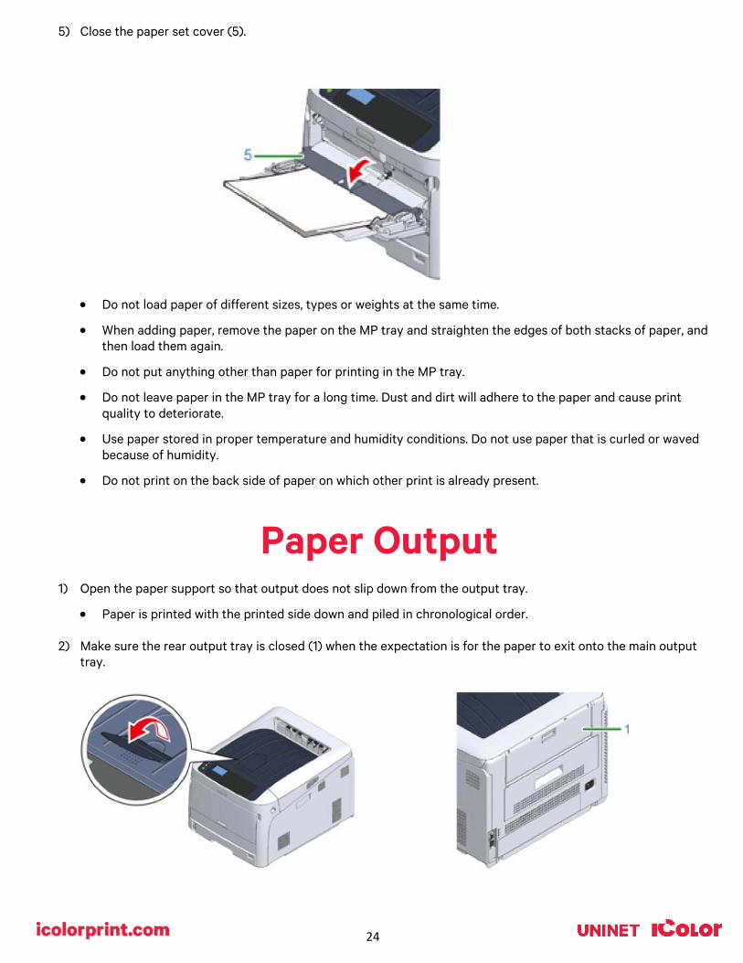
5) Close the paper set cover (5).
• Do not load paper of different sizes, types or weights at the same time.
• When adding paper, remove the paper on the MP tray and straighten the edges of both stacks of paper, and then load them again.
• Do not put anything other than paper for printing in the MP tray.
• Do not leave paper in the MP tray for a long time. Dust and dirt will adhere to the paper and cause print quality to deteriorate.
• Use paper stored in proper temperature and humidity conditions. Do not use paper that is curled or waved because of humidity.
• Do not print on the back side of paper on which other print is already present.
Paper Output
1) Open the paper support so that output does not slip down from the output tray.
• Paper is printed with the printed side down and piled in chronological order.
2) Make sure the rear output tray is closed (1) when the expectation is for the paper to exit onto the main output tray.

25
3) Use the rear output tray when a straight paper path is required, or when printing on envelopes, labels, or long
paper. Paper is printed with the printed side up and piled in reverse chronological order.
4) Open the rear output tray (1) on the rear side of the printer.
5) Unfold the paper support and the sub support.
Cancelling Printing
1) To cancel data currently being printed or ready to print, press the «CANCEL» button on the operator panel.
2) To cancel printing, select "Yes", then press the «ENTER» button.
• To continue printing, select "No", and then press the «ENTER» button.
• If no operation is made for three minutes, the screen disappears and printing resumes.

26
Energy Saving Modes
• The IColor™ 650 has three energy saving functions: Power Save Mode, Sleep Mode and Auto Power OFF Mode.
Power Save Mode • If you do not use the printer for a certain period of time, the printer automatically enters the
Power Save mode, saving power consumption.
• Or press the «POWER SAVE» button to enter the Power Save Mode manually.
• When the printer is in the Power Save Mode, the «POWER SAVE» button lights in green.
The time that elapses before entering the Power Save Mode is one minute by factory default. How to change the time that elapses before entering the Power Save Mode, see ”Setting the Time Before Entering the Power Save Mode”.
Sleep Mode
• The printer moves from the Power Save Mode to the Sleep Mode when the printer is left for the time set from the Power Save Mode status. In the Sleep Mode, the printer status and power consumption are almost the same as when the power is off.
• When the printer is in the Sleep Mode, the «POWER SAVE» button blinks.
The time that elapses before entering the Sleep Mode is 15 minutes by factory default. How to change the time that elapses before entering the Sleep Mode, see ”Setting the Time Before Entering the Sleep Mode”.
Restore from the Sleep Mode or the Power Save Mode • The printer moves from the Power Save Mode to the Sleep Mode when the printer is left for the time set from the
Power Save Mode status. In the Sleep Mode, the printer status and power consumption are almost the same as when the power is off.
• Press the «POWER SAVE» button to recover from Power Save Mode or Sleep Mode.
• The printer will recover from Power Save mode, when some data is received from a computer or another device.
Auto Power Off Mode • The printer equipped with the Auto Power Off function which automatically turns off the power if the it is left
unoperated for a certain period of time.
• To use the printer, turn the power on.
Setting the Time Before Entering Power Save Mode • When a printer is in the power saving mode, press the «POWER SAVE» button to restore from the mode.
• Check if the message “Ready To Print” appears. If the message is not displayed, press the «ON LINE» button.
1) Press the «Fn» key on the operator panel.
2) Enter «2» «0» «0» using the numeric keypad and then press the «ENTER» button.
3) Press the scroll buttons to specify the time and then press the «ENTER» button.
4) Press the «ON LINE» button.

27
Setting the Time Before Entering the Sleep Mode • When a printer is in the power saving mode, press the «POWER SAVE» button to restore from the mode.
• Check if the message “Ready To Print” appears. If the message is not displayed, press the «ON LINE» button.
5) Press the «Fn» key on the operator panel.
6) Enter «2» «0» «1» using the numeric keypad and then press the «ENTER» button.
7) Press the scroll buttons to specify the time and then press the «ENTER» button.
8) Press the «ON LINE» button.
Automatically Turning the Printer Off (Auto Power Off) • The printer is equipped with the Auto Power Off function which automatically turns the power off if it is left idle
for a certain period of time.
• There are three options for the Auto Power Off setting and [Auto Config] is set by factory default. o [Auto Config]: The printer automatically turns off after being left unoperated for a certain period of time
unless the printer is in the following conditions.
- A LAN cable is connected to the network interface connector.
- Wireless LAN is enabled.
o [Enable]: If you do not use the printer for a certain period of time, the printer automatically turns off.
o [Disable]: Disables the Auto Power Off function. The printer does not automatically turn off.
1) Press the down scroll button several times to select [Admin Setup] and press the «ENTER» button.
2) Enter the administrator password using the numeric (0-9) keys, and then press the «ENTER» button. • The factory default administrator password is "123456". If the administrator password is changed, enter the
updated password.
3) Press the down scroll button several times to select [Power Setup] and press the «ENTER» button.
4) Press the down button several times to select [Auto Power Off] and press the «ENTER» button.
5) Press the up or down scroll button to select value you want to set and press the «ENTER» button.
6) Make sure that [*] is displayed on the left of the set time.
7) Press the «BACK» button to display the [Ready To Print] screen.
Setting the Time Before Entering the Auto Power Off Mode • When a printer is in the power saving mode, press the «POWER SAVE» button to restore from the mode.
• Check if the message “Ready To Print” appears. If the message is not displayed, press the «ON LINE» button.
1) Press the «Fn» key on the operator panel.
2) Enter «2» «0» «2» using the numeric keypad and then press the «ENTER» button.
3) Press the scroll buttons to specify the time and then press the «ENTER» button.
4) Press the «ON LINE» button.

28
IColor™ ProRIP Software Introduction Use the IColor™ ProRIP software to print white as an overprint in one pass. This professional version is designed for higher volume printing with an all new interface. Design files can be printed directly from your favorite graphics program, as well as imported directly into IColor™ ProRIP. The IColor™ ProRIP software allows the user to control the spot white channel feature, as well as spot color overprinting, where white is needed as a top color for textiles. No need to create additional graphics with different color configurations – the software does it all – and in one pass. Enhance the brilliance of any graphic with white behind color.
The most important point of the IColor™ ProRIP software is that it allows colors to be put down in layers. Regular printer drivers only concern themselves with what the eye sees on the top layer; the RIP allows you to separately control each layer, thus giving you the ability to control not only what you see, but what is behind that top layer (typically the white layer). The IColor™ ProRIP gives you the unique ability to use one printer to print images with white as an underprint or an overprint. You can now print vibrant colors on clear or dark media regardless of the background to which it is applied, where the white is put down first and the colors afterwards.
Print and Transfer onto: Natural and synthetic fabric (Light and Dark) Mugs and ceramics Light, dark and clear labels Leather Light and dark paper stock Glass Acrylic Wood Metal Window Cling Banners And much more!
Create unique items – The possibilities are endless! T-shirts and sweatshirts Aprons Corporate logo shirts Mouse pads Sports apparel Jackets Tote bags Tattoos And much more!
29
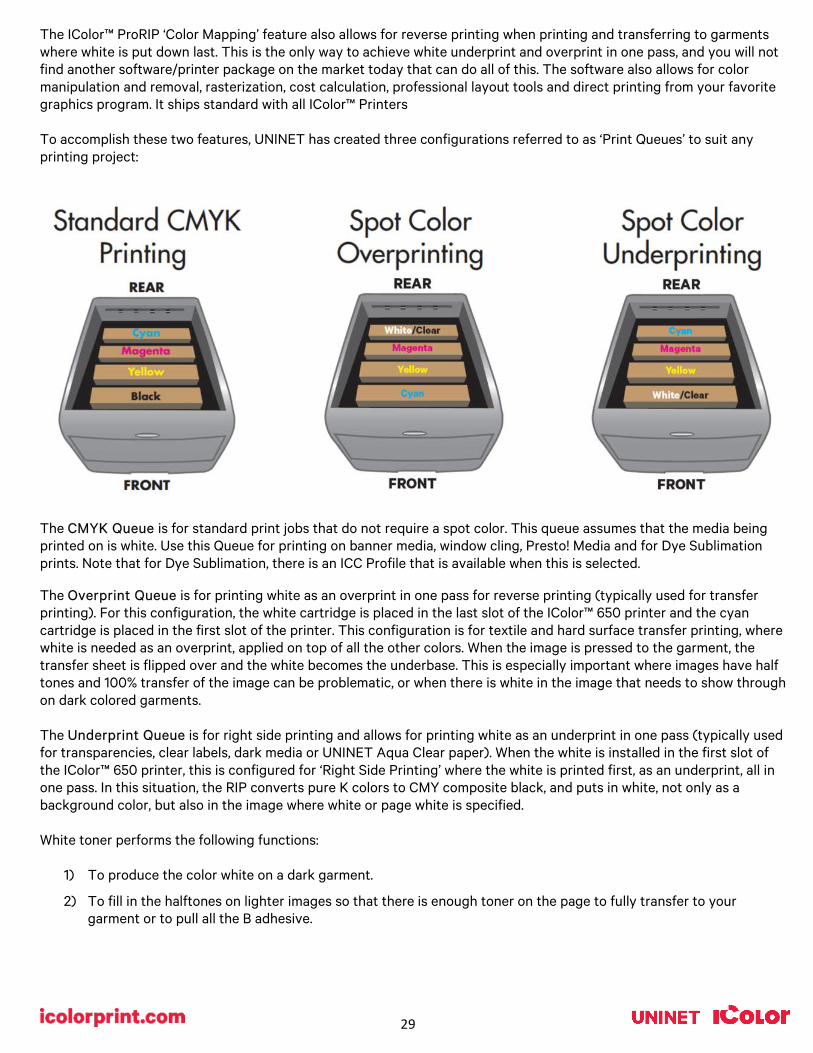
The IColor™ ProRIP ‘Color Mapping’ feature also allows for reverse printing when printing and transferring to garments where white is put down last. This is the only way to achieve white underprint and overprint in one pass, and you will not find another software/printer package on the market today that can do all of this. The software also allows for color manipulation and removal, rasterization, cost calculation, professional layout tools and direct printing from your favorite graphics program. It ships standard with all IColor™ Printers To accomplish these two features, UNINET has created three configurations referred to as ‘Print Queues’ to suit any printing project:
The CMYK Queue is for standard print jobs that do not require a spot color. This queue assumes that the media being printed on is white. Use this Queue for printing on banner media, window cling, Presto! Media and for Dye Sublimation prints. Note that for Dye Sublimation, there is an ICC Profile that is available when this is selected. The Overprint Queue is for printing white as an overprint in one pass for reverse printing (typically used for transfer printing). For this configuration, the white cartridge is placed in the last slot of the IColor™ 650 printer and the cyan cartridge is placed in the first slot of the printer. This configuration is for textile and hard surface transfer printing, where white is needed as an overprint, applied on top of all the other colors. When the image is pressed to the garment, the transfer sheet is flipped over and the white becomes the underbase. This is especially important where images have half tones and 100% transfer of the image can be problematic, or when there is white in the image that needs to show through on dark colored garments. The Underprint Queue is for right side printing and allows for printing white as an underprint in one pass (typically used for transparencies, clear labels, dark media or UNINET Aqua Clear paper). When the white is installed in the first slot of the IColor™ 650 printer, this is configured for ‘Right Side Printing’ where the white is printed first, as an underprint, all in one pass. In this situation, the RIP converts pure K colors to CMY composite black, and puts in white, not only as a background color, but also in the image where white or page white is specified. White toner performs the following functions:
1) To produce the color white on a dark garment.
2) To fill in the halftones on lighter images so that there is enough toner on the page to fully transfer to your garment or to pull all the B adhesive.

30
This second point is the most important one and the reason why you cannot simply use a CMYK printer for transfer printing. Also, this is why you MUST use the color white all the time (assuming your image has some halftones in it). Even when printing on a white garment and there is no white at all in your artwork. This is the biggest misconception with new users.
Don't make that mistake, always use the white toner cartridge for any type of transfer printing!
IColor™ ProRIP Software Installation
3) You will be prompted to insert the USB dongle before proceeding with the installation. If already inserted, click ‘Next’. (There is only one dongle shipped with your system, and can look like either of the types represented below).
• Make sure all other programs are closed and virus software is uninstalled.
Failure to uninstall virus software can lead to problems with installation and/or use of software.
If you keep the virus scan software active after installation, you must add the ProRIP to the ‘safe programs’ list or issues with ProRIP software can result. Windows Defender is the only program which, to date, has not affected the functionality of the ProRIP.
• Plug in the included dongle into a free USB port on your PC. This dongle contains all of the software, manuals and documents for your printer and software and also serves are your license key.
• Navigate to the RIP setup folder on the dongle and right click the setup file and select ‘Run as Administrator’. • Run the Installation and follow the steps pictured below. • NOTE: It is suggested to copy all of the installation files located on the USB drive to a folder on your computer for
safe keeping and ease of installation. • The IColor™ ProRIP dongle must be inserted at all times when installing or running the program.
1) Navigate to the RIP setup folder on the ProRIP dongle or on your PC if you’ve copied these files. Right click on the setup application file and ‘Run as administrator’.
2) Select the language for installation and click ‘OK’.

31
IMPORTANT: This USB dongle is your license key. Ensure that it is not lost or broken, as UNINET cannot replace it without a charge. You cannot use the software without it installed in your PC.
4) Select either the 32 or 64 bit application (dependent upon your version of windows). Accept the terms of the
license agreement and click ‘Next’.

32
5) Choose ‘Full install of IColor™ ProRIP’ and click ‘Next’. Click ‘Next’ again to accept the installation folder.
6) Click ‘Next’ to allow the creating of the IColor™ ProRIP Program Folder and the installation will begin.

33
7) If not already installed, you will be prompted to install .NET Framework, which is a necessary component to the ProRIP software. Accept the license terms and click ‘Install’. Once the InstallShield Wizard is complete, click ‘Finish’. This installation normally takes several minutes to complete.
ProRIP First Time Setup
1) Be sure the IColor™ ProRIP dongle is installed and you are connected to the internet. From the Windows Start menu, choose All Programs >> IColor™ ProRIP or double click on the desktop icon that was created upon installation. Launch the program. Create a shortcut if desired for quicker access later. Confirm first time setup by setting your preferred unit of measure and decimal places. This can be changed later under Tools >> Options.

34
2) Once the ProRIP opens, the Queue Wizard will begin the installation of the support files for your IColor™ printer. Click ‘Next’ and then ‘Install Printer’.
3) Select the appropriate printer from the support menu. Click ‘OK’. Then click ‘Next’ to continue the installation. Note that you may have already installed the printer driver in windows. This installation is for RIP functionality only.

35
4) Click the ‘Port Setup’ dropdown and select how your printer is connect (Network or USB).
You must complete this step or you will not be able to print.
5) If connected via network (recommended), choose TCP/IP. If connected by USB, choose the printer as identified in the drop down.
For USB connections, do not choose the port ‘Printer_USB-001+’. The proper port will also have the printer name in the description.
All other ports will update automatically, it is only necessary to do this for one queue.
6) If connected via network, once TCP/IP is selected, the software will poll your network for available printers. Select the proper IColor™ printer. Note that the IP address of the printer is displayed.
Be sure to set a static IP address for your printer so that the IP address does not change later. If this happens, you will have to repeat this step.

36
7) If you need to change or reset the ports in the future: Click Queue >> Manage Queues to view, update or change the port settings. Port settings will reset when the queues are updated so you will have to do this from time to time.
8) In the ‘Port’ drop down menu, choose the proper port. If connected via network (recommended), choose TCP/IP. If connected by USB, choose the printer as identified in the drop down. All other ports will update automatically, it is only necessary to do this for one queue.

37
9) If connected via network, once TCP/IP is selected, the software will poll your network for available printers. Select
the proper IColor™ printer. Note that the IP address of the printer is displayed. Be sure to set a static IP address for your printer so that the IP address does not change later. If this happens, you will have to repeat this step.
10) In order to print, select the proper Print Queue for your project. Then, select the Print Mode (otherwise known as
media type) and verify the size of that media before importing your graphic.
38
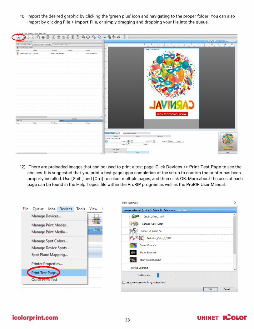
11) Import the desired graphic by clicking the ‘green plus’ icon and navigating to the proper folder. You can also
import by clicking File > Import File, or simply dragging and dropping your file into the queue.
12) There are preloaded images that can be used to print a test page. Click Devices >> Print Test Page to see the choices. It is suggested that you print a test page upon completion of the setup to confirm the printer has been properly installed. Use [Shift] and [Ctrl] to select multiple pages, and then click OK. More about the uses of each page can be found in the Help Topics file within the ProRIP program as well as the ProRIP User Manual.

39
Using the ProRIP Software (Summary)
Once your image is loaded, take note of the preconfigured settings relating to the media being used in the printer. The ‘Queue’ tab shows the size of the media that will be used, where to load the media into the printer and the paper type setting recommended. Each media type will contain this preconfigured data to make your printing experience as easy as possible. Overriding these settings could result in undesirable results.
To alter the color settings, click on ‘Color Adjust’ and adjust as needed. ‘Coverage %’ represents the amount of white/clear toner overprint or underprint (depending on which queue is being used). The ‘Vary hole size in areas of transparency’ option allows for rasterization of colors that fade into nothing and to retain partial transparency. It is suggested that this option is left on, as it will only apply itself where it’s needed. ‘Choke’ dictates how much the overprint white layer is pulled in under the colors. The higher the number, to more it’s pulled in (to avoid a white outline around your graphic).

40
• You can also adjust the size of any image by dragging and dropping the corner of the image in the preview pane.
• In this example, where we have a letter sized image placed on an A4 artboard, the red bar to the right of the image represents the portion of image that is outside the print margins. Be sure to resize to eliminate this bar before printing.
The ‘Page’ tab offers the ability to print multiple copies and nest images. You can also adjust the size of the image to fit your media here (and in the Queue tab).
The ‘Job’ tab allows you to lock the proportions of your image to maintain the aspect ratio. Here you can also mirror, rotate and invert the image, as well as adjust the margins of the print if necessary. Note that the mirror function is automatically on for any image loaded into the overprint queue.

41
Adjustments can also be made by using these icons at the top of the screen.
When ready, click the ‘Print’ icon to print your graphic.
If you encounter any of these issues when printing from the RIP, please refer page 24, step 7 to set the proper port in Queue Manager. • Port Failed to open • Holding • Prompt to save rather than print • Unknown error

42
Once the print has completed, the job will be archived in the reserved area for 7 days. If you wish to reprint that job, drag
and drop the job from the reserved section into the proper queue.
To lengthen the amount of time a job stays in reserve, click Queue>>Properties. Then click ‘Job Reserve’ and set the ‘Auto Clean Reserve’ time frame. Unclick to keep jobs in reserve forever.
43
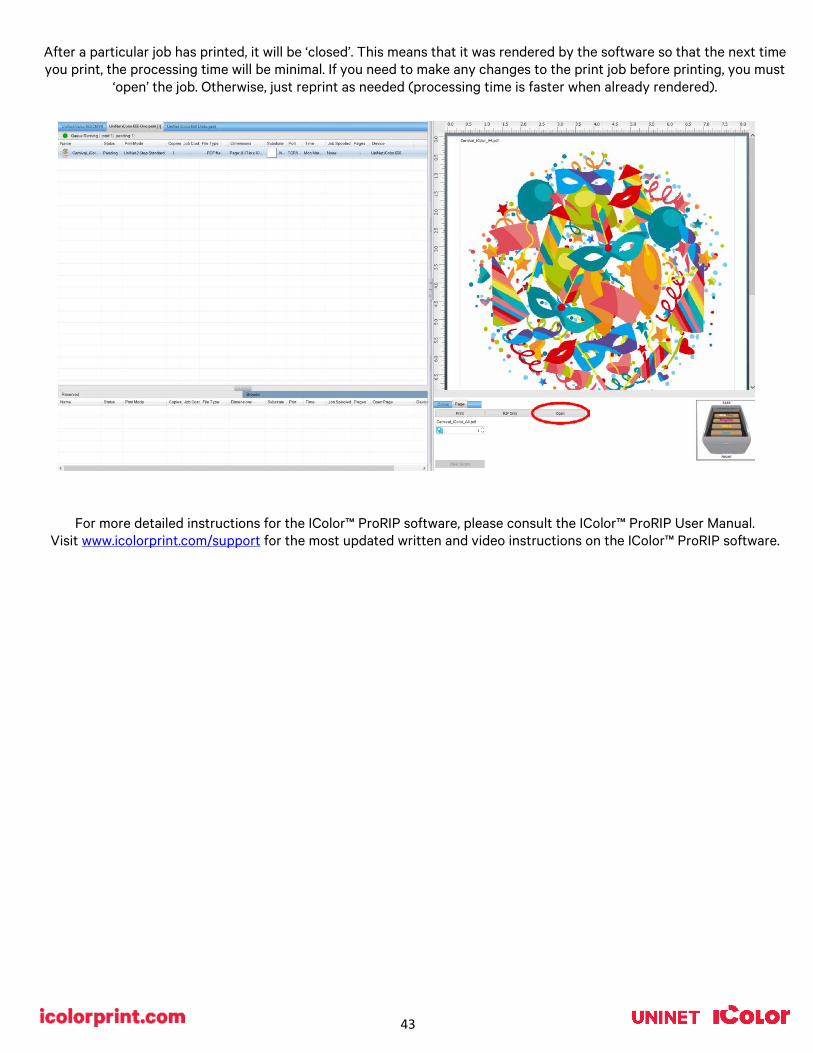
After a particular job has printed, it will be ‘closed’. This means that it was rendered by the software so that the next time you print, the processing time will be minimal. If you need to make any changes to the print job before printing, you must
‘open’ the job. Otherwise, just reprint as needed (processing time is faster when already rendered).
For more detailed instructions for the IColor™ ProRIP software, please consult the IColor™ ProRIP User Manual. Visit www.icolorprint.com/support for the most updated written and video instructions on the IColor™ ProRIP software.

44
IColor™ 650 Driver Installation (optional)
• Choose the appropriate driver that shipped on the ProRIP dongle (USB drive) with your printer based on how you have your printer connect (USB or Network).
• Only install this driver if you wish to print items outside of the RIP software, when white toner is not needed. You will only be able to print using the CMYK cartridges.
• UNINET recommends setting up your printer via Network instead of USB for most reliable and fastest performance.
• Duplex printing is also available when printing with the driver outside the RIP (never duplex with anything other than regular paper).
• Note: Installing a windows driver is not required for full printing capability within the ProRIP software.
Network Setup: 1. If not already done, connect the printer to your network via the provided LAN cable or connect the printer via Wi-
Fi and power on the printer. Your network will automatically assign an IP address to the printer.
• It is suggested that you program a static IP address to avoid possible reassignment of the IP address should the machine be powered off for an extended amount of time.
2. Locate the installation file on the USB drive that was shipped with your printer and double click to launch the setup program.
• File name is iColor_650_Network.exe
3. The driver will automatically find your printer and install. It is completely automated and will close once complete.
USB Setup: 1. Power on your printer but DO NOT connect the provided USB cable until instructed to do so from the driver
installation.
2. Locate the installation file on the USB drive that was shipped with your printer and double click to launch the setup program.
• File name is iColor_650_USB.exe
3. Connect the USB cable to the back of the printer and into an available USB port on your PC once instructed to do so.
4. The driver will automatically find your printer and install. Once installed, click ‘Exit’ to complete the process.

45
Toner / Drum Cartridge Replacement Guide
Because the IColor™ 650 features cartridge remapping to achieve a white underprint or overprint, it is important that you follow these rules when determining which color cartridge to order (pertains to both toner and drum units):
OVERPRINT Queue Configuration Supplies Replacement Guide Typically used for reverse print applications such as garment decoration
Printer Display Reads: Replace:
Cyan low/out/empty White/Clear (check which cartridge is installed) (Back of Printer)
Magenta low/out/empty Magenta Yellow low/out/empty Yellow Black low/out/empty Cyan (Front of Printer)
UNDERPRINT & CMYK Queue Configuration Supplies Replacement Guide Typically used for right side reading application such as printing on dark or clear media
Printer Display Reads: Replace:
Cyan low/out/empty Cyan (Back of Printer)
Magenta low/out/empty Magenta Yellow low/out/empty Yellow Black low/out/empty White/Clear/Black (check which cartridge is installed) (Front of Printer)
IMPORTANT NOTES:
1) When moving cartridges between overprint, underprint and CMYK configurations, the toner and drum units must move as a set.
Never disengage or turn the blue lever of the toner unit during this process.
You cannot put the white toner cartridge into the cyan drum unit (or vice versa) as it will cause catastrophic contamination, rendering the drum unit unusable.
2) Always power down your printer before moving cartridges to prevent electrostatic damage.
3) When switching cartridge configuration and also changing the white/black/clear cartridge, it should be done in two separate steps. It is not suggested to do this all at the same time.
• First switch the configuration, then power on the printer.
• Once it comes to ready, power down and swap the black/white/clear cartridge and power on again.
• Failure to follow this procedure could result in a cartridge error.
4) The black, white, clear, gold or silver cartridges can never be installed together. Only one of these 5 cartridges can be installed at any one time.

46
Use Genuine UNINET IColor™ Consumables
Only use genuine UNINET IColor™ consumables. The use of incompatible supplies (toner, drums, transfer belts, fusers) will cause damage to your printer not covered by your warranty.
Replacing Toner Cartridges
• When the "[COLOR] Toner Low" message ("[COLOR]" indicates C (cyan), M (magenta), Y (yellow) or K (black)) appears on the display screen, prepare a replacement toner cartridge.
• When the "[COLOR] Toner Empty" appears and printing is stopped, replace the toner cartridge.
Use the ‘Toner / Drum Cartridge Replacement Guide’ on page 44 to determine which color toner cartridge needs to be replaced based on how they are installed in the printer. Do not only follow the display, unless it calls M (magenta) or Y (yellow) which will always be correct.
Replacing the toner cartridge in the first station
1) Display will read K (black) low or empty.
2) Insert your finger into the recess on the right side of the printer and pull the front cover open lever (1) to open the front cover (2) forward.
3) Take note of the toner cartridge color installed. • Possible options are Cyan, Black, White, Silver, Gold or Clear.
4) Turn the toner cartridge lock lever (blue) (3) of the toner cartridge toward you until its top aligns on the mark to detach the toner cartridge from the image drum
5) Lift the toner cartridge (4) from the right side, and remove it from the printer.
6) Unpack a new toner cartridge, and shake the cartridge several times vertically and horizontally. Be sure to replace the toner with the same color that was removed.
47
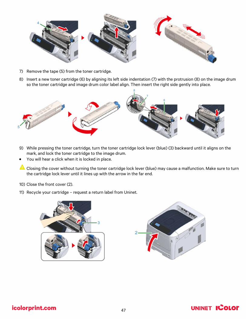
7) Remove the tape (5) from the toner cartridge.
8) Insert a new toner cartridge (6) by aligning its left side indentation (7) with the protrusion (8) on the image drum so the toner cartridge and image drum color label align. Then insert the right side gently into place.
9) While pressing the toner cartridge, turn the toner cartridge lock lever (blue) (3) backward until it aligns on the
mark, and lock the toner cartridge to the image drum. • You will hear a click when it is locked in place.
Closing the cover without turning the toner cartridge lock lever (blue) may cause a malfunction. Make sure to turn the cartridge lock lever until it lines up with the arrow in the far end.
10) Close the front cover (2).
11) Recycle your cartridge – request a return label from Uninet.

48
Replacing the toner cartridge in 2nd, 3rd and 4th Station
1) Display will read C (cyan), M (Magenta) or Y (yellow) low or empty.
2) Insert your finger into the recess on the right side of the printer and pull the front cover open lever (1) to open the front cover (2) forward.
3) Press the open button (3) and open the output tray (4).
4) Take note of the toner cartridge color installed in the 4th slot. • Possible options are Cyan, White or Clear.
• Y (yellow) and M (magenta) will never change and these cartridges never swap.
5) Turn the toner cartridge lock lever (blue) (5) of the toner cartridge toward you until its top aligns on the mark to detach the toner cartridge from the image drum.
6) Lift the toner cartridge (6) from the right side, and remove it from the printer.
7) Unpack a new toner cartridge, and shake the cartridge several times vertically and horizontally.

49
Be sure to replace the toner with the same color that was removed.
8) Remove the tape (7) from the toner cartridge.
9) Insert the left indentation (8) of the toner cartridge to the protrusion (9) of the image drum so that the labels of color attached to a new toner cartridge (6) and image drum come to the same side and set the right side firmly.
10) While pressing the toner cartridge, turn the toner cartridge lock lever (blue) (5) backward until it aligns on the
mark, and lock the toner cartridge to the image drum. • You will hear a click when it is locked in place.
Closing the cover without turning the toner cartridge lock lever (blue) may cause a malfunction. Make sure to turn the cartridge lock lever until it lines up with the arrow in the far end.
11) Close the output tray (4) by pushing the center of the output tray (4) firmly. Close the front cover (2). • The front cover cannot be closed if the output tray is not closed securely.
12) Recycle your cartridge – request a return label from Uninet.

50
Replacing Image Drum Cartridges
• When the ‘[COLOR] Image Drum Near Life’, (‘[COLOR]’ indicates C (cyan), M (magenta), Y (yellow) or K (black)) appears on the display screen, prepare a replacement drum cartridge.
• When the ‘Please install new Image Drum Unit’ appears and printing is stopped, replace the drum cartridge.
Use the ‘Toner / Drum Cartridge Replacement Guide’ on page 44 to determine which color drum cartridge needs to be replaced based on how they are installed in the printer. Do not only follow the display, unless it calls M (magenta) or Y (yellow) which will always be correct.
When using A4 paper (simplex printing), the estimated replacement cycle of an image drum is approximately 30,000 pages. This estimation assumes the standard use condition (three pages are printed at a time). Printing one page at a time reduces the drum lifetime approximately by half.
The actual number of pages you can print with the image drum depends on how you use the printer. It may be less than half the above estimation depending on the printing conditions.
Though opening and closing the front cover may extend the life of an image drum for a while, it is recommended to replace it soon after the "Install New image drum" is displayed.
Use extra care when handling the image drum (the green cylinder) because it is fragile.
Do not expose the image drum to direct sunlight or strong light (approximately 1,500 lux or more). Even under room lighting, do not leave the image drum for 5 minutes or more.
1) Determine which image drums require replacement, taking note that the color installed in the front or rear slot of
the printer may not match the display.
2) Insert your finger into the recess on the right side of the printer and pull the front cover open lever (1) to open the front cover (2) forward.
3) Press the open button (3) and open the output tray (4).
51
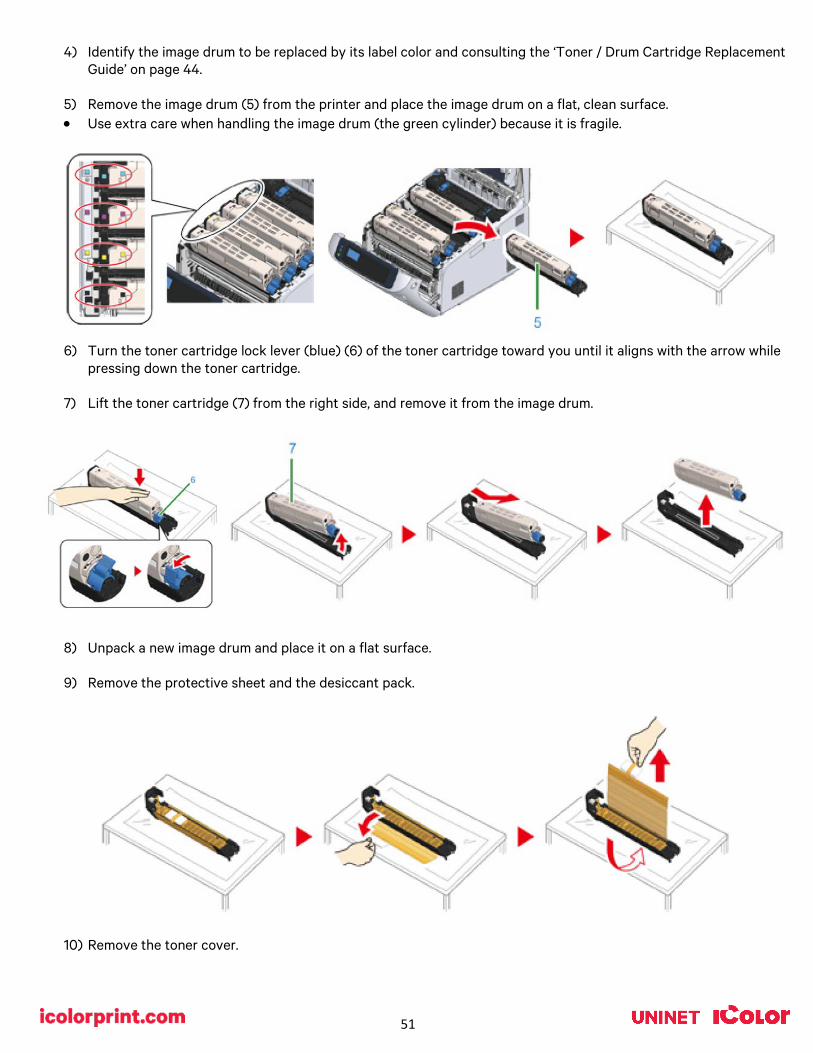
4) Identify the image drum to be replaced by its label color and consulting the ‘Toner / Drum Cartridge Replacement
Guide’ on page 44.
5) Remove the image drum (5) from the printer and place the image drum on a flat, clean surface. • Use extra care when handling the image drum (the green cylinder) because it is fragile.
6) Turn the toner cartridge lock lever (blue) (6) of the toner cartridge toward you until it aligns with the arrow while pressing down the toner cartridge.
7) Lift the toner cartridge (7) from the right side, and remove it from the image drum.
8) Unpack a new image drum and place it on a flat surface.
9) Remove the protective sheet and the desiccant pack.
10) Remove the toner cover.

52
11) Insert the toner cartridge (7) removed in step 7 by aligning its left side indentation (8) with the protrusion (9) on the image drum so that the toner cartridge and image drum color label align. Then insert the right side gently into place.
12) Turn the toner cartridge lock lever (blue) (6) backward until its top aligns with the mark while pressing down on the toner cartridge to attach it to the image drum.
13) Check the label color of the new image drum and place the drum into the printer. • Use extra care when handling the image drum (the green cylinder) because it is fragile.
53
14) Close the output tray (4) by pushing the center of the output tray (4) firmly. Close the front cover (2). • The front cover cannot be closed if the output tray is not closed securely.
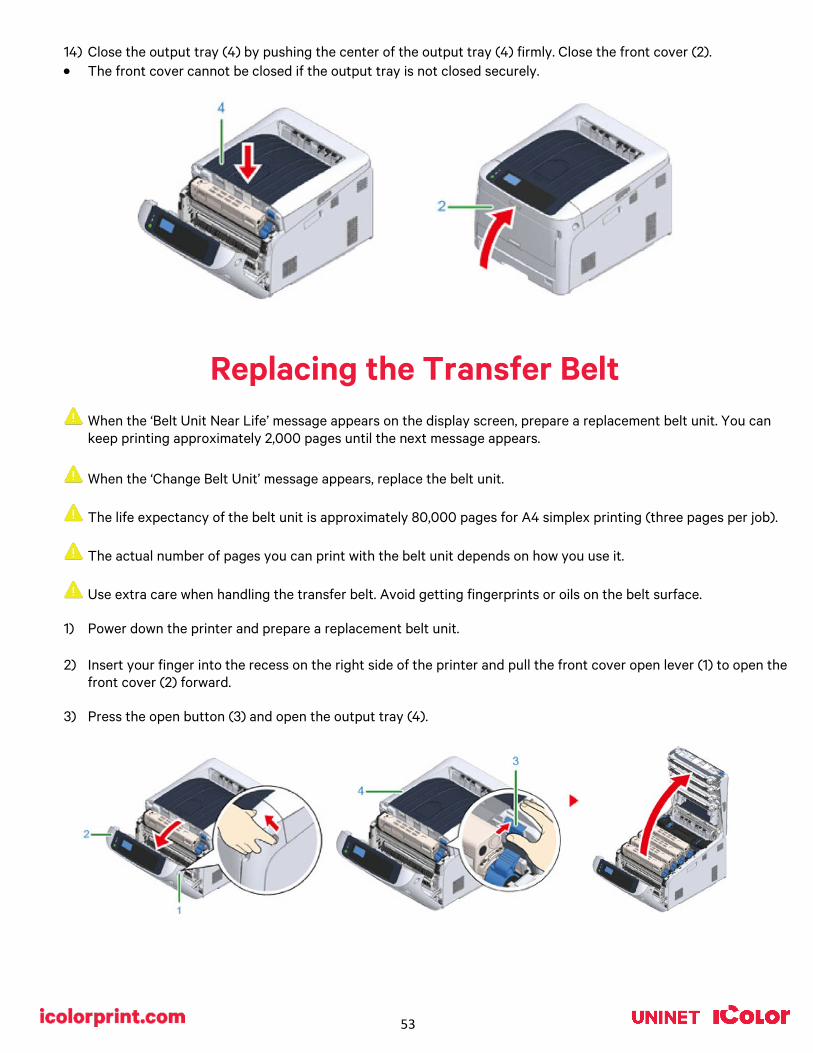
Replacing the Transfer Belt
When the ‘Belt Unit Near Life’ message appears on the display screen, prepare a replacement belt unit. You can keep printing approximately 2,000 pages until the next message appears.
When the ‘Change Belt Unit’ message appears, replace the belt unit.
The life expectancy of the belt unit is approximately 80,000 pages for A4 simplex printing (three pages per job).
The actual number of pages you can print with the belt unit depends on how you use it.
Use extra care when handling the transfer belt. Avoid getting fingerprints or oils on the belt surface.
1) Power down the printer and prepare a replacement belt unit.
2) Insert your finger into the recess on the right side of the printer and pull the front cover open lever (1) to open the front cover (2) forward.
3) Press the open button (3) and open the output tray (4).

54
4) Take all four image drums out of the printer, and then place them on a flat surface. • Use extra care when handling the image drum (the green cylinder, because it is fragile.
5) Cover the image drums you took out with paper so that the image drums do not expose to the light.
6) Turn the blue knobs (5) on each side of the belt unit in direction of the arrow to unlock.
7) Remove the belt unit by holding the blue handle (6).
8) Hold the blue handle of a new belt unit, support the bottom of the belt unit, and insert the axis of the belt unit into the groove (7) in the printer.
9) Lower the handle side of the belt unit and set the belt unit to the printer.
10) Turn the blue knobs (5) on both sides of the belt unit in the direction of the arrow to lock the belt unit. • Do not forget to turn the knobs and lock the belt unit. If you do not turn the knobs to lock the belt unit, image
drum cannot be attached properly.
11) Return all the four image drums to the printer. • Use extra care when handling the image drum (the green cylinder) because it is fragile.

55
12) Close the output tray (4) by pushing the center of the output tray firmly. Close the front cover (2). • The front cover cannot be closed if the output tray is not closed securely.
Replacing the Fuser Unit
When the ‘Fuser Unit Near Life’ message appears on the display screen, prepare a replacement fuser unit. You can keep printing approximately 2,500 pages until the next message appears.
When the "Change Fuser Unit" message appears, replace the fuser unit.
When using A4 paper (simplex printing), the estimated replacement cycle of a fuser unit is approximately 100,000 pages.
This estimation assumes the standard use condition (three pages are printed at a time). Printing one page at a time reduces the fuser unit lifetime approximately by half.
1) Power down the printer and prepare a replacement fuser unit.
2) Insert your finger into the recess on the right side of the printer and pull the front cover open lever (1) to open the
front cover (2) forward.
3) Press the open button (3) and open the output tray (4).

56
4) Pull forward the left locking lever (5) of the fuser unit to unlock.
5) Hold the fuser unit handle (6) and take out the fuser unit from the printer.
6) Peel off the tape from the new fuser unit, and pass the tape through the handle of the fuser unit.
7) Pull the protective sheet in the direction of the arrow to remove.
8) Pull forward the left locking lever (5) of the fuser unit.

57
9) Hold the handle and place the new fuser unit into the printer.
10) Push back the left locking lever (5) of the fuser unit to lock.
11) Close the output tray (4) by pushing the center of the output tray firmly. Close the front cover (2).
When Paper Jams Occur
• This section describes how to handle when a paper jam occurs.
• Check the error code on the operator panel and see the corresponding section.
Error Code ‘370’, ‘371’, ‘373’ • A paper jam has occurred around the duplex unit.
• Note: Never duplex transfer paper, only use it for plain copy paper.
1) Take out the duplex unit (1) by pulling it upward while holding the center recess on the back of the printer.
2) Check for jammed paper inside the printer. If jammed paper remains, remove it. • If the paper is not visible, check the innermost part of the printer.
• If the paper removed from the printer is shredded or torn, remove all paper fragments from inside the unit so that none are left inside.

58
3) Check for jammed paper in the duplex unit. If jammed paper remains, pull it out gently. Check the back side of the duplex unit and remove jammed paper gently if it remains.
4) Open the upper duplex unit cover (2) and check for jammed paper. If jammed paper remains, pull it out gently and
close the cover.
5) Replace the duplex unit (1) into the printer.
Error Code ‘380’, ‘401’, ‘637’ • A paper jam has occurred around the front cover.
• Note: When the error code 401 is displayed, paper may have automatically ejected. In this case, open and close the front cover to clear the error.
1) Insert your finger into the recess on the right side of the printer and pull the front cover open lever (1) to open the
front cover (2) forward.
2) Remove the jammed paper gently in the direction of the arrow if an edge of jammed paper can be seen. • If the paper is not visible, close the front cover.
• If the error persists, paper jam may have occured in the optional duplex unit. Refer to "Error Code ‘372’ to remove the jammed paper.
3) Close the front cover (2).

59
Error Code ‘381’, ‘638’ • A paper jam has occurred near the image drum.
1) Insert your finger into the recess on the right side of the printer and pull the front cover open lever (1) to open the
front cover (2) forward.
2) Press the open button (3) and open the output tray (4).
3) Remove all four image drums and place them on a flat surface. • Use extra care when handling the image drum (the green cylinder) because it is fragile.
4) Cover the removed image drums with paper so that the image drums are not exposed to light.
5) Pull out the jammed paper gently to the rear of the printer (the direction of the arrow) if an edge of jammed paper
can be seen. • Pull out the jammed paper gently while lifting the release levers (5) on the fuser unit if an edge of jammed paper
cannot be seen.
• If an edge of jammed paper still remains inside the unit, pull out the jammed paper gently to the rear of the printer.

60
6) Return all four image drums into the printer carefully.
7) Close the output tray (4) by pushing the center of the cover firmly.
8) Close the front cover (2). • The front cover cannot be closed if the output tray is not closed securely.
Error Code ‘382’, ‘383’, ‘385’, 639, ‘640’
• A paper jam has occurred near the fuser unit.
1) Insert your finger into the recess on the right side of the printer and pull the front cover open lever (1) to open the front cover (2) forward.
2) Press the open button (3) and open the output tray (4).
3) Remove all four image drums and place them on a flat surface. • Use extra care when handling the image drum (the green cylinder) because it is fragile.
4) Cover the removed image drums with paper so that the image drums are not exposed to light.
5) Remove any jammed paper remaining inside of the unit.
61
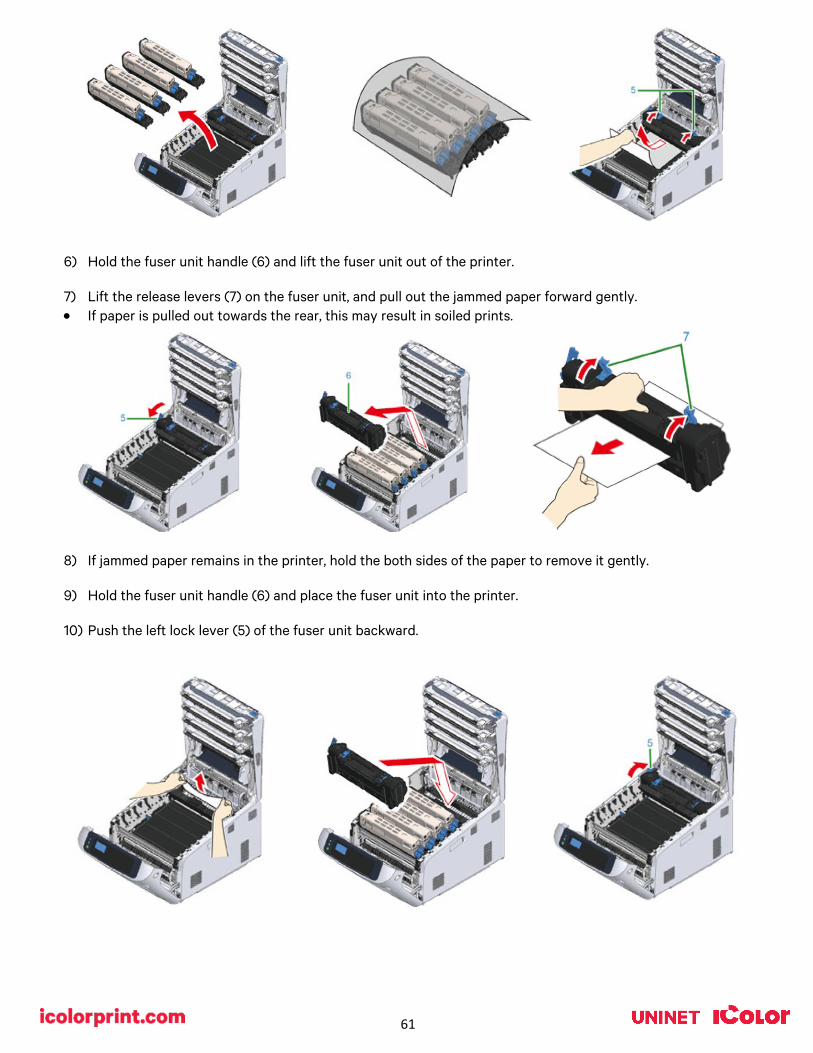
6) Hold the fuser unit handle (6) and lift the fuser unit out of the printer.
7) Lift the release levers (7) on the fuser unit, and pull out the jammed paper forward gently. • If paper is pulled out towards the rear, this may result in soiled prints.
8) If jammed paper remains in the printer, hold the both sides of the paper to remove it gently.
9) Hold the fuser unit handle (6) and place the fuser unit into the printer.
10) Push the left lock lever (5) of the fuser unit backward.

62
11) Return all four image drums into the printer carefully.
12) Close the output tray (4) by pushing the center of the cover firmly.
13) Close the front cover (2). • The front cover cannot be closed if the output tray is not closed securely.
Error Code ‘390’, ‘637’ • A paper jam has occurred while feeding paper from a tray.
1) If there is any paper on the MP tray, lift the paper set cover (1) and take it out.
2) Insert your finger into the recess on the right side of the printer and pull the front cover open lever (2) to open the front cover (3) forward.
3) Remove the jammed paper gently by pulling the edge of paper. • Do not use force when pulling out paper. This might damage the printer.
• If a paper jam has not occurred, then the paper has failed to feed. Please reduce the amount of paper set in the tray.
63
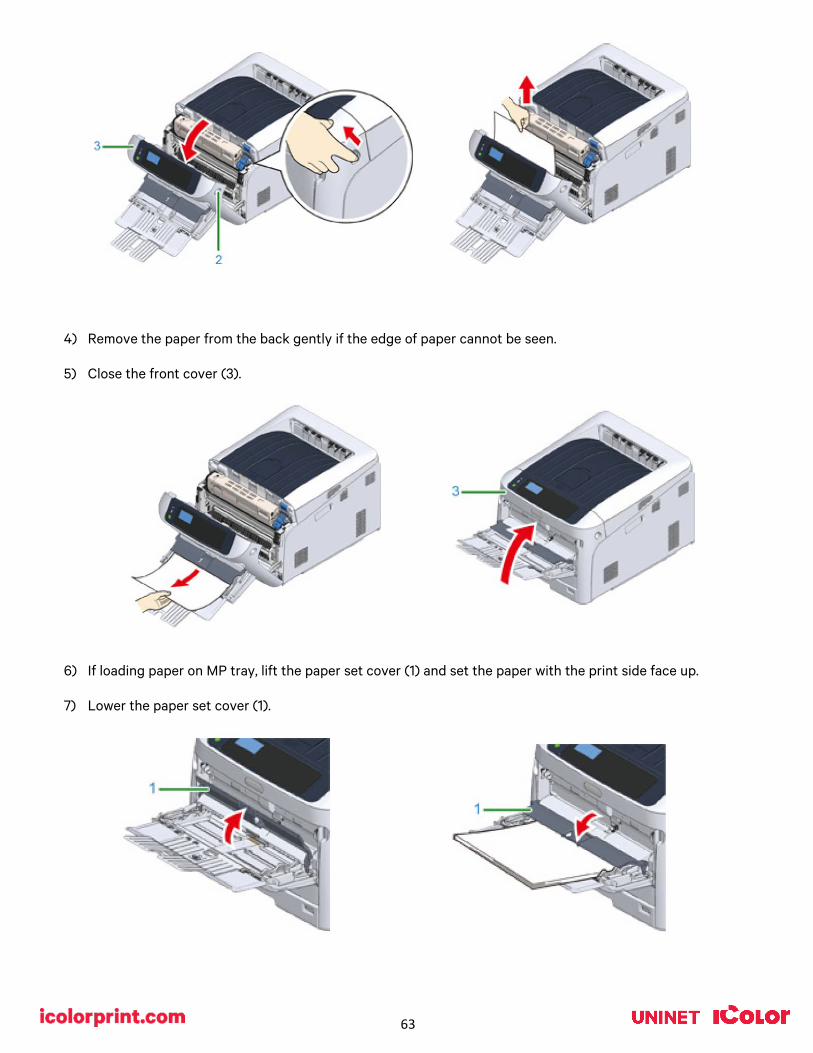
4) Remove the paper from the back gently if the edge of paper cannot be seen.
5) Close the front cover (3).
6) If loading paper on MP tray, lift the paper set cover (1) and set the paper with the print side face up.
7) Lower the paper set cover (1).
64
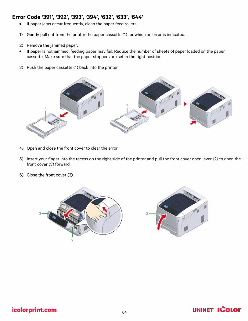
Error Code ‘391’, ‘392’, ‘393’, ‘394’, ‘632’, ‘633’, ‘644’ • If paper jams occur frequently, clean the paper feed rollers.
1) Gently pull out from the printer the paper cassette (1) for which an error is indicated.
2) Remove the jammed paper. • If paper is not jammed, feeding paper may fail. Reduce the number of sheets of paper loaded on the paper
cassette. Make sure that the paper stoppers are set in the right position.
3) Push the paper cassette (1) back into the printer.
4) Open and close the front cover to clear the error.
5) Insert your finger into the recess on the right side of the printer and pull the front cover open lever (2) to open the
front cover (3) forward.
6) Close the front cover (3).

65
Maintaining your Printer
Cleaning the LED Heads • Clean the LED heads if vertical white lines appear, images are faded, or the periphery of letters are smudged in
the printouts.
1) Insert your finger into the recess on the right side of the printer and pull the front cover open lever (1) to open the front cover (2) forward.
2) Press the open button (3) and open the output tray (4).
3) Wipe the four lenses of the LED heads with a soft tissue paper or a lint free cloth, lightly.
4) Close the output tray (top cover) (4) by pushing down on the center of the cover firmly.
5) Close the front cover (2).

66
Cleaning the Light-shielding Film • Clean the light-shielding film of the image drum becomes dirty, wipe the film by following the procedures below. 1) Insert your finger into the recess on the right side of the printer and pull the front cover open lever (1) to open the
front cover (2) forward.
2) Press the open button (3) and open the output tray (4).
3) Remove the image drum.
4) Wipe the light-shielding film (5) with soft tissue paper or a lint free cloth.
5) Close the output tray (top cover) (4) by pushing down on the center of the cover firmly.
6) Close the front cover (2).
Cleaning the Paper Feed Rollers (Tray 1) • Clean the paper feed roller in the paper tray and the rollers inside the printer.
1) Pull out the paper cassette (1).
2) Wipe the two paper feed rollers (2) inside the printer with a wet cloth that has been wrung out well.

67
3) Remove paper loaded in the paper cassette.
4) Wipe the paper feed roller (3) on the paper cassette with a wet cloth that has been wrung out well.
5) Load paper in the paper cassette. Push the paper cassette back into the printer.
Cleaning the Paper Feed Rollers (MP Tray)
• If paper jams occur frequently, clean the paper feed rollers.ean the paper feed roller in the paper tray and the rollers inside the printer.
1) Open the MP tray (2) forward by inserting your fingers into the front recesses (1).
2) Slightly lifting the MP tray (2), press the right arm (3) inward, then unlock the tab (4).

68
3) In the same manner, slightly lifting the MP tray, press the left arm inward, then unlock the tab.
4) Open the paper set cover (5) until it touches to the printer body.
5) Wipe paper feed rollers with a wet cloth that has been wrung out well.
Do not damage the paper end sensor lever when cleaning the rollers.
6) Open the separation roller cover (6) forward while pressing the center part of the MP tray.
7) Wipe the separation rollers (7) with a wet cloth that has been wrung out well.
8) Close the separation roller cover (6).
9) Lower the paper set cover (5).
10) While pressing the right arm (3) on the MP tray (2) inward, slightly lift the MP tray (2) and hook the tab (4).
Closing the MP tray without putting the tab back in place may crack the paper set cover. Be sure to put it back in place.
11) In the same manner, while pressing the left arm on the MP tray inward, slightly lift the MP tray and hook the tab.

69
12) Close the MP tray. If the MP tray cannot be closed, press the paper setting part of the MP tray downward to put the paper set cover back in place.
Cleaning the Resist Roller • Clean the resist rollers in the following steps when they are
dirty.
1) Open the front cover.
2) Wipe the metal part (1) and (2) of the resist roller which can be seen in front with a soft tissue paper.
When cleaning the metal part (2), do not touch the rubber roller which contacts the metal part (2).
3) Turn the metal parts downwards and wipe them until they get
clean.
4) Close the front cover.

70
Printing with Fluorescent Colors
Instantly transform your IColor™ printer into a fluorescent printer where the printed images produced will glow brightly under UV light. The upgrade kit consists of 3 toner and 3 drum cartridges (CMY) and is shipped in 6 separate boxes. Simply remove and store the standard CMY toner/drum cartridges and swap with the fluorescent kit to instantly print with UV sensitive toner while using the standard black cartridge in place. The white cartridge that shipped with your IColor™ 650 printer can also be used if a white overprint is required.
Operating on the same application principles as standard toner that ships with your printer, you can print and/or press onto virtually any surface using the appropriate transfer paper – or print directly onto paper, transparencies and label stock regardless of which printer is being used. Be sure to design your graphics with bright colors – avoid dark or black colors (unless specifically wanted), as those will not fluoresce well and may not look good as a final product. Most fluorescent images will be placed on a black or dark colored garment, so black would not be suggested in these cases anyway.
Specific installation instructions can be found at www.icolorprint.com/support
Printing with Dye Sublimation Toner
Instantly transform your IColor™ printer into a sublimation printer. The upgrade kit consists of 4 toner and 4 drum cartridges (CMYK) and is shipped in 8 separate boxes. Simply remove and store the standard cartridges and swap with the sublimation kit to instantly print and sublimate on coated materials.
Operating on the same application principles as standard ink sublimation systems, you must press onto white 100% polyester or sublimation coated materials for best results. 50/50 cotton poly blends may also be used for a lighter, vintage look. There is no white overprint option with sublimation, only CMYK prints are possible.
The IColor™ Dye Sublimation Upgrade Kit has several unique advantages suited for a production environment:
• Vastly faster print speeds: 35 pages per minute vs 34 pages per hour for ink (photo mode). • No clogged heads resulting from non-use. Toner based systems do not have this maintenance issue. • Longer expiration period. • Much higher page yield: 5,000 pages standard toner vs 350 pages for starter ink. • Use of regular copy paper instead of special dye sublimation paper.
Specific installation instructions can be found at www.icolorprint.com/support
Ask your dealer about upgrading to security and clear toner options as well!

71
Why use IColor™ SmartCUT? SmartCUT allows owners of smaller width printers to gain the benefits of tabloid or larger sized printers. SmartCUT is a user centric tool that is a key component to expanding the size constraints of popular print methods, especially as it relates to transfer printing commonly associated with garment decoration. This ground breaking application turns your letter / A4 sized printer into a tabloid ‘plus’ capable printer, allowing for the splitting and splicing of one graphic across two or more printed transfer sheets without seeing the seam! Use any oversized graphic along with a transparent transfer sheet, and the software will split it in half along the most logical path. You can choose to have it split along dark or light areas, depending on the color garment you will be pressing onto. With this software, you can make large designs that are not possible with even the most expensive of printing systems because you can split up your graphic onto as many transfer sheets as you want. SmartCUT can be used in tandem with any RIP software package and printer. It was designed from the ground up with ease of use as a paramount consideration. Most functions are automated to allow you to focus on finding the best starting point to split each job. Final results can be used on virtually any printer. White toner printers highly recommended. SmartCUT supports many file types such as PNG, JPG, BMP, GIF and TIFF files. The program works as an integral part of a decorating system, where the split pages are printed onto IColor™ Standard or Select transparent transfer media. The sheets are then lined up visually on the substrate through the transparent sheet. Print and press onto plus size garments such as 2X, 3X, 4X. The ability to print designs that properly fill out these large sizes creates the opportunity for high value garments that can fetch a premium price. A very high percentage of designs used are virtually imperceptible by even those who know that a seam exists. SmartCUT is more than just ‘splitting software’ – it’s a RIP enhancement tool! New features include:
• The ‘Selective Masking Tool’ allows you to point and click to rasterize or distress elements of your design based on color or shape.
• IColor™ ProRIP software integration for ease of use.
• The ‘Real Preview’ tool which applies the white adhesive behind the image (digitally) and then applies the image it to the color and texture of a shirt. The result is a much more realistic preview of how your image will look once pressed.

72
Color Registration Procedure
If the printer registration is out of alignment, run the Color Registration Procedure
Signs of this would appear as outlines of white or color around your graphic.
IMPORTANT! Remove the white toner and put the printer into the CYMK configuration with the black cartridge in the first slot and the cyan in the last slot. Basic Procedure:
1) Press the «Fn» key. • When a printer is in the power saving mode, press the «POWER SAVE» button to restore from the mode.
2) Press the «3», «0» and «1» on the numeric keypad and then press the «ENTER» button.
3) Make sure that [Execute] is selected and then press the «ENTER» button. • The message [Color Adjusting] appears in the second line (under [Ready To Print]) of the operator panel
display while adjusting the color registration.
Printing built in test pages The IColor™ 650 has two preloaded test pages which should be printed if print defects occur.
• CMYW and CMYK test page options are available. • This will give IColor™ technicians insight into what cartridge may be exhibiting issues.
1) Load letter or A4 size paper in the bottom tray (tray 1) in landscape format.
2) The cartridge order must be as follows:
• CMYW test page – Insert the Cyan toner/drum cartridge in the front slot and white in the rear slot
• CMYK test page – Insert the Black toner/drum cartridge in the front slot and cyan in the rear slot.
3) To print a test page: a) Press the Menu key.
b) Scroll down to ‘Print Information’ and press the Enter key.
c) Scroll down to ‘Demo Page’ and press the Enter key.
d) Select either CMYW or CMYK and press the Enter key.
e) Press the Enter key when you the display read ‘Execute?’
f) The test page will print.

73
Printing Tips
When transferring images with halftones, it’s possible that some of the adhesive from your 2 step paper will not transfer over to the toner during the first step. If you see this happen with your image, just reprint the image with a white overprint using the ProRIP to thicken up the density and give the adhesive something to stick to. Halftone colors use much less toner. Printing the white over the image will fill in the halftones of color, with density below 70%. Using white overprint is necessary, even when transferring to white colored textiles.
There are many variables that could produce different results. Specific steps may need to be altered based on: • Type and brand of Heat Press: The temperature and duration varies slightly based on the heat press being used.
All instructions are based on using a Hotronix Fusion press. Clam shell and other types of swing away presses may also yield different results.
• Type of image: Photos or full color graphics may require a longer press time than vector images or text.
• Type of garment or substrate: Cotton, Polyester, and Spandex material all respond differently to heat, as do hard surfaces like acrylic or wood. All textile instructions are based on cotton garments.
• Toner Coverage: Halftones in image may cause undesired results. Toner coverage should not be less than 70%, otherwise there will be issues with transferring the adhesive to the transfer sheet. Halftones can be corrected by printing white on top of color using the IColor™ ProRIP Software to apply a white layer in one pass. This will help with toner coverage and proper adherence to the garment.
To find the serial number of your unit, there are 3 ways:
1) Printed on the outside of the box the printer shipped in. 2) Through the control pad on the printer: Menu / Configuration / System / Serial number. 3) Print a system configuration page: Menu / Print Information / Configuration.
Consult the IColor™ knowledge base for specific instructions on a variety of transfer paper offered at: http://www.icolorprint.com/support (Or scan this QR Code)
Technical Support Email: Log a ticket at https://www.icolorprint.com/get-support
Technical Support Phone: 631-590-1040, Option 2
SAVE THE BOX AND PACKAGING! Needed if the machine needs to be sent back for service.

74
ALSO AVAILABLE:
• IColor™ Premium and Premium Stretch 2 Step Transfer Paper for light and dark colored garments
• IColor™ Select and Select Ultra Bright 2 Step Transfer Paper for light and dark colored garments
• IColor™ Standard 2 Step Transfer Paper for light and dark colored garments
• IColor™ Glitter Adhesive 2 Step Transfer Paper (for use with IColor™ Standard 2 Step Transfer Paper)
• IColor™ Light and Speed Trans Light 1-Step Transfer Paper for light colored garments
• IColor™ Presto 2 Step Transfer Paper for textiles and hard surfaces
• IColor™ Temporary Tattoo 2 Step and Easy Tattoo Transfer Paper
• IColor™ Classic, Premium, Wood and Leather and Ceramic Hard Surface 1-Step Transfer Paper
• IColor™ AquaClear 1-Step Transfer Paper for candles and other substrates not resistant to heat
• IColor™ Label / Sticker Paper (Clear and White) in Letter and Tabloid size
• IColor™ Window Cling Media (Clear and White) in Banner and cut sheet options
• IColor™ Banner Paper
• IColor™ Magnetic Media in Letter and Tabloid size …and more! Contact your dealer for more information.
IColor™ Transfer Paper Comparison Charts
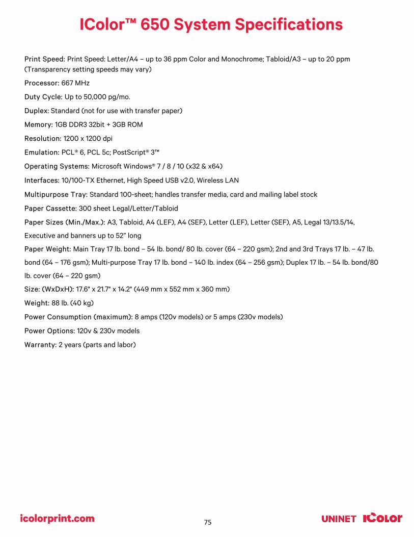
75
IColor™ 650 System Specifications
Print Speed: Print Speed: Letter/A4 – up to 36 ppm Color and Monochrome; Tabloid/A3 – up to 20 ppm (Transparency setting speeds may vary)
Processor: 667 MHz
Duty Cycle: Up to 50,000 pg/mo.
Duplex: Standard (not for use with transfer paper)
Memory: 1GB DDR3 32bit + 3GB ROM
Resolution: 1200 x 1200 dpi
Emulation: PCL® 6, PCL 5c; PostScript® 3™
Operating Systems: Microsoft Windows® 7 / 8 / 10 (x32 & x64)
Interfaces: 10/100-TX Ethernet, High Speed USB v2.0, Wireless LAN
Multipurpose Tray: Standard 100-sheet; handles transfer media, card and mailing label stock
Paper Cassette: 300 sheet Legal/Letter/Tabloid
Paper Sizes (Min./Max.): A3, Tabloid, A4 (LEF), A4 (SEF), Letter (LEF), Letter (SEF), A5, Legal 13/13.5/14,
Executive and banners up to 52” long
Paper Weight: Main Tray 17 lb. bond – 54 lb. bond/ 80 lb. cover (64 – 220 gsm); 2nd and 3rd Trays 17 lb. – 47 lb.
bond (64 – 176 gsm); Multi-purpose Tray 17 lb. bond – 140 lb. index (64 – 256 gsm); Duplex 17 lb. – 54 lb. bond/80
lb. cover (64 – 220 gsm)
Size: (WxDxH): 17.6" x 21.7" x 14.2" (449 mm x 552 mm x 360 mm)
Weight: 88 lb. (40 kg)
Power Consumption (maximum): 8 amps (120v models) or 5 amps (230v models)
Power Options: 120v & 230v models
Warranty: 2 years (parts and labor)