USER MANUAL - iColor Print
27
USER MANUAL Uninet LF-600 Digital die cutter for sheet labels THIS PRODUCT IS CERTIFIED:
Transcript of USER MANUAL - iColor Print

USER MANUAL
Uninet LF-600Digital die cutter for sheet labels
this product is certified:

iMark DIGITAL CUTTING SOFTWARE
The iMark software for the Gemini needs to be downloaded from our websites www.dpr-srl.it / www.dpr-llc.com (section: GEMINI - download software)
Execute the installation’s program iMark-setup.
The setup’s program requires various confirmations for the installation of the program.On some computers you could be asked the system administrator’s password to execute the installation, in the case you do not have this information; contact the technician who administrates the system.
During the installation, the iMark program icon is created on the desktop and a shortcut in the Windows Start Menu.
INSTALLATION OF THE iMark SOFTWARE
This software has been designed to effectively cut sheet labels.There are also functions for the management of cross cut and hatch.
Allows users to import AI and EPS format files.All files have to contain two reference marks.
The dedicated video camera connected to the software detects the crop mark in a fraction of a second and adapts the cut path to the inclination and distortion of the print.
The software runs with the operating systems Windows 7, 8, 10.
Most of old Windows XP computers can be used, but not all of them.The camera is connected to the computer through a USB port.
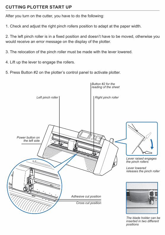
CUTTING PLOTTER START UP
After you turn on the cutter, you have to do the following:
1. Check and adjust the right pinch rollers position to adapt at the paper width.
2. The left pinch roller is in a fixed position and doesn’t have to be moved, otherwise youwould receive an error message on the display of the plotter.
3. The relocation of the pinch roller must be made with the lever lowered.
4. Lift up the lever to engage the rollers.
5. Press Button #2 on the plotter’s control panel to activate plotter.
Left pinch roller Right pinch roller
Button #2 for thereading of the sheet
Power button onthe left side
Adhesive cut position
Cross cut position
Lever raised engages the pinch rollers
Lever loweredreleases the pinch roller
The blade holder can be inserted in two different positions

CABLE CONNECTIONS AND AIR ADJUSTMENT
The regulation of the vacuum force and the blowers speed are intended to avoid that more than one sheet is picked up by the suction cups.The adhesive paper does not require any attention, you can leave the blower speed at minimum.
For thin or porous papers, it may be necessary to decrease the aspiration pressure rotating counter clockwise.If paper cardboards are not lifted by the suction cups you can increase the vacuum force by rotating the suction adjustment counterclockwise.
The connections of the usb cable do not follow any given position, the mini usb cable fits only in the side connector.
Main power supply
Calibration of Mini-USB cable to the computer suction vacuum
Side blowers adjustment
Mini-USB cable to the computer
1 2 3
1. Internal USB2. USB cable to the cutter3. USB cable to the camera
Bottom view
Left roller should alwaysbe on the lefmost position
Right rollermoves accordingly
with the paper width
Knob for settingthe paper width guides
Keep loose anddon’t press downon the paper
Knob for settingthe paper width guides
Feeder power button
The position of the feeder changesdepending on the paper width
Front view
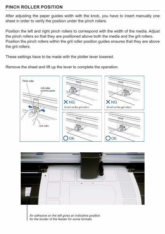
PINCH ROLLER POSITION
After adjusting the paper guides width with the knob, you have to insert manually one sheet in order to verify the position under the pinch rollers.
Position the left and right pinch rollers to correspond with the width of the media. Adjust the pinch rollers so that they are positioned above both the media and the grit rollers.Position the pinch rollers within the grit roller position guides ensures that they are above the grit rollers.
These settings have to be made with the plotter lever lowered.
Remove the sheet and lift up the lever to complete the operation.
An adhesive on the left gives an indicative position for the border of the feeder for some formats.
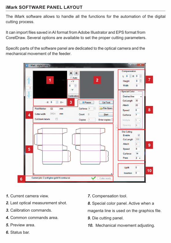
iMark SOFTWARE PANEL LAYOUT
The iMark software allows to handle all the functions for the automation of the digital cutting process.
It can import files saved in AI format from Adobe Illustrator and EPS format from CorelDraw. Several options are available to set the proper cutting parameters.
Specifc parts of the software panel are dedicated to the optical camera and the mechanical movement of the feeder.
1
3
5
6
4
7
8
9
10
2
1. Current camera view.2. Last optical measurement shot.
3. Calibration commands.
4. Common commands area.
5. Preview area.
6. Status bar.
7. Compensation tool.
8. Special color panel. Active when a
magenta line is used on the graphics file.
9. Die cutting panel.
10. Mechanical movement adjusting.
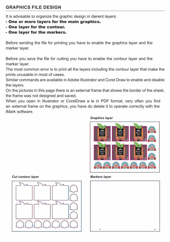
GRAPHICS FILE DESIGN
It is advisable to organize the graphic design in dierent layers:- One or more layers for the main graphics.- One layer for the contour.- One layer for the markers.
Before sending the file for printing you have to enable the graphics layer and the marker layer.
Before you save the file for cutting you have to enable the contour layer and the marker layer.The most common error is to print all the layers including the contour layer that make the prints unusable in most of cases.Similar commands are available in Adobe Illustrator and Corel Draw to enable and disable the layers.On the pictures in this page there is an external frame that shows the border of the sheet, the frame was not designed and saved.When you open in Illustrator or CorelDraw a le in PDF format, very often you find an external frame on the graphics, you have do delete it to operate correctly with the iMark software.
Graphics layer
Markers layerCut contour layer
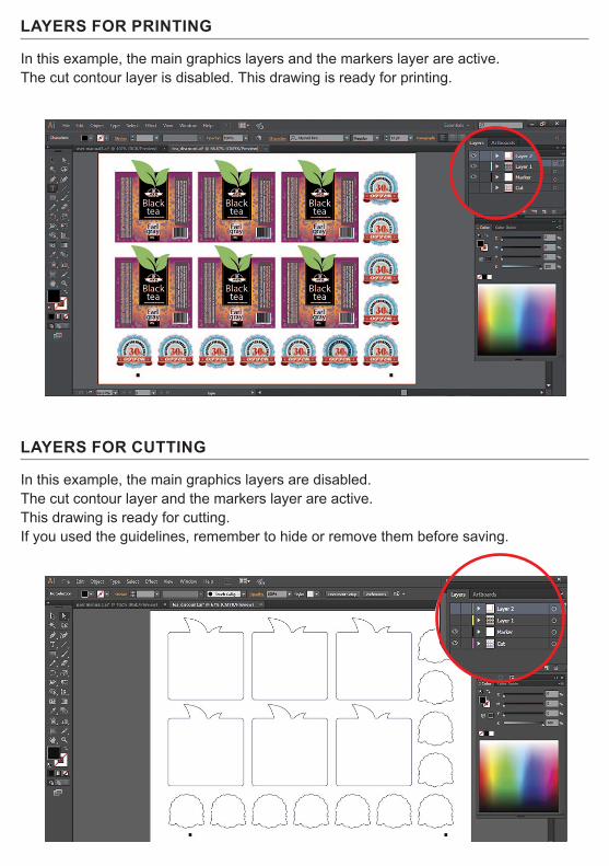
LAYERS FOR PRINTING
In this example, the main graphics layers and the markers layer are active. The cut contour layer is disabled. This drawing is ready for printing.
LAYERS FOR CUTTING
In this example, the main graphics layers are disabled.The cut contour layer and the markers layer are active.This drawing is ready for cutting.If you used the guidelines, remember to hide or remove them before saving.

SAVE FILE FOR CUTTING
The graphics must be saved in horizontal (landscape) view.
You do not have to use a particular thickness or color for the cut profile.The lines in magenta color are treated separately on iMark software.The black marks must be objects at the bottom of the graphics.You can create the files in every version of both Adobe Illustrator and CorelDraw. To save in A.I., see below:
Adobe illustrator export
In Adobe Illustrator, you have to save the cut path and the black-marks in illustrator 8 format.This file is for cut contour only, save it with a different name to the main file containing the full graphics.e.g. complete graphic file: acme_labels.aicut file: acme_labels_contour.ai
Corel Draw Export
From CorelDraw you have to export in EPS format.You can export by using the option ‘Selection only’ to save the contour and markers only.
Note the black mark minimum positions on the next diagram

BLACK MARKS POSITION AND CUTTING AREA
Minimum distance from the front side0.79” (20mm) for adhesive cut0.98” (25mm) for cross cut
Minimum distance of the black-mark from the front side 1.57” (40mm)
Minimum distance of the black-mark from the rear side 0.79” (20mm)
The cutting path can even touch the upper and rear side at a distance of about 0.40” (20mm) is preferable
Minimum distance from the bottom side 0.24” (6mm)
Black-mark square 0.16” (4mm).
Feeding direction
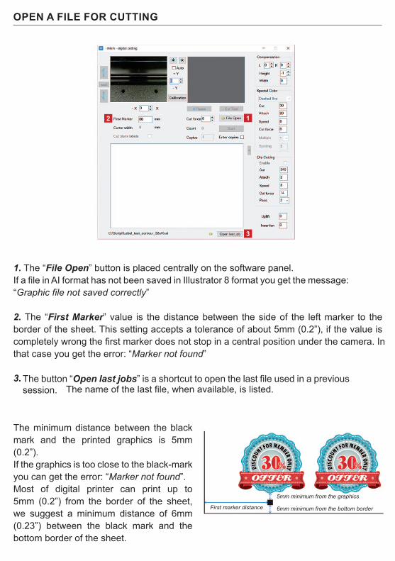
OPEN A FILE FOR CUTTING
The minimum distance between the black mark and the printed graphics is 5mm (0.2”).If the graphics is too close to the black-mark you can get the error: “Marker not found”.Most of digital printer can print up to 5mm (0.2”) from the border of the sheet, we suggest a minimum distance of 6mm (0.23”) between the black mark and the bottom border of the sheet.
1. The “File Open” button is placed centrally on the software panel.If a file in AI format has not been saved in Illustrator 8 format you get the message: “Graphic file not saved correctly”
2. The “First Marker” value is the distance between the side of the left marker to theborder of the sheet. This setting accepts a tolerance of about 5mm (0.2”), if the value is completely wrong the first marker does not stop in a central position under the camera. In that case you get the error: “Marker not found”
3. The button “Open last jobs” is a shortcut to open the last file used in a previous session. The name of the last file, when available, is listed.
12
3
5mm minimum from the graphics
6mm minimum from the bottom borderFirst marker distance

STATUS AND ERROR MESSAGES
If you get the message “Cutter off line!” it means that the cutting plotter is not available at all. Then turn on the plotter and make sure that the USB cable is connected to proceed.
If you get the message “Load Media” it means that the cutting plotter is connected but it is not ready to use, there is the message “Load media” on the display of the plotter.You have to raise the media lever and press button #2 on the cutting plotter panel.
When “Cutter ready” is displayed the “Cut Test” and “Start” buttons are enabled.
After you have loaded a file for cutting, on the status bar changes and there you find the name of the current job and the status of the cutting plotter.
When you press the button “Cut test” or “Start” and you get the message error: “ddcutter not connected”.You have to turn on the switch of the feeder, and check that the green light on the switch is on. If you continue to have this message check the USB connection.
The error message “Could not run Graph” is possible if the camera is not connected to the computer. You get the same error if you try to run more sessions of the software.When you check the USB connection you have to verify that the camera is connected to the USB hub and the USB cable is properly connected on the computer and on the hub side. The same error is possible if you try to open multiple sessions of the software.

BASIC OPERATIONS AND SETTINGS
1. The camera brightness adjustments may be useful when operating on critical luminositycondition.
2. Fine adjustment of the cut position, the values are in tenth of millimeters.
3. This is the maximum cutting width it depends on the position of the push rollers on thecutting plotter.
4. The “Cut blank labels” option allows to cut without reading the black marks. You haveto put the black marks on the graphics even though they are not read.
5. The “Pause” button stops temporarily the job you can press the same button thatbecome “Resume” to continue the job.
6. The “Cut Test” button allows to cut a single sheet for test, allows you to adjust the cutforce and the alignment between the graphic and the cut path before you execute the work.
7. The “Cut force” value sets the pressure of the blade on the cutting plotter.
8. The “Start” button launches the work and counts the labels cut on the “Count” box.
9. If you select the “Enter copies” option you can enter the number of copies to executeon the “Copies” box.
2
2
6
7
8
5
3
4
1
9
It is strongly recommended to use the “Cut test” button before the automatic execution of the work.
You may check the cut alignment and the cutting force.Since the blades is consumed gradually during the work, you have to set a cut force for a neat cut of the adhesive media.
You should verify that the label peel to perfectly and that the blade has just slightly pressed on the liner.
When you are cutting hundreds or thousands of sheets, remember check the cut quality when you put a new load of sheets on the feeder.
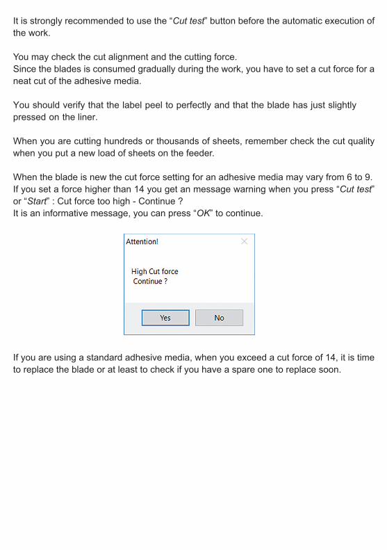
When the blade is new the cut force setting for an adhesive media may vary from 6 to 9.If you set a force higher than 14 you get an message warning when you press “Cut test” or “Start” : Cut force too high - Continue ?It is an informative message, you can press “OK” to continue.
If you are using a standard adhesive media, when you exceed a cut force of 14, it is time to replace the blade or at least to check if you have a spare one to replace soon.

PRINT AND CUT ALIGNMENT
The Y adjustment next to the preview allows you to set the vertical position of the cut lineBy increasing the Y you move the cutting upwards.By decreasing the Y you move the cutting downwards.
The X adjustment allows you to set up the horizontal position of the cut lineBy increasing the X you move the cutting rightwards.By decreasing the X you move the cutting leftwards.
The change of position is in tenths of a millimeter. The adjustment is necessary the first time you install the cutter.When you press the “Start” button the values are memorized and the following adjustments start from a “zero” value.Small variation can be inserted also during the processing; every variation will be eective from the next sheet.
i.e. In case your plotting job is 0.5mm lower than your desired cut job, enter 5 on the Y box to move it higher.
The “Calibration” button allow a cut-peel-measure procedure to find the proper alignment between printed graphics and cut path. You have to insert manually one of the black adhesive sheets provided.
Lower the media lever, insert manually the sheet , rise the lever and press the key #2 on the panel.
If the black adhesive sheets for the calibration procedure were not available you can print the file caliblack.pdf available
among the sample files.
The sheet must be in a central position between the push rollers.
You can align it with the edge of the feeder to keep it straight.

Press the “Calibration” buttonWhen you press “Cut Marker” the plotter cuts a small square.
Remove the small square adhesive to expose the white liner
Press the ”Read Marker” button to read the calibration valuesWhen you press “Set” you store the values that are specic for the camera installed on your plotter.
When you have finished you can remove the calibration sheet you have to rise the media lever, press the key #2 on the panel then you can cut a sample sheet to check the alignment.
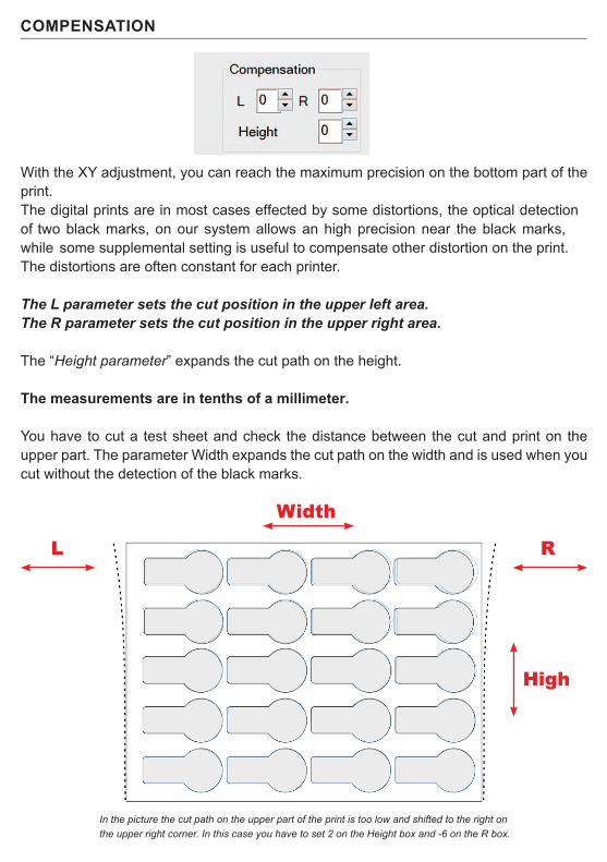
COMPENSATION
With the XY adjustment, you can reach the maximum precision on the bottom part of the print.The digital prints are in most cases effected by some distortions, the optical detection of two black marks, on our system allows an high precision near the black marks, while some supplemental setting is useful to compensate other distortion on the print.The distortions are often constant for each printer.
The L parameter sets the cut position in the upper left area.The R parameter sets the cut position in the upper right area.
The “Height parameter” expands the cut path on the height.
The measurements are in tenths of a millimeter.
You have to cut a test sheet and check the distance between the cut and print on the upper part. The parameter Width expands the cut path on the width and is used when you cut without the detection of the black marks.
In the picture the cut path on the upper part of the print is too low and shifted to the right on the upper right corner. In this case you have to set 2 on the Height box and -6 on the R box.
L R
High
Width

DIE CUTTING
You can make the die cutting on cardboard. Indicatively the usable paperweight goes from 120 to 350 grams (35 to 80 lbs). Thinner or thicker papers can be tested to verify the usability.To use the die cutting you have to move the blade holder in the outermost position.In this way, the blade works over the specic groove when it perforates the sheet.The “Cut Length” parameter identies the measure where the blade perforates completely the paper.The “Attach” parameter is the part where the blade rises without cutting.The values are expressed in tenths of a millimeter, in the following example, the stretch of the die cutting is 35mm, and the bridge attach is 0,3mm.
Select the “Enable” check box for die cutting.To modify the parameters you have to disable the die cut then make the modications. Select “Enable” again to conrm.The speed has to be set on a low value range, from 5 to 15, so you do not stress the blade too much, it will not inuence the speed of use with the adhesive cut, that remains unchanged.It is preferable to use two passes, it allows you to use a lower cut force (below 20); you get a cleaner cut and less blade wear.After any changes you have to press “Cut Test” for the first sheet, it allows you to check the cut quality and it sets all the parameter on the plotter.If you have to cut thin cardboard, leave 3 or more centimeters between the push roller and the cut path so the remaining paper is strong enough to transmit the movement of the sheet.

SPECIAL COLOR PANEL
The “Special Color” panel allows a separate management for the lines in magenta color on the graphics file.
When you use the pure magenta outline in your graphic it is recognized by the iMark software and the “Special color” panel is enabled, on the preview it is drawn in magenta while all the other colors are drawn in black.
The MAGENTA color is cut before the rest of the graphics, Speed and Cut force are settled separately.
The special color can be processed in different modes: Dashed linePlain cutBlade creasing
If used as Dashed line you can set the spacing. Cut Length is the section of the line cut by the blade. The gap is the part of the line where the blade rises up.
In this sample a dashed line is cut on a label for afruit jam jar.
It allows to rip easily the label when opening.
For this job enable the Die cutting option and place the blade holder on the outermost position so you can
avoid to damage the cutting mat.
The dashed line is used as folding line in a couple ofboxes. It is cut before of the die cut.

SPECIAL COLOR ‘PLAIN CUT’
When the “Special color” is used as “Plain Cut” you cut adhesive paper the blade works along the cutting mat you have to fine adjust the cut force to avoid to damage to the cutting mat.
This kind of job could be otherwise worked in two phases:First cut the label contour,then reinsert the sheets on the feeder,move the blade holder on the die cut position
The small labels with magenta contour are cut first.
Then the die cutting pass allows to separate the sheets.
MOST IMPORTANT:The Magenta Lines must be 100% MAGENTA.

SPECIAL COLOR “BLADE CREASING” (PATENT PENDING)
Using this technique you can simulate the creasing using multiple parallel passes of the blade at reduced force.
The blade creasing is carried on the back of the print, that means that the camera does not read the black marks but it detects the border and the corner of the sheet.
The small labels with magenta contour are cut first.
Then the die cutting pass allows to separate the sheets.
For this reason you have to get the distance of the black mark from the border with a ruler.
You have to measure the distance only once, this system works well only with the latest generation of digital printers which are very accurate for the print position on the sheet.The accuracy depends on the repeatability of the position of the print on the sheets, you can reach a value around 1mm (0.04”) then the graphics have to be designed accordingly.
distance of the markerfrom left border
distance of the markerfrom bottom

You have to load the sheet with the print face down.Pay attention to place the side with the black marks on the camera side.
The minimum distance of the cut path from the
right border is 0.99” (25mm)
Since the sheets are loaded upside-down the specifications of the cutting area and black marks are different to those used on the front-side mode.
The distance of the black mark to theright border must be 0.79” (20mm) or less

MECHANICAL MOVEMENTS
On the right bottom corner of the software window there are two settings for controlling the movement of the insertion arm.Uplift controls the height of the arm when inserting the sheet.
Insertion control how much the suction cups have to push the sheet into the plotter.If the insertion is too short the sheet is not pinched by the rollers.If insertion is too deep the sheet may bend during the insertion resulting not flat during the cutting process.
The values are expressed in tenth of millimeter.
Some small variations may be useful to adapt the movements to the quality of the paper.Thick paper may require to add some insertion.Adhesive media curled downward may need a positive Uplift value.
Uplift
Insertion

GRAPHTECH MAINTENANCE
The plotter cuts using a cutter blade mounted in a plunger. There are two different plungers to suit the diameter of the cutter blade to be mounted (the 0.9 mm cutter plunger is provided as a standard accessory). Be sure to mount the cutter blade in the corresponding cutter plunger.
Cutter Plunger
Cutter blade Plunger Blade-length adjustment knob
Plunger-cap
Blade-lengthadjustment knob
Plunger
0.9 mm diametercutter blade
Plunger-cap (blue)
Hole
Adjust the blade length by turning the blade-length adjustment knob. Turn the knob in direction “A” to extend the blade, or in direction “B” to retract the blade. When the knob is turned by one scale unit, the blade moves approximately 0.1 mm. One full turn of the knob moves the blade approximately 0.5 mm.
WARNING: It may result in damaging the cutter blade or the cutting mat if the blade is extended too much. Make sure the blade length is set less than the thickness of the media.
CAUTION:To avoid bodily injury, handle cutter blades with care.
Cutter blade movesapproximately 0.1 mmturning one scale unit
Scale
Scale
Bracket tohold tool Flange
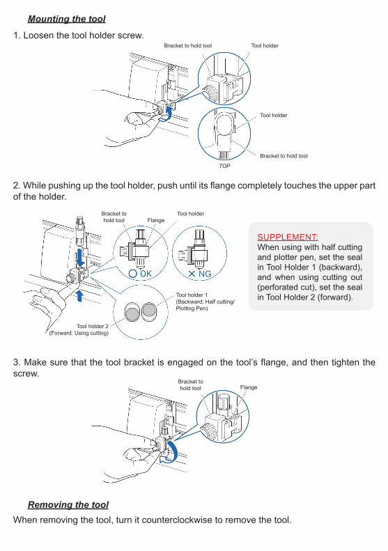
1. Loosen the tool holder screw.
Mounting the tool
2. While pushing up the tool holder, push until its flange completely touches the upper partof the holder.
3. Make sure that the tool bracket is engaged on the tool’s flange, and then tighten thescrew.
When removing the tool, turn it counterclockwise to remove the tool.Removing the tool
Bracket to hold tool Tool holder
Tool holder
Bracket to hold tool
TOP
Bracket tohold tool Flange
Tool holder
Tool holder 1(Backward: Half cutting/Plotting Pen)
Tool holder 2(Forward: Using cutting)
SUPPLEMENT:When using with half cutting and plotter pen, set the seal in Tool Holder 1 (backward), and when using cutting out (perforated cut), set the seal in Tool Holder 2 (forward).
Cutter blade movesapproximately 0.1 mmturning one scale unit
Scale
Scale
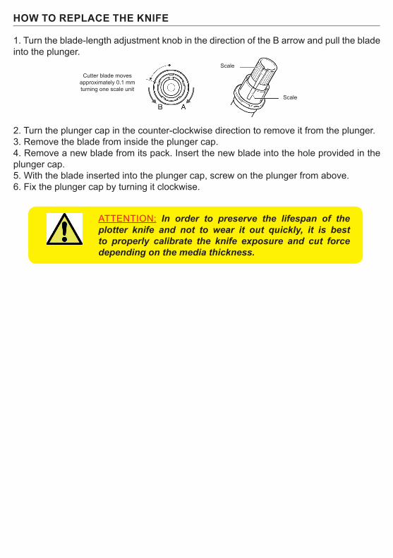
1. Turn the blade-length adjustment knob in the direction of the B arrow and pull the bladeinto the plunger.
2. Turn the plunger cap in the counter-clockwise direction to remove it from the plunger.3. Remove the blade from inside the plunger cap.4. Remove a new blade from its pack. Insert the new blade into the hole provided in theplunger cap.5. With the blade inserted into the plunger cap, screw on the plunger from above.6. Fix the plunger cap by turning it clockwise.
HOW TO REPLACE THE KNIFE
ATTENTION: In order to preserve the lifespan of the plotter knife and not to wear it out quickly, it is best to properly calibrate the knife exposure and cut force depending on the media thickness.

HOW TO REPLACE CUTTING MAT
1. Remove the cutting mat.-The cutting mat is attached to the cutting base (fig.2)-Please remove only the cutting mat from the cutting mat base from the location shown by the arrow (A) (fig.1)
- After removing the cutting mat, please make sure that there is no adhesive tape or other adhesives left on the cutting base.- Please clean the cutting matt base with alcohol before installing the cutting mat.- Installing the cutting mat with the remaining adhesive may affect cut quality.
2. Installing the cutting mat.- Fit the cutting mat with the front cutting base grooves (fig.3) and attach it from the location shown by the arrow (A) (fig.1) while peeling off the release paper.
CAUTION: Please turn off the power when replacing the cutting mat.Please move the tool carriage to “A” position allowing for ease of work.