ICM, ICMB - irp-cdn.multiscreensite.com€¦ · ICM, ICMB 23 22 21 20 19 °Celsiu 21,5 21,4 20,9...
8
ICM, ICMB
Transcript of ICM, ICMB - irp-cdn.multiscreensite.com€¦ · ICM, ICMB 23 22 21 20 19 °Celsiu 21,5 21,4 20,9...

ICM, ICMB

2
ICM, ICMB
23
22
21
20
19
°Celsiu
21,5
21,4 20,9
21,6
20,8 20,7
22,2
20,6
22,620,4
19,8
19,9
Networking of the body geometriesof the ICM
Temperature profile in thecan/magnetic drive area duringmedium conveyance
Flow patterns in the rear can area Temperature profile in the can/plainbearing area during operation
The model ICM magnetic drive chemical process pumpwas developed based oninput from leading chemical/ pharmaceutical companies.Modern engineering methods from the field of CAEapplications (computer aidedengineering), e.g. FEM (finite-element method) and CFD
(computational fluiddynamics) were used for this purpose. The ICM leverages years of process experience with our customers‘ and has been designed to meet customers‘ present and future expectations.
Special emphasis was paid to:• Reducing customer Life Cycle Cost (LCC) by minimizing maintenance, operating and installation cost• A comprehensive range of materials andaccessories are offered to meet
customer needs for a
• Integrated
possibilities to connect safety and monitoring devices• Designstandardization andsimplification to provide for easy maintenance and tominimize spare parts inventory requirements.
Design• Single-stage, magnetic drive centrifugal pump• Dimensions and technical design in accordance withDIN EN 22858/ ISO 2858/ DIN ISO 5199, ISO 15783
• Standard frame-mounteddesign, alternatively close-coupled• Sealless design eliminates the need for shaft sealing• Flanges drilled to DIN/ISO,ANSI, BS, JS
Markets• Chemical, pharmaceuticaland petrochemical industry,water treatment, pulppreparation, metal processing,general industry, nuclear power plants, food technology andwaste disposal/recyclingindustries.
Model ICMThe model ICM is ametallic magnetic drive chemical process pumpmade of stainless steel,Hastelloy, ductile cast iron and special metals. It has been engineered utilizingthe collective expertise and pumping process
knowledge at Richter,Goulds and Vogel.Designed for normal anddemanding chemical process applications , the ICM combinesperformance safety and reliability in an value added package.
Flow rates• 3/h (1490 3
• 3/h (1760 3
USgpm) at 3500 rpmHeads• up to 160 m (525ft) LC at 2900 rpm• up to 210 m (685ft) LC at 3500 rpm
TT• -40/+180°C (-40/+360°F),
280° °F) Pressures• up to 16 bar (235 psi),
optionally 25 bar (360 psi); sizes 65-40-315 and80-50-315: 25 bar (360 psi)as standard
Applications• Corrosive, environmentallycritical, dangerous, solids-containing, neutral and puremedia
Illustration of the "von Mises stress concentrations" in the Hastelloy can: Thepressure distribution is balanced, such that there are still enough safety reserveseven in areas of maximum stress (red area).
Design principles: Maximum Customer Value,Safety and Reliability
18 sizes with impeller Ø up to 315 mm

43
ICM, ICMB
Simplified Assembly andDisassembly• The number of ”loose”components has beenminimized due to its modular design concept• High component interchangeability within the frame size groups• No special tools required
• No fitting measurements• Split lantern/bearingpedestal design: Allows for maintenance of the drive side while keepingthe liquid end assembled and
”back pull out design”)
Drive magnet assembly with high-performance permanent magnets•330 Nm (≈ 100 kW at 2900 rpm), variable throughmodular design• Integral outer thrust ring prevents against contact withthe can in the event of a roller bearing failure Spark-free as an option
Sturdy bearing pedestal• Standard greased-for-life bearings• Options: flood oil lubrication with extra large oil volume, oil sump cooling,labyrinth oil seals
Can• Hastelloy C4 (2.4610) as standard• Non-welded, deep-drawnone-piece construction• Rated for an operatingpressure of 25 bar (360 psi),burst pressure > 150 bar (2175 psi)• Can monitors on requestFor details, see page 5
Inner magnet assembly• Inner magnet assembly with encapsulated magnets• Pump shaft and inner magnet assembly in one piece• Integral axial vanes assure positive pressurized flushingflow to both lubricate andcool the plain bearings
Pump conditionmonitoring• The ICM is prepared for the attachment/ installation of avariety of monitoring andcontrol devices.For details, see page 7
The sum of the technology and performance spectrumof the model ICM isextraordinary:The ICM is capable of handlinga wide range of applications inthe chemical process industry!Sealless design eliminates the need for shaft sealing providingleak-free, environmentally friendly operation.The ICM contributes to the technical standardisation inprocess engineering thanks toits universal applications.
Pump housing• Minimum corrosionallowance: 3 mm• Standard 3/8" housing drainconnection• Replaceable housing wear ring (optional)• Integrated connections for pressure and temperature monitors• Jacketed housing for mediaheating or cooling on request
Impeller• Precision-cast stainless
steel, optionally Hastelloy and other materials
• Back vanes or balance
•inducer:- reduces the NPSHr by
35-50 %- permits smaller pumps
at higher speeds =lower costs
- is advantageous for media with gas content
Excellent pump hydraulicsThe ICM utilizes the same hydraulic components offeredon the mechanically sealedVogel IC Series. Users benefit from reduced repair parts inventories due to this hydraulic design standardization.
Plain bearing pedestalIntegrated possibilities for connecting• plain bearing flushing feature with external medium, onrequest with can drain• temperature monitoring
Cartridge plain bearing• Standard Pure Silicon Carbide SiC (SSiC), highly abrasion-resistant, with universal chemicalresistance• Cartridge design eliminates measurements and fitting for simplified maintenance• Optional SAFEGLIDE® PLUSdry-running bearing systemprovide added safety duringupset conditions• High level of safety even in the event of plain bearing failureFor details, see page 5
● ● ● ● ● ● ● ● ● ● ● ● ● ● ● ● ● ● ● ● ● ● ● ● ● ● ● ● ● ● ● ●
● ●
● ●
● ●
● ●
● ●
● ●
● ●
● ●
● ●
● ●
● ●
● ●
● ●
● ●
● ●
● ●
● ●
● ●
● ●
●
● ●
●
●
●
●
●
●
●
●
●
●
●
●
●
●
● ●
● ●
● ●
● ●
● ●
● ●
● ●
● ●
● ●
● ●
● ●
● ●
● ●
● ●
● ●
●
● ●
● ●
● ●
● ●
● ●
● ●
● ●
● ●
● ●
● ●
● ●
● ●
●
● ● ●
● ●
● ●
● ●
● ●
● ●
● ●
● ●
● ●
● ●
● ●
● ●
● ●
● ●
● ● ● ● ● ● ● ● ● ● ● ● ● ● ● ● ● ● ● ● ● ● ●
● ● ● ● ● ● ● ● ● ● ● ● ● ● ● ● ● ● ● ● ● ● ● ● ● ● ● ● ● ● ● ● ● ● ● ●

9
ICM, ICMB
401 344 858 859 159 330 213
509 339 310 183
231
551
100
361
230
406
103
940/1
Item No. Part designation Stainlesssteel (VV)
Duplex(WW)
Ductilecast iron
(NL)Hastelloy
(CC)Alloy 20
(AA)Titanium
(TT)
Housing
Impeller
Plain bearing pedestal
Plain bearing cartridge
Inner mag. ass./Magnets
Can
Impeller nut
Distance washer
Key (impeller)
Housing gasket
Can gasket
Intermediate ring
Lantern
Drive mag. ass./Magnets
Bearing pedestal
Drive shaft
Rear bearing cover
Support bracket
Housing drain plug
Screws, nuts etc.
Inducer
Housing wear ring
Oil level sight glass
Options not shown:
Parts listand materials
Details
on request
Details
on request
Details on
request
0.7043
0.6020/NdFeB
0.6025
1.4021
1.0601
1.0037
Duplex 1.4462/SSiC
Duplex 1.4517/NdFeB
Hastelloy C4 2.4610
Duplex 1.4517
1.4571
1.4571
Asbestos-free aramide fibre
Asbestos-free aramide fibre
Hastelloy
Hastelloy
Hastelloy
Hastelloy
0.70431.4408
1.4408
1.4517
1.4517
Stainless steel Details on request
Duplex 1.4462 Details on Details on
request
Hastelloy1.4410 Duplex 1.4439 1.4410
Plastic/glass
Ductilecast iron/
stainl. steel
100
230
339
310
859
159
231
551
940/1
401
406
509
344
858
330
213
361
183
103
236
502
642

6
ICM, ICMB
100-65-160
100-65-200
125-80-250
100-65-250
80-50-250
200
80-50-315
50-32-250
50-32-200
50-32-160
65-40-160
125-100-200
125-80-200
125-80-160
65-40-250
80-50-160
200
80-50-160
65-40-160
50-32-160
125-100-200
65-40-200
50-32-200
65-40-250
50-32-250
80-50-31565-40-315
125-80-200
125-80-250
200
100-65-160
250
80-50-200
250
100
50
30
20
15
10
30
20
15
10
6
4
2
8
[m][ft]
3 15
80
30
40
100
50
30
8
20
3 10
[m] [ft]
5
10
15
20
50
150
20 400200100503010 [US gpm]
1005030201032 5 [m3/h] 200
800
PerformancecurvesThe Model ICM comprises18 sizes with impeller Øup to 315 mm.
It is designed for flow rates of • up to 340 m3/h3
2900 rpm• 3/h3
and heads of• up to 160 m (525ft) LC
• up to 210 m (685ft) LCat 3500 rpm
The sizes 50-32-160 to 80-50-160 as well as50-32-200 to 80-50-200 are available in close-coupleddesign ICMB, too.
Flow rates and heads above the ICM spectrum can be covered up to 500 m3/h 3
(2200 US gpm) by the mechanical seal pumpseries IC.
The performance curvesrelate to a viscosity of 1 mm2/s.2
Performance curves 2900/3500
Q at n = 3500 rpm (60Hz)
Hat
n=
3500
rpm
Hat
n=
2900
rpm
Q at n = 2900 rpm (50Hz)
Performance curves 1450/1750
Q at n = 1450 rpm (50Hz)
Hat
n=
1450
rpm
Hat
n=
1750
rpm
Q at n = 1750 rpm (60Hz)
900500
6
100
70
70
20
300
700
150
3020
15
700
300
50
[ft][m]
153/h]3
[ft] [m]
40
10
[m3/h]
[US gpm]2001005020
5030104
100
5 10 50 100 200
20
30
50
70
100
[US gpm]10 30 50 100 200 400
50
70
100
150
200
500
30
150
200
200
150
500
50
20 200100
30 1750
400
400
1750
30
100702053 10 15 30 50
15 50 100 200 500[US gpm]
[m3/h] 200
800

7
ICM, ICMBSafety first:Pump control andmonitoringWhen a sealless pumps isspecificed the Number One user concern is safe andleakfree operation, especially when noxious, toxic,carcinogenic and other hazardous materials are conveyed.The ICM has been designedsuch that most conditionmonitoring and speed controldevices can be easily andeconomically installed andretrofitted. The followingcondition monitoring optionsare available:
Pump speed control ®, Pump ® etc.)
Temperature monitor
Flow and filling level monitor
Pressure monitor
Motor load monitor
Can temperature monitor
Can leakage sensor in the lantern
Rolling bearing monitor
Connection for external flush supply
Customised solutions onrequest.
Secondary sealing:
The space around the can be sealed against the rollingbearings by means of specialshaft or labyrinth seals.
If the can is damaged, the drive side and atmosphere would be protected against the medium for a certain time.Therefore, in conjunction withone of the can monitors, thisresults in an effective preventive environmentalprotection in the case of critical media.
InducerAs an option all ICM pumpscan be fitted with a suctioninducer.
The inducer• reduces the NPSHr by 35-50 %• permits smaller pumps at higher speeds for lower installation costs• is advantageous for media with entrained gas, high vapor pressures or specific heats
ITT’s inducer technology hasbeen proven in practice for over thirty years.
1
2
3
5
4
6
7
8
9
1
9
1
7
8
35
41
2
3
41
2
26 8
8 5
ICM, ICMB ICM, ICMB
1
2 35 4
1
2 35 4
h 2h 1
DND
DN
S
a f
I
da f1
d 1
DN
S
1
2 532
42
23
54
15
Pumpengröße
50-32-160
50-32-200
50-32-250
65-40-160
65-40-200
65-40-250
65-40-315
80-50-160
80-50-200
80-50-250
80-50-315
100-65-160
100-65-200
100-65-250
125-80-160
125-80-200
125-80-250
125-100-
Flansche Pumpe Wellenende Gewicht kg
DNSmm
DNDmm
a f h1 h2 d l
50
50
50
65
65
65
65
80
80
80
80
100
100
100
125
125
125
125
32
32
32
40
40
40
40
50
50
50
50
65
65
65
80
80
80
80
80
100
80
100
100
125
100
100
125
125
100
100
125
125
125
125
385
385
500
385
385
500
500
385
385
500
500
500
500
500
500
500
500
132
160
180
132
160
180
200
160
160
180
225
160
180
200
180
180
225
160
180
225
160
180
225
250
180
200
225
280
200
225
250
225
250
280
24
24
32
24
24
32
32
24
24
32
32
32
32
32
32
32
32
50
50
80
50
50
80
80
50
50
80
80
80
80
80
80
80
80
Cartridge plain bearingsPlain bearings must run reliably. If, however, pump maintenance is required, it must be performed correctly and often as quickly as possible. The cartridge plain bearing system of the ICM is designed accordingly:• Fast and simpleinstallation and replacement of the plain bearings, no need for installation settings.• Cartridge design can be rebuilt/refurbished with individual components to minimize spare parts and repair costs.• Radial and thrust plain bearings made of highly
abrasion-resistant pure silicon carbide (SSiC) with universal chemical resistance• In case of a plain bearing failure the encapsulated cartridge design both will act to contain possible silicon carbide (SSiC) fragments and to prevent the inner magnet assembly from contacting the can.• Optionally the SAFEGLIDE®
PLUS bearing system can be supplied to provide an optimized dry-running capability. SAFEGLIDE® PLUS has proven its worth in thousands of operating chemical process pumps.
Separating cansThe can is the most important sealing element against the atmosphere. This component was thus carefully examined the development phase:The pressure and flow conditions inside the can were illustrated, simulated and analysed using a computer. The can is therefore optimally designed.• Hastelloy C4 (2.4610) as standard, deep-drawn non-welded design for reliable corrosion resistance
• Vortex breaking bead at the bottom of the can prevents against erosion of the can• Burst pressure >150 bar ( > 2,175 psi)• Large clearances (1.5 mm!) between the can and the inner magnet assembly allow for greater reliability in solid laden services or with higher viscous media• A double can arrangement is available on request where secondary containment is required
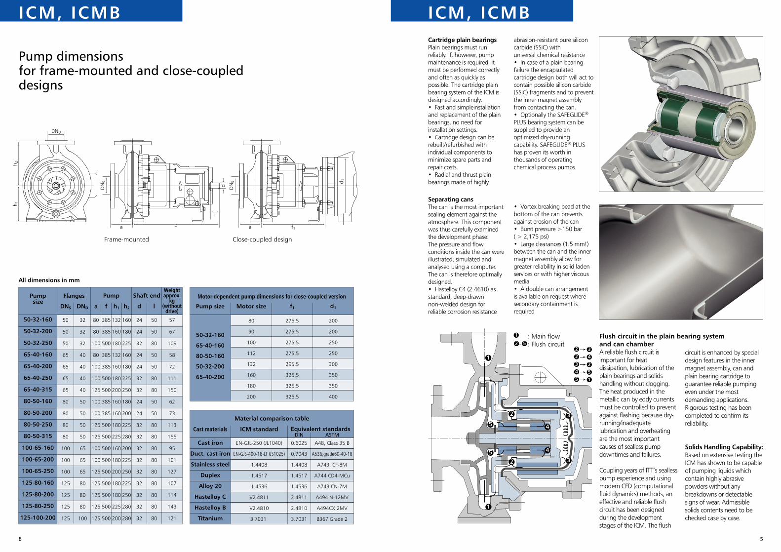
A reliable flush circuit is important for heat dissipation, lubrication of the plain bearings and solids handling without clogging.The heat produced in the metallic can by eddy currents must be controlled to prevent against flashing because dry-running/inadequate lubrication and overheating are the most important causes of sealless pump downtimes and failures.
Coupling years of ITT’s sealless pump experience and using modern CFD (computational fluid dynamics) methods, an effective and reliable flush circuit has been designed during the development stages of the ICM. The flush
circuit is enhanced by special design features in the inner magnet assembly, can and plain bearing cartridge to guarantee reliable pumping even under the most demanding applications. Rigorous testing has been completed to confirm its reliability.
Solids Handling Capability:Based on extensive testing the ICM has shown to be capable of pumping liquids which contain highly abrasive powders without any breakdowns or detectable signs of wear. Admissible solids contents need to be checked case by case.
Pumpsize
Flanges Pump
Cast materials
Cast iron
Duct. cast iron
Stainless steel
Duplex
Alloy 20
Hastelloy C
Hastelloy B
Titanium
ICM standard Equivalent standards
Material comparison table
Pump size Motor size
Motor-dependent pump dimensions for close-coupled version
Pump dimensionsfor frame-mounted and close-coupled designs
Close-coupled designFrame-mounted
50-32-160
50-32-200
50-32-250
65-40-160
65-40-200
65-40-250
65-40-315
80-50-160
80-50-200
80-50-250
80-50-315
100-65-160
100-65-200
100-65-250
125-80-160
125-80-200
125-80-250
125-100-200
DNS DND a f h1 h2 d l
50
50
50
65
65
65
65
80
80
80
80
100
100
100
125
125
125
125
32
32
32
40
40
40
40
50
50
50
50
65
65
65
80
80
80
100
80
80
100
80
100
100
125
100
100
125
125
100
100
125
125
125
125
125
385
385
500
385
385
500
500
385
385
500
500
500
500
500
500
500
500
500
132
160
180
132
160
180
200
160
160
180
225
160
180
200
180
180
225
200
160
180
225
160
180
225
250
180
200
225
280
200
225
250
225
250
280
280
24
24
32
24
24
32
32
24
24
32
32
32
32
32
32
32
32
32
50
50
80
50
50
80
80
50
50
80
80
80
80
80
80
80
80
80
50-32-160
65-40-160
80-50-160
50-32-200
65-40-200
80
90
100
112
132
160
180
200
275.5
275.5
275.5
275.5
295.5
325.5
325.5
325.5
200
200
250
250
300
350
350
400
f1 d1
ASTM
EN-GJL-250 (JL1040)
EN-GJS-400-18-LT (JS1025)
1.4408
1.4517
1.4536
V2.4811
V2.4810
3.7031
0.6025
0.7043
1.4408
1.4517
1.4536
2.4811
2.4810
3.7031
A48, Class 35 B
A536,grade60-40-18
A743, CF-8M
A744 CD4-MCu
A743 CN-7M
A494 N-12MV
A494CX 2MV
B367 Grade 2
DIN
Weight approx.
kg (without
drive)
57
67
109
58
72
111
150
62
73
113
155
95
101
127
107
114
143
121
Flush circuit in the plain bearing system and can chamber
All dimensions in mm
: Main flow- : Flush circuit
Shaft end

Europe
Egypt8 Ahmed El Shediak
Ard El Golf
Heliopolis
Cairo
Egypt
t: +20 2 4143782
f: +20 2 2912121
United KingdomMillwey Rise Industrial Estate
Axminster
Devon EX13 5HU
United Kingdom
t: + 44 1297 630250
f: + 44 1297 630256
Singapore298 Tiong Bahru Road
#03-05, Central Plaza
Singapore 168730
t: + 65 62763693
f: + 65 62763686
Middle East Asia Pacific
Americas
United States240 Fall Street
Seneca Falls, NY 13148
t: + 011 315-568-2811
f: + 011 315-568-2418
ITT Industries: www.itt.com Goulds: www.gouldspumps.com
©2003 Goulds Pumps, Inc.A subsidiary of ITT Industries Inc.
Form No. BICM/ICMB 12/03