Hydrodynamic Bearing Analysis of a Planetary Gear...
21
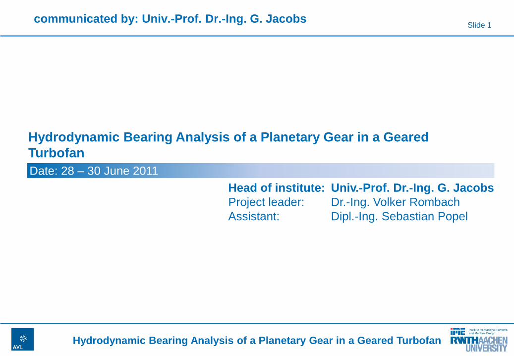
Slide 1 Hydrodynamic Bearing Analysis of a Planetary Gear in a Geared Turbofan Hydrodynamic Bearing Analysis of a Planetary Gear in a Geared Turbofan Head of institute: Univ.-Prof. Dr.-Ing. G. Jacobs Project leader: Dr.-Ing. Volker Rombach Assistant: Dipl.-Ing. Sebastian Popel Date: 28 – 30 June 2011 communicated by: Univ.-Prof. Dr.-Ing. G. Jacobs
Transcript of Hydrodynamic Bearing Analysis of a Planetary Gear...
Slide 1
Hydrodynamic Bearing Analysis of a Planetary Gear in a Geared Turbofan
Hydrodynamic Bearing Analysis of a Planetary Gear in a Geared
Turbofan
Head of institute: Univ.-Prof. Dr.-Ing. G. Jacobs
Project leader: Dr.-Ing. Volker Rombach
Assistant: Dipl.-Ing. Sebastian Popel
Date: 28 – 30 June 2011
communicated by: Univ.-Prof. Dr.-Ing. G. Jacobs
Slide 2
Hydrodynamic Bearing Analysis of a Planetary Gear in a Geared Turbofan
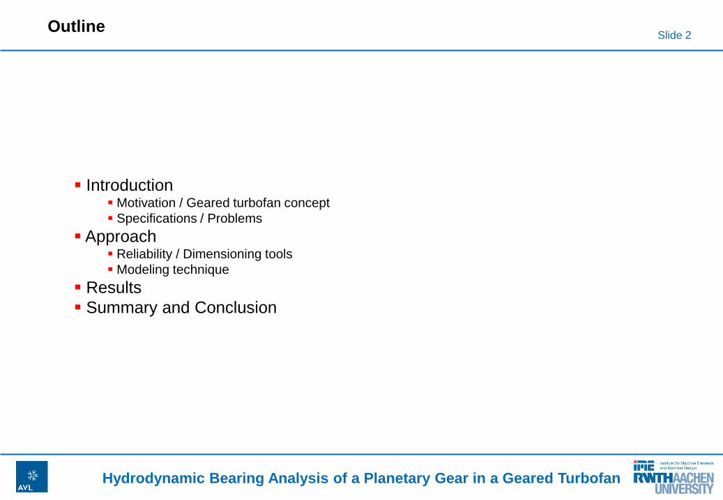
Outline
Introduction Motivation / Geared turbofan concept
Specifications / Problems
Approach Reliability / Dimensioning tools
Modeling technique
Results
Summary and Conclusion
Introduction Motivation / Geared turbofan concept
Specifications / Problems
Approach Reliability / Dimensioning tools
Modeling technique
Results
Summary and Conclusion
Slide 3
Hydrodynamic Bearing Analysis of a Planetary Gear in a Geared Turbofan
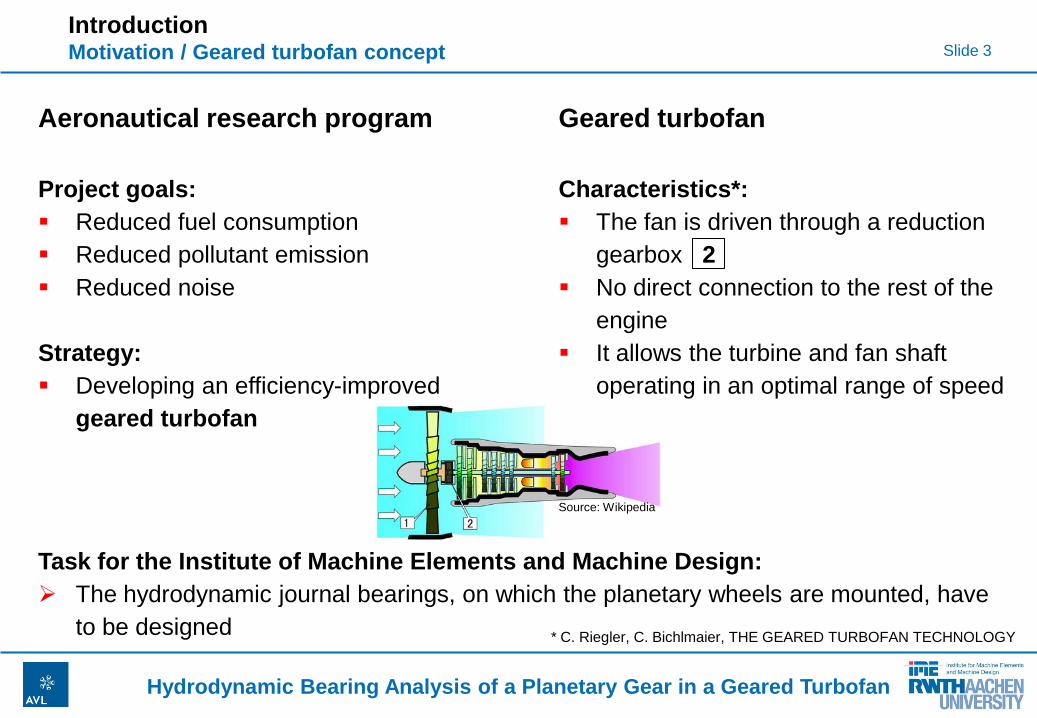
Introduction Motivation / Geared turbofan concept
Aeronautical research program
Project goals:
Reduced fuel consumption
Reduced pollutant emission
Reduced noise
Strategy:
Developing an efficiency-improved
geared turbofan
Geared turbofan
Characteristics*:
The fan is driven through a reduction
gearbox 2
No direct connection to the rest of the
engine
It allows the turbine and fan shaft
operating in an optimal range of speed
* C. Riegler, C. Bichlmaier, THE GEARED TURBOFAN TECHNOLOGY
Task for the Institute of Machine Elements and Machine Design:
The hydrodynamic journal bearings, on which the planetary wheels are mounted, have
to be designed
Source: Wikipedia

Slide 4
Hydrodynamic Bearing Analysis of a Planetary Gear in a Geared Turbofan
Introduction Specifications / Problems
Some specifications:
Mounting of the gear wheels on
hydrodynamic bearings
Planetary Gear with a fixed carrier
Rotational speed up to ~10.000 rpm
Project goals:
Verification of operation
Displacement of planetary gearwheel for high tooth accuracy
Optimum of bearing dimensioning regarding reliability and efficiency
Problems:
High Load at high circumferential speed and high temperature
Elastic deformation of the surrounding structure
Little know-how for dimensioning at these conditions available
Slide 5
Hydrodynamic Bearing Analysis of a Planetary Gear in a Geared Turbofan
Outline
Introduction Motivation / Geared turbofan concept
Specifications / Problems
Approach Reliability / Dimensioning tools
Modeling technique
Results
Summary and Conclusion
Slide 6
Hydrodynamic Bearing Analysis of a Planetary Gear in a Geared Turbofan
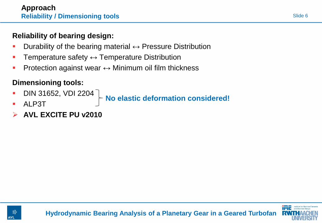
Reliability of bearing design:
Durability of the bearing material ↔ Pressure Distribution
Temperature safety ↔ Temperature Distribution
Protection against wear ↔ Minimum oil film thickness
Approach Reliability / Dimensioning tools
Dimensioning tools:
DIN 31652, VDI 2204
ALP3T
AVL EXCITE PU v2010
No elastic deformation considered!
Slide 7
Hydrodynamic Bearing Analysis of a Planetary Gear in a Geared Turbofan
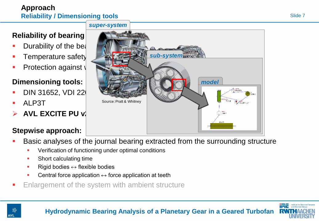
Reliability of bearing design:
Durability of the bearing material ↔ Pressure Distribution
Temperature safety ↔ Temperature Distribution
Protection against wear ↔ Minimum oil film thickness
Stepwise approach:
Basic analyses of the journal bearing extracted from the surrounding structure Verification of functioning under optimal conditions
Short calculating time
Rigid bodies ↔ flexible bodies
Central force application ↔ force application at teeth
Enlargement of the system with ambient structure
Approach Reliability / Dimensioning tools
Dimensioning tools:
DIN 31652, VDI 2204
ALP3T
AVL EXCITE PU v2010
No elastic deformation considered!
super-system
sub-system
model
Source: Pratt & Whitney
Slide 8
Hydrodynamic Bearing Analysis of a Planetary Gear in a Geared Turbofan
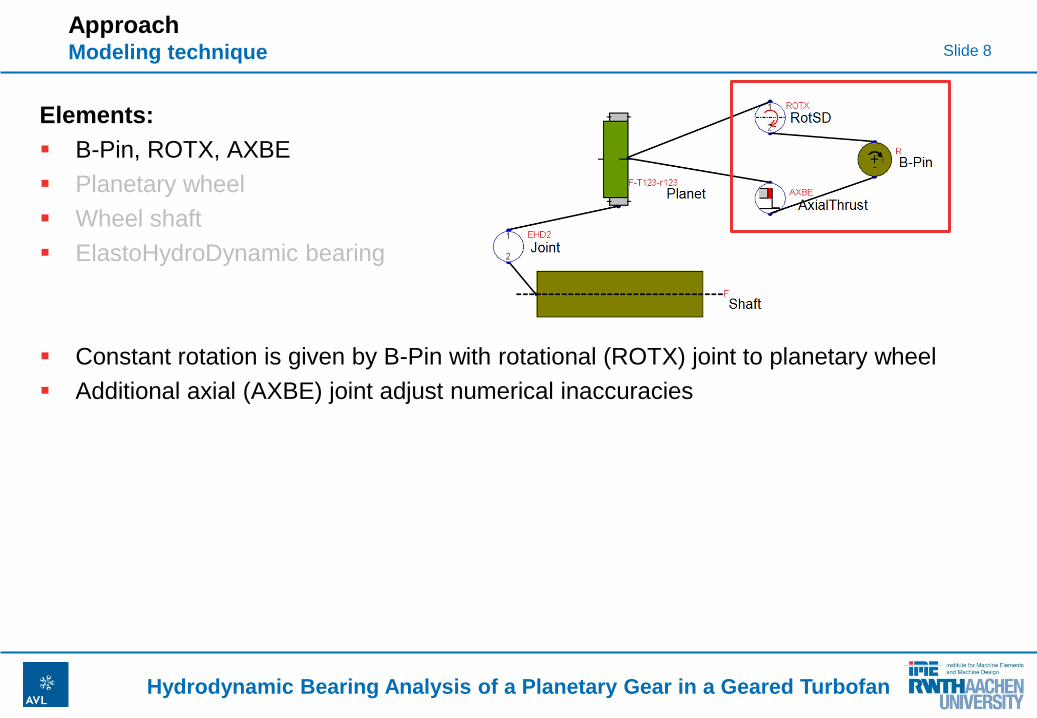
Elements:
B-Pin, ROTX, AXBE
Planetary wheel
Wheel shaft
ElastoHydroDynamic bearing
Constant rotation is given by B-Pin with rotational (ROTX) joint to planetary wheel
Additional axial (AXBE) joint adjust numerical inaccuracies
Approach Modeling technique
Slide 9
Hydrodynamic Bearing Analysis of a Planetary Gear in a Geared Turbofan
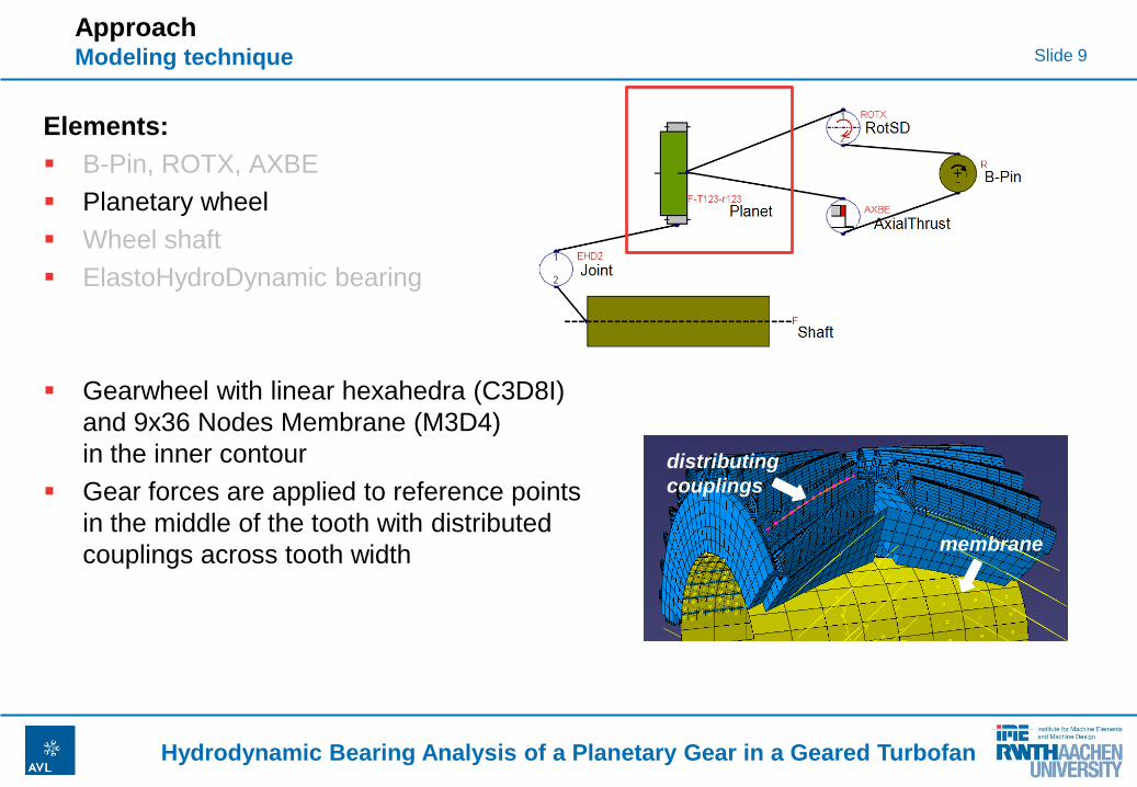
Elements:
B-Pin, ROTX, AXBE
Planetary wheel
Wheel shaft
ElastoHydroDynamic bearing
Gearwheel with linear hexahedra (C3D8I)
and 9x36 Nodes Membrane (M3D4)
in the inner contour
Gear forces are applied to reference points
in the middle of the tooth with distributed
couplings across tooth width
Approach Modeling technique
distributing
couplings
membrane
Slide 10
Hydrodynamic Bearing Analysis of a Planetary Gear in a Geared Turbofan
Elements:
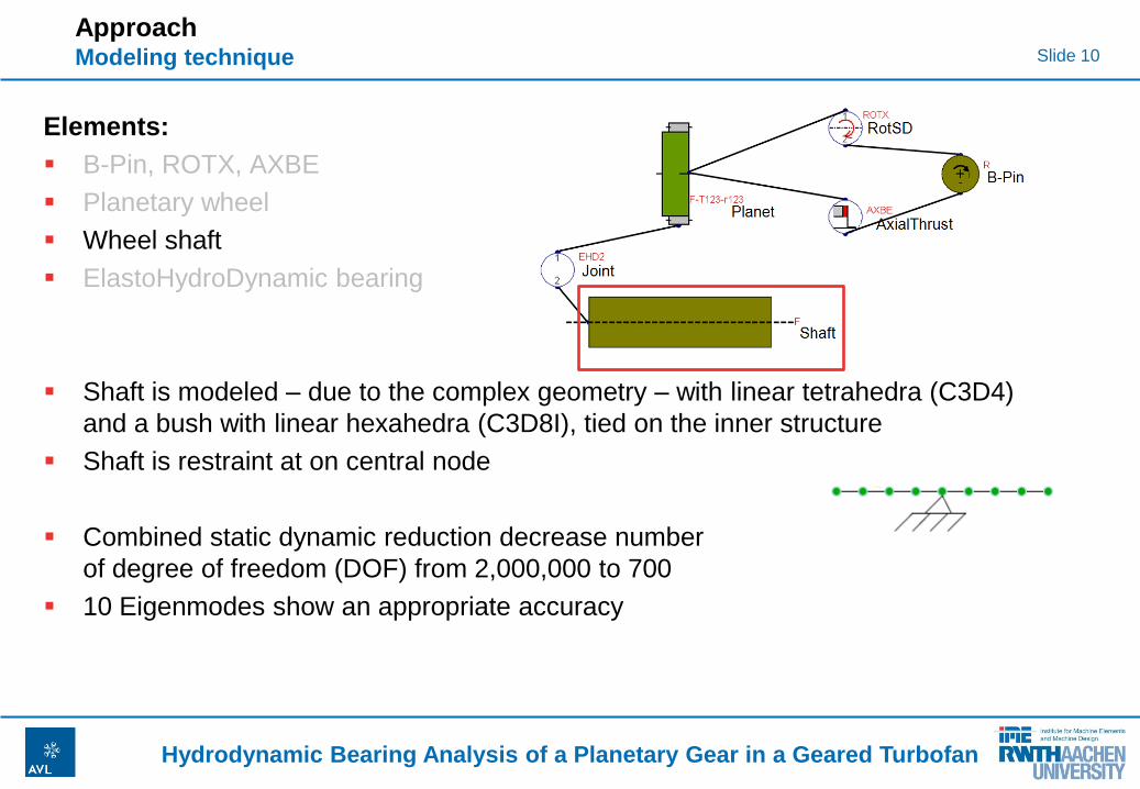
B-Pin, ROTX, AXBE
Planetary wheel
Wheel shaft
ElastoHydroDynamic bearing
Shaft is modeled – due to the complex geometry – with linear tetrahedra (C3D4)
and a bush with linear hexahedra (C3D8I), tied on the inner structure
Shaft is restraint at on central node
Combined static dynamic reduction decrease number
of degree of freedom (DOF) from 2,000,000 to 700
10 Eigenmodes show an appropriate accuracy
Approach Modeling technique
Slide 11
Hydrodynamic Bearing Analysis of a Planetary Gear in a Geared Turbofan
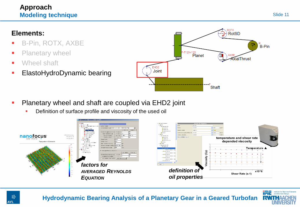
Elements:
B-Pin, ROTX, AXBE
Planetary wheel
Wheel shaft
ElastoHydroDynamic bearing
Planetary wheel and shaft are coupled via EHD2 joint Definition of surface profile and viscosity of the used oil
Approach Modeling technique
factors for
AVERAGED REYNOLDS
EQUATION
definition of
oil properties
Slide 12
Hydrodynamic Bearing Analysis of a Planetary Gear in a Geared Turbofan
Outline
Introduction Motivation / Geared turbofan concept
Specifications / Problems
Approach Reliability / Dimensioning tools
Modeling technique
Results
Summary and Conclusion
Slide 13
Hydrodynamic Bearing Analysis of a Planetary Gear in a Geared Turbofan
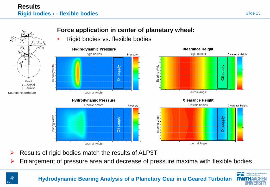
Results Rigid bodies ↔ flexible bodies
Oil
su
pp
ly
Oil
su
pp
ly
Oil
su
pp
ly
Oil
su
pp
ly
Force application in center of planetary wheel:
Rigid bodies vs. flexible bodies
Results of rigid bodies match the results of ALP3T
Enlargement of pressure area and decrease of pressure maxima with flexible bodies
Source: Haberhauer
Slide 14
Hydrodynamic Bearing Analysis of a Planetary Gear in a Geared Turbofan
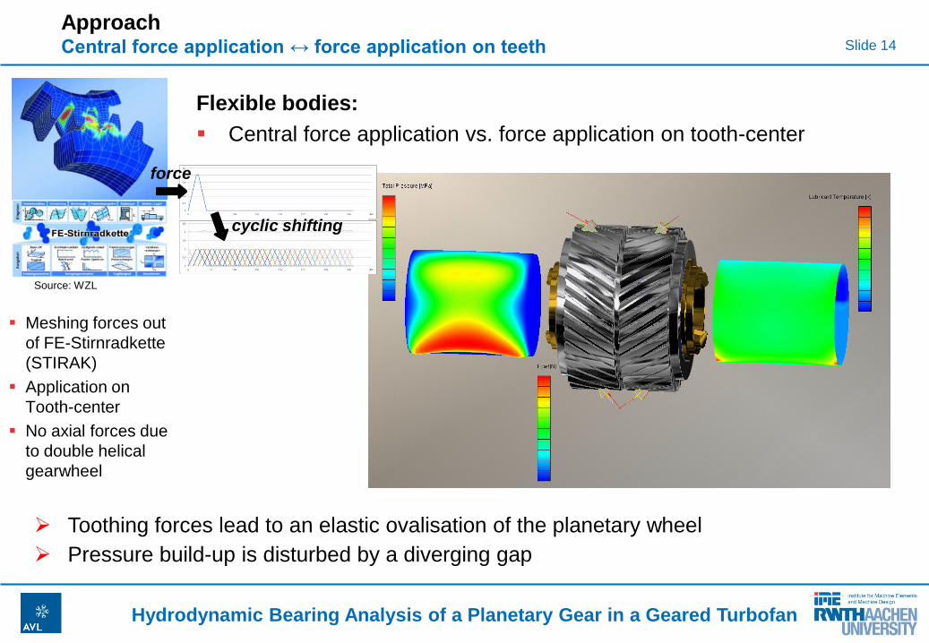
Approach Central force application ↔ force application on teeth
cyclic shifting
force
Flexible bodies:
Central force application vs. force application on tooth-center
Meshing forces out
of FE-Stirnradkette
(STIRAK)
Application on
Tooth-center
No axial forces due
to double helical
gearwheel
Toothing forces lead to an elastic ovalisation of the planetary wheel
Pressure build-up is disturbed by a diverging gap
Source: WZL
Slide 15
Hydrodynamic Bearing Analysis of a Planetary Gear in a Geared Turbofan
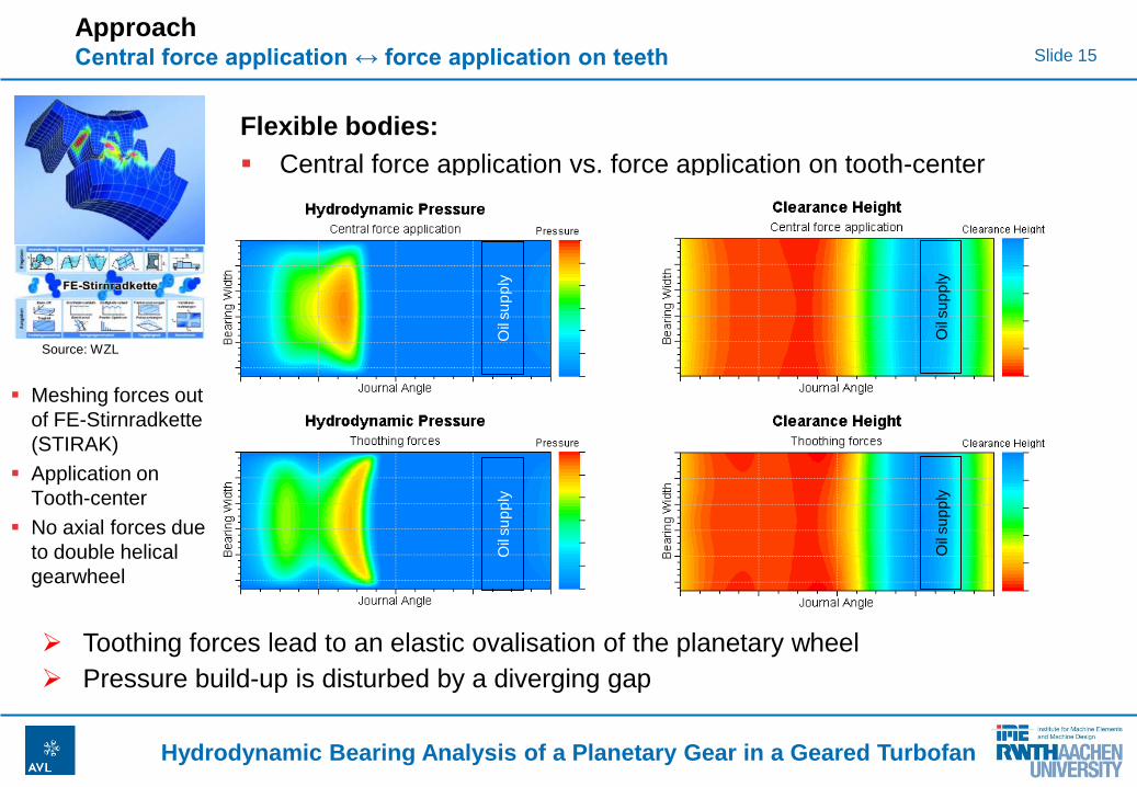
Approach Central force application ↔ force application on teeth
cyclic shifting
Flexible bodies:
Central force application vs. force application on tooth-center
Meshing forces out
of FE-Stirnradkette
(STIRAK)
Application on
Tooth-center
No axial forces due
to double helical
gearwheel
Toothing forces lead to an elastic ovalisation of the planetary wheel
Pressure build-up is disturbed by a diverging gap
cyclic shifting
Oil
su
pp
ly
Oil
su
pp
ly
Oil
su
pp
ly
Oil
su
pp
ly
Source: WZL
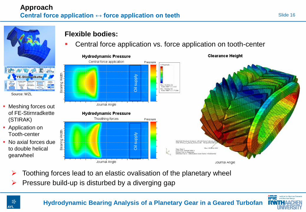
Slide 16
Hydrodynamic Bearing Analysis of a Planetary Gear in a Geared Turbofan
cyclic shifting
Oil
su
pp
ly
Oil
su
pp
ly
Oil
su
pp
ly
Oil
su
pp
ly
Approach Central force application ↔ force application on teeth
Flexible bodies:
Central force application vs. force application on tooth-center
Meshing forces out
of FE-Stirnradkette
(STIRAK)
Application on
Tooth-center
No axial forces due
to double helical
gearwheel
Toothing forces lead to an elastic ovalisation of the planetary wheel
Pressure build-up is disturbed by a diverging gap
Source: WZL
Slide 17
Hydrodynamic Bearing Analysis of a Planetary Gear in a Geared Turbofan
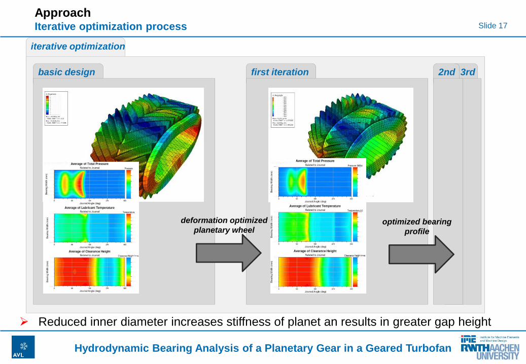
Approach Iterative optimization process
iterative optimization
basic design first iteration
deformation optimized
planetary wheel
3rd 2nd
optimized bearing
profile
Reduced inner diameter increases stiffness of planet an results in greater gap height
Slide 18
Hydrodynamic Bearing Analysis of a Planetary Gear in a Geared Turbofan
Outline
Introduction Motivation / Geared turbofan concept
Specifications / Problems
Approach Reliability / Dimensioning tools
Modeling technique
Results
Summary and Conclusion
Slide 19
Hydrodynamic Bearing Analysis of a Planetary Gear in a Geared Turbofan
Summary and Conclusion
Results of pressure distribution, temperature distribution and minimal oil film
thickness are essential for bearing design
Elastic deformation of planetary gearwheel and carrier shaft has a great
effect of the hydrodynamic pressure distribution and has to be considered
Flexible EHD2 contact is necessary for adequate simulation of the
planetary wheel bearing
Results show that bearing diameter has to be reduced to gain higher
stiffness of the planetary wheel
Fine tuning via contourisation of the bush surface
Several loops to achieve optimum geometry necessary
Next step is the enlargement of the system with ambient structure and the
remaining planets
Slide 20
Hydrodynamic Bearing Analysis of a Planetary Gear in a Geared Turbofan
Thank you for your attention!
Dipl.-Ing. Sebastian Popel
Phone: +49(0)241 80-95607
Fax: +49(0)241 80-92256
E-Mail: [email protected]
Slide 21
Hydrodynamic Bearing Analysis of a Planetary Gear in a Geared Turbofan
Citation
Slide 1: Wikipedia: http://en.wikipedia.org/wiki/Geared_turbofan (05/28/2011)
Slide 7: Pratt & Whitney: http://www.pw.utc.com/media_center/images_library/images_ce_library.asp (05/28/2011)
Slide 13: Haberhauer: H. Haberhauer, F. Bodenstein, Maschinenelemente - Gestaltung, Berechnung, Anwendung, 15. Auflage,
Springer-Verlag Berlin Heidelberg, 2009
Slide 14: WZL, RWTH Aachen: http://www.institut-wv.de/2819.html (05/28/2011)