HH E IE : HEA D IND IAL H D A LIC - TRD Manufacturing m, i. 3 . trd m, i. +312. c trd rga (r g a n)...
64
HH SERIES: HEAVY DUTY INDUSTRIAL HYDRAULIC company a
Transcript of HH E IE : HEA D IND IAL H D A LIC - TRD Manufacturing m, i. 3 . trd m, i. +312. c trd rga (r g a n)...

HH SERIES: HEAVY DUTY INDUSTRIAL HYDRAULIC
companya

3 YEAR WARRANTY
TRD Manufacturing Incorporated, A Bimba Company, is an employee owned company. We take great pride in our products.TRD Manufacturing, Inc. warranties its cylinders for a full 3 years to be free from defects in material and workmanship. TRD Manufacturing, Inc. mustbe notified prior to returning product for warranty evaluation. Contact your local TRD distributor to obtain an RGA (Returned Goods AuthorizationNumber) for proper tracking and expedited service on all warranty evaluations. TRD will repair or replace free of charge any products returned to thefactory within 3 years of shipment that is proven to be defective in material and/or workmanship.
A complete explanation of defects is required with the returned product. The TRD warranty applies only to products used properly and under normaloperating conditions. All products are to be used in a safe manner, in properly designed systems. Safeguards to prevent personal injury or equipmentdamage must be used and are the sole responsibility of the user.
In no event shall TRD Manufacturing, Inc. be liable for any consequential damages or installation costs resulting from delay or failure of delivery, defec-tive material or workmanship or out of a breach by TRD Manufacturing, Inc. of any contract.
2
The TRD difference...Precision machined throughout. We started in business as precision machinists. Every com-ponent is machined in a manner to enhance the performance of our products. Cylinder tubesare lathe cut, not sawed. Heads and caps are 100% CNC machined to tight tolerances in jigbored fixtures. Piston and rod diameters and concentricity are held to within two thousandthsof an inch, in CNC lathes. The results: cylinders that have a consistent performance and longlife. Our cylinders are truly “square”, which eliminates shimming! Try the TRD difference!
On time, consistent delivery. Every customer’s order is important. Our business is managedso large orders do not disrupt our published delivery schedules.
Cylinder Options and Custom Modifications - Since every cylinder is made to order, youcan customize each cylinder to best fit your application. You can choose from our extensivelist of standard options, or send us a sketch for a custom solution!
• Port size, type or location along with cushion locations can be made to yourspecifications. (All NFPA, BSP or SAE Sizes available)
• Rod End Styles and Designs:• (6) NFPA Standard rod end styles available• Custom or other thread lengths available• Metric or other thread styles available• Custom rod end styles available - just send us a sketch!• “Hollow” Rod designs can be gun-drilled to your specifications
• Most Cylinder Options Ship in 2-3 Days!
Quick response on all requests. Most requests are answered the day they are received.
Visit us on the web: http://www.trdmfg.com e-mail:[email protected]
CAD FILES: CONTACT TRD FOR SPECIFIC HYDRAULIC CYLINDER MODEL DRAWINGS

PAGE
WARRANTY & RETURN INFO. . . . . . . . . . . . . . . . . . . . . . . . . . . . . . . . . . . . . . . . . . . . . . . . . . . . . . 2
SERIES ‘HH’ Construction . . . . . . . . . . . . . . . . . . . . . . . . . . . . . . . . . . . . . . . . . . . . . . . . . . . . . . . . . 4
How To Order & NFPA Mounts . . . . . . . . . . . . . . . . . . . . . . . . . . . . . . . . . . . . . . . . . . . . . . . . . . . . . 5
Rod Ends . . . . . . . . . . . . . . . . . . . . . . . . . . . . . . . . . . . . . . . . . . . . . . . . . . . . . . . . . . . . . . . . . . . . . . 6
Dimension Drawings . . . . . . . . . . . . . . . . . . . . . . . . . . . . . . . . . . . . . . . . . . . . . . . . . . . . . . . . . . 7-25
Hydraulic Rod Lock . . . . . . . . . . . . . . . . . . . . . . . . . . . . . . . . . . . . . . . . . . . . . . . . . . . . . . . . . . 26-30
Accessories . . . . . . . . . . . . . . . . . . . . . . . . . . . . . . . . . . . . . . . . . . . . . . . . . . . . . . . . . . . . . . . . . 31-32
Alignment Couplers . . . . . . . . . . . . . . . . . . . . . . . . . . . . . . . . . . . . . . . . . . . . . . . . . . . . . . . . . . . . . 33
Cylinder Basic Options . . . . . . . . . . . . . . . . . . . . . . . . . . . . . . . . . . . . . . . . . . . . . . . . . . . . . . . . 34-39
Cylinder Uncommon Options . . . . . . . . . . . . . . . . . . . . . . . . . . . . . . . . . . . . . . . . . . . . . . . . . . 40-41
Balluff End of Stroke Sensors . . . . . . . . . . . . . . . . . . . . . . . . . . . . . . . . . . . . . . . . . . . . . . . . . . . 42-45
Balluff Transducers . . . . . . . . . . . . . . . . . . . . . . . . . . . . . . . . . . . . . . . . . . . . . . . . . . . . . . . . . . . 46-47
MTS Temposonics® Transducers . . . . . . . . . . . . . . . . . . . . . . . . . . . . . . . . . . . . . . . . . . . . . . . . . 48-52
Seal Kits . . . . . . . . . . . . . . . . . . . . . . . . . . . . . . . . . . . . . . . . . . . . . . . . . . . . . . . . . . . . . . . . . . . 53-54
DELIVERY SCHEDULE . . . . . . . . . . . . . . . . . . . . . . . . . . . . . . . . . . . . . . . . . . . . . . . . . . . . Back Cover
PAGE
• Force Chart . . . . . . . . . . . . . . . . . . . . . . . . 55
• Torque Charts . . . . . . . . . . . . . . . . . . . . . . . 55
• Pressure Rating . . . . . . . . . . . . . . . . . . . . . . 55
• Hydraulic Cylinder Speeds . . . . . . . . . . . . . 56
PAGE
• Weight Charts. . . . . . . . . . . . . . . . . . . . . . . 57
• Seal Compatibility . . . . . . . . . . . . . . . . . . . 58
• Misc. Conversion Charts . . . . . . . . . . . . . . . 59
• Fluid Power Formulas . . . . . . . . . . . . . . . . . 60
TABLE OF CONTENTS
3
TECHNICAL DATA

� FLOATING ROD BUSHING – Precision machined from150,000 PSI rated graphite filled ductile iron and PTFEcoated to reduce friction and extend cycle life. Bushingdesign “traps” lubrication in effective bearing area.Bronze bushings also available.
� PORTS – NPTF and SAE ports available standard. Non-standard locations, sizes, and other port styles can bemade to order to fit any application needs.
� PISTON ROD – Steel piston rod provides high strengthand damage resistance. Induction hardened andchrome plated for maximum wear resistance and longlife. (100K min. yield up to 5” rod; 75K min. yield for5½” rod)
� PISTON – Precision machined ductile iron provides highstrength and an excellent bearing surface for extendedcylinder life.
� TIE RODS – Pre-stressed high carbon steel tie rodconstruction eliminates axial loading of cylinder tubeand maintains compression on tube. (100K min. yield)
� CUSHION – Precision machined cushions are availableat either end and provide smooth deceleration whichhelps reduce end of stroke shock.
� PISTON SEALS – Heavy lip design Carboxilated Nitrile
seals with back-up rings are pressure activated and wearcompensating for extended life. Cast ring, EP, PTFE, andfluorocarbon designs available.
� ROD WIPER – Flocked nitrile wiper removescontaminants on retract stroke, helping insure long lifefor all internal components.
� ROD SEALS – Polyurethane seals offer high abrasionresistance and strength. Pressure activated double lipand wear compensating for extended life.
HEAD & CAP – Precision machined steel head and capare held to tight tolerances and insure accuratealignment for a truly “square” cylinder.
TUBE – Precision machined steel tube with hard chromeI.D. is honed and micro finished for extended seal lifeand improved cycle rates.
CUSHION ADJUSTMENT NEEDLE – Adjustable steelneedle design has fine thread metering and is positivelycaptured to prevent needle ejection during adjustment.
PISTON ROD STUD – Standard on KK1 and KK2threads for 5/8” - 2” rods (125K min. yield). Available upto 2 times standard “A” thread length.
WEAR BAND – Wear Guard Nylon (standard);reinforced PTFE for E and V seal option.
4
Floating Rod Bushing
SELF ALIGNMENT FEATURERod Bushing is designed to float .002”,improving bearing surface alignment.
• Reduces cylinder drag and erratic operation
• Reduces cylinder wear
• Provides a minimum of 25% longer life than“fixed” Rod Bushing designs
HEAVY-DUTY DESIGN FOR RELIABLE, CONSISTENT OPERATION
Performance options:
• RLH – Rod locks are used to hold linear cylinder loadsstationary in any mounting orientation during “power off”condition. See pages 22-26 for more information.
• ST – Stop tubes are used to reduce rod bearing and pistonstress (refer to page 34 for cylinder design guidance).
• CS – Center Supports are recommended for cylinders withlong strokes in horizontal applications to prevent bucklingof the cylinder and extend cylinder life.
• SSR – 17-4 Chrome Plated Stainless Steel Piston Rodprovide corrosion resistance in outdoor applicationsand wet environments. (100K min. yield up to 5” rod;75K min. yield 5½” rod)
• HP – High impact pistons use a high strength steel nutretained piston for fatigue resistance and additionalstrength in demanding applications.
OPERATINGPRESSURE
3000 PSI HYD (207 BAR)Refer�to�page�51 for�specific�PSI
OPERATINGTEMPERATURE
Standard Seals: -20°F to 200°F (-29°C to 93°C)Fluorocarbon: 0°F to 400°F (-18°C to 204°C)
SERIES ‘HH’ (NFPA) CYLINDER

5
HOW TO ORDER: SERIES ‘HH’ (HEAVY DUTY HYDRAULIC CYLINDERS)
HH - MF1 ___ - 250 x 10 - H2C6 - 100 - KK1 - P15 = N375 - S S S S -
SERIES
HHHEAVY DUTYHYDRAULIC
NFPA MOUNTS
MX0NO MOUNT(1.50” to 8.00” Bore)
MF1HEAD RECTANGULAR FLANGE(1.50” to 8.00” Bore)
MF2CAP RECTANGULAR FLANGE(1.50” to 8.00” Bore)
MF5HEAD SQUARE FLANGE(1.50” to 8.00” Bore)
MF6CAP SQUARE FLANGE(1.50” to 8.00” Bore)
ME5HEAD RECTANGULAR MOUNTINGHOLES (1.50” to 8.00” Bore)
ME6CAP RECTANGULAR MOUNTINGHOLES(1.50” to 8.00” Bore)
MP1FIXED CAP PIVOT CLEVIS (1.50” to 8.00” Bore)
MS2SIDE LUGS(1.50” to 8.00” Bore)
MS3CENTER LINE LUGS(1.50” to 8.00” Bore)
MS4BOTTOM TAPPED HOLES(1.50” to 8.00” Bore)
MS7END LUGS(1.50” to 6.00” Bore)
MT1HEAD TRUNNION(1.50” to 8.00” Bore)
MT2CAP TRUNNION(1.50” to 8.00” Bore)
MT4INTERMEDIATE (CENTER) TRUNNION(1.50” to 8.00” Bore)
MX1EXTENDED TIE RODS - HEAD & CAP(1.50” to 8.00” Bore)
MX2EXTENDED TIE RODS - CAP(1.50” to 8.00” Bore)
MX3EXTENDED TIE RODS - HEAD(1.50” to 8.00” Bore)
MF1
1.50”-8.00”Bores
MF2 MF5 MF6
MP1 MS2 MS3 MS7
MT2 MT4 MX1 MX2 MX3
NFPA MOUNTS
*Note: The desired Stop Tube lengthadds directly to the overallcylinder length.
STYLE
(BLANK)SINGLE
ROD
DDOUBLE
ROD
BORE
150 1.50” Bore
200 2.00” Bore
250 2.50” Bore
325 3.25” Bore
400 4.00” Bore
500 5.00” Bore
600 6.00” Bore
800 8.00” Bore
STROKE
0” to 120” Made to Order.
(Use decimals forfractional strokes)
CUSHIONS
H 1
2
3
4
C 5
6
7
8
Call out ‘H’ forhead cushion,
‘C’ for cap cush-ion, followed by
the desired location(s).
ROD SIZE
062 0.625” Rod Dia.
100 1.000” Rod Dia.
137 1.375” Rod Dia.
175 1.750” Rod Dia.
200 2.000” Rod Dia.
250 2.500” Rod Dia.
300 3.000” Rod Dia.
350 3.500” Rod Dia.
400 4.000” Rod Dia.
450 4.500” Rod Dia.
500 5.000” Rod Dia.
550 5.500” Rod Dia.
ROD END
KK1 Small Male Thread
KK2 Large Male Thread
KK3 Female Thread
KK4 Full Dia. Male Thread
KK5 Plain End
KK10 Rod Coupler End
KKM Metric Thread
KKX Non-Std Thread
When additional thread detailsare required, use format
“Rod End” = “Modification”.
Example: KKM=1.00x8
PORT SIZE
N062 1/16” NPTF
N125 1/8” NPTF
N250 1/4” NPTF
N375 3/8” NPTF
N500 1/2” NPTF
N750 3/4” NPTF
N1000 1” NPTF
N1500 11/2” NPTF
S2 #2 SAE
S3 #3 SAE
S4 #4 SAE
S5 #5 SAE
S6 #6 SAE
S8 #8 SAE
S10 #10 SAE
S12 #12 SAE
S16 #16 SAE
S24 #24 SAE
Port Note:For complex port designs, multipleport locations & sizes can be ordered.Call out locations and sizes for all setsusing the following format.
Example:-P15=N375 -P26=N500
(3/8” NPTF Ports at 1 & 5 and1/2” NPTF Ports at 2 & 6)
PORT LOC
P 1
2
3
4
5
6
7
8
9
Call out ‘P’ followed by all
desired locations.
OPTIONS
A=EXTENDED PISTON ROD THREAD(Example: A = 2”)(MAX = 2 TIMES ST’D “A” DIM.)
AS=ADJUSTABLE STROKE - RETRACT (SPECIFY LENGTH, Example: AS = 4”)
C=EXTENDED PISTON ROD(Example: IF C = 0.50”, THEN 1”ROD EXTENSION IS C = 1.50”)
CS CENTER SUPPORT
EKEXTENDED KEYPLATE(Refer to page 17 and 31 for
specifications)
ENELECTROLESS NICKEL PLATED(Refer to page 31 for
specifications)
HP HIGH IMPACT PISTON
NRNON-ROTATING (Refer to page 32 for
specifications)
RBBROD BUSHING MATERIAL:BRONZE
RLH “ROD LOCK READY” CYLINDER
RLH=
ROD LOCK MODEL NUMBERExample: RLH=1002501000(Refer to page 23-26 for ordering
instructions for assembled rod
locks)
SSR STAINLESS STEEL PISTON ROD
ST=
STOP TUBE (SPECIFY STOPTUBE LENGTH AND EFFECTIVESTROKE)Example: (HH-MS2-250x48ES-H2C6-ST=3*)
4WFFOUR WRENCH FLATS(ROD SIZES: 5/8”-3”)
XX= SPECIAL VARIATION (SPECIFY)
PISTON SEAL
SSTANDARD(Carboxilated)
C Cast-Ring
E EP
T PTFE
V Fluorocarbon
ROD SEAL
SSTANDARD(Polyurethane)
E EP
V Fluorocarbon
TUBE SEAL
SSTANDARD(Buna)
E EP
V Fluorocarbon
ROD WIPER *
SSTANDARD(Flocked Nitrile)
MMetalicScrapper
T PTFE
V Fluorocarbon
MS4 MT1
ME5 ME6
1.50”-8.00”Bores
1.50”-8.00”Bores
1.50”-8.00”Bores
1.50”-8.00”Bores
1.50”-8.00”Bores
1.50”-8.00”Bores
1.50”-8.00”Bores
1.50”-8.00”Bores
1.50”-8.00”Bores
1.50”-8.00”Bores
1.50”-8.00”Bores
1.50”-8.00”Bores
1.50”-6.00”Bores
1.50”-8.00”Bores
1.50”-8.00”Bores
1.50”-8.00”Bores
1.50”-8.00”Bores
Page 12
Page 17
Page 8 Page 8
Page 15
Page 12
Page 7
Page 15
Page 14
Page 10
Page 16
Page 14
Page 10
Page 16
Page 12
Page 10
Page 8
Page 13
SEALS
See Below forSeal OrderingInstructions
HOW TO ORDER SEALS
S S S S
MX0
Location 9 is center of cap face.
*Note: When cylinder design calls for all EP seals, use PTFE rod wiper.
MAXIMUM STROKE RECOMMENDATIONS
BORENO CENTERSUPPORT
WITH CENTER SUPPORTS (CS OPTION)
ONE SUPPORT TWO SUPPORTS
1.50” 44 INCHES STROKES OVER 44 INCHES STROKES OVER 89 INCHES
2.00” 74 INCHES STROKES OVER 74 INCHES STROKES OVER 99 INCHES
2.50” 84 INCHES STROKES OVER 84 INCHES NOTREQUIRED3.25” - 8.00” 99 INCHES STROKES OVER 99 INCHES

6
SERIES ‘HH’ DIMENSIONS: THREADS
ROD DIA (MM) A C D AC AD AE AF KK1 KK2 KK3 KK4 NA ±.002
0.625 0.750 0.375 0.500 1.125 0.625 0.250 0.375 7/16 - 20 * 1/2 - 20 * 7/16 - 20 5/8 - 18 —
1.000 1.125 0.500 0.875 1.625 0.938 0.375 0.688 3/4 - 16 * 7/8 - 14 * 3/4 - 16 1 - 14 —
1.375 1.625 0.625 1.125 1.750 1.063 0.375 0.875 1 - 14 * 11/4 - 12 * 1 - 14 13/8 - 12 —
1.750 2.000 0.750 1.500 2.000 1.313 0.500 1.125 11/4 - 12 * 11/2 - 12 * 11/4 - 12 13/4 - 12 —
2.000 2.250 0.875 1.750 2.625 1.688 0.625 1.375 11/2 - 12 * 13/4 - 12 * 11/2 - 12 2 - 12 —
2.500 3.000 1.000 2.125 3.250 1.938 0.750 1.750 17/8 - 12 21/4 - 12 17/8 - 12 21/2 - 12 —
3.000 3.500 1.000 2.625 3.625 2.438 0.875 2.250 21/4 - 12 23/4 - 12 21/4 - 12 3 - 12 —
3.500 3.500 1.000 3.000 4.375 2.688 1.000 2.500 21/2 - 12 31/4 - 12 21/2 - 12 31/2 - 12 —
4.000 4.000 1.000 — 4.500 2.688 1.000 3.000 3 - 12 33/4 - 12 3 - 12 4 - 12 3.937
4.500 4.500 1.000 — 5.250 3.188 1.500 3.500 31/4 - 12 41/4 - 12 31/4 - 12 41/2 - 12 4.421
5.000 5.000 1.000 — 5.375 3.188 1.500 3.875 31/2 - 12 43/4 - 12 31/2 - 12 5 - 12 4.921
5.500 5.500 1.000 — 6.250 3.938 1.875 4.375 4 - 12 51/4 - 12 4 - 12 51/2 - 12 5.421
* Studded rod end.(4 ) Wrench flats is an option.Note: Rods larger than 3.50” dia. utilize (4 ) 0.500” dia. spanner holes 0.500” deep.

FULL SQUARE RETAINERUSED ON:
BORE ROD DIA.
1.50 0.625
1.50 1.000
2.00 1.000
2.00 1.375
2.50 1.375
2.50 1.750
3.25 1.750
3.25 2.000
4.00 2.500
5.00 3.500
ROUND RETAINERUSED ON:
BORE ROD DIA.
2.50 1.000
3.25 1.375
4.00 1.750
4.00 2.000
5.00 2.000
5.00 2.500
6.00 2.500
LARGE ROUND RETAINERUSED ON:
BORE ROD DIA.
5.00 3.000
6.00 3.000
6.00 3.500
6.00 4.000
8.00 3.500
8.00 4.000
8.00 4.500
8.00 5.000
8.00 5.500
SERIES ‘HH’ DIMENSIONS: BASIC CYLINDER (NO MOUNT)
7
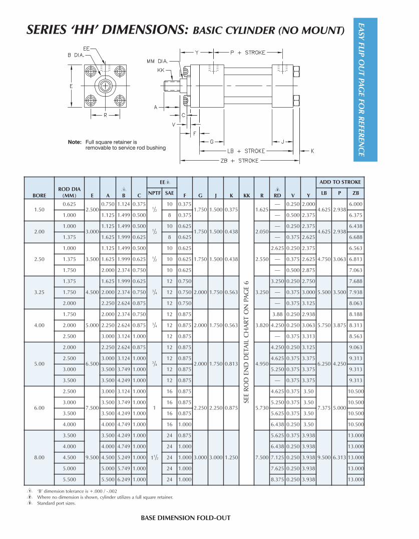
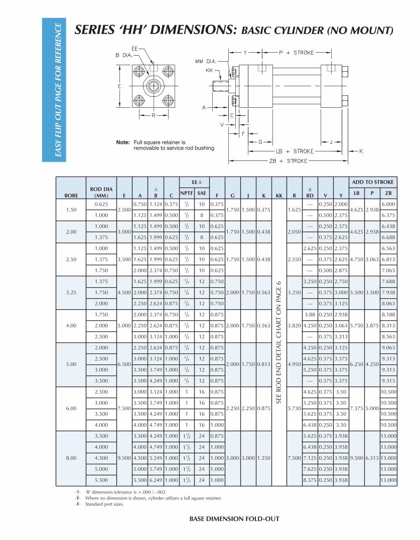
SERIES ‘HH’ DIMENSIONS: BASIC CYLINDER (NO MOUNT)
BOREROD DIA
(MM) E A<�
B C
EE>
F G J K KK R=�
RD V Y
ADD TO STROKE
NPTF SAE LB P ZB
1.500.625
2.5000.750 1.124 0.375
1/210 0.375
1.750 1.500 0.375
SEE
RO
D E
ND
DET
AIL
CH
AR
T O
N P
AG
E 6
1.625— 0.250 2.000
4.625 2.9386.000
1.000 1.125 1.499 0.500 8 0.375 — 0.500 2.375 6.375
2.001.000
3.0001.125 1.499 0.500
1/210 0.625
1.750 1.500 0.438 2.050— 0.250 2.375
4.625 2.9386.438
1.375 1.625 1.999 0.625 8 0.625 — 0.375 2.625 6.688
2.50
1.000
3.500
1.125 1.499 0.500
1/2
10 0.625
1.750 1.500 0.438 2.550
2.625 0.250 2.375
4.750 3.063
6.563
1.375 1.625 1.999 0.625 10 0.625 — 0.375 2.625 6.813
1.750 2.000 2.374 0.750 10 0.625 — 0.500 2.875 7.063
3.25
1.375
4.500
1.625 1.999 0.625
3/4
12 0.750
2.000 1.750 0.563 3.250
3.250 0.250 2.750
5.500 3.500
7.688
1.750 2.000 2.374 0.750 12 0.750 — 0.375 3.000 7.938
2.000 2.250 2.624 0.875 12 0.750 — 0.375 3.125 8.063
4.00
1.750
5.000
2.000 2.374 0.750
3/4
12 0.875
2.000 1.750 0.563 3.820
3.88 0.250 2.938
5.750 3.875
8.188
2.000 2.250 2.624 0.875 12 0.875 4.250 0.250 3.063 8.313
2.500 3.000 3.124 1.000 12 0.875 — 0.375 3.313 8.563
5.00
2.000
6.500
2.250 2.624 0.875
3/4
12 0.875
2.000 1.750 0.813 4.950
4.250 0.250 3.125
6.250 4.250
9.063
2.500 3.000 3.124 1.000 12 0.875 4.625 0.375 3.375 9.313
3.000 3.500 3.749 1.000 12 0.875 5.250 0.375 3.375 9.313
3.500 3.500 4.249 1.000 12 0.875 — 0.375 3.375 9.313
6.00
2.500
7.500
3.000 3.124 1.000
1
16 0.875
2.250 2.250 0.875 5.730
4.625 0.375 3.50
7.375 5.000
10.500
3.000 3.500 3.749 1.000 16 0.875 5.250 0.375 3.50 10.500
3.500 3.500 4.249 1.000 16 0.875 5.625 0.375 3.50 10.500
4.000 4.000 4.749 1.000 16 1.000 6.438 0.250 3.50 10.500
8.00
3.500
9.500
3.500 4.249 1.000
11/2
24 0.875
3.000 3.000 1.250 7.500
5.625 0.375 3.938
9.500 6.313
13.000
4.000 4.000 4.749 1.000 24 1.000 6.438 0.250 3.938 13.000
4.500 4.500 5.249 1.000 24 1.000 7.125 0.250 3.938 13.000
5.000 5.000 5.749 1.000 24 1.000 7.625 0.250 3.938 13.000
5.500 5.500 6.249 1.000 24 1.000 8.375 0.250 3.938 13.000
BASE DIMENSION FOLD-OUT
EASY FLIP
OU
T PAG
E FOR
REFER
ENC
E
< ‘B’ dimension tolerance is +.000 / -.002= Where no dimension is shown, cylinder utilizes a full square retainer.> Standard port sizes.
EASY
FLI
P O
UT
PAG
E FO
R R
EFER
ENC
E
SERIES ‘HH’ DIMENSIONS: BASIC CYLINDER (NO MOUNT)
BASE DIMENSION FOLD-OUT
< ‘B’ dimension tolerance is +.000 / -.002= Where no dimension is shown, cylinder utilizes a full square retainer.> Standard port sizes.
BOREROD DIA
(MM) E A<�
B C
EE>
F G J K KK R=�
RD V Y
ADD TO STROKE
NPTF SAE LB P ZB
1.500.625
2.5000.750 1.124 0.375 1/2 10 0.375
1.750 1.500 0.375
SEE
RO
D E
ND
DET
AIL
CH
AR
T O
N P
AG
E 6
1.625— 0.250 2.000
4.625 2.9386.000
1.000 1.125 1.499 0.500 1/2 8 0.375 — 0.500 2.375 6.375
2.001.000
3.0001.125 1.499 0.500 1/2 10 0.625
1.750 1.500 0.438 2.050— 0.250 2.375
4.625 2.9386.438
1.375 1.625 1.999 0.625 1/2 8 0.625 — 0.375 2.625 6.688
2.50
1.000
3.500
1.125 1.499 0.500 1/2 10 0.625
1.750 1.500 0.438 2.550
2.625 0.250 2.375
4.750 3.063
6.563
1.375 1.625 1.999 0.625 1/2 10 0.625 — 0.375 2.625 6.813
1.750 2.000 2.374 0.750 1/2 10 0.625 — 0.500 2.875 7.063
3.25
1.375
4.500
1.625 1.999 0.625 3/4 12 0.750
2.000 1.750 0.563 3.250
3.250 0.250 2.750
5.500 3.500
7.688
1.750 2.000 2.374 0.750 3/4 12 0.750 — 0.375 3.000 7.938
2.000 2.250 2.624 0.875 3/4 12 0.750 — 0.375 3.125 8.063
4.00
1.750
5.000
2.000 2.374 0.750 3/4 12 0.875
2.000 1.750 0.563 3.820
3.88 0.250 2.938
5.750 3.875
8.188
2.000 2.250 2.624 0.875 3/4 12 0.875 4.250 0.250 3.063 8.313
2.500 3.000 3.124 1.000 3/4 12 0.875 — 0.375 3.313 8.563
5.00
2.000
6.500
2.250 2.624 0.875 3/4 12 0.875
2.000 1.750 0.813 4.950
4.250 0.250 3.125
6.250 4.250
9.063
2.500 3.000 3.124 1.000 3/4 12 0.875 4.625 0.375 3.375 9.313
3.000 3.500 3.749 1.000 3/4 12 0.875 5.250 0.375 3.375 9.313
3.500 3.500 4.249 1.000 3/4 12 0.875 — 0.375 3.375 9.313
6.00
2.500
7.500
3.000 3.124 1.000 1 16 0.875
2.250 2.250 0.875 5.730
4.625 0.375 3.50
7.375 5.000
10.500
3.000 3.500 3.749 1.000 1 16 0.875 5.250 0.375 3.50 10.500
3.500 3.500 4.249 1.000 1 16 0.875 5.625 0.375 3.50 10.500
4.000 4.000 4.749 1.000 1 16 1.000 6.438 0.250 3.50 10.500
8.00
3.500
9.500
3.500 4.249 1.000 11/2 24 0.875
3.000 3.000 1.250 7.500
5.625 0.375 3.938
9.500 6.313
13.000
4.000 4.000 4.749 1.000 11/2 24 1.000 6.438 0.250 3.938 13.000
4.500 4.500 5.249 1.000 11/2 24 1.000 7.125 0.250 3.938 13.000
5.000 5.000 5.749 1.000 11/2 24 1.000 7.625 0.250 3.938 13.000
5.500 5.500 6.249 1.000 11/2 24 1.000 8.375 0.250 3.938 13.000

SERIES ‘HH’ DIMENSIONS: TRUNNION MOUNTS
MT1: HEAD TRUNNION
MT2: CAP TRUNNION
MT4: INTERMEDIATE TRUNNION
8
MAxIMUM PRESSURE PER BORE SIZE
MOUNT 1.50 2.00 2.50 3.25 4.00 5.00 6.00 8.00
MT1 MT2 MT4 3000 3000 3000 2800 1800 1200 1000 1000

BOREROD DIAM
(MM) E BD
<
TD TL TM UM UT UV xG
=
xI
MT4Min
Stroke
ADD TO STROKE
xI Max
xJ ZB
1.500.625
2.500 1.500 1.000 1.000 3.000 5.000 4.500 3.0001.875 3.500
0.2503.250 4.875 6.000
1.000 2.250 3.875 3.625 5.250 6.375
2.001.000
3.000 1.500 1.375 1.375 3.500 6.250 5.750 3.5002.250 4.000
0.2503.750 5.250 6.438
1.375 2.500 4.250 4.000 5.500 6.688
2.50
1.000
3.500 1.500 1.375 1.375 4.000 6.750 6.250 4.000
2.250 4.125
0.375
3.750 5.375 6.563
1.375 2.500 4.375 4.000 5.625 6.813
1.750 2.750 4.625 4.250 5.875 7.063
3.25
1.375
4.500 2.000 1.750 1.750 5.000 8.500 8.000 5.000
2.625 5.000
0.875
4.125 6.250 7.688
1.750 2.875 5.250 4.375 6.500 7.938
2.000 3.000 5.375 4.500 6.625 8.063
4.00
1.750
5.000 2.000 1.750 1.750 5.500 9.000 8.500 5.500
2.875 5.500
1.125
4.375 6.750 8.188
2.000 3.000 5.625 4.500 6.875 8.313
2.500 3.250 5.875 4.750 7.125 8.563
5.00
2.000
6.500 2.500 1.750 1.750 7.000 10.500 10.000 7.250
3.000 5.875
1.125
4.750 7.375 9.063
2.500 3.250 6.125 5.000 7.625 9.313
3.000 3.250 6.125 5.000 7.625 9.313
3.500 3.250 6.125 5.000 7.625 9.313
6.00
2.500
7.500 3.000 2.000 2.000 8.500 12.500 11.500 8.750
3.375 6.625
1.250
5.375 8.375 10.500
3.000 3.375 6.625 5.375 8.375 10.500
3.500 3.375 6.625 5.375 8.375 10.500
4.000 3.375 6.625 5.375 8.375 10.500
8.00
3.500
9.500 3.500 3.000 3.000 11.000 17.000 15.500 11.750
3.750 8.125
2.125
6.000 10.250 13.000
4.000 3.750 8.125 6.000 10.250 13.000
4.500 3.750 8.125 6.000 10.250 13.000
5.000 3.750 8.125 6.000 10.250 13.000
5.500 3.750 8.125 6.000 10.250 13.000
SERIES ‘HH’ DIMENSIONS: TRUNNION MOUNTS
< TD DIMENSION TOLERANCE IS + .000 / - .001
= XI DIMENSION IS THE MINIMUM THAT CAN BE SUPPLIED (CUSTOMER TO SPECIFY XI DIMENSION).
9

SERIES ‘HH’ DIMENSIONS: EXTENDED TIE ROD MOUNTS
Mx1: ExTENDED TIE-RODS - HEAD & CAP
Mx2: ExTENDED TIE-RODS - CAP END
Mx3: ExTENDED TIE-RODS - HEAD END
10
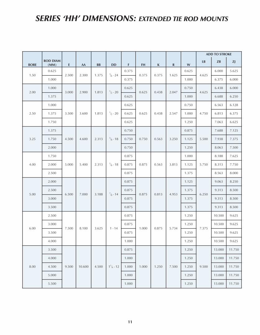
SERIES ‘HH’ DIMENSIONS: EXTENDED TIE ROD MOUNTS
BOREROD DIAM
(MM) E AA BB DD F FH K R W
ADD TO STROKE
LB ZB ZJ
1.500.625
2.500 2.300 1.375 3/8 - 240.375
0.375 0.375 1.6250.625
4.6256.000 5.625
1.000 0.375 1.000 6.375 6.000
2.001.000
3.000 2.900 1.813 1/2 - 200.625
0.625 0.438 2.0470.750
4.6256.438 6.000
1.375 0.625 1.000 6.688 6.250
2.50
1.000
3.500 3.600 1.813 1/2 - 20
0.625
0.625 0.438 2.547
0.750
4.750
6.563 6.128
1.375 0.625 1.000 6.813 6.375
1.750 0.625 1.250 7.063 6.625
3.25
1.375
4.500 4.600 2.313 5/8 - 18
0.750
0.750 0.563 3.250
0.875
5.500
7.688 7.125
1.750 0.750 1.125 7.938 7.375
2.000 0.750 1.250 8.063 7.500
4.00
1.750
5.000 5.400 2.313 5/8 - 18
0.875
0.875 0.563 3.813
1.000
5.750
8.188 7.625
2.000 0.875 1.125 8.313 7.750
2.500 0.875 1.375 8.563 8.000
5.00
2.000
6.500 7.000 3.188 7/8 - 14
0.875
0.875 0.813 4.953
1.125
6.250
9.063 8.250
2.500 0.875 1.375 9.313 8.500
3.000 0.875 1.375 9.313 8.500
3.500 0.875 1.375 9.313 8.500
6.00
2.500
7.500 8.100 3.625 1 - 14
0.875
1.000 0.875 5.734
1.250
7.375
10.500 9.625
3.000 0.875 1.250 10.500 9.625
3.500 0.875 1.250 10.500 9.625
4.000 1.000 1.250 10.500 9.625
8.00
3.500
9.500 10.600 4.500 11/4 - 12
0.875
1.000 1.250 7.500
1.250
9.500
13.000 11.750
4.000 1.000 1.250 13.000 11.750
4.500 1.000 1.250 13.000 11.750
5.000 1.000 1.250 13.000 11.750
5.500 1.000 1.250 13.000 11.750
11
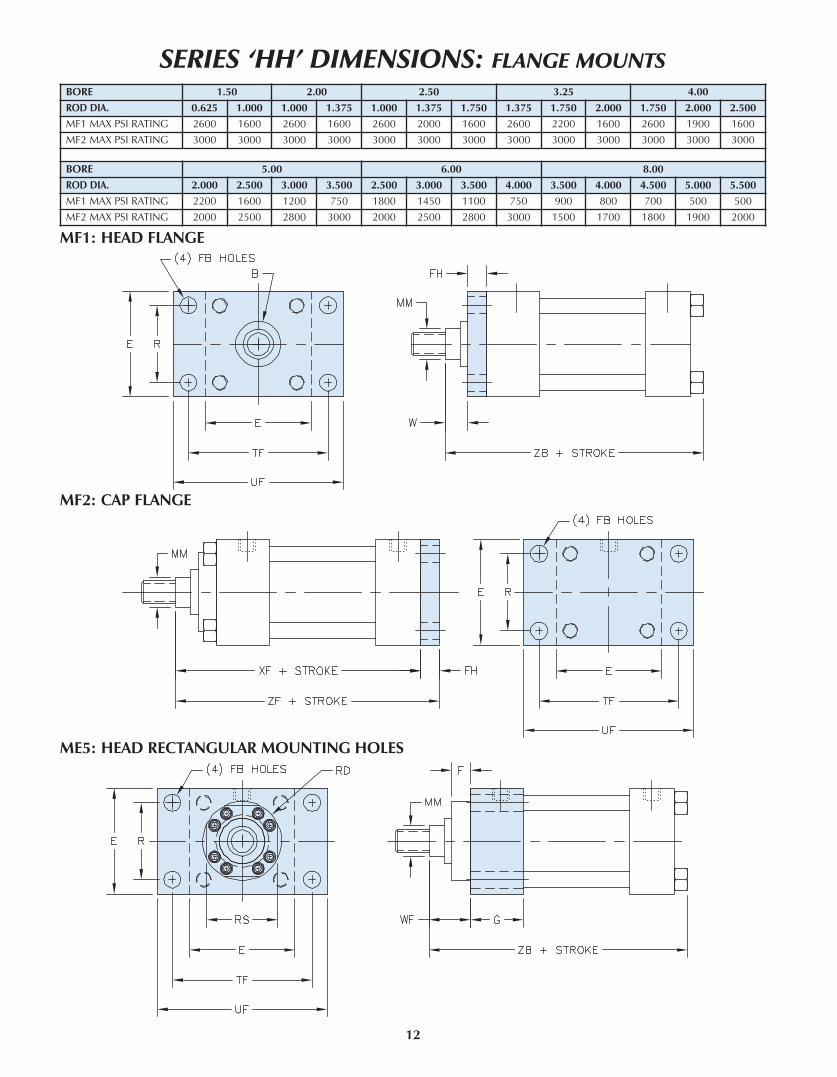
ME5: HEAD RECTANGULAR MOUNTING HOLES
BORE 1.50 2.00 2.50 3.25 4.00
ROD DIA. 0.625 1.000 1.000 1.375 1.000 1.375 1.750 1.375 1.750 2.000 1.750 2.000 2.500
MF1 MAX PSI RATING 2600 1600 2600 1600 2600 2000 1600 2600 2200 1600 2600 1900 1600
MF2 MAX PSI RATING 3000 3000 3000 3000 3000 3000 3000 3000 3000 3000 3000 3000 3000
BORE 5.00 6.00 8.00
ROD DIA. 2.000 2.500 3.000 3.500 2.500 3.000 3.500 4.000 3.500 4.000 4.500 5.000 5.500
MF1 MAX PSI RATING 2200 1600 1200 750 1800 1450 1100 750 900 800 700 500 500
MF2 MAX PSI RATING 2000 2500 2800 3000 2000 2500 2800 3000 1500 1700 1800 1900 2000
SERIES ‘HH’ DIMENSIONS: FLANGE MOUNTS
MF1: HEAD FLANGE
MF2: CAP FLANGE
12

BORE
RODDIAM(MM)
<�
B E F FB FH G J R RD RS TF UF W WF
ADD TO STROKE
xF ZB ZF
1.500.625 1.124
2.5000.375
0.438 0.375 1.750 1.500 1.6252.375 —
3.438 4.2500.625 1.000 5.625 6.000 6.000
1.000 1.499 0.375 2.563 2.438 1.000 1.375 6.000 6.375 6.375
2.001.000 1.499
3.0000.625
0.563 0.625 1.750 1.500 2.0472.625 —
4.125 5.1250.750 1.375 6.000 6.438 6.625
1.375 1.999 0.625 3.250 2.943 1.000 1.625 6.250 6.688 6.875
2.50
1.000 1.499
3.500
0.625
0.563 0.625 1.750 1.500 2.546
2.625 —
4.625 5.625
0.750 1.375 6.125 6.563 6.750
1.375 1.999 0.625 3.250 — 1.000 1.625 6.375 6.813 7.000
1.750 2.374 0.625 3.875 3.438 1.250 1.875 6.625 7.063 7.250
3.25
1.375 1.999
4.500
0.750
0.688 0.750 2.000 1.750 3.250
3.250 —
5.875 7.125
0.875 1.625 7.125 7.688 7.875
1.750 2.374 0.750 3.875 — 1.125 1.875 7.375 7.943 8.125
2.000 2.624 0.750 4.250 — 1.250 2.000 7.500 8.063 8.250
4.00
1.750 2.374
5.000
0.875
0.688 0.875 2.000 1.750 3.820
3.875 —
6.375 7.625
1.000 1.875 7.625 8.188 8.500
2.000 2.624 0.875 4.250 — 1.125 2.000 7.750 8.313 8.625
2.500 3.124 0.875 4.625 — 1.375 2.250 8.000 8.563 8.875
5.00
2.000 2.624
6.500
0.875
0.943 0.875 2.000 1.750 4.953
4.250 —
8.188 9.750
1.125 2.000 8.250 9.063 9.125
2.500 3.124 0.875 4.625 — 1.375 2.250 8.500 9.313 9.375
3.000 3.749 0.875 5.250 — 1.375 2.250 8.500 9.313 9.375
3.500 4.249 0.875 5.625 — 1.375 2.250 8.500 9.313 9.375
6.00
2.500 3.124
7.500
0.875
1.063 1.000 2.250 2.250 5.734
4.625 —
9.438 11.250
1.250 2.250 9.625 10.500 10.625
3.000 3.749 0.875 5.250 — 1.250 2.250 9.625 10.500 10.625
3.500 4.249 0.875 5.625 — 1.250 2.250 9.625 10.500 10.625
4.000 4.749 1.000 6.438 — 1.250 2.250 9.625 10.500 10.625
8.00
3.500 4.249
9.500
0.875
1.313 1.000 3.000 3.000 7.500
5.625 —
11.813 14.000
1.250 2.250 11.750 13.000 12.750
4.000 4.749 1.000 6.438 — 1.250 2.250 11.750 13.000 12.750
4.500 5.249 1.000 7.125 — 1.250 2.250 11.750 13.000 12.750
5.000 5.749 1.000 7.625 — 1.250 2.250 11.750 13.000 12.750
5.500 6.249 1.000 8.375 — 1.250 2.250 11.750 13.000 12.750
ME6: CAP RECTANGULAR MOUNTING HOLES
SERIES ‘HH’ DIMENSIONS: FLANGE MOUNTS
13
< ‘B’ dimension tolerance is +.000 / -.002
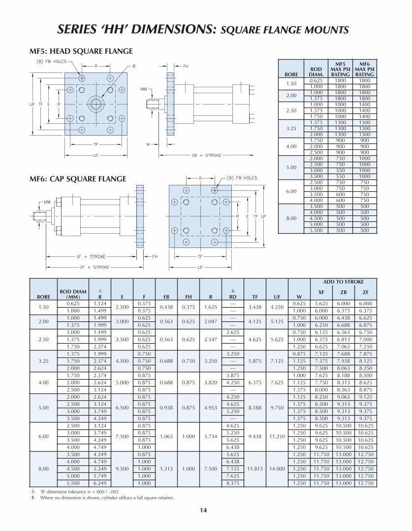
SERIES ‘HH’ DIMENSIONS: SQUARE FLANGE MOUNTS
BOREROD DIAM
(MM)<�
B E F FB FH R=�
RD TF UF W
ADD TO STROKE
xF ZB ZF
1.500.625 1.124
2.5000.375
0.438 0.375 1.625—
3.438 4.2500.625 5.625 6.000 6.000
1.000 1.499 0.375 — 1.000 6.000 6.375 6.375
2.001.000 1.499
3.0000.625
0.563 0.625 2.047—
4.125 5.1250.750 6.000 6.438 6.625
1.375 1.999 0.625 — 1.000 6.250 6.688 6.875
2.50
1.000 1.499
3.500
0.625
0.563 0.625 2.547
2.625
4.625 5.625
0.750 6.125 6.563 6.750
1.375 1.999 0.625 — 1.000 6.375 6.813 7.000
1.750 2.374 0.625 — 1.250 6.625 7.063 7.250
3.25
1.375 1.999
4.500
0.750
0.688 0.750 3.250
3.250
5.875 7.125
0.875 7.125 7.688 7.875
1.750 2.374 0.750 — 1.125 7.375 7.938 8.125
2.000 2.624 0.750 — 1.250 7.500 8.063 8.250
4.00
1.750 2.374
5.000
0.875
0.688 0.875 3.820
3.875
6.375 7.625
1.000 7.625 8.188 8.500
2.000 2.624 0.875 4.250 1.125 7.750 8.313 8.625
2.500 3.124 0.875 — 1.375 8.000 8.563 8.875
5.00
2.000 2.624
6.500
0.875
0.938 0.875 4.953
4.250
8.188 9.750
1.125 8.250 9.063 9.125
2.500 3.124 0.875 4.625 1.375 8.500 9.313 9.375
3.000 3.749 0.875 5.250 1.375 8.500 9.313 9.375
3.500 4.249 0.875 — 1.375 8.500 9.313 9.375
6.00
2.500 3.124
7.500
0.875
1.063 1.000 5.734
4.625
9.438 11.250
1.250 9.625 10.500 10.625
3.000 3.749 0.875 5.250 1.250 9.625 10.500 10.625
3.500 4.249 0.875 5.625 1.250 9.625 10.500 10.625
4.000 4.749 1.000 6.438 1.250 9.625 10.500 10.625
8.00
3.500 4.249
9.500
0.875
1.313 1.000 7.500
5.625
11.813 14.000
1.250 11.750 13.000 12.750
4.000 4.749 1.000 6.438 1.250 11.750 13.000 12.750
4.500 5.249 1.000 7.125 1.250 11.750 13.000 12.750
5.000 5.749 1.000 7.625 1.250 11.750 13.000 12.750
5.500 6.249 1.000 8.375 1.250 11.750 13.000 12.750
MF5: HEAD SQUARE FLANGE
MF6: CAP SQUARE FLANGE
14
< ‘B’ dimension tolerance is +.000 / -.002= Where no dimension is shown, cylinder utilizes a full square retainer.
BOREROD
DIAM.
MF5MAx PSIRATING
MF6MAx PSIRATING
1.500.625 1800 18001.000 1800 1800
2.001.000 1800 18001.375 1800 1800
2.501.000 1000 14001.375 1000 14001.750 1000 1400
3.251.375 1300 13001.750 1300 13002.000 1300 1300
4.001.750 900 9002.000 900 9002.500 900 900
5.00
2.000 750 10002.500 750 10003.000 550 10003.500 550 1000
6.00
2.500 750 7503.000 750 7503.500 600 7504.000 600 750
8.00
3.500 500 5004.000 500 5004.500 500 5005.000 500 5005.500 500 500

BOREROD DIAM
(MM) E E / 2 SB ST SU SW TS US xS
ADD TO STROKE
SS ZB
1.500.625
2.500 1.250 0.438 0.500 0.938 0.375 3.250 4.0001.375
3.8756.000
1.000 1.750 6.375
2.001.000
3.000 1.500 0.563 0.750 1.250 0.500 4.000 5.0001.875
3.6256.438
1.375 2.125 6.688
2.50
1.000
3.500 1.750 0.813 1.000 1.563 0.688 4.875 6.250
2.063
3.375
6.563
1.375 2.313 6.813
1.750 2.563 7.063
3.25
1.375
4.500 2.250 0.813 1.000 1.563 0.688 5.875 7.250
2.313
4.125
7.688
1.750 2.563 7.943
2.000 2.688 8.063
4.00
1.750
5.000 2.500 1.063 1.250 2.000 0.875 6.750 8.500
2.750
4.000
8.188
2.000 2.875 8.313
2.500 3.125 8.563
5.00
2.000
6.500 3.250 1.063 1.250 2.000 0.875 8.250 10.000
2.875
4.500
9.063
2.500 3.125 9.313
3.000 3.125 9.313
3.500 3.125 9.313
6.00
2.500
7.500 3.750 1.313 1.500 2.500 1.125 9.750 12.000
3.375
5.125
10.500
3.000 3.375 10.500
3.500 3.375 10.500
4.000 3.375 10.500
8.00
3.500
9.500 4.750 1.563 1.750 2.875 1.375 12.250 15.000
3.625
6.750
13.000
4.000 3.625 13.000
4.500 3.625 13.000
5.000 3.625 13.000
5.500 3.625 13.000
SERIES ‘HH’ DIMENSIONS: LUG MOUNTS
MS2: SIDE LUGS
MS3: CENTER LINE LUGS
15
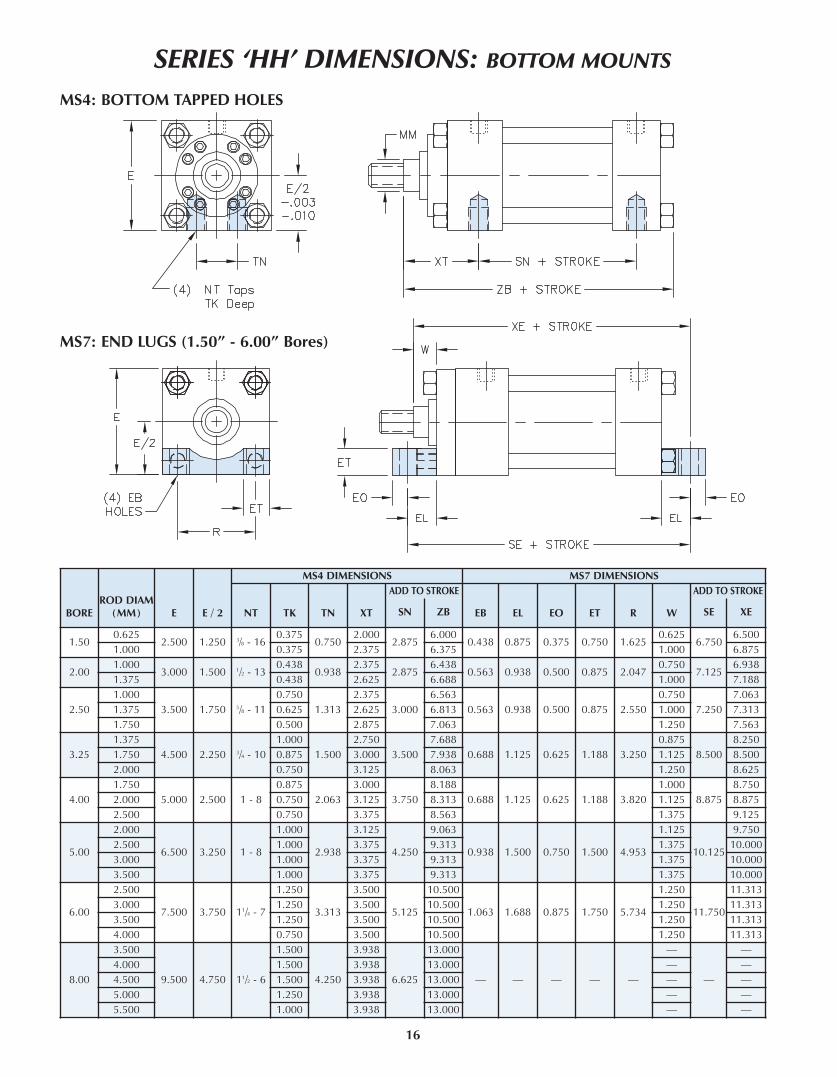
BOREROD DIAM
(MM) E E / 2
MS4 DIMENSIONS MS7 DIMENSIONS
NT TK TN xT
ADD TO STROKE
EB EL EO ET R W
ADD TO STROKE
SN ZB SE xE
1.500.625
2.500 1.250 3/8 - 160.375
0.7502.000
2.8756.000
0.438 0.875 0.375 0.750 1.6250.625
6.7506.500
1.000 0.375 2.375 6.375 1.000 6.875
2.001.000
3.000 1.500 1/2 - 130.438
0.9382.375
2.8756.438
0.563 0.938 0.500 0.875 2.0470.750
7.1256.938
1.375 0.438 2.625 6.688 1.000 7.188
2.50
1.000
3.500 1.750 5/8 - 11
0.750
1.313
2.375
3.000
6.563
0.563 0.938 0.500 0.875 2.550
0.750
7.250
7.063
1.375 0.625 2.625 6.813 1.000 7.313
1.750 0.500 2.875 7.063 1.250 7.563
3.25
1.375
4.500 2.250 3/4 - 10
1.000
1.500
2.750
3.500
7.688
0.688 1.125 0.625 1.188 3.250
0.875
8.500
8.250
1.750 0.875 3.000 7.938 1.125 8.500
2.000 0.750 3.125 8.063 1.250 8.625
4.00
1.750
5.000 2.500 1 - 8
0.875
2.063
3.000
3.750
8.188
0.688 1.125 0.625 1.188 3.820
1.000
8.875
8.750
2.000 0.750 3.125 8.313 1.125 8.875
2.500 0.750 3.375 8.563 1.375 9.125
5.00
2.000
6.500 3.250 1 - 8
1.000
2.938
3.125
4.250
9.063
0.938 1.500 0.750 1.500 4.953
1.125
10.125
9.750
2.500 1.000 3.375 9.313 1.375 10.000
3.000 1.000 3.375 9.313 1.375 10.000
3.500 1.000 3.375 9.313 1.375 10.000
6.00
2.500
7.500 3.750 11/4 - 7
1.250
3.313
3.500
5.125
10.500
1.063 1.688 0.875 1.750 5.734
1.250
11.750
11.313
3.000 1.250 3.500 10.500 1.250 11.313
3.500 1.250 3.500 10.500 1.250 11.313
4.000 0.750 3.500 10.500 1.250 11.313
8.00
3.500
9.500 4.750 11/2 - 6
1.500
4.250
3.938
6.625
13.000
— — — — —
—
—
—
4.000 1.500 3.938 13.000 — —
4.500 1.500 3.938 13.000 — —
5.000 1.250 3.938 13.000 — —
5.500 1.000 3.938 13.000 — —
SERIES ‘HH’ DIMENSIONS: BOTTOM MOUNTS
MS4: BOTTOM TAPPED HOLES
MS7: END LUGS (1.50” - 6.00” Bores)
16

SERIES ‘HH’ DIMENSIONS: PIVOT MOUNT & EXTENDED KEYPLATE
ExTENDED KEYPLATE (‘EK’ OPTION)
MP1: REAR PIVOT CLEVIS
BOREROD DIAM
(MM) E
ExTENDED KEYPLATE MP1 DIMENSINONS
FA FH PA CB < CD = CW F L LR M MR
ADD TO STROKE
LB xC
1.500.625
2.500 0.312 / 0.314 0.375 0.188 0.750 0.500 0.5000.375
0.7500.563
0.500 0.625 4.6256.375
1.000 0.375 0.563 6.750
2.001.000
3.000 0.562 / 0.564 0.625 0.313 1.250 0.750 0.6250.625
1.2501.000
0.750 0.938 4.6257.250
1.375 0.625 1.000 7.500
2.50
1.000
3.500 0.562 / 0.564 0.625 0.313 1.250 0.750 0.625
0.625
1.250
1.000
0.750 0.938 4.750
7.375
1.375 0.625 1.000 7.625
1.750 0.625 1.000 7.875
3.25
1.375
4.500 0.687 / 0.689 0.750 0.375 1.500 1.000 0.750
0.750
1.500
1.250
1.000 1.188 5.500
8.625
1.750 0.750 1.250 8.875
2.000 0.750 1.250 9.000
4.00
1.750
5.000 0.812 / 0.814 0.875 0.438 2.000 1.375 1.000
0.875
2.125
1.875
1.375 1.625 5.750
9.750
2.000 0.875 1.875 9.875
2.500 0.875 1.875 10.125
5.00
2.000
6.500 0.812 / 0.814 0.875 0.438 2.500 1.750 1.250
0.875
2.250
2.000
1.750 2.125 6.250
10.500
2.500 0.875 2.000 10.750
3.000 0.875 2.000 10.750
3.500 0.875 2.000 10.750
6.00
2.500
7.500 0.937 / 0.939 1.000 0.500 2.500 2.000 1.250
0.875
2.500
2.063
2.000 2.375 7.375
12.125
3.000 0.875 2.188 12.125
3.500 0.875 2.188 12.125
4.000 1.000 2.188 12.125
8.00
3.500
9.500 0.937 / 0.939 1.000 0.500 3.000 3.000 1.500
0.875
3.250
2.938
2.750 3.125 9.500
15.000
4.000 1.000 2.938 15.000
4.500 1.000 2.938 15.000
5.000 1.000 2.938 15.000
5.500 1.000 2.938 15.000
17
NOTE: PIVOT PIN INCLUDED WITH CYLINDER
< ‘CB’ dimension tolerance is +.010 to +.030 depending on bore size.= ‘CD’ dimension tolerance for pin is ±.001.

18
Mx0D: NO MOUNT
SERIES ‘HH’ DIMENSIONS: DOUBLE END MOUNTS
BOREROD DIA
(MM)E A
<�
B CEE
F G K KK R=�
RD V Y
ADD TOSTROKE
ADD 2xSTROKE
NPTF SAE LD P ZM
1.500.625
2.5000.750 1.124 0.375
1/210 0.375
1.750 0.375SE
E R
OD
EN
D D
ETA
IL C
HA
RT O
N P
AG
E 6
1.625— 0.250 2.000
4.875 2.8756.875
1.000 1.125 1.499 0.500 8 0.375 — 0.500 2.375 7.625
2.001.000
3.0001.125 1.499 0.500
1/210 0.625
1.750 0.438 2.047— 0.250 2.375
4.875 2.8757.625
1.375 1.625 1.999 0.625 8 0.625 — 0.375 2.625 8.125
2.50
1.000
3.500
1.125 1.499 0.500
1/2
10 0.625
1.750 0.438 2.547
2.625 0.250 2.375
5.000 3.000
7.750
1.375 1.625 1.999 0.625 10 0.625 — 0.375 2.625 8.250
1.750 2.000 2.374 0.750 10 0.625 — 0.500 2.875 8.750
3.25
1.375
4.500
1.625 1.999 0.625
3/4
12 0.750
2.000 0.563 3.250
3.250 0.250 2.750
5.750 3.500
9.000
1.750 2.000 2.374 0.750 12 0.750 — 0.375 3.000 9.500
2.000 2.250 2.624 0.875 12 0.750 — 0.375 3.125 9.750
4.00
1.750
5.000
2.000 2.374 0.750
3/4
12 0.875
2.000 0.563 3.820
3.875 0.250 2.938
6.000 3.875
9.750
2.000 2.250 2.624 0.875 12 0.875 4.250 0.250 3.063 10.000
2.500 3.000 3.124 1.000 12 0.875 — 0.375 3.313 10.500
5.00
2.000
6.500
2.250 2.624 0.875
3/4
12 0.875
2.000 0.813 4.953
4.250 0.250 3.125
6.500 4.250
10.500
2.500 3.000 3.124 1.000 12 0.875 4.625 0.375 3.375 11.000
3.000 3.500 3.749 1.000 12 0.875 5.250 0.375 3.375 11.000
3.500 3.500 4.249 1.000 12 0.875 — 0.375 3.375 11.000
6.00
2.500
7.500
3.000 3.124 1.000
1
16 0.875
2.250 0.875 5.734
4.625 0.375 3.500
7.375 4.875
11.875
3.000 3.500 3.749 1.000 16 0.875 5.250 0.375 3.500 11.875
3.500 3.500 4.249 1.000 16 0.875 5.625 0.375 3.500 11.875
4.000 4.000 4.749 1.000 16 1.000 6.438 0.250 3.500 11.875
8.00
3.500
9.500
3.500 4.249 1.000
11/2
24 0.875
3.000 1.250 7.500
5.625 0.375 3.938
9.500 6.125
14.000
4.000 4.000 4.749 1.000 24 1.000 6.438 0.250 3.938 14.000
4.500 4.500 5.249 1.000 24 1.000 7.125 0.250 3.938 14.000
5.000 5.000 5.749 1.000 24 1.000 7.625 0.250 3.938 14.000
5.500 5.500 6.249 1.000 24 1.000 8.375 0.250 3.938 14.000
< ‘B’ dimension tolerance is +.000 / -.002= Where no dimension is shown, cylinder utilizes a full square retainer.

19
SERIES ‘HH’ DIMENSIONS: DOUBLE END MOUNTS
ME5D: HEAD RECTANGULAR MOUNTING HOLES
BOREROD DIA
(MM)E F FB G R RD RS TF UF WF
ADD 2xSTROKE
ZM
1.500.625
2.5000.375
0.438 1.750 1.6252.375 —
3.438 4.2501.000 6.875
1.000 0.375 2.563 2.438 1.375 7.625
2.001.000
3.0000.625
0.563 1.750 2.0472.625 —
4.125 5.1251.375 7.625
1.375 0.625 3.250 2.938 1.625 8.125
2.50
1.000
3.500
0.625
0.563 1.750 2.547
2.625 —
4.625 5.625
1.375 7.750
1.375 0.625 3.250 — 1.625 8.250
1.750 0.625 3.875 3.438 1.875 8.750
3.25
1.375
4.500
0.750
0.688 2.000 3.250
3.250 —
5.875 7.125
1.625 9.000
1.750 0.750 3.875 — 1.875 9.500
2.000 0.750 4.250 — 2.000 9.750
4.00
1.750
5.000
0.875
0.688 2.000 3.820
3.875 —
6.375 7.625
1.875 9.750
2.000 0.875 4.250 — 2.000 10.000
2.500 0.875 4.625 — 2.250 10.500
5.00
2.000
6.500
0.875
0.938 2.000 4.953
4.250 —
8.188 9.750
2.000 10.500
2.500 0.875 4.625 — 2.250 11.000
3.000 0.875 5.250 — 2.250 11.000
3.500 0.875 5.625 — 2.250 11.000
6.00
2.500
7.500
0.875
1.063 2.250 5.725
4.625 —
9.438 11.250
2.250 11.875
3.000 0.875 5.250 — 2.250 11.875
3.500 0.875 5.625 — 2.250 11.875
4.000 1.000 6.438 — 2.250 11.875
8.00
3.500
9.500
0.875
1.313 3.000 7.500
5.625 —
11.813 14.000
2.250 14.000
4.000 1.000 6.438 — 2.250 14.000
4.500 1.000 7.125 — 2.250 14.000
5.000 1.000 7.625 — 2.250 14.000
5.500 1.000 8.375 — 2.250 14.000

20
SERIES ‘HH’ DIMENSIONS: DOUBLE END MOUNTS
BOREROD DIA
(MM)
MAx PSI RATING < E
=�
B FH FB R TF UF WADD 2xSTROKE
MF1D MF5D ZM
1.500.625 2600 1800
2.5001.124
0.375 0.438 1.625 3.438 4.2500.625 6.875
1.000 1600 1800 1.499 1.000 7.625
2.001.000 2600 1800
3.0001.499
0.625 0.563 2.047 4.125 5.1250.750 7.625
1.375 1600 1800 1.999 1.000 8.125
2.50
1.000 2600 1000
3.500
1.499
0.625 0.563 2.547 4.625 5.625
0.750 7.750
1.375 2000 1000 1.999 1.000 8.250
1.750 1600 1000 2.374 1.250 8.750
3.25
1.375 2600 1300
4.500
1.999
0.750 0.688 3.250 5.875 7.125
0.875 9.000
1.750 2200 1300 2.374 1.125 9.500
2.000 1600 1300 2.624 1.250 9.750
4.00
1.750 2600 900
5.000
2.374
0.875 0.688 3.820 6.375 7.625
1.000 9.750
2.000 1900 900 2.624 1.125 10.000
2.500 1600 900 3.124 1.378 10.500
5.00
2.000 2200 750
6.500
2.624
0.875 0.938 4.953 8.188 9.750
1.125 10.500
2.500 1600 750 3.124 1.375 11.000
3.000 1200 550 3.749 1.375 11.000
3.500 750 550 4.249 1.375 11.000
6.00
2.500 1800 750
7.500
3.124
1.000 1.063 5.725 9.438 11.250
1.250 11.875
3.000 1450 750 3.749 1.250 11.875
3.500 1100 600 4.249 1.250 11.875
4.000 750 600 4.749 1.250 11.875
8.00
3.500 900 500
9.500
4.249
1.000 1.313 7.500 11.813 14.000
1.250 14.000
4.000 800 500 4.749 1.250 14.000
4.500 700 500 5.249 1.250 14.000
5.000 500 500 5.749 1.250 14.000
5.500 500 500 6.249 1.250 14.000
MF1D: HEAD FLANGE
MF5D: HEAD SQUARE FLANGE
< Maximum pressure rating= ‘B’ dimension tolerance is +.000 / -.002

21
MS2D: SIDE LUGS
SERIES ‘HH’ DIMENSIONS: DOUBLE END MOUNTS
BORERODDIAM(MM)
E E / 2 SB ST SU SW TS US xSADD TOSTROKE
ADD 2xSTROKE
SSD ZM
1.500.625
2.500 1.250 0.438 0.500 0.938 0.375 3.250 4.0001.375
4.1256.875
1.000 1.750 7.625
2.001.000
3.000 1.500 0.563 0.750 1.250 0.500 4.000 5.0001.875
3.8757.625
1.375 2.125 8.125
2.50
1.000
3.500 1.750 0.813 1.000 1.563 0.688 4.875 6.250
2.063
3.625
7.750
1.375 2.313 8.250
1.750 2.563 8.750
3.25
1.375
4.500 2.250 0.813 1.000 1.563 0.688 5.875 7.250
2.313
4.375
9.000
1.750 2.563 9.500
2.000 2.688 9.750
4.00
1.750
5.000 2.500 1.063 1.250 2.000 0.875 6.750 8.500
2.750
4.250
9.750
2.000 2.875 10.000
2.500 3.125 10.500
5.00
2.000
6.500 3.250 1.063 1.250 2.000 0.875 8.250 10.000
2.875
4.750
10.500
2.500 3.125 11.000
3.000 3.125 11.000
3.500 3.125 11.000
6.00
2.500
7.500 3.750 1.313 1.500 2.500 1.125 9.750 12.000
3.375
5.125
11.875
3.000 3.375 11.875
3.500 3.375 11.875
4.000 3.375 11.875
8.00
3.500
9.500 4.750 1.563 1.750 2.875 1.375 12.250 15.000
3.625
6.750
14.000
4.000 3.625 14.000
4.500 3.625 14.000
5.000 3.625 14.000
5.500 3.625 14.000
MS3D: CENTER LINE LUGS
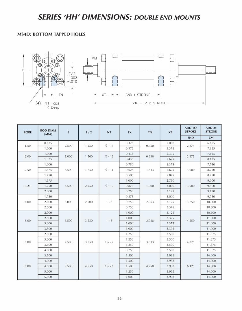
22
BOREROD DIAM
(MM)E E / 2 NT TK TN xT
ADD TOSTROKE
ADD 2xSTROKE
SND ZM
1.500.625
2.500 1.250 3/8 - 160.375
0.7502.000
2.8756.875
1.000 0.375 2.375 7.625
2.001.000
3.000 1.500 1/2 - 130.438
0.9382.375
2.8757.625
1.375 0.438 2.625 8.125
2.50
1.000
3.500 1.750 5/8 - 11
0.750
1.313
2.375
3.000
7.750
1.375 0.625 2.625 8.250
1.750 0.500 2.875 8.750
3.25
1.375
4.500 2.250 3/4 - 10
1.000
1.500
2.750
3.500
9.000
1.750 0.875 3.000 9.500
2.000 0.750 3.125 9.750
4.00
1.750
5.000 2.500 1 - 8
0.875
2.063
3.000
3.750
9.750
2.000 0.750 3.125 10.000
2.500 0.750 3.375 10.500
5.00
2.000
6.500 3.250 1 - 8
1.000
2.938
3.125
4.250
10.500
2.500 1.000 3.375 11.000
3.000 1.000 3.375 11.000
3.500 1.000 3.375 11.000
6.00
2.500
7.500 3.750 11/4 - 7
1.250
3.313
3.500
4.875
11.875
3.000 1.250 3.500 11.875
3.500 1.250 3.500 11.875
4.000 0.750 3.500 11.875
8.00
3.500
9.500 4.750 11/2 - 6
1.500
4.250
3.938
6.125
14.000
4.000 1.500 3.938 14.000
4.500 1.500 3.938 14.000
5.000 1.250 3.938 14.000
5.500 1.000 3.938 14.000
MS4D: BOTTOM TAPPED HOLES
SERIES ‘HH’ DIMENSIONS: DOUBLE END MOUNTS

23
MS7D: END LUGS <
BOREROD DIAM
(MM)E E / 2 EB EL EO ET R
ADD TO STROKEADD 2xSTROKE
SED xED ZM
1.500.625 2.500 1.250 0.438 0.875 0.375 0.750 1.625 7.375 7.125 6.875
1.000 Not Available
2.001.000 3.000 1.500 0.563 0.938 0.500 0.875 2.047 8.000 7.688 7.625
1.375 Not Available
2.50
1.0003.500 1.750 0.563 0.938 0.500 0.875 2.547 8.125
7.938 7.750
1.375 8.188 8.250
2.000 Not Available
3.25
1.375
4.500 2.250 0.688 1.125 0.625 1.188 3.250 9.500
9.250 9.000
1.750 9.500 9.500
2.000 9.625 9.750
4.00
1.7505.000 2.500 0.688 1.125 0.625 1.188 3.820 10.000
9.875 9.750
2.000 10.000 10.000
2.500 Not Available
5.00
2.000
6.500 3.250 0.938 1.500 0.750 1.500 4.953 11.250
10.875 10.500
2.500 11.125 11.000
3.000 11.125 11.000
3.500 Not Available
6.00
2.500
7.500 3.750 1.063 1.688 0.875 1.750 5.734 12.750
12.313 11.875
3.000 12.313 11.875
3.500 12.313 11.875
4.000 12.313 11.875
SERIES ‘HH’ DIMENSIONS: DOUBLE END MOUNTS
< When using this mount, the cylinder feet, head & cap are to be firmly supported.

24
SERIES ‘HH’ DIMENSIONS: DOUBLE END MOUNTS
BOREROD DIA
(MM)E BD TD TL TM UM UT UV xG
MT4MIN
STROKE
MT4xI
MIN
ADDSTROKE
ADD 2xSTROKE
MT4 xI MAx ZM
1.500.625
2.500 1.500 1.000 1.000 3.000 5.000 4.500 3.0001.875
0.2503.500 3.250 6.875
1.000 2.250 3.875 3.625 7.625
2.001.000
3.000 1.500 1.375 1.375 3.500 6.250 5.750 3.5002.250
0.2504.000 3.750 7.625
1.375 2.500 4.250 4.000 8.125
2.50
1.000
3.500 1.500 1.375 1.375 4.000 6.750 6.250 4.000
2.250
0.375
4.102 3.750 7.750
1.375 2.500 4.375 4.000 8.250
1.750 2.750 4.625 4.250 8.750
3.25
1.375
4.500 2.000 1.750 1.750 5.000 8.500 8.000 5.000
2.625
0.875
5.000 4.125 9.000
1.750 2.875 5.250 4.375 9.500
2.000 3.000 5.375 4.500 9.750
4.00
1.750
5.000 2.000 1.750 1.750 5.500 9.000 8.500 5.500
2.875
1.125
5.500 4.375 9.750
2.000 3.000 5.625 4.500 10.000
2.500 3.250 5.875 4.750 10.500
5.00
2.000
6.500 2.500 1.750 1.750 7.000 10.500 10.000 7.250
3.000
1.125
5.875 4.750 10.500
2.500 3.250 6.125 5.000 11.000
3.000 3.250 6.125 5.000 11.000
3.500 3.250 6.125 5.000 11.000
6.00
2.500
7.500 3.000 2.000 2.000 8.500 12.500 11.500 8.750
3.375
1.250
6.625 5.375 11.875
3.000 3.375 6.625 5.375 11.875
3.500 3.375 6.625 5.375 11.875
4.000 3.375 6.625 5.375 11.875
8.00
3.500
9.500 3.500 3.000 3.000 11.000 17.000 15.500 11.750
3.750
2.125
8.125 6.000 14.000
4.000 3.750 8.125 6.000 14.000
4.500 3.750 8.125 6.000 14.000
5.000 3.750 8.125 6.000 14.000
5.500 3.750 8.125 6.000 14.000
MT1D: HEAD TRUNNION
MT4D: INTERMEDIATE TRUNNION

25
SERIES ‘HH’ DIMENSIONS: DOUBLE END MOUNTS
Mx1D: ExTENDED TIE-RODS - HEAD & CAP
Mx3D: ExTENDED TIE-RODS - HEAD END
BOREROD DIA
(MM)E AA BB DD FH K R W
ADD TOSTROKE
ADD 2xSTROKE
LD ZM
1.500.625
2.500 2.300 1.375 3/8 - 24 0.375 0.375 1.6250.625
4.8756.875
1.000 1.000 7.625
2.001.000
3.000 2.900 1.813 1/2 - 20 0.625 0.438 2.0470.750
4.8757.625
1.375 1.000 8.125
2.50
1.000
3.500 3.600 1.813 1/2 - 20 0.625 0.438 2.547
0.750
5.000
7.750
1.375 1.000 8.250
1.750 1.250 8.750
3.25
1.375
4.500 4.600 2.313 5/8 - 18 0.750 0.563 3.250
0.875
5.750
9.000
1.750 1.125 9.500
2.000 1.250 9.750
4.00
1.750
5.000 5.400 2.313 5/8 - 18 0.875 0.563 3.820
1.000
6.000
9.750
2.000 1.125 10.000
2.500 1.375 10.500
5.00
2.000
6.500 7.000 3.188 7/8 - 14 0.875 0.813 4.953
1.125
6.500
10.500
2.500 1.375 11.000
3.000 1.375 11.000
3.500 1.375 11.000
6.00
2.500
7.500 8.100 3.625 1 - 14 1.000 0.875 5.734
1.250
7.375
11.875
3.000 1.250 11.875
3.500 1.250 11.875
4.000 1.250 11.875
8.00
3.500
9.500 10.600 4.500 11/4 - 12 1.000 1.250 7.500
1.250
9.500
14.000
4.000 1.250 14.000
4.500 1.250 14.000
5.000 1.250 14.000
5.500 1.250 14.000

The TRD difference...TRD’s floating rod bushing design and RL Series Rod Lock = OPTIMIZED RESULTS andSUPERIOR PERFORMANCE.
For rod locks to achieve the rated holding force and maximize cycle life, good alignment mustbe maintained between the locking mechanism and cylinder rod. With TRD’s Floating RodBushing design and accurate rod lock alignment - superior performance and trouble-freeoperation are assured.
Rod locks are used to hold linear cylinder loads stationary in any mounting orientation during“power off” condition. Units will lock in both directions to rated holding force. They are notdesigned to withstand rotational loads or to “brake” the load in dynamic applications. TRDoffers each rod lock model in three different holding force, depending on available releasepressure.
Refer to page 23 for minimum release pressure and corresponding holding force.
SERIES ‘HH’ WITH HYDRAULIC ROD LOCK
OPERATING PRINCIPAL
26
OPERATING PRESSURECylinder Refer to Cylinder Mount RatingRod Lock (Low PSI) 750 to 3000 PSI HYD.Rod Lock (Med PSI) 1000 to 3000 PSI HYD.Rod Lock (High PSI) 1500 to 3000 PSI HYD.
AxIAL MOVEMENT (CLAMPED) *Load Direction A .000”Load Direction B .012” Max.
* Represents clearance within the rod lock unit, .000”
movement due to actuation.
OPERATING TEMPERATUREStandard Seals 20°F to 200°F (-29°C to 93°C)
Fluorocarbon Seals 0°F to 400°F (-18°C to 204°C)
ROD MATERIAL REQUIREMENTSDiameter +.000” to -.002” Nominal Diameter
Hardened Shaft .0005” Minimum hard chromeFinish 6 to 10 micro-inch
Hydraulic PSI Exhausted, ZERO back pressure
Load ALoad B
3000 PSI (Max) Release Pressure
Air Vent Plug Balluff Prox. Switch(Optional)
CLAMPING (Locked) CONDITION:When hydraulic pressure is exhausted from rod lock,extreme spring force is applied to the piston/outer lockhousing which utilizes an ultra-fine tapered wedge,transferring the spring force directly to the rod.Clamping action does not move or disturb the rod,maintaining rod position during actuation.
UNCLAMPED CONDITION:When hydraulic pressure is applied to rod lock, thehydraulic pressure overcomes the spring force, mov-ing Piston Outer Locking Housing. This movementprovides clearance between the rod lock and pistonrod which allows free rod movement.
ROD “LOCKED”
ROD “FREE MOVING”
CLAMP SPECIFICATIONSResponse Time 100 ms (Clamp); 100 ms (Un-clamp)
Average Life 1,000,000 Clamp Cycles

RODSIZE
BORE MODEL NUMBER
<MIN.
RELEASEPSI
=MAx
HOLDINGFORCE
VOLUMEOF OIL WEIGHT
(LBS)CM3 IN3
1.750 3.25
RLH-175325750 750 8,200
30 1.8 65.1RLH-1753251000 1000 11,500
RLH-1753251500 1500 16,000
1.750 4.00
RLH-175400750 750 8,200
39 2.4 75.5RLH-1754001000 1000 12,000
RLH-1754001500 1500 17,000
2.000 3.25
RLH-200325750 750 8,200
39 2.4 64.0RLH-2003251000 1000 11,500
RLH-2003251500 1500 16,000
2.000 5.00
RLH-200500750 750 8,200
39 2.4 114.0RLH-2005001000 1000 12,000
RLH-2005001500 1500 17,000
2.500 6.00
RLH-250600750 750 30,000
129 7.9 270.0RLH-2506001000 1000 36,000
RLH-2506001500 1500 50,000
3.000 6.00RLH-300600750 750 17,000
129 7.9 260.0RLH-3006001000 1000 22,500
3.500 8.00
RLH-350800750 750 40,000
181 11.0 550.0RLH-3508001000 1000 55,000
RLH-3508001500 1500 80,000
4.000 8.00
RLH-400800750 750 40,000
230 14.0 530.0RLH-4008001000 1000 55,000
RLH-4008001500 1500 80,000
HOW TO ORDER: SERIES ‘HH’ WITH ROD LOCK
HH - ME5 - ___ - 2.50 x 10 - H2C6 - 100 - KK1 - P15 = N375 - S S S S -
NFPA MOUNT (TO MOUNT CYLINDER)
MF2 CAP RECTANGULAR FLANGE (1.50” to 6.00” Bore)
MF5 SQUARE FLANGE, HEAD END (1.50” to 8.00” Bore)
MF6 SQUARE FLANGE, CAP END (1.50” to 8.00” Bore)
MP1 FIXED CAP PIVOT CLEVIS (1.50” to 8.00” Bore)
MS2 SIDE LUGS (1.50” to 8.00” Bore)
MS3 CENTER LINE LUGS (1.50” to 8.00” Bore)
MS4 BOTTOM TAPPED HOLES (1.50” to 8.00” Bore)
MS7 END LUGS (1.50” to 8.00” Bore)
MT1 HEAD TRUNNION (1.50” to 8.00” Bore)
MT2 CAP TRUNNION (1.50” to 8.00” Bore)
MT4 INTERMEDIATE (CENTER) TRUNNION (1.50” to 8.00” Bore)
OPTIONS
RLHROD LOCK READY CYLINDERNO ROD LOCK INSTALLED
RLH=MODEL NUMBERCYLINDER WITH INSTALLED ROD LOCKExample: RLH=100250750
REQUIRED MOUNT
ME5HEAD RECTANGULARMOUNT (1.50” to 8.00” Bore)
TECHNICAL DATA: ROD LOCKS
See page 5 for additional cylinder How-to-Order information.
Rod Lock Model Numbers
RLH= 100 250 750
RODSIZE
062
100
137
175
200
BORE
150
200
250
325
400
500
600
800
RELEASEPSI
750
1000
1500
OPTIONS
PProximity
Switch Ready
VFluorocarbon
Seals
XSpecial
(Specify)
Replacement Rod Locks can beordered using the same methodology. Examples: RLH-1374001500RLH-100250750P
< Maximum hydraulic release pressure: 3000 PSI.= Holding forces are based on dry or mineral-oil lubricated shafts.
27
RODSIZE
BORE MODEL NUMBER
<MIN.
RELEASEPSI
=MAx
HOLDINGFORCE
VOLUMEOF OIL WEIGHT
(LBS)CM3 IN3
0.625 1.50
RLH-625150750 750 1,100
6 0.4 11.5RLH-6251501000 1000 1,800
RLH-6251501500 1500 2,250
1.000 1.50
RLH-100150750 750 1,200
6 0.4 10.5RLH-1001501000 1000 2,000
RLH-1001501500 1500 2,300
1.000 2.00
RLH-100200750 750 2,900
16 1.0 20.8RLH-1002001000 1000 5,200
RLH-1002001500 1500 5,600
1.000 2.50
RLH-100250750 750 2,900
16 1.0 31.0RLH-1002501000 1000 5,200
RLH-1002501500 1500 6,000
1.375 2.00
RLH-137200750 750 2,700
10 0.6 20.0RLH-1372001000 1000 2,700
RLH-1372001500 1500 5,200
1.375 2.50
RLH-137250750 750 2,700
16 1.0 30.2RLH-1372501000 1000 5,200
RLH-1372501500 1500 6,000
1.375 3.25
RLH-137325750 750 8,200
30 1.8 66.0RLH-1373251000 1000 11,500
RLH-1373251500 1500 16,000
1.750 2.50
RLH-175250750 750 3,500
16 1.0 29.5RLH-1752501200 1200 5,200
RLH-1752502000 2000 7,500

SERIES HH WITH ROD LOCK: BASIC CYLINDER ME5 (No Mount)
To be able to handle the high holding forces, the rod lock cylinder uses a ME5 full rectangle cylinder head and full rectanglebushing retainer plate to mount the rod lock unit to the cylinder.
Customers need to specify an additional mount to attach cylinder in the application.
Refer to pages 6 through 17 for basic cylinder dimensions not shown.
< Air Vent Plug.= M12x1 port for optional proximity switch (indicates unclamped condition).
28
RODDIA
(MM) BORE D E FH TF UF UW RL RLC RLEE RLF RLG RLJ RLP RLY
ADD TOSTROKE
RLZB
0.625 1.50 4.370 2.500 0.375 3.438 4.250 3.250 3.547 0.375 SAE 4 2.125 0.750 0.790 3.500 1.740 8.930
1.000 1.50 4.370 2.500 0.375 3.438 4.250 3.500 3.453 0.500 SAE 4 1.875 0.870 0.790 3.250 2.010 8.947
1.000 2.00 5.375 3.000 0.625 4.125 5.125 4.500 4.375 0.500 SAE 4 2.900 0.850 1.000 4.531 1.910 10.120
1.000 2.50 5.984 3.500 0.625 4.625 5.625 5.000 5.125 0.500 SAE 4 3.400 1.000 1.500 5.031 2.160 11.000
1.375 2.00 5.370 3.000 0.625 4.125 5.125 4.500 4.650 0.625 SAE 4 3.000 1.000 1.500 4.625 2.210 10.531
1.375 2.50 5.984 3.500 0.625 4.625 5.625 5.000 5.125 0.625 SAE 4 3.400 0.900 1.500 5.031 2.280 11.120
1.375 3.25 7.750 4.500 0.750 5.875 7.125 6.500 6.500 0.625 SAE 4 4.500 1.100 2.600 6.375 2.625 13.375
1.750 2.50 5.984 3.500 0.625 4.625 5.625 5.000 5.900 0.750 SAE 4 3.900 0.960 2.438 5.531 2.700 12.040
1.750 3.25 7.750 4.500 0.750 5.875 7.125 6.500 6.500 0.750 SAE 4 4.672 0.930 2.600 6.547 2.580 13.500
1.750 4.00 8.375 5.000 0.875 6.375 7.625 7.000 6.500 0.750 SAE 4 4.375 1.230 2.200 6.313 2.810 13.875
2.000 3.25 7.750 4.500 0.750 5.875 7.125 6.500 6.500 0.875 SAE 4 4.438 1.160 2.600 6.313 2.938 13.625
2.000 5.00 11.250 6.500 0.875 8.188 9.750 7.000 6.500 0.875 SAE 4 4.375 1.230 2.200 6.375 3.000 14.500
2.500 6.00 12.750 7.500 0.875 9.438 11.250 10.000 9.000 1.000 SAE 8 6.625 1.125 3.000 8.750 3.375 18.250
3.000 6.00 12.750 7.500 0.875 9.438 11.250 10.000 9.000 1.000 SAE 8 4.875 1.100 3.110 7.000 5.125 18.250
3.500 8.00 16.140 9.500 0.875 11.813 14.000 14.000 11.500 1.000 SAE 10 8.938 1.320 5.350 11.500 3.563 22.875
4.000 8.00 16.140 9.500 1.000 11.813 14.000 14.000 11.500 1.000 SAE 10 8.875 1.370 5.350 11.563 3.625 23.000

Rod Lock Hydraulic Circuit and Automatic Air Bleed Valve
In most applications, the sample circuit in figure 1 is used to actuate the rod lock. To “release” (unclamp) the rod lock, the3-way valve is energized, supplying pressure to the rod lock. In power failure modes, E-Stop, loss of hydraulic pressure, etc.,pressure is removed from the rod lock- spring energized rod lock “clamps” the rod holding it in place.
Avoid designs where the piston rod is moved while rod lock is actuated (clamped condition); piston rod and rod lockdamage may occur. Do not exceed the maximum holding force of the rod lock unit.
Air Bleeder
p
Recommendedif pressure spike occurif pressure not constant
Automatic Air Bleed Valve ABV-1
All rod lock units have a very short activation stroke and quick (100ms) response. It ishighly recommended that all air be removed from the rod lock unit. Trapped air at highpressure and frequent cycling can cause ignition of the air-oil mixture, causing miniexplosions (dieseling ) to occur- which will lead to seal failure.
To avoid trapped air, an Automatic Air Bleed Valve (or similar component) should beinstalled between the rod lock and the oil reservoir. Locate the ABV-1 as near as possible to the rod lock, in the port with the highest elevation (see figures 2 and 3).
ABV-1 Operation
The Automatic Air Bleed Valve (ABV-1)opens slightly each time pressure isremoved from the rod lock, allowing air toescape back to the oil resevoir.
For proper operation, back pressureexceeding 30 PSI (2 bar) should be avoid-ed between the ABV-1 and oil resevoir.
2.5
”[6
3.5
mm
]
SIT-EMMEA-4
AIR BLEEDP/N: SIT-EMMEA-4 G 1/4
Part Number: ABV-1(Order separately)
Note: Use NPTF fittings to install
Figure 2: Vertical Mount Figure 3: Horizontal Mount
Figure 1
29

ROD LOCK SENSORS (For Unclamped Condition)
An inductive proximity switch (with M12 x 1 thread) can be used to sensethe rod lock “unclamped” (free moving rod) condition.(BALLUFF Model: BES 516325S4)
PROxIMITY SENSOR INSTALLATION INSTRUCTIONS
1) Apply hydraulic pressure to rod lock (unclamped condition).
2) Assemble the proximity sensor jam nut and lock tooth washer to the proximity sensor. Thread the proximity sensor (byhand) into the M12 x 1 rod lock threaded port until it contacts the internal steel piston.
3) Back the proximity sensor out 1 full turn. While holding the proximity sensor’s position, tighten the jam nut to 15 ft-lbs(do not over torque).
4) With electrical power off, connect the proximity sensor electric wiring per the diagram included with the sensor. Whenthe electrical power is on, the proximity sensor LED should be “On”, indicating an unclamped condition. Slightadjustments may be necessary to set proximity sensor for proper operation.
5) Remove the hydraulic pressure to the rod lock, the proximity sensor LED should go “Off”, indicating the “clamped”conditions.
ROD LOCK INSTALLATION INSTRUCTIONS1) Using a flexible hydraulic rated hose, apply hydraulic pressure to the rod lock unit (refer�to�model�number�for�specific�rod
lock�hydraulic�release�pressure.)
2) With the rod lock counter-bored end facing the cylinder rod end, align rod lock to rod. Using care not to damage rodlock seals or bearings, slide the rod lock onto the piston rod until it contacts the cylinder mounting surface. Rod lockshould fully contact the cylinder.
3) Remove the hydraulic pressure to the rod lock. Torque cylinder tie rod nuts a little at a time, in a clockwise rotation,finishing with the proper cylinder tie rod torque. Refer�to�torque�charts�on�page�51.
4) Cycle the rod lock unit on and off several times. With pressure applied, the cylinder rod should move freely by hand.
5) If the cylinder rod does not move freely, remove the rod lock and repeat installation instructions. If the piston rod stilldrags, check the squareness of the rod lock to the cylinder and make adjustments as needed.
WARNING! DO NOT DISASSEMBLE ROD LOCK — UNIT CONTAINS HIGH SPRING FORCE THATCOULD CAUSE PERSONAL INJURY. Return to TRD Mfg. for service.
SCHEMATIC
Wiring Connections:PNP Normally Open
Load
1
4
3
12
3 4
N/C
N/O
+
-
ELECTRICAL DATA
SA Operational distance with steel 1.6 mm
Maximum switching frequency 800 Hz
Operating voltage 10 - 30 V DC
Supply voltage ripple ≤ 15% (Peak to Peak)
Load current capacity ≤ 200 mA
Protection against polarity reversal yes
Short circuit protected yes
Function display LED
Output resistance 2.2 K + Diode + LED
Ambient temperature range -25°C to 70°C (-13°F to 158°F)
Temperature of switch point ≤ 4 mm / °C
Parallel cap to load permitted 1 mF at 24 V DC
Residual voltage (unclamped) ≤ 0.8 V
Voltage drop (clamped) ≤ 2.5 V
Voltage rise on switching
Switching hysteresis ≤ 15% Sensing distance
Repeatability ≤ 5% Sensing distance
Current Consumption ≤ 25 mA clamped / ≤ 12 mA unclamped
View of Male Connector Pins
30
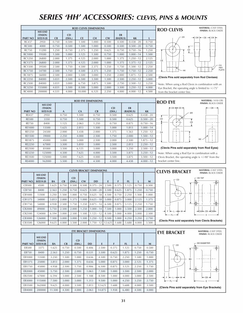
SERIES ‘HH’ ACCESSORIES: CLEVIS, PINS & MOUNTS
31
CLEVIS BRACKET DIMENSIONS
PART NO.
MAX LOAD
(TENSION)
RATED IN LBS BA CB
CD
(DIA.) CW DD E F FL L M
CB500 4500 1.625 0.750 0.500 0.500 0.375 - 24 2.500 0.375 1.125 0.750 0.500
CB750 8400 2.563 1.250 0.750 0.625 0.500 - 20 3.500 0.625 1.875 1.250 0.750
CB1000 13500 3.250 1.500 1.000 0.750 0.625 - 18 4.500 0.750 2.250 1.500 1.000
CB1375 34000 3.813 2.000 1.375 1.000 0.625 - 18 5.000 0.875 3.000 2.125 1.375
CB1750 54000 4.938 2.500 1.750 1.250 0.875 - 14 6.500 0.875 3.125 2.250 1.750
CB2000 89000 5.750 2.500 2.000 1.250 1.000 - 14 7.500 1.000 3.500 2.500 2.000
CB2500 124000 6.594 3.000 2.500 1.500 1.125 - 12 8.500 1.000 4.000 3.000 2.500
CB3000 126000 7.500 3.000 3.000 1.500 1.250 - 12 9.500 1.000 4.250 3.250 2.750
CB3500 126000 9.625 4.000 3.500 2.000 1.750 - 12 12.625 1.688 5.688 4.000 3.500
MATERIAL: CAST STEELFINISH: BLACK OXIDE
EYE BRACKET DIMENSIONS
PART NO
MAX LOAD
(TENSION)
RATED IN LBS BA CB
CD
(DIA.) DD E F FL L M
EB500 3375 1.625 0.750 0.500 0.406 2.500 0.375 1.125 0.750 0.500
EB750 8400 2.563 1.250 0.750 0.531 3.500 0.625 1.875 1.250 0.750
EB1000 13500 3.250 1.500 1.000 0.656 4.500 0.750 2.250 1.500 1.000
EB1375 25000 3.813 2.000 1.375 0.656 5.000 0.875 3.000 2.125 1.375
EB1750 45000 4.938 2.500 1.750 0.906 6.500 0.875 3.125 2.250 1.750
EB2000 45000 5.750 2.500 2.000 1.063 7.500 1.000 3.500 2.500 2.000
EB2500 67000 6.594 3.000 2.500 1.188 8.500 1.000 4.000 3.000 2.500
EB3000 115000 7.500 3.000 3.000 1.313 9.500 1.000 4.250 3.250 2.750
EB3500 162000 9.625 4.000 3.500 1.813 12.625 1.688 5.688 4.000 3.500
EB4000 200000 11.500 4.500 4.000 2.063 14.875 1.938 6.480 4.500 4.000
MATERIAL: CAST STEELFINISH: BLACK OXIDE
ROD EYE DIMENSIONS
PART NO
MAX LOAD
(TENSION)
RATED IN LBS A CA CB
CD
(DIA.)
ER
(RADIUS) KK
RE437 2950 0.750 1.500 0.750 0.500 0.625 0.438 - 20
RE500 3350 0.750 1.500 0.750 0.500 0.625 0.500 - 20
RE750 8400 1.125 2.063 1.250 0.750 0.875 0.750 - 16
RE1000 13500 1.625 2.813 1.500 1.000 1.813 1.000 - 14
RE1250 24500 2.000 3.438 2.000 1.375 1.563 1.250 - 12
RE1500 39000 2.250 4.000 2.500 1.750 2.000 1.500 - 12
RE1875 45000 3.000 5.000 2.500 2.000 2.500 1.875 - 12
RE2250 67000 3.500 5.810 3.000 2.500 2.813 2.250 - 12
RE2500 81000 3.500 6.125 3.000 3.000 3.250 2.500 - 12
RE3250 125000 4.500 7.625 4.000 3.500 3.875 3.250 - 12
RE3500 125000 5.000 7.625 4.000 3.500 3.875 3.500 - 12
RE4000 162000 5.500 9.125 4.500 4.000 4.438 4.000 - 12
MATERIAL: 1018 CRSFINISH: BLACK OXIDE
ROD CLEVIS DIMENSIONS
PART NO
MAX LOAD
(TENSION)
RATED IN LBS CB
CD
(DIA.) CE CH CW
ER
(RADIUS) KK L
RC437 2950 0.750 0.500 1.500 1.000 0.500 0.500 0.438 - 20 0.750
RC500 4000 0.750 0.500 1.500 1.000 0.500 0.500 0.500 - 20 0.750
RC750 11200 1.250 0.750 2.375 1.250 0.625 0.750 0.750 - 16 1.250
RC1000 19500 1.500 1.000 3.125 1.500 0.750 1.000 1.000 - 14 1.500
RC1250 26800 2.000 1.375 4.125 2.000 1.000 1.375 1.250 - 12 2.125
RC1375 26800 2.000 1.375 4.125 2.000 1.000 1.375 1.375 - 12 2.125
RC1500 39500 2.500 1.750 4.500 2.375 1.250 1.750 1.500 - 12 2.250
RC1750 54700 2.500 1.750 4.500 2.375 1.250 1.750 1.750 - 12 2.250
RC1875 56000 2.500 2.000 5.500 3.000 1.250 2.000 1.875 - 12 2.500
RC2250 84000 3.031 2.500 6.500 3.500 1.500 2.500 2.250 - 12 3.000
RC2500 84000 3.031 3.000 6.750 3.875 1.500 2.750 2.500 - 12 3.250
RC3250 155000 4.031 3.500 8.500 5.000 2.000 3.500 3.250 - 12 4.000
RC4000 200000 4.531 4.000 10.000 6.125 2.250 4.000 4.000 - 12 4.500
MATERIAL: CAST STEELFINISH: BLACK OXIDE
CLEVIS BRACKET
EYE BRACKET
ROD EYE
ROD CLEVIS
Note: When using a Rod Clevis in combination with an
Eye Bracket, the operating angle is limited to +/-75O
from the bracket center line.
Note: When using a Rod Eye in combination with a
Clevis Bracket, the operating angle is +/-90O from the
bracket center line.

FLANGE END COUPLER DIMENSIONS
PART NORODDIA.
B C D H I J L M N P
FEC625 0.625 0.406 1.500 0.563 45.0° 90.0° 0.219 4 1.125 0.250 0.656
FEC1000 1.000 0.750 2.000 0.875 30.0° 60.0° 0.281 6 1.500 0.375 1.063
FEC1375 1.375 0.938 2.500 1.000 30.0° 60.0° 0.344 6 2.000 0.375 1.438
FEC1750 1.750 1.188 3.000 1.250 22.5° 45.0° 0.344 8 2.375 0.500 1.813
FEC2000 2.000 1.438 3.500 1.625 15.0° 30.0° 0.406 12 2.688 0.625 2.063
FEC2500 2.500 1.875 4.000 1.875 15.0° 30.0° 0.406 12 3.188 0.750 2.625
FEC3000 3.000 2.375 5.000 2.375 15.0° 30.0° 0.531 12 4.000 0.875 3.125
FEC3500 3.500 2.625 5.875 2.625 15.0° 30.0° 0.656 12 4.688 1.000 3.625
FEC4000 4.000 3.125 6.375 2.625 15.0° 30.0° 0.656 12 5.188 1.000 4.125
FEC4500 4.500 3.625 6.875 3.125 15.0° 30.0° 0.656 12 5.688 1.500 4.625
FEC5000 5.000 4.000 7.375 3.125 15.0° 30.0° 0.656 12 6.188 1.500 5.125
FEC5500 5.500 4.500 8.250 3.875 15.0° 30.0° 0.781 12 6.875 1.875 5.625
WELD PLATE DIMENSIONS
PART NORODDIA.
E F G(DIA.)
H I K L M
WP625 0.625 0.500 2.000 0.250 45.0° 90.0° 10 - 24 4 1.125
WP1000 1.000 0.500 2.500 0.250 30.0° 60.0° 1/4 - 20 6 1.500
WP1375 1.375 0.625 3.000 0.250 30.0° 60.0° 5/16 - 18 6 2.000
WP1750 1.750 0.625 4.000 0.250 22.5° 45.0° 5/16 - 18 8 2.375
WP2000 2.000 0.750 4.000 0.375 15.0° 30.0° 3/8 - 16 12 2.688
WP2500 2.500 0.750 4.500 0.375 15.0° 30.0° 3/8 - 16 12 3.188
WP3000 3.000 1.000 5.500 0.375 15.0° 30.0° 1/2 - 13 12 4.000
WP3500 3.500 1.000 7.000 0.375 15.0° 30.0° 5/8 - 11 12 4.688
WP4000 4.000 1.000 7.000 0.375 15.0° 30.0° 5/8 - 11 12 5.188
WP4500 4.500 1.000 8.000 0.375 15.0° 30.0° 5/8 - 11 12 5.688
WP5000 5.000 1.000 8.000 0.375 15.0° 30.0° 5/8 - 11 12 6.188
WP5500 5.500 1.250 9.000 0.375 15.0° 30.0° 3/4 - 10 12 6.875
FLANGE END COUPLER
WELD PLATE
PIVOT PIN DIMENSIONS
PART NOMAx LOAD (TENSION)
RATED IN LBS CD LP LH
CP500C 5800 0.500 1.938 2.281CP750C 13250 0.750 2.719 3.094
CP1000C 23500 1.000 3.219 3.594CP1375C 44500 1.375 4.250 4.656CP1750C 72000 1.750 5.250 5.656CP2000C 94000 2.000 5.281 5.719CP2500C 145000 2.500 6.313 6.781CP3000C 210000 3.000 6.348 6.844CP3500C 285000 3.500 8.406 8.969CP4000C 375000 4.000 9.406 9.969
PIVOT PIN DIMENSIONS
PART NOMAx LOAD (TENSION)
RATED IN LBS CD LP LH
CP500E 5800 0.500 1.875 2.094CP750E 13250 0.750 2.625 2.938
CP1000E 23500 1.000 3.125 3.375CP1375E 44500 1.375 4.188 4.484CP1750E 72000 1.750 5.188 5.547CP2000E 94000 2.000 5.188 5.547CP2500E 145000 2.500 6.188 6.641CP3000E 210000 3.000 6.188 6.781CP3500E 285000 3.500 8.188 8.859CP4000E 375000 4.000 9.188 9.859
PIVOT PIN (INCLUDES E-CLIPS)
PIVOT PIN (INCLUDES COTTER PIN)
SERIES ‘HH’ ACCESSORIES: CLEVIS, PINS & MOUNTS
32
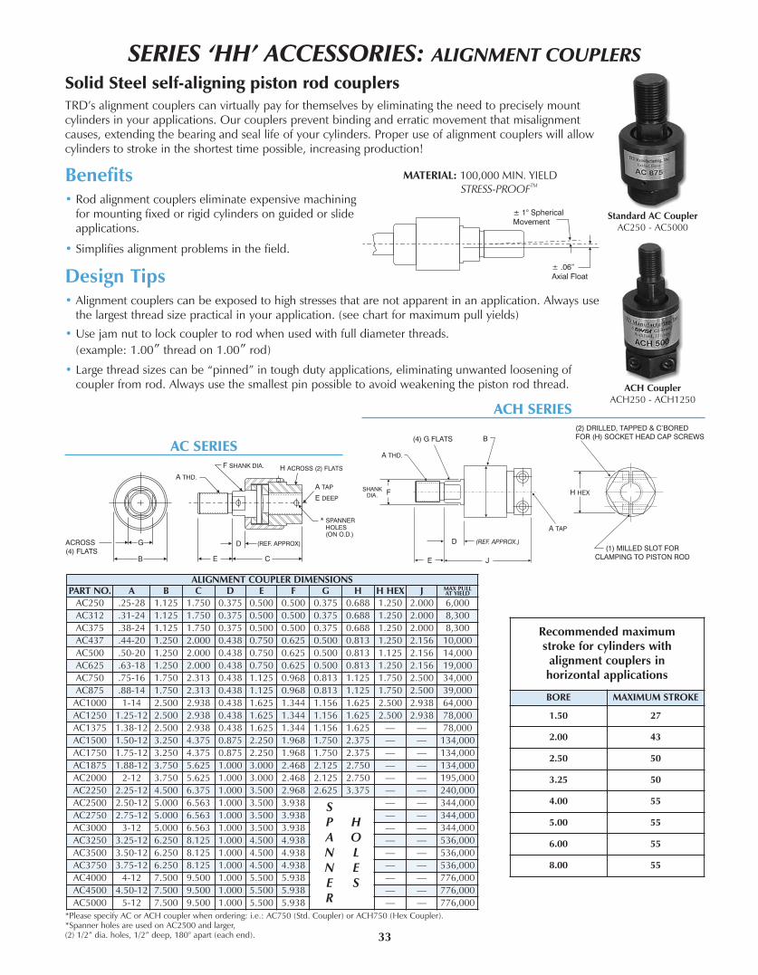
SERIES ‘HH’ ACCESSORIES: ALIGNMENT COUPLERS
Solid Steel self-aligning piston rod couplersTRD’s alignment couplers can virtually pay for themselves by eliminating the need to precisely mountcylinders in your applications. Our couplers prevent binding and erratic movement that misalignmentcauses, extending the bearing and seal life of your cylinders. Proper use of alignment couplers will allowcylinders to stroke in the shortest time possible, increasing production!
Benefits• Rod alignment couplers eliminate expensive machining
for mounting fixed or rigid cylinders on guided or slideapplications.
• Simplifies alignment problems in the field.
Design Tips• Alignment couplers can be exposed to high stresses that are not apparent in an application. Always use
the largest thread size practical in your application. (see chart for maximum pull yields)
• Use jam nut to lock coupler to rod when used with full diameter threads.
(example: 1.00” thread on 1.00” rod)
• Large thread sizes can be “pinned” in tough duty applications, eliminating unwanted loosening ofcoupler from rod. Always use the smallest pin possible to avoid weakening the piston rod thread.
ALIGNMENT COUPLER DIMENSIONSPART NO. A B C D E F G H H HEx J MAx PULL
AT YIELD
AC250 .25-28 1.125 1.750 0.375 0.500 0.500 0.375 0.688 1.250 2.000 6,000AC312 .31-24 1.125 1.750 0.375 0.500 0.500 0.375 0.688 1.250 2.000 8,300AC375 .38-24 1.125 1.750 0.375 0.500 0.500 0.375 0.688 1.250 2.000 8,300AC437 .44-20 1.250 2.000 0.438 0.750 0.625 0.500 0.813 1.250 2.156 10,000AC500 .50-20 1.250 2.000 0.438 0.750 0.625 0.500 0.813 1.125 2.156 14,000AC625 .63-18 1.250 2.000 0.438 0.750 0.625 0.500 0.813 1.250 2.156 19,000AC750 .75-16 1.750 2.313 0.438 1.125 0.968 0.813 1.125 1.750 2.500 34,000AC875 .88-14 1.750 2.313 0.438 1.125 0.968 0.813 1.125 1.750 2.500 39,000
AC1000 1-14 2.500 2.938 0.438 1.625 1.344 1.156 1.625 2.500 2.938 64,000AC1250 1.25-12 2.500 2.938 0.438 1.625 1.344 1.156 1.625 2.500 2.938 78,000AC1375 1.38-12 2.500 2.938 0.438 1.625 1.344 1.156 1.625 — — 78,000AC1500 1.50-12 3.250 4.375 0.875 2.250 1.968 1.750 2.375 — — 134,000AC1750 1.75-12 3.250 4.375 0.875 2.250 1.968 1.750 2.375 — — 134,000AC1875 1.88-12 3.750 5.625 1.000 3.000 2.468 2.125 2.750 — — 134,000AC2000 2-12 3.750 5.625 1.000 3.000 2.468 2.125 2.750 — — 195,000AC2250 2.25-12 4.500 6.375 1.000 3.500 2.968 2.625 3.375 — — 240,000AC2500 2.50-12 5.000 6.563 1.000 3.500 3.938 S
P HA ON LN EE SR
— — 344,000AC2750 2.75-12 5.000 6.563 1.000 3.500 3.938 — — 344,000AC3000 3-12 5.000 6.563 1.000 3.500 3.938 — — 344,000AC3250 3.25-12 6.250 8.125 1.000 4.500 4.938 — — 536,000AC3500 3.50-12 6.250 8.125 1.000 4.500 4.938 — — 536,000AC3750 3.75-12 6.250 8.125 1.000 4.500 4.938 — — 536,000AC4000 4-12 7.500 9.500 1.000 5.500 5.938 — — 776,000AC4500 4.50-12 7.500 9.500 1.000 5.500 5.938 — — 776,000AC5000 5-12 7.500 9.500 1.000 5.500 5.938 — — 776,000
ACH SERIES
AC SERIES
Standard AC CouplerAC250 - AC5000
ACH CouplerACH250 - ACH1250
*Please specify AC or ACH coupler when ordering: i.e.: AC750 (Std. Coupler) or ACH750 (Hex Coupler).*Spanner holes are used on AC2500 and larger, (2) 1/2” dia. holes, 1/2” deep, 180° apart (each end). 33
Recommended maximumstroke for cylinders with
alignment couplers inhorizontal applications
BORE MAxIMUM STROKE
1.50 27
2.00 43
2.50 50
3.25 50
4.00 55
5.00 55
6.00 55
8.00 55

SERIES ‘HH’ BASIC OPTIONS
34
“A=” refers to the length of piston rod thread.
Shorter than standard lengths can be furnished at no charge. Longerthan standard lengths can be furnished at a nominal price adder.Special�length�threads�do�not�delay�orders!
Note: Maximum threadlength is double thestandard “A” length.
A= Extended Piston Rod ThreadConsists of a threaded rod in the cylinder cap, non-removable.Provides an adjustable positive stop on the cylinder retract.
To�order,�specify�“AS”�and�length�of�adjustment�(Example:�AS=3”)
AS Adjustable Stroke (Retract)
Center Supports are recommended for longstroke cylinders to support tube and preventthe tie rods from sagging. Properly supportedcylinders will eliminate premature cylinderwear and eliminate tie rod vibration.
Center Supports can include MS2 mounts.
Contact TRD for more information.
CS Center Supports
PAGE• A= - Extended Piston Rod Thread . . . . . . . . . . . . . . . . . . 30• AS - Adjustable Stroke (Retract) . . . . . . . . . . . . . . . . . . . . . 30• C= - Extended Piston Rod . . . . . . . . . . . . . . . . . . . . . . . . . 30• CS - Center Support. . . . . . . . . . . . . . . . . . . . . . . . . . . . . . 30• C or H - Cushions . . . . . . . . . . . . . . . . . . . . . . . . . . . . . . . 31• EK - Extended Key Plate. . . . . . . . . . . . . . . . . . . . . . . . . . . 31• EN - Electroless Nickel Plating . . . . . . . . . . . . . . . . . . . . . . 31• HP - High Impact Piston (nut on piston rod) . . . . . . . . . . . 31• KKX - Non-Standard Rod Threads . . . . . . . . . . . . . . . . . . . 32
PAGE• Multiple Mounts . . . . . . . . . . . . . . . . . . . . . . . . . . . . . . . . 32• NR - Non-Rotating . . . . . . . . . . . . . . . . . . . . . . . . . . . . . . . 32• Port Options (BSPP, BSPT, NPTF, SAE, Flange) . . . . . . . . . 33• RBB - Rod Bushing - Bronze (Ductile Iron is Standard) . . 33• RLH - Rod Lock . . . . . . . . . . . . . . . . . . . . . . . . . . . . . . . . . 33• SSR - Stainless Steel Piston Rod . . . . . . . . . . . . . . . . . . . . . 33• Seals (Piston, Rod, Tube, Wiper). . . . . . . . . . . . . . . . . . . . . 33• ST - Stop Tube . . . . . . . . . . . . . . . . . . . . . . . . . . . . . . . . . . 34• XX - Special Modifications . . . . . . . . . . . . . . . . . . . . . . . . . 33
Index To Standard Options:
PAGE• AS3POS - Adjustable Mid Stroke (3 Position Cyl.) . . . . . . . 36• DAS - Double Rod Adjustable Stroke (Extend) . . . . . . . . . . 36• Spherical Bearing (cap pivot mount). . . . . . . . . . . . . . . . . . 36• Extra Wide Multiple Wear Bands . . . . . . . . . . . . . . . . . . . . 36• Hollow Piston Rods . . . . . . . . . . . . . . . . . . . . . . . . . . . . . . 36• Rod Boots . . . . . . . . . . . . . . . . . . . . . . . . . . . . . . . . . . . . . 36
PAGE• Paint and Other Special Finishes . . . . . . . . . . . . . . . . . . . . 36• Back To Back Cylinders . . . . . . . . . . . . . . . . . . . . . . . . . . . 37• 3-Position Cylinders . . . . . . . . . . . . . . . . . . . . . . . . . . . . . . 37• Tandem Cylinders . . . . . . . . . . . . . . . . . . . . . . . . . . . . . . . 37• Head & Cap Air Bleeds . . . . . . . . . . . . . . . . . . . . . . . . . . . 37• Rod Gland Drain . . . . . . . . . . . . . . . . . . . . . . . . . . . . . . . . 37
Uncommon Options:
”C=” is commonly referred to as PistonRod Extension. Piston rods can beextended to any length up to 120” totalpiston rod length, including stroke portion.Cylinders with long “C” lengths can bemounted away from obstacles or outsidehazardous environments.
C= Extended Piston Rod TIP
Piston rods can be made to any length up to 120 inches. Rodscan be easily extended to move a cylinder to a more accessiblelocation, or away from a less desirable environment.
Be sure to check piston rod column strength charts toproperly size the rod and prevent buckling.
Extended piston rods do not delay delivery.
ADJUSTABLE STROKE
BORE MAx. “AS”
1.50 Up to 8 inch
2.00-3.25 Up to 6 inch
4.00-6.00 Up to 5 inch
8.00 Up to 4 inch
CENTER SUPPORT RECOMMENDATIONS
BORE ONE SUPPORT TWO SUPPORTS
1.50” STROKES OVER 44 INCHES STROKES OVER 89 INCHES
2.00” STROKES OVER 74 INCHES STROKES OVER 99 INCHES
2.50” STROKES OVER 84 INCHES NOTREQUIRED3.25” - 8.00” STROKES OVER 99 INCHES

35
TRD’s cushion design featuresindustry proven technology and ultrafine adjustment needles for perfectdeceleration and long life. Cushionadjustment needle positions need tobe specified.
Example: H2C6
Cushions
SERIES ‘HH’ BASIC OPTIONS
EN or Electroless Nickel plating was invented in 1946, and has gainedworldwide commercial usage since 1964. Common usages include aircraftlanding gear, automotive brake cylinder and components, fuel injector parts,gas turbine parts, spray nozzles for chemical applications and manyelectronic devises including hard drives.
The properties of Electroless Nickel contribute to the multitude of uses. Thecoating provides an attractive finish, while exhibiting high abrasion andcorrosion resistance. It’s ability to uniformly coat blind holes, threads,internal surfaces and sharp edges contributes to its effectiveness. It has a veryhigh bonding strength to the base metal (100,000-200,000 PSI), so much sothat gas turbines use electroless nickel plating as a base to braze brokenblades to.
COMMON USAGES:
• FOOD PROCESSING — EN plating has been used to handle such diverseproducts as sodium hydroxide, food grade acids and fish oils. Excellentresistance to mild sanitizing caustics, chlorine, and chlorides in general.The natural smooth finish ensures cleanliness in food processingequipment.
• PETROLEUM AND CHEMICAL — The petroleum and chemical industryare large users of electroless nickel plating for corrosion protection. Designtip: Submit the list of chemicals and concentration levels to TRD forevaluation and recommendations. In some instances, Stainless Steelcylinders provide the best value and long cylinder life.
• MEDICAL AND PHARMACEUTICAL — The medical industry uses ENplated cylinders in clean-rooms, on equipment used to make plasma or IVbags, since it is critical that cylinder components need to be sterilized andparticle “flake free”. The pharmaceutical industry typically can be harsh onequipment, even abusive-but the equipment must remain completelyreliable. EN cylinders provide the most reliable and cost effective choice.
EN Electroless NickelEN CYLINDER SPECIFICATIONS
EN PLATED PARTS:
Tube, Head, Cap, Bushing Retainer, Mounts, TieRods and Nuts
OTHER COMPONENTS:
303/304 Stainless Steel: Rod Bushing RetainerScrews, Piston Rod (hard chrome plated), SAE 660Bronze Rod Bushing
EN PLATING SPECIFICATIONS:
HIGH PHOSPHORUS (highest corrosion resistantElectroless Nickel plating available)
COMPOSITION: 87-90% Nickel, 10-13% Phosphorus
HARDNESS: Rc 46-48
THICKNESS: .0005”-.0007”
LUBRICITY: Excellent (Similar to chrome)
COEFFICENT OFFRICTION: Low
FINISH: Bright and very smooth
MAx. STROKE = 50”
Other types of EN plating are available. ContactTRD with your specifications for a prompt quote.
NOTE: Due to the lower yield strength, StainlessSteel piston rods should be sized forproper column strength.
Extended Key Plate or “thrust key” is made from a full squarebushing retainer plate. The “key” is designed to fit in a milledslot on the equipment to prevent the cylinder from shifting.
An additional mount needs to be specified to secure cylinder.
Available bore sizes: 1.5” to 8” Bore
EK Extended Key Plate
Refer to page 17 for alldimensions and details
CUSHION LOCATIONSHEAD CUSHION CAP CUSHION
H1 C5H2 C6H3 C7H4 C8
Heavy-Duty hex nut to retain piston to piston rod.
HP “HP” Option
UNAVAILABLE CUSHIONLOCATIONS BY MOUNT
MOUNTHEAD
CUSHIONCAP
CUSHIONME5 H2, H4ME6 C6, C8MS3 H2, H4 C6, C8MT1 H2, H4MT2 C6, C8
STANDARD CUSHION LOCATIONSMOST MOUNTS H2 C6
MS3 MOUNT H3 C7 MT1 MOUNT H3 C6MT2 MOUNT H2 C7

36
SERIES ‘HH’ BASIC OPTIONS
Cylinders piston rods can be furnished with non-standard rod threads.
Ordering Example: HH - MF1 - 150 x 24 - 100 - KKx - .875 - 9UNC - P15 - SSSS
Custom Rod Thread Size
KKX Non-Standard Rod Threads
MULTIPLE MOUNTS
Benefits• Two internal guide rods throughout stroke
• High repeatability at each end of stroke(+/- 1 degree)
• All external dimensions are the same as standardcylinder (no additional length or width required)
• Standard Diameter Guide Rod Seals & BronzeBearings for long life and reliable operation
• Available in Double Rod End Models
Advantages• Eliminates the need for external guide shafts in
many positioning applications
• Guide rods are internal, self-cleaning, notsubjected to harsh cleaners
• Compact design saves space, no larger thanstandard NFPA cylinders!
• Durable, self-contained construction
Application Possibilities:
NR Non-Rotating (NFPA) Cylinders
AVAILABLE BORE SIZES WITH‘NR’ GUIDE ROD SIZES AND MAx. STROKE
BOREROD DIA.
(MM )CUSHIONS
MAxIMUMSTROKE
3.25 1.375 Cap Only 18”5.00 2.000 Available 30”
6.002.500
Available30”
3.000 30”8.00 3.500 Available 40”
Cylinders can be furnished with a wide selection of multiple mounts.
Ordering Example: HH - MF1 - MS2 - 250 x 12 - 100 - KK1 - P15 - SSSS
Add additional mount to part number
Note: External guide rod models areavailable with rectangular head and cap.Contact TRD for more information.

37
SERIES ‘HH’ BASIC OPTIONS
British Standard Pipe Taper (BSPT) threads have the same taper asAmerican NPT tapered threads, but use a 55° Whitworth threadform and different diameters. (Not interchangeable with NPT)
BSPT British Standard Pipe Taper
BSPPBritish Standard Pipe Parallel (BSPP), also referred to as BSP“Straight” Thread. (Not interchangeable with NPT)
British Standard Pipe Parallel
Cylinders can be furnished with NPTFor SAE O-Ring Boss (SAEJ514) ports atno-charge.
Cylinders can be furnished with BSPP,BSPT, or SAE Flange Ports foradditional cost.
PORT OPTIONS SAE FLANGE PORT
Cylinders can be furnished with Bronze (RBB) Rod Bushings (standard material: 150,000 PSI ductile iron, PTFE coated)
RBB Bronze Rod Bushings
Cylinders can be furnished with Hydraulic Rod Locks. Refer to pages 22-26 for complete specifications.
RLH Rod Lock
Cylinders can be furnished with Hard Chrome plated Stainless Steel Piston Rods.
Due to lower yield strength, stainless steel piston rods should be sized for proper column strength.
SSR 17-4 Stainless Steel Hard Chrome Plated Piston Rod
SEALS The HH Series allows for the use of different types of seal design and materialcompounds in every area, for maximum flexibility and performance.
Temperature Range:
Compatible with: Virtually all fluids
C Cast Iron Piston Rings
Aggressively scrapes the piston rod, removing foreign material such asspatter, sprays and powders. (Brass�contruction)
MS Metallic Rod Scraper
Piston: Carboxilated Nitrile Rod Seal: PolyurethaneTube Seals: Buna Rod Wiper: Flocked Nitrile
Temperature Rating: -20°F to 200°F (-29°C to 93°C)
Compatible with: Mineral based hydraulic fluids
S Standard Seals
Temperature Rating: -50°F to 300°F (-45°C to 149°C)
Compatible with: Most Phosphate Ester (Skydrol 500 and 7000,type 2) fluids
E Ethylene Propylene
Temperature Rating: -100°F to 400°F (-73°C to 204°C)
Compatible with: All Hydraulic fluids, and almost any fluid.Contact TRD for specific compatibility.
T Glass Filled PTFE
Temperature Rating: 0°F to 300°F (-18°C to 149°C)(Up to 400°F with reduced service life)
Compatible with: Some Phosphate Ester (Houghto-Safe 1000,1120; Pyrogard 42, 43, 53, 55) fluids; mineral based petroleum,halogenated hydrocarbons, silicate ester and diester fluids
V Fluorocarbon
PISTON SEAL
S STANDARD(Carboxilated)
C Cast-Ring
E EP
T PTFE
V Fluorocarbon
ROD SEAL
SSTANDARD(Polyurethane)
E EP
V Fluorocarbon
TUBE SEAL
S STANDARD(Buna)
E EP
V Fluorocarbon
ROD WIPER
S STANDARD(Flocked Nitrile)
MMetallicScraper
T PTFE
V Fluorocarbon
How to Order Seals
S S S S
Non-standard seals can be furnished.
Contact TRD for more information.
XX Special
Contact TRD for more information.
100,000 min. yield (rods up to 5.00)75,000 min. yield (5.500 rod)

38
SERIES ‘HH’ BASIC OPTIONS
Stop Tubes are designed to reduce the piston rodbushing stress to within the designed range of thebearing material. This will insure proper cylinderperformance, in any given application. StopTubes lower the cylinder bearing stress by addinglength to the piston, which increases the overalllength of the cylinder. (Note: TRD uses a doublepiston design when possible.)
Stop Tube Selection
To determine the proper amount of stop tube foryour application, you must first find the value of“D”, which represents the “stroke, adjusted�formounting�condition”. Each mounting conditioncreates different levels of bushing stress, whichhave direct impact on the amount of stop tuberequired. (See Chart 1)
Once the value of “D” is known, refer to Chart 2for the recommended amount of stop tube.
To order a Stop Tube:
• Add the stop tube prefix “ST=” and the stoptube length to the cylinder model number.
• Add “ES” after the cylinder stroke to indicatethat the stroke is the “effective stroke”.
Example:HH-MS2-2.50 x 42ES -100-KK2-P15=N375-SSSS -ST=2
ST Stop Tube and Rod Size Selection
Refer to page 35 for Rod Size Selection Chart

Piston Rod Size Selection
Standard rod sizes are usually suitable for shorter stroke applications at lower hydraulic pressures.With high thrust force or long stroke applications, you must check the “column strength” of the rodin the mounting style to determine the proper rod diameter size.
1. Determine the total axial thrust by multiplying the bore area size (in inches) by the operatingpressure (in PSI). Refer to page 51 for cylinder force chart.
2. From page 34, determine the value of “D” for the application.
3. Find the value of “D” in the chart below. Follow the value of “D” vertically on the graph until itintersects with the Axial Thrust value of the cylinder. The intersection of these two values willfall within one of the shaded areas representing the piston rod diameter size required for theapplication.
SERIES ‘HH’ BASIC OPTIONS
39

40
Double piston design allows for adjustment of the mid strokeposition. Three ported cylinder with adjustable stop collar.
Contact TRD with your specifications.
AS3POS Adjustable Mid Stroke (3 Position Cyl.)Consists of a double rod end cylinder and an adjustable stopcollar. Used to adjust the extend cylinder stroke.
Contact TRD with your specifications.
DAS Double Rod Adjustable Stroke (Extend)
SERIES ‘HH’ UNCOMMON OPTIONS
Spherical pivot bearingmounts can be furnishedas a weldment.
MP4SPSpherical Mount.
Contact TRD with yourspecifications.
SPHERICAL PIVOT BEARINGS8” Piston with two 1” wide wear bands shown.
EXTRA WIDE MULTIPLE WEAR BANDS
This cylinder shows amultitude of options:
Double OversizePiston Rod, Gun-Drilled, Double RodEnd with rodextension, specialfemale rod thread,and special sidedrilled angle hole inpiston rod.
HOLLOW PISTON RODSRod Boots are common in dirty environments —a standard spec for many applications.
(Note: Rod Boots add length to cylinder rod extension — contactTRD for specifications)
ROD BOOTS
Standard Finish: Black Urethane Paint (suitable for indoor or outdoor use.)
Optional Paint: Black Epoxy Paint (suitable for indoor use only.)
Additional Paint Choices: TRD can provide paint in any color or type.Contact TRD with your specifications.
Additional Finishes: TRD can provide special finishes,i.e., Nutride PlateContact TRD with your specifications — we would be pleased to provide a quote!
Heavy Chrome Plated Piston Rods.Contact TRD for more information.
SPECIAL FINISHES
PORT A PORT B PORT C
Contact TRD for rod column strength limitationsand more information.

SERIES ‘HH’ UNCOMMON OPTIONS
Back to Back cylinders consist of twoindividual cylinders built as one unit.These cylinders can act as a 4 positioncylinder.
Contact TRD for more information.
BTB Back-To-Back Cylinders
3P Three-Position Cylinder
3-POSITION CYLINDERSHOW THEY WORK
You can create a 3-Position cylinder from two of thesame bore size cylinders.
3-Position cylinders consist of multiple cylinders built asone unit having ONE exposed working rod end, capableof delivering 3 rod positions.
3-POSITION BENEFITS:• 3-POSITIONS IN ONE CYLINDER — One cylinder
produces three different rod end positions. By varyingstroke lengths, a multitude of positions can be created.
• SIMPLIFIES MACHINE DESIGNS — Eliminates theneed for an additional cylinder to create a thirdposition. 3-Position cylinders reduce space and thecost to mount multiple cylinders.
Note: Piston rods are not connected.Contact TRD for more information.
You can tandem different cylinderstogether to create unlimited designpossibilities.
Note: Piston rods are connected.
Contact TRD for more information.
TM Tandem Cylinders
Air bleeds can be provided at either or both ends ofthe cylinder. Air bleeds should be located at thehighest point in the cylinder for maximumeffectiveness. The location needs to be specified,similar to port locations.
Contact TRD for more information.
HEAD & CAP AIR BLEEDS
When no oil leakage can be tolerated, a rod bushing Drain port canbe provided. Since there isn’t any pressure in the drain line, cleartubing can offer a visual inspection of any leakage. A constant leakindicates that the rod seal is worn and needs to be replaced.
Contact TRD for more information.
ROD DRAIN
41

SERIES: BALLUFF INDUCTIVE SENSORS
42
Flexible Solutions for anOften Inflexible World
Balluff’s new Strokemaster®
cylinder-piston sensorsprovide precision end-of-stroke sensing for hydrauliccylinders. It also eliminatespost-installation cablemanagement problems with304° of rotational freedomon the connector.
Strokemaster® sensors allowinfinately adjustable andlockable cable positioninganytime after mounting tothe cylinder. Withoutbreaking the seal,Strokemaster® enablesquicker installation of thesensor and neat cable runs.
A high-pressure, inductiveproximity switch, theStrokemaster® sensorprovides a 2mm (0.8”)sensing range to pick up the“spud” of hydraulic cylindersand indicate fully retracted orextended position. It mountswith just two screws, andseals with an O-ring.Withstanding cylinderpressures to 3000 psi (207BAR), the embeddable designkeeps most of the switchprotected within the cylinder,with only a 0.62” (16mm)high housing exposedoutside. The rotating housingcan be locked in the desiredposition with either one oftwo set screws.
Strokemaster® sensors areavailable in 3-wire or 4-wireDC and 3-wire AC/DCversions, mini or microconnectors. Switchingfrequency is 50 Hz in theAC/DC versions. All units areweld-field immune andshort-circuit and reversepolarity protected. They fit allpopular cylinder designs,with standard probe lengthsof 0.912” - 4.560”(23.165mm - 115.8mm),along with available customprobe lengths and spacers.Probes are made of stainlesssteel with a ceramic face.Both DC and AC/DC sensorshave all metal housings.
Strokemaster® is CE-certified,and its housing is sealed toIP67 requirements.
Inductive Sensors
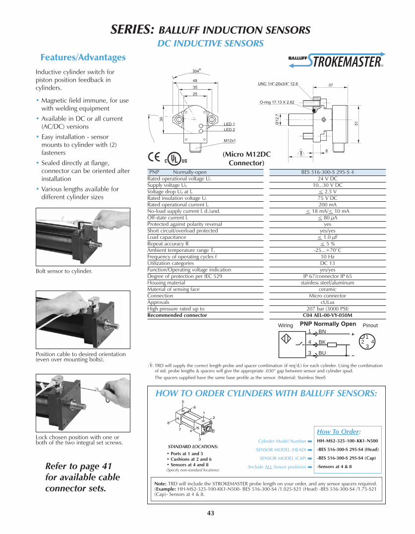
SERIES: BALLUFF INDUCTION SENSORSDC INDUCTIVE SENSORS
43
Features/Advantages
Inductive cylinder switch forpiston position feedback incylinders.
• Magnetic field immune, for usewith welding equipment
• Available in DC or all current(AC/DC) versions
• Easy installation - sensormounts to cylinder with (2)fasteners
• Sealed directly at flange,connector can be oriented afterinstallation
• Various lengths available fordifferent cylinder sizes
HOW TO ORDER CYLINDERS WITH BALLUFF SENSORS:
Bolt sensor to cylinder.
Position cable to desired orientation(even over mounting bolts).
Lock chosen position with one orboth of the two integral set screws.
PNP Normally-openRated operational voltage Ue
Supply voltage UB
Voltage drop Ud at leRated insulation voltage Ui
Rated operational current leNo-load supply current lr d./und.Off-state current lrProtected against polarity reversalShort circuit/overload protectedLoad capacitanceRepeat accuracy RAmbient temperature range Ta
Frequency of operating cycles fUtilization categoriesFunction/Operating voltage indicationDegree of protection per IEC 529Housing materialMaterial of sensing faceConnectionApprovalsHigh pressure rated up toRecommended connector
BES 516-300-S 295-S 424 V DC
10...30 V DC< 2.5 V75 V DC200 mA
< 18 mA/< 10 mA< 80 µA
yesyes/yes
< 1.0 µF< 5 %
-25...+70°C10 HzDC 13yes/yes
IP 67/connector IP 65stainless steel/aluminum
ceramicMicro connector
cULus207 bar (3000 PSI)
C04 AEL-00-VY-050M
< TRD will supply the correct length probe and spacer combination (if req’d.) for each cylinder. Using the combinationof std. probe lengths & spacers will give the appropriate .030” gap between sensor and cylinder spud.
The spacers supplied have the same base profile as the sensor. (Material: Stainless Steel)
Note: TRD will include the STROKEMASTER probe length on your order, and any sensor spacers required.(Example: HH-MS2-325-100-KK1-N500- BES 516-300-S4 /1.025-S21 (Head) -BES 516-300-S4 /1.75-S21(Cap)- Sensors at 4 & 8.
<
STANDARD LOCATIONS:
• Ports at 1 and 5• Cushions at 2 and 6• Sensors at 4 and 8(Specify�non-standard�locations)
(Micro M12DCConnector)
Refer to page 41for available cableconnector sets.
How To Order:
HH-MS2-325-100-KK1-N500
-BES 516-300-S 295-S4 (Head)
-BES 516-300-S 295-S4 (Cap)
-Sensors at 4 & 8
Cylinder Model Number
SENSOR MODEL (HEAD)
SENSOR MODEL (CAP)
(Include ALL Sensor positions)
PinoutWiring
1
344
1
3
BN
BK
BU
2
PNP Normally Open

44
SERIES: BALLUFF INDUCTION SENSORSAC/DC INDUCTIVE SENSORS
Normally-openRated operational voltage Ue
Supply voltage UB
Voltage drop Ud at leRated insulation voltage Ui
Rated operational current leMinimum operational current lmOff-state current lrInrush current lk (t = 20 ms)Protected against polarity reversalShort circuit protectedRepeat accuracy RAmbient temperature range Ta
Frequency of operating cycles fUtilization categoriesFunction/Operating voltage indicationDegree of protection per IEC 529Insulation classHousing materialMaterial of sensing faceConnectionApprovalsHigh pressure rated up toRecommended connector
BES 516-200-S 2-S21110 V AC
20...250 V AC/DC< 6 V
250 V AC500 mA
5 mA< 1.7 mA @ 110 V AC
3 A max./1 Hzyesyes
< 5 %-25...+70°C
< 50 HzAC 140/DC 13
yes/yesIP 67
1stainless steel/aluminum
ceramicMicro connector
cULus207 bar (3000 PSI)
C21 AE3-00-VY-150F
<
BES 516-200-S 2-S5110 V AC
20...250 V AC/DC< 6 V
250 V AC500 mA
5 mA< 1.7 mA @ 110 V AC
3 A max./1 Hzyesyes
< 5 %-25...+70°C
< 50 HzAC 140/DC 13
yes/yesIP 67
1stainless steel/aluminum
ceramicMini connector
cULus207 bar (3000 PSI)
C05 AE1-00-VY-150F
<
< TRD will supply the correct length probe and spacer combination (if req’d.) for each cylinder. Using the combinationof std. probe lengths & spacers will give the appropriate .030” gap between sensor and cylinder spud.
The spacers supplied have the same base profile as the sensor. (Material: Stainless Steel)
Refer to page 41for available cableconnector sets.
HOW TO ORDER CYLINDERS WITH BALLUFF SENSORS:
Note: TRD will include the STROKEMASTER probe length on your order, and any sensor spacers required.(Example: HH-MS2-325-100-KK1-N500- BES 516-200-S 2 /1.025-S21 (Head) -BES 516-200-S 2 /1.75-S21 (Cap)-Sensors at 4 & 8.
STANDARD LOCATIONS:
• Ports at 1 and 5• Cushions at 2 and 6• Sensors at 4 and 8(Specify�non-standard�locations)
How To Order:
HH-MS2-325-100-KK1-N500
-BES 516-200-S 2-S21 (Head)
-BES 516-200-S 2-S21 (Cap)
-Sensors at 4 & 8
Cylinder Model Number
SENSOR MODEL (HEAD)
SENSOR MODEL (CAP)
(Include ALL Sensor positions)
Pinout
12
34
Wiring
4
1
3
BN
BK
BU
PinoutWiring1
3
2
GR N
RD/BLK
RD/W H
~
~
12
3

45
Green
White
Black
SERIES: BALLUFF INDUCTION SENSORSCABLE CONNECTORS
3 Pole
Voltage Rating
Amperage
Wire Gauge
Jacket
Coupling Nut
Protection
Ambient Operating Temp.
UL Listed
CSA Certified
ORDER NUMBER
C05 AE1 00 * Y 150
300 V AC/DC
10A
16 AWG
PVC
Black Epoxy Coated Zinc
IP68 / NEMA 6P
-4 - 221°F (-21 to 105°C)
Yes
Yes
Note
3 Wire DC
3 Wire Normally Open, non-LED 1,2,3
3 Wire Normally Open PNP w/ LED
4 Wire DC (NO/NC)
4 Wire (Universal), non-LED 1,2,3
4 Wire PNP w/LED 1,3
Voltage Rating
Amperage
Wire Gauge
Jacket
Coupling Nut
*Optional Stainless Steel
Protection
Ambient Operating Temp.
UL Listed
CSA Certified
ORDER NUMBER
C04 AEC 00 * Y 050M
C04 AEH 00 * Y 050M
C04 AEL 00 * Y 050M
C04 AEM 00 * Y 050M
10 - 30 V DC
4 Amps
22 AWG
Yellow PVC or TPE
Black Epoxy Coated Zinc
*Stainless Type 303
IP68 / NEMA 6P
-4 - 221°F (-21 to 105°C)
Yes
Yes
Ordering Code
3 Pin Dual Keyway
Voltage Rating
Amperage
Wire Gauge
Jacket
Coupling Nut
O-Ring
Overmold Head
Protection
Ambient Operating Temp.
UL Listed
CSA Certified
ORDER NUMBER
C21 AE3 00 * Y 150F
250 V AC/DC
4A
22 AWG
Yellow PVC or TPE
Black Epoxy Coated Zinc
Viton
TPE
IP68 / NEMA 6P
-4 - 221°F (-21 to 105°C)
Yes
Yes
Connector
Style
Configuration
Recommended Connector
3-5 Pole Mini
Mini Size A
Straight Female
C05 AE1-00-VY-150F
Connector
Style
Configuration
Recommended Connector
Micro AC .50” x 20 UNF
3 Pin Dual Keyway
Straight Female
C21 AE3-00-VY-150F
Connector
Style
Configuration
Recommended Connector
Micro
M12 DC Single Keyway
Straight Female
C04 AEL-00-VY-050M
S4 - Micro Connectors(M12x1 Metric Threads)
S21 - Micro Connectors(½”-20 UNF Threads)
S5 - Mini Connectors(7/8”-16 UNF Threads)
* Insert V = PVC CableT = TPE Cable
For 3 pole versions only* Insert V = PVC Cable
T = TPE CableFor 3 pole versions only
Note: 15 ft cable isstandard (other lengthsavailable - contact factory)
* Insert V = PVC CableT = TPE Cable
For 3 pole versions only
Note: 5 meter cable is standard(other lengths available - contactfactory)
Note: 1 Add B = Braided 80% Metallic Braid, i.e. 050 MB2 Add S = S-Shielded 360 Degree Shield through
Coupling Nut, i.e. 050 MS3 Stainless Steel Couple Nut: Change E to S,
i.e. C04ASC00TY050M
Refer to Balluff Catalog foradditional cable connectors.

Balluff hasthe righttransducerfor anyapplication!
• Rod styles
• Profile styles
• Tubular styles
• Embeddable style
• Explosion-proof style
46
BALLUFF TRANSDUCERS
The waveguide consists of aspecial nickel-iron alloy with0.7 mm O.D. and 0.5 mm I.D.
A copper conductor isintroduced through the lengthof this tube. The start ofmeasurement is initiated by ashort current pulse. Thiscurrent generates a circularmagnetic field which rotatesaround the waveguide.
A permanent magnet at thepoint of measurement is usedas the marker element, whoselines of field run at right anglesto the electromagnetic field.
In the area on the waveguidewhere the two fields intersect,a magnetostrictive effect causes
an elastic deformation of thewaveguide, which propagatesalong the waveguide in bothdirections in the form of amechanical wave.
The mechanical wave isconverted to an electricalsignal by the signal converter.The propagation time of themechanical wave isdetermined by the position ofthe permanent magnet and canbe determined to resolutionsdown to 5 µm.
Enhanced Magnetostrictive Technology
Z• .75” x 16 UNF threads
• Pressure rated to 8700 PSI for usein hydraulic cylinders
• Replaceable electronics head
• Analog signal adjustable in field
W• Rugged all stainless steel housing
• Designed for demandingapplications
• Eliminates the need for protectivecover
• .75” - 16 UNF threads
• Pressure rated to 8700 PSI
K• Rugged all stainless steel housing
• Bolt in design
• Pressure rated to 8700 PSI
• Eliminates the need forprotective cover
Rod Style Rugged,CompactRod Style
Compact,Bolt-inRod Style
Sensor Output OptionsAnalog
0...10 V and 10...0 V • • •-5...+5 V and +5...-5 V • • •-10...+10 V and +10...-10 V • • •4...20 mA or 20...4 mA • • •0...20 mA or 20...0 mA • • •
DigitalStart/Stop, RS422 • • •Pulse-Width Modulated, RS422 • • •PWM (w/ recirculations), RS422 • • •
SpecializedSynchronous Serial Interface* • • •CANopen •Profibus DP •Quadrature •
Resolution0.1 mV (analog) • •0.2 µA (analog) • •16 bit (analog) •Controller-dependent (Start/Stop & PWM) • • •1,2,3,5,10 µm selectable (Quadrature output) •1,5,10,20,40 µm selectable (SSI output) • • •5 µm increments selectable (CANopen & Profibus) •10 µm
Stroke LengthActive measurement area: 2” to 156” 2” - 156” 2” - 156” 2” - 156”(Consult factory for longer lengths)
Wiring OptionsQuick disconnect • • •Cable-out • • •
Operating Voltage24 V DC (±20%) • • •±15 V DC (±2%) • • •*(24 or 25 bit binary or gray code)

TRD will build your cylinder with the proper magnet, spacer plates (if required), drilling andtapping, intermediate supports (if required) and furnish the transducer as a complete unit.All cylinder/transducer assemblies are 100% tested at TRD before shipping.
• Complete BALLUFF MICROPULSETM
Transducer information is available in
catalog form or electronic PDF
downloads.
Visit www.balluff.com
• Other Balluff models are available.
Call TRD Mfg. (800-654-2535) for
information and cylinder design
assistance.
BALLUFF TRANSDUCERS
INTERNAL MODELS (BALLUFF Z, W, K SERIES)
• Not available on MP1 and MP2Mounts
• 1.50” to 8” Bores
• Gun-drilled piston rod(Requires 1” piston rod or larger)
• Balluff Magnet(Installed on piston)
• May require additionalcap length
47
SERIES “Z” SHOWN
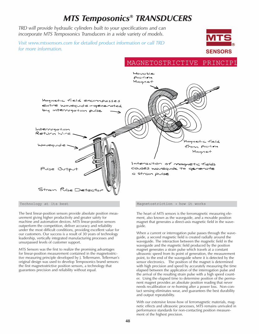
48
The best linear-position sensors provide absolute position meas-urement giving higher productivity and greater safety formachine and automation devices. MTS linear-position sensorsoutperform the competition, deliver accuracy and reliabilityunder the most difficult conditions, providing excellent value forour customers. Our success is a result of 30 years of technologyleadership, vertically integrated manufacturing processes andunsurpassed levels of customer support.
MTS Sensors was the first to realize the promising advantagesfor linear-position measurement contained in the magnetostric-tive measuring principle developed by J. Tellermann. Tellerman’soriginal design was used to develop Temposonics brand sensors:the first magnetostrictive position sensors, a technology thatguarantees precision and reliability without equal.
The heart of MTS sensors is the ferromagnetic measuring ele-ment, also known as the waveguide, and a movable positionmagnet that generates a direct-axis magnetic field in the wave-guide.
When a current or interrogation pulse passes through the wave-guide, a second magnetic field is created radially around thewaveguide. The interaction between the magnetic field in thewaveguide and the magnetic field produced by the positionmagnet generates a strain pulse which travels at a constantultrasonic speed from its point of generation, the measurementpoint, to the end of the waveguide where it is detected by thesensor electronics. The position of the magnet is determinedwith high precision and speed by accurately measuring the timeelapsed between the application of the interrogation pulse andthe arrival of the resulting strain pulse with a high speed count-er. Using the elapsed time to determine position of the perma-nent magnet provides an absolute position reading that neverneeds recalibration or re-homing after a power loss. Non-con-tact sensing eliminates wear, and guarantees the best durabilityand output repeatability.
With our extensive know-how of ferromagnetic materials, mag-netic effects and ultrasonic processes, MTS remains unrivaled inperformance standards for non-contacting position measure-ment of the highest precision.
Technology at its best Magnetostriction › how it works
MAGNETOSTRICTIVE PRINCIPLE
MTS Temposonics® TRANSDUCERSTRD�will�provide�hydraulic�cylinders�built�to�your�specifications�and�canincorporate�MTS�Temposonics�Transducers�in�a�wide�variety�of�models.
Visit�www.mtssensors.com�for�detailed�product�information�or�call�TRDfor�more�information.

49
(1) Additional output ranges available.
(2) Includes CANOpen and MTS multiple-magnet position, velocity and programmable limit switch output.
(3) Consult factory for stroke lengths greater than 10,060 mm (396 in.).
(4) ER stroke length range is 75 to 1,500 mm (3 to 60 in.). Articulated or unsupported sensor applications (e.g. using dual rod ends), must be limited to a maximum of 750 mm (30 in.) stroke length.
(5) R-Series SSI available with 0.001mm (0.00004 in.) resolution.
(6) Analog (Voltage or Current) resolution restricted by output ripple.
R›SERIESA smart sensor for fast, high precision, andsynchronized position control applications.
Hydraulic/pneumatic �H Style�
• Sensing element pressure housing threads into
standard size port on cylinder endcap.
• Industry standard for position feedback in fluid
power cylinders.
• Convenient sensor cartridge field replacement
without need to break oil seal.
• High pressure flange and isolation tube
(5000 psi static, 10,000 psi spike).
Profile �P Style�
• Extruded aluminum housing designed for
convenient machine surface mounting.
• Ideal for precision sensing external to fluid
power cylinders.
• Guided or “floating” position magnets Single
or multiple magnet operation.
H STYLEHydraulic/pneumaticsensor housing withintegral electronics
P STYLEAluminum extrusionProfile sensor housingwith integral electronics
F STYLEFlexible sensing elementhousing with integral electronics
H STYLEHydsens integ
DIRE CT SENSOR OUTPUTS
Voltage 0 to +10V, +10 to 0V
›10 to +10V, +10 to ›10V (1)
Voltage 0 to +10V, +10 to 0V
›10 to +10V, +10 to ›10V(1)
Voltage 0 to +10V, +10 to 0V
›10 to +10V, +10 to ›10V (1)
Voltage 0 to +10V, +10 to 0V
›10 to +10V, +10 to ›10V (
Current 0 or 4 to 20 mA,
20 to 4 or 0 mA
Current 0 or 4 to 20 mA,
20 to 4 or 0 mA
Current 0 or 4 to 20 mA,
20 to 4 or 0 mA
Current 0 or 4 to 20 mA,
20 to 4 or 0 mA
SSI, Synchronous Serial Interface,
(absolute encoder format)
SSI, Synchronous Serial Interface,
(absolute encoder format)
SSI, Synchronous Serial Interface,
(absolute encoder format)�
Fieldbus › CANbus (2), DeviceNet,
Profibus DP
Fieldbus › CANbus (2), DeviceNet,
Profibus DP
Fieldbus › CANbus(2), DeviceNet,
Profibus DP�
Digital Pulse Start/Stop or PWM
STROKE LENGTH50 to 7,620 mm (2 to 300 in.)50 to 5,080 mm (2 to 200 in.)250 to 10,060 mm (10 to 396 in.)
(3)
Volt
(2 t
Digi
RESOLUTION
16 bit, as low as 0.01 mm (0.0004
in.)
16 bit, as low as 0.01 mm (0.0004
in.)
16 bit, as low as 0.01 mm (0.0004
in.)
Infinite(
as low as 0.002mm (0.00008 in.)
(Digital) (5)
as low as 0.002mm (0.00008 in.)
(Digital) (5)
as low as 0.002mm (0.00008 in.)
(Digital) (5)
Controller Dependent
(Digital Pulse)
MEASUREMENT FEATURES
Position / Displacement Position / Displacement Position / Displacement Position / Displacement
Velocity Velocity Velocity �
Multiple magnets to 15 Multiple magnets to 15 Multiple magnets to 15 Multiple magnets to 15
Analog Zero and
Span Scale Adjustment
Analog Zero and
Span Scale Adjustment
Analog Zero and
Span Scale Adjustment
Analog Zero and
Span Scale Adjustment
EXTERNAL INTERFACES
� � �TDU›200 Digital Display
(for digital pulse outputs)
� � �MK›292 (Parallel 24 Bit Binary,
BCD, or Gray Code)

50
G›SERIESProgrammable sensors with built in diagnostics.
E›SERIESSensors designed for applications requiring simple
and economical position feedback.
Flexible �F Style�
• Durable sensing element flexible to an
8 inch minimum bend radius
• Ideal for position measurement along an arc
Stroke lengths from 10 to 396 inches
(consult factory for longer lengths)
• Convenient packaging and shipping for long
stroke lengths
• Facilitates use of long sensors in applications
with limited installation space
Rod and Cylinder �R Style�
• Rod actuated position feedback in an extruded
aluminum cylinder housing
• Reliable alternative to linear potentiometers
• Provides mounting alternative for articulated motion
• Eliminates need for complex mounting mechanisms
• Dust, debris and moisture tolerant
EASY FLIP
OU
T PAG
E FOR
REFER
ENC
E
H STYLEHydraulic/pneumaticsensor housing withintegral electronics
P STYLEAluminum extrusionProfile sensor housingwith integral electronics
P STYLEAluminum extrusion profile sensor housing with integral electronics
R STYLEProfile sensors with “Rod andCylinder” actuation and inte-gral electronics
EP2 STYLEAluminum extrusionProfile sensor housing withintegral electronics
Voltage 0 to +10V, +10 to 0V
›10 to +10V, +10 to ›10V (1)
Voltage 0 to +10V, +10 to 0V
›10 to +10V, +10 to ›10V (1)
Voltage 0 to +10V, +10 to 0VVoltage 0 to +10V, +10 to 0VVoltage 0 to +10V
Current 0 or 4 to 20 mA,
20 to 4 or 0 mA
Current 0 or 4 to 20 mA,
20 to 4 or 0 mA
Current 4 to 20 mA,
20 to 4 mA
Current 4 to 20 mA,
20 to 4 mA�
� � � � �
� � � � �
Digital Pulse Start/Stop or PWMDigital Pulse Start/Stop or PWMDigital Pulse Start/Stop Digital Pulse Start/Stop Digital Pulse Start/Stop
Voltage or Current 50 to 2,540 mm
(2 to 100 in.)
Digital Pulse 50 to 7,620 mm (2 to 300
Voltage or Current 50 to 2,540 mm
(2 to 100 in.)
Digital Pulse 50 to 5,080 mm (2 to 200
50 to 1,525 mm (2 to 60 in.)75 to 1,525 mm (3 to 60 in.) (4) 4, 6, 9, 12, 15, 18, 21, 24, 30, 36,
42
48, 54, and 60 in.
Infinite(6) Infinite (6) Infinite (6) Infinite(6) Infinite (6)
Controller Dependent
(Digital Pulse)
Controller Dependent
(Digital Pulse)
Controller Dependent
(Digital Pulse)
Controller Dependent
(Digital Pulse)�
Position / Displacement Position / Displacement Position / Displacement Position / Displacement Position / Displacement
� � � � �
Multiple magnets to 15 Multiple magnets to 15 � � �
Analog Zero and
Span Scale Adjustment
Analog Zero and
Span Scale Adjustment� � �
TDU›200 Digital Display
(for digital pulse outputs)
TDU›200 Digital Display
(for digital pulse outputs)
TDU›200 Digital Display
(for digital pulse outputs)
TDU›200 Digital Display
(for digital pulse outputs)�
MK›292 (Parallel 24 Bit Binary,
BCD, or Gray Code)
MK›292 (Parallel 24 Bit Binary,
BCD, or Gray Code)
MK›292 (Parallel 24 Bit Binary,
BCD, or Gray Code)
MK›292 (Parallel 24 Bit Binary,
BCD, or Gray Code)�

SELECT BY APPLICATION MECHANICSINSIDE CYLINDER
2-200 in.
ELECTRONICSHOUSING
ELECTRONIC INTERFACE
SENSOR MODEL
STROKE RANGE
FLANGETYPE
GH2-300 in.
2-300 in.
ThreadedIdeal for installation
from outside cylinder
Standard• Integral Electronics
• IP67 Housing
• Easy sensor cartridge replacementw/o breaking the hydraulic seal
RH
Analog or
Digital Pulse
Digital Serial (SSI)
Fieldbus
Analog with Position and Velocity
SELECT BY APPLICATION MECHANICSOUTSIDE CYLINDERAPPLICATIONHOUSING
ELECTRONIC INTERFACE
SENSOR MODEL
STROKE RANGE
EP2
EPM
2-60 in.
2-200 in.
FLOATING MAGNETIdeal for:
• Flange mountedmagnets
• Single or multiplemagnets
• Zero backlash
• Dirty environments RPM
Analog or
Digital Pulse
GPM
2-200 in.
2-60 in.
2-200 in.RPS
RPV
Analog or
Digital Pulse
GPS
GPV
ER3-60 in.*Analog or
Digital Pulse
10-396 in.**RF
CAPTIVE SLIDING MAGNETIdeal for:
• Situations where flange mounting the magnet is impractical
• Simplifying guidancemechanism for the magnet
ROD AND CYLINDERIdeal for:
• Articulated motion using rod-end attachments
• Dirty environments
• Linear potentiometerupgrades
* Articulated or unsupported sensor applications must be limited to a maximum of 30 in. stroke length
** Consult factory for stroke lengths >396 in.
Digital Serial (SSI)
Fieldbus
Analog with Position and Velocity
Digital Serial (SSI)
Fieldbus
Analog with Position and Velocity
Digital Serial (SSI)
Fieldbus
Analog with Position and Velocity
FLEXIBLE SENSING ELEMENTIdeal for:
• Curvilinear positioning
• Short installation heights
• Long stroke sensing (>300”)
• Single or multiple magnets
51
EASY
FLI
P O
UT
PAG
E FO
R R
EFER
ENC
E
EPS
EPV

TYPICAL APPLICATION MECHANICS: OUTSIDE CYLINDER IN›CYLINDERFLOATING MAGNETPositioning for:
• Shearing and forming
• Paper & film slitters
• Die casting machines
CAPTIVE SLIDING MAGNET
Positioning for:
• Presses
• Injection molding carriages & platens
ROD AND CYLINDERPositioning for:
• Wood & metal finishing
• Packaging machinery
• Doors and gates
FLEXIBLE SENSING ELEMENTPositioning for:
• Paper & film converting
• Long dam-gate cylinders
• Crane & turret control
EjectionControl
Mold ClosureControl
InjectionControl
INJECTIONMOLDINGMACHINETemposonics
TemposonicsTemposonics
ELECTRONICINTERFACE
OUTPUT VARIABLES STROKERANGE
MODELNOTES
E Series
G Series
MODELSERIES
SINGLE
POSITION
Analog Profile 2-60 in.
Rod 2-100 in.
Profile 2-100 in.
100% Null & Span Adjust
E Series
G Series
Digital Pulse Profile 2-60 in.
Rod 2-300 in.
Profile 2-200 in.
ProgrammablePWM Parameters
R SeriesDigital Serial (SSI) Rod 2-300 in.
Profile 2-200 in.
Flex 10-396 in.*
SoftwareProgrammable
R SeriesFieldbus Rod 2-300 in.
Profile 2-200 in.
Flex 10-396 in.*
SoftwareProgrammable
R SeriesAnalog Rod 2-300 in.
Profile 2-200 in.
Flex 10-396 in.*
100% Null & Span Adjust
POSITION +
VELOCITY
R SeriesFieldbus Rod 2-300 in.
Profile 2-200 in.
Flex 10-396 in.*
CANbus andProfibus only
R SeriesAnalog Rod 2-300 in.
Profile 2-200 in.
Flex 10-396 in.*
100% Null & SpanAdjust. Up to two
magnets
MULTIPLE POSITION
MAGNETS
G SeriesDigital Pulse Rod 2-300 in.
Profile 2-200 in.
Start/Stop only.Max. 15 magnets
R SeriesFieldbus Rod 2-300 in.
Profile 2-200 in.
Flex 10-396 in.*
CANbus andProfibus only.
Consult Factory for > 15 magnets * Consult Factory for stroke lengths >396 in.
SELECT BY APPLICATIONELECTRONICS
ELECTRONIC OUTPUT OPTIONSANALOGVoltage and Current
DIGITAL PULSEPWM & Start/Stop
DIGITAL SERIALSynchronous Serial Interface (SSI)
FIELDBUSCANbus, DeviceNet & Profibus
Position magnet Sensing element
Active stroke length
(Measuring range)
(V oltage or Current)
100 % Sensor Ouput
0
Start+ Start- Start
START/STOP
+ Stop- Stop
Time between Start and Stoppulses is proportionalto magnet position
Stop
MSB LSB
Clock (+)
Data (+)
RxD/TxD-P
RxD/TxD-N
VP
DGnd
+ 24 V DC
0 V
SENSOR
ASIC for
Position Calculation
Microprocessor System
Profibus-DP Controller
SPC 3
High-Speed RS-485
Transceiver
STANDARD THREADED HOUSINGUsed for:
• Hydraulic or pneumatic flangeor trunion mounted cylinders
• Rugged externally mountedIP67 housing
Paper Slitter Injection Molding Hood Door Positioning Short Installation Height Application
www.mtssensors.com52

53
(3) ROD BUSHING (DUCTILE IRON)
RodDiameter
Ductile Iron Bushing(Standard)
Metalic Scrapper(M option)
PTFE Wiper(E option)
0.625 HH-30-625 HH-30-625-MS HH-30-625-T
1.000 HH-30-1000 HH-30-1000-MS HH-30-1000-T
1.375 HH-30-1375 HH-30-1375-MS HH-30-1375-T
1.750 HH-30-1750 HH-30-1750-MS HH-30-1750-T
2.000 HH-30-2000 HH-30-2000-MS HH-30-2000-T
2.500 HH-30-2500 HH-30-2500-MS HH-30-2500-T
3.000 HH-30-3000 HH-30-3000-MS HH-30-3000-T
3.500 HH-30-3500 HH-30-3500-MS HH-30-3500-T
4.000 HH-30-4000 HH-30-4000-MS HH-30-4000-T
4.500 HH-30-4500 HH-30-4500-MS HH-30-4500-T
5.000 HH-30-5000 HH-30-5000-MS HH-30-5000-T
5.500 HH-30-5500 HH-30-5500-MS HH-30-5500-T
(1) PISTON SEAL
BoreCarboxilated Nitrile
(Standard)Fluorocarbon
(V option)Ethylene Propylene
(E option)Cast Iron Rings
(C option)PTFE w/ Glass
(T option)
1.50 HH-PS-15-CN HH-PS-15-V HH-PS-15-EP HH-PS-CR-15-TFP HH-PS-R5-15-T-B
2.00 HH-PS-20-CN HH-PS-20-V HH-PS-20-EP HH-PS-CR-20-TFP HH-PS-R5-20-T-B
2.50 HH-PS-25-CN HH-PS-25-V HH-PS-25-EP HH-PS-CR-25-TFP HH-PS-R5-25-T-B
3.25 HH-PS-32-CN HH-PS-32-V HH-PS-32-EP HH-PS-CR-32-TFP HH-PS-R5-32-T-B
4.00 HH-PS-40-CN HH-PS-40-V HH-PS-40-EP HH-PS-CR-40-TFP HH-PS-R5-40-T-B
5.00 HH-PS-50-CN HH-PS-50-V HH-PS-50-EP HH-PS-CR-50-TFP HH-PS-R5-50-T-B
6.00 HH-PS-60-CN HH-PS-60-V HH-PS-60-EP HH-PS-CR-60-TFP HH-PS-R5-60-T-B
8.00 HH-PS-80-CN HH-PS-80-V HH-PS-80-EP HH-PS-CR-80-TFP HH-PS-R5-80-T-B
1
2
3
4
5
6
7 14B
5B
1B 1B 7
(5) PART LIST - ROD SEAL
RodDiameter
Polyurethane(Standard)
Fluorocarbon(V option)
Ethylene Propylene(E option)
0.625 HH-RS-625-HT HH-RS-625-V HH-RS-625-EP
1.000 HH-RS-1000-HT HH-RS-1000-V HH-RS-1000-EP
1.375 HH-RS-1375-HT HH-RS-1375-V HH-RS-1375-EP
1.750 HH-RS-1750-HT HH-RS-1750-V HH-RS-1750-EP
2.000 HH-RS-2000-HT HH-RS-2000-V HH-RS-2000-EP
2.500 HH-RS-2500-HT HH-RS-2500-V HH-RS-2500-EP
3.000 HH-RS-3000-HT HH-RS-3000-V HH-RS-3000-EP
3.500 HH-RS-3500-HT HH-RS-3500-V HH-RS-3500-EP
4.000 HH-RS-4000-HT HH-RS-4000-V HH-RS-4000-EP
4.500 HH-RS-4500-HT HH-RS-4500-V HH-RS-4500-EP
5.000 HH-RS-5000-HT HH-RS-5000-V HH-RS-5000-EP
5.500 HH-RS-5500-HT HH-RS-5500-V HH-RS-5500-EP
(4) ROD BUSHING O-RING
RodDiameter
Buna(Standard)
Fluorocarbon(V option)
Ethylene Propylene(E option)
0.625 HH-BO-625-B HH-BO-625-V HH-BO-625-EP
1.000 HH-BO-1000-B HH-BO-1000-V HH-BO-1000-EP
1.375 HH-BO-1375-B HH-BO-1375-V HH-BO-1375-EP
1.750 HH-BO-1750-B HH-BO-1750-V HH-BO-1750-EP
2.000 HH-BO-2000-B HH-BO-2000-V HH-BO-2000-EP
2.500 HH-BO-2500-B HH-BO-2500-V HH-BO-2500-EP
3.000 HH-BO-3000-B HH-BO-3000-V HH-BO-3000-EP
3.500 HH-BO-3500-B HH-BO-3500-V HH-BO-3500-EP
4.000 HH-BO-4000-B HH-BO-4000-V HH-BO-4000-EP
4.500 HH-BO-4500-B HH-BO-4500-V HH-BO-4500-EP
5.000 HH-BO-5000-B HH-BO-5000-V HH-BO-5000-EP
5.500 HH-BO-5500-B HH-BO-5500-V HH-BO-5500-EP
PART LIST & SEAL KITS
(3) ROD BUSHING (BRONZE)
RodDiameter
Bronze Bushing(RBB Option)
Metalic Scrapper(M option)
PTFE Wiper(E option)
0.625 HH-30-625-BZ HH-30-625-BZ-MS HH-30-625-BZ-T
1.000 HH-30-1000-BZ HH-30-1000-BZ-MS HH-30-1000-BZ-T
1.375 HH-30-1375-BZ HH-30-1375-BZ-MS HH-30-1375-BZ-T
1.750 HH-30-1750-BZ HH-30-1750-BZ-MS HH-30-1750-BZ-T
2.000 HH-30-2000-BZ HH-30-2000-BZ-MS HH-30-2000-BZ-T
2.500 HH-30-2500-BZ HH-30-2500-BZ-MS HH-30-2500-BZ-T
3.000 HH-30-3000-BZ HH-30-3000-BZ-MS HH-30-3000-BZ-T
3.500 HH-30-3500-BZ HH-30-3500-BZ-MS HH-30-3500-BZ-T
4.000 HH-30-4000-BZ HH-30-4000-BZ-MS HH-30-4000-BZ-T
4.500 HH-30-4500-BZ HH-30-4500-BZ-MS HH-30-4500-BZ-T
5.000 HH-30-5000-BZ HH-30-5000-BZ-MS HH-30-5000-BZ-T
5.500 HH-30-5500-BZ HH-30-5500-BZ-MS HH-30-5500-BZ-T
(1B) PISTON SEAL BACKUP
BoreHytrel
(Backup for S)PTFE
(Backup for E & V)
1.50 HH-BU-PS-15-PM HH-BU-PS-15-T
2.00 HH-BU-PS-20-PM HH-BU-PS-20-T
2.50 HH-BU-PS-25-PM HH-BU-PS-25-T
3.25 HH-BU-PS-32-PM HH-BU-PS-32-T
4.00 HH-BU-PS-40-PM HH-BU-PS-40-T
5.00 HH-BU-PS-50-PM HH-BU-PS-50-T
6.00 HH-BU-PS-60-PM HH-BU-PS-60-T
8.00 HH-BU-PS-80-PM HH-BU-PS-80-T
(4B) ROD BUSHING O-RING BACKUP
RodDiameter
Polymyte(Backup for S)
PTFE(Backup for E&V)
0.625 HH-BU-BO-625-PM HH-BU-BO-625-T
1.000 HH-BU-BO-1000-PM HH-BU-BO-1000-T
1.375 HH-BU-BO-1375-PM HH-BU-BO-1375-T
1.750 HH-BU-BO-1750-PM HH-BU-BO-1750-T
2.000 HH-BU-BO-2000-PM HH-BU-BO-2000-T
2.500 HH-BU-BO-2500-PM HH-BU-BO-2500-T
3.000 HH-BU-BO-3000-PM HH-BU-BO-3000-T
3.500 HH-BU-BO-3500-PM HH-BU-BO-3500-T
4.000 HH-BU-BO-4000-PM HH-BU-BO-4000-T
4.500 HH-BU-BO-4500-PM HH-BU-BO-4500-T
5.000 HH-BU-BO-5000-PM HH-BU-BO-5000-T
5.500 HH-BU-BO-5500-PM HH-BU-BO-5500-T
(5B) ROD SEAL BACKUP
RodDiameter
Polymyte PTFE(Backup for E&V)
0.625 HH-BU-RS-625-PM HH-BU-RS-625-V
1.000 HH-BU-RS-1000-PM HH-BU-RS-1000-V
1.375 HH-BU-RS-1375-PM HH-BU-RS-1375-V
1.750 HH-BU-RS-1750-PM HH-BU-RS-1750-V
2.000 HH-BU-RS-2000-PM HH-BU-RS-2000-V
2.500 HH-BU-RS-2500-PM HH-BU-RS-2500-V
3.000 HH-BU-RS-3000-PM HH-BU-RS-3000-V
3.500 HH-BU-RS-3500-PM HH-BU-RS-3500-V
4.000 HH-BU-RS-4000-PM HH-BU-RS-4000-V
4.500 HH-BU-RS-4500-PM HH-BU-RS-4500-V
5.000 HH-BU-RS-5000-PM HH-BU-RS-5000-V
5.500 HH-BU-RS-5500-PM HH-BU-RS-5500-V
PARTS WITH THIS COLOR SCHEME ARE NON-STOCK ITEMS. CONTACT FACTORY FOR DELIVERY.
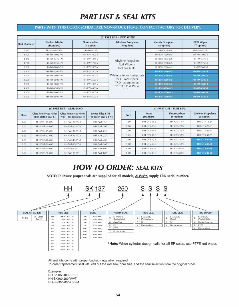
54
(7) PART LIST - TUBE SEAL
BoreBuna
(Standard)Fluorocarbon
(V option)Ethylene Propylene
(E option)
1.50 HH-OTS-15-B HH-OTS-15-V HH-OTS-15-EP
2.00 HH-OTS-20-B HH-OTS-20-V HH-OTS-20-EP
2.50 HH-OTS-25-B HH-OTS-25-V HH-OTS-25-EP
3.25 HH-OTS-32-B HH-OTS-32-V HH-OTS-32-EP
4.00 HH-OTS-40-B HH-OTS-40-V HH-OTS-40-EP
5.00 HH-OTS-50-B HH-OTS-50-V HH-OTS-50-EP
6.00 HH-OTS-60-B HH-OTS-60-V HH-OTS-60-EP
8.00 HH-OTS-80-B HH-OTS-80-V HH-OTS-80-EP
(2) PART LIST - ROD WIPER
Rod DiameterFlocked Nitrile
(Standard)Fluorocarbon
(V option)Ethylene Propylene
(E option)Metalic Scrapper
(M option)PTFE Wiper(T option)
0.625 HH-RW-625-FN HH-RW-625-V
Ethylene Propylene Rod Wiper is Not Available.
When cylinder design callsfor EP rod wipers, TRD recommends: ‘T’ PTFE Rod Wiper
HH-RW-625-MS HH-RW-625-T
1.000 HH-RW-1000-FN HH-RW-1000-V HH-RW-1000-MS HH-RW-1000-T
1.375 HH-RW-1375-FN HH-RW-1375-V HH-RW-1375-MS HH-RW-1375-T
1.750 HH-RW-1750-FN HH-RW-1750-V HH-RW-1750-MS HH-RW-1750-T
2.000 HH-RW-2000-FN HH-RW-2000-V HH-RW-2000-MS HH-RW-2000-T
2.500 HH-RW-2500-FN HH-RW-2500-V HH-RW-2500-MS HH-RW-2500-T
3.000 HH-RW-3000-FN HH-RW-3000-V HH-RW-3000-MS HH-RW-3000-T
3.500 HH-RW-3500-FN HH-RW-3500-V HH-RW-3500-MS HH-RW-3500-T
4.000 HH-RW-4000-FN HH-RW-4000-V HH-RW-4000-MS HH-RW-4000-T
4.500 HH-RW-4500-FN HH-RW-4500-V HH-RW-4500-MS HH-RW-4500-T
5.000 HH-RW-5000-FN HH-RW-5000-V HH-RW-5000-MS HH-RW-5000-T
5.500 HH-RW-5500-FN HH-RW-5500-V HH-RW-5500-MS HH-RW-5500-T
(6) PART LIST - WEAR BAND
BoreGlass Reinforced Nylon
(For piston seal S)Glass Reinforced NylonWide - (For piston seal T)
Bronze filled PTFE(For piston seal E & V)
1.50 HH-PWR-15-WG HH-PWR-15-WG-1 HH-PWR-15-T
2.00 HH-PWR-20-WG HH-PWR-20-WG-1 HH-PWR-20-T
2.50 HH-PWR-25-WG HH-PWR-25-WG-1 HH-PWR-25-T
3.25 HH-PWR-32-WG HH-PWR-32-WG-1 HH-PWR-32-T
4.00 HH-PWR-40-WG HH-PWR-40-WG-1 HH-PWR-40-T
5.00 HH-PWR-50-WG HH-PWR-50-WG-1 HH-PWR-50-T
6.00 HH-PWR-60-WG HH-PWR-60-WG HH-PWR-60-T
8.00 HH-PWR-80-WG HH-PWR-80-WG HH-PWR-80-T
PART LIST & SEAL KITS
HOW TO ORDER: SEAL KITS
BORE
150 1.50” Bore
200 2.00” Bore
250 2.50” Bore
325 3.25” Bore
400 4.00” Bore
500 5.00” Bore
600 6.00” Bore
800 8.00” Bore
ROD SIZE
062 0.625” Rod Dia.
100 1.000” Rod Dia.
137 1.375” Rod Dia.
175 1.750” Rod Dia.
200 2.000” Rod Dia.
250 2.500” Rod Dia.
300 3.000” Rod Dia.
350 3.500” Rod Dia.
400 4.000” Rod Dia.
450 4.500” Rod Dia.
500 5.000” Rod Dia.
550 5.500” Rod Dia.
PISTON SEAL
SSTANDARD(Carboxilated)
C Cast-Ring
E EP
T PTFE
V Fluorocarbon
ROD SEAL
SSTANDARD(Polyurethane)
E EP
V Fluorocarbon
TUBE SEAL
SSTANDARD(Buna)
E EP
V Fluorocarbon
ROD WIPER *
SSTANDARD(Flocked Nitrile)
M Metalic Scrapper
T PTFE
V Fluorocarbon
HH - SK 137 - 250 - S S S S
SEAL KIT SERIES
HH - SKHH Series
Seal Kit
All seal kits come with proper backup rings when required. To order replacement seal kits, call out the rod size, bore size, and the seal selection from the original order.
Examples:HH-SK137-400-SSSSHH-SK100-250-VVVTHH-SK-300-600-CSSM
*Note: When cylinder design calls for all EP seals, use PTFE rod wiper.
NOTE: To insure proper seals are supplied for all models, ALWAYS supply TRD serial number.
PARTS WITH THIS COLOR SCHEME ARE NON-STOCK ITEMS. CONTACT FACTORY FOR DELIVERY.

BORE
RODDIA.
(MM)
PRESSURE RATING PER MOUNT (PSI)
MF1 MF2 MF5 MT1 MT2 MT4
1.5000.625 2600 3000 3000 3000 3000 30001.000 1600 3000 3000 3000 3000 3000
2.0001.000 2600 3000 3000 3000 3000 30001.375 1600 3000 3000 3000 3000 3000
2.5001.000 2600 3000 3000 3000 3000 30001.375 2000 3000 3000 3000 3000 30001.750 1600 3000 3000 3000 3000 3000
3.2501.375 2600 3000 3000 2800 2800 28001.750 2200 3000 3000 2800 2800 28002.000 1600 3000 3000 2800 2800 2800
4.0001.750 2600 3000 3000 1800 1800 18002.000 1900 3000 3000 1800 1800 18002.500 1600 3000 3000 1800 1800 1800
5.000
2.000 2200 2000 3000 1200 1200 12002.500 1600 2500 3000 1200 1200 12003.000 1200 2800 3000 1200 1200 12003.500 750 3000 3000 1200 1200 1200
6.000
2.500 1800 2000 3000 1000 1000 10003.000 1450 2500 3000 1000 1000 10003.500 1100 2800 3000 1000 1000 10004.000 750 3000 3000 1000 1000 1000
8.000
3.500 900 1500 3000 1000 1000 10004.000 800 1700 3000 1000 1000 10004.500 700 1800 3000 1000 1000 10005.000 500 1900 3000 1000 1000 10005.500 500 2000 3000 1000 1000 1000
TECHNICAL DATA
All Torque Specs are based upon using anti-seize thread lubricant.
TRD SPEC: LPS Premium Copper Anti-SeizeTemperature Rating: -65°F to 1800°FMilitary Spec: MIL-PRF-907-E
TorqueTolerance: -0% to +5%
CYLINDER FORCE CHART*
BORE
RODDIA.
(MM)
EFFECTIVEPISTON
AREA
POUNDS OF FORCE AT PSI DISPLACEMENTPER INCH
OF STROKE(GALLONS)100 150 200 250 500 1000 1500 2000 2500 3000
1.50EXTEND 1.77 177 265 353 442 884 1767 2651 3534 4418 5301 .00765
0.625 1.46 146 219 292 365 730 1460 2191 2921 3651 4381 .006351.000 0.98 98 147 196 245 491 982 1473 1964 2454 2945 .00425
2.00EXTEND 3.14 314 471 628 785 1571 3142 4712 6283 7854 9425 .0136
1.000 2.36 236 353 471 589 1178 2356 3534 4712 5891 7069 .01021.375 1.66 166 249 331 414 828 1657 2485 3313 4142 4970 .0071
2.50
EXTEND 4.91 491 736 982 1227 2454 4909 7363 9818 12272 14726 .02131.000 4.12 412 619 825 1031 2062 4123 6185 8247 10308 12370 .01791.375 3.42 342 514 685 856 1712 3424 5136 6848 8560 10272 .01481.750 2.50 250 376 501 626 1252 2503 3755 5007 6259 7510 .0109
3.25
EXTEND 8.30 830 1244 1659 2074 4148 8296 12444 16592 20739 24887 .03591.375 6.81 681 1022 1362 1703 3405 6811 10216 13622 17027 20433 .02941.750 5.89 589 884 1178 1473 2945 5891 8836 11781 14726 17672 .02552.000 5.15 515 773 1031 1289 2577 5154 7731 10308 12885 15463 .0223
4.00
EXTEND 12.57 1257 1885 2513 3142 6283 12566 18850 25133 31416 37699 .05441.750 10.16 1016 1524 2032 2540 5081 10161 15242 20322 25403 30483 .04402.000 9.42 942 1414 1885 2356 4712 9425 14137 18850 23562 28274 .04082.500 7.66 766 1149 1532 1914 3829 7658 11486 15315 19144 22973 .0331
5.00
EXTEND 19.64 1964 2945 3927 4909 9818 19635 29453 39270 49088 58905 .08502.000 16.49 1649 2474 3299 4123 8247 16493 24740 32987 41234 49480 .07142.500 14.73 1473 2209 2945 3682 7363 14726 22089 29453 36816 44179 .06373.000 12.57 1257 1885 2513 3142 6283 12566 18850 25133 31416 37699 .05443.500 10.02 1002 1503 2004 2505 5009 10019 15028 20038 25047 30056 .0434
6.00
EXTEND 28.27 2827 4241 5655 7069 14137 28274 42412 56549 70686 84823 .12242.500 23.37 2337 3505 4673 5841 11683 23366 35048 46731 58414 70097 .10113.000 21.21 2121 3181 4241 5301 10603 21206 31809 42412 53015 63617 .09183.500 18.65 1865 2798 3730 4663 9325 18650 27975 37300 46625 55950 .08084.000 15.70 1570 2355 3140 3925 7850 15700 23550 31400 39250 47100 .0680
8.00
EXTEND 50.27 5027 7540 10053 12566 25133 50266 75398 100531 125664 150797 .21763.500 40.64 4064 6097 8129 10161 20322 40644 60967 81289 101611 121933 .17604.000 37.70 3770 5655 7540 9425 18850 37699 56549 75398 94248 113098 .16324.500 34.36 3436 5154 6872 8590 17181 34361 51542 68723 85903 103084 .14885.000 30.63 3063 4595 6126 7658 15315 30631 45946 61261 76577 91892 .13265.500 26.51 2651 3976 5301 6627 13254 26507 39761 53015 66268 79522 .1148
*Theoretical force. Actual force will be reduced by friction.
PRESSURE RATING CHARTCYLINDER TORQUE CHARTS
55
BUSHING RETAINER SCREWS TORQUE SPECSSHCS SIZE TORQUE (FT-LBS)1/4” Thread 15 FT-LBS
5/16” Thread 20 FT-LBS3/8” Thread 30 FT-LBS7/16” Thread 40 FT-LBS
BUSHING RETAINER HEx HEAD SCREWS TORQUE SPECSHEx HEAD SCREW SIZE TORQUE (FT-LBS)
3/8” Thread 30 FT-LBS1/2” Thread 40 FT-LBS5/8” Thread 50 FT-LBS7/8”Thread 90 FT-LBS1” Thread 125 FT-LBS
TIE ROD TORQUE SPECSBORE TIE ROD SIZE TORQUE (FT-LBS)1.50 .375 Dia. 25 FT-LBS2.00 .500 Dia. 50 FT-LBS2.50 .500 Dia. 50 FT-LBS3.25 .625 Dia. 120 FT-LBS4.00 .625 Dia. 130 FT-LBS5.00 .875 Dia. 300 FT-LBS6.00 1.000 Dia. 450 FT-LBS8.00 1.250 Dia. 900 FT-LBS
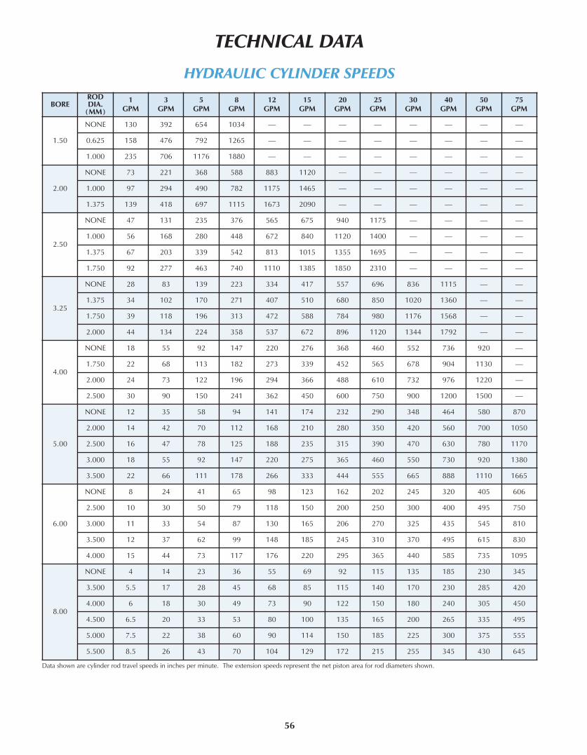
56
TECHNICAL DATA
BORERODDIA.
(MM)
1GPM
3GPM
5GPM
8GPM
12GPM
15GPM
20GPM
25GPM
30GPM
40GPM
50GPM
75GPM
1.50
NONE 130 392 654 1034 — — — — — — — —
0.625 158 476 792 1265 — — — — — — — —
1.000 235 706 1176 1880 — — — — — — — —
2.00
NONE 73 221 368 588 883 1120 — — — — — —
1.000 97 294 490 782 1175 1465 — — — — — —
1.375 139 418 697 1115 1673 2090 — — — — — —
2.50
NONE 47 131 235 376 565 675 940 1175 — — — —
1.000 56 168 280 448 672 840 1120 1400 — — — —
1.375 67 203 339 542 813 1015 1355 1695 — — — —
1.750 92 277 463 740 1110 1385 1850 2310 — — — —
3.25
NONE 28 83 139 223 334 417 557 696 836 1115 — —
1.375 34 102 170 271 407 510 680 850 1020 1360 — —
1.750 39 118 196 313 472 588 784 980 1176 1568 — —
2.000 44 134 224 358 537 672 896 1120 1344 1792 — —
4.00
NONE 18 55 92 147 220 276 368 460 552 736 920 —
1.750 22 68 113 182 273 339 452 565 678 904 1130 —
2.000 24 73 122 196 294 366 488 610 732 976 1220 —
2.500 30 90 150 241 362 450 600 750 900 1200 1500 —
5.00
NONE 12 35 58 94 141 174 232 290 348 464 580 870
2.000 14 42 70 112 168 210 280 350 420 560 700 1050
2.500 16 47 78 125 188 235 315 390 470 630 780 1170
3.000 18 55 92 147 220 275 365 460 550 730 920 1380
3.500 22 66 111 178 266 333 444 555 665 888 1110 1665
6.00
NONE 8 24 41 65 98 123 162 202 245 320 405 606
2.500 10 30 50 79 118 150 200 250 300 400 495 750
3.000 11 33 54 87 130 165 206 270 325 435 545 810
3.500 12 37 62 99 148 185 245 310 370 495 615 830
4.000 15 44 73 117 176 220 295 365 440 585 735 1095
8.00
NONE 4 14 23 36 55 69 92 115 135 185 230 345
3.500 5.5 17 28 45 68 85 115 140 170 230 285 420
4.000 6 18 30 49 73 90 122 150 180 240 305 450
4.500 6.5 20 33 53 80 100 135 165 200 265 335 495
5.000 7.5 22 38 60 90 114 150 185 225 300 375 555
5.500 8.5 26 43 70 104 129 172 215 255 345 430 645
HYDRAULIC CYLINDER SPEEDS
Data shown are cylinder rod travel speeds in inches per minute. The extension speeds represent the net piston area for rod diameters shown.

TECHNICAL DATA
57
BORE
RODDIA.
(MM)
MOUNT
ADD PERINCH OFSTROKEMxO
MxOwith KP ME5 ME6 MF1 MF2 MF5 MF6 MP1
MS2MS3MS7 MS4
MT1MT2 MT4
Mx1Mx2Mx3
1.500.625 7.2 7.3 9.1 8.8 7.6 8.2 8.6 9.0 7.6 7.8 7.2 7.6 9.5 7.4 .61.000 7.6 7.7 9.5 9.2 7.9 8.6 8.9 9.3 8.0 8.0 7.6 8.0 10 7.8 .8
2.001.000 11.5 11.7 14.2 13.8 12.6 13.9 14.7 15.6 12.7 12.8 11.4 12.7 16.5 12.1 1.01.375 12.3 12.5 15.2 14.6 13.7 14.7 15.5 16.4 13.5 13.6 12.2 13.5 17.0 12.9 1.4
2.501.000 16.1 17.3 19.3 18.8 17.1 19.5 19.4 20.8 17.3 19.4 15.8 17.2 22 16.8 1.31.375 16.7 16.9 19.9 19.4 17.7 19.9 19.6 21.3 17.9 19.9 16.4 17.8 22.5 17.2 1.81.750 18.1 18.3 21.3 20.8 19.1 21.3 21.2 22.7 19.3 21.2 17.5 19.2 24 18.6 2.3
3.251.375 32.8 35.3 38.6 37.9 35 38.9 39.6 42.5 36.2 36 32.2 35.4 42 33.7 2.31.750 33.7 34 39.5 38.8 35.9 39.8 40.5 43.4 37 37 33.1 36.1 43 34.6 2.92.000 34.3 34.6 40.1 39.4 36.5 40.4 41.1 44.0 37.7 38 33.7 36.7 43 35.3 3.2
4.001.750 44 47.3 50.6 49.8 47 52.5 53 57 50 50 43 47 54 45 3.12.000 45 47.7 51.6 50.8 48 53.5 54 58 51 51 44 48 55 46 3.42.500 47 47.5 54 53 50 55 56 60 52.5 53 46 49 56 48 4.4
5.00
2.000 79 87 89 88 83.5 93 92 100 86.5 85 78 80 93 82 4.82.500 81 88 91 90 85.5 95 94 102 90 87 80 83 96 84 5.23.000 85 90 95 94 89 99 98 105 92 91 84 87 99 88 7.03.500 86 87 96 95 90 100 99 106 93 92 85 88 100 89 8.4
6.00
2.500 124 134 140 140 131 145 145 153 137 136 122 127 143 128 6.53.000 126 135 142 142 133 147 147 159 139 138 124 129 145 130 7.83.500 128 136 144 144 135 149 149 160 141 140 126 131 147 132 9.24.000 132 139 148 148 139 153 152 164 145 144 130 135 151 136 10.9
8.00
3.500 256 275 288 288 266 290 285 305 282 277 253 263 288 265 11.74.000 261 277 293 293 271 295 290 310 286 282 258 268 293 270 13.34.500 264 279 296 296 274 298 293 313 289 285 261 271 296 273 14.45.000 268 281 300 300 278 302 297 317 294 289 265 275 301 277 17.55.500 276 285 308 308 285 309 304 324 301 297 273 282 308 285 19.7
WEIGHT CHARTS
HH SERIES BASIC CYLINDER WEIGHT CHARTWEIGHT�IN�POUNDS
All weights are in pounds.Note: Add 20% to mount and stroke weight for double rod end cylinders.
ACCESSORIESWEIGHT�IN�POUNDS
ROD CLEVIS ROD EYES EYE BRACKETS CLEVIS BRACKETS CLEVIS PINS WELD PLATE FLNG. END CPL.PART NO. WEIGHT PART NO. WEIGHT PART NO. WEIGHT PART NO. WEIGHT PART NO. WEIGHT PART NO. WEIGHT PART NO. WEIGHT PART NO. WEIGHTRC437 .40 RE437 .30 EB500 .86 CB500 .90 CP500C .12 CP500E .12 WP625 .45 FEC625 .41RC500 .40 RE500 .30 EB750 3.00 CB750 3.10 CP750C .38 CP750E .38 WP1000 .69 FEC1000 .65RC750 1.22 RE625 .30 EB1000 6.36 CB1000 6.20 CP1000C .80 CP1000E .80 WP1375 1.26 FEC1375 1.22
RC1000 2.58 RE750 1.10 EB1375 11.22 CB1375 9.70 CP1375C 1.22 CP1375E 1.22 WP1750 2.25 FEC1750 2.25RC1250 6.28 RE1000 2.40 EB1750 17.5 CB1750 17 CP1750C 4.1 CP1750E 3.78 WP2000 2.67 FEC2000 2.59RC1375 6.28 RE1250 5.58 EB2000 25 CB2000 26 CP2000C 5.36 CP2000E 4.93 WP2500 3.38 FEC2500 3.30RC1500 11.6 RE1375 5.58 EB2500 39 CB2500 37 CP2500C 9.42 CP2500E 9.22 WP3000 6.74 FEC3000 6.66RC1750 12.7 RE1500 10.52 EB3000 44 CB3000 44 CP3000C 13.69 CP3000E 13.57 WP3500 10.91 FEC3500 10.83RC1875 18 RE1875 11.5 EB3500 113 CB3500 113 CP3500C 24.42 CP3500E 24.12 WP4000 10.91 FEC4000 10.83RC2250 27 RE2250 23 EB4000 179 — — CP4000C 35.45 CP4000E 35.06 WP4500 14.26 FEC4500 14.86RC2500 36 RE2500 32 — — — — — — — — WP5000 14.26 FEC5000 14.86RC3250 71 RE3250 36 — — — — — — — — WP5500 22.55 FEC5500 22.47RC4000 107 RE3500 36 — — — — — — — — — — — —
— — RE4000 84 — — — — — — — — — — — —
ALIGNMENT COUPLERSWEIGHT�IN�POUNDS
PART NO. WEIGHT PART NO. WEIGHT PART NO. WEIGHT PART NO. WEIGHT PART NO. WEIGHTAC250 .30 AC625 .40 AC1375 7.50 AC2250 8.50 AC3500 39.5AC312 .30 AC750 1.10 AC1500 7.60 AC2500 28 AC3750 40.2AC375 .30 AC875 1.10 AC1750 7.60 AC2750 29.2 AC4000 55AC437 .30 AC1000 2.90 AC1875 8.00 AC3000 30.4 AC4500 60AC500 .30 AC1250 2.90 AC2000 8.30 AC3250 38 AC5000 66

TECHNICAL DATA
58
SEAL COMPATIBILITY
SEAL COMPATIBILITY WITH COMMON FLUIDSR�=�Recommended�����S�=�Satisfactory�����M�=�Marginal�����U�=�Unsatisfactory�����=�Insufficient�Data
FLUID NAMEMFG.CODE
MILITARYSPECIFICATION TRADE NAME/NUMBER COLOR
TYPE OF SEAL COMPOUND - COMMON NAME
BUNA-N BUTYL CORFAM EP VITON SILICONE NEOPRENE NAT. RUBBER POLYURE’NE
Water-Glycol 1 Houghto-Safe 600 Series red R R R R R S S R U
1 Houghto-Safe 500 Series red R R R R R S S R U
1 MIL-H22072 Houghto-Safe 271 red R R R R R S S — U
4 Ucon Hydrolube yel. or red R R R R R R/S S R U
4 Ucon M1 yellow R R R R R S S S U
5 Celluguard red R R R R R S S — U
10 Safety Fluid 200 bright pink R R R R R S S — U
Water/Oil 1 Houghto-Safe 5000 Series white R U R U R — S U U
Emulsion 3 FR creamy R U R U R — S U U
7 Irus 902 yellow R U R U R U S U M
8 Pyrogard C & D pale yellow R U R U R — S U U
Water-Soluble Oil — — milky R M R — R — S S M/U
Water-Fresh — — — R R R R R R M R M/U
Water-Salt — — — R R R R R R M R M/U
Phosphate Ester 1 Houghto-Safe 1000 Series green U R M/U R R M U U M
1 MIL-H-19547B Houghto-Safe 1120 green U R M/U R R M U U M
2 Pydraul F-9, 150, 625 cloudy bl. U R/S M/U S R R U U S
5 Fyrquel lt. green U R M/U R R M U U M
7 Shell SRF B.C.D. aqua gr. U R M/U R R M U U M
8 Pyrogard 42, 43, 53, 55, 190, 600 pale yel. U R M/U R R/S M U U M
2 Skydrol 500B purple U S U R U M U U U
2 Skydrol 7000 green U S U R U M U U U
2 Pydraul 312, 135 (2) blue gr. U M M M R R U U —
2 Pydraul AC cloudy bl. U S M/U S R R U U M/U
2 Pydraul 60 cloudy bl. U R M/U R U S U U M/U
8 Pydraul 210 (3) yellow U M — M R R U U M/U
Diester — MIL-H-7808 Lube Oil-Aircraft amber S U R U R U U U U
Clorinat. Hydrocarb 2 Aroclor 1200 Series 1 clear M S — S R S U U U
2 Pydraul A-200 cloudy bl. U M M M R R U U M/U
Silicate Ester 2 OS-45 Type 4 clear S U — S R U R U R
6 MILO-8200 Oronite 8200 clear S U — U R U R U R
6 MIL-8515 Oronite 8515 clear S U — U R U R U R
9 MIL-H-8446B Brayco 846 red brown S U — U R U R U R
Kerosene — clear R U R U R U M/U U R
Jet Fuel — MIL-J-5624 JP-3, 4, 5 (RP-1) lt. straw R U R U R U U U S
Diesel Fuel — — — clear R U R U R U M/U U R
Gasoline — — Gasoline various R U R/S U R U U U R
Petroleum Base — MIL-H-6083 Preservative Oil red R U R U R U R S R
Petroleum Base — MIL-H-5606 Aircraft Hyd. Fluid red R U R U R U S U R
Notes: (1) Halogenated(2) Petroleum and halogenated hydrocarbon
and phosphate ester mixture(3) Chlorinated phosphate ester
Manufacturer’s No. Manufacturer 4. Union Carbide & Chemical 8. Mobile OilCode Numbers 1. E.F. Houghton 5. Stauffer Chemical 9. Bray Oil - Royal Lubricant
2. Monsanto 6. Standard Oil (Ortho Chemical) 10. Texaco3. Gulf 7. Shell Chemical
ELASTOMER CHARACTERISTICS
ELASTOMER
STY
REN
EB
UTA
DIE
NE
BU
TY
L
CHLO
ROSU
LPH
ON
ATED
POLY
ETH
YLEN
ETH
YLE
NE
PR
OP
YLE
NE
FLU
OR
OC
AR
BO
N
FLU
OR
OSI
LIC
ON
E
NA
TU
RA
L
POLY
CH
LORO
PREN
E
NIT
RIL
E
PO
LYA
CR
YLI
C
PO
LYSU
LPH
IDE
PO
LYU
RET
HA
NE
SILI
CO
NE
EPIC
HLO
ROH
YDRI
N
PO
LYM
IDE
POLY
TETR
AFLU
OROE
THYL
ENE
SYMBOL SBR IIR CSM EPM V FPM FSI NR NBR ACM TR AU-EU SI ECDUPPER TEMP. LIMIT °F 194 500 212 248 284 347 392 176 230 266 320 221 212 392 284 896LOWER TEMP. LIMIT °F -58 -148 -22 -4 -49 5 -76 -76 -40 -49 -4 -67 -58 -76 -40 -400
ABRASION RESISTANCE S U M R • S • R R S • • R • S RCOMPRESSION SET RESIST. • • U M M S U R S R U U S S M •RESILIENCE M U U U U M U R S M M U S U S URADIATION U U • • • • M • • • • • S U U RWEATHER RESISTANCE M R R R R R R U U U R R R R S ROZONE RESISTANCE M R R R R R R M • M R S R R S •ADHESION TO METAL R S S R S R R R • R S R R R S S
R = RECOMMENDED S = SATISFACTORY M = MARGINAL U = UNSATISFACTORY • = CONSULT MFGR.

59
FRACTION EQUIVALENTS
FRACTION(INCHES)
DECIMAL(INCHES)
METRIC(MM)
(x 25.4)FRACTION(INCHES)
DECIMAL(INCHES)
METRIC(MM)
(x 25.4)FRACTION(INCHES)
DECIMAL(INCHES)
METRIC(MM)
(x 25.4)FRACTION(INCHES)
DECIMAL(INCHES)
METRIC(MM)
(x 25.4)1/64 .016 .4 17/64 .266 6.8 33/64 .516 13.1 49/64 .766 19.51/32 .031 .8 9/32 .281 7.1 17/32 .531 13.5 25/32 .781 19.83/64 .047 1.2 19/64 .297 7.5 35/64 .547 13.9 51/64 .797 20.21/16 .062 1.6 5/16 .312 7.9 9/16 .562 14.3 13/16 .812 20.65/64 .078 2.0 21/64 .328 8.3 37/64 .578 14.7 53/64 .828 21.03/32 .094 2.4 11/32 .344 8.7 19/32 .594 15.1 27/32 .844 21.47/64 .109 2.8 23/64 .359 9.1 39/64 .609 15.5 55/64 .859 21.81/8 .125 3.2 3/8 .375 9.5 5/8 .625 15.9 7/8 .875 22.2
9/64 .141 3.6 25/64 .391 9.9 41/64 .641 16.3 57/64 .891 22.65/32 .156 4.0 13/32 .406 10.3 21/32 .656 16.7 29/32 .906 23.0
11/64 .172 4.4 27.64 .422 10.7 43/64 .672 17.1 59/64 .922 23.43/16 .187 4.7 7/16 .437 11.1 11/16 .687 17.4 15/16 .937 23.8
13/64 .203 5.2 29/64 .453 11.5 45/64 .703 17.9 61/64 .953 24.27/32 .219 5.6 15/32 .469 11.9 23/32 .719 18.3 31/32 .969 24.6
15/64 .234 5.9 31/64 .484 12.3 47/64 .734 18.6 63/64 .984 25.01/4 .250 6.3 1/2 .500 12.7 3/4 .750 19.0 1 1.000 25.4
CONVERSION CHARTS
TEMPERATURE EQUIVALENTSFAHRENHEIT TO CELSIUS CONVERSION CELSIUS TO FAHRENHEIT CONVERSION
F° C° F° C° C° F° C° F°-30 -34.4 130 54.4 -30 -22 65 149-20 -28.9 140 60.0 -20 -4 70 158-10 -23.3 150 65.6 -10 14 75 1670 -17.8 160 71.1 0 32 80 176
10 -12.2 170 76.7 5 41 85 18520 -6.7 180 82.2 10 50 90 19430 -1.1 190 87.8 15 59 95 20340 4.4 200 93.3 20 68 100 21250 10.0 210 98.9 25 77 105 22160 15.6 220 104.4 30 86 110 23070 21.1 230 110.0 35 95 115 23980 26.7 240 115.6 40 104 120 24890 32.2 250 121.1 45 113 125 257
100 37.8 300 148.9 50 122 130 266110 43.3 350 176.7 55 131 150 302120 48.9 400 204.4 60 140 200 392
C° = (F° - 32) ÷ 1.8 F° = C° x 1.8 + 32
PRESSURE CONVERSIONSPSI KG/CM2 BARS KG/CM2 PSI BARS60 4.2 4.1 4 56.9 3.970 4.9 4.8 5 71.1 4.980 5.6 5.5 6 85.3 5.990 6.3 6.2 7 99.5 6.9
100 7.0 6.9 8 113.8 7.8150 10.5 10.3 9 128.0 8.8200 14.0 13.8 10 142.2 9.8250 17.6 17.2 20 284.4 19.6300 21.1 20.7 30 426.6 29.4350 24.6 24.1 40 568.8 39.2400 28.1 27.6 50 711.0 49.0450 31.6 31.0 60 853.2 58.8500 35.1 34.4 70 995.4 68.6550 38.7 37.9 80 1137.6 78.4600 42.2 41.3 90 1279.8 88.2650 45.7 44.8 100 1422.0 98.0700 49.2 48.2 150 2133.0 147.0750 52.7 51.7 200 2844.0 196.0800 56.2 55.1 250 3555.0 245.0850 59.8 58.6 300 4266.0 294.0900 63.3 62.0 350 4977.0 343.0950 66.8 65.5 — — —
1000 70.3 68.9 — — —1500 105.5 103.4 — — —2000 140.6 137.8 — — —2500 175.8 172.3 — — —3000 210.9 206.7 — — —3500 246.1 241.2 — — —4000 281.2 275.6 — — —4500 316.4 310.1 — — —5000 351.5 344.5 — — —
Kg/cm2 = PSI x .0703 PSI = Kg/cm2 x 14.22Bars = PSI x .0689 Bars = Kg/cm2 x .98
MEASUREMENT CONVERSIONSINCHES CM MM CM INCHES
1 2.5 25.4 1 .42 5.1 50.8 2 .83 7.6 76.2 3 1.24 10.2 101.6 4 1.65 12.7 127.0 5 2.06 15.2 152.4 6 2.47 17.8 177.8 7 2.88 20.3 203.2 8 3.19 22.9 228.6 9 3.5
10 25.4 254.0 10 3.915 38.1 381.0 20 7.920 50.8 508.0 30 11.825 63.5 635.0 40 15.830 76.2 762.0 50 19.735 88.9 889.0 60 23.640 101.6 1016.0 70 27.645 114.3 1143.0 80 31.550 127.0 1270.0 90 35.555 139.7 1397.0 100 39.460 152.4 1524.0 110 43.365 165.1 1651.0 120 47.370 177.8 1778.00 130 51.275 190.5 1905.0 140 55.280 203.2 2032.0 150 59.185 215.9 2159.0 160 63.090 228.6 2286.0 170 67.095 241.3 2413.0 180 70.9
100 254.0 2540.0 190 74.9— — — 200 78.8— — — 210 82.7— — — 220 86.7— — — 230 90.6— — — 240 94.6— — — 250 98.5— — — 260 102.4
cm = in. x 2.54 mm = in. x 25.4 in. = cm x .394

60
TECHNICAL DATA
PROPERTY WORD FORMULA MATHEMATIC EQUATION
FLUID PRESSUREpsi (Pounds per Square Inch)
Pressure =Force (lbs)Area (in2)
P =FA
CYLINDER AREA ExTENDin2 (Square Inches)
Area =FPiA4
x Diameter2 (inches) A = .7854 D2
CYLINDER AREA RETRACTin2 (Square Inches)
Area = ( FPi FPiA4
x Bore Diameter2) – (A4
x Rod Diameter2) A = (.7854 Db2) – (.7854 Dr
2)
CYLINDER FORCElbs. (Pounds of Force)
Force = Pressure (psi) x Net Area (in2) F = PA
CYLINDER VELOCITYft/s (Feet per Second)
Velocity =231 x Flow Rate (GPM)12 x 60 x Net Area (in2)
v =.3208 Q
A
CYLINDER VOLUMEG (Gallons of Fluid)
Volume =Net Area (in2) x Stroke (in)
231V =
A L231
CYLINDER FLOW RATEGPM (Gallons per Minute)
Flow Rate =12 x 60 x Velocity (ft/s) x Net Area (in2)
231Q = 3.117 v A
CYLINDER POWERhp (Horsepower)
Horsepower =Pressure (psi) x Flow Rate (GPM)
1714hp =
P Q1714
FLUID MOTOR TORQUElb-in (Inch Pounds)
Torque =Pressure (psi) x F.M. Displacement (in3/rev.)
2T =
P d2 2
Torque =Horsepower x 63025
RPMT =
63025 hpn
Torque =Flow Rate (GPM) x Pressure (psi) x 36.77
RPMT =
36.77 Q PN
FLUID MOTOR SPEEDRPM (Revolutions per Minute)
Speed =231 x Flow Rate (GPM)
F.M. Displacement (in3/rev.)n =
231 Qd
FLUID MOTOR POWERhp (Horsepower)
Horsepower =Torque (lbs-in) x RPM
63025hp =
T n 63025
PUMP OUTLET FLOWGPM (Gallons per Minute)
Flow =RPM x Pump Displacement (in3/rev.)
231Q =
n d231
FLOW RATE THROUGH PIPINGft/s Velocity (Feet per Second)
Velocity =.3208 x Flow Rate Through I.D. (GPM)
Internal Area (in2)v =
.3208 QA
TORQUE REQUIREMENTlb-in (Inch Pounds)
Torque = Lever Length (in.) x Pull (lbs.) T = L x F
COMMON FLUID POWER FORMULAS

Worldwide Distribution means there is a Professional DistributorRepresentative nearby – wherever you are – ready to service your needs.
Ask Your Local Distributor About These Other Products:
61
NFPA Aluminum Cylinders1.5” thru 12” BoresStrokes up to 120 inchesPermanent Lubrication
Series:FM, TA, TD, BTB, 3-P, MSE,MSR, TM, TRA, AT
Request Catalog:CAT-TRD1-0606
ISO 6431 Aluminum Cylinders32mm thru 100mm BoresStrokes up to 2800mmPermanent Lubrication
Series: AB
Request Catalog:CAT-ISO-1006
NFPA Stainless SteelCylinders
1.5” thru 8” BoresStrokes up to 120 inchesPermanent Lubrication
Series:SS, SS-AT, SS-MSE, SS-MSR
Request Catalog:CAT-TRDSS-0507
Round Stainless SteelCylinders
USDA-FDA approved1.5” thru 8” BoresStrokes up to 24 inchesNFPA interchangablePermanent Lubrication
Series: RS
Request Catalog:TRD-RS-11-07
Cylinders with continuouspiston rod position sensing
1.5” thru 8” BoresStrokes up to 24 inchesPermanent Lubrication
Series: PFLF
Positioning Systems
Request Catalog:PFLF-0601
Aluminum 2-StageTelescoping Cylinders
0.75”, 1.50”, 2.50”effective BoresStrokes up to 60 inchesPermanent Lubrication
Series: TC
Request Catalog:TRD-TC-1207
Steel Bench Top PressFrames and Cylinders
1.2 Ton to 5 TonStrokes up to 5 inchesPermanent Lubrication
Series: BTP
Request Catalog:TRD-BTP-0905
FM Series with Rod Lock1.50” thru 6” BoresStrokes up to 120 inchesPermanent Lubrication
Series: FM, RL
Request Catalog:TRD-RL-1008

©Copyright 2009 TRD Manufacturing, Inc. All Rights Reserved.
TRD DELIVERIES (F.O.B. Factory)
SERIES DELIVERY SCHEDULE
HH (HEAVY-DUTY HYDRAULIC - Up to 3000 PSI HYD) . . . . . . . . . . . . . . . . . 2-3 DAYSHH (HEAVY-DUTY HYDRAULIC) WITH ROD LOCK . . . . . . . . . . . . . . . . . . .3-4 WEEKSEN (ELECTROLESS NICKEL) . . . . . . . . . . . . . . . . . . . . . . . . . . . . . . . . . . . . . .7-10 DAYSTA (ALUMINUM - 250 PSI AIR) . . . . . . . . . . . . . . . . . . . . . . . . . . . . . . . . . . . . 2-3 DAYSTD (ALUMINUM - 250 PSI AIR) . . . . . . . . . . . . . . . . . . . . . . . . . . . . . . . . . . . 2-3 DAYSTRA (ALUMINUM - TRIPLE ROD) . . . . . . . . . . . . . . . . . . . . . . . . . . . . . . . . . . 2-3 DAYSFM (ALUMINUM - FLUSH MOUNT) WITH ROD LOCK . . . . . . . . . . . . . . . . . 2-3 DAYSBACK-TO-BACK (ALUMINUM - 250 PSI AIR) . . . . . . . . . . . . . . . . . . . . . . . . . 2-3 DAYS3-POSITION (ALUMINUM - 250 PSI AIR) . . . . . . . . . . . . . . . . . . . . . . . . . . . . 2-3 DAYSTANDEM (ALUMINUM - 250 PSI AIR OR 400 PSI HYD.) . . . . . . . . . . . . . . . . 2-3 DAYSMSE/MSR (ALUMINUM - MULTI-STAGE) . . . . . . . . . . . . . . . . . . . . . . . . . . . . 2-3 DAYSAIR BOOSTERS . . . . . . . . . . . . . . . . . . . . . . . . . . . . . . . . . . . . . . . . . . . . . . . . 2-3 DAYSAIR/OIL TANKS . . . . . . . . . . . . . . . . . . . . . . . . . . . . . . . . . . . . . . . . . . . . . . . . 2-3 DAYSTRD SWITCHES (R10, R10P, RAC, RHT, MSS) . . . . . . . . . . . . . . . . . . . . . . . . . . . .1 DAYBALLUFF STROKEMASTER / MICROPULSE . . . . . . . . . . . . . . . . . . . . . . . . . . . 5-7 DAYSMTS TEMPOSONICS . . . . . . . . . . . . . . . . . . . . . . . . . . . . . . . . . . . . . . . . . .10-15 DAYSROD CLEVIS, PINS, MOUNTS & ALIGNMENT COUPLERS . . . . . . . . . . . . . . . . . .1 DAYSS (STAINLESS STEEL - ALL STANDARD MODELS) . . . . . . . . . . . . . . . . . . . . . 3-5 DAYSSS-MS (STAINLESS STEEL - MULTI-STAGE) . . . . . . . . . . . . . . . . . . . . . . . . . . . 3-5 DAYS
STANDARD OPTIONS INCLUDED IN ABOVE DELIVERIES
RUSH SERVICES ARE AVAILABLE FOR ALL TRD PRODUCTS.CONTACT YOUR LOCAL TRD DISTRIBUTOR FOR DETAILS.
YOUR LOC A L D I S T R I B U TOR I S :
www.bimba.com
CAT-TRDHH-0609 Printed in the U.S.A.
10914 N. 2ND STREET • MACHESNEY PARK, ILLINOIS 61115-1400
PHONE: (815) 654-7775 • FAX: (815) 654-0690
WEBSITE: WWW.TRDMFG.COM • E-MAIL: [email protected]