HEAT EXCHANGER, AFTERCOOLER, AND SEPARATOR MAINTENANCE...
16
C 5.51 Bulletin 710 D R.P. ADAMS Subsidiary of Service Filtration Corporation HEAT EXCHANGER, AFTERCOOLER, AND SEPARATOR MAINTENANCE MANUAL P. O. Box 963 Buffalo, NY 14240 Phone (716) 877-2608 Toll Free (800) 896-8869 Fax (716) 877-9385 Website: www.rpadams.com Email: [email protected]
Transcript of HEAT EXCHANGER, AFTERCOOLER, AND SEPARATOR MAINTENANCE...

C 5.51 Bulletin 710 D
R.P. ADAMS Subs id ia ry o f Serv ice F i l t ra t ion Corpora t ion
HEAT EXCHANGER, AFTERCOOLER,
AND SEPARATOR MAINTENANCE MANUAL
P . O . B o x 9 6 3 B u f f a l o , N Y 1 4 2 4 0
P h o n e ( 7 1 6 ) 8 7 7 - 2 6 0 8 T o l l F r e e ( 8 0 0 ) 8 9 6 - 8 8 6 9
F a x ( 7 1 6 ) 8 7 7 - 9 3 8 5 W e b s i t e : w w w . r p a d a m s . c o m
E m a i l : i n f o @ r p a d a m s . c o m
R. P. ADAMS MAINTENANCE MANUAL
Page No. 2 Issue Date: October 22, 2004
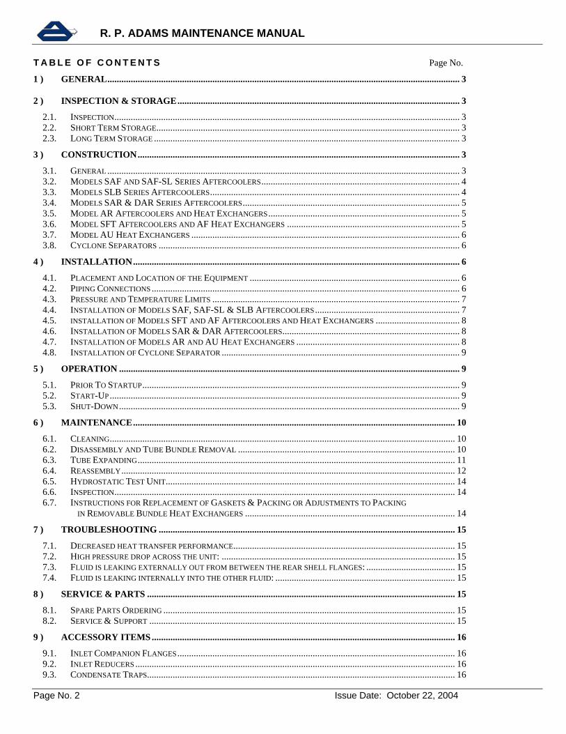
T A B L E O F C O N T E N T S Page No.
1 ) GENERAL....................................................................................................................................................... 3
2 ) INSPECTION & STORAGE......................................................................................................................... 3
2.1. INSPECTION.................................................................................................................................................... 3 2.2. SHORT TERM STORAGE.................................................................................................................................. 3 2.3. LONG TERM STORAGE ................................................................................................................................... 3
3 ) CONSTRUCTION.......................................................................................................................................... 3
3.1. GENERAL ....................................................................................................................................................... 3 3.2. MODELS SAF AND SAF-SL SERIES AFTERCOOLERS..................................................................................... 4 3.3. MODELS SLB SERIES AFTERCOOLERS........................................................................................................... 4 3.4. MODELS SAR & DAR SERIES AFTERCOOLERS............................................................................................. 5 3.5. MODEL AR AFTERCOOLERS AND HEAT EXCHANGERS.................................................................................. 5 3.6. MODEL SFT AFTERCOOLERS AND AF HEAT EXCHANGERS .......................................................................... 5 3.7. MODEL AU HEAT EXCHANGERS ................................................................................................................... 6 3.8. CYCLONE SEPARATORS ................................................................................................................................. 6
4 ) INSTALLATION............................................................................................................................................ 6
4.1. PLACEMENT AND LOCATION OF THE EQUIPMENT .......................................................................................... 6 4.2. PIPING CONNECTIONS .................................................................................................................................... 6 4.3. PRESSURE AND TEMPERATURE LIMITS .......................................................................................................... 7 4.4. INSTALLATION OF MODELS SAF, SAF-SL & SLB AFTERCOOLERS.............................................................. 7 4.5. INSTALLATION OF MODELS SFT AND AF AFTERCOOLERS AND HEAT EXCHANGERS .................................... 8 4.6. INSTALLATION OF MODELS SAR & DAR AFTERCOOLERS............................................................................ 8 4.7. INSTALLATION OF MODELS AR AND AU HEAT EXCHANGERS ...................................................................... 8 4.8. INSTALLATION OF CYCLONE SEPARATOR ...................................................................................................... 9
5 ) OPERATION .................................................................................................................................................. 9
5.1. PRIOR TO STARTUP........................................................................................................................................ 9 5.2. START-UP...................................................................................................................................................... 9 5.3. SHUT-DOWN.................................................................................................................................................. 9
6 ) MAINTENANCE.......................................................................................................................................... 10
6.1. CLEANING.................................................................................................................................................... 10 6.2. DISASSEMBLY AND TUBE BUNDLE REMOVAL ............................................................................................. 10 6.3. TUBE EXPANDING........................................................................................................................................ 11 6.4. REASSEMBLY............................................................................................................................................... 12 6.5. HYDROSTATIC TEST UNIT............................................................................................................................ 14 6.6. INSPECTION.................................................................................................................................................. 14 6.7. INSTRUCTIONS FOR REPLACEMENT OF GASKETS & PACKING OR ADJUSTMENTS TO PACKING IN REMOVABLE BUNDLE HEAT EXCHANGERS .......................................................................................... 14
7 ) TROUBLESHOOTING ............................................................................................................................... 15
7.1. DECREASED HEAT TRANSFER PERFORMANCE............................................................................................... 15 7.2. HIGH PRESSURE DROP ACROSS THE UNIT: .................................................................................................... 15 7.3. FLUID IS LEAKING EXTERNALLY OUT FROM BETWEEN THE REAR SHELL FLANGES: ...................................... 15 7.4. FLUID IS LEAKING INTERNALLY INTO THE OTHER FLUID: ............................................................................. 15
8 ) SERVICE & PARTS .................................................................................................................................... 15
8.1. SPARE PARTS ORDERING ............................................................................................................................. 15 8.2. SERVICE & SUPPORT ................................................................................................................................... 15
9 ) ACCESSORY ITEMS .................................................................................................................................. 16
9.1. INLET COMPANION FLANGES....................................................................................................................... 16 9.2. INLET REDUCERS ......................................................................................................................................... 16 9.3. CONDENSATE TRAPS.................................................................................................................................... 16

R. P. ADAMS MAINTENANCE MANUAL
Page No. 3 Issue Date: October 22, 2004
Inlet Outlet
FixedTubesheet
FloatingTubesheet
Baffles
Tubes
Inlet Outlet
FixedTubesheet
FloatingTubesheet
Baffles
Tubes
Figure 1 Removable Straight Tube Bundle
1 ) GENERAL
Your new R. P. Adams Heat Exchanger is designed and constructed to provide years of trouble free service. However, it must be operated and maintained in accordance with several simple, yet essential rules as described in this manual. Please read and understand all of these instructions carefully.
2 ) INSPECTION & STORAGE
2.1. Inspection Upon receipt of the heat exchanger, inspect for shipping damage to the unit and/or to the protective shipping covers. If damage is evident, check the integrity of the unit and inspect for possible foreign matter that may have gotten into the connections of the unit. If damage has occurred, notify the carrier immediately and file a damage claim. If damage is significant, then it is best to have a factory-authorized representative inspect the equipment prior to installation and operation. Arrangements can be made by contacting the factory at the address noted on the front cover of this manual.
2.2. Short Term Storage If the equipment is not placed in service immediately it should be stored indoors with temperature control between 40°F and 90°F and humidity control less than or equal to 50% relative humidity. Unheated inside storage or lack of humidity controls should be minimized whenever possible. Outside storage is not recommended unless the unit was specifically designed for these conditions.
2.3. Long Term Storage Equipment should be stored as per Section 2.2. All process, vent and drain connections should be sealed. For extended periods, it is best to have the chambers of the unit pressurized with an inert gas, which means that provisions for long-term storage must be made in advance of storing the equipment. In addition, equipment should be checked periodically to insure gas pressure is maintained.
3 ) CONSTRUCTION
3.1. General An Adams shell and tube heat exchanger consists primarily of a tube bundle within a shell. Each tube bundle is made up of a series of tubes, with one or two tubesheets depending upon the design, and corrosion resistant non-metallic baffling unless specified otherwise.
For removable bundle straight tube designs, the unit includes gaskets on the front and back of the stationary tubesheet and two (2) thick square rubber packing rings separated by a tell-tale vent ring on the floating rear tubesheet, which is fitted partially into the shell and partially into either a packing gland, channel, or bonnet. The telltale vent ring prevents cross contamination of the fluids in the unlikely event of a packing leak. The bundle can be removed from the shell at the fixed tubesheet
R. P. ADAMS MAINTENANCE MANUAL
Page No. 4 Issue Date: October 22, 2004
Figure 4. SLB Aftercooler with
integral Separator.
ADAMSAIRIN
AIR OUT
Moisture Reservoir
Sight Glass
WATER OUT Packing Gland SeparatorSeparator
WATER INName Plate
Inlet Companion Flange
TubesBaffles
Centering Screw Assembly
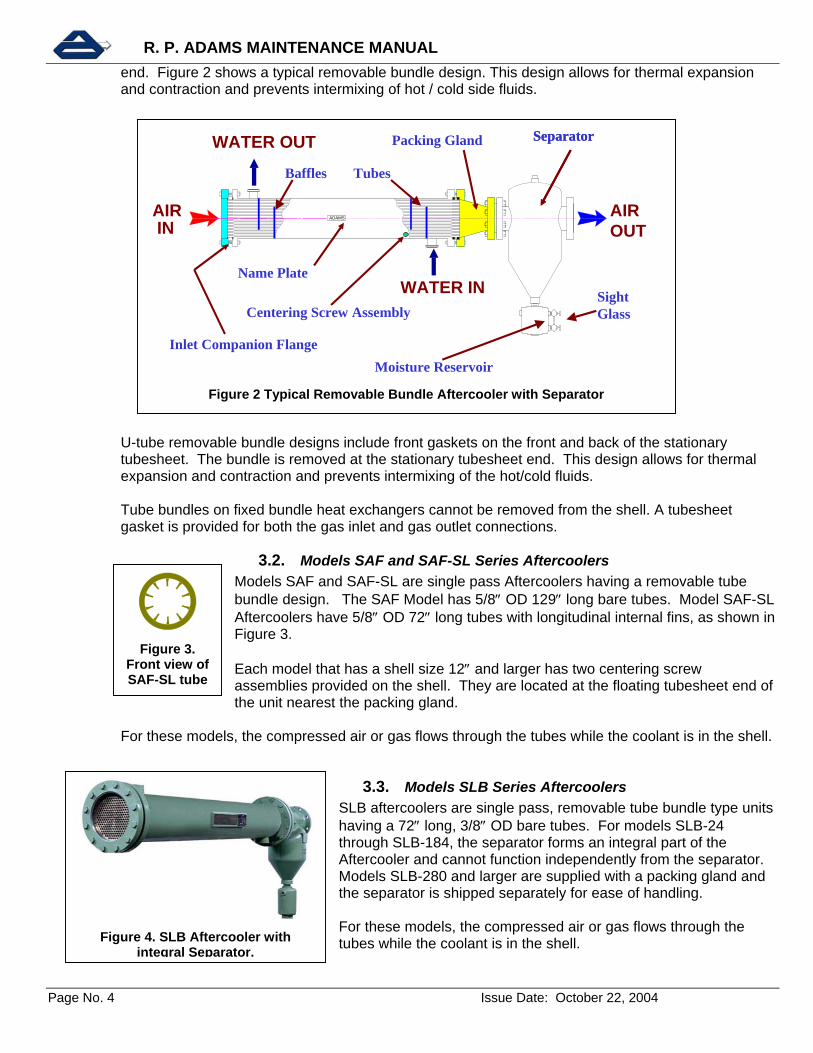
Figure 2 Typical Removable Bundle Aftercooler with Separator
Figure 3.
Front view of SAF-SL tube
end. Figure 2 shows a typical removable bundle design. This design allows for thermal expansion and contraction and prevents intermixing of hot / cold side fluids.
U-tube removable bundle designs include front gaskets on the front and back of the stationary tubesheet. The bundle is removed at the stationary tubesheet end. This design allows for thermal expansion and contraction and prevents intermixing of the hot/cold fluids. Tube bundles on fixed bundle heat exchangers cannot be removed from the shell. A tubesheet gasket is provided for both the gas inlet and gas outlet connections.
3.2. Models SAF and SAF-SL Series Aftercoolers Models SAF and SAF-SL are single pass Aftercoolers having a removable tube bundle design. The SAF Model has 5/8″ OD 129″ long bare tubes. Model SAF-SL Aftercoolers have 5/8″ OD 72″ long tubes with longitudinal internal fins, as shown in Figure 3.
Each model that has a shell size 12″ and larger has two centering screw assemblies provided on the shell. They are located at the floating tubesheet end of the unit nearest the packing gland.
For these models, the compressed air or gas flows through the tubes while the coolant is in the shell.
3.3. Models SLB Series Aftercoolers SLB aftercoolers are single pass, removable tube bundle type units having a 72″ long, 3/8″ OD bare tubes. For models SLB-24 through SLB-184, the separator forms an integral part of the Aftercooler and cannot function independently from the separator. Models SLB-280 and larger are supplied with a packing gland and the separator is shipped separately for ease of handling. For these models, the compressed air or gas flows through the tubes while the coolant is in the shell.
R. P. ADAMS MAINTENANCE MANUAL
Page No. 5 Issue Date: October 22, 2004
Figure 5. SAR Removable Bundle Aftercooler.
Figure 7. SFT Fixed Tube Aftercoolers
with companion flanges.
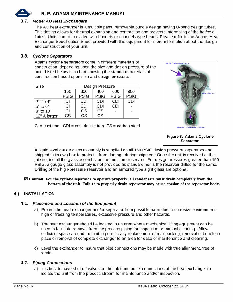
Figure 6. Bonnet and Channel ends for SAR & DAR
Aftercoolers.
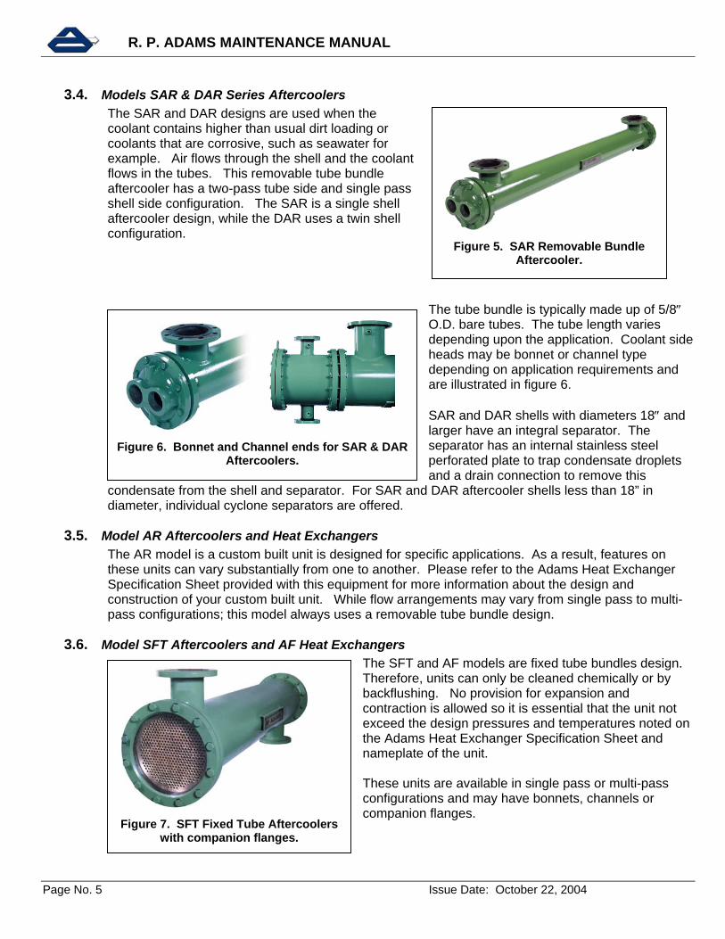
3.4. Models SAR & DAR Series Aftercoolers The SAR and DAR designs are used when the coolant contains higher than usual dirt loading or coolants that are corrosive, such as seawater for example. Air flows through the shell and the coolant flows in the tubes. This removable tube bundle aftercooler has a two-pass tube side and single pass shell side configuration. The SAR is a single shell aftercooler design, while the DAR uses a twin shell configuration.
The tube bundle is typically made up of 5/8″ O.D. bare tubes. The tube length varies depending upon the application. Coolant side heads may be bonnet or channel type depending on application requirements and are illustrated in figure 6.
SAR and DAR shells with diameters 18″ and larger have an integral separator. The separator has an internal stainless steel perforated plate to trap condensate droplets and a drain connection to remove this
condensate from the shell and separator. For SAR and DAR aftercooler shells less than 18” in diameter, individual cyclone separators are offered.
3.5. Model AR Aftercoolers and Heat Exchangers The AR model is a custom built unit is designed for specific applications. As a result, features on these units can vary substantially from one to another. Please refer to the Adams Heat Exchanger Specification Sheet provided with this equipment for more information about the design and construction of your custom built unit. While flow arrangements may vary from single pass to multi-pass configurations; this model always uses a removable tube bundle design.
3.6. Model SFT Aftercoolers and AF Heat Exchangers The SFT and AF models are fixed tube bundles design. Therefore, units can only be cleaned chemically or by backflushing. No provision for expansion and contraction is allowed so it is essential that the unit not exceed the design pressures and temperatures noted on the Adams Heat Exchanger Specification Sheet and nameplate of the unit.
These units are available in single pass or multi-pass configurations and may have bonnets, channels or companion flanges.
R. P. ADAMS MAINTENANCE MANUAL
Page No. 6 Issue Date: October 22, 2004
Figure 8. Adams Cyclone Separator.
3.7. Model AU Heat Exchangers The AU heat exchanger is a multiple pass, removable bundle design having U-bend design tubes. This design allows for thermal expansion and contraction and prevents intermixing of the hot/cold fluids. Units can be provided with bonnets or channels type heads. Please refer to the Adams Heat Exchanger Specification Sheet provided with this equipment for more information about the design and construction of your unit.
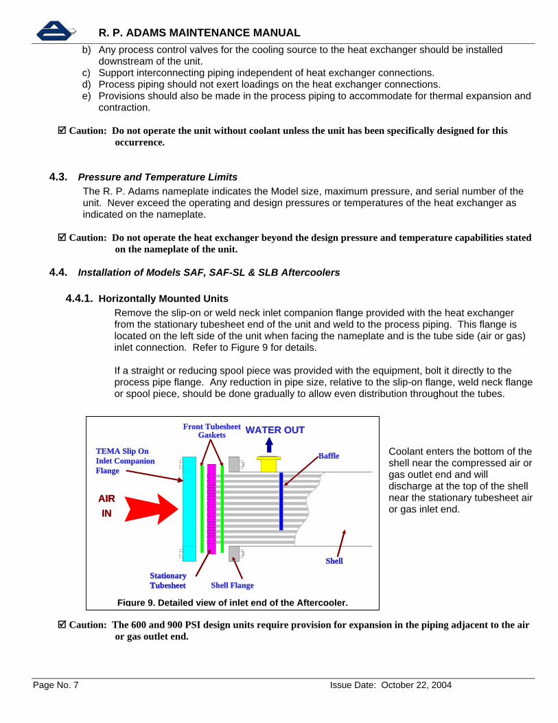
3.8. Cyclone Separators Adams cyclone separators come in different materials of construction, depending upon the size and design pressure of the unit. Listed below is a chart showing the standard materials of construction based upon size and design pressure: Size Design Pressure 150
PSIG 300
PSIG 400
PSIG 600
PSIG 900
PSIG 2″ To 4″ 5” to 6” 8” to 10” 12” & larger
CI CI CI CS
CDI CDI CS CS
CDI CDI CS CS
CDI CDI
-
CDI - -
CI = cast iron CDI = cast ductile iron CS = carbon steel A liquid level gauge glass assembly is supplied on all 150 PSIG design pressure separators and shipped in its own box to protect it from damage during shipment. Once the unit is received at the jobsite, install the glass assembly on the moisture reservoir. For design pressures greater than 150 PSIG, a gauge glass assembly is not provided as standard nor is the reservoir drilled for the same. Drilling of the high-pressure reservoir and an armored type sight glass are optional.
Caution: For the cyclone separator to operate properly, all condensate must drain completely from the bottom of the unit. Failure to properly drain separator may cause erosion of the separator body.
4 ) INSTALLATION
4.1. Placement and Location of the Equipment a) Protect the heat exchanger and/or separator from possible harm due to corrosive environment,
high or freezing temperatures, excessive pressure and other hazards.
b) The heat exchanger should be located in an area where mechanical lifting equipment can be used to facilitate removal from the process piping for inspection or manual cleaning. Allow sufficient space around the unit to permit easy replacement of rear packing, removal of bundle in place or removal of complete exchanger to an area for ease of maintenance and cleaning.
c) Level the exchanger to insure that pipe connections may be made with true alignment, free of
strain.
4.2. Piping Connections a) It is best to have shut off valves on the inlet and outlet connections of the heat exchanger to
isolate the unit from the process stream for maintenance and/or inspection.
R. P. ADAMS MAINTENANCE MANUAL
Page No. 7 Issue Date: October 22, 2004
AIR IN
WATER OUT
Stationary Tubesheet
Shell
TEMA Slip On Inlet Companion Flange
Front TubesheetGaskets
Shell Flange
Baffle
AIR IN
WATER OUT
Stationary TubesheetStationary Tubesheet
ShellShell
TEMA Slip On Inlet Companion Flange
Front TubesheetGaskets
Shell Flange
Baffle
Figure 9. Detailed view of inlet end of the Aftercooler.
b) Any process control valves for the cooling source to the heat exchanger should be installed downstream of the unit.
c) Support interconnecting piping independent of heat exchanger connections. d) Process piping should not exert loadings on the heat exchanger connections. e) Provisions should also be made in the process piping to accommodate for thermal expansion and
contraction.
Caution: Do not operate the unit without coolant unless the unit has been specifically designed for this occurrence.
4.3. Pressure and Temperature Limits The R. P. Adams nameplate indicates the Model size, maximum pressure, and serial number of the unit. Never exceed the operating and design pressures or temperatures of the heat exchanger as indicated on the nameplate.
Caution: Do not operate the heat exchanger beyond the design pressure and temperature capabilities stated on the nameplate of the unit.
4.4. Installation of Models SAF, SAF-SL & SLB Aftercoolers
4.4.1. Horizontally Mounted Units Remove the slip-on or weld neck inlet companion flange provided with the heat exchanger from the stationary tubesheet end of the unit and weld to the process piping. This flange is located on the left side of the unit when facing the nameplate and is the tube side (air or gas) inlet connection. Refer to Figure 9 for details. If a straight or reducing spool piece was provided with the equipment, bolt it directly to the process pipe flange. Any reduction in pipe size, relative to the slip-on flange, weld neck flange or spool piece, should be done gradually to allow even distribution throughout the tubes.
Coolant enters the bottom of the shell near the compressed air or gas outlet end and will discharge at the top of the shell near the stationary tubesheet air or gas inlet end.
Caution: The 600 and 900 PSI design units require provision for expansion in the piping adjacent to the air or gas outlet end.
R. P. ADAMS MAINTENANCE MANUAL
Page No. 8 Issue Date: October 22, 2004
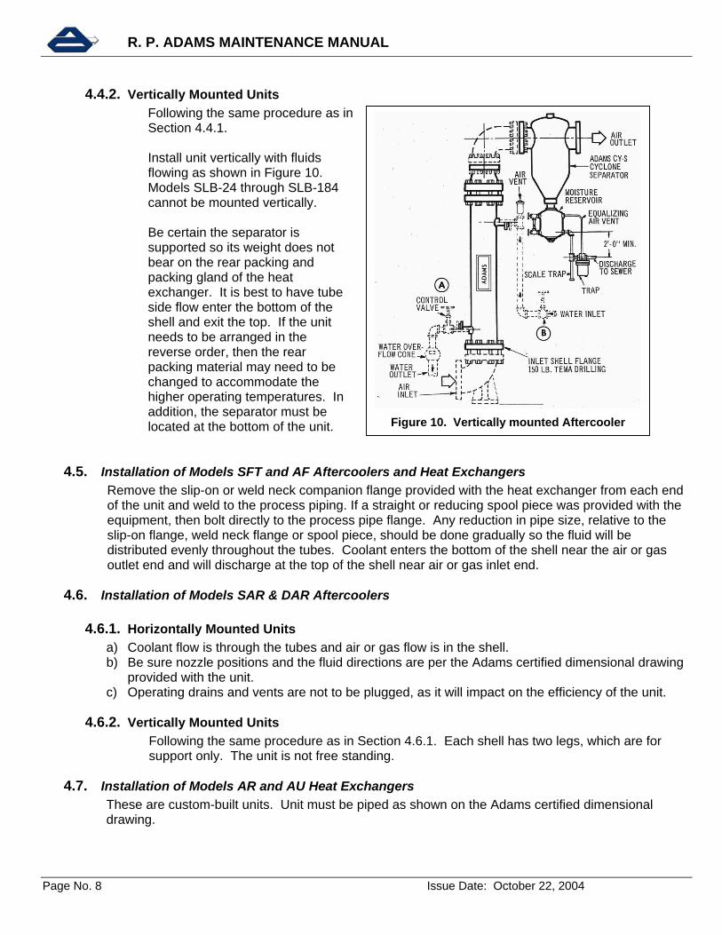
Figure 10. Vertically mounted Aftercooler
4.4.2. Vertically Mounted Units Following the same procedure as in Section 4.4.1. Install unit vertically with fluids flowing as shown in Figure 10. Models SLB-24 through SLB-184 cannot be mounted vertically. Be certain the separator is supported so its weight does not bear on the rear packing and packing gland of the heat exchanger. It is best to have tube side flow enter the bottom of the shell and exit the top. If the unit needs to be arranged in the reverse order, then the rear packing material may need to be changed to accommodate the higher operating temperatures. In addition, the separator must be located at the bottom of the unit.
4.5. Installation of Models SFT and AF Aftercoolers and Heat Exchangers Remove the slip-on or weld neck companion flange provided with the heat exchanger from each end of the unit and weld to the process piping. If a straight or reducing spool piece was provided with the equipment, then bolt directly to the process pipe flange. Any reduction in pipe size, relative to the slip-on flange, weld neck flange or spool piece, should be done gradually so the fluid will be distributed evenly throughout the tubes. Coolant enters the bottom of the shell near the air or gas outlet end and will discharge at the top of the shell near air or gas inlet end.
4.6. Installation of Models SAR & DAR Aftercoolers
4.6.1. Horizontally Mounted Units a) Coolant flow is through the tubes and air or gas flow is in the shell. b) Be sure nozzle positions and the fluid directions are per the Adams certified dimensional drawing
provided with the unit. c) Operating drains and vents are not to be plugged, as it will impact on the efficiency of the unit.
4.6.2. Vertically Mounted Units Following the same procedure as in Section 4.6.1. Each shell has two legs, which are for support only. The unit is not free standing.
4.7. Installation of Models AR and AU Heat Exchangers These are custom-built units. Unit must be piped as shown on the Adams certified dimensional drawing.

R. P. ADAMS MAINTENANCE MANUAL
Page No. 9 Issue Date: October 22, 2004
4.8. Installation of Cyclone Separator a) All cyclone separators are shipped separate from the aftercooler except for aftercooler models
SLB-24 through SLB-184, which are shipped assembled. b) Always install the separator as close to the aftercooler outlet as possible to maintain maximum
efficiency. c) It is important that the separator be installed in the proper direction in which the air or gas flows.
The separator has a flow direction arrow on its body to facilitate its proper installation. d) The bottom of the cyclone separator has a moisture reservoir to collect the condensate from the
gas stream and act as a silencer. To ensure optimum performance, all condensate must be drained manually or automatically from the separator. It is best to have a condensate trap downstream of the separator.
e) Do not connect more than one drain to a trap. f) Do not allow condensate to back up into the separator body. This will cause moisture to carry
over into the system affecting performance of equipment and product quality downstream. If the condensate is allowed to fill the separator body it will ultimately damage the body by an erosion corrosion mechanism.
g) For models SAR and DAR that have air or gas in the shell and the integral separator, use a separate trap for the shell side drain and another trap for the integral separator drain.
Caution: For the cyclone separator to operate properly, all condensate must drain completely from the
bottom of the separator. 5 ) OPERATION
5.1. Prior To Startup a) Ensure that all piping to and from the heat exchanger has been connected properly and in the
right direction of flow. b) Check to see that the unit has the proper drainage, vents and controls as required. c) Retighten external bolting on the exchanger. d) Clean or flush interconnecting piping and other equipment in system using a strainer in front of
the exchanger. e) Check safety devices, range and scales of instruments. f) Instruct operating personnel of unit limits, capabilities and function.
5.2. Start-Up a) Always circulate the cooling source first to prevent damaging baffles, packing and tube joints. b) Vent air from process piping and equipment. c) After full flow is obtained gradually, introduce the hot fluid. d) Avoid sudden temperature and pressure shocks. e) It is important to provide the recommended water flow rate to prevent fouling or erosion in the
unit. f) Do not operate without coolant unless unit has been designed for this occurrence.
Caution: Cold fluid should always be turned on first, and turned off last.
5.3. Shut-Down a) Shut down the hot fluid first. b) Stop the circulation of the coolant after a sufficient time has passed to allow the heat exchanger to
cool.
R. P. ADAMS MAINTENANCE MANUAL
Page No. 10 Issue Date: October 22, 2004
6 ) MAINTENANCE
6.1. Cleaning Heat exchangers are subject to many types of fouling by inert and organic deposits. Early detection and removal keeps the units thermal performance at its best, holds pressure losses to a minimum and reduces the likelihood of corrosion.
Some deposits can be removed by periodic backwashing. Removal of others can be accomplished by circulating a chemical cleaning solution. Other methods include brushing clean or mechanical rod out of the tubes.
Caution: Be sure cleaning solutions are compatible with materials of construction of the heat exchanger.
When in-plant cleaning capabilities are not available, a reliable cleaning service with trained technicians capable of analysis and equipped to perform a professional cleaning should be consulted. a) Avoid use of devices that score or scratch the smooth tube surfaces. b) When non-metallic baffles are used, avoid circulation of hot steam or liquids greater than the
design temperature.
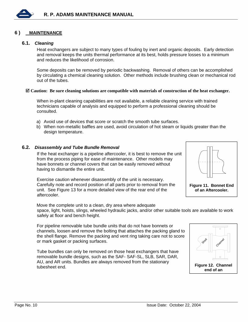
6.2. Disassembly and Tube Bundle Removal If the heat exchanger is a pipeline aftercooler, it is best to remove the unit from the process piping for ease of maintenance. Other models may have bonnets or channel covers that can be easily removed without having to dismantle the entire unit. Exercise caution whenever disassembly of the unit is necessary. Carefully note and record position of all parts prior to removal from the unit. See Figure 13 for a more detailed view of the rear end of the
aftercooler.
Move the complete unit to a clean, dry area where adequate space, light, hoists, slings, wheeled hydraulic jacks, and/or other suitable tools are available to work safely at floor and bench height.
For pipeline removable tube bundle units that do not have bonnets or channels, loosen and remove the bolting that attaches the packing gland to the shell flange. Remove the packing and vent ring taking care not to score or mark gasket or packing surfaces. Tube bundles can only be removed on those heat exchangers that have removable bundle designs, such as the SAF- SAF-SL, SLB, SAR, DAR, AU, and AR units. Bundles are always removed from the stationary tubesheet end.
Figure 11. Bonnet End
of an Aftercooler.
Shell
Chann
el
Figure 12. Channel
end of an

R. P. ADAMS MAINTENANCE MANUAL
Page No. 11 Issue Date: October 22, 2004
SHELL
JAM NUT
TFE GASKET
DISC1/4" DIA. - 20 T.P.I
ADAPTOR
JACKSCREW
1 ¼ " NPT HALF CPLG
Figure 14: Jack screw assembly detail.
AIR OUT
Floating Tubesheet
ShellShell
PackingGland
Vent RingPacking
Baffle
Shell Flange
WATER IN Figure 13. Rear end detail of an aftercooler.
Caution: To avoid baffle damage, do not drag tube bundles. Units having shell diameters of 12” and larger are equipped with two (2) rear floating tubesheet centering jacks. Move the heat exchanger so the jack assemblies, as shown in figure 14, are at the two and four o’clock or eight and ten o’clock position. This will place the baffle cuts in a vertical position, which is important on 30” diameter and larger shells. Remove jack adapters having the jack screw, jam nut, gasket, and adapter. Also remove jack discs by use of a suitable threaded bolt. Pull bundle of straight tube removable bundle units by means of rods inserted through the tubes and attached to a bearing plate cushioned by a soft material sandwiched between the floating tubesheet and the bearing plate. Pull the bundle straight and true. U-Bend bundles are removed by gripping behind the stationary tubesheet. Be sure not to damage the gasket surfaces. Support the bundle as it emerges. Protect tubes and baffles from damage by using suitable slings that avoid concentrated loading on a small area. Protect disassembled parts from damage and dirt.
Caution: When removing tube bundles from heat exchangers, exercise care to ensure that the bundle is not damaged. The weight of the bundle should be supported on tubesheets rather than individual tubes.
6.3. Tube Expanding a) Tube joints may be field expanded by a qualified mechanic.
R. P. ADAMS MAINTENANCE MANUAL
Page No. 12 Issue Date: October 22, 2004
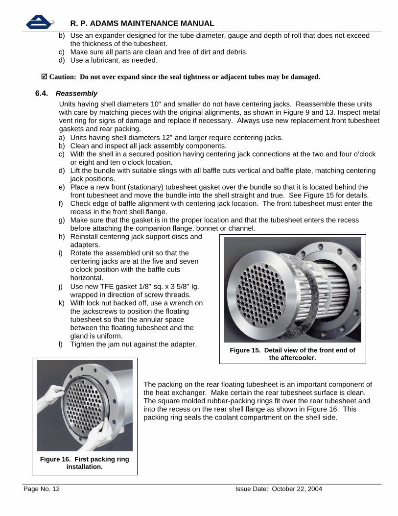
Figure 15. Detail view of the front end of the aftercooler.
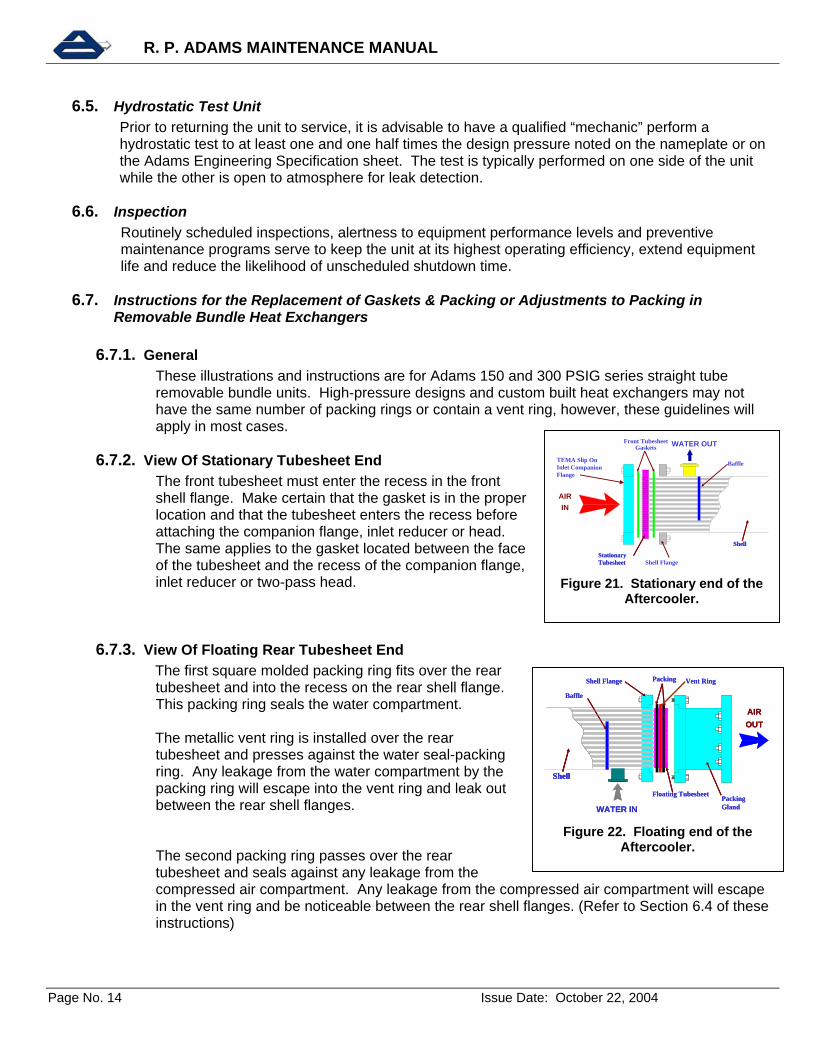
Figure 16. First packing ring installation.
b) Use an expander designed for the tube diameter, gauge and depth of roll that does not exceed the thickness of the tubesheet.
c) Make sure all parts are clean and free of dirt and debris. d) Use a lubricant, as needed.
Caution: Do not over expand since the seal tightness or adjacent tubes may be damaged.
6.4. Reassembly Units having shell diameters 10″ and smaller do not have centering jacks. Reassemble these units with care by matching pieces with the original alignments, as shown in Figure 9 and 13. Inspect metal vent ring for signs of damage and replace if necessary. Always use new replacement front tubesheet gaskets and rear packing. a) Units having shell diameters 12″ and larger require centering jacks. b) Clean and inspect all jack assembly components. c) With the shell in a secured position having centering jack connections at the two and four o’clock
or eight and ten o’clock location. d) Lift the bundle with suitable slings with all baffle cuts vertical and baffle plate, matching centering
jack positions. e) Place a new front (stationary) tubesheet gasket over the bundle so that it is located behind the
front tubesheet and move the bundle into the shell straight and true. See Figure 15 for details. f) Check edge of baffle alignment with centering jack location. The front tubesheet must enter the
recess in the front shell flange. g) Make sure that the gasket is in the proper location and that the tubesheet enters the recess
before attaching the companion flange, bonnet or channel. h) Reinstall centering jack support discs and
adapters. i) Rotate the assembled unit so that the
centering jacks are at the five and seven o’clock position with the baffle cuts horizontal.
j) Use new TFE gasket 1/8″ sq. x 3 5/8″ lg. wrapped in direction of screw threads.
k) With lock nut backed off, use a wrench on the jackscrews to position the floating tubesheet so that the annular space between the floating tubesheet and the gland is uniform.
l) Tighten the jam nut against the adapter.
The packing on the rear floating tubesheet is an important component of the heat exchanger. Make certain the rear tubesheet surface is clean. The square molded rubber-packing rings fit over the rear tubesheet and into the recess on the rear shell flange as shown in Figure 16. This packing ring seals the coolant compartment on the shell side.

R. P. ADAMS MAINTENANCE MANUAL
Page No. 13 Issue Date: October 22, 2004
A metal vent ring is installed over the rear tubesheet and presses against the first packing ring, as seen in Figure 17. Any coolant leakage by the first packing ring will escape into the vent ring gland and be visible from the outside of the unit between the rear shell flanges.
Figure 18 shows how a second rear-packing ring passes over the tubesheet and completes the seal for the compressed gas side. Any gas leakage by the second packing ring will escape into the vent ring gland and be visible from the outside of the unit between the rear shell flanges.
Assemble the packing gland on the heat exchanger using the bolts provided with the unit, as shown in Figure 19. Make certain the second packing ring properly enters the recess on the packing gland and passes smoothly over the vent ring.
Figure 20 shows how to tighten the packing gland bolts in an even manner so the space between the packing gland flange and the shell flange is even throughout its circumference. Continue to tighten until snug and no leakage occurs. Any leakage from the vent gland will be eliminated by evenly adjusting the packing gland retaining nuts.
Caution: Do not over tighten the packing gland to the rear shell flange as it may result in damage to the packing and vent ring.
Figure 18. Second packing ring installation.
Figure 17. Vent ring installation.
Figure 19. Packing gland installation.
Figure 20. Tightening of the packing gland.
R. P. ADAMS MAINTENANCE MANUAL
Page No. 14 Issue Date: October 22, 2004
AIR IN
WATER OUT
Stationary TubesheetStationary Tubesheet
ShellShell
TEMA Slip On Inlet Companion Flange
Front TubesheetGaskets
Shell Flange
Baffle
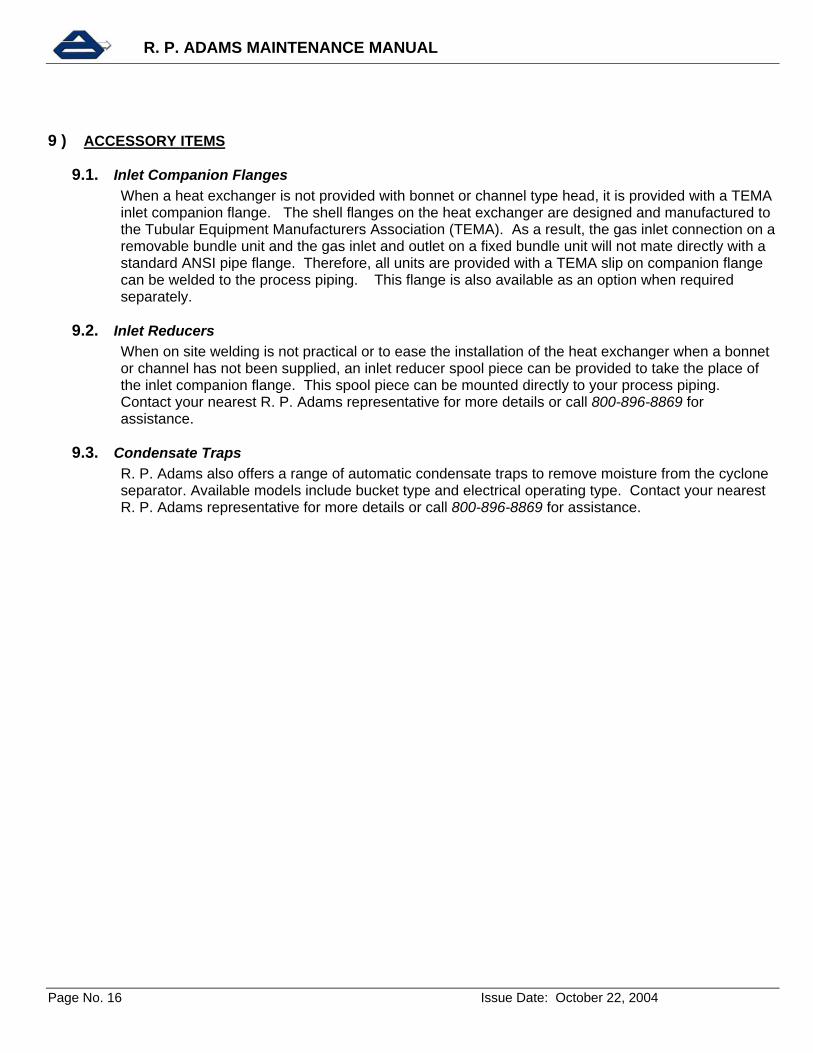
Figure 21. Stationary end of the Aftercooler.
AIR OUT
Floating Tubesheet
Shell
PackingGland
Vent RingPacking
Baffle
Shell Flange
WATER IN
AIR OUT
Floating Tubesheet
ShellShell
PackingGland
Vent RingPacking
Baffle
Shell Flange
WATER IN
Figure 22. Floating end of the Aftercooler.
6.5. Hydrostatic Test Unit Prior to returning the unit to service, it is advisable to have a qualified “mechanic” perform a hydrostatic test to at least one and one half times the design pressure noted on the nameplate or on the Adams Engineering Specification sheet. The test is typically performed on one side of the unit while the other is open to atmosphere for leak detection.
6.6. Inspection Routinely scheduled inspections, alertness to equipment performance levels and preventive maintenance programs serve to keep the unit at its highest operating efficiency, extend equipment life and reduce the likelihood of unscheduled shutdown time.
6.7. Instructions for the Replacement of Gaskets & Packing or Adjustments to Packing in Removable Bundle Heat Exchangers
6.7.1. General These illustrations and instructions are for Adams 150 and 300 PSIG series straight tube removable bundle units. High-pressure designs and custom built heat exchangers may not have the same number of packing rings or contain a vent ring, however, these guidelines will apply in most cases.
6.7.2. View Of Stationary Tubesheet End The front tubesheet must enter the recess in the front shell flange. Make certain that the gasket is in the proper location and that the tubesheet enters the recess before attaching the companion flange, inlet reducer or head. The same applies to the gasket located between the face of the tubesheet and the recess of the companion flange, inlet reducer or two-pass head.
6.7.3. View Of Floating Rear Tubesheet End The first square molded packing ring fits over the rear tubesheet and into the recess on the rear shell flange. This packing ring seals the water compartment.
The metallic vent ring is installed over the rear tubesheet and presses against the water seal-packing ring. Any leakage from the water compartment by the packing ring will escape into the vent ring and leak out between the rear shell flanges.
The second packing ring passes over the rear tubesheet and seals against any leakage from the compressed air compartment. Any leakage from the compressed air compartment will escape in the vent ring and be noticeable between the rear shell flanges. (Refer to Section 6.4 of these instructions)

R. P. ADAMS MAINTENANCE MANUAL
Page No. 15 Issue Date: October 22, 2004
6.7.4. View Of Packing Gland Figure 19 and 20 show the packing gland being installed to compress the packing rings. Be sure the packing rings and vent ring enter the recesses of the packing gland. Adjusting the packing bolts in an even manner so the space between the two flanges is uniform throughout its circumference. Any leakage from the vent ring will be eliminated by evenly adjusting the packing gland retaining nuts.
7 ) TROUBLESHOOTING
7.1. Decreased heat transfer performance a) Unit may be dirty or fouled. Inspect the unit for cleanliness and clean as required. b) Coolant flow or temperature is different than what the unit was originally designed for. Check the
operating conditions and compare them to the original design requirements. If conditions have changed, contact your nearest R. P. Adams representative for remedies to correct the problem.
c) Unit is operating under different conditions than it was originally designed. Contact your nearest R. P. Adams representative to check performance and remedies for correcting the problem.
7.2. High pressure drop across the unit: a) Unit may be dirty or fouled. Inspect unit for cleanliness and clean as required. b) More fluid is being put through the unit that it was designed for. Check the operating conditions
and compare them to the original design requirements. If conditions have changed, contact your nearest R. P. Adams representative for remedies to correct the problem.
7.3. Fluid is leaking externally out from between the rear shell flanges: a) The packing rings at the rear of the unit may need adjustment or replacement.
7.4. Fluid is leaking internally into the other fluid: a) When a fluid with the highest operating pressure is leaking into the other chamber, look for a tube
joint or tube leak(s). One method of checking is to hydrostatically test one of the chambers before the unit is disassembled. The leaking tube or joint can be identified for further inspection once the bundle is removed. Up to ten percent of the total number of tubes can be plugged before it adversely affects thermal heat transfer performance. If the tube joint is leaking, it can be expanded in accordance with Section 6.3.
8 ) SERVICE & PARTS
8.1. Spare Parts Ordering When placing an order for parts or requesting additional information about a particular unit, always
provide the model and serial number. If the unit is ASME Code stamped, the National Board Number is also helpful. This will assure that the replacement parts being supplied will be dimensionally and materially the same as the original.
8.2. Service & Support R. P. Adams offers responsive sales and technical support though a worldwide network of
experienced factory trained Engineers. You may contact your local representative for technical assistance. To find the representative nearest you, call 800-896-8869 for assistance.
R. P. ADAMS MAINTENANCE MANUAL
Page No. 16 Issue Date: October 22, 2004
9 ) ACCESSORY ITEMS
9.1. Inlet Companion Flanges When a heat exchanger is not provided with bonnet or channel type head, it is provided with a TEMA
inlet companion flange. The shell flanges on the heat exchanger are designed and manufactured to the Tubular Equipment Manufacturers Association (TEMA). As a result, the gas inlet connection on a removable bundle unit and the gas inlet and outlet on a fixed bundle unit will not mate directly with a standard ANSI pipe flange. Therefore, all units are provided with a TEMA slip on companion flange can be welded to the process piping. This flange is also available as an option when required separately.
9.2. Inlet Reducers When on site welding is not practical or to ease the installation of the heat exchanger when a bonnet
or channel has not been supplied, an inlet reducer spool piece can be provided to take the place of the inlet companion flange. This spool piece can be mounted directly to your process piping. Contact your nearest R. P. Adams representative for more details or call 800-896-8869 for assistance.
9.3. Condensate Traps R. P. Adams also offers a range of automatic condensate traps to remove moisture from the cyclone separator. Available models include bucket type and electrical operating type. Contact your nearest R. P. Adams representative for more details or call 800-896-8869 for assistance.