Understanding and Eliminating EMI in Microcontroller Applications
1Week 6© Vocational Training Council, Hong Kong.
8051 Assembly Language Programming (2)8051 Assembly Language Programming (2)
EEE3410 Microcontroller ApplicationsDepartment of Electrical Engineering
│ Lecture 6 │
2Week 6© Vocational Training Council, Hong Kong.
EEE3410 Microcontroller Applications
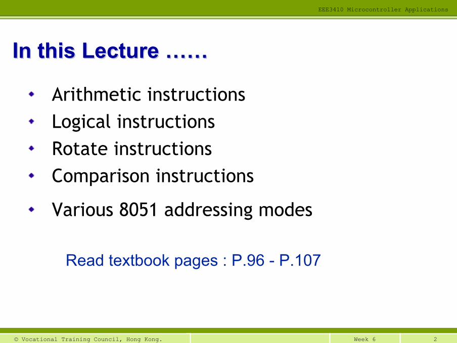
Read textbook pages : P.96 - P.107
Arithmetic instructionsLogical instructionsRotate instructionsComparison instructions
Various 8051 addressing modes
In this Lecture In this Lecture …………
3Week 6© Vocational Training Council, Hong Kong.
EEE3410 Microcontroller Applications
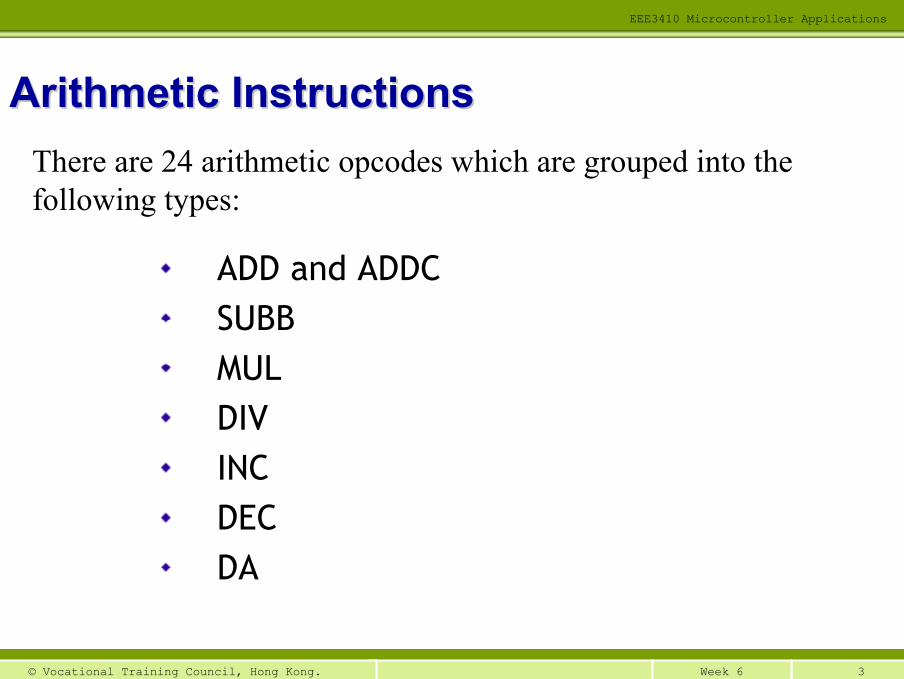
ADD and ADDCSUBBMULDIVINCDECDA
Arithmetic InstructionsArithmetic InstructionsThere are 24 arithmetic opcodes which are grouped into the following types:
4Week 6© Vocational Training Council, Hong Kong.
EEE3410 Microcontroller Applications
Flag: It is a 1-bit register that indicates the status of the result from an operation
Flags are either at a flag-state of value 0 or 1
Arithmetic flags indicate the status of the results from mathematical operations ( +, −, *, / )
Arithmetic FlagsArithmetic Flags
5Week 6© Vocational Training Council, Hong Kong.
EEE3410 Microcontroller Applications
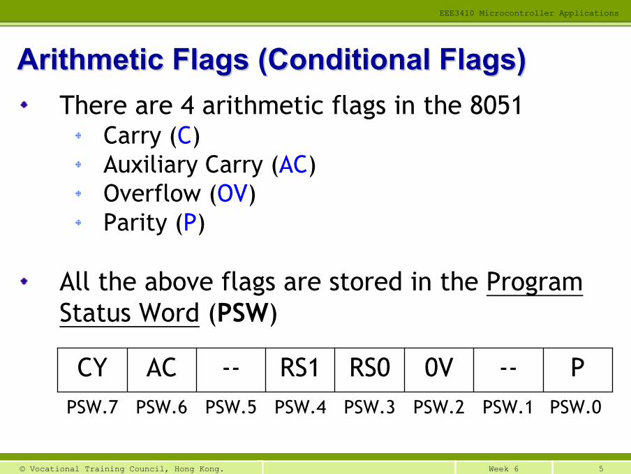
There are 4 arithmetic flags in the 8051Carry (C)Auxiliary Carry (AC)Overflow (OV)Parity (P)
All the above flags are stored in the Program Status Word (PSW)
Arithmetic Flags (Conditional Flags)Arithmetic Flags (Conditional Flags)
PSW.0PSW.1PSW.2PSW.3PSW.4PSW.5PSW.6PSW.7
P--0VRS0RS1--ACCY
6Week 6© Vocational Training Council, Hong Kong.
EEE3410 Microcontroller Applications
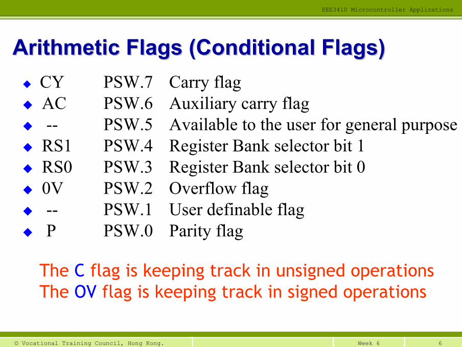
The C flag is keeping track in unsigned operationsThe OV flag is keeping track in signed operations
Arithmetic Flags (Conditional Flags)Arithmetic Flags (Conditional Flags)CY PSW.7 Carry flagAC PSW.6 Auxiliary carry flag-- PSW.5 Available to the user for general purposeRS1 PSW.4 Register Bank selector bit 1RS0 PSW.3 Register Bank selector bit 00V PSW.2 Overflow flag-- PSW.1 User definable flagP PSW.0 Parity flag
7Week 6© Vocational Training Council, Hong Kong.
EEE3410 Microcontroller Applications
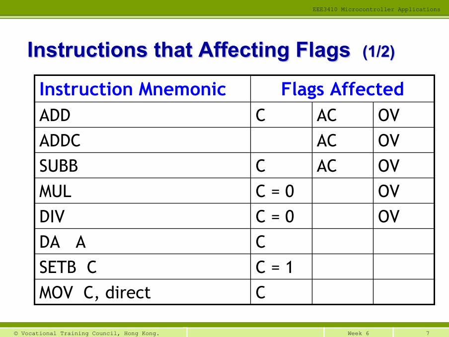
Instructions that Affecting Flags Instructions that Affecting Flags (1/2)(1/2)
C = 1SETB CCDA A
OVC = 0DIVOVC = 0MULOVACCSUBB
CMOV C, direct
OVACADDCOVACCADD
Flags AffectedInstruction Mnemonic
8Week 6© Vocational Training Council, Hong Kong.
EEE3410 Microcontroller Applications
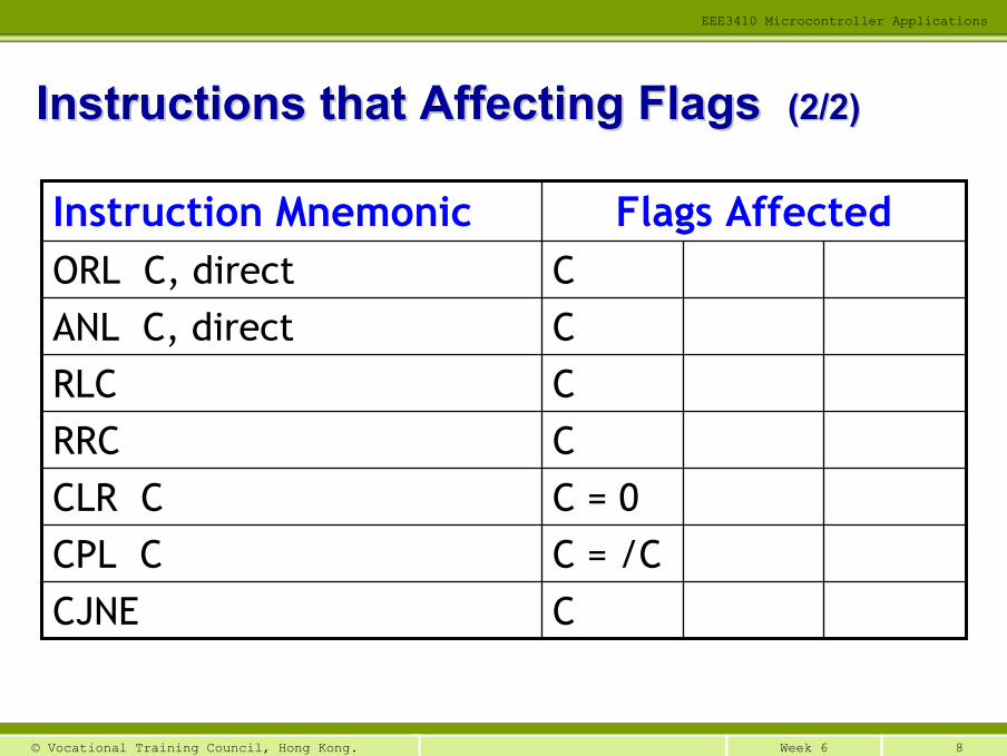
Instructions that Affecting Flags Instructions that Affecting Flags (2/2)(2/2)
CCJNE
CANL C, direct
C = 0CLR CC = /CCPL C
CRRCCRLC
CORL C, directFlags AffectedInstruction Mnemonic
9Week 6© Vocational Training Council, Hong Kong.
EEE3410 Microcontroller Applications
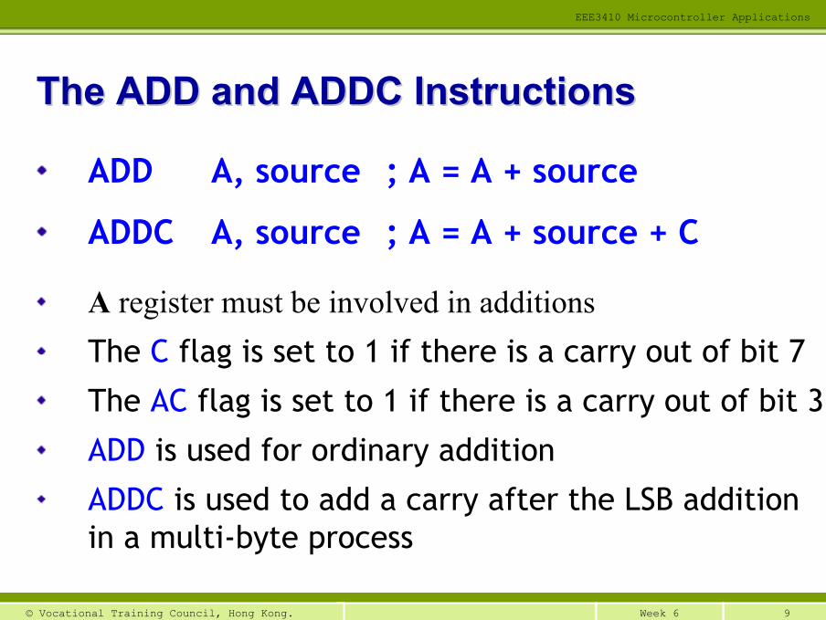
ADD A, source ; A = A + source
ADDC A, source ; A = A + source + C
A register must be involved in additionsThe C flag is set to 1 if there is a carry out of bit 7
The AC flag is set to 1 if there is a carry out of bit 3
ADD is used for ordinary addition
ADDC is used to add a carry after the LSB addition in a multi-byte process
The ADD and ADDC InstructionsThe ADD and ADDC Instructions
10Week 6© Vocational Training Council, Hong Kong.
EEE3410 Microcontroller Applications
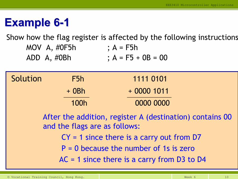
Solution F5h 1111 0101
+ 0Bh + 0000 1011
100h 0000 0000
After the addition, register A (destination) contains 00 and the flags are as follows:
CY = 1 since there is a carry out from D7P = 0 because the number of 1s is zero
AC = 1 since there is a carry from D3 to D4
Example 6Example 6--11Show how the flag register is affected by the following instructions.
MOV A, #0F5h ; A = F5hADD A, #0Bh ; A = F5 + 0B = 00
11Week 6© Vocational Training Council, Hong Kong.
EEE3410 Microcontroller Applications
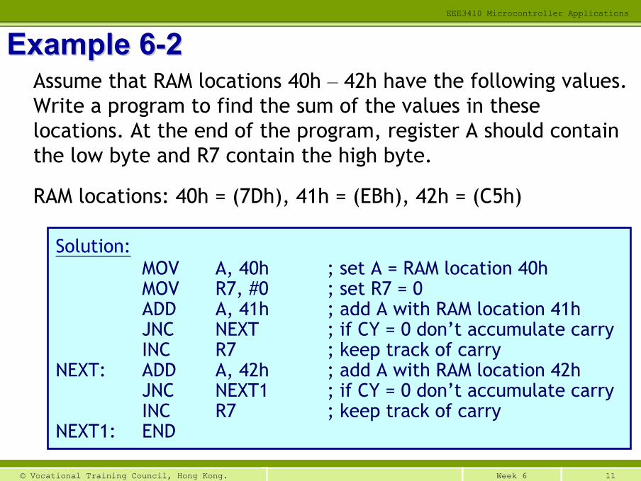
Example 6Example 6--22Assume that RAM locations 40h – 42h have the following values. Write a program to find the sum of the values in these locations. At the end of the program, register A should contain the low byte and R7 contain the high byte.
RAM locations: 40h = (7Dh), 41h = (EBh), 42h = (C5h)
Solution:MOV A, 40h ; set A = RAM location 40hMOV R7, #0 ; set R7 = 0ADD A, 41h ; add A with RAM location 41hJNC NEXT ; if CY = 0 don’t accumulate carryINC R7 ; keep track of carry
NEXT: ADD A, 42h ; add A with RAM location 42hJNC NEXT1 ; if CY = 0 don’t accumulate carryINC R7 ; keep track of carry
NEXT1: END
12Week 6© Vocational Training Council, Hong Kong.
EEE3410 Microcontroller Applications
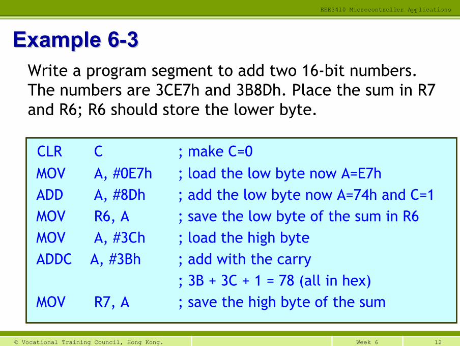
Example 6Example 6--33Write a program segment to add two 16-bit numbers. The numbers are 3CE7h and 3B8Dh. Place the sum in R7 and R6; R6 should store the lower byte.
CLR C ; make C=0MOV A, #0E7h ; load the low byte now A=E7hADD A, #8Dh ; add the low byte now A=74h and C=1MOV R6, A ; save the low byte of the sum in R6MOV A, #3Ch ; load the high byteADDC A, #3Bh ; add with the carry
; 3B + 3C + 1 = 78 (all in hex)MOV R7, A ; save the high byte of the sum
13Week 6© Vocational Training Council, Hong Kong.
EEE3410 Microcontroller Applications
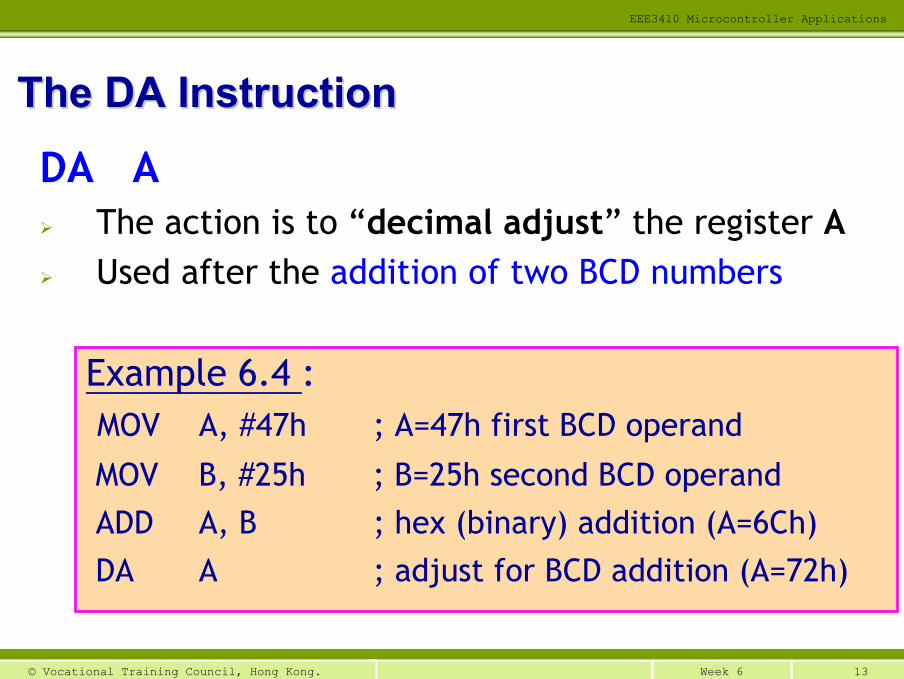
DA AThe action is to “decimal adjust” the register AUsed after the addition of two BCD numbers
The DA InstructionThe DA Instruction
Example 6.4 : MOV A, #47h ; A=47h first BCD operand
MOV B, #25h ; B=25h second BCD operandADD A, B ; hex (binary) addition (A=6Ch)DA A ; adjust for BCD addition (A=72h)
14Week 6© Vocational Training Council, Hong Kong.
EEE3410 Microcontroller Applications
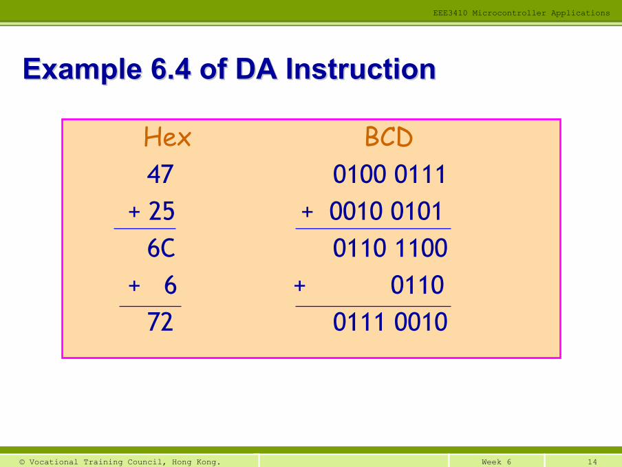
Example 6.4 of DA InstructionExample 6.4 of DA Instruction
Hex BCD47 0100 0111
+ 25 + 0010 01016C 0110 1100
+ 6 + 011072 0111 0010
15Week 6© Vocational Training Council, Hong Kong.
EEE3410 Microcontroller Applications
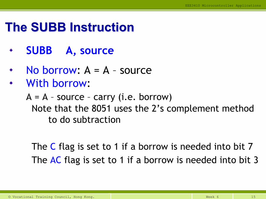
SUBB A, source
No borrow: A = A – sourceWith borrow: A = A – source – carry (i.e. borrow)Note that the 8051 uses the 2’s complement method
to do subtraction
The C flag is set to 1 if a borrow is needed into bit 7The AC flag is set to 1 if a borrow is needed into bit 3
The SUBB InstructionThe SUBB Instruction
16Week 6© Vocational Training Council, Hong Kong.
EEE3410 Microcontroller Applications
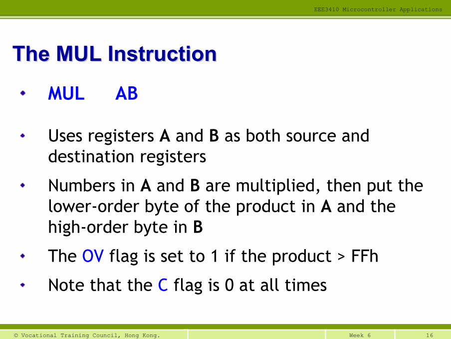
MUL AB
Uses registers A and B as both source and destination registers
Numbers in A and B are multiplied, then put the lower-order byte of the product in A and the high-order byte in B
The OV flag is set to 1 if the product > FFh
Note that the C flag is 0 at all times
The MUL InstructionThe MUL Instruction
17Week 6© Vocational Training Council, Hong Kong.
EEE3410 Microcontroller Applications
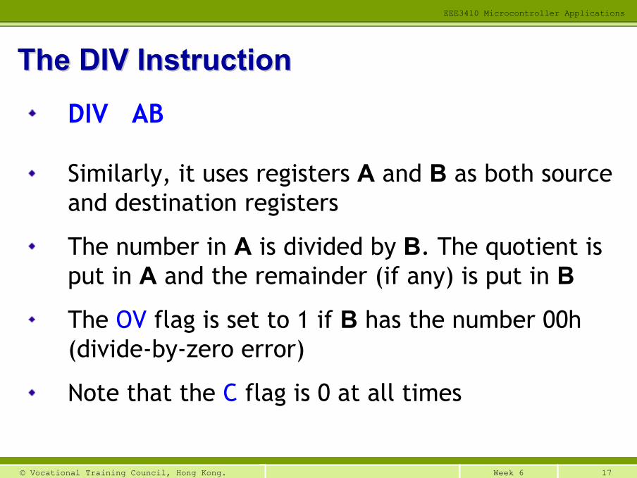
DIV AB
Similarly, it uses registers A and B as both source and destination registers
The number in A is divided by B. The quotient is put in A and the remainder (if any) is put in B
The OV flag is set to 1 if B has the number 00h (divide-by-zero error)
Note that the C flag is 0 at all times
The DIV InstructionThe DIV Instruction
18Week 6© Vocational Training Council, Hong Kong.
EEE3410 Microcontroller Applications
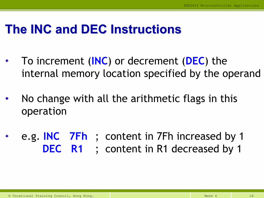
To increment (INC) or decrement (DEC) the internal memory location specified by the operand
No change with all the arithmetic flags in this operation
e.g. INC 7Fh ; content in 7Fh increased by 1DEC R1 ; content in R1 decreased by 1
The INC and DEC InstructionsThe INC and DEC Instructions
19Week 6© Vocational Training Council, Hong Kong.
EEE3410 Microcontroller Applications
Logical operations
Rotate and swap operations
Comparison operations
Logic Operation in 8051Logic Operation in 8051
20Week 6© Vocational Training Council, Hong Kong.
EEE3410 Microcontroller Applications
AND
OR
XOR (exclusive-OR)
NOT (invert/complement)
General Logic FunctionsGeneral Logic Functions
There are instructions available for the 8051 to implement the following logic functions
21Week 6© Vocational Training Council, Hong Kong.
EEE3410 Microcontroller Applications
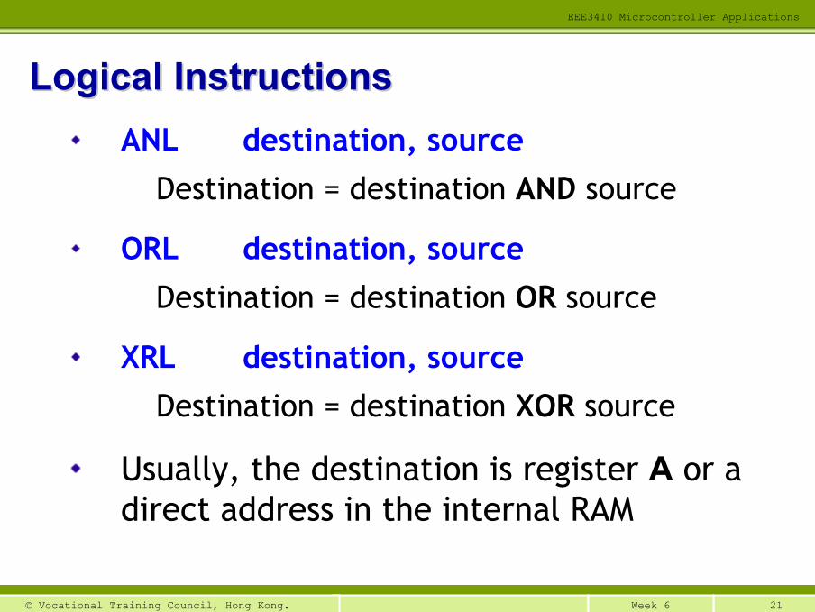
ANL destination, source
Destination = destination AND source
ORL destination, source
Destination = destination OR source
XRL destination, source
Destination = destination XOR source
Usually, the destination is register A or a direct address in the internal RAM
Logical InstructionsLogical Instructions
22Week 6© Vocational Training Council, Hong Kong.
EEE3410 Microcontroller Applications
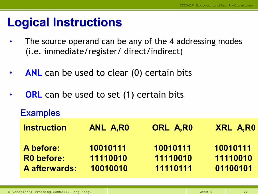
The source operand can be any of the 4 addressing modes (i.e. immediate/register/ direct/indirect)
ANL can be used to clear (0) certain bits
ORL can be used to set (1) certain bits
Logical InstructionsLogical Instructions
Instruction ANL A,R0 ORL A,R0 XRL A,R0
A before: 10010111 10010111 10010111R0 before: 11110010 11110010 11110010A afterwards: 10010010 11110111 01100101
ExamplesExamples
23Week 6© Vocational Training Council, Hong Kong.
EEE3410 Microcontroller Applications
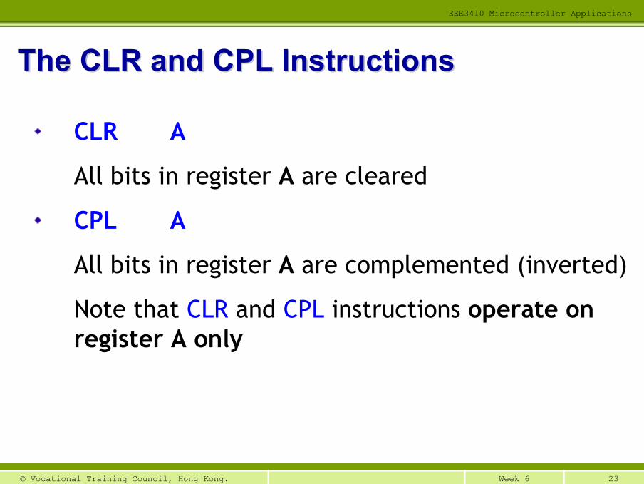
CLR A
All bits in register A are cleared
CPL A
All bits in register A are complemented (inverted)
Note that CLR and CPL instructions operate on register A only
The CLR and CPL InstructionsThe CLR and CPL Instructions
24Week 6© Vocational Training Council, Hong Kong.
EEE3410 Microcontroller Applications
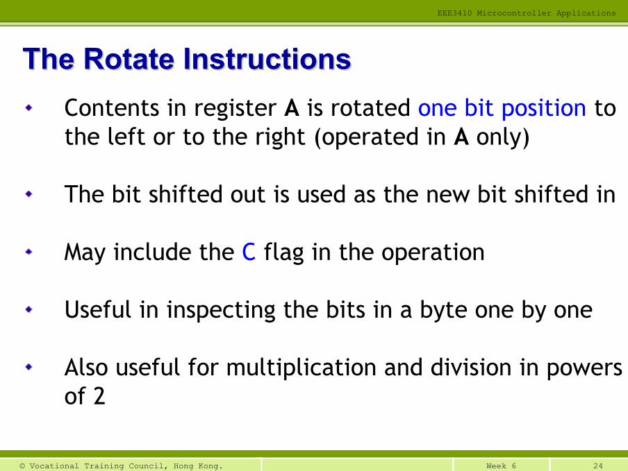
Contents in register A is rotated one bit position to the left or to the right (operated in A only)
The bit shifted out is used as the new bit shifted in
May include the C flag in the operation
Useful in inspecting the bits in a byte one by one
Also useful for multiplication and division in powers of 2
The Rotate InstructionsThe Rotate Instructions
25Week 6© Vocational Training Council, Hong Kong.
EEE3410 Microcontroller Applications
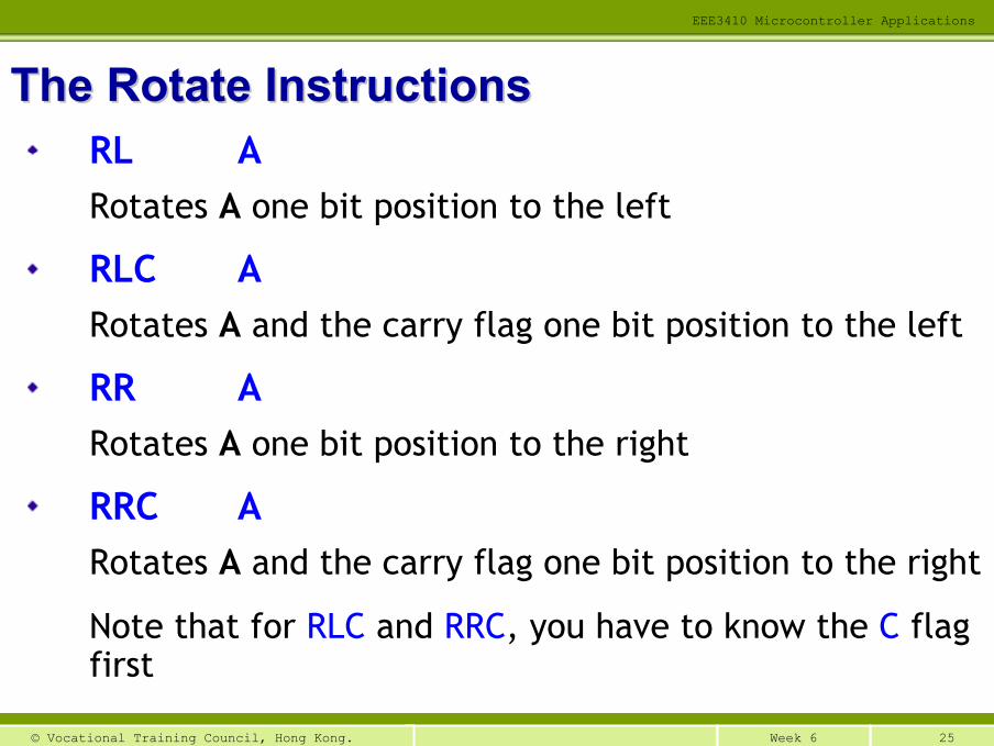
RL ARotates A one bit position to the left
RLC ARotates A and the carry flag one bit position to the left
RR ARotates A one bit position to the right
RRC ARotates A and the carry flag one bit position to the right
Note that for RLC and RRC, you have to know the C flag first
The Rotate InstructionsThe Rotate Instructions
26Week 6© Vocational Training Council, Hong Kong.
EEE3410 Microcontroller Applications
01234567
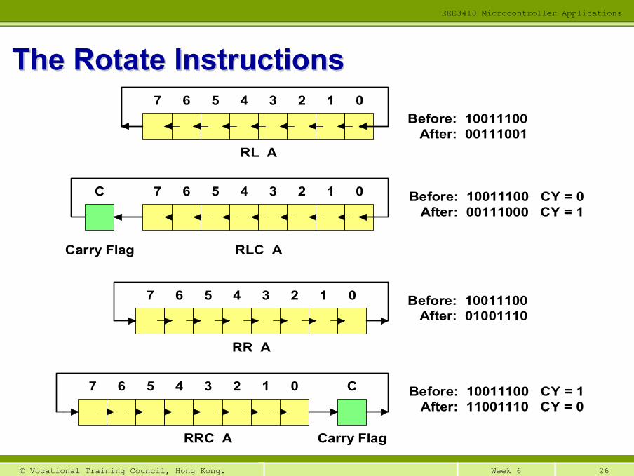
RL A
01234567C
RLC ACarry Flag
01234567
RR A
Before: 10011100 After: 00111001
C01234567
Carry FlagRRC A
Before: 10011100 CY = 0 After: 00111000 CY = 1
Before: 10011100 After: 01001110
Before: 10011100 CY = 1 After: 11001110 CY = 0
The Rotate InstructionsThe Rotate Instructions
27Week 6© Vocational Training Council, Hong Kong.
EEE3410 Microcontroller Applications
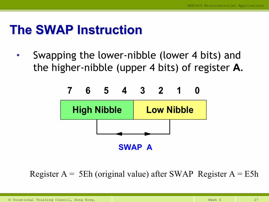
Swapping the lower-nibble (lower 4 bits) and the higher-nibble (upper 4 bits) of register A.
017 6 5 4 3 2
High Nibble Low Nibble
SWAP A
The SWAP InstructionThe SWAP Instruction
Register A = 5Eh (original value) after SWAP Register A = E5h
28Week 6© Vocational Training Council, Hong Kong.
EEE3410 Microcontroller Applications
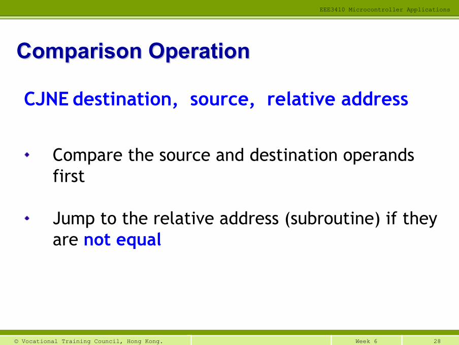
CJNE destination, source, relative address
Compare the source and destination operands first
Jump to the relative address (subroutine) if they are not equal
Comparison OperationComparison Operation
29Week 6© Vocational Training Council, Hong Kong.
EEE3410 Microcontroller Applications
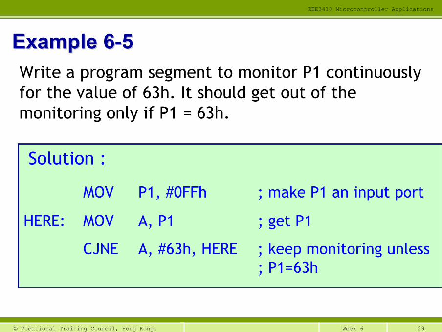
Example 6Example 6--55Write a program segment to monitor P1 continuously for the value of 63h. It should get out of the monitoring only if P1 = 63h.
Solution :
MOV P1, #0FFh ; make P1 an input port
HERE: MOV A, P1 ; get P1
CJNE A, #63h, HERE ; keep monitoring unless ; P1=63h
30Week 6© Vocational Training Council, Hong Kong.
EEE3410 Microcontroller Applications
Addressing mode: a method that…
Points out where the operands (i.e. source and destination) are, and
How these operands should be accessed
The opcode in an instruction specifies what addressing mode will be used
Addressing ModesAddressing Modes
31Week 6© Vocational Training Council, Hong Kong.
EEE3410 Microcontroller Applications
Immediate addressing
Register addressing
Direct addressing
Register indirect addressing
Indexed addressing
Absolute addressing
Long addressing
Relative addressing
Addressing ModesAddressing Modes
32Week 6© Vocational Training Council, Hong Kong.
EEE3410 Microcontroller Applications
Source operand is a constant number/character –“immediate data”
If the operand is a number, we must add a “#” sign before it
e.g. ADD A, #56h ; add 56(16) to the number in register A
e.g. MOV R6, #81 ; load 81(10) into R6
Applications: e.g. initialize a number of registers to zero; overwrite a constant character
Immediate AddressingImmediate Addressing
33Week 6© Vocational Training Council, Hong Kong.
EEE3410 Microcontroller Applications
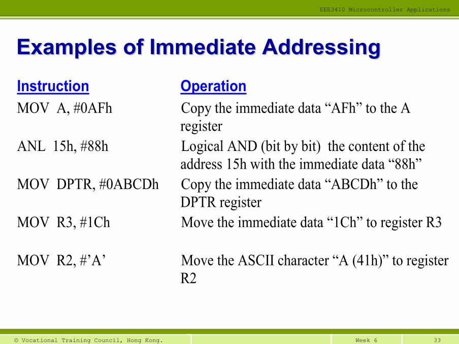
Instruction Operation MOV A, #0AFh Copy the immediate data “AFh” to the A
register ANL 15h, #88h Logical AND (bit by bit) the content of the
address 15h with the immediate data “88h” MOV DPTR, #0ABCDh Copy the immediate data “ABCDh” to the
DPTR register MOV R3, #1Ch Move the immediate data “1Ch” to register R3
MOV R2, #’A’ Move the ASCII character “A (41h)” to register R2
Examples of Immediate AddressingExamples of Immediate Addressing
34Week 6© Vocational Training Council, Hong Kong.
EEE3410 Microcontroller Applications
Add “#” before any immediate data
Only the source operand can be immediate
Add “h” after a base-16 number, “b” after a base-2 number; otherwise assumed base-10
Use ‘ ’ to enclose any character
Precede all base-16 numbers that begin with A-F by a “0”
Notes of Immediate AddressingNotes of Immediate Addressing
35Week 6© Vocational Training Council, Hong Kong.
EEE3410 Microcontroller Applications
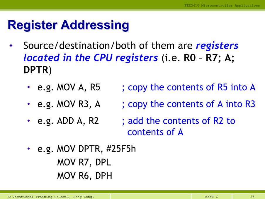
Source/destination/both of them are registers located in the CPU registers (i.e. R0 – R7; A; DPTR)
e.g. MOV A, R5 ; copy the contents of R5 into A
e.g. MOV R3, A ; copy the contents of A into R3
e.g. ADD A, R2 ; add the contents of R2 to contents of A
e.g. MOV DPTR, #25F5hMOV R7, DPLMOV R6, DPH
Register AddressingRegister Addressing
36Week 6© Vocational Training Council, Hong Kong.
EEE3410 Microcontroller Applications
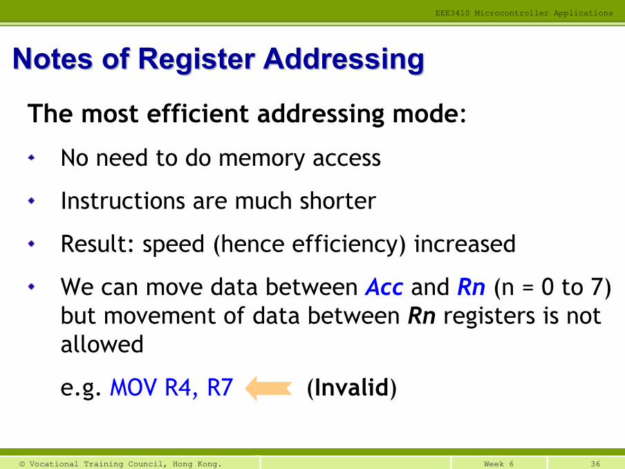
The most efficient addressing mode:
No need to do memory access
Instructions are much shorter
Result: speed (hence efficiency) increased
We can move data between Acc and Rn (n = 0 to 7) but movement of data between Rn registers is not allowed
e.g. MOV R4, R7 (Invalid)
Notes of Register AddressingNotes of Register Addressing
37Week 6© Vocational Training Council, Hong Kong.
EEE3410 Microcontroller Applications
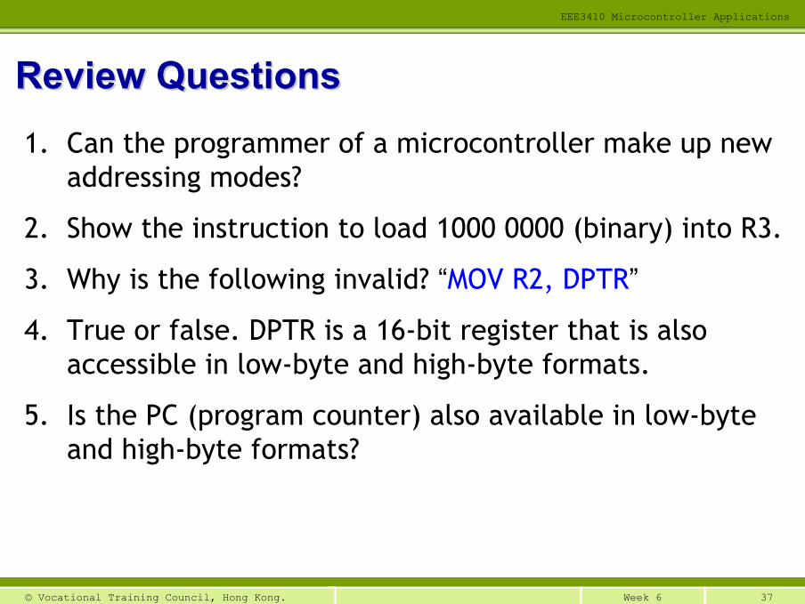
Review QuestionsReview Questions1. Can the programmer of a microcontroller make up new
addressing modes?
2. Show the instruction to load 1000 0000 (binary) into R3.
3. Why is the following invalid? “MOV R2, DPTR”
4. True or false. DPTR is a 16-bit register that is also accessible in low-byte and high-byte formats.
5. Is the PC (program counter) also available in low-byte and high-byte formats?
38Week 6© Vocational Training Council, Hong Kong.
EEE3410 Microcontroller Applications
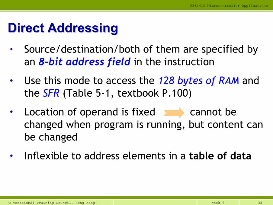
Source/destination/both of them are specified by an 8-bit address field in the instruction
Use this mode to access the 128 bytes of RAM and the SFR (Table 5-1, textbook P.100)
Location of operand is fixed cannot be changed when program is running, but content can be changed
Inflexible to address elements in a table of data
Direct AddressingDirect Addressing
39Week 6© Vocational Training Council, Hong Kong.
EEE3410 Microcontroller Applications
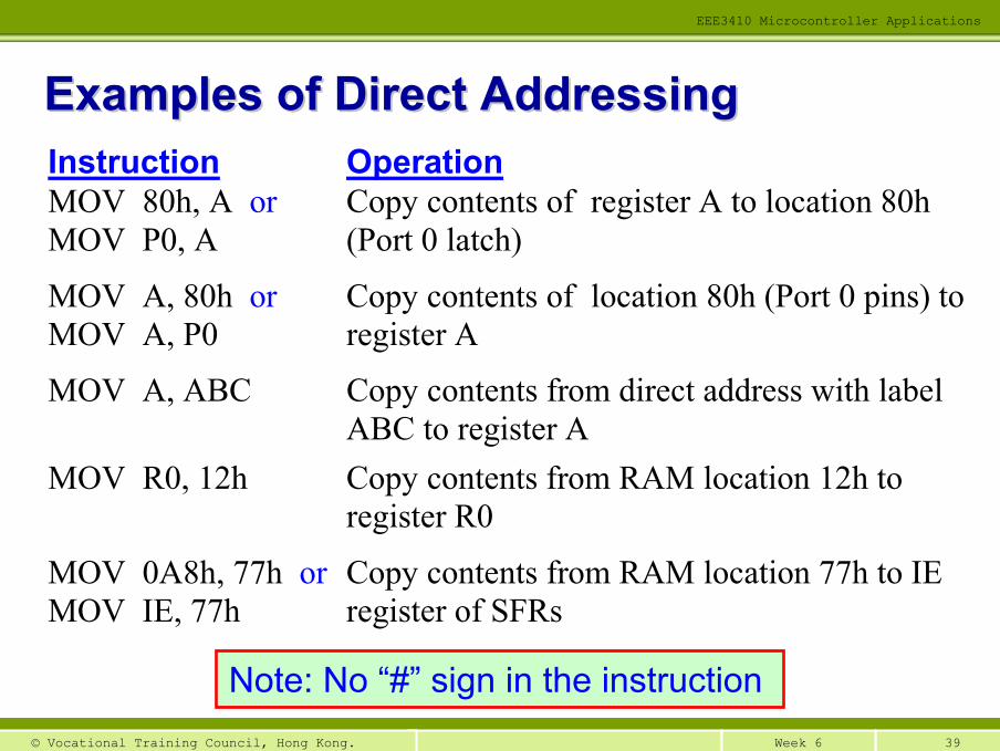
Instruction Operation MOV 80h, A or MOV P0, A
Copy contents of register A to location 80h (Port 0 latch)
MOV A, 80h or MOV A, P0
Copy contents of location 80h (Port 0 pins) to register A
MOV A, ABC Copy contents from direct address with label ABC to register A
MOV R0, 12h Copy contents from RAM location 12h to register R0
MOV 0A8h, 77h or MOV IE, 77h
Copy contents from RAM location 77h to IE register of SFRs
Examples of Direct AddressingExamples of Direct Addressing
Note: No “#” sign in the instruction
40Week 6© Vocational Training Council, Hong Kong.
EEE3410 Microcontroller Applications
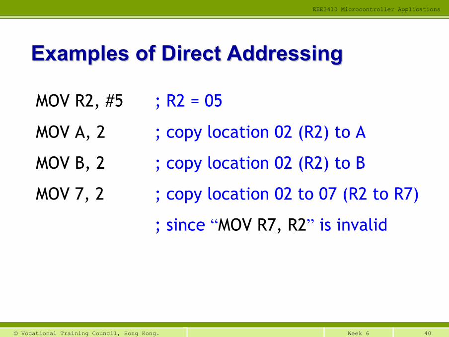
Examples of Direct AddressingExamples of Direct Addressing
MOV R2, #5 ; R2 = 05
MOV A, 2 ; copy location 02 (R2) to A
MOV B, 2 ; copy location 02 (R2) to B
MOV 7, 2 ; copy location 02 to 07 (R2 to R7)
; since “MOV R7, R2” is invalid
41Week 6© Vocational Training Council, Hong Kong.
EEE3410 Microcontroller Applications
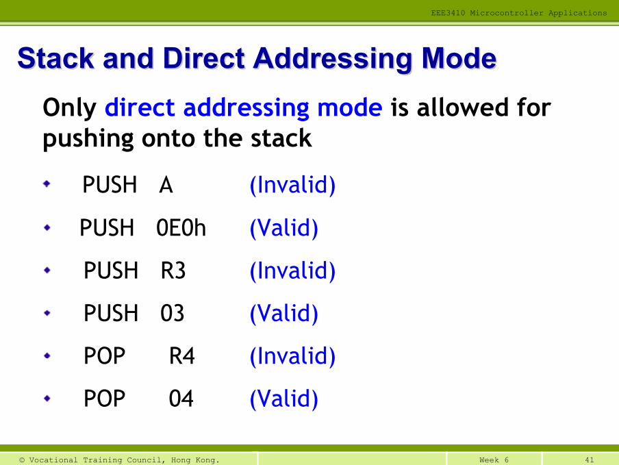
Stack and Direct Addressing ModeStack and Direct Addressing ModeOnly direct addressing mode is allowed for pushing onto the stack
PUSH A (Invalid)
PUSH 0E0h (Valid)
PUSH R3 (Invalid)
PUSH 03 (Valid)
POP R4 (Invalid)
POP 04 (Valid)
42Week 6© Vocational Training Council, Hong Kong.
EEE3410 Microcontroller Applications
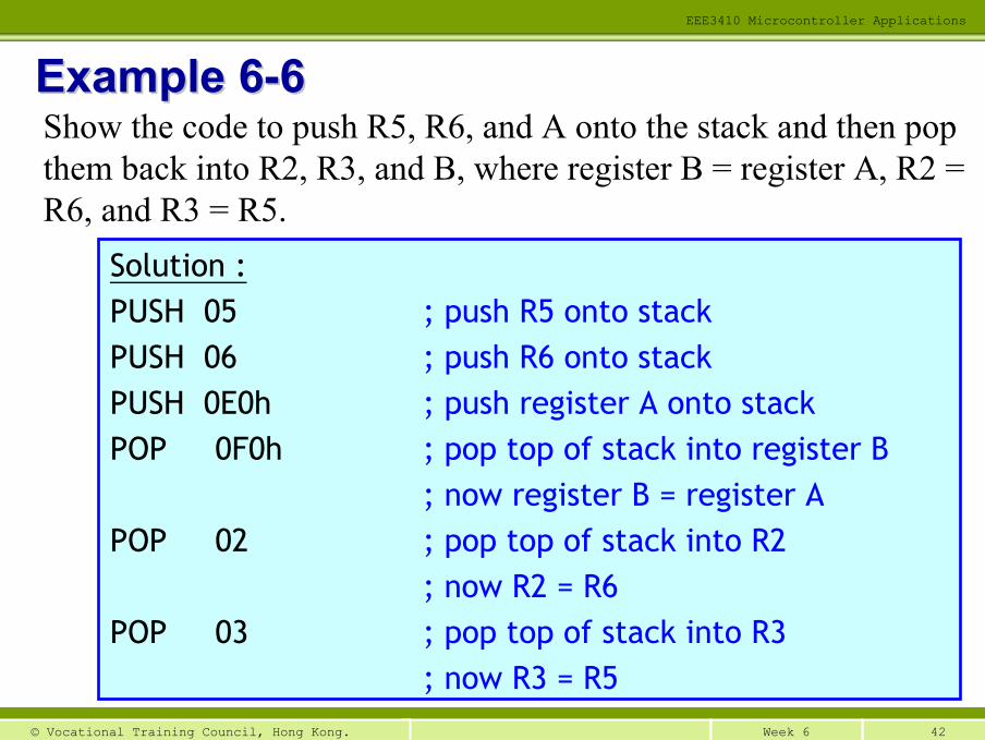
Example 6Example 6--66
Solution :PUSH 05 ; push R5 onto stackPUSH 06 ; push R6 onto stackPUSH 0E0h ; push register A onto stackPOP 0F0h ; pop top of stack into register B
; now register B = register APOP 02 ; pop top of stack into R2
; now R2 = R6POP 03 ; pop top of stack into R3
; now R3 = R5
Show the code to push R5, R6, and A onto the stack and then pop them back into R2, R3, and B, where register B = register A, R2 = R6, and R3 = R5.
43Week 6© Vocational Training Council, Hong Kong.
EEE3410 Microcontroller Applications
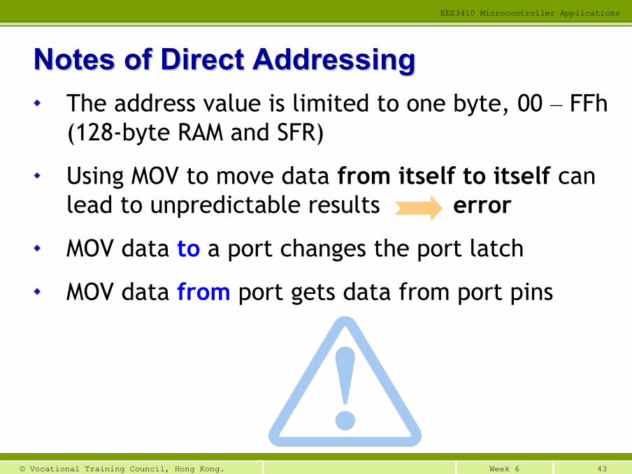
The address value is limited to one byte, 00 – FFh(128-byte RAM and SFR)
Using MOV to move data from itself to itself can lead to unpredictable results error
MOV data to a port changes the port latch
MOV data from port gets data from port pins
Notes of Direct AddressingNotes of Direct Addressing
44Week 6© Vocational Training Council, Hong Kong.
EEE3410 Microcontroller Applications
Use a register to hold the address of the operand; i.e. using a register as a pointer
Only R0 and R1 can be used when data is inside the CPU (address ranges from 00h – 7Fh)
R0 ,R1 and DPTR can be used when addressing external memory locations
Must put a “@” sign before the register name
Register Indirect AddressingRegister Indirect Addressing
45Week 6© Vocational Training Council, Hong Kong.
EEE3410 Microcontroller Applications
AfterAfter
Program memory
BeforeBefore
Addresses
ACC
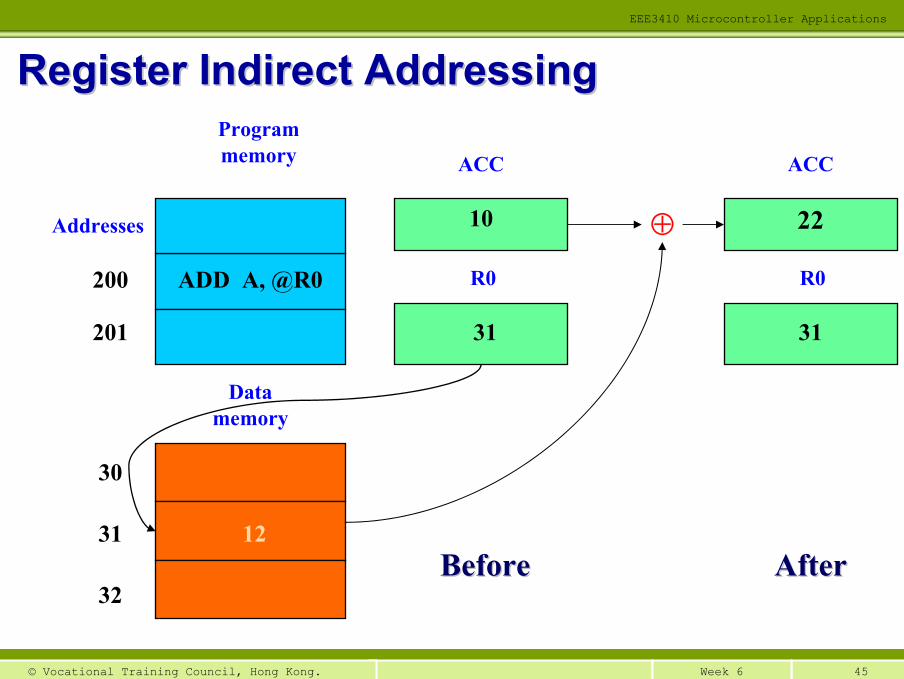
R0ADD A, @R0200
201
Data memory
1231
32
30
10
31
ACC
R0
31
22⊕
Register Indirect AddressingRegister Indirect Addressing
46Week 6© Vocational Training Council, Hong Kong.
EEE3410 Microcontroller Applications
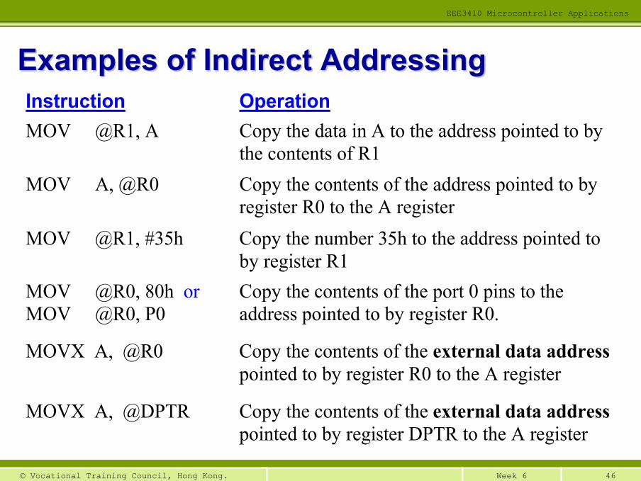
Instruction Operation MOV @R1, A Copy the data in A to the address pointed to by
the contents of R1 MOV A, @R0 Copy the contents of the address pointed to by
register R0 to the A register MOV @R1, #35h Copy the number 35h to the address pointed to
by register R1 MOV @R0, 80h or MOV @R0, P0
Copy the contents of the port 0 pins to the address pointed to by register R0.
MOVX A, @R0 Copy the contents of the external data address pointed to by register R0 to the A register
MOVX A, @DPTR Copy the contents of the external data address pointed to by register DPTR to the A register
Examples of Indirect AddressingExamples of Indirect Addressing
47Week 6© Vocational Training Council, Hong Kong.
EEE3410 Microcontroller Applications
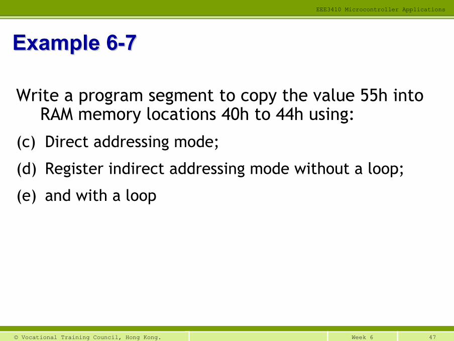
Write a program segment to copy the value 55h into RAM memory locations 40h to 44h using:
(c) Direct addressing mode;
(d) Register indirect addressing mode without a loop;
(e) and with a loop
Example 6Example 6--77
48Week 6© Vocational Training Council, Hong Kong.
EEE3410 Microcontroller Applications
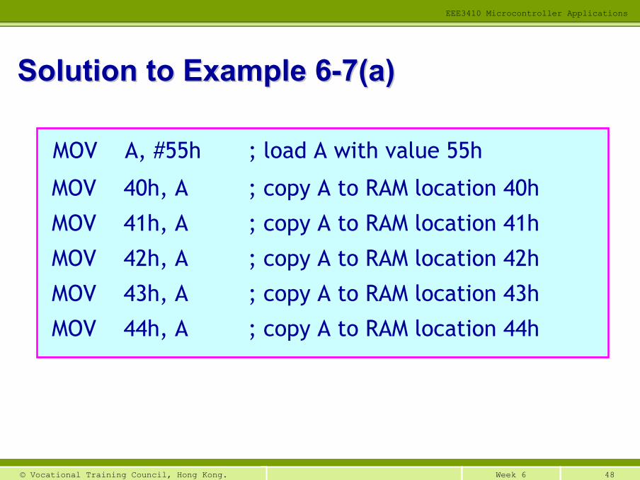
MOV A, #55h ; load A with value 55h
MOV 40h, A ; copy A to RAM location 40h
MOV 41h, A ; copy A to RAM location 41h
MOV 42h, A ; copy A to RAM location 42h
MOV 43h, A ; copy A to RAM location 43h
MOV 44h, A ; copy A to RAM location 44h
Solution to Example 6Solution to Example 6--7(a)7(a)
49Week 6© Vocational Training Council, Hong Kong.
EEE3410 Microcontroller Applications
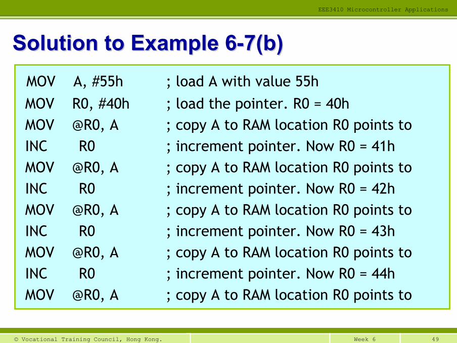
MOV A, #55h ; load A with value 55hMOV R0, #40h ; load the pointer. R0 = 40hMOV @R0, A ; copy A to RAM location R0 points toINC R0 ; increment pointer. Now R0 = 41hMOV @R0, A ; copy A to RAM location R0 points toINC R0 ; increment pointer. Now R0 = 42hMOV @R0, A ; copy A to RAM location R0 points toINC R0 ; increment pointer. Now R0 = 43h MOV @R0, A ; copy A to RAM location R0 points toINC R0 ; increment pointer. Now R0 = 44hMOV @R0, A ; copy A to RAM location R0 points to
Solution to Example 6Solution to Example 6--7(b)7(b)
50Week 6© Vocational Training Council, Hong Kong.
EEE3410 Microcontroller Applications
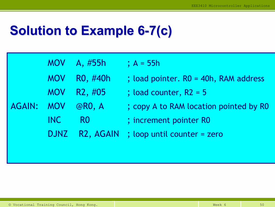
MOV A, #55h ; A = 55h
MOV R0, #40h ; load pointer. R0 = 40h, RAM address
MOV R2, #05 ; load counter, R2 = 5
AGAIN: MOV @R0, A ; copy A to RAM location pointed by R0
INC R0 ; increment pointer R0
DJNZ R2, AGAIN ; loop until counter = zero
Solution to Example 6Solution to Example 6--7(c)7(c)
51Week 6© Vocational Training Council, Hong Kong.
EEE3410 Microcontroller Applications
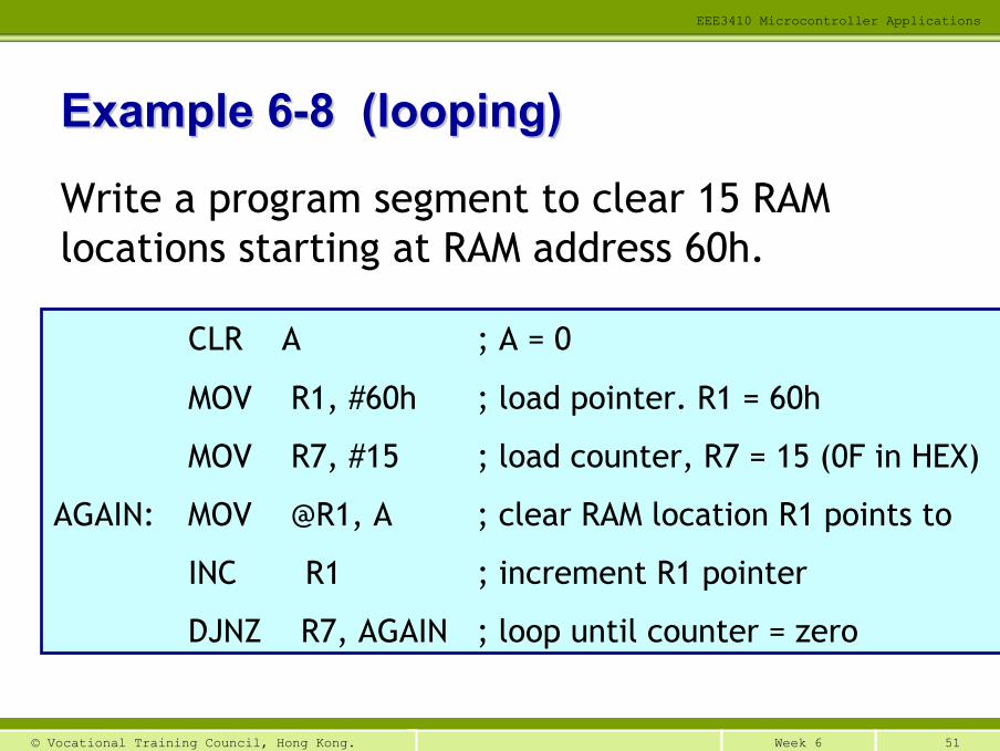
Example 6Example 6--8 (looping)8 (looping)
Write a program segment to clear 15 RAM locations starting at RAM address 60h.
CLR A ; A = 0
MOV R1, #60h ; load pointer. R1 = 60h
MOV R7, #15 ; load counter, R7 = 15 (0F in HEX)
AGAIN: MOV @R1, A ; clear RAM location R1 points to
INC R1 ; increment R1 pointer
DJNZ R7, AGAIN ; loop until counter = zero
52Week 6© Vocational Training Council, Hong Kong.
EEE3410 Microcontroller Applications
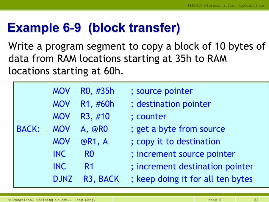
Example 6Example 6--9 (block transfer)9 (block transfer)Write a program segment to copy a block of 10 bytes of data from RAM locations starting at 35h to RAM locations starting at 60h.
MOV R0, #35h ; source pointerMOV R1, #60h ; destination pointerMOV R3, #10 ; counter
BACK: MOV A, @R0 ; get a byte from sourceMOV @R1, A ; copy it to destinationINC R0 ; increment source pointerINC R1 ; increment destination pointerDJNZ R3, BACK ; keep doing it for all ten bytes
53Week 6© Vocational Training Council, Hong Kong.
EEE3410 Microcontroller Applications
Using pointer in the program enables handling dynamic data structures an advantage
Dynamic data: the data value is not fixed
In this mode, we can defer the calculation of the address of data and the determination of the amount of memory to allocate at (program) runtime
Notes of Indirect AddressingNotes of Indirect Addressing
54Week 6© Vocational Training Council, Hong Kong.
EEE3410 Microcontroller Applications
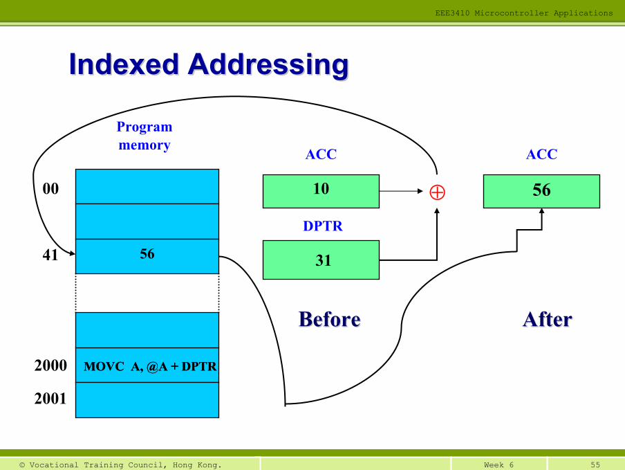
Using a base register (starting point) and an offset (how much to parse through) to form the effective address for a JMP or MOV instruction
Used to parse through an array of items or a look-up table
Usually, the DPTR is the base register and the “A” is the offset
A increases/decreases to parse through the list
Indexed AddressingIndexed Addressing
55Week 6© Vocational Training Council, Hong Kong.
EEE3410 Microcontroller Applications
AfterAfter
Program memory
BeforeBefore
ACC
DPTR
MOVC A, @A + DPTR2000
2001
41
00 10
31
ACC
56⊕
56
Indexed AddressingIndexed Addressing
MOVC A, @A + DPTR
56Week 6© Vocational Training Council, Hong Kong.
EEE3410 Microcontroller Applications
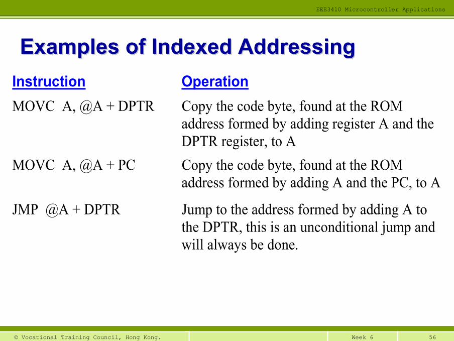
Instruction Operation MOVC A, @A + DPTR Copy the code byte, found at the ROM
address formed by adding register A and the DPTR register, to A
MOVC A, @A + PC Copy the code byte, found at the ROM address formed by adding A and the PC, to A
JMP @A + DPTR Jump to the address formed by adding A to the DPTR, this is an unconditional jump and will always be done.
Examples of Indexed AddressingExamples of Indexed Addressing
57Week 6© Vocational Training Council, Hong Kong.
EEE3410 Microcontroller Applications
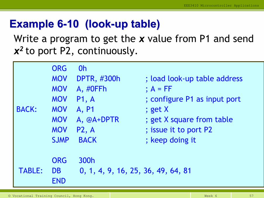
Example 6Example 6--10 (look10 (look--up table)up table)Write a program to get the x value from P1 and send x2 to port P2, continuously.
ORG 0hMOV DPTR, #300h ; load look-up table addressMOV A, #0FFh ; A = FFMOV P1, A ; configure P1 as input port
BACK: MOV A, P1 ; get XMOV A, @A+DPTR ; get X square from tableMOV P2, A ; issue it to port P2SJMP BACK ; keep doing it
ORG 300hTABLE: DB 0, 1, 4, 9, 16, 25, 36, 49, 64, 81
END
58Week 6© Vocational Training Council, Hong Kong.
EEE3410 Microcontroller Applications
Used in jump (“JMP”) instructions
Relative address: an 8-bit value
You may treat relative address as an offset
Labels indicate the JMP destinations (i.e. where to stop)
Assembler finds out the relative address using the label
Relative AddressingRelative Addressing
59Week 6© Vocational Training Council, Hong Kong.
EEE3410 Microcontroller Applications
The relative address is added to the PC
The sum is the address of the next instruction to be executed
As a result, program skips to the desired line right away instead of going through each line one by one
Labels indicate the JMP destinations (i.e. where to stop).
Relative AddressingRelative Addressing
60Week 6© Vocational Training Council, Hong Kong.
EEE3410 Microcontroller Applications
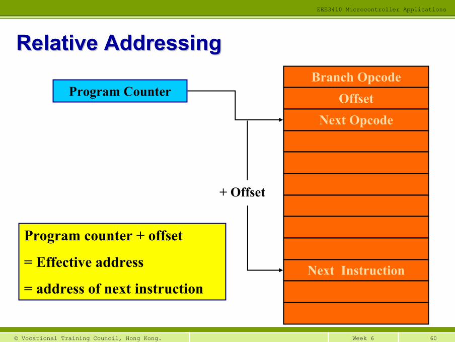
Program counter + offset
= Effective address
= address of next instruction
+ Offset
Branch OpcodeOffset
Next Opcode
Next Instruction
Program Counter
Relative AddressingRelative Addressing
61Week 6© Vocational Training Council, Hong Kong.
EEE3410 Microcontroller Applications
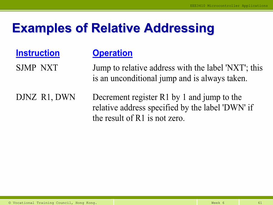
Instruction Operation SJMP NXT Jump to relative address with the label 'NXT'; this
is an unconditional jump and is always taken.
DJNZ R1, DWN Decrement register R1 by 1 and jump to the relative address specified by the label 'DWN' if the result of R1 is not zero.
Examples of Relative AddressingExamples of Relative Addressing
62Week 6© Vocational Training Council, Hong Kong.
EEE3410 Microcontroller Applications
Only used with the instructions ACALL and AJUMP
Similar to indexed addressing mode
The largest “jump” that can be made is 2K
Absolute AddressingAbsolute Addressing
Only used with the instructions LCALL and LJUMP
Similar to indexed addressing mode
The largest “jump” that can be made is 64K
Long AddressingLong Addressing
63Week 6© Vocational Training Council, Hong Kong.
EEE3410 Microcontroller Applications
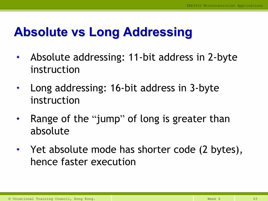
Absolute addressing: 11-bit address in 2-byte instruction
Long addressing: 16-bit address in 3-byte instruction
Range of the “jump” of long is greater than absolute
Yet absolute mode has shorter code (2 bytes), hence faster execution
Absolute Absolute vsvs Long AddressingLong Addressing
64Week 6© Vocational Training Council, Hong Kong.
EEE3410 Microcontroller Applications
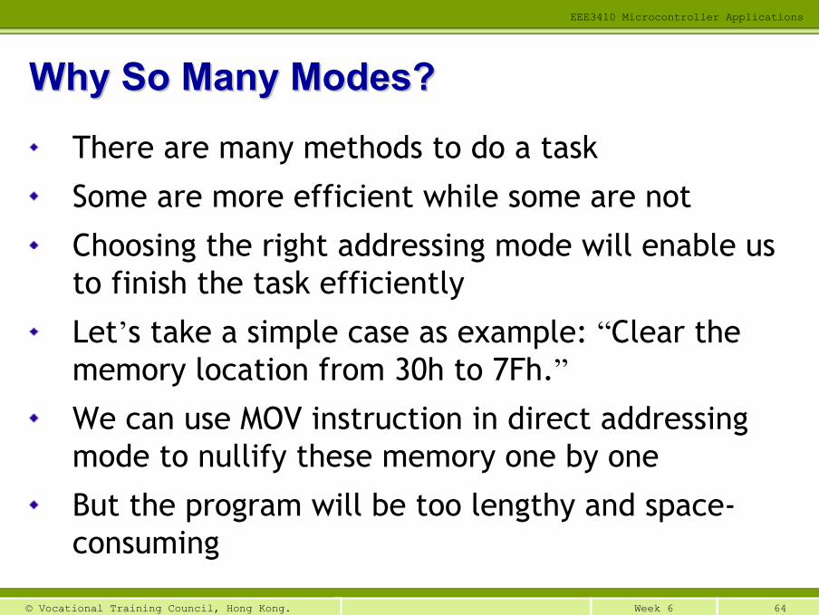
There are many methods to do a task
Some are more efficient while some are not
Choosing the right addressing mode will enable us to finish the task efficiently
Let’s take a simple case as example: “Clear the memory location from 30h to 7Fh.”We can use MOV instruction in direct addressing mode to nullify these memory one by one
But the program will be too lengthy and space-consuming
Why So Many Modes?Why So Many Modes?
65Week 6© Vocational Training Council, Hong Kong.
EEE3410 Microcontroller Applications
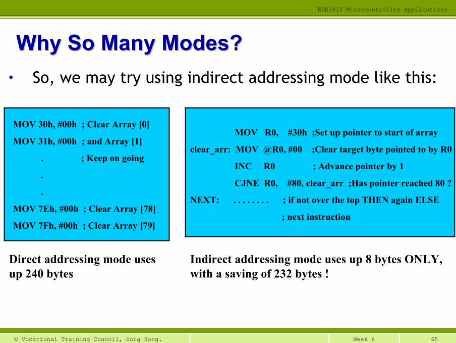
MOV 30h, #00h ; Clear Array [0]
MOV 31h, #00h ; and Array [1]
. ; Keep on going
.
.
MOV 7Eh, #00h ; Clear Array [78]
MOV 7Fh, #00h ; Clear Array [79]
Direct addressing mode uses up 240 bytes
MOV R0, #30h ;Set up pointer to start of array
clear_arr: MOV @R0, #00 ;Clear target byte pointed to by R0
INC R0 ; Advance pointer by 1
CJNE R0, #80, clear_arr ;Has pointer reached 80 ?
NEXT: . . . . . . . . ; if not over the top THEN again ELSE
; next instruction
Indirect addressing mode uses up 8 bytes ONLY, with a saving of 232 bytes !
Why So Many Modes?Why So Many Modes?So, we may try using indirect addressing mode like this:
66Week 6© Vocational Training Council, Hong Kong.
EEE3410 Microcontroller Applications
Yet, the program is still too long.
A much better method would be writing a subroutine (= function in C programming) to do nullification
Write a loop to call the subroutine for (7F-30+1) times to nullify all memory
As a result, we don’t have to write so many lines of program
A Little Further A Little Further ……....
67Week 6© Vocational Training Council, Hong Kong.
EEE3410 Microcontroller Applications
The 8051 Microcontroller and Embedded Systems -Using Assembly and C, Mazidi
Chapter 5 P.109 – P.135
Chapter 6 P.139 – P.167
Read referenceRead reference
1Week 6© Vocational Training Council, Hong Kong.
8051 Assembly Language Programming (2)8051 Assembly Language Programming (2)
EEE3410 Microcontroller ApplicationsDepartment of Electrical Engineering
│ END of Lecture 6 │