ECE 4510/5530 Microcontroller Applications Week 3 Lab 3bazuinb/ECE4510/Week3_1.pdf · ECE 4510/5530...
94
ECE 4510/5530 Microcontroller Applications Week 3 Lab 3 Dr. Bradley J. Bazuin Associate Professor Department of Electrical and Computer Engineering College of Engineering and Applied Sciences
Transcript of ECE 4510/5530 Microcontroller Applications Week 3 Lab 3bazuinb/ECE4510/Week3_1.pdf · ECE 4510/5530...
ECE 4510/5530Microcontroller Applications
Week 3 Lab 3
Dr. Bradley J. BazuinAssociate Professor
Department of Electrical and Computer EngineeringCollege of Engineering and Applied Sciences
ECE 2510 2
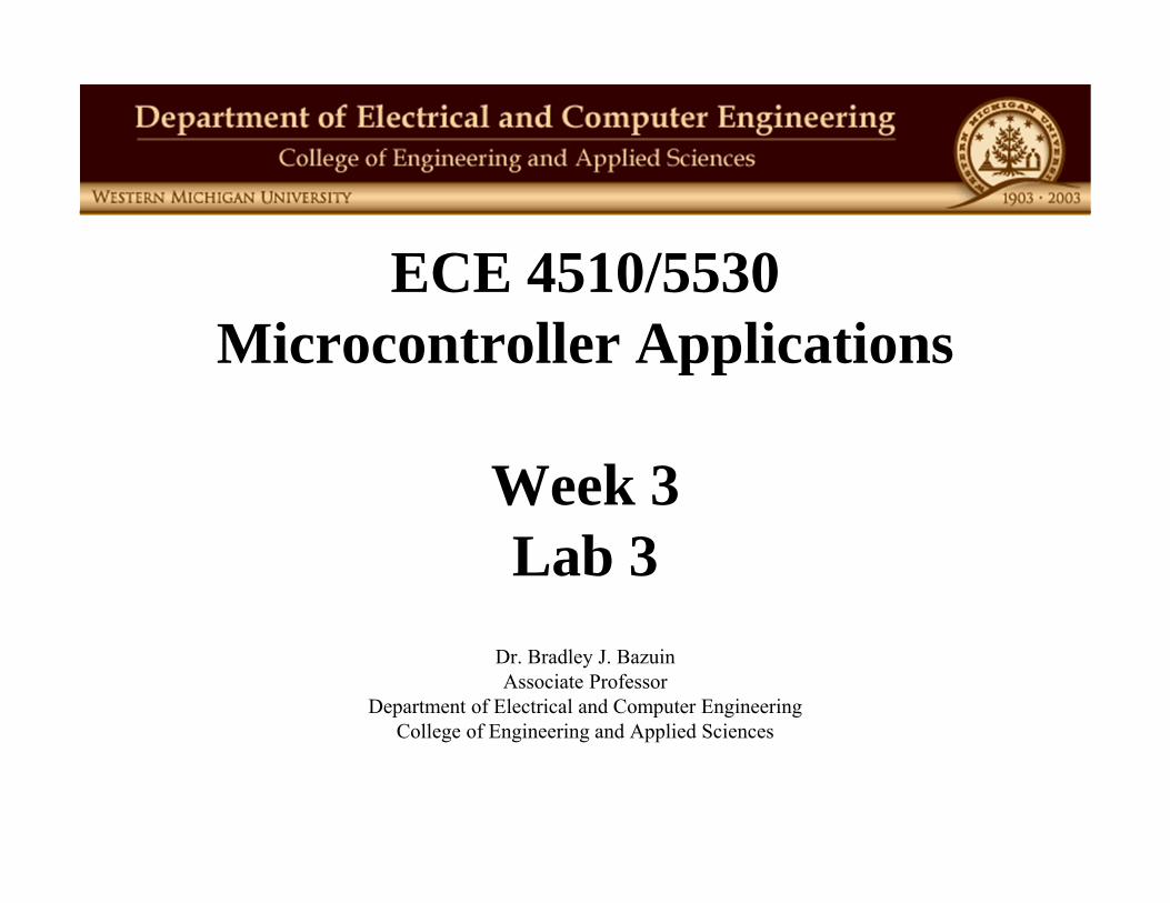
Lab 3 Elements
• Hardware Development– Clock-recovery-generator (CRG) (Chap. 6.6, 6.7) – 5 x 7 Matrix Display (Chap. 7.9)– Enhanced Capture Timer (ECT) (Chap. 8)
• Software Development Environment– Interrupts (Chap. 6.2, 6.5) – CRG_sw
RESETS AND INTERRUPTS
ECE 4510/5530
3
ECE 2510 4
What is a Reset?
• Hardware Reset– All hardware and software placed in the initial, default state.
• All registers and values reset to default conditions.• Assume RAM contains random binary values or is unchanged.
(If the power goes off, memory can change, if not, it stays the same.)– Activated by: Power turning on or reset pin on microcontroller
• Software Reset– Restart or reinitialize software without resetting the hardware
• Hardware memory are not changed except under program control, hardware peripheral registers may be “protected”.
• Registers/memory not initialized or used by the software are likely to remain unchanged.
– Activated by: a software command or, if programmed and enabled, a non-maskable interrupt pin … often called NMI(for us, the XIRQ can be used for this task if enabled)

ECE 2510 5
What is an Interrupt?
• An interrupt is a special event that requires the CPU to stop normal program execution and perform some “service related to the event”. – Examples of interrupts include I/O completion, timer time-out,
illegal opcodes, arithmetic overflow, divide-by-0, etc.– For most PCs, an interrupt is caused by a real-world event or by
something going wrong.– In most “real-time” signal processing almost all events drive
interrupts and interrupts are prioritized so the most important interrupt is worked on first.
• Interrupt sources– External: an external pin or level causes the interrupt– Internal: an internal microcontroller peripheral device or CPU
operation causes the interrupt– Software: the swi assembly language instruction is an interrupt
ECE 4510/5530
6
Reset Features
• The initial values of some CPU registers, flip-flops, and the control registers in I/O interface chips must be established in order for the computer to function properly.– The reset mechanism establishes these initial conditions for the
computer system.
• There are at least two types of resets: power-on reset and manual reset. – The power-on reset establishes the initial values of registers and
I/O control registers.– The manual reset without power-down allows the computer to get
out of most error conditions if hardware doesn’t fail.
• A reset is nonmaskable. After a reset, the CPU always starts at a defined address.
ECE 4510/5530
7
Hardware vs. Software Reset
• Hardware Resets are caused due to physical hardware conditions. (e.g. power-on, reset pin activated)– All processor register defaults set, all initialization performed
• Software Resets– Often associated with activation of a non-maskable interrupt
(NMI)– May not reset processor hardware, such as registers or peripherals.– May be used to stop a program and restart the operating system or
CPU monitor or Software (like D-Bug12).
ECE 2510 8
Interrupts
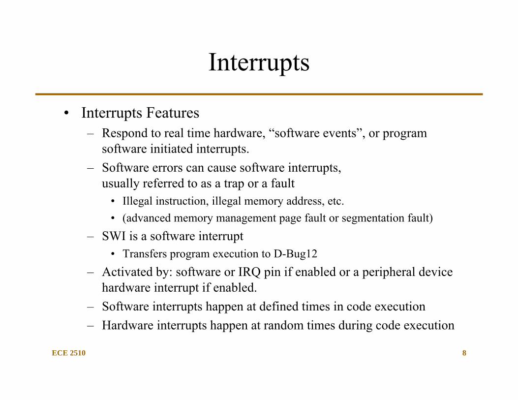
• Interrupts Features– Respond to real time hardware, “software events”, or program
software initiated interrupts.– Software errors can cause software interrupts,
usually referred to as a trap or a fault• Illegal instruction, illegal memory address, etc. • (advanced memory management page fault or segmentation fault)
– SWI is a software interrupt • Transfers program execution to D-Bug12
– Activated by: software or IRQ pin if enabled or a peripheral device hardware interrupt if enabled.
– Software interrupts happen at defined times in code execution– Hardware interrupts happen at random times during code execution
ECE 4510/5530
Functions of Interrupts
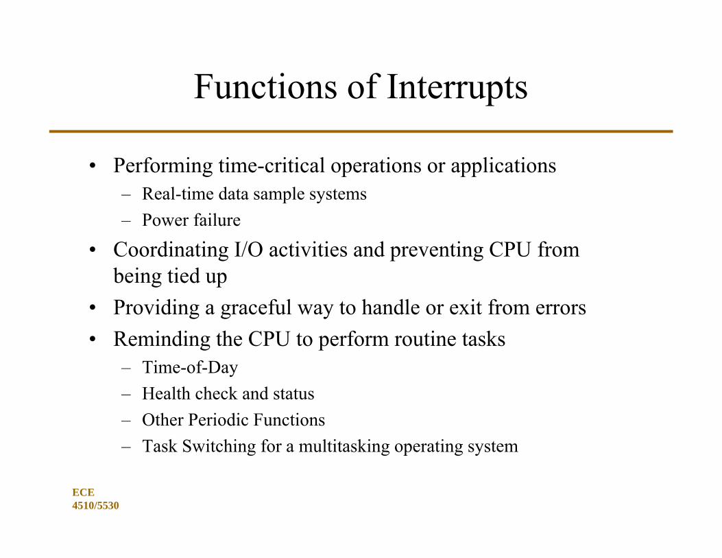
• Performing time-critical operations or applications– Real-time data sample systems– Power failure
• Coordinating I/O activities and preventing CPU from being tied up
• Providing a graceful way to handle or exit from errors• Reminding the CPU to perform routine tasks
– Time-of-Day– Health check and status– Other Periodic Functions– Task Switching for a multitasking operating system

ECE 4510/5530
10
Example of Real-Time Code Flow
• Sequential Code with Infinite Loop– Process as time is available
• Interrupts that must be immediately processed
External Interrupt Priority
Interrupt 1
Int 1 Process
Set Int 1 Flag
RTI
Interrupt 2
Int 2 Process
Set Int 2 Flag
RTI
Interrupt M
Int M Process
Set Int M Flag
RTI
ECE 4510/5530
11
Multi-tasking Operating Systems
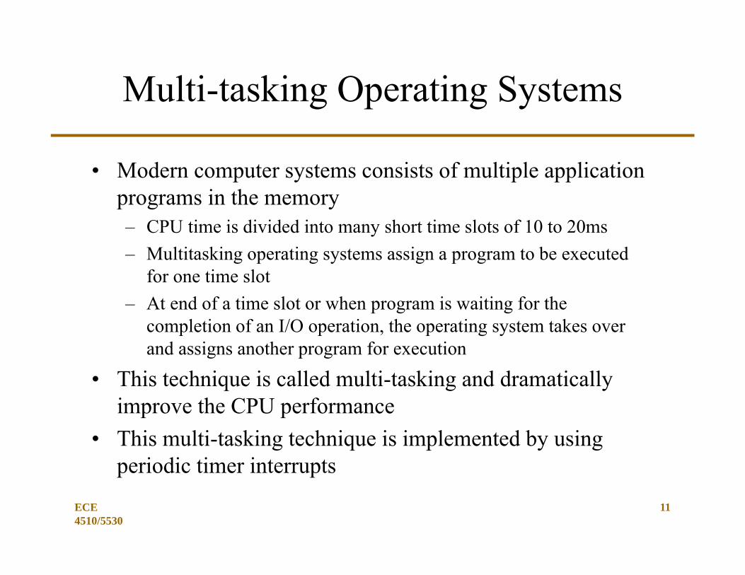
• Modern computer systems consists of multiple application programs in the memory– CPU time is divided into many short time slots of 10 to 20ms– Multitasking operating systems assign a program to be executed
for one time slot– At end of a time slot or when program is waiting for the
completion of an I/O operation, the operating system takes over and assigns another program for execution
• This technique is called multi-tasking and dramatically improve the CPU performance
• This multi-tasking technique is implemented by using periodic timer interrupts
ECE 4510/5530
Basics of Interrupts (1 of 5)
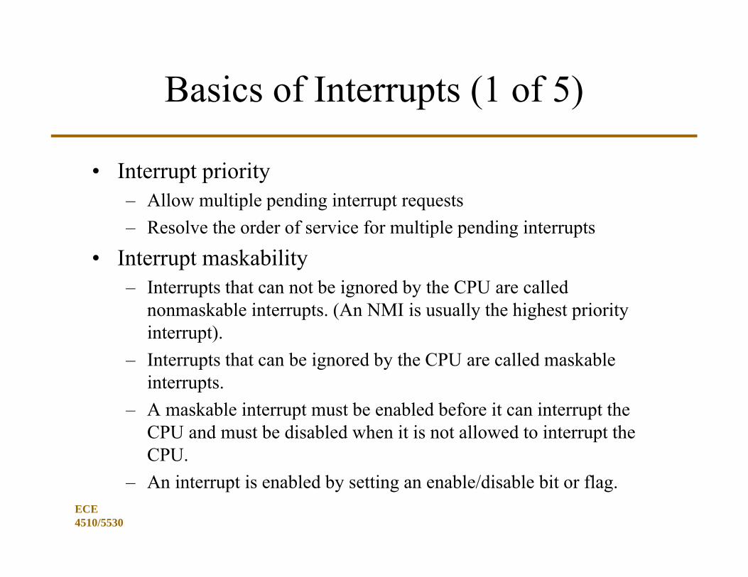
• Interrupt priority– Allow multiple pending interrupt requests– Resolve the order of service for multiple pending interrupts
• Interrupt maskability– Interrupts that can not be ignored by the CPU are called
nonmaskable interrupts. (An NMI is usually the highest priority interrupt).
– Interrupts that can be ignored by the CPU are called maskable interrupts.
– A maskable interrupt must be enabled before it can interrupt the CPU and must be disabled when it is not allowed to interrupt the CPU.
– An interrupt is enabled by setting an enable/disable bit or flag.
ECE 4510/5530
Basics of Interrupts (2 of 5)
• Interrupt service– CPU executes a program called the interrupt service routine.– A complete interrupt service cycle includes
1. Saving the program counter value in the stack2. Saving the CPU status (including the CPU status register and some
other registers) in the stack3. Identifying the cause of interrupt4. Resolving the starting address of the corresponding interrupt service
routine (ISR)5. Executing the interrupt service routine6. Restoring the CPU status and the program counter from the stack7. Restarting the interrupted program
– An ISR often looks exactly like a subroutine call, except that it is called due to an interrupt.
ECE 4510/5530
Basics of Interrupts (3 of 5)
• Interrupt vector– Starting address of the interrupt service routine
• Interrupt vector table– A table where all interrupt vectors are stored
• Methods of determining interrupt vectors– Predefined locations (Microchip PIC18, 8051 variants)– Fetching the vector from a predefined memory location (HCS12)– Executing an interrupt acknowledge cycle to fetch a vector number
in order to locate the interrupt vector (68000 and x86 families)
ECE 4510/5530
Basics of Interrupts (4 of 5)
• Steps required for interrupt programming– Step 1. Initializing the interrupt vector table– Step 2. Writing the interrupt service routine– Step 3. Enabling the desired interrupts at the appropriate location
in the system code.
• The overhead of interrupts– Saving and restoring of CPU status and other registers. (HCS12
needs to save all CPU registers).– Execution time of instructions of the interrupt service routine.
• Overhead time required to enter and exit an ISR– The execution of the return-from-interrupt (RTI) instruction that
will restore all the CPU registers.
ECE 4510/5530
Basics of Interrupts (5 of 5)
• Nasty details when using interrupts– Interrupt happen at random times that may not be predictable.
• Plan for the worst– Microprocessors should cleanly transition from normal operation to the
interrupt• They typically finish the instruction they are executing and save the
address of next instruction in stack so that it can resume the program later.– Microprocessor needs to identify the cause of the interrupt before it can
take appropriate action. This is built into the microprocessor hardware.– Interrupts will force the microprocessor to stop executing an
application program briefly• What is the application priority as compared to the interrupt?
– Interrupts if they return should resume the previous application code as though nothing happened (registers, CCR, etc.).
Important Interrupt Concepts
• Enabling and Disabling Interrupts– The programmer can let them happen or not– Typically global and local enables (one or all and then one each)– Typically the “interrupt status” can be checked even when not
enabled (polling is when software checks for “events”
• Pending interrupt– An interrupt waiting to happen
• Nested interrupts– When an interrupt is allowed to occur while the software is
executing another interrupt– Typically, interrupts are disabled automatically while an interrupt
is being serviced … waiting interrupts are “pending”.
ECE 2510 17
Using Interrupts
• Initialize the interrupting function and set the local interrupt enable bit– clear pending interrupts if possible
• Make sure a valid interrupt service routine (ISR) exists• Make sure the system can find the ISR code
– A ISR address table is often used for defined types of interrupts– Also called an interrupt vector (IV) table (address of address)
• When ready, set the global interrupt enable– Pending interrupts will immediately be serviced– Interrupt ISR will start where the IV says, even if you forgot to
define where in the IVECE 2510 18
ECE 2510 19
What is an Interrupt?
• An interrupt is a special event that requires the CPU to stop normal program execution and perform some “service related to the event”. – Examples of interrupts include I/O completion, timer time-out,
illegal opcodes, arithmetic overflow, divide-by-0, etc.– For most PCs, an interrupt is caused by a real-world event or by
something going wrong.– In most “real-time” signal processing almost all events drive
interrupts and interrupts are prioritized so the most important interrupt is worked on first.
• Interrupt sources– External: an external pin or level causes the interrupt– Internal: an internal microcontroller peripheral device or CPU
operation causes the interrupt– Software: the swi assembly language instruction is an interrupt
ECE 4510/5530
20
Major Interrupt Issues
• Maskable/Non-Maskable Interrupts• Interrupt Priority• Interrupt Service• Interrupt Vector• Interrupt Programming• Interrupt Overhead
ECE 2510 21
Maskable Interrupt Operation
• Program can request the CPU to service or ignore a maskable interrupt by setting or clearing an enable bit– When an interrupt is enabled, the CPU will respond to it– When an interrupt is disabled, the CPU will ignore it
• Multiple level masks (both enabled to operate):– Global enable bit
• all local interrupts are enabled or disabled– Local enable bit
• each interruptible function has an enable/disable bit
• HC12 also has a special XIRQ interrupt
Two Classes of Interrupts
• NMI Interrupts– Not always used, but possible
• All the other interrupts– The interrupts you will be using in almost every lab– Examples: RTI, IRQ, peripheral device interrupts
ECE 4510/5530 22
ECE 4510/5530
23
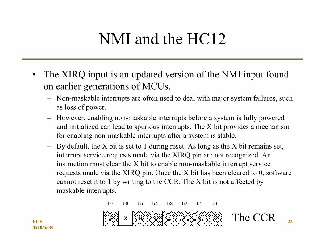
NMI and the HC12
• The XIRQ input is an updated version of the NMI input found on earlier generations of MCUs.– Non-maskable interrupts are often used to deal with major system failures, such
as loss of power.– However, enabling non-maskable interrupts before a system is fully powered
and initialized can lead to spurious interrupts. The X bit provides a mechanism for enabling non-maskable interrupts after a system is stable.
– By default, the X bit is set to 1 during reset. As long as the X bit remains set, interrupt service requests made via the XIRQ pin are not recognized. An instruction must clear the X bit to enable non-maskable interrupt service requests made via the XIRQ pin. Once the X bit has been cleared to 0, software cannot reset it to 1 by writing to the CCR. The X bit is not affected by maskable interrupts.
b7 b6 b5 b4 b3 b2 b1 b0
S X H I N Z V C The CCR
ECE 2510 24
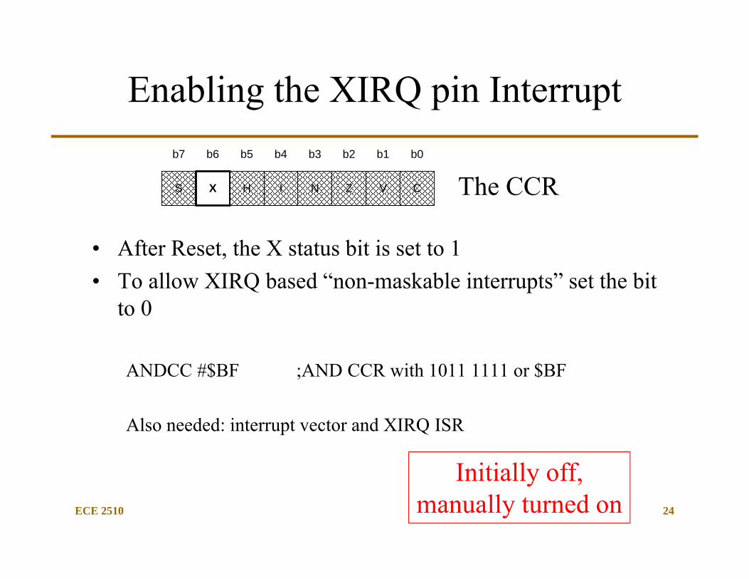
Enabling the XIRQ pin Interrupt
• After Reset, the X status bit is set to 1• To allow XIRQ based “non-maskable interrupts” set the bit
to 0
ANDCC #$BF ;AND CCR with 1011 1111 or $BF
Also needed: interrupt vector and XIRQ ISR
b7 b6 b5 b4 b3 b2 b1 b0
S X H I N Z V C The CCR
Initially off, manually turned on
ECE 2510 25
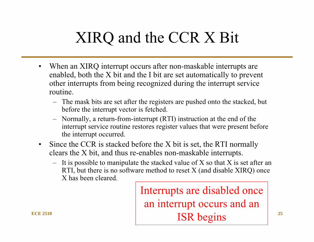
XIRQ and the CCR X Bit
• When an XIRQ interrupt occurs after non-maskable interrupts are enabled, both the X bit and the I bit are set automatically to prevent other interrupts from being recognized during the interrupt service routine. – The mask bits are set after the registers are pushed onto the stacked, but
before the interrupt vector is fetched.– Normally, a return-from-interrupt (RTI) instruction at the end of the
interrupt service routine restores register values that were present before the interrupt occurred.
• Since the CCR is stacked before the X bit is set, the RTI normally clears the X bit, and thus re-enables non-maskable interrupts. – It is possible to manipulate the stacked value of X so that X is set after an
RTI, but there is no software method to reset X (and disable XIRQ) once X has been cleared.
Interrupts are disabled once an interrupt occurs and an
ISR begins
ECE 2510 26
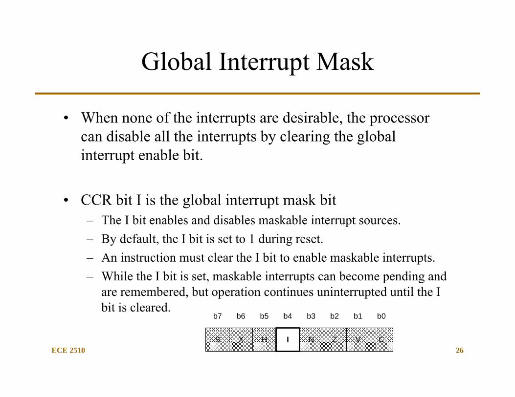
Global Interrupt Mask
• When none of the interrupts are desirable, the processor can disable all the interrupts by clearing the global interrupt enable bit.
• CCR bit I is the global interrupt mask bit– The I bit enables and disables maskable interrupt sources. – By default, the I bit is set to 1 during reset. – An instruction must clear the I bit to enable maskable interrupts. – While the I bit is set, maskable interrupts can become pending and
are remembered, but operation continues uninterrupted until the I bit is cleared.
b7 b6 b5 b4 b3 b2 b1 b0
S X H I N Z V C
ECE 2510 27
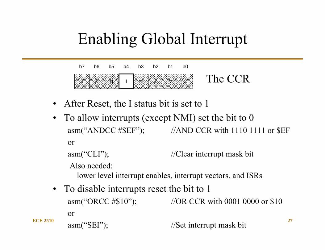
Enabling Global Interrupt
• After Reset, the I status bit is set to 1• To allow interrupts (except NMI) set the bit to 0
asm(“ANDCC #$EF”); //AND CCR with 1110 1111 or $EForasm(“CLI”); //Clear interrupt mask bitAlso needed:
lower level interrupt enables, interrupt vectors, and ISRs
• To disable interrupts reset the bit to 1asm(“ORCC #$10”); //OR CCR with 0001 0000 or $10orasm(“SEI”); //Set interrupt mask bit
The CCRb7 b6 b5 b4 b3 b2 b1 b0
S X H I N Z V C
ECE 2510 28
CCR: I Mask Bit
• When an interrupt occurs after interrupts are enabled, the I bit is automatically set to prevent other maskable interrupts during the interrupt service routine. – The I bit is set after the registers are stacked, but before the first
instruction in the interrupt service routine is executed.– Normally, an RTI instruction at the end of the interrupt service
routine restores register values that were present before the interrupt occurred.
• Since the CCR is stacked before the I bit is set, the RTI normally clears the I bit, and thus re-enables interrupts. – Interrupts can be re-enabled by clearing the I bit within the service
routine, but implementing a nested interrupt management scheme requires great care and seldom improves system performance.
Interrupt Hints
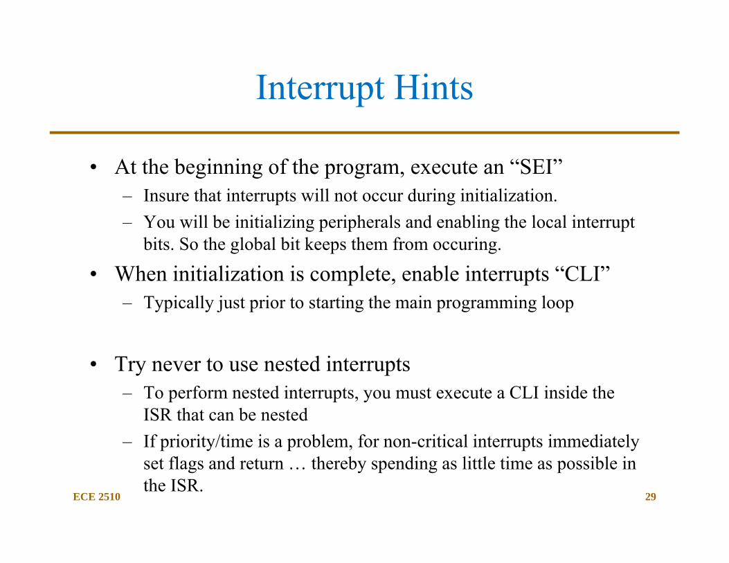
• At the beginning of the program, execute an “SEI”– Insure that interrupts will not occur during initialization. – You will be initializing peripherals and enabling the local interrupt
bits. So the global bit keeps them from occuring.
• When initialization is complete, enable interrupts “CLI”– Typically just prior to starting the main programming loop
• Try never to use nested interrupts– To perform nested interrupts, you must execute a CLI inside the
ISR that can be nested– If priority/time is a problem, for non-critical interrupts immediately
set flags and return … thereby spending as little time as possible in the ISR.
ECE 2510 29
ECE 4510/5530
30
Individual Interrupt Mask Bits
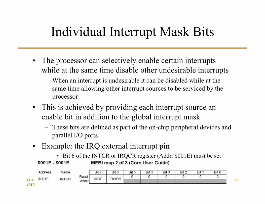
• The processor can selectively enable certain interrupts while at the same time disable other undesirable interrupts– When an interrupt is undesirable it can be disabled while at the
same time allowing other interrupt sources to be serviced by the processor
• This is achieved by providing each interrupt source an enable bit in addition to the global interrupt mask– These bits are defined as part of the on-chip peripheral devices and
parallel I/O ports
• Example: the IRQ external interrupt pin• Bit 6 of the INTCR or IRQCR register (Addr. $001E) must be set
ECE 4510/5530
31
Major Interrupt Issues
• Maskable Interrupts• Interrupt Priority• Interrupt Service• Interrupt Vector• Interrupt Programming• Interrupt Overhead
ECE 4510/5530
32
Interrupt Priority
• Controller may supports multiple interrupt sources at the same time– It is possible that several interrupts would be pending at the same
time– CPU has to decide which interrupt to service during this situation– Solution to this situation is to prioritize the interrupts
• Interrupt with highest priority receives service before interrupts at lower priorities– Many microcontrollers prioritize interrupts in hardware.
In the HC12, interrupt priority is based on the higest interrupt vector address
– For those microcontrollers that do not prioritize interrupts, software can be written to handle certain interrupts before others.
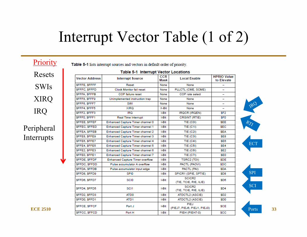
ECE 2510 33
Interrupt Vector Table (1 of 2)
ResetsSWIsXIRQ
Priority
IRQ
Peripheral Interrupts
ECT
SPI
SCI
Ports
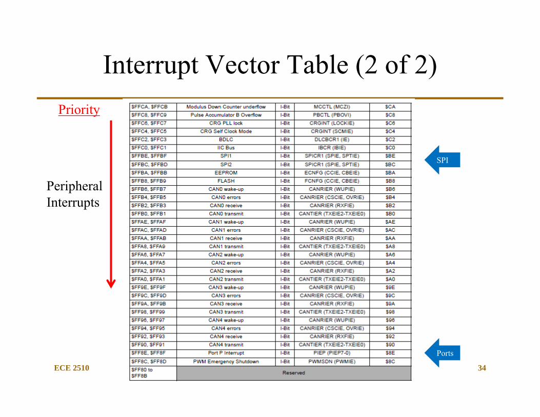
ECE 2510 34
Interrupt Vector Table (2 of 2)Priority
Peripheral Interrupts
Ports
SPI
ECE 4510/5530
35
Major Interrupt Issues
• Maskable Interrupts• Interrupt Priority• Interrupt Service• Interrupt Vector• Interrupt Programming• Interrupt Overhead
ECE 4510/5530
36
Interrupt Service
• CPU provides service to an interrupt by executing a program called an interrupt service routine (ISR)– The ISR begins at predefined address locations– The HCS12 has a predefined location for each interrupt where the
address of the ISR can be found. This is called an interrupt vector.
• After providing service to an interrupt, the CPU must resume normal program execution– It achieves this by saving the program counter and the CPU status
information before executing the interrupt service routine and then restoring the saved program counter and CPU status before exiting the interrupt service routine.
ECE 4510/5530
37
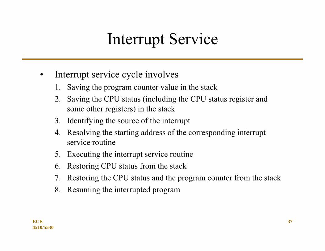
Interrupt Service
• Interrupt service cycle involves1. Saving the program counter value in the stack2. Saving the CPU status (including the CPU status register and
some other registers) in the stack3. Identifying the source of the interrupt4. Resolving the starting address of the corresponding interrupt
service routine5. Executing the interrupt service routine6. Restoring CPU status from the stack7. Restoring the CPU status and the program counter from the stack8. Resuming the interrupted program
ECE 4510/5530
38
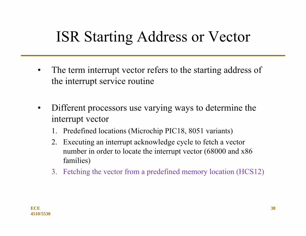
ISR Starting Address or Vector
• The term interrupt vector refers to the starting address of the interrupt service routine
• Different processors use varying ways to determine the interrupt vector1. Predefined locations (Microchip PIC18, 8051 variants)2. Executing an interrupt acknowledge cycle to fetch a vector
number in order to locate the interrupt vector (68000 and x86 families)
3. Fetching the vector from a predefined memory location (HCS12)
ECE 4510/5530
39
Major Interrupt Issues
• Maskable Interrupts• Interrupt Priority• Interrupt Service• Interrupt Vector• Interrupt Programming• Interrupt Overhead
ECE 2510 40
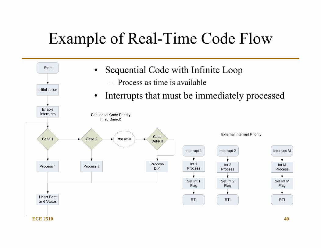
Example of Real-Time Code Flow
• Sequential Code with Infinite Loop– Process as time is available
• Interrupts that must be immediately processed
External Interrupt Priority
Interrupt 1
Int 1 Process
Set Int 1 Flag
RTI
Interrupt 2
Int 2 Process
Set Int 2 Flag
RTI
Interrupt M
Int M Process
Set Int M Flag
RTI
ECE 2510 41
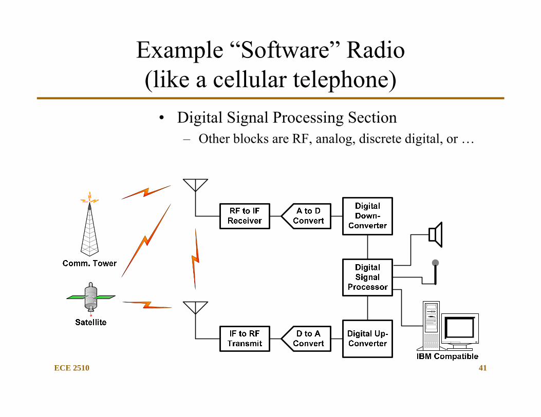
Example “Software” Radio(like a cellular telephone)
• Digital Signal Processing Section– Other blocks are RF, analog, discrete digital, or …
ECE 2510 42
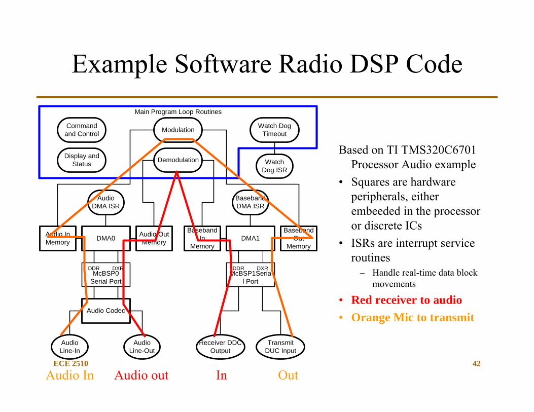
Example Software Radio DSP Code
Based on TI TMS320C6701 Processor Audio example
• Squares are hardware peripherals, either embeeded in the processor or discrete ICs
• ISRs are interrupt service routines
– Handle real-time data block movements
• Red receiver to audio• Orange Mic to transmit
Audio Line-In
AudioLine-Out
Audio Codec
DDR DXR
DMA0
McBSP0 Serial Port
AudioDMA ISR
Receiver DDC Output
TransmitDUC Input
DDR DXR
DMA1
McBSP1Serial Port
BasebandDMA ISR
Demodulation
Audio In Memory
Audio Out Memory
BasebandIn
Memory
BasebandOut
Memory
ModulationCommand and Control
Display and Status
Main Program Loop Routines
Watch Dog Timeout
Watch Dog ISR
InAudio In Audio out Out
ECE 2510 43
Interrupt Routine Programming
• Interrupt programming deals with how to provide service to the interrupt. Three steps are involved in interrupt programming:– Step 1a. Set the interrupt vector table with the ISR start address.
• Maybe be performed automatically using assembler/compiler directives.
– Step 1b. Initializing the peripheral hardware involved.– Step 2. Writing the interrupt service routine.– Step 3. Enabling the desired interrupts at the appropriate
location in the system code.
ECE 2510 44
Interrupt Programming: Step 1a
• Step1a:– Initialize the interrupt vector table– This step is not needed for microprocessors that have predefined
interrupt vectors, but we need to do it!– Two methods to initialize the interrupt vector table
• Can be done using the .org assembler directive• By loading the start address of ISR into index register and storing it
into the Debug-12 interrupt vector table memory
• Step 1b:– Initialize peripherals that will be used
• I/O port directions, levels, etc.
ECE 2510 45
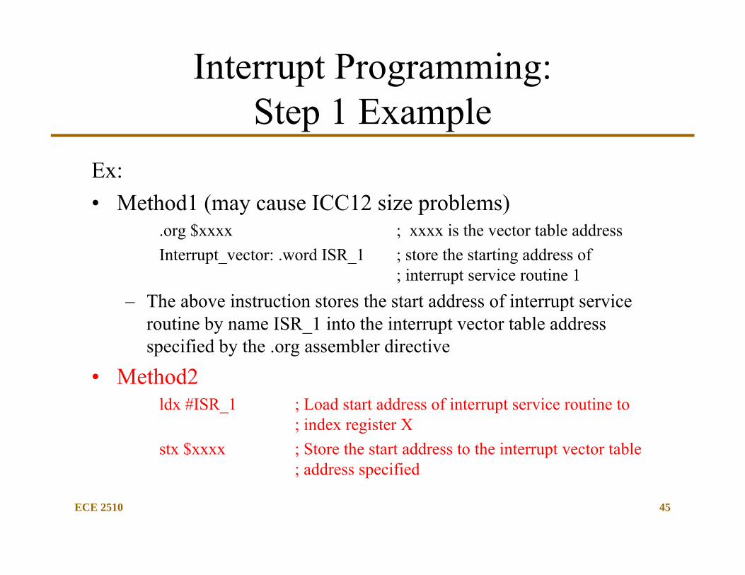
Interrupt Programming: Step 1 Example
Ex: • Method1 (may cause ICC12 size problems)
.org $xxxx ; xxxx is the vector table addressInterrupt_vector: .word ISR_1 ; store the starting address of
; interrupt service routine 1– The above instruction stores the start address of interrupt service
routine by name ISR_1 into the interrupt vector table address specified by the .org assembler directive
• Method2ldx #ISR_1 ; Load start address of interrupt service routine to
; index register Xstx $xxxx ; Store the start address to the interrupt vector table
; address specified
ECE 4510/5530
46
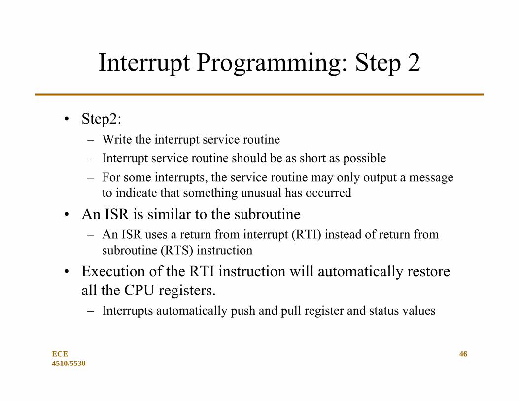
Interrupt Programming: Step 2
• Step2:– Write the interrupt service routine– Interrupt service routine should be as short as possible– For some interrupts, the service routine may only output a message
to indicate that something unusual has occurred
• An ISR is similar to the subroutine– An ISR uses a return from interrupt (RTI) instead of return from
subroutine (RTS) instruction
• Execution of the RTI instruction will automatically restore all the CPU registers.– Interrupts automatically push and pull register and status values
ECE 4510/5530
47
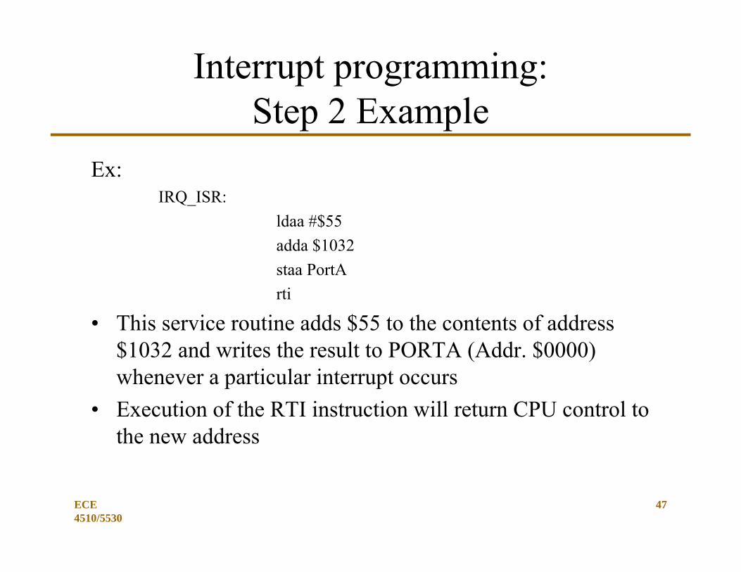
Interrupt programming: Step 2 Example
Ex:IRQ_ISR:
ldaa #$55adda $1032staa PortArti
• This service routine adds $55 to the contents of address $1032 and writes the result to PORTA (Addr. $0000) whenever a particular interrupt occurs
• Execution of the RTI instruction will return CPU control to the new address
ECE 4510/5530
48
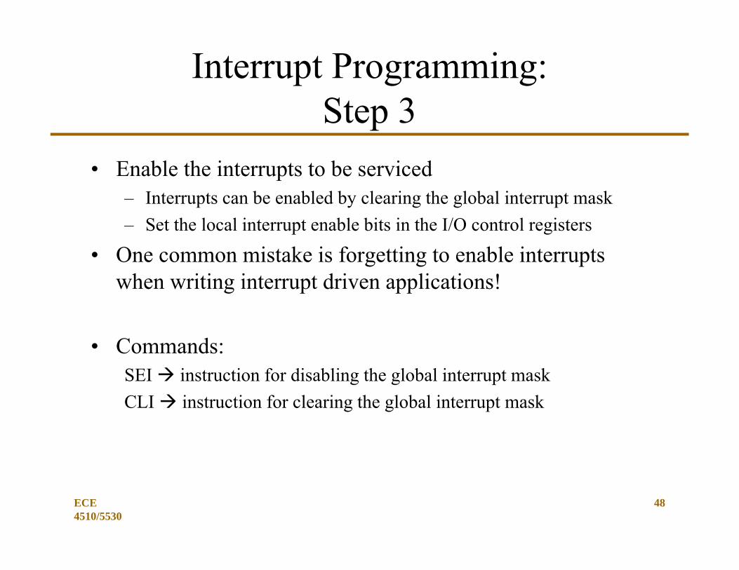
Interrupt Programming:Step 3
• Enable the interrupts to be serviced– Interrupts can be enabled by clearing the global interrupt mask– Set the local interrupt enable bits in the I/O control registers
• One common mistake is forgetting to enable interrupts when writing interrupt driven applications!
• Commands:SEI instruction for disabling the global interrupt maskCLI instruction for clearing the global interrupt mask
ECE 2510 49
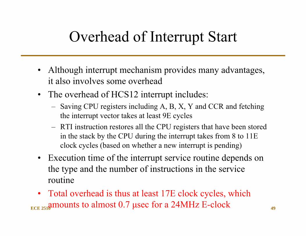
Overhead of Interrupt Start
• Although interrupt mechanism provides many advantages, it also involves some overhead
• The overhead of HCS12 interrupt includes:– Saving CPU registers including A, B, X, Y and CCR and fetching
the interrupt vector takes at least 9E cycles– RTI instruction restores all the CPU registers that have been stored
in the stack by the CPU during the interrupt takes from 8 to 11E clock cycles (based on whether a new interrupt is pending)
• Execution time of the interrupt service routine depends on the type and the number of instructions in the service routine
• Total overhead is thus at least 17E clock cycles, which amounts to almost 0.7 μsec for a 24MHz E-clock
ECE 2510 50
Return From Interrupt (RTI)
RTI Instruction:• RTI instruction is used to terminate interrupt service routines• RTI is an 8-cycle instruction when no other interrupt is pending and a
11-cycle instruction when other interrupt is pending• In either case first 5 cycles are used to restore the CCR, B:A, X, Y and
the return address from the stack• HCS12 then clears the I mask to enable further maskable interrupts• If no interrupt is pending, three program words are fetched to fill the
instruction queue from the area of return address and processing proceeds from there
CLOCK RECOVERY GENERATOR (CRG)
ECE 4510/5530
51

ECE 2510 52
Microcontroller Clocks
• Typical microcontrollers have multi-function clock generation circuitry. Built in user flexibility …– On IC clock generation– External input clock ports– External crystal connections for clocks– Clock rate multiplication/division circuits (PLL or counters)– Low power allowances (slow or stop the clock)– Special operation during power-on reset and hardware reset– Periodic clock based interrupts (watchdog timer)– And more …..
ECE 2510 53
VREG
Clock and ResetControl
Resetgenerator
Clock qualitychecker
COP RTI
Registers
SystemReset
Bus clock
Core clock
Oscillatorclock
Power onreset
RESETCM fail
Clockmonitor
OSC
PLL
OSCCLK
PLLCLK
XCLKS
EXTAL
XTAL
XFCVDDPLL
VSSPLL
CRG
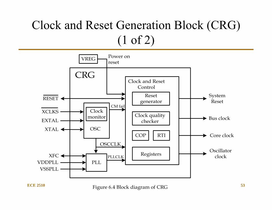
Figure 6.4 Block diagram of CRG
Clock and Reset Generation Block (CRG) (1 of 2)
ECE 2510 54
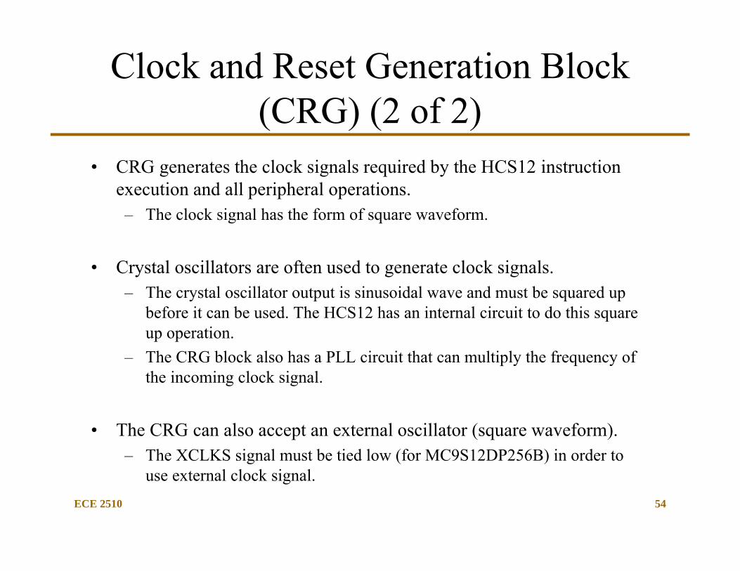
Clock and Reset Generation Block (CRG) (2 of 2)
• CRG generates the clock signals required by the HCS12 instruction execution and all peripheral operations.– The clock signal has the form of square waveform.
• Crystal oscillators are often used to generate clock signals.– The crystal oscillator output is sinusoidal wave and must be squared up
before it can be used. The HCS12 has an internal circuit to do this square up operation.
– The CRG block also has a PLL circuit that can multiply the frequency of the incoming clock signal.
• The CRG can also accept an external oscillator (square waveform). – The XCLKS signal must be tied low (for MC9S12DP256B) in order to
use external clock signal.
ECE 2510 55
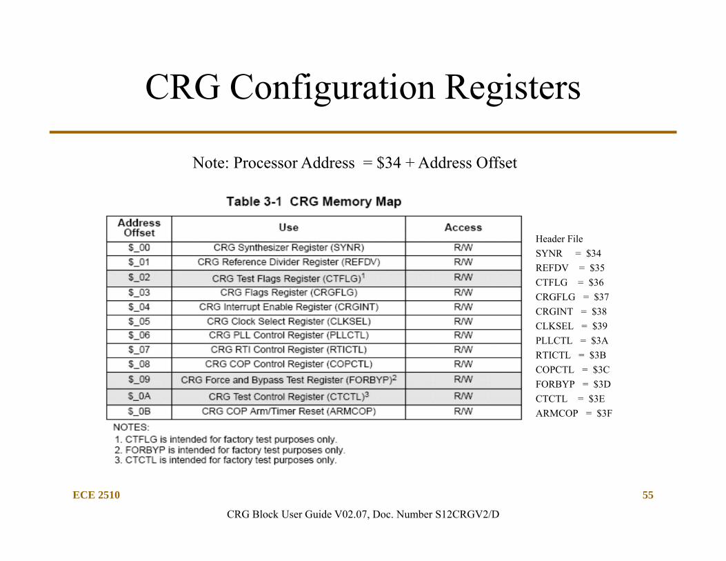
CRG Configuration Registers
CRG Block User Guide V02.07, Doc. Number S12CRGV2/D
Note: Processor Address = $34 + Address Offset
Header FileSYNR = $34REFDV = $35CTFLG = $36CRGFLG = $37CRGINT = $38CLKSEL = $39PLLCTL = $3ARTICTL = $3BCOPCTL = $3CFORBYP = $3DCTCTL = $3EARMCOP = $3F
ECE 2510 56
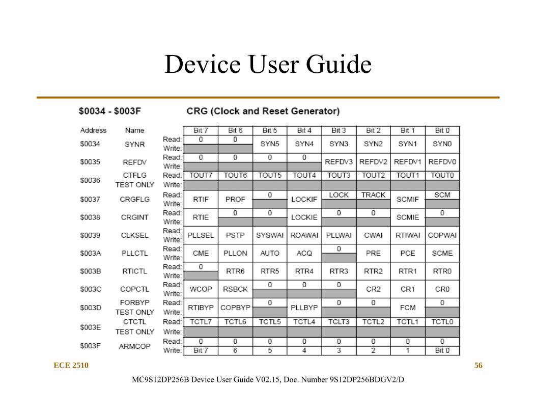
Device User Guide
MC9S12DP256B Device User Guide V02.15, Doc. Number 9S12DP256BDGV2/D
ECE 2510 57
Phaselockloop
1
0
1
0
Clockmonitor
Oscillator OSCCLK
PLLCLK
PLLSEL or SCM
SCM
clockphase
generator2
WAIT,STOP
wait(RTIWAI),stop(PSTP,PRE)
RTI enable
RTI
COP
wait (COPWAI),stop(PSTP, PCE)
COP enable
wait (SYSWAI),stop
stop (PSTP)
wait (CWAI,SYSWAI)stop
Coreclock
Busclock
oscillatorclock
oscillatorclock (pseudo stopmode)
extal
xtal
gatingcondition
= clock gate
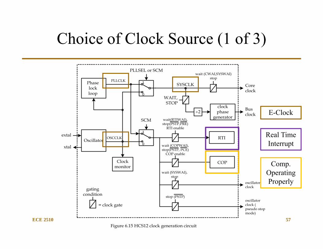
Figure 6.15 HCS12 clock generation circuit
SYSCLK
Choice of Clock Source (1 of 3)
E-Clock
Real Time Interrupt
Comp. Operating Properly

ECE 2510 58
Choice of Clock Source (2 of 3)
• The user can choose between using the external crystal or oscillator to produce the clock signal.– The external crystal is connected between the EXTAL and XTAL
pins and needs an on-chip oscillator circuitry to square it up.– The external clock source provided by the oscillator is connected
to the EXTAL pin and has a 2.5V peak-to-peak magnitude for the D family or CPUs (9s12DP256).
• The XCLKS signal must be grounded to select the external clock signal.
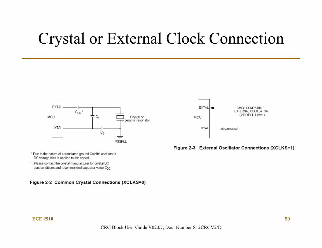
ECE 2510 59
Crystal or External Clock Connection
CRG Block User Guide V02.07, Doc. Number S12CRGV2/D
ECE 2510 60
Choice of Clock Source (3 of 3)
• The output from the OSC module in Figure 6.4 may bypass or go through the PLL circuit.– The PLL circuit has the capability to multiply incoming signal
frequency and stabilize its output signal frequency.
• Either the OSCCLK or the PLLCLK can be chosen as the SYSCLK which will be divided by 2 to derive the bus clock to control the instruction execution and peripheral operation. (E-clock from timing).
ECE 2510 61
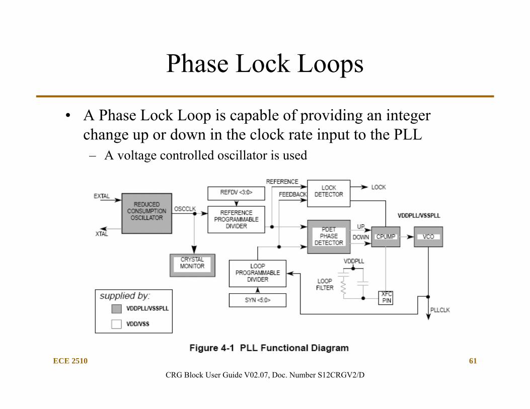
Phase Lock Loops
• A Phase Lock Loop is capable of providing an integer change up or down in the clock rate input to the PLL– A voltage controlled oscillator is used
CRG Block User Guide V02.07, Doc. Number S12CRGV2/D
ECE 2510 62
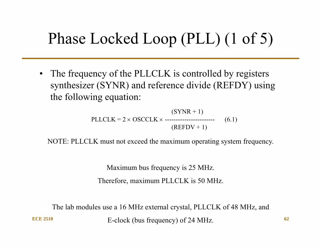
(SYNR + 1)PLLCLK = 2 OSCCLK ----------------------- (6.1)
(REFDV + 1)
Phase Locked Loop (PLL) (1 of 5)
• The frequency of the PLLCLK is controlled by registers synthesizer (SYNR) and reference divide (REFDY) using the following equation:
NOTE: PLLCLK must not exceed the maximum operating system frequency.
Maximum bus frequency is 25 MHz.
Therefore, maximum PLLCLK is 50 MHz.
The lab modules use a 16 MHz external crystal, PLLCLK of 48 MHz, and
E-clock (bus frequency) of 24 MHz.
ECE 2510 63
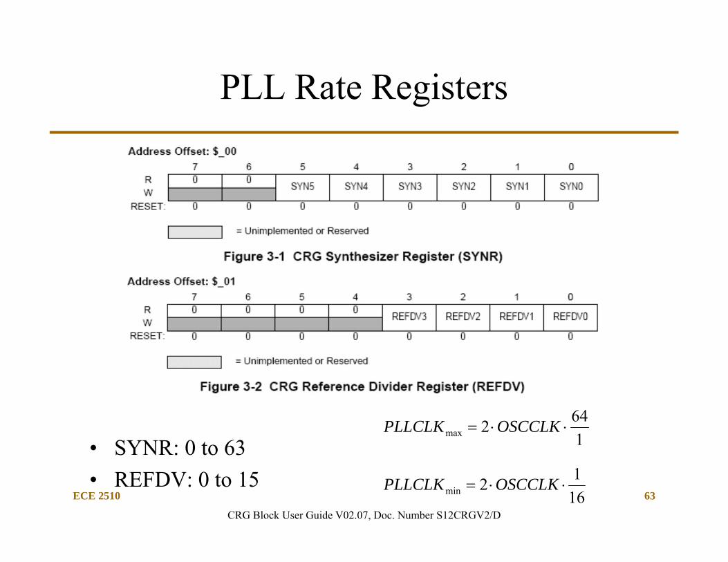
PLL Rate Registers
• SYNR: 0 to 63• REFDV: 0 to 15
1612min OSCCLKPLLCLK
1642max OSCCLKPLLCLK
CRG Block User Guide V02.07, Doc. Number S12CRGV2/D
ECE 2510 64
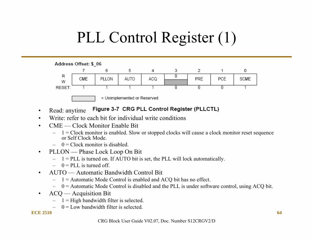
PLL Control Register (1)
• Read: anytime• Write: refer to each bit for individual write conditions• CME — Clock Monitor Enable Bit
– 1 = Clock monitor is enabled. Slow or stopped clocks will cause a clock monitor reset sequence or Self Clock Mode.
– 0 = Clock monitor is disabled.• PLLON — Phase Lock Loop On Bit
– 1 = PLL is turned on. If AUTO bit is set, the PLL will lock automatically.– 0 = PLL is turned off.
• AUTO — Automatic Bandwidth Control Bit– 1 = Automatic Mode Control is enabled and ACQ bit has no effect.– 0 = Automatic Mode Control is disabled and the PLL is under software control, using ACQ bit.
• ACQ — Acquisition Bit– 1 = High bandwidth filter is selected.– 0 = Low bandwidth filter is selected.
CRG Block User Guide V02.07, Doc. Number S12CRGV2/D
ECE 2510 65
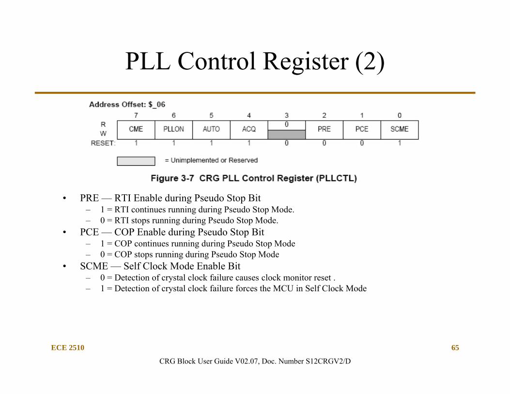
PLL Control Register (2)
• PRE — RTI Enable during Pseudo Stop Bit– 1 = RTI continues running during Pseudo Stop Mode.– 0 = RTI stops running during Pseudo Stop Mode.
• PCE — COP Enable during Pseudo Stop Bit– 1 = COP continues running during Pseudo Stop Mode– 0 = COP stops running during Pseudo Stop Mode
• SCME — Self Clock Mode Enable Bit– 0 = Detection of crystal clock failure causes clock monitor reset .– 1 = Detection of crystal clock failure forces the MCU in Self Clock Mode
CRG Block User Guide V02.07, Doc. Number S12CRGV2/D
ECE 2510 66
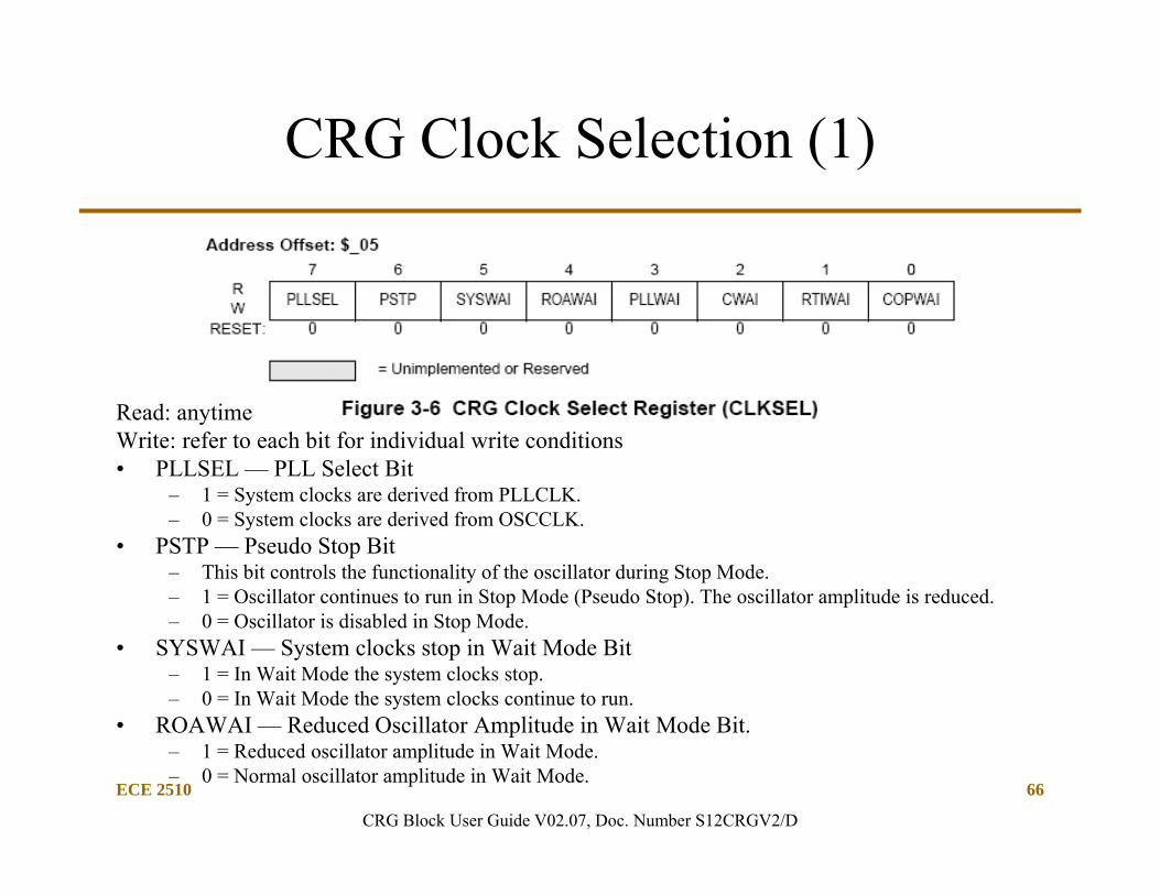
CRG Clock Selection (1)
Read: anytimeWrite: refer to each bit for individual write conditions• PLLSEL — PLL Select Bit
– 1 = System clocks are derived from PLLCLK.– 0 = System clocks are derived from OSCCLK.
• PSTP — Pseudo Stop Bit– This bit controls the functionality of the oscillator during Stop Mode.– 1 = Oscillator continues to run in Stop Mode (Pseudo Stop). The oscillator amplitude is reduced.– 0 = Oscillator is disabled in Stop Mode.
• SYSWAI — System clocks stop in Wait Mode Bit– 1 = In Wait Mode the system clocks stop.– 0 = In Wait Mode the system clocks continue to run.
• ROAWAI — Reduced Oscillator Amplitude in Wait Mode Bit.– 1 = Reduced oscillator amplitude in Wait Mode.– 0 = Normal oscillator amplitude in Wait Mode.
CRG Block User Guide V02.07, Doc. Number S12CRGV2/D
ECE 2510 67
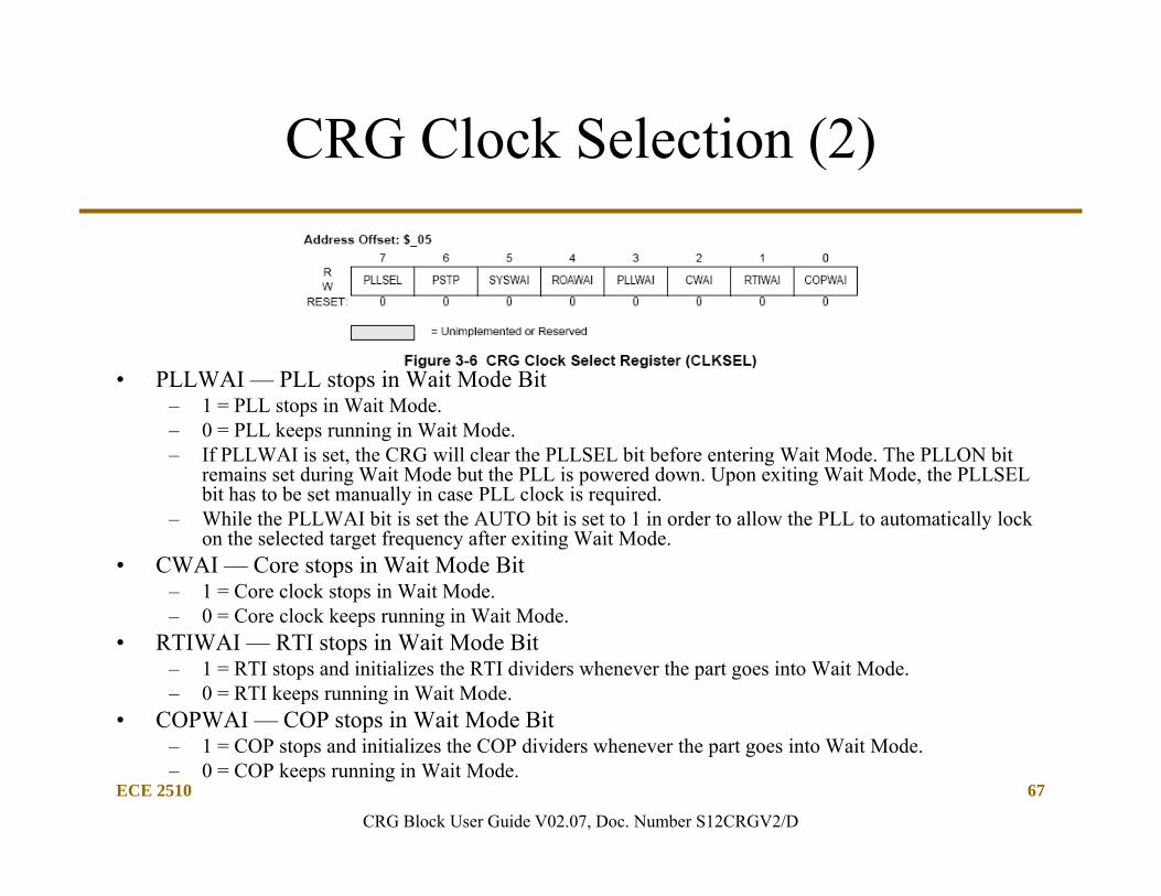
CRG Clock Selection (2)
• PLLWAI — PLL stops in Wait Mode Bit– 1 = PLL stops in Wait Mode.– 0 = PLL keeps running in Wait Mode.– If PLLWAI is set, the CRG will clear the PLLSEL bit before entering Wait Mode. The PLLON bit
remains set during Wait Mode but the PLL is powered down. Upon exiting Wait Mode, the PLLSEL bit has to be set manually in case PLL clock is required.
– While the PLLWAI bit is set the AUTO bit is set to 1 in order to allow the PLL to automatically lock on the selected target frequency after exiting Wait Mode.
• CWAI — Core stops in Wait Mode Bit– 1 = Core clock stops in Wait Mode.– 0 = Core clock keeps running in Wait Mode.
• RTIWAI — RTI stops in Wait Mode Bit– 1 = RTI stops and initializes the RTI dividers whenever the part goes into Wait Mode.– 0 = RTI keeps running in Wait Mode.
• COPWAI — COP stops in Wait Mode Bit– 1 = COP stops and initializes the COP dividers whenever the part goes into Wait Mode.– 0 = COP keeps running in Wait Mode.
CRG Block User Guide V02.07, Doc. Number S12CRGV2/D
ECE 2510 68
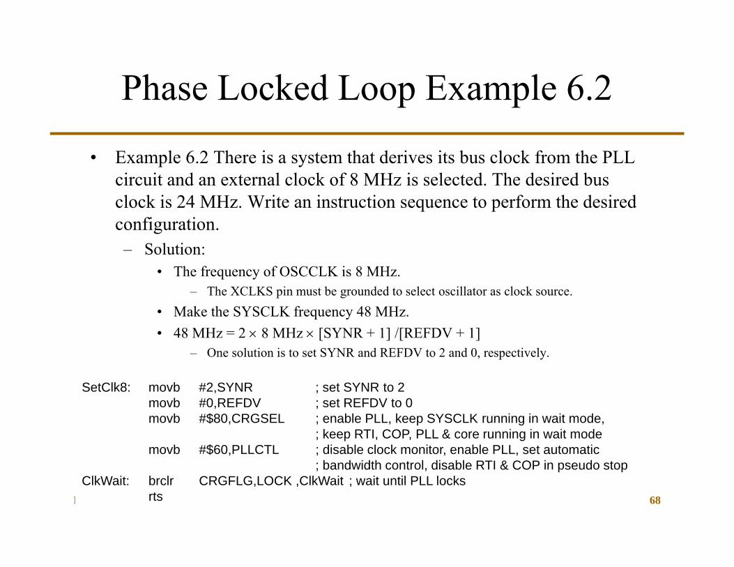
SetClk8: movb #2,SYNR ; set SYNR to 2movb #0,REFDV ; set REFDV to 0movb #$80,CRGSEL ; enable PLL, keep SYSCLK running in wait mode,
; keep RTI, COP, PLL & core running in wait modemovb #$60,PLLCTL ; disable clock monitor, enable PLL, set automatic
; bandwidth control, disable RTI & COP in pseudo stopClkWait: brclr CRGFLG,LOCK ,ClkWait ; wait until PLL locks
rts
Phase Locked Loop Example 6.2
• Example 6.2 There is a system that derives its bus clock from the PLL circuit and an external clock of 8 MHz is selected. The desired bus clock is 24 MHz. Write an instruction sequence to perform the desired configuration.– Solution:
• The frequency of OSCCLK is 8 MHz.– The XCLKS pin must be grounded to select oscillator as clock source.
• Make the SYSCLK frequency 48 MHz.• 48 MHz = 2 8 MHz [SYNR + 1] /[REFDV + 1]
– One solution is to set SYNR and REFDV to 2 and 0, respectively.
ECE 2510 69
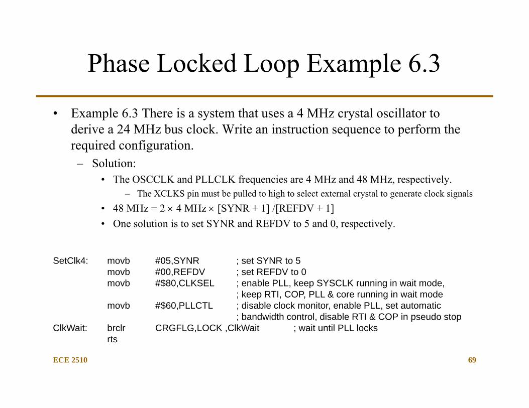
SetClk4: movb #05,SYNR ; set SYNR to 5movb #00,REFDV ; set REFDV to 0movb #$80,CLKSEL ; enable PLL, keep SYSCLK running in wait mode,
; keep RTI, COP, PLL & core running in wait modemovb #$60,PLLCTL ; disable clock monitor, enable PLL, set automatic
; bandwidth control, disable RTI & COP in pseudo stopClkWait: brclr CRGFLG,LOCK ,ClkWait ; wait until PLL locks
rts
Phase Locked Loop Example 6.3
• Example 6.3 There is a system that uses a 4 MHz crystal oscillator to derive a 24 MHz bus clock. Write an instruction sequence to perform the required configuration.– Solution:
• The OSCCLK and PLLCLK frequencies are 4 MHz and 48 MHz, respectively.– The XCLKS pin must be pulled to high to select external crystal to generate clock signals
• 48 MHz = 2 4 MHz [SYNR + 1] /[REFDV + 1] • One solution is to set SYNR and REFDV to 5 and 0, respectively.
ECE 2510 70
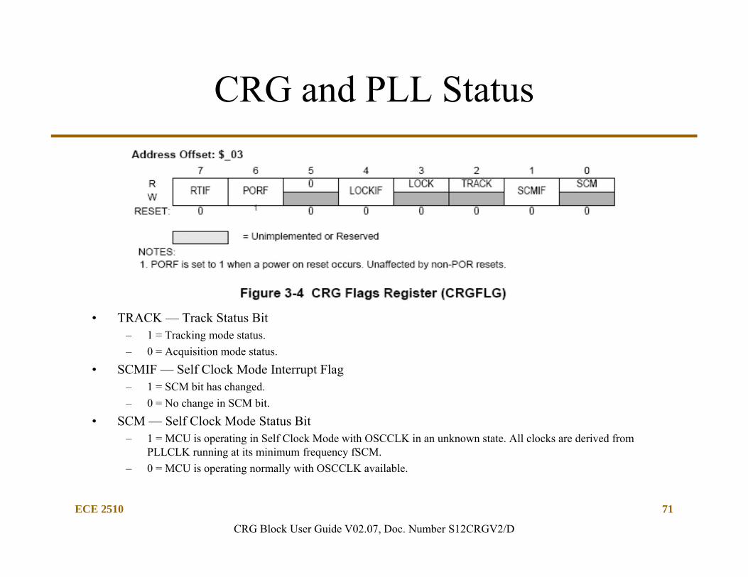
CRG and PLL Status
CRG Block User Guide V02.07, Doc. Number S12CRGV2/D
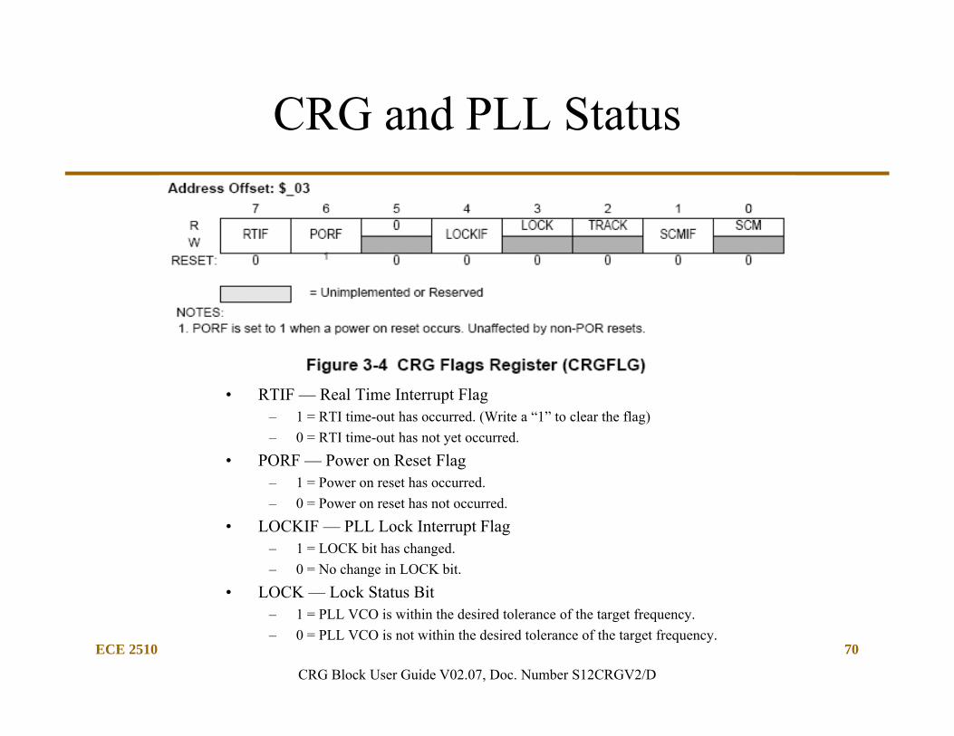
• RTIF — Real Time Interrupt Flag– 1 = RTI time-out has occurred. (Write a “1” to clear the flag)– 0 = RTI time-out has not yet occurred.
• PORF — Power on Reset Flag– 1 = Power on reset has occurred.– 0 = Power on reset has not occurred.
• LOCKIF — PLL Lock Interrupt Flag– 1 = LOCK bit has changed.– 0 = No change in LOCK bit.
• LOCK — Lock Status Bit– 1 = PLL VCO is within the desired tolerance of the target frequency.– 0 = PLL VCO is not within the desired tolerance of the target frequency.
ECE 2510 71
CRG and PLL Status
• TRACK — Track Status Bit– 1 = Tracking mode status.– 0 = Acquisition mode status.
• SCMIF — Self Clock Mode Interrupt Flag– 1 = SCM bit has changed.– 0 = No change in SCM bit.
• SCM — Self Clock Mode Status Bit– 1 = MCU is operating in Self Clock Mode with OSCCLK in an unknown state. All clocks are derived from
PLLCLK running at its minimum frequency fSCM.– 0 = MCU is operating normally with OSCCLK available.
CRG Block User Guide V02.07, Doc. Number S12CRGV2/D
ECE 2510 72
Clock Monitor
• The clock monitor circuit is based on an internal resistor-capacitor (RC) time delay so that it can operate without any MCU clocks. – If no OSCCLK edges are detected within this RC time delay, the clock
monitor indicates failure which asserts self clock mode or generates a system reset depending on the state of SCME bit.
– If the clock monitor is disabled or the presence of clocks is detected no failure is indicated.
• The clock monitor function is enabled/disabled by the CME control bit. (PLLCTL)– If no OSCCLK edges are detected within the RC time delay, the clock
monitor may reset the MCU if the CME bit in the PLLCTL register is set to 1.
– The SCME bit of the PLLCTL register must be cleared to 0 for clock monitor to work.
ECE 2510 73
Real-time interrupt (RTI) (1 of 3)
• The RTI can be used to generate a hardware interrupt at a fixed periodic rate. If enabled (by setting RTIE=1), this interrupt will occur at the rate selected by the RTICTL ($003B) register. – The RTI runs with a gated OSCCLK. At the end of the RTI time-out
period the RTIF flag is set to one and a new RTI time-out period starts immediately.
• A write to the RTICTL register restarts the RTI time-out period.– If the PRE bit is set, the RTI will continue to run in Pseudo-Stop Mode.
(in PLLCTL)
• The RTI interrupt is enabled by the interrupt enable register (CRGINT).
ECE 2510 74
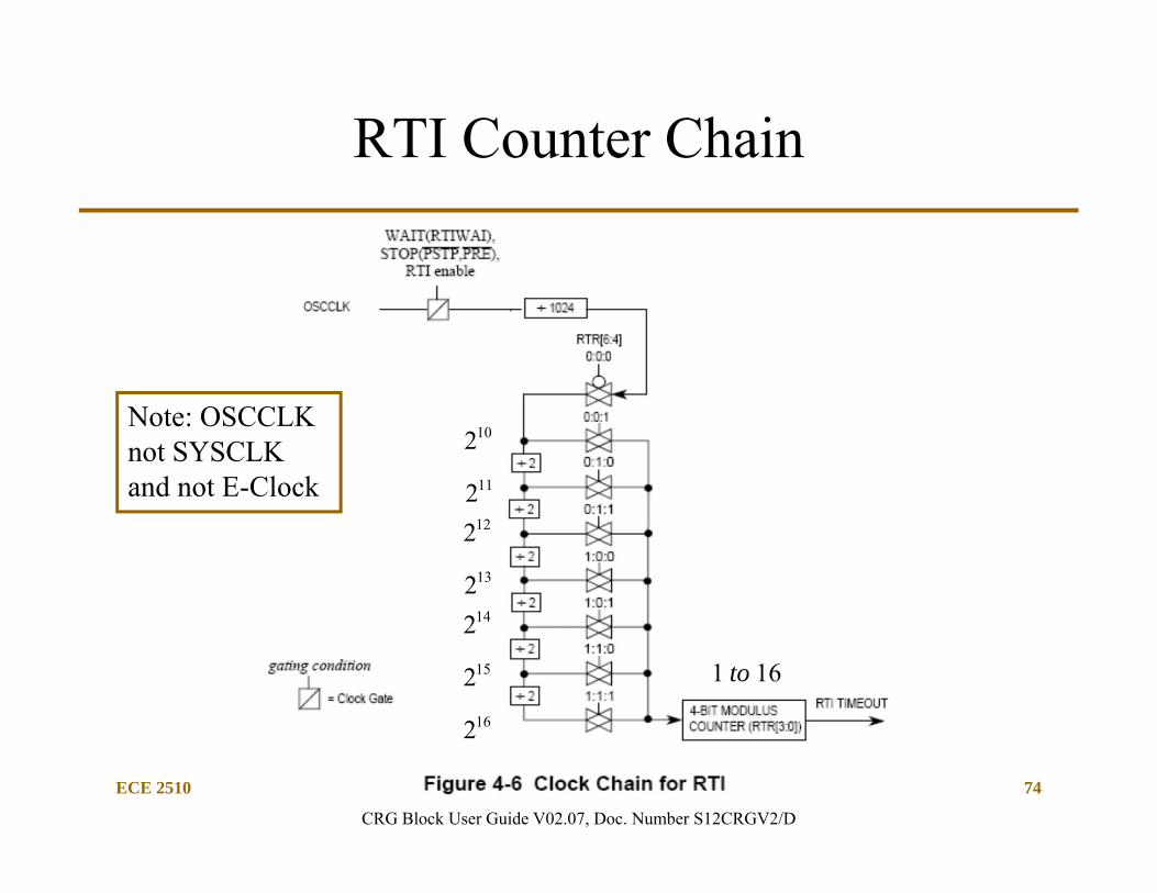
RTI Counter Chain
CRG Block User Guide V02.07, Doc. Number S12CRGV2/D
102112122132142152162
161 to
Note: OSCCLK not SYSCLK and not E-Clock
ECE 2510 75
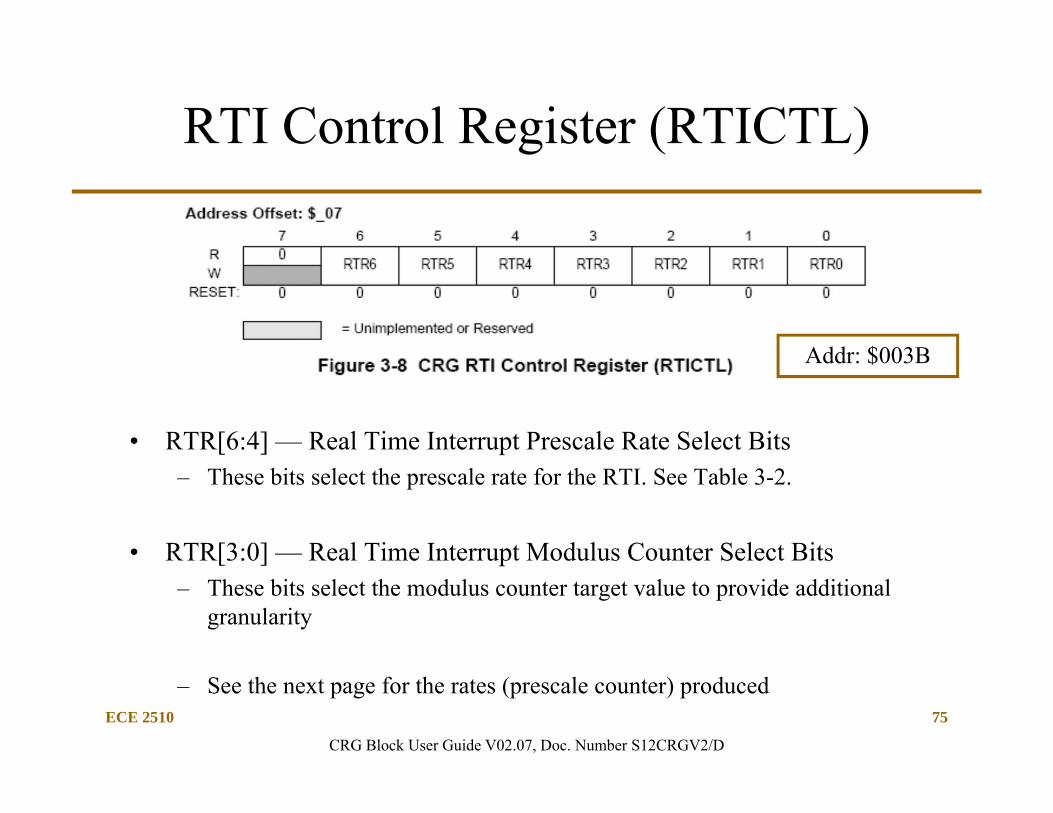
RTI Control Register (RTICTL)
• RTR[6:4] — Real Time Interrupt Prescale Rate Select Bits– These bits select the prescale rate for the RTI. See Table 3-2.
• RTR[3:0] — Real Time Interrupt Modulus Counter Select Bits– These bits select the modulus counter target value to provide additional
granularity
– See the next page for the rates (prescale counter) produced
CRG Block User Guide V02.07, Doc. Number S12CRGV2/D
Addr: $003B
ECE 2510 76
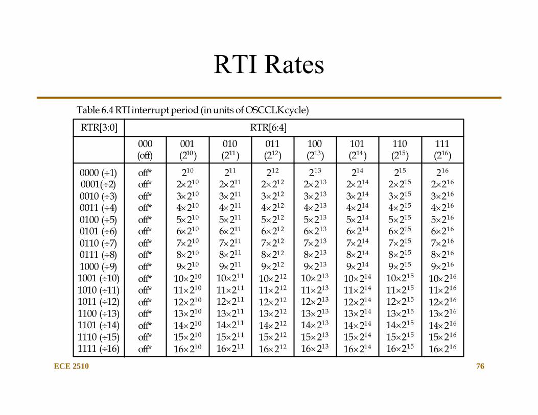
RTI RatesTable 6.4 RTI interrupt period (in units of OSCCLK cycle)
RTR[3:0] RTR[6:4]000(off)
001(210)
010(211)
011(212)
100(213)
101(214)
110(215)
111(216)
0000 (1)0001(2)0010 (3)0011 (4)0100 (5)0101 (6)0110 (7)0111 (8)1000 (9)1001 (10)1010 (11)1011 (12)1100 (13)1101 (14)1110 (15)1111 (16)
off*off*off*off*off*off*off*off*off*off*off*off*off*off*off*off*
210
2210
3210
4210
5210
6210
7210
8210
9210
10210
11210
12210
13210
14210
15210
16210
211
2211
3211
4211
5211
6211
7211
8211
9211
10211
11211
12211
13211
14211
15211
16211
212
2212
3212
4212
5212
6212
7212
8212
9212
10212
11212
12212
13212
14212
15212
16212
213
2213
3213
4213
5213
6213
7213
8213
9213
10213
11213
12213
13213
14213
15213
16213
214
2214
3214
4214
5214
6214
7214
8214
9214
10214
11214
12214
13214
14214
15214
16214
215
2215
3215
4215
5215
6215
7215
8215
9215
10215
11215
12215
13215
14215
15215
16215
216
2216
3216
4216
5216
6216
7216
8216
9216
10216
11216
12216
13216
14216
15216
16216
ECE 2510 77
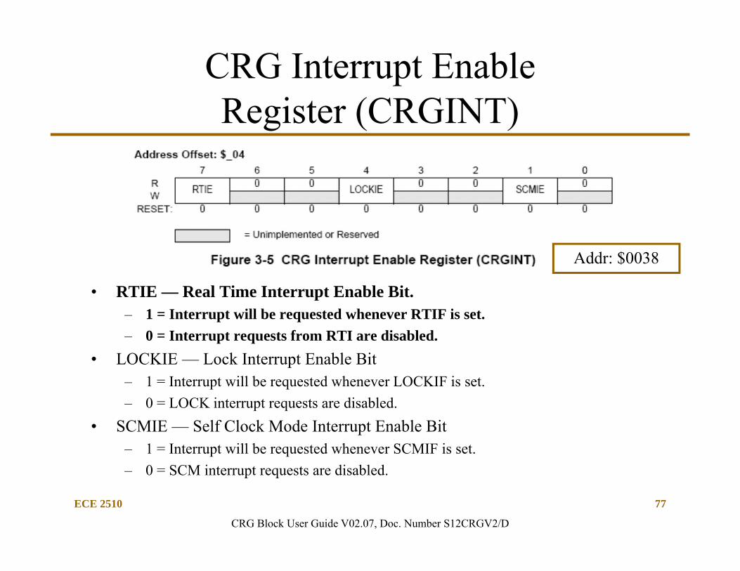
CRG Interrupt Enable Register (CRGINT)
• RTIE — Real Time Interrupt Enable Bit.– 1 = Interrupt will be requested whenever RTIF is set.– 0 = Interrupt requests from RTI are disabled.
• LOCKIE — Lock Interrupt Enable Bit– 1 = Interrupt will be requested whenever LOCKIF is set.– 0 = LOCK interrupt requests are disabled.
• SCMIE — Self Clock Mode Interrupt Enable Bit– 1 = Interrupt will be requested whenever SCMIF is set.– 0 = SCM interrupt requests are disabled.
CRG Block User Guide V02.07, Doc. Number S12CRGV2/D
Addr: $0038
ECE 2510 78
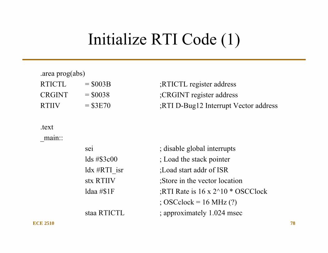
Initialize RTI Code (1)
.area prog(abs)RTICTL = $003B ;RTICTL register addressCRGINT = $0038 ;CRGINT register addressRTIIV = $3E70 ;RTI D-Bug12 Interrupt Vector address
.text_main::
sei ; disable global interrupts lds #$3c00 ; Load the stack pointerldx #RTI_isr ;Load start addr of ISRstx RTIIV ;Store in the vector locationldaa #$1F ;RTI Rate is 16 x 2^10 * OSCClock
; OSCclock = 16 MHz (?)staa RTICTL ; approximately 1.024 msec
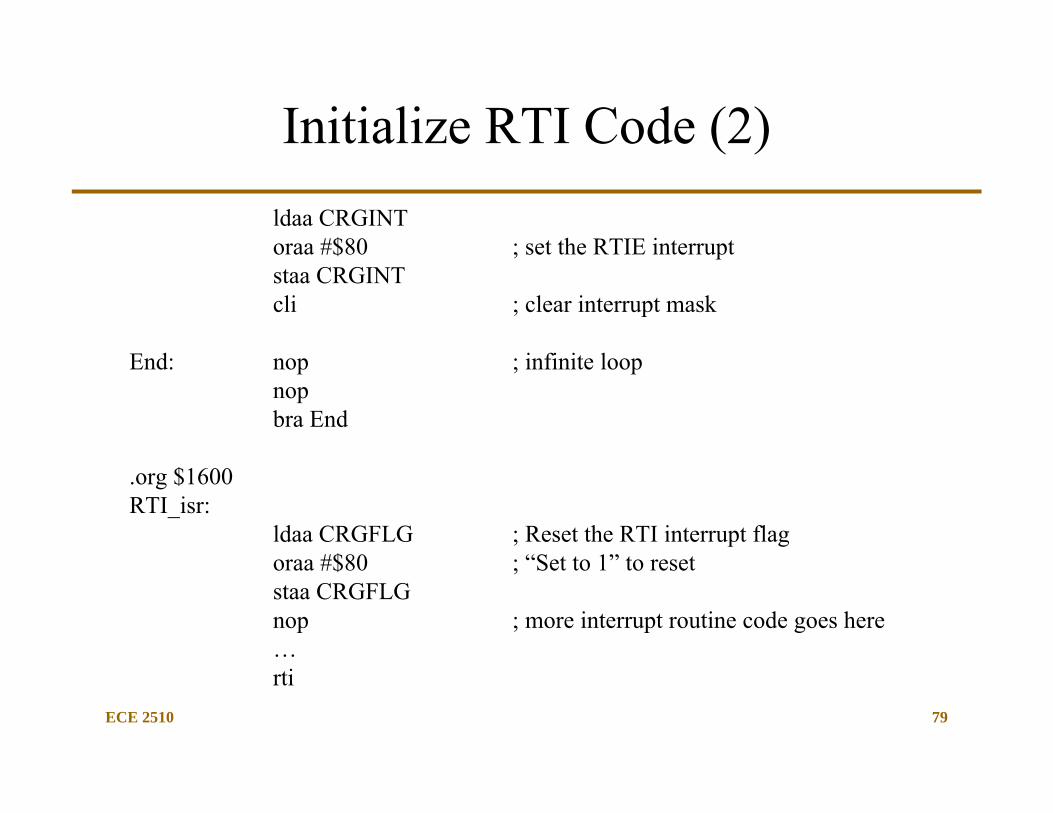
ECE 2510 79
Initialize RTI Code (2)ldaa CRGINToraa #$80 ; set the RTIE interruptstaa CRGINT cli ; clear interrupt mask
End: nop ; infinite loopnopbra End
.org $1600RTI_isr:
ldaa CRGFLG ; Reset the RTI interrupt flagoraa #$80 ; “Set to 1” to resetstaa CRGFLGnop ; more interrupt routine code goes here…rti
The RTI as Real-Time Monitor
• Every time the interrupt happens, a fixed number of clock cycles have occurred.
– If the crystal or external clock is accurate, the interrupts acts like the “time-tick” of a clock.
• Pro– Readily available time function interrupt. – RTI is a high-priority interrupt (just below IRQ)
• Con– The divide ratios available are not flexible, 1-15 x 2^ 10-16– You may be stuck with “strange” clock tick times. Selecting the
crystal frequency may provide useful time ticks. (10.24 MHz crystal OSCCLK/ 10 x 2^10 = 1 kHz or (1 msec)
ECE 2510 80
ECE 2510 81
The RTI as a Watchdog Timer
• Important control information:A write to the RTICTL register restarts the RTI time-out period.
• Therefore, for real-time processing, make the RTI time greater than the maximum time that is takes one of the infinite software loops – Include all possible times: loop code, interrupt ISR code and time
• At the end of every loop, re-write the RTICTL register
• If the RTI interrupt occurs, the software is broken!– Then, the RTI ISR should be an error recovery routine.
RTI INTERRUPT EXAMPLE
ECE 4510/5530
82
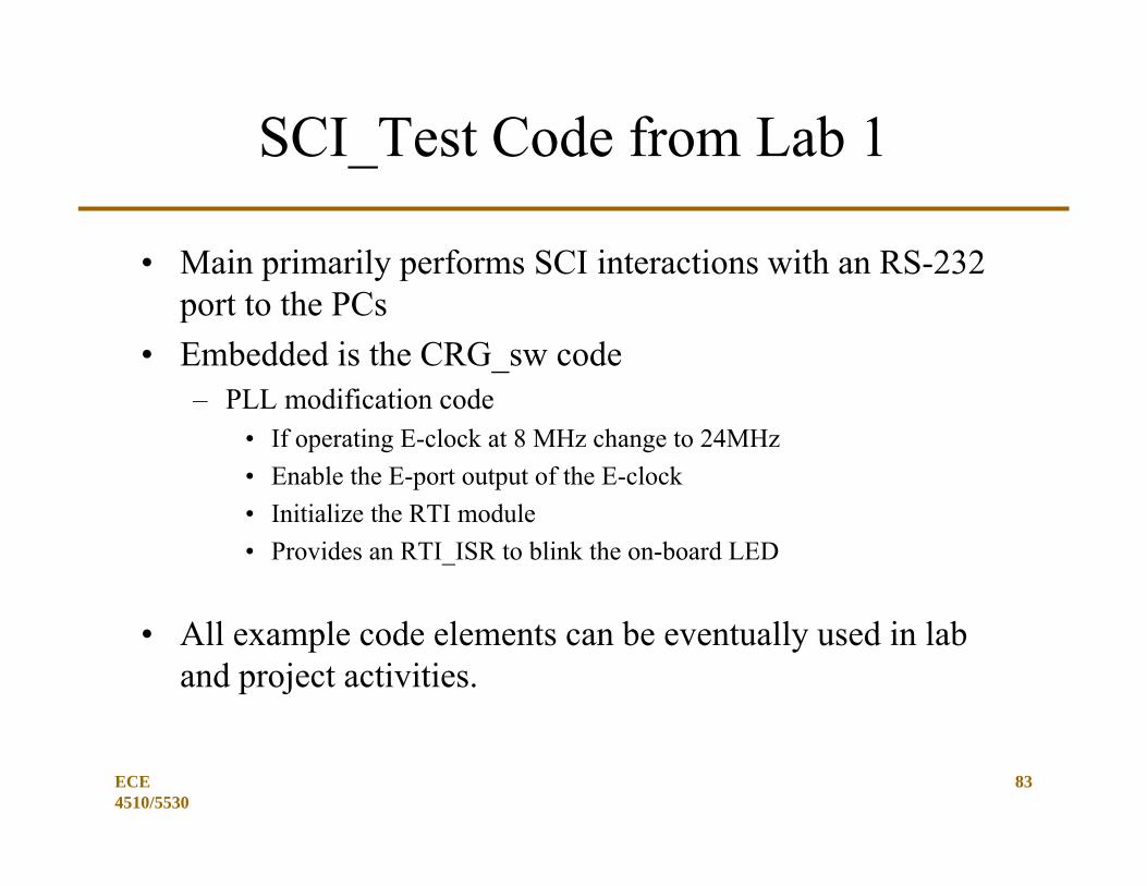
SCI_Test Code from Lab 1
• Main primarily performs SCI interactions with an RS-232 port to the PCs
• Embedded is the CRG_sw code– PLL modification code
• If operating E-clock at 8 MHz change to 24MHz• Enable the E-port output of the E-clock• Initialize the RTI module• Provides an RTI_ISR to blink the on-board LED
• All example code elements can be eventually used in lab and project activities.
ECE 4510/5530
83
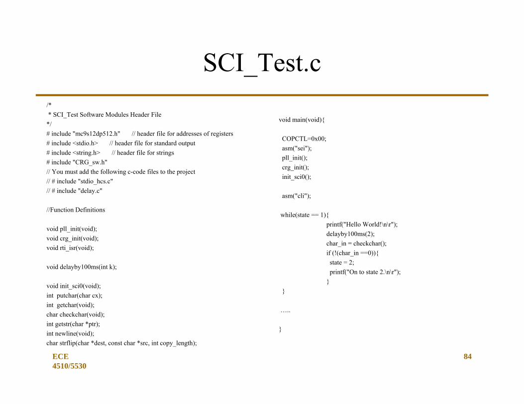
SCI_Test.c/** SCI_Test Software Modules Header File
*/# include "mc9s12dp512.h" // header file for addresses of registers# include <stdio.h> // header file for standard output# include <string.h> // header file for strings# include "CRG_sw.h"// You must add the following c-code files to the project// # include "stdio_hcs.c"// # include "delay.c"
//Function Definitions
void pll_init(void);void crg_init(void);void rti_isr(void);
void delayby100ms(int k);
void init_sci0(void);int putchar(char cx);int getchar(void);char checkchar(void);int getstr(char *ptr);int newline(void);char strflip(char *dest, const char *src, int copy_length);
ECE 4510/5530
84
void main(void){
COPCTL=0x00;asm("sei");pll_init();crg_init();init_sci0();
asm("cli");
while(state == 1){printf("Hello World!\n\r");delayby100ms(2);char_in = checkchar();if (!(char_in ==0)){state = 2;printf("On to state 2.\n\r");
}}
…..
}
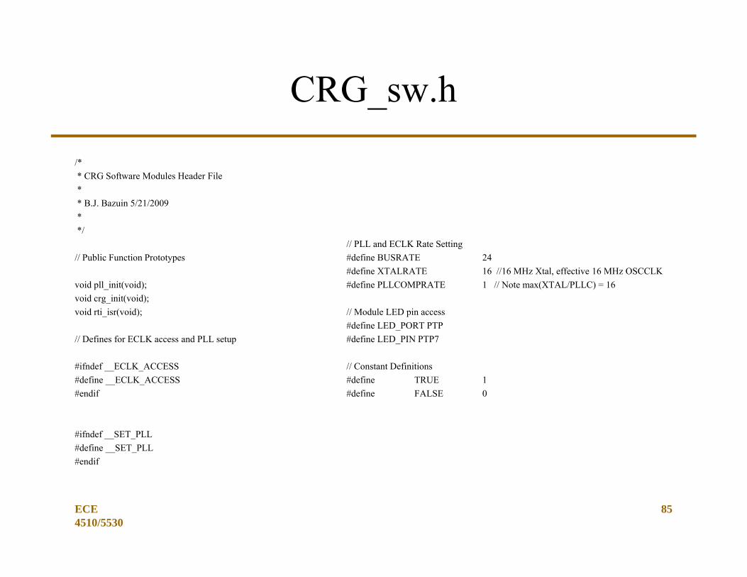
CRG_sw.h
/** CRG Software Modules Header File** B.J. Bazuin 5/21/2009**/
// Public Function Prototypes
void pll_init(void);void crg_init(void);void rti_isr(void);
// Defines for ECLK access and PLL setup
#ifndef __ECLK_ACCESS#define __ECLK_ACCESS#endif
#ifndef __SET_PLL#define __SET_PLL#endif
ECE 4510/5530
85
// PLL and ECLK Rate Setting#define BUSRATE 24#define XTALRATE 16 //16 MHz Xtal, effective 16 MHz OSCCLK#define PLLCOMPRATE 1 // Note max(XTAL/PLLC) = 16
// Module LED pin access#define LED_PORT PTP#define LED_PIN PTP7
// Constant Definitions#define TRUE 1#define FALSE 0
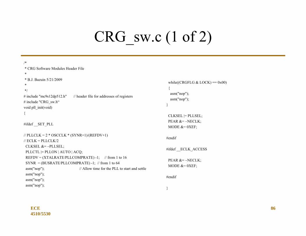
CRG_sw.c (1 of 2)/** CRG Software Modules Header File** B.J. Bazuin 5/21/2009**/
# include "mc9s12dp512.h" // header file for addresses of registers# include "CRG_sw.h“void pll_init(void){
#ifdef __SET_PLL
// PLLCLK = 2 * OSCCLK * (SYNR+1)/(REFDV+1)// ECLK = PLLCLK/2CLKSEL &= ~PLLSEL;PLLCTL |= PLLON | AUTO | ACQ;REFDV = (XTALRATE/PLLCOMPRATE) -1; // from 1 to 16SYNR = (BUSRATE/PLLCOMPRATE) -1; // from 1 to 64asm("nop"); // Allow time for the PLL to start and settleasm("nop");asm("nop");asm("nop");
ECE 4510/5530
86
while((CRGFLG & LOCK) == 0x00){
asm("nop");asm("nop");
}
CLKSEL |= PLLSEL;PEAR &= ~NECLK;MODE &= 0XEF;
#endif
#ifdef __ECLK_ACCESS
PEAR &= ~NECLK;MODE &= 0XEF;
#endif
}
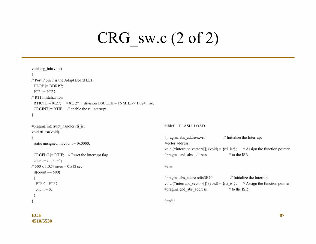
CRG_sw.c (2 of 2)
void crg_init(void){// Port P pin 7 is the Adapt Board LEDDDRP |= DDRP7;PTP |= PTP7;
// RTI IniitalizationRTICTL = 0x27; // 8 x 2^11 division OSCCLK = 16 MHz -> 1.024 msecCRGINT |= RTIE; // enable the rti interrupt
}
#pragma interrupt_handler rti_isrvoid rti_isr(void){static unsigned int count = 0x0000;
CRGFLG |= RTIF; // Reset the interrupt flagcount = count +1;
// 500 x 1.024 msec = 0.512 secif(count == 500){
PTP ^= PTP7;count = 0;
}}
ECE 4510/5530
87
#ifdef __FLASH_LOAD
#pragma abs_address:vrti // Initialize the Interrupt Vector addressvoid (*interrupt_vectors[]) (void) = {rti_isr}; // Assign the function pointer #pragma end_abs_address // to the ISR
#else
#pragma abs_address:0x3E70 // Initialize the Interrupt void (*interrupt_vectors[]) (void) = {rti_isr}; // Assign the function pointer #pragma end_abs_address // to the ISR
#endif

DEBUGGING TIPS
ECE 4510/5530
88
ECE 2510 89
Tips for Debugging Programs Involving Function Calls
• What to do when the program gets stuck?– Step 1
• Setting a breakpoint immediately before the function call.– Did you successfully get to this point with everything the way it should be
– Step 2• Setting a breakpoint immediately after the function call.
– Did the function execute and return– Did the function do the tasks required (function problem)
• Can you separate flow and function?– Code flow (executes, but the answer is wrong)– Code function (logical errors in the algorithm)
Reasons Why Code Flow Fails
• There are some infinite loops in the function.– Are you polling and the result never happens?– If the functions were tested as stand-alone code, do they work?
(Can you write test code to test the function? You should! )
• Calling other functions from within the function and they do not return.– If functions are nested, is one of those at fault?
ECE 2510 90
ECE 2510 91
General Debugging Strategy
• Make sure all functions work correctly– Test the function with it’s own special calling program– Work from the bottom up
• Debug intermediate functions. Make sure no intermediate function gets stuck. (If you have library code and test code for the library elements, it must be something else.)
• Use “leds” and text to monitor code progress– Use terminal I/O to write progress characters to the screen– Toggle the LED at the beginning of every code segment
CODING PRACTICESFOR THE MSP430
ECE 4510/5530
92
ECE 2510 93
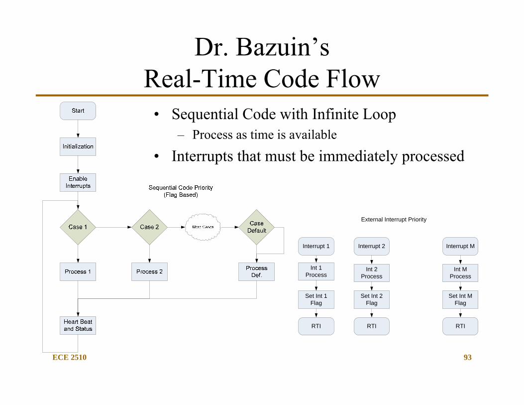
Dr. Bazuin’sReal-Time Code Flow
• Sequential Code with Infinite Loop– Process as time is available
• Interrupts that must be immediately processed
External Interrupt Priority
Interrupt 1
Int 1 Process
Set Int 1 Flag
RTI
Interrupt 2
Int 2 Process
Set Int 2 Flag
RTI
Interrupt M
Int M Process
Set Int M Flag
RTI
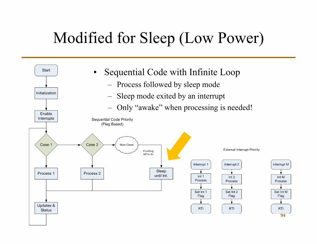
Modified for Sleep (Low Power)
94
• Sequential Code with Infinite Loop– Process followed by sleep mode– Sleep mode exited by an interrupt– Only “awake” when processing is needed!