Design Manual GEOPAK Drainage – Chapter 4 … · Geopak Drainage will fill in a prefix ......
23
Page 1 of 22 This section provides instructions on how to add nodes in Geopak Drainage. In Geopak Drainage, structures (intakes, junctions/manholes, and aprons) are called nodes. Opening a Project For instructions on starting a new Geopak Drainage project, see Section 4A-52. To open an existing project, start Geopak Drainage as shown in Section 4A-52. In the DRAINAGE dialog box, go to ProjectOpen and browse to the appropriate file: OR Choose a project at the bottom of the Project menu in the DRAINAGE dialog box: GEOPAK Drainage – Structures 4A-53 Design Manual Chapter 4 Drainage Originally Issued: 07-29-11 Revised: 05-09-17 Office of Design
-
Upload
hoangduong -
Category
Documents
-
view
235 -
download
0
Transcript of Design Manual GEOPAK Drainage – Chapter 4 … · Geopak Drainage will fill in a prefix ......

Page 1 of 22
This section provides instructions on how to add nodes in Geopak Drainage. In Geopak Drainage, structures (intakes, junctions/manholes, and aprons) are called nodes.
Opening a Project For instructions on starting a new Geopak Drainage project, see Section 4A-52. To open an existing project, start Geopak Drainage as shown in Section 4A-52. In the DRAINAGE dialog box, go to ProjectOpen and browse to the appropriate file:
OR
Choose a project at the bottom of the Project menu in the DRAINAGE dialog box:
GEOPAK Drainage – Structures
4A-53
Design Manual Chapter 4 Drainage Originally Issued: 07-29-11 Revised: 05-09-17
Office of Design

Chapter 4—Drainage Section 4A-53—GEOPAK Drainage – Structures
Page 2 of 22
Adding Nodes Nodes can be added in several ways:
• Using the Component menu in the DRAINAGE dialog box:
• Using the Drainage Nodes toolbox accessed through the DRAINAGE dialog box:
The following tool box will appear:
• Using the Drainage Tool box accessed through the DRAINAGE menu:
The following tool box will appear:
• Using the Navigator accessed through the DRAINAGE dialog box:
Click this icon
Click this icon

Chapter 4—Drainage Section 4A-53—GEOPAK Drainage – Structures
Page 3 of 22
The following tool box will appear:
Regardless of the method designers use add a node, the following dialog box will appear:
Geopak Drainage will fill in a prefix (if specified when setting the preferences, see Node Options in Section 4A-52) and a number. If preferred, the designer can enter a Node ID. The designer can also enter a Description. Click OK and the following dialog box window will open:
Properties Under OptionsProperties
Select the correct Node Type: from the drop down menu. Designers have several options to choose from.
1) Click this icon
2) Click the Add Item icon
Chapter 4—Drainage Section 4A-53—GEOPAK Drainage – Structures
Page 4 of 22
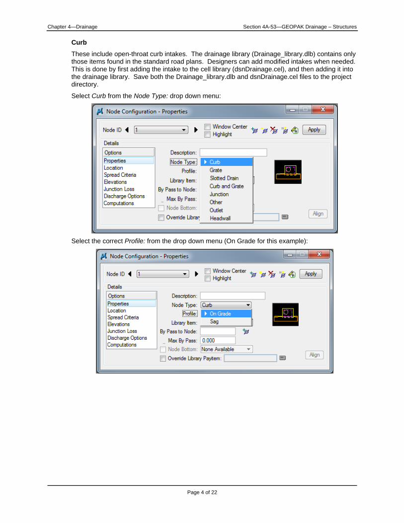
Curb
These include open-throat curb intakes. The drainage library (Drainage_library.dlb) contains only those items found in the standard road plans. Designers can add modified intakes when needed. This is done by first adding the intake to the cell library (dsnDrainage.cel), and then adding it into the drainage library. Save both the Drainage_library.dlb and dsnDrainage.cel files to the project directory.
Select Curb from the Node Type: drop down menu:
Select the correct Profile: from the drop down menu (On Grade for this example):

Chapter 4—Drainage Section 4A-53—GEOPAK Drainage – Structures
Page 5 of 22
Select the correct Library Item: from the drop down menu (SW-545L (12′) for this example):
Select the correct orientation for the throat opening. See the following drawing:
The correct throat orientation is on the side the flow is from. The drawing shows the throat opening for the intake on the left side of the intake.
Fill in the By Pass to Node: dialog box or click the icon next to it to select the node from MicroStation view. If there is no By Pass node, leave blank.
Fill in the Max By Pass: dialog box only if it is desirable to query for bypass flows which exceed a specific value. Filling in this box does not affect computations.
Click on this icon to select a node from MicroStation view

Chapter 4—Drainage Section 4A-53—GEOPAK Drainage – Structures
Page 6 of 22
Note: By Pass to Node: and Max By Pass: will not appear for intakes in a sag.
The Office of Design does not use separate cells for node bottoms, so Node Bottom: is not used.
Toggle on Override Library Payitem: if substituting a different pay item than the one defined in the drainage library.
Grate These include area intakes. The drainage library (Drainage_library.dlb) contains only those items found in the standard road plans (the SW-562 is included under Other, see below). Designers can add modified intakes when needed. This is done by first adding the intake to the cell library (dsnDrainage.cel), and then adding it into the drainage library. Save both the Drainage_library.dlb and dsnDrainage.cel files to the project directory.
Select Grate from the Node Type: drop down menu. When selecting an area intake, Profile: must be set to Sag. No intakes are available for On Grade. Area intakes are assumed to be at a low point.
Select the correct Library Item: from the drop down menu (SW-511 for this example):
The Office of Design does not use separate cells for node bottoms, so Node Bottom: is not used.
Toggle on Override Library Payitem: if substituting a different pay item than the one defined in the drainage library.
Slotted Drain
None are available.
Curb and Grate These include grate intakes. The drainage library (Drainage_library.dlb) contains only those items found in the standard road plans. Designers can add modified intakes when needed. This is done by first adding the intake to the cell library (dsnDrainage.cel), and then adding it into the drainage library. Save both the Drainage_library.dlb and dsnDrainage.cel files to the project directory.
Select Curb and Grate from the Node Type: drop down menu. Select either On Grade or Sag from the Profile: menu. Select the correct Library Item: from the drop down menu (SW-548 for this example):

Chapter 4—Drainage Section 4A-53—GEOPAK Drainage – Structures
Page 7 of 22
Fill in the By Pass to Node: dialog box or click the icon next to it to select the node from MicroStation view (same procedure used under Curb above). If there is no By Pass node, leave blank.
Fill in the Max By Pass: dialog box only if it is desirable to query for bypass flows which exceed a specific value. Filling in this box does not affect computations.
Note: By Pass to Node: and Max By Pass: will not appear for intakes in a sag.
The Office of Design does not use separate cells for node bottoms, so Node Bottom: is not used.
Toggle on Override Library Payitem: if substituting a different pay item than the one defined in the drainage library.
Junction
These include storm sewer manholes, as well as DR-122 and DR-141 pipe connections.
Note: Geopak Drainage will not calculate head losses through a pipe connection.
The drainage library (Drainage_library.dlb) contains only those items found in the standard road plans. Designers can add modified junctions when needed. This is done by first adding the jujnction to the cell library (dsnDrainage.cel), and then adding it into the drainage library. Save both the Drainage_library.dlb and dsnDrainage.cel files to the project directory.

Chapter 4—Drainage Section 4A-53—GEOPAK Drainage – Structures
Page 8 of 22
Select Junction from the Node Type: drop down menu:
Select the correct Library Item: from the drop down menu (SW-402 (4′x4′) for this example):
The Office of Design does not use separate cells for node bottoms, so Node Bottom: is not used.
Toggle on Override Library Payitem: if substituting a different pay item than the one defined in the drainage library.
Other
These include the SW-562 and metal, concrete pipe, and concrete arch pipe aprons (DR-200s). The designer must calculate flow into the structure and key-in a value for Supplied Discharge in Discharge Options (see below for more on Discharge Options).

Chapter 4—Drainage Section 4A-53—GEOPAK Drainage – Structures
Page 9 of 22
Select Other from the Node Type: drop down menu, then select the correct Library Item: from the drop down menu (DR-201 18″ for this example).
The Office of Design does not use separate cells for node bottoms, so Node Bottom: is not used.
Toggle on Override Library Payitem: if substituting a different pay item than the one defined in the drainage library.
Outlet
These include metal, concrete pipe, and concrete arch pipe aprons (DR-200s), as well as the DR-142 (in Geopak Drainage, can also be used when connecting to a box culvert). The drainage library (Drainage_library.dlb) contains only those items found in the standard road plans. Designers can add modified aprons when needed. This is done by first adding the apron to the cell library (dsnDrainage.cel), and then adding it into the drainage library. Save both the Drainage_library.dlb and dsnDrainage.cel files to the project directory.
Note: The Outlet must be at the end of the network (the system that connects all nodes, links, and areas contributing flow to the outlet) in order for the GEOPAK Drainage-Networks program to run. See Section 4A-56.
Select Outlet from the Node Type: drop down menu.

Chapter 4—Drainage Section 4A-53—GEOPAK Drainage – Structures
Page 10 of 22
Select the correct Library Item: from the drop down menu (DR-201 (24″) for this example):
Two options are available for setting tailwater conditions:
• Fix Tailwater at: This option assigns a computed value to the tailwater elevation.
• Tailwater Elevation: This option allows the designer to input a value for the tailwater elevation. Tailwater elevation is the elevation of the water at the outlet (be it a stream, river, lake, etc.) for a given storm event. If tailwater elevation is known or can be determined, choose this option.
The Office of Design does not use separate cells for node bottoms, so Node Bottom: is not used.
Toggle on Override Library Payitem: if substituting a different pay item than the one defined in the drainage library.
Headwall None are available.

Chapter 4—Drainage Section 4A-53—GEOPAK Drainage – Structures
Page 11 of 22
Location This option accurately places the node at a specific location.
Under OptionsLocation
Check the Chain and Profile boxes on and select each from the drop down menu:
Several options are available to align structures, see Align. Select the correct Align option from the drop down menu:
Designers can also input a station and offset.

Chapter 4—Drainage Section 4A-53—GEOPAK Drainage – Structures
Page 12 of 22
To place a node, click on the Station DP icon.
A node is placed by a point called the Location Station. The following example shows the point where the node will be placed according to the station and offset. See the Standard Road Plans.
Spread Criteria This option details the cross section in order for spread to be calculated.
Under OptionsSpread Criteria
Choose one of the Longitudinal Slope Source: options from the drop down menu:
• User Supplied – use when the gutter profile is not the same as the road or when a pre-
defined shape isn’t specified. In the adjacent box, key-in the actual longitudinal slope of the road in percent (e.g. 0.477 means 0.477%).

Chapter 4—Drainage Section 4A-53—GEOPAK Drainage – Structures
Page 13 of 22
• Reference PGL – use when the gutter profile is the same as the road.
• Shape – use in superelevated areas. To use this option, a file must be selected for the Superelevation Shapes File when setting the preferences (see Project Components in Section 4A-52).
Choose one of the Spread Source options from the drop down menu.
• User Supplied – This option allows designers to input Width, % Slope, and Roughness.
• Reference TIN – This option references a TIN file to fill in Width, % Slope, and Roughness.
• Library Item – This option uses a pre-defined shape from the drainage library to fill in Width, % Slope, and Roughness.
• Shape – This option uses the superelevation file chosen when setting the preferences (see Project Components in Section 4A-52) to fill in Width, % Slope, and Roughness.
• Shape and Lib. Item – This option uses a pre-defined shape from the drainage library to fill in cross Width, % Slope, and Roughness except in areas of superelevation, where the superelevation file chosen when filling in the preferences (see Project Components in Section 4A-52) is used.

Chapter 4—Drainage Section 4A-53—GEOPAK Drainage – Structures
Page 14 of 22
When inputting Width, % Slope, and Roughness, start at the face of the curb and work towards the crown of the road, i.e. the row of values at the top of the list represents the pavement section containing the face of the curb. The graphic below demonstrates:
To Add a row to the list:
a) Highlight the row before which the new row will go.
b) Fill in the correct values (for Roughness values use Table 2 of Section 4A-6).
c) Click the Add icon .
To Modify a row:
a) Highlight the row to be changed.
b) Fill in the correct values.
c) Click the Modify icon .
To Delete a row, highlight the row and click the Delete icon .
Pond Depth: is the height of the curb.
a) Highlight row new row should go before
b) Fill in desired values
c) Click Add List Item icon

Chapter 4—Drainage Section 4A-53—GEOPAK Drainage – Structures
Page 15 of 22
Pond Width: is the maximum allowable spread. For encroachment limits and information on spread, see Section 4A-6.
Elevations This option identifies the form grade of the node.
Under OptionsElevations
Typically, the TIN File from the Reference Surface options is not used. The TIN file would give top of curb elevations, which would result in incorrect intake elevations.
Choose one of the Elevation Source options from the drop down menu.
• User Supplied – This option allows the designer to key-in the exact value for the intake
elevation in the dialog box.
• Reference TIN – This option can be used only if a file has been chosen under the Reference Surface option; otherwise, this option will be grayed out.
• Reference PGL – This option can be used if the intake is at the same elevation as the profile (selected from OptionsLocations).
• PGL+Spread Section – This option can be used to determine the elevation at the location of the structure by subtracting spread criteria information from the Profile Grade Line.

Chapter 4—Drainage Section 4A-53—GEOPAK Drainage – Structures
Page 16 of 22
Under Node Elevation Option choose one of the options from the drop down menu.
• Same as Source – This option can be used to set the node elevation to be that determined
under Elevation Source.
• Constant Offset – This option can be used to key-in a value to offset from the Elevation Source (e.g. a sag where the intake is lower than the curb, e.g. an intake where the opening is set back behind the gutterline).
• User Supplied – This option can be used to key-in an exact value for the node elevation.
Choose one of the Vertical Alignment options from the drop down menu:
• Match Soffit – This option aligns the top inside (soffit) elevations of the inlet and outlet pipes.
Choose this option if the outlet pipe is larger than the inlet pipe.
• Match Invert – This option aligns the flow line elevations of the inlet and outlet pipes.
• Match Surface – This option aligns the calculated water surface elevations of the inlet and outlet pipes.
• Allow Drop Manhole – This option allows a drop across the node.
• Min. Fixed Drop – This option allows the designer to specify a minimum fixed drop from the invert of the inlet pipe to the invert of the outlet pipe. Designers should choose this option if the inlet and outlet pipes are the same size. A 0.3 foot drop is preferred; a 0.1 foot minimum drop is required.

Chapter 4—Drainage Section 4A-53—GEOPAK Drainage – Structures
Page 17 of 22
• Match Centerline – This option aligns the centerlines of the inlet and outlet pipes.
Minimum Depth: This is the minimum depth at which to bury the soffits. Refer to Section 4A-10 for guidance on minimum cover. Minimum Depth is measured from form grade for the intake.
Note: Soffit is the highest point of the internal surface of a pipe barrel.
Maximum Depth: This is the maximum depth at which to bury the inverts. Inverts must be located a minimum of 6″ above the bottom of the well. See Standard Road Plans.
Note: Invert is the lowest point of the internal surface of a pipe barrel. The invert is considered to be the same as the flow line.
Add Sump Depth: Toggling this option on allows designers to set the bottom of the well a desired elevation (in feet) below the lowest flow line. If pipe thicknesses less than 6″ are anticipated, set this at 0.5, see Standard Road Plans. If pipe thicknesses greater than 6″ are anticipated, this must be set to at least the pipe thickness (in feet).
Junction Loss This option allows designer choose how junction losses at a node are to be calculated.
Preliminary Design Junction losses are typically small and can be ignored in preliminary design. Toggle None on. This will allow the designer to compare Geopak Drainage results to hand calculations without the need to calculate head loss through the junction.

Chapter 4—Drainage Section 4A-53—GEOPAK Drainage – Structures
Page 18 of 22
Final Design
To accurately evaluate the hydraulic grade line (HGL), junction losses need to be included in the final design. When doing final design, toggle Defined Equations on. Geopak Drainage will use the default equations selected when setting up preferences (see Junction Losses in Section 4A-52).
Discharge Options This option allows designers to choose how discharge to a node is determined.
• Use Computed Discharge – This option uses the computed discharge from a stored drainage
area (see Section 4A-54) as the discharge to a node.
• Supplied Discharge – This option allows designers to key-in a discharge value.
• Disable Inlet Calculations – When toggled on, this option allows designers to override intake capacity calculations and key-in a value for capacity.
• Link Base Flow Area /Link Base Flow Discharge – These options allow designers to include additional discharge to a node. This discharge is not included in spread calculations, but is included in the pipe.

Chapter 4—Drainage Section 4A-53—GEOPAK Drainage – Structures
Page 19 of 22
o Link Flow Area – Allows designers to assign discharge from a specific drainage area to
be added to a node.
o Link Base Flow Discharge – Allows designers to key-in a specific additional amount of discharge to a node.
Computations Click Apply, the window will look something like the following:
Computations will be grayed out for the SW-562 and aprons used as inlets. The designer must determine capture and key-in under Discharge Options.

Chapter 4—Drainage Section 4A-53—GEOPAK Drainage – Structures
Page 20 of 22
Note: If an error message occurs, the program identifies areas not filled out properly. The example below demonstrates the error message created if the designer fails to include a longitudinal slope.
This examle demonstrates the error message created if the designer neglects to include a spread source.
Editing Nodes Nodes can be edited at any time. Designers have several options to open a node for editing:
• Using the Component menu in the DRAINAGE dialog box:

Chapter 4—Drainage Section 4A-53—GEOPAK Drainage – Structures
Page 21 of 22
• Using the Drainage Nodes toolbox accessed through the DRAINAGE dialog box:
The following tool box will appear:
• Using the Drainage Tool Box accessed through the DRAINAGE dialog box:
The following tool box will appear:
• Using the Navigator accessed through the DRAINAGE dialog box:
Click on this icon and hold mouse button down until drop down menu appears

Chapter 4—Drainage Section 4A-53—GEOPAK Drainage – Structures
Page 22 of 22
The following dialog box will appear:
Regardless of the method designers use edit a node, the Node Configuration - Properties dialog box will appear:
Changes are made in this dialog box.
Note: In order to have changes take place, the Apply button must be clicked.
2) Highlight node to be edited 3) Click Modify
Items icon
1) Click this icon

Chronology of Changes to Design Manual Section:004A-053 GEOPAK Drainage Structures
5/9/2017 RevisedUpdated references to renumbered RF standards.
5/8/2013 RevisedChange reference to Section 4A-5 on page 14 to Section 4A-6.
9/13/2012 RevisedUpdated Minimum Depth to reference Section 4A-10.
9/30/2011 RevisedAdded grate intakes to Geopak Drainage
7/29/2011 NEWNew