Design Guide Osp
37
Central Washington University Outside Plant Communications Distribution Design Guide (Revision 1.1) May 25, 2001
-
Upload
ochie-romero -
Category
Documents
-
view
76 -
download
0
description
OSP
Transcript of Design Guide Osp
Central Washington University
Outside Plant Communications DistributionDesign Guide
(Revision 1.1)
May 25, 2001
Conley Engineering, Inc.Consulting Electrical Engineers

TABLE OF CONTENTS
Table of Contents
LIST OF FIGURES.........................................................................................................................II
LIST OF TABLES................................................................................................II
INTRODUCTION.................................................................................................1DOCUMENT INTENT.......................................................................................................................1TYPE OF CONSTRUCTION................................................................................................................2
NEW CONSTRUCTION
OVERBUILD CONSTRUCTION
BASIC CONSTRUCTION
DESIGNER QUALIFICATIONS AND DESIGN STANDARDS........................................4DESIGNER QUALIFICATIONS............................................................................................................4DESIGN STANDARDS.....................................................................................................................4
REFERENCES, STANDARDS, AND CODES
MANUFACTURERS
DEVIATION FROM STANDARDS
DESIGN CONSIDERATIONS.................................................................................7OVERVIEW..................................................................................................................................7
TELECOMMUNICATIONS OUTSIDE PLANT MASTER PLAN
DEFINITION OF TERMS
PATHWAY SYSTEM........................................................................................................................9GENERAL DESIGN CONSIDERATIONS
UNDERGROUND CABLE VAULTS (UCVS)DUCTS (CONDUIT)DUCTBANKS
COMMUNICATIONS MEDIA............................................................................................................19GENERAL DESIGN CONSIDERATIONS
GROUNDING AND BONDING
MEDIA TYPES
TERMINATION
LABELING AND ADMINISTRATION
ENTRANCE FACILITIES.................................................................................................................23GENERAL DESIGN CONSIDERATIONS
GROUNDING AND BONDING
APPENDICES...................................................................................................24APPENDIX 1 — CONSTRUCTION DRAWINGS....................................................................................24APPENDIX 2 — BIBLIOGRAPHY AND REFERENCES............................................................................25
© 2023 Conley Engineering, Inc.
FIGURES AND TABLES
LIST OF FIGURES
FIGURE 1 — TWO-LEVEL HIERARCHICAL STAR TOPOLOGY....................................7FIGURE 2 — TYPICAL UCV DETAIL.....................................................................10FIGURE 3 — SPLAYED DUCT ENTRY/EXIT...........................................................11FIGURE 4 — CORRECT AND INCORRECT DUCT ENTRY/EXIT FROM A UCV..............11FIGURE 5 — DUCT ENTRANCES IN A UCV...........................................................15FIGURE 6 — TYPICAL 4X4 DUCTBANK DETAILS..................................................18
LIST OF TABLES
TABLE 1 — REFERENCES, STANDARDS, AND CODES............................................5TABLE 2 — DEFINITION OF TERMS.....................................................................8TABLE 3 — DUCT TYPES AND USAGE................................................................13TABLE 4 — DUCTBANK MINIMUM SEPARATIONS................................................16
© 2023 Conley Engineering, Inc. ii
INTRODUCTION
INTRODUCTION
The purpose of this document is to provide CWU staff, as well as consulting architects, engineers, and designers working for CWU with a guide for the design of outside plant (OSP) communications distribution systems that accurately reflect CWU and industry standards in effect as of this publication.
This document was originally produced (in 1999) based on industry standards and practices, as well as the telecommunications practices in use at that time at CWU. Under the current revision, it has been updated to reflect the methods, materials and standards that have been used to for providing telecommunications services to the existing Residence Hall facilities. The updated document also reflects changes in industry practice as of this publication.
Outside plant communications distribution systems designed for CWU are expected to support and integrate voice, data, and video communications with common media (fiber optic and unshielded twisted pair (UTP) copper cable).
In general, it is the responsibility of the outside plant communications distribution designer to coordinate with the other designers on a project (architecture, electrical, mechanical, etc.) to ensure that other systems are both compatible with and complementary to the communications cabling system. CWU’s design philosophy is that it is critical to coordinate between disciplines during the design phase of a project, rather than attempting to make adjustments in the field during construction.
DOCUMENT INTENT
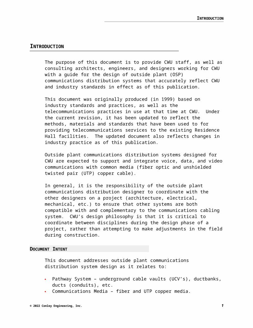
This document addresses outside plant communications distribution system design as it relates to:
Pathway System – underground cable vaults (UCV’s), ductbanks, ducts (conduits), etc.
Communications Media – fiber and UTP copper media. Building Entrance Facilities
This document is not intended to serve as a Master Specification nor for stand-alone use on design build projects — it is to be used in conjunction with the CWU Outside Plant Communications Distribution System Master Specification. This document should serve as a guide for making standards compliant design decisions which, in due course, will be reflected in a system specification based upon the CWU Outside Plant Communications Distribution System Master Specification. In addition to specifications for a telecommunications project, plan drawings and schematic diagrams will also
© 2023 Conley Engineering, Inc. 1
INTRODUCTION
need to be produced by the designer. The drawings should conform to the guidelines contained in this document.
In addition, this document is not intended to replace or detract from the Customer-Owned Outside Plant Design Manual (CO-OSP) produced and distributed by BICSI.1 Rather, this document is to be used in conjunction with the CO-OSP in order to reinforce selected CO-OSP content as well as highlight any differences between CO-OSP and CWU standards.
TYPE OF CONSTRUCTION
Throughout this document, reference will be made to three types of construction: new, overbuild and basic construction. Construction of a new outside plant communications distribution system as well as the addition to and/or modification of an existing outside plant communications distribution system are considered to be included in these construction projects. Tradeoffs between design standards and practicality will many times be dependent upon the type of construction. Different design approaches may be warranted given differing types of construction.
Where the type of construction is applicable to the current discussion, a superscripted circular number, such as this , will make reference next to the text. This number refers to a comment in a special Construction Reference box to the right of the text (see the example at right).
The three types of construction are defined below. These definitions are applicable to the purposes of this document only.
NEW CONSTRUCTION
New construction is defined as construction that results in a new (or new portion of an existing) outside plant communications distribution system. For the most part, new pathway will be constructed and new communications media will be installed in the pathway. A recent CWU project with components that typify this type of construction is:
Electrical Utility Upgrade Phase 1 – (1999-2001)
OVERBUILD CONSTRUCTION
Overbuild construction is defined as construction which may include demolition and/or abandonment of existing pathway and communications media, reuse of existing pathway for installation of new communications media, and the addition of new pathway and/or media to existing pathway and/or media. Common terms referring to this type of construction
1 The CO-OSP is probably the first widely distributed industry reference text for the design of standards compliant outside plant communications distribution systems.
© 2023 Conley Engineering, Inc. 2
CONSTRUCTION REFERENCE This is an example of a reference to the text at the left
INTRODUCTION
include expansion, renovation, remodel, addition, and retrofit, among others.
BASIC CONSTRUCTION
Basic construction is defined as construction that includes reuse of existing distribution pathway for the installation of new communications media. Demolition of existing communications media may be involved as well. In general, basic construction is focused on the installation of new communications media with no (or very minor) modifications made to the existing pathway system. Recent CWU projects with components that typify this type of construction are:
Campus Fiber Optic Backbone (FOB) – (1999-2001) Residential Network (RESNET) – (1999-2001)
© 2023 Conley Engineering, Inc. 3
DESIGNER QUALIFICATIONS AND DESIGN STANDARDS
DESIGNER QUALIFICATIONS AND DESIGN STANDARDS
DESIGNER QUALIFICATIONS
It is required that all outside plant communications distribution system designs executed on the behalf of CWU be designed by a Registered Communications Distribution Designer (RCDD) as certified by BICSI2. This means that the design project shall be managed under the direct supervision of an RCDD on the consultant’s staff. Project related communications between CWU and the consultant shall be mainly through the RCDD.
In addition to the RCDD certification, it is desirable that the RCDD have the following qualifications:
Professional Engineer (P.E.) in the electrical engineering field RCDD/LAN certification from BICSI MCSE certification from Microsoft Corporation3
In addition, the RCDD shall have the following qualifications:
The RCDD shall demonstrate a minimum of 5 years of experience in the design of outside plant communications distribution systems. Experience not directly related to the design of outside plant communications distribution systems, such as sales and/or marketing, project management, or installation experience, is not acceptable.
The RCDD shall demonstrate that he/she has designed or has had personal design oversight of a minimum of five projects similar in size and construction cost to the current CWU project.
The RCDD shall not be affiliated with any manufacturer associated with the communications distribution system industry.
The RCDD shall be completely familiar and conversant with the standards listed below.
DESIGN STANDARDS
REFERENCES, STANDARDS, AND CODES
CWU standards are based upon the Customer-Owned Outside Plant Design Manual (CO-OSP) produced by BICSI, the Telecommunications Distribution Methods Manual (TDMM) also produced by BICSI, ANSI/TIA/EIA and ISO/IEC standards, and NEC codes, among others.
2BICSI, 8610 Hidden River Pkwy, Tampa, FL 33637-1000 USA, Tampa, FL 33612-6415; 1-800-242-7405; www.bicsi.org3Microsoft Corporation, One Microsoft Way, Redmond, WA 98052-6399, (425) 882-8080; www.microsoft.com/mcse
© 2023 Conley Engineering, Inc. 4

DESIGNER QUALIFICATIONS AND DESIGN STANDARDS
It is required that the Designer be thoroughly familiar with the content and intent of these references, standards, and codes and that the Designer be capable of applying the content and intent of these references, standards, and codes to all outside plant communications system designs executed on the behalf of CWU.
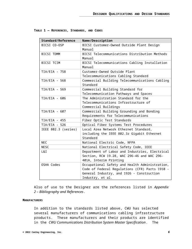
Listed in the table below are references, standards, and codes applicable to outside plant communications systems design. If questions arise as to which reference, standard, or code should apply in a given situation, the more stringent shall prevail. As each of these documents are modified over time, the latest edition and addenda to each of these documents is considered to be definitive.
TABLE 1 — REFERENCES, STANDARDS, AND CODES
Standard/Reference Name/DescriptionBICSI CO-OSP BICSI Customer-Owned Outside Plant Design ManualBICSI TDMM BICSI Telecommunications Distribution Methods
ManualBICSI TCIM BICSI Telecommunications Cabling Installation ManualTIA/EIA - 758 Customer-Owned Outside Plant Telecommunications
Cabling StandardTIA/EIA - 568 Commercial Building Telecommunications Cabling
StandardTIA/EIA - 569 Commercial Building Standard for Telecommunication
Pathways and SpacesTIA/EIA - 606 The Administration Standard for the
Telecommunications Infrastructure of Commercial Buildings
TIA/EIA - 607 Commercial Building Grounding and Bonding Requirements for Telecommunications
TIA/EIA - 455 Fiber Optic Test StandardsTIA/EIA - 526 Optical Fiber Systems Test ProceduresIEEE 802.3 (series) Local Area Network Ethernet Standard, including the
IEEE 802.3z Gigabit Ethernet Standard NEC National Electric Code, NFPANESC National Electrical Safety Code, IEEEL&I Department of Labor and Industries, Electrical Section,
RCW 19.28, WAC 296-46 and WAC 296-401A, Interim Printing
OSHA Codes Occupational Safety and Health Administration, Code of Federal Regulations (CFR) Parts 1910 - General Industry, and 1926 - Construction Industry, et al.
Also of use to the Designer are the references listed in Appendix 2 – Bibliography and References.
© 2023 Conley Engineering, Inc. 5
DESIGNER QUALIFICATIONS AND DESIGN STANDARDS
MANUFACTURERS
In addition to the standards listed above, CWU has selected several manufacturers of communications cabling infrastructure products. These manufacturers and their products are identified in the CWU Communications Distribution System Master Specification. The outside plant communications distribution designer is required to incorporate only these manufacturers into the design, and to design a communications distribution system that will be suitable for the use of products from these manufacturers.
DEVIATION FROM STANDARDS
It is not the intent of CWU to rigidly impose standards on every aspect of an outside plant communications system design. Each design is unique and each design may be subject to situations in which deviations from the standards are warranted.
If the Designer feels that deviation from a given standard is warranted, the Designer shall submit a written deviation request to CWU. The request will, at a minimum, indicate the standard from which there is a proposed deviation, the substitution being proposed in place of the standard, the reason the request is being made, and an explanation of the justifications (economic, technical or otherwise) for the deviation. The Designer may, upon written approval from CWU, incorporate the design deviation into the overall design. CWU approval is required on a project-by-project basis. The Designer should not assume that a deviation approval for one project means that the deviation will necessarily be approved for a subsequent project.
© 2023 Conley Engineering, Inc. 6
DESIGN CONSIDERATIONS
DESIGN CONSIDERATIONS
OVERVIEW
This section highlights design considerations of particular importance to CWU. It also discusses differing CWU standards given the type of construction (new, overbuild, or basic) for a particular project, as well as CWU standards that may differ from the standards listed previously in Table 1.
TELECOMMUNICATIONS OUTSIDE PLANT MASTER PLAN
Each design performed on the behalf of CWU shall conform to and integrate with the CWU Telecommunications Pathway Outside Plant Master Plan. This plan provides a 10-year strategy for the use and expansion of the underground telecommunications pathways on the CWU campus.
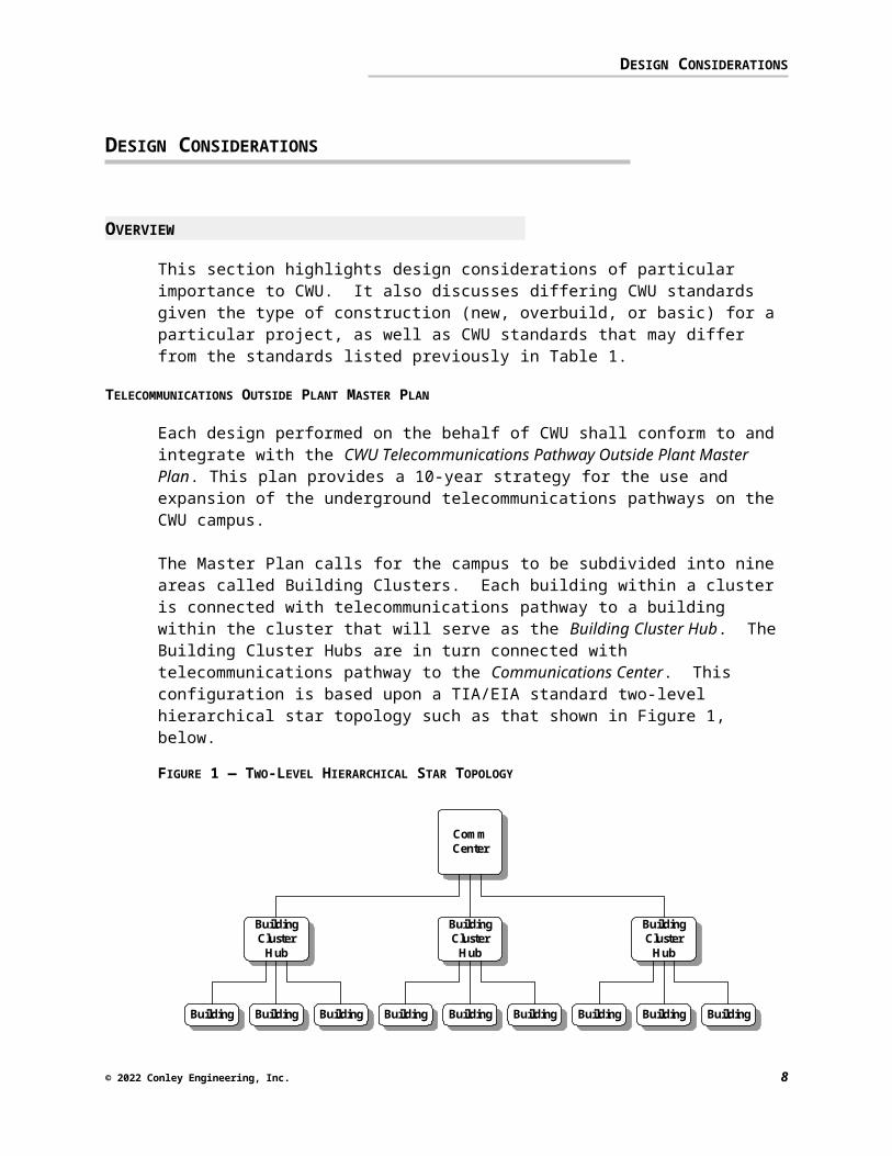
The Master Plan calls for the campus to be subdivided into nine areas called Building Clusters. Each building within a cluster is connected with telecommunications pathway to a building within the cluster that will serve as the Building Cluster Hub. The Building Cluster Hubs are in turn connected with telecommunications pathway to the Communications Center. This configuration is based upon a TIA/EIA standard two-level hierarchical star topology such as that shown in Figure 1, below.
FIGURE 1 — TWO-LEVEL HIERARCHICAL STAR TOPOLOGY
CommCenter
Building
BuildingClusterHub
BuildingBuildingBuilding
BuildingClusterHub
BuildingBuilding Building
BuildingClusterHub
Building Building
Please refer to the Master Plan – Overview drawing in the CWU Telecommunications Pathway Outside Plant Master Plan for more detail.
© 2023 Conley Engineering, Inc. 7
DESIGN CONSIDERATIONS
DEFINITION OF TERMS
The table below defines and clarifies common terms that will be used throughout this section — it is expected that the Designer is already familiar with these terms.
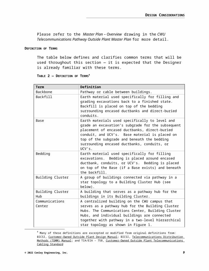
TABLE 2 — DEFINITION OF TERMS4
Term DefinitionBackbone Pathway or cable between buildings. Backfill Earth material used specifically for filling and grading
excavations back to a finished state. Backfill is placed on top of the bedding surrounding encased ductbanks and direct-buried conduits.
Base Earth materials used specifically to level and grade an excavation’s subgrade for the subsequent placement of encased ductbanks, direct-buried conduit, and UCV’s. Base material is placed on top of the subgrade and beneath the bedding surrounding encased ductbanks, conduits, or UCV’s.
Bedding Earth material used specifically for filling excavations. Bedding is placed around encased ductbank, conduits, or UCV’s. Bedding is placed on top of the Base (if a Base exists) and beneath the backfill.
Building Cluster A group of buildings connected via pathway in a star topology to a Building Cluster Hub (see below).
Building Cluster Hub A building that serves as a pathway hub for the buildings in its Building Cluster.
Communications Center
A centralized building on the CWU campus that serves as a pathway hub for the Building Cluster Hubs. The Communications Center, Building Cluster Hubs, and individual buildings are connected together with pathway in a two-level hierarchical star topology as shown in Figure 1.
Duct A single enclosed raceway (conduit) used for the routing of cables.
Ductbank An arrangement of multiple ducts, usually in tiers. Entrance Facility (EF)
The interface between the premises (in-building) communications distribution system and the outside plant communications distribution system and services (such as the public telephone network or inter-building (campus) backbone cabling.) The EF consists of protection hardware, connecting hardware and cable and equipment necessary to connect premises distribution to outside plant distribution.
Underground Cable Vault(UCV)
An underground cable vault (part of an underground duct system) used to facilitate placing, connectorizing, and maintaining telecommunications cables and associated equipment. “UCV” collectively refers to manholes, handholes, and pullholes.
4 Many of these definitions are excerpted or modified from original definitions from: BICSI, Customer-Owned Outside Plant Design Manual; BICSI, Telecommunications Distribution Methods (TDMM) Manual; and TIA/EIA – 758, Customer-Owned Outside Plant Telecommunications Cabling Standard
© 2023 Conley Engineering, Inc. 8
DESIGN CONSIDERATIONS
• Manholes
• Handholes/Pullholes
A large underground cable vault in which it is expected that a person can completely enter to perform work.
A small underground cable vault in which it is expected that a person cannot completely enter to perform work. Handholes/pullholes are used for the placement of cable only. Splicing and/or equipment are not permitted in handholes/pullholes.
© 2023 Conley Engineering, Inc. 9
DESIGN CONSIDERATIONS
PATHWAY SYSTEM
The pathway system (underground cable vaults, ducts, and ductbanks) is the foundational component of the outside plant communications distribution system. A pathway system designed with foresight provides for ease of administration, maintenance, future expansion, and replacement of cabling as technology changes. A well-designed pathway system contributes more to reducing the total cost of ownership of an outside plant communications distribution system than does any other single component.
This section describes design considerations for the pathway system that are of particular concern to CWU. The Designer is expected to refer to the TIA/EIA standards and the BICSI CO-OSP and TDMM for other and more specific design criteria and detail.
GENERAL DESIGN CONSIDERATIONS
As discussed previously, the design of pathway shall conform to the TIA/EIA standard two-level hierarchical star topology as defined in the CWU Telecommunications Pathway Outside Plant Master Plan.
Prior to design, the Designer is expected to meet with CWU and review CWU’s requirements for the project. Items to review should include proposed pathway routing, aesthetic requirements, long range plans that CWU has regarding new and existing buildings, paved areas, opens spaces, etc. which could be affected by the design, and any unique requirements specific to the project.
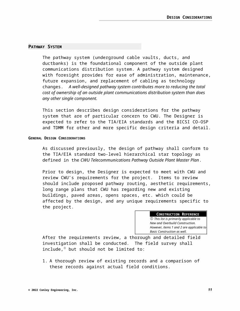
After the requirements review, a thorough and detailed field investigation shall be conducted. The field survey shall include, but should not be limited to:
1. A thorough review of existing records and a comparison of these records against actual field conditions.
2. Notation of the condition, suitability, and diagrams showing the locations of existing pathway, UCV’s, and building entrances likely to be used during the course of the project.
3. Documentation of where the telecommunications pathway will require coordination with pathway used for other utilities.
4. Investigate adverse ground conditions and obstructions (such as buildings, trees, etc.) and any significant changes in grade along the proposed pathway.
© 2023 Conley Engineering, Inc. 10
CONSTRUCTION REFERENCE This list is primarily applicable to New and Overbuild Construction. However, items 1 and 2 are applicable to Basic Construction as well.

DESIGN CONSIDERATIONS
5. Notation of the existing paving types and the type of material used as a base below the paving along the proposed route.
6. Notation of the most desirable locations for new underground cable vaults (UCV’s) and ductbank routes, as well as any alternative locations and routes.
Detailed design should commence only after the field survey has been conducted and reviewed by CWU.
The discussion below focuses on specific design considerations for the major components of the pathway system: UCV’s, ducts, and ductbanks.
UNDERGROUND CABLE VAULTS (UCVS)
UCVs provide accessible space in an outside plant pathway system for the pulling, placing, and splicing of cables, as well as for maintenance and operations equipment. UCV’s are also used to segment the pathway system into lengths compatible with standard reel lengths for outside plant cable and to conform to maximum pathway lengths as defined in the TIA/EIA standards.
Underground cable vaults consist of manholes and handholes/pullholes (see Table 2, above). UCV’s are also sometimes referred to as maintenance holes. Typically, manholes are installed for main ductbanks (i.e. ductbanks used for routing large portions of the telecommunications system backbone), and handholes/pullholes are installed for subsidiary ductbanks (i.e. ductbanks serving small clusters of buildings or a single building).
FIGURE 2 — TYPICAL UCV DETAIL
MANHOLE COVER WITH "COMMUNICATIONS" EMBOSSED IN CASTING.STENCIL MANHOLE NUMBER IN 3" LETTERS ON COVER
6" TO 1'-0"
4'-0"
MINIMUM 6" 4'-8" MINIMUM 6"
RESTORE FINISHED GRADE TO EXISTINGCONDITION (TURF, CONCRETE, OR ASPHALT).
FOR TURF AREAS, PROVIDE NEW SOD.
CONDUIT( TYPICAL )
GROUT ENVELOPE(TYPICAL)
UNDISTURBED EARTH
IMPORTED BACKFILL(95% COMPACTED)
CONDUIT END BELLFLUSH MOUNTED(TYPICAL)
GRAVEL
EXCAVATION BOTTOM(SMOOTH TO +/- 1")
The quantity of duct entrances in a UCV should be sized for both immediate
© 2023 Conley Engineering, Inc. 11
DESIGN CONSIDERATIONS
and future requirements. Adequate capacity for future duct entrances will mitigate the need for future wall breakouts. Additionally, UCVs configured for splayed duct entrances (rather than center entrances) are preferred. Splayed duct entry facilitates racking and minimizes bending of the communications cable. An example of splayed duct entry/exit is shown in the figure below.
FIGURE 3 — SPLAYED DUCT ENTRY/EXIT
When designing duct entry and exit from a UCV, it is desirable to have ducts enter and exist from opposite ends of the UCV. If possible, ducts entering the sidewalls of a UCV should be avoided, given that sidewall entry may reduce overall racking space, may cause minimum cable bend radii to be exceeded, can complicate (or hinder) future cable maintenance, and can increase construction costs during cable installation.
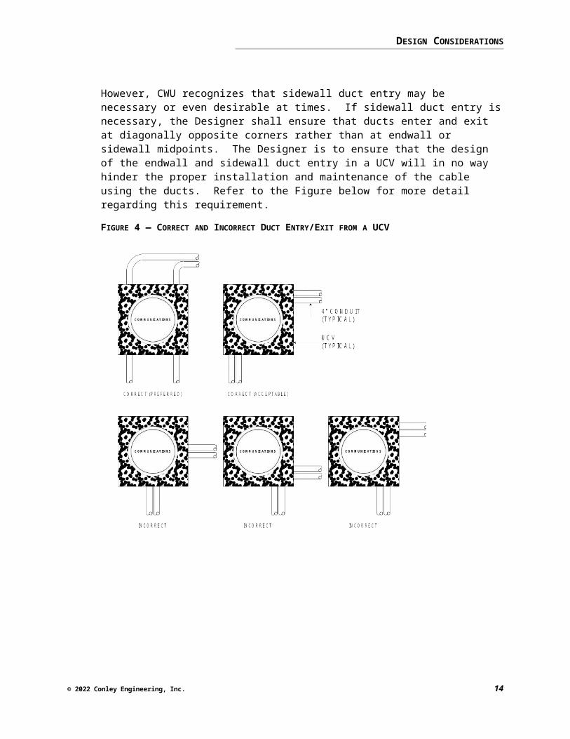
However, CWU recognizes that sidewall duct entry may be necessary or even desirable at times. If sidewall duct entry is necessary, the Designer shall ensure that ducts enter and exit at diagonally opposite corners rather than at endwall or sidewall midpoints. The Designer is to ensure that the design of the endwall and sidewall duct entry in a UCV will in no way hinder the proper installation and maintenance of the cable using the ducts. Refer to the Figure below for more detail regarding this requirement.
© 2023 Conley Engineering, Inc. 12
DESIGN CONSIDERATIONS
FIGURE 4 — CORRECT AND INCORRECT DUCT ENTRY/EXIT FROM A UCV
© 2023 Conley Engineering, Inc. 13

DESIGN CONSIDERATIONS
Other important design considerations for UCVs are:
A UCV shall not be shared between telecommunications and any other utility (such as electrical). In no instance are joint-use UCVs permissible.
All UCV’s should be equipped with provisions for grounding and bonding, struts for racking, pulling eyes, and a sump.
In general, powered devices shall not be installed in UCV’s. Top slabs for UCV’s shall be flush with the ground.
Design considerations unique to each type of UCV (manholes and handholes/pullholes) are discussed below.
MANHOLES
Manholes are used for pulling, placing, and splicing cables, and for providing accessible space for cable maintenance and operation equipment.
Ductbank depth, obstructions, and other utility pathways may necessitate placement of a manhole below normal depth. If this is the case, the roof of the manhole shall be placed at normal depth and riser extensions shall be used to increase the depth of the manhole. By doing so, the need for a deep collar (neck) will be eliminated. Additionally, lighting and ventilation can be maintained at a normal level. If a deep collar is unavoidable and the depth of the collar will exceed 24 inches, the Designer shall obtain written permission from CWU and ensure that the collar is equipped with permanent galvanized steps (rungs).
Diamond plate hinged or removable covers are not acceptable for manholes. For reference purposes, a typical manhole size is 5’ wide x 8’ long x 7’ high (exterior dimensions). Actual size may be as much as a foot or more larger in any direction.
HANDHOLES/PULLHOLES
Handholes/pullholes are used to facilitate cable placement in a pathway system. Handholes should not be used in place of manholes or for splicing cables. The primary use of a handhole/pullhole is to segment the pathway system. A handhole should be used if it is shown that a manhole is not required and if one or more of the following conditions exist:
When the bends in a section of duct will exceed 180-degrees (see Ducts, below).
© 2023 Conley Engineering, Inc. 14
CONSTRUCTION REFERENCE The following discussion of manholes and handhole/pullholes is primarily applicable to New and Overbuild Construction.
DESIGN CONSIDERATIONS
When the length of the section of duct will exceed the TIA/EIA standard maximum length (see Ducts, below).
For reference purposes, a handhole/pullhole is defined to be an underground cable vault sized 4’ wide x 4’ long x 4’ high (exterior dimensions) or smaller.
DUCTS (CONDUIT)
CWU has standardized on 4” conduits for telecommunications ducts, with the following two exceptions: Ducts containing cables that serve the Blue Light Emergency Telephones
shall be 1½” conduit. Ducts containing fiber optic cabling serving the power distribution system
metering equipment shall be 1½” conduit.The type of conduit to be used is dependent upon the application as shown in the following table.
TABLE 3 — DUCT TYPES AND USAGE
Conduit Type UsageSchedule 40 PVC Encased in concreteSchedule 80 PVC Direct-buriedRigid Galvanized Steel
Exposed
PVC Coated Steel Direct-buried, Transitions at building entrances
If the design utilizes any existing pathway, the existing ducts must be proven during design in order to ensure that the selected pathway is clear and serviceable. Proving the ducts prior to construction will not only aid the Designer in selecting the appropriate pathway for use, it will also minimize unexpected (and costly) problems or delays during construction. Acceptable proving methods are, in order of preference:
Pushing/pulling a test mandrel through the duct Blowing/pushing/pulling a ball through the duct Pulling on a previously installed pull cord and observing free movement
on both ends. This method does not prove that a duct is adequate for a given number of cables, however it does suggest that the duct is probably not completely obstructed.
It is left to the Designer to select the appropriate method for proving a given duct. The proving method should be selected only after determining the quantity and size of the communications media to be placed in the duct and after reviewing the condition of the duct in the field.
DUCT LENGTH
The length of each ductbank segment should be as long as possible (without exceeding the TIA/EIA maximum distance, see below) in order to
© 2023 Conley Engineering, Inc. 15
DESIGN CONSIDERATIONS
minimize the use of intermediary UCV’s, cable splices, and labor during installation of the communications media. In general, longer contiguous ducts equate to lower construction costs.
The maximum duct length (between UCV’s and/or buildings) permissible according to the TIA/EIA 758 standard is 600 ft. Duct sections exceeding this distance will require the installation of intermediate UCV’s.
In addition, as the number of bends in a pathway increases, the maximum length of the pathway will decrease, due to cable pulling tension constraints. Longer runs will therefore tolerate fewer bends. In general, the Designer should base the pathway system design on an initial segment length budget of approximately 300 feet, and designed in as straight a line as possible.
BENDS
The Designer shall ensure that bends consist of a single arc of a minimum15-foot radius. If a smaller radius is absolutely necessary, the radius shall be no less than 10 times the internal diameter of the duct. An individual bend shall not exceed 90 degrees.
Factory manufactured conduit bends should be used wherever possible. The use of 90-degree elbows or condulets (LB’s) is not permissible.
In order to minimize the sidewall pressure exerted on cable sheaths at bend points, the Designer should ensure that bends with the most severe radii occur at the beginning (feed end) of a duct section, rather than in the middle or at the pulling end.
A duct section may have no more than the equivalent of two 90-degree bends (a total of 180 degrees) between pull points. The 180-degree maximum shall include kicks and offsets. In addition, two 90-degree bends separated by less than 10 feet are not permissible. Where it is not possible to construct a section of duct within the 180-degree bend maximum, intermediary UCV’s must be installed.
© 2023 Conley Engineering, Inc. 16
CONSTRUCTION REFERENCE This requirement may be waived at times for New and Overbuild Construction given the following conditions: the duct run is straight; the Designer can demonstrate that the pulling tension of a typical communications cable making use of the duct will not be exceeded during installation.
The requirements of TIA/EIA 569-A, Figure C.5-2 should be met when calculating maximum section lengths.
CONSTRUCTION REFERENCE This requirement may be waived for Basic Construction. Older existing pathway may, at times, exceed this rule. The Designer should note on the Construction Documents where such conditions exist.
DESIGN CONSIDERATIONS
DUCT ENTRANCES IN UCV’S OR BUILDINGS
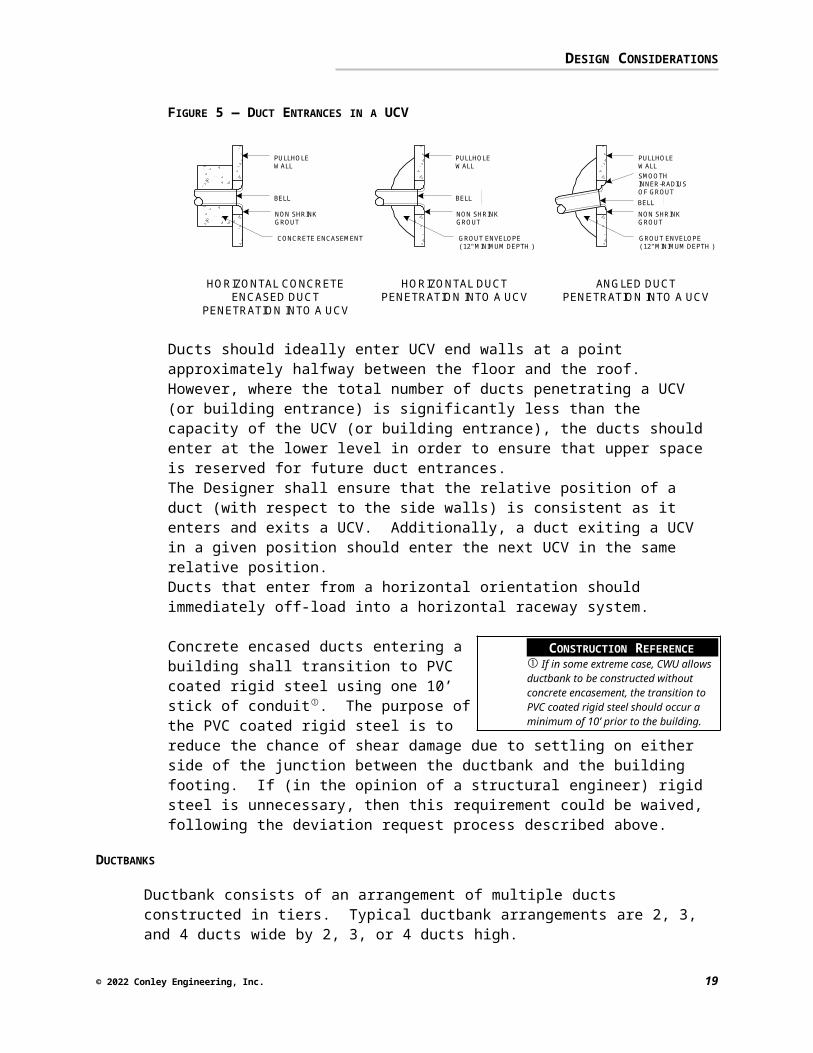
Duct entrances in a UCV should be as perpendicular as possible. Where this is not possible, the Designer should ensure that the Contractor installs a smooth inner radius of grout between the UCV and the conduit bell, as shown in the figure below:
FIGURE 5 — DUCT ENTRANCES IN A UCV
NON SHRINKGROUT
NON SHRINKGROUT
PULLHOLEWALL
SMOOTHINNER-RADIUSOF GROUT
PULLHOLEWALL
GROUT ENVELOPE( 12" MINIMUM DEPTH )
GROUT ENVELOPE( 12" MINIMUM DEPTH )
BELLBELL
HORIZONTAL DUCTPENETRATION INTO A UCV
ANGLED DUCTPENETRATION INTO A UCV
NON SHRINKGROUT
PULLHOLEWALL
CONCRETE ENCASEMENT
BELL
HORIZONTAL CONCRETEENCASED DUCT
PENETRATION INTO A UCV
Ducts should ideally enter UCV end walls at a point approximately halfway between the floor and the roof. However, where the total number of ducts penetrating a UCV (or building entrance) is significantly less than the capacity of the UCV (or building entrance), the ducts should enter at the lower level in order to ensure that upper space is reserved for future duct entrances. The Designer shall ensure that the relative position of a duct (with respect to the side walls) is consistent as it enters and exits a UCV. Additionally, a duct exiting a UCV in a given position should enter the next UCV in the same relative position. Ducts that enter from a horizontal orientation should immediately off-load into a horizontal raceway system.
Concrete encased ducts entering a building shall transition to PVC coated rigid steel using one 10’ stick of conduit. The purpose of the PVC coated rigid steel is to reduce the chance of shear damage due to settling on either side of the junction between the ductbank and the building footing. If (in the opinion of a structural engineer) rigid steel is unnecessary, then this requirement could be waived, following the deviation request process described above.
DUCTBANKS
Ductbank consists of an arrangement of multiple ducts constructed in tiers. Typical ductbank arrangements are 2, 3, and 4 ducts wide by 2, 3, or 4 ducts high.
© 2023 Conley Engineering, Inc. 17
CONSTRUCTION REFERENCE If in some extreme case, CWU allows ductbank to be constructed without concrete encasement, the transition to PVC coated rigid steel should occur a minimum of 10’ prior to the building.
DESIGN CONSIDERATIONS
CWU has standardized on ductbanks constructed of PVC conduits encased in concrete, with full-length reinforcement and formed sides.
In general, direct-buried conduit ductbanks are not permissible, unless extenuating circumstances warrant. Should the use of direct-buried PVC conduit ductbank be warranted, the Designer should ensure that all PVC bends are encased in concrete.
Where ductbank passes under paved surfaces capable of supporting motor vehicle traffic, conduit should transition to PVC coated rigid steel a minimum of 10’ outside the footprint of the paved surface.
The quantity of ducts to install within a ductbank will vary greatly depending upon the application. However, with the increasing migration from copper cable to fiber optic cable on the CWU campus, it is expected that the requirement for duct space will decrease over time.
In keeping with this expectation and with the recommendations made in the CWU Telecommunications Pathway Outside Plant Master Plan, typical ductbank configurations are shown below. It should be noted that these typical configurations should serve as a guideline only. The quantity of ducts in a duct bank should meet the needs of the application at hand and provide for future expansion capability.
Buildings up to 100,000 sq. ft.: 2 ducts Buildings 100,000 sq. ft. to 300,000 sq. ft.: 4 ducts Buildings larger than 300,000 sq. ft.: 6 ducts Buildings serving as a Building Cluster Hub: 6 ducts Pathway between Building Cluster Hubs and the Communications Center:
4 ducts
Unless specifically noted above, a typical ductbank will contain four ducts, arranged 2 wide x 2 high.
In general, ductbank used for telecommunications pathway should not be shared with other utilities. Budgetary constraints, space limitations, and various obstructions can make this difficult to achieve at times. Should shared ductbank be a necessity (rare situations requiring a deviation request), the Designer should ensure that adequate separation exists between duct used for telecommunications and duct used for other utilities. Refer to the table below for minimum separation distances.
© 2023 Conley Engineering, Inc. 18
CONSTRUCTION REFERENCE Ducts used for Blue Light Emergency Telephones are not subject to this requirement.
CONSTRUCTION REFERENCE This may not be possible for Overbuild Construction.
DESIGN CONSIDERATIONS
TABLE 4 — DUCTBANK MINIMUM SEPARATIONS
Structure Minimum Separations5
Power or other duct
Refer to the latest edition of the NEC/NESC (at the time of this writing: 3 inches if in concrete, 12 inches if in well tamped earth)
Pipes (gas, oil, water, etc.)
Refer to the latest edition of the NEC/NESC (at the time of this writing: 12 inches if parallel, 6 inches if crossing)
Should future circumstances warrant, CWU might desire to convert concrete-encased communications ductbank (not direct-buried ductbank) into electrical power ductbank. The Designer should therefore ensure that communications ductbank specifications (conduit spacing, reinforcement, grounding requirements, etc.) conform to NEC requirements for power ductbank.
If building ducts are constructed concurrently with and in the same duct bank with a main duct run, place building ducts (subsidiary/lateral ducts) on top of the ducts for the main run. This is economically advantageous, makes the building ducts more accessible, and affords some top protection for the main ducts.
Drain slope should exist at all points of the ductbank to allow drainage and prevent the accumulation of water. A drain slope of ¼” per foot is desirable if possible. If not possible due to inadequate natural slope or long duct runs, a drain slope of 3” per 100 feet is acceptable. If no other option exists, provide a drain slope by sloping the first half of the ductbank up towards the midpoint, and then down from the midpoint to the end (sometimes referred to as a ‘center crown’). Drain slope requirements shall be identified in the Contract Documents – they shall not be left up to the discretion of the Contractor.
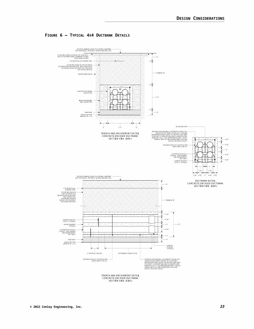
Details for a typical four-conduit ductbank (2 wide x 2 high) are shown in the figure below:
5 Measured from outside to outside
© 2023 Conley Engineering, Inc. 19
DESIGN CONSIDERATIONS
FIGURE 6 — TYPICAL 4X4 DUCTBANK DETAILS
1'-7"
4"
1'-7"
MINIMUM 18"
6"
RESTORE FINISHED GRADE TO EXISTING CONDITION.FOR TURF AREAS, PROVIDE 4" TOPSOIL AND NEW SOD.
IF EXISTING GRADE IS ASPHALT OR CONCRETE,SAWCUT EXISTING GRADE A MINIMUM 6" WIDER
THAN TRENCH WIDTH
IF EXISTING GRADE IS TURF OR EARTH,USE IMPORTED EARTH BACKFILL (95% COMPACTED).
IF EXISTING GRADE IS ASPHALT OR CONCRETE,USE GRAVEL BACKFILL
6" WIDE METALLIC WARNING TAPE
IMPORTED BEDDING(90% COMPACTED)
UNDISTURBED EARTH
TRENCH BOTTOM(SMOOTH TO +/- 1")
SAND BASE
CONCRETE DUCTBANK(SEE DETAIL)
6" 6"
TRENCH AND ENCASEMENT DETAILCONCRETE ENCASED DUCTBANK
SECTION VIEW (END)
6" WIDE METALLICWARNING TAPE
6"
4 1/2"
4 1/2"
3"
TRENCH BOTTOM(SMOOTH TO +/- 1")
2"
3 1/2"
MINIMUM 18"
3'-0" MINIMUM CONDUIT STUB
4"
CONDUITCOUPLER (TYPICAL)
CONDUIT SPACERS5'-0" O.C. (TYPICAL)
6" VERTICAL STAGGER
SAND BASE
GRAVEL BEDDING(TYPICAL)
RESTORE FINISHED GRADE TO EXISTING CONDITION.FOR TURF AREAS, PROVIDE 4" TOPSOIL AND NEW SOD.
IF EXISTING GRADE ISTURF OR EARTH, USE
IMPORTED EARTH BACKFILL(95% COMPACTED).
IF EXISTING GRADE ISASPHALT OR CONCRETE,
USE GRAVEL BACKFILL
1'-7"
#5 REBAR (LONGITUDINAL), CONTINUOUS ALONG FULLLENGTH OF DUCTBANK, (TYPICAL OF 2). PROVIDEINTERMEDIATE BARS ALONG TOP, BOTTOM, AND SIDESFOR EVERY 3 CONDUITS HIGH AND 3 CONDUITS WIDE.MAINTAIN 1"-6" O.C. FOR INTERMEDIATE BARS. DOWELREBAR 6" INTO UCV AND FOUNDATION WALLS ANDGROUT WITH EPOXY GROUT.
#5 REBAR HOOPS AT CONSTRUCTIONJOINTS AND AT 5'-0" O.C.
4" CONDUIT (4 1/2" O.D.)(TYPICAL - SIZE, NUMBER
AND ARRANGEMENTMAY VARY)
4 1/2"
3 1/2"
3 1/2"
3"
7 1/2"7 1/2"
3" 3 1/2"3 1/2" 4 1/2" 4 1/2"
4 1/2"
#2 GROUND WIRE
#5 REBAR (LONGITUDINAL), CONTINUOUS ALONG FULLLENGTH OF DUCTBANK, TYPICAL OF 4. PROVIDE
INTERMEDIATE BARS ALONG TOP, BOTTOM, AND SIDESFOR EVERY 3 CONDUITS HIGH AND 3 CONDUITS WIDE.MAINTAIN 1'-6" O.C. FOR INTERMEDIATE BARS. DOWEL
REBAR 6" INTO UCV AND FOUNDATION WALLS ANDGROUT WITH EPOXY GROUT.
#5 REBAR HOOPS AT CONSTRUCTIONJOINTS AND AT 60" O.C.
4" CONDUIT (4 1/2" O.D.)(TYPICAL - SIZE, NUMBER,
AND ARRANGEMENTMAY VARY)
CONDUIT SPACERS5-0"' O.C. (TYPICAL)
DUCTBANK DETAILCONCRETE ENCASED DUCTBANK
SECTION VIEW (END)
TRENCH AND ENCASEMENT DETAILCONCRETE ENCASED DUCTBANK
SECTION VIEW (SIDE)
© 2023 Conley Engineering, Inc. 20
DESIGN CONSIDERATIONS
COMMUNICATIONS MEDIA
The communications industry is now witnessing a convergence of technologies. Voice, data, and video are all capable of utilizing the same type of communications media (i.e. singlemode fiber). Additionally, these technologies are also beginning to converge into a single technology capable of combining voice, data, and video signals into a common signal transmitted down a single path.
Accordingly, and as discussed in the CWU Telecommunications Pathway Outside Plant Master Plan, CWU has standardized on singlemode fiber optic media as the media of choice for all future, voice, data, and video backbone systems. Copper media (for voice and various signaling systems) as well as multimode fiber optic media (for existing data network equipment and various building and power metering systems) will continue to be installed and used, but will be used less extensively as time progresses.
As the voice, data, and video systems begin to make use of the singlemode fiber on campus, existing copper and multimode fiber media can be removed. Additionally, singlemode fiber media is significantly smaller than the copper media used on campus. These two factors combined will tend to ease the shortage of duct space on campus.
This section defines design considerations for outside plant communications media (cable and connecting hardware) that are of particular concern to CWU. The Designer is expected to refer to the TIA/EIA standards and the BICSI CO-OSP and TDMM for other and more specific design criteria and detail.
GENERAL DESIGN CONSIDERATIONS
Following is a list of general items to consider when selecting a communications media system:
Direct-buried cable and aerial cable should not be used. If extenuating circumstances require the use of these cable types, the Designer must obtain approval from CWU in writing prior to finalizing the Construction Documents.
Fiber optic cable shall not be spliced. The CWU Telecommunications Pathway Outside Plant Master Plan has been designed to minimize the amount of fiber splices necessary in the outside plant.
Where cables are to be pulled through UCV’s without splicing, the duct selected for cable installation shall be at the same elevation as it enters and exits the UCV. Changes in duct selections, especially in elevations,
© 2023 Conley Engineering, Inc. 21
CONSTRUCTION REFERENCE This may not be possible for Overbuild and Basic Construction if the Designer must make use of the existing fiber optic outside plant cable.

DESIGN CONSIDERATIONS
should be avoided to ensure that no damage occurs to the cable sheaths and that pulling tensions are kept as low as possible.
Ducts are to be assigned during the course of design, not during construction. Duct assignments must be approved by CWU prior to the release of Construction Documents.
If a multiple ducts are available for use, the bottom ducts should be used first in order to facilitate future cable placement.
Communications cabling entering a building should be routed so as not to block or obstruct the planned usage or expansion of any other building that occupies or will occupy the space.
For long cable runs, the longest cable reel lengths obtainable shall be used. Splices should not be used except where cable reel lengths are exceeded. If splices are used, the Designer should ensure that: 1. The cable ends to be spliced have permanent slack loops with
sufficient length that the cable can be removed from the UCV and reach a satisfactory work surface for splice activities.
2. The splice location (UCV or EF) should have enough space for storing slack cable after the splice is completed.
50-foot service loops (cable slack) shall be provided for each end of a cable terminating in a building.
Service loops (cable slack) shall be provided for fiber optic cabling that enters a building in the UCV nearest the building entrance. The length of cable in the service loop shall be sufficient that if a cable break occurs between the UCV and the building, sufficient slack cable would be available in the UCV to reterminate the fiber optic cabling at the existing patch panel, without the use of a splice.
Communications backbone cables serving different systems (i.e. voice, data, video) shall be segregated6. Segregation can occur by using different ducts (the most desirable solution), or it may occur by using separate innerducts within the same duct.
Duct fill shall conform to the TIA/EIA standards and the NEC. For copper media, indoor dry splice enclosures shall be installed prior to
terminating the copper cable on building entrance protectors. Cables are to be tagged (labeled) at locations near where they enter a
UCV from a duct and near where they enter a duct to leave a UCV.
6 Segregation is desirable in order to ensure that when maintenance work is performed on a backbone cable serving a specific system, work on the cable will not disrupt the functionality of the backbone cables serving other systems
© 2023 Conley Engineering, Inc. 22
CONSTRUCTION REFERENCE For New Construction, use different ducts for cables serving different systems. For Overbuild and Basic construction, the use of innerduct is an acceptable alternative although inductive interference (see below) may be an issue. Sharing of ducts can produce undesirable inductive interference, can damage the facilities by subjecting the cable to abrasion and tensional stress if the facilities are pulled in at different times, and may present coordination problems between the various trades involved.

DESIGN CONSIDERATIONS
GROUNDING AND BONDING
CWU has standardized on considering all locations “exposed” for grounding, bonding, and electrical protection purposes. Cables with an outer metallic sheath shall be bonded at each UCV. Bond all other cables with dielectric components whenever a splice is made.
When a splice occurs in a UCV, metallic sheath components in the cable(s) and splice enclosures must be bonded to the UCV grounding system. Additionally, cable shield bond continuity shall be maintained. Bonds should be made with #6 AWG solid copper wire not more than 20’ long. If over 20’, the conductor must be sized according to NEC requirements.
Cables should be grounded as close to the entrance of the buildings as possible.
INNERDUCT
The use of innerduct for subducting purposes is strongly encouraged (although it may not be applicable to every situation). CWU has standardized on three configurations for subducting a 4-inch conduit with innerduct:
Three 1½” innerducts Two 1½” and one 1” innerduct Four 1” innerducts
It is left to the Designer to select the most appropriate configuration for subducting based upon the conditions of the duct and the application. Innerduct shall not be filled with cable beyond 50% capacity.
MEDIA TYPES
CWU recognizes three types of communications media for the campus backbone system:
Category 3 UTP (copper) – used for voice, analog signaling, and various metering applications
Singlemode Fiber Optic – used for data, video, and increasingly, voice applications
62.5/125 µm Multimode Fiber Optic – used primarily for data applications and various metering applications.
As discussed above, CWU has standardized on singlemode fiber for its voice, data, and video applications. However, copper and multimode fiber media will still be in use for some time.
The type and quantity of communications media to install will vary greatly depending upon the application. In keeping with the recommendations made in the CWU Telecommunications Pathway Outside Plant Master Plan, typical communications media configurations are shown below. It should be noted
© 2023 Conley Engineering, Inc. 23
DESIGN CONSIDERATIONS
that these typical configurations should serve as a guideline only. The type and quantity of communications media shall be determined on a case-by-case basis by the Designer, ensuring that it meets the needs of the application at hand and provides for future expansion capability.
BETWEEN BUILDING CLUSTER HUBS AND BUILDINGS
Singlemode Fiber: 12-Strands (4 Data, 4 Video, 4 Spare)
Multimode Fiber: 24-Strands (4 Data, 2 Access Control, 4 Fire Alarm, 2 HVAC Control, 2 Power Metering, 10 Spare)
Copper: 25-Pairs
BETWEEN BUILDING CLUSTER HUBS AND THE COMMUNICATIONS CENTER
Singlemode Fiber: 48-StrandsMultimode Fiber: 24-StrandsCopper: 0-Pairs
BETWEEN THE COMPUTER CENTER AND THE COMMUNICATIONS CENTER
Singlemode Fiber: 96-StrandsMultimode Fiber: 48-StrandsCopper: 0-Pairs
TERMINATION
Separate fiber patch panels shall be provided for multimode and singlemode fiber optic cabling. Fiber optic media shall be terminated on separate fiber patch panels depending upon fiber type.
Copper media shall always be terminated on building entrance protectors.
LABELING AND ADMINISTRATION
It is the responsibility of the Designer to ensure that the Construction Documents clearly define the labeling requirements and that the Contractor properly labels all outside plant media during construction. Inadequate or incomplete labeling is not acceptable. Refer to the Master Specification Section 16741 - Outside Plant Communications Circuits for more information.
© 2023 Conley Engineering, Inc. 24
CONSTRUCTION REFERENCE Hybrid fiber cable is permitted in Residence Halls only. CWU uses 12 SM/12MM hybrid fiber optic cable for these applications.
CONSTRUCTION REFERENCE For Residence Halls served by hybrid fiber: A single patch panel may be used to terminate both types of fiber in the hybrid cable – separate fiber patch panels are not required in this case.

DESIGN CONSIDERATIONS
ENTRANCE FACILITIES
This section defines design considerations for entrance facilities that are of particular concern to CWU and specific to the outside plant communications distribution system.
The Designer is expected to refer to the TIA/EIA standards and the BICSI CO-OSP and TDMM for other and more specific design criteria and detail. In addition, the Designer is expected to reference the CWU Inside Plant Communications Distribution Design Guide for more detail regarding the design of telecommunications spaces, including entrance facilities and equipment rooms.
GENERAL DESIGN CONSIDERATIONS
Following is a list of general items to consider when designing pathway and communications media into a building entrance facility:
In general, a structural engineer should approve all structural changes or penetrations into a building.
The entrance facility shall not be more than 50’ from the actual entrance into the building. In order to comply with NEC requirements, not more than 50’ of an outside plant cable can be exposed between the entrance conduit stub and the cable termination point. If more than 50’ is required, the cable7 must be routed in rigid metallic conduit. Fire-rated tape wrap is not acceptable.
Ducts entering a building shall transition to PVC coated rigid steel conduit a minimum of 10 feet prior to entering the building.
Ducts shall enter the entrance facility parallel to the backboard to be used. Ducts shall not enter perpendicular to the backboard surface, which could cause cables to be bent sharply.
Below grade ducts should extend 4” above finished floor. Building entrance protectors (primary protectors) should be provided for
all OSP copper cables and should support both primary (overvoltage) and secondary (overcurrent) protection.
GROUNDING AND BONDING
CWU has standardized on considering all locations “exposed” for grounding, bonding, and electrical protection purposes.
The ground terminal for building entrance protectors should be bonded directly to the electrical power ground.
7 Some types of fiber media are now “indoor/outdoor” rated and are therefore not subject to this requirement.
© 2023 Conley Engineering, Inc. 25
APPENDICES
APPENDICES
APPENDIX 1 — CONSTRUCTION DRAWINGS
Construction drawings should be thoroughly and accurately marked. Listed below are items that should be included on construction drawings, dependent upon the type of project8:
Routing of the pathway system, including ductbanks and UCV’s. Physical locations of obstructions, including UCVs, ductbanks, buildings,
roads, poles, existing underground utilities. Duct configurations indicating duct sizes and types between UCVs and
between UCVs and buildings. Duct contents indicating cable assignments. UCV and building cable racking diagrams (elevations) indicating the
positions of all existing and new cables and splice enclosures. Backboard/entrance facility elevations within buildings. Pair sizes, gauges, and types of copper cables. Strand counts and types of optical fibers. Drain slope requirements Labeling Phasing (if required) Staging
8 Much of the following list was excerpted from RUS Bulletin 1751F-644 Underground Plant Construction
© 2023 Conley Engineering, Inc. 26

APPENDICES
APPENDIX 2 — BIBLIOGRAPHY AND REFERENCES
AMP, Planning & Installation Guide
BICSI, Customer-Owned Outside Plant Design Manual
BICSI, Telecommunications Distribution Methods Manual
CWU, Telecommunications Pathway Outside Plant Master Plan
CWU, Outside Plant Communications Distribution System Master Specification
CWU, Premises Communications Distribution System Master Specification
CWU, Premises Communications Distribution Design Guide
IEEE, National Electrical Safety Code (NESC), 1997 Edition
NEC, National Electrical Code (NEC), 1999 Edition
OSHA, Code of Federal Regulations (CFR) Parts 1910 - General Industry, and 1926 - Construction Industry, et al
RUS, Bulletin 1751F-643 Underground Plant Design, 1998
RUS, Bulletin 1751-644 Underground Plant Construction, 1998
RUS, Bulletin 1751-815 Electrical Protection of Outside Plant, 1998
Siecor, Siecor Standard Recommended Procedures for Installation, 1998
TIA/EIA – 758, Customer-Owned Outside Plant Telecommunications Cabling Standard
TIA/EIA – 568A, Commercial Building Telecommunications Cabling Standard
TIA/EIA – 569A, Commercial Building Standards for Telecommunications Pathways and Spaces
TIA/EIA – 606, Administration Standards for the Telecommunications Infrastructure of Commercial Buildings
TIA/EIA – 607, Commercial Building Grounding and Bonding Requirements for Telecommunications
© 2023 Conley Engineering, Inc. 27