CIV100 – Mechanics · CIV100 – Mechanics Module 5: Internal Forces and Design by: Jinyue Zhang...
41
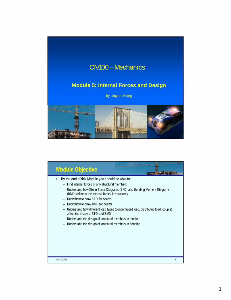
1 CIV100 – Mechanics Module 5: Internal Forces and Design by: Jinyue Zhang 2010/10/26 1 Module Objective • By the end of this Module you should be able to: – Find internal forces of any structural members – Understand how Shear Force Diagrams (SFD) and Bending Moment Diagrams (BMD) relate to the internal forces in structures – Know how to draw SFD for beams – Know how to draw BMD for beams – Understand how different load types (concentrated load, distributed load, couple) affect the shape of SFD and BMD – Understand the design of structural members in tension – Understand the design of structural members in bending
Transcript of CIV100 – Mechanics · CIV100 – Mechanics Module 5: Internal Forces and Design by: Jinyue Zhang...
1
CIV100 – Mechanics
Module 5: Internal Forces and Design
by: Jinyue Zhang
2010/10/26 1
Module Objective• By the end of this Module you should be able to:
– Find internal forces of any structural members– Understand how Shear Force Diagrams (SFD) and Bending Moment Diagrams
(BMD) relate to the internal forces in structures– Know how to draw SFD for beams– Know how to draw BMD for beams– Understand how different load types (concentrated load, distributed load, couple)
affect the shape of SFD and BMD– Understand the design of structural members in tension– Understand the design of structural members in bending

2
2010/10/26 2
Today’s Objective• Understand the concept of internal forces
– How to find internal forces of a structural member• Understand the concept of SFD and BFD
– How to draw SFD and BFD of a beam with simple loading
2010/10/26 3
Internal Forces• We have learnt this concept!

3
2010/10/26 4
Internal Forces• Now let’s look at multi-force member!
0
0
0
=
=
=
∑∑∑
Mo
Fy
Fx
2010/10/26 5
Internal Forces• Naming those internal forces

4
2010/10/26 6
Finding Internal Forces – Procedure for Analysis• Solve the whole structure first, find all reaction forces if necessary.• For frames and machines or their combinations, dismember the
structure and obtain the reactions at each connection.• Keep all distributed loadings, moments, and forces acting on the
member in their exact location, then cut the member to analysis by an imaginary section at the point where the internal loading is to be determined.
• Draw FBD of the segment that has the least number of loads and apply EoE to find internal forces:– Make assumption on unknown forces about their sense, if the EoE yields a
negative scalar, your assumption was wrong.– Moment should be summed at the cutting section where we eliminate the
unknown normal and share forces.
2010/10/26 7
Example 1• The bar is fixed at its end and is loaded as
shown. Determine the internal normal force at points B and C.

5
2010/10/26 8
Example 1• The bar is fixed at its end and is loaded as shown. Determine the internal normal force at points B and C.
2010/10/26 9
Example 2• Determine the internal normal force,
shear force, and bending moment at point B.

6
2010/10/26 10
Example 2• Determine the internal normal force, shear force, and bending moment at point B.
2010/10/26 11
Today’s Objective• What is Bending Moment Diagram (BMD)• What is Shear Force Diagram (SFD)• Understand the sign convention of BM and SF• 2 examples of plotting SFD and BMD

7
2010/10/26 12
SFD and BMD
An Interesting Applet!
2010/10/26 13
Sign Convention for Bending Moments• In North America, if the moment tends to cause the beam to curve upward it is
positive; if the moment tends to cause it to curve downward it is negative.
• If the upper side is in compression, it is positive.
• If it holds water, it is positive.
• If it smiles, it is positive.

8
2010/10/26 14
Sign Convention for Shear Forces• The only rule: if the shear force causes clockwise rotation of the member on which
it acts, it a positive shear force.
2010/10/26 15
Example 1• Draw the shear and moment diagrams for
the cantilevered beam.

9
2010/10/26 16
Example 1• Draw the shear and moment diagrams for the cantilevered beam.
Check you lecture notes to see how we develop the SFD and BMD.
2010/10/26 17
Example 2• Sketch the shear and moment diagrams
for the beam.

10
2010/10/26 18
Example 2• Sketch the shear and moment diagrams for the beam.
Check you lecture notes to see how we develop the SFD and BMD.
2010/10/26 19
Today’s Objective• Understand the relation between loads and SFD/BMD• Two examples
11
2010/10/26 20
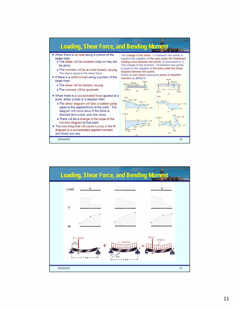
The change of the shear ΔV between two points is equal to the negative of the area under the distributed loading curve between the points. (if downward is +)The change of the moment ΔM between two points is equal to the negative of the area under the shear diagram between the points.Points of zero shear represents points of Max/Min moment as dM/dx=0
Loading, Shear Force, and Bending Moment
The slop is equal to the shear force.
2010/10/26 21
Loading, Shear Force, and Bending Moment
Load
V
M

12
2010/10/26 22
Example 1• Find internal forces at point C and then draw the shear and moment diagrams for the beam.
2010/10/26 23
Example 1• Find internal forces at point C and then draw the shear and moment diagrams for the beam.
To solve the reactions at A and B
∑MB=0-(Ay)(6) + (8)(4.5) + (4.5)(2) + (6)(1.5) = 0Ay = 9 kN
∑MA=0-(8)(1.5) - (4.5)(4) - (6)(4.5) +(By)(6) = 0By = 9.5 kN
∑Fx=0Bx = 6 kN
Check answers ∑Fy=08+4.5+6-9-9.5=0 √
To solve internal forces at C
∑MC=0Mc - (1.125)(0.5) - (3)(0.75) + (9.5)(1.5) = 0Mc = -11.437 kN.m
∑MB=0- (Cy)(1.5) + (1.125)(1) + (3)(0.75) = 0Cy = -5.375 kN.m
∑Fx=0Cx = 6 kN
Check answers ∑Fy=09.5-3-1.125-5.375=0 √

13
2010/10/26 24
Today’s Objective• Examples to review rules of drawing SFD and BMD
– Simple supported beam with uniformly distributed loading– More complex examples
2010/10/26 25
Simply Supported Beam with UDL
To Remember
2
81 wLMMax =
The point where SF is zero means peak BM, because ∂M/∂x=0.
14
2010/10/26 26
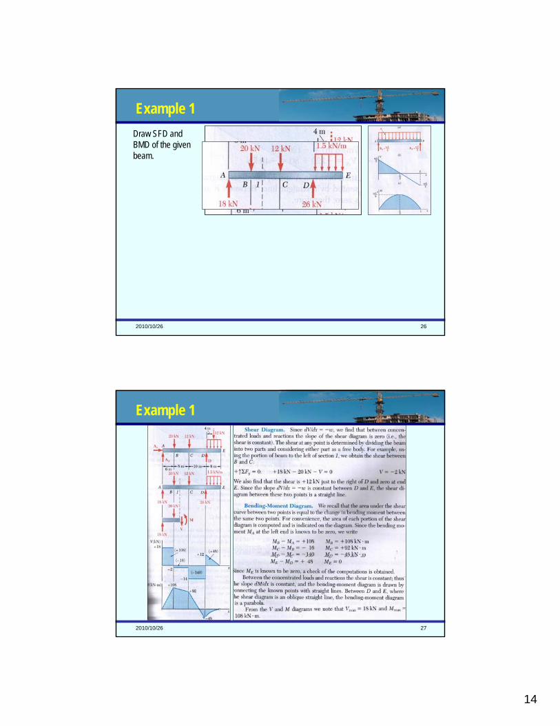
Example 1Draw SFD and BMD of the given beam.
2010/10/26 27
Example 1

15
2010/10/26 28
Example 2• Draw SFD, BMD, and NFD (normal force diagram) of the two members.
2010/10/26 29
Example 2• Draw SFD, BMD, and NFD (normal force diagram) of the two members.

16
2010/10/26 30
Example 2• Draw SFD, BMD, and NFD (normal force diagram) of the two members.
-
-
-
2010/10/26 31
Today’s Objective• More examples on SFD and BMD

17
2010/10/26 32
Example 1A foundation beam supports four columns as shown. Knowing that the weight of each column has already been included in the load shown on the column, and the foundation beam has a weight of 30kN/m. Assuming the reaction of the ground is uniformly distributed, draw the SFD and BMD of the foundation beam.
2010/10/26 33
Example 1A foundation beam supports four columns as shown. Knowing that the weight of each column has already been included in the load shown on the column, and the foundation beam has a weight of 30kN/m. Assuming the reaction of the ground is uniformly distributed, draw SFD/BMD of the foundation beam.

18
2010/10/26 34
More Examples
247.49kN
641.61kN
447.48kN
246.64kN
2010/10/26 35
More Examples
247.49kN
641.61kN
447.48kN
246.64kN

19
2010/10/26 36
Today’s Objective• Understand the following concepts
– Stress– Strain
• Understand Hooke’s Law– The relationship between axial stress and axial strain
• Understand the stress-strain diagram– The behaviour of “ductile” material– The behaviour of “brittle” material
• Be able to design a structural member in tension– Understand the concept of Load Factor (LF)
2010/10/26 37
Axial Stress
FFcosɵ
Fsinɵɵ

20
2010/10/26 38
Axial Stress
FFcosɵ
Fsinɵɵ
Axial Stress
2010/10/26 39
Axial Stress• Caused by an axial force.• Can be tensile stress or compressive stress.• Symbol used ‘σ’ (sigma)• Axial stress = Force / Area σ=P/A• Units are the same units of pressure (kPa, MPa, etc…)
211
1mNPa =
AP
=σ
To Remember
211
1mm
NMPa =

21
2010/10/26 40
Axial Stress• This equation tells us that:
– The greater the applied force the greater the stress.– The smaller the area on which the force is applied the greater the stress.
211
1mNPa =
AP
=σ
To Remember
211
1mm
NMPa =
2010/10/26 41
Axial Strain• Stresses cause the material to deform:
– Tension will cause elongation– Compression will cause shrinkage
• Symbol used ‘ε’ (epsilon)• Axial Strain = Change in length / Original length • ε = ΔL / L (no units)
LLΔ
=ε
To Remember
22
2010/10/26 42
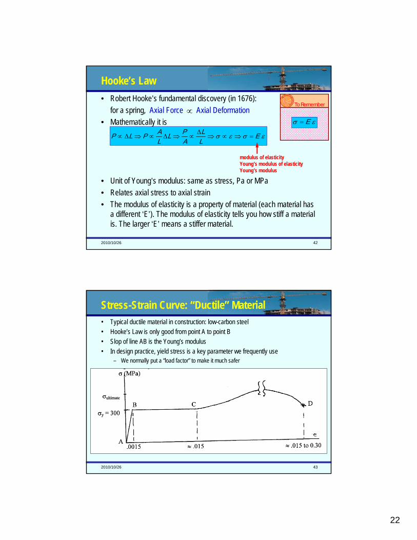
Hooke’s Law• Robert Hooke’s fundamental discovery (in 1676):
for a spring, Axial Force Axial Deformation• Mathematically it is
• Unit of Young’s modulus: same as stress, Pa or MPa• Relates axial stress to axial strain• The modulus of elasticity is a property of material (each material has
a different ‘E’). The modulus of elasticity tells you how stiff a material is. The larger ‘E’ means a stiffer material.
∝To Remember
εσεσ ELL
APL
LAPLP =⇒∝⇒
Δ∝⇒Δ∝⇒Δ∝
εσ E=
modulus of elasticityYoung’s modulus of elasticityYoung’s modulus
2010/10/26 43
Stress-Strain Curve: “Ductile” Material• Typical ductile material in construction: low-carbon steel• Hooke’s Law is only good from point A to point B• Slop of line AB is the Young’s modulus• In design practice, yield stress is a key parameter we frequently use
– We normally put a “load factor” to make it much safer

23
2010/10/26 44
Stress-Strain Curve: “Brittle” Material• Typical brittle material in construction: cast iron, concrete, rock• Hooke’s Law is only good at very beginning of the curve when the stress is small• Suddenly rupture without plastic region (yielding stage)• Capacity of resisting compression >>>>>>>>>>>> Capacity of resisting tension
2010/10/26 45
What is Design?• Design is to select a system (or a part of a system like a structural member) to
safely resist the anticipated loads.• In order to do a design, you need to analyze a given structure:
– Understand the structure and its overall geometry– Know the external loads– Know the material used to build the structure
• Steps to design:– Analyze the structure and find the internal forces– Look at the available material and find its strength– Select a solution to make sure the strength is greater than the load effects (the internal
forces caused by external loads)• There maybe many feasible solutions, you need to think other criteria like cost or aesthetics.
24
2010/10/26 46
Load Factor• To make a structure safe, we need:
Maximum Load Stress < Yield Stress for the Material
• Why?– Loading might be greater then your estimate– Material might not be as strong as specified– Structure analysis might be an approximation or simplification– Errors and mistakes
• To provide reasonable level of safety, we introduce a concept “Load Factor”– The load factor (LF) enlarge the effect of the anticipated or service loads, and thus requires
the structure to have greater capacity.– For example, if a member will have a tensile stress of 10 MPa, after applying a LF of 1.7, we
design the member as it would have a tensile stress of 10 MPa x 1.7 = 17 MPa
Is This Good Enough?
2010/10/26 47
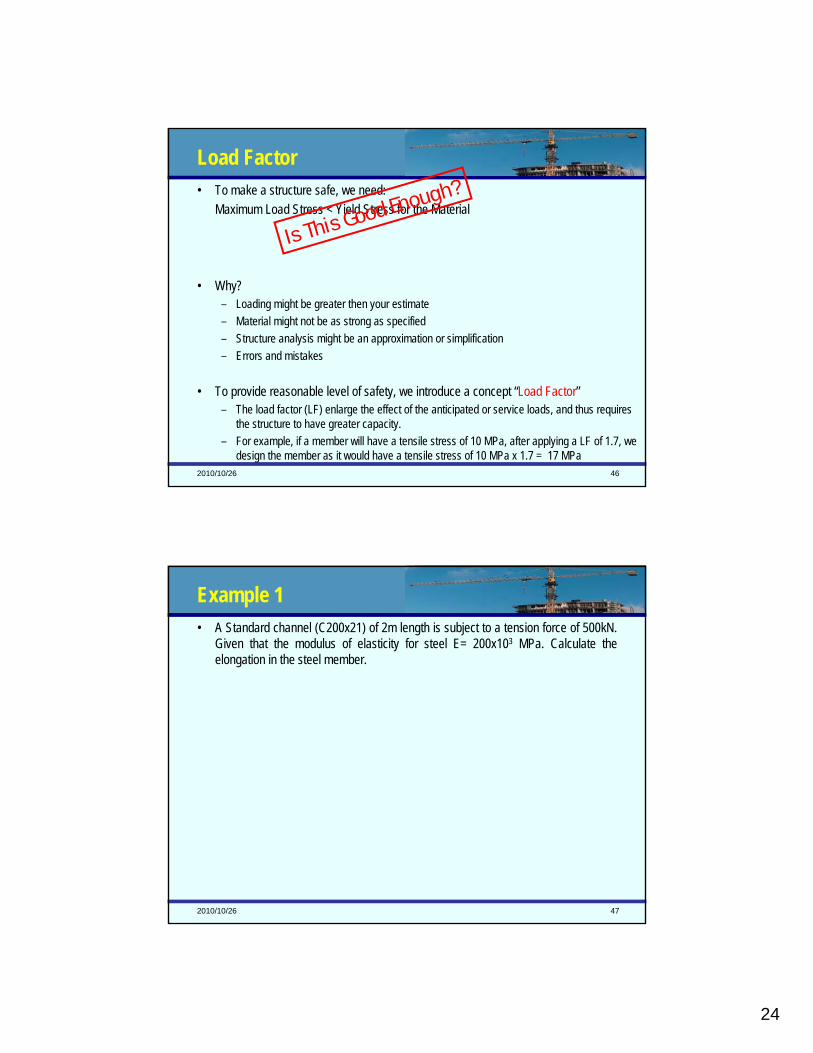
Example 1• A Standard channel (C200x21) of 2m length is subject to a tension force of 500kN.
Given that the modulus of elasticity for steel E= 200x103 MPa. Calculate the elongation in the steel member.

25
2010/10/26 48
Example 1• A Standard channel (C200x21) of 2m length is subject to a tension
force of 500kN. Given that the modulus of elasticity for steel E= 200x103 MPa. Calculate the elongation in the steel member.
• From tables: Cross Sectional Area = 2600mm2
• σ = (500 x 1000) / 2600 = 192.31 MPa (or N/mm2)
• ε = σ / E = 192.31 / 200000 = 9.6154 x 10⁻⁴
•∆L = L x ε = 2000 x 9.6154 x 10-4 = 1.923 mm
2010/10/26 49
Example 2• Design member AC of the truss. Structural
Steel is to be used in the design. The yield stress for the steel is 310 MPa, E=2x10⁵ MPa, and the load factor is 2.0. The rectangular cross-section (a=3b) will be cut from plates whose thickness, b, is only available in 5 mm increments.

26
2010/10/26 50
Example 2• Design member AC of the truss. Structural Steel is to be used in the
design. The yield stress for the steel is 310 MPa, E=2x10⁵ MPa, and the load factor is 2.0. The rectangular cross-section (a=3b) will be cut from plates whose thickness, b, is only available in 5 mm increments.
2010/10/26 51
Today’s Objective
• No “buckling”, ignore buckling issue in complementary notes!• The tensile strength (yielding stress due to tension) may be
different to its compressive strength (yielding stress due to compression). When design against axial forces, use the right yielding stress to calculate.
• Understand the relationship – Between load, pressure, and stress block– Between stress block and internal bending moment
• Calculate internal BM according to a given stress block– Examples

27
2010/10/26 52
Axial Stress in Bars • We have studied stress in a two force member which is in either tension or
compression.
• We call it stress block
AP
=σ
2010/10/26 53
Load, Pressure, and Stress • External Load vs. Pressure • Internal Forces vs. Stress
H
H/2
A distributed load acting over an area can be visualized as a volume:(a) The volume is equal to the magnitude of the equivalent single force, and(b) The line of action of the equivalent single force passes through the
centroid off the volume.

28
2010/10/26 54
Calculating Equivalent Force
2010/10/26 55
Calculating Equivalent Force
29
2010/10/26 56
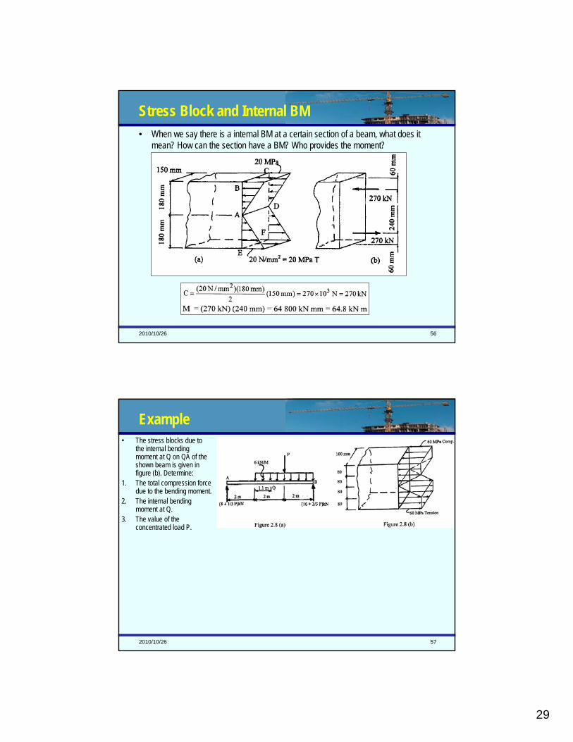
Stress Block and Internal BM • When we say there is a internal BM at a certain section of a beam, what does it
mean? How can the section have a BM? Who provides the moment?
2010/10/26 57
Example• The stress blocks due to
the internal bending moment at Q on QA of the shown beam is given in figure (b). Determine:
1. The total compression force due to the bending moment.
2. The internal bending moment at Q.
3. The value of the concentrated load P.

30
2010/10/26 58
Example• The stress blocks due to the internal
bending moment at Q on QA of the shown beam is given in figure (b). Determine:
1. The total compression force due to the bending moment.
2. The internal bending moment at Q.3. The value of the concentrated load P.
2010/10/26 59
Today’s Objective• More examples on stress blocks

31
2010/10/26 60
Example 1• This section is used to fabricate a
simply supported steel beam. The stress distribution due to the bending moment M in a certain section is shown in the diagram. Determine the total tension force and compression force, as well as the bending moment M.
2010/10/26 61
Example 1• This section is used to fabricate a simply supported steel beam. The stress
distribution due to the bending moment M in a certain section is shown in the diagram. Determine the total tension force and compression force, as well as the bending moment M.
Step-1:Divide the stress distribution into 3 distinct shapes (2 triangles and one rectangle) as shown.
Step-2:Find the values of the forces:F1= (1/2)188.125(66.5)(2x9.5)=118848N = 118.85kNF2 = 188.125(102)(9.5)=182293N = 182.29 kNF3 = (1/2)(215-188.125)(9.5)(102)=13021N = 13.02 kNThe volume of the compression stress block is the total compress force which is F1 + F2 + F3 = 314 kNThe total tension force is same as compression force because of the symmetry of the section.
Step-3:Find the moment caused by these forces (note these forces are equal and opposite thus causing a couple):M = F1(2*44.33) + F2(2*71.25) +F3(2*72.8333)
= 38411 kN.mm = 38.4 kN.m
32
2010/10/26 62
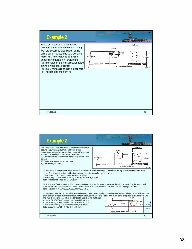
Example 2The cross section of a reinforced concrete beam is shown below along with the assumed distribution of the compression stress due to a bending moment M (the beam is subject to bending moment only). Determine:(a) The value of the compression force acting on the cross section(b) The tension stress in the steel bars(c) The bending moment M
2010/10/26 63
Example 2The cross section of a reinforced concrete beam is shown below along with the assumed distribution of the compression stress due to a bending moment M (the beam is subject to bending moment only). Determine:(a) The value of the compression force acting on the cross section(b) The tension stress in the steel bars(c) The bending moment M
(a) The value of compression force is the volume of stress block measured 110mm from the top over the entire width of the beam. The volume is further divided into two components: one cube plus one wedge.For the cube: F1=(22MPa)(110mm)(250mm)=605kNFor the wedge: F2=(30MPa-22MPa)(110mm)(0.5)(250mm)=110kNTotal compression force is F1+F2=715kN
(b) The tension force is equal to the compression force because the beam is subject to bending moment only, i.e. no normal force, so the total tension force is 715kN. The total area of the four reinforce bars A=4πr2=4(3.14)(15)2=2827mm2
Tension stress σ=P/A=715000N/2827mm2=252 MPa
(c) When we calculate the centroidal axis on the composite section, we ignore the impact of reinforce bars, i.e. we still trade the entire section is made by homogeneous material because the area of the steel bars is too small compared to the concrete area and thus is not significant. Then the centroidal axis is at the half height.M due to F1 = (605kN)(250mm-110mm/2)=117.98kNmM due to F2 = (110kN)(250mm-110mm/3)=23.467kNmM due to tension = (715kN)(250mm-50mm)=143kNmTotal Moment = 117.98+23.467+143=284kNm
250mm195mm 213mm
200mm

33
2010/10/26 64
Today’s Objective• Understand the stress due to bending moment
– Three fundamental assumptions– Bending stress formula, i.e. how to calculate bending stress
• Design a beam subject to bending moment
2010/10/26 65
Application• We have leant
– How to calculate the bending moment of a section (the internal force)– What is the bending stress– How they are related
• In many circumstances we need – To design a structural member (for example a beam) to hold the loads
• As such, we need – Analyze the internal forces, i.e. draw SFD, BMD, and NFD– Find the critical section– Design against NF, BM, and SF: σfactored loads < σyield

34
2010/10/26 66
Three Fundamental Assumptions• The material is linearly elastic, i.e. stress is proportional to strain.
• Plane sections before bending remain plane during bending.
• Bending stresses are independent of the stresses caused by internal axial and shear forces in the beam.
εσεσ E=⇒∝
2010/10/26 67
Bending Stress Formula• Let’s look at a bending element isolated from a beam
y∝εεσ ∝
y∝σ
yK=σ
yIM
Z
Z=σ
To Remember
yIM
Z
Z=σ
X
yz
z

35
2010/10/26 68
Design against Bending Moment• Where is the maximum stress due to bending, if we can
assume the beam is uniform (prismatic)?– At the location of the maximum bending moment. This can be
determined by checking BMD.– At the location in the cross section where y is maximum, i.e. in the
extreme top and bottom fibres.
• Section Modulus S– Unit is mm3
maxmax yI
LFM
Zyield ≥σ
yIM
Z
Z=σ
To Remember
maxyIS Z
Z =
maxyIS Z
Z =
yield
Zrequired
LFMyIS
σmax
max==
yieldrequired
LFMSσmax=
2010/10/26 69
Example 1

36
2010/10/26 70
Example 1
1041.4
2010/10/26 71
Example 2The wooden beam has a cross section (a x 3a). The tensile strength of wood is 12MPa and compressive strength of wood is 15MPa. Using a LF of 2 to design the beam section.

37
2010/10/26 72
Example 2The wooden beam has a cross section (a x 3a, increments of a = 10mm). The tensile strength of wood is 12MPa and compressive strength of wood is 15MPa. Using a LF of 2 to design the beam section.
2010/10/26 73
Be Prepared
• Previous final papers– 2003-07 fall term and solution: posted!– Earlier exams and spring term exams are available at:
http://exams.skule.ca, then “browse by code”, select “CIV”, then “CIV101”• Quiz #2 and Tutorial #10
– Quiz #2, this week, the first hour of tutorial class– Office hour for Quiz #2: Wednesday 4-5:45pm @ GB224– Get them back on Wednesday, Dec. 3rd, 3-5pm, out of GB224– Bring your questions about marking to the TA during office hours– No resubmission for Tutorial #10, you will get 2 marks as long as your submit and complete
• Office hours before your final: Dec. 4-7, 2-5pm @ GB224 (i2c lab)– Luai (Thursday, Dec. 4, who is marking your Quiz 2 and Tutorial 10)– Ahmed (Saturday, Dec. 6)– I will be available all 4 days
Final Exam: Monday, Dec. 8, 2008, 9:30am
Jinyue Zhang
Stamp

39
2010/10/26 76
Example 1For the shown beam, find the maximum bending moment. Select the least square section (a by a sq. mm) that can be used if the factor of safety is 1.3 and maximum stress is 280 MPa. (Neglect beam weight, don’t check buckling, increments of a = 5mm)
30º
2010/10/26 77
Example 1For the shown beam, find the maximum bending moment. Select the least square section (a by a sq. mm) that can be used if the factor of safety is 1.3 and maximum stress is 280 MPa. (Neglect beam weight, don’t check buckling)
30º

40
2010/10/26 78
Example 2Choose a steel wide-flange beam to take the shown loads. The yield stress is 290MPa and the load factor is 1.8. Neglecting the self-weight of the beam, and design criterion is to minimize weight. (a) Assuming no depth limits.
(b) The depth is not to exceed 400mm
2010/10/26 79
Example 2

41
2010/10/26 80
Example 2
mkNM
mxxM
xxxxxM
⋅=
=⇒=∂∂
++−=−+=
24.182
7143.20
57.108286.5410)21
)((20)2(286.54 2
Choose a steel wide-flange beam to take the shown loads. The yield stress is 290MPa and the load factor is 1.8. Neglecting the self-weight of the beam, and design criterion is to minimize weight. (a) Assuming no depth limits.(b) The depth is not to exceed 400mm
Step 1: Solving for reactionsTaking moment about A, solve By=85.714kNTaking moment about B, solve Ay=54.286kN
Step 2: Draw BMD
Step 3: calculate section modulus S
Step 4: choose a section(a) W457x89(b) W305x97
366
max )10(1311.1290
)8.1)(10(24.182 mmLFMSyield
required ===σ
2010/10/26 81
More Examples

42
2010/10/26 82
More Examples