Ansys Examples- SFD BMD
16
MET 210W Page 1 of 16 Handout – ANSYS Examples ANSYS is a software tool used by engineers to perform variety of analysis on mechanical parts and systems. The focus of this handout is using ANSYS to determine reactions, stresses and deflections in beams and frames. ANSYS uses the finite-element method to determine the reactions on a structure as well as the stress and deflections at various points on the structure. The basic component of a finite-element model is the element. Graphically, beam elements appear as a line, but to the software, an element is a series of equations that predict how the ends of the element will deform when loaded. For each two-dimensional beam element, six equations are needed to determine the rotation and translations of each node. Nodal translations are defined parallel and perpendicular to the element. Elements connect with each other at nodes. The response of an element to an applied load affects each of the elements connected to it at nodes. A model will have three equations for each node in the model. The deformations at each node are found by ANSYS using matrix math to solve all of the equations for the model simultaneously. The basic procedure for solving a beam problem using ANSYS is as follows: 1. Start the ANSYS program. 2. Specify the element type to be used. In ANSYS, the 2D beam element is designated as BEAM3. 3. Specify the real constants for the element: area (in 2 ), height (in) and moment of inertia (in 4 ). The area cannot be zero. The height is used to find bending stress. In ANSYS, the distance c is always taken as half of the height. Be aware of this when working with sections which are not symmetrical. 4. Indicate the material properties: modulus of elasticity (psi) and Poisson’s ratio. 5. Create nodes. A node is needed at each load and support as well as at any point of importance in the structure, which is any point where the stress or deflection is to be found. Each node will have a unique number. Nodes are located by Cartesian coordinates determined by the user. The length units used MUST be consistent with those used to define the real constants and material properties. 6. Create elements between nodes. Each element will have a unique number. Elements are defined by selecting a node for each of its end. Elements cannot have zero length. 7. Apply support constraints to nodes. Translation can be constrained parallel and perpendicular to the element to create pins and rollers. Rotation can also be constrained at a node when creating a fixed support. Beam element j Node i Node Length 2D Beam element
-
Upload
pednekarprakash -
Category
Documents
-
view
201 -
download
7
description
ANSYS
Transcript of Ansys Examples- SFD BMD

MET 210W Page 1 of 13
Handout – ANSYS Examples
ANSYS is a software tool used by engineers to perform variety of analysis on mechanical parts and systems. The focus of this handout is using ANSYS to determine reactions, stresses and deflections in beams and frames.
ANSYS uses the finite-element method to determine the reactions on a structure as well as the stress and deflections at various points on the structure. The basic component of a finite-element model is the element. Graphically, beam elements appear as a line, but to the software, an element is a series of equations that predict how the ends of the element will deform when loaded. For each two-dimensional beam element, six equations are needed to determine the rotation and translations of each node. Nodal translations are defined parallel and perpendicular to the element. Elements connect with each other at nodes. The response of an element to an applied load affects each of the elements connected to it at nodes. A model will have three equations for each node in the model. The deformations at each node are found by ANSYS using matrix math to solve all of the equations for the model simultaneously.
The basic procedure for solving a beam problem using ANSYS is as follows:1. Start the ANSYS program.2. Specify the element type to be used. In ANSYS, the 2D beam element is designated as BEAM3.3. Specify the real constants for the element: area (in2), height (in) and moment of inertia (in4). The
area cannot be zero. The height is used to find bending stress. In ANSYS, the distance c is always taken as half of the height. Be aware of this when working with sections which are not symmetrical.
4. Indicate the material properties: modulus of elasticity (psi) and Poisson’s ratio.5. Create nodes. A node is needed at each load and support as well as at any point of importance in
the structure, which is any point where the stress or deflection is to be found. Each node will have a unique number. Nodes are located by Cartesian coordinates determined by the user. The length units used MUST be consistent with those used to define the real constants and material properties.
6. Create elements between nodes. Each element will have a unique number. Elements are defined by selecting a node for each of its end. Elements cannot have zero length.
7. Apply support constraints to nodes. Translation can be constrained parallel and perpendicular to the element to create pins and rollers. Rotation can also be constrained at a node when creating a fixed support.
8. Apply concentrated loads and moments to the model at nodes. Loads are typically applied horizontally or vertically. All units must be compatible with other units used in the model. Distributed loads can be applied as pressures to the elements. Warning: the value specified for pressure is applied per unit length of the element. If an element is 12 inches long, a distributed load of 100 lbs/foot would be applied as 100/12 = 8.3333 lbs/inch.
9. Solve.10. Retrieve the reactions.11. Retrieve the deflection results at each node.12. Retrieve the stress and internal reaction results at each node as needed.13. Verify solutions using hand calculations remembering that the necessary conditions for equilibrium
are Fx = 0, Fy = 0, M = 0. Also recall that bending stress is the predominate stress in a beam. Bending stress is determined by = Mc/I.
EXAMPLE: A rectangular beam, 2-inches wide and 6-inches deep is shown in the figure below. Determine the magnitude and direction of the reactions and the deflection and bending stress at the midpoint of the beam. Use E = 1,500,000 psi and 0.24 for Poisson’s ratio.
Beam element
j Node
i Node
Length
2D Beam element
3 feet 3 feet 4 feet
200 lbs 50 lbs/ft
6 in
2 in
MET 210W Page 2 of 13
Handout – ANSYS Examples
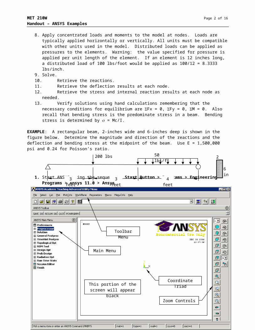
1. Start ANSYS using the sequence: Start Button > Programs > Engineering Programs > Ansys 11.0 > Ansys
2. Select the following from the Main Menu to specify the element type: Preprocessor > Element Type > Add/Edit/Delete
Pick the Add… button
Specify Beam and 2D elastic 3 Pick OK to close the Library of Element Types. Pick Close to
shut the Element Types dialog box. BEAM3 is now element type 1.
This portion of the screen will appear black
Main Menu
Toolbar Menu
Coordinate Triad
Zoom Controls

MET 210W Page 3 of 13
Handout – ANSYS Examples
3. Add the real constants to the model using Preprocessor > Real Constants > Add/Edit/Delete
Pick the Add… button. Type 1 BEAM3 should be listed in the new dialog box.
Make sure Type 1 BEAM 3 is selected and pick OK to open the Real Constant for BEAM3 dialog box. Specify area, area moment of inertia and total beam height as shown below.
Pick OK, then Close.
4. Add the material properties to the model using Preprocessor > Material Props > Material Models
Double-Click each one: Structural > Linear > Elastic > Isotropic for Material Model Number 1.
Specify EX = 1500000 psi and Poisson’s Ratio (PRXY) as .24.
Pick OK to close the dialog box. Select Material > Exit to close the Define Material Model
Behavior dialog box.

MET 210W Page 4 of 13
Handout – ANSYS Examples
Planning ahead, five nodes will be needed as shown in the figure below. At nodes 1 and 5, a support will be built. At node 2, a load will be applied. At node 3, results are required. The element between nodes 4 and 5 will have a distributed load.
5. Create nodes using the sequence Preprocessor > Modeling > Create > Nodes > In Active CS
Specify node number and X, Y, Z coordinates in the active coordinate system which is a Cartesian coordinate system by default. If the node number is left blank, ANSYS automatically assigns the next number. Pick Apply to set the node and reopen the dialog box for the next node.
Repeat for remaining nodes. Pick OK to set the last node and close the dialog box.
The screen should contain 5 numbered nodes. To plot nodes, select from the toolbar menu: Plot > Nodes. To generate a list of nodes, select from the toolbar menu: List > Nodes… Select the Coord.
w/Angles button, then OK. The nodes and their coordinates are listed in another window. This list can be saved or copied and pasted in another program such as Word or Excel.
Planning ahead, four elements will be needed:
6. Create elements using the sequence Preprocessor > Modeling > Create > Elements > Auto Numbered > Thru Nodes
Pick node 1 on the screen, then node 2, then pick Apply. Order is important. Choose the i-node, then the j-node – be consistent left to right.
Pick node 2, then node 3, then pick Apply. Pick node 3, then node 4, then pick Apply. Pick node 4, then node 5, then pick OK. This creates the last element and closes
the dialog box.
Four elements should appear on the screen at this point. To plot elements, select from the toolbar menu: Plot > Elements To generate a list of elements, select from the toolbar menu: List > Elements >
Nodes + Attributes. The elements are listed in another window by element number. The list contains the material number, element type number, real constant numbers, nodes and other information for each element. This list can be saved or copied and pasted in another program such as Word or Excel.
To display node and element numbers, select from the toolbar menu: PlotCtrls > Numbering…
Node 1(0, 0, 0)
Node 3(60, 0, 0)
Node 2(36, 0, 0)
Node 4(72, 0, 0)
Node 5(120, 0, 0)
36 in
60 in
72 in
120 in
Node 1 Node 3Node 2 Node 4 Node 5
Element 1 Element 2
Element 3
Element 4

MET 210W Page 5 of 13
Handout – ANSYS Examples
Planning ahead, three support constraints have to be created. A pin is at node 1 which will constrain translation in both the x- and y-directions. A roller at node 5 will constrain translation in the y-direction.
7. Create constraints (supports) using the main menu sequence Solution > Define Loads > Apply > Structural > Displacement > On Nodes
On the screen, select nodes 1 and 5 and pick OK on the dialog box. Pick UY in the DOFs to be constrained window, then OK to apply the supports.
These nodes are constrained vertically. UY is ANSYS for displacement in the y-direction. Since the displacement value was applied as zero (empty window in dialog box) the node will not move vertically.
Repeat this process by selecting node 1 and applying the UX constraint to it. Blue triangles should appear for each constraint applied to the model.
Note that if a fixed support is needed, its node would have UX, UY, and ROTZ all applied.
Node numbers on and off
The displayed numbers for each element can be set to show any of these:
No numberingElement numberMaterial numberElement type numberReal constant numberothers
Node 1 Node 5
ANSYS constraint symbol
Constrains translation in x-direction at the node.
Constrains translation in y-direction at the node.
Constrains rotation about the z-axis at the node.

MET 210W Page 6 of 13
Handout – ANSYS Examples
8. Create the concentrated load using the Main Menu sequence Solution > Define Loads > Apply > Structural > Force/Moment > On Nodes. Pick node 2 on the screen and pick OK on the dialog box.
Set the direction of the force to FY and specify the value of the force as -200 which will represent 200 pounds down at node 2. Pick OK. A red arrow should appear on the model to represent this force.
Create the distributed load using the main menu sequence Solution > Define Loads > Apply > Structural > Pressure > On Beams. Pick element 4 on the screen and pick OK on the dialog box.
At this point, the model should look like this:
FX = horizontal forceFY = vertical forceMZ = moment
Value of the force or moment. + is for right or up or CCW. – is for left or down or CW.
Specify the pressure in lbs/in. This is determined as
Pick OK to apply load and close the dialog box.
Note: positive values are down, towards the element and negative values are up, away from the element.

MET 210W Page 7 of 13
Handout – ANSYS Examples
9. To solve the model, use the following main menu sequence: Solution > Solve > Current LS. Pick OK from the information box that appears. Pick the Close button when ANSYS indicates that the solution is done. It should take less than a minute to solve simple beam and frame problems.
10. To obtain beam reactions, use the following main menu sequence: General Postproc > List Results > Reaction Solu. Pick All Items in the window and pick OK.
11. Get the deflections of each node using the main menu sequence: General Postproc > List Results > Nodal Solu.
To plot the deformed shape of the beam, use the main menu sequence: General Postproc > Plot Results > Deformed Shape
At node 1, the horizontal reaction is 0, the vertical reaction is 180 pounds up (+) and there is no moment reaction at a pin. These numbers match with the statics for this problem.
At node 5, there is no horizontal reaction, the vertical reaction is 220 pounds up (+) and there is no moment reaction at a roller. These numbers match with the statics for this problem.
Sum of the vertical reactions
Pick DOF Solution in the window, then Y-Component of displacement, and pick OK. (The X-Component of displacement option gives the horizontal deflection of each node and the Z-Component of rotation gives the rotation of each node.)
Vertical displacement of each node. Negative is down and positive is up. Note they are zero at the supports as expected. The maximum value from this model is at node 3. Note that the actual maximum value will only appear if a node exists at the point of maximum deflection.

MET 210W Page 8 of 13
Handout – ANSYS Examples
12. An Element Table has to be created to obtain the stress values and internal reactions at the nodes. Use the main menu sequence: General Postproc > Element Table > Define Table. Pick the Add… button.
Quantity at i-Node Suggested Label Sequence
Sequence Number
i-node j-node
Bending Stress BENDSTR NMISC 1 3
Bending Moment, M MMOMZ SMISC 6 12
Shear Force, V MFORY SMISC 2 8
Axial Force, F MFORX SMISC 1 7
To list the values in the element table use the main menu sequence General Postproc > Element Table > List Elem Table
4 quantities will be added to the table. For each one, a five step process is needed as shown in the figure below. A label is specified, By sequence num is selected, the sequence is chosen and the number is specified. Pick Apply to add the quantity to the table. Pick OK after the last one.
Add label name
Pick By sequence num
Select sequence SMISC or NMISC.
Add sequence number
Apply or OK
Select the table items to be listed. Pick OK

MET 210W Page 9 of 13
Handout – ANSYS Examples
NOTE: These values are for the i-node of each of the elements listed.
Elem 3
Element 1 i-node Element 1 i-node
Element 3 i-nodeElement 1 j-node
Element 2 i-node Element 4 i-node
Elem 1 Elem 2 Elem 4
Element 4 j-node
50 lbs/ft (4 ft) = 200#
220#MFORY = 20#MFORX = 0#
MMOMZ = 6000 in-lbs
psi500in36
)in3(lbsin6000
I
Mc4
50 lbs/ft (4 ft) = 200#
220#MFORY = 20#MFORX = 0#
MMOMZ = 5760 in-lbs
psi480in36
)in3(lbsin5760
I
Mc4
50 lbs/ft (4 ft) = 200#
220#MFORY = 20#MFORX = 0#
MMOMZ = 6480 in-lbs
psi540in36
)in3(lbsin6480
I
Mc4
13. Verify that each of the free-body diagrams is in equilibrium.
N2
N3
N4

MET 210W Page 10 of 13
Handout – ANSYS Examples
If a model has more nodes, say one per foot, the MMOMZ values could be copied to Excel to create an XY(Scatter) chart which would be the moment diagram for the beam. Of course, the moment for the last node would have to be added manually.
It should be noted that each of the options used to add items to the model has a delete option which is used to remove the items from the model. Hunt around as needed to use these options. If nodes and elements are deleted from the model, their numbers are automatically reused when new ones are created. Be sure to use the PlotCtrl > Numbering to check the numbers used in the model. The numbers can be compressed by using the menu sequence Preprocessing > Numbering Ctrls > Compress Numbers. For example, if the following are all nodes that are created in a model:
Compressing the node numbers does this:
If you wish to save the ANSYS model, use the File > Save As option. Specify a location and filename.
EXAMPLE: Determine the reactions at the supports and internal pin of the frame shown below. Use E = 29000000 psi, = .3, A = 1 in2, height = 1, and moment of inertia = 1 in4.
The ANSYS solution for this problem is pretty much the same as it was for the beam. The frame has an additional step.
1. Start ANSYS.2. Specify the element type as BEAM33. Specify the real constants: area = 1, moment of inertia = 1, and height = 1. The stress isn’t going to
be determined in this solution, so these numbers aren’t really that important but they can’t be zero.4. Specify the material properties: EX = 29000000, PRXY = .35. Create the nodes indicated in the table above. Note that two nodes are needed at each internal pin –
point B in this case.
1 3 5 6 7
1 2 3 4 5
2 ft
6 ft
B
A C
300 lbs
3 ft 3 ft
400 lbs NodeX-
coordinateY-
coordinateZ-
coordinate1 0 0 02 0 72 03 0 96 04 0 96 05 36 48 06 72 0 0
Note: we need two nodes at an internal pin!

MET 210W Page 11 of 13
Handout – ANSYS Examples
6. Create the elements for this model as follows:
Element Number i-node j-node
1 1 2
2 2 3
3 4 5
4 5 6
Note that each member of the frame is constructed with two elements. The members are not connected at this point. Before the model can be solved, the translational degrees of freedom for nodes 3 and 4 have to be “coupled”. Use the main menu sequence Preprocessor > Coupling/Ceqn > Couple DOFs to begin the coupling process. Select the two nodes to be coupled. Use the box option in the select dialog box. Pick OK when selected.
Specify 1 for the reference number. Pick DOF Label UX Pick Apply Specify 2 for the reference number. Pick DOF label UY Pick OK to apply and close the dialog box. Two green triangles should appear at the
internal pin indicating that the two degrees of freedom have been coupled.
7. Create the pins at A and C. Use UX and UY at both nodes 1 and 6.8. Apply the concentrated loads. At node 2, FX = 300 and at node 5, FY = -400.9. Solve
ANSYS Model of the Frame

MET 210W Page 12 of 13
Handout – ANSYS Examples
10. List the reaction solutions:
To get the forces on all the nodes, use the main menu sequence General Postproc > List Results > Element Solution. Scroll down and click on Structural Forces, then select X-Component of force. Pick OK. The values in this list are the element forces acting ON the node. Show these forces in the opposite directions on the element.
To get the moments on all the nodes, use the main menu sequence General Postproc > List Results > Element Solution. Scroll down and click on Structural Moments, then select Z-Component of moment. Pick OK. The values in this list are the element moments acting ON the node. Show these moments in the opposite directions on the element.
If you are not sure of the proper directions, figure it out remembering that the element must be in equilibrium, which is to say Fx = 0, Fy = 0, and M = 0.
E1
2
1
100#75#
75#
100#
5400 in·lbs
Note: This is a really small number: -0.19398 x 10⁻¹¹

MET 210W Page 13 of 13
Handout – ANSYS Examples
An element table can also be created to determine the moment, shear and axial forces at each node. In this case, the shear and axial forces are perpendicular and parallel to the element respectively. This may be the easier approach!
11. The deflections are not required.12. The stresses and internal reactions are not required.
The following are the proper free-body diagrams for each of the nodes and elements in the model. The values are taken from the reaction solution and from the member force and moments lists shown on the previous page. Notice that nodes 3 and 4 are attached to one another, so collectively, they are in equilibrium.
N1
2
2
3
N6
5
5
4
75#
100#
225#
500#
1
75#
100#
E1
N275#
100#
300#
100#
E2
225#
225#
100#
75#100#
75#
100#
5400 in·lb
5400 in·lb
5400 in·lb
5400 in·lb 100#
225#
N3225#
100#
N4225#
100#
E3
E4
6
100#225#
225#
100#7200 in·lb
400#7200 in·lb
7200 in·lb
225#
500#
100#
225#N5
225#
500#
7200 in·lb
225#
500#
225#
500#
FBD of Frame Nodes and Elements
Red forces are applied Blue forces are reactions Black forces are element forces
acting ON nodes Green forces are member forces
in directions opposite the tabulated values.
![Shear Force and Bending Moment Diagrams [SFD & BMD] DR. KIRAN KUMAR SHETTY Reader Department of Civil Engineering M.I.T., Manipal.](https://static.fdocuments.in/doc/165x107/5514466b5503466d1a8b5aae/shear-force-and-bending-moment-diagrams-sfd-bmd-dr-kiran-kumar-shetty-reader-department-of-civil-engineering-mit-manipal.jpg)


![Shear Force and Bending Moment Diagrams [SFD & BMD]](https://static.fdocuments.in/doc/165x107/56816254550346895dd29dc4/shear-force-and-bending-moment-diagrams-sfd-bmd-56cbd5feaac02.jpg)