
Cisco ICM Enterprise Edition Release 6.0(0) Pre ... · part of UCB’s public domain version of the...
172
Corporate Headquarters Cisco Systems, Inc. 170 West Tasman Drive San Jose, CA 95134-1706 USA http://www.cisco.com Tel: 408 526-4000 800 553-NETS (6387) Fax: 408 526-4100 Cisco ICM Enterprise Edition Pre-installation Planning Guide ICM Enterprise Edition Release 6.0(0) May, 2004
Transcript of Cisco ICM Enterprise Edition Release 6.0(0) Pre ... · part of UCB’s public domain version of the...

Cisco ICM Enterprise Edition Pre-installation Planning GuideICM Enterprise Edition Release 6.0(0)May, 2004
Corporate HeadquartersCisco Systems, Inc.170 West Tasman DriveSan Jose, CA 95134-1706USAhttp://www.cisco.comTel: 408 526-4000
800 553-NETS (6387)Fax: 408 526-4100

THE SPECIFICATIONS AND INFORMATION REGARDING THE PRODUCTS IN THIS MANUAL ARE SUBJECT TO CHANGE WITHOUT NOTICE. ALL STATEMENTS, INFORMATION, AND RECOMMENDATIONS IN THIS MANUAL ARE BELIEVED TO BE ACCURATE BUT ARE PRESENTED WITHOUT WARRANTY OF ANY KIND, EXPRESS OR IMPLIED. USERS MUST TAKE FULL RESPONSIBILITY FOR THEIR APPLICATION OF ANY PRODUCTS.
THE SOFTWARE LICENSE AND LIMITED WARRANTY FOR THE ACCOMPANYING PRODUCT ARE SET FORTH IN THE INFORMATION PACKET THAT SHIPPED WITH THE PRODUCT AND ARE INCORPORATED HEREIN BY THIS REFERENCE. IF YOU ARE UNABLE TO LOCATE THE SOFTWARE LICENSE OR LIMITED WARRANTY, CONTACT YOUR CISCO REPRESENTATIVE FOR A COPY.
The Cisco implementation of TCP header compression is an adaptation of a program developed by the University of California, Berkeley (UCB) as part of UCB’s public domain version of the UNIX operating system. All rights reserved. Copyright © 1981, Regents of the University of California.
NOTWITHSTANDING ANY OTHER WARRANTY HEREIN, ALL DOCUMENT FILES AND SOFTWARE OF THESE SUPPLIERS ARE PROVIDED “AS IS” WITH ALL FAULTS. CISCO AND THE ABOVE-NAMED SUPPLIERS DISCLAIM ALL WARRANTIES, EXPRESSED OR IMPLIED, INCLUDING, WITHOUT LIMITATION, THOSE OF MERCHANTABILITY, FITNESS FOR A PARTICULAR PURPOSE AND NONINFRINGEMENT OR ARISING FROM A COURSE OF DEALING, USAGE, OR TRADE PRACTICE.
IN NO EVENT SHALL CISCO OR ITS SUPPLIERS BE LIABLE FOR ANY INDIRECT, SPECIAL, CONSEQUENTIAL, OR INCIDENTAL DAMAGES, INCLUDING, WITHOUT LIMITATION, LOST PROFITS OR LOSS OR DAMAGE TO DATA ARISING OUT OF THE USE OR INABILITY TO USE THIS MANUAL, EVEN IF CISCO OR ITS SUPPLIERS HAVE BEEN ADVISED OF THE POSSIBILITY OF SUCH DAMAGES.
CCIP, CCSP, the Cisco Arrow logo, the Cisco Powered Network mark, Cisco Unity, Follow Me Browsing, FormShare, and StackWise are trademarks of Cisco Systems, Inc.; Changing the Way We Work, Live, Play, and Learn, and iQuick Study are service marks of Cisco Systems, Inc.; and Aironet, ASIST, BPX, Catalyst, CCDA, CCDP, CCIE, CCNA, CCNP, Cisco, the Cisco Certified Internetwork Expert logo, Cisco IOS, the Cisco IOS logo, Cisco Press, Cisco Systems, Cisco Systems Capital, the Cisco Systems logo, Empowering the Internet Generation, Enterprise/Solver, EtherChannel, EtherSwitch, Fast Step, GigaStack, Internet Quotient, IOS, IP/TV, iQ Expertise, the iQ logo, iQ Net Readiness Scorecard, LightStream, MGX, MICA, the Networkers logo, Networking Academy, Network Registrar, Packet, PIX, Post-Routing, Pre-Routing, RateMUX, Registrar, ScriptShare, SlideCast, SMARTnet, StrataView Plus, Stratm, SwitchProbe, TeleRouter, The Fastest Way to Increase Your Internet Quotient, TransPath, and VCO are registered trademarks of Cisco Systems, Inc. and/or its affiliates in the United States and certain other countries.
All other trademarks mentioned in this document or Website are the property of their respective owners. The use of the word partner does not imply a partnership relationship between Cisco and any other company. (0401R)
Cisco ICM Enterprise Edition Pre-installation Planning Guide: ICM Software Release 6.0(0)Copyright © 1996– 2004, Cisco Systems, Inc.All rights reserved.

Cisco ICM Enter
C O N T E N T S
About This Guide xi
Objective xi
Audience xi
Organization xii
Conventions xiv
Other Publications xiv
Obtaining Documentation xivCisco.com xvOrdering Documentation xv
Documentation Feedback xv
Obtaining Technical Assistance xviCisco Technical Support Website xviSubmitting a Service Request xviDefinitions of Service Request Severity xvii
Obtaining Additional Publications and Information xviii
C H A P T E R 1 Pre-installation Planning Overview 1-1
The Planning Process 1-1Coordinating and Scheduling Tasks 1-2Pre-installation Document Road Map 1-2NIC and ACD Supplements 1-3
C H A P T E R 2 ICM Enterprise Edition Overview 2-1
How the ICM Software Works 2-1
iiiprise Edition Pre-installation Planning Guide Release 6.0(0)

Contents
ICM Call Routing 2-2Pre-Routing 2-3The IXC Network 2-3Route Requests 2-3Route Responses 2-3ACDs 2-3Peripheral Gateway 2-4Post-Routing 2-4CTI Server 2-4Monitoring and Reporting 2-4Admin Workstation 2-5
ICM System Components and Processes 2-5CallRouter 2-5Logger 2-5Network Interface Controller (NIC) 2-5Peripheral Gateways 2-6Admin Workstations 2-7Historical Data Server 2-7WebView 2-8
ICM Options and Related Products 2-8Pre-Routing 2-9Post-Routing 2-11Pre- and Post-Routing Systems 2-12Computer Telephony Integration (CTI) 2-12
CTI Server 2-12Cisco CTI Object Server (CTI OS) 2-13
IVR Interface 2-13ICM Application Gateway 2-14ICM Gateway SQL 2-15Internet Script Editor 2-16
ivCisco ICM Enterprise Edition Pre-installation Planning Guide Release 6.0(0)

Contents
WebView 2-16ICM Multichannel Software 2-16IP Contact Center (IPCC) 2-17
C H A P T E R 3 IXC Overview 3-1
ICM Software and IXC Interaction 3-1Toll-Free Caller 3-3LEC-to-IXC 3-3Network Query 3-3ICM NIC 3-3NIC-to-CallRouter 3-3Best Destination Returned 3-3IXC Network 3-4Connecting the Call 3-4
Carrier Connections 3-4
Applying Fault Tolerance in NICs 3-4Goals for NIC Fault Tolerance 3-5Link Redundancy 3-5Route Diversity 3-6
3-7
C H A P T E R 4 Switch Overview 4-1
PG-to-Peripheral Connections 4-1
Supported ACD Switches 4-5
C H A P T E R 5 Peripheral Gateway Configurations 5-1
Peripheral Gateway Fault Tolerance 5-2
PG Platform Options 5-4Considerations for PGs and PIMs 5-6
vCisco ICM Enterprise Edition Pre-installation Planning Guide Release 6.0(0)

Contents
Standard PG Configuration 5-7
Remote ACD and IVR Connection to PGs 5-8
5-8
C H A P T E R 6 CTI Planning 6-1
CTI Server 6-1CTI Server Communications 6-2CTI Server Platform Options 6-3CTI Server Fault Tolerance 6-3
Cisco CTI Object Server (CTI OS) 6-4
Cisco Agent Desktop 6-5
CTI Server Client Application Models 6-5Agent Workstation (Desktop) Application 6-6CTI Bridge (All Events) Application 6-6
CTI Server Network and Database Planning 6-8Review the Desktop Network Environment 6-8Review Network Security Issues 6-8Address Desktop Software Roll-out and Distribution Issues 6-8Select a Well-known Port for CTI Server 6-8Plan a Fail-over Strategy for CTI Clients 6-9Develop a Database Strategy 6-9
Estimating CTI Server Message Traffic 6-9Documenting a Typical Call Scenario 6-10Estimating Required Bandwidth 6-11Choosing the CTI Server Platform 6-11
Third-Party Call Control 6-11
ACD Support for Client and Third-Party Call Control 6-14
viCisco ICM Enterprise Edition Pre-installation Planning Guide Release 6.0(0)

Contents
C H A P T E R 7 IVR Planning 7-1
Reviewing IVR Configuration Options 7-1Configuration with an ACD PG Only 7-3Configuration with IVR and ACD PGs 7-5Network-Side IVR with IVR and ACD PGs 7-6In-Network IVR with an ACD PG Only 7-7In-Network IVR with IVR and ACD PGs 7-9IVR Transfer Routing Using Third-Party Call Control 7-9IVR Programming and Application Development 7-10IVR Peripheral Gateway 7-11
C H A P T E R 8 ICM Application Gateway and ICM Gateway SQL Planning 8-1
ICM Application Gateway Planning 8-1Preparing the Host System 8-2Fault Tolerance 8-2
ICM Gateway SQL Planning 8-2Database Server Platform 8-3Planning for Data Transfer 8-4Configuration Overview 8-4
C H A P T E R 9 ICM Product Options 9-1
CTI 9-1
IVR 9-1
ICM Application Gateway and ICM Gateway SQL 9-1
Internet Script Editor 9-1
WebView 9-2
Outbound Option (formerly Blended Agent) 9-2
Cisco ICM Web Collaboration Option 9-2
viiCisco ICM Enterprise Edition Pre-installation Planning Guide Release 6.0(0)

Contents
Cisco ICM E-Mail Manager Option 9-2
Cisco Internet Service Node (ISN) 9-2
C H A P T E R 10 Planning for ICM Platforms 10-1
Determining the Number of PCs Required 10-1
ICM Platform Considerations 10-2Processor Utilization 10-4Paging Requirements 10-4Logger Expansion 10-4
Planning for Distributor AWs 10-5Distributors and Admin Sites 10-6Distributor and Client AW Requirements 10-7
Planning for Historical Data Servers 10-7HDS Advantages 10-9
10-9
C H A P T E R 11 Determining the Datacom Requirements 11-1
ICM Sites 11-2
The ICM Networks 11-2Private and Visible WAN Links 11-5Signaling Access Networking 11-6Local Area Networks 11-6Network Bandwidth Requirements 11-6Network Latency Requirements 11-8Heartbeat Detection 11-8Synchronization 11-10State Transfer 11-11Diverse Facilities 11-11
Cisco ICM QoS 11-12
viiiCisco ICM Enterprise Edition Pre-installation Planning Guide Release 6.0(0)

Contents
What Is Quality of Service? 11-12Deploying Cisco ICM QoS 11-13
Installing Microsoft Packet Scheduler 11-14Determining DSCP Markings 11-15Calculating QoS Bandwidth Requirements 11-17Installing and Configuring 802.1p-Capable Components 11-18Configuring QoS on IP Routes 11-19
Additional Tasks 11-19Specifying QoS Parameters During ICM Install 11-19Monitor QoS Performance 11-19
For More Information on QoS 11-19
Active Directory Model 11-20
TCP/IP Configuration 11-20
Central Sites 11-21The Visible Network 11-24
Visible IP Router Configuration 11-24The Private Network 11-26The Signaling Access Network 11-27The CallRouter Node 11-28
Disabling Windows 2000 Networking 11-30The Logger Node 11-31Optional Database Server Platform 11-34ICM Network Gateway 11-35Admin Workstations at a Central Site 11-36Peripheral Gateways at a Central Site 11-38
Contact Center Sites 11-39Simplexed PG Site 11-40Duplexed PG Site 11-42Duplexed PG Site with Separate IVR LAN 11-43PG Network Configuration 11-45
ixCisco ICM Enterprise Edition Pre-installation Planning Guide Release 6.0(0)

Contents
Contact Center IP Routers 11-46
Admin Sites 11-47
C H A P T E R 12 Site Preparation 12-1
C H A P T E R 13 IP Address Worksheets 13-1
Visible Network IP Address Requirements 13-1
Private Network IP Address Requirements 13-4
Signaling Access Network IP Requirements 13-5
Static Route Requirements 13-6
I N D E X
xCisco ICM Enterprise Edition Pre-installation Planning Guide Release 6.0(0)

About This Guide
ObjectiveThis guide describes pre-installation requirements and issues to address in preparing for a Cisco Intelligent Contact Management (ICM) Enterprise Edition installation. It does not discuss, for example, pre-installation planning for ICM multichannel software or for IP Contact Center and its components (such as Cisco CallManager or Cisco IP IVR).
For ICM multichannel software, see the Cisco ICM Multichannel Software Implementation Map and Cisco Multichannel Software Overview, as well as the documentation for Cisco E-Mail Manager Option and Cisco Web Collaboration Option (Cisco Collaboration Server, Cisco Dynamic Content Adapter, Cisco Media Blender).
For IP Contact Center Enterprise Edition, see the relevant documentation.
AudienceThis guide is intended for contact center managers, system support personnel, and plant engineers who are planning and preparing contact center sites for an ICM system installation. Readers should be familiar with contact center site planning and preparation issues. They should also have a basic understanding of the ICM system and the components that are installed as part of the system.
xiCisco ICM Enterprise Edition Pre-installation Planning Guide Release 6.0(0)

About This GuideOrganization
OrganizationThis document is organized as follows:
Chapter Description
Chapter 1, “Pre-installation Planning Overview”
Provides an overview of the ICM pre-installation planning process. This chapter includes a pre-installation document roadmap, which suggests an order to follow in using the ICM pre-installation planning guides.
Chapter 2, “ICM Enterprise Edition Overview”
Describes the role of the ICM software within the contact center enterprise. This chapter also reviews the main ICM software features.
Chapter 3, “IXC Overview”
Describes how to plan for access to the carrier’s intelligent network service. This chapter includes an overview of ICM/IXC interaction and a discussion of ICM-Network Interface Controller (NIC) fault tolerance.
Chapter 4, “Switch Overview”
Provides an overview of ICM PG-to-peripheral interaction.
Chapter 5, “Peripheral Gateway Configurations”
Describes the options for configuring Peripheral Gateways in the ICM enterprise.
Chapter 6, “CTI Planning”
Describes the pre-installation planning for CTI, including reviewing CTI Server communications and platform options; becoming familiar with the desktop options; estimating CTI message traffic; planning fault tolerance for the CTI Server; and reviewing ACD support for client control and third-party call control.
Chapter 7, “IVR Planning”
Describes the pre-installation planning tasks for the IVR option, including reviewing the options for integrating IVRs into the ICM system, determining if any IVR programming or application development is necessary, and reviewing the PG platform requirements for IVR.
xiiCisco ICM Enterprise Edition Pre-installation Planning Guide Release 6.0(0)

About This GuideOrganization
Chapter 8, “ICM Application Gateway and ICM Gateway SQL Planning”
Describes the pre-installation planning tasks for the ICM Application Gateway and ICM Gateway SQL options, including preparing host systems and databases; reviewing fault tolerance issues; and planning for data transfer (in the case of Gateway SQL).
Chapter 9, “ICM Product Options”
Provides a brief mention of various ICM product options.
Chapter 10, “Planning for ICM Platforms”
Describes how to determine the numbers and types of ICM nodes you will need.
Chapter 11, “Determining the Datacom Requirements”
Describes how to prepare network facilities for an ICM system installation, such as determining the requirements for visible and private networking, allocating IP addresses, and ordering any required network hardware.
Chapter 12, “Site Preparation”
Presents a brief list of basic considerations for site preparation.
Chapter 13, “IP Address Worksheets”
Provides worksheets you can use to record IP addresses for the visible and private networks.
Chapter Description
xiiiCisco ICM Enterprise Edition Pre-installation Planning Guide Release 6.0(0)

About This GuideConventions
ConventionsThis manual uses the following conventions:
Other PublicationsFor more information about Cisco Intelligent Contact Management (ICM) software, see the Cisco ICM documentation web page.
Obtaining DocumentationCisco documentation and additional literature are available on Cisco.com. Cisco also provides several ways to obtain technical assistance and other technical resources. These sections explain how to obtain technical information from Cisco Systems.
Format Examples
Boldface type is used for user entries, keys, buttons, and folder and submenu names.
Choose Design—>Retrieval Arguments from the InfoMaker menu bar.—
Italic type indicates one of the following:
• A newly introduced term
• For emphasis
• A generic syntax item that you must replace with a specific value
• A title of a publication
• A skill group is a collection of agents who share similar skills.
• Do not use the numerical naming convention that is used in the predefined templates (for example, persvc01).
• IF (condition, true-value, false-value)
• For more information, see the Cisco ICM Software Database Schema Handbook.
An arrow (—>) indicates an item from a pull-down menu.
The Save command from the File menu is referenced as File—>Save.
xivCisco ICM Enterprise Edition Pre-installation Planning Guide Release 6.0(0)

About This GuideDocumentation Feedback
Cisco.comYou can access the most current Cisco documentation at this URL:
http://www.cisco.com/univercd/home/home.htm
You can access the Cisco website at this URL:
http://www.cisco.com
You can access international Cisco websites at this URL:
http://www.cisco.com/public/countries_languages.shtml
Ordering DocumentationYou can find instructions for ordering documentation at this URL:
http://www.cisco.com/univercd/cc/td/doc/es_inpck/pdi.htm
You can order Cisco documentation in these ways:
• Registered Cisco.com users (Cisco direct customers) can order Cisco product documentation from the Ordering tool:
http://www.cisco.com/en/US/partner/ordering/index.shtml
• Nonregistered Cisco.com users can order documentation through a local account representative by calling Cisco Systems Corporate Headquarters (California, USA) at 408 526-7208 or, elsewhere in North America, by calling 800 553-NETS (6387).
Documentation FeedbackYou can send comments about technical documentation to [email protected].
xvCisco ICM Enterprise Edition Pre-installation Planning Guide Release 6.0(0)

About This GuideObtaining Technical Assistance
You can submit comments by using the response card (if present) behind the front cover of your document or by writing to the following address:
Cisco SystemsAttn: Customer Document Ordering170 West Tasman DriveSan Jose, CA 95134-9883
We appreciate your comments.
Obtaining Technical AssistanceFor all customers, partners, resellers, and distributors who hold valid Cisco service contracts, Cisco Technical Support provides 24-hour-a-day, award-winning technical assistance. The Cisco Technical Support Website on Cisco.com features extensive online support resources. In addition, Cisco Technical Assistance Center (TAC) engineers provide telephone support. If you do not hold a valid Cisco service contract, contact your reseller.
Cisco Technical Support WebsiteThe Cisco Technical Support Website provides online documents and tools for troubleshooting and resolving technical issues with Cisco products and technologies. The website is available 24 hours a day, 365 days a year at this URL:
http://www.cisco.com/techsupport
Access to all tools on the Cisco Technical Support Website requires a Cisco.com user ID and password. If you have a valid service contract but do not have a user ID or password, you can register at this URL:
http://tools.cisco.com/RPF/register/register.do
Submitting a Service RequestUsing the online TAC Service Request Tool is the fastest way to open S3 and S4 service requests. (S3 and S4 service requests are those in which your network is minimally impaired or for which you require product information.) After you describe your situation, the TAC Service Request Tool automatically provides
xviCisco ICM Enterprise Edition Pre-installation Planning Guide Release 6.0(0)

About This GuideObtaining Technical Assistance
recommended solutions. If your issue is not resolved using the recommended resources, your service request will be assigned to a Cisco TAC engineer. The TAC Service Request Tool is located at this URL:
http://www.cisco.com/techsupport/servicerequest
For S1 or S2 service requests or if you do not have Internet access, contact the Cisco TAC by telephone. (S1 or S2 service requests are those in which your production network is down or severely degraded.) Cisco TAC engineers are assigned immediately to S1 and S2 service requests to help keep your business operations running smoothly.
To open a service request by telephone, use one of the following numbers:
Asia-Pacific: +61 2 8446 7411 (Australia: 1 800 805 227)EMEA: +32 2 704 55 55USA: 1 800 553 2447
For a complete list of Cisco TAC contacts, go to this URL:
http://www.cisco.com/techsupport/contacts
Definitions of Service Request SeverityTo ensure that all service requests are reported in a standard format, Cisco has established severity definitions.
Severity 1 (S1)—Your network is “down,” or there is a critical impact to your business operations. You and Cisco will commit all necessary resources around the clock to resolve the situation.
Severity 2 (S2)—Operation of an existing network is severely degraded, or significant aspects of your business operation are negatively affected by inadequate performance of Cisco products. You and Cisco will commit full-time resources during normal business hours to resolve the situation.
Severity 3 (S3)—Operational performance of your network is impaired, but most business operations remain functional. You and Cisco will commit resources during normal business hours to restore service to satisfactory levels.
Severity 4 (S4)—You require information or assistance with Cisco product capabilities, installation, or configuration. There is little or no effect on your business operations.
xviiCisco ICM Enterprise Edition Pre-installation Planning Guide Release 6.0(0)

About This GuideObtaining Additional Publications and Information
Obtaining Additional Publications and InformationInformation about Cisco products, technologies, and network solutions is available from various online and printed sources.
• Cisco Marketplace provides a variety of Cisco books, reference guides, and logo merchandise. Visit Cisco Marketplace, the company store, at this URL:
http://www.cisco.com/go/marketplace/
• The Cisco Product Catalog describes the networking products offered by Cisco Systems, as well as ordering and customer support services. Access the Cisco Product Catalog at this URL:
http://cisco.com/univercd/cc/td/doc/pcat/
• Cisco Press publishes a wide range of general networking, training and certification titles. Both new and experienced users will benefit from these publications. For current Cisco Press titles and other information, go to Cisco Press at this URL:
http://www.ciscopress.com
• Packet magazine is the Cisco Systems technical user magazine for maximizing Internet and networking investments. Each quarter, Packet delivers coverage of the latest industry trends, technology breakthroughs, and Cisco products and solutions, as well as network deployment and troubleshooting tips, configuration examples, customer case studies, certification and training information, and links to scores of in-depth online resources. You can access Packet magazine at this URL:
http://www.cisco.com/packet
• iQ Magazine is the quarterly publication from Cisco Systems designed to help growing companies learn how they can use technology to increase revenue, streamline their business, and expand services. The publication identifies the challenges facing these companies and the technologies to help solve them, using real-world case studies and business strategies to help readers make sound technology investment decisions. You can access iQ Magazine at this URL:
http://www.cisco.com/go/iqmagazine
xviiiCisco ICM Enterprise Edition Pre-installation Planning Guide Release 6.0(0)

About This GuideObtaining Additional Publications and Information
• Internet Protocol Journal is a quarterly journal published by Cisco Systems for engineering professionals involved in designing, developing, and operating public and private internets and intranets. You can access the Internet Protocol Journal at this URL:
http://www.cisco.com/ipj
• World-class networking training is available from Cisco. You can view current offerings at this URL:
http://www.cisco.com/en/US/learning/index.html
xixCisco ICM Enterprise Edition Pre-installation Planning Guide Release 6.0(0)

About This GuideObtaining Additional Publications and Information
xxCisco ICM Enterprise Edition Pre-installation Planning Guide Release 6.0(0)

Cisco ICM Enterprise Edition Pre-installat
C H A P T E R 1
Pre-installation Planning OverviewNote This manual deals with Cisco ICM Enterprise Edition. For IP Contact Center Enterprise Edition, see the relevant documentation.
The Cisco Intelligent Contact Management (ICM) software is a distributed application that routes telephone calls, web inquiries, and e-mail across geographically distributed contact centers. A typical ICM system includes a number of computers located at different sites. A small ICM system might have computers at two or three sites. A larger system might have computers at 20 sites or more.
Because the ICM software works with different types of contact center equipment and sometimes one or more carrier networks, some pre-installation planning is necessary to ensure that the ICM installation process proceeds smoothly and on schedule.
This chapter provides an overview of the ICM pre-installation planning process. It also contains a pre-installation planning document roadmap, which suggests an order in which tasks might be started.
The Planning ProcessThe ICM pre-installation planning process involves coordinating and scheduling several tasks so they are completed in time for the arrival of the ICM PC platforms. You typically need to make preparations at each site that is to contain ICM components.
1-1ion Planning Guide Release 6.0(0)

Chapter 1 Pre-installation Planning OverviewThe Planning Process
Some pre-installation tasks may take longer than others. Therefore, try to start the time-consuming tasks early and continue working in parallel on the other pre-installation tasks.
Coordinating and Scheduling TasksCisco suggests that one person in your organization have overall responsibility for coordinating and scheduling the pre-installation planning tasks. This person can also delegate responsibility to ensure that tasks are assigned to people with the appropriate expertise.
For example, you might have your MIS expert begin working with Cisco to order the PC platforms. At the same time, your data communications expert can start the process of provisioning network facilities at each contact center site.
Pre-installation Document Road MapThe current document provides guidance on topics such as provisioning IXC access, preparing ACDs, and determining the ICM datacom requirements. In each case, one or more pre-installation tasks are covered.
You typically start the pre-installation planning tasks in the following order:
1. Getting Started: Document current contact handling procedures. Provide configuration data for contact center sites. Understand the ICM software. Review ICM product options. Determine ICM Configuration.
See Chapter 2, “ICM Enterprise Edition Overview”; Chapter 9, “ICM Product Options”; Cisco ICM Enterprise Edition Configuration Guide.
2. IXC Access: Review ICM/IXC interaction. Choose network link fault tolerances strategy. Review IXC access specifics.
See Chapter 3, “IXC Overview”; the relevant Cisco NIC Supplement document.
3. Switch Preparation: Determine ACD requirements. Determine CTI and MIS link requirements. Order required upgrades and enhancements.
See Chapter 4, “Switch Overview”; Chapter 5, “Peripheral Gateway Configurations”; the relevant Cisco ACD Supplement document(s).
1-2Cisco ICM Enterprise Edition Pre-installation Planning Guide Release 6.0(0)

Chapter 1 Pre-installation Planning OverviewThe Planning Process
4. Product Options and System Integration: Determine product option requirements. Order any required upgrades or enhancements.
See Chapter 6, “CTI Planning”; Chapter 7, “IVR Planning”; Chapter 8, “ICM Application Gateway and ICM Gateway SQL Planning”; Chapter 9, “ICM Product Options”.
5. Estimating System Size: Enter data using the ICM database sizing tool. Note the specifications provided by the tool. Determine the number of PCs required.
See the discussion of the ICM Database Administration tool (ICMDBA) in the Cisco ICM Enterprise Edition Administration Guide; Chapter 10, “Planning for ICM Platforms”.
6. Network and Site Requirements: Determine requirements for ICM networking. Allocate IP addresses. Order any additional network hardware. Meet basic site requirements. Order addition cabling or other equipment required.
See Chapter 11, “Determining the Datacom Requirements”; Chapter 12, “Site Preparation”; Chapter 13, “IP Address Worksheets”.
For example, since the lead-time for provisioning IXC access is several weeks, this task is started early in the process. You can then proceed with tasks such as making sure your contact center equipment (ACDs, PBXs, IVRs) have the necessary software releases and options. While that task is in progress, you can select ICM product options and component platforms and begin preparing the installation sites.
NIC and ACD SupplementsThe NIC Supplements are reference documents that contain specific information on how the ICM Network Interface Controller (NIC) interfaces to the supported IXC carrier networks. The NIC is the software process that allows the ICM system to communicate with the carrier’s intelligent switching network. You may want to refer to the NIC supplements for detailed technical information when you are planning for IXC access.
There are NICs, and NIC Supplements, for each carrier supported by the ICM software (AT&T, MCI, Sprint, etc.). The NIC Supplements are intended to be used as technical reference companions to the Cisco ICM software documentation set.
1-3Cisco ICM Enterprise Edition Pre-installation Planning Guide Release 6.0(0)

Chapter 1 Pre-installation Planning OverviewThe Planning Process
The ACD Supplements are reference documents that contain the specific information you need to maintain ICM Peripheral Gateways (PGs) in an ICM environment. The PG is the ICM component that provides an interface to proprietary ACD systems. There are ACD supplements for each ACD supported by the ICM software (Aspect CallCenter, Avaya DEFINITY, Nortel Meridian, etc.).
The ACD Supplements are intended to be used as the ACD-specific companions to the Cisco ICM software documentation set. For example, while other ICM documents such as the Cisco ICM Enterprise Edition Configuration Guide, and the Cisco ICM Enterprise Scripting and Media Routing Guide cover general topics such as configuring an overall ICM system and writing scripts to route contact center requests, the ACD Supplements provide specific information on configuring certain types of PGs and making any necessary adjustments to the ACD configuration. Refer to the ACD Supplements for detailed technical information when you are determining the requirements for your ACDs.
1-4Cisco ICM Enterprise Edition Pre-installation Planning Guide Release 6.0(0)

Cisco ICM Enterprise Edition Pre-installat
C H A P T E R 2
ICM Enterprise Edition OverviewIn the initial phase of pre-installation planning, you need to become familiar with the ICM system and understand how it fits into your contact center enterprise. You can then determine which products and components you want to deploy in an ICM virtual contact center.
In this chapter, complete the following pre-installation tasks:
• Determine the role of the ICM software in your enterprise. Understand how the ICM software fits into the contact center enterprise and carrier networks.
• Choose ICM products. Will your system be a complete Pre-Routing and Post-Routing system? Will you have other options such as ICM Gateway SQL, Cisco CTI, or IVR?
How the ICM Software WorksThe ICM Enterprise Edition works with your contact center equipment and the IXC carrier network to create a virtual contact center. In the virtual contact center model, multiple distributed contact centers are linked to form one contact center enterprise. The agents within the contact center enterprise become members of a single team that is capable of servicing customer contacts throughout the enterprise.
2-1ion Planning Guide Release 6.0(0)

Chapter 2 ICM Enterprise Edition OverviewHow the ICM Software Works
ICM Call RoutingThe ICM software makes the best use of your contact handling resources while ensuring that each customer is directed to the most appropriate resource available. To get a better idea of how the ICM software fits into the contact center and carrier environments, it might help to examine how the ICM software routes telephone calls (see Figure 2-1).
Figure 2-1 Intelligent Contact Routing (Telephone Calls)
4
1
Toll-FreeCaller
1-800-486-0029
Intelligent NetworkInterface
SS7UDP/IPX.25
LECSwitch
IXCSwitch
AT&TMCI
SprintNortel
BT
NetworkDatabase
Call Call
Data (RoutingRequests andResponses)
Enterprise CTIApplications
8
7
3
2
PublicNetwork
ACD, PBX,or IVR
DatabaseServer Admin
Workstation10
Agents
PeripheralGateway (PG)
Network InterfaceController
(NIC)Route Requests
Route Responses
Route Requests
Route Responses
Cal l Handli ng andPerformance Data
ICM CallRouter/Logger
5
9
Cal l
CTI Link Data 6
Calls:Data: Remote
AWs
LAN
Admin Workstation, WebviewHDS
WebView ClientWebView Client
WebView Client
2-2Cisco ICM Enterprise Edition Pre-installation Planning Guide Release 6.0(0)

Chapter 2 ICM Enterprise Edition OverviewHow the ICM Software Works
Pre-Routing
The ICM software executes call routing decisions before a call terminates at a contact center. This concept is called Pre-Routing. As shown in Figure 2-1, calls to be routed usually originate in the public telephone network as calls to a toll-free number (1).
The IXC Network
The ICM software is configured in the intelligent network of the IntereXchange Carrier (IXC) to receive a route request for each designated incoming call (2). A subsystem of the ICM software, called the Network Interface Controller (NIC), communicates with the carrier’s network through an intelligent network interface.
Route Requests
The NIC translates the network’s description of the call, including point of origin, number dialed, and any customer entered digits, into the language of the ICM software. The NIC passes this call information to the CallRouter in the form of a route request (3).
Route Responses
At this point, the ICM software may query an ANI or customer profile database before returning a route response to the NIC (4). The NIC passes a destination for the call back to the IXC network. The IXC is responsible for connecting the call and maintaining the voice path.
ACDs
Each contact center has one or more Automatic Call Distributor (ACD) systems that direct incoming calls to the telephone sets of individual agents (5). The ICM software maintains real-time communications with the ACDs in each contact center by using a Peripheral Gateway (PG).
2-3Cisco ICM Enterprise Edition Pre-installation Planning Guide Release 6.0(0)

Chapter 2 ICM Enterprise Edition OverviewHow the ICM Software Works
Peripheral Gateway
The PG communicates with the ACD over the switch vendor’s Computer Telephony Integration (CTI) link (6). To make optimal decisions, the ICM software must know the latest status for every call, agent, and agent group in its network. One purpose of the PG is to extract this status information from the ACD and forward it to the CallRouter’s in-memory database. (The PG can also be used as a CTI Server and as a communications interface between the ICM and Interactive Voice Response (IVR) systems located at contact center sites or in the network.)
Post-Routing
In private network configurations, ACDs can also originate call routing requests. This is called Post-Routing. Post-Routing provides the same intelligence used in Pre-Routing, but applies it to calls originating from a private network of ACD, PBX, and IVR systems. The PG assists in Post-Routing by forwarding routing requests to the ICM software and returning the target destinations to the ACD (7).
CTI Server
External server or workstation applications can subscribe with a PG that acts as a CTI Server (8). The CTI Server provides call and agent event data that can be used in screen-pops and other CTI applications. At the desktop level, the ICM CTI desktop provides an environment for integrating soft-phone, screen-pop, and data entry at the agent’s workstation.
Monitoring and Reporting
All event data that are gathered by the PG are forwarded to the ICM software and stored in an industry-standard relational database (9). These data are used in real-time monitoring and historical reporting. The standard ICM monitoring screens and reports can be easily modified with ICM-provided database access tools. Optionally, the data can be accessed directly with SQL or Open Database Connectivity (ODBC) tools.
2-4Cisco ICM Enterprise Edition Pre-installation Planning Guide Release 6.0(0)

Chapter 2 ICM Enterprise Edition OverviewICM System Components and Processes
Admin Workstation
The overall operation of the ICM software is monitored and controlled from an Admin Workstation (10). The ICM software can support multiple Admin Workstations (AWs) located throughout the contact center network.
ICM System Components and ProcessesMany different ICM system software components are involved in pre-installation planning. You may want to become familiar with the role of the components in the ICM system. (Note that not every component is used in every ICM system.)
CallRouterThis is the part of the ICM system that contains the call routing logic. The ICM software receives call routing requests and determines the best destination for each call. It also collects information about the entire system. The ICM software serves as a real-time server by forwarding performance and monitoring information to Distributor Admin Workstations.
LoggerThe Logger is the interface between the ICM software and the database manager (SQL Server). As the ICM software collects performance and monitoring information about the system, it passes the information to the Logger for storage in a central relational database. The database manager on the Logger maintains statistics and data for use in monitoring and reporting. The Logger also forwards historical information to the Historical Data Server (HDS).
Network Interface Controller (NIC)The NIC connects the ICM software to the IXC signaling network. The NIC receives a route request from the signaling network for each incoming call and passes the request to the ICM software. The ICM software responds with routing information (a routing label), which the NIC passes back to the IXC signaling
2-5Cisco ICM Enterprise Edition Pre-installation Planning Guide Release 6.0(0)

Chapter 2 ICM Enterprise Edition OverviewICM System Components and Processes
network. For clarity, the NIC is usually shown in figures as a separate computer. Actually, NICs are implemented as software on the ICM software platform (for example, on the CallRouter or Logger machines).
Peripheral GatewaysEach contact center device (ACD, PBX, or IVR) communicates with a Peripheral Gateway (PG). The PG reads status information from the device and passes it back to the ICM software. The PG runs one or more Peripheral Interface Manager (PIM) processes, which are the software components that communicate with proprietary ACD systems. A single PIM is required for each peripheral to which the PG will interface. Therefore, a single PG (and its associated PIMs) can serve multiple peripherals of the same kind. For example, one PG with four Aspect ACD PIMs can serve four Aspect ACDs in the contact center.
Note Beginning with ICM 5.0(0), a single PG can support both ACD PIMs and IVR PIMs, though the ACD PIMs must all be of the same kind and the IVR PIMs must all be of the same kind.
Peripheral Gateways may also serve as the platform for running CTI Server. Of course, the machine must have sufficient CPU and memory, and if CTI OS is used, the agent count must be no more than 500 simultaneous agents (your actual maximum may be less depending on factors such as your hardware configuration, incoming call rate, ratio of transfer/conference calls to regular calls, and so on; prior to CTI OS 5.1, the limit was 200 simultaneous agents). Cisco Agent Desktop is also typically installed on the PG hardware.
Note The CTI OS limit of 500 simultaneous agents applies regardless of whether CTI OS is on the PG or on a separate server.
A single server can support up to two PGs.
2-6Cisco ICM Enterprise Edition Pre-installation Planning Guide Release 6.0(0)

Chapter 2 ICM Enterprise Edition OverviewICM System Components and Processes
Admin WorkstationsThe Admin Workstation (AW) is the human interface to the ICM software. It serves as a control console from which you can monitor agent and contact center activity and change how the ICM software routes calls. For example, you can use the Admin Workstation to configure the ICM contact center data, create call routing scripts, and monitor and report on the ICM system or some part of the system. Admin Workstations can be located anywhere, as long as they have LAN, WAN, or dial-up connections to the ICM software.
One AW at each site maintains a connection directly with the ICM Central Controller (the Central Controller consists of the CallRouter and the Logger). This connection is referred to as the real-time feed. The real-time feed is used to send real-time monitoring data to a Distributor AW. The Distributor Admin Workstation receives the real-time data and acts as a real-time data distributor to all other AWs at the site. Admin Workstations that do not serve as real-time distributors are called Client Admin Workstations. (There must be at least one Distributor Admin Workstation at a site before a Client Admin Workstation can be installed.)
Historical Data ServerAdmin Workstations need to access historical data (half hour data, call detail, etc.) for historical reporting in the Script Editor or in third-party tools. The ICM system stores historical data in the central database on the Logger. Optionally, you can designate the real-time distributor Admin Workstation at a site to act as the Historical Data Server (HDS).
The HDS IP address requirements are identical to those of a standard Admin Workstation.
Note An HDS is not optional if you use ICM WebView. ICM WebView requires an HDS.
2-7Cisco ICM Enterprise Edition Pre-installation Planning Guide Release 6.0(0)

Chapter 2 ICM Enterprise Edition OverviewICM Options and Related Products
WebViewWebView is an application for contact center reporting. The WebView application is installed on a machine acting as a web server, and can be accessed and used through client browsers. WebView provides templates that meet standard reporting needs. WebView queries relational databases, formats report results, and contains tools that you can use to modify, save, and export reports.
Cisco ICM WebView reports on ICM system data. For this type of WebView, the WebView server is installed on an ICM Admin Workstation. Reports can be used to monitor the ACD or IPCC system, including task treatment, agent skill group performance, and individual agents. (Not only does ICM WebView require an HDS, it is recommended that the WebView server be installed on an HDS to reduce the historical load on the Logger.)
If multi-media options, including Collaboration Server and E-Mail Manager, are integrated with the ICM software, reports also include data on the activity of those applications and the agents and skill groups handling tasks from those applications. However, ICM WebView reports do not contain detailed session information for the multi-media options. Instead, the Collaboration Server’s reporting feature provides detailed information about agent and caller interaction, and WebView for E-Mail Manager provides detailed information about e-mail activity.
Note Unless otherwise specified, in this document “WebView” refers to “ICM Webview”.)
ICM Options and Related ProductsThe ICM software can be set up with a variety of options, such as adding software to perform database lookups or performing secondary call routing once a call has terminated at an ACD. In some cases, the ICM software is an integral part of other Cisco contact center products, such as the IP Contact Center (IPCC).
You may want to review the ICM software options and related products to learn about the different ways the ICM software can be deployed in a contact center enterprise.
2-8Cisco ICM Enterprise Edition Pre-installation Planning Guide Release 6.0(0)

Chapter 2 ICM Enterprise Edition OverviewICM Options and Related Products
Pre-RoutingPre-Routing allows the ICM software to execute routing decisions before a call terminates at a contact center. With Pre-Routing, the Network Interface Controller (NIC) receives the route request from the IXC and passes the call information to the ICM software. The ICM software processes the route request through a call routing script, which defines how the call should be routed. The ICM software returns a route response to the NIC, which in turn forwards it to the IXC. The route response contains the call’s final destination.
In Pre-Routing, the Peripheral Gateway’s role is to keep the ICM software informed of the real-time status of switches, calls, and agents in the contact center enterprise. The ICM software uses this real-time data to make an informed call routing decision. Figure 2-2 shows an example of a Pre-Routing system in which the PGs are located at remote contact center sites with the ACDs. In this case, the PGs communicate over a WAN to the ICM software.
2-9Cisco ICM Enterprise Edition Pre-installation Planning Guide Release 6.0(0)

Chapter 2 ICM Enterprise Edition OverviewICM Options and Related Products
Figure 2-2 Pre-Routing System
Pre-Routing systems require the following components:
• Network Interface Controller (NIC)
• CallRouter
• Logger
• Admin Workstation
• WebView Server
• Peripheral Gateway (PG)
The Pre-Routing capabilities are enabled through the Network Interface Controller (NIC) and the CallRouter processes. For clarity, in the figure the NIC is shown as a separate computer. Actually, NICs are implemented as software on the ICM software platform (for example, on the CallRouter or Logger machines).
WebView Server
WebView ClientWebView Client
WebView Client
2-10Cisco ICM Enterprise Edition Pre-installation Planning Guide Release 6.0(0)

Chapter 2 ICM Enterprise Edition OverviewICM Options and Related Products
The ICM routes calls within the public network based on several dynamic variables. You can use any combination of the following variables to route calls:
Calls are routed in the most efficient manner possible given the current contact center load conditions.
Post-RoutingPost-Routing systems have software that allows the CallRouter to make secondary routing decisions after a call has been received at a contact center. In Post-Routing, the ACD or IVR submits a route request to the ICM software. The ICM software executes scripts to process the routing request and return a destination address to the ACD. The ICM software then directs the ACD to send the call to an agent, skill group, or service, either in the same contact center or at a different contact center.
In making a Post-Routing decision, the ICM software can use the same information and script it uses in Pre-Routing. In other words, the same call routing intelligence that is used in the Pre-Routing of calls is applied to calls that are interflowed between contact center sites, transferred between agents, or transferred into or out of IVRs.
Table 2-1 Pre-Routing Variables
Agent availability Day of week
Agent skills Number dialed
Caller-entered digits Origin of call
Cost of the call Preferences
Cost of the transaction Quotas
Customer database lookup Scheduled agents
Customer-defined business rules Time of day
2-11Cisco ICM Enterprise Edition Pre-installation Planning Guide Release 6.0(0)

Chapter 2 ICM Enterprise Edition OverviewICM Options and Related Products
Pre- and Post-Routing SystemsA Pre- and Post-Routing ICM system is a complete intelligent call routing, monitoring, and reporting system. The ICM software can execute routing decisions before a call terminates at a contact center. It can also make secondary routing decisions after a call has been received at a contact center. A Pre- and Post-Routing system can be expanded with optional features such as ICM Application Gateway, ICM Gateway SQL, ICM IVR interface, and CTI Server to create an intelligent call routing and management solution in which all the elements of the contact center enterprise play a role in intelligent routing.
Computer Telephony Integration (CTI)Cisco CTI software provides an interface between the ICM software and agent desktop and server applications. The CTI software works with a PG’s ACD and IVR interface software and all associated ACDs to track events and transactions and forward call- and transaction-related data to an agent’s desktop computer.
The CTI software has full third-party call control features that allow agents and integrated desktop applications to perform tasks such as transferring calls, conferencing calls, and setting call data all within an enterprise framework. Voice and data collected by an agent at the desktop can be transferred in the form of a screen-pop among agents and across different ACD platforms. This allows customer and transaction data to accompany a call from an IVR or web server to the agent and from site-to-site as required. The ICM system can also use CTI data to determine call destinations based on factors such as customer value, business objectives, market penetration, and personalized service.
CTI Server
CTI Server, the basic server component of Cisco CTI, enables the ICM software to deliver agent, call, and customer data in real-time to a server and/or workstation application as events occur throughout the life of a call. The CTI Server is a software process that runs on a Peripheral Gateway (PG). It is the CTI gateway into the ICM software’s data and services.
• Pre-route indications identify a caller and provide associated attributes to applications while the call is still in the public or private network and before the caller is connected to an agent, web server or IVR.
2-12Cisco ICM Enterprise Edition Pre-installation Planning Guide Release 6.0(0)

Chapter 2 ICM Enterprise Edition OverviewICM Options and Related Products
• Call events are provided throughout all stages of the call flow, from the moment a call arrives at an answering location (ACD, PBX, IVR, web server) until the caller hangs up.
• Agent work state changes are reported as they occur.
Cisco CTI Object Server (CTI OS)
CTI Object Server (CTI OS) is a high-performance, scalable, fault-tolerant server-based solution for deploying CTI applications. CTI OS serves as a single point of integration for third-party applications, including Customer Relationship Management (CRM) systems, data mining, and workflow solutions. Configuration and behavior information is managed at the server, simplifying customization, updates, and maintenance. Servers can be accessed and managed remotely. Thin-client and browser-based applications that do not require Cisco software on the desktop can be developed and deployed with CTI OS.
CTI OS incorporates the following major components:
• CTI OS Toolkit
• Client Interface Library
• CTI OS Agent Phone
• CTI OS Supervisor Phone
CTI OS, a client of CTI Server, has a single all-events connection to Cisco CTI Server. In turn, CTI OS accepts client connections using session, agent, and call interfaces. These interfaces are implemented in COM, Java, C++, and C, allowing for a wide range of application development uses. The interfaces are used for call control, to access data values, and to receive event notifications.
IVR InterfaceThis option allows for running a Cisco interface to Interactive Voice Response (IVR) systems. The IVR interface software runs on a PG platform. It allows the ICM software to route calls to targets on IVRs and collect data from IVRs for use in call routing, real-time monitoring, and historical reporting.
The IVR interface can also provide queuing at a network-based or premises-based IVR. With this feature, calls can be directed to an IVR queue when no other appropriate answering resource is available.
2-13Cisco ICM Enterprise Edition Pre-installation Planning Guide Release 6.0(0)

Chapter 2 ICM Enterprise Edition OverviewICM Options and Related Products
The IVR interface is not specific to a particular IVR system or manufacturer. It is based on an open IVR model. Many IVR systems support Cisco’s Open IVR Interface Specification, including Cisco Internet Service Node (ISN). For a list of IVRs that support this interface, contact your Cisco representative.
Note You can integrate IVR systems into the ICM software in several different ways. Chapter 7, “IVR Planning” provides more information on IVR integration along with examples of how you might integrate IVRs with the ICM system.
ICM Application GatewayThe ICM Application Gateway option allows the ICM software to interact with a host system that is running another contact center application. Within the ICM software, the Gateway feature is implemented as an Application Gateway node in a call routing script. You add an Application Gateway node to a script to instruct the system to execute an external application. This allows the script to evaluate responses from the external application and base subsequent routing decisions on the results produced by the application.
The Gateway option allows the ICM system to interface with any external application, not just database applications. You can use the Gateway option within the ICM system to:
• Allow other applications to select a call’s destination.
• Control or trigger external applications through ICM call routing scripts.
• Pass data to and collect data from other contact center applications.
For example, a simple Gateway application might return a variable to the CallRouter that identifies the caller as having a premium account. The routing script can use this information to control where and how the call is routed. Optionally, the ICM can pass the retrieved information to the site that is receiving the call. Data such as account numbers, dates, billing phone numbers, and addresses can be passed along with the call to an answering resource.
Note Chapter 8, “ICM Application Gateway and ICM Gateway SQL Planning” provides more information on planning for the Gateway feature.
2-14Cisco ICM Enterprise Edition Pre-installation Planning Guide Release 6.0(0)

Chapter 2 ICM Enterprise Edition OverviewICM Options and Related Products
ICM Gateway SQLICM Gateway SQL allows the ICM software to query an external SQL Server database and use the data in call routing. If you have databases that contain customer account or profile information, you might want to perform database lookups to assist in call routing. The database lookups can be based on Calling Line ID (CLID), Dialed Number (DN), or Caller Entered Digits (CED) such as account or social security numbers.
A typical Gateway SQL application might prioritize callers. For example, a call routing script might use the caller’s CLID to access a database and retrieve data about the caller such as the caller’s average monthly bill. Based on this information, the routing script would route the caller to the most appropriate answering resource.
Figure 2-3 shows a basic Gateway SQL configuration. Note that this configuration requires an additional database server on which to load the external SQL Server database and data.
Figure 2-3 Gateway SQL Configuration
Note You need to perform some pre-installation planning if you are going to use the ICM Gateway SQL option. Chapter 8, “ICM Application Gateway and ICM Gateway SQL Planning” provides more information on planning for the ICM Gateway SQL feature.
2-15Cisco ICM Enterprise Edition Pre-installation Planning Guide Release 6.0(0)

Chapter 2 ICM Enterprise Edition OverviewICM Options and Related Products
Internet Script EditorInternet Script Editor is an application you can use to work with routing and administration scripts. It provides the same functionality as the ICM Script Editor software, without the need for a full Admin Workstation (AW).
Internet Script Editor works through the IIS Web server on ICM software, using HTTP to communicate with the ICM software.
The Internet Script Editor and the ICM Script Editor GUIs are essentially the same. The menus, toolbars, palette, and work space are utilized in the same manner in both applications. The differences between the two occur primarily in the method by which each application communicates with the ICM software.
WebViewWebView is the web-based reporting and script monitoring tool of the ICM software. The WebView Server attaches to the HDS on an Admin Workstation and is a web server in your corporate intranet. Other computers with access to the web can use the WebView server to generate ICM reports and monitor call routing scripts in real-time.
ICM Multichannel SoftwareThe Cisco multichannel software provides a flexible, integrated architecture to support a variety of agent and customer interactions for a contact center. The contact center manager can configure agents to handle voice, Web collaboration, text chat, and e-mail requests and have the agents switch between these media types on a task-by-task basis. The manager can also configure agents to support only one media type. Customers can choose the medium that is most comfortable and convenient for them.
Requests are routed by the ICM system using the same kind of business rules applied to contacts arriving from a carrier network. Every request is delivered to the most appropriate agent anywhere in the enterprise.
2-16Cisco ICM Enterprise Edition Pre-installation Planning Guide Release 6.0(0)

Chapter 2 ICM Enterprise Edition OverviewICM Options and Related Products
Note For more information about ICM multichannel software, see the Cisco ICM Multichannel Software Implementation Map and Cisco Multichannel Software Overview, as well as the documentation for Cisco E-Mail Manager Option and Cisco Web Collaboration Option (Cisco Collaboration Server, Cisco Dynamic Content Adapter, Cisco Media Blender).
IP Contact Center (IPCC)IP Contact Center (IPCC) is part of the Cisco Architecture for Voice, Video and Integrated Data (AVVID). IPCC combines Cisco’s IP telephony products and Intelligent Contact Management (ICM) software to create an IP-based contact management solution. IPCC provides a migration path to an IP-based contact center by supporting integration with legacy call center platforms and networks. With IPCC, agents can use Cisco IP phones to receive both time-division multiplexing (TDM) and voice-over-IP (VOIP) phone calls. Capabilities of IPCC include intelligent call routing, automatic call distribution (ACD) functionality, network-to-desktop computer telephony integration (CTI), interactive voice response (IVR) integration, call queuing, and consolidated reporting.
IPCC is based mainly on two Cisco products: Cisco CallManager and Cisco Intelligent Contact Management (ICM) software. CallManager provides traditional PBX telephony features in an IP telephony environment. ICM software provides enterprise-wide management and distribution of voice and data from ACDs, IVR systems, small office/home office (SOHO) agents, and desktop applications. Cisco IP phones and Cisco IP IVRs (as well as traditional TDM IVRs) are also part of the IPCC product.
Note For more information on IP Contact Center Enterprise Edition, see the relevant documentation.
2-17Cisco ICM Enterprise Edition Pre-installation Planning Guide Release 6.0(0)

Chapter 2 ICM Enterprise Edition OverviewICM Options and Related Products
2-18Cisco ICM Enterprise Edition Pre-installation Planning Guide Release 6.0(0)

Cisco ICM Enterprise Edition Pre-installat
C H A P T E R 3
IXC OverviewIf pre-routing is to be performed, the ICM Enterprise Edition software requires access to the IntereXchange Carrier intelligent call routing network. Each interexchange carrier offers intelligent network services that allow customer-premises equipment to participate in network-level call routing. The ICM software connects to one or more networks by using a Cisco Network Interface Controller (NIC).
Specifically, this chapter helps you to complete the following tasks:
• Choose your carrier(s). Cisco supports network interfaces to several carriers. You can use one or more carriers with the ICM software.
• Choose the types of network link fault tolerance to apply. It is important to apply fault tolerance in the network interface and the links to the carrier’s intelligent network.
• Order intelligent network service. Once you review the requirements for your specific Cisco NIC, order intelligent network service and work with the carrier and Cisco to bring the service on line.
ICM Software and IXC InteractionThe Network Interface Controller (NIC) is the interface between the ICM software and the IXC intelligent network. The NIC communicates with the IXC network by using network control links. These links are typically offered as part of the carrier’s intelligent network service.
3-1ion Planning Guide Release 6.0(0)
Chapter 3 IXC OverviewICM Software and IXC Interaction
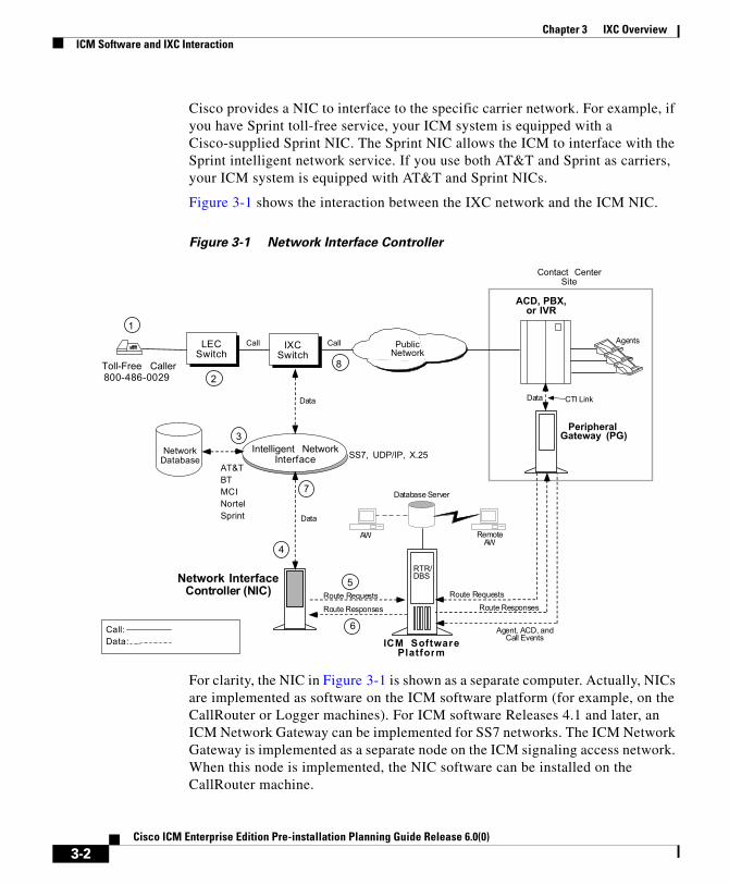
Cisco provides a NIC to interface to the specific carrier network. For example, if you have Sprint toll-free service, your ICM system is equipped with a Cisco-supplied Sprint NIC. The Sprint NIC allows the ICM to interface with the Sprint intelligent network service. If you use both AT&T and Sprint as carriers, your ICM system is equipped with AT&T and Sprint NICs.
Figure 3-1 shows the interaction between the IXC network and the ICM NIC.
Figure 3-1 Network Interface Controller
For clarity, the NIC in Figure 3-1 is shown as a separate computer. Actually, NICs are implemented as software on the ICM software platform (for example, on the CallRouter or Logger machines). For ICM software Releases 4.1 and later, an ICM Network Gateway can be implemented for SS7 networks. The ICM Network Gateway is implemented as a separate node on the ICM signaling access network. When this node is implemented, the NIC software can be installed on the CallRouter machine.
7
4
3
2
1
Toll-Free Caller800-486-0029
Intelligent NetworkInterface
LECSwitch
PublicNetwork
ACD, PBX,or IVR
Database Server
AW
Agents
PeripheralGateway (PG)
Network InterfaceController (NIC)
IXCSwitch
NetworkDatabase
Route Requests
Route Responses
Route RequestsRoute Responses
Agent, ACD, andCall EventsICM Software
Platform
6
5
8
Call Call
Data Data
Data
RemoteAW
CTI Link
RTR/DBS
Contact CenterSite
Call:Data:
SS7, UDP/IP, X.25AT&TBTMCINortelSprint
3-2Cisco ICM Enterprise Edition Pre-installation Planning Guide Release 6.0(0)

Chapter 3 IXC OverviewICM Software and IXC Interaction
Toll-Free Caller As shown in Figure 3-1, the flow of messages between the network and the ICM begins when a caller dials a toll-free number (1).
LEC-to-IXC The Local Exchange Carrier (LEC) determines which interexchange carrier (IXC) is providing transport for that particular number and forwards the call to the IXC switch (2).
Network Query The IXC switch holds the call momentarily while it queries a network database to determine where to route the call (3).
ICM NIC The network database forwards the query to the NIC and requests an intelligent routing decision (4).
NIC-to-CallRouter The NIC software process receives the request, translates it into a standard format, and forwards it to the ICM CallRouter process (5).
Best Destination Returned The ICM software selects the appropriate call routing script, assesses the skills and current real-time status of agents throughout the contact center network, and returns the best destination address back to the NIC (6).
3-3Cisco ICM Enterprise Edition Pre-installation Planning Guide Release 6.0(0)

Chapter 3 IXC OverviewCarrier Connections
IXC Network The NIC sends the destination address to the IXC network (7).
Connecting the Call The network instructs the originating IXC switch to connect the call to the destination specified by the ICM software (8). The total time taken by the carrier to connect the call varies. However, the additional time added by the ICM software to process the route request is typically less than half a second.
Carrier ConnectionsThe ICM software views the interexchange carriers (IXCs) as routing clients. The ICM software acts as a routing server. Table 3-1 summarizes the connections between routing clients and the ICM software.
Applying Fault Tolerance in NICsYou may already have a strategy for fault tolerance for some parts of the ICM system. For example, you might have decided to use a duplexed, distributed ICM Central Controller and duplexed PGs at each call center. It is just as important to apply fault tolerance to the NICs and intelligent network access links. Without a
Table 3-1 Interexchange Carrier Connections
Routing Client Connection to ICM
AT&T SS7 connection to the ICM Network Gateway
MCI IP connection to the ICM CallRouter
Nortel IP connection to the ICM CallRouter
Sprint X.25 connection to the ICM CallRouter
Stentor IP connection from the Stentor HyperStream frame-relay network to the ICM CallRouter.
3-4Cisco ICM Enterprise Edition Pre-installation Planning Guide Release 6.0(0)

Chapter 3 IXC OverviewApplying Fault Tolerance in NICs
connection to the carrier’s intelligent network, the ICM system cannot perform Pre-Routing. If these links are lost, calls are typically routed according to the default routing plans set up in the carrier network.
Note For more information on ICM system fault tolerance, see the Cisco ICM Enterprise Edition Administration Guide.
Goals for NIC Fault ToleranceThe goal in applying NIC fault tolerance is to add levels of protection that successively eliminate single points of failure. Cisco recommends an order of importance to follow when choosing the types of fault tolerance to apply in the carrier network-to-ICM system connection:
• First, use redundant links from the Cisco NIC to the carrier’s intelligent network.
• Next, if you have redundant links, provision those links on diverse facilities. This adds another level of fault tolerance to your network connection.
• For NICs that run on the ICM CallRouter platform, the NIC processes are duplexed when the CallRouter is duplexed.
The types of NIC fault tolerance you apply have a bearing on the number of links you need to provision for IXC intelligent network access.
Link RedundancyCisco recommends that you configure redundant links to the IXC network. In other words, rather than having a single link from the NIC to the IXC intelligent network, provision two links. Having just one link to the IXC network represents a single point of failure (that is, an area or node in the system that, should it fail, could cause the system to stop routing calls).
By using redundant links, you increase the reliability of the IXC network connection and add an important level of fault tolerance to the system. Figure 3-2 shows a simplexed ICM Central Controller and NIC with redundant links to the IXC network.
3-5Cisco ICM Enterprise Edition Pre-installation Planning Guide Release 6.0(0)

Chapter 3 IXC OverviewApplying Fault Tolerance in NICs
Figure 3-2 Redundant Links
In Figure 3-2, single points of failure still exist because the NIC, CallRouter, and Logger are simplexed. The simplexed Central Controller and NIC configuration is shown here only as an example. This type of simplexed configuration is used only for non-critical systems that can tolerate potentially long interruptions in service (for example, in lab or demo systems).
The major IXCs support redundant links to their intelligent networks. Contact your carrier for more information on access link options.
Route DiversityFor even more protection against network outages, Cisco recommends that the network links be provisioned on diverse network facilities. By having diverse links, you further reduce the risk that another single point of failure (in this case, the failure of a circuit) might cause you to lose the connection to the IXC network.
3-6Cisco ICM Enterprise Edition Pre-installation Planning Guide Release 6.0(0)

Chapter 3 IXC OverviewApplying Fault Tolerance in NICs
For example, you might provision one access link on one T1 circuit and provision the other access link on a different T1 circuit. By having diverse links, you protect against network failures in which an entire circuit is lost.
Figure 3-3 shows a simplexed ICM system with redundant links and route diversity:
Figure 3-3 Redundant Links and Route Diversity
This example provides more fault tolerance by protecting against circuit failure or the loss of an IXC Point Of Presence (POP). Although the NIC is at one location, the redundant links connect to two different POPs. If one IXC POP is taken out of service (for example, in the event of a natural disaster), one link can still access the IXC network through the other POP.
The major carriers provide options for route diversity. Check with your carrier to discuss having the links handled by different POPs. You need to make sure that both the IXC and the Local Exchange Carrier (LEC) are using diverse circuits. Your LEC may impose some limitations on link diversity from the NIC to the IXC POP (that is, over the “last mile”). These limitations often depend on whether the call center is located in a metropolitan or rural area.
3-7Cisco ICM Enterprise Edition Pre-installation Planning Guide Release 6.0(0)

Chapter 3 IXC OverviewApplying Fault Tolerance in NICs
3-8Cisco ICM Enterprise Edition Pre-installation Planning Guide Release 6.0(0)

Cisco ICM Enterprise Edition Pre-installat
C H A P T E R 4
Switch OverviewEach contact center device (ACD, PBX, or IVR) communicates with an ICM Peripheral Gateway (PG). The PG reads status information from the device and passes it back to the ICM software. The PG runs one or more Peripheral Interface Manager (PIM) processes, which are the software components that communicate with proprietary ACD systems. One PIM is required for each peripheral to which the PG will interface. So if you have two identical ACDs, your PG will require two PIMs.
A single PG can serve multiple peripherals of the same kind. For example, one computer with an Aspect PG and several Aspect PIMs can serve several Aspect ACDs in the contact center. Another PG and PIM on the same computer might serve an IVR.
Note Beginning with ICM 5.0(0), a single PG can support both ACD PIMs and IVR PIMs, though the ACD PIMs must all be of the same kind and the IVR PIMs must all be of the same kind.
This chapter provides an overview of how the PG interfaces with ACDs in a contact center environment.
PG-to-Peripheral ConnectionsEach contact center peripheral (ACD, PBX, or IVR) requires a connection to a Cisco Peripheral Gateway (PG). The Peripheral Gateway provides a software interface between ACD, PBX, and IVR systems and the ICM routing software.
4-1ion Planning Guide Release 6.0(0)

Chapter 4 Switch OverviewPG-to-Peripheral Connections
The PG connects to a peripheral via the peripheral’s computer telephony integration (CTI) link. In some cases, the PG also connects to the peripheral’s MIS subsystem. The MIS subsystem may be on a separate hardware platform or it may be integrated with the ACD, PBX, or IVR. The relationship of the Peripheral Gateway to an ACD system is shown in Figure 4-1.
Figure 4-1 Peripheral Gateway ACD/PBX Interface
Through the CTI link, the PG monitors changes in agent status, calculates call handling performance statistics, and forwards events to the CallRouter. The MIS connection provides additional information such as the mapping of individual agents to skill types and the current status of agents (either by themselves or relative to a given agent group or skill group). Typical agent states include Logged In, Ready, Talking In, Talking Out, Work Not Ready, etc. The MIS link may also provide the ICM system with ACD configuration data and historical reports.
Each PG has one or more connections to the peripheral. The type of connection used depends on the type of peripheral. For example, some ACDs use a TCP/IP Ethernet connection, while others require X.25 links. Table 4-1 summarizes the connections for the supported peripheral types.
Integrated ACD/PBXor Standalone ACD
ACDMIS
Peripheral Gateway CallRouter
Link to ICM system(local or WAN)
ACD MIS Link
CTI Link
CTI Link. Typically provides call and agentevent data and third-party call control.
Link to ACD database/MIS subsystem.Typically provides agent skill and ACD
configuration data and access to historicalreports.
4-2Cisco ICM Enterprise Edition Pre-installation Planning Guide Release 6.0(0)

Chapter 4 Switch OverviewPG-to-Peripheral Connections
Table 4-1 PG-to-Peripheral Connections
Peripheral Interfaces Connections
Alcatel 4400 ACD CTI: CSTA-2 TCP server port 2555
A TCP/IP Ethernet connection from the PG to the Alcatel 4400 ACD.
Aspect Call Center CTI: Application Bridge
A TCP/IP Ethernet connection from the PG LAN to the Aspect Application Bridge.
MIS: Real-Time Bridge
A TCP/IP Ethernet connection from the PG LAN to the Real-Time Bridge.
Aspect Contact Server
CTI: Contact Server CMI Server
A TCP/IP Ethernet connection from the PG LAN to the Aspect Contact Server CMI Server.
MIS: Real-Time Bridge
A TCP/IP Ethernet connection from the PG LAN to the Real-Time Bridge.
Avaya DEFINITY ECS
CTI: CVLAN with MAP/D interface
A TCP/IP Ethernet connection from the PG LAN to the ECS system.
MIS: CMS A TCP/IP Ethernet connection from the PG LAN to the CMS.
Ericsson ACP1000 CTI: ACP1000 Application Link for CSTA
A TCP/IP Ethernet connection from the PG LAN to the ACP1000 ApplicationLink CSTA Gateway hardware platform.
MIS: System command interface
A TTY serial link connects each PG to the ACP1000.
4-3Cisco ICM Enterprise Edition Pre-installation Planning Guide Release 6.0(0)

Chapter 4 Switch OverviewPG-to-Peripheral Connections
Ericsson MD-110 CTI: ApplicationLink CSTA Gateway
A TCP/IP Ethernet connection from the PG LAN to the ApplicationLink CSTA Gateway hardware platform.
CTI: ODBC Connection
A logical (Over TCP/IP) connection to the CCM machine that will carry agent group and login information.
NEC NEAX 2400 CTI: Infolink/OAI A TCP/IP Ethernet connection from the PG LAN to the NEC NEAX 2400.
Nortel Meridian CTI: Meridian Link or Symposium Call Center Server (SCCS) with Meridian Link Services (MLS).
MIS: Meridian MAX
A TCP/IP Ethernet MEI connection from the PG LAN to the MAX system. (Meridian Link is required only if Post-Routing or CTI is used.)
Nortel DMS-500, DMS-100 / SL-100
CTI: CompuCALL X.25 CompuCALL links (RS-232-C or V.35) from the DMS-100 to the PG. Optionally, a TCP/IP connection and an Ethernet Interface Unit (EIU) can be used to provide LAN connectivity to the PG.
Nortel Symposium CTI: Meridian Link Interface, Host Data Exchange Interface (HDX), Real-Time Data Interface (RTD)
A TCP/IP Ethernet connection from the PG LAN to the Symposium Call Center Server (SCCS).
Rockwell Galaxy MIS: FPDL A 19.2-Kbps Foreign Processor Data Link (FPDL) X.25 connection from the Galaxy ACD to the PG.
Table 4-1 PG-to-Peripheral Connections
4-4Cisco ICM Enterprise Edition Pre-installation Planning Guide Release 6.0(0)

Chapter 4 Switch OverviewSupported ACD Switches
Supported ACD SwitchesTo ensure that your ACD software version is compatible with ICM software, refer to the Cisco ICM Software Supported Switches (ACDs) spreadsheet. This document contains the latest information on ICM switch support.
Note For more details on how ACDs interface to the ICM software, see the appropriate Cisco ICM software ACD Supplement. The ACD Supplements provide more technical details on the ICM-to-ACD interface than is provided in this document.
Rockwell Spectrum CTI: Transaction Link
A TCP/IP connection from the PG to the Spectrum Transaction Link.
MIS: Supervisor CRT A 9600 baud serial link from the PG to a Supervisor CRT port on the Spectrum.
Siemens Hicom 300E (9006)
MIS: CallBridge CSTA Gateway
A TCP/IP Ethernet connection from the ICM LAN to the CallBridge CSTA Gateway. (The PG may connect directly to the Hicom 300E if the CallBridge software is installed on the PG platform.)
Siemens Rolm 9751 CBX (9005)
MIS: Supervisor Terminal
From two-to-eight 19.2-Kbps asynchronous serial ports from the PG to the 9751 CBX.
Table 4-1 PG-to-Peripheral Connections
4-5Cisco ICM Enterprise Edition Pre-installation Planning Guide Release 6.0(0)

Chapter 4 Switch OverviewSupported ACD Switches
4-6Cisco ICM Enterprise Edition Pre-installation Planning Guide Release 6.0(0)

Cisco ICM Enterprise Edition Pre-installat
C H A P T E R 5
Peripheral Gateway ConfigurationsAs part of planning for ACDs and PGs, you need to decide whether your Peripheral Gateways will be simplexed or duplexed. Simplexed means that one PG is used. Duplexed means that two essentially identical PGs are used, one as a backup system. (Both PGs run simultaneously, with some processes active on both PGs. See the discussion in Peripheral Gateway Fault Tolerance, page 5-2.)
Figure 5-1 shows examples of simplexed and duplexed contact center configurations. Typically, duplexed PGs are installed for fault tolerance.
Figure 5-1 PG Contact Center Configurations
AdminWork station
ACDPeripheralGateway
VisibleLAN
To Central ControllerSide A
IP Router
Simplexed PG
AdminWork station
ACD
VisibleLAN
PrivateLAN
PG1A
PG2B
To Central ControllerSide A
To Central ControllerSide B
IP RouterIP Router
Duplexed PG
To Central ControllerSide B
5-1ion Planning Guide Release 6.0(0)

Chapter 5 Peripheral Gateway ConfigurationsPeripheral Gateway Fault Tolerance
Note Some ACDs can connect directly to the ICM visible LAN. Others connect to the PG via serial or other types of communication links.
The Peripheral Gateway reads information from one or more peripherals at a contact center and sends status information back to the ICM CallRouter. A peripheral might be an ACD, IVR, PBX, or another device that distributes calls within the contact center. If the ICM system is performing Post-Routing, the PG also sends route requests to the CallRouter and receives routing instructions in response.
Peripheral Gateway Fault ToleranceDuplexed PGs are usually implemented to provide fault tolerance in the ICM software’s communication with peripherals. The duplexed PGs use a private network. The PG private network is used to synchronize certain processes within a duplexed PG pair. It is also used in “heartbeat detection,” which is a process by which each PG sends a heartbeat packet every 400 ms to keep track of the “health” of the other PG.
PGs use a combination of the hot standby and synchronization approaches to fault tolerance. In the hot standby approach, one set of processes is called the primary, and the other is called the backup. In this model, the primary process performs the work at hand while the backup process is idle. In the event of a primary process failure, the backup process is activated and takes over. In a duplexed PG system, the Peripheral Interface Manager (PIM) processes use the hot standby approach to fault tolerance.
In the synchronization approach, the critical process is duplicated on separate computers. There is no concept of primary and backup. Both process sets run in a synchronized fashion, processing duplicate input and producing duplicate output. Each synchronized process is an equal peer. Cisco refers to these equal peers as a synchronized process pair. In a duplexed PG system, the Open Peripheral Controller (OPC) process operates as a synchronized process pair.
Figure 5-2 shows how hot standby and synchronization are employed in a duplexed Peripheral Gateway.
5-2Cisco ICM Enterprise Edition Pre-installation Planning Guide Release 6.0(0)

Chapter 5 Peripheral Gateway ConfigurationsPeripheral Gateway Fault Tolerance
Figure 5-2 PG Fault Tolerance
The OPC processes communicate with each other via a private network connection and the Cisco Message Delivery Service (MDS). The MDS provides a synchronizer service which combines the input streams from the PIMs and PG Agents on both sides of the PG to ensure that both OPC processes see exactly the same input.
The OPC process is responsible for activating PIMs and PG Agents on each side of the duplexed PG. The OPC process also supplies uniform message sets from various PG types to the ICM Central Controller.
The PIMs manage the interface between different types of ACDs and the OPC. PIMs are duplicated on each side of the system and operate in hot standby mode. A PIM can be active on either side of the duplexed PG, but not on both sides at
ACD2
PG Side B
PG Agent
OPCOPC
PG Side A
PG Agent
PIM 1 PIM 2 PIM 3
ACD1
Idle pathActive path
PIM 2PIM 1 PIM 3
ACD3
To Side ACC Agent
To Side BCC Agent
To Side ACC Agent
To Side BCC Agent
CTI Links
Synchronized Processes
Central ControllerSide A
Central ControllerSide B
5-3Cisco ICM Enterprise Edition Pre-installation Planning Guide Release 6.0(0)
Chapter 5 Peripheral Gateway ConfigurationsPG Platform Options
the same time. For example, in Figure 5-2 PIMs 1 and 2 are active on Side A; PIM 3 is active on Side B. The duplexed OPCs communicate with each other through the MDS to ensure that a PIM is active only on one side at a time.
The duplexed PG architecture protects against a failure on one side of the PG. For example, if an adapter card controlling access to an ACD fails, a hot standby PIM can use the alternate PIM activation path. As shown in Figure 5-2, PIM3 has been activated from Side B of the PG. This might be in response to an adapter failure between the Side A PIM3 and ACD3.
In this type of failure scenario, the PG is able to maintain communication with the attached ACD.
Only one PG Agent actively communicates with a side of the Central Controller. When messages arrive at the Central Controller, they are delivered to both sides by the Central Controller Synchronizer process. The PG maintains idle communication paths to both sides of the Central Controller in case a switch-over to the other side of the Central Controller or PG is necessary.
PG Platform OptionsA maximum of two PGs can run on a single hardware platform. A single PG can serve only one type of ACD, but can also (as of ICM 5.0) contain one or more VRU PIMs and/or Media Routing PIMs provided that the server hardware has the capacity to support the aggregate processing load. For a single hardware platform to serve two different types of ACDs, you need two PGs—one for each peripheral type. Figure 5-3 shows some possible PG options.
5-4Cisco ICM Enterprise Edition Pre-installation Planning Guide Release 6.0(0)

Chapter 5 Peripheral Gateway ConfigurationsPG Platform Options
Figure 5-3 PG Platform Examples
As shown in Figure 5-3, you might have an Aspect PG on PGA and an Aspect PG on PGB. This duplexed PG pair could serve multiple Aspect ACDs. One Aspect Peripheral Interface Manager (PIM) would be added through ICM Setup for each Aspect ACD to be connected to this PG. In this example, three Aspect PIMs would be installed on each PG. The PIM is the ICM software interface between the PG and different types of contact center peripherals. One PIM is required for each peripheral connected to a PG.
In a mixed contact center environment, you might want to run two different types of PGs on a single hardware platform. For example, you might want to put an Aspect PG and a DEFINITY ECS PG on the same computer. In this way, one hardware platform could serve two types of ACDs provided that the hardware platform has the necessary memory and CPU capacity to support the aggregate processing load.
5-5Cisco ICM Enterprise Edition Pre-installation Planning Guide Release 6.0(0)

Chapter 5 Peripheral Gateway ConfigurationsPG Platform Options
Considerations for PGs and PIMsHere are some points to remember when planning for PGs and PIMs:
• Maximum PGs on a platform. A maximum of two PGs can run on a single hardware platform. These may be of the same or different types. For example, on a single machine you could have an Aspect PG and an Avaya PG, or you could have two Avaya PGs.
• PIMs and peripherals. You need one PIM for each peripheral that will be connected to the PG. The PIMs are installed along with the PG software by using the ICM Setup tool.
• A single PG serves peripherals of the same type. A single PG (and its associated PIMs) can serve only ACDs of the same type. For example, an Aspect PG with four PIMs can serve only four Aspect ACDs. It cannot serve three Aspect ACDs and an Avaya DEFINITY ACD. You can put VRU and Media Routing PIMs on the same PG as an ACD, but all VRU PIMs must service VRUs of the same type.
• Using two PGs on a platform. Before you commit to installing two PGs on a single computer, consider the expected call load for the ACDs that will be connected to the PGs. You need to be sure that the computer has enough memory and processing power to handle the expected call load. In addition, you should ensure that the bandwidth in the network between the PG and the ICM Central Controller is enough to handle the route request and event traffic that will be generated by the PGs. (These same considerations apply to using multiple PIMs on a PG, but to a lesser extent.)
• Properly sizing the PG hardware platform. Work with your ICM software support provider to properly size the PG hardware platform(s) and to determine which PG configuration is appropriate for your application. Cisco offers standard and high-end PG hardware platforms to suit more demanding contact center applications.
• CTI Server and an ACD PG on the same platform. You can install CTI Server and an IVR or ACD PG on the same hardware platform. The PG may run multiple PIMs. (The same considerations described earlier in “Using two PGs on a platform,” also apply to the CTI Server-PG configuration.)
5-6Cisco ICM Enterprise Edition Pre-installation Planning Guide Release 6.0(0)

Chapter 5 Peripheral Gateway ConfigurationsStandard PG Configuration
Standard PG ConfigurationIn most PG configurations, the PG is located with the ACD at a contact center site. The PG communicates with the Central Controller via the ICM visible network WAN links. These WAN links can be 56-Kbps dedicated circuits, or—if QoS is implemented—the corporate WAN can be used. When Admin Workstations are located with PGs and ACDs at the contact center site, the WAN links to the Central Controller can be shared by both PGs and AWs. If the PG is collocated with the ICM Central Controller, the PGs connect directly to the ICM visible LAN. Figure 5-4 shows an example of a standard PG configuration.
Figure 5-4 Standard PG Configuration (Duplexed PGs)
WebView Server
5-7Cisco ICM Enterprise Edition Pre-installation Planning Guide Release 6.0(0)

Chapter 5 Peripheral Gateway ConfigurationsRemote ACD and IVR Connection to PGs
Remote ACD and IVR Connection to PGsSome ACDs allow a remote connection to the ICM Peripheral Gateway. In a remote ACD configuration, the PGs are located at the central site along with the CallRouter, Logger, and NIC. The ACD is located at a remote contact center site.
For information on remote PG support, see the ACD Supplement for the particular ACD.
The IVR PG can communicate remotely with IVRs via a TCP/IP network. However, you must ensure that the network link between the PG and IVR system provides enough bandwidth to support the call load for the VRU.
Note Though specific to IP Contact Center, and therefore not germane to this manual, it should be noted that the IP IVR PG cannot be remote from the IP IVR.
5-8Cisco ICM Enterprise Edition Pre-installation Planning Guide Release 6.0(0)

Cisco ICM Enterprise Edition Pre-installat
C H A P T E R 6
CTI PlanningCisco CTI software provides an interface between the ICM software and agent desktop and server applications. The CTI software works with a Peripheral Gateway’s ACD and IVR interface software and associated ACDs to track call events and transactions and forward call- and transaction-related data to an agent’s desktop computer.
Pre-installation planning for CTI involves several tasks:
• Review CTI Server communications and platform options.
• Become familiar with the desktop options available with CTI Server.
• Estimate CTI message traffic.
• Plan fault tolerance for the CTI Server.
• Review ACD support for client control and third-party call control.
CTI ServerCTI Server, the basic server component of Cisco CTI, enables the ICM software to deliver agent, call, and customer data in real-time to a server and/or workstation application as events occur throughout the life of a call. The CTI Server is a software process that runs on a Peripheral Gateway (PG). It is the CTI gateway into the ICM software’s data and services.
Figure 6-1 shows a sample CTI Server system. CTI Servers may be running at one or several call centers in the enterprise.
6-1ion Planning Guide Release 6.0(0)

Chapter 6 CTI PlanningCTI Server
Figure 6-1 CTI Server Overview
One function of the CTI Server is to forward pre-route indications to CTI application servers. Pre-route indications identify the caller and provide CTI applications with other call attributes while the call is still in the public or private network (that is, before the call is connected to an agent or IVR resource).
CTI Server also reports call events and agent work state changes as they occur through each stage of the call flow—from the moment a call arrives at an answering resource (ACD, PBX, IVR), until the caller hangs up. In a desktop application environment, call event information is delivered to the targeted agent desktop at the same time the call is delivered.
CTI Server CommunicationsThe CTI Server uses TCP/IP Ethernet for communication with clients. Multi-protocol IP routers may be used to provide connectivity to clients on other types of LANs. The same LAN that is used for the Peripheral Gateway’s visible network interface can also be used for CTI client-to-server communications.
6-2Cisco ICM Enterprise Edition Pre-installation Planning Guide Release 6.0(0)

Chapter 6 CTI PlanningCTI Server
CTI Server Platform OptionsThe CTI Server runs on a machine that is also running a Cisco ACD (or VRU) PG process. The shared platform option is shown in Figure 6-2.
Figure 6-2 Shared CTI Server Platform
CTI Server Fault ToleranceYou can implement the CTI Server in a duplexed, fully fault-tolerant configuration. In a duplexed configuration, the CTI Server is installed on a pair of PC platforms. In the event of a failed CTI client connection, the client process can automatically reestablish a connection to either side of the duplexed CTI Servers. The call’s CTI client history list and any updates to call variables remain in effect when the connection is reestablished. Figure 6-3 shows a duplexed CTI Server configuration.
6-3Cisco ICM Enterprise Edition Pre-installation Planning Guide Release 6.0(0)

Chapter 6 CTI PlanningCisco CTI Object Server (CTI OS)
Figure 6-3 Duplexed CTI Server
Cisco CTI Object Server (CTI OS)CTI Object Server (CTI OS) is a high-performance, scalable, fault-tolerant server-based solution for deploying CTI applications. CTI OS serves as a single point of integration for third-party applications, including Customer Relationship Management (CRM) systems, data mining, and workflow solutions.
Configuration data is managed at the server, which helps simplify customization, updates, and maintenance of CTI applications. Servers can be accessed and managed remotely. Thin-client and browser-based applications that do not require Cisco software on the desktop can be developed and deployed with CTI OS.
CTI OS incorporates the following major components:
• CTI OS Toolkit
• Client Interface Library
• CTI OS Agent Phone
• CTI OS Supervisor Phone
6-4Cisco ICM Enterprise Edition Pre-installation Planning Guide Release 6.0(0)

Chapter 6 CTI PlanningCisco Agent Desktop
CTI OS is a client of CTI Server. It has a single all-events connection to Cisco CTI Server. In turn, CTI OS accepts client connections using session, agent, and call interfaces. These interfaces are implemented in COM, Java, C++, and C, allowing for a wide range of application development uses. The interfaces are used for call control, to access data values, and to receive event notifications.
The agent count for CTI OS must be no more than 500 simultaneous agents (your actual maximum may be less depending on factors such as your hardware configuration, incoming call rate, ratio of transfer/conference calls to regular calls, and so on; prior to CTI OS 5.1, the limit was 200 simultaneous agents).
CTI OS may run on the same hardware as a Peripheral Gateway.
For more information on CTI OS, refer to the Cisco ICM Software CTI OS document set.
Cisco Agent DesktopThe Cisco Agent Desktop product suite consists of these major components:
• Desktop Administrator
• Agent Desktop
• Supervisor Desktop
• Servers
Cisco Agent Desktop is typically installed on the PG hardware.
For more information on Cisco Agent Desktop, refer to the Cisco Agent Desktop document set.
CTI Server Client Application ModelsYou can use either of two client models to integrate call center applications with the ICM: agent workstation and CTI Bridge.
6-5Cisco ICM Enterprise Edition Pre-installation Planning Guide Release 6.0(0)

Chapter 6 CTI PlanningCTI Server Client Application Models
Agent Workstation (Desktop) ApplicationIn the agent workstation model, the client is an application running on a personal computer on an agent’s desktop. This client is interested in the call data and call events related to a single agent teleset. The agent workstation application might also be interested in agent state changes.
Typically, when the agent workstation application is informed of an incoming call, it will likely use the call data collected by the ICM system to retrieve caller-specific data from a database. This data is presented on the agent workstation screen at approximately the same time that the incoming call is connected to the agent.
While handling the call, the agent may wish to update some of the call data. For example, an agent who is processing an insurance claim may make some adjustments to the call data; an update ensures that the changes are not lost before the call is transferred to a second agent.
Upon completion of the call, the client may be used by the agent to add call-specific wrap-up information to the Termination_Call_Detail record logged in the ICM central database. This wrap-up data may be a key value that can help locate more detailed transaction information in some other database. If the agent should conference with or transfer the call to another agent on the same ACD with a CTI client workstation, then that agent’s CTI client also receives the incoming call data, including any updates made by the first agent. If the transfer or conference involves an agent on another ACD, the call data is provided to the remote CTI client if a translation route is used.
CTI Bridge (All Events) ApplicationCTI Bridge applications are interested in all call and agent state events that are occurring on the ACD, unlike agent workstation applications that are interested only in the events associated with a particular teleset. The CTI Bridge application is a user-written program that converts or adapts some or all of the CTI Server messages into another format; a single CTI Bridge application provides such services for multiple agent desktops. The CTI Bridge application can be designed to interface with CTI Servers or similar applications on systems that are already in use in the call center.
Some examples of CTI Bridge applications include:
6-6Cisco ICM Enterprise Edition Pre-installation Planning Guide Release 6.0(0)

Chapter 6 CTI PlanningCTI Server Client Application Models
• Message converter applications. For example, an application may convert the CTI Server message set to the message set of a foreign telephony server.
• Server-to-server communication applications. For example, an application may enable the CTI Server to speak directly to a help desk application’s middle tier server.
In a CTI Bridge configuration, a CTI Bridge application provides the connection between an existing desktop CTI application and the ICM (see Figure 6-4).
Figure 6-4 CTI Bridge Model
Note All of the functionality found in the agent workstation (desktop) model is also available in the CTI Bridge application model. However, the CTI Bridge application must be written to support this functionality.
6-7Cisco ICM Enterprise Edition Pre-installation Planning Guide Release 6.0(0)

Chapter 6 CTI PlanningCTI Server Network and Database Planning
CTI Server Network and Database PlanningSome pre-installation planning is necessary to prepare your CTI desktop and network environment for the introduction of a CTI Server.
Review the Desktop Network EnvironmentThe machine running CTI Server connects to the CTI desktop environment via an Ethernet LAN. Therefore, the CTI desktop environment must reside on an Ethernet LAN. Other networks, such as Token-Ring, may require additional network hardware if they are to be connected to a CTI Server.
Review Network Security IssuesYou need to be sure that the CTI desktop environment IP routing scheme is compatible with the ICM system and CTI Server. For example, you might currently have a firewall set up on the CTI environment LAN. If there is a firewall, you may need to change your system access setup or network configuration.
Address Desktop Software Roll-out and Distribution IssuesIf you are going to be installing the CTI OS or CTI Desktop software components on multiple desktops, you need to create a distribution strategy. For example, you may decide to place the software on a centralized server and allow appropriate desktops from throughout the enterprise to download the software. In addition, if you use this strategy and will be installing software across distributed sites, you must ensure that all sites have access to the centralized server.
Select a Well-known Port for CTI ServerA well-known port number identifies CTI Server as an application running in your internet. All CTI clients, as well as the system administrator, need to be aware of this well-known port number. If you do not want to use CTI Server’s default port
6-8Cisco ICM Enterprise Edition Pre-installation Planning Guide Release 6.0(0)

Chapter 6 CTI PlanningEstimating CTI Server Message Traffic
numbering scheme, you can choose a well-known port number that fits into your overall network environment. ICM Setup allows you to override the default port settings used to install the CTI Server PGs.
Plan a Fail-over Strategy for CTI ClientsCisco CTI includes automatic fail-over and recovery mechanisms. Ensure that each CTI client has a clear and established network path to a CTI Server in case of a fail-over. For example, you might plan for each CTI client to have access to local and remote CTI Servers.
Develop a Database StrategyYou might have CTI applications that perform database queries to retrieve customer information for use in call processing. Some CTI applications might acquire database records “pre-call” (that is, before the call arrives at an agent’s desktop). Other applications might query a database immediately after the call arrives at the agent’s deskset. Plan a strategy for executing database queries in the most efficient and timely manner possible.
Estimating CTI Server Message TrafficThe CTI Server makes call data available to applications in real time. To accomplish this task, the CTI Server process responds to requests from clients and originates unsolicited messages. All messages share a common message header and use the same set of data types.
Table 6-1 groups the messages into broad categories based on the nature of the message data.
6-9Cisco ICM Enterprise Edition Pre-installation Planning Guide Release 6.0(0)

Chapter 6 CTI PlanningEstimating CTI Server Message Traffic
CTI Server imposes varying degrees of message traffic against the PG based on the specific call center and CTI application environment in which it is deployed. Document a typical call scenario in your CTI application environment, prepare for adequate bandwidth, and order the proper PC platform.
Note For a description of the session management messages, see the latest version of the Cisco ICM Software CTI Server Message Reference Guide.
Documenting a Typical Call ScenarioTo estimate CTI Server message traffic, document a typical call scenario in your CTI application environment. The goal of this exercise is to account for all types of potential message traffic in the link between the CTI Server and the CTI application environment.
For example, a typical call might be handled as follows:
Table 6-1 CTI Server Message Categories
Category Description
Session Management Messages related to the establishment and maintenance of a client connection to the CTI Server. These messages typically happen at client startup, shutdown, and during auto-recovery.
Miscellaneous Messages related to system-level events on the PG (for example, peripheral off-line, loss of PG-to-Central Controller communications).
Call Events Messages related to call state changes.
Agent Events Messages related to agent state changes.
Call Data Update Messages related to CTI client modification of call data.
Client Control Messages related to the direct control of agent state (for example, login, logout) as well as control of inbound and outbound calls.
6-10Cisco ICM Enterprise Edition Pre-installation Planning Guide Release 6.0(0)

Chapter 6 CTI PlanningThird-Party Call Control
• The call is pre-routed.
• The call receives a call treatment such as a request to set call data.
• Next, maybe a simple call release, hold, transfer, or post-route request takes place.
• During this time an agent state may have changed (for example, from ready to work ready).
Estimating Required BandwidthYou need to ensure that you have enough bandwidth in the datacom connection to handle the message traffic between the CTI Server and the CTI application environment. For example, are you sure that a 56-Kbps connection will be adequate for your environment?
The call scenario process helps you to estimate the message load and calculate how much bandwidth is required in the link between the CTI Server and the CTI application environment (for example, 56K, 256K, or more).
Choosing the CTI Server PlatformYou also need to ensure that the CTI Server platform has adequate CPU processing speed and RAM to handle the message activity. You may require a high-end Cisco CTI Server/PG platform for the CTI Server.
Third-Party Call ControlThe term call control refers to the ability of an application that is external to the ACD to programmatically control a telephone call. For example, a CTI application might put a call on hold, transfer the call, or hang up the call.
With first-party call control, the CTI application can control only the teleset that is physically connected to the computer running the CTI application. First-party call control requires a physical connection between the computer and the telephone and other add-on hardware (see Figure 6-5).
6-11Cisco ICM Enterprise Edition Pre-installation Planning Guide Release 6.0(0)

Chapter 6 CTI PlanningThird-Party Call Control
Figure 6-5 Desktop First-Party Call Control
CTI Server products support third-party call control. Any call control initiated outside the ACD/teleset domain is referred to as third-party. With third-party call control, there is no physical connection between the computer and the teleset (see Figure 6-6).
6-12Cisco ICM Enterprise Edition Pre-installation Planning Guide Release 6.0(0)

Chapter 6 CTI PlanningThird-Party Call Control
Figure 6-6 Desktop Third-Party Call Control
The desktop CTI application communicates with the Cisco CTI Server over a LAN. The CTI Server in turn communicates with the ACD to send call control requests. In this model, the CTI application is not bound to any particular teleset. The CTI application can control any teleset connected to the ACD and CTI Server.
Note Most, but not all, ACDs support third-party call control.
Depending on the specific ACD, the client application can perform all or most of the following telephony functions:
• Answer/Hang up
• Agent Login and Wrap-up data
• Consultative/Blind Conference
• Consultative/Blind Transfer
• Generate DTMF tones
• Get/Set Agent states
• Get/Set ICM call data (ANI, DNIS, CED, UUI, call vars)
• Hold/Unhold/Swap Hold
• Make a call
6-13Cisco ICM Enterprise Edition Pre-installation Planning Guide Release 6.0(0)

Chapter 6 CTI PlanningACD Support for Client and Third-Party Call Control
• Redirect
ACD Support for Client and Third-Party Call ControlDifferent peripheral types implement and support varying levels of CTI functionality. For example, a different set of client control requests and call event types may be available depending on the peripheral type. In addition, there may be other CTI-related restrictions and implementation differences based on the type of peripheral. You need to take these differences into account when you write a CTI client application that will interface with third-party switches and devices. For example,
• The Rockwell Galaxy does not have CTI Server support.
• The Siemens Rolm 9751 CBX does not have CTI Server support, but does support screen-pop applications.
As part of CTI pre-installation planning, you need to review ACD support for client control and third-party call control.
6-14Cisco ICM Enterprise Edition Pre-installation Planning Guide Release 6.0(0)

Cisco ICM Enterprise Edition Pre-installat
C H A P T E R 7
IVR PlanningCisco provides an option for running an interface to Interactive Voice Response (IVR) systems. The IVR interface software allows IVRs to take advantage of ICM call routing features. For example, an IVR can use Post-Routing capabilities to select targets for calls it needs to transfer.
The IVR interface software runs as a PG process on a standard PG hardware platform. It allows the ICM to route calls to targets on an IVR and collect data from an IVR for use in call routing, real-time monitoring, and historical reporting.
The IVR interface is not specific to a particular IVR system or manufacturer. It is based on an open IVR model. Many IVR systems support Cisco’s Open IVR Interface Specification, including Cisco Internet Service Node (ISN). For a list of IVRs that support this interface, contact your Cisco representative.
To plan for this IVR option:
• Review the options for integrating IVRs into the ICM system.
• Determine if any IVR programming or application development is necessary.
• Review the Peripheral Gateway platform requirements.
Reviewing IVR Configuration OptionsIVRs can be located at the customer’s call center site or in the IXC network. At the call center, the IVR might be connected on the network side of the ACD or “behind” the ACD. In the IXC network, the IVR may be offered as a service by the network provider.
7-1ion Planning Guide Release 6.0(0)
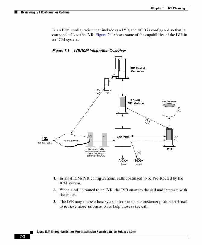
Chapter 7 IVR PlanningReviewing IVR Configuration Options
In an ICM configuration that includes an IVR, the ACD is configured so that it can send calls to the IVR. Figure 7-1 shows some of the capabilities of the IVR in an ICM system.
Figure 7-1 IVR/ICM Integration Overview
1. In most ICM/IVR configurations, calls continued to be Pre-Routed by the ICM system.
2. When a call is routed to an IVR, the IVR answers the call and interacts with the caller.
3. The IVR may access a host system (for example, a customer profile database) to retrieve more information to help process the call.
IVRIVR
Toll-FreeCallerPublic Network
IVR
Agent
ICM CentralController
Agent
Host DatabasePG withIVR Interface
ACD/PBX
NIC1
2
3
4
5
Optionally, IVRsmay be implemented
in the network orin front of the ACD
7-2Cisco ICM Enterprise Edition Pre-installation Planning Guide Release 6.0(0)

Chapter 7 IVR PlanningReviewing IVR Configuration Options
4. Often, the caller can get all the information he or she needs through simple interaction with the IVR. In some cases, however, the IVR needs to transfer the caller to an agent or another call resource.
5. In some configurations, the IVR can invoke Post-Routing to select an agent from anywhere in the call center enterprise. To do this, the IVR sends a route request to the PG. The PG forwards the request to the ICM system, which responds with a new destination for the call. The PG returns the new destination to the IVR. The IVR then signals the ACD or network to send the call to the specified destination.
The way in which an IVR is integrated into the ICM system affects the flow of call processing and determines the types of data the ICM can collect from the IVR. For example, an IVR that has a direct interface to an IVR PG (as shown in Figure 7-1) provides the ICM system with data that can be used in call routing, monitoring, and reporting. A configuration in which the IVR has an interface only to the ACD has more limited capabilities.
You can integrate IVRs into the ICM system in several different ways. Each integration option provides a different set of ICM functionality.
Configuration with an ACD PG OnlyIn this option, the IVR is attached only to the ACD. The ACD, in turn, is attached to a PG. The PG is running the Cisco peripheral interface software (PG software process) required to communicate with the specific type of ACD. There is no direct interface between the IVR and the ICM system (in other words, an IVR PG process is not implemented). See Figure 7-2.
7-3Cisco ICM Enterprise Edition Pre-installation Planning Guide Release 6.0(0)

Chapter 7 IVR PlanningReviewing IVR Configuration Options
Figure 7-2 Configuration With an ACD PG Only
In this configuration, the IVR must be connected to an ACD that supports Post-Routing. The IVR and ACD cooperate so that calls can be transferred from the IVR to the ACD, and then post-routed by the ACD via the PG.
The PG in this configuration has only the ACD peripheral interface software. It does not have the IVR interface software. Therefore, it does not provide the IVR with full access to the ICM Post-Routing.
In Figure 7-2, the IVR can handle a call in two different ways:
• The IVR can handle the call to completion (for example, if the caller wanted current billing information and needed no further assistance, the IVR could complete the call.)
• The IVR can transfer the call to the ACD. The ACD could then use the PG to post-route the call.
Caller
IVR
Public SwitchedNetwork
ACD/PBX
Agent
PG
HostApplication
NIC
ACD PeripheralInterface Software
CTI Link(Optional)
Host Link
Trunk s Trunk s
ICM CentralController
7-4Cisco ICM Enterprise Edition Pre-installation Planning Guide Release 6.0(0)

Chapter 7 IVR PlanningReviewing IVR Configuration Options
Configuration with IVR and ACD PGsThis configuration option is similar to the previous option except that an IVR PG process and host link to the IVR are implemented. In addition to monitoring the ACD for real-time agent and call event data, the PG can monitor the IVR for call and application data and control the movement of calls into and out of the IVR. The IVR data is also forwarded to the CallRouter for use in call routing and reporting.
As shown in Figure 7-3, the IVR and ACD interface software can be installed on the same PG hardware platform.
Figure 7-3 Configuration with IVR and ACD PGs
TCP/IP
Caller
IVR
Public SwitchedNetwork
ACD/PBX
Agent
PG
HostApplication
NIC
Host Link
Trunk s Trunk s
ICM CentralController
Gateway SQLor Gateway(optional)
TCP/IP
- ACD Peripheral Interface- Enterprise IVR software
7-5Cisco ICM Enterprise Edition Pre-installation Planning Guide Release 6.0(0)

Chapter 7 IVR PlanningReviewing IVR Configuration Options
Network-Side IVR with IVR and ACD PGsThe next configuration option places the IVR on the network side of the ACD. In this configuration, the IVR is connected to the network and potentially to the ACD. The IVR can receive calls directly from the network without ACD involvement. These calls might be pre-routed by the ICM, but this is not a requirement.
The IVR may also receive calls from the ACD (for example, when an agent transfers a call to the IVR). Again, these calls may or may not have been routed by the ICM. Figure 7-4 shows an example.
Figure 7-4 Network-Side IVR with IVR and ACD PGs
- ACD Peripheral Interface- Enterprise IVR software
TCP/IP
Caller
IVR
Public SwitchedNetwork
ACD/PBX
Agent
PG
Host Application
NIC
Host Link
Trunk s Trunk s
ICM CentralController
Gateway SQLor Gateway(optional)
TCP/IP
(To ICM System)
7-6Cisco ICM Enterprise Edition Pre-installation Planning Guide Release 6.0(0)

Chapter 7 IVR PlanningReviewing IVR Configuration Options
Once the IVR receives a call, it may handle the call to completion or transfer the call off-IVR for subsequent handling. The IVR may also use Post-Routing to select a target for the transfer. If the IVR transfers the call to an ACD, the IVR may or may not request routing instructions from the ICM.
This configuration is different from the earlier options in several ways:
• The IVR is connected to both the network and the ACD.
• A call that originated in the network can be transferred to the local ACD by tandem connecting a second trunk with the original trunk. A network call can be transferred to a remote ACD either by connecting a second trunk in tandem with the original trunk, or by invoking a “call take-back” feature in the network.
• A call that originated at the local ACD can be transferred to any target using Post-Routing.
In-Network IVR with an ACD PG OnlyIn this configuration, the IVR is provided as a service by the network service provider. The PG monitors the ACD and forwards data to the ICM system for use in call routing and reporting (Figure 7-5).
7-7Cisco ICM Enterprise Edition Pre-installation Planning Guide Release 6.0(0)

Chapter 7 IVR PlanningReviewing IVR Configuration Options
Figure 7-5 In-Network IVR with ACD PG Only
When the caller dials the toll-free number, the ICM instructs the network to send the call to the network-based IVR. The network IVR then prompts the caller for input. If the caller requires additional information (such as speaking to an agent), the IVR dials a “hidden” toll-free number. The network then queries the ICM system for a routing destination. The ICM system returns a routing label and the network sends the call to the specified ACD and DNIS. An agent at the ACD may handle the call to completion or transfer the call for subsequent handling.
ACD PeripheralInterface Software
CallerPublic Switched
Network
ACD/PBX
Agent
PG
Host Application
NIC
Host Link
Trunk s
ICM CentralController
NetworkIVR
TCP/IP
7-8Cisco ICM Enterprise Edition Pre-installation Planning Guide Release 6.0(0)

Chapter 7 IVR PlanningReviewing IVR Configuration Options
In-Network IVR with IVR and ACD PGsIn this configuration, the IVR is provided as a service by the network provider. The network sends all calls to a destination IVR. The IVR is responsible for handling a call to completion or transferring the call to another resource (for example, an agent at an ACD). See Figure 7-6.
Figure 7-6 In-Network IVR with IVR and ACD PGs
IVR Transfer Routing Using Third-Party Call ControlIn this configuration, the IVR invokes a transfer request to transfer a call to the ACD. The IVR uses a CTI link to the ACD which allows it to set variables in the transfer request (for example, CED, DNIS, CLID, Social Security number, or
NetworkIVR
PG
TCP/IP
ACD PeripheralInterface Software
- ACD Peripheral Interface- Enterprise IVR Software
CallerPublic Switched
Network
ACD/PBX
Agent
PG
Host Application
NIC
Host Link
Trunk s
ICM CentralController
TCP/IP
7-9Cisco ICM Enterprise Edition Pre-installation Planning Guide Release 6.0(0)

Chapter 7 IVR PlanningReviewing IVR Configuration Options
account number). This configuration is viable only if the IVR is attached to an ACD that supports Post-Routing. Figure 7-7 provides an example of this configuration.
Figure 7-7 IVR Transfer Routing with Third-Party Call Control
When the ACD receives the transfer from the IVR, it makes a route request to the PG in order to conduct an enterprise-wide agent selection. The PG routing client sends a route request to the CallRouter. The CallRouter passes a response to the PG and on to the ACD. The ACD then transfers the call to the specified destination.
IVR Programming and Application DevelopmentThe Open IVR Interface allows the ICM to see some level of IVR application-specific data (for example, menu selections). An IVR application developer can use the Open IVR Interface to implement call routing (routing client) and monitoring capabilities.
The IVR routing client allows the IVR to send route requests to the ICM via the PG. These requests can include data variables such as Customer ID and Menu Selections. The ICM system can use this data to instruct the IVR where to send
IVR
ACD/PBXwi th Th i rd-pa rty
Ca l l Contro l
CTI Link
TCP/IP
Trunk s
ACD PeripheralInterface Software
Host LinkCallerPublic Switched
Network
Agent
PG
Host Application
NIC
Trunk s
ICM CentralController
ICM Ne two rk
7-10Cisco ICM Enterprise Edition Pre-installation Planning Guide Release 6.0(0)

Chapter 7 IVR PlanningReviewing IVR Configuration Options
the call. The IVR monitoring interface allows the application developer to send IVR port and application activity data to the ICM system for use in call routing and reporting.
IVR Peripheral GatewayThe Cisco IVR interface software runs as a PG process on a standard Peripheral Gateway hardware platform. A single PG platform might run one or two IVR PG processes. Or it might run an IVR PG process and an ACD PG process. For example, you could have a PG hardware platform that runs an Aspect CallCenter PG process and an IVR PG process. Note, however, that a single PG hardware platform can run no more that two PG processes. A single PG can have PIMs for one type of ACD, plus VRU PIMs (all of the same type). The hardware platform must have sufficient capacity to handle the aggregate load from all attached peripherals.
IVR systems are typically connected to the PG via a TCP/IP connection. An IVR Peripheral Gateway (or duplexed PG set) is capable of connecting up to 32 IVRs simultaneously. However, bandwidth to the ICM Central Controller must be sufficient to support the number of IVRs connected.
In Figure 7-8, a duplexed set of PGs serve both an IVR system and an ACD system. These PGs would be equipped with both ACD and IVR interface software.
7-11Cisco ICM Enterprise Edition Pre-installation Planning Guide Release 6.0(0)

Chapter 7 IVR PlanningReviewing IVR Configuration Options
Figure 7-8 IVR-to-PG Interface
The IVR Peripheral Gateway can run in simplexed or duplexed configurations. In a duplexed configuration, only one side of the PG has an active connection to the IVR at a time.
Note When multiple IVRs are connected to a PG, IVRs that use poll-based monitoring may not be mixed with IVRs using any other kind of monitoring.
For information on how IVR systems fit into the ICM data communications networks, see Chapter 11, “Determining the Datacom Requirements”.
7-12Cisco ICM Enterprise Edition Pre-installation Planning Guide Release 6.0(0)

Cisco ICM Enterprise Edition Pre-installat
C H A P T E R 8
ICM Application Gateway and ICM Gateway SQL PlanningThe ICM Application Gateway and ICM Gateway SQL options allow ICM to integrate external contact center applications into the Intelligent Contact Management enterprise. Each of these options involves some pre-installation planning. For example, you may need to prepare host systems and databases; review fault tolerance issues; and, in the case of ICM Gateway SQL, plan for data transfer.
ICM Application Gateway PlanningThe ICM Application Gateway option allows the ICM system to interface with any external call center application. Within the ICM software, the ICM Application Gateway feature is implemented as a node in a call routing script. You add a Gateway node to a script to instruct the ICM to execute an external application. This allows the script to evaluate responses from an external application. The ICM can then base subsequent routing decisions on the results produced by the application.
A typical ICM Application Gateway application might return a variable to the CallRouter that identifies the caller as having a certain type of account. The script could then use this information to control where and how the call is routed. Optionally, the ICM software can pass the retrieved information to the site that is receiving the call. In this case, certain data such as account numbers, dates, billing phone numbers, and addresses are passed along with the call to an answering resource.
8-1ion Planning Guide Release 6.0(0)

Chapter 8 ICM Application Gateway and ICM Gateway SQL PlanningICM Gateway SQL Planning
Preparing the Host SystemTo prepare for the ICM Application Gateway option, you must set up the host system to communicate with the ICM system. This involves configuring the host application to listen to a socket on the target ICM machine. You also need to configure a name and port number to be used to connect the host system to the ICM central database. These steps are performed at system installation. However, you can begin preparing the host applications ahead of time.
During system installation, when connectivity between the ICM system and host system is established, you need to identify the host system to be queried by entering data in the Application_Gateway table.
Fault ToleranceYou can configure access to a single host application or duplicate host applications. In a single host configuration, configure the same host for both CallRouters (Side A and Side B). The single host method provides no protection against host failures; however, it does protect against connection failures.
In order to achieve a higher level of fault tolerance in an ICM Application Gateway application, you can connect duplicate host applications to the CallRouter. For example, the Side A and Side B CallRouters can each manage a connection to one of the duplicated host applications. Each time a script initiates a request, both CallRouters query their corresponding host. The CallRouters use the response from the host that responds first. This method is highly reliable. Even if a host or a connection fails, all query requests are satisfied.
ICM Gateway SQL PlanningThe ICM Gateway SQL option allows the CallRouter to query an external SQL Server database and use the data in call routing. If you are going to use the Gateway SQL option, you need to review several pre-installation planning issues:
• First, ICM Gateway SQL requires an additional Database Server hardware platform.
• You also need to be aware of the tasks involved in setting up the external host database and populating it with the data you want to use in call routing.
8-2Cisco ICM Enterprise Edition Pre-installation Planning Guide Release 6.0(0)

Chapter 8 ICM Application Gateway and ICM Gateway SQL PlanningICM Gateway SQL Planning
Database Server PlatformThe ICM Gateway SQL option requires a host database server. The host database server can be duplexed in order to maintain ICM fault tolerance. A duplexed ICM Gateway SQL system requires two identical host database server platforms. Each host database server resides on the same LAN segment as its corresponding ICM CallRouter. Figure 8-1 shows a duplexed ICM system that has a duplexed ICM Gateway SQL host database server.
Figure 8-1 ICM Gateway SQL Duplexed Configuration
8-3Cisco ICM Enterprise Edition Pre-installation Planning Guide Release 6.0(0)

Chapter 8 ICM Application Gateway and ICM Gateway SQL PlanningICM Gateway SQL Planning
Planning for Data TransferTo prepare an ICM system for ICM Gateway SQL, you need to make several decisions:
• Decide which data you want to use in the external database. For example, will you be using:
– Customer records?
– Account information?
– Other types of data?
• Decide where the data is coming from:
– Another database?
– A flat file?
– Other sources?
• Make a plan to transfer the data to the external database:
– What type of media will you use to transfer the data (tape, disk, network)?
– Will the transferred data be in a certain format (comma-separated values, text file, SQL Server syntax)?
Configuration OverviewFor ICM Gateway SQL, you must set up and configure one or more host databases to function with the ICM system.
• Choosing a host database server platform. The host database server must have adequate processing power and disk space. Cisco can provide you with specifications for basic and high-end host database server platforms.
• Setting up the host database. This includes:
– Installing SQL Server
– Creating a database on the host database server platform
– Defining fields and indexes
– Setting up permissions and replication
8-4Cisco ICM Enterprise Edition Pre-installation Planning Guide Release 6.0(0)

Chapter 8 ICM Application Gateway and ICM Gateway SQL PlanningICM Gateway SQL Planning
• Transferring data from a data source. This task involves transferring data to populate the database with the data to be used in call routing (for example, you might want to transfer customer records to the database).
• Configuring the ICM system to access the host database. This task involves setting up user names and passwords that the ICM system can use to access the data in the host database.
• Writing test scripts to test the ICM Gateway SQL option. This task involves monitoring test scripts that use the Script Editor DB Lookup node. The monitoring results are captured and stored in the Route_Call_Detail table to validate that the ICM Gateway SQL feature is functioning.
8-5Cisco ICM Enterprise Edition Pre-installation Planning Guide Release 6.0(0)

Chapter 8 ICM Application Gateway and ICM Gateway SQL PlanningICM Gateway SQL Planning
8-6Cisco ICM Enterprise Edition Pre-installation Planning Guide Release 6.0(0)

Cisco ICM Enterprise Edition Pre-installat
C H A P T E R 9
ICM Product OptionsThis chapter provides a brief mention of various ICM product options.
CTIThe various Cisco CTI options are discussed in Chapter 6, “CTI Planning”.
IVRCisco IVR integration is discussed in Chapter 7, “IVR Planning”.
ICM Application Gateway and ICM Gateway SQLThese options are discussed in Chapter 8, “ICM Application Gateway and ICM Gateway SQL Planning”.
Internet Script EditorInternet Script Editor is a web-based application you can use to work with routing and administration scripts. It provides the same functionality as the ICM Script Editor software, without the need for a full Admin Workstation (AW).
9-1ion Planning Guide Release 6.0(0)

Chapter 9 ICM Product OptionsWebView
WebViewCisco WebView is the reporting and script monitoring tool for ICM software. For more information on WebView, see the WebView document set.
Outbound Option (formerly Blended Agent)Cisco ICM Outbound Option provides outbound dialing functionality that can be “blended” with the existing inbound capabilities of ICM software. For more information on this option, see the Outbound Option document set.
Cisco ICM Web Collaboration Option This option provides Web collaboration between a caller and a contact center agent. It allows agents to share information with customers over the Web, such as Web pages, forms, and applications, while at the same time conducting a voice conversation or a text chat.
This option consists of Cisco Collaboration Server, Cisco Dynamic Content Adapter (DCA), and Cisco Media Blender. For more information on this option, see the Web Collaboration Option document set.
Cisco ICM E-Mail Manager OptionCisco E-Mail Manager manages high volumes of customer inquiries submitted to company e-mail boxes or a Web site. For more information on this option, see the E-Mail Manager Option document set.
Cisco Internet Service Node (ISN)Cisco ISN is a Web-based, AVVID-compatible platform that provides carrier-class Interactive Voice Response (IVR) and IP switching services over Voice Over IP (VoIP) networks. For more information on this product, see the Internet Service Node document set.
9-2Cisco ICM Enterprise Edition Pre-installation Planning Guide Release 6.0(0)

Cisco ICM Enterprise Edition Pre-installat
C H A P T E R10
Planning for ICM PlatformsOnce you have the system sizing recommendations, you can begin to order the appropriate hardware configuration. First, however, you must determine how many ICM nodes you will need.
The number of PCs required in an ICM system depends on the configuration of the Central Controller, PGs, NICs, and other nodes. For example, a duplexed Central Controller configuration requires additional PCs because the CallRouter and Logger are duplicated.
Determining the Number of PCs RequiredTable 10-1 shows how to determine the number of PCs required in your system. The counts of PCs in this example are based on an ICM configuration that has the following characteristics:
• The ICM system has a duplexed, geographically distributed Central Controller (in other words, each central site has a CallRouter and a Logger).
• One side of the Central Controller (Central Site 1) is located at a call center and consequently has a PG to serve one or more ACDs. The PG is duplexed (two PCs) for fault tolerance.
• This ICM installation has three remote call center sites and two Admin sites.
10-1ion Planning Guide Release 6.0(0)

Chapter 10 Planning for ICM PlatformsICM Platform Considerations
ICM Platform Considerations The ICM software runs on Intel Pentium machines. The operating system for the ICM software is Microsoft Windows 2000. The Cisco Enterprise Contact Routing Bill of Materials (BOM) contains information on PC configurations and provides examples of supported PC platforms.
Table 10-1 Sample PC Requirements
Sites Node Types
CallRtr Lgr Call/Lgr DB Server1 PG2 AW NetGwy3
Central Site 1 1 1 – – 2 1 –
Central Site 24 1 1 – – – 1 –
Remote Call Center 1
---------- ------ ------------ -------------- 2 – –
Remote Call Center 2
---------- ------ ------------ -------------- 2 – –
Remote Call Center 3
---------- ------ ------------ -------------- 2 – –
Admin Site 1 ---------- ------ ------------ -------------- --------- 1 –
Admin Site 2 ---------- ------ ------------ -------------- --------- 1 –
Total Nodes: 2 2 – – 8 4 –
Key: --------- These PCs are not installed at this type of site.– Not selected as an option in this particular configuration.1. Required only in ICM Gateway SQL configurations.
2. Only installed at the central site if that site also serves as a call center or you are using the remote ACD option.
3. An ICM Network Gateway node may be required in some NIC configurations.
4. A second central site is not required in duplexed-collocated Central Controller configurations.
10-2Cisco ICM Enterprise Edition Pre-installation Planning Guide Release 6.0(0)

Chapter 10 Planning for ICM PlatformsICM Platform Considerations
The PC specifications for ICM nodes vary depending on the size of the call center application. Very large database routing applications may require the CallRouter and Logger to be equipped with larger RAM configurations. In addition, if large amounts of historical data are to be kept on-line, the Logger may need extra drive storage, RAM, and CPU capability.
The following list identifies the nodes of an ICM system.
• CallRouter. Windows 2000 server-class PC. Standard and high-end models are available.
• Logger. Windows 2000 server-class PC. Standard and high-end models are available.
• ICM Gateway SQL Database Server. Windows 2000 server-class PC. This platform is offered for the ICM Gateway SQL external database routing option. Standard and high-performance models are available.
• ICM Network Gateway. Windows 2000 Workstation; desktop-class. This optional ICM node serves as an SS7 protocol gateway between the SS7 network and the ICM system.
• Peripheral Gateway. Windows 2000 desktop-class PC. The PG is offered in standard and high-end versions. A high-end PG may be required in instances where the PG serves multiple peripherals or runs software such as CTI Server or a third-party software application. Some PGs require specific hardware and software.
Note For more specific information on PG requirements, see Chapter 5, “Peripheral Gateway Configurations”.
• Admin Workstation. Windows 2000 desktop-class PC. Both standard and high-end AW platforms are available. If an Admin Workstation is going to serve as a Distributor AW, it requires the high-end AW platform.
• Historical Database Server AW. Windows 2000 desktop-class PC. The Historical Database Server AW option requires the high-end version of the ICM Admin Workstation.
10-3Cisco ICM Enterprise Edition Pre-installation Planning Guide Release 6.0(0)

Chapter 10 Planning for ICM PlatformsICM Platform Considerations
Processor UtilizationAs a general rule for all ICM nodes, processor utilization should be kept below 60 percent at the maximum expected call load on the system. This is needed in order to smooth out call request “spikes” as well as to allow enough reserve capacity to perform activities such as re-synchronization and background cleanup. Non-ICM software can make up a part of the 60 percent maximum load. The processor utilization figure (60 percent) covers all software running on the platform.
In addition to the utilization requirement, it is necessary that no software on the system run at a priority equal to or higher than the ICM software for more than 100 milliseconds in uninterrupted bursts. In other words, the ICM software needs to run on the system at least as frequently as once every 100 milliseconds. This is usually not a problem unless device drivers or other kernel-level software is installed, or process/thread priorities have changed incorrectly.
Paging RequirementsThe most time-critical component of the ICM system, the CallRouter node, must not be delayed due to disk I/O (that is, paging). The only disk I/O that should be occurring on ICM machines is for log file writes and database I/O. The database I/Os occur on Logger and Distributor AW machines. The simple rule is to provide enough main memory so that the entire working sets of critical processes remain in memory. Most customers achieve this with 256 MB of RAM, but larger configurations may require more RAM. The database platforms (Loggers, Distributor AWs, and ICM Gateway SQL machines) should have enough main memory so that all first level index pages are kept in main memory cache.
Logger ExpansionThe Logger platform you order may include a combination of internal and external SCSI hard drives. As your call center enterprise grows, your database requirements will typically grow as well. You might have more services, skill groups, and routes in your configuration, and you might be routing more calls each day. This will result in more historical data being stored in the central database.
10-4Cisco ICM Enterprise Edition Pre-installation Planning Guide Release 6.0(0)

Chapter 10 Planning for ICM PlatformsPlanning for Distributor AWs
When your database requirements change, contact your ICM software support provider to have the storage capacity of the central database increased. They can allocate more database space after your system is installed by:
• Remotely adding database space (if current disk space allows).
• Installing “hot-plugable” disk drives and configuring the disks while the system is running.
Note The Cisco ICM Enterprise Edition Administration Guide provides information for managing database space once the ICM system is installed and running.
Planning for Distributor AWsTo allow users to monitor current call center activity, the ICM system forwards real-time data to Distributor Admin Workstations at selected sites throughout the call center enterprise. Figure 10-1 illustrates the real-time architecture of the ICM system.
10-5Cisco ICM Enterprise Edition Pre-installation Planning Guide Release 6.0(0)

Chapter 10 Planning for ICM PlatformsPlanning for Distributor AWs
Figure 10-1 Real-Time Data Architecture
Real-time call and agent group status data arrives at the Central Controller from the Peripheral Gateways, which are constantly monitoring activity at each call center. The CallRouter acts as the real-time server. The CallRouter for the other side of the Central Controller acts as a back-up real-time server.
The CallRouter is responsible for providing real-time data to one or more Distributor AWs at each admin site. Client AWs at the site receive their real-time data through a connection to a Distributor AW. These AWs are called Client AWs because they do not have the local database and Distributor processes required to receive real-time data directly from the CallRouter.
Distributors and Admin SitesAdmin Workstations can be located with one or both sides of the Central Controller, at a call center, or at another site. Any site that contains AWs is referred to as an admin site. Each admin site requires at least one Distributor AW. Two Distributor AWs should be used (as shown in Figure 10-1) to provide fault tolerance in the real-time data distribution architecture.
10-6Cisco ICM Enterprise Edition Pre-installation Planning Guide Release 6.0(0)

Chapter 10 Planning for ICM PlatformsPlanning for Historical Data Servers
The primary Distributor AW maintains an active connection to the real-time server through which it receives real-time data. The secondary Distributor AW also maintains connections to the real-time server; however, these connections remain idle until needed (for example, in cases where the primary Distributor AW is unavailable for some reason). In sites that have two Distributor AWs, the Client AWs are configured to automatically switch to a secondary Distributor AW if the first distributor becomes non-functional for any reason.
Distributor and Client AW RequirementsThere is no set limit to how many Client AWs can be served by a Distributor AW. However, in order to serve multiple Client AWs the Distributor AW must be configured with at least 128 MB of RAM with 64 MB of that RAM dedicated to SQL Server. Cisco offers a high-end ICM Admin Workstation platform for Distributor AWs. Client AWs can run on the standard ICM AW platform.
Planning for Historical Data ServersHistorical data are stored in the ICM central database in summary five-minute and half-hour intervals. The ICM system also saves call detail records in the central database for each call routed. In most ICM environments, historical data is also forwarded to a Distributor AW where they are stored in a special database. The Distributor AW then acts as an Historical Data Server (HDS) for the admin site. Admin Workstations at the site query historical data from the HDS rather than directly from the Logger (see Figure 10-2).
10-7Cisco ICM Enterprise Edition Pre-installation Planning Guide Release 6.0(0)

Chapter 10 Planning for ICM PlatformsPlanning for Historical Data Servers
Figure 10-2 Historical Data Server Architecture
To set up an Historical Data Server, you must configure the Logger to perform historical data replication. You must also configure the real-time Distributor Admin Workstation to be an HDS. You can then create an HDS database on the real-time distributor.
Information in the real-time feed tells each client Admin Workstation where to obtain historical data. If the real-time distributor is a Historical Data Server, then it instructs its clients to get historical data from it. Otherwise, it instructs its clients to get historical data from the Logger.
Two Distributor AWs at a site can be set up as HDS machines, each having its own HDS database. The same fault-tolerant strategy that applies to the real-time Distributor AW also applies to the HDS. That is, when the primary HDS fails, other Client Admin Workstations at the site automatically switch over to use the backup HDS.
AW 5AW 4AW 3
AW 2
HistoricalData Server
DistributorAW 1
Central Controller
Admin Site
Logger with HistoricalData Replication enabled
10-8Cisco ICM Enterprise Edition Pre-installation Planning Guide Release 6.0(0)

Chapter 10 Planning for ICM Platforms
HDS Advantages
Note Beginning with ICM Release 5.0(0), WebView requires an HDS.
Implementing an HDS may have some advantages, depending on your reporting requirements and the number of Admin Workstations you plan to install. Most significantly, the HDS eliminates the performance impact on the central database caused when multiple AWs need to access the central database to generate reports.
In systems that have multiple remote Distributor Admin Workstations, the HDS brings ICM historical reporting data closer to the end user. Instead of accessing the central database over a remote connection, AWs can access the local HDS for historical data.
In addition to the potential performance advantages, each HDS can be set up to provide a specific set of database tables. You can also set specific times for retaining data in these tables. These capabilities give you flexibility in setting up reporting capabilities on a site-by-site basis.
The Historical Data Server also provides:
• Greater flexibility in leveraging Internet applications.
• An open interface for data mining and data warehousing applications.
• The ability to host other customer database tables and have them work with the HDS.
• Improved security and data access capabilities.
The HDS Admin Workstation requires a high-end AW platform with a more powerful CPU, greater disk capacity, and more RAM.
10-9Cisco ICM Enterprise Edition Pre-installation Planning Guide Release 6.0(0)

Chapter 10 Planning for ICM Platforms
10-10Cisco ICM Enterprise Edition Pre-installation Planning Guide Release 6.0(0)

Cisco ICM Enterprise Edition Pre-installat
C H A P T E R 11
Determining the Datacom RequirementsThe ICM system needs highly reliable networks to ensure sufficient real-time responsiveness and fault tolerance. Because the ICM system is a mission-critical, fault-tolerant system, it must be able to respond quickly when a node goes off-line for any reason. Depending on the situation, the ICM system might need to switch communication paths or activate other nodes to keep the system running without interruption.
In addition to responding to node failures, the ICM system needs to perform diagnostics on failed nodes so they can be returned to service as soon as possible. Often, the ICM diagnostic procedures take place over a Wide Area Network (WAN).
The ICM system must also be able to respond to route requests from the Interexchange Carriers (IXCs) within a certain minimum time-out period. For example, the AT&T intelligent call processing network requires a response from the ICM system within 200 milliseconds of receiving a route request. In a geographically distributed ICM configuration, this means that the ICM system must perform communications between the NICs and CallRouters on both sides of the Central Controller and return a route response all within the 200 millisecond time-out period.
This chapter helps you to prepare network facilities for an ICM system installation. In this chapter, complete the following tasks:
• Determine requirements for visible and private networking. The ICM networks must meet certain minimum bandwidth and latency requirements.
11-1ion Planning Guide Release 6.0(0)
Chapter 11 Determining the Datacom RequirementsICM Sites
• Allocate IP addresses. Assess the IP address requirements for ICM nodes at each site in the system.
• Fill out IP address worksheets. Use the worksheets in Chapter 13, “IP Address Worksheets” to assign IP addresses.
• Order any additional network hardware. To prepare the network facilities, you may need to order routers, bridges, or cabling.
This chapter also covers some of the options for configuring the ICM networks and integrating them with your existing networks.
ICM SitesThe ICM system consists of a number of computers, or nodes, which are typically located at more than one site. An ICM system can be distributed among anywhere from three to fifty sites or more. Each site might contain one or more nodes. The ICM system requires several networks to interconnect nodes within and among the sites.
ICM sites are of three basic types:
• Central sites. Contain one or both sides of the Central Controller (that is, the CallRouter and Logger) and possibly a separate Network Interface Controller. Central sites can also contain Admin Workstations and Peripheral Gateways.
• Contact center sites. Contain one or more Peripheral Gateways (PGs) and possibly Admin Workstations.
• Admin sites. Contain one or more Admin Workstations.
An ICM site might be a combination of any two or more of these. For example, a single location might be both a central site and a contact center site.
The ICM NetworksThe ICM system uses three independent communications networks:
11-2Cisco ICM Enterprise Edition Pre-installation Planning Guide Release 6.0(0)

Chapter 11 Determining the Datacom RequirementsThe ICM Networks
• Private network. This is a dedicated network that allows specific nodes to communicate with each other without outside interference. This network carries the data that is necessary to maintain and restore synchronization between the systems. The private network is not to be used for any other purpose.
• Visible network. This is a shared network that allows the Central Controller to communicate with local and remote nodes. It carries traffic between each side of the synchronized system and foreign systems. The visible network may also be used by the fault tolerance software as an alternate network to distinguish between node failures and network failures.
• Signaling Access Network. This network connects the ICM system to a carrier network or client network. When a SAN is implemented, the ICM system uses the SAN (not the private network) to communicate with the carrier network.
Figure 11-1 shows the two sides of the Central Controller, a contact center site, and an admin site. A private WAN links both sides of the duplexed Central Controller. A visible WAN links the contact center and admin sites to each side of the Central Controller. Nodes within each site are linked by a local area network (LAN).
11-3Cisco ICM Enterprise Edition Pre-installation Planning Guide Release 6.0(0)
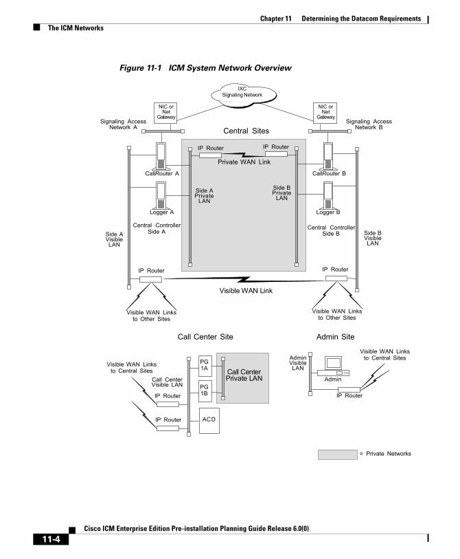
Chapter 11 Determining the Datacom RequirementsThe ICM Networks
Figure 11-1 ICM System Network Overview
Visible WAN Linksto Central Sites
ACD
PG1A
PG1B
Call CenterPrivate LANCall Center
Visible LAN
IP Router
IP Router
CallRouter A
Logger A
Central ControllerSide A
Admin
AdminVisibleLAN
IP Router
Visible WAN Linksto Central Sites
NIC orNet
Gateway
IP Router
Side APrivate
LAN
Side AVisibleLAN
Visible WAN Linksto Other Sites
Central ControllerSide B
IP Router
Side BPrivate
LAN
Side BVisibleLAN
Private WAN Link
Visible WAN Link
IP Router
= Private Networks
Visible WAN Linksto Other Sites
Call Center Site Admin Site
CallRouter B
Logger B
IP Router
Central SitesSignaling Access
Network ASignaling Access
Network B
IXCSignaling Network
NIC orNet
Gateway
11-4Cisco ICM Enterprise Edition Pre-installation Planning Guide Release 6.0(0)

Chapter 11 Determining the Datacom RequirementsThe ICM Networks
In Figure 11-1, the two sides of the Central Controller are geographically separated. The wide area network connections in both the private and visible networks are referred to as WAN links. WAN links in the ICM system are typically high-availability provisioned circuits. These links must possess extremely low and extremely predictable latency characteristics. Therefore, some types of WAN service cannot be used for WAN links within the ICM system (for example, packet routing).
Private and Visible WAN LinksThe two sides of the duplexed ICM Central Controller share a single private network and are linked via a private WAN link. They also share a visible network which connects the two sides via a visible WAN link. To ensure a high level of fault tolerance, the private WAN link and visible WAN links must be independent (that is, they must use different trunks and possibly even different service providers).
When the two sides of the Central Controller are collocated, the visible WAN link between the sites is not needed. The standard visible WAN links to remote contact center sites provide adequate connectivity between the two sides. In a collocated Central Controller configuration, the private network is implemented locally by using IP switches.
Remote contact centers connect to each side of the Central Controller via the visible network. Each visible WAN link to a contact center must have adequate bandwidth to support PGs and AWs at the contact center (the bandwidth requirement varies greatly as the configuration changes, that is, the call load, the number of agents, etc.).
When a contact center is collocated with a side of the Central Controller, the PGs and AWs connect to the visible LAN on that side. The PGs and AWs connect to the other side of the Central Controller via a visible WAN link. In such a configuration, a direct visible WAN link between the sides of the Central Controller is required to ensure adequate connectivity between the two sides. LAN bridges may optionally be deployed to isolate PGs from the AW LAN segment and to enhance protection against LAN outages.
Note See the section titled Central Sites, page 11-21, for some examples of collocated Central Controller configurations.
11-5Cisco ICM Enterprise Edition Pre-installation Planning Guide Release 6.0(0)
Chapter 11 Determining the Datacom RequirementsThe ICM Networks
Signaling Access NetworkingThe CallRouter machine connects to the IXC signaling network via the Signaling Access Network (SAN). A separate LAN interface card in the CallRouter is dedicated for use just by the SAN. The SAN connects the NICs on each side of the duplexed system to the IXC signaling network. In most cases, the NIC software runs on the CallRouter computer. For clarity, in Figure 11-1, the NIC is shown as a separate computer installed on the SAN.
A node called the ICM Network Gateway may also be installed on the SAN and used to interface to some SS7-based networks. The ICM Network Gateway is a dedicated machine that provides SS7 protocol handling services.
Local Area NetworksThe ICM system uses Ethernet for local area network connectivity. The particular Ethernet topology used is immaterial from an architectural standpoint. However, the topology used may be relevant from a network or systems management perspective. Typically, UTP is used in the private, visible, and signaling access LANs.
The three networks (visible, private, and signaling) should be on separate LAN segments. This requires the use of three Ethernet cards in the CallRouter machine.
Network Bandwidth RequirementsThe visible network bandwidth requirements for a typical ICM system are about 1,000 bytes of data per call over the networks that carry call data. For example, if a remote PG is managing 15 calls per second at a contact center site, it needs to transfer 15,000 bytes of data over the visible WAN to the central site every second (a total of 120,000 bits per second, ignoring packet overhead).
The bandwidth for the private WAN between the two sides of a duplexed Central Controller must support the total sustained call load for all ACD sites. In addition, bandwidth on this private WAN must provide some degree of burst resilience and enough reserve capacity to perform fault tolerant messaging and synchronization.
11-6Cisco ICM Enterprise Edition Pre-installation Planning Guide Release 6.0(0)

Chapter 11 Determining the Datacom RequirementsThe ICM Networks
Table 11-1 summarizes the network circuit requirements for visible and private networks within the ICM system.
You may require additional bandwidth on the visible WAN. The actual requirement depends on a number of factors, including call load, the number of ACDs, the number of agents, and the number of Admin sites.
Note If your network will be utilizing the Cisco ICM Quality of Service (QoS) feature, see also the section Cisco ICM QoS, page 11-12, for additional bandwidth considerations.
Table 11-1 Network Circuit Requirements
Network Purpose Facilities Min. Bandwidth
Private WAN Dedicated path that connects both sides of a duplexed, distributed ICM Central Controller.
T1 T1 dedicated
Visible WAN Circuits that connect PGs and AWs at remote sites to each side of the ICM Central Controller.
Typically, a T1 or a fractional T1.
128-Kbps dedicated.1
Signaling Access Network
Local area network that connects the NIC to the IXC carrier network or client network.2
Ethernet Unshielded Twisted Pair (UTP).
100 Mbps
Visible and private LANs
Local area networks that connect ICM nodes at a central site and PGs and AWs at remote contact center sites. (See Figure 11-1 for examples.)
Ethernet Unshielded Twisted Pair (UTP). Cisco recommends using manageable hubs.
100 Mbps
1. Variable, depending on load. See the section Calculating QoS Bandwidth Requirements, page 11-17, for a means of calculating the minimum required bandwidth for a Quality of Service (QoS) compliant network.
2. For the Sprint NIC, the local Ethernet Signaling Access Network is not implemented. Instead, X.25 WAN cards in the CallRouter platform serve as the Signaling Access Network and allow the CallRouter-NIC machine to connect to the IXC signaling network.
11-7Cisco ICM Enterprise Edition Pre-installation Planning Guide Release 6.0(0)

Chapter 11 Determining the Datacom RequirementsThe ICM Networks
Network Latency RequirementsThe ICM system is a real-time, fault-tolerant distributed system. To guarantee the real-time nature of the system and to support the methods used in fault tolerance, the WAN links in the ICM system must have extremely low and predictable message latency characteristics, especially in these critical areas:
• Route requests and route responses between the CallRouter/NIC and IXC. This communication must meet the strict message latency requirements of the carrier networks.
• Communications involving Post-Routing requests from PGs and route responses from the CallRouter. This communication must also be extremely fast since callers are on-line expecting the call to be answered by an appropriate agent.
• Communications from the PGs to the CallRouter concerning the real-time status of the contact center. The CallRouter needs this information to base its routing decisions on the latest data available from the contact center.
Three fault tolerance mechanisms of the ICM system require reliable, low latency communications. These are heartbeat detection, synchronization, and state transfer.
Note If your network will be utilizing the Cisco ICM Quality of Service (QoS) feature, see also the section Cisco ICM QoS, page 11-12, for additional latency considerations.
Heartbeat DetectionAs part of its fault-tolerant design, the ICM system must be able to quickly respond when a component goes off-line for any reason (typically, because of a failure in the node or in a network link). Each critical component in the system periodically sends short messages through the network to indicate that it is still on-line. These messages are called heartbeats.
11-8Cisco ICM Enterprise Edition Pre-installation Planning Guide Release 6.0(0)

Chapter 11 Determining the Datacom RequirementsThe ICM Networks
Communicating ICM components send heartbeats to each other at regular intervals. If a component fails to receive a heartbeat for five consecutive intervals, it assumes that the component or a network link has failed and it initiates recovery actions. Table 11-2 lists some of the nodes that send heartbeats, the network on which they are sent, and how often they are sent.
The two sides of a duplexed ICM Central Controller periodically test each other to see if the other side is operating correctly. As shown in Table 11-2, network latency from CallRouter-to-CallRouter over the private network must support round trip messaging of 100 milliseconds. If the bandwidth of the private network is not adequate, packets may need to be fragmented by IP routers in order to prevent long messages (greater than 1,500 bytes). Such long messages can delay transmission of User Diagram Protocol (UDP) packets, which indicate that the other side of the Central Controller is still operating.
Note Beginning with ICM 5.0(0), TCP keep-alive is used rather than UDP. However, UDP would continue to be used if a pre-5.0(0) PG were used with a 5.0(0) or 6.0(0) Central Controller (though this configuration is not supported except during an upgrade).
Another requirement of fault tolerance is that messages cannot be released back to a NIC or PG until the other side of the Central Controller has acknowledged receipt of a copy of the message. Therefore, in order to meet the 200 millisecond response times established by the carrier networks, and to leave some margin for queuing, a 100 millisecond round trip requirement is established.
Heartbeats from a remote PG to the CallRouter must compete with other network traffic on the visible WAN.
Table 11-2 Heartbeat Configuration
Node Medium Interval
AT&T NIC (or Network Gateway) to CallRouter
Signaling Access Network
200 milliseconds
CallRouter to CallRouter Private network 100 milliseconds
PG to CallRouter Visible network 400 milliseconds
PG to PG (if duplexed) Private network 100 milliseconds
11-9Cisco ICM Enterprise Edition Pre-installation Planning Guide Release 6.0(0)

Chapter 11 Determining the Datacom RequirementsThe ICM Networks
SynchronizationIn a duplexed Central Controller configuration, the private network allows the CallRouters and Loggers on each side to run in a synchronized fashion. This means that the CallRouter and Logger processes on each side of the system receive the same input and generate the same output.
To ensure synchronization, each message intended for the CallRouter or Logger is received by a Synchronizer process that runs on the CallRouter node. The Synchronizer forwards the message across the private network to the Synchronizer on the other side. The Synchronizers then remove any duplicates before passing the messages on to the CallRouter processes. If a message is intended for the Logger, the CallRouter passes it along (Figure 11-2).
Figure 11-2 Role of Synchronizers
Synchronizer Synchronizer
1
4
2
3
5
1
4
2
3
5
CallRouter CallRouter
Central ControllerSide A
Central ControllerSide B
1
2
3
4
5
1
2
3
4
5
Input MessagesPGs NICs
11-10Cisco ICM Enterprise Edition Pre-installation Planning Guide Release 6.0(0)

Chapter 11 Determining the Datacom RequirementsThe ICM Networks
Figure 11-2 shows how the Synchronizers combine input messages and send the messages in the same order to each side of the Central Controller. Both CallRouters receive the same input and generate the same output. The Synchronizers ensure that both sides of the Central Controller return identical destinations for the same call and write identical data to the databases.
State TransferThe fault tolerance of the ICM system enables nodes to restart after a failure. However, when a failed node restarts, the values of variables in its memory are out-of-date. Before returning the node to service, the ICM system must copy the values from its peer on the other side to the recovering node. That is, it must transfer the state of the running machine to the recovering machine. This transfer takes place over the private network.
Note that such state transfers occur after the failure and restart of any synchronized MDS client: PG, Logger, CallRouter, etc.
Diverse FacilitiesThe private WAN between Central Controllers (when the Central Controllers are geographically separated) and the visible WAN must be on separate facilities. They must use different circuits and different IP routers. As added protection, you might also want to use diverse routes or even different service providers for the private and visible WAN links. Otherwise, you run the risk of having a single network failure disable both the ICM private and visible WANs.
For example, if the private WAN failed, or a visible WAN link to one side of the Central Controller failed, the ICM system would continue to route calls and function normally. However, if the private WAN and the visible WAN were on the same facilities and failed simultaneously, the fault tolerance of the system would be compromised. In such a scenario, the failure of any single node on either side of the Central Controller would interrupt system processing. By provisioning the private WAN and visible WAN on separate facilities, you can eliminate this potential point of failure.
11-11Cisco ICM Enterprise Edition Pre-installation Planning Guide Release 6.0(0)

Chapter 11 Determining the Datacom RequirementsCisco ICM QoS
Cisco ICM QoSThis section describes the Cisco ICM Quality of Service (QoS) feature, and discusses considerations to take into account when planning for and deploying ICM networks that will utilize QoS.
What Is Quality of Service?Quality of Service is a set of capabilities that enables you to define a level of performance in a data communications network. QoS allows you to create differentiated services for network traffic, thereby providing better service for selected network traffic. For example, with QoS, you can increase bandwidth for critical traffic, limit bandwidth for non-critical traffic, and provide consistent network response. This enables you to use expensive network connections more efficiently, lets you establish service level agreements with customers of the network, and eliminates the need for Peripheral Gateways (PGs) to have dedicated leased lines for connection with ICM components.
QoS capabilities enable ICM software to overcome the following architectural limitations:
• ICM software requires dedicated leased lines. This means that ICM cannot be deployed in a converged network, which is more cost-effective and has more transmission capacity.
• Lack of a congestion control mechanism over the LAN segment. This is often considered not important because LAN resources tend to be less costly than WAN resources. However, with the increasing usage of multimedia applications on LANs, delays through LAN switches do become problematic. The QoS technology 802.1p tackles these delays.
• Lack of support for Cisco’s AVVID (Architecture for Voice, Video and Integrated Data) enterprise network architecture. AVVID defines the network design principles to optimize the integration of mission-critical applications in a convergent network environment. QoS is a key technology for AVVID. ICM should be AVVID compliant to be better deployed in a Cisco AVVID network.
• Problematic UDP heartbeats. The use of UDP heartbeats creates unnecessary complexity for ICM deployment in firewall and NAT (Network Address Translation) environments. For this reason, UDP heartbeats are replaced by TCP keep-alive messages in ICM QoS implementation.
11-12Cisco ICM Enterprise Edition Pre-installation Planning Guide Release 6.0(0)

Chapter 11 Determining the Datacom RequirementsCisco ICM QoS
To implement QoS, you define QoS properties and policies on network devices (routers and switches). The policies can differentiate traffic based on its source, destination, or type. For example, you can recognize traffic based on the network host, port, protocol, or even IP precedence values in the packets.
QoS primarily comes into play when the amount of traffic through an interface is greater than the interface's bandwidth. When the traffic through an interface exceeds the bandwidth, packets form one or more queues from which the device selects the next packet to send. By setting the queuing property on a device or interface, you can control how the queues are serviced, thus determining the priority of the traffic.
As a result of the initial phase of the ICM QoS project, ICM Releases 5.0(0) and 6.0(0) support DSCP (Differentiated Services Codepoint) and 802.1p marking for communication between the Peripheral Gateway Agent (PG Agent) and the Central Controller Agent (CC Agent).
Deploying Cisco ICM QoSThe process of deploying and implementing QoS is a combined effort supported by Cisco System Engineers, ICM Deployment Groups, and Cisco Partners. These Cisco representatives provide customers who plan to deploy QoS with the following assistance:
• Defining customer requirements. Cisco Professional Services and Cisco Partners utilize their historical knowledge of the customer’s ICM deployment, and QoS bandwidth calculation tools (see the section Calculating QoS Bandwidth Requirements, page 11-17), to assess these requirements.
• Reviewing the ICM portion of the customer’s QoS migration plan.
• Meeting with the customer to prepare a statement of work that defines the level of support Cisco will provide.
Alongside these steps, there are the following tasks to consider when planning to implement a QoS-compliant network in your ICM environment.
• Installing Microsoft Packet Scheduler on the public network interfaces
• Determining the DSCP markings.
• Determining bandwidth requirements (see the section Calculating QoS Bandwidth Requirements, page 11-17).
11-13Cisco ICM Enterprise Edition Pre-installation Planning Guide Release 6.0(0)

Chapter 11 Determining the Datacom RequirementsCisco ICM QoS
• Installing and configuring 802.1p-capable network components (optional).
• Configuring QoS on IP routers.
Installing Microsoft Packet Scheduler
Note In ICM 5.0(0), which used Windows 2000 SP3, Microsoft Packet Scheduler hotfixes were required. However, Microsoft has incorporated these hotfixes into Windows 2000 SP4—the base operating system for ICM 6.0(0).
Microsoft Packet Scheduler is a key component in creating the Windows 2000 QoS solution. It regulates how much data a given flow is allowed, when those packets are put onto the network, and in which order such packets (those ready for transmission) are sent.
Though Packet Scheduler installation is not strictly required, Cisco recommends that Packet Scheduler be installed in order to provide the ICM QoS implementation with two significant benefits:
• The Packet Scheduler’s shaping functionality mitigates the burst nature of ICM transmissions by smoothing transmission peaks over a given period of time, and thereby smoothing out network usage to affect a more steady use of the network.
• 802.1p tagging on Windows 2000 is available only if the Packet Scheduler is installed. Without the use of 802.1p, there is no physical guarantee that any prioritized data transmissions will receive a better service than best-effort transmissions receive in the LAN segment. Furthermore, there is no way to differentiate between higher-priority QoS-enabled traffic and lower-priority QoS-enabled traffic.
ICM DSCP markings can be done with or without Packet Scheduler. When Packet Scheduler is bypassed, packet marking occurs in the ICM software.
To install Microsoft Packet Scheduler, perform the following steps on both the CallRouter machines and the PG machines.
11-14Cisco ICM Enterprise Edition Pre-installation Planning Guide Release 6.0(0)
Chapter 11 Determining the Datacom RequirementsCisco ICM QoS
Note All current TCP connections are terminated when the Packet Scheduler is installed. Therefore, even though a reboot of the machine is not required when the Packet Scheduler is installed, current TCP connections are terminated. You should not install the Packet Scheduler if important connections are in progress.
Step 1 Open Network and Dial-up Connections.
Step 2 Right click the Network Connection (Public Visible) on which you want to install the QoS Packet Scheduler. Select Properties.
Step 3 Click the Install button. The Select Network Component Type dialog box appears.
Step 4 Select Service and click the Add button. The Select Network Service dialog box appears.
Step 5 Select QoS Packet Scheduler. Click OK to begin the installation process.
Determining DSCP Markings
ICM DSCP markings are set in compliance with Cisco AVVID recommendations (but can be overwritten if necessary). See Cisco AVVID Solution IP Telephony QoS Classification for details about Cisco AVVID packet classifications.
Before QoS implementation, IP-based prioritization is used to provide two externally visible priority levels (High and non-High) for the communication between the PG and the CC. In fact, however, there are three different priorities for application messages: High, Medium, and Low. High and medium priority messages are sent through the same High priority IP connection, and low priority messages are sent through the non-High priority IP connection.
With QoS implementation, DSCP is the means of marking and maintaining an IP packet’s relative priority as it traverses the network. The DSCP value for each priority must be defined appropriately so that its latency requirement is met.
Table 11-3 lists application messages under each priority and the corresponding latency requirement.
11-15Cisco ICM Enterprise Edition Pre-installation Planning Guide Release 6.0(0)

Chapter 11 Determining the Datacom RequirementsCisco ICM QoS
Three DSCP levels are available in accordance with message priorities if Packet Scheduler is bypassed. Enabling Packet Scheduler, in contrast, reduces a DSCP level because Microsoft Packet Scheduler supports at most three levels including best effort, and therefore both high and medium priority traffic will be marked with the same high priority DSCP value.
The following are recommended guidelines for specifying DSCP settings:
• If the ICM system is deployed in conjunction with an AVVID solution and Packet Scheduler is enabled, the recommended DSCP setting is to mark the high and medium priority traffic with a DSCP of 26 (AF31) and treat them with the same priority as VoIP control packets; to mark the low priority traffic with a DSCP of 10 (AF11).
• If Packet Scheduler is bypassed, Cisco recommends that you separate the medium priority traffic from high and mark it as 18 (AF21), and lower low priority traffic to 10 (AF11).
Table 11-3 PG-Router Message Priorities and Latency Requirements
Priority Messages Latency Requirement
High Routing
Application Heartbeat
Protocol control
Network probe
200 ms
Medium Resource status update
Resource status synchronization
Network probe
1,000 ms
Low Half-hour data
Call Termination Details
Timer notification
Routing client meters
Network probe
5 seconds
11-16Cisco ICM Enterprise Edition Pre-installation Planning Guide Release 6.0(0)

Chapter 11 Determining the Datacom RequirementsCisco ICM QoS
Note These recommended DSCP values are also fully compatible with the Type of Service (TOS) values used by layer 3 devices that do not support DSCP marking. These TOS values are fully understood and supported by most older network routers.
Note Make a note of the DSCP values that you specify, as you will need to specify them again during Router and PG setup. See the Cisco ICM Enterprise Edition Installation Guide for details.
Calculating QoS Bandwidth Requirements
Although QoS alleviates bandwidth usage and increases network throughput, network congestion is still unavoidable unless sufficient physical bandwidth is available along the path. For ICM, the bandwidth requirement at each priority is a function of traffic volume and latency requirement. It varies greatly for ICM systems depending on factors such as call load, traffic composition, call context information, and configuration settings.
Cisco provides the following QoS bandwidth calculation spreadsheets to help Cisco System Engineers, ICM Deployment Groups, and Cisco Partners project traffic volume and bandwidth requirement.
• The ACD/CM PG to CC Bandwidth Calculator Spreadsheet. This spreadsheet calculates the volume of traffic sent between the ACD (or Call Manager) PG and the Central Controller.
• The VRU PG to CC Bandwidth Calculator Spreadsheet. This spreadsheet calculates the volume of traffic sent between the VRU PG and the Central Controller.
Note The ICM QoS bandwidth reservations are only made within the local MS Packet Scheduler for the purpose of shaping; no reservations are made in the network. Therefore, the bandwidth settings on IP devices must be configured manually or by using Cisco tools.
11-17Cisco ICM Enterprise Edition Pre-installation Planning Guide Release 6.0(0)

Chapter 11 Determining the Datacom RequirementsCisco ICM QoS
Installing and Configuring 802.1p-Capable Components
Note 802.1p is optional. However, see Installing Microsoft Packet Scheduler, page 11-14, for reasons why you might want to use it.
802.1p expresses priority class by setting three bits in the Layer 2 MAC header, whose binary values 0 through 7 represent eight distinct priority classes (named as Class of Service). For ICM, the default 802.1p settings are compliant with Cisco AVVID recommendations. Specifically, the high and medium traffic uses the value of 3, and the low priority traffic uses the value of 1. See Cisco AVVID Solution IP Telephony QoS Classification for details about Cisco AVVID packet classifications.
If you wish to enable 802.1p marking capabilities as part of your QoS implementation, you must perform the following tasks:
• Install and enable Microsoft Packet Scheduler, as discussed in the section “Installing Microsoft Packet Scheduler”.
• Install 802.1p-capable NICs in the QoS-enabled ICM computers (the Router and the PG)
• Enable 802.1p on the NICs, through the Advanced tab on the NIC Properties screen. This is done by enabling a selection most often referred to as QoS Packet Tagging.
• Install 802.1p-capable switches on the LAN segment.
• Configure 802.1p-capable switches and coordinate their configuration with the settings on the Router and/or the PG.
Note It is recommended that you install NIC cards before you install ICM software. If you add a NIC card after you install ICM software, you will need to reinstall ICM software.
Refer to Cisco AVVID Network Infrastructure Enterprise Quality of Service Design for details about AVVID-Enabled campus network design, switch selection, and QoS configuration commands.
11-18Cisco ICM Enterprise Edition Pre-installation Planning Guide Release 6.0(0)

Chapter 11 Determining the Datacom RequirementsCisco ICM QoS
Configuring QoS on IP Routes
See Cisco AVVID Network Infrastructure Enterprise Quality of Service Design for details about AVVID-Enabled WAN design, router selection, and QoS configuration commands.
Additional TasksThis section briefly discusses a few additional tasks that you need to perform, after the deployment tasks listed in the previous sections, to ensure that your QoS-enabled network runs correctly and efficiently.
Specifying QoS Parameters During ICM Install
During ICM Router and Peripheral Gateway setup, you need to specify values for DSCP markings and for bandwidth reservations. Refer to the Cisco ICM Enterprise Edition Installation Guide for details.
Monitor QoS Performance
Once your QoS implementation is up and running, you can use the Windows Performance Monitor to track the performance values associated with links between the Peripheral Gateway Agent (PG Agent) and the Central Controller Agent (CC Agent). See the Cisco ICM Enterprise Edition Administration Guide for information on using the Windows Performance Monitor.
Note Depending on your operating system version, this tool may be named System Monitor
For More Information on QoSThe following are Cisco documents that contain additional information on QoS. You can access most Cisco documentation from the Cisco corporate website at http://www.cisco.com.
• Cisco AVVID Network Infrastructure Overview
11-19Cisco ICM Enterprise Edition Pre-installation Planning Guide Release 6.0(0)

Chapter 11 Determining the Datacom RequirementsActive Directory Model
• Cisco AVVID Network Infrastructure Enterprise Quality of Service Design
• Cisco AVVID Solution: IP Telephony QoS Classification
• Planning for Quality of Service
• Quality of Service Networking
• Cisco IP Telephony QoS Design Guide
Active Directory ModelEffective with Release 5.0(0), ICM software requires the use of the Windows 2000 Active Directory service and Domain Name System (DNS) to maintain the Active Directory model. This means that you must specify a preferred and an alternate DNS server. See the documents Cisco ICM Windows 2000 Planning Guide and Cisco ICM Windows 2000 Staging Guide for more information.
Note ICM Release 6.0(0) supports Windows 2003 Active Directory where Domain Controllers are dedicated servers (that is, not running any ICM application).
TCP/IP ConfigurationTo set up IP addresses for Windows 2000 nodes, use the TCP/IP Properties dialog box. To display this dialog box, go to the Windows 2000 Start menu and choose Settings > Network and Dialup Connections > Local Area Connection. In the Local Area Connection Status window, click on Properties. Select Internet Protocol (TCP/IP) and click on Properties.
Select “Use the following IP address.” Enter the IP address and click OK. To enter additional IP addresses, open the TCP/IP Properties window again and click the Advanced button. The Advanced TCP/IP Settings window allows you to enter additional IP addresses.
11-20Cisco ICM Enterprise Edition Pre-installation Planning Guide Release 6.0(0)

Chapter 11 Determining the Datacom RequirementsCentral Sites
Central SitesEach side of the Central Controller includes the CallRouter, Logger, and Network Interface Controller (NIC). These may be on three separate nodes, two nodes, or a single node. Although the NICs are indicated as separate nodes for clarity, in fact a NIC is implemented as a process within the CallRouter node. The two sides of the Central Controller may be at two different central sites as shown in Figure 11-3.
Figure 11-3 Geographically Distributed Central Controller
IP Router
CallRouter A
Logger A
Central ControllerSide A
IP Router
Side APrivateLAN
Side AVisibleLAN
Visible WAN Linksto Other Sites
Central ControllerSide B
IP Router
Side BPrivateLAN
Side BVisibleLAN
Private WAN Link
Visible WAN Link
IP Router
Visible WAN Linksto Other Sites
CallRouter B
Logger B
IXCSignaling Network
NICor Net
GatewaySignaling AccessNetwork A
Signaling AccessNetwork B
NICor Net
Gateway
11-21Cisco ICM Enterprise Edition Pre-installation Planning Guide Release 6.0(0)

Chapter 11 Determining the Datacom RequirementsCentral Sites
The private network carries ICM system traffic between the nodes on one side of the Central Controller and between the nodes on both sides of the system. The traffic between the two sides of the Central Controller consists of synchronization and state transfer messaging between the CallRouters and Loggers. Most communications between the CallRouter and Logger on one side take place over the private network.
The private WAN link (see Figure 11-3) is critical to the overall responsiveness of the ICM system. First, it must provide sufficient bandwidth to handle simultaneous synchronizer and state transfer traffic. It must also have enough bandwidth left over in case additional data must be transferred as part of a recovery operation. Since the private WAN link is the only link that carries Central Controller synchronization and state transfer traffic, you may want to provision backup service of some kind as a contingency for network outages.
The IP routers in the private network always use traffic prioritization, and frequently use IP fragmentation, to ensure that high priority ICM system traffic does not experience excessive queuing delay. Alternately, both sides of the Central Controller may be collocated at a single site as shown in Figure 11-4.
11-22Cisco ICM Enterprise Edition Pre-installation Planning Guide Release 6.0(0)

Chapter 11 Determining the Datacom RequirementsCentral Sites
Figure 11-4 Collocated Central Controller
In a collocated Central Controller configuration, IP switches separate the Side A and Side B private Ethernet LANs for fault tolerance. This private network bridge replaces the private WAN link shown earlier in Figure 11-3. A visible network bridge also connects the Side A and Side B visible networks.
CallRouter A
Logger A
Central ControllerSide A
IP Router
Side APrivate
LAN
Side AVisibleLAN
Visible WAN Linksto Other Sites
Central ControllerSide B
IP Router
Side BVisibleLAN
Visible WAN Linksto Other Sites
CallRouter B
Logger B
IXCSignaling Network
NICor Net
GatewaySignaling AccessNetwork A
Signaling AccessNetwork B
Private NetworkBridge
Visible NetworkBridge
Side BPrivate
LAN
NICor Net
Gateway
11-23Cisco ICM Enterprise Edition Pre-installation Planning Guide Release 6.0(0)

Chapter 11 Determining the Datacom RequirementsCentral Sites
The Visible NetworkEach central site has a visible network that connects nodes within that site. To allow communication between sites, each side of the Central Controller must have one IP router on its visible LAN.
Note When a Peripheral Gateway is collocated with one side of a duplexed, geographically distributed Central Controller, you must have a direct connection between the visible WAN IP routers at the two central sites. This ensures that there is adequate visible network connectivity between the sides of the Central Controller.
The IP router requires a single address on the LAN. It also requires that you define a static route on the IP router for each contact center’s visible LAN and for each admin site’s visible LAN.
Visible IP Router Configuration
To allow optimal tuning of the network, Cisco recommends using IP routers that allow you to prioritize packets based on a range of source or destination port numbers. Typically, you need to set up the IP router to give higher priority to certain outgoing network packets. Also, depending on the bandwidth available on the visible WAN, you may need to set up IP fragmentation. Table 11-4 summarizes the configuration for the visible network IP router.
Table 11-4 Central Site Visible IP Router Configuration
Attribute Requirements
IP Addresses One address required.
Default Gateway The network bridge (or the IP router used as bridge), if any. Otherwise, the IP router does not have a default gateway.
11-24Cisco ICM Enterprise Edition Pre-installation Planning Guide Release 6.0(0)

Chapter 11 Determining the Datacom RequirementsCentral Sites
You may need to prioritize packets as described in Table 11-5.
The maximum queuing delay is 50 milliseconds to contact center sites that use Post-Routing or translation routes and 200 milliseconds to other contact center sites. You may have to implement fragmentation to meet these limits.
Static Routes Define one static route for the visible LAN at each remote contact center site and each admin site. If the central sites are geographically separated, add a static route for the other central site.
Other Turn off any preset routing protocols.
Give higher priority to specific network packets.
Use fragmentation if necessary to limit the queuing delay.
Table 11-5 Visible Network Packet Priorities from Central Site
Packet Type High Priority Low Priority
TCP If received from the CallRouter’s high priority address (as derived from the packet’s source address).
If received from any other address.
UDP1
1. When both CallRouter and PG are running ICM Release 5.0(0) or later, heartbeats are not used; TCP is used instead. This is determined on a PG path basis.
If source or destination port number is in the range 39000–39999.2
2. If you cannot configure the IP router to assign priority based on a range of port numbers, then assign a high priority to all UDP packets.
All other UDP packets.
Table 11-4 Central Site Visible IP Router Configuration (continued)
11-25Cisco ICM Enterprise Edition Pre-installation Planning Guide Release 6.0(0)

Chapter 11 Determining the Datacom RequirementsCentral Sites
The Private NetworkEach central site must also have its own private LAN. If the sides of the Central Controller are geographically separated, each private LAN has one IP router to communicate with the private WAN that connects the two sides.
If the two sides of the Central Controller are collocated, the IP router on the private LAN is not needed. If two central sites are geographically separated, each side requires an IP router on the private network.
Table 11-6 summarizes the configuration for the private network IP router.
Table 11-7 describes how private network packets must be prioritized.
Table 11-6 Central Site Private IP Router Configuration
Setting Requirements
IP Addresses One address required on the private LAN.
Default Gateway None.Static Routes Define one static route for the private LAN at the other
central site.
Other Turn off any preset routing protocols.
Give higher priority to specific network packets.
11-26Cisco ICM Enterprise Edition Pre-installation Planning Guide Release 6.0(0)

Chapter 11 Determining the Datacom RequirementsCentral Sites
The Signaling Access NetworkEach central site must have its own Signaling Access Network (SAN). The ICM system uses the Signaling Access Network to communicate with the IXC signaling network. The Signaling Access Network for the MCI, AT&T, Nortel, and Stentor NICs is implemented as an Ethernet LAN. This LAN is separate from the ICM private LAN.
In Sprint NIC configurations, the Signaling Access Network is implemented via Eicon X.25 WAN cards on the CallRouter platform. These cards allow the ICM system to connect the IXC signaling network. The X.25 links to the IXC signaling network are considered the Signaling Access Network. In these configurations, the separate Ethernet Signaling Access Network is not required.
Figure 11-5 shows a typical Signaling Access Network for a single central site. It assumes that the two sides are geographically separated.
Note The IP addresses shown in this and subsequent figures are examples only. Use addresses specific to your networks.
Table 11-7 Private Network Packet Priorities from Central Site
Packet Type High Priority Low Priority
TCP If the source address is the local CallRouter’s high priority address or the destination address is the other CallRouter’s high priority address.
All other TCP packets.
UDP If source or destination port number is in the range 39000–39999.1
1. If you cannot configure the IP router to assign priority based on a range of port numbers, then assign a high priority to all UDP packets.
All other UDP packets.
11-27Cisco ICM Enterprise Edition Pre-installation Planning Guide Release 6.0(0)

Chapter 11 Determining the Datacom RequirementsCentral Sites
Figure 11-5 Central Site Signaling Access Network
The CallRouter NodeThe CallRouter connects to the visible network through the visible LAN; and to the private network through the private LAN. The CallRouter also has a connection to the Signaling Access Network. (See Figure 11-6.)
Subnet199.199.210.0
Signaling AccessNetwork
Central SitePrivate IP Router
Router A
High: 199.199.199.11Low: 199.199.199.10
Subnet199.199.199.0
199.199.254.1
Central SiteVisible LAN
Central SitePrivate LAN
High: 199.199.254.11Low: 199.199.254.10
Subnet199.199.254.0
Central SiteVisible IP Router
199.199.199.1
Logger A
199.199.199.8 199.199.254.8
NICor Net
Gateway
199.199.210.2
11-28Cisco ICM Enterprise Edition Pre-installation Planning Guide Release 6.0(0)

Chapter 11 Determining the Datacom RequirementsCentral Sites
Figure 11-6 CallRouter Network Connections
As shown in Figure 11-6, the CallRouter requires two addresses on the visible LAN; two addresses on the private LAN; and two addresses on the signaling access LAN. This allows the ICM system to separate high-priority network traffic from low-priority traffic.
Table 11-8 summarizes the visible network configuration for the CallRouter.
Table 11-9 summarizes the private network configuration for the CallRouter.
Table 11-8 CallRouter Visible Network Configuration
Setting Requirements
IP Addresses Two required: one for high priority data; one for low (normal) priority data.
Default Gateway Visible network IP router.
Static Routes None.
Other Preferred and alternate DNS server. See Active Directory Model, page 11-20.
Central SitePrivate IP Router
Router A
High: 199.199.199.11Low: 199.199.199.10
Subnet199.199.199.0
199.199.254.1
Central SiteVisible LAN
Central SitePrivate LAN
High: 199.199.254.11Low: 199.199.254.10
Subnet199.199.254.0
Central SiteVisible IP Router
199.199.199.1
Subnet199.199.210.0 Signaling Access
Network
199.199.210.2
High: 199.199.210.11Low: 199.199.210.10
NICor Net
Gateway
11-29Cisco ICM Enterprise Edition Pre-installation Planning Guide Release 6.0(0)

Chapter 11 Determining the Datacom RequirementsCentral Sites
Note Instructions on disabling Windows 2000 networking on the private LAN appear later in this section.
Table 11-10 summarizes the Signaling Access Network configuration for the CallRouter.
Disabling Windows 2000 Networking
You need to disable network bindings for the private LAN adaptor on machines that connect to the ICM private network.
Table 11-9 CallRouter Private Network Configuration
Setting Requirements
IP Addresses Two required: one for high priority data; one for low (normal) priority data.
Default Gateway None. (The default gateway is on the visible LAN.)
Static Routes If the sides of the Central Controller are geographically separated, define one static route for the subnet address of the private LAN on the other side of the Central Controller.
Other Disable Windows 2000 networking on the private LAN.
Table 11-10 CallRouter Signaling Access LAN Configuration
Setting Requirements
IP Addresses Two may be required, the second functioning as a serviceability interface for your ICM service provider.
Default Gateway None.
Static Routes None.
Other Disable Windows 2000 networking on the Signaling Access Network.
11-30Cisco ICM Enterprise Edition Pre-installation Planning Guide Release 6.0(0)

Chapter 11 Determining the Datacom RequirementsCentral Sites
You can disable Windows 2000 networking on the private LAN interface through the Network and Dial-up Connections window. Right click on the My Network Places icon on the Windows 2000 desktop. The Network and Dial-up Connections window appears. (Optionally, you can right-click on the My Computer icon, select Explore, then right click on My Network Places and select Properties.)
Choose Advanced > Advanced Settings to display the Advanced Settings window:
Make sure that the visible network connection appears first in the list, followed by the private network connection. You can change the order in which the network connections appear by using the arrow buttons on the right side of the window. Select the private network connection and disable both “File and Printer Sharing for Microsoft Networks” and “Client for Microsoft Networks.”
The Logger NodeThe Logger can be on the same node as the CallRouter, as shown in Figure 11-7, or it can be a separate node as shown in Figure 11-8.
11-31Cisco ICM Enterprise Edition Pre-installation Planning Guide Release 6.0(0)

Chapter 11 Determining the Datacom RequirementsCentral Sites
Figure 11-7 CallRouter and Logger Combination
If the CallRouter and Logger are on the same node, then the Logger has no specific requirements; it uses low priority addresses defined for the node on the visible and private networks. If the two are on separate nodes, then the Logger requires its own connections to both the visible and private LANs (see Figure 11-8).
Router/Logger A
Central SitePrivate IP Router
High: 199.199.199.11Low: 199.199.199.10
Subnet199.199.199.0
199.199.254.1
Central SiteVisible LAN
Central SitePrivate LAN
High: 199.199.254.11Low: 199.199.254.10
Subnet199.199.254.0
Central SiteVisible IP Router
199.199.199.1
Subnet199.199.210.0 Signaling Access
Network
High: 199.199.210.11Low: 199.199.210.10
11-32Cisco ICM Enterprise Edition Pre-installation Planning Guide Release 6.0(0)

Chapter 11 Determining the Datacom RequirementsCentral Sites
Figure 11-8 Logger as a Separate Node
In addition to the IP addresses shown, the Logger node may require two additional addresses on the visible network. These addresses allow for dial-in connections by your ICM support provider’s Distributed Diagnostic and Service Network (DDSN).
Table 11-11 summarizes the visible network connections for the Logger.
Table 11-12 summarizes the private network configuration for the Logger.
Table 11-11 Logger Visible Network Configuration
Setting Requirements
IP Addresses Three addresses may be required: one for normal data; two more for DDSN dial-up connections.
Default Gateway Visible network IP router.
Static Routes None.
Other Preferred and alternate DNS server. See Active Directory Model, page 11-20.
Central SitePrivate IP Router
Router A
High: 199.199.199.11Low: 199.199.199.10
Subnet199.199.199.0
199.199.254.1
Central SiteVisible LAN
Central SitePrivate LAN
High: 199.199.254.11Low: 199.199.254.10
Subnet199.199.254.0
Central SiteVisible IP Router
199.199.199.1
Logger A
199.199.199.8 199.199.254.8
Subnet199.199.210.0 Signaling Access
Network
High: 199.199.210.11Low: 199.199.210.10
11-33Cisco ICM Enterprise Edition Pre-installation Planning Guide Release 6.0(0)

Chapter 11 Determining the Datacom RequirementsCentral Sites
If the Logger is on the same computer as the CallRouter, then the visible and private network IP configuration for the CallRouter is all that is required.
If the Logger is a separate node, you must disable networking on the private LAN interface (as was required for the CallRouter).
Define a static route in ICMEXEC.BAT, as for the CallRouter.
Optional Database Server PlatformIf you order the Cisco ICM Gateway SQL option, you need to set up an additional SQL Server database platform. The database server requires one IP address and one connection to the ICM visible network (Figure 11-9).
Table 11-12 Logger Private Network Configuration
Setting Requirements
IP Addresses One address required.
Default Gateway None. (The default gateway is on the visible LAN.)
Static Routes If the two sides of the Central Controller are geographically separated, define one static route for the subnet address of the private LAN for the other side of the Central Controller.
Other Disable Windows 2000 networking on the private LAN interface. (See Disabling Windows 2000 Networking, page 11-30, for more information.)
11-34Cisco ICM Enterprise Edition Pre-installation Planning Guide Release 6.0(0)
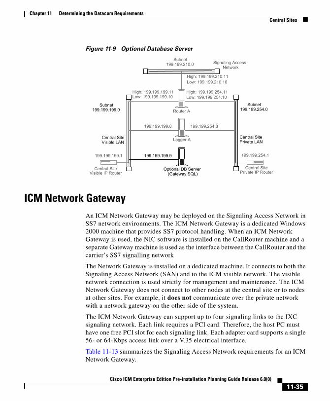
Chapter 11 Determining the Datacom RequirementsCentral Sites
Figure 11-9 Optional Database Server
ICM Network GatewayAn ICM Network Gateway may be deployed on the Signaling Access Network in SS7 network environments. The ICM Network Gateway is a dedicated Windows 2000 machine that provides SS7 protocol handling. When an ICM Network Gateway is used, the NIC software is installed on the CallRouter machine and a separate Gateway machine is used as the interface between the CallRouter and the carrier’s SS7 signalling network
The Network Gateway is installed on a dedicated machine. It connects to both the Signaling Access Network (SAN) and to the ICM visible network. The visible network connection is used strictly for management and maintenance. The ICM Network Gateway does not connect to other nodes at the central site or to nodes at other sites. For example, it does not communicate over the private network with a network gateway on the other side of the system.
The ICM Network Gateway can support up to four signaling links to the IXC signaling network. Each link requires a PCI card. Therefore, the host PC must have one free PCI slot for each signaling link. Each adapter card supports a single 56- or 64-Kbps access link over a V.35 electrical interface.
Table 11-13 summarizes the Signaling Access Network requirements for an ICM Network Gateway.
Central SitePrivate IP Router
Router A
High: 199.199.199.11Low: 199.199.199.10
Subnet199.199.199.0
199.199.254.1
Central SiteVisible LAN
Central SitePrivate LAN
High: 199.199.254.11Low: 199.199.254.10
Subnet199.199.254.0
Central SiteVisible IP Router
199.199.199.1
Logger A
199.199.199.8 199.199.254.8
Optional DB Server(Gateway SQL)
199.199.199.9
Subnet199.199.210.0 Signaling Access
Network
High: 199.199.210.11Low: 199.199.210.10
11-35Cisco ICM Enterprise Edition Pre-installation Planning Guide Release 6.0(0)

Chapter 11 Determining the Datacom RequirementsCentral Sites
Table 11-14 summarizes the visible network requirements for an ICM Network Gateway.
Admin Workstations at a Central SiteCisco recommends that you isolate the CallRouter, Logger, and PGs from the Admin Workstation LAN segment by using IP switches. This limits the impact of one network’s problems on another. By isolating the Central Controller and PGs from the Admin Workstation LAN segment, you can protect critical components from network hardware and software failures (for example, an open Ethernet tap or a network error burst).
Table 11-13 ICM Network Gateway Signaling Access Network Configuration
Setting Requirements
IP Addresses One address required.
Default Gateway None.
Static Routes None.
Other A HOSTS file is set up and changes are made to the CONFIG.SYS and AUTOEXEC.BAT files. Consult with your ICM support provider before changing these settings.
Table 11-14 ICM Network Gateway Visible Network Configuration
Setting Requirements
IP Addresses One address required.
Default Gateway Visible network IP router.
Static Routes None.
Other A HOSTS file is set up and changes are made to the CONFIG.SYS and AUTOEXEC.BAT files. Consult with your ICM support provider before changing these settings.
11-36Cisco ICM Enterprise Edition Pre-installation Planning Guide Release 6.0(0)

Chapter 11 Determining the Datacom RequirementsCentral Sites
For further protection against LAN outages, you can use an IP router instead of a bridge. You can then place the Admin Workstation on a separate LAN with other contact center computers and applications. The IP router is a better option in this situation. LAN bridges tend to forward network error bursts from one side of a LAN to the other. IP routers provide a better fire wall, since they do not forward network errors to other LANs.
The Admin Workstation must reside on a network visible to the ICM software.
Figure 11-10 shows how you can use a LAN bridge or an IP router to isolate PGs and the Central Controller from the Admin Workstation LAN segment.
Figure 11-10 Admin Workstation at a Central Site
Note For specific information about configuring an Admin Workstation, see Admin Sites, page 11-47.
11-37Cisco ICM Enterprise Edition Pre-installation Planning Guide Release 6.0(0)
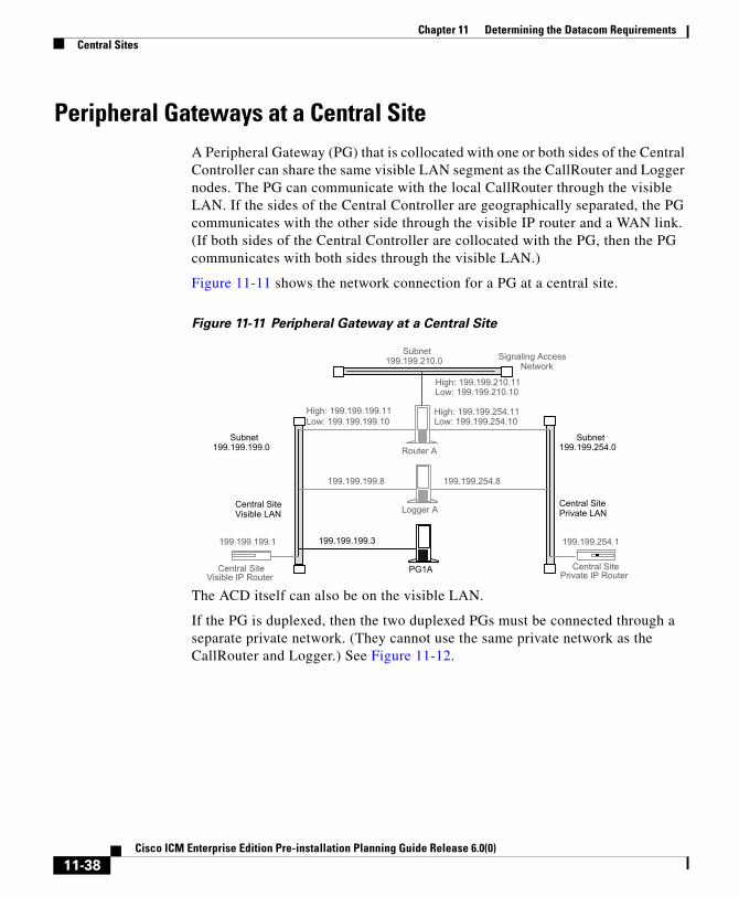
Chapter 11 Determining the Datacom RequirementsCentral Sites
Peripheral Gateways at a Central SiteA Peripheral Gateway (PG) that is collocated with one or both sides of the Central Controller can share the same visible LAN segment as the CallRouter and Logger nodes. The PG can communicate with the local CallRouter through the visible LAN. If the sides of the Central Controller are geographically separated, the PG communicates with the other side through the visible IP router and a WAN link. (If both sides of the Central Controller are collocated with the PG, then the PG communicates with both sides through the visible LAN.)
Figure 11-11 shows the network connection for a PG at a central site.
Figure 11-11 Peripheral Gateway at a Central Site
The ACD itself can also be on the visible LAN.
If the PG is duplexed, then the two duplexed PGs must be connected through a separate private network. (They cannot use the same private network as the CallRouter and Logger.) See Figure 11-12.
Central SitePrivate IP Router
Router A
High: 199.199.199.11Low: 199.199.199.10
Subnet199.199.199.0
199.199.254.1
Central SiteVisible LAN
Central SitePrivate LAN
High: 199.199.254.11Low: 199.199.254.10
Subnet199.199.254.0
Central SiteVisible IP Router
199.199.199.1
Logger A
199.199.199.8 199.199.254.8
PG1A
199.199.199.3
Subnet199.199.210.0 Signaling Access
Network
High: 199.199.210.11Low: 199.199.210.10
11-38Cisco ICM Enterprise Edition Pre-installation Planning Guide Release 6.0(0)

Chapter 11 Determining the Datacom RequirementsContact Center Sites
Figure 11-12 Duplexed Peripheral Gateways at a Central Site
If you have more than one pair of duplexed PGs at a site, each pair requires its own private LAN. The private LAN for the PGs allows for synchronization and state transfer between the PGs. It is not used for any other purpose.
Note When a Peripheral Gateway is located with one side of a geographically distributed Central Controller, you must have a WAN link directly connecting the visible WAN IP routers at the two central sites. This ensures that there is adequate visible network connectivity between the sides of the Central Controller. For more information on PG networking requirements, see the next section, “Contact Center Sites.”
Contact Center SitesEach contact center site includes at least one ACD, at least one Peripheral Gateway (PG), and optionally, one or more Admin Workstations. Contact centers may also have an Interactive Voice Response (IVR) unit. For fault-tolerance, the contact center site must include a duplexed pair of PGs.
Central SitePrivate IP Router
Router A
High: 199.199.199.11Low: 199.199.199.10
Subnet199.199.199.0
199.199.254.1
Central SiteVisible LAN
Central SitePrivate LAN
High: 199.199.254.11Low: 199.199.254.10
Subnet199.199.254.0
Central SiteVisible IP Router
199.199.199.1
Logger A
199.199.199.8 199.199.254.8
PG1A
199.199.199.3 199.199.225.3
199.199.225.2 PG1Private LAN
PG1B
199.199.199.2
Subnet199.199.210.0 Signaling Access
Network
High: 199.199.210.11Low: 199.199.210.10
11-39Cisco ICM Enterprise Edition Pre-installation Planning Guide Release 6.0(0)

Chapter 11 Determining the Datacom RequirementsContact Center Sites
A remote contact center complex is reached via the visible network, often with multiple access paths and through multiple IP routers. The contact center site must have at least one IP router on the visible network for communication with the Central Controller. For maximum fault-tolerance, the site should have two IP routers, each connecting to one side of the Central Controller.
Note For information on installing and configuring the ICM Peripheral Gateway software, see the Cisco ICM Enterprise Edition Installation Guide.
Simplexed PG SiteFigure 11-13 shows one option for a contact center configuration with a simplexed PG and an Admin Workstation. This site contains an ACD and an IVR system. The IVR PG software and the ACD PG software may be installed on the same PC hardware platform.
11-40Cisco ICM Enterprise Edition Pre-installation Planning Guide Release 6.0(0)

Chapter 11 Determining the Datacom RequirementsContact Center Sites
Figure 11-13 Contact Center with Simplexed PG
As shown in Figure 11-13, the PG and AW share a single Ethernet LAN and an IP router. The IP router uses prioritization and IP fragmentation to minimize queuing delays for high-priority ICM system traffic. Cisco recommends that the PG, ACD, IVR, and IP router be separated from other devices by a bridge or IP router. This isolates the critical ICM components from outages that might be caused by other equipment and networks.
The contact center example shown in Figure 11-13 is a low fault tolerance configuration. It is recommended only for non-fault tolerant sites (for example, for contact center sites with one PG or admin sites with AWs only). A simplexed PG configuration can represent a single point of failure. Loss of the only PG would stop the flow of real-time data from the contact center to the CallRouter and prevent the use of Post-Routing and translation routes. You can protect against possible failures by using duplexed PGs.
AdminWorkstation
ACD
IP Router
PG A(Simplexed)
VisibleEthernet (UTP)
To Central ControllerSide A
Non-ICMequipment
To Central ControllerSide B
Bridge orIP Router
Visible WAN Links
IVR
11-41Cisco ICM Enterprise Edition Pre-installation Planning Guide Release 6.0(0)

Chapter 11 Determining the Datacom RequirementsContact Center Sites
Duplexed PG SiteA duplexed PG configuration provides enhanced fault-tolerance. See Figure 11-14.
Figure 11-14 Fault Tolerant Contact Center
Note that a PG private LAN is added to allow direct communication between the two PGs. If you have more than one duplexed pair of PGs at a site, each PG pair requires its own private LAN.
To further enhance the fault-tolerance of the contact center, you can configure each PG with its own visible LAN and IP router. This eliminates the LAN as a single point of failure. Each PG communicates with one side of the Central Controller using its own LAN and IP router.
AdminWorkstation
IP Router IP Router
Side A VisibleEthernet (UTP)
PG1 PrivateEthernet (UTP)
Bridge orIP Router
To Central ControllerSide A
To Central ControllerSide B
PG1 A PG1 B
Visible WAN Links
IVR
Side B VisibleEthernet (UTP)
ACD
Bridge(Optional)
Bridge(Optional)
AdminWorkstatio
11-42Cisco ICM Enterprise Edition Pre-installation Planning Guide Release 6.0(0)

Chapter 11 Determining the Datacom RequirementsContact Center Sites
If you used a single IP router instead of two, you introduce a potential single point of failure to the contact center site. Loss of the one IP router would stop the flow of real-time data from the contact center to the CallRouter and stop the flow of monitoring data from the Central Controller to the Admin Workstation. It would also prevent the use of Post-Routing and translation routes for this contact center.
One of the two IP routers shown in Figure 11-14 serves as the default gateway for the PG. By default, the PG communicates with that side of the Central Controller. The PG must have a static route defined to the other side of the Central Controller through the other IP router.
Each PG may contain a modem to allow dial-in access through your ICM support provider’s Distributed Diagnostic and Service Network (DDSN). In addition to its normal address on the visible network, the PG would then require two additional visible LAN addresses for this dial-in access.
Duplexed PG Site with Separate IVR LANAnother contact center configuration may be used in cases where IVR systems need to be separated due to security concerns or when management of the IVRs must be carefully protected. Figure 11-15 shows an example of such a fault tolerant contact center site.
11-43Cisco ICM Enterprise Edition Pre-installation Planning Guide Release 6.0(0)

Chapter 11 Determining the Datacom RequirementsContact Center Sites
Figure 11-15 Fault Tolerant Contact Center—IVR on Separate LAN
With this option, the ACD is on the visible LAN under the assumption that another CTI application needs to interface to the ACD. An alternative would be to have the ACD on the same LAN as the IVR system.
AdminWorkstation
IP Router IP Router
Side A VisibleEthernet (UTP)
PG1 PrivateEthernet (UTP)
Bridge orIP Router
To Central ControllerSide A
To Central ControllerSide B
PG1 A PG1 B
Visible WAN Links
IVR
Side B VisibleEthernet (UTP)
ACD
Bridge(Optional)
Bridge(Optional)
AdminWorkstation
11-44Cisco ICM Enterprise Edition Pre-installation Planning Guide Release 6.0(0)

Chapter 11 Determining the Datacom RequirementsContact Center Sites
PG Network ConfigurationTable 11-15 summarizes the network configuration for a simplexed PG.
Table 11-16 summarizes the network configuration for a duplexed PG.
Table 11-15 Simplexed PG Network Configuration
Setting Requirements
IP Addresses Three addresses may be required on the visible LAN: one for normal data and two for use by the DDSN.
Default Gateway Define one of the visible network IP routers as the default gateway for the PG.
Static Routes Define one static route to the visible LAN at the central site that is not targeted by the default gateway IP router.
Other Preferred and alternate DNS server. See Active Directory Model, page 11-20.
Table 11-16 Duplexed PG Network Configuration
Setting Requirements
IP Addresses Each PG may require three addresses on the visible LAN (one for normal traffic plus two addresses for DDSN dial-up connections) and two addresses on the private LAN (one for high priority and one for low priority data).
Default Gateway Define one of the visible network IP routers as the default gateway for each PG. Do not use the same IP router as the default gateway for both PGs.
Static Routes Each PG requires a static route to the side of the Central Controller that is not targeted by its default gateway IP router.
Other Preferred and alternate DNS server. See Active Directory Model, page 11-20.
11-45Cisco ICM Enterprise Edition Pre-installation Planning Guide Release 6.0(0)

Chapter 11 Determining the Datacom RequirementsContact Center Sites
Note For more information on how Peripheral Gateways connect to ACDs, see Chapter 5, “Peripheral Gateway Configurations”.
Contact Center IP RoutersThe IP router requires a single address on the LAN. It also requires that you define a static route on the IP router to the side of the Central Controller (central site visible LAN) that is not targeted by the PG’s default gateway IP router.
To allow optimal tuning of the network, Cisco recommends that you use IP routers that allow you to prioritize packets based on a range of source or destination port numbers. Typically, you need to set up the IP router to give higher priority to certain outgoing network packets. Also, depending on the bandwidth available on the visible WAN, you may need to set up IP fragmentation.
Table 11-17 summarizes the configuration for the IP routers.
See Table 11-18 for information about packet priorities.
Table 11-17 Contact Center IP Router Configuration
Setting Requirements
IP Addresses Each IP router requires one address on the visible LAN.
Default Gateway Network bridge or IP router used as bridge, if any. Otherwise, the IP router does not have a default gateway.
Static Routes Each IP router must have a static route to reach one central site visible LAN.
Other Turn off any preset routing protocols.
Give higher priority to specific network packets.
Use fragmentation if necessary to limit the queuing delay.
11-46Cisco ICM Enterprise Edition Pre-installation Planning Guide Release 6.0(0)

Chapter 11 Determining the Datacom RequirementsAdmin Sites
The maximum queuing delay is 50 milliseconds if the site uses Post-Routing or translation routes; 200 milliseconds otherwise. You may have to set up fragmentation to meet these limits.
Admin SitesAn admin site contains one or more Admin Workstations. Each admin site must have a visible LAN and an IP router to communicate with the central sites. An admin site does not require a private LAN (see Figure 11-16).
Table 11-18 Contact Center Packet Priorities
Packet Type High Priority Low Priority
TCP If sending to the CallRouter’s high priority address (as derived from the packet’s destination address).
If sending to any other address.
UDP If source or destination port number is in the range 39000–39999.1
1. If you cannot configure the IP router to assign priority based on a range of port numbers, then assign a high priority to all UDP packets.
All other UDP packets.
11-47Cisco ICM Enterprise Edition Pre-installation Planning Guide Release 6.0(0)

Chapter 11 Determining the Datacom RequirementsAdmin Sites
Figure 11-16 Admin Site Configuration
You can have multiple Admin Workstations on a single LAN.
11-48Cisco ICM Enterprise Edition Pre-installation Planning Guide Release 6.0(0)

Cisco ICM Enterprise Edition Pre-installat
C H A P T E R12
Site PreparationOnce you have provisioned IXC access, ordered the required ACD/PBX options, ordered the PC platform, and determined your data communications requirements, you can begin preparing for the arrival of the ICM equipment. You need to prepare each site that is to contain ICM equipment. The sites must have adequate power facilities, security, and space for equipment layout.
Be sure to consider the following site preparation tasks:
• Meet basic site requirements. Prepare for the arrival of equipment; provide a secure staging area; ensure that sites are ready for occupancy; order and assemble equipment racks.
• Design a floor plan for each site. Consider operator workspace, cabling distribution, and maintenance access to ICM nodes.
• Meet the power and environmental requirements at each site. Review the PC hardware documentation for specifics on power and environmental requirements.
• Provide adequate security for the ICM system. Allow only authorized access to the ICM system and any backed-up data.
• Determine additional cabling or other equipment required. You may need equipment such as rack-mounting hardware or an uninterruptible power supply (UPS).
• Order any additional cabling or equipment. Order any additional equipment in time for the arrival of the ICM system components.
12-1ion Planning Guide Release 6.0(0)

Chapter 12 Site Preparation
12-2Cisco ICM Enterprise Edition Pre-installation Planning Guide Release 6.0(0)

Cisco ICM Enterprise Edition Pre-installat
C H A P T E R13
IP Address WorksheetsThis chapter provides worksheets you can use to record IP addresses for the visible and private networks. You also need to define static routes for some of the nodes in the ICM system.
Visible Network IP Address RequirementsTable 13-1 lists the IP address requirements for ICM node connections to the visible network. The ICM nodes are listed as duplexed pairs (for example, CallRouter A and CallRouter B). You may or may not have duplexed nodes in your configuration. Supply IP addresses only for the nodes you have in your configuration.
Table 13-1 Visible Network IP Address Requirements
Node Location Address Type IP Address
CallRouter A High Priority
Low Priority
Default IP Gateway1
Netmask
CallRouter B High Priority
Low Priority
Default IP Gateway1
13-1ion Planning Guide Release 6.0(0)

Chapter 13 IP Address WorksheetsVisible Network IP Address Requirements
Netmask
Logger A Normal data
RAS 1
RAS 2
Default IP Gateway1
Netmask
Modem Tel. Number
Logger B Normal data
RAS 1
RAS 2
Default IP Gateway1
Netmask
Modem Tel. Number
Central Site IP Router
Normal data
Remote Contact Center Site IP Router
Normal data
PG1A Normal data
RAS 1
RAS 2
Default IP Gateway2
Netmask
Modem Tel. Number
PG1B Normal data
RAS 1
RAS 2
Default IP Gateway2
Netmask
Table 13-1 Visible Network IP Address Requirements (continued)
13-2Cisco ICM Enterprise Edition Pre-installation Planning Guide Release 6.0(0)

Chapter 13 IP Address WorksheetsVisible Network IP Address Requirements
Modem Tel. Number
PG2A Normal data
RAS 1
RAS 2
Default IP Gateway2
Netmask
Modem Tel. Number
PG2B Normal data
RAS 1
RAS 2
Default IP Gateway2
Netmask
Modem Tel. Number
PG3A Normal data
RAS 1
RAS 2
Default IP Gateway2
Netmask
Modem Tel. Number
PG3B Normal data
RAS 1
RAS 2
Default IP Gateway2
Netmask
Modem Tel. Number
AW 1 Normal data
Default IP Gateway3
Netmask
Table 13-1 Visible Network IP Address Requirements (continued)
13-3Cisco ICM Enterprise Edition Pre-installation Planning Guide Release 6.0(0)

Chapter 13 IP Address WorksheetsPrivate Network IP Address Requirements
Private Network IP Address RequirementsTable 13-2 lists the IP address requirements for ICM node connections to the private network. The ICM nodes are listed as duplexed pairs (for example, CallRouter A and CallRouter B). You may or may not have duplexed nodes in your configuration. You need to supply IP addresses only for the nodes you have in your configuration.
AW 2 Normal data
Default IP Gateway3
Netmask
1. This is the visible network IP address for the central site IP router.
2. This is the IP address of one of the visible network IP routers. In a duplexed PG configuration, do not use the same IP router as the default gateway for both PGs.
3. This is the IP address of the local IP router on the visible LAN.
Table 13-1 Visible Network IP Address Requirements (continued)
Table 13-2 Private Network IP Address Requirements
Node Location Address Type IP Address
CallRouter A High Priority
Low Priority
CallRouter B High Priority
Low Priority
Logger A Normal data
Logger B Normal data
Central Site Private Net IP Router
Normal data
PG1A1 High Priority
Low Priority
PG1B High Priority
Low Priority
13-4Cisco ICM Enterprise Edition Pre-installation Planning Guide Release 6.0(0)

Chapter 13 IP Address WorksheetsSignaling Access Network IP Requirements
Signaling Access Network IP RequirementsTable 13-3 lists the IP address requirements for ICM node connections to the Signaling Access Network. The ICM nodes are listed as duplexed pairs (for example, CallRouter A and CallRouter B). You may or may not have duplexed nodes in your configuration. You need to supply IP addresses only for the nodes you have in your configuration
PG2A High Priority
Low Priority
PG2B High Priority
Low Priority
PG3A High Priority
Low Priority
PG3B High Priority
Low Priority1. PGs require private network IP addresses only when they are duplexed.
Table 13-2 Private Network IP Address Requirements (continued)
Table 13-3 Signaling Access Network IP Address Requirements
Node Location Address Type IP Address
CallRouter A High Priority
Low Priority
CallRouter B High Priority
Low Priority
Network Gateway 1A Normal data
Network Gateway 1B Normal data
13-5Cisco ICM Enterprise Edition Pre-installation Planning Guide Release 6.0(0)
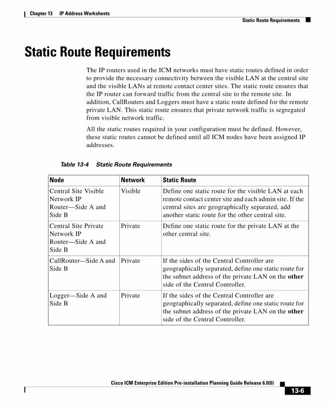
Chapter 13 IP Address WorksheetsStatic Route Requirements
Static Route RequirementsThe IP routers used in the ICM networks must have static routes defined in order to provide the necessary connectivity between the visible LAN at the central site and the visible LANs at remote contact center sites. The static route ensures that the IP router can forward traffic from the central site to the remote site. In addition, CallRouters and Loggers must have a static route defined for the remote private LAN. This static route ensures that private network traffic is segregated from visible network traffic.
All the static routes required in your configuration must be defined. However, these static routes cannot be defined until all ICM nodes have been assigned IP addresses.
Table 13-4 Static Route Requirements
Node Network Static Route
Central Site Visible Network IP Router—Side A and Side B
Visible Define one static route for the visible LAN at each remote contact center site and each admin site. If the central sites are geographically separated, add another static route for the other central site.
Central Site Private Network IP Router—Side A and Side B
Private Define one static route for the private LAN at the other central site.
CallRouter—Side A and Side B
Private If the sides of the Central Controller are geographically separated, define one static route for the subnet address of the private LAN on the other side of the Central Controller.
Logger—Side A and Side B
Private If the sides of the Central Controller are geographically separated, define one static route for the subnet address of the private LAN on the other side of the Central Controller.
13-6Cisco ICM Enterprise Edition Pre-installation Planning Guide Release 6.0(0)

Chapter 13 IP Address WorksheetsStatic Route Requirements
PG (all PGs) Visible One of the two IP routers at a contact center is targeted as the default gateway for the PG. However, the PG needs IP connectivity to both sides of the Central Controller. Therefore, for each PG you must define a static route to the other IP router (that is, to the IP router that is not targeted as the PG’s default gateway IP router).
Remote Contact Center IP Routers
Visible For each IP router, define a static route to one side of the Central Controller (to the central site visible network IP router).
Admin Site IP Routers Visible For each Admin Site IP router, define a static route to one side of the Central Controller (to the central site visible network IP router).
Table 13-4 Static Route Requirements (continued)
13-7Cisco ICM Enterprise Edition Pre-installation Planning Guide Release 6.0(0)

Chapter 13 IP Address WorksheetsStatic Route Requirements
13-8Cisco ICM Enterprise Edition Pre-installation Planning Guide Release 6.0(0)

Cisco ICM Enterprise Edition Pre-install
I N D E X
Numerics
802.1p marking 11-18
A
Addresses
CallRouter 11-29, 11-30
IP router 11-24, 11-26, 11-46
Logger 11-33, 11-34
Peripheral Gateway 11-45
Admin site
networking 11-47
Admin Workstation 2-5, 2-7
at call center 11-41
at central site 11-36
isolating 11-36, 11-41
Agent workstation application 6-6
All Events application 6-6
Applications
agent workstation 6-6
All Events 6-6
CTI Bridge 6-6
desktop 6-6
models 6-5
B
Bandwidth Requirements
QoS 11-17
Bandwidth requirements 11-7
Bindings 11-30
Blended Agent 9-2
Bridge application 6-6
Bridges
LAN 11-36, 11-41
private network 11-26
C
Call
detail records 10-7
Call center
duplexed site 11-41
network configuration 11-39
simplexed site 11-40
Call control 6-11
CallRouter 2-5
network configuration 11-28
Call routing
overview 2-2
IN-1ation Planning Guide Release 6.0(0)

Index
Central Controller 2-7
collocated 11-26
network configuration 11-21
visible network connection 11-24, 11-39
Central site 11-21
Admin Workstation 11-36
CallRouter 11-28
Logger 11-31, 11-32
Peripheral Gateway 11-38
visible LAN 11-24
Client applications
models 6-5
Client AWs 10-6
Collaboration Server 2-17
Computer Telephony Integration (CTI) 2-4, 2-12
message set 6-9
Configurations
Gateway SQL 2-15
IVR 2-13, 7-1
Pre-Routing 2-10
Connections
PG-to-peripheral 4-2
CTI 2-12, 9-1
messaging considerations 6-10
networking 6-8
overview 2-12, 6-1
PG platform options 6-2
rollout 6-8
CTI Bridge application 6-6
IN-2Cisco ICM Enterprise Edition Pre-installation Plannin
CTI Server 2-12, 6-1, 6-6
messaging 6-9
CTI server
fault tolerance 6-3
platform options 6-3
D
Database
in-memory 2-4
server for Gateway SQL 8-2
Database routing 2-15
DDSN 11-33, 11-45
Default gateway
CallRouter 11-29, 11-30
IP router 11-24, 11-26, 11-46
Logger 11-33
Peripheral Gateway 11-45
Desktop application 6-6
Dial-in connections 11-33, 11-45
Distributed Diagnostic and Service Network (DDSN)
Logger IP address requirements 11-33
Distributor AW 10-5
at Admin Sites 10-6
Diversity
for IXC links 3-6
Dynamic Content Adapter 2-17
g Guide Release 6.0(0)

Index
E
E-Mail Manager Option 2-17, 9-2
Ethernet 11-7
External applications 2-14
integrating with ICR 8-1
External databases
integrating with ICR 8-2
F
Failed nodes 11-11
detecting 11-8
Fault tolerance
for PGs 5-2
G
Gateway
overview 2-14
Gateway option
planning for 8-1
Gateway SQL
configuration overview 8-4
data transfer 8-4
overview 2-15
planning for 8-2
Cisco ICM Enterprise Edition
H
HDS 2-7, 10-7
Heartbeats 11-8
High priority packets 11-29, 11-30
Historical Data Server 2-7, 10-7
HOSTS file 11-36
I
ICM 2-12, 6-1
ICM Application Gateway 2-14, 8-1
ICM Gateway SQL 2-15, 8-2
ICM Network Gateway 11-35
In-memory database 2-4
Integration
IVR optionsvru_options_ch7 7-3
Intelligent CallRouter
overview 2-2
Intelligent Contact Management 2-12, 6-1
Interactive Voice Response (IVR)
and ICR integration 7-1
in-network example 7-7, 7-9
integration optionsvru_options_ch7 7-3
monitoring interface 7-11
routing client 7-10
third-party call control 7-9
transfer routing 7-9
Interexchange Carrier (IXC) 3-3
IN-3Pre-installation Planning Guide Release 6.0(0)

Index
Internet Script Editor 2-16, 9-1
Internet Service Note (ISN) 9-2
IP addresses
CallRouter 11-29, 11-30
Logger 11-33, 11-34
Peripheral Gateway 11-45
IP Contact Center (IPCC) 2-17
IP router
and LAN segmentation 11-37
private network 11-26
visible network 11-24, 11-46
IVR 9-1
overview 2-13
planning for 7-1
IXC signaling network 2-5
L
LAN 11-2
admin site 11-47
bridges 11-36, 11-41
call center 11-41
central site 11-24, 11-36, 11-38
private 11-24, 11-39, 11-42
segmentation 11-37, 11-41
visible 11-24, 11-41, 11-42
LEC 3-3
Link redundancy 3-5
Local Exchange Carrier 3-3
IN-4Cisco ICM Enterprise Edition Pre-installation Plannin
Local Exchange Carrier (LEC)
and route diversity 3-7
Logger 2-5
network configuration 11-31, 11-32
Low priority packets 11-29, 11-30
M
Media Blender 2-17
Multichannel Software 2-16
N
NetBEUI 11-30
NetBIOS 11-30
Network
database 3-3
Network Bindings 11-30
Network Interface Controller
private network IP requirements 11-36
Network Interface Controller (NIC) 2-3, 2-5
overview of 3-1
Networks
admin sites 11-47
call center sites 11-39
central sites 11-21
configuration 11-2
private 11-3
visible 11-3
g Guide Release 6.0(0)

Index
NIC 2-3
NIC fault tolerance 3-5
NT networking 11-30
O
Open
database connectivity (ODBC) tools 2-4
IVR Interface 7-1
Open Peripheral Controller (OPC) 5-2
Outbound Option 9-2
P
Packet Scheduler 11-14
PC paging requirements 10-4
PC processor utilization 10-4
Performance Monitor, Windows 11-19
Peripheral Gateway 2-12
fault tolerance 5-2
Peripheral Gateway (PG) 2-4, 2-6, 4-1
configurations 5-1
duplexed 11-41
network configuration 11-43
process examples 5-5
relationship to peripherals 4-2
standard configuration 5-7
with Central Controller 11-38
Peripheral Interface Manager (PIM) 5-2, 5-5
Cisco ICM Enterprise Edition
PG 2-12
Planning process
overview of 1-1
Post-Routing 2-4, 2-11, 11-47
and VRUs 7-3
Pre-Routing 2-3, 2-9
configurations 2-10
Private
network configuration 2-4
Private network 11-3
call centers 11-42
IP router 11-26
Product options 2-1
Provisioning
IXC access 3-1
Q
Quality of Service (QoS) 11-12
R
Redundancy
for IXC links 3-5
Restarting nodes 11-11
Route diversity 3-6
example 3-7
LEC requirements 3-7
Routing
IN-5Pre-installation Planning Guide Release 6.0(0)

Index
requests 2-3
responses 2-3
script 3-3
S
Signaling network
and NICs 2-6
Sites
admin 11-47
call center 11-39
central 11-21
SQL tools 2-4
State transfer 11-11
Static routes
CallRouter 11-30
IP router 11-25, 11-26, 11-46
Logger 11-34
Peripheral Gateway 11-45
Synchronization 11-10
T
T1 11-7
TCP packets 11-25, 11-27, 11-47
Third-party call control 6-12
IN-6Cisco ICM Enterprise Edition Pre-installation Plannin
U
UDP packets 11-25, 11-27, 11-47
Unshielded Twisted Pair (UTP) 11-7
Update 6-6
V
Visible network 11-3
call center 11-40
central sites 11-24
IP router 11-24, 11-46
W
WAN 11-2
admin site 11-47
between central sites 11-24, 11-39
call center site 11-40
central site 11-24, 11-26, 11-46
failures 11-11
private 11-7, 11-26
visible 11-7, 11-24, 11-46
Web Collaboration Option 2-17, 9-2
WebView 2-8, 2-16, 9-2
Wide Area Network (WAN) 11-3
Wrap-up 6-6
g Guide Release 6.0(0)