Cisco ICM Enterprise Edition Release 6.0(0) Configuration Guide
312
Corporate Headquarters Cisco Systems, Inc. 170 West Tasman Drive San Jose, CA 95134-1706 USA http://www.cisco.com Tel: 408 526-4000 800 553-NETS (6387) Fax: 408 526-4100 Cisco ICM Enterprise Edition Configuration Guide ICM Enterprise Edition Release 6.0(0) May 2004 Customer Order Number: Text Part Number:
Transcript of Cisco ICM Enterprise Edition Release 6.0(0) Configuration Guide
Corporate HeadquartersCisco Systems, Inc.170 West Tasman DriveSan Jose, CA 95134-1706USAhttp://www.cisco.comTel: 408 526-4000
800 553-NETS (6387)Fax: 408 526-4100
Cisco ICM Enterprise Edition Configuration GuideICM Enterprise Edition Release 6.0(0)
May 2004
Customer Order Number: Text Part Number:

THE SPECIFICATIONS AND INFORMATION REGARDING THE PRODUCTS IN THIS MANUAL ARE SUBJECT TO CHANGE WITHOUT NOTICE. ALL STATEMENTS, INFORMATION, AND RECOMMENDATIONS IN THIS MANUAL ARE BELIEVED TO BE ACCURATE BUT ARE PRESENTED WITHOUT WARRANTY OF ANY KIND, EXPRESS OR IMPLIED. USERS MUST TAKE FULL RESPONSIBILITY FOR THEIR APPLICATION OF ANY PRODUCTS.
THE SOFTWARE LICENSE AND LIMITED WARRANTY FOR THE ACCOMPANYING PRODUCT ARE SET FORTH IN THE INFORMATION PACKET THAT SHIPPED WITH THE PRODUCT AND ARE INCORPORATED HEREIN BY THIS REFERENCE. IF YOU ARE UNABLE TO LOCATE THE SOFTWARE LICENSE OR LIMITED WARRANTY, CONTACT YOUR CISCO REPRESENTATIVE FOR A COPY.
The Cisco implementation of TCP header compression is an adaptation of a program developed by the University of California, Berkeley (UCB) as part of UCB’s public domain version of the UNIX operating system. All rights reserved. Copyright © 1981, Regents of the University of California.
NOTWITHSTANDING ANY OTHER WARRANTY HEREIN, ALL DOCUMENT FILES AND SOFTWARE OF THESE SUPPLIERS ARE PROVIDED “AS IS” WITH ALL FAULTS. CISCO AND THE ABOVE-NAMED SUPPLIERS DISCLAIM ALL WARRANTIES, EXPRESSED OR IMPLIED, INCLUDING, WITHOUT LIMITATION, THOSE OF MERCHANTABILITY, FITNESS FOR A PARTICULAR PURPOSE AND NONINFRINGEMENT OR ARISING FROM A COURSE OF DEALING, USAGE, OR TRADE PRACTICE.
IN NO EVENT SHALL CISCO OR ITS SUPPLIERS BE LIABLE FOR ANY INDIRECT, SPECIAL, CONSEQUENTIAL, OR INCIDENTAL DAMAGES, INCLUDING, WITHOUT LIMITATION, LOST PROFITS OR LOSS OR DAMAGE TO DATA ARISING OUT OF THE USE OR INABILITY TO USE THIS MANUAL, EVEN IF CISCO OR ITS SUPPLIERS HAVE BEEN ADVISED OF THE POSSIBILITY OF SUCH DAMAGES.
CCIP, CCSP, the Cisco Arrow logo, the Cisco Powered Network mark, Cisco Unity, Follow Me Browsing, FormShare, and StackWise are trademarks of Cisco Systems, Inc.; Changing the Way We Work, Live, Play, and Learn, and iQuick Study are service marks of Cisco Systems, Inc.; and Aironet, ASIST, BPX, Catalyst, CCDA, CCDP, CCIE, CCNA, CCNP, Cisco, the Cisco Certified Internetwork Expert logo, Cisco IOS, the Cisco IOS logo, Cisco Press, Cisco Systems, Cisco Systems Capital, the Cisco Systems logo, Empowering the Internet Generation, Enterprise/Solver, EtherChannel, EtherFast, EtherSwitch, Fast Step, GigaDrive, GigaStack, HomeLink, Internet Quotient, IOS, IP/TV, iQ Expertise, the iQ logo, iQ Net Readiness Scorecard, LightStream, Linksys, MeetingPlace, MGX, the Networkers logo, Networking Academy, Network Registrar, Packet, PIX, Post-Routing, Pre-Routing, ProConnect, RateMUX, Registrar, ScriptShare, SlideCast, SMARTnet, StrataView Plus, SwitchProbe, TeleRouter, The Fastest Way to Increase Your Internet Quotient, TransPath, and VCO are registered trademarks of Cisco Systems, Inc. and/or its affiliates in the United States and certain other countries.
All other trademarks mentioned in this document or Website are the property of their respective owners. The use of the word partner does not imply a partnership relationship between Cisco and any other company. (0403R)
Cisco ICM Enterprise Edition Configuration GuideCopyright © 2000–2004, Cisco Systems, Inc.All rights reserved.
78-11589-03
C O N T E N T S
About This Guide xiii
Purpose xiii
Audience xiii
Organization xiv
Conventions xv
Other Publications xvi
Obtaining Documentation xvi
World Wide Web xvi
Documentation CD-ROM xvi
Ordering Documentation xvi
Documentation Feedback xvii
Obtaining Technical Assistance xvii
Cisco.com xviii
Technical Assistance Center xviii
Cisco TAC Web Site xix
Cisco TAC Escalation Center xix
C H A P T E R 1 Overview 1-1
ICM Software 1-1
Components 1-2
Central Controller to IXC Signaling Network 1-3
Central Controller to Peripheral Gateways 1-4
Central Controller to ICM Admin Workstations 1-4
ICM Routing Targets 1-5
Peripheral Targets 1-5
iiiCisco ICM Enterprise Edition Configuration Guide Version 6.0
Contents
Scheduled Targets 1-6
Peripherals 1-6
The ICM Admin Workstation 1-8
The ICM Admin Workstation Group 1-9
Central and Local Databases 1-10
Lock Administration 1-10
Configuration Management 1-11
Script Management 1-11
C H A P T E R 2 How Routing Works 2-1
The Routing Process 2-1
Routing Requests 2-3
Targets 2-3
ICM System Processing 2-6
Determine call type 2-7
Execute script 2-8
Determine route 2-8
Determine trunk group and DNIS 2-8
Determine label 2-9
Routing Client’s Processing 2-9
The Peripheral’s Processing 2-10
Translation Routes 2-10
Timeouts and Thresholds 2-11
Routing Clients 2-12
Timeout Threshold 2-12
Late Threshold 2-12
Timeout Limit 2-13
Abandoned Call Wait Time 2-13
Service Level 2-14
ivCisco ICM Enterprise Edition Configuration Guide Version 6.0
78-11589-03
Contents
Service Level Threshold 2-14
Service Level Types 2-15
C H A P T E R 3 The ICM Configuration Manager 3-1
Accessing the Configuration Manager 3-2
Configuration Manager 3-2
Online Help 3-5
Troubleshooting 3-6
Problem: 3-6
Discussion: 3-6
Solution: 3-6
Problem: 3-6
Discussion: 3-6
Solution: 3-7
Configuration Manager Tools 3-7
Bulk Configuration Tools 3-8
Explorer and List Tools 3-9
Explorer Tools 3-9
List Tools 3-10
Miscellaneous Tools 3-11
Wizards 3-12
Common Bulk, List, and Explorer Tool Features 3-12
Common List and Explorer Tool Features 3-14
Accessing Database Records 3-16
Saving Configuration Data to the Database 3-18
Feature Control 3-18
Script Node Control 3-19
Node Control Table 3-19
Configuring a Feature Control Set 3-20
vCisco ICM Enterprise Edition Configuration Guide Version 6.0
78-11589-03
Contents
Security Settings 3-22
Validating Configuration Data 3-23
Deleting Configuration Records 3-24
Types of Deletion 3-25
Deletion Dependencies 3-26
Administering Deleted Records 3-27
C H A P T E R 4 Configuring Multiple Records at a Time 4-1
Data You Can Bulk Configure 4-2
Insert and Edit Windows 4-3
Bulk Configuration Features 4-4
Retrieving and Editing Records 4-5
Sorting Records 4-7
Finding Data in a List of Records 4-7
Selecting Data 4-8
Editing a Range of Data 4-9
Inserting New Records 4-11
Importing Data 4-12
Import/Export Data File Format 4-14
Exporting Data 4-15
Applying Security Settings to Multiple Records 4-16
Deleting and Undeleting Records 4-16
C H A P T E R 5 Configuring Routing Clients 5-1
The Routing Client Subsystem 5-1
Interface Controllers 5-2
Examples of Routing Client Subsystems 5-3
Configuring a Network Interface Controller (NIC) 5-4
NIC Explorer Tab Descriptions 5-5
viCisco ICM Enterprise Edition Configuration Guide Version 6.0
78-11589-03
Contents
Logical Interface Controller Tab 5-5
Physical Interface Controller Tab 5-6
Routing Client Tab 5-7
Sprint Routing Clients 5-11
CRSP and France Telecom Routing Clients 5-11
Configuring Dialed Number/Script Selectors 5-12
Dialed Number/Script Selector List Tab Descriptions 5-14
Attributes Tab 5-14
Dialed Number Label Tab 5-15
C H A P T E R 6 Configuring Peripherals and Trunk Groups 6-1
The Peripheral Subsystem 6-1
Peripheral Gateways (PGs) 6-2
Configuring a PG 6-3
PG Explorer Tab Descriptions 6-4
Logical Controller Tab 6-4
Peripheral Tab 6-7
Advanced Tab 6-9
Skill Group MaskTab 6-11
Routing Client Tab 6-11
Peripheral Monitor Tab 6-14
Default Route Tab 6-17
Agent Distribution Tab 6-18
Defining PGs and Peripherals 6-20
Modifying a PG or a Peripheral 6-22
Deleting a PG or a Peripheral 6-23
Configuring Trunk Groups and Trunks 6-24
Network Trunk Groups, Trunk Groups, and Trunks 6-25
Network Trunk Group Tab Descriptions 6-27
viiCisco ICM Enterprise Edition Configuration Guide Version 6.0
78-11589-03
Contents
Trunk Group Tab Descriptions 6-27
Trunk Tab Descriptions 6-28
C H A P T E R 7 Configuring Skill Targets 7-1
The Skill Targets Subsystem 7-2
Services 7-3
Service Explorer 7-3
Service Explorer Tab Descriptions 7-4
Service Tab 7-4
Advanced Tab 7-6
Service Members Tab 7-6
Route Tab 7-7
Peripheral Target Tab 7-7
Label Tab 7-8
Modifying, Defining, and Deleting Services 7-9
Skill Groups 7-11
Skill Group Explorer 7-11
Skill Group Explorer Tab Descriptions 7-12
Skill Group Tab 7-12
Skill Group Members Tab 7-15
Subgroup Mask Tab 7-15
Sub Skill Groups Tab 7-16
Route Tab 7-17
Peripheral Target Tab 7-19
Label Tab 7-20
Modifying, Defining, and Deleting Skill Groups 7-21
Mapping Skill Groups to Services 7-23
Persons 7-23
Select filter data 7-24
Optional filter 7-24
viiiCisco ICM Enterprise Edition Configuration Guide Version 6.0
78-11589-03
Contents
Condition filter 7-25
Value 7-25
Save 7-25
Retrieve 7-25
Cancel filter changes 7-26
Persons List Tool Tab Descriptions 7-26
Attributes tab 7-26
Agents 7-29
Agent Explorer Tab Descriptions 7-30
Agent Tab 7-30
Skill Group Membership Tab 7-32
Supervisor Tab 7-33
Mapping Agents to Skill Groups 7-34
Agent Reporting and Distribution 7-34
Agent State Trace 7-36
Temporary Agents 7-36
Importing Agent Configuration Data from the Peripheral 7-36
Input File Formats 7-39
Enterprise Data 7-41
Enterprise Services 7-41
Enterprise Skill Groups 7-42
C H A P T E R 8 Configuring Routes and Routing Targets 8-1
The Routes and Targets Subsystem 8-1
Route Configuration 8-3
Network Targets 8-6
Announcement Configuration Information 8-9
Labels 8-10
Label Types 8-10
ixCisco ICM Enterprise Edition Configuration Guide Version 6.0
78-11589-03
Contents
Special Sprint Labels 8-11
Creating Labels 8-12
Mapping Labels 8-14
Service Arrays 8-15
Application Wizard 8-18
Scheduled Targets 8-23
Translation Routes 8-28
Translation Route Wizard 8-29
C H A P T E R 9 Configuring ICM Software for Integrated Applications 9-1
ICM 6.0 Software Requirements 9-1
Verify Pre-Integration Configuration 9-3
Configuring ICM Software for Integration 9-3
Media Routing Domains 9-4
Media Routing Peripheral Gateway (MR-PG) 9-6
Configuring the MR-PG 9-7
Installing the MR-PG 9-8
Configuring and Installing the IPCC PG 9-11
Installing CTI Server 9-14
Agents 9-18
Non Voice Agents 9-19
Application Instance 9-20
Application Connections 9-22
Additional Configuration Setups 9-23
Using Application Gateways 9-24
Configuring Application Gateways 9-24
Skill Group Configuration with ICM Script Editor 9-26
Universal Queue 9-26
Routing Script Configuration 9-27
xCisco ICM Enterprise Edition Configuration Guide Version 6.0
78-11589-03
Contents
Queue to Specific Agent 9-28
Queue to Agent Expression 9-29
Pushing Information to Waiting Cisco Collaboration Server Callers 9-30
Agent Reporting on the Admin Workstation for a Particular PG 9-30
Application Object Filter 9-31
C H A P T E R 10 Configuring ICM Variables 10-1
ECC (Expanded Call Context) Variables 10-1
ECC Variables for Cisco Blended Collaboration or Voice MRDs with Collaboration 10-4
User Variables 10-5
C H A P T E R 11 Network IVRs/VRUs 11-1
Introducing Network IVRs/VRUs 11-1
VRU Configuration Tools 11-2
Network VRU Explorer 11-2
Select filter data box 11-2
Network VRU Label Tree 11-3
Network VRU Tab 11-5
Label tab 11-5
Network VRU Script List Tool 11-6
Select filter data box 11-6
Network VRU Script List box 11-6
Attributes tab 11-7
Security tab 11-7
VRU Currency List Tool 11-8
Select filter data box 11-8
VRU Currency list box 11-8
Attributes tab 11-8
VRU Defaults List Tool 11-8
xiCisco ICM Enterprise Edition Configuration Guide Version 6.0
78-11589-03
Contents
Select filter data box 11-9
VRU defaults list box 11-9
Attributes tab 11-9
VRU Locale List Tool 11-12
Select filter data box 11-12
VRU locales list box 11-13
Attributes tab 11-13
Configuring Network VRUs and VRU Scripts 11-13
VRU Port Map Data Descriptions 11-15
Network VRU Script Data Descriptions 11-16
Configuring Network VRUs 11-18
Network VRU Labels 11-18
Network VRU System Information 11-19
Network VRU Script Configuration 11-19
Accessing VRUs in ICM Scripts 11-20
Queuing Calls at VRUs 11-21
A P P E N D I X A Configure ICM Tools A-1
I N D E X
xiiCisco ICM Enterprise Edition Configuration Guide Version 6.0
78-11589-03
About This Guide
PurposeThe manual shows how to use Cisco Intelligent Contact Management (ICM) configuration tools to configure and maintain the ICM database.
For how to create and manage ICM scripts, see the Cisco ICM Enterprise Edition Scripting and Media Routing Guide. For specific information on an ACD or NIC, see the appropriate Cisco ICM software ACD or NIC supplement documentation or ask your customer representative for that documentation.
AudienceThis document is intended for Cisco ICM system administrators. A system administrator should have a general understanding of call center operations and management and specific information about the call centers and carrier networks connected to Cisco ICM software.
xiiiCisco ICM Enterprise Edition Configuration Guide Version 6.0
78-11589-03
About This GuideOrganization
OrganizationThe manual is divided into the following sections.
Chapter Description
Chapter 1, “Overview” Describes the Cisco ICM system and introduces the Admin Workstation Group set of tools.
Chapter 2, “How Routing Works”
Describes how ICM software interacts with the interexchange carrier (IXC) signaling network and your call centers.
Chapter 3, “The ICM Configuration Manager”
Describes the ICM Configuration Manager tool and how to use it to define and maintain information about your enterprise in the ICM database.
Chapter 4, “Configuring Multiple Records at a Time”
Explains how to configure multiple records at a time.
Chapter 5, “Configuring Routing Clients”
Explains how to define your routing clients.
Chapter 6, “Configuring Peripherals and Trunk Groups”
Explains how to define your peripherals, trunk groups, and dialed numbers.
Chapter 7, “Configuring Skill Targets”
Explains how to define the services, skill groups, and agents associated with each peripheral.
Chapter 8, “Configuring Routes and Routing Targets”
Explains how to define the routes and targets within your system.
Chapter 9, “Configuring ICM Software for Integrated Applications”
Describes how to configure multimedia applications in ICM software.
Chapter 10, “Configuring ICM Variables”
Describes the ECC and user variables and how to define and use them.
xivCisco ICM Enterprise Edition Configuration Guide Version 6.0
78-11589-03
About This GuideConventions
ConventionsThis manual uses the following conventions.
Chapter 11, “Network IVRs/VRUs”
This chapter discusses the Network IVR/VRU feature that lets you divert a call to an interactive voice response unit for additional processing.
Appendix A, “Configure ICM Tools”
Shows how the Configure ICM menu in ICM, version 4.5, is mapped to the new Configuration Manager tools in ICM, version 4.6.
Chapter Description
Format Example
Boldface type is used for user entries, keys, buttons, and folder and submenu names.
Start the ICM Configuration Manager and select Tools > List Tools > Expanded Call Variable List.
Italic type indicates one of the following:
• A newly introduced term
• For emphasis
• A generic syntax item that you must replace with a specific value
• A title of a publication
• A skill group is a collection of agents who share similar skills.
• Do not use the numerical naming convention that is used in the predefined templates (for example, persvc01).
• IF (condition, true-value, false-value)
• For more information, see the Cisco ICM Enterprise Edition Database Schema Handbook.
An arrow ( > ) indicates an item from a pull-down menu.
The Save command from the File menu is referenced as File > Save.
xvCisco ICM Enterprise Edition Configuration Guide Version 6.0
78-11589-03
About This GuideOther Publications
Other PublicationsFor additional information about Cisco Intelligent Contact Management (ICM) software, see the Cisco web site listing ICM documentation.
Obtaining DocumentationThe following sections provide sources for obtaining documentation from Cisco Systems.
World Wide WebYou can access the most current Cisco documentation on the World Wide Web at the following URL:
http://www.cisco.com
Translated documentation is available at the following URL:
http://www.cisco.com/public/countries_languages.shtml
Documentation CD-ROMCisco documentation and additional literature are available in a Cisco Documentation CD-ROM package, which is shipped with your product. The Documentation CD-ROM is updated monthly and may be more current than printed documentation. The CD-ROM package is available as a single unit or through an annual subscription.
Ordering DocumentationCisco documentation is available in the following ways:
• Registered Cisco Direct Customers can order Cisco Product documentation from the Networking Products MarketPlace:
http://www.cisco.com/cgi-bin/order/order_root.pl
xviCisco ICM Enterprise Edition Configuration Guide Version 6.0
78-11589-03
About This GuideObtaining Technical Assistance
• Registered Cisco.com users can order the Documentation CD-ROM through the online Subscription Store:
http://www.cisco.com/go/subscription
• Nonregistered Cisco.com users can order documentation through a local account representative by calling Cisco corporate headquarters (California, USA) at 408 526-7208 or, in North America, by calling 800 553-NETS(6387).
Documentation FeedbackIf you are reading Cisco product documentation on Cisco.com, you can submit technical comments electronically. Click Leave Feedback at the bottom of the Cisco Documentation home page. After you complete the form, print it out and fax it to Cisco at 408 527-0730.
You can e-mail your comments to [email protected].
To submit your comments by mail, use the response card behind the front cover of your document, or write to the following address:
Cisco SystemsAttn: Document Resource Connection170 West Tasman DriveSan Jose, CA 95134-9883
We appreciate your comments.
Obtaining Technical AssistanceCisco provides Cisco.com as a starting point for all technical assistance. Customers and partners can obtain documentation, troubleshooting tips, and sample configurations from online tools by using the Cisco Technical Assistance Center (TAC) Web Site. Cisco.com registered users have complete access to the technical support resources on the Cisco TAC Web Site.
xviiCisco ICM Enterprise Edition Configuration Guide Version 6.0
78-11589-03
About This GuideObtaining Technical Assistance
Cisco.comCisco.com is the foundation of a suite of interactive, networked services that provides immediate, open access to Cisco information, networking solutions, services, programs, and resources at any time, from anywhere in the world.
Cisco.com is a highly integrated Internet application and a powerful, easy-to-use tool that provides a broad range of features and services to help you to
• Streamline business processes and improve productivity
• Resolve technical issues with online support
• Download and test software packages
• Order Cisco learning materials and merchandise
• Register for online skill assessment, training, and certification programs
You can self-register on Cisco.com to obtain customized information and service. To access Cisco.com, go to the following URL:
http://www.cisco.com
Technical Assistance CenterThe Cisco TAC is available to all customers who need technical assistance with a Cisco product, technology, or solution. Two types of support are available through the Cisco TAC: the Cisco TAC Web Site and the Cisco TAC Escalation Center.
Inquiries to Cisco TAC are categorized according to the urgency of the issue:
• Priority level 4 (P4)—You need information or assistance concerning Cisco product capabilities, product installation, or basic product configuration.
• Priority level 3 (P3)—Your network performance is degraded. Network functionality is noticeably impaired, but most business operations continue.
xviiiCisco ICM Enterprise Edition Configuration Guide Version 6.0
78-11589-03
About This GuideObtaining Technical Assistance
• Priority level 2 (P2)—Your production network is severely degraded, affecting significant aspects of business operations. No workaround is available.
• Priority level 1 (P1)—Your production network is down, and a critical impact to business operations will occur if service is not restored quickly. No workaround is available.
Which Cisco TAC resource you choose is based on the priority of the problem and the conditions of service contracts, when applicable.
Cisco TAC Web Site
The Cisco TAC Web Site allows you to resolve P3 and P4 issues yourself, saving both cost and time. The site provides around-the-clock access to online tools, knowledge bases, and software. To access the Cisco TAC Web Site, go to the following URL:
http://www.cisco.com/tac
All customers, partners, and resellers who have a valid Cisco services contract have complete access to the technical support resources on the Cisco TAC Web Site. The Cisco TAC Web Site requires a Cisco.com login ID and password. If you have a valid service contract but do not have a login ID or password, go to the following URL to register:
http://www.cisco.com/register/
If you cannot resolve your technical issues by using the Cisco TAC Web Site, and you are a Cisco.com registered user, you can open a case online by using the TAC Case Open tool at the following URL:
http://www.cisco.com/tac/caseopen
If you have Internet access, it is recommended that you open P3 and P4 cases through the Cisco TAC Web Site.
Cisco TAC Escalation Center
The Cisco TAC Escalation Center addresses issues that are classified as priority level 1 or priority level 2; these classifications are assigned when severe network degradation significantly impacts business operations. When you contact the TAC Escalation Center with a P1 or P2 problem, a Cisco TAC engineer will automatically open a case.
xixCisco ICM Enterprise Edition Configuration Guide Version 6.0
78-11589-03
About This GuideObtaining Technical Assistance
To obtain a directory of toll-free Cisco TAC telephone numbers for your country, go to the following URL:
http://www.cisco.com/warp/public/687/Directory/DirTAC.shtml
Before calling, please check with your network operations center to determine the level of Cisco support services to which your company is entitled; for example, SMARTnet, SMARTnet Onsite, or Network Supported Accounts (NSA). In addition, please have available your service agreement number and your product serial number.
xxCisco ICM Enterprise Edition Configuration Guide Version 6.0
78-11589-03
Cisco ICM Enterprise78-11589-03
C H A P T E R 1
OverviewThis chapter provides the following information:
• An introduction to the Intelligent Contact Management (ICM) software and its components
• An introduction to the ICM Admin Workstation tools
• A summary of system management tasks
ICM SoftwareCisco Intelligent Contact Management (ICM) software provides enterprise-wide distribution of multi-channel contacts (inbound/outbound telephone calls, Web collaboration requests, e-mail messages, chat requests) across geographically separated contact centers. ICM software is an open standards based solution whose capabilities include routing, queuing, monitoring, and fault tolerance. ICM software forms the basis for the Cisco Customer Contact Suite.
ICM software functions across environments as well as across channels.
ICM software functions in the older environment of telephone calls delivered over TDM line, of hardware ACDs and IVRs, and of call centers centralized around the hardware. ICM software can route calls for a single 800 number or for several different numbers. ICM software reads information about each incoming call from the public network, determines the best destination for that call, and returns information to the public network instructing it where to route the call. This is known as call-by-call routing.
1-1 Editon Configuration Guide Version 6.0
Chapter 1 OverviewICM Software
ICM software makes routing decisions by executing scripts that can easily be modified. These scripts can use real-time information about activity at the contact centers to find the destination best able to handle the call. You can monitor how the system is handling calls and can make changes to the scripts when needed.
ICM software functions in the newer environment of multi-channel contacts delivered through IP connections, of software ACDs and IVRs, and of contact centers that can be as decentralized as the Internet or as centralized as business practices—not hardware necessities—require them to be.
And ICM software functions in the mixed transition environment that involves all of the above.
ComponentsThe ICM software consists of several components:
• The Central Controller includes the computer that runs the Call Management process which makes the actual routing decisions and a central database that stores information about the entire system. The Central Controller consists of one or more computers.
• The Network Interface Controller (NIC) connects to the IXC signaling network. ICM software both receives routing requests and returns responses through the NIC.
• A Peripheral Gateway (PG) is typically located in each contact center and is connected to each peripheral (ACD, PBX, IVR, or Call Manager). The PG reads information from the peripheral, converts it into the format used by ICM software, and forwards it to the Central Controller.
• An ICM Admin Workstation can be located anywhere on the wide area network. The ICM Admin Workstation allows you to monitor the activity of the system or a part of the system. It also allows you to update the routing scripts or ICM configuration data.
Figure 1-1 shows the connections within ICM software and between ICM software and the IXC signaling network and contact center peripherals.
1-2Cisco ICM Enterprise Editon Configuration Guide Version 6.0
78-11589-03
Chapter 1 OverviewICM Software
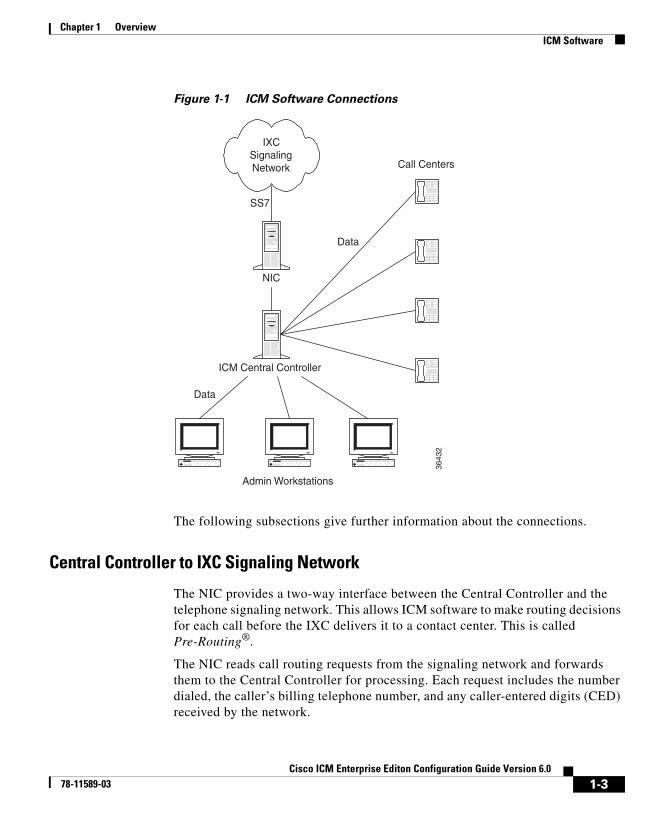
Figure 1-1 ICM Software Connections
The following subsections give further information about the connections.
Central Controller to IXC Signaling Network
The NIC provides a two-way interface between the Central Controller and the telephone signaling network. This allows ICM software to make routing decisions for each call before the IXC delivers it to a contact center. This is called Pre-Routing®.
The NIC reads call routing requests from the signaling network and forwards them to the Central Controller for processing. Each request includes the number dialed, the caller’s billing telephone number, and any caller-entered digits (CED) received by the network.
Call Centers
SS7
Data
ICM Central Controller
NIC
IXCSignalingNetwork
Data
Admin Workstations
3643
2
1-3Cisco ICM Enterprise Editon Configuration Guide Version 6.0
78-11589-03
Chapter 1 OverviewICM Software
When the Central Controller has determined a destination for the call, it returns the routing information to the NIC. The NIC then passes the information to the IXC signaling network.
The ICM software serves as a routing server for the IXC signaling network while the IXC serves as a routing client to the ICM software.
Central Controller to Peripheral Gateways
Each contact center has a Peripheral Gateway (PG) to read information from the site’s phone system and relay that information to the Central Controller. The PG reads information from the local peripheral (an ACD, PBX, IVR, or Call Manager). This includes information about agent availability, maximum and average caller wait times, and so on. The Peripheral Gateway then forwards the information to the Central Controller.
This information serves two purposes within the Central Controller:
• The router can use this information to determine where to route incoming calls.
• Users of ICM Admin Workstations can use this to monitor the performance of part or all of the system.
Optionally, the ICM software can make routing decisions in response to requests from each contact center (for example, for intelligent agent-to-agent transfers or transfers from a voice response unit). This is called Post-Routing®. If Post-Routing is enabled, then Peripheral Gateways can also pass routing requests to the Central Controller and receive routes in return. In this configuration, the ACD, PBX, or Call Manager serves as a routing client to the ICM software.
Central Controller to ICM Admin Workstations
Users at ICM Admin Workstations can read information from the Central Controller and can send the Central Controller changes to the system configuration or to the routing scripts.
The Central Controller includes a database that stores both information collected from the Peripheral Gateways and information that the Central Controller has accumulated about calls it has routed. You can monitor this information to measure the performance of the system as a whole or of a specific site or group.
1-4Cisco ICM Enterprise Editon Configuration Guide Version 6.0
78-11589-03
Chapter 1 OverviewICM Software
ICM Routing TargetsICM software can route a call to a carrier resource such as an announcement or to a target at a peripheral. A peripheral, such as an ACD, PBX, or Call Manager dispatches calls within a contact center.
Peripheral Targets
Depending on the capabilities of the peripheral and the type of routing instructions you use, ICM software might choose a specific agent at the peripheral to handle the call. In that case, the peripheral merely dispatches the call to the chosen agent. In other cases, ICM software might specify only a group of agents or a type of service to be provided to the caller. That is, ICM software can route to three types of peripheral targets:
• Agent. A specific individual who receives calls through the peripheral. (ICM software, however, cannot guarantee that the specific agent will be available when the call arrives.) The Queue to Agent node allows the targeting of a task (the work performed by an agent) to a script-specified agent. This node enables an agent to receive and operate on more than one task at a time.
• Skill group. A group of agents who share a common set of skills and who can, therefore, all handle specific types of calls. Each skill group contains one or more agents. If supported by the peripheral, each agent can be a member of more than one skill group.
• Service. A type of processing the caller requires. For example, a peripheral might have services defined for sales, technical support, or opening new accounts. Each service has one or more skill groups whose members can provide the service. Each skill group can be associated with more than one service.
In the last two cases, the peripheral must choose a specific agent within the group who can provide the service. In each case, the peripheral plays a key role in completing the routing that ICM software has determined. Therefore, ICM software and the peripheral must be set up to complement each other. They must have the same understanding of the agents, skill groups, and services available at each site.
For specific information about how ICM software routes a call and its coordination with peripherals, see Chapter 2, “How Routing Works.”
1-5Cisco ICM Enterprise Editon Configuration Guide Version 6.0
78-11589-03

Chapter 1 OverviewPeripherals
Scheduled Targets
Some routing clients also support scheduled targets. A scheduled target is a group of agents not associated with a Peripheral Gateway. ICM software cannot monitor the group directly. Instead it relies on a periodic schedule to determine the number of agents logged on to the group. The routing client informs ICM software when a call to the group ends. Since ICM software knows how many calls it has routed to the group, it can determine the number of calls in progress. Based on this and the schedule, ICM software can determine whether the target can handle an additional call.
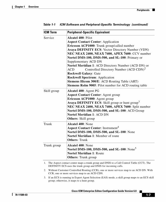
PeripheralsDifferent peripheral manufacturers use different terminology for agents, skill groups, and services. For example, a service might be called an application, split, or gate. A skill group might be called an agent group or hunt group.
Table 1-1 summarizes the mapping of ICM terminology to ACD-specific terminology.
Table 1-1 ICM Software and Peripheral-Specific Terminology
ICM Term Peripheral-Specific Equivalent
Agent Agent
Peripheral target
Alcatel 400: DNIS Ericsson ACP1000: Trunk group or queue NEC NEAX 2400, NEAX 7400, APEX 7600: Pilot number Nortel DMS-100, DMS-500, and SL-100: Primary or Supplementary ACD DN Rockwell Galaxy: DNIS Siemens Hicom 300/E: Destination ACD Others: Trunk group and DNIS1
1-6Cisco ICM Enterprise Editon Configuration Guide Version 6.0
78-11589-03
Chapter 1 OverviewPeripherals
Service Alcatel 400: Pilot Aspect Contact Center: Application Ericsson ACP1000: Trunk group/called number Avaya DEFINITY ECS: Vector Directory Number (VDN) NEC NEAX 2400, NEAX 7400, APEX 7600: CCV number Nortel DMS-100, DMS-500, and SL-100: Primary or Supplementary ACD DN Nortel Meridian 1: ACD Directory Number (ACD DN) or ACD Controlled Directory Number (ACD CDN)2
Rockwell Galaxy: Gate Rockwell Spectrum: Application Siemens Hicom 300/E: ACD Routing Table (ART) Siemens Rolm 9005: Pilot number for ACD routing table
Skill group Alcatel 400: Agent PG Aspect Contact Center: Agent group Ericsson ACP1000: Agent group Avaya DEFINITY ECS: Skill group or hunt group3
NEC NEAX 2400, NEAX 7400, APEX 7600: Split number Nortel DMS-100, DMS-500, and SL-100: ACD Group Nortel Meridian 1: ACD DN Others: Skill group
Trunk Alcatel 400: None Aspect Contact Center: Instrument4 Nortel DMS-100, DMS-500, and SL-100: None Nortel Meridian 1: Member of route Others: Trunk
Trunk group Alcatel 400: None Nortel DMS-100, DMS-500, and SL-100: None5
Nortel Meridian 1: Route Others: Trunk group
1. The Aspect contact center maps a trunk group and DNIS to a Call Control Table (CCT). The DEFINITY ECS uses the trunk group and DNIS for incoming calls.
2. Without Customer Controlled Routing (CCR), one or more services map to an ACD DN. With CCR, one or more services map to an ACD CDN.
3. If an ECS is running in Expert Agent Selection (EAS) mode, a skill group maps to an ECS skill group; otherwise, it maps to a hunt group.
Table 1-1 ICM Software and Peripheral-Specific Terminology (continued)
ICM Term Peripheral-Specific Equivalent
1-7Cisco ICM Enterprise Editon Configuration Guide Version 6.0
78-11589-03
Chapter 1 OverviewThe ICM Admin Workstation
Note Multi-channel applications function as application instances. See Chapter 9, “Configuring ICM Software for Integrated Applications,” for more information about these applications.
In some cases the ICM concept is very close to the corresponding ACD feature. For example, the ICM concept of a service is very similar to the Aspect concept of an application. In other cases, the ACD does not have a feature that maps exactly to the ICM feature. In these cases, you might choose a different mapping than shown in Table 1-1. For example, although it might make sense to associate each VDN on a DEFINITY ECS with an ICM service, you could also map each hunt group to a service.
On a Avaya DEFINITY ECS running in EAS mode and on Rockwell Galaxy ACDs, each skill group has primary and secondary subgroups. ICM software emulates this by automatically creating additional skill groups for these peripheral types. For example, when you configure the Sales skill group for a Galaxy ACD, ICM software automatically creates the Sales.pri and Sales.sec skill groups in addition to the base Sales group. In monitoring and scripts, you can reference the .pri and .sec skill groups directly or you can refer to the base skill group.
Some ACDs have limitations that prevent them from making full use of specific features of ICM software.
See the Cisco ICM Enterprise Edition Pre installation Planning guide for the current list of supported peripherals with any peripheral-specific limitations.
The ICM Admin WorkstationAn ICM Admin Workstation provides tools and resources for supervisors, system administrators, and system managers. You can use these resources to:
• Initialize and update configuration information.
• Write and update routing scripts and administrative scripts.
4. A contact center instrument can be a trunk, a teleset, or a workstation.
5. Define one network trunk group and one associated trunk group for each DMS-100, DMS-500, and SL-100.
1-8Cisco ICM Enterprise Editon Configuration Guide Version 6.0
78-11589-03
Chapter 1 OverviewThe ICM Admin Workstation
• Monitor the execution of scripts.
You can also monitor the performance of skill groups, services, routes, and trunks through the ICM Admin Workstation.
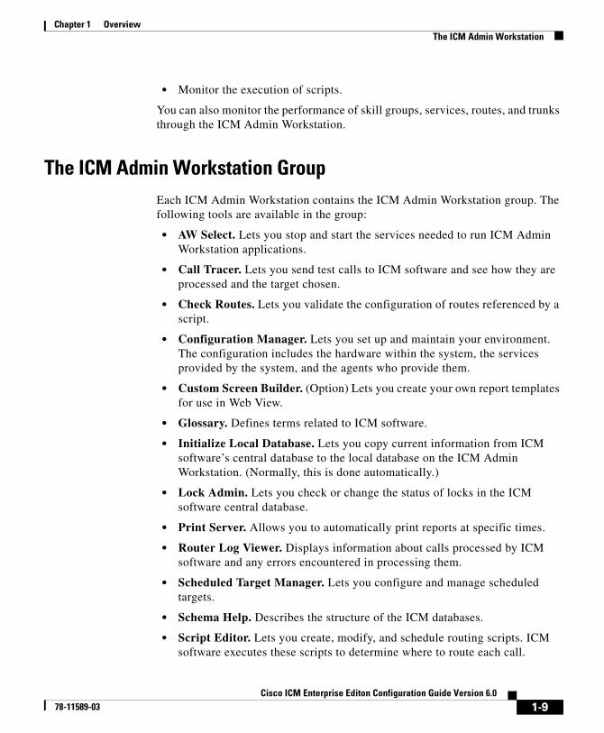
The ICM Admin Workstation GroupEach ICM Admin Workstation contains the ICM Admin Workstation group. The following tools are available in the group:
• AW Select. Lets you stop and start the services needed to run ICM Admin Workstation applications.
• Call Tracer. Lets you send test calls to ICM software and see how they are processed and the target chosen.
• Check Routes. Lets you validate the configuration of routes referenced by a script.
• Configuration Manager. Lets you set up and maintain your environment. The configuration includes the hardware within the system, the services provided by the system, and the agents who provide them.
• Custom Screen Builder. (Option) Lets you create your own report templates for use in Web View.
• Glossary. Defines terms related to ICM software.
• Initialize Local Database. Lets you copy current information from ICM software’s central database to the local database on the ICM Admin Workstation. (Normally, this is done automatically.)
• Lock Admin. Lets you check or change the status of locks in the ICM software central database.
• Print Server. Allows you to automatically print reports at specific times.
• Router Log Viewer. Displays information about calls processed by ICM software and any errors encountered in processing them.
• Scheduled Target Manager. Lets you configure and manage scheduled targets.
• Schema Help. Describes the structure of the ICM databases.
• Script Editor. Lets you create, modify, and schedule routing scripts. ICM software executes these scripts to determine where to route each call.
1-9Cisco ICM Enterprise Editon Configuration Guide Version 6.0
78-11589-03
Chapter 1 OverviewThe ICM Admin Workstation
• Service Control. Lets you stop and start ICM-related services.
Note In order to conserve system resources, it is recommended you minimize all ICM process windows prior to configuring your system.
• Setup. Lets you modify ICM setup parameters.
For more information the Custom Screen Builder, see the Cisco ICM/IP Contact Center Enterprise Edition Template Design Guide.
Central and Local DatabasesThe Central Controller includes a database that stores the system configuration information and routing scripts. At least one ICM Admin Workstation (referred to as a distributor AW) at each site has its own local database that contains a copy of data from the central database. Other ICM Admin Workstations at the site can read data from the distributor AW’s local database. ICM software’s UpdateAW background process automatically keeps the local database synchronized with the central database.
When you save a change to configuration data or scripts, ICM software immediately applies that change to the central database. The UpdateAW process copies the change to all local databases.
Lock AdministrationTo modify a script, you must first obtain a lock on that script. This prevents other users from changing the same script until you have saved your changes. When you edit a script, the Script Editor automatically acquires a script lock for you. The script lock applies to only one script.
Optionally, you can obtain a master lock that prevents other users from making any changes to scripts or configuration data. The master lock is for backwards compatibility only. If a user holds the master lock, only that user can make changes to any scripts or configuration data.
To acquire and release a lock, do the following:
1-10Cisco ICM Enterprise Editon Configuration Guide Version 6.0
78-11589-03
Chapter 1 OverviewConfiguration Management
Step 1 Start Lock Admin from the ICM Admin Workstation group. The Lock Admin dialog box appears, showing the status of all locks.
Step 2 Select the lock by clicking on the Type column of the row describing the lock.
Step 3 Click Release.
Step 4 Click Close when done.
Configuration ManagementICM configuration information is permanently stored in the Central Controller database. ICM software configuration consists of hardware entities, call targets, announcements, routes, dialed numbers, and regions. Use the ICM Configuration Manager tools to create and modify configuration data. When you apply a change in the ICM Configuration Manager, it is immediately applied to the central database.
To get started setting up and maintaining your configuration, see Chapter 3, “The ICM Configuration Manager.”
Script ManagementAfter you have set up your configuration, you can write routing scripts and administrative scripts:
• A routing script processes a call routing request from a routing client and determines the best destination for that call. ICM software then passes a label associated with the destination back to the routing client.
• An administrative script runs periodically to perform a task, such as setting variables.
Use the Script Editor to create, maintain, and monitor scripts.
1-11Cisco ICM Enterprise Editon Configuration Guide Version 6.0
78-11589-03
Chapter 1 OverviewScript Management
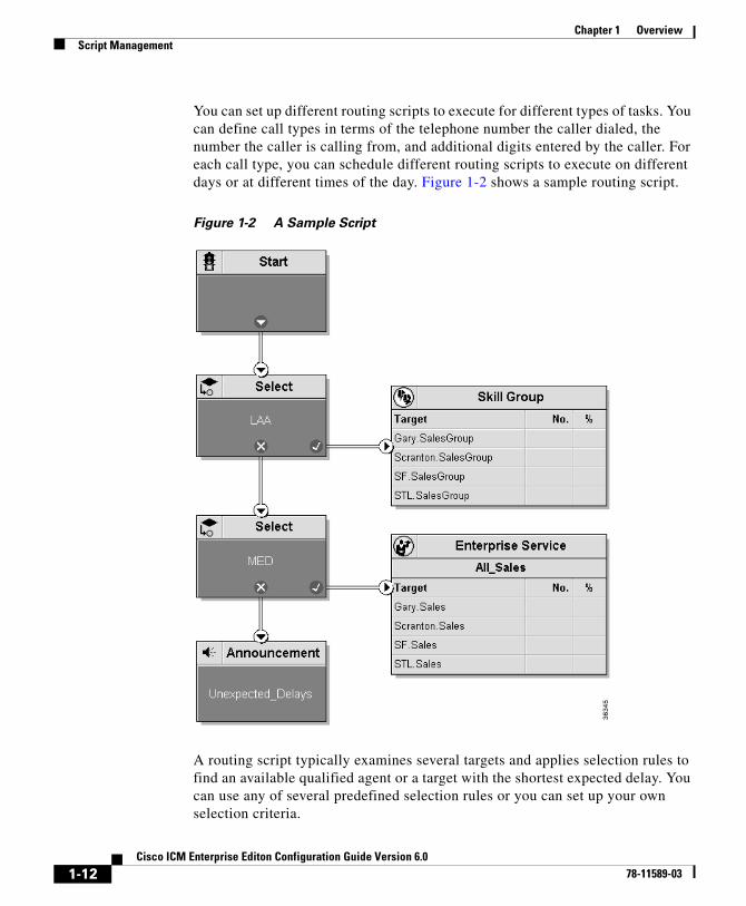
You can set up different routing scripts to execute for different types of tasks. You can define call types in terms of the telephone number the caller dialed, the number the caller is calling from, and additional digits entered by the caller. For each call type, you can schedule different routing scripts to execute on different days or at different times of the day. Figure 1-2 shows a sample routing script.
Figure 1-2 A Sample Script
A routing script typically examines several targets and applies selection rules to find an available qualified agent or a target with the shortest expected delay. You can use any of several predefined selection rules or you can set up your own selection criteria.
1-12Cisco ICM Enterprise Editon Configuration Guide Version 6.0
78-11589-03

Chapter 1 OverviewScript Management
Within the Script Editor, you can open a script for browsing, monitoring, or editing. When you open a script for editing, the Script Editor automatically obtains the lock for that script.
To get started using the Script Editor to create or maintain scripts, see the Cisco ICM Software Scripting and Media Routing Guide.
1-13Cisco ICM Enterprise Editon Configuration Guide Version 6.0
78-11589-03

Chapter 1 OverviewScript Management
1-14Cisco ICM Enterprise Editon Configuration Guide Version 6.0
78-11589-03
Cisco ICM Enterprise78-11589-03
C H A P T E R 2
How Routing WorksThis chapter describes in detail the process of routing a call. It includes:
• An overview of the routing process
• A description of routing requests and routing clients
• Information about how calls arrive at targets
• An overview of translation routes
• The importance of timeouts and thresholds
Understanding this process will help you set up the configuration of your ICM software and create effective scripts.
The Routing ProcessTo properly route calls, three independent systems must work together:
• The routing client
• ICM software
• The peripheral that ultimately receives the call
The routing client requests a route from ICM software, receives a response, and delivers the call to the specified destination.
ICM software receives routing requests and determines the appropriate destination for the call. The destination is an announcement (which is played by the routing client), a scheduled target, or a specific target at a peripheral (represented by a trunk group and DNIS).
2-1 Editon Configuration Guide Version 6.0
Chapter 2 How Routing WorksThe Routing Process
A peripheral is a switch at a call center, such as an ACD, a PBX, or Call Manager. The peripheral completes the routing by dispatching the call to the specific target determined by ICM software.
The process of routing a call consists of the following steps:
Step 1 A routing client requests a route from ICM software.
Step 2 ICM software, using information supplied by the routing client, categorizes the request as a specific call type.
Step 3 ICM software executes a routing script scheduled for the call type to find a destination for the call. The destination can be a routing label, an announcement, or a skill target: a service, skill group, or agent. (If the script fails to find a destination, ICM software uses a default destination based on the dialed number.)
Step 4 If the destination is an announcement, scheduled target, or skill target, ICM software maps that destination to a routing label. A routing label is a character string value that the routing client maps to a destination trunk group and, optionally, a Dialed Number Identification Service (DNIS) value for the call.
Step 5 ICM software passes the routing label back to the routing client.
Step 6 The routing client interprets the label to find the destination.
Step 7 The routing client dispatches the call to the destination (with the appropriate DNIS value, if any).
Step 8 If the call is sent to a peripheral, the peripheral must determine the specific target for which the call is intended. The peripheral typically makes this determination based on the trunk group on which the call arrived and, optionally, the DNIS value sent with the call. The peripheral then completes the routing by dispatching the call appropriately.
The following sections describe the process in detail.
2-2Cisco ICM Enterprise Editon Configuration Guide Version 6.0
78-11589-03
Chapter 2 How Routing WorksRouting Requests
Routing RequestsICM software receives routing requests from routing clients. A routing client can be either an interexchange carrier (IXC) or a peripheral. Routing clients are classified by type, where type is either the specific IXC (for example, AT&T, MCI, or Sprint) or the specific type of the peripheral (for example, VRU or a specific type of ACD).
Routing clients send messages to ICM software. One type of message is a route request. In this case, given a call, the routing client asks ICM software for a destination, or route, for that call. If the routing client is an IXC, this is the only type of message that it sends.
Routing requests are of two types: Pre-Routing and Post-Routing. A Pre-Routing request is sent by an IXC to determine the initial destination for a call. A Post-Routing request is sent by the peripheral that receives the call to either refine the original route or to redirect the call.
A routing request includes the following information about the call to be routed:
• Dialed Number (DN). The number the caller dialed.
• Calling Line ID (CLID). The caller’s billing telephone number. This value is also referred to as Automatic Number Identification or ANI.
• Caller-Entered Digits (CED). Digits the caller entered on a touch-tone phone in response to prompts.
Post-Routing messages vary depending on the type of the peripheral.
TargetsA target is the destination for a call. The target can be either a label, an announcement defined by the routing client, or a target at a peripheral.
On a high level, a target at the peripheral is a service, skill group, or individual agent that ICM software selects to handle the call. This is called the skill target. Regardless of the specific skill target, every call routed by ICM software must also be associated with a service. The combination of a skill target and a service is a route.
2-3Cisco ICM Enterprise Editon Configuration Guide Version 6.0
78-11589-03
Chapter 2 How Routing WorksTargets
On a lower level, a target represents a network trunk group at the peripheral and, optionally, a Dialed Number Identification Service (DNIS) value. The routing client uses this type of target, called a peripheral target, to route the call.
On a still lower level, each peripheral target or announcement maps to a routing label. A label is a character string that the routing client associates with a specific peripheral target or announcement.
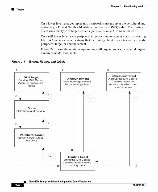
Figure 2-1 shows the relationships among skill targets, routes, peripheral targets, announcements, and labels.
Figure 2-1 Targets, Routes, and Labels
1c
Scheduled TargetA group the ICM Centrol
Controller does notmonitor, but which has
a set schedule
RouteSkill Target and Service
Peripheral TargetNetwork Trunk Group
and DNIS
Routing LabelString the ICM Central
Controller returns to therouting client
1b 1c2
3
1a
2
3
1b1a
Skill TargetService, Skill Group,Agent, or Translation
Route
AnnouncementAudio message defined
by the routing client
3662
2
2-4Cisco ICM Enterprise Editon Configuration Guide Version 6.0
78-11589-03

Chapter 2 How Routing WorksTargets
ICM software works from the top to the bottom of Figure 2-1:
1. A routing script determines a destination for the call. If the destination is a routing label, then ICM software can return that value directly to the routing client. Otherwise, the destination is one of the following:
– A skill target to receive the call
– An announcement to be played
– A scheduled target to receive the call
2. If the destination is a skill target, that skill target has an associated route.
3. ICM software uses the route to find an associated peripheral target supported by the routing client.
4. The peripheral target is associated with a label. ICM software returns that label to the routing client. If the destination is an announcement, ICM software only needs to find the label associated with that announcement and return the label to the routing client.
The routing client’s processing depends on the type of the label. Some labels instruct the routing client to take a special action: playing a busy signal for the caller, playing an unanswered ring for the caller, or making a special query. For normal labels, the routing client converts the label to an announcement, scheduled target, or peripheral target by working up from the bottom of Figure 2-1:
1. The routing client receives a label from ICM software in response to its route request. It translates that label into one of the following:
– A peripheral target
– An announcement
– A scheduled target
– An unrouted task that gets routed to a local agent
If the result is an announcement, it plays the announcement for the caller. If the result is a scheduled target, it delivers the call to that target.
2. If the result is a peripheral target, the routing client delivers the call to the specified network trunk group at the peripheral and sends the specified DNIS value, if any, with it.
3. The peripheral itself must then recognize the network trunk group and DNIS for the call as it arrives and determine the associated service and skill target.
2-5Cisco ICM Enterprise Editon Configuration Guide Version 6.0
78-11589-03
Chapter 2 How Routing WorksTargets
The peripheral then completes the process by locating the appropriate agent to handle the call.
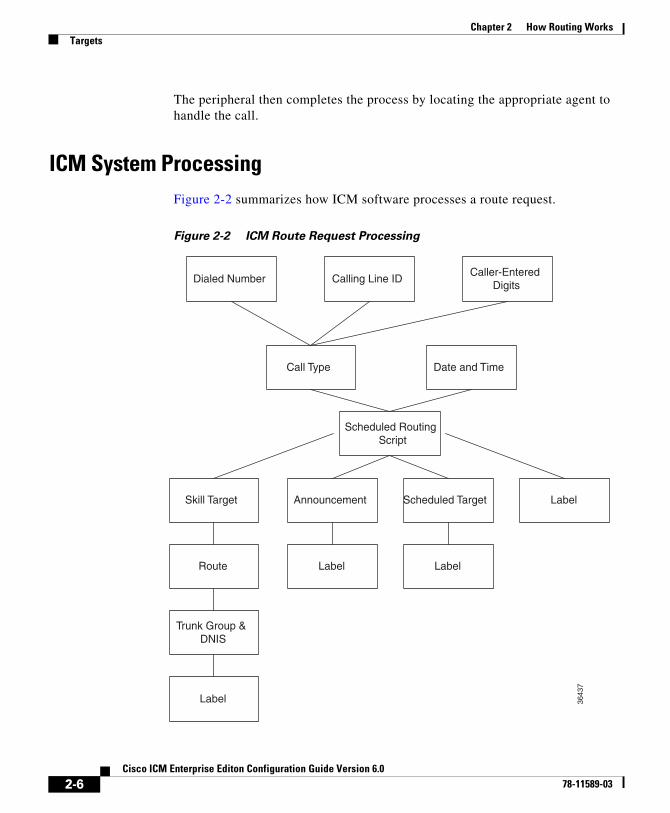
ICM System ProcessingFigure 2-2 summarizes how ICM software processes a route request.
Figure 2-2 ICM Route Request Processing
Dialed Number Calling Line ID
Date and TimeCall Type
Scheduled RoutingScript
Caller-EnteredDigits
Skill Target Scheduled Target Label
Route
Announcement
Label
Trunk Group &DNIS
Label
Label36
437
2-6Cisco ICM Enterprise Editon Configuration Guide Version 6.0
78-11589-03
Chapter 2 How Routing WorksTargets
The following subsections describe this processing.
Determine call type
When ICM software receives a route request for a call, it first determines the call type of the call. A call type is a category of incoming ICM routable tasks. Each call type has a schedule that determines which routing script or scripts are active for that call type at any time.
There are two classes of call types:
• Voice (phone calls)
• Non-voice (for example, e-mail and text chat)
Voice call types are categorized by the dialed number (DN), the caller-entered digits (CED), and the calling line ID (CLID).
Non-voice call types are categorized by the Script Type Selector, Application String 1, and Application String 2.
In either case, the last two categories of the call type are optional. For voice call types, the caller-entered digits and the calling line ID are optional, depending on the call. For non-voice call types, Application String 1 and Application String 2 are optional, depending on the application.
While chat sessions and blended collaboration are different from e-mail and also require call variables, the call variables are not part of the call type definition.
For example, you might define three call types to correspond to three sales regions within the country. You might have a network prompt that lets the caller enter 1 for sales, 2 for support, and 3 for information. If a call arrives for the dialed number 800.486.0029, with a CLID from the 403 (San Jose region) area code, and the caller enters 1 (sales) in response to the prompt, that call is classified as Western Sales.
If another call arrives with the same dialed number, but with a CLID from the 212 (New York City) area code, and the caller-entered digit 1, that call is classified as Eastern Sales.
You can define a general default call type and a specific default call type for each routing client. If the call qualifiers do not map to a specific call type, ICM software uses a default call type defined for the routing client. If no default call type is defined for the routing client, ICM software uses the general default call type.
2-7Cisco ICM Enterprise Editon Configuration Guide Version 6.0
78-11589-03
Chapter 2 How Routing WorksTargets
Execute script
Each call type has specific routing scripts scheduled for different times of day and different days of the year. ICM software finds the script currently scheduled for the call type and executes it. If that script fails to find a suitable destination (that is, a label, announcement, or skill target) for the call, then ICM software uses a default target associated with the Dialed Number value.
If ICM software finds an announcement or scheduled target for the call, then it can immediately resolve that to a label to return to the routing client. If ICM software finds a skill target for the call, it must perform a few extra steps before it finds a label.
Determine route
If ICM software finds a skill target for the call, that target has an associated route. You specify the route when you set up the target within the routing script. A route represents the combination of a skill target and a service. That is, a route represents the destination for a call and the type of service to be provided to the caller. Every call routed to a peripheral must have an associated service.
For example, the skill target for a call might be the skill group Denver.PostSales and the associated service might be Denver.TechSupport. Another call might also be routed to the Denver.PostSales group with the associated service Denver.Upgrades.
Note If the destination is itself a service, for example Chicago.Sales, then the associated service should also be Chicago.Sales. To associate a service skill target with a route for a different service would skew the statistics for those services.
Determine trunk group and DNIS
Once it has determined a route for a call, ICM software finds an associated peripheral target (trunk group and DNIS). It is possible to have several peripheral targets associated with the same route, but typically only one of those targets is valid for the routing client. For example, if you have switched access lines, two IXCs could direct calls to the same trunk group and DNIS, but each requires a different label value for that target. Therefore, you need to define two separate
2-8Cisco ICM Enterprise Editon Configuration Guide Version 6.0
78-11589-03

Chapter 2 How Routing WorksTargets
peripheral targets for the route. If more than one peripheral target is associated with the route, ICM software chooses the first peripheral target that maps to a valid label for the routing client.
Determine label
Each peripheral target, scheduled target, or announcement maps to one or more labels. ICM software finds the first label that is valid for the routing client and dialed number and returns that label to the routing client. It is then up to the routing client to interpret the label.
Default label
It is possible that the ICM software might fail to find a call type for a route request. Also, the ICM software may execute the script currently scheduled for a call type and fail to find a destination for the call. In these cases, it uses a default label that is defined for the dialed number. If no default label is defined for the dialed number, the ICM software returns an error to the routing client.
The routing client itself also has some default action defined. When you set up each routing client you can specify the maximum time that client can wait for a response to a routing request. If ICM software has not returned a destination for the call before the time limit is reached, or if ICM software returns an error, the routing client performs its own default action.
For more information on timeout limits, see the “Timeouts and Thresholds” section on page 2-11.
Routing Client’s ProcessingThe routing client begins by requesting a route for a call from ICM software. ICM software processes the request as described in the preceding section and returns a label to the routing client.
The routing client has its own internal mappings for labels to announcements, scheduled targets, and peripheral targets. It uses these mappings to interpret the label from ICM software:
• Busy. Routing client plays a busy signal for the caller.
• Ring. Routing client plays an unanswered ring for the caller.
2-9Cisco ICM Enterprise Editon Configuration Guide Version 6.0
78-11589-03
Chapter 2 How Routing WorksTranslation Routes
• Normal and the label maps to an announcement. Routing client plays the announcement for the caller.
• Normal and the label maps to a scheduled target. Routing client delivers the call to that target.
• Normal or DNIS Override and the label maps to a peripheral target (that is, a trunk group and a DNIS). Routing client delivers the call and the specified DNIS value to that trunk group. The peripheral then has responsibility for dispatching the call to the appropriate skill target.
The Peripheral’s ProcessingWhen a peripheral receives a call, it determines the trunk group on which the call arrived and the DNIS value, if any, associated with it. The peripheral must be programmed to map these values to the same service and skill target determined by ICM software.
The peripheral, acting as a routing client, can also send a routing request to ICM software.
Translation RoutesSometimes you want to send additional information along with the call to a skill target. Translation routes allow you to do that.
A translation route is a temporary destination for a call. When ICM software returns a translation route label to the routing client, it also sends a message directly to the Peripheral Gateway (PG) at the targeted peripheral. This message alerts the PG that a call will be arriving that requires route translation. The message contains the following information:
• The trunk group on which the call will arrive and the DNIS value associated with it.
• A label to be used by the PG to determine the ultimate skill target of the call. This is a label that the PG can interpret to find the correct destination.
• Instructions for further processing to be performed by the PG. This further processing might include, for example, looking up an account number in a database.
2-10Cisco ICM Enterprise Editon Configuration Guide Version 6.0
78-11589-03
Chapter 2 How Routing WorksTimeouts and Thresholds
When the peripheral sees the call arrive on the specified trunk group and with the specified DNIS value, it passes this information to the PG. The PG then combines it with the information it has received from ICM software. It then sends the call along with this information to the skill target specified by the label it received. At the same time, the peripheral might, for example, send a message to a host computer that controls the display on the agent’s workstation. This allows data, such as the caller’s account information, to be displayed on the screen when the call arrives. The PG coordinates communication among the network, the peripheral, and the computer application that controls the display.
To set up a translation route, you must do the following:
• Set up a translation route associated with the peripheral. You do not need a separate translation route for each possible skill target at the site, but you need at least one for each peripheral that performs translation routing.
• Set up one or more routes and associated peripheral targets for the translation route. Typically, all peripheral targets for a translation route refer to the same trunk group, but with different DNIS values.
• Set up a label for the original routing client for the call to access each of the peripheral targets associated with the translation route. For example, if the routing client is an interexchange carrier (IXC), you must set up a label to the targets with the IXC. This allows the call to be initially sent to the translation route at the peripheral.
• For each peripheral target that you want to be able to ultimately access via a translation route, set a label with the peripheral as the routing client. For example, you might want to be able to send calls to the Atlanta.Support skill group through a translation route. To do this, you must configure a label for that skill group with the Atlanta peripheral as the routing client. This allows the peripheral to determine the ultimate destination for the call.
• To display data on the agent’s workstation when the call arrives, you must configure the peripheral to inform the PG which agent is receiving the call.
Timeouts and ThresholdsIn setting up your configuration, you need to specify several timeout and timing threshold values.
2-11Cisco ICM Enterprise Editon Configuration Guide Version 6.0
78-11589-03
Chapter 2 How Routing WorksTimeouts and Thresholds
For routing clients, you must specify the maximum time ICM software can spend before responding to each routing request. You must also specify the maximum time for the routing client to wait for a response before it stops sending new requests to ICM software.
For each service at a peripheral, you must specify your goal for the maximum time a caller must wait before the call is answered. ICM software uses this value in calculating the service level.
You can specify how to count abandoned calls in the service level calculation. You can also specify the minimum time a call must be in the queue before it can be considered abandoned.
For specific information about configuring routing clients, peripherals, and services, see Chapters 4 through 7.
Routing ClientsIn some cases, a routing client might be unable to receive routing responses from ICM software. Sometimes this affects only a single request, but other times the routing client loses contact with ICM software for longer periods. You can specify the amount of time for the routing client to wait before giving up on a single request and the amount of time to wait before it stops sending any requests to ICM software.
Timeout Threshold
The timeout threshold is the amount of time to wait for each routing request. Set this value to be the same as the routing client’s timeout threshold. Under normal conditions, ICM software finds a routing label for the call within this limit. However, if this threshold is exceeded and ICM software has not yet sent a response to the request, the routing client performs its own default action to route the call. You can specify the timeout threshold in milliseconds. For example, for AT&T ICP connections, set the timeout threshold to 1500 milliseconds.
Late Threshold
You can specify a second threshold, the late threshold, that is shorter than the timeout threshold. If ICM software returns a response after this threshold has passed, it is considered a late response. The routing client can still use the
2-12Cisco ICM Enterprise Editon Configuration Guide Version 6.0
78-11589-03

Chapter 2 How Routing WorksTimeouts and Thresholds
response, but it is logged as a late response. A large number of late responses might be an early indicator of problems within the system. You can specify the late threshold in milliseconds. For example, for AT&T ICP connections, set the late threshold to 500 milliseconds.
Timeout Limit
ICM software is designed to be a highly reliable system. Distributed duplicated hardware and software fault-tolerance ensure very high availability. However, the NIC uses a timeout limit to provide a safety net to ensure that your calls continue to be routed even if ICM software were to become completely unavailable. If the routing client receives no responses from ICM software within the timeout limit (and a minimum number of requests have been made), it stops sending requests to ICM software. You can set the minimum number of requests that must be made (the consecutive timeout limit) when you set up the NIC software. The default is 10.
When a routing request first exceeds the timeout threshold, the NIC for the routing client starts a timer. If the timer reaches the timeout limit before the routing client receives any on-time routing responses from ICM software, then the NIC tells the routing client to stop sending routing requests to ICM software. An on-time response is a response within the timeout threshold. You can specify the timeout limit in seconds. For example, for AT&T ICP connections, set the timeout limit to 10 seconds.
Abandoned Call Wait TimeWhen a call is delivered to a peripheral, the caller might be placed in a queue waiting for an agent to become available. Normally, if the caller hangs up before being connected with an agent, the call is considered abandoned. A high number of abandoned calls might mean that you are losing business because callers are being made to wait too long.
However, if a caller hangs up almost immediately after being placed in a queue, you might not want to count that as an abandoned call. In these cases, caller impatience or excessive queue times are not the problem; the caller probably hung up for another reason. Tracking these as abandoned calls can be misleading.
2-13Cisco ICM Enterprise Editon Configuration Guide Version 6.0
78-11589-03
Chapter 2 How Routing WorksTimeouts and Thresholds
Therefore, you can specify a minimum amount of time that a caller must wait before the call can be considered abandoned. This value is called the abandoned call wait time. You can set this value for each peripheral. A typical value might be 10 seconds. This would mean that if the caller hangs up in the first 10 seconds, the call is not considered abandoned, nor is it counted as a call offered. If the caller waits at least 10 seconds and then hangs up, the call is counted as both offered and abandoned. (In the real-time data, a call is counted as offered as soon as it arrives at the peripheral. Therefore, a short call might appear as a call offered in the real-time data, but is not counted as offered in the historical data.)
Service LevelService level is a measure of how well you are meeting your goals for answering calls. For each service, you can set a goal for the maximum time a caller spends in a queue before being connected to an agent. This value is the service level threshold. The service level is usually expressed as the percentage of calls that are answered within the threshold.
To calculate the service level for a period of time, ICM software determines the number of calls that have had a service level event within that period. A service level event occurs when one of three things happens to a call:
• It is answered within the service level threshold.
• It is abandoned within the service level threshold.
• It reaches the service level threshold without being answered or abandoned.
All calls that have a service level event within a specified period are considered as service level calls offered for that period. This differs from a simple call’s offered value, which counts each call at the time it is first offered to the service.
Service Level Threshold
The service level threshold is the number of seconds you set as a goal for connecting a call with an agent. When you set up a peripheral, you can specify a default service level threshold for all services associated with that peripheral. When you set up each service, you can choose to either use the default threshold set for the peripheral or specify a threshold for the service itself in the Service Level Threshold field. If you do not specify a service level threshold for an
2-14Cisco ICM Enterprise Editon Configuration Guide Version 6.0
78-11589-03
Chapter 2 How Routing WorksTimeouts and Thresholds
individual service, the default threshold you specified for the peripheral is used. Typically, you should set these values to match the service level thresholds being used by the peripheral itself.
Service Level Types
Different peripheral types use slightly different formulas to calculate service level. ICM software provides a uniform calculation across all peripherals. This allows you to apply uniform metrics and performance goals across all peripherals. However, ICM software also tracks the service level as calculated by the peripheral itself. This is called the peripheral service level. You can use this value, for example, to continue to compare performance to historical norms.
Some peripherals let you select one of several types of service level calculation. You can specify which of these types of service level you want ICM software to track.
The uniform service level calculation performed by ICM software can be done in any of three ways:
• Abandoned calls ignored. The number of calls answered within the threshold divided by the number of calls that had a service level event minus the number of calls that were abandoned before exceeding the service level threshold. Calls abandoned before the service level threshold expired are removed from this calculation.
• Abandoned calls negatively impact service level. The number of calls answered within the threshold divided by the number of calls that had a service level event. This treats these abandoned calls as though they had exceeded the threshold.
• Abandoned calls positively impact service level. The number of calls answered within the threshold plus the number of calls abandoned within the threshold, all divided by the number of calls that had a service level event. This treats these abandoned calls as though they were answered within the threshold.
Figure 2-3 illustrates these different ways of calculating service level.
2-15Cisco ICM Enterprise Editon Configuration Guide Version 6.0
78-11589-03
Chapter 2 How Routing WorksTimeouts and Thresholds
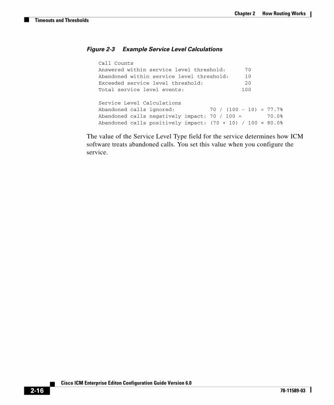
Figure 2-3 Example Service Level Calculations
Call CountsAnswered within service level threshold: 70Abandoned within service level threshold: 10Exceeded service level threshold: 20Total service level events: 100
Service Level CalculationsAbandoned calls ignored: 70 / (100 - 10) = 77.7%Abandoned calls negatively impact: 70 / 100 = 70.0%Abandoned calls positively impact: (70 + 10) / 100 = 80.0%
The value of the Service Level Type field for the service determines how ICM software treats abandoned calls. You set this value when you configure the service.
2-16Cisco ICM Enterprise Editon Configuration Guide Version 6.0
78-11589-03
Cisco ICM Enterprise78-11589-03
C H A P T E R 3
The ICM Configuration ManagerAfter you have installed ICM and have it running, use the Configuration Manager to view and update the configuration information in the ICM database. The configuration information describes the people, groups, and devices that are part of your enterprise.
For example, use the Configuration Manager to specify:
• The devices in your system and the clients they serve, including:
– The peripherals at your contact centers
– The routing clients served by your system
• Targets at the peripherals to which ICM software can direct calls, including:
– Trunks and trunk groups connected to peripherals
– Skill targets associated with each peripheral: agents, skill groups, services, and translation routes
– Information used by scripts to organize call requests and direct calls to targets, including call types, regions, prefixes, and dialed numbers
– Targets understood by the routing client, including announcements, peripheral targets, and routing labels
– The associations among routing labels, routes, peripheral targets, and skill targets
• Enterprise services and enterprise skill groups as a combination of individual services and groups from different contact centers
3-1 Editon Configuration Guide Version 6.0
Chapter 3 The ICM Configuration ManagerAccessing the Configuration Manager
Accessing the Configuration ManagerTo access the Configuration Manager:
• In the ICM Admin Workstation group, double-click the Configuration Manager icon
or
• From the Start menu, select Programs > ICM Admin Workstation > Configuration Manager.
Configuration Manager When you start the Configuration Manager, the Configuration Manager window appears. Figure 3-1 shows the window with the top-level directories displayed for all its menus.
The ICM Configuration Manager lets you view and update the configuration information in the ICM database. The configuration information describes the people, groups, and devices that are part of your enterprise.
To set up the configuration of a new system when you are a new user, follow the steps in the menu bar’s Step by Step Configuration selection list.
Use the tools in the Telephony Contact Center Configuration menu in the order given to configure, first Network Interface Controllers (NICs), then peripherals, and so on. After you configure ICM software for your telephony contact center, then you can configure the software for multi-media applications.
The tools in the MultiMedia Contact Center Configuration menu are also in the order in which you might use them. For example: you must have a media class before you can create a media routing domain for that class. And you must have an application instance before you can specify the path to that application.
3-2Cisco ICM Enterprise Editon Configuration Guide Version 6.0
78-11589-03

Chapter 3 The ICM Configuration ManagerConfiguration Manager
To …
• Access the configuration tools according to the menu selections of the former Configure ICM tool, in the menu, select Configure ICM.
• Access all the tools you can use in the Configuration Manager, in the menu bar, select Tools.
3-3Cisco ICM Enterprise Editon Configuration Guide Version 6.0
78-11589-03
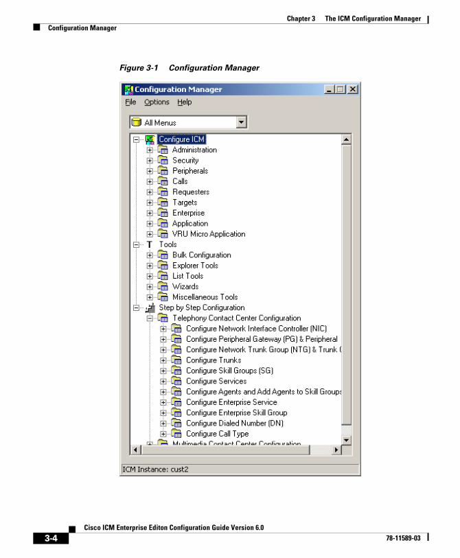
Chapter 3 The ICM Configuration ManagerConfiguration Manager
Figure 3-1 Configuration Manager
3-4Cisco ICM Enterprise Editon Configuration Guide Version 6.0
78-11589-03
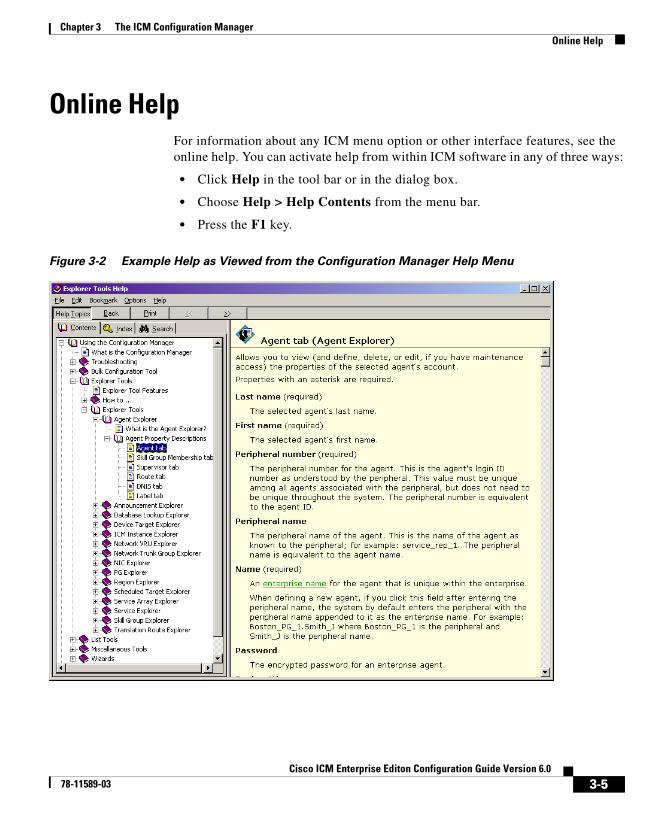
Chapter 3 The ICM Configuration ManagerOnline Help
Online HelpFor information about any ICM menu option or other interface features, see the online help. You can activate help from within ICM software in any of three ways:
• Click Help in the tool bar or in the dialog box.
• Choose Help > Help Contents from the menu bar.
• Press the F1 key.
Figure 3-2 Example Help as Viewed from the Configuration Manager Help Menu
3-5Cisco ICM Enterprise Editon Configuration Guide Version 6.0
78-11589-03
Chapter 3 The ICM Configuration ManagerTroubleshooting
TroubleshootingThe following section lists problems which may occur when editing records.
Problem: If an edit is made and saved in one configuration tool while another configuration tool is open, the edited data will not display in the other configuration tool window (or selection boxes) until you click Retrieve.
Discussion:
Clicking Retrieve not only retrieves data when you first open a configuration tool but also refreshes (updates the display of) the data that is currently in the database. The configuration tools do not automatically update the display of data when it is changed in the database unless you click Save or Retrieve.
Solution:
Click Retrieve.
Problem: When I saved an edited record, it disappeared from the display of records
Discussion:
If you edit a record so that one of its fields no longer matches the filter selected in the Select filter data box, and then save that record, it will disappear from the list of displayed records. This happens because the save function not only saves the data in the database but also refreshes the open window to display the current database data according to the current filter selections.
3-6Cisco ICM Enterprise Editon Configuration Guide Version 6.0
78-11589-03
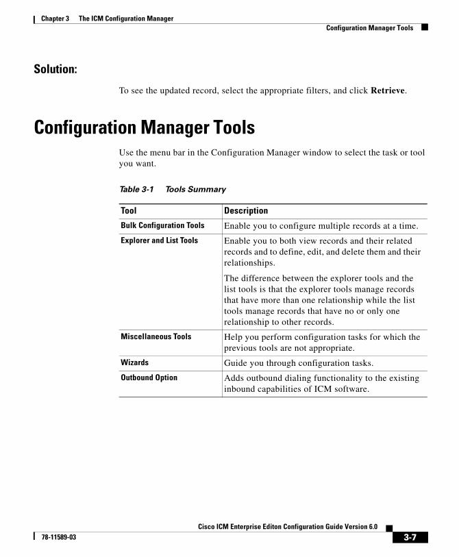
Chapter 3 The ICM Configuration ManagerConfiguration Manager Tools
Solution:
To see the updated record, select the appropriate filters, and click Retrieve.
Configuration Manager ToolsUse the menu bar in the Configuration Manager window to select the task or tool you want.
Table 3-1 Tools Summary
Tool Description
Bulk Configuration Tools Enable you to configure multiple records at a time.
Explorer and List Tools Enable you to both view records and their related records and to define, edit, and delete them and their relationships.
The difference between the explorer tools and the list tools is that the explorer tools manage records that have more than one relationship while the list tools manage records that have no or only one relationship to other records.
Miscellaneous Tools Help you perform configuration tasks for which the previous tools are not appropriate.
Wizards Guide you through configuration tasks.
Outbound Option Adds outbound dialing functionality to the existing inbound capabilities of ICM software.
3-7Cisco ICM Enterprise Editon Configuration Guide Version 6.0
78-11589-03
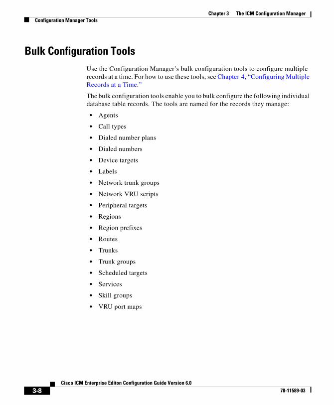
Chapter 3 The ICM Configuration ManagerConfiguration Manager Tools
Bulk Configuration ToolsUse the Configuration Manager’s bulk configuration tools to configure multiple records at a time. For how to use these tools, see Chapter 4, “Configuring Multiple Records at a Time.”
The bulk configuration tools enable you to bulk configure the following individual database table records. The tools are named for the records they manage:
• Agents
• Call types
• Dialed number plans
• Dialed numbers
• Device targets
• Labels
• Network trunk groups
• Network VRU scripts
• Peripheral targets
• Regions
• Region prefixes
• Routes
• Trunks
• Trunk groups
• Scheduled targets
• Services
• Skill groups
• VRU port maps
3-8Cisco ICM Enterprise Editon Configuration Guide Version 6.0
78-11589-03
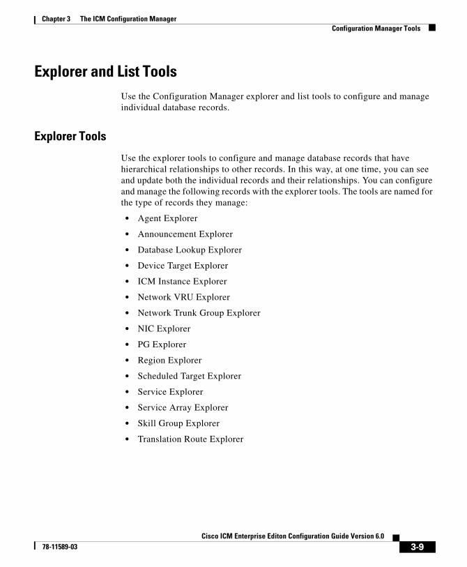
Chapter 3 The ICM Configuration ManagerConfiguration Manager Tools
Explorer and List ToolsUse the Configuration Manager explorer and list tools to configure and manage individual database records.
Explorer Tools
Use the explorer tools to configure and manage database records that have hierarchical relationships to other records. In this way, at one time, you can see and update both the individual records and their relationships. You can configure and manage the following records with the explorer tools. The tools are named for the type of records they manage:
• Agent Explorer
• Announcement Explorer
• Database Lookup Explorer
• Device Target Explorer
• ICM Instance Explorer
• Network VRU Explorer
• Network Trunk Group Explorer
• NIC Explorer
• PG Explorer
• Region Explorer
• Scheduled Target Explorer
• Service Explorer
• Service Array Explorer
• Skill Group Explorer
• Translation Route Explorer
3-9Cisco ICM Enterprise Editon Configuration Guide Version 6.0
78-11589-03
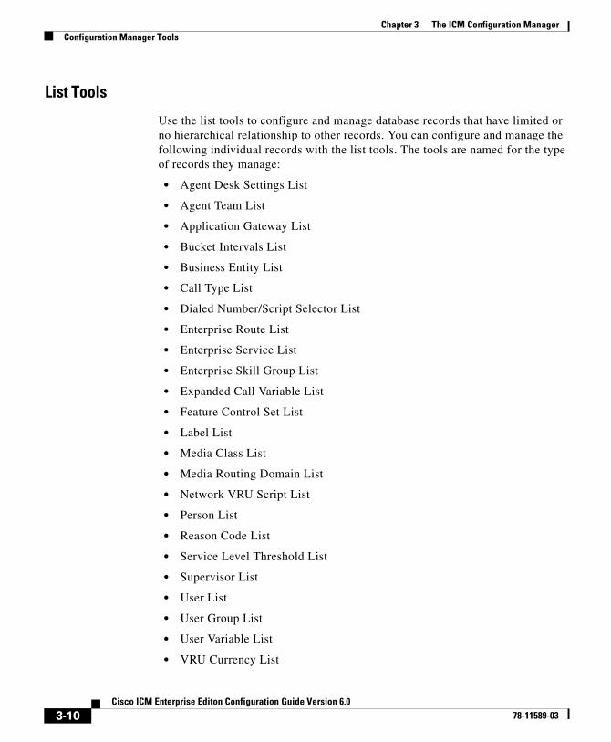
Chapter 3 The ICM Configuration ManagerConfiguration Manager Tools
List Tools
Use the list tools to configure and manage database records that have limited or no hierarchical relationship to other records. You can configure and manage the following individual records with the list tools. The tools are named for the type of records they manage:
• Agent Desk Settings List
• Agent Team List
• Application Gateway List
• Bucket Intervals List
• Business Entity List
• Call Type List
• Dialed Number/Script Selector List
• Enterprise Route List
• Enterprise Service List
• Enterprise Skill Group List
• Expanded Call Variable List
• Feature Control Set List
• Label List
• Media Class List
• Media Routing Domain List
• Network VRU Script List
• Person List
• Reason Code List
• Service Level Threshold List
• Supervisor List
• User List
• User Group List
• User Variable List
• VRU Currency List
3-10Cisco ICM Enterprise Editon Configuration Guide Version 6.0
78-11589-03
Chapter 3 The ICM Configuration ManagerConfiguration Manager Tools
• VRU Defaults List
• VRU Locale List
Miscellaneous ToolsThe following Configuration Manager tools enable you to do miscellaneous functions not available with the other tools:
• Deleted Objects
Enables you to view all records deleted from the database and to permanently delete them if you no longer want them available for your records.
• Integrity Check
Allows you to perform specific integrity checks on the configuration data in the ICM database.
• Region Editor
Allows you to:
– View, create, update (cut, copy, paste, move, or edit), and delete custom regions.
– View, copy, or move predefined regions, but not edit or delete them.
• Script Reference
Allows you to generate a report that shows which routing scripts reference a specific configuration record.
• System Information
Allows you to view and set general and application gateway information about your enterprise.
• Unreferenced
Lists the database tables that have unreferenced records. Use this tool to find specific integrity problems within the database.
3-11Cisco ICM Enterprise Editon Configuration Guide Version 6.0
78-11589-03
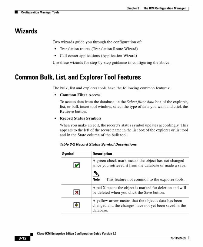
Chapter 3 The ICM Configuration ManagerConfiguration Manager Tools
WizardsTwo wizards guide you through the configuration of:
• Translation routes (Translation Route Wizard)
• Call center applications (Application Wizard)
Use these wizards for step-by-step guidance in configuring the above.
Common Bulk, List, and Explorer Tool FeaturesThe bulk, list and explorer tools have the following common features:
• Common Filter Access
To access data from the database, in the Select filter data box of the explorer, list, or bulk insert tool window, select the type of data you want and click the Retrieve button.
• Record Status Symbols
When you make an edit, the record’s status symbol updates accordingly. This appears to the left of the record name in the list box of the explorer or list tool and in the State column of the bulk tool.
Table 3-2 Record Status Symbol Descriptions
Symbol Description
A green check mark means the object has not changed since you retrieved it from the database or made a save.
Note This feature not common to the explorer tools.
A red X means the object is marked for deletion and will be deleted when you click the Save button.
A yellow arrow means that the object's data has been changed and the changes have not yet been saved in the database.
3-12Cisco ICM Enterprise Editon Configuration Guide Version 6.0
78-11589-03

Chapter 3 The ICM Configuration ManagerConfiguration Manager Tools
• ID status box
The label in the ID box at the bottom of the screen identifies the ICM system (instance) on which you are working.
• Delete/Undelete button
When a record is selected and you click the Delete button, that button toggles to Undelete and a red x marks the record for deletion. As soon as you save your database changes the marked record(s) is deleted from the database.
• Save button
No changes are made to the database until you click the Save button.
A yellow addition sign means the object is to be inserted into the database when you click the Save button.
A red circle with a red slash through it indicates the object was created using an application and is controlled by the Application Object Filter (AOF).
Table 3-2 Record Status Symbol Descriptions (continued)
Symbol Description
3-13Cisco ICM Enterprise Editon Configuration Guide Version 6.0
78-11589-03
Chapter 3 The ICM Configuration ManagerConfiguration Manager Tools
Common List and Explorer Tool FeaturesThe list and explorer tools share the following features.
• List Box of Retrieved Records
Both the explorer and list tools have a list box that displays retrieved records. Selecting a record in this list displays that record’s properties in the right side of the tool window. Once displayed, you can edit a record if you have maintenance access to it.
– Tree (only in explorer tools)
In an explorer window, the retrieved list is called a directory tree, which can be expanded or contracted to show a hierarchy of records. A legend above the tree identifies the types of records that can be displayed in the tree.
With the mouse, you can select a record in a tree and then move it to another part of the tree, as long as it’s object type belongs in that tree location.
– UNASSIGNED (only in explorer tools)
The explorer tree can also contain UNASSIGNED records. These are stored in an UNASSIGNED directory for the selected directory tree object.
A record is named UNASSIGNED if it was not assigned (mapped) to a parent object. For example, a label, created in the Bulk Configuration Tool, might not have been assigned to a peripheral target, or a route might not have been assigned to a service.
You can also use the Label Bulk Configuration tool to take the output of a switch and create 20 or 30 labels. Then, using an explorer tool, you can attach the labels to an appropriate location.
– List (only in list tools)
In a list window, the retrieved list is called a list and has no legend above it since its records have no or only one relationship to another record.
• Adding New Records
The Add button is enabled only after you use the Select filter data section of the window.
3-14Cisco ICM Enterprise Editon Configuration Guide Version 6.0
78-11589-03
Chapter 3 The ICM Configuration ManagerConfiguration Manager Tools
In the explorer tools, when a record in the tree is selected, you can add another record of the same kind or a record immediately below it in the tree hierarchy. In the list tools, the add button is enabled only for the single type of records listed.
• Deleting Records
Selecting a record and clicking Delete marks the record (with a red x) for deletion. However, the record is not deleted until you click Save.
Delete toggles to Undelete when you select an object marked for deletion. To undelete an object marked for deletion, select it and click Undelete.
• Options Menu
In the explorer and list tool windows, right clicking on a retrieved record displays an options menu containing all the editing options for that record.
Note This menu is not available in the list tools if you have read-only access.
3-15Cisco ICM Enterprise Editon Configuration Guide Version 6.0
78-11589-03
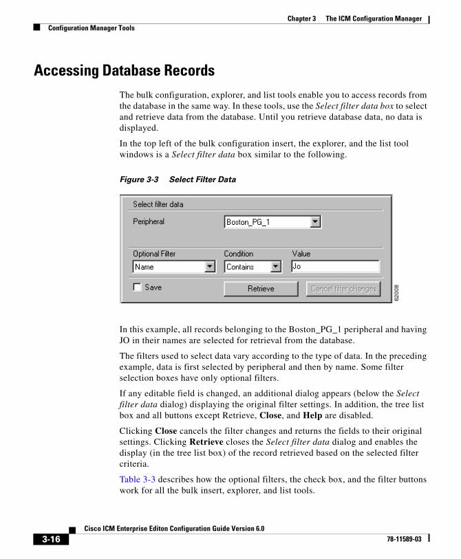
Chapter 3 The ICM Configuration ManagerConfiguration Manager Tools
Accessing Database RecordsThe bulk configuration, explorer, and list tools enable you to access records from the database in the same way. In these tools, use the Select filter data box to select and retrieve data from the database. Until you retrieve database data, no data is displayed.
In the top left of the bulk configuration insert, the explorer, and the list tool windows is a Select filter data box similar to the following.
Figure 3-3 Select Filter Data
In this example, all records belonging to the Boston_PG_1 peripheral and having JO in their names are selected for retrieval from the database.
The filters used to select data vary according to the type of data. In the preceding example, data is first selected by peripheral and then by name. Some filter selection boxes have only optional filters.
If any editable field is changed, an additional dialog appears (below the Select filter data dialog) displaying the original filter settings. In addition, the tree list box and all buttons except Retrieve, Close, and Help are disabled.
Clicking Close cancels the filter changes and returns the fields to their original settings. Clicking Retrieve closes the Select filter data dialog and enables the display (in the tree list box) of the record retrieved based on the selected filter criteria.
Table 3-3 describes how the optional filters, the check box, and the filter buttons work for all the bulk insert, explorer, and list tools.
3-16Cisco ICM Enterprise Editon Configuration Guide Version 6.0
78-11589-03
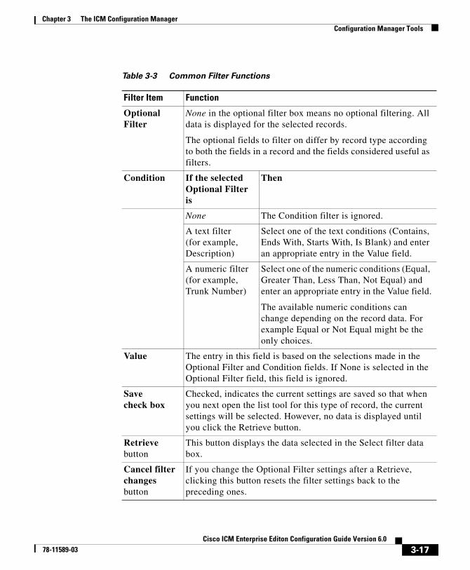
Chapter 3 The ICM Configuration ManagerConfiguration Manager Tools
Table 3-3 Common Filter Functions
Filter Item Function
Optional Filter
None in the optional filter box means no optional filtering. All data is displayed for the selected records.
The optional fields to filter on differ by record type according to both the fields in a record and the fields considered useful as filters.
Condition If the selectedOptional Filter is
Then
None The Condition filter is ignored.
A text filter(for example, Description)
Select one of the text conditions (Contains, Ends With, Starts With, Is Blank) and enter an appropriate entry in the Value field.
A numeric filter (for example, Trunk Number)
Select one of the numeric conditions (Equal, Greater Than, Less Than, Not Equal) and enter an appropriate entry in the Value field.
The available numeric conditions can change depending on the record data. For example Equal or Not Equal might be the only choices.
Value The entry in this field is based on the selections made in the Optional Filter and Condition fields. If None is selected in the Optional Filter field, this field is ignored.
Savecheck box
Checked, indicates the current settings are saved so that when you next open the list tool for this type of record, the current settings will be selected. However, no data is displayed until you click the Retrieve button.
Retrievebutton
This button displays the data selected in the Select filter data box.
Cancel filter changesbutton
If you change the Optional Filter settings after a Retrieve, clicking this button resets the filter settings back to the preceding ones.
3-17Cisco ICM Enterprise Editon Configuration Guide Version 6.0
78-11589-03
Chapter 3 The ICM Configuration ManagerConfiguration Manager Tools
Saving Configuration Data to the DatabaseWhen you have completed adding information in an open configuration window, click Save.
ICM software saves the configuration data and immediately applies your changes to both the local and central ICM database.
Note Whenever any data is retrieved by a configuration tool, it notes the last change mark on that data at this point in time. If you then attempt to change that item, it first checks the current copy in the database for its change mark. If the change marks do not agree, it indicates another user has changed this item since you last retrieved it, and an error is returned. You must then discard any changes, using Retrieve to obtain the latest information for editing.
This approach is called optimistic locking, and assumes that it is rare to have two people needing to change the same item at the same time. This prevents the performance and maintenance issues involved with hard locking items, while still preventing one person from accidentally overwriting another user’s changes.
Feature ControlIn general, feature control addresses the need of restricting users, or classes of users, from all functionality of the ICM software.
A distinction should be made between object level control and feature control:
• Object control, part of the ICM software partitioning feature, is a method of security for prohibiting access to configuration data in the ICM database.
• Feature control, like the limited AW, is a method of security for prohibiting access to ICM software features.
Script Editor feature control addresses the need of restricting users, or classes of users, from some or all of the functionality of the ICM Script Editor software. In a possible deployment scenario, an ICM software administrator can restrict certain people from doing specific types of script editing. Similar functionality was previously available in the ICM software in both the “Limited AWs” and the WebView “Quick Edit” feature control.
3-18Cisco ICM Enterprise Editon Configuration Guide Version 6.0
78-11589-03
Chapter 3 The ICM Configuration ManagerConfiguration Manager Tools
An administrator has two means to restrict access to the editing features of Script Editor and Internet Script Editor:
• Edit options
• Script node control
It is also possible for an administrator top use a combination of both feature control options.
Note In previous ICM Software versions (including, and prior to ICM 4.x), any change made to the read-only status of a user was not dynamically updated in the Script Editor. Script Editor had to be closed, then reopened before the change took effect. In ICM Software version 5.0, any change made to a user’s read-only status (using the User List tool) is automatically updated in Script Editor.
Refer to the Cisco ICM Software Scripting and Media Routing Guide for additional feature control information.
Script Node Control
Script node control allows an administrator to create feature sets that can be assigned to users. The feature set controls which script nodes are accessible to the user.
Node Control Table
The node control table (on the Configuration Manager Script Editor Feature Control dialog) has two columns, the Node column and the Available column. This table allows an administrator to create feature control sets that can be assigned to users. The feature control set controls which script nodes are accessible to the user.
If a script is opened that contains a disabled node, you can browse or monitor the script but you cannot put the script into edit mode. If you attempt to put this script into edit mode a message indicating you are not authorized to enter edit mode is displayed. However, you can still Quick Edit the script, just not the node.
3-19Cisco ICM Enterprise Editon Configuration Guide Version 6.0
78-11589-03
Chapter 3 The ICM Configuration ManagerConfiguration Manager Tools
Node column
A node is an executable element within a script. A script consists of nodes, connections, routing targets, and comments. Every script begins with a Start node. This column lists of all the nodes that can be used in a script.
Available column
Each checked node in this column appears on editing pallet of the feature-control-set user, regardless of the edit mode (Full Edit or Quick Edit Only).
There are two possible presentation effects:
• Enabled nodes are displayed on the object palette
• Disabled nodes are removed from the object palette
Configuring a Feature Control Set
Configuring a feature control set consists of:
• Creating a feature controls set (see How to create a feature control set, page 3-20)
• Assigning users to a feature controls set (see How to assign users to a feature control set, page 3-21)
• Selecting the script nodes available in a feature controls set (see How to select script nodes for a feature control set, page 3-21)
How to create a feature control set
The system administrator can create a feature control set using the ICM Configuration Manager on the ICM distributor.
Step 1 Ensure the user(s) the feature set is to be assigned to are configured.
Step 2 Start the Configuration Manager by selecting:Start > Programs > ICM Admin Workstation > Configuration ManagerThe Configuration Manager dialog opens.
Step 3 Select Tools > List Tools > Feature Control Set List.
Step 4 In the Feature Control Set section (on the left), click Add.
3-20Cisco ICM Enterprise Editon Configuration Guide Version 6.0
78-11589-03
Chapter 3 The ICM Configuration ManagerConfiguration Manager Tools
Step 5 Select the Attributes tab.
Step 6 Enter the name of the feature control set. The name appears in the left section when Enter or Tab is pressed.
Step 7 Enter a description (optional).
How to assign users to a feature control set
Step 1 Start the Configuration Manager by selecting:Start > Programs > ICM Admin Workstation > Configuration ManagerThe Configuration Manager dialog opens.
Step 2 Select Tools > List Tools > User List.
Step 3 Select the user to whom feature control set is to be assigned.
Note If no users appear, add the user(s) using the User List Tool.
Step 4 On the Attribute tab, select the feature set for the selected user.
Step 5 Click Save when you are finished assigning feature sets.
How to select script nodes for a feature control set
Step 1 Select the name of the feature control set to be assigned.
Step 2 Select the Attributes tab.
Step 3 Select Advanced (under Script Editor).
Step 4 In the Script Editor Feature Control dialog, select the nodes for this feature control set and an edit option (Full Edit or Quick Edit).
Step 5 Click OK.
Step 6 Click Save.
3-21Cisco ICM Enterprise Editon Configuration Guide Version 6.0
78-11589-03
Chapter 3 The ICM Configuration ManagerConfiguration Manager Tools
Security SettingsFor the Security button (in the explorer and bulk tools) or tab (in the list tools) to be visible and enabled:
• The ICM Partition installation setup option must be installed on your ICM system.
• You must have maintenance access to the selected database record(s) and to the system class.
Note For additional information refer to the ICM Software Security Guide.
How to view or apply security settings
Step 1 Follow the steps for viewing the item whose security setting you want to see or apply. (See the online help if you have questions.)
The selected item’s configuration information displays.
Step 2 Select the item(s) whose security settings you want to view or edit.
Note You can apply security setting to more than one record at a time only in the Bulk Configuration tool. In this tool’s window, if there are security settings on the selected records and they are mixed (different records having different settings), no security data is displayed. If you want to apply one setting to records with mixed settings, select Override existing settings.
Step 3 Click Security. The Security dialog box displays.
Step 4 View and/or make the security settings.
• To remove access to the records: In the User Access display area of the Security dialog box, select the user or group to remove and click Remove.
• To edit access to the records: In the User Access display area, select the user or group to edit and click Edit or double-click on the item you want to edit. Then in the Edit Permissions dialog box, select the access type and click OK.
3-22Cisco ICM Enterprise Editon Configuration Guide Version 6.0
78-11589-03
Chapter 3 The ICM Configuration ManagerConfiguration Manager Tools
• To add access to the selected records:
a. Click Add. The Add Users and Groups dialog box displays.
b. Select User or Group.
c. Select the user or group name(s) for which you want access rights.
d. Select the Access type from the selection list and click OK:
Read access means a specific user or group can view or reference the object, but cannot modify it.
Reference access means a specific user or group can reference the object in a script. This includes read access, but not write access.
Maintenance access means a specific user or group can update or delete the object as well as view and use it.
Step 5 When done, in the Security dialog box, click OK.
Validating Configuration DataAfter making changes or additions to your configuration, you should always check that it is internally consistent and complete.
Note It is especially important to perform integrity checks if you have imported data from another source.
How to check the integrity of your configuration data
Step 1 In the Configuration Manager menu, select Miscellaneous Tools > Integrity Check. The Integrity Check dialog box appears.
Step 2 Choose the type of check option that you want to perform or click Select All to choose all the check options. (For specific information about each of these options and the tables and fields they check, see the Configuration Manager online help.)
3-23Cisco ICM Enterprise Editon Configuration Guide Version 6.0
78-11589-03
Chapter 3 The ICM Configuration ManagerConfiguration Manager Tools
Step 3 Click Perform Check. The Configuration Manager performs the check and one of the following happens:
• If the check discovers a problem, the Configuration Manager displays messages in the Integrity Problems text box. Double-click on a message to receive specific information about the records in the data table at the bottom of the window.
• If the check completes without finding any invalid data, the Configuration Manager displays a message saying the integrity check completed successfully.
Step 4 When all checks are complete, click Close. The Integrity Check dialog box closes.
Many database records need references to related records. For example, each peripheral target ought to reference a route and each trunk group ought to reference a network trunk group.
How to check record references
Step 1 In the Configuration Manager menu, select Miscellaneous Tools > Unreferenced Objects. The Unreferenced Object dialog box appears listing the database tables containing objects that are missing references.
Step 2 To see the specific rows that are missing references in a table, double-click on the table name. Double-clicking on a table name entry displays that table showing the records that are missing references.
Deleting Configuration RecordsAt some point, you might want to remove configuration records from your database; for example, if data has been entered in error or changes occur in your business.
3-24Cisco ICM Enterprise Editon Configuration Guide Version 6.0
78-11589-03

Chapter 3 The ICM Configuration ManagerConfiguration Manager Tools
How to delete a record
Step 1 Within Configuration Manager, open any one of the tools in which you can configure that type of record and retrieve the record.
Step 2 Select the retrieved record.
Step 3 Click Delete. A red X (marked for deletion) appears in the window next to the name of the record. The Delete button toggles to Undelete. To undelete the record, select it and click Undelete.
Step 4 Click Save to save the deletion to the database. The record is deleted from the database and is removed from the window.
Note Some deleted records can still be viewed, as described in the “Administering Deleted Records” section on page 3-27. The following section, Types of Deletion, describes why.
Step 5 Click Save. The deletion is saved to the database and the record disappears from the window.
Types of Deletion
Depending on the record involved, the Configuration Manager performs one of two types of deletion:
• Immediate deletion. The ICM software immediately removes the record from the database. (Also known as “physical deletion.”)
• Logical deletion. The ICM software sets the record’s Deleted field to Y (yes), but the record remains in the database. The Configuration Manager and the ICM Router treat the record as though it were deleted. The record remains in the database, however, for historical reporting purposes.
3-25Cisco ICM Enterprise Editon Configuration Guide Version 6.0
78-11589-03
Chapter 3 The ICM Configuration ManagerConfiguration Manager Tools
Immediate Deletion
Some tables—for example, the Skill Group Member table, which maps agents to skill groups—do not have a Deleted field. When you delete a record from such a table, ICM software immediately removes the record from the central and local database.
Logical Deletion
Other tables, for example, the Skill Group table, which describes a skill group associated with a peripheral—do have a Deleted field. When you delete a record from such a table, ICM software does not remove the record from the central and local database. Instead, ICM software sets the record’s Deleted Field to Y to indicate that it is logically deleted.
Logical deletion ensures that any references to the record—for example, references to a skill group in call detail records—remain valid. However, the Configuration Manager and the Script Editor treat the record as though it were deleted.
Caution Never attempt to set a configuration record’s Deleted field directly. Changing a Deleted field directly can compromise the integrity of your ICM database. Use the Configuration Manager Tools > Miscellaneous Tools > Deleted Objects option to permanently remove logically deleted records.
Deletion Dependencies
How a configuration tool processes a record deletion request depends on whether, and how, the record is referenced by other configuration records:
• If no other records reference the current record, the configuration tool deletes the record.
• If other records reference the current record—and the configuration tool can neither modify the references nor delete the other records—the configuration tool does not delete the record.
3-26Cisco ICM Enterprise Editon Configuration Guide Version 6.0
78-11589-03
Chapter 3 The ICM Configuration ManagerConfiguration Manager Tools
Administering Deleted Records
The Configuration Manager lets you view logically deleted records. It also allows you to permanently delete these records.
How to view deleted records
Step 1 In Configuration Manager menu, select Tools > Miscellaneous Tools > Deleted Objects. The Deleted Objects dialog box appears, indicating the tables in which records are marked for deletion and the number of records so marked.
Step 2 To see the specific records marked for deletion within a table, double-click on a table name. If you double-click on a table name entry, a list window appears showing records from that table that are marked for logical deletion.
Step 3 To remove a record(s) from the database entirely, select it in the list (or use the Select All button to select all) and click Delete Permanently. The Configuration Manager displays a message indicating the operation completed.
You must have access rights to a record to be able to delete it permanently.
Step 4 Click Close to close the dialog box.
3-27Cisco ICM Enterprise Editon Configuration Guide Version 6.0
78-11589-03

Chapter 3 The ICM Configuration ManagerConfiguration Manager Tools
3-28Cisco ICM Enterprise Editon Configuration Guide Version 6.0
78-11589-03
Cisco ICM Enterprise78-11589-03
C H A P T E R 4
Configuring Multiple Records at a TimeThis chapter shows you how to use the Configuration Manager Bulk Configuration Tool to insert and update multiple configuration records in a single transaction from a single screen.
In some cases, you might need to work with multiple records of configuration data simultaneously. For example, you might want to:
• Import records from a text file
• Modify a specific field in multiple records
• Insert a set of records
The Bulk Configuration Tool let you perform these operations on several ICM data tables simultaneously. This tool supplements the Configuration Manager explorer and list tools, which allow you to insert and update single records.
How to access the Bulk Configuration Tools
Step 1 Double-click the Configuration Manager in the ICM Admin Workstation group.
Step 2 In the Menu selection box, select Tools > Bulk Configuration.
Step 3 Then from the submenu selection list, select Insert if you need to insert data or Edit if you need to edit.
Step 4 Finally, in the next menu selection list, select the type of table with which you need to work.
4-1 Editon Configuration Guide Version 6.0
Chapter 4 Configuring Multiple Records at a TimeData You Can Bulk Configure
Data You Can Bulk ConfigureFrom the Bulk Configuration menu, you can choose to create or update records in one of the following database tables:
• Agent
• Call Type
• Dial Number Plan
• Device Target
• Dialed Number
• Label
• Network Trunk Group
• Network VRU Script
• Peripheral Target
• Region
• Region Prefix
• Route
• Scheduled Target
• Service
• Skill Group
• Trunk
• Trunk Group
• VRU Port Map
Start by selecting the Bulk Configuration Insert or Edit menu. Then select the database table you want to modify.
If you have any questions, see the online help. The help contains table record and field definitions and procedures for all that you can do with the Bulk Configuration Tool. The following sections briefly describe the tool and how to use it.
4-2Cisco ICM Enterprise Editon Configuration Guide Version 6.0
78-11589-03
Chapter 4 Configuring Multiple Records at a TimeInsert and Edit Windows
Insert and Edit WindowsDepending on whether you select Bulk Configuration > Insert or Edit, the Bulk Configuration Insert or Edit window for the selected database table opens. These two windows have the following features:
• Same Options
Both windows have the same options except for Insert (Insert window) and Retrieve (Edit window).
Reason for Two Windows
The reason for having both an insert and an edit window is to prevent confusion when editing records since some configuration objects can only be edited when inserted into the database, the database being a relational one. For example, when you insert the record of a label, you can edit all its fields. However, once you define (and save it in the database) its routing client, the only way you can redefine the routing client is by deleting the label and creating a new one.
• Saving Changes
The changes you make in the Insert or Edit window are not applied to the database until you click Save or Close. The Close button closes the window and gives you the option of saving or cancelling any database changes.
• Initial Display
Initially, both windows open without data and wait for your retrieval command (in the Edit window) or insert/import command (in the Insert window).
• Editable Data Table Fields
Columns with an asterisk (*) next to the title indicate required fields. Fields shaded in blue cannot be modified directly. However, in some cases setting or changing one field will make another field updateable.
4-3Cisco ICM Enterprise Editon Configuration Guide Version 6.0
78-11589-03
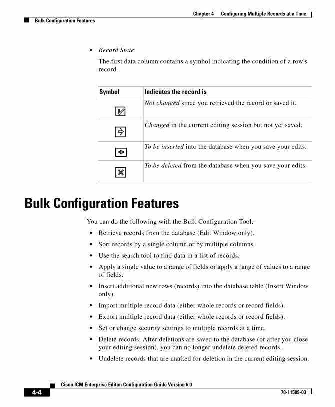
Chapter 4 Configuring Multiple Records at a TimeBulk Configuration Features
• Record State
The first data column contains a symbol indicating the condition of a row's record.
Bulk Configuration FeaturesYou can do the following with the Bulk Configuration Tool:
• Retrieve records from the database (Edit Window only).
• Sort records by a single column or by multiple columns.
• Use the search tool to find data in a list of records.
• Apply a single value to a range of fields or apply a range of values to a range of fields.
• Insert additional new rows (records) into the database table (Insert Window only).
• Import multiple record data (either whole records or record fields).
• Export multiple record data (either whole records or record fields).
• Set or change security settings to multiple records at a time.
• Delete records. After deletions are saved to the database (or after you close your editing session), you can no longer undelete deleted records.
• Undelete records that are marked for deletion in the current editing session.
Symbol Indicates the record is
Not changed since you retrieved the record or saved it.
Changed in the current editing session but not yet saved.
To be inserted into the database when you save your edits.
To be deleted from the database when you save your edits.
4-4Cisco ICM Enterprise Editon Configuration Guide Version 6.0
78-11589-03
Chapter 4 Configuring Multiple Records at a TimeBulk Configuration Features
The following sections describe how to use the Bulk Configuration Tool.
Retrieving and Editing RecordsUse the Select filter data box in the Edit window to retrieve records from the database.
How to retrieve and edit existing records
Step 1 Within the Bulk Configuration > Edit menu, select the name of the database table you want to modify. The appropriate Edit window appears. (Initially, no records are shown.)
Step 2 Do one of the following:
• To retrieve a range of records, specify values in the Select filter data fields. For example, you could enter values that would retrieve only dialed numbers associated with a specific customer, with a specific routing client, or both.
• To retrieve all records, leave the Customer and Routing Client fields set to All.
Step 3 Click Retrieve. The appropriate rows are displayed in the Edit window as in the following example.
4-5Cisco ICM Enterprise Editon Configuration Guide Version 6.0
78-11589-03
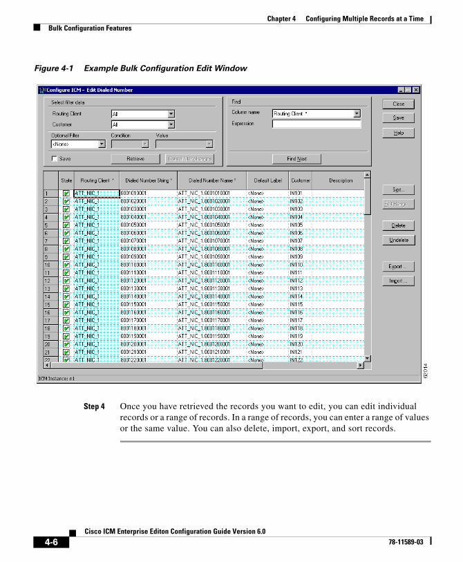
Chapter 4 Configuring Multiple Records at a TimeBulk Configuration Features
Figure 4-1 Example Bulk Configuration Edit Window
Step 4 Once you have retrieved the records you want to edit, you can edit individual records or a range of records. In a range of records, you can enter a range of values or the same value. You can also delete, import, export, and sort records.
4-6Cisco ICM Enterprise Editon Configuration Guide Version 6.0
78-11589-03
Chapter 4 Configuring Multiple Records at a TimeBulk Configuration Features
Sorting RecordsYou can sort records (rows) in two ways: by one column or by multiple columns.
You might want to sort by multiple columns if the first column(s) to sort by has the same value in more than one field, for example, the same routing client, label, or customer name.
• To sort records by one column: double-click on that column’s header. To reverse the sort, double-click a second time. When you double-click, an A (Ascending) or D (Descending) appears after the header to indicate the sort order.
• To sort records by multiple columns, see the following procedure.
How to sort records by multiple columns
Step 1 In the Insert or Edit window, click Sort. The Sort dialog box displays.
Step 2 In the Columns available for sort list, select each column by which you want to sort and click Add.
The primary sorting column will be the first column listed in the Columns selected for sort list. To change the column sort order, select a column and click the Up or Down arrow.
The data within each column is sorted in Ascending order unless you deselect the check box beside the column.
Step 3 Click OK.
Finding Data in a List of RecordsAfter you have retrieved a set of records, you can use the Find area of the Edit window (Column Name and Expression fields) to search for specific records within the set.
4-7Cisco ICM Enterprise Editon Configuration Guide Version 6.0
78-11589-03

Chapter 4 Configuring Multiple Records at a TimeBulk Configuration Features
How to find data
Step 1 In Find box of the Edit or Insert window, select the database column in which you want to search for data.
Tip: You can also select a column by clicking in that column.
Step 2 In the Find box Expression field, enter the value for which you want to search. You can enter a full value or a sub-string.
Step 3 Click Find Next to locate the first record that matches the search criteria. The first row that contains the specified expression in the selected column is highlighted.
Selecting DataYou can select whole records for importing, exporting, setting security, deleting, or undeleting. Or, you can select the same field in multiple records for simultaneous editing.
How to select records
Clicking in the left-most numbered field in a row both selects that row and highlights it. Clicking in any field in a row also selects the row but does not highlight it.
How to select one field in multiple records
You can select one edit-control field (when there is no section box in the field) in multiple records in any one of the following three ways:
• Click the field where you want to start and, keeping the left mouse button held down, move the cursor to the last field.
• Click the field where you want to start. While holding down the Shift key, click the last field.
• Click the field where you want to start. While holding down the Shift key, make your selection by clicking the down arrow.
• Press Ctrl, then left-click on each field you wish to select. This allows you to select a random group of fields.
4-8Cisco ICM Enterprise Editon Configuration Guide Version 6.0
78-11589-03

Chapter 4 Configuring Multiple Records at a TimeBulk Configuration Features
For selecting one value in multiple selection box fields, see the following section, “Editing a Range of Data”.
Editing a Range of DataYou can edit a range of data in a table column in several ways:
• Apply a single value to a range of (edit-control) fields
• Apply a single value to a range of selection-box fields
• Apply a range of values to a range of fields
How to apply a single value to a range of edit-control fields
An edit-control field is one you can edit that does not contain a selection box.
Step 1 Make your selection: click the field where you want the range to start and, keeping the left mouse button held down, move the cursor to the last field in the range.
Step 2 Type the new entry that you want to appear in all the fields.
Step 3 Click Enter or Tab. This applies the change to all the records in the range and moves the focus to the next data field.
How to apply a single value to a range of selection-box fields
Step 1 Select the first field where you want the range to start.
Step 2 Hold down the Shift key and keep it down for steps 3, 4, and 5.
Step 3 Click the selection-box down arrow but keep the left mouse button held down and select the fields you want in the range.
Step 4 Click the last field in the selection to display the selection list.
You can also open the selection box by pressing Alt + an arrow key.
Step 5 Click your selection.
4-9Cisco ICM Enterprise Editon Configuration Guide Version 6.0
78-11589-03
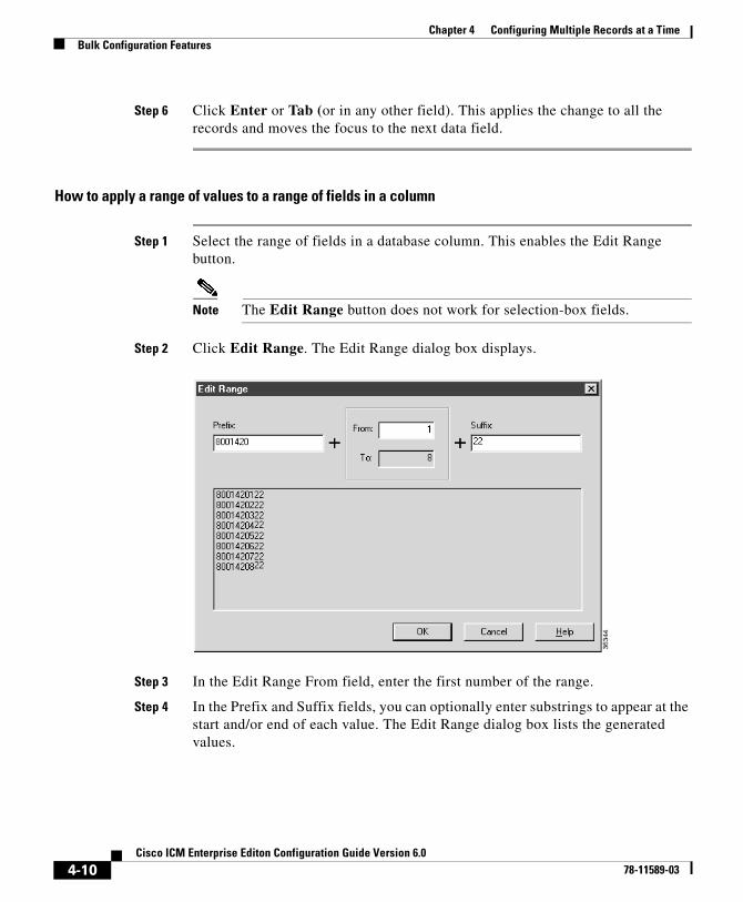
Chapter 4 Configuring Multiple Records at a TimeBulk Configuration Features
Step 6 Click Enter or Tab (or in any other field). This applies the change to all the records and moves the focus to the next data field.
How to apply a range of values to a range of fields in a column
Step 1 Select the range of fields in a database column. This enables the Edit Range button.
Note The Edit Range button does not work for selection-box fields.
Step 2 Click Edit Range. The Edit Range dialog box displays.
Step 3 In the Edit Range From field, enter the first number of the range.
Step 4 In the Prefix and Suffix fields, you can optionally enter substrings to appear at the start and/or end of each value. The Edit Range dialog box lists the generated values.
4-10Cisco ICM Enterprise Editon Configuration Guide Version 6.0
78-11589-03
Chapter 4 Configuring Multiple Records at a TimeBulk Configuration Features
Note When entering a numeric range, you may also enter leading zeros to ensure proper alignment (i.e., 001 to 999).
Step 5 Click OK. This applies the changes to the fields you selected in the Insert or Edit window.
Inserting New RecordsYou can insert new records by inserting multiple blank rows (records) and filling in the data (see How to insert new records, page 4-11) or by importing the data (see How to import data, page 4-12).
You can also edit the data you insert when you insert it.
How to insert new records
Step 1 In the Bulk Configuration > Insert menu, select the name of the data table to which you want to add records. The appropriate Insert window opens, automatically displaying one new row.
Step 2 To create additional rows, enter the number of additional rows in the Quantity field and click Insert. The additional rows are added in the Insert window.
Step 3 Enter the data in the rows:
• If you want to edit individual fields in the new rows, type the information you want in each of the fields and go to Step 8.
• If you want to edit a column in multiple rows so that a range of values is entered, go to Step 4.
• For other ways of entering data into multiple rows, see the “Editing a Range of Data” section on page 4-9.
Step 4 Select the rows in the column you want to modify.
Step 5 Click Edit Range. The Edit Range dialog box appears.
Step 6 Enter a prefix (optional), the start value for the range, and a suffix (optional). The generated values are listed in the dialog box.
4-11Cisco ICM Enterprise Editon Configuration Guide Version 6.0
78-11589-03

Chapter 4 Configuring Multiple Records at a TimeBulk Configuration Features
Step 7 Click OK to close the Edit Range dialog box and apply the values to the column you selected.
Step 8 When you have finished setting fields in the new rows, press Enter to apply your changes to the ICM database.
You can leave empty rows, the system ignores them.
Note No changes are made to the database until you press Enter.
Importing DataYou can import data from a specified text file into the opened database table. Whole records or only columns of data can be imported, if the data matches (see Step 3 of the following procedure). If any error occurs during the import process, the process is cancelled.
How to import data
Step 1 In the Insert or Edit window, click Import.
Step 2 In the Import dialog box, click File.
Step 3 In the File Open dialog box, select the file containing the data you want to import and click Open. For a description of the required import-file format, see the “Import/Export Data File Format” section following this procedure.
The Import File Data area displays the first few lines of the opened file.
• When importing data in the Edit mode, the following rules apply:
– The Bulk Configuration Tool reads only those records whose primary key values match those of records in the Edit window.
If there is a record that does not match the primary key value, the record is considered to be an error and a message box with the primary key value pops up to ask you to correct the problem.
4-12Cisco ICM Enterprise Editon Configuration Guide Version 6.0
78-11589-03

Chapter 4 Configuring Multiple Records at a TimeBulk Configuration Features
– If any field in the import record is null, the corresponding field value in the grid window become blank for an edit cell or uses the default value for a drop-down list cell.
– If any field is missing in the import file, the corresponding field in the Edit window remain unchanged.
– If there is a larger number of records in the file to be imported than the number of rows in the grid, it is considered as an error and a message box pops up asking you to correct it.
– If there is a duplicated primary key in the file to be imported, it is considered as an error. A message box with the duplicated primary key value pops up asking you to correct it.
– After importing, all records imported (including records marked for deletion in the grid) are marked as “Changed” regardless whether the value is changed or not.
– After a importing, the records are displayed in index order (ordered by logical keys). If you did not sort before importing, the order appears the same after the import.
• When importing data in the Insert mode, the following rules apply:
– Only a single import is supported and any existing rows are removed from the grid. When you click Import, a message box pops up if there is any record in the grid. You will see the following message:
“All the existing data will be replaced by the data to be imported. If you want to retain the current data on the grid please click the Cancel button then save or export the existing data. Click the OK button to proceed with the importing.”
– After importing, all rows are marked as “New” and the ordering is the same as that in the file imported from.
– In the Import Insert mode, the tool reads only those records whose primary key values are not presented. If the primary key field is selected for file to be imported, it is considered an error and a message box with the primary key field name pops up asking you to correct the problem.
– If any field in the import record is null, the corresponding field value in the grid window becomes blank for an edit cell or uses the default value for a drop-down list cell.
4-13Cisco ICM Enterprise Editon Configuration Guide Version 6.0
78-11589-03
Chapter 4 Configuring Multiple Records at a TimeBulk Configuration Features
Note If headers are included in the imported file, the Add and Remove buttons are not enabled and you can only import the record(s) as a whole. In that case, go to Step 6.
Step 4 If the imported data does not contain headers, in the Available Fields list box, select the names of the fields to import that match the data and click Add.
Step 5 To change the order of the columns, select a column and move it within the list by clicking Up or Down.
Step 6 Click OK. The data is imported into the data table.
Import/Export Data File FormatThe import and export files used by the Bulk Configuration Tool can optionally include a header that identifies the table and columns in the file. The header is followed by one line for each row of data.
The following rules apply to the file headers:
• A line beginning with a number sign (#) is a comment and is ignored.
• Blank lines are also ignored.
• The header content is indicated by a line beginning with two underline characters and the word TABLE or COLUMNS. The following line contains the name of the table or the name of the columns. For example:
__TABLECall_Type__COLUMNSCallTypeIDEnterpriseNameDescriptionDeleted CustomerDefinitionID
• All column names must be on a single line and are separated by Tab characters.
The following rules apply to the data in the files:
• One row of table data per line.
• Column values must be in the same order in all rows. If columns are specified in the header, the columns in the data rows must be in the same order.
4-14Cisco ICM Enterprise Editon Configuration Guide Version 6.0
78-11589-03
Chapter 4 Configuring Multiple Records at a TimeBulk Configuration Features
• Column values are separated by a single Tab character.
• Fields intentionally left blank must be represented by two adjacent Tab characters or a Tab character at the end of a line. On import, the default value is used for such a value.
• String values may include spaces.
• An error occurs on import if a line contains too few or too many values.
Tip: A simple way to create the import file with a valid format is to use Excel and save it as Text (Tab delimited) (*.TXT).
Exporting DataThe export function saves the selected records or field(s) to a tab-delimited text file that you can import into the ICM database or into a database tool such as Microsoft Excel. If any error occurs during the export process, the process is cancelled.
How to export data
Step 1 Select the rows with fields you want to export.
Note If you intend to import this data into the Edit window, you must export a primary key field along with any other fields. The primary key field has the same column name as the database table name.
Note All rows selected (including records marked for deletion) are exported.
Step 2 Click Export.
Step 3 Select the Header option if you want to include a header containing the table name and column names in the output file. This is recommended since it makes it clear what is in the file.
Step 4 In the Export dialog box, select the column(s) you want to export and click Add or AddAll.
4-15Cisco ICM Enterprise Editon Configuration Guide Version 6.0
78-11589-03
Chapter 4 Configuring Multiple Records at a TimeBulk Configuration Features
Step 5 To change the order of the columns to export, select one of them and move it within the list by clicking Up or Down.
Step 6 Click File and specify the file name and directory to which to save the data.
Step 7 Click OK.
Applying Security Settings to Multiple RecordsFor instructions on how to view or apply security settings to multiple records, see Security Settings, page 3-22.
Deleting and Undeleting RecordsYou can delete one or more records at a time and you can undelete records marked for deletion.
How to delete records
Step 1 Select the row(s) to be deleted.
Note Selecting any field in a row (or any range of fields in a column) selects the rows of which they are a part.
Step 2 Click Delete. The selected rows are marked for deletion.
Step 3 Click Save. The rows marked for deletion are deleted from the database.
Note You can no longer undelete records marked for deletion once you have saved your changes to the database.
4-16Cisco ICM Enterprise Editon Configuration Guide Version 6.0
78-11589-03

Chapter 4 Configuring Multiple Records at a TimeBulk Configuration Features
How to undelete records
Step 1 Select the rows marked for deletion.
Step 2 Click Undelete. The deletion mark is removed from the records.
Step 3 Click Save. The change is saved to the database.
4-17Cisco ICM Enterprise Editon Configuration Guide Version 6.0
78-11589-03

Chapter 4 Configuring Multiple Records at a TimeBulk Configuration Features
4-18Cisco ICM Enterprise Editon Configuration Guide Version 6.0
78-11589-03
Cisco ICM Enterprise78-11589-03
C H A P T E R 5
Configuring Routing ClientsThis chapter describes how to set up routing clients and their directly related elements. It includes:
• An introduction to the Routing Client subsystem
• Instructions on how to view, delete, modify, and define:
• Network Interface Controllers (NICs)
• Routing clients
• Dialed numbers
The Routing Client SubsystemA routing client is an entity that sends route requests to ICM software. A routing client can be:
• A public network interexchange carrier (IXC), such as AT&T, BT, MCI, Nortel, or Sprint
• A private network peripheral, such as an Aspect or Lucent ACD
Figure 5-1 shows the elements of the Routing Client subsystem.
5-1 Editon Configuration Guide Version 6.0
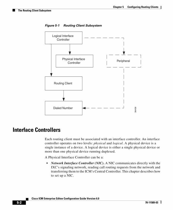
Chapter 5 Configuring Routing ClientsThe Routing Client Subsystem
Figure 5-1 Routing Client Subsystem
Interface ControllersEach routing client must be associated with an interface controller. An interface controller operates on two levels: physical and logical. A physical device is a single instance of a device. A logical device is either a single physical device or more than one physical device running duplexed.
A Physical Interface Controller can be a:
• Network Interface Controller (NIC). A NIC communicates directly with the IXC’s signaling network, reading call routing requests from the network and transferring them to the ICM’s Central Controller. This chapter describes how to set up a NIC.
Logical InterfaceController
Physical InterfaceController
Routing Client
Dialed Number
Peripheral
3643
8
5-2Cisco ICM Enterprise Editon Configuration Guide Version 6.0
78-11589-03
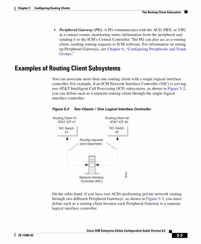
Chapter 5 Configuring Routing ClientsThe Routing Client Subsystem
• Peripheral Gateway (PG). A PG communicates with the ACD, PBX, or VRU at a contact center, monitoring status information from the peripheral and sending it to the ICM’s Central Controller. The PG can also act as a routing client, sending routing requests to ICM software. For information on setting up Peripheral Gateways, see Chapter 6, “Configuring Peripherals and Trunk Groups.”
Examples of Routing Client Subsystems You can associate more than one routing client with a single logical interface controller. For example, if an ICM Network Interface Controller (NIC) is serving two AT&T Intelligent Call Processing (ICP) subsystems, as shown in Figure 5-2, you can define each as a separate routing client through the single logical interface controller.
Figure 5-2 Two Clients / One Logical Interface Controller
On the other hand, if you have two ACDs performing private network routing through two different Peripheral Gateways, as shown in Figure 5-3, you must define each as a routing client because each Peripheral Gateway is a separate logical interface controller.
Network InterfaceController (NIC)
Routing Client #2: AT&T ICP #2
Routing requests(and responses)
Routing Client #1: AT&T ICP #1
IXC Switch#1
IXC Switch#2
3643
4
5-3Cisco ICM Enterprise Editon Configuration Guide Version 6.0
78-11589-03
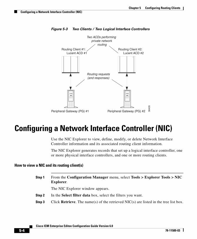
Chapter 5 Configuring Routing ClientsConfiguring a Network Interface Controller (NIC)
Figure 5-3 Two Clients / Two Logical Interface Controllers
Configuring a Network Interface Controller (NIC) Use the NIC Explorer to view, define, modify, or delete Network Interface Controller information and its associated routing client information.
The NIC Explorer generates records that set up a logical interface controller, one or more physical interface controllers, and one or more routing clients.
How to view a NIC and its routing client(s)
Step 1 From the Configuration Manager menu, select Tools > Explorer Tools > NIC Explorer.
The NIC Explorer window appears.
Step 2 In the Select filter data box, select the filters you want.
Step 3 Click Retrieve. The name(s) of the retrieved NIC(s) are listed in the tree list box.
Peripheral Gateway (PG) #1 Peripheral Gateway (PG) #2
Routing requests(and responses)
Routing Client #1: Lucent ACD #1
Routing Client #2: Lucent ACD #2
Two ACDs performingprivate network
routing
3643
5
5-4Cisco ICM Enterprise Editon Configuration Guide Version 6.0
78-11589-03
Chapter 5 Configuring Routing ClientsConfiguring a Network Interface Controller (NIC)
Step 4 In the tree list box, select the NIC whose records you want to view. The selected NIC’s configuration information displays in the fields on the right. For field descriptions, see the “NIC Explorer Tab Descriptions” section on page 5-5.
Step 5 To view a routing client record, in the tree list box, expand the tree branch for the selected NIC and select the NIC’s routing client icon.
The routing client configuration information displays in the window on the right. For field descriptions, see Table 5-3 on page 5-8.
NIC Explorer Tab DescriptionsThe following tables describe the tabbed property fields and buttons that configure a NIC and its routing client(s).
Logical Interface Controller Tab
The Logical Interface Controller tab allows you to view (and define or edit, if you have maintenance access) the properties of the selected logical interface controller.
The NIC (Network Interface Controller) is the computer and process within ICM software that reads call routing requests from the network and transfers them to the ICM Central Controller. It consists of a logical interface controller and one or two physical interface controllers. The number of physical interface controllers permitted depends on the client type.
Table 5-1 Logical Interface Controller Tab Descriptions
Field/Button Description
Controller ID (required)
A unique identifier for the NIC’s logical controller. This is a read-only field. When you create a new NIC, the system places UNASSIGNED in this field and automatically creates an ID when you save your edits.
Name (required) The enterprise name for the NIC’s logical controller. This name also identifies the NIC and must be unique for all logical controllers in the enterprise.
5-5Cisco ICM Enterprise Editon Configuration Guide Version 6.0
78-11589-03
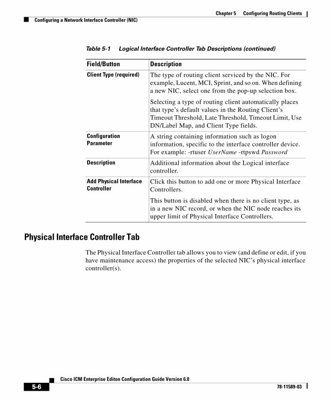
Chapter 5 Configuring Routing ClientsConfiguring a Network Interface Controller (NIC)
Physical Interface Controller Tab
The Physical Interface Controller tab allows you to view (and define or edit, if you have maintenance access) the properties of the selected NIC’s physical interface controller(s).
Client Type (required) The type of routing client serviced by the NIC. For example, Lucent, MCI, Sprint, and so on. When defining a new NIC, select one from the pop-up selection box.
Selecting a type of routing client automatically places that type’s default values in the Routing Client’s Timeout Threshold, Late Threshold, Timeout Limit, Use DN/Label Map, and Client Type fields.
Configuration Parameter
A string containing information such as logon information, specific to the interface controller device. For example: -rtuser UserName -rtpswd Password
Description Additional information about the Logical interface controller.
Add Physical Interface Controller
Click this button to add one or more Physical Interface Controllers.
This button is disabled when there is no client type, as in a new NIC record, or when the NIC node reaches its upper limit of Physical Interface Controllers.
Table 5-1 Logical Interface Controller Tab Descriptions (continued)
Field/Button Description
5-6Cisco ICM Enterprise Editon Configuration Guide Version 6.0
78-11589-03
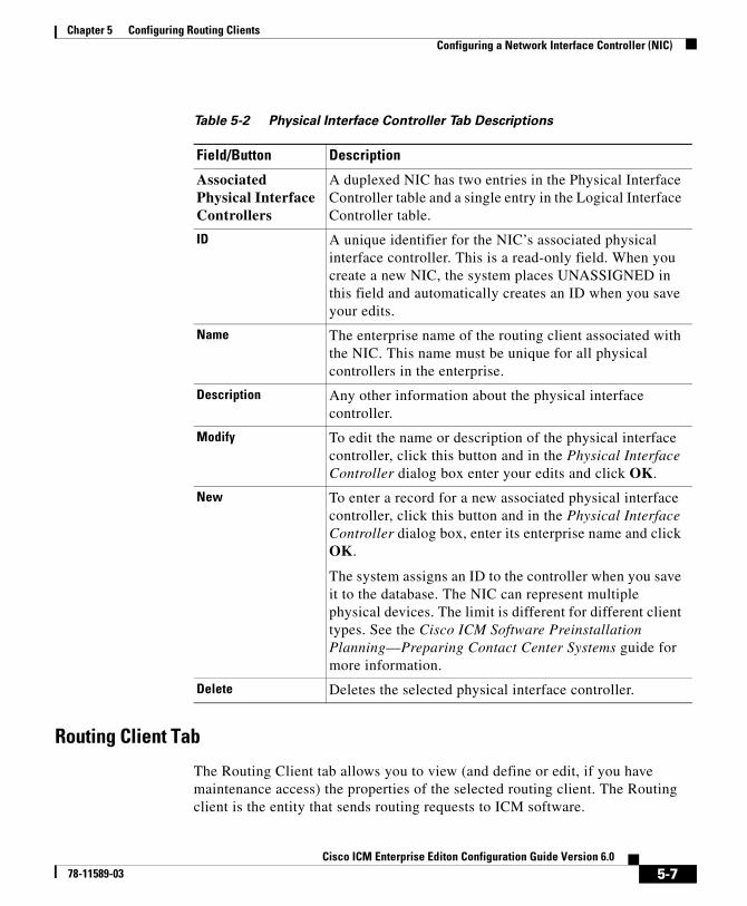
Chapter 5 Configuring Routing ClientsConfiguring a Network Interface Controller (NIC)
Routing Client Tab
The Routing Client tab allows you to view (and define or edit, if you have maintenance access) the properties of the selected routing client. The Routing client is the entity that sends routing requests to ICM software.
Table 5-2 Physical Interface Controller Tab Descriptions
Field/Button Description
Associated Physical Interface Controllers
A duplexed NIC has two entries in the Physical Interface Controller table and a single entry in the Logical Interface Controller table.
ID A unique identifier for the NIC’s associated physical interface controller. This is a read-only field. When you create a new NIC, the system places UNASSIGNED in this field and automatically creates an ID when you save your edits.
Name The enterprise name of the routing client associated with the NIC. This name must be unique for all physical controllers in the enterprise.
Description Any other information about the physical interface controller.
Modify To edit the name or description of the physical interface controller, click this button and in the Physical Interface Controller dialog box enter your edits and click OK.
New To enter a record for a new associated physical interface controller, click this button and in the Physical Interface Controller dialog box, enter its enterprise name and click OK.
The system assigns an ID to the controller when you save it to the database. The NIC can represent multiple physical devices. The limit is different for different client types. See the Cisco ICM Software Preinstallation Planning—Preparing Contact Center Systems guide for more information.
Delete Deletes the selected physical interface controller.
5-7Cisco ICM Enterprise Editon Configuration Guide Version 6.0
78-11589-03
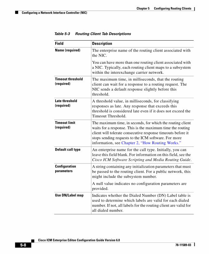
Chapter 5 Configuring Routing ClientsConfiguring a Network Interface Controller (NIC)
Table 5-3 Routing Client Tab Descriptions
Field Description
Name (required) The enterprise name of the routing client associated with the NIC.
You can have more than one routing client associated with a NIC. Typically, each routing client maps to a subsystem within the interexchange carrier network.
Timeout threshold (required)
The maximum time, in milliseconds, that the routing client can wait for a response to a routing request. The NIC sends a default response slightly before this threshold.
Late threshold (required)
A threshold value, in milliseconds, for classifying responses as late. Any response that exceeds this threshold is considered late even if it does not exceed the Timeout Threshold.
Timeout limit (required)
The maximum time, in seconds, for which the routing client waits for a response. This is the maximum time the routing client will tolerate consecutive response timeouts before it stops sending requests to the ICM software. For more information, see Chapter 2, “How Routing Works.”
Default call type An enterprise name for the call type. Initially, you can leave this field blank. For information on this field, see the Cisco ICM Software Scripting and Media Routing Guide.
Configuration parameters
A string containing any initialization parameters that must be passed to the routing client. For a public network, this might include the subsystem number.
A null value indicates no configuration parameters are provided.
Use DN/Label map Indicates whether the Dialed Number (DN) Label table is used to determine which labels are valid for each dialed number. If not, all labels for the routing client are valid for all dialed number.
5-8Cisco ICM Enterprise Editon Configuration Guide Version 6.0
78-11589-03
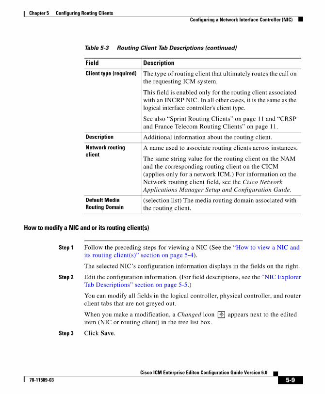
Chapter 5 Configuring Routing ClientsConfiguring a Network Interface Controller (NIC)
How to modify a NIC and or its routing client(s)
Step 1 Follow the preceding steps for viewing a NIC (See the “How to view a NIC and its routing client(s)” section on page 5-4).
The selected NIC’s configuration information displays in the fields on the right.
Step 2 Edit the configuration information. (For field descriptions, see the “NIC Explorer Tab Descriptions” section on page 5-5.)
You can modify all fields in the logical controller, physical controller, and router client tabs that are not greyed out.
When you make a modification, a Changed icon appears next to the edited item (NIC or routing client) in the tree list box.
Step 3 Click Save.
Client type (required) The type of routing client that ultimately routes the call on the requesting ICM system.
This field is enabled only for the routing client associated with an INCRP NIC. In all other cases, it is the same as the logical interface controller's client type.
See also “Sprint Routing Clients” on page 11 and “CRSP and France Telecom Routing Clients” on page 11.
Description Additional information about the routing client.
Network routing client
A name used to associate routing clients across instances.
The same string value for the routing client on the NAM and the corresponding routing client on the CICM (applies only for a network ICM.) For information on the Network routing client field, see the Cisco Network Applications Manager Setup and Configuration Guide.
Default Media Routing Domain
(selection list) The media routing domain associated with the routing client.
Table 5-3 Routing Client Tab Descriptions (continued)
Field Description
5-9Cisco ICM Enterprise Editon Configuration Guide Version 6.0
78-11589-03
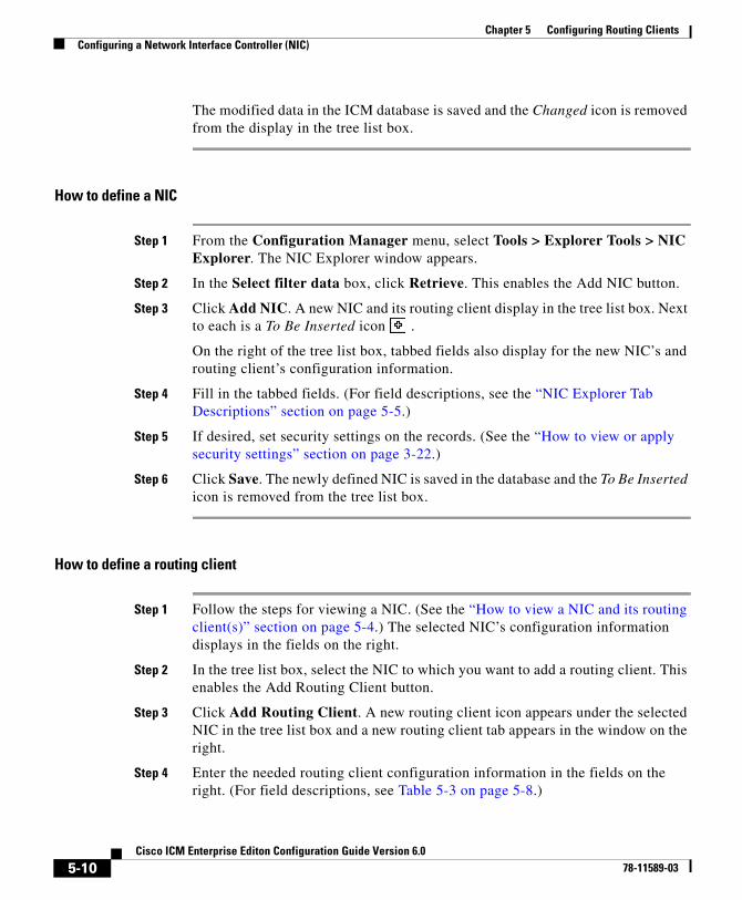
Chapter 5 Configuring Routing ClientsConfiguring a Network Interface Controller (NIC)
The modified data in the ICM database is saved and the Changed icon is removed from the display in the tree list box.
How to define a NIC
Step 1 From the Configuration Manager menu, select Tools > Explorer Tools > NIC Explorer. The NIC Explorer window appears.
Step 2 In the Select filter data box, click Retrieve. This enables the Add NIC button.
Step 3 Click Add NIC. A new NIC and its routing client display in the tree list box. Next to each is a To Be Inserted icon .
On the right of the tree list box, tabbed fields also display for the new NIC’s and routing client’s configuration information.
Step 4 Fill in the tabbed fields. (For field descriptions, see the “NIC Explorer Tab Descriptions” section on page 5-5.)
Step 5 If desired, set security settings on the records. (See the “How to view or apply security settings” section on page 3-22.)
Step 6 Click Save. The newly defined NIC is saved in the database and the To Be Inserted icon is removed from the tree list box.
How to define a routing client
Step 1 Follow the steps for viewing a NIC. (See the “How to view a NIC and its routing client(s)” section on page 5-4.) The selected NIC’s configuration information displays in the fields on the right.
Step 2 In the tree list box, select the NIC to which you want to add a routing client. This enables the Add Routing Client button.
Step 3 Click Add Routing Client. A new routing client icon appears under the selected NIC in the tree list box and a new routing client tab appears in the window on the right.
Step 4 Enter the needed routing client configuration information in the fields on the right. (For field descriptions, see Table 5-3 on page 5-8.)
5-10Cisco ICM Enterprise Editon Configuration Guide Version 6.0
78-11589-03
Chapter 5 Configuring Routing ClientsConfiguring a Network Interface Controller (NIC)
Step 5 If desired, set security settings on the records. (See the “How to view or apply security settings” section on page 3-22.)
Step 6 Click Save.
Sprint Routing Clients
If you specify Sprint as the type of routing client, the NIC Explorer automatically generates some additional records:
• An announcement named NPA_Blocked_Recording (if it does not already exist).
• A label named @NPA Blocked Recording associated with the generated routing client. The label type is Normal and the target is the NPA_Blocked_Recording announcement.
• A label named @Slow Busy associated with the generated routing client. The label type is Busy.
These records provide support for Sprint’s NPA Blocked Recording feature and for returning a busy signal to the caller.
CRSP and France Telecom Routing Clients
• CRSP. If you specify CRSP as the type of routing client, the following two labels are automatically created by the NIC Explorer and are associated with the new routing client:
– “ringForever” with a label type of 3 (ring)
– “busyForver” with a label type of 2 (busy)
• France Telecom. If you specify France Telecom as the routing client, the following three labels are automatically created by the NIC Explorer and are associated with the new routing client:
– @Interdiction
– @Fermeture
– @RenvoiForce
All three have the Label Type of 0 (Normal).
5-11Cisco ICM Enterprise Editon Configuration Guide Version 6.0
78-11589-03
Chapter 5 Configuring Routing ClientsConfiguring Dialed Number/Script Selectors
When a CRSP or France Telecom routing client record is deleted, the preceding labels associated with the routing client are also deleted.
How to delete a NIC
Step 1 Follow the steps for viewing a NIC. (See the “How to view a NIC and its routing client(s)” section on page 5-4.)
The selected NIC’s configuration information displays in the fields on the right.
Step 2 In the tree list box, select the NIC whose records you want to delete.
Step 3 Click Delete.
Step 4 This places a Marked for Deletion icon next to the NIC in the tree list box. This also toggles the Delete button to Undelete.
To undelete a NIC marked for deletion, select it in the tree list box and click Undelete.
Step 5 Click Save.
This deletes from the database the NIC marked for deletion and removes it from the tree list box. Once you do this, you cannot undelete the NIC.
Configuring Dialed Number/Script SelectorsAfter you have set up a routing client, you need to define the dialed number/script selectors serviced by it. A dialed number/script selector can represent an actual number dialed by a caller or any string passed by a routing client to indicate the number dialed.
The Configuration Manager’s Dialed Number/Script Selector List tool allows you to list the dialed number/script selectors currently defined in the ICM database, to define new ones, and to view, edit, or delete the records of existing ones. The following instructions show you how to configure individual dialed number/script selectors. For configuring multiple dialed number/script selectors at a time, see Chapter 4, “Configuring Multiple Records at a Time”.
5-12Cisco ICM Enterprise Editon Configuration Guide Version 6.0
78-11589-03
Chapter 5 Configuring Routing ClientsConfiguring Dialed Number/Script Selectors
How to view, define, delete, or modify dialed number/script selectors
Step 1 From within the Configuration Manager menu, select Tools > List Tools > Dialed Number/Script Selector List. The Dialed Number/Script Selector List window appears.
Step 2 In the Select filter data area, select the Routing client and Customer associated with the dialed number/script selector.
Note Once you have saved a Dialed Number record to the ICM database, you cannot update the Routing Client field.
If you are viewing or modifying a previously created record and you want to limit the number of records retrieved from the database, also select one of the optional filters.
Step 3 Click Retrieve. This enables the Add button and displays a list of the retrieved dialed number/script selectors.
The properties of the dialed number/script selector selected in the Dialed Number/Script Selector list box on the left side of the window are displayed in the property tabs on the right side of the window:
• The Attributes tab allows you to view and (if you have maintenance access) to define, edit, or delete the attributes of the selected dialed number/script selector. Attributes with an asterisk are required. Table 5-4 describes these attributes.
• The Dialed Number Label tab allows you to map labels (in addition to a default label) to the selected dialed number/script selector. Table 5-5 describes the fields and buttons on this tab.
• The Security tab allows you to set security settings to the selected record. For a description of how to use the Security tab, see Security Settings, page 3-22.
Step 4 This step depends on what you want to do:
• To add a new dialed number/script selector, click Add and enter the appropriate values in the tabbed property fields on the right side of the window.
• To delete a dialed number/script selector, select that number in the Dialed Number/Script Selector list box and click Delete.
5-13Cisco ICM Enterprise Editon Configuration Guide Version 6.0
78-11589-03
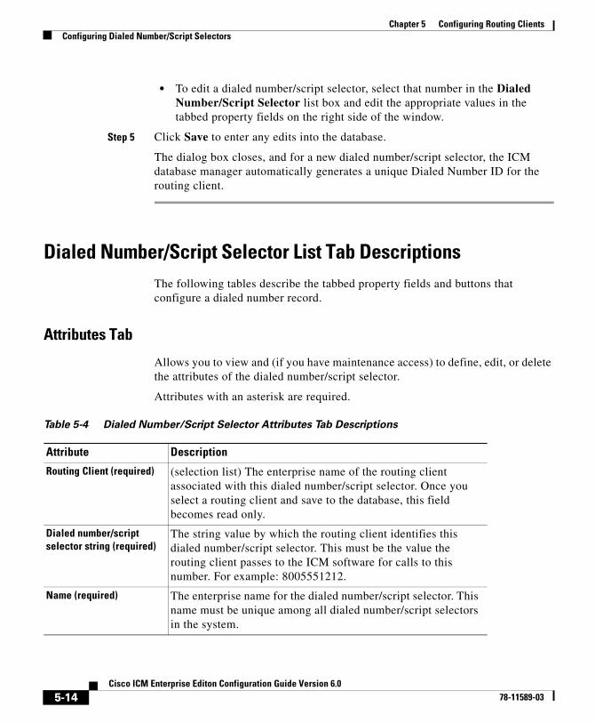
Chapter 5 Configuring Routing ClientsConfiguring Dialed Number/Script Selectors
• To edit a dialed number/script selector, select that number in the Dialed Number/Script Selector list box and edit the appropriate values in the tabbed property fields on the right side of the window.
Step 5 Click Save to enter any edits into the database.
The dialog box closes, and for a new dialed number/script selector, the ICM database manager automatically generates a unique Dialed Number ID for the routing client.
Dialed Number/Script Selector List Tab DescriptionsThe following tables describe the tabbed property fields and buttons that configure a dialed number record.
Attributes Tab
Allows you to view and (if you have maintenance access) to define, edit, or delete the attributes of the dialed number/script selector.
Attributes with an asterisk are required.
Table 5-4 Dialed Number/Script Selector Attributes Tab Descriptions
Attribute Description
Routing Client (required) (selection list) The enterprise name of the routing client associated with this dialed number/script selector. Once you select a routing client and save to the database, this field becomes read only.
Dialed number/script selector string (required)
The string value by which the routing client identifies this dialed number/script selector. This must be the value the routing client passes to the ICM software for calls to this number. For example: 8005551212.
Name (required) The enterprise name for the dialed number/script selector. This name must be unique among all dialed number/script selectors in the system.
5-14Cisco ICM Enterprise Editon Configuration Guide Version 6.0
78-11589-03
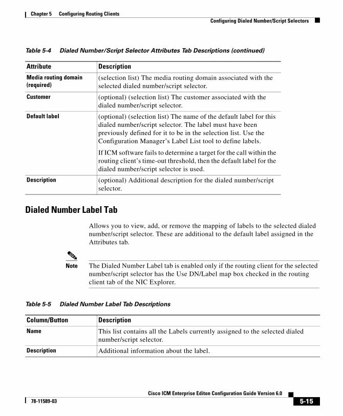
Chapter 5 Configuring Routing ClientsConfiguring Dialed Number/Script Selectors
Dialed Number Label Tab
Allows you to view, add, or remove the mapping of labels to the selected dialed number/script selector. These are additional to the default label assigned in the Attributes tab.
Note The Dialed Number Label tab is enabled only if the routing client for the selected number/script selector has the Use DN/Label map box checked in the routing client tab of the NIC Explorer.
Media routing domain (required)
(selection list) The media routing domain associated with the selected dialed number/script selector.
Customer (optional) (selection list) The customer associated with the dialed number/script selector.
Default label (optional) (selection list) The name of the default label for this dialed number/script selector. The label must have been previously defined for it to be in the selection list. Use the Configuration Manager’s Label List tool to define labels.
If ICM software fails to determine a target for the call within the routing client’s time-out threshold, then the default label for the dialed number/script selector is used.
Description (optional) Additional description for the dialed number/script selector.
Table 5-4 Dialed Number/Script Selector Attributes Tab Descriptions (continued)
Attribute Description
Table 5-5 Dialed Number Label Tab Descriptions
Column/Button Description
Name This list contains all the Labels currently assigned to the selected dialed number/script selector.
Description Additional information about the label.
5-15Cisco ICM Enterprise Editon Configuration Guide Version 6.0
78-11589-03

Chapter 5 Configuring Routing ClientsConfiguring Dialed Number/Script Selectors
Add To assign a label to the dialed number/script selector selected in the Dialed Number/Script Selector list box, click Add. Then in the Add Label dialog box, select a label name and click OK.
Note For labels to appear in this dialog box, they must have been previously defined for the selected dialed number/script selector routing client. Use the Label List tool to define labels.
Remove To remove a label from the dialed number/list selector selected in the Dialed Number/Script Selector list box, select the label name and click Remove.
Table 5-5 Dialed Number Label Tab Descriptions (continued)
Column/Button Description
5-16Cisco ICM Enterprise Editon Configuration Guide Version 6.0
78-11589-03
Cisco ICM Enterprise78-11589-03
C H A P T E R 6
Configuring Peripherals and Trunk GroupsThis chapter describes how to configure peripherals and the trunk groups associated with them. It includes:
• An introduction to the Peripheral Subsystem
• Instructions on how to view, define, delete, or modify:
– Peripheral Gateways
– Peripherals
– Network Trunk Groups
– Trunk Groups
– Trunks
The Peripheral SubsystemA peripheral is a switch, such as an ACD, PBX, VRU, or Call Manager. Calls arrive at the peripheral through trunks that are organized into trunk groups. ICM software monitors activity at each peripheral and can route calls to targets at each peripheral.
The logical interface controller and physical interface controller represent the Peripheral Gateway (PG) through which the peripheral communicates with the ICM system.
Figure 6-1 shows the elements in a peripheral subsystem.
6-1 Editon Configuration Guide Version 6.0
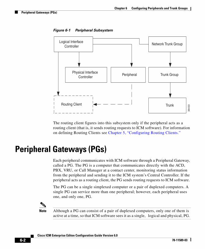
Chapter 6 Configuring Peripherals and Trunk GroupsPeripheral Gateways (PGs)
Figure 6-1 Peripheral Subsystem
The routing client figures into this subsystem only if the peripheral acts as a routing client (that is, it sends routing requests to ICM software). For information on defining Routing Clients see Chapter 5, “Configuring Routing Clients.”
Peripheral Gateways (PGs)Each peripheral communicates with ICM software through a Peripheral Gateway, called a PG. The PG is a computer that communicates directly with the ACD, PBX, VRU, or Call Manager at a contact center, monitoring status information from the peripheral and sending it to the ICM system’s Central Controller. If the peripheral acts as a routing client, the PG sends routing requests to ICM software.
The PG can be a single simplexed computer or a pair of duplexed computers. A single PG can service more than one peripheral; however, each peripheral uses one, and only one, PG.
Note Although a PG can consist of a pair of duplexed computers, only one of them is active at a time, so that ICM software sees it as a single, logical and physical, PG.
Logical InterfaceController
Network Trunk Group
Trunk Group
Trunk
PeripheralPhysical Interface
Controller
Routing Client
36433
6-2Cisco ICM Enterprise Editon Configuration Guide Version 6.0
78-11589-03
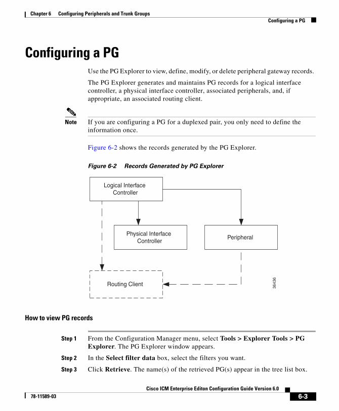
Chapter 6 Configuring Peripherals and Trunk GroupsConfiguring a PG
Configuring a PG Use the PG Explorer to view, define, modify, or delete peripheral gateway records.
The PG Explorer generates and maintains PG records for a logical interface controller, a physical interface controller, associated peripherals, and, if appropriate, an associated routing client.
Note If you are configuring a PG for a duplexed pair, you only need to define the information once.
Figure 6-2 shows the records generated by the PG Explorer.
Figure 6-2 Records Generated by PG Explorer
How to view PG records
Step 1 From the Configuration Manager menu, select Tools > Explorer Tools > PG Explorer. The PG Explorer window appears.
Step 2 In the Select filter data box, select the filters you want.
Step 3 Click Retrieve. The name(s) of the retrieved PG(s) appear in the tree list box.
Logical InterfaceController
PeripheralPhysical Interface
Controller
Routing Client
3643
6
6-3Cisco ICM Enterprise Editon Configuration Guide Version 6.0
78-11589-03
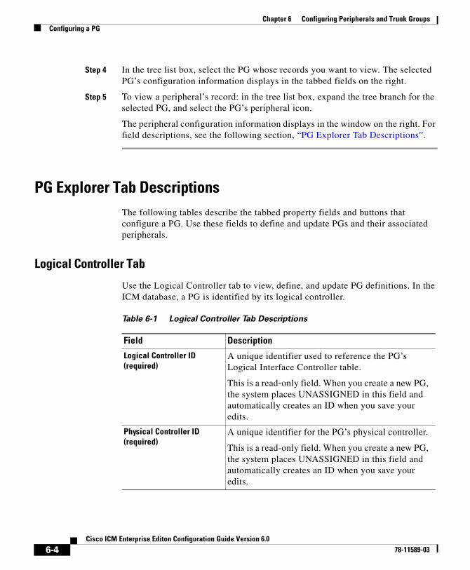
Chapter 6 Configuring Peripherals and Trunk GroupsConfiguring a PG
Step 4 In the tree list box, select the PG whose records you want to view. The selected PG’s configuration information displays in the tabbed fields on the right.
Step 5 To view a peripheral’s record: in the tree list box, expand the tree branch for the selected PG, and select the PG’s peripheral icon.
The peripheral configuration information displays in the window on the right. For field descriptions, see the following section, “PG Explorer Tab Descriptions”.
PG Explorer Tab DescriptionsThe following tables describe the tabbed property fields and buttons that configure a PG. Use these fields to define and update PGs and their associated peripherals.
Logical Controller Tab
Use the Logical Controller tab to view, define, and update PG definitions. In the ICM database, a PG is identified by its logical controller.
Table 6-1 Logical Controller Tab Descriptions
Field Description
Logical Controller ID (required)
A unique identifier used to reference the PG’s Logical Interface Controller table.
This is a read-only field. When you create a new PG, the system places UNASSIGNED in this field and automatically creates an ID when you save your edits.
Physical Controller ID (required)
A unique identifier for the PG’s physical controller.
This is a read-only field. When you create a new PG, the system places UNASSIGNED in this field and automatically creates an ID when you save your edits.
6-4Cisco ICM Enterprise Editon Configuration Guide Version 6.0
78-11589-03

Chapter 6 Configuring Peripherals and Trunk GroupsConfiguring a PG
Name (required) An enterprise name for the PG. This name must be unique for all PGs in the enterprise.
An enterprise name:
• Is a character-string name commonly used to identify an object in the ICM database.
• Must be unique among all objects of a specific type. For example, each service must have an enterprise name that is unique among all services.
• Can be up to 32 characters. The valid characters are upper-case and lower-case letters, digits, periods (.) and underlines (_). The first character of the name must be a letter or digit.
Note It is recommended you keep the name short as it is used in composite names which are limited to a 32 character length, i.e., an agent enterprise name.
Table 6-1 Logical Controller Tab Descriptions (continued)
Field Description
6-5Cisco ICM Enterprise Editon Configuration Guide Version 6.0
78-11589-03
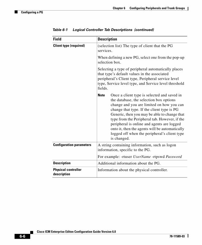
Chapter 6 Configuring Peripherals and Trunk GroupsConfiguring a PG
Client type (required) (selection list) The type of client that the PG services.
When defining a new PG, select one from the pop-up selection box.
Selecting a type of peripheral automatically places that type’s default values in the associated peripheral’s Client type, Peripheral service level type, Service level type, and Service level threshold fields.
Note Once a client type is selected and saved in the database, the selection box options change and you are limited on how you can change that type. If the client type is PG Generic, then you may be able to change that type from the Peripheral tab. However, if the peripheral is online and agents are logged onto it, then the agents will be automatically logged off when the peripheral’s client type is changed.
Configuration parameters A string containing information, such as logon information, specific to the PG.
For example: -rtuser UserName -rtpswd Password
Description Additional information about the PG.
Physical controller description
Information about the physical controller.
Table 6-1 Logical Controller Tab Descriptions (continued)
Field Description
6-6Cisco ICM Enterprise Editon Configuration Guide Version 6.0
78-11589-03
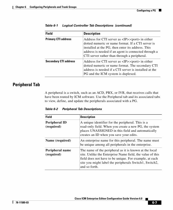
Chapter 6 Configuring Peripherals and Trunk GroupsConfiguring a PG
Peripheral Tab
A peripheral is a switch, such as an ACD, PBX, or IVR, that receives calls that have been routed by ICM software. Use the Peripheral tab and its associated tabs to view, define, and update the peripherals associated with a PG.
Primary CTI address Address for CTI server as <IP>:<port> in either dotted numeric or name format. If a CTI server is installed at the PG, then enter its address. This address is needed if an agent is connected through a CTI server rather than through a peripheral.
Secondary CTI address Address for CTI server as <IP>:<port> in either dotted numeric or name format. The secondary CTI address is needed if a CTI server is installed at the PG and the ICM system is duplexed.
Table 6-1 Logical Controller Tab Descriptions (continued)
Field Description
Table 6-2 Peripheral Tab Descriptions
Field Description
Peripheral ID (required)
A unique identifier for the peripheral. This is a read-only field. When you create a new PG, the system places UNASSIGNED in this field and automatically creates an ID when you save your edits.
Name (required) An enterprise name for this peripheral. The name must be unique among all peripherals in the enterprise.
Peripheral name (required)
The name of the peripheral as it is known at the local site. Unlike the Enterprise Name field, the value of this field does not have to be unique. For example, at each site you might label the peripherals Switch1, Switch2, and so forth.
6-7Cisco ICM Enterprise Editon Configuration Guide Version 6.0
78-11589-03

Chapter 6 Configuring Peripherals and Trunk GroupsConfiguring a PG
Client type (required)
The type of peripheral. The value for this field comes from the Logical Controller Client Type field.
Note Once a client type is selected and saved in the database, the selection box options change and you are limited on how you can change that type. If the client type is PG Generic, then you may be able to change that type from the Peripheral tab. However, if the peripheral is online and agents are logged onto it, then the agents will be automatically logged off when the peripheral’s client type is changed.
Location (required) The peripheral's location. For example: the name of a city, building, or department.
Abandoned call wait time (required)
Minimum time in seconds an incoming call must be queued before being considered an abandoned call if the caller hangs up.
Configuration parameters
A string containing any parameters that must be sent to the device to initialize it. In most cases, you should leave this string blank.
Call control variable map
A string that describes the mappings of the peripheral’s call control variables to ICM software’s call control variables.
Description Additional information about the peripheral.
Default desk settings (selection list) Default desk settings for agents associated with the peripheral. If NONE is the only option in the selection list, you need to create desk settings. To create desk settings, use the Configuration Manager’s Agent Desk Settings List tool.
Table 6-2 Peripheral Tab Descriptions (continued)
Field Description
6-8Cisco ICM Enterprise Editon Configuration Guide Version 6.0
78-11589-03
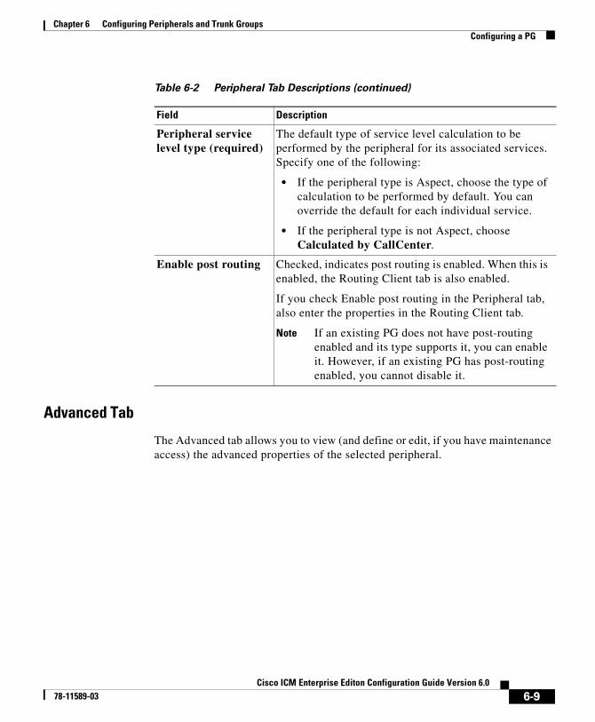
Chapter 6 Configuring Peripherals and Trunk GroupsConfiguring a PG
Advanced Tab
The Advanced tab allows you to view (and define or edit, if you have maintenance access) the advanced properties of the selected peripheral.
Peripheral service level type (required)
The default type of service level calculation to be performed by the peripheral for its associated services. Specify one of the following:
• If the peripheral type is Aspect, choose the type of calculation to be performed by default. You can override the default for each individual service.
• If the peripheral type is not Aspect, choose Calculated by CallCenter.
Enable post routing Checked, indicates post routing is enabled. When this is enabled, the Routing Client tab is also enabled.
If you check Enable post routing in the Peripheral tab, also enter the properties in the Routing Client tab.
Note If an existing PG does not have post-routing enabled and its type supports it, you can enable it. However, if an existing PG has post-routing enabled, you cannot disable it.
Table 6-2 Peripheral Tab Descriptions (continued)
Field Description
6-9Cisco ICM Enterprise Editon Configuration Guide Version 6.0
78-11589-03
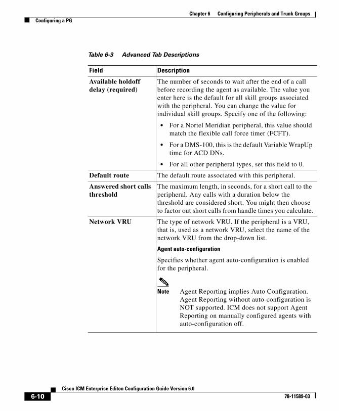
Chapter 6 Configuring Peripherals and Trunk GroupsConfiguring a PG
Table 6-3 Advanced Tab Descriptions
Field Description
Available holdoff delay (required)
The number of seconds to wait after the end of a call before recording the agent as available. The value you enter here is the default for all skill groups associated with the peripheral. You can change the value for individual skill groups. Specify one of the following:
• For a Nortel Meridian peripheral, this value should match the flexible call force timer (FCFT).
• For a DMS-100, this is the default Variable WrapUp time for ACD DNs.
• For all other peripheral types, set this field to 0.
Default route The default route associated with this peripheral.
Answered short calls threshold
The maximum length, in seconds, for a short call to the peripheral. Any calls with a duration below the threshold are considered short. You might then choose to factor out short calls from handle times you calculate.
Network VRU The type of network VRU. If the peripheral is a VRU, that is, used as a network VRU, select the name of the network VRU from the drop-down list.
Agent auto-configuration
Specifies whether agent auto-configuration is enabled for the peripheral.
Note Agent Reporting implies Auto Configuration. Agent Reporting without auto-configuration is NOT supported. ICM does not support Agent Reporting on manually configured agents with auto-configuration off.
6-10Cisco ICM Enterprise Editon Configuration Guide Version 6.0
78-11589-03
Chapter 6 Configuring Peripherals and Trunk GroupsConfiguring a PG
Skill Group MaskTab
This tab allows you to view (and define or edit, if you have maintenance access) the default number of subskill groups associated with the selected peripheral.
Note For some peripherals (Definity ECS EAS, Nortel Meridian, Rockwell Galaxy, and Rockwell Spectrum), the Configuration Manager can automatically create subgroups (primary, secondary, and so on) for each skill group.
Subskill Group Check Boxes
The maximum number of subgroups that may be created depends on the Peripheral's client type, and may be none. Where subgroups are available, a default selection has been made. You may change this default, either to none or any number up to the maximum number allowed for this client type.
If you later edit the subgroup selection, removing any previously used subgroups may cause loss of reporting information and should be done carefully. Changes done here will be reflected in all Skill Group entries that currently exist for this Peripheral, which do not explicitly override the settings in the Peripheral.
Check a box for each subskill group you want to be associated by default with the peripheral. For each box you check, a skill group record is created in the database if the primary skill group uses the peripheral’s default.
The number of subskill groups used by a primary skill group is specified in the Subgroup Mask tab of the Skill Group Explorer. There, you can add more subskill groups than are defined for the peripheral if the selected skill group requires additional ones.
Routing Client Tab
A routing client represents an entity that sends routing requests to the ICM software through a logical interface controller. Use the Routing Client tab to view, define, or update a PG’s routing clients.
6-11Cisco ICM Enterprise Editon Configuration Guide Version 6.0
78-11589-03
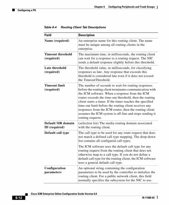
Chapter 6 Configuring Peripherals and Trunk GroupsConfiguring a PG
Table 6-4 Routing Client Tab Descriptions
Field Description
Name (required) An enterprise name for this routing client. The name must be unique among all routing clients in the enterprise.
Timeout threshold (required)
The maximum time, in milliseconds, the routing client can wait for a response to a routing request. The NIC sends a default response slightly before this threshold.
Late threshold (required)
The threshold value, in milliseconds, for classifying responses as late. Any response that exceeds this threshold is considered late even if it does not exceed the TimeoutThreshold.
Timeout limit (required)
The number of seconds to wait for routing responses before the routing client terminates communication with the ICM software. When a response from the ICM router exceeds the time-out threshold, then the routing client starts a timer. If the timer reaches the specified time-out limit before the routing client receives any responses from the ICM router, then the routing client assumes the ICM system is off-line and stops sending it routing requests.
Default MR domain ID (required)
(selection list) The media routing domain associated with the routing client.
Default call type The call type to be used for any route request that does not match a defined call type mapping. The drop-down list contains all configured call types.
The ICM software uses the default call type for any routing request from the routing client that does not otherwise map to a call type. If you do not define a default call type for the routing client, the ICM software uses a general default call type.
Configuration parameters
An optional string containing the configuration parameters to be used by the controller to initialize the routing client. For a public network client, this field normally specifies the subsystem for the NIC to use.
6-12Cisco ICM Enterprise Editon Configuration Guide Version 6.0
78-11589-03
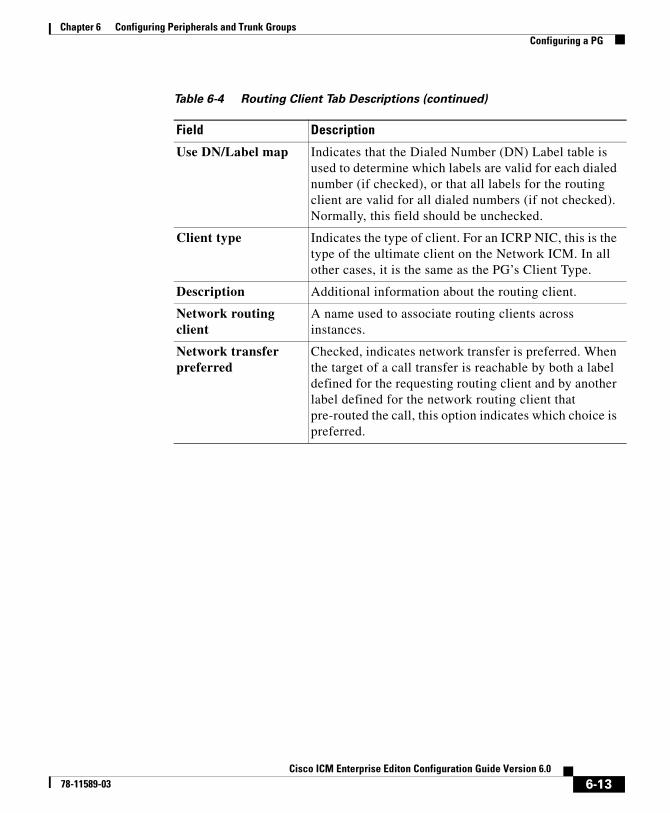
Chapter 6 Configuring Peripherals and Trunk GroupsConfiguring a PG
Use DN/Label map Indicates that the Dialed Number (DN) Label table is used to determine which labels are valid for each dialed number (if checked), or that all labels for the routing client are valid for all dialed numbers (if not checked). Normally, this field should be unchecked.
Client type Indicates the type of client. For an ICRP NIC, this is the type of the ultimate client on the Network ICM. In all other cases, it is the same as the PG’s Client Type.
Description Additional information about the routing client.
Network routing client
A name used to associate routing clients across instances.
Network transfer preferred
Checked, indicates network transfer is preferred. When the target of a call transfer is reachable by both a label defined for the requesting routing client and by another label defined for the network routing client that pre-routed the call, this option indicates which choice is preferred.
Table 6-4 Routing Client Tab Descriptions (continued)
Field Description
6-13Cisco ICM Enterprise Editon Configuration Guide Version 6.0
78-11589-03
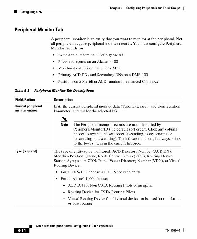
Chapter 6 Configuring Peripherals and Trunk GroupsConfiguring a PG
Peripheral Monitor Tab
A peripheral monitor is an entity that you want to monitor at the peripheral. Not all peripherals require peripheral monitor records. You must configure Peripheral Monitor records for:
• Extension numbers on a Definity switch
• Pilots and agents on an Alcatel 4400
• Monitored entities on a Siemens ACD
• Primary ACD DNs and Secondary DNs on a DMS-100
• Positions on a Meridian ACD running in enhanced CTI mode
Table 6-5 Peripheral Monitor Tab Descriptions
Field/Button Description
Current peripheral monitor entries
Lists the current peripheral monitor data (Type, Extension, and Configuration Parameter) entered for the selected PG.
Note The Peripheral monitor records are initially sorted by PeripheralMonitorID (the default sort order). Click any column header to reverse the sort order (ascending-to-descending or descending-to- ascending). The indicator to the right always points to the lowest item in the current list order.
Type (required) The type of entity to be monitored: ACD Directory Number (ACD DN), Meridian Position, Queue, Route Control Group (RCG), Routing Device, Station, Symposium CDN, Trunk, Vector Directory Number (VDN), or Virtual Routing Device.
• For a DMS-100, choose ACD DN for each entry.
• For an Alcatel 4400, choose:
– ACD DN for Non CSTA Routing Pilots or an agent
– Routing Device for CSTA Routing Pilots
– Virtual Routing Device for all virtual devices to be used for translation or post routing
6-14Cisco ICM Enterprise Editon Configuration Guide Version 6.0
78-11589-03

Chapter 6 Configuring Peripherals and Trunk GroupsConfiguring a PG
Extension • For an Alcatel 4400, the DN for a pilot or the agent number for an agent.
• For a Avaya Definity, if there is a single extension number, enter the number here (for example, 6002) and do not enter it in the parameter string. If there is more than one number, leave this field blank and enter the numbers as a range in the parameter string.
• For a DMS-100, the Primary ACD DN, Secondary DN, or a non-digit character.
• For a Meridian ACD, this field is not used.
• For a Siemens ACD, the extension number to be monitored.
Table 6-5 Peripheral Monitor Tab Descriptions (continued)
Field/Button Description
6-15Cisco ICM Enterprise Editon Configuration Guide Version 6.0
78-11589-03
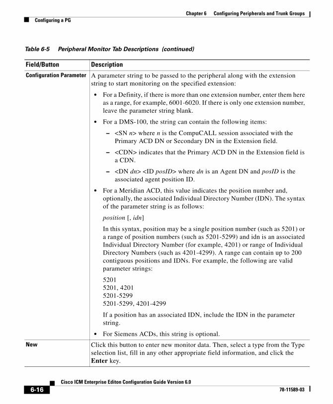
Chapter 6 Configuring Peripherals and Trunk GroupsConfiguring a PG
Configuration Parameter A parameter string to be passed to the peripheral along with the extension string to start monitoring on the specified extension:
• For a Definity, if there is more than one extension number, enter them here as a range, for example, 6001-6020. If there is only one extension number, leave the parameter string blank.
• For a DMS-100, the string can contain the following items:
– <SN n> where n is the CompuCALL session associated with the Primary ACD DN or Secondary DN in the Extension field.
– <CDN> indicates that the Primary ACD DN in the Extension field is a CDN.
– <DN dn> <ID posID> where dn is an Agent DN and posID is the associated agent position ID.
• For a Meridian ACD, this value indicates the position number and, optionally, the associated Individual Directory Number (IDN). The syntax of the parameter string is as follows:
position [, idn]
In this syntax, position may be a single position number (such as 5201) or a range of position numbers (such as 5201-5299) and idn is an associated Individual Directory Number (for example, 4201) or range of Individual Directory Numbers (such as 4201-4299). A range can contain up to 200 contiguous positions and IDNs. For example, the following are valid parameter strings:
52015201, 42015201-52995201-5299, 4201-4299
If a position has an associated IDN, include the IDN in the parameter string.
• For Siemens ACDs, this string is optional.
New Click this button to enter new monitor data. Then, select a type from the Type selection list, fill in any other appropriate field information, and click the Enter key.
Table 6-5 Peripheral Monitor Tab Descriptions (continued)
Field/Button Description
6-16Cisco ICM Enterprise Editon Configuration Guide Version 6.0
78-11589-03
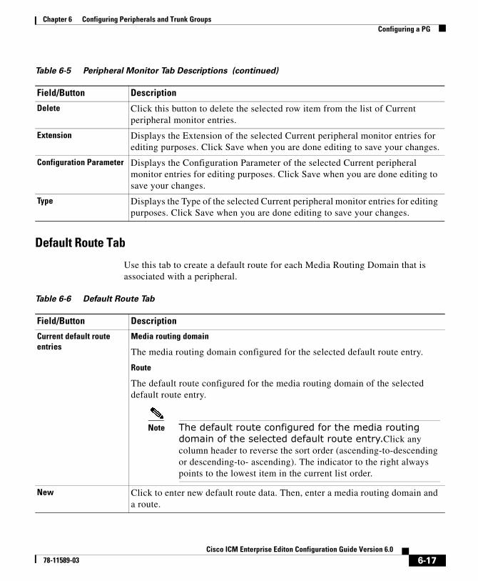
Chapter 6 Configuring Peripherals and Trunk GroupsConfiguring a PG
Default Route Tab
Use this tab to create a default route for each Media Routing Domain that is associated with a peripheral.
Delete Click this button to delete the selected row item from the list of Current peripheral monitor entries.
Extension Displays the Extension of the selected Current peripheral monitor entries for editing purposes. Click Save when you are done editing to save your changes.
Configuration Parameter Displays the Configuration Parameter of the selected Current peripheral monitor entries for editing purposes. Click Save when you are done editing to save your changes.
Type Displays the Type of the selected Current peripheral monitor entries for editing purposes. Click Save when you are done editing to save your changes.
Table 6-5 Peripheral Monitor Tab Descriptions (continued)
Field/Button Description
Table 6-6 Default Route Tab
Field/Button Description
Current default route entries
Media routing domain
The media routing domain configured for the selected default route entry.
Route
The default route configured for the media routing domain of the selected default route entry.
Note The default route configured for the media routing domain of the selected default route entry.Click any column header to reverse the sort order (ascending-to-descending or descending-to- ascending). The indicator to the right always points to the lowest item in the current list order.
New Click to enter new default route data. Then, enter a media routing domain and a route.
6-17Cisco ICM Enterprise Editon Configuration Guide Version 6.0
78-11589-03
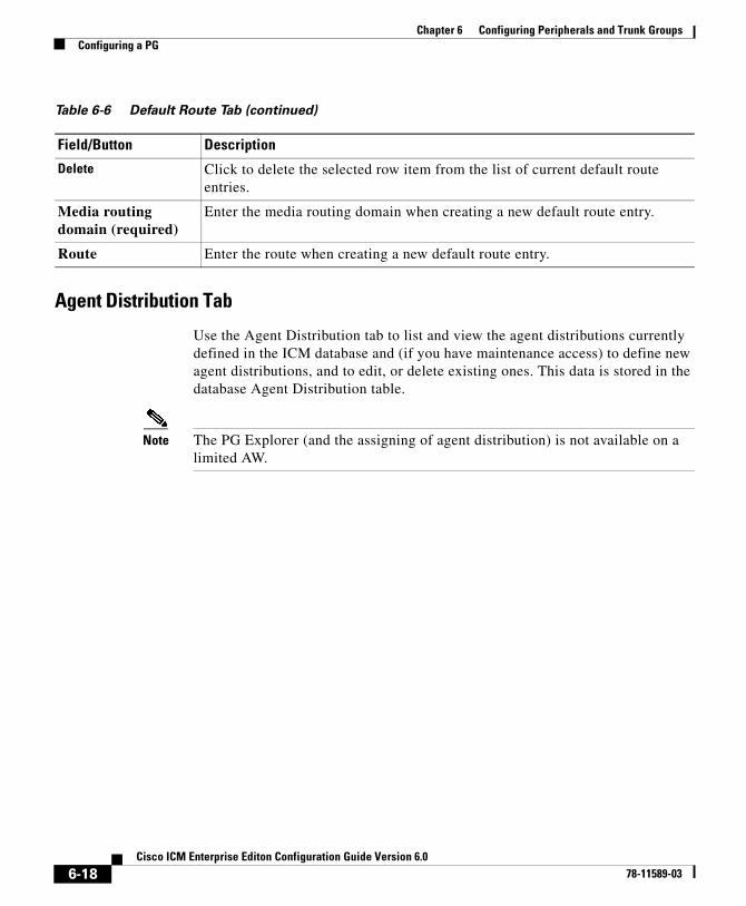
Chapter 6 Configuring Peripherals and Trunk GroupsConfiguring a PG
Agent Distribution Tab
Use the Agent Distribution tab to list and view the agent distributions currently defined in the ICM database and (if you have maintenance access) to define new agent distributions, and to edit, or delete existing ones. This data is stored in the database Agent Distribution table.
Note The PG Explorer (and the assigning of agent distribution) is not available on a limited AW.
Delete Click to delete the selected row item from the list of current default route entries.
Media routing domain (required)
Enter the media routing domain when creating a new default route entry.
Route Enter the route when creating a new default route entry.
Table 6-6 Default Route Tab (continued)
Field/Button Description
6-18Cisco ICM Enterprise Editon Configuration Guide Version 6.0
78-11589-03
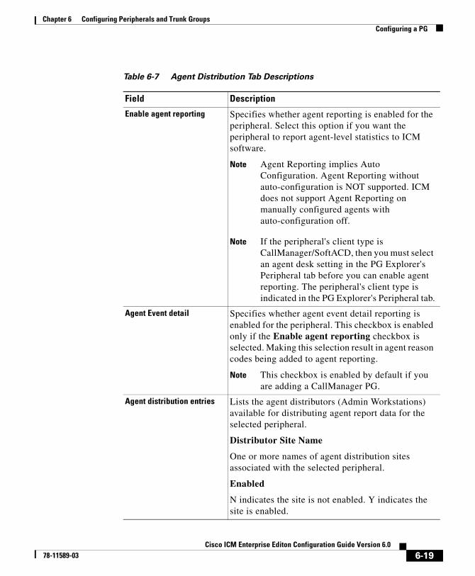
Chapter 6 Configuring Peripherals and Trunk GroupsConfiguring a PG
Table 6-7 Agent Distribution Tab Descriptions
Field Description
Enable agent reporting Specifies whether agent reporting is enabled for the peripheral. Select this option if you want the peripheral to report agent-level statistics to ICM software.
Note Agent Reporting implies Auto Configuration. Agent Reporting without auto-configuration is NOT supported. ICM does not support Agent Reporting on manually configured agents with auto-configuration off.
Note If the peripheral's client type is CallManager/SoftACD, then you must select an agent desk setting in the PG Explorer's Peripheral tab before you can enable agent reporting. The peripheral's client type is indicated in the PG Explorer's Peripheral tab.
Agent Event detail Specifies whether agent event detail reporting is enabled for the peripheral. This checkbox is enabled only if the Enable agent reporting checkbox is selected. Making this selection result in agent reason codes being added to agent reporting.
Note This checkbox is enabled by default if you are adding a CallManager PG.
Agent distribution entries Lists the agent distributors (Admin Workstations) available for distributing agent report data for the selected peripheral.
Distributor Site Name
One or more names of agent distribution sites associated with the selected peripheral.
Enabled
N indicates the site is not enabled. Y indicates the site is enabled.
6-19Cisco ICM Enterprise Editon Configuration Guide Version 6.0
78-11589-03
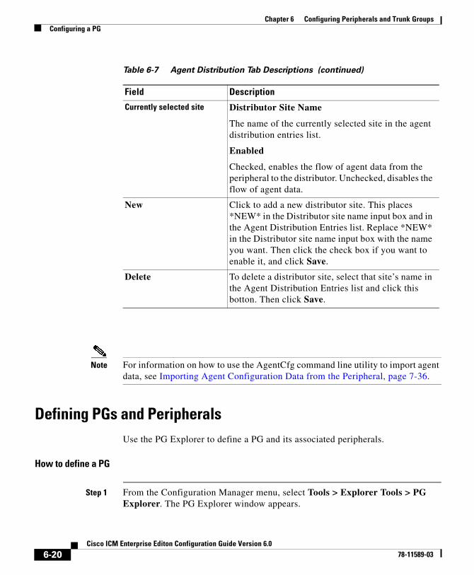
Chapter 6 Configuring Peripherals and Trunk GroupsConfiguring a PG
Note For information on how to use the AgentCfg command line utility to import agent data, see Importing Agent Configuration Data from the Peripheral, page 7-36.
Defining PGs and PeripheralsUse the PG Explorer to define a PG and its associated peripherals.
How to define a PG
Step 1 From the Configuration Manager menu, select Tools > Explorer Tools > PG Explorer. The PG Explorer window appears.
Currently selected site Distributor Site Name
The name of the currently selected site in the agent distribution entries list.
Enabled
Checked, enables the flow of agent data from the peripheral to the distributor. Unchecked, disables the flow of agent data.
New Click to add a new distributor site. This places *NEW* in the Distributor site name input box and in the Agent Distribution Entries list. Replace *NEW* in the Distributor site name input box with the name you want. Then click the check box if you want to enable it, and click Save.
Delete To delete a distributor site, select that site’s name in the Agent Distribution Entries list and click this botton. Then click Save.
Table 6-7 Agent Distribution Tab Descriptions (continued)
Field Description
6-20Cisco ICM Enterprise Editon Configuration Guide Version 6.0
78-11589-03
Chapter 6 Configuring Peripherals and Trunk GroupsConfiguring a PG
Step 2 In the Select filter data box, click Retrieve. This enables the Add PG button.
Step 3 Click Add PG. A new PG appears in the tree list box with a To Be Inserted icon next to it. Tabbed fields also appear on the right for the new PG’s
configuration information.
Step 4 Fill in the tabbed fields. (For field descriptions, see the “PG Explorer Tab Descriptions” section on page 6-4.)
Step 5 If desired, set security settings on the records. (See the “How to view or apply security settings” section on page 3-22.)
Step 6 Click Save to save the newly defined PG in the database.
How to define a peripheral
Step 1 Follow the steps for viewing a PG. (See the “How to view PG records” section on page 6-3.)
The selected PG’s configuration information appears in the fields on the right. For field descriptions, see the “PG Explorer Tab Descriptions” section on page 6-4.
Step 2 In the tree list box, select the PG to which you want to add a peripheral. This enables the Add Peripheral button.
Step 3 Click Add Peripheral. A peripheral is added to the selected PG in the tree list box. Also a new set of tabbed fields appear on the right for the new PG’s configuration information.
Step 4 Enter the needed peripheral configuration information in the fields on the right. (For field descriptions, see Table 6-2 on page 6-7.)
Step 5 If desired, set security settings on the records. (See the “How to view or apply security settings” section on page 3-22.)
Step 6 Click Save.
After you have defined a peripheral, you can define the trunks, agents, groups, and services associated with that peripheral.
6-21Cisco ICM Enterprise Editon Configuration Guide Version 6.0
78-11589-03
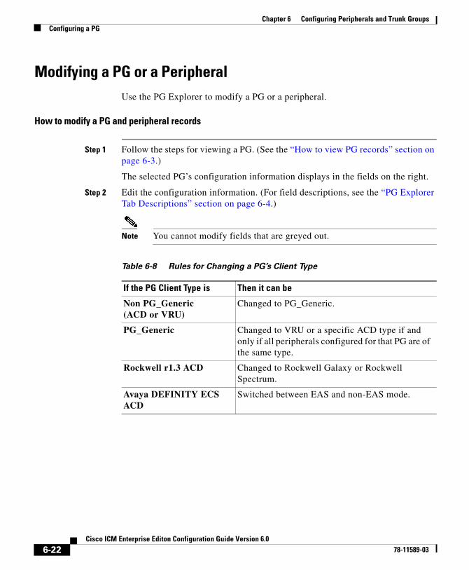
Chapter 6 Configuring Peripherals and Trunk GroupsConfiguring a PG
Modifying a PG or a PeripheralUse the PG Explorer to modify a PG or a peripheral.
How to modify a PG and peripheral records
Step 1 Follow the steps for viewing a PG. (See the “How to view PG records” section on page 6-3.)
The selected PG’s configuration information displays in the fields on the right.
Step 2 Edit the configuration information. (For field descriptions, see the “PG Explorer Tab Descriptions” section on page 6-4.)
Note You cannot modify fields that are greyed out.
Table 6-8 Rules for Changing a PG’s Client Type
If the PG Client Type is Then it can be
Non PG_Generic (ACD or VRU)
Changed to PG_Generic.
PG_Generic Changed to VRU or a specific ACD type if and only if all peripherals configured for that PG are of the same type.
Rockwell r1.3 ACD Changed to Rockwell Galaxy or Rockwell Spectrum.
Avaya DEFINITY ECS ACD
Switched between EAS and non-EAS mode.
6-22Cisco ICM Enterprise Editon Configuration Guide Version 6.0
78-11589-03
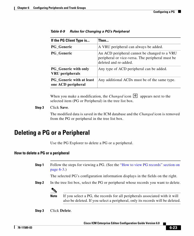
Chapter 6 Configuring Peripherals and Trunk GroupsConfiguring a PG
When you make a modification, the Changed icon appears next to the selected item (PG or Peripheral) in the tree list box.
Step 3 Click Save.
The modified data is saved in the ICM database and the Changed icon is removed from the PG or peripheral in the tree list box.
Deleting a PG or a PeripheralUse the PG Explorer to delete a PG or a peripheral.
How to delete a PG or a peripheral
Step 1 Follow the steps for viewing a PG. (See the “How to view PG records” section on page 6-3.)
The selected PG’s configuration information displays in the fields on the right.
Step 2 In the tree list box, select the PG or peripheral whose records you want to delete.
Note If you select a PG, the records for all peripherals associated with it will also be deleted. If you select a peripheral, only its records will be deleted.
Step 3 Click Delete.
Table 6-9 Rules for Changing a PG’s Peripheral
If the PG Client Type is... Then...
PG_Generic A VRU peripheral can always be added.
PG_Generic An ACD peripheral cannot be changed to a VRU peripheral or vice-versa. The peripheral must be deleted and re-added.
PG_Generic with only VRU peripherals
Any type of ACD peripheral can be added.
PG_Generic with at least one ACD peripheral
Any additional ACDs must be of the same type.
6-23Cisco ICM Enterprise Editon Configuration Guide Version 6.0
78-11589-03
Chapter 6 Configuring Peripherals and Trunk GroupsConfiguring Trunk Groups and Trunks
Step 4 This places a Marked for Deletion icon next to the selected item in the tree list box. This also toggles the Delete button to Undelete.
To undelete an item marked for deletion, select it in the tree list box and click Undelete.
Step 5 Click Save.
This deletes from the database the PG or peripheral marked for deletion and removes it from the tree list box. Once you do this, you cannot undelete the deleted item.
Configuring Trunk Groups and TrunksEvery peripheral has one or more associated trunk groups, with each trunk group containing one or more physical trunks. Trunk groups map to trunk sets defined by the peripheral.
A peripheral dispatches a call to the appropriate skill target based on the trunk group on which the call arrives and the DNIS value that accompanies it. The peripheral treats all trunks with a particular trunk group the same, but it might treat trunks within another trunk group differently.
Note The DMS-100 does not have trunk groups, but within ICM software you must define one network trunk group and one trunk group for each DMS-100.
When setting up trunk groups and trunks, you must specify:
• Each trunk group that can receive calls
• How many trunks are in each trunk group, or configuration information for each trunk in the group
This section describes how to configure the trunk groups and trunks that will be used by routing clients and peripherals.
6-24Cisco ICM Enterprise Editon Configuration Guide Version 6.0
78-11589-03
Chapter 6 Configuring Peripherals and Trunk GroupsConfiguring Trunk Groups and Trunks
Network Trunk Groups, Trunk Groups, and TrunksRouting clients deliver calls to trunk groups at the peripheral. However, a routing client might group the trunks differently from the way the peripheral groups them. The groups as seen by the routing client are called network trunk groups.
A network trunk group:
• Is a collection of peripheral trunk groups.
• Can map directly to a single trunk group at the peripheral or to multiple trunk groups.
• Can also map to trunk groups at different peripherals, provided that all the peripherals are associated with the same Peripheral Gateway. (Only valid for VRU peripherals.)
How to view a network trunk group, its trunk groups, and its trunks
Step 1 From the Configuration Manager menu, select Tools > Explorer Tools > Network Trunk Group Explorer. The Network Trunk Group Explorer window appears.
6-25Cisco ICM Enterprise Editon Configuration Guide Version 6.0
78-11589-03
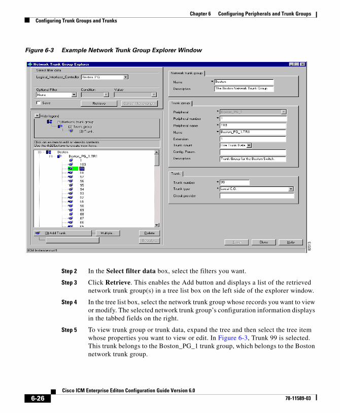
Chapter 6 Configuring Peripherals and Trunk GroupsConfiguring Trunk Groups and Trunks
Figure 6-3 Example Network Trunk Group Explorer Window
Step 2 In the Select filter data box, select the filters you want.
Step 3 Click Retrieve. This enables the Add button and displays a list of the retrieved network trunk group(s) in a tree list box on the left side of the explorer window.
Step 4 In the tree list box, select the network trunk group whose records you want to view or modify. The selected network trunk group’s configuration information displays in the tabbed fields on the right.
Step 5 To view trunk group or trunk data, expand the tree and then select the tree item whose properties you want to view or edit. In Figure 6-3, Trunk 99 is selected. This trunk belongs to the Boston_PG_1 trunk group, which belongs to the Boston network trunk group.
6-26Cisco ICM Enterprise Editon Configuration Guide Version 6.0
78-11589-03
Chapter 6 Configuring Peripherals and Trunk GroupsConfiguring Trunk Groups and Trunks
The property tabs on the right side of the explorer window display the properties of the item selected in the tree list box. Properties with an asterisk are required. If you have maintenance access, you can define or edit these properties.
Network Trunk Group Tab Descriptions
Allows you to view (and define or edit, if you have maintenance access) the properties of the selected network trunk group.
Trunk Group Tab Descriptions
Allows you to view (and define or edit, if you have maintenance access) the properties of the selected trunk group.
Table 6-10 Network Trunk Group Tab Descriptions
Property Description
Name (required) An enterprise name for the network trunk group. This name must be unique for all network trunk groups in the system.
Description (optional) Any other information about the network trunk group.
Table 6-11 Trunk Group Tab Descriptions
Property Description
Peripheral (required) (selection list) The enterprise name of the peripheral with which the trunk group is associated.
Note Once you have saved a trunk group record to the ICM database, you cannot update this field.
Peripheral number (required)
The number of this trunk group as understood by the peripheral.
This value must be unique among all trunk groups connected to the same peripheral, but not throughout the entire system. Once you install the data to the central database, you cannot change this field.
6-27Cisco ICM Enterprise Editon Configuration Guide Version 6.0
78-11589-03
Chapter 6 Configuring Peripherals and Trunk GroupsConfiguring Trunk Groups and Trunks
Trunk Tab DescriptionsAllows you to view (and define or edit, if you have maintenance access) the properties of the selected trunk.
Peripheral name (required)
The name of this trunk group as understood by the peripheral.
This value must be unique among all trunk groups connected to the same peripheral, but not throughout the entire system.
Name (required) The enterprise name for the trunk group. This name must be unique among all trunk groups in the entire system. If you click in this field when entering a new trunk group, the system by default creates a name from the peripheral and the peripheral name. For example: Boston_PG.TrunkGroup2 where Boston_PG is the peripheral and TrunkGroup2 is the peripheral name.
Extension • If the peripheral is a Avaya DEFINITY ECS, the extension number that the peripheral associates with this trunk group.
• If the peripheral is a Nortel Meridian running in enhanced CTI mode, the Meridian route access code (ACOD) for this route.
• For all other peripheral types, this field should be blank.
Trunk count (selection list) The number of trunks in this trunk group or Use Trunk Data.
If Use Trunk Data is selected, ICM software determines the trunk count dynamically by counting the associated records in the Trunk table.
Config. Param. A parameter string that ICM software must send to the ACD to configure the trunk group.
Description A description for the trunk group.
Table 6-11 Trunk Group Tab Descriptions (continued)
Property Description
6-28Cisco ICM Enterprise Editon Configuration Guide Version 6.0
78-11589-03
Chapter 6 Configuring Peripherals and Trunk GroupsConfiguring Trunk Groups and Trunks
How to edit a network trunk group, its trunk groups, and its trunks
Step 1 From the Configuration Manager menu, select Tools > Explorer Tools > Network Trunk Group Explorer. The Network Trunk Group Explorer window appears.
Table 6-12 Trunk Tab Descriptions
Property Description
Trunk number (required) The number of this trunk within the trunk group.
Trunk type (required) (selection list) The trunk’s trunk type: DID/DNIS, Foreign Exchange, Interflow, Local Central Office, PRI, Tie Line, or WATS. Table 6-13 lists the types of trunks that ICM software supports.
Circuit provider The name of the carrier that provides the circuit for this trunk. The provider is either a local phone company or an interexchange carrier.
Table 6-13 Trunk Types
Trunk Type Description
Local CO Connects the peripheral directly to the local telephone company’s central office (CO).
Foreign exchange Connects the peripheral directly to the central office of a non-local central office.
WATS Dedicated to Wide Area Telecommunication Service (WATS). This is a special service that allows a peripheral to place or receive calls from specific regions at a discounted price.
DID/DNIS Supports Direct Inside Dial (DID) or Dialed Number Identification Service (DNIS). A code to identify the number dialed by the caller accompanies each call. The peripheral can then dispatch the call to a specific target.
PRI Supports ISDN Primary Rate Interface (PRI). This mode typically provides 23 channels for voice or data and one channel for signaling information (23B + 1D).
Tie-line Connects one peripheral directly with another across a wide area.
Interflow Dedicated line that allows one peripheral to off-load calls to another peripheral.
6-29Cisco ICM Enterprise Editon Configuration Guide Version 6.0
78-11589-03
Chapter 6 Configuring Peripherals and Trunk GroupsConfiguring Trunk Groups and Trunks
Step 2 In the Select filter data box, select the filters you want.
Step 3 Click Retrieve. This displays a list of the retrieved network trunk group(s) in a tree list box on the left side of the explorer window.
Step 4 In the tree list box, select the item you want to edit. Expand the tree if necessary. This displays the selected item’s property tab on the right side of the window.
Step 5 Edit the appropriate properties. For property descriptions, see the “Network Trunk Group Tab Descriptions” section on page 6-27.
Step 6 Click Save.
How to define a network trunk group, its trunk groups, and its trunks
Step 1 From the Configuration Manager menu, select Tools > Explorer Tools > Network Trunk Group. The Network Trunk Group Explorer window appears.
Step 2 In the Select filter data box, select the filters you want.
Step 3 Click Retrieve. This displays a list of the retrieved trunk groups and enables the add functionality.
Step 4 This step depends on what you want to do:
• To add a new network trunk group, click Add Network Trunk Group.
• To add a new trunk group, select the network trunk group to which you want to add a group, and click Add Network Trunk Group.
• To add a new trunk, select the trunk group to which you want to add a trunk, and click Add Trunk.
Step 5 Enter the appropriate values in the tabbed property fields on the right side of the window. For property descriptions, see the “Network Trunk Group Tab Descriptions” section on page 6-27.
Step 6 Click Save.
6-30Cisco ICM Enterprise Editon Configuration Guide Version 6.0
78-11589-03
Chapter 6 Configuring Peripherals and Trunk GroupsConfiguring Trunk Groups and Trunks
How to delete a network trunk group, its trunk groups, and its trunks
Step 1 From the Configuration Manager menu, select Tools > Explorer Tools > Network Trunk Group Explorer. The Network Trunk Group Explorer window appears.
Step 2 In the Select filter data box, select the filters you want.
Step 3 Click Retrieve. This displays a list of the retrieved network trunk groups.
Step 4 In the tree list box, select the network trunk group, trunk group, or trunk whose records you want to delete.
Note If you select a network trunk group, the records for all trunk groups and trunks associated with it will also be deleted. If you select a trunk, only its records will be deleted.
Step 5 Click Delete.
Step 6 This places a Marked for Deletion icon next to the selected item in the tree list box. This also toggles the Delete button to Undelete.
To undelete an item marked for deletion, select it in the tree list box and click Undelete.
Step 7 Click Save.
This deletes from the database the item marked for deletion and removes it from the tree list box. Once you do this, you cannot undelete the deleted item.
How to define multiple trunks
You can quickly define multiple trunks of the same type for a specific trunk group by using the Multiple button in the Network Trunk Group Explorer window.
Step 1 From within the Network Trunk Group Explorer, select the trunk group to which you want to add trunks. This enables the Multiple button.
6-31Cisco ICM Enterprise Editon Configuration Guide Version 6.0
78-11589-03
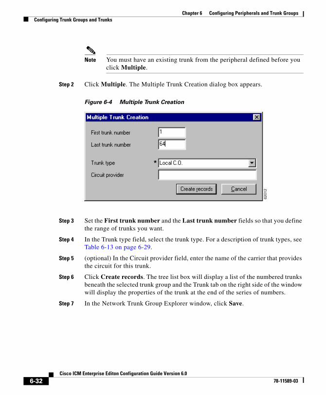
Chapter 6 Configuring Peripherals and Trunk GroupsConfiguring Trunk Groups and Trunks
Note You must have an existing trunk from the peripheral defined before you click Multiple.
Step 2 Click Multiple. The Multiple Trunk Creation dialog box appears.
Figure 6-4 Multiple Trunk Creation
Step 3 Set the First trunk number and the Last trunk number fields so that you define the range of trunks you want.
Step 4 In the Trunk type field, select the trunk type. For a description of trunk types, see Table 6-13 on page 6-29.
Step 5 (optional) In the Circuit provider field, enter the name of the carrier that provides the circuit for this trunk.
Step 6 Click Create records. The tree list box will display a list of the numbered trunks beneath the selected trunk group and the Trunk tab on the right side of the window will display the properties of the trunk at the end of the series of numbers.
Step 7 In the Network Trunk Group Explorer window, click Save.
6-32Cisco ICM Enterprise Editon Configuration Guide Version 6.0
78-11589-03

Chapter 6 Configuring Peripherals and Trunk GroupsConfiguring Trunk Groups and Trunks
Note If a trunk number in the range you specified has already been used, that trunk number is selected in the tree list box and a message displays. Before you can save the data, you must edit the trunk number.
6-33Cisco ICM Enterprise Editon Configuration Guide Version 6.0
78-11589-03

Chapter 6 Configuring Peripherals and Trunk GroupsConfiguring Trunk Groups and Trunks
6-34Cisco ICM Enterprise Editon Configuration Guide Version 6.0
78-11589-03
Cisco ICM Enterprise78-11589-03
C H A P T E R 7
Configuring Skill TargetsThis chapter describes how to set up the entities that ICM software selects to handle calls at a peripheral. It includes:
• An introduction to the skill targets subsystem
• Instructions on how to view, define, delete, or modify:
– Services
– Skill Groups
– Agents
– Persons
– Agent reporting
– Enterprise services
– Enterprise skill groups
This chapter also includes instructions for using theagentcfg.exe utility that allows you to update you ICM database with agent information from an ICM peripheral.
7-1 Editon Configuration Guide Version 6.0
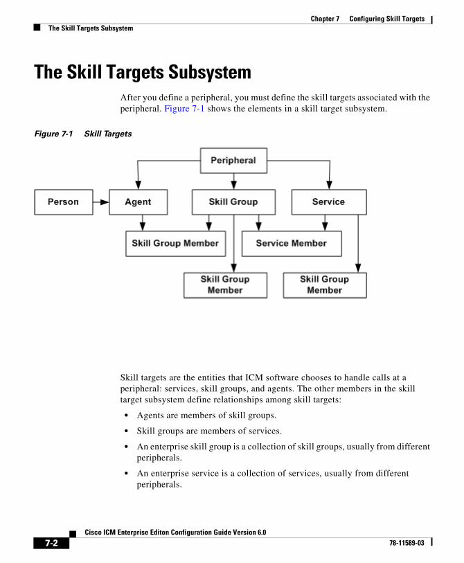
Chapter 7 Configuring Skill TargetsThe Skill Targets Subsystem
The Skill Targets SubsystemAfter you define a peripheral, you must define the skill targets associated with the peripheral. Figure 7-1 shows the elements in a skill target subsystem.
Figure 7-1 Skill Targets
Skill targets are the entities that ICM software chooses to handle calls at a peripheral: services, skill groups, and agents. The other members in the skill target subsystem define relationships among skill targets:
• Agents are members of skill groups.
• Skill groups are members of services.
• An enterprise skill group is a collection of skill groups, usually from different peripherals.
• An enterprise service is a collection of services, usually from different peripherals.
7-2Cisco ICM Enterprise Editon Configuration Guide Version 6.0
78-11589-03
Chapter 7 Configuring Skill TargetsServices
The rest of this chapter describes how to define these skill targets and establish the relationships among them.
ServicesYou must provide information about each service associated with a peripheral. A service is a type of caller need that the peripheral handles; for example, Sales, Support, and Information might all be services.
Use the Service Explorer to configure services and their associated records.
Service ExplorerThe following sections show you how to use the Service Explorer to view and configure a service and its associated routes, peripheral targets, and labels.
How to view a service
Step 1 In the Configuration Manager menu, select Tools > Explorer Tools > Service Explorer. The Service Explorer window appears.
Step 2 In the Select filter data box, select the peripheral associated with the service you want to view. You can choose the name from the drop-down list.
Note Once you have saved a service record to the ICM database, you cannot change the peripheral to which it is associated.
Step 3 Select any other filters you want. None in the Optional filter box means all services associated with the selected peripheral will be displayed.
Step 4 Click Retrieve. This lists in the tree list box the name(s) of the retrieved service(s).
7-3Cisco ICM Enterprise Editon Configuration Guide Version 6.0
78-11589-03
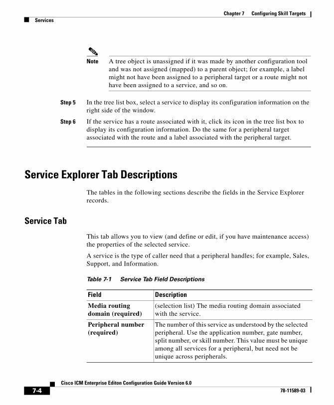
Chapter 7 Configuring Skill TargetsServices
Note A tree object is unassigned if it was made by another configuration tool and was not assigned (mapped) to a parent object; for example, a label might not have been assigned to a peripheral target or a route might not have been assigned to a service, and so on.
Step 5 In the tree list box, select a service to display its configuration information on the right side of the window.
Step 6 If the service has a route associated with it, click its icon in the tree list box to display its configuration information. Do the same for a peripheral target associated with the route and a label associated with the peripheral target.
Service Explorer Tab DescriptionsThe tables in the following sections describe the fields in the Service Explorer records.
Service Tab
This tab allows you to view (and define or edit, if you have maintenance access) the properties of the selected service.
A service is the type of caller need that a peripheral handles; for example, Sales, Support, and Information.
Table 7-1 Service Tab Field Descriptions
Field Description
Media routing domain (required)
(selection list) The media routing domain associated with the service.
Peripheral number (required)
The number of this service as understood by the selected peripheral. Use the application number, gate number, split number, or skill number. This value must be unique among all services for a peripheral, but need not be unique across peripherals.
7-4Cisco ICM Enterprise Editon Configuration Guide Version 6.0
78-11589-03
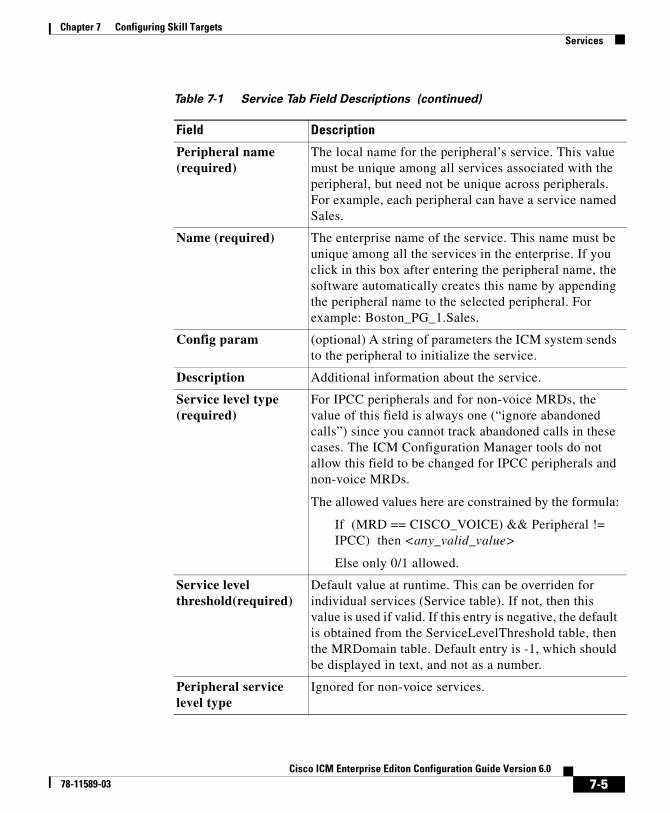
Chapter 7 Configuring Skill TargetsServices
Peripheral name (required)
The local name for the peripheral’s service. This value must be unique among all services associated with the peripheral, but need not be unique across peripherals. For example, each peripheral can have a service named Sales.
Name (required) The enterprise name of the service. This name must be unique among all the services in the enterprise. If you click in this box after entering the peripheral name, the software automatically creates this name by appending the peripheral name to the selected peripheral. For example: Boston_PG_1.Sales.
Config param (optional) A string of parameters the ICM system sends to the peripheral to initialize the service.
Description Additional information about the service.
Service level type (required)
For IPCC peripherals and for non-voice MRDs, the value of this field is always one (“ignore abandoned calls”) since you cannot track abandoned calls in these cases. The ICM Configuration Manager tools do not allow this field to be changed for IPCC peripherals and non-voice MRDs.
The allowed values here are constrained by the formula:
If (MRD == CISCO_VOICE) && Peripheral != IPCC) then <any_valid_value>
Else only 0/1 allowed.
Service level threshold(required)
Default value at runtime. This can be overriden for individual services (Service table). If not, then this value is used if valid. If this entry is negative, the default is obtained from the ServiceLevelThreshold table, then the MRDomain table. Default entry is -1, which should be displayed in text, and not as a number.
Peripheral service level type
Ignored for non-voice services.
Table 7-1 Service Tab Field Descriptions (continued)
Field Description
7-5Cisco ICM Enterprise Editon Configuration Guide Version 6.0
78-11589-03
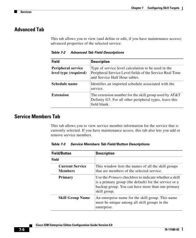
Chapter 7 Configuring Skill TargetsServices
Advanced Tab
This tab allows you to view (and define or edit, if you have maintenance access) advanced properties of the selected service.
Service Members Tab
This tab allows you to view service member information for the service that is currently selected. If you have maintenance access, this tab also lets you add or remove service members.
Table 7-2 Advanced Tab Field Descriptions
Field Description
Peripheral service level type (required)
Type of service level calculation to be used in the Peripheral Service Level fields of the Service Real Time and Service Half Hour tables.
Schedule name Identifies an imported schedule associated with the service.
Extension The extension number for the skill group used by AT&T Definity G3. For all other peripheral types, leave this field blank.
Table 7-3 Service Members Tab Field/Button Descriptions
Field/Button Description
Field
Current Service Members
This window lists the names of all the skill groups that are members of the selected service.
Primary Use the Primary checkbox to indicate whether a skill is a primary group (the default) for the service or a backup group. You can have more than one primary skill group.
Skill Group Name An enterprise name for the skill group. This name must be unique among all skill groups in the enterprise.
7-6Cisco ICM Enterprise Editon Configuration Guide Version 6.0
78-11589-03
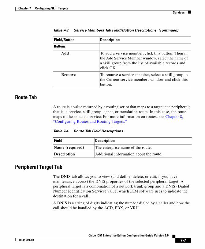
Chapter 7 Configuring Skill TargetsServices
Route Tab
A route is a value returned by a routing script that maps to a target at a peripheral; that is, a service, skill group, agent, or translation route. In this case, the route maps to the selected service. For more information on routes, see Chapter 8, “Configuring Routes and Routing Targets.”
Peripheral Target Tab
The DNIS tab allows you to view (and define, delete, or edit, if you have maintenance access) the DNIS properties of the selected peripheral target. A peripheral target is a combination of a network trunk group and a DNIS (Dialed Number Identification Service) value, which ICM software uses to indicate the destination for a call.
A DNIS is a string of digits indicating the number dialed by a caller and how the call should be handled by the ACD, PBX, or VRU.
Buttons
Add To add a service member, click this button. Then in the Add Service Member window, select the name of a skill group from the list of available records and click OK.
Remove To remove a service member, select a skill group in the Current service members window and click this button.
Table 7-3 Service Members Tab Field/Button Descriptions (continued)
Field/Button Description
Table 7-4 Route Tab Field Descriptions
Field Description
Name (required) The enterprise name of the route.
Description Additional information about the route.
7-7Cisco ICM Enterprise Editon Configuration Guide Version 6.0
78-11589-03
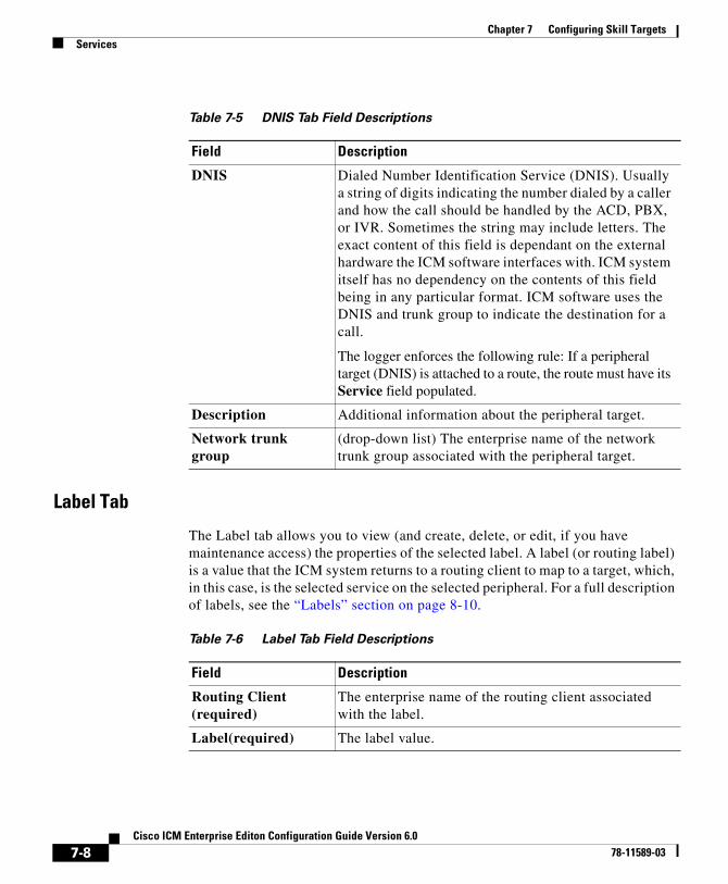
Chapter 7 Configuring Skill TargetsServices
Label Tab
The Label tab allows you to view (and create, delete, or edit, if you have maintenance access) the properties of the selected label. A label (or routing label) is a value that the ICM system returns to a routing client to map to a target, which, in this case, is the selected service on the selected peripheral. For a full description of labels, see the “Labels” section on page 8-10.
Table 7-5 DNIS Tab Field Descriptions
Field Description
DNIS Dialed Number Identification Service (DNIS). Usually a string of digits indicating the number dialed by a caller and how the call should be handled by the ACD, PBX, or IVR. Sometimes the string may include letters. The exact content of this field is dependant on the external hardware the ICM software interfaces with. ICM system itself has no dependency on the contents of this field being in any particular format. ICM software uses the DNIS and trunk group to indicate the destination for a call.
The logger enforces the following rule: If a peripheral target (DNIS) is attached to a route, the route must have its Service field populated.
Description Additional information about the peripheral target.
Network trunk group
(drop-down list) The enterprise name of the network trunk group associated with the peripheral target.
Table 7-6 Label Tab Field Descriptions
Field Description
Routing Client (required)
The enterprise name of the routing client associated with the label.
Label(required) The label value.
7-8Cisco ICM Enterprise Editon Configuration Guide Version 6.0
78-11589-03
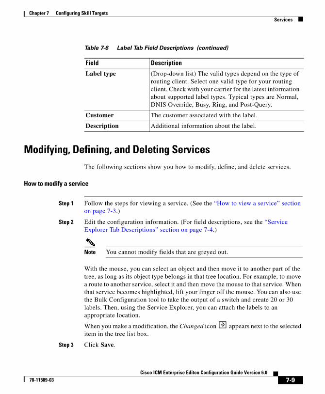
Chapter 7 Configuring Skill TargetsServices
Modifying, Defining, and Deleting ServicesThe following sections show you how to modify, define, and delete services.
How to modify a service
Step 1 Follow the steps for viewing a service. (See the “How to view a service” section on page 7-3.)
Step 2 Edit the configuration information. (For field descriptions, see the “Service Explorer Tab Descriptions” section on page 7-4.)
Note You cannot modify fields that are greyed out.
With the mouse, you can select an object and then move it to another part of the tree, as long as its object type belongs in that tree location. For example, to move a route to another service, select it and then move the mouse to that service. When that service becomes highlighted, lift your finger off the mouse. You can also use the Bulk Configuration tool to take the output of a switch and create 20 or 30 labels. Then, using the Service Explorer, you can attach the labels to an appropriate location.
When you make a modification, the Changed icon appears next to the selected item in the tree list box.
Step 3 Click Save.
Label type (Drop-down list) The valid types depend on the type of routing client. Select one valid type for your routing client. Check with your carrier for the latest information about supported label types. Typical types are Normal, DNIS Override, Busy, Ring, and Post-Query.
Customer The customer associated with the label.
Description Additional information about the label.
Table 7-6 Label Tab Field Descriptions (continued)
Field Description
7-9Cisco ICM Enterprise Editon Configuration Guide Version 6.0
78-11589-03
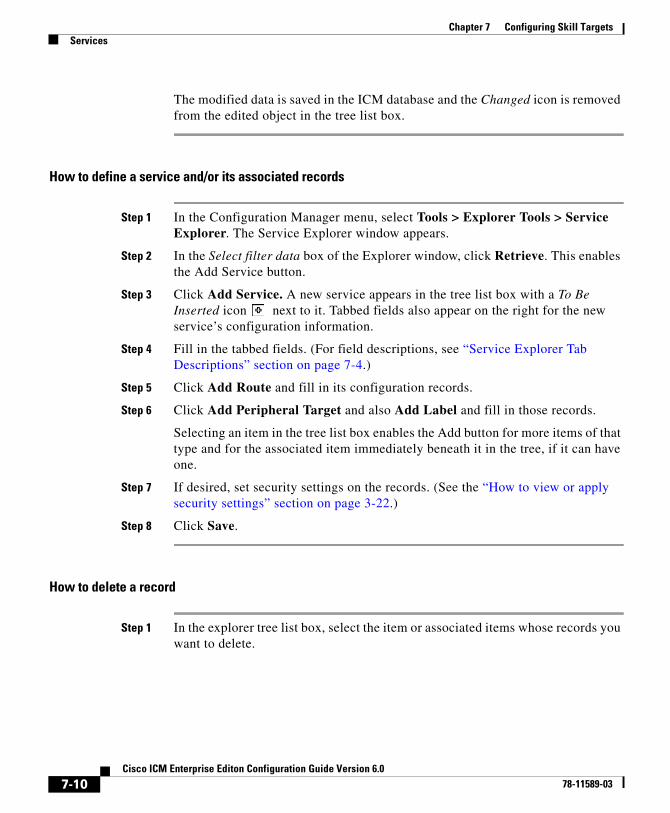
Chapter 7 Configuring Skill TargetsServices
The modified data is saved in the ICM database and the Changed icon is removed from the edited object in the tree list box.
How to define a service and/or its associated records
Step 1 In the Configuration Manager menu, select Tools > Explorer Tools > Service Explorer. The Service Explorer window appears.
Step 2 In the Select filter data box of the Explorer window, click Retrieve. This enables the Add Service button.
Step 3 Click Add Service. A new service appears in the tree list box with a To Be Inserted icon next to it. Tabbed fields also appear on the right for the new service’s configuration information.
Step 4 Fill in the tabbed fields. (For field descriptions, see “Service Explorer Tab Descriptions” section on page 7-4.)
Step 5 Click Add Route and fill in its configuration records.
Step 6 Click Add Peripheral Target and also Add Label and fill in those records.
Selecting an item in the tree list box enables the Add button for more items of that type and for the associated item immediately beneath it in the tree, if it can have one.
Step 7 If desired, set security settings on the records. (See the “How to view or apply security settings” section on page 3-22.)
Step 8 Click Save.
How to delete a record
Step 1 In the explorer tree list box, select the item or associated items whose records you want to delete.
7-10Cisco ICM Enterprise Editon Configuration Guide Version 6.0
78-11589-03
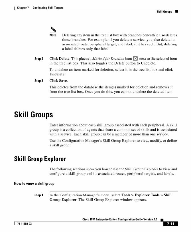
Chapter 7 Configuring Skill TargetsSkill Groups
Note Deleting any item in the tree list box with branches beneath it also deletes those branches. For example, if you delete a service, you also delete its associated route, peripheral target, and label, if it has such. But, deleting a label deletes only that label.
Step 2 Click Delete. This places a Marked for Deletion icon next to the selected item in the tree list box. This also toggles the Delete button to Undelete.
To undelete an item marked for deletion, select it in the tree list box and click Undelete.
Step 3 Click Save.
This deletes from the database the item(s) marked for deletion and removes it from the tree list box. Once you do this, you cannot undelete the deleted item.
Skill GroupsEnter information about each skill group associated with each peripheral. A skill group is a collection of agents that share a common set of skills and is associated with a service. Each skill group can be a member of more than one service.
Use the Configuration Manager’s Skill Group Explorer to view, modify, or define a skill group.
Skill Group ExplorerThe following sections show you how to use the Skill Group Explorer to view and configure a skill group and its associated routes, peripheral targets, and labels.
How to view a skill group
Step 1 In the Configuration Manager’s menu, select Tools > Explorer Tools > Skill Group Explorer. The Skill Group Explorer window appears.
7-11Cisco ICM Enterprise Editon Configuration Guide Version 6.0
78-11589-03
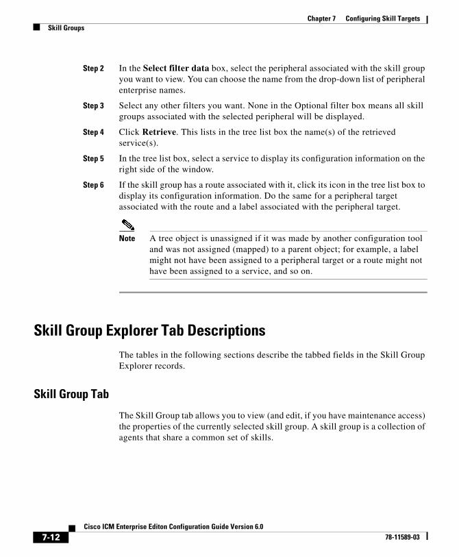
Chapter 7 Configuring Skill TargetsSkill Groups
Step 2 In the Select filter data box, select the peripheral associated with the skill group you want to view. You can choose the name from the drop-down list of peripheral enterprise names.
Step 3 Select any other filters you want. None in the Optional filter box means all skill groups associated with the selected peripheral will be displayed.
Step 4 Click Retrieve. This lists in the tree list box the name(s) of the retrieved service(s).
Step 5 In the tree list box, select a service to display its configuration information on the right side of the window.
Step 6 If the skill group has a route associated with it, click its icon in the tree list box to display its configuration information. Do the same for a peripheral target associated with the route and a label associated with the peripheral target.
Note A tree object is unassigned if it was made by another configuration tool and was not assigned (mapped) to a parent object; for example, a label might not have been assigned to a peripheral target or a route might not have been assigned to a service, and so on.
Skill Group Explorer Tab DescriptionsThe tables in the following sections describe the tabbed fields in the Skill Group Explorer records.
Skill Group Tab
The Skill Group tab allows you to view (and edit, if you have maintenance access) the properties of the currently selected skill group. A skill group is a collection of agents that share a common set of skills.
7-12Cisco ICM Enterprise Editon Configuration Guide Version 6.0
78-11589-03
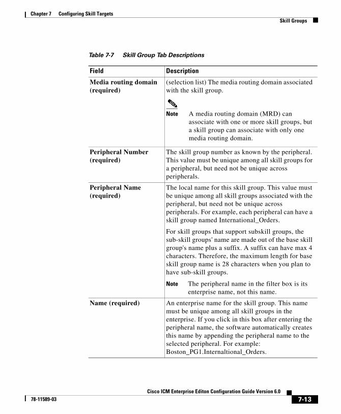
Chapter 7 Configuring Skill TargetsSkill Groups
Table 7-7 Skill Group Tab Descriptions
Field Description
Media routing domain (required)
(selection list) The media routing domain associated with the skill group.
Note A media routing domain (MRD) can associate with one or more skill groups, but a skill group can associate with only one media routing domain.
Peripheral Number (required)
The skill group number as known by the peripheral. This value must be unique among all skill groups for a peripheral, but need not be unique across peripherals.
Peripheral Name (required)
The local name for this skill group. This value must be unique among all skill groups associated with the peripheral, but need not be unique across peripherals. For example, each peripheral can have a skill group named International_Orders.
For skill groups that support subskill groups, the sub-skill groups' name are made out of the base skill group's name plus a suffix. A suffix can have max 4 characters. Therefore, the maximum length for base skill group name is 28 characters when you plan to have sub-skill groups.
Note The peripheral name in the filter box is its enterprise name, not this name.
Name (required) An enterprise name for the skill group. This name must be unique among all skill groups in the enterprise. If you click in this box after entering the peripheral name, the software automatically creates this name by appending the peripheral name to the selected peripheral. For example: Boston_PG1.Internaltional_Orders.
7-13Cisco ICM Enterprise Editon Configuration Guide Version 6.0
78-11589-03

Chapter 7 Configuring Skill TargetsSkill Groups
Available Holdoff Delay The number of seconds to wait after a call ends before recording the agent as Available. You can enter a value or choose the default.
• For a Nortel Meridian peripheral, set this value to match the flexible call force timer (FCFT).
• For a DMS-100, enter the Variable WrapUp time for the ACD DN.
• For all other peripheral types, set this field to zero.
Priority (read-only) Indicates the routing priority of this base group for the skill. The value 0 indicates a base skill group. This is the default when there is only one skill group and there are no priorities. For sub skill group priorities please refer to the Sub Skill Group tab as well as the Subgroup Mask tab.
Extension If the peripheral is a Avaya DEFINITY ECS or Rockwell Spectrum, enter the extension number associated with the skill group. For all other peripheral types, leave this field blank.
ICM picks the agent Checked, indicates that the ICM software selects the agent. This option is used for IPCC-like routing where the ICM software picks the agent to handle a request.
Unchecked, indicates another entity, typically an ACD, does the agent selection (after the ICM software has sent a call to an ACD skill group).
This option applies to pre-routed requests.
ConfigParam (Optional) A string of parameters the ICM software sends to the peripheral to initialize the skill group.
Description Additional information about the skill group.
Table 7-7 Skill Group Tab Descriptions (continued)
Field Description
7-14Cisco ICM Enterprise Editon Configuration Guide Version 6.0
78-11589-03
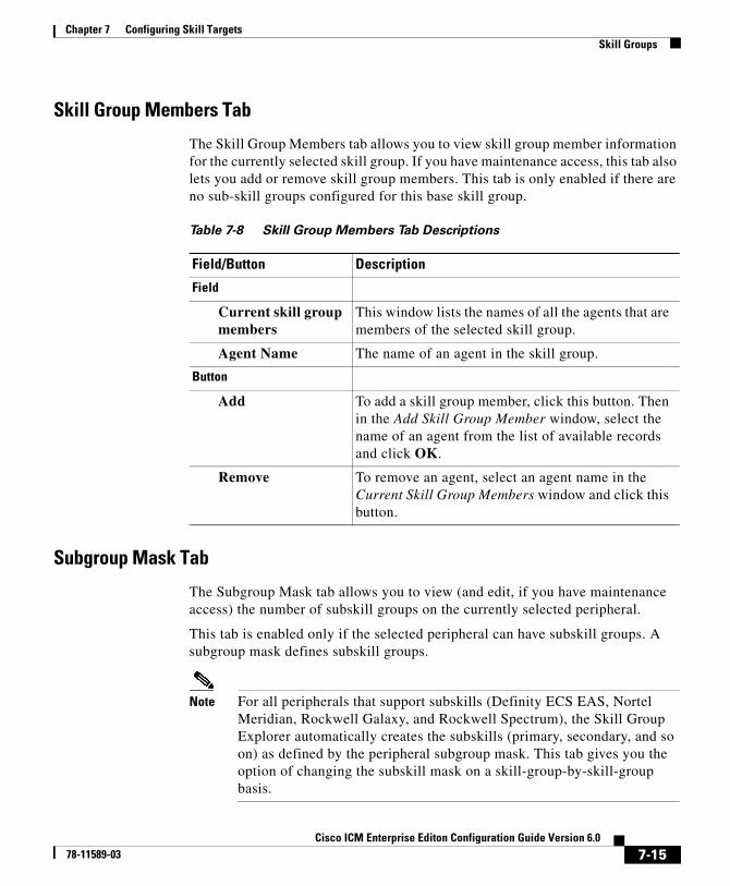
Chapter 7 Configuring Skill TargetsSkill Groups
Skill Group Members Tab
The Skill Group Members tab allows you to view skill group member information for the currently selected skill group. If you have maintenance access, this tab also lets you add or remove skill group members. This tab is only enabled if there are no sub-skill groups configured for this base skill group.
Subgroup Mask Tab
The Subgroup Mask tab allows you to view (and edit, if you have maintenance access) the number of subskill groups on the currently selected peripheral.
This tab is enabled only if the selected peripheral can have subskill groups. A subgroup mask defines subskill groups.
Note For all peripherals that support subskills (Definity ECS EAS, Nortel Meridian, Rockwell Galaxy, and Rockwell Spectrum), the Skill Group Explorer automatically creates the subskills (primary, secondary, and so on) as defined by the peripheral subgroup mask. This tab gives you the option of changing the subskill mask on a skill-group-by-skill-group basis.
Table 7-8 Skill Group Members Tab Descriptions
Field/Button Description
Field
Current skill group members
This window lists the names of all the agents that are members of the selected skill group.
Agent Name The name of an agent in the skill group.
Button
Add To add a skill group member, click this button. Then in the Add Skill Group Member window, select the name of an agent from the list of available records and click OK.
Remove To remove an agent, select an agent name in the Current Skill Group Members window and click this button.
7-15Cisco ICM Enterprise Editon Configuration Guide Version 6.0
78-11589-03
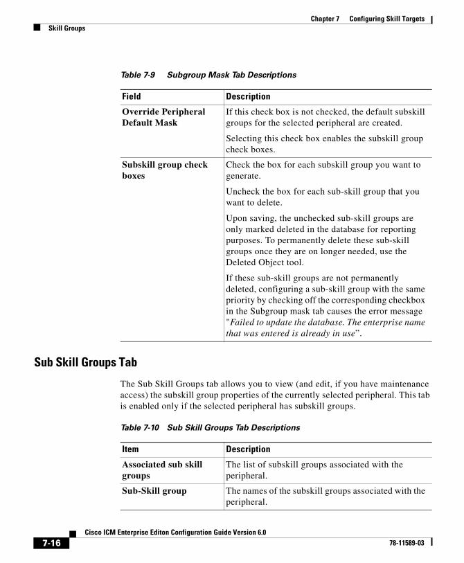
Chapter 7 Configuring Skill TargetsSkill Groups
Sub Skill Groups Tab
The Sub Skill Groups tab allows you to view (and edit, if you have maintenance access) the subskill group properties of the currently selected peripheral. This tab is enabled only if the selected peripheral has subskill groups.
Table 7-9 Subgroup Mask Tab Descriptions
Field Description
Override Peripheral Default Mask
If this check box is not checked, the default subskill groups for the selected peripheral are created.
Selecting this check box enables the subskill group check boxes.
Subskill group check boxes
Check the box for each subskill group you want to generate.
Uncheck the box for each sub-skill group that you want to delete.
Upon saving, the unchecked sub-skill groups are only marked deleted in the database for reporting purposes. To permanently delete these sub-skill groups once they are on longer needed, use the Deleted Object tool.
If these sub-skill groups are not permanently deleted, configuring a sub-skill group with the same priority by checking off the corresponding checkbox in the Subgroup mask tab causes the error message "Failed to update the database. The enterprise name that was entered is already in use”.
Table 7-10 Sub Skill Groups Tab Descriptions
Item Description
Associated sub skill groups
The list of subskill groups associated with the peripheral.
Sub-Skill group The names of the subskill groups associated with the peripheral.
7-16Cisco ICM Enterprise Editon Configuration Guide Version 6.0
78-11589-03
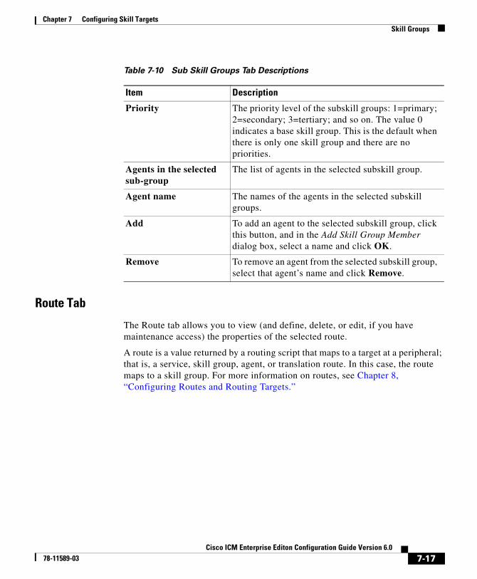
Chapter 7 Configuring Skill TargetsSkill Groups
Route Tab
The Route tab allows you to view (and define, delete, or edit, if you have maintenance access) the properties of the selected route.
A route is a value returned by a routing script that maps to a target at a peripheral; that is, a service, skill group, agent, or translation route. In this case, the route maps to a skill group. For more information on routes, see Chapter 8, “Configuring Routes and Routing Targets.”
Priority The priority level of the subskill groups: 1=primary; 2=secondary; 3=tertiary; and so on. The value 0 indicates a base skill group. This is the default when there is only one skill group and there are no priorities.
Agents in the selected sub-group
The list of agents in the selected subskill group.
Agent name The names of the agents in the selected subskill groups.
Add To add an agent to the selected subskill group, click this button, and in the Add Skill Group Member dialog box, select a name and click OK.
Remove To remove an agent from the selected subskill group, select that agent’s name and click Remove.
Table 7-10 Sub Skill Groups Tab Descriptions
Item Description
7-17Cisco ICM Enterprise Editon Configuration Guide Version 6.0
78-11589-03

Chapter 7 Configuring Skill TargetsSkill Groups
Table 7-11 Route Tab Descriptions
Field Description
Skill group priority Set to 0 if the route is assigned to the base skill group. If the route is assigned to a sub skill group (as listed on the Sub skill groups tab), select the setting (1, 2, 3, etc.) that matches the desired sub skill group from the sub skill groups list. The number of priority levels available depends upon the subgroup mask setting (1-64) on the Subgroup Mask tab which in turn depends upon the peripheral chosen.
Name (required) The enterprise name of the route.
You might derive the enterprise name for the route from the skill group and service associated with it. For example, you might have a route associated with the Dallas.TeleSales service and the Dallas.Sales skill group. You might name the route Dallas.TS_Sales.
7-18Cisco ICM Enterprise Editon Configuration Guide Version 6.0
78-11589-03
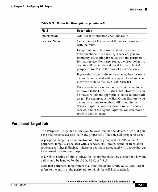
Chapter 7 Configuring Skill TargetsSkill Groups
Peripheral Target Tab
The Peripheral Target tab allows you to view (and define, delete, or edit, if you have maintenance access) the DNIS properties of the selected peripheral target.
A peripheral target is a combination of a trunk group and a DNIS value. A peripheral target is associated with a service, skill group, agent, or translation route at a peripheral. Each peripheral target is also associated with a route that can be returned by a routing script.
A DNIS is a string of digits indicating the number dialed by a caller and how the call should be handled by the ACD, PBX, or VRU.
Note that peripheral target refers to a trunk group and DNIS value. Skill target refers to the entity at the peripheral to which the call is dispatched.
Description Additional information about the route.
Service Name (selection list) The name of the service associated with the route.
Every route must be associated with a service for it to be functional. By choosing a service, you are implicitly associating the route with the peripheral for that service. For a new route, the drop-down list contains all the services defined for the selected peripheral (or PG, in the case of a service array).
If you select None as the service name, then the route cannot be associated with a peripheral and you can move the route to the UNASSIGNED list.
Once a route has a service selected, it can no longer be moved to the UNASSIGNED list. However, it can be moved within the appropriate tool to another skill target. For example, in the Skill Group Explorer, you can move a route to another skill group, in the Service Explorer, you can move a route to another service, and in the Agent Explorer, you can move a route to another agent.
Table 7-11 Route Tab Descriptions (continued)
Field Description
7-19Cisco ICM Enterprise Editon Configuration Guide Version 6.0
78-11589-03
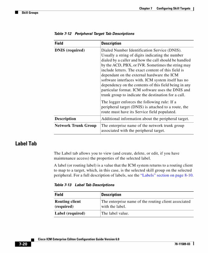
Chapter 7 Configuring Skill TargetsSkill Groups
Label Tab
The Label tab allows you to view (and create, delete, or edit, if you have maintenance access) the properties of the selected label.
A label (or routing label) is a value that the ICM system returns to a routing client to map to a target, which, in this case, is the selected skill group on the selected peripheral. For a full description of labels, see the “Labels” section on page 8-10.
Table 7-12 Peripheral Target Tab Descriptions
Field Description
DNIS (required) Dialed Number Identification Service (DNIS). Usually a string of digits indicating the number dialed by a caller and how the call should be handled by the ACD, PBX, or IVR. Sometimes the string may include letters. The exact content of this field is dependant on the external hardware the ICM software interfaces with. ICM system itself has no dependency on the contents of this field being in any particular format. ICM software uses the DNIS and trunk group to indicate the destination for a call.
The logger enforces the following rule: If a peripheral target (DNIS) is attached to a route, the route must have its Service field populated.
Description Additional information about the peripheral target.
Network Trunk Group The enterprise name of the network trunk group associated with the peripheral target.
Table 7-13 Label Tab Descriptions
Field Description
Routing client (required)
The enterprise name of the routing client associated with the label.
Label (required) The label value.
7-20Cisco ICM Enterprise Editon Configuration Guide Version 6.0
78-11589-03
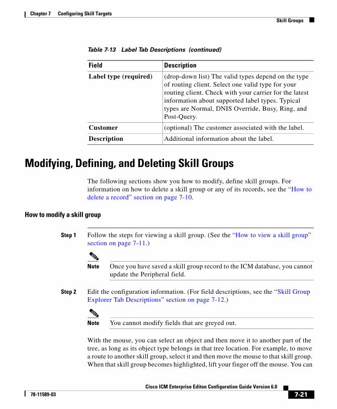
Chapter 7 Configuring Skill TargetsSkill Groups
Modifying, Defining, and Deleting Skill GroupsThe following sections show you how to modify, define skill groups. For information on how to delete a skill group or any of its records, see the “How to delete a record” section on page 7-10.
How to modify a skill group
Step 1 Follow the steps for viewing a skill group. (See the “How to view a skill group” section on page 7-11.)
Note Once you have saved a skill group record to the ICM database, you cannot update the Peripheral field.
Step 2 Edit the configuration information. (For field descriptions, see the “Skill Group Explorer Tab Descriptions” section on page 7-12.)
Note You cannot modify fields that are greyed out.
With the mouse, you can select an object and then move it to another part of the tree, as long as its object type belongs in that tree location. For example, to move a route to another skill group, select it and then move the mouse to that skill group. When that skill group becomes highlighted, lift your finger off the mouse. You can
Label type (required) (drop-down list) The valid types depend on the type of routing client. Select one valid type for your routing client. Check with your carrier for the latest information about supported label types. Typical types are Normal, DNIS Override, Busy, Ring, and Post-Query.
Customer (optional) The customer associated with the label.
Description Additional information about the label.
Table 7-13 Label Tab Descriptions (continued)
Field Description
7-21Cisco ICM Enterprise Editon Configuration Guide Version 6.0
78-11589-03
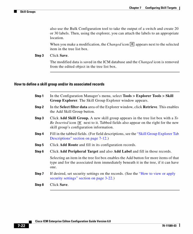
Chapter 7 Configuring Skill TargetsSkill Groups
also use the Bulk Configuration tool to take the output of a switch and create 20 or 30 labels. Then, using the explorer, you can attach the labels to an appropriate location.
When you make a modification, the Changed icon appears next to the selected item in the tree list box.
Step 3 Click Save.
The modified data is saved in the ICM database and the Changed icon is removed from the edited object in the tree list box.
How to define a skill group and/or its associated records
Step 1 In the Configuration Manager’s menu, select Tools > Explorer Tools > Skill Group Explorer. The Skill Group Explorer window appears.
Step 2 In the Select filter data area of the Explorer window, click Retrieve. This enables the Add Skill Group button.
Step 3 Click Add Skill Group. A new skill group appears in the tree list box with a To Be Inserted icon next to it. Tabbed fields also appear on the right for the new skill group’s configuration information.
Step 4 Fill in the tabbed fields. (For field descriptions, see the “Skill Group Explorer Tab Descriptions” section on page 7-12.)
Step 5 Click Add Route and fill in its configuration records.
Step 6 Click Add Peripheral Target and also Add Label and fill in those records.
Selecting an item in the tree list box enables the Add button for more items of that type and for the associated item immediately beneath it in the tree, if it can have one.
Step 7 If desired, set security settings on the records. (See the “How to view or apply security settings” section on page 3-22.)
Step 8 Click Save.
7-22Cisco ICM Enterprise Editon Configuration Guide Version 6.0
78-11589-03
Chapter 7 Configuring Skill TargetsPersons
Mapping Skill Groups to ServicesWhen you define services and skill groups, you can establish the mappings of skill groups to services. Each skill group can be mapped to zero, one, or more services; each service can be mapped to zero, one, or more skill groups.
You can define some service member skill groups as being primary for the service. ICM software uses the primary attribute in determining the destination for a call to the service. For example, the Longest Available Agent (LAA) for a service is really the LAA for the primary group(s) configured for that service.
How to map skill groups to services
Step 1 Within the Configuration Manager menu, select Tools > Explorer Tools > Service Explorer. The Service Explorer window appears.
Step 2 Select the filters you want and click Retrieve. The retrieved services appear in the list box.
Step 3 Select the service you want and click the Service Members tab.
Step 4 This step depends on whether you want to add or to remove skill group(s):
• To remove a skill group(s), select the skill group’s name(s) and click Remove.
• To add a skill group(s), click Add, and in the Add Service Member dialog box, select the skill group(s) and click OK.
The available skill groups are all those defined for the selected peripheral.
Step 5 In the Service Members tab, select the Primary check box for any skill groups that you want to be primary.
Step 6 When finished, in the Skill Group Explorer window, click Save.
PersonsYou must associate every agent with a person record. The person stores the login name, first name, last name, and password. On ICM you can have multiple agents per person. An agent is an “extension” of a person on a given peripheral.
7-23Cisco ICM Enterprise Editon Configuration Guide Version 6.0
78-11589-03
Chapter 7 Configuring Skill TargetsPersons
The Persons List tool allows you to list the persons currently defined in the ICM database, to define new ones, and to view, edit, or delete the records of existing ones.
Note You can create Persons and or Agents in ICM software, the Cisco Collaboration application, or the Cisco E-Mail Manager application. Creating them in one of the preceding makes them available to all. However if agents exist in your enterprise in ICM software and you want them to be able to work on an ICM application, you must also enable those existing agents in that application.
Available person records are records that have not been mapped to any agent records (including logically deleted ones) at the peripheral selected in the Agent Explorer. To free a person associated with a logically deleted agent, use the Configuration Manager’s Deleted Objects tool to permanently delete the logically deleted agent.
Select filter dataUse the Select filter data box to select and retrieve data from the database. Until you retrieve database data, no data is displayed.
Optional filter
None means no optional filtering. All data is displayed for the selected records.
The optional fields to filter on differ by record type according to both the fields in a record and the fields considered useful as filters.
7-24Cisco ICM Enterprise Editon Configuration Guide Version 6.0
78-11589-03

Chapter 7 Configuring Skill TargetsPersons
Condition filter
Value
The entry in this field is based on the selections made in the Optional Filter and Condition fields. If None is selected in the Optional Filter field, this field is ignored.
Save
Checked, indicates the current settings are saved so that when you next open the list tool for this type of record, the current settings will be selected. However, no data is displayed until you click the Retrieve button.
Retrieve
This button displays the data selected in the Select filter data box.
Table 7-14 Option Filters
If the selected Optional Filter is Then
None The Condition filter is ignored.
A text filter (for example, Description) Select one of the text conditions (Contains, Ends With, Starts With, Is Blank) and enter an appropriate entry in the Value field.
A numeric filter (for example, Trunk Number)
Select one of the numeric conditions (Equal, Greater Than, Less Than, Not Equal) and enter an appropriate entry in the Value field.
The available numeric conditions can change depending on the record data. For example Equal or Not Equal might be the only choices.
7-25Cisco ICM Enterprise Editon Configuration Guide Version 6.0
78-11589-03
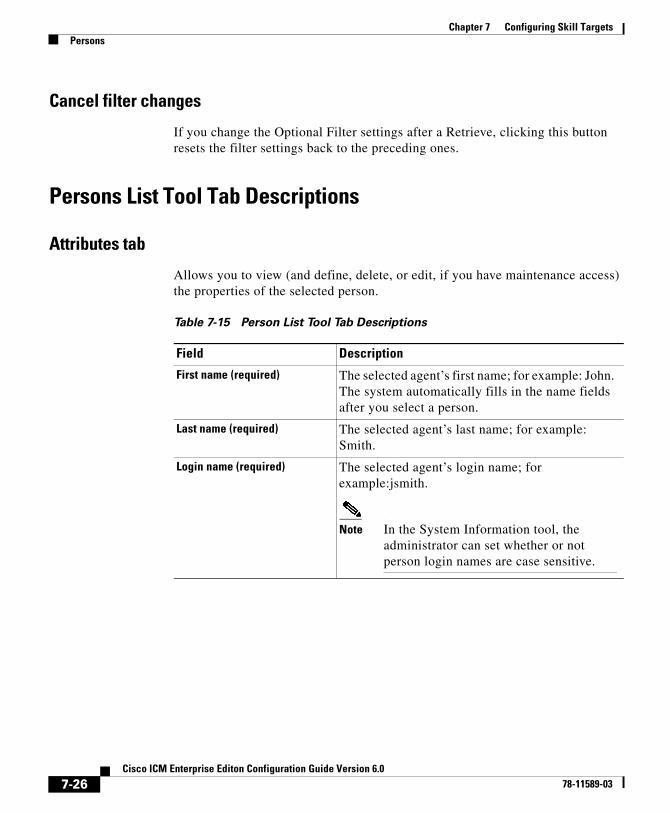
Chapter 7 Configuring Skill TargetsPersons
Cancel filter changes
If you change the Optional Filter settings after a Retrieve, clicking this button resets the filter settings back to the preceding ones.
Persons List Tool Tab Descriptions
Attributes tab
Allows you to view (and define, delete, or edit, if you have maintenance access) the properties of the selected person.
Table 7-15 Person List Tool Tab Descriptions
Field Description
First name (required) The selected agent’s first name; for example: John. The system automatically fills in the name fields after you select a person.
Last name (required) The selected agent’s last name; for example: Smith.
Login name (required) The selected agent’s login name; for example:jsmith.
Note In the System Information tool, the administrator can set whether or not person login names are case sensitive.
7-26Cisco ICM Enterprise Editon Configuration Guide Version 6.0
78-11589-03

Chapter 7 Configuring Skill TargetsPersons
Password (optional) An MD5 encrypted password, used for authentication by ICM and by applications integrated with ICM. The password is restricted to the 7-bit printable ASCII characters (any of the 94 characters with the numeric values from 32 to 126). Control characters (for example, 'tab') and international characters are not allowed. This means passwords cannot be entered in a non-Western alphabet, such as Kanji.
Note In the System Information tool, the administrator can set the number of required characters for person passwords. A person password is case sensitive.
Change Password Click to change your password.
Note Enables the Password and Confirm Password fields.
Confirm Password Used when changing your password.
Table 7-15 Person List Tool Tab Descriptions (continued)
Field Description
7-27Cisco ICM Enterprise Editon Configuration Guide Version 6.0
78-11589-03
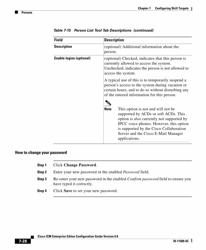
Chapter 7 Configuring Skill TargetsPersons
How to change your password
Step 1 Click Change Password.
Step 2 Enter your new password in the enabled Password field.
Step 3 Re-enter your new password in the enabled Confirm password field to ensure you have typed it correctly.
Step 4 Click Save to set your new password.
Description (optional) Additional information about the person.
Enable logins (optional) (optional) Checked, indicates that this person is currently allowed to access the system. Unchecked, indicates the person is not allowed to access the system.
A typical use of this is to temporarily suspend a person’s access to the system during vacation or certain hours, and to do so without disturbing any of the entered information for this person.
Note This option is not and will not be supported by ACDs or soft ACDs. This option is also currently not supported by IPCC voice phones. However, this option is supported by the Cisco Collaboration Server and the Cisco E-Mail Manager applications.
Table 7-15 Person List Tool Tab Descriptions (continued)
Field Description
7-28Cisco ICM Enterprise Editon Configuration Guide Version 6.0
78-11589-03
Chapter 7 Configuring Skill TargetsAgents
AgentsAn agent is a person who handles calls from a peripheral or supervises those who do. You need to set up each agent associated with each peripheral.
Use the Configuration Manager’s Agent Explorer to configure agents.
Note If partitioning is enabled, you need supervisor privileges to add or remove an agent from a skill group and you need administrator privileges to define an agent record and to edit it in other ways.
ICM software also provides a utility that allows you to insert and update agent records based on data in a text file. For more information, see the “Importing Agent Configuration Data from the Peripheral” section on page 7-36.
How to view or modify an agent(s) record
Step 1 In the Configuration Manager menu, select Tools > Explorer Tools > Agent Explorer. The Agent Explorer window appears.
Step 2 In the Select filter data box, select the peripheral with which the agent is associated. Enter any other filters you want and click Retrieve.
The retrieved enterprise names for the agents are displayed in the list box.
Step 3 Select the agent name whose properties you want to view and use the tabs on the right side of the window to view the properties.
Step 4 Edit the properties appropriate. See the online help if you have questions.
Step 5 When finished, in the Agent Explorer window, click Save.
How to create an agent
Step 1 In the Configuration Manager menu, select Tools > Explorer Tools > Agent Explorer. The Agent Explorer window appears.
Step 2 In the Select filter data box, select the peripheral with which the agent is to associated and click Retrieve. This enables the Add Agent button.
7-29Cisco ICM Enterprise Editon Configuration Guide Version 6.0
78-11589-03
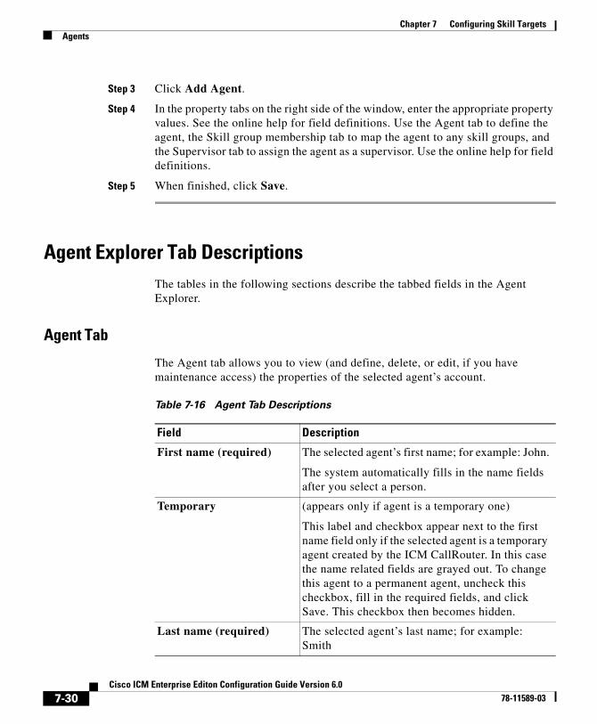
Chapter 7 Configuring Skill TargetsAgents
Step 3 Click Add Agent.
Step 4 In the property tabs on the right side of the window, enter the appropriate property values. See the online help for field definitions. Use the Agent tab to define the agent, the Skill group membership tab to map the agent to any skill groups, and the Supervisor tab to assign the agent as a supervisor. Use the online help for field definitions.
Step 5 When finished, click Save.
Agent Explorer Tab DescriptionsThe tables in the following sections describe the tabbed fields in the Agent Explorer.
Agent Tab
The Agent tab allows you to view (and define, delete, or edit, if you have maintenance access) the properties of the selected agent’s account.
Table 7-16 Agent Tab Descriptions
Field Description
First name (required) The selected agent’s first name; for example: John.
The system automatically fills in the name fields after you select a person.
Temporary (appears only if agent is a temporary one)
This label and checkbox appear next to the first name field only if the selected agent is a temporary agent created by the ICM CallRouter. In this case the name related fields are grayed out. To change this agent to a permanent agent, uncheck this checkbox, fill in the required fields, and click Save. This checkbox then becomes hidden.
Last name (required) The selected agent’s last name; for example: Smith
7-30Cisco ICM Enterprise Editon Configuration Guide Version 6.0
78-11589-03

Chapter 7 Configuring Skill TargetsAgents
Login name (required) The selected agent’s login name; for example:jsmith. The login name must be unique within the enterprise. Use the System Info tool to determine if the login name is to be case-sensitive or not.
Select Person (optional) Click this button to select a person to associate with the agent record. You can select a person for a new agent, an existing agent, or a temporary agent.
To create an agent record, you must associate a person with the agent. For an existing agent record, you can select a different person (from the current one selected) to be associated with that agent record.
If you select a person for a temporary agent, you make that agent a permanent one. You cannot demote an agent to be a temporary one.
An ICM agent’s personal information is stored in the database’s Person table.
Enterprise Name (required)
An enterprise name for the agent that is unique within the enterprise.
When defining a new agent, if you click this field after entering the agent’s first and last name, the system by default enters as the enterprise name the peripheral with the agent’s last and first name appended to it. For example: Boston_PG_1.Smith_John where Boston_PG_1 is the peripheral and Smith_John is the agent’s last and first name.
Table 7-16 Agent Tab Descriptions (continued)
Field Description
7-31Cisco ICM Enterprise Editon Configuration Guide Version 6.0
78-11589-03
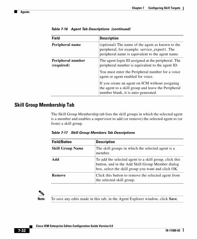
Chapter 7 Configuring Skill TargetsAgents
Skill Group Membership Tab
The Skill Group Membership tab lists the skill groups in which the selected agent is a member and enables a supervisor to add (or remove) the selected agent to (or from) a skill group.
Note To save any edits made in this tab, in the Agent Explorer window, click Save.
Peripheral name (optional) The name of the agent as known to the peripheral; for example: service_expert1. The peripheral name is equivalent to the agent name.
Peripheral number (required)
The agent login ID assigned at the peripheral. The peripheral number is equivalent to the agent ID.
You must enter the Peripheral number for a voice agent or agent enabled for voice.
If you create an agent on ICM without assigning the agent to a skill group and leave the Peripheral number blank, it is auto-generated.
Table 7-16 Agent Tab Descriptions (continued)
Field Description
Table 7-17 Skill Group Members Tab Descriptions
Field/Button Description
Skill Group Name The skill groups in which the selected agent is a member.
Add To add the selected agent to a skill group, click this button, and in the Add Skill Group Member dialog box, select the skill group you want and click OK.
Remove Click this button to remove the selected agent from the selected skill group.
7-32Cisco ICM Enterprise Editon Configuration Guide Version 6.0
78-11589-03
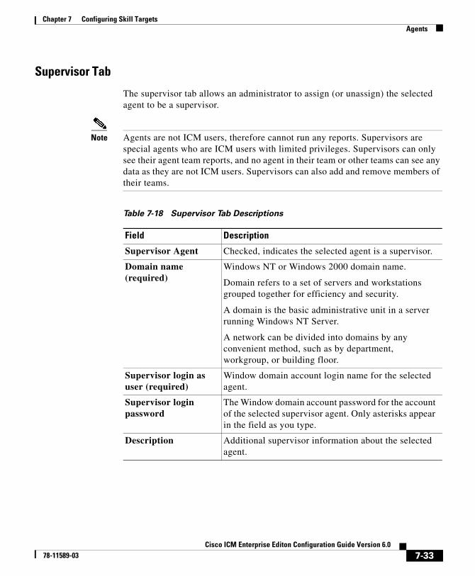
Chapter 7 Configuring Skill TargetsAgents
Supervisor Tab
The supervisor tab allows an administrator to assign (or unassign) the selected agent to be a supervisor.
Note Agents are not ICM users, therefore cannot run any reports. Supervisors are special agents who are ICM users with limited privileges. Supervisors can only see their agent team reports, and no agent in their team or other teams can see any data as they are not ICM users. Supervisors can also add and remove members of their teams.
Table 7-18 Supervisor Tab Descriptions
Field Description
Supervisor Agent Checked, indicates the selected agent is a supervisor.
Domain name (required)
Windows NT or Windows 2000 domain name.
Domain refers to a set of servers and workstations grouped together for efficiency and security.
A domain is the basic administrative unit in a server running Windows NT Server.
A network can be divided into domains by any convenient method, such as by department, workgroup, or building floor.
Supervisor login as user (required)
Window domain account login name for the selected agent.
Supervisor login password
The Window domain account password for the account of the selected supervisor agent. Only asterisks appear in the field as you type.
Description Additional supervisor information about the selected agent.
7-33Cisco ICM Enterprise Editon Configuration Guide Version 6.0
78-11589-03
Chapter 7 Configuring Skill TargetsAgents
Mapping Agents to Skill GroupsAfter you have set up skill groups and agents, enter the assignments of agents to skill groups as configured for the peripheral. Each agent can belong to zero, one, or more skill groups.
You can use the Configuration Manager’s Skill Group Explorer to map agents to skill groups.
How to assign agents to a skill group
Step 1 Within the Configuration Manager menu, select Tools > Explorer Tools > Agent Explorer. The Agent Explorer window appears.
Step 2 Select the filters you want and click Retrieve. The retrieved agents appear in the list box.
Step 3 Select the agent you want assign to a skill group and click the Skill Group Membership tab.
Step 4 This step depends on whether you want to add or to remove agent. On the Skill group membership tab:
• To remove the selected agent from a skill group, select the appropriate skill group(s) and click Remove.
• To add the selected agent to a skill group, click Add, and in the Add Skill Group Member dialog, select the appropriate skill group(s) and click OK.
The available skill groups are all those defined for the selected peripheral.
Step 5 When finished, in the Agent Explorer window, click Save.
Agent Reporting and DistributionYou can optionally license Agent Reporting for one or more PGs in your system. This allows you to view reports about individual agents as well as skill groups and services.
7-34Cisco ICM Enterprise Editon Configuration Guide Version 6.0
78-11589-03
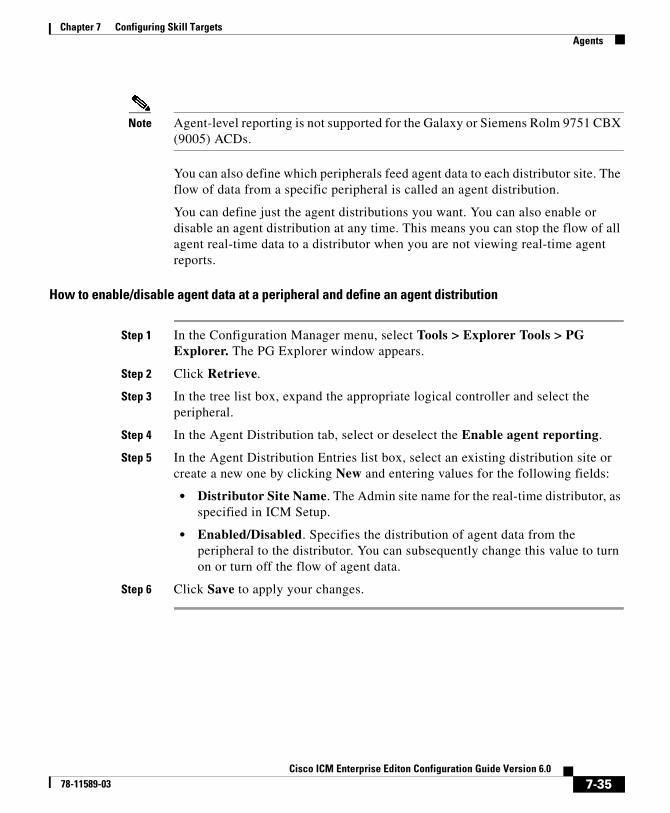
Chapter 7 Configuring Skill TargetsAgents
Note Agent-level reporting is not supported for the Galaxy or Siemens Rolm 9751 CBX (9005) ACDs.
You can also define which peripherals feed agent data to each distributor site. The flow of data from a specific peripheral is called an agent distribution.
You can define just the agent distributions you want. You can also enable or disable an agent distribution at any time. This means you can stop the flow of all agent real-time data to a distributor when you are not viewing real-time agent reports.
How to enable/disable agent data at a peripheral and define an agent distribution
Step 1 In the Configuration Manager menu, select Tools > Explorer Tools > PG Explorer. The PG Explorer window appears.
Step 2 Click Retrieve.
Step 3 In the tree list box, expand the appropriate logical controller and select the peripheral.
Step 4 In the Agent Distribution tab, select or deselect the Enable agent reporting.
Step 5 In the Agent Distribution Entries list box, select an existing distribution site or create a new one by clicking New and entering values for the following fields:
• Distributor Site Name. The Admin site name for the real-time distributor, as specified in ICM Setup.
• Enabled/Disabled. Specifies the distribution of agent data from the peripheral to the distributor. You can subsequently change this value to turn on or turn off the flow of agent data.
Step 6 Click Save to apply your changes.
7-35Cisco ICM Enterprise Editon Configuration Guide Version 6.0
78-11589-03
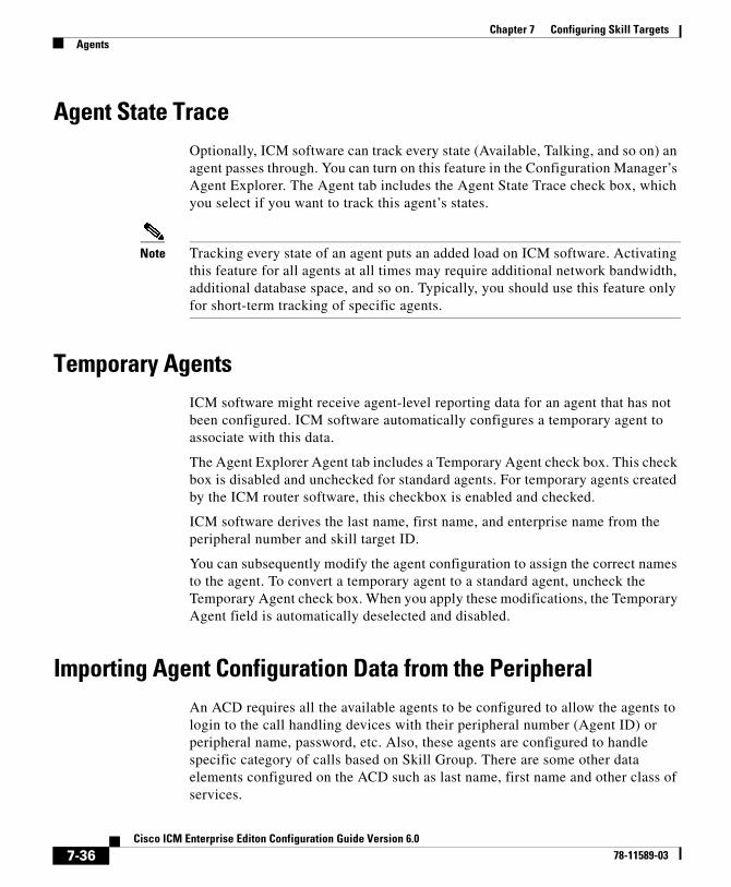
Chapter 7 Configuring Skill TargetsAgents
Agent State TraceOptionally, ICM software can track every state (Available, Talking, and so on) an agent passes through. You can turn on this feature in the Configuration Manager’s Agent Explorer. The Agent tab includes the Agent State Trace check box, which you select if you want to track this agent’s states.
Note Tracking every state of an agent puts an added load on ICM software. Activating this feature for all agents at all times may require additional network bandwidth, additional database space, and so on. Typically, you should use this feature only for short-term tracking of specific agents.
Temporary AgentsICM software might receive agent-level reporting data for an agent that has not been configured. ICM software automatically configures a temporary agent to associate with this data.
The Agent Explorer Agent tab includes a Temporary Agent check box. This check box is disabled and unchecked for standard agents. For temporary agents created by the ICM router software, this checkbox is enabled and checked.
ICM software derives the last name, first name, and enterprise name from the peripheral number and skill target ID.
You can subsequently modify the agent configuration to assign the correct names to the agent. To convert a temporary agent to a standard agent, uncheck the Temporary Agent check box. When you apply these modifications, the Temporary Agent field is automatically deselected and disabled.
Importing Agent Configuration Data from the PeripheralAn ACD requires all the available agents to be configured to allow the agents to login to the call handling devices with their peripheral number (Agent ID) or peripheral name, password, etc. Also, these agents are configured to handle specific category of calls based on Skill Group. There are some other data elements configured on the ACD such as last name, first name and other class of services.
7-36Cisco ICM Enterprise Editon Configuration Guide Version 6.0
78-11589-03
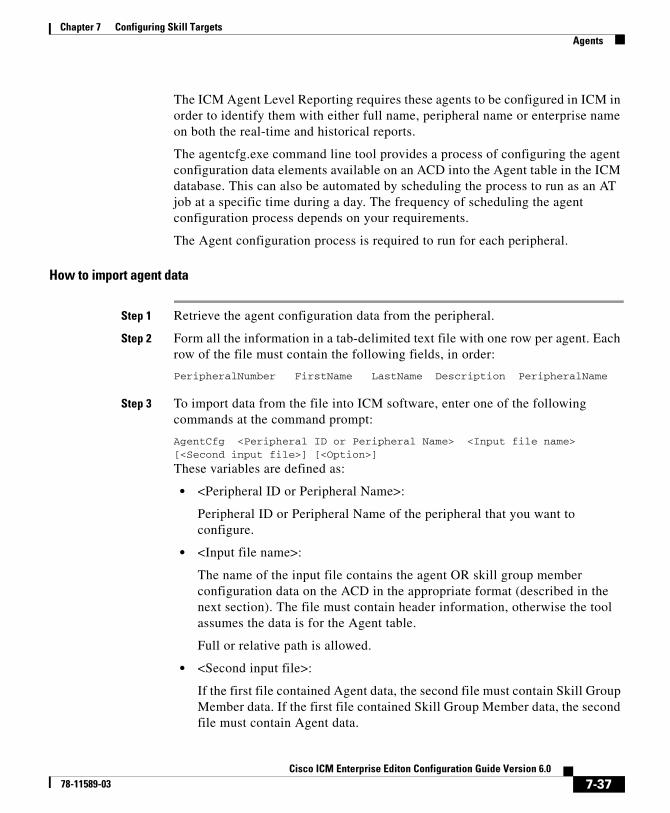
Chapter 7 Configuring Skill TargetsAgents
The ICM Agent Level Reporting requires these agents to be configured in ICM in order to identify them with either full name, peripheral name or enterprise name on both the real-time and historical reports.
The agentcfg.exe command line tool provides a process of configuring the agent configuration data elements available on an ACD into the Agent table in the ICM database. This can also be automated by scheduling the process to run as an AT job at a specific time during a day. The frequency of scheduling the agent configuration process depends on your requirements.
The Agent configuration process is required to run for each peripheral.
How to import agent data
Step 1 Retrieve the agent configuration data from the peripheral.
Step 2 Form all the information in a tab-delimited text file with one row per agent. Each row of the file must contain the following fields, in order:
PeripheralNumber FirstName LastName Description PeripheralName
Step 3 To import data from the file into ICM software, enter one of the following commands at the command prompt:
AgentCfg <Peripheral ID or Peripheral Name> <Input file name> [<Second input file>] [<Option>]
These variables are defined as:
• <Peripheral ID or Peripheral Name>:
Peripheral ID or Peripheral Name of the peripheral that you want to configure.
• <Input file name>:
The name of the input file contains the agent OR skill group member configuration data on the ACD in the appropriate format (described in the next section). The file must contain header information, otherwise the tool assumes the data is for the Agent table.
Full or relative path is allowed.
• <Second input file>:
If the first file contained Agent data, the second file must contain Skill Group Member data. If the first file contained Skill Group Member data, the second file must contain Agent data.
7-37Cisco ICM Enterprise Editon Configuration Guide Version 6.0
78-11589-03
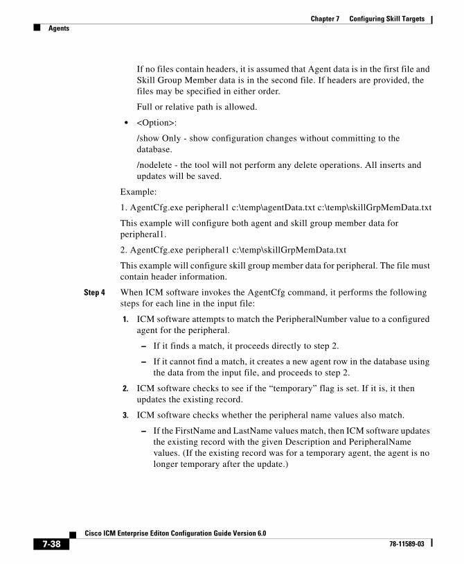
Chapter 7 Configuring Skill TargetsAgents
If no files contain headers, it is assumed that Agent data is in the first file and Skill Group Member data is in the second file. If headers are provided, the files may be specified in either order.
Full or relative path is allowed.
• <Option>:
/show Only - show configuration changes without committing to the database.
/nodelete - the tool will not perform any delete operations. All inserts and updates will be saved.
Example:
1. AgentCfg.exe peripheral1 c:\temp\agentData.txt c:\temp\skillGrpMemData.txt
This example will configure both agent and skill group member data for peripheral1.
2. AgentCfg.exe peripheral1 c:\temp\skillGrpMemData.txt
This example will configure skill group member data for peripheral. The file must contain header information.
Step 4 When ICM software invokes the AgentCfg command, it performs the following steps for each line in the input file:
1. ICM software attempts to match the PeripheralNumber value to a configured agent for the peripheral.
– If it finds a match, it proceeds directly to step 2.
– If it cannot find a match, it creates a new agent row in the database using the data from the input file, and proceeds to step 2.
2. ICM software checks to see if the “temporary” flag is set. If it is, it then updates the existing record.
3. ICM software checks whether the peripheral name values also match.
– If the FirstName and LastName values match, then ICM software updates the existing record with the given Description and PeripheralName values. (If the existing record was for a temporary agent, the agent is no longer temporary after the update.)
7-38Cisco ICM Enterprise Editon Configuration Guide Version 6.0
78-11589-03

Chapter 7 Configuring Skill TargetsAgents
– If the values do not match, then ICM software marks the existing record as deleted and inserts a new row with the data from the input file. If an agent is configured for the peripheral in the database, but is not listed in the input file, then ICM software marks the agent as deleted in the database.
4. The ICM software does a loop through the Skill Group Member input file container and compares the records in file and those in database:
– if the record is found in file but does not exist in the database, the record is inserted.
– if the record is found in the database but does not exist in the file, the record is deleted.
Input File Formats
When using the AgentCfg.exe tool to import data, the input files must be formatted as described below.
Note that the _ _TABLE and _ _COLUMNS and the line below each is considered the header. The header is not always required. The beginning of this section indicates when the headers are needed.
Agent configuration data file
The input file should contain the list of all the agents configured on the ACD for that peripheral in the following format:
_ _TABLE
Agent
Indicates the name of the table to which the data will be configured. The table name is always Agent and this line should not be changed.
_ _COLUMNS
Indicates the tab delimited column names corresponds to the data values. This line also should not be changed. The columns need to be in the order as shown below:
PeripheralNumber<tab>FirstName<tab>LastName<tab>Description<tab>PeripheralName1045<tab>F1045<tab>L1045<tab>Auto Configured by Router<tab>F1045.L10451046<tab>F1046<tab>L1046<tab>Auto Configured by Router<tab>F1046.L1046
7-39Cisco ICM Enterprise Editon Configuration Guide Version 6.0
78-11589-03

Chapter 7 Configuring Skill TargetsAgents
1047<tab>F1047<tab>L1047<tab>Auto Configured by Router<tab>F1047.L1047<eof>
The following indicates the tab delimited data values correspond to the column names:
1045<tab>F1045<tab>L1045<tab>Auto Configured by Router<tab>F1045.L1045
Skill Group Member configuration data file
Note that the __TABLE and __COLUMNS and the line below each is considered the header. The header is not always required.
The input file should contain the list of all the skill group member data as a relation between skill group and agents, which configured on the ACD for that peripheral in the following format:
_ _TABLE
Skill_Group_Member
Indicates the name of the table to which the data will be configured. The table name is always Skill_Group_Member and this line should not be changed.
_ _COLUMNS
Indicates the tab delimited column names corresponds to the data values. This line also should not be changed. The columns need to be in the order that has been shown below.
SkillGroupEnterpriseName <tab> AgentPeripheralNumberSkillGroupExterprise1<tab>1045SkillGroupExterprise2<tab>1046SkillGroupExterprise1<tab>1046
SkillGroupEnterpriseName is the ExterpriseName of the skill group, which the agent belongs to.
AgentPeripheralNumber is the agent’s login ID assigned at the switch, which is the same as the above Agent Peripheral Number.
The following indicates the tab delimited data values correspond to the column names:
SkillGroupExterprise1<tab>1045
7-40Cisco ICM Enterprise Editon Configuration Guide Version 6.0
78-11589-03

Chapter 7 Configuring Skill TargetsEnterprise Data
Enterprise DataWithin a script, you often want to examine a set of possible targets on different peripherals before deciding where to send the call. For example, if you are routing a sales call, you might want to check the Sales skill groups at each call center to find which has the longest available agent or shortest expected delay.
An enterprise service is a set of services that can be referenced in a script. The individual services can be associated with different peripherals. Similarly, an enterprise skill group is a set of skill groups that can be referenced in a script. The individual skill groups can be associated with different peripherals.
In addition to using them within a script, you can track enterprise services and enterprise skill groups through monitoring screens and reports. This allows you to easily follow the performance, for example, of all Support services within the system.
For information on monitoring screens and reports, see the Cisco ICM Software Supervisor Guide.
If your system has partitioning enabled, each enterprise service and enterprise skill group is associated with a specific business entity. If partitioning is not enabled, you can ignore the Business Entity field.
Enterprise ServicesWithin a routing script, you can use an enterprise service as a shorthand for a set of services. You might want to scan several services to find, for example, the service with the shortest expected delay. Within the script, you can specify individual services to scan or, if you have an enterprise service defined, you can simply specify the enterprise service.
How to create an enterprise service and assign specific services
Step 1 In the Configuration Manager menu, select Tools > List Tools > Enterprise Service List. The Enterprise Service List window appears.
Step 2 In the Select filter data box, select the filters you want and click Retrieve. This enables the Add button and lists the currently defined enterprise services for the selected business entity(s).
7-41Cisco ICM Enterprise Editon Configuration Guide Version 6.0
78-11589-03
Chapter 7 Configuring Skill TargetsEnterprise Data
Step 3 Click Add.
Step 4 In the Attributes tab, enter values for the following fields:
• Name. A name for the enterprise service. This name must be unique among all enterprise services in the system.
• Business Entity. If partitioning is enabled, the business entity to which the enterprise service belongs.
• Description. Any other information you want about the enterprise service.
Step 5 Click Save to save the changes.
Step 6 Click the Members tab.
Step 7 In the Members tab, click Add.
Step 8 In the Add Enterprise Service Member dialog box, select the services you want to add and click OK. The dialog box closes and the selected services are listed as members in the Members tab.
Step 9 When done, click Save to save the changes.
Enterprise Skill GroupsJust as you can use an enterprise service as a shorthand for a collection of services, so you can use an enterprise skill group as a shorthand for a collection of skill groups. The skill groups can be defined on different peripherals.
How to create an enterprise skill group
Step 1 In the Configuration Manager menu, select Tools > List Tools > Enterprise Skill Groups List. The Enterprise Skill Group List window appears.
Step 2 In the Select filter data box, select the filters you want and click Retrieve. This enables the Add button and lists the currently defined skill groups for the selected business entity(s).
Step 3 Click Add, and in the Attributes tab, enter values for the following fields:
• Name. A name for the enterprise skill group. This name must be unique among all enterprise skill groups in the system.
7-42Cisco ICM Enterprise Editon Configuration Guide Version 6.0
78-11589-03

Chapter 7 Configuring Skill TargetsEnterprise Data
• Business Entity. If partitioning is enabled, the business entity to which the enterprise skill belongs.
• Description. Any other information about the enterprise skill group.
Step 4 Click Save to save the changes.
Step 5 Click the Members tab.
Step 6 In the Members tab, click Add.
Step 7 In the Add Enterprise Skill Group Member dialog box, select the skill groups you want to add and click OK. The dialog box closes and the selected skill groups are listed as members in the Members tab.
Note The Skill Group list includes base skill groups as well as primary and secondary groups for those switches that support them. Typically, you should add either the base group or the associated primary and secondary groups, but not all three, to the enterprise skill group.
Step 8 Click Save to save the changes to the database.
7-43Cisco ICM Enterprise Editon Configuration Guide Version 6.0
78-11589-03

Chapter 7 Configuring Skill TargetsEnterprise Data
7-44Cisco ICM Enterprise Editon Configuration Guide Version 6.0
78-11589-03
Cisco ICM Enterprise78-11589-03
C H A P T E R 8
Configuring Routes and Routing TargetsThis chapter describes how to configure the information that routing clients use to interpret the response from ICM software and route the call to its destination. It includes:
• An overview of the routes and targets subsystem
• Information on how to configure routes, network targets, and labels
• A discussion of mapping labels to dialed numbers
• Information about service arrays
• Instructions for using the Application Wizard
• A discussion of default route and default label
• Information about scheduled targets and translation routes
The Routes and Targets SubsystemFor every routing request it processes, ICM software determines an announcement to be played to the caller, a route for the call, or a special action such as ring-no-answer or signal busy.
8-1 Editon Configuration Guide Version 6.0
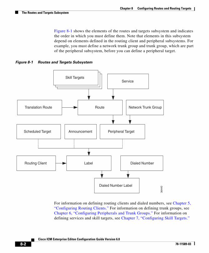
Chapter 8 Configuring Routes and Routing TargetsThe Routes and Targets Subsystem
Figure 8-1 shows the elements of the routes and targets subsystem and indicates the order in which you must define them. Note that elements in this subsystem depend on elements defined in the routing client and peripheral subsystems. For example, you must define a network trunk group and trunk group, which are part of the peripheral subsystem, before you can define a peripheral target.
Figure 8-1 Routes and Targets Subsystem
For information on defining routing clients and dialed numbers, see Chapter 5, “Configuring Routing Clients.” For information on defining trunk groups, see Chapter 6, “Configuring Peripherals and Trunk Groups.” For information on defining services and skill targets, see Chapter 7, “Configuring Skill Targets.”
Skill Targets
Route
Announcement
Dialed Number
Service
Translation Route
Scheduled Target
LabelRouting Client
Peripheral Target
Network Trunk Group
Dialed Number Label
3644
0
8-2Cisco ICM Enterprise Editon Configuration Guide Version 6.0
78-11589-03
Chapter 8 Configuring Routes and Routing TargetsRoute Configuration
This chapter describes the relationship between the elements in the Routes and Targets subsystem and how to configure them.
Route ConfigurationA route consists of two components:
• The skill target (agent, skill group, service, translation route, or service array) at a peripheral which can handle a call.
• The service by which the peripheral classifies the call.
Note You must have defined the skill target and service before you can configure a route. Follow the steps in the Configuration Manager’s Step by Step Configuration menu when configuring your ICM system.
How to define and update a route
In the Configuration Manager, you can define and update many routes at a time using the Route Bulk tool. Or you can create and update a route using one of the following explorer tools:
• Agent Explorer
• Skill Group Explorer
• Service Explorer
• Service Array Explorer
• Translation Route Explorer
With the explorer tools, you can define and update a route at the same time you define and update its target. You can access all the tools for creating routes from the Configuration Manager’s ICM Configure > Targets > Route menu. See Figure 8-2.
8-3Cisco ICM Enterprise Editon Configuration Guide Version 6.0
78-11589-03
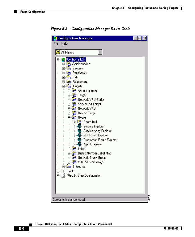
Chapter 8 Configuring Routes and Routing TargetsRoute Configuration
Figure 8-2 Configuration Manager Route Tools
8-4Cisco ICM Enterprise Editon Configuration Guide Version 6.0
78-11589-03
Chapter 8 Configuring Routes and Routing TargetsRoute Configuration
How to define or modify a route
Use the Configuration Manager’s Route Bulk tool to create multiple routes. To create individual routes, use the Configuration Manager’s explorer tool appropriate for the route target. Follow the instructions in the online help.
The following instructions apply in general to all the explorer tools dealing with routes.
Step 1 In the appropriate explorer window:
• To define a new route, select the target for which you are creating the route and click Add Route.
• To modify a route, select the route.
Step 2 In the Route tab, enter values for the following fields:
• Name. A unique name for the route. You might derive the name for the route from the skill target and service associated with it. For example, you might have a route associated with the Dallas.TeleSales service and the Dallas.Sales skill group. You might name the route Dallas.TS_Sales.
• Description. Text identifying the route.
• Service name. (selection list) Every route must be associated with a service. By choosing a service, you are implicitly associating the route with the peripheral for that service. For a new route, the drop-down list contains all the services defined for the selected peripheral (or PG, in the case of a service array).
To assign the route to another service, in the tree list, drag it to the desired peripheral. You can also move the route to the UNASSIGNED list.
Warning When you break the association between a route and a peripheral, ICM software removes the Route ID value from all peripheral targets that reference that route.
Step 3 Click Save. ICM software saves your changes in the database.
8-5Cisco ICM Enterprise Editon Configuration Guide Version 6.0
78-11589-03
Chapter 8 Configuring Routes and Routing TargetsNetwork Targets
How to set a default route for a peripheral
After you have defined routes, you can set a default route for each peripheral. ICM software uses the default route to classify calls for statistical purposes.
For each call that arrives at a peripheral, ICM software records monitoring information in the real-time and historical tables for the route associated with that call. If ICM software cannot determine a route for the call, it uses the default route defined for the peripheral.
By defining a default route for each peripheral, you ensure that ICM software captures route information for every call. You might want to create a special route for this purpose. You can then determine which calls are not being accounted for properly.
Step 1 In the Configuration Manager menu, select Tools > Explorer Tools > PG Explorer. The PG Explorer window appears.
Step 2 In the tree list window, select the peripheral you want to modify and click the Advanced tab.
Step 3 In the Default route field, select the enterprise name of a route from the selection list. The list includes all routes associated with skill targets at the chosen peripheral.
Step 4 After choosing the route, click Save to enter your edits into the database.
Network TargetsRouting clients do not send calls directly to services, skill groups, or agents. They send each call to an announcement or to a specific trunk group at a peripheral. If the call is sent to a trunk group, the routing client can also send a DNIS value for the call. The combination of trunk group and DNIS value is a peripheral target.
You must define the announcements and peripheral targets that the routing clients use. These are called network targets. Later, you can associate a routing label with each network target.
8-6Cisco ICM Enterprise Editon Configuration Guide Version 6.0
78-11589-03
Chapter 8 Configuring Routes and Routing TargetsNetwork Targets
How to define peripheral targets
A peripheral target is a combination of a network trunk group and a DNIS value. You must work with your interexchange carrier or other routing client to set up the trunk groups on which you expect to receive calls and the DNIS values that are sent with them.
Step 1 In the Configuration Manager menu, select Configure ICM > Targets > Target from the menu bar.
The resulting menu (see Figure 8-3) gives you the option of creating multiple peripheral targets, using the Peripheral Target Bulk configuration tool or creating a peripheral target for a service, a service array, a skill group, a translation route, or an agent. Select the appropriate tool for your needs.
Step 2 Use the online help if you have questions.
Step 3 When finished, click Save.
.
8-7Cisco ICM Enterprise Editon Configuration Guide Version 6.0
78-11589-03
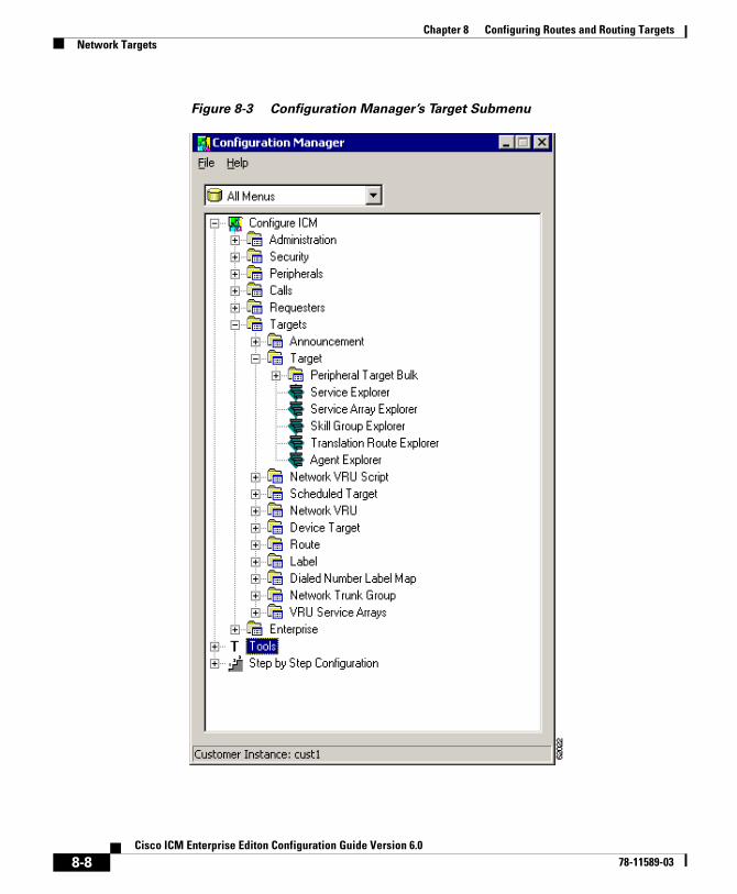
Chapter 8 Configuring Routes and Routing TargetsNetwork Targets
Figure 8-3 Configuration Manager’s Target Submenu
8-8Cisco ICM Enterprise Editon Configuration Guide Version 6.0
78-11589-03
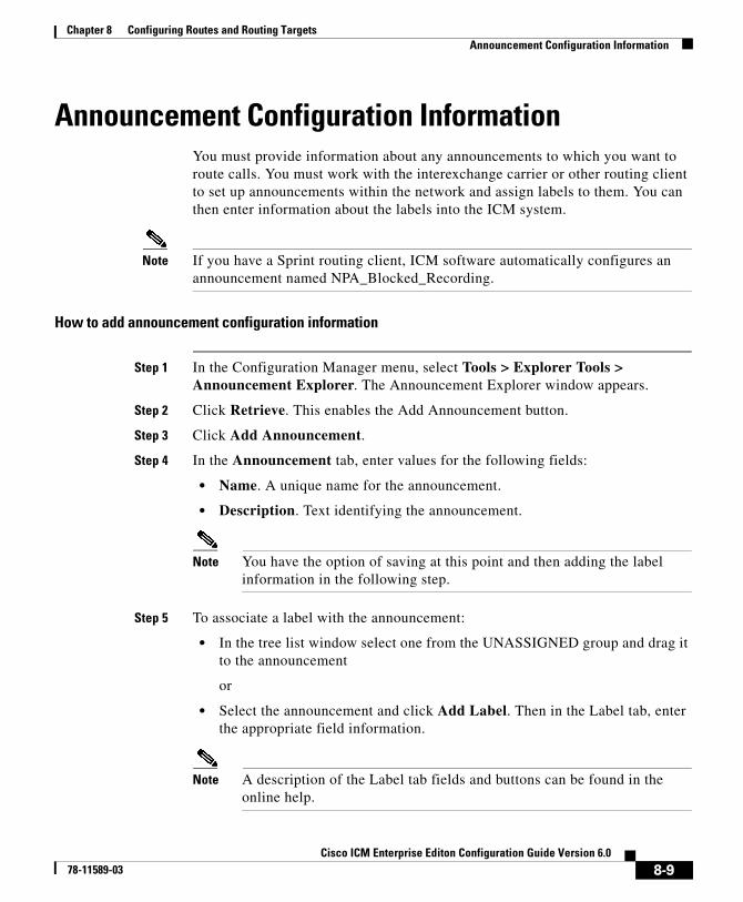
Chapter 8 Configuring Routes and Routing TargetsAnnouncement Configuration Information
Announcement Configuration InformationYou must provide information about any announcements to which you want to route calls. You must work with the interexchange carrier or other routing client to set up announcements within the network and assign labels to them. You can then enter information about the labels into the ICM system.
Note If you have a Sprint routing client, ICM software automatically configures an announcement named NPA_Blocked_Recording.
How to add announcement configuration information
Step 1 In the Configuration Manager menu, select Tools > Explorer Tools > Announcement Explorer. The Announcement Explorer window appears.
Step 2 Click Retrieve. This enables the Add Announcement button.
Step 3 Click Add Announcement.
Step 4 In the Announcement tab, enter values for the following fields:
• Name. A unique name for the announcement.
• Description. Text identifying the announcement.
Note You have the option of saving at this point and then adding the label information in the following step.
Step 5 To associate a label with the announcement:
• In the tree list window select one from the UNASSIGNED group and drag it to the announcement
or
• Select the announcement and click Add Label. Then in the Label tab, enter the appropriate field information.
Note A description of the Label tab fields and buttons can be found in the online help.
8-9Cisco ICM Enterprise Editon Configuration Guide Version 6.0
78-11589-03
Chapter 8 Configuring Routes and Routing TargetsLabels
Step 6 Click Save to save the announcement configuration settings. ICM software automatically generates a unique Network Target ID value.
LabelsAfter defining announcements and peripheral targets, you must define the labels that your routing clients use to reference network targets. The label is the value that ICM software returns to the routing client. The routing client then translates the label to an announcement or peripheral target (trunk group and DNIS) that the peripheral will convert to the skill target and service you specify.
Note For an AT&T ICP connection, ICM software treats a CRP code as a label.
Label TypesIn defining a label, you must specify a label type by selecting an option from the Type drop-down list in the Label Configuration selection box.
Note Each label you define is valid only for a specific routing client; not all label types are valid for all types of routing clients. Check with your carrier for the latest information about supported label types.
Table 8-1 lists the configured label types ICM software supports. In addition to these labels, a script can create a dynamic label, which is defined in realtime through a script expression and then passed to a routing client.
8-10Cisco ICM Enterprise Editon Configuration Guide Version 6.0
78-11589-03
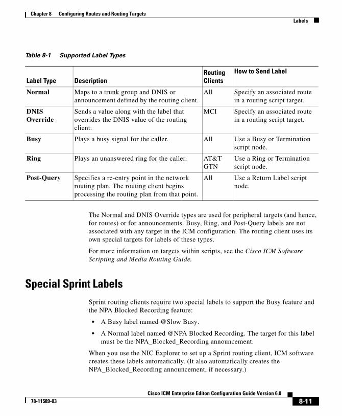
Chapter 8 Configuring Routes and Routing TargetsLabels
The Normal and DNIS Override types are used for peripheral targets (and hence, for routes) or for announcements. Busy, Ring, and Post-Query labels are not associated with any target in the ICM configuration. The routing client uses its own special targets for labels of these types.
For more information on targets within scripts, see the Cisco ICM Software Scripting and Media Routing Guide.
Special Sprint LabelsSprint routing clients require two special labels to support the Busy feature and the NPA Blocked Recording feature:
• A Busy label named @Slow Busy.
• A Normal label named @NPA Blocked Recording. The target for this label must be the NPA_Blocked_Recording announcement.
When you use the NIC Explorer to set up a Sprint routing client, ICM software creates these labels automatically. (It also automatically creates the NPA_Blocked_Recording announcement, if necessary.)
Table 8-1 Supported Label Types
Label Type DescriptionRouting Clients
How to Send Label
Normal Maps to a trunk group and DNIS or announcement defined by the routing client.
All Specify an associated route in a routing script target.
DNIS Override
Sends a value along with the label that overrides the DNIS value of the routing client.
MCI Specify an associated route in a routing script target.
Busy Plays a busy signal for the caller. All Use a Busy or Termination script node.
Ring Plays an unanswered ring for the caller. AT&T GTN
Use a Ring or Termination script node.
Post-Query Specifies a re-entry point in the network routing plan. The routing client begins processing the routing plan from that point.
All Use a Return Label script node.
8-11Cisco ICM Enterprise Editon Configuration Guide Version 6.0
78-11589-03
Chapter 8 Configuring Routes and Routing TargetsLabels
The label names @Slow Busy and @NPA Blocked Recording are reserved for this specific use. You must not create any other labels with these names.
Creating LabelsTo set up a label, you create configuration information and associate the label with a network target.
How to create a label
Step 1 In the Configuration Manager menu, select Configure ICM > Targets > Label.
Step 2 This displays the following menu options for configuring a label:
• Label Bulk
• Label List
• Service Explorer
• Service Array Explorer
• Skill Group Explorer
• Translation Route Explorer
• Agent Explorer
• Announcement Explorer
• Network VRU Explorer
Step 3 Select the tool you need:
• Use the Label Bulk tool to configure many labels at a time.
• Use the Label List tool to configure individual labels for any network targets.
• Use the preceding explorer tools to configure labels for a specific network target (services, service arrays, skill groups, translation routes, agents, announcements, network VRUs).
Step 4 Enter values for the following fields. Use the online help if you have questions:
• Routing Client. (required) The enterprise name of the routing client that can receive this label.
• Label. (required)
8-12Cisco ICM Enterprise Editon Configuration Guide Version 6.0
78-11589-03
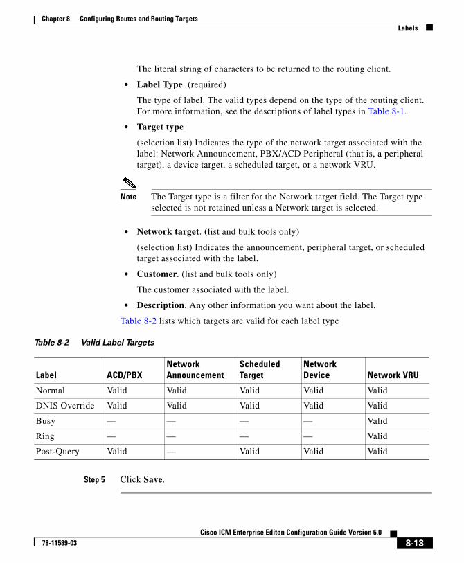
Chapter 8 Configuring Routes and Routing TargetsLabels
The literal string of characters to be returned to the routing client.
• Label Type. (required)
The type of label. The valid types depend on the type of the routing client. For more information, see the descriptions of label types in Table 8-1.
• Target type
(selection list) Indicates the type of the network target associated with the label: Network Announcement, PBX/ACD Peripheral (that is, a peripheral target), a device target, a scheduled target, or a network VRU.
Note The Target type is a filter for the Network target field. The Target type selected is not retained unless a Network target is selected.
• Network target. (list and bulk tools only)
(selection list) Indicates the announcement, peripheral target, or scheduled target associated with the label.
• Customer. (list and bulk tools only)
The customer associated with the label.
• Description. Any other information you want about the label.
Table 8-2 lists which targets are valid for each label type
Step 5 Click Save.
Table 8-2 Valid Label Targets
Label ACD/PBXNetwork Announcement
Scheduled Target
Network Device Network VRU
Normal Valid Valid Valid Valid Valid
DNIS Override Valid Valid Valid Valid Valid
Busy — — — — Valid
Ring — — — — Valid
Post-Query Valid — Valid Valid Valid
8-13Cisco ICM Enterprise Editon Configuration Guide Version 6.0
78-11589-03
Chapter 8 Configuring Routes and Routing TargetsLabels
Mapping LabelsFor some routing clients, all labels are valid for all dialed number/script selectors. For other routing clients, you must specify which labels are valid for each dialed number/script selector. You specify whether the mapping of labels to dialed number/script selectors is necessary when you configure the routing client. For more information on this, see Chapter 5, “Configuring Routing Clients.”
How to map specific labels to a dialed number/script selector
Step 1 In the Configuration Manager menu, select Tools > List Tools > Dialed Number/Script Selector List. The Dialed Number/Script Selector List window appears.
Step 2 Select the filters you want and click Retrieve. The enterprise names for the retrieved dialed number/script selectors are listed in the list box.
Step 3 Select the enterprise name for the dialed number/script selector you want.
Step 4 Click the Dialed Number Label tab.
The Name column displays a list of all labels currently associated with that dialed number/script selector.
Note For a call associated with this dialed number/script selector, ICM software can return only labels assigned to the dialed number/script selector.
Step 5 Click Add.
Step 6 In the Add Label dialog box, select a label name and click OK.
Note For labels to appear in this dialog selection box, they must have been previously defined for the selected dialed number/script selector’s routing client. Use the Label List tool to define labels.
Step 7 Click Save.
8-14Cisco ICM Enterprise Editon Configuration Guide Version 6.0
78-11589-03

Chapter 8 Configuring Routes and Routing TargetsService Arrays
How to set a default label for a dialed number/script selector
After you have defined labels, you can set a default label for each dialed number/script selector. If ICM software fails to find a label by running the routing scripts for the call type, it uses the default label for the dialed number/script selector.
You can use the Configuration Manager’s Dialed Number Bulk tool to configure many dialed number/script selectors at a time or the Dialed Number/Script Selector List tool to configure one at a time. The following instructions show how to use the Dialed Number/Script Selector List tool.
Step 1 In the Configuration Manager’s menu, select Tools > List Tools > Dialed Number/Script Selector List. The Dialed Number/Script Selector List window appears.
Step 2 Select the filters you want click Retrieve. The enterprise names for the dialed number/script selector(s) retrieved are listed in the list box.
Step 3 Select the dialed number/script selector you want and click the Attributes tab.
Step 4 In the Default label field, select the enterprise name of a label from the selection list. This list includes all labels associated with the same routing client as the dialed number/script selector.
Step 5 After choosing the label, click Save.
Note Within a routing script, you can explicitly invoke the default label for the current dialed number/script selector by using a Termination node.
Service ArraysService arrays are closely tied to network trunk groups. Typically, you use service arrays in cases where:
• You have similar peripheral services defined on multiple VRUs.
• VRUs all share the same network group.
8-15Cisco ICM Enterprise Editon Configuration Guide Version 6.0
78-11589-03
Chapter 8 Configuring Routes and Routing TargetsService Arrays
By grouping the services of multiple VRUs into a service array, you can send calls to a single target (a service array) and let the network deliver the call to any one of the peripheral services that make up the service array. For example, if several VRUs each support a Quotes service, you can define a Quotes service array for those services.
How to configure service arrays
Step 1 In the Configuration Manager menu, select Configure ICM > Targets > VRU Service Arrays > Service Array Explorer. The Service Array Explorer window appears.
Step 2 In the Select filter data box, select the appropriate filters and click Retrieve. This enables the Add Service array button and displays a list of all currently defined service arrays associated with the selected PG.
Step 3 You can define a new service array or modify an existing one:
• To set up a new service array, click Add Service array.
Note To create subsequent service arrays for the same PG, select the PG in the tree list window and then click Add Service array.
• To modify an existing service array, select it in the tree list window.
Step 4 In the Service Array tab for the selected service array, enter values for the following fields:
• Name. A unique name for the service array.
• Description. Additional information about the service array.
Step 5 Click the Members tab.
This tab lists the services that are current service array members of the selected PG.
• To add service members, click Add. Then in the Add Service Member window, select the name of a service from the list of available records and click OK. The Available records list contains all the services connected to the peripherals associated with the selected PG.
• To remove a service member, select it in the list and click Remove.
8-16Cisco ICM Enterprise Editon Configuration Guide Version 6.0
78-11589-03
Chapter 8 Configuring Routes and Routing TargetsService Arrays
Step 6 Add or modify a route associated with the service array:
• To add a route, select the service array in the tree list box, and click Add Route. Or in the tree list box, select a route from the UNASSIGNED group and drag it to the service array. Then in the Route tab, enter or modify the Name and Description.
• To modify the route, select it in the tree list box, and modify the Name and Description in the Route tab.
Step 7 Add or modify one or more peripheral targets for the route:
• To add a peripheral target, select the route and click Add Peripheral target. Or in the tree list box, select a peripheral target from the UNASSIGNED group and drag it to the route. Then in the Peripheral target tab, enter the following:
– DNIS. The DNIS value for the peripheral target. The routing client delivers this value to the trunk group along with the call.
– Description. Any additional information about the DNIS value.
– Network trunk group. The group on which to deliver calls for the service array.
Step 8 To add or modify a label for the peripheral target:
• To add a label, select the peripheral target in the tree list box, and click Add Label. Or in the tree list box, select a label from the UNASSIGNED group and drag it to the peripheral target. Then in the Label tab, enter or modify the following:
– Routing client. The enterprise name of the routing client that can receive this label.
– Label. The literal string of characters to be returned to the routing client.
– Label type. The type of label. The valid types depend on the type of the routing client. For more information, see the descriptions of label types in Table 8-1.
– Description. Any additional information about the label.
• To modify the label, select it in the tree list box, and modify the preceding fields in the Route tab.
Step 9 Click Save to save the changes to the database.
8-17Cisco ICM Enterprise Editon Configuration Guide Version 6.0
78-11589-03
Chapter 8 Configuring Routes and Routing TargetsApplication Wizard
Step 10 Click Close to close the Service Array Explorer.
Application WizardThe Application Wizard provides an alternate method for defining labels, peripheral targets, and routes and associating them with services at a peripheral.
Before starting the Application Wizard, you must have defined the routing client, peripheral, network trunk groups (and associated trunk groups), and services to be used. Within the Application Wizard you can create dialed numbers, labels, peripheral targets, and routes.
Note The Application Wizard does not allow you to associate routes and targets with skill groups or agents. It allows you to target only services.
How to use the Application Wizard
Step 1 In the Configuration Manager menu, select Tools > Wizards > Application Wizard. The Routing window appears.
Step 2 Choose the type of application you want to set up (Pre-Routing or Post-Routing) and click Next to continue. The Routing Client and Dialed Number window appears, displaying information about all the configured routing clients of the type you selected.
8-18Cisco ICM Enterprise Editon Configuration Guide Version 6.0
78-11589-03
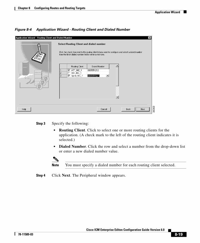
Chapter 8 Configuring Routes and Routing TargetsApplication Wizard
Figure 8-4 Application Wizard - Routing Client and Dialed Number
Step 3 Specify the following:
• Routing Client. Click to select one or more routing clients for the application. (A check mark to the left of the routing client indicates it is selected.)
• Dialed Number. Click the row and select a number from the drop-down list or enter a new dialed number value.
Note You must specify a dialed number for each routing client selected.
Step 4 Click Next. The Peripheral window appears.
8-19Cisco ICM Enterprise Editon Configuration Guide Version 6.0
78-11589-03
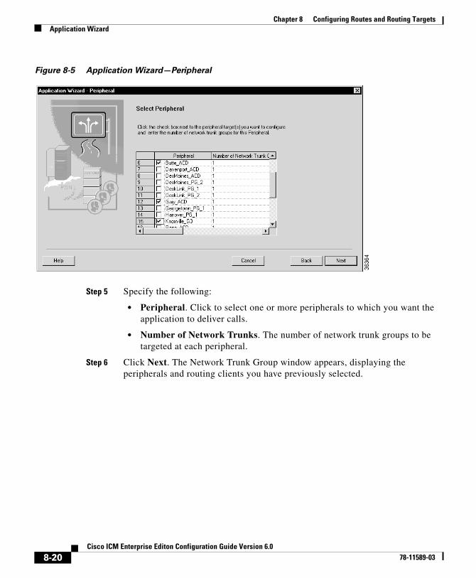
Chapter 8 Configuring Routes and Routing TargetsApplication Wizard
Figure 8-5 Application Wizard—Peripheral
Step 5 Specify the following:
• Peripheral. Click to select one or more peripherals to which you want the application to deliver calls.
• Number of Network Trunks. The number of network trunk groups to be targeted at each peripheral.
Step 6 Click Next. The Network Trunk Group window appears, displaying the peripherals and routing clients you have previously selected.
8-20Cisco ICM Enterprise Editon Configuration Guide Version 6.0
78-11589-03
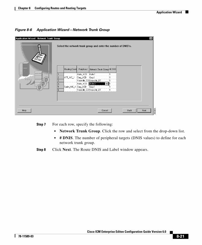
Chapter 8 Configuring Routes and Routing TargetsApplication Wizard
Figure 8-6 Application Wizard—Network Trunk Group
Step 7 For each row, specify the following:
• Network Trunk Group. Click the row and select from the drop-down list.
• # DNIS. The number of peripheral targets (DNIS values) to define for each network trunk group.
Step 8 Click Next. The Route DNIS and Label window appears.
8-21Cisco ICM Enterprise Editon Configuration Guide Version 6.0
78-11589-03
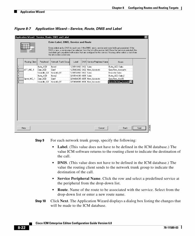
Chapter 8 Configuring Routes and Routing TargetsApplication Wizard
Figure 8-7 Application Wizard—Service, Route, DNIS and Label
Step 9 For each network trunk group, specify the following:
• Label. (This value does not have to be defined in the ICM database.) The value ICM software returns to the routing client to indicate the destination of the call.
• DNIS. (This value does not have to be defined in the ICM database.) The value the routing client sends to the network trunk group to indicate the destination of the call.
• Service Peripheral Name. Click the row and select a predefined service at the peripheral from the drop-down list.
• Route. Name of the route to be associated with the service. Select from the drop-down list or enter a new route name.
Step 10 Click Next. The Application Wizard displays a dialog box listing the changes that will be made to the ICM database.
8-22Cisco ICM Enterprise Editon Configuration Guide Version 6.0
78-11589-03
Chapter 8 Configuring Routes and Routing TargetsScheduled Targets
Step 11 Click Finish to save the changes and exit the Application Wizard.
Scheduled TargetsA scheduled target is a special type of destination for a call. ICM software has only limited information about a scheduled target: the number of calls that the target can handle simultaneously and the number of calls currently in progress at the target.
Note Scheduled targets are only available for NICs that use intelligent network support. These include CRSP, INAP (CS-1 and CS-2), Carrier AIN, and CWC routing targets.
ICM software determines the number of calls the target can handle by referring to a periodic schedule associated with the target, as shown in Figure 8-8.
8-23Cisco ICM Enterprise Editon Configuration Guide Version 6.0
78-11589-03
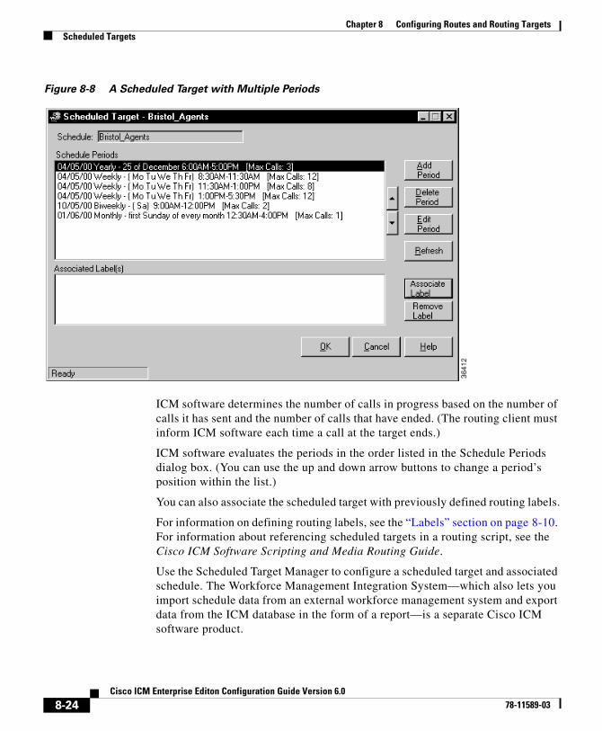
Chapter 8 Configuring Routes and Routing TargetsScheduled Targets
Figure 8-8 A Scheduled Target with Multiple Periods
ICM software determines the number of calls in progress based on the number of calls it has sent and the number of calls that have ended. (The routing client must inform ICM software each time a call at the target ends.)
ICM software evaluates the periods in the order listed in the Schedule Periods dialog box. (You can use the up and down arrow buttons to change a period’s position within the list.)
You can also associate the scheduled target with previously defined routing labels.
For information on defining routing labels, see the “Labels” section on page 8-10. For information about referencing scheduled targets in a routing script, see the Cisco ICM Software Scripting and Media Routing Guide.
Use the Scheduled Target Manager to configure a scheduled target and associated schedule. The Workforce Management Integration System—which also lets you import schedule data from an external workforce management system and export data from the ICM database in the form of a report—is a separate Cisco ICM software product.
8-24Cisco ICM Enterprise Editon Configuration Guide Version 6.0
78-11589-03
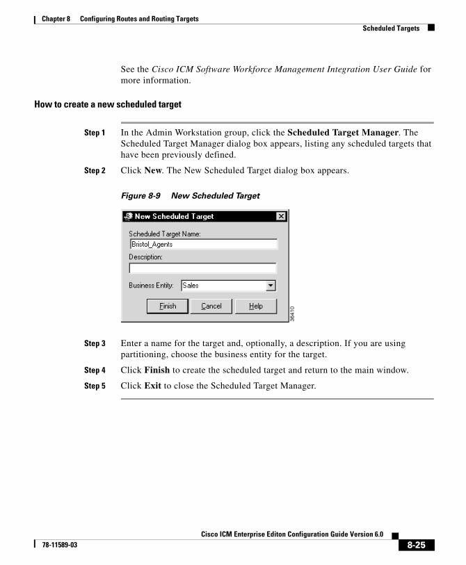
Chapter 8 Configuring Routes and Routing TargetsScheduled Targets
See the Cisco ICM Software Workforce Management Integration User Guide for more information.
How to create a new scheduled target
Step 1 In the Admin Workstation group, click the Scheduled Target Manager. The Scheduled Target Manager dialog box appears, listing any scheduled targets that have been previously defined.
Step 2 Click New. The New Scheduled Target dialog box appears.
Figure 8-9 New Scheduled Target
Step 3 Enter a name for the target and, optionally, a description. If you are using partitioning, choose the business entity for the target.
Step 4 Click Finish to create the scheduled target and return to the main window.
Step 5 Click Exit to close the Scheduled Target Manager.
8-25Cisco ICM Enterprise Editon Configuration Guide Version 6.0
78-11589-03
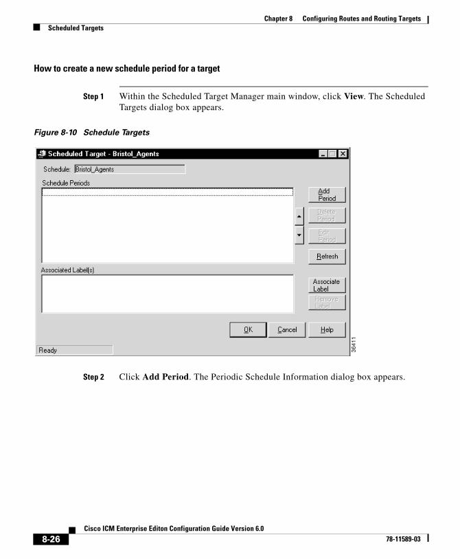
Chapter 8 Configuring Routes and Routing TargetsScheduled Targets
How to create a new schedule period for a target
Step 1 Within the Scheduled Target Manager main window, click View. The Scheduled Targets dialog box appears.
Figure 8-10 Schedule Targets
Step 2 Click Add Period. The Periodic Schedule Information dialog box appears.
8-26Cisco ICM Enterprise Editon Configuration Guide Version 6.0
78-11589-03
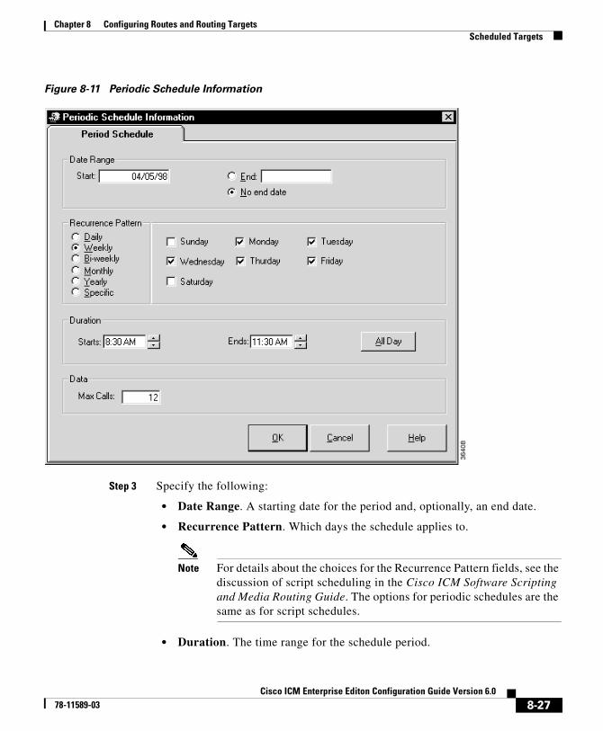
Chapter 8 Configuring Routes and Routing TargetsScheduled Targets
Figure 8-11 Periodic Schedule Information
Step 3 Specify the following:
• Date Range. A starting date for the period and, optionally, an end date.
• Recurrence Pattern. Which days the schedule applies to.
Note For details about the choices for the Recurrence Pattern fields, see the discussion of script scheduling in the Cisco ICM Software Scripting and Media Routing Guide. The options for periodic schedules are the same as for script schedules.
• Duration. The time range for the schedule period.
8-27Cisco ICM Enterprise Editon Configuration Guide Version 6.0
78-11589-03
Chapter 8 Configuring Routes and Routing TargetsTranslation Routes
• Data. The maximum number of calls in progress the target that can handle during the specified period.
Step 4 Click OK to save the period information and return to the Scheduled Target dialog box.
Note None of the periods you have added or changed are saved until you click the Scheduled Target’s OK button.
Step 5 Click Exit to close the Scheduled Target Manager.
How to associate labels with a scheduled target
Step 1 Within the Scheduled Target Manager main window, click Associate Label. The Associate Label dialog box appears, displaying a list of labels not currently associated with a target.
Step 2 Choose a label from the list and click OK to save the label and return to the Scheduled Target Manager dialog box.
Step 3 Repeat Steps 1 and 2 to associate additional labels with the scheduled target.
Step 4 Click OK in the Scheduled Target dialog box to save the changes you have made and return to the Scheduled Target Manager main window.
Step 5 Click Exit to close the Scheduled Target Manager.
Translation RoutesA translation route is a special destination for a call that allows you to deliver other information along with the call. You do this by delivering the call first to the translation route. While the routing client is processing the call, ICM software delivers the final destination for the call to the Peripheral Gateway along with any other necessary information. The peripheral then works with the PG to reroute the call to the ultimate target and ensure that the appropriate information is also delivered.
8-28Cisco ICM Enterprise Editon Configuration Guide Version 6.0
78-11589-03
Chapter 8 Configuring Routes and Routing TargetsTranslation Route Wizard
A single translation route can be used to send information to any number of different targets. However, because the PG must uniquely identify the call, you cannot perform translation routing on two calls to the same peripheral target simultaneously. To avoid this, you typically define a set of peripheral targets, and routes, for each translation route.
Translation Route WizardYou can define translation routes within the Configuration Manager. However, defining the correct associations with peripheral targets, labels, and routes is complicated. To automate much of the process, use the Translation Route Wizard.
Note You can also use the Translation Route Wizard to view configuration or integrity reports on translation routes, update existing translation routes, or to delete translation routes and their associated entities.
How to create a translation route
Step 1 In the Configuration Manager, select Tools > Wizards > Translation Route Wizard. The Translation Route Wizard introductory dialog box opens.
Step 2 Click Next. The Select Configuration Task dialog box appears.
Step 3 To create a translation route, choose Create New and click Next. The Define Translation Route dialog box appears.
8-29Cisco ICM Enterprise Editon Configuration Guide Version 6.0
78-11589-03
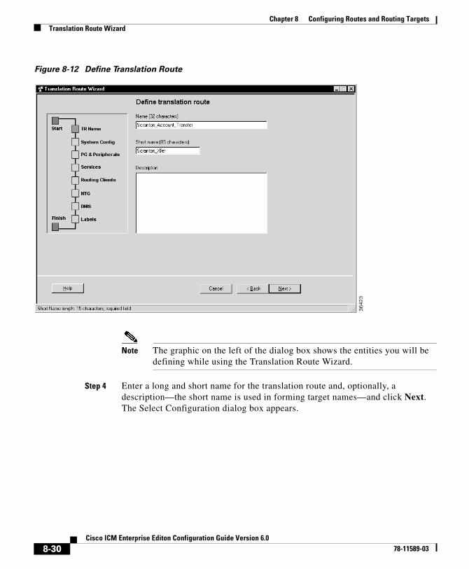
Chapter 8 Configuring Routes and Routing TargetsTranslation Route Wizard
Figure 8-12 Define Translation Route
Note The graphic on the left of the dialog box shows the entities you will be defining while using the Translation Route Wizard.
Step 4 Enter a long and short name for the translation route and, optionally, a description—the short name is used in forming target names—and click Next. The Select Configuration dialog box appears.
8-30Cisco ICM Enterprise Editon Configuration Guide Version 6.0
78-11589-03
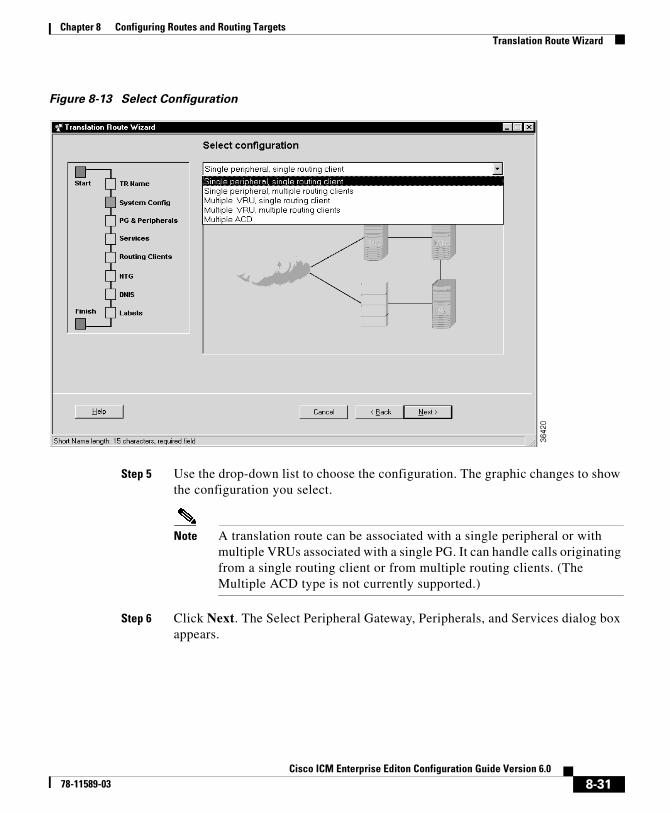
Chapter 8 Configuring Routes and Routing TargetsTranslation Route Wizard
Figure 8-13 Select Configuration
Step 5 Use the drop-down list to choose the configuration. The graphic changes to show the configuration you select.
Note A translation route can be associated with a single peripheral or with multiple VRUs associated with a single PG. It can handle calls originating from a single routing client or from multiple routing clients. (The Multiple ACD type is not currently supported.)
Step 6 Click Next. The Select Peripheral Gateway, Peripherals, and Services dialog box appears.
8-31Cisco ICM Enterprise Editon Configuration Guide Version 6.0
78-11589-03
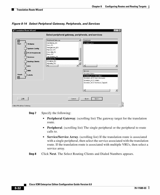
Chapter 8 Configuring Routes and Routing TargetsTranslation Route Wizard
Figure 8-14 Select Peripheral Gateway, Peripherals, and Services
Step 7 Specify the following:
• Peripheral Gateway. (scrolling list) The gateway target for the translation route.
• Peripheral. (scrolling list) The single peripheral or the peripheral to route calls to.
• Service/Service Array. (scrolling list) If the translation route is associated with a single peripheral, then select the service associated with the translation route. If the translation route is associated with multiple VRUs, then select a service array.
Step 8 Click Next. The Select Routing Clients and Dialed Numbers appears.
8-32Cisco ICM Enterprise Editon Configuration Guide Version 6.0
78-11589-03
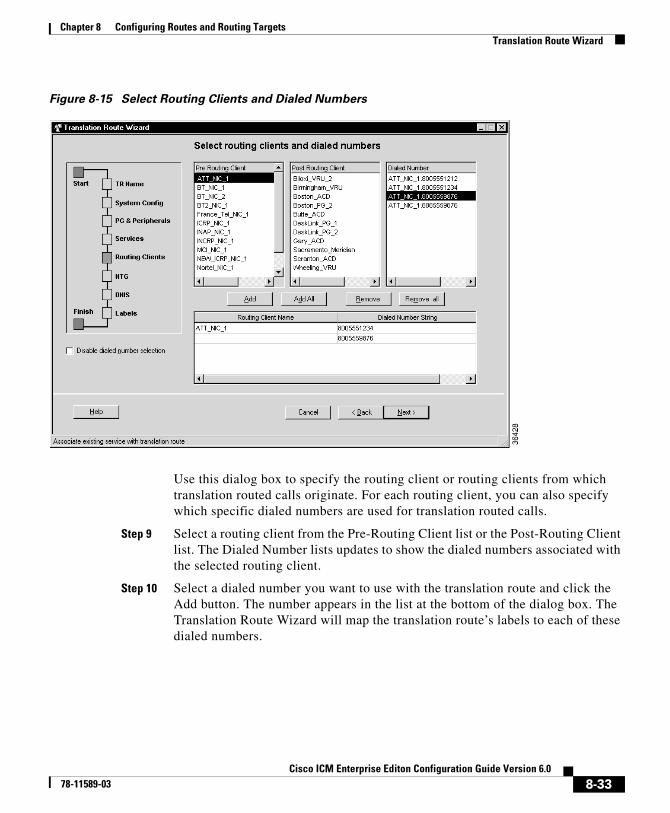
Chapter 8 Configuring Routes and Routing TargetsTranslation Route Wizard
Figure 8-15 Select Routing Clients and Dialed Numbers
Use this dialog box to specify the routing client or routing clients from which translation routed calls originate. For each routing client, you can also specify which specific dialed numbers are used for translation routed calls.
Step 9 Select a routing client from the Pre-Routing Client list or the Post-Routing Client list. The Dialed Number lists updates to show the dialed numbers associated with the selected routing client.
Step 10 Select a dialed number you want to use with the translation route and click the Add button. The number appears in the list at the bottom of the dialog box. The Translation Route Wizard will map the translation route’s labels to each of these dialed numbers.
8-33Cisco ICM Enterprise Editon Configuration Guide Version 6.0
78-11589-03
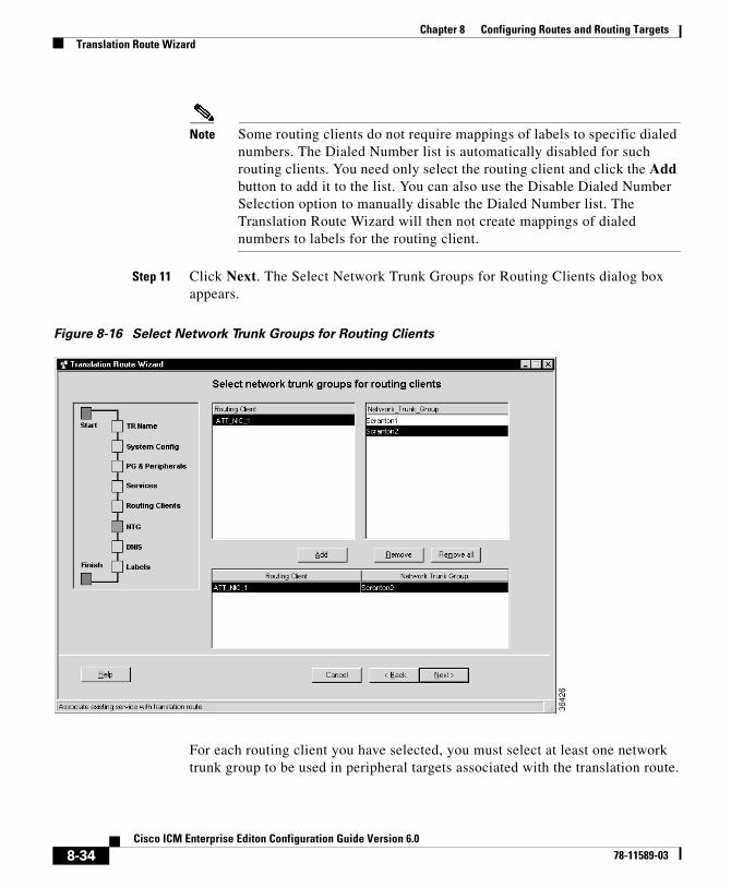
Chapter 8 Configuring Routes and Routing TargetsTranslation Route Wizard
Note Some routing clients do not require mappings of labels to specific dialed numbers. The Dialed Number list is automatically disabled for such routing clients. You need only select the routing client and click the Add button to add it to the list. You can also use the Disable Dialed Number Selection option to manually disable the Dialed Number list. The Translation Route Wizard will then not create mappings of dialed numbers to labels for the routing client.
Step 11 Click Next. The Select Network Trunk Groups for Routing Clients dialog box appears.
Figure 8-16 Select Network Trunk Groups for Routing Clients
For each routing client you have selected, you must select at least one network trunk group to be used in peripheral targets associated with the translation route.
8-34Cisco ICM Enterprise Editon Configuration Guide Version 6.0
78-11589-03
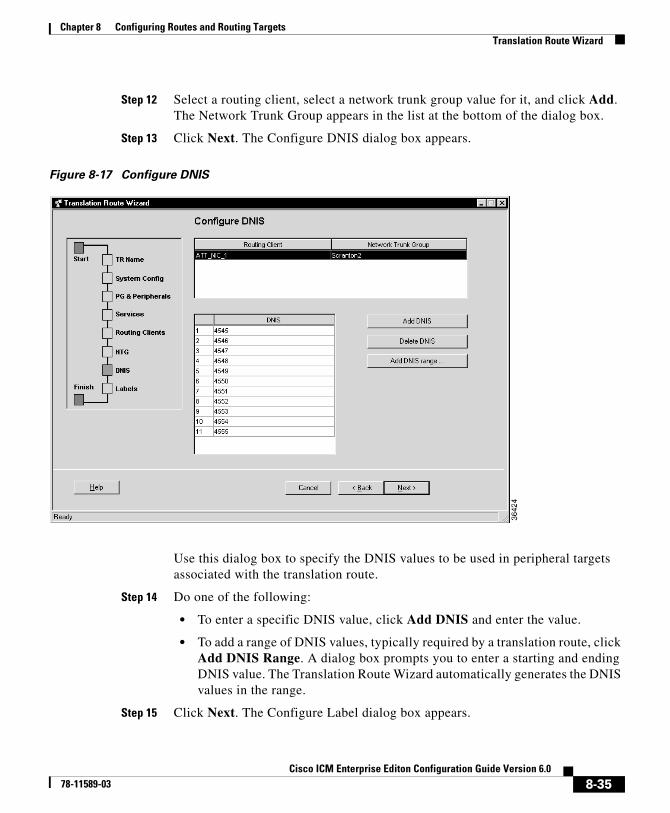
Chapter 8 Configuring Routes and Routing TargetsTranslation Route Wizard
Step 12 Select a routing client, select a network trunk group value for it, and click Add. The Network Trunk Group appears in the list at the bottom of the dialog box.
Step 13 Click Next. The Configure DNIS dialog box appears.
Figure 8-17 Configure DNIS
Use this dialog box to specify the DNIS values to be used in peripheral targets associated with the translation route.
Step 14 Do one of the following:
• To enter a specific DNIS value, click Add DNIS and enter the value.
• To add a range of DNIS values, typically required by a translation route, click Add DNIS Range. A dialog box prompts you to enter a starting and ending DNIS value. The Translation Route Wizard automatically generates the DNIS values in the range.
Step 15 Click Next. The Configure Label dialog box appears.
8-35Cisco ICM Enterprise Editon Configuration Guide Version 6.0
78-11589-03

Chapter 8 Configuring Routes and Routing TargetsTranslation Route Wizard
Figure 8-18 Configure Label
Use this dialog box to define a label for each peripheral target. A label consists of a prefix and a suffix. Each DNIS value requires a unique label.
Step 16 Do one of the following:
• Enter prefixes and suffixes individually.
• Use the buttons in this dialog box to set a range of values or to base the prefix or suffix values on the DNIS values.
Step 17 Click Next. The Wizard Complete dialog box appears.
8-36Cisco ICM Enterprise Editon Configuration Guide Version 6.0
78-11589-03
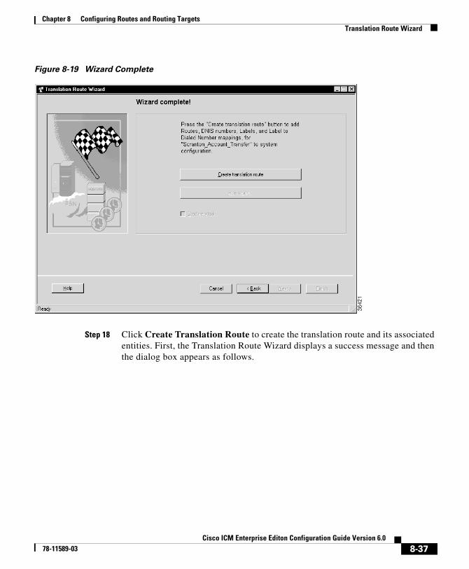
Chapter 8 Configuring Routes and Routing TargetsTranslation Route Wizard
Figure 8-19 Wizard Complete
Step 18 Click Create Translation Route to create the translation route and its associated entities. First, the Translation Route Wizard displays a success message and then the dialog box appears as follows.
8-37Cisco ICM Enterprise Editon Configuration Guide Version 6.0
78-11589-03
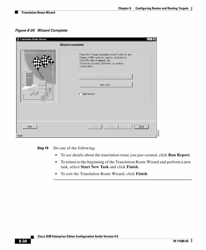
Chapter 8 Configuring Routes and Routing TargetsTranslation Route Wizard
Figure 8-20 Wizard Complete
Step 19 Do one of the following:
• To see details about the translation route you just created, click Run Report.
• To return to the beginning of the Translation Route Wizard and perform a new task, select Start New Task and click Finish.
• To exit the Translation Route Wizard, click Finish.
8-38Cisco ICM Enterprise Editon Configuration Guide Version 6.0
78-11589-03
Cisco ICM Enterprise78-11589-03
C H A P T E R 9
Configuring ICM Software for Integrated ApplicationsThese instructions provide information for installing and configuring ICM 6.0 software as part of a system integrated with the Cisco Collaboration Server and Cisco E-Mail Manager applications.
For additional information about Cisco Intelligent Contact Management (ICM) software, see the Cisco web site listing ICM documentation: http://www.cisco.com/univercd/cc/td/doc/product/icm/index.htm.
For a high-level overview of integrating the applications with ICM software, refer to the Cisco Customer Contact Suite Implementation Map that is delivered with ICM software.
Note Important! While performing the tasks outlined in this chapter, be sure to note the ICM software configuration information, as you will need to enter this information when configuring the integrated applications.
ICM 6.0 Software Requirements
Note Important! ICM software and the integrated applications should not be installed on the same machine.
9-1 Editon Configuration Guide Version 6.0
Chapter 9 Configuring ICM Software for Integrated ApplicationsICM 6.0 Software Requirements
Before you begin configuring ICM software for the integrated applications, you must upgrade ICM software from Version 4.6 (with SQL 7.0 and WebView installed) to 6.0.
Refer to the Cisco 4.6.2 to 6.0 ICM Software Upgrade Migration Guide for specific upgrade and installation requirements.
How to install the application interface
Note Important! You must install the application interface before beginning the ICM configuration.
If you want your Admin Workstation to be the point of contact for the integrated applications (Cisco Collaboration Server and Cisco E-Mail Manager) configuration (to host the CMS Server), you need to perform this installation.
Refer to the Cisco ICM Software Installation Guide for detailed information about the Admin Workstation setup.
Step 1 Run setup.exe from the ICM CD-ROM.
Step 2 Select your Distributor AW and click Edit. The Admin Workstation properties window displays.
Step 3 Click the Next button. The Real-time Distributor Node Properties window displays.
Step 4 Click the CMS Node checkbox. Selecting this option installs the CMS Server on the Admin Workstation.
Step 5 Finish the installation process.
After installing the application interface, you need to run the CMS Control tool on the installed Admin Workstation to set up, from the ICM side, the connections that allow the integrated applications to talk to that Admin Workstation. You must also configure each application’s end of the connection.
To improve performance, if no debugging is being performed using that console, keep the CMS node console minimized. If the console is not minimized, considerable CPU resources are tied up displaying numerous messages from the system I/O.
9-2Cisco ICM Enterprise Editon Configuration Guide Version 6.0
78-11589-03
Chapter 9 Configuring ICM Software for Integrated ApplicationsConfiguring ICM Software for Integration
See the “Application Connections” section on page 9-22 for more information about using the CMS Control tool to set up the connections between ICM software and the integrated applications.
Verify Pre-Integration ConfigurationVerify the configuration by doing the following:
• Verify that all processes, including all PIMs and CTI servers, are active (that is, all processes start, duplexed routers load the configuration and synchronize, and all PIMs and CTI servers are active).
• Verify that the MSSQL server has started. Submit sample calls through all routing clients and all call types. Use the Call Tracer tool in the ICM Script Editor to test router call handling functionality.
Note This test should be done prior to the ICM upgrade and after the ICM upgrade. Failures should be addressed prior to integration.
Configuring ICM Software for IntegrationTo configure ICM software for the applications, you need to configure/install the following:
• Media routing domains for appropriate media classes within ICM software
• Media routing peripheral gateways (PGs) and peripherals
• ECC (Expanded Call Context) variables
• Application instance(s) and define them in ICM software
• Agents (you can create agents either in ICM software or in the applications.
• Connections to the CMS server using the Application tab of the CMS Control tool in the ICM Admin Workstation folder
• Configuration work on the integrated applications
• Skill group configuration using ICM Script Editor
• Information to push to waiting Cisco Collaboration Server callers
9-3Cisco ICM Enterprise Editon Configuration Guide Version 6.0
78-11589-03
Chapter 9 Configuring ICM Software for Integrated ApplicationsConfiguring ICM Software for Integration
Note Although it is possible to create agents and skill groups on ICM and then enable them on the application, it is recommended they be created from the application admin interface.
The following sections describe each of the preceding, their configuration and installation instructions, and indicate the ICM configuration tool you need for each configuration. Refer to a configuration tool’s online help if you have any questions.
Note Before using the ICM configuration tools to perform each configuration process, if you have more than one ICM instance you want to configure, open the AW Select tool in the ICM Admin Workstation and select the ICM instance with which you want to work.
Media Routing DomainsTo create and then assign a media routing domain to a media class (physical media that ICM software treats as a single concept), use the ICM Configuration Manager’s Media Routing Domain List tool.
ICM software uses Media Routing Domains (MRDs) to organize how requests from different media are routed. An MRD is a collection of skill groups and services that are associated with a common communication medium. ICM software uses an MRD to route a task to an agent who is associated with a skill group and a particular medium.
Before you can configure your application (for example, the Cisco Collaboration Server) to use ICM software as a routing engine, MRDs must be established in ICM software. These MRDs have unique IDs across the enterprise. Then, on the application, you must enable those ICM Media Routing Domains that you need to use.
Note Important! The MRD IDs must be created in ICM software first, and then passed on to the person configuring the application, in order to perform a successful configuration. In Cisco Collaboration Server you only need the MRD name, you do not need the MRD ID.
9-4Cisco ICM Enterprise Editon Configuration Guide Version 6.0
78-11589-03
Chapter 9 Configuring ICM Software for Integrated ApplicationsConfiguring ICM Software for Integration
A media class describes the type of requests you want to set up for routing on ICM software. Pre-defined media classes include:
• Cisco Multi-session chat
• Cisco Single-session chat
• Cisco Blended Collaboration (voice and single-session chat)
• Cisco Voice
• Cisco E-mail Manager
Note A number of media classes are pre-defined for Cisco applications bundled with ICM software. There is currently no reason for you to create a new media class. Future third party applications that interface with ICM software may result in the defining of additional media classes.
How to configure the Media Routing Domain
Step 1 Start the ICM Configuration Manager and select Tools > List Tools > Media Routing Domain List. The Media Routing Domain List window displays. Click the Retrieve button and then the Add button to display the Attributes tab.
Step 2 Enter the following information:
• Name. Enter the enterprise name of the MRD.
• Media Class. Use the drop-down list to select the media class for the integrated application.
• The MRDomainID is a required read-only field. (An ID number will be automatically created when you save your entry.)
Step 3 After entering the required fields, save the configuration and close the window.
Note Refer to the ICM Configuration Manager’s online help for detailed information about the Media Routing Domain List tool.
9-5Cisco ICM Enterprise Editon Configuration Guide Version 6.0
78-11589-03
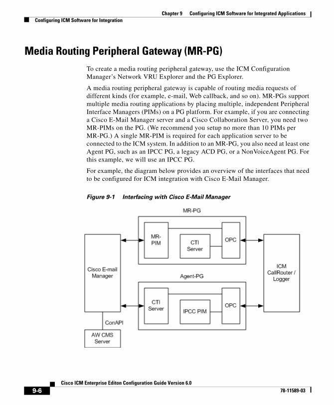
Chapter 9 Configuring ICM Software for Integrated ApplicationsConfiguring ICM Software for Integration
Media Routing Peripheral Gateway (MR-PG)To create a media routing peripheral gateway, use the ICM Configuration Manager’s Network VRU Explorer and the PG Explorer.
A media routing peripheral gateway is capable of routing media requests of different kinds (for example, e-mail, Web callback, and so on). MR-PGs support multiple media routing applications by placing multiple, independent Peripheral Interface Managers (PIMs) on a PG platform. For example, if you are connecting a Cisco E-Mail Manager server and a Cisco Collaboration Server, you need two MR-PIMs on the PG. (We recommend you setup no more than 10 PIMs per MR-PG.) A single MR-PIM is required for each application server to be connected to the ICM system. In addition to an MR-PG, you also need at least one Agent PG, such as an IPCC PG, a legacy ACD PG, or a NonVoiceAgent PG. For this example, we will use an IPCC PG.
For example, the diagram below provides an overview of the interfaces that need to be configured for ICM integration with Cisco E-Mail Manager.
Figure 9-1 Interfacing with Cisco E-Mail Manager
9-6Cisco ICM Enterprise Editon Configuration Guide Version 6.0
78-11589-03
Chapter 9 Configuring ICM Software for Integrated ApplicationsConfiguring ICM Software for Integration
Configuring the MR-PG
The MR-PG interface provides routing instructions to the integrated applications, while the Agent PG configuration is used to report agent state and status to ICM software.
Note No agents are configured on MR-PGs. Agents are configured on NonVoice Agent PGs or other agent PGs.
The ICM software media routing mechanism leverages and takes advantage of the existing ICM Network VRU operational infrastructures. In order to setup for media routing, you must configure a Network VRU in the ICM configuration. This Network VRU configuration has no relationship with any actual Network VRU in your environment.
How to configure the MR-PG
Step 1 Start the ICM Configuration Manager. From the ICM Configuration Manager menu, select Configure ICM > Targets > Network VRU > Network VRU Explorer. The Network VRU Explorer window displays.
Step 2 Click the Retrieve button and then click the Add Network VRU button. The Network VRU dialog box displays.
Step 3 Do the following:
• Enter a name for the Network VRU (for example, Cust_MR_VRU).
• Select Type 2 from Type drop-down list.
• Optionally, enter a description (i.e., Media Routing).
• Save and close the window.
Step 4 From the ICM Configuration Manager menu, select Configure ICM > Peripherals > Peripheral > PG Explorer. The PG Explorer window displays.
Step 5 Click the Retrieve and then click the Add PG button. The Logical controller dialog box displays.
Step 6 Do the following:
9-7Cisco ICM Enterprise Editon Configuration Guide Version 6.0
78-11589-03
Chapter 9 Configuring ICM Software for Integrated ApplicationsConfiguring ICM Software for Integration
• Enter a name for the PG (for example, Cust_MR_PG1).
• Select MR PG as the Client Type.
Step 7 In the tree section of the window, expand the tree and click the Add Peripheral button. The Peripheral configuration dialog box displays.
Step 8 Do the following:
• Select the Peripheral tab and check the Enable Post Routing box.
• Select the Advanced tab and select the previously created Network VRU from the drop-down list.
• On the Routing Client tab, enter a routing client name (for example, Cust_MR_PG1_1.RC) and set the default timeouts to 2000, 1000, and 10, respectively.
• Save the configuration. After you save the configuration, the system assigns a Logical Controller ID and a Physical Controller ID.
Note We recommend you make a note of these values because you will need to provide them when you install the MR-PG.
• Close the window.
Installing the MR-PG
Customer contact applications use the MediaRouting interface to request instructions from ICM software when they receive a contact request from a customer using one of the mediums, such as e-mail, Web-collaboration, or voice. When ICM software receives a new task request from the application, ICM runs a pre-defined ICM script to determine how to handle the task. As a result of the execution of the ICM script, ICM sends an instruction to the application to do one of the following:
• While the application is executing an application script that is stored on the application server, ICM is looking for a best available agent that has the matching skill within the enterprise, and assigns this agent to this task.
9-8Cisco ICM Enterprise Editon Configuration Guide Version 6.0
78-11589-03
Chapter 9 Configuring ICM Software for Integrated ApplicationsConfiguring ICM Software for Integration
• Handle the new task with an ICM determined best available agent that has the matching skill within the enterprise or a label the application utilizes to determine the best available agent for the task.
Note When choosing where to install the MR-PG, be aware you can only install two PG’s per server.
How to install the MR-PG
Step 1 Run setup.exe from the ICM CD-ROM on the machine that you want to make an MR-PG. Add the customer if you have not already done so.
Step 2 Click Add in the Instance Components section and choose Peripheral Gateway from the ICM Component Selection window. The Peripheral Gateway Properties window displays.
Step 3 Do the following:
• Choose Production Mode.
Note The Auto Start at System Startup option ensures that the Peripheral Gateway can restart itself automatically if necessary. It is strongly recommended that you set the Auto Start feature after installation is complete. The server may need to be rebooted a number of times during installation, and problems could occur if the node starts before hotfixes and/or databases are applied.
• Specify whether the PG is part of a duplexed pair.
• In the ID field, choose the PG’s device identifier as enabled in the CallRouter’s Device Management Protocol (DMP) configuration dialog (part of the CallRouter portion of ICM setup.exe; enables the connection between the Router and the PG). Each logical PG must have a unique device assignment at the CallRouter. (If a PG is duplexed, both physical machines use the same device assignment.) To add another logical PG, you must enable another PG device for the CallRouter.
• If the PG is duplexed, specify whether you are installing Side A or Side B. If the PG is simplexed, select Side A.
9-9Cisco ICM Enterprise Editon Configuration Guide Version 6.0
78-11589-03
Chapter 9 Configuring ICM Software for Integrated ApplicationsConfiguring ICM Software for Integration
• Use the Client Type Selection section of the window to select MediaRouting and click the Add button.
• Select the drive and language as appropriate and click the Next button.
Step 4 The Peripheral Gateway Component Properties window displays.
Enter the Logical Controller ID generated when you configured the PG with the PG Explorer in Step 8 of the “How to configure the MR-PG” section on page 9-7. Click the Add button and select PIM 1 from the list.
Step 5 The MediaRouting Configuration box displays.
Step 6 Do the following:
• To put the PIM into service, check the Enabled option. This allows the PIM to communicate with the peripheral when the Peripheral Gateway is running.
• Enter the peripheral name in the Peripheral name field. In most cases, you should use the enterprise name from the associated Peripheral record.
Note When creating peripheral names, use short descriptive names and keep the length to a minimum.
• Enter the Peripheral ID from the Peripheral record.
• For Application Hostname (1), enter the host name or the IP address of the application server machine (i.e., Cisco Media Blender for connection to Cisco Collaboration Server or Cisco E-Mail Manager). If using the host name, the name must be in the host’s file.
• For Application Connection Port (1), enter the port number on the application server machine that the PIM will use to communicate with the application.
Note When creating a PIM on the MR-PG for Cisco E-Mail Manager, you must set the Application Connection Port to 1600 (default is 2000); set it to 2000 for the Cisco Collaboration Server.
• Leave Application Hostname (2) blank.
• Leave Application Connection Port (2) blank.
9-10Cisco ICM Enterprise Editon Configuration Guide Version 6.0
78-11589-03
Chapter 9 Configuring ICM Software for Integrated ApplicationsConfiguring ICM Software for Integration
Note The Application Hostname and Application Connection Port are used for Cisco E-Mail Manager and Cisco Collaboration Server failover. Both applications initially try to connect to the first host. If unsuccessful, Cisco E-Mail Manager and Cisco Collaboration Server then try to connect to the second host. If this attempt to connect is also unsuccessful, they then re-try connecting to the first host. This process repeats until successful connection to the host.
• For Heartbeat Interval (seconds), specify how often the PG should check its connection to the application server. Use the default value.
• For Reconnect Interval (seconds), specify how often the PG should try to re-establish a lost connection to the application server. Use the default value.
• Click OK.
Step 7 From the Peripheral Gateway Component Properties window, click the Next button. The Device Management Protocol Properties window displays. Enter the appropriate settings and click the Next button.
Step 8 The Peripheral Gateway Network Interfaces window displays. Enter the appropriate settings and click the Next button.
Step 9 The Check Setup Information window displays. Verify the setup information and click the Next button. ICM software installs the PG.
Step 10 When the Setup Complete window displays, click the Finish button to exit from the setup program.
Configuring and Installing the IPCC PG
When agents and skill groups are created—whether from an application (Cisco Collaboration Server or Cisco E-Mail Manager) or on ICM software—they must reside on a peripheral. A peripheral can be associated with an IPCC, SoftACD, or Legacy ACD for agents doing any work on the phone. If the agents on the peripheral will never be doing phone work, one or more NonVoice peripherals can be used.
9-11Cisco ICM Enterprise Editon Configuration Guide Version 6.0
78-11589-03
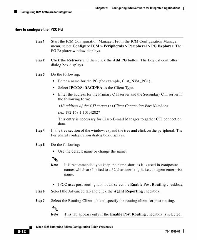
Chapter 9 Configuring ICM Software for Integrated ApplicationsConfiguring ICM Software for Integration
How to configure the IPCC PG
Step 1 Start the ICM Configuration Manager. From the ICM Configuration Manager menu, select Configure ICM > Peripherals > Peripheral > PG Explorer. The PG Explorer window displays.
Step 2 Click the Retrieve and then click the Add PG button. The Logical controller dialog box displays.
Step 3 Do the following:
• Enter a name for the PG (for example, Cust_NVA_PG1).
• Select IPCC/SoftACD/EA as the Client Type.
• Enter the address for the Primary CTI server and the Secondary CTI server in the following form:
<IP address of the CTI server>:<Client Connection Port Number>
i.e., 192.168.1.101:42027
This entry is necessary for Cisco E-mail Manager to gather CTI connection data.
Step 4 In the tree section of the window, expand the tree and click on the peripheral. The Peripheral configuration dialog box displays.
Step 5 Do the following:
• Use the default name or change the name.
Note It is recommended you keep the name short as it is used in composite names which are limited to a 32 character length, i.e., an agent enterprise name.
• IPCC uses post routing, do not un-select the Enable Post Routing checkbox.
Step 6 Select the Advanced tab and click the Agent Reporting checkbox.
Step 7 Select the Routing Client tab and specify the routing client for post routing.
Note This tab appears only if the Enable Post Routing checkbox is selected.
9-12Cisco ICM Enterprise Editon Configuration Guide Version 6.0
78-11589-03
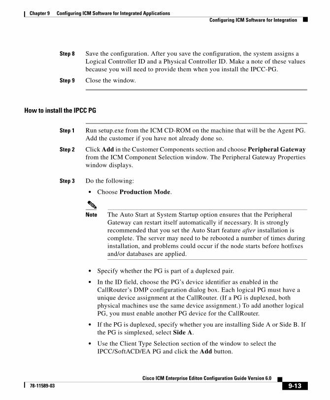
Chapter 9 Configuring ICM Software for Integrated ApplicationsConfiguring ICM Software for Integration
Step 8 Save the configuration. After you save the configuration, the system assigns a Logical Controller ID and a Physical Controller ID. Make a note of these values because you will need to provide them when you install the IPCC-PG.
Step 9 Close the window.
How to install the IPCC PG
Step 1 Run setup.exe from the ICM CD-ROM on the machine that will be the Agent PG. Add the customer if you have not already done so.
Step 2 Click Add in the Customer Components section and choose Peripheral Gateway from the ICM Component Selection window. The Peripheral Gateway Properties window displays.
Step 3 Do the following:
• Choose Production Mode.
Note The Auto Start at System Startup option ensures that the Peripheral Gateway can restart itself automatically if necessary. It is strongly recommended that you set the Auto Start feature after installation is complete. The server may need to be rebooted a number of times during installation, and problems could occur if the node starts before hotfixes and/or databases are applied.
• Specify whether the PG is part of a duplexed pair.
• In the ID field, choose the PG’s device identifier as enabled in the CallRouter’s DMP configuration dialog box. Each logical PG must have a unique device assignment at the CallRouter. (If a PG is duplexed, both physical machines use the same device assignment.) To add another logical PG, you must enable another PG device for the CallRouter.
• If the PG is duplexed, specify whether you are installing Side A or Side B. If the PG is simplexed, select Side A.
• Use the Client Type Selection section of the window to select the IPCC/SoftACD/EA PG and click the Add button.
9-13Cisco ICM Enterprise Editon Configuration Guide Version 6.0
78-11589-03
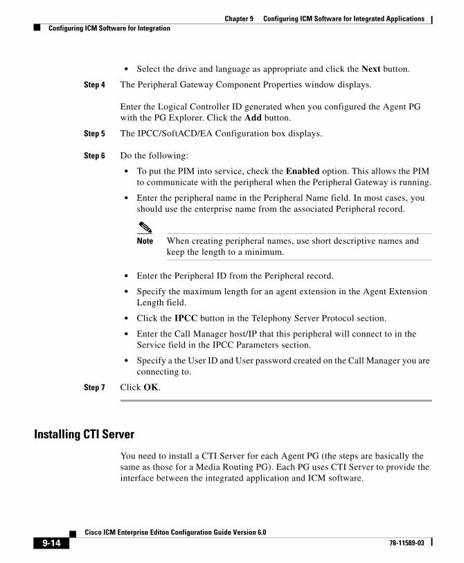
Chapter 9 Configuring ICM Software for Integrated ApplicationsConfiguring ICM Software for Integration
• Select the drive and language as appropriate and click the Next button.
Step 4 The Peripheral Gateway Component Properties window displays.
Enter the Logical Controller ID generated when you configured the Agent PG with the PG Explorer. Click the Add button.
Step 5 The IPCC/SoftACD/EA Configuration box displays.
Step 6 Do the following:
• To put the PIM into service, check the Enabled option. This allows the PIM to communicate with the peripheral when the Peripheral Gateway is running.
• Enter the peripheral name in the Peripheral Name field. In most cases, you should use the enterprise name from the associated Peripheral record.
Note When creating peripheral names, use short descriptive names and keep the length to a minimum.
• Enter the Peripheral ID from the Peripheral record.
• Specify the maximum length for an agent extension in the Agent Extension Length field.
• Click the IPCC button in the Telephony Server Protocol section.
• Enter the Call Manager host/IP that this peripheral will connect to in the Service field in the IPCC Parameters section.
• Specify a the User ID and User password created on the Call Manager you are connecting to.
Step 7 Click OK.
Installing CTI Server
You need to install a CTI Server for each Agent PG (the steps are basically the same as those for a Media Routing PG). Each PG uses CTI Server to provide the interface between the integrated application and ICM software.
9-14Cisco ICM Enterprise Editon Configuration Guide Version 6.0
78-11589-03
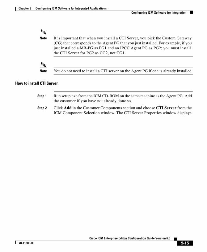
Chapter 9 Configuring ICM Software for Integrated ApplicationsConfiguring ICM Software for Integration
Note It is important that when you install a CTI Server, you pick the Custom Gateway (CG) that corresponds to the Agent PG that you just installed. For example, if you just installed a MR-PG as PG1 and an IPCC Agent PG as PG2; you must install the CTI Server for PG2 as CG2, not CG1.
Note You do not need to install a CTI server on the Agent PG if one is already installed.
How to install CTI Server
Step 1 Run setup.exe from the ICM CD-ROM on the same machine as the Agent PG. Add the customer if you have not already done so.
Step 2 Click Add in the Customer Components section and choose CTI Server from the ICM Component Selection window. The CTI Server Properties window displays.
9-15Cisco ICM Enterprise Editon Configuration Guide Version 6.0
78-11589-03
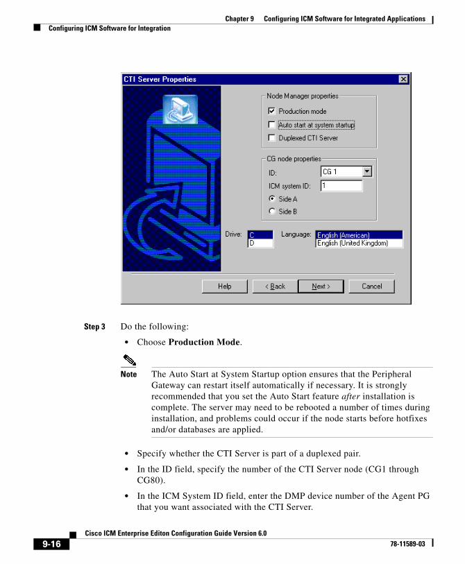
Chapter 9 Configuring ICM Software for Integrated ApplicationsConfiguring ICM Software for Integration
Step 3 Do the following:
• Choose Production Mode.
Note The Auto Start at System Startup option ensures that the Peripheral Gateway can restart itself automatically if necessary. It is strongly recommended that you set the Auto Start feature after installation is complete. The server may need to be rebooted a number of times during installation, and problems could occur if the node starts before hotfixes and/or databases are applied.
• Specify whether the CTI Server is part of a duplexed pair.
• In the ID field, specify the number of the CTI Server node (CG1 through CG80).
• In the ICM System ID field, enter the DMP device number of the Agent PG that you want associated with the CTI Server.
9-16Cisco ICM Enterprise Editon Configuration Guide Version 6.0
78-11589-03

Chapter 9 Configuring ICM Software for Integrated ApplicationsConfiguring ICM Software for Integration
Note The DMP device number is the checkbox you checked for the PG (that is, if you checked box 1, the device number is 1, box 2, the device number is 2, etc.).
• If the CTI Server is duplexed, specify whether you are installing Side A or Side B. If the CTI Server is simplexed, select Side A.
• Select the drive and language as appropriate and click the Next button.
Step 4 The CTI Server Component Properties window displays.
Enter the Client Connection Port Number.
Note If a particular instance of Cisco Collaboration Server and Cisco E-Mail Manager are using agents on the same peripheral, you must use the same port number in order to communicate with the CTI Server node associated with that peripheral.
9-17Cisco ICM Enterprise Editon Configuration Guide Version 6.0
78-11589-03
Chapter 9 Configuring ICM Software for Integrated ApplicationsConfiguring ICM Software for Integration
Step 5 Click the Next button. The CTI Server Network Interface Properties window displays. Enter the appropriate interface information.
Step 6 Click the Next button to view the setup information window. If the information is correct, click the Next button and finish the installation.
AgentsYou can create persons (records that contain personal information about an agent) and agents (person who handles customer contact) in ICM software and in the Cisco Collaboration Server and Cisco E-Mail Manager applications.
• Creating them in Cisco Collaboration Server or in Cisco E-mail Manager makes them available to ICM.
• Creating them in ICM does not make them immediately available to ICM, the application must enable the agent.
• An agent created in Cisco Collaboration Server must be enabled in Cisco E-mail Manager.
• An agent created in Cisco E-mail Manager must be enabled in Cisco Collaboration Server.
Tip Creating an agent in an application rather than in ICM software is more productive since the application automatically creates the person record and agent record for the agent in the ICM database. When you create an Agent record, you have the option of associating it with an existing Person record (clicking the Select Person button). If you do not associate the Agent record with an existing Person record, a new Person record is automatically created when you create the agent
Configuring an agent for multi-media means assigning that agent to at least two skill groups (one for each media). For example, the agent might handle both e-mail and phones, Single-session chat and phones, or Blended Collaboration and e-mail.
9-18Cisco ICM Enterprise Editon Configuration Guide Version 6.0
78-11589-03
Chapter 9 Configuring ICM Software for Integrated ApplicationsConfiguring ICM Software for Integration
Note Use the integrated applications to assign an agent an application-specific skill group. Application-specific skill groups must be created and maintained in the application, not in ICM software.
If you want to configure phone agents in ICM software, you must first create person records for them in the ICM Configuration Manager’s Person List tool.
Every agent is associated with a person record. This is primarily a person’s first and last name and login password. This record must exist before you can create an agent in ICM software (see How to create an agent, page 7-29).
The purpose of the person record is so that, in a multi-channel contact center, one person can be assigned as an agent on different peripherals since ICM software defines an agent as belonging to only one peripheral.
Note The preceding is also true for non-integrated ICM systems.
The second step in creating an agent in ICM software is to use the ICM Configuration Manager’s Agent Explorer tool to create the agent. When you do so, the agent is associated with a person.
Non Voice Agents
A NonVoiceAgent PG/PIM is only intended for use at a site that does not have voice, but that does want to use ICM to do its multi-channel (Non Voice) contact routing. For such a site a Non Voice Agent PG is necessary, since every agent must be associated with a peripheral, and the site has no Agent peripheral other than the NonVoiceAgent PG. (A Media Routing PG is also needed, but an MR-PG is not an Agent PG.)
At a site with voice, some agents may be NonVoice agents, that is, these agents will not make/take telephone calls. Such agents are created on the IPCC or ACD PG for that site and indicated by a Peripheral Number beginning with the letters NV. You do not require a separate NonVoiceAgent PG for these agents.
9-19Cisco ICM Enterprise Editon Configuration Guide Version 6.0
78-11589-03
Chapter 9 Configuring ICM Software for Integrated ApplicationsConfiguring ICM Software for Integration
Note In this discussion “voice” means the making/taking of telephone calls, while NonVoice implies the inability to make/take any such calls. This is to be distinguished from the meaning of Voice with regard to Media Classes. The Media Classes called Voice and Blended Collaboration both involve “voice” in the current sense.
• If a NonVoice agent is created through Cisco Collaboration Server or Cisco E-Mail Manager, a peripheral-unique Peripheral Number beginning with the letters NV is automatically generated. If later you wish to change a NonVoice agent to a voice enabled agent, go to the Agent Explorer in ICM Configuration Manager and change the agent’s Peripheral Number to the agent’s peripheral-unique voice Peripheral Number (often the agent’s telephone number). Do not simply remove the letters NV from the beginning of the previously generated Peripheral Number. If the agent was created as a voice agent, a peripheral-unique peripheral number is assigned at creation.
• If a NonVoice agent is being created through ICM Configuration Manager, leave the Peripheral Number field blank when creating the agent. The system will then generate a peripheral-unique Peripheral Number beginning with NV.
If it is later decided that an existing NonVoice agent should be allowed to receive telephone calls, change the agent’s Peripheral Number to a voice Peripheral Number, using Agent Explorer, as indicated above in the first bulleted item.
If it is decided that an existing voice-enabled agent should become a NonVoice agent, delete the Peripheral Number as it appears in the Agent Explorer—thus blanking the field—and then continue as indicated above in the second bulleted item.
Application Instance
Note Important! Application instances must be configured before you configure Cisco Collaboration Server or Cisco E-Mail Manager.
9-20Cisco ICM Enterprise Editon Configuration Guide Version 6.0
78-11589-03
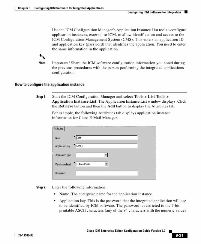
Chapter 9 Configuring ICM Software for Integrated ApplicationsConfiguring ICM Software for Integration
Use the ICM Configuration Manager’s Application Instance List tool to configure application instances, external to ICM, to allow identification and access to the ICM Configuration Management System (CMS). This enters an application ID and application key (password) that identifies the application. You need to enter the same information in the application.
Note Important! Share the ICM software configuration information you noted during the previous procedures with the person performing the integrated applications configuration.
How to configure the application instance
Step 1 Start the ICM Configuration Manager and select Tools > List Tools > Application Instance List. The Application Instance List window displays. Click the Retrieve button and then the Add button to display the Attributes tab.
For example, the following Attributes tab displays application instance information for Cisco E-Mail Manager.
Step 2 Enter the following information:
• Name. The enterprise name for the application instance.
• Application key. This is the password that the integrated application will use to be identified by ICM software. The password is restricted to the 7-bit printable ASCII characters (any of the 94 characters with the numeric values
9-21Cisco ICM Enterprise Editon Configuration Guide Version 6.0
78-11589-03
Chapter 9 Configuring ICM Software for Integrated ApplicationsConfiguring ICM Software for Integration
from 32 to 126). Control characters (for example, 'tab') and international characters are not allowed. This means passwords cannot be entered in a non-Western alphabet, such as Kanji.
• Application type. Available options are: Cisco_Collaboration_Server and Cisco_Email_Manager.
• Permission Level. Select the permission level from the drop-down list.
Step 3 After entering the required fields, save the configuration and close the window.
Note Refer to the ICM Configuration Manager’s online help for detailed information about the Application Instance List tool.
Application ConnectionsIn order for the application to communicate with the ICM system for configuration purposes, a communications path between ICM software and the application must be established.
You can define the communications path from ICM software (CMS Server) to the application using the Application tab in the CMS Control tool (resides on Distributor Admin Workstation in icm\bin directory). A similar user interface on the application side (Cisco Collaboration Server or Cisco E-Mail Manager) is used to define the communications path from the application to the CMS Server.
Within the Application tab, the Application Connections table lists the current application connections, where you can add, edit, and delete application connections.
Note The Application link and ICM Distributor AW link must match on the application side.
How to configure CMS Server connections
Step 1 Start the ICM Admin Workstation and double-click the CMS Control icon.
9-22Cisco ICM Enterprise Editon Configuration Guide Version 6.0
78-11589-03
Chapter 9 Configuring ICM Software for Integrated ApplicationsConfiguring ICM Software for Integration
Step 2 Select the Application tab.
Step 3 Click Add. The Application Connection Details dialog box displays.
Step 4 Enter the application connection properties:
• ICM Distributor AW link. The ICM RMI Driver connection end point identity; for example, CEM1_Application_Servant.
• ICM Distributor AW RMI registry port. The port number for the ICM Distributor AW RMI registry.
• Application link. The application RMI Driver connection end point identity; for example, CEM1_Application_Client.
• Application RMI registry port. The port number for the Application RMI registry.
• Application host name. The computer address where the application interface client resides. This name can be either an IP address or a name resolved by DNS or WINS; for example, CEM1.
Step 5 Click OK twice. This restarts the Cms_Jserver on the Admin Workstation.
Note When you click OK the second time to save your changes and close the CMS Control window, a message box may appear that states:“The CmsJServer process is about to be cycled. Click OK to proceed or Cancel to quit.”Click OK to proceed.
Note Refer to the application-specific instructions for specific field information. Refer to the CMS Control tool’s online help for specific information about the field descriptions.
Additional Configuration SetupsAfter configuring ICM software, you need to perform the following configurations in the Cisco Collaboration Server application:
9-23Cisco ICM Enterprise Editon Configuration Guide Version 6.0
78-11589-03
Chapter 9 Configuring ICM Software for Integrated ApplicationsConfiguring ICM Software for Integration
• Once you have configured ICM software and Cisco Collaboration Server, more configuration must occur on the Cisco Media Blender server. These tasks include:
– Ensuring Cisco Media Blender connection property files have been copied from the Cisco Collaboration Server
– Configuring the firewall gateway
• ICM and ACD queues:
– If the Collaboration server will be used to send requests submitted to it to ICM software, you must create one ICM queue. When a request is submitted to an ICM queue, ICM software will route the request to the Collaboration server and agent most appropriate to handle the request.
– If you are using legacy ACDs for Blended Collaboration you must create ACD queues on the Collaboration server. ACD queues are used to communicate with Cisco Media Blender.
Refer to the Cisco Collaboration Server installation CD for documentation on performing these configurations.
Using Application Gateways An application gateway is an optional ICM feature that allows you to invoke an external application from within a script (using a Gateway node). You can pass data to the application and receive data in return, which you can then examine and use for routing decisions.
Before you can use these nodes in a script, you must first configure the gateways.
The application gateway requires connection information to communicate with the external application. You perform this task using the Configuration Manager.
Configuring Application Gateways
You must configure an application gateway for each application you want to access from within scripts. Configuration information includes data such as:
• The type of application the gateway will interact with: a non-ICM application or an application on another ICM system
• The form of connection the gateway will use: duplex or simplex
9-24Cisco ICM Enterprise Editon Configuration Guide Version 6.0
78-11589-03
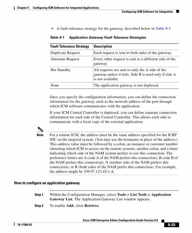
Chapter 9 Configuring ICM Software for Integrated ApplicationsConfiguring ICM Software for Integration
• A fault tolerance strategy for the gateway, described below in Table 9-1
Once you specify the configuration information, you can define the connection information for the gateway, such as the network address of the port through which ICM software communicates with the application.
If your ICM Central Controller is duplexed, you can define separate connection information for each side of the Central Controller. This allows each side to communicate with a local copy of the external application.
Note For a remote ICM, the address must be the same address specified for the ICRP NIC on the targeted system. (You may use the hostname in place of the address.) This address value must be followed by a colon, an instance or customer number (denoting which ICM to access on the remote system), another colon, and a letter indicating which side of the NAM system prefers to use this connection. The preference letters are A (side A of the NAM prefers this connection), B (side B of the NAM prefers this connection), N (neither side of the NAM prefers this connection), or R (both sides of the NAM prefer this connection). For example, the address might be 199.97.123.45:1:A.
How to configure an application gateway
Step 1 Within the Configuration Manager, select Tools > List Tools > Application Gateway List. The Application Gateway List window appears.
Step 2 To enable Add, click Retrieve.
Table 9-1 Application Gateway Fault Tolerance Strategies
Fault Tolerance Strategy Description
Duplicate Request Each request is sent to both sides of the gateway.
Alternate Request Every other request is sent to a different side of the gateway.
Hot Standby All requests are sent to only the A side of the gateway unless it fails. Side B is used only if side A is not available.
None The application gateway is not duplexed.
9-25Cisco ICM Enterprise Editon Configuration Guide Version 6.0
78-11589-03
Chapter 9 Configuring ICM Software for Integrated ApplicationsConfiguring ICM Software for Integration
Step 3 Click Add. The Attributes property tab appears.
Step 4 Complete the Attributes property tab.
Note For additional information refer to the online Help.
Step 5 Click Save to create the application gateway.
Next, configure the connection information for the application gateway.
How to configure an application gateway connection and set the default connection parameters
Step 1 Within the Application Gateway List window, click Retrieve and select the desired Application Gateway.
Step 2 Complete the Connection property tab(s).
Note For additional information refer to the online Help.
Step 3 Click Save to apply your changes.
Skill Group Configuration with ICM Script Editor
Universal Queue
Universal Queue is the ability of the ICM software to route requests from voice, web, chat, and e-mail channels from a single queue point directly to appropriately skilled agents. With Universal Queue, ICM software treats requests from different media channels as a part of a single queue. Routing scripts send queued requests to agents based on business rules regardless of the media channel. For example, the routing of asynchronous channels such as e-mail, and synchronous channels such as voice and chat, allows ICM software to deliver the right contact to the right resource the first time, regardless of the channel it came through.
9-26Cisco ICM Enterprise Editon Configuration Guide Version 6.0
78-11589-03
Chapter 9 Configuring ICM Software for Integrated ApplicationsConfiguring ICM Software for Integration
The Queue to Agent node allows the targeting of a task (the work performed by an agent) to a script-specified agent. The Queue to Agent node enables an agent to receive and operate on more than one task at a time. As a result, Universal Queue coordinates an agent’s ability to work on multiple tasks of various media. It supports a simple control model where an agent’s ability to handle an additional task depends on what task that agent is currently handling. For this level of control, ICM software must have exclusive access to task assignment.
Note For Universal Queue to work, the agent must be assigned to skill groups that “ICM picks the agent,” for which ICM software does the routing.
The CallRouter has the ability to move tasks out of the present script execution and resubmit them into the system as a new invocation.
Routing Script Configuration
Due to the introduction of a Media Routing Domain relationship, skill groups are medium specific. When an agent logs into ICM software via a phone, or via Cisco Collaboration Server or Cisco E-Mail Manager, the agent actually logs into an MRD. This automatically logs the agent into skill groups associated with that agent within that MRD. Then, as a task request for a specific MRD begins script execution, the CallRouter considers only the skill groups associated with that specific MRD. This allows one script to be written to handle many MRDs.
When upgrading from an earlier version of ICM software, setup upgrades all existing skill group definitions to the Voice Media Routing Domain. (MRDs for Single-session Chat, Multi-session Chat, Email, or Blended Collaboration media classes must be added using the ICM Configuration Manager’s Media Routing Domain List tool.)
The associated MRD applies to most related objects. Service member objects only map skill groups to services of the same media routing domain.
Skill groups are created as follows:
• Cisco Collaboration Server and Cisco E-Mail Manager skill groups (Cisco Collaboration Server Single-session chat, Cisco Collaboration Server Multi-session chat, Cisco Collaboration Server Blended Collaboration - IPCC, and Cisco E-Mail Manager e-mail) are configured (created, modified, deleted and agent assignment is done) on the applications.
9-27Cisco ICM Enterprise Editon Configuration Guide Version 6.0
78-11589-03

Chapter 9 Configuring ICM Software for Integrated ApplicationsConfiguring ICM Software for Integration
• Legacy ACD skill groups are configured on the ACD and on ICM software.
Queue to Specific Agent
To assign a task to a specific agent, the CallRouter needs to do four things:
1. Pick an agent to receive the task.
2. Pick the MRD.
3. Pick a skill group from the list provided by the MRD selection.
4. Pick a route from the list provided by the skill group selection.
Using this style of Queue to Agent node, you select a specific agent at script design time.
In this case, where it is obvious who the agent is, the node property sheet displays a choice of routes for the peripheral that the agent is assigned to.
Note Routes, agents, skill groups, and services are all associated with a peripheral.
How to select multiple skill groups and routes for different media by agent
Step 1 In ICM Script Editor, open the appropriate script in Edit mode.
Step 2 Select the Queue to Agent node.
Step 3 Right-click and select Properties to open the Queue to Agent Properties dialog box.
Step 4 Ensure the Queue to Agent type is set to Select using direct references. If not:
a. Select Change to open the Queue Agent Type dialog box.
b. Select Explicit agent references.
c. Click OK to return to the Queue to Agent Properties dialog box.
Step 5 Select an agent from the drop-down list in the Agent column. This enables the rest of the columns.
Step 6 In the Domain column, select the appropriate MRD.
9-28Cisco ICM Enterprise Editon Configuration Guide Version 6.0
78-11589-03

Chapter 9 Configuring ICM Software for Integrated ApplicationsConfiguring ICM Software for Integration
Step 7 In the appropriate column, select a skill group and a Route valid for the selected agent and MRD.
You can specify the agent multiple times, each with a different MRD selection.
Queue to Agent Expression
In this mode of the Queue to Agent node, the agent identity is determined by the queue to agent expression at runtime.
Since the agent and MRD are not known until script execution time, you need some way of selecting an appropriate skill group and route. To accomplish this, pick an enterprise skill group. Ensure the enterprise skill group includes appropriate skill groups to cover all MRD cases for that agent. To select the route, use an enterprise route. Again, ensure that the enterprise route includes an appropriate collection of routes.
How to select multiple skill groups and routes for different media by agent expression
Step 1 In ICM Script Editor, open the appropriate script in Edit mode.
Step 2 Select the Queue to Agent node.
Step 3 Right-click and select Properties to open the Queue to Agent Properties dialog box.
Step 4 Ensure the Queue to Agent type is set to Select using indirect references. If not:
a. Select Change to open the Queue Agent Type dialog box.
b. Select Lookup agent references by expression.
c. Click OK to return to the Queue to Agent Properties dialog box.
Step 5 Enter an agent expression (normally task.PreferredAgentID) into the Agent Expression column. Formula Editor is enabled when the Agent Expression column is selected.
Note PreferreAgentID is not used by Cisco Collaboration Server. If you wish to set the agent ID dynamically in the Agent Expression field, use a Call variable or an ECC variable.
9-29Cisco ICM Enterprise Editon Configuration Guide Version 6.0
78-11589-03
Chapter 9 Configuring ICM Software for Integrated ApplicationsConfiguring ICM Software for Integration
Step 6 In the appropriate column, select an appropriate Enterprise Skill Group and an Enterprise Route valid for the entered agent expression.
You can specify the agent expression multiple times, each with a different enterprise skill group and enterprise route selection.
Refer to the Cisco ICM Software Scripting and Media Routing Guide for more information about using ICM Script Editor.
Pushing Information to Waiting Cisco Collaboration Server Callers
On the ICM Central Controller, you can create a Network VRU script list, which lists scripts set up to play to callers waiting for an agent. With the ICM-integrated Cisco Collaboration Server, you can set up a VRU script list to point to URLs or text messages to display on the browsers of callers waiting for a Collaboration agent.
With ICM routing, you have the option of displaying information, such as advertisements or informational URLs to a caller who is waiting to join a session with an agent. You can also populate these ads or URLs so that they display caller information originating in the callform. This way, you can personalize ads or messages seen by the waiting caller.
Refer to the Cisco Collaboration Server Administration Guide for detailed instructions on setting up this information.
Agent Reporting on the Admin Workstation for a Particular PGThe following instructions provide information on how to configure the AW for agent reporting of real time and historical data.
How to configure agent reporting
Step 1 With WebView and the third-party tools installed, set up an HDS database on the AW.
9-30Cisco ICM Enterprise Editon Configuration Guide Version 6.0
78-11589-03
Chapter 9 Configuring ICM Software for Integrated ApplicationsApplication Object Filter
Step 2 Check the WebView Reporting checkbox in the Real-time Distributor Node Properties window of the AW setup.
Step 3 Click the Real-time Distributor option in the Admin Workstation Properties window of the AW setup.
Step 4 Check the Historical Data Server checkbox in the Real-time Distributor Properties window of the AW setup.
Note Make a note of the AW’s Distributor Site Name in the AW setup because this information will be needed later on.
Step 5 Configure the same AW for the Historical Data Server in the setup for the AW.
Step 6 Configure the Logger for HDS replication by clicking the Historical Data Replication checkbox in the Logger Properties window.
Step 7 Open the PG Explorer in the ICM Configuration Manager and select the PIM.
Step 8 Configure the PG PIM for Agent Reporting by clicking the Agent Reporting checkbox on the Advanced tab.
Step 9 Open the Agent Distribution List Tool in the ICM Configuration Manager and add an entry for that PG/PIM and the AW’s Distributor Site Name (see Step 4), exactly as it appears in the AW setup.
Application Object FilterThe application object filter restricts access to application specific data that is not owned by the running application (for example, Cisco E-Mail Manger or Cisco Collaboration Server). Application owned data includes skill groups, services, application paths, and routes. The application object filter is not applicable if there are no multimedia applications.
Access to the application object filter is restricted. You must use a super user password (case sensitive) to enable or disable the application object filter. This password is set as “password” during installation.
9-31Cisco ICM Enterprise Editon Configuration Guide Version 6.0
78-11589-03
Chapter 9 Configuring ICM Software for Integrated ApplicationsApplication Object Filter
Normally enabled, the application object filter prevents administrators from creating or editing application specific skill groups, services, application paths, or routes in the Configuration Manager. You would want this enabled since creating or editing the preceding application specific data using ICM could cause the application to become out of sync with the ICM. These items should be created and updated in the application requiring them, and not in ICM software.
Disabling the application object filter allows administrators to create, delete, or edit application specific skill groups, services, application paths, and routes from the Configuration Manager tools. You might want to do this if, for example, an application is dead (you cannot access the application) and application specific data needs to be removed from the ICM database. Another example of when you would want to disable the application object filter would be you need clean up after removing an application.
How to disable an application object filter:
Step 1 Select Options > Application Object Filter.
Step 2 Enter the Password when prompted.
Step 3 Select Disable.
Step 4 The tool opens and the status line indicates the application object filter is disabled.
Note Open tools are not affected by the change in the application object filter status. The status change only effects tools opened after the application object filter status has been changed.
Note Each time the Configuration Manager opens, the application object filter reverts to its default status – enabled.
9-32Cisco ICM Enterprise Editon Configuration Guide Version 6.0
78-11589-03
Cisco ICM Enterprise78-11589-03
C H A P T E R10
Configuring ICM VariablesThere re two types of ICM variables you can configure:
• Expanded Call Context variables
• User variables
ECC (Expanded Call Context) VariablesExpanded Call Context (ECC) variables are variables that you define and enable in the Configuration Manager to store values associated with the call. You can specify the variable name and data type. The name must begin with the string user. These are in addition to the variables the ICM software defines for each call (PeripheralVariable1 through PeripheralVariable10, CallerEnteredDigits, CallingLineID, etc.).
An ECC variable name can be up to 33 bytes long (1-32 usable characters + a null terminator). In addition, it is highly recommended that you use the following naming convention when creating an ECC variable:
user.<CompanyName>.<VariableDescription>
In this syntax:
• <CompanyName> is the name of your company
• <VariableDescription> is a descriptive tag for the variable.
For example, you could use the following name for an ECC variable created for Cisco account numbers:
user.Cisco.AcctNum
10-1 Editon Configuration Guide Version 6.0

Chapter 10 Configuring ICM Variables
Using this naming convention will prevent naming conflicts with any third-party applications that interface with ICM software.
Note If your corporation is large, you may even want to break <VariableDescription> down to include the Business Unit, Division, or other organizational entity that exists in your company.
An ECC variable can be either a scalar variable or an array.
The maximum length of a scalar variable or array element can be 1 to 210 bytes.
The maximum number of elements in an array can be 1 to 255.
The maximum buffer size for each scalar variable = 5 + the maximum length of the variable where the 5 bytes includes 4 bytes to tag the variable and 1 byte for the null terminator.
The maximum buffer size for each array = 5 + (1 + the maximum length of array element) * (the maximum number of elements in the array). There is a null terminator for each element, as well as a null terminator for the array as a whole.
Since the total size of the buffer used to store the variables internally is 2000 bytes, the total sum of all the maximum buffer sizes for each variable and each array must be no greater than 2000.
For example, if you intended to use one scalar ECC variable with a maximum length of 100 bytes, one scalar ECC variable with a maximum length of 80 bytes, and an ECC array with a maximum of 9 elements with each element having a maximum length of 200 bytes, the buffer size would be:
(5+100) + (5+80) + (5 + (1+200)*9) = 2004
This is too large so the length of one of the scalar ECC variables or the length of the array ECC variable needs to be adjusted.
Expanded call variable configuration consists of two steps:
• Setting the Enable Expanded Call Context option in the System Information dialog box
• Defining the variable through the Expanded Call Variable List in the Configuration Manager
10-2Cisco ICM Enterprise Editon Configuration Guide Version 6.0
78-11589-03
Chapter 10 Configuring ICM Variables
How to set the Enable Expanded Call Context option
Step 1 Within the Configuration Manager, select Tools > Miscellaneous Tools > System Information. The System Information window appears.
Step 2 Select Enable Expanded Call Context.
Note For additional information refer to the online Help.
Step 3 Click Save to apply your changes.
How to define an Expanded Call Context (ECC) variable
Step 1 Within the Configuration Manager, select Tools > List Tools > Expanded Call Variable List. The Expanded Call Variable List window appears.
Step 2 In the Expanded Call Variable List window, enable Add by clicking Retrieve.
Step 3 Click Add. The Attributes property tab appears.
Step 4 Complete the Attributes property tab.
Note The Name and Maximum Length fields are required. All other fields are optional. The Name must begin with “user” and cannot exceed 32 characters. The recommended syntax is: user.<CompanyName>.<VariableDescription>.For additional information refer to the online Help.
Step 5 Click Save to apply your changes.
For Web Callback and Delayed Callback to work properly, an ECC variable (also known as a named variable) must be defined. The Cisco CTI driver supports the use of ECC variables in addition to the standard call variables associated with a call. Before an ECC variable can be used, it must be defined in the ICM ECC variable database table.
10-3Cisco ICM Enterprise Editon Configuration Guide Version 6.0
78-11589-03
Chapter 10 Configuring ICM Variables
See How to define an Expanded Call Context (ECC) variable, page 10-3 or the Cisco ICM Software Configuration Manager online help for a description of how to create ECC variables. See the Cisco ICM Enterprise Edition Database Schema Handbook.
ECC Variables for Cisco Blended Collaboration or Voice MRDs with Collaboration
ECC variables must be configured in the ICM Configuration Manager’s Expanded Call Variable List tool (for each integrated application) in order to route requests using the voice Media Routing Domain.
For Cisco Blended Collaboration or Voice MRDs with Collaboration, the ECC variables are:
• user.cisco.cmb
• user.cisco.cmb.callclass
Note You do not need to specify these variables in your input map on the Cisco Collaboration Server; however, Collaboration automatically configures these variables when you enable the Voice MRDs associated with your specific Cisco Collaboration Server instance.
In addition, if changes are made to the ECC variables in your inmap file, or to ECC variables in ICM software, you must restart Cisco Collaboration Server for changes to take effect.
Note Important! While their default size is 40 characters, use the Expanded Call Variable List tool in the ICM Configuration Manager to limit the user.cisco.cmb variable to 8 bytes and the user.cisco.cmb.callclass variable to 10 bytes to prevent ECC space limitation issues.
Note Refer to the ICM Configuration Manager’s online help for detailed information about the Expanded Call Variable List tool.
10-4Cisco ICM Enterprise Editon Configuration Guide Version 6.0
78-11589-03
Chapter 10 Configuring ICM Variables
User VariablesYou can also create global user variables. For example, you could create a user variable called usertemp to serve as a temporary storage area for a string value used by an If node.
Each user variable must:
• Have a name that begins with user.
• Be associated with an object type, for example, Service. (This enables ICM software to maintain an instance of that variable for each object of that type in the system.)
• Be identified as a persistent (retains value across CallRouter restarts) or non-persistent (does not retain value across CallRouter restarts) variable.
Note A user variable can store a value up to 40 characters long.
After you have defined a variable, you can then use the Script Editor Formula Editor to access the variable and reference it in expressions, just as you would with a “built-in” variable
How to define a user variable
Step 1 Within the Configuration Manager, select Tools > List Tools > User Variable List. The User Variable List window appears.
Step 2 In the User Variable List window, enable Add by clicking Retrieve.
Step 3 Click Add. The Attributes property tab appears.
Step 4 Complete the Attributes property tab.
Note The Variable name, Object type, and Data type fields are required. All other fields are optional. For additional information refer to the online Help.
Step 5 Click Save to apply your changes.
10-5Cisco ICM Enterprise Editon Configuration Guide Version 6.0
78-11589-03

Chapter 10 Configuring ICM Variables
10-6Cisco ICM Enterprise Editon Configuration Guide Version 6.0
78-11589-03
Cisco ICM Enterprise78-11589-03
C H A P T E R 11
Network IVRs/VRUsThis chapter discusses the Network IVR/VRU feature that lets you divert a call to an interactive voice response unit for additional processing. It includes:
• An introduction to IVR/VRUs
• Information on how to configure IVR/VRUs
• A discussion on how to access IVR/VRUs in scripts
• Instructions on how to queue calls at IVR/VRUs
Introducing Network IVRs/VRUsEach routing client can have one or more associated Network Voice Response Units (VRUs). A VRU is a telecommunications computer, also called an Interactive Voice Response (IVR) unit, that responds to caller-entered touch-tone digits.
The routing client can be a public network interexchange carrier (IXC) intelligent network, such as the BT INAP, or a private network peripheral, such as an Aspect or Avaya ACD.
Note Network VRUs are only available for intelligent public network IXCs, not all public network IXCs.
11-1 Editon Configuration Guide Version 6.0
Chapter 11 Network IVRs/VRUsVRU Configuration Tools
A Network VRU supports ICM software’s service control interface. An ICM routing script can divert a call to a Network VRU and instruct the VRU to perform specific processing before ICM software determines the final destination for the call.
Preparation for using the VRU feature includes:
• Setting up Network VRU targets with the Configuration Manager
• Inserting VRU nodes in the routing script
This chapter describes how to perform these tasks.
Note For the remainder of this chapter, the term VRU will be used exclusively to be consistent with the on-screen prompts.
VRU Configuration Tools
Network VRU ExplorerThis tool allows a Network Applications Manager (NAM) to view, edit, or define network VRUs, labels, and their associations. The ICM software can send a customer call to a network VRU.
Note The Network VRU Explorer is not available on a limited AW.
To begin, select the filters you want and click Retrieve.
The changes you make in the Network VRU Explorer window are not applied to the database until you click Save.
Select filter data box
Use the Select filter data box (see Accessing Database Records, page 3-16 for additional information) to select and retrieve data from the database. Until you retrieve database data, no data is displayed.
11-2Cisco ICM Enterprise Editon Configuration Guide Version 6.0
78-11589-03
Chapter 11 Network IVRs/VRUsVRU Configuration Tools
Network VRU Label Tree
Hide/Show legend
This button toggles between Hide and Show. Click it to hide or show a diagram identifying all the objects that can be displayed in the tree list box and showing their hierarchy.
Tree list box
The tree list box displays the names of the retrieved Network VRUs and, when expanded, the labels associated with them.
When you select an item within the tree, details about that item appear in the tabbed property fields to the right of the tree list box.
Tree list box Properties
• Expanding (+)/contracting (-) the tree (+ and – buttons)
• Displaying option menu (right mouse button clicking)
• Making tree connections (drag and drop)
With the mouse, you can select an object and then move it to another part of the tree, as long as its object type belongs in that tree location.
For example, to move a route to another service, select it by clicking the left mouse button, and then move the mouse to that service. When that service becomes highlighted, lift your finger off the mouse. You could also use the Bulk Configuration tool to take the output of a switch and create 20 or 30 labels. Then, using one of the explorer tools, you could attach these UNASSIGNED labels to an appropriate location.
• Symbols indicating object state (see Record Status Symbol Descriptions, Table 3-2 on page 3-12.
• UNASSIGNED tree objects
A tree object is marked UNASSIGNED if it was made by another configuration tool and was not assigned (mapped) to a parent object.
For example, a label might not have been assigned to a peripheral target or a route might not have been assigned to a service.
11-3Cisco ICM Enterprise Editon Configuration Guide Version 6.0
78-11589-03

Chapter 11 Network IVRs/VRUsVRU Configuration Tools
With the mouse, you can select an UNASSIGNED object and move it to a tree branch, as long as it’s an object that belongs in that tree location. Use the window legend to see what objects belong where.
When you move an UNASSIGNED object to an appropriate tree-branch location, you assign that object to the object above it in the tree. Then the object is no longer unassigned. For example, in this way you might assign an unassigned label to a peripheral target.
Add
When an object in the tree is selected, you can add another object of the same kind or an object immediately below it in the tree hierarchy. The Add buttons are enabled accordingly.
Add Network VRU
Click to add a network VRU to the database.
Add Label
Click to add a label to the selected network VRU.
Delete
Click to delete the selected object in the tree. This marks the selected object for deletion. When you click Save, the object is deleted from the database.
If a network VRU is selected, it and the labels associated with it are marked for deletion. If a label is selected, only that label’s record is marked for deletion.
Undelete
The Delete button toggles to Undelete when you select an object marked for deletion. To undelete an object marked for deletion, select it and click Undelete.
Security
Visible only if you have partitioning. Enabled only if you have maintenance access to the database record.
11-4Cisco ICM Enterprise Editon Configuration Guide Version 6.0
78-11589-03

Chapter 11 Network IVRs/VRUsVRU Configuration Tools
Click to apply security options to the selected tree object. For a description of the security options, click.
ID status box
The label in the ID box at the bottom of the screen identifies the ICM system on which you are working.
Network VRU Tab
Allows you to view (and define or edit, if you have maintenance access) the properties of the selected network VRU.
Label tab
Allows you to view (and create, delete, or edit, if you have maintenance access) the properties of the selected label.
Table 11-1 Network VRU Explorer Network VRU Tab Descriptions
Field Description
Name (required) An enterprise name for the network VRU. This name must be unique for all network VRUs in the enterprise
Type (required) (selection list) The type of network VRU. For additional information see Voice Response Unit (VRU) Types, Table 11-5 on page 11-14.
Description Additional information about the network VRU.
Table 11-2 Network VRU Explorer Label Tab Descriptions
Field Description
Routing client (required) The enterprise name of the routing client associated with the label.
Label (required) The label value.
11-5Cisco ICM Enterprise Editon Configuration Guide Version 6.0
78-11589-03
Chapter 11 Network IVRs/VRUsVRU Configuration Tools
Network VRU Script List ToolThis tool allows you to list the network VRU scripts currently defined in the ICM database, to define new ones, and to view, edit, or delete the records of existing ones.
Network VRU scripts are created by VRU engineers for VRUs. This list tool defines these previously created scripts for ICM software so it can interact with the scripts.
Note The Network VRU Script List tool is not available on a limited AW.
Select filter data box
Use the Select filter data box (see Accessing Database Records, page 3-16 for additional information) to select and retrieve data from the database. Until you retrieve database data, no data is displayed.
Network VRU Script List box
Lists the network VRU scripts retrieved or created in the current editing session. The tabbed fields on the right side of the window display the properties of the selected network VRU script.
Label type (required) (Drop-down list) The valid types depend on the type of routing client. Select one valid type for your routing client. Check with your carrier for the latest information about supported label types. Typical types are Normal, DNIS Override, Busy, Ring, and Post-Query.
Customer (optional) The customer associated with the label.
Description Additional information about the label.
Table 11-2 Network VRU Explorer Label Tab Descriptions (continued)
Field Description
11-6Cisco ICM Enterprise Editon Configuration Guide Version 6.0
78-11589-03
Chapter 11 Network IVRs/VRUsVRU Configuration Tools
Attributes tab
Allows you to view and (if you have maintenance access) to define, edit, or delete the attributes of the selected network VRU script.
Security tab
Visible only on partitioned systems and enabled only on records for which you have maintenance access. See the
Table 11-3 VRU Script List Tool Application Tab Descriptions
Field Description
Name (required) An enterprise name for the VRU script. This name must be unique for all VRU scripts in the system.
Network VRU (required) (selection list) The network VRU associated with the VRU script.
VRU script name (required) The number by which the script is known to the VRU.
Timeout (seconds) (required)
The number of seconds the ICM should wait for a response after directing the routing client to run this script. If the ICM does not receive a response from the routing client within this time, it assumes the VRU script has failed.
Configuration param A string to be passed to the VRU when the script is invoked.
Customer (selection list) The customer associated with the VRU script, if any.
Interruptible Checked, indicates the script can be interrupted (for example, if an agent becomes available to handle the call).
Overridable) Checked, indicates the script can make itself interruptible or non-interruptible.
Description Any additional information about the VRU script.
11-7Cisco ICM Enterprise Editon Configuration Guide Version 6.0
78-11589-03
Chapter 11 Network IVRs/VRUsVRU Configuration Tools
VRU Currency List ToolThis tool allows you to list the VRU currencies currently defined in the ICM database, to define new ones, and to view, edit, or delete the records of existing ones.
Select filter data box
Use the Select filter data box (see Accessing Database Records, page 3-16 for additional information) to select and retrieve data from the database. Until you retrieve database data, no data is displayed.
VRU Currency list box
Lists the VRU currencies retrieved and or created in the current editing session. The tabbed field on the right side of the window displays the name of the selected VRU currency.
Attributes tab
Allows you to view and (if you have maintenance access) to define, modify, and delete currencies.
Currency (required)
The type of currency (pounds, dollars, yens, and so on) that the VRU uses when playing prompts. For example, the type of currency is needed if a caller requests information regarding a bank statement. The currency type cannot be longer than 10 characters.
VRU Defaults List ToolThis tool allows you to list VRU defaults currently defined in the ICM database, to define new ones, and to view, edit, or delete the records of existing ones.
11-8Cisco ICM Enterprise Editon Configuration Guide Version 6.0
78-11589-03
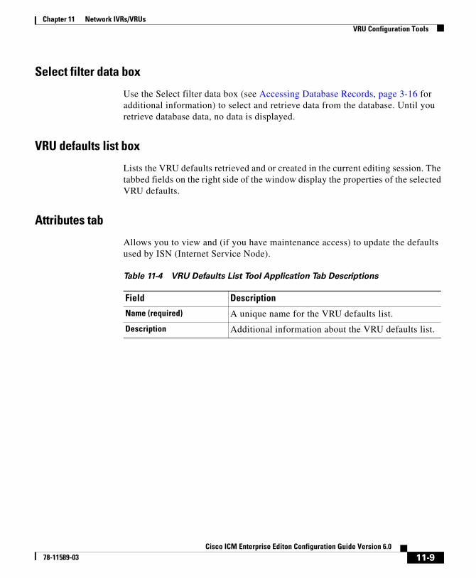
Chapter 11 Network IVRs/VRUsVRU Configuration Tools
Select filter data box
Use the Select filter data box (see Accessing Database Records, page 3-16 for additional information) to select and retrieve data from the database. Until you retrieve database data, no data is displayed.
VRU defaults list box
Lists the VRU defaults retrieved and or created in the current editing session. The tabbed fields on the right side of the window display the properties of the selected VRU defaults.
Attributes tab
Allows you to view and (if you have maintenance access) to update the defaults used by ISN (Internet Service Node).
Table 11-4 VRU Defaults List Tool Application Tab Descriptions
Field Description
Name (required) A unique name for the VRU defaults list.
Description Additional information about the VRU defaults list.
11-9Cisco ICM Enterprise Editon Configuration Guide Version 6.0
78-11589-03
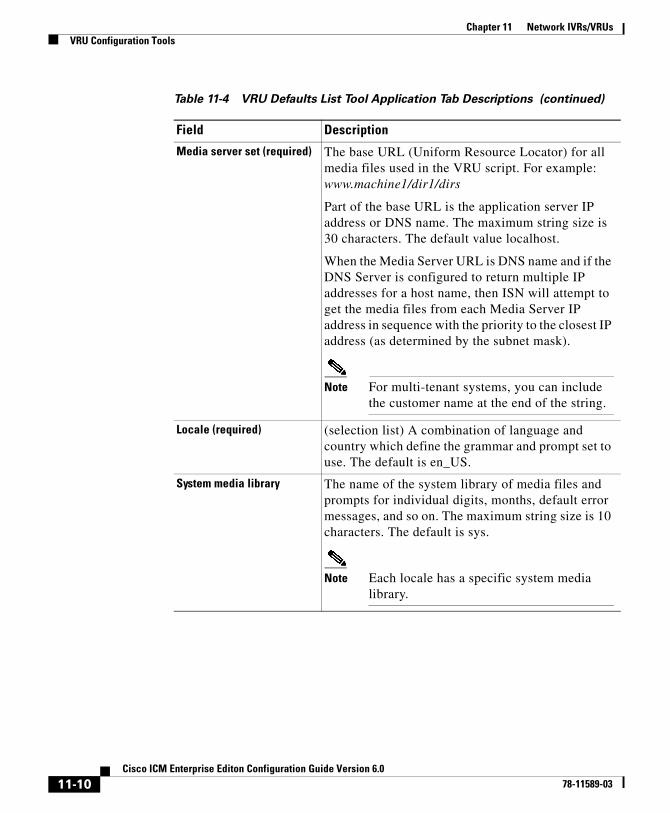
Chapter 11 Network IVRs/VRUsVRU Configuration Tools
Media server set (required) The base URL (Uniform Resource Locator) for all media files used in the VRU script. For example: www.machine1/dir1/dirs
Part of the base URL is the application server IP address or DNS name. The maximum string size is 30 characters. The default value localhost.
When the Media Server URL is DNS name and if the DNS Server is configured to return multiple IP addresses for a host name, then ISN will attempt to get the media files from each Media Server IP address in sequence with the priority to the closest IP address (as determined by the subnet mask).
Note For multi-tenant systems, you can include the customer name at the end of the string.
Locale (required) (selection list) A combination of language and country which define the grammar and prompt set to use. The default is en_US.
System media library The name of the system library of media files and prompts for individual digits, months, default error messages, and so on. The maximum string size is 10 characters. The default is sys.
Note Each locale has a specific system media library.
Table 11-4 VRU Defaults List Tool Application Tab Descriptions (continued)
Field Description
11-10Cisco ICM Enterprise Editon Configuration Guide Version 6.0
78-11589-03
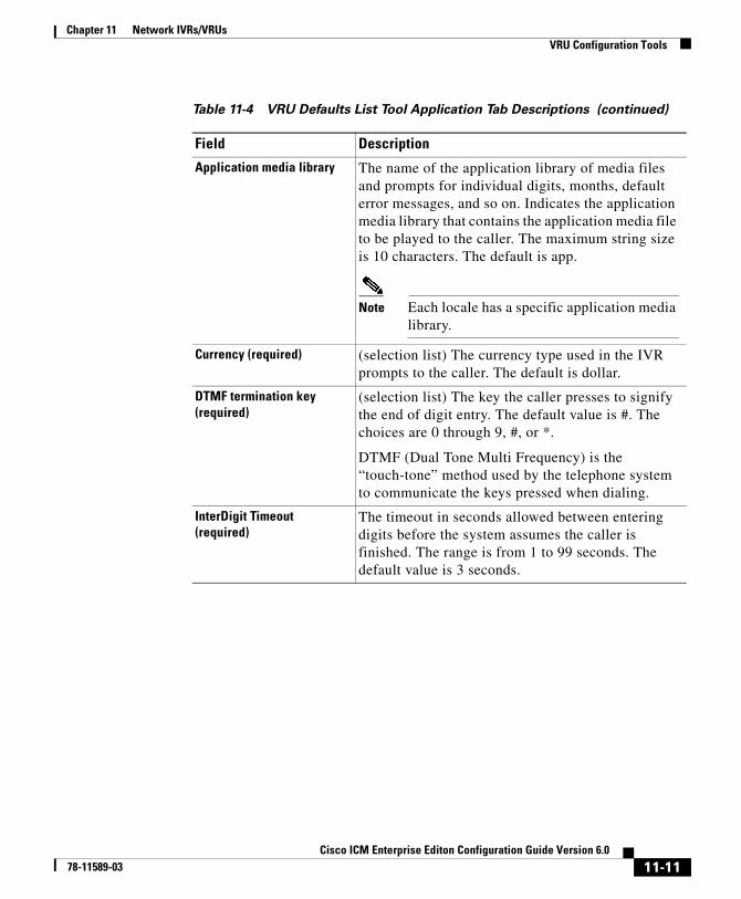
Chapter 11 Network IVRs/VRUsVRU Configuration Tools
Application media library The name of the application library of media files and prompts for individual digits, months, default error messages, and so on. Indicates the application media library that contains the application media file to be played to the caller. The maximum string size is 10 characters. The default is app.
Note Each locale has a specific application media library.
Currency (required) (selection list) The currency type used in the IVR prompts to the caller. The default is dollar.
DTMF termination key (required)
(selection list) The key the caller presses to signify the end of digit entry. The default value is #. The choices are 0 through 9, #, or *.
DTMF (Dual Tone Multi Frequency) is the “touch-tone” method used by the telephone system to communicate the keys pressed when dialing.
InterDigit Timeout (required)
The timeout in seconds allowed between entering digits before the system assumes the caller is finished. The range is from 1 to 99 seconds. The default value is 3 seconds.
Table 11-4 VRU Defaults List Tool Application Tab Descriptions (continued)
Field Description
11-11Cisco ICM Enterprise Editon Configuration Guide Version 6.0
78-11589-03
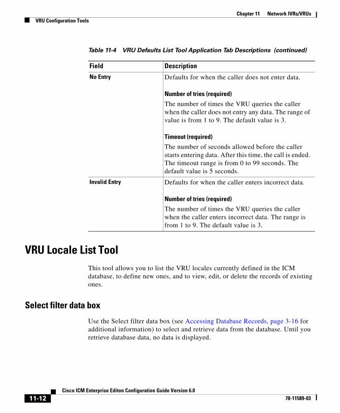
Chapter 11 Network IVRs/VRUsVRU Configuration Tools
VRU Locale List ToolThis tool allows you to list the VRU locales currently defined in the ICM database, to define new ones, and to view, edit, or delete the records of existing ones.
Select filter data box
Use the Select filter data box (see Accessing Database Records, page 3-16 for additional information) to select and retrieve data from the database. Until you retrieve database data, no data is displayed.
No Entry Defaults for when the caller does not enter data.
Number of tries (required)
The number of times the VRU queries the caller when the caller does not entry any data. The range of value is from 1 to 9. The default value is 3.
Timeout (required)
The number of seconds allowed before the caller starts entering data. After this time, the call is ended. The timeout range is from 0 to 99 seconds. The default value is 5 seconds.
Invalid Entry Defaults for when the caller enters incorrect data.
Number of tries (required)
The number of times the VRU queries the caller when the caller enters incorrect data. The range is from 1 to 9. The default value is 3.
Table 11-4 VRU Defaults List Tool Application Tab Descriptions (continued)
Field Description
11-12Cisco ICM Enterprise Editon Configuration Guide Version 6.0
78-11589-03
Chapter 11 Network IVRs/VRUsConfiguring Network VRUs and VRU Scripts
VRU locales list box
Lists the VRU locales retrieved and or created in the current editing session. The tabbed fields on the right side of the window display the properties of the selected VRU locales.
VRU Locale
A combination of language and country which define the grammar and prompt set to use when the VRU plays prompts.
Attributes tab
Allows you to view and (if you have maintenance access) to define, modify, and delete VRU locales.
Locale (required)
A combination of language and country which define the grammar and prompt set to use when the VRU plays prompts. The default is en_US. This cannot be longer than 10 characters.
Configuring Network VRUs and VRU ScriptsBefore you start configuring a Network VRU, you must know its type. The VRU type determines what routing script nodes ICM software needs to use to communicate with the VRU. For example, when interacting with a Type 3 VRU, ICM software will need to execute a routing script containing a Send to VRU node in order to successfully process a call.
Table 11-5 lists the VRU types that are currently available.
11-13Cisco ICM Enterprise Editon Configuration Guide Version 6.0
78-11589-03
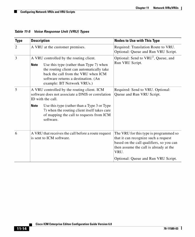
Chapter 11 Network IVRs/VRUsConfiguring Network VRUs and VRU Scripts
Table 11-5 Voice Response Unit (VRU) Types
Type Description Nodes to Use with This Type
2 A VRU at the customer premises. Required: Translation Route to VRU. Optional: Queue and Run VRU Script.
3 A VRU controlled by the routing client.
Note Use this type (rather than Type 7) when the routing client can automatically take back the call from the VRU when ICM software returns a destination. (An example: BT Network VRUs.)
Optional: Send to VRU1, Queue, and Run VRU Script.
5 A VRU controlled by the routing client. ICM software does not associate a DNIS or correlation ID with the call.
Note Use this type (rather than a Type 3 or Type 7) when the routing client itself takes care of mapping the call to requests from ICM software.
Required: Send to VRU. Optional: Queue and Run VRU Script.
6 A VRU that receives the call before a route request is sent to ICM software.
The VRU for this type is programmed so that it can recognize such a request based on the call qualifiers, so you can then assume the call is already at the VRU.
Optional: Queue and Run VRU Script.
11-14Cisco ICM Enterprise Editon Configuration Guide Version 6.0
78-11589-03
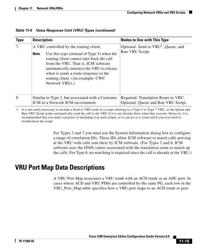
Chapter 11 Network IVRs/VRUsConfiguring Network VRUs and VRU Scripts
For Types 3 and 7 you must use the System Information dialog box to configure a range of correlation IDs. These IDs allow ICM software to match calls arriving at the VRU with calls sent there by ICM software. (For Types 2 and 8, ICM software uses the DNIS values associated with the translation route to match up the calls. For Type 6, no matching is required since the call is already at the VRU.)
VRU Port Map Data DescriptionsA VRU Port Map associates a VRU trunk with an ACD trunk or an ADC port. In cases where ACD and VRU PIMs are controlled by the same PG, each row in the VRU_Port_Map table specifies how a VRU port maps to an ACD trunk or port.
7 A VRU controlled by the routing client.
Note Use this type (instead of Type 3) when the routing client cannot take back the call from the VRU. That is, ICM software automatically instructs the VRU to release when it sends a route response to the routing client. (An example: CWC Network VRUs.)
Optional: Send to VRU1, Queue, and Run VRU Script.
8 Similar to Type 2, but associated with a Customer ICM in a Network ICM environment.
Required: Translation Route to VRU. Optional: Queue and Run VRU Script.
1. It is not really necessary to include a Send to VRU node in a script referring to a Type 3 or Type 7 VRU, as the Queue and Run VRU Script nodes automatically send the call to the VRU if it is not already there when they execute. However, it is recommended that you make a practice of including it in such scripts, as it can act as a visual aid if you ever need to troubleshoot the script.
Table 11-5 Voice Response Unit (VRU) Types (continued)
Type Description Nodes to Use with This Type
11-15Cisco ICM Enterprise Editon Configuration Guide Version 6.0
78-11589-03
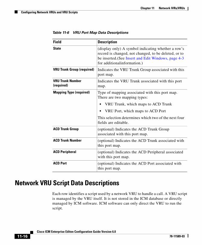
Chapter 11 Network IVRs/VRUsConfiguring Network VRUs and VRU Scripts
Network VRU Script Data DescriptionsEach row identifies a script used by a network VRU to handle a call. A VRU script is managed by the VRU itself. It is not stored in the ICM database or directly managed by ICM software. ICM software can only direct the VRU to run the script.
Table 11-6 VRU Port Map Data Descriptions
Field Description
State (display only) A symbol indicating whether a row’s record is changed, not changed, to be deleted, or to be inserted.(See Insert and Edit Windows, page 4-3 for additionalinformation.)
VRU Trunk Group (required) Indicates the VRU Trunk Group associated with this port map.
VRU Trunk Number (required)
Indicates the VRU Trunk associated with this port map.
Mapping Type (required) Type of mapping associated with this port map. There are two mapping types:
• VRU Trunk, which maps to ACD Trunk
• VRU Port, which maps to ACD Port
This selection determines which two of the next four fields are editable.
ACD Trunk Group (optional) Indicates the ACD Trunk Group associated with this port map.
ACD Trunk Number (optional) Indicates the ACD Trunk associated with this port map.
ACD Peripheral (optional) Indicates the ACD Peripheral associated with this port map.
ACD Port (optional) Indicates the ACD Port associated with this port map.
11-16Cisco ICM Enterprise Editon Configuration Guide Version 6.0
78-11589-03
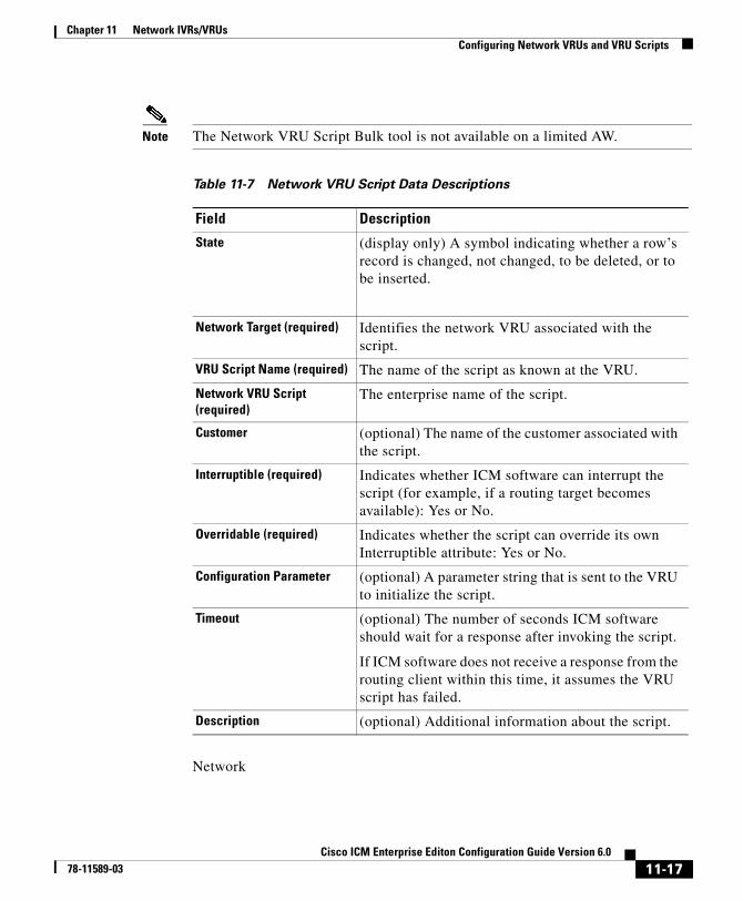
Chapter 11 Network IVRs/VRUsConfiguring Network VRUs and VRU Scripts
Note The Network VRU Script Bulk tool is not available on a limited AW.
Network
Table 11-7 Network VRU Script Data Descriptions
Field Description
State (display only) A symbol indicating whether a row’s record is changed, not changed, to be deleted, or to be inserted.
Network Target (required) Identifies the network VRU associated with the script.
VRU Script Name (required) The name of the script as known at the VRU.
Network VRU Script (required)
The enterprise name of the script.
Customer (optional) The name of the customer associated with the script.
Interruptible (required) Indicates whether ICM software can interrupt the script (for example, if a routing target becomes available): Yes or No.
Overridable (required) Indicates whether the script can override its own Interruptible attribute: Yes or No.
Configuration Parameter (optional) A parameter string that is sent to the VRU to initialize the script.
Timeout (optional) The number of seconds ICM software should wait for a response after invoking the script.
If ICM software does not receive a response from the routing client within this time, it assumes the VRU script has failed.
Description (optional) Additional information about the script.
11-17Cisco ICM Enterprise Editon Configuration Guide Version 6.0
78-11589-03
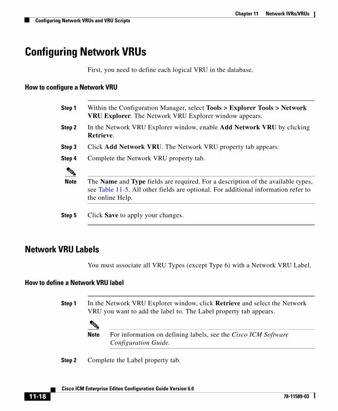
Chapter 11 Network IVRs/VRUsConfiguring Network VRUs and VRU Scripts
Configuring Network VRUsFirst, you need to define each logical VRU in the database.
How to configure a Network VRU
Step 1 Within the Configuration Manager, select Tools > Explorer Tools > Network VRU Explorer. The Network VRU Explorer window appears.
Step 2 In the Network VRU Explorer window, enable Add Network VRU by clicking Retrieve.
Step 3 Click Add Network VRU. The Network VRU property tab appears.
Step 4 Complete the Network VRU property tab.
Note The Name and Type fields are required. For a description of the available types, see Table 11-5. All other fields are optional. For additional information refer to the online Help.
Step 5 Click Save to apply your changes.
Network VRU Labels
You must associate all VRU Types (except Type 6) with a Network VRU Label.
How to define a Network VRU label
Step 1 In the Network VRU Explorer window, click Retrieve and select the Network VRU you want to add the label to. The Label property tab appears.
Note For information on defining labels, see the Cisco ICM Software Configuration Guide.
Step 2 Complete the Label property tab.
11-18Cisco ICM Enterprise Editon Configuration Guide Version 6.0
78-11589-03

Chapter 11 Network IVRs/VRUsConfiguring Network VRUs and VRU Scripts
Note The Routing client, Label, and Label type fields are required. All other fields are optional. For additional information refer to the online Help.
Step 3 Click Save to apply your changes.
Network VRU System Information
For Network VRUs, you must use the System Information dialog box to define a range of correlation IDs so ICM software can communicate with the VRU about the call.
How to set the default Network VRU and range of correlation numbers
Step 1 Within the Configuration Manager, select Tools > Miscellaneous Tools > System Information. The System Information window appears.
Step 2 In the System Information window, select the Default Network VRU.
Step 3 Enter the Minimum Correlation Number.
Step 4 Enter the Maximum Correlation Number.
Note For additional information refer to the online Help.
Step 5 Click Save to apply your changes.
Network VRU Script Configuration To allow a routing script to control the processing on the VRU, you must configure VRU-based scripts within ICM software. An ICM routing script can then direct the VRU to run a specific script.
11-19Cisco ICM Enterprise Editon Configuration Guide Version 6.0
78-11589-03
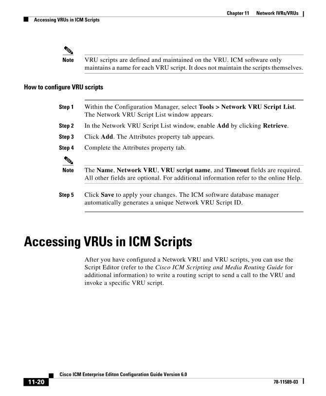
Chapter 11 Network IVRs/VRUsAccessing VRUs in ICM Scripts
Note VRU scripts are defined and maintained on the VRU. ICM software only maintains a name for each VRU script. It does not maintain the scripts themselves.
How to configure VRU scripts
Step 1 Within the Configuration Manager, select Tools > Network VRU Script List. The Network VRU Script List window appears.
Step 2 In the Network VRU Script List window, enable Add by clicking Retrieve.
Step 3 Click Add. The Attributes property tab appears.
Step 4 Complete the Attributes property tab.
Note The Name, Network VRU, VRU script name, and Timeout fields are required. All other fields are optional. For additional information refer to the online Help.
Step 5 Click Save to apply your changes. The ICM software database manager automatically generates a unique Network VRU Script ID.
Accessing VRUs in ICM ScriptsAfter you have configured a Network VRU and VRU scripts, you can use the Script Editor (refer to the Cisco ICM Scripting and Media Routing Guide for additional information) to write a routing script to send a call to the VRU and invoke a specific VRU script.
11-20Cisco ICM Enterprise Editon Configuration Guide Version 6.0
78-11589-03

Chapter 11 Network IVRs/VRUsQueuing Calls at VRUs
Queuing Calls at VRUsYou can queue a call at a Network VRU until a specific resource becomes available. A call can be queued for one or more skill groups, an enterprise skill group, or one or more scheduled targets. As soon as an agent becomes available at one of the specified targets, the call is removed from queue and sent to the target.
11-21Cisco ICM Enterprise Editon Configuration Guide Version 6.0
78-11589-03

Chapter 11 Network IVRs/VRUsQueuing Calls at VRUs
11-22Cisco ICM Enterprise Editon Configuration Guide Version 6.0
78-11589-03
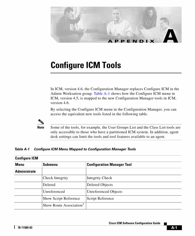
Ci78-11589-03
A
P P E N D I X A Configure ICM ToolsIn ICM, version 4.6, the Configuration Manager replaces Configure ICM in the Admin Worksation group. Table A-1 shows how the Configure ICM menu in ICM, version 4.5, is mapped to the new Configuration Manager tools in ICM, version 4.6.
By selecting the Configure ICM menu in the Configuration Manager, you can access the equivalent new tools listed in the following table.
Note Some of the tools, for example, the User Groups List and the Class List tools are only accessible to those who have a partitioned ICM system. In addition, agent desk settings can limit the tools and tool features available to an agent.
Table A-1 Configure ICM Menu Mapped to Configuration Manager Tools
Configure ICM
Menu Submenu Configuration Manager Tool
Administrate
Check Integrity Integrity Check
Deleted Deleted Objects
Unreferenced Unreferenced Objects
Show Script Reference Script Reference
Show Route Association1
A-1sco ICM Software Configuration Guide
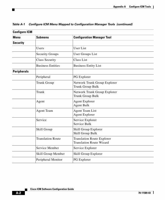
Appendix A Configure ICM Tools
Security
Users User List
Security Groups User Groups List
Class Security Class List
Business Entities Business Entity List
Peripherals
Peripheral PG Explorer
Trunk Group Network Trunk Group ExplorerTrunk Group Bulk
Trunk Network Trunk Group ExplorerTrunk Group Bulk
Agent Agent ExplorerAgent Bulk
Agent Team Agent Team ListAgent Explorer
Service Service ExplorerService Bulk
Skill Group Skill Group ExplorerSkill Group Bulk
Translation Route Translation Route ExplorerTranslation Route Wizard
Service Member Service Explorer
Skill Group Member Skill Group Explorer
Peripheral Monitor PG Explorer
Table A-1 Configure ICM Menu Mapped to Configuration Manager Tools (continued)
Configure ICM
Menu Submenu Configuration Manager Tool
A-2Cisco ICM Software Configuration Guide
78-11589-03
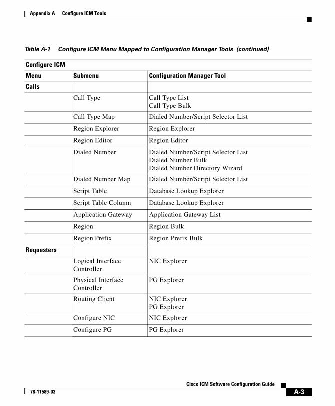
Appendix A Configure ICM Tools
Calls
Call Type Call Type ListCall Type Bulk
Call Type Map Dialed Number/Script Selector List
Region Explorer Region Explorer
Region Editor Region Editor
Dialed Number Dialed Number/Script Selector ListDialed Number BulkDialed Number Directory Wizard
Dialed Number Map Dialed Number/Script Selector List
Script Table Database Lookup Explorer
Script Table Column Database Lookup Explorer
Application Gateway Application Gateway List
Region Region Bulk
Region Prefix Region Prefix Bulk
Requesters
Logical Interface Controller
NIC Explorer
Physical Interface Controller
PG Explorer
Routing Client NIC ExplorerPG Explorer
Configure NIC NIC Explorer
Configure PG PG Explorer
Table A-1 Configure ICM Menu Mapped to Configuration Manager Tools (continued)
Configure ICM
Menu Submenu Configuration Manager Tool
A-3Cisco ICM Software Configuration Guide
78-11589-03
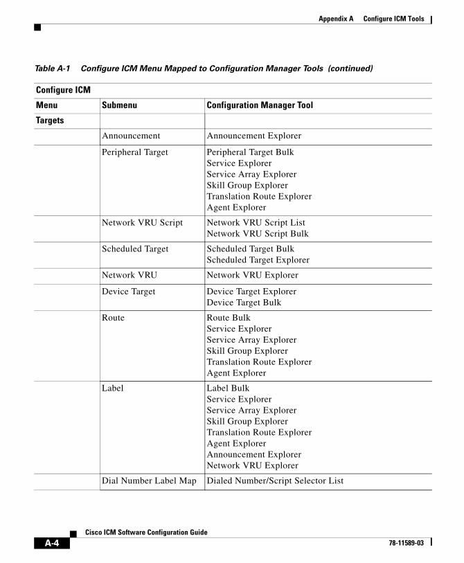
Appendix A Configure ICM Tools
Targets
Announcement Announcement Explorer
Peripheral Target Peripheral Target BulkService ExplorerService Array ExplorerSkill Group ExplorerTranslation Route ExplorerAgent Explorer
Network VRU Script Network VRU Script ListNetwork VRU Script Bulk
Scheduled Target Scheduled Target BulkScheduled Target Explorer
Network VRU Network VRU Explorer
Device Target Device Target ExplorerDevice Target Bulk
Route Route BulkService ExplorerService Array ExplorerSkill Group ExplorerTranslation Route ExplorerAgent Explorer
Label Label BulkService ExplorerService Array ExplorerSkill Group ExplorerTranslation Route ExplorerAgent ExplorerAnnouncement ExplorerNetwork VRU Explorer
Dial Number Label Map Dialed Number/Script Selector List
Table A-1 Configure ICM Menu Mapped to Configuration Manager Tools (continued)
Configure ICM
Menu Submenu Configuration Manager Tool
A-4Cisco ICM Software Configuration Guide
78-11589-03
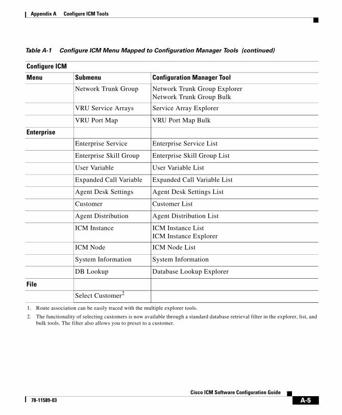
Appendix A Configure ICM Tools
Network Trunk Group Network Trunk Group ExplorerNetwork Trunk Group Bulk
VRU Service Arrays Service Array Explorer
VRU Port Map VRU Port Map Bulk
Enterprise
Enterprise Service Enterprise Service List
Enterprise Skill Group Enterprise Skill Group List
User Variable User Variable List
Expanded Call Variable Expanded Call Variable List
Agent Desk Settings Agent Desk Settings List
Customer Customer List
Agent Distribution Agent Distribution List
ICM Instance ICM Instance ListICM Instance Explorer
ICM Node ICM Node List
System Information System Information
DB Lookup Database Lookup Explorer
File
Select Customer2
1. Route association can be easily traced with the multiple explorer tools.
2. The functionality of selecting customers is now available through a standard database retrieval filter in the explorer, list, and bulk tools. The filter also allows you to preset to a customer.
Table A-1 Configure ICM Menu Mapped to Configuration Manager Tools (continued)
Configure ICM
Menu Submenu Configuration Manager Tool
A-5Cisco ICM Software Configuration Guide
78-11589-03

Appendix A Configure ICM Tools
A-6Cisco ICM Software Configuration Guide
78-11589-03
Cisco ICM Enterprise E78-11589-03
I N D E X
Symbols
@NPA_Blocked_Recording label 8-11
@Slow Busy label 8-11
A
Abandoned calls 2-13, 2-15
in service level calculation 7-5
wait time 2-14
ACD
DN 1-7
Routing Table (Rolm) 1-7
Adding, ECC variables 10-3
administrative scripts 1-11
Admin Workstation 1-2, 1-4, 1-8
connections 1-4
distributor 1-10
installing the ConApi interface 9-2
advanced tab
peripheral gateway explorer 6-9
PG explorer 6-9
service explorer 7-6
Agent
definition 7-30
distributions 7-35
group (Aspect CallCenter) 1-7
reporting 9-30
agent bulk configuration tool 3-8
AgentCfg utility 7-36
agent desk settings list tool 3-10
agent distribution tab
peripheral gateway explorer 6-18
PG explorer 6-18
agent explorer 3-9, 7-29, 7-30
agent tab 7-30
skill group membership tab 7-32
supervisor tab 7-33
tab descriptions 7-30
Agent-level reporting 7-34
Agents 1-5, 9-18
auto-configuration 7-36
defining 7-29
groups of 1-5
peripheral terminology 1-6
skill group assignments 7-34
temporary 7-36
Agent state trace 7-36
agent tab
agent explorer
IN-1dtion Configuration Guide Version 6.0
Index
7-30
agent team list tool 3-10
Alcatel 4400
terminology 1-6
ANI 2-3
announcement explorer 3-9
Announcements 2-3, 2-8, 2-9, 8-9
NPA Blocked Recording 8-9
AOF 9-31
Application
Aspect CallCenter 1-7
connections 9-22
external 9-24
gateways 9-24
instance, configuring 9-21
instances 9-20
Rockwell Spectrum 1-7
Wizard 8-18
application gateway
how to configure 9-25
application gateway list tool 3-10, 9-25
application object filter 9-31
disabling 9-32
application wizard 3-12, 8-18
Aspect CallCenter
terminology 1-6
attributes tab
dialed number/script selector list tool 5-14
network VRU script list tool 11-7
IN-2Cisco ICM Enterprise Edtion Configuration Guide Ver
persons list tool 7-26
VRU currency list tool 11-8
VRU defaults list tool 11-9
VRU locales list tool 11-13
Automatic Number Identification 2-3
Available Holdoff Delay 6-10, 7-14
of skill groups 7-14
Avaya Definity ECS
terminology 1-6
B
Bucket 3-10
bucket intervals list 3-10
bulk configurationn tools
sorting records 4-7
Bulk Configuration Tool 4-1
bulk configuration tool
agent 3-8
call type 3-8
device targets 3-8
dialed number plans 3-8
dialed numbers 3-8
labels 3-8
network trunk groups 3-8
network VRU scripts 3-8
peripheral targets 3-8
region prefixes 3-8
regions 3-8
sion 6.078-11589-03
Index
routes 3-8
scheduled targets 3-8
services 3-8
skill groups 3-8
trunk groups 3-8
trunks 3-8
VRU port maps 3-8
bulk configuration tools 3-8
configurable data 4-2
edit window 4-3
features 4-4
how to access 4-1
insert window 4-3
retrieving records (rows) 4-5
tools summary 3-7
bulk tools
common features 3-12
business entity list tool 3-10
Busy
labels 8-11
C
call center applications 3-12
Caller-Entered Digits (CED) 2-3
examples 2-7
Calling Line ID (CLID) 2-3
examples 2-7
Calls
Cisco ICM Ent78-11589-03
abandoned 2-13, 2-15
offered 2-14
Call Type
determining 2-7
call type bulk configuration tool 3-8
call type list tool 3-10
Central Controller 1-2
change password
how to 7-28
Circuit provider 6-29
Cisco Collaboration Server, pushing information to waiting callers 9-30
CMS Server, configuring connections 9-22
ConApi interface, installing 9-2
configuration data 1-11, 3-2
checking integrity 3-23
deleted records 3-27
deleting 3-24
ICM needs to work 3-1
integrity 3-23
unreferenced records 3-24
validating 3-23
configuration manager 3-1, 3-2
deletion 3-24
help 3-5
Configuring
application instance 9-21
CMS Server connections 9-22
IPCC PG 9-12
Media Routing Domain ID 9-5
IN-3erprise Edtion Configuration Guide Version 6.0
Index
MR-PG 9-7
configuring a feature control set 3-20
configuring network VRUs 11-13
configuring VRU scripts 11-13
Connections
data communications 1-2
Contact management process 1-2
CRSP 5-11
CTI server, installing 9-15
D
database lookup explorer 3-9
Databases
central 1-10
local 1-10
Default
call types 2-7
labels 2-9, 8-15
route, peripherals 8-6
service level threshold 2-14
targets 2-8
default route tab
peripheral gateway explorer 6-17
PG explorer 6-17
Delayed Callback 10-3
delete/undelete button
common features 3-13
deleted configuration data 3-27
IN-4Cisco ICM Enterprise Edtion Configuration Guide Ver
dependencies 3-27
deleted objects tool 3-11
Deleting data 4-16
deletion
immediate 3-26
logical 3-26
deletion dependencies 3-26
Dependencies, VRU types 11-13
Destination ACD (Rolm) 1-6
Destroy Permanently button 3-27
device target bulk configuration tool 3-8
device target explorer 3-9
Dialed Number (DN) 2-3
configuring 5-12
default label 2-9, 8-15
defining 5-13
for translation route 8-33
mapping to labels 5-8, 8-14
modifying 5-13
viewing 5-13
dialed number/script selector list tool 3-10
attributes tab 5-14
dialed number label tab 5-15
dialed number/script selector list tool tab
descriptions 5-14
dialed number/script selectors list tool 5-12
dialed number bulk configuration tool 3-8
Dialed Number Identification Service 2-4
dialed number label tab
sion 6.078-11589-03
Index
dialed number/script selector list tool 5-15
dialed number plan bulk configuration tool 3-8
Distributor Admin Workstation 1-10
DMS-100See Nortel DMS-100 1-6
DNIS 2-4, 2-10
for translation route 8-35
Override labels 8-11
Dynamic label 8-10
E
ECC variables 10-1, 10-3
adding 10-3
Delayed Callback 10-3
for integrated applications 9-18
Web Callback 10-3
edit options 3-19
Edit range 4-9, 4-10
procedures 4-9
Enable Expanded Call Context Setting 10-3
Enterprise
services 7-41
skill groups 7-41, 7-42
targets 7-41
enterprise route list tool 3-10
enterprise service list tool 3-10, 7-41
enterprise skill group list tool 3-10
enterprise skill groups list tool 7-42
Ericsson ACP1000
Cisco ICM Ent78-11589-03
terminology 1-6
Expanded Call Context (ECC) variables, naming convention 10-1
expanded call context variables 10-1
expanded call variable list tool 3-10
explorer tools 3-9
agent explorer 3-9
announcement explorer 3-9
common features 3-12, 3-14
database lookup explorer 3-9
device target explorer 3-9
ICM instance explorer 3-9
network trunk group explorer 3-9
network VRU explorer 3-9, 11-2
NIC explorer 3-9
peripheral gateway explorer 3-9
PG explorer 3-9
region explorer 3-9
scheduled target explorer 3-9
service array explorer 3-9
service explorer 3-9
skill group explorer 3-9
tools summary 3-7
translation route explorer 3-9
Export file format 4-14
Exporting records 4-15
procedure 4-15
Extension numbers
of services 7-6
of skill groups 7-14
IN-5erprise Edtion Configuration Guide Version 6.0
Index
External
applications 9-24
F
F1 key 3-5
feature control 3-18
configuring a feature control set 3-20
how to assign users to a feature control set 3-21
how to create a feature control set 3-20
how to select script nodes for a feature control set 3-21
node control table 3-19
available column 3-20
node column 3-20
Script Editor 3-18
script node control 3-19
script object control 3-19
feature control set
how to assign users 3-21
how to create 3-20
how to select script nodes 3-21
feature control set list tool 3-10
Fields
ID 4-12
File format 4-14
Flexible call force timer 6-10, 7-14
France Telecom 5-11
IN-6Cisco ICM Enterprise Edtion Configuration Guide Ver
G
Gate (Rockwell Galaxy) 1-7
green check mark 3-12
Groups
of agents 1-5
skill 1-5
trunk 2-4, 2-10
H
Header format 4-14
help
on configuration manager 3-5
I
ICM Gateways 9-24
ICM instance explorer 3-9
ICM software 1-1
6.0 requirements 9-2
architecture 1-2
Central Controller 1-2
icons
descriptions 3-12
green check mark 3-12
record state 4-4
record state changed 4-4
record state not changed 4-4
sion 6.078-11589-03
Index
record state to be deleted 4-4
record state to be inserted 4-4
red circle with a red slash 3-13
red X 3-12
yellow addition sign 3-13
yellow arrow 3-12
ICP subsystems 5-3
ID fields 4-12
ID status box
common features 3-13
immediate deletion 3-26
immediate deletion (configuration manager) 3-26
Import file format 4-14
Importing records 4-12
procedure 4-12
Installing
ConApi interface 9-2
CTI server 9-15
IPCC PG 9-13
MR-PG 9-9
integrity checks 3-23
integrity check tool 3-11
Intelligent Call Processing (ICP) 5-3
Interexchange carrier (IXC) 2-3, 5-1
IPCC PG
configuring 9-12
installing 9-13
IVRs 11-1
Cisco ICM Ent78-11589-03
L
label bulk configuration tool 3-8
label list tool 3-10
Labels 2-4, 2-9, 2-10
announcements 2-8
AT&T ICP connection 8-10
busy 8-11
default 2-9, 8-15
defining 8-10
dynamic 8-10
for translation route 8-35
label type 7-9, 7-21
mapping to dialed numbers 5-8, 8-14, 8-34
normal 8-11
ring 8-11
routing client 7-8, 7-20
scheduled targets 2-8
Sprint-specific 8-11
types and client processing 2-5
valid types 8-13
label tab
network VRU explorer 11-5
service explorer 7-8
skill group explorer 7-20
Late
responses 2-13
threshold 2-12
Limitations
IN-7erprise Edtion Configuration Guide Version 6.0
Index
of peripherals 1-8
list tool
VRU locale list 3-11
List Tools
tools summary 3-7
list tools 3-10
3-10
agent desk settings list 3-10
agent team list 3-10
application gateway list 3-10, 9-25
bucket intervals list 3-10
business entity list 3-10
call type list 3-10
common features 3-12, 3-14
dialed number/script selector list 3-10
enterprise route list 3-10
enterprise service list 3-10, 7-41
enterprise skill group list 3-10
enterprise skill groups list 7-42
expanded call variable list 3-10
label list 3-10
media class list 3-10
media routing domain list 3-10
MRD list 3-10
network VRU script list 3-10, 11-6
person list 3-10
reason code list 3-10
service level threshold list 3-10
supervisor list 3-10
IN-8Cisco ICM Enterprise Edtion Configuration Guide Ver
user group list 3-10
user list 3-10
user variable list 3-10
VRU currency list 3-10, 11-8
VRU defaults list 3-11, 11-8
VRU locale list 11-12
Locks 1-10
getting 1-10
Master 1-10
releasing 1-10
script 1-10
locks
script 1-13
logical
deletion (configuration manager) 3-26
Logical controller
client type 6-6
configuration parameters 6-6
delete 6-20
description 6-6
new 6-20
physical controller description 6-6
logical controller tab
periperal gateway explorer 6-4
PG explorer 6-4
logical deletion 3-26
logical interface controller tab
NIC explorer 5-5
sion 6.078-11589-03
Index
M
mapping
skill groups to services 7-23
Master lock 1-10
Media classes 9-5
media class list tool 3-10
media routing domain 7-4, 7-13
Media Routing Domain ID, configuring 9-5
media routing domain list tool 3-10
Media routing domains 9-4
MeridianSee Nortel Meridian 1-6
miscellaneous tool
deleted objects tool 3-11
miscellaneous tools 3-11
integrity check tool 3-11
region editor 3-11
script reference tool 3-11
system information tool 3-11
tools summary 3-7
unreferenced tool 3-11
MRD list tool 3-10
MR-PG
configuring 9-7
installing 9-9
N
naming convention
Cisco ICM Ent78-11589-03
Expanded Call Context (ECC) variables 10-1
user variables 10-5
NEC NEAX 2400
terminology 1-6
Network Interface Controller (NIC) 1-2, 5-3, 5-5
configuring 5-4
connections 1-3
defining 5-10
deleting 5-12
field descriptions 5-5
modifying 5-9
viewing 5-4, 5-10
network IVRs 11-1
Network routing client 5-9
Network targets 8-6
network trunk group bulk configuration tool 3-8
network trunk group explorer 3-9, 6-25
network trunk group tab 6-27
tab descriptions 6-27
trunk group tab 6-27
Network trunk groups 6-25, 7-8
definition 6-25
for translation route 8-34
network VRU explorer 3-9, 11-2
label tab 11-5
network VRU tab 11-5
Network VRUs 11-1
scripts 11-20
network VRUs 11-1
IN-9erprise Edtion Configuration Guide Version 6.0
Index
configuring 11-13
Network VRUs, configuring 11-13
network VRU script bulk configuration tool 3-8
network VRU script data descriptions 11-16
network VRU script list tool 3-10, 11-6
attributes tab 11-7
network VRU tab
network VRU explorer 11-5
NIC
associated physical interface controllers 5-7
client type 5-6
configuration parameter 5-6
controller ID 5-5
description 5-6
see Network Interface Controller 1-2, 5-4
NIC Explorer 5-4, 5-10
field descriptions 5-5
NIC explorer 3-9
logical interface controller tab 5-5
routing client tab 5-7
node control table 3-19
available column 3-20
node column 3-20
Nodes, Queue to Agent 9-27
Non Voice agents 9-19
Normal labels 8-11
Nortel DMS-100
trunk groups 6-24
Nortel DMS100
IN-10Cisco ICM Enterprise Edtion Configuration Guide Ver
terminology 1-6
Nortel Meridian
terminology 1-6
NPA Blocked Recording 8-9, 8-11
O
object control 3-18
Offered calls 2-14
online help 3-5
optional filter 7-24
optional filters 7-25
Outbound Option 3-7
P
Peripheral Gateway (PG) 1-2, 2-10, 5-3, 6-2
configuring 5-3, 6-2
connections 1-4
defining 6-20
deleting 6-23
for translation route 8-32
viewing 6-3
peripheral gateway explorer 3-9, 6-3
advanced tab 6-9
agent distribution tab 6-18
default route tab 6-17
logical controller tab 6-4
peripheral monitor tab 6-14
sion 6.078-11589-03
Index
peripheral tab 6-7
routing client tab 6-11
skill group mask tab 6-11
tab descriptions 6-4
Peripheral monitor
config param 6-16
entries 6-14
extension 6-15
peripheral monitor tab
peripheral gateway explorer 6-14
PG explorer 6-14
peripheral name 7-13
peripheral number 7-13
Peripherals 1-5, 6-1, 6-7
abandoned call wait time 6-8
answered short calls threshold 6-10
as routing clients 5-1
available holdoff delay 6-10
call control variable map 6-8
client type 6-8
configuration parameters 6-8
default desk settings 6-8
default route 6-10
default routes 8-6
defining 6-21
deleting 6-23
description 6-8
enable post routing 6-9
for translation route 8-32
Cisco ICM Ent78-11589-03
limitations 1-8
location 6-8
name 6-7
network VRU 6-10
peripheral ID 6-7
peripheral name 6-7
peripheral service level type 6-9
route association 8-5
service level type 7-6
terminology 1-6
peripheral service level type 7-5
peripheral tab
peripheral gateway explorer 6-7
PG explorer 6-7
Peripheral target
definition 7-19
DNIS 7-8, 7-20
network trunk group 7-8, 7-20
Peripheral targets 2-4, 2-8, 2-9, 8-7
peripheral terminology 1-6
route associations 8-5
peripheral target tab
service explorer 7-7
skill group explorer 7-19
person list tool 3-10
Persons 9-18
persons 7-23
persons list tool 7-24
attributes tab 7-26
IN-11erprise Edtion Configuration Guide Version 6.0

Index
PG
agent distribution entries 6-19
currently selected site 6-20
enable agent reporting 6-19
logical controller ID 6-4
name 6-5
physical controller ID 6-4
See Peripheral Gateway 1-2
PG explorer 3-9, 6-3
advanced tab 6-9
agent distribution tab 6-18
default route tab 6-17
field descriptions 6-4
logical controller tab 6-4
modifying peripheral records 6-22
modifying PG 6-22
peripheral monitor tab 6-14
peripheral tab 6-7
routing client tab 6-11
skill group mask tab 6-11
tab descriptions 6-4
Physical interface controller
description 5-7
for a NIC 5-4
for a PG 6-3
ID 5-7
name 5-7
Pilot number (Rolm ACD) 1-7
Post-Query labels 8-11
IN-12Cisco ICM Enterprise Edtion Configuration Guide Ver
Post-Routing 2-3
Pre-integration configuration, verifying 9-3
Q
Queue to Agent Expression 9-29
Queue to Agent node 9-27
Queue to Specific Agent 9-28
R
reason code list tool 3-10
records
deleting 3-25
Records (rows) 4-5, 4-8
selecting 4-8
records (rows)
retrieving 4-5
record state 4-4
changed 4-4
not changed 4-4
to be deleted 4-4
to be inserted 4-4
record status symbol descriptions 3-12
red circle with a red slash 3-13
red X 3-12
region bulk configuration tool 3-8
region editor 3-11
region explorer 3-9
sion 6.078-11589-03
Index
region prefix bulk configuration tool 3-8
Remote ICRs 9-24
Reporting
agentlevel 7-34
Requests
routing 2-3
Responses
late 5-8
time limits 5-8
Retrieving records 4-5
Ring
labels 8-11
Rockwell Galaxy
terminology 1-6
Rockwell Spectrum
terminology 1-6
Rolm 9005 1-6
route bulk configuration tool 3-8
route bulk list tool 8-5
Routes 2-3, 2-8
default 8-6
defining 8-3
description 7-19
name 7-18
names 7-7, 7-18, 8-5
Nortel Meridian 1-7
peripheral association 8-5
peripheral target associations 8-5
selecting for different media by agent 9-28
Cisco ICM Ent78-11589-03
selecting for different media by agent expression 9-29
service name 7-19
services 8-5
skill group priority 7-18
translation 2-10, 8-28
route tab
service explorer 7-7
skill group explorer 7-17
Routing calls
ICM processing 2-7
peripheral processing 2-10
requests 2-3
routing client processing 2-9
Routing clients 2-3, 5-7
client type 5-9, 6-13
configuration parameters 5-8, 6-12
CRSP 5-11
default call type 5-8, 6-12
defining 5-1, 5-10
description 5-9, 6-13
for translation route 8-33
late threshold 2-12, 5-8, 6-12
modifying 5-9
name 5-8, 6-12
network 6-13
network trunk groups 6-25
peripherals 2-10
PG as 6-3
Sprint configuration 5-11
IN-13erprise Edtion Configuration Guide Version 6.0
Index
thresholds 2-12
timeout limit 2-13, 5-8, 6-12
timeouts 2-12
timeout threshold 2-12, 6-12
use DN/Label map 5-8, 6-13
viewing 5-4, 5-10
routing client tab
NIC explorer 5-7
peripheral gateway explorer 6-11
PG explorer 6-11
Routing labels 2-4, 2-9, 2-10
announcements 2-8
busy 8-11
defining 8-10
mapping to dialed number 5-8
mapping to dialed numbers 8-14
ring 8-11
scheduled targets 2-8
Sprint-specific 8-11
types 2-5, 8-13
Routing requests 2-3
late responses 2-13
Routing scripts 2-8
routing scripts 1-11
Routing targets 1-5
announcements 8-9
peripheral 8-7
scheduled targets 8-23
translation routes 8-28
IN-14Cisco ICM Enterprise Edtion Configuration Guide Ver
S
save button
common features 3-13
Scheduled
targets 2-8, 8-23
scheduled target explorer 3-9
schedule target bulk configuration tool 3-8
Script locks 1-10, 1-13
script node control 3-19
script object control 3-19
script reference tool 3-11
Scripts 2-8
VRU 11-20
scripts 1-11
Security settings
applying 3-22
security tab
network VRU script list tool 11-7
select filter data 7-24
select filter data dialog 3-16
Selecting
multiple skill groups and routes for different media by agent 9-28
multiple skill groups and routes for different media by agent expression 9-29
Selecting records (rows) 4-8
service array explorer 3-9
Service arrays 8-15
for translation route 8-32
sion 6.078-11589-03
Index
service bulk configuration tool 3-8
service explorer 3-9, 7-3
advanced tab 7-6
label tab 7-8
peripheral target tab 7-7
route tab 7-7
service members tab 7-6
service tab 7-4
tab descriptions 7-4
Service level 2-14
events 2-14
peripheral 7-6
threshold 7-5
threshold, default for peripheral 2-14
threshold, default for service 2-14
types 2-15, 7-5
service level threshold list tool 3-10
service members tab
service explorer 7-6
Services 1-5, 2-8
adding members to 7-7
config param 7-5
defining 7-3
enterprise 7-41
extension 7-6
for routes 8-5
for translation route 8-32
mapping to skill groups 7-23
media routing domain 7-4
Cisco ICM Ent78-11589-03
names 7-5
peripheral name 7-5
peripheral number 7-4
peripheral service level type 7-6
peripheral terminology 1-7
removing members from 7-7
schedule name 7-6
service level 7-6
service level threshold 7-5
service level type 7-5
service tab
service explorer 7-4
Siemens Hicom
terminology 1-6
Siemens Rolm 9751
CBX 1-6
skil group mask tab
PG explorer 6-11
skill group bulk configuration tool 3-8
skill group explorer 3-9, 7-11
label tab 7-20
peripheral target tab 7-19
route tab 7-17
skill group members tab 7-15
skill group tab 7-12
subgroup mask tab 7-15
sub skill groups tab 7-16
tab descriptions 7-12
skill group mask tab
IN-15erprise Edtion Configuration Guide Version 6.0
Index
peripheral gateway explorer 6-11
skill group membership tab
agent explorer 7-32
skill group members tab
skill group explorer 7-15
Skill groups 1-5
adding members to 7-14, 7-15
agent assignments 7-34
available holdoff delay 7-14
base 1-8
ConfigParam 7-14
configuration 9-26
defining 7-11
definition 7-12
description 7-14
enterprise 7-41, 7-42
extension 7-14
mapping to services 7-23
name 7-13
peripheral name 7-13
peripheral number 7-13
peripheral terminology 1-7
primary 1-8
priority 7-14
removing members from 7-15
secondary 1-8
selecting multiple for different media by agent 9-28
selecting multiple for different media by agent expression 9-29
IN-16Cisco ICM Enterprise Edtion Configuration Guide Ver
subskills 7-15
skill group tab
skill group explorer 7-12
Skill targets 2-3, 2-8, 7-2
Sorting records (rows)
procedure 4-7
sorting records (rows) 4-7
Sprint
Busy feature 8-11
configuration 5-11
NPA Blocked Recording feature 8-9
NPA Blocked Recording features 8-11
routing clients 5-11
States
of agents 7-36
Subgroup Mask 7-15
subgroup mask tab
skill group explorer 7-15
sub skill groups tab
skill group explorer 7-16
supervisor list tool 3-10
supervisor tab
agent explorer 7-32, 7-33
system information tool 3-11
T
Targets 1-5, 2-3
announcements 2-3, 2-8, 2-9, 8-9
sion 6.078-11589-03
Index
default 2-8
enterprise 7-41
in network 8-6
peripheral 2-4, 2-8, 2-9, 8-7
scheduled 8-23
scheduled targets 2-8
skill 2-3, 2-8, 7-2
translation routes 8-28
Temporary agents 7-36
Terminology
peripheral-specific 1-6
Thresholds 2-11
service level 2-14, 7-5
Timeouts 2-11
limit 2-13
threshold 2-12
Tools
Configuration Manager xv, A-1
configuration manager 3-2
ICM Configure xv, A-1
tools summary 3-7
bulk configuration tools 3-7
explorer tools 3-7
list tools 3-7
miscellaneous tools 3-7
wizards 3-7
Tracing
agent states 7-36
translation route explorer 3-9
Cisco ICM Ent78-11589-03
Translation routes 2-10
defining 8-28
deleting 8-38
reports 8-38
updating 8-38
Translation Route Wizard 8-29
translation route wizard 3-12, 8-29
trunk bulk configuration tool 3-8
trunk group bulk configuration tool 3-8
Trunk groups 2-4, 2-10
configuring 6-24
DMS-100 6-24
for translation route 8-34
network 6-25, 7-8
peripheral terminology 1-7
trunk group tab
network trunk group explorer 6-27
Trunks
circuit provider 6-29
configuring 6-24
defining multiple 6-31
peripheral terminology 1-7
type 6-29
U
Undelete data 4-17
Universal Queue 9-26
unreferenced configuration records 3-24
IN-17erprise Edtion Configuration Guide Version 6.0
Index
unreferenced tool 3-11
UpdateAW process 1-10
user group list tool 3-10
user list tool 3-10
user variable list tool 3-10
user variables 10-5
naming convention 10-5
V
variables
Expanded Call Context (ECC) 10-1
expanded call context (ECC) 10-1
user 10-5
Variable WrapUp 6-10, 7-14
VDN 1-7
Vector Directory Number (VDN) 1-7
Verifying pre-integration configuration 9-3
View
flowing 3-22
VRU
network 11-1
scripts 11-20
scripts, configuring 11-13
types 11-13
VRU configuration tools 11-2
VRU currency list tool 3-10, 11-8
attributes tab 11-8
VRU defaults list tool 3-11, 11-8
IN-18Cisco ICM Enterprise Edtion Configuration Guide Ver
attributes tab 11-9
VRU locale list tool 3-11, 11-12
VRU locales list tool
attributes tab 11-13
VRU port map bulk configuration tool 3-8
VRU port map data descriptions 11-15
VRUs 11-1
VRU scripts
configuring 11-13
VRU types 11-13, 11-14
W
Web Callback 10-3
Wizards
Translation Route 8-29
wizards
application wizard 3-12, 8-18
tools summary 3-7
translation route wizard 3-12, 8-29
Y
yellow addition sign 3-13
yellow arrow 3-12
sion 6.078-11589-03