C²I² Systems FDDI and CDDI Adapters
24
User Manual for the C²I² Systems FDDI and CDDI Adapters C²I² Systems Document No. CCII/FDDI/6-MAN/008 Document Issue 1.5 Issue Date 2016-06-02 Print Date 2016-06-02 File Name P:\FDDI\TECH\MAN\CFDMAN08.wpd Distribution List No. DN 0383 © C²I² Systems The copyright of this document is the property of C²I² Systems. The document is issued for the sole purpose for which it is supplied, on the express terms that it may not be copied in whole or part, used by or disclosed to others except as authorised in writing by C²I² Systems. Document prepared by C²I² Systems, Cape Town
Transcript of C²I² Systems FDDI and CDDI Adapters
User Manualfor the
C²I² Systems
FDDI and CDDI Adapters
C²I² Systems Document No. CCII/FDDI/6-MAN/008
Document Issue 1.5
Issue Date 2016-06-02
Print Date 2016-06-02
File Name P:\FDDI\TECH\MAN\CFDMAN08.wpd
Distribution List No. DN 0383
© C²I² Systems The copyright of this document is the property of C²I² Systems. The document is issued for the solepurpose for which it is supplied, on the express terms that it may not be copied in whole or part, used byor disclosed to others except as authorised in writing by C²I² Systems.
Document prepared by C²I² Systems, Cape Town

CCII/FDDI/6-MAN/008 2016-06-02 Issue 1.5
CFDMAN08.wpd Page iii of vi
Amendment History
Issue Description Date ECP No.
1.1 Second Official Release 1998-11-27 -
1.2 Third Official Release. Updated to latest Template. 2002-10-30 RF 0025
1.3 Pin-outs for Frontpanel CDDI Adapters Added 2003-02-28 CCII/FDDI/6-ECP/013
1.4 Pin-outs for PC-104 Adapter Added 2005-10-21 CCII/FDDI/6-ECP/025
1.5 Improve document naming consistency, address change 2016-06-02 CCII/FDDI/6-ECP/035

CCII/FDDI/6-MAN/008 2016-06-02 Issue 1.5
CFDMAN08.wpd Page iv of vi
Contents
1. Scope . . . . . . . . . . . . . . . . . . . . . . . . . . . . . . . . . . . . . . . . . . . . . . . . . . . . . . . . . . . . . . . . . . . 1
1.1 Introduction . . . . . . . . . . . . . . . . . . . . . . . . . . . . . . . . . . . . . . . . . . . . . . . . . . . . . . . . . . . . . . . . . . . . . . . . . 11.2 System Overview . . . . . . . . . . . . . . . . . . . . . . . . . . . . . . . . . . . . . . . . . . . . . . . . . . . . . . . . . . . . . . . . . . . . . 1
2. Applicable and Reference Documents . . . . . . . . . . . . . . . . . . . . . . . . . . . . . . . . . . . . . . . . . 2
2.1 Applicable Documents . . . . . . . . . . . . . . . . . . . . . . . . . . . . . . . . . . . . . . . . . . . . . . . . . . . . . . . . . . . . . . . . . 22.2 Reference Documents . . . . . . . . . . . . . . . . . . . . . . . . . . . . . . . . . . . . . . . . . . . . . . . . . . . . . . . . . . . . . . . . . 2
3. General Information . . . . . . . . . . . . . . . . . . . . . . . . . . . . . . . . . . . . . . . . . . . . . . . . . . . . . . . . 3
3.1 The Adapter Kit . . . . . . . . . . . . . . . . . . . . . . . . . . . . . . . . . . . . . . . . . . . . . . . . . . . . . . . . . . . . . . . . . . . . . . 33.2 Handling Instructions . . . . . . . . . . . . . . . . . . . . . . . . . . . . . . . . . . . . . . . . . . . . . . . . . . . . . . . . . . . . . . . . . . 33.3 Items Required to Install the Adapter . . . . . . . . . . . . . . . . . . . . . . . . . . . . . . . . . . . . . . . . . . . . . . . . . . . . . . 3
3.3.1 Cables . . . . . . . . . . . . . . . . . . . . . . . . . . . . . . . . . . . . . . . . . . . . . . . . . . . . . . . . . . . . . . . . . . . . . . 33.3.2 HCC Requirements . . . . . . . . . . . . . . . . . . . . . . . . . . . . . . . . . . . . . . . . . . . . . . . . . . . . . . . . . . . . 4
3.3.2.1 PMC Adapter . . . . . . . . . . . . . . . . . . . . . . . . . . . . . . . . . . . . . . . . . . . . . . . . . . . . . . . . . 43.3.2.2 PCI-104 . . . . . . . . . . . . . . . . . . . . . . . . . . . . . . . . . . . . . . . . . . . . . . . . . . . . . . . . . . . . . 4
3.3.3 Documentation . . . . . . . . . . . . . . . . . . . . . . . . . . . . . . . . . . . . . . . . . . . . . . . . . . . . . . . . . . . . . . . . 43.3.4 Software . . . . . . . . . . . . . . . . . . . . . . . . . . . . . . . . . . . . . . . . . . . . . . . . . . . . . . . . . . . . . . . . . . . . . 5
4. Installation of the Adapter . . . . . . . . . . . . . . . . . . . . . . . . . . . . . . . . . . . . . . . . . . . . . . . . . . . 6
4.1 Installation Overview . . . . . . . . . . . . . . . . . . . . . . . . . . . . . . . . . . . . . . . . . . . . . . . . . . . . . . . . . . . . . . . . . . 64.2 Testing with Loop-Back Cables / Wrap Plugs for Transceiver Tests . . . . . . . . . . . . . . . . . . . . . . . . . . . . . . 6
4.2.1 Fibre SAS . . . . . . . . . . . . . . . . . . . . . . . . . . . . . . . . . . . . . . . . . . . . . . . . . . . . . . . . . . . . . . . . . . . . 64.2.2 Fibre DAS . . . . . . . . . . . . . . . . . . . . . . . . . . . . . . . . . . . . . . . . . . . . . . . . . . . . . . . . . . . . . . . . . . . . 74.2.3 Copper SAS . . . . . . . . . . . . . . . . . . . . . . . . . . . . . . . . . . . . . . . . . . . . . . . . . . . . . . . . . . . . . . . . . . 74.2.4 Copper DAS . . . . . . . . . . . . . . . . . . . . . . . . . . . . . . . . . . . . . . . . . . . . . . . . . . . . . . . . . . . . . . . . . . 7
4.3 Testing with or without Loop-Back Cables / Wrap Plugs for Transceiver Tests . . . . . . . . . . . . . . . . . . . . . 74.3.1 Test Failure . . . . . . . . . . . . . . . . . . . . . . . . . . . . . . . . . . . . . . . . . . . . . . . . . . . . . . . . . . . . . . . . . . . 8
4.4 Attach the Adapter to Your Network . . . . . . . . . . . . . . . . . . . . . . . . . . . . . . . . . . . . . . . . . . . . . . . . . . . . . . 94.5 Connector Identification . . . . . . . . . . . . . . . . . . . . . . . . . . . . . . . . . . . . . . . . . . . . . . . . . . . . . . . . . . . . . . . . 9
4.5.1 PMC FDDI Adapter, DAS, ST Connectors . . . . . . . . . . . . . . . . . . . . . . . . . . . . . . . . . . . . . . . . . . . 94.5.2 PMC FDDI Adapter, DAS, Reversed ST Connectors . . . . . . . . . . . . . . . . . . . . . . . . . . . . . . . . . . 104.5.3 PMC FDDI Adapter, DAS, SC Connectors . . . . . . . . . . . . . . . . . . . . . . . . . . . . . . . . . . . . . . . . . . 114.5.4 PMC CDDI Adapter, DAS, HR-10 Connectors . . . . . . . . . . . . . . . . . . . . . . . . . . . . . . . . . . . . . . . 124.5.5 PC-104 . . . . . . . . . . . . . . . . . . . . . . . . . . . . . . . . . . . . . . . . . . . . . . . . . . . . . . . . . . . . . . . . . . . . . 13
5. Installation of the Protocol Drivers . . . . . . . . . . . . . . . . . . . . . . . . . . . . . . . . . . . . . . . . . . 14
6. Contact Details . . . . . . . . . . . . . . . . . . . . . . . . . . . . . . . . . . . . . . . . . . . . . . . . . . . . . . . . . . . 15
6.1 Contact Person . . . . . . . . . . . . . . . . . . . . . . . . . . . . . . . . . . . . . . . . . . . . . . . . . . . . . . . . . . . . . . . . . . . . . 156.2 Physical Address . . . . . . . . . . . . . . . . . . . . . . . . . . . . . . . . . . . . . . . . . . . . . . . . . . . . . . . . . . . . . . . . . . . . 156.3 Postal Address . . . . . . . . . . . . . . . . . . . . . . . . . . . . . . . . . . . . . . . . . . . . . . . . . . . . . . . . . . . . . . . . . . . . . . 156.4 Voice and Electronic Contacts . . . . . . . . . . . . . . . . . . . . . . . . . . . . . . . . . . . . . . . . . . . . . . . . . . . . . . . . . . 156.5 Product Support . . . . . . . . . . . . . . . . . . . . . . . . . . . . . . . . . . . . . . . . . . . . . . . . . . . . . . . . . . . . . . . . . . . . . 15

CCII/FDDI/6-MAN/008 2016-06-02 Issue 1.5
CFDMAN08.wpd Page v of vi
Annexure A . . . . . . . . . . . . . . . . . . . . . . . . . . . . . . . . . . . . . . . . . . . . . . . . . . . . . . . . . . . . . . . . . 16
Data Sheet . . . . . . . . . . . . . . . . . . . . . . . . . . . . . . . . . . . . . . . . . . . . . . . . . . . . . . . . . . . . . . . . . . . . . . . . . . . . . . . 16
Annexure B . . . . . . . . . . . . . . . . . . . . . . . . . . . . . . . . . . . . . . . . . . . . . . . . . . . . . . . . . . . . . . . . . 17
Pin Assignments . . . . . . . . . . . . . . . . . . . . . . . . . . . . . . . . . . . . . . . . . . . . . . . . . . . . . . . . . . . . . . . . . . . . . . . . . . 17
CCII/FDDI/6-MAN/008 2016-06-02 Issue 1.5
CFDMAN08.wpd Page vi of vi
List of Figures
Figure 1 : ST Connector . . . . . . . . . . . . . . . . . . . . . . . . . . . . . . . . . . . . . . . . . . . . . . . . . . . . . . . . . . . . . . . . . . . . . . 3
Figure 2 : HR10A Connector . . . . . . . . . . . . . . . . . . . . . . . . . . . . . . . . . . . . . . . . . . . . . . . . . . . . . . . . . . . . . . . . . . 4
Figure 3 : HR10A Wrap Plug . . . . . . . . . . . . . . . . . . . . . . . . . . . . . . . . . . . . . . . . . . . . . . . . . . . . . . . . . . . . . . . . . . 4
Figure 4 : FDDI SAS Loop-Back . . . . . . . . . . . . . . . . . . . . . . . . . . . . . . . . . . . . . . . . . . . . . . . . . . . . . . . . . . . . . . . 6
Figure 5 : FDDI DAS Loop-Back . . . . . . . . . . . . . . . . . . . . . . . . . . . . . . . . . . . . . . . . . . . . . . . . . . . . . . . . . . . . . . . 7
Figure 6 : Typical Message Screen of the Diagnostic Program . . . . . . . . . . . . . . . . . . . . . . . . . . . . . . . . . . . . . . . . 8
Figure 7 : Typical Error Message Screen of the Diagnostic Program . . . . . . . . . . . . . . . . . . . . . . . . . . . . . . . . . . . 8
Figure 8 : PMC FDDI DAS ST Connector Identification . . . . . . . . . . . . . . . . . . . . . . . . . . . . . . . . . . . . . . . . . . . . . . 9
Figure 9 : PMC FDDI DAS ST Frontpanel Layout . . . . . . . . . . . . . . . . . . . . . . . . . . . . . . . . . . . . . . . . . . . . . . . . . . 9
Figure 10 : PMC FDDI DAS ST-1 Connector Identification . . . . . . . . . . . . . . . . . . . . . . . . . . . . . . . . . . . . . . . . . . 10
Figure 11 : PMC CDDI DAS SC Connector Identification . . . . . . . . . . . . . . . . . . . . . . . . . . . . . . . . . . . . . . . . . . . 11
Figure 12 : PMC FDDI DAS SC Frontpanel Layout . . . . . . . . . . . . . . . . . . . . . . . . . . . . . . . . . . . . . . . . . . . . . . . . 11
Figure 13 : PMC CDDI DAS HR10 Connector Identification . . . . . . . . . . . . . . . . . . . . . . . . . . . . . . . . . . . . . . . . . 12
Figure 14 : PMC CDDI DAS HR10 Frontpanel Layout . . . . . . . . . . . . . . . . . . . . . . . . . . . . . . . . . . . . . . . . . . . . . . 12
Figure 15 : PC-104 Connector Identification . . . . . . . . . . . . . . . . . . . . . . . . . . . . . . . . . . . . . . . . . . . . . . . . . . . . . 13
Figure 16 : Pin Locations . . . . . . . . . . . . . . . . . . . . . . . . . . . . . . . . . . . . . . . . . . . . . . . . . . . . . . . . . . . . . . . . . . . . 17
CCII/FDDI/6-MAN/008 2016-06-02 Issue 1.5
CFDMAN08.wpd Page vii of vi
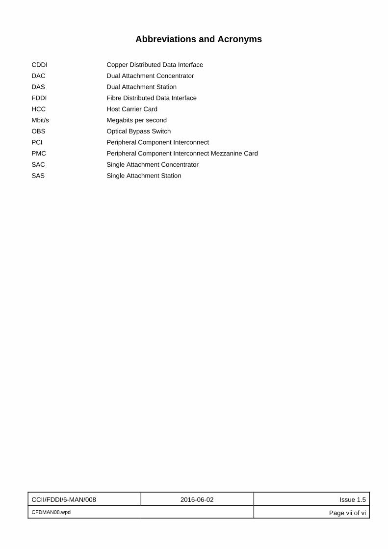
Abbreviations and Acronyms
CDDI Copper Distributed Data Interface
DAC Dual Attachment Concentrator
DAS Dual Attachment Station
FDDI Fibre Distributed Data Interface
HCC Host Carrier Card
Mbit/s Megabits per second
OBS Optical Bypass Switch
PCI Peripheral Component Interconnect
PMC Peripheral Component Interconnect Mezzanine Card
SAC Single Attachment Concentrator
SAS Single Attachment Station

CCII/FDDI/6-MAN/008 2016-06-02 Issue 1.5
CFDMAN08.wpd Page 1 of 17
1. Scope
1.1 Introduction
This document is the User Manual for the C²I² Systems Fibre Distributed Data Interface (FDDI) and CopperDistributed Data Interface (CDDI) Adapters.
1.2 System Overview
The Peripheral Component Interconnect (PCI) Mezzanine Card (PMC) FDDI adapters attach Host CarrierCards (HCC) to 100 Mbit/s Fibre Distributed Data Interface (FDDI) networks using fibre optic cable.
The PMC CDDI adapters attach HCCs to 100 Mbit/s Copper Distributed Data Interface (CDDI) networks usingcopper twisted pair cable.
At present, the range of C²I² Systems FDDI and CDDI adapters covers the PMC (PCI Mezzanine Connector)and the PCI-104 bus architecture.

CCII/FDDI/6-MAN/008 2016-06-02 Issue 1.5
CFDMAN08.wpd Page 2 of 17
2. Applicable and Reference Documents
2.1 Applicable Documents
2.1.1 CCII/FDDI/6-MAN/002, User Manual for the FDDI Adapter 4.3 BSD VxWorks Software Driver.
2.1.2 CCII/FDDI/6-MAN/003, Generic User Manual for the FDDI Adapter VxWorks BIT Application.
2.2 Reference Documents
2.2.1 CCII/FDDI/6-MAN/001, User Manual for the FDDI Adapter VxWorks Enhanced Network Software Driver.

CCII/FDDI/6-MAN/008 2016-06-02 Issue 1.5
CFDMAN08.wpd Page 3 of 17
3. General Information
3.1 The Adapter Kit
The adapter kit consists of the following items :
• Cardboard Package• Electrostatic Discharge (ESD) Protective Bag• the Adapter• screws as required• CD containing User Manuals, Installation Guides and Drivers
If any item is missing or damaged, contact C²I² Systems.
Please refer to the Release Notes on the diskette for the latest information regarding this product.
3.2 Handling Instructions
Follow strict ESD handling procedures. Failure to do so may result in damage to the adapter.Do not open the ESD protective package containing the adapter until you are prompted to do so.
3.3 Items Required to Install the Adapter
3.3.1 Cables
Fibre FDDI Single Attachment Station (SAS) adapter
One duplex optic fibre patch lead or two optic fibrecables with the appropriate FDDI ST or SCconnectors.
FDDI Dual Attachment Station(DAS) adapter
Two duplex optic fibre patch leads or four optic fibrecables with the appropriate FDDI ST or SCconnectors.
Copper CDDI SAS adapter One twisted pair patch lead with HR10Aconnectors. Testing of transceivers will also requireone HR10A wrap plug (see Figure 3)
CDDI DAS adapter Two twisted pair patch leads with HR10Aconnectors. Testing of transceivers will also requiretwo HR10A wrap plugs (see Figure 3).
Figure 1 : ST Connector

CCII/FDDI/6-MAN/008 2016-06-02 Issue 1.5
CFDMAN08.wpd Page 4 of 17
Figure 2 : HR10A Connector
HR10A Connector as seen from front (socket) side
Figure 3 : HR10A Wrap Plug
Note : These cables are not provided with the adapter.
3.3.2 HCC Requirements
Note : The HCC should be correctly configured before you proceed with the adapter installation. Referto the documentation for the specific HCC.
3.3.2.1 PMC Adapter
An HCC equipped with at least one empty PMC expansion slot is required to host a PMC FDDI orCDDI Adapter.
3.3.2.2 PCI-104
A stable PCI-104 system is required to host a PCI-104 FDDI or CDDI Adapter.
3.3.3 Documentation
C this Installation Guide
C the Documentation provided for the HCC

CCII/FDDI/6-MAN/008 2016-06-02 Issue 1.5
CFDMAN08.wpd Page 5 of 17
3.3.4 Software
C the Software Driver for the FDDI Adapter - in some instances this is included with the OperatingSystem (Linux, Windows)
C at least one of the operating systems supported by the HCC and the FDDI Adapter drivers
C for a full listing of Operating Systems and Drivers supported please refer to the installation disksand/or the web site located at (http://www.ccii.co.za/).

CCII/FDDI/6-MAN/008 2016-06-02 Issue 1.5
CFDMAN08.wpd Page 6 of 17
4. Installation of the Adapter
4.1 Installation Overview
If you are testing a previously installed adapter, skip to Step 5. The installation of the adapter requires thecompletion of the following steps:
C prepare the HCC for installation of a PMC or PC-104 adapterC install the adapterC reinstall the HCC and reconnect the cables if requiredC restart and configure the HCCC connect loop-back cables / wrap plugs for transceiver testsC test the adapterC attach the adapter to your network
Refer to the documentation for the HCC.
There are two ways to test the adapter :
C a test with loop-back covering all devices including the transceiverC a test without loop-back covering all devices except the transceiver
4.2 Testing with Loop-Back Cables / Wrap Plugs for Transceiver Tests
4.2.1 Fibre SAS
Connect a fibre cable as shown in Figure 4. You may have to remove process plugs from the transceiver if theadapter is being used for the first time.
Figure 4 : FDDI SAS Loop-Back

CCII/FDDI/6-MAN/008 2016-06-02 Issue 1.5
CFDMAN08.wpd Page 7 of 17
4.2.2 Fibre DAS
Connect two fibre cables as shown in Figure 5. You may have to remove process plugs from the transceiversif the adapter is being used for the first time.
Figure 5 : FDDI DAS Loop-Back
4.2.3 Copper SAS
Connect a single HR10A wrap plug (shown in Figure 3).
4.2.4 Copper DAS
Connect two HR10A wrap plugs (shown in Figure 3).
4.3 Testing with or without Loop-Back Cables / Wrap Plugs for Transceiver Tests
The test executable is available for DOS (SKFPDIAG.EXE) and VxWorks (ccFdBit.a).
To run the VxWorks test software, follow the instructions in Generic User Manual for the FDDI VxWorks BITApplication [2.1.2].
To test the adapter using DOS, follow these steps :
1. Boot with DOS and wait until the operating system is loaded and the DOS prompt is displayed onthe screen. If you are not able to initiate DOS or if the DOS prompt does not appear, check yourconfiguration.
2. Insert the Driver Installation Diskette (that has been delivered with the adapter) in diskette drive A.
3. For PMC adapters, type in :
cd a: [Press Enter ]SKFPDIAG [Press Enter ]
4. When the Main Menu of the diagnostic program is displayed, select by using the arrow keys tohighlight the option and pressing the <Enter> key.
C “Diagnostics” if you want to perform the test without Loop-Back-back or
C “Diagnostics with Loop-back" if you want to perform the test with loop-back
Several tests are performed. This will take 1 to 4 minutes. After all the tests are run, a message is displayed.
CCII/FDDI/6-MAN/008 2016-06-02 Issue 1.5
CFDMAN08.wpd Page 8 of 17
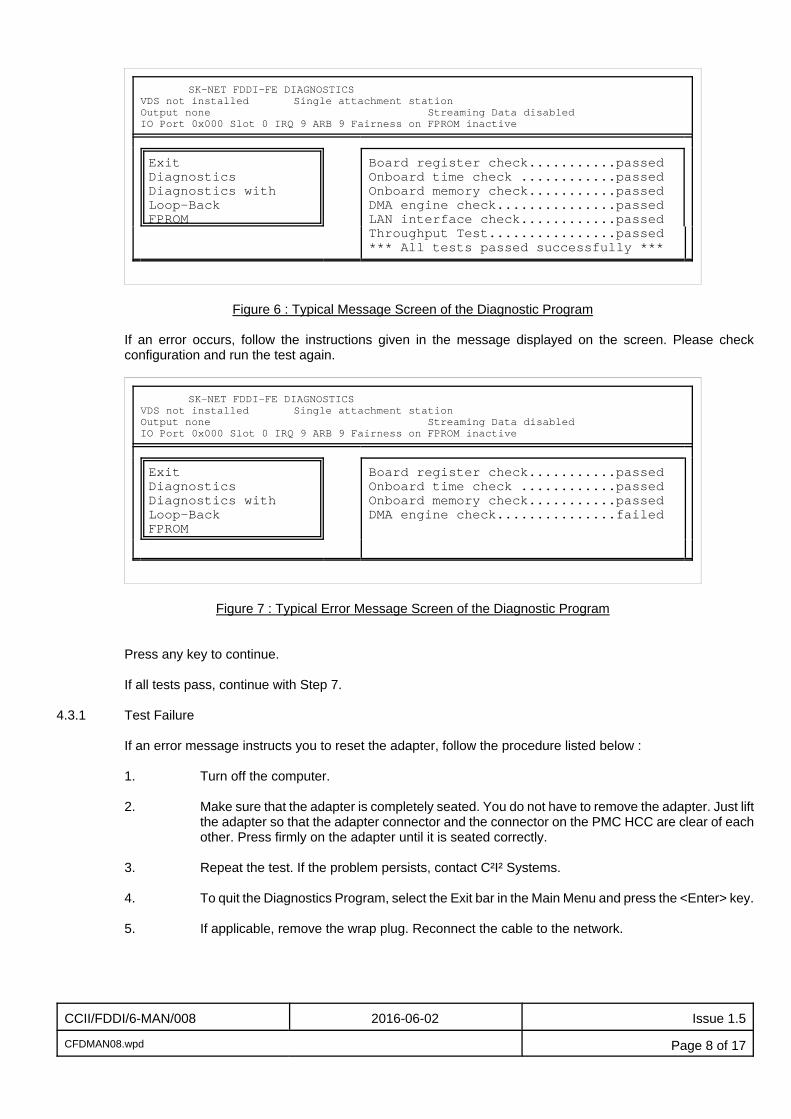
SK-NET FDDI-FE DIAGNOSTICS VDS not installed Single attachment stationOutput none Streaming Data disabled IO Port 0x000 Slot 0 IRQ 9 ARB 9 Fairness on FPROM inactive
ExitDiagnosticsDiagnostics withLoop-BackFPROM
Board register check...........passedOnboard time check ............passedOnboard memory check...........passedDMA engine check...............passedLAN interface check............passedThroughput Test................passed*** All tests passed successfully ***
Figure 6 : Typical Message Screen of the Diagnostic Program
If an error occurs, follow the instructions given in the message displayed on the screen. Please checkconfiguration and run the test again.
SK-NET FDDI-FE DIAGNOSTICS VDS not installed Single attachment stationOutput none Streaming Data disabled IO Port 0x000 Slot 0 IRQ 9 ARB 9 Fairness on FPROM inactive
ExitDiagnosticsDiagnostics withLoop-BackFPROM
Board register check...........passedOnboard time check ............passedOnboard memory check...........passedDMA engine check...............failed
Figure 7 : Typical Error Message Screen of the Diagnostic Program
Press any key to continue.
If all tests pass, continue with Step 7.
4.3.1 Test Failure
If an error message instructs you to reset the adapter, follow the procedure listed below :
1. Turn off the computer.
2. Make sure that the adapter is completely seated. You do not have to remove the adapter. Just liftthe adapter so that the adapter connector and the connector on the PMC HCC are clear of eachother. Press firmly on the adapter until it is seated correctly.
3. Repeat the test. If the problem persists, contact C²I² Systems.
4. To quit the Diagnostics Program, select the Exit bar in the Main Menu and press the <Enter> key.
5. If applicable, remove the wrap plug. Reconnect the cable to the network.

CCII/FDDI/6-MAN/008 2016-06-02 Issue 1.5
CFDMAN08.wpd Page 9 of 17
6. If you do not intend to connect the system to the FDDI network right now, reinsert the process pluginto the optic transceiver. The process plug will protect the optic transceiver from dustaccumulation.
4.4 Attach the Adapter to Your Network
The SAS adapter supports single attachment to a concentrator.
The DAS adapter supports either dual attachment to the main ring path or dual homing to one or twoconcentrators.
4.5 Connector Identification
4.5.1 PMC FDDI Adapter, DAS, ST Connectors
Figure 8 shows the location of network connectors on the PMC FDDI Adapter with ST Connectors, as seenfrom the component side of the adapter. Figure 9 shows the frontpanel layout.
Si
Po
Pi
So
In
Out
In
Out
Port B
Port A
Bypass
Figure 8 : PMC FDDI DAS ST Connector Identification
B
R
APort B Port A
Si Po Pi So
Figure 9 : PMC FDDI DAS ST Frontpanel Layout
Note : Pi = Primary InSi = Secondary InPo = Primary OutSo = Secondary Out
Refer to Annexure B for Optical Bypass Pin-outs.

CCII/FDDI/6-MAN/008 2016-06-02 Issue 1.5
CFDMAN08.wpd Page 10 of 17
4.5.2 PMC FDDI Adapter, DAS, Reversed ST Connectors
Figure 10 shows the location of network connectors on the PMC FDDI Adapter with reversed ST Connectors,as seen from the track side of the adapter.
Figure 10 : PMC FDDI DAS ST-1 Connector Identification

CCII/FDDI/6-MAN/008 2016-06-02 Issue 1.5
CFDMAN08.wpd Page 11 of 17
4.5.3 PMC FDDI Adapter, DAS, SC Connectors
Figure 11 shows the location of network connectors on the PMC FDDI Adapter with SC Connectors, as seenfrom the component side of the adapter. Figure 12 shows the frontpanel layout.
Note : Pi = Primary InSi = Secondary InPo = Primary OutSo = Secondary Out
Refer to Annexure B for Optical Bypass Pin-outs.
Figure 11 : PMC CDDI DAS SC Connector Identification
Figure 12 : PMC FDDI DAS SC Frontpanel Layout
CCII/FDDI/6-MAN/008 2016-06-02 Issue 1.5
CFDMAN08.wpd Page 12 of 17
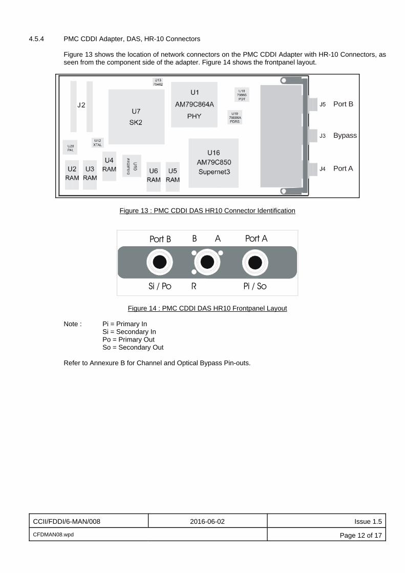
4.5.4 PMC CDDI Adapter, DAS, HR-10 Connectors
Figure 13 shows the location of network connectors on the PMC CDDI Adapter with HR-10 Connectors, asseen from the component side of the adapter. Figure 14 shows the frontpanel layout.
Port B
Port A
Bypass
Figure 13 : PMC CDDI DAS HR10 Connector Identification
B
R
APort B Port A
Si / Po Pi / So
Figure 14 : PMC CDDI DAS HR10 Frontpanel Layout
Note : Pi = Primary InSi = Secondary InPo = Primary OutSo = Secondary Out
Refer to Annexure B for Channel and Optical Bypass Pin-outs.
CCII/FDDI/6-MAN/008 2016-06-02 Issue 1.5
CFDMAN08.wpd Page 13 of 17
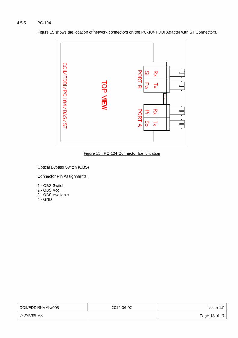
4.5.5 PC-104
Figure 15 shows the location of network connectors on the PC-104 FDDI Adapter with ST Connectors.
Figure 15 : PC-104 Connector Identification
Optical Bypass Switch (OBS)
Connector Pin Assignments :
1 - OBS Switch2 - OBS Vcc3 - OBS Available4 - GND
CCII/FDDI/6-MAN/008 2016-06-02 Issue 1.5
CFDMAN08.wpd Page 14 of 17
5. Installation of the Protocol Drivers
For the DOS protocol drivers, complete installation instructions are given in readme files on the InstallationDiskettes. Look for the .TXT files stored in the sub-directory of the corresponding driver on the InstallationDiskettes.
Installation instructions for the VxWorks protocol drivers are in the Generic User Manual for the FDDI 4.3 BSDVxWorks Software Driver [2.1.1].
Once the driver is installed and loaded, the adapter is ready for use.
Use one of the following tables to determine the status of your network connection :
Note : With a SAS adapter, the DAS LED does not apply in the following tables.
Adapters with Two LEDsSAS DAS
B A
Off Off Driver not loaded, adapter not operational.
Yellow Yellow Station management code is running, adapter is not connected to the network (for example,cable is disconnected).
Green Off SAS: adapter is ready for use (connected to network and operational).PMC DAS: adapter active at Channel B.
Off Green SAS: driver not loaded, adapter not operational.PMC DAS: adapter active at Channel A.
Green Green Adapter is ready for use (connected to network and operational).
Adapters with Three LEDsSAS DAS
Green(B)
Yellow(R)
Green(A)
Off Off Off Driver not loaded, adapter not operational.
Off On Off Station management code is running, adapter is not connected to the network (forexample, cable is disconnected).
On Off On SAS: adapter is ready for use (connected to network and operational).PMC DAS: adapter active at Channel B.
Off Off On SAS: driver not loaded, adapter not operational.PMC DAS: adapter active at Channel A.
On Off On Adapter is ready for use (connected to network and operational).

CCII/FDDI/6-MAN/008 2016-06-02 Issue 1.5
CFDMAN08.wpd Page 15 of 17
6. Contact Details
6.1 Contact Person
Direct all correspondence and / or support queries to the Project Manager at C²I² Systems.
6.2 Physical Address
C²I² SystemsReal-Time House, Block TGreenford Office EstatePunters Way7708 KenilworthCape TownSouth Africa
6.3 Postal Address
C²I² SystemsP.O. Box 1717701 RondeboschSouth Africa
6.4 Voice and Electronic Contacts
Tel : (+27) (0)21 683 5490Fax : (+27) (0)21 683 5435Email : [email protected] : [email protected] : http://www.ccii.co.za/
6.5 Product Support
Support on C²I² Systems products is available telephonically between Monday and Friday from 09:00 to 17:00CAT. Central African Time (CAT = GMT + 2).
CCII/FDDI/6-MAN/008 2016-06-02 Issue 1.5
CFDMAN08.wpd Page 16 of 17
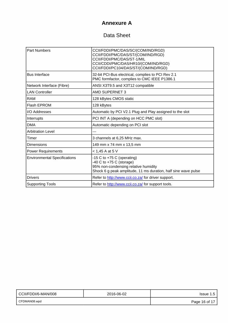
Annexure A
Data Sheet
Part Numbers CCII/FDDI/PMC/DAS/SC/(COM/IND/RGD) CCII/FDDI/PMC/DAS/ST/(COM/IND/RGD)CCII/FDDI/PMC/DAS/ST-1/MILCCII/CDDI/PMC/DAS/HR10/(COM/IND/RGD)CCII/FDDI/PC104/DAS/ST/(COM/IND/RGD)
Bus Interface 32-bit PCI-Bus electrical, complies to PCI Rev 2.1PMC formfactor, complies to CMC IEEE P1386.1
Network Interface (Fibre) ANSI X3T9.5 and X3T12 compatible
LAN Controller AMD SUPERNET 3
RAM 128 kBytes CMOS static
Flash EPROM 128 kBytes
I/O Addresses Automatic by PCI V2.1 Plug and Play assigned to the slot
Interrupts PCI INT A (depending on HCC PMC slot)
DMA Automatic depending on PCI slot
Arbitration Level ---
Timer 3 channels at 6,25 MHz max.
Dimensions 149 mm x 74 mm x 13,5 mm
Power Requirements < 1,45 A at 5 V
Environmental Specifications -15 C to +75 C (operating)-40 C to +75 C (storage)95% non-condensing relative humidityShock 6 g peak amplitude, 11 ms duration, half sine wave pulse
Drivers Refer to http://www.ccii.co.za/ for driver support.
Supporting Tools Refer to http://www.ccii.co.za/ for support tools.
CCII/FDDI/6-MAN/008 2016-06-02 Issue 1.5
CFDMAN08.wpd Page 17 of 17
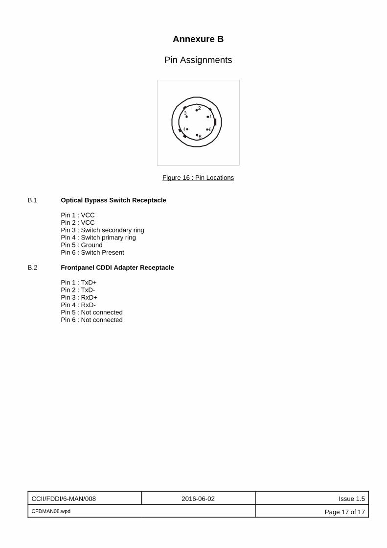
Annexure B
Pin Assignments
Figure 16 : Pin Locations
B.1 Optical Bypass Switch Receptacle
Pin 1 : VCCPin 2 : VCCPin 3 : Switch secondary ringPin 4 : Switch primary ringPin 5 : GroundPin 6 : Switch Present
B.2 Frontpanel CDDI Adapter Receptacle
Pin 1 : TxD+Pin 2 : TxD-Pin 3 : RxD+Pin 4 : RxD-Pin 5 : Not connectedPin 6 : Not connected