FIBER DISTRIBUTED DATA INTERFACE (FDDI)
21
FIBER DISTRIBUTED DATA INTERFACE (FDDI)
-
Upload
colette-barton -
Category
Documents
-
view
106 -
download
10
description
FIBER DISTRIBUTED DATA INTERFACE (FDDI). Introduction. Shared media network like Ethernet ( IEEE 802.3) & IBM token ring (IEEE 802.5) 100 mbps speed Runs on optical fiber American National Standards Institute (ANSI) standard. FDDI Basic Principle. Token ring network like IEEE 802.5 - PowerPoint PPT Presentation
Transcript of FIBER DISTRIBUTED DATA INTERFACE (FDDI)

FIBER DISTRIBUTED DATA INTERFACE (FDDI)
Introduction
٭ Shared media network like Ethernet ( IEEE 802.3) &
IBM token ring (IEEE 802.5)
٭ 100 mbps speed
٭ Runs on optical fiber
٭ American National Standards Institute (ANSI) standard

FDDI Basic Principle
• Token ring network like IEEE 802.5
• Token: a special sequence of bits
• Token circulates around the ring
• A station removes the token from ring before transmission
• After transmission, the station returns the token to the ring
• Collisions are prevented as there is only one token in the ring
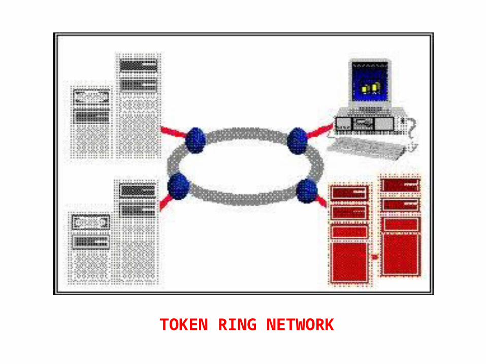
TOKEN RING NETWORK

FDDI Basic Principle
• Token ring network like IEEE 802.5
• Token: a special sequence of bits
• Token circulates around the ring
• A station removes the token from ring before transmission
• After transmission, the station returns the token to the ring
• Collisions are prevented as there is only one token in the
ring

FDDI Physical Properties
• Dual-counter-rotating token ring architecture
• One ring is primary and the other secondary
• Up to 500 stations with a maximum distance of 2 km
between any pair of stations for multimode fiber
• With single-mode fiber the distance can be up to 40 km
• Maximum ring length is 100 km (total fiber length is 200
km for two rings)
• Uses 4b/5b encoding
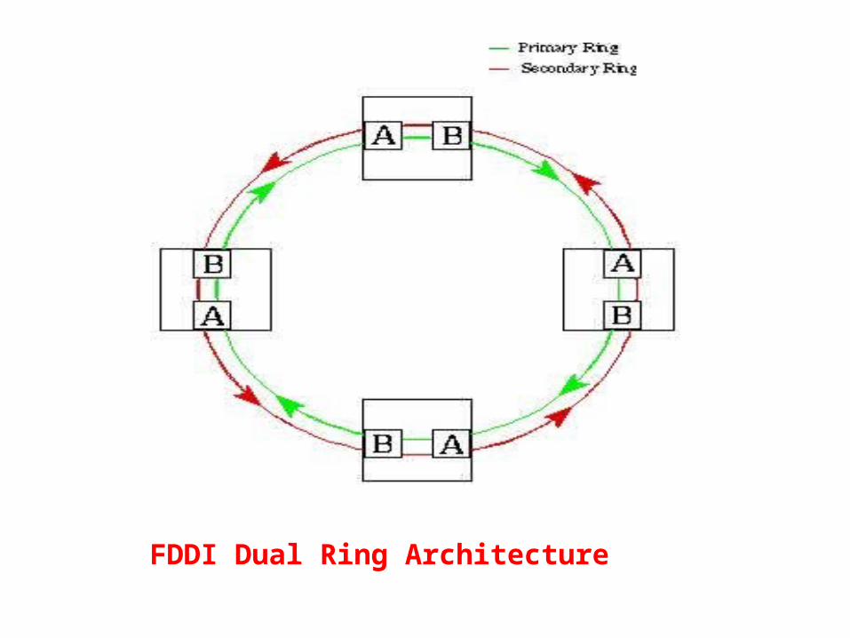
FDDI Dual Ring Architecture
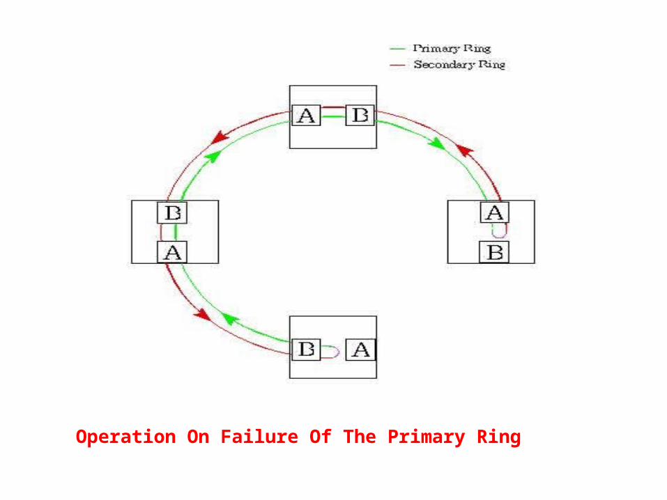
Operation On Failure Of The Primary Ring
FDDI Architectural Model
• According to the OSI-RM, FDDI specifies layer 1 (physical
layer) and part of layer 2 (data link control layer)
• The physical layer handles the transmission of raw bits
over a communications link
• The data link control (dlc) layer is responsible for
maintaining the integrity of information exchanged
between two points

Relationship Between FDDI and OSI-RM

The PMD Layer
• PMD layer defines the type of media interconnection and its
characteristics such as transmitter power, frequencies, receiver
sensitivities, bit error rates (per), optical components etc.
• PMD-MMF: MultiMode (62.5 micron core diameter) Fiber
• PMD-SMF: Single-Mode (8-10 micron core diameter) Fiber
• Also defines STP, UTP as media and FDDI on SONET
The PHY layer
• Provides the media independent functions associated with
the OSI physical layer
• Reception: decodes the received bit stream from PMD into a
symbol stream for use by the mac layer
• Transmission: encodes the data and control symbols
provided by mac using 4b/5b encoding for the PMD layer
• Also provides SMT the services required for the
establishment and maintenance of the FDDI ring (by
continuously listening to the incoming signal)

The MAC Layer
• Provides fair & deterministic access
• Fair: no node has advantage over another in accessing the
medium
• Deterministic: under error-free conditions, the time a node has
to wait to access the medium can be predicted
• Medium access is controlled by a token
• Token permits the node that receives it to transmit frames
• The mac layer of the node that generated the frame is responsible
for removing the token

The SMT Layer• A sophisticated, built-in network monitoring and
management capability
• SMT is not an OSI-RM specification
• Making use of the services provided by PMD, PHY, and
MAC, it carries out many functions such as node
initialization, bypassing faulty nodes, coordination of node
insertion and removal, fault isolation and recovery
• SMT is most commonly implemented as a software process
running on the FDDI device
FDDI Benefits
• High bandwidth (10 times more than Ethernet)
• Larger distances between FDDI nodes because of very low
attenuation ( 0.3 dB/km) in fibers
• Improved signal-to-noise ratio because of no interference from
external radio frequencies and electromagnetic noise
• Per typical of fiber-optic systems (10^-11) is substantially
better than that in copper (10^-5) and microwave systems
(10^-7)
• Very difficult to tap signals form a fiber cable
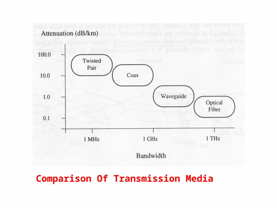
Comparison Of Transmission Media

FDDI Limitations
• High cost of optical components required for
transmission/reception of signals (especially for
single mode fiber networks)
• More complex to implement than existing low
speed LAN technologies such as IEEE 802.3 and
IEEE 802.5

Applications of FDDI
• Office automation at the desktop
• Backbones for factory automation
• Backend data center applications
• Campus LAN interconnection
• Intercampus Backbones Or Metropolitan Area Networks
(mans)
• Interconnection of private branch exchanges (pbxs)
• Workgroup and departmental LANs
• Integrated transport for multimedia applications
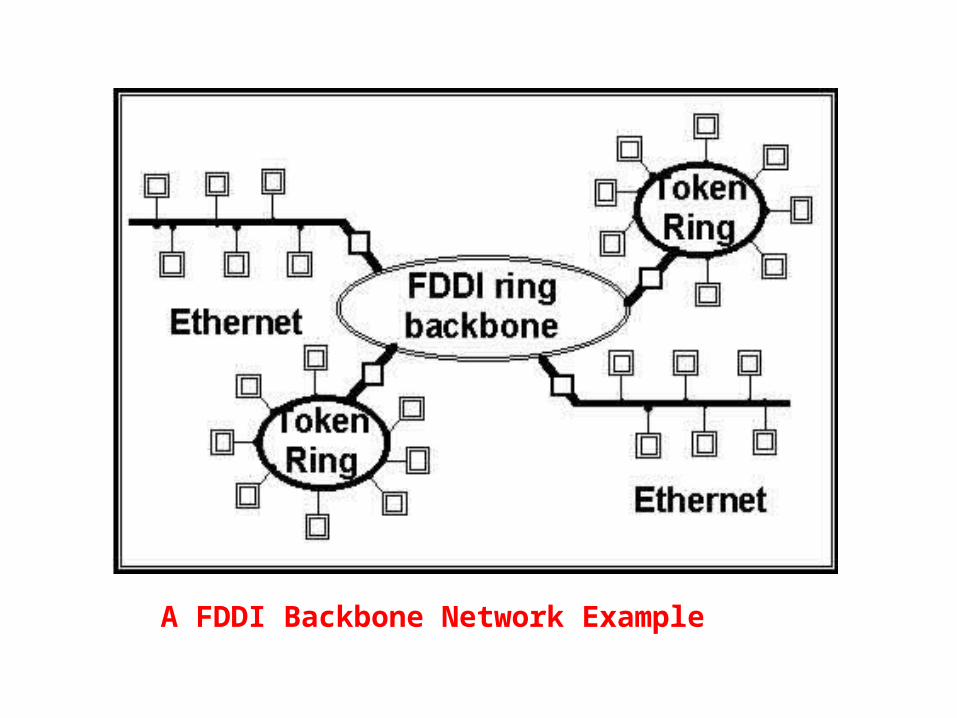
A FDDI Backbone Network Example

Comparison With Other Networks
FEATURES FDDI ETHERNET TOKEN RING
Transmission rate
125 mbaud 20 mbaud 8 & 32 mbaud
Data rate 100 mbps 10 mbps 4 & 16 mbps
Signal encoding
4b/5b (80% efficient)
Manchester (50% efficient)
Differential manchester (50%
efficient)
Maximum coverage
100 km 2.5 km Configuration dependent
Maximum nodes
500 1024 250
Maximum distance between nodes
2 km (multimode fiber)
40 km (single-mode fiber)
2.5 km 300 m (recommended
100 m)

The End
……. Thank You …….