LinkBuilder FDDI Workgroup Hub User Guide
176
LinkBuilder ® FDDI Workgroup Hub User Guide A member of the LinkBuilder FDDI family For 3Com User Group Information 1-800-NET-3Com or your local 3Com office Manual Part No. 09-0447-000 Published July 1993. Printed in the U.S.A.
Transcript of LinkBuilder FDDI Workgroup Hub User Guide
i
LinkBuilder® FDDI Workgroup HubUser Guide
A member of the LinkBuilder FDDI family
For 3Com User Group Information1-800-NET-3Comor your local 3Com office
Manual Part No. 09-0447-000Published July 1993. Printed in the U.S.A.

ii
3Com Corporation5400 Bayfront PlazaSanta ClaraCalifornia, USA95052-8145
© 3Com Corporation, 1993. All rights reserved. No part of this manual may be reproduced in any form or byany means or used to make any derivative work (such as translation, transformation, or adaptation) withoutpermission from 3Com Corporation.
3Com Corporation reserves the right to revise this publication and to make changes in content from time totime without obligation on the part of 3Com Corporation to provide notification of such revision or change.
3Com Corporation provides this guide without warranty of any kind, either implied or expressed, including,but not limited to, the implied warranties of merchantability and fitness for a particular purpose. 3Com maymake improvements or changes in the product(s) and/or the program(s) described in this manual at any time.
If you are a government agency, then this software and documentation is provided to you subject to thefollowing restricted rights:
For units of the Department of Defense:Restricted Rights Legend: Use, duplication, or disclosure by the Government is subject to restrictions asset forth in subparagraph (c) (1) (ii) of the Rights in Technical Data and Computer Software Clause at 48C.F.R. 52.227-7013. 3Com Corporation, 5400 Bayfront Plaza, Santa Clara, California 95052-8145.
For civilian agencies:Restricted Rights Legend: Use, reproduction, or disclosure is subject to restrictions set forth insubparagraph (a) through (d) of the Commercial Computer Software – Restricted Rights clause at 48C.F.R. 52.227-19 and the limitations set forth in 3Com’s standard commercial agreement for the Software.Unpublished rights reserved under the copyright laws of the United States.
Portions of this manual are reproduced in whole or in part with permission from (as appropriate).
3Com and LinkBuilder are registered trademarks of 3Com Corporation. CardFacts, NetFacts, Ask3Com,3ComFacts, and CardBoard are service marks of 3Com Corporation.
Motorola is a registered trademark of Motorola Corporation. National Semiconductor is a registeredtrademark of National Semiconductor Corporation. CompuServe is a service mark of CompuServe,Incorporated.
Manual written by John Jeter. Edited by Nancy Kurahashi. Technical illustrations and production by TimBuckreus.

iii
LIMITED WARRANTY
HARDWARE: 3Com warrants its hardware products to be free from defects in workmanship and materials,under normal use and service, for the following lengths of time from the date of purchase from 3Com or itsAuthorized Reseller:
Bridge, gateway, and other internetworking products One yearServer products One yearStation products One yearNetwork adapters LifetimeLinkBuilder® 10BT and 10BTi hubs Three yearsOther transmission products One yearSpare parts and spares kits 90 daysInstrumentation 90 days
If a product does not operate as warranted during the applicable warranty period, 3Com shall, at its expense,correct any such defect by repairing the defective product or part or, at its option, by delivering to Customeran equivalent product or part to replace the defective item. All products that are replaced will become theproperty of 3Com. Replacement products may be new or reconditioned. Any replaced or repaired product orpart has a ninety (90) day warranty or the remainder of the initial warranty period, whichever is longer.
3Com shall not be responsible for any software, firmware, information, or memory data of Customercontained in, stored on, or integrated with any products returned to 3Com pursuant to any warranty.
SOFTWARE: 3Com warrants that the software programs licensed from it will perform in substantialconformance to the program specifications therefor for a period of ninety (90) days from the date of purchasefrom 3Com or its Authorized Reseller. 3Com warrants the magnetic media containing software against failureduring the warranty period. No updates are provided. 3Com’s sole obligation hereunder shall be (at 3Com’sdiscretion) to refund the purchase price paid by Customer for any defective software products, or to replaceany defective media with software which substantially conforms to 3Com’s applicable publishedspecifications. Customer assumes responsibility for the selection of the appropriate applications program andassociated reference materials. 3Com makes no warranty that its software products will work in combinationwith any hardware or applications software products provided by third parties, that the operation of thesoftware products will be uninterrupted or error free, or that all defects in the software products will becorrected. For any third party products listed in the 3Com software product documentation or specificationsas being compatible, 3Com will make reasonable efforts to provide compatibility, except where the non-compatibility is caused by a “bug” or defect in the third party’s product.
STANDARD WARRANTY SERVICE: Standard warranty service for hardware products may be obtainedby delivering the defective product, accompanied by a copy of the dated proof of purchase, to 3Com’sCorporate Service Center or to an Authorized 3Com Service Center during the applicable warranty period.Standard warranty service for software products may be obtained by telephoning 3Com’s Corporate ServiceCenter or an Authorized 3Com Service Center, within the warranty period. Products returned to 3Com’sCorporate Service Center must be pre-authorized by 3Com with a Return Material Authorization (RMA)number marked on the outside of the package, and sent prepaid, insured, and packaged appropriately for safeshipment. The repaired or replaced item will be shipped to Customer, at 3Com’s expense, not later than thirty(30) days after receipt by 3Com.

iv
WARRANTIES EXCLUSIVE: IF A 3COM PRODUCT DOES NOT OPERATE AS WARRANTEDABOVE, CUSTOMER’S SOLE REMEDY SHALL BE REPAIR, REPLACEMENT, OR REFUND OF THEPURCHASE PRICE PAID, AT 3COM’S OPTION. THE FOREGOING WARRANTIES AND REMEDIESARE EXCLUSIVE AND ARE IN LIEU OF ALL OTHER WARRANTIES, EXPRESS OR IMPLIED,EITHER IN FACT OR BY OPERATION OF LAW, STATUTORY OR OTHERWISE, INCLUDINGWARRANTIES OF MERCHANTABILITY AND FITNESS FOR A PARTICULAR PURPOSE. 3COMNEITHER ASSUMES NOR AUTHORIZES ANY OTHER PERSON TO ASSUME FOR IT ANY OTHERLIABILITY IN CONNECTION WITH THE SALE, INSTALLATION, MAINTENANCE OR USE OF ITSPRODUCTS.
3COM SHALL NOT BE LIABLE UNDER THIS WARRANTY IF ITS TESTING AND EXAMINATIONDISCLOSE THAT THE ALLEGED DEFECT IN THE PRODUCT DOES NOT EXIST OR WAS CAUSEDBY CUSTOMER’S OR ANY THIRD PERSON’S MISUSE, NEGLECT, IMPROPER INSTALLATION ORTESTING, UNAUTHORIZED ATTEMPTS TO REPAIR, OR ANY OTHER CAUSE BEYOND THERANGE OF THE INTENDED USE, OR BY ACCIDENT, FIRE, LIGHTNING, OR OTHER HAZARD.
LIMITATION OF LIABILITY. IN NO EVENT, WHETHER BASED IN CONTRACT OR TORT(INCLUDING NEGLIGENCE) SHALL 3COM BE LIABLE FOR INCIDENTAL, CONSEQUENTIAL,INDIRECT, SPECIAL, OR PUNITIVE DAMAGES OF ANY KIND, OR FOR LOSS OF REVENUE, LOSSOF BUSINESS, OR OTHER FINANCIAL LOSS ARISING OUT OF OR IN CONNECTION WITH THESALE, INSTALLATION, MAINTENANCE, USE, PERFORMANCE, FAILURE, OR INTERRUPTION OFITS PRODUCTS, EVEN IF 3COM OR ITS AUTHORIZED RESELLER HAS BEEN ADVISED OF THEPOSSIBILITY OF SUCH DAMAGES.
Some states do not allow the exclusion of implied warranties or the limitation of incidental or consequentialdamages for consumer products, so the above limitations and exclusions may not apply to you. This warrantygives you specific legal rights which may vary from state to state.
3Com Corporation5400 Bayfront PlazaSanta Clara, CA 95052-8145(408) 764-50006/15/92

v
WARNING: This equipment (3C781, 3C782, 3C783) has been tested and found to comply with the limits for aClass B digital device, pursuant to Part 15 of the FCC Rules. These limits are designed to provide reasonableprotection against harmful interference in a residential installation. This equipment generates, uses and canradiate radio frequency energy and, if not installed and used in accordance with the instructions, may causeharmful interference to radio communications. However, there is no guarantee that interference will not occurin a particular installation. If this equipment does cause harmful interference to radio or television reception,which can be determined by turning the equipment off and on, the user is encouraged to try to correct theinterference by one or more of the following measures:
■ Reorient or relocate the receiving antenna.
■ Increase the separation between the equipment and receiver.
■ Connect the equipment into an outlet on a circuit different from the one which the receiver is connected to.
■ Consult the dealer or an experienced radio/TV technician for help.
The user may find the following booklet prepared by the Federal Communications Commission helpful:
The Interference Handbook
This booklet is available from the U.S. Government Printing Office, Washington, D.C. 20402. Stock No.004-000-00345-4.
NOTE: In order to maintain compliance with the limits of a Class B digital device, 3Com requires that you usequality interface cables when connecting to this device. Changes or modifications not expressly approved by3Com could void the user’s authority to operate this equipment. Suggested cable types are:
■ Thin Ethernet (50 ohm) for BNC connections: 3C530-xxx or equivalent
■ Thick Ethernet (50 ohm) for AUI connections: 3C120-xxx or equivalent
■ For UTP and STP connections:
Unshielded twisted-pair (100 ohm):
– Level 3 LAN and high speed data cable. Example, Anixter® CM-00424BAG-3 or equivalent.
– Level 4 extended distance LAN cable. Example, Anixter® CM-00424BAG-4 or equivalent.
Shielded twisted-pair (100 ohm):
– Level 5 data grade media cable. Example, AT&T® type 2061, 1061, or equivalent.
Shielded twisted-pair (150 ohm):
– Suggested cable type IBM® type 1, specification no. 4716748, type CL2, CM or MP, or equivalent.
WARNING: This equipment (3C784) has been tested and found to comply with the limits for a Class A digitaldevice, pursuant to Part 15 of the FCC Rules. These limits are designed to provide reasonable protectionagainst harmful interference in a commercial installation. This equipment generates, uses and can radiate radiofrequency energy and, if not installed and used in accordance with the instructions, may cause harmfulinterference to radio communications. Operation of this equipment in a residential area is likely to causeharmful interference, in which case, the user will be required to correct the interference at the user’s ownexpense.
Changes or modifications not expressly approved by 3Com could void the user’s authority to operate thisequipment.

vi
VDE Class B ComplianceHiermit wird bescheinigt, dass die 3C781, 3C782, 3C783 in Übereinstimmung mit den Bestimmungen der Vfg1046/1984 funk-entstört sind.
Der Deutschen Bundespost wurde das Inverkehrbringen dieses Gërates angezeigt und die Berechtigung zurÜberprüfung der Serie auf Einhaltung der Bestimmungen eingeräumt.
We hereby certify that the 3C781, 3C782, 3C783 comply with the RFI Suppression Requirements of Vfg1046/1984. The German Postal Service was notified that the equipment is being marketed. The GermanPostal Service has the right to re-test the equipment and to verify that it complies.
3Com Corporation5400 Bayfront PlazaSanta Clara, California, U.S.A.95052-8145

vii
Contents
Quick StartRoad Map to Hub Operations 1Unpacking the Hub 2Unpacking the Modules 3Installing the Modules 4Connecting to the Ring 6
Chapter 1 OverviewFDDI Technology 1-2
Physical Medium Dependent (PMD) Protocol 1-4Fiber-Optic 1-4Shielded Twisted Pair (STP) 1-4Unshielded Twisted Pair (UTP) 1-5
Physical (PHY) Protocol 1-5Media Access Control (MAC) Protocol 1-5Station Management (SMT) Protocol 1-6
Features and Functions 1-6Site Selection 1-8Typical FDDI Ring Setups 1-9Management and Media Modules 1-11
Management Module 1-11Media Modules 1-12
Fiber Media Port Module 1-12STP Media Port Module 1-14UTP Media Port Module 1-14

viii
Chapter 2 Installing the HubUnpacking the Hub 2-1Mounting the Hub in a Rack 2-2Equipping the Hub 2-5
Basic Contents 2-5Hub Chassis 2-6Media Port Modules 2-6Installing the Battery 2-7Keys for Fiber Port Modules 2-9STP Cascade Connector 2-11
Installing Modules 2-12Removing Modules 2-14Accessing the Hub 2-16
Changing the Serial Port’s Baud Rate 2-16Installing an Optional Modem 2-18Using Telnet to Access the Hub 2-19
Planning Connections 2-19FDDI Cabling Rules 2-20
Fiber-Optic Cable 2-20Shielded Twisted-Pair Cable 2-20Unshielded Twisted-Pair Cable 2-21
Data Flow Specifications 2-23Connecting to the Dual Ring 2-24
Installing an Optical Bypass Switch 2-26
Chapter 3 Configuring the HubAttachment Options 3-1
Dual Attachment Hub 3-2Single Attachment Hub 3-4Null Attachment Hub 3-5Dual Homing 3-6
Default Configuration 3-7Accessing Configuration Commands 3-8
Management Console Commands 3-8Primitive Console Commands 3-9
Accessing the Primitive Console Command Mode 3-9Returning to the Management Console Command Mode 3-11

ix
Port Connections 3-11Configuring Modules 3-15
Using the STP Cascade Connector 3-18
Chapter 4 Setting Up the HubCommands 4-1
Command Descriptions 4-2Display of Command Results 4-2
Setting Addresses 4-3IP Address 4-3Netmask 4-4Broadcast Address 4-4Default Gateway Address 4-4
Setting the Password 4-5Setting Attachment Port Configurations 4-6Using Station Management Parameters 4-7
Setting SMT Parameters 4-7Neighbor Notification Timer (T-Notify) 4-7Target Token Rotation Time (T-Req) 4-8Link Error Rate (LER) 4-8
Displaying SMT Parameters 4-11Maximum Token Rotation Time (T-Max) 4-11Negotiated Time (T-Neg) 4-11Valid Transmission Timer (TVX) 4-11
Downloading New Images 4-12Downloading from the TFTP Option 4-12Displaying the Current Download Method 4-14

x
Chapter 5 Using the HubGetting Hub Information 5-1
Show Hub Configuration 5-1Show MAC Frame Statistics 5-1Show IP Addresses 5-3Show MIB Counters 5-3Show Neighbor Stations 5-4Show Station Identification 5-4Show Ports Information 5-5
Module Designation 5-6PMD Class 5-6PHY Type 5-7Neighbor 5-7PCM State 5-7Connect State 5-9LER Alarm and LER Cutoff 5-9LER Estimate 5-9LEM Rejects 5-10LEM Count 5-10
Show Ring State 5-10Interpreting the LEDs 5-11
Management Module LEDs 5-11WRAP LED 5-13FAN FAIL LED 5-14HI TEMP LED 5-14LOW BATT LED 5-14Dangerous Environmental Conditions Display 5-14RESET Function 5-15
Media Module LEDs 5-16Using Miscellaneous Commands 5-17
Diagnosing Network Problems 5-17ping Command 5-18route Command 5-19arp Command 5-20show log and clear log Commands 5-21
Using Connectivity Commands 5-22connect and disconnect Commands 5-22logout Command 5-22

xi
Appendix A System MessagesError Messages A-1Download Messages A-4Fault Log Error Code Messages A-6
Appendix B Technical Specifications
Appendix C CommandsManagement Console Commands C-1
Set Commands C-1set attach C-1set baud C-2set boot C-3set gateway C-4set help C-4set ip C-4set ler C-5set pwd C-6set tnotify C-6set treq C-6
Show Commands C-7show attach C-7show baud C-7show boot C-7show cfm C-8show fstats C-9show gateway C-9show help C-10show ip C-10show log C-10show mib counters C-10show neigh C-11show obs C-11show ports C-12show rev C-13show ring C-14

xii
show sid C-14show tmax C-14show tneg C-15show tnotify C-15show treq C-15show tvx C-15
Diagnostic and Connectivity Commands C-16arp C-16clear C-16connect C-17disconnect C-17help C-17logout C-17ping C-18reset C-18route C-18
Primitive Console Commands C-19Set Commands C-20
set attach C-20set baud C-20set boot C-20set defaults C-20set gateway C-20set help | ? C-20set ip C-20set pwd C-20set tnotify C-20set treq C-21

xiii
Display Commands C-21show attach C-21show baud C-21show boot C-21show gateway C-21show help | ? C-21show ip C-21show log C-21show obs C-22show rev C-22show sid C-22show tnotify C-22show treq C-22show tvx C-22
Miscellaneous Commands C-22clear C-22help | ? C-22reset C-22
Appendix D Technical SupportOn-line Product Support D-1
CardBoard Bulletin Board Service D-1Automated Fax Service D-2Ask3Com On-line Service D-23Com Documentation on CD-ROM D-3
Support from Your Network Supplier D-3U.S. and Canada D-3Outside the U.S. and Canada D-3
Returning Products for Repair D-5
Glossary
Index

xiv
Figures
1-1. Ring Wrap 1-31-2. The LinkBuilder FDDI Workgroup Hub 1-81-3. Physical Topology for Typical FDDI Ring 1-91-4. FDDI Ring of Trees 1-101-5. Management Module, Front Panel 1-111-6. Fiber Media Port Module, Front Panel 1-131-7. Removing a Dust Plug from a Fiber Transceiver 1-131-8. STP Media Port Module, Front Panel 1-141-9. UTP Media Port Module, Front Panel 1-14
2-1. Attaching Mounting Brackets to the Hub 2-32-2. LinkBuilder FDDI Workgroup Hub Installed in a Distribution Rack 2-42-3. Battery Location on the Management Module 2-82-4. Media Module Keys Identified by Port Type 2-92-5. Inserting a Type M Key into a Fiber Transceiver 2-102-6. STP Module Cascade Connector 2-122-7. Cross-over Connections on a UTP Cable 2-212-8. UTP Cabling Distances per ANSI Standards 2-222-9. Direction of Data Flow Through a Hub and Stations 2-242-10. Optical Bypass Switch 2-262-11. Cabling for Installing an Optical Bypass Switch 2-272-12. Rack Mounting a Hub with an Attached Optical Bypass Switch 2-28
xv
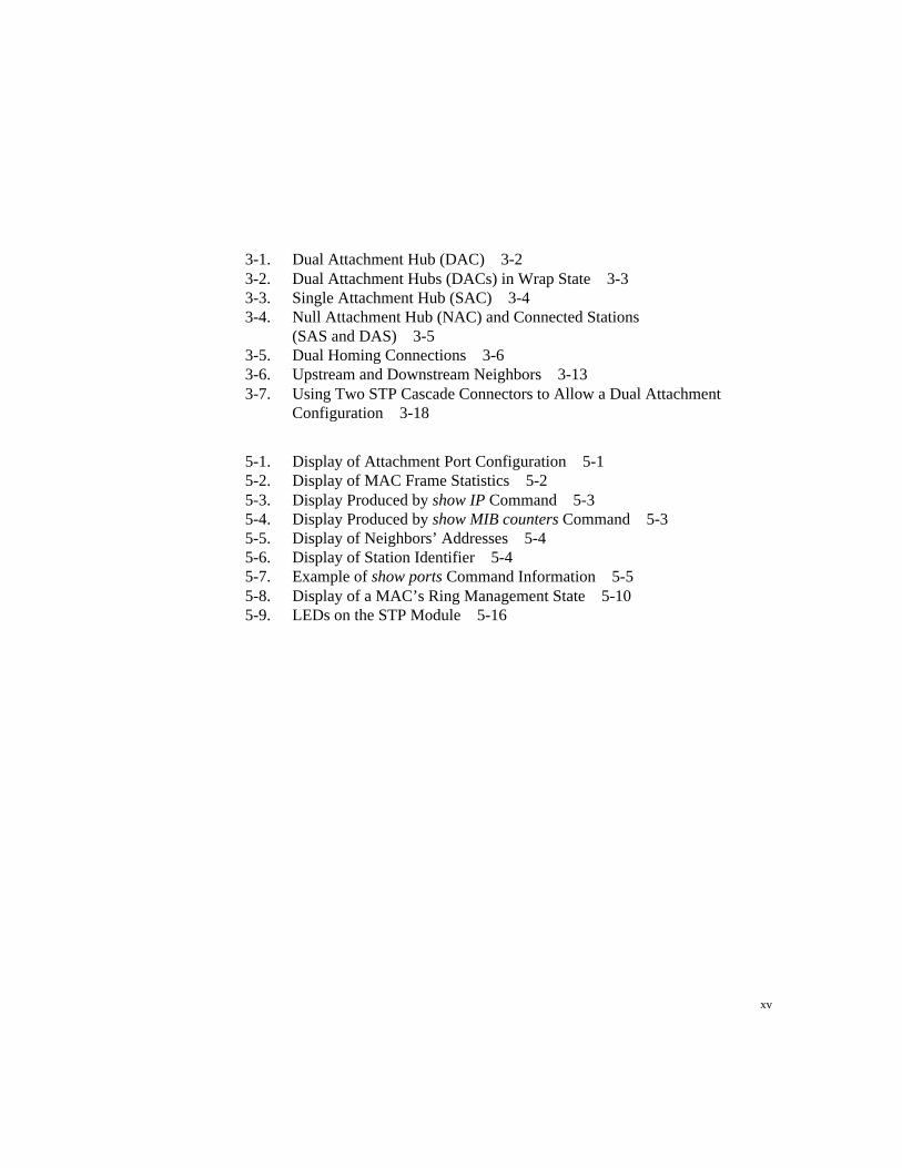
3-1. Dual Attachment Hub (DAC) 3-23-2. Dual Attachment Hubs (DACs) in Wrap State 3-33-3. Single Attachment Hub (SAC) 3-43-4. Null Attachment Hub (NAC) and Connected Stations
(SAS and DAS) 3-53-5. Dual Homing Connections 3-63-6. Upstream and Downstream Neighbors 3-133-7. Using Two STP Cascade Connectors to Allow a Dual Attachment
Configuration 3-18
5-1. Display of Attachment Port Configuration 5-15-2. Display of MAC Frame Statistics 5-25-3. Display Produced by show IP Command 5-35-4. Display Produced by show MIB counters Command 5-35-5. Display of Neighbors’ Addresses 5-45-6. Display of Station Identifier 5-45-7. Example of show ports Command Information 5-55-8. Display of a MAC’s Ring Management State 5-105-9. LEDs on the STP Module 5-16
xvi
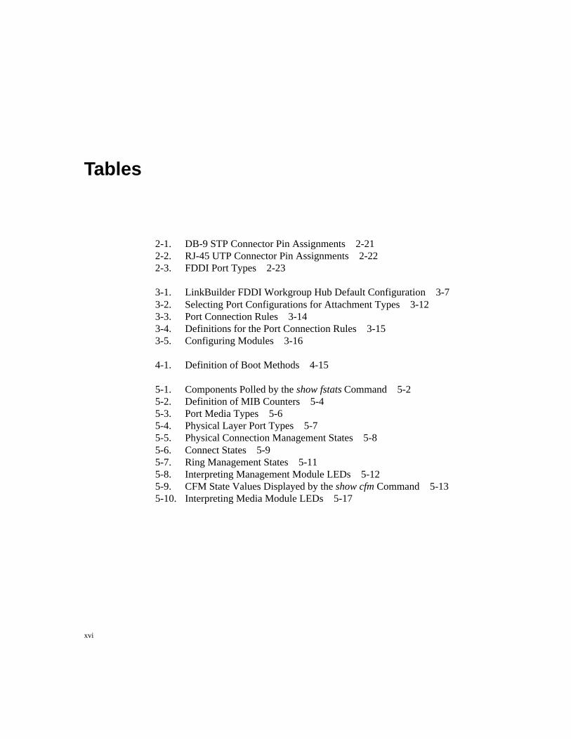
Tables
2-1. DB-9 STP Connector Pin Assignments 2-212-2. RJ-45 UTP Connector Pin Assignments 2-222-3. FDDI Port Types 2-23
3-1. LinkBuilder FDDI Workgroup Hub Default Configuration 3-73-2. Selecting Port Configurations for Attachment Types 3-123-3. Port Connection Rules 3-143-4. Definitions for the Port Connection Rules 3-153-5. Configuring Modules 3-16
4-1. Definition of Boot Methods 4-15
5-1. Components Polled by the show fstats Command 5-25-2. Definition of MIB Counters 5-45-3. Port Media Types 5-65-4. Physical Layer Port Types 5-75-5. Physical Connection Management States 5-85-6. Connect States 5-95-7. Ring Management States 5-115-8. Interpreting Management Module LEDs 5-125-9. CFM State Values Displayed by the show cfm Command 5-135-10. Interpreting Media Module LEDs 5-17

®
3
2
1
0
LinkBuilder ®
FDDI WORKGROUP HUB®
FIBER PORT MODULE
UTP PORT MODULE
MANAGEMENT MODULEOPTICAL BYPASS
SERIAL PORT
M/M
ATTACH
B/A
S/M STATUS TOKEN WRAPFAN FAIL
HI TEMP
LOW BATT
PWR
®
GRN GRN YEL
= SIGNAL DETECT = PORT STATE = LINK ERROR
PWR
®
GRN GRN YEL
= SIGNAL DETECT = PORT STATE = LINK ERROR
PWR
®
RESET
GRN GRN YEL
= SIGNAL DETECT = PORT STATE = LINK ERROR
PWR
®
GRN GRN YEL
= SIGNAL DETECT = PORT STATE = LINK ERROR STP PORT MODULE
3Com’s FDDI Training andReference Manual
Understanding FDDI (3CS-360) is a pragmatic independent study course andreference manual written for professionals involved in the design,implementation, or support of multivendor FDDI networks.
Chapters 1 through 5 contain core information about FDDI. These chaptersexplore critical elements of an FDDI environment, including attachmentstations, MAC interfaces, concentrators, and optical bypass switches. Portkeying and configuration, internetworking, ring startup, operation, faultisolation and ring recovery, light properties, fiber media, and optics are alsocovered.
Chapters 6 through 12 constitute a 250-page technical reference that takesyou down to the engineering level. Here 3Com interprets the FDDI standardsto provide tangible and accessible information on all four FDDI protocollayers and the SMT Management Information Base.
This text-based course comes with a testing diskette to guide and reinforcethe learning process. Students who pass the test receive a certificate ofcompletion.
For ordering information and details about other courses in 3Com’s datanetworking technology series, turn the page.

®
3
2
1
0
LinkBuilder ®
FDDI WORKGROUP HUB®
FIBER PORT MODULE
UTP PORT MODULE
MANAGEMENT MODULEOPTICAL BYPASS
SERIAL PORT
M/M
ATTACH
B/A
S/M STATUS TOKEN WRAPFAN FAIL
HI TEMP
LOW BATT
PWR
®
GRN GRN YEL
= SIGNAL DETECT = PORT STATE = LINK ERROR
PWR
®
GRN GRN YEL
= SIGNAL DETECT = PORT STATE = LINK ERROR
PWR
®
RESET
GRN GRN YEL
= SIGNAL DETECT = PORT STATE = LINK ERROR
PWR
®
GRN GRN YEL
= SIGNAL DETECT = PORT STATE = LINK ERROR STP PORT MODULE
Additional 3Com DataNetworking Courses
3Com’s practical self-paced training on the networking industry’s prevailingstandards and architectures provides a cost-effective way for professionalsto keep pace with the complex planning and support demands of a multivendordata network. Each course contains supplementary technical materialsorganized for easy future reference.
These courses come in text format, with an interactive testing diskette toguide and reinforce the learning process. Students who pass the final testreceive a certificate of completion.
Introduction to Bridging and Routing (3CS-011)
Network Architectures, Standards and Protocols (3CS-330)
Introduction to SNMP (3CS-350)
Understanding TCP/IP (3CS-340A)
WAN Technologies for Internetworking (3CS-370)
Order through your authorized 3Com reseller or local 3Com office. Availabilityin self-study format may vary outside the U.S. To order directly from 3ComEducation Services, call 1-800-876-3266, press option 7, then option 3. Callersoutside the U.S. should call 408-492-1790 or contact the 3Com office in theirarea for local pricing and delivery.

1-1Chapter Title
®
wants to hear from you!To ensure the very best 3Com service andsupport, take advantage of our One-YearWarranty on 3Com‘s LinkBuilder® FDDIWorkgroup Hub.
Please fill out and return the enclosedregistration card to start your one-yearwarranty period.

1-2 Chapter Title
Customers in the countries shown below should send the completedregistration card to the appropriate address.
■ France, Spain, Portugal, Greece
3Com France, Marketing DepartmentZA de Courtaboeuf25, Ave de la BaltiqueB.P. 60991945 Les Ulis CedexFrance
■ Italy
3Com Mediterraneo Srl, Marketing DepartmentVia Michelangelo Buonarroti 120093 Cologno Monzese (MI)MilanoItalia
■ United Kingdom, Eire
3Com UK Ltd., Marketing DepartmentPacific HouseThird Avenue, Globe ParkMarlow-on-ThamesBuckinghamshire, SL7 1YWUnited Kingdom
■ Sweden, Finland, Norway, Denmark
3Com Nordic AB, Marketing DepartmentBox 1110164 22 KistaSweden
■ Germany, Austria, Switzerland
3Com GmbH, Marketing DepartmentGustav-Heinemann-Ring 1238000 Muenchen 83Germany
■ Belgium, Netherlands, Luxembourg
3Com Benelux, Marketing DepartmentPlanetenweg 802nd Floor2132 HP HoofddorpNetherlands
Customers in other non-U.S. locations should send the registration cardto the U.S. address on the front of the card.
1Quick Start
Quick Start
Use this Quick Start procedure if:
■ You are experienced in installing and operating LinkBuilder FDDI hubs.
■ You have an FDDI segment running with other network devices attachedto it.
Road Map to Hub OperationsThe steps listed below summarize the procedures needed to make the 3Com®
LinkBuilder® FDDI Workgroup Hub operational. The list also shows whereeach step is discussed in this user guide.
1. Unpacking the hub and modules– Quick Start– Chapter 2: “Unpacking the Hub”; “Installing Modules”
2. Installing the modules– Quick Start– Chapter 2: “Installing Modules”
3. Connecting a terminal– Chapter 2: “Accessing the Hub”
4. Determining legal port connections– Chapter 2: “Planning Connections”– Chapter 3: “Attachment Options”; “Port Connections”
5. Attaching the hub to the ring– Chapter 2: “Connecting to the Dual Ring”
6. Attaching other devices to the hub– Chapter 2: “Data Flow Specifications”
2 Quick Start
7. Configuring attachment ports– Chapter 3: “Configuring Modules”
8. Setting up the hub for network operations– Chapter 4: “Setting Addresses”;
“Using Station Management Parameters”;“Downloading New Images”
9. Monitoring hub operations– Chapter 5: “Getting Hub Information”;
“Interpreting the LEDs”;“Using Miscellaneous Commands”
Unpacking the HubThe FDDI Workgroup Hub is shipped separately from the management moduleand media port modules. To unpack the hub, follow these steps:
1. Open the shipping container and carefully remove its contents.
2. Return all packing materials to the shipping container and save it.
If the hub must be returned, ship it in its original shipping container (orequivalent), or the warranty will be voided.
3. Verify that you have received all items on the packing list, and inspecteach item for damage.
The basic package includes the following items:
■ LinkBuilder FDDI Workgroup Hub (base unit)
■ LinkBuilder FDDI Workgroup Hub User Guide
■ LinkBuilder FDDI System Software diskette, version 1.0
■ Standard ac power cord
■ Two brackets and eight screws for rack mounting
■ Four rubber pads for tabletop placement

3Quick Start
The LinkBuilder FDDI System Software diskette, version 1.0, contains areadme file and a backup image for the flash EPROM.
A 3-volt lithium battery is shipped with the management module. Thebattery is in a small bag inside the management module shipping container.
If you ordered an STP media port module, one cascade connector will beshipped with the module.
For complete instructions on installing the hub, the modules, and thebattery, see Chapter 2, “Installing the Hub.”
4. Place the hub either in an EIA 19-inch rack or on a table or desk.
■ For rack mounting, attach the two brackets to the front sides of thehub. Then attach the brackets to the front mounting rails of the rack.Use the eight screws that are supplied with the hub. (See Figures 2-1and 2-2.)
■ For tabletop placement, fasten the rubber pads that come with the hubon the four bottom corners of the base unit.
Unpacking the ModulesThe management modules and media port modules are packaged and shippedseparately. Two modules (the management module and at least one media portmodule) plus the hub constitute the minimum functional setup. To unpack themodules, follow the steps below:
CAUTION: Each module is packed in an antistatic bag to protect it duringshipment. To avoid damaging any highly static-sensitive components on themodule or the hub, be sure to reduce any static electricity on your person. Oneway to do this is to touch the metal part of the hub. You can maintaingrounding by wearing a wrist strap attached to the hub.
1. Carefully remove each module from its shipping container and set itaside.

4 Quick Start
2. Keep all packing and shipping materials.
If a module must be returned, ship it in its original shipping container (orone providing equivalent protection), or the warranty will be voided.
3. One at a time, remove each module from its antistatic bag.
4. Check the modules for any visible signs of damage.
If you detect damage, immediately notify your network supplier and thecarrier that delivered the module.
5. Place the modules back in their antistatic bags until you are ready toinstall them.
Installing the ModulesNOTE: You must install the management module first. It can only be installedin slot 0. It will not function in any other slot. Install the remaining modules inadjacent slots (in numerically ascending order) so there are no empty slotsbetween modules.
When you install the management module for the first time, be sure that powerto the hub is off. There is no power switch on the hub. Power to the hub isprovided by connecting the power cord to the hub and to an ac outlet.
NOTE: The hub allows “power-on insertion,” which means that you do nothave to unplug the power cord for module insertion or removal. After removingor inserting a module, press the RESET button, which is recessed on themanagement module, or enter the reset command on the command line. Thisreinitializes the ring and causes the system to run its power-on self-tests (POST).

5Quick Start
To install the modules, follow these steps:
1. Remove all jewelry from your hands and wrists.
2. If necessary, remove blanking plates from the module slots.
Keep the removed blanking plates in a safe place for possible future use.
3. Remove the module from its antistatic bag.
Prepare a clean, level work area nearby on which to place the module.Avoid contact with any of the module’s components.
4. Insert the module slowly into its slot.
5. Gently align and push the module’s bus connector into its slot in thebackplane of the hub.
6. When the module is completely seated, tighten the captive thumbscrews on each end of the module.
7. To turn on the hub, plug one end of the ac power cord into the back ofthe hub and the other end into an electrical socket.
The green PWR LED lights, indicating the hub is on and ready forconfiguration.
After installing the management module and one or more media modules, one ortwo empty slots may remain in the base unit. Insert a blanking plate into each ofthese empty slots. This keeps objects from falling into the hub and prevents RFemissions from an open slot.

6 Quick Start
Connecting to the RingAfter installing the modules and plugging in the power cord, you are ready toconnect the hub to the ring by attaching the appropriate cables to the attachmentports, which are the two leftmost ports on the module installed in slot 1. Tocomplete the connection to the ring, you must configure the attachment ports.For detailed information on connecting the hub to the ring, see the references inthe “Road Map to Hub Operations” section earlier in this chapter.
1-1Overview
Chapter 1Overview
The 3Com® LinkBuilder® FDDI Workgroup Hub brings Fiber Distributed DataInterface (FDDI) high-speed LAN technology to the desktop. (Throughout thisguide, the LinkBuilder FDDI Workgroup Hub will be referred to as “the hub.”)
The hub supports remote management via Station Management (SMT) 7.3 orTelnet protocol. Local management is provided via a console interface or amodem attached to the management module’s serial port. The SMT 7.3standard specifies the format of management information so that it is consistentwith the object-oriented approach defined by OSI management standards. Thestandard SMT Management Information Base (MIB) variables are present in theLinkBuilder FDDI Workgroup Hub software.
A modular stand-alone device, the hub provides four module slots and a passivebackplane. When installed and equipped with the appropriate modules, the hubcan be connected to the FDDI backbone ring, to other FDDI hubs, and to otherstations. The RS-232–based console interface provides the capability toconfigure and monitor the media port modules installed in the chassis.
The hub chassis contains an integrated internal power supply and a fan. Itrequires a single management module and supports one to three media modulesfor ring and station attachment.
The hub is an intelligent device with a unique FDDI MAC (Media AccessControl) address implemented with National Semiconductor® Corporation’sBMAC (FDDI Media Access Controller) technologies. In addition, National’sBSI (FDDI System Interface) implements an interface between the BMACdevice and the host system, providing a multiframe, MAC-level interface to oneor more MAC users. The hub’s single MAC supports dual, single, or nullattachment and dual homing.
1-2 Overview
The management module is based on the Motorola® 68EC020 processor, whichprovides the following:
■ 256 KB of nonvolatile RAM
■ 1 MB of local RAM
■ 512 KB of EPROM
■ 1 MB of flash memory
■ 128 KB of RAM for frame buffer and descriptors
This guide is intended for network installers and operators who are familiar withFDDI technology and experienced in installing hubs. The next section containsa brief summary of FDDI technology; it is intended as an overview only. (Fordetailed information about FDDI architecture and its functionality, 3Comrecommends that you secure the FDDI self-paced study course, UnderstandingFDDI, 3CS-360, available through 3Com Education Services.)
FDDI TechnologyFDDI technology is an American National Standards Institute (ANSI) standardthat supports data transfer rates of 100 million bits per second (100 Mbps).Advancements in fiber technology allow modulated beams of light to be carriedin dual counter-rotating token rings made of glass fiber-optic cable. The FDDIstandard now includes the definition of other types of cabling media, includingshielded twisted pair (STP) and unshielded twisted pair (UTP). FDDI providesfor up to 500 nodes operating over tens of kilometers. The maximum networklength is 100 km.
FDDI’s dual-ring architecture provides a high level of reliability and faulttolerance. Under normal operation one of the rings, called the primary ring orthe trunk ring, carries data traffic. The other ring, called the secondary ring, isgenerally used for automatic recovery in the event of a break in the primaryring. If a fault occurs, as shown in Figure 1-1, the dual attached stations oneither side of the fault detect and automatically bypass it. This ringreconfiguration is known as a ring wrap.

1-3Overview
Primary ring
Secondary ring
Ring wrapRing wrap
Break in ring or station failure
Figure 1-1. Ring Wrap
The FDDI standard developed by the American National Standards Institute(ANSI) defines four protocols:
■ Physical Medium Dependent (PMD)
■ Physical (PHY)
■ Media Access Control (MAC)
■ Station Management (SMT)
Each of these protocols is briefly defined below.
1-4 Overview
Physical Medium Dependent (PMD) ProtocolThe Physical Medium Dependent protocol provides all of the services necessaryto exchange data across the cable medium. PMD also specifies an optionaloptical bypass facility that enhances reliability. This bypass capability isinvoked when an FDDI station is powered off. (For information on the opticalbypass switch, see Chapter 2, “Installing the Hub.”)
The PMD services included for each type of media supported by theLinkBuilder FDDI Workgroup Hub are listed below.
Fiber-Optic
The PMD standard provides these services for fiber media:
■ Optical power and cable requirements for 62.5/125 µm fiber-optic cables
■ Power requirements for optical bypass switches and fiber-optic transceivers
■ FDDI cable connector (the Media Interface Connector [MIC]), matingrequirements, and keying
■ Light wavelength of 1300 nm (nanometers)
Shielded Twisted Pair (STP)
The PMD standard uses the SDDI de facto standard and provides these servicesfor STP:
■ Transmit signal amplitude of 350–700 mV, peak-to-peak
■ Cable fault detect
■ DB-9 cable connector, specifying M as a male connector and A, B, and Sas female connectors

1-5Overview
Unshielded Twisted Pair (UTP)
The ANSI TP-PMD standard provides these services for UTP:
■ Cable requirements for category 5 UTP as defined by EIA/TIA-568
■ Electrical requirements for UTP transceivers
■ FDDI-UTP cable connector
Physical (PHY) ProtocolThe Physical protocol is responsible for encoding and decoding of data andcontrol information on the FDDI network. It specifies the following:
■ 4B/5B nonreturn to zero inverted (NRZI) encoding scheme (for fiber andSTP modules)
■ MLT-3 with stream cipher encoding scheme (for UTP modules)
■ Clocking rules
■ Clocking frequency of 125 MHz
■ Serial-to-parallel conversion rules
Media Access Control (MAC) ProtocolThe Media Access Control protocol controls the flow of data on the FDDI ring.The MAC typically exists in every hub and station accessed by the FDDI ring,but stations without MACs are allowed. This protocol specifies the following:
■ Token-passing protocol
■ Capture and retransmission of token
■ Packet formation and framing of data
■ Address generation and recognition
■ 32-bit cyclic redundancy check (CRC) verification and error detection
■ Recovery mechanisms
1-6 Overview
NOTE: In contrast to the PMD protocol, the PHY and MAC protocols aremedia-independent; that is, the same protocols function regardless of themedium being used (fiber, STP, or UTP).
Station Management (SMT) ProtocolThe Station Management protocol is involved in network management andmonitoring for all layers of the FDDI stack. Every node on an FDDI ringparticipates in the management of the ring. As such, all nodes exchange SMTinformation to control network operation. SMT specifies the following:
■ Status of links between nodes
■ Error detection and fault isolation algorithms
■ Monitoring of all ring and station activities
■ Ring maintenance
■ Ring initialization, control, and performance
Features and FunctionsThe LinkBuilder FDDI Workgroup Hub performs the following tasks in anFDDI network:
■ Connects end stations, bridges, routers, and other FDDI devices as well asadditional hubs to the network
■ Isolates segment breaks through an attachment configuration called dualhoming and dual attachment
■ Bypasses nodes that have been turned off or are experiencing problems
■ Extends the network’s geographical diameter by regenerating all receivedsignals when repeating them onto the network
1-7Overview
The hub provides the following features:
■ Media flexibility. You can use any mix of one, two, or three of these portmodules in the hub:
– FDDI media port module supporting 62.5/125 µm fiber-optic cableper the ANSI FDDI standard
– STP media port module supporting shielded twisted-pair (STP) type 1cable and the SDDI de facto standard
– UTP media port module supporting level 5 and screened level 5, datagrade unshielded twisted-pair (UTP) cabling system per the ANSITP-PMD standard
■ Upgradeability. You can easily change from copper media to fiber mediaand vice versa using the available port modules.
■ Configurability. You can configure the two leftmost ports of the slot 1module to meet any one of four network configurations: dual attachment,single attachment, null attachment, and dual homing.
■ Serviceability with power-on insertion. You can insert and remove themedia port modules without removing power from the hub.
■ Flash EPROM. The presence of the flash EPROM makes the hub’ssoftware easily upgradeable because future software images can bedownloaded into flash memory over the network via the Trivial FileTransfer Protocol (TFTP). (See the section “Downloading New Images” inChapter 4 for information on downloading images into the flash EPROM.)
■ FDDI benefits. You can take advantage of the many benefits provided byFDDI technology, including:
– Increased data rate of 100 Mbps– Longer distance between nodes via fiber-optic cable– Immunity to electronic “noise” (fiber only)– Support of large networks comprising up to 500 nodes– Fault tolerance and fault isolation– Improved network management

1-8 Overview
Figure 1-2 shows the LinkBuilder FDDI hub with the management module andall three types of media modules installed.
PWR
®FIBER PORT MODULEGRN
GRN YEL
= SIGNAL DETECT = PORT STATE = LINK ERROR
PWR
®UTP PORT MODULEGRN
GRN YEL
= SIGNAL DETECT = PORT STATE = LINK ERROR
PWR
®MANAGEMENT MODULE
RESET
OPTICAL BYPASS
SERIAL PORT
M/M
ATTACH
B/A
S/M STATUS TOKEN WRAPFAN FAIL
HI TEMP
LOW BATT
GRN GRN YEL
= SIGNAL DETECT = PORT STATE = LINK ERROR
PWR
®
GRN GRN YEL
= SIGNAL DETECT = PORT STATE = LINK ERROR STP PORT MODULE
®
Figure 1-2. The LinkBuilder FDDI Workgroup Hub
Site SelectionThe hub is housed in a 16.8 x 11.6 x 5.2 inch chassis that can be placed on atabletop or easily mounted in an Electronics Industries Association (EIA)standard 19-inch rack. You can mount more than one hub in a rack dependingon your network needs.
Included with the chassis are four small rubber pads (to be inserted on thebottom four corners for tabletop placement) and two attachable brackets (to beattached on two sides for rack mounting) for your choice of placement.
When selecting a site for the hub, remember that the hub can be connected to anexternal terminal for initial configuration. In this case you will need room infront of the chassis to place and access the terminal.
Instead of attaching a terminal to the hub, you can configure the hub over thenetwork by using the TCP Telnet protocol. You can also access the hub via amodem attached to the serial port.
1-9Overview
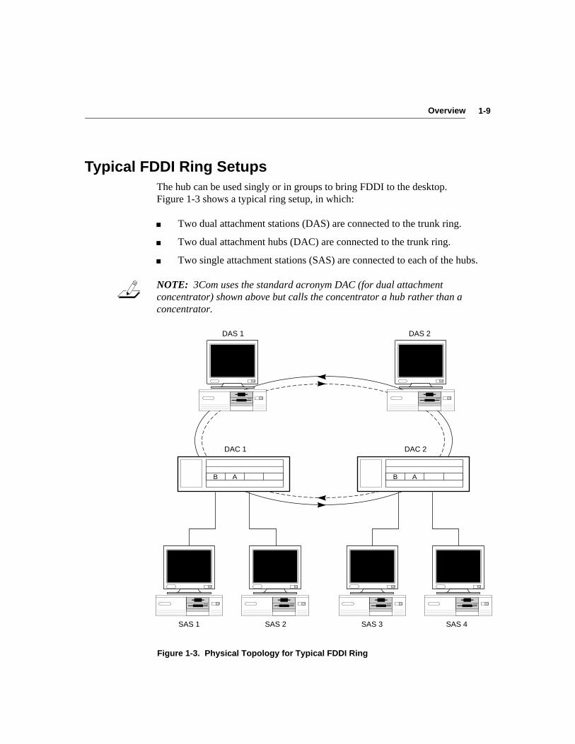
Typical FDDI Ring SetupsThe hub can be used singly or in groups to bring FDDI to the desktop.Figure 1-3 shows a typical ring setup, in which:
■ Two dual attachment stations (DAS) are connected to the trunk ring.
■ Two dual attachment hubs (DAC) are connected to the trunk ring.
■ Two single attachment stations (SAS) are connected to each of the hubs.
NOTE: 3Com uses the standard acronym DAC (for dual attachmentconcentrator) shown above but calls the concentrator a hub rather than aconcentrator.
DAS 1
SAS 1 SAS 2
DAS 2
SAS 3 SAS 4
DAC 1 DAC 2
B A B A
Figure 1-3. Physical Topology for Typical FDDI Ring

1-10 Overview
The most common “FDDI to the desktop” configuration is the ring of treestopology, shown in Figure 1-4. This figure illustrates the connecting of stationsusing a hub to form a tree-like structure that branches off the main trunk ring.
DAS
DAC
SAC
DAS
SAS SAS
SAC
SAS SAS
SAS SAS
Figure 1-4. FDDI Ring of Trees
1-11Overview
Management and Media ModulesThe hub chassis provides slots for one management module (required) and threemedia modules, which can be mixed or matched. This section briefly describeseach of these modules. (For information about the operation of the managementand media modules, see Chapter 5, “Using the Hub.”)
Management ModuleThe LinkBuilder FDDI Management Module, hereafter called the “managementmodule,” must be inserted in slot 0 (the bottom slot) of the hub. Its mainpurpose is to run the Station Management (SMT) 7.3 software that is requiredfor FDDI operations.
The management module provides management and configuration functionsthrough a console interface. Access to this interface is either by a 9-pinRS-232C console serial port for a terminal or modem connection or via a TCPTelnet protocol connection over the network.
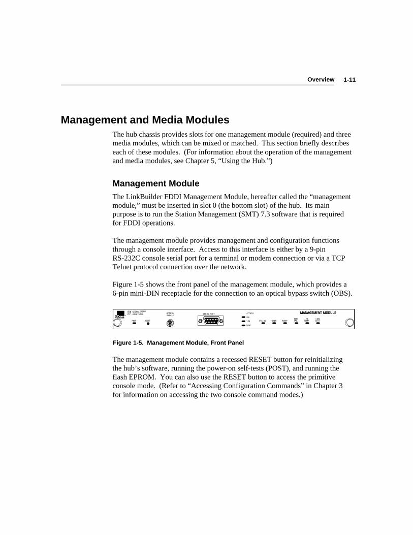
Figure 1-5 shows the front panel of the management module, which provides a6-pin mini-DIN receptacle for the connection to an optical bypass switch (OBS).
PWR
®MANAGEMENT MODULE
RESET
OPTICAL BYPASS
SERIAL PORT
M/M
ATTACH
B/A
S/M STATUS TOKEN WRAPFAN FAIL
HI TEMP
LOW BATT
GRN GRN YEL
= SIGNAL DETECT = PORT STATE = LINK ERROR
Figure 1-5. Management Module, Front Panel
The management module contains a recessed RESET button for reinitializingthe hub’s software, running the power-on self-tests (POST), and running theflash EPROM. You can also use the RESET button to access the primitiveconsole mode. (Refer to “Accessing Configuration Commands” in Chapter 3for information on accessing the two console command modes.)

1-12 Overview
By interpreting the LEDs on the management module, you can:
■ Monitor network activity
■ Determine chassis environmental factors
■ Discover ring attachment configuration
Refer to “Interpreting the LEDs” in Chapter 5 for detailed information about theLEDs on all hub modules.
Media ModulesThree media modules are currently available. Each module can be placed in anyslot, but the modules must be installed from the bottom up, beginning with slot 1.Do not leave empty slots between modules.
The two leftmost ports on any module installed in slot 1 are designated asattachment ports. The module in slot 1 is given a default configuration of dualattachment, B/A connection. Only the two leftmost ports of modules installed inslot 1 can be configured.
The three modules are:
■ LinkBuilder FDDI 4-port Optic Module (fiber media port module)
■ LinkBuilder FDDI 6-port STP Module (STP media port module)
■ LinkBuilder FDDI 8-port UTP Module (UTP media port module)
Fiber Media Port Module
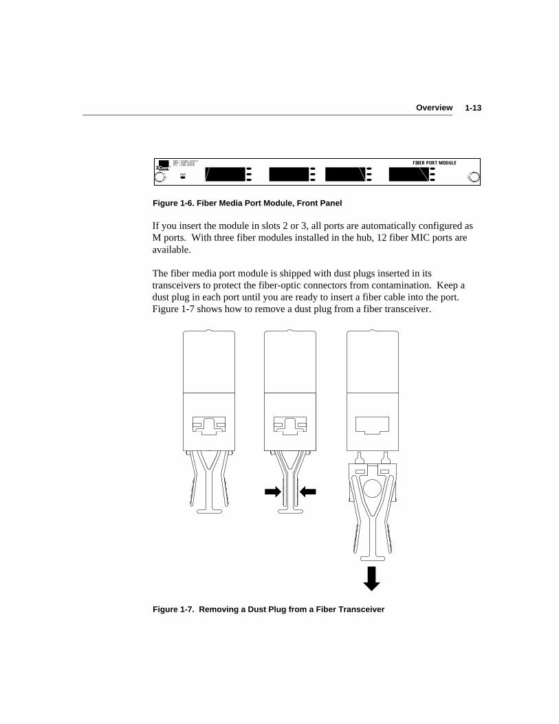
The fiber media port module provides four ports, as shown in Figure 1-6. Whenthis module is installed in slot 1, you can configure the attachment ports (the twoleftmost ports) as B and A, S and M, or M and M as necessary to support a givenattachment. (Refer to Chapter 4 for instructions for configuring the attachmentports.) The remaining two ports are M (master) ports by default.
1-13Overview
PWR
®FIBER PORT MODULEGRN
GRN YEL
= SIGNAL DETECT = PORT STATE = LINK ERROR
Figure 1-6. Fiber Media Port Module, Front Panel
If you insert the module in slots 2 or 3, all ports are automatically configured asM ports. With three fiber modules installed in the hub, 12 fiber MIC ports areavailable.
The fiber media port module is shipped with dust plugs inserted in itstransceivers to protect the fiber-optic connectors from contamination. Keep adust plug in each port until you are ready to insert a fiber cable into the port.Figure 1-7 shows how to remove a dust plug from a fiber transceiver.
Figure 1-7. Removing a Dust Plug from a Fiber Transceiver
1-14 Overview
STP Media Port Module
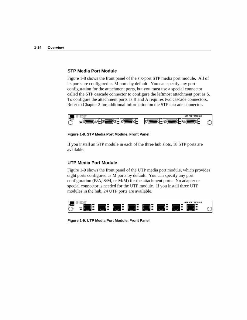
Figure 1-8 shows the front panel of the six-port STP media port module. All ofits ports are configured as M ports by default. You can specify any portconfiguration for the attachment ports, but you must use a special connectorcalled the STP cascade connector to configure the leftmost attachment port as S.To configure the attachment ports as B and A requires two cascade connectors.Refer to Chapter 2 for additional information on the STP cascade connector.
PWR
®
GRN GRN YEL
= SIGNAL DETECT = PORT STATE = LINK ERROR STP PORT MODULE
Figure 1-8. STP Media Port Module, Front Panel
If you install an STP module in each of the three hub slots, 18 STP ports areavailable.
UTP Media Port Module
Figure 1-9 shows the front panel of the UTP media port module, which provideseight ports configured as M ports by default. You can specify any portconfiguration (B/A, S/M, or M/M) for the attachment ports. No adapter orspecial connector is needed for the UTP module. If you install three UTPmodules in the hub, 24 UTP ports are available.
PWR
®UTP PORT MODULEGRN
GRN YEL
= SIGNAL DETECT = PORT STATE = LINK ERROR
Figure 1-9. UTP Media Port Module, Front Panel

2-1Installing the Hub
Chapter 2Installing the Hub
This chapter describes installation of the LinkBuilder FDDI Workgroup Hub. Itincludes the following topics:
■ Unpacking the hub
■ Rack mounting the hub
■ Equipping the hub
■ Installing and removing modules
■ Accessing the hub
■ Understanding data flow
■ Installing an optional optical bypass switch
NOTE: For a step-by-step procedure for installing the hub and preparing it fornetwork operations, see the Quick Start chapter at the beginning of this guide.
Unpacking the HubTo unpack the hub, follow these steps:
1. Open the shipping container and carefully remove its contents.
2. Return all packing materials to the shipping container and save it.
If the hub must be returned, ship it in its original shipping container (or oneproviding equivalent protection), or the warranty will be voided.
3. Verify that you have received all items on the packing list, and inspecteach item for damage.
If you find any omissions or damage, contact your network supplier andthe carrier that delivered the package.

2-2 Installing the Hub
Mounting the Hub in a RackMounting the hub in a rack involves installing mounting brackets onto the huband mounting the hub in the rack. To mount the hub in a 19-inch distributionrack, follow these instructions:
1. Lift the hub from its packing container and place it on a table or otherflat surface.
You should get help lifting the hub; it weighs slightly more than 15 pounds(6.8 kg). You will also need help when screwing the hub into the rack.
2. Determine where you will attach the hub to the rack.
Align the mounting brackets to the holes in the vertical rails of the rack andmark the holes where you will screw the mounting brackets.
3. Attach the two supplied mounting brackets to the hub, using thescrews that came with the hub. See Figure 2-1.
Locate the holes on each side of the hub into which you will attach themounting brackets.
If you lose one of the screws, replace it with a 10/32 x 3/8 inch pan-headcross-recessed screw with an integral lock washer.
4. With the help of at least one other person, carefully lift the hub intoposition in the rack.
Align the mounting brackets to the holes you designated for mounting.
2-3Installing the Hub
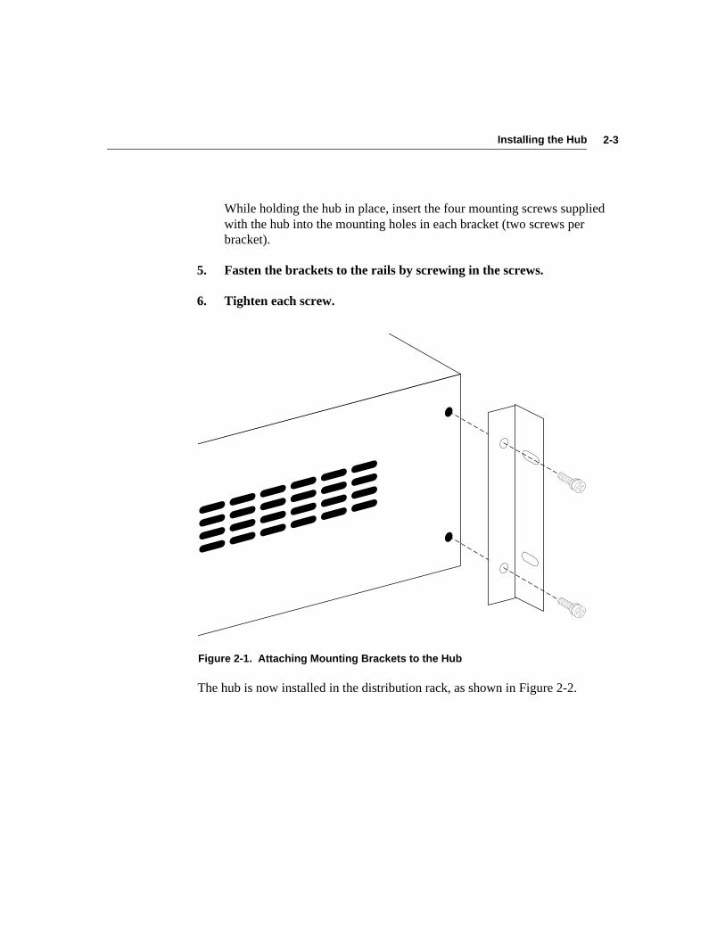
While holding the hub in place, insert the four mounting screws suppliedwith the hub into the mounting holes in each bracket (two screws perbracket).
5. Fasten the brackets to the rails by screwing in the screws.
6. Tighten each screw.
Figure 2-1. Attaching Mounting Brackets to the Hub
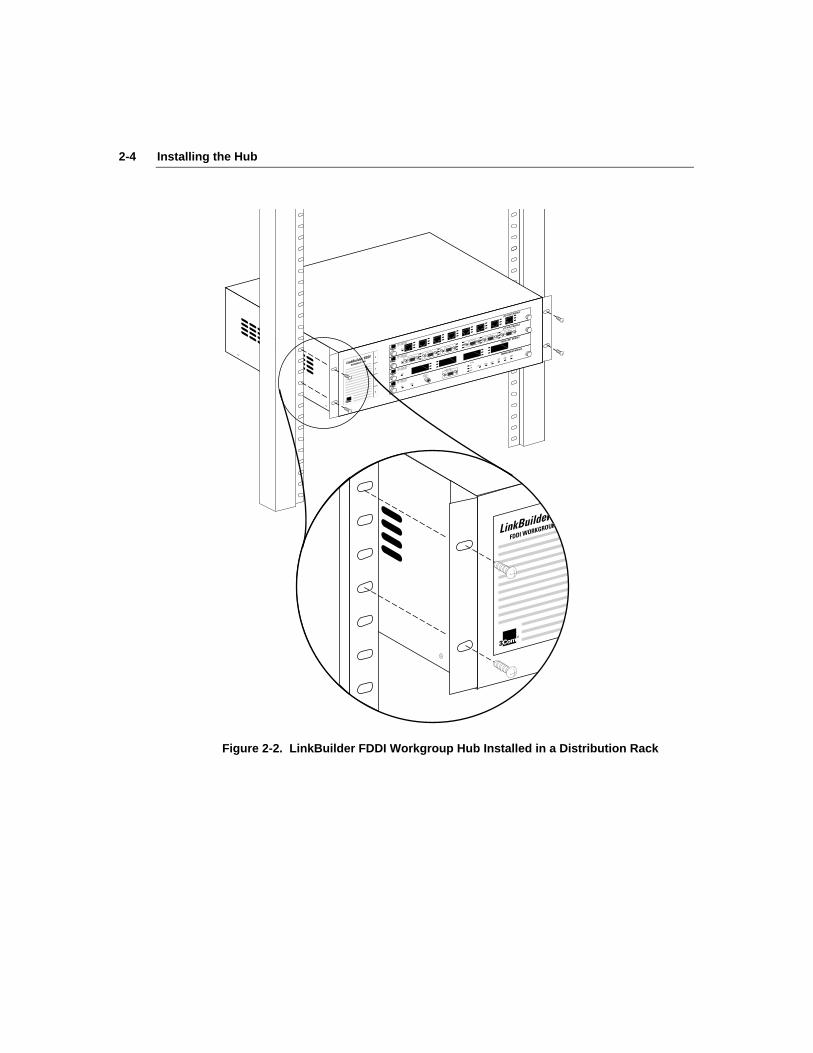
The hub is now installed in the distribution rack, as shown in Figure 2-2.
2-4 Installing the Hub
PWR®
FIBER PORT MODULE
GRN GRN YEL
= SIGNAL DETECT
= PORT STATE
= LINK ERROR
MANAGEMENT MODULE
M/M
ATTACH
B/A
S/MSTATUS
TOKENWRAP
FAN FAIL
HI TEMP
LOW BATT
SERIAL PORT
PWR® RESET
OPTICAL
BYPASS
GRN GRN YEL
= SIGNAL DETECT
= PORT STATE
= LINK ERROR
PWR®
GRN GRN YEL
= SIGNAL DETECT
= PORT STATE
= LINK ERROR
STP PORT MODULE
PWR®
UTP PORT MODULE
GRN GRN YEL
= SIGNAL DETECT
= PORT STATE
= LINK ERROR
®
®
Figure 2-2. LinkBuilder FDDI Workgroup Hub Installed in a Distribution Rack

2-5Installing the Hub
Equipping the HubThis section discusses the following hub equipment:
■ Hub chassis
■ Management module
■ Lithium battery
■ Media port modules
■ Fiber port keys (optional)
■ Cascade connector (optional)
Basic ContentsThe basic package includes the following items:
■ LinkBuilder FDDI Workgroup Hub (base unit)
■ LinkBuilder FDDI Workgroup Hub User Guide
■ LinkBuilder FDDI System Software diskette, version 1.0
■ Standard ac power cord
■ Two brackets and eight screws for rack mounting
■ Four rubber pads for tabletop placement
The LinkBuilder FDDI System Software diskette, version 1.0, contains a readmefile and a backup image for the flash EPROM.
One LinkBuilder Management Module, which is shipped separately, is requiredfor each hub.
A 3-volt lithium battery is shipped with the management module. The battery isin a small bag inside the management module shipping container. For batteryfunctions and installation instructions, see the section “Installing the Battery”later in this chapter.
2-6 Installing the Hub
If you ordered a fiber media module, four small packets of fiber port modulekeys will be included with the module. For information on installing these keys,see the section “Keys for Fiber Port Modules” later in this chapter.
If you ordered an STP media port module, one cascade connector will beshipped with the module. For information about the cascade connector, refer tothe section “STP Cascade Connector” later in this chapter.
NOTE: Remember to fill out the Product Registration Card at the back of thismanual and return it to 3Com, or call 1-800-NET-3Com for immediateregistration.
Hub ChassisThe LinkBuilder FDDI hub is shipped with no modules installed; the modulesyou ordered are shipped separately and packaged individually. The hub isshipped with two blanking plates attached over slots 2 and 3.
Install the management module in slot 0. Install one of the media port modulesin slot 1. To install additional modules, remove the blanking plates and insertthe modules. Retain the blanking plates for possible future use when modulesare removed. (Refer to the section “Installing Modules” later in this chapter forcomplete information about mounting the modules in the hub.)
Media Port ModulesDepending on your order, you should also have received one or more of thefollowing modules:
■ LinkBuilder FDDI 4-port fiber port module
■ LinkBuilder FDDI 6-port STP port module
■ LinkBuilder FDDI 8-port UTP port module
2-7Installing the Hub
Installing the BatteryA lithium battery, which powers the nonvolatile memory bank, is supplied withthe management module. The hub’s nonvolatile memory preserves thefollowing:
■ Boot parameters
■ Last download status
■ Set command parameters
■ Fault log entries
The lithium battery is a 3-volt, 550 mA-hr battery in a 2450 blister pack. It canlast up to 10 years before it must be replaced. However, its actual lifetimedepends on the number and duration of power outages that may occur. It hasenough capacity to last up to 5500 hours after power is lost.
Replace the battery when the LOW BAT LED lights. You can purchasereplacements in most computer and electronic retail stores. Ask for a type 2450battery. Be sure to replace the battery with one made by the same manufacturer.
CAUTION: The battery may explode if it is replaced incorrectly. Replace thebattery only with the same or equivalent type as described above. Used lithiumbatteries can be considered other household waste and disposed of accordingly.
Do not incinerate, disassemble, or deform batteries. Do not attempt to rechargethe battery. Do not heat the battery over 100˚ C.
Failure to follow these handling instructions may result in battery failure,including seal breakdown, leakage, internal shorting, fire, and potentialexplosion.
ACHTUNG: Diese Batterie kann explodieren, wenn sie falsch installiert wird.Verwenden Sie nur den gleichen oder entsprechenden vom Herstellerempfohlenen Typ. Verbrauchte Batterien sind nach den Angaben desHerstellers zu entsorgen.
2-8 Installing the Hub
You must insert the battery on the management module before installing themodule in the hub. To install the battery in the management module, followthese steps:
1. Remove the battery from its container.
Each management module is shipped with its battery in a small bag insidethe shipping container.
2. Remove the management module from its antistatic bag.
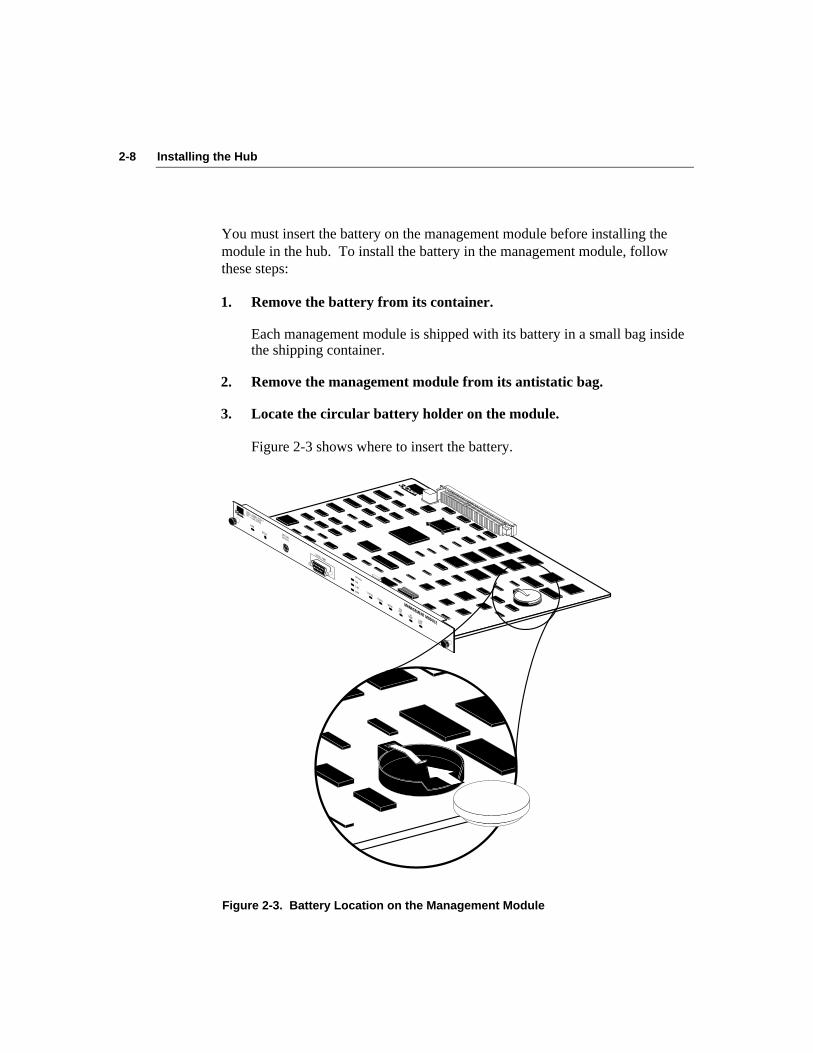
3. Locate the circular battery holder on the module.
Figure 2-3 shows where to insert the battery.
®
PWR
®
MANAGEMENT MODULE
RESET OPTICAL BYPASS
SERIAL PORT
M/M
ATTACHB/AS/M
STATUSTOKEN
WRAPFAN FAIL
HI TEMPLOW BATT
GRN GRN YEL = SIGNAL DETECT
= PORT STATE
= LINK ERROR
Figure 2-3. Battery Location on the Management Module
2-9Installing the Hub
4. Carefully slide the battery into its circular holder.
Ensure that the “+” sign on the battery faces up and makes contact with thepositive clip that holds the battery in place.
The management module is now ready to be installed in slot 0. Follow theinstructions given in the section “Installing Modules” later in this chapter.
To remove the battery for replacement, reverse the procedure above.
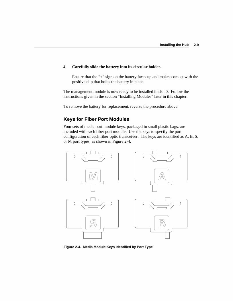
Keys for Fiber Port ModulesFour sets of media port module keys, packaged in small plastic bags, areincluded with each fiber port module. Use the keys to specify the portconfiguration of each fiber-optic transceiver. The keys are identified as A, B, S,or M port types, as shown in Figure 2-4.
Figure 2-4. Media Module Keys Identified by Port Type
2-10 Installing the Hub
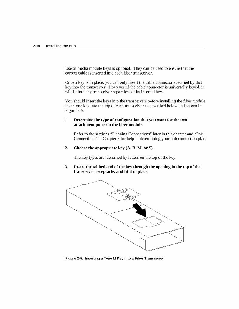
Use of media module keys is optional. They can be used to ensure that thecorrect cable is inserted into each fiber transceiver.
Once a key is in place, you can only insert the cable connector specified by thatkey into the transceiver. However, if the cable connector is universally keyed, itwill fit into any transceiver regardless of its inserted key.
You should insert the keys into the transceivers before installing the fiber module.Insert one key into the top of each transceiver as described below and shown inFigure 2-5:
1. Determine the type of configuration that you want for the twoattachment ports on the fiber module.
Refer to the sections “Planning Connections” later in this chapter and “PortConnections” in Chapter 3 for help in determining your hub connection plan.
2. Choose the appropriate key (A, B, M, or S).
The key types are identified by letters on the top of the key.
3. Insert the tabbed end of the key through the opening in the top of thetransceiver receptacle, and fit it in place.
Figure 2-5. Inserting a Type M Key into a Fiber Transceiver

2-11Installing the Hub
4. Push the back of the key down until it snaps into place.
The key sits flush with the top of the transceiver.
If you decide to change the configuration of a fiber module attachment port, youmust change the key in the transceiver receptacle. To remove a key from thereceptacle, follow these steps:
1. Remove the attached cable from the transceiver.
2. Remove the module from the hub.
Refer to the section “Removing Modules” later in this chapter.
3. Place the tip of a small, flat screwdriver in the slot at the back of thekey and exert gentle but firm pressure on the screwdriver.
4. Remove the key.
Replace the removed key in its plastic bag for possible future use.
5. Insert the appropriate key into the transceiver.
Reinsert the module into the hub and insert the different cable into therekeyed transceiver.
STP Cascade ConnectorBy default, all ports on the STP module are physically configured as M ports. Ifyou want to configure the STP module’s attachment ports differently, you mustuse an STP cascade connector to allow the use of these ports as B, A, or S porttypes.
NOTE: A module’s attachment ports are the two leftmost ports when a moduleis installed in slot 1. Whenever a module is installed in a slot other than shot 1,the two leftmost ports are no longer designated “attachment ports.”
2-12 Installing the Hub
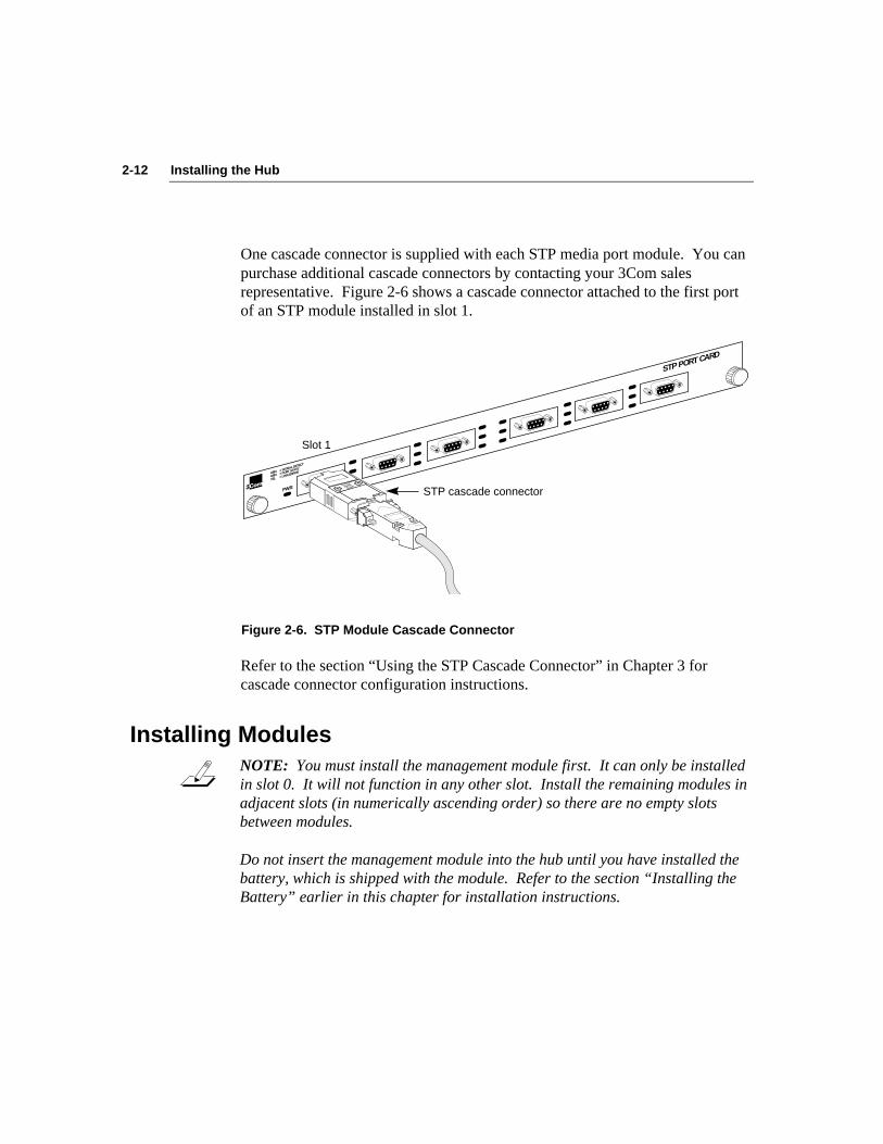
One cascade connector is supplied with each STP media port module. You canpurchase additional cascade connectors by contacting your 3Com salesrepresentative. Figure 2-6 shows a cascade connector attached to the first portof an STP module installed in slot 1.
®
STP PORT CARD
PWR
GRN GRN YEL
= SIGNAL DETECT
= PORT STATE
= LINK ERROR
STP cascade connector
Slot 1
Figure 2-6. STP Module Cascade Connector
Refer to the section “Using the STP Cascade Connector” in Chapter 3 forcascade connector configuration instructions.
Installing ModulesNOTE: You must install the management module first. It can only be installedin slot 0. It will not function in any other slot. Install the remaining modules inadjacent slots (in numerically ascending order) so there are no empty slotsbetween modules.
Do not insert the management module into the hub until you have installed thebattery, which is shipped with the module. Refer to the section “Installing theBattery” earlier in this chapter for installation instructions.
2-13Installing the Hub
To install the management module and the media modules for the first time,follow these steps:
1. Remove all jewelry from your hands and wrists.
2. If you are installing modules in slots 2 or 3, remove the blanking platesfrom those slots.
Keep the removed blanking plates in a safe place for possible future use.
CAUTION: Each module is packed in an antistatic bag to protect it duringshipment. To avoid damaging any highly static-sensitive components on themodule or the hub, be sure to reduce any static electricity on your person. Oneway to do this is to touch the metal part of the hub. You can maintaingrounding by wearing a wrist strap attached to the hub.
3. Remove the module from its antistatic bag.
Prepare a clean, level work area nearby on which to place the module.Avoid contact with any of the module’s components.
4. Insert the module slowly into its slot.
The printing on the module’s front panel indicates its correct horizontalorientation.
5. Gently align and push the module’s bus connector into its slot in thebackplane of the hub.
6. When the module is completely seated, tighten the captive thumbscrews on each end of the module.
7. To turn on the hub, plug one end of the ac power cord into the back ofthe hub and the other end into an electrical outlet.
The PWR LED turns green, indicating the hub is on and ready forconfiguration.

2-14 Installing the Hub
There is no power switch on the hub. Power to the hub is provided byconnecting the power cord to the hub and to an ac outlet.
NOTE: The hub allows “power-on insertion,” which means that you do nothave to unplug the power cord for module insertion or removal. When youreplace a module, reset the hub by pressing the RESET button or entering thereset command. Resetting the hub reinitializes the hub and causes the system torun its power-on self-tests (POST).
CAUTION: When the hub is reinitialized, any devices connected to the hub aremomentarily disconnected. This could result in serious data loss unless youtake preventative measures before changing installed modules. To avoidpotential problems, enter the disconnect command before activating the resetfunction.
After you install the management module and one or more media modules, oneor two empty slots may remain in the base unit. Insert a blanking plate into eachof these empty slots. This keeps objects from falling into the hub and preventsRF emissions from an open slot.
Removing ModulesTo remove modules from the hub, follow these steps:
CAUTION: Observe the same precautions outlined above regarding dischargeof static electricity and potential loss of data.
1. Disconnect all cables connected to the module that you want toremove.
You do not have to unplug the hub from its power source.
2. Enter the disconnect command.
This disconnects the hub from the ring.
3. Remove all jewelry from your hands and wrists.

2-15Installing the Hub
4. Turn the thumb screws on each end of the module counterclockwise toloosen them.
5. Holding a thumb screw in each hand, slowly pull the module from itsslot.
6. Place the module on a clean surface, or replace the module in itsoriginal antistatic bag.
7. Place a blanking plate over the empty slot.
NOTE: There must be no empty slots between modules. For example, if youremove a module from slot 2 and there is a module in slot 3, you must move themodule in slot 3 into slot 2 or else replace the removed module with a newmodule. Otherwise, an error condition will exist, and the hub will not functionproperly.
8. Reset the hub.
You can either enter the reset command or press the RESET button that isrecessed on the management module.
2-16 Installing the Hub
Accessing the HubTo monitor hub activity and (optionally) configure the hub to suit yourparticular network environment, you must set up an interface with the hub. Youcan access the hub in several ways:
■ Connect a terminal such as a VT100 or similar dumb terminal to theRS-232 serial port on the management module, using a null-modemconnector to the terminal.
■ Connect a PC running terminal emulation software to the RS-232 serialport on the management module, using a null-modem connector to the PC.
■ Attach a modem to the serial port on the management module. (Refer tothe section “Installing an Optional Modem” later in this chapter.)
■ Access the hub across the network using the TCP Telnet protocol. (Referto the section “Using Telnet to Access the Hub” later in this chapter.)
Once one of these connection is made, you can use the console commands tomonitor and configure the hub. Two console command sets are available: themanagement console command mode and the primitive console commandmode. These command modes are discussed in Chapter 3. The commands inthese command sets are listed and described in Appendix C, “Commands.”Instructions for using the commands are provided in Chapter 4, “Setting Up theHub.”
Changing the Serial Port’s Baud RateWhen you connect a terminal or modem to the hub, you may need to change thebaud rate of the serial port. The serial port’s default baud rate is 9600.
To display the serial port’s baud rate, enter the show baud command.

2-17Installing the Hub
To change the hub’s baud rate to match the baud rate of a terminal or modem,follow these steps:
1. Enter the set baud command. Type:
set baud
This selection prompt appears:
Select one of the following:1. 12002. 24003. 48004. 9600
Baudrate?
2. Type a number to select a baud rate. For example, type:
3 [Enter]
This confirmation appears:
Baud rate changed to 4800
3. Reset the hub by pressing the recessed RESET button on themanagement module front panel.
The new baud rate will take effect when the self-tests are finished.
NOTE: The other default parameters of the serial port are Parity = None, DataBits = 8, and Stop Bits = 1.

2-18 Installing the Hub
Installing an Optional ModemIf you want to access the hub via a Hayes modem, you must prepare the modemcorrectly for use with the hub. Follow these steps:
1. If necessary, change the hub’s baud rate to match the modem’sbaud rate.
Refer to the preceding section, “Changing the Serial Port’s Baud Rate,” forinstructions on changing the baud rate.
NOTE: Before you install a modem, you should set a password to restrictaccess to the hub.
2. Log out from the hub by entering the logout command. Type:
logout [Enter]
3. Be sure the modem is turned off.
4. Connect the modem to the hub’s serial port.
The serial port requires a female DB-9 connector. The modem requires amale DB-25 connector.
5. Power-on the modem.
Within 2 minutes the modem will be programmed to auto-answer withintwo rings. The modem is ready to respond to the hub when the AA LEDcomes on.

2-19Installing the Hub
Using Telnet to Access the HubTo use the Telnet protocol to access the hub, the hub must be connected to thenetwork and must be running. You must also have the Telnet protocol runningon some device on your network. Follow these steps:
1. Enter the telnet command followed by the hub’s IP address. Forexample, type:
telnet 123.45.67.89 [Enter]
When the connection is completed, the hub prompt appears. You nowhave access to the management console commands. You cannot accessprimitive console commands via a Telnet connection.
2. When finished, exit Telnet by typing:
logout [Enter]
3. Press any key and enter the password at the prompt.
Planning ConnectionsAs you plan the network layout of the FDDI ring with its connections to one ormore hubs and various other devices, you must be aware of the following:
■ FDDI cabling rules
■ FDDI data flow specifications
■ Port attachment rules and connection restrictions
This section discusses FDDI cabling rules and data flow specifications. Chapter3 contains detailed information about port connections and port attachmentrules.

2-20 Installing the Hub
FDDI Cabling RulesThe type of cabling you use depends on the media modules that you ordered.When installing the hub and the modules, observe these FDDI cabling rules:
Fiber-Optic Cable
■ All cabling media must conform to the American National Standard FDDIPhysical Layer Medium Dependent (PMD) Standard, ISO 166-1990,American National Standards Institute.
■ The standard FDDI cabling type supported by the LinkBuilder FDDIWorkgroup Hub is multimode 62.5/125 µm.
■ The maximum length of this cable from the hub to any potential end stationis approximately 2 km (1.25 mi) per the ANSI X3T9.5 specification.Attenuation must not exceed 11 dBm on any link between nodes regardlessof distance.
NOTE: When you insert the fiber-optic cable’s media interface connector(MIC) into a fiber module port, the MIC must click twice to ensure a completeconnection.
Shielded Twisted-Pair Cable
■ The standard STP cabling type supported by the LinkBuilder FDDIWorkgroup Hub is category 1 STP cable with DB-9 connectors. No cross-over wiring is required.
■ The maximum length of this cable from the hub to any potential end stationis 100 m (328 ft) per the SDDI de facto STP standard.
■ The STP cable connectors must conform to IBM token ring standards ortheir equivalent. The specifications for this standard are contained in AMPdocument number 6609, revision 11/01/88. Contact AMP Inc., Harrisburg,PA 17105, for a copy of this document.
■ The pin assignments for the type DB-9 FDDI shielded twisted-pairinterface connector are shown in Table 2-1.
2-21Installing the Hub
Table 2-1. DB-9 STP Connector Pin Assignments
Pin No. Function
1 Transmit (+)2 Not used3 Not used4 Not used5 Receive (+)6 Transmit (–)7 Not used8 Not used9 Receive (–)
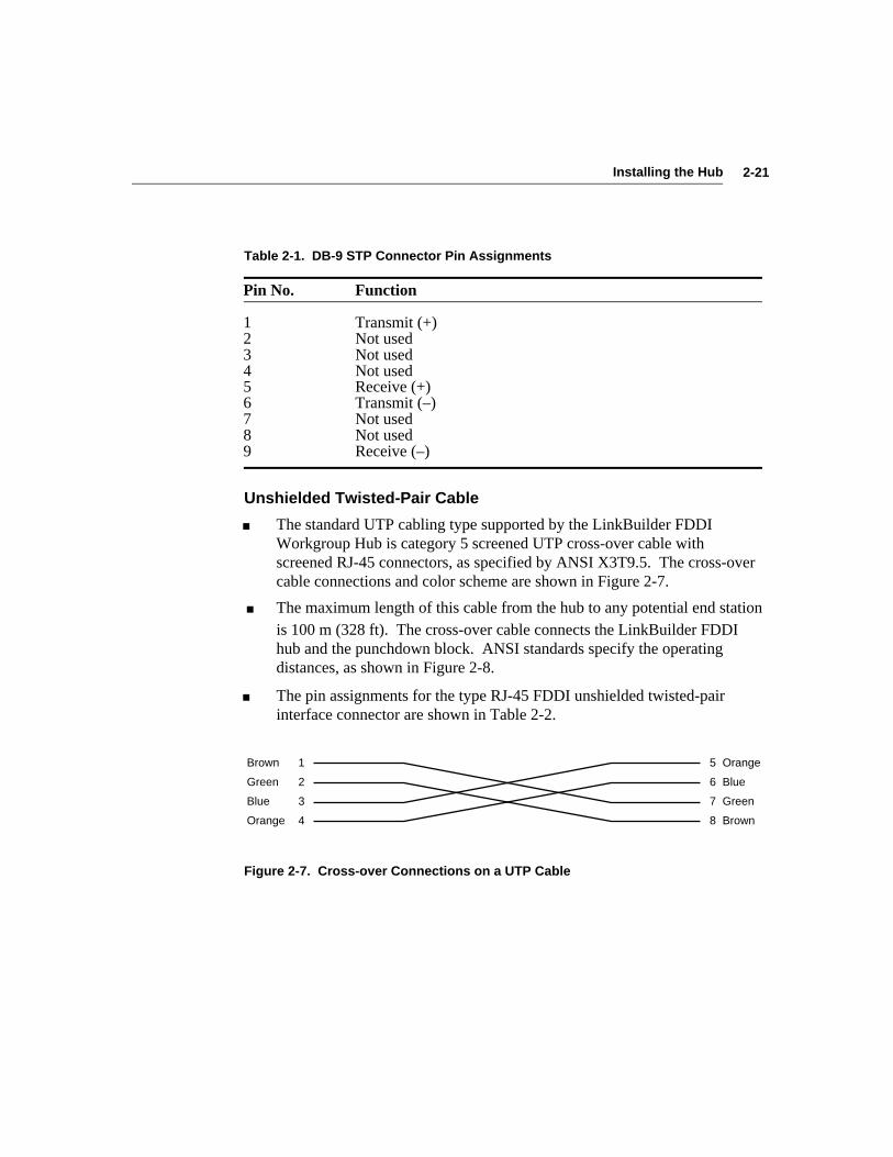
Unshielded Twisted-Pair Cable
■ The standard UTP cabling type supported by the LinkBuilder FDDIWorkgroup Hub is category 5 screened UTP cross-over cable withscreened RJ-45 connectors, as specified by ANSI X3T9.5. The cross-overcable connections and color scheme are shown in Figure 2-7.
■ The maximum length of this cable from the hub to any potential end stationis 100 m (328 ft). The cross-over cable connects the LinkBuilder FDDIhub and the punchdown block. ANSI standards specify the operatingdistances, as shown in Figure 2-8.
■ The pin assignments for the type RJ-45 FDDI unshielded twisted-pairinterface connector are shown in Table 2-2.
51
62
73
84
Brown
Green
Blue
Orange Brown
Green
Orange
Blue
Figure 2-7. Cross-over Connections on a UTP Cable
2-22 Installing the Hub
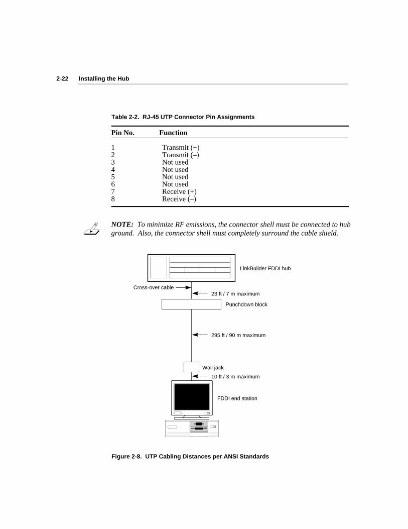
Table 2-2. RJ-45 UTP Connector Pin Assignments
Pin No. Function
1 Transmit (+)2 Transmit (–)3 Not used4 Not used5 Not used6 Not used7 Receive (+)8 Receive (–)
NOTE: To minimize RF emissions, the connector shell must be connected to hubground. Also, the connector shell must completely surround the cable shield.
LinkBuilder FDDI hub
23 ft / 7 m maximum
Punchdown block
295 ft / 90 m maximum
Wall jack
10 ft / 3 m maximum
FDDI end station
Cross-over cable
Figure 2-8. UTP Cabling Distances per ANSI Standards
2-23Installing the Hub
Data Flow SpecificationsThe FDDI standard specifies that data travels on the primary ring in acounterclockwise direction, and that data traveling on the secondary ring rotatesclockwise. (Refer to Figure 3-1.) As you attach the hub to the ring and networkdevices to the hub, be aware of the data flow direction.
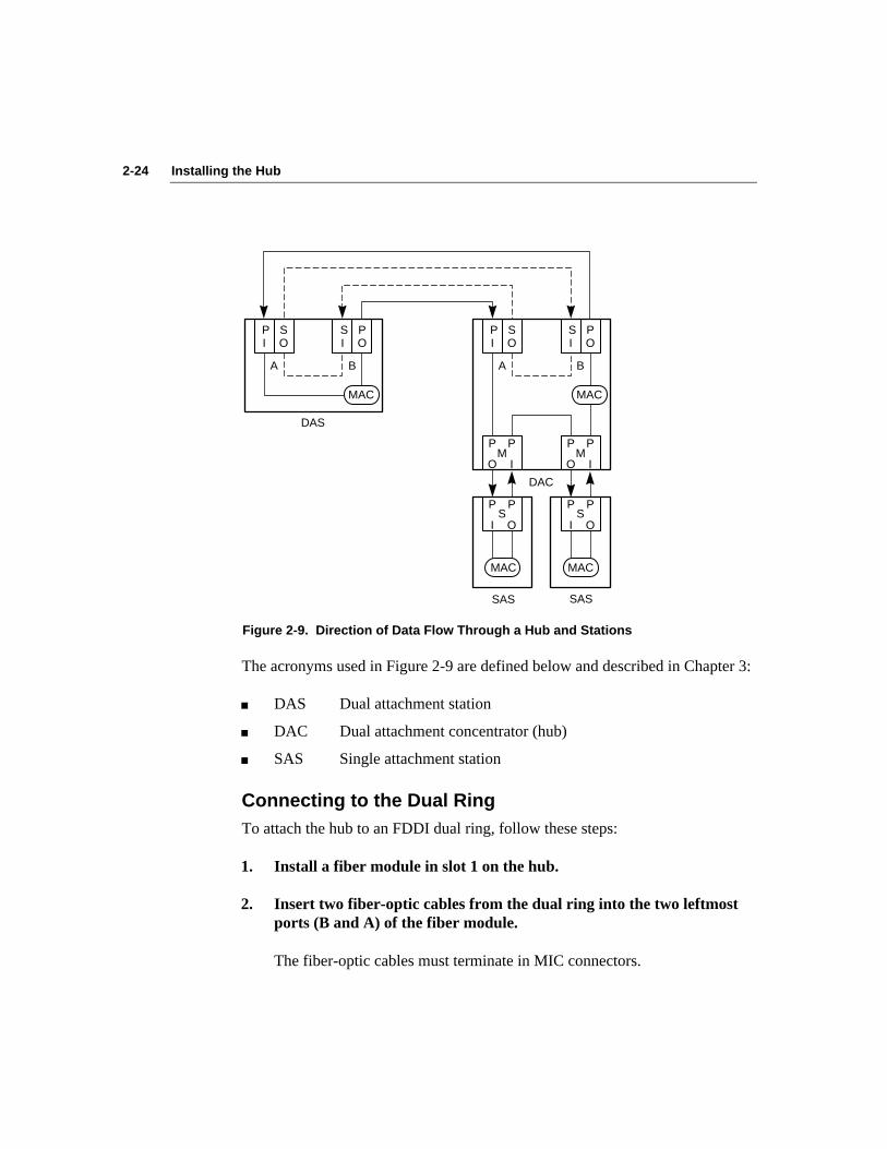
Table 2-3 shows the four supported port types and the direction of data flowthrough each port. Figure 2-9 illustrates the various port types and the data flowdirection allowed by the FDDI standard.
Table 2-3. FDDI Port Types
Port Data Flow Direction Use
A Primary In/Secondary Out Connects dual attachment(PI/SO) devices to the trunk ring
B Primary Out/Secondary In Connects dual attachment(PO/SI) devices to the trunk ring
M Master (PO/PI) Connects single attachmentdevices to the hub port; usesthe primary ring only
S Slave (PI/PO) Connects single attachmentdevices to the hub; uses therimary ring only
Table 2-3 and Figure 2-9 show that the primary ring (solid line) enters the Aport as Primary In (PI) and exits as Primary Out (PO) through port B. Thesecondary ring (dashed line) enters through port B as Secondary In (SI) andexits through port A as Secondary Out (SO).
For both master (M) and slave (S) ports, the primary ring enters the port as PIand exits as PO. The secondary ring never connects to these two ports.
2-24 Installing the Hub
P I
S O
S I
P O
A B
MAC
DAS
P I
S O
S I
P O
A B
DAC
MAC
S
MAC
S
MAC
M
SASSAS
P
I
P
OM
P
I
P
O
P
O
P
I
P
O
P
I
Figure 2-9. Direction of Data Flow Through a Hub and Stations
The acronyms used in Figure 2-9 are defined below and described in Chapter 3:
■ DAS Dual attachment station
■ DAC Dual attachment concentrator (hub)
■ SAS Single attachment station
Connecting to the Dual RingTo attach the hub to an FDDI dual ring, follow these steps:
1. Install a fiber module in slot 1 on the hub.
2. Insert two fiber-optic cables from the dual ring into the two leftmostports (B and A) of the fiber module.
The fiber-optic cables must terminate in MIC connectors.

2-25Installing the Hub
The default configuration of the attachment ports (the two leftmost ports on themodule installed in slot 1) is B/A. If the attachment ports have been configureddifferently (as shown by the ATTACH LEDs on the management module), youmust reconfigure them, as detailed below:
1. Configure the attachment ports as B and A. Type:
set attach
This selection prompt appears:
Select one of the following:1. B/A2. S/M3. M/M
Attachment port configuration?
2. Select the attachment port configuration that you want. For example,type:
1 [Enter]
These confirmation lines appear:
Current configuration: M/MInitialize attachment as: B/A
3. Reset the hub by pressing the recessed RESET button on themanagement module front panel.
The attachment ports will be initialized as B/A.
2-26 Installing the Hub
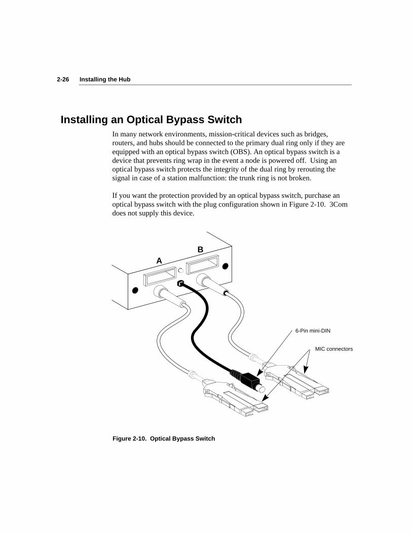
Installing an Optical Bypass SwitchIn many network environments, mission-critical devices such as bridges,routers, and hubs should be connected to the primary dual ring only if they areequipped with an optical bypass switch (OBS). An optical bypass switch is adevice that prevents ring wrap in the event a node is powered off. Using anoptical bypass switch protects the integrity of the dual ring by rerouting thesignal in case of a station malfunction: the trunk ring is not broken.
If you want the protection provided by an optical bypass switch, purchase anoptical bypass switch with the plug configuration shown in Figure 2-10. 3Comdoes not supply this device.
AB
6-Pin mini-DIN
MIC connectors
Figure 2-10. Optical Bypass Switch

2-27Installing the Hub
To detect the presence of an optical bypass switch on your system, enter theshow obs command. To install an optical bypass switch with the configurationshown in Figure 2-11, follow these steps:
1. Plug the A and B Media Interface Connectors (MIC connectors) froma network device or another hub into the B and A receptacles on theoptical bypass switch.
The device’s A connector must be placed in the B receptacle and the Bconnector in the A receptacle.
2. Plug the A and B MIC connectors of the optical bypass switch into theA and B ports on the FDDI hub (A to A and B to B).
B A
DAC
Optical bypass switch
B A
A B
DAS
DAC
DAS
B A
A
6-Pin mini-DIN
B
FDDI hub
Network devices
Figure 2-11. Cabling for Installing an Optical Bypass Switch
2-28 Installing the Hub
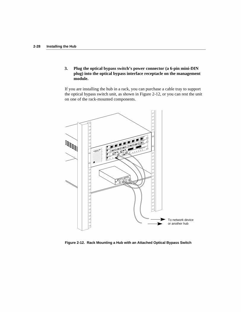
3. Plug the optical bypass switch’s power connector (a 6-pin mini-DINplug) into the optical bypass interface receptacle on the managementmodule.
If you are installing the hub in a rack, you can purchase a cable tray to supportthe optical bypass switch unit, as shown in Figure 2-12, or you can rest the uniton one of the rack-mounted components.
To network device or another hub
PWR®
FIBER PORT MODULE
GRN GRN YEL
= SIGNAL DETECT
= PORT STATE
= LINK ERROR
MANAGEMENT MODULE
M/M
ATTACH
B/A
S/MSTATUS
TOKENWRAP
FAN FAIL
HI TEMP
LOW BATT
SERIAL PORT
PWR® RESET
OPTICAL
BYPASS
GRN GRN YEL
= SIGNAL DETECT
= PORT STATE
= LINK ERROR
PWR®
GRN GRN YEL
= SIGNAL DETECT
= PORT STATE
= LINK ERROR
STP PORT MODULE
PWR®
UTP PORT MODULE
GRN GRN YEL
= SIGNAL DETECT
= PORT STATE
= LINK ERROR
®
Figure 2-12. Rack Mounting a Hub with an Attached Optical Bypass Switch

3-1Configuring the Hub
Chapter 3Configuring the Hub
After you have installed the hub and its modules and physically connected it tothe ring, you can configure the hub to operate in your network environment.This chapter discusses the following topics:
■ Attachment options supported by the hub
■ Default configuration of the hub and its modules
■ Console command access modes
■ Rules for media module port connections
Attachment OptionsThe LinkBuilder FDDI Workgroup Hub supports four types of standardconfigurations:
■ Dual attachment concentrator (DAC)
■ Single attachment concentrator (SAC)
■ Null attachment concentrator (NAC)
■ Dual homing (DH)
NOTE: 3Com uses the standard acronyms shown above but calls theconcentrator a hub.
Each type of configuration is discussed in this section. (Refer to the section“Configuring Modules” later in this chapter for information about using the setattach command to configure the hub.)
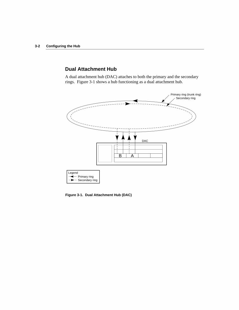
3-2 Configuring the Hub
Dual Attachment HubA dual attachment hub (DAC) attaches to both the primary and the secondaryrings. Figure 3-1 shows a hub functioning as a dual attachment hub.
B A
DAC
Primary ring (trunk ring)Secondary ring
Primary ring Secondary ring
Legend
Figure 3-1. Dual Attachment Hub (DAC)
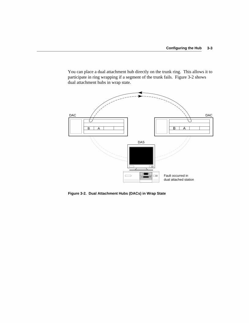
3-3Configuring the Hub
You can place a dual attachment hub directly on the trunk ring. This allows it toparticipate in ring wrapping if a segment of the trunk fails. Figure 3-2 showsdual attachment hubs in wrap state.
B A
DACDAC
DAS
Fault occurred in dual attached station
B A
Figure 3-2. Dual Attachment Hubs (DACs) in Wrap State

3-4 Configuring the Hub
Single Attachment HubA single attachment hub (SAC) is never attached directly to the dual trunk ring.Instead, it is attached to another hub, which is connected to the main ring.Figure 3-3 shows a single attachment hub connected to the network via a dualattachment hub. The single attachment hub in this example is connected tothree single attachment stations.
Primary ring
Secondary ring
S M M M
SAC
B A
DAC
M M
SAS SASSAS
Figure 3-3. Single Attachment Hub (SAC)
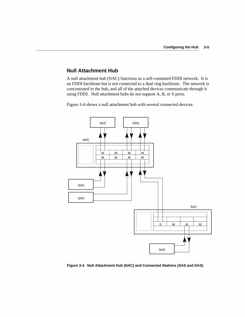
3-5Configuring the Hub
Null Attachment HubA null attachment hub (NAC) functions as a self-contained FDDI network. It isan FDDI backbone but is not connected to a dual ring backbone. The network isconcentrated in the hub, and all of the attached devices communicate through itusing FDDI. Null attachment hubs do not support A, B, or S ports.
Figure 3-4 shows a null attachment hub with several connected devices.
M M M M
SAS
SAS
S M M M
SAS
M M M M
SAC
NAC
SAS DAS
Figure 3-4. Null Attachment Hub (NAC) and Connected Stations (SAS and DAS)
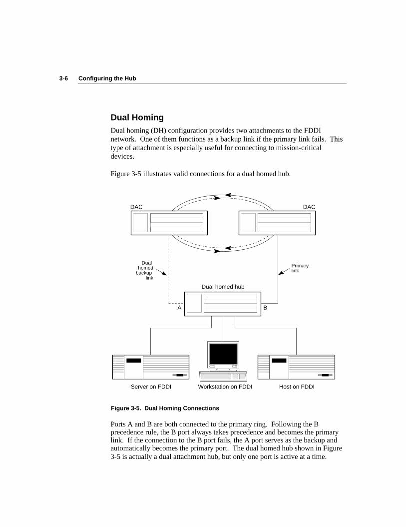
3-6 Configuring the Hub
Dual HomingDual homing (DH) configuration provides two attachments to the FDDInetwork. One of them functions as a backup link if the primary link fails. Thistype of attachment is especially useful for connecting to mission-criticaldevices.
Figure 3-5 illustrates valid connections for a dual homed hub.
DAC DAC
Dual homed
backup link
Primary link
A B
Dual homed hub
Server on FDDI Host on FDDIWorkstation on FDDI
Figure 3-5. Dual Homing Connections
Ports A and B are both connected to the primary ring. Following the Bprecedence rule, the B port always takes precedence and becomes the primarylink. If the connection to the B port fails, the A port serves as the backup andautomatically becomes the primary port. The dual homed hub shown in Figure3-5 is actually a dual attachment hub, but only one port is active at a time.
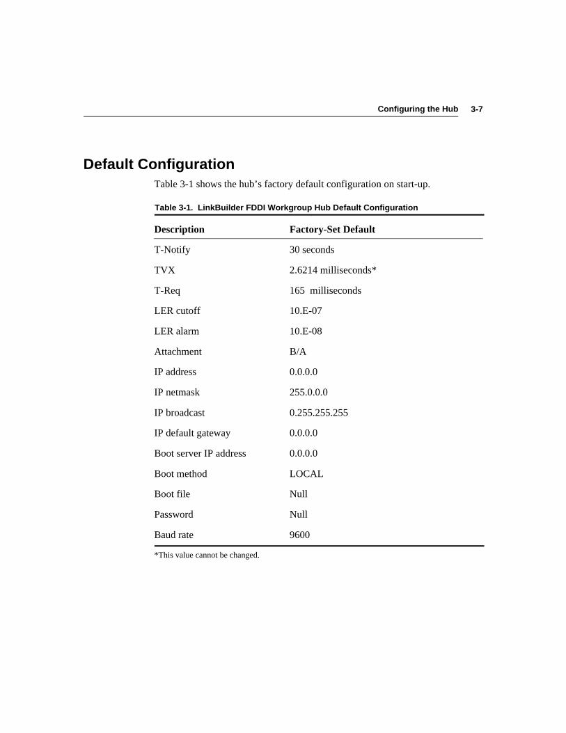
3-7Configuring the Hub
Default ConfigurationTable 3-1 shows the hub’s factory default configuration on start-up.
Table 3-1. LinkBuilder FDDI Workgroup Hub Default Configuration
Description Factory-Set Default
T-Notify 30 seconds
TVX 2.6214 milliseconds*
T-Req 165 milliseconds
LER cutoff 10.E-07
LER alarm 10.E-08
Attachment B/A
IP address 0.0.0.0
IP netmask 255.0.0.0
IP broadcast 0.255.255.255
IP default gateway 0.0.0.0
Boot server IP address 0.0.0.0
Boot method LOCAL
Boot file Null
Password Null
Baud rate 9600
*This value cannot be changed.
3-8 Configuring the Hub
You can operate the hub using its default configuration without making anychanges whatsoever. However, you may want to change various parameters tosuit your particular network environment. Refer to Chapters 4 and 5 andAppendix C for information about making changes to the hub’s defaultconfiguration.
If you should want to return the hub to its default configuration (after makingchanges), use the set defaults command, which is accessible only in theprimitive command mode.
Accessing Configuration CommandsYou can configure the hub using the commands in two command modes:
■ Management console commands
■ Primitive console commands
Management Console CommandsManagement console commands allow you to:
■ Display current parameter settings and configuration information
■ Set or change certain configuration-related parameters
■ Display a list and descriptions of the command set
■ Invoke several TCP/IP network troubleshooting commands
You can access the management console command mode by doing one of thefollowing:
■ Attaching a terminal to the RS-232 serial port on the management module
■ Connecting a Hayes-compatible modem to the RS-232 serial port on themanagement module
■ Using the TCP Telnet protocol over the network

3-9Configuring the Hub
Primitive Console CommandsThe “primitive” console commands, which are a subset of the managementconsole commands, are accessible in case of unusual system situations. Forexample, you can access the primitive console command mode if:
■ You forget the password. (You do not need a password to access theprimitive console command mode. Once in this mode, you can set a newpassword.)
■ You have downloaded a faulty image into the flash EPROM, and you mustreset the hub.
■ You have configured the hub with illegal parameters and nothing canoperate. You must reset the hub.
Unlike the management console command mode, when the primitive consolecommand mode is active, no connection to the ring exists. In primitive modeyou can change only those parameters that involve nonvolatile RAM.
You can access the primitive console command mode only via a terminalattached to the serial port on the management module. Remote access through amodem or via Telnet is not supported.
Accessing the Primitive Console Command Mode
To access the primitive console command mode, follow these steps:
1. Press the RESET button once.
The RESET button is recessed on the management module. Use a bentpaper clip or other small, pointed object to press the RESET button.
NOTE: You cannot access the primitive console command mode by typing thereset command.
2. Watch the STATUS LED on the management module.
The STATUS LED is normally amber. When the STATUS LED flashesamber/green, you have 10 seconds to press the RESET button again.

3-10 Configuring the Hub
If you do not press the RESET button during the 10 seconds that theSTATUS LED is flashing amber/green, you are denied access to theprimitive console command mode, and this message appears:
Primitive console entry has timed out.
3. Press RESET again.
This message appears:
Press Ctrl-P to enter Primitive Console.
4. Hold down the [Control] and [P] keys.
The hub is now in the primitive console command mode. The STATUSLED flashes amber/green continuously while you are in the primitiveconsole command mode.
If you do not enter a primitive console command within 15 seconds, aninactivity timeout will cause the hub to return to the management consolecommand mode.
If you do not press [Ctrl]+P within 10 seconds, the system times out.
If your attempt to enter the primitive console command mode fails and thetimeout occurs, you can try again by following the steps above.
3-11Configuring the Hub
Returning to the Management Console Command Mode
To return to the management console command mode without reattempting toenter the primitive console command mode, follow these steps:
1. Press [Enter].
This message appears:
3Com LinkBuilder® FDDI Workgroup Hub
The password prompt appears.
2. Enter the password and press [Enter].
To return to the management console command mode from the primitiveconsole command mode, reset the hub.
Port ConnectionsThe two leftmost ports on any module installed in slot 1 serve as attachmentports. You can configure these ports to be any of the following:
■ B/A (dual attachment)
■ S/M (slave/master)
■ M/M (master/master)
The way you configure these ports determines the type of attachment supportedby the hub. The configurable attachment types are as follows:
■ Dual attachment
■ Dual homing attachment
■ Single attachment
■ Null attachment
Table 3-2 shows how to configure the attachment ports for the desiredattachment type.
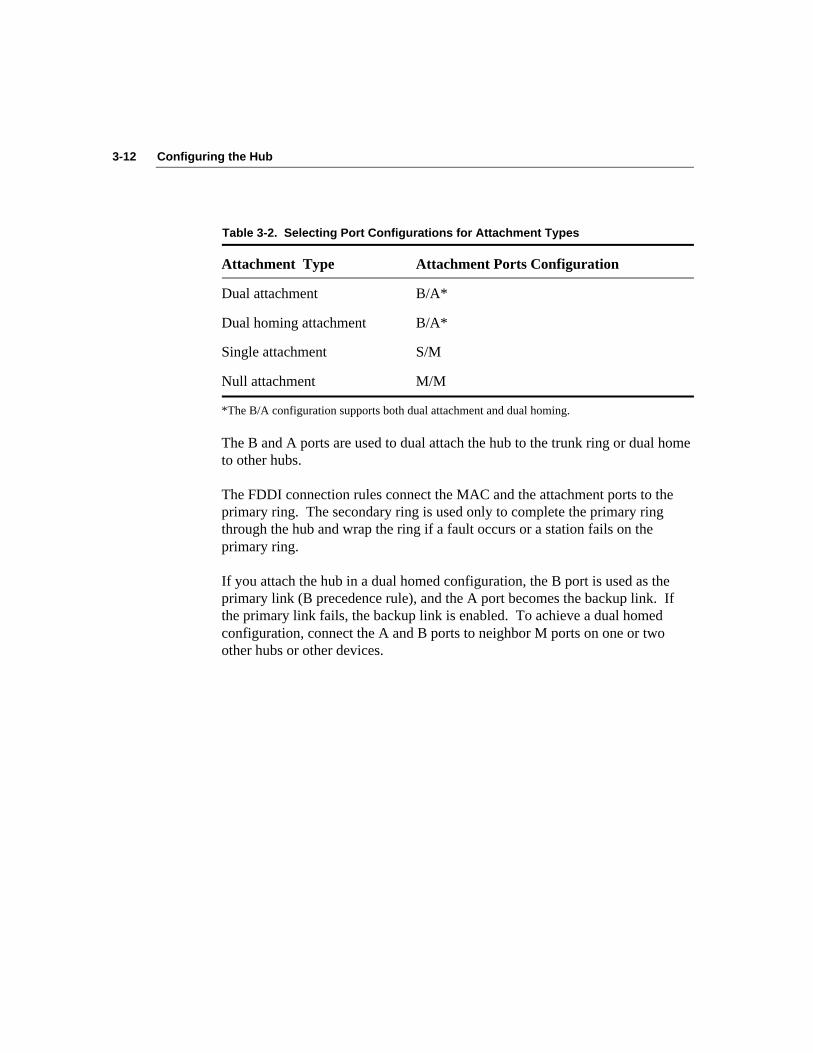
3-12 Configuring the Hub
Table 3-2. Selecting Port Configurations for Attachment Types
Attachment Type Attachment Ports Configuration
Dual attachment B/A*
Dual homing attachment B/A*
Single attachment S/M
Null attachment M/M
*The B/A configuration supports both dual attachment and dual homing.
The B and A ports are used to dual attach the hub to the trunk ring or dual hometo other hubs.
The FDDI connection rules connect the MAC and the attachment ports to theprimary ring. The secondary ring is used only to complete the primary ringthrough the hub and wrap the ring if a fault occurs or a station fails on theprimary ring.
If you attach the hub in a dual homed configuration, the B port is used as theprimary link (B precedence rule), and the A port becomes the backup link. Ifthe primary link fails, the backup link is enabled. To achieve a dual homedconfiguration, connect the A and B ports to neighbor M ports on one or twoother hubs or other devices.
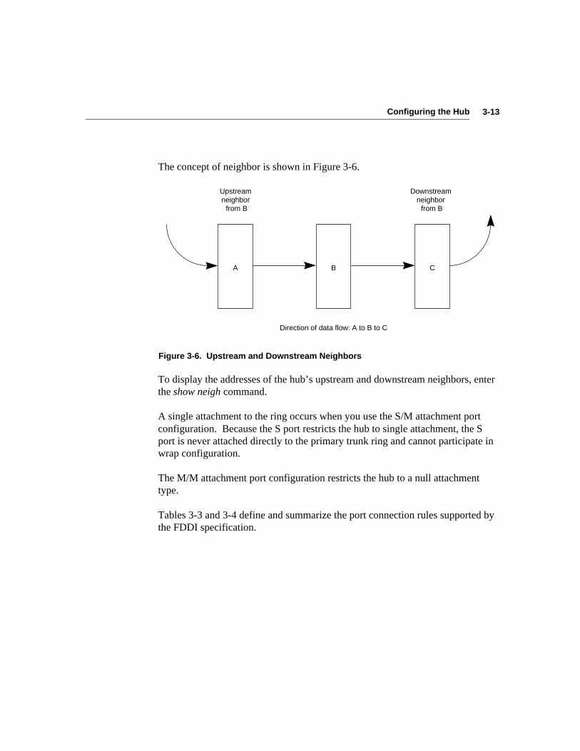
3-13Configuring the Hub
The concept of neighbor is shown in Figure 3-6.
Upstream neighbor
from B
Downstream neighbor
from B
CBA
Direction of data flow: A to B to C
Figure 3-6. Upstream and Downstream Neighbors
To display the addresses of the hub’s upstream and downstream neighbors, enterthe show neigh command.
A single attachment to the ring occurs when you use the S/M attachment portconfiguration. Because the S port restricts the hub to single attachment, the Sport is never attached directly to the primary trunk ring and cannot participate inwrap configuration.
The M/M attachment port configuration restricts the hub to a null attachmenttype.
Tables 3-3 and 3-4 define and summarize the port connection rules supported bythe FDDI specification.
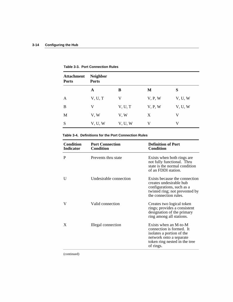
3-14 Configuring the Hub
Table 3-3. Port Connection Rules
Attachment NeighborPorts Ports
A B M S
A V, U, T V V, P, W V, U, W
B V V, U, T V, P, W V, U, W
M V, W V, W X V
S V, U, W V, U, W V V
Table 3-4. Definitions for the Port Connection Rules
Condition Port Connection Definition of PortIndicator Condition Condition
P Prevents thru state Exists when both rings arenot fully functional. Thrustate is the normal conditionof an FDDI station.
U Undesirable connection Exists because the connectioncreates undesirable hubconfigurations, such as atwisted ring; not prevented bythe connection rules.
V Valid connection Creates two logical tokenrings; provides a consistentdesignation of the primaryring among all stations.
X Illegal connection Exists when an M-to-Mconnection is formed. Itisolates a portion of thenetwork onto a separatetoken ring nested in the treeof rings.
(continued)

3-15Configuring the Hub
Table 3-4. Definitions for the Port Connection Rules (continued)
Condition Port Connection Definition of PortIndicator Condition Condition
W Wrap state Exists when a break in theprimary ring occurs and thestations on either side of thebreak join the primary andsecondary rings. It can alsoindicate that the ring iswrapped at a particular port.
T Twisted ring Exists when an A-to-A or aB-to-B connection is formed.It divides the network intotwo groups of stations thatdisagree on which token ringis the primary ring.
The connections listed below are not allowed:
■ M to M: an illegal connection
■ A to A: an undesirable connection that creates a twisted ring
■ B to B: an undesirable connection that creates a twisted ring
The connection rules do not necessarily prevent undesirable connections. An“undesirable connection” designation reflects the connection status of thesending node only. The connection can still be made if the receiving nodeexhibits an acceptable connection status.
Configuring ModulesYou can only configure the module inserted in slot 1, and you can onlyconfigure the two leftmost ports (the attachment ports) of that module. Theattachment port configuration is stored in nonvolatile RAM. Any attachmentport configuration changes that you make take effect when the system isreinitialized. To reinitialize the hub, execute the reset command.

3-16 Configuring the Hub
All three types of port modules can be installed in slot 1. The type of moduleyou install depends on the medium you are using to connect the hub to the nextnode.
Table 3-5 shows how to configure each module for the type of attachmentdesired and what additional equipment or action is necessary to complete theconnection. (Refer to the section “Setting Attachment Port Configurations” inChapter 4 for information about configuring the attachment ports.)
For example, if you want to establish either a dual attachment or a dual homedconnection, configure the module’s attachment ports as B/A. For a singleattachment connection, configure the module’s attachment ports as S/M. For anull attachment, set the attachment ports as M/M.
To discover the configuration of the attachment ports on the module in slot 1,check the ATTACH LED display on the management module or enter the showattach command. The ATTACH LED is lit whenever there is a moduleinstalled in slot 1.
Table 3-5. Configuring Modules
Attachment AdditionalAttachment Port Equipment
Module Type Configuration Required
Fiber Dual B/A None
Dual homing B/A None
Single S/M None
Null M/M None
STP Dual B/A 2 Cascade connectors
Dual homing B/A 2 Cascade connectors
Single S/M 1 Cascade connector
Null M/M None
(continued)

3-17Configuring the Hub
Table 3-5. Configuring Modules (continued)
Attachment AdditionalAttachment Port Equipment
Module Type Configuration Required
UTP Dual B/A Cross-over cable
Dual homing B/A Cross-over cable
Single S/M Cross-over cable
Null M/M Cross-over cable
To change the configuration of the attachment ports, follow these steps:
1. Enter the set attach command. Type:
set attach
This selection prompt appears:
Select one of the following:1. B/A2. S/M3. M/M
Attachment port configuration?
2. Select the attachment port configuration that you want. For example,type:
2 [Enter]
These confirmation lines appear:
Current configuration: B/AInitialize attachment as: S/M
When you reset the hub, the attachment ports will be configured as S/M.
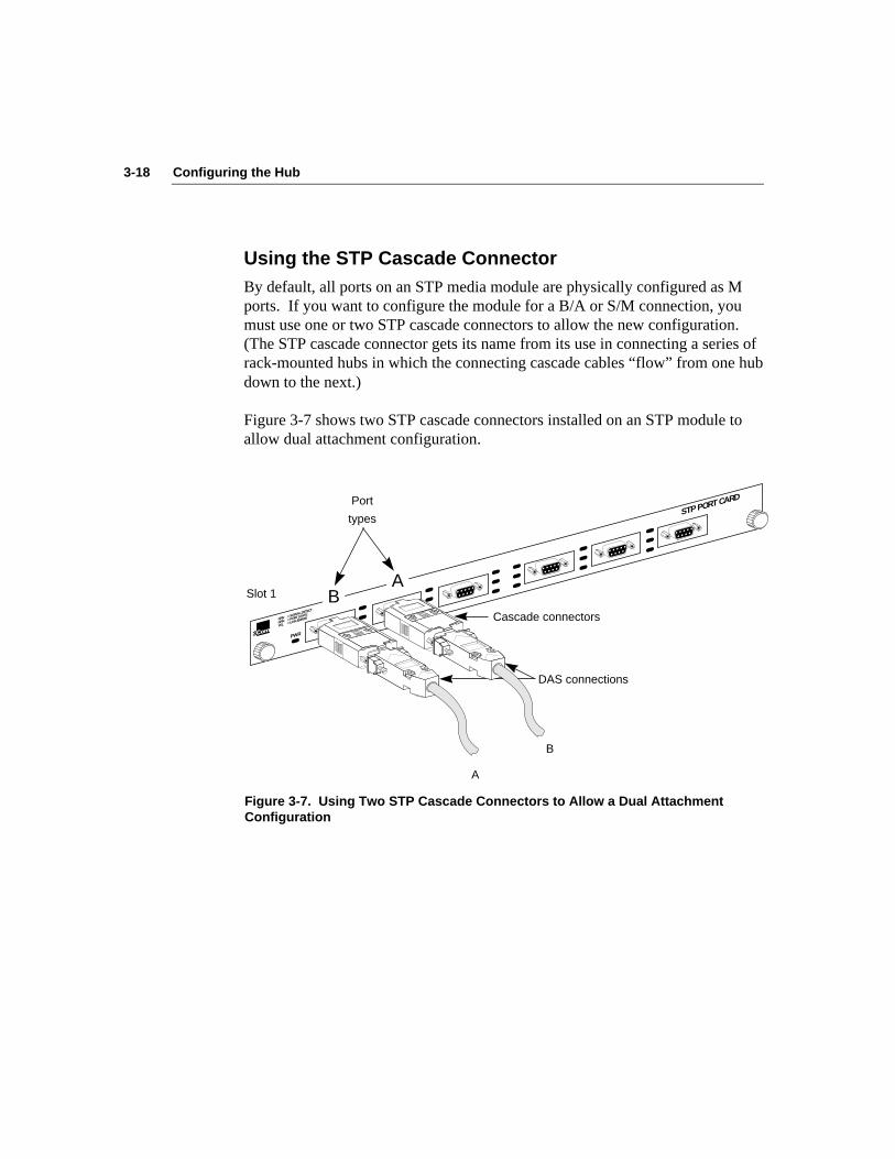
3-18 Configuring the Hub
Using the STP Cascade ConnectorBy default, all ports on an STP media module are physically configured as Mports. If you want to configure the module for a B/A or S/M connection, youmust use one or two STP cascade connectors to allow the new configuration.(The STP cascade connector gets its name from its use in connecting a series ofrack-mounted hubs in which the connecting cascade cables “flow” from one hubdown to the next.)
Figure 3-7 shows two STP cascade connectors installed on an STP module toallow dual attachment configuration.
Cascade connectors
DAS connections
®
STP PORT CARD
PWR
GRN GRN YEL
= SIGNAL DETECT
= PORT STATE
= LINK ERROR
Slot 1
A
B
Port
types
BA
Figure 3-7. Using Two STP Cascade Connectors to Allow a Dual AttachmentConfiguration

3-19Configuring the Hub
To use an STP module in a dual attachment configuration, for example, followthese steps:
1. If the attachment ports are not currently configured as B/A, configurethe attachment ports to be B/A by invoking the set attach command.
2. Reset the hub.
This step is unnecessary if the attachment ports are already set as B/A.
3. Install two cascade connectors.
Insert one cascade connector in each of the two leftmost ports of the STPmodule in slot 1.
4. Attach the appropriate cables to the two cascade connectors.
The cable from port number 1 (the B port) should attach to port A on thedevice to be dual attached. The cable from port number 2 (the A port)should attach to port B on the device.
4-1Setting Up the Hub
Chapter 4Setting Up the Hub
The LinkBuilder FDDI Workgroup Hub is shipped ready to plug in and usewithout the need to change any parameters. In all probability, however, youwill want to make a number of changes to adapt the hub to your networkenvironment. This chapter discusses how to use the management consolecommands to set up the hub and make any desired parameter changes. Topicsinclude:
■ Using commands to:– Set addresses– Set the password– Set attachment port configuration– Set station management parameters
■ Downloading new images
CommandsThe commands supported by the management console command mode and theprimitive console command mode enable you to set and display the basicparameters needed to configure and operate the hub. The commands aregrouped into three functional categories that are defined below:
■ Use set commands to institute various functions.
■ Use show commands to display default parameter settings and reflect anychanges you make.
■ Use miscellaneous commands to support various diagnostic andtroubleshooting functions.
4-2 Setting Up the Hub
Command DescriptionsFor a complete listing and detailed description of all the commands, refer toAppendix C, “Commands.”
■ For a list of the set commands with brief definitions, type:
set ? orset help
■ For a list of the show commands with brief definitions, type:
show ? orshow help
■ To display a list of the miscellaneous commands with brief definitions,type:
help or?
Display of Command ResultsYou can use the set commands to change various parameters. The results ofseveral management console command actions are shown in a two-line display,as follows:
Current . . . .Initialize . . . .
Where Current is the present parameter setting and Initialize is the desiredparameter setting that will take effect when the hub is reset.

4-3Setting Up the Hub
Setting AddressesThe hub management module uses the TCP/IP network environment fordownloading images and managing the hub. Refer to the section “DownloadingNew Images” later in this chapter for a discussion of downloading procedures.
The console command set provides for setting and displayingTCP/IP-related addresses. To display these addresses, enter the show ipcommand.
IP AddressThe IP address is a unique 32-bit identifier for a specific TCP/IP host or otherdevice. Contact your network administrator for the IP addresses that you need.
■ To set the IP address, type set ip followed by the hub’s IP address, thenetmask (optional), and the broadcast IP address (optional). For example,type:
set ip 128.45.87.25 255.255.0.0 128.45.255.255 [Enter]
Your input is echoed after you press [Enter], as shown below:
IP address :128.45.87.25Netmask :255.255.0.0Broadcast :128.45.255.255
■ If you type only set ip, this usage message appears:
Usage: set ip address [netmask] [broadcast]where address is the IP address for this hubnetmask is the IP network mask [optional]broadcast is the IP broadcast address [optional]
e.g. set ip 128.45.87.25 255.255.0.0 0.0.255.255
■ If you type set ip followed by only one IP address, the netmask andbroadcast address are automatically calculated, as shown below:
set ip 128.45.87.25IP address :128.45.87.25Netmask :255.255.0.0
Broadcast :128.45.255.255
4-4 Setting Up the Hub
NOTE: In this manual, the address format used (three digits in each octet) isassumed to be decimal representation. If you prefer hexadecimalrepresentation, the address format would be 0x12.0x34.0x56.0x78. The “0x”indicates that the subsequent digits represent hexadecimal values.
NetmaskThe netmask, also known as the subnet mask, is used when multiple physicalnetworks share the same IP address. The bits in the mask determine those bitsof the IP address that specify various subnetworks. The mask is determinedlocally.
Broadcast AddressThe broadcast address is a special group address. It denotes all stations on thenetwork, and all the bits are set to one. For example, if you entered128.45.255.255, the message would be broadcast to all IP hosts on network128.45.
Default Gateway AddressThe default gateway address is the Internet address of the gateway used whenthere are multiple IP networks. The default gateway address is administeredlocally, usually by an MIS department.
To set the default gateway address, enter the set gateway command followed bythe default address. If you omit the address, this message appears:
Usage: set gateway addresswhere address is the IP default gateway addresse.g. set gateway 128.45.76.10
4-5Setting Up the Hub
Setting the PasswordAccess to the hub is password-protected. To display the password prompt whenthe hub is first powered up, press any key. The modem init string (AT&F)appears briefly. You are then prompted for the password. The hub is shippedwith no password installed. At the password prompt, press [Enter].
You can set the password using either the management or the primitive consolecommand mode. (Refer to the section “Accessing Configuration Commands” inChapter 3 for information about these two console command modes.) Once youenter a password, it will be required every time you reset the hub.
To set your own password, follow these steps:
1. Enter the set pwd command from the terminal that is connected to themanagement module’s serial port.
You will be prompted for the old password if you are in the managementconsole command mode.
NOTE: In the primitive console command mode you will not be promptedfor the old password. Skip to step 3.
2. Enter the old password.
You will be prompted for a new password.
3. Enter the new password.
The password can be one to eight alphanumeric characters. Passwords arecase sensitive.
4. At the next prompt, confirm the new password by reentering it.
If you entered the new password correctly, this message appears:
Password changed
If you entered the password incorrectly, this message appears:
Password not changed.
4-6 Setting Up the Hub
Setting Attachment Port ConfigurationsTo configure the attachment ports, use the set attach command.
1. Type the command:
set attach
This selection prompt appears:
Select one of the following:
1. B/A2. S/M3. M/M
Attachment port configuration?
2. Enter the configuration you want. For example, type:
2 [Enter]
A confirmation message similar to the following appears:
Current configuration is : B/A
Initialize attachment as : S/M
This message means that the hub’s current attachment port configuration isB/A (dual attachment). When you reset the hub, the attachment ports willbe initialized as S/M. (Refer to Chapter 3, “Configuring the Hub,” fordescriptions and diagrams of the attachments supported by the LinkBuilderFDDI Workgroup Hub.)
4-7Setting Up the Hub
Using Station Management ParametersThe hub supports a number of station management (SMT) parameters to helpyou understand and manage the processes occurring in the FDDI ring. You canset and display three of these parameters. You can display three otherparameters, but you cannot set them.
Setting SMT ParametersUsing the console interface, you can display and change these SMT parameters:
■ Neighbor Notification Timer (T-Notify)
■ Target Rotation Time (T-Req)
■ Link Error Rate (LER) alarm and cutoff values
Neighbor Notification Timer (T-Notify)
The T-Notify parameter functions as one element of the Neighbor Notificationprotocol. This protocol allows a MAC to determine the address of its logicalupstream and downstream neighbors. The Neighbor Notification process isperformed independently for each MAC in a station. The process facilitates thedetection of, isolation of, and recovery from network errors by supplying eachMAC with logical fault information.
The protocol performs these functions by periodically initiating a request-response frame exchange between a MAC and its nearest downstream neighbor.The T-Notify parameter determines how frequently Neighbor InformationFrames (NIFs) are broadcast to the ring.
The T-Notify parameter is stored in nonvolatile RAM. You can set it using theset tnotify command. The factory-set default for T-Notify is 30 seconds, but itcan be set in the range of 2 to 30 seconds. A change to T-Notify takes effectimmediately.
To show the current value of T-Notify, enter the show tnotify command. Adisplay similar to the following appears:
T-Notify = 20 seconds

4-8 Setting Up the Hub
Target Token Rotation Time (T-Req)
The FDDI ring is initialized every time a station joins or leaves the ring. Duringthe initialization process, all stations on the ring agree on a “token rotationtime.” This is the maximum amount of time that any station has to wait for atoken to arrive, and it establishes the minimum level of service on the ring.(Level of service relates to how often a station requires access to the token.)
The Target Token Rotation Time (TTRT) is the service level required by anindividual station. During the initialization process, each station makes arequest for a level of service that is identical to its local TTRT. This servicelevel request is called T-Req.
T-Req is stored in nonvolatile RAM and can be set using the set treq command.The factory-set default is 165 milliseconds. Changes to T-Req take effect onlywhen the system is reset.
To display the current value of the Target Token Rotation Time parameter, enterthe show treq command. This display appears:
Current T-Req = 165000 microsecondsInitialize T-Req as = 160000 microseconds
Link Error Rate (LER)
The Link Error Monitor (LEM) examines the Link Error Rate (LER) per activeport as part of its responsibility for keeping link quality at an acceptable level.The LEM uses a threshold test to compare the current LER cutoff threshold tothe LER alarm threshold.
NOTE: You must always keep the LER_Alarm parameter larger than the valueentered for the LER_Cutoff parameter.
These two thresholds are explained below:
LER_Alarm. This threshold is the LER at which a link connection exceeds thepresent threshold and will generate an alarm. The factory-set default is 10.E-08(10-8). This error rate is equivalent to about one error per second.
4-9Setting Up the Hub
Set this value higher if the link between stations must handle higher error levels.This can be necessary if you are waiting for minor unit or cable repairs but thering is still operational. Set this value lower if you are confident of the qualityof the link.
To change the LER_Alarm parameter, follow these steps:
1. Enter the set ler alarm command. Type:
set ler alarm [Enter]
You are prompted for the module number and the port number.
Module?
Port?
The current LER values are displayed, followed by a prompt for yourresponse. For example:
Current LER Alarm exponent = 8
Current LER Cutoff exponent = 7
LER alarm [7...15]?
2. Enter the new LER alarm value. For example, type:
7 [Enter]
If you enter an alarm value that is less than the current cutoff value, thismessage appears:
Error: The alarm exponent must be >= current cutoffexponent.
Set alarm exponent >= 7 or change the cutoffvalue.
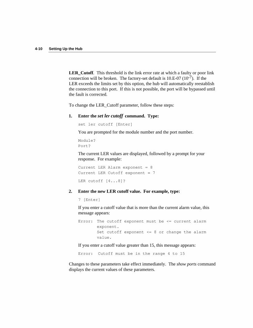
4-10 Setting Up the Hub
LER_Cutoff. This threshold is the link error rate at which a faulty or poor linkconnection will be broken. The factory-set default is 10.E-07 (10-7). If theLER exceeds the limits set by this option, the hub will automatically reestablishthe connection to this port. If this is not possible, the port will be bypassed untilthe fault is corrected.
To change the LER_Cutoff parameter, follow these steps:
1. Enter the set ler cutoff command. Type:
set ler cutoff [Enter]
You are prompted for the module number and the port number.
Module?Port?
The current LER values are displayed, followed by a prompt for yourresponse. For example:
Current LER Alarm exponent = 8
Current LER Cutoff exponent = 7
LER cutoff [4...8]?
2. Enter the new LER cutoff value. For example, type:
7 [Enter]
If you enter a cutoff value that is more than the current alarm value, thismessage appears:
Error: The cutoff exponent must be <= current alarmexponent.Set cutoff exponent <= 8 or change the alarm
value.
If you enter a cutoff value greater than 15, this message appears:
Error: Cutoff must be in the range 4 to 15
Changes to these parameters take effect immediately. The show ports commanddisplays the current values of these parameters.

4-11Setting Up the Hub
Displaying SMT ParametersThese three SMT parameters, which you can display but cannot change, provideadditional information about ring timer functions:
■ Maximum Token Rotation Time (T-Max)
■ Negotiated Time (T-Neg)
■ Valid Transmission Timer (TVX)
Maximum Token Rotation Time (T-Max)
The Maximum Token Rotation Time (T-Max) is the maximum length of timeallowed for the token to move around the ring. The factory-set default is 167.77milliseconds. To view the value of the T-Max parameter, enter the show tmaxcommand. A display similar to the following appears:
T-Max = 167772 microseconds
Negotiated Time (T-Neg)
The Negotiated Time (T-Neg) is the ring’s operational Target Token RotationTime that results from the stations’ bidding process in which the stationrequesting the fastest token rotation time wins the right to initialize the ring. Toview the current value of T-Neg, enter the show tneg command. A displaysimilar to the following appears:
T-Neg = 83886 microseconds
Valid Transmission Timer (TVX)
The Media Access Control (MAC) protocol is responsible for all frame-basedfunctions and controls a station’s access to the ring. Each MAC is required tomaintain a Valid Transmission Timer (TVX). The expiration threshold of theTVX indicates the maximum time allowed between the receipt of valid framesor tokens.
The factory-set default is 2621.40 microseconds. You cannot adjust the value ofTVX, but you can display its value. To display the current value of TVX, enterthe show tvx command. A display similar to the following appears:
TVX Value in use = 2.62 milliseconds
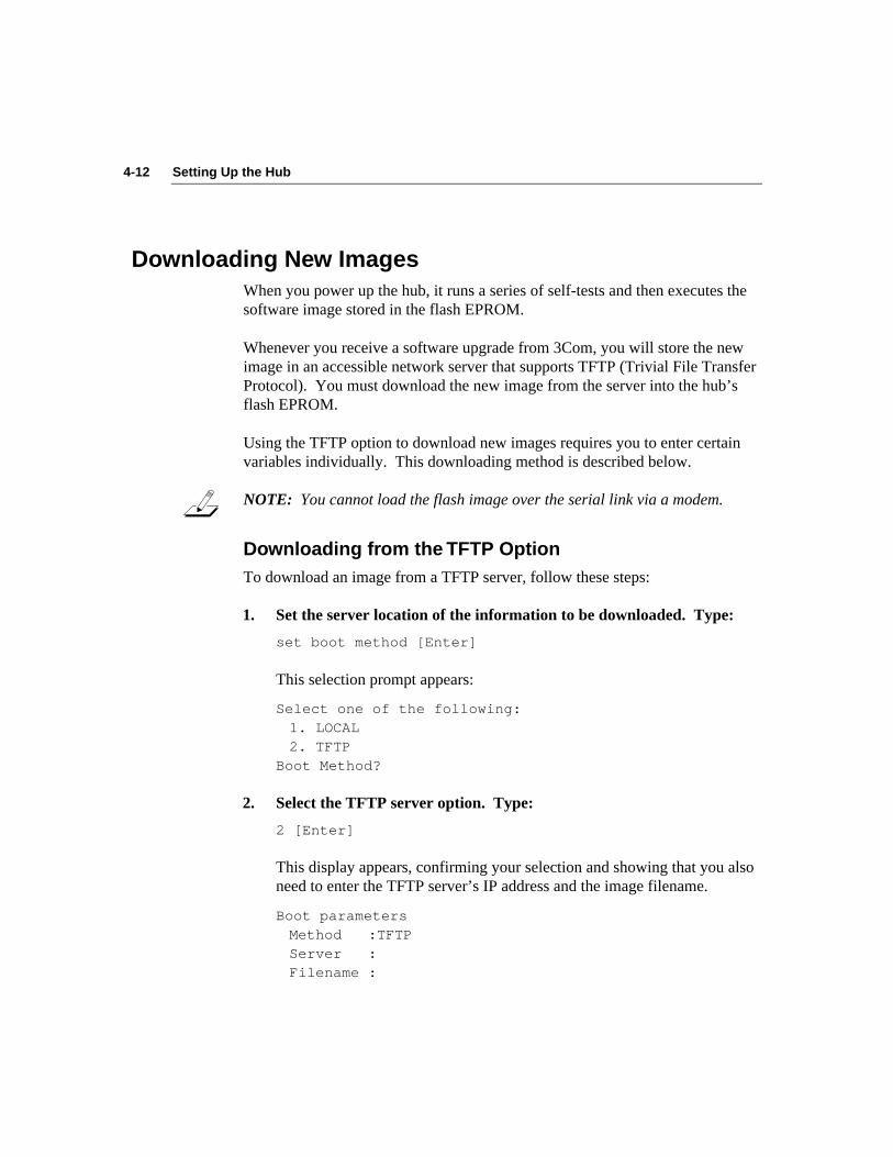
4-12 Setting Up the Hub
Downloading New ImagesWhen you power up the hub, it runs a series of self-tests and then executes thesoftware image stored in the flash EPROM.
Whenever you receive a software upgrade from 3Com, you will store the newimage in an accessible network server that supports TFTP (Trivial File TransferProtocol). You must download the new image from the server into the hub’sflash EPROM.
Using the TFTP option to download new images requires you to enter certainvariables individually. This downloading method is described below.
NOTE: You cannot load the flash image over the serial link via a modem.
Downloading from the TFTP OptionTo download an image from a TFTP server, follow these steps:
1. Set the server location of the information to be downloaded. Type:
set boot method [Enter]
This selection prompt appears:
Select one of the following:1. LOCAL2. TFTP
Boot Method?
2. Select the TFTP server option. Type:
2 [Enter]
This display appears, confirming your selection and showing that you alsoneed to enter the TFTP server’s IP address and the image filename.
Boot parametersMethod :TFTPServer :Filename :

4-13Setting Up the Hub
3. Set the TFTP server’s IP address. Type:
set boot server [Enter]
This prompt appears:
Enter server IP address in dot notation?
4. Type the server’s IP address. For example, type:
123.44.55.66 [Enter]
This confirmation appears:
Boot parametersMethod : TFTPServer : 123.44.55.66Filename :
5. Set the image filename to be used. Type:
set boot filename
The file name prompt appears:
Enter filename?
6. Type the name of the image file after the question mark. For example,type:
newimage [Enter]
This display appears, showing your entries:
Boot parametersMethod : LOCALServer : 123.44.55.66Filename : newimage
Optionally, if connection to the TFTP server is through a gateway, youmust enter the gateway address.
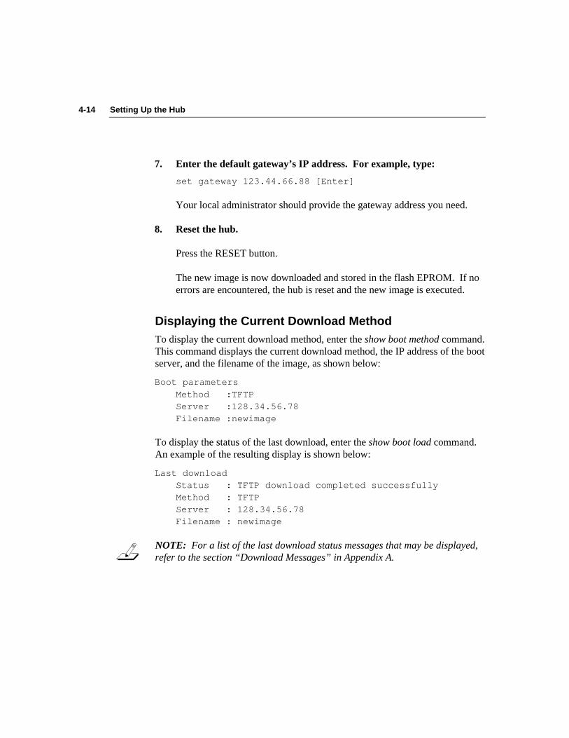
4-14 Setting Up the Hub
7. Enter the default gateway’s IP address. For example, type:
set gateway 123.44.66.88 [Enter]
Your local administrator should provide the gateway address you need.
8. Reset the hub.
Press the RESET button.
The new image is now downloaded and stored in the flash EPROM. If noerrors are encountered, the hub is reset and the new image is executed.
Displaying the Current Download MethodTo display the current download method, enter the show boot method command.This command displays the current download method, the IP address of the bootserver, and the filename of the image, as shown below:
Boot parameters
Method :TFTPServer :128.34.56.78Filename :newimage
To display the status of the last download, enter the show boot load command.An example of the resulting display is shown below:
Last downloadStatus : TFTP download completed successfullyMethod : TFTPServer : 128.34.56.78Filename : newimage
NOTE: For a list of the last download status messages that may be displayed,refer to the section “Download Messages” in Appendix A.

4-15Setting Up the Hub
Table 4-1 summarizes the available boot methods.
Table 4-1. Definition of Boot Methods
Boot Method Definition
LOCAL Runs flash EPROM (default)
TFTP Uses the TFTP protocol and local configuration parameters toload a new image across the network
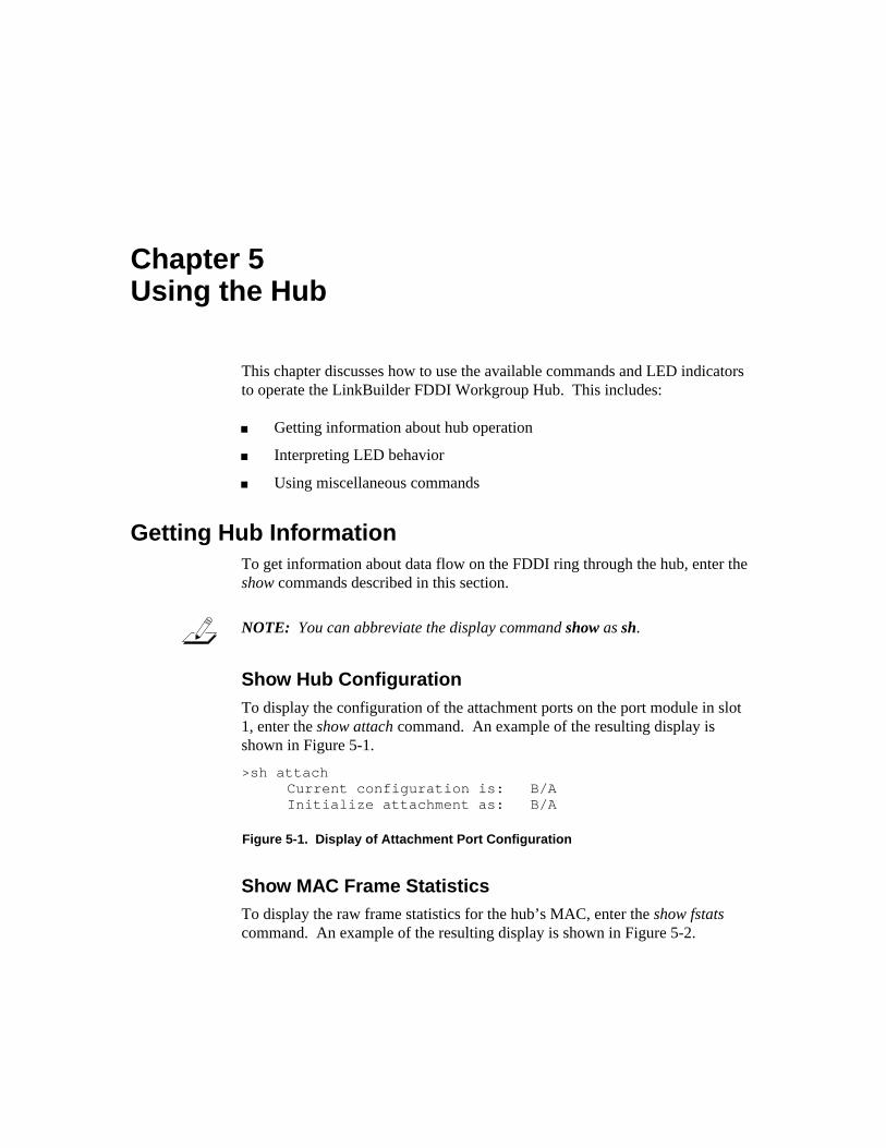
5-1Using the Hub
Chapter 5Using the Hub
This chapter discusses how to use the available commands and LED indicatorsto operate the LinkBuilder FDDI Workgroup Hub. This includes:
■ Getting information about hub operation
■ Interpreting LED behavior
■ Using miscellaneous commands
Getting Hub InformationTo get information about data flow on the FDDI ring through the hub, enter theshow commands described in this section.
NOTE: You can abbreviate the display command show as sh.
Show Hub ConfigurationTo display the configuration of the attachment ports on the port module in slot1, enter the show attach command. An example of the resulting display isshown in Figure 5-1.
>sh attachCurrent configuration is: B/AInitialize attachment as: B/A
Figure 5-1. Display of Attachment Port Configuration
Show MAC Frame StatisticsTo display the raw frame statistics for the hub’s MAC, enter the show fstatscommand. An example of the resulting display is shown in Figure 5-2.
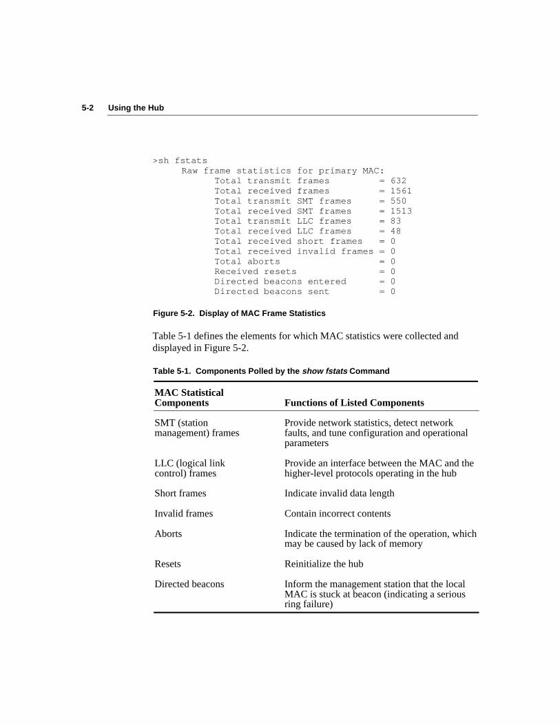
5-2 Using the Hub
>sh fstatsRaw frame statistics for primary MAC:
Total transmit frames = 632Total received frames = 1561Total transmit SMT frames = 550Total received SMT frames = 1513Total transmit LLC frames = 83Total received LLC frames = 48Total received short frames = 0Total received invalid frames = 0Total aborts = 0Received resets = 0Directed beacons entered = 0Directed beacons sent = 0
Figure 5-2. Display of MAC Frame Statistics
Table 5-1 defines the elements for which MAC statistics were collected anddisplayed in Figure 5-2.
Table 5-1. Components Polled by the show fstats Command
MAC StatisticalComponents Functions of Listed Components
SMT (station Provide network statistics, detect networkmanagement) frames faults, and tune configuration and operational
parameters
LLC (logical link Provide an interface between the MAC and thecontrol) frames higher-level protocols operating in the hub
Short frames Indicate invalid data length
Invalid frames Contain incorrect contents
Aborts Indicate the termination of the operation, whichmay be caused by lack of memory
Resets Reinitialize the hub
Directed beacons Inform the management station that the localMAC is stuck at beacon (indicating a seriousring failure)
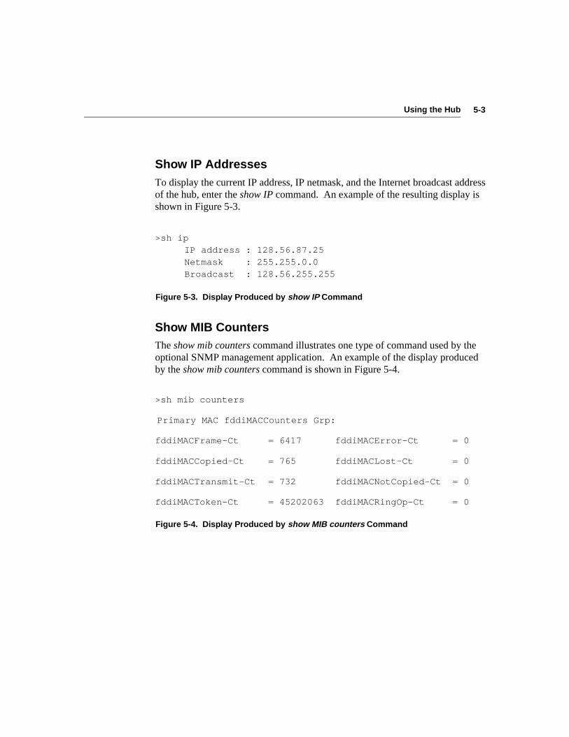
5-3Using the Hub
Show IP AddressesTo display the current IP address, IP netmask, and the Internet broadcast addressof the hub, enter the show IP command. An example of the resulting display isshown in Figure 5-3.
>sh ipIP address : 128.56.87.25Netmask : 255.255.0.0Broadcast : 128.56.255.255
Figure 5-3. Display Produced by show IP Command
Show MIB CountersThe show mib counters command illustrates one type of command used by theoptional SNMP management application. An example of the display producedby the show mib counters command is shown in Figure 5-4.
>sh mib counters
Primary MAC fddiMACCounters Grp:
fddiMACFrame-Ct = 6417 fddiMACError-Ct = 0
fddiMACCopied-Ct = 765 fddiMACLost-Ct = 0
fddiMACTransmit-Ct = 732 fddiMACNotCopied-Ct = 0
fddiMACToken-Ct = 45202063 fddiMACRingOp-Ct = 0
Figure 5-4. Display Produced by show MIB counters Command
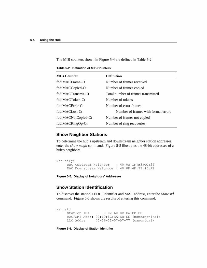
5-4 Using the Hub
The MIB counters shown in Figure 5-4 are defined in Table 5-2.
Table 5-2. Definition of MIB Counters
MIB Counter Definition
fddiMACFrame-Ct Number of frames received
fddiMACCopied-Ct Number of frames copied
fddiMACTransmit-Ct Total number of frames transmitted
fddiMACToken-Ct Number of tokens
fddiMACError-Ct Number of error frames
fddiMACLost-Ct Number of frames with format errors
fddiMACNotCopied-Ct Number of frames not copied
fddiMACRingOp-Ct Number of ring recoveries
Show Neighbor StationsTo determine the hub’s upstream and downstream neighbor station addresses,enter the show neigh command. Figure 5-5 illustrates the 48-bit addresses of ahub’s neighbors.
>sh neighMAC Upstream Neighbor : 40:0A:1F:B3:CC:24MAC Downstream Neighbor : 40:0D:4F:33:40:AE
Figure 5-5. Display of Neighbors’ Addresses
Show Station IdentificationTo discover the station’s FDDI identifier and MAC address, enter the show sidcommand. Figure 5-6 shows the results of entering this command.
>sh sidStation ID: 00 00 02 60 8C EA EB EEMAC/SMT Addr: 02:60:8C:EA:EB:EE (noncanonical)LLC Addr: 40-06-31-57-D7-77 (canonical)
Figure 5-6. Display of Station Identifier
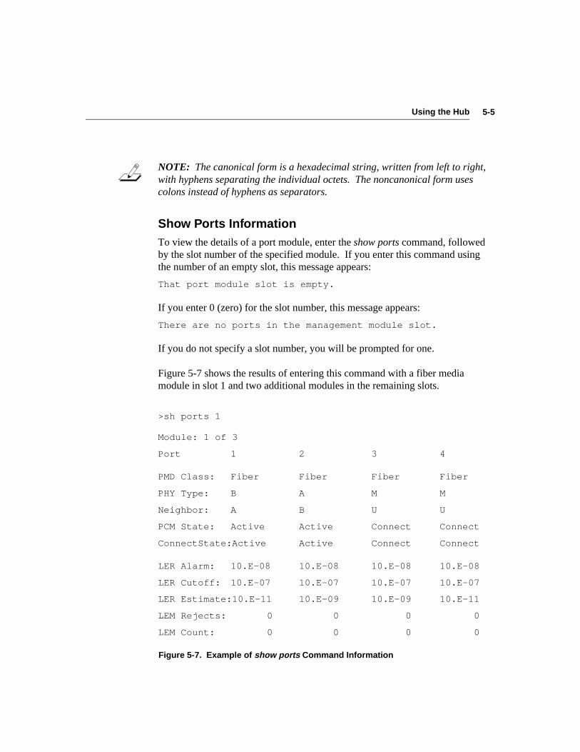
5-5Using the Hub
NOTE: The canonical form is a hexadecimal string, written from left to right,with hyphens separating the individual octets. The noncanonical form usescolons instead of hyphens as separators.
Show Ports InformationTo view the details of a port module, enter the show ports command, followedby the slot number of the specified module. If you enter this command usingthe number of an empty slot, this message appears:
That port module slot is empty.
If you enter 0 (zero) for the slot number, this message appears:
There are no ports in the management module slot.
If you do not specify a slot number, you will be prompted for one.
Figure 5-7 shows the results of entering this command with a fiber mediamodule in slot 1 and two additional modules in the remaining slots.
>sh ports 1
Module: 1 of 3
Port 1 2 3 4
PMD Class: Fiber Fiber Fiber Fiber
PHY Type: B A M M
Neighbor: A B U U
PCM State: Active Active Connect Connect
ConnectState:Active Active Connect Connect
LER Alarm: 10.E-08 10.E-08 10.E-08 10.E-08
LER Cutoff: 10.E-07 10.E-07 10.E-07 10.E-07
LER Estimate:10.E-11 10.E-09 10.E-09 10.E-11
LEM Rejects: 0 0 0 0
LEM Count: 0 0 0 0
Figure 5-7. Example of show ports Command Information
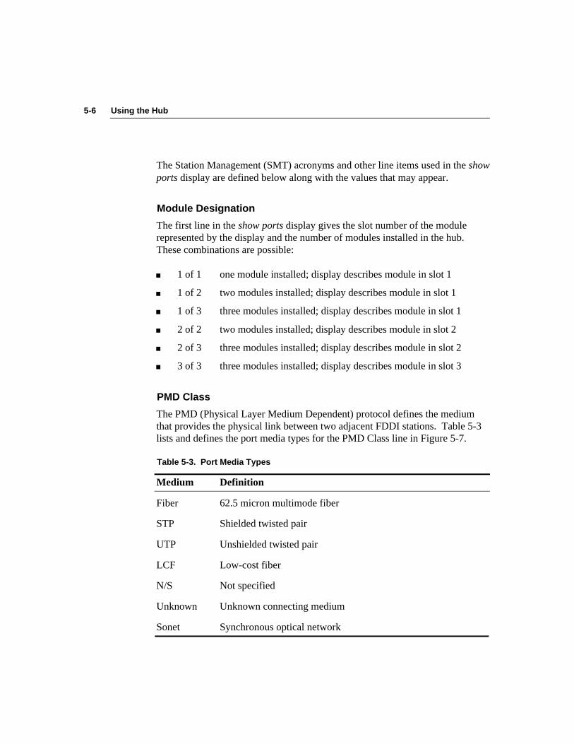
5-6 Using the Hub
The Station Management (SMT) acronyms and other line items used in the showports display are defined below along with the values that may appear.
Module Designation
The first line in the show ports display gives the slot number of the modulerepresented by the display and the number of modules installed in the hub.These combinations are possible:
■ 1 of 1 one module installed; display describes module in slot 1
■ 1 of 2 two modules installed; display describes module in slot 1
■ 1 of 3 three modules installed; display describes module in slot 1
■ 2 of 2 two modules installed; display describes module in slot 2
■ 2 of 3 three modules installed; display describes module in slot 2
■ 3 of 3 three modules installed; display describes module in slot 3
PMD Class
The PMD (Physical Layer Medium Dependent) protocol defines the mediumthat provides the physical link between two adjacent FDDI stations. Table 5-3lists and defines the port media types for the PMD Class line in Figure 5-7.
Table 5-3. Port Media Types
Medium Definition
Fiber 62.5 micron multimode fiber
STP Shielded twisted pair
UTP Unshielded twisted pair
LCF Low-cost fiber
N/S Not specified
Unknown Unknown connecting medium
Sonet Synchronous optical network
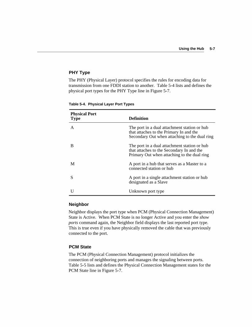
5-7Using the Hub
PHY Type
The PHY (Physical Layer) protocol specifies the rules for encoding data fortransmission from one FDDI station to another. Table 5-4 lists and defines thephysical port types for the PHY Type line in Figure 5-7.
Table 5-4. Physical Layer Port Types
Physical PortType Definition
A The port in a dual attachment station or hubthat attaches to the Primary In and theSecondary Out when attaching to the dual ring
B The port in a dual attachment station or hubthat attaches to the Secondary In and thePrimary Out when attaching to the dual ring
M A port in a hub that serves as a Master to aconnected station or hub
S A port in a single attachment station or hubdesignated as a Slave
U Unknown port type
Neighbor
Neighbor displays the port type when PCM (Physical Connection Management)State is Active. When PCM State is no longer Active and you enter the showports command again, the Neighbor field displays the last reported port type.This is true even if you have physically removed the cable that was previouslyconnected to the port.
PCM State
The PCM (Physical Connection Management) protocol initializes theconnection of neighboring ports and manages the signaling between ports.Table 5-5 lists and defines the Physical Connection Management states for thePCM State line in Figure 5-7.

5-8 Using the Hub
Table 5-5. Physical Connection Management States
Physical ConnectionManagement States Definition
Active The port is incorporated into the token ringpath.
Break A port connection has been broken and arestart process has begun.
Connect Both ends of the port’s requested connectionare synchronized.
Join This signal ensures that both ends of aconnection can enter the active state together.
Next The port is exchanging connection informationwith its neighboring ports.
Off The port is in an Off state.
Signal The port is ready to transmit data.
Trace The port recognizes a fault condition and istrying to detect its location.
Verify The port is in the process of entering theActive state.
Maintenance (Maint) The port has moved from the Off state to theMaint state, which can be used to determinethe status of the neighboring machine.

5-9Using the Hub
Connect State
The Connect State indicates the state of each ports’ connection. Table 5-6 liststhe values and defines the connect states for the Connect State line in Figure 5-7.
Table 5-6. Connect States
Connect StateValue Definition
Active The port is incorporated into the token ringpath.
Connect Both ends of the port’s requested connectionare in the process of being synchronized.
Disabled The port is nonoperational.
Standby The port is waiting for initialization to finishbefore completing the requested connection. Inthe case of a dual homing configuration, the Aport is held in Standby while the B port isActive.
LER Alarm and LER Cutoff
The LER alarm value is the Link Error Rate (LER) at which a link connectionexceeds the present threshold and generates an alarm.
The LER cutoff is the link error rate at which a faulty or poor link connectionwill be broken.
For a complete description of these two link error rate parameters and theirvalues, refer to the section “Setting SMT Parameters” in Chapter 4.
LER Estimate
This parameter provides a long-term average Link Error Rate estimate. LEREstimate ranges from 10-4 to 10-15.
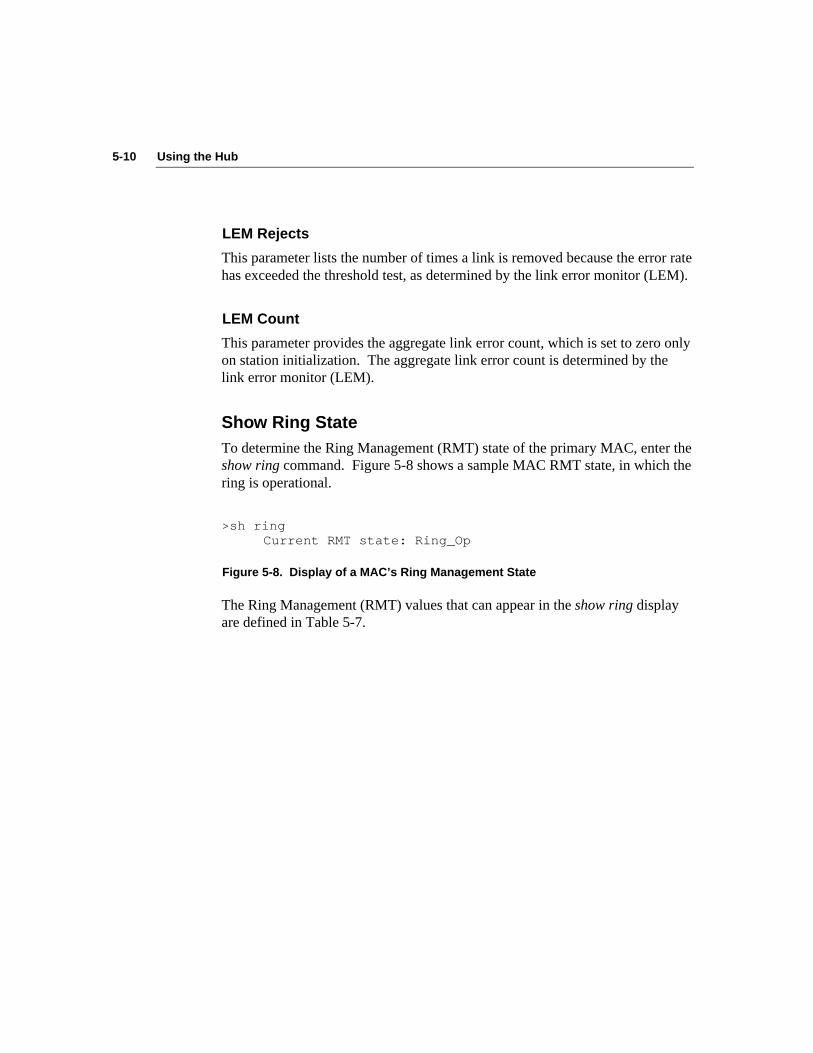
5-10 Using the Hub
LEM Rejects
This parameter lists the number of times a link is removed because the error ratehas exceeded the threshold test, as determined by the link error monitor (LEM).
LEM Count
This parameter provides the aggregate link error count, which is set to zero onlyon station initialization. The aggregate link error count is determined by thelink error monitor (LEM).
Show Ring StateTo determine the Ring Management (RMT) state of the primary MAC, enter theshow ring command. Figure 5-8 shows a sample MAC RMT state, in which thering is operational.
>sh ringCurrent RMT state: Ring_Op
Figure 5-8. Display of a MAC’s Ring Management State
The Ring Management (RMT) values that can appear in the show ring displayare defined in Table 5-7.
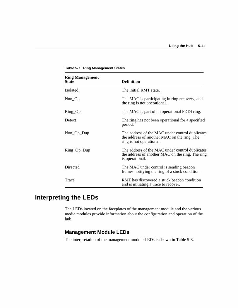
5-11Using the Hub
Table 5-7. Ring Management States
Ring ManagementState Definition
Isolated The initial RMT state.
Non_Op The MAC is participating in ring recovery, andthe ring is not operational.
Ring_Op The MAC is part of an operational FDDI ring.
Detect The ring has not been operational for a specifiedperiod.
Non_Op_Dup The address of the MAC under control duplicatesthe address of another MAC on the ring. Thering is not operational.
Ring_Op_Dup The address of the MAC under control duplicatesthe address of another MAC on the ring. The ringis operational.
Directed The MAC under control is sending beaconframes notifying the ring of a stuck condition.
Trace RMT has discovered a stuck beacon conditionand is initiating a trace to recover.
Interpreting the LEDs
The LEDs located on the faceplates of the management module and the variousmedia modules provide information about the configuration and operation of thehub.
Management Module LEDsThe interpretation of the management module LEDs is shown in Table 5-8.

5-12 Using the Hub
Table 5-8. Interpreting Management Module LEDs
LED Color Indicators Meaning
PWR Green Hub is on.
ATTACH Only one attachment exists at any one time.Configuration refers only to module in slot 1:
B/A Green Port 1= B, port 2 = A, other ports = M
S/M Green Port 1= S, other ports = M
M/M Green All ports = M
STATUS Amber From 0 to 20 seconds after reset: power-onself-test (POST) is in progress.
20+ seconds after reset: hardware failure hasoccurred in management module, backplane,or critical parts of port modules.
Flashing amber/green Access to the primitive command mode isavailable now. If a reset occurs during thislimited period, you are instructed to press[Ctrl]+P to enter primitive console mode
Flashing amber/off Failure has occurred during downloadoperation.
Flashing green/off TFTP download is in progress.
Green Normal operation.
TOKEN Green The token is circulating and the ring isoperational.
Off A ring operation is occurring.
WRAP Amber The ring is wrapped.
FAN FAIL Amber A fan failure has occurred.
HI TEMP Amber A high-temperature condition exists (above50˚ C inside the chassis).
LOW BATT Amber A low battery voltage condition exists.

5-13Using the Hub
Additional information about the last four LEDs in Table 5-8 is provided below.
WRAP LED
If the WRAP LED is on, a ring wrap condition exists on the hub. To determinewhere the wrap has occurred, enter the show cfm command. This commanddisplays the Configuration Management (CFM) state of the dual ring inside thehub. Table 5-9 defines the possible CFM states. A path in this definitionrepresents the segment of a logical ring that passes through a station.
Table 5-9. CFM State Values Displayed by the show cfm Command
CFM State Definition
Wrap_a The secondary path is wrapped to the A port.
Wrap_b The primary path is wrapped to the B port.
Wrap_s The primary path is wrapped to the S port.
C_wrap_a The primary and secondary paths are joined internally to thestation and wrapped to the A port.
C_wrap_b The primary and secondary paths are joined internally to thestation and wrapped to the B port.
C_wrap_s The primary and secondary paths are joined internally to thestation and wrapped to the S port.
Isolated The MAC or port is not inserted into any path.
Thru The primary path enters the A port and emerges from the Bport. The secondary path enters the B port and emerges fromthe A port. This is normal FDDI operation.
Not all wrap conditions activate the WRAP LED. The WRAP LED lights whena wrap condition involves a peer-mode connection. A, B, and S ports areconsidered peer ports, and any connection between two peer ports is a peer-mode connection. (An S-to-S connection is the exception and is not considereda peer-mode connection.)
Any connection of an A, B, or S port with an M port is a tree-mode connection.When the wrap condition involves a port connected in tree mode (an M port),the WRAP LED remains off.

5-14 Using the Hub
FAN FAIL LED
If the FAN FAIL LED shows amber, the fan has failed and must be replaced.You must send the hub base unit back to 3Com to replace the fan. Contact your3Com representative for a Return Materials Authorization (RMA).
HI TEMP LED
If the HI TEMP LED shows amber, it means that the temperature in the hubexceeds 50° C. Check to be sure that nothing is blocking air flow around thechassis. If the temperature in the wiring closet exceeds 50° C and nothing isblocking the flow of air into the hub, you should install a cooling system for thecloset.
LOW BATT LED
If the LOW BATT LED is on, a low battery condition exists and nonvolatileRAM will not retain data if power is lost. You must replace the battery. See theinstructions in the section “Installing the Battery” in Chapter 2.
Dangerous Environmental Conditions Display
If any of the environmental dangers exist (Fan Fail, Hi Temp, or Low Batt), theappropriate LED listed in Table 5-8 will show amber. In addition, anappropriate message appears on a terminal directly or remotely (Telnet)connected to the hub.
When one or more of these conditions exist, a message is appended to anydisplayed command string or new line followed by [Enter] that you type. Forexample, if all conditions were to exist, you would see the following alertmessage after you entered a command and the terminal displayed thecommand’s response:
Hardware: (FAN FAILURE) (HIGH TEMP) (LOW BATTERY)
Only those conditions that exist will be displayed. If none exist, nothing isdisplayed.
5-15Using the Hub
If a high temperature condition existed but no longer does, this messageappears:
Hardware: (HIGH TEMP SEEN)
To remove this message, enter the clear alarm command, as shown below:
clear alarm [Enter]
This is the only environmental condition that requires you to invoke the clearalarm command. The other two danger conditions are cleared only when thecondition no longer exists. Otherwise, the warnings reappear with everysubsequent command and new line that you type.
Reset Function
The reset function reinitializes the hub and runs the power-on self-tests (POST).You should perform a reset before removing or adding a module to the hub. Anydevices connected to the hub when a reset is performed are momentarilydisconnected until the tests are completed. The hub then attempts to reconnectthe devices.
Before the reset begins, you are prompted to confirm the reset request. Thisgives you the opportunity to make changes in network connections, such asentering the disconnect command, which disconnects the hub from the ring.This allows you to avoid other problems that could occur with an unexpectedinterruption of service.
You can perform the reset function in one of two ways:
■ Enter the reset command on the command line.
■ Press the RESET button on the management module.
The RESET button on the management module is recessed behind the faceplate.To access the RESET button, insert a small pointed object, such as the tip of asharp pencil or end of a bent paper clip, into the hole below the RESET label.
Pressing the RESET button performs the two functions described below:
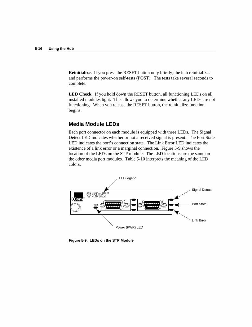
5-16 Using the Hub
Reinitialize. If you press the RESET button only briefly, the hub reinitializesand performs the power-on self-tests (POST). The tests take several seconds tocomplete.
LED Check. If you hold down the RESET button, all functioning LEDs on allinstalled modules light. This allows you to determine whether any LEDs are notfunctioning. When you release the RESET button, the reinitialize functionbegins.
Media Module LEDsEach port connector on each module is equipped with three LEDs. The SignalDetect LED indicates whether or not a received signal is present. The Port StateLED indicates the port’s connection state. The Link Error LED indicates theexistence of a link error or a marginal connection. Figure 5-9 shows thelocation of the LEDs on the STP module. The LED locations are the same onthe other media port modules. Table 5-10 interprets the meaning of the LEDcolors.
Signal Detect
Port State
Link Error
PWR
®
GRN GRN YEL
= SIGNAL DETECT = PORT STATE = LINK ERROR
LED legend
Power (PWR) LED
Figure 5-9. LEDs on the STP Module
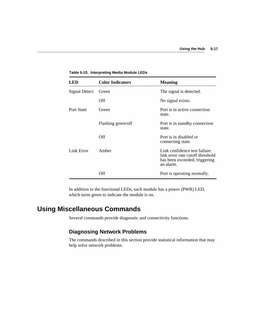
5-17Using the Hub
Table 5-10. Interpreting Media Module LEDs
LED Color Indicators Meaning
Signal Detect Green The signal is detected.
Off No signal exists.
Port State Green Port is in active connectionstate.
Flashing green/off Port is in standby connectionstate.
Off Port is in disabled orconnecting state.
Link Error Amber Link confidence test failure:link error rate cutoff thresholdhas been exceeded, triggeringan alarm.
Off Port is operating normally.
In addition to the functional LEDs, each module has a power (PWR) LED,which turns green to indicate the module is on.
Using Miscellaneous CommandsSeveral commands provide diagnostic and connectivity functions.
Diagnosing Network ProblemsThe commands described in this section provide statistical information that mayhelp solve network problems.

5-18 Using the Hub
ping Command
The ping command sends echo frames to a host and expects to receive a likenumber of echo frames in return. Use the ping command to find out whether ornot a host on the network is operational. For example, type:
ping 128.45.87.20
where 128.45.87.20 is the host address in Internet dot notation. The address caneither be a specific station IP address or a broadcast address.
If the host is operational, this reply is displayed:
128.45.87.20 is alive
If the host is not operational, this reply is displayed:
no answer from 128.45.87.20
You can specify two options with the ping command:
■ size This optional argument has a default value of 56 bytesand specifies the number of data bytes in the echo frames.
■ cnt This optional argument (count) has a default value of one (1)and specifies the number of echo frames to be sent.
If you type the size option with the ping command, the echoing display includesthe host address and the number of bytes in the frame, which should equal thesize data bytes plus eight frame header bytes. For example, if you type thisstring, in which 64 is the size option variable:
ping 128.45.87.10 64
this response is displayed:
PING 128.45.87.10: 64 data bytes
128.45.87.10 is alive

5-19Using the Hub
If you type the count option with the ping command, the resulting displaycontains the ping statistics, which include the number of packets sent, thenumber of packets received, and the percentage of packets lost. For example, ifyou type this string, in which 64 is the size option variable and 5 is the countoption variable:
ping 128.45.87.10 64 5
this response is displayed:
PING 128.45.87.10: 64 data bytes
72 bytes from 128.45.87.10: icmp_seq=0.72 bytes from 128.45.87.10: icmp_seq=1.72 bytes from 128.45.87.10: icmp_seq=2.72 bytes from 128.45.87.10: icmp_seq=3.72 bytes from 128.45.87.10: icmp_seq=4.
——128.45.87.10 PING STATISTICS——5 packets transmitted, 5 packets received, 0% packet loss
To stop the transmission of echo frames before the specified number ofresponses has been achieved, press [Ctrl]+D. If you request a very large countoption and the command has not completed its run, the transmission of echoframes will be aborted by a logout or a timeout.
route Command
The route command allows you to add and delete entries in the routing table forthe specific host indicated by the destination and gateway addresses. You canalso display the destination and gateway addresses.
■ To add a destination and gateway to the routing table, use this format:
route add xxx.xxx.xxx.xxx yyy.yyy.yyy.yyy
where xxx.xxx.xxx.xxx is the destination IP address and yyy.yyy.yyy.yyy isthe gateway IP address.

5-20 Using the Hub
By including a metric option, you can indicate the number of hops (numberof gateways separating the source and destination) to the designateddestination network. For example, to indicate five hops in the abovecommand line, type:
route add 128.87.45.12 128.87.45.33 5
■ To delete a route from the routing table, use the IP address in Internet dotnotation. For example, type:
route del 128.87.45.12 128.87.45.33
■ To determine the IP addresses of the destination and gateway, enter theroute dump command. For example, type:
route dump [Enter]
This display appears:
DESTINATION GATEWAY
128.87.0.0 128.87.45.15
arp Command
The arp command allows you to display and change information in the AddressResolution Protocol (ARP) table of the hub. The Address Resolution Protocolmaps known IP addresses (32 bits long) to MAC addresses (48 bits long).
■ To display the contents of the ARP table, type:
arp dump
■ To delete the IP address of the host, type:
arp del xxx.xxx.xxx.xxx
where xxx.xxx.xxx.xxx is the IP address of the host in Internet dot notation.
■ To add an entry to the ARP table, type:
arp set xxx.xxx.xxx.xxx hh.hh.hh.hh.hh.hh
where xxx.xxx.xxx.xxx is the IP address of the host andhh.hh.hh.hh.hh.hh is the host 48-bit MAC address in noncanonicalformat.

5-21Using the Hub
show log and clear log Commands
The fault log keeps a limited history of recent faults that have occurred in thesystem.
■ To display the fault log, type:
show log
A typical fault log is shown below:
Fault Log:
1. 10000001 0# 0 2. 10000002 0# 0
The first column shows the order of all faults since the last clear logcommand. The second column is the code specifying the type of fault.(Refer to “Fault Log Error Code Messages” in Appendix A forexplanations of the error codes.) The third column is a time stamp (inseconds), showing when the fault occurred. (The timer is restarted aftereach reset.) The fourth column is the number of resets since the lastrecorded reset.
■ To clear the fault log, type:
clear log
■ To display the fault log in reverse order, type:
show log last
This could be helpful when there are a large number of faults in the log andyou want to see the last one first.
5-22 Using the Hub
Using Connectivity CommandsThree connectivity commands deal with connecting the hub to the FDDI ring,disconnecting the hub from the ring, and logging out of a console session.
connect and disconnect Commands
Once you have installed the hub and attached it to the ring and to other networkdevices, you have established a connect condition. You do not have to enter theconnect command to effect the connection to the ring.
When you enter the disconnect (discon) command, you disable the ports on theinstalled modules and disconnect the hub from the ring. The TOKEN LED onthe management module turns off to indicate the hub is no longer receivingtokens on the ring.
CAUTION: To avoid the possible loss of data on devices connected to the hub,invoke the disconnect command before removing or adding a module.
When the connect or disconnect function has been completed, this notificationappears:
Done.
logout Command
When you want to close a session from the console, enter the logout command.This command also closes a Telnet session if access to the console was throughTelnet.
A-1System Messages
Appendix ASystem Messages
This appendix lists the error and information messages that may be displayed on the terminalattached to the hub. The messages are listed alphabetically. Each message includes a briefexplanation and suggested action.
Error Messages
Bad route command
Meaning: You entered a route command with incorrect syntax.
Action: Follow this syntax for the route command:
route add destination|gateway [metric]route delete destination|gateway [metric]route dump
Baud rate must be 1200, 2400, 4800, or 9600
Meaning: You entered an invalid baud rate for the serial port.
Action: Enter the set baud command again using one of the valid baud rates.
Change failed with error xx
Meaning: The change you were attempting to make failed because of the error specifiedby xx.
Action: Take care of error xx first; then attempt to make the change again.
A-2 System Messages
Invalid IP address xxxxxx
Meaning: You entered an IP address using an incorrect format.
Action: Reenter the address using the dotted decimal notation format xxx.xxx.xxx.xxxwhere xxx.xxx.xxx.xxx is the syntactic representation for a 32-bit integerconsisting of four 8-bit numbers written in base 10 with dots separating them.
Invalid port number xx
Meaning: You entered a port number for a port that does not exist.
Action: Check the module you are using to determine the number of ports it has. Thefiber module has four ports. The STP module has six ports. The UTP modulehas eight ports.
Invalid response xxxxxxx
Meaning: You entered an invalid choice in response to a menu prompt.
Action: Display the menu again. Read the displayed instructions carefully. In mostcases you should enter a number.
Invalid slot number xx
Meaning: You entered a slot number for a slot that does not exist.
Action: The LinkBuilder FDDI Workgroup Hub has four slots. Slot 0 can only be usedfor the management module. You can insert any of the media modules in slots1, 2, and 3.
Network is unreachable
Meaning: The IP address that you entered does not match your current network.
Action: Reenter the correct network address.
A-3System Messages
Route already exists
Meaning: The route you attempted to add with the route command duplicates a route thatalready exists in the routing table.
Action: Reenter the route command with a different route specification.
Route does not exist
Meaning: The route you attempted to delete with the route command does not exist in therouting table.
Action: Reenter the route command with the correct route specification.
That port module slot is empty
Meaning: No module is installed in the selected slot.
Action: Examine the hub to determine where each module is installed and enter a correctslot number.
The path/filename is more than xx characters in length
Meaning: The path/filename that you entered is too long.
Action: Reenter the path/filename using no more than xx characters.
The xx exponent must be <= the current alarm exponent
Meaning: The LER cutoff exponent must be less than the LER alarm exponent.
Action: Set the cutoff exponent to be less than the alarm exponent.
A-4 System Messages
The xx exponent must be >= the current cutoff exponent
Meaning: The LER alarm exponent must be greater than the LER cutoff exponent.
Action: Set the alarm exponent to be greater than the cutoff value.
There are no ports in the management module slot
Meaning: You entered the slot number 0 (zero) in the show ports command.
Action: Examine the hub to see where the media modules are installed and enter acorrect slot number.
xx must be in the range xx to xx
Meaning: An exponent must fall within the given range of values. For example, the LERCutoff parameter must be set to a value between 4 to 15.
Action: Change the value of the exponent to be within the range shown.
Download Messages
Download image requested has invalid format!
Meaning: You have requested and received the wrong filename. The image that wasdownloaded is not an executable image for this filename. You no longer havean executable image in flash memory.
Action: Reissue the download request.

A-5System Messages
Download image unusable — corrupted!
Meaning: A serious error occurred during download. You no longer have an executableimage in flash memory.
Action: Reissue the download request.
Download image unusable — not executable!
Meaning: A serious error occurred during download, or you may have requested thewrong filename. You no longer have an executable image in flash memory.
Action: Reissue the download request.
No response from TFTP server.
Meaning: The TFTP download request could not be completed because the requestedserver did not respond.
Action: Check the server’s IP address. Check also to be sure the server is connected tothe network and is operational. If the server is on a remote network, check thegateway’s IP address that is saved in nonvolatile RAM.
TFTP Abort - Flash memory error
Meaning: The requested image could not be written to flash memory because of a flashchip problem. You no longer have an executable image in flash.
Action: Contact 3Com technical support. Refer to Appendix D for instructions ongetting 3Com support.

A-6 System Messages
TFTP Abort - invalid NVRAM parameters.
Meaning: The TFTP download request could not be completed because the requested IPaddress, server IP address, or image filename was incorrect. The existing imagewill not be changed.
Action: Make sure that you have entered the correct the IP addresses or image filename.Then reissue the download request.
TFTP Attempt using NVRAM parameters.
Meaning: The TFTP download request was interrupted. The existing image will not bechanged.
Action: Check to be sure the TFTP server is operating properly, and reissue thedownload request.
TFTP download completed successfully.
Meaning: The software image has been downloaded successfully.
Action: Proceed with normal hub operations.
Fault Log Error Code Messages
The x’s in each designation represent any hexadecimal digit.
00xxxxxx
Meaning: Nonvolatile RAM error on the management module.
Action: Check LOW BATT LED. If the battery is low, replace it and try the operationagain. If the problem persists, contact 3Com support.
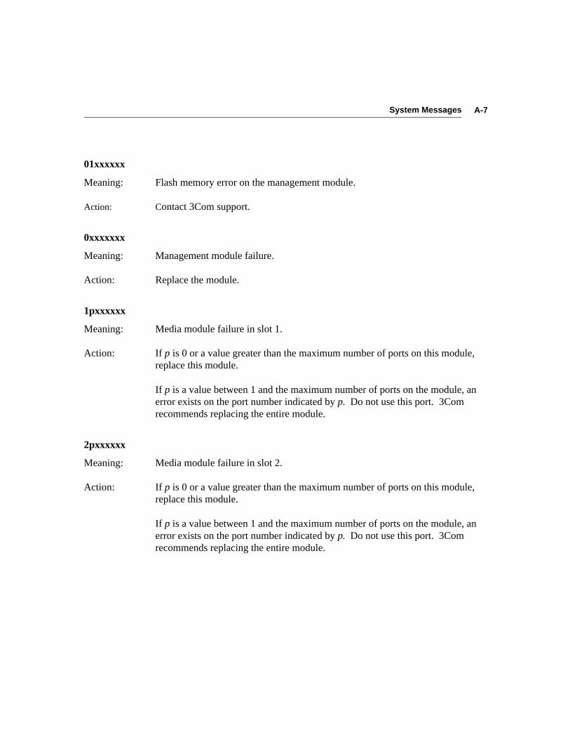
A-7System Messages
01xxxxxx
Meaning: Flash memory error on the management module.
Action: Contact 3Com support.
0xxxxxxx
Meaning: Management module failure.
Action: Replace the module.
1pxxxxxx
Meaning: Media module failure in slot 1.
Action: If p is 0 or a value greater than the maximum number of ports on this module,replace this module.
If p is a value between 1 and the maximum number of ports on the module, anerror exists on the port number indicated by p. Do not use this port. 3Comrecommends replacing the entire module.
2pxxxxxx
Meaning: Media module failure in slot 2.
Action: If p is 0 or a value greater than the maximum number of ports on this module,replace this module.
If p is a value between 1 and the maximum number of ports on the module, anerror exists on the port number indicated by p. Do not use this port. 3Comrecommends replacing the entire module.
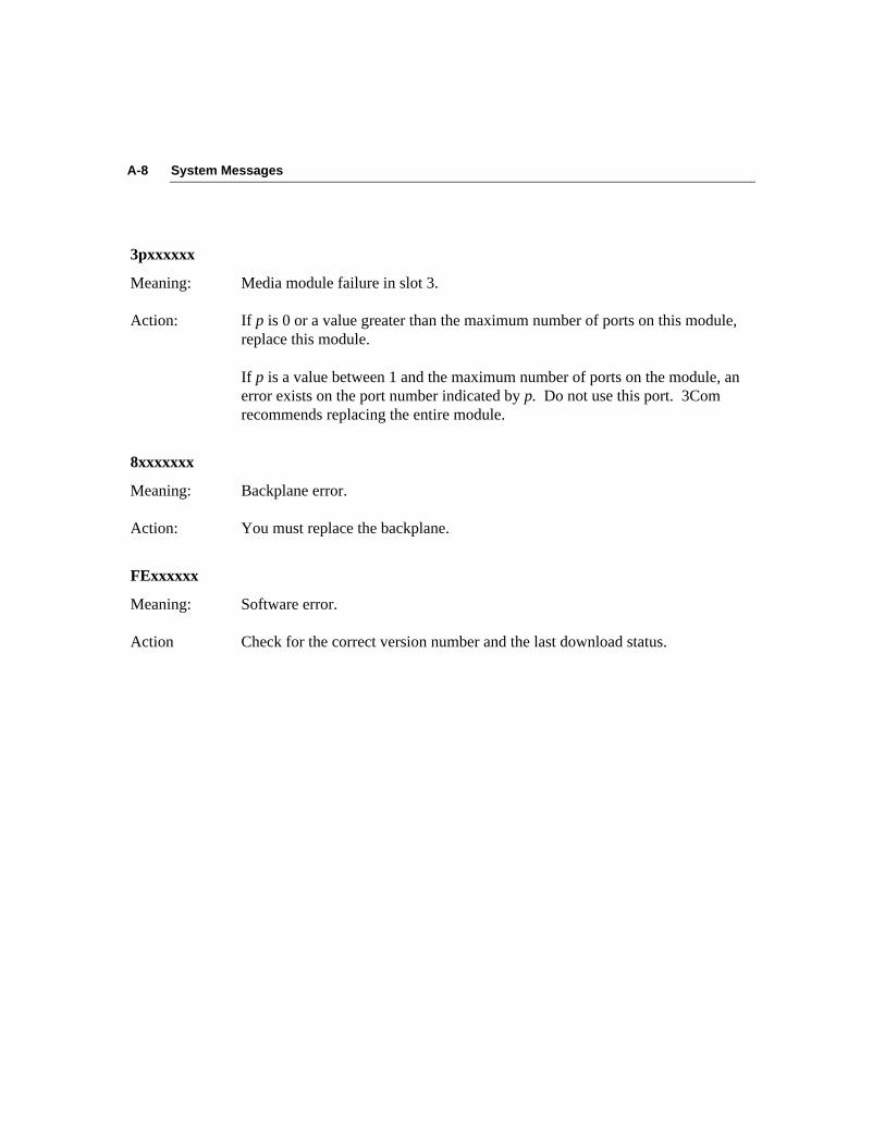
A-8 System Messages
3pxxxxxx
Meaning: Media module failure in slot 3.
Action: If p is 0 or a value greater than the maximum number of ports on this module,replace this module.
If p is a value between 1 and the maximum number of ports on the module, anerror exists on the port number indicated by p. Do not use this port. 3Comrecommends replacing the entire module.
8xxxxxxx
Meaning: Backplane error.
Action: You must replace the backplane.
FExxxxxx
Meaning: Software error.
Action Check for the correct version number and the last download status.

B-1Technical Specifications
Appendix BTechnical Specifications
This appendix provides the physical, electrical, and environmental specificationsfor the LinkBuilder FDDI Workgroup Hub.
Physical CharacteristicsWidth 16.8 in (42.6 cm)Depth 11.6 in (29.4 cm)Height 5.2 in (13.3 cm)Weight (empty) 15 lb 2 oz (6.86 kg)Weight (fully loaded) 19 lb (8.5 kg)
Power RequirementsAC line frequency 100 to 240 Vac, 47 to 63 HzCurrent consumption 3.2 amps (RMS) 115 Vac, 240 watts
Environmental RequirementsStorage temperature 22˚ to 194˚ F (–30˚ to 90˚ C)Operating temperature 32˚ to 122˚ F (0˚ to 50˚ C)Altitude To 10,000 ft (3,050 m)Storage humidity 5-95% noncondensing @ 104˚ F (40˚ C)Operating humidity 5-95% noncondensing @ 104˚ F (40˚ C)
Battery Specifications3V 2450 lithiumApproved manufacturers are Duracell, Sanyo, Renata, and Seiko.

B-2 Technical Specifications
Standards ComplianceFCC approval: FCC/VDE Class B (for LinkBuilder FDDI Management Module,Fiber-Optic Module, and STP [SDDI] Module)
FCC approval: FCC Class A (for LinkBuilder FDDI UTP Module)
If no UTP modules are installed in the hub, the hub complies with the limits of aClass B digital device. If a UTP module is installed in the hub, the entire hubcomplies with the limits of a Class A digital device.

C-1Commands
Appendix CCommands
This appendix describes the commands in the two command sets used tomanage and configure the hub. The two command sets are:
■ Management console commands
■ Primitive console commands
The commands in each set are grouped into categories and arrangedalphabetically within each category.
Management Console CommandsThe management console command set contains three categories of commands:
■ Set commands
■ Display commands
■ Diagnostic and connectivity commands
Set Commands
set attachSyntaxset attach
DescriptionThe set attach command allows you to set the configuration of the two leftmostports on the module in slot 1.
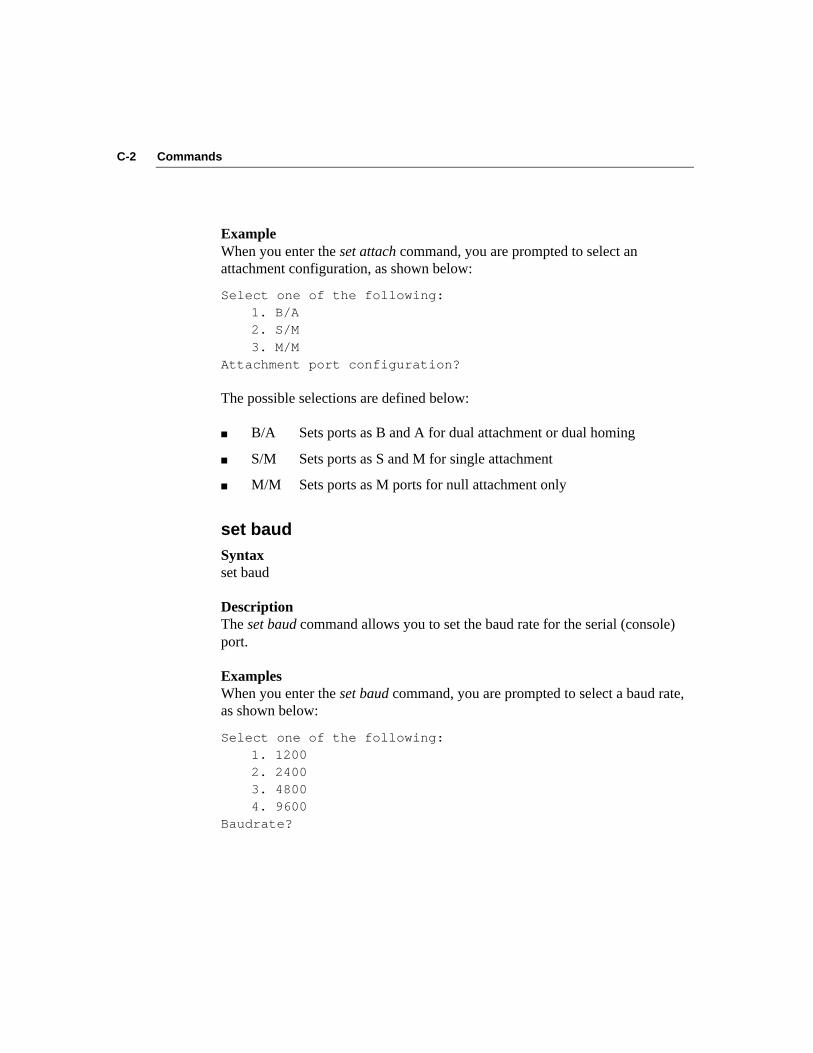
C-2 Commands
ExampleWhen you enter the set attach command, you are prompted to select anattachment configuration, as shown below:
Select one of the following:1. B/A2. S/M
3. M/MAttachment port configuration?
The possible selections are defined below:
■ B/A Sets ports as B and A for dual attachment or dual homing
■ S/M Sets ports as S and M for single attachment
■ M/M Sets ports as M ports for null attachment only
set baudSyntaxset baud
DescriptionThe set baud command allows you to set the baud rate for the serial (console)port.
ExamplesWhen you enter the set baud command, you are prompted to select a baud rate,as shown below:
Select one of the following:1. 12002. 24003. 48004. 9600
Baudrate?

C-3Commands
You can also enter the baud rate on the same line with the set baud command, asshown below:
set baud 4800 [Enter]
set bootSyntaxset boot [method | filename | server]
Simplified Syntaxset boot methodset boot filenameset boot server
DescriptionThe set boot method command allows you to select the method to use whendownloading an image to the flash EPROM. The available options are:
LOCAL Loads and runs the flash EPROM code (default)TFTP Uses TFTP and local configuration parameters to load a new
image over the network
The set boot filename command allows you to set the filename of the softwareimage to be loaded when using TFTP.
The set boot server command allows you to set the IP address of the boot server.
ExamplesAn example of each option is shown below:
■ When you enter the set boot method command, you are prompted to selectthe server location of the information to be downloaded, as shown below:
Select one of the following:1. LOCAL
2. TFTPBoot Method?
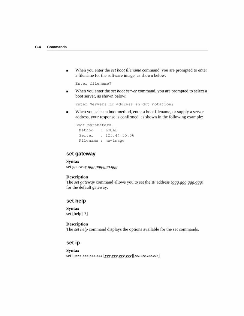
C-4 Commands
■ When you enter the set boot filename command, you are prompted to entera filename for the software image, as shown below:
Enter filename?
■ When you enter the set boot server command, you are prompted to select aboot server, as shown below:
Enter Servers IP address in dot notation?
■ When you select a boot method, enter a boot filename, or supply a serveraddress, your response is confirmed, as shown in the following example:
Boot parametersMethod : LOCAL
Server : 123.44.55.66Filename : newimage
set gatewaySyntaxset gateway ggg.ggg.ggg.ggg
DescriptionThe set gateway command allows you to set the IP address (ggg.ggg.ggg.ggg)for the default gateway.
set helpSyntaxset [help | ?]
DescriptionThe set help command displays the options available for the set commands.
set ipSyntaxset ipxxx.xxx.xxx.xxx [yyy.yyy.yyy.yyy][zzz.zzz.zzz.zzz]
C-5Commands
DescriptionThe set ip command allows you to set the IP address, netmask, and broadcastaddress for IP services.
set lerSyntaxset ler [alarm | cutoff]
Simplified Syntaxset ler alarmset ler cutoff
DescriptionThe set ler alarm command sets the link error rate (LER) alarm threshold(fddiPORTLer-Alarm).
The set ler cutoff command sets the link error rate (LER) cutoff threshold(fddiPORTLer-Cutoff).
ExampleWhen you enter either command, you are prompted for the module number andthe port number.
Module?Port?
The current settings of the LER alarm and LER cutoff are then displayed:
Current LER Alarm exponent = 7
Current LER Cutoff exponent = 6
You are then prompted to enter a value for either the LER alarm or the LERcutoff.
NOTE: You must always keep the LER_Alarm parameter larger than the valueentered for the LER_Cutoff parameter.

C-6 Commands
set pwdSyntaxset pwd
DescriptionThe set pwd command allows you to set and change the password:
■ You are prompted for the old password.
■ You are then prompted for a new password.
■ You are prompted for the new password again.
Passwords can be one to eight alphanumeric characters and are case sensitive.Null passwords are allowed.
set tnotifySyntaxset tnotify val
DescriptionThe set tnotify command sets T-Notify (fddiSMTT-Notify) to the decimalvalue specified by val. This value is used in the Neighbor Notification protocol.T-Notify must be in the range of 2 to 30 seconds. The default is 30 seconds.
set treqSyntaxset treq val
DescriptionThe set treq command sets the Target Token Rotation Time(fddiMACT-Req) for the MAC on the primary ring. The time is set to thedecimal value specified by val. The default is 165000 microseconds (165milliseconds).
C-7Commands
Show Commands
show attachSyntaxshow attach
DescriptionThe show attach command displays the configuration of the attachment ports(the two leftmost ports) on the module in slot 1.
The configuration is not restricted regardless of the slot 1 module type. If themodule type physically creates an illegal connection, a warning is displayed.The possible attachment port configurations are:
■ B/A B and A for dual attachment or dual homing
■ S/M S and M for single attachment
■ M/M M ports for null attachment only
show baudSyntaxshow baud
DescriptionThe show baud command displays the baud rate for the serial port.
show bootSyntaxshow boot [method | load]
DescriptionThe show boot method command displays the boot parameters (method, imagefilename, and IP address of the boot server). The show boot load commanddisplays the status of the last download.
C-8 Commands
The boot method can be one of the following:
■ LOCAL Runs flash EPROM (default)
■ TFTP Uses the TFTP protocol and local configurationparameters to load a new image across the network
The show boot load command displays the parameters used and the status of thelast download to the flash EPROM.
show cfmSyntaxshow cfm
DescriptionThe show cfm command displays the Configuration Management (CFM) state(fddiSMTCF-State) of the dual ring inside the hub.
ValuesCFM states are listed below:
■ Wrap_A
■ Wrap_B
■ Wrap_S
■ C_Wrap_A
■ C_Wrap_B
■ C_Wrap_S
■ Isolated
■ Thru
C-9Commands
show fstatsSyntaxshow fstats
DescriptionThe show fstats command displays the following raw frame statistics forthe hub’s MAC:
■ Total transmit frames
■ Total received frames
■ Total transmit SMT frames
■ Total received SMT frames
■ Total transmit LLC frames
■ Total received LLC frames
■ Total received short frames
■ Total received invalid frames
■ Total aborts
■ Received resets
■ Directed beacon entered
■ Directed beacons sent
show gatewaySyntaxshow gateway
DescriptionThe show gateway command displays the IP address of the default gateway.

C-10 Commands
show helpSyntaxshow [help | ?]
DescriptionThe show help or show ? command displays the options available for the showcommands.
show ipSyntaxshow ip
DescriptionThe show ip command displays the current IP address, IP netmask, and theInternet broadcast address.
show logSyntaxshow log [last]
DescriptionThe show log command displays the contents of the fault log.
The show log last command displays the fault log entries in reverse order.
show mib countersSyntaxshow mib counters
DescriptionThe show mib counters command displays the number of the entities counted bythe fddiMAC-CounterGrp, as shown below:

C-11Commands
■ Total number of frames received (fddiMACFrame-Ct)
■ Number of frames copied (fddiMACCopied-Ct)
■ Number of frames transmitted (fddiMACTransmit-Ct)
■ Number of tokens (fddiMACToken-Ct)
■ Number of error frames (fddiMACError-Ct)
■ Number of frames with format errors (fddiMACLost-Ct)
■ Number of frames not copied (fddiMACNotCopied-Ct)
■ Number of ring recoveries (fddiMACRingOp-Ct)
show neighSyntaxshow neigh
DescriptionThe show neigh command displays the 48-bit address of the upstream(fddiMACUpstreamNbr) and downstream (fddiMACDownstreamNbr) neighborstations in noncanonical format.
show obsSyntaxshow obs
DescriptionThe show obs command displays the presence or absence of an optical bypassswitch.
ValuesNOT PRESENT No bypass switch exists on the hub.
PRESENT A bypass switch is connected to the hub.
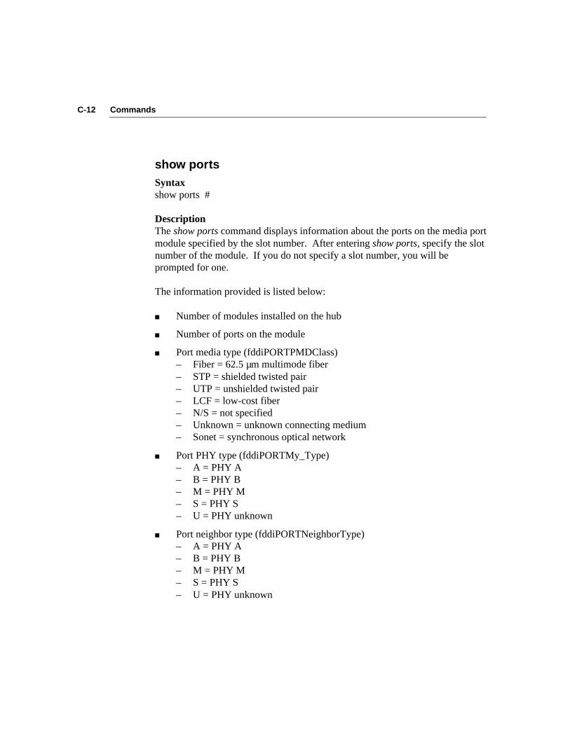
C-12 Commands
show portsSyntaxshow ports #
DescriptionThe show ports command displays information about the ports on the media portmodule specified by the slot number. After entering show ports, specify the slotnumber of the module. If you do not specify a slot number, you will beprompted for one.
The information provided is listed below:
■ Number of modules installed on the hub
■ Number of ports on the module
■ Port media type (fddiPORTPMDClass)– Fiber = 62.5 µm multimode fiber– STP = shielded twisted pair– UTP = unshielded twisted pair– LCF = low-cost fiber– N/S = not specified– Unknown = unknown connecting medium– Sonet = synchronous optical network
■ Port PHY type (fddiPORTMy_Type)– A = PHY A– B = PHY B– M = PHY M– S = PHY S– U = PHY unknown
■ Port neighbor type (fddiPORTNeighborType)– A = PHY A– B = PHY B– M = PHY M– S = PHY S– U = PHY unknown

C-13Commands
■ Port PCM state (fddiPORTPCMState)– Active– Break– Connect– Join– Next– Off– Signal– Trace– Verify– Maintenance (abbreviated as “Maint”)
■ Port status (fddiPORTConnectState)– Active– Connecting (abbreviated as “Connect”)– Disabled (abbreviated as “Disable”)– Standby
■ LER Alarm
■ LER Cutoff
■ LER Estimate
■ LER Rejects
■ LER Count
show revSyntaxshow rev
DescriptionThe show rev command displays the version number and the release date of theEPROM (firmware) and software.
C-14 Commands
show ringSyntaxshow ring
DescriptionThe show ring command displays the Ring Management (RMT) state(fddiMACRMTState) for the MAC on the primary ring.
The possible RMT states are listed below:
■ Isolated
■ Non_Op
■ Ring_Op
■ Detect
■ Non_Op_Dup
■ Ring_Op_Dup
■ Directed
■ Trace
show sidSyntaxshow sid
DescriptionThe show sid command displays the 64-bit FDDI station identifier(fddiSMTStationId), the 48-bit MAC address (fddiMACSMTAddress), and the48-bit LLC address.
show tmaxSyntaxshow tmax
C-15Commands
DescriptionThe show tmax command displays the value of T-Max (fddiMACT-Max), themaximum length of time allowed for the token to move around the ring.
show tnegSyntaxshow tneg
DescriptionThe show tneg command displays the current value of T-Neg (fddiMACT-Neg),the ring’s operational Target Token Rotation Time.
show tnotifySyntaxshow tnotify
DescriptionThe show tnotify command displays the value of T-Notify (fddiSMTT-Notify)for the hub, which determines how frequently Neighbor Information Frames(NIFs) are broadcast to the ring.
show treqSyntaxshow treq
DescriptionThe show treq command displays the value of T-Req (fddiMACT-Req), whichis the requested Target Token Rotation Time for the MAC on the primary ring.
show tvxSyntaxshow tvx
C-16 Commands
Description
The show tvx command displays the value of the Valid Transmission Timer(fddiMACTvxValue), which is the maximum time allowed by the MAC on theprimary ring for the receipt of valid frames or tokens.
Diagnostic and Connectivity Commands
arpSyntaxarp [dump | del | set]
Simplified Syntaxarp dumparp del host_addressarp set host_address hardware_address
DescriptionThe arp command displays information contained in the Address ResolutionProtocol (ARP) table. It also allows you to change information stored in theARP table.
■ arp dump Displays the current contents of the ARP table
■ arp del Deletes the IP host address
■ arp set Adds the host IP address and the host 48-bit FDDI address innoncanonical format to the ARP table
clearSyntaxclear [log | alarm]
DescriptionThe clear log command clears the fault log, which contains a limited history ofrecent faults that have occurred in the system.

C-17Commands
The clear alarm command clears the (HIGH TEMP SEEN) alarm that appearson the console when the condition existed previously but is no longer present.
connectSyntaxconnect
DescriptionThe connect command connects the hub to the FDDI ring.
disconnectSyntaxdiscon | disconnect
DescriptionThe disconnect command disconnects the hub from the FDDI ring. It alsoremoves all ports from the ring.
helpSyntaxhelp | ?
DescriptionThe help or ? command displays a list of commands with brief commanddescriptions.
logoutSyntaxlogout
DescriptionThe logout command logs the user out of a console session. In addition toclosing a console session, it also closes a Telnet session if access to the consolehas been through Telnet.

C-18 Commands
pingSyntaxping host_address [size] [cnt]
Simplified Syntaxping host_address The host address in Internet dot notation.
ping host_address size (Optional). Specifies the number of databytes (defaults to 56 bytes).
ping host_address cnt (Optional). Specifies the number of echoframes to be sent. (The default is one [1].)
DescriptionThe ping command sends echo frames, composed of random data bits, to a hostto test the IP stack.
resetSyntaxreset
DescriptionThe reset function reinitializes the hub and performs the power-on self-tests(POST).
Before the reset begins, you are asked this question:
Are you sure [y/n]?
You can enter the reset command on the command line or press the RESETbutton that is recessed on the management module.
routeSyntaxroute [add | delete] destination gateway [metric]route dump
C-19Commands
Simplified Syntaxroute add destinationroute add destination gatewayroute add destination gateway metricroute delete destinationroute delete destination gatewayroute delete destination gateway metricroute dump
DescriptionThe route command adds or deletes a path to a particular device or hub, where:
■ destination is the destination IP address.
■ gateway is the gateway IP address.
■ metric is the number of hops (number of gatewaysseparating the source and destination) to thenetwork. (Optional)
The route dump command displays the current IP addresses of the destinationand gateway.
Primitive Console CommandsThe primitive console command set contains three categories of commands:
■ Set commands■ Display commands■ Miscellaneous commands
NOTE: The primitive console commands are a subset of the managementconsole commands. The command descriptions are therefore abbreviated. Forcomplete command descriptions, refer to the section “Management ConsoleCommands” earlier in this appendix.

C-20 Commands
Set Commands
set attachSets the configuration of the first two ports of the module in slot 1.
set baudSets the console (serial) port baud rate.
set bootSets the boot method, filename of the software image, or server IP address.
set defaultsSets the factory defaults.
set gatewaySets the IP address for the default gateway.
set help | ?Lists the set commands and gives information about them.
set ipSets the IP address, IP netmask, and the Internet broadcast address.
set pwdSets the new password. In primitive command mode, you will not be promptedfor your old password.
set tnotifySets the T-Notify value used in the Neighbor Notification protocol.
C-21Commands
set treqSets the Target Token Rotation Time (T-Req).
Display Commands
show attachDisplays the configuration of the attachment ports on the module in slot 1 of thehub.
show baudDisplays the baud rate setting for the serial port.
show bootDisplays the boot method, filename of the software image, and boot server IPaddress.
show gatewayDisplays the default gateway address.
show help | ?Lists the show commands and gives information about them.
show ipDisplays the current IP address, netmask, and broadcast address.
show logDisplays the contents of the fault log.
C-22 Commands
show obsDetects the presence or absence of an optical bypass switch.
show revDisplays the revision number of the EPROM and software.
show sidDisplays the 64-bit station ID and the 48-bit MAC address.
show tnotifyDisplays the value of T-Notify.
show treqDisplays the value of T-Req.
show tvxDisplays the value of TVX.
Miscellaneous Commands
clearClears the fault log.
help | ?Lists the miscellaneous commands and gives information about them.
resetReinitializes the hub and runs the power-on self-tests (POST).

D-1Technical Support
Appendix DTechnical Support
This appendix explains how to obtain worldwide support for 3Com products.
On-line Product Support3Com offers worldwide product support 24 hours a day, seven days a week,through automated on-line systems.
CardBoardSM Bulletin Board ServiceCardBoard is 3Com’s menu-driven bulletin board service. It contains the mostcurrent adapter information in downloadable files. CardBoard provides:
■ Software drivers
■ Technical tips
■ Product information
■ Diagnostic programs
■ Software patches and fixes
These files are easy to access through a modem connection. Call the CardBoardtelephone number nearest you:
Australia (61) (2) 955 2073Up to 2400 baud, 8 data bits, no parity, 1 stop bit
France (33) (1) 69 86 69 54Up to 9600 baud, 8 data bits, no parity, 1 stop bit
Germany (49) 89 62732-188/189Up to 9600 baud, 8 data bits, no parity, 1 stop bit
Italy (39) (2) 27 30 06 80Up to 9600 baud, 8 data bits, no parity, 1 stop bit
D-2 Technical Support
U.K. (44) 442 278278Up to 14400 baud, 8 data bits, no parity, 1 stop bit
U.S. (1) (408) 980-8204Up to 19200 baud, 8 data bits, no parity, 1 stop bit
For information on international CardBoard access numbers added since thismanual was published, contact your local 3Com office. Refer to the list ofinternational sales offices later in this appendix.
Automated Fax Service3Com’s interactive fax service provides data sheets, technical articles, diagrams,and troubleshooting instructions on 3Com products 24 hours a day, seven days aweek. To access this service, dial (1) (408) 727-7021 from anywhere in theworld using your touch-tone telephone.
Within this service you may choose to access CardFactsSM (containing adapterinformation) or 3ComFactsSM (containing network system product information).
■ CardFacts provides adapter installation diagrams, configuration drawings,troubleshooting instructions, and technical articles. Document 9999provides you with an index of adapter documents.
■ 3ComFactsSM provides data sheets and technical articles on 3Com’s hub,bridge, router, terminal server, and software products. Document 8888provides you with an index of system product documents.
Ask3ComSM On-line ServiceAsk3Com is an on-line service, located on CompuServeSM. This service isaccessible worldwide. Ask3Com contains extensive technical and marketinginformation on all 3Com products. To use Ask3Com, you must first obtain aCompuServe account. To open an account, contact yourlocal CompuServe office.
To use Ask3Com, log into CompuServe, type:
GO THREECOM
and press [Enter] to see the Ask3Com main menu.

D-3Technical Support
3Com Documentation on CD-ROMAn extensive library of 3Com product documentation is available in CD-ROMformat through Support on Site for Networks subscription service. Thismultivendor CD-ROM service, offered by Computer Library, a division of ZiffCommunication, contains technical information and documentation from majordata networking hardware and software manufacturers. Stand-alone andconcurrent user network subscriptions are available. To order, call ComputerLibrary at (800) 827-7889, extension 515. Outside the U.S. call (212) 503-4400or use fax number (212) 503-4487.
Support from Your Network SupplierIf additional assistance is required, contact your network supplier. Manysuppliers are authorized 3Com service partners who are qualified to provide avariety of services, including network planning, installation, hardwaremaintenance, application training, and support services.
U.S. and CanadaCall the following number to locate your local 3Com sales office:
U.S. (1) (800) NET-3Com
The 3Com sales office will refer you to the nearest 3Com authorized servicepartner.
Outside the U.S. and CanadaTo locate a 3Com authorized service partner near you, contact your local 3Comsales office.
Australia (61) 2 959 3020Belgium/Netherlands (31) 25 032 2120France (33) 1 698 66800Germany (49) 89 678210Hong Kong (852) 868 9111Italy (39) 22 7302041Japan (81) 3 546 62233

D-4 Technical Support
Nordic (46) 8 703 4870Singapore (65) 321 8929Taiwan (886) 2 775 4352U.K. (44) 628 890 670
When you contact a 3Com authorized service partner for assistance, have thefollowing information ready:
■ Diagnostic error messages
■ A list of system hardware and software, including revision levels
■ Detail on recent configuration changes, if applicable
3Com’s service partner will determine what action needs to be taken to resolvethe problem. 3Com service partners can verify hardware failures and advise youwhen it is more cost-effective to replace, rather than repair, a product.
D-5Technical Support
Returning Products for RepairA product sent directly to 3Com for repair must first be assigned a ReturnMaterials Authorization number (RMA). A product sent to 3Com without anRMA number will be returned to the sender unopened, at the sender’s expense.
When you call for an RMA number, be prepared to provide the product name,serial number, and diagnostic error messages. Payment, shipping instructions,and turnaround time will be confirmed when the RMA number is assigned.
To obtain an RMA number, call or fax:
Europe Phone (44) (0) 442 231000Fax (44) (0) 442 236824
U.S. Phone (800) 876-3266, press option 2Fax (408) 764-7290
NOTE: RMA forms (except Europe) are available on CardFacts.Dial (408) 727-7021.
Outside Europe and the U.S.Phone (408) 492-1790Fax (408) 764-7290
1Glossary
Glossary
Attachment The capability of a station or concentrator (or FDDI hub) forconnection into an FDDI network. Stations and concentratorsare classified as dual attachment, single attachment, or nullattachment.
Beacon A special type of frame transmitted when a station detects alogical problem on the ring. It is automatically transmittedduring the ring initialization sequence when the claim tokenprocess does not finish in the time allotted for it. The beaconprocess can indicate either a station hardware or softwarefailure.
Broadcast A packet delivery system that delivers a copy of a given packetto all hosts that attach to it.
Bypass The ability of a node to optically isolate itself from the FDDInetwork while maintaining the continuity of the cable plant.See also Optical bypass.
Canonical order The agreed upon bit order of transmission. Canonicaladdressing is when the least significant bit of the mostsignificant byte is always transmitted first. The FDDI hub’sLLC (logical link control) address appears in canonical orderwhen the show sid command is issued.
CDDI Copper Distributed Data Interface. FDDI over twisted-paircopper wire.
2 Glossary
Concentrator A sophisticated multiplexer or hub device that has additionalports beyond those required for its own attachment to the mainring of an FDDI network. These additional ports are forattaching other FDDI nodes (including single attachmentstations [SASs] and other concentrators) in a tree topology.Concentrators may be stand-alone (null attachment) and notconnected to the main ring; they may support only theinterconnection of a few SASs.
DAC Dual Attachment Concentrator. A concentrator with A and Bports for attachment to both the primary and secondary rings.
DAS Dual Attachment Station. A station with A and B ports forattachment to the primary ring only.
Dotted decimal notation The syntactic representation for a 32-bit integer that consists offour 8-bit numbers written in base 10 with periods (dots)separating them.
Downstream The normal direction of data flow on a token ring network.Also, the adjacent station in the transmission (ring) path.
Dual counter-rotating ring A dual-ring LAN topology in which two separate fiber orcopper cables provide signal paths on which informationtravels in opposite directions. The second ring provides abackup for the first ring in the event of failure of the first(primary) ring.
Dual ring A pair of counter-rotating logical rings.
Dual homing An FDDI redundant topology. This refers to one of twosituations: in the first, a dual-MAC station is connected to (ishomed on) both rings at the same time. The second situationinvolves redundant attachments of a dual-attached station orconcentrator to the ring(s), with one attachment functioning asa backup link.

3Glossary
Dual ring of trees One of the FDDI-supported topologies in which only one ringis permitted to have multiple trees of any depth (consisting ofsingle-attached concentrators and stations), which are cascadedoff the main ring.
FDDI Fiber Distributed Data Interface. The local area networkingstandard that provides high bandwidth for interconnectingcomputers and peripheral devices using a fiber-optic mediumin a ring configuration.
The FDDI specification is made up of standards thatcorrespond to the IEEE OSI model layers (on the physical anddata link levels). These standards specify the physicalinterfaces, functions, and operations needed to supportinteroperability between devices.
Fiber-optic cable A fiber-optic cable consists of a glass center, cladding, a bufferlayer, strength members, and a cable sheath. The glass centersupports the transmission of light signals.
Gateway A special-purpose, dedicated computer that attaches to two ormore networks and routes packets from one to another.
IP Internet protocol, which defines the Internet datagram as theunit of information passed across the Internet and provides thebasis for the Internet connectionless, best-effort packetdelivery service.
ISO International Standards Organization. The internationalagency that develops information-exchange standardsimplementation.
Logical ring A set of MACs serially connected to form a single ring. Afault-free FDDI network provides two logical rings.
4 Glossary
MAC Media Access Control. MAC, the OSI access layer, specifiesthe access mechanism used by FDDI nodes for transmittingand receiving data on the ring. The MAC is responsible forreceiving frames and transmitting frames according to the rulesof a timed token rotation protocol, a dynamic protocol uniqueto FDDI.
MIB Management Information Base. A set of FDDI-managedobjects. The MIB defines the data that a network manager canexpect to get about a managed device. It defines the accesspermissions for each data item, and the size, type, andsemantics of each data item.
MIC Media Interface Connector. A mated connector pair thatprovides an attachment between an FDDI node and a fiber-optic cable. MIC connectors are normally keyed, both toprevent accidental reversal of transmit and receive fibers andto ensure connection only to ports of the correct type.
Noncanonical order The agreed upon bit order of transmission. Noncanonicaladdressing is when the most significant bit of the mostsignificant byte is transmitted first. The FDDI hub’s MAC/SMT address appears in noncanonical order when the show sidcommand is issued.
Null attachment A concentrator that can be considered a self-containedconcentrator FDDI network but is not connected to a dual ring backbone. It
does not contain an A, B, or S port.
Optical bypass An optional facility that allows the FDDI optical signal tobypass FDDI nodes when they are powered off.
Peer-mode connection A connection between peer ports (A, B, and S ports).
5Glossary
PHY Physical Layer Protocol. The sublayer that describes themedium-independent portion of the OSI Physical layer andspecifies the rules for encoding digital data for transmissionfrom one FDDI station to another. It also provides the linkbetween the PMD and the MAC layer.
Ping Packet InterNet Groper. A program used in the Internet to findout whether or not a host on the network is operational bysending it echo frames and waiting to receive the same numberof frames in return.
PMD Physical Layer Medium Dependent. The sublayer in the FDDIarchitecture that specifies the optical fiber hardwarecomponents that create the physical link between two adjacentFDDI stations.
Port A point of access where a physical connection is madebetween a device and cabling to another device, network, etc.The FDDI standard defines four port types: A, B, M, and S.
Port type A (Primary IN/Secondary OUT) allows attachmentto the incoming primary ring and to the outgoing secondaryring.
Port type B (Secondary IN/Primary OUT) allows attachment tothe outgoing primary ring and to the incoming secondary ring.
Port type M (Master) allows attachment between aconcentrator and a single-attach station. Uses the primary ringonly. See SAS.
Port type S (Slave) allows attachment between an SAS or SACand a concentrator. Uses the primary ring only.
6 Glossary
Primary path The segment(s) of the primary ring that pass through a station.Conditions may exist in parts of the network that may causethe path to be in a different ring (that is, secondary instead ofprimary).
Primary ring In the dual counter-rotating token ring architecture, the ringthat carries data traffic.
Ring A set of stations through which information is passedsequentially between stations, each station in turn examiningor copying the information, until the information is returned tothe originating station.
Ring wrap The ring reconfiguration that takes place when a break occursin the primary ring and the dual attached hubs and stations oneither side of the fault detect and automatically bypass it.
SAC Single Attachment Concentrator. A concentrator that connectsa single ring only (usually the primary ring) to the FDDInetwork.
SAS Single Attachment Station. A station that offers a singleattachment to the FDDI network. The connection is to onering only (usually the primary ring), and that attachment ismade through a concentrator; there is no direct attachment tothe trunk ring.
SDDI Shielded [Twisted-Pair] Distributed Data Interface. FDDIover shielded twisted-pair per the SDDI de facto STP standard.
Secondary ring In the dual counter-rotating token ring architecture, the ringthat is generally used for automatic recovery in the event of abreak in the primary ring.
SMT Station Management. The function within an FDDI noderesponsible for managing, maintaining, and controlling all thelocal and remote station functions.
7Glossary
Station An addressable node on an FDDI network capable oftransmitting, repeating, and receiving information. A stationhas exactly one SMT, at least one MAC, at least one PHY, andat least one PMD.
STP Shielded Twisted-Pair. Shielded four-conductor electricalcable that can be used as the communication medium on anFDDI ring in place of optical fiber.
Telnet The Internet standard protocol for remote terminal connectionservice. Telnet lets a user interact with a remote time-sharingsystem at another site as though the user’s terminal connecteddirectly to the hub or concentrator.
TFTP Trivial File Transfer Protocol. A simplified version of the FileTransfer Protocol (FTP) used to transfer files.
Thru state The condition in which both rings are fully functional.
Token The special frame that passes from station to station on anFDDI ring any time the ring can carry data. The token iscaptured by a station that is ready to transmit data, and isreleased back to the ring at the end of the allotted transmissiontime. During token-capture time, only the station possessingthe token can transmit data.
Tree A physical topology consisting of a hierarchy of master-slaveconnections between a concentrator and other FDDI nodes(including subordinate concentrators).
Tree-mode connection A connection between tree ports (M ports).
Trunk A physical loop topology, either open or closed, employingtwo optical fiber signal paths, one in each direction, forming asequence of peer connections between FDDI nodes.

8 Glossary
Upstream The direction on a token ring network that is contrary to thenormal direction of data flow (that is, downstream).
UTP Unshielded Twisted-Pair. A cable consisting of two twisted-pair conductors that are not insulated.
Wrap A ring recovery condition that is automatically activated whena downstream station detects a fault in the primary ring, andthe stations on either side of the fault connect the two rings tocreate a single ring. When this occurs, the primary andsecondary rings have been concatenated.

1Index
Index
? command, C-17, C-223Com sales offices, D-33ComFacts, D-2
AA port, 2-23accessing the hub, 2-16
via a modem, 2-16, 2-18via a PC with terminal emulation, 2-16via a terminal, 2-16via Telnet, 2-16, 2-19
accessing the primitive console commandmode, 3-9
Address Resolution Protocol (ARP), 5-20addresses
broadcast, 4-4default gateway, 4-4IP, 4-3netmask, 4-4
American National Standards Institute(ANSI), 1-3
ANSI protocols, 1-3Media Access Control, 1-5Physical, 1-5Physical Medium Dependent, 1-4Station Management, 1-6
ANSI standard UTP cabling distances, 2-22arp command, 5-20, C-16Ask3Com, D-2
ATTACH LED, 3-16, 5-12attachment options, 3-1
dual attachment, 3-2dual homing attachment, 3-6null attachment, 3-5single attachment, 3-4
attachment ports, 4-6configuring, 3-11, 3-12, 4-6displaying configuration of, 5-1
BB port, 2-23battery
installation, 2-7specifications, B-1
baud rate, changing, 2-16blanking plates, 2-15boot methods, 4-15broadcast address, 4-4bulletin board information system
(CardBoard), D-1
Ccabling
fiber-optic, 1-4, 2-20shielded twisted-pair, 1-4, 2-20unshielded twisted-pair, 1-5, 2-21
cabling rules, 2-20CardBoard, D-1

Index2
C (continued)CardFacts, D-2cascade connector, 2-11, 3-18CFM, 5-13clear alarm command, 5-15, C-17clear command, C-16, C-22clear log command, 5-21, C-16commands. See under individual command
names.Computer Library, D-3configuration
attachment ports, 3-11, 3-12, 4-6hub, 3-1, 3-7modules, 3-15
configuration commands, 3-8Configuration Management (CFM), 5-13connect command, 5-22, C-17Connect State, 5-9connecting to the dual ring, 2-24console command modes, 2-16, 3-8
Ddangerous environmental conditions, 5-14data flow direction, 2-23DB-9 STP connector pin assignments, 2-21default configuration, 3-7default gateway address, 4-4disconnect (discon) command, 5-15, 5-22,
C-17distribution rack, 2-2documentation on CD-ROM, D-3download messages, A-4download status, 4-14downloading from TFTP, 4-12downloading software images, 4-12dual attachment hub (DAC), 3-2dual homing (DH), 3-6dual ring connections, 2-24dust plug, 1-13
Eelectrical specifications, B-1environmental specifications, B-1error messages, A-1
Ffactory default configuration, 3-7FAN FAIL LED, 5-12, 5-14fault log, 5-21fault log error code messages, A-6fax service (3ComFacts), D-2FCC standards compliance, B-2FDDI
benefits, 1-7cabling rules, 2-20connection rules, 3-12self-paced study course, 1-2standard attachment options, 3-1technology, 1-2
FDDI ringconnecting to, 2-24data flow specifications, 2-23setup examples, 1-9
fiber media port module, 1-12keys for, 2-6, 2-9
fiber-optic cabling rules, 2-20flash EPROM, 1-7, 4-12frame statistics, 5-1
Ggateway address, 4-4
Hhelp command, C-17, C-22HI TEMP LED, 5-12, 5-14how to
access hub commands, 3-8access the hub, 2-16attach an optional modem, 2-18attach devices to the hub, 2-23attach the hub to the ring, 2-24

3Index
H (continued)change the baud rate, 2-16clear the fault log, 5-21configure attachment ports, 3-11, 4-6configure modules, 3-15connect a terminal to the hub, 2-16detect the presence of dangerous
conditions, 5-14disconnect from the ring, 5-22display port information, 5-5display status of last download, 4-14download new images, 4-12enter primitive console command
mode, 3-9find the location of a wrap, 5-13insert and replace the battery, 2-7insert fiber module keys, 2-10install an optical bypass switch, 2-26install modules, 2-12install the STP cascade connector, 2-11interpret download messages, A-4interpret fault log error messages, A-6interpret LER parameters, 4-8interpret system error messages, A-1interpret the LEDs, 5-11monitor module functions, 5-16plan FDDI ring configurations, 3-1plan port connections, 2-19, 3-11rack-mount the hub, 2-2remove modules, 2-14reset the hub, 5-15select proper cabling, 2-20set IP addresses, 4-3set the password, 4-5understand fault log error codes, A-6unpack the hub, 2-1use station management parameters,
(SMT), 4-7use Telnet to access the hub, 2-19use the reset function, 5-15
hubaccessing, 2-16attachment options, 3-1configuring, 3-1connecting to the ring, 2-24connecting to a terminal, 2-16default configuration, 3-7disconnecting from the ring, 5-22displaying IP addresses, 5-3features and functions, 1-6information, 5-1 to 5-11installing modules, 4, 2-12package contents, 2, 2-5rack mounting, 2-2resetting, 5-15setting the password, 4-5site selection, 1-8station management parameters, 4-7unpacking, 2, 2-1
hub commands, 4-1help descriptions, 4-2
hub modulesfiber, 1-12management, 1-11media, 1-12STP, 1-14UTP, 1-14
Iimage, downloading, 4-12installation
battery, 2-7cascade connector, 3-18fiber port keys, 2-10hub, 2-5image, 4-12modem, 2-18modules, 4, 2-12optical bypass switch, 2-26
IP address, 4-3, 5-3

Index4
Kkeys, fiber port module, 2-9
LLEDs, 5-11
ATTACH, 3-16, 5-12FAN FAIL, 5-12, 5-14HI TEMP, 5-12, 5-14Link Error, 5-17LOW BATT, 5-12, 5-14management module, 5-11media modules, 5-16Port State, 5-17PWR, 5-12Signal Detect, 5-17STATUS, 5-12TOKEN, 5-12, 5-22WRAP, 5-12, 5-13
LEM Count, 5-10LEM Rejects, 5-10LER alarm, 4-8, 5-9LER cutoff, 4-10, 5-9LER Estimate, 5-9Link Error LED, 5-17Link Error Monitor (LEM), 4-8Link Error Rate (LER), 4-8, 5-9LinkBuilder FDDI Workgroup Hub. See hub.lithium battery, 2-5
installation, 2-7logout command, 5-22, C-17LOW BATT LED, 5-12, 5-14
MM port, 2-23MAC
frame statistics, 5-1functions, 1-5Media Access Control protocol, 1-5
management console commands, 3-8, C-1
management modulebattery, 2-5functions, 1-11installing, 4, 2-12LEDs, 5-12removing, 2-14RESET button, 1-11, 5-15
Maximum Token Rotation Time (T-Max),4-11
media modulesconfiguring, 3-15fiber, 1-12
keys, 2-9installing, 4, 2-12LEDs, 5-16removing, 2-14STP, 1-14unpacking, 3UTP, 1-14
Media Access Control (MAC) protocol, 1-3metric option, 5-20, C-18MIB counters, 5-3miscellaneous command display, 4-2modem, installing, 2-18
NNegotiated Time (T-Neg), 4-11neighbor, defined, 3-13neighbor station addresses, 5-4Neighbor Notification protocol, 4-7netmask, 4-4null attachment hub (NAC), 3-5
Oon-line technical services, D-1, D-2optical bypass switch (OBS), 2-26
cabling, 2-27

5Index
Ppassword, setting, 4-5PCM
neighbor fields, 5-7state, 5-8
peer-mode connection, 5-13PHY layer
functions, 1-5port types, 5-7protocol, 1-5
physical specifications, B-1Physical Connection Management
(PCM), 5-7states, 5-8
Physical Medium Dependent (PMD)protocol, 1-3
Physical (PHY) layer protocol, 1-3pin assignments
DB-9 STP connector, 2-21RJ-45 UTP connector, 2-22
ping command, 5-18, C-18PMD layer
fiber-optic services, 1-4optical bypass switch, 1-4protocol, 1-4port media types, 5-6STP services, 1-4UTP services, 1-5
portconnections, 2-19, 3-11information display, 5-5media, 5-6types, 2-23, 5-7
Port State LED, 5-17power requirements, B-1power-on insertion, 4, 2-14primitive console command mode, 3-9
accessing, 3-9leaving, 3-11
primitive console commands, 3-9, C-19product information service
(Ask3Com), D-2PWR LED, 5-12
Rreinitializing, 5-16removing modules, 2-14repair, returning products for, D-5reset command, 5-15, C-18, C-22reset function, 5-15
check LEDs, 5-16reinitialize the hub, 5-16
RESET button, 5-15Return Materials Authorization (RMA)
number, D-5ring
connecting to, 6, 2-24disconnecting from, 5-22
ring of trees, 1-10ring wrap, 1-2RJ-45 UTP connector pin
assignments, 2-22RMT primary MAC state, 5-10route command, 5-19, C-18route dump command, 5-20, C-19
SS port, 2-23set attach command, 4-6, C-1, C-20set baud command, C-2, C-20set boot command, C-3, C-20set boot filename command, 4-13, C-4set boot method command, 4-12, C-3set boot server command, 4-13, C-4set commands, 4-2, C-1, C-20set defaults command, C-20set gateway command, 4-4, 4-14, C-4,
C-20set help command, C-4, C-20set ip command, 4-3, C-4, C-20

Index6
S (continued)set ler alarm command, 4-9, C-5set ler cutoff command, 4-10, C-5set pwd command, 4-5, C-6, C-20set tnotify command, C-6, C-20set treq command, C-6, C-21setup. See installation.shielded twisted pair. See STP.show ? command, C-10, C-21show attach command, 5-1, C-7, C-21show baud command, C-7, C-21show boot command, C-7, C-21show boot load command, 4-14, C-7show boot method command, 4-14, C-7show cfm command, 5-13, C-8show commands, 4-2, C-7show fstats command, 5-1, C-9show gateway command, C-9, C-21show help command, C-10, C-21show ip command, 4-3, 5-3, C-10, C-21show log command, 5-21, C-10, C-21show log last command, 5-21, C-10show mib counters command, 5-3, C-10show neigh command, 5-4, C-11show obs command, C-11, C-22show ports command, 5-5, C-12show rev command, C-13, C-22show ring command, 5-10, C-14show sid command, 5-4, C-14, C-22show tmax command, C-14show tneg command, C-15show tnotify command, C-15, C-22show treq command, C-15, C-22show tvx command, C-15, C-22Signal Detect LED, 5-17single attachment hub (SAC), 3-4
SMTfunctions, 1-6maximum token rotation time, 4-11negotiated time, 4-11neighbor notification timer, 4-7target token rotation time, 4-8valid transmission timer, 4-11
software image, downloading, 4-12specifications, B-1station identifier, 5-4station management parameters (SMT), 4-7Station Management (SMT), 1-3
MIB, 1-1remote management, 1-1
STATUS LED, 5-12STP
cabling rules, 2-20media port module, 1-14module cascade connector, 2-11pin assignments, 2-21
subnet mask, 4-4system messages, A-1system software diskette, 2-5
TT-Max, 4-11T-Neg, 4-11T-Notify, 4-7T-Req, 4-8Target Token Rotation Time (TTRT), 4-8technical specifications, B-1technical support services, D-1Telnet protocol, 2-16, 2-19terminal connections, 2-16TFTP download option, 4-12TOKEN LED, 5-12, 5-22tree-mode connection, 5-13TVX, 4-11twisted ring, 3-14

7Index
Uunshielded twisted pair. See UTP.UTP
cabling rules, 2-21media port module, 1-14pin assignments, 2-22
VValid Transmission Timer (TVX), 4-11
WWRAP LED, 5-12, 5-13wrap state, 3-15, 5-13