Chapter 1 Rotating Wall Technique and Centrifugal...
18
July 15, 2015 15:39 World Scientific Review Volume - 9in x 6in ”Anderegg RW les Houches15” page 1 Chapter 1 Rotating Wall Technique and Centrifugal Separation Fran¸ cois Anderegg University of California San Diego, Physics Dept. 0319, La Jolla CA 92093, USA [email protected] This chapter describes the ”rotating wall” technique which enables es- sentially unlimited confinement time of 10 9 to 10 10 charged particles in a Penning trap. The applied rotating wall electric field provides a positive torque that counteract background drags, resulting in radial compres- sion or steady state confinement in near-thermal equilibrium states. The last part of the chapter discuss centrifugal separation of rotating multi-species non-neutral plasma. Separation occurs when the centrifu- gal energy is larger than the mixing due to thermal energy. 1. Basic Physics Idea Let’s consider a non-neutral plasma contained in a Penning-Malmberg trap as shown on figure 1. The trap consist of a series of cylindrical electrodes carefully aligned with the magnetic field B = -B ˆ z. Longitudinal confine- ment is produced by potentials V applied to the end electrodes, and radial confinement is produced by the magnetic field. For simplicity, let’s assume B V V B E Fig. 1. Penning-Malmberg trap. 1
Transcript of Chapter 1 Rotating Wall Technique and Centrifugal...
July 15, 2015 15:39 World Scientific Review Volume - 9in x 6in ”Anderegg RW les Houches15” page 1
Chapter 1
Rotating Wall Technique and Centrifugal Separation
Francois Anderegg
University of California San Diego, Physics Dept. 0319,
La Jolla CA 92093, USA
This chapter describes the ”rotating wall” technique which enables es-sentially unlimited confinement time of 109 to 1010 charged particles in aPenning trap. The applied rotating wall electric field provides a positivetorque that counteract background drags, resulting in radial compres-sion or steady state confinement in near-thermal equilibrium states.The last part of the chapter discuss centrifugal separation of rotatingmulti-species non-neutral plasma. Separation occurs when the centrifu-gal energy is larger than the mixing due to thermal energy.
1. Basic Physics Idea
Let’s consider a non-neutral plasma contained in a Penning-Malmberg trapas shown on figure 1. The trap consist of a series of cylindrical electrodescarefully aligned with the magnetic field B = �Bz. Longitudinal confine-ment is produced by potentials V applied to the end electrodes, and radialconfinement is produced by the magnetic field. For simplicity, let’s assume
B!
V! V!
B!
E!
Fig. 1. Penning-Malmberg trap.
1
MacFA
MacFA
July 15, 2015 15:39 World Scientific Review Volume - 9in x 6in ”Anderegg RW les Houches15” page 2
2 F. Anderegg
that the plasma consist of positive charges, so our choice of B directionwill make all rotation frequencies and velocities positive.
The charges produce a radial electric field pointing to the wall, creatingan azimuthal E⇥B drift of the particles v✓ = Er/B , resulting in a rotationfrequency:
fE =v✓
2⇡r=
Er
B2⇡r. (1)
The electric field satisfies Gauss’ law:
r ·E =nq
✏0, (2)
and in cylindrical coordinates, the radial component is:
1
r
@
@r
(rEr) =nq
✏0. (3)
Multiplying by r and integrating gives:
rEr =q
✏0
rZ
0
n(r0)r0dr0 . (4)
For a radially uniform density:
Er =q
✏0r=
1
2r
2n =
rnq
2✏0, (5)
therefore
fE =nq
4⇡✏0B. (6)
One sees that for a uniform density plasma the rotation is constant out tothe plasma edge rp ; that is the plasma is rotating as a rigid rotor, at a rateproportional to the density n.
Non-neutral plasma have extraordinary confinement properties,1 in par-ticular in a azimuthally symmetric system the plasma angular momentumP✓ is conserved
P✓ =X
j
(mv✓j + qA✓rj) , (7)
with A✓ = B r/2 for a uniform magnetic field. The first term is the mechan-ical angular momentum and the second is the canonical angular momentum.

July 15, 2015 15:39 World Scientific Review Volume - 9in x 6in ”Anderegg RW les Houches15” page 3
Rotating Wall and Centrifugal Separation 3
For large magnetic field the canonical angular momentum term dominatesand
P✓⇠=
X
j
qBr
2j
2(8a)
P
T✓
⇠=X
j
qB
2(r2j �R
2W ) , (8b)
where the sum on j is over all the particles in the trap. The PT✓ of equation
8b explicitly includes both the plasma charges and an equal number ofimage charges located at RW and may be seen as more intuitive. Notethat equation 8b is valid for cylindrical trap with uniform wall radius, andreflects the fact that the magnitude of the total angular momentum isminimum when all particles have been lost at the wall.
Therefore if one particle move outward increasing its rj , other particleshave to move inwards. Consequently in theory, non-neutral plasmas relaxtowards a confined thermal equilibrium state as viewed in a frame rotatingat rate fE .
In reality, perfect symmetry is never realized in the laboratory. Residualgas, magnetic field asymmetries, and electrodes imperfections create dragson the rotating plasma, reducing its rotation rate and therefore decreasingits density and its angular momentum.
There are several methods to add angular momentum to the particlesof a Penning trap:
• In the single particle regime, a sideband technique known as”axialisation” couples the magnetron motion to an ”other” motion in thetrap (either cyclotron or axial). The ”other” motion is damped, either bylaser cooling or by a resonant circuit, resulting in a radial compressionof the particle density. The axialisation technique works in the singleparticle regime, but not in the plasma regime where the Debye length�D is smaller than the plasma radius rp . This axialisation technique hasbeen presented in detail during the winter school and the chapter writtenby R. Thompson in this volume covers the subject.
• The radiation pressure of a laser has been successfully used to torque onthe plasma and increase its density.2
• In principle rotating the entire trap at the plasma rotation frequency fE
would alleviate the drag on the plasma, but this is rather impracticalsince non-neutral plasmas typically rotate at 1kHz 6 fE 6100MHz. No

July 15, 2015 15:39 World Scientific Review Volume - 9in x 6in ”Anderegg RW les Houches15” page 4
4 F. Anderegg
macroscopic objects can rotate at these rates due to the limitation ofmaterial strength. A more practical solution is to apply a time-varyingpotential to azimuthally sectored electrode, at frequencies fRW .
V! V!
0º!
90º!
180º!
270º!
0º!
90º!
180º!
270º!
0º!
45º!
90º!
135º!
180º!
225º!
270º!
315º!
Fig. 2. Segmented electrode to apply ”rotating wall” perturbation with dipole m✓ = 1
and quadrupole drive m✓ = 2.
Figure 2 shows schematically an azimuthally segmented electrode forapplying a ”rotating wall” perturbation. The time dependent potentialapplied to each azimuthal sector is:
�j(✓, t) = ARW cos [m✓ (✓j � 2⇡fRW t)] ,
✓j � �✓2 < ✓ < ✓j +
�✓2 ;
(9)
here m✓=1 represents a dipole drive and m✓=2 a quadruple drive. Thesignal applied to each sector is a sine wave with a phase shifted by ✓j .Inside the trap, a charged particle ”sees” a rotating electric field.
The fundamental concept of a rotating electric field is simple but dueto the finite size of sectored electrodes, unwanted spatial harmonics can besignificant. An extreme example is applying a quadrupole drive with onlyfour electrodes, where the amplitude of the backward rotating electric field(m✓=-2) is as large as the forward one (Am✓=�2/Am✓=2 = 1). One shouldnote that the plasma may still couple to one direction preferentially, sincethe rotating perturbation is Doppler shifted in the plasma rotating frame.Using eight sectors significantly improves the quality of the drive. Here thestrongest backward rotating component is m✓=-6, (Am✓=�6/Am✓=2
⇠= 2/3)that is the useful m✓=2 component is about 60% of the signal compared toabout 40% m✓=-6 rotating backward.
1.1. Torque Balance
The plasma is in equilibrium when the sum of all the torques applied tothe plasma equals zero. Ambient, lab-frame e↵ects such as collisions with

July 15, 2015 15:39 World Scientific Review Volume - 9in x 6in ”Anderegg RW les Houches15” page 5
Rotating Wall and Centrifugal Separation 5
residual gas particles or an asymmetric B field will exert a ”drag” on therotating plasma. In contrast a rotating wall with fRW > fE will ”spin-up”the plasma. A drag decreases the magnitude of PT
✓ and increases < r
2j >,
whereas spinning-up increases the magnitude of PT✓ and decreases < r
2j >.
This can be proven formally using thermodynamics argument.3
Steady state is achieved when
|⌧RW | = |⌧ambient| , (10)
and the compression of the plasma happens when
|⌧RW | > |⌧ambient| . (11)
In principle any electric field rotating faster than the plasma will torqueon a plasma and compress it; but Debye shielding may render the rotatingwall torque too small to be useful. The rotating wall field can be greatlyenhanced by a plasma wave resonance, and working in the vicinity of az-imuthally rotating plasma modes has been generally successful. It is ofteneasier to couple to these rotating modes from the end of the plasma column.
Any radially expanding plasma is necessarily releasing electrostatic en-ergy, resulting in plasma heating. The minimum heating that the plasmawill have in the presence of an ”ideal” rotating wall balancing ambienttorques will be:
2⇡fRW ⌧RW = 2⇡fE⌧ambient (12)
In general, the heating will be larger due to the presence of unwantedspatial harmonics and imperfection in the rotating wall drive. Typicallythe unwanted spatial harmonics are reduced by increasing the number ofazimuthal sectors, but no systematic experiment have been performed yet.
At high temperatures, plasma modes are damped and plasma are lesscollisional; both e↵ects are reducing coupling to the rotating wall electricfield. Therefore to successfully implement the rotating wall technique, acooling su�cient to balance the unwanted heating is necessary.
1.2. Typical Form of Cooling Used for Rotating Wall
1.2.1. Cyclotron radiation
An accelerated charge q radiates energy at a rate given by the Larmorformula:
dE
dt
=q
2a
2
6⇡✏0c3. (13)

July 15, 2015 15:39 World Scientific Review Volume - 9in x 6in ”Anderegg RW les Houches15” page 6
6 F. Anderegg
For a charged particle gyrating in a magnetic field, the acceleration is a? =⌦cv? and energy is E? = 1
2mv
2? resulting in:
dE?dt
=q
2⌦2cE?
3⇡✏0mc
3. (14)
Averaging the above equation over a Maxwellian distribution yields:4,5
dT?dt
=�3T?2⌧r
(15)
with radiation time ⌧r given by
⌧r =�3T?
2T?=
3
2
T?3⇡✏0mc
3
q
2⌦2cT?
=9
2
⇡✏0m3c
3
q
4B
2. (16)
One sees that the radiation time is short for light particles in a large mag-netic field; for electrons (or positrons):
⌧r =3.86 sec
B
2Tesla
. (17)
In contrast ions are too massive to be cooled by cyclotron radiation in anypractical trap magnetic field.
1.2.2. Collisions with residual gas particles
E↵ective ion cooling can be achieved from collisions with residual gas par-ticles at rate ⌫iN . The gas is at temperature TN and the cooling rate is:
T
⇠= ⌫iN (T � TN ) (18)
One sees that if the di↵erence of temperature in between the gas and theplasma is large, then collisions with background gas is e↵ective. The ion-neutral collision rate ⌫iN is typically of the order of 10�2sec�1. For example,magnesium ions colliding with H2 through dipole interactions, one obtains:
⌫iN⇠= 0.019sec�1
✓PN
10�9 mbar
◆ �Mg+onH2
�(19)
Succesful cooling of positron, has also been achieved using vibrationalmodes of large gas molecules.6

July 15, 2015 15:39 World Scientific Review Volume - 9in x 6in ”Anderegg RW les Houches15” page 7
Rotating Wall and Centrifugal Separation 7
1.2.3. Laser cooling
This technique has been presented in detail during the winter school andthe chapter written by C. Champenois in this volume covers the subject.Laser cooling is e↵ective to cool ions, but only a few kind of ions can belaser cooled since closed two level system is preferred.
Sympathetic cooling has been successfully used to cool other ion throughcollision with laser cooled ion,7 or to cool antiproton with electron that arecooled by cyclotron radiation.8
2. Results from Various Experiments
The rotating wall technique has been implemented on numerous experi-ments. Here I will briefly review results from 3 experiments. The first oneis the original demonstration of the rotating wall technique, demonstrat-ing the importance of plasma modes in the coupling. The second showsthe ”strong drive regime”, and the third experiment demonstrates that acrystallized plasma can phase-locked its rotation to the rotating wall drive.
2.1. Rotating Wall Coupled Through Plasma Modes
Experiment in Penning-Malmberg traps containing about 109 magnesiumions or 3⇥109 electrons have demonstrated that a rotation wall perturbationcan control the plasma density and radius; and that the confinement timeof the particles is essentially ”infinite” (weeks).9 For electron experimentswith a magnetic field of 4 Tesla, cyclotron cooling is rapid with cooling time⌧r ⇠ 0.24sec. For the data presented in this section, ions plasma are cooledby weak collisions with residual gas particles giving cooling time ⌧ ⇠ 20.sec.
Both dipole (m✓=1) and quadruple (m✓=2) rotating wall drive producesignificant plasma compression for both electrons and ions. The experimen-tal arrangement used a rotating wall perturbation applied to the end of theplasma column as shown on figure 2. Density profiles for both electron andion plasma are shown on figure 3a. The electron density is measured with adestructive plasma dump on a moveable collimator plate with a small hole.The charge passing through the small hole is measured by a Faraday cupresulting in a line integrated density. The density is obtained by dividingthe line integrated density by the plasma length.
A low density plasma (A) is compressed by sweeping up the rotatingwall frequency slowly into profile (B) and (C). The ion density profilesmeasured with Laser Induced Fluorescence are shown on the upper frame.

July 15, 2015 15:39 World Scientific Review Volume - 9in x 6in ”Anderegg RW les Houches15” page 8
8 F. Anderegg
These profiles are steady state and confined for periods of weeks. Oneshould note that ion plasmas that are confined for a long time exhibit slowchemical reactions even at ultra high vacuum, with residual backgroundgas (mainly H2) converting metallic ion into metal hydride ions.
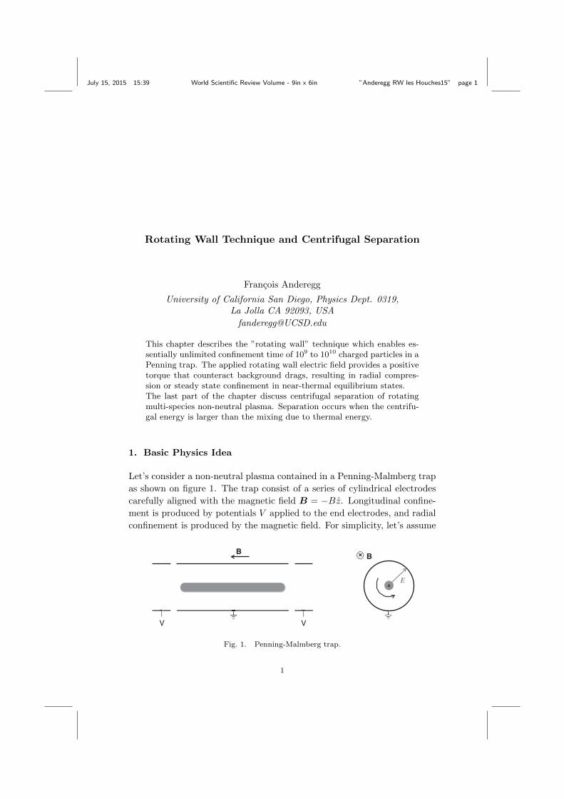
Fig. 3. Left) Electron and ion density profiles. Right) Density and temperature during
rotating wall frequency sweep.
Figure 3b shows the central plasma density plotted versus the rotatingwall frequency. As the frequency is ramped up, the plasma density increasesand the rotation frequency fE of equation 6 increases. The plasma rotationfrequency is always lower than the rotating wall frequency (fRW > fE) andtherefore some ”slip” is present. The maximum ion density achieved in thisexperiment was 13% of the Brillouin density (i.e. maximum stable densityin a Penning trap). As the density increases, the background drag increasesas ⇠ n
20 while the rotating wall torque remain constant, so the slip increases.
More heating is generated and the rotating wall coupling decreases, leadingto a abrupt reduction of the density in the trap.
Also, the plasma temperature shows spikes each time the rotating walldrive imperfections excite a longitudinal plasma mode. Here the longitu-dinal plasma modes are detrimental to the rotating wall coupling. Careshould be taken to rapidly change the rotating wall frequency when onesuch mode is encountered, otherwise the control of the plasma density maybe lost since the coupling decreases as the temperature increase.
Figure 4 demonstrates that the coupling of the rotating wall to theplasma is much larger in the vicinity of azimuthal (rotating) plasma modes,for both m✓ = 1 and m✓ = 2. Here the electron plasma profile B of figure3a is in equilibrium with the rotating wall at fRW=0.5 MHz, then fRW
July 15, 2015 15:39 World Scientific Review Volume - 9in x 6in ”Anderegg RW les Houches15” page 9
Rotating Wall and Centrifugal Separation 9
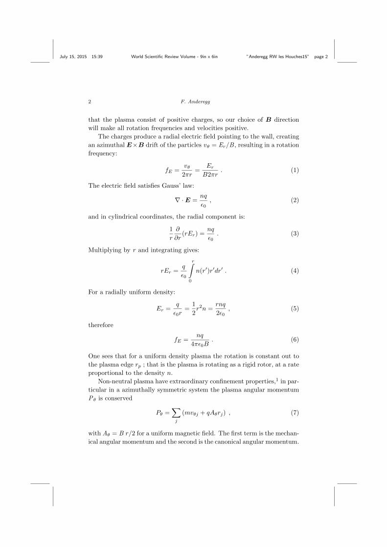
Fig. 4. Compression rate versus rotating wall frequency for m✓ = 1 and m✓ = 2 drives.
is changed and the compression rate is measured at r = 0. When therotating wall frequency is close to an azimuthal plasma mode characterizedby (mz,mr), the compression rate is significantly larger. When the rotatingwall is phased so as to rotate backwards (labeled as negative frequencies onfigure 4, rapid expansion is observed in the vicinity of backward travelingmodes.
Compression peaks are broadened and their amplitude is reduced dueto Landau damping when the temperature gets too high. Depending on theplasma geometry and particles masses, compression peaks due to plasmamode can be very broad and appear continuous.
On figure 4 one sees that the heating rate increases as fRW increasesdue to increased slip rate.
2.2. Strong Drive regime
This technique relies on a large amplitude drive and seems to be less sen-sitive to plasma modes, when the cooling rate is large enough and thebackground drag small enough. The geometry of this experiment is similarto the canonical Penning-Malmberg trap, with a rotating wall applied atthe end of the plasma column as show on figure 2. Typically ⇠ 109 electronsare confined in a magnetic field of B = 5.T resulting in a strong cyclotron

July 15, 2015 15:39 World Scientific Review Volume - 9in x 6in ”Anderegg RW les Houches15” page 10
10 F. Anderegg
radiation with a cooling time ⌧r = 0.15 sec. A dipole (m✓ = 1) drive isapplied at a fixed frequency.10
0.1V!
1.0V!
1.0V!
1.0V!
0.1V!
Fig. 5. a)Weak (0.1V) and strong drive(1.0V), b) Density below and above critical
amplitude (0.7V).
Two distinct plasma responses are observed depending on the strengthof the rotating wall drive. At low amplitude (0.1V), compression is ob-served only at discrete rotating wall frequencies as shown on figure 5a, dueto plasma modes couplings. At large amplitude (1.0V) compression is ob-served over a wide range of frequencies and no significant slip is observed.In this experiment, the rotation frequency is inferred from a density mea-surement, and no direct rotation frequency measurement is performed. Atlarge amplitude the central frame of figure 5a suggest that the plasma isrotating faster than the rotating mode frequencies indicted by dashed lines.
Also a bifurcation behavior is observed as the amplitude of the driveexceeds a critical strength of 0.7V as shown in figure 5b, the plasma densityrapidly reaches n = 2⇥ 1010cm�3.
Here the increased cyclotron cooling and the low background transportis what allow this new regime to be observed.
2.3. Phased-Locked Rotating Crystal
Beryllium ions contained in a Penning trap are laser cooled to T < 10mK(⇠ 10�6eV). The plasma consists of 102 < N < 106 ions, and is stronglycoupled, since the potential energy between neighboring ions is larger that

July 15, 2015 15:39 World Scientific Review Volume - 9in x 6in ”Anderegg RW les Houches15” page 11
Rotating Wall and Centrifugal Separation 11
the ion thermal energy. The rotating wall perturbation is applied uniformlyacross the axial extend of the plasma with 2 sets of azimuthally segmentedelectrodes (the compensation electrodes). Plasma compression is observedwith both m✓=1 and m✓=2 drives.11
Theoretically, the dipole field (m✓=1) can not control the plasma rota-tion of a single-species plasma in a quadratic trap. This is because it onlycauses a center-of-mass orbital motion about the trap axis and is thus de-coupled from the internal plasma rotation. Experimentally the dipole field(m✓=1) works in the presence of impurities ions, while the quadrupole field(m✓=2 ) always works. The NIST trap is shown schematically in figure 6a.
m! = 2!
m = 1
Fig. 6. a) NIST trap for ion crystal b)Plasma rotation controlled with rotating wall
frequency.
Figure 6b shows the plasma rotation frequency inferred from the mea-sured plasma aspect ratio. The plasma rotation frequency increases linearlywith the applied rotating wall frequency, in both weakly and strongly cou-pled plasmas.
For a more accurate determination of the rotation rate, the time depen-dance of Bragg-scattered light from the rotating crystal has been detectedby strobing the camera. Without strobing, figure 7a show the time aver-aged di↵raction pattern of concentric ring because of the plasma rotationabout the axial laser beam. With strobing, figure 7b shows a time-resolvedpattern accumulated over 106 rotations. The well-defined rectangular dotpattern demonstrates that the crystal is phase locked to the rotating fieldthat is (fE = fRW ).
Here the rotating wall electric field changes the trap potential in the

July 15, 2015 15:39 World Scientific Review Volume - 9in x 6in ”Anderegg RW les Houches15” page 12
12 F. Anderegg
Fig. 7. a) Time averaged di↵raction pattern and b) strobed di↵raction pattern.
rotating frame, the plasma boundary is slightly deformed to a try-axialellipsoid, and the shear force in the crystal transmit the torque to theinterior. The plasma shape deformation has been measured and is typicallyless than 1%, but it generates a su�cient torques to phase lock the plasmarotation.
The NIST group demonstrated the rotating wall technique works in thestrongly coupled regime, and that the plasma rotation is phased lock to therotating wall drive for long period of time.
Rotating Wall Summary
The rotating wall is a very successful technique, allowing essentially unlim-ited confinement of non-neutral plasmas. The frequency of the rotating wallcontrols the plasma density. The coupling of the rotating perturbation tothe plasma is well understood for crystallized plasma, but in the ”plasma”regime many plasma distortions (such as waves) can contribute.
3. Centrifugal Separation
The bulk rotation of a multi-species ion plasma tends to produce centrifugalseparation of its component species. To understand the mechanism, let’swrite the radial force balance of a small piece of plasma located at radiusr.
0 = na(r)[qE(r)� qB!rar +m!
2rar]�
@pa
@r
(20)
where pa = nakBTa is the thermal pressure of species a. With B > 0 andB = �Bz here, all frequencies (!ra,!E) are positive and !r ⌘ ✓. [Other

July 15, 2015 15:39 World Scientific Review Volume - 9in x 6in ”Anderegg RW les Houches15” page 13
Rotating Wall and Centrifugal Separation 13
conventions chose B = Bz, and define a ”rotation frequency” !r ⌘ �✓ soas to make !r > 0 ].
Equation 20 can be rewritten in terms of rotation !E and cyclotron⌦ca”frequencies”:
!E(r) =E(r)
Br
and ⌦ca =qB
ma(21)
giving:
!ra = !E(r)�1
qBna(r)r
@pa
@r
+!
2ra
⌦ca. (22)
The last term is the centrifugal correction to the rotation rate; is gen-erally small but it causes centrifugal separation. Before reaching thermalequilibrium, each species rotates at a di↵erent rate, and the collisional dragbetween species causes torques which drive one species out and the otherin. Consider a drag force for species a of the form
F✓a = �X
b
⌫ab mar(!ra � !rb) (23)
where ⌫ab is the collision rate between species a and b. This drag ✓-forceproduces a F✓ ⇥B drift in the radial direction that causes centrifugal sep-aration. The resulting radial flux �ra of species a is simply the chargedensity times the drift velocity. Combining the last two equations one gets:
�ra = nqF✓a
qB
=X
b
Dab
kBTa
@pa
@r
� na
nb
@pb
@r
+ na(mb!2rb �ma!
2ra)r
�(24)
where Dab = ⌫ab r
2ca is a di↵usion coe�cient and rca =
pkBTa/⌦ca is
the thermal cyclotron radius of species a. The first two terms are di↵usivefluxes, which tend to mix the species, while the last term is a mobility termseparating the species due to centrifugal force acting on each species. Notethat the flux �ra vanishes when Ta(r) = Tb(r) = T , !ra(r) = !rb(r) = !r
and the densities satisfy thermal equilibrium.In thermal equilibrium, each species density can be written as:3
na(r) = na(0) exp
�qa
kBT
✓�(r)� ma
qa
!
2rr
2
2� B!rr
2
2
◆�(25)
Note that the only di↵erence between species comes from the !2r term, and
for the separation to be significant, this term must be large compared to

July 15, 2015 15:39 World Scientific Review Volume - 9in x 6in ”Anderegg RW les Houches15” page 14
14 F. Anderegg
the thermal energy kBT . More precisely for simple two species case, thefollowing has to be satisfied:
q
����m1
q1� m2
q2
����!2rR
2p > kBT (26)
The separation length is defined as :
lsep ⌘ kBT
|m1 �m2| !2rRp
. (27)
When lsep < Rp separation occurs in the plasma, and when lsep ⌧ �D
then complete separation takes place, with species arranged in separateconcentric rings.
For two species carrying the same charge, equation 25 leads to:
na(r)
nb(r)= Cab exp
1
2kBT(ma �mb) !
2rr
2
�(28)
where Cab is a constant determined by the overall fraction of each species.
!
"
#
$
%
! " # $ % &
'(()"!*(+,-$
!.
/(),,.
0123(4#$5&("*
'!
'67#%
'67#&
'67#5
8(9(*:"(;("!-&(<=
# >!
!
"
#
$
%
&''("!)'*+,$
!-
./01'2#$34'#!
&!
&56#%
&56#4
&56#3
7'8'%9:';'"!,$'<=
# >!
Fig. 8. Radial density profile of multi-species plasma showing warm un-separated
plasma (top), and cold separated plasma (bottom).
Shown on figure 8 are measured density profiles for a warm plasma withnegligible separation (top), and for a cold plasma with strong separation12
(bottom). The symbols represent LIF-measured densities of magnesium

July 15, 2015 15:39 World Scientific Review Volume - 9in x 6in ”Anderegg RW les Houches15” page 15
Rotating Wall and Centrifugal Separation 15
ion isotopes. The solid flat line is the total density n0 obtained from therotation frequency. The curves are predictions of equation 28, here thetheory prediction have been convoluted with the finite size probe laser beam�l so they can be compared directly with the experimental measurements.At T = 4.8 ⇥ 10�3 eV, the species are uniformly mixed. Note that thesum of the Mg+ isotopes is 25% lower than to the total plasma densitydue to the presence of impurity ions H3O+ and O+
2 not detected by theLIF diagnostic. As the plasma is laser cooled down to T = 7.1⇥ 10�5 eV,the species centrifugally separate and concentrate into radial annuli. Thecentral hole observed in the Mg+ density is the result of the lighter impurityspecies H3O+.
More dramatic separation is routinely observed in electron-antiprotonplasmas.13
The rate R at which the centrifugal separation occurs can be easilyestimated if the mobility flux is smaller or equal to the di↵usive flux. Thisrate is then roughly the rate required for particles to di↵use across theplasma radius rp.
R ⇠ Dab
r
2p
⇠ 0.1s�1⇣
n0
107cm�3
⌘rµ(amu)
T
✓1
B(Tesla)Rp(cm)
◆2
(29)
Shown on figure 9 is the re-mixing rate of previously separated magne-sium ions isotopes. The plasma is abruptly heated with a burst of cyclotronheating, changing from T ⇠ 5 ⇥ 10�5eV to T ⇠ 10�3 eV. The squares areLIF measurements of the normalized density ratio Mg25/Mg24. The solidline is the result of a calculation of the flux �ra from equation 24 startingfrom the initially measured density profiles and measured T (t).
0
0.2
0.4
0.6
0.8
1
10-4
10-3
0 0.1 0.2 0.3 0.4 0.5
Norm
alize
d n 25
/n24
T [e
V]
time [sec]
WF 25107-25307
Fig. 9. Re-mixing of magnesium isotopes after a burst of heat (black vertical bar). ⇥represents temperature and squares are concentration of Mg25.
July 15, 2015 15:39 World Scientific Review Volume - 9in x 6in ”Anderegg RW les Houches15” page 16
16 F. Anderegg
Centrifugal Separation Summary
We have seen that multi-species plasma are centrifugally separated whenthe centrifugal energy is larger than the thermal energy (Eq. 26) and thatthe separation is complete when the separation length is smaller than theDebye screening length (Eq. 27). For plasma close to thermal equilib-rium: the radial densities distribution and the separation-remixing rate arecorrectly describe by a drag force due to collision between species.
4. Simple Tutorial Problems
4.1. Problem 1
Calculate the E⇥B rotation frequency of a single species, uniform plasma,of density 107cm�3 in a 3 Tesla magnetic field.a) Consider an electron plasma.b) Consider a Magnesium ion plasma.
As we have seen in the first section of this chapter, E⇥B rotation rateof a constant density plasma is:
fE =nq
4⇡✏0B⇠=
1013 · 1.6⇥ 10�19
4⇡ · 8.8⇥ 10�12 · 3⇠= 4.8kHz
Note that here we are assuming that the density is low compare to themaximum density achievable in a Penning trap (”Brillouin density”).For most plasmas in Penning traps this assumption is satisfied ( i.e.2!r ⌧ ⌦c). Here the cyclotron frequency of a singly ionized magnesiumion is ⌦Mg24
c /2⇡ ⇠= 1.9MHz, clearly within our approximation. For plasmasapproaching the Brillouin limit, a rigorous description is given by D. Dubinin the chapter on plasmas in Penning trap.
E ⇥B drifts are independent of the mass of the trapped charged parti-cles, but dependent on the charge q. Therefore ions and electrons rotate inopposite direction. Figure 1 of this chapter shows the (positive) rotationdirection for positive charges in B = �Bz.
4.2. Problem 2
Estimate the minimum rotation frequency necessary to observe centrifugalseparation of magnesium 24 from magnesium 25 for a temperature of 10Kand a plasma radius of 5mm.

July 15, 2015 15:39 World Scientific Review Volume - 9in x 6in ”Anderegg RW les Houches15” page 17
Rotating Wall and Centrifugal Separation 17
Assuming thermal equilibrium we have see that for singly ionized ionthe separation occurs when:
|m1 �m2| (2⇡fERp)2> kBT
Therefore
fE >
1
2⇡Rp
skBT
|m1 �m2|
>
1
2⇡ · 5⇥ 10�3
s1.38⇥ 10�23 · 10
| 25� 24 | · 1.67⇥ 10�27
> 9.15kHz
Acknowledgements
This work was supported by National Science Foundation Grant PHY-1414570, Department of Energy Grant DE-SC0002451and Department ofEnergy High Energy Density Laboratory Plasma Grant DE-SC0008693.The author thanks the organizers of Les Houches Winter School for theopportunity to contribute to the workshop. The author also thanks Prof.C.F. Driscoll, Prof. D.H.E. Dubin and Prof. T.M.O’Neil for many years ofenlightening guidance and theoretical support.
References
1. T.M. O’Neil, A Confinement Theorem for Nonneutral Plasmas, Phys. Fluids23, 2216-2218 (1980). D.H.E. Dubin and T.M. O’Neil, Trapped NonneutralPlasmas, Liquids, and Crystals (The Thermal Equilibrium States), Rev. Mod.
Phys. 71, 87-172, (1999).2. D.J. Heinzen, J.J. Bollinger, F.L. Moore, W.M. Itano, and D.J. Wineland,
Rotational Equilibria and Low-Order Modes of a Non-Neutral Ion Plasma,Phys. Rev. Lett. 66 , 2080-2083 (1991).
3. T.M. O’Neil and D.H.E. Dubin, Thermal Equilibria and Thermodynamics ofTrapped Plasmas with a Single Sign of Charge, Phys. Plasmas 5, 2163-2193,(1998).
4. T.M. O’Neil, Cooling of a Pure Electron Plasma by Cyclotron Radiation,Phys. Fluids 23, 725 (1980).
5. B.R. Beck, J. Fajans, and J.H. Malmberg Temperature and Anisotropic-Temperature Relaxation Measurements in Cold, Pure-Electron Plasmas,Phys. Plasmas 3, 1250 (1996).
6. J. R. Danielson, D. H. E. Dubin, R. G. Greaves and C. M. Surko, Plasmaand Trap-Based Techniques for Science with Positrons, Rev. Mod. Phys., 87,247 (2015).

July 15, 2015 15:39 World Scientific Review Volume - 9in x 6in ”Anderegg RW les Houches15” page 18
18 F. Anderegg
7. D.J. Larson, J.C. Bergquist, J.J. Bollinger, W.M. Itano, and D.J. Wineland,Sympathetic Cooling of Trapped Ions: A Laser Cooled Two Species Nonneu-tral Ion Plasma, Phys. Rev. Lett. 57, 70-73 (1986).
8. G. Gabrielse, X. Fei, L.A. Orozco, R.L. Tjoelker, J. Haas, H. Kalinowsky, T.Trainor, W. Kells, Cooling and Slowing of Trapped Antiprotons Below 100meV, Phys. Rev. Lett. 63, 1360-1363 (1989).
9. X.-P. Huang, F. Anderegg, E.M. Hollmann, C.F. Driscoll and T.M. O’Neil,Steady-State Confinement of Non-neutral Plasma by Rotating ElectricFields, Phys. Rev. Lett. 78, 875-878 (1997). F. Anderegg, E.M. Hollmann,and C.F. Driscoll, Rotating Field Confinement of Pure Electron PlasmasUsing Trivelpiece-Gould Modes, Phys. Rev. Lett. 78, 4875 (1998).
10. J. R. Danielson, C. M. Surko and T. M. O’Neil, High-density Fixed pointfor Radially Compressed Single-component Plasmas, Phys. Rev. Lett. 99,135005, (2007).
11. X.-P. Huang, J.J. Bollinger, T.B. Mitchell, W.M. Itano, and D.H.E. Dubin,Precise control of the global rotation of strongly coupled ion plasmas in aPenning trap, Phys. Plasmas 5, 1656 (1998).
12. M. A↵olter, F. Anderegg, D. H. E. Dubin, and C. F. Driscoll, CyclotronMode Frequency Shifts in Multi-Species Ion Plasmas, Physics of Plasmas
22, 055701, (2015).13. G.B. Andresen, et al., Centrifugal Separation and Equilibration Dynamics in
an Electron-Antiproton Plasma, Phys. Rev. Lett., 106 145001, (2011).