NON-ISOTHERMAL SIMULATION OF THE FLOW IN CO · PDF filenon-isothermal simulation of the flow...
5
NON-ISOTHERMAL SIMULATION OF THE FLOW IN CO-ROTATING AND COUNTER- ROTATING TWIN-SCREW EXTRUDERS USING MESH PARTITIOING TECHNIQUE Mahesh Gupta, Michigan Technological University Plastic Flow, LLC Houghton, MI 49931 Houghton, MI 49931 Abstract A new algorithm for simulation of non-isothermal flow in a twin-screw extruder is introduced. In the new algorithm, the finite element mesh of tetrahedral elements is created in the complete barrel including the space occupied by the screws. By partitioning the tetrahedral elements which are intersected by the screw surfaces into two tetrahedral, pyramidal or prismatic finite elements, the new algorithm allows the flow simulation in twin- screw extruder without regenerating the finite element mesh as the two screws rotate. Introduction A twin-screw extruder [1] consists of two closely matching screws which rotate in an eight-shaped barrel. Depending upon the required application, the two screws may rotate in the same direction (co-rotating) or in the opposite direction (counter-rotating). Counter-rotating extruders are typically used to generate high pressure required for extruding complex profiles, whereas co- rotating extruders are used for applications such as mixing, compounding and devolatilization of polymers. Even though twin-screw extruders have been used for polymer processing applications since the early 1960s, because of the complexity of the flow in a twin- screw extruder, newer designs for twin-screw extruders have been primarily developed by trial-and-error and based upon the past experience of the designers. To compensate for the lack of deep understanding of the flow in twin-screw extruders, screws for twin-screw extruders are typically available as interchangeable elements. Several feasible combinations of the interchangeable screw elements are often tried before obtaining the required flow characteristics. The time wasted in the trial- and-error approach, which rarely provides an optimal design, can be saved if a software, which can accurately simulate the flow in a twin-screw extruder, is available for optimizing the design and processing condition in the extruder. Such a software for simulation of non- isothermal flow of polymer in a twin-screw extruder has been developed in this work. Simulation of Flow in Twin-Screw Extruders In the literature, a simplified one-dimensional or two- dimensional analysis has typically been used to analyze the flow in twin-screw extruders [1]. However, because of the complexity of the flow in twin-screw extruders, a simplified one-dimensional or two-dimensional analysis typically results in a large error in the predictions, and hence, in the designs which are based upon such analyses. In particular, the flow in the intermeshing region between the two screws determines the mixing characteristics and the overall behavior of a twin-screw extruder. However, the flow in the intermeshing region of a twin-screw extruder is extremely complex, and cannot be captured by a one-dimensional or two-dimensional analysis. With the rapid increase in speed and versatility of computers over the last decade, a full three-dimensional simulation of flow in a twin-screw extruder is now feasible [2, 3, 5 – 7]. Three-dimensional simulation of the flow in a twin-screw extruder requires simultaneous solution of the mass, momentum and energy conservation equations for an inertia-less, incompressible flow, which are given below. Momentum conservation: ( ) 0 ~ 2 = p e (1) Mass conservation: 0 = v r (2) Energy conservation: ( ) ( ) e e T k T v t T C p ~ : ~ 2 + = + r (3) In Eqns. (1) – (3) e ~ is the strain-rate tensor, T the temperature, t the time, p the pressure, the viscosity, v r the velocity, and k, and C p are the thermal conductivity, density and heat capacity of the polymer. Because of the complexity of the shape of the flow domain, and the time-dependent nature of the flow in a twin-screw extruder, obtaining an accurate solution of Eqns. (1) – (3) can be quite challenging. A finite element simulation of an isothermal flow in a twin-screw extruder can be performed by using a finite element mesh over the flow domain for the current configuration of the two screws [2, 3]. However, such a scheme cannot be employed for simulating non-isothermal effects in the flow. Because of the convection term in the energy equation (Eqn. 3), in order to predict the evolution of temperature distribution, the information on the temperature distribution in the previous time step is required. If different finite element meshes are used for the flow domains at different time steps, since the temperature at the nodes in the current finite element mesh is not known at the previous time step, the temperature distribution in the time-dependent flow domain in a twin-screw extruder cannot be predicted by such an approach. A new technique developed in this work, which allow simulation of the non-isothermal flow in a twin-screw extruder without any mesh regeneration, is described in the next section. ANTEC 2008 / 316
Transcript of NON-ISOTHERMAL SIMULATION OF THE FLOW IN CO · PDF filenon-isothermal simulation of the flow...
NON-ISOTHERMAL SIMULATION OF THE FLOW IN CO-ROTATING AND COUNTER-ROTATING TWIN-SCREW EXTRUDERS USING MESH PARTITIOING TECHNIQUE
Mahesh Gupta, Michigan Technological University Plastic Flow, LLC Houghton, MI 49931 Houghton, MI 49931
Abstract A new algorithm for simulation of non-isothermal
flow in a twin-screw extruder is introduced. In the new algorithm, the finite element mesh of tetrahedral elements is created in the complete barrel including the space occupied by the screws. By partitioning the tetrahedral elements which are intersected by the screw surfaces into two tetrahedral, pyramidal or prismatic finite elements, the new algorithm allows the flow simulation in twin-screw extruder without regenerating the finite element mesh as the two screws rotate.
Introduction A twin-screw extruder [1] consists of two closely
matching screws which rotate in an eight-shaped barrel. Depending upon the required application, the two screws may rotate in the same direction (co-rotating) or in the opposite direction (counter-rotating). Counter-rotating extruders are typically used to generate high pressure required for extruding complex profiles, whereas co-rotating extruders are used for applications such as mixing, compounding and devolatilization of polymers.
Even though twin-screw extruders have been used for polymer processing applications since the early 1960s, because of the complexity of the flow in a twin-screw extruder, newer designs for twin-screw extruders have been primarily developed by trial-and-error and based upon the past experience of the designers. To compensate for the lack of deep understanding of the flow in twin-screw extruders, screws for twin-screw extruders are typically available as interchangeable elements. Several feasible combinations of the interchangeable screw elements are often tried before obtaining the required flow characteristics. The time wasted in the trial-and-error approach, which rarely provides an optimal design, can be saved if a software, which can accurately simulate the flow in a twin-screw extruder, is available for optimizing the design and processing condition in the extruder. Such a software for simulation of non-isothermal flow of polymer in a twin-screw extruder has been developed in this work.
Simulation of Flow in Twin-Screw Extruders In the literature, a simplified one-dimensional or two-
dimensional analysis has typically been used to analyze the flow in twin-screw extruders [1]. However, because of the complexity of the flow in twin-screw extruders, a simplified one-dimensional or two-dimensional analysis typically results in a large error in the predictions, and
hence, in the designs which are based upon such analyses. In particular, the flow in the intermeshing region between the two screws determines the mixing characteristics and the overall behavior of a twin-screw extruder. However, the flow in the intermeshing region of a twin-screw extruder is extremely complex, and cannot be captured by a one-dimensional or two-dimensional analysis.
With the rapid increase in speed and versatility of computers over the last decade, a full three-dimensional simulation of flow in a twin-screw extruder is now feasible [2, 3, 5 – 7]. Three-dimensional simulation of the flow in a twin-screw extruder requires simultaneous solution of the mass, momentum and energy conservation equations for an inertia-less, incompressible flow, which are given below.
Momentum conservation: ( ) 0~2 =∇−η⋅∇ pe (1)
Mass conservation: 0=⋅∇ vr (2)
Energy conservation: ( ) ( ) eeTkTvtTC p
~:~2η+∇⋅∇=∇⋅+∂∂ρr
(3)
In Eqns. (1) – (3) e~ is the strain-rate tensor, T the temperature, t the time, p the pressure, η the viscosity, vr
the velocity, and k, ρ and Cp are the thermal conductivity, density and heat capacity of the polymer.
Because of the complexity of the shape of the flow domain, and the time-dependent nature of the flow in a twin-screw extruder, obtaining an accurate solution of Eqns. (1) – (3) can be quite challenging. A finite element simulation of an isothermal flow in a twin-screw extruder can be performed by using a finite element mesh over the flow domain for the current configuration of the two screws [2, 3]. However, such a scheme cannot be employed for simulating non-isothermal effects in the flow. Because of the convection term in the energy equation (Eqn. 3), in order to predict the evolution of temperature distribution, the information on the temperature distribution in the previous time step is required. If different finite element meshes are used for the flow domains at different time steps, since the temperature at the nodes in the current finite element mesh is not known at the previous time step, the temperature distribution in the time-dependent flow domain in a twin-screw extruder cannot be predicted by such an approach. A new technique developed in this work, which allow simulation of the non-isothermal flow in a twin-screw extruder without any mesh regeneration, is described in the next section.
ANTEC 2008 / 316

New Algorithm for Simulation of Non-Isothermal Flow in a Twin-Screw Extruder
Instead of generating a new finite element mesh for each new configuration of the two rotating screws in a twin-screw extruder, in the new algorithm developed in this research, a finite element mesh of tetrahedral elements is generated over the complete barrel, including the space occupied by the two screws. The mesh inside the barrel, which is generated without any consideration to the configuration of the two screws, remains unaltered as the two screws rotate inside the barrel. This decoupling between the finite element mesh in the barrel and the configuration of the two screws is possible because in the new algorithm developed in this research the screw surfaces are allowed to cut through the tetrahedral elements in the finite element mesh in the barrel. Mesh Partitioning Technique
In the new flow simulation algorithm, the surface of each of the two screws is represented by a surface mesh of linear, triangular finite elements. These meshes of triangular elements for the two screws act as partitioning surfaces for the mesh of tetrahedral elements in the barrel. In the new algorithm, every tetrahedral element in the barrel which is intersected by a screw surface is partitioned into two finite elements – one element on each side of the screw surface. That is, one of the two newly generated elements lies inside the screw, with the other element being in the polymer flow domain.
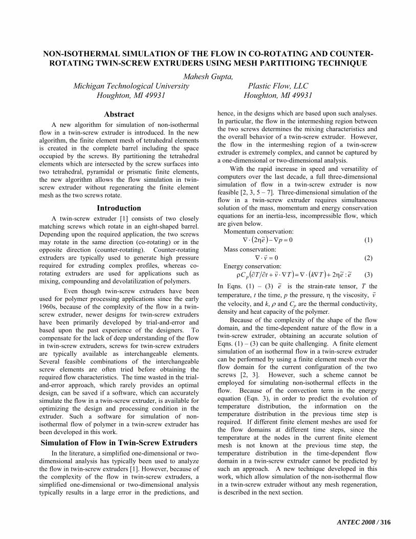
When a two-dimensional plane intersects a tetrahedral finite element, it leads to one of the following four combinations of two finite elements. o One tetrahedral and one prismatic element (Fig. 1 a), o Two tetrahedral elements (Fig. 1 b), o One pyramidal and one tetrahedral element (Fig. 1 c) o Two prismatic elements (Fig. 1 d).
In our new scheme for simulation of the flow in twin-screw extruders, each of the tetrahedral finite elements intersected by screw surfaces is replaced by one of these four combinations of the two finite elements. In the software developed in this project, two screws are rotated after each time step, and the intersection between the two screw surfaces and the tetrahedral elements in the finite element mesh in the barrel is determined. The elements which are intersected by the screw surfaces are then partitioned appropriately according to one of the four configurations shown in Fig. 1.
Constitutive Equation for Two-Phase Flow The resin used for the simulations presented in this
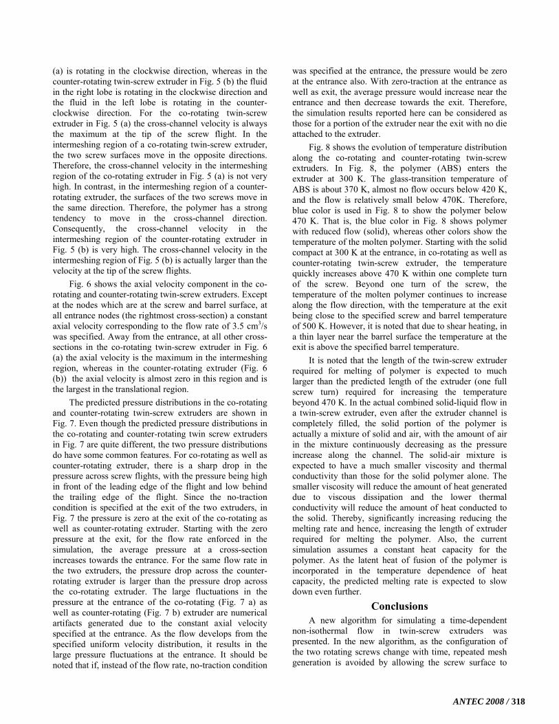
paper is an acrylonitrile butadiene styrene (ABS) resin. The resin used is an extrusion grade material with a melt flow rate (MFR) of 2.5 dg/min (230oC, 3.8 kg). The shear viscosity data for this resin at temperatures of 190, 230, and 270oC is shown in Fig. 2 [8]. The experimental data shown in Fig. 2 was used to fit the Cross-WLF model (Eqn. 4) for viscosity of the ABS resin.
( ) n−∗τγη+
η=η 1
0
0
1 &,
−+−
−=η)(
)(exp
2
110
a
a
TTATTA
D (4)
The values of Cross-WLF viscosity model parameters thus obtained are n = 0.35, τ* = 2.70×10⁴ Pa, D1 =6.487×10¹¹ Pa.s, Ta = 100 ˚C, A1 = 27.66, A2 = 89.37 K. The melt density, heat capacity and thermal conductivity were assumed to be constant at 0.88 g/cm3, 2345 J/kg.K and 0.18 W/m.K, respectively.
Geometry of Twin-Screw Extruder The finite element mesh of tetrahedral elements in the
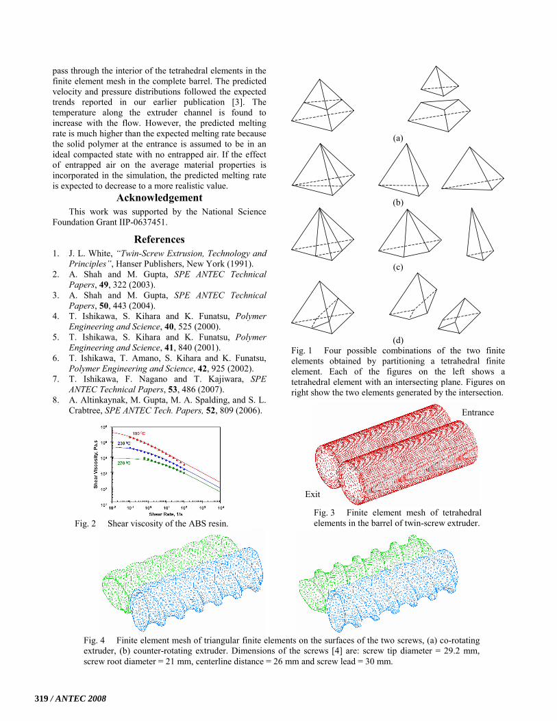
barrel of the twin-screw extruder is shown in Fig. 3. The same finite element mesh was used for simulating the flow in co-rotating as well as counter-rotating twin-screw extruder. However, as expected, the finite element meshes of triangular finite elements on the surfaces of the two screws shown in Fig. 4, which were used to partition the intersected tetrahedral elements in the finite element mesh in the barrel, are different for the co-rotating and counter-rotating twin-screw extruders. The screw geometries shown in Fig. 4 were obtained by rotating the two-lobe cross-section of Ishikawa et al. [4] with a screw lead of 30 mm (that is, screw pitch = 15 mm). With the screw lead being the same as its diameter, extruder length equivalent to three screw diameters was obtained by rotating the two lobe cross-sections through three full rotations.
Results and Discussion To simulate the flow in the co-rotating twin-screw
extruder, both the screws were rotated at 60 RPM in the clockwise direction, whereas for the counter-rotating twin-screw extruder, the left screw was rotated in the counter-clockwise direction and the right-hand-side screw was rotated in the clockwise direction. In the co-rotating as well as counter-rotating extruder, the flow is entering on the right side (marked entrance in Fig. 3) and leaving on the left side (marked exit in Fig. 3). A flow rate of 3.5 cm3/s was specified at the entrance, the no-slip condition was enforced at the barrel surface, whereas no-traction condition was employed at the exit of the extruder. At the screw as well as barrel surface, temperature of 500 K was used and the polymer entered the extruders at 300 K. That is, the polymer entering the extruder is in a compacted solid state. The increase in temperature and the flow of the polymer along the twin-screw extruder channel is simulated in the present work. The predictions for co-rotating as well as counter-rotating twin-screw extruders are presented in the remaining of this section.
The cross-channel velocity distributions in various cross-sections of the co-rotating and counter-rotating twin-screw extruders are shown in Fig. 5. The arrows in Fig. 5 show the direction of cross-channel velocity whereas the color of the arrows depicts the magnitude of the cross-channel velocity. As mentioned above for the direction of rotation of the two screws, the fluid in both the lobes of the co-rotating twin-screw extruder in Fig. 5
317 / ANTEC 2008
(a) is rotating in the clockwise direction, whereas in the counter-rotating twin-screw extruder in Fig. 5 (b) the fluid in the right lobe is rotating in the clockwise direction and the fluid in the left lobe is rotating in the counter-clockwise direction. For the co-rotating twin-screw extruder in Fig. 5 (a) the cross-channel velocity is always the maximum at the tip of the screw flight. In the intermeshing region of a co-rotating twin-screw extruder, the two screw surfaces move in the opposite directions. Therefore, the cross-channel velocity in the intermeshing region of the co-rotating extruder in Fig. 5 (a) is not very high. In contrast, in the intermeshing region of a counter-rotating extruder, the surfaces of the two screws move in the same direction. Therefore, the polymer has a strong tendency to move in the cross-channel direction. Consequently, the cross-channel velocity in the intermeshing region of the counter-rotating extruder in Fig. 5 (b) is very high. The cross-channel velocity in the intermeshing region of Fig. 5 (b) is actually larger than the velocity at the tip of the screw flights.
Fig. 6 shows the axial velocity component in the co-rotating and counter-rotating twin-screw extruders. Except at the nodes which are at the screw and barrel surface, at all entrance nodes (the rightmost cross-section) a constant axial velocity corresponding to the flow rate of 3.5 cm3/s was specified. Away from the entrance, at all other cross-sections in the co-rotating twin-screw extruder in Fig. 6 (a) the axial velocity is the maximum in the intermeshing region, whereas in the counter-rotating extruder (Fig. 6 (b)) the axial velocity is almost zero in this region and is the largest in the translational region.
The predicted pressure distributions in the co-rotating and counter-rotating twin-screw extruders are shown in Fig. 7. Even though the predicted pressure distributions in the co-rotating and counter-rotating twin screw extruders in Fig. 7 are quite different, the two pressure distributions do have some common features. For co-rotating as well as counter-rotating extruder, there is a sharp drop in the pressure across screw flights, with the pressure being high in front of the leading edge of the flight and low behind the trailing edge of the flight. Since the no-traction condition is specified at the exit of the two extruders, in Fig. 7 the pressure is zero at the exit of the co-rotating as well as counter-rotating extruder. Starting with the zero pressure at the exit, for the flow rate enforced in the simulation, the average pressure at a cross-section increases towards the entrance. For the same flow rate in the two extruders, the pressure drop across the counter-rotating extruder is larger than the pressure drop across the co-rotating extruder. The large fluctuations in the pressure at the entrance of the co-rotating (Fig. 7 a) as well as counter-rotating (Fig. 7 b) extruder are numerical artifacts generated due to the constant axial velocity specified at the entrance. As the flow develops from the specified uniform velocity distribution, it results in the large pressure fluctuations at the entrance. It should be noted that if, instead of the flow rate, no-traction condition
was specified at the entrance, the pressure would be zero at the entrance also. With zero-traction at the entrance as well as exit, the average pressure would increase near the entrance and then decrease towards the exit. Therefore, the simulation results reported here can be considered as those for a portion of the extruder near the exit with no die attached to the extruder.
Fig. 8 shows the evolution of temperature distribution along the co-rotating and counter-rotating twin-screw extruders. In Fig. 8, the polymer (ABS) enters the extruder at 300 K. The glass-transition temperature of ABS is about 370 K, almost no flow occurs below 420 K, and the flow is relatively small below 470K. Therefore, blue color is used in Fig. 8 to show the polymer below 470 K. That is, the blue color in Fig. 8 shows polymer with reduced flow (solid), whereas other colors show the temperature of the molten polymer. Starting with the solid compact at 300 K at the entrance, in co-rotating as well as counter-rotating twin-screw extruder, the temperature quickly increases above 470 K within one complete turn of the screw. Beyond one turn of the screw, the temperature of the molten polymer continues to increase along the flow direction, with the temperature at the exit being close to the specified screw and barrel temperature of 500 K. However, it is noted that due to shear heating, in a thin layer near the barrel surface the temperature at the exit is above the specified barrel temperature.
It is noted that the length of the twin-screw extruder required for melting of polymer is expected to much larger than the predicted length of the extruder (one full screw turn) required for increasing the temperature beyond 470 K. In the actual combined solid-liquid flow in a twin-screw extruder, even after the extruder channel is completely filled, the solid portion of the polymer is actually a mixture of solid and air, with the amount of air in the mixture continuously decreasing as the pressure increase along the channel. The solid-air mixture is expected to have a much smaller viscosity and thermal conductivity than those for the solid polymer alone. The smaller viscosity will reduce the amount of heat generated due to viscous dissipation and the lower thermal conductivity will reduce the amount of heat conducted to the solid. Thereby, significantly increasing reducing the melting rate and hence, increasing the length of extruder required for melting the polymer. Also, the current simulation assumes a constant heat capacity for the polymer. As the latent heat of fusion of the polymer is incorporated in the temperature dependence of heat capacity, the predicted melting rate is expected to slow down even further.
Conclusions A new algorithm for simulating a time-dependent
non-isothermal flow in twin-screw extruders was presented. In the new algorithm, as the configuration of the two rotating screws change with time, repeated mesh generation is avoided by allowing the screw surface to
ANTEC 2008 / 318
pass through the interior of the tetrahedral elements in the finite element mesh in the complete barrel. The predicted velocity and pressure distributions followed the expected trends reported in our earlier publication [3]. The temperature along the extruder channel is found to increase with the flow. However, the predicted melting rate is much higher than the expected melting rate because the solid polymer at the entrance is assumed to be in an ideal compacted state with no entrapped air. If the effect of entrapped air on the average material properties is incorporated in the simulation, the predicted melting rate is expected to decrease to a more realistic value.
Acknowledgement This work was supported by the National Science
Foundation Grant IIP-0637451.
References 1. J. L. White, “Twin-Screw Extrusion, Technology and
Principles”, Hanser Publishers, New York (1991). 2. A. Shah and M. Gupta, SPE ANTEC Technical
Papers, 49, 322 (2003). 3. A. Shah and M. Gupta, SPE ANTEC Technical
Papers, 50, 443 (2004). 4. T. Ishikawa, S. Kihara and K. Funatsu, Polymer
Engineering and Science, 40, 525 (2000). 5. T. Ishikawa, S. Kihara and K. Funatsu, Polymer
Engineering and Science, 41, 840 (2001). 6. T. Ishikawa, T. Amano, S. Kihara and K. Funatsu,
Polymer Engineering and Science, 42, 925 (2002). 7. T. Ishikawa, F. Nagano and T. Kajiwara, SPE
ANTEC Technical Papers, 53, 486 (2007). 8. A. Altinkaynak, M. Gupta, M. A. Spalding, and S. L.
Crabtree, SPE ANTEC Tech. Papers, 52, 809 (2006).
(a)
(b)
(c)
(d) Fig. 1 Four possible combinations of the two finite elements obtained by partitioning a tetrahedral finite element. Each of the figures on the left shows a tetrahedral element with an intersecting plane. Figures on right show the two elements generated by the intersection.
Fig. 4 Finite element mesh of triangular finite elements on the surfaces of the two screws, (a) co-rotating extruder, (b) counter-rotating extruder. Dimensions of the screws [4] are: screw tip diameter = 29.2 mm, screw root diameter = 21 mm, centerline distance = 26 mm and screw lead = 30 mm.
Fig. 2 Shear viscosity of the ABS resin. Fig. 3 Finite element mesh of tetrahedral elements in the barrel of twin-screw extruder.
Entrance
Exit
319 / ANTEC 2008

(a) Fig. 8 Temperature distribution in co-ro
(a)
Fig. 7 Pressure distribution in co-rot
Fig. 5 Cross-channel velocity distribution in counter-rotating (b) twin-screw extruders.
(a)
(a)(b)
Fig. 6 Axial velocity distribution in co-rotating (a) and counter-rotating (b) twin-screw extruders.
)
(b(b) tating (a) and counter-rotating (b) twin-screw extruders.
(b) ating (a) and counter-rotating (b) twin-screw extruders.
co-rotating (a) and
ANTEC 2008 / 320