Governors - ssmengg.edu.inssmengg.edu.in/.../Mechanical/4thSem/theoryofmachine/Governors.pdf · The...
79
Governors 18 Features 1. Introduction. 2. Types of Governors. 3. Centrifugal Governors. 4. Terms Used in Governors. 5. Watt Governor. 6. Porter Governor. 7. Proell Governor. 8. Hartnell Governor. 9. Hartung Governor. 10. Wilson-Hartnell Governor. 11. Pickering Governor. 12. Sensitiveness of Governors. 13. Stability of Governors. 14. Isochronous Governor. 15. Hunting. 16. Effort and Power of a Governor. 17. Effort and Power of a Porter Governor. 18. Controlling Force. 19. Controlling Force Diagram for a Porter Governor. 20. Controlling Force Diagram for a Spring-controlled Governor. 21. Coefficient of Insensitiveness. 18.1. Introduction The function of a governor is to regulate the mean speed of an engine, when there are variations in the load e.g. when the load on an engine increases, its speed decreases, therefore it becomes necessary to increase the supply of work- ing fluid. On the other hand, when the load on the engine decreases, its speed increases and thus less working fluid is required. The governor automatically controls the supply of working fluid to the engine with the varying load conditions and keeps the mean speed within certain limits. A little consideration will show, that when the load increases, the configuration of the governor changes and a valve is moved to increase the supply of the working fluid ; conversely, when the load decreases, the engine speed in- creases and the governor decreases the supply of working fluid. Note : We have discussed in Chapter 16 (Art. 16.8) that the func- tion of a flywheel in an engine is entirely different from that of a governor. It controls the speed variation caused by the fluctuations of the engine turning moment during each cycle of operation. It does not control the speed variations caused by a varying load. The varying demand for power is met by the governor regulating the supply of working fluid. 18.2. Types of Governors The governors may, broadly, be classified as 1. Centrifugal governors, and 2. Inertia governors. 653
Transcript of Governors - ssmengg.edu.inssmengg.edu.in/.../Mechanical/4thSem/theoryofmachine/Governors.pdf · The...

Chapter 18 : Governors � 653
Governors
18Features1. Introduction.2. Types of Governors.3. Centrifugal Governors.4. Terms Used in Governors.5. Watt Governor.6. Porter Governor.7. Proell Governor.8. Hartnell Governor.9. Hartung Governor.
10. Wilson-Hartnell Governor.11. Pickering Governor.12. Sensitiveness of Governors.13. Stability of Governors.14. Isochronous Governor.15. Hunting.
16. Effort and Power of aGovernor.
17. Effort and Power of a PorterGovernor.
18. Controlling Force.19. Controlling Force Diagram
for a Porter Governor.20. Controlling Force Diagram
for a Spring-controlledGovernor.
21. Coefficient ofInsensitiveness.
18.1. IntroductionThe function of a governor is to regulate the mean
speed of an engine, when there are variations in the load e.g.when the load on an engine increases, its speed decreases,therefore it becomes necessary to increase the supply of work-ing fluid. On the other hand, when the load on the enginedecreases, its speed increases and thus less working fluid isrequired. The governor automatically controls the supply ofworking fluid to the engine with the varying load conditionsand keeps the mean speed within certain limits.
A little consideration will show, that when the loadincreases, the configuration of the governor changes and avalve is moved to increase the supply of the working fluid ;conversely, when the load decreases, the engine speed in-creases and the governor decreases the supply of workingfluid.Note : We have discussed in Chapter 16 (Art. 16.8) that the func-tion of a flywheel in an engine is entirely different from that of agovernor. It controls the speed variation caused by the fluctuationsof the engine turning moment during each cycle of operation. Itdoes not control the speed variations caused by a varying load. Thevarying demand for power is met by the governor regulating thesupply of working fluid.
18.2. Types of GovernorsThe governors may, broadly, be classified as
1. Centrifugal governors, and 2. Inertia governors.
653
654 � Theory of Machines
The centrifugal governors, may further be classified as follows :
18.3. Centrifugal Governors
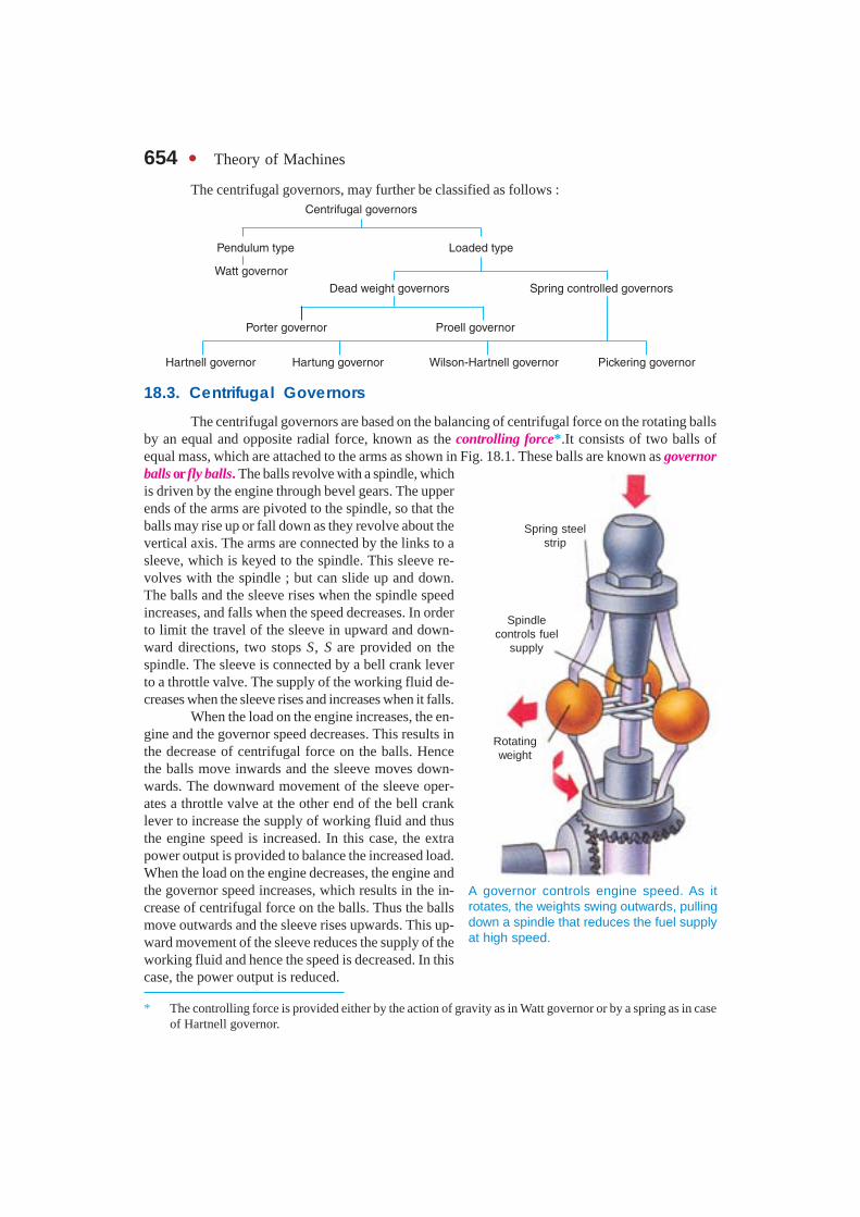
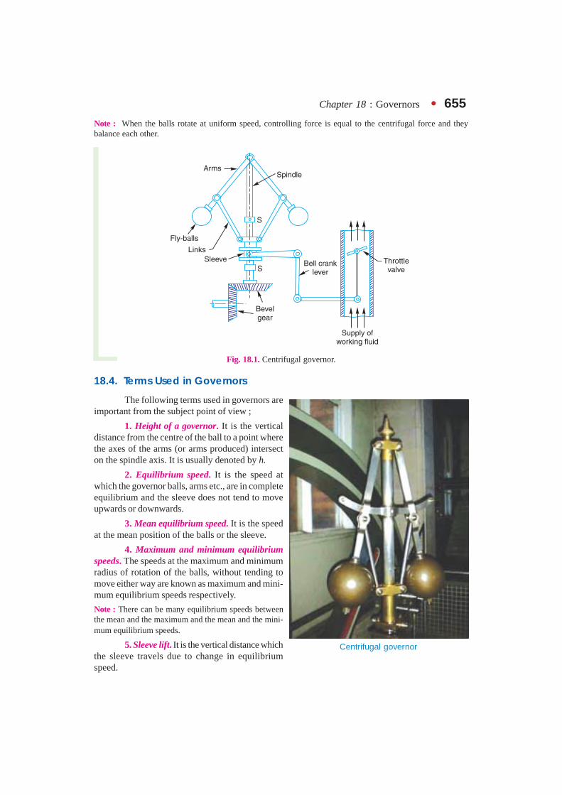
The centrifugal governors are based on the balancing of centrifugal force on the rotating ballsby an equal and opposite radial force, known as the controlling force*.It consists of two balls ofequal mass, which are attached to the arms as shown in Fig. 18.1. These balls are known as governorballs or fly balls. The balls revolve with a spindle, whichis driven by the engine through bevel gears. The upperends of the arms are pivoted to the spindle, so that theballs may rise up or fall down as they revolve about thevertical axis. The arms are connected by the links to asleeve, which is keyed to the spindle. This sleeve re-volves with the spindle ; but can slide up and down.The balls and the sleeve rises when the spindle speedincreases, and falls when the speed decreases. In orderto limit the travel of the sleeve in upward and down-ward directions, two stops S, S are provided on thespindle. The sleeve is connected by a bell crank leverto a throttle valve. The supply of the working fluid de-creases when the sleeve rises and increases when it falls.
When the load on the engine increases, the en-gine and the governor speed decreases. This results inthe decrease of centrifugal force on the balls. Hencethe balls move inwards and the sleeve moves down-wards. The downward movement of the sleeve oper-ates a throttle valve at the other end of the bell cranklever to increase the supply of working fluid and thusthe engine speed is increased. In this case, the extrapower output is provided to balance the increased load.When the load on the engine decreases, the engine andthe governor speed increases, which results in the in-crease of centrifugal force on the balls. Thus the ballsmove outwards and the sleeve rises upwards. This up-ward movement of the sleeve reduces the supply of theworking fluid and hence the speed is decreased. In thiscase, the power output is reduced.
* The controlling force is provided either by the action of gravity as in Watt governor or by a spring as in caseof Hartnell governor.
A governor controls engine speed. As itrotates, the weights swing outwards, pullingdown a spindle that reduces the fuel supplyat high speed.
Spring steelstrip
Spindlecontrols fuel
supply
Rotatingweight
Chapter 18 : Governors � 655Note : When the balls rotate at uniform speed, controlling force is equal to the centrifugal force and theybalance each other.
Fig. 18.1. Centrifugal governor.
18.4. Terms Used in Governors
The following terms used in governors areimportant from the subject point of view ;
1. Height of a governor. It is the verticaldistance from the centre of the ball to a point wherethe axes of the arms (or arms produced) intersecton the spindle axis. It is usually denoted by h.
2. Equilibrium speed. It is the speed atwhich the governor balls, arms etc., are in completeequilibrium and the sleeve does not tend to moveupwards or downwards.
3. Mean equilibrium speed. It is the speedat the mean position of the balls or the sleeve.
4. Maximum and minimum equilibriumspeeds. The speeds at the maximum and minimumradius of rotation of the balls, without tending tomove either way are known as maximum and mini-mum equilibrium speeds respectively.
Note : There can be many equilibrium speeds betweenthe mean and the maximum and the mean and the mini-mum equilibrium speeds.
5. Sleeve lift. It is the vertical distance whichthe sleeve travels due to change in equilibriumspeed.
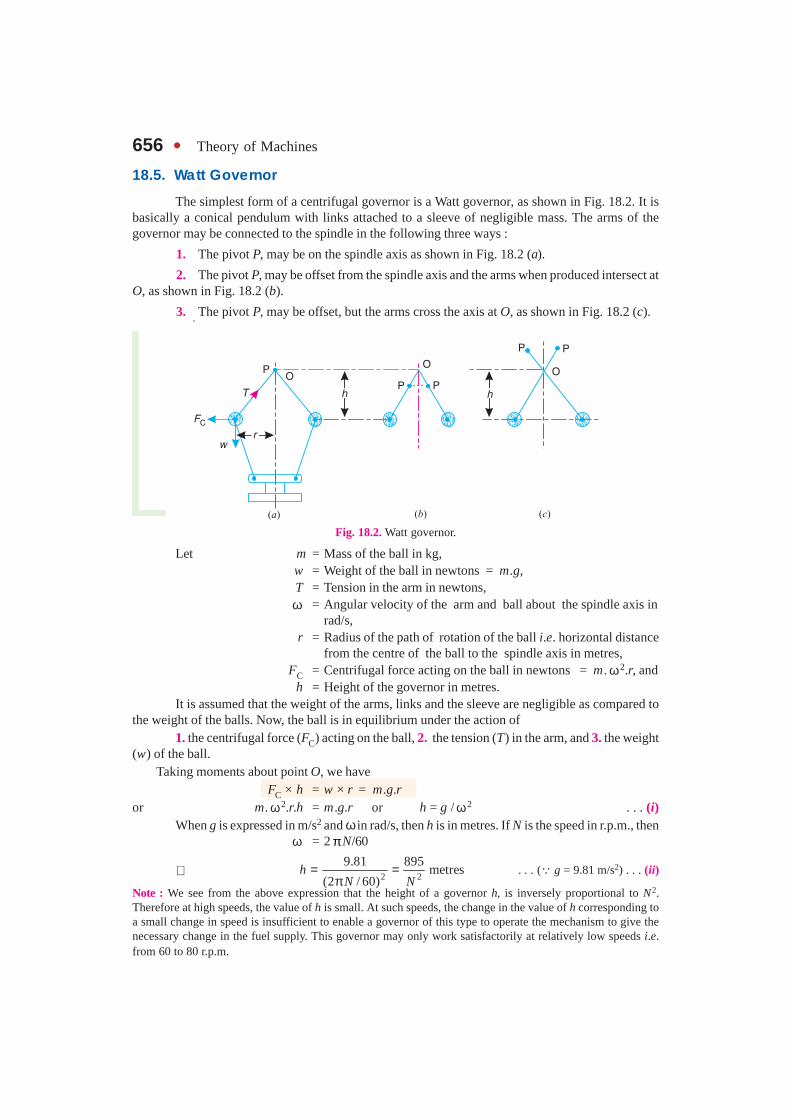
Centrifugal governor
656 � Theory of Machines
18.5. Watt Governor
The simplest form of a centrifugal governor is a Watt governor, as shown in Fig. 18.2. It isbasically a conical pendulum with links attached to a sleeve of negligible mass. The arms of thegovernor may be connected to the spindle in the following three ways :
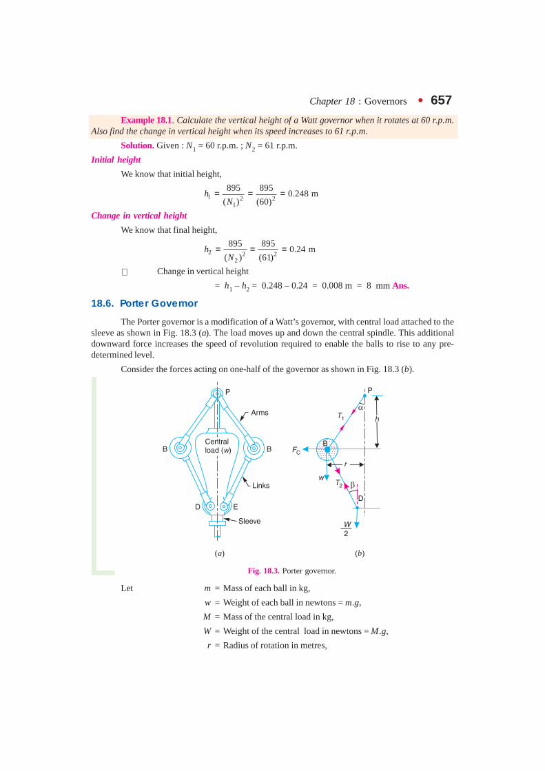
1. The pivot P, may be on the spindle axis as shown in Fig. 18.2 (a).
2. The pivot P, may be offset from the spindle axis and the arms when produced intersect atO, as shown in Fig. 18.2 (b).
3. The pivot P, may be offset, but the arms cross the axis at O, as shown in Fig. 18.2 (c).
Fig. 18.2. Watt governor.
Let m = Mass of the ball in kg,w = Weight of the ball in newtons = m.g,T = Tension in the arm in newtons,ω = Angular velocity of the arm and ball about the spindle axis in
rad/s,r = Radius of the path of rotation of the ball i.e. horizontal distance
from the centre of the ball to the spindle axis in metres,FC = Centrifugal force acting on the ball in newtons = m. ω2.r, and
h = Height of the governor in metres.It is assumed that the weight of the arms, links and the sleeve are negligible as compared to
the weight of the balls. Now, the ball is in equilibrium under the action of1. the centrifugal force (FC) acting on the ball, 2. the tension (T) in the arm, and 3. the weight
(w) of the ball.Taking moments about point O, we have
FC × h = w × r = m.g.ror m. ω2.r.h = m.g.r or h = g / ω2 . . . (i)
When g is expressed in m/s2 and ω in rad/s, then h is in metres. If N is the speed in r.p.m., thenω = 2 πN/60
∴ 2 2
9.81 895metres
(2 / 60)h
N N= =
π. . . (∵ g = 9.81 m/s2) . . . (ii)
Note : We see from the above expression that the height of a governor h, is inversely proportional to N2.Therefore at high speeds, the value of h is small. At such speeds, the change in the value of h corresponding toa small change in speed is insufficient to enable a governor of this type to operate the mechanism to give thenecessary change in the fuel supply. This governor may only work satisfactorily at relatively low speeds i.e.from 60 to 80 r.p.m.
Chapter 18 : Governors � 657Example 18.1. Calculate the vertical height of a Watt governor when it rotates at 60 r.p.m.
Also find the change in vertical height when its speed increases to 61 r.p.m.
Solution. Given : N1 = 60 r.p.m. ; N2 = 61 r.p.m.
Initial height
We know that initial height,
1 2 21
895 8950.248 m
( ) (60)h
N= = =
Change in vertical height
We know that final height,
2 2 22
895 8950.24 m
( ) (61)h
N= = =
∴ Change in vertical height
= h1 – h2 = 0.248 – 0.24 = 0.008 m = 8 mm Ans.
18.6. Porter Governor
The Porter governor is a modification of a Watt’s governor, with central load attached to thesleeve as shown in Fig. 18.3 (a). The load moves up and down the central spindle. This additionaldownward force increases the speed of revolution required to enable the balls to rise to any pre-determined level.
Consider the forces acting on one-half of the governor as shown in Fig. 18.3 (b).
(a) (b)
Fig. 18.3. Porter governor.
Let m = Mass of each ball in kg,
w = Weight of each ball in newtons = m.g,
M = Mass of the central load in kg,
W = Weight of the central load in newtons = M.g,
r = Radius of rotation in metres,

658 � Theory of Machines
h = Height of governor in metres ,
N = Speed of the balls in r.p.m .,
ω = Angular speed of the balls in rad/s= 2 πN/60 rad/s,
FC = Centrifugal force acting on the ballin newtons = m. ω2.r,
T1 = Force in the arm in newtons,
T2 = Force in the link in newtons,
α = Angle of inclination of the arm (orupper link) to the vertical, and
β = Angle of inclination of the link
(or lower link) to the vertical.Though there are several ways of determining the
relation between the height of the governor (h) and theangular speed of the balls (ω), yet the following twomethods are important from the subject point of view :
1. Method of resolution of forces ; and2. Instantaneous centre method.
1. Method of resolution of forces
Considering the equilibrium of the forces actingat D, we have
2.
cos2 2
W M gT β = =
or 2.
2 cos
M gT =
β . . . (i)
Again, considering the equilibrium of the forces acting on B. The point B is in equilibriumunder the action of the following forces, as shown in Fig. 18.3 (b).
(i) The weight of ball (w = m.g),(ii) The centrifugal force (FC),
(iii) The tension in the arm (T1), and(iv) The tension in the link (T2).Resolving the forces vertically,
1 2.
cos cos .2
M gT T w m gα = β + = + . . . (ii)
2.
. . . cos2
M gT
β = �
Resolving the forces horizontally,T1 sin α + T2 sin β = FC
1 C.
sin sin2 cos
M gT Fα + × β =
β 2.
. . .2 cos
M gT
= β
�
1 C.
sin tan2
M gT Fα + × β =
∴ 1 C.
sin – tan2
M gT Fα = × β . . . (iii)
A big hydel generator. Governors areused to control the supply of working
fluid (water in hydel generators).
Note : This picture is given as additionalinformation and is not a direct example of
the current chapter.
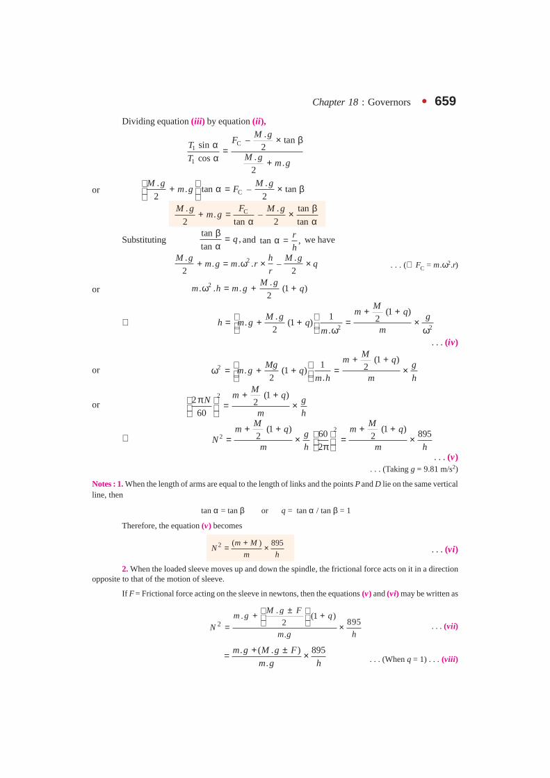
Chapter 18 : Governors � 659Dividing equation (iii) by equation (ii),
C1
1
.– tansin 2
.cos .2
M gFT
M gT m g
× βα =α +
or C. .
. tan – tan2 2
M g M gm g F
+ α = × β C. . tan
. –2 tan 2 tan
FM g M gm g
β+ = ×α α
Substitutingtan
,tan
qβ =α
and tan ,r
hα = we have
2. .. . . –
2 2
M g h M gm g m r q
r+ = ω × × . . . (∴ FC = m.ω2.r)
or 2 .. . . (1 )
2
M gm h m g qω = + +
∴ 2 2
(1 ). 1 2. (1 )2 .
Mm qM g g
h m g qmm
+ + = + + = × ω ω . . . (iv)
or 2(1 )1 2. (1 )
2 .
Mm qMg g
m g qm h m h
+ + ω = + + = ×
or 2 (1 )2 2
60
Mm qN g
m h
+ +π = ×
∴ 2
2(1 ) (1 )60 8952 2
2
M Mm q m qg
Nm h m h
+ + + + = × = × π . . . (v)
. . . (Taking g = 9.81 m/s2)
Notes : 1. When the length of arms are equal to the length of links and the points P and D lie on the same verticalline, then
tan α = tan β or q = tan α / tan β = 1
Therefore, the equation (v) becomes
2 ( ) 895m M
Nm h
+= × . . . (vi)
2. When the loaded sleeve moves up and down the spindle, the frictional force acts on it in a directionopposite to that of the motion of sleeve.
If F = Frictional force acting on the sleeve in newtons, then the equations (v) and (vi) may be written as
2
.. (1 )
8952.
M g Fm g q
Nm g h
± + + = × . . . (vii)
. ( . ) 895
.
m g M g F
m g h
+ ±= × . . . (When q = 1) . . . (viii)

660 � Theory of Machines
The + sign is used when the sleeve moves upwards or the governor speed increases and negative sign isused when the sleeve moves downwards or the governor speed decreases.
3. On comparing the equation (vi) with equation (ii) of Watt’s governor (Art. 18.5), we find that the
mass of the central load (M) increases the height of governor in the ratio m M
m
+.
2. Instantaneous centre method
In this method, equilibrium of the forces acting onthe link BD are considered. The instantaneous centre I liesat the point of intersection of PB produced and a line throughD perpendicular to the spindle axis, as shown in Fig. 18.4.Taking moments about the point I,
C 2
WF BM w IM ID× = × + ×
..
2
M gm g IM ID= × + ×
∴ C.
.2
IM M g IDF m g
BM BM= × + ×
..
2
IM M g IM MDm g
BM BM
+ = × +
..
2
IM M g IM MDm g
BM BM BM = × + +
.. tan (tan tan )
2
M gm g= α + α + β
. . . tan , and tanIM MD
BM BM = α = β �
Dividing throughout by tan α,
C . tan .. 1 . (1 )
tan 2 tan 2
F M g M gm g m g q
β= + + = + + α α tan
. . .tan
q β
= α �
We know that FC = m.ω2.r, and tanr
hα =
∴ 2 .. . . (1 )
2
h M gm r m g q
rω × = + +
or 2 2
.. (1 ) (1 )12 2
M g Mm g q m q g
hm m
+ + + += × = ×
ω ω. . . (Same as before)
When tan α = tan β or q = 1, then
2
m M gh
m
+= ×ω
Fig. 18.4. Instantaneous centremethod.

Chapter 18 : Governors � 661Example 18.2. A Porter governor has equal arms each 250 mm long and pivoted on the axis
of rotation. Each ball has a mass of 5 kg and the mass of the central load on the sleeve is 25 kg. Theradius of rotation of the ball is 150 mm when the governor begins to lift and 200 mm when thegovernor is at maximum speed. Find the minimum and maximum speeds and range of speed of thegovernor.
Solution. Given : BP = BD = 250 mm = 0.25 m ; m = 5 kg ; M = 15 kg ; r1 = 150 mm= 0.15m; r2 = 200 mm = 0.2 m
Fig. 18.5
The minimum and maximum positions of the governor are shown in Fig. 18.5 (a) and (b)respectively.
Minimum speed when r1 = BG = 0.15 mLet N1 = Minimum speed.
From Fig. 18.5 (a), we find that height of the governor,
2 2 2 21 ( ) – ( ) (0.25) – (0.15) 0.2 mh PG PB BG= = = =
We know that2
11
895 5 15 895( ) 17 900
5 0.2
m MN
m h
+ += × = × =
∴ N1 = 133.8 r.p.m. Ans.
Maximum speed when r2 = BG = 0.2 m
Let N2 = Maximum speed.
From Fig. 18.5 (b), we find that height of the governor,
2 2 2 22 ( ) – ( ) (0.25) – (0.2) 0.15 mh PG PB BG= = = =
We know that
2
22
895 5 15 895( ) 23 867
5 0.15
m MN
m h
+ += × = × =
∴ N2 = 154.5 r.p.m. Ans.
662 � Theory of Machines
Range of speed
We know that range of speed
= N2 – N1 = 154.4 – 133.8 = 20.7 r.p.m. Ans.
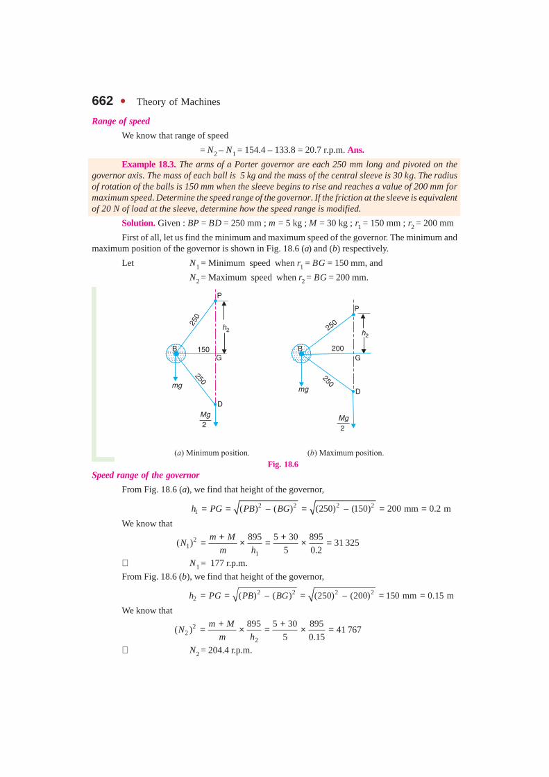
Example 18.3. The arms of a Porter governor are each 250 mm long and pivoted on thegovernor axis. The mass of each ball is 5 kg and the mass of the central sleeve is 30 kg. The radiusof rotation of the balls is 150 mm when the sleeve begins to rise and reaches a value of 200 mm formaximum speed. Determine the speed range of the governor. If the friction at the sleeve is equivalentof 20 N of load at the sleeve, determine how the speed range is modified.
Solution. Given : BP = BD = 250 mm ; m = 5 kg ; M = 30 kg ; r1 = 150 mm ; r2 = 200 mm
First of all, let us find the minimum and maximum speed of the governor. The minimum andmaximum position of the governor is shown in Fig. 18.6 (a) and (b) respectively.
Let N1 = Minimum speed when r1 = BG = 150 mm, and
N2 = Maximum speed when r2 = BG = 200 mm.
Fig. 18.6Speed range of the governor
From Fig. 18.6 (a), we find that height of the governor,
2 2 2 21 ( ) – ( ) (250) – (150) 200 mm 0.2 mh PG PB BG= = = = =
We know that
21
1
895 5 30 895( ) 31 325
5 0.2
m MN
m h
+ += × = × =
∴ N1 = 177 r.p.m.
From Fig. 18.6 (b), we find that height of the governor,
2 2 2 22 ( ) – ( ) (250) – (200) 150 mm 0.15 mh PG PB BG= = = = =
We know that
22
2
895 5 30 895( ) 41 767
5 0.15
m MN
m h
+ += × = × =
∴ N2 = 204.4 r.p.m.

Chapter 18 : Governors � 663We know that speed range of the governor
= N2 – N1 = 204.4 – 177 = 27.4 r.p.m. Ans.
Speed range when friction at the sleeve is equivalent of 20N of load (i.e. when F = 20 N)
We know that when the sleeve moves downwards,the friction force (F) acts upwards and the minimum speed isgiven by
2
11
. ( . – ) 895( )
.
m g M g FN
m g h
+= ×
5 9.81 (30 9.81 – 20) 895
295005 9.81 0.2
× + ×= × =×
∴ N1 = 172 r.p.m.
We also know that when the sleeve moves upwards,the frictional force (F) acts downwards and the maximumspeed is given by
22
2
. ( . ) 895( )
.
m g M g FN
m g h
+ += ×
5 9.81 (30 9.81 20) 895
442005 9.81 0.15
× + × += × =×
∴ N2 = 210 r.p.m.
We know that speed range of the governor
= N2 – N1 = 210 – 172 = 38 r.p.m. Ans.
Example 18.4. In an engine governor of the Porter type, the upper and lower arms are 200 mmand 250 mm respectively and pivoted on the axis of rotation. The mass of the central load is 15 kg,the mass of each ball is 2 kg and friction of the sleeve together with the resistance of the operatinggear is equal to a load of 25 N at the sleeve. If the limiting inclinations of the upper arms to thevertical are 30° and 40°, find, taking friction into account, range of speed of the governor.
Solution . Given : BP = 200 mm = 0.2 m ; BD = 250 mm = 0.25 m ; M = 15 kg ; m = 2 kg ;F = 25 N ; α1 = 30°; α2 = 40°
First of all, let us find the minimum and maximum speed of the governor.
The minimum and maximum position of the governor is shown Fig. 18.7 (a) and (b)respectively.
Let N1 = Minimum speed, and
N2 = Maximum speed.
From Fig. 18.7 (a), we find that minimum radius of rotation,
r1 = BG = BP sin 30° = 0.2 × 0.5 = 0.1 m
Height of the governor,
h1 = PG = BP cos 30° = 0.2 × 0.866 = 0.1732 m
A series of hydel generators.
Note : This picture is given as additionalinformation and is not a direct example of
the current chapter.

664 � Theory of Machines
and 2 2 2 2( ) – ( ) (0.25) – (0.1) 0.23DG BD BG= = = m
∴ tan β1 = BG/DG = 0.1/0.23 = 0.4348
and tan α1 = tan 30° = 0.5774
∴1
11
tan 0.43480.753
tan 0.5774q
β= = =α
Fig. 18.7
We know that when the sleeve moves downwards, the frictional force (F) acts upwards andthe minimum speed is given by
12
11
. –. (1 )
8952( )
.
M g Fm g q
Nm g h
+ + = ×
15 9.81 – 242 9.81 (1 0.753)
895233596
2 9.81 0.1732
× × + + = × =×
∴ N1 = 183.3 r.p.m.
Now from Fig. 18.7 (b),we find that maximum radius of rotation,
r2 = BG = BP sin 40° = 0.2 × 0.643 = 0.1268 m
Height of the governor,
h2 = PG = BP cos 40° = 0.2 × 0.766 = 0.1532 m
and 2 2 2 2( ) – ( ) (0.25) – (0.1268) 0.2154 mDG BD BG= = =
∴ tan β2 = BG/DG = 0.1268 / 0.2154 = 0.59
and tan α2 = tan 40° = 0.839
∴2
22
tan 0.590.703
tan 0.839q
β= = =α

Chapter 18 : Governors � 665We know that when the sleeve moves upwards, the frictional force (F) acts downwards and
the maximum speed is given by
2
22
2
.. (1 )
8952( )
.
m g Fm g q
Nm g h
+ + + = ×
15 9.81 242 9.81 (1 0.703)
895249 236
2 9.81 0.1532
× + × + + = × =×
∴ N2 = 222 r.p.m.
We know that range of speed
= N2 – N1 = 222 – 183.3 = 38.7 r.p.m. Ans.
Example 18.5. A Porter governor has all four arms 250 mm long. The upper arms areattached on the axis of rotation and the lower arms are attached to the sleeve at a distance of 30 mmfrom the axis. The mass of each ball is 5 kg and the sleeve has a mass of 50 kg. The extreme radii ofrotation are 150 mm and 200 mm. Determine the range of speed of the governor.
Solution. Given : BP = BD = 250 mm ; DH = 30 mm ; m = 5 kg ; M = 50 kg ;r1 = 150 mm ; r2 = 200 mm
First of all, let us find the minimum and maximum speed of the governor. The minimum andmaximum position of the governor is shown in Fig. 18.8 (a) and (b) respectively.
Fig. 18.8
Let N1 = Minimum speed when r1 = BG = 150 mm ; and
N2 = Maximum speed when r2 = BG = 200 mm.
From Fig. 18.8 (a), we find that height of the governor,
2 2 2 21 ( ) – ( ) (250) – (150) 200 mm 0.2 mh PG BP BG= = = = =
BF = BG – FG = 150 – 30 = 120 mm . . . (� FG = DH)

666 � Theory of Machines
and 2 2 2 2( ) – ( ) (250) – (120) 219 mmDF DB BF= = =
∴ tan α1 = BG/PG = 150 / 200 = 0.75
and tan β1 = BF/DF = 120/219 = 0.548
∴1
11
tan 0.5480.731
tan 0.75q
β= = =α
We know that 1
21
1
50(1 ) 5 (1 0.731)895 8952 2( ) 43206
5 0.2
Mm q
Nm h
+ + + += × = × =
∴ N1 = 208 r.p.m.
From Fig. 18.8(b), we find that height of the governor,
2 2 2 22 ( ) ( ) (250) (200) 150 mm 0.15 mh PG BP BG= = − = − = =
BF = BG – FG = 200 – 30 = 170 mm
and 2 2 2 2( ) ( ) (250) (170) 183mmDF DB BF= − = − =
∴ tan α2= BG/PG = 200/150 = 1.333
and tan β2= BF/DF = 170/183 = 0.93
22
2
tan 0.930.7
tan 1.333q
β∴ = = =α
We know that
2
22
2
50(1 ) 5 (1 0.7)895 8952 2( ) 56 683
5 0.15
Mm q
Nm h
+ + + += × = × =
∴ N2 = 238 r.p.m.
We know that range of speed
= N2 – N1 = 238 – 208 = 30 r.p.m. Ans.
Example 18.6. The arms of a Porter governor are 300 mm long. The upper arms are pivotedon the axis of rotation. The lower arms are attached to a sleeve at a distance of 40 mm from the axisof rotation. The mass of the load on the sleeve is 70 kg and the mass of each ball is 10 kg. Determinethe equilibrium speed when the radius of rotation of the balls is 200 mm. If the friction is equivalentto a load of 20 N at the sleeve, what will be the range of speed for this position ?
Solution. Given : BP = BD = 300 mm ; DH = 40 mm ; M = 70 kg ; m = 10 kg ; r = BG = 200 mm
Equilibrium speed when the radius of rotation r = BG = 200 mm
Let N = Equilibrium speed.The equilibrium position of the governor is shown in Fig. 18.9. From the figure, we find that
height of the governor,
2 2 2 2( ) – ( ) (300) – (200) 224 mmh PG BP BG= = = =
= 0.224m

Chapter 18 : Governors � 667 ∴ BF = BG – FG = 200 – 40 = 160
. . . (� FG = DH)
and 2 2 2 2( ) – ( ) (300) – (160) 254 mmDF DB BF= = =
∴ tan α = BG/PG = 200 / 224 = 0.893
and tan β = BF/DF = 160 / 254 = 0.63
∴ tan 0.63
0.705tan 0.893
qβ= = =α
We know that
2
(1 ) 8952M
m qN
m h
+ += ×
7010 (1 0.705) 8952 27 840
10 0.224
+ += × =
∴ N2 = 167 r.p.m. Ans.
Range of speed when friction is equivalent to load of 20 Nat the sleeve ( i.e. when F = 20 N)
Let N1 = Minimum equilibrium speed, and
N2 = Maximum equilibrium speed.
We know that when the sleeve moves downwards,the frictional force (F) acts upwards and the minimum equi-librium speed is given by
21
. –. (1 )
8952( )
.
M g Fm g q
Nm g h
+ + = ×
70 9.81 – 2010 9.81 (1 0.705)
895227 144
10 9.81 0.224
× × + + = × =×
∴ N1 = 164.8 r.p.m.
We also know that when the sleeve moves upwards, the frictional force (F) acts downwardsand the maximum equilibrium speed is given by
22
.. (1 )
8952( )
.
M g Fm g q
Nm g h
+ + + = ×
70 9.81 2010 9.81 (1 0.705)
895228 533
10 9.81 0.224
× + × + + = × =×
∴ N2 = 169 r.p.m.
Fig. 18.9
An 18th century governor.

668 � Theory of Machines
We know that range of speed
= N2 – N1 = 169 – 164.8 = 4.2 r.p.m. Ans.
Example 18.7. A loaded Porter governor has four links each 250 mm long, two revolvingmasses each of 3 kg and a central dead weight of mass 20 kg. All the links are attached to respectivesleeves at radial distances of 40 mm from the axis of rotation. The masses revolve at a radius of 150mm at minimum speed and at a radius of 200 mm at maximum speed. Determine the range of speed.
Solution. Given : BP = BD = 250 mm ; m = 3 kg ; M = 20 kg ; PQ = DH = 40 mm ;r1 = 150 mm ; r2 = 200 mm
First of all, let us find the minimum and maximum speed of the governor.
The minimum and maximum position of the governor is shown in Fig. 18.10 (a) and (b) respectively.
Let N1 = Minimum speed when r1 = BG = 150 mm, and
N2 = Minimum speed when r2 = BG = 200 mm.
From Fig. 18.10 (a), we find that
BF = BG – FG = 150 – 40 = 110 mm
and sin α1 = BF / BP = 110 / 250 = 0.44 or α1 = 26.1°
∴ Height of the governor,
h1 = OG = BG / tan α1 = 150 / tan 26.1° = 306 mm = 0.306 m
Fig. 18.10
Since all the links are attached to respective sleeves at equal distances (i.e.40 mm) from theaxis of rotation, therefore
tan α1 = tan β1 or q = 1
We know that2
11
895 3 20 895( ) 22424
3 0.306
m MN
m h
+ += × = × =
N1 = 150 r.p.m.

Chapter 18 : Governors � 669Now from Fig. 18.10 (b), we find that
BF = BG – FG = 200 – 40 = 160 mm
and sin α2 = BF/BP = 160 / 250 = 0.64 or β2 = 39.8°
∴ Height of the governor,
h2 = OG = BG / tan α2 = 200 / tan 39.8° = 240 mm = 0.24 m
In this case also,
tan α2 = tan β2 or q = 1
We know that 2
22
895 3 20 895( ) 28 590
3 0.24
m MN
m h
+ += × = × =
∴ N2 = 169 r.p.m.
We know that range of speed
= N2 – N1 = 169 – 150 = 19 r.p.m. Ans.
Example 18.8. All the arms of a Porter governor are 178 mm long and are hinged at adistance of 38 mm from the axis of rotation. The mass of each ball is 1.15 kg and mass of the sleeveis 20 kg. The governor sleeve begins to rise at 280 r.p.m. when the links are at an angle of 30° to thevertical. Assuming the friction force to be constant, determine the mini-mum and maximum speed of rotation when the inclination of the armsto the vertical is 45°.
Solution. Given : BP = BD = 178 mm ; PQ = DH = 38 mm ;m = 1.15 kg ; M = 20 kg ; N = 280 r.p.m. ; α = β = 30°
First of all, let us find the friction force (F). The equilibriumposition of the governor when the lines are at 30° to vertical, is shownin Fig. 18.11. From the figure, we find that radius of rotation,
r = BG = BF + FG = BP × sin α + FG
= 178 sin 30° + 38 = 127 mm
and height of the governor,
h = BG / tan α= 127 / tan 30° = 220 mm = 0.22 m
We know that
2 . ( ) 895
.
m g Mg FN
m g h
+ ±= ×
. . . (∴ tan α = tan β or q = 1)
2 1.15 9.81 20 9.81 895(280)
1.15 9.81 0.22
F× + × ±= ××
or2(280) 1.15 9.81 0.22
– 1.15 9.81 – 20 9.81895
F× × ×± = × ×
= 217.5 – 11.3 – 196.2 = 10 N
We know that radius of rotation when inclination of the arms to the vertical is 45 (i.e. when α = β = 45°),
r = BG = BF + FG = BP × sin α + FG
= 178 sin 45° + 38 = 164 mm
Fig. 18.11

670 � Theory of Machines
and height of the governor,
h = BG / tan α = 164 / tan 45° = 164 mm = 0.164 m
Let N1 = Minimum speed of rotation, and
N2 = Maximum speed of rotation.
We know that2
1. ( . – ) 895
( ).
m g M g FN
m g h
+= ×
1.15 9.81 (20 9.81 – 10) 89595 382
1.15 9.81 0.164
× + ×= × =×
∴ N1 = 309 r.p.m. Ans.
and 22
. ( . ) 895( )
.
m g M g FN
m g h
+ += ×
1.15 9.81 (20 9.81 10) 895105 040
1.15 9.81 0.164
× + × += × =×
N2 = 324 r.p.m. Ans.
18.7. Proell Governor
The Proell governor has the balls fixed at B and C to the extension of the links DF and EG, asshown in Fig. 18.12 (a). The arms FP and GQ are pivoted at P and Q respectively.
Consider the equilibrium of the forces on one-half of the governor as shown in Fig. 18.12 (b).The instantaneous centre (I) lies on the intersection of the line PF produced and the line from Ddrawn perpendicualr to the spindle axis. The prependicular BM is drawn on ID.
Fig. 18.12. Proell governor.
Taking moments about I, using the same notations as discussed in Art. 18.6 (Porter governor),
C.
.2 2
W M gF BM w IM ID m g IM ID× = × + × = × + × . . . (i)
∴ C.
.2
IM M g IM MDF m g
BM BM
+ = × + . . . ( � ID = IM + MD)
Chapter 18 : Governors � 671
Multiplying and dividing by FM, we have
C.
.2
FM IM M g IM MDF m g
BM FM FM FM
= × + + .
. tan (tan tan )2
FM M gm g
BM = × α + α + β
. tantan . 1
2 tan
FM M gm g
BM
β= × α + + α
We know that FC = m.ω2 r ; tanr
hα = and
tan
tanq
β=α
∴ 2 .. . . (1 )
2
FM r M gm r m g q
BM h ω = × + +
and2
(1 )2
Mm qFM g
BM m h
+ + ω =
. . . (ii)
Substituting ω = 2π N/60, and g = 9.81 m/s2, we get
2(1 ) 8952
Mm qFM
NBM m h
+ + =
. . . (iii)
Notes : 1. The equation (i) may be applied to any given configuration of the governor.
2. Comparing equation (iii) with the equation (v) of the Porter governor (Art. 18.6), we see that theequilibrium speed reduces for the given values of m, M and h. Hence in order to have the same equilibriumspeed for the given values of m, M and h, balls of smaller masses are used in the Proell governor than in thePorter governor.
3. When α = β, then q = 1. Therefore equation (iii) may be written as
2 895FM m MN
BM m h
+ = (h being in metres) ...(iv)
Example 18.9. A Proell governor has equal arms of length 300 mm. The upper and lowerends of the arms are pivoted on the axis of the governor. The extension arms of the lower links areeach 80 mm long and parallel to the axis when the radii of rotation of the balls are 150 mm and200 mm. The mass of each ball is 10 kg and the mass of the central load is 100 kg. Determine therange of speed of the governor.
Solution. Given : PF = DF = 300 mm ; BF = 80 mm ; m = 10 kg ; M = 100 kg ;r1 = 150 mm; r2 = 200 mm
First of all, let us find the minimum and maximum speed of the governor. The minimum andmaximum position of the governor is shown in Fig. 18.13.
Let N1 = Minimum speed when radius of rotation, r1 = FG = 150 mm ; and
N2 = Maximum speed when radius of rotation , r2 = FG = 200 mm.
From Fig. 18.13 (a), we find that height of the governor,
2 2 2 21 ( ) – ( ) (300) – (150) 260 mm 0.26 mh PG PF FG= = = = =
672 � Theory of Machines
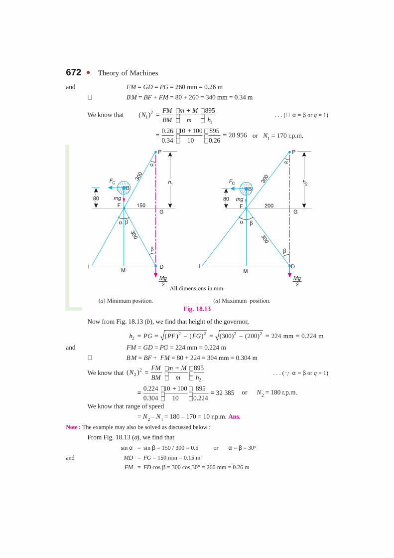
and FM = GD = PG = 260 mm = 0.26 m
∴ BM = BF + FM = 80 + 260 = 340 mm = 0.34 m
We know that 21
1
895( )
FM m MN
BM m h
+ = . . . (∴ α = β or q = 1)
0.26 10 100 895
28 9560.34 10 0.26
+ = = or N1 = 170 r.p.m.
Fig. 18.13
Now from Fig. 18.13 (b), we find that height of the governor,
2 2 2 22 ( ) – ( ) (300) – (200) 224 mm 0.224 mh PG PF FG= = = = =
and FM = GD = PG = 224 mm = 0.224 m
∴ BM = BF + FM = 80 + 224 = 304 mm = 0.304 m
We know that 22
2
895( )
FM m MN
BM m h
+ = . . . (� α = β or q = 1)
0.224 10 100 89532 385
0.304 10 0.224
+ = = or N2 = 180 r.p.m.
We know that range of speed
= N2 – N1 = 180 – 170 = 10 r.p.m. Ans.
Note : The example may also be solved as discussed below :
From Fig. 18.13 (a), we find that
sin α = sin β = 150 / 300 = 0.5 or α = β = 30°
and MD = FG = 150 mm = 0.15 m
FM = FD cos β = 300 cos 30° = 260 mm = 0.26 m
Chapter 18 : Governors � 673IM = FM tan α = 0.26 tan 30° = 0.15 m
BM = BF + FM = 80 + 260 = 340 mm = 0.34 m
ID = IM + MD = 0.15 + 0.15 = 0.3 m
We know that centrifugal force,
2
2 21C 1 1 1
2( ) 10 0.15 0.0165 ( )
60
NF m r N
π = ω = = Now taking moments about point I,
C.
.2
M gF BM m g IM ID× = × + ×
or2
1100 9.81
0.0165 ( ) 0.34 10 9.81 0.15 0.32
N×= × × + ×
0.0056 (N1)2 = 14.715 + 147.15 = 161.865
∴ 21
161.865( ) 28 904
0.0056N = = or N1 = 170 r.p.m.
Similarly N2 may be calculated.
Example 18.10. A governor of the Proell type has each arm 250 mm long. The pivots of theupper and lower arms are 25 mm from the axis. The central load acting on the sleeve has a mass of25 kg and the each rotating ball has a mass of 3.2 kg. When the governor sleeve is in mid-position,the extension link of the lower arm is vertical and the radius of the path of rotation of the masses is175 mm. The vertical height of the governor is 200 mm.
If the governor speed is 160 r.p.m. when in mid-position, find : 1. length of the extensionlink; and 2. tension in the upper arm.
Note : This picture is given as additional information and is not a direct example of the current chapter.
An overview of a combined cycle power plant. Governors are used in power plants to control theflow of working fluids.
674 � Theory of Machines
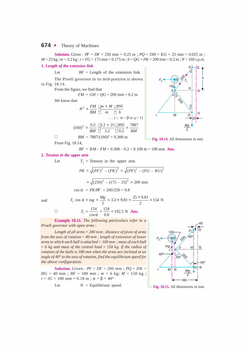
Solution. Given : PF = DF = 250 mm = 0.25 m ; PQ = DH = KG = 25 mm = 0.025 m ;M = 25 kg ; m = 3.2 kg ; r = FG = 175 mm = 0.175 m ; h = QG = PK = 200 mm = 0.2 m ; N = 160 r.p.m.
1. Length of the extension link
Let BF = Length of the extension link.
The Proell governor in its mid-position is shownin Fig. 18.14.
From the figure, we find thatFM = GH = QG = 200 mm = 0.2 m
We know that
2 895FM m MN
BM m h
+ = . . . (� α = β or q = 1)
2 0.2 3.2 25 895 7887(160)
3.2 0.2BM BM
+ = = ∴ BM = 7887/(160)2 = 0.308 m
From Fig. 18.14,
BF = BM – FM = 0.308 – 0.2 = 0.108 m = 108 mm Ans.2. Tension in the upper arm
Let T1 = Tension in the upper arm.
2 2 2 2( ) – ( ) ( ) – ( – )PK PF FK PF FG KG= =
2 2(250) – (175 – 25) 200 mm= =
cos α = PK/PF = 200/250 = 0.8
and 125 9.81
cos 3.2 9.81 154 N2 2
MgT mg
×α = + = × + =
∴ 1154 154
192.5 Ncos 0.8
T = = =α
Ans.
Example 18.11. The following particulars refer to aProell governor with open arms :
Length of all arms = 200 mm ; distance of pivot of armsfrom the axis of rotation = 40 mm ; length of extension of lowerarms to which each ball is attached = 100 mm ; mass of each ball= 6 kg and mass of the central load = 150 kg. If the radius ofrotation of the balls is 180 mm when the arms are inclined at anangle of 40° to the axis of rotation, find the equilibrium speed forthe above configuration.
Solution. Given : PF = DF = 200 mm ; PQ = DK =HG = 40 mm ; BF = 100 mm ; m = 6 kg; M = 150 kg ;r = JG = 180 mm = 0.18 m ; α = β = 40°
Let N = Equilibrium speed. Fig. 18.15. All dimensions in mm.
Fig. 18.14. All dimensions in mm.
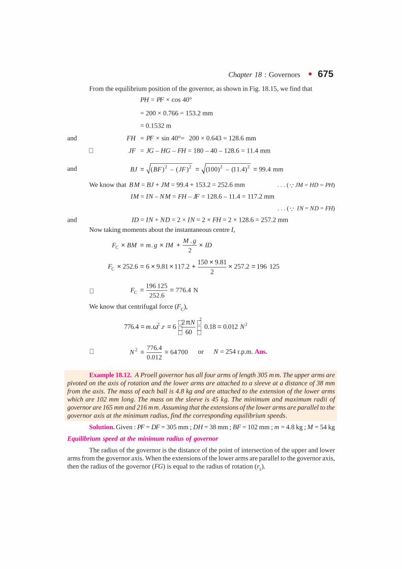
Chapter 18 : Governors � 675From the equilibrium position of the governor, as shown in Fig. 18.15, we find that
PH = PF × cos 40°
= 200 × 0.766 = 153.2 mm
= 0.1532 m
and FH = PF × sin 40°= 200 × 0.643 = 128.6 mm
∴ JF = JG – HG – FH = 180 – 40 – 128.6 = 11.4 mm
and 2 2( ) – ( )BJ BF JF= 2 2(100) – (11.4) 99.4 mm= =
We know that BM = BJ + JM = 99.4 + 153.2 = 252.6 mm . . . (�JM = HD = PH)
IM = IN – NM = FH – JF = 128.6 – 11.4 = 117.2 mm
. . . (� IN = ND = FH)
and ID = IN + ND = 2 × IN = 2 × FH = 2 × 128.6 = 257.2 mm
Now taking moments about the instantaneous centre I,
C.
.2
M gF BM m g IM ID× = × + ×
C150 9.81
252.6 6 9.81 117.2 257.2 196 1252
F×× = × × + × =
∴ C196 125
776.4 N252.6
F = =
We know that centrifugal force (FC),
2
2 22776.4 . . 6 0.18 0.012
60
Nm r N
π = ω = =
∴ 2 776.464700
0.012N = = or N = 254 r.p.m. Ans.
Example 18.12. A Proell governor has all four arms of length 305 mm. The upper arms arepivoted on the axis of rotation and the lower arms are attached to a sleeve at a distance of 38 mmfrom the axis. The mass of each ball is 4.8 kg and are attached to the extension of the lower armswhich are 102 mm long. The mass on the sleeve is 45 kg. The minimum and maximum radii ofgovernor are 165 mm and 216 mm. Assuming that the extensions of the lower arms are parallel to thegovernor axis at the minimum radius, find the corresponding equilibrium speeds.
Solution. Given : PF = DF = 305 mm ; DH = 38 mm ; BF = 102 mm ; m = 4.8 kg ; M = 54 kg
Equilibrium speed at the minimum radius of governor
The radius of the governor is the distance of the point of intersection of the upper and lowerarms from the governor axis. When the extensions of the lower arms are parallel to the governor axis,then the radius of the governor (FG) is equal to the radius of rotation (r1).
676 � Theory of Machines
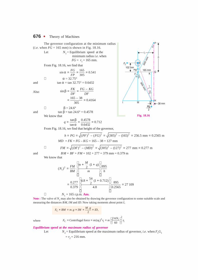
The governor configuration at the minimum radius(i.e. when FG = 165 mm) is shown in Fig. 18.16.
Let N1 = Equilibrium speed at the minimum radius i.e. when FG = r1 = 165 mm.
From Fig. 18.16, we find that
165
sin 0.541305
FG
FPα = = =
∴ α = 32.75°and tan α = tan 32.75° = 0.6432
–sin
165 – 380.4164
305
FK FG KG
DF DFβ = =
= =
∴ β = 24.6°and tan β = tan 24.6° = 0.4578
We know that
tan 0.4578
0.712tan 0.6432
qβ= = =α
From Fig. 18.16, we find that height of the governor,
2 2 2 2( ) – ( ) (305) – (165) 256.5 mm 0.2565 mh PG PF FG= = = = = MD = FK = FG – KG = 165 – 38 = 127 mm
∴ 2 2 2 2( ) – ( ) (305) – (127) 277 mm 0.277 mFM DF MD= = = =and BM = BF + FM = 102 + 277 = 379 mm = 0.379 m
We know that
2
1
(1 ) 8952( )
Mm qFM
NBM m h
+ + =
544.8 (1 0.712)0.277 8952 27 109
0.379 4.8 0.2565
+ + = =
∴ N1 = 165 r.p.m. Ans.Note : The valve of N1 may also be obtained by drawing the governor configuration to some suitable scale andmeasuring the distances BM, IM and ID. Now taking moments about point I,
C.
. ,2
M gF BM m g IM ID× = × + ×
where 2
2 1C 1 1 1
2Centrifugal force ( )
60
NF m r m r
π = = ω = Equilibrium speed at the maximum radius of governor
Let N2 = Equilibrium speed at the maximum radius of governor, i.e. when F1G1
= r2 = 216 mm.
Fig. 18.16
Also
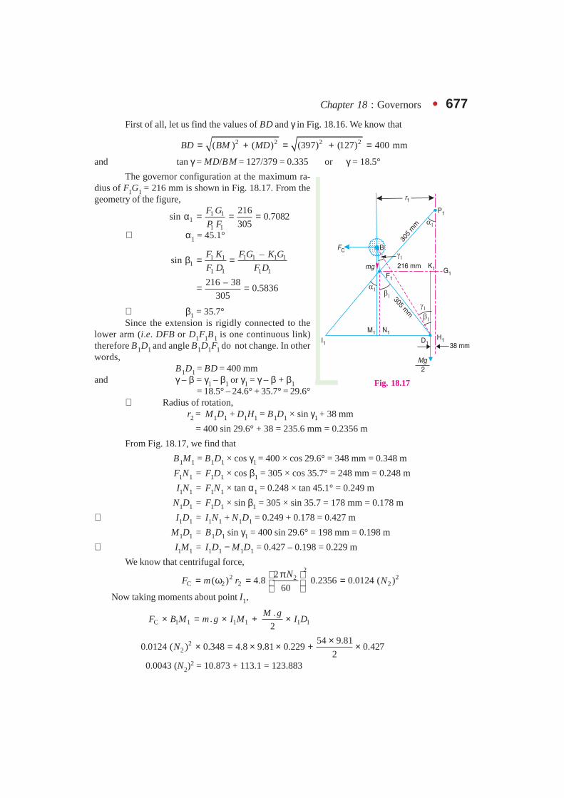
Chapter 18 : Governors � 677First of all, let us find the values of BD and γ in Fig. 18.16. We know that
2 2 2 2( ) ( ) (397) (127) 400 mmBD BM MD= + = + =
and tan γ = MD/BM = 127/379 = 0.335 or γ = 18.5°
The governor configuration at the maximum ra-dius of F1G1 = 216 mm is shown in Fig. 18.17. From thegeometry of the figure,
1 11
1 1
216sin 0.7082
305
F G
P Fα = = =
∴ α 1 = 45.1°
1 1 1 1 1 11
1 1 1 1
–sin
216 – 380.5836
305
F K F G K G
F D F Dβ = =
= =
∴ β 1 = 35.7°Since the extension is rigidly connected to the
lower arm (i.e. DFB or D1F1B1 is one continuous link)therefore B1D1 and angle B1D1F1 do not change. In otherwords,
B1D1 = BD = 400 mmand γ – β = γ1 – β1 or γ1 = γ – β + β1
= 18.5° – 24.6° + 35.7° = 29.6°∴ Radius of rotation,
r2 = M1D1 + D1H1 = B1D1 × sin γ1 + 38 mm
= 400 sin 29.6° + 38 = 235.6 mm = 0.2356 m
From Fig. 18.17, we find that
B1M1 = B1D1 × cos γ1 = 400 × cos 29.6° = 348 mm = 0.348 m
F1N1 = F1D1 × cos β1 = 305 × cos 35.7° = 248 mm = 0.248 m
I1N1 = F1N1 × tan α1 = 0.248 × tan 45.1° = 0.249 m
N1D1 = F1D1 × sin β1 = 305 × sin 35.7 = 178 mm = 0.178 m
∴ I1D1 = I1N1 + N1D1 = 0.249 + 0.178 = 0.427 m
M1D1 = B1D1 sin γ1 = 400 sin 29.6° = 198 mm = 0.198 m
∴ I1M1 = I1D1 − M1D1 = 0.427 – 0.198 = 0.229 m
We know that centrifugal force,2
2 22C 2 2 2
2( ) 4.8 0.2356 0.0124 ( )
60
NF m r N
π = ω = = Now taking moments about point I1,
C 1 1 1 1 1 1.
.2
M gF B M m g I M I D× = × + ×
22
54 9.810.0124 ( ) 0.348 4.8 9.81 0.229 0.427
2N
×× = × × + ×
0.0043 (N2)2 = 10.873 + 113.1 = 123.883
Fig. 18.17
678 � Theory of Machines
∴ 22
123.883( ) 28 810
0.0043N = = or N2 = 170 r.p.m. Ans.
Note : The value of N2 may also be obtained by drawing the governor configuration to some suitable scale andmeasuring the distances B1M1, I1M1 and I1D1.
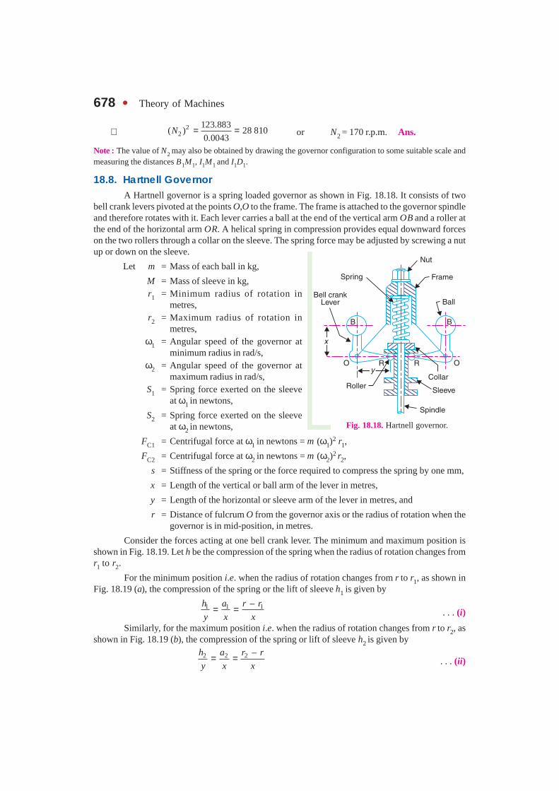
18.8. Hartnell GovernorA Hartnell governor is a spring loaded governor as shown in Fig. 18.18. It consists of two
bell crank levers pivoted at the points O,O to the frame. The frame is attached to the governor spindleand therefore rotates with it. Each lever carries a ball at the end of the vertical arm OB and a roller atthe end of the horizontal arm OR. A helical spring in compression provides equal downward forceson the two rollers through a collar on the sleeve. The spring force may be adjusted by screwing a nutup or down on the sleeve.
Let m = Mass of each ball in kg,
M = Mass of sleeve in kg,r1 = Minimum radius of rotation in
metres,r2 = Maximum radius of rotation in
metres,ω1 = Angular speed of the governor at
minimum radius in rad/s,ω2 = Angular speed of the governor at
maximum radius in rad/s,S1 = Spring force exerted on the sleeve
at ω1 in newtons,
S2 = Spring force exerted on the sleeveat ω2 in newtons,
FC1 = Centrifugal force at ω1 in newtons = m (ω1)2 r1,
FC2 = Centrifugal force at ω2 in newtons = m (ω2)2 r2,
s = Stiffness of the spring or the force required to compress the spring by one mm,
x = Length of the vertical or ball arm of the lever in metres,
y = Length of the horizontal or sleeve arm of the lever in metres, and
r = Distance of fulcrum O from the governor axis or the radius of rotation when thegovernor is in mid-position, in metres.
Consider the forces acting at one bell crank lever. The minimum and maximum position isshown in Fig. 18.19. Let h be the compression of the spring when the radius of rotation changes fromr1 to r2.
For the minimum position i.e. when the radius of rotation changes from r to r1, as shown inFig. 18.19 (a), the compression of the spring or the lift of sleeve h1 is given by
1 1 1–h a r r
y x x= = . . . (i)
Similarly, for the maximum position i.e. when the radius of rotation changes from r to r2, asshown in Fig. 18.19 (b), the compression of the spring or lift of sleeve h2 is given by
2 2 2 –h a r r
y x x= = . . . (ii)
Fig. 18.18. Hartnell governor.
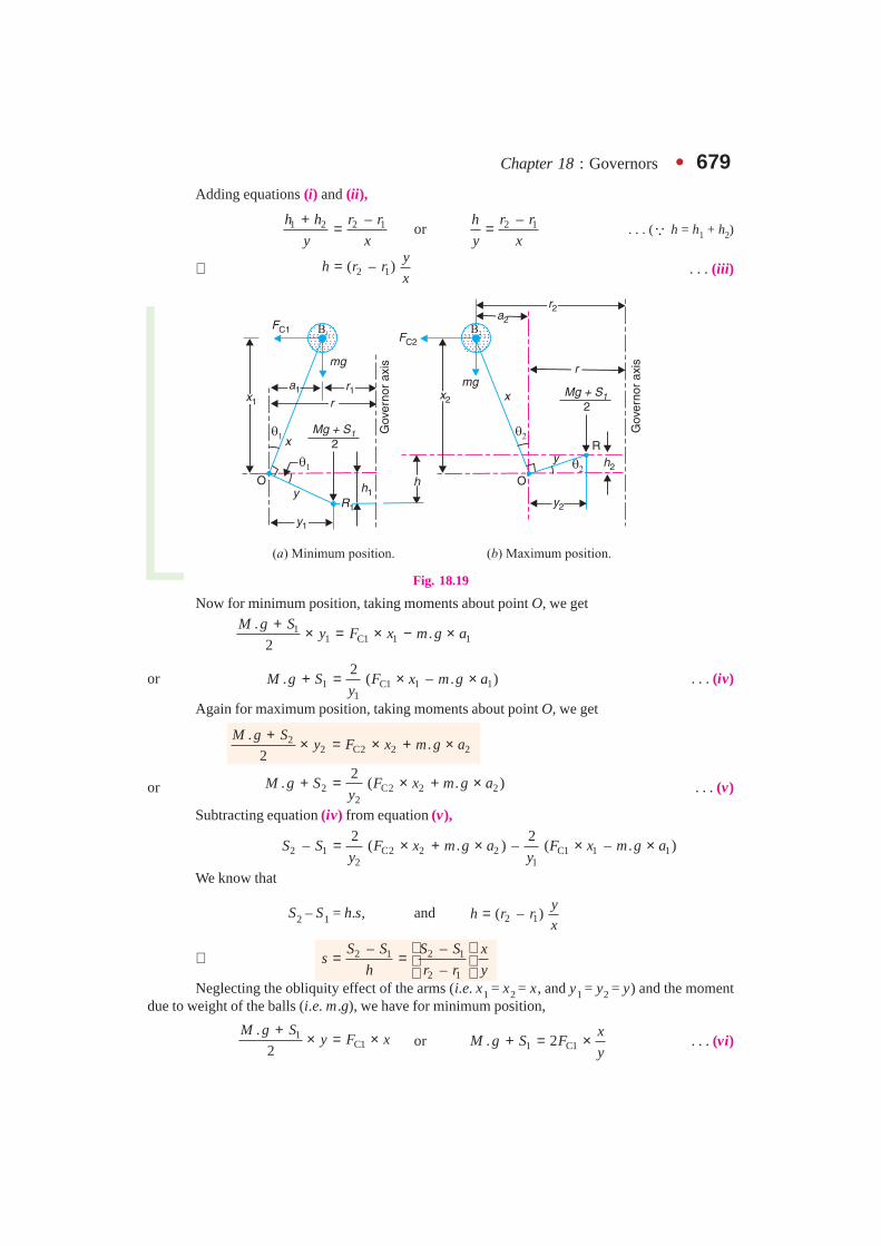
Chapter 18 : Governors � 679Adding equations (i) and (ii),
1 2 2 1–h h r r
y x
+ = or 2 1–r rh
y x= . . . (� h = h1 + h2)
∴ 2 1( – )y
h r rx
= . . . (iii)
Fig. 18.19
Now for minimum position, taking moments about point O, we get
11 C1 1 1
..
2
M g Sy F x m g a
+ × = × − ×
or 1 C1 1 11
2. ( – . )M g S F x m g a
y+ = × × . . . (iv)
Again for maximum position, taking moments about point O, we get
22 C2 2 2
..
2
M g Sy F x m g a
+× = × + ×
or 2 C2 2 22
2. ( . )M g S F x m g a
y+ = × + × . . . (v)
Subtracting equation (iv) from equation (v),
2 1 C2 2 2 C1 1 12 1
2 2– ( . ) – ( – . )S S F x m g a F x m g a
y y= × + × × ×
We know that
S2 – S1 = h.s, and 2 1( – )y
h r rx
=
∴ 2 1 2 1
2 1
– –
–
S S S S xs
h r r y
= =
Neglecting the obliquity effect of the arms (i.e. x1 = x2 = x, and y1 = y2 = y) and the moment
due to weight of the balls (i.e. m.g), we have for minimum position,
1C1
.
2
M g Sy F x
+× = × or 1 C1. 2
xM g S F
y+ = × . . . (vi)

680 � Theory of Machines
Similarly for maximum position,
2C2
.
2
M g Sy F x
+× = × or 2 C2. 2
xM g S F
y+ = × . . . (vii)
Subtracting equation (vi) from equation (vii),
2 1 C2 C1– 2 ( – )x
S S F Fy
= ...(viii)
We know that
S2 – S1 = h.s, and 2 1( – )y
h r rx
=
∴2
C2 C12 1
2 1
––2
–
F FS S xs
h r r y
= =
. . . (ix)
Notes : 1. Unless otherwise stated, the obliquity effect of the arms and the moment due to the weight of the ballsis neglected, in actual practice.
2. When friction is taken into account, the weight of the sleeve (M.g) may be replaced by (M.g. ± F).
3. The centrifugal force (FC) for any intermediate position (i.e. between the minimum and maximumposition) at a radius of rotation (r) may be obtained as discussed below :
Since the stiffness for a given spring is constant for all positions, therefore for minimum and interme-diate position,
2
C C1
1
–2
–
F F xs
r r y
=
. . . (x)
and for intermediate and maximum position,2
C2 C
2
–2
–
F F xs
r r y
=
. . . (xi)
∴ From equations (ix), (x) and (xi),
C2 C1 C C1 C2 C
2 1 1 2
– – –
– – –
F F F F F F
r r r r r r= =
or1 2
C C1 C2 C1 C2 C2 C12 1 2 1
– –( – ) – ( – )
– –
r r r rF F F F F F F
r r r r
= + =
Example 18.13. A Hartnell governor having a central sleeve spring and two right-angled
bell crank levers moves between 290 r.p.m. and 310 r.p.m. for a sleeve lift of 15 mm. The sleeve armsand the ball arms are 80 mm and 120 mm respectively. The levers are pivoted at 120 mm from thegovernor axis and mass of each ball is 2.5 kg. The ball arms are parallel to the governor axis at thelowest equilibrium speed. Determine : 1. loads on the spring at the lowest and the highest equilib-rium speeds, and 2. stiffness of the spring.
Solution. Given : N1 = 290 r.p.m. or ω1 = 2 π × 290/60 = 30.4 rad/s ; N2 = 310 r.p.m. orω2 = 2 π × 310/60 = 32.5 rad/s ; h = 15 mm = 0.015 m ; y = 80 mm = 0.08 m ; x = 120 mm =0.12 m ; r = 120 mm = 0.12 m ; m = 2.5 kg
1. Loads on the spring at the lowest and highest equilibrium speeds
Let S = Spring load at lowest equilibrium speed, and
S2 = Spring load at highest equilibrium speed.
Since the ball arms are parallel to governor axis at the lowest equilibrium speed (i.e. atN1 = 290 r.p.m.), as shown in Fig. 18.20 (a), therefore
r = r1 = 120 mm = 0.12 m

Chapter 18 : Governors � 681We know that centrifugal force at the minimum speed,
FC1 = m (ω1)2 r1 = 2.5 (30.4)2 0.12 = 277 N
Now let us find the radius of rotation at the highest equilibrium speed, i.e. at N2 = 310 r.p.m.
The position of ball arm and sleeve arm at the highest equilibrium speed is shown in Fig. 18.20 (b).
Let r2 = Radius of rotation at N2 = 310 r.p.m.
We know that 2 1( – )y
h r rx
=
or 2 10.12
0.12 0.015 0.1425 m0.08
xr r h
y
= + = + = ∴ Centrifugal force at the maximum speed,
FC2 = m (ω2)2 r2 = 2.5 × (32.5)2 × 0.1425 = 376 N
Fig. 18.20
Neglecting the obliquity effect of arms and the moment due to the weight of the balls, wehave for lowest position,
1 C10.12
. 2 2 277 831 N0.08
xM g S F
y+ = × = × × =
∴ S2 = 831 N Ans. (� M = 0)
and for highest position,
2 C20.12
. 2 2 376 1128 N0.08
xM g S F
y+ = × = × × =
∴ S1 = 1128 N Ans. (� M = 0)
2. Stiffness of the spring
We know that stiffness of the spring,
2 1– 1128 – 83119.8 N/mm
15
S Ss
h= = = Ans.
Example 18.14. In a spring loaded Hartnell type governor, the extreme radii of rotation ofthe balls are 80 mm and 120 mm. The ball arm and the sleeve arm of the bell crank lever are equalin length. The mass of each ball is 2 kg. If the speeds at the two extreme positions are 400 and420 r.p.m., find : 1. the initial compression of the central spring, and 2. the spring constant.

682 � Theory of Machines
Solution. Given : r1 = 80 mm = 0.08 m ; r2 = 120 mm = 0.12 m ; x = y ; m = 2 kg ; N1 = 400r.p.m. or ω = 2 π × 400/60 = 41.9 rad/s ; N2 = 420 r.p.m. or ω2 = 2 π × 420/60 = 44 rad/s
Initial compression of the central spring
We know that the centrifugal force at the minimum speed,
FC1 = m (ω1)2 r1 = 2 (41.9)2 0.08 = 281 N
and centrifugal force at the maximum speed,
FC2 = m (ω2)2 r2 = 2 (44)2 0.12 = 465 N
Let S1 = Spring force at the minimum speed, and
S2 = Spring force at the maximum speed.
We know that for minimum position,
1 C1. 2x
M g S Fy
+ = ×
∴ S1 = 2 FC1 = 2 × 281 = 562 N . . . (�M = 0 and x = y)
Similarly for maximum position,
2 C2. 2x
M g S Fy
+ = ×
∴ S2 = 2 FC2 = 2 × 465 = 930 N
We know that lift of the sleeve,
2 1 2 1( – ) – 120 – 80 40 mmy
h r r r rx
= = = = . . . (�x = y)
∴ Stiffness of the spring,
2 1– 930 – 5629.2 N/mm
40
S Ss
h= = =
We know that initial compression of the central spring
1 56261 mm
9.2
S
s= = = Ans.
2. Spring constant
We have calculated above that the spring constant or stiffness of the spring,
s = 9.2 N/mm Ans.
Example 18.15. A spring loaded governor of the Hartnell type has arms of equal length. Themasses rotate in a circle of 130 mm diameter when the sleeve is in the mid position and the ball armsare vertical. The equilibrium speed for this position is 450 r.p.m., neglecting friction. The maximumsleeve movement is to be 25 mm and the maximum variation of speed taking in account the friction tobe 5 per cent of the mid position speed. The mass of the sleeve is 4 kg and the friction may beconsidered equivalent to 30 N at the sleeve. The power of the governor must be sufficient to over-come the friction by one per cent change of speed either way at mid-position. Determine, neglectingobliquity effect of arms ; 1. The value of each rotating mass : 2. The spring stiffness in N/mm ; and3. The initial compression of spring.
Solution.Given : x = y ; d = 130 mm or r = 65 mm = 0.065 m ; N = 450 r.p.m. orω = 2 π × 450/60 = 47.23 rad/s ; h = 25 mm = 0.025 m ; M = 4 kg ; F = 30 N
1. Value of each rotating mass
Let m = Value of each rotating mass in kg, and
S = Spring force on the sleeve at mid position in newtons.
Chapter 18 : Governors � 683Since the change of speed at mid position to overcome friction is 1 per cent either way
(i.e. ± 1%), therefore
Minimum speed at mid position,
ω = ω – 0.01ω = 0.99ω = 0.99 × 47.13 = 46.66 rad/s
and maximum speed at mid-position,
ω2 = ω + 0.01ω = 1.01ω = 1.01 × 47.13 = 47.6 rad/s
∴ Centrifugal force at the minimum speed,
FC1 = m (ω1 )2 r = m (46.66)2 0.065 = 141.5 m N
and centrifugal force at the maximum speed,
FC2 = m (ω2)2 r = m (47.6)2 0.0065 = 147.3 m N
We know that for minimum speed at mid-position,
C1( . ) 2x
S M g F Fy
+ + = ×
or S + (4 × 9.81 – 30) = 2 × 141.5 m × 1. . . (� x = y)
∴ S + 9.24 = 283 m . . . (i)
and for maximum speed at mid-position,
C2( . ) 2x
S M g F Fy
+ + = ×
S + (4 × 9.81 + 30) = 2 × 147.3 m × 1. . . (�x = y)
∴ S + 69.24 = 294.6 m. . . (ii)
From equations (i) and (ii),
m = 5.2 kg Ans.
2. Spring stiffness in N/mm
Let s = Spring stiffness in N/mm.
Since the maximum variation of speed, considering friction is ± 5% of the mid-positionspeed, therefore,
Minimum speed considering friction,
ω1' = ω – 0.05ω = 0.95ω = 0.95 × 47.13 = 44.8 rad/s
and maximum speed considering friction,
ω2' = ω + 0.05ω = 1.05ω = 1.05 × 47.13 = 49.5 rad/s
We know that minimum radius of rotation considering friction,
1 10.025
– 0.065 – 0.0525 m2
xr r h
y= × = =
1... , and2
hx y h
= = �
A steam turbine used in thermal powerstations.
Note : This picture is given as additionalinformation and is not a direct example of the
current chapter.

684 � Theory of Machines
and maximum radius of rotation considering friction,
2 20.025
0.065 0.0775 m2
xr r h
y= + × = + =
2... , and2
hx y h
= = �
∴ Centrifugal force at the minimum speed considering friction,
FC1' = m (ω′1)2 r1 = 5.2 (44.8)2 0.0525 = 548 N
and centrifugal force at the maximum speed considering friction,FC2' = m (ω2')2 r2 = 5.2 (49.5)2 0.0775 = 987 N
Let S1 = Spring force at minimum speed considering friction, andS2 = Spring force at maximum speed considering friction.
We know that for minimum speed considering friction,
1 C1( . – ) 2x
S M g F Fy
′+ = ×
S1 + (4 × 9.81 – 30) = 2 × 548 × 1 . . . (� x = y)
∴ S1 + 9.24 = 1096 or S1 = 1096 – 9.24 = 1086.76 Nand for maximum speed considering friction,
2 C2( . ) 2x
S M g F Fy
′+ + = ×
S2 + (4 × 9.81 + 30) = 2 × 987 × 1 . . . (� x = y)
∴ S2 + 69.24 = 1974 or S2 = 1974 – 69.24 = 1904.76 NWe know that stiffness of the spring,
2 1– 1904.76 – 1086.7632.72 N/mm
25
S Ss
h= = = Ans.
3. Initial compression of the spring
We know that initial compression of the spring
1 1086.7633.2 mm
32.72
S
s= = = Ans.
Example 18.16. In a spring loaded governor of the Hartnell type, the mass of each ball is1kg, length of vertical arm of the bell crank lever is 100 mm and that of the horizontal arm is 50 mm.The distance of fulcrum of each bell crank lever is 80 mm from the axis of rotation of the governor.The extreme radii of rotation of the balls are 75 mm and 112.5 mm. The maximum equilibrium speedis 5 per cent greater than the minimum equilibrium speed which is 360 r.p.m. Find, neglecting obliq-uity of arms, initial compression of the spring and equilibrium speed corresponding to the radius ofrotation of 100 mm.
Solution. Given : m = 1 kg ; x = 100 mm = 0.1 m ; y = 50 mm = 0.05 m ; r = 80 mm= 0.08 m ; r1 = 75 mm = 0.075 m ; r2 = 112.5 mm = 0.1125 m ; N1 = 360 r.p.m. orω1 = 2 π × 360/60 = 37.7 rad/s
Since the maximum equilibrium speed is 5% greater than the minimum equilibrium speed(ω1), therefore maximum equilibrium speed,
ω2 = 1.05 × 37.7 = 39.6 rad/s
We know that centrifugal force at the minimum equilibrium speed,
FC1 = m (ω1)2 r1 = 1 (37.7)2 0.075 = 106.6 N

Chapter 18 : Governors � 685 and centrifugal force at the maximum equilibrium speed,
FC2 = m (ω2)2 r2 = 1 (39.6)2 0.1125 = 176.4 N
Initial compression of the spring
Let S1 = Spring force corresponding to ω1, and
S2 = Spring force corresponding to ω2.
Since the obliquity of arms is neglected, therefore for minimum equilibrium position,
1 C10.1
. 2 2 106.6 426.4 N0.05
xM g S F
y+ = × = × × =
∴ S1 = 426.4 N ...(�M = 0)
and for maximum equilibrium position,
2 C20.1
. 2 2 176.4 705.6 N0.05
xM g S F
y+ = × = × × =
∴ S2 = 705.6 N ...(�M = 0)
We know that lift of the sleeve,
2 10.05
( – ) (0.1125 – 0.075) 0.018 75 m0.1
yh r r
x= = =
and stiffness of the spring 2 1– 705.6 – 426.4
14 890 N/m 14.89 N/mm0.018 75
S Ss
h= = = =
∴ Initial compression of the spring
1 426.428.6 mm
14.89
S
s= = = Ans.
Equilibrium speed corresponding to radius of rotation r = 100 mm = 0.1 m
Let N = Equilibrium speed in r.p.m.
Since the obliquity of the arms is neglected, therefore the centrifugal force at any instant,
1C C1 C2 C1
2 1
–( – )
–
r rF F F F
r r
= +
0.1 – 0.075
106.6 (176.4 – 106.6) 153 N0.1125 – 0.075
= + =
We know that centrifugal force (FC ),
22 22
153 . . 1 0.1 0.001160
Nm r N
π = ω = = ∴ N 2 = 153 / 0.0011 = 139 090 or N = 373 r.p.m. Ans.
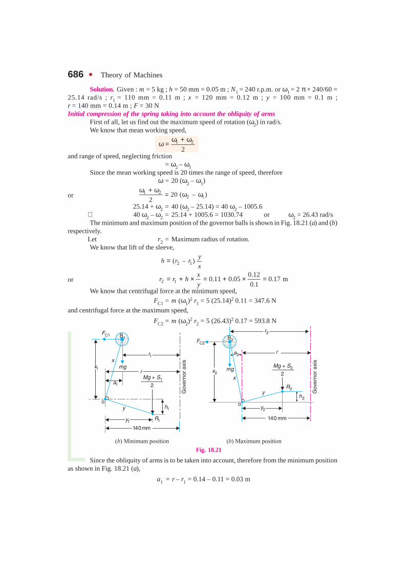
Example 18.17. In a spring loaded governor of the Hartnell type, the mass of each ball is5 kg and the lift of the sleeve is 50 mm. The speed at which the governor begins to float is 240 r.p.m.,and at this speed the radius of the ball path is 110 mm. The mean working speed of the governor is 20times the range of speed when friction is neglected. If the lengths of ball and roller arm of the bellcrank lever are 120 mm and 100 mm respectively and if the distance between the centre of pivot ofbell crank lever and axis of governor spindle is 140 mm, determine the initial compression of thespring taking into account the obliquity of arms.
If friction is equivalent to a force of 30 N at the sleeve, find the total alteration in speed beforethe sleeve begins to move from mid-position.
686 � Theory of Machines
Solution. Given : m = 5 kg ; h = 50 mm = 0.05 m ; N1 = 240 r.p.m. or ω1 = 2 π × 240/60 =25.14 rad/s ; r1 = 110 mm = 0.11 m ; x = 120 mm = 0.12 m ; y = 100 mm = 0.1 m ;r = 140 mm = 0.14 m ; F = 30 NInitial compression of the spring taking into account the obliquity of arms
First of all, let us find out the maximum speed of rotation (ω2) in rad/s.We know that mean working speed,
1 2
2
ω + ωω =
and range of speed, neglecting friction= ω2 – ω1
Since the mean working speed is 20 times the range of speed, thereforeω = 20 (ω2 – ω1)
or 1 22 120 ( – )
2
ω + ω= ω ω
25.14 + ω2 = 40 (ω2 – 25.14) = 40 ω2 – 1005.6∴ 40 ω2 – ω2 = 25.14 + 1005.6 = 1030.74 or ω2 = 26.43 rad/sThe minimum and maximum position of the governor balls is shown in Fig. 18.21 (a) and (b)
respectively.Let r2 = Maximum radius of rotation.We know that lift of the sleeve,
2 1( – )y
h r rx
=
or 2 10.12
0.11 0.05 0.17 m0.1
xr r h
y= + × = + × =
We know that centrifugal force at the minimum speed,
FC1 = m (ω1)2 r1 = 5 (25.14)2 0.11 = 347.6 N
and centrifugal force at the maximum speed,
FC2 = m (ω2)2 r2 = 5 (26.43)2 0.17 = 593.8 N
Fig. 18.21
Since the obliquity of arms is to be taken into account, therefore from the minimum positionas shown in Fig. 18.21 (a),
a1 = r – r1 = 0.14 – 0.11 = 0.03 m
Chapter 18 : Governors � 687
2 2 2 21 1– ( ) (0.12) – (0.03) 0.1162 mx x a= = =
and 2 2 2 21 1– ( ) (0.1) – (0.025) 0.0986 my y h= = =
. . . (� h1 = h / 2 = 0.025 m)
Similarly, for the maximum position, as shown in Fig. 18.21 (b),
a2 = r2 – r = 0.17 – 0.14 = 0.03 m
∴ x2 = x1 = 0.1162 m . . . (� a2 = a1)
and y2 = y1 = 0.0986 m . . . (� h2 = h1)
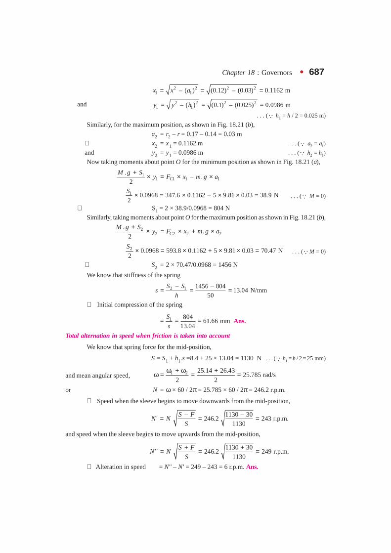
Now taking moments about point O for the minimum position as shown in Fig. 18.21 (a),
11 C1 1 1
.– .
2
M g Sy F x m g a
+× = × ×
1 0.0968 347.6 0.1162 – 5 9.81 0.03 38.9 N2
S× = × × × = . . . (� M = 0)
∴ S1 = 2 × 38.9/0.0968 = 804 N
Similarly, taking moments about point O for the maximum position as shown in Fig. 18.21 (b),
22 C2 2 2
..
2
M g Sy F x m g a
+ × = × + ×
2 0.0968 593.8 0.1162 5 9.81 0.03 70.47 N2
S × = × + × × = . . . (�M = 0)
∴ S2 = 2 × 70.47/0.0968 = 1456 N
We know that stiffness of the spring
2 1– 1456 – 80413.04 N/mm
50
S Ss
h= = =
∴ Initial compression of the spring
1 80461.66 mm
13.04
S
s= = = Ans.
Total alternation in speed when friction is taken into account
We know that spring force for the mid-position,
S = S1 + h1.s =8.4 + 25 × 13.04 = 1130 N . . . (� h1 = h / 2 = 25 mm)
and mean angular speed, 1 2 25.14 26.4325.785 rad/s
2 2
ω + ω +ω = = =
or N = ω × 60 / 2π = 25.785 × 60 / 2π = 246.2 r.p.m.
∴ Speed when the sleeve begins to move downwards from the mid-position,
– 1130 – 30246.2 243 r.p.m.
1130
S FN N
S′ = = =
and speed when the sleeve begins to move upwards from the mid-position,
1130 30246.2 249 r.p.m.
1130
S FN N
S
+ +′′ = = =
∴ Alteration in speed = N'' – N' = 249 – 243 = 6 r.p.m. Ans.

688 � Theory of Machines
Example 18.18. Fig. 18.22 shows diagram-matically a centrifugal governor. The masses ‘m’ aredirectly connected to one another by two parallel andidentical close coiled springs, one on either side. Inthe position shown, with the mass arms parallel tothe axis of rotation, the equilibrium speed is 900r.p.m. Given ball circle radius = 70 mm ; length ofball arm = 85 mm and length of sleeve arm = 50mm.
1. When the speed is increased by 1% withoutany change of radius for the given position, an axialforce of 30 N is required at the sleeve to maintainequilibrium. Determine the mass of each ball.
2. Find the stiffness and initial extension of eachspring, if the rate of sleeve movement, when in mid position is 20 mm for 480 r.p.m. change of speed.
Solution. Given : N = 900 r.p.m. or ω = 2 π × 900/60 = 94.26 rad/s ; r = 70 mm= 0.07 m; x = 85 mm = 0.085 m ; y = 50 mm = 0.05 m ; W = 30 N
1. Mass of each ball
Let m = Mass of each ball in kg.
We know that centrifugal force at the equilibrium speed,
FC = m.ω2.r = m (94.26)2 0.07 = 622 mN
Since the speed is increased by 1% without any change of radius, therefore increased speed,
ω1 = ω + 0.01 ω = 1.01 ω = 1.01 × 94.26 = 95.2 rad/s
and centrifugal force at the increased speed,
FC1 = m (ω1)2 r = m (95.2)2 0.07 = 634.4 mN
Now taking moments about point O as shown in Fig. 18.23, we get
C1 C( – ) 0.085 0.052
WF F = ×
30(634.4 – 622 ) 0.085 0.05 0.75
2m m = × =
1.054 m = 0.75
or m = 0.75/1.054 = 0.7 kg Ans.
2. Stiffness and initial extension of each spring
Let s = Stiffness of each spring.
We know that centrifugal force at the equilibrium speed, i.e. at 900 r.p.m.
FC = 622 m = 622 × 0.7 = 435.4 N
Since the change of speed is 480 r.p.m., therefore increased speed,
N2 = 900 + 480 = 1380 r.p.m.
∴ Angular increased speed,
ω2 = 2 π × 1380/60 = 144.5 rad/s
Fig. 18.23
Fig. 18.22.
Chapter 18 : Governors � 689
Also, it is given that for 480 r.p.m. change of speed, the rate of sleeve movement is 20 mm, i.e.
h = 20 mm = 0.02 m
Let r = Radius of rotation at 900 r.p.m. = 0.07 m . . . (Given)
r2 = Radius of rotation at 1380 r.p.m.
We know that for the radius of rotation to change from r to r2 , the increase in length of radius ofrotation is
20.085
– 0.02 0.034 m0.05
xr r h
y= × = × =
∴ r2 = r + 0.034 = 0.07 + 0.034 = 0.104 m
and centrifugal force at the increased speed (ω2),
FC2= m (ω2)2 r2 = 0.7 (144.5)2 0.104 = 1520 N
∴ Stiffness of each spring,
C2 C
2
–Increase in force for one ball 1520 – 435.4=
Increase in length for each spring 2 ( – ) 2 (0.104 – 0.07)
F Fs
r r= =
= 15 950 N/m = 15.95 N/mm Ans.
and initial extension of each spring
C 435.427.3 mm
15.95
F
s= = = Ans.
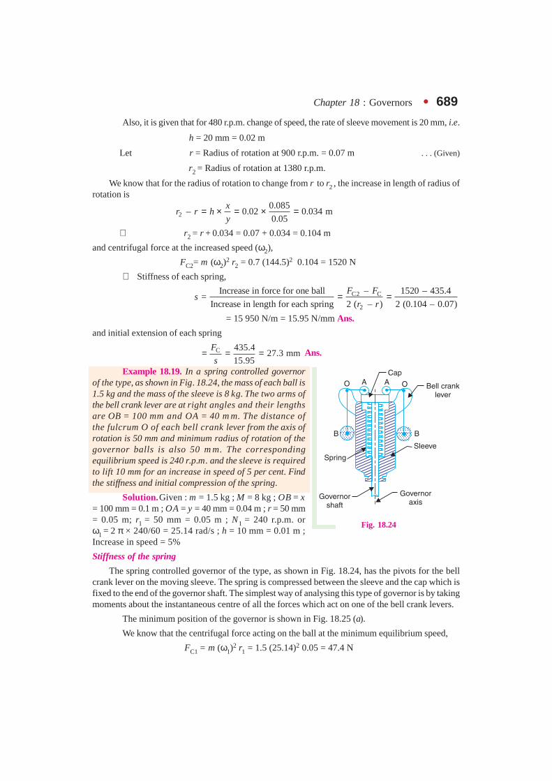
Example 18.19. In a spring controlled governorof the type, as shown in Fig. 18.24, the mass of each ball is1.5 kg and the mass of the sleeve is 8 kg. The two arms ofthe bell crank lever are at right angles and their lengthsare OB = 100 mm and OA = 40 m m. The distance ofthe fulcrum O of each bell crank lever from the axis ofrotation is 50 mm and minimum radius of rotation of thegovernor balls is also 50 m m. The correspondingequilibrium speed is 240 r.p.m. and the sleeve is requiredto lift 10 mm for an increase in speed of 5 per cent. Findthe stiffness and initial compression of the spring.
Solution.Given : m = 1.5 kg ; M = 8 kg ; OB = x= 100 mm = 0.1 m ; OA = y = 40 mm = 0.04 m ; r = 50 mm= 0.05 m; r1 = 50 mm = 0.05 m ; N1 = 240 r.p.m. orω1 = 2 π × 240/60 = 25.14 rad/s ; h = 10 mm = 0.01 m ;Increase in speed = 5%
Stiffness of the spring
The spring controlled governor of the type, as shown in Fig. 18.24, has the pivots for the bellcrank lever on the moving sleeve. The spring is compressed between the sleeve and the cap which isfixed to the end of the governor shaft. The simplest way of analysing this type of governor is by takingmoments about the instantaneous centre of all the forces which act on one of the bell crank levers.
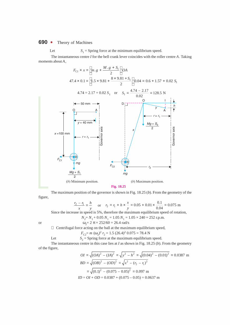
The minimum position of the governor is shown in Fig. 18.25 (a).
We know that the centrifugal force acting on the ball at the minimum equilibrium speed,
FC1 = m (ω1)2 r1 = 1.5 (25.14)2 0.05 = 47.4 N
Fig. 18.24
690 � Theory of Machines
Let S1 = Spring force at the minimum equilibrium speed.
The instantaneous centre I for the bell crank lever coincides with the roller centre A . Takingmoments about A ,
1
C1.
.2
M g SF x m g OA
+ × = +
1
18 9.81
47.4 0.1 1.5 9.81 0.04 0.6 1.57 0.022
SS
× + × = × + = + +
4.74 = 2.17 + 0.02 S1 or 14.74 – 2.17
128.5 N0.02
S = =
Fig. 18.25
The maximum position of the governor is shown in Fig. 18.25 (b). From the geometry of thefigure,
2 1–r r h
x y= or 2 1
0.10.05 0.01 0.075 m
0.04
xr r h
y= + × = + × =
Since the increase in speed is 5%, therefore the maximum equilibrium speed of rotation, N2= N1 + 0.05 N1 = 1.05 N1 = 1.05 × 240 = 252 r.p.m.
or ω2= 2 π × 252/60 = 26.4 rad/s∴ Centrifugal force acting on the ball at the maximum equilibrium speed,
FC2= m (ω2)2 r2 = 1.5 (26.4)2 0.075 = 78.4 N
Let S2 = Spring force at the maximum equilibrium speed.The instantaneous centre in this case lies at I as shown in Fig. 18.25 (b). From the geometry
of the figure,
2 2 2 2 2 2( ) – ( ) – (0.04) – (0.01) 0.0387 mOI OA IA y h= = = =
2 2 2 22 1( ) – ( ) – ( – )BD OB OD x r r= =
2 2(0.1) – (0.075 – 0.05) 0.097 m= = ID = OI + OD = 0.0387 + (0.075 – 0.05) = 0.0637 m
Chapter 18 : Governors � 691Now taking moments about I,
2C2
..
2
M g SF BD m g ID OI
+× = × + ×
28 9.8178.4 0.097 1.5 9.81 0.0637 0.0387
2
S× + × = × × + 7.6 = 0.937 + 1.52 + 0.02 S2 = 2.457 + 0.019 S2
∴2
7.6 – 2.457270.7 N
0.019S = =
We know that stiffness of the spring,
2 1– 270.7 – 128.514.22 N/mm
10
S Ss
h= = = Ans.
Initial compression of the spring
We know that initial compression of the spring
1 128.59.04 mm
14.22
S
s= = = Ans.
18.9. Hartung GovernorA spring controlled governor of the Hartung type is shown in Fig. 18.26 (a). In this type of
governor, the vertical arms of the bell crank levers are fitted with spring balls which compress againstthe frame of the governor when the rollers at the horizontal arm press against the sleeve.
An overview of a thermal power station.
Note : This picture is given as additional information and is not a direct example of the current chapter.
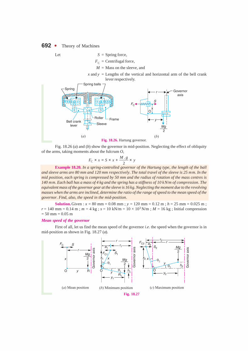
692 � Theory of Machines
Let S = Spring force,
FC = Centrifugal force,
M = Mass on the sleeve, and
x and y = Lengths of the vertical and horizontal arm of the bell cranklever respectively.
Fig. 18.26. Hartung governor.
Fig. 18.26 (a) and (b) show the governor in mid-position. Neglecting the effect of obliquityof the arms, taking moments about the fulcrum O,
C.
2
M gF x S x y× = × + ×
Example 18.20. In a spring-controlled governor of the Hartung type, the length of the balland sleeve arms are 80 mm and 120 mm respectively. The total travel of the sleeve is 25 mm. In themid position, each spring is compressed by 50 mm and the radius of rotation of the mass centres is140 mm. Each ball has a mass of 4 kg and the spring has a stiffness of 10 kN/m of compression. Theequivalent mass of the governor gear at the sleeve is 16 kg. Neglecting the moment due to the revolvingmasses when the arms are inclined, determine the ratio of the range of speed to the mean speed of thegovernor. Find, also, the speed in the mid-position.
Solution.Given : x = 80 mm = 0.08 mm ; y = 120 mm = 0.12 m ; h = 25 mm = 0.025 m ;r = 140 mm = 0.14 m ; m = 4 kg ; s = 10 kN/m = 10 × 103 N/m ; M = 16 kg ; Initial compression= 50 mm = 0.05 m
Mean speed of the governor
First of all, let us find the mean speed of the governor i.e. the speed when the governor is inmid-position as shown in Fig. 18.27 (a).
Fig. 18.27

Chapter 18 : Governors � 693Let ω = Mean angular speed in rad/s, and
N = Mean speed in r.p.m.
We know that the centrifugal force acting on the ball spring,
FC = m.ω2.r = 4 × ω2 × 0.14 = 0.56 ω2 N
and Spring force, S = Stiffness × Initial compression = 10 × 103 × 0.05 = 500 N
Now taking moments about point O, neglecting the moment due to the revolving masses, wehave
C.
2
M gF x S x y× = × + ×
2 16 9.810.56 0.08 500 0.08 0.12 40 9.42 49.42
2
×ω × = × + × = + =
∴ 2 49.421103
0.56 0.08ω = =
×or ω = 33.2 rad/s
and33.23 60
317 r.p.m.2
N×= =π
Ans.
Ratio of range of speed to mean speed
Let ω1 = Minimum angular speed in rad/s, at the minimum radius ofrotation r1,
ω2 = Maximum angular speed in rad/s, at the maximum radius ofrotation r2,
N1 and N2 = Corresponding minimum and maximum speeds in r.p.m.
The minimum and maximum position is shown in Fig. 18.27 (b) and (c) respectively. First ofall, let us find the minimum speed N1.
From the geometry of the Fig. 18.27 (b),
1
1
–r r x
h y= or 1 1
0.025 0.08– 0.14 – 0.132 m
2 0.12
xr r h
y= × = × =
. . . (� h1 = h/2)
We know that centrifugal force at the minimum position,
FC1 = m (ω1)2 r1 = 4 (ω1)
2 0.132 = 0.528 (ω1)2 N
and spring force at the minimum position,
S1 = [Initial compression – (r – r1)] × Stiffness
= [0.05 – (0.14 – 0.132)] 10 × 103 = 420 N
Now taking moments about the fulcrum O, neglecting the obliquity of arms (i.e. taking x1 = xand y1 = y),
C1 1.
2
M gF x S x y× = × + ×
21
16 9.810.528 ( ) 0.08 420 0.08 0.12 33.6 9.42 43.02
2
×ω = × + × = + =
∴ 21
43.02( ) 1019
0.528 0.08ω = =
×or ω1 = 32 rad/s
and 132 60
305.5 r.p.m.2
N×= =π
694 � Theory of Machines
Now let us find the maximum speed N2. From the geometry of the Fig. 18.27 (c),
2
2
–r r x
h y= or 2 2
0.025 0.080.14 0.148 m
2 0.12
xr r h
y= + × = + × =
. . . (∵ h2 = h/2)
We know that centrifugal force at the maximum position,
FC2 = m (ω2)2 r2 = 4 (ω2)2 0.148 = 0.592 (ω2)
2 N
and spring force at the maximum position,
S2 = [Initial compression + (r2 – r) × Stiffness
= [0.05 + (0.148 – 0.14)] × 10 × 103 = 580 N
Now taking moments about the fulcrum O, neglecting obliquity of arms (i.e. taking x2 = x andy2 = y),
C2 2.
2
M gF x S x y× = × + ×
22
16 9.810.592 ( ) 0.08 580 0.08 0.12 46.4 9.42 55.82
2
×ω = × + × = + =
∴ 22
55.82( ) 1178
0.592 0.08ω = =
×or ω2 = 34.32 rad/s
and 234.32 60
327.7 r.p.m.2
N×= =
πWe know that range of speed
= N2 – N1 = 327.7 – 305.5 = 22.2 r.p.m.
∴ Ratio of range of speed to mean speed
2 1– 22.20.07
317
N N
N= = = or 7% Ans.
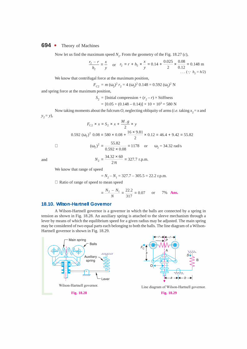
18.10.18.10.18.10.18.10.18.10. WWWWWilson-Harilson-Harilson-Harilson-Harilson-Hartnell Gotnell Gotnell Gotnell Gotnell GovvvvvererererernornornornornorA Wilson-Hartnell governor is a governor in which the balls are connected by a spring in
tension as shown in Fig. 18.28. An auxiliary spring is attached to the sleeve mechanism through alever by means of which the equilibrium speed for a given radius may be adjusted. The main springmay be considered of two equal parts each belonging to both the balls. The line diagram of a Wilson-Hartnell governor is shown in Fig. 18.29.
Fig. 18.28 Fig. 18.29

Chapter 18 : Governors � 695Let P = Tension in the main spring or ball spring A ,
S = Tension in the auxiliary spring B,
m = Mass of each ball,
M = Mass of sleeve,
sb = Stiffness of each ball spring,
sa = Stiffness of auxiliary spring,
FC = Centrifugal force of each ball, and
r = Radius of rotation of balls,
Now total downward force on the sleeve
= M.g + S × b/a
Taking moments about O and neglecting the effect of the pull of gravity on the ball,
C. /
( – )2
M g S b aF P x y
+ ×= ×
Let suffixes 1 and 2 be used to denote the values at minimum and maximum equilibriumspeeds respectively.
∴ At minimum equilibrium speed,
1C1 1
. /( – )
2
M g S b aF P x y
+ ×= × . . . (i)
and at maximum equilibrium speed,
2C2 2
. /( – )
2
M g S b aF P x y
+ ×= × . . . (ii)
Subtracting equation (i) from equation (ii), we have
C2 C1 2 1 2 1[( – ) – ( – )] ( – )2
b yF F P P x S S
a= × . . . (iii)
When the radius increases from r1 to r2, the ball springs extend by the amount 2 (r2 – r1) and
the auxiliary spring extend by the amount 2 1( – )y b
r rx a
×
∴ P2 – P1 = 2 sb × 2 (r2 – r1) = 4 sb (r2 – r1)
and 2 1 2 1– ( – )ay b
S S s r rx a
= ×
Substituting the values of (P2 – P1) and (S2 – S1) in equation (iii),
C2 C1 2 1 2 1[( – ) – 4 ( – )] ( – )2b a
y b b yF F s r r x s r r
x a a= × × ×
2
C2 C1 2 1 2 1( – ) – 4 ( – ) ( – )2a
bs y b
F F s r r r rx a
= ×
∴2
C2 C1
2 1
–4
2 –a
bs F Fy b
sx a r r
+ × = Note : When the auxiliary spring is not used, then sa = 0.
∴ C2 C1
2 1
–4
–b
F Fs
r r= or C2 C1
2 1
–
4 ( – )b
F Fs
r r=

696 � Theory of Machines
Example 18.21. The following particulars refer to a Wilson-Hartnell governor :
Mass of each ball = 2 kg ; minimum radius = 125 mm ; maximum radius = 175 mm ; minimumspeed = 240 r.p.m. ; maximum speed = 250 r.p.m. ; length of the ball arm of each bell crank lever = 150mm; length of the sleeve arm of each bell crank lever = 100 mm ; combined stiffness of the two ballsprings = 0.2 kN/m. Find the equivalent stiffness of the auxiliary spring referred to the sleeve.
Solution. Given : m = 2 kg ; r1 = 125 mm = 0.125 m ; r2 = 175 mm = 0.175 m ;N1 = 240 r.p.m. or ω1 = 2 π × 240/60 = 25.14 rad/s ; N2 = 250 r.p.m. or ω2 = 2 π = 250/60= 26.2 rad/s ; x = 150 mm = 0.15 m; y = 100 mm = 0.1 m ; sb = 0.2 kN/m = 200 N/m
Let s = Equivalent stiffness of the auxiliary spring referred to the sleeve
2
ab
sa
= We know that centrifugal force at the minimum speed,
FC1 = m (ω1)2 r1 = 2 (25.14)2 0.125 = 158 N
and centrifugal force at the maximum speed,
FC2 = m (ω2)2 r2 = 2 (26.2)2 0.175 = 240 N
We know that2
C2 C1
2 1
–4
2 –a
bs F Fy b
sx a r r
+ × = 2
0.1 240 – 1584 200 1640
2 0.15 0.175 – 0.125bs b
a × + × = =
2
800 0.22 1640ab
sa
+ = or
2
0.22 1640 – 800 840ab
sa
= =
∴2
800 / 0.22 3818 N/m = 3.818 kN/mab
sa
= = Ans.
Example 18.22. A spring loaded governor is shownin Fig. 18.30. The two balls, each of mass 6 kg, are connectedacross by two springs . An auxiliary spring B provides anadditional force at the sleeve through the medium of a leverwhich pivots about a fixed centre at its left hand end. In themean position, the radius of the governor balls is 120 mmand the speed is 600 r.p.m. The tension in each spring isthen 1 kN. Find the tension in the spring B for this position.
When the sleeve moves up 15 mm, the speed is to be630 r.p.m. Find the necessary stiffness of the spring B, if thestiffness of each spring A is 10 kN/m. Neglect the momentproduced by the mass of the balls.
Solution. Given : m = 6 kg ; r = r1 = 120 mm = 0.12 m ; N = N1 = 600 r.p.m. orω1 = 2π × 600/60 = 62.84 rad/s
Tension in spring B
Let SB1 = Spring force or tension in spring B, and
M.g = Total load at the sleeve.
Fig. 18.30

Chapter 18 : Governors � 697We know that centrifugal force at the minimum speed,
FC1 = m (ω1)2 r1 = 6 (62.84)2 0.12 = 2843 N
Since the tension in each spring A is 1 kN and there are two springs, therefore
Total spring force in spring A ,
SA1 = 2 × 1 = 2 kN = 2000 N
Taking moments about the pivot P (neglecting the moment produced by the mass of balls) inorder to find the force Mg on the sleeve, in the mean position as shown in Fig. 18.31 (a),
C1 A1.
90 90 902
M gF S× = × + × or C1 A1
.
2
M gF S= +
∴ M.g = 2 FC1 – 2 SA1 = 2 × 2843 – 2 × 2000 = 1686 N
Now taking moments about point Q,
SB1 × 160 = M .g. (80 + 160) = 1686 × 240 = 404 640
∴ SB1 = 404 640/160 = 2529 N Ans.
Fig. 18.31
Stiffness of the spring B
Given : h = 15 mm = 0.015 m ; N2 = 630 r.p.m. or ω2 = 2 π × 630/60 = 66 rad/s;SA = 10 kN/m = 10 × 103 N/m
Let sB = Stiffness of spring B.
The maximum position is shown in Fig. 18.31 (b).
First of all, let us find the maximum radius of rotation (r2) when the sleeve moves up by0.015 m. We know that
2 1( – )y
h r rx
= or 2 1 0.12 0.015 0.135 mx
r r hy
= + × = + =
. . . (� x = y = 90 mm = 0.09 m)
∴ Centrifugal force at the maximum speed,
FC2 = m (ω2)2 r2 = 6 (66)2 0.135 = 3528 N
We know that extension of the spring A ,
= 2 (r2 – r1) × No. of springs = 2 (0.135 – 0.12) 2 = 0.06 m
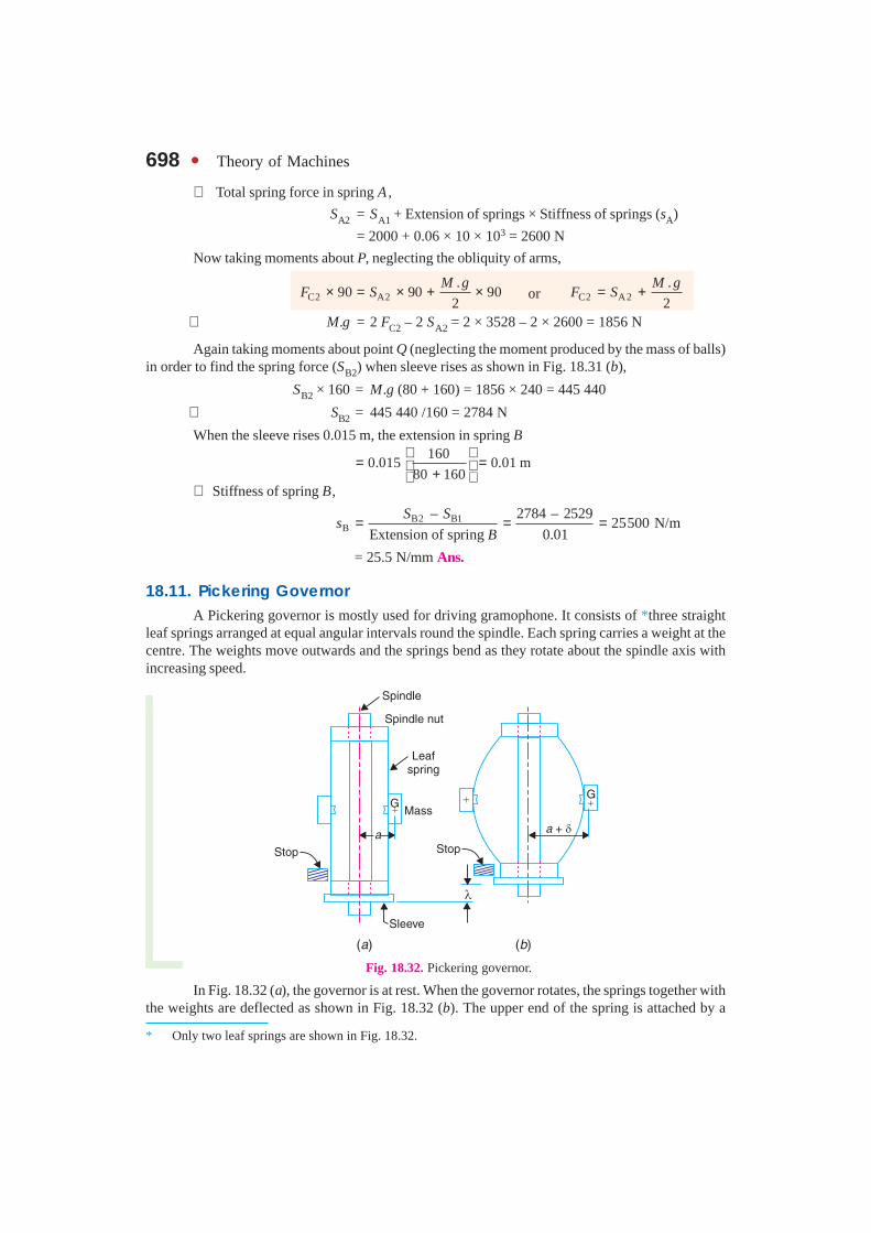
698 � Theory of Machines
∴ Total spring force in spring A ,
SA2 = SA1 + Extension of springs × Stiffness of springs (sA)
= 2000 + 0.06 × 10 × 103 = 2600 N
Now taking moments about P, neglecting the obliquity of arms,
C2 A2.
90 90 902
M gF S× = × + × or C2 A2
.
2
M gF S= +
∴ M.g = 2 FC2 – 2 SA2 = 2 × 3528 – 2 × 2600 = 1856 N
Again taking moments about point Q (neglecting the moment produced by the mass of balls)in order to find the spring force (SB2) when sleeve rises as shown in Fig. 18.31 (b),
SB2 × 160 = M.g (80 + 160) = 1856 × 240 = 445 440
∴ SB2 = 445 440 /160 = 2784 N
When the sleeve rises 0.015 m, the extension in spring B160
0.015 0.01 m80 160
= = +
∴ Stiffness of spring B,
B2 B1B
– 2784 – 252925500 N/m
Extension of spring 0.01
S Ss
B= = =
= 25.5 N/mm Ans.
18.11. Pickering GovernorA Pickering governor is mostly used for driving gramophone. It consists of *three straight
leaf springs arranged at equal angular intervals round the spindle. Each spring carries a weight at thecentre. The weights move outwards and the springs bend as they rotate about the spindle axis withincreasing speed.
Fig. 18.32. Pickering governor.
In Fig. 18.32 (a), the governor is at rest. When the governor rotates, the springs together withthe weights are deflected as shown in Fig. 18.32 (b). The upper end of the spring is attached by a
* Only two leaf springs are shown in Fig. 18.32.

Chapter 18 : Governors � 699screw to hexagonal nut fixed to the governor spindle. The lower end of the spring is attached to asleeve which is free to slide on the spindle. The spindle runs in a bearing at each end and is driventhrough gearing by the motor. The sleeve can rise until it reaches a stop, whose position is adjustable.
Let m = Mass attached at the centre of the leaf spring, a = Distance from the spindle axis to the centre of gravity of the mass, when the governor is at rest, ω = Angular speed of the governor spindle, δ = Deflection of the centre of the leaf spring at angular speed ω,
a + δ = Distance from the spindle axis to the centre of gravity of the mass,when the governor is rotating, and
λ = Lift of the sleeve corresponding to the deflection δ.We know that the maximum deflection of a leaf spring with both ends fixed and carrying a
load (W ) at the centre is,3.
192
W l
EIδ = . . . (i)
where l = Distance between the fixed ends of the spring,
E = Young’s modulus of the material of the spring, and
I = Moment of inertia of its cross-section about the neutral axis 3.
12
b t=
(where b and t are width and thickness of spring).
In case of a Pickering governor, the central load is the centrifugal force.
∴ W = FC = m.ω2 (a + δ) . . . (ii)
Substituting the value of W in equation (i), we have2 3. ( )
192 .
m a l
E I
ω + δδ =
Note: The empirical relation between the lift of the sleeve and the deflection δ is, 22.4
l
δλ = approximately.
Example 18.23. A gramophone is driven by a Pickering governor. The mass of each discattached to the centre of a leaf spring is 20 g. The each spring is 5 mm wide and 0.125 mm thick. Theeffective length of each spring is 40 mm. The distance from the spindle axis to the centre of gravity ofthe mass when the governor is at rest, is 10 mm. Find the speed of the turntable when the sleeve hasrisen 0.8 mm and the ratio of the governor speed to the turntable speed is 10.5. Take E = 210 kN/mm2.
Solution.Given : m = 20 g = 0.02 kg ; b = 5 mm ; t = 0.125 mm ; a = 10 mm = 0.01 m ;E = 210 kN/mm2 = 210 × 103 N/mm2
We know that moment of inertia of the spring about its neutral axis,3 3
–3 4. 5 (0.125)0.8 10 mm
12 12
b tI = = = ×
Since the effective length of each spring is 40 mm and lift of sleeve (λ) = 0.8 mm, therefore
Length of spring between fixed ends,
l = 40 – 0.8 = 39.2 mm
We know that the central deflection (λ),2 2
22.4 2.40.8 0.06
39.2l
δ δ= = = δ

700 � Theory of Machines
∴ δ 2 = 0.8/0.06 = 13.3 or δ = 3.65 mm
Let N = Speed of the governor, and
N1 = Speed of the turntable.
∴ N/N1 = 10.5
We know that2 3. ( )
192 .
m a l
E I
ω +δδ =
2 3 22
3 –3
0.02 (10 3.65) (39.2) 16 4453.65 0.51
32256192 210 10 0.8 10
ω + ω= = = ω× × × ×
∴ 2 3.657.156
0.51ω = = or ω = 2.675 rad/s
and N = ω × 60/2π = 2.675 × 60/2π = 25.5 r.p.m. Ans.
∴ N1 = N/10.5 = 25.5/10.5 = 2.43 r.p.m. Ans.
18.12. Sensitiveness of GovernorsConsider two governors A and B running at the same speed. When this speed increases or
decreases by a certain amount, the lift of the sleeve of governor A is greater than the lift of the sleeveof governor B. It is then said that the governor A is more sensitive than the governor B.
In general, the greater the lift of the sleeve corresponding to a given fractional change inspeed, the greater is the sensitiveness of the governor. It may also be stated in another way that for agiven lift of the sleeve, the sensitiveness of the governor increases as the speed range decreases. Thisdefinition of sensitiveness may be quite satisfactory when the governor is considered as an independentmechanism. But when the governor is fitted to an engine, the practical requirement is simply that thechange of equilibrium speed from the full load to the no load position of the sleeve should be as smalla fraction as possible of the mean equilibrium speed. The actual displacement of the sleeve is immaterial,provided that it is sufficient to change the energy supplied to the engine by the required amount. Forthis reason, the sensitiveness is defined as the ratio of the difference between the maximum andminimum equilibrium speeds to the mean equilibrium speed.
Let N1 = Minimum equilibrium speed,
N2 = Maximum equilibrium speed, and
N = Mean equilibrium speed 1 2 .2
N N+=
∴ Sensitiveness of the governor
2 1 2 1
1 2
2( – )N N N N
N N N
−= =+
2 1
1 2
2( – )ω ω=ω + ω . . . (In terms of angular speeds)
18.13. Stability of GovernorsA governor is said to be stable when for every speed within the working range there is a
definite configuration i.e. there is only one radius of rotation of the governor balls at which thegovernor is in equilibrium. For a stable governor, if the equilibrium speed increases, the radius ofgovernor balls must also increase.
Note : A governor is said to be unstable, if the radius of rotation decreases as the speed increases.
...(Given)
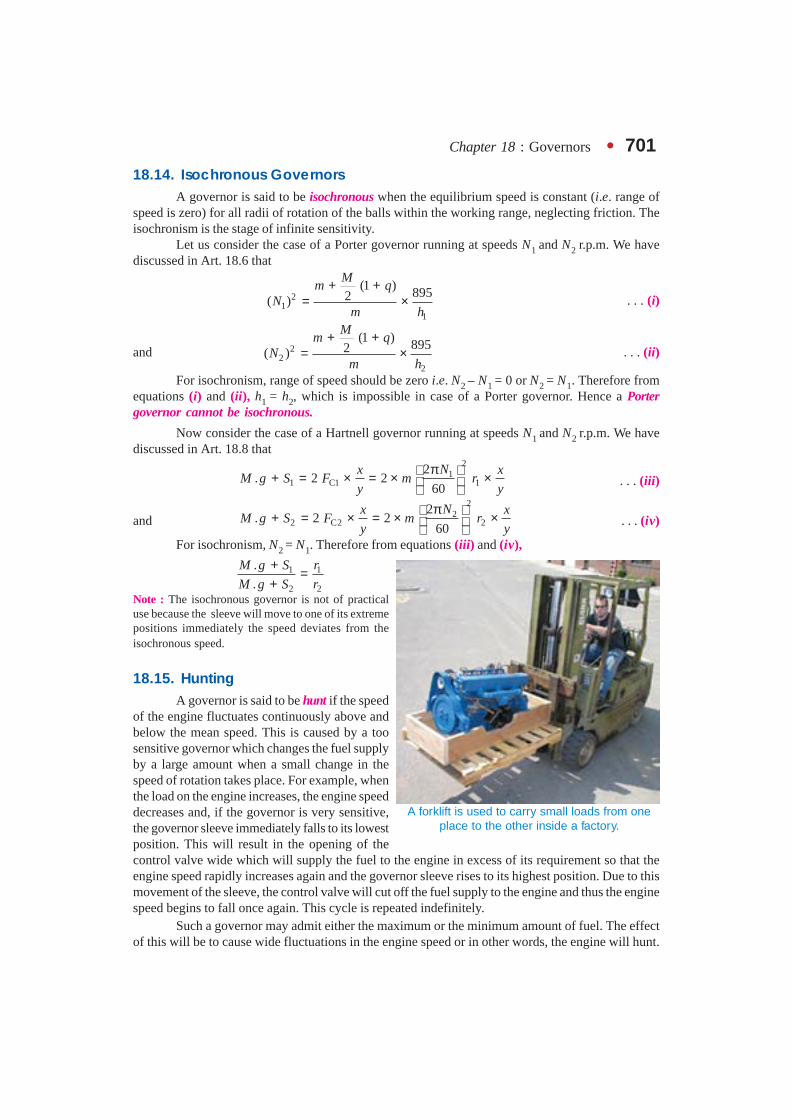
Chapter 18 : Governors � 701
18.14. Isochronous GovernorsA governor is said to be isochronous when the equilibrium speed is constant (i.e. range of
speed is zero) for all radii of rotation of the balls within the working range, neglecting friction. Theisochronism is the stage of infinite sensitivity.
Let us consider the case of a Porter governor running at speeds N1 and N2 r.p.m. We havediscussed in Art. 18.6 that
21
1
(1 ) 8952( )
Mm q
Nm h
+ += × . . . (i)
and 22
2
(1 ) 8952( )
Mm q
Nm h
+ += × . . . (ii)
For isochronism, range of speed should be zero i.e. N2 – N1 = 0 or N2 = N1. Therefore fromequations (i) and (ii), h1 = h2, which is impossible in case of a Porter governor. Hence a Portergovernor cannot be isochronous.
Now consider the case of a Hartnell governor running at speeds N1 and N2 r.p.m. We havediscussed in Art. 18.8 that
21
1 C1 12
. 2 260
Nx xM g S F m r
y y
π + = × = × × . . . (iii)
and
22
2 C2 22
. 2 260
Nx xM g S F m r
y y
π + = × = × × . . . (iv)
For isochronism, N2 = N1. Therefore from equations (iii) and (iv),
1 1
2 2
.
.
M g S r
M g S r
+ =+
Note : The isochronous governor is not of practicaluse because the sleeve will move to one of its extremepositions immediately the speed deviates from theisochronous speed.
18.15. HuntingA governor is said to be hunt if the speed
of the engine fluctuates continuously above andbelow the mean speed. This is caused by a toosensitive governor which changes the fuel supplyby a large amount when a small change in thespeed of rotation takes place. For example, whenthe load on the engine increases, the engine speeddecreases and, if the governor is very sensitive,the governor sleeve immediately falls to its lowestposition. This will result in the opening of thecontrol valve wide which will supply the fuel to the engine in excess of its requirement so that theengine speed rapidly increases again and the governor sleeve rises to its highest position. Due to thismovement of the sleeve, the control valve will cut off the fuel supply to the engine and thus the enginespeed begins to fall once again. This cycle is repeated indefinitely.
Such a governor may admit either the maximum or the minimum amount of fuel. The effectof this will be to cause wide fluctuations in the engine speed or in other words, the engine will hunt.
A forklift is used to carry small loads from oneplace to the other inside a factory.
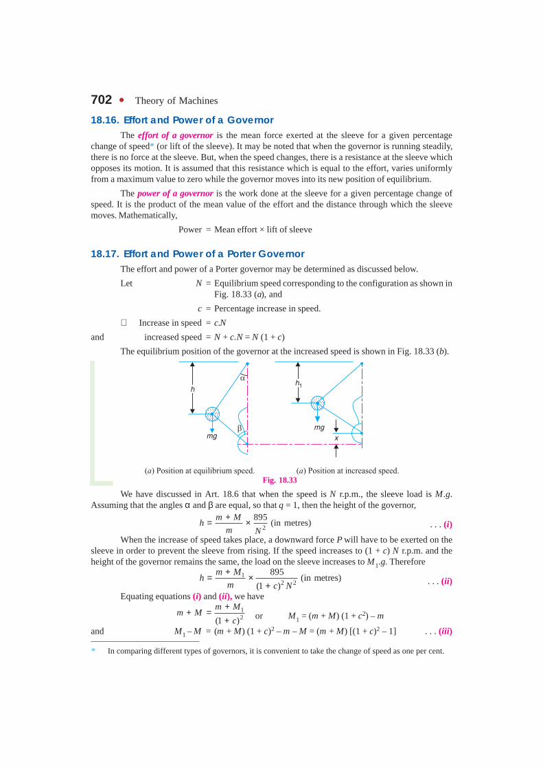
702 � Theory of Machines
18.16. Effort and Power of a GovernorThe effort of a governor is the mean force exerted at the sleeve for a given percentage
change of speed* (or lift of the sleeve). It may be noted that when the governor is running steadily,there is no force at the sleeve. But, when the speed changes, there is a resistance at the sleeve whichopposes its motion. It is assumed that this resistance which is equal to the effort, varies uniformlyfrom a maximum value to zero while the governor moves into its new position of equilibrium.
The power of a governor is the work done at the sleeve for a given percentage change ofspeed. It is the product of the mean value of the effort and the distance through which the sleevemoves. Mathematically,
Power = Mean effort × lift of sleeve
18.17. Effort and Power of a Porter GovernorThe effort and power of a Porter governor may be determined as discussed below.
Let N = Equilibrium speed corresponding to the configuration as shown inFig. 18.33 (a), and
c = Percentage increase in speed.
∴ Increase in speed = c.N
and increased speed = N + c.N = N (1 + c)
The equilibrium position of the governor at the increased speed is shown in Fig. 18.33 (b).
Fig. 18.33
We have discussed in Art. 18.6 that when the speed is N r.p.m., the sleeve load is M.g.Assuming that the angles α and β are equal, so that q = 1, then the height of the governor,
2
895(in metres)
m Mh
m N
+= × . . . (i)
When the increase of speed takes place, a downward force P will have to be exerted on thesleeve in order to prevent the sleeve from rising. If the speed increases to (1 + c) N r.p.m. and theheight of the governor remains the same, the load on the sleeve increases to M1.g. Therefore
12 2
895(in metres)
(1 )
m Mh
m c N
+= ×+ . . . (ii)
Equating equations (i) and (ii), we have12(1 )
m Mm M
c
++ =
+ or M1 = (m + M) (1 + c2) – m
and M1 – M = (m + M) (1 + c)2 – m – M = (m + M) [(1 + c)2 – 1] . . . (iii)
* In comparing different types of governors, it is convenient to take the change of speed as one per cent.

Chapter 18 : Governors � 703
A little consideration will show that (M1 – M)g is the downward force which must be appliedin order to prevent the sleeve from rising as the speed increases. It is the same force which acts on thegovernor sleeve immediately after the increase of speed has taken place and before the sleeve beginsto move. When the sleeve takes the new position as shown in Fig. 18.33 (b), this force graduallydiminishes to zero.
Let P = Mean force exerted on the sleeve during the increase in speed orthe effort of the governor.
∴2
1( – ) ( ) [(1 ) – 1]
2 2
M M g m M c gP
+ += =
2( ) [1 2 – 1]( )
2
m M c c gc m M g
+ + += = + . . . (iv)
. . . (Neglecting c2, being very small)
If F is the frictional force (in newtons) at the sleeve, thenP = c (m.g + M.g ± F)
We have already discussed that the power of a governor is the product of the governor effortand the lift of the sleeve.
Let x = Lift of the sleeve.∴ Governor power = P × x . . . (v)If the height of the governor at speed N is h and at an increased speed (1 + c) N is h1, then
x = 2 (h – h1)As there is no resultant force at the sleeve in the two equilibrium positions, therefore
2
895,
m Mh
m N
+= × and 1 2 2
895,
(1 )
m Mh
m c N
+= ×+
∴ 12
1
(1 )
h
h c=
+or 1 2(1 )
hh
c=
+
We know that 1 2 2
12 ( – ) 2 – 2 1 –
(1 ) (1 )
hx h h h h
c c
= = =
+ + 2
2
1 2 – 1 22 2
1 21 2
c c ch h
cc c
+ += = ++ + . . . (vi)
. . . (Neglecting c2, being very small)Substituting the values of P and x in equation (v), we have
Governor power 22 4
( ) 2 ( ) .1 2 1 2
c cc m M g h m M g h
c c
= + × = + + +
. . . (vii)
Notes : 1. If α is not equal to β, i.e. tan β / tan α = q, then the equations (i) and (ii) may be written as
2
(1 ) 8952M
m qh
m N
+ += × . . . (viii)
When speed increases to (1 + c) N and height of the governor remains the same, then
1
2
(1 ) 8952(1 )
Mm q
hm c N
+ += ×
+. . . (ix)
704 � Theory of Machines
From equations (viii) and (ix), we have
1
2
(1 )2(1 )
2 (1 )
Mm qM
m qc
+ ++ + =
+
or21 (1 ) (1 ) (1 ) –
2 2
M Mq m q c m
+ = + + +
∴2
21 (1 )(1 ) –
2 1 2 1
M m c M mc
q q
+= + +
+ +
or2
21 (1 )– (1 ) – –
2 2 1 2 1 2
M M m c M m Mc
q q
+= + +
+ +
2 2[ (1 ) – 1 ] [ (1 ) – 1 ]1 2
m Mc c
q= + + +
+
2[ (1 ) – 1 ]1 2
m Mc
q
= + + +
∴ Governor effort, 21 –[1 2 – 1]
2 1 2
M M m MP g c c g
q
= = + + + + 2
(2 ) .1 2 1
m M mc g M c g
q q
= + = + + +
. . . (Neglecting c2)
The equation (vi) for the lift of the sleeve becomes,
2(1 )
1 2
cx q h
c
= + +
∴ 2 2
Governor power . (1 )1 1 2
m cP x M c g q h
q c
= × = + + + +
[ ]2 22 4
2 (1 ) . (1 ) .1 2 1 2 2
c c Mm M q g h m q g h
c c = + + = + + + +
2. The above method of determining the effort and power of a Porter governor may be followed for anyother type of the governor.
Example 18.24. A Porter governor has equal arms each 250 mm long and pivoted on theaxis of rotation. Each ball has a mass of 5 kg and the mass of the central load on the sleeve is 25 kg.The radius of rotation of the ball is 150 mm when the governor begins to lift and 200 mm when thegovernor is at maximum speed. Find the range of speed, sleeve lift, governor effort and power of thegovernor in the following cases :
1. When the friction at the sleeve is neglected, and2. When the friction at the sleeve is equivalent to 10 N.Solution. Given : BP = BD = 250 mm ; m = 5 kg ; M = 25 kg ; r1 =150 mm ; r2 = 200 mm ;
F = 10 N1. When the friction at the sleeve is neglected
First of all, let us find the minimum and maximum speed of rotation. The minimum andmaximum position of the governor is shown in Fig. 18.34 (a) and (b) respectively.
Let N1 = Minimum speed, andN2 = Maximum speed.
From Fig. 18.34 (a),
2 2 2 21 ( ) – ( ) (250) – (150) 200 mm 0.2 mh PG BP BG= = = = =
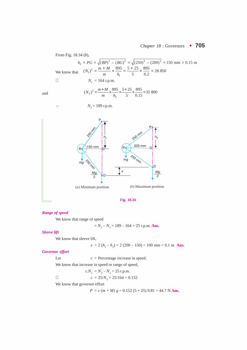
Chapter 18 : Governors � 705
From Fig. 18.34 (b),2 2 2 2
2 ( ) – ( ) (250) – (200) 150 mm 0.15 mh PG BP BG= = = = =
We know that2
11
895 5 25 895( ) 26 850
5 0.2
m MN
m h
+ += × = × =
∴ N1 = 164 r.p.m.
and 2
22
895 5 25 895( ) 35 800
5 0.15
m MN
m h
+ += × = × =
� N2 = 189 r.p.m.
Fig. 18.34
Range of speed
We know that range of speed
= N2 – N1 = 189 – 164 = 25 r.p.m. Ans.
Sleeve lift
We know that sleeve lift,
x = 2 (h1 – h2) = 2 (200 – 150) = 100 mm = 0.1 m Ans.
Governor effort
Let c = Percentage increase in speed.
We know that increase in speed or range of speed,
c.N1 = N2 – N1 = 25 r.p.m.
∴ c = 25/N1 = 25/164 = 0.152
We know that governor effort
P = c (m + M) g = 0.152 (5 + 25) 9.81 = 44.7 N Ans.

706 � Theory of Machines
Power of the governor
We know that power of the governor
= P.x = 44.7 × 0.1 = 4.47 N-m Ans.
2. When the friction at the sleeve is taken into account
We know that 21
1
. ( . – ) 895( )
.
m g M g FN
m g h
+= ×
5 9.81 (25 9.81 – 10) 89525 938
5 9.81 0.2
× + ×= × =×
∴ N1 = 161 r.p.m.
and 22
2
. ( . ) 895( )
.
m g M g FN
m g h
+ += ×
5 9.81 (25 9.81 10) 895
37 0165 9.81 0.15
× + × += × =×
∴ N2 = 192.4 r.p.m.
Range of speed
We know that range of speed
= N2 – N1 = 192.4 – 161 = 31.4 r.p.m. Ans.
Sleeve lift
The sleeve lift (x) will be same as calculated above.
∴ Sleeve lift, x = 100 mm = 0.1 m Ans.
Governor effort
Let c = Percentage increase in speed.
We know that increase in speed or range of speed,
c.N1 = N2 – N1 = 31.4 r.p.m.
∴ c = 31.4/N1 = 31.4/161 = 0.195
We know that governor effort,
P = c (m.g + M.g + F) = 0.195 (5 × 9.81 + 25 × 9.81 + 10) N
= 57.4 N Ans.
Power of the governor
We know that power of the governor
= P.x = 57.4 × 0.1 = 5.74 N-m Ans.
Example 18.25. The upper arms of a Porter governor has lengths 350 mm and are pivotedon the axis of rotation. The lower arms has lengths 300 mm and are attached to the sleeve at adistance of 40 mm from the axis. Each ball has a mass of 4 kg and mass on the sleeve is 45 kg.Determine the equilibrium speed for a radius of rotation of 200 mm and find also the effort andpower of the governor for 1 per cent speed change.
Solution. Given : PB = 350 mm = 0.35 m ; BD = 300 mm = 0.3 m ; DE = 40 mm = 0.04 m ;m = 4 kg ; M = 45 kg ; r = BG = 200 mm = 0.2 m ; c = 1% = 0.01

Chapter 18 : Governors � 707Equilibrium speed
Let N = Equilibrium speed.
The equilibrium position of the governor is shown in Fig.18.35. From the geometry of the figure,
2 2( ) – ( )h PG PB BG= =
2 2(0.35) – (0.2) 0.287 m= =
0.2
tan 0.6970.287
BG
PGα = = =
∴ BH = BG – HG = 0.2 – 0.04 = 0.16 m. . . (� HG = DE)
and 2 2( ) – ( )DH BD BH=
2 2(0.3) – (0.16) 0.254 m= =
∴ tan β = BH/DH = 0.16 / 0.254 = 0.63
and tan 0.63
0.904tan 0.697
qβ= = =α
We know that
2
45(1 ) 4 (1 0.904)895 8952 2 36 517
4 0.287
Mm q
Nm h
+ + + += × = × =
∴ N = 191 r.p.m. Ans.Effort of the governor
We know that effort of the governor,
2 2 40.01 45 9.81 4.8 N
1 1 0.904
mP c M g
q
×= + = + = + + Ans.
Power of the governorWe know that power of the governor
24(1 ) .
1 2 2
c Mm q g h
c = + + +
24 (0.01) 454 (1 0.904) 9.81 0.287 0.052 N-m
1 2 0.01 2 = + + × = + ×
= 52 N-mm Ans.
Example 18.26. The radius of rotation of the balls of a Hartnell governor is 80 mm at theminimum speed of 300 r.p.m. Neglecting gravity effect, determine the speed after the sleeve haslifted by 60 mm. Also determine the initial compression of the spring, the governor effort and thepower.
The particulars of the governor are given below:
Length of ball arm = 150 mm ; length of sleeve arm = 100 mm ; mass of each ball = 4 kg ; andstiffness of the spring = 25 N/mm.
Fig. 18.35
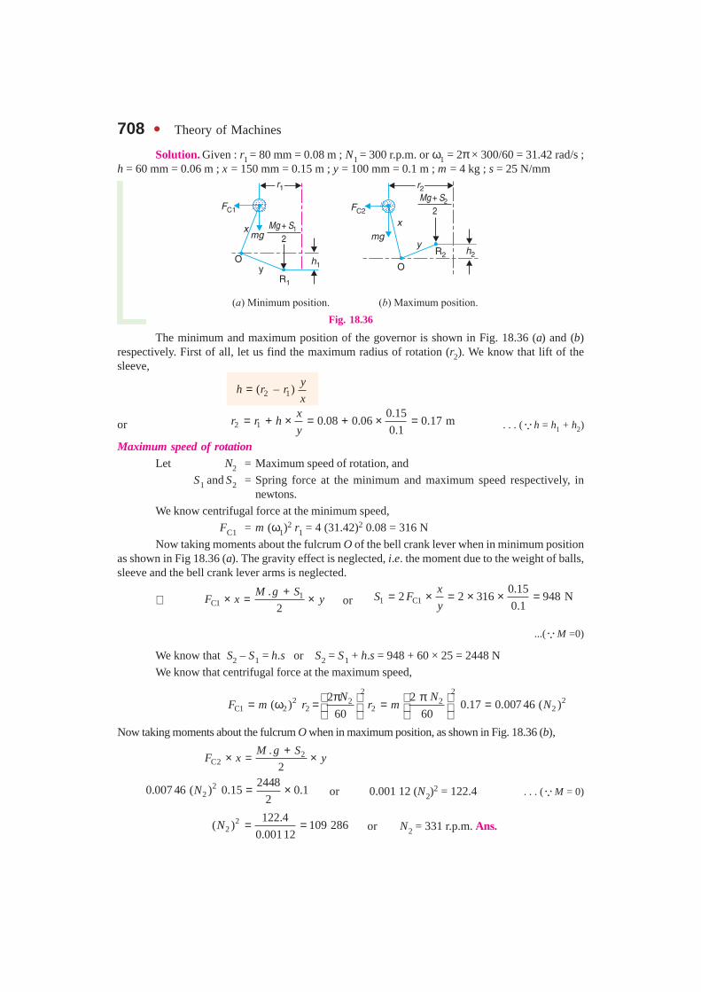
708 � Theory of Machines
Solution. Given : r1 = 80 mm = 0.08 m ; N1 = 300 r.p.m. or ω1 = 2π × 300/60 = 31.42 rad/s ;h = 60 mm = 0.06 m ; x = 150 mm = 0.15 m ; y = 100 mm = 0.1 m ; m = 4 kg ; s = 25 N/mm
Fig. 18.36
The minimum and maximum position of the governor is shown in Fig. 18.36 (a) and (b)respectively. First of all, let us find the maximum radius of rotation (r2). We know that lift of thesleeve,
2 1( – )y
h r rx
=
or 2 10.15
0.08 0.06 0.17 m0.1
xr r h
y= + × = + × = . . . (�h = h1 + h2)
Maximum speed of rotationLet N2 = Maximum speed of rotation, and
S1 and S2 = Spring force at the minimum and maximum speed respectively, innewtons.
We know centrifugal force at the minimum speed,
FC1 = m (ω1)2 r1 = 4 (31.42)2 0.08 = 316 N
Now taking moments about the fulcrum O of the bell crank lever when in minimum positionas shown in Fig 18.36 (a). The gravity effect is neglected, i.e. the moment due to the weight of balls,sleeve and the bell crank lever arms is neglected.
∴ 1C1
.
2
M g SF x y
+× = × or 1 C1
0.152 2 316 948 N
0.1
xS F
y= × = × × =
...(�M =0)
We know that S2 – S1 = h.s or S2 = S1 + h.s = 948 + 60 × 25 = 2448 N
We know that centrifugal force at the maximum speed,
2 2
2 22 2C1 2 2 2 2
2 2( ) 0.17 0.007 46 ( )
60 60
N NF m r r m N
π π = ω = = = Now taking moments about the fulcrum O when in maximum position, as shown in Fig. 18.36 (b),
2C2
.
2
M g SF x y
+× = ×
22
24480.007 46 ( ) 0.15 0.1
2N = × or 0.001 12 (N2)
2 = 122.4 . . . (�M = 0)
22
122.4( ) 109 286
0.00112N = = or N2 = 331 r.p.m. Ans.

Chapter 18 : Governors � 709Initial compression of the spring
We know that initial compression of the spring
1 94837.92 mm
25
S
s= = = Ans.
Governor effortWe know that the governor effort,
2 1– 2448 – 948750 N
2 2
S SP = = = Ans.
Governor powerWe know that the governor power
= P × h = 750 × 0.06 = 45 N-m Ans.Example 18.27. In a Hartnell governor, the lengths of ball and sleeve arms of a bell crank
lever are 120 mm and 100 mm respectively. The distance of the fulcrum of the bell crank lever fromthe governor axis is 140 mm. Each governor ball has a mass of 4 kg. The governor runs at a meanspeed of 300 r.p.m. with the ball arms vertical and sleeve arms horizontal. For an increase of speedof 4 per cent, the sleeve moves 10 mm upwards. Neglecting friction, find :
1. the minimum equilibrium speed if the total sleeve movement is limited to 20 mm, 2. thespring stiffness, 3. the sensitiveness of the governor, and 4. the spring stiffness if the governor is to beisochronous at 300 r.p.m.
Solution. Given : x = 120 mm = 0.12 m ; y = 100 mm = 0.1 m ; r = 140 mm = 0.14 m ;m = 4 kg ; N = 300 r.p.m. or ω = 2π × 300/60 = 31.42 rad/s ; h1 = 10 mm = 0.01 m ; h = 20 mm = 0.02 m1. Minimum equilibrium speed
Let N1 = Minimum equilibrium speed,
r1 = Radius of rotation in the minimum position, i.e. when the sleevemoves downward, and
r2 = Radius of rotation in the maximum position, i.e. when the sleevemoves upward.
Since the increase in speed is 4%, therefore maximum speed,N2 = N + 0.04 N = 1.04 N = 1.04 × 300 = 312 r.p.m.
or ω2 = 2π × 312 / 60 = 32.7 rad/sWe know that lift of the sleeve for the maximum position,
h2 = h – h1 = 0.02 – 0.01 = 0.01 mNow for the minimum position,
1 1–h r r
y x= or 1 1
0.12– 0.14 – 0.01 0.128 m
0.1
xr r h
y= × = × =
Similarly for the maximum position,
2 2 –h r r
y x= or 2 2
0.120.14 0.01 0.152 m
0.1
xr r h
y= + × = + × =
We know that centrifugal force in the mean position,FC = m.ω2.r = 4 (31.42)2 0.14 = 553 N
Centrifugal force in the minimum position,
22 21
C1 1 2 12
( ) 4 0.128 0.0056 ( )60
NF m r N
π = ω = = . . . (i)

710 � Theory of Machines
and centrifugal force in the maximum position,
FC2 = m.(ω2)2 r2 = 4 (32.7)2 0.152 = 650 N
We know that centrifugal force at any instant,
1C C1 C2 C1
2 1
–( – )
–
r rF F F F
r r
= +
C1 C1 10.14 – 0.128
553 (650 – ) 0.5 3250.152 – 0.128 CF F F
= + = +
∴ C1553 – 325
456 N0.5
F = = ...(ii)
From equations (i) and (ii),
21
456( ) 81 428
0.0056N = = or N1 = 285.4 r.p.m. Ans.
2. Spring stiffness
Let S1 and S2 = Spring force at the minimum and maximum position.
Neglecting the effect of obliquity of arms, we have for the minimum position,
1C1
.
2
M g Sy F x
+ × = × or1 C1
0.122 2 456 1094.4 N
0.1
xS F
y= × = × × =
. . . (�M = 0)
and for the maximum position,
2C2
.
2
M g Sy F x
+× = × or 2 C2
0.122 2 650 1560 N
0.1
xS F
y= × = × × =
We know that spring stiffness,
2 1– 1560 – 1064.423.28 N/mm
20
S Ss
h= = = Ans.
3. Sensitiveness of the governor
We know that sensitiveness of the governor
2 1
1 2
2 ( – ) 2 (312 – 285.4)0.089 or 8.9%
285.4 312
N N
N N= = =
+ + Ans.
4. Spring stiffness for the governor to be isochronous at 300 r.p.m.
The governor is isochronous, when N = N1 = N2 = 300 r.p.m. or ω = ω1 = ω2 = 31.42 rad/s
∴ FC1 = m.ω2.r1 = 4 (31.42)2 0.128 = 505.5 N
and FC2 = m.ω2.r2 = 4 (31.42)2 0.152 = 600 N
We know that 1 C10.12
2 2 505.5 1213 N0.1
xS F
y= × = × × =
and 2 C20.12
2 2 600 1440 N0.1
xS F
y= × = × × =
∴ Spring stiffness, 2 1– 1440 – 121311.35 N/mm
20
S Ss
h= = = Ans.
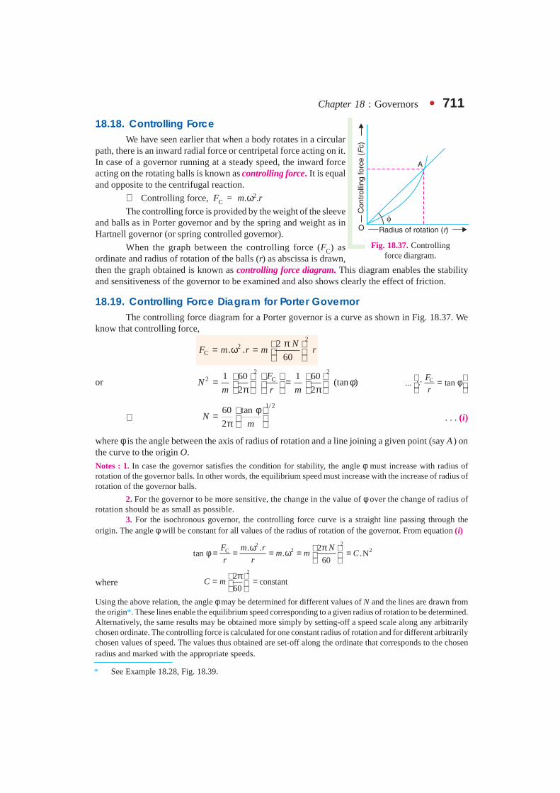
Chapter 18 : Governors � 711
18.18. Controlling ForceWe have seen earlier that when a body rotates in a circular
path, there is an inward radial force or centripetal force acting on it.In case of a governor running at a steady speed, the inward forceacting on the rotating balls is known as controlling force. It is equaland opposite to the centrifugal reaction.
∴ Controlling force, FC = m.ω2.r
The controlling force is provided by the weight of the sleeveand balls as in Porter governor and by the spring and weight as inHartnell governor (or spring controlled governor).
When the graph between the controlling force (FC) asordinate and radius of rotation of the balls (r) as abscissa is drawn,then the graph obtained is known as controlling force diagram. This diagram enables the stabilityand sensitiveness of the governor to be examined and also shows clearly the effect of friction.
18.19. Controlling Force Diagram for Porter GovernorThe controlling force diagram for a Porter governor is a curve as shown in Fig. 18.37. We
know that controlling force,2
2C
2. .
60
NF m r m r
π = ω =
or2 2
2 C1 60 1 60(tan )
2 2
FN
m r m
= = φ π π C... tan
F
r = φ �
∴1/ 2
60 tan
2N
m
φ = π . . . (i)
where φ is the angle between the axis of radius of rotation and a line joining a given point (say A ) onthe curve to the origin O.
Notes : 1. In case the governor satisfies the condition for stability, the angle φ must increase with radius ofrotation of the governor balls. In other words, the equilibrium speed must increase with the increase of radius ofrotation of the governor balls.
2. For the governor to be more sensitive, the change in the value of φ over the change of radius ofrotation should be as small as possible.
3. For the isochronous governor, the controlling force curve is a straight line passing through theorigin. The angle φ will be constant for all values of the radius of rotation of the governor. From equation (i)
222 2C . . 2
tan . .N60
F m r Nm m C
r r
ω π φ = = = ω = =
where2
2constant
60C m
π = = Using the above relation, the angle φ may be determined for different values of N and the lines are drawn fromthe origin*. These lines enable the equilibrium speed corresponding to a given radius of rotation to be determined.Alternatively, the same results may be obtained more simply by setting-off a speed scale along any arbitrarilychosen ordinate. The controlling force is calculated for one constant radius of rotation and for different arbitrarilychosen values of speed. The values thus obtained are set-off along the ordinate that corresponds to the chosenradius and marked with the appropriate speeds.
Fig. 18.37. Controllingforce diargram.
* See Example 18.28, Fig. 18.39.
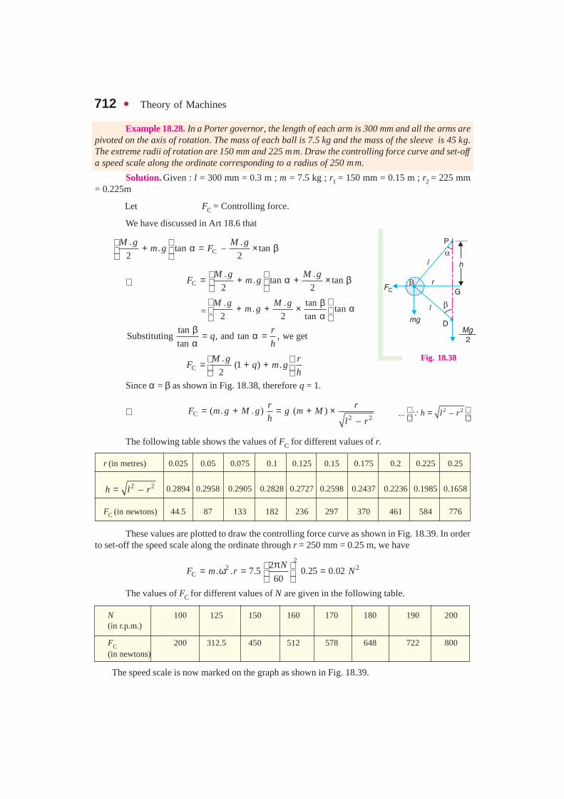
712 � Theory of Machines
Example 18.28. In a Porter governor, the length of each arm is 300 mm and all the arms arepivoted on the axis of rotation. The mass of each ball is 7.5 kg and the mass of the sleeve is 45 kg.The extreme radii of rotation are 150 mm and 225 mm. Draw the controlling force curve and set-offa speed scale along the ordinate corresponding to a radius of 250 mm.
Solution. Given : l = 300 mm = 0.3 m ; m = 7.5 kg ; r1 = 150 mm = 0.15 m ; r2 = 225 mm= 0.225m
Let FC = Controlling force.
We have discussed in Art 18.6 that
C. .
. tan – tan2 2
M g M gm g F
+ α = × β
∴ C. .
. tan tan2 2
M g M gF m g = + α + × β
=. . tan
. tan2 2 tan
M g M gm g
β+ + × α α tan
Substituting , and tan , we gettan
rq
h
β = α =α
C.
(1 ) .2
M g rF q m g
h = + +
Since α = β as shown in Fig. 18.38, therefore q = 1.
∴ C2 2
( . . ) ( )–
r rF m g M g g m M
h l r= + = + × 2 2... –h l r =
�
The following table shows the values of FC for different values of r.
r (in metres) 0.025 0.05 0.075 0.1 0.125 0.15 0.175 0.2 0.225 0.25
2 2–h l r= 0.2894 0.2958 0.2905 0.2828 0.2727 0.2598 0.2437 0.2236 0.1985 0.1658
FC (in newtons) 44.5 87 133 182 236 297 370 461 584 776
These values are plotted to draw the controlling force curve as shown in Fig. 18.39. In orderto set-off the speed scale along the ordinate through r = 250 mm = 0.25 m, we have
22 2
C2
. . 7.5 0.25 0.0260
NF m r N
π = ω = = The values of FC for different values of N are given in the following table.
N 100 125 150 160 170 180 190 200(in r.p.m.)
FC 200 312.5 450 512 578 648 722 800(in newtons)
The speed scale is now marked on the graph as shown in Fig. 18.39.
Fig. 18.38
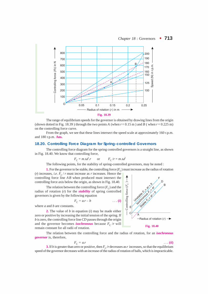
Chapter 18 : Governors � 713
Fig. 18.39
The range of equilibrium speeds for the governor is obtained by drawing lines from the origin(shown dotted in Fig. 18.39 ) through the two points A (when r = 0.15 m ) and B ( when r = 0.225 m)on the controlling force curve.
From the graph, we see that these lines intersect the speed scale at approximately 160 r.p.m.and 180 r.p.m. Ans.
18.20. Controlling Force Diagram for Spring-controlled GovernorsThe controlling force diagram for the spring controlled governors is a straight line, as shown
in Fig. 18.40. We know that controlling force,
FC = m.ω2.r or FC /r = m.ω2
The following points, for the stability of spring-controlled governors, may be noted :
1. For the governor to be stable, the controlling force (FC) must increase as the radius of rotation(r) increases, i.e. FC / r must increase as r increases. Hence thecontrolling force line A B when produced must intersect thecontrolling force axis below the origin, as shown in Fig. 18.40.
The relation between the controlling force (FC) and theradius of rotation (r) for the stability of spring controlledgovernors is given by the following equation
FC = a.r – b . . . (i)
where a and b are constants.
2. The value of b in equation (i) may be made eitherzero or positive by increasing the initial tension of the spring. Ifb is zero, the controlling force line CD passes through the originand the governor becomes isochronous because FC /r willremain constant for all radii of rotation.
The relation between the controlling force and the radius of rotation, for an isochronousgovernor is, therefore,
FC = a.r . . . (ii)3. If b is greater than zero or positive, then FC /r decreases as r increases, so that the equilibrium
speed of the governor decreases with an increase of the radius of rotation of balls, which is impracticable.
Fig. 18.40

714 � Theory of Machines
Such a governor is said to be unstable and the relation between the controlling force and the radius ofrotation is, therefore
FC = a.r + b . . . (iii)
Example 18.29. The particulars of a governor ofthe type as shown in Fig. 18.41, are as follows:
The mass of each ball is 1.5 kg and the mass of thesleeve is 7.5 kg. The lengths of the ball arm and sleeve armof the bell crank lever are 112.5 mm and 50 mm respectivelyand are at right angles to each other. The extreme radii ofrotation are 62.5 mm and 112.5 mm. At the minimum radius,the ball arm is vertical and the spring load is 160 N. Thespring stiffness is 10.5 N/mm. Draw the controlling forcecurve and mark the speed scale along the ordinate through125 mm.
Solution. Given : m = 1.5 kg ; M = 7.5 kg ;x = 112.5 mm = 0.1125 m ; y = 50 mm = 0.05 m ; r1 = 62.5 mm= 0.0625 m ; r2 = 112.5 mm = 0.1125 m ; S1 = 160 N ;s = 10.5 N/mm = 10 500 N/m
Let S1 and S2 be the spring loads at the minimum and maximum radius of rotation.
The minimum and maximum position of the balls is shown in Fig. 18.42 (a) and (b)respectively. Taking moments about the instantaneous centre I, for the maximum position as shownin Fig. 18.42 (b),
Fig. 18.42
2C2
..
2
M g SF BD m g ID IO
+× = × + ×
or 2C2
.cos . ( sin cos ) cos
2
M g SF x m g x y y
+× θ = θ + θ + × θ
∴ 2C2
.. tan
2
M g Sy yF m g
x x
+ = θ + + × . . . (i)
We know thatS2 – S1 = h.s = y sin θ × s
∴ S2 = S1 + y sin θ × s = 160 + 0.05 × sin θ × 10 500= 160 + 525 sin θ . . . (ii)
Fig. 18.41

Chapter 18 : Governors � 715Now the equation (i) may be written as
C20.05 7.5 9.81 160 525 sin 0.05
1.5 9.81 tan0.1125 2 0.1125
F× + + θ = × θ + + ×
= 14.7 tan θ + 116.5 sin θ + 58.5 ...(iii)
From the geometry of Fig. 18.42 (b), we find that
r2 = r1 + OD = r1 + x sin θ = 0.0625 + 0.1125 sin θ ...(iv)
In order to determine the controlling force and the radius of rotation of the ball for differentvalues of θ, the angle θ is treated as variable. From equations (iii) and (iv), the values of controllingforce (FC) and radius of rotation (r) for different values of θ are tabulated below :
θ° 0 5 10 15 20 25 30
sin θ 0 0.0871 0.1736 0.2588 0.342 0.4226 0.5
tan θ 0 0.0875 0.1763 0.2679 0.364 0.4663 0.5773
FC (N) 58.5 70 81.3 92.6 103.7 114.6 125.2
r (m) 0.0625 0.0723 0.082 0.092 0.101 0.11 0.1187
The graph between FC and r is plotted as shown in Fig. 18.43. It may be seen that thecontrolling force curve is nearly a straight line.
Fig. 18.43

716 � Theory of Machines
In order to set off the speed scale along the ordinate through r = 125 mm = 0.125 m,2
2 2C
2. . 1.5 0.125 0.00206
60
NF m r N
π = ω = = The corresponding values of FC and N are given in the following table :
N (r.p.m.) 200 210 220 230 240 250 260
FC (N) 82.4 90.8 99.7 109 118.6 128.7 139.2
The speed scale is now marked on the graph as shown in Fig. 18.43. The range of equilibriumspeeds for the governor is obtained by drawing lines from the origin (shown dotted in Fig. 18.43)through the two points A (when r = 0.0625 m) and B (when r = 0.1125 m) on the controlling force curve.
From the graph we see that these lines intersect the speed scale at approximately 238 r.p.m.and 252 r.p.m. Ans.
18.21. Coefficient of Insensitiveness
In the previous articles, we have assumed the governor to be frictionless. In actual practice,there is always friction in the joints and operating mechanism of the governor. Since the frictionalforce always acts in the opposite direction to that of motion, therefore, when the speed of rotationdecreases, the friction prevents the downward movement of the sleeve and the radial inward movementof the balls. On the other hand, when the speed of rotation increases, the friction prevents the upwardmovement of the sleeve and radial outward movement of the balls.
Fig. 18.44
Let FS = Force required at the sleeve to overcome friction,
FB = Corresponding radial force required at each ball,
FC = Controlling force on each ball, and
W = Total load on the sleeve = M.g.
∴ For decrease in speed, sleeve load (taking friction into account),
W1 = W – FS or M1.g = M.g – FS
and for increase in speed, sleeve load (taking friction into account),W2 = W + FS or M1.g = M.g + FS
Similarly, for decrease in speed, controlling force,FC1 = FC – FB
and for increase in speed, controlling force,
FC2 = FC + FB
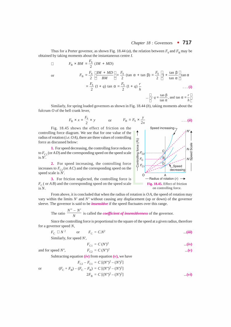
Chapter 18 : Governors � 717Thus for a Porter governor, as shown Fig. 18.44 (a), the relation between FS and FB may be
obtained by taking moments about the instantaneous centre I.
∴ SB ( )
2
FF BM IM MD× = +
or S S SB
tan(tan tan ) 1 tan
2 2 2 tan
F F FIM MDF
BM
+ β = = α + β = + α α
S S(1 ) tan (1 )
2 2
F F rq q
h= + α = + . . . (i)
tan... , and tan
tan
rq
h
β= α = α �
Similarly, for spring loaded governors as shown in Fig. 18.44 (b), taking moments about thefulcrum O of the bell crank lever,
SB 2
FF x y× = × or B S 2
yF F
x= × . . . (ii)
Fig. 18.45 shows the effect of friction on thecontrolling force diagram. We see that for one value of theradius of rotation (i.e. OA), there are three values of controllingforce as discussed below:
1. For speed decreasing, the controlling force reducesto FC1 (or AD) and the corresponding speed on the speed scaleis N'.
2. For speed increasing, the controlling forceincreases to FC2 (or AC) and the corresponding speed on thespeed scale is N'.
3. For friction neglected, the controlling force isFC ( or A B) and the corresponding speed on the speed scaleis N .
From above, it is concluded that when the radius of rotation is OA, the speed of rotation mayvary within the limits N' and N'' without causing any displacement (up or down) of the governorsleeve. The governor is said to be insensitive if the speed fluctuates over this range.
The ratio –N N
N
′′ ′ is called the coefficient of insensitiveness of the governor.
Since the controlling force is proportional to the square of the speed at a given radius, thereforefor a governor speed N,
FC ∝ N 2 or FC = C.N2 ...(iii)
Similarly, for speed N',
FC1 = C (N')2 ...(iv)
and for speed N'', FC2 = C (N'')2 ...(v)
Subtracting equation (iv) from equation (v), we have
FC2 – FC1 = C [(N'')2 – (N')2]
or (FC + FB) – (FC – FB) = C [(N'')2 – (N')2]
2FB = C [(N'')2 – (N')2] ...(vi)
Fig. 18.45. Effect of frictionon controlling force.
718 � Theory of Machines
Dividing equation (vi) by equation (iii)
2 2
B2 2
C
2 ( ) – ( ) ( ) ( – ) –F N N N N N N N N N N
F N NN N
′′ ′ ′′ ′ ′′ ′ ′′ ′ ′′ ′+ += = = ×
Since 2
N N′′ ′+ is approximately equal to N, therefore
B
C
2 –2
F N N
F N
′′ ′= ×
∴ Coefficient of insensitiveness
B
C
– FN N
N F
′′ ′= = . . . (vii)
Notes : 1 In case of a Porter governor, as shown in Fig. 18.44 (a), (i.e. when the lower arm is not attached on thegovernor axis),
SB (1 )
2
F rF q
h= +
∴ Coefficient of insensitiveness
B S
C C
–(1 )
2
N N F F rq
N F F h
′′ ′= = = + . . . (viii)
2. When all the arms of a Porter governor are attached to the governor axis, then q = 1. In that case,
B Sr
F Fh
= ×
∴ Coefficient of insensitiveness
B S
C C
–N N F F r
N F F h
′′ ′= = = × . . . (ix)
3. In case of a Porter governor when all the arms are attached to the governor axis, the coefficient ofinsensitiveness may also be determined as discussed below :
Let h = Height of the governor at the mean speed N, when friction is neglected,
F = Frictional force on the sleeve,
N' and N'' = Minimum and maximum speed when friction is taken into account.
We have discussed above that the governor is insensitive when the sleeve does not move downwardswhen the speed falls to N' or upwards when the speed rises to N'' . In other words, the height of the governor (h)remains the same for minimum and maximum speeds N' and N'' respectively. We know that
2 895m MN
m h
+= ×
Similarly,2 . ( . – ) 895
( ).
m g M g FN
m g h
+′ = ×
and2 . ( . ) 895
( ).
m g M g FN
m g h
+ +′′ = ×
Now (N'')2 – (N')2 = (N'' + N') (N'' – N') = 2 N (N'' – N') . ..2
N NN
′′ ′+ = �
∴2 2( ) – ( )
–2
N NN N
N
′′ ′′′ ′ =

Chapter 18 : Governors � 719and coefficient of insensitiveness
2 2
2
. ( . ) . ( . – )–
– ( ) – ( ) . .
2 2
m g M g F m g M g FN N N N m g m g
m MN Nm
+ + +′′ ′ ′′ ′
= = =+
1 2
2 ( ) ( )
F F
m M g m M g
= = + +
...(x)
4. In case of a Porter governor, when the upper arms are pivoted to the governor axis and the lowerarms are at a certain distance from the governor axis i.e. when α is not equal to β (Refer Art. 18.6), then it maybe proved that
Coefficient of insensitiveness
– (1 )
2 . . (1 )
N N F q
N m g M g q
′′ ′ +=+ +
5. In case of a Hartnell governor,
B S2
yF F
x= ×
∴ Coefficient of insensitiveness B S
C C
–
2
N N F F y
N F F x
′′ ′= = = × ...(xi)
Example 18.30. A Porter governor has equal arms 200 mm long pivoted on the axis ofrotation. The mass of each ball is 3 kg and the mass on the sleeve is 15 kg. The ball path is 120 mmwhen the governor begins to lift and 160 mm at the maximum speed. Determine the range of speed.
If the friction at the sleeve is equivalent to a force of 10 N, find the coefficient of insensitiveness.
Solution.Given : BP = BD = 200 mm = 0.2 m ; m = 3 kg ; M = 15 kg ; r1 = 120 mm = 0.12 m ;r2 = 160 mm = 0.16 m ; F = 10 N
Range of speed
First of all, let us find the minimum and maximum speed of rotation.
Fig. 18.46
The minimum and maximum position of the balls is shown in Fig 18.46 (a) and (b) respectively.
Let N1 = Minimum speed, and
N2 = Maximum speed.

720 � Theory of Machines
From Fig. 18.46 (a), 2 2 2 21 ( ) – ( ) (0.2) – (0.12) 0.16 mh BP BG= = =
and from Fig. 18.46 (b), 2 2 2 22 ( ) – ( ) (0.2) – (0.16) 0.12 mh BP BG= = =
We know that 2
11
895 3 15 895( ) 33 563
3 0.16
m MN
m h
+ += × = × =
∴ N1 = 183.2 r.p.m.
Similarly2
21
895 3 15 895( ) 44750
3 0.12
m MN
m h
+ += × = × =
∴ N2 = 211.5 r.p.m.We know that range of speed
= N2 – N1 = 211.5 – 183.2 = 28.3 r.p.m. Ans.Coefficient of insensitiveness
We know that coefficient of insensitiveness,
– 10
0.0566 5.66%( ) (3 15) 9.81
N N F
N m M g
′′ ′= = = =
+ + Ans.
Example 18.31. The following particulars refer to a Proell governor with open arms :
Length of all arms = 200 mm, distance of pivot of arms from the axis of rotation = 40 mm,length of extension of lower arms to which the ball is attached = 100 mm, mass of each ball = 6 kgand mass of the central load = 150 kg. If the radius of rotation of the balls is 180 mm when the armsare inclined at 40° to the axis of rotation, find :
1. the equilibrium speed for the above configuration, 2. the coefficient of insensitiveness ifthe friction of the governor mechanism is equivalent to a force of 20 N at the sleeve, and 3. the rangeof speed between which the governor is inoperative.
Solution. Given : PF = FD = 200 mm = 0.2 m ; DK = 40 mm = 0.04 m ; BF = 100 mm= 0.1 m ; m = 6 kg ; M = 150 kg ; r = JG = 180 mm = 0.18 m ; F = 20 N
1. Equilibrium speed
Let N = Equilibrium speed.
From the equilibrium position, as shown in Fig 18.47, we find that the height of the governor,
h = PH = PF cos 40°
= 0.2 × 0.766 = 0.1532 m
and FH = PF sin 40°
= 0.2 × 0.643 = 0.1286 m
∴ JF = JG – HG – FH
= 0.18 – 0.04 – 0.1286
= 0.0114 m
and 2 2( ) – ( )BJ BF JF=
2 2(0.1) – (0.0114)=
= 0.0993 m
BM = BJ + JM
= 0.0993 + 0.1532 = 0.2525 m . . . ( � JM = MD = PH)
Fig. 18.47All dimensions in mm.

Chapter 18 : Governors � 721 IM = IN – MN = FH – JF = 0.1286 – 0.0114 = 0.1172 m
ID = 2 × IN = 2 × FH = 2 × 0.1286 = 0.2572 m
We know that centrifugal force,
2
2 2C
2. . 6 0.18 0.012
60
NF m r N
π = ω = = Now taking moments about I,
C.
.2
M gF BM m g IM ID× = × + ×
2 150 9.810.012 0.2525 6 9.81 0.1172 0.2572
2N
×× = × × + ×
or 0.003 03 N 2 = 6.9 + 189.2 = 196.1
∴ N 2 = 196.1/0.003 03 = 64 720 or N = 254.4 r.p.m. Ans.Coefficient of insensitiveness
Let N' and N'' = Minimum and maximum speed considering friction.
We know that centrifugal force at the minimum speed,2
2 2C
2( ) 6 0.18 0.012 ( )
60
NF m r N
′π ′ ′ ′= ω = = and centrifugal force at the maximum speed,
22 2
C2
( ) 6 0.18 0.012 ( )60
NF m r N
′′π ′′ ′′ ′′= ω = = Taking moments about I, when sleeve moves downwards,
C.
.2
M g FF BM m g IM ID
−′ × = × + ×
2 150 9.81 200.012( ) 0.2525 6 9.81 0.1172 0.2572
2N
× −′ = × × + ×
0.003 03 (N')2 = 6.9 + 186.7 = 193.6
∴ (N')2 = 193.6/0.003 03 = 63 894 or N' = 252.8 r.p.m.
Again taking moments about I, when the sleeve moves upwards,
C.
.2
M g FF BM m g IM ID
+′′ × = × + ×
2 150 9.81 200.012 ( ) 0.2525 6 9.81 0.1172 0.2572
2N
× +′′ = × × + ×
0.003 03 (N'')2 = 6.9 + 191.8 = 198.7
∴ (N'')2 = 198.7/0.003 03 = 65 578 or N'' = 256 r.p.m.
We know that coefficient of insensitiveness,
– 256 – 252.80.0126 or 1.26%
254.4
N N
N
′′ ′= = Ans.
3. Range of speed
We know that range of speed
= N'' – N' = 256 – 252.8 = 3.2 r.p.m. Ans.

722 � Theory of Machines
Example 18.32. A spring controlled governor is shown in Fig. 18.48. The central spindledoes not move axially. The mass of the sleeve is 20 kg and the frictional resistance to its movement isequivalent to 20 N. The balls attached to the right angled bell crank levers have mass 4 kg each. Thestiffness of the spring is 40 N/mm compression. The radius of rotation of the balls is 125 mm when thesleeve is in its lowest position, and the ball arms are vertical and the spring exerts a force of 600 N.Determine :
1. the speed at which the sleeve will begin to rise from its lowest position,
2. the range of speed when the sleeve is 12.5 mm above its lowest position, and
3. the coefficient of insensitiveness at higher speed.
Solution.Given : M = 20 kg ; F = 20 N ; m = 4 kg ; s = 40 N/mm ; r1 = 125 mm = 0.125 m ;S1 = 600 N
1. Speed at which sleeve will begin to rise from its lowest position
Let N1 = Required speed.
The lowest position is shown in Fig. 18.49 (a).
We know that the centrifugal force at the lowest position,2
2 21C1 1 1 1
2( ) 4 0.125 0.0055 ( )
60
NF m r N
π = ω = =
Fig. 18.48 Fig. 18.49
Since the sleeve is about to rise, therefore frictional resistance is taken positive. Also thecentral spindle is stationary, therefore all the forces are transferred to both the pivots of the bell crank
lever i.e. 1.
2
M g S F+ + at each pivot, as shown in Fig. 18.49 (a).
Since the pivot O moves vertically and the roller A moves horizontally, therefore A is theinstantaneous centre of the bell crank lever.
Now taking moments about A ,
1C1
..
2
M g S FF OB m g OA
+ + × = + 2
120 9.81 600 20
0.0055 ( ) 0.19 4 9.81 0.0852
N× + + = × +
0.001 05 (N1)2 = 3.3 + 34.7 = 38 or (N1)2 = 38 / 0.001 05 = 36 190
∴ N1 = 190 r.p.m. Ans.
Chapter 18 : Governors � 723
2. Range of speed
The highest position is shown in Fig. 18.49 (b).
Let N2 =Maximum speed,
h = Lift of the sleeve = 12.5 mm = 0.0125 m . . . (Given)
r2 = Maximum radius of rotation of the balls, and
S2 = Maximum spring force.
We know that lift of the sleeve
2 1 2 1( – ) ( – )y OA
h r r r rx OB
= × = × . . (Here x = OB, and y = OA)
∴ r2 = r1 + h × OB/OA = 0.125 + 0.0125 × 0.19/0.085 = 0.153 m
We know that centrifugal force at the highest position,
2 22
C2 2 2 22
( ) 4 0.153 0.0067 ( )60
NF m r N
π = ω = = and S2 – S1 = h.s or S2 = S1 + h.s = 600 + 12.5 × 40 = 1100 N
From Fig 18.49 (b), we find that
2 2 2 2( ) – ( ) (85) – (12.5) 84 mm 0.084 mOI OA AI= = = =
. . . (� AI = h)
2 2 2 2( ) – ( ) (190) – (153 – 125) 188 mm 0.188 mBC OB OC= = = =
. . . (�OC = r2 – r1)
and IC = OI + OC = 84 + (153 – 125) = 112 mm = 0.112 m
Now taking moments about the instantaneous centre I,
2C2
..
2
M g S FF BC m g IC OI
+ ±× = × + ×
The ± sign denotes that at the highest position, the sleeve may either rise or fall. Therefore
2
220 9.81 1100 20
0.0067 ( ) 0.188 4 9.81 0.112 0.0842
N× + ± = × × +
0.001 26 (N2)2 = 4.4 + 54.4 ± 0.84 = 58.8 ± 0.84
Taking – ve sign, when the sleeve is about to fall,
0.001 26 (N2)2 = 58.8 – 0.84 = 57.96
(N2)2 = 57.96/0.001 26 = 46 000 or N2 = 214.5 r.p.m.
Taking + ve sign, when the sleeve is about to lift,
0.001 26 (N2')2 = 58.8 + 0.84 = 59.64
(N2')2 = 59.64/0.001 26 = 47 333 or N2' = 217.5 r.p.m.
∴ Range of speed at the maximum radius
= N2' – N2 = 217.5 – 214.5 = 3 r.p.m. Ans.
724 � Theory of Machines
3. Coefficient of insensitiveness at higher speed
We know that coefficient of insensitiveness
2 2
2 2
2 ( – ) 2 (217.5 – 214.5)0.014 1.4%
217.5 214.5
N N
N N
′= = = =
+′ + Ans.
Example 18.33. In a spring controlled governor, the curve of controlling force is a straightline. When balls are 400 mm apart, the controlling force is 1200 N and when 200 mm apart, thecontrolling force is 450 N. At what speed will the governor run when the balls are 250 mm apart?What initial tension on the spring would be required for isochronism and what would then be thespeed ? The mass of each ball is 9 kg.
Solution. Given : When balls are 400 mm apart, i.e. when the radius of rotation (r2) is 200mm, the controlling force,
FC2 = 1200 N
When balls are 200 mm apart i.e. when the radius of rotation (r1) is 100 mm, the controllingforce,
FC1 = 450 N
Mass of each ball, m = 9 kg
Speed of the governor when the balls are 250 mm apart, i.e. when radius of rotation (r) is 125 mm
Let N = Required speed.
We know that for the stability of the spring controlled governors, the controlling force (FC) isexpressed in the form
* FC = a.r – b . . . (i)When r = r1 = 100 mm = 0.1 m, then
450 = a × 0.1 – b = 0.1 a – b . . .(ii)and when r = r2 = 200 mm = 0.2 m, then
1200 = a × 0.2 – b = 0.2 a – b . . . (iii)From equations (ii) and (iii), we find that
a = 7500, and b = 300Now the equation (i) may be written as
FC = 7500 r – 300 . . . (iv)Substituting r = 125 mm = 0.125 m, in equation (iv), we get
FC = 7500 × 0.125 – 300 = 637.5 N
We know that2
2C
2. .
60
NF m r m r
π = ω = 2
22637.5 9 0.125 0.012 34
60
NN
π = = ∴ N 2 = 637.5 / 0.012 34 = 51 661 or N = 227.3 r.p.m. Ans.
* We find that C1 C2
1 2
450 12004500 and 6000.
0.1 0.2F F
r r= = = =
Since FC / r increases as r increases, therefore for stability
FC = a.r – b (See Art. 18.20)

Chapter 18 : Governors � 725Initial tension on the spring for isochronism
We have discussed in Art. 18.20 that for an isochronous governor, the controlling force linepassed through the origin (i.e. b = 0). The value of b is made zero by increasing the initial tension ofthe spring to 300 N.
∴ Initial tension on the spring for isochronism = 300 N Ans.
Isochronous speed
Let N' = Isochronous speed, and
FC' = Controlling force at the isochronous speed.
We know that for isochronism,
FC' = a.r or m (ω')2 r = a.r or m (ω')2 = a
∴2
2
60
Nm a
′π = or 9 × 0.011 (N')2 = 7500
(N)2 = 7500 / 0.099 = 75 758 or N' = 275 r.p.m. Ans.
Example 18.34. The controlling force (FC) in newtons and the radius of rotation (r) inmetres for a spring controlled governor is given by the expression
FC = 2800 r – 76
The mass of the ball is 5 kg and the extreme radii of rotation of the balls are 100 mm and175 mm. Find the maximum and minimum speeds of equilibrium. If the friction of the governormechanism is equivalent to a force of 5 N at each ball, find the coefficient of insensitiveness of thegovernor at the extreme radii.
Solution. Given : m = 5 kg ; r1 = 100 mm = 0.1 m ; r2 = 175 mm = 0.175 m
Maximum and minimum speeds of equilibrium
Let N2 and N1 = Maximum and minimum speeds of equilibrium respectively.
The controlling force is given by the expression,
FC = 2800 r – 76
∴ Controlling force at the minimum radius of rotation (i.e. at r1 = 0.1 m),
FC1 = 2800 × 0.1 – 76 = 204 N
and controlling force at the maximum radius of rotation (i.e. at r2 = 0.175 m),
FC2 = 2800 × 0.175 – 76 = 414 N
We know that2
2 1C1 1 1 1
2( )
60
NF m r m r
π = ω =
or2
211
2204 5 0.1 0.0055 ( )
60
NN
π = = ∴ (N1)2 = 204 / 0.0055 = 37 091 or N1 = 192.6 r.p.m. Ans.
Similarly2
2 2C2 2 2 2
2( )
60
NF m r m r
π = ω =
or2
222
2414 5 0.175 0.0096 ( )
60
NN
π = = ∴ (N2)2 = 414 / 0.0096 = 43 125 or N2 = 207.6 r.p.m. Ans.

726 � Theory of Machines
Coefficient of insensitiveness
Let N1' and N2' = Minimum and maximum speeds of the governor considering friction.
We know that frictional force at each ball
= 5 N . . . (Given)
∴
2
2 1C1 1 1 1
2– ( )
60
NF F m r m r
′π′ = ω =
2
211
2204 – 5 5 0.1 0.0055 ( )
60
NN
′π ′ = =
∴ 21 1
204 – 5( ) 36 182 or 190.2 r.p.m.
0.0055N N′ ′= = =
Similarly
2
2 2C2 2 2 2
2( )
60
NF F m r m r
′π′ + = ω =
2
222
2414 5 5 0.175 0.0096 ( )
60
NN
′π ′ + = =
∴ 22 2
414 5( ) 43 646 or 209 r.p.m.
0.0096N N
+′ ′= = =
We know that coefficient of insensitiveness
2 1
2 1
2 ( – ) 2 (209 – 190.2)0.094 or 9.4%
209 190.2
N N
N N
′ ′= = =
+′ ′+ Ans.
EXERCISES1. The length of the upper arm of a Watt governor is 400 mm and its inclination to the vertical is 30°.
Find the percentage increase in speed, if the balls rise by 20 mm. [Ans. 3%]
2. A Porter governor has two balls each of mass 3 kg and a central load of mass 15 kg. The arms are all200 mm long, pivoted on the axis. If the maximum and minimum radii of rotation of the balls are 160mm and 120 mm respectively, find the range of speed. [Ans. 28.3 r.p.m.]
3. In a Porter governor, the mass of the central load is 18 kg and the mass of each ball is 2 kg. The toparms are 250 mm while the bottom arms are each 300 mm long. The friction of the sleeve is 14 N. Ifthe top arms make 45° with the axis of rotation in the equilibrium position, find the range of speed ofthe governor in that position. [Ans. 15 r.p.m.]
4. A loaded governor of the Porter type has equal arms and links each 250 mm long. The mass of eachball is 2 kg and the central mass is 12 kg. When the ball radius is 150 mm, the valve is fully open andwhen the radius is 185 mm, the valve is closed. Find the maximum speed and the range of speed. If themaximum speed is to be increased 20% by an addition of mass to the central load, find what additionalmass is required. [Ans. 193 r.p.m. ; 16 r.p.m.; 6.14 kg]
5. The arms of a Porter governor are 300 mm long. The upper arms are pivoted on the axis of rotationand the lower arms are attached to the sleeve at a distance of 35 mm from the axis of rotation. The loadon the sleeve is 54 kg and the mass of each ball is 7 kg. Determine the equilibrium speed when the
Chapter 18 : Governors � 727radius of the balls is 225 mm. What will be the range of speed for this position, if the frictionalresistances to the motion of the sleeve are equivalent to a force of 30 N?
[Ans. 174.3 r.p.m. ; 8.5 r.p.m.]
6. In a Porter governor, the upper and lower arms are each 250 mm long and are pivoted on the axis ofrotation. The mass of each rotating ball is 3 kg and the mass of the sleeve is 20 kg. The sleeve is in itslowest position when the arms are inclined at 30° to the governor axis. The lift of the sleeve is 36 mm.Find the force of friction at the sleeve, if the speed at the moment it rises from the lowest position isequal to the speed at the moment it falls from the highest position. Also, find the range of speed of thegovernor. [Ans. 9.8 N ; 16 r.p.m.]
7. A Porter governor has links 150 mm long and are attached to pivots at a radial distance of 30 mm fromthe vertical axis of the governor. The mass of each ball is 1.75 kg and the mass of the sleeve is 25 kg.The governor sleeve begins to rise at 300 r.p.m. when the links are at 30° to the vertical. Assuming thefriction force to be constant, find the minimum and maximum speed of rotation when the inclinationof the links is 45° to the vertical. [Ans. 284 r.p.m. ; 347 r.p.m.]
8. A Proell governor has all the four arms of length 250 mm. The upper and lower ends of the arms arepivoted on the axis of rotation of the governor. The extension arms of the lower links are each 100 mmlong and parallel to the axis when the radius of the ball path is 150 mm. The mass of each ball is 4.5kg and the mass of the central load is 36 kg. Determine the equilibrium speed of the governor.
[Ans. 164 r.p.m.]9. A Proell governor has arms of 300 mm length. The upper arms are hinged on the axis of rotation,
whereas the lower arms are pivoted at a distance of 35 mm from the axis of rotation. The extension oflower arms to which the balls are attached are 100 mm long. The mass of each ball is 8 kg and the masson the sleeve is 60 kg. At the minimum radius of rotation of 200 mm, the extensions are parallel to thegovernor axis. Determine the equilibrium speed of the governor for the given configuration. Whatwill be the equilibrium speed for the maximum radius of 250 mm?
[Ans. 144.5 r.p.m. ; 158.2 r.p.m.]10. A spring controlled governor of the Hartnell type with a central spring under compression has balls
each of mass 2 kg. The ball and sleeve arms of the bell crank levers are respectively 100 mm and 60mm long and are at right angles. In the lowest position of the governor sleeve, the radius of rotation ofthe balls is 80 mm and the ball arms are parallel to the governor axis. Find the initial load on the springin order that the sleeve may begin to lift at 300 r.p.m. If the stiffness of the spring is 30 kN/m, what isthe equilibrium speed corresponding to a sleeve lift of 10 mm? [Ans. 527 N ; 342 r.p.m.]
11. In a governor of the Hartnell type, the mass of each ball is 1.5 kg and the lengths of the vertical andhorizontal arms of the bell crank lever are 100 mm and 50 mm respectively. The fulcrum of the bellcrank lever is at a distance of 90 mm from the axis of rotation. The maximum and minimum radii ofrotation of balls are 120 mm and 80 mm and the corresponding equilibrium speeds are 325 and 300r.p.m. Find the stiffness of the spring and the equilibrium speed when the radius of rotation is 100 mm.
[Ans. 18 kN/m, 315 r.p.m.]12. A governor of the Hartnell type has equal balls of mass 3 kg, set initially at a radius of 200 mm. The
arms of the bell crank lever are 110 mm vertically and 150 mm horizontally. Find : 1. the initialcompressive force on the spring, if the speed for an initial ball radius of 200 mm is 240 r.p.m. ; and 2.the stiffness of the spring required to permit a sleeve movement of 4 mm on a fluctuation of 7.5 percent in the engine speed. [Ans. 556 N ; 23.75 N/mm]
13. A spring controlled governor of the Hartnell type has the following data :
Mass of the ball = 1.8 kg ; Mass of the sleeve = 6 kg ; Ball and sleeve arms of the bell crank lever = 150mm and 120 mm respectively. The equilibrium speed and radius of rotation for the lowest position ofthe sleeve are 400 r.p.m. and 150 mm respectively. The sleeve lift is 10 mm and the change in speedfor full sleeve lift is 5%. During an overhaul, the spring was compressed 2 mm more than the correctcompression for the initial setting. Determine the stiffness of the spring and the new equilibriumspeed for the lowest position of the sleeve. [Ans. 28.96 N/mm ; 472 r.p.m.]

728 � Theory of Machines
14. A spring controlled governor of the Hartnell type has two rotating balls of mass 1.35 kg each. The ballarm is 75 mm and the sleeve arm is 62.5 mm. In the mid position of the sleeve, the sleeve arm ishorizontal and the balls rotate in a circle of 100 mm radius. The total sleeve movement is 30 mm.
Due to maladjustment of the spring, it is found that the equilibrium speed at the topmost positionof the sleeve is 420 r.p.m. and that corresponding to the lowest position is 435 r.p.m.
Determine : 1. stiffness and initial compression of the spring, and 2. the required initial compressionof the spring to give an equilibrium speed at the topmost position which is 12 r.p.m. more than at thelowest position. Neglect the moment due to mass of the balls.
[Ans. 6.3 N/mm, 87.54 mm ; 53.5 mm]
15. A Hartnell governor has two rotating balls, of mass 2.7 kg each. The ball radius is 125 mm in the meanposition when the ball arms are vertical and the speed is 150 r.p.m. with the sleeve rising. The lengthof the ball arms is 140 mm and the length of the sleeve arms 90 mm. The stiffness of the spring is7 kN/m and the total sleeve movement is 12 mm from the mean position. Allowing for a constantfriction force of 14 N acting at the sleeve, determine the speed range of the governor in the lowest andhighest sleeve positions. Neglect the obliquity of the ball arms. [Ans. 10.7 r.pm., 6.6 r.pm.]
16. The spring controlled governor of the Hartung type has two rotating masses each of 2.5 kg and thelimits of their radius of rotation are 100 mm and 125 mm. The each mass is directly controlled by aspring attached to it and to the inner casing of the governor as shown in Fig 18.26 (a). The stiffness ofthe spring is 8 kN/m and the force on each spring, when the masses are in their mid-position, is 320 N.In addition, there is an equivalent constant inward radial force of 80 N acting on each revolving massin order to allow for the dead weight of the mechanism. Neglecting friction, find the range of speed ofthe governor. [Ans. 51 r.p.m.]
17. In a spring controlled governor of the Hartung type, the lengths of the horizontal and vertical arms ofthe bell crank levers are 100 mm and 80 mm respectively. The fulcrum of the bell crank lever is at adistance of 120 mm from the axis of the governor. The each revolving mass is 9 kg. The stiffness of thespring is 25 kN/m. If the length of each spring is 120 mm when the radius of rotation is 70 mm and theequilibrium speed is 360 r.p.m., find the free length of the spring. If the radius of rotation increases to120 mm, what will be the corresponding percentage increase in speed ?
[Ans 145.75 mm ; 10.83%]
[Hint. Free length of the spring = Length of the spring + compression of the spring]
18. The following particulars refer to a Wilson-Hartnell governor :
Mass of each ball = 4 kg ; minimum radius = 80 mm ; maximum radius = 90 mm ; minimum speed =240 r.p.m.; maximum speed = 252 r.p.m.; length of the ball arm of each bell crank lever = 80 mm ;length of sleeve arm of each bell crank lever = 60 mm ; combined stiffness of the two ball springs =750 N/m.
Find the required stiffness of the auxiliary spring, if the lever is pivoted at the mid-point.
[Ans. 6.786 kN/m]
19. A spring loaded governor of the Wilson-Hartnell typeis shown in Fig 18.50. Two balls each of mass 4 kg areconnected across by two springs A . The stiffness ofeach spring is 750 N/m and a free length of 100 mm.The length of ball arm of each bell crank lever is 80mm and that of sleeve arm is 60 mm. The lever ispivoted at its mid-point. The speed of the governor is240 r.p.m. in its mean position and the radius of rotationof the ball is 80 mm. If the lift of the sleeve is 7.5 mmfor an increase of speed of 5%, find the requiredstiffness of the auxiliary spring B. [Ans. 6.756 kN/m] Fig. 18.50
Chapter 18 : Governors � 72920. A Porter governor has all four arms 200 mm long. The upper arms are pivoted on the axis of rotation
and the lower arms are attached to a sleeve at a distance of 25 mm from the axis. Each ball has a massof 2 kg and the mass of the load on the sleeve is 20 kg. If the radius of rotation of the balls at a speedof 250 r.p.m. is 100 mm, find the speed of the governor after the sleeve has lifted 50 mm. Alsodetermine the effort and power of the governor. [Ans. 275.6 r.p.m.; 22.4 N ; 1.12 N-m]
21. A Porter governor has arms 250 mm each and four rotating flyballs of mass 0.8 kg each. The sleevemovement is restricted to ± 20 mm from the height when the mean speed is 100 r.p.m. Calculate thecentral dead load and sensitivity of the governor neglecting friction when the flyball exerts a centrifugalforce of 9.81 N. Determine also the effort and power of the governor for 1 percent speed change.
[Ans. 11.76 N; 11.12; 0.196 N; 7.7 N-mm]
22. The upper arms of a Porter governor are pivoted on the axis of rotation and the lower arms are pivotedto the sleeve at a distance of 30 mm from the axis of rotation. The length of each arm is 300 mm andthe mass of each ball is 6 kg. If the equilibrium speed is 200 r.p.m. when the radius of rotation is 200mm, find the required mass on the sleeve. If the friction is equivalent to a force of 40 N at the sleeve,find the coefficient of insensitiveness at 200 mm radius. [Ans. 61.1 kg. ; 6%]
23. In a spring controlled governor, the radial force acting on the balls was 4500 N when the centre ofballs was 200 mm from the axis and 7500 N when at 300 mm. Assuming that the force varies directlyas the radius, find the radius of the ball path when the governor runs at 270 r.p.m. Also find whatalteration in spring load is required in order to make the governor isochronous and the speed at whichit would then run. The mass of each ball is 30 kg. [Ans. 250 mm ; 1500 N ; 301.5 r.p.m.]
DO YOU KNOW ?1. What is the function of a governor ? How does it differ from that of a flywheel ?
2. State the different types of governors. What is the difference between centrifugal and inertia typegovernors ? Why is the former preferred to the latter ?
3. Explain the term height of the governor. Derive an expression for the height in the case of a Wattgovernor. What are the limitations of a Watt governor ?
4. What are the effects of friction and of adding a central weight to the sleeve of a Watt governor ?
5. Discuss the controlling force and stability of a governor and show that the stability of a governordepends on the slope of the curve connecting the controlling force (FC) and radius of rotation (r) andthe value (FC /r).
6. What is stability of a governor ? Sketch the controlling force versus radius diagrams for a stable,unstable and isochronous governor. Derive the conditions for stability.
7. Explain clearly how would you determine from the controlling force curve whether a governor isstable, unstable or isochronous. Show also how the effect of friction may be indicated on the curve.
8. Define and explain the following terms relating to governors :
1. Stability, 2. Sensitiveness, 3. Isochronism, and 4. Hunting.
9. Explain the terms and derive expressions for ‘effort’ and ‘power’ of a Porter governor.
10. Prove that the sensitiveness of a Proell governor is greater than that of a Porter governor.
11. Write short note on ‘coefficient of insensitiveness’ of governors.
OBJECTIVE TYPE QUESTIONS1. The height of a Watt’s governor (in metres) in equal to
(a) 8.95/N2 (b) 89.5/N2 (c) 895/N2 (d) 8950/N2
where N = Speed of the arm and ball about the spindle axis.
730 � Theory of Machines
2. The ratio of the height of a Porter governor (when the length of arms and links are equal) to the heightof a Watt’s governor is
(a)m
m M+ (b)M
m M+ (c)m M
m
+(d)
m M
M
+
where m = Mass of the ball, and
M = Mass of the load on the sleeve.
3. When the sleeve of a Porter governor moves upwards, the governor speed
(a) increases (b) decreases (c) remains unaffected
4. A Hartnell governor is a
(a) pendulum type governor (b) spring loaded governor
(c) dead weight governor (d) inertia governor
5. Which of the following governor is used to drive a gramophone ?
(a) Watt governor (b) Porter governor
(c) Pickering governor (d) Hartnell governor
6. Which of the following is a spring controlled governor?
(a) Hartnell (b) Hartung (c) Pickering (d) all of these
7. For two governors A and B, the lift of sleeve of governor A is more than that of governor B, for a givenfractional change in speed. It indicates that
(a) governor A is more sensitive than governor B
(b) governor B is more sensitive than governor A
(c) both governors A and B are equally sensitive
(d) none of the above
8. The sensitiveness of a governor is given by
(a)2 1
meanωω − ω
(b) 2 1
mean
ω − ωω
(c)2 1
2 mean
ω − ωω (d) none of these
where ω1 and ω2 = Minimum and maximum angular speed, and
ωmean = Mean angular speed.
9. In a Hartnell governor, if a spring of greater stiffness is used, then the governor will be
(a) more sensitive (b) less sensitive (c) isochronous
10. A governor is said to be hunting, if the speed of the engine
(a) remains constant at the mean speed
(b) is above the mean speed
(c) is below the mean speed
(d) fluctuates continuously above and below the mean speed.
11. A hunting governor is
(a) more stable (b) less sensitive (c) more sensitive (d) none of these
12. Isochronism in a governor is desirable when
(a) the engine operates at low speeds
(b) the engine operates at high speeds
(c) the engine operates at variable speeds
(d) one speed is desired under one load
Chapter 18 : Governors � 73113. The power of a governor is equal to
(a)2
( )1 2
cm M h
c+
+ (b)22
( )1 2
cm M h
c+
+
(c)23
( )1 2
cm M h
c+
+ (d)24
( )1 2
cm M h
c+
+
where c = Percentage increase in speed.
14. When the relation between the controlling force (FC ) and radius of rotation (r) for a spring controlledgovernor is FC = a.r + b, then the governor will be
(a) stable (b) unstable (c) isochronous
15. For a governor, if FC is the controlling force, r is the radius of rotation of the balls, the stability of thegovernor will be ensured when
(a)C Cd F F
dr r> (b)
C Cd F F
dr r< (c)
C 0d F
dr= (d) none of these
ANSWERS1. (c) 2. (c) 3. (a) 4. (b) 5. (c)
6. (d) 7. (a) 8. (b) 9. (b) 10. (d)
11. (c) 12. (d) 13. (d) 14. (b) 15. (a)