BENTLEY DATA ACQUISITION - Florida Department … · DATA ACQUISITION Vi R i tVersion Requirements...
59
BENTLEY DATA ACQUISITION BENTLEY DATA ACQUISITION
-
Upload
vuongxuyen -
Category
Documents
-
view
215 -
download
0
Transcript of BENTLEY DATA ACQUISITION - Florida Department … · DATA ACQUISITION Vi R i tVersion Requirements...

BENTLEY DATA ACQUISITIONBENTLEY DATA ACQUISITION

DATA ACQUISITIONV i R i tVersion Requirements
MicroStation V8i/GEOPAK SS2 (.566) or
Power GEOPAK SS2 (.566)
N t V i 566 i B tl d t t i 536Note: Version .566 is a Bentley update to version .536 (08.11.07.566)
FDOT2010 FDOTSS2 FDOT2010 or FDOTSS2

ISSUES AND LIMITATIONSWITH D A SS2WITH D.A. SS2
When processing an OBS in D.A., Geodesy is NOT being applied
D.A. SS2 does not process OBS “Taping”, “SOE”, or “Eccentricity”
Tolerances and Error Estimates must be set in a configuration variable or defaults will be used. This includes turning on and off the Least Squares g qAdjustment.
Use the latest FDOT seed file

3D vs. 2D
Although a 2D seed file can be used for some purposes, like creating the 2D TOPORD.dgn survey deliverable, generally for surveying purposes a 3D seed file should be g y y g p pused.
If a surface is to be created a 3D seed file is necessaryy
The future is 3D deliverables

STYLE FILES ARE PRESETIN FDOT2010IN FDOT2010
A Style file is the equivalent of a feature table
For Roadway Design the style file is fdote_10.xml orfdot_ss2.xml
For Right of Way Mapping the style file is fdote_10rw or fdot_ss2rw.xml
In FDOT software the style files are automatically set by the configuration.
Remember this Key-in: “dataacquisition redraw”

MICROSTATION GEOGRAPHIC COORDINATE SYSTEMSCOORDINATE SYSTEMS

ACTIVATE DATA ACQUISITION

ACTIVATE DATA ACQUISITION

The D.A. dialogue box and the D.A details dialogue box g gwill open and can be docked

FDOT SEED FILES CONTAIN DESIGN FILE SETTINGS FOR D AFILE SETTINGS FOR D.A.


SETTING UNITS FORDATA ACQUISITIONDATA ACQUISITION

SETTING UNITS FORDATA ACQUISITIONDATA ACQUISITION

FDOT LOCATION SURVEYING WORKFLOW FOR D A SS2WORKFLOW FOR D.A. SS2
EFB for Windows field data collection
Process the segment in EFB
Drag and drop the “XYZ” file into the Data Acquisition tree.
The Data Format dialogue box will pop up. Press the Accept XYZ CTL Type button to import the XYZ file.
- D.A. will automatically extract the chains for that segment from the associated “OBS” file with the same name.

Drag and Drop the “XYZ” File
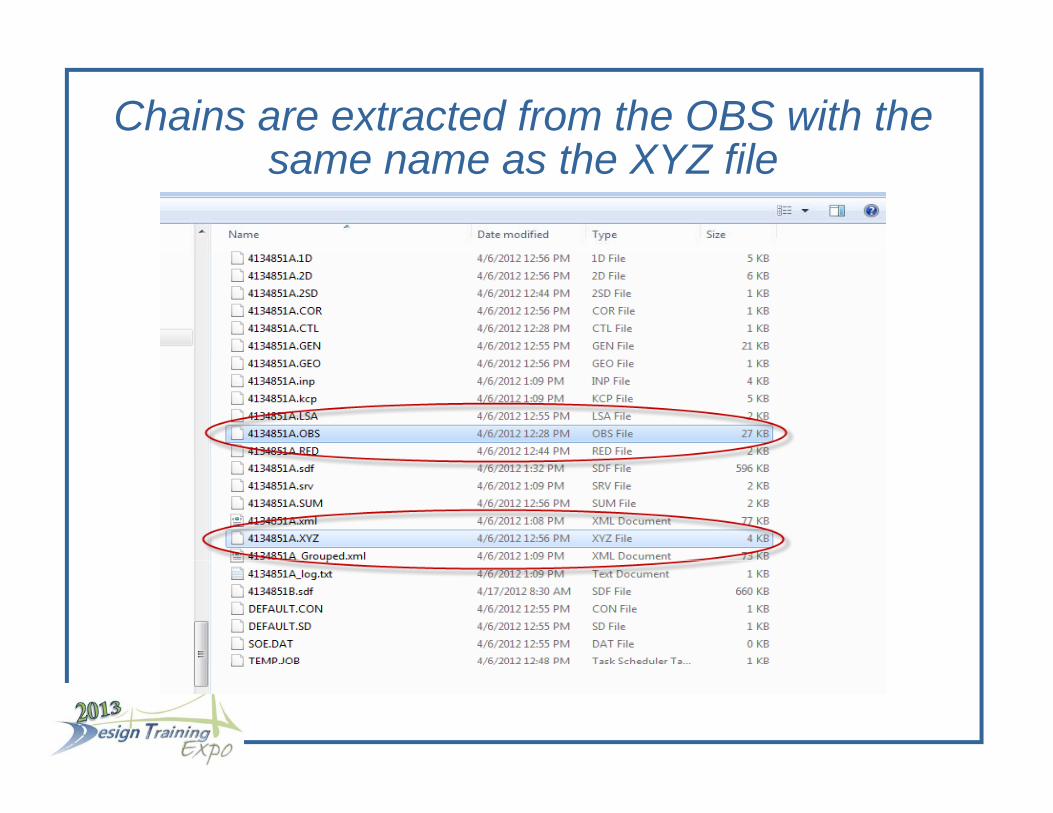
Chains are extracted from the OBS with the th XYZ filsame name as the XYZ file

Fi ld B kField Books
Continue dragging and dropping segments into D.A. until all segments have been added to the field book
The field book can be renamed from Default 1 to an appropriate name
Additional field books can be added by right clicking and selecting “New…”
Data can be added to the “New field book by right clicking on that field book.

POINT SCALES ARE SET BY THE FDOT XML STYLE FILEXML STYLE FILE
Cells will be brought in at 5 times their original scale (1”=50’).
Line styles for linear features will be brought in at a 1.00 scale factor.
To view the line styles at a desired scale from the Models pull down, click on Model Properties and set the line style scale to the desired scale.

LINE STYLE SCALES CAN BE VISUALIZED IN MODEL PROPERTIESIN MODEL PROPERTIES

CHAIN EDITING
Data Acquisition has tools for building and editing linear features (chains).
Editing the OBS to add or edit collected chains is also an option and provides legacy data that can be used across multiple platforms, including CAiCE and Civil 3D.p p g
For Data Acquisition it is a simple process to delete the field book and re-drag and drop the XYZ segments to g p gvisualize the updated chains
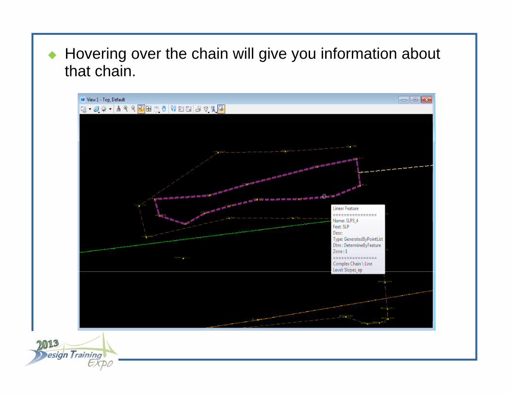
Hovering over the chain will give you information about that chainthat chain.

Right clicking on the chain will give access to chain editing functionalityediting functionality

Chain editing functionality can also be accessed from the D A treeD.A. tree

The “Link Code” in the chain point list dialogue controls curvaturecurvature.
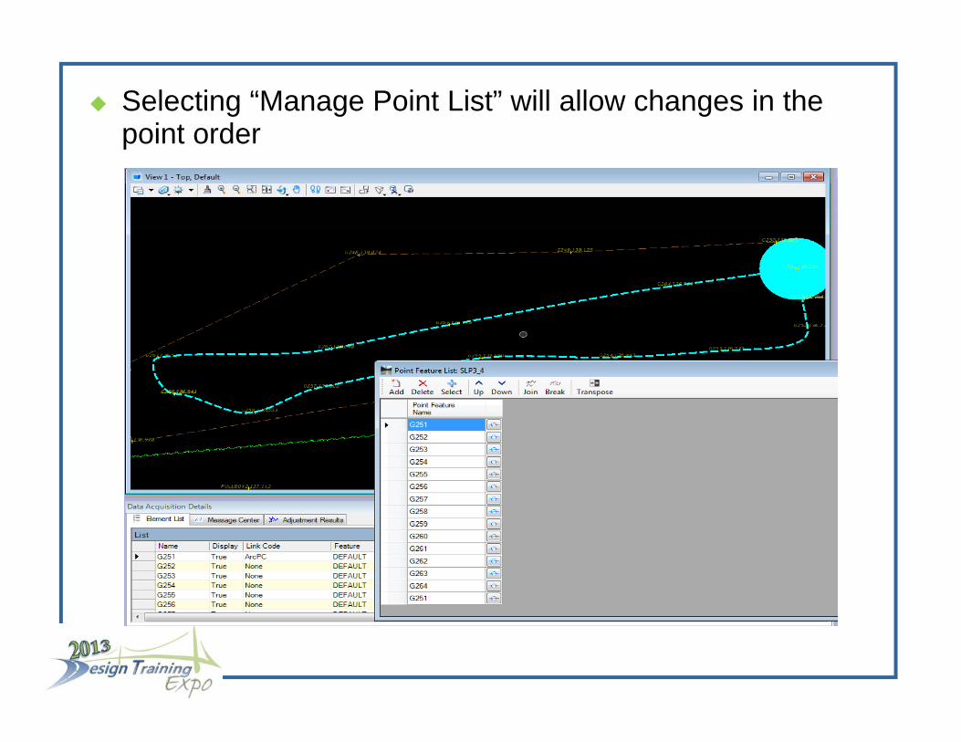
Selecting “Manage Point List” will allow changes in the point orderpoint order

Features that do not match the Style File will show up in the D A tree in redthe D.A. tree in red

SURFACESSURFACES
Surfaces are created automatically.
The “All Field Books” surface is created by default. This surface is made up of all data in the database.
Checking the appropriate box in the Surface tree will show the graphics for that attribute.
Right clicking on the Surface will allow the user to export the surface to permanent graphics or a TIN file.

C ti S ifi S fCreating Specific Surfaces
Right Clicking on Surfaces in the DA tree will allow the user to create a new surface
Creating a surface from a selection set will allow users to create a surface in a specific area from graphical data in the current view
Select the desired data, right click on “Surfaces” and create a surface from the field book selection set
DTM point attributes can be edited by using chain editing functionalityy


Rename the surface, give a side length and change the “Dissolve Type“ to side lengthDissolve Type to side length

The “DTM Attribute” in the chain point list dialogue controls DTM propertiescontrols DTM properties.

Create as many surfaces as is needed.

A GEOPAK TIN file can be created by right clicking on the surface name and selecting Export tothe surface name and selecting Export to…

C ti S f f LIDARCreating Surfaces from LIDAR
At the request of the Missouri DOT, Bentley has come up with a specific workflow for creating a surface directly from a classified LIDAR LAS file using Data Acquisitiong q
In the D.A. tree, right click on “Surfaces”
Create Surface Create Surface
Import External Surface…
I t LIDAR LAS Import LIDAR LAS

Create a new surface by Importing a LIDAR LAS file

Choose the LAS file to import

C ti S f f LIDARCreating Surfaces from LIDAR
The Lidar LAS import dialogue box is used to filter the LIDAR data
Choose the appropriate classifications to create a surface
Always use the “Tin Filter”
Input the Z Tolerance
Al th “C ” ti Always use the “Coarse” option
Always use “Reinsert Points” option

C ti S f f LIDARCreating Surfaces from LIDAR
What is the “Z Tolerance” ???
Bentley defines the Z Tolerance as being ½ the acceptable vertical error for a project with vertical error being the vertical distance @ 95% confidence level of the maximum point spacingp p g
NSSDA on Vertical Accuracy: “If vertical error is normally distributed, the factor 1.9600 is applied to compute linear pp perror at the 95% confidence level”
Therefore NSSDA defines Vertical Accuracy = 1.9600 x yRoot Mean Square of the Elevation (RMSE)


Choose the LAS file to import, choose classifications, set settings Z Tolerance and click the “Filter” buttonsettings, Z Tolerance and click the Filter button

Point features are reduced by the filter. Click the “Accept” button to create the surfaceAccept button to create the surface.

Right click on the surface to Create Graphics or to export the surface to a GEOPAK TINthe surface to a GEOPAK TIN

CREATING FDOT SURVEY DELIVERABLESDELIVERABLES
Creating the GDTMRD file can be done using GEOPAK g gand the TIN file created from D.A.
Creating the DREXRD, TOPORD, and UTEXRD files can g , ,easily be done by “visualizing” the graphics using the level display filters
Individual features can be visualized using the feature styles in the D.A. tree
Check to visualize, uncheck to turn off visualization of groups or individual features

CREATING FDOT SURVEY DELIVERABLESDELIVERABLES
To visualize the DREXRD, TOPORD or UTEXRD ,elements select the appropriate filter in the level display manager
To create the DGN file put a fence around the elements in the view
Type in the Key-in box “fence file” and the windows “Save As” dialogue box will open so a file can be saved
Type in a file name and press “Open”. The dialogue box will close and then you must click on the view to accept the creation of the filethe creation of the file

CREATING FDOT SURVEY DELIVERABLESDELIVERABLES
Note that if this is a 3D TOPORD.dgn file a 2D file must gbe created as the final deliverable
Close the current Data Acquisition project file and open q p j pthe new 3D TOPORD.dgn file.
Click on File>Export>2D… to create the TOPORD01.dgn p gfile
As in any survey deliverable normal MicroStation editing y y gwill be necessary to complete the deliverable for delivery to design

CREATING FDOT SURVEY DELIVERABLESDELIVERABLES

CREATING FDOT RIGHT OF WAY DELIVERABLESDELIVERABLES
In Data Acquisition there is no need to re-import or massage data to go from Surveying deliveries to Right ofmassage data to go from Surveying deliveries to Right of Way deliveries even though levels, cells, line styles and attributes are significantly different
Change the FDOT Menu bar configuration from Roadway Design to Right of Way Mapping
Re-open the DGN file and type into the Key-in box, “dataacquisition redraw”

The R/W Style File is automatically attached. Type in the Key-in box “dataacquisition redraw”Key-in box dataacquisition redraw

CREATING FDOT RIGHT OF WAY DELIVERABLESDELIVERABLES
The “dataaquisition redraw” Key-in will apply the current The dataaquisition redraw Key in will apply the current Style File features
Note the differences are not immediately apparent Note the differences are not immediately apparent however, they include:- R/W style monuments- Some cells have a mask- Many of the “dashed” lines for existing point features
are now solid lines- Some custom line styles like railroad centerlines are
different in right of way

Creating The TOPORW File
Note the difference in Categories Note the difference in Categories
The TOPORW can be visualized by checking the categories in the D A tree structurecategories in the D.A. tree structure- Check the box for Existing Topography- Check the box for Existing Monuments
All th b h ld b h k d l th- All other boxes should be unchecked unless the feature is desired to be included in the TOPORW File
The process for creating the TOPORW deliverable is The process for creating the TOPORW deliverable is identical to creating the TOPORD (Use “fence file” and then export to a 2D)

IMPORTING CAiCE PROJECTSIMPORTING CAiCE PROJECTS
Data Acquisition will accommodate importing CAiCE projects
Choose the appropriate configuration (Roadway or- Choose the appropriate configuration (Roadway or Right of Way)
- Choose the appropriate seed filepp p
- Drag and drop the CAiCE PT4 file into Data Acquisition

All points and survey chains are imported into Data AcquisitionAcquisition
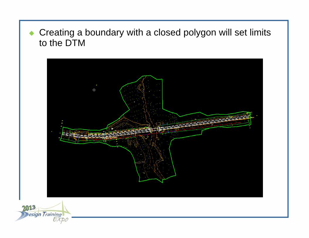
Creating a boundary with a closed polygon will set limits to the DTMto the DTM

To Import a CAiCE Surface, right click on Surfaces and Import the CAiCE XY# fileImport the CAiCE XY# file

Right click on Boundary in the surface tree and “Import Selection”Selection

The DTM is limited to the selected boundary

EXPORTING POINTS AND CHAINS TO GEOPAKGEOPAK
Data Acquisition is a work in progress
At some point a left turn must be made and data moved to GEOPAK
SS3 will have improvements over SS2 and the left turn will be further down the road
Eventually there may not be a need to use GEOPAK for surveying purposes

EXPORTING POINTS AND CHAINS TO GEOPAKGEOPAK
Right Click on the Field Book in the D.A. tree and select “Export to>GEOPAK Format”
The format is a GPK file
Point and survey chain features along with descriptors will be included