Civil Platform Update Derricke Gray, GEOPAK Product Manager.

1
GEOPAK PLAN AND PROFILE SHEET LAYOUT TOOL 2001+NCDOT ROADWAY DESIGN UNIT IMPLEMENTATION
OVERVIEW:
Geopak Plan and Profile Sheet Layout Tool automates the process of generating our plan and
profile sheets. This application will provide our designers the ability to efficiently and effectively create
and clip our plan and profile sheets. In addition, Iplot Organizer works very well with this application
once the sheets have been created. There is one major procedural practice that has to be agreed on Unit
wide before we can implement this. Most Roadway Designers prefer to show the same range of
stationing that is on the plan sheets on the corresponding profile sheets. For example, for our first plan
sheet, sheet 4, we clipped an area on our design that encompasses station ranges for 10+00.00 to
24+00.00. On sheet 24, our first profile sheet, the station range should also be from 10+00.00 to
24+00.00. Some Roadway Designers prefer a 1300’ stationing range for plan and profile sheets, and
other prefers 1400’. For our initial evaluation of this application we will set up for 1400’ stationing
shown on our plans and profile sheets.
Recommend 1400’ as standard and enforce.
REQUIREMENTS:
! Plan/Profile Sheet Library file (*.psl) – Provided and managed by Cadd Administrators.
! *.gpk
! Design file with all pertaining reference files (i.e. drn, row, and pln’s)
! Profile file
! Updated Workspace for new sheet cells.
! Plan & Profile Sheet Compatibility set to Geopak 2001+ (under Geopak User Preference).

2
PROCEDURE:
Plan Sheet Layout
1. Open your design file (dsn). Make sure all the reference files are attached. Even though reference
files can be added later, it would involve a little bit more work.
2. Activate the Geopak Sheet Layout tool. In the Geopak Road Tool Frame " Plans PreparationFamily " Plan/Profile Sheet Composition Toolbox.
3. Attach Sheet Library (*.psl). Sheet " Library " Attach.
We will be using NCDOT_English_PlanProfile.psl inC:\NCDOT_MSJ_WORKSPACE\NCDOT_STDS\ENGLISH\geopak\ folder.

3
NOTE: Because this file is located in the NCDOT Workspace, the file will be
overwritten with the Workspace Update Program.
4. Set sheet type to PLAN.
5. Set scale to 50 ft/in.
6. Populate Sheet Composition dialog setting box.
" Sheet Composition toolbox.
Choose clip mode By Station Range: Radial
Horizontal: 0.00
Vertical: 0.00
Station Range: 1400.00
Close dialog box
4
7. Layout sheets.
" Layout Sheets toolbox.
Job: rdy (Select the location and name of your gpk file.)Choose Multiple Sheets
Double click inside the highlighted row in the settings window to set the Plan Port Data dialog box
parameters.
Chain: L (Choose the chain name to place the plan sheets along.) Offset: 0.00
5
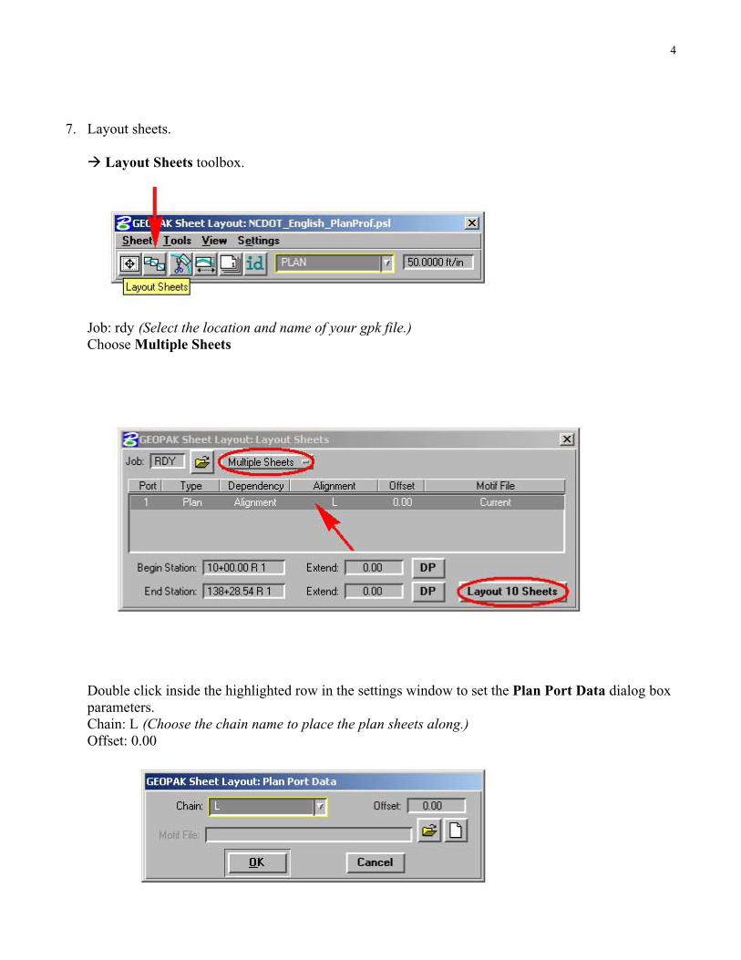
" OK
Begin Station: 10+00.00 R 1 (Accept or enter desired beginning station .) Extend: 0.00 (Enter desired distance or DP from beginning station to start clipping) End Station: 138+28.54 R 1 (Accept or enter desired ending station .) Extend: 0.00 (Enter desired distance or DP from ending station to stop clipping)
Select " Layout [No. of] Sheets button.
Close dialog box
Repeat this step if plan sheets are required for -Y- Lines.
TIP! Use the Begin Station and End Station options to place clipping shapes for
your -Y- Lines that overlap the mainline. See Modifying Clipping Area forOverlapping -Y- Line Sheets for more details.
8. Modify clipping area for each sheet (if needed).
" Modify Sheets toolbox.
Use the Shape: field to highlight and navigate to the sheet you want to modify or view; else use the
Identify button to locate the sheet to edit.
6
Types of modifications
Slide Sheets – Using a fixed station on the clipped sheet (Left Station, Center Station, or
Right Station) as a point of reference, users can either key-in a distance in the Extend: field
or manually (Dynamic) slide the clipped sheets laterally to the alignment. If the clipped sheet needs
to slide perpendicular to the alignment, then use the Sheet Chord Offset option. Users can
furthermore rotate the angle of the clipped sheet by using the Additional Rotation about LeftStation: option.
NOTE: The Slide Preceding Sheets and Slide Following Sheets options will
only work with sliding the clipped sheets laterally (Extend: option). They have
no effect on the Sheet Chord Offset and the Additional Rotation about LeftStation options. In addition to this type of modification, notice the shape area of
the clipped sheets still maintains the 1400’ station range to be shown.
Modify Drawing Area - Sometimes a sheet or two needs to be readjusted to show only a
portion of a normal size sheet. Such is the case when creating an interchange sheet and having
to adjust the sheet before and/or sheet after it. Users can use this type of modification to perform
such a task. Using a fixed point on the clipped sheet (under Hold To: Left Station, Center Station,
or Right Station) users can key-in a fixed distance (station) in the Drawing Shown: field and the
Horizontal: clipped out field is automatically adjusted.
NOTE: The Vertical: field is not automatically adjusted. This is due to the fact
that when we changed our parameter to show just station range we wanted shown,
the program needs to adjust how much to clip out left and right of the sheet
(horizontally). The offset distance to be clipped from top and bottom of sheet is
disregarded in its automation. However, the user can manually key-in a fix offset
distance in the Vertical: field and the program accepts that value. Also note that
the Slide Preceding Sheets and Slide Following Sheets options are available. It
is important to be aware of which sheets you want to move when you make the
change and which sheets you want to stay static.
" Apply to save the modification changes.
Close dialog box.
Modifying Clipping Area for Overlapping -Y- Line Sheets
Do not use the Modify Sheets tool to modify the clipping area for overlapping -Y- Line sheets.
When the modifications have been applied using the Modify Sheets tool, the clipping shape will be
reset back to its orignal form. It is recommended that your basic Microstation edit tools be used to
modify the shapes for clipping. The Modify Element, Insert Vertex, and Delete Vertex tools are very
effective tools for this type of modification. Below is an example what to do when the user
encounters the task of modifying the clipping area for -Y- Line sheets.

7
We have sheets 14 and 15 for our -Y- Line overlapping our -L- Mainline on sheet 9.
When laying out sheet 14, choose and key-in an even station on the -Y- Line that both alignments
share in the End Station Field. Compensate for the 1400’ station to be shown on each sheet by
keying in the adjusted distance in the Begin Station Extend: field. This will put our match line
exactly at station 17+00.

8
Now we have two clipping areas overlapping each other.
Use your MicroStation editing tools to modify the clipping areas. There is really not a right or wrong
way to modify these shape and to show how much of the drawing on each sheet. Most of time it is
up to the designer’s engineering judgement and preferences. There are, however, some few basic
guidelines to follow to make your sheets more aesthetically pleasing. They are as follow:
1. The length of the match line should be the same on both sheets.
2. Your clipping shapes should extend at least the length of your match line or longer.
3. Match line and clipping shape should project radially from your alignment at an even station.
4. Clipping shape areas should not overlap each other once proper modification has been made.
Here is one possible solution for placing and modifying sheet 15 clipping area.

9
9. Change sheet number and sequence.
Bring up the Sheet Number Manager. " Sheet Number Manager toolbox. Start with sequence 1
and hold down the left mouse button and drag it down to the bottom of the last sequence number to
select all sheets.
" Edit Sheet Number. In the Starting at Sheet Number field key-in 4. " OK.
TIP!: It may be necessary to edit the sequence in some cases. When a sheet like
our interchange is laid out after our regular sheets, the sequence number is after
our last sheet. The interchange sheet is located somewhere in the middle. But our
sequence and sheet number are both off. We need to renumber the sheet to correct
sequence and sheet number, in this order. To accomplish this, first select the sheet
to be renumbered. " Edit Sequence Number. Key-in the new sequence number
in the Beginning Sequence Number: field. " Ok. Start with new sequence
number and drag the cursor to the last sequence number. " Edit Sheet Number.
In the Starting at Sheet Number field key-in the new sheet number. " Ok.
Repeat the procedure if another sheet is to be renumbered.

10
NOTE: The Highlight Clipping Shape and the Window Center Clipping Shapeoptions are available when the sheet is selected.
Close dialog box and click Yes to save change.
10. Create plan sheets.
• " Clip Sheets.
• Key-in where the plan sheet files are to be
placed in the Directory: Field.
• In the Sheet Name Prefix: Field key-in
TIP_rdy_psh_s.
• Change the Rotate Reference option to RotateView.
• Accept or Key-in the sheets to be generated in
the Sheet Range Begin: End: fields.
• Key-in your TIP (with a dash (-)) in the ProjectNumber: field.
• Key-in “MATCH LINE –L- STA”
XXX+XX.XX “SEE SHEET __” in the MatchLine: field.
• " Process Sheets.
NOTE: The Directory: field may be left unpopulated. If this option is used, then
the plan sheets will be created and placed in your current working directory or in
the same directory where this MicroStation session was opened.
11. Edit clip area in each sheet (if needed).
What this application did was generate a plan sheet file for you with the maximum area shown on
each sheet. We still can edit and clip the desired area to the way we’ve been doing it. The red
clipping shape is still on our plan sheet cell. Let’s look at what we have just created.

11
Here is a typical plan sheet cell.
Here is what we have just created.

12
Here is what we can do with the sheet border shapes in our title sheet.
End of Section
13
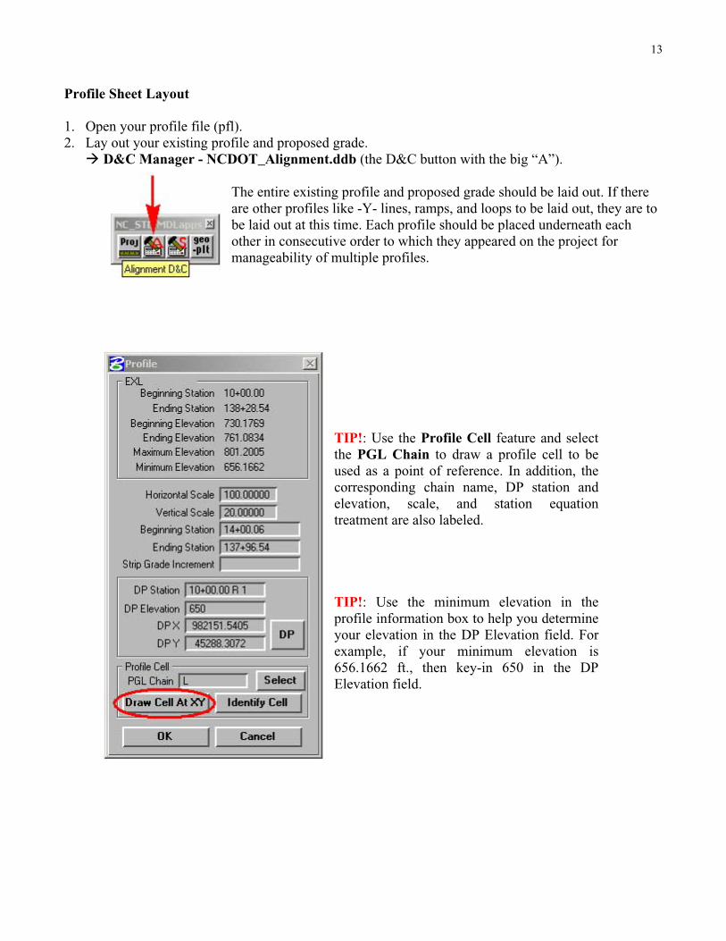
Profile Sheet Layout
1. Open your profile file (pfl).
2. Lay out your existing profile and proposed grade.
" D&C Manager - NCDOT_Alignment.ddb (the D&C button with the big “A”).
The entire existing profile and proposed grade should be laid out. If there
are other profiles like -Y- lines, ramps, and loops to be laid out, they are to
be laid out at this time. Each profile should be placed underneath each
other in consecutive order to which they appeared on the project for
manageability of multiple profiles.
TIP!: Use the Profile Cell feature and select
the PGL Chain to draw a profile cell to be
used as a point of reference. In addition, the
corresponding chain name, DP station and
elevation, scale, and station equation
treatment are also labeled.
TIP!: Use the minimum elevation in the
profile information box to help you determine
your elevation in the DP Elevation field. For
example, if your minimum elevation is
656.1662 ft., then key-in 650 in the DP
Elevation field.

14
3. Activate the Geopak Sheet Layout tool. In the Geopak Road Tool Frame " Plans PreparationFamily " Plan/Profile Sheet Composition Toolbox.
4. Attach Sheet Library (*.psl). Sheet " Library " Attach.
We will be using NCDOT_English_PlanProfile.psl inC:\NCDOT_MSJ_WORKSPACE\NCDOT_STDS\ENGLISH\geopak\ folder.
Set sheet type to DUAL PROFILE.
Set scale to 50 ft/in.

15
5. Populate Sheet Composition dialog setting box.
" Sheet Composition toolbox.
Choose clip mode By BeginStation/Overlap
Horizontal: 0.00
Vertical: 0.00
Drawing Shown: 1400.00
Overlap: 0.00
Close dialog box

16
6. Layout sheets.
" Layout Sheets toolbox
Job: rdy (Select the location and name of your gpk file.)Choose Multiple SheetsDouble click on the 1
st row to edit the settings for Port 1.
Profile: LPRO (Choose the profile name.)Chain: L (Choose the chain name.)Station: 10+00.00 R 1 (Accept or key-inDP station.)Elevation: 650 (Accept or key-in DPelevation.)Horizontal Scale: 100
Vertical Scale: 20
" By DP – defines X and Y coordinates
of reference DP point.
TIP!: The Identify Cellfeature will auto-populate all
the fields from Chain: down.
That’s very cool!
" OK

17
Double click on the 2nd
row to edit the settings for Port 2. In most cases, the settings for port 1 is the
same for port 2. If this is the case then just click Ok. If not repeat the procedure for changing the
setting for Port 1.
Begin Station: 10+00.00 R 1 (Accept or enter desired beginning station .) Extend: 0.00 (Enter desired distance or DP from beginning station to start clipping) End Station: 138+28.54 R 1 (Accept or enter desired ending station .) Extend: 0.00 (Enter desired distance or DP from ending station to stop clipping)
Select " Layout [No. of] Sheets button.
Repeat the procedure if other profiles are to be laid out.
Close dialog box
7. Modify the sheet clipping area (if needed).
" Modify Sheets toolbox.
Use the Shape: field to highlight and navigate to the sheet you want to modify or view; else use the
Identify button to locate the sheet to edit.

18
Types of modifications
Slide Sheets – Using a fixed station on the clipped sheet (Left Station, Center Station, or
Right Station) as a point of reference, users can either key-in a distance in the Extend: field
or manually (Dynamic) slide the clipped sheets laterally to the alignment. If the clipped sheet
needed to slide perpendicular to the alignment, then use the Sheet Chord Offset option. Users can
furthermore rotate the angle of the clipped sheet by using the Additional Rotation about LeftStation: option. Note that the Slide Preceding Sheets and Slide Following Sheets options will only
work with sliding the clipped sheets laterally (Extend: option). They have no effect on the SheetChord Offset and the Additional Rotation about Left Station options. In addition to this type of
modification, notice the shape area of the clipped sheets still maintains the 1400’ station range to be
shown.
Modify Drawing Area – Use this option only if the drawing area was modified in the plan
sheets.
" Apply to save the modification changes.
Close dialog box.
10. Change sheet number and sequence.
Bring up the Sheet Number Manager. " Sheet Number Manager toolbox.
Start with sequence 1 and hold down the mouse button and drag it down to the bottom of the last
sequence number to select all sheets. " Edit Sheet Number.

19
In the Starting at Sheet Number field key-in first profile sheet number. " OK.Close dialog box and click Yes to save change.
11. Create profile sheets.
" Clip Sheets.
• Key-in where the profile sheet files are to be
placed in the Directory: Field.
• In the Sheet Name Prefix: Field key-in
TIP_rdy_pfl_s.
• Change the Rotate View option to RotateReference.
• Key-in 50 in the Sheets per File: field.
• Accept or key-in the sheets to be generated
in the Sheet Range Begin: End: fields.
• Key-in your TIP (with a dash (-)) in the
Project Number: field.
• Process Sheets.
TIP!: Notice that the sheet title may
be entered in the Labels andAnnotations frame. I recommend
key-in your main line PGL chain
name (-L-). This will work for most
of your sheets. If the label name is

20
not correct, then manually edit it. Hopefully, the option to label the PGL chain
name on profile sheets will be available in future Geopak updates.
TIP!: Select the Auxiliary Sheet Annotations option to label your sheet number
and profile name next to your sheet. Use these parameters.
TIP! Turn level 63 off in your profile file and select Save Settings under the File
menu. This will turn off the display of the brown and red port shapes in the file.
After the profile sheets have been processed, level 63 will also be turn off and the
port shapes are not displayed. Any view attribute setting can be inherited by the
produced sheet file(s) from your original file using this method of creating plan
and profile sheets.
End of Section

21
Interplot Organizer
OVERVIEW:
With the automation of the plan and profile sheet layout tool, I feel compelled to incorporate the
overall procedure with Interplot Organizer. Generating an Interplot Organizer set is also an automated
process. Did you know that Roadway Design always had the ability to create an Interplot Organizer set
in a matter of seconds? How would you like to create an Interplot Organizer set of 20 plan sheets in less
than a minute? Sounds enticing don’t it? With the placement of a construction shape element in our
sheet cells, we have eliminated the process of having to open each file individually and define the fence
area to be plotted and saving our Iparm files. Interplot Organizer will create our Iparm files for us
automatically.
REQUIREMENTS:
Interplot Organizer
Updated NCDOT plan and profile sheet cells
PROCEDURE:
Plan sheets
1. Connect to your TIP as R: drive.
2. Launch an Interplot Organizer session.
" Start. " Programs. " Interplot Utilities. " Interplot Organizer.

22
3. Set print setup.
" File. " Print Setup.
In the Name: field, choose your appropriate plotter.
rd-hp[group number]b – use this plotter for half-size plan and profile sheet plots.
rd-[group number]oce34- user this plotter for full-size plan and profile sheet plots.
4. Save your ips file.
" File. " Save As.
In the Save in: field, choose the appropriate folder to save the ips file in.
R:\Roadway\iFiles\HalfSize\ – path to this folder for half-size plots.
R:\Roadway\iFiles\FullSize\ – path to this folder for full-size plots.
In the File name: field key-in your TIP_hs.ips for half-size plots, your TIP_fs.ips for full-size plots.
23
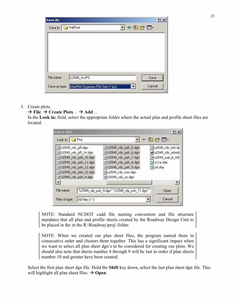
5. Create plots.
" File. " Create Plots… " Add…
In the Look in: field, select the appropriate folder where the actual plan and profile sheet files are
located.
NOTE: Standard NCDOT cadd file naming convention and file structure
mandates that all plan and profile sheets created by the Roadway Design Unit to
be placed in the in the R:\Roadway\proj\ folder.
NOTE: When we created our plan sheet files, the program named them in
consecutive order and clusters them together. This has a significant impact when
we want to select all plan sheet dgn’s to be considered for creating our plots. We
should also note that sheets number 4 through 9 will be last in order if plan sheets
number 10 and greater have been created.
Select the first plan sheet dgn file. Hold the Shift key down, select the last plan sheet dgn file. This
will highlight all plan sheet files. " Open.

24
" Browse. Select the appropriate Interplot setting file.
English_FullSize.set
English_HalfSize.set
Metric_FullSize.Set
Metric_FullSize36.Set
Metric_HalfSize.set
" Open
Select MicroStation DGN Files in the Manually specified options: frame. " Options…

25
Under the Layout tab, key-in the appropriate plot scale in the Scale: field. Within the Rotation:frame, key-in 180 for half-size plots, 90 for full-size plots, in the Specify angle: field.
NOTE: Although our *.set file will set the right rotation for you and the scale is
automatically determined by the software, it is good practice to key-in the desire
rotation and scale. When plots are created from an existing Iparm file, it inherits
the plotting properties of the resulting plot process. The rotation and scale values
may be different. For example, we plot sheet 5 with a rotation of 0 and a scale of
50. We then create our plots from this existing Iparm file to the plots we’ve
already made. Our Organizer set show a rotation of 0 and scale of 50, while the
rest of our plots are rotated 180 and have a scale of 100.
TIP!: Use a plot scale that works for most of your sheets when creating plots for
multiple sheet with different plot scales. Then later manually change the plot scale
of the few sheets to their respective scale. For example if you have a project with
15 plan sheets with a full-size plot scale of 50:1, 2 interchange sheets of full-plot
scale 100:1, a title sheet with plot scale of 1750:1, and typical sheets with full-size
plot scale of 10:1, use a scale of 50:1. Once the plots have been created, change
the scale of the sheets manually to their respective scale.
Select the Area tab. Select Describe Plot Shape option in the Define plot area automaticallyframe.

26
Check to see if Create one plot from the first matching shape option is selected. " OK.
Notice that the Plot shape option is automatically selected in the Plot area frame.

27
" OK. "OK.
6. Edit plot properties, plot name, sheet number, or plot sequence (if needed).
TIP!: When selecting a group of plots for editing, use the Shift key to include all
the plots in between your selection. If just wanted to include only the selected
plots then use the Ctrl key.
TIP! When you have sheets number greater than 10, I recommend putting a zero
“0” in front of plot sheet number 4 through 9. Then use your Plot Name sort
button to arrange the sequence of the plotting order. Use the up and down arrows
to individually or in a selected group move the order of the plots. For full-size
plots only I would recommend moving the last sheet number to be the first sheet
to be plotted. The full-size sheet plotter will collate them in this manner resulting
in the last sheet plotted on top. I hope that makes sense.

28
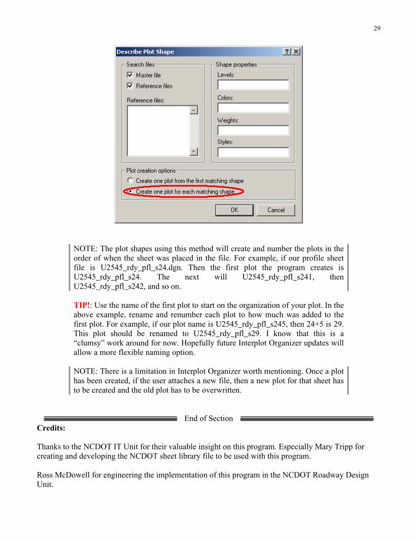
Profile sheets
Pretty much there are not that many setting changes from creating plan sheet plots to profile sheet
plots. As matter of fact, there is only one keynote to be aware of. When we created the profile sheet file
we placed multiple sheets in one file. As a result of this action, we have to change the way we instruct
the program to find our construction shape element in our sheet cells. In step 5 for creating plots for plan
sheets, after we selected the Area tab, within the Describe Plot Shape dialog box, we must change our
selection from Create one plot from the first matching shape to Create one plot for each matchingshape. This will tell the program to create plots from all of the shapes in that file.
29
NOTE: The plot shapes using this method will create and number the plots in the
order of when the sheet was placed in the file. For example, if our profile sheet
file is U2545_rdy_pfl_s24.dgn. Then the first plot the program creates is
U2545_rdy_pfl_s24. The next will U2545_rdy_pfl_s241, then
U2545_rdy_pfl_s242, and so on.
TIP!: Use the name of the first plot to start on the organization of your plot. In the
above example, rename and renumber each plot to how much was added to the
first plot. For example, if our plot name is U2545_rdy_pfl_s245, then 24+5 is 29.
This plot should be renamed to U2545_rdy_pfl_s29. I know that this is a
“clumsy” work around for now. Hopefully future Interplot Organizer updates will
allow a more flexible naming option.
NOTE: There is a limitation in Interplot Organizer worth mentioning. Once a plot
has been created, if the user attaches a new file, then a new plot for that sheet has
to be created and the old plot has to be overwritten.
End of Section
Credits:
Thanks to the NCDOT IT Unit for their valuable insight on this program. Especially Mary Tripp for
creating and developing the NCDOT sheet library file to be used with this program.
Ross McDowell for engineering the implementation of this program in the NCDOT Roadway Design
Unit.