Automotive Electrical Sys
366
Automotive Electrical and Electronic Systems Classroom Manual Fifth Edition Update Chek-Chart John F. Kershaw, Ed.D. Revision Author James D. Halderman Series Advisor Upper Saddle River, New Jersey Columbus, Ohio
description
Electric Sys
Transcript of Automotive Electrical Sys
AutomotiveElectricalandElectronicSystems
ClassroomManual
Fifth Edition Update
Chek-Chart
John F. Kershaw, Ed.D.Revision Author
James D. HaldermanSeries Advisor
Upper Saddle River, New JerseyColumbus, Ohio
ker88839_fm.qxd 1/9/06 11:37 AM Page i
Executive Editor: Tim PeytonEditorial Assistant: Nancy KestersonProduction Editor: Christine BuckendahlProduction Supervision: Angela Kearney, Carlisle Editorial ServicesDesign Coordinator: Diane Y. ErnsbergerCover Designer: Jeff VanikCover photo: Super StockProduction Manager: Deidra SchwartzMarketing Manager: Ben Leonard
This book was set in Times by Carlisle Publishing Services. It was printed and bound by Bind Rite Graphics. The cover was printed by Lehigh.
Portion of materials contained herein have been reprinted with permission of General Motors Corporation,Service and Parts Operations. License Agreement #0310805.
Copyright © 2007 by Pearson Education, Inc., Upper Saddle River, New Jersey 07458.
Pearson Prentice Hall. All rights reserved. Printed in the United States of America. This publication isprotected by Copyright and permission should be obtained from the publisher prior to any prohibitedreproduction, storage in a retrieval system, or transmission in any form or by any means, electronic,mechanical, photocopying, recording, or likewise. For information regarding permission(s), write to:Rights and Permissions Department.
Pearson Prentice Hall™ is a trademark of Pearson Education, Inc.Pearson
® is a registered trademark of Pearson plcPrentice Hall
® is a registered trademark of Pearson Education, Inc.
Pearson Education Ltd. Pearson Education Australia Pty. LimitedPearson Education Singapore Pte. Ltd. Pearson Education North Asia Ltd.Pearson Education Canada, Ltd. Pearson Educación de Mexico, S.A. de C.V.Pearson Education—Japan Pearson Education Malaysia Pte. Ltd.
10 9 8 7 6 5 4 3 2 1ISBN 0-13-238883-9
ker88839_fm.qxd 1/31/06 5:03 PM Page ii
Automotive Electrical and Electronic Systems is part ofthe Chek-Chart Series in Automotive Technology,which also includes:
• Automatic Transmissions and Transaxles• Automotive Brake Systems• Automotive Heating, Ventilation, and Air
Conditioning• Automotive Manual Drive Train and Rear Axle• Automotive Steering, Suspension, and Wheel
Alignment• Automotive Engine Repair and Rebuilding• Engine Performance, Diagnosis, and Tune-Up• Fuel Systems and Emission Controls.
Since 1929, the Chek-Chart Series in AutomotiveTechnology has provided vehicle specification,training, and repair information to the professionalautomotive service field.
Each book in the Chek-Chart series aims to helpinstructors teach students to become competent andknowledgeable professional automotive technicians.The texts are the core of a learning system that leadsa student from basic theories to actual hands-onexperience.
The entire series is job-oriented, designed for stu-dents who intend to work in the automotive serviceprofession. Knowledge gained from these books andthe instructors enables students to get and keep jobs inthe automotive repair industry. Learning the materialand techniques in these volumes is a giant leap towarda satisfying, rewarding career.
NEW TO THE FIFTHEDITION UPDATEThe fifth edition of Automotive Electrical andElectronic Systems has been updated to include newcoverage of ignition systems. Ignition coverage hadbeen a standard feature of the text through the fourthedition, but was removed from the fifth edition. Basedon feedback from numerous users who wanted theignition material back in the book, this updated fifthedition was produced. It includes new ignition chap-ters in both the Classroom and Shop Manuals.
Introduction
iii
ker88839_fm.qxd 1/9/06 11:37 AM Page iii
WHY ARE THERETWO MANUALS?Unless you are familiar with the other books in thisseries, Automotive Electrical and Electronic Systems isunlike any other textbook you have used before. It isactually two books, the Classroom Manual and the ShopManual. They have different purposes and should beused together.
The Classroom Manual teaches what a technicianneeds to know about electrical and electronic theory,systems, and components. The Classroom Manual isvaluable in class and at home, both for study and forreference. The text and illustrations can be used foryears hence to refresh your memory about the basics ofautomotive electrical and electronic systems and alsoabout related topics in automotive history, physics,mathematics, and technology. This fifth edition updatetext is based upon detailed learning objectives, whichare listed in the beginning of each chapter.
The Shop Manual teaches test procedures, trou-bleshooting techniques, and how to repair the systemsand components introduced in the Classroom Manual.The Shop Manual provides the practical, hands-on infor-mation required for working on automotive electricaland electronic systems. Use the two manuals together tounderstand fully how the systems work and how to makerepairs when something is not working. This fifth editionupdate text is based upon the 2002 NATEF (NationalAutomotive Technicians Education Foundation) Tasks,which are listed in the beginning of each chapter. Thefifth edition update Shop Manual contains Job Sheetassessments that cover the 56 tasks in the NATEF 2002A6 Electrical/Electronics repair area.
WHAT IS IN THESEMANUALS?The following key features of the Classroom Manualmake it easier to learn and remember the material:
• Each chapter is based on detailed learning objec-tives, which are listed in the beginning of eachchapter.
• Each chapter is divided into self-contained sec-tions for easier understanding and review. Thisorganization clearly shows which parts make upwhich systems and how various parts or systemsthat perform the same task differ or are the same.
• Most parts and processes are fully illustrated withdrawings or photographs. Important topics appearin several different ways, to make sure otheraspects of them are seen.
• A list of Key Terms begins each chapter. Theseterms are printed in boldface type in the text anddefined in the Glossary at the end of the manual.Use these words to build the vocabulary needed tounderstand the text.
• Review Questions are included for each chapter.Use them to test your knowledge.
• Every chapter has a brief summary at the end tohelp you review for exams.
• Brief but informative sidebars augment the techni-cal information and present “real world” aspects ofthe subject matter.
The Shop Manual has detailed instructions on test,service, and overhaul procedures for modern electri-cal and electronic systems and their components.These are easy to understand and often include step-by-step explanations of the procedure. The ShopManual contains:
• ASE/NATEF tasks, which are listed in the begin-ning of each chapter and form the framework forthe chapter’s content
• A list of Key Terms at the beginning of eachchapter (These terms are printed in boldface typewhere first used in the text.)
• Helpful information on the use and maintenanceof shop tools and test equipment
• Safety precautions• Clear illustrations and diagrams to help you
locate trouble spots while learning to read ser-vice literature
• Test procedures and troubleshooting hints thathelp you work better and faster
• Repair tips used by professionals, presentedclearly and accurately
• Asample test at the back of the manual that is sim-ilar to those given for Automotive Service
How to Use This Book
iv
ker88839_fm.qxd 1/9/06 11:37 AM Page iv
How to Use This Book v
Excellence (ASE) certification (Use this test tohelp you study and prepare when you are ready tobe certified as an electrical and electronics expert.)
WHERE SHOULDI BEGIN?If you already know something about automotive elec-trical and electronic systems and how to repair them,this book is a helpful review. If you are just starting inautomotive repair, then this book provides a solid foun-dation on which to develop professional-level skills.
Your instructor has designed a course that builds onwhat you already know and effectively uses the avail-able facilities and equipment. You may be asked toread certain chapters of these manuals out of order.That’s fine. The important thing is to really understandeach subject before moving on to the next.
Study the Key Terms in boldface type and use thereview questions to help understand the material.
When reading the Classroom Manual, be sure to referto the Shop Manual to relate the descriptive text to theservice procedures. When working on actual vehiclesystems and components, look to the ClassroomManual to keep the basic information fresh in yourmind. Working on such a complicated piece of equip-ment as a modern automobile is not easy. Use theinformation in the Classroom Manual, the proceduresin the Shop Manual, and the knowledge of yourinstructor to guide you.
The Shop Manual is a good book for work, notjust a good workbook. Keep it on hand while actuallyworking on a vehicle. It will lie flat on the work-bench and under the chassis, and it is designed towithstand quite a bit of rough handling.
When you perform actual test and repairprocedures, you need a complete and accurate sourceof manufacturer specifications and procedures forthe specific vehicle. As the source for these specifi-cations, most automotive repair shops have theannual service information (on paper, CD, orInternet formats) from the vehicle manufacturer oran independent guide.
v
ker88839_fm.qxd 1/9/06 11:37 AM Page v

ker88839_fm.qxd 1/9/06 11:37 AM Page vi

The publisher sincerely thanks the following vehi-cle manufacturers, industry suppliers, and organi-zations for supplying information and illustrationsused in the Chek-Chart Series in AutomotiveTechnology.
Allen TestproductsAmerican Isuzu Motors, Inc.Automotive Electronic ServicesBear Manufacturing CompanyBorg-Warner CorporationDaimlerChrysler CorporationDelphi CorporationFluke CorporationFram CorporationGeneral Motors CorporationHonda Motor Company, Ltd.Jaguar Cars, Inc.Marquette Manufacturing CompanyMazda Motor Corporation
Mercedes-Benz USA, Inc.Mitsubishi Motor Sales of America, Inc.Nissan North America, Inc.The Prestolite CompanyRobert Bosch CorporationSaab Cars USA, Inc.Snap-on Tools CorporationToyota Motor Sales, U.S.A., Inc.Vetronix CorporationVolkswagen of AmericaVolvo Cars of North America
The comments, suggestions, and assistance ofthe following reviewers were invaluable: RickEscalambre, Skyline College, San Bruno, CA,and Eugene Wilson, Mesa Community College,Mesa, AZ.
The publisher also thanks Series AdvisorJames D. Halderman.
Acknowledgments
vii
ker88839_fm.qxd 1/31/06 5:03 PM Page vii

ker88839_fm.qxd 1/9/06 11:37 AM Page viii
Chapter 1 — Tools, Fasteners, and Safety 1Learning Objectives 1Key Terms 1Threaded Fasteners 1Metric Bolts 2Grades of Bolts 2Nuts 3Washers 4Basic Tool List 4Tool Sets and Accessories 10Brand Name Versus Proper Term 10Safety Tips for Using Hand Tools 11Measuring Tools 11Safety Tips for Technicians 13Safety in Lifting (Hoisting) a Vehicle 15Electrical Cord Safety 17Fire Extinguishers 19Summary 20Review Questions 20
Chapter 2 — Introduction to Electricity 21Learning Objectives 21Key Terms 21What is Electricity? 22Atomic Structure 22Sources of Electricity 25Historical Figures in Electricity 30Summary 31Review Questions 32
Chapter 3 — Electrical Fundamentals 35Learning Objectives 35Key Terms 35Conductors and Insulators 36Characteristics of Electricity 36Complete Electrical Circuit 40Ohm’s Law 42Power 44Capacitance 45Summary 49Review Questions 50
Chapter 4 — Magnetism 53Learning Objectives 53Key Terms 53Magnetism 54Electromagnetism 55Electromagnetic Induction 60Transformers 65Electromagnetic Interference (EMI)
Suppression 65Summary 68Review Questions 70
Chapter 5 — Series, Parallel, and Series-Parallel Circuits 71
Learning Objectives 71Key Terms 71Basic Circuits 71Series Circuit 72Parallel Circuit 72Series Circuit Voltage Drops 73Parallel Circuit Voltage Drops 75Calculating Series Circuit Total
Resistance 76Calculating Parallel Circuit Total
Resistance 78Series-Parallel Circuits 79Series and Parallel Circuit Faults 82Summary of Series Circuit Operation 84Summary of Parallel Circuit Operation 84Review Questions 85
Chapter 6 — Electrical Diagrams and Wiring 89
Learning Objectives 89Key Terms 89Wiring and Harnesses 90Wire Types and Materials 92Wire Size 93Connectors and Terminals 96Ground Paths 99Multiplex Circuits 100
Contents
ix
ker88839_fm.qxd 1/9/06 11:37 AM Page ix
Electrical System Polarity 103Common Electrical Parts 103Wire Color Coding 109The Language of Electrical Diagrams 111Diagrams 112Summary 124Review Questions 126
Chapter 7 — Automotive Battery Operation 129
Learning Objectives 129Key Terms 129Electrochemical Action 130Battery Electrolyte 134State-of-Charge Indicators 135Wet-Charged and Dry-Charged
Batteries 136Battery Charging Voltage 136Battery Selection and Rating Methods 136Battery Installations 138Battery Installation Components 140Battery Life and Performance Factors 142Summary 144Review Questions 145
Chapter 8 — Charging System Operation 147Learning Objectives 147Key Terms 147Charging System Development 148DC Generator 148Charging Voltage 148Diode Rectification 150AC Generator (Alternator) Components 152Current Production in an AC Generator 156Voltage Regulation 161Electromagnetic Regulators 162Solid-state Regulators 163Charge/Voltage/Current Indicators 168Charging System Protection 170Complete AC Generator Operation 170AC Generator (Alternator) Design
Differences 171Summary 179Review Questions 181
Chapter 9 — Starting System Operation 183Learning Objectives 183Key Terms 183Starting System Circuits 184Basic Starting System Parts 184Specific Starting Systems 188Starter Motors 192Frame and Field Assembly 192DC Starter Motor Operation 194Armature and Commutator Assembly 197
Permanent-Magnet Fields 197Starter Motor and Drive Types 198Overrunning Clutch 203Summary 204Review Questions 206
Chapter 10 — Automotive Electronics 209Learning Objectives 209Key Terms 209Semiconductors 210Electrostatic Discharge (ESD) 213Diodes 213Photonic Semiconductors 215Rectifier Circuits 216Transistors 217Silicon-Controlled Rectifiers (SCRs) 221Integrated Circuits 222Using Electronic Signals 222Summary 223Review Questions 224
Chapter 11 — The Ignition Primary andSecondary Circuits and Components 227
Learning Objectives 227Key Terms 227Need for High Voltage 228High Voltage Through Induction 228Basic Circuits and Current 229Primary Circuit Components 230Switching and Triggering 230Monitoring Ignition Primary Circuit
Voltages 234Primary and Secondary Circuits 236Ignition Coils 237Distributor Cap and Rotor 247Ignition Cables 250Spark Plugs 250Spark Plug Construction 252Summary 255Review Questions 256
Chapter 12 — Automotive Lighting Systems 257
Learning Objectives 257Key Terms 257Headlamp Circuits 258Common Automotive Bulbs 268Taillamp, License Plate Lamp, and Parking
Lamp Circuits 269Stop Lamp and Turn Signal Circuits 270Hazard Warning Lamp (Emergency Flasher)
Circuits 274Backup Lamp Circuits 275Side Marker and Clearance Lamp
Circuits 276
x Contents
ker88839_fm.qxd 1/9/06 11:37 AM Page x
Contents xi
Instrument Panel and Interior Lamp Circuits 277
Summary 280Review Questions 281
Chapter 13 — Gauges, Warning Devices, andDriver Information System Operation 283
Learning Objectives 283Key Terms 283Electromagnetic Instrument Circuits 284Malfunction Indicator Lamp (MIL) 289Speedometer 292Electronic Instrument Circuits 292Head-Up Display (HUD) 299Summary 302Review Questions 303
Chapter 14 — Horns, Wiper, and WasherSystem Operation 305
Learning Objectives 305Key Terms 305Horn Circuits 305Windshield Wipers and Washers 307Summary 313Review Questions 314
Chapter 15 — Body Accessory SystemsOperation 315
Learning Objectives 315Key Terms 315Heating and Air-Conditioning Systems 316Class 2 IPM-Controlled HVAC Systems 323Radios and Entertainment Systems 325Rear-Window Defogger and Defroster 328Power Windows 328Power Seats 329Heated Seats 331Power Door Locks, Trunk Latches, and Seat-
Back Releases 334Automatic Door Lock (ADL) System 335Remote/Keyless Entry Systems 335Theft Deterrent Systems 341Cruise Control Systems 345Supplemental Restraint Systems 347Summary 351Review Questions 352
Glossary 355
Index 361
ker88839_fm.qxd 1/9/06 11:37 AM Page xi

ker88839_fm.qxd 1/9/06 11:37 AM Page xii
1
LEARNINGOBJECTIVESUpon completion and review of this chapter, youshould be able to:
• Prepare for ASE assumed knowledge con-tent of the proper use of tools and shopequipment.
• Explain the strength ratings of threadedfasteners.
• Describe how to safely hoist a vehicle.
• Discuss how to safely use hand tools.
• List the personal safety equipment that allservice technicians should wear.
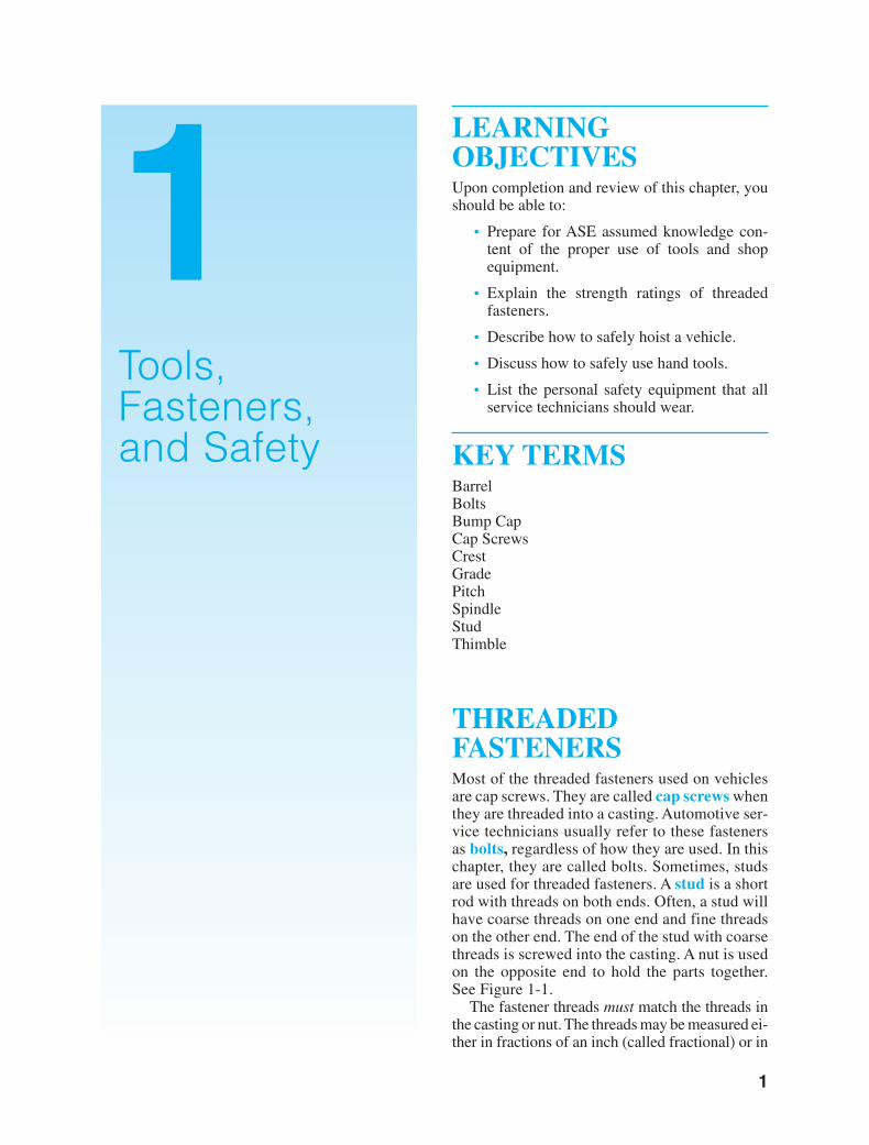
KEY TERMSBarrelBoltsBump CapCap ScrewsCrestGradePitchSpindleStudThimble
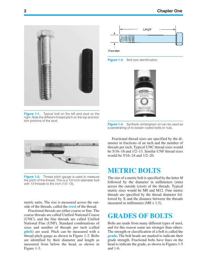
THREADEDFASTENERSMost of the threaded fasteners used on vehiclesare cap screws. They are called cap screws whenthey are threaded into a casting. Automotive ser-vice technicians usually refer to these fastenersas bolts, regardless of how they are used. In thischapter, they are called bolts. Sometimes, studsare used for threaded fasteners. A stud is a shortrod with threads on both ends. Often, a stud willhave coarse threads on one end and fine threadson the other end. The end of the stud with coarsethreads is screwed into the casting. A nut is usedon the opposite end to hold the parts together.See Figure 1-1.
The fastener threads must match the threads inthe casting or nut. The threads may be measured ei-ther in fractions of an inch (called fractional) or in
1Tools,Fasteners,and Safety
ker88839_ch01.qxd 1/9/06 11:20 AM Page 1
2 Chapter One
Figure 1-2. Thread pitch gauge is used to measurethe pitch of the thread. This is a 1/2-inch-diameter boltwith 13 threads to the inch (1/2–13).
Figure 1-4. Synthetic wintergreen oil can be used asa penetrating oil to loosen rusted bolts or nuts.
Figure 1-3. Bolt size identification.
Figure 1-1. Typical bolt on the left and stud on theright. Note the different thread pitch on the top and bot-tom portions of the stud.
metric units. The size is measured across the out-side of the threads, called the crest of the thread.
Fractional threads are either coarse or fine. Thecoarse threads are called Unified National Coarse(UNC), and the fine threads are called UnifiedNational Fine (UNF). Standard combinations ofsizes and number of threads per inch (calledpitch) are used. Pitch can be measured with athread pitch gauge as shown in Figure 1-2. Boltsare identified by their diameter and length asmeasured from below the head, as shown inFigure 1-3.
Fractional thread sizes are specified by the di-ameter in fractions of an inch and the number ofthreads per inch. Typical UNC thread sizes wouldbe 5/16–18 and 1/2–13. Similar UNF thread sizeswould be 5/16–24 and 1/2–20.
METRIC BOLTSThe size of a metric bolt is specified by the letter Mfollowed by the diameter in millimeters (mm)across the outside (crest) of the threads. Typicalmetric sizes would be M8 and M12. Fine metricthreads are specified by the thread diameter fol-lowed by X and the distance between the threadsmeasured in millimeters (M8 × 1.5).
GRADES OF BOLTSBolts are made from many different types of steel,and for this reason some are stronger than others.The strength or classification of a bolt is called thegrade. The bolt heads are marked to indicate theirgrade strength. Fractional bolts have lines on thehead to indicate the grade, as shown in Figures 1-5and 1-6.
ker88839_ch01.qxd 1/9/06 11:20 AM Page 2
Tools, Fasteners, and Safety 3
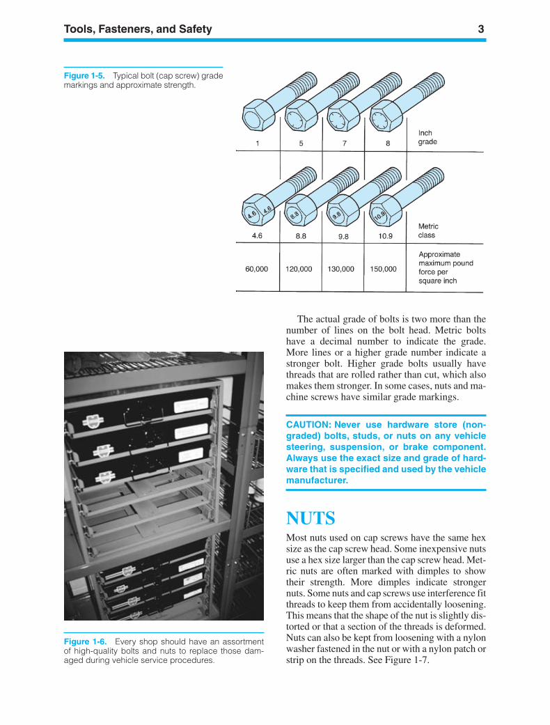
Figure 1-5. Typical bolt (cap screw) grademarkings and approximate strength.
Figure 1-6. Every shop should have an assortmentof high-quality bolts and nuts to replace those dam-aged during vehicle service procedures.
The actual grade of bolts is two more than thenumber of lines on the bolt head. Metric boltshave a decimal number to indicate the grade.More lines or a higher grade number indicate astronger bolt. Higher grade bolts usually havethreads that are rolled rather than cut, which alsomakes them stronger. In some cases, nuts and ma-chine screws have similar grade markings.
CAUTION: Never use hardware store (non-graded) bolts, studs, or nuts on any vehiclesteering, suspension, or brake component.Always use the exact size and grade of hard-ware that is specified and used by the vehiclemanufacturer.
NUTSMost nuts used on cap screws have the same hexsize as the cap screw head. Some inexpensive nutsuse a hex size larger than the cap screw head. Met-ric nuts are often marked with dimples to showtheir strength. More dimples indicate strongernuts. Some nuts and cap screws use interference fitthreads to keep them from accidentally loosening.This means that the shape of the nut is slightly dis-torted or that a section of the threads is deformed.Nuts can also be kept from loosening with a nylonwasher fastened in the nut or with a nylon patch orstrip on the threads. See Figure 1-7.
ker88839_ch01.qxd 1/9/06 11:20 AM Page 3
4 Chapter One
Figure 1-8. Combination wrench. The openings are the same size at both ends. Noticethe angle of the open end to permit use in close spaces.
Figure 1-9. Three different qualities of open-end wrenches. The cheap wrench on the leftis made from weaker steel and is thicker and less accurately machined than the standardin the center. The wrench on the right is of professional quality (and price).
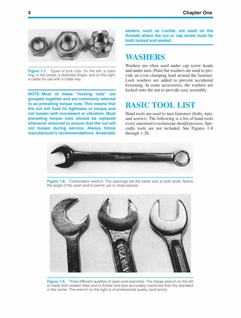
Figure 1-7. Types of lock nuts. On the left, a nylonring; in the center, a distorted shape; and on the right,a castle for use with a cotter key.
NOTE: Most of these “locking nuts” aregrouped together and are commonly referredto as prevailing torque nuts. This means thatthe nut will hold its tightness or torque andnot loosen with movement or vibration. Mostprevailing torque nuts should be replacedwhenever removed to ensure that the nut willnot loosen during service. Always followmanufacturer’s recommendations. Anaerobic
sealers, such as Loctite, are used on thethreads where the nut or cap screw must beboth locked and sealed.
WASHERSWashers are often used under cap screw headsand under nuts. Plain flat washers are used to pro-vide an even clamping load around the fastener.Lock washers are added to prevent accidentalloosening. In some accessories, the washers arelocked onto the nut to provide easy assembly.
BASIC TOOL LISTHand tools are used to turn fasteners (bolts, nuts,and screws). The following is a list of hand toolsevery automotive technician should possess. Spe-cialty tools are not included. See Figures 1-8through 1-26.
ker88839_ch01.qxd 1/9/06 11:20 AM Page 4
Tools, Fasteners, and Safety 5
Tool chest1/4-inch drive socket set (1/4 in. to 9/16 in. Stan-
dard and deep sockets; 6 mm to 15 mm standardand deep sockets)
1/4-inch drive ratchet1/4-inch drive 2-inch extension1/4-inch drive 6-inch extension1/4-inch drive handle3/8-inch drive socket set (3/8 in. to 7/8 in. stan-
dard and deep sockets; 10 mm to 19 mm stan-dard and deep sockets)
3/8-inch drive Torx set (T40, T45, T50, and T55)3/8-inch drive 13/16-inch plug socket3/8-inch drive 5/8-inch plug socket3/8-inch drive ratchet3/8-inch drive 1 1/2-inch extension3/8-inch drive 3-inch extension3/8-inch drive 6-inch extension3/8-inch drive 18-inch extension3/8-inch drive universal3/8-inch drive socket set (1/2 in. to 1 in. standard
and deep sockets)1/2-inch drive ratchet1/2-inch drive breaker bar1/2-inch drive 5-inch extension1/2-inch drive 10-inch extension3/8-inch to 1/4-inch adapter1/2-inch to 3/8-inch adapter3/8-inch to 1/2-inch adapterCrowfoot set (frictional inch)Crowfoot set (metric)3/8- through 1-inch combination wrench set10 millimeters through 19 millimeters combina-
tion wrench set1/16-inch through 1/4-inch hex wrench set2 millimeters through 12 millimeters hex wrench set
3/8-inch hex socket13 millimeters to 14 millimeters flare nut wrench15 millimeters to 17 millimeters flare nut wrench5/16-inch to 3/8-inch flare nut wrench7/16-inch to 1/2-inch flare nut wrench1/2-inch to 9/16-inch flare nut wrenchDiagonal pliersNeedle pliersAdjustable-jaw pliersLocking pliersSnap-ring pliersStripping or crimping pliersBall-peen hammerRubber hammerDead-blow hammerFive-piece standard screwdriver setFour-piece Phillips screwdriver set#15 Torx screwdriver#20 Torx screwdriverAwlMill fileCenter punchPin punches (assorted sizes)ChiselUtility knifeValve core toolFilter wrench (large filters)Filter wrench (smaller filters)Safety glassesCircuit testerFeeler gaugeScraperPinch barSticker knifeMagnet
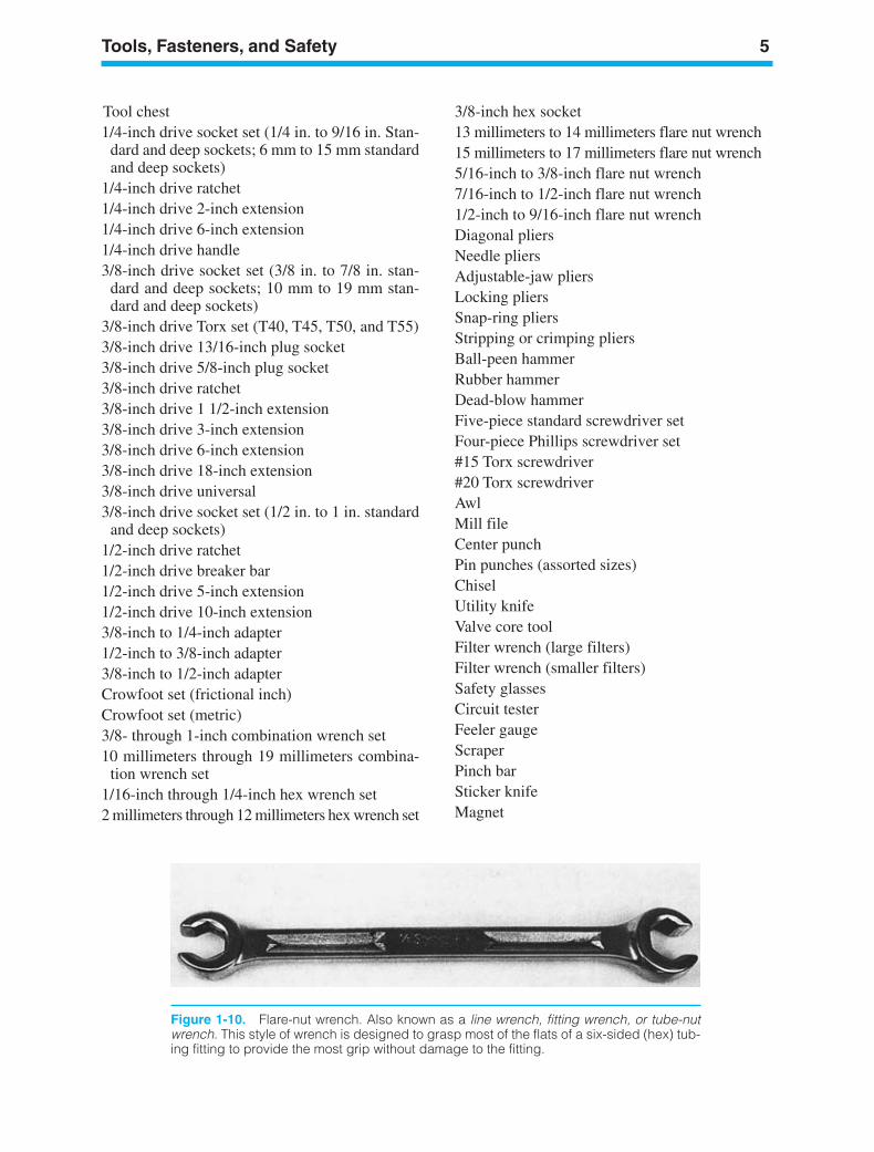
Figure 1-10. Flare-nut wrench. Also known as a line wrench, fitting wrench, or tube-nutwrench. This style of wrench is designed to grasp most of the flats of a six-sided (hex) tub-ing fitting to provide the most grip without damage to the fitting.
ker88839_ch01.qxd 1/9/06 11:20 AM Page 5
6
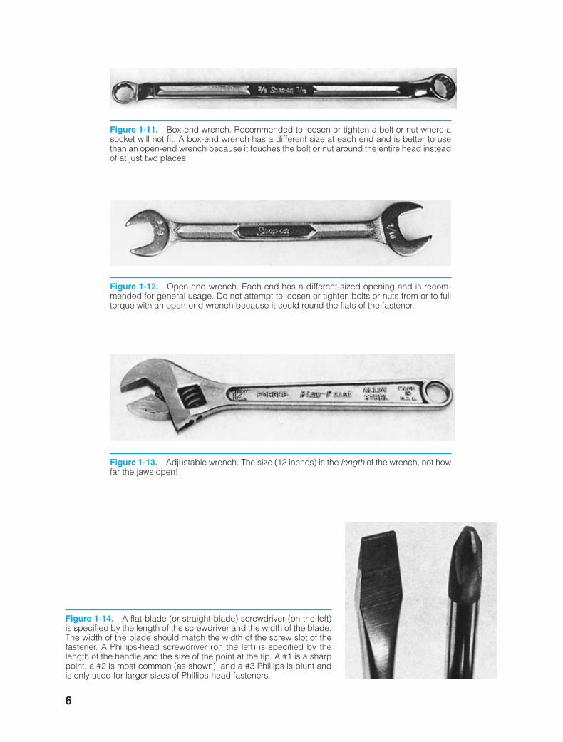
Figure 1-11. Box-end wrench. Recommended to loosen or tighten a bolt or nut where asocket will not fit. A box-end wrench has a different size at each end and is better to usethan an open-end wrench because it touches the bolt or nut around the entire head insteadof at just two places.
Figure 1-12. Open-end wrench. Each end has a different-sized opening and is recom-mended for general usage. Do not attempt to loosen or tighten bolts or nuts from or to fulltorque with an open-end wrench because it could round the flats of the fastener.
Figure 1-14. A flat-blade (or straight-blade) screwdriver (on the left)is specified by the length of the screwdriver and the width of the blade.The width of the blade should match the width of the screw slot of thefastener. A Phillips-head screwdriver (on the left) is specified by thelength of the handle and the size of the point at the tip. A #1 is a sharppoint, a #2 is most common (as shown), and a #3 Phillips is blunt andis only used for larger sizes of Phillips-head fasteners.
Figure 1-13. Adjustable wrench. The size (12 inches) is the length of the wrench, not howfar the jaws open!
ker88839_ch01.qxd 1/9/06 11:20 AM Page 6
7
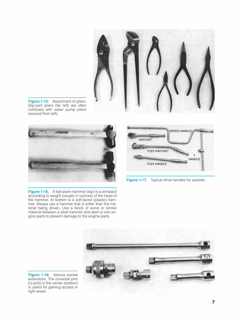
Figure 1-15. Assortment of pliers.Slip-joint pliers (far left) are oftenconfused with water pump pliers(second from left).
Figure 1-16. A ball-peen hammer (top) is purchasedaccording to weight (usually in ounces) of the head ofthe hammer. At bottom is a soft-faced (plastic) ham-mer. Always use a hammer that is softer than the ma-terial being driven. Use a block of wood or similarmaterial between a steel hammer and steel or iron en-gine parts to prevent damage to the engine parts.
SPEED HANDLE
RATCHET
FLEX RATCHET
FLEX HANDLE
THANDLE
Figure 1-17. Typical drive handles for sockets.
Figure 1-18. Various socketextensions. The universal joint(U-joint) in the center (bottom)is useful for gaining access intight areas.
ker88839_ch01.qxd 1/9/06 11:20 AM Page 7
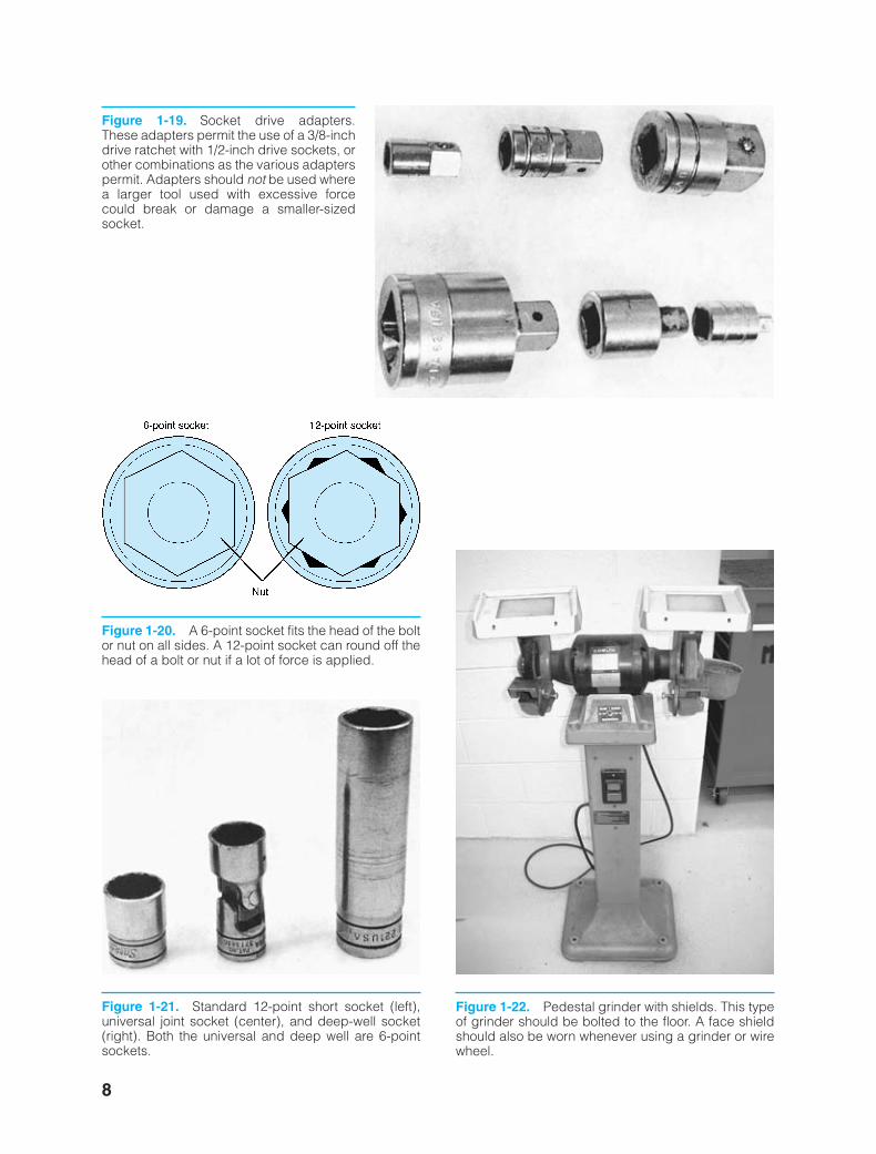
Figure 1-19. Socket drive adapters.These adapters permit the use of a 3/8-inchdrive ratchet with 1/2-inch drive sockets, orother combinations as the various adapterspermit. Adapters should not be used wherea larger tool used with excessive forcecould break or damage a smaller-sizedsocket.
Figure 1-20. A 6-point socket fits the head of the boltor nut on all sides. A 12-point socket can round off thehead of a bolt or nut if a lot of force is applied.
Figure 1-21. Standard 12-point short socket (left),universal joint socket (center), and deep-well socket(right). Both the universal and deep well are 6-pointsockets.
Figure 1-22. Pedestal grinder with shields. This typeof grinder should be bolted to the floor. A face shieldshould also be worn whenever using a grinder or wirewheel.
8
ker88839_ch01.qxd 1/9/06 11:20 AM Page 8
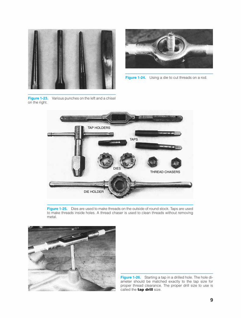
Figure 1-23. Various punches on the left and a chiselon the right.
Figure 1-24. Using a die to cut threads on a rod.
TAP HOLDERS
TAPS
THREAD CHASERSDIES
DIE HOLDER
Figure 1-25. Dies are used to make threads on the outside of round stock. Taps are usedto make threads inside holes. A thread chaser is used to clean threads without removingmetal.
Figure 1-26. Starting a tap in a drilled hole. The hole di-ameter should be matched exactly to the tap size forproper thread clearance. The proper drill size to use iscalled the tap drill size.
9
ker88839_ch01.qxd 1/9/06 11:20 AM Page 9
10 Chapter One
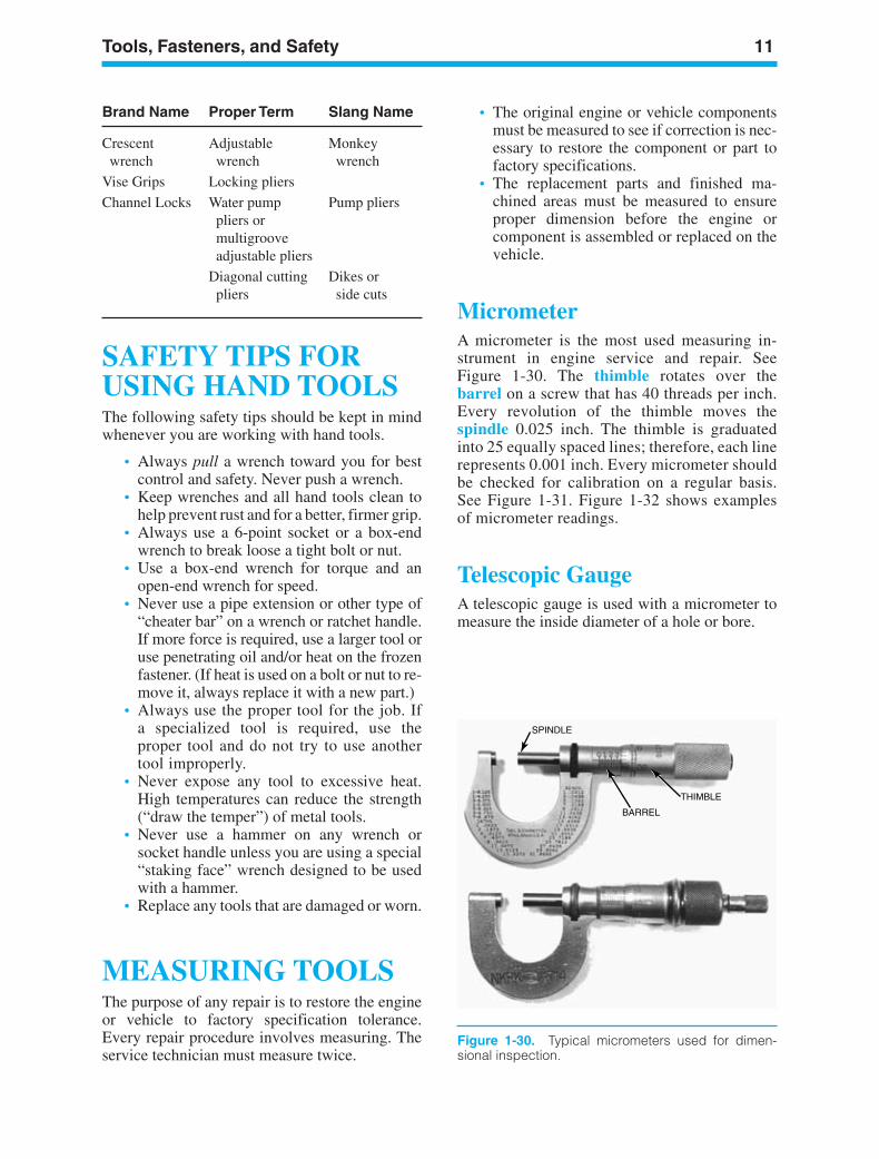
Figure 1-28. An inexpensive muffin tin can be usedto keep small parts separated.
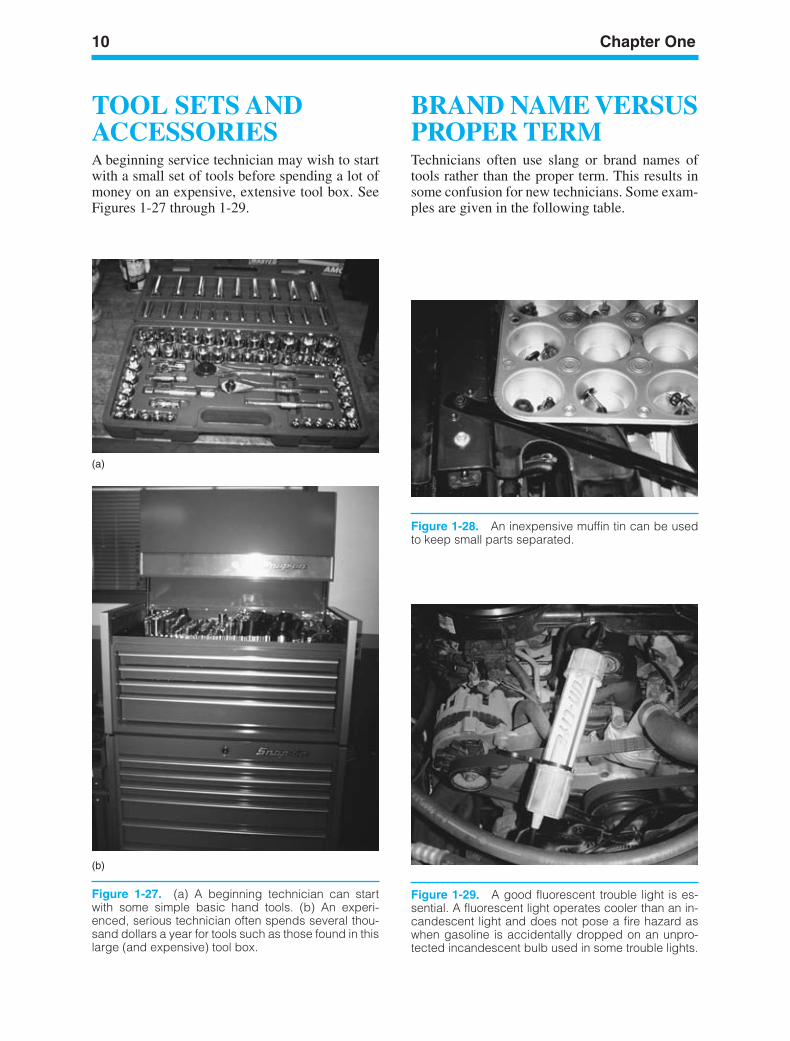
Figure 1-27. (a) A beginning technician can startwith some simple basic hand tools. (b) An experi-enced, serious technician often spends several thou-sand dollars a year for tools such as those found in thislarge (and expensive) tool box.
TOOL SETS ANDACCESSORIESA beginning service technician may wish to startwith a small set of tools before spending a lot ofmoney on an expensive, extensive tool box. SeeFigures 1-27 through 1-29.
BRAND NAME VERSUSPROPER TERMTechnicians often use slang or brand names oftools rather than the proper term. This results insome confusion for new technicians. Some exam-ples are given in the following table.
Figure 1-29. A good fluorescent trouble light is es-sential. A fluorescent light operates cooler than an in-candescent light and does not pose a fire hazard aswhen gasoline is accidentally dropped on an unpro-tected incandescent bulb used in some trouble lights.
(a)
(b)
ker88839_ch01.qxd 1/9/06 11:20 AM Page 10
Tools, Fasteners, and Safety 11
SAFETY TIPS FORUSING HAND TOOLSThe following safety tips should be kept in mindwhenever you are working with hand tools.
• Always pull a wrench toward you for bestcontrol and safety. Never push a wrench.
• Keep wrenches and all hand tools clean tohelp prevent rust and for a better, firmer grip.
• Always use a 6-point socket or a box-endwrench to break loose a tight bolt or nut.
• Use a box-end wrench for torque and anopen-end wrench for speed.
• Never use a pipe extension or other type of“cheater bar” on a wrench or ratchet handle.If more force is required, use a larger tool oruse penetrating oil and/or heat on the frozenfastener. (If heat is used on a bolt or nut to re-move it, always replace it with a new part.)
• Always use the proper tool for the job. Ifa specialized tool is required, use theproper tool and do not try to use anothertool improperly.
• Never expose any tool to excessive heat.High temperatures can reduce the strength(“draw the temper”) of metal tools.
• Never use a hammer on any wrench orsocket handle unless you are using a special“staking face” wrench designed to be usedwith a hammer.
• Replace any tools that are damaged or worn.
MEASURING TOOLSThe purpose of any repair is to restore the engineor vehicle to factory specification tolerance.Every repair procedure involves measuring. Theservice technician must measure twice.
Brand Name Proper Term Slang Name
Crescent Adjustable Monkey wrench wrench wrench
Vise Grips Locking pliers
Channel Locks Water pump Pump plierspliers or multigroove adjustable pliers
Diagonal cutting Dikes or pliers side cuts
SPINDLE
BARREL
THIMBLE
Figure 1-30. Typical micrometers used for dimen-sional inspection.
• The original engine or vehicle componentsmust be measured to see if correction is nec-essary to restore the component or part tofactory specifications.
• The replacement parts and finished ma-chined areas must be measured to ensureproper dimension before the engine orcomponent is assembled or replaced on thevehicle.
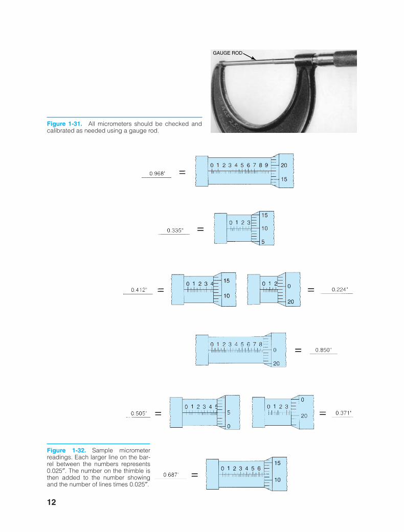
MicrometerA micrometer is the most used measuring in-strument in engine service and repair. SeeFigure 1-30. The thimble rotates over thebarrel on a screw that has 40 threads per inch.Every revolution of the thimble moves thespindle 0.025 inch. The thimble is graduatedinto 25 equally spaced lines; therefore, each linerepresents 0.001 inch. Every micrometer shouldbe checked for calibration on a regular basis.See Figure 1-31. Figure 1-32 shows examplesof micrometer readings.
Telescopic GaugeA telescopic gauge is used with a micrometer tomeasure the inside diameter of a hole or bore.
ker88839_ch01.qxd 1/9/06 11:20 AM Page 11
GAUGE ROD
Figure 1-31. All micrometers should be checked andcalibrated as needed using a gauge rod.
Figure 1-32. Sample micrometerreadings. Each larger line on the bar-rel between the numbers represents0.025″. The number on the thimble isthen added to the number showingand the number of lines times 0.025″.
12
ker88839_ch01.qxd 1/9/06 11:21 AM Page 12
Tools, Fasteners, and Safety 13
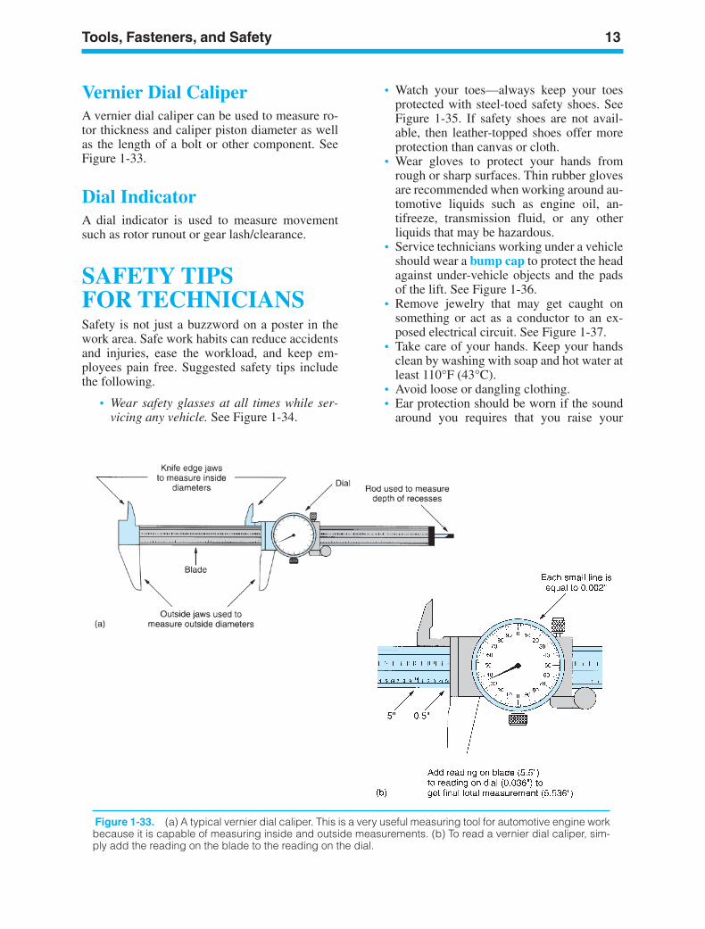
Vernier Dial CaliperA vernier dial caliper can be used to measure ro-tor thickness and caliper piston diameter as wellas the length of a bolt or other component. SeeFigure 1-33.
Dial IndicatorA dial indicator is used to measure movementsuch as rotor runout or gear lash/clearance.
SAFETY TIPS FOR TECHNICIANSSafety is not just a buzzword on a poster in thework area. Safe work habits can reduce accidentsand injuries, ease the workload, and keep em-ployees pain free. Suggested safety tips includethe following.
• Wear safety glasses at all times while ser-vicing any vehicle. See Figure 1-34.
• Watch your toes—always keep your toesprotected with steel-toed safety shoes. SeeFigure 1-35. If safety shoes are not avail-able, then leather-topped shoes offer moreprotection than canvas or cloth.
• Wear gloves to protect your hands fromrough or sharp surfaces. Thin rubber glovesare recommended when working around au-tomotive liquids such as engine oil, an-tifreeze, transmission fluid, or any otherliquids that may be hazardous.
• Service technicians working under a vehicleshould wear a bump cap to protect the headagainst under-vehicle objects and the padsof the lift. See Figure 1-36.
• Remove jewelry that may get caught onsomething or act as a conductor to an ex-posed electrical circuit. See Figure 1-37.
• Take care of your hands. Keep your handsclean by washing with soap and hot water atleast 110°F (43°C).
• Avoid loose or dangling clothing.• Ear protection should be worn if the sound
around you requires that you raise your
Figure 1-33. (a) A typical vernier dial caliper. This is a very useful measuring tool for automotive engine workbecause it is capable of measuring inside and outside measurements. (b) To read a vernier dial caliper, sim-ply add the reading on the blade to the reading on the dial.
ker88839_ch01.qxd 1/9/06 11:21 AM Page 13

14 Chapter One
Figure 1-34. Safety glassesshould be worn at all timeswhen working on or around anyvehicle or servicing any compo-nent.
Figure 1-35. Steel-toed shoes are a worthwhile in-vestment to help prevent foot injury due to falling ob-jects. Even these well-worn shoes can protect the feetof this service technician.
Figure 1-36. One version of a bump cap is thispadded plastic insert that is worn inside a regular clothcap.
voice (sound level higher than 90 dB). (Atypical lawnmower produces noise at a levelof about 110 dB. This means that everyonewho uses a lawnmower or other lawn or gar-den equipment should wear ear protection.)
• When lifting any object, get a secure gripwith solid footing. Keep the load close toyour body to minimize the strain. Lift withyour legs and arms, not your back.
• Do not twist your body when carrying aload. Instead, pivot your feet to help preventstrain on the spine.
• Ask for help when moving or lifting heavyobjects.
• Push a heavy object rather than pull it. (Thisis opposite to the way you should work withtools—never push a wrench! If you do anda bolt or nut loosens, your entire weight isused to propel your hand(s) forward. Thisusually results in cuts, bruises, or otherpainful injury.)
• Always connect an exhaust hose to thetailpipe of any running vehicle to help pre-
Figure 1-37. Remove all jewelry before performingservice work on any vehicle.
ker88839_ch01.qxd 1/9/06 11:21 AM Page 14
Tools, Fasteners, and Safety 15
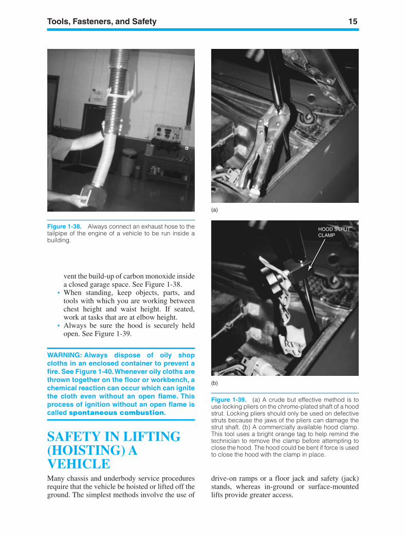
vent the build-up of carbon monoxide insidea closed garage space. See Figure 1-38.
• When standing, keep objects, parts, andtools with which you are working betweenchest height and waist height. If seated,work at tasks that are at elbow height.
• Always be sure the hood is securely heldopen. See Figure 1-39.
WARNING: Always dispose of oily shopcloths in an enclosed container to prevent afire. See Figure 1-40.Whenever oily cloths arethrown together on the floor or workbench, achemical reaction can occur which can ignitethe cloth even without an open flame. Thisprocess of ignition without an open flame iscalled spontaneous combustion.
SAFETY IN LIFTING(HOISTING) AVEHICLEMany chassis and underbody service proceduresrequire that the vehicle be hoisted or lifted off theground. The simplest methods involve the use of
Figure 1-38. Always connect an exhaust hose to thetailpipe of the engine of a vehicle to be run inside abuilding.
HOOD STRUTCLAMP
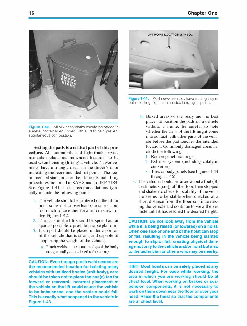
Figure 1-39. (a) A crude but effective method is touse locking pliers on the chrome-plated shaft of a hoodstrut. Locking pliers should only be used on defectivestruts because the jaws of the pliers can damage thestrut shaft. (b) A commercially available hood clamp.This tool uses a bright orange tag to help remind thetechnician to remove the clamp before attempting toclose the hood. The hood could be bent if force is usedto close the hood with the clamp in place.
drive-on ramps or a floor jack and safety (jack)stands, whereas in-ground or surface-mountedlifts provide greater access.
(a)
(b)
ker88839_ch01.qxd 1/9/06 11:21 AM Page 15
16 Chapter One
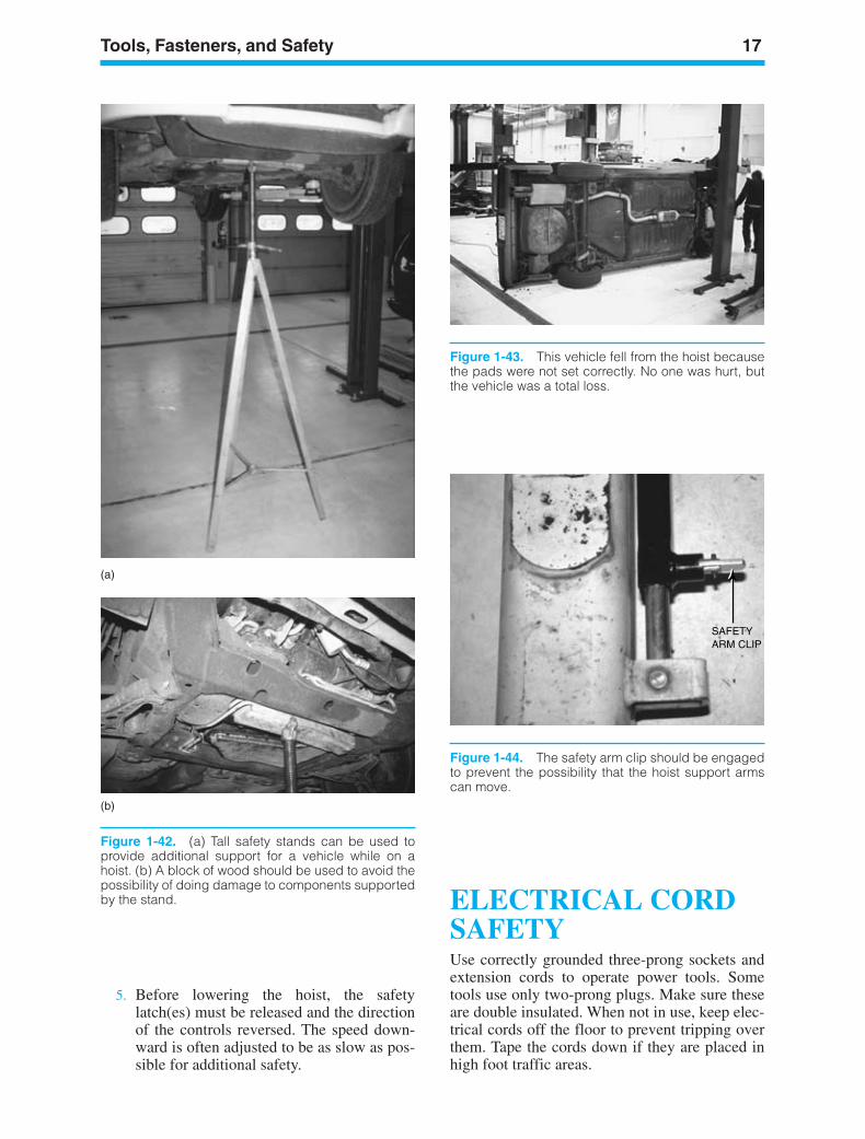
Figure 1-40. All oily shop cloths should be stored ina metal container equipped with a lid to help preventspontaneous combustion.
LIFT POINT LOCATION SYMBOL
Figure 1-41. Most newer vehicles have a triangle sym-bol indicating the recommended hoisting lift points.
Setting the pads is a critical part of this pro-cedure. All automobile and light-truck servicemanuals include recommended locations to beused when hoisting (lifting) a vehicle. Newer ve-hicles have a triangle decal on the driver’s doorindicating the recommended lift points. The rec-ommended standards for the lift points and liftingprocedures are found in SAE Standard JRP-2184.See Figure 1-41. These recommendations typi-cally include the following points.
1. The vehicle should be centered on the lift orhoist so as not to overload one side or puttoo much force either forward or rearward.See Figure 1-42.
2. The pads of the lift should be spread as farapart as possible to provide a stable platform.
3. Each pad should be placed under a portionof the vehicle that is strong and capable ofsupporting the weight of the vehicle.
a. Pinch welds at the bottom edge of the bodyare generally considered to be strong.
CAUTION: Even though pinch weld seams arethe recommended location for hoisting manyvehicles with unitized bodies (unit-body), careshould be taken not to place the pad(s) too farforward or rearward. Incorrect placement ofthe vehicle on the lift could cause the vehicleto be imbalanced, and the vehicle could fall.This is exactly what happened to the vehicle inFigure 1-43.
b. Boxed areas of the body are the bestplaces to position the pads on a vehiclewithout a frame. Be careful to notewhether the arms of the lift might comeinto contact with other parts of the vehi-cle before the pad touches the intendedlocation. Commonly damaged areas in-clude the following.1. Rocker panel moldings2. Exhaust system (including catalytic
converter)3. Tires or body panels (see Figures 1-44
through 1-46)4. The vehicle should be raised about a foot (30
centimeters [cm]) off the floor, then stoppedand shaken to check for stability. If the vehi-cle seems to be stable when checked at ashort distance from the floor continue rais-ing the vehicle and continue to view the ve-hicle until it has reached the desired height.
CAUTION: Do not look away from the vehiclewhile it is being raised (or lowered) on a hoist.Often one side or one end of the hoist can stopor fail, resulting in the vehicle being slantedenough to slip or fall, creating physical dam-age not only to the vehicle and/or hoist but alsoto the technician or others who may be nearby.
HINT: Most hoists can be safely placed at anydesired height. For ease while working, thearea in which you are working should be atchest level. When working on brakes or sus-pension components, it is not necessary towork on them down near the floor or over yourhead. Raise the hoist so that the componentsare at chest level.
ker88839_ch01.qxd 1/9/06 11:21 AM Page 16
Tools, Fasteners, and Safety 17
Figure 1-42. (a) Tall safety stands can be used toprovide additional support for a vehicle while on ahoist. (b) A block of wood should be used to avoid thepossibility of doing damage to components supportedby the stand.
Figure 1-43. This vehicle fell from the hoist becausethe pads were not set correctly. No one was hurt, butthe vehicle was a total loss.
SAFETYARM CLIP
Figure 1-44. The safety arm clip should be engagedto prevent the possibility that the hoist support armscan move.
5. Before lowering the hoist, the safetylatch(es) must be released and the directionof the controls reversed. The speed down-ward is often adjusted to be as slow as pos-sible for additional safety.
ELECTRICAL CORDSAFETYUse correctly grounded three-prong sockets andextension cords to operate power tools. Sometools use only two-prong plugs. Make sure theseare double insulated. When not in use, keep elec-trical cords off the floor to prevent tripping overthem. Tape the cords down if they are placed inhigh foot traffic areas.
(a)
(b)
ker88839_ch01.qxd 1/9/06 11:21 AM Page 17
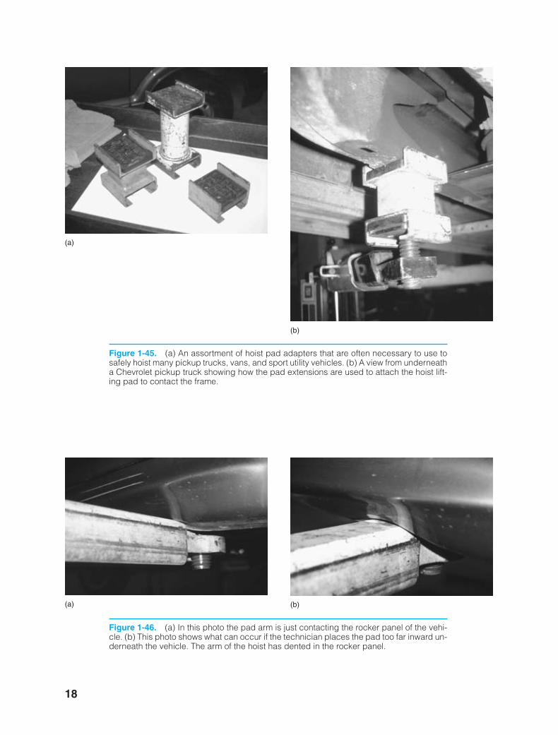
Figure 1-45. (a) An assortment of hoist pad adapters that are often necessary to use tosafely hoist many pickup trucks, vans, and sport utility vehicles. (b) A view from underneatha Chevrolet pickup truck showing how the pad extensions are used to attach the hoist lift-ing pad to contact the frame.
(a)
(b)
Figure 1-46. (a) In this photo the pad arm is just contacting the rocker panel of the vehi-cle. (b) This photo shows what can occur if the technician places the pad too far inward un-derneath the vehicle. The arm of the hoist has dented in the rocker panel.
(a) (b)
18
ker88839_ch01.qxd 1/9/06 11:21 AM Page 18
Tools, Fasteners, and Safety 19
FIREEXTINGUISHERSThere are four classes of fire extinguishers. Eachclass should be used on specific fires only.
• Class A—is designed for use on generalcombustibles, such as cloth, paper, andwood.
• Class B—is designed for use on flammableliquids and greases, including gasoline, oil,thinners, and solvents.
• Class C—is used only on electrical fires.• Class D—is effective only on combustible
metals such as powdered aluminum,sodium, or magnesium.
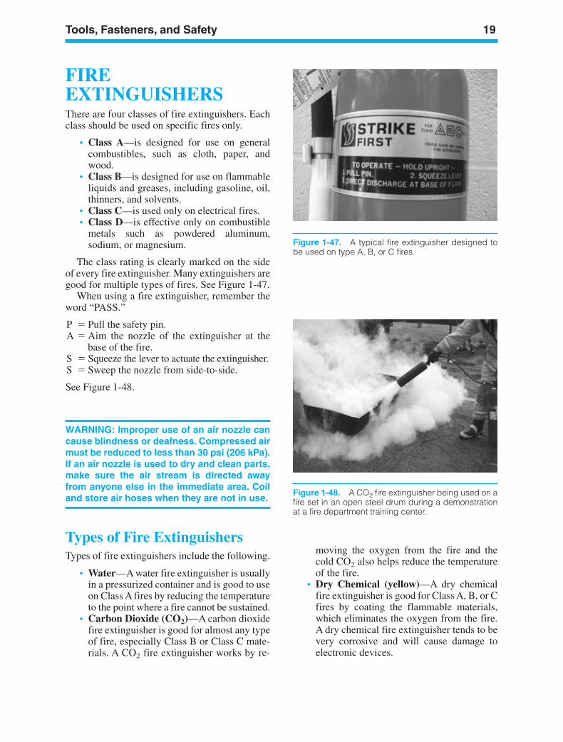
The class rating is clearly marked on the sideof every fire extinguisher. Many extinguishers aregood for multiple types of fires. See Figure 1-47.
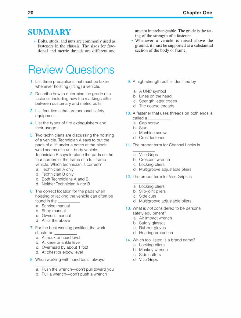
When using a fire extinguisher, remember theword “PASS.”
P Pull the safety pin.A Aim the nozzle of the extinguisher at the
base of the fire.S Squeeze the lever to actuate the extinguisher.S Sweep the nozzle from side-to-side.
See Figure 1-48.
WARNING: Improper use of an air nozzle cancause blindness or deafness. Compressed airmust be reduced to less than 30 psi (206 kPa).If an air nozzle is used to dry and clean parts,make sure the air stream is directed awayfrom anyone else in the immediate area. Coiland store air hoses when they are not in use.
Types of Fire ExtinguishersTypes of fire extinguishers include the following.
• Water—A water fire extinguisher is usuallyin a pressurized container and is good to useon Class A fires by reducing the temperatureto the point where a fire cannot be sustained.
• Carbon Dioxide (CO2)—A carbon dioxidefire extinguisher is good for almost any typeof fire, especially Class B or Class C mate-rials. A CO2 fire extinguisher works by re-
moving the oxygen from the fire and thecold CO2 also helps reduce the temperatureof the fire.
• Dry Chemical (yellow)—A dry chemicalfire extinguisher is good for Class A, B, or Cfires by coating the flammable materials,which eliminates the oxygen from the fire.A dry chemical fire extinguisher tends to bevery corrosive and will cause damage toelectronic devices.
Figure 1-47. A typical fire extinguisher designed tobe used on type A, B, or C fires.
Figure 1-48. A CO2 fire extinguisher being used on afire set in an open steel drum during a demonstrationat a fire department training center.
ker88839_ch01.qxd 1/9/06 11:21 AM Page 19
20 Chapter One
SUMMARY• Bolts, studs, and nuts are commonly used as
fasteners in the chassis. The sizes for frac-tional and metric threads are different and
are not interchangeable. The grade is the rat-ing of the strength of a fastener.
• Whenever a vehicle is raised above theground, it must be supported at a substantialsection of the body or frame.
Review Questions1. List three precautions that must be taken
whenever hoisting (lifting) a vehicle.
2. Describe how to determine the grade of afastener, including how the markings differbetween customary and metric bolts.
3. List four items that are personal safetyequipment.
4. List the types of fire extinguishers andtheir usage.
5. Two technicians are discussing the hoistingof a vehicle. Technician A says to put thepads of a lift under a notch at the pinchweld seams of a unit-body vehicle.Technician B says to place the pads on thefour corners of the frame of a full-framevehicle. Which technician is correct?a. Technician A onlyb. Technician B onlyc. Both Technicians A and Bd. Neither Technician A nor B
6. The correct location for the pads whenhoisting or jacking the vehicle can often befound in the ___________a. Service manualb. Shop manualc. Owner’s manuald. All of the above
7. For the best working position, the workshould be ___________a. At neck or head levelb. At knee or ankle levelc. Overhead by about 1 footd. At chest or elbow level
8. When working with hand tools, always___________a. Push the wrench—don’t pull toward youb. Pull a wrench—don’t push a wrench
9. A high-strength bolt is identified by___________a. A UNC symbolb. Lines on the headc. Strength letter codesd. The coarse threads
10. A fastener that uses threads on both ends iscalled a ___________a. Cap screwb. Studc. Machine screwd. Crest fastener
11. The proper term for Channel Locks is___________a. Vise Gripsb. Crescent wrenchc. Locking pliersd. Multigroove adjustable pliers
12. The proper term for Vise Grips is___________a. Locking pliersb. Slip-joint pliersc. Side cutsd. Multigroove adjustable pliers
13. What is not considered to be personalsafety equipment?a. Air impact wrenchb. Safety glassesc. Rubber glovesd. Hearing protection
14. Which tool listed is a brand name?a. Locking pliersb. Monkey wrenchc. Side cuttersd. Vise Grips
ker88839_ch01.qxd 1/9/06 11:21 AM Page 20
LEARNINGOBJECTIVESUpon completion and review of this chapter, youshould be able to:
• Define electricity, atomic structure, and elec-tron movement and explain atomic theory inrelation to battery operation, using like andunlike charges.
• Explain the different sources of electricity.• Describe the scientists who were instrumen-
tal in the development of the different tenetsof electrical theory.
KEY TERMSAmberAtomBatteryCurrentElectricityElectrolyteElectronElectrostatic Discharge (ESD)HorsepowerIonMatterNeutronNucleusPhotoelectricityPiezoelectricityProtonStatic ElectricityThermocoupleThermoelectricityValenceVoltage
INTRODUCTIONThis chapter reviews what electricity is in its basicform. We will look at natural forms of electricalenergy, and the people who have historically playeda part in developing the theories that explain elec-tricity. It is extremely important for automotivetechnicians to learn all that they can about basicelectricity and electronics, because in today’s mod-ern automobile, there is a wire or computer con-nected to just about everything.
21
2Introduction toElectricity
ker88839_ch02.qxd 1/9/06 11:21 AM Page 21
22 Chapter Two
Many of us take for granted the sources of elec-tricity. Electricity is a natural form of energy thatcomes from many sources. For example, electric-ity is in the atmosphere all around us; a generatorjust puts it in motion. We cannot create or destroyenergy, only change it, yet we can successfullyproduce electricity and harness it by changingvarious other forms of natural energy.
WHAT ISELECTRICITY?Was electricity invented or discovered? The answeris that electricity was discovered. So who discoveredelectricity? Ben Franklin? Thomas Edison figuredout how to use electricity to make light bulbs, recordplayers, and movies. But neither of these scientist/inventors had anything to do with the discovery ofelectricity.
Actually, the Greeks discovered electricity.They found that if they took amber (a translu-cent, yellowish resin, derived from fossilizedtrees) and rubbed it against other materials, itbecame charged with an unseen force that had theability to attract other lightweight objects such asfeathers, somewhat like a magnet picks up metalobjects. In 1600, William Gilbert published abook describing these phenomena. He also dis-covered that other materials shared the ability toattract, such as sulfur and glass. He used the Latinword “elektron” to describe amber and the word“electrica” for similar substances. Sir ThomasBrowne first used the word electricity during the1600s. Two thousand years after ancient Greece,electricity is all around us. We use it every day.But what exactly is electricity? You can’t see it.You can’t smell it. You can’t touch it; well, youcould touch it, but it would probably be ashocking experience and could cause seriousinjury. Next, we will discuss atomic structure tofind a more exact definition of electricity.
ATOMIC STRUCTUREWe define matter as anything that takes upspace and, when subjected to gravity, has weight.There are many different kinds of matter. OnEarth, we have classified over a hundred ele-ments. Each element is a type of matter that hascertain individual characteristics. Most havebeen found in nature. Examples of natural ele-
ments are copper, iron, gold, and silver. Otherelements have been produced only in the labora-tory. Every material we know is made up of oneor more elements.
Let’s say we take a chunk of material—a rockwe found in the desert, for example—and beginto divide it into smaller parts. First we divide itin half. Then we test both halves to see if it stillhas the same characteristics. Next we take one ofthe halves and divide it into two parts. We testthose two parts. By this process, we might dis-cover that the rock contains three different ele-ments. Some of our pieces would have the char-acteristics of copper, for example. Others wouldshow themselves to be carbon, yet others wouldbe iron.
AtomsIf you could keep dividing the material indefi-nitely, you would eventually get a piece that onlyhad the characteristics of a single element. At thatpoint, you would have an atom, which is the small-est particle into which an element can be dividedand still have all the characteristics of that element.An atom is the smallest particle that has the char-acteristic of the element. An atom is so small that itcannot be seen with a conventional microscope,even a very powerful one. An atom is itself madeup of smaller particles. You can think of these asuniversal building blocks. Scientists have discov-ered many particles in the atom, but for the purposeof explaining electricity, we need to talk about justthree: electrons, protons, and neutrons.
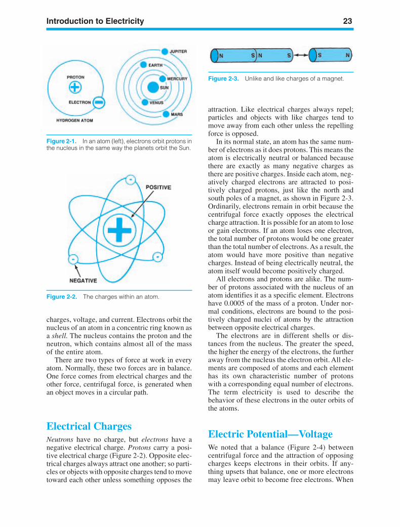
All the atoms of any particular element lookessentially the same, but the atoms of each ele-ment are different from those of another element.All atoms share the same basic structure. At thecenter of the atom is the nucleus, containingprotons and neutrons, as shown in Figure 2-1.Orbiting around the nucleus, in constant motion,are the electrons. The structure of the atom resem-bles planets in orbit around a sun.
The exact number of each of an atom’sparticles—protons, neutrons, and electrons—depends on which element the atom is from. Thesimplest atom is that of the element hydrogen. Ahydrogen atom (Figure 2-1) contains one proton,one neutron, and one electron. Aluminum, bycomparison, has 13 protons, 14 neutrons, and13 electrons. These particles—protons, neu-trons, and electrons—are important to usbecause they are used to explain electrical
ker88839_ch02.qxd 1/9/06 11:21 AM Page 22
Introduction to Electricity 23
Figure 2-1. In an atom (left), electrons orbit protons inthe nucleus in the same way the planets orbit the Sun.
charges, voltage, and current. Electrons orbit thenucleus of an atom in a concentric ring known asa shell. The nucleus contains the proton and theneutron, which contains almost all of the massof the entire atom.
There are two types of force at work in everyatom. Normally, these two forces are in balance.One force comes from electrical charges and theother force, centrifugal force, is generated whenan object moves in a circular path.
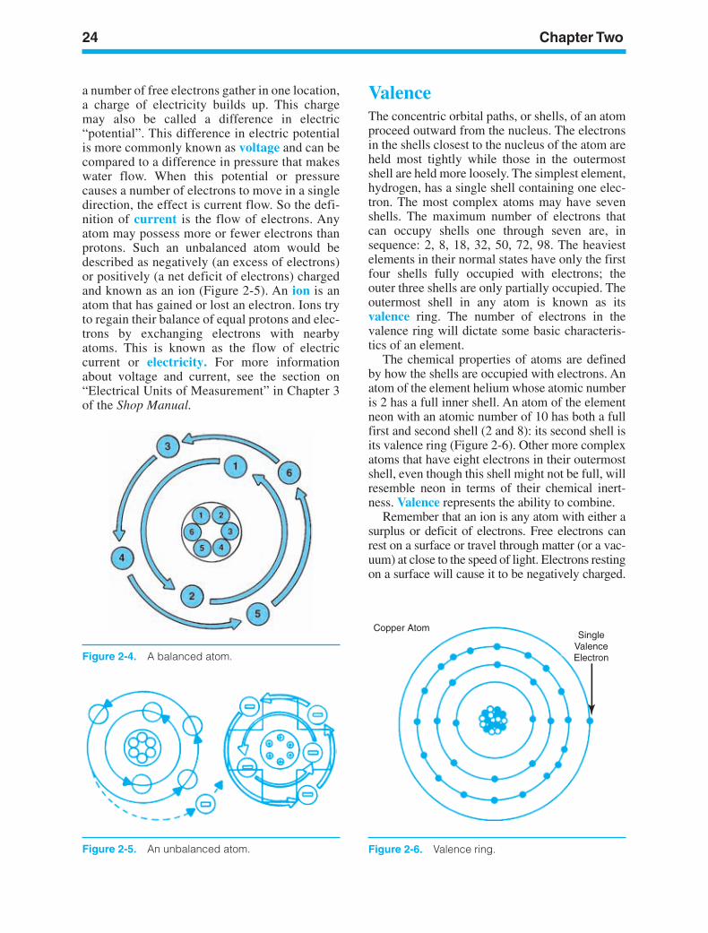
Electrical ChargesNeutrons have no charge, but electrons have anegative electrical charge. Protons carry a posi-tive electrical charge (Figure 2-2). Opposite elec-trical charges always attract one another; so parti-cles or objects with opposite charges tend to movetoward each other unless something opposes the
attraction. Like electrical charges always repel;particles and objects with like charges tend tomove away from each other unless the repellingforce is opposed.
In its normal state, an atom has the same num-ber of electrons as it does protons. This means theatom is electrically neutral or balanced becausethere are exactly as many negative charges asthere are positive charges. Inside each atom, neg-atively charged electrons are attracted to posi-tively charged protons, just like the north andsouth poles of a magnet, as shown in Figure 2-3.Ordinarily, electrons remain in orbit because thecentrifugal force exactly opposes the electricalcharge attraction. It is possible for an atom to loseor gain electrons. If an atom loses one electron,the total number of protons would be one greaterthan the total number of electrons. As a result, theatom would have more positive than negativecharges. Instead of being electrically neutral, theatom itself would become positively charged.
All electrons and protons are alike. The num-ber of protons associated with the nucleus of anatom identifies it as a specific element. Electronshave 0.0005 of the mass of a proton. Under nor-mal conditions, electrons are bound to the posi-tively charged nuclei of atoms by the attractionbetween opposite electrical charges.
The electrons are in different shells or dis-tances from the nucleus. The greater the speed,the higher the energy of the electrons, the furtheraway from the nucleus the electron orbit. All ele-ments are composed of atoms and each elementhas its own characteristic number of protonswith a corresponding equal number of electrons.The term electricity is used to describe thebehavior of these electrons in the outer orbits ofthe atoms.
Electric Potential—VoltageWe noted that a balance (Figure 2-4) betweencentrifugal force and the attraction of opposingcharges keeps electrons in their orbits. If any-thing upsets that balance, one or more electronsmay leave orbit to become free electrons. When
Figure 2-2. The charges within an atom.
Figure 2-3. Unlike and like charges of a magnet.
ker88839_ch02.qxd 1/9/06 11:21 AM Page 23
a number of free electrons gather in one location,a charge of electricity builds up. This chargemay also be called a difference in electric“potential”. This difference in electric potentialis more commonly known as voltage and can becompared to a difference in pressure that makeswater flow. When this potential or pressurecauses a number of electrons to move in a singledirection, the effect is current flow. So the defi-nition of current is the flow of electrons. Anyatom may possess more or fewer electrons thanprotons. Such an unbalanced atom would bedescribed as negatively (an excess of electrons)or positively (a net deficit of electrons) chargedand known as an ion (Figure 2-5). An ion is anatom that has gained or lost an electron. Ions tryto regain their balance of equal protons and elec-trons by exchanging electrons with nearbyatoms. This is known as the flow of electriccurrent or electricity. For more informationabout voltage and current, see the section on“Electrical Units of Measurement” in Chapter 3of the Shop Manual.
24 Chapter Two
Figure 2-5. An unbalanced atom.
ValenceThe concentric orbital paths, or shells, of an atomproceed outward from the nucleus. The electronsin the shells closest to the nucleus of the atom areheld most tightly while those in the outermostshell are held more loosely. The simplest element,hydrogen, has a single shell containing one elec-tron. The most complex atoms may have sevenshells. The maximum number of electrons thatcan occupy shells one through seven are, insequence: 2, 8, 18, 32, 50, 72, 98. The heaviestelements in their normal states have only the firstfour shells fully occupied with electrons; theouter three shells are only partially occupied. Theoutermost shell in any atom is known as itsvalence ring. The number of electrons in thevalence ring will dictate some basic characteris-tics of an element.
The chemical properties of atoms are definedby how the shells are occupied with electrons. Anatom of the element helium whose atomic numberis 2 has a full inner shell. An atom of the elementneon with an atomic number of 10 has both a fullfirst and second shell (2 and 8): its second shell isits valence ring (Figure 2-6). Other more complexatoms that have eight electrons in their outermostshell, even though this shell might not be full, willresemble neon in terms of their chemical inert-ness. Valence represents the ability to combine.
Remember that an ion is any atom with either asurplus or deficit of electrons. Free electrons canrest on a surface or travel through matter (or a vac-uum) at close to the speed of light. Electrons restingon a surface will cause it to be negatively charged.
Figure 2-4. A balanced atom.
Copper AtomSingle
ValenceElectron
Figure 2-6. Valence ring.
ker88839_ch02.qxd 1/9/06 11:21 AM Page 24
Introduction to Electricity 25
Because the electrons are not moving, that surfaceis described as having a negative static electricalcharge. The extent of the charge is measured involtage or charge differential. A stream of movingelectrons is known as an electrical current. Forinstance, if a group of positive ions passes in closeproximity to electrons resting on a surface, they willattract the electrons by causing them to fill the“holes” left by the missing electrons in the positiveions. Current flow is measured in amperes: oneampere equals 6.28 × 10¹⁸ electrons (1 coulomb)passing a given point per second.
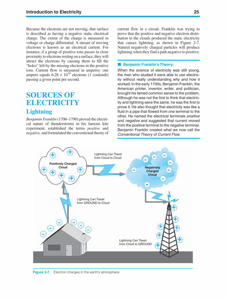
SOURCES OFELECTRICITYLightningBenjamin Franklin (1706–1790) proved the electri-cal nature of thunderstorms in his famous kiteexperiment, established the terms positive andnegative, and formulated the conventional theory of
current flow in a circuit. Franklin was trying toprove that the positive and negative electron distri-bution in the clouds produced the static electricitythat causes lightning, as shown in Figure 2-7.Natural negatively charged particles will producelightning when they find a path negative to positive.
Benjamin Franklin’s Theory:
When the science of electricity was still young,the men who studied it were able to use electric-ity without really understanding why and how itworked. In the early 1700s, Benjamin Franklin, theAmerican printer, inventor, writer, and politician,brought his famed common sense to the problem.Although he was not the first to think that electric-ity and lightning were the same, he was the first toprove it. He also thought that electricity was like afluid in a pipe that flowed from one terminal to theother. He named the electrical terminals positiveand negative and suggested that current movedfrom the positive terminal to the negative terminal.Benjamin Franklin created what we now call theConventional Theory of Current Flow.
Lightning Can Travelfrom Cloud to Cloud
Lightning Can Travelfrom GROUND to Cloud
Lightning Can Travelfrom Cloud to GROUND
Positively ChargedCloud Negatively
ChargedCloud
Figure 2-7. Electron charges in the earth’s atmosphere.
ker88839_ch02.qxd 1/9/06 11:21 AM Page 25
26 Chapter Two
Figure 2-8. Static electricity discharge to metal object.
Plastic Comb withA Negative ChargeAfter Combing Hair
Small Pieces of Paper
Figure 2-9. Static electricity discharge attraction.
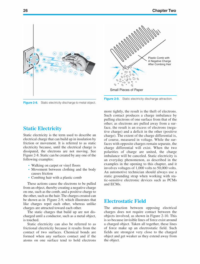
Static ElectricityStatic electricity is the term used to describe anelectrical charge that can build up in insulation byfriction or movement. It is referred to as staticelectricity because, until the electrical charge isdissipated, the electrons are not moving. SeeFigure 2-8. Static can be created by any one of thefollowing examples:
• Walking on carpet or vinyl floors• Movement between clothing and the body
causes friction• Combing hair with a plastic comb
These actions cause the electrons to be pulledfrom an object, thereby creating a negative chargeon one, such as the comb, and a positive charge tothe other, such as the hair. The charges created canbe shown as in Figure 2-9, which illustrates thatlike charges repel each other, whereas unlikecharges are attracted toward each other.
The static charges that build up are not dis-charged until a conductor, such as a metal object,is touched.
Static electricity can also be referred to asfrictional electricity because it results from thecontact of two surfaces. Chemical bonds areformed when any surfaces contact and if theatoms on one surface tend to hold electrons
more tightly, the result is the theft of electrons.Such contact produces a charge imbalance bypulling electrons of one surface from that of theother; as electrons are pulled away from a sur-face, the result is an excess of electrons (nega-tive charge) and a deficit in the other (positivecharge). The extent of the charge differential is,of course, measured in voltage. While the sur-faces with opposite charges remain separate, thecharge differential will exist. When the twopolarities of charge are united, the chargeimbalance will be canceled. Static electricity isan everyday phenomenon, as described in theexamples in the opening to this chapter, and itinvolves voltages of 1,000 volts to 50,000 volts.An automotive technician should always use astatic grounding strap when working with sta-tic-sensitive electronic devices such as PCMsand ECMs.
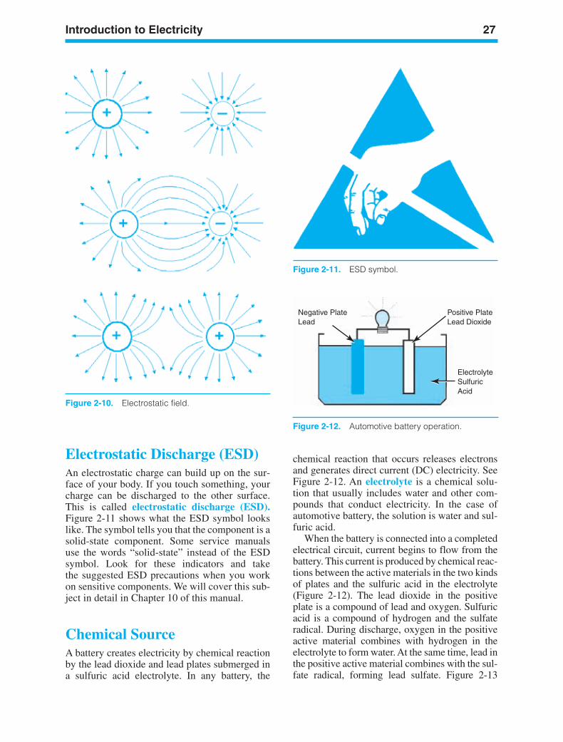
Electrostatic FieldThe attraction between opposing electricalcharges does not require contact between theobjects involved, as shown in Figure 2-10. Thisis so because invisible lines of force exist arounda charged object. Taken all together, these linesof force make up an electrostatic field. Suchfields are strongest very close to the chargedobject and get weaker as they extend away fromthe object.
ker88839_ch02.qxd 1/9/06 11:21 AM Page 26
Introduction to Electricity 27
Figure 2-10. Electrostatic field.
Figure 2-11. ESD symbol.
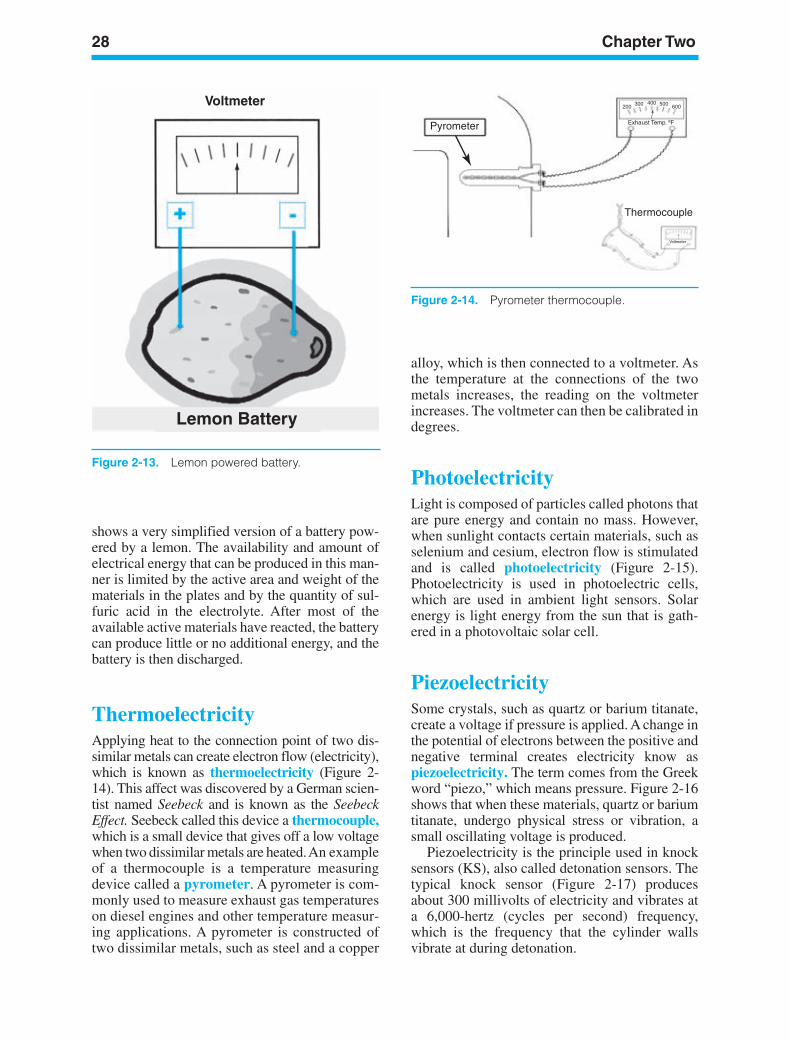
Electrostatic Discharge (ESD)An electrostatic charge can build up on the sur-face of your body. If you touch something, yourcharge can be discharged to the other surface.This is called electrostatic discharge (ESD).Figure 2-11 shows what the ESD symbol lookslike. The symbol tells you that the component is asolid-state component. Some service manualsuse the words “solid-state” instead of the ESDsymbol. Look for these indicators and takethe suggested ESD precautions when you workon sensitive components. We will cover this sub-ject in detail in Chapter 10 of this manual.
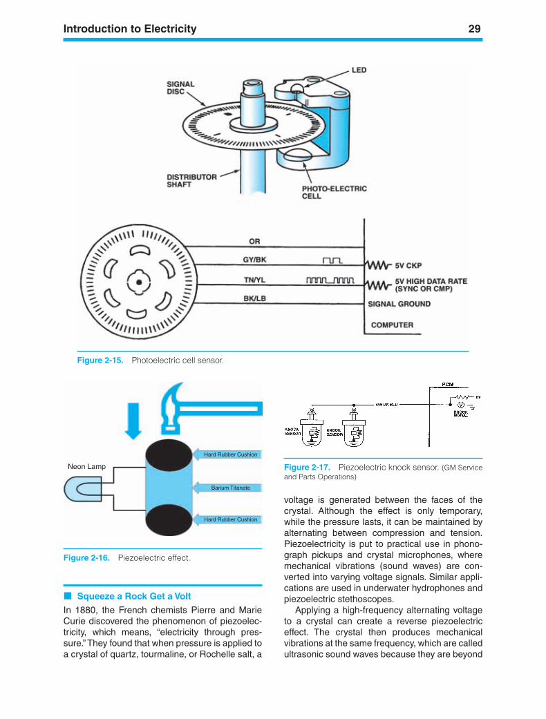
Chemical SourceA battery creates electricity by chemical reactionby the lead dioxide and lead plates submerged ina sulfuric acid electrolyte. In any battery, the
chemical reaction that occurs releases electronsand generates direct current (DC) electricity. See Figure 2-12. An electrolyte is a chemical solu-tion that usually includes water and other com-pounds that conduct electricity. In the case ofautomotive battery, the solution is water and sul-furic acid.
When the battery is connected into a completedelectrical circuit, current begins to flow from thebattery. This current is produced by chemical reac-tions between the active materials in the two kindsof plates and the sulfuric acid in the electrolyte(Figure 2-12). The lead dioxide in the positiveplate is a compound of lead and oxygen. Sulfuricacid is a compound of hydrogen and the sulfateradical. During discharge, oxygen in the positiveactive material combines with hydrogen in theelectrolyte to form water. At the same time, lead inthe positive active material combines with the sul-fate radical, forming lead sulfate. Figure 2-13
Negative PlateLead
Positive PlateLead Dioxide
ElectrolyteSulfuricAcid
Figure 2-12. Automotive battery operation.
ker88839_ch02.qxd 1/9/06 11:21 AM Page 27
28 Chapter Two
Voltmeter
Lemon Battery
Figure 2-13. Lemon powered battery.
Pyrometer
200 300 400 500 600
Voltmeter
Thermocouple
Exhaust Temp. ºF
Figure 2-14. Pyrometer thermocouple.
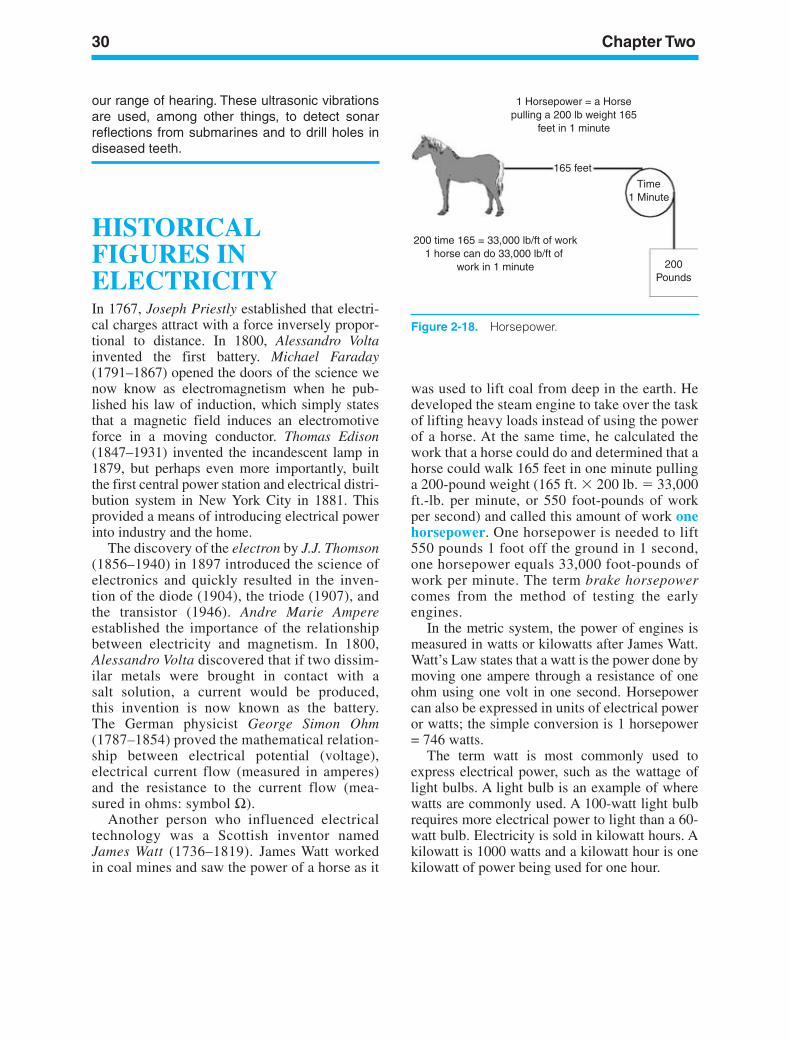
shows a very simplified version of a battery pow-ered by a lemon. The availability and amount ofelectrical energy that can be produced in this man-ner is limited by the active area and weight of thematerials in the plates and by the quantity of sul-furic acid in the electrolyte. After most of theavailable active materials have reacted, the batterycan produce little or no additional energy, and thebattery is then discharged.
ThermoelectricityApplying heat to the connection point of two dis-similar metals can create electron flow (electricity),which is known as thermoelectricity (Figure 2-14). This affect was discovered by a German scien-tist named Seebeck and is known as the SeebeckEffect. Seebeck called this device a thermocouple,which is a small device that gives off a low voltagewhen two dissimilar metals are heated. An exampleof a thermocouple is a temperature measuringdevice called a pyrometer. A pyrometer is com-monly used to measure exhaust gas temperatureson diesel engines and other temperature measur-ing applications. A pyrometer is constructed oftwo dissimilar metals, such as steel and a copper
alloy, which is then connected to a voltmeter. Asthe temperature at the connections of the twometals increases, the reading on the voltmeterincreases. The voltmeter can then be calibrated indegrees.
PhotoelectricityLight is composed of particles called photons thatare pure energy and contain no mass. However,when sunlight contacts certain materials, such asselenium and cesium, electron flow is stimulatedand is called photoelectricity (Figure 2-15).Photoelectricity is used in photoelectric cells,which are used in ambient light sensors. Solarenergy is light energy from the sun that is gath-ered in a photovoltaic solar cell.
PiezoelectricitySome crystals, such as quartz or barium titanate,create a voltage if pressure is applied. A change inthe potential of electrons between the positive andnegative terminal creates electricity know aspiezoelectricity. The term comes from the Greekword “piezo,” which means pressure. Figure 2-16shows that when these materials, quartz or bariumtitanate, undergo physical stress or vibration, asmall oscillating voltage is produced.
Piezoelectricity is the principle used in knocksensors (KS), also called detonation sensors. Thetypical knock sensor (Figure 2-17) producesabout 300 millivolts of electricity and vibrates ata 6,000-hertz (cycles per second) frequency,which is the frequency that the cylinder wallsvibrate at during detonation.
ker88839_ch02.qxd 1/9/06 11:21 AM Page 28
Introduction to Electricity 29
Neon Lamp
Hard Rubber Cushion
Barium Titanate
Hard Rubber Cushion
Figure 2-16. Piezoelectric effect.
Figure 2-15. Photoelectric cell sensor.
Figure 2-17. Piezoelectric knock sensor. (GM Serviceand Parts Operations)
voltage is generated between the faces of thecrystal. Although the effect is only temporary,while the pressure lasts, it can be maintained byalternating between compression and tension.Piezoelectricity is put to practical use in phono-graph pickups and crystal microphones, wheremechanical vibrations (sound waves) are con-verted into varying voltage signals. Similar appli-cations are used in underwater hydrophones andpiezoelectric stethoscopes.
Applying a high-frequency alternating voltageto a crystal can create a reverse piezoelectriceffect. The crystal then produces mechanicalvibrations at the same frequency, which are calledultrasonic sound waves because they are beyond
Squeeze a Rock Get a Volt
In 1880, the French chemists Pierre and MarieCurie discovered the phenomenon of piezoelec-tricity, which means, “electricity through pres-sure.” They found that when pressure is applied toa crystal of quartz, tourmaline, or Rochelle salt, a
ker88839_ch02.qxd 1/9/06 11:22 AM Page 29
30 Chapter Two
1 Horsepower = a Horsepulling a 200 lb weight 165
feet in 1 minute
165 feet
Time1 Minute
200Pounds
200 time 165 = 33,000 lb/ft of work1 horse can do 33,000 lb/ft of
work in 1 minute
Figure 2-18. Horsepower.
our range of hearing. These ultrasonic vibrationsare used, among other things, to detect sonarreflections from submarines and to drill holes indiseased teeth.
HISTORICALFIGURES INELECTRICITYIn 1767, Joseph Priestly established that electri-cal charges attract with a force inversely propor-tional to distance. In 1800, Alessandro Voltainvented the first battery. Michael Faraday(1791–1867) opened the doors of the science wenow know as electromagnetism when he pub-lished his law of induction, which simply statesthat a magnetic field induces an electromotiveforce in a moving conductor. Thomas Edison(1847–1931) invented the incandescent lamp in1879, but perhaps even more importantly, builtthe first central power station and electrical distri-bution system in New York City in 1881. Thisprovided a means of introducing electrical powerinto industry and the home.
The discovery of the electron by J.J. Thomson(1856–1940) in 1897 introduced the science ofelectronics and quickly resulted in the inven-tion of the diode (1904), the triode (1907), andthe transistor (1946). Andre Marie Ampereestablished the importance of the relationshipbetween electricity and magnetism. In 1800,Alessandro Volta discovered that if two dissim-ilar metals were brought in contact with asalt solution, a current would be produced,this invention is now known as the battery.The German physicist George Simon Ohm(1787–1854) proved the mathematical relation-ship between electrical potential (voltage),electrical current flow (measured in amperes)and the resistance to the current flow (mea-sured in ohms: symbol Ω).
Another person who influenced electricaltechnology was a Scottish inventor namedJames Watt (1736–1819). James Watt workedin coal mines and saw the power of a horse as it
was used to lift coal from deep in the earth. Hedeveloped the steam engine to take over the taskof lifting heavy loads instead of using the powerof a horse. At the same time, he calculated thework that a horse could do and determined that ahorse could walk 165 feet in one minute pullinga 200-pound weight (165 ft. 200 lb. 33,000ft.-lb. per minute, or 550 foot-pounds of workper second) and called this amount of work onehorsepower. One horsepower is needed to lift550 pounds 1 foot off the ground in 1 second,one horsepower equals 33,000 foot-pounds ofwork per minute. The term brake horsepowercomes from the method of testing the earlyengines.
In the metric system, the power of engines ismeasured in watts or kilowatts after James Watt.Watt’s Law states that a watt is the power done bymoving one ampere through a resistance of oneohm using one volt in one second. Horsepowercan also be expressed in units of electrical poweror watts; the simple conversion is 1 horsepower= 746 watts.
The term watt is most commonly used toexpress electrical power, such as the wattage oflight bulbs. A light bulb is an example of wherewatts are commonly used. A 100-watt light bulbrequires more electrical power to light than a 60-watt bulb. Electricity is sold in kilowatt hours. Akilowatt is 1000 watts and a kilowatt hour is onekilowatt of power being used for one hour.
ker88839_ch02.qxd 1/9/06 11:22 AM Page 30
Introduction to Electricity 31
SUMMARYThe Greeks discovered the first type of electricityin the form of static electricity when they observedthat amber rubbed with fur would attract light-weight objects such as feathers. Static electricity iselectricity at rest or without any motion. All matteris composed of atoms and electrical charge is acomponent of all atoms, so all matter is electricalin essence. An atom is the smallest part of an ele-ment that retains all of the properties of that ele-ment. All atoms share the same basic structure. Atthe center of the atom is the nucleus, containingprotons, neutrons, and electrons. When an atom isbalanced, the number of protons will match thenumber of electrons and the atom can be describedas being in an electrically neutral state. The phe-nomenon we describe as electricity concerns thebehavior of atoms that have become, for whateverreason, unbalanced or ionized. Electricity may bedefined as the movement of free electrons from oneatom to another.
An electrostatic charge can build up on the sur-face of your body. If you touch something, yourcharge can be discharged to the other surface,which is called electrostatic discharge (ESD). Anautomotive technician should always use a sta-tic grounding strap when working with static-sensitive electronic devices.
When light contacts certain materials, such asselenium and cesium, electron flow is stimulatedand is called photoelectricity. Solar energy is lightenergy (photons) from the sun that is gathered in aphotovoltaic solar cell. A photon is pure energythat contains no mass. Thermoelectricity is elec-tricity produced when two dissimilar metals areheated to generate an electrical voltage. A thermo-couple is a small device made of two dissimilarmetals that gives off a low voltage when heated.Piezoelectricity is electricity produced when mate-rials such as quartz or barium titanate are placedunder pressure. The production of electricity fromchemical energy is demonstrated in the lead-acidbattery. Electromagnetic induction is the produc-tion of electricity when a current is carried througha conductor and a magnetic field is produced.
Andre Marie Ampere established the impor-tance of the relationship between electricity andmagnetism. Alessandro Volta discovered that iftwo dissimilar metals were brought in contactwith a salt solution, a current would be pro-duced; this invention is now known as the bat-tery. George Simon Ohm showed a relationshipbetween resistance, current, and voltage in anelectrical circuit; he developed what is known asOhm’s Law. James Watt developed a methodused to express a unit of electrical power knownas Watt’s Law.
ker88839_ch02.qxd 1/9/06 11:22 AM Page 31
32 Chapter Two
Review Questions1. The general name given every substance in
the physical universe is which of thefollowing:a. Massb. Matterc. Compoundd. Nucleus
2. The smallest part of an element that retainsall of its characteristics is which of thefollowing:a. Atomb. Protonc. Compoundd. Neutron
3. The particles that orbit around the center ofan atom are called which of the following:a. Electronsb. Moleculesc. Nucleusd. Protons
4. An atom that loses or gains one electron iscalled which of the following:a. Balancedb. An elementc. A moleculed. An ion
5. Technician A says the battery provideselectricity by releasing free electrons.Technician B says the battery stores energyin a chemical form. Who is right?a. A onlyb. B onlyc. Both A and Bd. Neither A nor B
6. Static electricity is being discussed.Technician A says that static electricity iselectricity in motion. Technician B says anelectrostatic charge can build up on thesurface of your body. Who is right?a. A onlyb. B onlyc. Both A and Bd. Neither A nor B
7. What people discovered electricity?a. The Italiansb. The Germansc. The Greeksd. The Irish
8. Technician A says batteries produce directcurrent from a chemical reaction.Technician B says that an electrolyte is achemical solution of water andhydrochloric acid that will conductelectricity. Who is right?a. A onlyb. B onlyc. Both A and Bd. Neither A nor B
9. Two technicians are discussingthermoelectricity. Technician A saysapplying heat to the connection point of twodissimilar metals can create electron flow(electricity). Technician B says athermocouple is a small device made of twodissimilar metals that gives off a low voltagewhen heated. Who is right?a. A onlyb. B onlyc. Both A and Bd. Neither A nor B
10. Technician A says when sunlight contactscertain materials, electron flow is stimulated.Technician B says solar energy is lightenergy from the moon that is gathered in aphotovoltaic solar cell. Who is right?a. A onlyb. B onlyc. Both A and Bd. Neither A nor B
11. Two technicians are discussing howpiezoelectricity works. Technician A says itis electricity produced when barium titanateis placed under pressure. Technician Bsays when no change in the potential ofelectrons between positive and negativeterminal occurs, the barium titanate createselectricity. Who is right?a. A onlyb. B onlyc. Both A and Bd. Neither A nor B
12. James Watt’s term horsepower is beingdiscussed. Technician A says onehorsepower equals 33,000 foot-pounds ofwork per hour. Technician B says onehorsepower would be produced when ahorse walked 165 feet in one minute pulling
ker88839_ch02.qxd 1/9/06 11:22 AM Page 32

Introduction to Electricity 33
a 500-pound weight or 165 ft. × 500 lb. =33,000 ft-lb. Who is right?a. A onlyb. B onlyc. Both A and Bd. Neither A nor B
13. Technician A says Andre Marie Ampereestablished the importance of therelationship between electricity and
magnetism. Technician B says AlessandroVolta discovered that if two dissimilar metalswere brought in contact with a watersolution, a current would be produced. Whois right?a. A onlyb. B onlyc. Both A and Bd. Neither A nor B
ker88839_ch02.qxd 1/9/06 11:22 AM Page 33

ker88839_ch02.qxd 1/9/06 11:22 AM Page 34
LEARNINGOBJECTIVESUpon completion and review of this chapter, youshould be able to:
• Explain the terms conductor, insulator, andsemiconductor, and differentiate betweentheir functions.
• Identify and explain the basic electrical con-cepts of resistance, voltage, current, voltagedrop, and conductance.
• Define the two theories of current flow(conventional and electron) and explain thedifference between DC and AC current.
• Explain the cause-and-effect relationship inOhm’s law between voltage, current, resis-tance, and voltage drop.
• Define electrical power and its Ohm’s lawrelationship.
• Define capacitance and describe the func-tion of a capacitor in an automotive electri-cal circuit.
KEY TERMSAmpereCapacitanceCapacitorCircuitConductorsConventional TheoryCurrentGroundInsulatorsOhmOhm’s LawResistanceResistorsSemiconductorsVoltageVoltage DropWatt
INTRODUCTIONThis chapter reviews all of the basic electricalprinciples required to understand electronics andthe automotive electrical/electronic systems in thelater chapters. An automotive technician musthave a thorough grasp of the basis of electricity
35
3ElectricalFundamentals
ker88839_ch03.qxd 1/9/06 11:22 AM Page 35
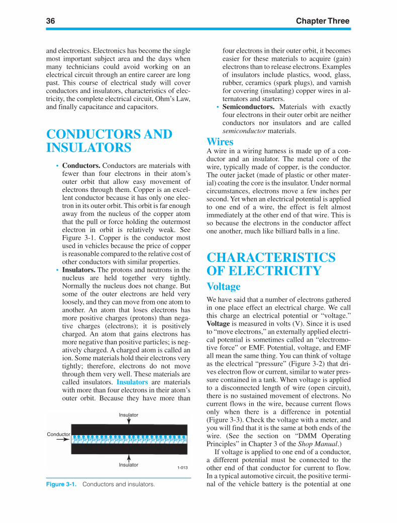
36 Chapter Three
and electronics. Electronics has become the singlemost important subject area and the days whenmany technicians could avoid working on anelectrical circuit through an entire career are longpast. This course of electrical study will coverconductors and insulators, characteristics of elec-tricity, the complete electrical circuit, Ohm’s Law,and finally capacitance and capacitors.
CONDUCTORS ANDINSULATORS
• Conductors. Conductors are materials withfewer than four electrons in their atom’souter orbit that allow easy movement ofelectrons through them. Copper is an excel-lent conductor because it has only one elec-tron in its outer orbit. This orbit is far enoughaway from the nucleus of the copper atomthat the pull or force holding the outermostelectron in orbit is relatively weak. SeeFigure 3-1. Copper is the conductor mostused in vehicles because the price of copperis reasonable compared to the relative cost ofother conductors with similar properties.
• Insulators. The protons and neutrons in thenucleus are held together very tightly.Normally the nucleus does not change. Butsome of the outer electrons are held veryloosely, and they can move from one atom toanother. An atom that loses electrons hasmore positive charges (protons) than nega-tive charges (electrons); it is positivelycharged. An atom that gains electrons hasmore negative than positive particles; is neg-atively charged. A charged atom is called anion. Some materials hold their electrons verytightly; therefore, electrons do not movethrough them very well. These materials arecalled insulators. Insulators are materialswith more than four electrons in their atom’souter orbit. Because they have more than
four electrons in their outer orbit, it becomeseasier for these materials to acquire (gain)electrons than to release electrons. Examplesof insulators include plastics, wood, glass,rubber, ceramics (spark plugs), and varnishfor covering (insulating) copper wires in al-ternators and starters.
• Semiconductors. Materials with exactlyfour electrons in their outer orbit are neitherconductors nor insulators and are calledsemiconductor materials.
WiresA wire in a wiring harness is made up of a con-ductor and an insulator. The metal core of thewire, typically made of copper, is the conductor.The outer jacket (made of plastic or other mater-ial) coating the core is the insulator. Under normalcircumstances, electrons move a few inches persecond. Yet when an electrical potential is appliedto one end of a wire, the effect is felt almostimmediately at the other end of that wire. This isso because the electrons in the conductor affectone another, much like billiard balls in a line.
CHARACTERISTICSOF ELECTRICITYVoltageWe have said that a number of electrons gatheredin one place effect an electrical charge. We callthis charge an electrical potential or “voltage.”Voltage is measured in volts (V). Since it is usedto “move electrons,” an externally applied electri-cal potential is sometimes called an “electromo-tive force” or EMF. Potential, voltage, and EMFall mean the same thing. You can think of voltageas the electrical “pressure” (Figure 3-2) that dri-ves electron flow or current, similar to water pres-sure contained in a tank. When voltage is appliedto a disconnected length of wire (open circuit),there is no sustained movement of electrons. Nocurrent flows in the wire, because current flowsonly when there is a difference in potential(Figure 3-3). Check the voltage with a meter, andyou will find that it is the same at both ends of thewire. (See the section on “DMM OperatingPrinciples” in Chapter 3 of the Shop Manual.)
If voltage is applied to one end of a conductor,a different potential must be connected to theother end of that conductor for current to flow.In a typical automotive circuit, the positive termi-nal of the vehicle battery is the potential at one
Conductor
Insulator
Insulator1-013
Figure 3-1. Conductors and insulators.
ker88839_ch03.qxd 1/9/06 11:22 AM Page 36
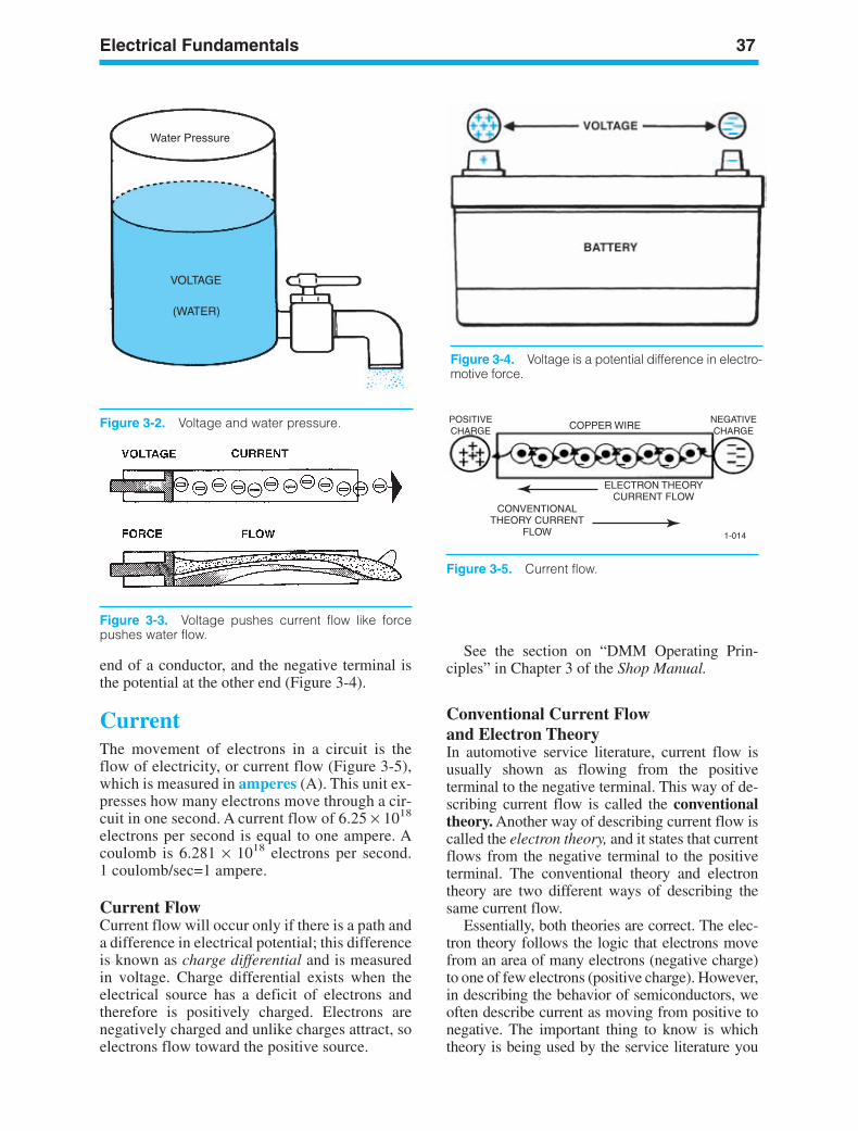
Electrical Fundamentals 37
Water Pressure
VOLTAGE
(WATER)
Figure 3-2. Voltage and water pressure.
Figure 3-3. Voltage pushes current flow like forcepushes water flow.
Figure 3-4. Voltage is a potential difference in electro-motive force.
POSITIVECHARGE
NEGATIVECHARGECOPPER WIRE
ELECTRON THEORYCURRENT FLOW
CONVENTIONALTHEORY CURRENT
FLOW 1-014
Figure 3-5. Current flow.
See the section on “DMM Operating Prin-ciples” in Chapter 3 of the Shop Manual.
Conventional Current Flowand Electron TheoryIn automotive service literature, current flow isusually shown as flowing from the positiveterminal to the negative terminal. This way of de-scribing current flow is called the conventionaltheory. Another way of describing current flow iscalled the electron theory, and it states that currentflows from the negative terminal to the positiveterminal. The conventional theory and electrontheory are two different ways of describing thesame current flow.
Essentially, both theories are correct. The elec-tron theory follows the logic that electrons movefrom an area of many electrons (negative charge)to one of few electrons (positive charge). However,in describing the behavior of semiconductors, weoften describe current as moving from positive tonegative. The important thing to know is whichtheory is being used by the service literature you
end of a conductor, and the negative terminal isthe potential at the other end (Figure 3-4).
CurrentThe movement of electrons in a circuit is theflow of electricity, or current flow (Figure 3-5),which is measured in amperes (A). This unit ex-presses how many electrons move through a cir-cuit in one second. A current flow of 6.25 × 10¹⁸
electrons per second is equal to one ampere. Acoulomb is 6.281 × 10¹⁸ electrons per second.1 coulomb/sec=1 ampere.
Current FlowCurrent flow will occur only if there is a path anda difference in electrical potential; this differenceis known as charge differential and is measuredin voltage. Charge differential exists when theelectrical source has a deficit of electrons andtherefore is positively charged. Electrons arenegatively charged and unlike charges attract, soelectrons flow toward the positive source.
ker88839_ch03.qxd 1/9/06 11:22 AM Page 37
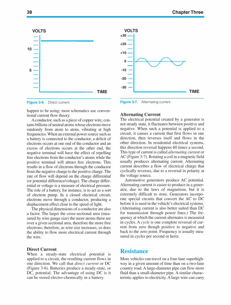
38 Chapter Three
VOLTS
TIME
10
5
Figure 3-6. Direct current.
VOLTS
TIME
+30
+20
+10
0
-10
-20
-30
Figure 3-7. Alternating current.
happen to be using; most schematics use conven-tional current flow theory.
A conductor, such as a piece of copper wire, con-tains billions of neutral atoms whose electrons moverandomly from atom to atom, vibrating at highfrequencies. When an external power source such asa battery is connected to the conductor, a deficit ofelectrons occurs at one end of the conductor and anexcess of electrons occurs at the other end, thenegative terminal will have the effect of repellingfree electrons from the conductor’s atoms while thepositive terminal will attract free electrons. Thisresults in a flow of electrons through the conductorfrom the negative charge to the positive charge. Therate of flow will depend on the charge differential(or potential difference/voltage). The charge differ-ential or voltage is a measure of electrical pressure.The role of a battery, for instance, is to act as a sortof electron pump. In a closed electrical circuit,electrons move through a conductor, producing adisplacement effect close to the speed of light.
The physical dimensions of a conductor are alsoa factor. The larger the cross-sectional area (mea-sured by wire gauge size) the more atoms there areover a given sectional area, therefore the more freeelectrons; therefore, as wire size increases, so doesthe ability to flow more electrical current throughthe wire.
Direct CurrentWhen a steady-state electrical potential isapplied to a circuit, the resulting current flows inone direction. We call that direct current or DC(Figure 3-6). Batteries produce a steady-state, orDC, potential. The advantage of using DC is itcan be stored electro-chemically in a battery.
Alternating CurrentThe electrical potential created by a generator isnot steady state, it fluctuates between positive andnegative. When such a potential is applied to acircuit, it causes a current that first flows in onedirection, then reverses itself and flows in theother direction. In residential electrical systems,this direction reversal happens 60 times a second.This type of current is called alternating current orAC (Figure 3-7). Rotating a coil in a magnetic fieldusually produces alternating current. Alternatingcurrent describes a flow of electrical charge thatcyclically reverses, due to a reversal in polarity atthe voltage source.
Automotive generators produce AC potential.Alternating current is easier to produce in a gener-ator, due to the laws of magnetism, but it isextremely difficult to store. Generators incorpo-rate special circuits that convert the AC to DCbefore it is used in the vehicle’s electrical systems.(Alternating current is also better suited than DCfor transmission through power lines.) The fre-quency at which the current alternates is measuredin cycles. A cycle is one complete reversal of cur-rent from zero though positive to negative andback to the zero point. Frequency is usually mea-sured in cycles per second or hertz.
ResistanceMore vehicles can travel on a four-lane superhigh-way in a given amount of time than on a two-lanecountry road. A large-diameter pipe can flow morefluid than a small-diameter pipe. A similar charac-teristic applies to electricity. A large wire can carry
ker88839_ch03.qxd 1/9/06 11:22 AM Page 38
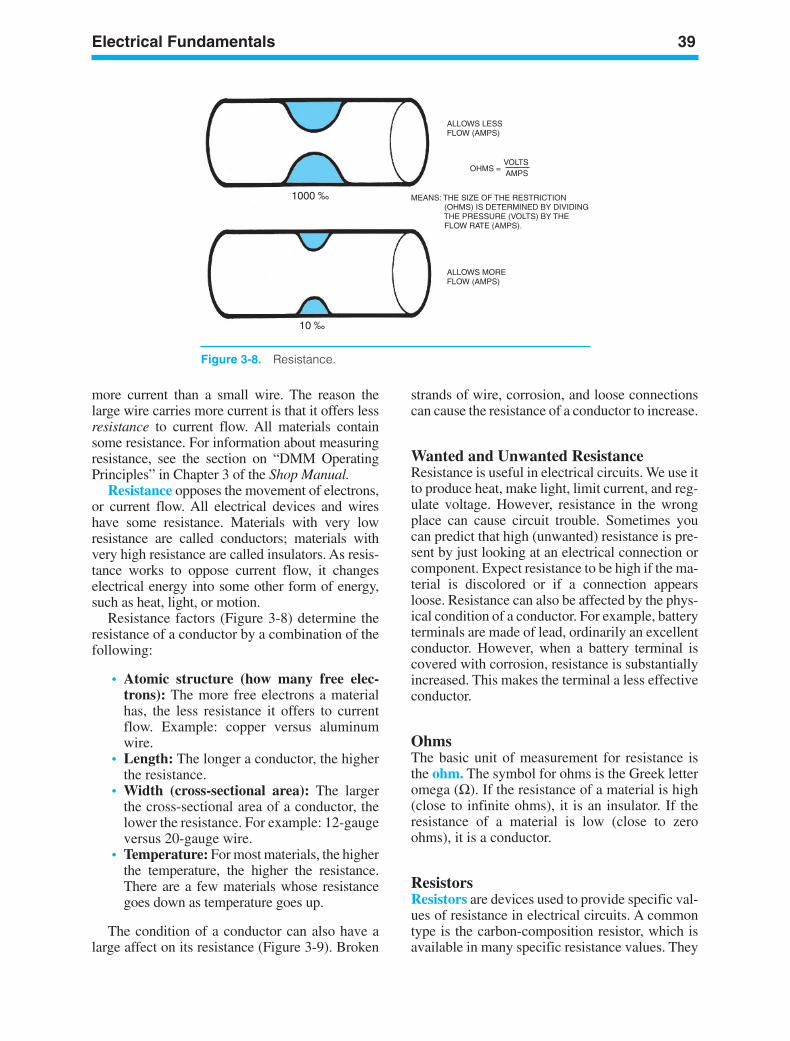
Electrical Fundamentals 39
1000 ‰
10 ‰
ALLOWS LESSFLOW (AMPS)
OHMS = VOLTSAMPS
MEANS: THE SIZE OF THE RESTRICTION (OHMS) IS DETERMINED BY DIVIDING THE PRESSURE (VOLTS) BY THE FLOW RATE (AMPS).
ALLOWS MOREFLOW (AMPS)
Figure 3-8. Resistance.
more current than a small wire. The reason thelarge wire carries more current is that it offers lessresistance to current flow. All materials containsome resistance. For information about measuringresistance, see the section on “DMM OperatingPrinciples” in Chapter 3 of the Shop Manual.
Resistance opposes the movement of electrons,or current flow. All electrical devices and wireshave some resistance. Materials with very lowresistance are called conductors; materials withvery high resistance are called insulators. As resis-tance works to oppose current flow, it changeselectrical energy into some other form of energy,such as heat, light, or motion.
Resistance factors (Figure 3-8) determine theresistance of a conductor by a combination of thefollowing:
• Atomic structure (how many free elec-trons): The more free electrons a materialhas, the less resistance it offers to currentflow. Example: copper versus aluminumwire.
• Length: The longer a conductor, the higherthe resistance.
• Width (cross-sectional area): The largerthe cross-sectional area of a conductor, thelower the resistance. For example: 12-gaugeversus 20-gauge wire.
• Temperature: For most materials, the higherthe temperature, the higher the resistance.There are a few materials whose resistancegoes down as temperature goes up.
The condition of a conductor can also have alarge affect on its resistance (Figure 3-9). Broken
strands of wire, corrosion, and loose connectionscan cause the resistance of a conductor to increase.
Wanted and Unwanted ResistanceResistance is useful in electrical circuits. We use itto produce heat, make light, limit current, and reg-ulate voltage. However, resistance in the wrongplace can cause circuit trouble. Sometimes youcan predict that high (unwanted) resistance is pre-sent by just looking at an electrical connection orcomponent. Expect resistance to be high if the ma-terial is discolored or if a connection appearsloose. Resistance can also be affected by the phys-ical condition of a conductor. For example, batteryterminals are made of lead, ordinarily an excellentconductor. However, when a battery terminal iscovered with corrosion, resistance is substantiallyincreased. This makes the terminal a less effectiveconductor.
OhmsThe basic unit of measurement for resistance isthe ohm. The symbol for ohms is the Greek letteromega (Ω). If the resistance of a material is high(close to infinite ohms), it is an insulator. If theresistance of a material is low (close to zeroohms), it is a conductor.
ResistorsResistors are devices used to provide specific val-ues of resistance in electrical circuits. A commontype is the carbon-composition resistor, which isavailable in many specific resistance values. They
ker88839_ch03.qxd 1/9/06 11:22 AM Page 39
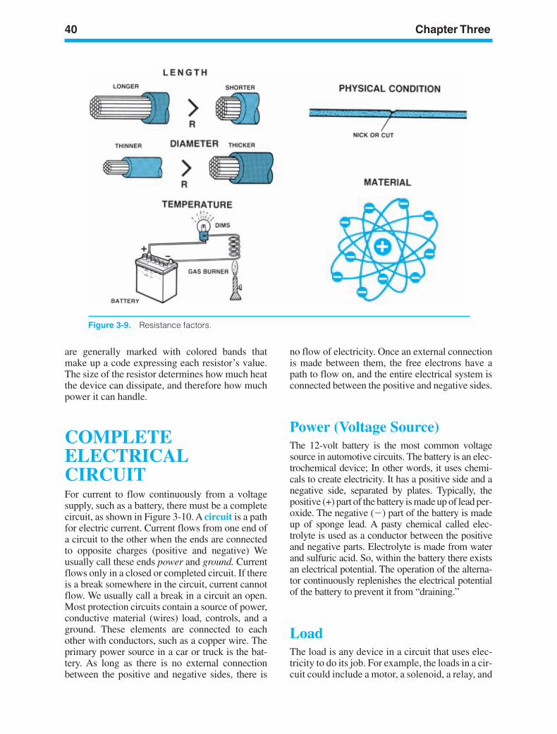
40 Chapter Three
Figure 3-9. Resistance factors.
are generally marked with colored bands thatmake up a code expressing each resistor’s value.The size of the resistor determines how much heatthe device can dissipate, and therefore how muchpower it can handle.
COMPLETEELECTRICALCIRCUITFor current to flow continuously from a voltagesupply, such as a battery, there must be a completecircuit, as shown in Figure 3-10. A circuit is a pathfor electric current. Current flows from one end ofa circuit to the other when the ends are connectedto opposite charges (positive and negative) Weusually call these ends power and ground. Currentflows only in a closed or completed circuit. If thereis a break somewhere in the circuit, current cannotflow. We usually call a break in a circuit an open.Most protection circuits contain a source of power,conductive material (wires) load, controls, and aground. These elements are connected to eachother with conductors, such as a copper wire. Theprimary power source in a car or truck is the bat-tery. As long as there is no external connectionbetween the positive and negative sides, there is
no flow of electricity. Once an external connectionis made between them, the free electrons have apath to flow on, and the entire electrical system isconnected between the positive and negative sides.
Power (Voltage Source)The 12-volt battery is the most common voltagesource in automotive circuits. The battery is an elec-trochemical device; In other words, it uses chemi-cals to create electricity. It has a positive side and anegative side, separated by plates. Typically, thepositive (+) part of the battery is made up of lead per-oxide. The negative () part of the battery is madeup of sponge lead. A pasty chemical called elec-trolyte is used as a conductor between the positiveand negative parts. Electrolyte is made from waterand sulfuric acid. So, within the battery there existsan electrical potential. The operation of the alterna-tor continuously replenishes the electrical potentialof the battery to prevent it from “draining.”
LoadThe load is any device in a circuit that uses elec-tricity to do its job. For example, the loads in a cir-cuit could include a motor, a solenoid, a relay, and
ker88839_ch03.qxd 1/9/06 11:22 AM Page 40
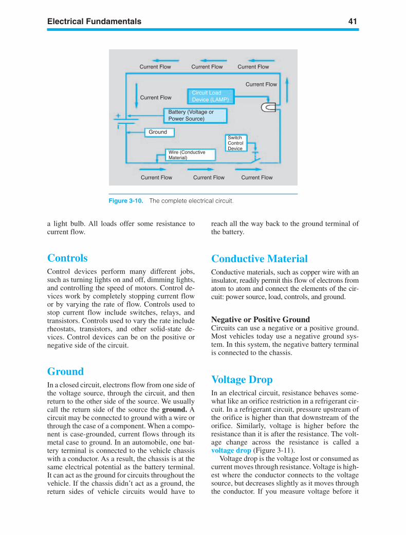
Electrical Fundamentals 41
Figure 3-10. The complete electrical circuit.
a light bulb. All loads offer some resistance tocurrent flow.
ControlsControl devices perform many different jobs,such as turning lights on and off, dimming lights,and controlling the speed of motors. Control de-vices work by completely stopping current flowor by varying the rate of flow. Controls used tostop current flow include switches, relays, andtransistors. Controls used to vary the rate includerheostats, transistors, and other solid-state de-vices. Control devices can be on the positive ornegative side of the circuit.
GroundIn a closed circuit, electrons flow from one side ofthe voltage source, through the circuit, and thenreturn to the other side of the source. We usuallycall the return side of the source the ground. Acircuit may be connected to ground with a wire orthrough the case of a component. When a compo-nent is case-grounded, current flows through itsmetal case to ground. In an automobile, one bat-tery terminal is connected to the vehicle chassiswith a conductor. As a result, the chassis is at thesame electrical potential as the battery terminal.It can act as the ground for circuits throughout thevehicle. If the chassis didn’t act as a ground, thereturn sides of vehicle circuits would have to
reach all the way back to the ground terminal ofthe battery.
Conductive MaterialConductive materials, such as copper wire with aninsulator, readily permit this flow of electrons fromatom to atom and connect the elements of the cir-cuit: power source, load, controls, and ground.
Negative or Positive GroundCircuits can use a negative or a positive ground.Most vehicles today use a negative ground sys-tem. In this system, the negative battery terminalis connected to the chassis.
Voltage DropIn an electrical circuit, resistance behaves some-what like an orifice restriction in a refrigerant cir-cuit. In a refrigerant circuit, pressure upstream ofthe orifice is higher than that downstream of theorifice. Similarly, voltage is higher before theresistance than it is after the resistance. The volt-age change across the resistance is called avoltage drop (Figure 3-11).
Voltage drop is the voltage lost or consumed ascurrent moves through resistance. Voltage is high-est where the conductor connects to the voltagesource, but decreases slightly as it moves throughthe conductor. If you measure voltage before it
ker88839_ch03.qxd 1/9/06 11:22 AM Page 41
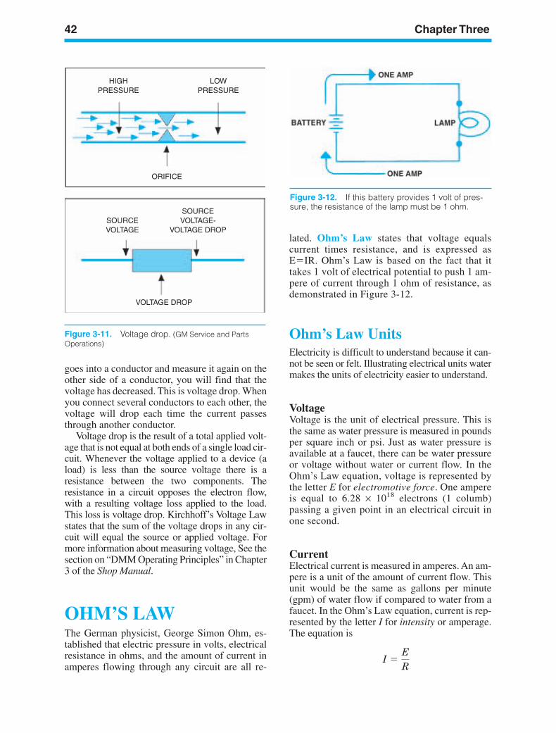
42 Chapter Three
HIGHPRESSURE
LOWPRESSURE
ORIFICE
SOURCEVOLTAGE
SOURCEVOLTAGE-
VOLTAGE DROP
VOLTAGE DROP
Figure 3-11. Voltage drop. (GM Service and PartsOperations)
Figure 3-12. If this battery provides 1 volt of pres-sure, the resistance of the lamp must be 1 ohm.
goes into a conductor and measure it again on theother side of a conductor, you will find that thevoltage has decreased. This is voltage drop. Whenyou connect several conductors to each other, thevoltage will drop each time the current passesthrough another conductor.
Voltage drop is the result of a total applied volt-age that is not equal at both ends of a single load cir-cuit. Whenever the voltage applied to a device (aload) is less than the source voltage there is aresistance between the two components. Theresistance in a circuit opposes the electron flow,with a resulting voltage loss applied to the load.This loss is voltage drop. Kirchhoff’s Voltage Lawstates that the sum of the voltage drops in any cir-cuit will equal the source or applied voltage. Formore information about measuring voltage, See thesection on “DMM Operating Principles” in Chapter3 of the Shop Manual.
OHM’S LAWThe German physicist, George Simon Ohm, es-tablished that electric pressure in volts, electricalresistance in ohms, and the amount of current inamperes flowing through any circuit are all re-
lated. Ohm’s Law states that voltage equalscurrent times resistance, and is expressed asEIR. Ohm’s Law is based on the fact that ittakes 1 volt of electrical potential to push 1 am-pere of current through 1 ohm of resistance, asdemonstrated in Figure 3-12.
Ohm’s Law UnitsElectricity is difficult to understand because it can-not be seen or felt. Illustrating electrical units watermakes the units of electricity easier to understand.
VoltageVoltage is the unit of electrical pressure. This isthe same as water pressure is measured in poundsper square inch or psi. Just as water pressure isavailable at a faucet, there can be water pressureor voltage without water or current flow. In theOhm’s Law equation, voltage is represented bythe letter E for electromotive force. One ampereis equal to 6.28 × 10¹⁸ electrons (1 columb)passing a given point in an electrical circuit inone second.
CurrentElectrical current is measured in amperes. An am-pere is a unit of the amount of current flow. Thisunit would be the same as gallons per minute(gpm) of water flow if compared to water from afaucet. In the Ohm’s Law equation, current is rep-resented by the letter I for intensity or amperage.The equation is
I E
R
ker88839_ch03.qxd 1/9/06 11:22 AM Page 42
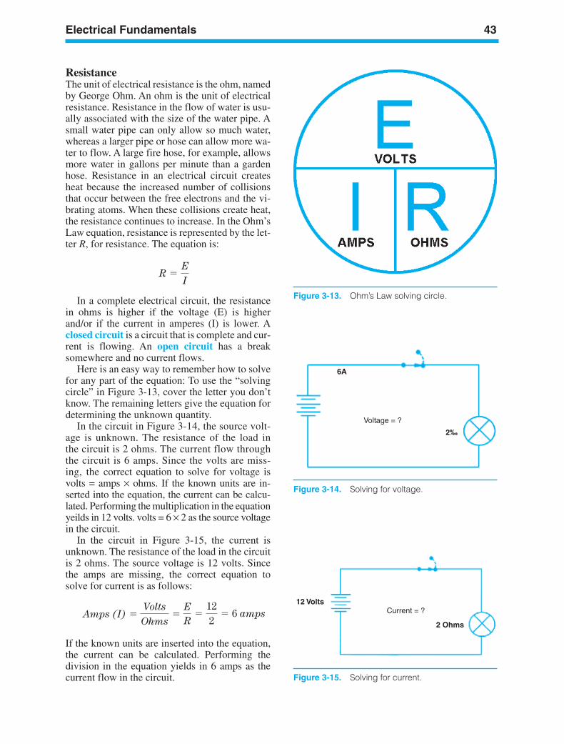
Electrical Fundamentals 43
Figure 3-13. Ohm’s Law solving circle.
6A
Voltage = ?
2‰
Figure 3-14. Solving for voltage.
ResistanceThe unit of electrical resistance is the ohm, namedby George Ohm. An ohm is the unit of electricalresistance. Resistance in the flow of water is usu-ally associated with the size of the water pipe. Asmall water pipe can only allow so much water,whereas a larger pipe or hose can allow more wa-ter to flow. A large fire hose, for example, allowsmore water in gallons per minute than a gardenhose. Resistance in an electrical circuit createsheat because the increased number of collisionsthat occur between the free electrons and the vi-brating atoms. When these collisions create heat,the resistance continues to increase. In the Ohm’sLaw equation, resistance is represented by the let-ter R, for resistance. The equation is:
In a complete electrical circuit, the resistancein ohms is higher if the voltage (E) is higherand/or if the current in amperes (I) is lower. Aclosed circuit is a circuit that is complete and cur-rent is flowing. An open circuit has a breaksomewhere and no current flows.
Here is an easy way to remember how to solvefor any part of the equation: To use the “solvingcircle” in Figure 3-13, cover the letter you don’tknow. The remaining letters give the equation fordetermining the unknown quantity.
In the circuit in Figure 3-14, the source volt-age is unknown. The resistance of the load inthe circuit is 2 ohms. The current flow throughthe circuit is 6 amps. Since the volts are miss-ing, the correct equation to solve for voltage isvolts = amps × ohms. If the known units are in-serted into the equation, the current can be calcu-lated. Performing the multiplication in the equationyeilds in 12 volts. volts = 6 × 2 as the source voltagein the circuit.
In the circuit in Figure 3-15, the current isunknown. The resistance of the load in the circuitis 2 ohms. The source voltage is 12 volts. Sincethe amps are missing, the correct equation tosolve for current is as follows:
If the known units are inserted into the equation,the current can be calculated. Performing thedivision in the equation yields in 6 amps as thecurrent flow in the circuit.
Amps (I) Volts
Ohms
E
R
122
6 amps
R E
I
12 VoltsCurrent = ?
2 Ohms
Figure 3-15. Solving for current.
ker88839_ch03.qxd 1/9/06 11:22 AM Page 43
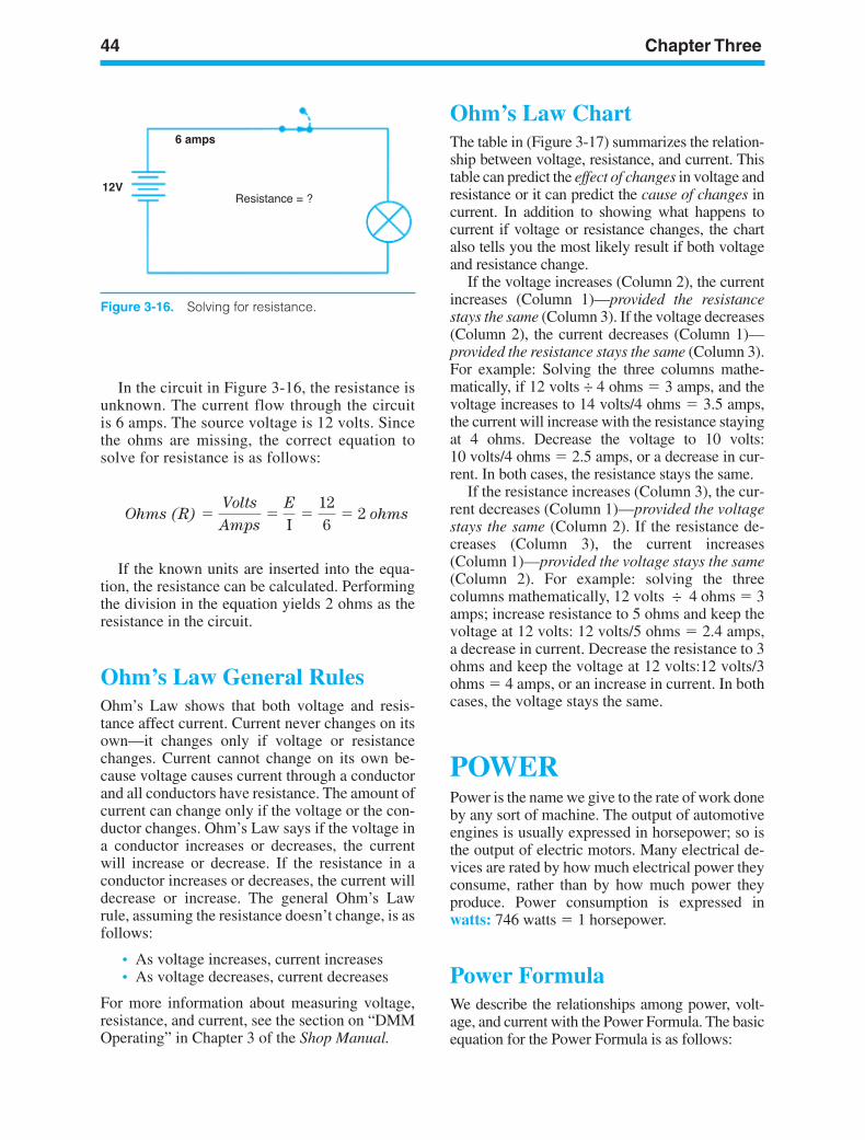
44 Chapter Three
Figure 3-16. Solving for resistance.
In the circuit in Figure 3-16, the resistance isunknown. The current flow through the circuitis 6 amps. The source voltage is 12 volts. Sincethe ohms are missing, the correct equation tosolve for resistance is as follows:
If the known units are inserted into the equa-tion, the resistance can be calculated. Performingthe division in the equation yields 2 ohms as theresistance in the circuit.
Ohm’s Law General RulesOhm’s Law shows that both voltage and resis-tance affect current. Current never changes on itsown—it changes only if voltage or resistancechanges. Current cannot change on its own be-cause voltage causes current through a conductorand all conductors have resistance. The amount ofcurrent can change only if the voltage or the con-ductor changes. Ohm’s Law says if the voltage ina conductor increases or decreases, the currentwill increase or decrease. If the resistance in aconductor increases or decreases, the current willdecrease or increase. The general Ohm’s Lawrule, assuming the resistance doesn’t change, is asfollows:
• As voltage increases, current increases• As voltage decreases, current decreases
For more information about measuring voltage,resistance, and current, see the section on “DMMOperating” in Chapter 3 of the Shop Manual.
Ohms (R) Volts
Amps
E
I
126
2 ohms
Ohm’s Law ChartThe table in (Figure 3-17) summarizes the relation-ship between voltage, resistance, and current. Thistable can predict the effect of changes in voltage andresistance or it can predict the cause of changes incurrent. In addition to showing what happens tocurrent if voltage or resistance changes, the chartalso tells you the most likely result if both voltageand resistance change.
If the voltage increases (Column 2), the currentincreases (Column 1)—provided the resistancestays the same (Column 3). If the voltage decreases(Column 2), the current decreases (Column 1)—provided the resistance stays the same (Column 3).For example: Solving the three columns mathe-matically, if 12 volts ÷ 4 ohms 3 amps, and thevoltage increases to 14 volts/4 ohms 3.5 amps,the current will increase with the resistance stayingat 4 ohms. Decrease the voltage to 10 volts:10 volts/4 ohms 2.5 amps, or a decrease in cur-rent. In both cases, the resistance stays the same.
If the resistance increases (Column 3), the cur-rent decreases (Column 1)—provided the voltagestays the same (Column 2). If the resistance de-creases (Column 3), the current increases(Column 1)—provided the voltage stays the same(Column 2). For example: solving the threecolumns mathematically, 12 volts ÷ 4 ohms 3amps; increase resistance to 5 ohms and keep thevoltage at 12 volts: 12 volts/5 ohms 2.4 amps,a decrease in current. Decrease the resistance to 3ohms and keep the voltage at 12 volts:12 volts/3ohms 4 amps, or an increase in current. In bothcases, the voltage stays the same.
POWERPower is the name we give to the rate of work doneby any sort of machine. The output of automotiveengines is usually expressed in horsepower; so isthe output of electric motors. Many electrical de-vices are rated by how much electrical power theyconsume, rather than by how much power theyproduce. Power consumption is expressed inwatts: 746 watts 1 horsepower.
Power FormulaWe describe the relationships among power, volt-age, and current with the Power Formula. The basicequation for the Power Formula is as follows:
ker88839_ch03.qxd 1/9/06 11:22 AM Page 44
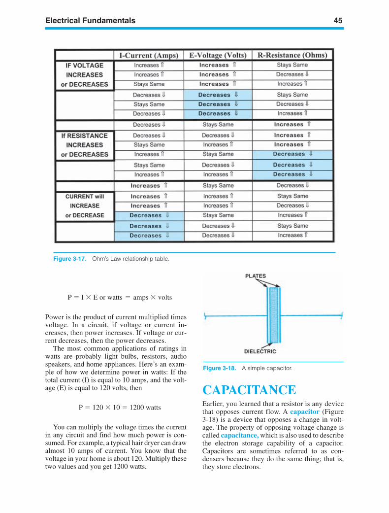
Electrical Fundamentals 45
Figure 3-17. Ohm’s Law relationship table.
Power is the product of current multiplied timesvoltage. In a circuit, if voltage or current in-creases, then power increases. If voltage or cur-rent decreases, then the power decreases.
The most common applications of ratings inwatts are probably light bulbs, resistors, audiospeakers, and home appliances. Here’s an exam-ple of how we determine power in watts: If thetotal current (I) is equal to 10 amps, and the volt-age (E) is equal to 120 volts, then
You can multiply the voltage times the currentin any circuit and find how much power is con-sumed. For example, a typical hair dryer can drawalmost 10 amps of current. You know that thevoltage in your home is about 120. Multiply thesetwo values and you get 1200 watts.
P 120 10 1200 watts
P I E or watts = amps volts
CAPACITANCEEarlier, you learned that a resistor is any devicethat opposes current flow. A capacitor (Figure3-18) is a device that opposes a change in volt-age. The property of opposing voltage change iscalled capacitance, which is also used to describethe electron storage capability of a capacitor.Capacitors are sometimes referred to as con-densers because they do the same thing; that is,they store electrons.
Figure 3-18. A simple capacitor.
ker88839_ch03.qxd 1/9/06 11:22 AM Page 45
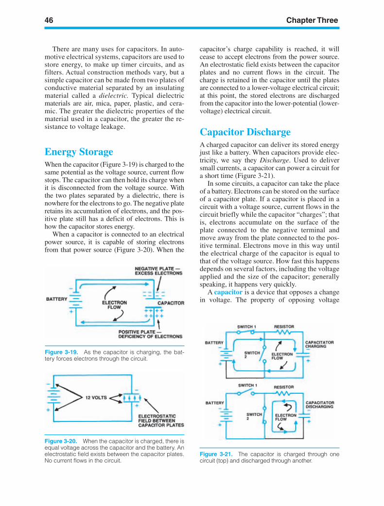
46 Chapter Three
Figure 3-20. When the capacitor is charged, there isequal voltage across the capacitor and the battery. Anelectrostatic field exists between the capacitor plates.No current flows in the circuit.
Figure 3-19. As the capacitor is charging, the bat-tery forces electrons through the circuit.
Figure 3-21. The capacitor is charged through onecircuit (top) and discharged through another.
There are many uses for capacitors. In auto-motive electrical systems, capacitors are used tostore energy, to make up timer circuits, and asfilters. Actual construction methods vary, but asimple capacitor can be made from two plates ofconductive material separated by an insulatingmaterial called a dielectric. Typical dielectricmaterials are air, mica, paper, plastic, and cera-mic. The greater the dielectric properties of thematerial used in a capacitor, the greater the re-sistance to voltage leakage.
Energy StorageWhen the capacitor (Figure 3-19) is charged to thesame potential as the voltage source, current flowstops. The capacitor can then hold its charge whenit is disconnected from the voltage source. Withthe two plates separated by a dielectric, there isnowhere for the electrons to go. The negative plateretains its accumulation of electrons, and the pos-itive plate still has a deficit of electrons. This ishow the capacitor stores energy.
When a capacitor is connected to an electricalpower source, it is capable of storing electronsfrom that power source (Figure 3-20). When the
capacitor’s charge capability is reached, it willcease to accept electrons from the power source.An electrostatic field exists between the capacitorplates and no current flows in the circuit. Thecharge is retained in the capacitor until the platesare connected to a lower-voltage electrical circuit;at this point, the stored electrons are dischargedfrom the capacitor into the lower-potential (lower-voltage) electrical circuit.
Capacitor DischargeA charged capacitor can deliver its stored energyjust like a battery. When capacitors provide elec-tricity, we say they Discharge. Used to deliversmall currents, a capacitor can power a circuit fora short time (Figure 3-21).
In some circuits, a capacitor can take the placeof a battery. Electrons can be stored on the surfaceof a capacitor plate. If a capacitor is placed in acircuit with a voltage source, current flows in thecircuit briefly while the capacitor “charges”; thatis, electrons accumulate on the surface of theplate connected to the negative terminal andmove away from the plate connected to the pos-itive terminal. Electrons move in this way untilthe electrical charge of the capacitor is equal tothat of the voltage source. How fast this happensdepends on several factors, including the voltageapplied and the size of the capacitor; generallyspeaking, it happens very quickly.
A capacitor is a device that opposes a changein voltage. The property of opposing voltage
ker88839_ch03.qxd 1/9/06 11:22 AM Page 46
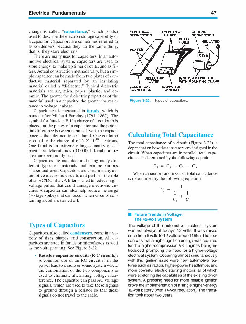
Electrical Fundamentals 47
Figure 3-22. Types of capacitors.
change is called “capacitance,” which is alsoused to describe the electron storage capability ofa capacitor. Capacitors are sometimes referred toas condensers because they do the same thing,that is, they store electrons.
There are many uses for capacitors. In an auto-motive electrical system, capacitors are used tostore energy, to make up timer circuits, and as fil-ters. Actual construction methods vary, but a sim-ple capacitor can be made from two plates of con-ductive material separated by an insulatingmaterial called a “dielectric.” Typical dielectricmaterials are air, mica, paper, plastic, and ce-ramic. The greater the dielectric properties of thematerial used in a capacitor the greater the resis-tance to voltage leakage.
Capacitance is measured in farads, which isnamed after Michael Faraday (1791–1867). Thesymbol for farads is F. If a charge of 1 coulomb isplaced on the plates of a capacitor and the poten-tial difference between them is 1 volt, the capaci-tance is then defined to be 1 farad. One coulombis equal to the charge of 6.25 1018 electrons.One farad is an extremely large quantity of ca-pacitance. Microfarads (0.000001 farad) or Fare more commonly used.
Capacitors are manufactured using many dif-ferent types of materials and can be variousshapes and sizes. Capacitors are used in many au-tomotive electronic circuits and perform the roleof an AC/DC filter. A filter is used to reduce high-voltage pulses that could damage electronic cir-cuits. A capacitor can also help reduce the surge(voltage spike) that can occur when circuits con-taining a coil are turned off.
Types of CapacitorsCapacitors, also called condensers, come in a va-riety of sizes, shapes, and construction. All ca-pacitors are rated in farads or microfarads as wellas the voltage rating. See Figure 3-22.
• Resistor-capacitor circuits (R-C circuits):A common use of an RC circuit is in thepower lead to a radio or sound system wherethe combination of the two components isused to eliminate alternating voltage inter-ference. The capacitor can pass AC voltagesignals, which are used to take these signalsto ground through a resistor so that thesesignals do not travel to the radio.
Calculating Total CapacitanceThe total capacitance of a circuit (Figure 3-23) isdependent on how the capacitors are designed in thecircuit. When capacitors are in parallel, total capa-citance is determined by the following equation:
When capacitors are in series, total capacitanceis determined by the following equation:
Future Trends in Voltage:The 42-Volt System
The voltage of the automotive electrical systemwas not always at today’s 12 volts. It was raisedonce from 6 volts to 12 volts around 1955.The rea-son was that a higher ignition energy was requiredfor the higher-compression V8 engines being in-troduced, prompting the need for a higher-voltageelectrical system. Occurring almost simultaneouslywith this ignition issue were new automotive fea-tures such as radios, higher-power headlamps, andmore powerful electric starting motors, all of whichwere stretching the capabilities of the existing 6-voltsystem. A pressing need for more reliable ignitiondrove the implementation of a single higher-energy12-volt battery (with 14-volt regulation). The transi-tion took about two years.
Ct 1
1Ct
1Ct
CT C1 C2 C3
ker88839_ch03.qxd 1/9/06 11:22 AM Page 47
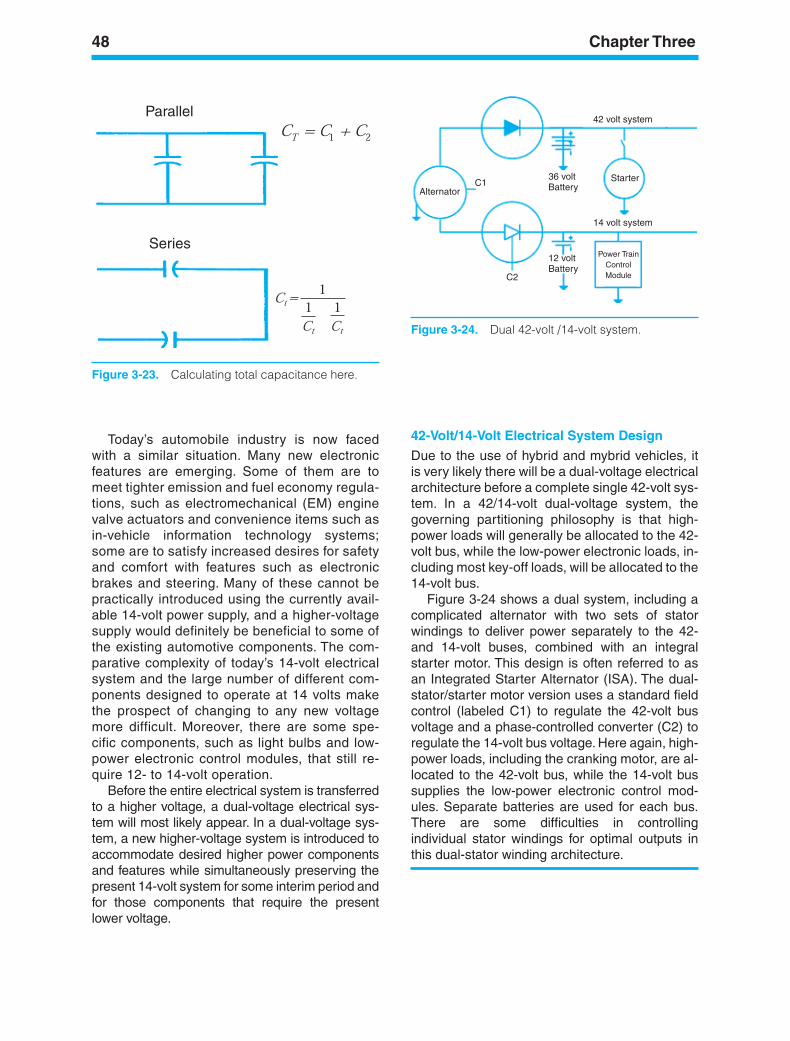
48 Chapter Three
Parallel
Series
Figure 3-23. Calculating total capacitance here.
42 volt system
AlternatorC1
36 voltBattery
12 voltBattery
Power TrainControlModule
14 volt system
C2
Starter
Figure 3-24. Dual 42-volt /14-volt system.
Today’s automobile industry is now facedwith a similar situation. Many new electronicfeatures are emerging. Some of them are tomeet tighter emission and fuel economy regula-tions, such as electromechanical (EM) enginevalve actuators and convenience items such asin-vehicle information technology systems;some are to satisfy increased desires for safetyand comfort with features such as electronicbrakes and steering. Many of these cannot bepractically introduced using the currently avail-able 14-volt power supply, and a higher-voltagesupply would definitely be beneficial to some ofthe existing automotive components. The com-parative complexity of today’s 14-volt electricalsystem and the large number of different com-ponents designed to operate at 14 volts makethe prospect of changing to any new voltagemore difficult. Moreover, there are some spe-cific components, such as light bulbs and low-power electronic control modules, that still re-quire 12- to 14-volt operation.
Before the entire electrical system is transferredto a higher voltage, a dual-voltage electrical sys-tem will most likely appear. In a dual-voltage sys-tem, a new higher-voltage system is introduced toaccommodate desired higher power componentsand features while simultaneously preserving thepresent 14-volt system for some interim period andfor those components that require the presentlower voltage.
42-Volt/14-Volt Electrical System Design
Due to the use of hybrid and mybrid vehicles, itis very likely there will be a dual-voltage electricalarchitecture before a complete single 42-volt sys-tem. In a 42/14-volt dual-voltage system, thegoverning partitioning philosophy is that high-power loads will generally be allocated to the 42-volt bus, while the low-power electronic loads, in-cluding most key-off loads, will be allocated to the14-volt bus.
Figure 3-24 shows a dual system, including acomplicated alternator with two sets of statorwindings to deliver power separately to the 42-and 14-volt buses, combined with an integralstarter motor. This design is often referred to asan Integrated Starter Alternator (ISA). The dual-stator/starter motor version uses a standard fieldcontrol (labeled C1) to regulate the 42-volt busvoltage and a phase-controlled converter (C2) toregulate the 14-volt bus voltage. Here again, high-power loads, including the cranking motor, are al-located to the 42-volt bus, while the 14-volt bussupplies the low-power electronic control mod-ules. Separate batteries are used for each bus.There are some difficulties in controllingindividual stator windings for optimal outputs inthis dual-stator winding architecture.
ker88839_ch03.qxd 1/9/06 11:22 AM Page 48
Electrical Fundamentals 49
SUMMARYA conductor is a metallic element that containsfewer than four electrons in its outer shell. Aninsulator is a non-metallic substance that containsmore than four electrons in the outer shell.Semiconductors are a group of materials thatcannot be classified either as conductors orinsulators; they have exactly four electrons in theirouter shell. Current flow is measured by the num-ber of free electrons passing a given point in an
electrical circuit per second. Electrical pressure orcharge differential is measured in volts, resistancein ohms and current in amperes. If a hydraulic cir-cuit analogy is used to describe an electrical cir-cuit, voltage is equivalent to fluid pressure,current to the flow in gpm, and resistance to flowrestriction.
Capacitors are used to store electrons: this con-sists of conductor plates separated by a dielectric.Capacitance is measured in farads: capacitors arerated by voltage and by capacitance.
ker88839_ch03.qxd 1/9/06 11:22 AM Page 49
50 Chapter Three
Review Questions1. Which of the following methods can
calculate circuit current?a. Multiplying amps times ohmsb. Dividing ohms by voltsc. Dividing volts by ohmsd. Multiplying volts times watts
2. Which of the following methods cancalculate circuit resistance?a. Dividing amps into voltsb. Dividing volts into ampsc. Multiplying volts times ampsd. Multiplying amps times ohms
3. Which of the following causes voltage dropin a circuit?a. Increase in wire sizeb. Increase in resistancec. Increase in insulationd. Decrease in current
4. Which of the following describes a functionof a capacitor in an electrical circuit?a. Timing deviceb. Rectificationc. DC-to-AC conversiond. Inductance
5. Which of the following is a measure ofelectrical current?a. Amperesb. Ohmsc. Voltaged. Watts
6. A material with many free electrons is agooda. Compoundb. Conductorc. Insulatord. Semiconductor
7. A material with four electrons in the valencering is which of these:a. Compoundb. Insulatorc. Semiconductord. Conductor
8. The conventional theory of current flow saysthat current flowsa. Randomlyb. Positive to negativec. Negative to positived. At 60 cycles per second
9. Voltage is which of these items:a. Applied to a circuitb. Flowing in a circuitc. Built into a circuitd. Flowing out of a circuit
10. The unit that represents resistance tocurrent flow is which of these items:a. Ampereb. Voltc. Ohmd. Watt
11. In automotive systems, voltage is suppliedby which of these components:a. Alternatorb. ECMc. DC Generatord. Voltage Regulator
12. Which of the following characteristic doesnot affect resistance?a. Diameter of the conductorb. Temperature of the conductorc. Atomic structure of the conductord. Direction of current flow in the conductor
13. The resistance in a longer piece of wire iswhich of these:a. Higherb. Lowerc. Unchangedd. Higher, then lower
14. According to Ohm’s Law, when one voltpushes one ampere of current through aconductor, the resistance is:a. Zerob. One ohmc. One wattd. One coulomb
15. The sum of the voltage drops in a circuitequals which of these:a. Amperageb. Resistancec. Source voltaged. Shunt circuit voltage
16. Which of the following is a measure ofelectrical pressure?a. Amperesb. Ohmsc. Voltaged. Watts
ker88839_ch03.qxd 1/9/06 11:22 AM Page 50
Electrical Fundamentals 51
17. Which of the following causes voltage dropin a circuit?a. Increase in wire sizeb. Increase in resistancec. Increase in insulationd. Decrease in current
18. Where E volts, I amperes, andR resistance, Ohm’s Law is written aswhich of these formulas:a. I E Rb. E I Rc. R E Id. E 12 R
19. In a closed circuit with a capacitor, currentwill continue to flow until the voltage chargeacross the capacitor plates becomes whichof these:a. Less than the source voltageb. Equal to the source voltagec. Greater than the source voltaged. Equal to the resistance of the plates
20. Capacitors are also called which of theseitems:a. Diodesb. Resistorsc. Condensersd. Dielectrics
21. Capacitors are rated ina. Microcoulombsb. Megawattsc. Microfaradsd. Milliohms
ker88839_ch03.qxd 1/9/06 11:22 AM Page 51

ker88839_ch03.qxd 1/9/06 11:22 AM Page 52

53
4Magnetism
LEARNINGOBJECTIVESUpon completion and review of this chapter, youshould be able to:
• Define magnetism, electromagnetism, elec-tromagnetic induction, and magnetomotiveforce.
• Compare the units of magnetism to elec-tricity: magnetic force to current, field den-sity to voltage, and reluctance to resistance.
• Explain the use and operation of automo-tive circuit components that use electro-magnetic induction and magnetism, toinclude alternators, motors, starters, relays,and solenoids.
KEY TERMSAC Generator/AlternatorCommutatorElectromagnetElectromagnetic inductionElectromagnetic Interference (EMI)ElectromagnetismLeft-Hand RuleLines of ForceMagnetic FieldMagnetic Field IntensityMagnetic FluxMutual InductionRelayReluctanceRight-Hand RuleSelf-InductionTransformers
INTRODUCTIONIn this chapter you will learn about magnetism,electromagnetism, electromagnetic induction, andmagnetomotive force. This knowledge is appliedthorough the explanation of the operation of auto-motive circuit components that use electromag-netic induction and magnetism, such as DC andAC generators (alternators), motors, starters,relays, and solenoids.
ker88839_ch04.qxd 1/9/06 11:23 AM Page 53
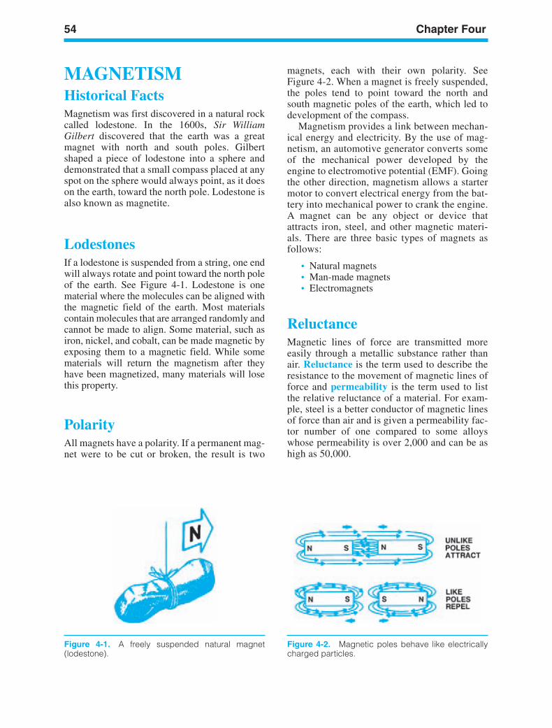
54 Chapter Four
Figure 4-2. Magnetic poles behave like electricallycharged particles.
MAGNETISMHistorical FactsMagnetism was first discovered in a natural rockcalled lodestone. In the 1600s, Sir WilliamGilbert discovered that the earth was a greatmagnet with north and south poles. Gilbertshaped a piece of lodestone into a sphere anddemonstrated that a small compass placed at anyspot on the sphere would always point, as it doeson the earth, toward the north pole. Lodestone isalso known as magnetite.
LodestonesIf a lodestone is suspended from a string, one endwill always rotate and point toward the north poleof the earth. See Figure 4-1. Lodestone is onematerial where the molecules can be aligned withthe magnetic field of the earth. Most materialscontain molecules that are arranged randomly andcannot be made to align. Some material, such asiron, nickel, and cobalt, can be made magnetic byexposing them to a magnetic field. While somematerials will return the magnetism after theyhave been magnetized, many materials will losethis property.
PolarityAll magnets have a polarity. If a permanent mag-net were to be cut or broken, the result is two
magnets, each with their own polarity. SeeFigure 4-2. When a magnet is freely suspended,the poles tend to point toward the north andsouth magnetic poles of the earth, which led todevelopment of the compass.
Magnetism provides a link between mechan-ical energy and electricity. By the use of mag-netism, an automotive generator converts someof the mechanical power developed by theengine to electromotive potential (EMF). Goingthe other direction, magnetism allows a startermotor to convert electrical energy from the bat-tery into mechanical power to crank the engine.A magnet can be any object or device thatattracts iron, steel, and other magnetic materi-als. There are three basic types of magnets asfollows:
• Natural magnets• Man-made magnets• Electromagnets
ReluctanceMagnetic lines of force are transmitted moreeasily through a metallic substance rather thanair. Reluctance is the term used to describe theresistance to the movement of magnetic lines offorce and permeability is the term used to listthe relative reluctance of a material. For exam-ple, steel is a better conductor of magnetic linesof force than air and is given a permeability fac-tor number of one compared to some alloyswhose permeability is over 2,000 and can be ashigh as 50,000.
Figure 4-1. A freely suspended natural magnet(lodestone).
ker88839_ch04.qxd 1/9/06 11:23 AM Page 54
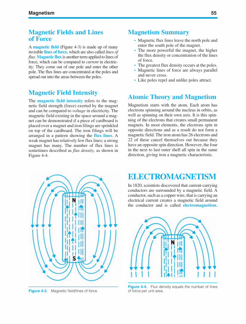
Magnetism 55
Figure 4-3. Magnetic field/lines of force.Figure 4-4. Flux density equals the number of linesof force per unit area.
Magnetic Fields and Linesof ForceA magnetic field (Figure 4-3) is made up of manyinvisible lines of force, which are also called lines offlux. Magnetic flux is another term applied to lines offorce, which can be compared to current in electric-ity: They come out of one pole and enter the otherpole. The flux lines are concentrated at the poles andspread out into the areas between the poles.
Magnetic Field IntensityThe magnetic field intensity refers to the mag-netic field strength (force) exerted by the magnetand can be compared to voltage in electricity. Themagnetic field existing in the space around a mag-net can be demonstrated if a piece of cardboard isplaced over a magnet and iron filings are sprinkledon top of the cardboard. The iron filings will bearranged in a pattern showing the flux lines. Aweak magnet has relatively few flux lines; a strongmagnet has many. The number of flux lines issometimes described as flux density, as shown inFigure 4-4.
Magnetism Summary• Magnetic flux lines leave the north pole and
enter the south pole of the magnet.• The more powerful the magnet, the higher
the flux density or concentration of the linesof force.
• The greatest flux density occurs at the poles.• Magnetic lines of force are always parallel
and never cross.• Like poles repel and unlike poles attract.
Atomic Theory and MagnetismMagnetism starts with the atom. Each atom haselectrons spinning around the nucleus in orbits, aswell as spinning on their own axis. It is this spin-ning of the electrons that creates small permanentmagnets. In most elements, the electrons spin inopposite directions and as a result do not form amagnetic field. The iron atom has 26 electrons and22 of these cancel themselves out because theyhave an opposite spin direction. However, the fourin the next to last outer shell all spin in the samedirection, giving iron a magnetic characteristic.
ELECTROMAGNETISMIn 1820, scientists discovered that current-carryingconductors are surrounded by a magnetic field. Aconductor, such as a copper wire, that is carrying anelectrical current creates a magnetic field aroundthe conductor and is called electromagnetism.
ker88839_ch04.qxd 1/9/06 11:23 AM Page 55
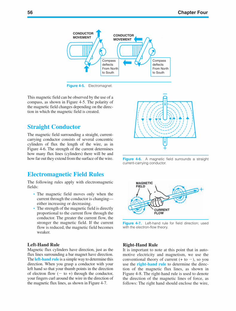
56 Chapter Four
CONDUCTORMOVEMENT
CompassdeflectsFrom Northto South
Compassdeflects From Northto South
CONDUCTORMOVEMENT
Figure 4-5. Electromagnet.
Figure 4-6. A magnetic field surrounds a straightcurrent-carrying conductor.
Figure 4-7. Left-hand rule for field direction; usedwith the electron-flow theory.
This magnetic field can be observed by the use of acompass, as shown in Figure 4-5. The polarity ofthe magnetic field changes depending on the direc-tion in which the magnetic field is created.
Straight ConductorThe magnetic field surrounding a straight, current-carrying conductor consists of several concentriccylinders of flux the length of the wire, as inFigure 4-6. The strength of the current determineshow many flux lines (cylinders) there will be andhow far out they extend from the surface of the wire.
Electromagnetic Field RulesThe following rules apply with electromagneticfields:
• The magnetic field moves only when thecurrent through the conductor is changing—either increasing or decreasing.
• The strength of the magnetic field is directlyproportional to the current flow through theconductor. The greater the current flow, thestronger the magnetic field. If the currentflow is reduced, the magnetic field becomesweaker.
Left-Hand RuleMagnetic flux cylinders have direction, just as theflux lines surrounding a bar magnet have direction.The left-hand rule is a simple way to determine thisdirection. When you grasp a conductor with yourleft hand so that your thumb points in the directionof electron flow ( to +) through the conductor,your fingers curl around the wire in the direction ofthe magnetic flux lines, as shown in Figure 4-7.
Right-Hand RuleIt is important to note at this point that in auto-motive electricity and magnetism, we use theconventional theory of current (+ to ), so youuse the right-hand rule to determine the direc-tion of the magnetic flux lines, as shown inFigure 4-8. The right-hand rule is used to denotethe direction of the magnetic lines of force, asfollows: The right hand should enclose the wire,
ker88839_ch04.qxd 1/9/06 11:23 AM Page 56
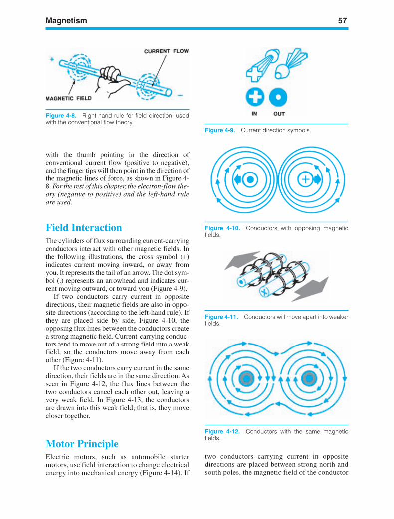
Magnetism 57
Figure 4-9. Current direction symbols.
Figure 4-11. Conductors will move apart into weakerfields.
Figure 4-8. Right-hand rule for field direction; usedwith the conventional flow theory.
Figure 4-10. Conductors with opposing magneticfields.
with the thumb pointing in the direction ofconventional current flow (positive to negative),and the finger tips will then point in the direction ofthe magnetic lines of force, as shown in Figure 4-8. For the rest of this chapter, the electron-flow the-ory (negative to positive) and the left-hand ruleare used.
Field InteractionThe cylinders of flux surrounding current-carryingconductors interact with other magnetic fields. Inthe following illustrations, the cross symbol (+)indicates current moving inward, or away fromyou. It represents the tail of an arrow. The dot sym-bol (.) represents an arrowhead and indicates cur-rent moving outward, or toward you (Figure 4-9).
If two conductors carry current in oppositedirections, their magnetic fields are also in oppo-site directions (according to the left-hand rule). Ifthey are placed side by side, Figure 4-10, theopposing flux lines between the conductors createa strong magnetic field. Current-carrying conduc-tors tend to move out of a strong field into a weakfield, so the conductors move away from eachother (Figure 4-11).
If the two conductors carry current in the samedirection, their fields are in the same direction. Asseen in Figure 4-12, the flux lines between thetwo conductors cancel each other out, leaving avery weak field. In Figure 4-13, the conductorsare drawn into this weak field; that is, they movecloser together.
Motor PrincipleElectric motors, such as automobile startermotors, use field interaction to change electricalenergy into mechanical energy (Figure 4-14). If
Figure 4-12. Conductors with the same magneticfields.
two conductors carrying current in oppositedirections are placed between strong north andsouth poles, the magnetic field of the conductor
ker88839_ch04.qxd 1/9/06 11:23 AM Page 57
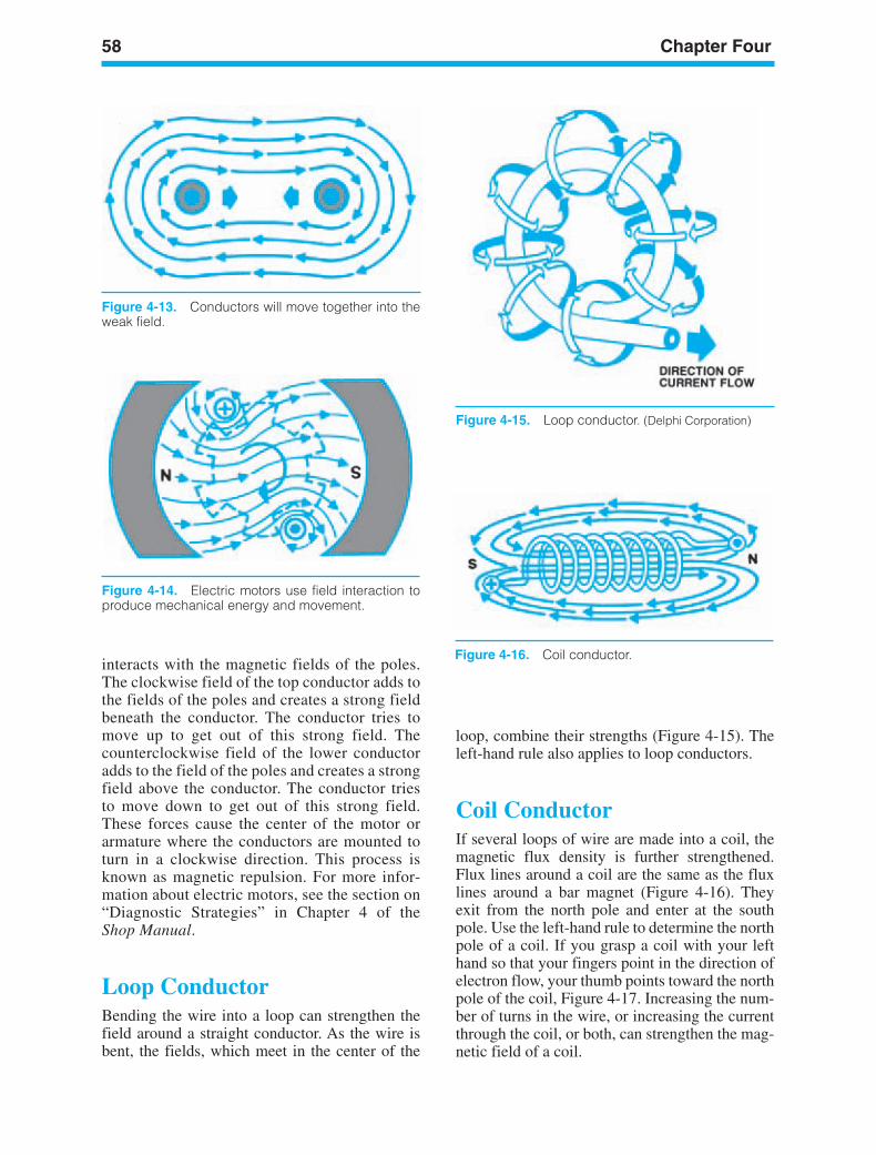
58 Chapter Four
Figure 4-15. Loop conductor. (Delphi Corporation)
Figure 4-14. Electric motors use field interaction toproduce mechanical energy and movement.
Figure 4-13. Conductors will move together into theweak field.
interacts with the magnetic fields of the poles.The clockwise field of the top conductor adds tothe fields of the poles and creates a strong fieldbeneath the conductor. The conductor tries tomove up to get out of this strong field. Thecounterclockwise field of the lower conductoradds to the field of the poles and creates a strongfield above the conductor. The conductor triesto move down to get out of this strong field.These forces cause the center of the motor orarmature where the conductors are mounted toturn in a clockwise direction. This process isknown as magnetic repulsion. For more infor-mation about electric motors, see the section on“Diagnostic Strategies” in Chapter 4 of theShop Manual.
Loop ConductorBending the wire into a loop can strengthen thefield around a straight conductor. As the wire isbent, the fields, which meet in the center of the
Figure 4-16. Coil conductor.
loop, combine their strengths (Figure 4-15). Theleft-hand rule also applies to loop conductors.
Coil ConductorIf several loops of wire are made into a coil, themagnetic flux density is further strengthened.Flux lines around a coil are the same as the fluxlines around a bar magnet (Figure 4-16). Theyexit from the north pole and enter at the southpole. Use the left-hand rule to determine the northpole of a coil. If you grasp a coil with your lefthand so that your fingers point in the direction ofelectron flow, your thumb points toward the northpole of the coil, Figure 4-17. Increasing the num-ber of turns in the wire, or increasing the currentthrough the coil, or both, can strengthen the mag-netic field of a coil.
ker88839_ch04.qxd 1/9/06 11:23 AM Page 58
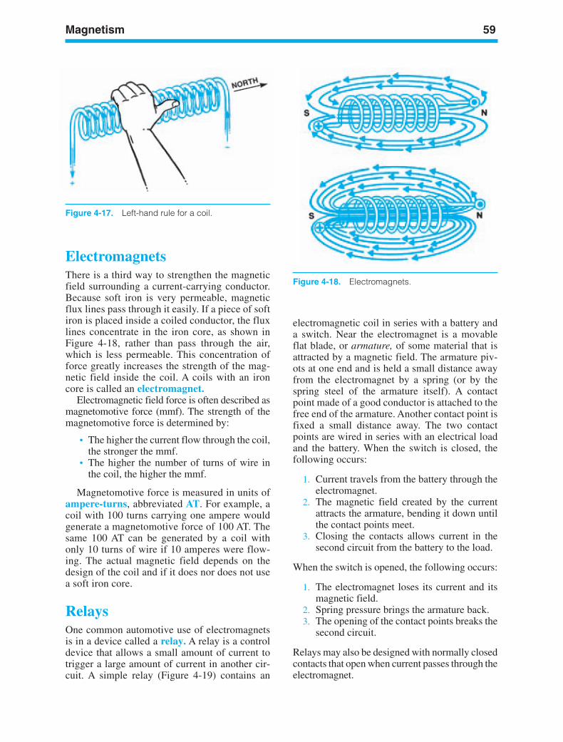
Magnetism 59
Figure 4-18. Electromagnets.
Figure 4-17. Left-hand rule for a coil.
ElectromagnetsThere is a third way to strengthen the magneticfield surrounding a current-carrying conductor.Because soft iron is very permeable, magneticflux lines pass through it easily. If a piece of softiron is placed inside a coiled conductor, the fluxlines concentrate in the iron core, as shown inFigure 4-18, rather than pass through the air,which is less permeable. This concentration offorce greatly increases the strength of the mag-netic field inside the coil. A coils with an ironcore is called an electromagnet.
Electromagnetic field force is often described asmagnetomotive force (mmf). The strength of themagnetomotive force is determined by:
• The higher the current flow through the coil,the stronger the mmf.
• The higher the number of turns of wire inthe coil, the higher the mmf.
Magnetomotive force is measured in units ofampere-turns, abbreviated AT. For example, acoil with 100 turns carrying one ampere wouldgenerate a magnetomotive force of 100 AT. Thesame 100 AT can be generated by a coil withonly 10 turns of wire if 10 amperes were flow-ing. The actual magnetic field depends on thedesign of the coil and if it does nor does not usea soft iron core.
RelaysOne common automotive use of electromagnetsis in a device called a relay. A relay is a controldevice that allows a small amount of current totrigger a large amount of current in another cir-cuit. A simple relay (Figure 4-19) contains an
electromagnetic coil in series with a battery anda switch. Near the electromagnet is a movableflat blade, or armature, of some material that isattracted by a magnetic field. The armature piv-ots at one end and is held a small distance awayfrom the electromagnet by a spring (or by thespring steel of the armature itself). A contactpoint made of a good conductor is attached to thefree end of the armature. Another contact point isfixed a small distance away. The two contactpoints are wired in series with an electrical loadand the battery. When the switch is closed, thefollowing occurs:
1. Current travels from the battery through theelectromagnet.
2. The magnetic field created by the currentattracts the armature, bending it down untilthe contact points meet.
3. Closing the contacts allows current in thesecond circuit from the battery to the load.
When the switch is opened, the following occurs:
1. The electromagnet loses its current and itsmagnetic field.
2. Spring pressure brings the armature back.3. The opening of the contact points breaks the
second circuit.
Relays may also be designed with normally closedcontacts that open when current passes through theelectromagnet.
ker88839_ch04.qxd 1/9/06 11:23 AM Page 59
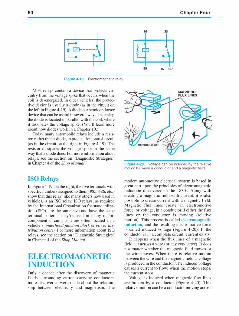
60 Chapter Four
86 30
85 87 87A
Figure 4-19. Electromagnetic relay.
Figure 4-20. Voltage can be induced by the relativemotion between a conductor and a magnetic field.
Most relays contain a device that protects cir-cuitry from the voltage spike that occurs when thecoil is de-energized. In older vehicles, the protec-tive device is usually a diode (as in the circuit onthe left in Figure 4-19). A diode is a semiconductordevice that can be useful in several ways. In a relay,the diode is located in parallel with the coil, whereit dissipates the voltage spike. (You’ll learn moreabout how diodes work in a Chapter 10.)
Today many automobile relays include a resis-tor, rather than a diode, to protect the control circuit(as in the circuit on the right in Figure 4-19). Theresistor dissipates the voltage spike in the sameway that a diode does. For more information aboutrelays, see the section on “Diagnostic Strategies”in Chapter 4 of the Shop Manual.
ISO RelaysIn Figure 4-19, on the right, the five terminals withspecific numbers assigned to them (#85, #86, etc.)show that this relay, like many others now used invehicles, is an ISO relay. ISO relays, as requiredby the International Organization for standardiza-tion (ISO), are the same size and have the sameterminal pattern. They’re used in many major-component circuits, and are often located in avehicle’s underhood junction block or power dis-tribution center. For more information about ISOrelays, see the section on “Diagnostic Strategies”in Chapter 4 of the Shop Manual.
ELECTROMAGNETICINDUCTIONOnly a decade after the discovery of magneticfields surrounding current-carrying conductors,more discoveries were made about the relation-ship between electricity and magnetism. The
modem automotive electrical system is based ingreat part upon the principles of electromagneticinduction discovered in the 1830s. Along withcreating a magnetic field with current, it is alsopossible to create current with a magnetic field.Magnetic flux lines create an electromotiveforce, or voltage, in a conductor if either the fluxlines or the conductor is moving (relativemotion). This process is called electromagneticinduction, and the resulting electromotive forceis called induced voltage (Figure 4-20). If theconductor is in a complete circuit, current exists.
It happens when the flux lines of a magneticfield cut across a wire (or any conductor). It doesnot matter whether the magnetic field moves orthe wire moves. When there is relative motionbetween the wire and the magnetic field, a voltageis produced in the conductor. The induced voltagecauses a current to flow; when the motion stops,the current stops.
Voltage is induced when magnetic flux linesare broken by a conductor (Figure 4-20). Thisrelative motion can be a conductor moving across
ker88839_ch04.qxd 1/9/06 11:23 AM Page 60
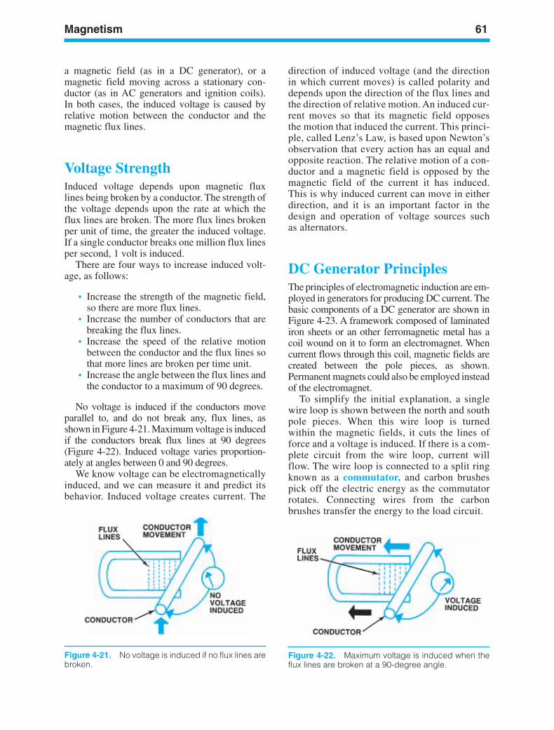
Magnetism 61
Figure 4-22. Maximum voltage is induced when theflux lines are broken at a 90-degree angle.
Figure 4-21. No voltage is induced if no flux lines arebroken.
a magnetic field (as in a DC generator), or amagnetic field moving across a stationary con-ductor (as in AC generators and ignition coils).In both cases, the induced voltage is caused byrelative motion between the conductor and themagnetic flux lines.
Voltage StrengthInduced voltage depends upon magnetic fluxlines being broken by a conductor. The strength ofthe voltage depends upon the rate at which theflux lines are broken. The more flux lines brokenper unit of time, the greater the induced voltage.If a single conductor breaks one million flux linesper second, 1 volt is induced.
There are four ways to increase induced volt-age, as follows:
• Increase the strength of the magnetic field,so there are more flux lines.
• Increase the number of conductors that arebreaking the flux lines.
• Increase the speed of the relative motionbetween the conductor and the flux lines sothat more lines are broken per time unit.
• Increase the angle between the flux lines andthe conductor to a maximum of 90 degrees.
No voltage is induced if the conductors moveparallel to, and do not break any, flux lines, asshown in Figure 4-21. Maximum voltage is inducedif the conductors break flux lines at 90 degrees(Figure 4-22). Induced voltage varies proportion-ately at angles between 0 and 90 degrees.
We know voltage can be electromagneticallyinduced, and we can measure it and predict itsbehavior. Induced voltage creates current. The
direction of induced voltage (and the directionin which current moves) is called polarity anddepends upon the direction of the flux lines andthe direction of relative motion. An induced cur-rent moves so that its magnetic field opposesthe motion that induced the current. This princi-ple, called Lenz’s Law, is based upon Newton’sobservation that every action has an equal andopposite reaction. The relative motion of a con-ductor and a magnetic field is opposed by themagnetic field of the current it has induced.This is why induced current can move in eitherdirection, and it is an important factor in thedesign and operation of voltage sources suchas alternators.
DC Generator PrinciplesThe principles of electromagnetic induction are em-ployed in generators for producing DC current. Thebasic components of a DC generator are shown inFigure 4-23. A framework composed of laminatediron sheets or an other ferromagnetic metal has acoil wound on it to form an electromagnet. Whencurrent flows through this coil, magnetic fields arecreated between the pole pieces, as shown.Permanent magnets could also be employed insteadof the electromagnet.
To simplify the initial explanation, a singlewire loop is shown between the north and southpole pieces. When this wire loop is turnedwithin the magnetic fields, it cuts the lines offorce and a voltage is induced. If there is a com-plete circuit from the wire loop, current willflow. The wire loop is connected to a split ringknown as a commutator, and carbon brushespick off the electric energy as the commutatorrotates. Connecting wires from the carbonbrushes transfer the energy to the load circuit.
ker88839_ch04.qxd 1/9/06 11:23 AM Page 61
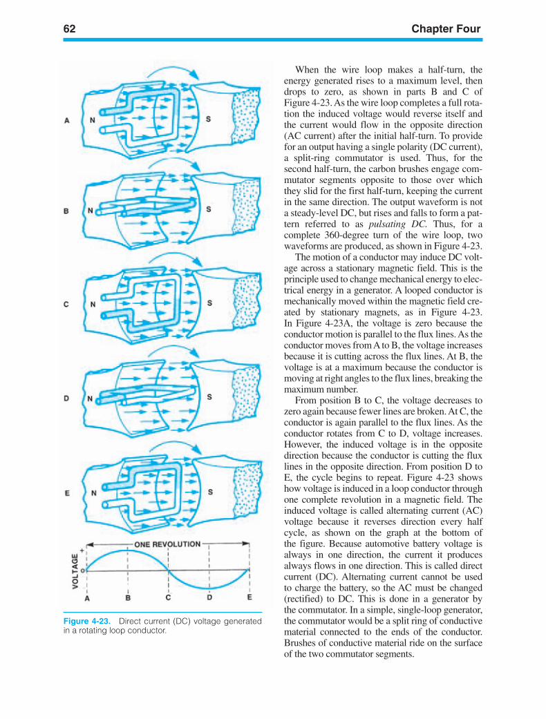
62 Chapter Four
Figure 4-23. Direct current (DC) voltage generatedin a rotating loop conductor.
When the wire loop makes a half-turn, theenergy generated rises to a maximum level, thendrops to zero, as shown in parts B and C ofFigure 4-23. As the wire loop completes a full rota-tion the induced voltage would reverse itself andthe current would flow in the opposite direction(AC current) after the initial half-turn. To providefor an output having a single polarity (DC current),a split-ring commutator is used. Thus, for thesecond half-turn, the carbon brushes engage com-mutator segments opposite to those over whichthey slid for the first half-turn, keeping the currentin the same direction. The output waveform is nota steady-level DC, but rises and falls to form a pat-tern referred to as pulsating DC. Thus, for acomplete 360-degree turn of the wire loop, twowaveforms are produced, as shown in Figure 4-23.
The motion of a conductor may induce DC volt-age across a stationary magnetic field. This is theprinciple used to change mechanical energy to elec-trical energy in a generator. A looped conductor ismechanically moved within the magnetic field cre-ated by stationary magnets, as in Figure 4-23.In Figure 4-23A, the voltage is zero because theconductor motion is parallel to the flux lines. As theconductor moves from A to B, the voltage increasesbecause it is cutting across the flux lines. At B, thevoltage is at a maximum because the conductor ismoving at right angles to the flux lines, breaking themaximum number.
From position B to C, the voltage decreases tozero again because fewer lines are broken. At C, theconductor is again parallel to the flux lines. As theconductor rotates from C to D, voltage increases.However, the induced voltage is in the oppositedirection because the conductor is cutting the fluxlines in the opposite direction. From position D toE, the cycle begins to repeat. Figure 4-23 showshow voltage is induced in a loop conductor throughone complete revolution in a magnetic field. Theinduced voltage is called alternating current (AC)voltage because it reverses direction every halfcycle, as shown on the graph at the bottom ofthe figure. Because automotive battery voltage isalways in one direction, the current it producesalways flows in one direction. This is called directcurrent (DC). Alternating current cannot be usedto charge the battery, so the AC must be changed(rectified) to DC. This is done in a generator bythe commutator. In a simple, single-loop generator,the commutator would be a split ring of conductivematerial connected to the ends of the conductor.Brushes of conductive material ride on the surfaceof the two commutator segments.
ker88839_ch04.qxd 1/9/06 11:23 AM Page 62
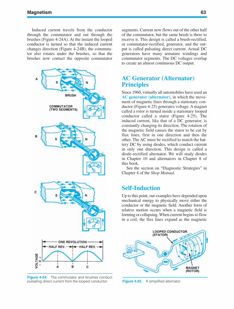
Magnetism 63
Figure 4-24. The commutator and brushes conductpulsating direct current from the looped conductor.
Induced current travels from the conductorthrough the commutator and out through thebrushes (Figure 4-24A). At the instant the loopedconductor is turned so that the induced currentchanges direction (Figure 4-24B), the commuta-tor also rotates under the brushes, so that thebrushes now contact the opposite commutator
segments. Current now flows out of the other halfof the commutator, but the same brush is there toreceive it. This design is called a brush-rectified,or commutator-rectified, generator, and the out-put is called pulsating direct current. Actual DCgenerators have many armature windings andcommutator segments. The DC voltages overlapto create an almost continuous DC output.
AC Generator (Alternator)PrinciplesSince 1960, virtually all automobiles have used anAC generator (alternator), in which the move-ment of magnetic lines through a stationary con-ductor (Figure 4-25) generates voltage. A magnetcalled a rotor is turned inside a stationary loopedconductor called a stator (Figure 4-25). Theinduced current, like that of a DC generator, isconstantly changing its direction. The rotation ofthe magnetic field causes the stator to be cut byflux lines, first in one direction and then theother. The AC must be rectified to match the bat-tery DC by using diodes, which conduct currentin only one direction. This design is called adiode-rectified alternator. We will study diodesin Chapter 10 and alternators in Chapter 8 ofthis book.
See the section on “Diagnostic Strategies” inChapter 4 of the Shop Manual.
Self-InductionUp to this point, our examples have depended uponmechanical energy to physically move either theconductor or the magnetic field. Another form ofrelative motion occurs when a magnetic field isforming or collapsing. When current begins to flowin a coil, the flux lines expand as the magnetic
Figure 4-25. A simplified alternator.
ker88839_ch04.qxd 1/9/06 11:23 AM Page 63
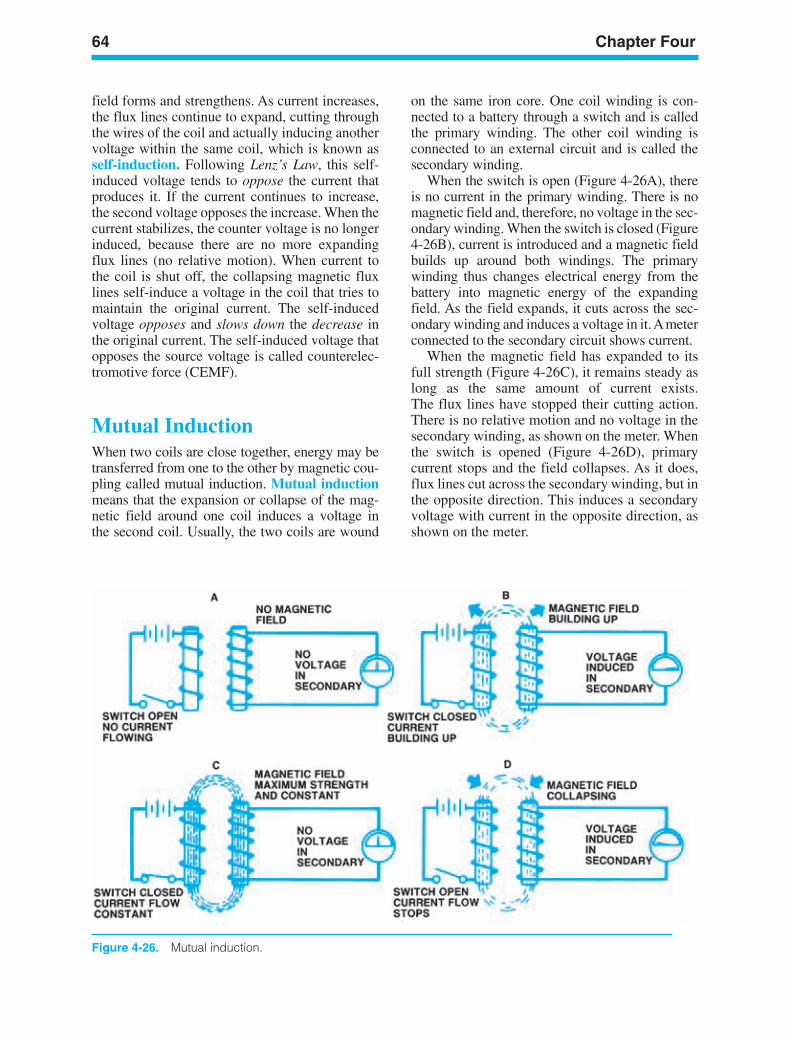
64 Chapter Four
Figure 4-26. Mutual induction.
field forms and strengthens. As current increases,the flux lines continue to expand, cutting throughthe wires of the coil and actually inducing anothervoltage within the same coil, which is known asself-induction. Following Lenz’s Law, this self-induced voltage tends to oppose the current thatproduces it. If the current continues to increase,the second voltage opposes the increase. When thecurrent stabilizes, the counter voltage is no longerinduced, because there are no more expandingflux lines (no relative motion). When current tothe coil is shut off, the collapsing magnetic fluxlines self-induce a voltage in the coil that tries tomaintain the original current. The self-inducedvoltage opposes and slows down the decrease inthe original current. The self-induced voltage thatopposes the source voltage is called counterelec-tromotive force (CEMF).
Mutual InductionWhen two coils are close together, energy may betransferred from one to the other by magnetic cou-pling called mutual induction. Mutual inductionmeans that the expansion or collapse of the mag-netic field around one coil induces a voltage inthe second coil. Usually, the two coils are wound
on the same iron core. One coil winding is con-nected to a battery through a switch and is calledthe primary winding. The other coil winding isconnected to an external circuit and is called thesecondary winding.
When the switch is open (Figure 4-26A), thereis no current in the primary winding. There is nomagnetic field and, therefore, no voltage in the sec-ondary winding. When the switch is closed (Figure4-26B), current is introduced and a magnetic fieldbuilds up around both windings. The primarywinding thus changes electrical energy from thebattery into magnetic energy of the expandingfield. As the field expands, it cuts across the sec-ondary winding and induces a voltage in it. Ameterconnected to the secondary circuit shows current.
When the magnetic field has expanded to itsfull strength (Figure 4-26C), it remains steady aslong as the same amount of current exists.The flux lines have stopped their cutting action.There is no relative motion and no voltage in thesecondary winding, as shown on the meter. Whenthe switch is opened (Figure 4-26D), primarycurrent stops and the field collapses. As it does,flux lines cut across the secondary winding, but inthe opposite direction. This induces a secondaryvoltage with current in the opposite direction, asshown on the meter.
ker88839_ch04.qxd 1/9/06 11:23 AM Page 64
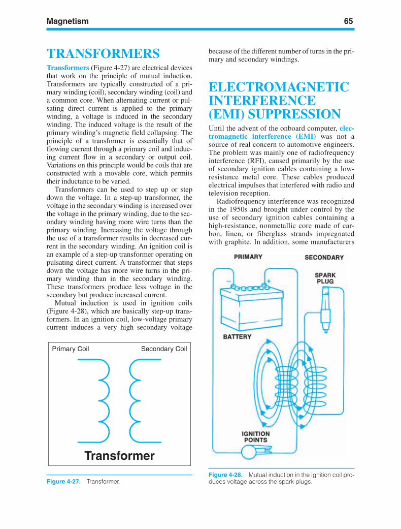
Magnetism 65
Primary Coil Secondary Coil
Transformer
Figure 4-27. Transformer.Figure 4-28. Mutual induction in the ignition coil pro-duces voltage across the spark plugs.
TRANSFORMERSTransformers (Figure 4-27) are electrical devicesthat work on the principle of mutual induction.Transformers are typically constructed of a pri-mary winding (coil), secondary winding (coil) anda common core. When alternating current or pul-sating direct current is applied to the primarywinding, a voltage is induced in the secondarywinding. The induced voltage is the result of theprimary winding’s magnetic field collapsing. Theprinciple of a transformer is essentially that offlowing current through a primary coil and induc-ing current flow in a secondary or output coil.Variations on this principle would be coils that areconstructed with a movable core, which permitstheir inductance to be varied.
Transformers can be used to step up or stepdown the voltage. In a step-up transformer, thevoltage in the secondary winding is increased overthe voltage in the primary winding, due to the sec-ondary winding having more wire turns than theprimary winding. Increasing the voltage throughthe use of a transformer results in decreased cur-rent in the secondary winding. An ignition coil isan example of a step-up transformer operating onpulsating direct current. A transformer that stepsdown the voltage has more wire turns in the pri-mary winding than in the secondary winding.These transformers produce less voltage in thesecondary but produce increased current.
Mutual induction is used in ignition coils(Figure 4-28), which are basically step-up trans-formers. In an ignition coil, low-voltage primarycurrent induces a very high secondary voltage
because of the different number of turns in the pri-mary and secondary windings.
ELECTROMAGNETICINTERFERENCE(EMI) SUPPRESSIONUntil the advent of the onboard computer, elec-tromagnetic interference (EMI) was not asource of real concern to automotive engineers.The problem was mainly one of radiofrequencyinterference (RFI), caused primarily by the useof secondary ignition cables containing a low-resistance metal core. These cables producedelectrical impulses that interfered with radio andtelevision reception.
Radiofrequency interference was recognizedin the 1950s and brought under control by theuse of secondary ignition cables containing ahigh-resistance, nonmetallic core made of car-bon, linen, or fiberglass strands impregnatedwith graphite. In addition, some manufacturers
ker88839_ch04.qxd 1/9/06 11:23 AM Page 65
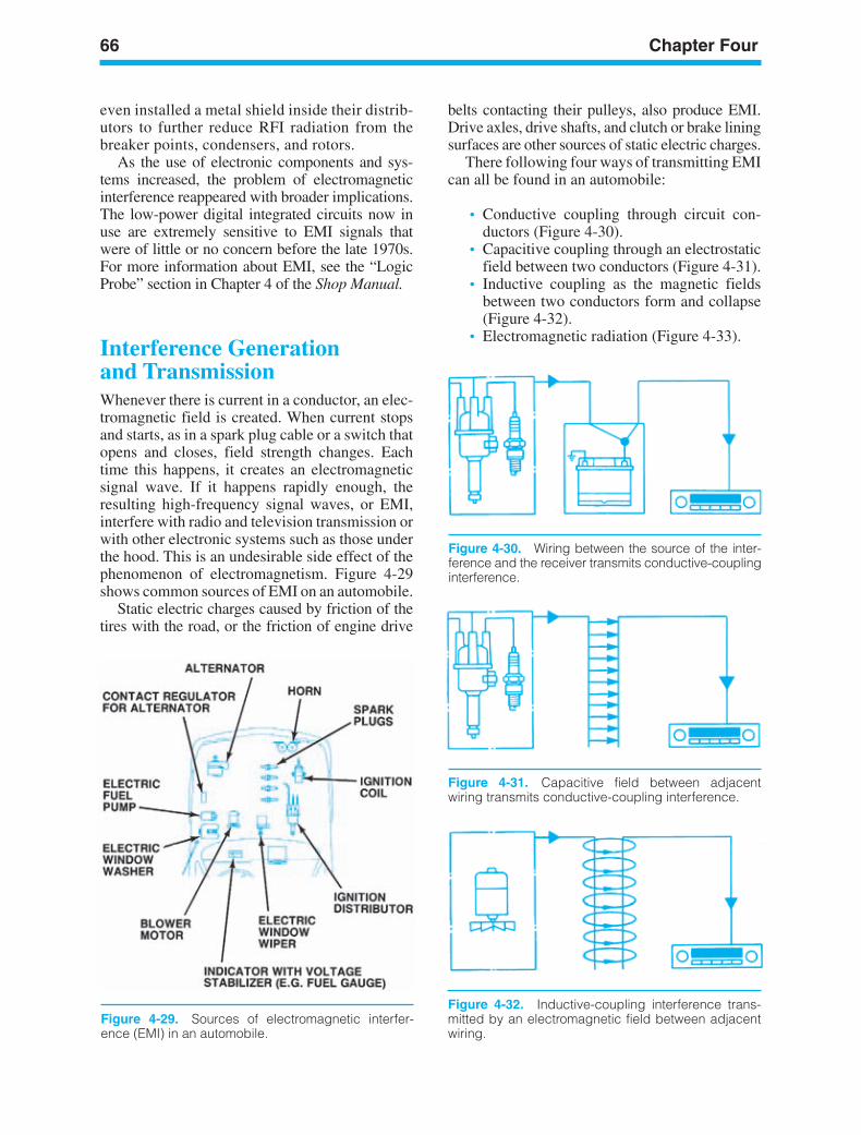
66 Chapter Four
Figure 4-29. Sources of electromagnetic interfer-ence (EMI) in an automobile.
Figure 4-30. Wiring between the source of the inter-ference and the receiver transmits conductive-couplinginterference.
Figure 4-31. Capacitive field between adjacentwiring transmits conductive-coupling interference.
Figure 4-32. Inductive-coupling interference trans-mitted by an electromagnetic field between adjacentwiring.
even installed a metal shield inside their distrib-utors to further reduce RFI radiation from thebreaker points, condensers, and rotors.
As the use of electronic components and sys-tems increased, the problem of electromagneticinterference reappeared with broader implications.The low-power digital integrated circuits now inuse are extremely sensitive to EMI signals thatwere of little or no concern before the late 1970s.For more information about EMI, see the “LogicProbe” section in Chapter 4 of the Shop Manual.
Interference Generationand TransmissionWhenever there is current in a conductor, an elec-tromagnetic field is created. When current stopsand starts, as in a spark plug cable or a switch thatopens and closes, field strength changes. Eachtime this happens, it creates an electromagneticsignal wave. If it happens rapidly enough, theresulting high-frequency signal waves, or EMI,interfere with radio and television transmission orwith other electronic systems such as those underthe hood. This is an undesirable side effect of thephenomenon of electromagnetism. Figure 4-29shows common sources of EMI on an automobile.
Static electric charges caused by friction of thetires with the road, or the friction of engine drive
belts contacting their pulleys, also produce EMI.Drive axles, drive shafts, and clutch or brake liningsurfaces are other sources of static electric charges.
There following four ways of transmitting EMIcan all be found in an automobile:
• Conductive coupling through circuit con-ductors (Figure 4-30).
• Capacitive coupling through an electrostaticfield between two conductors (Figure 4-31).
• Inductive coupling as the magnetic fieldsbetween two conductors form and collapse(Figure 4-32).
• Electromagnetic radiation (Figure 4-33).
ker88839_ch04.qxd 1/9/06 11:23 AM Page 66
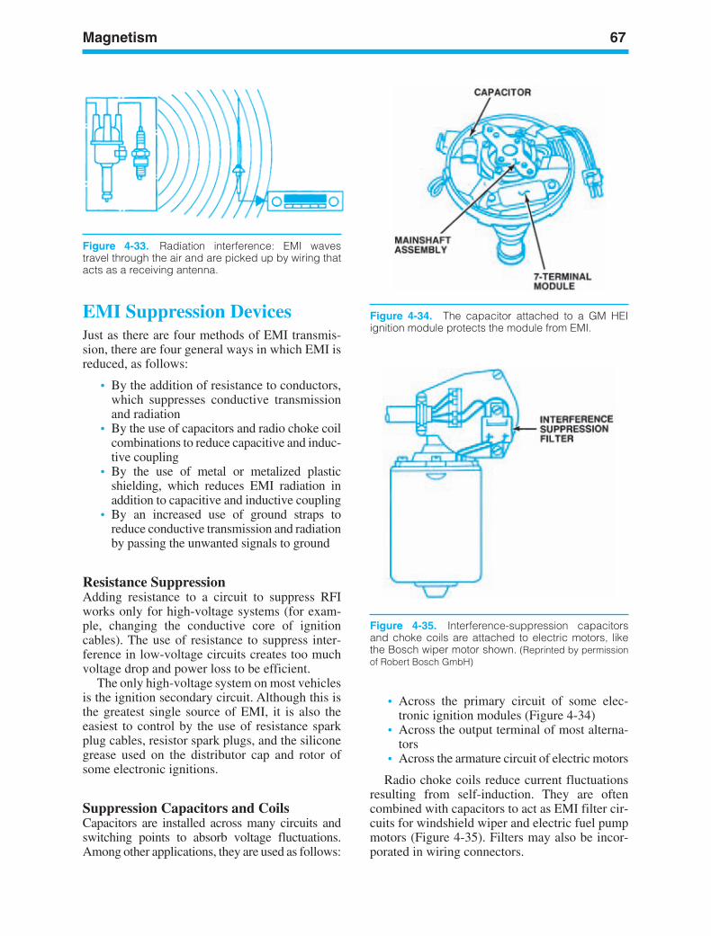
Magnetism 67
Figure 4-34. The capacitor attached to a GM HEIignition module protects the module from EMI.
Figure 4-33. Radiation interference: EMI wavestravel through the air and are picked up by wiring thatacts as a receiving antenna.
EMI Suppression DevicesJust as there are four methods of EMI transmis-sion, there are four general ways in which EMI isreduced, as follows:
• By the addition of resistance to conductors,which suppresses conductive transmissionand radiation
• By the use of capacitors and radio choke coilcombinations to reduce capacitive and induc-tive coupling
• By the use of metal or metalized plasticshielding, which reduces EMI radiation inaddition to capacitive and inductive coupling
• By an increased use of ground straps toreduce conductive transmission and radiationby passing the unwanted signals to ground
Resistance SuppressionAdding resistance to a circuit to suppress RFIworks only for high-voltage systems (for exam-ple, changing the conductive core of ignitioncables). The use of resistance to suppress inter-ference in low-voltage circuits creates too muchvoltage drop and power loss to be efficient.
The only high-voltage system on most vehiclesis the ignition secondary circuit. Although this isthe greatest single source of EMI, it is also theeasiest to control by the use of resistance sparkplug cables, resistor spark plugs, and the siliconegrease used on the distributor cap and rotor ofsome electronic ignitions.
Suppression Capacitors and CoilsCapacitors are installed across many circuits andswitching points to absorb voltage fluctuations.Among other applications, they are used as follows:
• Across the primary circuit of some elec-tronic ignition modules (Figure 4-34)
• Across the output terminal of most alterna-tors
• Across the armature circuit of electric motors
Radio choke coils reduce current fluctuationsresulting from self-induction. They are oftencombined with capacitors to act as EMI filter cir-cuits for windshield wiper and electric fuel pumpmotors (Figure 4-35). Filters may also be incor-porated in wiring connectors.
Figure 4-35. Interference-suppression capacitorsand choke coils are attached to electric motors, likethe Bosch wiper motor shown. (Reprinted by permissionof Robert Bosch GmbH)
ker88839_ch04.qxd 1/9/06 11:23 AM Page 67
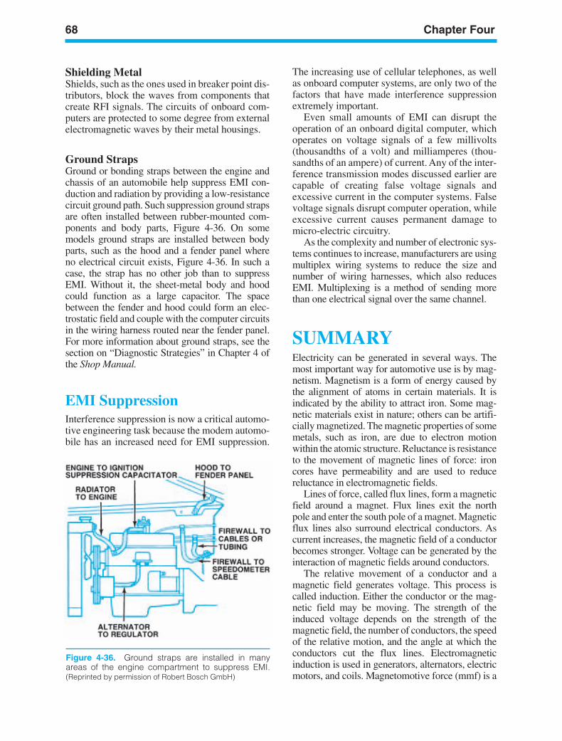
68 Chapter Four
Figure 4-36. Ground straps are installed in manyareas of the engine compartment to suppress EMI.(Reprinted by permission of Robert Bosch GmbH)
Shielding MetalShields, such as the ones used in breaker point dis-tributors, block the waves from components thatcreate RFI signals. The circuits of onboard com-puters are protected to some degree from externalelectromagnetic waves by their metal housings.
Ground StrapsGround or bonding straps between the engine andchassis of an automobile help suppress EMI con-duction and radiation by providing a low-resistancecircuit ground path. Such suppression ground strapsare often installed between rubber-mounted com-ponents and body parts, Figure 4-36. On somemodels ground straps are installed between bodyparts, such as the hood and a fender panel whereno electrical circuit exists, Figure 4-36. In such acase, the strap has no other job than to suppressEMI. Without it, the sheet-metal body and hoodcould function as a large capacitor. The spacebetween the fender and hood could form an elec-trostatic field and couple with the computer circuitsin the wiring harness routed near the fender panel.For more information about ground straps, see thesection on “Diagnostic Strategies” in Chapter 4 ofthe Shop Manual.
EMI SuppressionInterference suppression is now a critical automo-tive engineering task because the modem automo-bile has an increased need for EMI suppression.
The increasing use of cellular telephones, as wellas onboard computer systems, are only two of thefactors that have made interference suppressionextremely important.
Even small amounts of EMI can disrupt theoperation of an onboard digital computer, whichoperates on voltage signals of a few millivolts(thousandths of a volt) and milliamperes (thou-sandths of an ampere) of current. Any of the inter-ference transmission modes discussed earlier arecapable of creating false voltage signals andexcessive current in the computer systems. Falsevoltage signals disrupt computer operation, whileexcessive current causes permanent damage tomicro-electric circuitry.
As the complexity and number of electronic sys-tems continues to increase, manufacturers are usingmultiplex wiring systems to reduce the size andnumber of wiring harnesses, which also reducesEMI. Multiplexing is a method of sending morethan one electrical signal over the same channel.
SUMMARYElectricity can be generated in several ways. Themost important way for automotive use is by mag-netism. Magnetism is a form of energy caused bythe alignment of atoms in certain materials. It isindicated by the ability to attract iron. Some mag-netic materials exist in nature; others can be artifi-cially magnetized. The magnetic properties of somemetals, such as iron, are due to electron motionwithin the atomic structure. Reluctance is resistanceto the movement of magnetic lines of force: ironcores have permeability and are used to reducereluctance in electromagnetic fields.
Lines of force, called flux lines, form a magneticfield around a magnet. Flux lines exit the northpole and enter the south pole of a magnet. Magneticflux lines also surround electrical conductors. Ascurrent increases, the magnetic field of a conductorbecomes stronger. Voltage can be generated by theinteraction of magnetic fields around conductors.
The relative movement of a conductor and amagnetic field generates voltage. This process iscalled induction. Either the conductor or the mag-netic field may be moving. The strength of theinduced voltage depends on the strength of themagnetic field, the number of conductors, the speedof the relative motion, and the angle at which theconductors cut the flux lines. Electromagneticinduction is used in generators, alternators, electricmotors, and coils. Magnetomotive force (mmf) is a
ker88839_ch04.qxd 1/9/06 11:23 AM Page 68

Magnetism 69
measure of electromagnetic field strength. The unitof measure used for mmf is ampere-turns. Theprinciple of a transformer can be summarized bydescribing it as flowing current through a primarycoil and inducing a current flow in a secondary oroutput coil.
Electromagnetism can also generate electro-magnetic interference (EMI) and radiofrequencyinterference (RFI). Such interference can disruptradio and television signals, as well as electronicsystem signals. Many devices are used to sup-press this interference in automotive systems.
ker88839_ch04.qxd 1/9/06 11:23 AM Page 69
70 Chapter Four
Review Questions1. Which of the following can store energy in
the form of an electromagnetic charge?a. Thermocoupleb. Induction coilc. Potentiometerd. Capacitor
2. Current flows through a heated thermocouplebecause of the two-way flow ofa. Electrons between dissimilar materialsb. The blockage of free electrons between
the metalsc. The one-way transfer of free electrons
between the metalsd. Random electron flow
3. Which of the following forms of generatingelectricity is not widely used in anautomobile?a. Heatb. Pressurec. Chemistryd. Magnetism
4. The lines of force of a magnet are calleda. Flux linesb. Magnetic polarityc. Magnetic linesd. Flux density
5. A material through which magnetic forcecan easily flow has a higha. Reluctanceb. Permeabilityc. Capacitanced. Magnetic attraction
6. The left-hand rule says that if you grasp aconductor in your left hand with your thumbpointing in the direction of the electron ( to+) flow,a. Your fingers will point in the direction of
the magnetic flux lines.b. Your fingers will point in the opposite
direction of the magnetic flux lines.c. Your fingers will point at right angles to
the magnetic flux lines.d. Your fingers will point at a 45-degree
angle to the magnetic flux lines.
7. The left-hand rule is useful to determinea. The direction of current flowb. The length of the magnetic flux linesc. The strength of the magnetic fieldd. Flux density
8. When two parallel conductors carryelectrical current in opposite directions,their magnetic fields willa. Force them apartb. Pull them togetherc. Cancel each other outd. Rotate around the conductors in the
same direction
9. The motor principle of changing electricalenergy into mechanical energy requiresa. Two semiconductors carrying current in
opposite directionsb. Two semiconductors carrying current in
the same directionc. Two conductors carrying current in
opposite directionsd. Two conductors carrying current in the
same direction
10. Which of the following will not increaseinduced voltage?a. Increasing the strength of the magnetic
fieldb. Increasing the number of conductors
cutting flux linesc. Increasing the speed of the relative
motion between the conductor and theflux lines
d. Increasing the angle between the flux linesand the conductor beyond 90 degrees
11. The _________ in an automobile DCgenerator rectifies AC to DC.a. Armatureb. Commutatorc. Field coild. Loop conductor
12. In an ignition coil, low-voltage primarycurrent induces a very high secondaryvoltage because ofa. The different number of wire turns in the
two windings.b. An equal number of turns in the two
windingsc. The constant current flow through the
primary windingd. The bigger wire in the secondary winding
13. To reduce EMI, manufacturers have done allof the following except:a. Using low resistance in electrical systemsb. Installing metal shielding in componentsc. Increasing the use of ground strapsd. Using capacitors and choke coils
ker88839_ch04.qxd 1/9/06 11:23 AM Page 70
LEARNINGOBJECTIVESUpon completion and review of this chapter, youshould be able to:
• Define a series circuit.• Identify the series circuit laws and
apply Ohm’s Law for voltage, current, andresistance.
• Define a parallel circuit.• Identify the parallel-circuit laws and
apply Ohm’s Law for voltage, current, andresistance.
• Define Kirchhoff’s Voltage Drop Law andCurrent Law.
• Define a series-parallel circuit.• Identify the series and parallel circuit loads
of a series-parallel circuit.• Using Ohm’s Law, solve series-parallel cir-
cuits for voltage, current, and resistance.
KEY TERMSCircuitKirchhoff’s Law of CurrentKirchhoff’s Law of Voltage DropsParallel CircuitSeries CircuitSeries-Parallel CircuitsVoltage Drop
INTRODUCTIONIn this chapter you will apply the individual seriesand parallel circuit laws learned in previous chaptersto a combination circuit consisting of some compo-nents connected in series and some in parallel.Series/parallel electrical circuits seem complicated,but are in fact fairly simple to understand if youremember which circuit laws apply to each circuitload component. Most vehicle electrical circuitsused today contain several series-parallel circuits, orportions of a series-parallel circuit.
BASIC CIRCUITSIn Chapter 3, we explained that a circuit is a pathfor electric current (Figure 5-1). Current flowsfrom one end of a circuit to the other when theends are connected to opposite charges (positive
71
5Series,Parallel, andSeries-ParallelCircuits
ker88839_ch05.qxd 1/9/06 11:24 AM Page 71
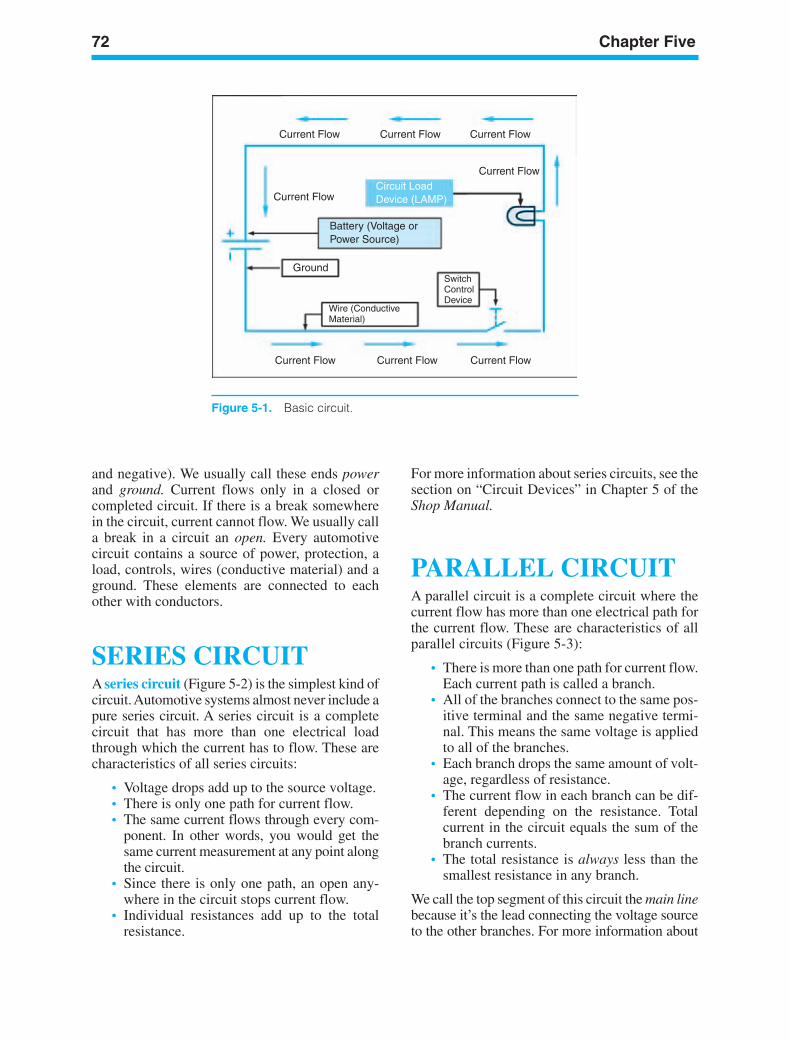
72 Chapter Five
Current Flow Current Flow Current Flow
Current FlowCurrent FlowCurrent Flow
Current Flow
Current FlowCircuit LoadDevice (LAMP)
Battery (Voltage orPower Source)
Ground
Wire (ConductiveMaterial)
SwitchControlDevice
Figure 5-1. Basic circuit.
and negative). We usually call these ends powerand ground. Current flows only in a closed orcompleted circuit. If there is a break somewherein the circuit, current cannot flow. We usually calla break in a circuit an open. Every automotivecircuit contains a source of power, protection, aload, controls, wires (conductive material) and aground. These elements are connected to eachother with conductors.
SERIES CIRCUITA series circuit (Figure 5-2) is the simplest kind ofcircuit. Automotive systems almost never include apure series circuit. A series circuit is a completecircuit that has more than one electrical loadthrough which the current has to flow. These arecharacteristics of all series circuits:
• Voltage drops add up to the source voltage.• There is only one path for current flow.• The same current flows through every com-
ponent. In other words, you would get thesame current measurement at any point alongthe circuit.
• Since there is only one path, an open any-where in the circuit stops current flow.
• Individual resistances add up to the totalresistance.
For more information about series circuits, see thesection on “Circuit Devices” in Chapter 5 of theShop Manual.
PARALLEL CIRCUITA parallel circuit is a complete circuit where thecurrent flow has more than one electrical path forthe current flow. These are characteristics of allparallel circuits (Figure 5-3):
• There is more than one path for current flow.Each current path is called a branch.
• All of the branches connect to the same pos-itive terminal and the same negative termi-nal. This means the same voltage is appliedto all of the branches.
• Each branch drops the same amount of volt-age, regardless of resistance.
• The current flow in each branch can be dif-ferent depending on the resistance. Totalcurrent in the circuit equals the sum of thebranch currents.
• The total resistance is always less than thesmallest resistance in any branch.
We call the top segment of this circuit the main linebecause it’s the lead connecting the voltage sourceto the other branches. For more information about
ker88839_ch05.qxd 1/9/06 11:24 AM Page 72
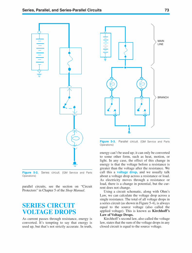
Series, Parallel, and Series-Parallel Circuits 73
Figure 5-2. Series circuit. (GM Service and PartsOperations)
MAINLINE
BRANCH
Figure 5-3. Parallel circuit. (GM Service and PartsOperations)
parallel circuits, see the section on “CircuitProtectors” in Chapter 5 of the Shop Manual.
SERIES CIRCUITVOLTAGE DROPSAs current passes through resistance, energy isconverted. It’s tempting to say that energy isused up, but that’s not strictly accurate. In truth,
energy can’t be used up; it can only be convertedto some other form, such as heat, motion, orlight. In any case, the effect of this change inenergy is that the voltage before a resistance isgreater than the voltage after the resistance. Wecall this a voltage drop, and we usually talkabout a voltage drop across a resistance or load.As electricity moves through a resistance orload, there is a change in potential, but the cur-rent does not change.
Using a circuit schematic, along with Ohm’sLaw, we can calculate the voltage drop across asingle resistance. The total of all voltage drops ina series circuit (as shown in Figure 5-4), is alwaysequal to the source voltage (also called theapplied voltage). This is known as Kirchhoff’sLaw of Voltage Drops.
Kirchhoff’s second law, also called the voltagelaw, states that the sum of the voltage drops in anyclosed circuit is equal to the source voltage.
ker88839_ch05.qxd 1/9/06 11:24 AM Page 73
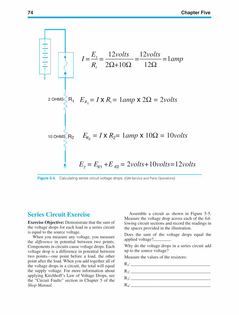
74 Chapter Five
IE
R
12volts 12volts1amp
12Ω= == =
t
t
R R
R 2
R2R1T
R2
2 OHMS
10 OHMS2
1 E = I x R = 1amp x 2Ω = 2volts
E = I x R = 1amp x 10Ω = 10volts
E = E +E = 2volts+10volts=12volts
2Ω+10Ω
1 1
Figure 5-4. Calculating series circuit voltage drops. (GM Service and Parts Operations)
Series Circuit ExerciseExercise Objective: Demonstrate that the sum ofthe voltage drops for each load in a series circuitis equal to the source voltage.
When you measure any voltage, you measurethe difference in potential between two points.Components in circuits cause voltage drops. Eachvoltage drop is a difference in potential betweentwo points—one point before a load, the otherpoint after the load. When you add together all ofthe voltage drops in a circuit, the total will equalthe supply voltage. For more information aboutapplying Kirchhoff’s Law of Voltage Drops, seethe “Circuit Faults” section in Chapter 5 of theShop Manual.
Assemble a circuit as shown in Figure 5-5.Measure the voltage drop across each of the fol-lowing circuit sections and record the readings inthe spaces provided in the illustration.
Does the sum of the voltage drops equal theapplied voltage?————Why do the voltage drops in a series circuit addup to the source voltage?
Measure the values of the resistors:
R1: ____________________________________
R2: ____________________________________
R3: ____________________________________
R4: ____________________________________
ker88839_ch05.qxd 1/9/06 11:24 AM Page 74
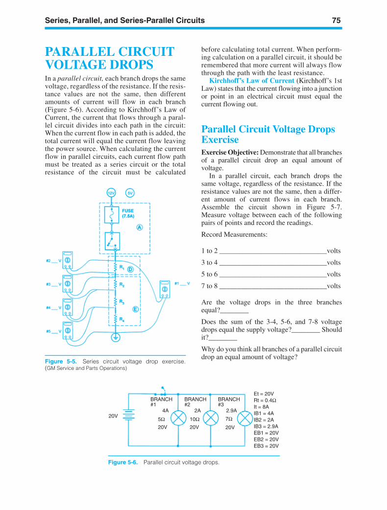
Series, Parallel, and Series-Parallel Circuits 75
Figure 5-5. Series circuit voltage drop exercise.(GM Service and Parts Operations)
20V
BRANCH#1
4A 2A 2.9A
BRANCH#2
BRANCH#3
5Ω 10Ω 7Ω20V20V 20V
Et = 20VRt = 0.4ΩIt = 8AIB1 = 4AIB2 = 2AIB3 = 2.9AEB1 = 20VEB2 = 20VEB3 = 20V
PARALLEL CIRCUITVOLTAGE DROPSIn a parallel circuit, each branch drops the samevoltage, regardless of the resistance. If the resis-tance values are not the same, then differentamounts of current will flow in each branch(Figure 5-6). According to Kirchhoff’s Law ofCurrent, the current that flows through a paral-lel circuit divides into each path in the circuit:When the current flow in each path is added, thetotal current will equal the current flow leavingthe power source. When calculating the currentflow in parallel circuits, each current flow pathmust be treated as a series circuit or the totalresistance of the circuit must be calculated
before calculating total current. When perform-ing calculation on a parallel circuit, it should beremembered that more current will always flowthrough the path with the least resistance.
Kirchhoff’s Law of Current (Kirchhoff’s 1stLaw) states that the current flowing into a junctionor point in an electrical circuit must equal thecurrent flowing out.
Parallel Circuit Voltage DropsExerciseExercise Objective: Demonstrate that all branchesof a parallel circuit drop an equal amount ofvoltage.
In a parallel circuit, each branch drops thesame voltage, regardless of the resistance. If theresistance values are not the same, then a differ-ent amount of current flows in each branch.Assemble the circuit shown in Figure 5-7.Measure voltage between each of the followingpairs of points and record the readings.
Record Measurements:
1 to 2 ______________________________volts
3 to 4 ______________________________volts
5 to 6 ______________________________volts
7 to 8 ______________________________volts
Are the voltage drops in the three branchesequal?________
Does the sum of the 3-4, 5-6, and 7-8 voltagedrops equal the supply voltage?________ Shouldit?________
Why do you think all branches of a parallel circuitdrop an equal amount of voltage?
Figure 5-6. Parallel circuit voltage drops.
ker88839_ch05.qxd 1/9/06 11:24 AM Page 75
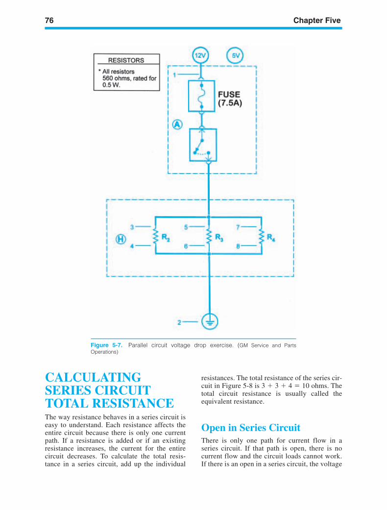
76 Chapter Five
Figure 5-7. Parallel circuit voltage drop exercise. (GM Service and PartsOperations)
CALCULATINGSERIES CIRCUITTOTAL RESISTANCEThe way resistance behaves in a series circuit iseasy to understand. Each resistance affects theentire circuit because there is only one currentpath. If a resistance is added or if an existingresistance increases, the current for the entirecircuit decreases. To calculate the total resis-tance in a series circuit, add up the individual
resistances. The total resistance of the series cir-cuit in Figure 5-8 is 3 3 4 10 ohms. Thetotal circuit resistance is usually called theequivalent resistance.
Open in Series CircuitThere is only one path for current flow in aseries circuit. If that path is open, there is nocurrent flow and the circuit loads cannot work.If there is an open in a series circuit, the voltage
ker88839_ch05.qxd 1/9/06 11:24 AM Page 76
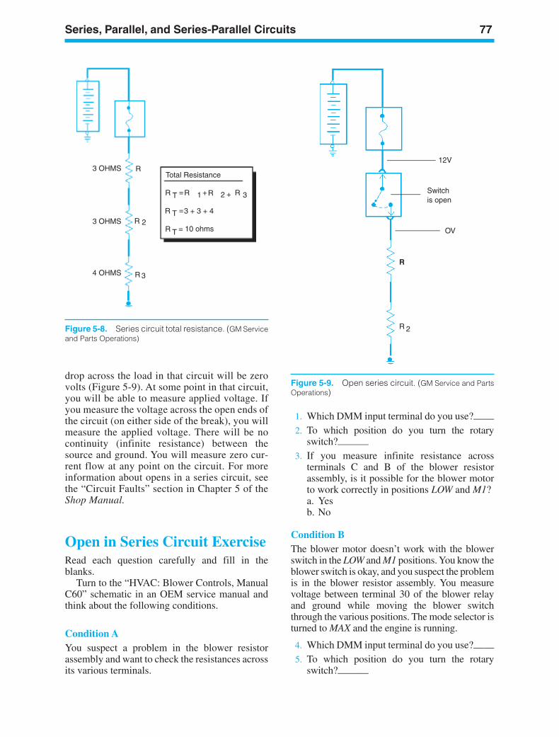
Series, Parallel, and Series-Parallel Circuits 77
3 OHMS
3 OHMS
4 OHMS
R
R
R
2
3
Total Resistance
R R R RT 1 2= ++ 3
R T =3 + 3 + 4
R T = 10 ohms
Figure 5-8. Series circuit total resistance. (GM Serviceand Parts Operations)
12V
Switchis open
OV
R
R 2
Figure 5-9. Open series circuit. (GM Service and PartsOperations)
1. Which DMM input terminal do you use?——2. To which position do you turn the rotary
switch?———3. If you measure infinite resistance across
terminals C and B of the blower resistorassembly, is it possible for the blower motorto work correctly in positions LOW and M1?a. Yesb. No
Condition BThe blower motor doesn’t work with the blowerswitch in the LOW and M1 positions. You know theblower switch is okay, and you suspect the problemis in the blower resistor assembly. You measurevoltage between terminal 30 of the blower relayand ground while moving the blower switchthrough the various positions. The mode selector isturned to MAX and the engine is running.
4. Which DMM input terminal do you use?——5. To which position do you turn the rotary
switch?———
drop across the load in that circuit will be zerovolts (Figure 5-9). At some point in that circuit,you will be able to measure applied voltage. Ifyou measure the voltage across the open ends ofthe circuit (on either side of the break), you willmeasure the applied voltage. There will be nocontinuity (infinite resistance) between thesource and ground. You will measure zero cur-rent flow at any point on the circuit. For moreinformation about opens in a series circuit, seethe “Circuit Faults” section in Chapter 5 of theShop Manual.
Open in Series Circuit ExerciseRead each question carefully and fill in theblanks.
Turn to the “HVAC: Blower Controls, ManualC60” schematic in an OEM service manual andthink about the following conditions.
Condition AYou suspect a problem in the blower resistorassembly and want to check the resistances acrossits various terminals.
ker88839_ch05.qxd 1/9/06 11:24 AM Page 77
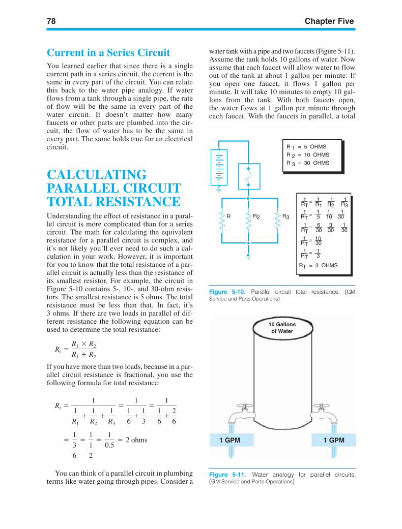
78 Chapter Five
R 1 = 5 OHMS
R 2 = 10 OHMS
R 3 = 30 OHMS
1 1 1 1
1 1 1 1
1 6 3 1
1 10
1 1
RT = 3 OHMS
RT
RT 5 10 30
RT 30 30 30
RT
RT
R1 R2 R3
30
3
=
=
=
=
=
R R2 R3
Figure 5-10. Parallel circuit total resistance. (GMService and Parts Operations)
10 Gallonsof Water
1 GPM 1 GPM
Figure 5-11. Water analogy for parallel circuits.(GM Service and Parts Operations)
Current in a Series CircuitYou learned earlier that since there is a singlecurrent path in a series circuit, the current is thesame in every part of the circuit. You can relatethis back to the water pipe analogy. If waterflows from a tank through a single pipe, the rateof flow will be the same in every part of thewater circuit. It doesn’t matter how manyfaucets or other parts are plumbed into the cir-cuit, the flow of water has to be the same inevery part. The same holds true for an electricalcircuit.
CALCULATINGPARALLEL CIRCUITTOTAL RESISTANCEUnderstanding the effect of resistance in a paral-lel circuit is more complicated than for a seriescircuit. The math for calculating the equivalentresistance for a parallel circuit is complex, andit’s not likely you’ll ever need to do such a cal-culation in your work. However, it is importantfor you to know that the total resistance of a par-allel circuit is actually less than the resistance ofits smallest resistor. For example, the circuit inFigure 5-10 contains 5-, 10-, and 30-ohm resis-tors. The smallest resistance is 5 ohms. The totalresistance must be less than that. In fact, it’s3 ohms. If there are two loads in parallel of dif-ferent resistance the following equation can beused to determine the total resistance:
If you have more than two loads, because in a par-allel circuit resistance is fractional, you use thefollowing formula for total resistance:
You can think of a parallel circuit in plumbingterms like water going through pipes. Consider a
=
1
3
6
=
1
1
2
=
1
0.5= 2 ohms
Rt 1
1
R1
1
R2
1
R3
1
1
6
1
3
1
1
6
2
6
Rt R1 R2
R1 R2
water tank with a pipe and two faucets (Figure 5-11).Assume the tank holds 10 gallons of water. Nowassume that each faucet will allow water to flowout of the tank at about 1 gallon per minute: Ifyou open one faucet, it flows 1 gallon perminute. It will take 10 minutes to empty 10 gal-lons from the tank. With both faucets open,the water flows at 1 gallon per minute througheach faucet. With the faucets in parallel, a total
ker88839_ch05.qxd 1/9/06 11:24 AM Page 78
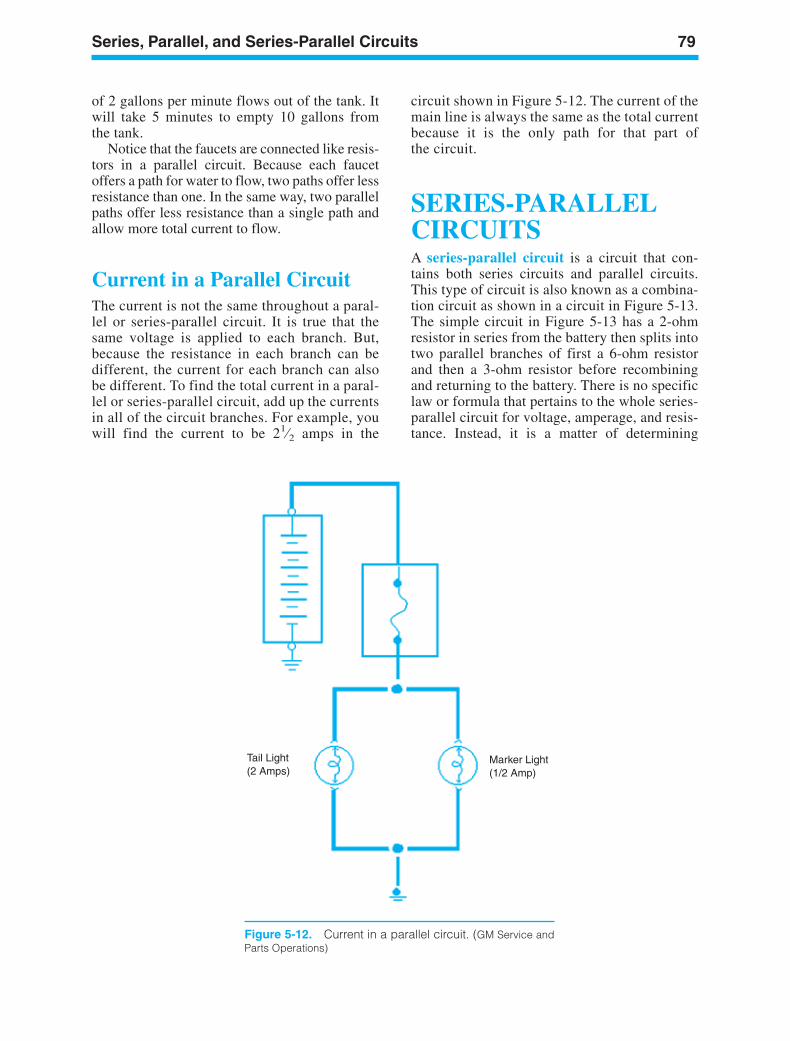
Series, Parallel, and Series-Parallel Circuits 79
Tail Light(2 Amps)
Marker Light(1/2 Amp)
Figure 5-12. Current in a parallel circuit. (GM Service andParts Operations)
of 2 gallons per minute flows out of the tank. Itwill take 5 minutes to empty 10 gallons fromthe tank.
Notice that the faucets are connected like resis-tors in a parallel circuit. Because each faucetoffers a path for water to flow, two paths offer lessresistance than one. In the same way, two parallelpaths offer less resistance than a single path andallow more total current to flow.
Current in a Parallel CircuitThe current is not the same throughout a paral-lel or series-parallel circuit. It is true that thesame voltage is applied to each branch. But,because the resistance in each branch can bedifferent, the current for each branch can alsobe different. To find the total current in a paral-lel or series-parallel circuit, add up the currentsin all of the circuit branches. For example, youwill find the current to be 21⁄2 amps in the
circuit shown in Figure 5-12. The current of themain line is always the same as the total currentbecause it is the only path for that part ofthe circuit.
SERIES-PARALLELCIRCUITSA series-parallel circuit is a circuit that con-tains both series circuits and parallel circuits.This type of circuit is also known as a combina-tion circuit as shown in a circuit in Figure 5-13.The simple circuit in Figure 5-13 has a 2-ohmresistor in series from the battery then splits intotwo parallel branches of first a 6-ohm resistorand then a 3-ohm resistor before recombiningand returning to the battery. There is no specificlaw or formula that pertains to the whole series-parallel circuit for voltage, amperage, and resis-tance. Instead, it is a matter of determining
ker88839_ch05.qxd 1/9/06 11:24 AM Page 79
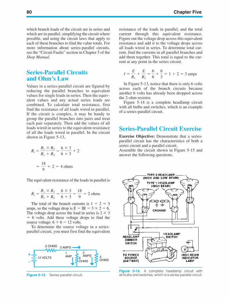
80 Chapter Five
Figure 5-14. A complete headlamp circuit withall bulbs and switches, which is a series-parallel circuit.
which branch loads of the circuit are in series andwhich are in parallel, simplifying the circuit wherepossible, and using the circuit laws that apply toeach of these branches to find the value totals. Formore information about series-parallel circuits,see the “Circuit Faults” section in Chapter 5 of theShop Manual.
Series-Parallel Circuitsand Ohm’s LawValues in a series-parallel circuit are figured byreducing the parallel branches to equivalentvalues for single loads in series. Then the equiv-alent values and any actual series loads arecombined. To calculate total resistance, firstfind the resistance of all loads wired in parallel.If the circuit is complex, it may be handy togroup the parallel branches into pairs and treateach pair separately. Then add the values of allloads wired in series to the equivalent resistanceof all the loads wired in parallel. In the circuitshown in Figure 5-13,
The equivalent resistance of the loads in parallel is
The total of the branch currents is 1 2 3amps, so the voltage drop is E IR 3 2 6.The voltage drop across the load in series is 2 3 6 volts. Add these voltage drops to find thesource voltage: 6 6 12 volts.
To determine the source voltage in a series-parallel circuit, you must first find the equivalent
Rt R1 R2
R1 R2
6 3
6 3
18
9 2 ohms
=
18
9+ 2 = 4 ohms
Rt R1 R2
R1 R2
6 3
6 3 2
resistance of the loads in parallel, and the totalcurrent through this equivalent resistance.Figure out the voltage drop across this equivalentresistance and add it to the voltage drops acrossall loads wired in series. To determine total cur-rent, find the currents in all parallel branches andadd them together. This total is equal to the cur-rent at any point in the series circuit.
In Figure 5-13, notice that there is only 6 voltsacross each of the branch circuits becauseanother 6 volts has already been dropped acrossthe 2-ohm resistor.
Figure 5-14 is a complete headlamp circuitwith all bulbs and switches, which is an exampleof a series-parallel circuit.
Series-Parallel Circuit ExerciseExercise Objective: Demonstrate that a series-parallel circuit has the characteristics of both aseries circuit and a parallel circuit.Assemble the circuit shown in Figure 5-15 andanswer the following questions.
I E
R1
E
R2
6
6
6
3 1 2 3 amps
2 OHMS 3 AMPS
3OHMS
2AMPS
6OHMS
1AMP12 VOLTS
Figure 5-13. Series-parallel circuit.
ker88839_ch05.qxd 1/9/06 11:24 AM Page 80
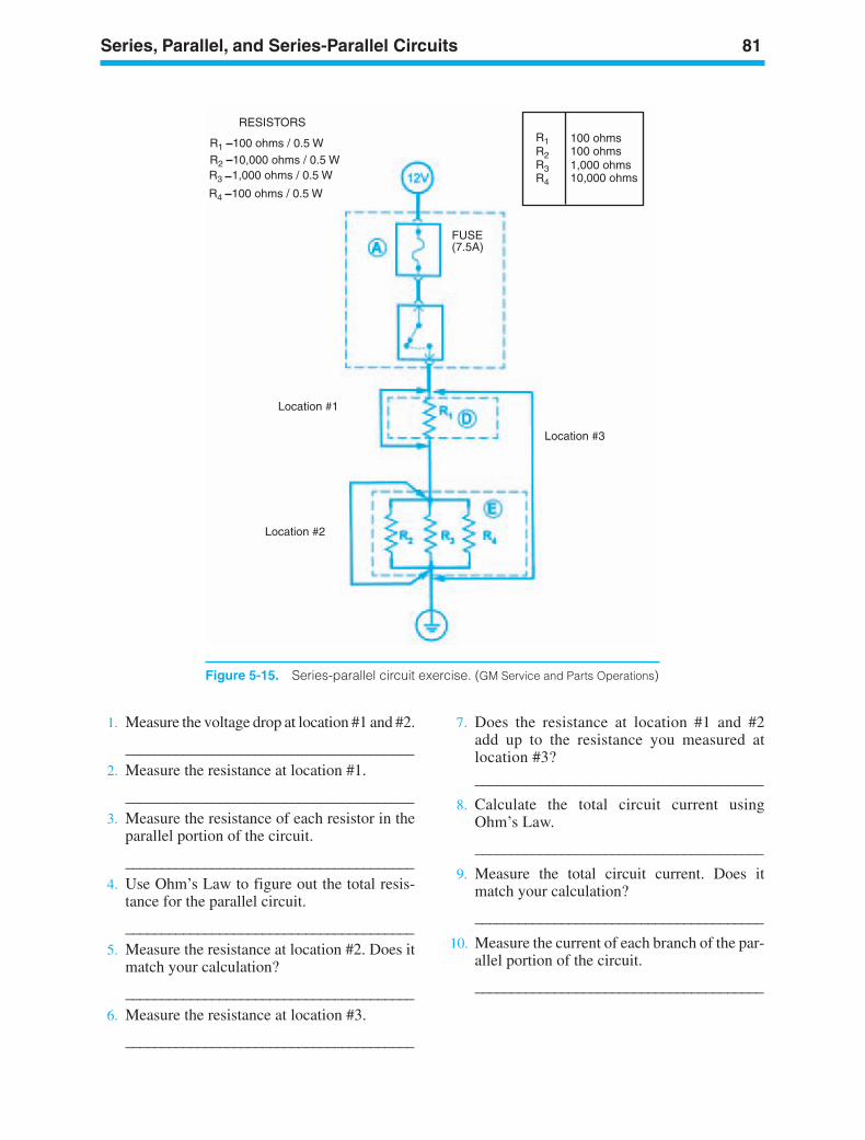
Series, Parallel, and Series-Parallel Circuits 81
RESISTORS
R1 100 ohms / 0.5 WR2 10,000 ohms / 0.5 WR3 1,000 ohms / 0.5 W
R4 100 ohms / 0.5 W
R1
R3
R2
R4
100 ohms1,000 ohms10,000 ohms
100 ohms
FUSE(7.5A)
Location #3
Location #1
Location #2
Figure 5-15. Series-parallel circuit exercise. (GM Service and Parts Operations)
1. Measure the voltage drop at location #1 and #2.
________________________________________2. Measure the resistance at location #1.
________________________________________3. Measure the resistance of each resistor in the
parallel portion of the circuit.
________________________________________4. Use Ohm’s Law to figure out the total resis-
tance for the parallel circuit.
________________________________________5. Measure the resistance at location #2. Does it
match your calculation?
________________________________________6. Measure the resistance at location #3.
________________________________________
7. Does the resistance at location #1 and #2add up to the resistance you measured atlocation #3?________________________________________
8. Calculate the total circuit current usingOhm’s Law.
________________________________________
9. Measure the total circuit current. Does itmatch your calculation?
________________________________________
10. Measure the current of each branch of the par-allel portion of the circuit.
________________________________________
ker88839_ch05.qxd 1/9/06 11:24 AM Page 81
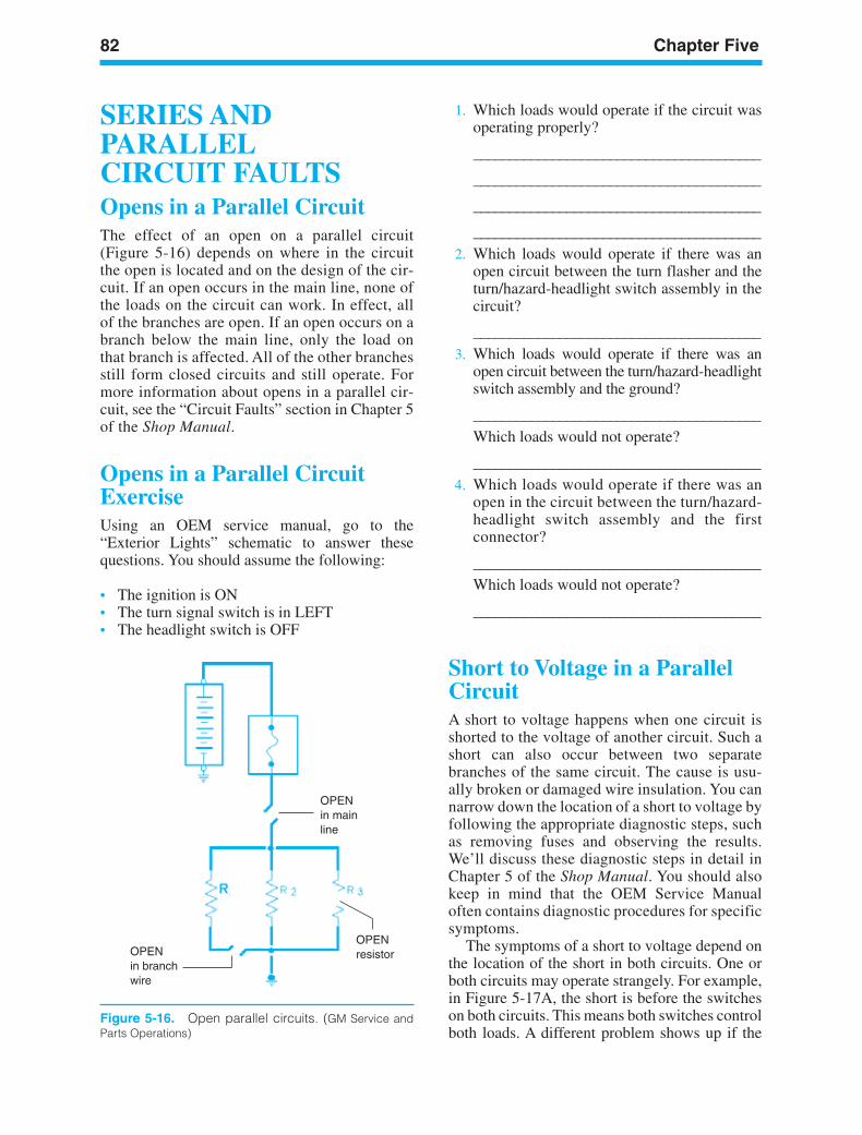
82 Chapter Five
OPENin mainline
OPENresistorOPEN
in branchwire
Figure 5-16. Open parallel circuits. (GM Service andParts Operations)
SERIES ANDPARALLEL CIRCUIT FAULTSOpens in a Parallel CircuitThe effect of an open on a parallel circuit(Figure 5-16) depends on where in the circuitthe open is located and on the design of the cir-cuit. If an open occurs in the main line, none ofthe loads on the circuit can work. In effect, allof the branches are open. If an open occurs on abranch below the main line, only the load onthat branch is affected. All of the other branchesstill form closed circuits and still operate. Formore information about opens in a parallel cir-cuit, see the “Circuit Faults” section in Chapter 5of the Shop Manual.
Opens in a Parallel CircuitExerciseUsing an OEM service manual, go to the“Exterior Lights” schematic to answer thesequestions. You should assume the following:
• The ignition is ON• The turn signal switch is in LEFT• The headlight switch is OFF
1. Which loads would operate if the circuit wasoperating properly?
________________________________________
________________________________________
________________________________________
________________________________________2. Which loads would operate if there was an
open circuit between the turn flasher and theturn/hazard-headlight switch assembly in thecircuit?
________________________________________3. Which loads would operate if there was an
open circuit between the turn/hazard-headlightswitch assembly and the ground?
________________________________________Which loads would not operate?
________________________________________4. Which loads would operate if there was an
open in the circuit between the turn/hazard-headlight switch assembly and the firstconnector?
________________________________________Which loads would not operate?
________________________________________
Short to Voltage in a ParallelCircuitA short to voltage happens when one circuit isshorted to the voltage of another circuit. Such ashort can also occur between two separatebranches of the same circuit. The cause is usu-ally broken or damaged wire insulation. You cannarrow down the location of a short to voltage byfollowing the appropriate diagnostic steps, suchas removing fuses and observing the results.We’ll discuss these diagnostic steps in detail inChapter 5 of the Shop Manual. You should alsokeep in mind that the OEM Service Manualoften contains diagnostic procedures for specificsymptoms.
The symptoms of a short to voltage depend onthe location of the short in both circuits. One orboth circuits may operate strangely. For example,in Figure 5-17A, the short is before the switcheson both circuits. This means both switches controlboth loads. A different problem shows up if the
ker88839_ch05.qxd 1/9/06 11:24 AM Page 82
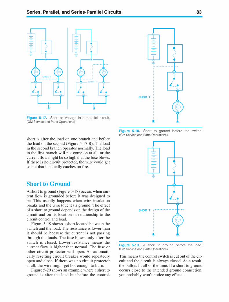
Series, Parallel, and Series-Parallel Circuits 83
Figure 5-17. Short to voltage in a parallel circuit.(GM Service and Parts Operations)
Figure 5-18. Short to ground before the switch.(GM Service and Parts Operations)
Figure 5-19. A short to ground before the load.(GM Service and Parts Operations)
short is after the load on one branch and beforethe load on the second (Figure 5-17 B). The loadin the second branch operates normally. The loadin the first branch will not come on at all, or thecurrent flow might be so high that the fuse blows.If there is no circuit protector, the wire could getso hot that it actually catches on fire.
Short to GroundA short to ground (Figure 5-18) occurs when cur-rent flow is grounded before it was designed tobe. This usually happens when wire insulationbreaks and the wire touches a ground. The effectof a short to ground depends on the design of thecircuit and on its location in relationship to thecircuit control and load.
Figure 5-19 shows a short located between theswitch and the load. The resistance is lower thanit should be because the current is not passingthrough the loads. The fuse blows only after theswitch is closed. Lower resistance means thecurrent flow is higher than normal. The fuse orother circuit protector will open. An automati-cally resetting circuit breaker would repeatedlyopen and close. If there was no circuit protectorat all, the wire might get hot enough to burn.
Figure 5-20 shows an example where a short toground is after the load but before the control.
This means the control switch is cut out of the cir-cuit and the circuit is always closed. As a result,the bulb is lit all of the time. If a short to groundoccurs close to the intended ground connection,you probably won’t notice any effects.
ker88839_ch05.qxd 1/9/06 11:24 AM Page 83
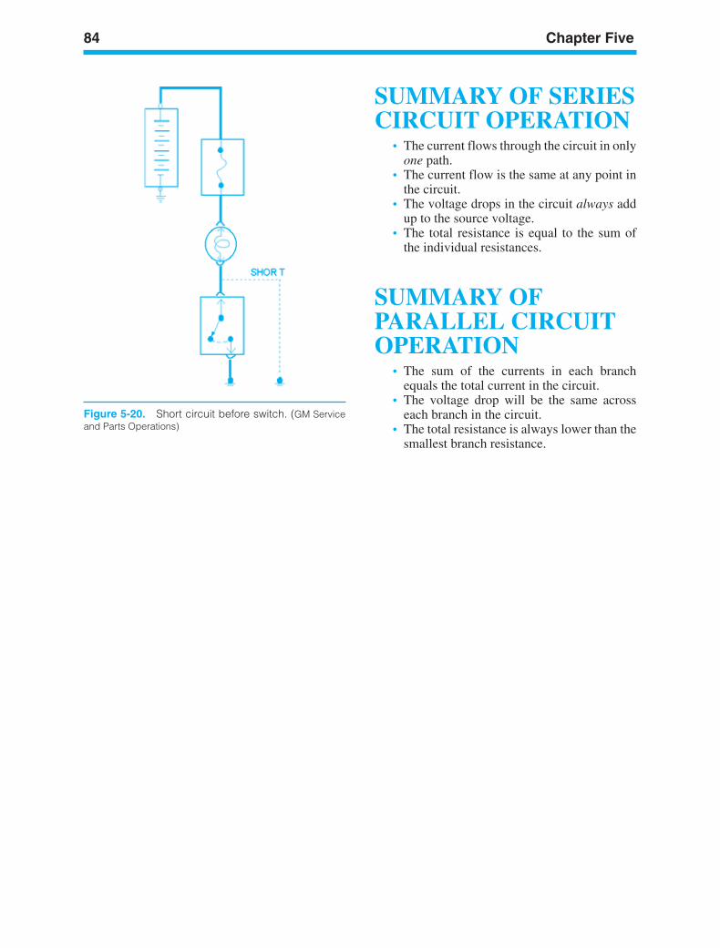
84 Chapter Five
Figure 5-20. Short circuit before switch. (GM Serviceand Parts Operations)
SUMMARY OF SERIESCIRCUIT OPERATION
• The current flows through the circuit in onlyone path.
• The current flow is the same at any point inthe circuit.
• The voltage drops in the circuit always addup to the source voltage.
• The total resistance is equal to the sum ofthe individual resistances.
SUMMARY OFPARALLEL CIRCUITOPERATION
• The sum of the currents in each branchequals the total current in the circuit.
• The voltage drop will be the same acrosseach branch in the circuit.
• The total resistance is always lower than thesmallest branch resistance.
ker88839_ch05.qxd 1/9/06 11:24 AM Page 84
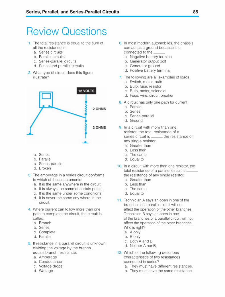
Series, Parallel, and Series-Parallel Circuits 85
Review Questions1. The total resistance is equal to the sum of
all the resistance in:a. Series circuitsb. Parallel circuitsc. Series-parallel circuitsd. Series and parallel circuits
2. What type of circuit does this figureillustrate?
a. Seriesb. Parallelc. Series-paralleld. Broken
3. The amperage in a series circuit conformsto which of these statements:a. It is the same anywhere in the circuit.b. It is always the same at certain points.c. It is the same under some conditions.d. It is never the same any where in the
circuit.
4. Where current can follow more than onepath to complete the circuit, the circuit iscalled:a. Branchb. Seriesc. Completed. Parallel
5. If resistance in a parallel circuit is unknown,dividing the voltage by the branch ————equals branch resistance.a. Amperageb. Conductancec. Voltage dropsd. Wattage
6. In most modern automobiles, the chassiscan act as a ground because it isconnected to the ———a. Negative battery terminalb. Generator output boltc. Generator groundd. Positive battery terminal
7. The following are all examples of loads:a. Switch, motor, bulbb. Bulb, fuse, resistorc. Bulb, motor, solenoidd. Fuse, wire, circuit breaker
8. A circuit has only one path for current.a. Parallelb. Seriesc. Series-paralleld. Ground
9. In a circuit with more than one resistor, the total resistance of a series circuit is ——— the resistance ofany single resistor.a. Greater thanb. Less thanc. The samed. Equal to
10. In a circuit with more than one resistor, thetotal resistance of a parallel circuit is ———the resistance of any single resistor.a. Greater thanb. Less thanc. The samed. Equal to
11. Technician A says an open in one of thebranches of a parallel circuit will not affect the operation of the other branches.Technician B says an open in one of the branches of a parallel circuit will notaffect the operation of the other branches.Who is right?a. A onlyb. B onlyc. Both A and Bd. Neither A nor B
12. Which of the following describescharacteristics of two resistancesconnected in series?a. They must have different resistances.b. They must have the same resistance.
ker88839_ch05.qxd 1/9/06 11:24 AM Page 85
86 Chapter Five
c. The voltage drop will be equal acrosseach.
d. There will be only one path for current to flow.
13. What happens when one resistance in aseries circuit is open?a. The current in the other resistance is at
maximum.b. The current is zero at all resistances.c. The voltage drop increases.d. The current stays the same.
14. Which of the following is true regarding a series circuit with unequalresistances?a. The highest resistance has the most
current.b. The lowest resistance has the most
current.c. The lowest resistance has the highest
voltage drop.d. The highest resistance has the highest
voltage drop.
15. Which of the following is true regarding aparallel circuit with unequal branchresistance?a. The current is equal in all branches.b. The current is higher in the highest
resistance branch.c. The voltage is higher in the lowest
resistance branch.d. The current is higher in the lowest
resistance branch.
16. The total resistance of a series circuit is:a. Equal to the currentb. The sum of the individual
resistancesc. Always a high resistanced. Each resistance multiplied together
17. In a circuit with three parallel branches, ifone branch opens, the total current will:a. Increaseb. Decreasec. Stay the samed. Blow the fuse
18. Which of the following is true regardingseries-parallel circuits?a. Voltages are always equal across each
load.b. Current is equal throughout the circuit.
c. Only one current path is possible.d. Voltage applied to the parallel
branches is the source voltage minusany voltage drop across loads wired inseries.
19. The amperage in a series circuit is:a. The same throughout the
entire circuitb. Different, depending on the number of
loadsc. Sometimes the same, depending on the
number of loadsd. Never the same anywhere in the
circuit
20. What does a short circuit to ground beforethe load cause?a. An increase in circuit resistanceb. Voltage to increasec. Current flow to Increased. Current flow to decrease
21. Three lamps are connected in parallel. What would happen if one lamp burns out?a. The other two lamps would go out.b. Current flow would increase through the
“good” lamps.c. Total circuit resistance would go up.d. Voltage at the other two lamps would
increase.
22. Total resistance in a series circuit is equalto the:a. Sum of the individual resistancesb. Voltage drop across the resistor with the
highest valuec. Current in the circuit divided by the
source voltaged. Percent of error in the voltmeter itself
23. Parallel circuits are being discussed. Technician A says that adding more branches to a parallel circuit reduces total circuit resistance.Technician B says that adding morebranches to a parallel circuit increases the total current flowing in the circuit. Who is right?a. Technician Ab. Technician Bc. Both A and Bd. Neither A nor B
ker88839_ch05.qxd 1/9/06 11:24 AM Page 86
c. Both A and Bd. Neither A nor B
26. What is the name for a circuit that allows only one path for current to flow?a. Series circuitb. Parallel circuitc. Series-parallel circuitd. Integrated circuit
Series, Parallel, and Series-Parallel Circuits 87
24. The sum of all voltage drops in a seriescircuit equals the:a. Voltage across the largest loadb. Voltage across the smallest loadc. Source or applied voltage
25. What is the name for a circuit that allowstwo or more paths for current flow?a. Series circuitb. Parallel circuit
ker88839_ch05.qxd 1/9/06 11:24 AM Page 87

ker88839_ch05.qxd 1/9/06 11:24 AM Page 88
LEARNINGOBJECTIVESUpon completion and review of this chapter, youshould be able to:
• Identify the wire types and materials used inautomotive wiring.
• Explain how wire size is determined by boththe American Wire Gauge (AWG) systemand the metric system.
• Explain the use of a wiring harness anddefine the different types of connectors andterminal ends.
• Define the ground, parallel data, serial data,and multiplexing paths.
• Identify common electrical parts and explaintheir operation.
• Explain the color-coding of automotivewiring.
• Explain the terms used in the language ofautomotive wiring diagrams.
• Identify the component symbols used inautomotive wiring schematics.
• Explain the purpose of a wiring diagram orschematic.
KEY TERMSCircuit NumberColor CodingComponent SymbolsConnectorsGround CableInstallation DiagramMetric Wire SizesMultiplexingPrimary WiringSchematic DiagramSolenoidSwitchesWeatherproof ConnectorsWire Gauge DiagramWire Gauge NumberWiring Harness
89
6ElectricalDiagrams and Wiring
ker88839_ch06.qxd 1/9/06 11:25 AM Page 89
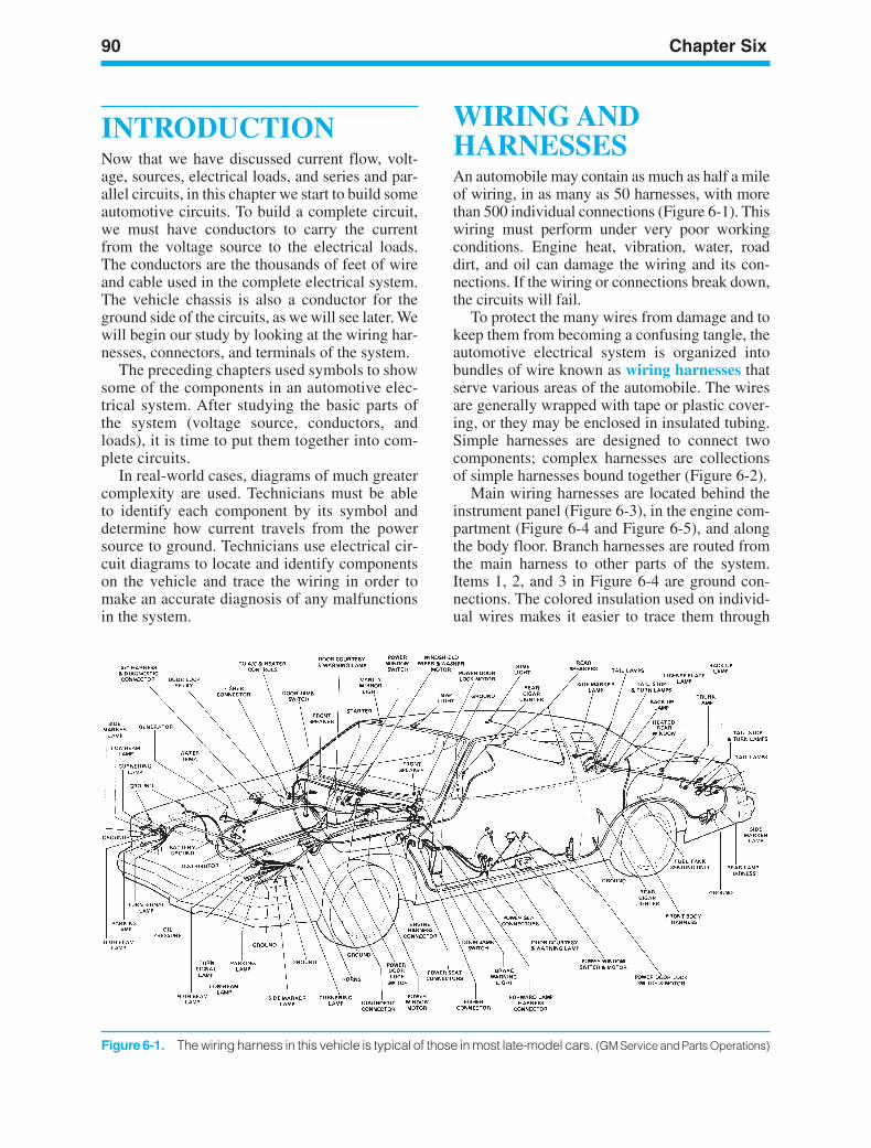
90 Chapter Six
Figure 6-1. The wiring harness in this vehicle is typical of those in most late-model cars. (GM Service and Parts Operations)
INTRODUCTIONNow that we have discussed current flow, volt-age, sources, electrical loads, and series and par-allel circuits, in this chapter we start to build someautomotive circuits. To build a complete circuit,we must have conductors to carry the currentfrom the voltage source to the electrical loads.The conductors are the thousands of feet of wireand cable used in the complete electrical system.The vehicle chassis is also a conductor for theground side of the circuits, as we will see later. Wewill begin our study by looking at the wiring har-nesses, connectors, and terminals of the system.
The preceding chapters used symbols to showsome of the components in an automotive elec-trical system. After studying the basic parts ofthe system (voltage source, conductors, andloads), it is time to put them together into com-plete circuits.
In real-world cases, diagrams of much greatercomplexity are used. Technicians must be ableto identify each component by its symbol anddetermine how current travels from the powersource to ground. Technicians use electrical cir-cuit diagrams to locate and identify componentson the vehicle and trace the wiring in order tomake an accurate diagnosis of any malfunctionsin the system.
WIRING ANDHARNESSESAn automobile may contain as much as half a mileof wiring, in as many as 50 harnesses, with morethan 500 individual connections (Figure 6-1). Thiswiring must perform under very poor workingconditions. Engine heat, vibration, water, roaddirt, and oil can damage the wiring and its con-nections. If the wiring or connections break down,the circuits will fail.
To protect the many wires from damage and tokeep them from becoming a confusing tangle, theautomotive electrical system is organized intobundles of wire known as wiring harnesses thatserve various areas of the automobile. The wiresare generally wrapped with tape or plastic cover-ing, or they may be enclosed in insulated tubing.Simple harnesses are designed to connect twocomponents; complex harnesses are collectionsof simple harnesses bound together (Figure 6-2).
Main wiring harnesses are located behind theinstrument panel (Figure 6-3), in the engine com-partment (Figure 6-4 and Figure 6-5), and alongthe body floor. Branch harnesses are routed fromthe main harness to other parts of the system.Items 1, 2, and 3 in Figure 6-4 are ground con-nections. The colored insulation used on individ-ual wires makes it easier to trace them through
ker88839_ch06.qxd 1/9/06 11:25 AM Page 90
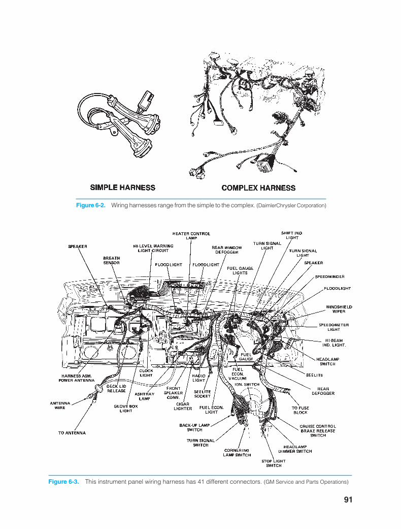
91
Figure 6-2. Wiring harnesses range from the simple to the complex. (DaimlerChrysler Corporation)
Figure 6-3. This instrument panel wiring harness has 41 different connectors. (GM Service and Parts Operations)
ker88839_ch06.qxd 1/9/06 11:25 AM Page 91
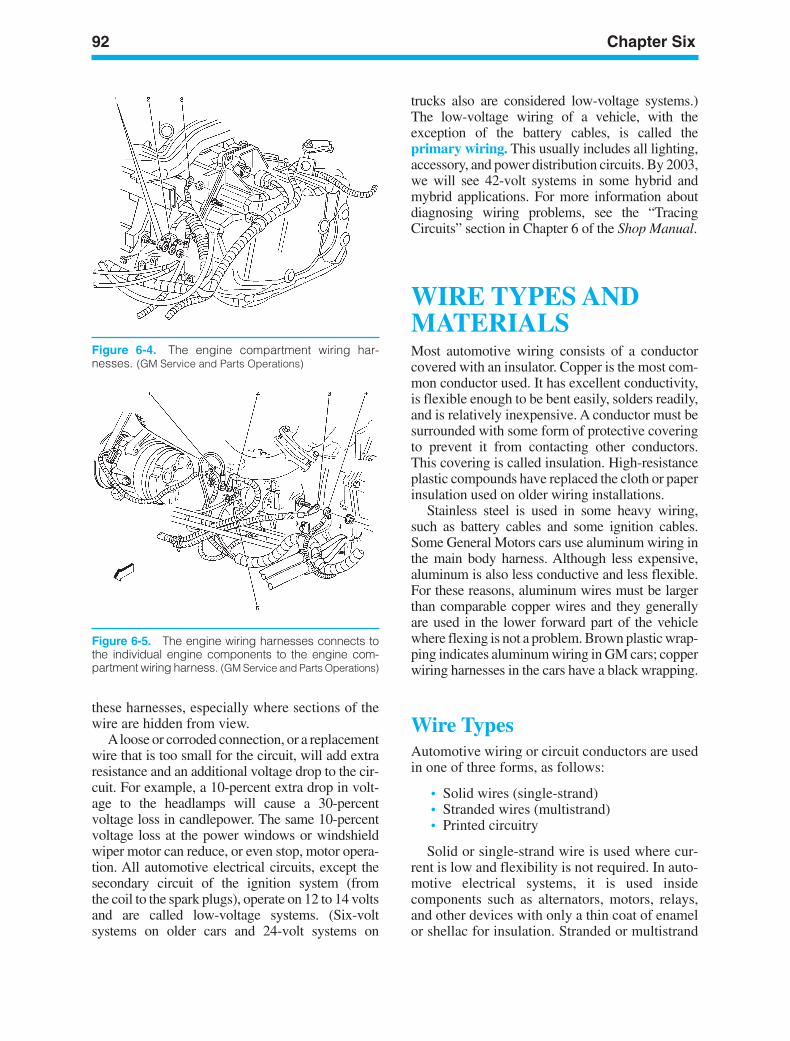
92 Chapter Six
Figure 6-4. The engine compartment wiring har-nesses. (GM Service and Parts Operations)
Figure 6-5. The engine wiring harnesses connects tothe individual engine components to the engine com-partment wiring harness. (GM Service and Parts Operations)
these harnesses, especially where sections of thewire are hidden from view.
Aloose or corroded connection, or a replacementwire that is too small for the circuit, will add extraresistance and an additional voltage drop to the cir-cuit. For example, a 10-percent extra drop in volt-age to the headlamps will cause a 30-percentvoltage loss in candlepower. The same 10-percentvoltage loss at the power windows or windshieldwiper motor can reduce, or even stop, motor opera-tion. All automotive electrical circuits, except thesecondary circuit of the ignition system (fromthe coil to the spark plugs), operate on 12 to 14 voltsand are called low-voltage systems. (Six-voltsystems on older cars and 24-volt systems on
trucks also are considered low-voltage systems.)The low-voltage wiring of a vehicle, with theexception of the battery cables, is called theprimary wiring. This usually includes all lighting,accessory, and power distribution circuits. By 2003,we will see 42-volt systems in some hybrid andmybrid applications. For more information aboutdiagnosing wiring problems, see the “TracingCircuits” section in Chapter 6 of the Shop Manual.
WIRE TYPES ANDMATERIALSMost automotive wiring consists of a conductorcovered with an insulator. Copper is the most com-mon conductor used. It has excellent conductivity,is flexible enough to be bent easily, solders readily,and is relatively inexpensive. A conductor must besurrounded with some form of protective coveringto prevent it from contacting other conductors.This covering is called insulation. High-resistanceplastic compounds have replaced the cloth or paperinsulation used on older wiring installations.
Stainless steel is used in some heavy wiring,such as battery cables and some ignition cables.Some General Motors cars use aluminum wiring inthe main body harness. Although less expensive,aluminum is also less conductive and less flexible.For these reasons, aluminum wires must be largerthan comparable copper wires and they generallyare used in the lower forward part of the vehiclewhere flexing is not a problem. Brown plastic wrap-ping indicates aluminum wiring in GM cars; copperwiring harnesses in the cars have a black wrapping.
Wire TypesAutomotive wiring or circuit conductors are usedin one of three forms, as follows:
• Solid wires (single-strand)• Stranded wires (multistrand)• Printed circuitry
Solid or single-strand wire is used where cur-rent is low and flexibility is not required. In auto-motive electrical systems, it is used insidecomponents such as alternators, motors, relays,and other devices with only a thin coat of enamelor shellac for insulation. Stranded or multistrand
ker88839_ch06.qxd 1/9/06 11:25 AM Page 92
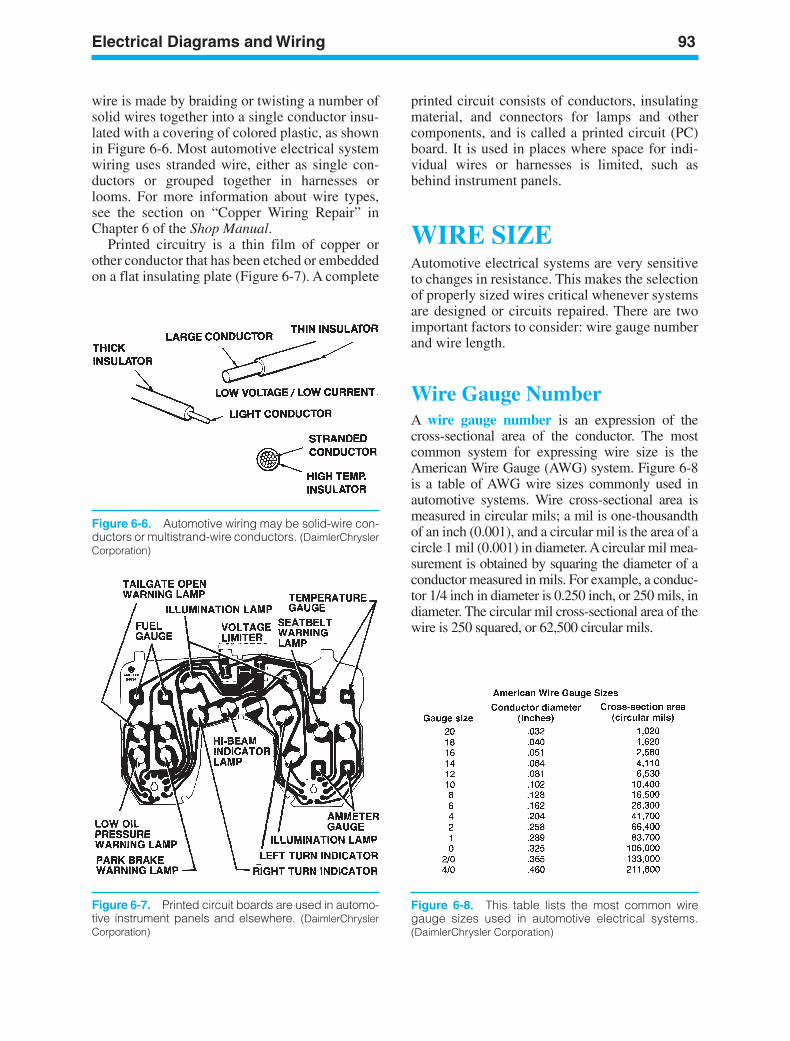
Electrical Diagrams and Wiring 93
Figure 6-6. Automotive wiring may be solid-wire con-ductors or multistrand-wire conductors. (DaimlerChryslerCorporation)
Figure 6-7. Printed circuit boards are used in automo-tive instrument panels and elsewhere. (DaimlerChryslerCorporation)
wire is made by braiding or twisting a number ofsolid wires together into a single conductor insu-lated with a covering of colored plastic, as shownin Figure 6-6. Most automotive electrical systemwiring uses stranded wire, either as single con-ductors or grouped together in harnesses orlooms. For more information about wire types,see the section on “Copper Wiring Repair” inChapter 6 of the Shop Manual.
Printed circuitry is a thin film of copper orother conductor that has been etched or embeddedon a flat insulating plate (Figure 6-7). A complete
printed circuit consists of conductors, insulatingmaterial, and connectors for lamps and othercomponents, and is called a printed circuit (PC)board. It is used in places where space for indi-vidual wires or harnesses is limited, such asbehind instrument panels.
WIRE SIZEAutomotive electrical systems are very sensitiveto changes in resistance. This makes the selectionof properly sized wires critical whenever systemsare designed or circuits repaired. There are twoimportant factors to consider: wire gauge numberand wire length.
Wire Gauge NumberA wire gauge number is an expression of thecross-sectional area of the conductor. The mostcommon system for expressing wire size is theAmerican Wire Gauge (AWG) system. Figure 6-8is a table of AWG wire sizes commonly used inautomotive systems. Wire cross-sectional area ismeasured in circular mils; a mil is one-thousandthof an inch (0.001), and a circular mil is the area of acircle 1 mil (0.001) in diameter. A circular mil mea-surement is obtained by squaring the diameter of aconductor measured in mils. For example, a conduc-tor 1/4 inch in diameter is 0.250 inch, or 250 mils, indiameter. The circular mil cross-sectional area of thewire is 250 squared, or 62,500 circular mils.
Figure 6-8. This table lists the most common wiregauge sizes used in automotive electrical systems.(DaimlerChrysler Corporation)
ker88839_ch06.qxd 1/9/06 11:25 AM Page 93
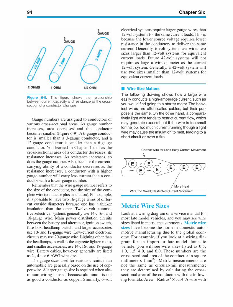
94 Chapter Six
Figure 6-9. This figure shows the relationshipbetween current capacity and resistance as the cross-section of a conductor changes.
Correct Wire for Load Easy Current Movement
Wire Too Small; Restricted Current Movement
More Heat
E EE E
EE E
Gauge numbers are assigned to conductors ofvarious cross-sectional areas. As gauge numberincreases, area decreases and the conductorbecomes smaller (Figure 6-9). A 6-gauge conduc-tor is smaller than a 3-gauge conductor, and a12-gauge conductor is smaller than a 6-gaugeconductor. You learned in Chapter 1 that as thecross-sectional area of a conductor decreases, itsresistance increases. As resistance increases, sodoes the gauge number. Also, because the current-carrying ability of a conductor decreases as theresistance increases, a conductor with a highergauge number will carry less current than a con-ductor with a lower gauge number.
Remember that the wire gauge number refers tothe size of the conductor, not the size of the com-plete wire (conductor plus insulation). For example,it is possible to have two 16-gauge wires of differ-ent outside diameters because one has a thickerinsulation than the other. Twelve-volt automo-tive zelectrical systems generally use 14-, 16-, and18-gauge wire. Main power distribution circuitsbetween the battery and alternator, ignition switch,fuse box, headlamp switch, and larger accessoriesuse 10- and 12-gauge wire. Low-current electroniccircuits may use 20-gauge wire. Lighting other thanthe headlamps, as well as the cigarette lighter, radio,and smaller accessories, use 14-, 16-, and 18-gaugewire. Battery cables, however, generally are listedas 2-, 4-, or 6-AWG wire size.
The gauge sizes used for various circuits in anautomobile are generally based on the use of cop-per wire. A larger gauge size is required when alu-minum wiring is used, because aluminum is notas good a conductor as copper. Similarly, 6-volt
electrical systems require larger-gauge wires than12-volt systems for the same current loads. This isbecause the lower source voltage requires lowerresistance in the conductors to deliver the samecurrent. Generally, 6-volt systems use wires twosizes larger than 12-volt systems for equivalentcurrent loads. Future 42-volt systems will notrequire as large a wire diameter as the current12-volt system. Generally, a 42-volt system willuse two sizes smaller than 12-volt systems forequivalent current loads.
Wire Size Matters
The following drawing shows how a large wireeasily conducts a high-amperage current, such asyou would find going to a starter motor. The heav-iest wires are often called cables, but their pur-pose is the same. On the other hand, a compara-tively light wire tends to restrict current flow, whichmay generate excess heat if the wire is too smallfor the job.Too much current running though a lightwire may cause the insulation to melt, leading to ashort circuit or even a fire.
Metric Wire SizesLook at a wiring diagram or a service manual formost late model vehicles, and you may see wiresizes listed in metric measurements. Metric wiresizes have become the norm in domestic auto-motive manufacturing due to the global econ-omy. For example, if you look at a wiring dia-gram for an import or late-model domesticvehicle, you will see wire sizes listed as 0.5,1.0, 1.5, 4.0, and 6.0. These numbers are thecross-sectional area of the conductor in squaremillimeters (mm2). Metric measurements arenot the same as circular-mil measurements;they are determined by calculating the cross-sectional area of the conductor with the follow-ing formula: Area = Radius2 × 3.14. A wire with
ker88839_ch06.qxd 1/9/06 11:25 AM Page 94
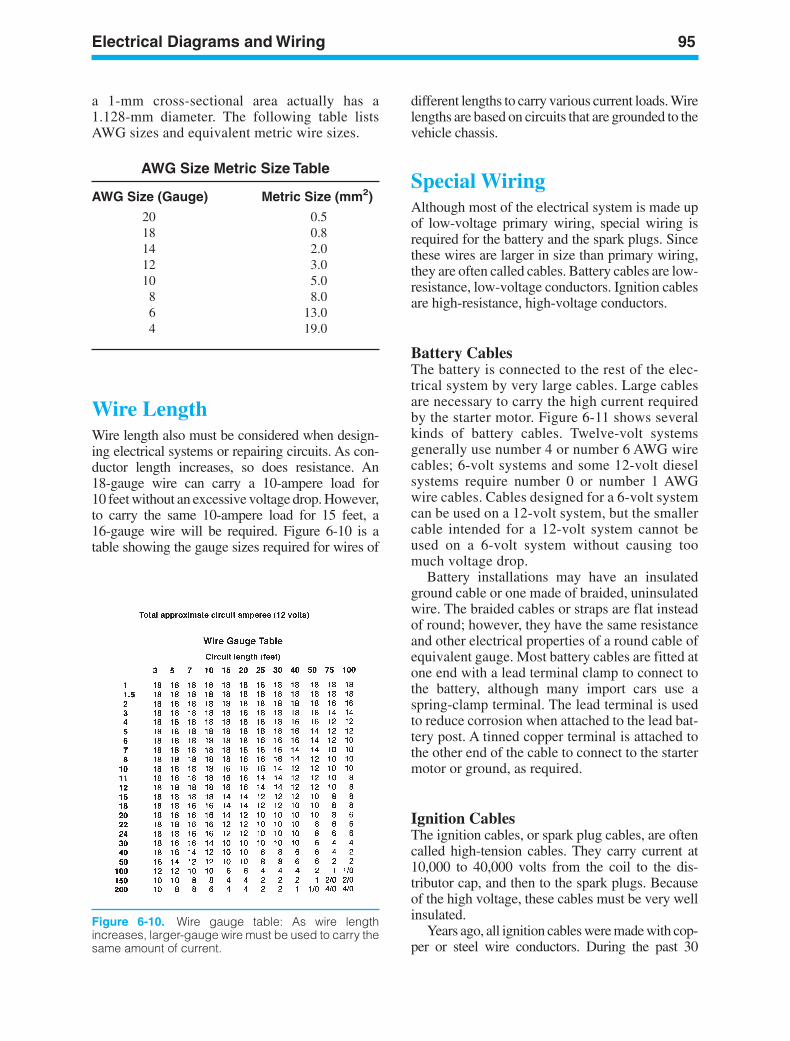
Electrical Diagrams and Wiring 95
Figure 6-10. Wire gauge table: As wire lengthincreases, larger-gauge wire must be used to carry thesame amount of current.
a 1-mm cross-sectional area actually has a1.128-mm diameter. The following table listsAWG sizes and equivalent metric wire sizes.
AWG Size Metric Size Table
AWG Size (Gauge) Metric Size (mm2)
20 0.518 0.814 2.012 3.010 5.08 8.06 13.04 19.0
Wire LengthWire length also must be considered when design-ing electrical systems or repairing circuits. As con-ductor length increases, so does resistance. An18-gauge wire can carry a 10-ampere load for10 feet without an excessive voltage drop. However,to carry the same 10-ampere load for 15 feet, a16-gauge wire will be required. Figure 6-10 is atable showing the gauge sizes required for wires of
different lengths to carry various current loads. Wirelengths are based on circuits that are grounded to thevehicle chassis.
Special WiringAlthough most of the electrical system is made upof low-voltage primary wiring, special wiring isrequired for the battery and the spark plugs. Sincethese wires are larger in size than primary wiring,they are often called cables. Battery cables are low-resistance, low-voltage conductors. Ignition cablesare high-resistance, high-voltage conductors.
Battery CablesThe battery is connected to the rest of the elec-trical system by very large cables. Large cablesare necessary to carry the high current requiredby the starter motor. Figure 6-11 shows severalkinds of battery cables. Twelve-volt systemsgenerally use number 4 or number 6 AWG wirecables; 6-volt systems and some 12-volt dieselsystems require number 0 or number 1 AWGwire cables. Cables designed for a 6-volt systemcan be used on a 12-volt system, but the smallercable intended for a 12-volt system cannot beused on a 6-volt system without causing toomuch voltage drop.
Battery installations may have an insulatedground cable or one made of braided, uninsulatedwire. The braided cables or straps are flat insteadof round; however, they have the same resistanceand other electrical properties of a round cable ofequivalent gauge. Most battery cables are fitted atone end with a lead terminal clamp to connect tothe battery, although many import cars use aspring-clamp terminal. The lead terminal is usedto reduce corrosion when attached to the lead bat-tery post. A tinned copper terminal is attached tothe other end of the cable to connect to the startermotor or ground, as required.
Ignition CablesThe ignition cables, or spark plug cables, are oftencalled high-tension cables. They carry current at10,000 to 40,000 volts from the coil to the dis-tributor cap, and then to the spark plugs. Becauseof the high voltage, these cables must be very wellinsulated.
Years ago, all ignition cables were made with cop-per or steel wire conductors. During the past 30
ker88839_ch06.qxd 1/9/06 11:25 AM Page 95
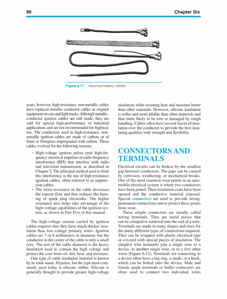
96 Chapter Six
Figure 6-11. Assorted battery cables.
years, however, high-resistance, non-metallic cableshave replaced metallic conductor cables as originalequipment on cars and light trucks. Although metallic-conductor ignition cables are still made, they aresold for special high-performance or industrialapplications and are not recommended for highwayuse. The conductors used in high-resistance, non-metallic ignition cables are made of carbon, or oflinen or fiberglass impregnated with carbon. Thesecables evolved for the following reasons:
• High-voltage ignition pulses emit high-fre-quency electrical impulses or radio frequencyinterference (RFI) that interfere with radioand television transmission, as described inChapter 2. The principal method used to limitthis interference is the use of high-resistanceignition cables, often referred to as suppres-sion cables.
• The extra resistance in the cable decreasesthe current flow and thus reduces the burn-ing of spark plug electrodes. The higherresistance also helps take advantage of thehigh-voltage capabilities of the ignition sys-tem, as shown in Part Five of this manual.
The high-voltage current carried by ignitioncables requires that they have much thicker insu-lation than low-voltage primary wires. Ignitioncables are 7 or 8 millimeters in diameter, but theconductor in the center of the cable is only a smallcore. The rest of the cable diameter is the heavyinsulation used to contain the high voltage andprotect the core from oil, dirt, heat, and moisture.
One type of cable insulation material is knownby its trade name, Hypalon, but the type most com-monly used today is silicone rubber. Silicone isgenerally thought to provide greater high-voltage
insulation while resisting heat and moisture betterthan other materials. However, silicone insulationis softer and more pliable than other materials andthus more likely to be torn or damaged by roughhandling. Cables often have several layers of insu-lation over the conductor to provide the best insu-lating qualities with strength and flexibility.
CONNECTORS ANDTERMINALSElectrical circuits can be broken by the smallestgap between conductors. The gaps can be causedby corrosion, weathering, or mechanical breaks.One of the most common wear points in an auto-mobile electrical system is where two conductorshave been joined. Their insulation coats have beenopened and the conductive material exposed.Special connectors are used to provide strong,permanent connections and to protect these pointsfrom wear.
These simple connectors are usually calledwiring terminals. They are metal pieces thatcan be crimped or soldered onto the end of a wire.Terminals are made in many shapes and sizes forthe many different types of connections required.They can be wrapped with plastic electrical tapeor covered with special pieces of insulation. Thesimplest wire terminals join a single wire to adevice, to another single wire, or to a few otherwires (Figure 6-12). Terminals for connecting toa device often have a lug ring, a spade, or a hook,which can be bolted onto the device. Male andfemale spade terminals or bullet connectors areoften used to connect two individual wires
ker88839_ch06.qxd 1/9/06 11:25 AM Page 96
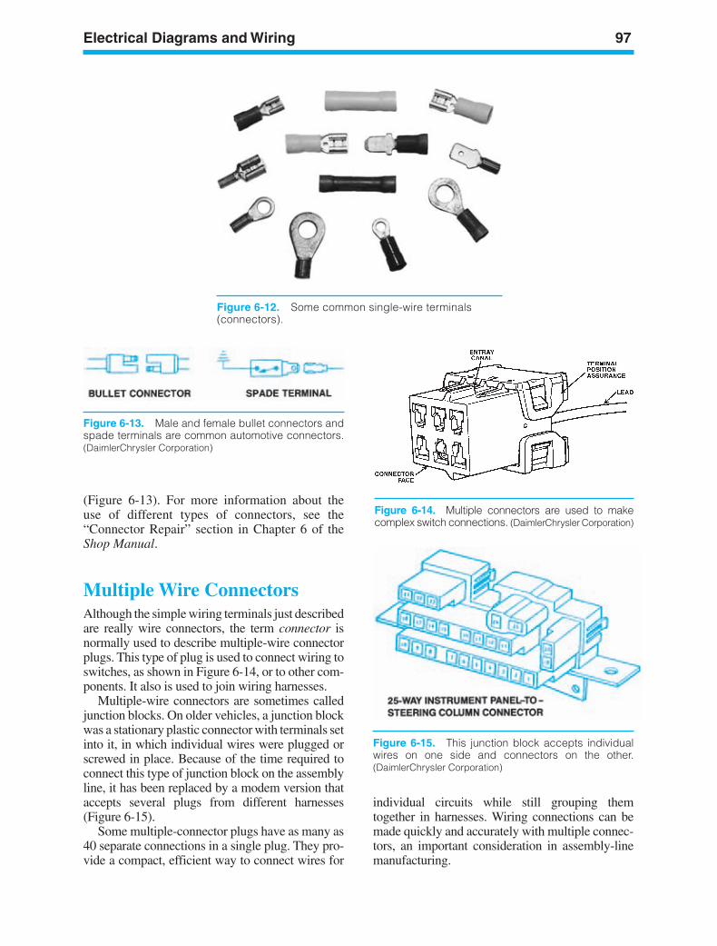
Electrical Diagrams and Wiring 97
Figure 6-12. Some common single-wire terminals(connectors).
(Figure 6-13). For more information about the use of different types of connectors, see the“Connector Repair” section in Chapter 6 of theShop Manual.
Multiple Wire ConnectorsAlthough the simple wiring terminals just describedare really wire connectors, the term connector isnormally used to describe multiple-wire connectorplugs. This type of plug is used to connect wiring toswitches, as shown in Figure 6-14, or to other com-ponents. It also is used to join wiring harnesses.
Multiple-wire connectors are sometimes calledjunction blocks. On older vehicles, a junction blockwas a stationary plastic connector with terminals setinto it, in which individual wires were plugged orscrewed in place. Because of the time required toconnect this type of junction block on the assemblyline, it has been replaced by a modem version thataccepts several plugs from different harnesses(Figure 6-15).
Some multiple-connector plugs have as many as40 separate connections in a single plug. They pro-vide a compact, efficient way to connect wires for
individual circuits while still grouping themtogether in harnesses. Wiring connections can bemade quickly and accurately with multiple connec-tors, an important consideration in assembly-linemanufacturing.
Figure 6-13. Male and female bullet connectors andspade terminals are common automotive connectors.(DaimlerChrysler Corporation)
Figure 6-15. This junction block accepts individualwires on one side and connectors on the other.(DaimlerChrysler Corporation)
Figure 6-14. Multiple connectors are used to makecomplex switch connections. (DaimlerChrysler Corporation)
ker88839_ch06.qxd 1/9/06 11:25 AM Page 97
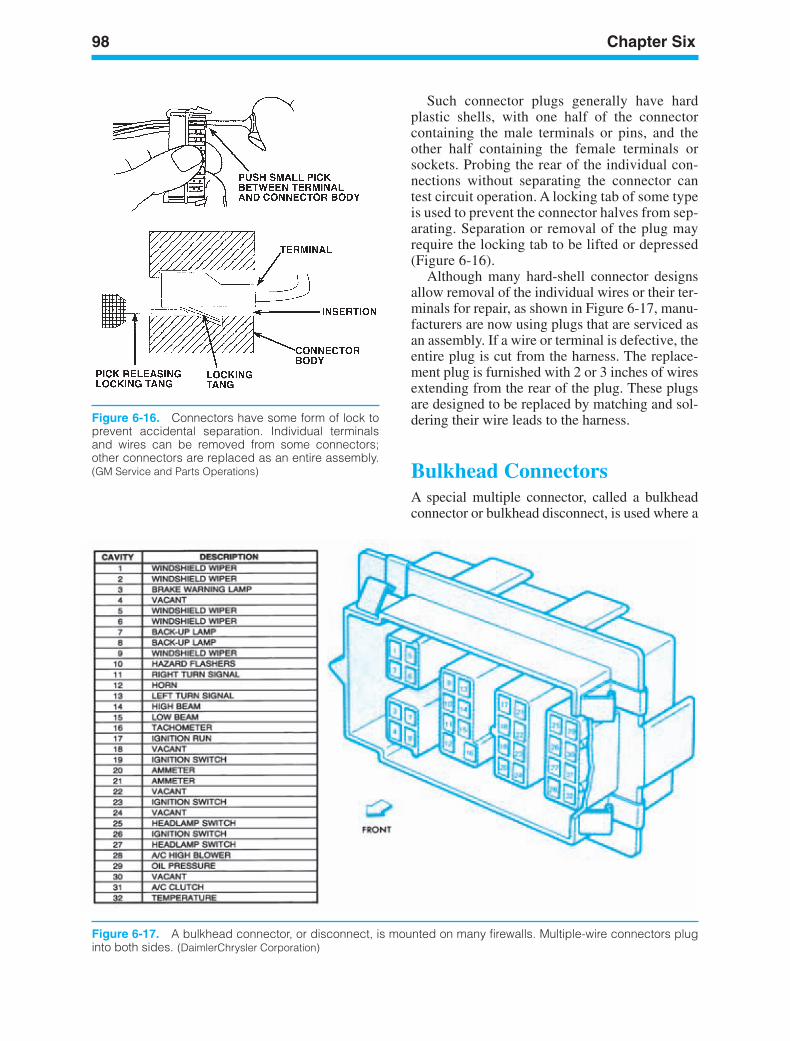
98 Chapter Six
Figure 6-16. Connectors have some form of lock toprevent accidental separation. Individual terminalsand wires can be removed from some connectors;other connectors are replaced as an entire assembly.(GM Service and Parts Operations)
Figure 6-17. A bulkhead connector, or disconnect, is mounted on many firewalls. Multiple-wire connectors pluginto both sides. (DaimlerChrysler Corporation)
Such connector plugs generally have hardplastic shells, with one half of the connectorcontaining the male terminals or pins, and theother half containing the female terminals orsockets. Probing the rear of the individual con-nections without separating the connector cantest circuit operation. A locking tab of some typeis used to prevent the connector halves from sep-arating. Separation or removal of the plug mayrequire the locking tab to be lifted or depressed(Figure 6-16).
Although many hard-shell connector designsallow removal of the individual wires or their ter-minals for repair, as shown in Figure 6-17, manu-facturers are now using plugs that are serviced asan assembly. If a wire or terminal is defective, theentire plug is cut from the harness. The replace-ment plug is furnished with 2 or 3 inches of wiresextending from the rear of the plug. These plugsare designed to be replaced by matching and sol-dering their wire leads to the harness.
Bulkhead ConnectorsA special multiple connector, called a bulkheadconnector or bulkhead disconnect, is used where a
ker88839_ch06.qxd 1/9/06 11:25 AM Page 98
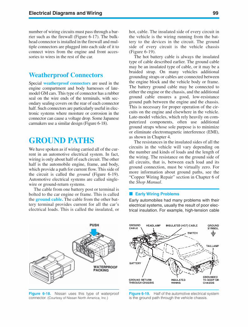
Electrical Diagrams and Wiring 99
Figure 6-18. Nissan uses this type of waterproofconnector. (Courtesy of Nissan North America, Inc.)
Figure 6-19. Half of the automotive electrical systemis the ground path through the vehicle chassis.
number of wiring circuits must pass through a bar-rier such as the firewall (Figure 6-17). The bulk-head connector is installed in the firewall and mul-tiple connectors are plugged into each side of it toconnect wires from the engine and front acces-sories to wires in the rest of the car.
Weatherproof ConnectorsSpecial weatherproof connectors are used in theengine compartment and body harnesses of late-model GM cars. This type of connector has a rubberseal on the wire ends of the terminals, with sec-ondary sealing covers on the rear of each connectorhalf. Such connectors are particularly useful in elec-tronic systems where moisture or corrosion in theconnector can cause a voltage drop. Some Japanesecarmakers use a similar design (Figure 6-18).
GROUND PATHSWe have spoken as if wiring carried all of the cur-rent in an automotive electrical system. In fact,wiring is only about half of each circuit. The otherhalf is the automobile engine, frame, and body,which provide a path for current flow. This side ofthe circuit is called the ground (Figure 6-19).Automotive electrical systems are called single-wire or ground-return systems.
The cable from one battery post or terminal isbolted to the car engine or frame. This is calledthe ground cable. The cable from the other bat-tery terminal provides current for all the car’selectrical loads. This is called the insulated, or
hot, cable. The insulated side of every circuit inthe vehicle is the wiring running from the bat-tery to the devices in the circuit. The groundside of every circuit is the vehicle chassis(Figure 6-19).
The hot battery cable is always the insulatedtype of cable described earlier. The ground cablemay be an insulated type of cable, or it may be abraided strap. On many vehicles additionalgrounding straps or cables are connected betweenthe engine block and the vehicle body or frame.The battery ground cable may be connected toeither the engine or the chassis, and the additionalground cable ensures a good, low-resistanceground path between the engine and the chassis.This is necessary for proper operation of the cir-cuits on the engine and elsewhere in the vehicle.Late-model vehicles, which rely heavily on com-puterized components, often use additionalground straps whose sole purpose is to minimizeor eliminate electromagnetic interference (EMI),as shown in Chapter 4.
The resistances in the insulated sides of all thecircuits in the vehicle will vary depending onthe number and kinds of loads and the length ofthe wiring. The resistance on the ground side ofall circuits, that is, between each load and itsground connection, must be virtually zero. Formore information about ground paths, see the“Copper Wiring Repair” section in Chapter 6 ofthe Shop Manual.
Early Wiring Problems
Early automobiles had many problems with theirelectrical systems, usually the result of poor elec-trical insulation. For example, high-tension cable
ker88839_ch06.qxd 1/9/06 11:25 AM Page 99
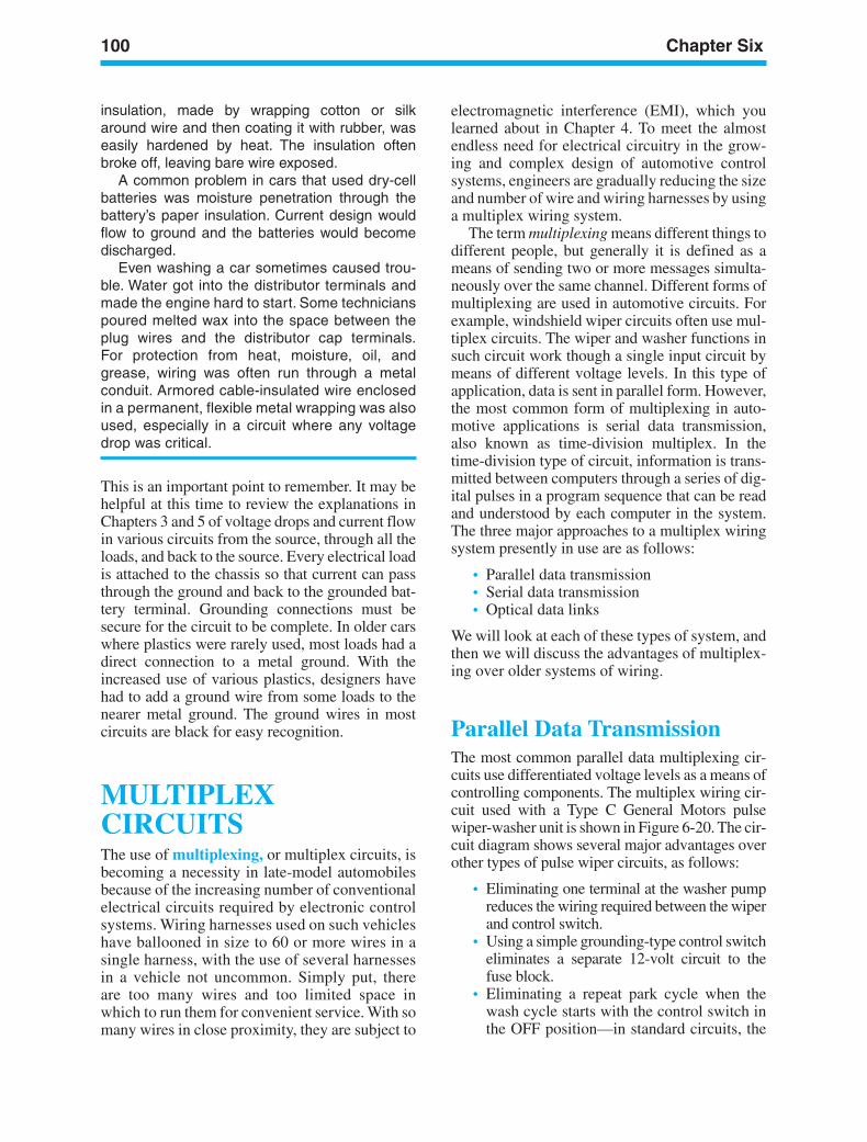
100 Chapter Six
insulation, made by wrapping cotton or silkaround wire and then coating it with rubber, waseasily hardened by heat. The insulation oftenbroke off, leaving bare wire exposed.
A common problem in cars that used dry-cellbatteries was moisture penetration through thebattery’s paper insulation. Current design wouldflow to ground and the batteries would becomedischarged.
Even washing a car sometimes caused trou-ble. Water got into the distributor terminals andmade the engine hard to start. Some technicianspoured melted wax into the space between theplug wires and the distributor cap terminals.For protection from heat, moisture, oil, andgrease, wiring was often run through a metalconduit. Armored cable-insulated wire enclosedin a permanent, flexible metal wrapping was alsoused, especially in a circuit where any voltagedrop was critical.
This is an important point to remember. It may behelpful at this time to review the explanations inChapters 3 and 5 of voltage drops and current flowin various circuits from the source, through all theloads, and back to the source. Every electrical loadis attached to the chassis so that current can passthrough the ground and back to the grounded bat-tery terminal. Grounding connections must besecure for the circuit to be complete. In older carswhere plastics were rarely used, most loads had adirect connection to a metal ground. With theincreased use of various plastics, designers havehad to add a ground wire from some loads to thenearer metal ground. The ground wires in mostcircuits are black for easy recognition.
MULTIPLEXCIRCUITSThe use of multiplexing, or multiplex circuits, isbecoming a necessity in late-model automobilesbecause of the increasing number of conventionalelectrical circuits required by electronic controlsystems. Wiring harnesses used on such vehicleshave ballooned in size to 60 or more wires in asingle harness, with the use of several harnessesin a vehicle not uncommon. Simply put, thereare too many wires and too limited space inwhich to run them for convenient service. With somany wires in close proximity, they are subject to
electromagnetic interference (EMI), which youlearned about in Chapter 4. To meet the almostendless need for electrical circuitry in the grow-ing and complex design of automotive controlsystems, engineers are gradually reducing the sizeand number of wire and wiring harnesses by usinga multiplex wiring system.
The term multiplexing means different things todifferent people, but generally it is defined as ameans of sending two or more messages simulta-neously over the same channel. Different forms ofmultiplexing are used in automotive circuits. Forexample, windshield wiper circuits often use mul-tiplex circuits. The wiper and washer functions insuch circuit work though a single input circuit bymeans of different voltage levels. In this type ofapplication, data is sent in parallel form. However,the most common form of multiplexing in auto-motive applications is serial data transmission,also known as time-division multiplex. In thetime-division type of circuit, information is trans-mitted between computers through a series of dig-ital pulses in a program sequence that can be readand understood by each computer in the system.The three major approaches to a multiplex wiringsystem presently in use are as follows:
• Parallel data transmission• Serial data transmission• Optical data links
We will look at each of these types of system, andthen we will discuss the advantages of multiplex-ing over older systems of wiring.
Parallel Data TransmissionThe most common parallel data multiplexing cir-cuits use differentiated voltage levels as a means ofcontrolling components. The multiplex wiring cir-cuit used with a Type C General Motors pulsewiper-washer unit is shown in Figure 6-20. The cir-cuit diagram shows several major advantages overother types of pulse wiper circuits, as follows:
• Eliminating one terminal at the washer pumpreduces the wiring required between the wiperand control switch.
• Using a simple grounding-type control switcheliminates a separate 12-volt circuit to thefuse block.
• Eliminating a repeat park cycle when thewash cycle starts with the control switch inthe OFF position—in standard circuits, the
ker88839_ch06.qxd 1/9/06 11:25 AM Page 100
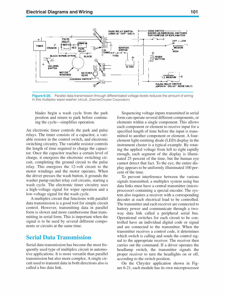
Electrical Diagrams and Wiring 101
Figure 6-20. Parallel data transmission through differentiated voltage levels reduces the amount of wiringin this multiplex wiper-washer circuit. (DaimlerChrysler Corporation)
blades begin a wash cycle from the parkposition and return to park before continu-ing the cycle—simplifies operation.
An electronic timer controls the park and pulserelays. The timer consists of a capacitor, a vari-able resistor in the control switch, and electronicswitching circuitry. The variable resistor controlsthe length of time required to charge the capaci-tor. Once the capacitor reaches a certain level ofcharge, it energizes the electronic switching cir-cuit, completing the ground circuit to the pulserelay. This energizes the 12-volt circuit to themotor windings and the motor operates. Whenthe driver presses the wash button, it grounds thewasher pump ratchet relay coil circuits, starting awash cycle. The electronic timer circuitry usesa high-voltage signal for wiper operation and alow-voltage signal for the wash cycle.
A multiplex circuit that functions with paralleldata transmission is a good tool for simple circuitcontrol. However, transmitting data in parallelform is slower and more cumbersome than trans-mitting in serial form. This is important when thesignal is to be used by several different compo-nents or circuits at the same time.
Serial Data TransmissionSerial data transmission has become the most fre-quently used type of multiplex circuit in automo-tive applications. It is more versatile than paralleltransmission but also more complex. A single cir-cuit used to transmit data in both directions also iscalled a bus data link.
Sequencing voltage inputs transmitted in serialform can operate several different components, orelements within a single component. This allowseach component or element to receive input for aspecified length of time before the input is trans-mitted to another component or element. A four-element light-emitting diode (LED) display in theinstrument cluster is a typical example. By rotat-ing the applied voltage from left to right rapidlyenough, each segment of the display is illumi-nated 25 percent of the time, but the human eyecannot detect that fact. To the eye, the entire dis-play appears to be uniformly illuminated 100 per-cent of the time.
To prevent interference between the varioussignals transmitted, a multiplex system using busdata links must have a central transmitter (micro-processor) containing a special encoder. The sys-tem also requires a receiver with a correspondingdecoder at each electrical load to be controlled.The transmitter and each receiver are connected tobattery power and communicate through a two-way data link called a peripheral serial bus.Operational switches for each circuit to be con-trolled have an individual digital code or signaland are connected to the transmitter. When thetransmitter receives a control code, it determineswhich switch is calling and sends the control sig-nal to the appropriate receiver. The receiver thencarries out the command. If a driver operates theheadlamp switch, the transmitter signals theproper receiver to turn the headlights on or off,according to the switch position.
On the Chrysler application shown in Fig-ure 6-21, each module has its own microprocessor
ker88839_ch06.qxd 1/9/06 11:25 AM Page 101
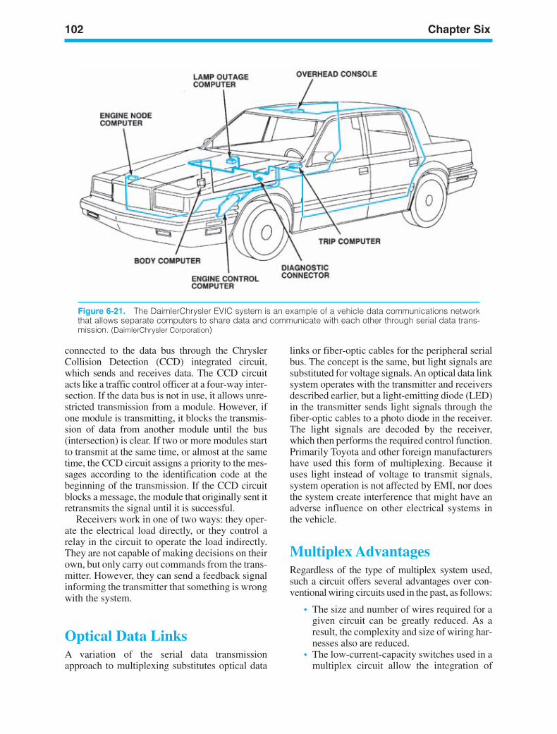
102 Chapter Six
Figure 6-21. The DaimlerChrysler EVIC system is an example of a vehicle data communications networkthat allows separate computers to share data and communicate with each other through serial data trans-mission. (DaimlerChrysler Corporation)
connected to the data bus through the ChryslerCollision Detection (CCD) integrated circuit,which sends and receives data. The CCD circuitacts like a traffic control officer at a four-way inter-section. If the data bus is not in use, it allows unre-stricted transmission from a module. However, ifone module is transmitting, it blocks the transmis-sion of data from another module until the bus(intersection) is clear. If two or more modules startto transmit at the same time, or almost at the sametime, the CCD circuit assigns a priority to the mes-sages according to the identification code at thebeginning of the transmission. If the CCD circuitblocks a message, the module that originally sent itretransmits the signal until it is successful.
Receivers work in one of two ways: they oper-ate the electrical load directly, or they control arelay in the circuit to operate the load indirectly.They are not capable of making decisions on theirown, but only carry out commands from the trans-mitter. However, they can send a feedback signalinforming the transmitter that something is wrongwith the system.
Optical Data LinksA variation of the serial data transmissionapproach to multiplexing substitutes optical data
links or fiber-optic cables for the peripheral serialbus. The concept is the same, but light signals aresubstituted for voltage signals. An optical data linksystem operates with the transmitter and receiversdescribed earlier, but a light-emitting diode (LED)in the transmitter sends light signals through thefiber-optic cables to a photo diode in the receiver.The light signals are decoded by the receiver,which then performs the required control function.Primarily Toyota and other foreign manufacturershave used this form of multiplexing. Because ituses light instead of voltage to transmit signals,system operation is not affected by EMI, nor doesthe system create interference that might have anadverse influence on other electrical systems inthe vehicle.
Multiplex AdvantagesRegardless of the type of multiplex system used,such a circuit offers several advantages over con-ventional wiring circuits used in the past, as follows:
• The size and number of wires required for agiven circuit can be greatly reduced. As aresult, the complexity and size of wiring har-nesses also are reduced.
• The low-current-capacity switches used in amultiplex circuit allow the integration of
ker88839_ch06.qxd 1/9/06 11:25 AM Page 102
Electrical Diagrams and Wiring 103
various touch-type switches into the overallvehicle design.
• The master computer or transmitter can beprogrammed with timing functions for con-venience features, such as locking doorsabove a given speed or unlocking them whenthe ignition is shut off.
ELECTRICALSYSTEM POLARITYWe discussed positive (+) and negative () elec-trical charges in Chapter 3. We learned that likecharges repel each other and unlike chargesattract each other. We also noted that the terminalsof a voltage source are identified as positive andnegative. In Chapter 2, we defined magneticpolarity in terms of the north and south poles of amagnet and observed that unlike poles of a mag-net attract each other, just as unlike charges do.Similarly, like poles repel each other.
The polarity of an electrical system refers tothe connections of the positive and negative ter-minals of the voltage source, the battery, to theinsulated and ground sides of the system. Alldomestic cars and trucks manufactured since1956 have the negative battery terminal con-nected to ground and the positive terminal con-nected to the insulated side of the system. Theseare called negative-ground systems and are saidto have positive polarity.
Before 1956, 6-volt Ford and Chrysler vehi-cles had the positive battery terminal connectedto ground and the negative terminal connectedto the insulated side of the system. These arecalled positive-ground systems and are said tohave negative polarity. Foreign manufacturersused positive-ground systems as late as 1969. Inboth kinds of systems, we say that currentleaves the hot side of the battery and returnsthrough the ground path to the grounded batteryterminal.
In your service work, it is very important torecognize system polarity negative or positiveground before working on the electrical system.Some electrical components and test equipmentare sensitive to the system polarity and must beinstalled with their connections matching those ofthe battery. Reversing polarity can damage alter-nators, cause motors to run backwards, ruin elec-tronic modules, and cause relays or solenoids tomalfunction.
COMMONELECTRICAL PARTSMany common electrical parts are used in variouscircuits in an electrical system. All circuits haveswitches of some kind to control current flow.Most circuits have some form of protective device,such as a fuse or circuit breaker, to protect againsttoo much current flow. Various kinds of solenoids,relays, and motors are used in many circuits, andwhatever their purpose, they operate in similarways wherever they are used.
Before we look at complete circuits and systemdiagrams later in this next chapter, we should learnabout some of the common devices used in manycircuits.
SwitchesSwitches are used in automobile electrical sys-tems to start, stop, or redirect current flow. Theycan be operated manually by the driver orremotely through mechanical linkage. Manualswitches, such as the ignition switch and the head-lamp switch, allow the driver to control the opera-tion of the engine and accessories. Examples areshown in Figure 6-22; the driver or the passengerscontrol a remotely operated switch indirectly. Forexample, a mechanical switch called a neutralsafety switch on automatic transmission gearselectors will not let the engine start if the auto-mobile is in gear. Switches operated by openingand closing the doors control the interior lights.For more information about switches, see the“Copper Wiring Repair” section in Chapter 6 ofthe Shop Manual.
Toggle Push-Pull Push ButtonSwitches exist in many forms but have common char-acteristics. They all depend upon physical movementfor operation. A simple switch contains one or moresets of contact points, with half of the points station-ary and the other half movable. When the switch isoperated, the movable points change position.
Switches can be designed so that the points arenormally open and switch operation closes them toallow current flow. Normally closed switches allowthe operator to open the points and stop currentflow. For example, in an automobile with a seatbeltwarning buzzer, the switch points are opened when
ker88839_ch06.qxd 1/9/06 11:25 AM Page 103
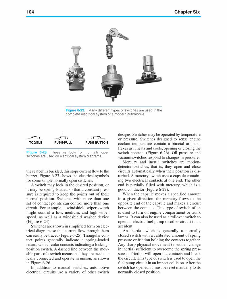
104 Chapter Six
Figure 6-23. These symbols for normally openswitches are used on electrical system diagrams.
the seatbelt is buckled; this stops current flow to thebuzzer. Figure 6-23 shows the electrical symbolsfor some simple normally open switches.
A switch may lock in the desired position, orit may be spring-loaded so that a constant pres-sure is required to keep the points out of theirnormal position. Switches with more than oneset of contact points can control more than onecircuit. For example, a windshield wiper switchmight control a low, medium, and high wiperspeed, as well as a windshield washer device(Figure 6-24).
Switches are shown in simplified form on elec-trical diagrams so that current flow through themcan easily be traced (Figure 6-25). Triangular con-tact points generally indicate a spring-loadedreturn, with circular contacts indicating a locking-position switch. A dashed line between the mov-able parts of a switch means that they are mechan-ically connected and operate in unison, as shownin Figure 6-26.
In addition to manual switches, automotiveelectrical circuits use a variety of other switch
designs. Switches may be operated by temperatureor pressure. Switches designed to sense enginecoolant temperature contain a bimetal arm thatflexes as it heats and cools, opening or closing theswitch contacts (Figure 6-26). Oil pressure andvacuum switches respond to changes in pressure.
Mercury and inertia switches are motion-detector switches, that is, they open and closecircuits automatically when their position is dis-turbed. A mercury switch uses a capsule contain-ing two electrical contacts at one end. The otherend is partially filled with mercury, which is agood conductor (Figure 6-27).
When the capsule moves a specified amountin a given direction, the mercury flows to theopposite end of the capsule and makes a circuitbetween the contacts. This type of switch oftenis used to turn on engine compartment or trunklamps. It can also be used as a rollover switch toopen an electric fuel pump or other circuit in anaccident.
An inertia switch is generally a normallyclosed switch with a calibrated amount of springpressure or friction holding the contacts together.Any sharp physical movement (a sudden changein inertia) sufficient to overcome the spring pres-sure or friction will open the contacts and breakthe circuit. This type of switch is used to open thefuel pump circuit in an impact collision. After theswitch has opened, it must be reset manually to itsnormally closed position.
Figure 6-22. Many different types of switches are used in thecomplete electrical system of a modern automobile.
ker88839_ch06.qxd 1/9/06 11:25 AM Page 104

Electrical Diagrams and Wiring 105
Figure 6-25. This starting and ignition switch has twosets of contacts linked together by the dashed line.Triangular terminals in the start (ST) position indicatethat this position is spring-Ioaded and that the switchwill return to RUN when the key is released.(DaimlerChrysler Corporation)
Figure 6-24. The instrument panel switch in this two-speed windshield wiper circuit has two sets of con-tacts linked together, as shown by the broken line. The Park switch is operated by mechanical linkage fromthe wiper motor armature. (DaimlerChrysler Corporation)
Figure 6-26. A coolant temperature switch inits normally open position.
Figure 6-27. A mercury switch is activated by motion.
RelaysA relay is a switch that uses electromagnetism tophysically move the contacts. It allows a smallcurrent to control a much larger one. As youremember from our introduction to relays inChapter 2, a small amount of current flowthrough the relay coil moves an armature to openor close a set of contact points. This is called thecontrol circuit because the points control theflow of a much larger amount of current through
ker88839_ch06.qxd 1/9/06 11:25 AM Page 105
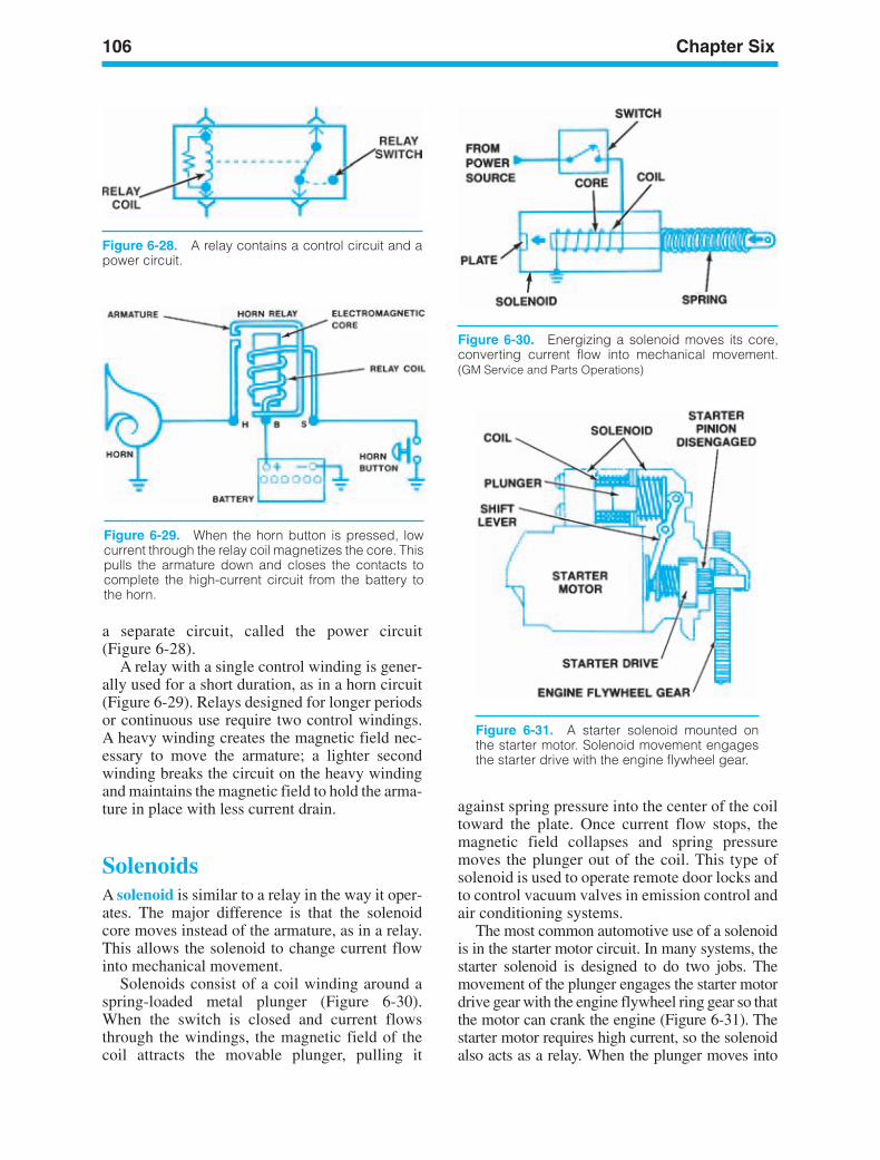
106 Chapter Six
Figure 6-28. A relay contains a control circuit and apower circuit.
Figure 6-29. When the horn button is pressed, lowcurrent through the relay coil magnetizes the core. Thispulls the armature down and closes the contacts tocomplete the high-current circuit from the battery tothe horn.
Figure 6-30. Energizing a solenoid moves its core,converting current flow into mechanical movement.(GM Service and Parts Operations)
Figure 6-31. A starter solenoid mounted onthe starter motor. Solenoid movement engagesthe starter drive with the engine flywheel gear.
a separate circuit, called the power circuit(Figure 6-28).
A relay with a single control winding is gener-ally used for a short duration, as in a horn circuit(Figure 6-29). Relays designed for longer periodsor continuous use require two control windings.A heavy winding creates the magnetic field nec-essary to move the armature; a lighter secondwinding breaks the circuit on the heavy windingand maintains the magnetic field to hold the arma-ture in place with less current drain.
SolenoidsA solenoid is similar to a relay in the way it oper-ates. The major difference is that the solenoidcore moves instead of the armature, as in a relay.This allows the solenoid to change current flowinto mechanical movement.
Solenoids consist of a coil winding around aspring-loaded metal plunger (Figure 6-30).When the switch is closed and current flowsthrough the windings, the magnetic field of thecoil attracts the movable plunger, pulling it
against spring pressure into the center of the coiltoward the plate. Once current flow stops, themagnetic field collapses and spring pressuremoves the plunger out of the coil. This type ofsolenoid is used to operate remote door locks andto control vacuum valves in emission control andair conditioning systems.
The most common automotive use of a solenoidis in the starter motor circuit. In many systems, thestarter solenoid is designed to do two jobs. Themovement of the plunger engages the starter motordrive gear with the engine flywheel ring gear so thatthe motor can crank the engine (Figure 6-31). Thestarter motor requires high current, so the solenoidalso acts as a relay. When the plunger moves into
ker88839_ch06.qxd 1/9/06 11:25 AM Page 106
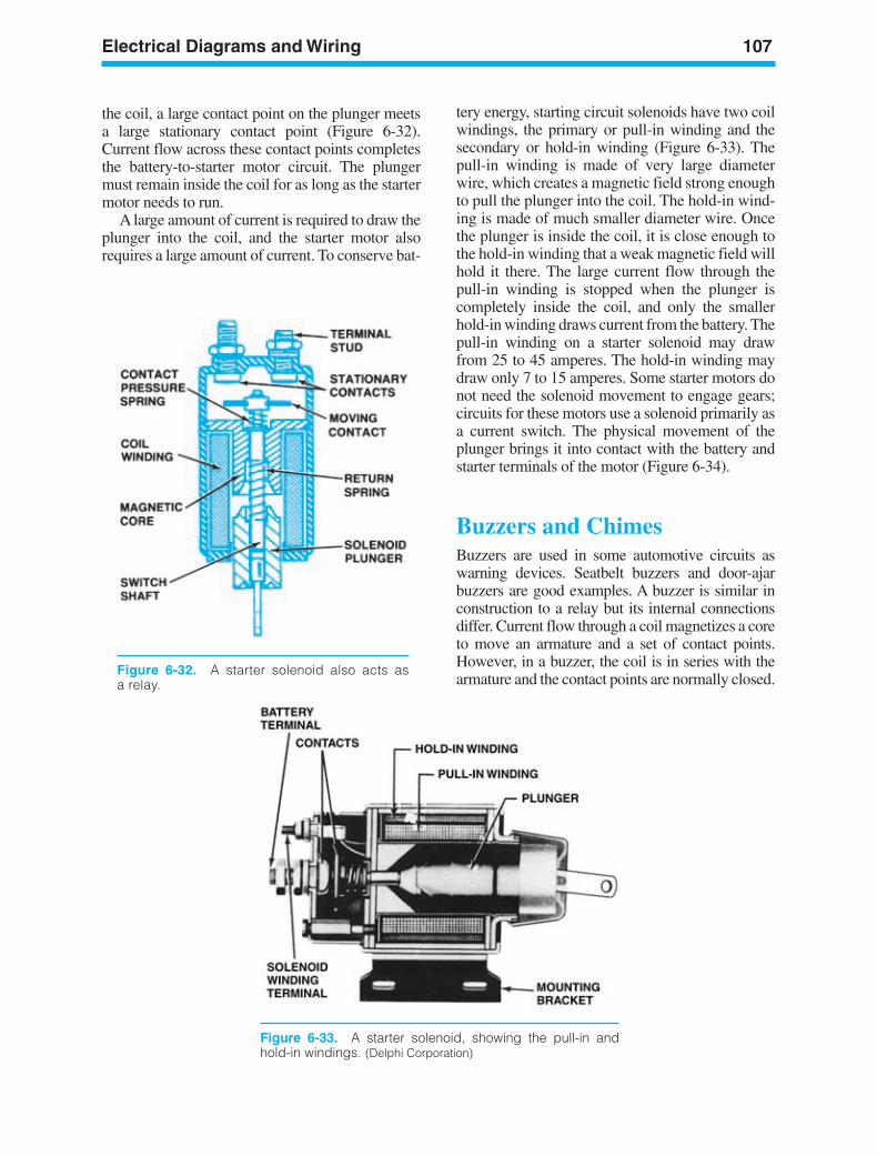
Electrical Diagrams and Wiring 107
Figure 6-32. A starter solenoid also acts asa relay.
the coil, a large contact point on the plunger meetsa large stationary contact point (Figure 6-32).Current flow across these contact points completesthe battery-to-starter motor circuit. The plungermust remain inside the coil for as long as the startermotor needs to run.
A large amount of current is required to draw theplunger into the coil, and the starter motor alsorequires a large amount of current. To conserve bat-
Figure 6-33. A starter solenoid, showing the pull-in andhold-in windings. (Delphi Corporation)
tery energy, starting circuit solenoids have two coilwindings, the primary or pull-in winding and thesecondary or hold-in winding (Figure 6-33). Thepull-in winding is made of very large diameterwire, which creates a magnetic field strong enoughto pull the plunger into the coil. The hold-in wind-ing is made of much smaller diameter wire. Oncethe plunger is inside the coil, it is close enough tothe hold-in winding that a weak magnetic field willhold it there. The large current flow through thepull-in winding is stopped when the plunger iscompletely inside the coil, and only the smallerhold-in winding draws current from the battery. Thepull-in winding on a starter solenoid may drawfrom 25 to 45 amperes. The hold-in winding maydraw only 7 to 15 amperes. Some starter motors donot need the solenoid movement to engage gears;circuits for these motors use a solenoid primarily asa current switch. The physical movement of theplunger brings it into contact with the battery andstarter terminals of the motor (Figure 6-34).
Buzzers and ChimesBuzzers are used in some automotive circuits aswarning devices. Seatbelt buzzers and door-ajarbuzzers are good examples. A buzzer is similar inconstruction to a relay but its internal connectionsdiffer. Current flow through a coil magnetizes a coreto move an armature and a set of contact points.However, in a buzzer, the coil is in series with thearmature and the contact points are normally closed.
ker88839_ch06.qxd 1/9/06 11:25 AM Page 107
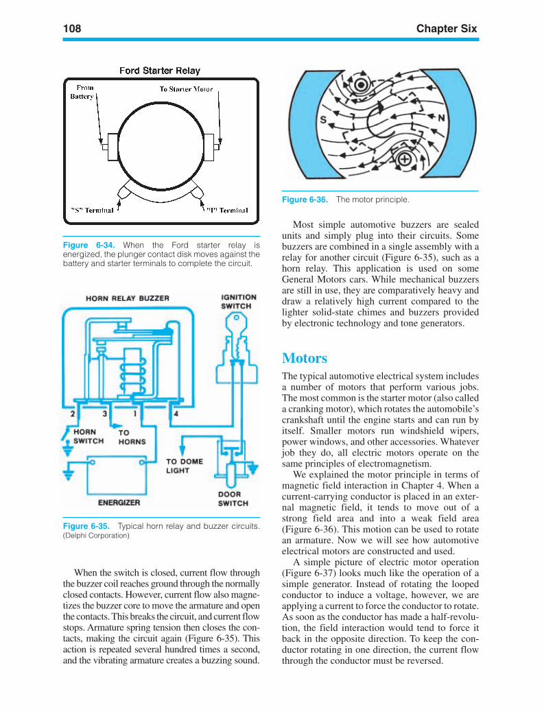
108 Chapter Six
Figure 6-36. The motor principle.
Figure 6-35. Typical horn relay and buzzer circuits.(Delphi Corporation)
When the switch is closed, current flow throughthe buzzer coil reaches ground through the normallyclosed contacts. However, current flow also magne-tizes the buzzer core to move the armature and openthe contacts. This breaks the circuit, and current flowstops. Armature spring tension then closes the con-tacts, making the circuit again (Figure 6-35). Thisaction is repeated several hundred times a second,and the vibrating armature creates a buzzing sound.
Most simple automotive buzzers are sealedunits and simply plug into their circuits. Somebuzzers are combined in a single assembly with arelay for another circuit (Figure 6-35), such as ahorn relay. This application is used on someGeneral Motors cars. While mechanical buzzersare still in use, they are comparatively heavy anddraw a relatively high current compared to thelighter solid-state chimes and buzzers providedby electronic technology and tone generators.
MotorsThe typical automotive electrical system includesa number of motors that perform various jobs.The most common is the starter motor (also calleda cranking motor), which rotates the automobile’scrankshaft until the engine starts and can run byitself. Smaller motors run windshield wipers,power windows, and other accessories. Whateverjob they do, all electric motors operate on thesame principles of electromagnetism.
We explained the motor principle in terms ofmagnetic field interaction in Chapter 4. When acurrent-carrying conductor is placed in an exter-nal magnetic field, it tends to move out of astrong field area and into a weak field area(Figure 6-36). This motion can be used to rotatean armature. Now we will see how automotiveelectrical motors are constructed and used.
A simple picture of electric motor operation(Figure 6-37) looks much like the operation of asimple generator. Instead of rotating the loopedconductor to induce a voltage, however, we areapplying a current to force the conductor to rotate.As soon as the conductor has made a half-revolu-tion, the field interaction would tend to force itback in the opposite direction. To keep the con-ductor rotating in one direction, the current flowthrough the conductor must be reversed.
Figure 6-34. When the Ford starter relay isenergized, the plunger contact disk moves against thebattery and starter terminals to complete the circuit.
ker88839_ch06.qxd 1/9/06 11:25 AM Page 108
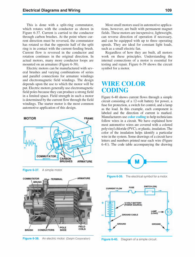
Electrical Diagrams and Wiring 109
Figure 6-37. A simple motor.
This is done with a split-ring commutator,which rotates with the conductor as shown inFigure 6-37. Current is carried to the conductorthrough carbon brushes. At the point where cur-rent direction must be reversed, the commutatorhas rotated so that the opposite half of the splitring is in contact with the current-feeding brush.Current flow is reversed in the conductor androtation continues in the original direction. Inactual motors, many more conductor loops aremounted on an armature (Figure 6-38).
Electric motors can be manufactured with sev-eral brushes and varying combinations of seriesand parallel connections for armature windingsand electromagnetic field windings. The designdepends upon the use to which the motor will beput. Electric motors generally use electromagneticfield poles because they can produce a strong fieldin a limited space. Field strength in such a motoris determined by the current flow through the fieldwindings. The starter motor is the most commonautomotive application of this design.
Most small motors used in automotive applica-tions, however, are built with permanent magnetfields. These motors are inexpensive, lightweight,can reverse direction of operation if necessary,and can be equipped with up to three operatingspeeds. They are ideal for constant light loads,such as a small electric fan.
Regardless of how they are built, all motorswork on these principles. Understanding theinternal connections of a motor is essential fortesting and repair. Figure 6-39 shows the circuitsymbol for a motor.
WIRE COLORCODINGFigure 6-40 shows current flows through a simplecircuit consisting of a 12-volt battery for power, afuse for protection, a switch for control, and a lampas the load. In this example, each component islabeled and the direction of current is marked.Manufacturers use color coding to help techniciansfollow wires in a circuit. We have explained howmost automotive wires are covered with a coloredpolyvinyl chloride (PVC), or plastic, insulation. Thecolor of the insulation helps identify a particularwire in the system. Some drawings of a circuit haveletters and numbers printed near each wire (Figure6-41). The code table accompanying the drawing
Figure 6-38. An electric motor. (Delphi Corporation)
Figure 6-39. The electrical symbol for a motor.
Figure 6-40. Diagram of a simple circuit.
ker88839_ch06.qxd 1/27/06 5:02 PM Page 109
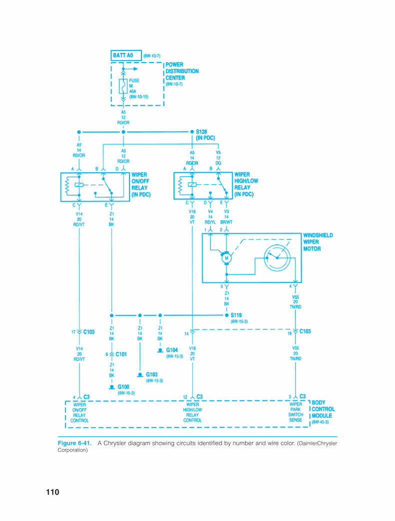
110
Figure 6-41. A Chrysler diagram showing circuits identified by number and wire color. (DaimlerChryslerCorporation)
ker88839_ch06.qxd 1/9/06 11:25 AM Page 110
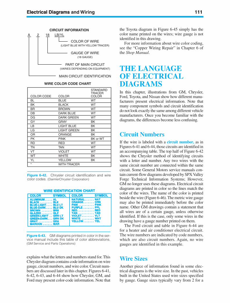
explains what the letters and numbers stand for. ThisChrysler diagram contains code information on wiregauge, circuit numbers, and wire color. Circuit num-bers are discussed later in this chapter. Figures 6-41,6-42, 6-43, and 6-44 show how Chrysler, GM, andFord may present color-code information. Note that
the Toyota diagram in Figure 6-45 simply has thecolor name printed on the wires; wire gauge is notidentified in this drawing.
For more information about wire color coding,see the “Copper Wiring Repair” in Chapter 6 ofthe Shop Manual.
THE LANGUAGEOF ELECTRICALDIAGRAMSIn this chapter, illustrations from GM, Chrysler,Ford, Toyota, and Nissan show how different manu-facturers present electrical information. Note thatmany component symbols and circuit identificationdo not look exactly the same among different vehiclemanufacturers. Once you become familiar with thediagrams, the differences become less confusing.
Circuit NumbersIf the wire is labeled with a circuit number, as inFigures 6-41 and 6-44, those circuits are identified inan accompanying table. The top half of Figure 6-42shows the Chrysler method of identifying circuitswith a letter and number. Any two wires with thesame circuit number are connected within the samecircuit. Some General Motors service manuals con-tain current-flow diagrams developed by SPX ValleyForge Technical Information Systems; However,GM no longer uses these diagrams. Electrical circuitdiagrams are printed in color so the lines match thecolor of the wires. The name of the color is printedbeside the wire (Figure 6-46). The metric wire gaugemay also be printed immediately before the colorname. Other GM drawings contain a statement thatall wires are of a certain gauge, unless otherwiseidentified. If this is the case, only some wires in thedrawing have a gauge number printed on them.
The Ford circuit and table in Figure 6-44 arefor a heater and air conditioner electrical circuit.The wire numbers are indicated by code numbers,which are also circuit numbers. Again, no wiregauges are identified in this example.
Wire SizesAnother piece of information found in some elec-trical diagrams is the wire size. In the past, vehiclesbuilt in the United States used wire sizes specifiedby gauge. Gauge sizes typically vary from 2 for a
Electrical Diagrams 111Electrical Diagrams and Wiring 111
A 2 18 LB/YL
COLOR OF WIRE(LIGHT BLUE WITH YELLOW TRACER)
GAUGE OF WIRE(18 GAUGE)
PART OF MAIN CIRCUIT(VARIES DEPENDING ON EQUIPMENT)
MAIN CIRCUIT IDENTIFICATION
WIRE COLOR CODE CHART
STANDARDTRACER
COLOR CODE COLOR COLORBL BLUE WTBK BLACK WTBR BROWN WTDB DARK BLUE WTDG DARK GREEN WTGY GRAY BKLB LIGHT BLUE BKLG LIGHT GREEN BKOR ORANGE BKPK PINK BK or WTRD RED WTTN TAN WTVT VIOLET WTWT WHITE BKYL YELLOW BK* WITH TRACER
CIRCUIT INFORMATION
Figure 6-42. Chrysler circuit identification and wirecolor codes. (DaimlerChrysler Corporation)
Figure 6-43. GM diagrams printed in color in the ser-vice manual include this table of color abbreviations.(GM Service and Parts Operations)
ker88839_ch06.qxd 1/9/06 11:25 AM Page 111
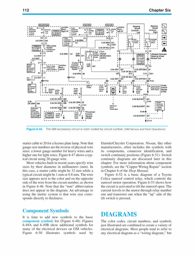
112 Chapter Six
Figure 6-44. The GM accessory circuit is color coded by circuit number. (GM Service and Parts Operations)
DaimlerChrysler Corporation. Nissan, like othermanufacturers, often includes the symbols withits components, connector identification, andswitch continuity positions (Figure 6-51). Switchcontinuity diagrams are discussed later in thischapter. For more information about componentsymbols, see the “Copper Wiring Repair” sectionin Chapter 6 of the Shop Manual.
Figure 6-52 is a basic diagram of a ToyotaCelica sunroof control relay, which controls thesunroof motor operation. Figure 6-53 shows howthe circuit is activated to tilt the sunroof open. Thecurrent travels to the motor through relay numberone and transistor one when the “up” side of thetilt switch is pressed.
DIAGRAMSThe color codes, circuit numbers, and symbolsjust illustrated are combined to create a variety ofelectrical diagrams. Most people tend to refer toany electrical diagram as a “wiring diagram,” but
starter cable to 20 for a license plate lamp. Note thatgauge-size numbers are the reverse of physical wiresizes: a lower gauge number for heavy wires and ahigher one for light wires. Figure 6-47 shows a typ-ical circuit using 20-gauge wire.
Most vehicles built in recent years specify wiresizes by their diameter in millimeters (mm). Inthis case, a starter cable might be 32 mm while atypical circuit might be 1 mm or 0.8 mm. The wiresize appears next to the color and on the oppositeside of the wire from the circuit number, as shownin Figure 6-46. Note that the “mm” abbreviationdoes not appear in the diagram. An advantage tousing the metric system is that wire size corre-sponds directly to thickness.
Component SymbolsIt is time to add new symbols to the basiccomponent symbols list (Figure 6-48). Figures6-49A and 6-49B show additional symbols formany of the electrical devices on GM vehicles.Figure 6-50 illustrates symbols used by
ker88839_ch06.qxd 1/9/06 11:25 AM Page 112
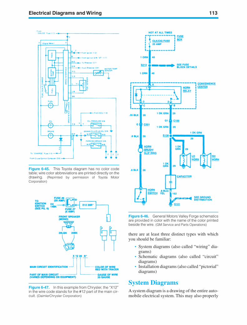
Electrical Diagrams and Wiring 113
there are at least three distinct types with whichyou should be familiar:
• System diagrams (also called “wiring” dia-grams)
• Schematic diagrams (also called “circuit”diagrams)
• Installation diagrams (also called “pictorial”diagrams)
System DiagramsA system diagram is a drawing of the entire auto-mobile electrical system. This may also properly
Figure 6-45. This Toyota diagram has no color codetable; wire color abbreviations are printed directly on thedrawing. (Reprinted by permission of Toyota MotorCorporation)
Figure 6-46. General Motors Valley Forge schematicsare provided in color with the name of the color printedbeside the wire. (GM Service and Parts Operations)
Figure 6-47. In this example from Chrysler, the “X12”in the wire code stands for the #12 part of the main cir-cuit. (DaimlerChrysler Corporation)
ker88839_ch06.qxd 1/9/06 11:25 AM Page 113
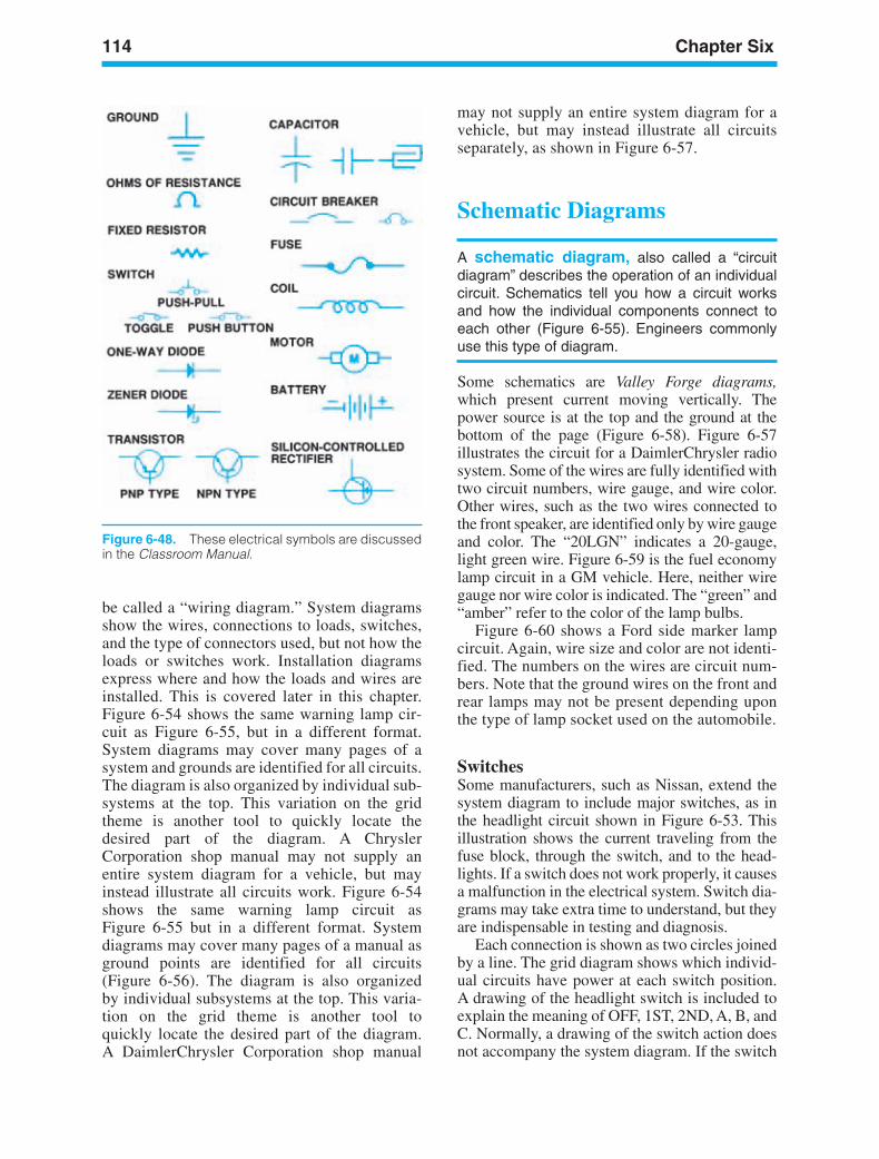
114 Chapter Six
Figure 6-48. These electrical symbols are discussedin the Classroom Manual.
be called a “wiring diagram.” System diagramsshow the wires, connections to loads, switches,and the type of connectors used, but not how theloads or switches work. Installation diagramsexpress where and how the loads and wires areinstalled. This is covered later in this chapter.Figure 6-54 shows the same warning lamp cir-cuit as Figure 6-55, but in a different format.System diagrams may cover many pages of asystem and grounds are identified for all circuits.The diagram is also organized by individual sub-systems at the top. This variation on the gridtheme is another tool to quickly locate thedesired part of the diagram. A ChryslerCorporation shop manual may not supply anentire system diagram for a vehicle, but mayinstead illustrate all circuits work. Figure 6-54shows the same warning lamp circuit asFigure 6-55 but in a different format. Systemdiagrams may cover many pages of a manual asground points are identified for all circuits(Figure 6-56). The diagram is also organizedby individual subsystems at the top. This varia-tion on the grid theme is another tool toquickly locate the desired part of the diagram.A DaimlerChrysler Corporation shop manual
may not supply an entire system diagram for avehicle, but may instead illustrate all circuitsseparately, as shown in Figure 6-57.
Schematic Diagrams
A schematic diagram, also called a “circuitdiagram” describes the operation of an individualcircuit. Schematics tell you how a circuit worksand how the individual components connect toeach other (Figure 6-55). Engineers commonlyuse this type of diagram.
Some schematics are Valley Forge diagrams,which present current moving vertically. Thepower source is at the top and the ground at thebottom of the page (Figure 6-58). Figure 6-57illustrates the circuit for a DaimlerChrysler radiosystem. Some of the wires are fully identified withtwo circuit numbers, wire gauge, and wire color.Other wires, such as the two wires connected tothe front speaker, are identified only by wire gaugeand color. The “20LGN” indicates a 20-gauge,light green wire. Figure 6-59 is the fuel economylamp circuit in a GM vehicle. Here, neither wiregauge nor wire color is indicated. The “green” and“amber” refer to the color of the lamp bulbs.
Figure 6-60 shows a Ford side marker lampcircuit. Again, wire size and color are not identi-fied. The numbers on the wires are circuit num-bers. Note that the ground wires on the front andrear lamps may not be present depending uponthe type of lamp socket used on the automobile.
SwitchesSome manufacturers, such as Nissan, extend thesystem diagram to include major switches, as inthe headlight circuit shown in Figure 6-53. Thisillustration shows the current traveling from thefuse block, through the switch, and to the head-lights. If a switch does not work properly, it causesa malfunction in the electrical system. Switch dia-grams may take extra time to understand, but theyare indispensable in testing and diagnosis.
Each connection is shown as two circles joinedby a line. The grid diagram shows which individ-ual circuits have power at each switch position.A drawing of the headlight switch is included toexplain the meaning of OFF, 1ST, 2ND, A, B, andC. Normally, a drawing of the switch action doesnot accompany the system diagram. If the switch
ker88839_ch06.qxd 1/9/06 11:25 AM Page 114
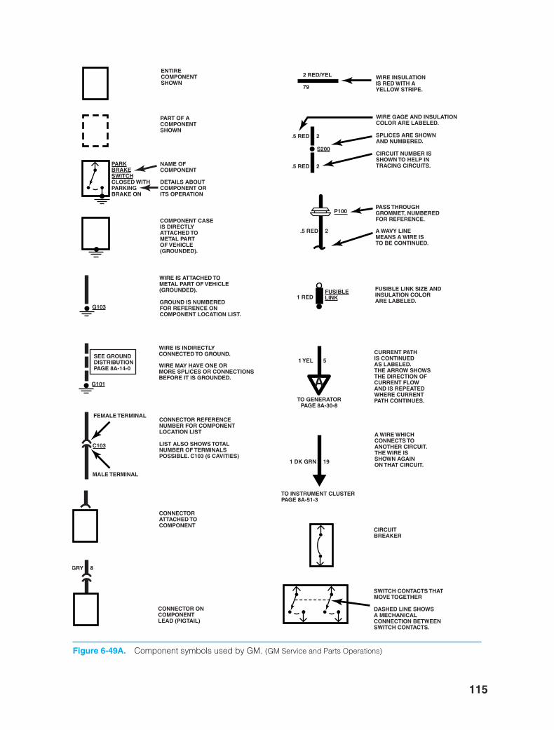
115
ENTIRECOMPONENTSHOWN
PART OF ACOMPONENTSHOWN
PARKBRAKESWITCHCLOSED WITHPARKINGBRAKE ON
FUSIBLELINK
NAME OFCOMPONENT
DETAILS ABOUTCOMPONENT ORITS OPERATION
COMPONENT CASEIS DIRECTLYATTACHED TOMETAL PARTOF VEHICLE(GROUNDED).
G103
S200
P100
G101
C103
WIRE IS ATTACHED TOMETAL PART OF VEHICLE(GROUNDED).
GROUND IS NUMBEREDFOR REFERENCE ONCOMPONENT LOCATION LIST.
SEE GROUNDDISTRIBUTIONPAGE 8A-14-0
WIRE IS INDIRECTLYCONNECTED TO GROUND.
WIRE MAY HAVE ONE ORMORE SPLICES OR CONNECTIONSBEFORE IT IS GROUNDED.
FEMALE TERMINAL
MALE TERMINAL
CONNECTOR REFERENCENUMBER FOR COMPONENTLOCATION LIST
LIST ALSO SHOWS TOTALNUMBER OF TERMINALSPOSSIBLE. C103 (6 CAVITIES)
CONNECTORATTACHED TOCOMPONENT
GRY 8
CONNECTOR ONCOMPONENTLEAD (PIGTAIL)
2 RED/YEL
79
WIRE INSULATIONIS RED WITH AYELLOW STRIPE.
.5 RED 2
.5 RED 2
.5 RED 2
1 YEL 5
1 DK GRN 19
1 RED
WIRE GAGE AND INSULATIONCOLOR ARE LABELED.
SPLICES ARE SHOWNAND NUMBERED.
CIRCUIT NUMBER ISSHOWN TO HELP INTRACING CIRCUITS.
PASS THROUGHGROMMET, NUMBEREDFOR REFERENCE.
A WAVY LINEMEANS A WIRE ISTO BE CONTINUED.
FUSIBLE LINK SIZE ANDINSULATION COLORARE LABELED.
ATO GENERATOR
PAGE 8A-30-8
CURRENT PATHIS CONTINUEDAS LABELED.THE ARROW SHOWSTHE DIRECTION OFCURRENT FLOWAND IS REPEATEDWHERE CURRENTPATH CONTINUES.
TO INSTRUMENT CLUSTERPAGE 8A-51-3
A WIRE WHICHCONNECTS TOANOTHER CIRCUIT.THE WIRE IS SHOWN AGAINON THAT CIRCUIT.
CIRCUITBREAKER
SWITCH CONTACTS THATMOVE TOGETHER
DASHED LINE SHOWSA MECHANICALCONNECTION BETWEENSWITCH CONTACTS.
Figure 6-49A. Component symbols used by GM. (GM Service and Parts Operations)
ker88839_ch06.qxd 1/9/06 11:25 AM Page 115
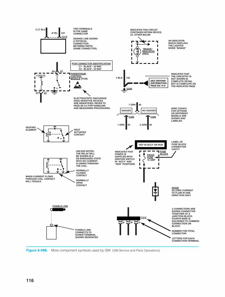
116
.5 LT BLU
.8 YEL 237
C216
C1
C2
TWO TERMINALSIN THE SAMECONNECTOR
DASHED LINE SHOWSA PHYSICALCONNECTIONBETWEEN PARTS(SAME CONNECTOR).
A9
D4
POWERTRAINCONTROLMODULE (PCM)
PCM CONNECTOR IDENTIFICATIONC1 - BLACK - 32 WAYC2 - BLACK - 24 WAY
ELECTROSTATIC DISCHARGE(ESD) SENSITIVE DEVICESARE INDENTIFIED. REFER TOPAGE 8A-3-0 FOR HANDLINGAND MEASURING PROCEDURES.
5 VOLTS
HEAT-ACTUATEDCONTACT
HEATINGELEMENT
WHEN CURRENT FLOWSTHROUGH COIL, CONTACTWILL TOGGLE.
UNLESS NOTED,THE RELAY WILLBE SHOWN IN ADE-ENERGIZED STATEWITH NO CURRENTFLOWING THROUGHTHE COIL.
NORMALLYCLOSEDCONTACT
NORMALLYOPENCONTACT
FUSIBLE LINK
FUSIBLE LINKCONNECTS TOSCREW TERMINAL.SHOWN SEPARATED
“BRAKE”INDICATOR(RED)
INDICATES THIS CIRCUITCONTINUES WITHIN DEVICE;I.E. OTHER BULBS
AN INDICATORWHICH DISPLAYSTHE LIGHTEDWORD “BRAKE”
3 BLK 150
1 ORN 40
1 ORN 40 .5 ORN 40
G200
SEE GROUNDDISTRIBUTIONPAGE 8A-14-0
INDICATES THATTHE CIRCUITRY ISNOT SHOWN INCOMPLETE DETAILBUT IS COMPLETE ONTHE INDICATED PAGE
C309C309
GAUGES NO GAUGESWIRE CHOICSFOR OPTIONSOR DIFFERENTMODELS ARESHOWN AND LABELED.
RADIOFUSE10 AMP
DIODEALLOWS CURRENTTO FLOW IN ONEDIRECTION ONLY
FUSEBLOCK
LABEL OFFUSE BLOCKCONNECTORCAVITY
INDICATES THATPOWER ISSUPPLIED WITHIGNITION SWITCHIN “ACCY” AND“RUN” POSITIONS
HOT IN ACCY OR RUN
C210
B M D
3 CONNECTORS ARESHOWN CONNECTEDTOGETHER AT AJUNCTION BLOCK.FOURTH WIRE ISSOLDERED TO COMMONCONNECTION ONBLOCK.
NUMBER FOR TOTALCONNECTOR
LETTERS FOR EACHCONNECTION TERMINAL
Figure 6-49B. More component symbols used by GM. (GM Service and Parts Operations)
ker88839_ch06.qxd 1/9/06 11:25 AM Page 116
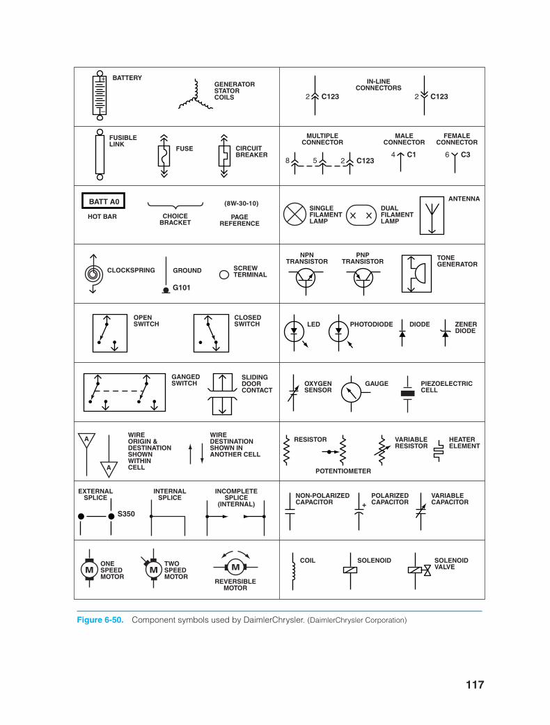
117
+
–
BATTERY
FUSIBLELINK
FUSE CIRCUITBREAKER
GENERATORSTATORCOILS 2 C123
2 C1234 C1 6 C3
2 C123
IN-LINECONNECTORS
58
MULTIPLECONNECTOR
MALECONNECTOR
FEMALECONNECTOR
BATT A0
HOT BAR CHOICEBRACKET
(8W-30-10)
PAGEREFERENCE
SINGLEFILAMENTLAMP
DUALFILAMENTLAMP
ANTENNA
TONEGENERATOR
NPNTRANSISTOR
PNPTRANSISTOR
SCREWTERMINAL
GROUND
G101
CLOCKSPRING
OPENSWITCH
CLOSEDSWITCH LED PHOTODIODE DIODE ZENER
DIODE
OXYGENSENSOR
GAUGE PIEZOELECTRICCELL
GANGEDSWITCH
SLIDINGDOORCONTACT
A
A
WIREORIGIN &DESTINATIONSHOWNWITHINCELL
WIREDESTINATIONSHOWN INANOTHER CELL
RESISTOR
POTENTIOMETER
VARIABLERESISTOR
HEATERELEMENT
+NON-POLARIZEDCAPACITOR
POLARIZEDCAPACITOR
VARIABLECAPACITOR
S350
EXTERNALSPLICE
INTERNALSPLICE
INCOMPLETESPLICE
(INTERNAL)
MM MONESPEEDMOTOR
TWOSPEEDMOTOR
REVERSIBLEMOTOR
COIL SOLENOID SOLENOIDVALVE
Figure 6-50. Component symbols used by DaimlerChrysler. (DaimlerChrysler Corporation)
ker88839_ch06.qxd 1/27/06 5:02 PM Page 117
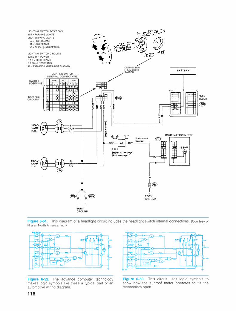
118
LIGHTING SWITCHINTERNAL CONNECTIONS
OFF 1ST 2ND
A B C A B C A B C
55
6
67
8
8
9
9
10
10
11
12
7
CONNECTORFROM LIGHTSWITCH
SWITCH POSITIONS
INDIVIDUAL
CIRCUITS
LIGHTING SWITCH POSITIONS1ST = PARKING LIGHTS2ND = DRIVING LIGHTS
A = HIGH BEAMSB = LOW BEAMSC = FLASH (HIGH BEAMS)
LIGHTING SWITCH CIRCUITS5, 8 & 11 = POWER6 & 9 = HIGH BEAMS7 & 10 = LOW BEAMS12 = PARKING LIGHTS (NOT SHOWN)
Figure 6-51. This diagram of a headlight circuit includes the headlight switch internal connections. (Courtesy ofNissan North America, Inc.)
Figure 6-52. The advance computer technologymakes logic symbols like these a typical part of anautomotive wiring diagram.
Figure 6-53. This circuit uses logic symbols toshow how the sunroof motor operates to tilt themechanism open.
ker88839_ch06.qxd 1/9/06 11:25 AM Page 118
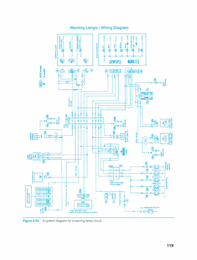
119
Figure 6-54. A system diagram for a warning lamp circuit.
ker88839_ch06.qxd 1/9/06 11:25 AM Page 119
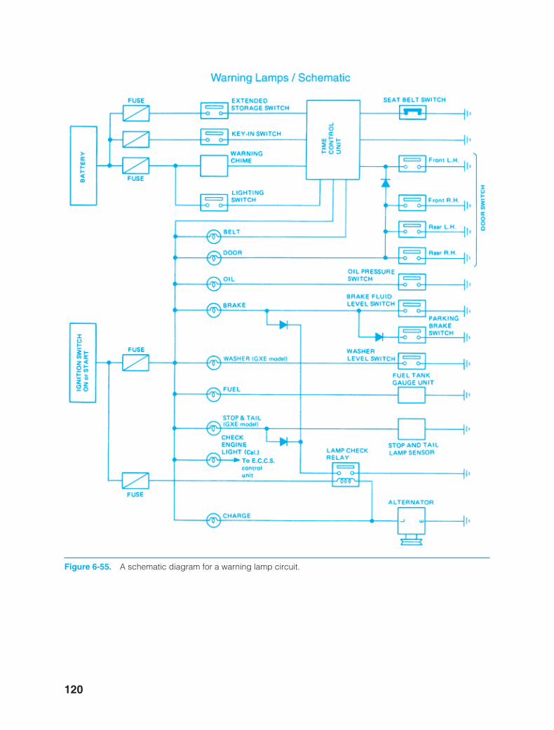
120
Figure 6-55. A schematic diagram for a warning lamp circuit.
ker88839_ch06.qxd 1/9/06 11:25 AM Page 120
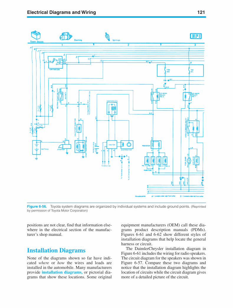
Electrical Diagrams and Wiring 121
Figure 6-56. Toyota system diagrams are organized by individual systems and include ground points. (Reprintedby permission of Toyota Motor Corporation)
positions are not clear, find that information else-where in the electrical section of the manufac-turer’s shop manual.
Installation DiagramsNone of the diagrams shown so far have indi-cated where or how the wires and loads areinstalled in the automobile. Many manufacturersprovide installation diagrams, or pictorial dia-grams that show these locations. Some original
equipment manufacturers (OEM) call these dia-grams product description manuals (PDMs).Figures 6-61 and 6-62 show different styles ofinstallation diagrams that help locate the generalharness or circuit.
The DaimlerChrysler installation diagram inFigure 6-61 includes the wiring for radio speakers.The circuit diagram for the speakers was shown inFigure 6-57. Compare these two diagrams andnotice that the installation diagram highlights thelocation of circuits while the circuit diagram givesmore of a detailed picture of the circuit.
ker88839_ch06.qxd 1/9/06 11:25 AM Page 121
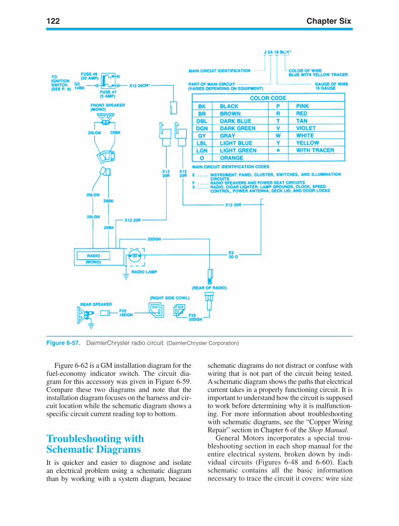
122 Chapter Six
Figure 6-57. DaimlerChrysler radio circuit. (DaimlerChrysler Corporation)
Figure 6-62 is a GM installation diagram for thefuel-economy indicator switch. The circuit dia-gram for this accessory was given in Figure 6-59.Compare these two diagrams and note that theinstallation diagram focuses on the harness and cir-cuit location while the schematic diagram shows aspecific circuit current reading top to bottom.
Troubleshooting withSchematic DiagramsIt is quicker and easier to diagnose and isolatean electrical problem using a schematic diagramthan by working with a system diagram, because
schematic diagrams do not distract or confuse withwiring that is not part of the circuit being tested.Aschematic diagram shows the paths that electricalcurrent takes in a properly functioning circuit. It isimportant to understand how the circuit is supposedto work before determining why it is malfunction-ing. For more information about troubleshootingwith schematic diagrams, see the “Copper WiringRepair” section in Chapter 6 of the Shop Manual.
General Motors incorporates a special trou-bleshooting section in each shop manual for theentire electrical system, broken down by indi-vidual circuits (Figures 6-48 and 6-60). Eachschematic contains all the basic informationnecessary to trace the circuit it covers: wire size
ker88839_ch06.qxd 1/9/06 11:25 AM Page 122
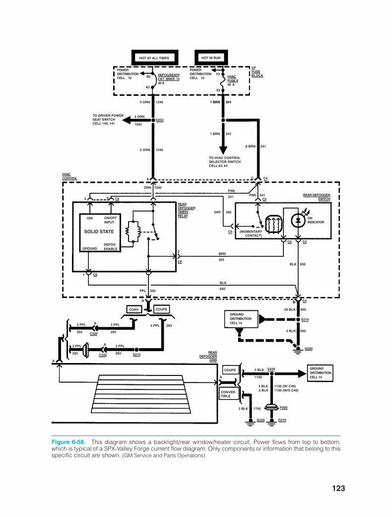
123
5 ORN 1240 1 BRN 241
1 BRN 241
.8 BRN 2415 ORN 1240
ORN 1240
GRY 292
5 PPL 293
PPL 293
PNK 241
BLK 650
.35 BLK 650
3 BLK 1150 (W/ C49)
3 BLK 1750
.5 BLK 1150 (W/O C49)
3 BLK 650
1 BRN 241
POWERDISTRIBUTIONCELL 10
POWERDISTRIBUTIONCELL 10B3
A3
DEFOG/SEATSCKT BRKR 1230 A
HVACFUSE 620 A
HOT AT ALL TIMES HOT IN RUN
F2
E2
I/PFUSEBLOCK
REARDEFOGGERTIMER/RELAY
REARDEFOGGER
GRID
REAR DEFOGGERSWITCH
HVACCONTROL
TO DRIVER POWERSEAT SWITCHCELL 140, 141
3 ORN
1240S252
C4
C6
C6
C6
C5
C5
C4
C5
C5
TO HVAC CONTROLSELECTOR SWITCHCELL 63, 64
A C
PNK
241
BRN
293
3 PPL
293
3 PPL
293
3 PPL
293
3 PPL
293
3 BLK
1150
BLK
650
4 3
(MOMENTARYCONTACT)
2
IGN ON/OFFINPUT
GROUNDDEFOGENABLE
SOLID STATE
1
ONINDICATOR
B D
CONV COUPE
COUPE
A
A
A
A
C320
C330
S420
S315
S216
G200
G320 G310
P300
GROUNDDISTRIBUTIONCELL 14
GROUNDDISTRIBUTIONCELL 14
D
CONVER-TIBLE
Figure 6-58. This diagram shows a backlight/rear window/heater circuit. Power flows from top to bottom,which is typical of a SPX-Valley Forge current flow diagram. Only components or information that belong to thisspecific circuit are shown. (GM Service and Parts Operations)
ker88839_ch06.qxd 1/9/06 11:25 AM Page 123
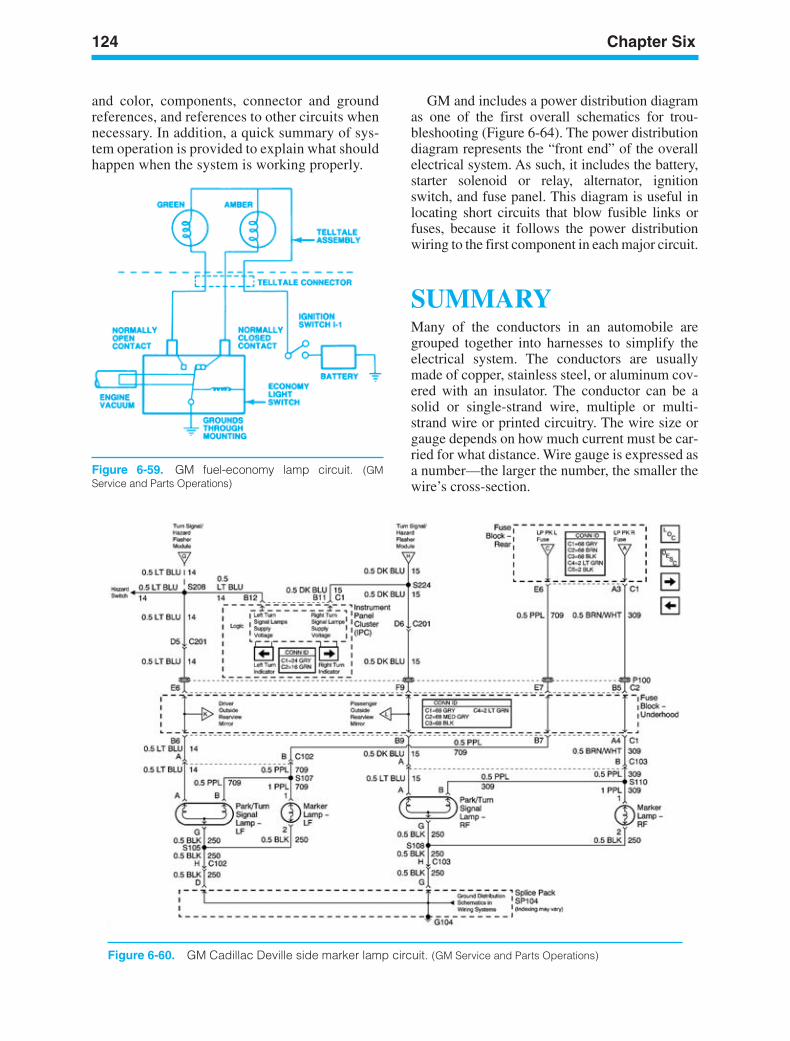
and color, components, connector and groundreferences, and references to other circuits whennecessary. In addition, a quick summary of sys-tem operation is provided to explain what shouldhappen when the system is working properly.
124 Chapter Six
Figure 6-59. GM fuel-economy lamp circuit. (GMService and Parts Operations)
Figure 6-60. GM Cadillac Deville side marker lamp circuit. (GM Service and Parts Operations)
GM and includes a power distribution diagramas one of the first overall schematics for trou-bleshooting (Figure 6-64). The power distributiondiagram represents the “front end” of the overallelectrical system. As such, it includes the battery,starter solenoid or relay, alternator, ignitionswitch, and fuse panel. This diagram is useful inlocating short circuits that blow fusible links orfuses, because it follows the power distributionwiring to the first component in each major circuit.
SUMMARYMany of the conductors in an automobile aregrouped together into harnesses to simplify theelectrical system. The conductors are usuallymade of copper, stainless steel, or aluminum cov-ered with an insulator. The conductor can be asolid or single-strand wire, multiple or multi-strand wire or printed circuitry. The wire size orgauge depends on how much current must be car-ried for what distance. Wire gauge is expressed asa number—the larger the number, the smaller thewire’s cross-section.
ker88839_ch06.qxd 1/9/06 11:25 AM Page 124
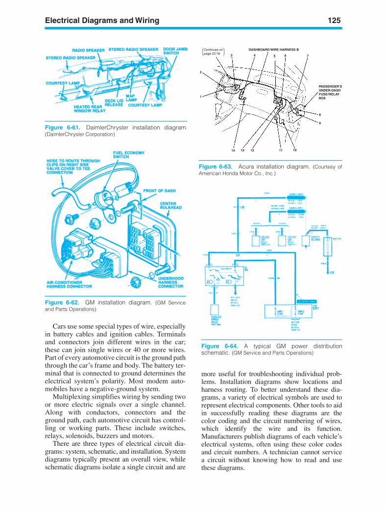
Cars use some special types of wire, especiallyin battery cables and ignition cables. Terminalsand connectors join different wires in the car;these can join single wires or 40 or more wires.Part of every automotive circuit is the ground paththrough the car’s frame and body. The battery ter-minal that is connected to ground determines theelectrical system’s polarity. Most modem auto-mobiles have a negative-ground system.
Multiplexing simplifies wiring by sending twoor more electric signals over a single channel.Along with conductors, connectors and theground path, each automotive circuit has control-ling or working parts. These include switches,relays, solenoids, buzzers and motors.
There are three types of electrical circuit dia-grams: system, schematic, and installation. Systemdiagrams typically present an overall view, whileschematic diagrams isolate a single circuit and are
more useful for troubleshooting individual prob-lems. Installation diagrams show locations andharness routing. To better understand these dia-grams, a variety of electrical symbols are used torepresent electrical components. Other tools to aidin successfully reading these diagrams are thecolor coding and the circuit numbering of wires,which identify the wire and its function.Manufacturers publish diagrams of each vehicle’selectrical systems, often using these color codesand circuit numbers. A technician cannot servicea circuit without knowing how to read and usethese diagrams.
Electrical Diagrams and Wiring 125
Figure 6-61. DaimlerChrysler installation diagram.(DaimlerChrysler Corporation)
Figure 6-62. GM installation diagram. (GM Serviceand Parts Operations)
Continues onpage 22-18
DASHBOARD WIRE HARNESS B
1
2
3 4 5 6 7
8
9
1011121314
PASSENGER’SUNDER-DASHFUSE/RELAYBOX
Figure 6-63. Acura installation diagram. (Courtesy ofAmerican Honda Motor Co., Inc.)
Figure 6-64. A typical GM power distributionschematic. (GM Service and Parts Operations)
ker88839_ch06.qxd 1/9/06 11:25 AM Page 125
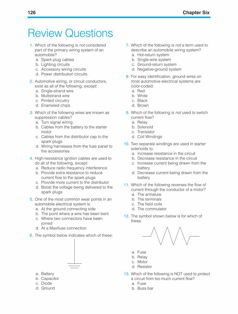
126 Chapter Six
Review Questions1. Which of the following is not considered
part of the primary wiring system of anautomobile?a. Spark plug cablesb. Lighting circuitsc. Accessory wiring circuitsd. Power distribution circuits
2. Automotive wiring, or circuit conductors,exist as all of the following, except:a. Single-strand wireb. Multistrand wirec. Printed circuitryd. Enameled chips
3. Which of the following wires are known assuppression cables?a. Turn signal wiringb. Cables from the battery to the starter
motorc. Cables from the distributor cap to the
spark plugsd. Wiring harnesses from the fuse panel to
the accessories
4. High-resistance ignition cables are used todo all of the following, except:a. Reduce radio frequency interferenceb. Provide extra resistance to reduce
current flow to the spark plugsc. Provide more current to the distributord. Boost the voltage being delivered to the
spark plugs
5. One of the most common wear points in anautomobile electrical system is:a. At the ground connecting sideb. The point where a wire has been bentc. Where two connectors have been
joinedd. At a Maxifuse connection
6. The symbol below indicates which of these:
a. Batteryb. Capacitorc. Dioded. Ground
7. Which of the following is not a term used todescribe an automobile wiring system?a. Hot-return systemb. Single-wire systemc. Ground-return systemd. Negative-ground system
8. For easy identification, ground wires onmost automotive electrical systems arecolor-coded:a. Redb. Whitec. Blackd. Brown
9. Which of the following is not used to switchcurrent flow?a. Relayb. Solenoidc. Transistord. Coil Windings
10. Two separate windings are used in startersolenoids to:a. Increase resistance in the circuitb. Decrease resistance in the circuitc. Increase current being drawn from the
batteryd. Decrease current being drawn from the
battery
11. Which of the following reverses the flow ofcurrent through the conductor of a motor?a. The armatureb. The terminalsc. The field coilsd. The commutator
12. The symbol shown below is for which ofthese:
a. Fuseb. Relayc. Motord. Resistor
13. Which of the following is NOT used to protecta circuit from too much current flow?a. Fuseb. Buss bar
ker88839_ch06.qxd 1/9/06 11:25 AM Page 126
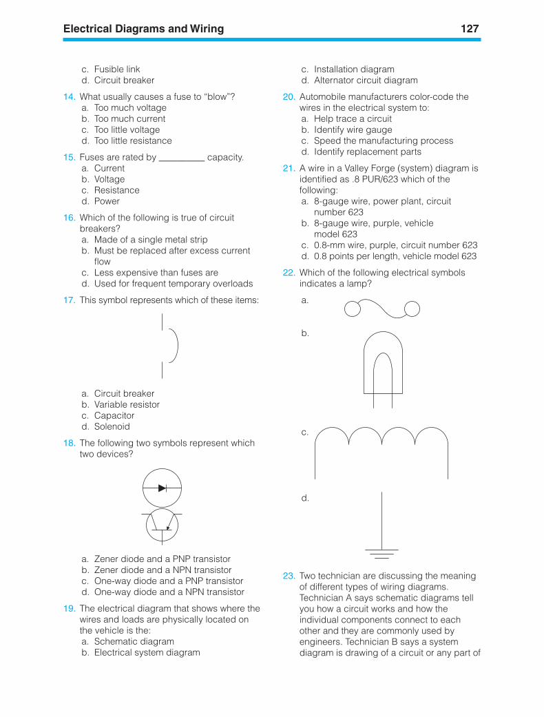
Electrical Diagrams and Wiring 127
c. Installation diagramd. Alternator circuit diagram
20. Automobile manufacturers color-code thewires in the electrical system to:a. Help trace a circuitb. Identify wire gaugec. Speed the manufacturing processd. Identify replacement parts
21. A wire in a Valley Forge (system) diagram isidentified as .8 PUR/623 which of thefollowing:a. 8-gauge wire, power plant, circuit
number 623b. 8-gauge wire, purple, vehicle
model 623c. 0.8-mm wire, purple, circuit number 623d. 0.8 points per length, vehicle model 623
22. Which of the following electrical symbolsindicates a lamp?
a.
b.
c.
d.
23. Two technician are discussing the meaningof different types of wiring diagrams.Technician A says schematic diagrams tellyou how a circuit works and how theindividual components connect to eachother and they are commonly used byengineers. Technician B says a systemdiagram is drawing of a circuit or any part of
c. Fusible linkd. Circuit breaker
14. What usually causes a fuse to “blow”?a. Too much voltageb. Too much currentc. Too little voltaged. Too little resistance
15. Fuses are rated by __________ capacity.a. Currentb. Voltagec. Resistanced. Power
16. Which of the following is true of circuitbreakers?a. Made of a single metal stripb. Must be replaced after excess current
flowc. Less expensive than fuses ared. Used for frequent temporary overloads
17. This symbol represents which of these items:
a. Circuit breakerb. Variable resistorc. Capacitord. Solenoid
18. The following two symbols represent whichtwo devices?
a. Zener diode and a PNP transistorb. Zener diode and a NPN transistorc. One-way diode and a PNP transistord. One-way diode and a NPN transistor
19. The electrical diagram that shows where thewires and loads are physically located onthe vehicle is the:a. Schematic diagramb. Electrical system diagram
ker88839_ch06.qxd 1/9/06 11:25 AM Page 127
128 Chapter Six
a circuit that shows circuit numbers, wiresize, and color-coding. Who is right?a. A onlyb. B onlyc. Both A and Bd. Neither A nor B
24. Technician A says the battery cableprovides a connection from the vehiclechassis to the battery. Technician B saysthat automotive electrical systems arecalled double-wire or positive returnsystems. Who is right?a. A onlyb. B only
c. Both A and Bd. Neither A nor B
25. Technicians are discussing wiregauge sizes. Technician A says wiresize numbers are based on the cross-sectional area of the conductor andlarger wires have lower gaugenumbers. Technician B says wirecross-section is measured in circular rods.Who is right?a. A onlyb. B onlyc. Both A and Bd. Neither A nor B
ker88839_ch06.qxd 1/9/06 11:25 AM Page 128
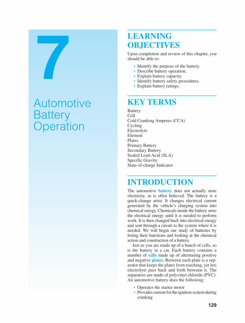
LEARNINGOBJECTIVESUpon completion and review of this chapter, youshould be able to:
• Identify the purpose of the battery.• Describe battery operation.• Explain battery capacity.• Identify battery safety procedures.• Explain battery ratings.
KEY TERMSBatteryCellCold Cranking Amperes (CCA)CyclingElectrolyteElementPlatesPrimary BatterySecondary BatterySealed Lead-Acid (SLA)Specific GravityState-of-charge Indicator
INTRODUCTIONThe automotive battery does not actually storeelectricity, as is often believed. The battery is aquick-change artist. It changes electrical currentgenerated by the vehicle’s charging system intochemical energy. Chemicals inside the battery storethe electrical energy until it is needed to performwork. It is then changed back into electrical energyand sent through a circuit to the system where it isneeded. We will begin our study of batteries bylisting their functions and looking at the chemicalaction and construction of a battery.
Just as you are made up of a bunch of cells, sois the battery in a car. Each battery contains anumber of cells made up of alternating positiveand negative plates. Between each plate is a sep-arator that keeps the plates from touching, yet letselectrolyte pass back and forth between it. Theseparators are made of polyvinyl chloride (PVC).An automotive battery does the following:
• Operates the starter motor• Provides current for the ignition system during
cranking
129
7AutomotiveBatteryOperation
ker88839_ch07.qxd 1/9/06 11:26 AM Page 129
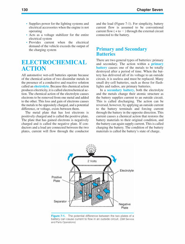
130 Chapter Seven
• Supplies power for the lighting systems andelectrical accessories when the engine is notoperating
• Acts as a voltage stabilizer for the entireelectrical system
• Provides current when the electricaldemand of the vehicle exceeds the output ofthe charging system
ELECTROCHEMICALACTIONAll automotive wet-cell batteries operate becauseof the chemical action of two dissimilar metals inthe presence of a conductive and reactive solutioncalled an electrolyte. Because this chemical actionproduces electricity, it is called electrochemical ac-tion. The chemical action of the electrolyte causeselectrons to be removed from one metal and addedto the other. This loss and gain of electrons causesthe metals to be oppositely charged, and a potentialdifference, or voltage, exists between them.
The metal plate that has lost electrons ispositively charged and is called the positive plate.The plate that has gained electrons is negativelycharged and is called the negative plate. If con-ductors and a load are connected between the twoplates, current will flow through the conductor
and the load (Figure 7-1). For simplicity, batterycurrent flow is assumed to be conventionalcurrent flow ( + to ) through the external circuitconnected to the battery.
Primary and SecondaryBatteriesThere are two general types of batteries: primaryand secondary. The action within a primarybattery causes one of the metals to be totallydestroyed after a period of time. When the bat-tery has delivered all of its voltage to an outsidecircuit, it is useless and must be replaced. Manysmall dry-cell batteries, such as those for flash-lights and radios, are primary batteries.
In a secondary battery, both the electrolyteand the metals change their atomic structure asthe battery supplies current to an outside circuit.This is called discharging. The action can bereversed, however, by applying an outside currentto the battery terminals and forcing currentthrough the battery in the opposite direction. Thiscurrent causes a chemical action that restores thebattery materials to their original condition, andthe battery can again supply current. This is calledcharging the battery. The condition of the batterymaterials is called the battery’s state of charge.
Figure 7-1. The potential difference between the two plates of abattery can cause current to flow in an outside circuit. (GM Serviceand Parts Operations)
ker88839_ch07.qxd 1/9/06 11:26 AM Page 130
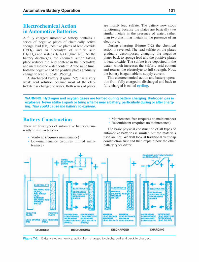
Automotive Battery Operation 131
WARNING: Hydrogen and oxygen gases are formed during battery charging. Hydrogen gas isexplosive. Never strike a spark or bring a flame near a battery, particularly during or after charg-ing. This could cause the battery to explode.
Figure 7-2. Battery electrochemical action from charged to discharged and back to charged.
Battery ConstructionThere are four types of automotive batteries cur-rently in use, as follows:
• Vent-cap (requires maintenance)• Low-maintenance (requires limited main-
tenance)
• Maintenance-free (requires no maintenance)• Recombinant (requires no maintenance)
The basic physical construction of all types ofautomotive batteries is similar, but the materialsused are not. We will look at traditional vent-capconstruction first and then explain how the otherbattery types differ.
Electrochemical Actionin Automotive BatteriesA fully charged automotive battery contains aseries of negative plates of chemically activesponge lead (Pb), positive plates of lead dioxide(PbO2) and an electrolyte of sulfuric acid(H2SO4) and water (H2O2) (Figure 7-2). As thebattery discharges, the chemical action takingplace reduces the acid content in the electrolyteand increases the water content. At the same time,both the negative and the positive plates graduallychange to lead sulphate (PbSO4).
A discharged battery (Figure 7-2) has a veryweak acid solution because most of the elec-trolyte has changed to water. Both series of plates
are mostly lead sulfate. The battery now stopsfunctioning because the plates are basically twosimilar metals in the presence of water, ratherthan two dissimilar metals in the presence of anelectrolyte.
During charging (Figure 7-2) the chemicalaction is reversed. The lead sulfate on the platesgradually decomposes, changing the negativeplates back to sponge lead and the positive platesto lead dioxide. The sulfate is re-deposited in thewater, which increases the sulfuric acid contentand returns the electrolyte to full strength. Now,the battery is again able to supply current.
This electrochemical action and battery opera-tion from fully charged to discharged and back tofully charged is called cycling.
ker88839_ch07.qxd 1/9/06 11:26 AM Page 131
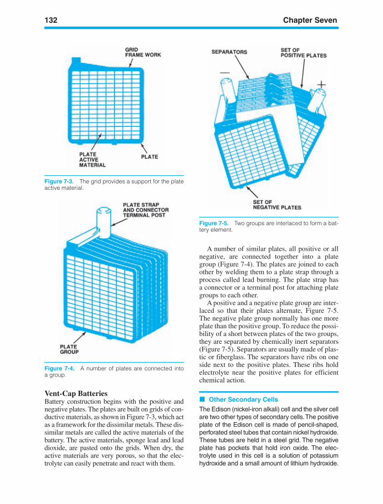
132 Chapter Seven
Figure 7-5. Two groups are interlaced to form a bat-tery element.
Vent-Cap BatteriesBattery construction begins with the positive andnegative plates. The plates are built on grids of con-ductive materials, as shown in Figure 7-3, which actas a framework for the dissimilar metals. These dis-similar metals are called the active materials of thebattery. The active materials, sponge lead and leaddioxide, are pasted onto the grids. When dry, theactive materials are very porous, so that the elec-trolyte can easily penetrate and react with them.
Figure 7-3. The grid provides a support for the plateactive material.
A number of similar plates, all positive or allnegative, are connected together into a plategroup (Figure 7-4). The plates are joined to eachother by welding them to a plate strap through aprocess called lead burning. The plate strap hasa connector or a terminal post for attaching plategroups to each other.
A positive and a negative plate group are inter-laced so that their plates alternate, Figure 7-5. The negative plate group normally has one moreplate than the positive group. To reduce the possi-bility of a short between plates of the two groups,they are separated by chemically inert separators(Figure 7-5). Separators are usually made of plas-tic or fiberglass. The separators have ribs on oneside next to the positive plates. These ribs holdelectrolyte near the positive plates for efficientchemical action.
Other Secondary Cells
The Edison (nickel-iron alkali) cell and the silver cellare two other types of secondary cells.The positiveplate of the Edison cell is made of pencil-shaped,perforated steel tubes that contain nickel hydroxide.These tubes are held in a steel grid. The negativeplate has pockets that hold iron oxide. The elec-trolyte used in this cell is a solution of potassiumhydroxide and a small amount of lithium hydroxide.
Figure 7-4. A number of plates are connected intoa group.
ker88839_ch07.qxd 1/9/06 11:26 AM Page 132
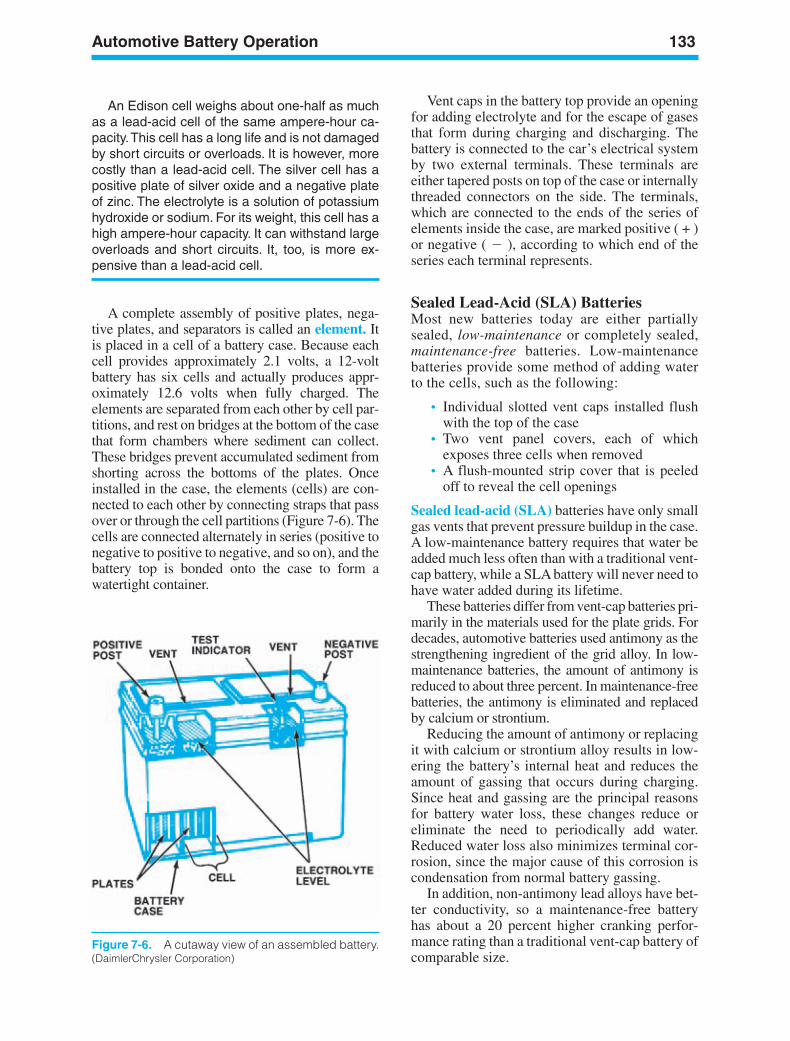
Automotive Battery Operation 133
Figure 7-6. A cutaway view of an assembled battery.(DaimlerChrysler Corporation)
An Edison cell weighs about one-half as muchas a lead-acid cell of the same ampere-hour ca-pacity.This cell has a long life and is not damagedby short circuits or overloads. It is however, morecostly than a lead-acid cell. The silver cell has apositive plate of silver oxide and a negative plateof zinc. The electrolyte is a solution of potassiumhydroxide or sodium. For its weight, this cell has ahigh ampere-hour capacity. It can withstand largeoverloads and short circuits. It, too, is more ex-pensive than a lead-acid cell.
A complete assembly of positive plates, nega-tive plates, and separators is called an element. Itis placed in a cell of a battery case. Because eachcell provides approximately 2.1 volts, a 12-voltbattery has six cells and actually produces appr-oximately 12.6 volts when fully charged. Theelements are separated from each other by cell par-titions, and rest on bridges at the bottom of the casethat form chambers where sediment can collect.These bridges prevent accumulated sediment fromshorting across the bottoms of the plates. Onceinstalled in the case, the elements (cells) are con-nected to each other by connecting straps that passover or through the cell partitions (Figure 7-6). Thecells are connected alternately in series (positive tonegative to positive to negative, and so on), and thebattery top is bonded onto the case to form awatertight container.
Vent caps in the battery top provide an openingfor adding electrolyte and for the escape of gasesthat form during charging and discharging. Thebattery is connected to the car’s electrical systemby two external terminals. These terminals areeither tapered posts on top of the case or internallythreaded connectors on the side. The terminals,which are connected to the ends of the series ofelements inside the case, are marked positive ( + )or negative ( ), according to which end of theseries each terminal represents.
Sealed Lead-Acid (SLA) BatteriesMost new batteries today are either partiallysealed, low-maintenance or completely sealed,maintenance-free batteries. Low-maintenancebatteries provide some method of adding waterto the cells, such as the following:
• Individual slotted vent caps installed flushwith the top of the case
• Two vent panel covers, each of whichexposes three cells when removed
• A flush-mounted strip cover that is peeledoff to reveal the cell openings
Sealed lead-acid (SLA) batteries have only smallgas vents that prevent pressure buildup in the case.A low-maintenance battery requires that water beadded much less often than with a traditional vent-cap battery, while a SLA battery will never need tohave water added during its lifetime.
These batteries differ from vent-cap batteries pri-marily in the materials used for the plate grids. Fordecades, automotive batteries used antimony as thestrengthening ingredient of the grid alloy. In low-maintenance batteries, the amount of antimony isreduced to about three percent. In maintenance-freebatteries, the antimony is eliminated and replacedby calcium or strontium.
Reducing the amount of antimony or replacingit with calcium or strontium alloy results in low-ering the battery’s internal heat and reduces theamount of gassing that occurs during charging.Since heat and gassing are the principal reasonsfor battery water loss, these changes reduce oreliminate the need to periodically add water.Reduced water loss also minimizes terminal cor-rosion, since the major cause of this corrosion iscondensation from normal battery gassing.
In addition, non-antimony lead alloys have bet-ter conductivity, so a maintenance-free batteryhas about a 20 percent higher cranking perfor-mance rating than a traditional vent-cap battery ofcomparable size.
ker88839_ch07.qxd 1/9/06 11:26 AM Page 133
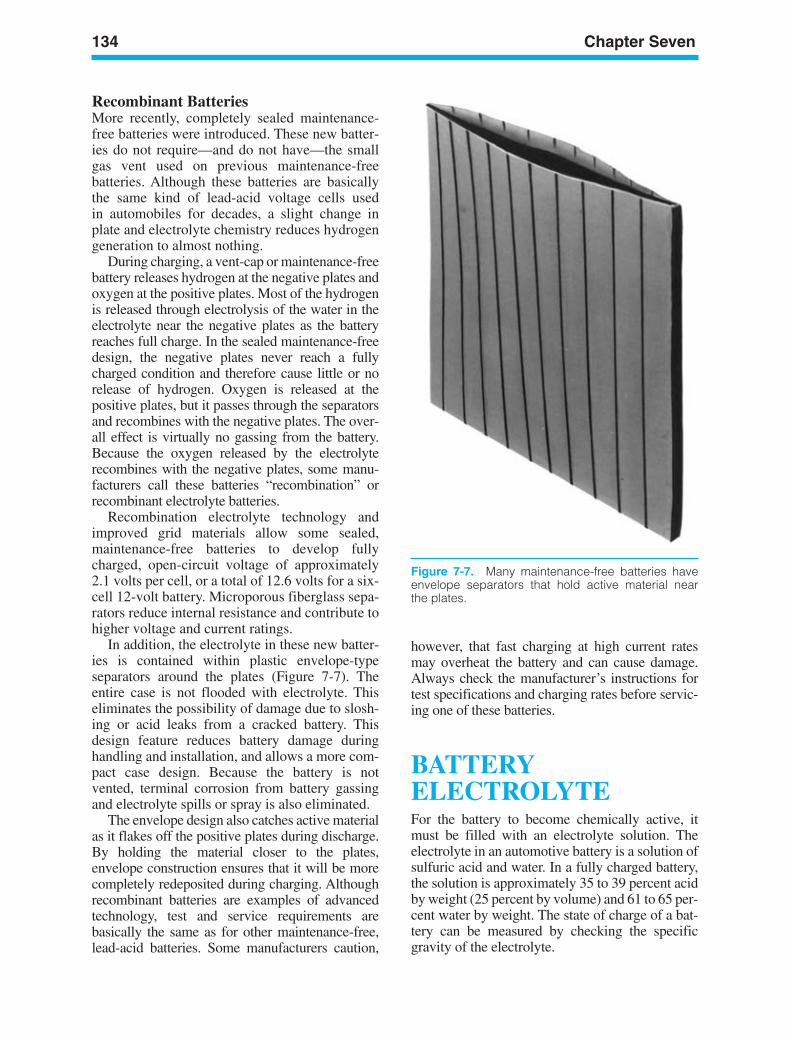
134 Chapter Seven
Figure 7-7. Many maintenance-free batteries haveenvelope separators that hold active material nearthe plates.
Recombinant BatteriesMore recently, completely sealed maintenance-free batteries were introduced. These new batter-ies do not require—and do not have—the smallgas vent used on previous maintenance-freebatteries. Although these batteries are basicallythe same kind of lead-acid voltage cells usedin automobiles for decades, a slight change inplate and electrolyte chemistry reduces hydrogengeneration to almost nothing.
During charging, a vent-cap or maintenance-freebattery releases hydrogen at the negative plates andoxygen at the positive plates. Most of the hydrogenis released through electrolysis of the water in theelectrolyte near the negative plates as the batteryreaches full charge. In the sealed maintenance-freedesign, the negative plates never reach a fullycharged condition and therefore cause little or norelease of hydrogen. Oxygen is released at thepositive plates, but it passes through the separatorsand recombines with the negative plates. The over-all effect is virtually no gassing from the battery.Because the oxygen released by the electrolyterecombines with the negative plates, some manu-facturers call these batteries “recombination” orrecombinant electrolyte batteries.
Recombination electrolyte technology andimproved grid materials allow some sealed,maintenance-free batteries to develop fullycharged, open-circuit voltage of approximately2.1 volts per cell, or a total of 12.6 volts for a six-cell 12-volt battery. Microporous fiberglass sepa-rators reduce internal resistance and contribute tohigher voltage and current ratings.
In addition, the electrolyte in these new batter-ies is contained within plastic envelope-typeseparators around the plates (Figure 7-7). Theentire case is not flooded with electrolyte. Thiseliminates the possibility of damage due to slosh-ing or acid leaks from a cracked battery. Thisdesign feature reduces battery damage duringhandling and installation, and allows a more com-pact case design. Because the battery is notvented, terminal corrosion from battery gassingand electrolyte spills or spray is also eliminated.
The envelope design also catches active materialas it flakes off the positive plates during discharge.By holding the material closer to the plates,envelope construction ensures that it will be morecompletely redeposited during charging. Althoughrecombinant batteries are examples of advancedtechnology, test and service requirements arebasically the same as for other maintenance-free,lead-acid batteries. Some manufacturers caution,
however, that fast charging at high current ratesmay overheat the battery and can cause damage.Always check the manufacturer’s instructions fortest specifications and charging rates before servic-ing one of these batteries.
BATTERYELECTROLYTEFor the battery to become chemically active, itmust be filled with an electrolyte solution. Theelectrolyte in an automotive battery is a solution ofsulfuric acid and water. In a fully charged battery,the solution is approximately 35 to 39 percent acidby weight (25 percent by volume) and 61 to 65 per-cent water by weight. The state of charge of a bat-tery can be measured by checking the specificgravity of the electrolyte.
ker88839_ch07.qxd 1/9/06 11:26 AM Page 134
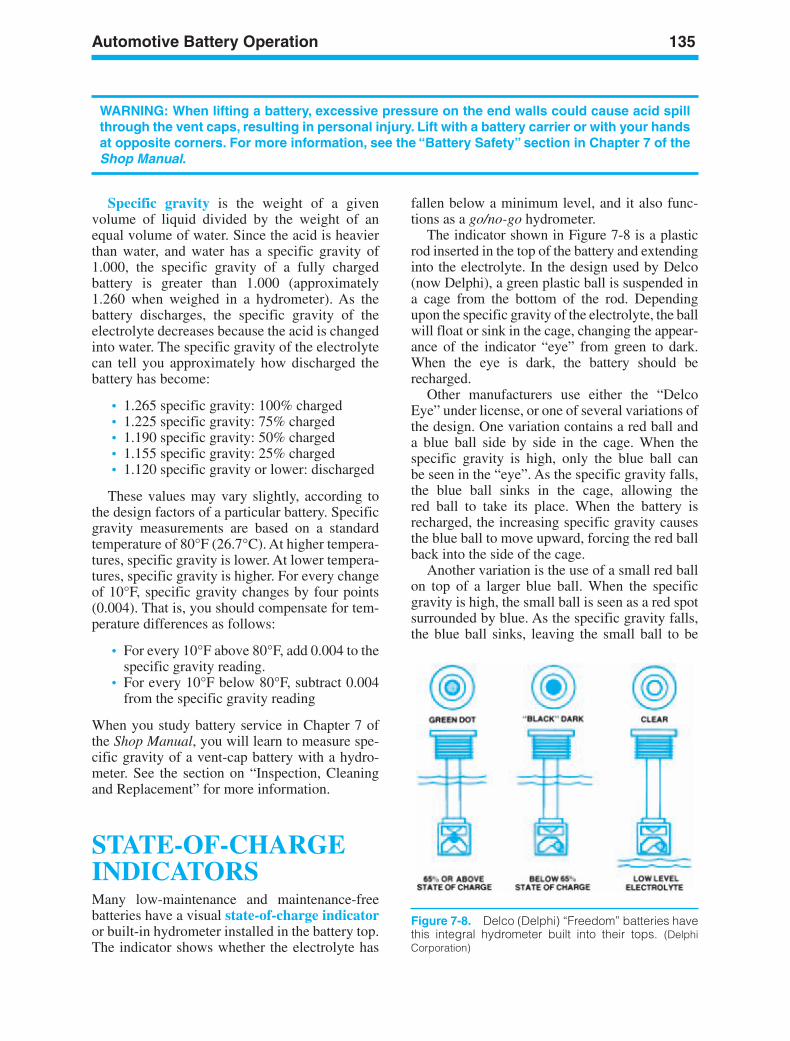
Automotive Battery Operation 135
WARNING: When lifting a battery, excessive pressure on the end walls could cause acid spillthrough the vent caps, resulting in personal injury. Lift with a battery carrier or with your handsat opposite corners. For more information, see the “Battery Safety” section in Chapter 7 of theShop Manual.
Specific gravity is the weight of a givenvolume of liquid divided by the weight of anequal volume of water. Since the acid is heavierthan water, and water has a specific gravity of1.000, the specific gravity of a fully chargedbattery is greater than 1.000 (approximately1.260 when weighed in a hydrometer). As thebattery discharges, the specific gravity of theelectrolyte decreases because the acid is changedinto water. The specific gravity of the electrolytecan tell you approximately how discharged thebattery has become:
• 1.265 specific gravity: 100% charged• 1.225 specific gravity: 75% charged• 1.190 specific gravity: 50% charged• 1.155 specific gravity: 25% charged• 1.120 specific gravity or lower: discharged
These values may vary slightly, according tothe design factors of a particular battery. Specificgravity measurements are based on a standardtemperature of 80°F (26.7°C). At higher tempera-tures, specific gravity is lower. At lower tempera-tures, specific gravity is higher. For every changeof 10°F, specific gravity changes by four points(0.004). That is, you should compensate for tem-perature differences as follows:
• For every 10°F above 80°F, add 0.004 to thespecific gravity reading.
• For every 10°F below 80°F, subtract 0.004from the specific gravity reading
When you study battery service in Chapter 7 ofthe Shop Manual, you will learn to measure spe-cific gravity of a vent-cap battery with a hydro-meter. See the section on “Inspection, Cleaningand Replacement” for more information.
STATE-OF-CHARGEINDICATORSMany low-maintenance and maintenance-freebatteries have a visual state-of-charge indicatoror built-in hydrometer installed in the battery top.The indicator shows whether the electrolyte has
fallen below a minimum level, and it also func-tions as a go/no-go hydrometer.
The indicator shown in Figure 7-8 is a plasticrod inserted in the top of the battery and extendinginto the electrolyte. In the design used by Delco(now Delphi), a green plastic ball is suspended ina cage from the bottom of the rod. Dependingupon the specific gravity of the electrolyte, the ballwill float or sink in the cage, changing the appear-ance of the indicator “eye” from green to dark.When the eye is dark, the battery should berecharged.
Other manufacturers use either the “DelcoEye” under license, or one of several variations ofthe design. One variation contains a red ball anda blue ball side by side in the cage. When thespecific gravity is high, only the blue ball canbe seen in the “eye”. As the specific gravity falls,the blue ball sinks in the cage, allowing thered ball to take its place. When the battery isrecharged, the increasing specific gravity causesthe blue ball to move upward, forcing the red ballback into the side of the cage.
Another variation is the use of a small red ballon top of a larger blue ball. When the specificgravity is high, the small ball is seen as a red spotsurrounded by blue. As the specific gravity falls,the blue ball sinks, leaving the small ball to be
Figure 7-8. Delco (Delphi) “Freedom” batteries havethis integral hydrometer built into their tops. (DelphiCorporation)
ker88839_ch07.qxd 1/9/06 11:26 AM Page 135
136 Chapter Seven
seen as a red spot surrounded by a clear area. Thebattery then should be recharged.
If the electrolyte drops below the level of thecage in batteries using a state-of-charge indicator,the “eye” will appear clear or light yellow. Thismeans that the battery must be replaced because ithas lost too much electrolyte. For more informa-tion, see the “Battery Testing” section in Chapter 7of the Shop Manual.
WET-CHARGED ANDDRY-CHARGEDBATTERIESBatteries may be manufactured and sold as eitherwet-charged or dry-charged batteries. Beforemaintenance-free batteries became widely used,dry-charged batteries were very common. A wet-charged battery is completely filled with anelectrolyte when it is built. A dry-charged batteryis shipped from the factory without electrolyte.During manufacture, the positive and negativeplates are charged and then completely washedand dried. The battery is then assembled andsealed to keep out moisture. It will remaincharged as long as it is sealed, and it can be storedfor a long time in any reasonable environment.A dry-charged battery is put into service byadding electrolyte, checking the battery state ofcharge, and charging if needed.
Even when a wet-charged battery is not in use,a slow reaction occurs between the plates and theelectrolyte. This is a self-discharging reaction, andwill eventually discharge the battery almost com-pletely. Because this reaction occurs faster athigher temperatures, wet-charged batteries shouldbe stored in as cool a place as possible when not inuse. A fully charged battery stored at a room tem-perature of 100°F (38°C) will almost completelydischarge after 90 days. If the battery is stored at atemperature of 60°F (16°C), very little dischargewill take place.
BATTERY CHARGINGVOLTAGEForcing current through it in the direction oppo-site from its discharge current charges a battery.In an automobile, the generator or alternator
supplies this charging current. The batteryoffers some resistance to this charging current,because of the battery’s chemical voltage andthe resistance of the battery’s internal parts. Thebattery’s chemical voltage is another form ofcounterelectromotive force (CEMF) that youstudied in Chapter 4.
When a battery is fully charged, its CEMF isvery high. Very little charging current can flowthrough it. When the battery is discharged, itsCEMF is very low, and charging current flowsfreely. For charging current to enter the battery,the charging voltage must be higher than thebattery’s CEMF plus the voltage drop caused bythe battery’s internal resistance.
Understanding this relationship of CEMF to thebattery state of charge is helpful. When the battery isnearly discharged, it needs, and will accept, a lot ofcharging current. When the battery is fully charged,the high CEMF will resist charging current. Any ad-ditional charging current could overheat and damagethe battery materials. Charging procedures are ex-plained in Chapter 3 of your Shop Manual. See alsothe section on “Battery Testing” in Chapter 7 of theShop Manual.
The temperature of the battery affects thecharging voltage because temperature affectsthe resistance of the electrolyte. Cold electrolytehas higher resistance than warm electrolyte, so acolder battery is harder to charge. The effects oftemperature must be considered when servicingautomotive charging systems and batteries, as weshall see later in this chapter.
BATTERY SELECTIONAND RATINGMETHODSAutomotive batteries are available in a variety ofsizes, shapes, and current ratings. They are called“starting batteries” and are designed to deliver alarge current output for a brief time to start anengine. After starting, the charging system takesover to supply most of the current required tooperate the car. The battery acts as a systemstabilizer and provides current whenever theelectrical loads exceed the charging currentoutput. An automotive battery must provide goodcranking power for the car’s engine and adequatereserve power for the electrical system in which itis used.
ker88839_ch07.qxd 1/9/06 11:26 AM Page 136
Automotive Battery Operation 137
Manufacturers also make 12-volt automotive-type batteries that are not designed for automotiveuse. These are called “cycling batteries” and aredesigned to provide a power source for a vehicleor accessory without continual recharging.Cycling batteries provide a constant low currentfor a long period of time. They are designed forindustrial, marine, and recreational vehicle (RV)or motor home use. Most of their current capacityis exhausted in each cycle before recharging.
The brief high current flow required of a startingbattery is produced by using relatively thin plates,compared to those used in a cycling battery. Thethicker plates of the cycling battery will providea constant current drain for several hours. Usinga starting battery in an application calling for acycling battery will shorten its life considerably, aswe shall see later in the chapter. The use of acycling battery to start and operate a car will causeexcessive internal heat from the brief but high cur-rent draw, resulting in a shorter service life.
Test standards and rating methods devised bythe Battery Council International (BCI) andthe Society of Automotive Engineers (SAE) aredesigned to measure a battery’s ability to meet therequirements of its intended service.
The BCI publishes application charts that listthe correct battery for any car. Optional heavy-duty
the ignition system until the engine starts. Thisrequires a high discharge over a very short timespan. Cold engines require more power to turnover, but batteries have difficulty deliveringpower when it is cold. Cold cranking amperes(CCA) are an important measurement of bat-tery capacity because they measure the dis-charge load, in amps, that a battery can supplyfor 30 seconds at 0°F while maintaining a volt-age of 1.2 volts per cell (7.2 volts per battery)or higher. The CCA rating generally falls be-tween 300 and 970 for most passenger cars; itis identified as 300 CCA, 400 CCA, 500 CCA,and so on. The rating is typically higher forcommercial vehicles. For more informationabout cold cranking amps, see the section on“Battery Testing” in Chapter 7 of the ShopManual. Some batteries are rated as high as1,100 CCA.
Cranking Amps (CA)Cranking amps (CA) represent the discharge load(in amps) that a fully charged battery can supplyfor 30 seconds at 32°F while maintaining a volt-age of 1.2 volts per cell (7.2 volts per 12 voltbattery) or higher.
NOTE: CA (Cranking Amps) is nearly the same as CCA (Cold Cranking Amps), but the two rat-ings should not be confused. CCA is rated at 0°F. CA, on the other hand is measured at a tem-perature of 32°F. The difference in temperature will produce a considerable amount of addi-tional current when measured as a CA rating.
batteries are normally used in cars with air condi-tioning or several major electrical accessories or incars operated in cold climates. To ensure adequatecranking power and to meet all other electricalneeds, a replacement battery may have a higher rat-ing, but never a lower rating, than the original unit.The battery must also be the correct size for the car,and have the correct type of terminals. BCI stan-dards include a coding system called the groupnumber. BCI battery rating methods are explainedin the following paragraphs.
Cold Cranking Amperes (CCA)The primary duty of the battery is to start theengine. It cranks, or rotates, the crankshaftwhile it maintains sufficient voltage to activate
Reserve Capacity RatingReserve capacity is the time required (in min-utes) for a fully charged battery at 80˚F under aconstant 25-amp draw to reach a voltage of 10.5volts. This rating helps determine the battery’sability to sustain a minimum vehicle electricalload in the event of a charging system failure.The minimum electrical load under the worstpossible conditions (winter driving at night)would likely require current for the ignition, low-beam headlights, windshield wipers, and the de-froster at low speed. Reserve capacity is usefulfor measuring the battery’s ability to power a ve-hicle that has small, long-term parasitic electricalloads but enough reserve to crank the engine.
Battery reserve capacity ratings range from 30to 175 minutes, and correspond approximately to
ker88839_ch07.qxd 1/9/06 11:26 AM Page 137
138 Chapter Seven
the length of time a vehicle can be driven after thecharging system has failed. The reserve capacityof a battery can be used to judge how much elec-trical drain in milliamperes could be acceptable us-ing the reserve capacity in minutes divided by 4.For example, a battery with an RC rating of 120minutes should have a maximum battery drain of30 mA (120 4 30).
Historical Ampere-Hour Rating
The oldest battery rating method, no longer usedto rate batteries, was the ampere-hour rating.Thisrating method was the industry standard fordecades. It was replaced, however, years ago bythe cranking performance and reserve capacityratings, which provide better indications of abattery’s performance. The ampere-hour methodwas also called the 20-hour discharge ratingmethod. This rating represented the steadycurrent flow that a battery delivered at a tempera-ture of 80°F (27°C) without cell voltage fallingbelow 1.75 volts (a total of 10.5 volts for a 12-voltbattery). For example, a battery that continuouslydelivered 3 amperes for 20 hours was rated as a60 ampere-hour battery (3 amperes × 20 hours =60 ampere-hours).
Historical Watt-Hour Rating
Many years ago, batteries were rated in watthours. A watt hour is the drain of a battery equalto one watt, which is one volt times one amp for aperiod of one hour or any combination of wattageand time. The watt hour rating of the battery wasmeasured at 0°F (18°C).
Battery Size SelectionBattery size and weight are major factors for thedesign engineer. A typical battery can weighabout 50 pounds and takes space in the vehicle.Powertrain and electronic design engineers wantthe vehicle to have enough capacity for automaticheadlights, which remain on for several minutesafter the engine is turned off, as well as to providethe electrical power to start the engine under allextremely low temperature conditions. Due to ve-hicle packaging considerations, the battery can belocated under the hood, behind the front bumper,under the rear seat, or in the trunk area. The bat-tery selected must of course be able to fit into thevehicle and use the same cable converter as theoriginal, as well as be able to be held down in the
vehicle. There are several different types of hold-downs including:
• Bracket over the top of the battery• Bottom bracket that wedges into a notch at
the base of the battery
When selecting a battery, check the weight ofthe battery in the size that fits the vehicle. Aheavier battery has more lead and is likely to outperform a lighter battery of the same size andtype of construction.
Group NumberManufacturers provide a designated amount ofspace, usually in the engine compartment, to ac-commodate the battery. Since battery companiesbuild batteries of various current-capacity ratingsin a variety of sizes and shapes, it is useful to havea guide when replacing a battery, because it mustfit into the space provided. The BCI size groupnumber identifies a battery in terms of its length,width, height, terminal design, and other physicalfeatures.
BATTERYINSTALLATIONSMost automobiles use one 6-cell, 12-volt batteryinstalled in the engine compartment. Certain fac-tors influence battery location as follows:
• The distance between the battery and the alter-nator or starter motor determines the length ofthe cables used. Cable length is importantbecause of electrical system resistance. Thelonger the cables, the greater the resistance.
• The battery should be located away from hotengine components in a position where itcan be cooled by airflow.
• The battery should be in a location where itcan be securely mounted as protectionagainst internal damage from vibration.
• The battery should be positioned where itcan be easily serviced.
The decrease in size of late-model vehicles has re-sulted in lighter, smaller batteries with greater ca-pacity. The use of new plastics and improved gridand plate materials has contributed to the new bat-tery designs.
ker88839_ch07.qxd 1/9/06 11:26 AM Page 138
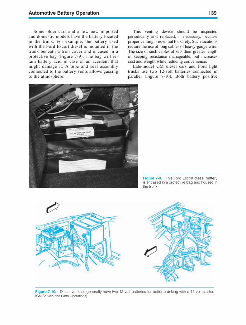
Automotive Battery Operation 139
Figure 7-9. This Ford Escort diesel batteryis encased in a protective bag and housed inthe trunk.
Figure 7-10. Diesel vehicles generally have two 12-volt batteries for better cranking with a 12-volt starter.(GM Service and Parts Operations)
Some older cars and a few new importedand domestic models have the battery locatedin the trunk. For example, the battery usedwith the Ford Escort diesel is mounted in thetrunk beneath a trim cover and encased in aprotective bag (Figure 7-9). The bag will re-tain battery acid in case of an accident thatmight damage it. A tube and seal assemblyconnected to the battery vents allows gassingto the atmosphere.
This venting device should be inspectedperiodically and replaced, if necessary, becauseproper venting is essential for safety. Such locationsrequire the use of long cables of heavy-gauge wire.The size of such cables offsets their greater lengthin keeping resistance manageable, but increasescost and weight while reducing convenience.
Late-model GM diesel cars and Ford lighttrucks use two 12-volt batteries connected inparallel (Figure 7-10). Both battery positive
ker88839_ch07.qxd 1/9/06 11:26 AM Page 139
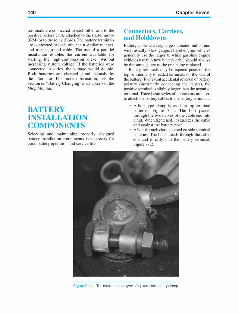
140 Chapter Seven
Figure 7-11. The most common type of top terminal battery clamp.
terminals are connected to each other and to thepositive battery cable attached to the starter motor(GM) or to the relay (Ford). The battery terminalsare connected to each other in a similar manner,and to the ground cable. The use of a parallelinstallation doubles the current available forstarting the high-compression diesel withoutincreasing system voltage. If the batteries wereconnected in series, the voltage would double.Both batteries are charged simultaneously bythe alternator. For more information, see thesection on “Battery Changing” in Chapter 7 of theShop Manual.
BATTERYINSTALLATIONCOMPONENTSSelecting and maintaining properly designedbattery installation components is necessary forgood battery operation and service life.
Connectors, Carriers,and HolddownsBattery cables are very large-diameter multistrandwire, usually 0 to 6 gauge. Diesel engine vehiclesgenerally use the larger 0, while gasoline enginevehicles use 6. A new battery cable should alwaysbe the same gauge as the one being replaced.
Battery terminals may be tapered posts on thetop or internally threaded terminals on the side ofthe battery. To prevent accidental reversal of batterypolarity (incorrectly connecting the cables), thepositive terminal is slightly larger than the negativeterminal. Three basic styles of connectors are usedto attach the battery cables to the battery terminals:
• A bolt-type clamp is used on top-terminalbatteries, Figure 7-11. The bolt passesthrough the two halves of the cable end intoa nut. When tightened, it squeezes the cableend against the battery post.
• A bolt-through clamp is used on side-terminalbatteries. The bolt threads through the cableend and directly into the battery terminal,Figure 7-12.
ker88839_ch07.qxd 1/9/06 11:26 AM Page 140
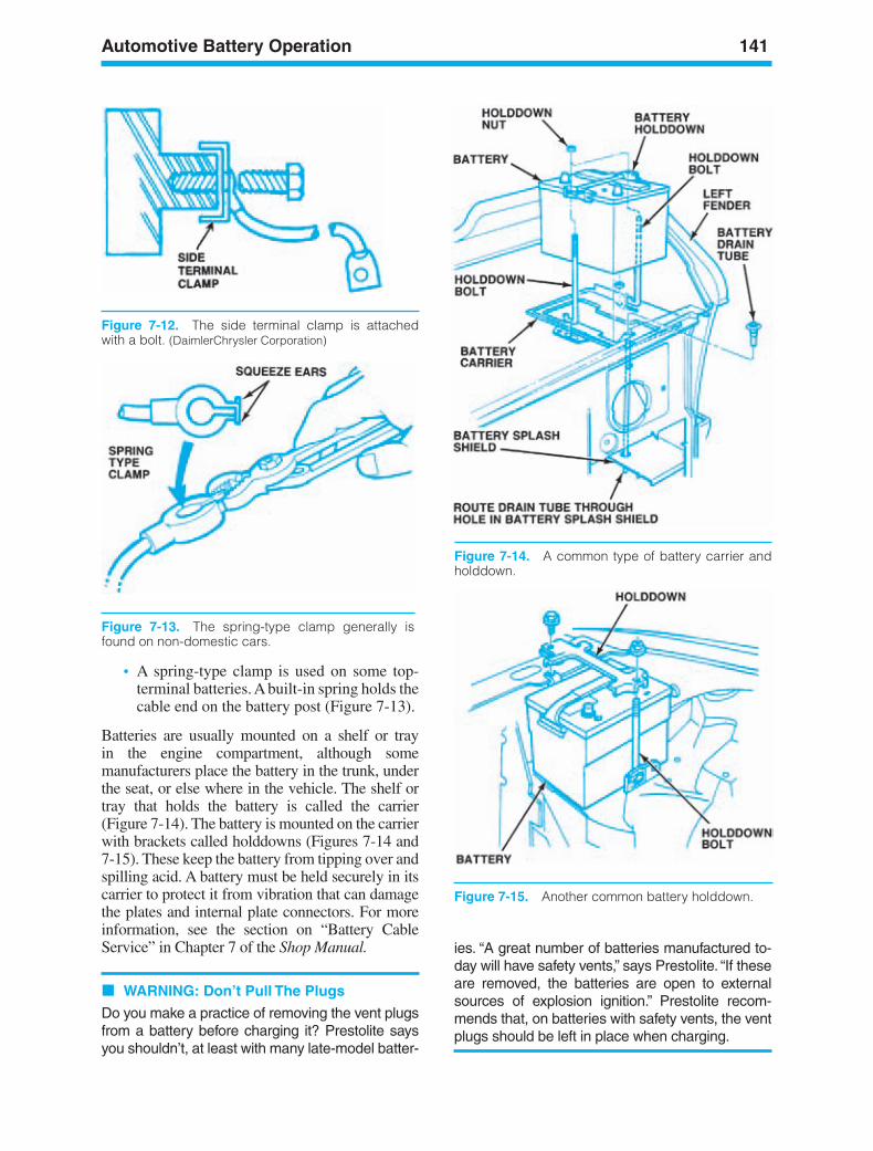
Automotive Battery Operation 141
Figure 7-12. The side terminal clamp is attachedwith a bolt. (DaimlerChrysler Corporation)
Figure 7-13. The spring-type clamp generally isfound on non-domestic cars.
• A spring-type clamp is used on some top-terminal batteries. A built-in spring holds thecable end on the battery post (Figure 7-13).
Batteries are usually mounted on a shelf or trayin the engine compartment, although somemanufacturers place the battery in the trunk, underthe seat, or else where in the vehicle. The shelf ortray that holds the battery is called the carrier(Figure 7-14). The battery is mounted on the carrierwith brackets called holddowns (Figures 7-14 and7-15). These keep the battery from tipping over andspilling acid. A battery must be held securely in itscarrier to protect it from vibration that can damagethe plates and internal plate connectors. For moreinformation, see the section on “Battery CableService” in Chapter 7 of the Shop Manual.
WARNING: Don’t Pull The Plugs
Do you make a practice of removing the vent plugsfrom a battery before charging it? Prestolite saysyou shouldn’t, at least with many late-model batter-
ies. “A great number of batteries manufactured to-day will have safety vents,” says Prestolite. “If theseare removed, the batteries are open to externalsources of explosion ignition.” Prestolite recom-mends that, on batteries with safety vents, the ventplugs should be left in place when charging.
Figure 7-14. A common type of battery carrier andholddown.
Figure 7-15. Another common battery holddown.
ker88839_ch07.qxd 1/9/06 11:27 AM Page 141
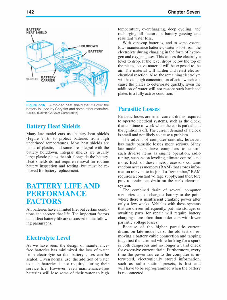
142 Chapter Seven
Figure 7-16. A molded heat shield that fits over thebattery is used by Chrysler and some other manufac-turers. (DaimlerChrysler Corporation)
BATTERY LIFE ANDPERFORMANCEFACTORSAll batteries have a limited life, but certain condi-tions can shorten that life. The important factorsthat affect battery life are discussed in the follow-ing paragraphs.
Electrolyte LevelAs we have seen, the design of maintenance-free batteries has minimized the loss of waterfrom electrolyte so that battery cases can besealed. Given normal use, the addition of waterto such batteries is not required during theirservice life. However, even maintenance-freebatteries will lose some of their water to high
Battery Heat ShieldsMany late-model cars use battery heat shields(Figure 7-16) to protect batteries from highunderhood temperatures. Most heat shields aremade of plastic, and some are integral with thebattery holddown. Integral shields are usuallylarge plastic plates that sit alongside the battery.Heat shields do not require removal for routinebattery inspection and testing, but must be re-moved for battery replacement.
temperature, overcharging, deep cycling, andrecharging all factors in battery gassing andresultant water loss.
With vent-cap batteries, and to some extent,low- maintenance batteries, water is lost from theelectrolyte during charging in the form of hydro-gen and oxygen gases. This causes the electrolytelevel to drop. If the level drops below the top ofthe plates, active material will be exposed to theair. The material will harden and resist electro-chemical reaction. Also, the remaining electrolytewill have a high concentration of acid, which cancause the plates to deteriorate quickly. Even theaddition of water will not restore such hardenedplates to a fully active condition.
Parasitic LossesParasitic losses are small current drains requiredto operate electrical systems, such as the clock,that continue to work when the car is parked andthe ignition is off. The current demand of a clockis small and not likely to cause a problem.
The advent of computer controls, however,has made parasitic losses more serious. Manylate-model cars have computers to controlsuch diverse items as engine operation, radiotuning, suspension leveling, climate control, andmore. Each of these microprocessors containsrandom access memory (RAM) that stores infor-mation relevant to its job. To “remember,” RAMrequires a constant voltage supply, and thereforeputs a continuous drain on the car’s electricalsystem.
The combined drain of several computermemories can discharge a battery to the pointwhere there is insufficient cranking power afteronly a few weeks. Vehicles with these systemsthat are driven infrequently, put into storage, orawaiting parts for repair will require batterycharging more often than older cars with lowerparasitic voltage losses.
Because of the higher parasitic currentdrains on late-model cars, the old test of re-moving a battery cable connection and tappingit against the terminal while looking for a sparkis both dangerous and no longer a valid checkfor excessive current drain. Furthermore, everytime the power source to the computer is in-terrupted, electronically stored information,such as radio station presets, is lost andwill have to be reprogrammed when the batteryis reconnected.
ker88839_ch07.qxd 1/9/06 11:27 AM Page 142
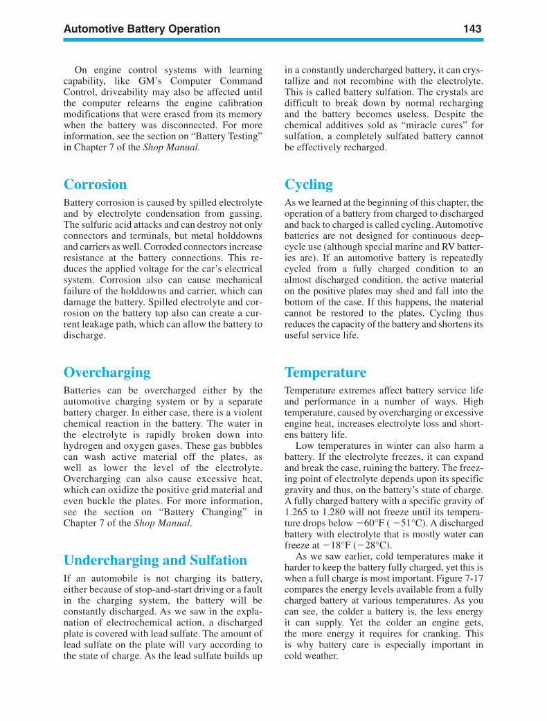
Automotive Battery Operation 143
On engine control systems with learningcapability, like GM’s Computer CommandControl, driveability may also be affected untilthe computer relearns the engine calibrationmodifications that were erased from its memorywhen the battery was disconnected. For moreinformation, see the section on “Battery Testing”in Chapter 7 of the Shop Manual.
CorrosionBattery corrosion is caused by spilled electrolyteand by electrolyte condensation from gassing.The sulfuric acid attacks and can destroy not onlyconnectors and terminals, but metal holddownsand carriers as well. Corroded connectors increaseresistance at the battery connections. This re-duces the applied voltage for the car’s electricalsystem. Corrosion also can cause mechanicalfailure of the holddowns and carrier, which candamage the battery. Spilled electrolyte and cor-rosion on the battery top also can create a cur-rent leakage path, which can allow the battery todischarge.
OverchargingBatteries can be overcharged either by theautomotive charging system or by a separatebattery charger. In either case, there is a violentchemical reaction in the battery. The water inthe electrolyte is rapidly broken down intohydrogen and oxygen gases. These gas bubblescan wash active material off the plates, aswell as lower the level of the electrolyte.Overcharging can also cause excessive heat,which can oxidize the positive grid material andeven buckle the plates. For more information,see the section on “Battery Changing” inChapter 7 of the Shop Manual.
Undercharging and SulfationIf an automobile is not charging its battery,either because of stop-and-start driving or a faultin the charging system, the battery will beconstantly discharged. As we saw in the expla-nation of electrochemical action, a dischargedplate is covered with lead sulfate. The amount oflead sulfate on the plate will vary according tothe state of charge. As the lead sulfate builds up
in a constantly undercharged battery, it can crys-tallize and not recombine with the electrolyte.This is called battery sulfation. The crystals aredifficult to break down by normal rechargingand the battery becomes useless. Despite thechemical additives sold as “miracle cures” forsulfation, a completely sulfated battery cannotbe effectively recharged.
CyclingAs we learned at the beginning of this chapter, theoperation of a battery from charged to dischargedand back to charged is called cycling. Automotivebatteries are not designed for continuous deep-cycle use (although special marine and RV batter-ies are). If an automotive battery is repeatedlycycled from a fully charged condition to analmost discharged condition, the active materialon the positive plates may shed and fall into thebottom of the case. If this happens, the materialcannot be restored to the plates. Cycling thusreduces the capacity of the battery and shortens itsuseful service life.
TemperatureTemperature extremes affect battery service lifeand performance in a number of ways. Hightemperature, caused by overcharging or excessiveengine heat, increases electrolyte loss and short-ens battery life.
Low temperatures in winter can also harm abattery. If the electrolyte freezes, it can expandand break the case, ruining the battery. The freez-ing point of electrolyte depends upon its specificgravity and thus, on the battery’s state of charge.A fully charged battery with a specific gravity of1.265 to 1.280 will not freeze until its tempera-ture drops below 60°F ( 51°C). A dischargedbattery with electrolyte that is mostly water canfreeze at 18°F (28°C).
As we saw earlier, cold temperatures make itharder to keep the battery fully charged, yet this iswhen a full charge is most important. Figure 7-17compares the energy levels available from a fullycharged battery at various temperatures. As youcan see, the colder a battery is, the less energyit can supply. Yet the colder an engine gets,the more energy it requires for cranking. Thisis why battery care is especially important incold weather.
ker88839_ch07.qxd 1/9/06 11:27 AM Page 143
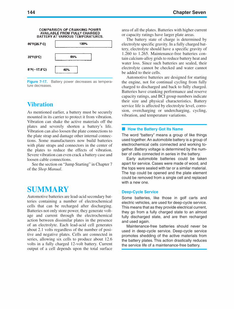
144 Chapter Seven
VibrationAs mentioned earlier, a battery must be securelymounted in its carrier to protect it from vibration.Vibration can shake the active materials off theplates and severely shorten a battery’s life.Vibration can also loosen the plate connections tothe plate strap and damage other internal connec-tions. Some manufacturers now build batterieswith plate straps and connectors in the center ofthe plates to reduce the effects of vibration.Severe vibration can even crack a battery case andloosen cable connections.
See the section on “Jump Starting” in Chapter 7of the Shop Manual.
SUMMARYAutomotive batteries are lead-acid secondary bat-teries containing a number of electrochemicalcells that can be recharged after discharging.Batteries not only store power, they generate volt-age and current through the electrochemicalaction between dissimilar plates in the presenceof an electrolyte. Each lead-acid cell generatesabout 2.1 volts regardless of the number of posi-tive and negative plates. Cells are connected inseries, allowing six cells to produce about 12.6volts in a fully charged 12-volt battery. Currentoutput of a cell depends upon the total surface
area of all the plates. Batteries with higher currentor capacity ratings have larger plate areas.
The battery state of charge is determined byelectrolyte specific gravity. In a fully charged bat-tery, electrolyte should have a specific gravity of1.260 to 1.265. Maintenance-free batteries con-tain calcium-alloy grids to reduce battery heat andwater loss. Since such batteries are sealed, theirelectrolyte cannot be checked and water cannotbe added to their cells.
Automotive batteries are designed for startingthe engine, not for continual cycling from fullycharged to discharged and back to fully charged.Batteries have cranking performance and reservecapacity ratings, and BCI group numbers indicatetheir size and physical characteristics. Batteryservice life is affected by electrolyte level, corro-sion, overcharging or undercharging, cycling,vibration, and temperature variations.
How the Battery Got Its Name
The word “battery” means a group of like thingsused together. An automobile battery is a group ofelectrochemical cells connected and working to-gether. Battery voltage is determined by the num-ber of cells connected in series in the battery.
Early automobile batteries could be takenapart for service. Cases were made of wood, andthe tops were sealed with tar or a similar material.The top could be opened and the plate elementcould be removed from a single cell and replacedwith a new one.
Deep-Cycle Service
Some batteries, like those in golf carts andelectric vehicles, are used for deep-cycle service.This means that as they provide electrical current,they go from a fully charged state to an almostfully discharged state, and are then rechargedand used again.
Maintenance-free batteries should never beused in deep-cycle service. Deep-cycle servicepromotes shedding of the active materials fromthe battery plates. This action drastically reducesthe service life of a maintenance-free battery.
Figure 7-17. Battery power decreases as tempera-ture decreases.
ker88839_ch07.qxd 1/9/06 11:27 AM Page 144
Automotive Battery Operation 145
Review Questions1. Which of the following occurs within an
automobile battery?a. The positive plate gains electrons and is
positively charged.b. The negative plate loses electrons and
is negatively charged.c. The positive plate loses electrons
and the negative plate gains electrons.d. The positive plate gains electrons
and the negative plate loses electrons.
2. Battery electrolyte is a mixture of waterand:a. Lead peroxideb. Sulfuric acidc. Lead sulfated. Sulfur crystals
3. The plates of a discharged battery are:a. Two similar metals in the presence of an
electrolyteb. Two similar metals in the presence
of waterc. Two dissimilar metals in the presence of
an electrolyted. Two dissimilar metals in the presence
of water
4. Which of the following is true abouta “secondary” battery?a. It can be recharged.b. Neither the electrolyte nor the metals
change their atomic structure.c. One of the metals is totally destroyed by
the action of the battery.d. The action of the battery cannot
be reversed.
5. Which of the following does not occurduring battery recharging?a. The lead sulfate on the plates gradually
decomposes.b. The sulfate is redeposited in the water.c. The electrolyte is returned to full
strength.d. The negative plates change back
to lead sulfate.
6. Each cell of an automobile battery canproduce about ________ volts.a. 1.2b. 2.1
c. 4.2d. 6
7. Which of the following is true of a 6-voltautomobile battery?a. It has six cells connected in series.b. It has three cells connected in series.c. It has six cells connected in parallel.d. It has three cells connected in parallel.
8. The correct ratio of water to sulfuric acid inbattery electrolyte is approximately:a. 80 percent water to 20 percent
sulfuric acidb. 60 percent water to 40 percent
sulfuric acidc. 40 percent water to 60 percent
sulfuric acidd. 20 percent water to 80 percent
sulfuric acid
9. At 80°F, the correct specific gravity ofelectrolyte in a fully charged battery is:a. 1.200 to 1.225b. 1.225 to 1.265c. 1.265 to 1.280d. 1.280 to 1.300
10. A specific gravity of 1.170 to 1.190 at 80°Findicates that a battery’s state of chargeis about:a. 75 percentb. 50 percentc. 25 percentd. 10 percent
11. Which of the following materials is not usedfor battery separators?a. Leadb. Woodc. Paperd. Plastic
12. Batteries are rated in terms of:a. Amperes at 65°Fb. Resistance at 32°Fc. Voltage level at 80°Fd. Cranking performance at 0°F
13. Maintenance-free batteries:a. Have individual cell capsb. Require water infrequentlyc. Have three pressure ventsd. Use non-antimony lead alloys
ker88839_ch07.qxd 1/9/06 11:27 AM Page 145
146 Chapter Seven
14. Which of the following statements is not trueof a replacement battery?a. It may have the same rating as
the original battery.b. It may have a higher rating than the
original battery.c. It may have a lower rating than the
original battery.d. It should be selected according to an
application chart.
15. An automobile battery with a crankingperformance rating of 380 can deliver380 amps for:a. 30 seconds at 0°Fb. 60 seconds at 0°Fc. 90 seconds at 32°Fd. 90 seconds at 0°F
16. The principal cause of battery water loss is:a. Spillage from the vent capsb. Leakage through the battery casec. Conversion of water to sulfuric acidd. Evaporation due to heat of the
charging current
17. Which of the following is not true of amaintenance-free battery?a. It will resist overcharging better than a
vent-cap battery.b. It will lose water slower than a vent-cap
battery.c. It will produce a greater voltage than
a vent-cap battery.d. It has a greater electrolyte capacity than
a vent-cap battery.
18. The electrolyte in a fully charged battery willgenerally not freeze until the temperaturedrops to:a. 32°Fb. 0°Fc. 20°Fd. 50°F
19. The grid material used in a maintenance-free battery is alloyed with:a. Siliconb. Antimonyc. Calciumd. Germanium
20. Low-maintenance batteries:a. Have no cell capsb. Have a higher proportion of sulfuric acidc. Have no gas-pressure ventsd. Require infrequent water addition
21. Recombinant batteries are:a. Rebuilt unitsb. Completely sealedc. Vented to release gassingd. Able to produce a higher cell voltage
22. Which of these parts of a battery hold theelectrical charge?a. Side-post typesb. Positive and negative platesc. Top-post typed. Bottom plates
23. Technician A says that the battery termampere-hour refers to stored chargecapacity of a battery. Technician B says thata 75-ampere-hour charge applied to a 200-ampere-hour battery should turn the chargeindicator green. Who is right?a. A onlyb. B onlyc. Both A and Bd. Neither A nor B
24. On a vehicle with the two battery 12-voltsystem, the battery’s connection is whichone of the following?a. Series circuitb. Parallel circuitc. DC circuitd. AC circuit
25. During normal operation, the battery(s)perform all of the following functions,except:a. Provides electrical energy for the
accessories when the engine isnot running
b. Acts as voltage storage for the truckelectrical system
c. Serves as the voltage source for startingd. Provides voltage for the injection
solenoid when running
26. The subject of battery ratings is beingdiscussed. Technician A says reservecapacity is a rating that represents the time inminutes that a battery can operate a truck atnight with minimum electrical load. TechnicianB says that cranking amps (CA) is basicallythe same as cold cranking amps (CCA) butat a temperature of 32°F. Who is right?a. A onlyb. B onlyc. Both A and Bd. Neither A nor B
ker88839_ch07.qxd 1/9/06 11:27 AM Page 146
LEARNINGOBJECTIVESUpon completion and review of this chapter, youshould be able to:
• Identify charging system development andprinciples.
• Explain the operation of a DC generator.• Identify AC charging system components
and explain charging voltage.• Explain diode rectification.• Identify AC generator components and
explain their function.• Explain current production in an AC gener-
ator (alternator) operation.• Identify different OEM AC generators and
explain those differences.• Explain how voltage is regulated in an AC
generator.• Identify the different types of voltage regu-
lators and explain how they operate.
KEY TERMSAC GeneratorsDelta-Type StatorDiodeField CircuitFull-Wave RectificationHalf-Wave RectificationOutput CircuitRotorSine Wave VoltageSingle-Phase CurrentSingle-Phase VoltageSliprings and BrushesStatorThree-phase CurrentVoltage RegulatorY-Type Stator
INTRODUCTIONThe charging system converts the engine’smechanical energy into electrical energy. Thiselectrical energy is used to maintain the battery’sstate of charge and to operate the loads of the auto-motive electrical system. In this chapter we willuse the conventional theory of current: Electronsmove from positive to negative ( to ).
147
8ChargingSystemOperation
ker88839_ch08.qxd 1/9/06 11:27 AM Page 147
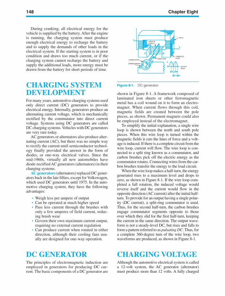
148 Chapter Eight
FIELD
LAMINATEDCORE
OUTPUTWAVE
COMMUTATOR
CARBON BRUSH
LINES OFFORCE
WIRE LOOP
Figure 8-1. DC generator.
During cranking, all electrical energy for thevehicle is supplied by the battery. After the engineis running, the charging system must produceenough electrical energy to recharge the batteryand to supply the demands of other loads in theelectrical system. If the starting system is in poorcondition and draws too much current, or if thecharging system cannot recharge the battery andsupply the additional loads, more energy must bedrawn from the battery for short periods of time.
CHARGING SYSTEMDEVELOPMENTFor many years, automotive charging systems usedonly direct current (DC) generators to provideelectrical energy. Internally, generators produce analternating current voltage, which is mechanicallyrectified by the commutator into direct currentvoltage. Systems using DC generators are calledDC charging systems. Vehicles with DC generatorsare very rare today.
AC generators or alternators also produce alter-nating current (AC), but there was no simple wayto rectify the current until semiconductor technol-ogy finally provided the answer in the form ofdiodes, or one-way electrical valves. Since themid-1960s, virtually all new automobiles havediode-rectified AC generators (alternators) in theircharging systems.
AC generators (alternators) replaced DC gener-ators back in the late fifties, except for Volkswagen,which used DC generators until 1975. In the auto-motive charging system, they have the followingadvantages:
• Weigh less per ampere of output• Can be operated at much higher speed• Pass less current through the brushes with
only a few amperes of field current, reduc-ing brush wear
• Govern their own maximum current output,requiring no external current regulation
• Can produce current when rotated in eitherdirection, although their cooling fans usu-ally are designed for one-way operation.
DC GENERATORThe principles of electromagnetic induction areemployed in generators for producing DC cur-rent. The basic components of a DC generator are
shown in Figure 8-1. A framework composed oflaminated iron sheets or other ferromagneticmetal has a coil wound on it to form an electro-magnet. When current flows through this coil,magnetic fields are created between the polepieces, as shown. Permanent magnets could alsobe employed instead of the electromagnet.
To simplify the initial explanation, a single wireloop is shown between the north and south polepieces. When this wire loop is turned within themagnetic fields it cuts the lines of force and a volt-age is induced. If there is a complete circuit from thewire loop, current will flow. The wire loop is con-nected to a split ring known as a commutator, andcarbon brushes pick off the electric energy as thecommutator rotates. Connecting wires from the car-bon brushes transfer the energy to the load circuit.
When the wire loop makes a half-turn, the energygenerated rises to a maximum level and drops tozero, as shown in Figure 8-1. If the wire loop com-pleted a full rotation, the induced voltage wouldreverse itself and the current would flow in theopposite direction (AC current) after the initial half-turn. To provide for an output having a single polar-ity (DC current), a split-ring commutator is used.Thus, for the second half-turn, the carbon brushesengage commutator segments opposite to thoseover which they slid for the first half-turn, keepingthe current in the same direction. The output wave-form is not a steady-level DC, but rises and falls toform a pattern referred to as pulsating DC. Thus, fora complete 360-degree turn of the wire loop, twowaveforms are produced, as shown in Figure 8-1.
CHARGING VOLTAGEAlthough the automotive electrical system is calleda 12-volt system, the AC generator (alternator)must produce more than 12 volts. A fully charged
ker88839_ch08.qxd 1/9/06 11:27 AM Page 148
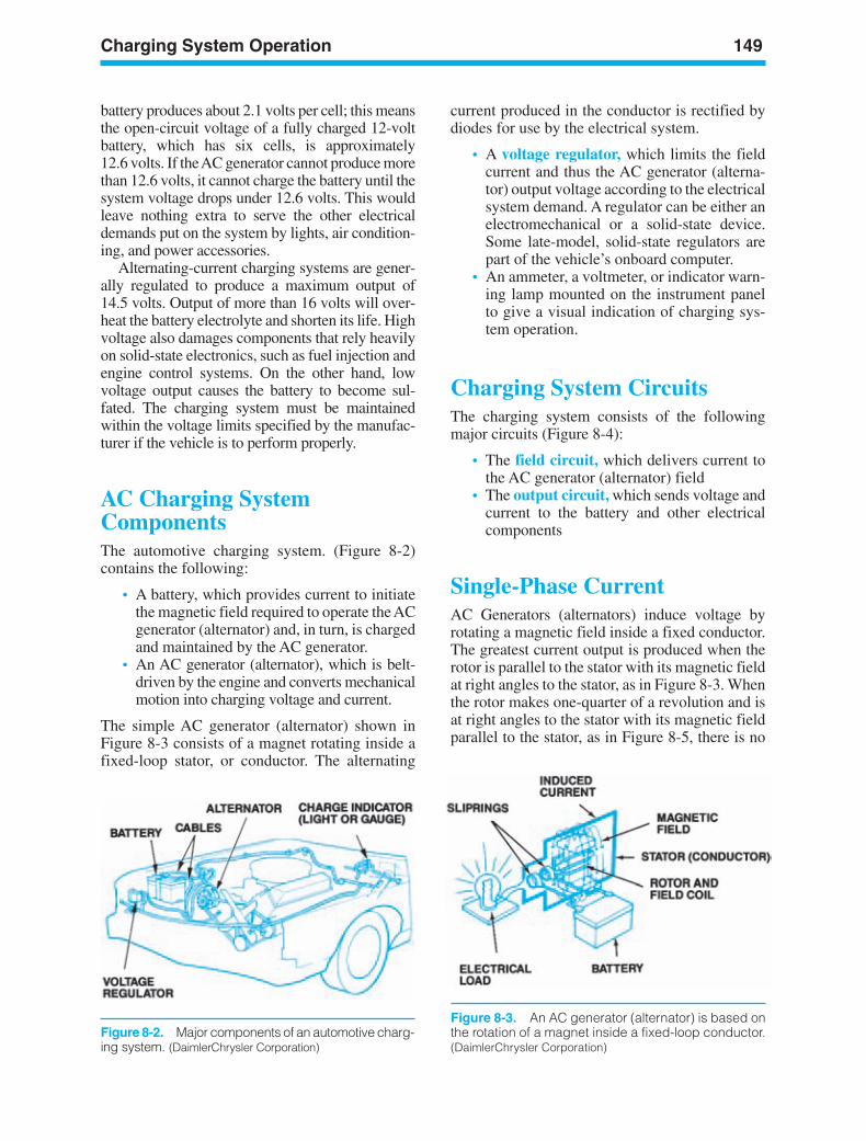
Charging System Operation 149
Figure 8-3. An AC generator (alternator) is based onthe rotation of a magnet inside a fixed-loop conductor.(DaimlerChrysler Corporation)
battery produces about 2.1 volts per cell; this meansthe open-circuit voltage of a fully charged 12-voltbattery, which has six cells, is approximately12.6 volts. If the AC generator cannot produce morethan 12.6 volts, it cannot charge the battery until thesystem voltage drops under 12.6 volts. This wouldleave nothing extra to serve the other electricaldemands put on the system by lights, air condition-ing, and power accessories.
Alternating-current charging systems are gener-ally regulated to produce a maximum output of14.5 volts. Output of more than 16 volts will over-heat the battery electrolyte and shorten its life. Highvoltage also damages components that rely heavilyon solid-state electronics, such as fuel injection andengine control systems. On the other hand, lowvoltage output causes the battery to become sul-fated. The charging system must be maintainedwithin the voltage limits specified by the manufac-turer if the vehicle is to perform properly.
AC Charging SystemComponentsThe automotive charging system. (Figure 8-2)contains the following:
• A battery, which provides current to initiatethe magnetic field required to operate the ACgenerator (alternator) and, in turn, is chargedand maintained by the AC generator.
• An AC generator (alternator), which is belt-driven by the engine and converts mechanicalmotion into charging voltage and current.
The simple AC generator (alternator) shown inFigure 8-3 consists of a magnet rotating inside afixed-loop stator, or conductor. The alternating
current produced in the conductor is rectified bydiodes for use by the electrical system.
• A voltage regulator, which limits the fieldcurrent and thus the AC generator (alterna-tor) output voltage according to the electricalsystem demand. A regulator can be either anelectromechanical or a solid-state device.Some late-model, solid-state regulators arepart of the vehicle’s onboard computer.
• An ammeter, a voltmeter, or indicator warn-ing lamp mounted on the instrument panelto give a visual indication of charging sys-tem operation.
Charging System CircuitsThe charging system consists of the followingmajor circuits (Figure 8-4):
• The field circuit, which delivers current tothe AC generator (alternator) field
• The output circuit, which sends voltage andcurrent to the battery and other electricalcomponents
Single-Phase CurrentAC Generators (alternators) induce voltage byrotating a magnetic field inside a fixed conductor.The greatest current output is produced when therotor is parallel to the stator with its magnetic fieldat right angles to the stator, as in Figure 8-3. Whenthe rotor makes one-quarter of a revolution and isat right angles to the stator with its magnetic fieldparallel to the stator, as in Figure 8-5, there is no
Figure 8-2. Major components of an automotive charg-ing system. (DaimlerChrysler Corporation)
ker88839_ch08.qxd 1/9/06 11:27 AM Page 149
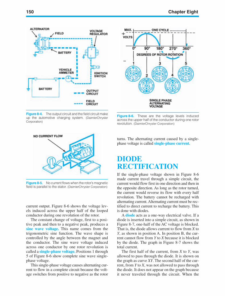
150 Chapter Eight
Figure 8-4. The output circuit and the field circuit makeup the automotive charging system. (DaimlerChryslerCorporation)
Figure 8-6. These are the voltage levels inducedacross the upper half of the conductor during one rotorrevolution. (DaimlerChrysler Corporation)
current output. Figure 8-6 shows the voltage lev-els induced across the upper half of the loopedconductor during one revolution of the rotor.
The constant change of voltage, first to a posi-tive peak and then to a negative peak, produces asine wave voltage. This name comes from thetrigonometric sine function. The wave shape iscontrolled by the angle between the magnet andthe conductor. The sine wave voltage inducedacross one conductor by one rotor revolution iscalled a single-phase voltage. Positions 1 through5 of Figure 8-6 show complete sine wave single-phase voltage.
This single-phase voltage causes alternating cur-rent to flow in a complete circuit because the volt-age switches from positive to negative as the rotor
turns. The alternating current caused by a single-phase voltage is called single-phase current.
DIODERECTIFICATIONIf the single-phase voltage shown in Figure 8-6made current travel through a simple circuit, thecurrent would flow first in one direction and then inthe opposite direction. As long as the rotor turned,the current would reverse its flow with every halfrevolution. The battery cannot be recharged withalternating current. Alternating current must be rec-tified to direct current to recharge the battery. Thisis done with diodes.
A diode acts as a one-way electrical valve. If adiode is inserted into a simple circuit, as shown inFigure 8-7, one-half of the AC voltage is blocked.That is, the diode allows current to flow from X toY, as shown in position A. In position B, the cur-rent cannot flow from Y to X because it is blockedby the diode. The graph in Figure 8-7 shows thetotal current.
The first half of the current, from X to Y, wasallowed to pass through the diode. It is shown onthe graph as curve XY. The second half of the cur-rent, from Y to X, was not allowed to pass throughthe diode. It does not appear on the graph becauseit never traveled through the circuit. When the
Figure 8-5. No current flows when the rotor’s magneticfield is parallel to the stator. (DaimlerChrysler Corporation)
ker88839_ch08.qxd 1/9/06 11:27 AM Page 150
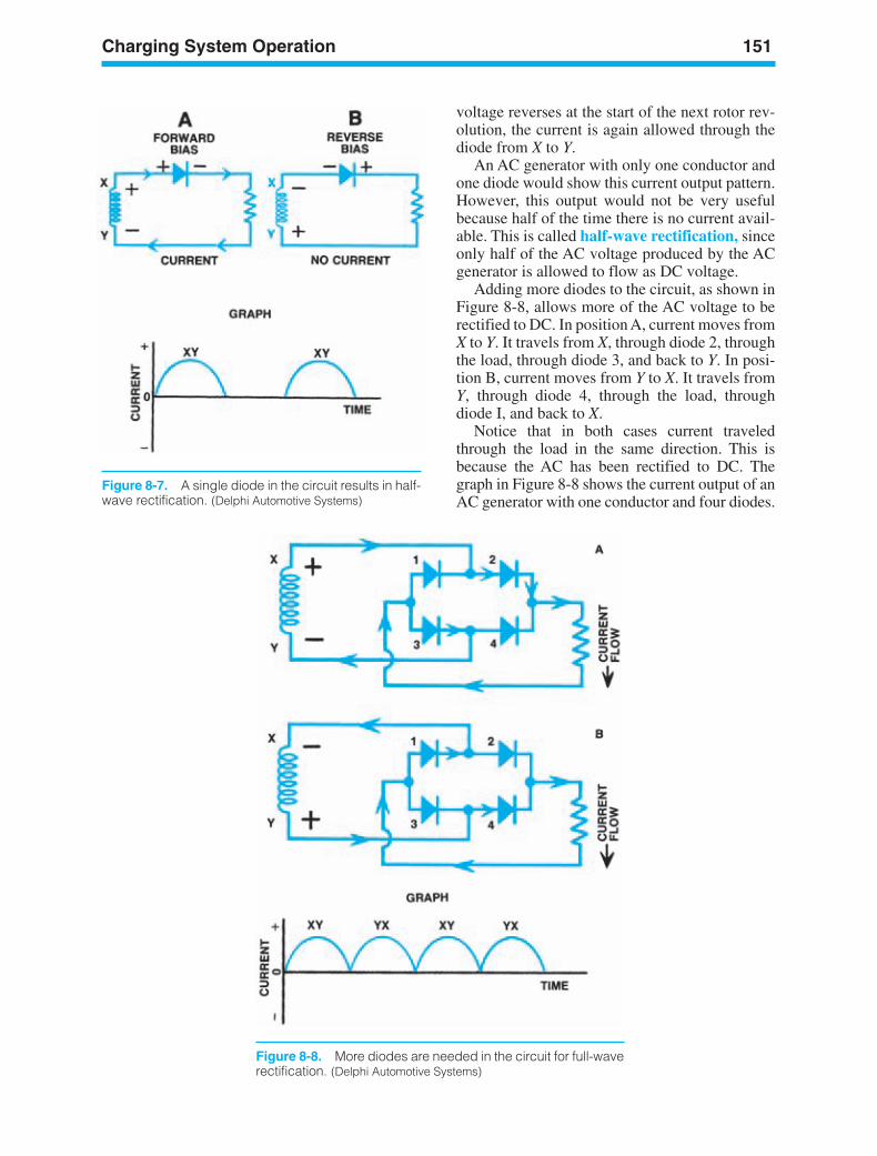
Charging System Operation 151
Figure 8-7. A single diode in the circuit results in half-wave rectification. (Delphi Automotive Systems)
voltage reverses at the start of the next rotor rev-olution, the current is again allowed through thediode from X to Y.
An AC generator with only one conductor andone diode would show this current output pattern.However, this output would not be very usefulbecause half of the time there is no current avail-able. This is called half-wave rectification, sinceonly half of the AC voltage produced by the ACgenerator is allowed to flow as DC voltage.
Adding more diodes to the circuit, as shown inFigure 8-8, allows more of the AC voltage to berectified to DC. In position A, current moves fromX to Y. It travels from X, through diode 2, throughthe load, through diode 3, and back to Y. In posi-tion B, current moves from Y to X. It travels fromY, through diode 4, through the load, throughdiode I, and back to X.
Notice that in both cases current traveledthrough the load in the same direction. This isbecause the AC has been rectified to DC. Thegraph in Figure 8-8 shows the current output of anAC generator with one conductor and four diodes.
Figure 8-8. More diodes are needed in the circuit for full-waverectification. (Delphi Automotive Systems)
ker88839_ch08.qxd 1/9/06 11:27 AM Page 151
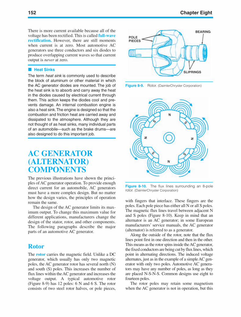
152 Chapter Eight
There is more current available because all of thevoltage has been rectified. This is called full-waverectification. However, there are still momentswhen current is at zero. Most automotive ACgenerators use three conductors and six diodes toproduce overlapping current waves so that currentoutput is never at zero.
Heat Sinks
The term heat sink is commonly used to describethe block of aluminum or other material in whichthe AC generator diodes are mounted. The job ofthe heat sink is to absorb and carry away the heatin the diodes caused by electrical current throughthem. This action keeps the diodes cool and pre-vents damage. An internal combustion engine isalso a heat sink.The engine is designed so that thecombustion and friction heat are carried away anddissipated to the atmosphere. Although they arenot thought of as heat sinks, many individual partsof an automobile—such as the brake drums—arealso designed to do this important job.
AC GENERATOR(ALTERNATOR)COMPONENTSThe previous illustrations have shown the princi-ples of AC generator operation. To provide enoughdirect current for an automobile, AC generatorsmust have a more complex design. But no matterhow the design varies, the principles of operationremain the same.
The design of the AC generator limits its max-imum output. To change this maximum value fordifferent applications, manufacturers change thedesign of the stator, rotor, and other components.The following paragraphs describe the majorparts of an automotive AC generator.
RotorThe rotor carries the magnetic field. Unlike a DCgenerator, which usually has only two magneticpoles, the AC generator rotor has several north (N)and south (S) poles. This increases the number offlux lines within the AC generator and increases thevoltage output. A typical automotive rotor(Figure 8-9) has 12 poles: 6 N and 6 S. The rotorconsists of two steel rotor halves, or pole pieces,
with fingers that interlace. These fingers are thepoles. Each pole piece has either all N or all S poles.The magnetic flux lines travel between adjacent Nand S poles (Figure 8-10). Keep in mind that analternator is an AC generator; in some Europeanmanufacturers’ service manuals, the AC generator(alternator) is referred to as a generator.
Along the outside of the rotor, note that the fluxlines point first in one direction and then in the other.This means as the rotor spins inside the AC generator,the fixed conductors are being cut by flux lines, whichpoint in alternating directions. The induced voltagealternates, just as in the example of a simple AC gen-erator with only two poles. Automotive AC genera-tors may have any number of poles, as long as theyare placed N-S-N-S. Common designs use eight tofourteen poles.
The rotor poles may retain some magnetismwhen the AC generator is not in operation, but this
Figure 8-9. Rotor. (DaimlerChrysler Corporation)
Figure 8-10. The flux lines surrounding an 8-polerotor. (DaimlerChrysler Corporation)
ker88839_ch08.qxd 1/9/06 11:27 AM Page 152
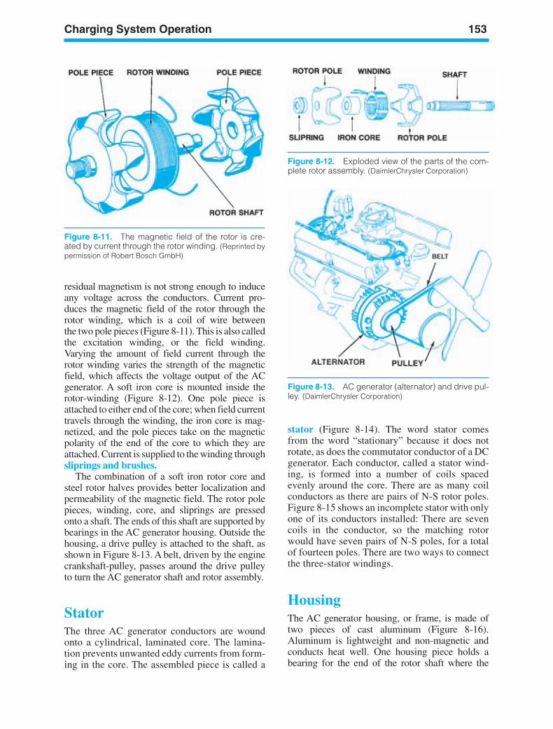
Charging System Operation 153
Figure 8-11. The magnetic field of the rotor is cre-ated by current through the rotor winding. (Reprinted bypermission of Robert Bosch GmbH)
Figure 8-12. Exploded view of the parts of the com-plete rotor assembly. (DaimlerChrysler Corporation)
residual magnetism is not strong enough to induceany voltage across the conductors. Current pro-duces the magnetic field of the rotor through therotor winding, which is a coil of wire betweenthe two pole pieces (Figure 8-11). This is also calledthe excitation winding, or the field winding.Varying the amount of field current through therotor winding varies the strength of the magneticfield, which affects the voltage output of the ACgenerator. A soft iron core is mounted inside therotor-winding (Figure 8-12). One pole piece isattached to either end of the core; when field currenttravels through the winding, the iron core is mag-netized, and the pole pieces take on the magneticpolarity of the end of the core to which they areattached. Current is supplied to the winding throughsliprings and brushes.
The combination of a soft iron rotor core andsteel rotor halves provides better localization andpermeability of the magnetic field. The rotor polepieces, winding, core, and sliprings are pressedonto a shaft. The ends of this shaft are supported bybearings in the AC generator housing. Outside thehousing, a drive pulley is attached to the shaft, asshown in Figure 8-13. A belt, driven by the enginecrankshaft-pulley, passes around the drive pulleyto turn the AC generator shaft and rotor assembly.
StatorThe three AC generator conductors are woundonto a cylindrical, laminated core. The lamina-tion prevents unwanted eddy currents from form-ing in the core. The assembled piece is called a
stator (Figure 8-14). The word stator comesfrom the word “stationary” because it does notrotate, as does the commutator conductor of a DCgenerator. Each conductor, called a stator wind-ing, is formed into a number of coils spacedevenly around the core. There are as many coilconductors as there are pairs of N-S rotor poles.Figure 8-15 shows an incomplete stator with onlyone of its conductors installed: There are sevencoils in the conductor, so the matching rotorwould have seven pairs of N-S poles, for a totalof fourteen poles. There are two ways to connectthe three-stator windings.
HousingThe AC generator housing, or frame, is made oftwo pieces of cast aluminum (Figure 8-16).Aluminum is lightweight and non-magnetic andconducts heat well. One housing piece holds abearing for the end of the rotor shaft where the
Figure 8-13. AC generator (alternator) and drive pul-ley. (DaimlerChrysler Corporation)
ker88839_ch08.qxd 1/9/06 11:27 AM Page 153
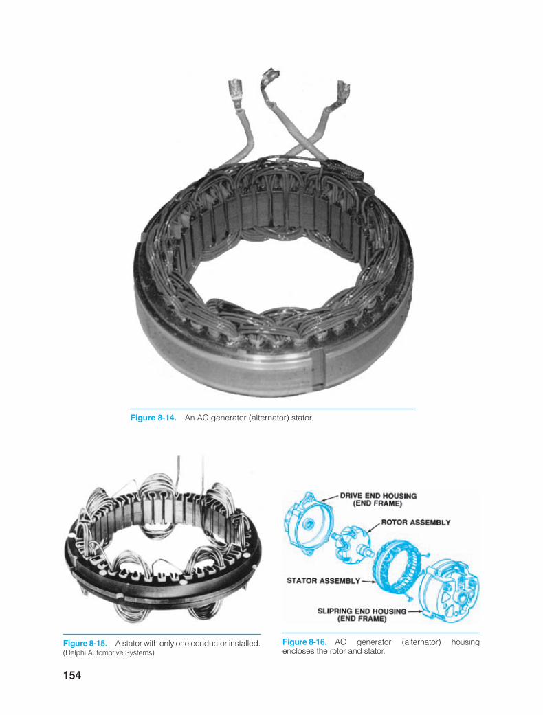
154
Figure 8-14. An AC generator (alternator) stator.
Figure 8-15. A stator with only one conductor installed.(Delphi Automotive Systems)
Figure 8-16. AC generator (alternator) housingencloses the rotor and stator.
ker88839_ch08.qxd 1/9/06 11:27 AM Page 154
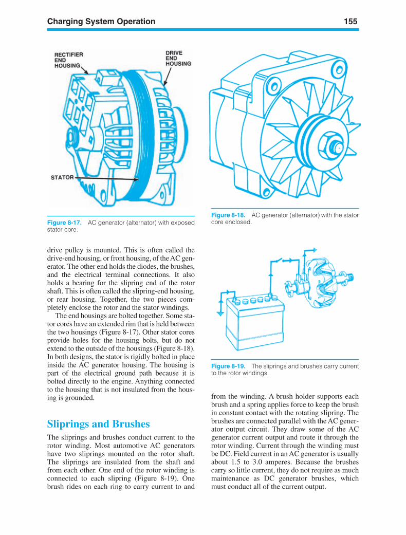
Charging System Operation 155
Figure 8-17. AC generator (alternator) with exposedstator core.
Figure 8-18. AC generator (alternator) with the statorcore enclosed.
drive pulley is mounted. This is often called thedrive-end housing, or front housing, of the AC gen-erator. The other end holds the diodes, the brushes,and the electrical terminal connections. It alsoholds a bearing for the slipring end of the rotorshaft. This is often called the slipring-end housing,or rear housing. Together, the two pieces com-pletely enclose the rotor and the stator windings.
The end housings are bolted together. Some sta-tor cores have an extended rim that is held betweenthe two housings (Figure 8-17). Other stator coresprovide holes for the housing bolts, but do notextend to the outside of the housings (Figure 8-18).In both designs, the stator is rigidly bolted in placeinside the AC generator housing. The housing ispart of the electrical ground path because it isbolted directly to the engine. Anything connectedto the housing that is not insulated from the hous-ing is grounded.
Sliprings and BrushesThe sliprings and brushes conduct current to therotor winding. Most automotive AC generatorshave two sliprings mounted on the rotor shaft.The sliprings are insulated from the shaft andfrom each other. One end of the rotor winding isconnected to each slipring (Figure 8-19). Onebrush rides on each ring to carry current to and
from the winding. A brush holder supports eachbrush and a spring applies force to keep the brushin constant contact with the rotating slipring. Thebrushes are connected parallel with the AC gener-ator output circuit. They draw some of the ACgenerator current output and route it through therotor winding. Current through the winding mustbe DC. Field current in an AC generator is usuallyabout 1.5 to 3.0 amperes. Because the brushescarry so little current, they do not require as muchmaintenance as DC generator brushes, whichmust conduct all of the current output.
Figure 8-19. The sliprings and brushes carry currentto the rotor windings.
ker88839_ch08.qxd 1/9/06 11:27 AM Page 155
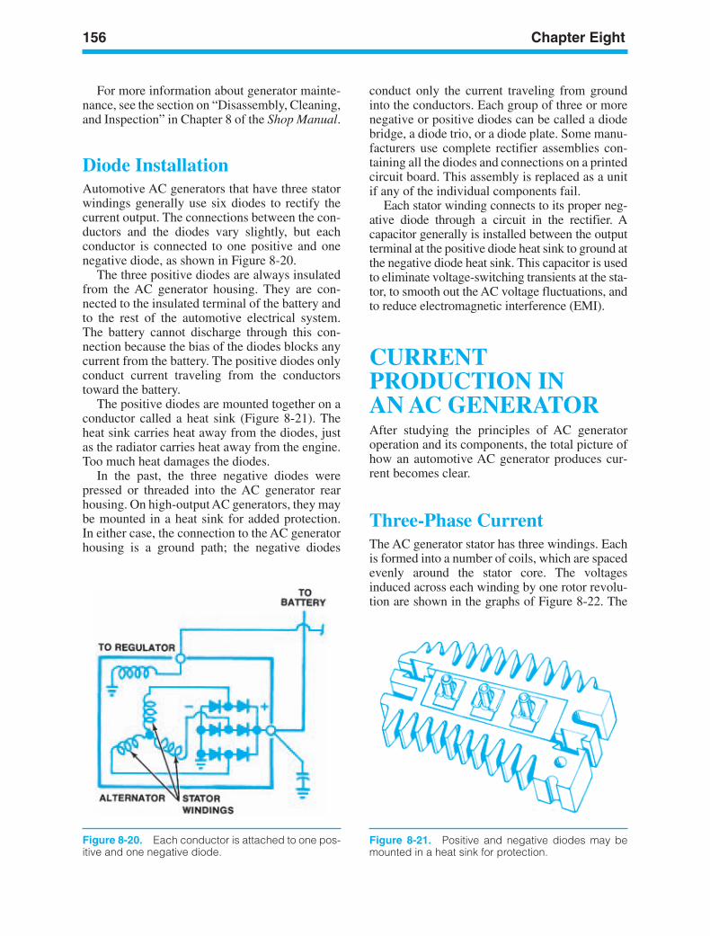
156 Chapter Eight
Figure 8-20. Each conductor is attached to one pos-itive and one negative diode.
Figure 8-21. Positive and negative diodes may bemounted in a heat sink for protection.
For more information about generator mainte-nance, see the section on “Disassembly, Cleaning,and Inspection” in Chapter 8 of the Shop Manual.
Diode InstallationAutomotive AC generators that have three statorwindings generally use six diodes to rectify thecurrent output. The connections between the con-ductors and the diodes vary slightly, but eachconductor is connected to one positive and onenegative diode, as shown in Figure 8-20.
The three positive diodes are always insulatedfrom the AC generator housing. They are con-nected to the insulated terminal of the battery andto the rest of the automotive electrical system.The battery cannot discharge through this con-nection because the bias of the diodes blocks anycurrent from the battery. The positive diodes onlyconduct current traveling from the conductorstoward the battery.
The positive diodes are mounted together on aconductor called a heat sink (Figure 8-21). Theheat sink carries heat away from the diodes, justas the radiator carries heat away from the engine.Too much heat damages the diodes.
In the past, the three negative diodes werepressed or threaded into the AC generator rearhousing. On high-output AC generators, they maybe mounted in a heat sink for added protection.In either case, the connection to the AC generatorhousing is a ground path; the negative diodes
conduct only the current traveling from groundinto the conductors. Each group of three or morenegative or positive diodes can be called a diodebridge, a diode trio, or a diode plate. Some manu-facturers use complete rectifier assemblies con-taining all the diodes and connections on a printedcircuit board. This assembly is replaced as a unitif any of the individual components fail.
Each stator winding connects to its proper neg-ative diode through a circuit in the rectifier. Acapacitor generally is installed between the outputterminal at the positive diode heat sink to ground atthe negative diode heat sink. This capacitor is usedto eliminate voltage-switching transients at the sta-tor, to smooth out the AC voltage fluctuations, andto reduce electromagnetic interference (EMI).
CURRENTPRODUCTION INAN AC GENERATORAfter studying the principles of AC generatoroperation and its components, the total picture ofhow an automotive AC generator produces cur-rent becomes clear.
Three-Phase CurrentThe AC generator stator has three windings. Eachis formed into a number of coils, which are spacedevenly around the stator core. The voltagesinduced across each winding by one rotor revolu-tion are shown in the graphs of Figure 8-22. The
ker88839_ch08.qxd 1/9/06 11:27 AM Page 156
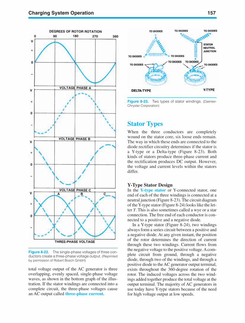
Charging System Operation 157
Figure 8-22. The single-phase voltages of three con-ductors create a three-phase voltage output. (Reprintedby permission of Robert Bosch GmbH)
total voltage output of the AC generator is threeoverlapping, evenly spaced, single-phase voltagewaves, as shown in the bottom graph of the illus-tration. If the stator windings are connected into acomplete circuit, the three-phase voltages causean AC output called three-phase current.
Stator TypesWhen the three conductors are completelywound on the stator core, six loose ends remain.The way in which these ends are connected to thediode rectifier circuitry determines if the stator isa Y-type or a Delta-type (Figure 8-23). Bothkinds of stators produce three-phase current andthe rectification produces DC output. However,the voltage and current levels within the statorsdiffer.
Y-Type Stator DesignIn the Y-type stator or Y-connected stator, oneend of each of the three windings is connected at aneutral junction (Figure 8-23). The circuit diagramof the Y-type stator (Figure 8-24) looks like the let-ter Y. This is also sometimes called a wye or a starconnection. The free end of each conductor is con-nected to a positive and a negative diode.
In a Y-type stator (Figure 8-24), two windingsalways form a series circuit between a positive anda negative diode. At any given instant, the positionof the rotor determines the direction of currentthrough these two windings. Current flows fromthe negative voltage to the positive voltage. Acom-plete circuit from ground, through a negativediode, through two of the windings, and through apositive diode to the AC generator output terminal,exists throughout the 360-degree rotation of therotor. The induced voltages across the two wind-ings added together produce the total voltage at theoutput terminal. The majority of AC generators inuse today have Y-type stators because of the needfor high voltage output at low speeds.
Figure 8-23. Two types of stator windings. (Daimler-Chrysler Corporation)
ker88839_ch08.qxd 1/9/06 11:27 AM Page 157
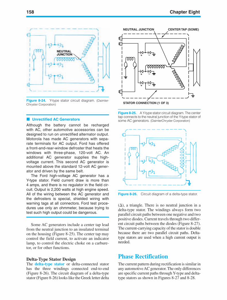
158 Chapter Eight
Figure 8-24. Y-type stator circuit diagram. (Daimler-Chrysler Corporation)
+
+
+
–
–
–
NEUTRAL JUNCTION
STATOR CONNECTION (1 OF 3)
CENTER TAP (SOME)
Figure 8-25. A Y-type stator circuit diagram. The centertap connects to the neutral junction of the Y-type stator ofsome AC generators. (DaimlerChrysler Corporation)
Figure 8-26. Circuit diagram of a delta-type stator.
Unrectified AC Generators
Although the battery cannot be rechargedwith AC, other automotive accessories can bedesigned to run on unrectified alternator output.Motorola has made AC generators with sepa-rate terminals for AC output. Ford has offereda front-and-rear-window defroster that heats thewindows with three-phase, 120-volt AC. Anadditional AC generator supplies the high-voltage current. This second AC generator ismounted above the standard 12-volt AC gener-ator and driven by the same belt.
The Ford high-voltage AC generator has a Y-type stator. Field current draw is more than 4 amps, and there is no regulator in the field cir-cuit. Output is 2,200 watts at high engine speed.All of the wiring between the AC generator andthe defrosters is special, shielded wiring withwarning tags at all connectors. Ford test proce-dures use only an ohmmeter, because trying totest such high output could be dangerous.
Some AC generators include a center tap leadfrom the neutral junction to an insulated terminalon the housing (Figure 8-25). The center tap maycontrol the field current, to activate an indicatorlamp, to control the electric choke on a carbure-tor, or for other functions.
Delta-Type Stator DesignThe delta-type stator or delta-connected statorhas the three windings connected end-to-end(Figure 8-26). The circuit diagram of a delta-typestator (Figure 8-26) looks like the Greek letter delta
(), a triangle. There is no neutral junction in adelta-type stator. The windings always form twoparallel circuit paths between one negative and twopositive diodes. Current travels through two differ-ent circuit paths between the diodes (Figure 8-27).The current-carrying capacity of the stator is doublebecause there are two parallel circuit paths. Delta-type stators are used when a high current output isneeded.
Phase RectificationThe current pattern during rectification is similar inany automotive AC generator. The only differencesare specific current paths through Y-type and delta-type stators as shown in Figures 8-27 and 8-28.
ker88839_ch08.qxd 1/9/06 11:27 AM Page 158

Charging System Operation 159
Figure 8-27. A typical current path during rectifica-tion in a delta-type stator. (DaimlerChrysler Corporation)
Figure 8-28. A typical current path during rectifica-tion in a Y-type stator. (DaimlerChrysler Corporation)
Rectification withMultiple-Pole RotorsThe three-phase voltage output used in the exam-ples (Figure 8-29) is the voltage, which wouldresult if the rotor had only one N and one S pole.Actual AC generator rotors have many N and Spoles. Each of these N-S pairs produces one com-plete voltage sine wave per rotor revolution, acrosseach of the three windings. One complete sinewave begins at zero volts, climbs to a positive,peak, drops past zero to a negative peak, thenreturns to zero, or baseline voltage. In Figure 8-30,the sine wave voltage caused by a single pole isshown as a dashed line. The actual voltage tracefrom one winding of a 12-pole AC generator is
shown as a solid line. The entire stator output isthree of these waves, evenly spaced and overlap-ping (Figure 8-31). The maximum voltage valuefrom these waves pushes current through thediodes (Figure 8-32).
After rectification, AC generator (alternator)output is DC voltage, which is slightly lower thanthe maximum voltage peaks of the stator output.The positive portion of the AC sine wave greaterthan the DC output voltage is viewable on anoscilloscope in what is called an AC generator(alternator) ripple pattern (Figure 8-33).
Excitation Field CircuitField current through the rotor windings createsthe magnetic field of the rotor. Field current isdrawn from the AC generator output circuit once
Figure 8-29. The three-phase voltage from one revo-lution of the rotor. (Reprinted by permission of RobertBosch GmbH)
Figure 8-30. An AC generator (alternator) with sixpairs of N-S poles would produce the solid line volt-age trace. The dashed line represents an alternatorwith one pair. (Reprinted by permission of Robert BoschGmbH)
ker88839_ch08.qxd 1/9/06 11:28 AM Page 159
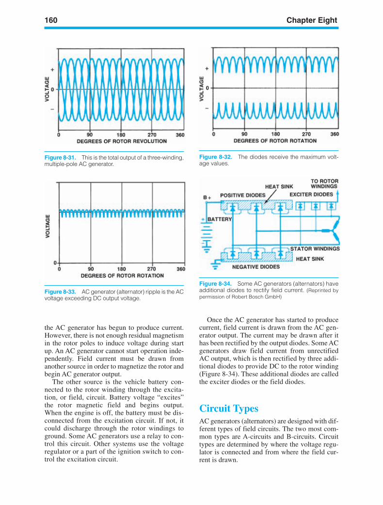
160 Chapter Eight
Figure 8-31. This is the total output of a three-winding,multiple-pole AC generator.
Figure 8-32. The diodes receive the maximum volt-age values.
Figure 8-34. Some AC generators (alternators) haveadditional diodes to rectify field current. (Reprinted bypermission of Robert Bosch GmbH)
Figure 8-33. AC generator (alternator) ripple is the ACvoltage exceeding DC output voltage.
Once the AC generator has started to producecurrent, field current is drawn from the AC gen-erator output. The current may be drawn after ithas been rectified by the output diodes. Some ACgenerators draw field current from unrectifiedAC output, which is then rectified by three addi-tional diodes to provide DC to the rotor winding(Figure 8-34). These additional diodes are calledthe exciter diodes or the field diodes.
Circuit TypesAC generators (alternators) are designed with dif-ferent types of field circuits. The two most com-mon types are A-circuits and B-circuits. Circuittypes are determined by where the voltage regu-lator is connected and from where the field cur-rent is drawn.
the AC generator has begun to produce current.However, there is not enough residual magnetismin the rotor poles to induce voltage during startup. An AC generator cannot start operation inde-pendently. Field current must be drawn fromanother source in order to magnetize the rotor andbegin AC generator output.
The other source is the vehicle battery con-nected to the rotor winding through the excita-tion, or field, circuit. Battery voltage “excites”the rotor magnetic field and begins output.When the engine is off, the battery must be dis-connected from the excitation circuit. If not, itcould discharge through the rotor windings toground. Some AC generators use a relay to con-trol this circuit. Other systems use the voltageregulator or a part of the ignition switch to con-trol the excitation circuit.
ker88839_ch08.qxd 1/9/06 11:28 AM Page 160
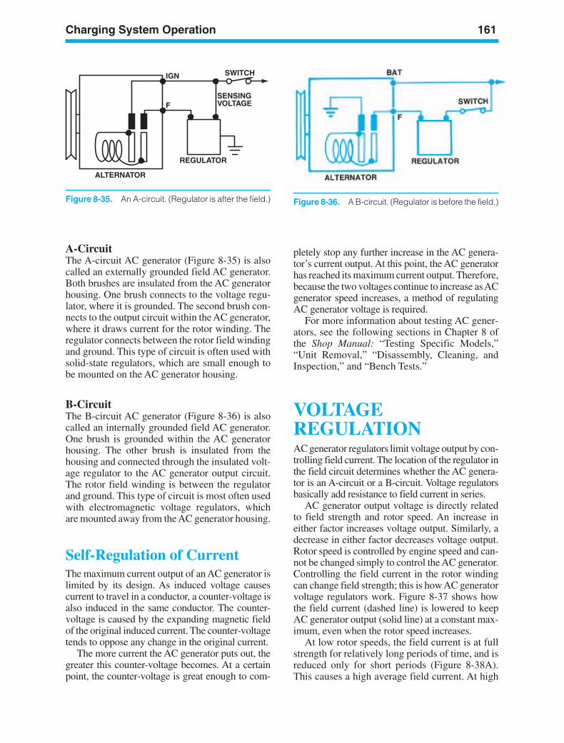
Charging System Operation 161
ALTERNATOR
REGULATOR
IGN
F
SWITCH
SENSINGVOLTAGE
Figure 8-35. An A-circuit. (Regulator is after the field.)
A-CircuitThe A-circuit AC generator (Figure 8-35) is alsocalled an externally grounded field AC generator.Both brushes are insulated from the AC generatorhousing. One brush connects to the voltage regu-lator, where it is grounded. The second brush con-nects to the output circuit within the AC generator,where it draws current for the rotor winding. Theregulator connects between the rotor field windingand ground. This type of circuit is often used withsolid-state regulators, which are small enough tobe mounted on the AC generator housing.
B-CircuitThe B-circuit AC generator (Figure 8-36) is alsocalled an internally grounded field AC generator.One brush is grounded within the AC generatorhousing. The other brush is insulated from thehousing and connected through the insulated volt-age regulator to the AC generator output circuit.The rotor field winding is between the regulatorand ground. This type of circuit is most often usedwith electromagnetic voltage regulators, whichare mounted away from the AC generator housing.
Self-Regulation of CurrentThe maximum current output of an AC generator islimited by its design. As induced voltage causescurrent to travel in a conductor, a counter-voltage isalso induced in the same conductor. The counter-voltage is caused by the expanding magnetic fieldof the original induced current. The counter-voltagetends to oppose any change in the original current.
The more current the AC generator puts out, thegreater this counter-voltage becomes. At a certainpoint, the counter-voltage is great enough to com-
pletely stop any further increase in the AC genera-tor’s current output. At this point, the AC generatorhas reached its maximum current output. Therefore,because the two voltages continue to increase as ACgenerator speed increases, a method of regulatingAC generator voltage is required.
For more information about testing AC gener-ators, see the following sections in Chapter 8 ofthe Shop Manual: “Testing Specific Models,”“Unit Removal,” “Disassembly, Cleaning, andInspection,” and “Bench Tests.”
VOLTAGEREGULATIONAC generator regulators limit voltage output by con-trolling field current. The location of the regulator inthe field circuit determines whether the AC genera-tor is an A-circuit or a B-circuit. Voltage regulatorsbasically add resistance to field current in series.
AC generator output voltage is directly relatedto field strength and rotor speed. An increase ineither factor increases voltage output. Similarly, adecrease in either factor decreases voltage output.Rotor speed is controlled by engine speed and can-not be changed simply to control the AC generator.Controlling the field current in the rotor windingcan change field strength; this is how AC generatorvoltage regulators work. Figure 8-37 shows howthe field current (dashed line) is lowered to keepAC generator output (solid line) at a constant max-imum, even when the rotor speed increases.
At low rotor speeds, the field current is at fullstrength for relatively long periods of time, and isreduced only for short periods (Figure 8-38A).This causes a high average field current. At high
Figure 8-36. A B-circuit. (Regulator is before the field.)
ker88839_ch08.qxd 1/9/06 11:28 AM Page 161
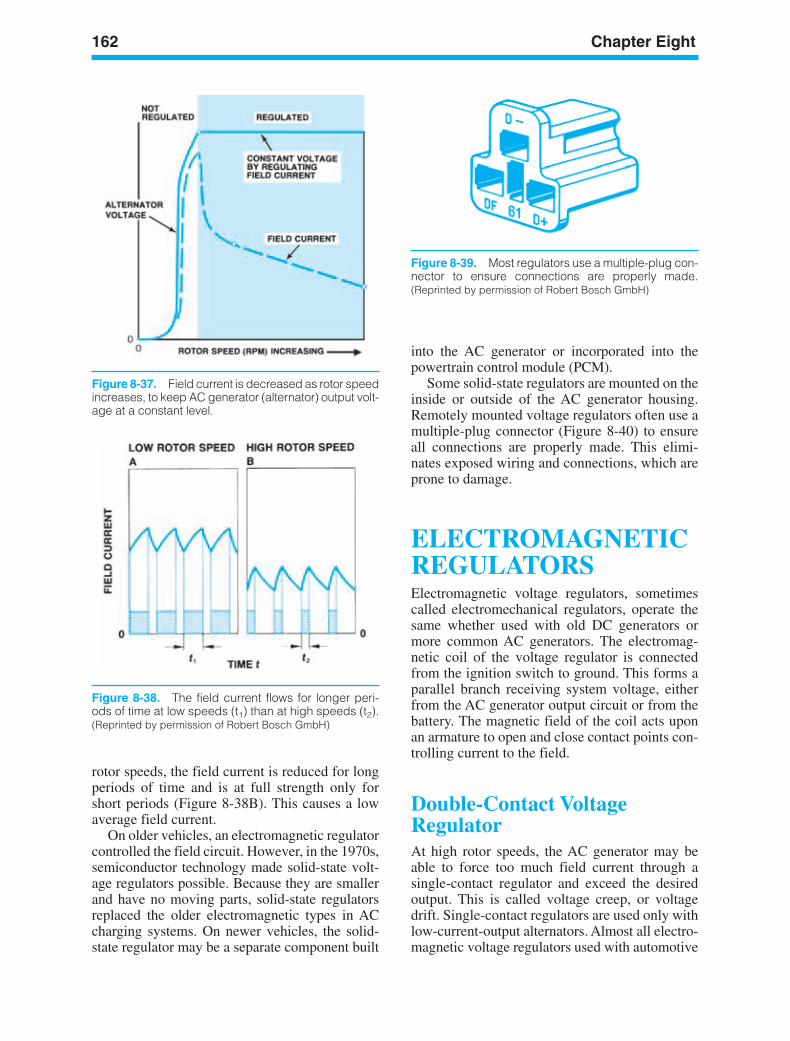
162 Chapter Eight
Figure 8-37. Field current is decreased as rotor speedincreases, to keep AC generator (alternator) output volt-age at a constant level.
Figure 8-38. The field current flows for longer peri-ods of time at low speeds (t1) than at high speeds (t2).(Reprinted by permission of Robert Bosch GmbH)
Figure 8-39. Most regulators use a multiple-plug con-nector to ensure connections are properly made.(Reprinted by permission of Robert Bosch GmbH)
rotor speeds, the field current is reduced for longperiods of time and is at full strength only forshort periods (Figure 8-38B). This causes a lowaverage field current.
On older vehicles, an electromagnetic regulatorcontrolled the field circuit. However, in the 1970s,semiconductor technology made solid-state volt-age regulators possible. Because they are smallerand have no moving parts, solid-state regulatorsreplaced the older electromagnetic types in ACcharging systems. On newer vehicles, the solid-state regulator may be a separate component built
into the AC generator or incorporated into thepowertrain control module (PCM).
Some solid-state regulators are mounted on theinside or outside of the AC generator housing.Remotely mounted voltage regulators often use amultiple-plug connector (Figure 8-40) to ensureall connections are properly made. This elimi-nates exposed wiring and connections, which areprone to damage.
ELECTROMAGNETICREGULATORSElectromagnetic voltage regulators, sometimescalled electromechanical regulators, operate thesame whether used with old DC generators ormore common AC generators. The electromag-netic coil of the voltage regulator is connectedfrom the ignition switch to ground. This forms aparallel branch receiving system voltage, eitherfrom the AC generator output circuit or from thebattery. The magnetic field of the coil acts uponan armature to open and close contact points con-trolling current to the field.
Double-Contact VoltageRegulatorAt high rotor speeds, the AC generator may beable to force too much field current through asingle-contact regulator and exceed the desiredoutput. This is called voltage creep, or voltagedrift. Single-contact regulators are used only withlow-current-output alternators. Almost all electro-magnetic voltage regulators used with automotive
ker88839_ch08.qxd 1/9/06 11:28 AM Page 162
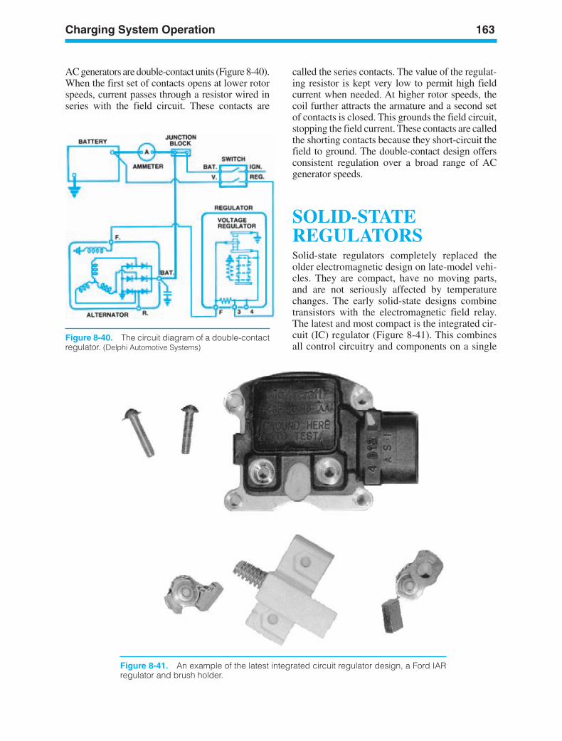
Charging System Operation 163
Figure 8-40. The circuit diagram of a double-contactregulator. (Delphi Automotive Systems)
AC generators are double-contact units (Figure 8-40).When the first set of contacts opens at lower rotorspeeds, current passes through a resistor wired inseries with the field circuit. These contacts are
called the series contacts. The value of the regulat-ing resistor is kept very low to permit high fieldcurrent when needed. At higher rotor speeds, thecoil further attracts the armature and a second setof contacts is closed. This grounds the field circuit,stopping the field current. These contacts are calledthe shorting contacts because they short-circuit thefield to ground. The double-contact design offersconsistent regulation over a broad range of ACgenerator speeds.
SOLID-STATEREGULATORSSolid-state regulators completely replaced theolder electromagnetic design on late-model vehi-cles. They are compact, have no moving parts,and are not seriously affected by temperaturechanges. The early solid-state designs combinetransistors with the electromagnetic field relay.The latest and most compact is the integrated cir-cuit (IC) regulator (Figure 8-41). This combinesall control circuitry and components on a single
Figure 8-41. An example of the latest integrated circuit regulator design, a Ford IARregulator and brush holder.
ker88839_ch08.qxd 1/9/06 11:28 AM Page 163
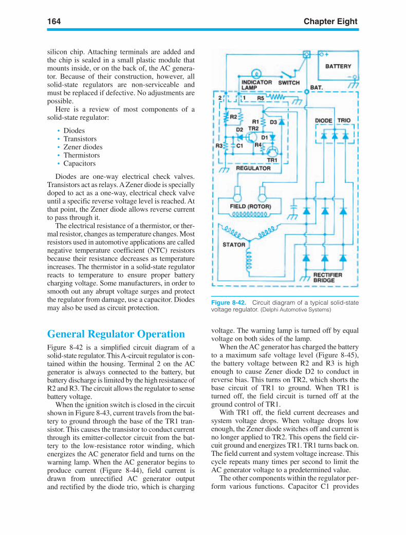
164 Chapter Eight
Figure 8-42. Circuit diagram of a typical solid-statevoltage regulator. (Delphi Automotive Systems)
silicon chip. Attaching terminals are added andthe chip is sealed in a small plastic module thatmounts inside, or on the back of, the AC genera-tor. Because of their construction, however, allsolid-state regulators are non-serviceable andmust be replaced if defective. No adjustments arepossible.
Here is a review of most components of asolid-state regulator:
• Diodes• Transistors• Zener diodes• Thermistors• Capacitors
Diodes are one-way electrical check valves.Transistors act as relays. AZener diode is speciallydoped to act as a one-way, electrical check valveuntil a specific reverse voltage level is reached. Atthat point, the Zener diode allows reverse currentto pass through it.
The electrical resistance of a thermistor, or ther-mal resistor, changes as temperature changes. Mostresistors used in automotive applications are callednegative temperature coefficient (NTC) resistorsbecause their resistance decreases as temperatureincreases. The thermistor in a solid-state regulatorreacts to temperature to ensure proper batterycharging voltage. Some manufacturers, in order tosmooth out any abrupt voltage surges and protectthe regulator from damage, use a capacitor. Diodesmay also be used as circuit protection.
General Regulator OperationFigure 8-42 is a simplified circuit diagram of asolid-state regulator. This A-circuit regulator is con-tained within the housing. Terminal 2 on the ACgenerator is always connected to the battery, butbattery discharge is limited by the high resistance ofR2 and R3. The circuit allows the regulator to sensebattery voltage.
When the ignition switch is closed in the circuitshown in Figure 8-43, current travels from the bat-tery to ground through the base of the TR1 tran-sistor. This causes the transistor to conduct currentthrough its emitter-collector circuit from the bat-tery to the low-resistance rotor winding, whichenergizes the AC generator field and turns on thewarning lamp. When the AC generator begins toproduce current (Figure 8-44), field current isdrawn from unrectified AC generator outputand rectified by the diode trio, which is charging
voltage. The warning lamp is turned off by equalvoltage on both sides of the lamp.
When the AC generator has charged the batteryto a maximum safe voltage level (Figure 8-45),the battery voltage between R2 and R3 is highenough to cause Zener diode D2 to conduct inreverse bias. This turns on TR2, which shorts thebase circuit of TR1 to ground. When TR1 isturned off, the field circuit is turned off at theground control of TR1.
With TR1 off, the field current decreases andsystem voltage drops. When voltage drops lowenough, the Zener diode switches off and current isno longer applied to TR2. This opens the field cir-cuit ground and energizes TR1. TR1 turns back on.The field current and system voltage increase. Thiscycle repeats many times per second to limit theAC generator voltage to a predetermined value.
The other components within the regulator per-form various functions. Capacitor C1 provides
ker88839_ch08.qxd 1/9/06 11:28 AM Page 164
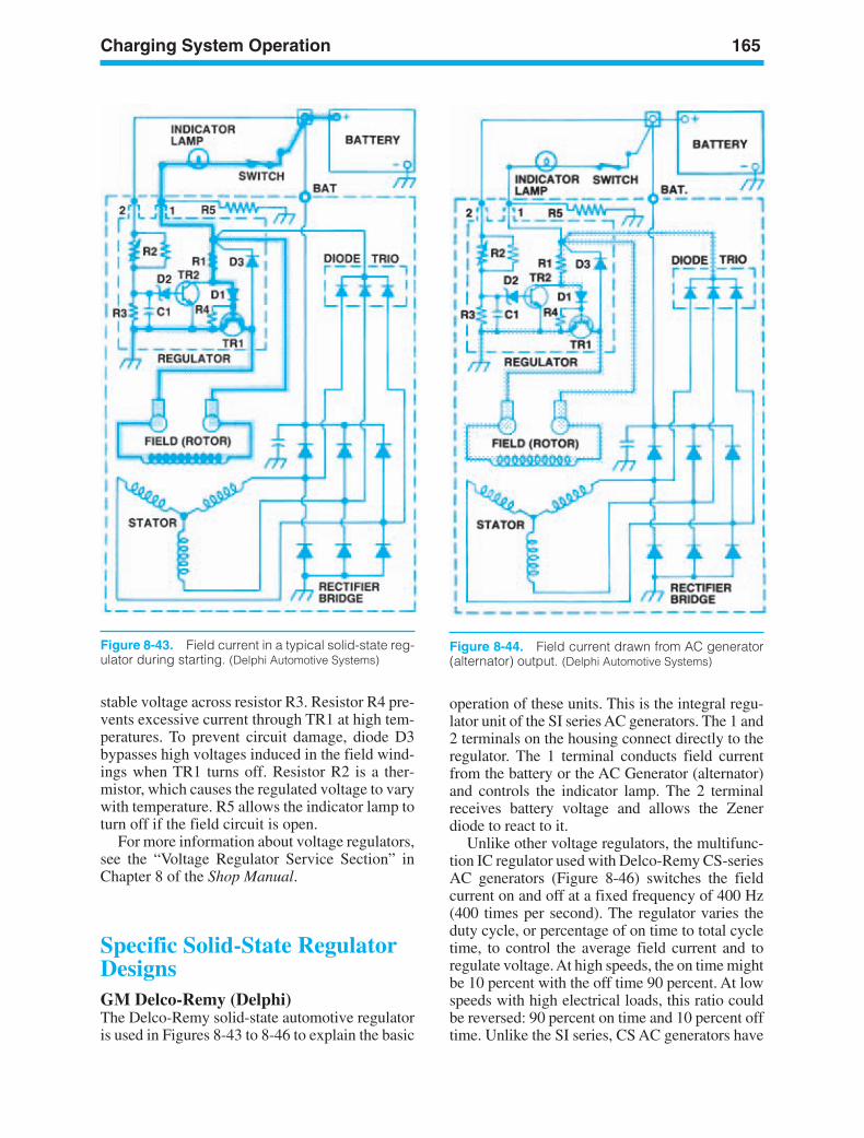
Charging System Operation 165
Figure 8-43. Field current in a typical solid-state reg-ulator during starting. (Delphi Automotive Systems)
stable voltage across resistor R3. Resistor R4 pre-vents excessive current through TR1 at high tem-peratures. To prevent circuit damage, diode D3bypasses high voltages induced in the field wind-ings when TR1 turns off. Resistor R2 is a ther-mistor, which causes the regulated voltage to varywith temperature. R5 allows the indicator lamp toturn off if the field circuit is open.
For more information about voltage regulators,see the “Voltage Regulator Service Section” inChapter 8 of the Shop Manual.
Specific Solid-State RegulatorDesignsGM Delco-Remy (Delphi)The Delco-Remy solid-state automotive regulatoris used in Figures 8-43 to 8-46 to explain the basic
operation of these units. This is the integral regu-lator unit of the SI series AC generators. The 1 and2 terminals on the housing connect directly to theregulator. The 1 terminal conducts field currentfrom the battery or the AC Generator (alternator)and controls the indicator lamp. The 2 terminalreceives battery voltage and allows the Zenerdiode to react to it.
Unlike other voltage regulators, the multifunc-tion IC regulator used with Delco-Remy CS-seriesAC generators (Figure 8-46) switches the fieldcurrent on and off at a fixed frequency of 400 Hz(400 times per second). The regulator varies theduty cycle, or percentage of on time to total cycletime, to control the average field current and toregulate voltage. At high speeds, the on time mightbe 10 percent with the off time 90 percent. At lowspeeds with high electrical loads, this ratio couldbe reversed: 90 percent on time and 10 percent offtime. Unlike the SI series, CS AC generators have
Figure 8-44. Field current drawn from AC generator(alternator) output. (Delphi Automotive Systems)
ker88839_ch08.qxd 1/9/06 11:28 AM Page 165
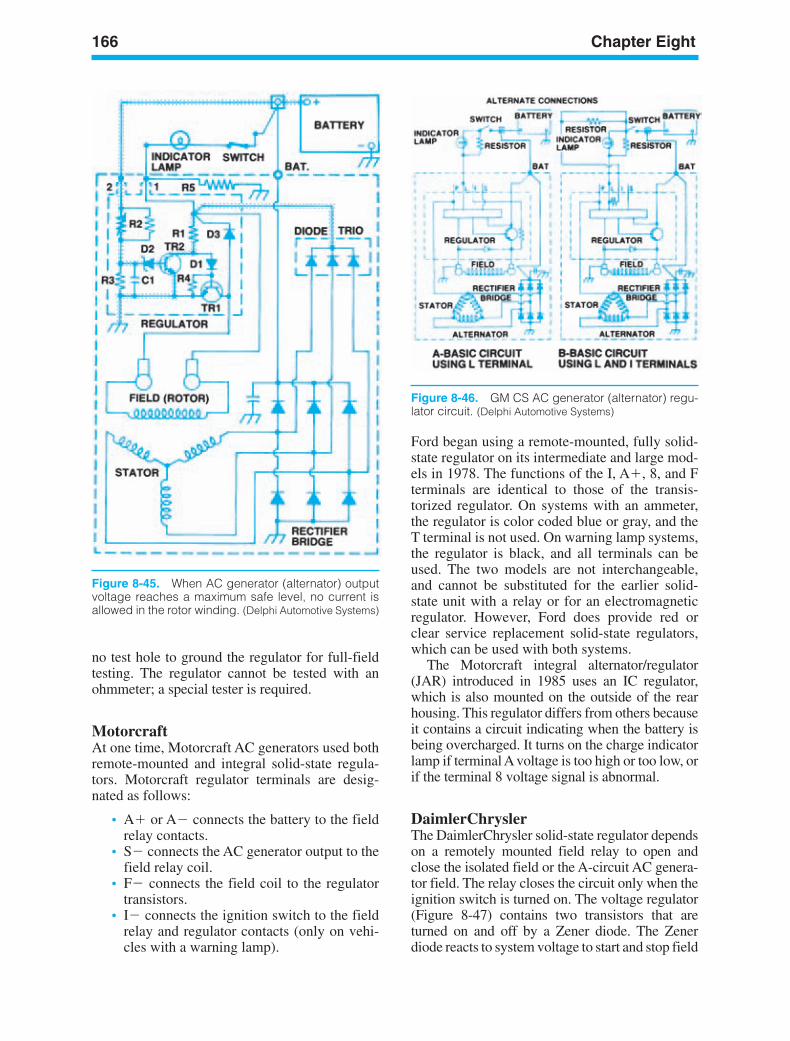
166 Chapter Eight
Figure 8-45. When AC generator (alternator) outputvoltage reaches a maximum safe level, no current isallowed in the rotor winding. (Delphi Automotive Systems)
Figure 8-46. GM CS AC generator (alternator) regu-lator circuit. (Delphi Automotive Systems)
no test hole to ground the regulator for full-fieldtesting. The regulator cannot be tested with anohmmeter; a special tester is required.
MotorcraftAt one time, Motorcraft AC generators used bothremote-mounted and integral solid-state regula-tors. Motorcraft regulator terminals are desig-nated as follows:
• A or A connects the battery to the fieldrelay contacts.
• S connects the AC generator output to thefield relay coil.
• F connects the field coil to the regulatortransistors.
• I connects the ignition switch to the fieldrelay and regulator contacts (only on vehi-cles with a warning lamp).
Ford began using a remote-mounted, fully solid-state regulator on its intermediate and large mod-els in 1978. The functions of the I, A, 8, and Fterminals are identical to those of the transis-torized regulator. On systems with an ammeter,the regulator is color coded blue or gray, and theT terminal is not used. On warning lamp systems,the regulator is black, and all terminals can beused. The two models are not interchangeable,and cannot be substituted for the earlier solid-state unit with a relay or for an electromagneticregulator. However, Ford does provide red orclear service replacement solid-state regulators,which can be used with both systems.
The Motorcraft integral alternator/regulator(JAR) introduced in 1985 uses an IC regulator,which is also mounted on the outside of the rearhousing. This regulator differs from others becauseit contains a circuit indicating when the battery isbeing overcharged. It turns on the charge indicatorlamp if terminal A voltage is too high or too low, orif the terminal 8 voltage signal is abnormal.
DaimlerChryslerThe DaimlerChrysler solid-state regulator dependson a remotely mounted field relay to open andclose the isolated field or the A-circuit AC genera-tor field. The relay closes the circuit only when theignition switch is turned on. The voltage regulator(Figure 8-47) contains two transistors that areturned on and off by a Zener diode. The Zenerdiode reacts to system voltage to start and stop field
ker88839_ch08.qxd 1/9/06 11:28 AM Page 166

Charging System Operation 167
Figure 8-47. DaimlerChrysler solid-state voltage reg-ulator. (DaimlerChrysler Corporation)
current. The field current travels through whatDaimlerChrysler calls a field-suppression diode,which limits current to control AC generator out-put. The regulator also contains a thermistor tocontrol battery charging voltage at various temper-atures. The regulator has two terminals: One isconnected to the ignition system; the other is con-nected to the alternator field.
Computer-ControlledRegulationDaimlerChrysler Corporation eliminated the sepa-rate regulator by moving its function to the pow-ertrain control module (PCM) in 1985. When theignition is turned on, the PCM logic module or logiccircuit checks battery temperature to determine thecontrol voltage (Figure 8-48). A pre-driver transis-tor in the logic module or logic circuit then signalsthe power module or power circuit driver transistorto turn the AC generator current on (Figure 8-49).The logic module or logic circuit continually mon-itors battery temperature and system voltage. At thesame time, it transmits output signals to the powermodule or power circuit driver to adjust the fieldcurrent as required to maintain output between 13.6and 14.8 volts. Figure 8-50 shows the complete cir-cuitry involved.
General Motors has taken a different approachto regulating CS charging system voltage elec-tronically. Turning the ignition switch on sup-plies voltage to activate a solid-state digitalregulator, which uses pulse-width modulation(PWM) to supply rotor current and thus controloutput voltage. The rotor current is proportionalto the PWM pulses from the digital regulator.
With the ignition on, narrow width pulses aresent to the rotor, creating a weak magnetic field.As the engine starts, the regulator senses AC gen-erator rotation through AC voltage detected on aninternal wire. Once the engine is running, theregulator switches the field current on and off ata fixed frequency of about 400 cycles per second(400 Hz). By changing the pulse width, or on-offtime, of each cycle, the regulator provides acorrect average field current for proper systemvoltage control.
A lamp driver in the digital regulator controlsthe indicator warning lamp, turning on the bulbwhen it detects an under- or over-voltage condi-tion. The warning lamp also illuminates if the ACgenerator is not rotating. The PCM does notdirectly control charging system voltage, as in theDaimlerChrysler application. However, it doesmonitor battery and system voltage through anignition switch circuit. If the PCM reads a voltageabove 17 volts, or less than 9 volts for longer than
Figure 8-48. DaimlerChrysler solid-state voltage reg-ulator. (DaimlerChrysler Corporation)
Figure 8-49. Battery temperature circuit of the Daimler-Chrysler computer regulated charging system. (Daimler-Chrysler Corporation)
ker88839_ch08.qxd 1/9/06 11:28 AM Page 167
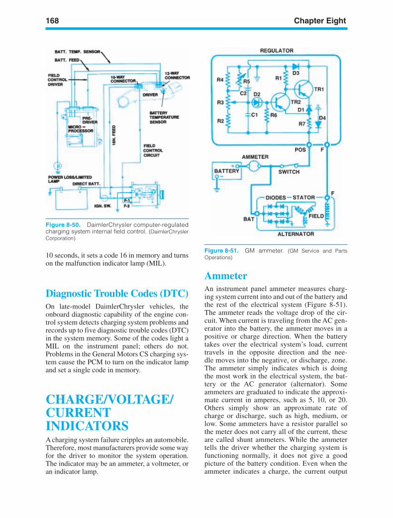
168 Chapter Eight
Figure 8-51. GM ammeter. (GM Service and PartsOperations)10 seconds, it sets a code 16 in memory and turns
on the malfunction indicator lamp (MIL).
Diagnostic Trouble Codes (DTC)On late-model DaimlerChrysler vehicles, theonboard diagnostic capability of the engine con-trol system detects charging system problems andrecords up to five diagnostic trouble codes (DTC)in the system memory. Some of the codes light aMIL on the instrument panel; others do not.Problems in the General Motors CS charging sys-tem cause the PCM to turn on the indicator lampand set a single code in memory.
CHARGE/VOLTAGE/CURRENTINDICATORSA charging system failure cripples an automobile.Therefore, most manufacturers provide some wayfor the driver to monitor the system operation.The indicator may be an ammeter, a voltmeter, oran indicator lamp.
AmmeterAn instrument panel ammeter measures charg-ing system current into and out of the battery andthe rest of the electrical system (Figure 8-51).The ammeter reads the voltage drop of the cir-cuit. When current is traveling from the AC gen-erator into the battery, the ammeter moves in apositive or charge direction. When the batterytakes over the electrical system’s load, currenttravels in the opposite direction and the nee-dle moves into the negative, or discharge, zone.The ammeter simply indicates which is doingthe most work in the electrical system, the bat-tery or the AC generator (alternator). Someammeters are graduated to indicate the approxi-mate current in amperes, such as 5, 10, or 20.Others simply show an approximate rate ofcharge or discharge, such as high, medium, orlow. Some ammeters have a resistor parallel sothe meter does not carry all of the current, theseare called shunt ammeters. While the ammetertells the driver whether the charging system isfunctioning normally, it does not give a goodpicture of the battery condition. Even when theammeter indicates a charge, the current output
Figure 8-50. DaimlerChrysler computer-regulatedcharging system internal field control. (DaimlerChryslerCorporation)
ker88839_ch08.qxd 1/9/06 11:28 AM Page 168
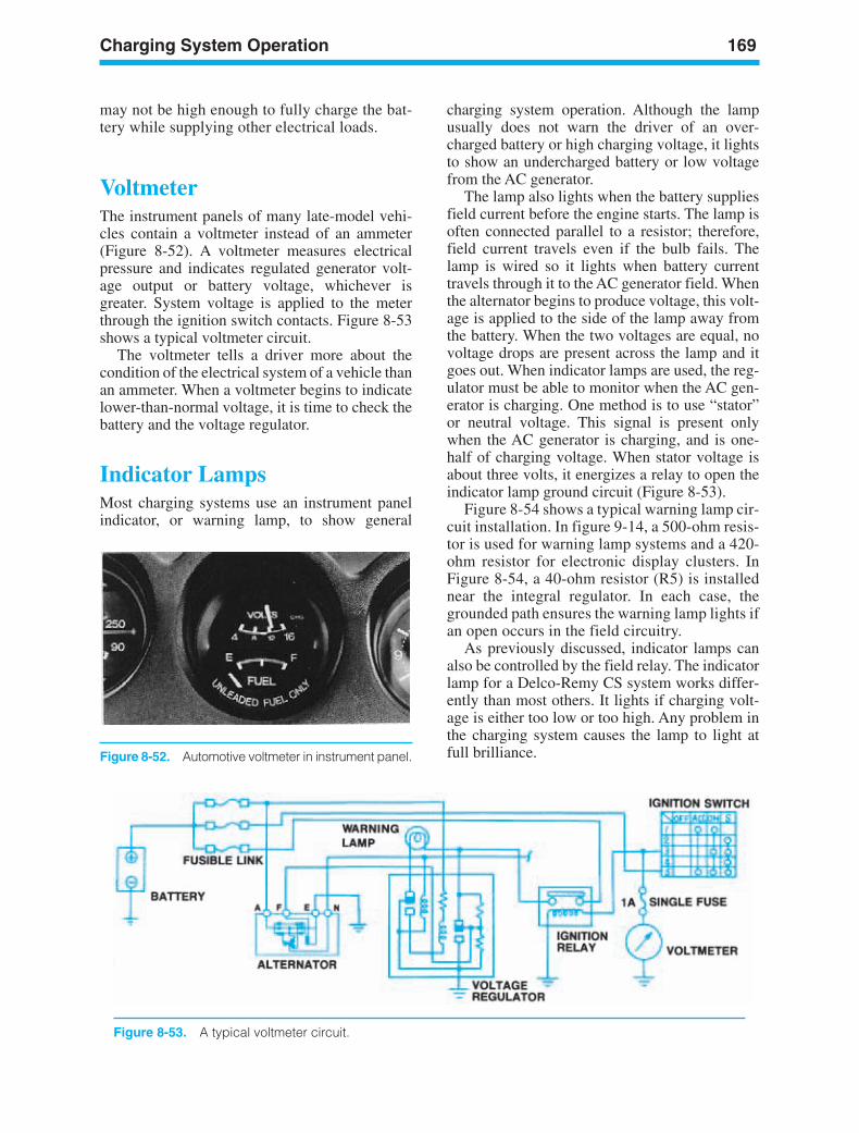
Charging System Operation 169
Figure 8-52. Automotive voltmeter in instrument panel.
may not be high enough to fully charge the bat-tery while supplying other electrical loads.
VoltmeterThe instrument panels of many late-model vehi-cles contain a voltmeter instead of an ammeter(Figure 8-52). A voltmeter measures electricalpressure and indicates regulated generator volt-age output or battery voltage, whichever isgreater. System voltage is applied to the meterthrough the ignition switch contacts. Figure 8-53shows a typical voltmeter circuit.
The voltmeter tells a driver more about thecondition of the electrical system of a vehicle thanan ammeter. When a voltmeter begins to indicatelower-than-normal voltage, it is time to check thebattery and the voltage regulator.
Indicator LampsMost charging systems use an instrument panelindicator, or warning lamp, to show general
charging system operation. Although the lampusually does not warn the driver of an over-charged battery or high charging voltage, it lightsto show an undercharged battery or low voltagefrom the AC generator.
The lamp also lights when the battery suppliesfield current before the engine starts. The lamp isoften connected parallel to a resistor; therefore,field current travels even if the bulb fails. Thelamp is wired so it lights when battery currenttravels through it to the AC generator field. Whenthe alternator begins to produce voltage, this volt-age is applied to the side of the lamp away fromthe battery. When the two voltages are equal, novoltage drops are present across the lamp and itgoes out. When indicator lamps are used, the reg-ulator must be able to monitor when the AC gen-erator is charging. One method is to use “stator”or neutral voltage. This signal is present onlywhen the AC generator is charging, and is one-half of charging voltage. When stator voltage isabout three volts, it energizes a relay to open theindicator lamp ground circuit (Figure 8-53).
Figure 8-54 shows a typical warning lamp cir-cuit installation. In figure 9-14, a 500-ohm resis-tor is used for warning lamp systems and a 420-ohm resistor for electronic display clusters. InFigure 8-54, a 40-ohm resistor (R5) is installednear the integral regulator. In each case, thegrounded path ensures the warning lamp lights ifan open occurs in the field circuitry.
As previously discussed, indicator lamps canalso be controlled by the field relay. The indicatorlamp for a Delco-Remy CS system works differ-ently than most others. It lights if charging volt-age is either too low or too high. Any problem inthe charging system causes the lamp to light atfull brilliance.
Figure 8-53. A typical voltmeter circuit.
ker88839_ch08.qxd 1/9/06 11:28 AM Page 169
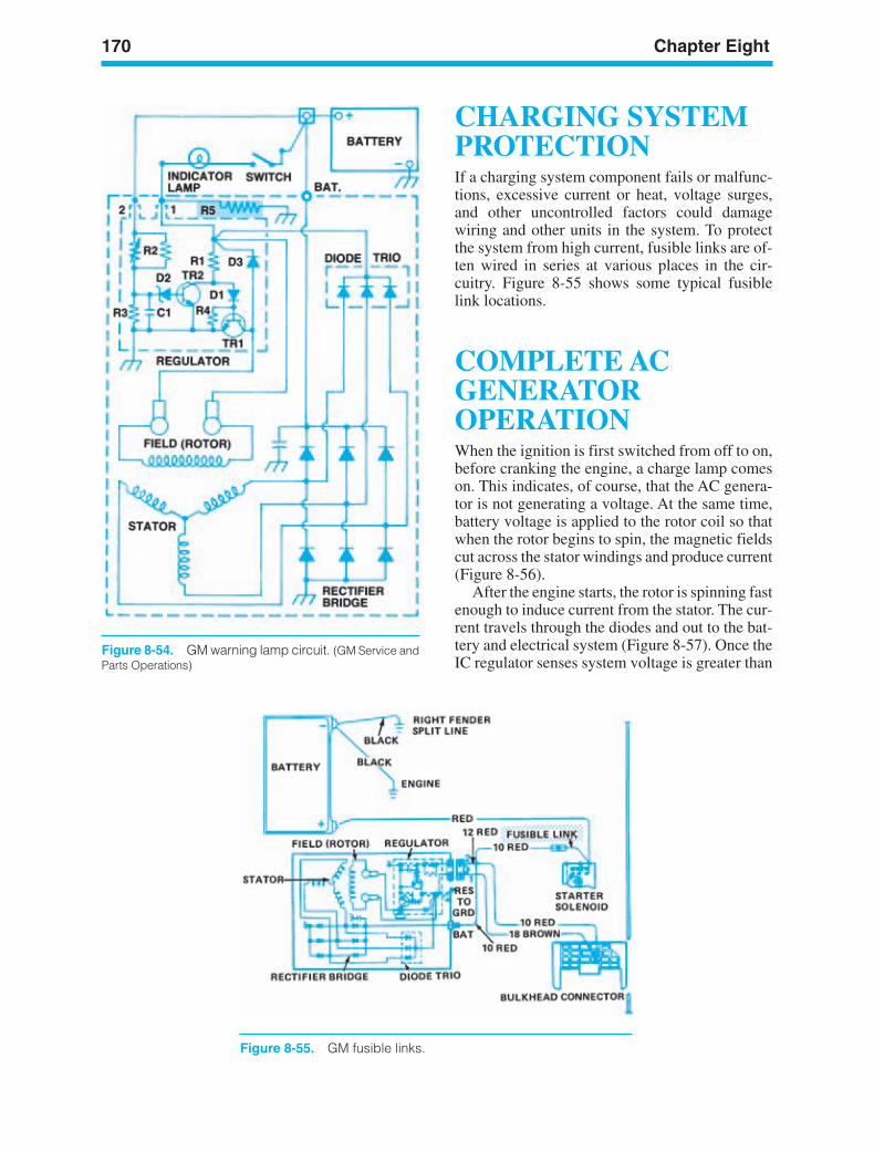
170 Chapter Eight
Figure 8-54. GM warning lamp circuit. (GM Service andParts Operations)
Figure 8-55. GM fusible links.
CHARGING SYSTEMPROTECTIONIf a charging system component fails or malfunc-tions, excessive current or heat, voltage surges,and other uncontrolled factors could damagewiring and other units in the system. To protectthe system from high current, fusible links are of-ten wired in series at various places in the cir-cuitry. Figure 8-55 shows some typical fusiblelink locations.
COMPLETE ACGENERATOROPERATIONWhen the ignition is first switched from off to on,before cranking the engine, a charge lamp comeson. This indicates, of course, that the AC genera-tor is not generating a voltage. At the same time,battery voltage is applied to the rotor coil so thatwhen the rotor begins to spin, the magnetic fieldscut across the stator windings and produce current(Figure 8-56).
After the engine starts, the rotor is spinning fastenough to induce current from the stator. The cur-rent travels through the diodes and out to the bat-tery and electrical system (Figure 8-57). Once theIC regulator senses system voltage is greater than
ker88839_ch08.qxd 1/9/06 11:28 AM Page 170
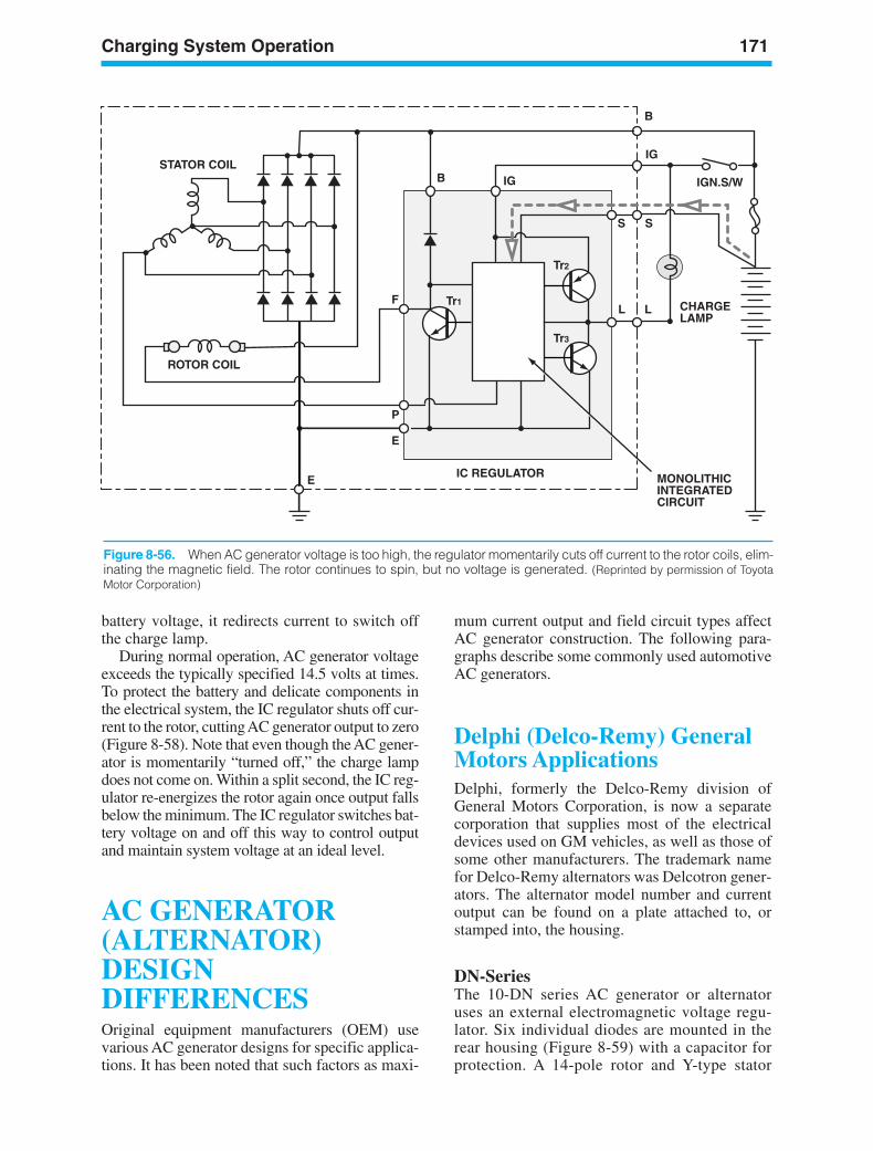
Charging System Operation 171
battery voltage, it redirects current to switch offthe charge lamp.
During normal operation, AC generator voltageexceeds the typically specified 14.5 volts at times.To protect the battery and delicate components inthe electrical system, the IC regulator shuts off cur-rent to the rotor, cutting AC generator output to zero(Figure 8-58). Note that even though the AC gener-ator is momentarily “turned off,” the charge lampdoes not come on. Within a split second, the IC reg-ulator re-energizes the rotor again once output fallsbelow the minimum. The IC regulator switches bat-tery voltage on and off this way to control outputand maintain system voltage at an ideal level.
AC GENERATOR(ALTERNATOR)DESIGNDIFFERENCESOriginal equipment manufacturers (OEM) usevarious AC generator designs for specific applica-tions. It has been noted that such factors as maxi-
mum current output and field circuit types affectAC generator construction. The following para-graphs describe some commonly used automotiveAC generators.
Delphi (Delco-Remy) GeneralMotors ApplicationsDelphi, formerly the Delco-Remy division ofGeneral Motors Corporation, is now a separatecorporation that supplies most of the electricaldevices used on GM vehicles, as well as those ofsome other manufacturers. The trademark namefor Delco-Remy alternators was Delcotron gener-ators. The alternator model number and currentoutput can be found on a plate attached to, orstamped into, the housing.
DN-SeriesThe 10-DN series AC generator or alternatoruses an external electromagnetic voltage regu-lator. Six individual diodes are mounted in therear housing (Figure 8-59) with a capacitor forprotection. A 14-pole rotor and Y-type stator
MONOLITHICINTEGRATEDCIRCUIT
IC REGULATOR
ROTOR COIL
STATOR COIL
B
B IG
IG
IGN.S/W
CHARGELAMP
E
E
S S
L LTr1
Tr3
Tr2
F
P
Figure 8-56. When AC generator voltage is too high, the regulator momentarily cuts off current to the rotor coils, elim-inating the magnetic field. The rotor continues to spin, but no voltage is generated. (Reprinted by permission of ToyotaMotor Corporation)
ker88839_ch08.qxd 1/9/06 11:28 AM Page 171
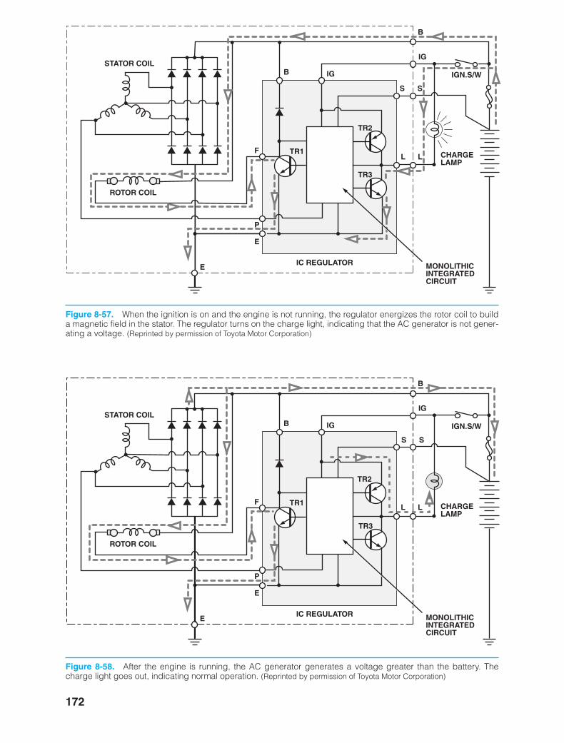
172
MONOLITHICINTEGRATEDCIRCUIT
IC REGULATOR
ROTOR COIL
STATOR COIL
B
B IG
IG
IGN.S/W
CHARGELAMP
E
E
S S
L LTR1
TR3
TR2
F
P
Figure 8-57. When the ignition is on and the engine is not running, the regulator energizes the rotor coil to builda magnetic field in the stator. The regulator turns on the charge light, indicating that the AC generator is not gener-ating a voltage. (Reprinted by permission of Toyota Motor Corporation)
MONOLITHICINTEGRATEDCIRCUIT
IC REGULATOR
ROTOR COIL
STATOR COIL
B
B IG
IG
IGN.S/W
CHARGELAMP
E
E
S S
L LTR1
TR3
TR2
F
P
Figure 8-58. After the engine is running, the AC generator generates a voltage greater than the battery. Thecharge light goes out, indicating normal operation. (Reprinted by permission of Toyota Motor Corporation)
ker88839_ch08.qxd 1/9/06 11:28 AM Page 172
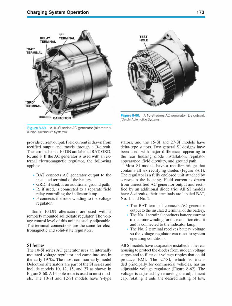
Charging System Operation 173
provide current output. Field current is drawn fromrectified output and travels through a B-circuit.The terminals on a 10-DN are labeled BAT, GRD,R, and F. If the AC generator is used with an ex-ternal electromagnetic regulator, the followingapplies:
• BAT connects AC generator output to theinsulated terminal of the battery.
• GRD, if used, is an additional ground path.• R, if used, is connected to a separate field
relay controlling the indicator lamp.• F connects the rotor winding to the voltage
regulator.
Some 10-DN alternators are used with aremotely mounted solid-state regulator. The volt-age control level of this unit is usually adjustable.The terminal connections are the same for elec-tromagnetic and solid-state regulators.
SI SeriesThe 10-SI series AC generator uses an internallymounted voltage regulator and came into use inthe early 1970s. The most common early modelDelcotron alternators are part of the SI series andinclude models 10, 12, 15, and 27 as shown inFigure 8-60. A 14-pole rotor is used in most mod-els. The 10-SI and 12-SI models have Y-type
stators, and the 15-SI and 27-SI models havedelta-type stators. Two general SI designs havebeen used, with major differences appearing inthe rear housing diode installation, regulatorappearance, field circuitry, and ground path.
Most SI models have a rectifier bridge thatcontains all six rectifying diodes (Figure 8-61).The regulator is a fully enclosed unit attached byscrews to the housing. Field current is drawnfrom unrectified AC generator output and recti-fied by an additional diode trio. All SI modelshave A-circuits, their terminals are labeled BAT,No. 1, and No. 2.
• The BAT terminal connects AC generatoroutput to the insulated terminal of the battery.
• The No. 1 terminal conducts battery currentto the rotor winding for the excitation circuitand is connected to the indicator lamp.
• The No. 2 terminal receives battery voltageso the voltage regulator can react to systemoperating conditions.
All SI models have a capacitor installed in the rearhousing to protect the diodes from sudden voltagesurges and to filter out voltage ripples that couldproduce EMI. The 27-SI, which is inten-ded principally for commercial vehicles, has anadjustable voltage regulator (Figure 8-62). Thevoltage is adjusted by removing the adjustmentcap, rotating it until the desired setting of low,
Figure 8-59. A 10-SI series AC generator (alternator).(Delphi Automotive Systems)
Figure 8-60. A 10-SI series AC generator [Delcotron].(Delphi Automotive Systems)
ker88839_ch08.qxd 1/9/06 11:28 AM Page 173
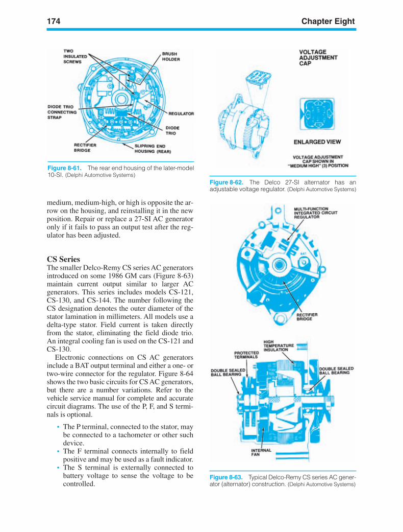
174 Chapter Eight
Figure 8-63. Typical Delco-Remy CS series AC gener-ator (alternator) construction. (Delphi Automotive Systems)
medium, medium-high, or high is opposite the ar-row on the housing, and reinstalling it in the newposition. Repair or replace a 27-SI AC generatoronly if it fails to pass an output test after the reg-ulator has been adjusted.
CS SeriesThe smaller Delco-Remy CS series AC generatorsintroduced on some 1986 GM cars (Figure 8-63)maintain current output similar to larger ACgenerators. This series includes models CS-121,CS-130, and CS-144. The number following theCS designation denotes the outer diameter of thestator lamination in millimeters. All models use adelta-type stator. Field current is taken directlyfrom the stator, eliminating the field diode trio.An integral cooling fan is used on the CS-121 andCS-130.
Electronic connections on CS AC generatorsinclude a BAT output terminal and either a one- ortwo-wire connector for the regulator. Figure 8-64shows the two basic circuits for CS AC generators,but there are a number variations. Refer to thevehicle service manual for complete and accuratecircuit diagrams. The use of the P, F, and S termi-nals is optional.
• The P terminal, connected to the stator, maybe connected to a tachometer or other suchdevice.
• The F terminal connects internally to fieldpositive and may be used as a fault indicator.
• The S terminal is externally connected tobattery voltage to sense the voltage to becontrolled.
Figure 8-61. The rear end housing of the later-model10-SI. (Delphi Automotive Systems)
Figure 8-62. The Delco 27-SI alternator has anadjustable voltage regulator. (Delphi Automotive Systems)
ker88839_ch08.qxd 1/9/06 11:28 AM Page 174
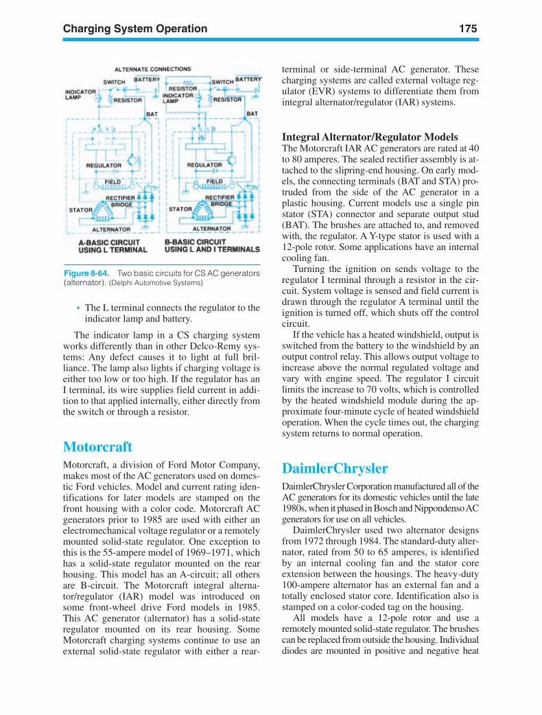
Charging System Operation 175
terminal or side-terminal AC generator. Thesecharging systems are called external voltage reg-ulator (EVR) systems to differentiate them fromintegral alternator/regulator (IAR) systems.
Integral Alternator/Regulator ModelsThe Motorcraft IAR AC generators are rated at 40to 80 amperes. The sealed rectifier assembly is at-tached to the slipring-end housing. On early mod-els, the connecting terminals (BAT and STA) pro-truded from the side of the AC generator in aplastic housing. Current models use a single pinstator (STA) connector and separate output stud(BAT). The brushes are attached to, and removedwith, the regulator. A Y-type stator is used with a12-pole rotor. Some applications have an internalcooling fan.
Turning the ignition on sends voltage to theregulator I terminal through a resistor in the cir-cuit. System voltage is sensed and field current isdrawn through the regulator A terminal until theignition is turned off, which shuts off the controlcircuit.
If the vehicle has a heated windshield, output isswitched from the battery to the windshield by anoutput control relay. This allows output voltage toincrease above the normal regulated voltage andvary with engine speed. The regulator I circuitlimits the increase to 70 volts, which is controlledby the heated windshield module during the ap-proximate four-minute cycle of heated windshieldoperation. When the cycle times out, the chargingsystem returns to normal operation.
DaimlerChryslerDaimlerChrysler Corporation manufactured all of theAC generators for its domestic vehicles until the late1980s, when it phased in Bosch and Nippondenso ACgenerators for use on all vehicles.
DaimlerChrysler used two alternator designsfrom 1972 through 1984. The standard-duty alter-nator, rated from 50 to 65 amperes, is identifiedby an internal cooling fan and the stator coreextension between the housings. The heavy-duty100-ampere alternator has an external fan and atotally enclosed stator core. Identification also isstamped on a color-coded tag on the housing.
All models have a 12-pole rotor and use aremotely mounted solid-state regulator. The brushescan be replaced from outside the housing. Individualdiodes are mounted in positive and negative heat
• The L terminal connects the regulator to theindicator lamp and battery.
The indicator lamp in a CS charging systemworks differently than in other Delco-Remy sys-tems: Any defect causes it to light at full bril-liance. The lamp also lights if charging voltage iseither too low or too high. If the regulator has anI terminal, its wire supplies field current in addi-tion to that applied internally, either directly fromthe switch or through a resistor.
MotorcraftMotorcraft, a division of Ford Motor Company,makes most of the AC generators used on domes-tic Ford vehicles. Model and current rating iden-tifications for later models are stamped on thefront housing with a color code. Motorcraft ACgenerators prior to 1985 are used with either anelectromechanical voltage regulator or a remotelymounted solid-state regulator. One exception tothis is the 55-ampere model of 1969–1971, whichhas a solid-state regulator mounted on the rearhousing. This model has an A-circuit; all othersare B-circuit. The Motorcraft integral alterna-tor/regulator (IAR) model was introduced onsome front-wheel drive Ford models in 1985.This AC generator (alternator) has a solid-stateregulator mounted on its rear housing. SomeMotorcraft charging systems continue to use anexternal solid-state regulator with either a rear-
Figure 8-64. Two basic circuits for CS AC generators(alternator). (Delphi Automotive Systems)
ker88839_ch08.qxd 1/9/06 11:28 AM Page 175
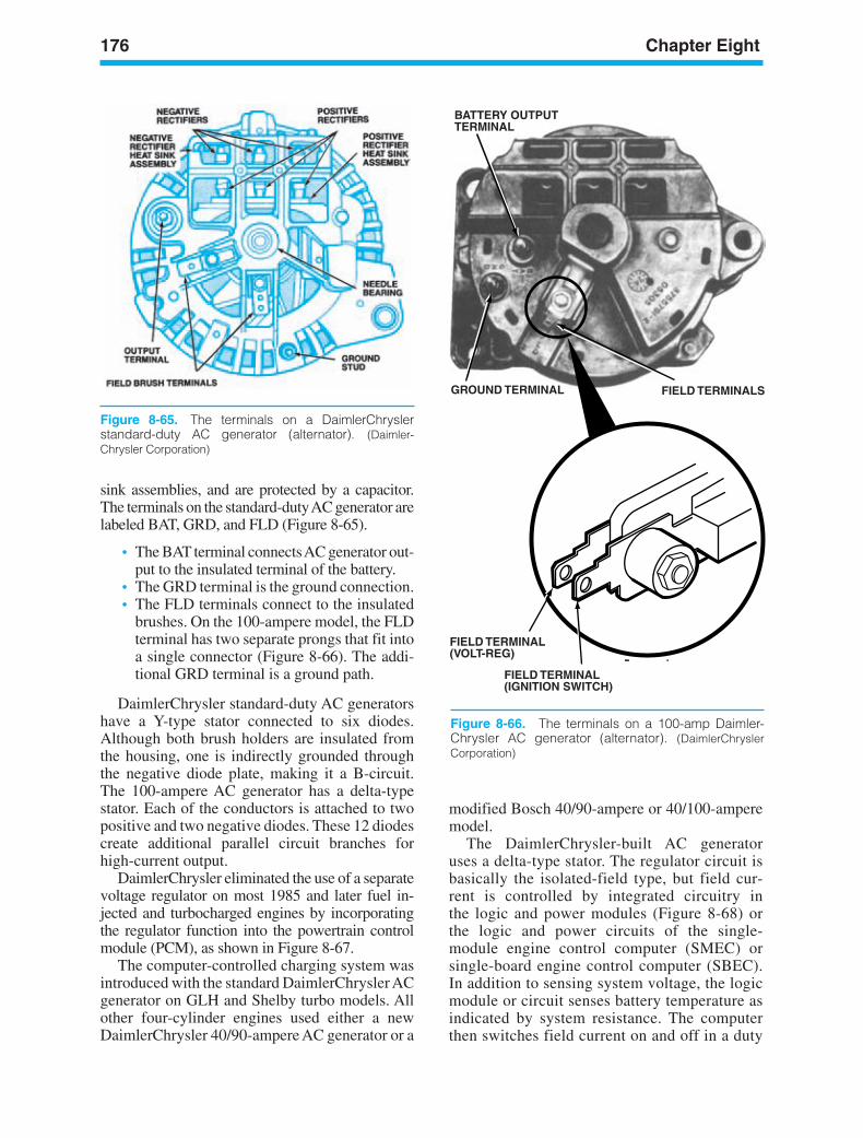
176 Chapter Eight
GROUND TERMINAL FIELD TERMINALS
FIELD TERMINAL (VOLT-REG)
FIELD TERMINAL (IGNITION SWITCH)
BATTERY OUTPUTTERMINAL
Figure 8-66. The terminals on a 100-amp Daimler-Chrysler AC generator (alternator). (DaimlerChryslerCorporation)
sink assemblies, and are protected by a capacitor.The terminals on the standard-duty AC generator arelabeled BAT, GRD, and FLD (Figure 8-65).
• The BAT terminal connects AC generator out-put to the insulated terminal of the battery.
• The GRD terminal is the ground connection.• The FLD terminals connect to the insulated
brushes. On the 100-ampere model, the FLDterminal has two separate prongs that fit intoa single connector (Figure 8-66). The addi-tional GRD terminal is a ground path.
DaimlerChrysler standard-duty AC generatorshave a Y-type stator connected to six diodes.Although both brush holders are insulated fromthe housing, one is indirectly grounded throughthe negative diode plate, making it a B-circuit.The 100-ampere AC generator has a delta-typestator. Each of the conductors is attached to twopositive and two negative diodes. These 12 diodescreate additional parallel circuit branches forhigh-current output.
DaimlerChrysler eliminated the use of a separatevoltage regulator on most 1985 and later fuel in-jected and turbocharged engines by incorporatingthe regulator function into the powertrain controlmodule (PCM), as shown in Figure 8-67.
The computer-controlled charging system wasintroduced with the standard DaimlerChrysler ACgenerator on GLH and Shelby turbo models. Allother four-cylinder engines used either a newDaimlerChrysler 40/90-ampere AC generator or a
modified Bosch 40/90-ampere or 40/100-amperemodel.
The DaimlerChrysler-built AC generatoruses a delta-type stator. The regulator circuit isbasically the isolated-field type, but field cur-rent is controlled by integrated circuitry inthe logic and power modules (Figure 8-68) orthe logic and power circuits of the single-module engine control computer (SMEC) orsingle-board engine control computer (SBEC).In addition to sensing system voltage, the logicmodule or circuit senses battery temperature asindicated by system resistance. The computerthen switches field current on and off in a duty
Figure 8-65. The terminals on a DaimlerChrysler standard-duty AC generator (alternator). (Daimler-Chrysler Corporation)
ker88839_ch08.qxd 1/9/06 11:28 AM Page 176
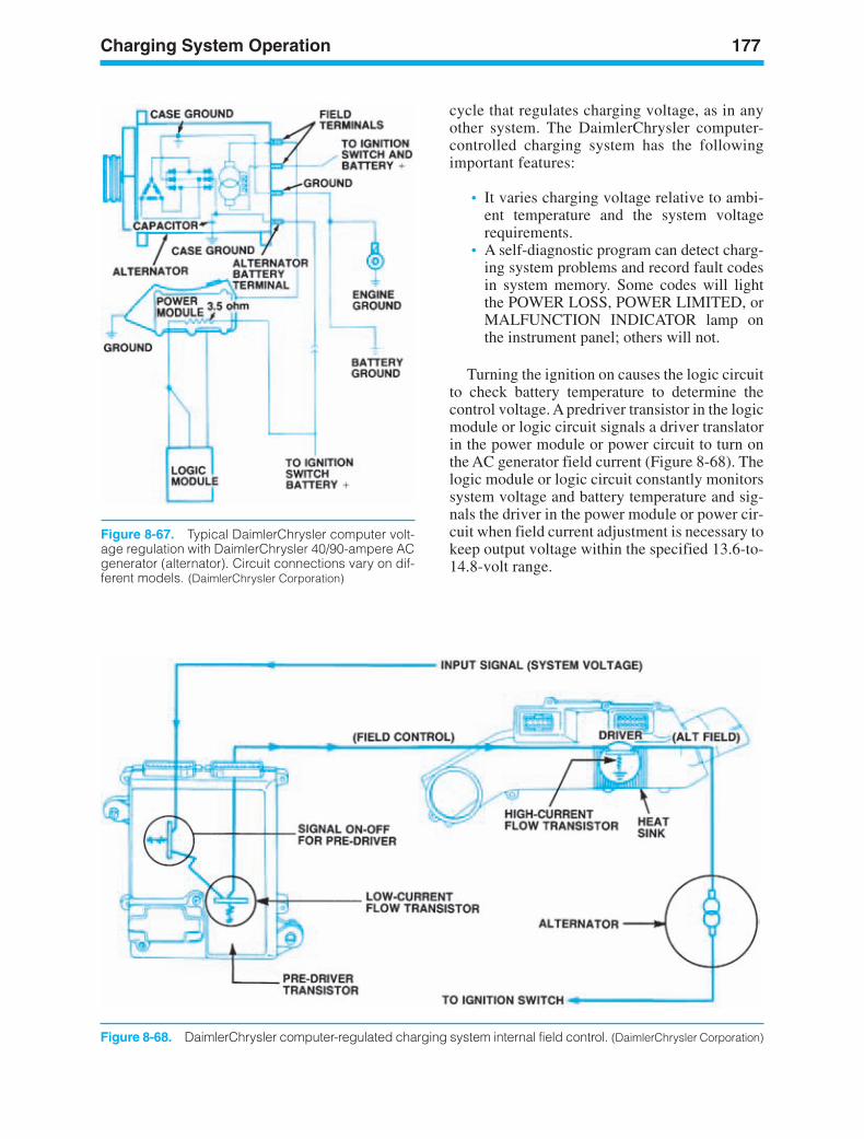
Charging System Operation 177
Figure 8-67. Typical DaimlerChrysler computer volt-age regulation with DaimlerChrysler 40/90-ampere ACgenerator (alternator). Circuit connections vary on dif-ferent models. (DaimlerChrysler Corporation)
cycle that regulates charging voltage, as in anyother system. The DaimlerChrysler computer-controlled charging system has the followingimportant features:
• It varies charging voltage relative to ambi-ent temperature and the system voltagerequirements.
• A self-diagnostic program can detect charg-ing system problems and record fault codesin system memory. Some codes will lightthe POWER LOSS, POWER LIMITED, orMALFUNCTION INDICATOR lamp onthe instrument panel; others will not.
Turning the ignition on causes the logic circuitto check battery temperature to determine thecontrol voltage. A predriver transistor in the logicmodule or logic circuit signals a driver translatorin the power module or power circuit to turn onthe AC generator field current (Figure 8-68). Thelogic module or logic circuit constantly monitorssystem voltage and battery temperature and sig-nals the driver in the power module or power cir-cuit when field current adjustment is necessary tokeep output voltage within the specified 13.6-to-14.8-volt range.
Figure 8-68. DaimlerChrysler computer-regulated charging system internal field control. (DaimlerChrysler Corporation)
ker88839_ch08.qxd 1/9/06 11:28 AM Page 177
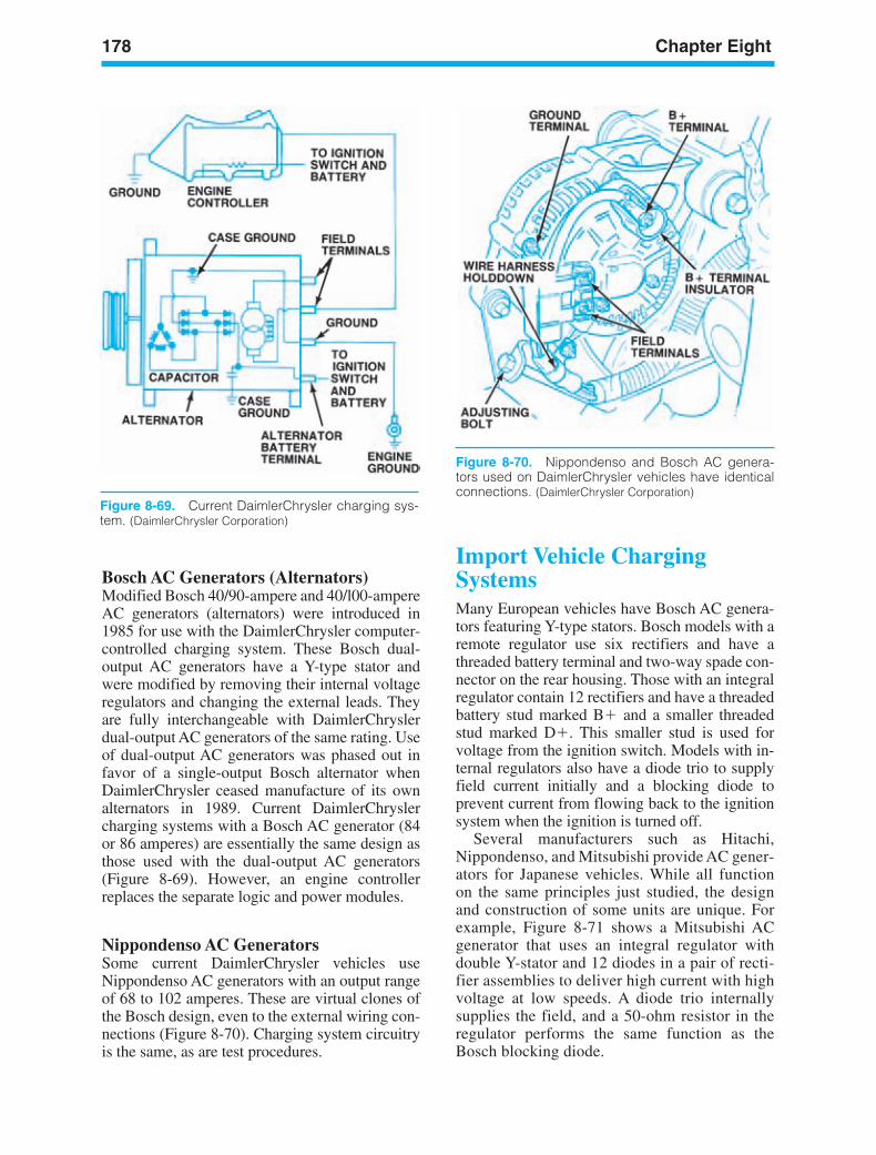
178 Chapter Eight
Figure 8-70. Nippondenso and Bosch AC genera-tors used on DaimlerChrysler vehicles have identicalconnections. (DaimlerChrysler Corporation)
Bosch AC Generators (Alternators)Modified Bosch 40/90-ampere and 40/l00-ampereAC generators (alternators) were introduced in1985 for use with the DaimlerChrysler computer-controlled charging system. These Bosch dual-output AC generators have a Y-type stator andwere modified by removing their internal voltageregulators and changing the external leads. Theyare fully interchangeable with DaimlerChryslerdual-output AC generators of the same rating. Useof dual-output AC generators was phased out infavor of a single-output Bosch alternator whenDaimlerChrysler ceased manufacture of its ownalternators in 1989. Current DaimlerChryslercharging systems with a Bosch AC generator (84or 86 amperes) are essentially the same design asthose used with the dual-output AC generators(Figure 8-69). However, an engine controllerreplaces the separate logic and power modules.
Nippondenso AC GeneratorsSome current DaimlerChrysler vehicles useNippondenso AC generators with an output rangeof 68 to 102 amperes. These are virtual clones ofthe Bosch design, even to the external wiring con-nections (Figure 8-70). Charging system circuitryis the same, as are test procedures.
Import Vehicle ChargingSystemsMany European vehicles have Bosch AC genera-tors featuring Y-type stators. Bosch models with aremote regulator use six rectifiers and have athreaded battery terminal and two-way spade con-nector on the rear housing. Those with an integralregulator contain 12 rectifiers and have a threadedbattery stud marked B and a smaller threadedstud marked D. This smaller stud is used forvoltage from the ignition switch. Models with in-ternal regulators also have a diode trio to supplyfield current initially and a blocking diode toprevent current from flowing back to the ignitionsystem when the ignition is turned off.
Several manufacturers such as Hitachi,Nippondenso, and Mitsubishi provide AC gener-ators for Japanese vehicles. While all functionon the same principles just studied, the designand construction of some units are unique. Forexample, Figure 8-71 shows a Mitsubishi ACgenerator that uses an integral regulator withdouble Y-stator and 12 diodes in a pair of recti-fier assemblies to deliver high current with highvoltage at low speeds. A diode trio internallysupplies the field, and a 50-ohm resistor in theregulator performs the same function as theBosch blocking diode.
Figure 8-69. Current DaimlerChrysler charging sys-tem. (DaimlerChrysler Corporation)
ker88839_ch08.qxd 1/9/06 11:28 AM Page 178
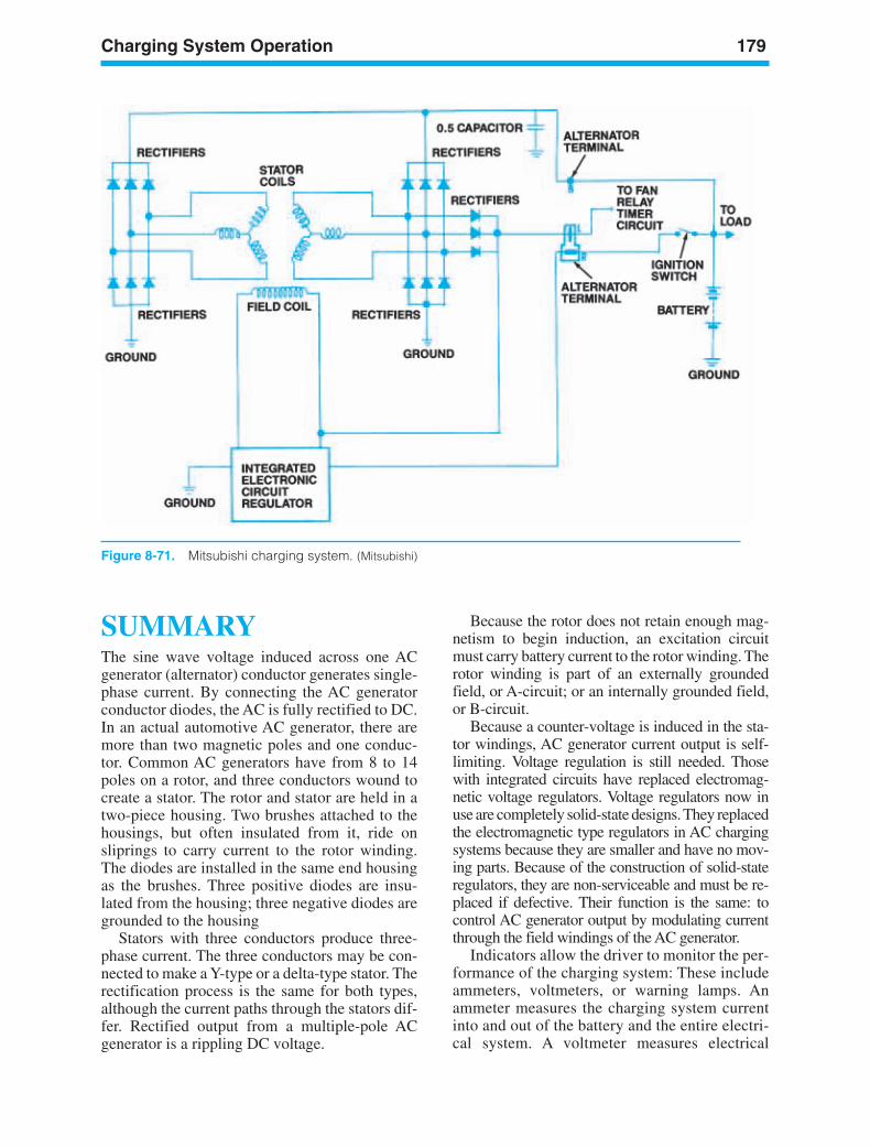
Charging System Operation 179
SUMMARYThe sine wave voltage induced across one ACgenerator (alternator) conductor generates single-phase current. By connecting the AC generatorconductor diodes, the AC is fully rectified to DC.In an actual automotive AC generator, there aremore than two magnetic poles and one conduc-tor. Common AC generators have from 8 to 14poles on a rotor, and three conductors wound tocreate a stator. The rotor and stator are held in atwo-piece housing. Two brushes attached to thehousings, but often insulated from it, ride onsliprings to carry current to the rotor winding.The diodes are installed in the same end housingas the brushes. Three positive diodes are insu-lated from the housing; three negative diodes aregrounded to the housing
Stators with three conductors produce three-phase current. The three conductors may be con-nected to make a Y-type or a delta-type stator. Therectification process is the same for both types,although the current paths through the stators dif-fer. Rectified output from a multiple-pole ACgenerator is a rippling DC voltage.
Because the rotor does not retain enough mag-netism to begin induction, an excitation circuitmust carry battery current to the rotor winding. Therotor winding is part of an externally groundedfield, or A-circuit; or an internally grounded field,or B-circuit.
Because a counter-voltage is induced in the sta-tor windings, AC generator current output is self-limiting. Voltage regulation is still needed. Thosewith integrated circuits have replaced electromag-netic voltage regulators. Voltage regulators now inuse are completely solid-state designs. They replacedthe electromagnetic type regulators in AC chargingsystems because they are smaller and have no mov-ing parts. Because of the construction of solid-stateregulators, they are non-serviceable and must be re-placed if defective. Their function is the same: tocontrol AC generator output by modulating currentthrough the field windings of the AC generator.
Indicators allow the driver to monitor the per-formance of the charging system: These includeammeters, voltmeters, or warning lamps. Anammeter measures the charging system currentinto and out of the battery and the entire electri-cal system. A voltmeter measures electrical
Figure 8-71. Mitsubishi charging system. (Mitsubishi)
ker88839_ch08.qxd 1/9/06 11:28 AM Page 179
180 Chapter Eight
pressure and indicates regulated AC generatorvoltage output or battery voltage. Indicatorlamps illuminate on the instrument panel of thevehicle and indicate to the driver general charg-ing system operation status.
Wiring and other components in the chargingsystem may be damaged if the system fails or mal-functions due to excessive current or heat, voltagesurges, and other uncontrolled factors. Fusiblelinks are used in these circuits to protect the circuitform high current.
Common AC generators used by domestic man-ufacturers include the Delco-Remy SI and CS seriesused by OM; the Motorcraft IAR, rear-terminal, andside-terminal models used by Ford; and theDaimlerChrysler-built, Bosch, and Nippondensomodels used by DaimlerChrysler. Most Europeanimports use Bosch AC generators, while Asianimports use alternators made by several manu-facturers, including Hitachi, Nippondenso, andMitsubishi.
ker88839_ch08.qxd 1/9/06 11:28 AM Page 180
Charging System Operation 181
Review Questions1. Alternators induce voltage by rotating:
a. A magnetic field inside a fixedconductor
b. A conductor inside a magnetic fieldc. A stator inside a fieldd. A spring past a stator
2. In an alternator, induced voltage is at itsmaximum value when the angle betweenthe magnetic lines and the loopedconductor is:a. 0 degreesb. 45 degreesc. 90 degreesd. 180 degrees
3. The sine wave voltage induced across oneconductor by one rotor revolution is called:a. Single-phase currentb. Open-circuit voltagec. Diode rectificationd. Half-phase current
4. Alternating current in an alternator isrectified by:a. Brushesb. Diodesc. Slip ringsd. Transistors
5. An alternator with only one conductor andone diode would show which of thefollowing current output patterns?a. Three-phase currentb. Open-circuit voltagec. Half-wave rectificationd. Full-wave rectification
6. An alternator consists of:a. A stator, a rotor, sliprings, brushes,
and diodesb. A stator, an armature, sliprings, brushes,
and diodesc. A stator, a rotor, a commutator, brushes,
and diodesd. A stator, a rotor, a field relay, brushes,
and diodes
7. A typical automotive alternator has howmany poles?a. 2 to 4b. 6 to 8c. 8 to 14d. 12 to 20
8. The three alternator conductors are woundonto a cylindrical, laminated metal-piececalled:a. Rotor coreb. Stator corec. Armature cored. Field core
9. Automotive alternators that have threeconductors generally use how many diodesto rectify the output current?a. Threeb. Sixc. Nined. Twelve
10. Which of the following is not true of thepositive diodes in an alternator?a. They are connected to the insulated
terminal of the battery.b. They conduct only the current
moving from ground into the conductor.
c. They are mounted in a heat sink.d. The bias of the diodes prevents the
battery from discharging.
11. A group of three or more like diodes may becalled:a. Diode wingb. Diode tripletc. Diode dishd. Diode bridge
12. Y-type stators are used in alternators thatrequire:a. Low voltage output at high alternator
speedb. High voltage output at low alternator
speedc. Low voltage at low alternator speedd. High voltage at high alternator speed
13. Which of the following is true of a delta-typestator?a. There is no neutral junction.b. There is no ground connection.c. The windings always form a series circuit.d. The circuit diagram looks like a
parallelogram.
14. Delta-type stators are used:a. When high-voltage output is neededb. When low-voltage output is needed
ker88839_ch08.qxd 1/9/06 11:28 AM Page 181
182 Chapter Eight
c. When high-current output is neededd. When low-current output is needed
15. Which of the following is a commonly usedtype of field circuit in automotivealternators?a. X-circuitb. Y-circuitc. Connected-field circuitc. A-circuit
16. Alternator output voltage is directly related to:a. Field strengthb. Rotor speedc. Both field strength and rotor speedd. Neither field strength nor rotor speed
17. Double-contact voltage regulators containall of the following except:a. An armatureb. An electromagnetc. Two sets of contact pointsd. A solenoid
18. The shorting contacts of a double-contactregulator:a. Increase voltage creepb. Increase field currentc. React to battery temperature changesd. Short the field circuit to the alternator
19. Which of the following can not be used in atotally solid-state regulator?a. Zener diodesb. Thermistorsc. Capacitorsd. Circuit breakers
20. Which of the following is used to smooth outany abrupt voltage surges and protect aregulator?a. Transistorb. Capacitorc. Thermistord. Relays
21. Which of the following is used to monitor thecharging system?a. Ammeterb. Ohmmeterc. Dynamometerd. Fusible link
22. Warning lamps are installed sothat they will not light when the following is true:a. The voltage on the battery side of the
lamp is higher.b. Field current is flowing from the battery
to the alternator.c. The voltage on both sides of the lamp
is equal.d. The voltage on the resistor side of the
lamp is higher.
23. Maximum current output in an alternator isreached when the following is true:a. It reaches maximum designed speed.b. Electrical demands from the system are
at the minimum.c. Induced countervoltage becomes great
enough to stop current increase.d. Induced countervoltage drops low
enough to stop voltage increase.
24. The regulator is a charging systemdevice that controls circuit openingand closing:a. Ignition-to-batteryb. Alternator-to-thermistorc. Battery-to-accessoryd. Voltage source-to-battery
25. Which of the following methods is usedto regulate supply current to thealternator field?a. Fault codesb. Charge indicator lampc. Pulse-width modulationd. Shunt resistor
ker88839_ch08.qxd 1/9/06 11:28 AM Page 182
183
9StartingSystemOperation
LEARNINGOBJECTIVESUpon completion and review of this chapter, youshould be able to:
• Define the two circuits of the automotivestarting system.
• Identify the basic starting systems parts andexplain their function in the system.
• Define the different designs of startingsystems used by the different automotivemanufacturers.
• Identify the internal components of anautomotive starter motor and explain theiroperation.
• Define the term magnetic repulsion andexplain how a DC starter motor operates.
• Define the terms series, shunt (parallel),and compound (series-parallel) as theyapply to starter motor internal circuitry.
• Explain the operation of the armature andfields.
• Define starter motor drives and explain theiroperation.
• Define the different designs of startingmotors used by the different automotivemanufacturers.
• Explain the operation of the overrunningclutch.
KEY TERMSArmatureBrushesClutch Start SwitchCompound MotorDetentedIgnition SwitchLap WindingMagnetic RepulsionMagnetic SwitchOverrunning ClutchPinion GearSeries MotorShunt MotorSolenoidSolenoid-Actuated StarterStarter DriveStarting Safety SwitchTorque
ker88839_ch09.qxd 1/9/06 11:29 AM Page 183
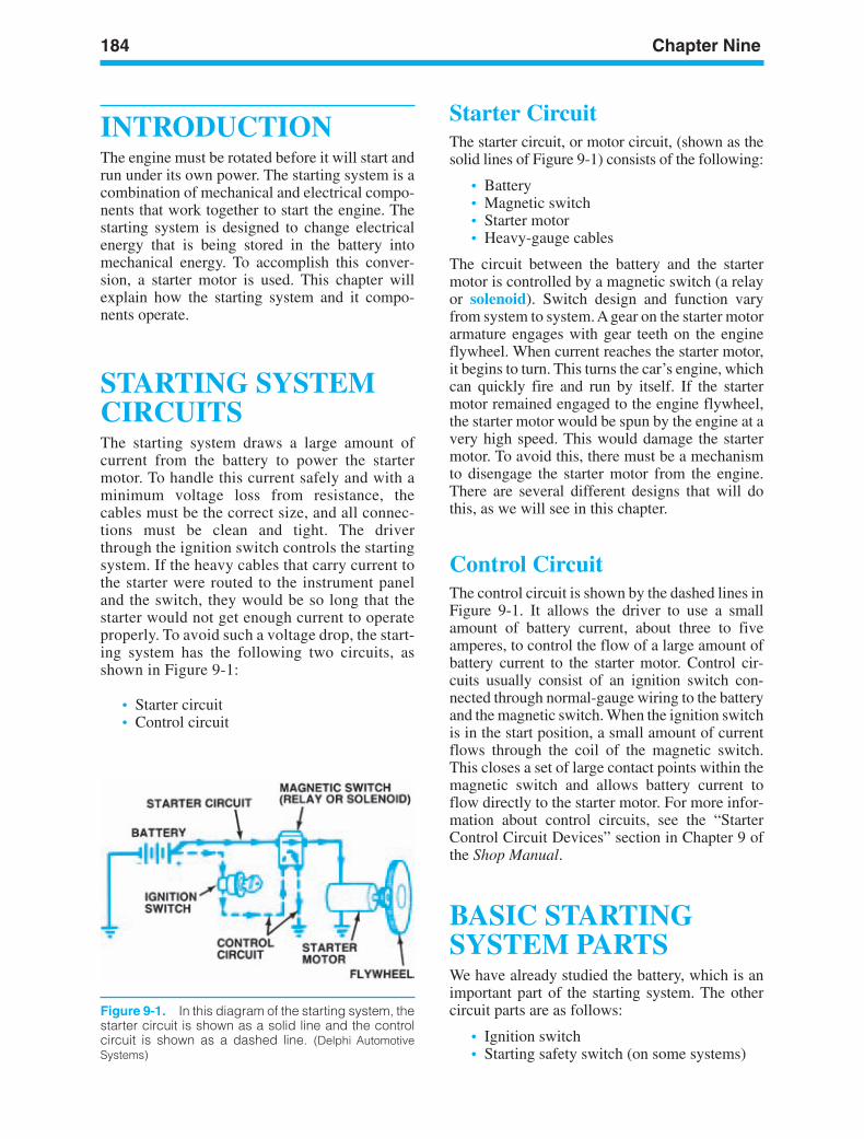
184 Chapter Nine
Figure 9-1. In this diagram of the starting system, thestarter circuit is shown as a solid line and the controlcircuit is shown as a dashed line. (Delphi AutomotiveSystems)
INTRODUCTIONThe engine must be rotated before it will start andrun under its own power. The starting system is acombination of mechanical and electrical compo-nents that work together to start the engine. Thestarting system is designed to change electricalenergy that is being stored in the battery intomechanical energy. To accomplish this conver-sion, a starter motor is used. This chapter willexplain how the starting system and it compo-nents operate.
STARTING SYSTEMCIRCUITSThe starting system draws a large amount ofcurrent from the battery to power the startermotor. To handle this current safely and with aminimum voltage loss from resistance, thecables must be the correct size, and all connec-tions must be clean and tight. The driverthrough the ignition switch controls the startingsystem. If the heavy cables that carry current tothe starter were routed to the instrument paneland the switch, they would be so long that thestarter would not get enough current to operateproperly. To avoid such a voltage drop, the start-ing system has the following two circuits, asshown in Figure 9-1:
• Starter circuit• Control circuit
Starter CircuitThe starter circuit, or motor circuit, (shown as thesolid lines of Figure 9-1) consists of the following:
• Battery• Magnetic switch• Starter motor• Heavy-gauge cables
The circuit between the battery and the startermotor is controlled by a magnetic switch (a relayor solenoid). Switch design and function varyfrom system to system. A gear on the starter motorarmature engages with gear teeth on the engineflywheel. When current reaches the starter motor,it begins to turn. This turns the car’s engine, whichcan quickly fire and run by itself. If the startermotor remained engaged to the engine flywheel,the starter motor would be spun by the engine at avery high speed. This would damage the startermotor. To avoid this, there must be a mechanismto disengage the starter motor from the engine.There are several different designs that will dothis, as we will see in this chapter.
Control CircuitThe control circuit is shown by the dashed lines inFigure 9-1. It allows the driver to use a smallamount of battery current, about three to fiveamperes, to control the flow of a large amount ofbattery current to the starter motor. Control cir-cuits usually consist of an ignition switch con-nected through normal-gauge wiring to the batteryand the magnetic switch. When the ignition switchis in the start position, a small amount of currentflows through the coil of the magnetic switch.This closes a set of large contact points within themagnetic switch and allows battery current toflow directly to the starter motor. For more infor-mation about control circuits, see the “StarterControl Circuit Devices” section in Chapter 9 ofthe Shop Manual.
BASIC STARTINGSYSTEM PARTSWe have already studied the battery, which is animportant part of the starting system. The othercircuit parts are as follows:
• Ignition switch• Starting safety switch (on some systems)
ker88839_ch09.qxd 1/9/06 11:29 AM Page 184
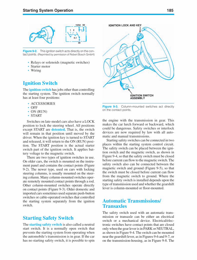
Starting System Operation 185
Figure 9-2. This ignition switch acts directly on the con-tact points. (Reprinted by permission of Robert Bosch GmbH)
Figure 9-3. Column-mounted switches act directlyon the contact points.
• Relays or solenoids (magnetic switches)• Starter motor• Wiring
Ignition SwitchThe ignition switch has jobs other than controllingthe starting system. The ignition switch normallyhas at least four positions:
• ACCESSORIES• OFF• ON (RUN)• START
Switches on late-model cars also have a LOCKposition to lock the steering wheel. All positionsexcept START are detented. That is, the switchwill remain in that position until moved by thedriver. When the ignition key is turned to STARTand released, it will return to the ON (RUN) posi-tion. The START position is the actual starterswitch part of the ignition switch. It applies bat-tery voltage to the magnetic switch.
There are two types of ignition switches in use.On older cars, the switch is mounted on the instru-ment panel and contains the contact points (Figure9-2). The newer type, used on cars with lockingsteering columns, is usually mounted on the steer-ing column. Many column-mounted switches oper-ate remotely mounted contact points through a rod.Other column-mounted switches operate directlyon contact points (Figure 9-3). Older domestic andimported cars sometimes used separate push-buttonswitches or cable-operated switches that controlledthe starting system separately from the ignitionswitch.
Starting Safety SwitchThe starting safety switch is also called a neutralstart switch. It is a normally open switch thatprevents the starting system from operating whenthe automobile’s transmission is in gear. If the carhas no starting safety switch, it is possible to spin
the engine with the transmission in gear. Thismakes the car lurch forward or backward, whichcould be dangerous. Safety switches or interlockdevices are now required by law with all auto-matic and manual transmissions.
Starting safety switches can be connected in twoplaces within the starting system control circuit.The safety switch can be placed between the igni-tion switch and the magnetic switch, as shown inFigure 9-4, so that the safety switch must be closedbefore current can flow to the magnetic switch. Thesafety switch also can be connected between themagnetic switch and ground (Figure 9-5), so thatthe switch must be closed before current can flowfrom the magnetic switch to ground. Where thestarting safety switch is installed depends upon thetype of transmission used and whether the gearshiftlever is column-mounted or floor-mounted.
Automatic Transmissions/TransaxlesThe safety switch used with an automatic trans-mission or transaxle can be either an electricalswitch or a mechanical device. Electrical/elec-tronic switches have contact points that are closedonly when the gear lever is in PARK or NEUTRAL,as shown in Figure 9-4. The switch can be mountednear the gearshift lever, as in Figures 9-6 and 9-7, oron the transmission-housing, as in Figure 9-8. The
ker88839_ch09.qxd 1/9/06 11:29 AM Page 185
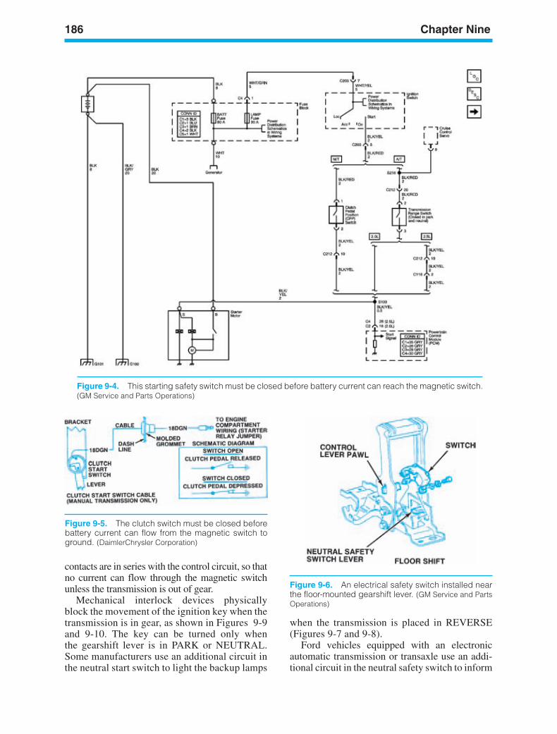
186 Chapter Nine
Figure 9-6. An electrical safety switch installed nearthe floor-mounted gearshift lever. (GM Service and PartsOperations)
Figure 9-4. This starting safety switch must be closed before battery current can reach the magnetic switch.(GM Service and Parts Operations)
Figure 9-5. The clutch switch must be closed beforebattery current can flow from the magnetic switch toground. (DaimlerChrysler Corporation)
contacts are in series with the control circuit, so thatno current can flow through the magnetic switchunless the transmission is out of gear.
Mechanical interlock devices physicallyblock the movement of the ignition key when thetransmission is in gear, as shown in Figures 9-9and 9-10. The key can be turned only whenthe gearshift lever is in PARK or NEUTRAL.Some manufacturers use an additional circuit inthe neutral start switch to light the backup lamps
when the transmission is placed in REVERSE(Figures 9-7 and 9-8).
Ford vehicles equipped with an electronicautomatic transmission or transaxle use an addi-tional circuit in the neutral safety switch to inform
ker88839_ch09.qxd 1/9/06 11:29 AM Page 186
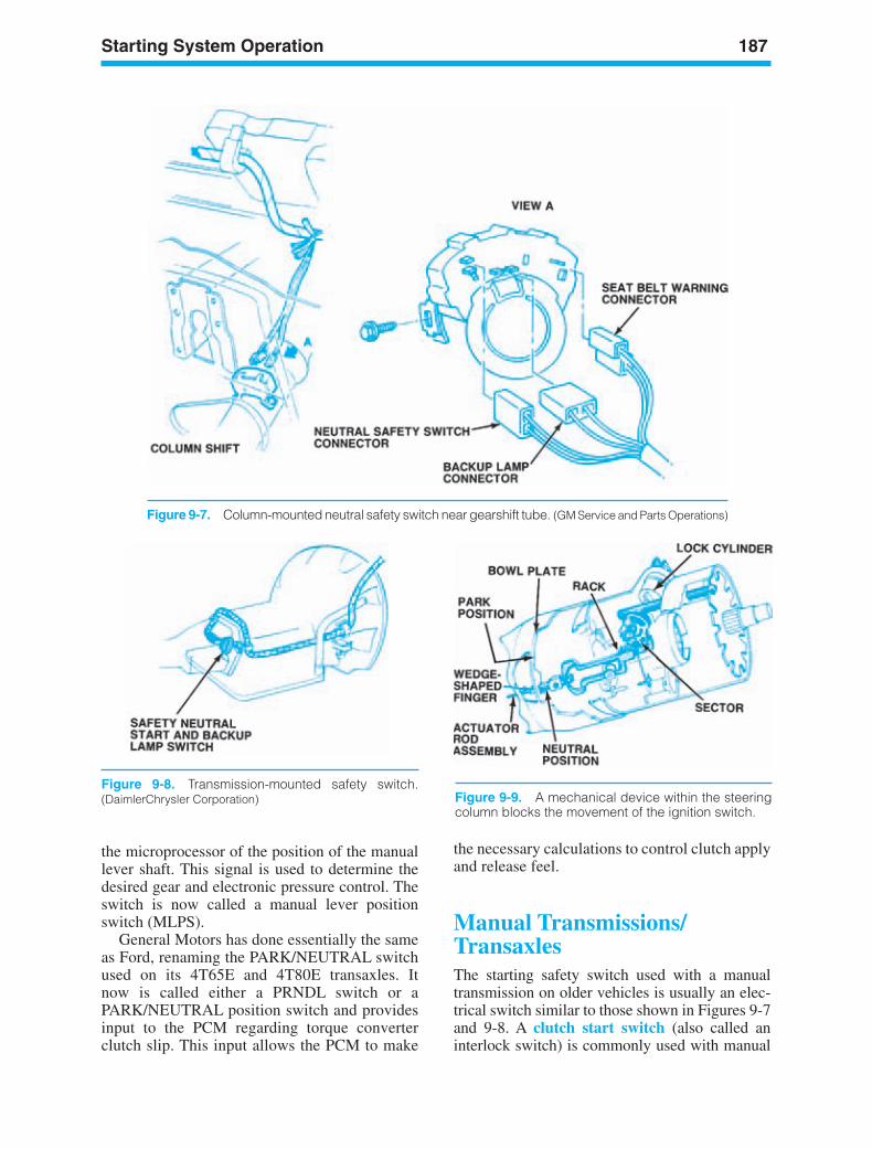
Starting System Operation 187
Figure 9-8. Transmission-mounted safety switch.(DaimlerChrysler Corporation)
Figure 9-7. Column-mounted neutral safety switch near gearshift tube. (GM Service and Parts Operations)
Figure 9-9. A mechanical device within the steeringcolumn blocks the movement of the ignition switch.
the microprocessor of the position of the manuallever shaft. This signal is used to determine thedesired gear and electronic pressure control. Theswitch is now called a manual lever positionswitch (MLPS).
General Motors has done essentially the sameas Ford, renaming the PARK/NEUTRAL switchused on its 4T65E and 4T80E transaxles. Itnow is called either a PRNDL switch or aPARK/NEUTRAL position switch and providesinput to the PCM regarding torque converterclutch slip. This input allows the PCM to make
the necessary calculations to control clutch applyand release feel.
Manual Transmissions/TransaxlesThe starting safety switch used with a manualtransmission on older vehicles is usually an elec-trical switch similar to those shown in Figures 9-7and 9-8. A clutch start switch (also called aninterlock switch) is commonly used with manual
ker88839_ch09.qxd 1/9/06 11:29 AM Page 187
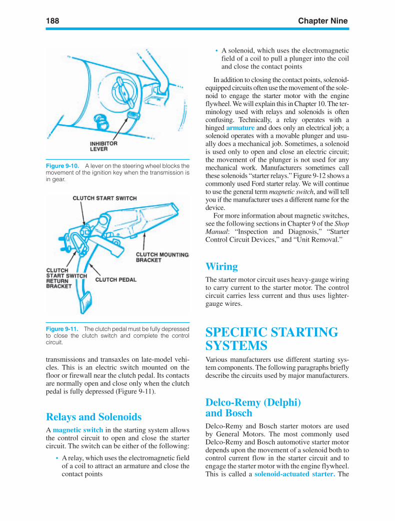
188 Chapter Nine
Figure 9-11. The clutch pedal must be fully depressedto close the clutch switch and complete the control circuit.
transmissions and transaxles on late-model vehi-cles. This is an electric switch mounted on thefloor or firewall near the clutch pedal. Its contactsare normally open and close only when the clutchpedal is fully depressed (Figure 9-11).
Relays and SolenoidsA magnetic switch in the starting system allowsthe control circuit to open and close the startercircuit. The switch can be either of the following:
• A relay, which uses the electromagnetic fieldof a coil to attract an armature and close thecontact points
• A solenoid, which uses the electromagneticfield of a coil to pull a plunger into the coiland close the contact points
In addition to closing the contact points, solenoid-equipped circuits often use the movement of the sole-noid to engage the starter motor with the engineflywheel. We will explain this in Chapter 10. The ter-minology used with relays and solenoids is oftenconfusing. Technically, a relay operates with ahinged armature and does only an electrical job; asolenoid operates with a movable plunger and usu-ally does a mechanical job. Sometimes, a solenoidis used only to open and close an electric circuit;the movement of the plunger is not used for anymechanical work. Manufacturers sometimes callthese solenoids “starter relays.” Figure 9-12 shows acommonly used Ford starter relay. We will continueto use the general term magnetic switch, and will tellyou if the manufacturer uses a different name for thedevice.
For more information about magnetic switches,see the following sections in Chapter 9 of the ShopManual: “Inspection and Diagnosis,” “StarterControl Circuit Devices,” and “Unit Removal.”
WiringThe starter motor circuit uses heavy-gauge wiringto carry current to the starter motor. The controlcircuit carries less current and thus uses lighter-gauge wires.
SPECIFIC STARTINGSYSTEMSVarious manufacturers use different starting sys-tem components. The following paragraphs brieflydescribe the circuits used by major manufacturers.
Delco-Remy (Delphi)and BoschDelco-Remy and Bosch starter motors are usedby General Motors. The most commonly usedDelco-Remy and Bosch automotive starter motordepends upon the movement of a solenoid both tocontrol current flow in the starter circuit and toengage the starter motor with the engine flywheel.This is called a solenoid-actuated starter. The
Figure 9-10. A lever on the steering wheel blocks themovement of the ignition key when the transmission isin gear.
ker88839_ch09.qxd 1/9/06 11:29 AM Page 188
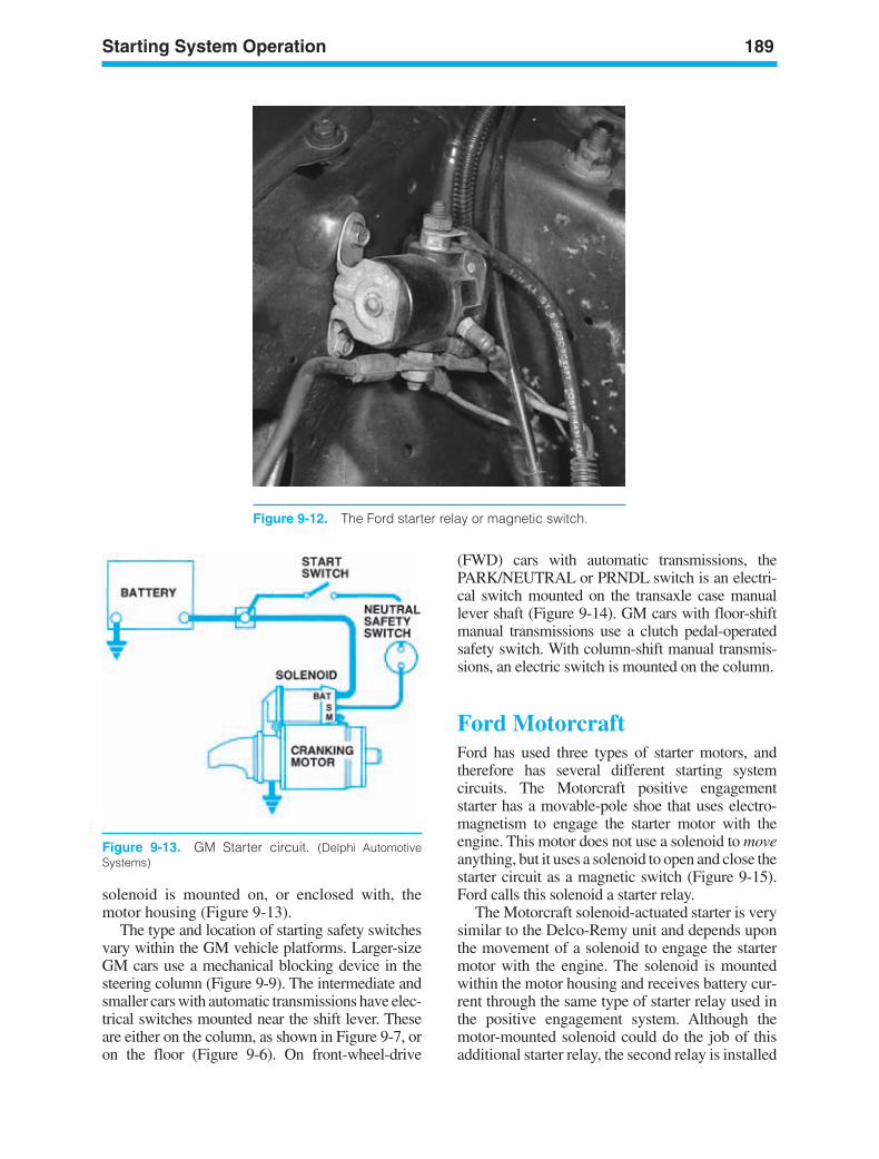
Starting System Operation 189
Figure 9-12. The Ford starter relay or magnetic switch.
Figure 9-13. GM Starter circuit. (Delphi AutomotiveSystems)
solenoid is mounted on, or enclosed with, themotor housing (Figure 9-13).
The type and location of starting safety switchesvary within the GM vehicle platforms. Larger-sizeGM cars use a mechanical blocking device in thesteering column (Figure 9-9). The intermediate andsmaller cars with automatic transmissions have elec-trical switches mounted near the shift lever. Theseare either on the column, as shown in Figure 9-7, oron the floor (Figure 9-6). On front-wheel-drive
(FWD) cars with automatic transmissions, thePARK/NEUTRAL or PRNDL switch is an electri-cal switch mounted on the transaxle case manuallever shaft (Figure 9-14). GM cars with floor-shiftmanual transmissions use a clutch pedal-operatedsafety switch. With column-shift manual transmis-sions, an electric switch is mounted on the column.
Ford MotorcraftFord has used three types of starter motors, andtherefore has several different starting systemcircuits. The Motorcraft positive engagementstarter has a movable-pole shoe that uses electro-magnetism to engage the starter motor with theengine. This motor does not use a solenoid to moveanything, but it uses a solenoid to open and close thestarter circuit as a magnetic switch (Figure 9-15).Ford calls this solenoid a starter relay.
The Motorcraft solenoid-actuated starter is verysimilar to the Delco-Remy unit and depends uponthe movement of a solenoid to engage the startermotor with the engine. The solenoid is mountedwithin the motor housing and receives battery cur-rent through the same type of starter relay used inthe positive engagement system. Although themotor-mounted solenoid could do the job of thisadditional starter relay, the second relay is installed
ker88839_ch09.qxd 1/9/06 11:29 AM Page 189
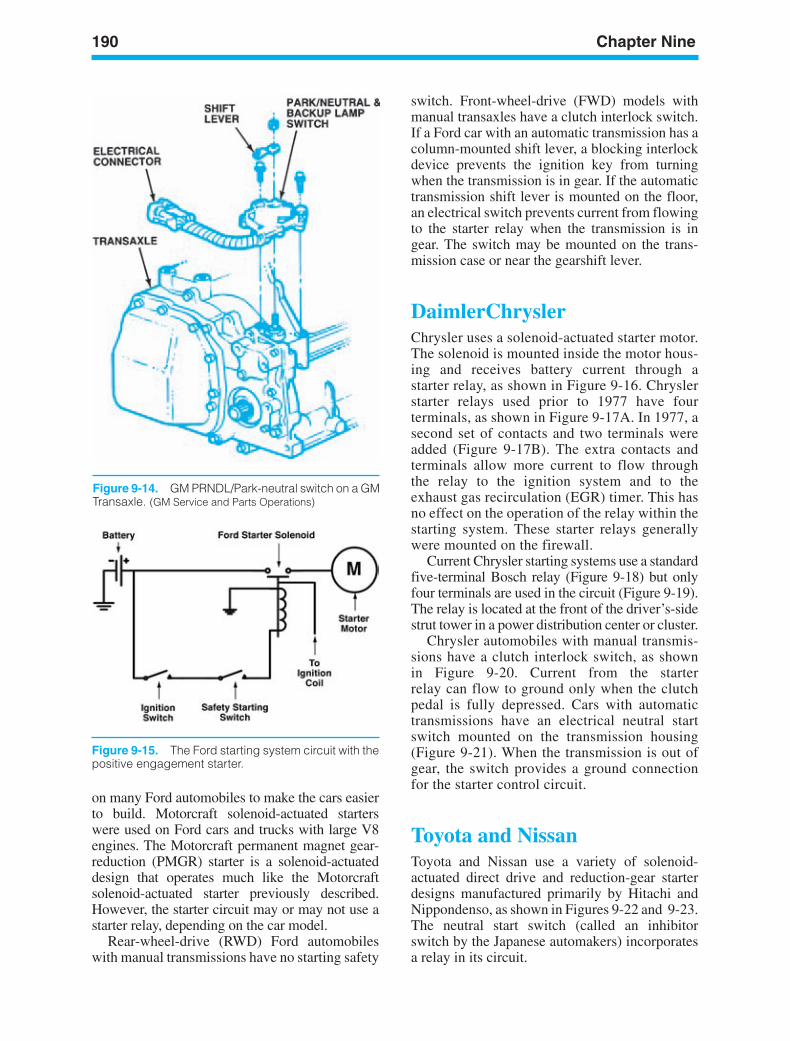
190 Chapter Nine
Figure 9-14. GM PRNDL/Park-neutral switch on a GMTransaxle. (GM Service and Parts Operations)
Figure 9-15. The Ford starting system circuit with thepositive engagement starter.
on many Ford automobiles to make the cars easierto build. Motorcraft solenoid-actuated starterswere used on Ford cars and trucks with large V8engines. The Motorcraft permanent magnet gear-reduction (PMGR) starter is a solenoid-actuateddesign that operates much like the Motorcraftsolenoid-actuated starter previously described.However, the starter circuit may or may not use astarter relay, depending on the car model.
Rear-wheel-drive (RWD) Ford automobileswith manual transmissions have no starting safety
switch. Front-wheel-drive (FWD) models withmanual transaxles have a clutch interlock switch.If a Ford car with an automatic transmission has acolumn-mounted shift lever, a blocking interlockdevice prevents the ignition key from turningwhen the transmission is in gear. If the automatictransmission shift lever is mounted on the floor,an electrical switch prevents current from flowingto the starter relay when the transmission is ingear. The switch may be mounted on the trans-mission case or near the gearshift lever.
DaimlerChryslerChrysler uses a solenoid-actuated starter motor.The solenoid is mounted inside the motor hous-ing and receives battery current through astarter relay, as shown in Figure 9-16. Chryslerstarter relays used prior to 1977 have fourterminals, as shown in Figure 9-17A. In 1977, asecond set of contacts and two terminals wereadded (Figure 9-17B). The extra contacts andterminals allow more current to flow throughthe relay to the ignition system and to theexhaust gas recirculation (EGR) timer. This hasno effect on the operation of the relay within thestarting system. These starter relays generallywere mounted on the firewall.
Current Chrysler starting systems use a standardfive-terminal Bosch relay (Figure 9-18) but onlyfour terminals are used in the circuit (Figure 9-19).The relay is located at the front of the driver’s-sidestrut tower in a power distribution center or cluster.
Chrysler automobiles with manual transmis-sions have a clutch interlock switch, as shownin Figure 9-20. Current from the starterrelay can flow to ground only when the clutchpedal is fully depressed. Cars with automatictransmissions have an electrical neutral startswitch mounted on the transmission housing(Figure 9-21). When the transmission is out ofgear, the switch provides a ground connectionfor the starter control circuit.
Toyota and NissanToyota and Nissan use a variety of solenoid-actuated direct drive and reduction-gear starterdesigns manufactured primarily by Hitachi andNippondenso, as shown in Figures 9-22 and 9-23.The neutral start switch (called an inhibitorswitch by the Japanese automakers) incorporatesa relay in its circuit.
ker88839_ch09.qxd 1/9/06 11:29 AM Page 190
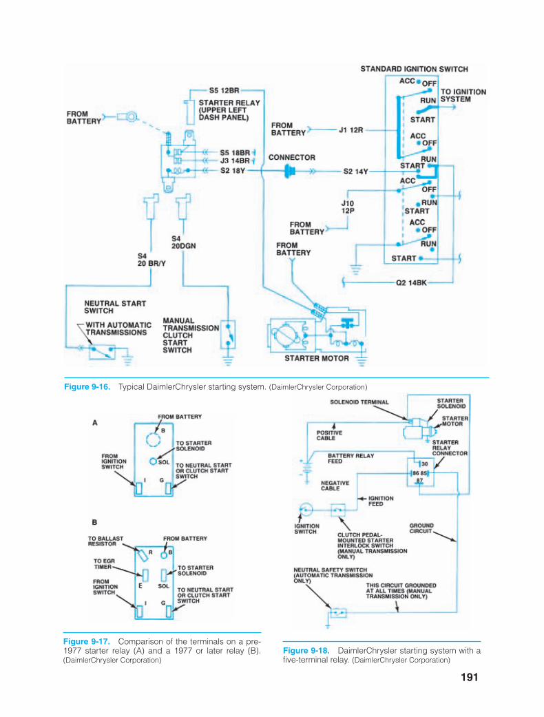
191
Figure 9-17. Comparison of the terminals on a pre-1977 starter relay (A) and a 1977 or later relay (B).(DaimlerChrysler Corporation)
Figure 9-18. DaimlerChrysler starting system with afive-terminal relay. (DaimlerChrysler Corporation)
Figure 9-16. Typical DaimlerChrysler starting system. (DaimlerChrysler Corporation)
ker88839_ch09.qxd 1/9/06 11:29 AM Page 191
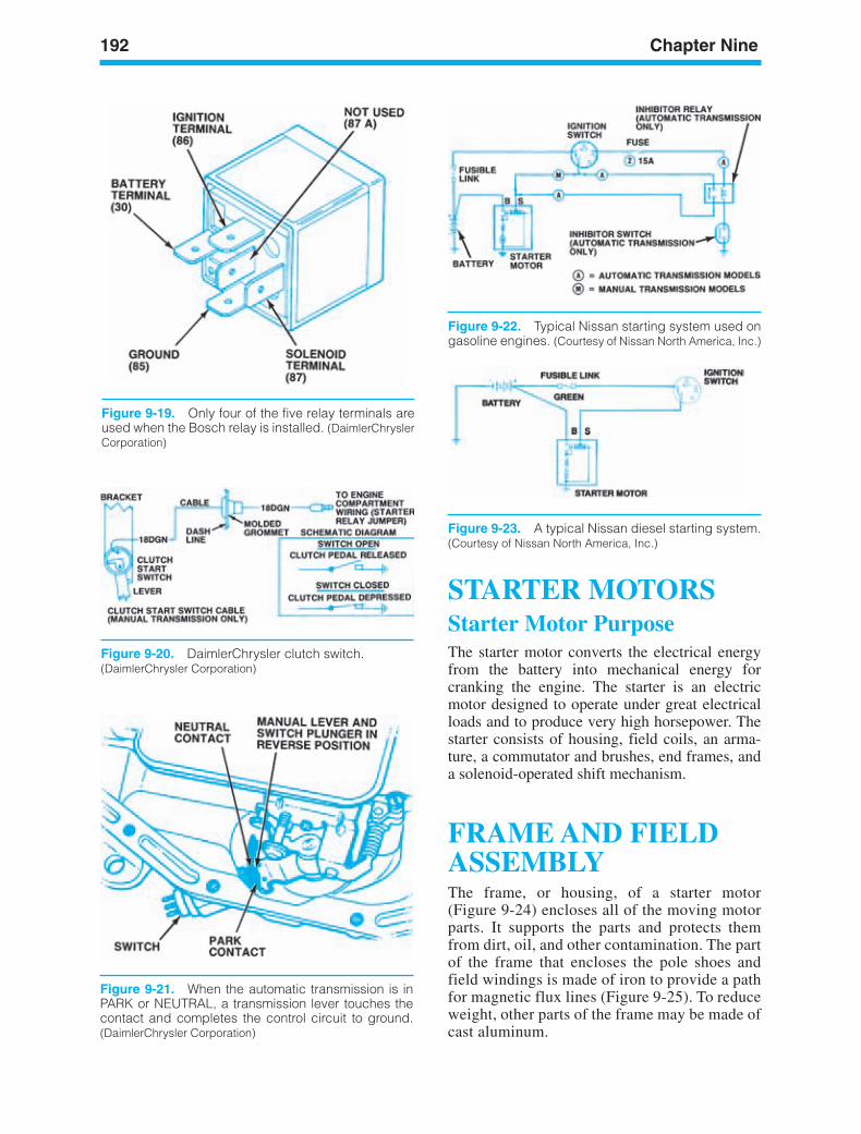
192 Chapter Nine
Figure 9-19. Only four of the five relay terminals areused when the Bosch relay is installed. (DaimlerChryslerCorporation)
Figure 9-23. A typical Nissan diesel starting system.(Courtesy of Nissan North America, Inc.)
Figure 9-20. DaimlerChrysler clutch switch.(DaimlerChrysler Corporation)
Figure 9-21. When the automatic transmission is inPARK or NEUTRAL, a transmission lever touches thecontact and completes the control circuit to ground.(DaimlerChrysler Corporation)
STARTER MOTORSStarter Motor PurposeThe starter motor converts the electrical energyfrom the battery into mechanical energy forcranking the engine. The starter is an electricmotor designed to operate under great electricalloads and to produce very high horsepower. Thestarter consists of housing, field coils, an arma-ture, a commutator and brushes, end frames, anda solenoid-operated shift mechanism.
FRAME AND FIELDASSEMBLYThe frame, or housing, of a starter motor(Figure 9-24) encloses all of the moving motorparts. It supports the parts and protects themfrom dirt, oil, and other contamination. The partof the frame that encloses the pole shoes andfield windings is made of iron to provide a pathfor magnetic flux lines (Figure 9-25). To reduceweight, other parts of the frame may be made ofcast aluminum.
Figure 9-22. Typical Nissan starting system used ongasoline engines. (Courtesy of Nissan North America, Inc.)
ker88839_ch09.qxd 1/9/06 11:29 AM Page 192
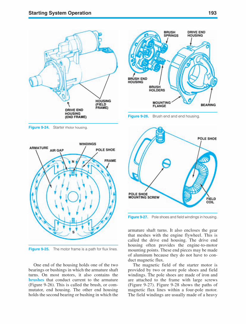
Starting System Operation 193
Figure 9-25. The motor frame is a path for flux lines.
Figure 9-24. Starter motor housing.
Figure 9-26. Brush end and end housing.
armature shaft turns. It also encloses the gearthat meshes with the engine flywheel. This iscalled the drive end housing. The drive endhousing often provides the engine-to-motormounting points. These end pieces may be madeof aluminum because they do not have to con-duct magnetic flux.
The magnetic field of the starter motor isprovided by two or more pole shoes and fieldwindings. The pole shoes are made of iron andare attached to the frame with large screws(Figure 9-27). Figure 9-28 shows the paths ofmagnetic flux lines within a four-pole motor.The field windings are usually made of a heavy
One end of the housing holds one of the twobearings or bushings in which the armature shaftturns. On most motors, it also contains thebrushes that conduct current to the armature(Figure 9-26). This is called the brush, or com-mutator, end housing. The other end housingholds the second bearing or bushing in which the
Figure 9-27. Pole shoes and field windings in housing.
ker88839_ch09.qxd 1/9/06 11:29 AM Page 193
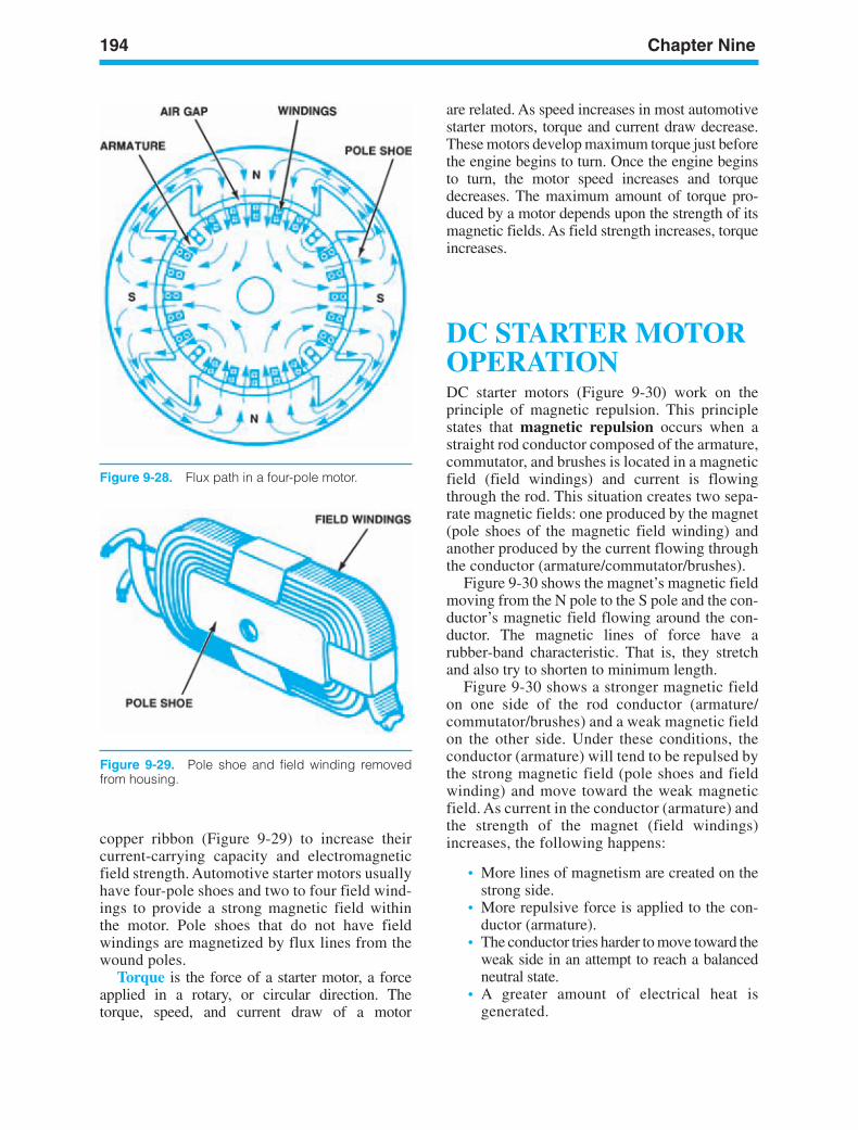
194 Chapter Nine
Figure 9-28. Flux path in a four-pole motor.
Figure 9-29. Pole shoe and field winding removedfrom housing.
copper ribbon (Figure 9-29) to increase theircurrent-carrying capacity and electromagneticfield strength. Automotive starter motors usuallyhave four-pole shoes and two to four field wind-ings to provide a strong magnetic field withinthe motor. Pole shoes that do not have fieldwindings are magnetized by flux lines from thewound poles.
Torque is the force of a starter motor, a forceapplied in a rotary, or circular direction. Thetorque, speed, and current draw of a motor
are related. As speed increases in most automotivestarter motors, torque and current draw decrease.These motors develop maximum torque just beforethe engine begins to turn. Once the engine beginsto turn, the motor speed increases and torquedecreases. The maximum amount of torque pro-duced by a motor depends upon the strength of itsmagnetic fields. As field strength increases, torqueincreases.
DC STARTER MOTOROPERATIONDC starter motors (Figure 9-30) work on theprinciple of magnetic repulsion. This principlestates that magnetic repulsion occurs when astraight rod conductor composed of the armature,commutator, and brushes is located in a magneticfield (field windings) and current is flowingthrough the rod. This situation creates two sepa-rate magnetic fields: one produced by the magnet(pole shoes of the magnetic field winding) andanother produced by the current flowing throughthe conductor (armature/commutator/brushes).
Figure 9-30 shows the magnet’s magnetic fieldmoving from the N pole to the S pole and the con-ductor’s magnetic field flowing around the con-ductor. The magnetic lines of force have arubber-band characteristic. That is, they stretchand also try to shorten to minimum length.
Figure 9-30 shows a stronger magnetic fieldon one side of the rod conductor (armature/commutator/brushes) and a weak magnetic fieldon the other side. Under these conditions, theconductor (armature) will tend to be repulsed bythe strong magnetic field (pole shoes and fieldwinding) and move toward the weak magneticfield. As current in the conductor (armature) andthe strength of the magnet (field windings)increases, the following happens:
• More lines of magnetism are created on thestrong side.
• More repulsive force is applied to the con-ductor (armature).
• The conductor tries harder to move toward theweak side in an attempt to reach a balancedneutral state.
• A greater amount of electrical heat isgenerated.
ker88839_ch09.qxd 1/9/06 11:29 AM Page 194
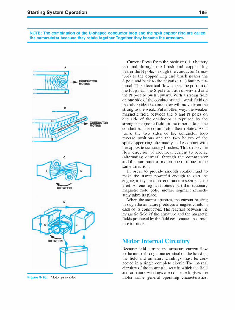
Starting System Operation 195
Figure 9-30. Motor principle.
NOTE: The combination of the U-shaped conductor loop and the split copper ring are calledthe commutator because they rotate together.Together they become the armature.
Current flows from the positive ( ) batteryterminal through the brush and copper ringnearer the N pole, through the conductor (arma-ture) to the copper ring and brush nearer theS pole and back to the negative () battery ter-minal. This electrical flow causes the portion ofthe loop near the S pole to push downward andthe N pole to push upward. With a strong fieldon one side of the conductor and a weak field onthe other side, the conductor will move from thestrong to the weak. Put another way, the weakermagnetic field between the S and N poles onone side of the conductor is repulsed by thestronger magnetic field on the other side of theconductor. The commutator then rotates. As itturns, the two sides of the conductor loopreverse positions and the two halves of thesplit copper ring alternately make contact withthe opposite stationary brushes. This causes theflow direction of electrical current to reverse(alternating current) through the commutatorand the commutator to continue to rotate in thesame direction.
In order to provide smooth rotation and tomake the starter powerful enough to start theengine, many armature commutator segments areused. As one segment rotates past the stationarymagnetic field pole, another segment immedi-ately takes its place.
When the starter operates, the current passingthrough the armature produces a magnetic field ineach of its conductors. The reaction between themagnetic field of the armature and the magneticfields produced by the field coils causes the arma-ture to rotate.
Motor Internal CircuitryBecause field current and armature current flowto the motor through one terminal on the housing,the field and armature windings must be con-nected in a single complete circuit. The internalcircuitry of the motor (the way in which the fieldand armature windings are connected) gives themotor some general operating characteristics.
ker88839_ch09.qxd 1/9/06 11:29 AM Page 195
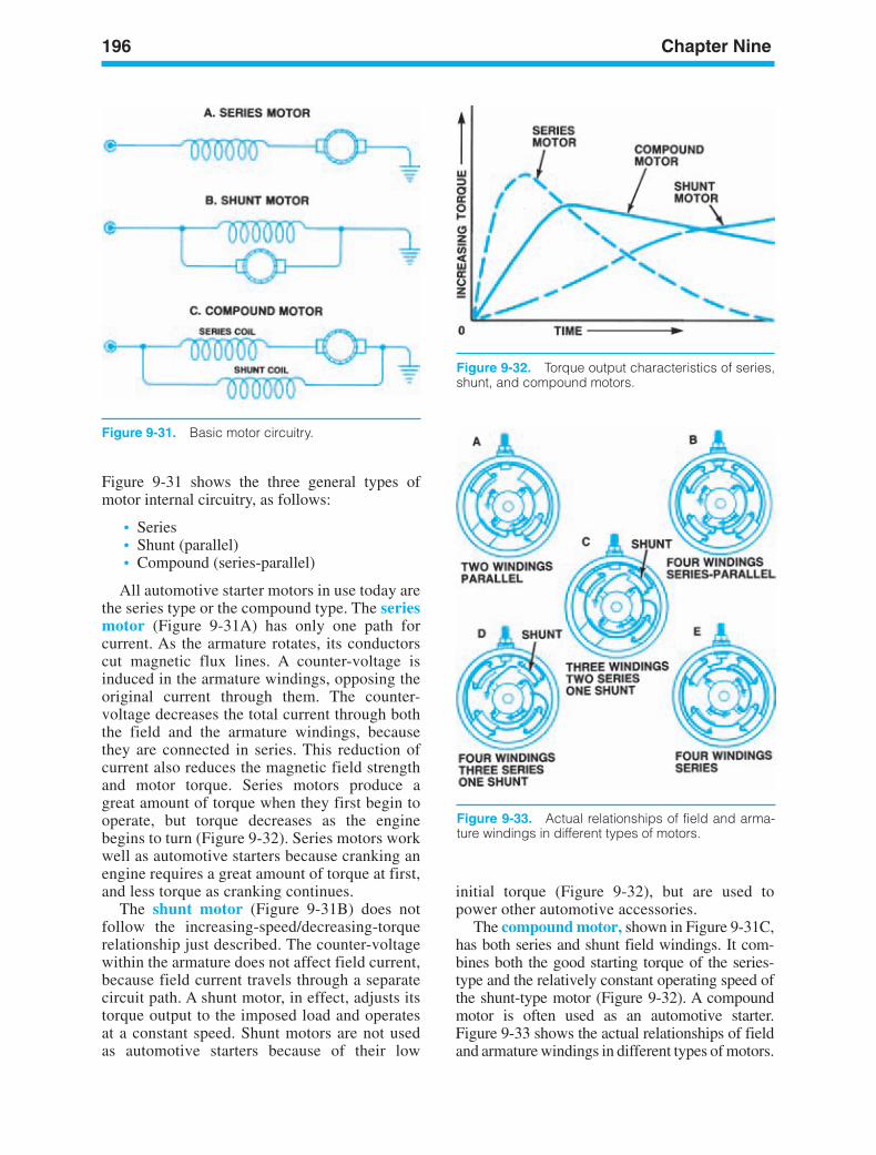
196 Chapter Nine
Figure 9-31. Basic motor circuitry.
Figure 9-32. Torque output characteristics of series,shunt, and compound motors.
initial torque (Figure 9-32), but are used topower other automotive accessories.
The compound motor, shown in Figure 9-31C,has both series and shunt field windings. It com-bines both the good starting torque of the series-type and the relatively constant operating speed ofthe shunt-type motor (Figure 9-32). A compoundmotor is often used as an automotive starter.Figure 9-33 shows the actual relationships of fieldand armature windings in different types of motors.
Figure 9-33. Actual relationships of field and arma-ture windings in different types of motors.
Figure 9-31 shows the three general types ofmotor internal circuitry, as follows:
• Series• Shunt (parallel)• Compound (series-parallel)
All automotive starter motors in use today arethe series type or the compound type. The seriesmotor (Figure 9-31A) has only one path forcurrent. As the armature rotates, its conductorscut magnetic flux lines. A counter-voltage isinduced in the armature windings, opposing theoriginal current through them. The counter-voltage decreases the total current through boththe field and the armature windings, becausethey are connected in series. This reduction ofcurrent also reduces the magnetic field strengthand motor torque. Series motors produce agreat amount of torque when they first begin tooperate, but torque decreases as the enginebegins to turn (Figure 9-32). Series motors workwell as automotive starters because cranking anengine requires a great amount of torque at first,and less torque as cranking continues.
The shunt motor (Figure 9-31B) does notfollow the increasing-speed/decreasing-torquerelationship just described. The counter-voltagewithin the armature does not affect field current,because field current travels through a separatecircuit path. A shunt motor, in effect, adjusts itstorque output to the imposed load and operatesat a constant speed. Shunt motors are not usedas automotive starters because of their low
ker88839_ch09.qxd 1/9/06 11:29 AM Page 196
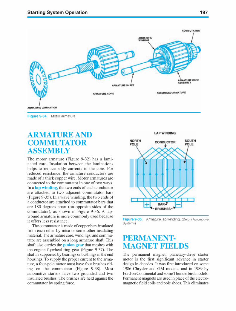
Starting System Operation 197
Figure 9-34. Motor armature.
ARMATURE ANDCOMMUTATORASSEMBLYThe motor armature (Figure 9-32) has a lami-nated core. Insulation between the laminationshelps to reduce eddy currents in the core. Forreduced resistance, the armature conductors aremade of a thick copper wire. Motor armatures areconnected to the commutator in one of two ways.In a lap winding, the two ends of each conductorare attached to two adjacent commutator bars(Figure 9-35). In a wave winding, the two ends ofa conductor are attached to commutator bars thatare 180 degrees apart (on opposite sides of thecommutator), as shown in Figure 9-36. A lap-wound armature is more commonly used becauseit offers less resistance.
The commutator is made of copper bars insulatedfrom each other by mica or some other insulatingmaterial. The armature core, windings, and commu-tator are assembled on a long armature shaft. Thisshaft also carries the pinion gear that meshes withthe engine flywheel ring gear (Figure 9-37). Theshaft is supported by bearings or bushings in the endhousings. To supply the proper current to the arma-ture, a four-pole motor must have four brushes rid-ing on the commutator (Figure 9-38). Mostautomotive starters have two grounded and twoinsulated brushes. The brushes are held against thecommutator by spring force.
PERMANENT-MAGNET FIELDSThe permanent magnet, planetary-drive startermotor is the first significant advance in starterdesign in decades. It was first introduced on some1986 Chrysler and GM models, and in 1989 byFord on Continental and some Thunderbird models.Permanent magnets are used in place of the electro-magnetic field coils and pole shoes. This eliminates
Figure 9-35. Armature lap winding. (Delphi AutomotiveSystems)
ker88839_ch09.qxd 1/9/06 11:29 AM Page 197
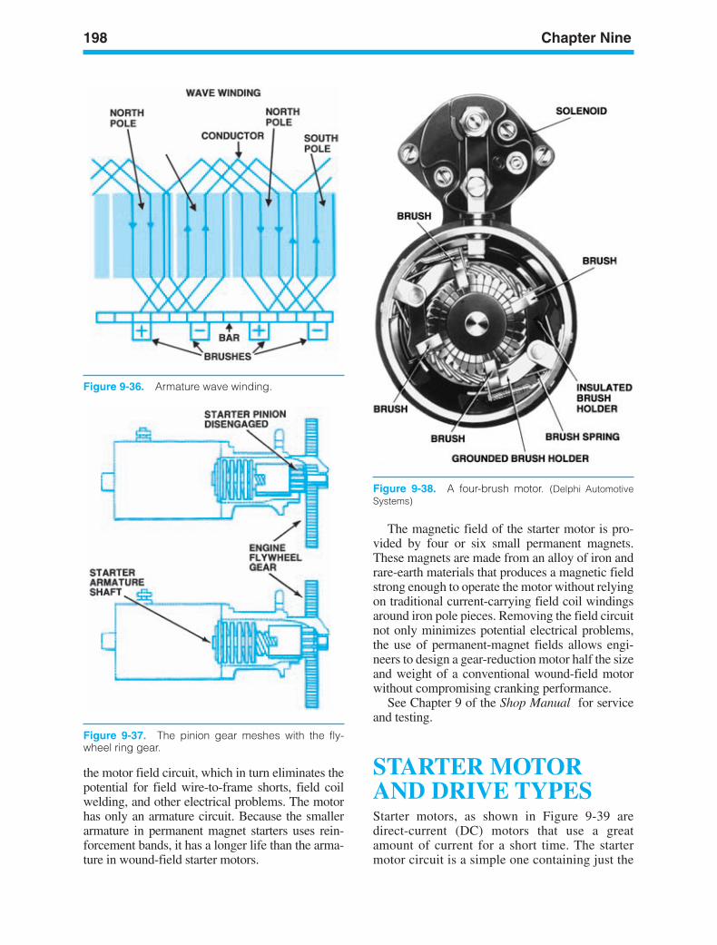
198 Chapter Nine
Figure 9-36. Armature wave winding.
Figure 9-37. The pinion gear meshes with the fly-wheel ring gear.
Figure 9-38. A four-brush motor. (Delphi AutomotiveSystems)
the motor field circuit, which in turn eliminates thepotential for field wire-to-frame shorts, field coilwelding, and other electrical problems. The motorhas only an armature circuit. Because the smallerarmature in permanent magnet starters uses rein-forcement bands, it has a longer life than the arma-ture in wound-field starter motors.
The magnetic field of the starter motor is pro-vided by four or six small permanent magnets.These magnets are made from an alloy of iron andrare-earth materials that produces a magnetic fieldstrong enough to operate the motor without relyingon traditional current-carrying field coil windingsaround iron pole pieces. Removing the field circuitnot only minimizes potential electrical problems,the use of permanent-magnet fields allows engi-neers to design a gear-reduction motor half the sizeand weight of a conventional wound-field motorwithout compromising cranking performance.
See Chapter 9 of the Shop Manual for serviceand testing.
STARTER MOTORAND DRIVE TYPESStarter motors, as shown in Figure 9-39 aredirect-current (DC) motors that use a greatamount of current for a short time. The startermotor circuit is a simple one containing just the
ker88839_ch09.qxd 1/9/06 11:30 AM Page 198
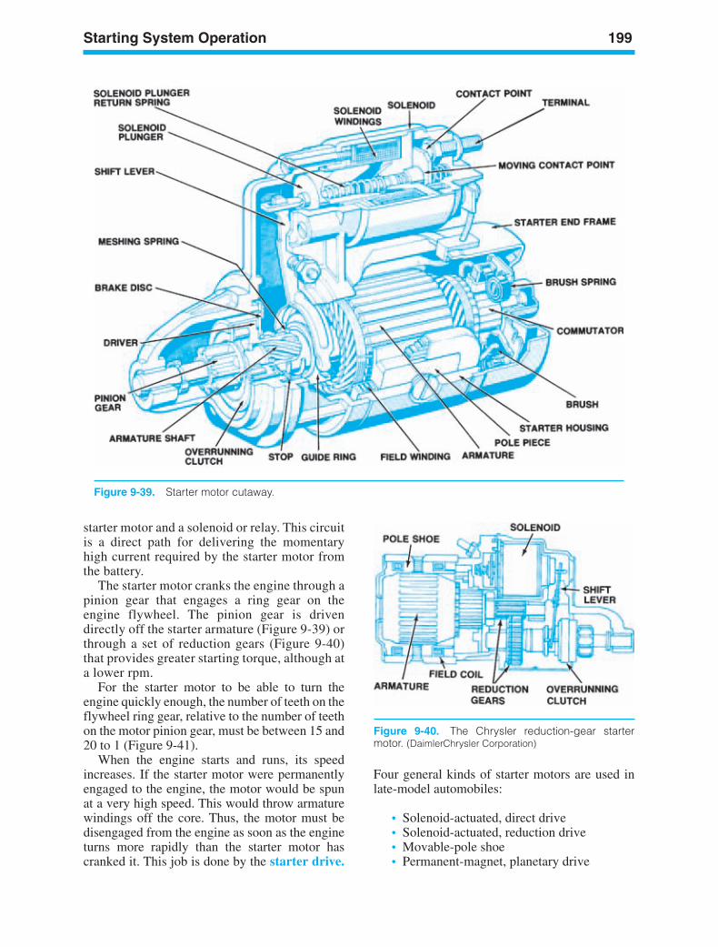
Starting System Operation 199
Figure 9-40. The Chrysler reduction-gear startermotor. (DaimlerChrysler Corporation)
starter motor and a solenoid or relay. This circuitis a direct path for delivering the momentaryhigh current required by the starter motor fromthe battery.
The starter motor cranks the engine through apinion gear that engages a ring gear on theengine flywheel. The pinion gear is drivendirectly off the starter armature (Figure 9-39) orthrough a set of reduction gears (Figure 9-40)that provides greater starting torque, although ata lower rpm.
For the starter motor to be able to turn theengine quickly enough, the number of teeth on theflywheel ring gear, relative to the number of teethon the motor pinion gear, must be between 15 and20 to 1 (Figure 9-41).
When the engine starts and runs, its speedincreases. If the starter motor were permanentlyengaged to the engine, the motor would be spunat a very high speed. This would throw armaturewindings off the core. Thus, the motor must bedisengaged from the engine as soon as the engineturns more rapidly than the starter motor hascranked it. This job is done by the starter drive.
Four general kinds of starter motors are used inlate-model automobiles:
• Solenoid-actuated, direct drive• Solenoid-actuated, reduction drive• Movable-pole shoe• Permanent-magnet, planetary drive
Figure 9-39. Starter motor cutaway.
ker88839_ch09.qxd 1/9/06 11:30 AM Page 199
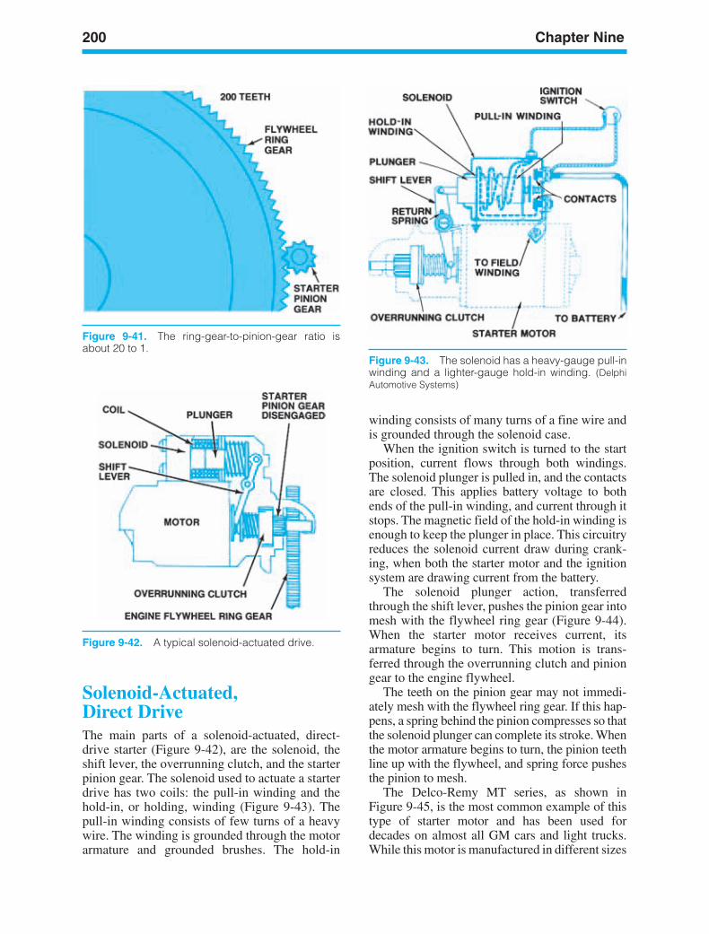
200 Chapter Nine
Figure 9-43. The solenoid has a heavy-gauge pull-inwinding and a lighter-gauge hold-in winding. (DelphiAutomotive Systems)
Solenoid-Actuated,Direct DriveThe main parts of a solenoid-actuated, direct-drive starter (Figure 9-42), are the solenoid, theshift lever, the overrunning clutch, and the starterpinion gear. The solenoid used to actuate a starterdrive has two coils: the pull-in winding and thehold-in, or holding, winding (Figure 9-43). Thepull-in winding consists of few turns of a heavywire. The winding is grounded through the motorarmature and grounded brushes. The hold-in
winding consists of many turns of a fine wire andis grounded through the solenoid case.
When the ignition switch is turned to the startposition, current flows through both windings.The solenoid plunger is pulled in, and the contactsare closed. This applies battery voltage to bothends of the pull-in winding, and current through itstops. The magnetic field of the hold-in winding isenough to keep the plunger in place. This circuitryreduces the solenoid current draw during crank-ing, when both the starter motor and the ignitionsystem are drawing current from the battery.
The solenoid plunger action, transferredthrough the shift lever, pushes the pinion gear intomesh with the flywheel ring gear (Figure 9-44).When the starter motor receives current, itsarmature begins to turn. This motion is trans-ferred through the overrunning clutch and piniongear to the engine flywheel.
The teeth on the pinion gear may not immedi-ately mesh with the flywheel ring gear. If this hap-pens, a spring behind the pinion compresses so thatthe solenoid plunger can complete its stroke. Whenthe motor armature begins to turn, the pinion teethline up with the flywheel, and spring force pushesthe pinion to mesh.
The Delco-Remy MT series, as shown inFigure 9-45, is the most common example of thistype of starter motor and has been used fordecades on almost all GM cars and light trucks.While this motor is manufactured in different sizes
Figure 9-41. The ring-gear-to-pinion-gear ratio isabout 20 to 1.
Figure 9-42. A typical solenoid-actuated drive.
ker88839_ch09.qxd 1/9/06 11:30 AM Page 200
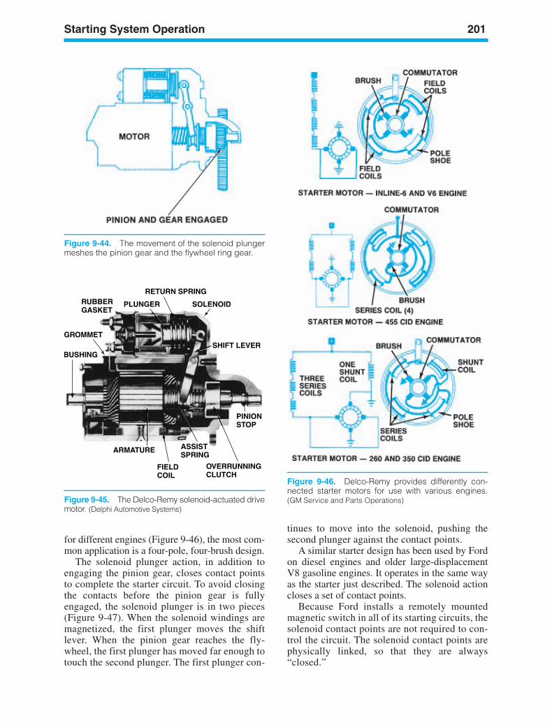
Starting System Operation 201
Figure 9-44. The movement of the solenoid plungermeshes the pinion gear and the flywheel ring gear.
RETURN SPRING
PLUNGERRUBBERGASKET
GROMMET
BUSHING
SOLENOID
SHIFT LEVER
PINIONSTOP
OVERRUNNINGCLUTCH
ASSISTSPRING
FIELDCOIL
ARMATURE
Figure 9-45. The Delco-Remy solenoid-actuated drivemotor. (Delphi Automotive Systems)
Figure 9-46. Delco-Remy provides differently con-nected starter motors for use with various engines.(GM Service and Parts Operations)
for different engines (Figure 9-46), the most com-mon application is a four-pole, four-brush design.
The solenoid plunger action, in addition toengaging the pinion gear, closes contact pointsto complete the starter circuit. To avoid closingthe contacts before the pinion gear is fullyengaged, the solenoid plunger is in two pieces(Figure 9-47). When the solenoid windings aremagnetized, the first plunger moves the shiftlever. When the pinion gear reaches the fly-wheel, the first plunger has moved far enough totouch the second plunger. The first plunger con-
tinues to move into the solenoid, pushing thesecond plunger against the contact points.
A similar starter design has been used by Fordon diesel engines and older large-displacementV8 gasoline engines. It operates in the same wayas the starter just described. The solenoid actioncloses a set of contact points.
Because Ford installs a remotely mountedmagnetic switch in all of its starting circuits, thesolenoid contact points are not required to con-trol the circuit. The solenoid contact points arephysically linked, so that they are always“closed.”
ker88839_ch09.qxd 1/9/06 11:30 AM Page 201
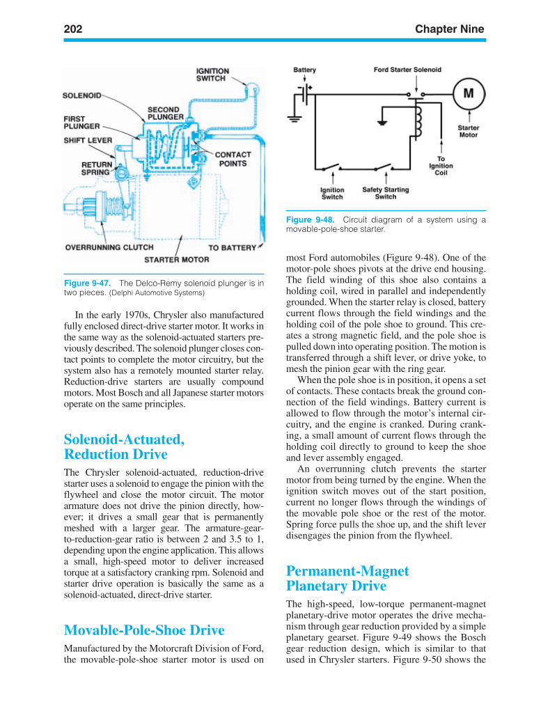
202 Chapter Nine
Figure 9-48. Circuit diagram of a system using amovable-pole-shoe starter.
Figure 9-47. The Delco-Remy solenoid plunger is intwo pieces. (Delphi Automotive Systems)
In the early 1970s, Chrysler also manufacturedfully enclosed direct-drive starter motor. It works inthe same way as the solenoid-actuated starters pre-viously described. The solenoid plunger closes con-tact points to complete the motor circuitry, but thesystem also has a remotely mounted starter relay.Reduction-drive starters are usually compoundmotors. Most Bosch and all Japanese starter motorsoperate on the same principles.
Solenoid-Actuated,Reduction DriveThe Chrysler solenoid-actuated, reduction-drivestarter uses a solenoid to engage the pinion with theflywheel and close the motor circuit. The motorarmature does not drive the pinion directly, how-ever; it drives a small gear that is permanentlymeshed with a larger gear. The armature-gear-to-reduction-gear ratio is between 2 and 3.5 to 1,depending upon the engine application. This allowsa small, high-speed motor to deliver increasedtorque at a satisfactory cranking rpm. Solenoid andstarter drive operation is basically the same as asolenoid-actuated, direct-drive starter.
Movable-Pole-Shoe DriveManufactured by the Motorcraft Division of Ford,the movable-pole-shoe starter motor is used on
most Ford automobiles (Figure 9-48). One of themotor-pole shoes pivots at the drive end housing.The field winding of this shoe also contains aholding coil, wired in parallel and independentlygrounded. When the starter relay is closed, batterycurrent flows through the field windings and theholding coil of the pole shoe to ground. This cre-ates a strong magnetic field, and the pole shoe ispulled down into operating position. The motion istransferred through a shift lever, or drive yoke, tomesh the pinion gear with the ring gear.
When the pole shoe is in position, it opens a setof contacts. These contacts break the ground con-nection of the field windings. Battery current isallowed to flow through the motor’s internal cir-cuitry, and the engine is cranked. During crank-ing, a small amount of current flows through theholding coil directly to ground to keep the shoeand lever assembly engaged.
An overrunning clutch prevents the startermotor from being turned by the engine. When theignition switch moves out of the start position,current no longer flows through the windings ofthe movable pole shoe or the rest of the motor.Spring force pulls the shoe up, and the shift leverdisengages the pinion from the flywheel.
Permanent-MagnetPlanetary DriveThe high-speed, low-torque permanent-magnetplanetary-drive motor operates the drive mecha-nism through gear reduction provided by a simpleplanetary gearset. Figure 9-49 shows the Boschgear reduction design, which is similar to thatused in Chrysler starters. Figure 9-50 shows the
ker88839_ch09.qxd 1/9/06 11:30 AM Page 202
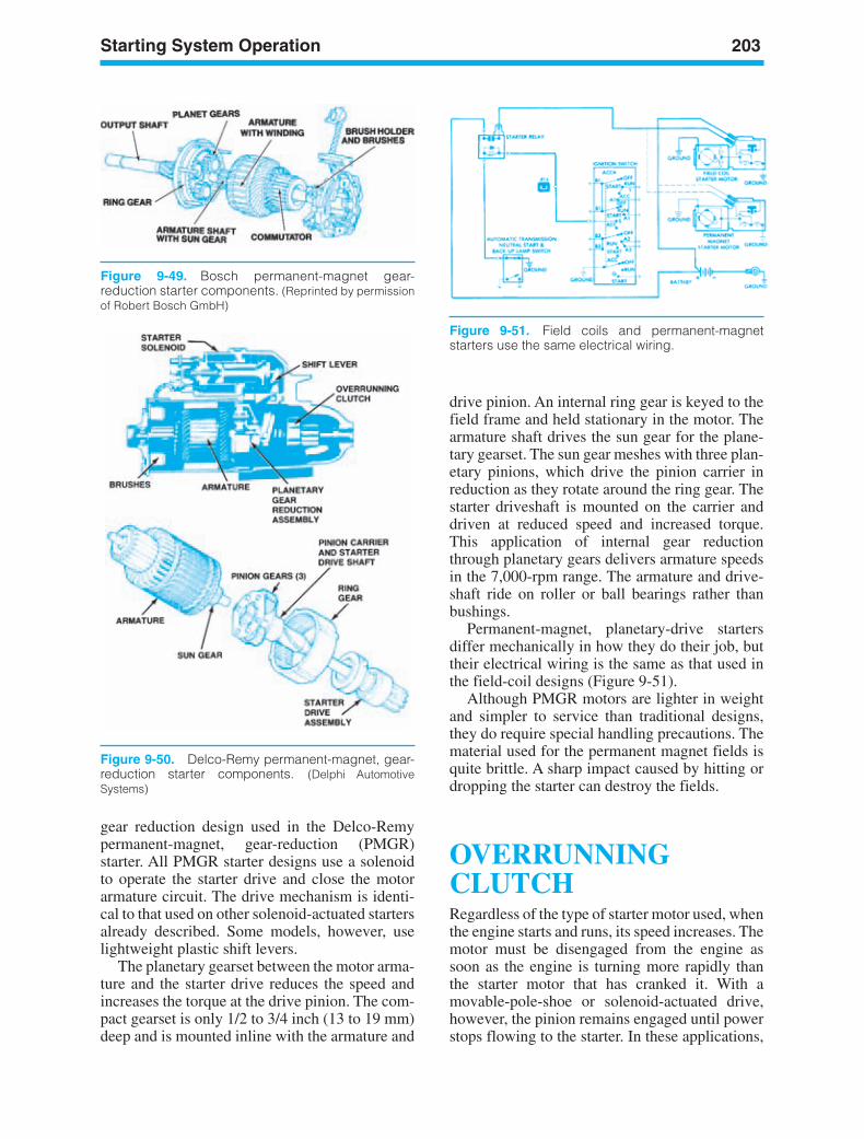
Starting System Operation 203
Figure 9-50. Delco-Remy permanent-magnet, gear-reduction starter components. (Delphi AutomotiveSystems)
Figure 9-49. Bosch permanent-magnet gear-reduction starter components. (Reprinted by permissionof Robert Bosch GmbH)
drive pinion. An internal ring gear is keyed to thefield frame and held stationary in the motor. Thearmature shaft drives the sun gear for the plane-tary gearset. The sun gear meshes with three plan-etary pinions, which drive the pinion carrier inreduction as they rotate around the ring gear. Thestarter driveshaft is mounted on the carrier anddriven at reduced speed and increased torque.This application of internal gear reductionthrough planetary gears delivers armature speedsin the 7,000-rpm range. The armature and drive-shaft ride on roller or ball bearings rather thanbushings.
Permanent-magnet, planetary-drive startersdiffer mechanically in how they do their job, buttheir electrical wiring is the same as that used inthe field-coil designs (Figure 9-51).
Although PMGR motors are lighter in weightand simpler to service than traditional designs,they do require special handling precautions. Thematerial used for the permanent magnet fields isquite brittle. A sharp impact caused by hitting ordropping the starter can destroy the fields.
OVERRUNNINGCLUTCHRegardless of the type of starter motor used, whenthe engine starts and runs, its speed increases. Themotor must be disengaged from the engine assoon as the engine is turning more rapidly thanthe starter motor that has cranked it. With amovable-pole-shoe or solenoid-actuated drive,however, the pinion remains engaged until powerstops flowing to the starter. In these applications,
Figure 9-51. Field coils and permanent-magnetstarters use the same electrical wiring.
gear reduction design used in the Delco-Remypermanent-magnet, gear-reduction (PMGR)starter. All PMGR starter designs use a solenoidto operate the starter drive and close the motorarmature circuit. The drive mechanism is identi-cal to that used on other solenoid-actuated startersalready described. Some models, however, uselightweight plastic shift levers.
The planetary gearset between the motor arma-ture and the starter drive reduces the speed andincreases the torque at the drive pinion. The com-pact gearset is only 1/2 to 3/4 inch (13 to 19 mm)deep and is mounted inline with the armature and
ker88839_ch09.qxd 1/9/06 11:30 AM Page 203
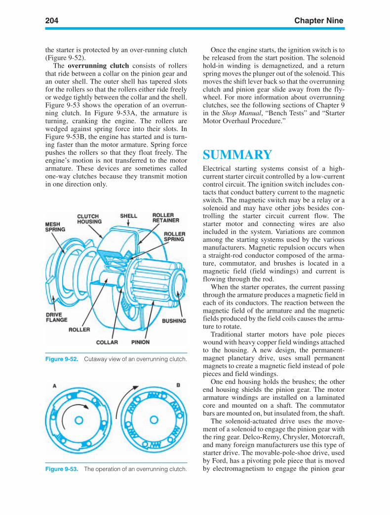
204 Chapter Nine
Figure 9-53. The operation of an overrunning clutch.
Figure 9-52. Cutaway view of an overrunning clutch.
the starter is protected by an over-running clutch(Figure 9-52).
The overrunning clutch consists of rollersthat ride between a collar on the pinion gear andan outer shell. The outer shell has tapered slotsfor the rollers so that the rollers either ride freelyor wedge tightly between the collar and the shell.Figure 9-53 shows the operation of an overrun-ning clutch. In Figure 9-53A, the armature isturning, cranking the engine. The rollers arewedged against spring force into their slots. InFigure 9-53B, the engine has started and is turn-ing faster than the motor armature. Spring forcepushes the rollers so that they float freely. Theengine’s motion is not transferred to the motorarmature. These devices are sometimes calledone-way clutches because they transmit motionin one direction only.
Once the engine starts, the ignition switch is tobe released from the start position. The solenoidhold-in winding is demagnetized, and a returnspring moves the plunger out of the solenoid. Thismoves the shift lever back so that the overrunningclutch and pinion gear slide away from the fly-wheel. For more information about overrunningclutches, see the following sections of Chapter 9in the Shop Manual, “Bench Tests” and “StarterMotor Overhaul Procedure.”
SUMMARYElectrical starting systems consist of a high-current starter circuit controlled by a low-currentcontrol circuit. The ignition switch includes con-tacts that conduct battery current to the magneticswitch. The magnetic switch may be a relay or asolenoid and may have other jobs besides con-trolling the starter circuit current flow. Thestarter motor and connecting wires are alsoincluded in the system. Variations are commonamong the starting systems used by the variousmanufacturers. Magnetic repulsion occurs whena straight-rod conductor composed of the arma-ture, commutator, and brushes is located in amagnetic field (field windings) and current isflowing through the rod.
When the starter operates, the current passingthrough the armature produces a magnetic field ineach of its conductors. The reaction between themagnetic field of the armature and the magneticfields produced by the field coils causes the arma-ture to rotate.
Traditional starter motors have pole pieceswound with heavy copper field windings attachedto the housing. A new design, the permanent-magnet planetary drive, uses small permanentmagnets to create a magnetic field instead of polepieces and field windings.
One end housing holds the brushes; the otherend housing shields the pinion gear. The motorarmature windings are installed on a laminatedcore and mounted on a shaft. The commutatorbars are mounted on, but insulated from, the shaft.
The solenoid-actuated drive uses the move-ment of a solenoid to engage the pinion gear withthe ring gear. Delco-Remy, Chrysler, Motorcraft,and many foreign manufacturers use this type ofstarter drive. The movable-pole-shoe drive, usedby Ford, has a pivoting pole piece that is movedby electromagnetism to engage the pinion gear
ker88839_ch09.qxd 1/9/06 11:30 AM Page 204

Starting System Operation 205
with the ring gear. In the planetary-gear driveused by Chrysler, Ford, and GM, an armature-shaft sun gear meshes with the planetary pinions,which drive the pinion carrier in reduction asthey rotate around the ring gear. The starter
driveshaft is mounted on the carrier and driven atreduced speed and increased torque. An overrun-ning clutch is used with all starter designs to pre-vent the engine from spinning the motor anddamaging it.
ker88839_ch09.qxd 1/9/06 11:30 AM Page 205
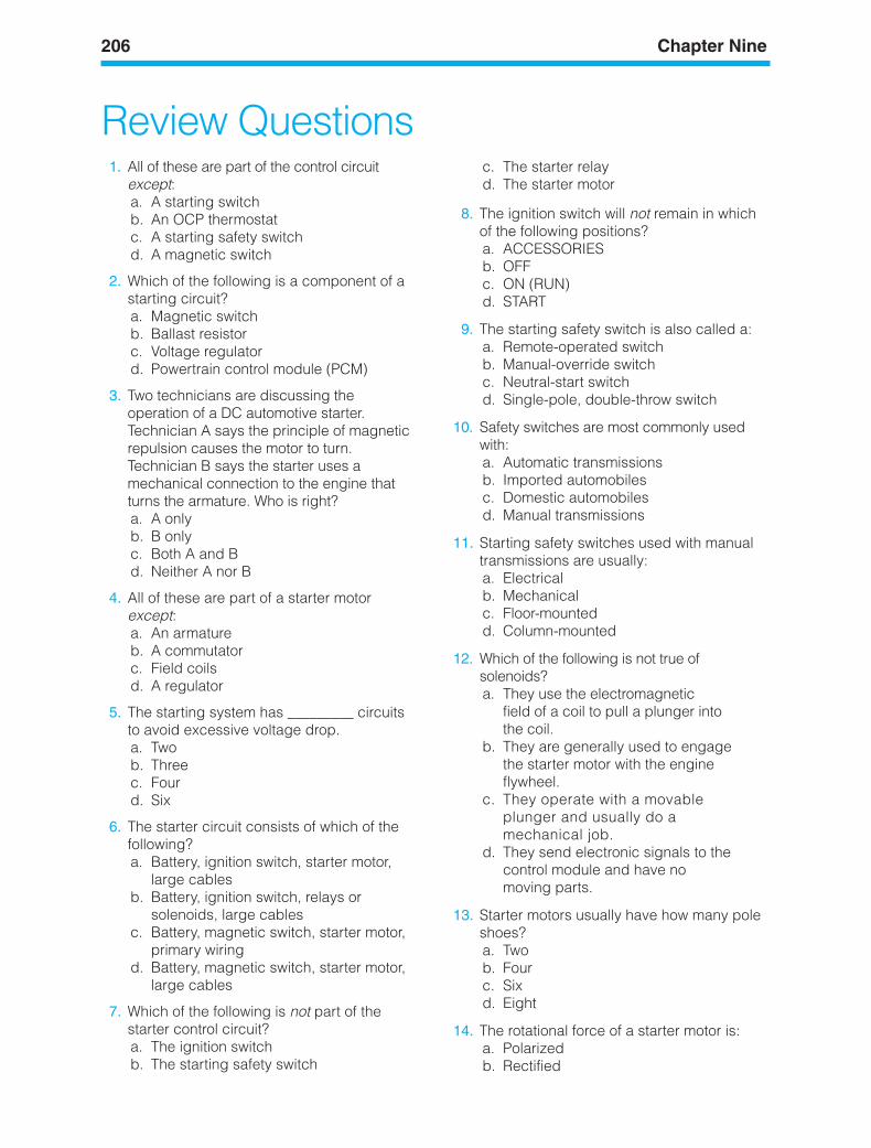
206 Chapter Nine
Review Questions1. All of these are part of the control circuit
except:a. A starting switchb. An OCP thermostatc. A starting safety switchd. A magnetic switch
2. Which of the following is a component of astarting circuit?a. Magnetic switchb. Ballast resistorc. Voltage regulatord. Powertrain control module (PCM)
3. Two technicians are discussing theoperation of a DC automotive starter.Technician A says the principle of magneticrepulsion causes the motor to turn.Technician B says the starter uses amechanical connection to the engine thatturns the armature. Who is right?a. A onlyb. B onlyc. Both A and Bd. Neither A nor B
4. All of these are part of a starter motorexcept:a. An armatureb. A commutatorc. Field coilsd. A regulator
5. The starting system has _________ circuitsto avoid excessive voltage drop.a. Twob. Threec. Fourd. Six
6. The starter circuit consists of which of thefollowing?a. Battery, ignition switch, starter motor,
large cablesb. Battery, ignition switch, relays or
solenoids, large cablesc. Battery, magnetic switch, starter motor,
primary wiringd. Battery, magnetic switch, starter motor,
large cables
7. Which of the following is not part of thestarter control circuit?a. The ignition switchb. The starting safety switch
c. The starter relayd. The starter motor
8. The ignition switch will not remain in whichof the following positions?a. ACCESSORIESb. OFFc. ON (RUN)d. START
9. The starting safety switch is also called a:a. Remote-operated switchb. Manual-override switchc. Neutral-start switchd. Single-pole, double-throw switch
10. Safety switches are most commonly usedwith:a. Automatic transmissionsb. Imported automobilesc. Domestic automobilesd. Manual transmissions
11. Starting safety switches used with manualtransmissions are usually:a. Electricalb. Mechanicalc. Floor-mountedd. Column-mounted
12. Which of the following is not true ofsolenoids?a. They use the electromagnetic
field of a coil to pull a plunger intothe coil.
b. They are generally used to engagethe starter motor with the engineflywheel.
c. They operate with a movableplunger and usually do amechanical job.
d. They send electronic signals to thecontrol module and have nomoving parts.
13. Starter motors usually have how many poleshoes?a. Twob. Fourc. Sixd. Eight
14. The rotational force of a starter motor is:a. Polarizedb. Rectified
ker88839_ch09.qxd 1/9/06 11:30 AM Page 206
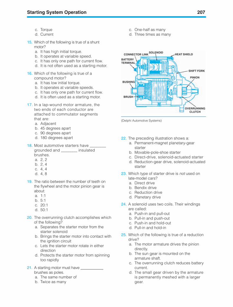
Starting System Operation 207
(Delphi Automotive Systems)
c. Torqued. Current
15. Which of the following is true of a shuntmotor?a. It has high initial torque.b. It operates at variable speed.c. It has only one path for current flow.d. It is not often used as a starting motor.
16. Which of the following is true of acompound motor?a. It has low initial torque.b. It operates at variable speeds.c. It has only one path for current flow.d. It is often used as a starting motor.
17. In a lap-wound motor armature, thetwo ends of each conductor areattached to commutator segmentsthat are:a. Adjacentb. 45 degrees apartc. 90 degrees apartd. 180 degrees apart
18. Most automotive starters have ________grounded and ________ insulatedbrushes.a. 2, 2b. 2, 4c. 4, 4d. 4, 8
19. The ratio between the number of teeth onthe flywheel and the motor pinion gear isabout:a. 1:1b. 5:1c. 20:1d. 50:1
20. The overrunning clutch accomplishes whichof the following?a. Separates the starter motor from the
starter solenoidb. Brings the starter motor into contact with
the ignition circuitc. Lets the starter motor rotate in either
directiond. Protects the starter motor from spinning
too rapidly
21. A starting motor must have ____________brushes as poles.a. The same number ofb. Twice as many
22. The preceding illustration shows a:a. Permanent-magnet planetary-gear
starterb. Movable-pole-shoe starterc. Direct-drive, solenoid-actuated starterd. Reduction-gear drive, solenoid-actuated
starter
23. Which type of starter drive is not used onlate-model cars?a. Direct driveb. Bendix drivec. Reduction drived. Planetary drive
24. A solenoid uses two coils. Their windingsare called:a. Push-in and pull-outb. Pull-in and push-outc. Push-in and hold-outd. Pull-in and hold-in
25. Which of the following is true of a reductiondrive?a. The motor armature drives the pinion
directly.b. The sun gear is mounted on the
armature shaft.c. The overrunning clutch reduces battery
current.d. The small gear driven by the armature
is permanently meshed with a largergear.
c. One-half as manyd. Three times as many
ker88839_ch09.qxd 1/9/06 11:30 AM Page 207

208 Chapter Nine
26. The planetary drive starter uses:a. Permanent magnetsb. Field coilsc. Both A and Bd. Neither A nor B
27. Which of the following is not required of apermanent magnet starter?a. Brush testingb. Commutator testingc. Field circuit testingd. Armature testing
ker88839_ch09.qxd 1/9/06 11:30 AM Page 208

LEARNINGOBJECTIVESUpon completion and review of this chapter, youshould be able to:
• Identify the basic types and construction ofsolid-state devices used in automotive elec-tronic circuits.
• Identify an ESD symbol and explain its use.• Explain the use and function of diodes in an
automotive circuit.• Explain forward-biased diodes and reverse-
biased diodes.• Explain the use and function of transistors and
the different types used in automotive circuits.• Explain the operation of a silicon-controlled
rectifier (SCR).• Identify and explain the operation of pho-
tonic semiconductors.• Identify and explain the term integrated cir-
cuit and how one uses electronic signals.
KEY TERMSAnodeCathodeDiodeDopingElectrostatic Discharge (ESD)Field-Effect Transistor (FET)Forward BiasIntegrated Circuit (ICs)Light-Emitting Diode (LED)N-Type MaterialP-Type MaterialPN JunctionPhotonic SemiconductorsRectifierReverse BiasSemiconductorsSilicon-Controlled Rectifier (SCR)TransistorZener Diode
INTRODUCTIONThis chapter will review the basic semiconductorsand the electronic principles required to under-stand how electronic and computer-controlledsystems manage the various systems in today’s
209
10AutomotiveElectronics
ker88839_ch10.qxd 1/9/06 11:31 AM Page 209
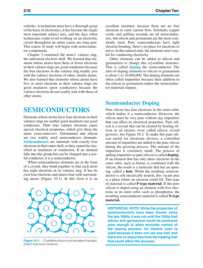
210 Chapter Ten
Figure 10-1. Crystalline silicon is an excellent insulator.(Delphi Automotive Systems)
vehicles. A technician must have a thorough graspof the basis of electronics, it has become the singlemost important subject area, and the days whentechnicians could avoid working on an electroniccircuit throughout an entire career are long past.This course of study will begin with semiconduc-tor components.
Chapter 3 examined the atom’s valence ring,the outermost electron shell. We learned that ele-ments whose atoms have three or fewer electronsin their valence rings are good conductors becausethe free electrons in the valence ring readily joinwith the valence electrons of other, similar atoms.We also learned that elements whose atoms havefive or more electrons in their valence rings aregood insulators (poor conductors) because thevalence electrons do not readily join with those ofother atoms.
SEMICONDUCTORSElements whose atoms have four electrons in theirvalence rings are neither good insulators nor goodconductors. Their four valence electrons causespecial electrical properties, which give them thename semiconductors. Germanium and siliconare two widely used semiconductor elements.Semiconductors are materials with exactly fourelectrons in their outer shell, so they cannot be clas-sified as insulators or conductors. If an elementfalls into this group but can be changed into a use-ful conductor, it is a semiconductor.
When semiconductor elements are in the formof a crystal, they bond together so that each atomhas eight electrons in its valence ring: It has itsown four electrons and shares four with surround-ing atoms (Figure 10-1). In this form it is an
excellent insulator, because there are no freeelectrons to carry current flow. Selenium, copperoxide, and gallium arsenide are all semiconduc-tors, but silicon and germanium are the most com-monly used. Pure semiconductors have tightelectron bonding; there’s no place for electrons tomove. In this natural state, the elements aren’t use-ful for conducting electricity.
Other elements can be added to silicon andgermanium to change this crystalline structure.This is called doping the semiconductor. Theratio of doping elements to silicon or germaniumis about 1 to 10,000,000. The doping elements areoften called impurities because their addition tothe silicon or germanium makes the semiconduc-tor materials impure.
Semiconductor DopingPure silicon has four electrons in the outer orbit,which makes it a semiconductor. However, thesilicon must be very pure without any impuritiesthat can affect its electrical properties. Pure sili-con is a crystal that can be created by heating sil-icon in an electric oven called silicon crystalgrowers. See Figure 10-2. To make this pure sili-con useful for electronic devices, a controlledamount of impurities are added to the pure siliconduring the growing process. The amount of theimpurities is extremely small. The process ofadding impurities to pure silicon is called doping.If an element that has only three electrons in theouter orbit, such as boron, is combined with thesilicon, the result is a molecule that has an open-ing, called a hole. While the resulting semicon-ductor is still electrically neutral, this vacant areais a place where an electron could fill. This typeof material is called P-type material. If the puresilicon is doped using an element with five elec-trons in its outer orbit, such as phosphorus, theresulting semiconductor material is called N-typematerial.
HISTORICAL NOTE: While the properties ofsemiconductors have been known sincethe late 1800s, it was not until the 1930s thatsilicon and germanium could be producedpure enough to allow accurate control ofthe doping process. An electric oven isused because it does not use any fuel, andthere are no impurities from the heating fuelthat could affect the process.
ker88839_ch10.qxd 1/9/06 11:31 AM Page 210
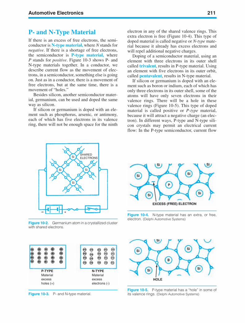
Automotive Electronics 211
SHAREDELECTRONSSi
SiSi
Si
_ +
Figure 10-2. Germanium atom in a crystallized clusterwith shared electrons.
P-TYPE N-TYPEMaterialexcessholes (+)
Materialexcesselectrons (-)
Figure 10-3. P- and N-type material.
Figure 10-4. N-type material has an extra, or free,electron. (Delphi Automotive Systems)
Figure 10-5. P-type material has a “hole” in some ofits valence rings. (Delphi Automotive Systems)
P- and N-Type MaterialIf there is an excess of free electrons, the semi-conductor is N-type material, where N stands fornegative. If there is a shortage of free electrons,the semiconductor is P-type material, whereP stands for positive. Figure 10-3 shows P- andN-type materials together. In a conductor, wedescribe current flow as the movement of elec-trons, in a semiconductor, something else is goingon. Just as in a conductor, there is a movement offree electrons, but at the same time, there is amovement of “holes.”
Besides silicon, another semiconductor mater-ial, germanium, can be used and doped the sameway as silicon.
If silicon or germanium is doped with an ele-ment such as phosphorus, arsenic, or antimony,each of which has five electrons in its valencering, there will not be enough space for the ninth
electron in any of the shared valence rings. Thisextra electron is free (Figure 10-4). This type ofdoped material is called negative or N-type mate-rial because it already has excess electrons andwill repel additional negative charges.
Doping of a semiconductor material, using anelement with three electrons in its outer shellcalled trivalent, results in P-type material. Usingan element with five electrons in its outer orbit,called pentavalent, results in N-type material.
If silicon or germanium is doped with an ele-ment such as boron or indium, each of which hasonly three electrons in its outer shell, some of theatoms will have only seven electrons in theirvalence rings. There will be a hole in thesevalence rings (Figure 10-5). This type of dopedmaterial is called positive or P-type material,because it will attract a negative charge (an elec-tron). In different ways, P-type and N-type sili-con crystals may permit an electrical currentflow: In the P-type semiconductor, current flow
ker88839_ch10.qxd 1/9/06 11:31 AM Page 211
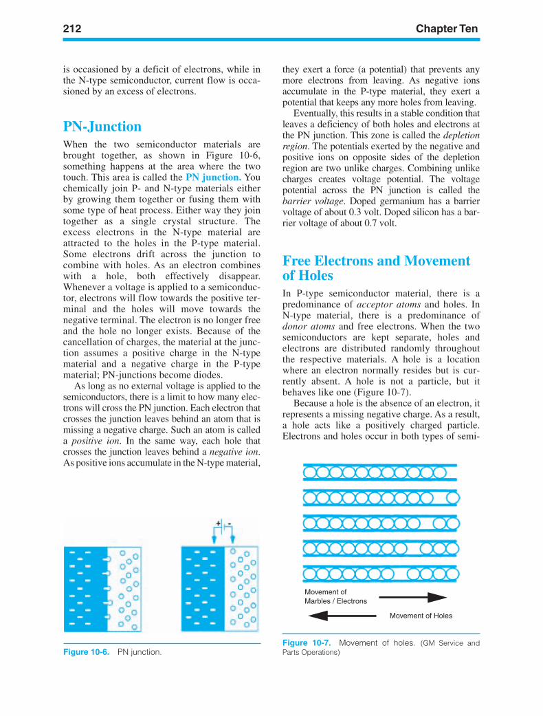
212 Chapter Ten
Figure 10-6. PN junction.
Movement ofMarbles / Electrons
Movement of Holes
Figure 10-7. Movement of holes. (GM Service andParts Operations)
is occasioned by a deficit of electrons, while inthe N-type semiconductor, current flow is occa-sioned by an excess of electrons.
PN-JunctionWhen the two semiconductor materials arebrought together, as shown in Figure 10-6,something happens at the area where the twotouch. This area is called the PN junction. Youchemically join P- and N-type materials eitherby growing them together or fusing them withsome type of heat process. Either way they jointogether as a single crystal structure. Theexcess electrons in the N-type material areattracted to the holes in the P-type material.Some electrons drift across the junction tocombine with holes. As an electron combineswith a hole, both effectively disappear.Whenever a voltage is applied to a semiconduc-tor, electrons will flow towards the positive ter-minal and the holes will move towards thenegative terminal. The electron is no longer freeand the hole no longer exists. Because of thecancellation of charges, the material at the junc-tion assumes a positive charge in the N-typematerial and a negative charge in the P-typematerial; PN-junctions become diodes.
As long as no external voltage is applied to thesemiconductors, there is a limit to how many elec-trons will cross the PN junction. Each electron thatcrosses the junction leaves behind an atom that ismissing a negative charge. Such an atom is calleda positive ion. In the same way, each hole thatcrosses the junction leaves behind a negative ion.As positive ions accumulate in the N-type material,
they exert a force (a potential) that prevents anymore electrons from leaving. As negative ionsaccumulate in the P-type material, they exert apotential that keeps any more holes from leaving.
Eventually, this results in a stable condition thatleaves a deficiency of both holes and electrons atthe PN junction. This zone is called the depletionregion. The potentials exerted by the negative andpositive ions on opposite sides of the depletionregion are two unlike charges. Combining unlikecharges creates voltage potential. The voltagepotential across the PN junction is called thebarrier voltage. Doped germanium has a barriervoltage of about 0.3 volt. Doped silicon has a bar-rier voltage of about 0.7 volt.
Free Electrons and Movementof HolesIn P-type semiconductor material, there is apredominance of acceptor atoms and holes. InN-type material, there is a predominance ofdonor atoms and free electrons. When the twosemiconductors are kept separate, holes andelectrons are distributed randomly throughoutthe respective materials. A hole is a locationwhere an electron normally resides but is cur-rently absent. A hole is not a particle, but itbehaves like one (Figure 10-7).
Because a hole is the absence of an electron, itrepresents a missing negative charge. As a result,a hole acts like a positively charged particle.Electrons and holes occur in both types of semi-
ker88839_ch10.qxd 1/9/06 11:31 AM Page 212

Automotive Electronics 213
P N+ _
ANODE CATHODE
Figure 10-8. ESD symbol. (GM Service and PartsOperations) Figure 10-9. Diode.
conductor material. In P-type material, wedescribe current flow as holes moving. In N-typematerial, we describe current flow as electronsmoving. Holes cannot actually carry current.When we talk about current flow in terms of holesmoving in one direction, we’re actually describ-ing the movement of the absent electrons movingin the opposite direction.
ELECTROSTATICDISCHARGE (ESD)An electrostatic charge can build up on the sur-face of your body. If you touch something yourcharge can be discharged to the other surface.This is called electrostatic discharge (ESD).Figure 10-8 shows the ESD symbol indicatingthat the component is solid-state. Some servicemanuals use the words solid-state instead ofthe ESD symbol. Look for these indicators andtake the suggested ESD precautions when youwork on sensitive components.
DIODESNow that you’ve learned what a semiconductor is,let’s look at some basic examples. The simplestkind of semiconductor is a diode (Figure 10-9). It’smade of one layer of P-type material and one ofN-type material. The diode is the simplest semicon-ductor device that allows current to flow in only one
direction. A diode can function as a switch, actingas either conductor or insulator, depending on thedirection of current flow. Diodes turn on when thepolarity of the current is correct and turn off whenthe flow has the wrong polarity. The suffix -ode lit-erally means terminal. For instance, it is used as thesuffix for cathode and anode. The word diodemeans literally, having two terminals.
Previous sections discussed how both P-typeand N-type semiconductor crystals can conductelectricity. Either the proportion of holes or sur-plus of electrons determines the actual resistanceof each type. When a chip is manufactured usingboth P- and N-type semiconductors, electronswill flow in only one direction. The diode is usedin electronic circuitry as a sort of one-way checkvalve that will conduct electricity in one direction(forward) and block it in the other (reverse).
Anode/CathodeIf current flows from left to right in Figure 10-9,it’s correct to place a positive plus sign to the leftand a negative minus sign to the right of the diode.The positive side of the diode is the anode and thenegative side is the cathode. Associate anodewith A (it’s the positive side) and cathode withC (the negative side). The cathode is the endwith the stripe. Basically, the following types ofdiodes are used in automotive applications:
• Regular diodes (used for rectification, orchanging AC to DC)
• Clamping diodes (to control voltage spikesand surges that could damage solid-statecircuits)
• LEDs (light emitting diodes, used asindicators)
• Zener diodes (voltage regulation)• Photodiodes
ker88839_ch10.qxd 1/9/06 11:31 AM Page 213
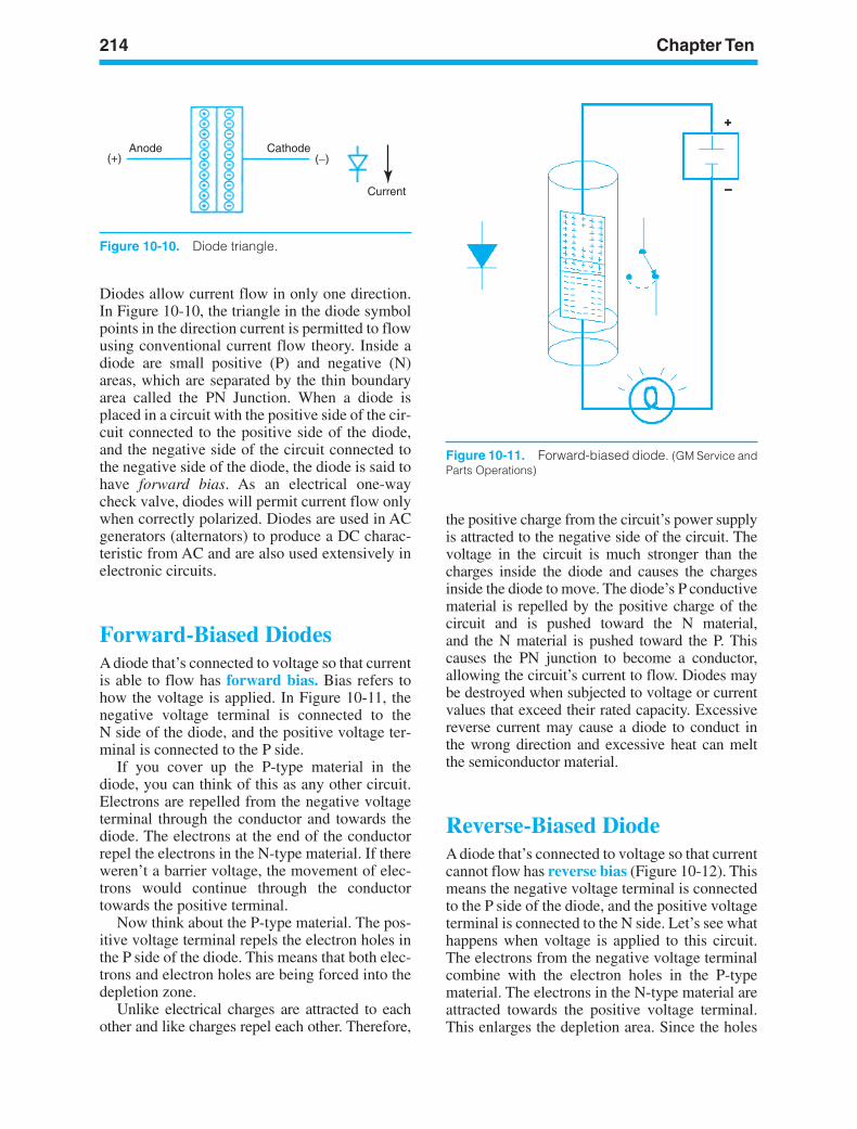
214 Chapter Ten
CathodeAnode
Current
( )_(+)
Figure 10-11. Forward-biased diode. (GM Service andParts Operations)
Figure 10-10. Diode triangle.
Diodes allow current flow in only one direction.In Figure 10-10, the triangle in the diode symbolpoints in the direction current is permitted to flowusing conventional current flow theory. Inside adiode are small positive (P) and negative (N)areas, which are separated by the thin boundaryarea called the PN Junction. When a diode isplaced in a circuit with the positive side of the cir-cuit connected to the positive side of the diode,and the negative side of the circuit connected tothe negative side of the diode, the diode is said tohave forward bias. As an electrical one-waycheck valve, diodes will permit current flow onlywhen correctly polarized. Diodes are used in ACgenerators (alternators) to produce a DC charac-teristic from AC and are also used extensively inelectronic circuits.
Forward-Biased DiodesA diode that’s connected to voltage so that currentis able to flow has forward bias. Bias refers tohow the voltage is applied. In Figure 10-11, thenegative voltage terminal is connected to theN side of the diode, and the positive voltage ter-minal is connected to the P side.
If you cover up the P-type material in thediode, you can think of this as any other circuit.Electrons are repelled from the negative voltageterminal through the conductor and towards thediode. The electrons at the end of the conductorrepel the electrons in the N-type material. If thereweren’t a barrier voltage, the movement of elec-trons would continue through the conductortowards the positive terminal.
Now think about the P-type material. The pos-itive voltage terminal repels the electron holes inthe P side of the diode. This means that both elec-trons and electron holes are being forced into thedepletion zone.
Unlike electrical charges are attracted to eachother and like charges repel each other. Therefore,
the positive charge from the circuit’s power supplyis attracted to the negative side of the circuit. Thevoltage in the circuit is much stronger than thecharges inside the diode and causes the chargesinside the diode to move. The diode’s P conductivematerial is repelled by the positive charge of thecircuit and is pushed toward the N material,and the N material is pushed toward the P. Thiscauses the PN junction to become a conductor,allowing the circuit’s current to flow. Diodes maybe destroyed when subjected to voltage or currentvalues that exceed their rated capacity. Excessivereverse current may cause a diode to conduct inthe wrong direction and excessive heat can meltthe semiconductor material.
Reverse-Biased DiodeA diode that’s connected to voltage so that currentcannot flow has reverse bias (Figure 10-12). Thismeans the negative voltage terminal is connectedto the P side of the diode, and the positive voltageterminal is connected to the N side. Let’s see whathappens when voltage is applied to this circuit.The electrons from the negative voltage terminalcombine with the electron holes in the P-typematerial. The electrons in the N-type material areattracted towards the positive voltage terminal.This enlarges the depletion area. Since the holes
ker88839_ch10.qxd 1/9/06 11:31 AM Page 214
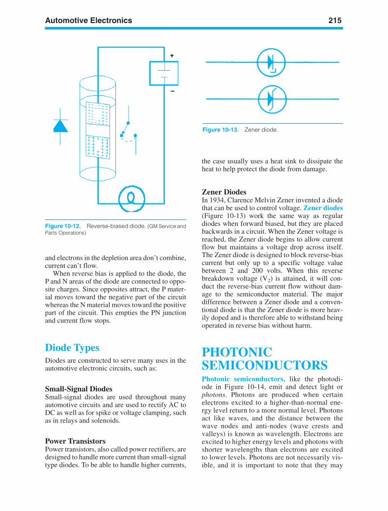
Automotive Electronics 215
Figure 10-12. Reverse-biased diode. (GM Service andParts Operations)
Figure 10-13. Zener diode.
and electrons in the depletion area don’t combine,current can’t flow.
When reverse bias is applied to the diode, theP and N areas of the diode are connected to oppo-site charges. Since opposites attract, the P mater-ial moves toward the negative part of the circuitwhereas the N material moves toward the positivepart of the circuit. This empties the PN junctionand current flow stops.
Diode TypesDiodes are constructed to serve many uses in theautomotive electronic circuits, such as:
Small-Signal DiodesSmall-signal diodes are used throughout manyautomotive circuits and are used to rectify AC toDC as well as for spike or voltage clamping, suchas in relays and solenoids.
Power TransistorsPower transistors, also called power rectifiers, aredesigned to handle more current than small-signaltype diodes. To be able to handle higher currents,
the case usually uses a heat sink to dissipate theheat to help protect the diode from damage.
Zener DiodesIn 1934, Clarence Melvin Zener invented a diodethat can be used to control voltage. Zener diodes(Figure 10-13) work the same way as regulardiodes when forward biased, but they are placedbackwards in a circuit. When the Zener voltage isreached, the Zener diode begins to allow currentflow but maintains a voltage drop across itself.The Zener diode is designed to block reverse-biascurrent but only up to a specific voltage valuebetween 2 and 200 volts. When this reversebreakdown voltage (V2) is attained, it will con-duct the reverse-bias current flow without dam-age to the semiconductor material. The majordifference between a Zener diode and a conven-tional diode is that the Zener diode is more heav-ily doped and is therefore able to withstand beingoperated in reverse bias without harm.
PHOTONICSEMICONDUCTORSPhotonic semiconductors, like the photodi-ode in Figure 10-14, emit and detect light orphotons. Photons are produced when certainelectrons excited to a higher-than-normal ene-rgy level return to a more normal level. Photonsact like waves, and the distance between thewave nodes and anti-nodes (wave crests andvalleys) is known as wavelength. Electrons areexcited to higher energy levels and photons withshorter wavelengths than electrons are excitedto lower levels. Photons are not necessarily vis-ible, and it is important to note that they may
ker88839_ch10.qxd 1/9/06 11:31 AM Page 215
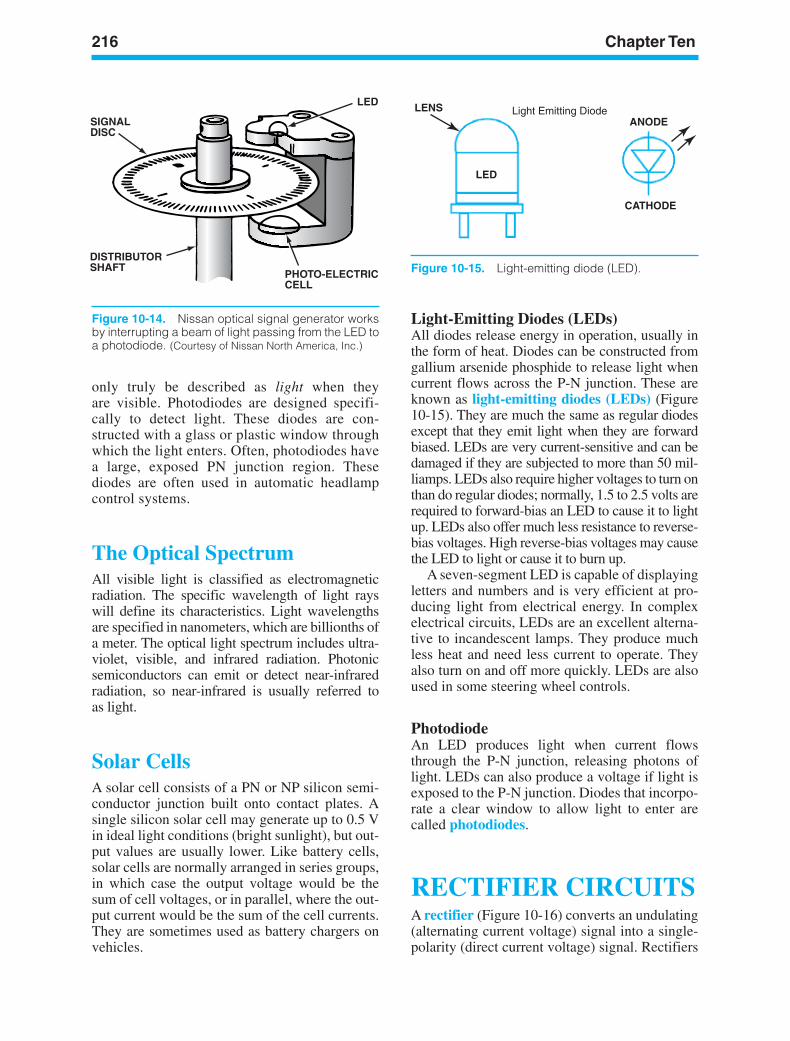
216 Chapter Ten
SIGNALDISC
DISTRIBUTORSHAFT
PHOTO-ELECTRICCELL
LED LENS
LED
ANODE
CATHODE
Light Emitting Diode
Figure 10-14. Nissan optical signal generator worksby interrupting a beam of light passing from the LED toa photodiode. (Courtesy of Nissan North America, Inc.)
Figure 10-15. Light-emitting diode (LED).
only truly be described as light when theyare visible. Photodiodes are designed specifi-cally to detect light. These diodes are con-structed with a glass or plastic window throughwhich the light enters. Often, photodiodes havea large, exposed PN junction region. Thesediodes are often used in automatic headlampcontrol systems.
The Optical SpectrumAll visible light is classified as electromagneticradiation. The specific wavelength of light rayswill define its characteristics. Light wavelengthsare specified in nanometers, which are billionths ofa meter. The optical light spectrum includes ultra-violet, visible, and infrared radiation. Photonicsemiconductors can emit or detect near-infraredradiation, so near-infrared is usually referred toas light.
Solar CellsA solar cell consists of a PN or NP silicon semi-conductor junction built onto contact plates. Asingle silicon solar cell may generate up to 0.5 Vin ideal light conditions (bright sunlight), but out-put values are usually lower. Like battery cells,solar cells are normally arranged in series groups,in which case the output voltage would be thesum of cell voltages, or in parallel, where the out-put current would be the sum of the cell currents.They are sometimes used as battery chargers onvehicles.
Light-Emitting Diodes (LEDs)All diodes release energy in operation, usually inthe form of heat. Diodes can be constructed fromgallium arsenide phosphide to release light whencurrent flows across the P-N junction. These areknown as light-emitting diodes (LEDs) (Figure10-15). They are much the same as regular diodesexcept that they emit light when they are forwardbiased. LEDs are very current-sensitive and can bedamaged if they are subjected to more than 50 mil-liamps. LEDs also require higher voltages to turn onthan do regular diodes; normally, 1.5 to 2.5 volts arerequired to forward-bias an LED to cause it to lightup. LEDs also offer much less resistance to reverse-bias voltages. High reverse-bias voltages may causethe LED to light or cause it to burn up.
A seven-segment LED is capable of displayingletters and numbers and is very efficient at pro-ducing light from electrical energy. In complexelectrical circuits, LEDs are an excellent alterna-tive to incandescent lamps. They produce muchless heat and need less current to operate. Theyalso turn on and off more quickly. LEDs are alsoused in some steering wheel controls.
PhotodiodeAn LED produces light when current flowsthrough the P-N junction, releasing photons oflight. LEDs can also produce a voltage if light isexposed to the P-N junction. Diodes that incorpo-rate a clear window to allow light to enter arecalled photodiodes.
RECTIFIER CIRCUITSA rectifier (Figure 10-16) converts an undulating(alternating current voltage) signal into a single-polarity (direct current voltage) signal. Rectifiers
ker88839_ch10.qxd 1/9/06 11:31 AM Page 216
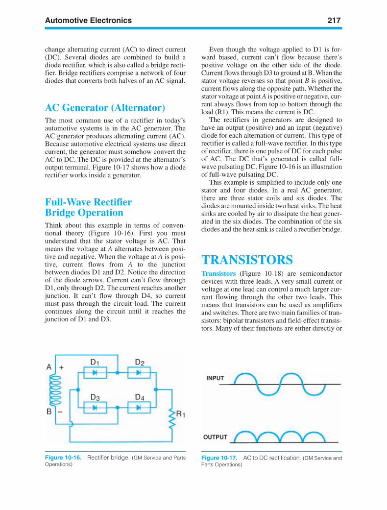
Automotive Electronics 217
Figure 10-16. Rectifier bridge. (GM Service and PartsOperations)
Figure 10-17. AC to DC rectification. (GM Service andParts Operations)
change alternating current (AC) to direct current(DC). Several diodes are combined to build adiode rectifier, which is also called a bridge recti-fier. Bridge rectifiers comprise a network of fourdiodes that converts both halves of an AC signal.
AC Generator (Alternator)The most common use of a rectifier in today’sautomotive systems is in the AC generator. TheAC generator produces alternating current (AC).Because automotive electrical systems use directcurrent, the generator must somehow convert theAC to DC. The DC is provided at the alternator’soutput terminal. Figure 10-17 shows how a dioderectifier works inside a generator.
Full-Wave RectifierBridge OperationThink about this example in terms of conven-tional theory (Figure 10-16). First you mustunderstand that the stator voltage is AC. Thatmeans the voltage at A alternates between posi-tive and negative. When the voltage at A is posi-tive, current flows from A to the junctionbetween diodes D1 and D2. Notice the directionof the diode arrows. Current can’t flow throughD1, only through D2. The current reaches anotherjunction. It can’t flow through D4, so currentmust pass through the circuit load. The currentcontinues along the circuit until it reaches thejunction of D1 and D3.
Even though the voltage applied to D1 is for-ward biased, current can’t flow because there’spositive voltage on the other side of the diode.Current flows through D3 to ground at B. When thestator voltage reverses so that point B is positive,current flows along the opposite path. Whether thestator voltage at point A is positive or negative, cur-rent always flows from top to bottom through theload (R1). This means the current is DC.
The rectifiers in generators are designed tohave an output (positive) and an input (negative)diode for each alternation of current. This type ofrectifier is called a full-wave rectifier. In this typeof rectifier, there is one pulse of DC for each pulseof AC. The DC that’s generated is called full-wave pulsating DC. Figure 10-16 is an illustrationof full-wave pulsating DC.
This example is simplified to include only onestator and four diodes. In a real AC generator,there are three stator coils and six diodes. Thediodes are mounted inside two heat sinks. The heatsinks are cooled by air to dissipate the heat gener-ated in the six diodes. The combination of the sixdiodes and the heat sink is called a rectifier bridge.
TRANSISTORSTransistors (Figure 10-18) are semiconductordevices with three leads. A very small current orvoltage at one lead can control a much larger cur-rent flowing through the other two leads. Thismeans that transistors can be used as amplifiersand switches. There are two main families of tran-sistors: bipolar transistors and field-effect transis-tors. Many of their functions are either directly or
ker88839_ch10.qxd 1/9/06 11:31 AM Page 217
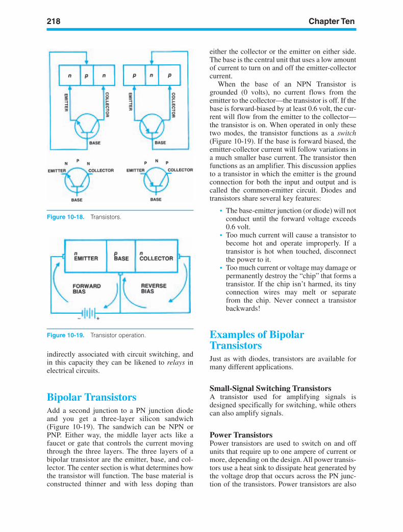
218 Chapter Ten
Figure 10-19. Transistor operation.
Figure 10-18. Transistors.
indirectly associated with circuit switching, andin this capacity they can be likened to relays inelectrical circuits.
Bipolar TransistorsAdd a second junction to a PN junction diodeand you get a three-layer silicon sandwich(Figure 10-19). The sandwich can be NPN orPNP. Either way, the middle layer acts like afaucet or gate that controls the current movingthrough the three layers. The three layers of abipolar transistor are the emitter, base, and col-lector. The center section is what determines howthe transistor will function. The base material isconstructed thinner and with less doping than
either the collector or the emitter on either side.The base is the central unit that uses a low amountof current to turn on and off the emitter-collectorcurrent.
When the base of an NPN Transistor isgrounded (0 volts), no current flows from theemitter to the collector—the transistor is off. If thebase is forward-biased by at least 0.6 volt, the cur-rent will flow from the emitter to the collector—the transistor is on. When operated in only thesetwo modes, the transistor functions as a switch(Figure 10-19). If the base is forward biased, theemitter-collector current will follow variations ina much smaller base current. The transistor thenfunctions as an amplifier. This discussion appliesto a transistor in which the emitter is the groundconnection for both the input and output and iscalled the common-emitter circuit. Diodes andtransistors share several key features:
• The base-emitter junction (or diode) will notconduct until the forward voltage exceeds0.6 volt.
• Too much current will cause a transistor tobecome hot and operate improperly. If atransistor is hot when touched, disconnectthe power to it.
• Too much current or voltage may damage orpermanently destroy the “chip” that forms atransistor. If the chip isn’t harmed, its tinyconnection wires may melt or separatefrom the chip. Never connect a transistorbackwards!
Examples of BipolarTransistorsJust as with diodes, transistors are available formany different applications.
Small-Signal Switching TransistorsA transistor used for amplifying signals isdesigned specifically for switching, while otherscan also amplify signals.
Power TransistorsPower transistors are used to switch on and offunits that require up to one ampere of current ormore, depending on the design. All power transis-tors use a heat sink to dissipate heat generated bythe voltage drop that occurs across the PN junc-tion of the transistors. Power transistors are also
ker88839_ch10.qxd 1/9/06 11:31 AM Page 218
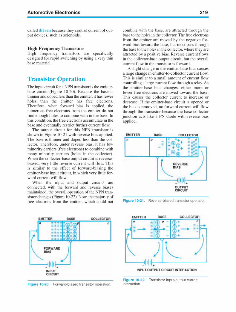
Automotive Electronics 219
Figure 10-22. Transistor input/output currentinteraction.Figure 10-20. Forward-biased transistor operation.
Figure 10-21. Reverse-biased transistor operation.
called driven because they control current of out-put devices, such as solenoids.
High Frequency TransistorsHigh frequency transistors are specificallydesigned for rapid switching by using a very thinbase material.
Transistor OperationThe input circuit for a NPN transistor is the emitter-base circuit (Figure 10-20). Because the base isthinner and doped less than the emitter, it has fewerholes than the emitter has free electrons.Therefore, when forward bias is applied, thenumerous free electrons from the emitter do notfind enough holes to combine with in the base. Inthis condition, the free electrons accumulate in thebase and eventually restrict further current flow.
The output circuit for this NPN transistor isshown in Figure 10-21 with reverse bias applied.The base is thinner and doped less than the col-lector. Therefore, under reverse bias, it has fewminority carriers (free electrons) to combine withmany minority carriers (holes in the collector).When the collector-base output circuit is reverse-biased, very little reverse current will flow. Thisis similar to the effect of forward-biasing theemitter-base input circuit, in which very little for-ward current will flow.
When the input and output circuits areconnected, with the forward and reverse biasesmaintained, the overall operation of the NPN tran-sistor changes (Figure 10-22). Now, the majority offree electrons from the emitter, which could not
combine with the base, are attracted through thebase to the holes in the collector. The free electronsfrom the emitter are moved by the negative for-ward bias toward the base, but most pass throughthe base to the holes in the collector, where they areattracted by a positive bias. Reverse current flowsin the collector-base output circuit, but the overallcurrent flow in the transistor is forward.
A slight change in the emitter-base bias causesa large change in emitter-to-collector current flow.This is similar to a small amount of current flowcontrolling a large current flow through a relay. Asthe emitter-base bias changes, either more orfewer free electrons are moved toward the base.This causes the collector current to increase ordecrease. If the emitter-base circuit is opened orthe bias is removed, no forward current will flowthrough the transistor because the base-collectorjunction acts like a PN diode with reverse biasapplied.
ker88839_ch10.qxd 1/9/06 11:31 AM Page 219
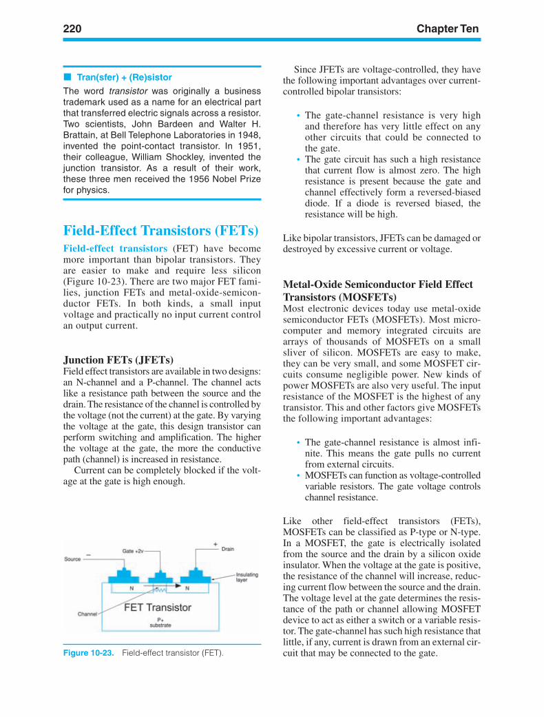
220 Chapter Ten
Figure 10-23. Field-effect transistor (FET).
Tran(sfer) + (Re)sistor
The word transistor was originally a businesstrademark used as a name for an electrical partthat transferred electric signals across a resistor.Two scientists, John Bardeen and Walter H.Brattain, at Bell Telephone Laboratories in 1948,invented the point-contact transistor. In 1951,their colleague, William Shockley, invented thejunction transistor. As a result of their work,these three men received the 1956 Nobel Prizefor physics.
Field-Effect Transistors (FETs)Field-effect transistors (FET) have becomemore important than bipolar transistors. Theyare easier to make and require less silicon(Figure 10-23). There are two major FET fami-lies, junction FETs and metal-oxide-semicon-ductor FETs. In both kinds, a small inputvoltage and practically no input current controlan output current.
Junction FETs (JFETs)Field effect transistors are available in two designs:an N-channel and a P-channel. The channel actslike a resistance path between the source and thedrain. The resistance of the channel is controlled bythe voltage (not the current) at the gate. By varyingthe voltage at the gate, this design transistor canperform switching and amplification. The higherthe voltage at the gate, the more the conductivepath (channel) is increased in resistance.
Current can be completely blocked if the volt-age at the gate is high enough.
Since JFETs are voltage-controlled, they havethe following important advantages over current-controlled bipolar transistors:
• The gate-channel resistance is very highand therefore has very little effect on anyother circuits that could be connected tothe gate.
• The gate circuit has such a high resistancethat current flow is almost zero. The highresistance is present because the gate andchannel effectively form a reversed-biaseddiode. If a diode is reversed biased, theresistance will be high.
Like bipolar transistors, JFETs can be damaged ordestroyed by excessive current or voltage.
Metal-Oxide Semiconductor Field EffectTransistors (MOSFETs)Most electronic devices today use metal-oxidesemiconductor FETs (MOSFETs). Most micro-computer and memory integrated circuits arearrays of thousands of MOSFETs on a smallsliver of silicon. MOSFETs are easy to make,they can be very small, and some MOSFET cir-cuits consume negligible power. New kinds ofpower MOSFETs are also very useful. The inputresistance of the MOSFET is the highest of anytransistor. This and other factors give MOSFETsthe following important advantages:
• The gate-channel resistance is almost infi-nite. This means the gate pulls no currentfrom external circuits.
• MOSFETs can function as voltage-controlledvariable resistors. The gate voltage controlschannel resistance.
Like other field-effect transistors (FETs),MOSFETs can be classified as P-type or N-type.In a MOSFET, the gate is electrically isolatedfrom the source and the drain by a silicon oxideinsulator. When the voltage at the gate is positive,the resistance of the channel will increase, reduc-ing current flow between the source and the drain.The voltage level at the gate determines the resis-tance of the path or channel allowing MOSFETdevice to act as either a switch or a variable resis-tor. The gate-channel has such high resistance thatlittle, if any, current is drawn from an external cir-cuit that may be connected to the gate.
ker88839_ch10.qxd 1/9/06 11:31 AM Page 220
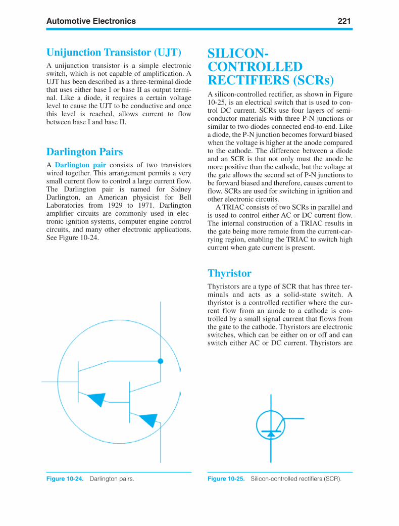
Automotive Electronics 221
Figure 10-24. Darlington pairs.
Unijunction Transistor (UJT)A unijunction transistor is a simple electronicswitch, which is not capable of amplification. AUJT has been described as a three-terminal diodethat uses either base I or base II as output termi-nal. Like a diode, it requires a certain voltagelevel to cause the UJT to be conductive and oncethis level is reached, allows current to flowbetween base I and base II.
Darlington PairsA Darlington pair consists of two transistorswired together. This arrangement permits a verysmall current flow to control a large current flow.The Darlington pair is named for SidneyDarlington, an American physicist for BellLaboratories from 1929 to 1971. Darlingtonamplifier circuits are commonly used in elec-tronic ignition systems, computer engine controlcircuits, and many other electronic applications.See Figure 10-24.
SILICON-CONTROLLEDRECTIFIERS (SCRs)A silicon-controlled rectifier, as shown in Figure10-25, is an electrical switch that is used to con-trol DC current. SCRs use four layers of semi-conductor materials with three P-N junctions orsimilar to two diodes connected end-to-end. Likea diode, the P-N junction becomes forward biasedwhen the voltage is higher at the anode comparedto the cathode. The difference between a diodeand an SCR is that not only must the anode bemore positive than the cathode, but the voltage atthe gate allows the second set of P-N junctions tobe forward biased and therefore, causes current toflow. SCRs are used for switching in ignition andother electronic circuits.
A TRIAC consists of two SCRs in parallel andis used to control either AC or DC current flow.The internal construction of a TRIAC results inthe gate being more remote from the current-car-rying region, enabling the TRIAC to switch highcurrent when gate current is present.
ThyristorThyristors are a type of SCR that has three ter-minals and acts as a solid-state switch. Athyristor is a controlled rectifier where the cur-rent flow from an anode to a cathode is con-trolled by a small signal current that flows fromthe gate to the cathode. Thyristors are electronicswitches, which can be either on or off and canswitch either AC or DC current. Thyristors are
Figure 10-25. Silicon-controlled rectifiers (SCR).
ker88839_ch10.qxd 1/9/06 11:31 AM Page 221
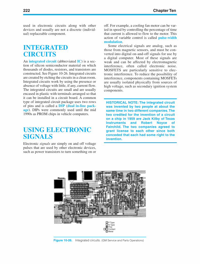
222 Chapter Ten
Figure 10-26. Integrated circuits. (GM Service and Parts Operations)
used in electronic circuits along with otherdevices and usually are not a discrete (individ-ual) replaceable component.
INTEGRATEDCIRCUITSAn integrated circuit (abbreviated IC) is a sec-tion of silicon semiconductor material on whichthousands of diodes, resistors, and transistors areconstructed. See Figure 10-26. Integrated circuitsare created by etching the circuits in a clean room.Integrated circuits work by using the presence orabsence of voltage with little, if any, current flow.The integrated circuits are small and are usuallyencased in plastic with terminals arranged so thatit can be installed in a circuit board. A commontype of integrated circuit package uses two rowsof pins and is called a DIP (dual in-line pack-age). DIPs were commonly used until the mid1990s as PROM chips in vehicle computers.
USING ELECTRONICSIGNALSElectronic signals are simply on and off voltagepulses that are used by other electronic devices,such as power transistors to turn something on or
off. For example, a cooling fan motor can be var-ied in speed by controlling the percentage of timethat current is allowed to flow to the motor. Thisaction of variable control is called pulse-widthmodulation.
Some electrical signals are analog, such asthose from magnetic sensors, and must be con-verted into digital on-and-off signals for use bya digital computer. Most of these signals areweak and can be affected by electromagneticinterference, often called electronic noise.MOSFETS are particularly sensitive to elec-tronic interference. To reduce the possibility ofinterference, components containing MOSFETsare usually isolated physically from sources ofhigh voltage, such as secondary ignition systemcomponents.
HISTORICAL NOTE: The integrated circuitwas invented by two people at about thesame time in two different companies.Thetwo credited for the invention of a circuiton a chip in 1959 are Jack Kilby of TexasInstruments and Robert Noyce ofFairchild. The two companies agreed togrant license to each other since bothconceded that each had some right to theinvention.
ker88839_ch10.qxd 1/9/06 11:31 AM Page 222
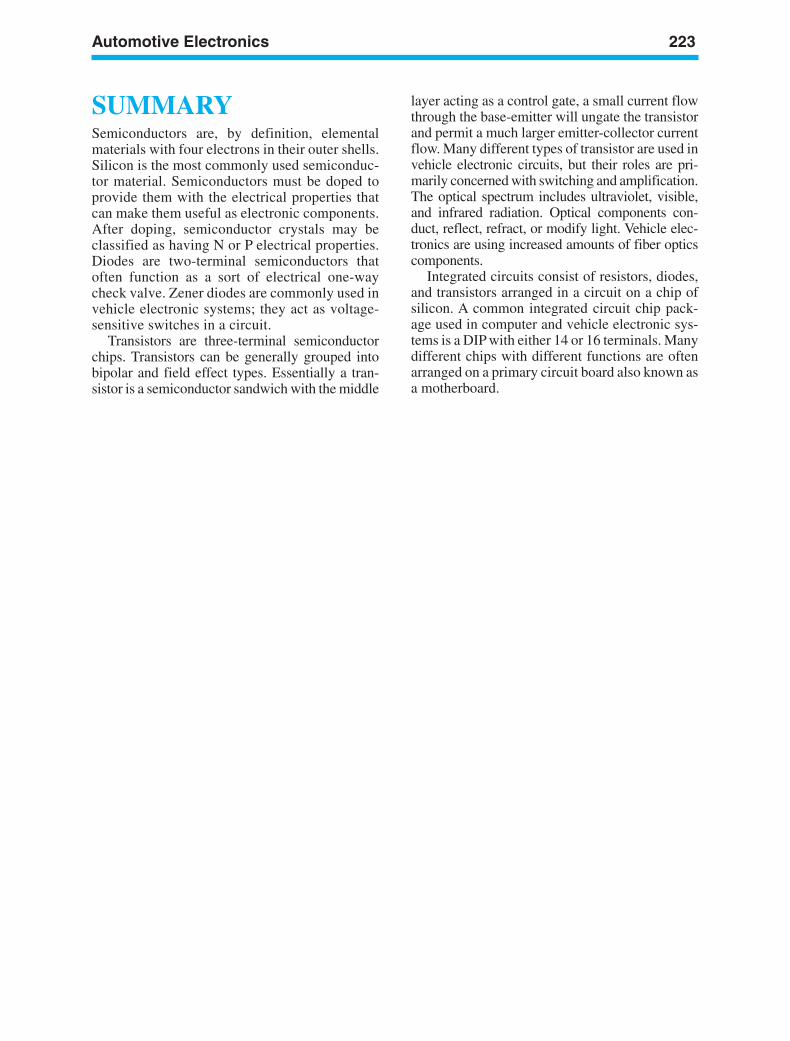
Automotive Electronics 223
SUMMARYSemiconductors are, by definition, elementalmaterials with four electrons in their outer shells.Silicon is the most commonly used semiconduc-tor material. Semiconductors must be doped toprovide them with the electrical properties thatcan make them useful as electronic components.After doping, semiconductor crystals may beclassified as having N or P electrical properties.Diodes are two-terminal semiconductors thatoften function as a sort of electrical one-waycheck valve. Zener diodes are commonly used invehicle electronic systems; they act as voltage-sensitive switches in a circuit.
Transistors are three-terminal semiconductorchips. Transistors can be generally grouped intobipolar and field effect types. Essentially a tran-sistor is a semiconductor sandwich with the middle
layer acting as a control gate, a small current flowthrough the base-emitter will ungate the transistorand permit a much larger emitter-collector currentflow. Many different types of transistor are used invehicle electronic circuits, but their roles are pri-marily concerned with switching and amplification.The optical spectrum includes ultraviolet, visible,and infrared radiation. Optical components con-duct, reflect, refract, or modify light. Vehicle elec-tronics are using increased amounts of fiber opticscomponents.
Integrated circuits consist of resistors, diodes,and transistors arranged in a circuit on a chip ofsilicon. A common integrated circuit chip pack-age used in computer and vehicle electronic sys-tems is a DIP with either 14 or 16 terminals. Manydifferent chips with different functions are oftenarranged on a primary circuit board also known asa motherboard.
ker88839_ch10.qxd 1/9/06 11:31 AM Page 223
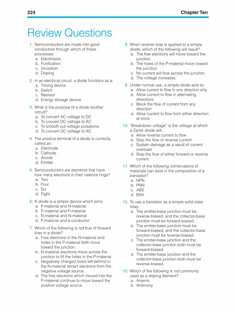
224 Chapter Ten
1. Semiconductors are made into goodconductors through which of theseprocesses:a. Electrolysisb. Purificationc. Ionizationd. Doping
2. In an electrical circuit, a diode functions as a:a. Timing deviceb. Switchc. Resistord. Energy storage device
3. What is the purpose of a diode rectifiercircuit?a. To convert AC voltage to DCb. To convert DC voltage to ACc. To smooth out voltage pulsationsd. To convert DC voltage to AC
4. The positive terminal of a diode is correctlycalled an:a. Electrodeb. Cathodec. Anoded. Emitter
5. Semiconductors are elements that havehow many electrons in their valence rings?a. Twob. Fourc. Sixd. Eight
6. A diode is a simple device which joins:a. P-material and N-materialb. P-material and P-materialc. N-material and N-materiald. P-material and a conductor
7. Which of the following is not true of forwardbias in a diode?a. Free electrons in the N-material and
holes in the P-material both movetoward the junction.
b. N-material electrons move across thejunction to fill the holes in the P-material.
c. Negatively charged holes left behind inthe N-material attract electrons from thenegative voltage source.
d. The free electrons which moved into theP-material continue to move toward thepositive voltage source.
8. When reverse bias is applied to a simplediode, which of the following will result?a. The free electrons will move toward the
junction.b. The holes of the P-material move toward
the junction.c. No current will flow across the junction.d. The voltage increases.
9. Under normal use, a simple diode acts to:a. Allow current to flow in one direction onlyb. Allow current to flow in alternating
directionsc. Block the flow of current from any
directiond. Allow current to flow from either direction
at once
10. “Breakdown voltage” is the voltage at whicha Zener diode will:a. Allow reverse current to flowb. Stop the flow of reverse currentc. Sustain damage as a result of current
overloadd. Stop the flow of either forward or reverse
current
11. Which of the following combinations ofmaterials can exist in the composition of atransistor?a. NPNb. PNNc. ABSd. BSA
12. To use a transistor as a simple solid-staterelay:a. The emitter-base junction must be
reverse-biased, and the collector-basejunction must be forward-biased.
b. The emitter-base junction must beforward-biased, and the collector-basejunction must be reverse-biased.
c. The emitter-base junction and thecollector-base junction both must beforward-biased.
d. The emitter-base junction and thecollector-base junction both must bereverse-biased.
13. Which of the following is not commonlyused as a doping element?a. Arsenicb. Antimony
Review Questions
ker88839_ch10.qxd 1/9/06 11:31 AM Page 224
Automotive Electronics 225
c. Phosphorusd. Silicon
14. The display faces of digital instruments areoften made of:a. Silicon-controlled rectifiersb. Integrated circuitsc. Light-emitting diodesd. Thyristors
15. All of the following are parts of a field-effecttransistor (FET), except the:a. Drainb. Source
c. Based. Gate
16. All of the following are characteristics of anintegrated circuit (IC), except:a. It is extremely small.b. It contains thousands of individual
components.c. It is manufactured from silicon.d. It is larger than a hybrid circuit.
ker88839_ch10.qxd 1/9/06 11:31 AM Page 225

ker88839_ch10.qxd 1/9/06 11:31 AM Page 226
227
LEARNINGOBJECTIVESUpon completion and review of this chapter, youwill be able to:
• Explain the process of mutual induction inthe ignition coil.
• List the components in the primary ignitioncircuit.
• Describe the differences between electronicand distributorless ignition systems.
• Have knowledge of the different solid-statetriggering devices.
• Describe the operation of the secondary ig-nition system.
• List the secondary ignition components.
• List conditions that cause high resistance inthe secondary circuit.
• Explain the various design features of sparkplugs.
KEY TERMSAvailable VoltageBakeliteBreaker PointsBurn TimeCapacitive-Discharge
Ignition SystemCurrent Limiting HumpDistributor Ignition
(DI) SystemDwellDwell TimeElectronic Ignition
(EI) SystemsExtended-Core
Spark PlugFiring LineFiring VoltageFixed DwellHall Effect SwitchHeat RangeInductive-Discharge
Ignition System
11The Ignition:Primary andSecondaryCircuits andComponents
IonizeMagnetic Pulse
GeneratorMagnetic SaturationMechanical Ignition
SystemsNo-Load OscillationOptical Signal
GeneratorReachRequired VoltageResistor-Type Spark
PlugsSelf-InductionSpark VoltageTelevision-Radio-
Suppression (TVRS)Cables
Variable DwellVoltage DecayVoltage Reserve
ker88839_ch11.qxd 1/9/06 11:31 AM Page 227
228 Chapter Eleven
INTRODUCTIONThe primary ignition circuit is considered to be theheart of the ignition system. The secondary igni-tion circuit cannot function efficiently if the pri-mary ignition circuit is damaged. This chapterexplains components of the low-voltage primaryignition circuit and how the circuit operates.Breaker points opened and closed the low-voltageprimary circuit until the 1970s when solid-stateelectronic switching devices took their place.Whether breaker points or electronic switches areused, the principles of producing high voltage byelectromagnetic induction remain the same.
NEED FOR HIGHVOLTAGEEnergy is supplied to the automotive electricalsystem by the battery. The battery supplies abouttwelve volts, but the voltage required to ignite theair-fuel mixture ranges from about 5,000 to morethan 40,000 volts, depending upon engine operat-ing conditions.
High voltage is required to create an arc acrossthe spark plug air gap. The required voltage levelincreases when the:
• Spark plug air gap increases• Engine operating temperature increases• Air-fuel mixture is lean• Air-fuel mixture is at a greater pressure
Battery voltage must be greatly increased to meetthe needs of the ignition system. Engine operatingtemperature increases the required voltage becauseresistance increases with greater temperature. Alean air-fuel mixture contains fewer volatile fuelparticles, so resistance increases. More voltage isneeded when the air-fuel mixture is at a greaterpressure because resistance increases with an in-crease in pressure. The ignition system boosts volt-age using electromagnetic induction.
HIGH VOLTAGETHROUGHINDUCTIONAny current-carrying conductor or coil is sur-rounded by a magnetic field. As current in the coilincreases or decreases, the magnetic field expandsor contracts. If a second coiled conductor is placed
within this magnetic field, the expanding or con-tracting magnetic flux lines will cut the secondcoil, causing a voltage to be induced into the sec-ond coil. This transfer of energy between two un-connected conductors is called mutual induction.
Induction in the Ignition CoilThe ignition coil uses the principle of mutual in-duction to step up or transform low battery volt-age to high ignition voltage. The ignition coil,Figure 11-1, contains two windings of copperwire wrapped around a soft iron core. The primarywinding is made of a hundred or so turns of heavywire. It connects to the battery and carries current.The secondary winding is made of many thousandturns of fine wire. When current in the primarywinding increases or decreases, a voltage is in-duced into the secondary winding, Figure 11-1.
The ratio of the number of turns in the secondarywinding to the number of turns in the primary wind-ing is generally between 100:1 and 200:1. This ra-tio is the voltage multiplier. That is, any voltageinduced in the secondary winding is 100 to 200times the voltage present in the primary winding.
Several factors govern the induction of volt-age. Only two of these factors are easily control-lable in an ignition system. Induced voltageincreases with:
• More magnetic flux lines• More rapid movement of flux lines
More magnetic flux lines produce a stronger mag-netic field because there is a greater current. Therapid movement of flux lines results in a fastercollapse of the field because of the abrupt end tothe current.
Voltage applied to the coil primary windingwith breaker points is about nine to ten volts.However, at high speeds, voltage may rise totwelve volts or more. This voltage pushes fromone to four amperes of current through the pri-mary winding. Primary current causes a magneticfield buildup around the windings. Building up acomplete magnetic field is called magnetic satu-ration, or coil saturation. When this current stops,the primary winding magnetic field collapses. Agreater voltage is self-induced in the primarywinding by the collapse of its own magnetic field.This self-induction creates from 250 to 400 voltsin the primary winding. For example, in a typicalelectronic ignition system, when the switchingdevice turns ON, the current in the primary igni-tion circuit increases to approximately 5.5 amps.As the magnetic field builds in the primary cir-
ker88839_ch11.qxd 1/9/06 11:31 AM Page 228
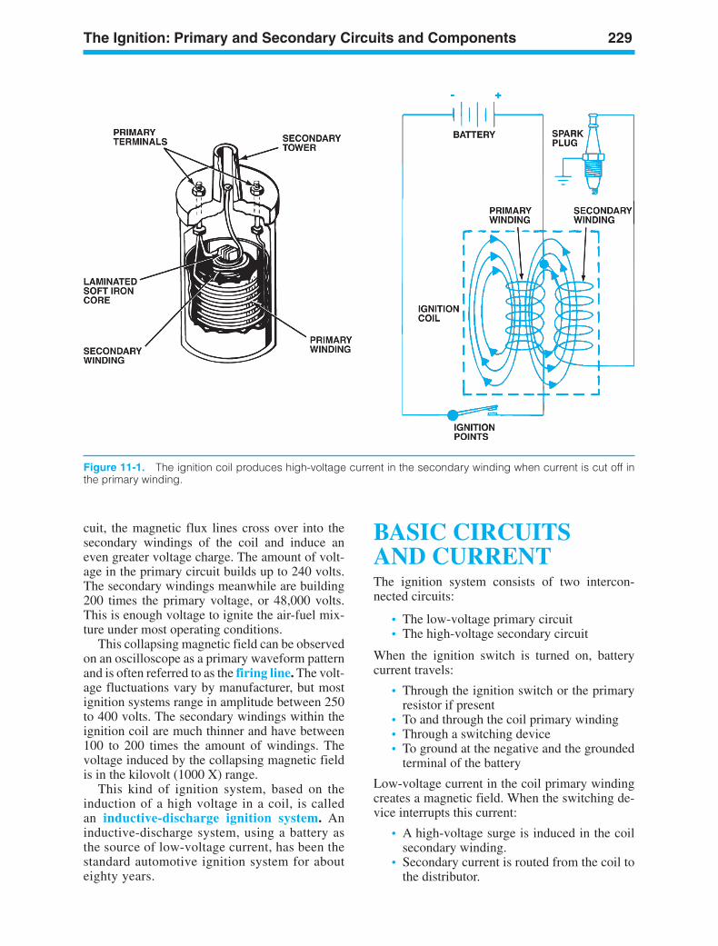
The Ignition: Primary and Secondary Circuits and Components 229
Figure 11-1. The ignition coil produces high-voltage current in the secondary winding when current is cut off inthe primary winding.
cuit, the magnetic flux lines cross over into thesecondary windings of the coil and induce aneven greater voltage charge. The amount of volt-age in the primary circuit builds up to 240 volts.The secondary windings meanwhile are building200 times the primary voltage, or 48,000 volts.This is enough voltage to ignite the air-fuel mix-ture under most operating conditions.
This collapsing magnetic field can be observedon an oscilloscope as a primary waveform patternand is often referred to as the firing line. The volt-age fluctuations vary by manufacturer, but mostignition systems range in amplitude between 250to 400 volts. The secondary windings within theignition coil are much thinner and have between100 to 200 times the amount of windings. Thevoltage induced by the collapsing magnetic fieldis in the kilovolt (1000 X) range.
This kind of ignition system, based on theinduction of a high voltage in a coil, is calledan inductive-discharge ignition system. Aninductive-discharge system, using a battery asthe source of low-voltage current, has been thestandard automotive ignition system for abouteighty years.
BASIC CIRCUITS AND CURRENTThe ignition system consists of two intercon-nected circuits:
• The low-voltage primary circuit• The high-voltage secondary circuit
When the ignition switch is turned on, batterycurrent travels:
• Through the ignition switch or the primaryresistor if present
• To and through the coil primary winding• Through a switching device• To ground at the negative and the grounded
terminal of the battery
Low-voltage current in the coil primary windingcreates a magnetic field. When the switching de-vice interrupts this current:
• A high-voltage surge is induced in the coilsecondary winding.
• Secondary current is routed from the coil tothe distributor.
ker88839_ch11.qxd 1/9/06 11:31 AM Page 229
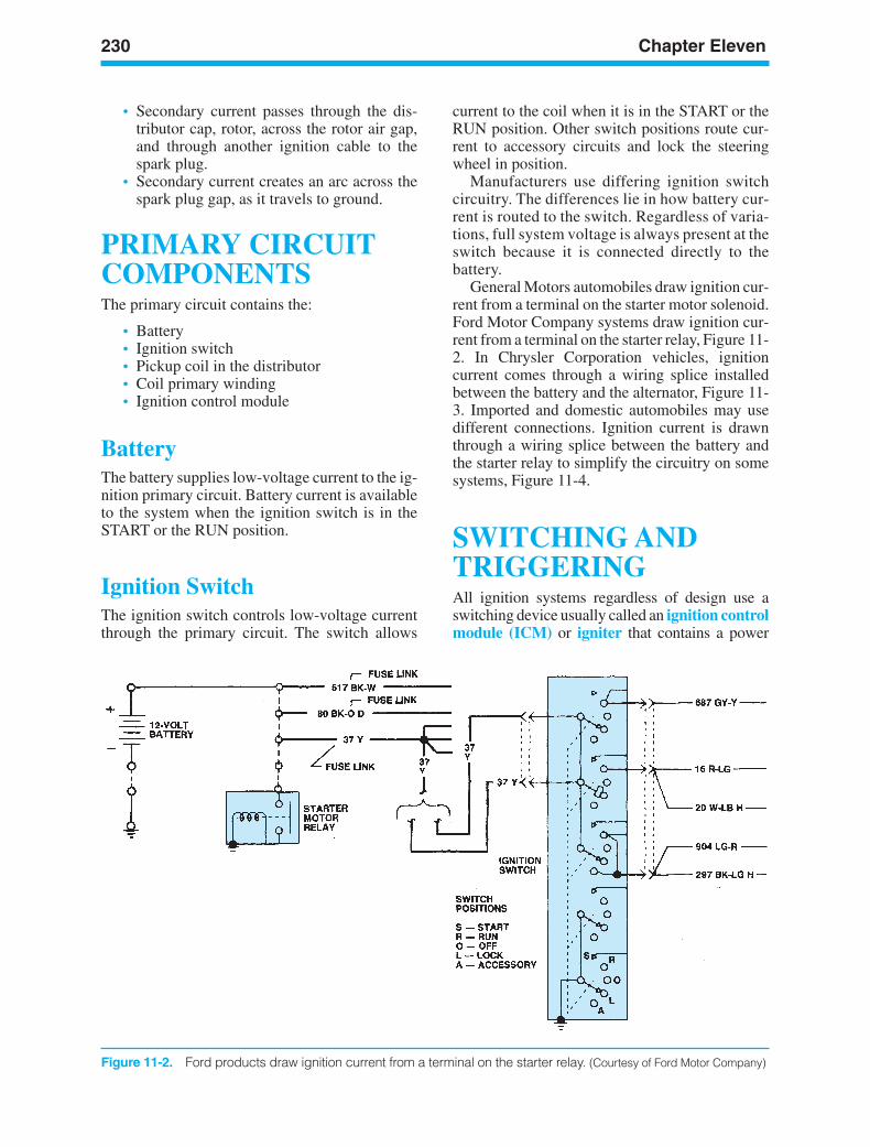
230 Chapter Eleven
Figure 11-2. Ford products draw ignition current from a terminal on the starter relay. (Courtesy of Ford Motor Company)
• Secondary current passes through the dis-tributor cap, rotor, across the rotor air gap,and through another ignition cable to thespark plug.
• Secondary current creates an arc across thespark plug gap, as it travels to ground.
PRIMARY CIRCUITCOMPONENTSThe primary circuit contains the:
• Battery• Ignition switch• Pickup coil in the distributor• Coil primary winding• Ignition control module
BatteryThe battery supplies low-voltage current to the ig-nition primary circuit. Battery current is availableto the system when the ignition switch is in theSTART or the RUN position.
Ignition SwitchThe ignition switch controls low-voltage currentthrough the primary circuit. The switch allows
current to the coil when it is in the START or theRUN position. Other switch positions route cur-rent to accessory circuits and lock the steeringwheel in position.
Manufacturers use differing ignition switchcircuitry. The differences lie in how battery cur-rent is routed to the switch. Regardless of varia-tions, full system voltage is always present at theswitch because it is connected directly to thebattery.
General Motors automobiles draw ignition cur-rent from a terminal on the starter motor solenoid.Ford Motor Company systems draw ignition cur-rent from a terminal on the starter relay, Figure 11-2. In Chrysler Corporation vehicles, ignitioncurrent comes through a wiring splice installedbetween the battery and the alternator, Figure 11-3. Imported and domestic automobiles may usedifferent connections. Ignition current is drawnthrough a wiring splice between the battery andthe starter relay to simplify the circuitry on somesystems, Figure 11-4.
SWITCHING ANDTRIGGERINGAll ignition systems regardless of design use aswitching device usually called an ignition controlmodule (ICM) or igniter that contains a power
ker88839_ch11.qxd 1/9/06 11:31 AM Page 230
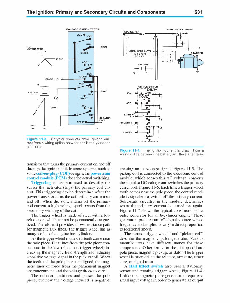
STANDARD IGNITION SWITCH
ACC
ACC
ACC
ACC
OFF
OFF
OFF
OFF
RUN
RUN
RUN
RUN
START
STARTSTART
START
START
TO ALTERNATOR
BATTERY
+
-
J1 12R
S2 14Y
J1012P
IGN
ACC
INDICATORLIGHT
Figure 11-3. Chrysler products draw ignition cur-rent from a wiring splice between the battery and thealternator.
IGN
ACC
STARTIGN
INDICATOR
LIGHTS
BATTERY
+-
IGNITION SWITCHSTART
ONOFFLOCK
ACCB1
B2
B3
SPLICE "A"RED
STARTER SOLENOID
STARTERRED W/TR 6 CYL
RED 6 CYLRED V8
Figure 11-4. The ignition current is drawn from awiring splice between the battery and the starter relay.
transistor that turns the primary current on and offthrough the ignition coil. In some systems, such assome coil-on-plug (COP) designs, the powertraincontrol module (PCM) does the actual switching.
Triggering is the term used to describe thesensor that activates (trips) the primary coil cir-cuit. This triggering device determines when thepower transistor turns the coil primary current onand off. When the switch turns off the primarycoil current, a high-voltage spark occurs from thesecondary winding of the coil.
The trigger wheel is made of steel with a lowreluctance, which cannot be permanently magne-tized. Therefore, it provides a low-resistance pathfor magnetic flux lines. The trigger wheel has asmany teeth as the engine has cylinders.
As the trigger wheel rotates, its teeth come nearthe pole piece. Flux lines from the pole piece con-centrate in the low-reluctance trigger wheel, in-creasing the magnetic field strength and inducinga positive voltage signal in the pickup coil. Whenthe teeth and the pole piece are aligned, the mag-netic lines of force from the permanent magnetare concentrated and the voltage drops to zero.
The reluctor continues and passes the polepiece, but now the voltage induced is negative,
creating an ac voltage signal, Figure 11-5. Thepickup coil is connected to the electronic controlmodule, which senses this AC voltage, convertsthe signal to DC voltage and switches the primarycurrent off, Figure 11-6. Each time a trigger wheeltooth comes near the pole piece, the control mod-ule is signaled to switch off the primary current.Solid-state circuitry in the module determineswhen the primary current is turned on again.Figure 11-7 shows the typical construction of apulse generator for an 8-cylinder engine. Thesegenerators produce an AC signal voltage whosefrequency and amplitude vary in direct proportionto rotational speed.
The terms “trigger wheel” and “pickup coil”describe the magnetic pulse generator. Variousmanufacturers have different names for thesecomponents. Other terms for the pickup coil arepole piece, magnetic pickup, or stator. The triggerwheel is often called the reluctor, armature, timercore, or signal rotor.
A Hall Effect switch also uses a stationarysensor and rotating trigger wheel, Figure 11-8.Unlike the magnetic pulse generator, it requires asmall input voltage in order to generate an output
The Ignition: Primary and Secondary Circuits and Components 231
ker88839_ch11.qxd 1/9/06 11:31 AM Page 231
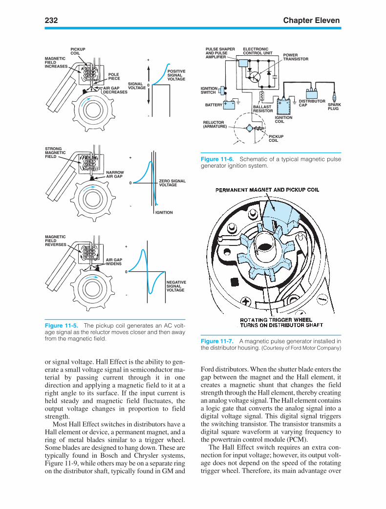
232 Chapter Eleven
Figure 11-7. A magnetic pulse generator installed inthe distributor housing. (Courtesy of Ford Motor Company)
or signal voltage. Hall Effect is the ability to gen-erate a small voltage signal in semiconductor ma-terial by passing current through it in onedirection and applying a magnetic field to it at aright angle to its surface. If the input current isheld steady and magnetic field fluctuates, theoutput voltage changes in proportion to fieldstrength.
Most Hall Effect switches in distributors have aHall element or device, a permanent magnet, and aring of metal blades similar to a trigger wheel.Some blades are designed to hang down. These aretypically found in Bosch and Chrysler systems,Figure 11-9, while others may be on a separate ringon the distributor shaft, typically found in GM and
Ford distributors. When the shutter blade enters thegap between the magnet and the Hall element, itcreates a magnetic shunt that changes the fieldstrength through the Hall element, thereby creatingan analog voltage signal. The Hall element containsa logic gate that converts the analog signal into adigital voltage signal. This digital signal triggersthe switching transistor. The transistor transmits adigital square waveform at varying frequency tothe powertrain control module (PCM).
The Hall Effect switch requires an extra con-nection for input voltage; however, its output volt-age does not depend on the speed of the rotatingtrigger wheel. Therefore, its main advantage over
POSITIVESIGNALVOLTAGE
SIGNALVOLTAGE
0
+
-
0
+
-
0
+
-
ZERO SIGNALVOLTAGE
NEGATIVESIGNALVOLTAGE
POLEPIECE
AIR GAPDECREASES
PICKUPCOIL
MAGNETICFIELDINCREASES
IGNITION
NARROWAIR GAP
STRONGMAGNETICFIELD
MAGNETICFIELDREVERSES
AIR GAPWIDENS
Figure 11-5. The pickup coil generates an AC volt-age signal as the reluctor moves closer and then awayfrom the magnetic field.
SPARKPLUG
DISTRIBUTORCAP
IGNITIONCOIL
BALLASTRESISTOR
POWERTRANSISTOR
ELECTRONICCONTROL UNIT
PULSE SHAPERAND PULSEAMPLIFIER
IGNITIONSWITCH
BATTERY
PICKUPCOIL
RELUCTOR(ARMATURE)
+ -+ -
Figure 11-6. Schematic of a typical magnetic pulsegenerator ignition system.
ker88839_ch11.qxd 1/9/06 11:31 AM Page 232
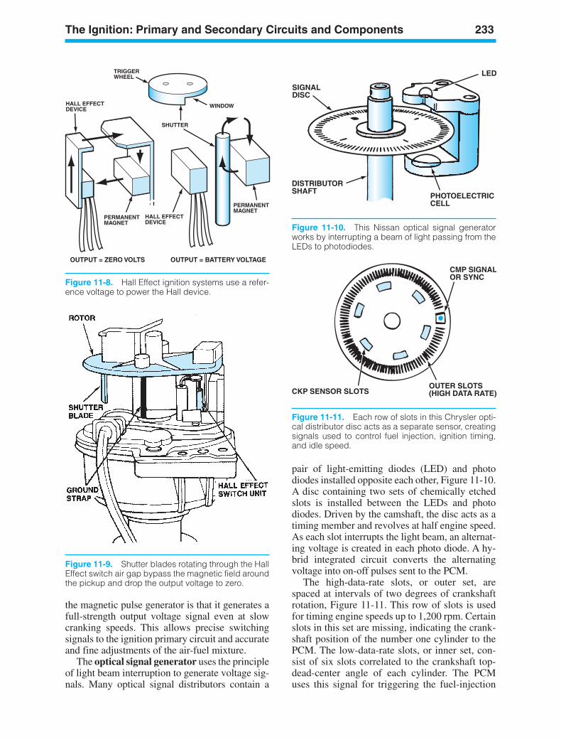
The Ignition: Primary and Secondary Circuits and Components 233
TRIGGERWHEEL
WINDOW
PERMANENTMAGNET
PERMANENTMAGNET
SHUTTER
HALL EFFECTDEVICE
HALL EFFECTDEVICE
OUTPUT = ZERO VOLTS OUTPUT = BATTERY VOLTAGE
Figure 11-8. Hall Effect ignition systems use a refer-ence voltage to power the Hall device.
Figure 11-9. Shutter blades rotating through the HallEffect switch air gap bypass the magnetic field aroundthe pickup and drop the output voltage to zero.
SIGNALDISC
DISTRIBUTORSHAFT
PHOTOELECTRICCELL
LED
Figure 11-10. This Nissan optical signal generatorworks by interrupting a beam of light passing from theLEDs to photodiodes.
the magnetic pulse generator is that it generates afull-strength output voltage signal even at slowcranking speeds. This allows precise switchingsignals to the ignition primary circuit and accurateand fine adjustments of the air-fuel mixture.
The optical signal generator uses the principleof light beam interruption to generate voltage sig-nals. Many optical signal distributors contain a
pair of light-emitting diodes (LED) and photodiodes installed opposite each other, Figure 11-10.A disc containing two sets of chemically etchedslots is installed between the LEDs and photodiodes. Driven by the camshaft, the disc acts as atiming member and revolves at half engine speed.As each slot interrupts the light beam, an alternat-ing voltage is created in each photo diode. A hy-brid integrated circuit converts the alternatingvoltage into on-off pulses sent to the PCM.
The high-data-rate slots, or outer set, arespaced at intervals of two degrees of crankshaftrotation, Figure 11-11. This row of slots is usedfor timing engine speeds up to 1,200 rpm. Certainslots in this set are missing, indicating the crank-shaft position of the number one cylinder to thePCM. The low-data-rate slots, or inner set, con-sist of six slots correlated to the crankshaft top-dead-center angle of each cylinder. The PCMuses this signal for triggering the fuel-injection
CMP SIGNALOR SYNC
OUTER SLOTS(HIGH DATA RATE)CKP SENSOR SLOTS
Figure 11-11. Each row of slots in this Chrysler opti-cal distributor disc acts as a separate sensor, creatingsignals used to control fuel injection, ignition timing,and idle speed.
ker88839_ch11.qxd 1/9/06 11:31 AM Page 233
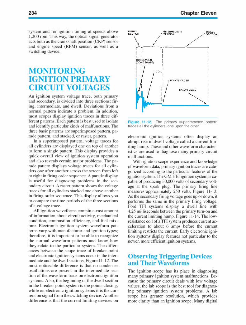
234 Chapter Eleven
system and for ignition timing at speeds above1,200 rpm. This way, the optical signal generatoracts both as the crankshaft position (CKP) sensorand engine speed (RPM) sensor, as well as aswitching device.
MONITORINGIGNITION PRIMARYCIRCUIT VOLTAGESAn ignition system voltage trace, both primaryand secondary, is divided into three sections: fir-ing, intermediate, and dwell. Deviations from anormal pattern indicate a problem. In addition,most scopes display ignition traces in three dif-ferent patterns. Each pattern is best used to isolateand identify particular kinds of malfunctions. Thethree basic patterns are superimposed pattern, pa-rade pattern, and stacked, or raster, pattern.
In a superimposed pattern, voltage traces forall cylinders are displayed one on top of anotherto form a single pattern. This display provides aquick overall view of ignition system operationand also reveals certain major problems. The pa-rade pattern displays voltage traces for all cylin-ders one after another across the screen from leftto right in firing order sequence. A parade displayis useful for diagnosing problems in the sec-ondary circuit. A raster pattern shows the voltagetraces for all cylinders stacked one above anotherin firing order sequence. This display allows youto compare the time periods of the three sectionsof a voltage trace.
All ignition waveforms contain a vast amountof information about circuit activity, mechanicalcondition, combustion efficiency, and fuel mix-ture. Electronic ignition system waveform pat-terns vary with manufacturer and ignition types;therefore, it is important to be able to recognizethe normal waveform patterns and know howthey relate to the particular system. The differ-ences between the scope trace of breaker pointand electronic ignition systems occur in the inter-mediate and the dwell sections, Figure 11-12. Themost noticeable difference is that no condenseroscillations are present in the intermediate sec-tion of the waveform trace on electronic ignitionsystems. Also, the beginning of the dwell sectionin the breaker point system is the points closing,while on electronic ignition systems it is the cur-rent on signal from the switching device. Anotherdifference is that the current limiting devices on
electronic ignition systems often display anabrupt rise in dwell voltage called a current lim-iting hump. These and other waveform character-istics are used to diagnose many primary circuitmalfunctions.
With ignition scope experience and knowledgeof waveform data, primary ignition traces are cate-gorized according to the particular features of theignition system. The GM HEI ignition system is ca-pable of producing 30,000 volts of secondary volt-age at the spark plug. The primary firing linemeasures approximately 250 volts, Figure 11-13.As the secondary firing voltage goes up or down, itperforms the same in the primary firing voltage.Ford TFI systems display a dwell line with 4.25 milliseconds between the primary turn-on andthe current limiting hump, Figure 11-14. The low-resistance coil of a TFI system produces current ac-celeration to about 6 amps before the currentlimiting restricts the current. Early electronic igni-tion systems display features not particular to thenewer, more efficient ignition systems.
Observing Triggering Devicesand Their WaveformsThe ignition scope has its place in diagnosingmany primary ignition system malfunctions. Be-cause the primary circuit deals with low voltagevalues, the lab scope is the best tool for diagnos-ing primary ignition system problems. A labscope has greater resolution, which providesmore clarity than an ignition scope. Many digital
Figure 11-12. The primary superimposed patterntraces all the cylinders, one upon the other.
ker88839_ch11.qxd 1/9/06 11:31 AM Page 234
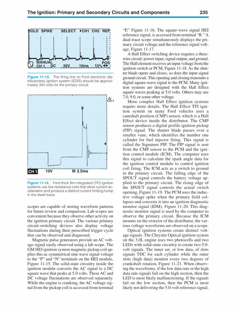
The Ignition: Primary and Secondary Circuits and Components 235
MANUALCH 1
1
DC 50V 10ms 15%
HOLD SPIKE SELECT CH1 CH2 REF
POS
Figure 11-13. The firing line on Ford electronic dis-tributorless ignition system (EDIS) should be approxi-mately 342 volts for the primary circuit.
4.25 V:
10V M 2.5msCH 1
Figure 11-14. Ford thick film integrated (TFI) ignitionsystems use low-resistance coils that allow current ac-celeration and produce a distinct current limiting humpin the dwell trace.
scopes are capable of storing waveform patternsfor future review and comparison. Lab scopes areconvenient because they observe other activity onthe ignition primary circuit. The various primarycircuit-switching devices also display voltagefluctuations during their prescribed trigger cyclethat can be observed and diagnosed.
Magnetic pulse generators provide an AC volt-age signal easily observed using a lab scope. TheGM HEI ignition system magnetic pickup coil ap-plies this ac symmetrical sine wave signal voltageto the “P” and “N” terminals on the HEI module,Figure 11-15. The solid-state circuitry inside theignition module converts the AC signal to a DCsquare wave that peaks at 5.0 volts. These AC andDC voltage fluctuations are observed separately.While the engine is cranking, the AC voltage sig-nal from the pickup coil is accessed from terminal
“P,” Figure 11-16. The square-wave signal HEIreference signal, is accessed from terminal “R.” Adual-trace scope simultaneously displays the pri-mary circuit voltage and the reference signal volt-age, Figure 11-17.
A Hall Effect switching device requires a three-wire circuit: power input, signal output, and ground.The Hall element receives an input voltage from theignition switch or PCM, Figure 11-18. As the shut-ter blade opens and closes, so does the input signalground circuit. This opening and closing transmits adigital square-wave signal to the PCM. Many igni-tion systems are designed with the Hall Effectsquare waves peaking at 5.0 volts. Others may use7.0, 9.0, or some other voltage.
More complex Hall Effect ignition systemsrequire more details. The Hall Effect TFI igni-tion system on many Ford vehicles uses acamshaft position (CMP) sensor, which is a HallEffect device inside the distributor. The CMPsensor produces a digital profile ignition pickup(PIP) signal. The shutter blade passes over asmaller vane, which identifies the number onecylinder for fuel injector firing. This signal iscalled the Signature PIP. The PIP signal is sentfrom the CMP sensor to the PCM and the igni-tion control module (ICM). The computer usesthis signal to calculate the spark angle data forthe ignition control module to control ignitioncoil firing. The ICM acts as a switch to groundin the primary circuit. The falling edge of theSPOUT signal controls the battery voltage ap-plied to the primary circuit. The rising edge ofthe SPOUT signal controls the actual switchopening, Figure 11-19. The PCM uses the induc-tive voltage spike when the primary field col-lapses and converts it into an ignition diagnosticmonitor signal (IDM), Figure 11-20. This diag-nostic monitor signal is used by the computer toobserve the primary circuit. Because the ICMmounts on the exterior of the distributor, the var-ious voltage waveforms are observed on a scope.
Optical ignition systems create distinct volt-age signals. The Chrysler Optical ignition systemon the 3.0L engine uses two photocells and twoLEDs with solid-state circuitry to create two 5.0-volt signals. The inner set, or low data, of slotssignals TDC for each cylinder while the outerslots (high data) monitor every two degrees ofcrankshaft rotation, Figure 11-21. When observ-ing the waveforms, if the low data rate or the highdata rate signals fail on the high section, then theLED is most likely malfunctioning. If the signalsfail on the low section, then the PCM is mostlikely not delivering the 5.0-volt reference signal.
ker88839_ch11.qxd 1/9/06 11:31 AM Page 235
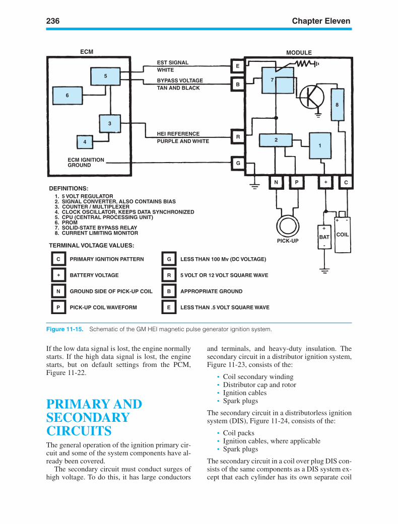
236 Chapter Eleven
ECM
DEFINITIONS:
TERMINAL VOLTAGE VALUES:
MODULE
5
6
3
4
ECM IGNITIONGROUND
1. 5 VOLT REGULATOR2. SIGNAL CONVERTER, ALSO CONTAINS BIAS3. COUNTER / MULTIPLEXER4. CLOCK OSCILLATOR, KEEPS DATA SYNCHRONIZED5. CPU (CENTRAL PROCESSING UNIT)6. PROM7. SOLID-STATE BYPASS RELAY8. CURRENT LIMITING MONITOR
EST SIGNALWHITE
BYPASS VOLTAGE
E
B
R
G
TAN AND BLACK
HEI REFERENCEPURPLE AND WHITE
7
8
12
N P +
+
+
-
-
C
BAT COILPICK-UP
C
+
N
P
PRIMARY IGNITION PATTERN
BATTERY VOLTAGE
GROUND SIDE OF PICK-UP COIL
PICK-UP COIL WAVEFORM
G
R
B
E
LESS THAN 100 Mv (DC VOLTAGE)
5 VOLT OR 12 VOLT SQUARE WAVE
APPROPRIATE GROUND
LESS THAN .5 VOLT SQUARE WAVE
Figure 11-15. Schematic of the GM HEI magnetic pulse generator ignition system.
If the low data signal is lost, the engine normallystarts. If the high data signal is lost, the enginestarts, but on default settings from the PCM,Figure 11-22.
PRIMARY ANDSECONDARYCIRCUITSThe general operation of the ignition primary cir-cuit and some of the system components have al-ready been covered.
The secondary circuit must conduct surges ofhigh voltage. To do this, it has large conductors
and terminals, and heavy-duty insulation. Thesecondary circuit in a distributor ignition system,Figure 11-23, consists of the:
• Coil secondary winding• Distributor cap and rotor• Ignition cables• Spark plugs
The secondary circuit in a distributorless ignitionsystem (DIS), Figure 11-24, consists of the:
• Coil packs• Ignition cables, where applicable• Spark plugs
The secondary circuit in a coil over plug DIS con-sists of the same components as a DIS system ex-cept that each cylinder has its own separate coil
ker88839_ch11.qxd 1/9/06 11:31 AM Page 236
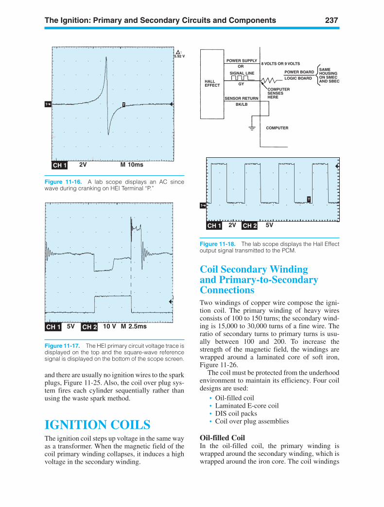
The Ignition: Primary and Secondary Circuits and Components 237
5.92 V:
2V M 10msCH 1
T1
Figure 11-16. A lab scope displays an AC sincewave during cranking on HEI Terminal “P.”
5V 10 V M 2.5msCH 1 CH 2
Figure 11-17. The HEI primary circuit voltage trace isdisplayed on the top and the square-wave referencesignal is displayed on the bottom of the scope screen.
POWER SUPPLYOR
SIGNAL LINE
GY
SENSOR RETURN
BK/LB
HALLEFFECT
COMPUTERSENSESHERE
COMPUTER
8 VOLTS OR 9 VOLTS
POWER BOARD
LOGIC BOARD
SAMEHOUSING ON SMECAND SBEC
2V 5VCH 1 CH 2
1
T
Figure 11-18. The lab scope displays the Hall Effectoutput signal transmitted to the PCM.
and there are usually no ignition wires to the sparkplugs, Figure 11-25. Also, the coil over plug sys-tem fires each cylinder sequentially rather thanusing the waste spark method.
IGNITION COILSThe ignition coil steps up voltage in the same wayas a transformer. When the magnetic field of thecoil primary winding collapses, it induces a highvoltage in the secondary winding.
Coil Secondary Winding and Primary-to-SecondaryConnectionsTwo windings of copper wire compose the igni-tion coil. The primary winding of heavy wiresconsists of 100 to 150 turns; the secondary wind-ing is 15,000 to 30,000 turns of a fine wire. Theratio of secondary turns to primary turns is usu-ally between 100 and 200. To increase thestrength of the magnetic field, the windings arewrapped around a laminated core of soft iron,Figure 11-26.
The coil must be protected from the underhoodenvironment to maintain its efficiency. Four coildesigns are used:
• Oil-filled coil• Laminated E-core coil• DIS coil packs• Coil over plug assemblies
Oil-filled CoilIn the oil-filled coil, the primary winding iswrapped around the secondary winding, which iswrapped around the iron core. The coil windings
ker88839_ch11.qxd 1/9/06 11:31 AM Page 237
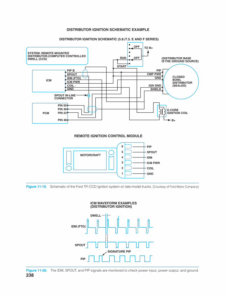
238
SYSTEM: REMOTE MOUNTEDDISTRIBUTOR,COMPUTER CONTROLLEDDWELL (CCD)
ICM
RUN
START
TO B+OFF
OFF (DISTRIBUTOR BASEIS THE GROUND SOURCE)
PIPCMP PWR
IGN GNDSHIELD
GND CLOSEDBOWLDISTRIBUTOR(SEALED)
E-COREIGNITION COIL
B+
PIP BSPOUTIDM (FTO)ICM PWRCOIL -GND
SPOUT IN-LINECONNECTOR
PCM
PIN 50PIN 49PIN 23
PIN 48
DISTRIBUTOR IGNITION SCHEMATIC (5.8./7.5. E AND F SERIES)
DISTRIBUTOR IGNITION SCHEMATIC EXAMPLE
REMOTE IGNITION CONTROL MODULE
MOTORCRAFT
6
5
4
3
2
1
PIP
SPOUT
IDM
ICM PWR
COIL
GND
Figure 11-19. Schematic of the Ford TFI CCD ignition system on late-model trucks. (Courtesy of Ford Motor Company)
IDM (FTO)
SPOUT
PIP
SIGNATURE PIP
DWELL
ICM WAVEFORM EXAMPLES (DISTRIBUTOR IGNITION)
Figure 11-20. The IDM, SPOUT, and PIP signals are monitored to check power input, power output, and ground.
ker88839_ch11.qxd 1/9/06 11:31 AM Page 238
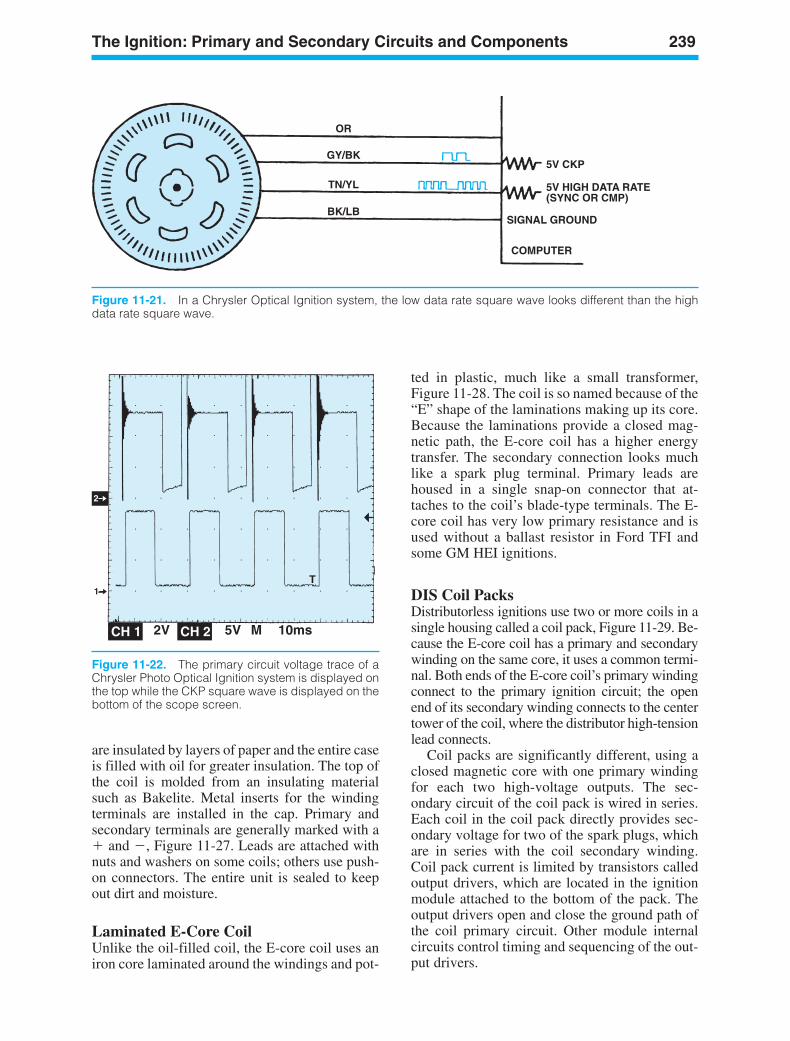
The Ignition: Primary and Secondary Circuits and Components 239
2V 5V M 10msCH 1 CH 2
2
1T
Figure 11-22. The primary circuit voltage trace of aChrysler Photo Optical Ignition system is displayed onthe top while the CKP square wave is displayed on thebottom of the scope screen.
are insulated by layers of paper and the entire caseis filled with oil for greater insulation. The top ofthe coil is molded from an insulating materialsuch as Bakelite. Metal inserts for the windingterminals are installed in the cap. Primary andsecondary terminals are generally marked with a and , Figure 11-27. Leads are attached withnuts and washers on some coils; others use push-on connectors. The entire unit is sealed to keepout dirt and moisture.
Laminated E-Core CoilUnlike the oil-filled coil, the E-core coil uses aniron core laminated around the windings and pot-
ted in plastic, much like a small transformer,Figure 11-28. The coil is so named because of the“E” shape of the laminations making up its core.Because the laminations provide a closed mag-netic path, the E-core coil has a higher energytransfer. The secondary connection looks muchlike a spark plug terminal. Primary leads arehoused in a single snap-on connector that at-taches to the coil’s blade-type terminals. The E-core coil has very low primary resistance and isused without a ballast resistor in Ford TFI andsome GM HEI ignitions.
DIS Coil PacksDistributorless ignitions use two or more coils in asingle housing called a coil pack, Figure 11-29. Be-cause the E-core coil has a primary and secondarywinding on the same core, it uses a common termi-nal. Both ends of the E-core coil’s primary windingconnect to the primary ignition circuit; the openend of its secondary winding connects to the centertower of the coil, where the distributor high-tensionlead connects.
Coil packs are significantly different, using aclosed magnetic core with one primary windingfor each two high-voltage outputs. The sec-ondary circuit of the coil pack is wired in series.Each coil in the coil pack directly provides sec-ondary voltage for two of the spark plugs, whichare in series with the coil secondary winding.Coil pack current is limited by transistors calledoutput drivers, which are located in the ignitionmodule attached to the bottom of the pack. Theoutput drivers open and close the ground path ofthe coil primary circuit. Other module internalcircuits control timing and sequencing of the out-put drivers.
5V HIGH DATA RATE (SYNC OR CMP)
SIGNAL GROUND
5V CKP
COMPUTER
OR
GY/BK
TN/YL
BK/LB
Figure 11-21. In a Chrysler Optical Ignition system, the low data rate square wave looks different than the highdata rate square wave.
ker88839_ch11.qxd 1/9/06 11:31 AM Page 239
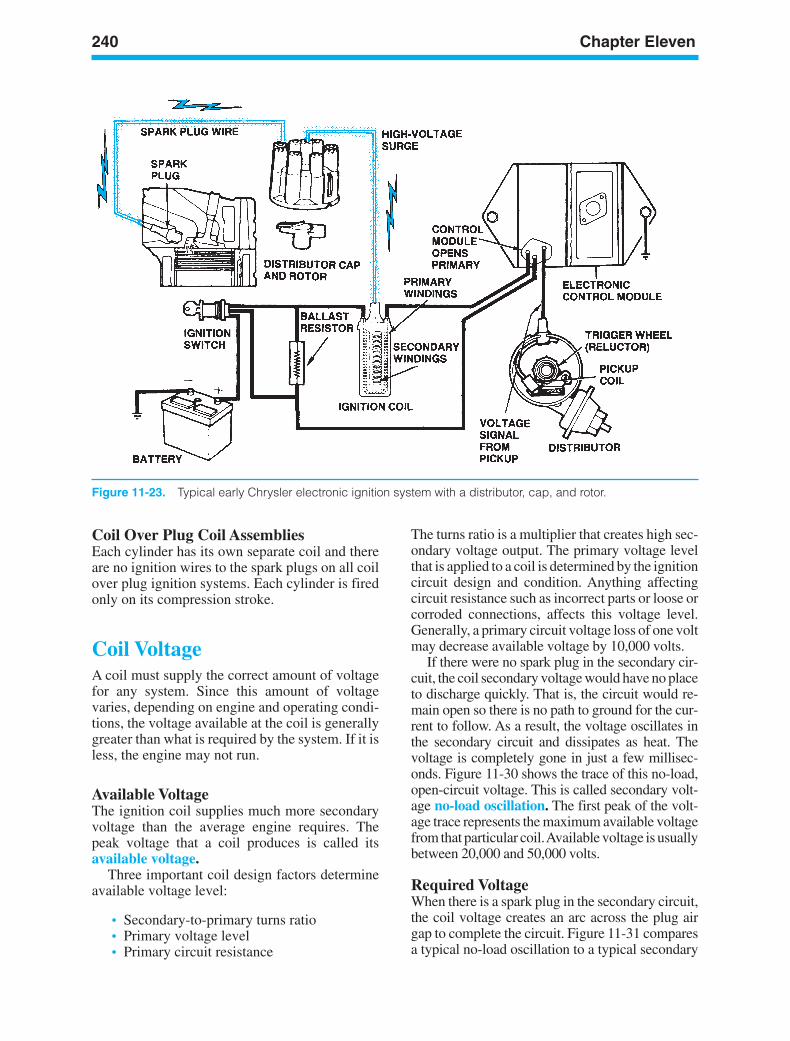
240 Chapter Eleven
Figure 11-23. Typical early Chrysler electronic ignition system with a distributor, cap, and rotor.
Coil Over Plug Coil AssembliesEach cylinder has its own separate coil and thereare no ignition wires to the spark plugs on all coilover plug ignition systems. Each cylinder is firedonly on its compression stroke.
Coil VoltageA coil must supply the correct amount of voltagefor any system. Since this amount of voltagevaries, depending on engine and operating condi-tions, the voltage available at the coil is generallygreater than what is required by the system. If it isless, the engine may not run.
Available VoltageThe ignition coil supplies much more secondaryvoltage than the average engine requires. Thepeak voltage that a coil produces is called itsavailable voltage.
Three important coil design factors determineavailable voltage level:
• Secondary-to-primary turns ratio• Primary voltage level• Primary circuit resistance
The turns ratio is a multiplier that creates high sec-ondary voltage output. The primary voltage levelthat is applied to a coil is determined by the ignitioncircuit design and condition. Anything affectingcircuit resistance such as incorrect parts or loose orcorroded connections, affects this voltage level.Generally, a primary circuit voltage loss of one voltmay decrease available voltage by 10,000 volts.
If there were no spark plug in the secondary cir-cuit, the coil secondary voltage would have no placeto discharge quickly. That is, the circuit would re-main open so there is no path to ground for the cur-rent to follow. As a result, the voltage oscillates inthe secondary circuit and dissipates as heat. Thevoltage is completely gone in just a few millisec-onds. Figure 11-30 shows the trace of this no-load,open-circuit voltage. This is called secondary volt-age no-load oscillation. The first peak of the volt-age trace represents the maximum available voltagefrom that particular coil.Available voltage is usuallybetween 20,000 and 50,000 volts.
Required VoltageWhen there is a spark plug in the secondary circuit,the coil voltage creates an arc across the plug airgap to complete the circuit. Figure 11-31 comparesa typical no-load oscillation to a typical secondary
ker88839_ch11.qxd 1/9/06 11:31 AM Page 240
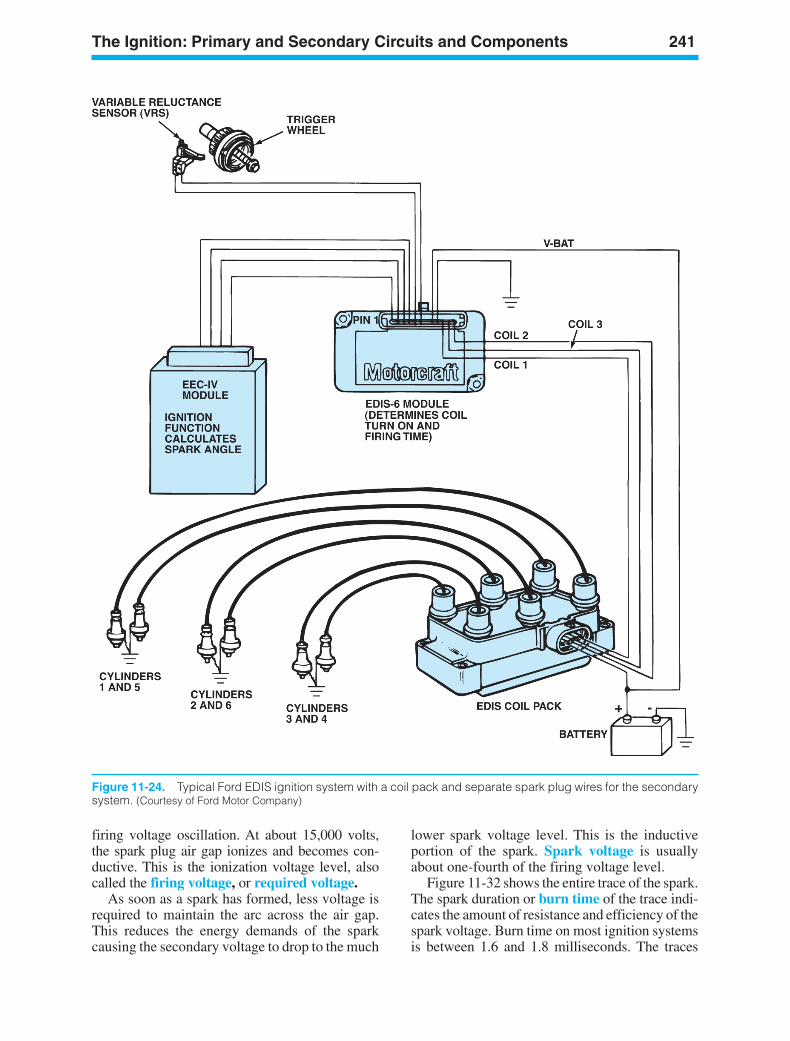
The Ignition: Primary and Secondary Circuits and Components 241
Figure 11-24. Typical Ford EDIS ignition system with a coil pack and separate spark plug wires for the secondarysystem. (Courtesy of Ford Motor Company)
firing voltage oscillation. At about 15,000 volts,the spark plug air gap ionizes and becomes con-ductive. This is the ionization voltage level, alsocalled the firing voltage, or required voltage.
As soon as a spark has formed, less voltage isrequired to maintain the arc across the air gap.This reduces the energy demands of the sparkcausing the secondary voltage to drop to the much
lower spark voltage level. This is the inductiveportion of the spark. Spark voltage is usuallyabout one-fourth of the firing voltage level.
Figure 11-32 shows the entire trace of the spark.The spark duration or burn time of the trace indi-cates the amount of resistance and efficiency of thespark voltage. Burn time on most ignition systemsis between 1.6 and 1.8 milliseconds. The traces
ker88839_ch11.qxd 1/9/06 11:31 AM Page 241
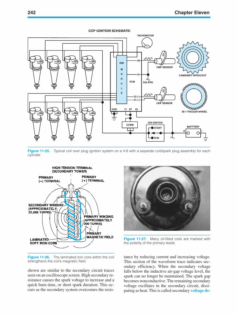
Figure 11-25. Typical coil over plug ignition system on a V-8 with a separate coil/spark plug assembly for eachcylinder.
Figure 11-26. The laminated iron core within the coilstrengthens the coil’s magnetic field.
Figure 11-27. Many oil-filled coils are marked withthe polarity of the primary leads.
tance by reducing current and increasing voltage.This section of the waveform trace indicates sec-ondary efficiency. When the secondary voltagefalls below the inductive air-gap voltage level, thespark can no longer be maintained. The spark gapbecomes nonconductive. The remaining secondaryvoltage oscillates in the secondary circuit, dissi-pating as heat. This is called secondary voltage de-
shown are similar to the secondary circuit tracesseen on an oscilloscope screen. High secondary re-sistance causes the spark voltage to increase and aquick burn time, or short spark duration. This oc-curs as the secondary system overcomes the resis-
242 Chapter Eleven
ker88839_ch11.qxd 1/9/06 11:31 AM Page 242
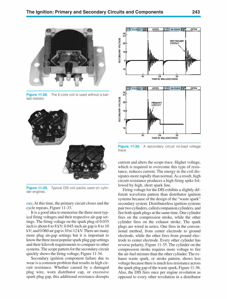
The Ignition: Primary and Secondary Circuits and Components 243
Figure 11-28. The E-core coil is used without a bal-last resistor.
Figure 11-29. Typical DIS coil packs used on cylin-der engines.
Figure 11-30. A secondary circuit no-load voltagetrace.
cay. At this time, the primary circuit closes and thecycle repeats, Figure 11-33.
It is a good idea to memorize the three most typ-ical firing voltages and their respective air-gap set-tings. The firing voltage on the spark plug of 0.035inch is about 6 to 8 kV; 0.045-inch air gap is 8 to 10kV; and 0.060 air gap is 10 to 12 kV. There are manymore plug air-gap settings but it is important toknow the three most popular spark plug gap settingsand their kilovolt requirements to compare to othersystems. The scope pattern for the secondary circuitquickly shows the firing voltage, Figure 11-34.
Secondary ignition component failure due towear is a common problem that results in high cir-cuit resistance. Whether caused by a damagedplug wire, worn distributor cap, or excessivespark plug gap, this additional resistance disrupts
current and alters the scope trace. Higher voltage,which is required to overcome this type of resis-tance, reduces current. The energy in the coil dis-sipates more rapidly than normal. As a result, highcircuit resistance produces a high firing spike fol-lowed by high, short spark line.
Firing voltage for the DIS exhibits a slightly dif-ferent waveform pattern than distributor ignitionsystems because of the design of the “waste spark”secondary system. Distributorless ignition systemspair two cylinders, called companion cylinders, andfire both spark plugs at the same time. One cylinderfires on the compression stroke, while the othercylinder fires on the exhaust stroke. The sparkplugs are wired in series. One fires in the conven-tional method, from center electrode to groundelectrode, while the other fires from ground elec-trode to center electrode. Every other cylinder hasreverse polarity, Figure 11-35. The cylinder on thecompression stroke requires more voltage to firethe air-fuel mixture than the other cylinder. The ex-haust waste spark, or stroke pattern, shows lessvoltage because there is much less resistance acrossthe spark plug gap of the waste spark, Figure 11-36.Also, the DIS fires once per engine revolution asopposed to every other revolution in a distributor
ker88839_ch11.qxd 1/9/06 11:31 AM Page 243
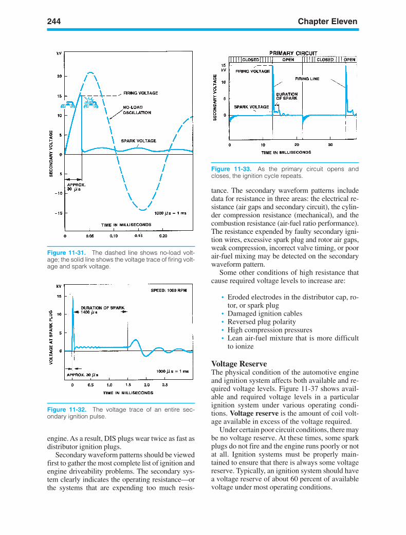
244 Chapter Eleven
Figure 11-31. The dashed line shows no-load volt-age; the solid line shows the voltage trace of firing volt-age and spark voltage.
Figure 11-32. The voltage trace of an entire sec-ondary ignition pulse.
Figure 11-33. As the primary circuit opens andcloses, the ignition cycle repeats.
engine. As a result, DIS plugs wear twice as fast asdistributor ignition plugs.
Secondary waveform patterns should be viewedfirst to gather the most complete list of ignition andengine driveability problems. The secondary sys-tem clearly indicates the operating resistance—orthe systems that are expending too much resis-
tance. The secondary waveform patterns includedata for resistance in three areas: the electrical re-sistance (air gaps and secondary circuit), the cylin-der compression resistance (mechanical), and thecombustion resistance (air-fuel ratio performance).The resistance expended by faulty secondary igni-tion wires, excessive spark plug and rotor air gaps,weak compression, incorrect valve timing, or poorair-fuel mixing may be detected on the secondarywaveform pattern.
Some other conditions of high resistance thatcause required voltage levels to increase are:
• Eroded electrodes in the distributor cap, ro-tor, or spark plug
• Damaged ignition cables• Reversed plug polarity• High compression pressures• Lean air-fuel mixture that is more difficult
to ionize
Voltage ReserveThe physical condition of the automotive engineand ignition system affects both available and re-quired voltage levels. Figure 11-37 shows avail-able and required voltage levels in a particularignition system under various operating condi-tions. Voltage reserve is the amount of coil volt-age available in excess of the voltage required.
Under certain poor circuit conditions, there maybe no voltage reserve. At these times, some sparkplugs do not fire and the engine runs poorly or notat all. Ignition systems must be properly main-tained to ensure that there is always some voltagereserve. Typically, an ignition system should havea voltage reserve of about 60 percent of availablevoltage under most operating conditions.
ker88839_ch11.qxd 1/9/06 11:31 AM Page 244
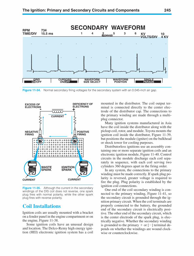
The Ignition: Primary and Secondary Circuits and Components 245
SECONDARY WAVEFORMRPMTIME/DIV KV 10
73415.5 ms 1 4 2 5 3 6
FROZEN VOLTS/DIV 4 KV
GRIDON/OFF
CURSORSON/OFF
WAVEFORMSIZE SELECT
WAVEFORMPOSITION
SINGLEPARADEPARADEOFFON
Figure 11-34. Normal secondary firing voltages for the secondary system with an 0.045-inch air gap.
EXCESS OFELECTRONS
CURRENT
DEFICIENCY OFELECTRONS
NEGATIVEFIRING
POSITIVEFIRING
- +
CURRENTCURRENT
WASTESPARK
IGNITIONSPARK
Figure 11-35. Although the current in the secondarywindings of the DIS coil does not reverse, one sparkplug fires with normal polarity, while the other sparkplug fires with reverse polarity.
Coil InstallationsIgnition coils are usually mounted with a bracketon a fender panel in the engine compartment or onthe engine, Figure 11-38.
Some ignition coils have an unusual designand location. The Delco-Remy high energy igni-tion (HEI) electronic ignition system has a coil
mounted in the distributor. The coil output ter-minal is connected directly to the center elec-trode of the distributor cap. The connections tothe primary winding are made through a multi-plug connector.
Many ignition systems manufactured in Asiahave the coil inside the distributor along with thepickup coil, rotor, and module. Toyota mounts theignition coil inside the distributor, Figure 11-39,but positions the module (igniter) on the bulkheador shock tower for cooling purposes.
Distributorless ignitions use an assembly con-taining one or more separate ignition coils and anelectronic ignition module, Figure 11-40. Controlcircuits in the module discharge each coil sepa-rately in sequence, with each coil serving twocylinders 360 degrees apart in the firing order.
In any system, the connections to the primarywinding must be made correctly. If spark plug po-larity is reversed, greater voltage is required tofire the plug. Plug polarity is established by theignition coil connections.
One end of the coil secondary winding is con-nected to the primary winding, Figure 11-41, sothe secondary circuit is grounded through the ig-nition primary circuit. When the coil terminals areproperly connected to the battery, the groundedend of the secondary circuit is electrically posi-tive. The other end of the secondary circuit, whichis the center electrode of the spark plug, is elec-trically negative. Whether the secondary windingis grounded to the primary or [] terminal de-pends on whether the windings are wound clock-wise or counterclockwise.
ker88839_ch11.qxd 1/9/06 11:31 AM Page 245
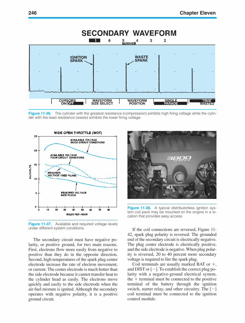
246 Chapter Eleven
Figure 11-36. The cylinder with the greatest resistance (compression) exhibits high firing voltage while the cylin-der with the least resistance (waste) exhibits the lower firing voltage.
Figure 11-37. Available and required voltage levelsunder different system conditions.
Figure 11-38. A typical distributorless ignition sys-tem coil pack may be mounted on the engine in a lo-cation that provides easy access.
The secondary circuit must have negative po-larity, or positive ground, for two main reasons.First, electrons flow more easily from negative topositive than they do in the opposite direction.Second, high temperatures of the spark plug centerelectrode increase the rate of electron movement,or current. The center electrode is much hotter thanthe side electrode because it cannot transfer heat tothe cylinder head as easily. The electrons movequickly and easily to the side electrode when theair-fuel mixture is ignited. Although the secondaryoperates with negative polarity, it is a positiveground circuit.
If the coil connections are reversed, Figure 11-42, spark plug polarity is reversed. The groundedend of the secondary circuit is electrically negative.The plug center electrode is electrically positive,and the side electrode is negative. When plug polar-ity is reversed, 20 to 40 percent more secondaryvoltage is required to fire the spark plug.
Coil terminals are usually marked BAT or ,and DIST or []. To establish the correct plug po-larity with a negative-ground electrical system,the terminal must be connected to the positiveterminal of the battery through the ignitionswitch, starter relay, and other circuitry. The []coil terminal must be connected to the ignitioncontrol module.
ker88839_ch11.qxd 1/9/06 11:31 AM Page 246
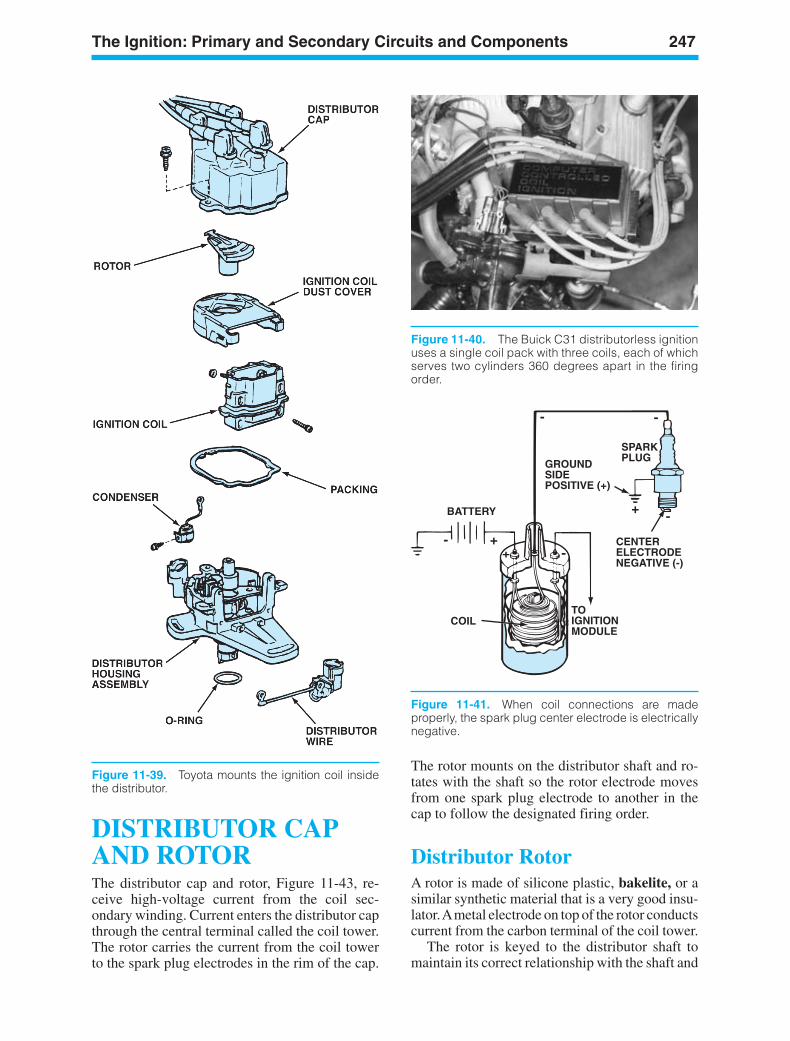
The Ignition: Primary and Secondary Circuits and Components 247
Figure 11-39. Toyota mounts the ignition coil insidethe distributor.
Figure 11-40. The Buick C31 distributorless ignitionuses a single coil pack with three coils, each of whichserves two cylinders 360 degrees apart in the firingorder.
BATTERY
COIL
-
-
-+
+
- -
SPARKPLUG
CONDENSER
BREAKERPOINTS
GROUNDSIDE POSITIVE (+)
CENTERELECTRODENEGATIVE (-)
TOIGNITIONMODULE
Figure 11-41. When coil connections are madeproperly, the spark plug center electrode is electricallynegative.
DISTRIBUTOR CAPAND ROTORThe distributor cap and rotor, Figure 11-43, re-ceive high-voltage current from the coil sec-ondary winding. Current enters the distributor capthrough the central terminal called the coil tower.The rotor carries the current from the coil towerto the spark plug electrodes in the rim of the cap.
The rotor mounts on the distributor shaft and ro-tates with the shaft so the rotor electrode movesfrom one spark plug electrode to another in thecap to follow the designated firing order.
Distributor RotorA rotor is made of silicone plastic, bakelite, or asimilar synthetic material that is a very good insu-lator.Ametal electrode on top of the rotor conductscurrent from the carbon terminal of the coil tower.
The rotor is keyed to the distributor shaft tomaintain its correct relationship with the shaft and
ker88839_ch11.qxd 1/9/06 11:31 AM Page 247
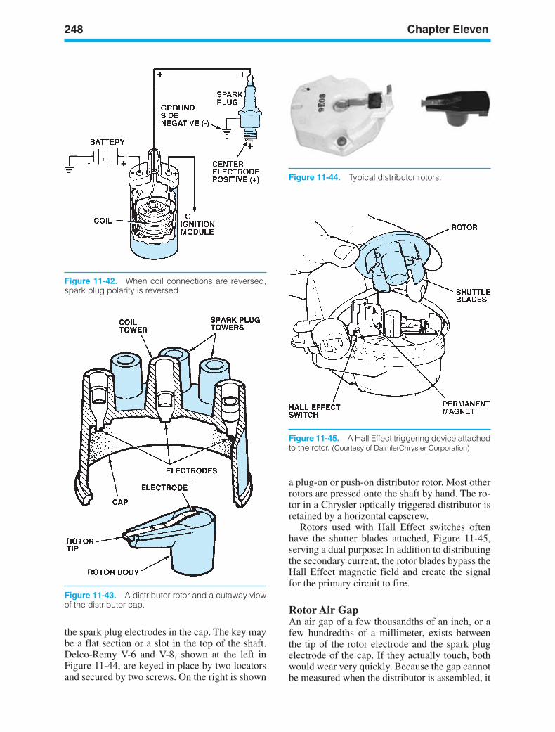
248 Chapter Eleven
the spark plug electrodes in the cap. The key maybe a flat section or a slot in the top of the shaft.Delco-Remy V-6 and V-8, shown at the left inFigure 11-44, are keyed in place by two locatorsand secured by two screws. On the right is shown
a plug-on or push-on distributor rotor. Most otherrotors are pressed onto the shaft by hand. The ro-tor in a Chrysler optically triggered distributor isretained by a horizontal capscrew.
Rotors used with Hall Effect switches oftenhave the shutter blades attached, Figure 11-45,serving a dual purpose: In addition to distributingthe secondary current, the rotor blades bypass theHall Effect magnetic field and create the signalfor the primary circuit to fire.
Rotor Air GapAn air gap of a few thousandths of an inch, or afew hundredths of a millimeter, exists betweenthe tip of the rotor electrode and the spark plugelectrode of the cap. If they actually touch, bothwould wear very quickly. Because the gap cannotbe measured when the distributor is assembled, it
Figure 11-42. When coil connections are reversed,spark plug polarity is reversed.
Figure 11-43. A distributor rotor and a cutaway viewof the distributor cap.
Figure 11-44. Typical distributor rotors.
Figure 11-45. A Hall Effect triggering device attachedto the rotor. (Courtesy of DaimlerChrysler Corporation)
ker88839_ch11.qxd 1/9/06 11:31 AM Page 248

The Ignition: Primary and Secondary Circuits and Components 249
is usually described in terms of the voltage re-quired to create an arc across the electrodes. Onlyabout 3,000 volts are required to create an arcacross some air gaps, but others require as muchas 9,000 volts. As the rotor completes the sec-ondary circuit and the plug fires, the rotor air gapadds resistance to the circuit. This raises the plugfiring voltage, suppresses secondary current, andreduces RFI.
Distributor CapThe distributor cap is also made of silicone plas-tic, Bakelite, or a similar material that resistschemical attack and protects other distributorparts. Metal electrodes in the spark plug towersand a carbon insert in the coil tower provide elec-trical connections with the ignition cables and therotor electrode. The cap is keyed to the distributorhousing and is held on by two or four spring-loaded clips or by screws.
Delco-Remy HEI distributor caps with an inte-gral coil, Figure 11-46, are secured by four spring-loaded clips. When removing this cap, ensure thatall four clips are disengaged and clear of the hous-ing.Then lift the cap straight up to avoid bending thecarbon button in the cap and the spring that connectsit to the coil. If the button and spring are distorted,arcing can occur that will burn the cap and rotor.
COVER
COIL
DISTRIBUTORCAP
CABLESAND LOOMS
Figure 11-46. Many Delco-Remy HEI electronic ignition systems used on V-6 and V-8 engines have a coilmounted in the distributor cap.
Positive-engagement spark plug cables areused with some Chrysler and Ford 4-cylinder ig-nition systems. There are no electrodes in distrib-utor caps used with these cables. A terminalelectrode attached to the distributor-cap end ofthe cable locks inside the cap to form the distrib-utor contact terminal. The secondary terminal ofthe cable is pressed into the cap, Figure 11-47.
Figure 11-47. Chrysler 4 cylinder distributors haveused positive locking terminal electrodes as part of theignition cable since 1980. (Courtesy of DaimlerChryslerCorporation)
ker88839_ch11.qxd 1/9/06 11:31 AM Page 249
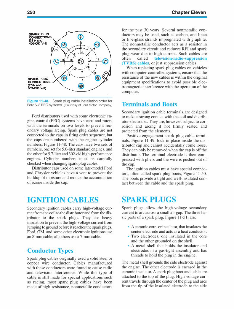
250 Chapter Eleven
Figure 11-48. Spark plug cable installation order forFord V-8 EEC systems. (Courtesy of Ford Motor Company)
Ford distributors used with some electronic en-gine control (EEC) systems have caps and rotorswith the terminals on two levels to prevent sec-ondary voltage arcing. Spark plug cables are notconnected to the caps in firing order sequence, butthe caps are numbered with the engine cylindernumbers, Figure 11-48. The caps have two sets ofnumbers, one set for 5.0-liter standard engines, andthe other for 5.7-liter and 302-cid high-performanceengines. Cylinder numbers must be carefullychecked when changing spark plug cables.
Distributor caps used on some late-model Fordand Chrysler vehicles have a vent to prevent thebuildup of moisture and reduce the accumulationof ozone inside the cap.
IGNITION CABLESSecondary ignition cables carry high-voltage cur-rent from the coil to the distributor and from the dis-tributor to the spark plugs. They use heavyinsulation to prevent the high-voltage current fromjumping to ground before it reaches the spark plugs.Ford, GM, and some other electronic ignitions usean 8-mm cable; all others use a 7-mm cable.
Conductor TypesSpark plug cables originally used a solid steel orcopper wire conductor. Cables manufacturedwith these conductors were found to cause radioand television interference. While this type ofcable is still made for special applications suchas racing, most spark plug cables have beenmade of high-resistance, nonmetallic conductors
for the past 30 years. Several nonmetallic con-ductors may be used, such as carbon, and linenor fiberglass strands impregnated with graphite.The nonmetallic conductor acts as a resistor inthe secondary circuit and reduces RFI and sparkplug wear due to high current. Such cables areoften called television-radio-suppression(TVRS) cables, or just suppression cables.
When replacing spark plug cables on vehicleswith computer-controlled systems, ensure that theresistance of the new cables is within the originalequipment specifications to avoid possible elec-tromagnetic interference with the operation of thecomputer.
Terminals and BootsSecondary ignition cable terminals are designedto make a strong contact with the coil and distrib-utor electrodes. They are, however, subject to cor-rosion and arcing if not firmly seated andprotected from the elements.
Positive-engagement spark plug cable termi-nals, Figure 11-49, lock in place inside the dis-tributor cap and cannot accidentally come loose.They can only be removed when the cap is off thedistributor. The terminal electrode is then com-pressed with pliers and the wire is pushed out ofthe cap.
The ignition cables must have special connec-tors, often called spark plug boots, Figure 11-50.The boots provide a tight and well-insulated con-tact between the cable and the spark plug.
SPARK PLUGSSpark plugs allow the high-voltage secondarycurrent to arc across a small air gap. The three ba-sic parts of a spark plug, Figure 11-51, are:
• Aceramic core, or insulator, that insulates thecenter electrode and acts as a heat conductor.
• Two electrodes, one insulated in the coreand the other grounded on the shell.
• A metal shell that holds the insulator andelectrodes in a gas-tight assembly and hasthreads to hold the plug in the engine.
The metal shell grounds the side electrode againstthe engine. The other electrode is encased in theceramic insulator. A spark plug boot and cable areattached to the top of the plug. High-voltage cur-rent travels through the center of the plug and arcsfrom the tip of the insulated electrode to the side
ker88839_ch11.qxd 1/9/06 11:31 AM Page 250
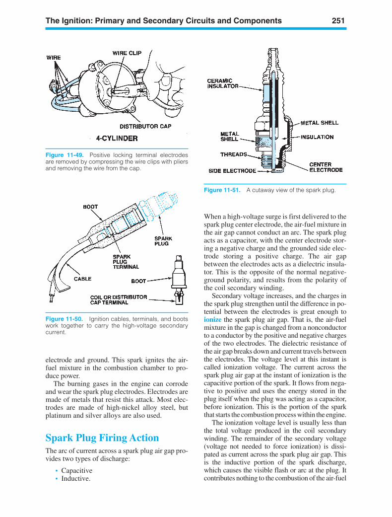
The Ignition: Primary and Secondary Circuits and Components 251
Figure 11-50. Ignition cables, terminals, and bootswork together to carry the high-voltage secondarycurrent.
electrode and ground. This spark ignites the air-fuel mixture in the combustion chamber to pro-duce power.
The burning gases in the engine can corrodeand wear the spark plug electrodes. Electrodes aremade of metals that resist this attack. Most elec-trodes are made of high-nickel alloy steel, butplatinum and silver alloys are also used.
Spark Plug Firing ActionThe arc of current across a spark plug air gap pro-vides two types of discharge:
• Capacitive• Inductive.
When a high-voltage surge is first delivered to thespark plug center electrode, the air-fuel mixture inthe air gap cannot conduct an arc. The spark plugacts as a capacitor, with the center electrode stor-ing a negative charge and the grounded side elec-trode storing a positive charge. The air gapbetween the electrodes acts as a dielectric insula-tor. This is the opposite of the normal negative-ground polarity, and results from the polarity ofthe coil secondary winding.
Secondary voltage increases, and the charges inthe spark plug strengthen until the difference in po-tential between the electrodes is great enough toionize the spark plug air gap. That is, the air-fuelmixture in the gap is changed from a nonconductorto a conductor by the positive and negative chargesof the two electrodes. The dielectric resistance ofthe air gap breaks down and current travels betweenthe electrodes. The voltage level at this instant iscalled ionization voltage. The current across thespark plug air gap at the instant of ionization is thecapacitive portion of the spark. It flows from nega-tive to positive and uses the energy stored in theplug itself when the plug was acting as a capacitor,before ionization. This is the portion of the sparkthat starts the combustion process within the engine.
The ionization voltage level is usually less thanthe total voltage produced in the coil secondarywinding. The remainder of the secondary voltage(voltage not needed to force ionization) is dissi-pated as current across the spark plug air gap. Thisis the inductive portion of the spark discharge,which causes the visible flash or arc at the plug. Itcontributes nothing to the combustion of the air-fuel
Figure 11-49. Positive locking terminal electrodesare removed by compressing the wire clips with pliersand removing the wire from the cap.
Figure 11-51. A cutaway view of the spark plug.
ker88839_ch11.qxd 1/9/06 11:31 AM Page 251
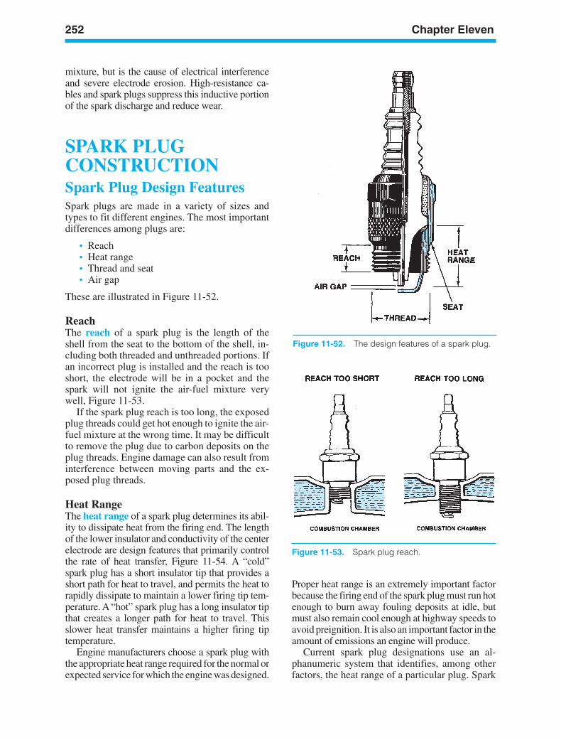
252 Chapter Eleven
mixture, but is the cause of electrical interferenceand severe electrode erosion. High-resistance ca-bles and spark plugs suppress this inductive portionof the spark discharge and reduce wear.
SPARK PLUGCONSTRUCTIONSpark Plug Design FeaturesSpark plugs are made in a variety of sizes andtypes to fit different engines. The most importantdifferences among plugs are:
• Reach• Heat range• Thread and seat• Air gap
These are illustrated in Figure 11-52.
ReachThe reach of a spark plug is the length of theshell from the seat to the bottom of the shell, in-cluding both threaded and unthreaded portions. Ifan incorrect plug is installed and the reach is tooshort, the electrode will be in a pocket and thespark will not ignite the air-fuel mixture verywell, Figure 11-53.
If the spark plug reach is too long, the exposedplug threads could get hot enough to ignite the air-fuel mixture at the wrong time. It may be difficultto remove the plug due to carbon deposits on theplug threads. Engine damage can also result frominterference between moving parts and the ex-posed plug threads.
Heat RangeThe heat range of a spark plug determines its abil-ity to dissipate heat from the firing end. The lengthof the lower insulator and conductivity of the centerelectrode are design features that primarily controlthe rate of heat transfer, Figure 11-54. A “cold”spark plug has a short insulator tip that provides ashort path for heat to travel, and permits the heat torapidly dissipate to maintain a lower firing tip tem-perature. A “hot” spark plug has a long insulator tipthat creates a longer path for heat to travel. Thisslower heat transfer maintains a higher firing tiptemperature.
Engine manufacturers choose a spark plug withthe appropriate heat range required for the normal orexpected service for which the engine was designed.
Proper heat range is an extremely important factorbecause the firing end of the spark plug must run hotenough to burn away fouling deposits at idle, butmust also remain cool enough at highway speeds toavoid preignition. It is also an important factor in theamount of emissions an engine will produce.
Current spark plug designations use an al-phanumeric system that identifies, among otherfactors, the heat range of a particular plug. Spark
Figure 11-52. The design features of a spark plug.
Figure 11-53. Spark plug reach.
ker88839_ch11.qxd 1/9/06 11:31 AM Page 252
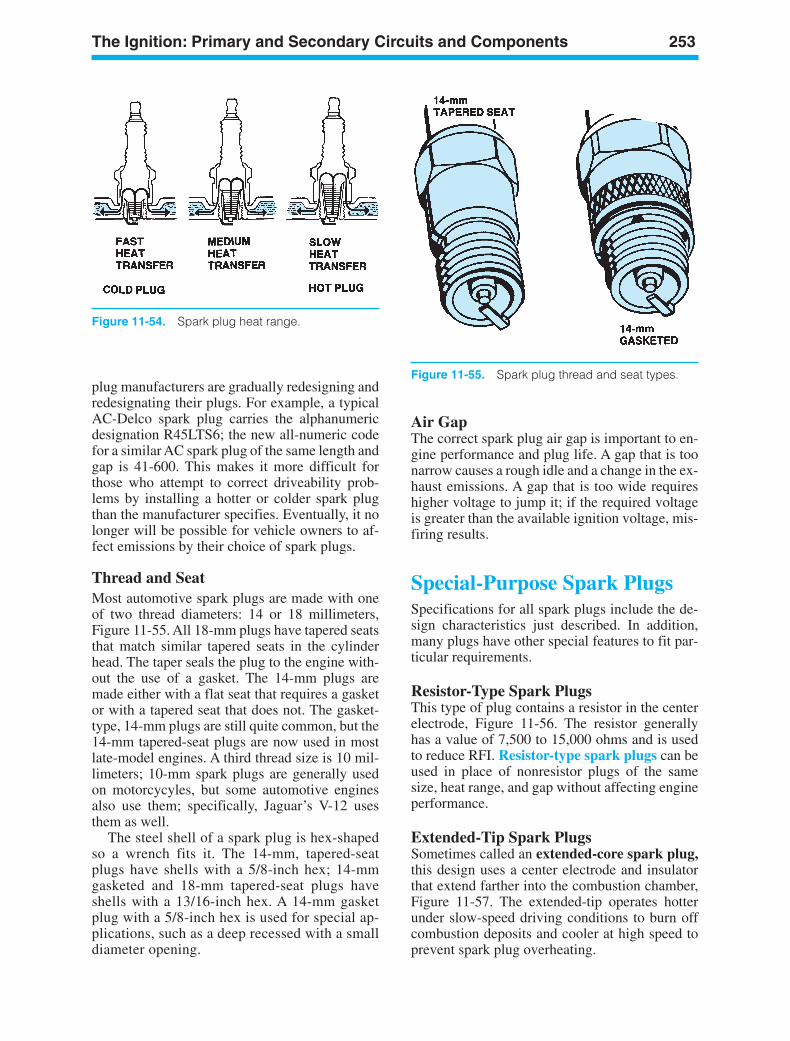
The Ignition: Primary and Secondary Circuits and Components 253
Air GapThe correct spark plug air gap is important to en-gine performance and plug life. A gap that is toonarrow causes a rough idle and a change in the ex-haust emissions. A gap that is too wide requireshigher voltage to jump it; if the required voltageis greater than the available ignition voltage, mis-firing results.
Special-Purpose Spark PlugsSpecifications for all spark plugs include the de-sign characteristics just described. In addition,many plugs have other special features to fit par-ticular requirements.
Resistor-Type Spark PlugsThis type of plug contains a resistor in the centerelectrode, Figure 11-56. The resistor generallyhas a value of 7,500 to 15,000 ohms and is usedto reduce RFI. Resistor-type spark plugs can beused in place of nonresistor plugs of the samesize, heat range, and gap without affecting engineperformance.
Extended-Tip Spark PlugsSometimes called an extended-core spark plug,this design uses a center electrode and insulatorthat extend farther into the combustion chamber,Figure 11-57. The extended-tip operates hotterunder slow-speed driving conditions to burn offcombustion deposits and cooler at high speed toprevent spark plug overheating.
plug manufacturers are gradually redesigning andredesignating their plugs. For example, a typicalAC-Delco spark plug carries the alphanumericdesignation R45LTS6; the new all-numeric codefor a similar AC spark plug of the same length andgap is 41-600. This makes it more difficult forthose who attempt to correct driveability prob-lems by installing a hotter or colder spark plugthan the manufacturer specifies. Eventually, it nolonger will be possible for vehicle owners to af-fect emissions by their choice of spark plugs.
Thread and SeatMost automotive spark plugs are made with oneof two thread diameters: 14 or 18 millimeters,Figure 11-55. All 18-mm plugs have tapered seatsthat match similar tapered seats in the cylinderhead. The taper seals the plug to the engine with-out the use of a gasket. The 14-mm plugs aremade either with a flat seat that requires a gasketor with a tapered seat that does not. The gasket-type, 14-mm plugs are still quite common, but the14-mm tapered-seat plugs are now used in mostlate-model engines. A third thread size is 10 mil-limeters; 10-mm spark plugs are generally usedon motorcycyles, but some automotive enginesalso use them; specifically, Jaguar’s V-12 usesthem as well.
The steel shell of a spark plug is hex-shapedso a wrench fits it. The 14-mm, tapered-seatplugs have shells with a 5/8-inch hex; 14-mmgasketed and 18-mm tapered-seat plugs haveshells with a 13/16-inch hex. A 14-mm gasketplug with a 5/8-inch hex is used for special ap-plications, such as a deep recessed with a smalldiameter opening.
Figure 11-54. Spark plug heat range.
Figure 11-55. Spark plug thread and seat types.
ker88839_ch11.qxd 1/9/06 11:31 AM Page 253
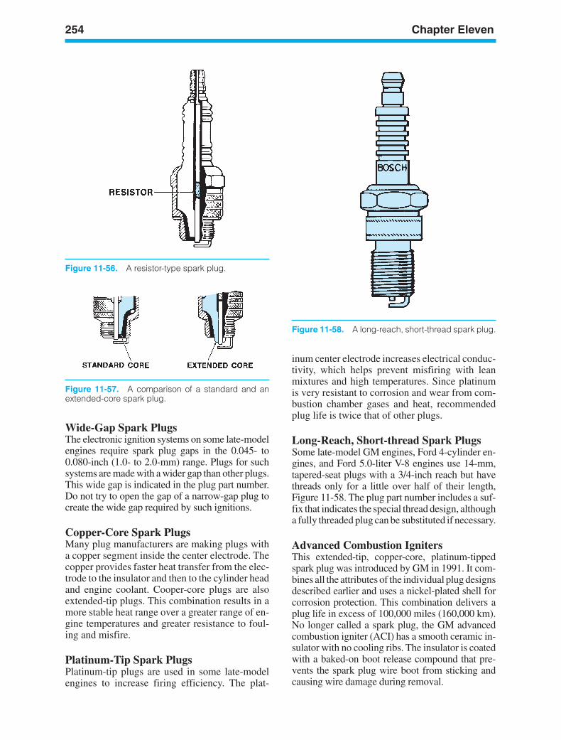
254 Chapter Eleven
Wide-Gap Spark PlugsThe electronic ignition systems on some late-modelengines require spark plug gaps in the 0.045- to0.080-inch (1.0- to 2.0-mm) range. Plugs for suchsystems are made with a wider gap than other plugs.This wide gap is indicated in the plug part number.Do not try to open the gap of a narrow-gap plug tocreate the wide gap required by such ignitions.
Copper-Core Spark PlugsMany plug manufacturers are making plugs witha copper segment inside the center electrode. Thecopper provides faster heat transfer from the elec-trode to the insulator and then to the cylinder headand engine coolant. Cooper-core plugs are alsoextended-tip plugs. This combination results in amore stable heat range over a greater range of en-gine temperatures and greater resistance to foul-ing and misfire.
Platinum-Tip Spark PlugsPlatinum-tip plugs are used in some late-modelengines to increase firing efficiency. The plat-
inum center electrode increases electrical conduc-tivity, which helps prevent misfiring with leanmixtures and high temperatures. Since platinumis very resistant to corrosion and wear from com-bustion chamber gases and heat, recommendedplug life is twice that of other plugs.
Long-Reach, Short-thread Spark PlugsSome late-model GM engines, Ford 4-cylinder en-gines, and Ford 5.0-liter V-8 engines use 14-mm,tapered-seat plugs with a 3/4-inch reach but havethreads only for a little over half of their length,Figure 11-58. The plug part number includes a suf-fix that indicates the special thread design, althougha fully threaded plug can be substituted if necessary.
Advanced Combustion IgnitersThis extended-tip, copper-core, platinum-tippedspark plug was introduced by GM in 1991. It com-bines all the attributes of the individual plug designsdescribed earlier and uses a nickel-plated shell forcorrosion protection. This combination delivers aplug life in excess of 100,000 miles (160,000 km).No longer called a spark plug, the GM advancedcombustion igniter (ACI) has a smooth ceramic in-sulator with no cooling ribs. The insulator is coatedwith a baked-on boot release compound that pre-vents the spark plug wire boot from sticking andcausing wire damage during removal.
Figure 11-56. A resistor-type spark plug.
Figure 11-57. A comparison of a standard and anextended-core spark plug.
Figure 11-58. A long-reach, short-thread spark plug.
ker88839_ch11.qxd 1/9/06 11:31 AM Page 254
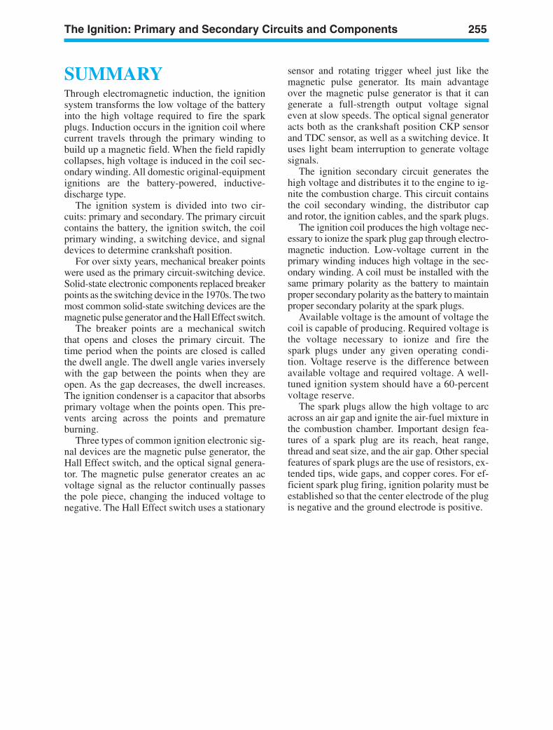
The Ignition: Primary and Secondary Circuits and Components 255
SUMMARYThrough electromagnetic induction, the ignitionsystem transforms the low voltage of the batteryinto the high voltage required to fire the sparkplugs. Induction occurs in the ignition coil wherecurrent travels through the primary winding tobuild up a magnetic field. When the field rapidlycollapses, high voltage is induced in the coil sec-ondary winding. All domestic original-equipmentignitions are the battery-powered, inductive-discharge type.
The ignition system is divided into two cir-cuits: primary and secondary. The primary circuitcontains the battery, the ignition switch, the coilprimary winding, a switching device, and signaldevices to determine crankshaft position.
For over sixty years, mechanical breaker pointswere used as the primary circuit-switching device.Solid-state electronic components replaced breakerpoints as the switching device in the 1970s. The twomost common solid-state switching devices are themagnetic pulse generator and the Hall Effect switch.
The breaker points are a mechanical switchthat opens and closes the primary circuit. Thetime period when the points are closed is calledthe dwell angle. The dwell angle varies inverselywith the gap between the points when they areopen. As the gap decreases, the dwell increases.The ignition condenser is a capacitor that absorbsprimary voltage when the points open. This pre-vents arcing across the points and prematureburning.
Three types of common ignition electronic sig-nal devices are the magnetic pulse generator, theHall Effect switch, and the optical signal genera-tor. The magnetic pulse generator creates an acvoltage signal as the reluctor continually passesthe pole piece, changing the induced voltage tonegative. The Hall Effect switch uses a stationary
sensor and rotating trigger wheel just like themagnetic pulse generator. Its main advantageover the magnetic pulse generator is that it cangenerate a full-strength output voltage signaleven at slow speeds. The optical signal generatoracts both as the crankshaft position CKP sensorand TDC sensor, as well as a switching device. Ituses light beam interruption to generate voltagesignals.
The ignition secondary circuit generates thehigh voltage and distributes it to the engine to ig-nite the combustion charge. This circuit containsthe coil secondary winding, the distributor capand rotor, the ignition cables, and the spark plugs.
The ignition coil produces the high voltage nec-essary to ionize the spark plug gap through electro-magnetic induction. Low-voltage current in theprimary winding induces high voltage in the sec-ondary winding. A coil must be installed with thesame primary polarity as the battery to maintainproper secondary polarity as the battery to maintainproper secondary polarity at the spark plugs.
Available voltage is the amount of voltage thecoil is capable of producing. Required voltage isthe voltage necessary to ionize and fire thespark plugs under any given operating condi-tion. Voltage reserve is the difference betweenavailable voltage and required voltage. A well-tuned ignition system should have a 60-percentvoltage reserve.
The spark plugs allow the high voltage to arcacross an air gap and ignite the air-fuel mixture inthe combustion chamber. Important design fea-tures of a spark plug are its reach, heat range,thread and seat size, and the air gap. Other specialfeatures of spark plugs are the use of resistors, ex-tended tips, wide gaps, and copper cores. For ef-ficient spark plug firing, ignition polarity must beestablished so that the center electrode of the plugis negative and the ground electrode is positive.
ker88839_ch11.qxd 1/9/06 11:31 AM Page 255
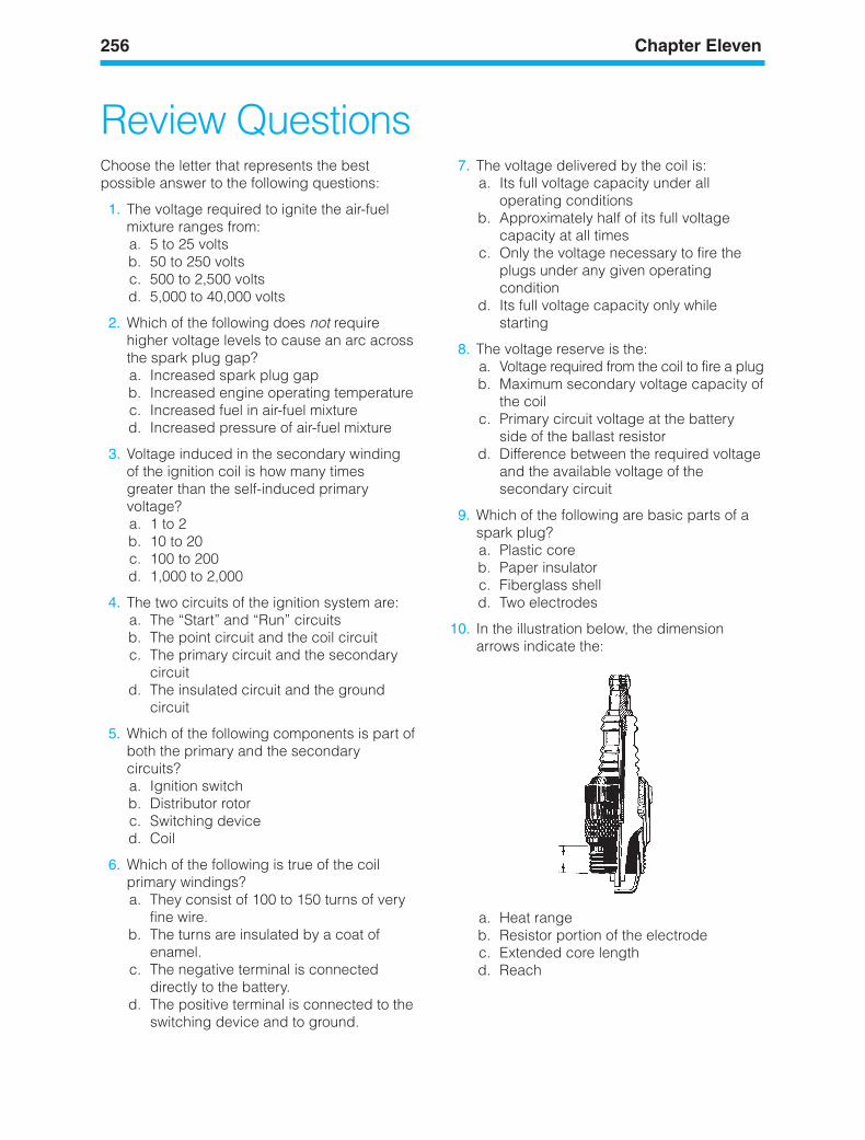
256 Chapter Eleven
Review QuestionsChoose the letter that represents the bestpossible answer to the following questions:
1. The voltage required to ignite the air-fuelmixture ranges from:a. 5 to 25 voltsb. 50 to 250 voltsc. 500 to 2,500 voltsd. 5,000 to 40,000 volts
2. Which of the following does not requirehigher voltage levels to cause an arc acrossthe spark plug gap?a. Increased spark plug gapb. Increased engine operating temperaturec. Increased fuel in air-fuel mixtured. Increased pressure of air-fuel mixture
3. Voltage induced in the secondary windingof the ignition coil is how many timesgreater than the self-induced primaryvoltage?a. 1 to 2b. 10 to 20c. 100 to 200d. 1,000 to 2,000
4. The two circuits of the ignition system are:a. The “Start” and “Run” circuitsb. The point circuit and the coil circuitc. The primary circuit and the secondary
circuitd. The insulated circuit and the ground
circuit
5. Which of the following components is part ofboth the primary and the secondarycircuits?a. Ignition switchb. Distributor rotorc. Switching deviced. Coil
6. Which of the following is true of the coilprimary windings?a. They consist of 100 to 150 turns of very
fine wire.b. The turns are insulated by a coat of
enamel.c. The negative terminal is connected
directly to the battery.d. The positive terminal is connected to the
switching device and to ground.
7. The voltage delivered by the coil is:a. Its full voltage capacity under all
operating conditionsb. Approximately half of its full voltage
capacity at all timesc. Only the voltage necessary to fire the
plugs under any given operatingcondition
d. Its full voltage capacity only whilestarting
8. The voltage reserve is the:a. Voltage required from the coil to fire a plugb. Maximum secondary voltage capacity of
the coilc. Primary circuit voltage at the battery
side of the ballast resistord. Difference between the required voltage
and the available voltage of thesecondary circuit
9. Which of the following are basic parts of aspark plug?a. Plastic coreb. Paper insulatorc. Fiberglass shelld. Two electrodes
10. In the illustration below, the dimensionarrows indicate the:
a. Heat rangeb. Resistor portion of the electrodec. Extended core lengthd. Reach
ker88839_ch11.qxd 1/9/06 11:31 AM Page 256
LEARNINGOBJECTIVESUpon completion and review of this chapter, youshould be able to:
• Identify and explain the operation of mostautomotive headlight systems.
• Identify the common bulbs used in automo-tive lighting systems.
• Define the taillamp, license plate lamp, andparking lamp circuits.
• Identify the components and define the stoplamp and turn signal circuits.
• Define the hazard warning lamp (emer-gency flasher) circuit.
• Identify the components and explain theoperation of the backup light, side marker,and clearance lamp circuits.
• Identify the components and explain theoperation of the instrument panel lighting.
KEY TERMSAsymmetricalBackup LampsClearance MarkersDaytime Running Lights (DRL)Dimmer SwitchFlasher UnitsHalogen Sealed-Beam HeadlampsHazard Warning LampHeadlamp CircuitHigh-Intensity Discharge (HID) LampPotentiometersRheostatsSealed-Beam HeadlampsSide Marker LampsStop LampsSymmetricalTurn Signal Switch
INTRODUCTIONAutomotive lighting circuits include importantsafety features, so they must be properly under-stood and serviced. Lighting circuits follow generalpatterns, according to the devices they serve,although slight variations appear from manufac-turer to manufacturer.
257
12AutomotiveLightingSystems
ker88839_ch12.qxd 1/9/06 11:32 AM Page 257
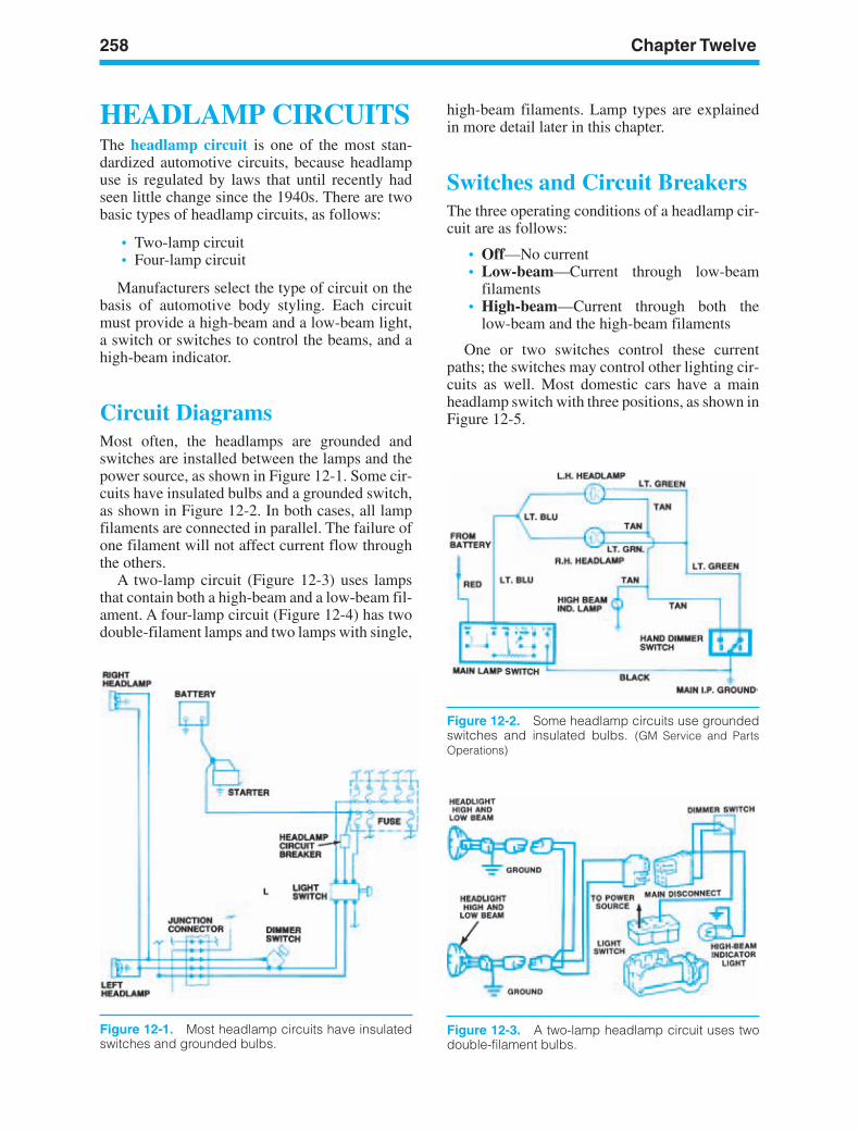
258 Chapter Twelve
HEADLAMP CIRCUITSThe headlamp circuit is one of the most stan-dardized automotive circuits, because headlampuse is regulated by laws that until recently hadseen little change since the 1940s. There are twobasic types of headlamp circuits, as follows:
• Two-lamp circuit• Four-lamp circuit
Manufacturers select the type of circuit on thebasis of automotive body styling. Each circuitmust provide a high-beam and a low-beam light,a switch or switches to control the beams, and ahigh-beam indicator.
Circuit DiagramsMost often, the headlamps are grounded andswitches are installed between the lamps and thepower source, as shown in Figure 12-1. Some cir-cuits have insulated bulbs and a grounded switch,as shown in Figure 12-2. In both cases, all lampfilaments are connected in parallel. The failure ofone filament will not affect current flow throughthe others.
A two-lamp circuit (Figure 12-3) uses lampsthat contain both a high-beam and a low-beam fil-ament. A four-lamp circuit (Figure 12-4) has twodouble-filament lamps and two lamps with single,
high-beam filaments. Lamp types are explainedin more detail later in this chapter.
Switches and Circuit BreakersThe three operating conditions of a headlamp cir-cuit are as follows:
• Off—No current• Low-beam—Current through low-beam
filaments• High-beam—Current through both the
low-beam and the high-beam filaments
One or two switches control these currentpaths; the switches may control other lighting cir-cuits as well. Most domestic cars have a mainheadlamp switch with three positions, as shown inFigure 12-5.
Figure 12-1. Most headlamp circuits have insulatedswitches and grounded bulbs.
Figure 12-2. Some headlamp circuits use groundedswitches and insulated bulbs. (GM Service and PartsOperations)
Figure 12-3. A two-lamp headlamp circuit uses twodouble-filament bulbs.
ker88839_ch12.qxd 1/9/06 11:32 AM Page 258
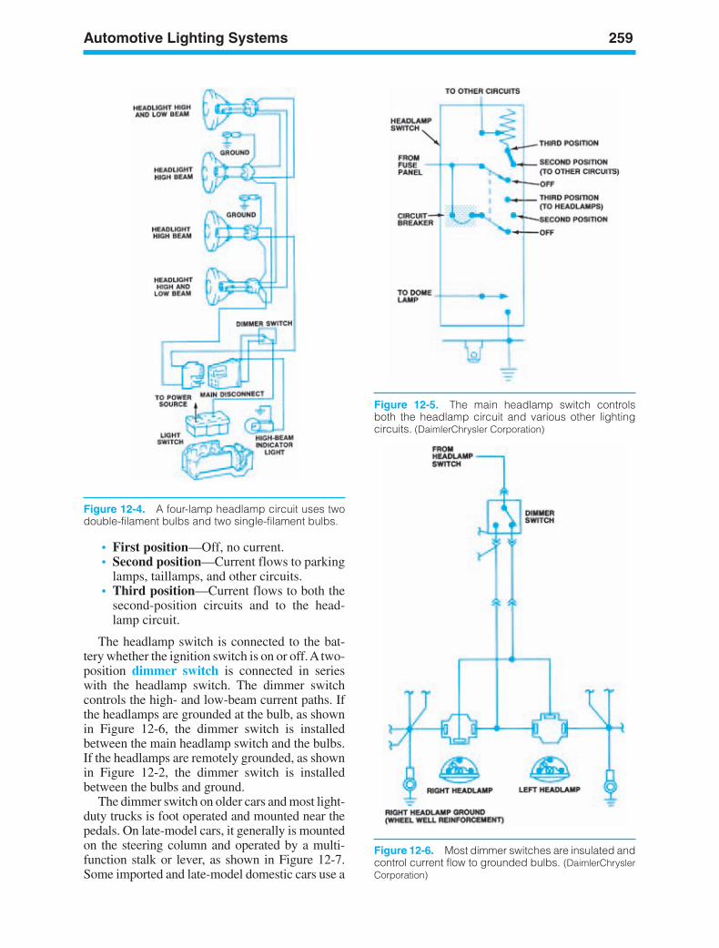
Automotive Lighting Systems 259
Figure 12-4. A four-lamp headlamp circuit uses twodouble-filament bulbs and two single-filament bulbs.
• First position—Off, no current.• Second position—Current flows to parking
lamps, taillamps, and other circuits.• Third position—Current flows to both the
second-position circuits and to the head-lamp circuit.
The headlamp switch is connected to the bat-tery whether the ignition switch is on or off. A two-position dimmer switch is connected in serieswith the headlamp switch. The dimmer switchcontrols the high- and low-beam current paths. Ifthe headlamps are grounded at the bulb, as shownin Figure 12-6, the dimmer switch is installedbetween the main headlamp switch and the bulbs.If the headlamps are remotely grounded, as shownin Figure 12-2, the dimmer switch is installedbetween the bulbs and ground.
The dimmer switch on older cars and most light-duty trucks is foot operated and mounted near thepedals. On late-model cars, it generally is mountedon the steering column and operated by a multi-function stalk or lever, as shown in Figure 12-7.Some imported and late-model domestic cars use a
Figure 12-5. The main headlamp switch controlsboth the headlamp circuit and various other lightingcircuits. (DaimlerChrysler Corporation)
Figure 12-6. Most dimmer switches are insulated andcontrol current flow to grounded bulbs. (DaimlerChryslerCorporation)
ker88839_ch12.qxd 1/9/06 11:32 AM Page 259
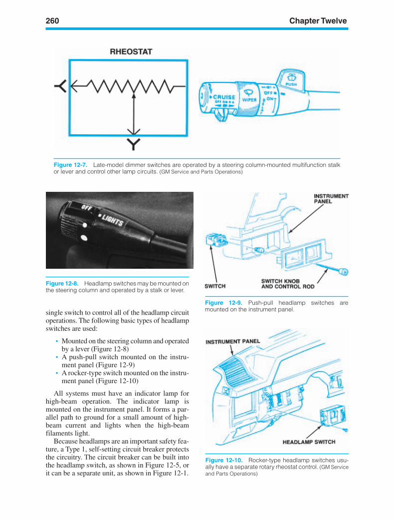
260 Chapter Twelve
single switch to control all of the headlamp circuitoperations. The following basic types of headlampswitches are used:
• Mounted on the steering column and operatedby a lever (Figure 12-8)
• A push-pull switch mounted on the instru-ment panel (Figure 12-9)
• A rocker-type switch mounted on the instru-ment panel (Figure 12-10)
All systems must have an indicator lamp forhigh-beam operation. The indicator lamp ismounted on the instrument panel. It forms a par-allel path to ground for a small amount of high-beam current and lights when the high-beamfilaments light.
Because headlamps are an important safety fea-ture, a Type 1, self-setting circuit breaker protectsthe circuitry. The circuit breaker can be built intothe headlamp switch, as shown in Figure 12-5, orit can be a separate unit, as shown in Figure 12-1.
Figure 12-7. Late-model dimmer switches are operated by a steering column-mounted multifunction stalkor lever and control other lamp circuits. (GM Service and Parts Operations)
Figure 12-8. Headlamp switches may be mounted onthe steering column and operated by a stalk or lever.
Figure 12-9. Push-pull headlamp switches aremounted on the instrument panel.
Figure 12-10. Rocker-type headlamp switches usu-ally have a separate rotary rheostat control. (GM Serviceand Parts Operations)
ker88839_ch12.qxd 1/9/06 11:32 AM Page 260

Automotive Lighting Systems 261
Headlamps
Until 1940, a small replaceable bulb mountedbehind a glass lens was used to provide light fornight driving. Safety standards established in theUnited States in 1940 made round, sealed-beamunits mandatory on domestic cars. Repeatedattempts to modify the standards after World War IIwere only partially successful, beginning with theintroduction of rectangular sealed-beam units in themid-1970s. The first major change in headlightdesign came with the rectangular halogen head-lamp, which appeared on some 1980 models.Since that time, considerable progress has beenmade in establishing other types, such as compos-ite headlamps that use replaceable halogen bulbs.
Conventional Sealed-BeamHeadlampsA sealed-beam headlamp is a one-piece, replace-able unit containing a tungsten filament, a reflector,a lens, and connecting terminals, as shown inFigure 12-12. The position of the filament in frontof the reflector determines whether the filamentwill cast a high or a low beam. The glass lens isdesigned to spread this beam in a specific way.Headlamps have symmetrical or asymmetricalbeams, as shown in Figure 12-12. All high beamsare spread symmetrically; all low beams are spreadasymmetrically.
Halogen Sealed-BeamHeadlampsHalogen sealed-beam headlamps (Figure 12-13)first appeared as options on some 1980 domesticcars. Their illumination comes from passing current
Figure 12-11. A cutaway view of a conventionalsealed-beam headlamp.
Figure 12-12. The glass lens design determineswhether the beam is symmetrical or asymmetrical.
LensHalogen filledinner bulb
Filament
Hermeticallysealed housing
Figure 12-13. Halogen sealed-beam headlamps.(DaimlerChrysler Corporation)
through a filament in a pressure-filled halogencapsule, instead of through a filament in a conven-tional evacuated sealed-beam bulb. Halogen lampsprovide brighter, whiter light than conventionalheadlamps.
Service and adjustment procedures are the samefor halogen sealed-beam lamps as they are for con-ventional sealed-beams. Early bulb-type halogenlamps were not interchangeable with conventionalsealed-beam headlamps, but today halogen sealed-beam lamps can often be used as direct replace-ments for their conventional counterpart. Halogenlamps are manufactured of glass or plastic. Glasslamps carry an “H” prefix; plastic lamps have an“HP” prefix. Plastic lamps are less susceptible to
ker88839_ch12.qxd 1/9/06 11:32 AM Page 261
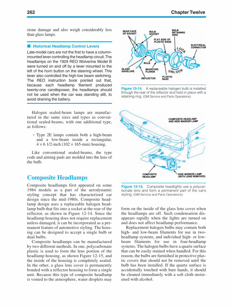
262 Chapter Twelve
stone damage and also weigh considerably lessthan glass lamps.
Historical Headlamp Control Levers
Late-model cars are not the first to have a column-mounted lever controlling the headlamp circuit.Theheadlamps on the 1929 REO Wolverine Model Bwere turned on and off by a lever mounted to theleft of the horn button on the steering wheel. Thislever also controlled the high-low beam switching.The REO instruction book pointed out that,because each headlamp filament producedtwenty-one candlepower, the headlamps shouldnot be used when the car was standing still, toavoid draining the battery.
Halogen sealed-beam lamps are manufac-tured in the same sizes and types as conven-tional sealed-beams, with one additional type,as follows:
• Type 2E lamps contain both a high-beamand a low-beam inside a rectangular, 4 × 6 1/2-inch (102 × 165-mm) housing.
Like conventional sealed-beams, the typecode and aiming pads are molded into the lens ofthe bulb.
Composite HeadlampsComposite headlamps first appeared on some1984 models as a part of the aerodynamicstyling concept that has characterized cardesign since the mid-1980s. Composite head-lamp design uses a replaceable halogen head-lamp bulb that fits into a socket at the rear of thereflector, as shown in Figure 12-14. Since theheadlamp housing does not require replacementunless damaged, it can be incorporated as a per-manent feature of automotive styling. The hous-ing can be designed to accept a single bulb ordual bulbs.
Composite headlamps can be manufacturedby two different methods. In one, polycarbonateplastic is used to form the lens portion of theheadlamp housing, as shown Figure 12-15, andthe inside of the housing is completely sealed.In the other, a glass lens cover is permanentlybonded with a reflector housing to form a singleunit. Because this type of composite headlampis vented to the atmosphere, water droplets may
form on the inside of the glass lens cover whenthe headlamps are off. Such condensation dis-appears rapidly when the lights are turned onand does not affect headlamp performance.
Replacement halogen bulbs may contain bothhigh- and low-beam filaments for use in two-headlamp systems, and individual high- or low-beam filaments for use in four-headlampsystems. The halogen bulbs have a quartz surfacethat can be easily stained when handled. For thisreason, the bulbs are furnished in protective plas-tic covers that should not be removed until thebulb has been installed. If the quartz surface isaccidentally touched with bare hands, it shouldbe cleaned immediately with a soft cloth moist-ened with alcohol.
Figure 12-14. A replaceable halogen bulb is installedthrough the rear of the reflector and held in place with aretaining ring. (GM Service and Parts Operations)
Figure 12-15. Composite headlights use a polycar-bonate lens and form a permanent part of the car’sstyling. (GM Service and Parts Operations)
ker88839_ch12.qxd 1/9/06 11:32 AM Page 262
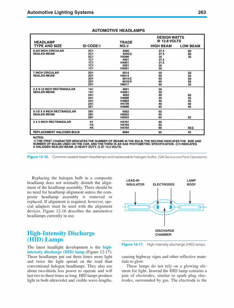
Automotive Lighting Systems 263
Replacing the halogen bulb in a compositeheadlamp does not normally disturb the align-ment of the headlamp assembly. There should beno need for headlamp alignment unless the com-posite headlamp assembly is removed orreplaced. If alignment is required, however, spe-cial adapters must be used with the alignmentdevices. Figure 12-16 describes the automotiveheadlamps currently in use.
High-Intensity Discharge(HID) LampsThe latest headlight development is the high-intensity discharge (HID) lamp (Figure 12-17).These headlamps put out three times more lightand twice the light spread on the road thanconventional halogen headlamps. They also useabout two-thirds less power to operate and willlast two to three times as long. HID lamps producelight in both ultraviolet and visible wave-lengths,
causing highway signs and other reflective mate-rials to glow.
These lamps do not rely on a glowing ele-ment for light. Instead the HID lamp contains apair of electrodes, similar to spark plug elec-trodes, surrounded by gas. The electrode is the
Figure 12-16. Common sealed-beam headlamps and replaceable halogen bulbs. (GM Service and Parts Operations)
LEAD-ININSULATOR ELECTRODES
LAMPBODY
DISCHARGECHAMBER
Figure 12-17. High-intensity discharge (HID) lamps.
ker88839_ch12.qxd 1/9/06 11:32 AM Page 263
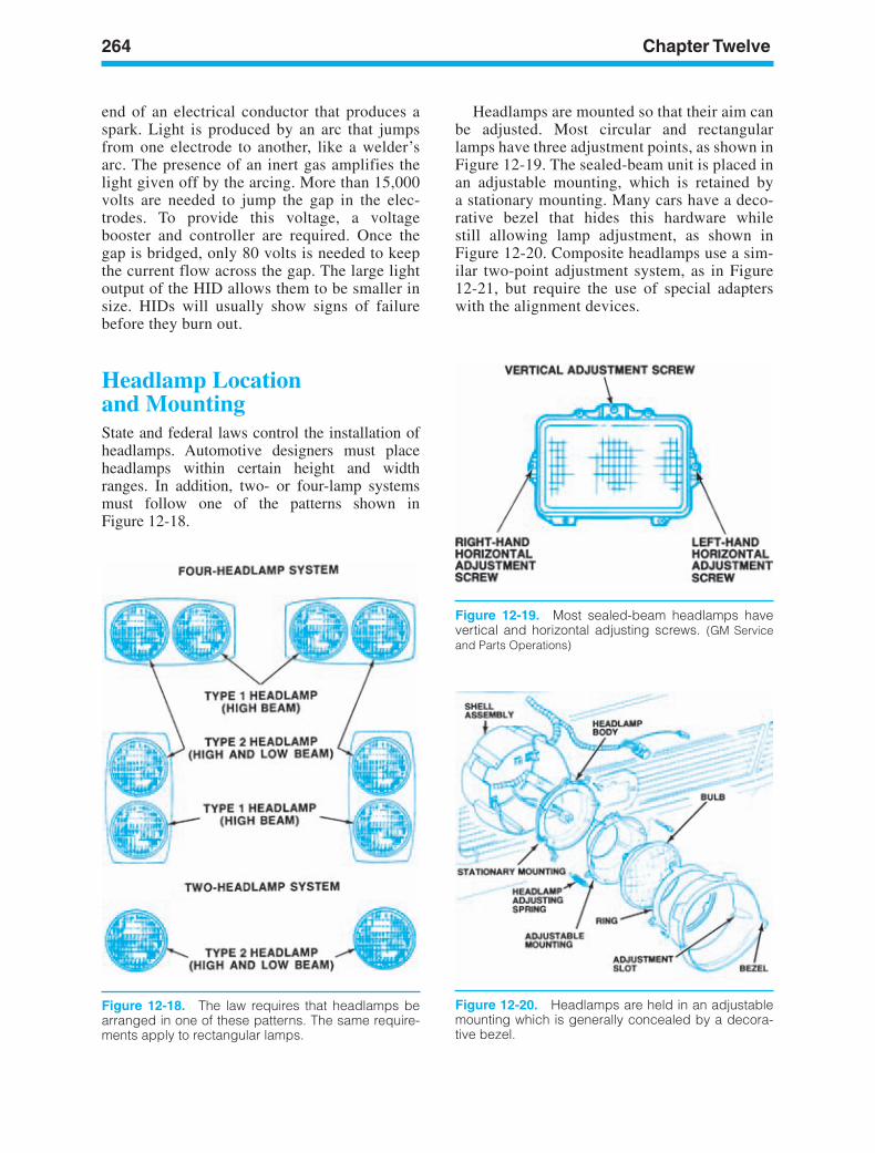
264 Chapter Twelve
Figure 12-18. The law requires that headlamps bearranged in one of these patterns. The same require-ments apply to rectangular lamps.
Figure 12-19. Most sealed-beam headlamps havevertical and horizontal adjusting screws. (GM Serviceand Parts Operations)
Figure 12-20. Headlamps are held in an adjustablemounting which is generally concealed by a decora-tive bezel.
end of an electrical conductor that produces aspark. Light is produced by an arc that jumpsfrom one electrode to another, like a welder’sarc. The presence of an inert gas amplifies thelight given off by the arcing. More than 15,000volts are needed to jump the gap in the elec-trodes. To provide this voltage, a voltagebooster and controller are required. Once thegap is bridged, only 80 volts is needed to keepthe current flow across the gap. The large lightoutput of the HID allows them to be smaller insize. HIDs will usually show signs of failurebefore they burn out.
Headlamp Locationand MountingState and federal laws control the installation ofheadlamps. Automotive designers must placeheadlamps within certain height and widthranges. In addition, two- or four-lamp systemsmust follow one of the patterns shown inFigure 12-18.
Headlamps are mounted so that their aim canbe adjusted. Most circular and rectangularlamps have three adjustment points, as shown inFigure 12-19. The sealed-beam unit is placed inan adjustable mounting, which is retained bya stationary mounting. Many cars have a deco-rative bezel that hides this hardware whilestill allowing lamp adjustment, as shown inFigure 12-20. Composite headlamps use a sim-ilar two-point adjustment system, as in Figure12-21, but require the use of special adapterswith the alignment devices.
ker88839_ch12.qxd 1/9/06 11:32 AM Page 264
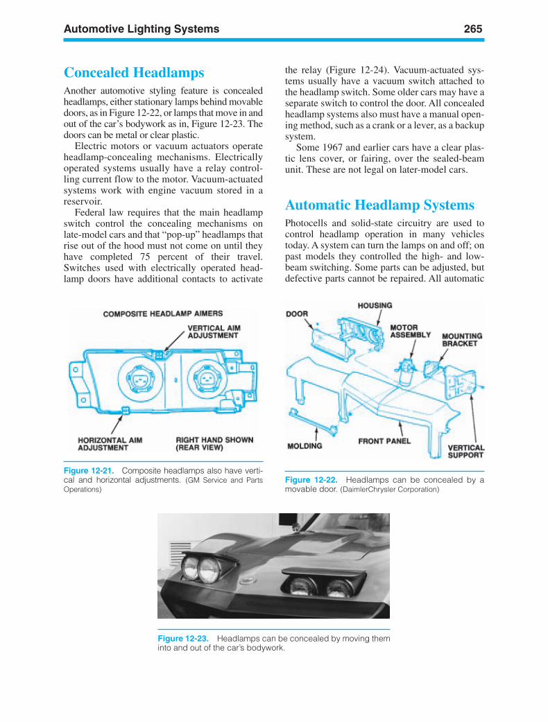
Automotive Lighting Systems 265
Figure 12-21. Composite headlamps also have verti-cal and horizontal adjustments. (GM Service and PartsOperations)
Figure 12-22. Headlamps can be concealed by amovable door. (DaimlerChrysler Corporation)
Concealed HeadlampsAnother automotive styling feature is concealedheadlamps, either stationary lamps behind movabledoors, as in Figure 12-22, or lamps that move in andout of the car’s bodywork as in, Figure 12-23. Thedoors can be metal or clear plastic.
Electric motors or vacuum actuators operateheadlamp-concealing mechanisms. Electricallyoperated systems usually have a relay control-ling current flow to the motor. Vacuum-actuatedsystems work with engine vacuum stored in areservoir.
Federal law requires that the main headlampswitch control the concealing mechanisms onlate-model cars and that “pop-up” headlamps thatrise out of the hood must not come on until theyhave completed 75 percent of their travel.Switches used with electrically operated head-lamp doors have additional contacts to activate
the relay (Figure 12-24). Vacuum-actuated sys-tems usually have a vacuum switch attached tothe headlamp switch. Some older cars may have aseparate switch to control the door. All concealedheadlamp systems also must have a manual open-ing method, such as a crank or a lever, as a backupsystem.
Some 1967 and earlier cars have a clear plas-tic lens cover, or fairing, over the sealed-beamunit. These are not legal on later-model cars.
Automatic Headlamp SystemsPhotocells and solid-state circuitry are used tocontrol headlamp operation in many vehiclestoday. A system can turn the lamps on and off; onpast models they controlled the high- and low-beam switching. Some parts can be adjusted, butdefective parts cannot be repaired. All automatic
Figure 12-23. Headlamps can be concealed by moving theminto and out of the car’s bodywork.
ker88839_ch12.qxd 1/9/06 11:32 AM Page 265
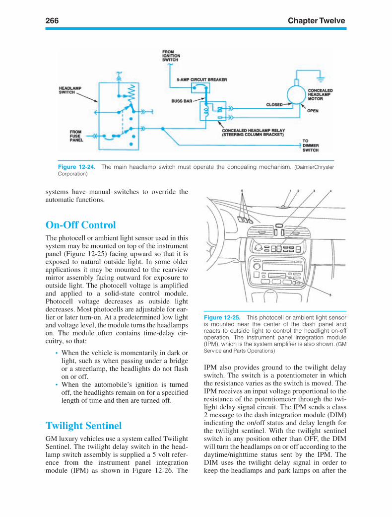
266 Chapter Twelve
Figure 12-24. The main headlamp switch must operate the concealing mechanism. (DaimlerChryslerCorporation)
Figure 12-25. This photocell or ambient light sensoris mounted near the center of the dash panel andreacts to outside light to control the headlight on-offoperation. The instrument panel integration module(IPM), which is the system amplifier is also shown. (GMService and Parts Operations)
IPM also provides ground to the twilight delayswitch. The switch is a potentiometer in whichthe resistance varies as the switch is moved. TheIPM receives an input voltage proportional to theresistance of the potentiometer through the twi-light delay signal circuit. The IPM sends a class2 message to the dash integration module (DIM)indicating the on/off status and delay length forthe twilight sentinel. With the twilight sentinelswitch in any position other than OFF, the DIMwill turn the headlamps on or off according to thedaytime/nighttime status sent by the IPM. TheDIM uses the twilight delay signal in order tokeep the headlamps and park lamps on after the
systems have manual switches to override theautomatic functions.
On-Off ControlThe photocell or ambient light sensor used in thissystem may be mounted on top of the instrumentpanel (Figure 12-25) facing upward so that it isexposed to natural outside light. In some olderapplications it may be mounted to the rearviewmirror assembly facing outward for exposure tooutside light. The photocell voltage is amplifiedand applied to a solid-state control module.Photocell voltage decreases as outside lightdecreases. Most photocells are adjustable for ear-lier or later turn-on. At a predetermined low lightand voltage level, the module turns the headlampson. The module often contains time-delay cir-cuitry, so that:
• When the vehicle is momentarily in dark orlight, such as when passing under a bridgeor a streetlamp, the headlights do not flashon or off.
• When the automobile’s ignition is turnedoff, the headlights remain on for a specifiedlength of time and then are turned off.
Twilight SentinelGM luxury vehicles use a system called TwilightSentinel. The twilight delay switch in the head-lamp switch assembly is supplied a 5 volt refer-ence from the instrument panel integrationmodule (IPM) as shown in Figure 12-26. The
ker88839_ch12.qxd 1/9/06 11:32 AM Page 266
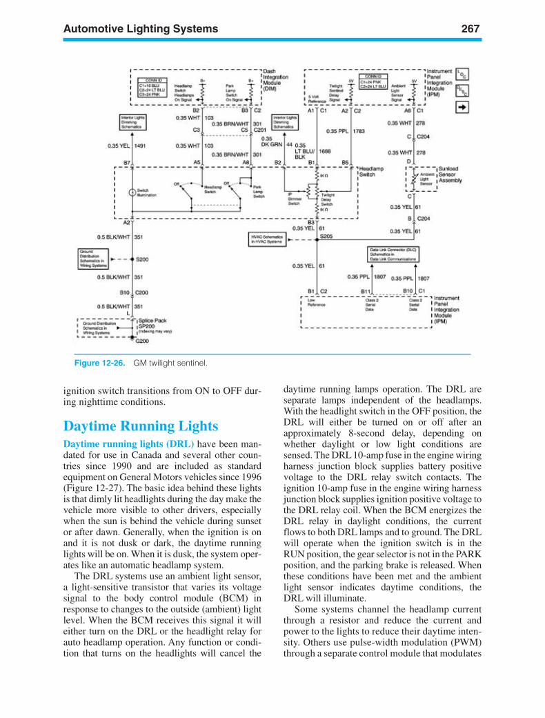
Automotive Lighting Systems 267
Figure 12-26. GM twilight sentinel.
ignition switch transitions from ON to OFF dur-ing nighttime conditions.
Daytime Running LightsDaytime running lights (DRL) have been man-dated for use in Canada and several other coun-tries since 1990 and are included as standardequipment on General Motors vehicles since 1996(Figure 12-27). The basic idea behind these lightsis that dimly lit headlights during the day make thevehicle more visible to other drivers, especiallywhen the sun is behind the vehicle during sunsetor after dawn. Generally, when the ignition is onand it is not dusk or dark, the daytime runninglights will be on. When it is dusk, the system oper-ates like an automatic headlamp system.
The DRL systems use an ambient light sensor,a light-sensitive transistor that varies its voltagesignal to the body control module (BCM) inresponse to changes to the outside (ambient) lightlevel. When the BCM receives this signal it willeither turn on the DRL or the headlight relay forauto headlamp operation. Any function or condi-tion that turns on the headlights will cancel the
daytime running lamps operation. The DRL areseparate lamps independent of the headlamps.With the headlight switch in the OFF position, theDRL will either be turned on or off after anapproximately 8-second delay, depending onwhether daylight or low light conditions aresensed. The DRL 10-amp fuse in the engine wiringharness junction block supplies battery positivevoltage to the DRL relay switch contacts. Theignition 10-amp fuse in the engine wiring harnessjunction block supplies ignition positive voltage tothe DRL relay coil. When the BCM energizes theDRL relay in daylight conditions, the currentflows to both DRL lamps and to ground. The DRLwill operate when the ignition switch is in theRUN position, the gear selector is not in the PARKposition, and the parking brake is released. Whenthese conditions have been met and the ambientlight sensor indicates daytime conditions, theDRL will illuminate.
Some systems channel the headlamp currentthrough a resistor and reduce the current andpower to the lights to reduce their daytime inten-sity. Others use pulse-width modulation (PWM)through a separate control module that modulates
ker88839_ch12.qxd 1/9/06 11:32 AM Page 267
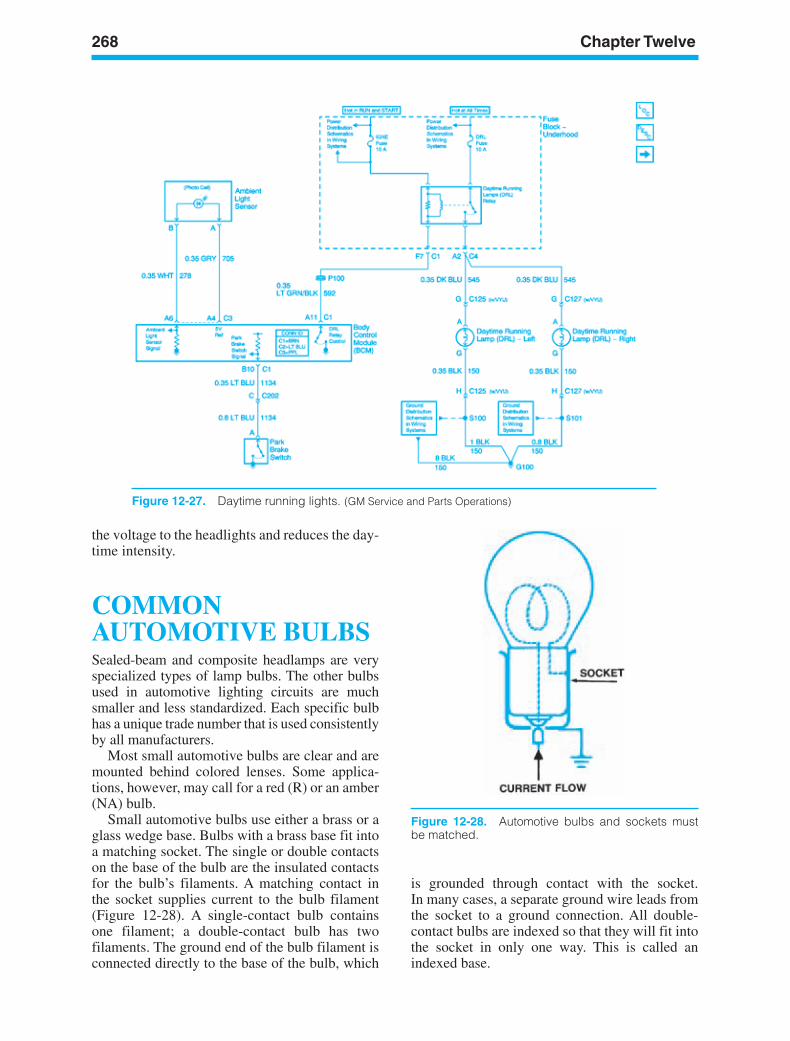
268 Chapter Twelve
Figure 12-27. Daytime running lights. (GM Service and Parts Operations)
Figure 12-28. Automotive bulbs and sockets mustbe matched.
the voltage to the headlights and reduces the day-time intensity.
COMMONAUTOMOTIVE BULBSSealed-beam and composite headlamps are veryspecialized types of lamp bulbs. The other bulbsused in automotive lighting circuits are muchsmaller and less standardized. Each specific bulbhas a unique trade number that is used consistentlyby all manufacturers.
Most small automotive bulbs are clear and aremounted behind colored lenses. Some applica-tions, however, may call for a red (R) or an amber(NA) bulb.
Small automotive bulbs use either a brass or aglass wedge base. Bulbs with a brass base fit intoa matching socket. The single or double contactson the base of the bulb are the insulated contactsfor the bulb’s filaments. A matching contact inthe socket supplies current to the bulb filament(Figure 12-28). A single-contact bulb containsone filament; a double-contact bulb has twofilaments. The ground end of the bulb filament isconnected directly to the base of the bulb, which
is grounded through contact with the socket.In many cases, a separate ground wire leads fromthe socket to a ground connection. All double-contact bulbs are indexed so that they will fit intothe socket in only one way. This is called anindexed base.
ker88839_ch12.qxd 1/9/06 11:32 AM Page 268
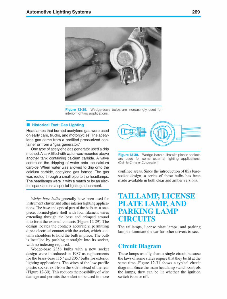
Automotive Lighting Systems 269
Historical Fact: Gas Lighting
Headlamps that burned acetylene gas were usedon early cars, trucks, and motorcycles.The acety-lene gas came from a prefilled pressurized con-tainer or from a “gas generator.”
One type of acetylene gas generator used a dripmethod.A tank filled with water was mounted aboveanother tank containing calcium carbide. A valvecontrolled the dripping of water onto the calciumcarbide. When water was allowed to drip onto thecalcium carbide, acetylene gas formed. The gaswas routed through a small pipe to the headlamps.The headlamps were lit with a match or by an elec-tric spark across a special lighting attachment.
Wedge-base bulbs generally have been used forinstrument cluster and other interior lighting applica-tions. The base and optical part of the bulb are a one-piece, formed-glass shell with four filament wiresextending through the base and crimped around it to form the external contacts (Figure 12-29). Thedesign locates the contacts accurately, permittingdirect electrical contact with the socket, which con-tains shoulders to hold the bulb in place. The bulbis installed by pushing it straight into its socket,with no indexing required.
Wedge-base 2358 bulbs with a new socketdesign were introduced in 1987 as replacementsfor the brass-base 1157 and 2057 bulbs for exteriorlighting applications. The wires of the low-profileplastic socket exit from the side instead of the rear(Figure 12-30). This reduces the possibility of wiredamage and permits the socket to be used in more
confined areas. Since the introduction of this base-socket design, a series of these bulbs has beenmade available in both clear and amber versions.
TAILLAMP, LICENSEPLATE LAMP, ANDPARKING LAMPCIRCUITSThe taillamps, license plate lamps, and parkinglamps illuminate the car for other drivers to see.
Circuit DiagramThese lamps usually share a single circuit becausethe laws of some states require that they be lit at thesame time. Figure 12-31 shows a typical circuitdiagram. Since the main headlamp switch controlsthe lamps, they can be lit whether the ignitionswitch is on or off.
Figure 12-29. Wedge-base bulbs are increasingly used forinterior lighting applications.
Figure 12-30. Wedge-base bulbs with plastic socketsare used for some external lighting applications.(DaimlerChrysler Corporation)
ker88839_ch12.qxd 1/9/06 11:32 AM Page 269
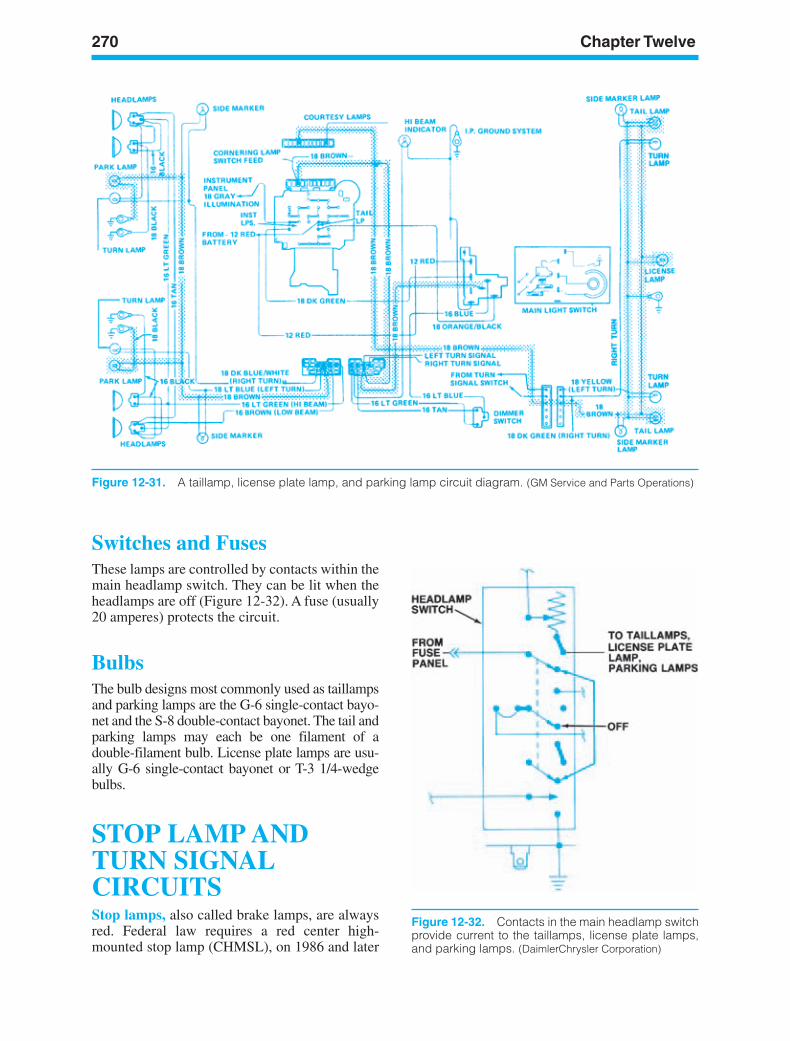
270 Chapter Twelve
Figure 12-32. Contacts in the main headlamp switchprovide current to the taillamps, license plate lamps,and parking lamps. (DaimlerChrysler Corporation)
Figure 12-31. A taillamp, license plate lamp, and parking lamp circuit diagram. (GM Service and Parts Operations)
Switches and FusesThese lamps are controlled by contacts within themain headlamp switch. They can be lit when theheadlamps are off (Figure 12-32). A fuse (usually20 amperes) protects the circuit.
BulbsThe bulb designs most commonly used as taillampsand parking lamps are the G-6 single-contact bayo-net and the S-8 double-contact bayonet. The tail andparking lamps may each be one filament of adouble-filament bulb. License plate lamps are usu-ally G-6 single-contact bayonet or T-3 1/4-wedgebulbs.
STOP LAMP ANDTURN SIGNALCIRCUITSStop lamps, also called brake lamps, are alwaysred. Federal law requires a red center high-mounted stop lamp (CHMSL), on 1986 and later
ker88839_ch12.qxd 1/9/06 11:32 AM Page 270
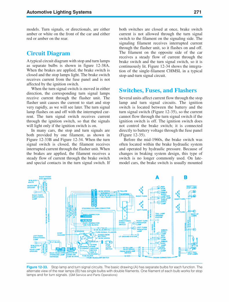
Automotive Lighting Systems 271
models. Turn signals, or directionals, are eitheramber or white on the front of the car and eitherred or amber on the rear.
Circuit DiagramA typical circuit diagram with stop and turn lampsas separate bulbs is shown in figure 12-38A.When the brakes are applied, the brake switch isclosed and the stop lamps light. The brake switchreceives current from the fuse panel and is notaffected by the ignition switch.
When the turn signal switch is moved in eitherdirection, the corresponding turn signal lampsreceive current through the flasher unit. Theflasher unit causes the current to start and stopvery rapidly, as we will see later. The turn signallamp flashes on and off with the interrupted cur-rent. The turn signal switch receives currentthrough the ignition switch, so that the signalswill light only if the ignition switch is on.
In many cars, the stop and turn signals areboth provided by one filament, as shown inFigure 12-33B and Figure 12-34. When the turnsignal switch is closed, the filament receivesinterrupted current through the flasher unit. Whenthe brakes are applied, the filament receives asteady flow of current through the brake switchand special contacts in the turn signal switch. If
both switches are closed at once, brake switchcurrent is not allowed through the turn signalswitch to the filament on the signaling side. Thesignaling filament receives interrupted currentthrough the flasher unit, so it flashes on and off.The filament on the opposite side of the carreceives a steady flow of current through thebrake switch and the turn signal switch, so it iscontinuously lit. Figure 12-34 shows the integra-tion of the single-filament CHMSL in a typicalstop-and-turn signal circuit.
Switches, Fuses, and FlashersSeveral units affect current flow through the stoplamp and turn signal circuits. The ignitionswitch is located between the battery and theturn signal switch (Figure 12-35), so the currentcannot flow through the turn signal switch if theignition switch is off. The ignition switch doesnot control the brake switch; it is connecteddirectly to battery voltage through the fuse panel(Figure 12-35).
Before the mid-1960s, the brake switch wasoften located within the brake hydraulic systemand operated by hydraulic pressure. Because ofchanges in braking system design, this type ofswitch is no longer commonly used. On late-model cars, the brake switch is usually mounted
Figure 12-33. Stop lamp and turn signal circuits. The basic drawing (A) has separate bulbs for each function. Thealternate view of the rear lamps (B) has single bulbs with double filaments. One filament of each bulb works for stoplamps and for turn signals. (GM Service and Parts Operations)
ker88839_ch12.qxd 1/9/06 11:32 AM Page 271
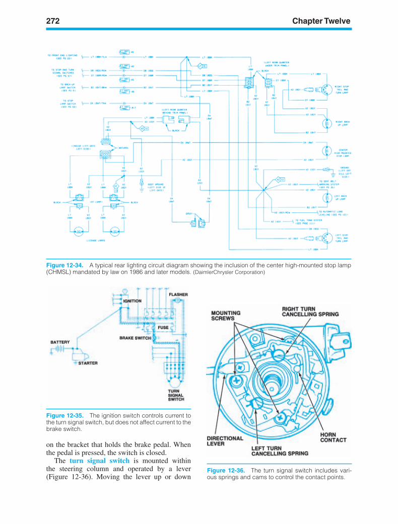
272 Chapter Twelve
Figure 12-34. A typical rear lighting circuit diagram showing the inclusion of the center high-mounted stop lamp(CHMSL) mandated by law on 1986 and later models. (DaimlerChrysler Corporation)
Figure 12-35. The ignition switch controls current tothe turn signal switch, but does not affect current to thebrake switch.
Figure 12-36. The turn signal switch includes vari-ous springs and cams to control the contact points.
on the bracket that holds the brake pedal. Whenthe pedal is pressed, the switch is closed.
The turn signal switch is mounted withinthe steering column and operated by a lever(Figure 12-36). Moving the lever up or down
ker88839_ch12.qxd 1/9/06 11:32 AM Page 272
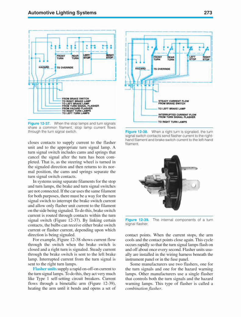
Automotive Lighting Systems 273
Figure 12-37. When the stop lamps and turn signalsshare a common filament, stop lamp current flowsthrough the turn signal switch.
closes contacts to supply current to the flasherunit and to the appropriate turn signal lamp. Aturn signal switch includes cams and springs thatcancel the signal after the turn has been com-pleted. That is, as the steering wheel is turned inthe signaled direction and then returns to its nor-mal position, the cams and springs separate theturn signal switch contacts.
In systems using separate filaments for the stopand turn lamps, the brake and turn signal switchesare not connected. If the car uses the same filamentfor both purposes, there must be a way for the turnsignal switch to interrupt the brake switch currentand allow only flasher unit current to the filamenton the side being signaled. To do this, brake switchcurrent is routed through contacts within the turnsignal switch (Figure 12-37). By linking certaincontacts, the bulbs can receive either brake switchcurrent or flasher current, depending upon whichdirection is being signaled.
For example, Figure 12-38 shows current flowthrough the switch when the brake switch isclosed and a right turn is signaled. Steady currentthrough the brake switch is sent to the left brakelamp. Interrupted current from the turn signal issent to the right turn lamps.
Flasher units supply a rapid on-off-on current tothe turn signal lamps. To do this, they act very muchlike Type 1 self-setting circuit breakers. Currentflows through a bimetallic arm (Figure 12-39),heating the arm until it bends and opens a set of
contact points. When the current stops, the armcools and the contact points close again. This cycleoccurs rapidly so that the turn signal lamps flash onand off about once every second. Flasher units usu-ally are installed in the wiring harness beneath theinstrument panel or in the fuse panel.
Some manufacturers use two flashers, one forthe turn signals and one for the hazard warninglamps. Other manufacturers use a single flasherthat controls both the turn signals and the hazardwarning lamps. This type of flasher is called acombination flasher.
Figure 12-38. When a right turn is signaled, the turnsignal switch contacts send flasher current to the right-hand filament and brake switch current to the left-handfilament.
Figure 12-39. The internal components of a turnsignal flasher.
ker88839_ch12.qxd 1/9/06 11:32 AM Page 273
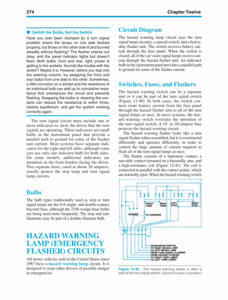
274 Chapter Twelve
Figure 12-40. The hazard warning switch is often apart of the turn signal switch. (DaimlerChrysler Corporation)
Switch the Bulbs, Not the Switch
Have you ever been stumped by a turn signalproblem where the lamps on one side flashedproperly, but those on the other side lit and burnedsteadily without flashing? The flasher checks outokay, and the panel indicator lights but doesn’tflash. Both bulbs, front and rear, light; power isgetting to the sockets. Sounds like trouble with theswitch? Maybe it is. However, before you tear intothe steering column, try swapping the front andrear bulbs from one side to the other. Sometimes,a little corrosion on a socket and the resistance ofan individual bulb can add up to cumulative resis-tance that unbalances the circuit and preventsflashing. Swapping the bulbs or cleaning the con-tacts can reduce the resistance to within limits,restore equilibrium, and get the system workingcorrectly again.
The turn signal circuit must include one ormore indicators to show the driver that the turnsignals are operating. These indicators are smallbulbs in the instrument panel that provide aparallel path to ground for some of the flasherunit current. Most systems have separate indi-cators for the right and left sides, although somecars use only one indicator bulb for both sides.On some models, additional indicators aremounted on the front fenders facing the driver.Two separate fuses, rated at about 20 amperes,usually protect the stop lamp and turn signallamp circuits.
BulbsThe bulb types traditionally used as stop or turnsignal lamps are the S-8 single- and double-contactbayonet base, although the 2358 wedge-base bulbsare being used more frequently. The stop and turnfilaments may be part of a double-filament bulb.
HAZARD WARNINGLAMP (EMERGENCYFLASHER) CIRCUITSAll motor vehicles sold in the United States since1967 have a hazard warning lamp circuit. It isdesigned to warn other drivers of possible dangerin emergencies.
Circuit DiagramThe hazard warning lamp circuit uses the turnsignal lamp circuitry, a special switch, and a heavy-duty flasher unit. The switch receives battery cur-rent through the fuse panel. When the switch isclosed, all of the car’s turn signal lamps receive cur-rent through the hazard flasher unit. An indicatorbulb in the instrument panel provides a parallel pathto ground for some of the flasher current.
Switches, Fuses, and FlashersThe hazard warning switch can be a separateunit or it can be part of the turn signal switch(Figure 12-40). In both cases, the switch con-tacts route battery current from the fuse panelthrough the hazard flasher unit to all of the turnsignal lamps at once. In most systems, the haz-ard warning switch overrides the operation ofthe turn signal switch. A 15- to 20-ampere fuseprotects the hazard warning circuit.
The hazard warning flasher looks like a turnsignal flasher when assembled, but it is constructeddifferently and operates differently, in order tocontrol the large amount of current required toflash all of the turn signal lamps at once.
The flasher consists of a stationary contact, amovable contact mounted on a bimetallic arm, anda high-resistance coil (Figure 12-41). The coil isconnected in parallel with the contact points, whichare normally open. When the hazard warning switch
ker88839_ch12.qxd 1/9/06 11:32 AM Page 274
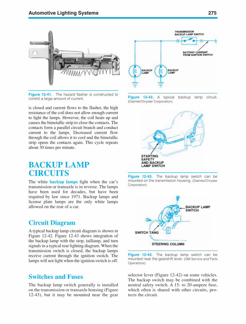
Automotive Lighting Systems 275
Figure 12-42. A typical backup lamp circuit.(DaimlerChrysler Corporation)
Figure 12-41. The hazard flasher is constructed tocontrol a large amount of current.
Figure 12-43. The backup lamp switch can bemounted on the transmission housing. (DaimlerChryslerCorporation)
is closed and current flows to the flasher, the highresistance of the coil does not allow enough currentto light the lamps. However, the coil heats up andcauses the bimetallic strip to close the contacts. Thecontacts form a parallel circuit branch and conductcurrent to the lamps. Decreased current flowthrough the coil allows it to cool and the bimetallicstrip opens the contacts again. This cycle repeatsabout 30 times per minute.
BACKUP LAMPCIRCUITSThe white backup lamps light when the car’stransmission or transaxle is in reverse. The lampshave been used for decades, but have beenrequired by law since 1971. Backup lamps andlicense plate lamps are the only white lampsallowed on the rear of a car.
Circuit DiagramA typical backup lamp circuit diagram is shown inFigure 12-42. Figure 12-43 shows integration ofthe backup lamp with the stop, taillamp, and turnsignals in a typical rear lighting diagram. When thetransmission switch is closed, the backup lampsreceive current through the ignition switch. Thelamps will not light when the ignition switch is off.
Switches and FusesThe backup lamp switch generally is installedon the transmission or transaxle housing (Figure12-43), but it may be mounted near the gear
selector lever (Figure 12-42) on some vehicles.The backup switch may be combined with theneutral safety switch. A 15- to 20-ampere fuse,which often is shared with other circuits, pro-tects the circuit.
Figure 12-44. The backup lamp switch can bemounted near the gearshift lever. (GM Service and PartsOperations)
ker88839_ch12.qxd 1/9/06 11:32 AM Page 275
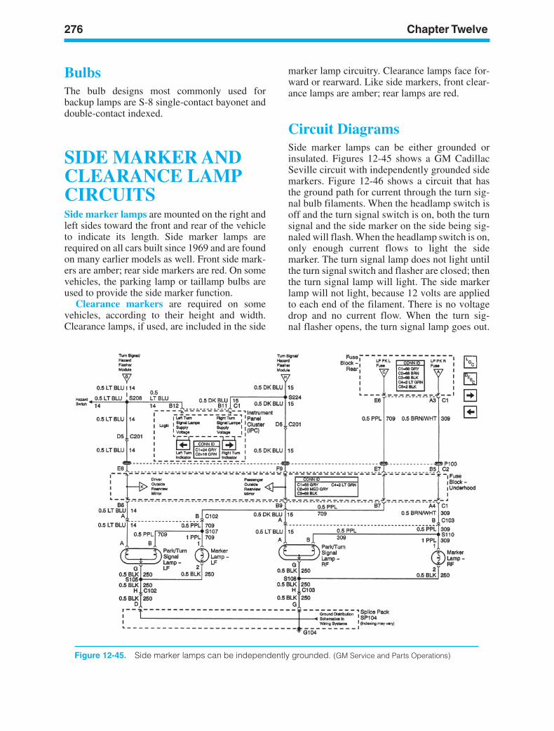
276 Chapter Twelve
Figure 12-45. Side marker lamps can be independently grounded. (GM Service and Parts Operations)
BulbsThe bulb designs most commonly used forbackup lamps are S-8 single-contact bayonet anddouble-contact indexed.
SIDE MARKER ANDCLEARANCE LAMPCIRCUITSSide marker lamps are mounted on the right andleft sides toward the front and rear of the vehicleto indicate its length. Side marker lamps arerequired on all cars built since 1969 and are foundon many earlier models as well. Front side mark-ers are amber; rear side markers are red. On somevehicles, the parking lamp or taillamp bulbs areused to provide the side marker function.
Clearance markers are required on somevehicles, according to their height and width.Clearance lamps, if used, are included in the side
marker lamp circuitry. Clearance lamps face for-ward or rearward. Like side markers, front clear-ance lamps are amber; rear lamps are red.
Circuit DiagramsSide marker lamps can be either grounded orinsulated. Figures 12-45 shows a GM CadillacSeville circuit with independently grounded sidemarkers. Figure 12-46 shows a circuit that hasthe ground path for current through the turn sig-nal bulb filaments. When the headlamp switch isoff and the turn signal switch is on, both the turnsignal and the side marker on the side being sig-naled will flash. When the headlamp switch is on,only enough current flows to light the sidemarker. The turn signal lamp does not light untilthe turn signal switch and flasher are closed; thenthe turn signal lamp will light. The side markerlamp will not light, because 12 volts are appliedto each end of the filament. There is no voltagedrop and no current flow. When the turn sig-nal flasher opens, the turn signal lamp goes out.
ker88839_ch12.qxd 1/9/06 11:32 AM Page 276
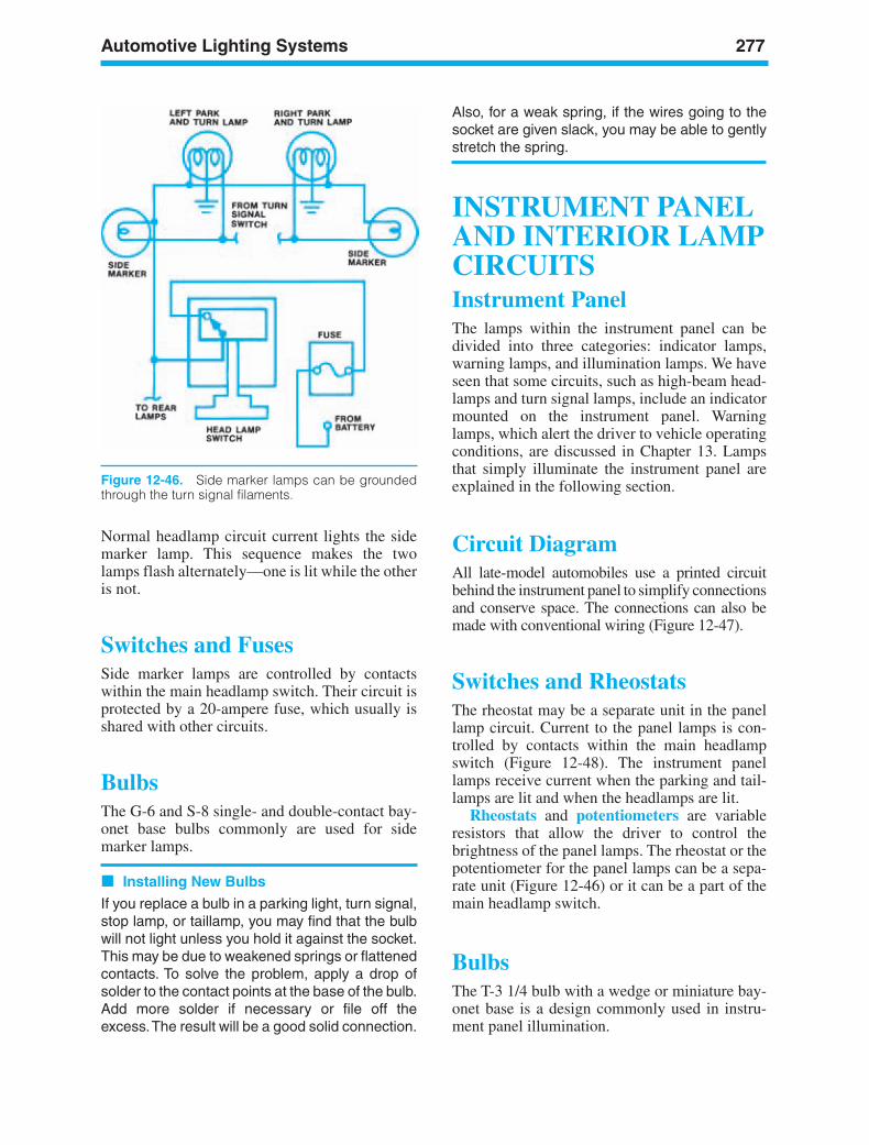
Automotive Lighting Systems 277
Figure 12-46. Side marker lamps can be groundedthrough the turn signal filaments.
Normal headlamp circuit current lights the sidemarker lamp. This sequence makes the twolamps flash alternately—one is lit while the otheris not.
Switches and FusesSide marker lamps are controlled by contactswithin the main headlamp switch. Their circuit isprotected by a 20-ampere fuse, which usually isshared with other circuits.
BulbsThe G-6 and S-8 single- and double-contact bay-onet base bulbs commonly are used for sidemarker lamps.
Installing New Bulbs
If you replace a bulb in a parking light, turn signal,stop lamp, or taillamp, you may find that the bulbwill not light unless you hold it against the socket.This may be due to weakened springs or flattenedcontacts. To solve the problem, apply a drop ofsolder to the contact points at the base of the bulb.Add more solder if necessary or file off theexcess.The result will be a good solid connection.
Also, for a weak spring, if the wires going to thesocket are given slack, you may be able to gentlystretch the spring.
INSTRUMENT PANELAND INTERIOR LAMPCIRCUITSInstrument PanelThe lamps within the instrument panel can bedivided into three categories: indicator lamps,warning lamps, and illumination lamps. We haveseen that some circuits, such as high-beam head-lamps and turn signal lamps, include an indicatormounted on the instrument panel. Warninglamps, which alert the driver to vehicle operatingconditions, are discussed in Chapter 13. Lampsthat simply illuminate the instrument panel areexplained in the following section.
Circuit DiagramAll late-model automobiles use a printed circuitbehind the instrument panel to simplify connectionsand conserve space. The connections can also bemade with conventional wiring (Figure 12-47).
Switches and RheostatsThe rheostat may be a separate unit in the panellamp circuit. Current to the panel lamps is con-trolled by contacts within the main headlampswitch (Figure 12-48). The instrument panellamps receive current when the parking and tail-lamps are lit and when the headlamps are lit.
Rheostats and potentiometers are variableresistors that allow the driver to control thebrightness of the panel lamps. The rheostat or thepotentiometer for the panel lamps can be a sepa-rate unit (Figure 12-46) or it can be a part of themain headlamp switch.
BulbsThe T-3 1/4 bulb with a wedge or miniature bay-onet base is a design commonly used in instru-ment panel illumination.
ker88839_ch12.qxd 1/9/06 11:32 AM Page 277
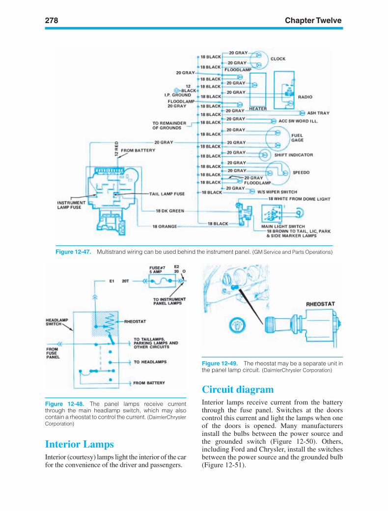
278 Chapter Twelve
Figure 12-47. Multistrand wiring can be used behind the instrument panel. (GM Service and Parts Operations)
Figure 12-49. The rheostat may be a separate unit inthe panel lamp circuit. (DaimlerChrysler Corporation)
Figure 12-48. The panel lamps receive currentthrough the main headlamp switch, which may alsocontain a rheostat to control the current. (DaimlerChryslerCorporation)
Interior LampsInterior (courtesy) lamps light the interior of the carfor the convenience of the driver and passengers.
Circuit diagramInterior lamps receive current from the batterythrough the fuse panel. Switches at the doorscontrol this current and light the lamps when oneof the doors is opened. Many manufacturersinstall the bulbs between the power source andthe grounded switch (Figure 12-50). Others,including Ford and Chrysler, install the switchesbetween the power source and the grounded bulb(Figure 12-51).
ker88839_ch12.qxd 1/9/06 11:32 AM Page 278
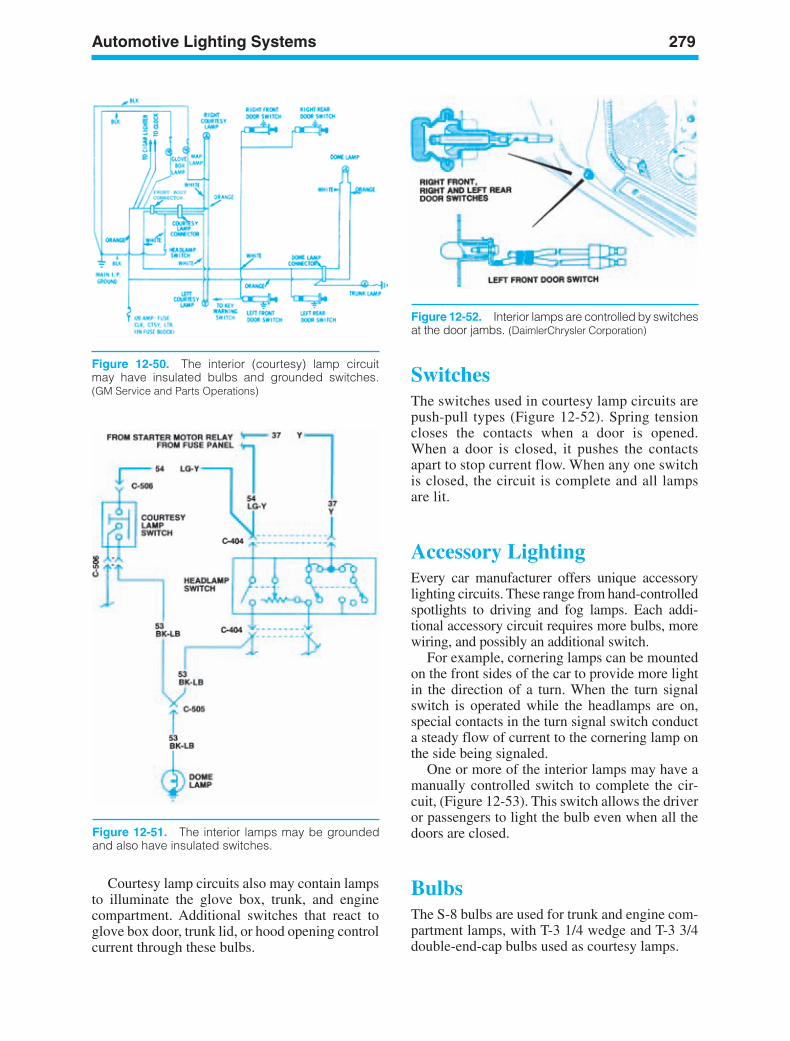
Automotive Lighting Systems 279
Figure 12-51. The interior lamps may be groundedand also have insulated switches.
Courtesy lamp circuits also may contain lampsto illuminate the glove box, trunk, and enginecompartment. Additional switches that react toglove box door, trunk lid, or hood opening controlcurrent through these bulbs.
SwitchesThe switches used in courtesy lamp circuits arepush-pull types (Figure 12-52). Spring tensioncloses the contacts when a door is opened.When a door is closed, it pushes the contactsapart to stop current flow. When any one switchis closed, the circuit is complete and all lampsare lit.
Accessory LightingEvery car manufacturer offers unique accessorylighting circuits. These range from hand-controlledspotlights to driving and fog lamps. Each addi-tional accessory circuit requires more bulbs, morewiring, and possibly an additional switch.
For example, cornering lamps can be mountedon the front sides of the car to provide more lightin the direction of a turn. When the turn signalswitch is operated while the headlamps are on,special contacts in the turn signal switch conducta steady flow of current to the cornering lamp onthe side being signaled.
One or more of the interior lamps may have amanually controlled switch to complete the cir-cuit, (Figure 12-53). This switch allows the driveror passengers to light the bulb even when all thedoors are closed.
BulbsThe S-8 bulbs are used for trunk and engine com-partment lamps, with T-3 1/4 wedge and T-3 3/4double-end-cap bulbs used as courtesy lamps.
Figure 12-50. The interior (courtesy) lamp circuitmay have insulated bulbs and grounded switches.(GM Service and Parts Operations)
Figure 12-52. Interior lamps are controlled by switchesat the door jambs. (DaimlerChrysler Corporation)
ker88839_ch12.qxd 1/9/06 11:32 AM Page 279
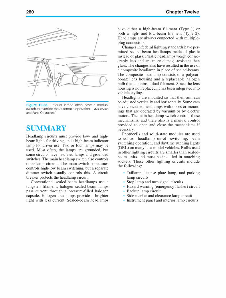
280 Chapter Twelve
Figure 12-53. Interior lamps often have a manualswitch to override the automatic operation. (GM Serviceand Parts Operations)
SUMMARYHeadlamp circuits must provide low- and high-beam lights for driving, and a high-beam indicatorlamp for driver use. Two or four lamps may beused. Most often, the lamps are grounded, butsome circuits have insulated lamps and groundedswitches. The main headlamp switch also controlsother lamp circuits. The main switch sometimescontrols high-low beam switching, but a separatedimmer switch usually controls this. A circuitbreaker protects the headlamp circuit.
Conventional sealed-beam headlamps use atungsten filament; halogen sealed-beam lampspass current through a pressure-filled halogencapsule. Halogen headlamps provide a brighterlight with less current. Sealed-beam headlamps
have either a high-beam filament (Type 1) orboth a high- and low-beam filament (Type 2).Headlamps are always connected with multiple-plug connectors.
Changes in federal lighting standards have per-mitted sealed-beam headlamps made of plasticinstead of glass. Plastic headlamps weigh consid-erably less and are more damage-resistant thanglass. The changes also have resulted in the use ofa composite headlamp in place of sealed-beams.The composite headlamp consists of a polycar-bonate lens housing and a replaceable halogenbulb that contains a dual filament. Since the lenshousing is not replaced, it has been integrated intovehicle styling.
Headlights are mounted so that their aim canbe adjusted vertically and horizontally. Some carshave concealed headlamps with doors or mount-ings that are operated by vacuum or by electricmotors. The main headlamp switch controls thesemechanisms, and there also is a manual controlprovided to open and close the mechanisms ifnecessary.
Photocells and solid-state modules are usedto control headlamp on-off switching, beamswitching operation, and daytime running lights(DRL) on many late-model vehicles. Bulbs usedin other lighting circuits are smaller than sealed-beam units and must be installed in matchingsockets. These other lighting circuits includethe following:
• Taillamp, license plate lamp, and parkinglamp circuits
• Stop lamp and turn signal circuits• Hazard warning (emergency flasher) circuit• Backup lamp circuit• Side marker and clearance lamp circuit• Instrument panel and interior lamp circuits
ker88839_ch12.qxd 1/9/06 11:32 AM Page 280
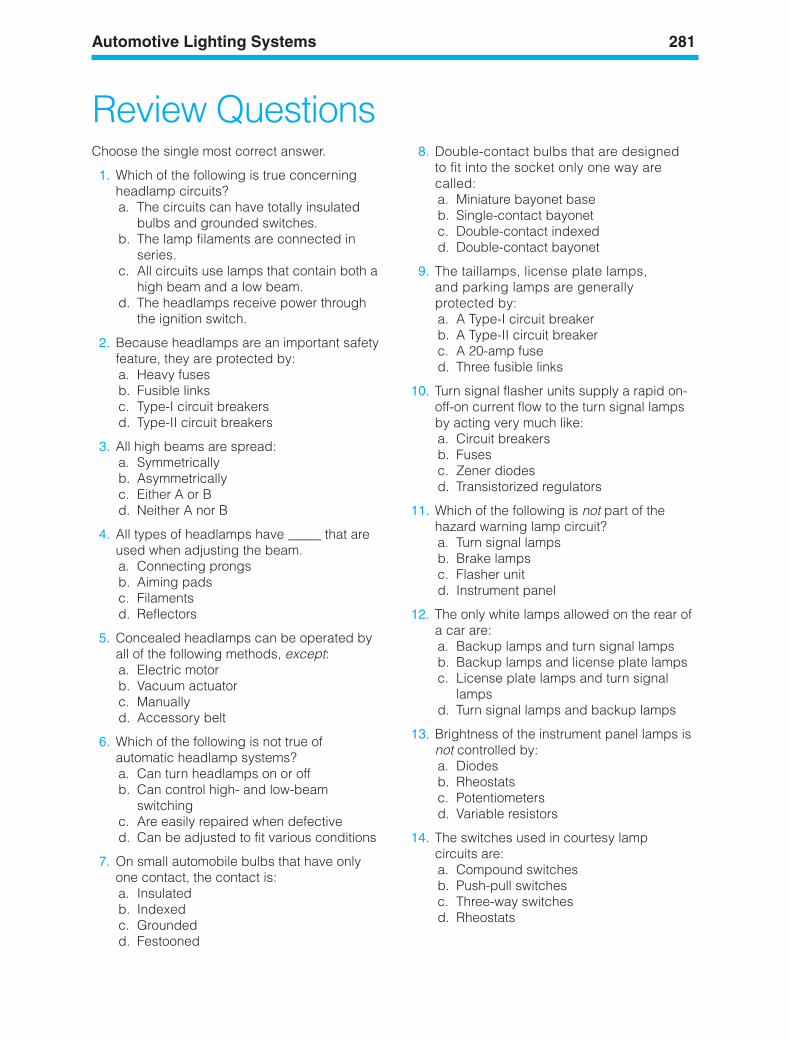
Automotive Lighting Systems 281
Review QuestionsChoose the single most correct answer.
1. Which of the following is true concerningheadlamp circuits?a. The circuits can have totally insulated
bulbs and grounded switches.b. The lamp filaments are connected in
series.c. All circuits use lamps that contain both a
high beam and a low beam.d. The headlamps receive power through
the ignition switch.
2. Because headlamps are an important safetyfeature, they are protected by:a. Heavy fusesb. Fusible linksc. Type-I circuit breakersd. Type-II circuit breakers
3. All high beams are spread:a. Symmetricallyb. Asymmetricallyc. Either A or Bd. Neither A nor B
4. All types of headlamps have _____ that areused when adjusting the beam.a. Connecting prongsb. Aiming padsc. Filamentsd. Reflectors
5. Concealed headlamps can be operated byall of the following methods, except:a. Electric motorb. Vacuum actuatorc. Manuallyd. Accessory belt
6. Which of the following is not true ofautomatic headlamp systems?a. Can turn headlamps on or offb. Can control high- and low-beam
switchingc. Are easily repaired when defectived. Can be adjusted to fit various conditions
7. On small automobile bulbs that have onlyone contact, the contact is:a. Insulatedb. Indexedc. Groundedd. Festooned
8. Double-contact bulbs that are designedto fit into the socket only one way arecalled:a. Miniature bayonet baseb. Single-contact bayonetc. Double-contact indexedd. Double-contact bayonet
9. The taillamps, license plate lamps,and parking lamps are generallyprotected by:a. A Type-I circuit breakerb. A Type-II circuit breakerc. A 20-amp fused. Three fusible links
10. Turn signal flasher units supply a rapid on-off-on current flow to the turn signal lampsby acting very much like:a. Circuit breakersb. Fusesc. Zener diodesd. Transistorized regulators
11. Which of the following is not part of thehazard warning lamp circuit?a. Turn signal lampsb. Brake lampsc. Flasher unitd. Instrument panel
12. The only white lamps allowed on the rear ofa car are:a. Backup lamps and turn signal lampsb. Backup lamps and license plate lampsc. License plate lamps and turn signal
lampsd. Turn signal lamps and backup lamps
13. Brightness of the instrument panel lamps isnot controlled by:a. Diodesb. Rheostatsc. Potentiometersd. Variable resistors
14. The switches used in courtesy lampcircuits are:a. Compound switchesb. Push-pull switchesc. Three-way switchesd. Rheostats
ker88839_ch12.qxd 1/9/06 11:32 AM Page 281

282 Chapter Twelve
15. Which of the following is not true ofcomposite headlamps?a. Use replaceable bulbsb. Are part of the car’s stylingc. Have a polycarbonate lensd. May be red or amber
16. Halogen sealed-beam lamps:a. Are not as damage-resistant as glassb. Produce 30 percent less lightc. May be made of plasticd. Have been used since the 1940s
ker88839_ch12.qxd 1/9/06 11:32 AM Page 282
LEARNINGOBJECTIVESUpon completion and review of this chapter, youshould be able to:
• Identify and explain the operation of elec-tromagnetic instrument circuits, includinggauges and sending units.
• Explain the operation of malfunction indi-cator lamps (MIL).
• Explain the operation of a simple mechanicalspeedometer.
• Identify and explain the operation of driverinformation systems (electronic instrumentcircuits).
• Explain the operation of the head-up display(HUD).
KEY TERMSAir Core GaugeBimetallic GaugeD’Arsonval MovementDriver Information Center (DIC)Driver Information System (DIS)GaugesGround SensorHead-up Display (HUD)Instrument Panel Cluster (IPC)Malfunction Indicator Lamp (MIL)Menu DrivenNonvolatile RAMThree-Coil MovementVacuum Fluorescent Display (VFD)Warning Lamps
INTRODUCTIONThis chapter covers the operation and commoncircuits of gauges, warning devices, and driverinformation systems. These systems include cool-ing fans, electromagnetic instrument circuits(sending and receiving gauges), and electronicinstrument circuits (driver information systems).
283
13Gauges,WarningDevices, andDriverInformationSystemOperation
ker88839_ch13.qxd 1/9/06 11:33 AM Page 283
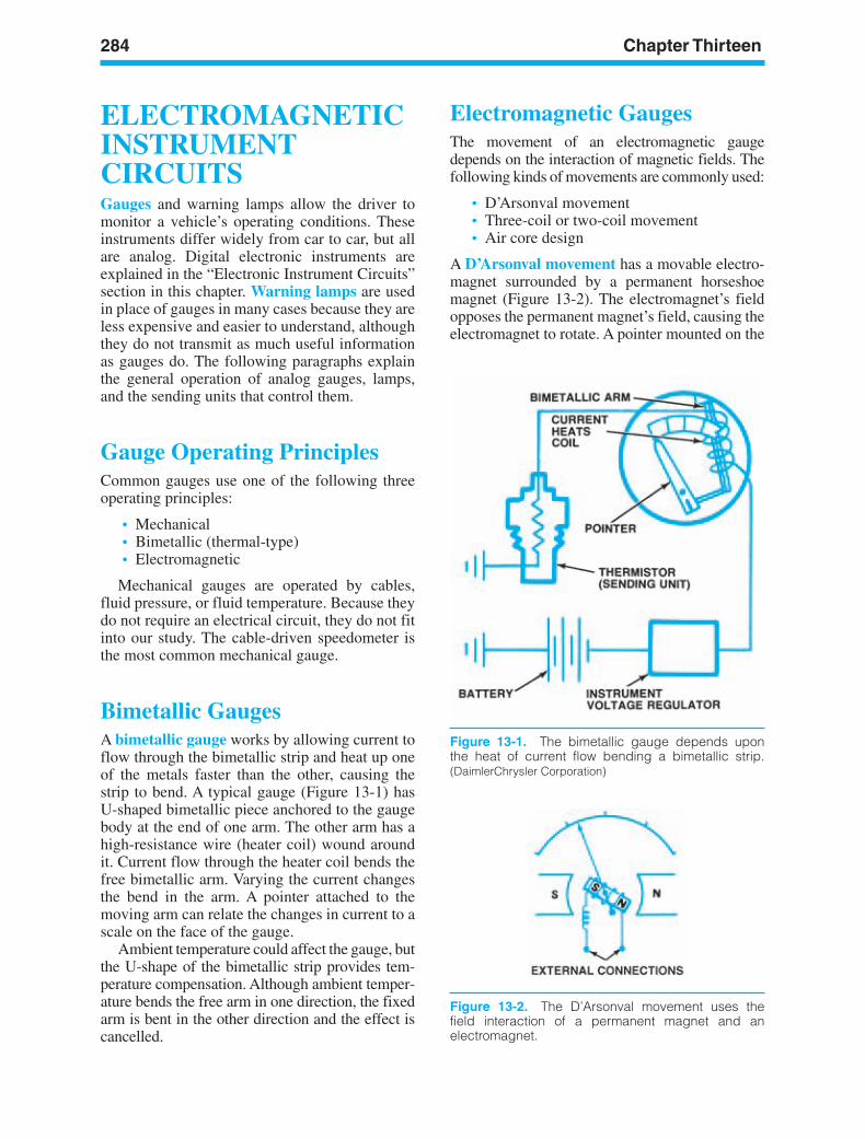
284 Chapter Thirteen
ELECTROMAGNETICINSTRUMENTCIRCUITSGauges and warning lamps allow the driver tomonitor a vehicle’s operating conditions. Theseinstruments differ widely from car to car, but allare analog. Digital electronic instruments areexplained in the “Electronic Instrument Circuits”section in this chapter. Warning lamps are usedin place of gauges in many cases because they areless expensive and easier to understand, althoughthey do not transmit as much useful informationas gauges do. The following paragraphs explainthe general operation of analog gauges, lamps,and the sending units that control them.
Gauge Operating PrinciplesCommon gauges use one of the following threeoperating principles:
• Mechanical• Bimetallic (thermal-type)• Electromagnetic
Mechanical gauges are operated by cables,fluid pressure, or fluid temperature. Because theydo not require an electrical circuit, they do not fitinto our study. The cable-driven speedometer isthe most common mechanical gauge.
Bimetallic GaugesA bimetallic gauge works by allowing current toflow through the bimetallic strip and heat up oneof the metals faster than the other, causing thestrip to bend. A typical gauge (Figure 13-1) has U-shaped bimetallic piece anchored to the gaugebody at the end of one arm. The other arm has ahigh-resistance wire (heater coil) wound aroundit. Current flow through the heater coil bends thefree bimetallic arm. Varying the current changesthe bend in the arm. A pointer attached to themoving arm can relate the changes in current to ascale on the face of the gauge.
Ambient temperature could affect the gauge, butthe U-shape of the bimetallic strip provides tem-perature compensation. Although ambient temper-ature bends the free arm in one direction, the fixedarm is bent in the other direction and the effect iscancelled.
Electromagnetic GaugesThe movement of an electromagnetic gaugedepends on the interaction of magnetic fields. Thefollowing kinds of movements are commonly used:
• D’Arsonval movement• Three-coil or two-coil movement• Air core design
A D’Arsonval movement has a movable electro-magnet surrounded by a permanent horseshoemagnet (Figure 13-2). The electromagnet’s fieldopposes the permanent magnet’s field, causing theelectromagnet to rotate. A pointer mounted on the
Figure 13-2. The D’Arsonval movement uses thefield interaction of a permanent magnet and anelectromagnet.
Figure 13-1. The bimetallic gauge depends uponthe heat of current flow bending a bimetallic strip.(DaimlerChrysler Corporation)
ker88839_ch13.qxd 1/9/06 11:33 AM Page 284
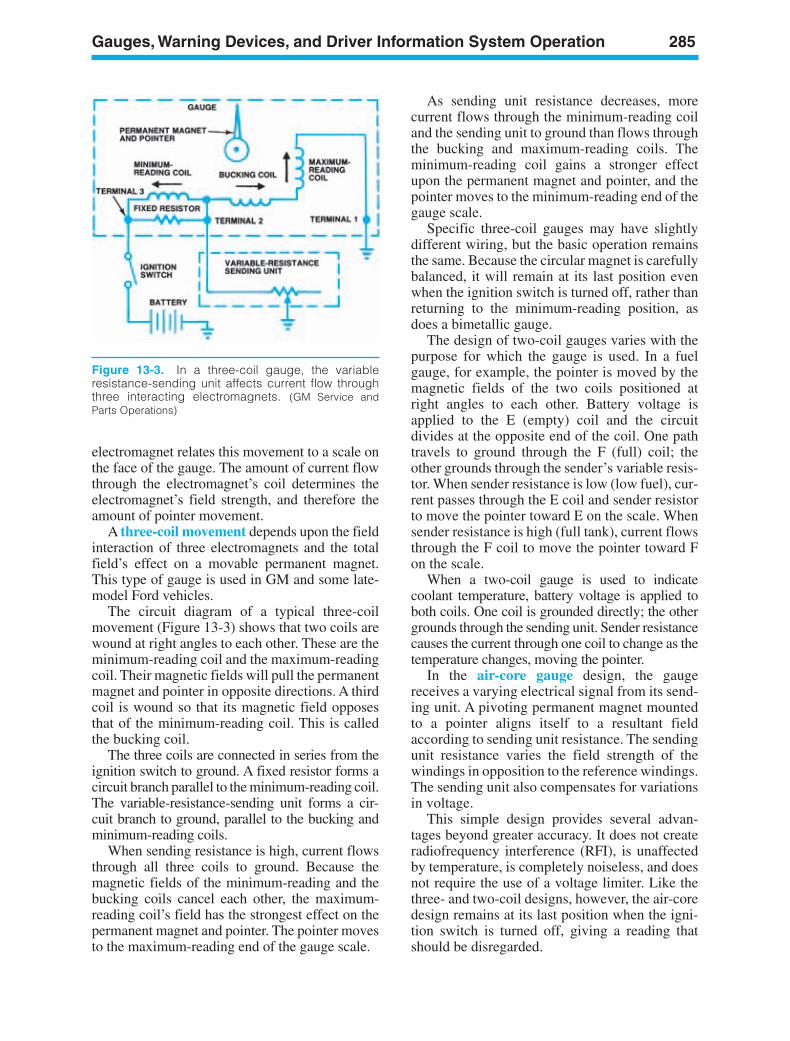
Gauges, Warning Devices, and Driver Information System Operation 285
Figure 13-3. In a three-coil gauge, the variableresistance-sending unit affects current flow throughthree interacting electromagnets. (GM Service andParts Operations)
electromagnet relates this movement to a scale onthe face of the gauge. The amount of current flowthrough the electromagnet’s coil determines theelectromagnet’s field strength, and therefore theamount of pointer movement.
A three-coil movement depends upon the fieldinteraction of three electromagnets and the totalfield’s effect on a movable permanent magnet.This type of gauge is used in GM and some late-model Ford vehicles.
The circuit diagram of a typical three-coilmovement (Figure 13-3) shows that two coils arewound at right angles to each other. These are theminimum-reading coil and the maximum-readingcoil. Their magnetic fields will pull the permanentmagnet and pointer in opposite directions. A thirdcoil is wound so that its magnetic field opposesthat of the minimum-reading coil. This is calledthe bucking coil.
The three coils are connected in series from theignition switch to ground. A fixed resistor forms acircuit branch parallel to the minimum-reading coil.The variable-resistance-sending unit forms a cir-cuit branch to ground, parallel to the bucking andminimum-reading coils.
When sending resistance is high, current flowsthrough all three coils to ground. Because themagnetic fields of the minimum-reading and thebucking coils cancel each other, the maximum-reading coil’s field has the strongest effect on thepermanent magnet and pointer. The pointer movesto the maximum-reading end of the gauge scale.
As sending unit resistance decreases, morecurrent flows through the minimum-reading coiland the sending unit to ground than flows throughthe bucking and maximum-reading coils. Theminimum-reading coil gains a stronger effectupon the permanent magnet and pointer, and thepointer moves to the minimum-reading end of thegauge scale.
Specific three-coil gauges may have slightlydifferent wiring, but the basic operation remainsthe same. Because the circular magnet is carefullybalanced, it will remain at its last position evenwhen the ignition switch is turned off, rather thanreturning to the minimum-reading position, asdoes a bimetallic gauge.
The design of two-coil gauges varies with thepurpose for which the gauge is used. In a fuelgauge, for example, the pointer is moved by themagnetic fields of the two coils positioned atright angles to each other. Battery voltage isapplied to the E (empty) coil and the circuitdivides at the opposite end of the coil. One pathtravels to ground through the F (full) coil; theother grounds through the sender’s variable resis-tor. When sender resistance is low (low fuel), cur-rent passes through the E coil and sender resistorto move the pointer toward E on the scale. Whensender resistance is high (full tank), current flowsthrough the F coil to move the pointer toward Fon the scale.
When a two-coil gauge is used to indicatecoolant temperature, battery voltage is applied toboth coils. One coil is grounded directly; the othergrounds through the sending unit. Sender resistancecauses the current through one coil to change as thetemperature changes, moving the pointer.
In the air-core gauge design, the gaugereceives a varying electrical signal from its send-ing unit. A pivoting permanent magnet mountedto a pointer aligns itself to a resultant fieldaccording to sending unit resistance. The sendingunit resistance varies the field strength of thewindings in opposition to the reference windings.The sending unit also compensates for variationsin voltage.
This simple design provides several advan-tages beyond greater accuracy. It does not createradiofrequency interference (RFI), is unaffectedby temperature, is completely noiseless, and doesnot require the use of a voltage limiter. Like thethree- and two-coil designs, however, the air-coredesign remains at its last position when the igni-tion switch is turned off, giving a reading thatshould be disregarded.
ker88839_ch13.qxd 1/9/06 11:33 AM Page 285
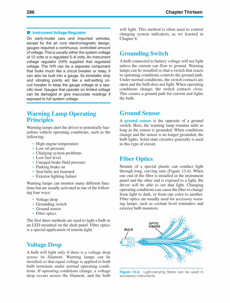
286 Chapter Thirteen
Instrument Voltage Regulator
On early-model cars and imported vehicles,except for the air core electromagnetic design,gauges required a continuous, controlled amountof voltage.This is usually either the system voltageof 12 volts or a regulated 5–6 volts. An instrumentvoltage regulator (IVR) supplied that regulatedvoltage. The IVR can be a separate componentthat looks much like a circuit breaker or relay; itcan also be built into a gauge. Its bimetallic stripand vibrating points act like a self-setting cir-cuit breaker to keep the gauge voltage at a spe-cific level. Gauges that operate on limited voltagecan be damaged or give inaccurate readings ifexposed to full system voltage.
Warning Lamp OperatingPrinciplesWarning lamps alert the driver to potentially haz-ardous vehicle operating conditions, such as thefollowing:
• High engine temperature• Low oil pressure• Charging system problems• Low fuel level• Unequal brake fluid pressure• Parking brake on• Seat belts not fastened• Exterior lighting failure
Warning lamps can monitor many different func-tions but are usually activated in one of the follow-ing four ways:
• Voltage drop• Grounding switch• Ground sensor• Fiber optics
The first three methods are used to light a bulb oran LED mounted on the dash panel. Fiber opticsis a special application of remote light.
Voltage DropA bulb will light only if there is a voltage dropacross its filament. Warning lamps can beinstalled so that equal voltage is applied to bothbulb terminals under normal operating condi-tions. If operating conditions change, a voltagedrop occurs across the filament, and the bulb
will light. This method is often used to controlcharging system indicators, as we learned inChapter 8.
Grounding SwitchA bulb connected to battery voltage will not lightunless the current can flow to ground. Warninglamps can be installed so that a switch that reactsto operating conditions controls the ground path.Under normal conditions, the switch contacts areopen and the bulb does not light. When operatingconditions change, the switch contacts close.This creates a ground path for current and lightsthe bulb.
Ground SensorA ground sensor is the opposite of a groundswitch. Here, the warning lamp remains unlit aslong as the sensor is grounded. When conditionschange and the sensor is no longer grounded, thebulb lights. Solid-state circuitry generally is usedin this type of circuit.
Fiber OpticsStrands of a special plastic can conduct lightthrough long, curving runs (Figure 13-4). Whenone end of the fiber is installed in the instrumentpanel and the other end is exposed to a light, thedriver will be able to see that light. Changingoperating conditions can cause the fiber to changefrom light to dark, or from one color to another.Fiber optics are usually used for accessory warn-ing lamps, such as coolant level reminders andexterior bulb monitors.
Figure 13-4. Light-carrying fibers can be used inaccessory instruments.
ker88839_ch13.qxd 1/9/06 11:33 AM Page 286
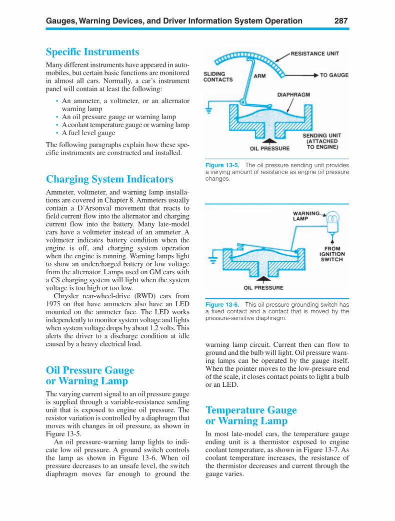
Gauges, Warning Devices, and Driver Information System Operation 287
Figure 13-5. The oil pressure sending unit providesa varying amount of resistance as engine oil pressurechanges.
Figure 13-6. This oil pressure grounding switch hasa fixed contact and a contact that is moved by thepressure-sensitive diaphragm.
Specific InstrumentsMany different instruments have appeared in auto-mobiles, but certain basic functions are monitoredin almost all cars. Normally, a car’s instrumentpanel will contain at least the following:
• An ammeter, a voltmeter, or an alternatorwarning lamp
• An oil pressure gauge or warning lamp• Acoolant temperature gauge or warning lamp• A fuel level gauge
The following paragraphs explain how these spe-cific instruments are constructed and installed.
Charging System IndicatorsAmmeter, voltmeter, and warning lamp installa-tions are covered in Chapter 8. Ammeters usuallycontain a D’Arsonval movement that reacts tofield current flow into the alternator and chargingcurrent flow into the battery. Many late-modelcars have a voltmeter instead of an ammeter. Avoltmeter indicates battery condition when theengine is off, and charging system operationwhen the engine is running. Warning lamps lightto show an undercharged battery or low voltagefrom the alternator. Lamps used on GM cars witha CS charging system will light when the systemvoltage is too high or too low.
Chrysler rear-wheel-drive (RWD) cars from1975 on that have ammeters also have an LEDmounted on the ammeter face. The LED worksindependently to monitor system voltage and lightswhen system voltage drops by about 1.2 volts. Thisalerts the driver to a discharge condition at idlecaused by a heavy electrical load.
Oil Pressure Gaugeor Warning LampThe varying current signal to an oil pressure gaugeis supplied through a variable-resistance sendingunit that is exposed to engine oil pressure. Theresistor variation is controlled by a diaphragm thatmoves with changes in oil pressure, as shown inFigure 13-5.
An oil pressure-warning lamp lights to indi-cate low oil pressure. A ground switch controlsthe lamp as shown in Figure 13-6. When oilpressure decreases to an unsafe level, the switchdiaphragm moves far enough to ground the
warning lamp circuit. Current then can flow toground and the bulb will light. Oil pressure warn-ing lamps can be operated by the gauge itself.When the pointer moves to the low-pressure endof the scale, it closes contact points to light a bulbor an LED.
Temperature Gaugeor Warning LampIn most late-model cars, the temperature gaugeending unit is a thermistor exposed to enginecoolant temperature, as shown in Figure 13-7. Ascoolant temperature increases, the resistance ofthe thermistor decreases and current through thegauge varies.
ker88839_ch13.qxd 1/9/06 11:33 AM Page 287
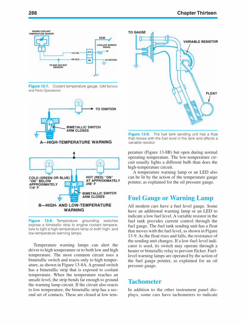
288 Chapter Thirteen
Figure 13-7. Coolant temperature gauge. (GM Serviceand Parts Operations)
Figure 13-8. Temperature grounding switchesexpose a bimetallic strip to engine coolant tempera-ture to light a high-temperature lamp or both high- andlow-temperature warning lamps.
Figure 13-9. The fuel tank sending unit has a floatthat moves with the fuel level in the tank and affects avariable resistor.
Temperature warning lamps can alert thedriver to high temperature or to both low and hightemperature. The most common circuit uses abimetallic switch and reacts only to high temper-ature, as shown in Figure 13-8A. A ground switchhas a bimetallic strip that is exposed to coolanttemperature. When the temperature reaches anunsafe level, the strip bends far enough to groundthe warning lamp circuit. If the circuit also reactsto low temperature, the bimetallic strip has a sec-ond set of contacts. These are closed at low tem-
perature (Figure 13-8B) but open during normaloperating temperature. The low-temperature cir-cuit usually lights a different bulb than does thehigh-temperature circuit.
A temperature warning lamp or an LED alsocan be lit by the action of the temperature gaugepointer, as explained for the oil pressure gauge.
Fuel Gauge or Warning LampAll modern cars have a fuel level gauge. Somehave an additional warning lamp or an LED toindicate a low fuel level. A variable resistor in thefuel tank provides current control through thefuel gauge. The fuel tank sending unit has a floatthat moves with the fuel level, as shown in Figure13-9. As the float rises and falls, the resistance ofthe sending unit changes. If a low-fuel-level indi-cator is used, its switch may operate through aheater or bimetallic relay to prevent flicker. Fuel-level warning lamps are operated by the action ofthe fuel gauge pointer, as explained for an oilpressure gauge.
TachometerIn addition to the other instrument panel dis-plays, some cars have tachometers to indicate
ker88839_ch13.qxd 1/9/06 11:33 AM Page 288
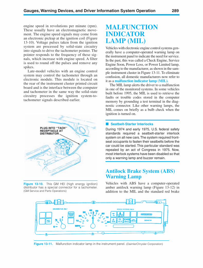
Gauges, Warning Devices, and Driver Information System Operation 289
Figure 13-10. This GM HEI (high energy ignition)distributor has a special connector for a tachometer.(GM Service and Parts Operations)
engine speed in revolutions per minute (rpm).These usually have an electromagnetic move-ment. The engine speed signals may come froman electronic pickup at the ignition coil (Figure13-10). Voltage pulses taken from the ignitionsystem are processed by solid-state circuitryinto signals to drive the tachometer pointer. Thepointer responds to the frequency of these sig-nals, which increase with engine speed. A filteris used to round off the pulses and remove anyspikes.
Late-model vehicles with an engine controlsystem may control the tachometer through anelectronic module. This module is located onthe rear of the instrument cluster printed circuitboard and is the interface between the computerand tachometer in the same way the solid-statecircuitry processes the ignition system-to-tachometer signals described earlier.
MALFUNCTIONINDICATORLAMP (MIL)Vehicles with electronic engine control systems gen-erally have a computer-operated warning lamp onthe instrument panel to indicate the need for service.In the past, this was called a Check Engine, ServiceEngine Soon, Power Loss, or Power Limited lamp,according to the manufacturer, as shown in the sam-ple instrument cluster in Figure 13-11. To eliminateconfusion, all domestic manufacturers now refer toit as a malfunction indicator lamp (MIL).
The MIL lamp alerts the driver to a malfunctionin one of the monitored systems. In some vehiclesbuilt before 1995, the MIL is used to retrieve thefaults or trouble codes stored in the computermemory by grounding a test terminal in the diag-nostic connector. Like other warning lamps, theMIL comes on briefly as a bulb check when theignition is turned on.
Seatbelt-Starter Interlocks
During 1974 and early 1975, U.S. federal safetystandards required a seatbelt-starter interlocksystem on all new cars.The system required front-seat occupants to fasten their seatbelts before thecar could be started. This particular standard wasrepealed by an act of Congress in 1975. Now,most interlock systems have been disabled so thatonly a warning lamp and buzzer remain.
Antilock Brake System (ABS)Warning LampVehicles with ABS have a computer-operatedamber antilock warning lamp (Figure 13-12) inaddition to the MIL and the standard red brake
Figure 13-11. Malfunction indicator lamp in the instrument panel. (DaimlerChrysler Corporation)
ker88839_ch13.qxd 1/9/06 11:33 AM Page 289
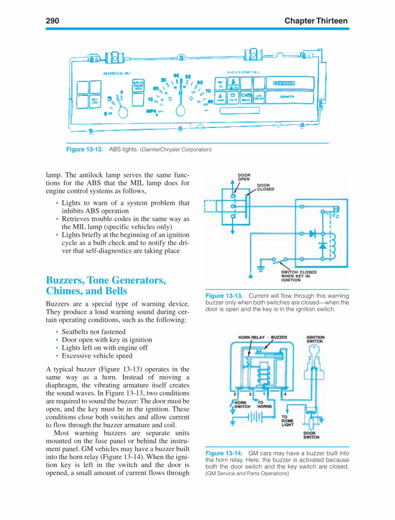
290 Chapter Thirteen
Figure 13-12. ABS lights. (DaimlerChrysler Corporation)
Figure 13-13. Current will flow through this warningbuzzer only when both switches are closed—when thedoor is open and the key is in the ignition switch.
Figure 13-14. GM cars may have a buzzer built intothe horn relay. Here, the buzzer is activated becauseboth the door switch and the key switch are closed.(GM Service and Parts Operations)
lamp. The antilock lamp serves the same func-tions for the ABS that the MIL lamp does forengine control systems as follows,
• Lights to warn of a system problem thatinhibits ABS operation
• Retrieves trouble codes in the same way asthe MIL lamp (specific vehicles only)
• Lights briefly at the beginning of an ignitioncycle as a bulb check and to notify the dri-ver that self-diagnostics are taking place
Buzzers, Tone Generators,Chimes, and BellsBuzzers are a special type of warning device.They produce a loud warning sound during cer-tain operating conditions, such as the following:
• Seatbelts not fastened• Door open with key in ignition• Lights left on with engine off• Excessive vehicle speed
A typical buzzer (Figure 13-13) operates in thesame way as a horn. Instead of moving adiaphragm, the vibrating armature itself createsthe sound waves. In Figure 13-13, two conditionsare required to sound the buzzer: The door must beopen, and the key must be in the ignition. Theseconditions close both switches and allow currentto flow through the buzzer armature and coil.
Most warning buzzers are separate unitsmounted on the fuse panel or behind the instru-ment panel. GM vehicles may have a buzzer builtinto the horn relay (Figure 13-14). When the igni-tion key is left in the switch and the door isopened, a small amount of current flows through
ker88839_ch13.qxd 1/9/06 11:33 AM Page 290
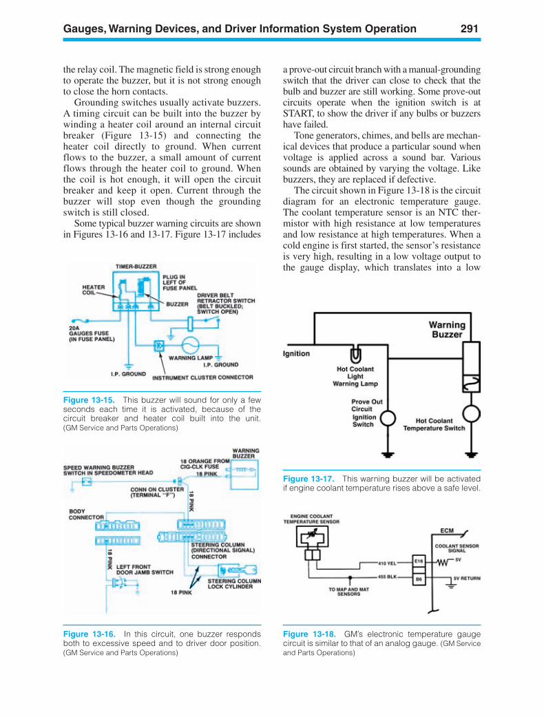
Gauges, Warning Devices, and Driver Information System Operation 291
Figure 13-15. This buzzer will sound for only a fewseconds each time it is activated, because of thecircuit breaker and heater coil built into the unit.(GM Service and Parts Operations)
Figure 13-16. In this circuit, one buzzer respondsboth to excessive speed and to driver door position.(GM Service and Parts Operations)
the relay coil. The magnetic field is strong enoughto operate the buzzer, but it is not strong enoughto close the horn contacts.
Grounding switches usually activate buzzers.A timing circuit can be built into the buzzer bywinding a heater coil around an internal circuitbreaker (Figure 13-15) and connecting theheater coil directly to ground. When currentflows to the buzzer, a small amount of currentflows through the heater coil to ground. Whenthe coil is hot enough, it will open the circuitbreaker and keep it open. Current through thebuzzer will stop even though the groundingswitch is still closed.
Some typical buzzer warning circuits are shownin Figures 13-16 and 13-17. Figure 13-17 includes
a prove-out circuit branch with a manual-groundingswitch that the driver can close to check that thebulb and buzzer are still working. Some prove-outcircuits operate when the ignition switch is atSTART, to show the driver if any bulbs or buzzershave failed.
Tone generators, chimes, and bells are mechan-ical devices that produce a particular sound whenvoltage is applied across a sound bar. Varioussounds are obtained by varying the voltage. Likebuzzers, they are replaced if defective.
The circuit shown in Figure 13-18 is the circuitdiagram for an electronic temperature gauge.The coolant temperature sensor is an NTC ther-mistor with high resistance at low temperaturesand low resistance at high temperatures. When acold engine is first started, the sensor’s resistanceis very high, resulting in a low voltage output tothe gauge display, which translates into a low
Figure 13-18. GM’s electronic temperature gaugecircuit is similar to that of an analog gauge. (GM Serviceand Parts Operations)
Figure 13-17. This warning buzzer will be activatedif engine coolant temperature rises above a safe level.
ker88839_ch13.qxd 1/9/06 11:33 AM Page 291
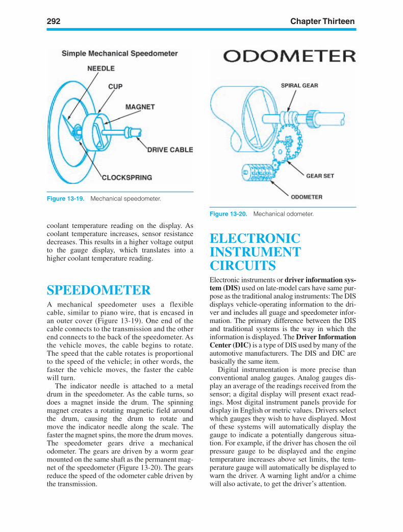
292 Chapter Thirteen
Figure 13-19. Mechanical speedometer.
Figure 13-20. Mechanical odometer.
coolant temperature reading on the display. Ascoolant temperature increases, sensor resistancedecreases. This results in a higher voltage outputto the gauge display, which translates into ahigher coolant temperature reading.
SPEEDOMETERA mechanical speedometer uses a flexiblecable, similar to piano wire, that is encased inan outer cover (Figure 13-19). One end of thecable connects to the transmission and the otherend connects to the back of the speedometer. Asthe vehicle moves, the cable begins to rotate.The speed that the cable rotates is proportionalto the speed of the vehicle; in other words, thefaster the vehicle moves, the faster the cablewill turn.
The indicator needle is attached to a metaldrum in the speedometer. As the cable turns, sodoes a magnet inside the drum. The spinningmagnet creates a rotating magnetic field aroundthe drum, causing the drum to rotate andmove the indicator needle along the scale. Thefaster the magnet spins, the more the drum moves.The speedometer gears drive a mechanicalodometer. The gears are driven by a worm gearmounted on the same shaft as the permanent mag-net of the speedometer (Figure 13-20). The gearsreduce the speed of the odometer cable driven bythe transmission.
ELECTRONICINSTRUMENTCIRCUITSElectronic instruments or driver information sys-tem (DIS) used on late-model cars have same pur-pose as the traditional analog instruments: The DISdisplays vehicle-operating information to the dri-ver and includes all guage and speedometer infor-mation. The primary difference between the DISand traditional systems is the way in which theinformation is displayed. The Driver InformationCenter (DIC) is a type of DIS used by many of theautomotive manufacturers. The DIS and DIC arebasically the same item.
Digital instrumentation is more precise thanconventional analog gauges. Analog gauges dis-play an average of the readings received from thesensor; a digital display will present exact read-ings. Most digital instrument panels provide fordisplay in English or metric values. Drivers selectwhich gauges they wish to have displayed. Mostof these systems will automatically display thegauge to indicate a potentially dangerous situa-tion. For example, if the driver has chosen the oilpressure gauge to be displayed and the enginetemperature increases above set limits, the tem-perature gauge will automatically be displayed towarn the driver. A warning light and/or a chimewill also activate, to get the driver’s attention.
ker88839_ch13.qxd 1/9/06 11:33 AM Page 292
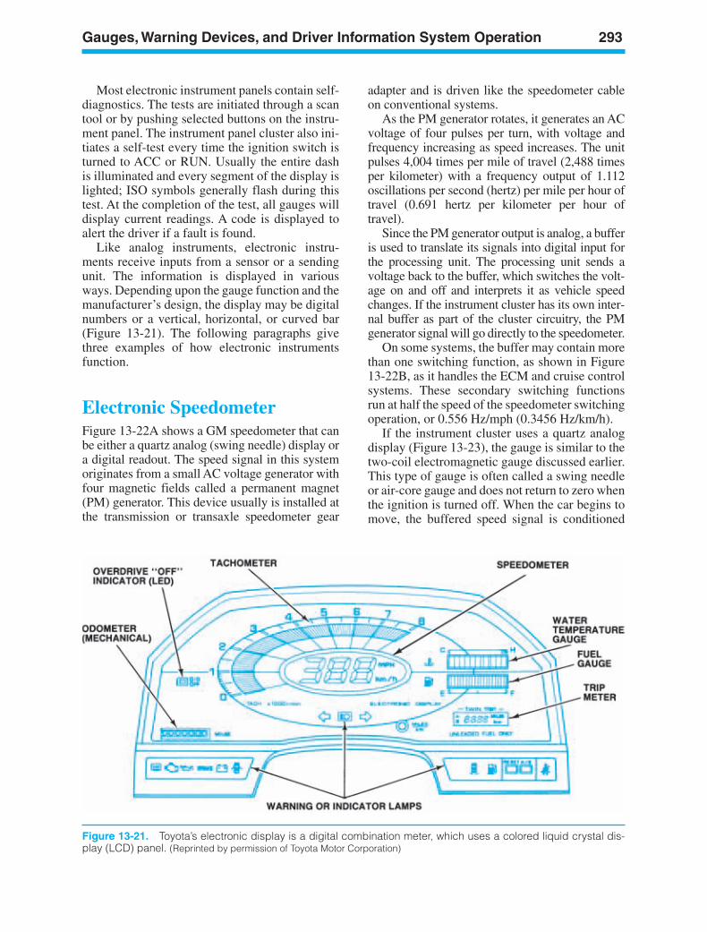
Gauges, Warning Devices, and Driver Information System Operation 293
Most electronic instrument panels contain self-diagnostics. The tests are initiated through a scantool or by pushing selected buttons on the instru-ment panel. The instrument panel cluster also ini-tiates a self-test every time the ignition switch isturned to ACC or RUN. Usually the entire dashis illuminated and every segment of the display islighted; ISO symbols generally flash during thistest. At the completion of the test, all gauges willdisplay current readings. A code is displayed toalert the driver if a fault is found.
Like analog instruments, electronic instru-ments receive inputs from a sensor or a sendingunit. The information is displayed in variousways. Depending upon the gauge function and themanufacturer’s design, the display may be digitalnumbers or a vertical, horizontal, or curved bar(Figure 13-21). The following paragraphs givethree examples of how electronic instrumentsfunction.
Electronic SpeedometerFigure 13-22A shows a GM speedometer that canbe either a quartz analog (swing needle) display ora digital readout. The speed signal in this systemoriginates from a small AC voltage generator withfour magnetic fields called a permanent magnet(PM) generator. This device usually is installed atthe transmission or transaxle speedometer gear
Figure 13-21. Toyota’s electronic display is a digital combination meter, which uses a colored liquid crystal dis-play (LCD) panel. (Reprinted by permission of Toyota Motor Corporation)
adapter and is driven like the speedometer cableon conventional systems.
As the PM generator rotates, it generates an ACvoltage of four pulses per turn, with voltage andfrequency increasing as speed increases. The unitpulses 4,004 times per mile of travel (2,488 timesper kilometer) with a frequency output of 1.112oscillations per second (hertz) per mile per hour oftravel (0.691 hertz per kilometer per hour oftravel).
Since the PM generator output is analog, a bufferis used to translate its signals into digital input forthe processing unit. The processing unit sends avoltage back to the buffer, which switches the volt-age on and off and interprets it as vehicle speedchanges. If the instrument cluster has its own inter-nal buffer as part of the cluster circuitry, the PMgenerator signal will go directly to the speedometer.
On some systems, the buffer may contain morethan one switching function, as shown in Figure13-22B, as it handles the ECM and cruise controlsystems. These secondary switching functionsrun at half the speed of the speedometer switchingoperation, or 0.556 Hz/mph (0.3456 Hz/km/h).
If the instrument cluster uses a quartz analogdisplay (Figure 13-23), the gauge is similar to thetwo-coil electromagnetic gauge discussed earlier.This type of gauge is often called a swing needleor air-core gauge and does not return to zero whenthe ignition is turned off. When the car begins tomove, the buffered speed signal is conditioned
ker88839_ch13.qxd 1/9/06 11:34 AM Page 293
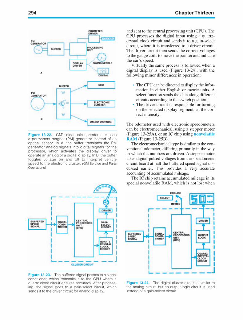
294 Chapter Thirteen
Figure 13-23. The buffered signal passes to a signalconditioner, which transmits it to the CPU where aquartz clock circuit ensures accuracy. After process-ing, the signal goes to a gain-select circuit, whichsends it to the driver circuit for analog display.
Figure 13-24. The digital cluster circuit is similar tothe analog circuit, but an output-logic circuit is usedinstead of a gain-select circuit.
Figure 13-22. GM’s electronic speedometer usesa permanent magnet (PM) generator instead of anoptical sensor. In A, the buffer translates the PMgenerator analog signals into digital signals for theprocessor, which activates the display driver tooperate an analog or a digital display. In B, the buffertoggles voltage on and off to interpret vehiclespeed to the electronic cluster. (GM Service and PartsOperations)
and sent to the central processing unit (CPU). TheCPU processes the digital input using a quartz-crystal clock circuit and sends it to a gain-selectcircuit, where it is transferred to a driver circuit.The driver circuit then sends the correct voltagesto the gauge coils to move the pointer and indicatethe car’s speed.
Virtually the same process is followed when adigital display is used (Figure 13-24), with thefollowing minor differences in operation:
• The CPU can be directed to display the infor-mation in either English or metric units. Aselect function sends the data along differentcircuits according to the switch position.
• The driver circuit is responsible for turningon the selected display segments at the cor-rect intensity.
The odometer used with electronic speedometerscan be electromechanical, using a stepper motor(Figure 13-25A), or an IC chip using nonvolatileRAM (Figure 13-25B).
The electromechanical type is similar to the con-ventional odometer, differing primarily in the wayin which the numbers are driven. A stepper motortakes digital-pulsed voltages from the speedometercircuit board at half the buffered speed signal dis-cussed earlier. This provides a very accurateaccounting of accumulated mileage.
The IC chip retains accumulated mileage in itsspecial nonvolatile RAM, which is not lost when
ker88839_ch13.qxd 1/9/06 11:34 AM Page 294
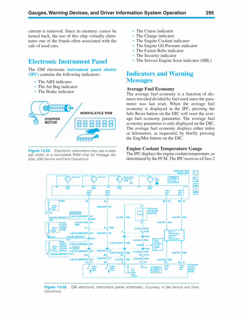
Gauges, Warning Devices, and Driver Information System Operation 295
Figure 13-25. Electronic odometers may use a step-per motor or a nonvolatile RAM chip for mileage dis-play. (GM Service and Parts Operations)
current is removed. Since its memory cannot beturned back, the use of this chip virtually elimi-nates one of the frauds often associated with thesale of used cars.
Electronic Instrument PanelThe GM electronic instrument panel cluster(IPC) contains the following indicators:
• The ABS indicator• The Air Bag indicator• The Brake indicator
• The Cruise indicator• The Charge indicator• The Engine Coolant indicator• The Engine Oil Pressure indicator• The Fasten Belts indicator• The Security indicator• The Service Engine Soon indicator (MIL)
Indicators and WarningMessagesAverage Fuel EconomyThe average fuel economy is a function of dis-tance traveled divided by fuel used since the para-meter was last reset. When the average fueleconomy is displayed in the IPC, pressing theInfo Reset button on the DIC will reset the aver-age fuel economy parameter. The average fueleconomy parameter is only displayed on the DIC.The average fuel economy displays either milesor kilometers, as requested, by briefly pressingthe Eng/Met button on the DIC.
Engine Coolant Temperature GaugeThe IPC displays the engine coolant temperature, asdetermined by the PCM. The IPC receives a Class 2
Figure 13-26. GM electronic instrument panel schematic. (Courtesy of GM Service and PartsOperations)
ker88839_ch13.qxd 1/9/06 11:34 AM Page 295
296 Chapter Thirteen
message from the PCM indicating the enginecoolant temperature. The engine coolant tempera-ture gauge defaults to C if the following is true:
• The PCM detects a malfunction in the enginecoolant temperature sensor circuit.
• The IPC detects a loss of Class 2 communi-cations with the PCM.
Fuel GaugeThe IPC displays the fuel level, as determined bythe PCM. The IPC receives a Class 2 message fromthe PCM indicating the fuel level percentage. Thefuel gauge defaults to empty if the following is true:
• The PCM detects a malfunction in the fuellevel sensor signal circuit.
• The IPC detects a loss of Class 2 communi-cations with the PCM.
Fuel RangeThe fuel range is the estimated distance that thevehicle can travel under the current fuel economyand fuel level conditions. The driver cannot resetthe fuel range parameter. “LO” is displayed in thefuel range display when the range is calculated tobe less than 64 km (40 miles). The fuel range dis-plays either miles or kilometers, as requested, bybriefly pressing the Eng/Met button on the DIC.
OdometerThe IPC contains a season odometer and two tripodometers. The IPC calculates the mileage basedon the vehicle-speed signal circuit from the PCM.The odometer will display “Error” if an internal IPCmemory failure is detected. The odometer displayseither miles or kilometers, as requested, by brieflypressing the Eng/Met button on the DIC. Pressingthe Reset Trip A/B button for greater than 2 secondswill reset the trip odometer that is displayed.
PRNDL DisplayThe IPC displays the selected automatic trans-mission/transaxle gear position determined by thePCM, as sensed by the gear position selected bythe driver. The IPC receives a Class 2 messagefrom the PCM indicating the gear position. ThePRNDL for the transmission gear position displayblanks if the following is true:
• The PCM detects a malfunction in the trans-mission range switch signal circuit.
• The IPC receives a Class 2 message indicat-ing the park position and the column parkswitch indicates a position other than park.
• The IPC detects a loss of Class 2 communi-cations with the PCM.
SpeedometerThe IPC displays the vehicle speed based on theinformation received from the PCM. The PCMconverts the data from the vehicle speed sensorto a 4,000-pulses/mile signal. The IPC uses thevehicle-speed signal circuit from the PCM in orderto calculate the vehicle speed. The speedometerdefaults to 0 km/h (0 mph) if a malfunction inthe vehicle speed signal circuit exists. The speedo-meter displays either miles or kilometers, asrequested, by briefly pressing the Eng/Met buttonon the DIC.
The speedometer display configuration canbe changed by using the Dspl Mode button. Thespeedometer can be configured in one of the fol-lowing formats:
• Analog display only• Analog and digital displays• Digital display only
TachometerThe IPC displays the engine speed based on infor-mation received from the PCM. The PCM convertsthe data from the engine to a 2-pulses-per-engine-revolution signal. The IPC uses the engine-speedsignal circuit from the PCM to calculate the enginespeed. The tachometer defaults to 0 rpm if a mal-function in the engine-speed signal circuit exists.
VoltmeterThe IPC displays the system voltage.
Driver InformationCenter (DIC)The DIC vehicle information displays vehicleoperation parameters that are available to the dri-ver when the ignition is in the RUN position. Onmany applications, the driver can navigatethrough the various parameters displayed on theDIC using the Info Up and Info Down buttons.Some parameters can be reset by briefly pressingthe Info Reset button.
ker88839_ch13.qxd 1/9/06 11:34 AM Page 296
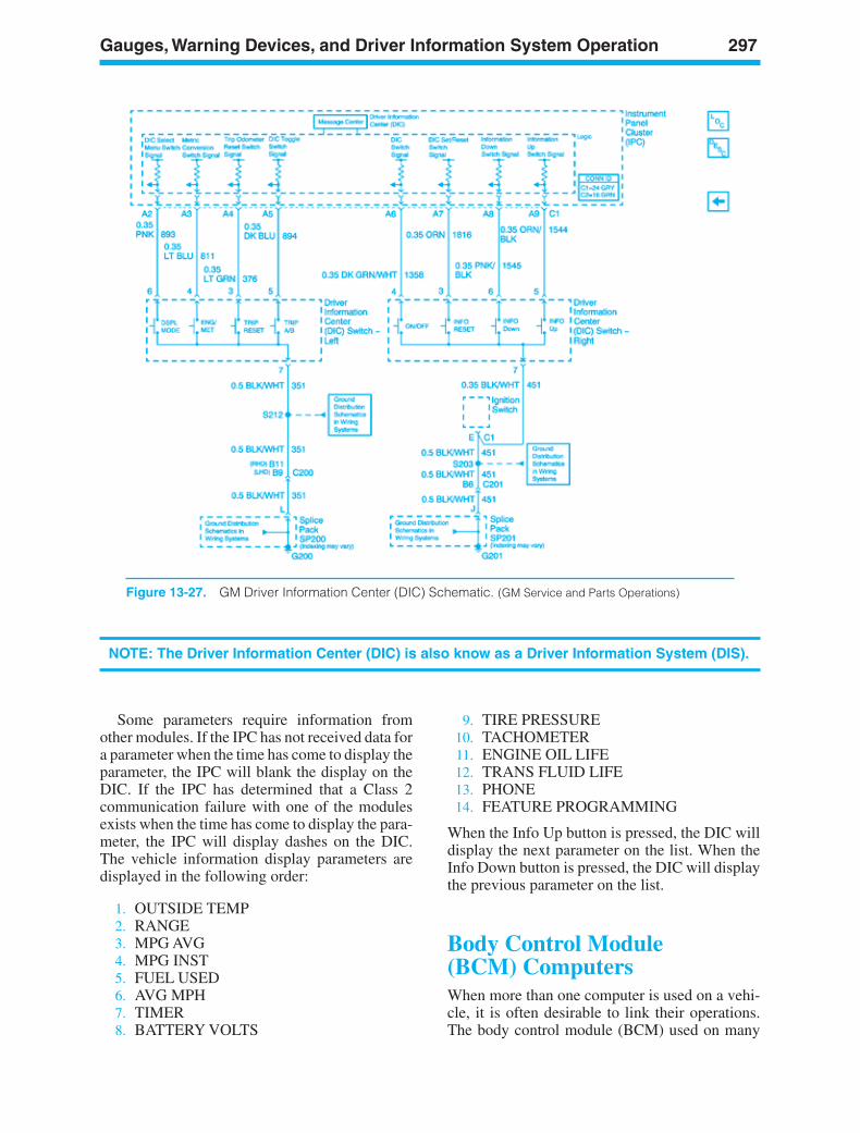
Gauges, Warning Devices, and Driver Information System Operation 297
Figure 13-27. GM Driver Information Center (DIC) Schematic. (GM Service and Parts Operations)
NOTE: The Driver Information Center (DIC) is also know as a Driver Information System (DIS).
Some parameters require information fromother modules. If the IPC has not received data fora parameter when the time has come to display theparameter, the IPC will blank the display on theDIC. If the IPC has determined that a Class 2communication failure with one of the modulesexists when the time has come to display the para-meter, the IPC will display dashes on the DIC.The vehicle information display parameters aredisplayed in the following order:
1. OUTSIDE TEMP2. RANGE3. MPG AVG4. MPG INST5. FUEL USED6. AVG MPH7. TIMER8. BATTERY VOLTS
9. TIRE PRESSURE10. TACHOMETER11. ENGINE OIL LIFE12. TRANS FLUID LIFE13. PHONE14. FEATURE PROGRAMMING
When the Info Up button is pressed, the DIC willdisplay the next parameter on the list. When theInfo Down button is pressed, the DIC will displaythe previous parameter on the list.
Body Control Module(BCM) ComputersWhen more than one computer is used on a vehi-cle, it is often desirable to link their operations.The body control module (BCM) used on many
ker88839_ch13.qxd 1/9/06 11:34 AM Page 297
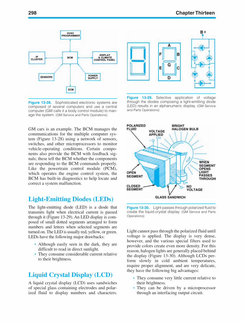
298 Chapter Thirteen
Figure 13-29. Selective application of voltagethrough the diodes composing a light-emitting diode(LED) results in an alphanumeric display. (GM Serviceand Parts Operations)
Figure 13-30. Light passes through polarized fluid tocreate the liquid-crystal display. (GM Service and PartsOperations)
Figure 13-28. Sophisticated electronic systems arecomposed of several computers and use a centralcomputer (GM calls it a body control module) to man-age the system. (GM Service and Parts Operations)
GM cars is an example. The BCM manages thecommunications for the multiple computer sys-tem (Figure 13-28) using a network of sensors,switches, and other microprocessors to monitorvehicle-operating conditions. Certain compo-nents also provide the BCM with feedback sig-nals; these tell the BCM whether the componentsare responding to the BCM commands properly.Like the powertrain control module (PCM),which operates the engine control system, theBCM has built-in diagnostics to help locate andcorrect a system malfunction.
Light-Emitting Diodes (LEDs)The light-emitting diode (LED) is a diode thattransmits light when electrical current is passedthrough it (Figure 13-29). An LED display is com-posed of small dotted segments arranged to formnumbers and letters when selected segments areturned on. The LED is usually red, yellow, or green.LEDs have the following major drawbacks:
• Although easily seen in the dark, they aredifficult to read in direct sunlight.
• They consume considerable current relativeto their brightness.
Liquid Crystal Display (LCD)A liquid crystal display (LCD) uses sandwichesof special glass containing electrodes and polar-ized fluid to display numbers and characters.
Light cannot pass through the polarized fluid untilvoltage is applied. The display is very dense,however, and the various special filters used toprovide colors create even more density. For thisreason, halogen lights are generally placed behindthe display (Figure 13-30). Although LCDs per-form slowly in cold ambient temperatures,require proper alignment, and are very delicate,they have the following big advantages:
• They consume very little current relative totheir brightness.
• They can be driven by a microprocessorthrough an interfacing output circuit.
ker88839_ch13.qxd 1/9/06 11:34 AM Page 298
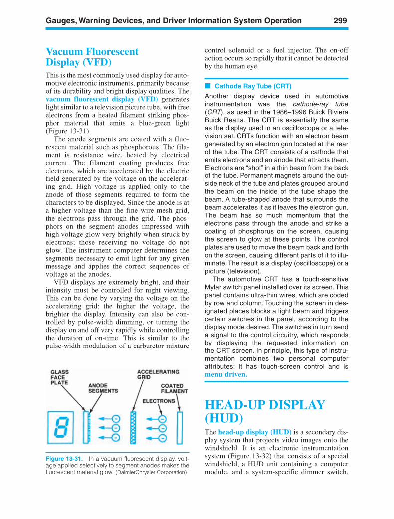
Gauges, Warning Devices, and Driver Information System Operation 299
Figure 13-31. In a vacuum fluorescent display, volt-age applied selectively to segment anodes makes thefluorescent material glow. (DaimlerChrysler Corporation)
Vacuum FluorescentDisplay (VFD)This is the most commonly used display for auto-motive electronic instruments, primarily becauseof its durability and bright display qualities. Thevacuum fluorescent display (VFD) generateslight similar to a television picture tube, with freeelectrons from a heated filament striking phos-phor material that emits a blue-green light(Figure 13-31).
The anode segments are coated with a fluo-rescent material such as phosphorous. The fila-ment is resistance wire, heated by electricalcurrent. The filament coating produces freeelectrons, which are accelerated by the electricfield generated by the voltage on the accelerat-ing grid. High voltage is applied only to theanode of those segments required to form thecharacters to be displayed. Since the anode is ata higher voltage than the fine wire-mesh grid,the electrons pass through the grid. The phos-phors on the segment anodes impressed withhigh voltage glow very brightly when struck byelectrons; those receiving no voltage do notglow. The instrument computer determines thesegments necessary to emit light for any givenmessage and applies the correct sequences ofvoltage at the anodes.
VFD displays are extremely bright, and theirintensity must be controlled for night viewing.This can be done by varying the voltage on theaccelerating grid: the higher the voltage, thebrighter the display. Intensity can also be con-trolled by pulse-width dimming, or turning thedisplay on and off very rapidly while controllingthe duration of on-time. This is similar to thepulse-width modulation of a carburetor mixture
control solenoid or a fuel injector. The on-offaction occurs so rapidly that it cannot be detectedby the human eye.
Cathode Ray Tube (CRT)
Another display device used in automotiveinstrumentation was the cathode-ray tube(CRT), as used in the 1986–1996 Buick RivieraBuick Reatta. The CRT is essentially the sameas the display used in an oscilloscope or a tele-vision set. CRTs function with an electron beamgenerated by an electron gun located at the rearof the tube. The CRT consists of a cathode thatemits electrons and an anode that attracts them.Electrons are “shot” in a thin beam from the backof the tube. Permanent magnets around the out-side neck of the tube and plates grouped aroundthe beam on the inside of the tube shape thebeam. A tube-shaped anode that surrounds thebeam accelerates it as it leaves the electron gun.The beam has so much momentum that theelectrons pass through the anode and strike acoating of phosphorus on the screen, causingthe screen to glow at these points. The controlplates are used to move the beam back and forthon the screen, causing different parts of it to illu-minate. The result is a display (oscilloscope) or apicture (television).
The automotive CRT has a touch-sensitiveMylar switch panel installed over its screen. Thispanel contains ultra-thin wires, which are codedby row and column. Touching the screen in des-ignated places blocks a light beam and triggerscertain switches in the panel, according to thedisplay mode desired. The switches in turn senda signal to the control circuitry, which respondsby displaying the requested information onthe CRT screen. In principle, this type of instru-mentation combines two personal computerattributes: It has touch-screen control and ismenu driven.
HEAD-UP DISPLAY(HUD)The head-up display (HUD) is a secondary dis-play system that projects video images onto thewindshield. It is an electronic instrumentationsystem (Figure 13-32) that consists of a specialwindshield, a HUD unit containing a computermodule, and a system-specific dimmer switch.
ker88839_ch13.qxd 1/9/06 11:34 AM Page 299
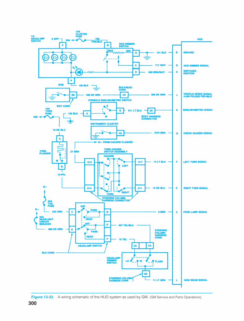
300Figure 13-32. A wiring schematic of the HUD system as used by GM. (GM Service and Parts Operations)
ker88839_ch13.qxd 1/9/06 11:34 AM Page 300
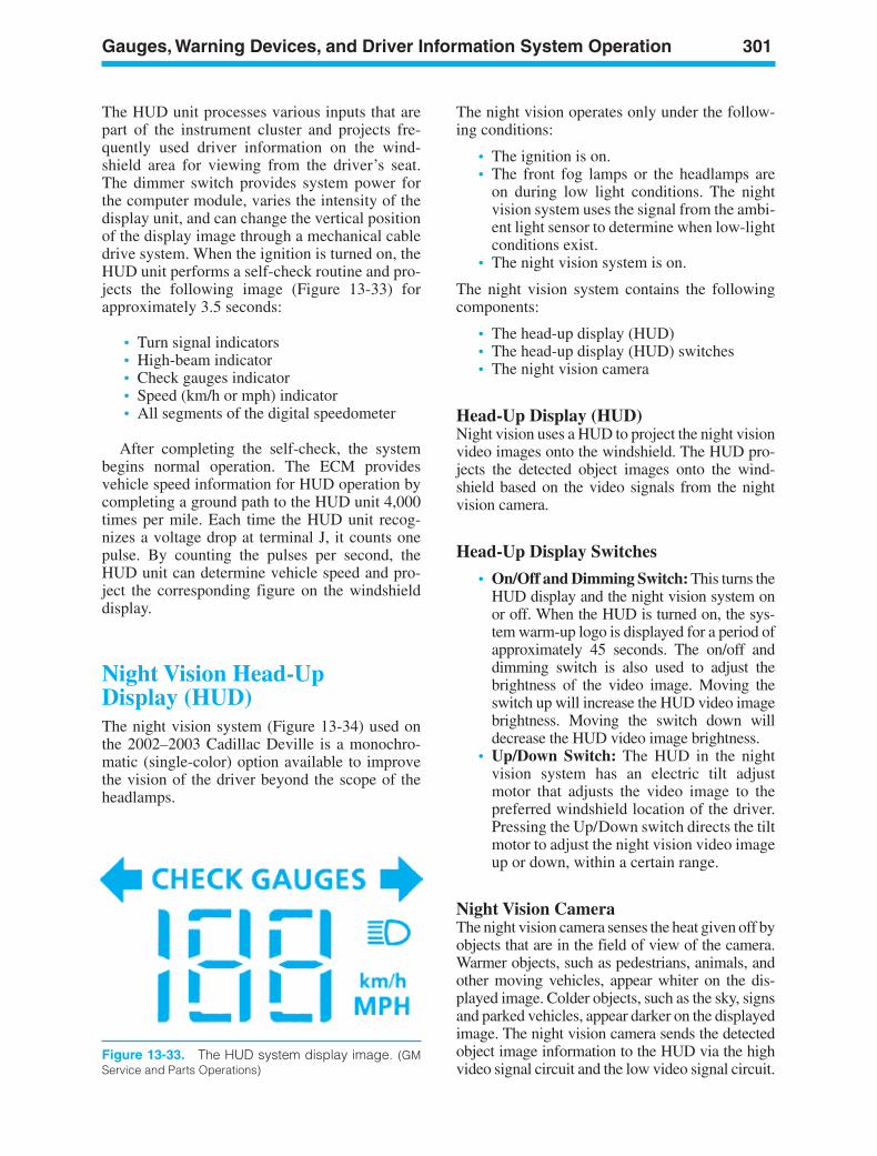
Gauges, Warning Devices, and Driver Information System Operation 301
The HUD unit processes various inputs that arepart of the instrument cluster and projects fre-quently used driver information on the wind-shield area for viewing from the driver’s seat.The dimmer switch provides system power forthe computer module, varies the intensity of thedisplay unit, and can change the vertical positionof the display image through a mechanical cabledrive system. When the ignition is turned on, theHUD unit performs a self-check routine and pro-jects the following image (Figure 13-33) forapproximately 3.5 seconds:
• Turn signal indicators• High-beam indicator• Check gauges indicator• Speed (km/h or mph) indicator• All segments of the digital speedometer
After completing the self-check, the systembegins normal operation. The ECM providesvehicle speed information for HUD operation bycompleting a ground path to the HUD unit 4,000times per mile. Each time the HUD unit recog-nizes a voltage drop at terminal J, it counts onepulse. By counting the pulses per second, theHUD unit can determine vehicle speed and pro-ject the corresponding figure on the windshielddisplay.
Night Vision Head-UpDisplay (HUD)The night vision system (Figure 13-34) used onthe 2002–2003 Cadillac Deville is a monochro-matic (single-color) option available to improvethe vision of the driver beyond the scope of theheadlamps.
The night vision operates only under the follow-ing conditions:
• The ignition is on.• The front fog lamps or the headlamps are
on during low light conditions. The nightvision system uses the signal from the ambi-ent light sensor to determine when low-lightconditions exist.
• The night vision system is on.
The night vision system contains the followingcomponents:
• The head-up display (HUD)• The head-up display (HUD) switches• The night vision camera
Head-Up Display (HUD)Night vision uses a HUD to project the night visionvideo images onto the windshield. The HUD pro-jects the detected object images onto the wind-shield based on the video signals from the nightvision camera.
Head-Up Display Switches
• On/Off and Dimming Switch: This turns theHUD display and the night vision system onor off. When the HUD is turned on, the sys-tem warm-up logo is displayed for a period ofapproximately 45 seconds. The on/off anddimming switch is also used to adjust thebrightness of the video image. Moving theswitch up will increase the HUD video imagebrightness. Moving the switch down willdecrease the HUD video image brightness.
• Up/Down Switch: The HUD in the nightvision system has an electric tilt adjustmotor that adjusts the video image to thepreferred windshield location of the driver.Pressing the Up/Down switch directs the tiltmotor to adjust the night vision video imageup or down, within a certain range.
Night Vision CameraThe night vision camera senses the heat given off byobjects that are in the field of view of the camera.Warmer objects, such as pedestrians, animals, andother moving vehicles, appear whiter on the dis-played image. Colder objects, such as the sky, signsand parked vehicles, appear darker on the displayedimage. The night vision camera sends the detectedobject image information to the HUD via the highvideo signal circuit and the low video signal circuit.
Figure 13-33. The HUD system display image. (GMService and Parts Operations)
ker88839_ch13.qxd 1/9/06 11:34 AM Page 301
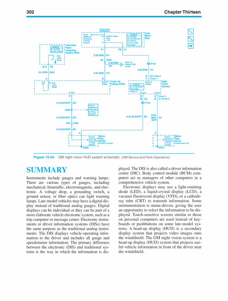
302 Chapter Thirteen
SUMMARYInstruments include gauges and warning lamps.There are various types of gauges, includingmechanical, bimetallic, electromagnetic, and elec-tronic. A voltage drop, a grounding switch, aground sensor, or fiber optics can light warninglamps. Late-model vehicles may have a digital dis-play instead of traditional analog gauges. Digitaldisplays can be individual or they can be part of amore elaborate vehicle electronic system, such as atrip computer or message center. Electronic instru-ments or driver information systems (DISs) havethe same purpose as the traditional analog instru-ments: The DIS displays vehicle-operating infor-mation to the driver and includes all gauge andspeedometer information. The primary differencebetween the electronic (DIS) and traditional sys-tems is the way in which the information is dis-
played. The DIS is also called a driver informationcenter (DIC). Body control module (BCM) com-puters act as managers of other computers in acomprehensive vehicle system.
Electronic displays may use a light-emittingdiode (LED), a liquid-crystal display (LCD), avacuum fluorescent display (VFD), or a cathode-ray tube (CRT) to transmit information. Someinstrumentation is menu-driven, giving the useran opportunity to select the information to be dis-played. Touch-sensitive screens similar to thoseon personal computers are used instead of key-boards or pushbuttons on some late-model sys-tems. A head-up display (HUD) is a secondarydisplay system that projects video images ontothe windshield. The GM night vision system is ahead-up display (HUD) system that projects use-ful vehicle information in front of the driver nearthe windshield.
Figure 13-34. GM night vision HUD system schematic. (GM Service and Parts Operations)
ker88839_ch13.qxd 1/9/06 11:34 AM Page 302
Gauges, Warning Devices, and Driver Information System Operation 303
Review Questions1. Which of the following is not a reason why
warning lamps have replaced gauges inautomobiles?a. Cheaper to manufactureb. Cheaper to installc. More accurated. Easier to understand
2. Temperature compensation in bimetallicgauges is accomplished by:a. Current flow through the heater coilb. The shape of the bimetallic stripc. An external resistor in the circuitd. Hermetically sealing the unit
3. Gauges with three-coil movements are mostoften used by:a. General Motorsb. Fordc. DaimlerChryslerd. Toyota
4. An oil pressure warning lamp is usuallycontrolled by:a. Voltage dropb. Ground switchc. Ground sensord. Manual switch
5. The sending unit in the fuel gauge uses a:a. Fixed resistorb. Zener diodec. Floatd. Diaphragm
6. Buzzers are a special type of warningdevice that are activated by:a. Voltage dropb. Ground switchesc. Diaphragmsd. Optical fibers
7. Two technicians are discussing driverinformation systems. Technician A saysthe head-up display (HUD) is asecondary display system that projectsvideo images onto the windshield.Technician B says that a liquid-crystaldisplay (LCD) is an indicator inwhich electrons from a heated filamentstrike a phosphor material that emits light.Who is right?a. A onlyb. B only
c. Both A and Bd. Neither A nor B
8. In GM BCM computer-controlled electric fancircuits:a. The BCM switches the control line
voltage on/off with pulse-widthmodulation.
b. The fan control module switches theground on/off.
c. Both A and Bd. Neither A nor B
9. Electromagnetic gauges do not use a:a. Mechanical movementb. D’Arsonval movementc. Air core movementd. Two- or three-coil movement
10. Which type of gauge does not use aninstrument voltage regulator (IVR)?a. D’Arsonval movementb. Air core movementc. Two-coil movementd. Three-coil movement
11. Technician A says GM’s electronicspeedometer interprets vehicle speed byusing a buffer to switch the voltage on/off.Technician B says GM’s electronicspeedometer uses a buffer to translate theanalog input of the PM generator into digitalsignals. Who is right?a. A onlyb. B onlyc. Both A and Bd. Neither A nor B
12. Technician A says an electronicspeedometer cannot use a stepper motor toprovide the display. Technician B says theuse of nonvolatile RAM prevents theodometer from being turned back. Who isright?a. A onlyb. B onlyc. Both A and Bd. Neither A nor B
13. An electronic display device usingelectrodes and polarized fluid to createnumbers and characters is called:a. LCDb. LED
ker88839_ch13.qxd 1/9/06 11:34 AM Page 303
304 Chapter Thirteen
c. VFDd. CRT
14. Which electronic display device is mostfrequently used because it is very bright,consumes relatively little power, and canprovide a wide variety of colors through theuse of filters?a. LCDb. LED
c. VFDd. CRT
15. Which electronic display device is difficult toread in daylight and consumes considerablepower relative to its brightness?a. LCDb. LEDc. VFDd. CRT
ker88839_ch13.qxd 1/9/06 11:34 AM Page 304
LEARNINGOBJECTIVESUpon completion and review of this chapter, youshould be able to:
• Explain the operation of an automotive horn.• Identify the different types of wiper systems
and explain their operation.• Identify the different types of windshield
washer systems and explain their operation.
KEY TERMSAutomobile HornDepressed Park PositionHorn RelayHorn SwitchWasher PumpsWiper Switch
INTRODUCTIONThis chapter introduces you to the operation of anautomotive horn and washer/wiper circuits. It willfurther show how various original equipment man-ufacturers apply technology to their horn andwasher/wiper systems. Chapter 14 of the ShopManual shows you how to diagnose horn andwiper/washer system concerns.
HORN CIRCUITSAn automobile horn is a safety device operated bythe driver to alert pedestrians and other motorists.Some states require two horn systems, with differ-ent sound levels for city and country use.
Circuit DiagramSome early automobiles used a simple series horncircuit, as shown in Figure 14-1A. Battery currentis supplied to the horn circuit through the fusepanel, or from a terminal on the starter relay orsolenoid. The normally open horn switch isinstalled between the power source and thegrounded horn. When the driver pushes the hornbutton, the horn switch closes and current flowsthrough the circuit to sound the horn. If the car hasmore than one horn (Figure 14-1B), each hornwill form a parallel path to ground.
305
14Horns, Wiper,and WasherSystemOperation
ker88839_ch14.qxd 1/9/06 11:34 AM Page 305
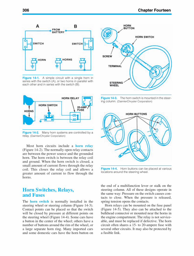
306 Chapter Fourteen306 Chapter Fourteen
the end of a multifunction lever or stalk on thesteering column. All of these designs operate inthe same way: Pressure on the switch causes con-tacts to close. When the pressure is released,spring tension opens the contacts.
Horn relays can be mounted on the fuse panel(Figure 14-5). They also can be attached to thebulkhead connector or mounted near the horns inthe engine compartment. The relay is not service-able, and must be replaced if defective. The horncircuit often shares a 15- to 20-ampere fuse withseveral other circuits. It may also be protected bya fusible link.
Figure 14-1. A simple circuit with a single horn inseries with the switch (A), or two horns in parallel witheach other and in series with the switch (B).
Figure 14-2. Many horn systems are controlled by arelay. (DaimlerChrysler Corporation)
Figure 14-3. The horn switch is mounted in the steer-ing column. (DaimlerChrysler Corporation)
Figure 14-4. Horn buttons can be placed at variouslocations around the steering wheel.
Most horn circuits include a horn relay(Figure 14-2). The normally open relay contactsare between the power source and the groundedhorn. The horn switch is between the relay coiland ground. When the horn switch is closed, asmall amount of current flows through the relaycoil. This closes the relay coil and allows agreater amount of current to flow through thehorns.
Horn Switches, Relays,and FusesThe horn switch is normally installed in thesteering wheel or steering column (Figure 14-3).Contact points can be placed so that the switchwill be closed by pressure at different points onthe steering wheel (Figure 14-4). Some cars havea button in the center of the wheel; others have anumber of buttons around the rim of the wheel, ora large separate horn ring. Many imported carsand some domestic cars have the horn button on
ker88839_ch14.qxd 1/9/06 11:34 AM Page 306
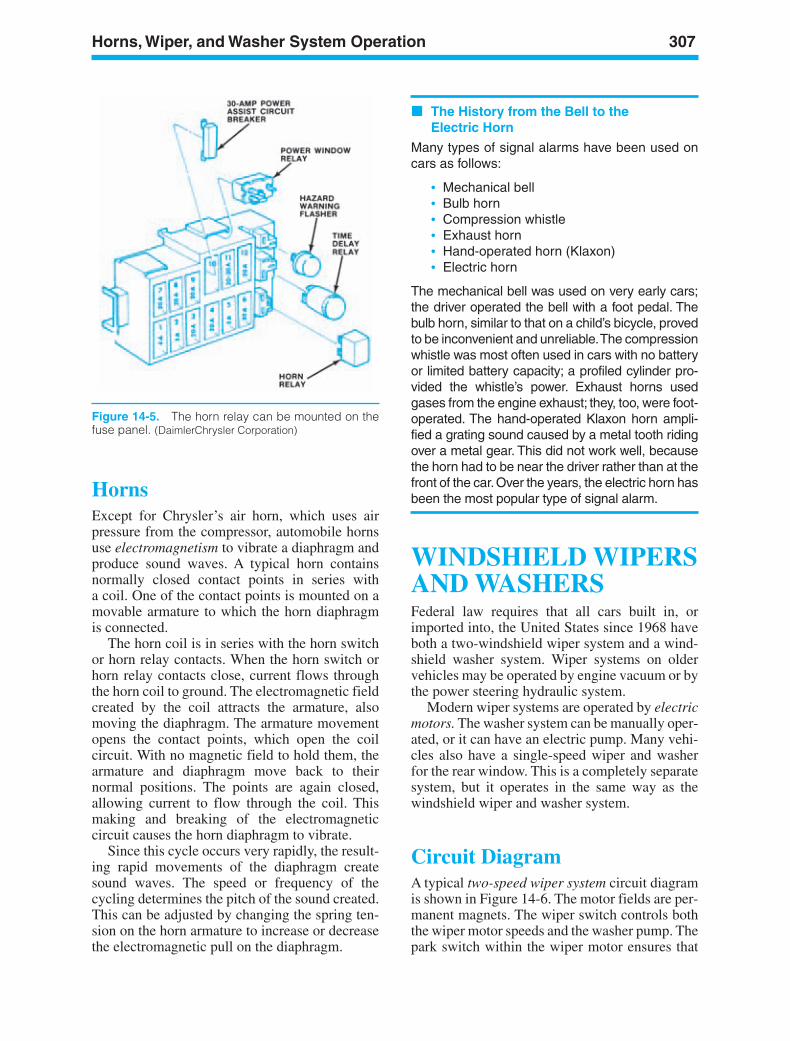
Horns, Wiper, and Washer System Operation 307
HornsExcept for Chrysler’s air horn, which uses airpressure from the compressor, automobile hornsuse electromagnetism to vibrate a diaphragm andproduce sound waves. A typical horn containsnormally closed contact points in series witha coil. One of the contact points is mounted on amovable armature to which the horn diaphragmis connected.
The horn coil is in series with the horn switchor horn relay contacts. When the horn switch orhorn relay contacts close, current flows throughthe horn coil to ground. The electromagnetic fieldcreated by the coil attracts the armature, alsomoving the diaphragm. The armature movementopens the contact points, which open the coilcircuit. With no magnetic field to hold them, thearmature and diaphragm move back to theirnormal positions. The points are again closed,allowing current to flow through the coil. Thismaking and breaking of the electromagneticcircuit causes the horn diaphragm to vibrate.
Since this cycle occurs very rapidly, the result-ing rapid movements of the diaphragm createsound waves. The speed or frequency of thecycling determines the pitch of the sound created.This can be adjusted by changing the spring ten-sion on the horn armature to increase or decreasethe electromagnetic pull on the diaphragm.
The History from the Bell to theElectric Horn
Many types of signal alarms have been used oncars as follows:
• Mechanical bell• Bulb horn• Compression whistle• Exhaust horn• Hand-operated horn (Klaxon)• Electric horn
The mechanical bell was used on very early cars;the driver operated the bell with a foot pedal. Thebulb horn, similar to that on a child’s bicycle, provedto be inconvenient and unreliable.The compressionwhistle was most often used in cars with no batteryor limited battery capacity; a profiled cylinder pro-vided the whistle’s power. Exhaust horns usedgases from the engine exhaust; they, too, were foot-operated. The hand-operated Klaxon horn ampli-fied a grating sound caused by a metal tooth ridingover a metal gear. This did not work well, becausethe horn had to be near the driver rather than at thefront of the car.Over the years, the electric horn hasbeen the most popular type of signal alarm.
WINDSHIELD WIPERSAND WASHERSFederal law requires that all cars built in, orimported into, the United States since 1968 haveboth a two-windshield wiper system and a wind-shield washer system. Wiper systems on oldervehicles may be operated by engine vacuum or bythe power steering hydraulic system.
Modern wiper systems are operated by electricmotors. The washer system can be manually oper-ated, or it can have an electric pump. Many vehi-cles also have a single-speed wiper and washerfor the rear window. This is a completely separatesystem, but it operates in the same way as thewindshield wiper and washer system.
Circuit DiagramA typical two-speed wiper system circuit diagramis shown in Figure 14-6. The motor fields are per-manent magnets. The wiper switch controls boththe wiper motor speeds and the washer pump. Thepark switch within the wiper motor ensures that
Figure 14-5. The horn relay can be mounted on thefuse panel. (DaimlerChrysler Corporation)
ker88839_ch14.qxd 1/9/06 11:34 AM Page 307
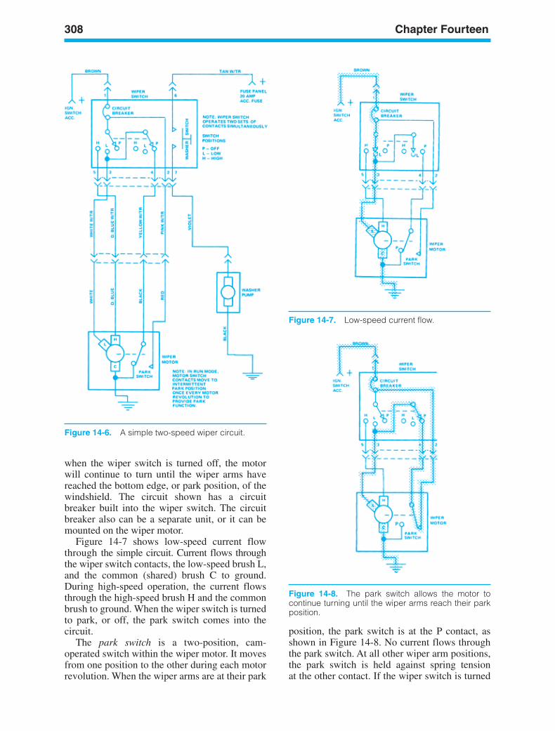
308 Chapter Fourteen
Figure 14-6. A simple two-speed wiper circuit.
when the wiper switch is turned off, the motorwill continue to turn until the wiper arms havereached the bottom edge, or park position, of thewindshield. The circuit shown has a circuitbreaker built into the wiper switch. The circuitbreaker also can be a separate unit, or it can bemounted on the wiper motor.
Figure 14-7 shows low-speed current flowthrough the simple circuit. Current flows throughthe wiper switch contacts, the low-speed brush L,and the common (shared) brush C to ground.During high-speed operation, the current flowsthrough the high-speed brush H and the commonbrush to ground. When the wiper switch is turnedto park, or off, the park switch comes into thecircuit.
The park switch is a two-position, cam-operated switch within the wiper motor. It movesfrom one position to the other during each motorrevolution. When the wiper arms are at their park
position, the park switch is at the P contact, asshown in Figure 14-8. No current flows throughthe park switch. At all other wiper arm positions,the park switch is held against spring tensionat the other contact. If the wiper switch is turned
Figure 14-7. Low-speed current flow.
Figure 14-8. The park switch allows the motor tocontinue turning until the wiper arms reach their parkposition.
ker88839_ch14.qxd 1/9/06 11:34 AM Page 308
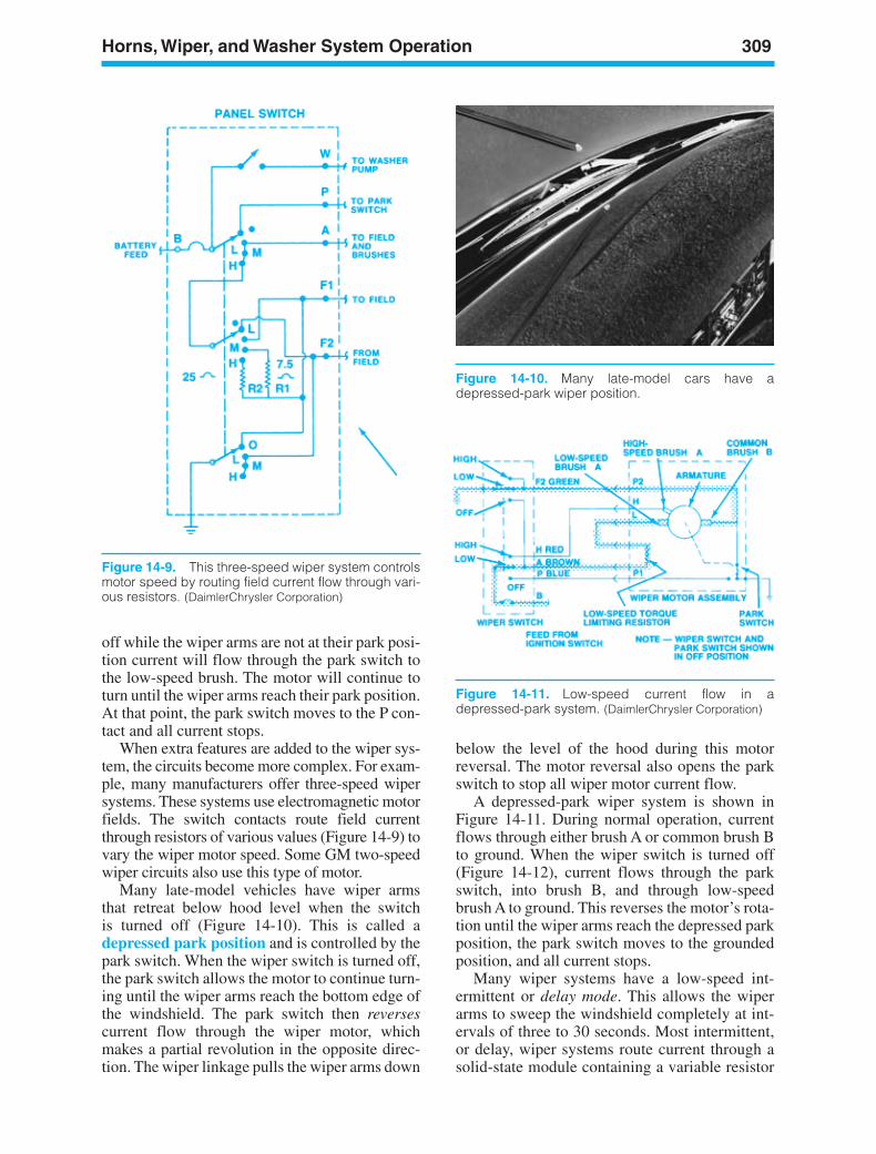
Horns, Wiper, and Washer System Operation 309
Figure 14-10. Many late-model cars have adepressed-park wiper position.
Figure 14-9. This three-speed wiper system controlsmotor speed by routing field current flow through vari-ous resistors. (DaimlerChrysler Corporation)
off while the wiper arms are not at their park posi-tion current will flow through the park switch tothe low-speed brush. The motor will continue toturn until the wiper arms reach their park position.At that point, the park switch moves to the P con-tact and all current stops.
When extra features are added to the wiper sys-tem, the circuits become more complex. For exam-ple, many manufacturers offer three-speed wipersystems. These systems use electromagnetic motorfields. The switch contacts route field currentthrough resistors of various values (Figure 14-9) tovary the wiper motor speed. Some GM two-speedwiper circuits also use this type of motor.
Many late-model vehicles have wiper armsthat retreat below hood level when the switchis turned off (Figure 14-10). This is called adepressed park position and is controlled by thepark switch. When the wiper switch is turned off,the park switch allows the motor to continue turn-ing until the wiper arms reach the bottom edge ofthe windshield. The park switch then reversescurrent flow through the wiper motor, whichmakes a partial revolution in the opposite direc-tion. The wiper linkage pulls the wiper arms down
below the level of the hood during this motorreversal. The motor reversal also opens the parkswitch to stop all wiper motor current flow.
A depressed-park wiper system is shown inFigure 14-11. During normal operation, currentflows through either brush A or common brush Bto ground. When the wiper switch is turned off(Figure 14-12), current flows through the parkswitch, into brush B, and through low-speedbrush A to ground. This reverses the motor’s rota-tion until the wiper arms reach the depressed parkposition, the park switch moves to the groundedposition, and all current stops.
Many wiper systems have a low-speed int-ermittent or delay mode. This allows the wiperarms to sweep the windshield completely at int-ervals of three to 30 seconds. Most intermittent,or delay, wiper systems route current through asolid-state module containing a variable resistor
Figure 14-11. Low-speed current flow in adepressed-park system. (DaimlerChrysler Corporation)
ker88839_ch14.qxd 1/9/06 11:34 AM Page 309
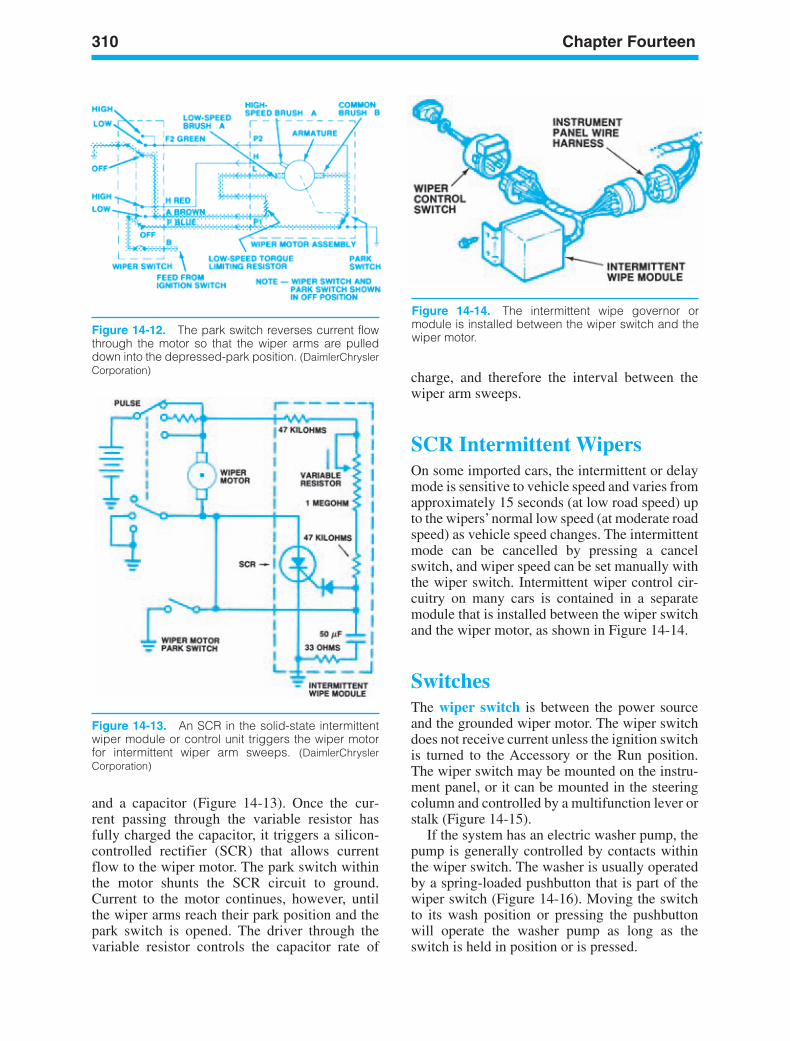
310 Chapter Fourteen
Figure 14-13. An SCR in the solid-state intermittentwiper module or control unit triggers the wiper motorfor intermittent wiper arm sweeps. (DaimlerChryslerCorporation)
and a capacitor (Figure 14-13). Once the cur-rent passing through the variable resistor hasfully charged the capacitor, it triggers a silicon-controlled rectifier (SCR) that allows currentflow to the wiper motor. The park switch withinthe motor shunts the SCR circuit to ground.Current to the motor continues, however, untilthe wiper arms reach their park position and thepark switch is opened. The driver through thevariable resistor controls the capacitor rate of
charge, and therefore the interval between thewiper arm sweeps.
SCR Intermittent WipersOn some imported cars, the intermittent or delaymode is sensitive to vehicle speed and varies fromapproximately 15 seconds (at low road speed) upto the wipers’normal low speed (at moderate roadspeed) as vehicle speed changes. The intermittentmode can be cancelled by pressing a cancelswitch, and wiper speed can be set manually withthe wiper switch. Intermittent wiper control cir-cuitry on many cars is contained in a separatemodule that is installed between the wiper switchand the wiper motor, as shown in Figure 14-14.
SwitchesThe wiper switch is between the power sourceand the grounded wiper motor. The wiper switchdoes not receive current unless the ignition switchis turned to the Accessory or the Run position.The wiper switch may be mounted on the instru-ment panel, or it can be mounted in the steeringcolumn and controlled by a multifunction lever orstalk (Figure 14-15).
If the system has an electric washer pump, thepump is generally controlled by contacts withinthe wiper switch. The washer is usually operatedby a spring-loaded pushbutton that is part of thewiper switch (Figure 14-16). Moving the switchto its wash position or pressing the pushbuttonwill operate the washer pump as long as theswitch is held in position or is pressed.
Figure 14-12. The park switch reverses current flowthrough the motor so that the wiper arms are pulleddown into the depressed-park position. (DaimlerChryslerCorporation)
Figure 14-14. The intermittent wipe governor ormodule is installed between the wiper switch and thewiper motor.
ker88839_ch14.qxd 1/9/06 11:35 AM Page 310
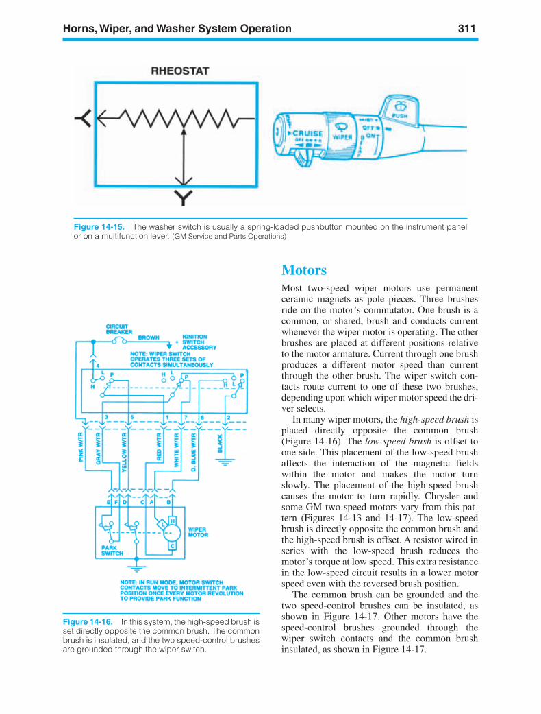
Horns, Wiper, and Washer System Operation 311
MotorsMost two-speed wiper motors use permanentceramic magnets as pole pieces. Three brushesride on the motor’s commutator. One brush is acommon, or shared, brush and conducts currentwhenever the wiper motor is operating. The otherbrushes are placed at different positions relativeto the motor armature. Current through one brushproduces a different motor speed than currentthrough the other brush. The wiper switch con-tacts route current to one of these two brushes,depending upon which wiper motor speed the dri-ver selects.
In many wiper motors, the high-speed brush isplaced directly opposite the common brush(Figure 14-16). The low-speed brush is offset toone side. This placement of the low-speed brushaffects the interaction of the magnetic fieldswithin the motor and makes the motor turnslowly. The placement of the high-speed brushcauses the motor to turn rapidly. Chrysler andsome GM two-speed motors vary from this pat-tern (Figures 14-13 and 14-17). The low-speedbrush is directly opposite the common brush andthe high-speed brush is offset. A resistor wired inseries with the low-speed brush reduces themotor’s torque at low speed. This extra resistancein the low-speed circuit results in a lower motorspeed even with the reversed brush position.
The common brush can be grounded and thetwo speed-control brushes can be insulated, asshown in Figure 14-17. Other motors have thespeed-control brushes grounded through thewiper switch contacts and the common brushinsulated, as shown in Figure 14-17.
Figure 14-15. The washer switch is usually a spring-loaded pushbutton mounted on the instrument panelor on a multifunction lever. (GM Service and Parts Operations)
Figure 14-16. In this system, the high-speed brush isset directly opposite the common brush. The commonbrush is insulated, and the two speed-control brushesare grounded through the wiper switch.
ker88839_ch14.qxd 1/9/06 11:35 AM Page 311
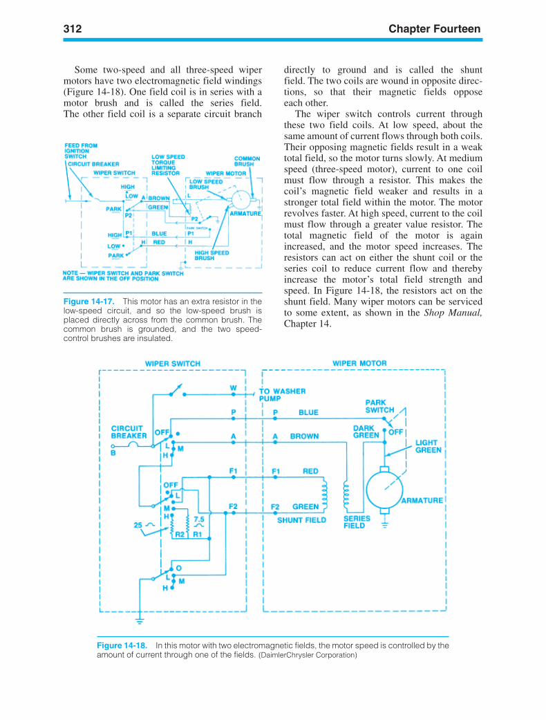
312 Chapter Fourteen
Figure 14-17. This motor has an extra resistor in thelow-speed circuit, and so the low-speed brush isplaced directly across from the common brush. Thecommon brush is grounded, and the two speed-control brushes are insulated.
directly to ground and is called the shuntfield. The two coils are wound in opposite direc-tions, so that their magnetic fields opposeeach other.
The wiper switch controls current throughthese two field coils. At low speed, about thesame amount of current flows through both coils.Their opposing magnetic fields result in a weaktotal field, so the motor turns slowly. At mediumspeed (three-speed motor), current to one coilmust flow through a resistor. This makes thecoil’s magnetic field weaker and results in astronger total field within the motor. The motorrevolves faster. At high speed, current to the coilmust flow through a greater value resistor. Thetotal magnetic field of the motor is againincreased, and the motor speed increases. Theresistors can act on either the shunt coil or theseries coil to reduce current flow and therebyincrease the motor’s total field strength andspeed. In Figure 14-18, the resistors act on theshunt field. Many wiper motors can be servicedto some extent, as shown in the Shop Manual,Chapter 14.
Figure 14-18. In this motor with two electromagnetic fields, the motor speed is controlled by theamount of current through one of the fields. (DaimlerChrysler Corporation)
Some two-speed and all three-speed wipermotors have two electromagnetic field windings(Figure 14-18). One field coil is in series with amotor brush and is called the series field.The other field coil is a separate circuit branch
ker88839_ch14.qxd 1/9/06 11:35 AM Page 312
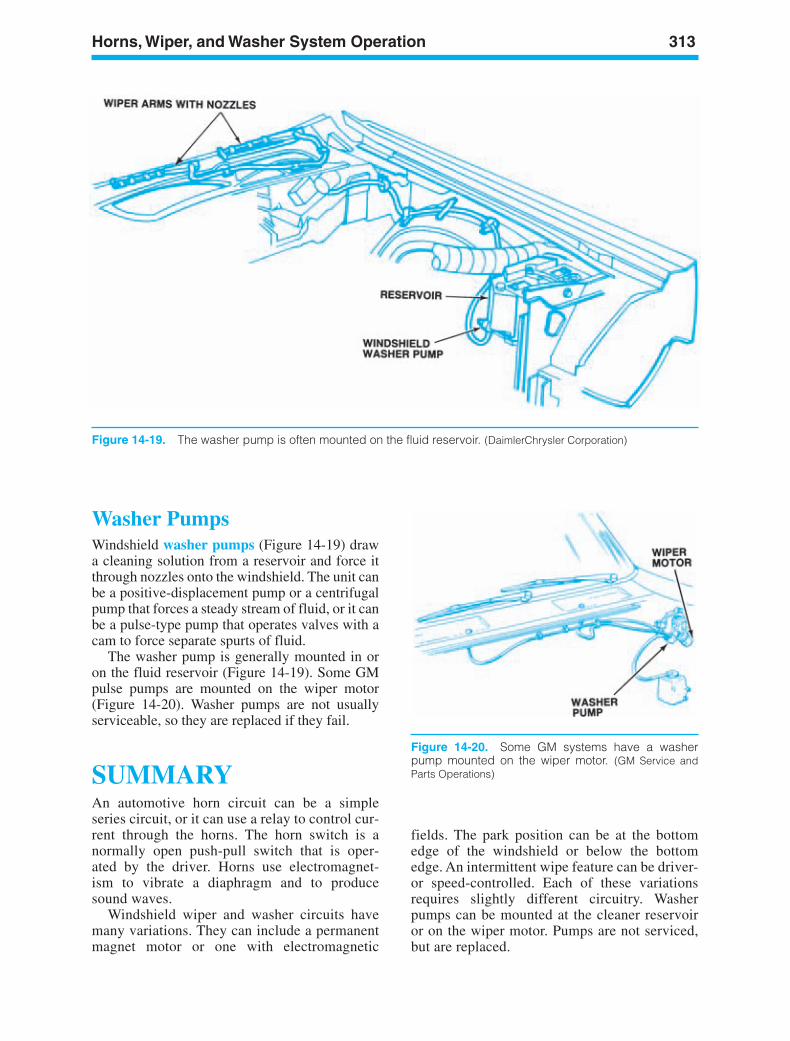
Horns, Wiper, and Washer System Operation 313
Figure 14-19. The washer pump is often mounted on the fluid reservoir. (DaimlerChrysler Corporation)
Washer PumpsWindshield washer pumps (Figure 14-19) drawa cleaning solution from a reservoir and force itthrough nozzles onto the windshield. The unit canbe a positive-displacement pump or a centrifugalpump that forces a steady stream of fluid, or it canbe a pulse-type pump that operates valves with acam to force separate spurts of fluid.
The washer pump is generally mounted in oron the fluid reservoir (Figure 14-19). Some GMpulse pumps are mounted on the wiper motor(Figure 14-20). Washer pumps are not usuallyserviceable, so they are replaced if they fail.
SUMMARYAn automotive horn circuit can be a simpleseries circuit, or it can use a relay to control cur-rent through the horns. The horn switch is anormally open push-pull switch that is oper-ated by the driver. Horns use electromagnet-ism to vibrate a diaphragm and to producesound waves.
Windshield wiper and washer circuits havemany variations. They can include a permanentmagnet motor or one with electromagnetic
Figure 14-20. Some GM systems have a washerpump mounted on the wiper motor. (GM Service andParts Operations)
fields. The park position can be at the bottomedge of the windshield or below the bottomedge. An intermittent wipe feature can be driver-or speed-controlled. Each of these variationsrequires slightly different circuitry. Washerpumps can be mounted at the cleaner reservoiror on the wiper motor. Pumps are not serviced,but are replaced.
ker88839_ch14.qxd 1/9/06 11:35 AM Page 313
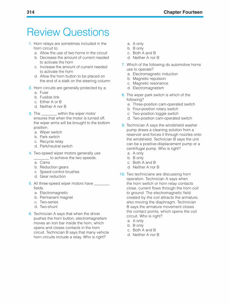
314 Chapter Fourteen
Review Questions1. Horn relays are sometimes included in the
horn circuit to:a. Allow the use of two horns in the circuitb. Decrease the amount of current needed
to activate the hornc. Increase the amount of current needed
to activate the hornd. Allow the horn button to be placed on
the end of a stalk on the steering column
2. Horn circuits are generally protected by a:a. Fuseb. Fusible linkc. Either A or Bd. Neither A nor B
3. The ________ within the wiper motorensures that when the motor is turned off,the wiper arms will be brought to the bottomposition.a. Wiper switchb. Park switchc. Recycle relayd. Park/neutral switch
4. Two-speed wiper motors generally use________ to achieve the two speeds.a. Camsb. Reduction gearsc. Speed-control brushesd. Gear reduction
5. All three-speed wiper motors have ________fields.a. Electromagneticb. Permanent magnetc. Two-seriesd. Two-shunt
6. Technician A says that when the driverpushes the horn button, electromagnetismmoves an iron bar inside the horn, whichopens and closes contacts in the horncircuit. Technician B says that many vehiclehorn circuits include a relay. Who is right?
a. A onlyb. B onlyc. Both A and Bd. Neither A nor B
7. Which of the following do automotive hornsuse to operate?a. Electromagnetic inductionb. Magnetic repulsionc. Magnetic resonanced. Electromagnetism
8. The wiper park switch is which of thefollowing?a. Three-position cam-operated switchb. Four-position rotary switchc. Two-position toggle switchd. Two-position cam-operated switch
9. Technician A says the windshield washerpump draws a cleaning solution from areservoir and forces it through nozzles ontothe windshield. Technician B says the unitcan be a positive-displacement pump or acentrifugal pump. Who is right?a. A onlyb. B onlyc. Both A and Bd. Neither A nor B
10. Two technicians are discussing hornoperation. Technician A says whenthe horn switch or horn relay contactsclose, current flows through the horn coilto ground. The electromagnetic fieldcreated by the coil attracts the armature,also moving the diaphragm. TechnicianB says the armature movement closesthe contact points, which opens the coilcircuit. Who is right?a. A onlyb. B onlyc. Both A and Bd. Neither A nor B
ker88839_ch14.qxd 1/9/06 11:35 AM Page 314
LEARNINGOBJECTIVESUpon completion and review of this chapter, youshould be able to:
• Identify the components of the automo-tive HVAC (Heater Ventilator and Air Con-ditioning System) and explain the operation.
• Identify radio and/or entertainment systemcomponents and explain their operation.
• Explain the operation of the rear windowdefroster/defogger and heated windshields.
• Explain the operation of power windowsand seats.
• Explain the operation of Power Door Locks,Trunk Latches, and Seat Back Releases.
• Identify the different types of REMOTE/Keyless Entry Systems and explain theiroperation.
• Identify the different types of Theft DeterrentSystems and explain their operation.
• Explain the operation of cruise control systems.• Explain the operation of the Supplemental
Restraint System (SRS).
KEY TERMSAir Bag ModuleAutomatic Door Lock (ADL)Data LinkDefrosterHeater fanInflator ModuleIgniter AssemblySafing sensorServomotorServo UnitTransducer
INTRODUCTIONElectrical accessories provide driver and passen-ger comfort, convenience, and entertainment.New electrical accessories are introduced everyyear, but some systems have been common formany years. Such systems increasingly are beingautomated with computer control. This chapterwill explain the electrical operation of some com-mon accessory systems.
315
15BodyAccessorySystemsOperation
ker88839_ch15.qxd 1/9/06 11:35 AM Page 315
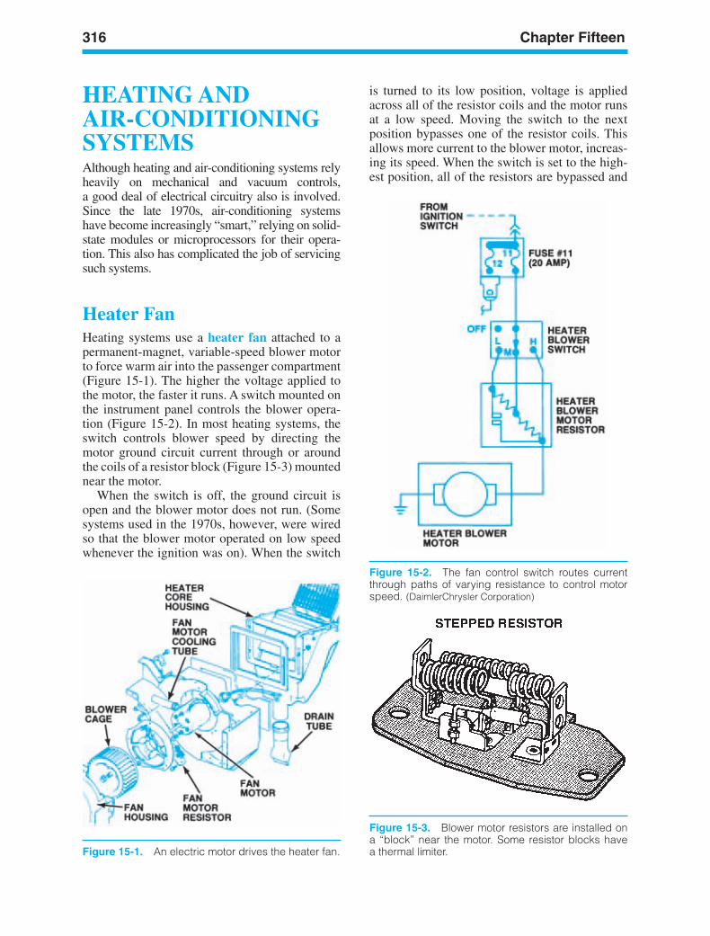
316 Chapter Fifteen
HEATING ANDAIR-CONDITIONINGSYSTEMSAlthough heating and air-conditioning systems relyheavily on mechanical and vacuum controls,a good deal of electrical circuitry also is involved.Since the late 1970s, air-conditioning systemshave become increasingly “smart,” relying on solid-state modules or microprocessors for their opera-tion. This also has complicated the job of servicingsuch systems.
Heater FanHeating systems use a heater fan attached to apermanent-magnet, variable-speed blower motorto force warm air into the passenger compartment(Figure 15-1). The higher the voltage applied tothe motor, the faster it runs. A switch mounted onthe instrument panel controls the blower opera-tion (Figure 15-2). In most heating systems, theswitch controls blower speed by directing themotor ground circuit current through or aroundthe coils of a resistor block (Figure 15-3) mountednear the motor.
When the switch is off, the ground circuit isopen and the blower motor does not run. (Somesystems used in the 1970s, however, were wiredso that the blower motor operated on low speedwhenever the ignition was on). When the switch
is turned to its low position, voltage is appliedacross all of the resistor coils and the motor runsat a low speed. Moving the switch to the nextposition bypasses one of the resistor coils. Thisallows more current to the blower motor, increas-ing its speed. When the switch is set to the high-est position, all of the resistors are bypassed and
Figure 15-1. An electric motor drives the heater fan.
Figure 15-2. The fan control switch routes currentthrough paths of varying resistance to control motorspeed. (DaimlerChrysler Corporation)
Figure 15-3. Blower motor resistors are installed ona “block” near the motor. Some resistor blocks havea thermal limiter.
ker88839_ch15.qxd 1/9/06 11:35 AM Page 316
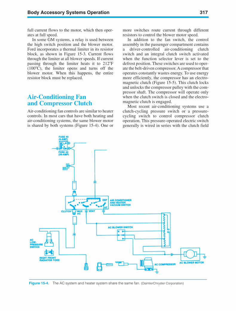
Body Accessory Systems Operation 317
full current flows to the motor, which then oper-ates at full speed.
In some GM systems, a relay is used betweenthe high switch position and the blower motor.Ford incorporates a thermal limiter in its resistorblock, as shown in Figure 15-3. Current flowsthrough the limiter at all blower speeds. If currentpassing through the limiter heats it to 212F(100C), the limiter opens and turns off theblower motor. When this happens, the entireresistor block must be replaced.
Air-Conditioning Fanand Compressor ClutchAir-conditioning fan controls are similar to heatercontrols. In most cars that have both heating andair-conditioning systems, the same blower motoris shared by both systems (Figure 15-4). One or
more switches route current through differentresistors to control the blower motor speed.
In addition to the fan switch, the controlassembly in the passenger compartment containsa driver-controlled air-conditioning clutchswitch and an integral clutch switch activatedwhen the function selector lever is set to thedefrost position. These switches are used to oper-ate the belt-driven compressor. A compressor thatoperates constantly wastes energy. To use energymore efficiently, the compressor has an electro-magnetic clutch (Figure 15-5). This clutch locksand unlocks the compressor pulley with the com-pressor shaft. The compressor will operate onlywhen the clutch switch is closed and the electro-magnetic clutch is engaged.
Most recent air-conditioning systems use aclutch-cycling pressure switch or a pressure-cycling switch to control compressor clutchoperation. This pressure-operated electric switchgenerally is wired in series with the clutch field
Figure 15-4. The AC system and heater system share the same fan. (DaimlerChrysler Corporation)
ker88839_ch15.qxd 1/9/06 11:35 AM Page 317
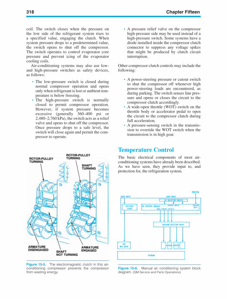
318 Chapter Fifteen
coil. The switch closes when the pressure onthe low side of the refrigerant system rises toa specified value, engaging the clutch. Whensystem pressure drops to a predetermined value,the switch opens to shut off the compressor.The switch operates to control evaporator corepressure and prevent icing of the evaporatorcooling coils.
Air-conditioning systems may also use low-and high-pressure switches as safety devices,as follows:
• The low-pressure switch is closed duringnormal compressor operation and opensonly when refrigerant is lost or ambient tem-perature is below freezing.
• The high-pressure switch is normallyclosed to permit compressor operation.However, if system pressure becomesexcessive (generally 360–400 psi or2,480–2,760 kPa), the switch acts as a reliefvalve and opens to shut off the compressor.Once pressure drops to a safe level, theswitch will close again and permit the com-pressor to operate.
Figure 15-5. The electromagnetic clutch in this air-conditioning compressor prevents the compressorfrom wasting energy.
Figure 15-6. Manual air conditioning system blockdiagram. (GM Service and Parts Operations)
• A pressure relief valve on the compressorhigh-pressure side may be used instead of ahigh-pressure switch. Some systems have adiode installed inside the compressor clutchconnector to suppress any voltage spikesthat might be produced by clutch circuitinterruption.
Other compressor clutch controls may include thefollowing:
• A power-steering pressure or cutout switchto shut the compressor off whenever highpower-steering loads are encountered, asduring parking. The switch senses line pres-sure and opens or closes the circuit to thecompressor clutch accordingly.
• A wide-open throttle (WOT) switch on thethrottle body or accelerator pedal to openthe circuit to the compressor clutch duringfull acceleration.
• A pressure-sensing switch in the transmis-sion to override the WOT switch when thetransmission is in high gear.
Temperature ControlThe basic electrical components of most air-conditioning systems have already been described.As we have seen, they provide input to, andprotection for, the refrigeration system.
ker88839_ch15.qxd 1/9/06 11:35 AM Page 318
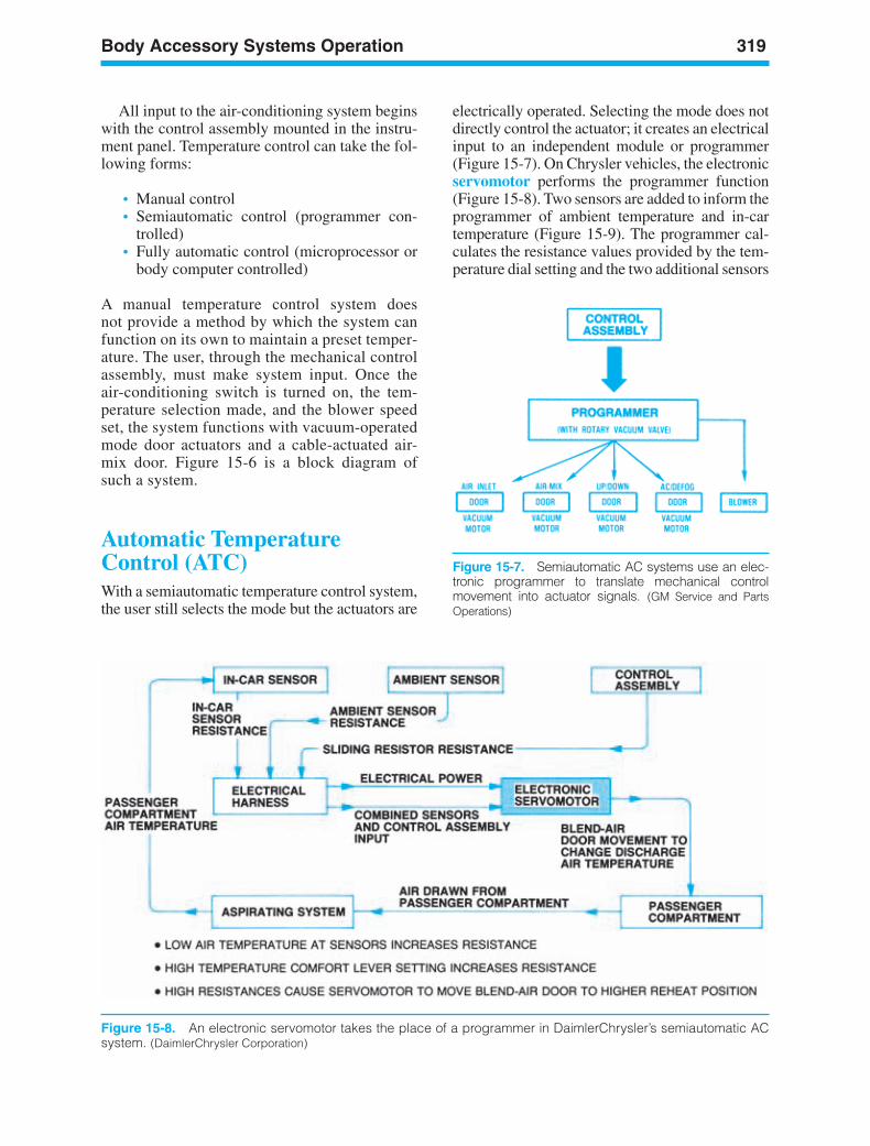
Body Accessory Systems Operation 319
All input to the air-conditioning system beginswith the control assembly mounted in the instru-ment panel. Temperature control can take the fol-lowing forms:
• Manual control• Semiautomatic control (programmer con-
trolled)• Fully automatic control (microprocessor or
body computer controlled)
A manual temperature control system doesnot provide a method by which the system canfunction on its own to maintain a preset temper-ature. The user, through the mechanical controlassembly, must make system input. Once theair-conditioning switch is turned on, the tem-perature selection made, and the blower speedset, the system functions with vacuum-operatedmode door actuators and a cable-actuated air-mix door. Figure 15-6 is a block diagram ofsuch a system.
Automatic TemperatureControl (ATC)With a semiautomatic temperature control system,the user still selects the mode but the actuators are
electrically operated. Selecting the mode does notdirectly control the actuator; it creates an electricalinput to an independent module or programmer(Figure 15-7). On Chrysler vehicles, the electronicservomotor performs the programmer function(Figure 15-8). Two sensors are added to inform theprogrammer of ambient temperature and in-cartemperature (Figure 15-9). The programmer cal-culates the resistance values provided by the tem-perature dial setting and the two additional sensors
Figure 15-8. An electronic servomotor takes the place of a programmer in DaimlerChrysler’s semiautomatic ACsystem. (DaimlerChrysler Corporation)
Figure 15-7. Semiautomatic AC systems use an elec-tronic programmer to translate mechanical controlmovement into actuator signals. (GM Service and PartsOperations)
ker88839_ch15.qxd 1/9/06 11:35 AM Page 319
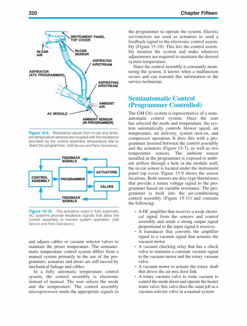
320 Chapter Fifteen
Figure 15-10. The actuators used in fully automaticAC systems provide feedback signals that allow thecontrol assembly to monitor system operation. (GMService and Parts Operations)
the programmer to operate the system. Electricservomotors are used as actuators to send afeedback signal to the electronic control assem-bly (Figure 15-10). This lets the control assem-bly monitor the system and make whateveradjustments are required to maintain the desiredsystem temperature.
Since the control assembly is constantly moni-toring the system, it knows when a malfunctionoccurs and can transmit this information to theservice technician.
Semiautomatic Control(Programmer Controlled)The GM C61 system is representative of a semi-automatic control system. Once the userhas selected the mode and temperature, the sys-tem automatically controls blower speed, airtemperature, air delivery, system turn-on, andcompressor operation. It does this with a pro-grammer inserted between the control assemblyand the actuators (Figure 15-7), as well as twotemperature sensors. The ambient sensorinstalled in the programmer is exposed to ambi-ent airflow through a hole in the module wall;the in-car sensor is located under the instrumentpanel top cover. Figure 15-9 shows the sensorlocations. Both sensors are disc-type thermistorsthat provide a return voltage signal to the pro-grammer based on variable resistance. The pro-grammer is built into the air-conditioningcontrol assembly (Figure 15-11) and containsthe following:
• A DC amplifier that receives a weak electri-cal signal from the sensors and controlassembly and sends a strong output signalproportional to the input signal it receives
• A transducer that converts the amplifiersignal to a vacuum signal that actuates thevacuum motor
• A vacuum checking relay that has a checkvalve to maintain a constant vacuum signalto the vacuum motor and the rotary vacuumvalve
• A vacuum motor to actuate the rotary shaftthat drives the air-mix door link
• A rotary vacuum valve to route vacuum tocontrol the mode doors and operate the heaterwater valve; this valve does the same job as avacuum selector valve in a manual system
and adjusts cables or vacuum selector valves tomaintain the preset temperature. The semiauto-matic temperature control system differs from amanual system primarily in the use of the pro-grammer; actuators and doors are still moved bymechanical linkage and cables.
In a fully automatic temperature controlsystem, the control assembly is electronicinstead of manual. The user selects the modeand the temperature. The control assemblymicroprocessor sends the appropriate signals to
Figure 15-9. Resistance values from in-car and ambi-ent temperature sensors are coupled with the resistanceprovided by the control assembly temperature dial todirect the programmer. (GM Service and Parts Operations)
ker88839_ch15.qxd 1/9/06 11:35 AM Page 320
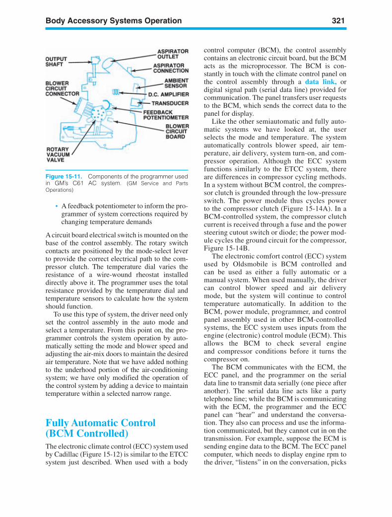
Body Accessory Systems Operation 321
• A feedback potentiometer to inform the pro-grammer of system corrections required bychanging temperature demands
A circuit board electrical switch is mounted on thebase of the control assembly. The rotary switchcontacts are positioned by the mode-select leverto provide the correct electrical path to the com-pressor clutch. The temperature dial varies theresistance of a wire-wound rheostat installeddirectly above it. The programmer uses the totalresistance provided by the temperature dial andtemperature sensors to calculate how the systemshould function.
To use this type of system, the driver need onlyset the control assembly in the auto mode andselect a temperature. From this point on, the pro-grammer controls the system operation by auto-matically setting the mode and blower speed andadjusting the air-mix doors to maintain the desiredair temperature. Note that we have added nothingto the underhood portion of the air-conditioningsystem; we have only modified the operation ofthe control system by adding a device to maintaintemperature within a selected narrow range.
Fully Automatic Control (BCM Controlled)The electronic climate control (ECC) system usedby Cadillac (Figure 15-12) is similar to the ETCCsystem just described. When used with a body
control computer (BCM), the control assemblycontains an electronic circuit board, but the BCMacts as the microprocessor. The BCM is con-stantly in touch with the climate control panel onthe control assembly through a data link, ordigital signal path (serial data line) provided forcommunication. The panel transfers user requeststo the BCM, which sends the correct data to thepanel for display.
Like the other semiautomatic and fully auto-matic systems we have looked at, the userselects the mode and temperature. The systemautomatically controls blower speed, air tem-perature, air delivery, system turn-on, and com-pressor operation. Although the ECC systemfunctions similarly to the ETCC system, thereare differences in compressor cycling methods.In a system without BCM control, the compres-sor clutch is grounded through the low-pressureswitch. The power module thus cycles powerto the compressor clutch (Figure 15-14A). In aBCM-controlled system, the compressor clutchcurrent is received through a fuse and the powersteering cutout switch or diode; the power mod-ule cycles the ground circuit for the compressor,Figure 15-14B.
The electronic comfort control (ECC) systemused by Oldsmobile is BCM controlled andcan be used as either a fully automatic or amanual system. When used manually, the drivercan control blower speed and air deliverymode, but the system will continue to controltemperature automatically. In addition to theBCM, power module, programmer, and controlpanel assembly used in other BCM-controlledsystems, the ECC system uses inputs from theengine (electronic) control module (ECM). Thisallows the BCM to check several engineand compressor conditions before it turns thecompressor on.
The BCM communicates with the ECM, theECC panel, and the programmer on the serialdata line to transmit data serially (one piece afteranother). The serial data line acts like a partytelephone line; while the BCM is communicatingwith the ECM, the programmer and the ECCpanel can “hear” and understand the conversa-tion. They also can process and use the informa-tion communicated, but they cannot cut in on thetransmission. For example, suppose the ECM issending engine data to the BCM. The ECC panelcomputer, which needs to display engine rpm tothe driver, “listens” in on the conversation, picks
Figure 15-11. Components of the programmer usedin GM’s C61 AC system. (GM Service and PartsOperations)
ker88839_ch15.qxd 1/9/06 11:35 AM Page 321
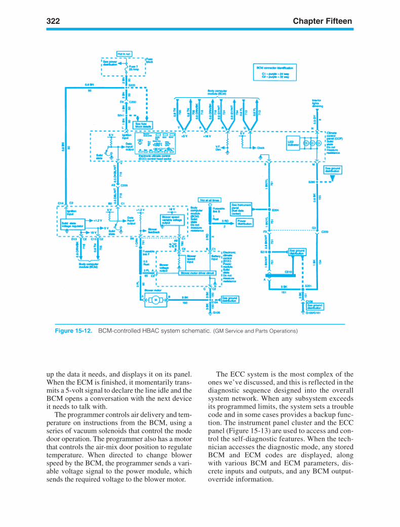
322 Chapter Fifteen
up the data it needs, and displays it on its panel.When the ECM is finished, it momentarily trans-mits a 5-volt signal to declare the line idle and theBCM opens a conversation with the next deviceit needs to talk with.
The programmer controls air delivery and tem-perature on instructions from the BCM, using aseries of vacuum solenoids that control the modedoor operation. The programmer also has a motorthat controls the air-mix door position to regulatetemperature. When directed to change blowerspeed by the BCM, the programmer sends a vari-able voltage signal to the power module, whichsends the required voltage to the blower motor.
The ECC system is the most complex of theones we’ve discussed, and this is reflected in thediagnostic sequence designed into the overallsystem network. When any subsystem exceedsits programmed limits, the system sets a troublecode and in some cases provides a backup func-tion. The instrument panel cluster and the ECCpanel (Figure 15-13) are used to access and con-trol the self-diagnostic features. When the tech-nician accesses the diagnostic mode, any storedBCM and ECM codes are displayed, alongwith various BCM and ECM parameters, dis-crete inputs and outputs, and any BCM output-override information.
Figure 15-12. BCM-controlled HBAC system schematic. (GM Service and Parts Operations)
ker88839_ch15.qxd 1/9/06 11:35 AM Page 322
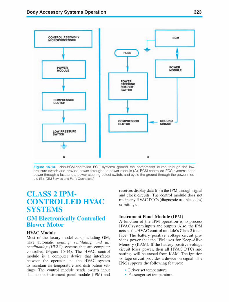
Body Accessory Systems Operation 323
Figure 15-13. Non-BCM-controlled ECC systems ground the compressor clutch through the low-pressure switch and provide power through the power module (A). BCM-controlled ECC systems sendpower through a fuse and a power steering cutout switch, and cycle the ground through the power mod-ule (B). (GM Service and Parts Operations)
CLASS 2 IPM-CONTROLLED HVACSYSTEMSGM Electronically ControlledBlower MotorHVAC ModuleMost of the luxury model cars, including GM,have automatic heating, ventilating, and airconditioning (HVAC) systems that are computercontrolled (Figure 15-14). The HVAC controlmodule is a computer device that interfacesbetween the operator and the HVAC systemto maintain air temperature and distribution set-tings. The control module sends switch inputdata to the instrument panel module (IPM) and
receives display data from the IPM through signaland clock circuits. The control module does notretain any HVAC DTCs (diagnostic trouble codes)or settings.
Instrument Panel Module (IPM)A function of the IPM operation is to processHVAC system inputs and outputs. Also, the IPMacts as the HVAC control module’s Class 2 inter-face. The battery positive voltage circuit pro-vides power that the IPM uses for Keep-AliveMemory (KAM). If the battery positive voltagecircuit loses power, then all HVAC DTCs andsettings will be erased from KAM. The ignitionvoltage circuit provides a device on signal. TheIPM supports the following features:
• Driver set temperature• Passenger set temperature
ker88839_ch15.qxd 1/9/06 11:36 AM Page 323
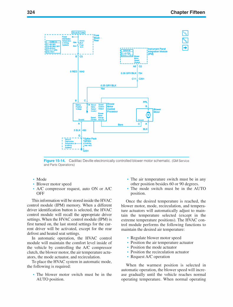
324 Chapter Fifteen
Figure 15-14. Cadillac Deville electronically controlled blower motor schematic. (GM Serviceand Parts Operations)
• Mode• Blower motor speed• A/C compressor request, auto ON or A/C
OFF
This information will be stored inside the HVACcontrol module (IPM) memory. When a differentdriver identification button is selected, the HVACcontrol module will recall the appropriate driversettings. When the HVAC control module (IPM) isfirst turned on, the last stored settings for the cur-rent driver will be activated, except for the reardefrost and heated seat settings.
In automatic operation, the HVAC controlmodule will maintain the comfort level inside ofthe vehicle by controlling the A/C compressorclutch, the blower motor, the air temperature actu-ators, the mode actuator, and recirculation.
To place the HVAC system in automatic mode,the following is required:
• The blower motor switch must be in theAUTO position.
• The air temperature switch must be in anyother position besides 60 or 90 degrees.
• The mode switch must be in the AUTOposition.
Once the desired temperature is reached, theblower motor, mode, recirculation, and tempera-ture actuators will automatically adjust to main-tain the temperature selected (except in theextreme temperature positions). The HVAC con-trol module performs the following functions tomaintain the desired air temperature:
• Regulate blower motor speed• Position the air temperature actuator• Position the mode actuator• Position the recirculation actuator• Request A/C operation
When the warmest position is selected inautomatic operation, the blower speed will incre-ase gradually until the vehicle reaches normaloperating temperature. When normal operating
ker88839_ch15.qxd 1/9/06 11:36 AM Page 324
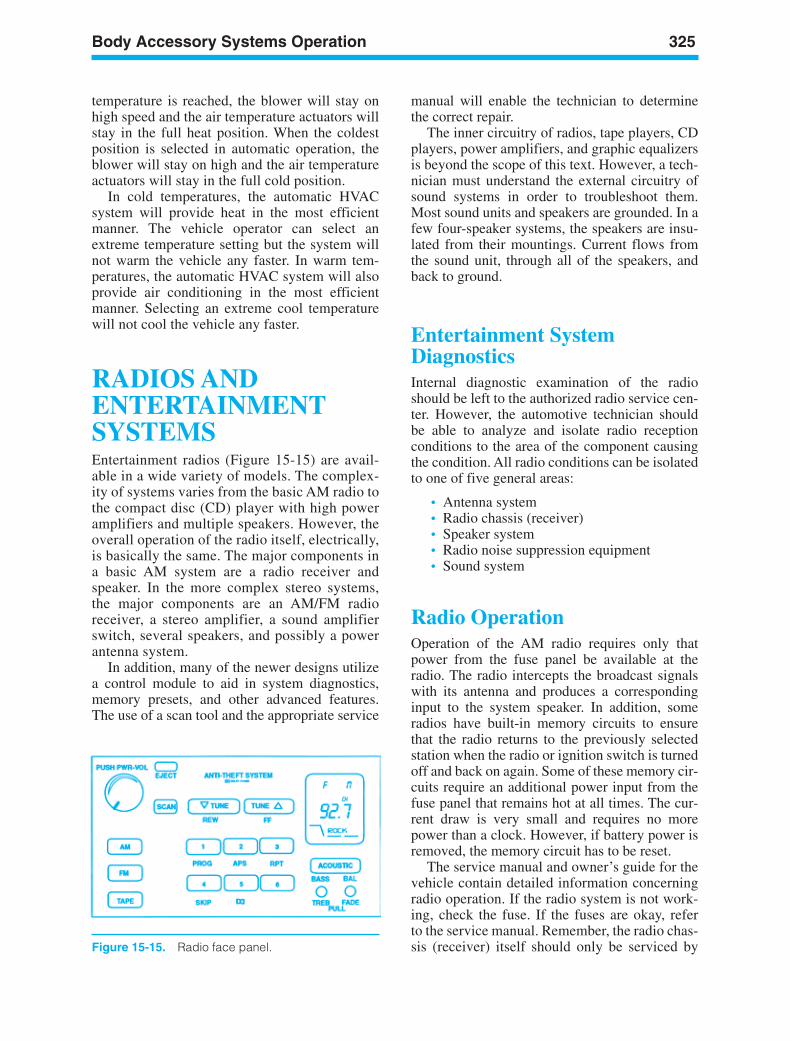
Body Accessory Systems Operation 325
Figure 15-15. Radio face panel.
temperature is reached, the blower will stay onhigh speed and the air temperature actuators willstay in the full heat position. When the coldestposition is selected in automatic operation, theblower will stay on high and the air temperatureactuators will stay in the full cold position.
In cold temperatures, the automatic HVACsystem will provide heat in the most efficientmanner. The vehicle operator can select anextreme temperature setting but the system willnot warm the vehicle any faster. In warm tem-peratures, the automatic HVAC system will alsoprovide air conditioning in the most efficientmanner. Selecting an extreme cool temperaturewill not cool the vehicle any faster.
RADIOS ANDENTERTAINMENTSYSTEMSEntertainment radios (Figure 15-15) are avail-able in a wide variety of models. The complex-ity of systems varies from the basic AM radio tothe compact disc (CD) player with high poweramplifiers and multiple speakers. However, theoverall operation of the radio itself, electrically,is basically the same. The major components ina basic AM system are a radio receiver andspeaker. In the more complex stereo systems,the major components are an AM/FM radioreceiver, a stereo amplifier, a sound amplifierswitch, several speakers, and possibly a powerantenna system.
In addition, many of the newer designs utilizea control module to aid in system diagnostics,memory presets, and other advanced features.The use of a scan tool and the appropriate service
manual will enable the technician to determinethe correct repair.
The inner circuitry of radios, tape players, CDplayers, power amplifiers, and graphic equalizersis beyond the scope of this text. However, a tech-nician must understand the external circuitry ofsound systems in order to troubleshoot them.Most sound units and speakers are grounded. In afew four-speaker systems, the speakers are insu-lated from their mountings. Current flows fromthe sound unit, through all of the speakers, andback to ground.
Entertainment SystemDiagnosticsInternal diagnostic examination of the radioshould be left to the authorized radio service cen-ter. However, the automotive technician shouldbe able to analyze and isolate radio receptionconditions to the area of the component causingthe condition. All radio conditions can be isolatedto one of five general areas:
• Antenna system• Radio chassis (receiver)• Speaker system• Radio noise suppression equipment• Sound system
Radio OperationOperation of the AM radio requires only thatpower from the fuse panel be available at theradio. The radio intercepts the broadcast signalswith its antenna and produces a correspondinginput to the system speaker. In addition, someradios have built-in memory circuits to ensurethat the radio returns to the previously selectedstation when the radio or ignition switch is turnedoff and back on again. Some of these memory cir-cuits require an additional power input from thefuse panel that remains hot at all times. The cur-rent draw is very small and requires no morepower than a clock. However, if battery power isremoved, the memory circuit has to be reset.
The service manual and owner’s guide for thevehicle contain detailed information concerningradio operation. If the radio system is not work-ing, check the fuse. If the fuses are okay, referto the service manual. Remember, the radio chas-sis (receiver) itself should only be serviced by
ker88839_ch15.qxd 1/9/06 11:36 AM Page 325
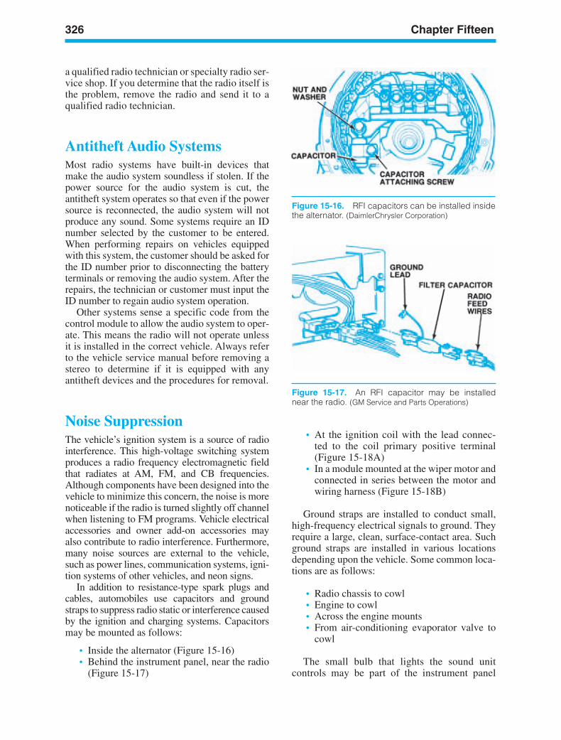
326 Chapter Fifteen
Figure 15-17. An RFI capacitor may be installednear the radio. (GM Service and Parts Operations)
Figure 15-16. RFI capacitors can be installed insidethe alternator. (DaimlerChrysler Corporation)
a qualified radio technician or specialty radio ser-vice shop. If you determine that the radio itself isthe problem, remove the radio and send it to aqualified radio technician.
Antitheft Audio SystemsMost radio systems have built-in devices thatmake the audio system soundless if stolen. If thepower source for the audio system is cut, theantitheft system operates so that even if the powersource is reconnected, the audio system will notproduce any sound. Some systems require an IDnumber selected by the customer to be entered.When performing repairs on vehicles equippedwith this system, the customer should be asked forthe ID number prior to disconnecting the batteryterminals or removing the audio system. After therepairs, the technician or customer must input theID number to regain audio system operation.
Other systems sense a specific code from thecontrol module to allow the audio system to oper-ate. This means the radio will not operate unlessit is installed in the correct vehicle. Always referto the vehicle service manual before removing astereo to determine if it is equipped with anyantitheft devices and the procedures for removal.
Noise SuppressionThe vehicle’s ignition system is a source of radiointerference. This high-voltage switching systemproduces a radio frequency electromagnetic fieldthat radiates at AM, FM, and CB frequencies.Although components have been designed into thevehicle to minimize this concern, the noise is morenoticeable if the radio is turned slightly off channelwhen listening to FM programs. Vehicle electricalaccessories and owner add-on accessories mayalso contribute to radio interference. Furthermore,many noise sources are external to the vehicle,such as power lines, communication systems, igni-tion systems of other vehicles, and neon signs.
In addition to resistance-type spark plugs andcables, automobiles use capacitors and groundstraps to suppress radio static or interference causedby the ignition and charging systems. Capacitorsmay be mounted as follows:
• Inside the alternator (Figure 15-16)• Behind the instrument panel, near the radio
(Figure 15-17)
• At the ignition coil with the lead connec-ted to the coil primary positive terminal(Figure 15-18A)
• In a module mounted at the wiper motor andconnected in series between the motor andwiring harness (Figure 15-18B)
Ground straps are installed to conduct small,high-frequency electrical signals to ground. Theyrequire a large, clean, surface-contact area. Suchground straps are installed in various locationsdepending upon the vehicle. Some common loca-tions are as follows:
• Radio chassis to cowl• Engine to cowl• Across the engine mounts• From air-conditioning evaporator valve to
cowl
The small bulb that lights the sound unitcontrols may be part of the instrument panel
ker88839_ch15.qxd 1/9/06 11:36 AM Page 326
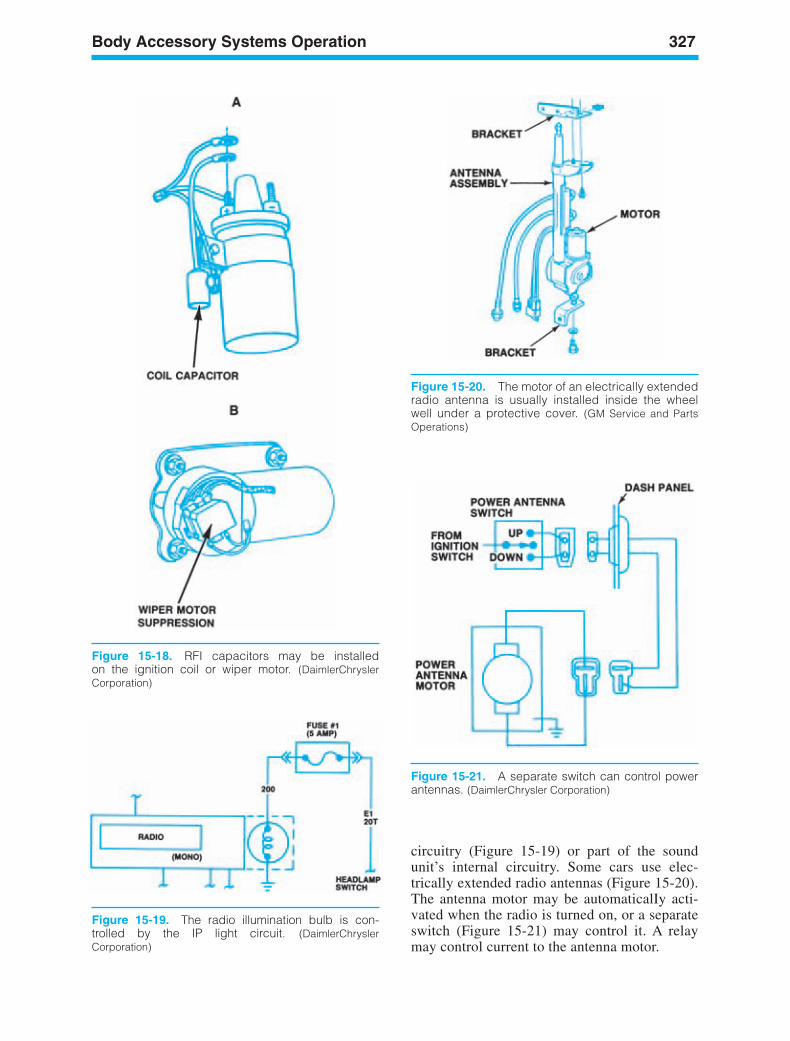
Body Accessory Systems Operation 327
Figure 15-18. RFI capacitors may be installedon the ignition coil or wiper motor. (DaimlerChryslerCorporation)
Figure 15-20. The motor of an electrically extendedradio antenna is usually installed inside the wheelwell under a protective cover. (GM Service and PartsOperations)
Figure 15-21. A separate switch can control powerantennas. (DaimlerChrysler Corporation)
circuitry (Figure 15-19) or part of the soundunit’s internal circuitry. Some cars use elec-trically extended radio antennas (Figure 15-20).The antenna motor may be automaticalIy acti-vated when the radio is turned on, or a separateswitch (Figure 15-21) may control it. A relaymay control current to the antenna motor.
Figure 15-19. The radio illumination bulb is con-trolled by the IP light circuit. (DaimlerChryslerCorporation)
ker88839_ch15.qxd 1/9/06 11:36 AM Page 327

328 Chapter Fifteen
Figure 15-22. Defroster circuit with grid. (Daimler-Chrysler Corporation)
Figure 15-23. Late-model system with a solid-statetiming module that turns off the defroster current auto-matically. (DaimlerChrysler Corporation)
REAR-WINDOWDEFOGGER ANDDEFROSTERSome older vehicles have a rear-window defog-ger, which is a motor-driven fan similar to thatused in the heating system but mounted behindthe rear seat near the rear window. It is controlledby a separate switch that routes current throughcircuits of varying resistance (like a heater fan) tochange motor speed. Heat is provided electricallyby a length of resistance wire in the defogger unit.The resistance heater is connected in parallel withthe motor so that it heats when the motor is run-ning at either high or low speed.
Rear Window DefrosterA defroster is a grid of electrical heating conduc-tors that is bonded to the rear window glass(Figure 15-22). The defroster grid is sometimescalled a defogger. Current through the grid maybe controlled by a separate switch and a relay(Figure 15-22) or by a switch-relay combination(Figure 15-23). In both designs, when the switchis closed, the relay is energized and an indicator
lamp is lit. The relay contact points conduct cur-rent to the rear window grid.
Most late-model systems have a solid-statetiming module that turns off the defroster cur-rent automatically. In the system shown inFigure 15-23, the switch ON position energizesthe relay’s pull-in and hold-in coils. The switchNORMAL position keeps the hold-in coil ener-gized so that the relay points remain closed.Cleaning the inside rear glass should be donecarefully to avoid scratching the grid materialand causing an open in the circuit.
POWER WINDOWSCar doors can contain motors to raise and lowerthe window glass (Figure 15-24). The motors usu-ally are the permanent-magnet type and are insu-lated at their mounting and grounded through thecontrol switch (Figure 15-25) or the masterswitch. Each control switch operates one motor,except for the driver’s door switch. This is a mas-ter switch that can control any of the motors.Some systems have a mechanical locking devicethat allows only the driver’s switch to control anyof the motors.
The single-motor control switches each haveone terminal that is connected to battery voltage.Each of the other two switch terminals is con-
ker88839_ch15.qxd 1/9/06 11:36 AM Page 328
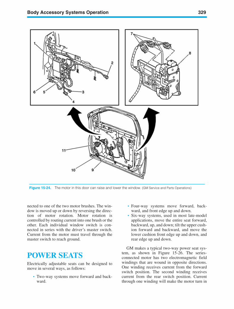
Body Accessory Systems Operation 329
Figure 15-24. The motor in this door can raise and lower the window. (GM Service and Parts Operations)
nected to one of the two motor brushes. The win-dow is moved up or down by reversing the direc-tion of motor rotation. Motor rotation iscontrolled by routing current into one brush or theother. Each individual window switch is con-nected in series with the driver’s master switch.Current from the motor must travel through themaster switch to reach ground.
POWER SEATSElectrically adjustable seats can be designed tomove in several ways, as follows:
• Two-way systems move forward and back-ward.
• Four-way systems move forward, back-ward, and front edge up and down.
• Six-way systems, used in most late-modelapplications, move the entire seat forward,backward, up, and down; tilt the upper cush-ion forward and backward, and move thelower cushion front edge up and down, andrear edge up and down.
GM makes a typical two-way power seat sys-tem, as shown in Figure 15-26. The series-connected motor has two electromagnetic fieldwindings that are wound in opposite directions.One winding receives current from the forwardswitch position. The second winding receivescurrent from the rear switch position. Currentthrough one winding will make the motor turn in
ker88839_ch15.qxd 1/9/06 11:36 AM Page 329
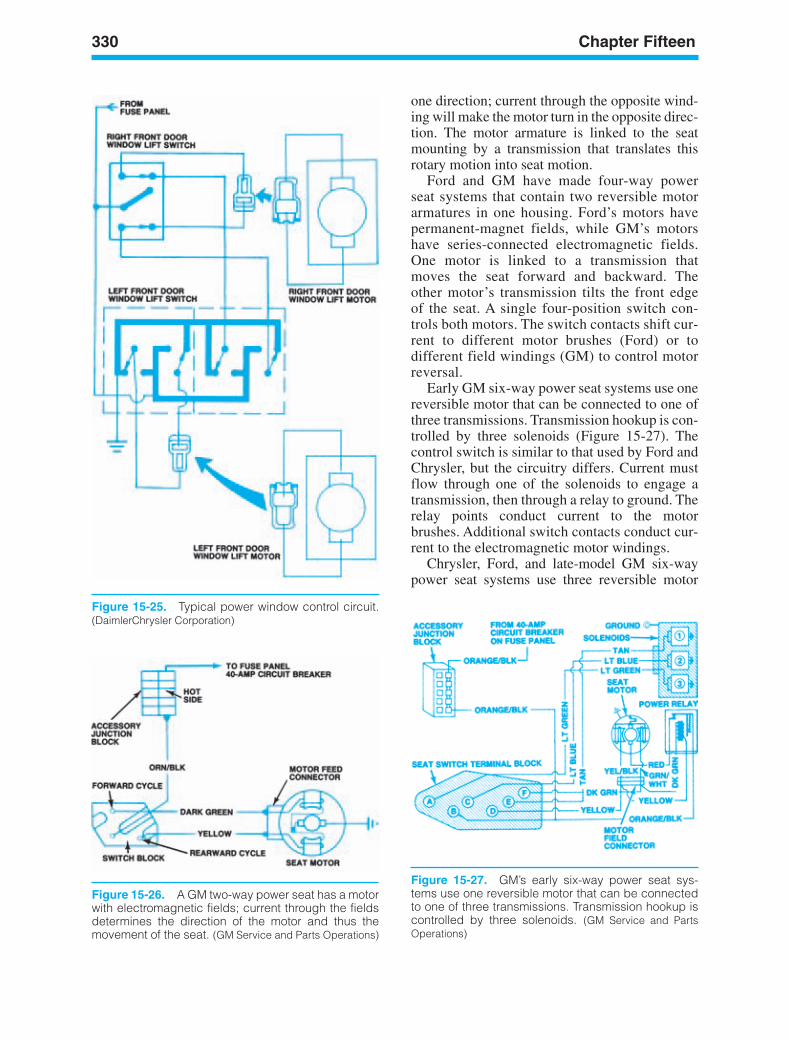
330 Chapter Fifteen
Figure 15-25. Typical power window control circuit.(DaimlerChrysler Corporation)
Figure 15-26. A GM two-way power seat has a motorwith electromagnetic fields; current through the fieldsdetermines the direction of the motor and thus themovement of the seat. (GM Service and Parts Operations)
one direction; current through the opposite wind-ing will make the motor turn in the opposite direc-tion. The motor armature is linked to the seatmounting by a transmission that translates thisrotary motion into seat motion.
Ford and GM have made four-way powerseat systems that contain two reversible motorarmatures in one housing. Ford’s motors havepermanent-magnet fields, while GM’s motorshave series-connected electromagnetic fields.One motor is linked to a transmission thatmoves the seat forward and backward. Theother motor’s transmission tilts the front edgeof the seat. A single four-position switch con-trols both motors. The switch contacts shift cur-rent to different motor brushes (Ford) or todifferent field windings (GM) to control motorreversal.
Early GM six-way power seat systems use onereversible motor that can be connected to one ofthree transmissions. Transmission hookup is con-trolled by three solenoids (Figure 15-27). Thecontrol switch is similar to that used by Ford andChrysler, but the circuitry differs. Current mustflow through one of the solenoids to engage atransmission, then through a relay to ground. Therelay points conduct current to the motorbrushes. Additional switch contacts conduct cur-rent to the electromagnetic motor windings.
Chrysler, Ford, and late-model GM six-waypower seat systems use three reversible motor
Figure 15-27. GM’s early six-way power seat sys-tems use one reversible motor that can be connectedto one of three transmissions. Transmission hookup iscontrolled by three solenoids. (GM Service and PartsOperations)
ker88839_ch15.qxd 1/9/06 11:36 AM Page 330
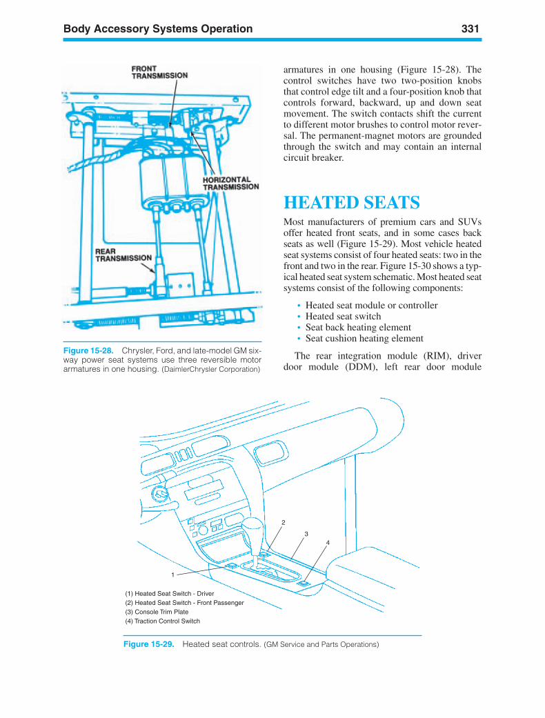
Body Accessory Systems Operation 331
(1) Heated Seat Switch - Driver(2) Heated Seat Switch - Front Passenger(3) Console Trim Plate(4) Traction Control Switch
1
2
34
Figure 15-29. Heated seat controls. (GM Service and Parts Operations)
Figure 15-28. Chrysler, Ford, and late-model GM six-way power seat systems use three reversible motorarmatures in one housing. (DaimlerChrysler Corporation)
armatures in one housing (Figure 15-28). Thecontrol switches have two two-position knobsthat control edge tilt and a four-position knob thatcontrols forward, backward, up and down seatmovement. The switch contacts shift the currentto different motor brushes to control motor rever-sal. The permanent-magnet motors are groundedthrough the switch and may contain an internalcircuit breaker.
HEATED SEATSMost manufacturers of premium cars and SUVsoffer heated front seats, and in some cases backseats as well (Figure 15-29). Most vehicle heatedseat systems consist of four heated seats: two in thefront and two in the rear. Figure 15-30 shows a typ-ical heated seat system schematic. Most heated seatsystems consist of the following components:
• Heated seat module or controller• Heated seat switch• Seat back heating element• Seat cushion heating element
The rear integration module (RIM), driverdoor module (DDM), left rear door module
ker88839_ch15.qxd 1/9/06 11:36 AM Page 331
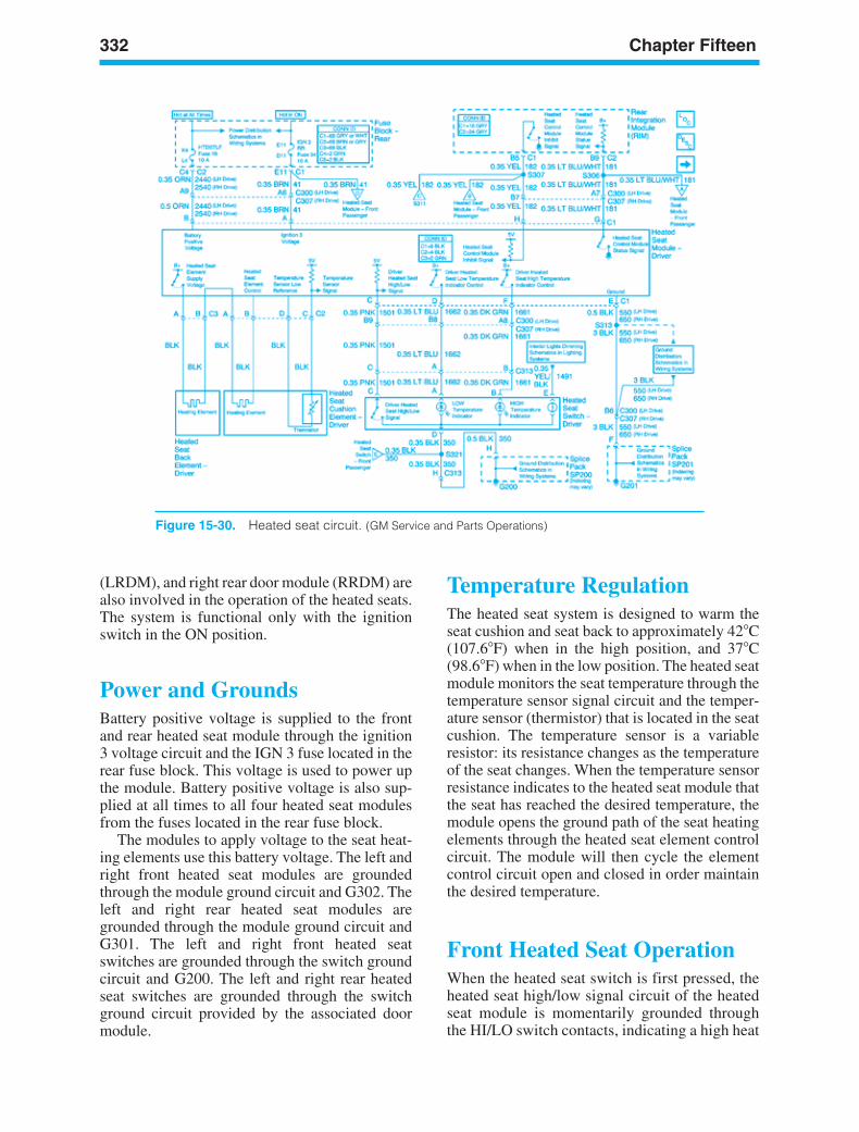
332 Chapter Fifteen
Figure 15-30. Heated seat circuit. (GM Service and Parts Operations)
(LRDM), and right rear door module (RRDM) arealso involved in the operation of the heated seats.The system is functional only with the ignitionswitch in the ON position.
Power and GroundsBattery positive voltage is supplied to the frontand rear heated seat module through the ignition3 voltage circuit and the IGN 3 fuse located in therear fuse block. This voltage is used to power upthe module. Battery positive voltage is also sup-plied at all times to all four heated seat modulesfrom the fuses located in the rear fuse block.
The modules to apply voltage to the seat heat-ing elements use this battery voltage. The left andright front heated seat modules are groundedthrough the module ground circuit and G302. Theleft and right rear heated seat modules aregrounded through the module ground circuit andG301. The left and right front heated seatswitches are grounded through the switch groundcircuit and G200. The left and right rear heatedseat switches are grounded through the switchground circuit provided by the associated doormodule.
Temperature RegulationThe heated seat system is designed to warm theseat cushion and seat back to approximately 42C(107.6F) when in the high position, and 37C(98.6F) when in the low position. The heated seatmodule monitors the seat temperature through thetemperature sensor signal circuit and the temper-ature sensor (thermistor) that is located in the seatcushion. The temperature sensor is a variableresistor: its resistance changes as the temperatureof the seat changes. When the temperature sensorresistance indicates to the heated seat module thatthe seat has reached the desired temperature, themodule opens the ground path of the seat heatingelements through the heated seat element controlcircuit. The module will then cycle the elementcontrol circuit open and closed in order maintainthe desired temperature.
Front Heated Seat OperationWhen the heated seat switch is first pressed, theheated seat high/low signal circuit of the heatedseat module is momentarily grounded throughthe HI/LO switch contacts, indicating a high heat
ker88839_ch15.qxd 1/9/06 11:36 AM Page 332
Body Accessory Systems Operation 333
command. In response to this signal, the heatedseat module applies battery positive voltage tothe seat cushion/back heating elements, settingthe temperature level to high heat. When theheated seat switch is pressed a second time, theheated seat high/low signal circuit of the heatedseat module is again momentarily groundedthrough the HI/LO switch contacts, indicating alow heat command. In response to this secondsignal, the heated seat module then sets the tem-perature level to low heat. When the heated seatswitch is pressed a third time, the heated seathigh/low signal circuit of the heated seat moduleis again momentarily grounded through theHI/LO switch contacts, indicating a heat off com-mand. In response to this signal, the heated seatmodule removes battery voltage from the seatheating elements.
Front Heated Seat SwitchIndicatorsWhen the heated seat is off and the front heatedseat switch is pressed once, the heated seat tem-perature is set to high heat. The heated seat mod-ule applies 5 volts through the heated seat hightemperature indicator control circuit to the heatedseat switch, illuminating the high temperatureindicator. When the switch is pressed a secondtime the heated seat temperature is set to low heat.The heated seat module applies 5 volts throughthe heated seat low temperature indicator controlcircuit to the heated seat switch, illuminating thelow temperature indicator. After the switch ispressed a third time, the heated seat is turned off,and the front heated seat module removes thevoltage from the low temperature indicator.
Rear Heated Seat OperationWhen the heated seat switch is first pressed,the heated seat switch signal circuit of the reardoor module is momentarily grounded throughthe switch contacts, indicating a high heat com-mand. The rear door module then sends a simplebuss interface (SBI) message to the driver’sdoor module (DDM), indicating the high heatcommand. The DDM then sends out a Class 2message to the rear integration module (RIM),indicating the high heat command. The RIMmomentarily sends a 35-millisecond one-shot
pulse signal that is pulled low through the heatedseat switch signal circuit of the rear heated seatmodule, indicating the high heat command.In response to this signal, the heated seat modulewill then apply battery positive voltage to the seatcushion/back heating elements, setting the tem-perature level to high heat.
When the switch is pressed a second time, theheated seat switch signal circuit of the rear doormodule is again momentarily grounded, indicat-ing a low heat command. The rear door modulethen sends out a SBI message to the DDM,indicating the low heat command. The DDM thensends out a Class 2 message to the RIM, indicat-ing the low heat command. The RIM againmomentarily sends a 35-millisecond one-shotpulse signal that is pulled low through the heatedseat switch signal circuit of the heated seat mod-ule, indicating the low heat command. Inresponse to this signal, the heated seat modulethen sets the temperature level to low heat.
After the switch is pressed a third time, theheated seat switch signal circuit of the rear doormodule is again momentarily grounded, indicat-ing a heat off command. The rear door modulethen sends out a SBI message to the DDM, indi-cating the heat off command. The DDM thensends out a Class 2 message to the RIM, indicat-ing the heat off command. The RIM againmomentarily sends a 35-millisecond one-shotpulse signal that is pulled low through the heatedseat switch signal circuit of the heated seat mod-ule, indicating the heat off command. In responseto this signal, the heated seat module thenremoves the battery voltage from the seat heatingelements, turning off the heated seats.
Rear Heated Seat SwitchIndicatorsWhen the heated seat is off and the rear heatedseat switch is pressed once, the heated seat tem-perature is set to high heat. The rear door moduleapplies battery positive voltage through theheated seat high temperature indicator control cir-cuit to the heated seat switch, illuminating thehigh temperature indicator. When pressed a sec-ond time, the heated seat temperature is set to lowheat. The rear door module the applies batterypositive voltage through the heated seat low tem-perature indicator control circuit to the heatedseat switch, illuminating the low temperatureindicator. After the switch is pressed a third time,
ker88839_ch15.qxd 1/9/06 11:36 AM Page 333
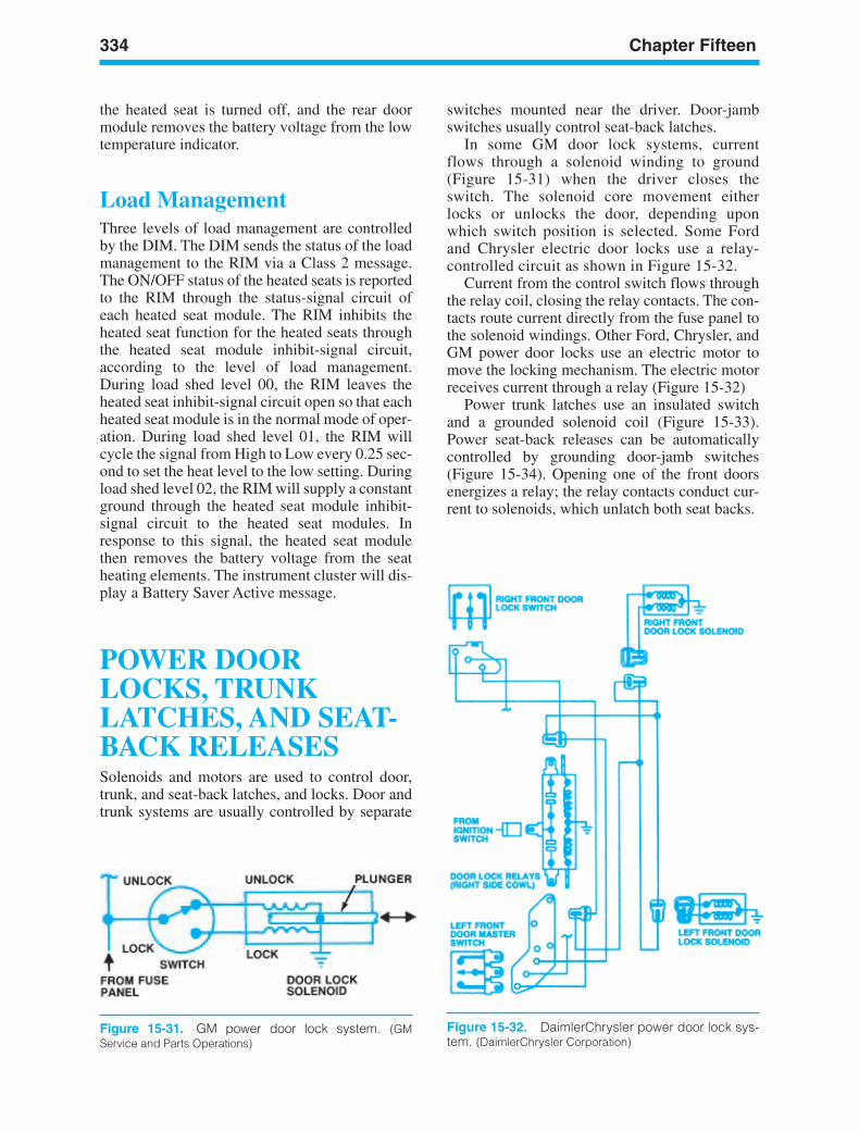
334 Chapter Fifteen
Figure 15-31. GM power door lock system. (GMService and Parts Operations)
Figure 15-32. DaimlerChrysler power door lock sys-tem. (DaimlerChrysler Corporation)
the heated seat is turned off, and the rear doormodule removes the battery voltage from the lowtemperature indicator.
Load ManagementThree levels of load management are controlledby the DIM. The DIM sends the status of the loadmanagement to the RIM via a Class 2 message.The ON/OFF status of the heated seats is reportedto the RIM through the status-signal circuit ofeach heated seat module. The RIM inhibits theheated seat function for the heated seats throughthe heated seat module inhibit-signal circuit,according to the level of load management.During load shed level 00, the RIM leaves theheated seat inhibit-signal circuit open so that eachheated seat module is in the normal mode of oper-ation. During load shed level 01, the RIM willcycle the signal from High to Low every 0.25 sec-ond to set the heat level to the low setting. Duringload shed level 02, the RIM will supply a constantground through the heated seat module inhibit-signal circuit to the heated seat modules. Inresponse to this signal, the heated seat modulethen removes the battery voltage from the seatheating elements. The instrument cluster will dis-play a Battery Saver Active message.
POWER DOORLOCKS, TRUNKLATCHES, AND SEAT-BACK RELEASESSolenoids and motors are used to control door,trunk, and seat-back latches, and locks. Door andtrunk systems are usually controlled by separate
switches mounted near the driver. Door-jambswitches usually control seat-back latches.
In some GM door lock systems, currentflows through a solenoid winding to ground(Figure 15-31) when the driver closes theswitch. The solenoid core movement eitherlocks or unlocks the door, depending uponwhich switch position is selected. Some Fordand Chrysler electric door locks use a relay-controlled circuit as shown in Figure 15-32.
Current from the control switch flows throughthe relay coil, closing the relay contacts. The con-tacts route current directly from the fuse panel tothe solenoid windings. Other Ford, Chrysler, andGM power door locks use an electric motor tomove the locking mechanism. The electric motorreceives current through a relay (Figure 15-32)
Power trunk latches use an insulated switchand a grounded solenoid coil (Figure 15-33).Power seat-back releases can be automaticallycontrolled by grounding door-jamb switches(Figure 15-34). Opening one of the front doorsenergizes a relay; the relay contacts conduct cur-rent to solenoids, which unlatch both seat backs.
ker88839_ch15.qxd 1/9/06 11:36 AM Page 334
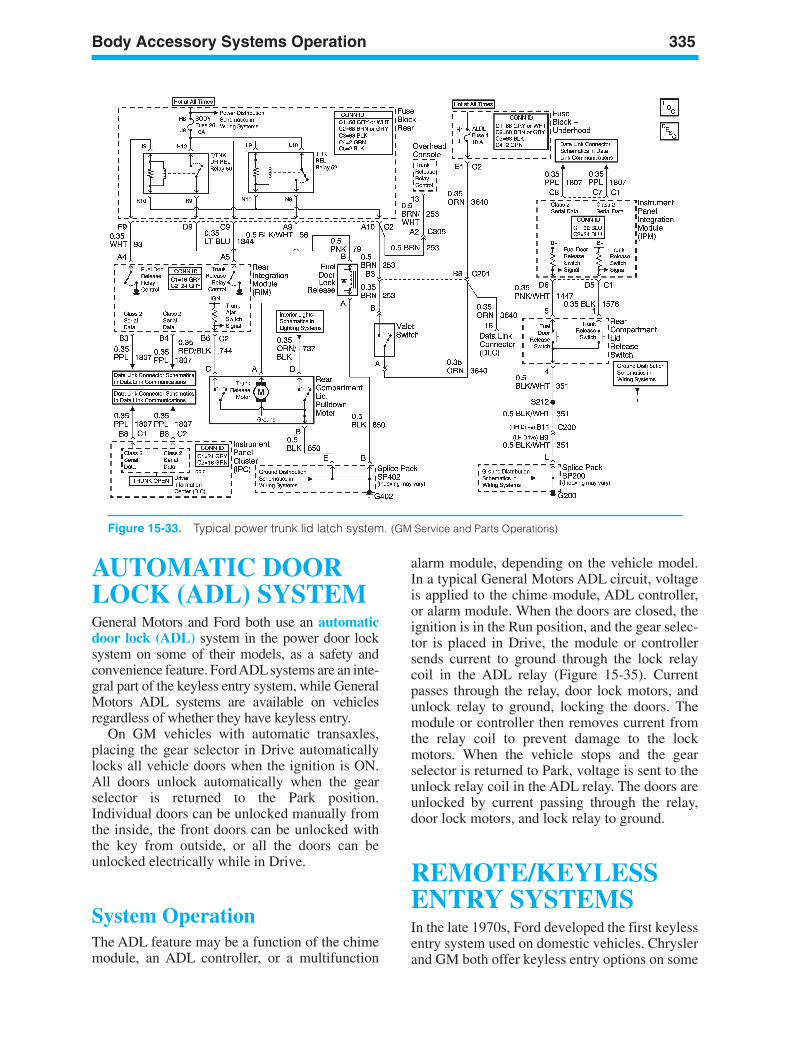
Body Accessory Systems Operation 335
Figure 15-33. Typical power trunk lid latch system. (GM Service and Parts Operations)
AUTOMATIC DOORLOCK (ADL) SYSTEMGeneral Motors and Ford both use an automaticdoor lock (ADL) system in the power door locksystem on some of their models, as a safety andconvenience feature. Ford ADLsystems are an inte-gral part of the keyless entry system, while GeneralMotors ADL systems are available on vehiclesregardless of whether they have keyless entry.
On GM vehicles with automatic transaxles,placing the gear selector in Drive automaticallylocks all vehicle doors when the ignition is ON.All doors unlock automatically when the gearselector is returned to the Park position.Individual doors can be unlocked manually fromthe inside, the front doors can be unlocked withthe key from outside, or all the doors can beunlocked electrically while in Drive.
System OperationThe ADL feature may be a function of the chimemodule, an ADL controller, or a multifunction
alarm module, depending on the vehicle model.In a typical General Motors ADL circuit, voltageis applied to the chime module, ADL controller,or alarm module. When the doors are closed, theignition is in the Run position, and the gear selec-tor is placed in Drive, the module or controllersends current to ground through the lock relaycoil in the ADL relay (Figure 15-35). Currentpasses through the relay, door lock motors, andunlock relay to ground, locking the doors. Themodule or controller then removes current fromthe relay coil to prevent damage to the lockmotors. When the vehicle stops and the gearselector is returned to Park, voltage is sent to theunlock relay coil in the ADL relay. The doors areunlocked by current passing through the relay,door lock motors, and lock relay to ground.
REMOTE/KEYLESSENTRY SYSTEMSIn the late 1970s, Ford developed the first keylessentry system used on domestic vehicles. Chryslerand GM both offer keyless entry options on some
ker88839_ch15.qxd 1/9/06 11:36 AM Page 335
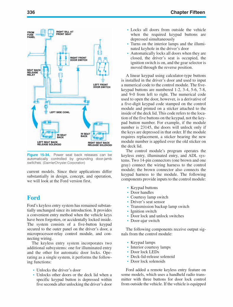
336 Chapter Fifteen
Figure 15-34. Power seat back releases can beautomatically controlled by grounding door-jambswitches. (DaimlerChrysler Corporation)
current models. Since their applications differsubstantially in design, concept, and operation,we will look at the Ford version first.
FordFord’s keyless entry system has remained substan-tially unchanged since its introduction. It providesa convenient entry method when the vehicle keyshave been forgotten, or accidentally locked inside.The system consists of a five-button keypadsecured to the outer panel on the driver’s door, amicroprocessor-relay control module, and con-necting wiring.
The keyless entry system incorporates twoadditional subsystems: one for illuminated entryand the other for automatic door locks. Ope-rating as a single system, it performs the follow-ing functions:
• Unlocks the driver’s door• Unlocks other doors or the deck lid when a
specific keypad button is depressed withinfive seconds after unlocking the driver’s door
• Locks all doors from outside the vehiclewhen the required keypad buttons aredepressed simultaneously
• Turns on the interior lamps and the illumi-nated keyhole in the driver’s door
• Automatically locks all doors when they areclosed, the driver’s seat is occupied, theignition switch is on, and the gear selector ismoved through the reverse position.
A linear keypad using calculator-type buttonsis installed in the driver’s door and used to inputa numerical code to the control module. The five-keypad buttons are numbered 1-2, 3-4, 5-6, 7-8,and 9-0 from left to right. The numerical codeused to open the door, however, is a derivative ofa five-digit keypad code stamped on the controlmodule and printed on a sticker attached to theinside of the deck lid. This code refers to the loca-tion of the five buttons on the keypad, not the key-pad button number. For example, if the modulenumber is 23145, the doors will unlock only ifthe keys are depressed in that order. If the modulerequires replacement, a sticker bearing the newmodule number is applied over the old sticker onthe deck lid.
The control module’s program operates thekeyless entry, illuminated entry, and ADL sys-tems. Two 14-pin connectors (one brown and onegray) connect the wiring harness to the controlmodule; the brown connector also connects thekeypad harness to the module. The followingcomponents provide inputs to the control module:
• Keypad buttons• Door handles• Courtesy lamp switch• Driver’s seat sensor• Transmission backup lamp switch• Ignition switch• Door lock and unlock switches• Door-ajar switch
The following components receive output sig-nals from the control module:
• Keypad lamps• Interior courtesy lamps• Door lock LEDs• Deck-lid-release solenoid• Door lock solenoids
Ford added a remote keyless entry feature onsome models, which uses a handheld radio trans-mitter with three buttons for door lock controlfrom outside the vehicle. If the vehicle is equipped
ker88839_ch15.qxd 1/9/06 11:36 AM Page 336
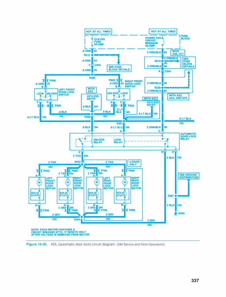
337
Figure 15-35. ADL (automatic door lock) circuit diagram. (GM Service and Parts Operations)
ker88839_ch15.qxd 1/9/06 11:36 AM Page 337
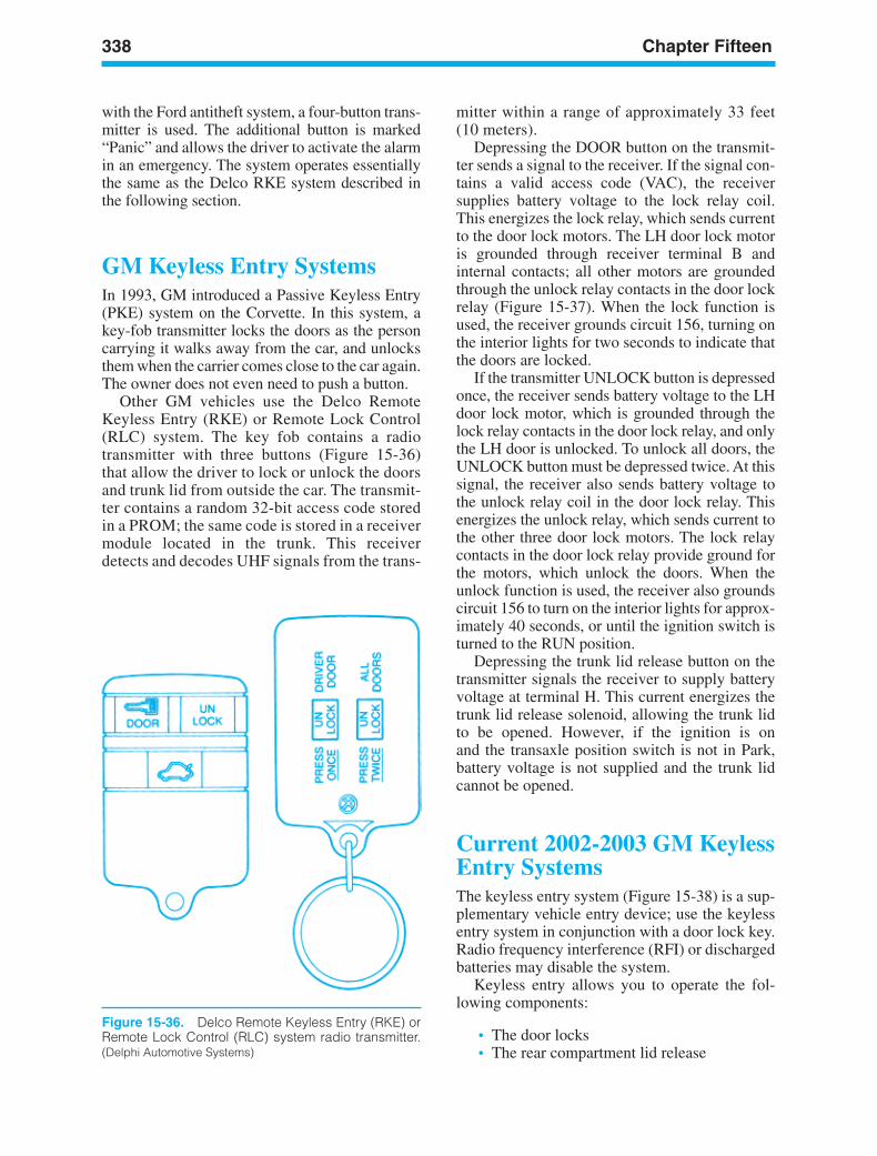
338 Chapter Fifteen
Figure 15-36. Delco Remote Keyless Entry (RKE) orRemote Lock Control (RLC) system radio transmitter.(Delphi Automotive Systems)
mitter within a range of approximately 33 feet(10 meters).
Depressing the DOOR button on the transmit-ter sends a signal to the receiver. If the signal con-tains a valid access code (VAC), the receiversupplies battery voltage to the lock relay coil.This energizes the lock relay, which sends currentto the door lock motors. The LH door lock motoris grounded through receiver terminal B andinternal contacts; all other motors are groundedthrough the unlock relay contacts in the door lockrelay (Figure 15-37). When the lock function isused, the receiver grounds circuit 156, turning onthe interior lights for two seconds to indicate thatthe doors are locked.
If the transmitter UNLOCK button is depressedonce, the receiver sends battery voltage to the LHdoor lock motor, which is grounded through thelock relay contacts in the door lock relay, and onlythe LH door is unlocked. To unlock all doors, theUNLOCK button must be depressed twice. At thissignal, the receiver also sends battery voltage tothe unlock relay coil in the door lock relay. Thisenergizes the unlock relay, which sends current tothe other three door lock motors. The lock relaycontacts in the door lock relay provide ground forthe motors, which unlock the doors. When theunlock function is used, the receiver also groundscircuit 156 to turn on the interior lights for approx-imately 40 seconds, or until the ignition switch isturned to the RUN position.
Depressing the trunk lid release button on thetransmitter signals the receiver to supply batteryvoltage at terminal H. This current energizes thetrunk lid release solenoid, allowing the trunk lidto be opened. However, if the ignition is onand the transaxle position switch is not in Park,battery voltage is not supplied and the trunk lidcannot be opened.
Current 2002-2003 GM KeylessEntry SystemsThe keyless entry system (Figure 15-38) is a sup-plementary vehicle entry device; use the keylessentry system in conjunction with a door lock key.Radio frequency interference (RFI) or dischargedbatteries may disable the system.
Keyless entry allows you to operate the fol-lowing components:
• The door locks• The rear compartment lid release
with the Ford antitheft system, a four-button trans-mitter is used. The additional button is marked“Panic” and allows the driver to activate the alarmin an emergency. The system operates essentiallythe same as the Delco RKE system described inthe following section.
GM Keyless Entry SystemsIn 1993, GM introduced a Passive Keyless Entry(PKE) system on the Corvette. In this system, akey-fob transmitter locks the doors as the personcarrying it walks away from the car, and unlocksthem when the carrier comes close to the car again.The owner does not even need to push a button.
Other GM vehicles use the Delco RemoteKeyless Entry (RKE) or Remote Lock Control(RLC) system. The key fob contains a radiotransmitter with three buttons (Figure 15-36)that allow the driver to lock or unlock the doorsand trunk lid from outside the car. The transmit-ter contains a random 32-bit access code storedin a PROM; the same code is stored in a receivermodule located in the trunk. This receiverdetects and decodes UHF signals from the trans-
ker88839_ch15.qxd 1/9/06 11:36 AM Page 338
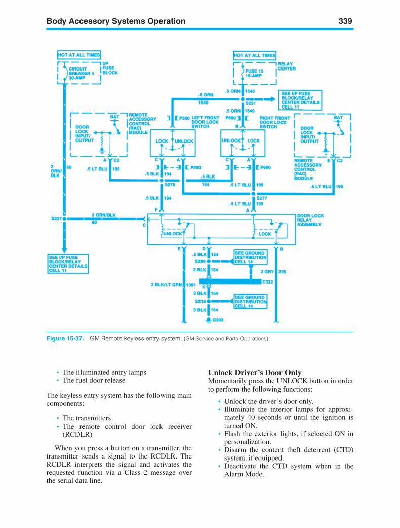
Body Accessory Systems Operation 339
Figure 15-37. GM Remote keyless entry system. (GM Service and Parts Operations)
• The illuminated entry lamps• The fuel door release
The keyless entry system has the following maincomponents:
• The transmitters• The remote control door lock receiver
(RCDLR)
When you press a button on a transmitter, thetransmitter sends a signal to the RCDLR. TheRCDLR interprets the signal and activates therequested function via a Class 2 message overthe serial data line.
Unlock Driver’s Door OnlyMomentarily press the UNLOCK button in orderto perform the following functions:
• Unlock the driver’s door only.• Illuminate the interior lamps for approxi-
mately 40 seconds or until the ignition isturned ON.
• Flash the exterior lights, if selected ON inpersonalization.
• Disarm the content theft deterrent (CTD)system, if equipped.
• Deactivate the CTD system when in theAlarm Mode.
ker88839_ch15.qxd 1/9/06 11:36 AM Page 339
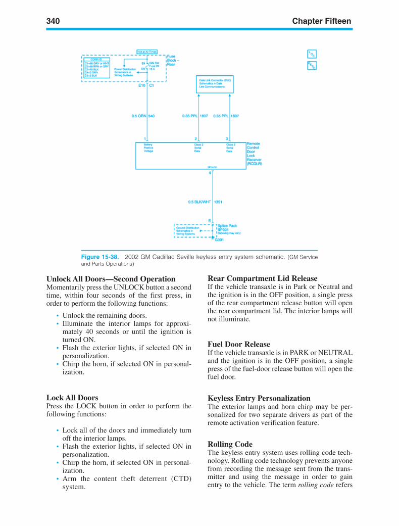
340 Chapter Fifteen
Figure 15-38. 2002 GM Cadillac Seville keyless entry system schematic. (GM Serviceand Parts Operations)
Unlock All Doors—Second OperationMomentarily press the UNLOCK button a secondtime, within four seconds of the first press, inorder to perform the following functions:
• Unlock the remaining doors.• Illuminate the interior lamps for approxi-
mately 40 seconds or until the ignition isturned ON.
• Flash the exterior lights, if selected ON inpersonalization.
• Chirp the horn, if selected ON in personal-ization.
Lock All DoorsPress the LOCK button in order to perform thefollowing functions:
• Lock all of the doors and immediately turnoff the interior lamps.
• Flash the exterior lights, if selected ON inpersonalization.
• Chirp the horn, if selected ON in personal-ization.
• Arm the content theft deterrent (CTD)system.
Rear Compartment Lid ReleaseIf the vehicle transaxle is in Park or Neutral andthe ignition is in the OFF position, a single pressof the rear compartment release button will openthe rear compartment lid. The interior lamps willnot illuminate.
Fuel Door ReleaseIf the vehicle transaxle is in PARK or NEUTRALand the ignition is in the OFF position, a singlepress of the fuel-door release button will open thefuel door.
Keyless Entry PersonalizationThe exterior lamps and horn chirp may be per-sonalized for two separate drivers as part of theremote activation verification feature.
Rolling CodeThe keyless entry system uses rolling code tech-nology. Rolling code technology prevents anyonefrom recording the message sent from the trans-mitter and using the message in order to gainentry to the vehicle. The term rolling code refers
ker88839_ch15.qxd 1/9/06 11:36 AM Page 340
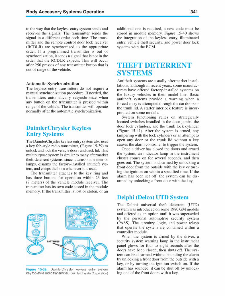
Body Accessory Systems Operation 341
to the way that the keyless entry system sends andreceives the signals. The transmitter sends thesignal in a different order each time. The trans-mitter and the remote control door lock receiver(RCDLR) are synchronized to the appropriateorder. If a programmed transmitter is out ofsynchronization, it sends a signal that is not in theorder that the RCDLR expects. This will occurafter 256 presses of any transmitter button that isout of range of the vehicle.
Automatic SynchronizationThe keyless entry transmitters do not require amanual synchronization procedure. If needed, thetransmitters automatically resynchronize whenany button on the transmitter is pressed withinrange of the vehicle. The transmitter will operatenormally after the automatic synchronization.
DaimlerChrysler Keyless Entry SystemsThe DaimlerChrysler keyless entry system also usesa key fob-style radio transmitter, (Figure 15-39) tounlock and lock the vehicle doors and deck lid. Thismultipurpose system is similar to many aftermarkettheft-deterrent systems, since it turns on the interiorlamps, disarms the factory-installed antitheft sys-tem, and chirps the horn whenever it is used.
The transmitter attaches to the key ring andhas three buttons for operation within 23 feet(7 meters) of the vehicle module receiver. Thetransmitter has its own code stored in the modulememory. If the transmitter is lost or stolen, or an
additional one is required, a new code must bestored in module memory. Figure 15-40 showsthe integration of the keyless entry, illuminatedentry, vehicle theft security, and power door locksystems with the BCM.
THEFT DETERRENTSYSTEMSAntitheft systems are usually aftermarket instal-lations, although in recent years, some manufac-turers have offered factory-installed systems onthe luxury vehicles in their model line. Basicantitheft systems provide a warning when aforced entry is attempted through the car doors orthe trunk lid. A starter interlock feature is incor-porated on some models.
System functioning relies on strategicallylocated switches installed in the door jambs, thedoor lock cylinders, and the trunk lock cylinder(Figure 15-41). After the system is armed, anytampering with the lock cylinders or an attempt toopen any door or the trunk lid without a keycauses the alarm controller to trigger the system.
Once a driver has closed the doors and armedthe system, an indicator lamp in the instrumentcluster comes on for several seconds, and thengoes out. The system is disarmed by unlocking afront door from the outside with the key or turn-ing the ignition on within a specified time. If thealarm has been set off, the system can be dis-armed by unlocking a front door with the key.
Delphi (Delco) UTD SystemThe Delphi universal theft deterrent (UTD)system was introduced on some 1980 GM modelsand offered as an option until it was supersededby the personal automotive security system(PASS). The circuitry, logic, and power relaysthat operate the system are contained within acontroller module.
When the system is armed by the driver, asecurity system warning lamp in the instrumentpanel glows for four to eight seconds after thedoors have been closed, then shuts off. The sys-tem can be disarmed without sounding the alarmby unlocking a front door from the outside with akey, or by turning the ignition switch on. If thealarm has sounded, it can be shut off by unlock-ing one of the front doors with a key.
Figure 15-39. DaimlerChrysler keyless entry systemkey fob-style radio transmitter. (DaimlerChrysler Corporation)
ker88839_ch15.qxd 1/9/06 11:36 AM Page 341
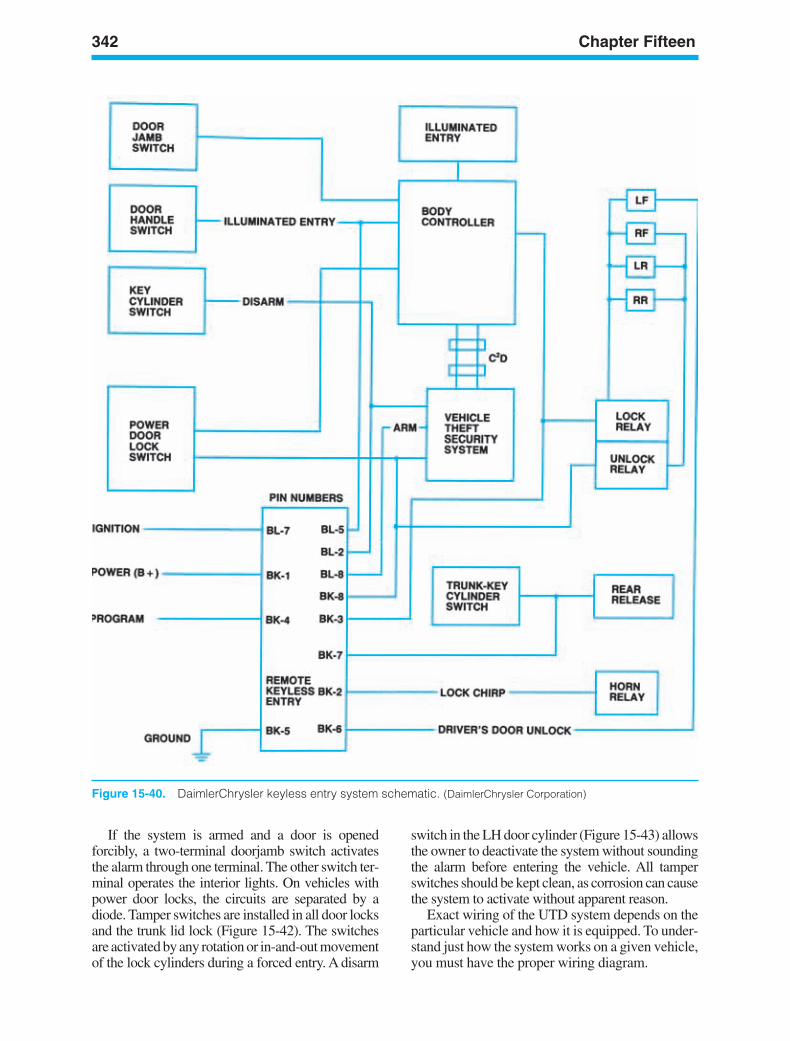
342 Chapter Fifteen
Figure 15-40. DaimlerChrysler keyless entry system schematic. (DaimlerChrysler Corporation)
If the system is armed and a door is openedforcibly, a two-terminal doorjamb switch activatesthe alarm through one terminal. The other switch ter-minal operates the interior lights. On vehicles withpower door locks, the circuits are separated by adiode. Tamper switches are installed in all door locksand the trunk lid lock (Figure 15-42). The switchesare activated by any rotation or in-and-out movementof the lock cylinders during a forced entry. A disarm
switch in the LH door cylinder (Figure 15-43) allowsthe owner to deactivate the system without soundingthe alarm before entering the vehicle. All tamperswitches should be kept clean, as corrosion can causethe system to activate without apparent reason.
Exact wiring of the UTD system depends on theparticular vehicle and how it is equipped. To under-stand just how the system works on a given vehicle,you must have the proper wiring diagram.
ker88839_ch15.qxd 1/9/06 11:36 AM Page 342
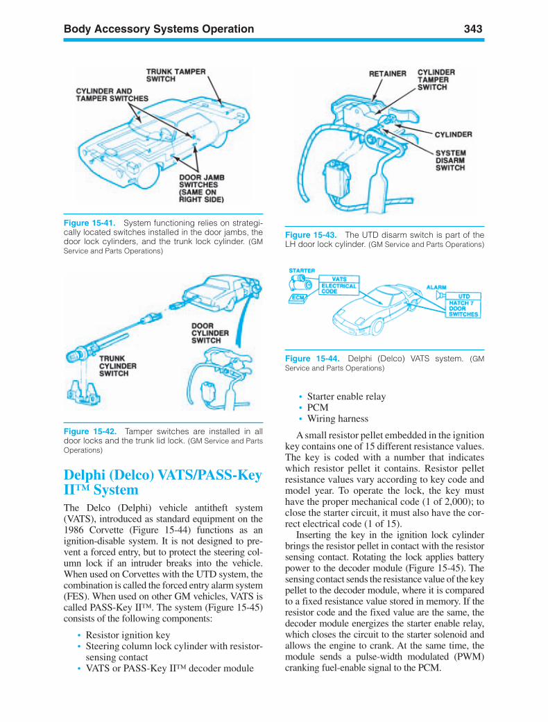
Body Accessory Systems Operation 343
Figure 15-41. System functioning relies on strategi-cally located switches installed in the door jambs, thedoor lock cylinders, and the trunk lock cylinder. (GMService and Parts Operations)
Figure 15-42. Tamper switches are installed in alldoor locks and the trunk lid lock. (GM Service and PartsOperations)
Figure 15-43. The UTD disarm switch is part of theLH door lock cylinder. (GM Service and Parts Operations)
Figure 15-44. Delphi (Delco) VATS system. (GMService and Parts Operations)
Delphi (Delco) VATS/PASS-KeyII™ SystemThe Delco (Delphi) vehicle antitheft system(VATS), introduced as standard equipment on the1986 Corvette (Figure 15-44) functions as an ignition-disable system. It is not designed to pre-vent a forced entry, but to protect the steering col-umn lock if an intruder breaks into the vehicle.When used on Corvettes with the UTD system, thecombination is called the forced entry alarm system(FES). When used on other GM vehicles, VATS iscalled PASS-Key II™. The system (Figure 15-45)consists of the following components:
• Resistor ignition key• Steering column lock cylinder with resistor-
sensing contact• VATS or PASS-Key II™ decoder module
• Starter enable relay• PCM• Wiring harness
A small resistor pellet embedded in the ignitionkey contains one of 15 different resistance values.The key is coded with a number that indicateswhich resistor pellet it contains. Resistor pelletresistance values vary according to key code andmodel year. To operate the lock, the key musthave the proper mechanical code (1 of 2,000); toclose the starter circuit, it must also have the cor-rect electrical code (1 of 15).
Inserting the key in the ignition lock cylinderbrings the resistor pellet in contact with the resistorsensing contact. Rotating the lock applies batterypower to the decoder module (Figure 15-45). Thesensing contact sends the resistance value of the keypellet to the decoder module, where it is comparedto a fixed resistance value stored in memory. If theresistor code and the fixed value are the same, thedecoder module energizes the starter enable relay,which closes the circuit to the starter solenoid andallows the engine to crank. At the same time, themodule sends a pulse-width modulated (PWM)cranking fuel-enable signal to the PCM.
ker88839_ch15.qxd 1/9/06 11:36 AM Page 343
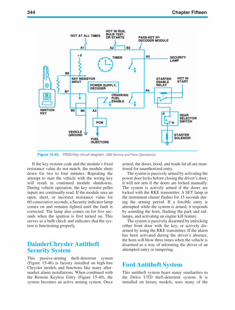
344 Chapter Fifteen
Figure 15-45. PASS-Key circuit diagram. (GM Service and Parts Operations)
If the key resistor code and the module’s fixedresistance value do not match, the module shutsdown for two to four minutes. Repeating theattempt to start the vehicle with the wrong keywill result in continued module shutdowns.During vehicle operation, the key resistor pelletinputs are continually read. If the module sees anopen, short, or incorrect resistance value for60 consecutive seconds, a Security indicator lampcomes on and remains lighted until the fault iscorrected. The lamp also comes on for five sec-onds when the ignition is first turned on. Thisserves as a bulb check and indicates that the sys-tem is functioning properly.
DaimlerChrysler AntitheftSecurity SystemThis passive-arming theft-deterrent system(Figure 15-46) is factory installed on high-lineChrysler models and functions like many after-market alarm installations. When combined withthe Remote Keyless Entry (Figure 15-40), thesystem becomes an active arming system. Once
armed, the doors, hood, and trunk lid all are mon-itored for unauthorized entry.
The system is passively armed by activating thepower door locks before closing the driver’s door;it will not arm if the doors are locked manually.The system is actively armed if the doors arelocked with the RKE transmitter. A SET lamp inthe instrument cluster flashes for 15 seconds dur-ing the arming period. If a forcible entry isattempted while the system is armed, it respondsby sounding the horn, flashing the park and tail-lamps, and activating an engine kill feature.
The system is passively disarmed by unlockingeither front door with the key, or actively dis-armed by using the RKE transmitter. If the alarmhas been activated during the driver’s absence,the horn will blow three times when the vehicle isdisarmed as a way of informing the driver of anattempted entry or tampering.
Ford Antitheft SystemThis antitheft system bears many similarities tothe Delco UTD theft-deterrent system. It isinstalled on luxury models, uses many of the
ker88839_ch15.qxd 1/9/06 11:36 AM Page 344
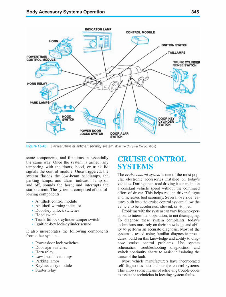
Body Accessory Systems Operation 345
Figure 15-46. DaimlerChrysler antitheft security system. (DaimlerChrysler Corporation)
same components, and functions in essentiallythe same way. Once the system is armed, anytampering with the doors, hood, or trunk lidsignals the control module. Once triggered, thesystem flashes the low-beam headlamps, theparking lamps, and alarm indicator lamp onand off; sounds the horn; and interrupts thestarter circuit. The system is composed of the fol-lowing components:
• Antitheft control module• Antitheft warning indicator• Door-key unlock switches• Hood switch• Trunk-lid lock-cylinder tamper switch• Ignition-key lock-cylinder sensor
It also incorporates the following componentsfrom other systems:
• Power door lock switches• Door-ajar switches• Horn relay• Low-beam headlamps• Parking lamps• Keyless entry module• Starter relay
CRUISE CONTROLSYSTEMSThe cruise control system is one of the most pop-ular electronic accessories installed on today’svehicles. During open-road driving it can maintaina constant vehicle speed without the continuedeffort of driver. This helps reduce driver fatigueand increases fuel economy. Several override fea-tures built into the cruise control system allow thevehicle to be accelerated, slowed, or stopped.
Problems with the system can vary from no oper-ation, to intermittent operation, to not disengaging.To diagnose these system complaints, today’stechnicians must rely on their knowledge and abil-ity to perform an accurate diagnosis. Most of thesystem is tested using familiar diagnostic proce-dures; build on this knowledge and ability to diag-nose cruise control problems. Use systemschematics, troubleshooting diagnostics, andswitch continuity charts to assist in isolating thecause of the fault.
Most vehicle manufacturers have incorporatedself-diagnostics into their cruise control systems.This allows some means of retrieving trouble codesto assist the technician in locating system faults.
ker88839_ch15.qxd 1/9/06 11:36 AM Page 345
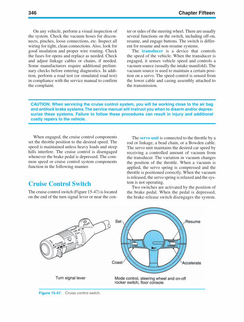
346 Chapter Fifteen
Figure 15-47. Cruise control switch.
On any vehicle, perform a visual inspection ofthe system. Check the vacuum hoses for discon-nects, pinches, loose connections, etc. Inspect allwiring for tight, clean connections. Also, look forgood insulation and proper wire routing. Checkthe fuses for opens and replace as needed. Checkand adjust linkage cables or chains, if needed.Some manufacturers require additional prelimi-nary checks before entering diagnostics. In addi-tion, perform a road test (or simulated road test)in compliance with the service manual to confirmthe complaint.
CAUTION: When servicing the cruise control system, you will be working close to the air bagand antilock brake systems.The service manual will instruct you when to disarm and/or depres-surize these systems. Failure to follow these procedures can result in injury and additionalcostly repairs to the vehicle.
When engaged, the cruise control componentsset the throttle position to the desired speed. Thespeed is maintained unless heavy loads and steephills interfere. The cruise control is disengagedwhenever the brake pedal is depressed. The com-mon speed or cruise control system componentsfunction in the following manner.
Cruise Control SwitchThe cruise control switch (Figure 15-47) is locatedon the end of the turn signal lever or near the cen-
The servo unit is connected to the throttle by arod or linkage, a bead chain, or a Bowden cable.The servo unit maintains the desired car speed byreceiving a controlled amount of vacuum fromthe transducer. The variation in vacuum changesthe position of the throttle. When a vacuum isapplied, the servo spring is compressed and thethrottle is positioned correctly. When the vacuumis released, the servo spring is relaxed and the sys-tem is not operating.
Two switches are activated by the position ofthe brake pedal. When the pedal is depressed,the brake-release switch disengages the system.
ter or sides of the steering wheel. There are usuallyseveral functions on the switch, including off-on,resume, and engage buttons. The switch is differ-ent for resume and non-resume systems.
The transducer is a device that controlsthe speed of the vehicle. When the transducer isengaged, it senses vehicle speed and controls avacuum source (usually the intake manifold). Thevacuum source is used to maintain a certain posi-tion on a servo. The speed control is sensed fromthe lower cable and casing assembly attached tothe transmission.
ker88839_ch15.qxd 1/9/06 11:36 AM Page 346
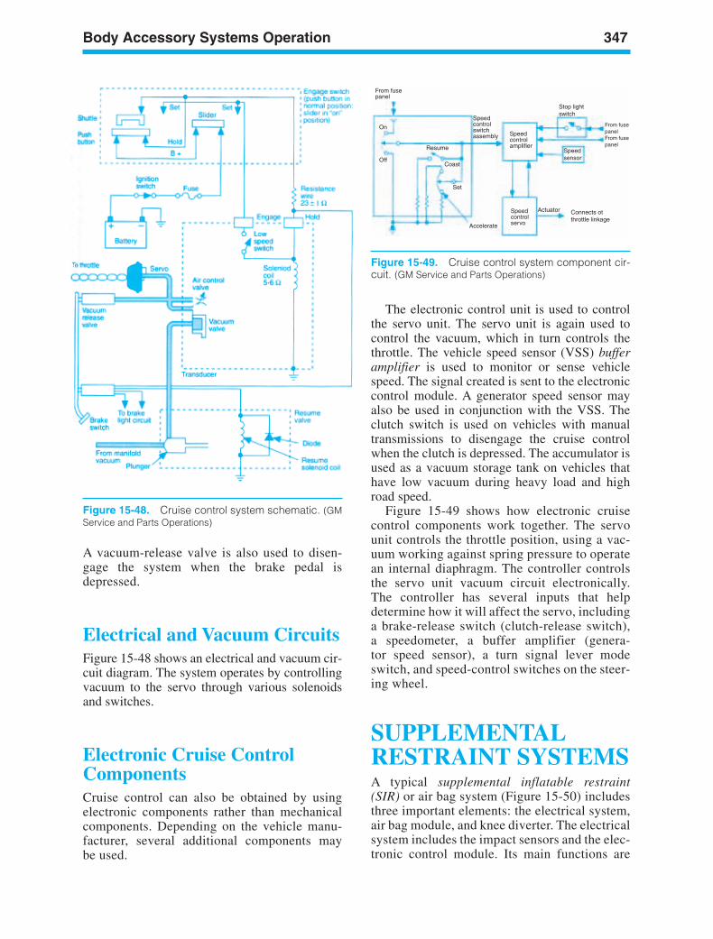
Body Accessory Systems Operation 347
Figure 15-48. Cruise control system schematic. (GMService and Parts Operations)
The electronic control unit is used to controlthe servo unit. The servo unit is again used tocontrol the vacuum, which in turn controls thethrottle. The vehicle speed sensor (VSS) bufferamplifier is used to monitor or sense vehiclespeed. The signal created is sent to the electroniccontrol module. A generator speed sensor mayalso be used in conjunction with the VSS. Theclutch switch is used on vehicles with manualtransmissions to disengage the cruise controlwhen the clutch is depressed. The accumulator isused as a vacuum storage tank on vehicles thathave low vacuum during heavy load and highroad speed.
Figure 15-49 shows how electronic cruisecontrol components work together. The servounit controls the throttle position, using a vac-uum working against spring pressure to operatean internal diaphragm. The controller controlsthe servo unit vacuum circuit electronically.The controller has several inputs that helpdetermine how it will affect the servo, includinga brake-release switch (clutch-release switch),a speedometer, a buffer amplifier (genera-tor speed sensor), a turn signal lever modeswitch, and speed-control switches on the steer-ing wheel.
SUPPLEMENTALRESTRAINT SYSTEMSA typical supplemental inflatable restraint(SIR) or air bag system (Figure 15-50) includesthree important elements: the electrical system,air bag module, and knee diverter. The electricalsystem includes the impact sensors and the elec-tronic control module. Its main functions are
From fusepanel
Speedcontrolswitchassembly Speed
controlamplifier
Set
Resume
Off
On
SpeedcontrolservoAccelerate
Actuator Connects ot throttle linkage
From fusepanelFrom fusepanel
Stop lightswitch
Speedsensor
Coast
Figure 15-49. Cruise control system component cir-cuit. (GM Service and Parts Operations)
A vacuum-release valve is also used to disen-gage the system when the brake pedal isdepressed.
Electrical and Vacuum CircuitsFigure 15-48 shows an electrical and vacuum cir-cuit diagram. The system operates by controllingvacuum to the servo through various solenoidsand switches.
Electronic Cruise ControlComponentsCruise control can also be obtained by usingelectronic components rather than mechanicalcomponents. Depending on the vehicle manu-facturer, several additional components maybe used.
ker88839_ch15.qxd 1/9/06 11:36 AM Page 347
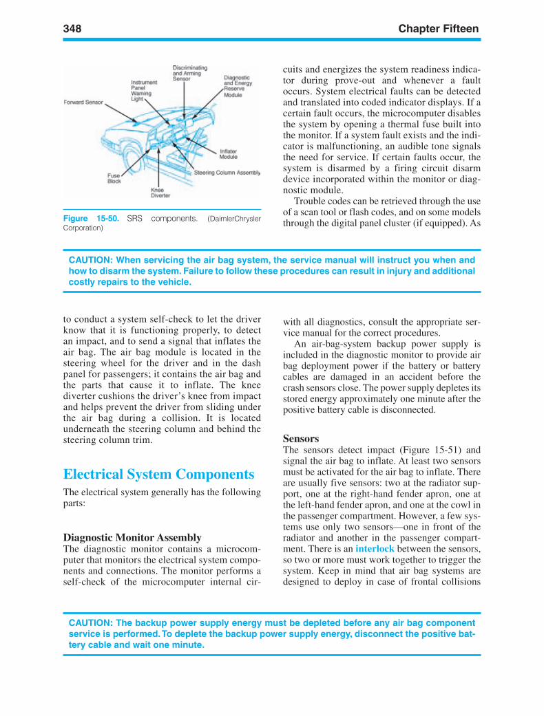
348 Chapter Fifteen
Figure 15-50. SRS components. (DaimlerChryslerCorporation)
to conduct a system self-check to let the driverknow that it is functioning properly, to detectan impact, and to send a signal that inflates theair bag. The air bag module is located in thesteering wheel for the driver and in the dashpanel for passengers; it contains the air bag andthe parts that cause it to inflate. The kneediverter cushions the driver’s knee from impactand helps prevent the driver from sliding underthe air bag during a collision. It is locatedunderneath the steering column and behind thesteering column trim.
CAUTION: When servicing the air bag system, the service manual will instruct you when andhow to disarm the system. Failure to follow these procedures can result in injury and additionalcostly repairs to the vehicle.
Electrical System ComponentsThe electrical system generally has the followingparts:
Diagnostic Monitor AssemblyThe diagnostic monitor contains a microcom-puter that monitors the electrical system compo-nents and connections. The monitor performs aself-check of the microcomputer internal cir-
cuits and energizes the system readiness indica-tor during prove-out and whenever a faultoccurs. System electrical faults can be detectedand translated into coded indicator displays. If acertain fault occurs, the microcomputer disablesthe system by opening a thermal fuse built intothe monitor. If a system fault exists and the indi-cator is malfunctioning, an audible tone signalsthe need for service. If certain faults occur, thesystem is disarmed by a firing circuit disarmdevice incorporated within the monitor or diag-nostic module.
Trouble codes can be retrieved through the useof a scan tool or flash codes, and on some modelsthrough the digital panel cluster (if equipped). As
CAUTION: The backup power supply energy must be depleted before any air bag componentservice is performed.To deplete the backup power supply energy, disconnect the positive bat-tery cable and wait one minute.
with all diagnostics, consult the appropriate ser-vice manual for the correct procedures.
An air-bag-system backup power supply isincluded in the diagnostic monitor to provide airbag deployment power if the battery or batterycables are damaged in an accident before thecrash sensors close. The power supply depletes itsstored energy approximately one minute after thepositive battery cable is disconnected.
SensorsThe sensors detect impact (Figure 15-51) andsignal the air bag to inflate. At least two sensorsmust be activated for the air bag to inflate. Thereare usually five sensors: two at the radiator sup-port, one at the right-hand fender apron, one atthe left-hand fender apron, and one at the cowl inthe passenger compartment. However, a few sys-tems use only two sensors—one in front of theradiator and another in the passenger compart-ment. There is an interlock between the sensors,so two or more must work together to trigger thesystem. Keep in mind that air bag systems aredesigned to deploy in case of frontal collisions
ker88839_ch15.qxd 1/9/06 11:36 AM Page 348
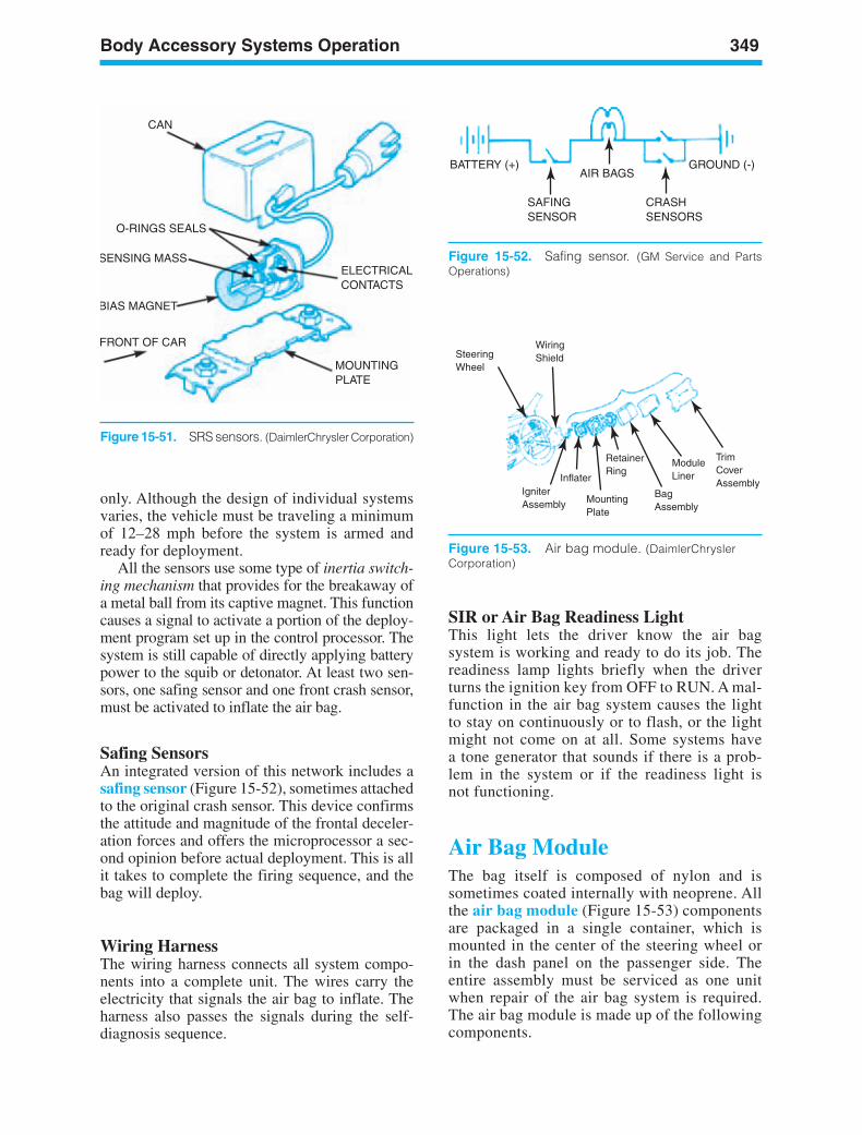
Body Accessory Systems Operation 349
CAN
O-RINGS SEALS
SENSING MASS
BIAS MAGNET
FRONT OF CAR
MOUNTINGPLATE
ELECTRICALCONTACTS
BATTERY (+)AIR BAGS
SAFINGSENSOR
CRASHSENSORS
GROUND (-)
Figure 15-52. Safing sensor. (GM Service and PartsOperations)
SIR or Air Bag Readiness LightThis light lets the driver know the air bagsystem is working and ready to do its job. Thereadiness lamp lights briefly when the driverturns the ignition key from OFF to RUN. A mal-function in the air bag system causes the lightto stay on continuously or to flash, or the lightmight not come on at all. Some systems havea tone generator that sounds if there is a prob-lem in the system or if the readiness light isnot functioning.
Air Bag ModuleThe bag itself is composed of nylon and issometimes coated internally with neoprene. Allthe air bag module (Figure 15-53) componentsare packaged in a single container, which ismounted in the center of the steering wheel orin the dash panel on the passenger side. Theentire assembly must be serviced as one unitwhen repair of the air bag system is required.The air bag module is made up of the followingcomponents.
only. Although the design of individual systemsvaries, the vehicle must be traveling a minimumof 12–28 mph before the system is armed andready for deployment.
All the sensors use some type of inertia switch-ing mechanism that provides for the breakaway ofa metal ball from its captive magnet. This functioncauses a signal to activate a portion of the deploy-ment program set up in the control processor. Thesystem is still capable of directly applying batterypower to the squib or detonator. At least two sen-sors, one safing sensor and one front crash sensor,must be activated to inflate the air bag.
Safing SensorsAn integrated version of this network includes asafing sensor (Figure 15-52), sometimes attachedto the original crash sensor. This device confirmsthe attitude and magnitude of the frontal deceler-ation forces and offers the microprocessor a sec-ond opinion before actual deployment. This is allit takes to complete the firing sequence, and thebag will deploy.
Wiring HarnessThe wiring harness connects all system compo-nents into a complete unit. The wires carry theelectricity that signals the air bag to inflate. Theharness also passes the signals during the self-diagnosis sequence.
WiringShieldSteering
Wheel
IgniterAssembly
Inflater
MountingPlate
RetainerRing
BagAssembly
ModuleLiner
TrimCoverAssembly
Figure 15-53. Air bag module. (DaimlerChryslerCorporation)
Figure 15-51. SRS sensors. (DaimlerChrysler Corporation)
ker88839_ch15.qxd 1/9/06 11:36 AM Page 349
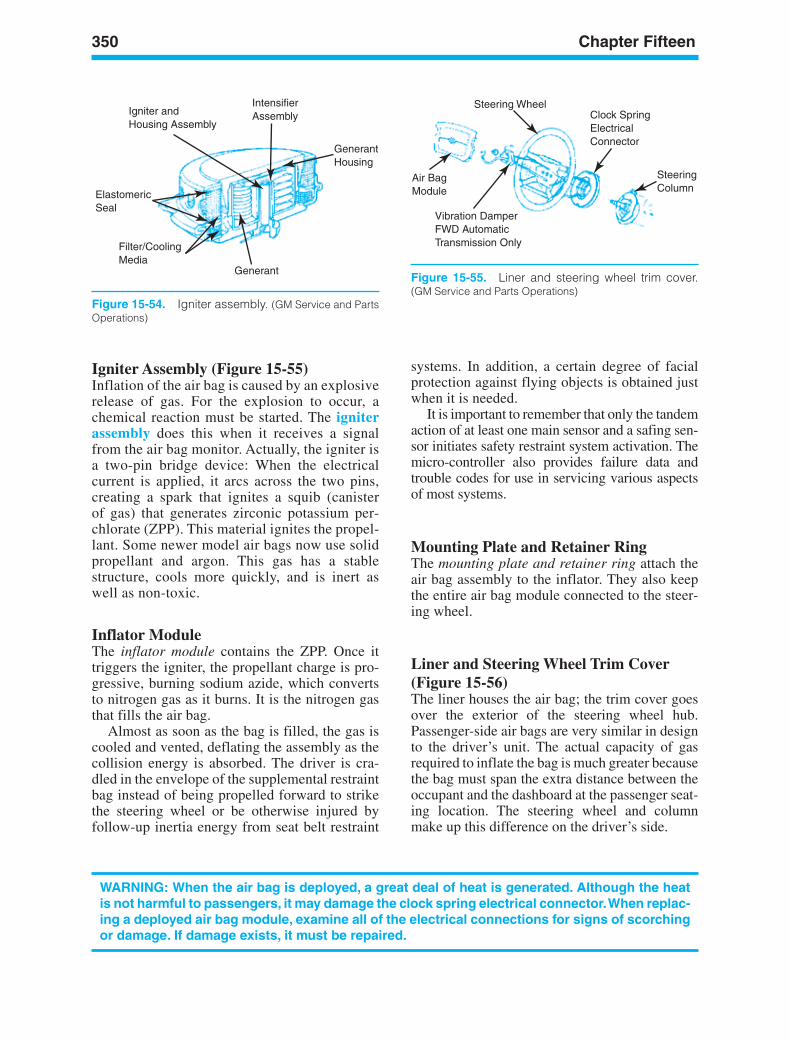
350 Chapter Fifteen
Igniter andHousing Assembly
IntensifierAssembly
GenerantHousing
Generant
ElastomericSeal
Filter/CoolingMedia
Figure 15-54. Igniter assembly. (GM Service and PartsOperations)
Igniter Assembly (Figure 15-55)Inflation of the air bag is caused by an explosiverelease of gas. For the explosion to occur, achemical reaction must be started. The igniterassembly does this when it receives a signalfrom the air bag monitor. Actually, the igniter isa two-pin bridge device: When the electricalcurrent is applied, it arcs across the two pins,creating a spark that ignites a squib (canisterof gas) that generates zirconic potassium per-chlorate (ZPP). This material ignites the propel-lant. Some newer model air bags now use solidpropellant and argon. This gas has a stablestructure, cools more quickly, and is inert aswell as non-toxic.
Inflator ModuleThe inflator module contains the ZPP. Once ittriggers the igniter, the propellant charge is pro-gressive, burning sodium azide, which convertsto nitrogen gas as it burns. It is the nitrogen gasthat fills the air bag.
Almost as soon as the bag is filled, the gas iscooled and vented, deflating the assembly as thecollision energy is absorbed. The driver is cra-dled in the envelope of the supplemental restraintbag instead of being propelled forward to strikethe steering wheel or be otherwise injured byfollow-up inertia energy from seat belt restraint
systems. In addition, a certain degree of facialprotection against flying objects is obtained justwhen it is needed.
It is important to remember that only the tandemaction of at least one main sensor and a safing sen-sor initiates safety restraint system activation. Themicro-controller also provides failure data andtrouble codes for use in servicing various aspectsof most systems.
Mounting Plate and Retainer RingThe mounting plate and retainer ring attach theair bag assembly to the inflator. They also keepthe entire air bag module connected to the steer-ing wheel.
Liner and Steering Wheel Trim Cover(Figure 15-56)The liner houses the air bag; the trim cover goesover the exterior of the steering wheel hub.Passenger-side air bags are very similar in designto the driver’s unit. The actual capacity of gasrequired to inflate the bag is much greater becausethe bag must span the extra distance between theoccupant and the dashboard at the passenger seat-ing location. The steering wheel and columnmake up this difference on the driver’s side.
WARNING: When the air bag is deployed, a great deal of heat is generated. Although the heatis not harmful to passengers, it may damage the clock spring electrical connector.When replac-ing a deployed air bag module, examine all of the electrical connections for signs of scorchingor damage. If damage exists, it must be repaired.
Steering Wheel
Air BagModule
Vibration DamperFWD Automatic Transmission Only
Clock SpringElectricalConnector
SteeringColumn
Figure 15-55. Liner and steering wheel trim cover.(GM Service and Parts Operations)
ker88839_ch15.qxd 1/9/06 11:36 AM Page 350
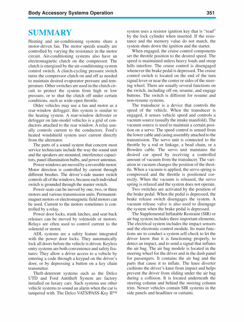
Body Accessory Systems Operation 351
SUMMARYHeating and air-conditioning systems share amotor-driven fan. The motor speeds usually arecontrolled by varying the resistance in the motorcircuit. Air-conditioning systems also have anelectromagnetic clutch on the compressor. Theclutch is energized by the air-conditioning systemcontrol switch. A clutch-cycling pressure switchturns the compressor clutch on and off as neededto maintain desired evaporator pressure and tem-perature. Other switches are used in the clutch cir-cuit to protect the system from high or lowpressure, or to shut the clutch off under certainconditions, such as wide-open throttle.
Older vehicles may use a fan and motor as arear-window defogger; this system is similar tothe heating system. A rear-window defroster ordefogger on late-model vehicles is a grid of con-ductors attached to the rear window. A relay usu-ally controls current to the conductors. Ford’sheated windshield system uses current directlyfrom the alternator.
The parts of a sound system that concern mostservice technicians include the way the sound unitand the speakers are mounted, interference capaci-tors, panel illumination bulbs, and power antennas.
Power windows are moved by a reversible motor.Motor direction is controlled by current throughdifferent brushes. The driver’s-side master switchcontrols all of the windows, because each individualswitch is grounded through the master switch.
Power seats can be moved by one, two, or threemotors and various transmission units. Permanent-magnet motors or electromagnetic field motors canbe used. Current to the motors sometimes is con-trolled by a relay.
Power door locks, trunk latches, and seat-backreleases can be moved by solenoids or motors.Relays are often used to control current to thesolenoid or motor.
ADL systems are a safety feature integratedwith the power door locks. They automaticallylock all doors before the vehicle is driven. Keylessentry systems are both convenience and safety fea-tures: They allow a driver access to a vehicle byentering a code through a keypad on the driver’sdoor, or by depressing a button on a key chaintransmitter.
Theft-deterrent systems such as the DelcoUTD and Ford Antitheft System are factoryinstalled on luxury cars. Such systems use othervehicle systems to sound an alarm when the car istampered with. The Delco VATS/PASS-Key II™
system uses a resistor ignition key that is “read”by the lock cylinder when inserted. If the resis-tance and the memory value do not match, thesystem shuts down the ignition and the starter.
When engaged, the cruise control componentsset the throttle position to the desired speed. Thespeed is maintained unless heavy loads and steephills interfere. The cruise control is disengagedwhenever the brake pedal is depressed. The cruisecontrol switch is located on the end of the turnsignal lever or near the center or sides of the steer-ing wheel. There are usually several functions onthe switch, including off-on, resume, and engagebuttons. The switch is different for resume andnon-resume systems.
The transducer is a device that controls thespeed of the vehicle. When the transducer isengaged, it senses vehicle speed and controls avacuum source (usually the intake manifold). Thevacuum source is used to maintain a certain posi-tion on a servo. The speed control is sensed fromthe lower cable and casing assembly attached to thetransmission. The servo unit is connected to thethrottle by a rod or linkage, a bead chain, or aBowden cable. The servo unit maintains thedesired car speed by receiving a controlledamount of vacuum from the transducer. The vari-ation in vacuum changes the position of the throt-tle. When a vacuum is applied, the servo spring iscompressed and the throttle is positioned cor-rectly. When the vacuum is released, the servospring is relaxed and the system does not operate.
Two switches are activated by the position ofthe brake pedal. When the pedal is depressed, thebrake release switch disengages the system. Avacuum release valve is also used to disengagethe system when the brake pedal is depressed.
The Supplemental Inflatable Restraint (SIR) orair bag system includes three important elements.The electrical system includes the impact sensorsand the electronic control module. Its main func-tions are to conduct a system self-check to let thedriver know that it is functioning properly, todetect an impact, and to send a signal that inflatesthe air bag. The air bag module is located in thesteering wheel for the driver and in the dash panelfor passengers. It contains the air bag and theparts that cause it to inflate. The knee divertercushions the driver’s knee from impact and helpsprevent the driver from sliding under the air bagduring a collision. It is located underneath thesteering column and behind the steering columntrim. Newer vehicles contain SIR systems in theside panels and headliner or curtains.
ker88839_ch15.qxd 1/9/06 11:36 AM Page 351
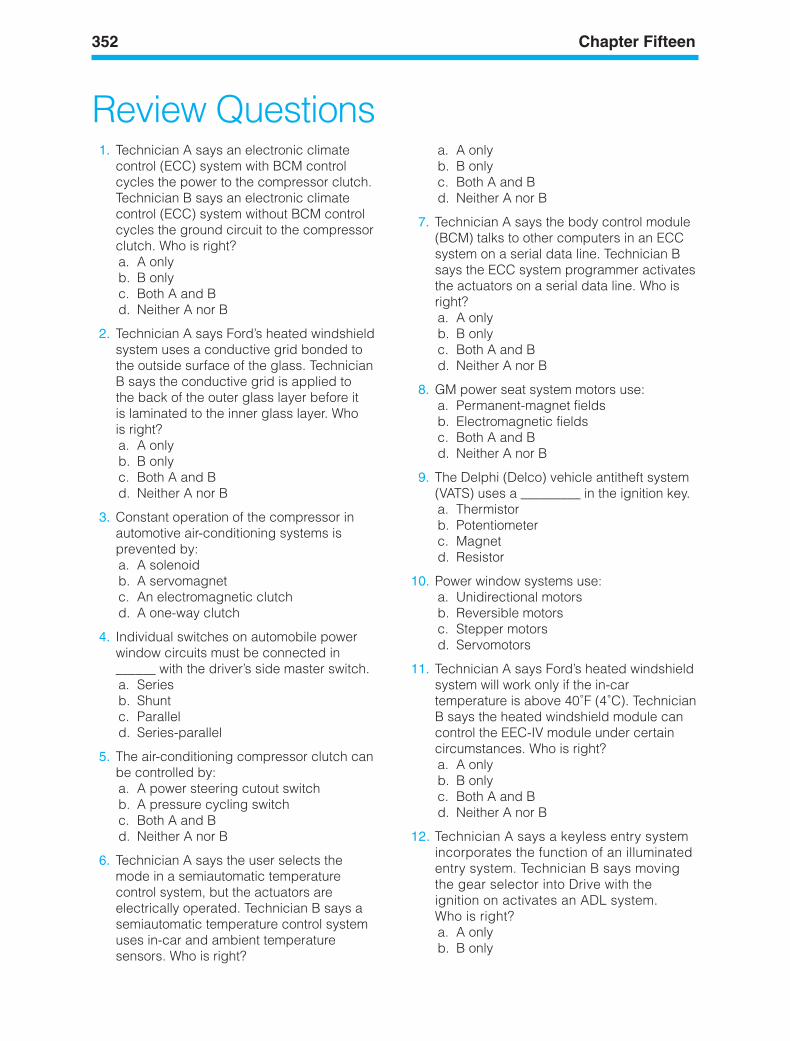
352 Chapter Fifteen
Review Questions1. Technician A says an electronic climate
control (ECC) system with BCM controlcycles the power to the compressor clutch.Technician B says an electronic climatecontrol (ECC) system without BCM controlcycles the ground circuit to the compressorclutch. Who is right?a. A onlyb. B onlyc. Both A and Bd. Neither A nor B
2. Technician A says Ford’s heated windshieldsystem uses a conductive grid bonded tothe outside surface of the glass. TechnicianB says the conductive grid is applied tothe back of the outer glass layer before itis laminated to the inner glass layer. Whois right?a. A onlyb. B onlyc. Both A and Bd. Neither A nor B
3. Constant operation of the compressor inautomotive air-conditioning systems isprevented by:a. A solenoidb. A servomagnetc. An electromagnetic clutchd. A one-way clutch
4. Individual switches on automobile powerwindow circuits must be connected in______ with the driver’s side master switch.a. Seriesb. Shuntc. Paralleld. Series-parallel
5. The air-conditioning compressor clutch canbe controlled by:a. A power steering cutout switchb. A pressure cycling switchc. Both A and Bd. Neither A nor B
6. Technician A says the user selects themode in a semiautomatic temperaturecontrol system, but the actuators areelectrically operated. Technician B says asemiautomatic temperature control systemuses in-car and ambient temperaturesensors. Who is right?
a. A onlyb. B onlyc. Both A and Bd. Neither A nor B
7. Technician A says the body control module(BCM) talks to other computers in an ECCsystem on a serial data line. Technician Bsays the ECC system programmer activatesthe actuators on a serial data line. Who isright?a. A onlyb. B onlyc. Both A and Bd. Neither A nor B
8. GM power seat system motors use:a. Permanent-magnet fieldsb. Electromagnetic fieldsc. Both A and Bd. Neither A nor B
9. The Delphi (Delco) vehicle antitheft system(VATS) uses a _________ in the ignition key.a. Thermistorb. Potentiometerc. Magnetd. Resistor
10. Power window systems use:a. Unidirectional motorsb. Reversible motorsc. Stepper motorsd. Servomotors
11. Technician A says Ford’s heated windshieldsystem will work only if the in-cartemperature is above 40˚F (4˚C). TechnicianB says the heated windshield module cancontrol the EEC-IV module under certaincircumstances. Who is right?a. A onlyb. B onlyc. Both A and Bd. Neither A nor B
12. Technician A says a keyless entry systemincorporates the function of an illuminatedentry system. Technician B says movingthe gear selector into Drive with theignition on activates an ADL system.Who is right?a. A onlyb. B only
ker88839_ch15.qxd 1/9/06 11:36 AM Page 352
Body Accessory Systems Operation 353
c. Both A and Bd. Neither A nor B
13. Technician A says the Delco RemoteKeyless Entry (RKE) and the Remote LockControl (RLC) are different keyless entrysystems. Technician B says the RKE andRLC systems are subsystems of the VATand PASS systems. Who is right?a. A onlyb. B onlyc. Both A and Bd. Neither A nor B
14. Technician A says if the resistance value ofthe ignition key in the PASS system does notmatch the UHF value stored in the receiver’smemory, the vehicle will not start.Technician B says a factory-installed theft-deterrent system is a complex multiple-circuit system. Who is right?a. A onlyb. B onlyc. Both A and Bd. Neither A nor B
15. In a cruise control system, whichcomponent controls the amount of vacuumthat is applied to the servo unit?a. The throttle bodyb. The cruise control switchc. The transducerd. The brake pedal position switch
16. Which of the following actions willdeactivate cruise control operation?a. Applying the accelerator pedalb. Applying the brake
c. Driving up a steep hilld. Releasing the accelerator pedal
17. In an electronically controlled cruise controlsystem, what component is used to monitorvehicle speed?a. Wheel speed sensorb. Generator speed sensorc. Turbine speed sensord. Vehicle speed sensor
18. What enables an air bag to deploy in anaccident, even if the battery becomesdisconnected during the crash?a. A mechanical push-arm igniterb. A backup power supplyc. The velocity versus solid object sensord. A “sudden stop” signal received from
the vehicle speed sensor
19. Though different manufacturers havedifferent specifications, how fast must avehicle be moving before the air bagsystem is armed and ready to deploy ifneeded?a. Any speed above zerob. Between 3 and 10 mphc. Between 12 and 28 mphd. At least 45 mph
20. When servicing an air bag, what is the firststep you should take?a. Disconnect the battery negative cable.b. Disconnect the clockspring electrical
connector.c. Take resistance measurements at all
electrical connectors.d. Disconnect the impact sensors.
ker88839_ch15.qxd 1/9/06 11:36 AM Page 353

ker88839_ch15.qxd 1/9/06 11:36 AM Page 354