Automotive Electrical Disturbances - TestWorld...AUTOMOTIVE ElEcTrIcAl dIsTUrbAncEs ... management...
40
AUTOMOTIVE ELECTRICAL DISTURBANCES TRANSIENT EMISSIONS, IMMUNITY AND BATTERY SIMULATIONS
Transcript of Automotive Electrical Disturbances - TestWorld...AUTOMOTIVE ElEcTrIcAl dIsTUrbAncEs ... management...
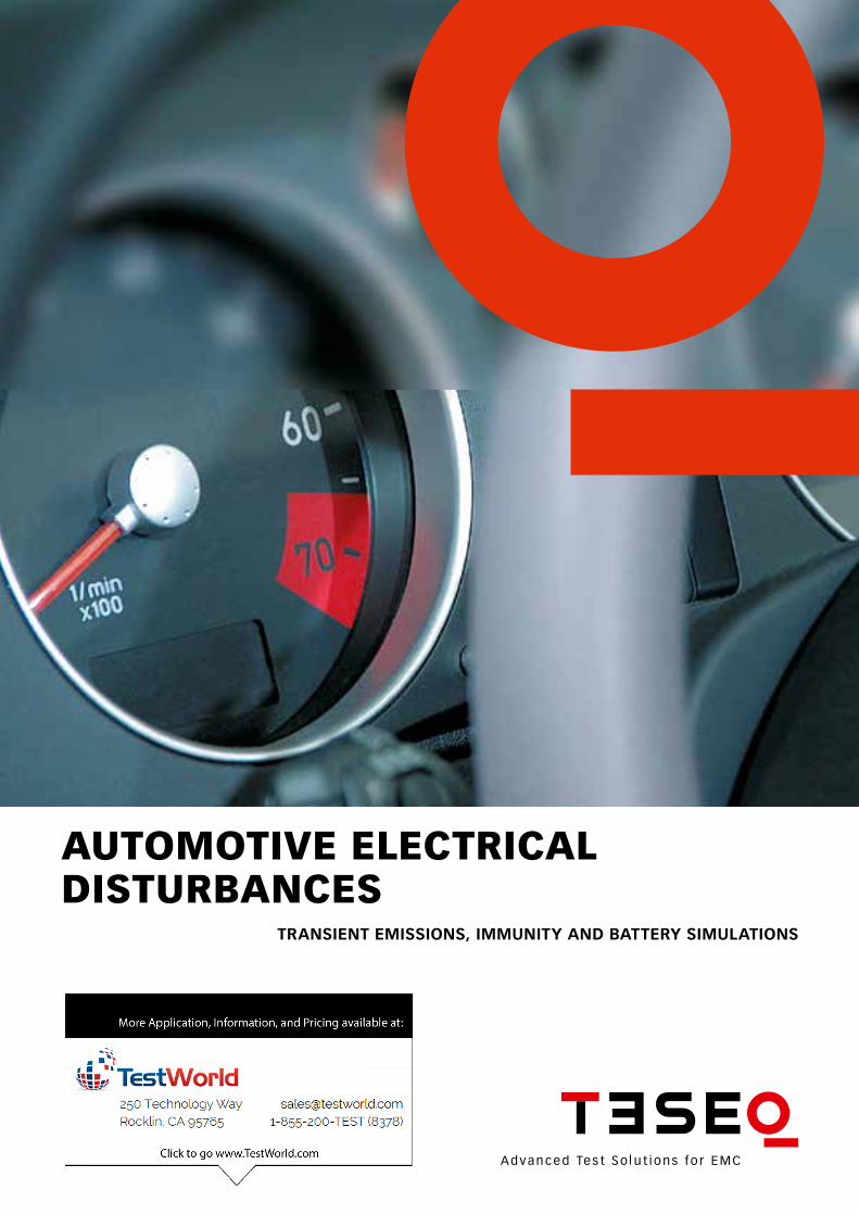
AUTOMOTIVE ElEcTrIcAl dIsTUrbAncEs
TRANSIENT EMISSIONS, IMMUNITY ANd bATTERY SIMULATIONS

FULL COMPLIANT Transient immunity testing Battery, starting, and power quality simulations Low frequency magnetic immunity testing Transient emissions testing
Teseq® offers the most complete suite of test solutions for auto-motive component testing. Dozens of standards refer to ISO 7637 to fulfill a wide range of requirements. This product guide is generally limited to transients coupled on battery and signal lines, low frequency tests up to 320 kHz, battery simulation tests, and low frequency mag-netic fields.
3
AUTOMOTIVE sOlUTIOns
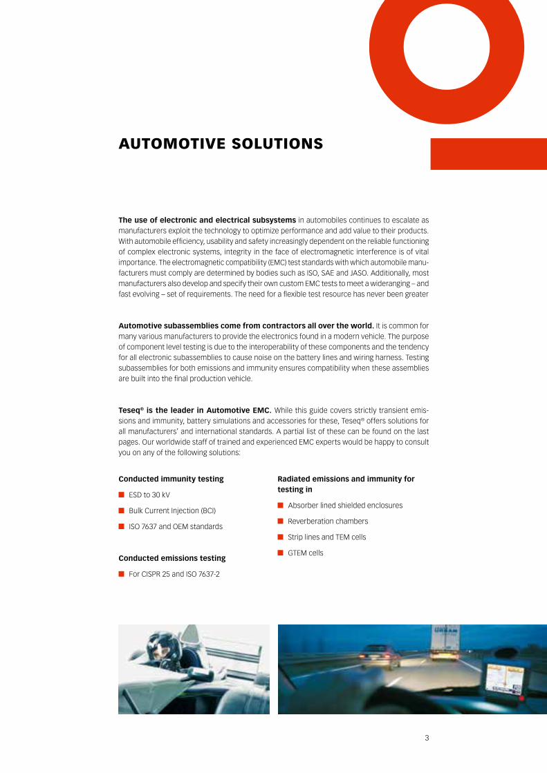
The use of electronic and electrical subsystems in automobiles continues to escalate as manufacturers exploit the technology to optimize performance and add value to their products. With automobile efficiency, usability and safety increasingly dependent on the reliable functioning of complex electronic systems, integrity in the face of electromagnetic interference is of vital importance. The electromagnetic compatibility (EMC) test standards with which automobile manu-facturers must comply are determined by bodies such as ISO, SAE and JASO. Additionally, most manufacturers also develop and specify their own custom EMC tests to meet a wideranging – and fast evolving – set of requirements. The need for a flexible test resource has never been greater
Automotive subassemblies come from contractors all over the world. It is common for many various manufacturers to provide the electronics found in a modern vehicle. The purpose of component level testing is due to the interoperability of these components and the tendency for all electronic subassemblies to cause noise on the battery lines and wiring harness. Testing subassemblies for both emissions and immunity ensures compatibility when these assemblies are built into the final production vehicle.
Teseq® is the leader in Automotive EMC. While this guide covers strictly transient emis-sions and immunity, battery simulations and accessories for these, Teseq® offers solutions for all manufacturers’ and international standards. A partial list of these can be found on the last pages. Our worldwide staff of trained and experienced EMC experts would be happy to consult you on any of the following solutions:
Radiated emissions and immunity for testing in
Absorber lined shielded enclosures
Reverberation chambers
Strip lines and TEM cells
GTEM cells
Conducted immunity testing
ESD to 30 kV
Bulk Current Injection (BCI)
ISO 7637 and OEM standards
Conducted emissions testing
For CISPR 25 and ISO 7637-2
4
OVErVIEW
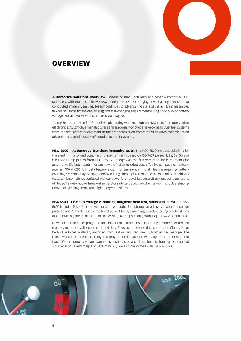
Automotive solutions overview. Dozens of manufacturer’s and other automotive EMC standards with their roots in ISO 7637 continue to evolve bringing new challenges to users of conducted immunity testing. Teseq® continues to advance the state of the art, bringing simple, flexible solutions for the challenging and fast-changing requirements using up to 60 V of battery voltage. For an overview of standards, see page 37.
Teseq® has been at the forefront of the pioneering work to establish EMC tests for motor vehicle electronics. Automotive manufacturers and suppliers worldwide have come to trust test systems from Teseq®. Active involvement in the standardization committees ensures that the latest advances are continuously reflected in our test systems.
NSG 5500 – Automotive transient immunity tests. The NSG 5500 includes solutions for transient immunity and coupling of these transients based on ISO 7637 pulses 1, 2a, 3a, 3b and the Load Dump pulses from ISO 16750-2. Teseq® was the first with modular instruments for automotive EMC standards – we are now the first to include a cost-effective compact, completely internal 100 A (250 A inrush) battery switch for transient immunity testing requiring battery coupling. Systems may be upgraded by adding simple plugin modules to expand on traditional tests. While sometimes confused with our powerful and well known arbitrary function generators, all Teseq®’s automotive transient generators utilize capacitive discharges into pulse shaping networks, yielding compliant, high energy transients.
NSG 5600 – Complex voltage variations, magnetic field test, sinusoidal burst. The NSG 5600 includes Teseq®’s improved function generator for automotive voltage variations based on pulse 2b and 4. In addition to traditional pulse 4 tests, simulating vehicle-starting profiles it may also contain segments made up of sine waves, DC ramps, triangles and square waves, and more.
Now included are user programmable exponential functions and a utility to store user defined memory maps or oscilloscope captured data. These user-defined data sets, called Clones TM can be built in Excel, Mathcad, imported from text or captured directly from an oscilloscope. The Clones™ can then be used freely in a programmed sequence with any of the other segment types. Other complex voltage variations such as dips and drops testing, transformer coupled sinusoidal noise and magnetic field immunity are also performed with the NSG 5600.
5
The NSG 5500 and NSG 5600 are controlled by the unique AutoStar™ software. This software is the basis of the power of the Teseq® automotive conducted immunity systems. It includes full reporting, control, DUT monitoring, sequencing and test editing. Included in the AutoStar™ package are hundreds of pre-programmed test routines for known standards. The software offers our users the option of downloading new standards from the web, controlling full function testing of the Device Under Test (DUT), performing pulse verification with a customizable user interface to suit the operator’s tastes.
Teseq®’s AutoStar™ offers more than just a control package. AutoStar™ is an open test man-agement platform with a graphical interface and flexible test report functionality. Complete customer solutions with fully integrated installations are possible through the complementary range of test systems for radiated interference immunity and emission measurements. For more details, please see the last page at this guide.
AES 5501 – Automotive Emissions System. While immunity contains much of the complica-tion and variability of the test requirements, it is only half of the requirement. The emissions of each DUT must also be measured. The requirement is rather simple: switch on and off the DUT and measure any returns that come from the subassembly with an oscilloscope. The standards, however, have various strict requirements for cable length, layout, switching and simulation of the vehicle’s wiring harness impedance. Generally, one must measure using a mechanical switch (as close as possible to the production switch) and again a very fast electrical switch. The AES 5501 is unique in that all of the various components are provided to the user: the artificial network, whose job is simulating the vehicle impedance, and both types of switches, plus a unique control station for controlling the switching times and other critical tasks. The AES 5501 is a stand-alone system designed to meet all of the emissions requirements.
battery simulator systems for immunity testing are fast, reliable and modular. Unique solutions involve very high inrush current, flexible operating modes and high bandwidth that are peerless in the industry. For example, our 60 V, PA 5840-150 has 150 A peak current for 200 ms (50 A continuous) and a bandwidth up to 150 kHz. In our standard configuration with the NSG 5600 controlling this battery simulator, and the NSG 5500 generating the transients and 100 A coupling, using a single output, the total solution can fit into a standard 19-inch rack, thus saving the user space in the EMC test laboratory.
Accessories. Teseq® also provides fully compliant accessories for capacitive, transformer, diode and other complex coupling methods and our Ford EMC-CS-2009 compliant relay chatter immunity simulator. Besides, Teseq® offers the required attenuators and voltage probes and all other necessary measurement accessories. Refer to the section dedicated to accessories for more details.
6
AUTOsTAr™ sOfTWArE
AutoStar™ is more than just an operating program for test routines – it is, in fact, a test management platform for full control of the capacitive discharge transient simulations, supply voltage variations and other automotive immunity tests. AutoStar™ supports test sequencing, reporting and device under test evaluation.
based on the concept of an open system, AutoStar™ integrates all the generators and other circuitry present in the installation into a consistent and uniform graphical user interface. AutoStar™ presents the operator with a clear, structured, visual interface with menu bars, test lists, test sequence information and graphical pulse information.
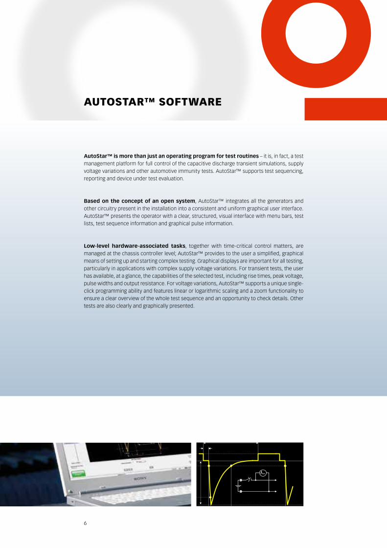
Low-level hardware-associated tasks, together with time-critical control matters, are managed at the chassis controller level; AutoStar™ provides to the user a simplified, graphical means of setting up and starting complex testing. Graphical displays are important for all testing, particularly in applications with complex supply voltage variations. For transient tests, the user has available, at a glance, the capabilities of the selected test, including rise times, peak voltage, pulse widths and output resistance. For voltage variations, AutoStar™ supports a unique single-click programming ability and features linear or logarithmic scaling and a zoom functionality to ensure a clear overview of the whole test sequence and an opportunity to check details. Other tests are also clearly and graphically presented.
US
UA
0
t3
t2
V
t
90%
10%
t1 td
tr
- +
EUT
7
The test library contains not only the preprogrammed test routines in accordance with inter-national standards such as ISO and SAE, but also test conditions that conform to a wide range of manufacturers’ in-house standards. The user can implement these tests directly, modify them and store them under a new designation or create new test definitions from the ground up and include them in the list as well. The standards are pre-programmed in a separate database for the ability of updating the standards independently from the rest of the software. Updates are continually made available at the Teseq® automotive website for download.
Sequences consisting of tests of the same or differing categories can be arbitrarily merged and then also be stored for later use. The user guidance facility provides information regarding avail-able parameters and includes a protective feature against prohibited parameter combinations with appropriate warning flags.
Test evaluation and reporting. Reports concerning individual tests and test sequences are produced automatically and are in a form which can be used for technical files and quality assur-ance documents. The user is provided with a range of editable fields for remarks and specification of the task at hand. AutoStar™ supports both an internal report, and the ability to use Word. Using the template feature of Microsoft Word, the reports can be customized using the company logo and contact information of the end user. AutoStar™ supports multiple templates so that the header of the report can be further customized for special needs.
Auto-configuration. At startup, the software automatically detects and recognizes the modules and other elements that are present in the system. This auto-configuration feature provides the user with all the available functions automatically. The test configuration can also be selected manually which is used to make a conscious limitation on the functions available and particularly for off-line operation. This mode of operation enables test routines to be prepared in the office without the test system connected.
8
cAUsE Of AUTOMOTIVE cOndUcTEdprOblEMs And ThEIr sIMUlATIOns
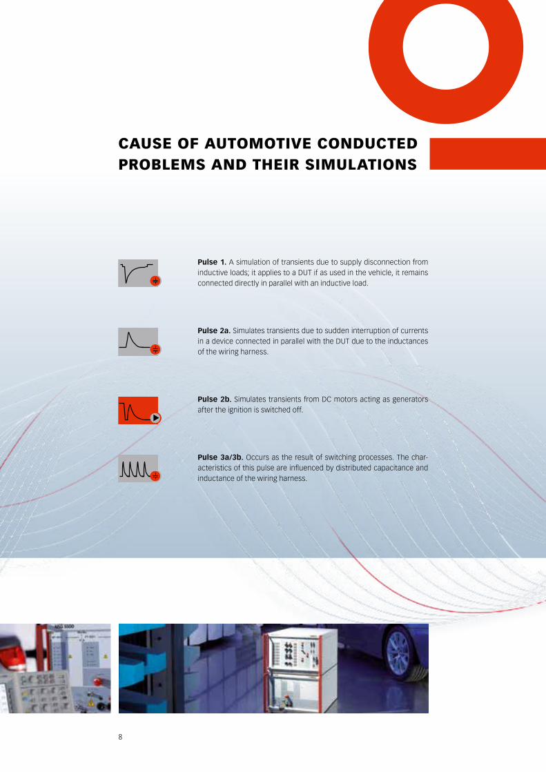
Pulse 1. A simulation of transients due to supply disconnection from inductive loads; it applies to a DUT if as used in the vehicle, it remains connected directly in parallel with an inductive load.
Pulse 2a. Simulates transients due to sudden interruption of currents in a device connected in parallel with the DUT due to the inductances of the wiring harness.
Pulse 2b. Simulates transients from DC motors acting as generators after the ignition is switched off.
Pulse 3a/3b. Occurs as the result of switching processes. The char-acteristics of this pulse are influenced by distributed capacitance and inductance of the wiring harness.
9
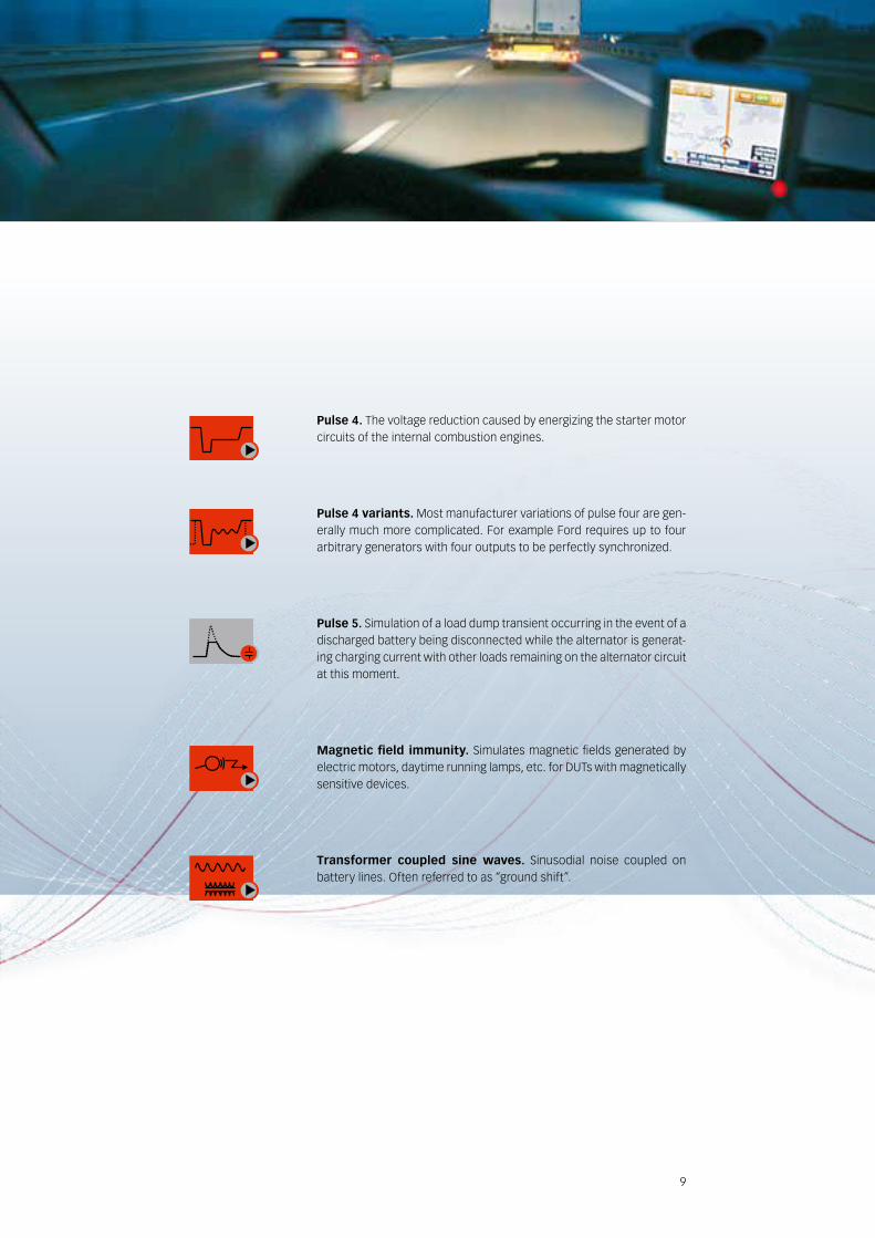
Pulse 4. The voltage reduction caused by energizing the starter motor circuits of the internal combustion engines.
Pulse 4 variants. Most manufacturer variations of pulse four are gen-erally much more complicated. For example Ford requires up to four arbitrary generators with four outputs to be perfectly synchronized.
Pulse 5. Simulation of a load dump transient occurring in the event of a discharged battery being disconnected while the alternator is generat-ing charging current with other loads remaining on the alternator circuit at this moment.
Magnetic field immunity. Simulates magnetic fields generated by electric motors, daytime running lamps, etc. for DUTs with magnetically sensitive devices.
Transformer coupled sine waves. Sinusodial noise coupled on battery lines. Often referred to as “ground shift”.
EMISSION AES 5501: the ISO 7637-2 compliant emission system
IMMUNITY NSG 5500: compact and modular solution MT 5511: transient generator ISO pulse 1, 2a, 6 and variants FT 5531: EFT generator ISO pulse 3a/3b and variants LD 5550: load dump generator
ON-SITEOn-site calibration.Fast turnaround for send-in service.
KNOW-HOWMembership in standards committees.Calibration of any EMC manufacturer’s equipment.
TrAnsIEnT EMIssIOns And IMMUnITy TEsTIng
Emission tests measuring of the disturbances caused by the device under test (DUT) which is a subassembly when deactivated or activated is emissions testing.
Immunity tests consisting of several generators and coupling methods that simulate the many known forms of disturbances that occur in the motor vehicle.
11
fAsT cOMplIAncE TO TrAnsIEnT dIsTUrbAncEs
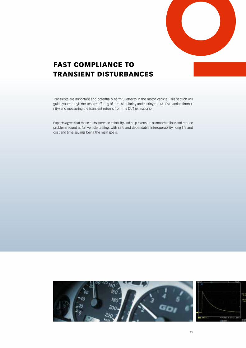
Transients are important and potentially harmful effects in the motor vehicle. This section will guide you through the Teseq® offering of both simulating and testing the DUT’s reaction (immu-nity) and measuring the transient returns from the DUT (emissions).
Experts agree that these tests increase reliability and help to ensure a smooth rollout and reduce problems found at full vehicle testing, with safe and dependable interoperability, long life and cost and time savings being the main goals.
12
AEs 5501 – EMIssIOn sysTEM
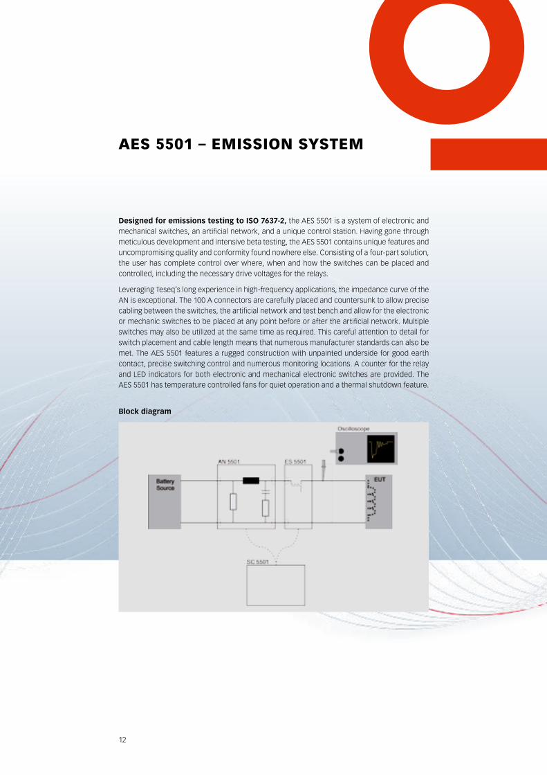
designed for emissions testing to ISO 7637-2, the AES 5501 is a system of electronic and mechanical switches, an artificial network, and a unique control station. Having gone through meticulous development and intensive beta testing, the AES 5501 contains unique features and uncompromising quality and conformity found nowhere else. Consisting of a four-part solution, the user has complete control over where, when and how the switches can be placed and controlled, including the necessary drive voltages for the relays.
Leveraging Teseq’s long experience in high-frequency applications, the impedance curve of the AN is exceptional. The 100 A connectors are carefully placed and countersunk to allow precise cabling between the switches, the artificial network and test bench and allow for the electronic or mechanic switches to be placed at any point before or after the artificial network. Multiple switches may also be utilized at the same time as required. This careful attention to detail for switch placement and cable length means that numerous manufacturer standards can also be met. The AES 5501 features a rugged construction with unpainted underside for good earth contact, precise switching control and numerous monitoring locations. A counter for the relay and LED indicators for both electronic and mechanical electronic switches are provided. The AES 5501 has temperature controlled fans for quiet operation and a thermal shutdown feature.
EUT
block diagram
Oscilloscope
MS 5501 AN 5501
SC 5501
ES 5501
Batterysource
13
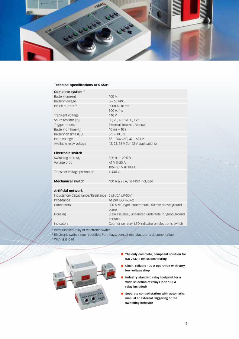
The only complete, compliant solution for
ISO 7637-2 emissions testing
Clean, reliable 100 A operation with very
low voltage drop
Industry standard relay footprint for a
wide selection of relays (one 100 A
relay included)
Separate control station with automatic,
manual or external triggering of the
switching behavior
Technical specifications AES 5501
Complete system 1)
Battery current 100 ABattery voltage 0 – 60 VDCInrush current 2) 1000 A, 10 ms 300 A, 1 sTransient voltage 440 VShunt resistor (RS) 10, 20, 40, 120 Ω, ExtTrigger modes External, Internal, ManualBattery off time (td) 10 ms – 10 sBattery on time (tON) 0.5 – 10.5 sInput voltage 85 – 264 VAC, 47 – 63 HzAvailable relay voltage 12, 24, 36 V (for 42 V applications)
Electronic switchSwitching time ΔtS 300 ns ± 20% 3)Voltage drop <1 V @ 25 A Typ.<2.1 V @ 100 ATransient voltage protection > 440 V
Mechanical switch 100 A & 25 A, half-ISO included
Artificial networkInductance / Capacitance / Resistance 5 μH/0.1 μF/50 ΩImpedance As per ISO 7637-2Connectors 100 A MC type, countersunk, 50 mm above ground
planeHousing Stainless steel, unpainted underside for good ground
contactIndicators Counter on relay, LED indicator on electronic switch
1) With supplied relay or electronic switch2) Electronic switch, non repetitive. For relays, consult manufacturer’s documentation3) With test load
14
nsg 5500 – IMMUnITy gEnErATOr
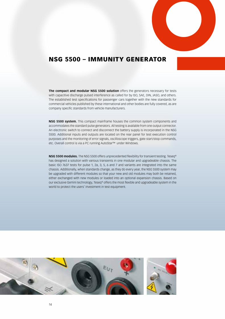
The compact and modular NSG 5500 solution offers the generators necessary for tests with capacitive discharge pulsed interference as called for by ISO, SAE, DIN, JASO, and others. The established test specifications for passenger cars together with the new standards for commercial vehicles published by these international and other bodies are fully covered, as are company specific standards from vehicle manufacturers.
NSG 5500 system. This compact mainframe houses the common system components and accommodates the standard pulse generators. All testing is available from one output connector. An electronic switch to connect and disconnect the battery supply is incorporated in the NSG 5500. Additional inputs and outputs are located on the rear panel for test execution control purposes and the monitoring of error signals, oscilloscope triggers, gate start/stop commands, etc. Overall control is via a PC running AutoStar™ under Windows.
NSG 5500 modules. The NSG 5500 offers unprecedented flexibility for transient testing. Teseq®
has designed a solution with various transients in one modular and upgradeable chassis. The basic ISO 7637 tests for pulse 1, 2a, 3, 5, 6 and 7 and variants are integrated into the same chassis. Additionally, when standards change, as they do every year, the NSG 5500 system may be upgraded with different modules so that your new and old modules may both be retained, either exchanged with new modules or loaded into an optional expansion chassis. Based on our exclusive Gemini technology, Teseq® offers the most flexible and upgradeable system in the world to protect the users’ investment in test equipment.
15
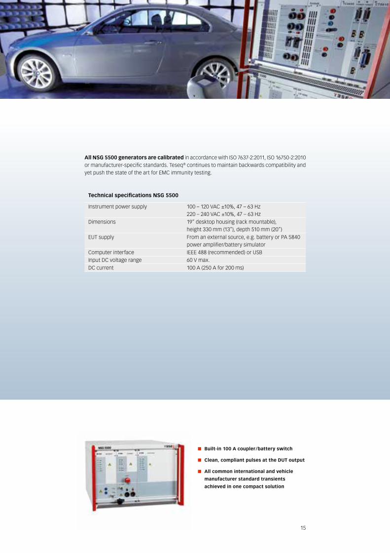
All NSG 5500 generators are calibrated in accordance with ISO 7637-2:2011, ISO 16750-2:2010 or manufacturer-specific standards. Teseq® continues to maintain backwards compatibility and yet push the state of the art for EMC immunity testing.
built-in 100 A coupler / battery switch
Clean, compliant pulses at the dUT output
All common international and vehicle
manufacturer standard transients
achieved in one compact solution
Technical specifications NSG 5500
Instrument power supply 100 – 120 VAC ±10%, 47 – 63 Hz 220 – 240 VAC ±10%, 47 – 63 HzDimensions 19” desktop housing (rack mountable),
height 330 mm (13”), depth 510 mm (20”)EUT supply From an external source, e.g. battery or PA 5840
power amplifier/battery simulatorComputer interface IEEE 488 (recommended) or USBInput DC voltage range 60 V max.DC current 100 A (250 A for 200 ms)
16
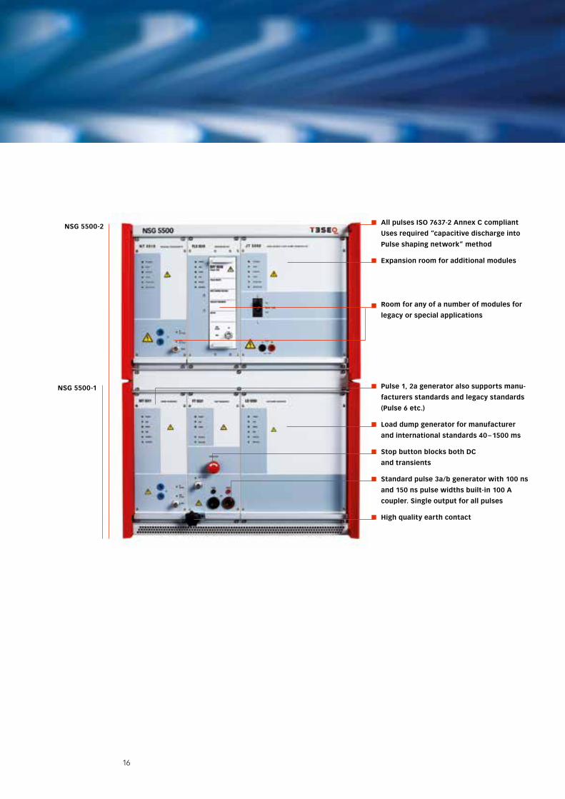
All pulses ISO 7637-2 Annex C compliant
Uses required “capacitive discharge into
Pulse shaping network” method
Expansion room for additional modules
Room for any of a number of modules for
legacy or special applications
Pulse 1, 2a generator also supports manu-
facturers standards and legacy standards
(Pulse 6 etc.)
Load dump generator for manufacturer
and international standards 40 – 1500 ms
Stop button blocks both dC
and transients
Standard pulse 3a/b generator with 100 ns
and 150 ns pulse widths built-in 100 A
coupler. Single output for all pulses
High quality earth contact
NSG 5500-2
NSG 5500-1
17
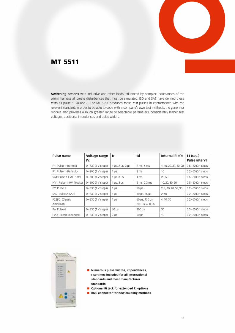
Pulse name Voltage range (V)
tr td Internal Ri (Ω) t1 (sec.)Pulse interval
P1: Pulse 1 (normal) 0 – 330 (1 V steps) 1 µs, 2 µs, 3 µs 2 ms, 6 ms 4, 10, 20, 30, 50, 90 0.5 – 60 (0.1 steps)
R1: Pulse 1 (Renault) 0 – 200 (1 V steps) 1 µs 2 ms 10 0.2 – 60 (0.1 steps)
SA1: Pulse 1 (SAE, 1ms) 0 – 600 (1 V steps) 1 µs, 3 µs 1 ms 20, 50 0.5 – 60 (0.1 steps)
HV1: Pulse 1 (HV, Trucks) 0 – 600 (1 V steps) 1 µs, 3 µs 2 ms, 2.3 ms 10, 20, 30, 50 0.5 – 60 (0.1 steps)
P2: Pulse 2 0 – 330 (1 V steps) 1 µs 50 µs 2, 4, 10, 20, 50, 90 0.2 – 60 (0.1 steps)
SA2: Pulse 2 (SAE) 0 – 330 (1 V steps) 1 µs 50 µs, 35 µs 2, 50 0.2 – 60 (0.1 steps)
F22BC: (Classic
American)
0 – 330 (1 V steps) 1 µs 50 µs, 150 µs,
200 µs, 400 µs
4, 10, 30 0.2 – 60 (0.1 steps)
P6: Pulse 6 0 – 330 (1 V steps) 60 µs 300 µs 30 0.5 – 60 (0.1 steps)
P22: Classic Japanese 0 – 330 (1 V steps) 2 µs 50 µs 10 0.2 – 60 (0.1 steps)
MT 5511
Switching actions with inductive and other loads influenced by complex inductances of the wiring harness all create disturbances that must be simulated. ISO and SAE have defined these tests as pulse 1, 2a and 6. The MT 5511 produces these test pulses in conformance with the relevant standard. In order to be able to cope with a company’s own test methods, the generator module also provides a much greater range of selectable parameters, considerably higher test voltages, additional impedances and pulse widths.
Numerous pulse widths, impendances,
rise times included for all international
standards and most manufacturer
standards
Optional Ri jack for extended Ri options
bNC connector for new coupling methods
18
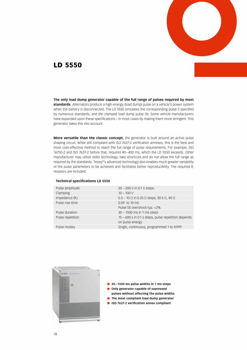
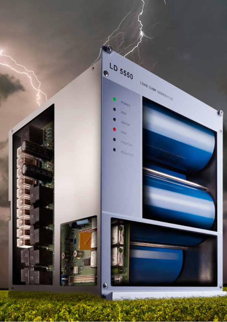
ld 5550
The only load dump generator capable of the full range of pulses required by most standards. Alternators produce a high-energy (load dump) pulse on a vehicle’s power system when the battery is disconnected. The LD 5550 simulates the corresponding pulse 5 specified by numerous standards, and the clamped load dump pulse 5b. Some vehicle manufacturers have expanded upon these specifications – in most cases by making them more stringent. This generator takes this into account.
More versatile than the classic concept, the generator is built around an active pulse shaping circuit. While still compliant with ISO 7637-2 verification annexes, this is the best and most cost-effective method to reach the full range of pulse requirements. For example, ISO 16750-2 and ISO 7637-2 before that, requires 40 – 400 ms, which the LD 5550 exceeds. Other manufacturer may utilize older technology, take shortcuts and do not allow the full range as required by the standards. Teseq®’s advanced technology also enables much greater variability of the pulse parameters to be achieved and facilitates better reproducibility. The required Ri
resistors are included.
30 – 1500 ms pulse widths in 1 ms steps
Only generator capable of supressed
pulses without affecting the pulse widths
The most compliant load dump generator
ISO 7637-2 verification annex compliant
Technical specifications LD 5550
Pulse amplitude 20 – 200 V in 0.1 V stepsClamping 10 – 100 VImpedance (Ri) 0.5 – 10 Ω in 0.25 Ω steps; 30.5 Ω, 40 Ω Pulse rise time 0.09 to 10 ms
Pulse 5b overshoot typ. <2%Pulse duration 30 – 1500 ms in 1 ms stepsPulse repetition 15 – 600 s in 0.1 s steps, pulse repetition depends
on pulse energyPulse modes Single, continuous, programmed 1 to 9,999
19
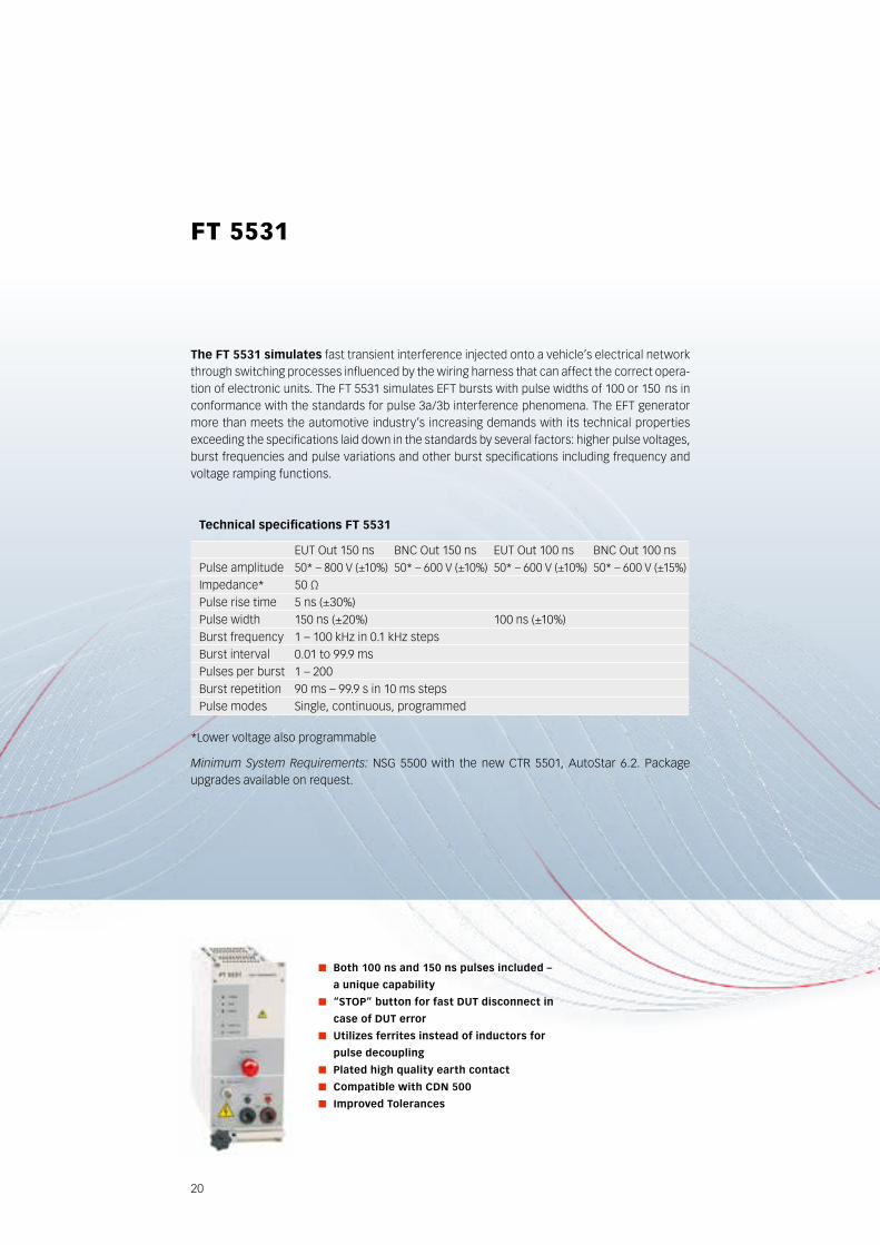
20
The FT 5531 simulates fast transient interference injected onto a vehicle’s electrical network through switching processes influenced by the wiring harness that can affect the correct opera-tion of electronic units. The FT 5531 simulates EFT bursts with pulse widths of 100 or 150 ns in conformance with the standards for pulse 3a/3b interference phenomena. The EFT generator more than meets the automotive industry’s increasing demands with its technical properties exceeding the specifications laid down in the standards by several factors: higher pulse voltages, burst frequencies and pulse variations and other burst specifications including frequency and voltage ramping functions.
both 100 ns and 150 ns pulses included –
a unique capability
“STOP” button for fast dUT disconnect in
case of dUT error
Utilizes ferrites instead of inductors for
pulse decoupling
Plated high quality earth contact
Compatible with CdN 500
Improved Tolerances
fT 5531
Technical specifications FT 5531
EUT Out 150 ns BNC Out 150 ns EUT Out 100 ns BNC Out 100 nsPulse amplitude 50* – 800 V (±10%) 50* – 600 V (±10%) 50* – 600 V (±10%) 50* – 600 V (±15%)Impedance* 50 ΩPulse rise time 5 ns (±30%)Pulse width 150 ns (±20%) 100 ns (±10%)Burst frequency 1 – 100 kHz in 0.1 kHz stepsBurst interval 0.01 to 99.9 msPulses per burst 1 – 200Burst repetition 90 ms – 99.9 s in 10 ms stepsPulse modes Single, continuous, programmed
*Lower voltage also programmable
Minimum System Requirements: NSG 5500 with the new CTR 5501, AutoStar 6.2. Package upgrades available on request.
21
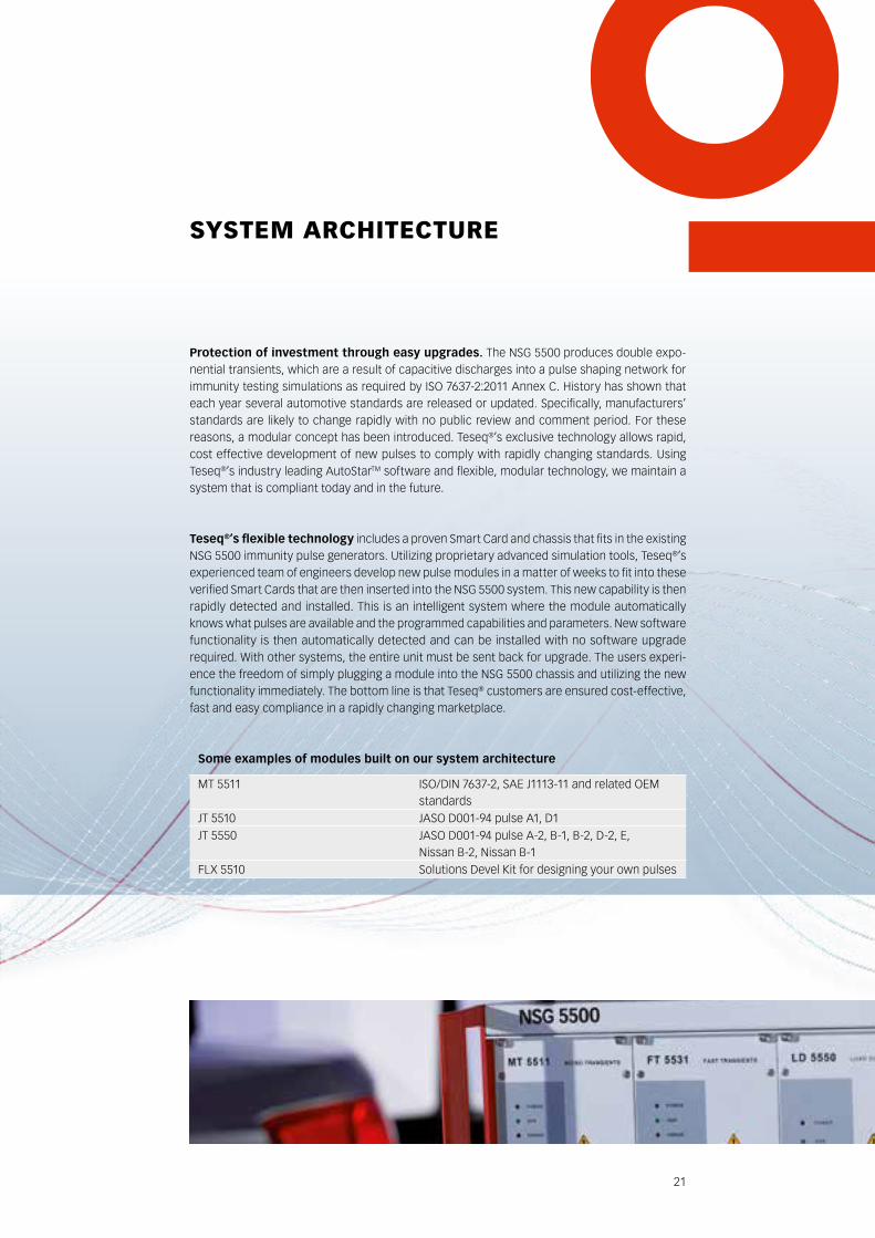
Protection of investment through easy upgrades. The NSG 5500 produces double expo-nential transients, which are a result of capacitive discharges into a pulse shaping network for immunity testing simulations as required by ISO 7637-2:2011 Annex C. History has shown that each year several automotive standards are released or updated. Specifically, manufacturers’ standards are likely to change rapidly with no public review and comment period. For these reasons, a modular concept has been introduced. Teseq®’s exclusive technology allows rapid, cost effective development of new pulses to comply with rapidly changing standards. Using Teseq®’s industry leading AutoStarTM software and flexible, modular technology, we maintain a system that is compliant today and in the future.
Teseq®’s flexible technology includes a proven Smart Card and chassis that fits in the existing NSG 5500 immunity pulse generators. Utilizing proprietary advanced simulation tools, Teseq®’s experienced team of engineers develop new pulse modules in a matter of weeks to fit into these verified Smart Cards that are then inserted into the NSG 5500 system. This new capability is then rapidly detected and installed. This is an intelligent system where the module automatically knows what pulses are available and the programmed capabilities and parameters. New software functionality is then automatically detected and can be installed with no software upgrade required. With other systems, the entire unit must be sent back for upgrade. The users experi-ence the freedom of simply plugging a module into the NSG 5500 chassis and utilizing the new functionality immediately. The bottom line is that Teseq® customers are ensured cost-effective, fast and easy compliance in a rapidly changing marketplace.
sysTEM ArchITEcTUrE
Some examples of modules built on our system architecture
MT 5511 ISO/DIN 7637-2, SAE J1113-11 and related OEM standards
JT 5510 JASO D001-94 pulse A1, D1JT 5550 JASO D001-94 pulse A-2, B-1, B-2, D-2, E,
Nissan B-2, Nissan B-1FLX 5510 Solutions Devel Kit for designing your own pulses
22
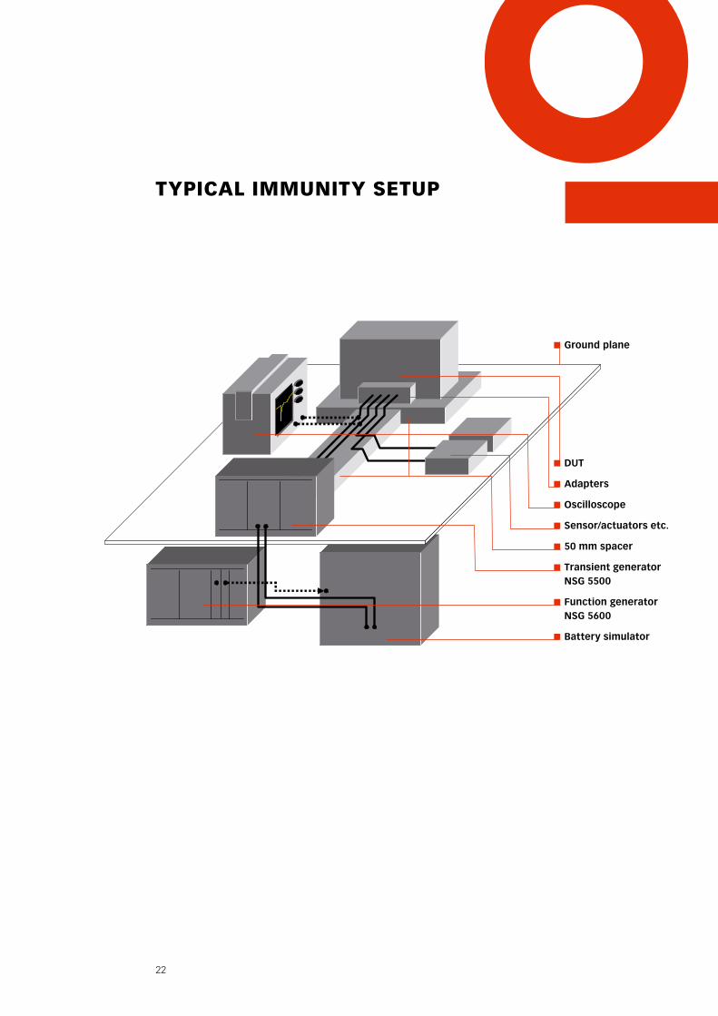
TypIcAl IMMUnITy sETUp
dUT
Adapters
Oscilloscope
Sensor/actuators etc.
50 mm spacer
Transient generator NSG 5500
Function generator NSG 5600
battery simulator
Ground plane
23
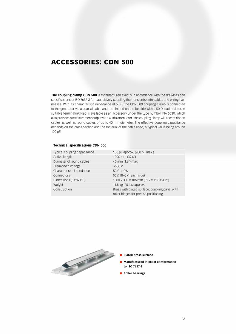
AccEssOrIEs: cdn 500
The coupling clamp CdN 500 is manufactured exactly in accordance with the drawings and specifications of ISO 7637-3 for capacitively coupling the transients onto cables and wiring har-nesses. With its characteristic impedance of 50 Ω, the CDN 500 coupling clamp is connected to the generator via a coaxial cable and terminated on the far side with a 50 Ω load resistor. A suitable terminating load is available as an accessory under the type number INA 5030, which also provides a measurement output via a 40 dB attenuator. The coupling clamp will accept ribbon cables as well as round cables of up to 40 mm diameter. The effective coupling capacitance depends on the cross section and the material of the cable used, a typical value being around 100 pF.
Plated brass surface
Manufactured in exact conformance
to ISO 7637-3
Roller bearings
Technical specifications CDN 500
Typical coupling capacitance 100 pF approx. (200 pF max.)Active length 1000 mm (39.4”)Diameter of round cables 40 mm (1.6”) max.Breakdown voltage >500 V Characteristic impedance 50 Ω ±10%Connectors 50 Ω BNC (1 each side)Dimensions (L x W x H) 1300 x 300 x 106 mm (51.2 x 11.8 x 4.2”)Weight 11.5 kg (25 lbs) approx.Construction Brass with plated surface; coupling panel with
roller hinges for precise positioning
24

ALL IN ONE NSG 5600 – full-featured multichannel arbitrary generator and more FG 5620 – function generator DS 5630 – dips and drops switch PA 5640 – power amplifier TC 5650 – transformer coupled sine waves
bATTEry sIMUlATIOn And
VOlTAgE VArIATIOn
battery Simulation Simulations of battery effects, dropouts, noise and ripple in the motor vehicle.
26
nsg 5600 – IMMUnITy gEnErATOr
Behavior of the vehicles battery network is a complicated topic requiring often complex simula-tions. The NSG 5600 is designed to make this simple with our unique, scalable function generator and accessories including a powerful dropout switch, and modules for transformer coupled sine wave noise, and power magnetics testing.
Utilizing the only automotive EMC specific synchronized, multichannel function generator (FG) in the world, the software integrates the various system components seamlessly into the overall system concept with uniform operating procedures and user guidance together with a comprehensive test result reporting facility.
NSG 5600. Designed to be used either alone or in combination with a NSG 5500 system, the NSG 5600 is designed to simulate events that include voltage dropouts, sinusoidal noise and other events superimposed on the automotive battery: Dips and drops, and ISO and SAE pulse 2b and pulse 4 and other starting profiles. The NSG 5600 is the leader in synchronized voltage variations, such as power cycling tests (on up to four FGs) as required by various standards such as CI 230 defined in the Ford EMC-CS-2009 standard. Additionally, the NSG 5600 may be configured for magnetic field immunity testing. The basic NSG 5600 includes one FG 5620 but additional capability may be added using any of the modules on the following pages.
27
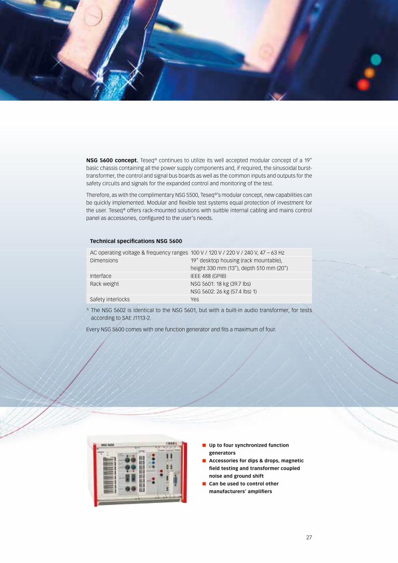
NSG 5600 concept. Teseq® continues to utilize its well accepted modular concept of a 19” basic chassis containing all the power supply components and, if required, the sinusoidal burst-transformer, the control and signal bus boards as well as the common inputs and outputs for the safety circuits and signals for the expanded control and monitoring of the test.
Therefore, as with the complimentary NSG 5500, Teseq®’s modular concept, new capabilities can be quickly implemented. Modular and flexible test systems equal protection of investment for the user. Teseq® offers rack-mounted solutions with suitble internal cabling and mains control panel as accessories, configured to the user’s needs.
Up to four synchronized function
generators
Accessories for dips & drops, magnetic
field testing and transformer coupled
noise and ground shift
Can be used to control other
manu facturers’ amplifiers
Technical specifications NSG 5600
AC operating voltage & frequency ranges 100 V / 120 V / 220 V / 240 V, 47 – 63 HzDimensions 19” desktop housing (rack mountable),
height 330 mm (13”), depth 510 mm (20”)Interface IEEE 488 (GPIB)Rack weight NSG 5601: 18 kg (39.7 lbs)
NSG 5602: 26 kg (57.4 lbs) 1)Safety interlocks Yes
1) The NSG 5602 is identical to the NSG 5601, but with a built-in audio transformer, for tests according to SAE J1113-2.
Every NSG 5600 comes with one function generator and fits a maximum of four.
28
The function generator FG 5620 is used universally throughout the NSG 5600 for the control of DC sources and power amplifiers. The AutoStar TM software defines the necessary voltage/frequency conditions. The controller converts this information into algorithms for the FG (function generator), which creates an image of the requirements in its own memory and then gener-ates the output signals for the addressed power modules during the test run. All the requisite waveforms can be created numerically from the basic functions or by loading a CloneTM, e.g. a memory map of values from a storage oscilloscope or other external application, the FG also generates waveforms that can be difficult to describe mathematically or where real-world events need to be simulated. AutoStar™ supports any external application that can output an ASCII list, MathCAD or Microsoft Excel, for example.
Single-click programming of complicated
signals
320 kHz bandwidth
Unique Clone™ function
Very accurate ±10 V output for controlling
battery simulators or power amplifiers /
power supplies
FG 5620 FG 5621
fg 5620 And fg 5621
Technical specifications FG 5620
Basic functions DC voltage, sine, square, triangle, ramp and exponential function
Ramping capabilities Amplitude, frequency, DC offsetOutput voltage –10 to +10 VResolution 10 mVAccuracy ± (1% + 10 mV)Impedance 10 ΩShort circuit protection YesNumber of segments per waveform 1 to 100Frequency range DC -320 kHzFrequency resolution 0.01 HzAmplitude & offset ramping LinearFrequency ramping sine / square / triangle Linear, log (base 10)Phase angle 0 to 360° in 15° stepsRectification None, positive, negativeTest duration 1 ms to 9,999 h, 1 to 9,999 cyclesClone™ memory for oscilloscope capture or imported Excel or text files 30 k samplesSynchronization Up to four channels
29
ds 5630
The dS 5630 switches the voltage source through to the EUT connection under program-control. The primary input and the auxiliary connection enable two sources to be used. The DC switching capacity of 70 V / 75 A is capable of coping with high power requirements.
The selectable switching conditions are: Output (EUT)
to primary source
to auxiliary source
switched off (open)
dip and drop from primary to auxiliary source and back again
to primary source with 2 Ω extra impedance (SAE J1113-11 pulse 2b)
Fast switching for standards that require
≈1 µs rise/fall times
Used to support Power Magnetics and
other applications in the NSG 5600
Overcurrent protection
Technical specifications DS 5630
Primary input voltage –14 to 60 VCurrent 0 to 75 AVoltage drop 2 Vmax @ 75 AAuxiliary input voltage 0 to 60 VCurrent 0 to 75 ASwitch time on < 1.2 µsSwitch time off < 0.5 µs
(13.5 to 0 V with 1 kΩ load) Pulse width 20000 – 0.003 ms ± (10% or 1 µs)SAE pulse 2 output impedance 2 ΩOvervoltage protection 60 VOvercurrent protection 75 A
30
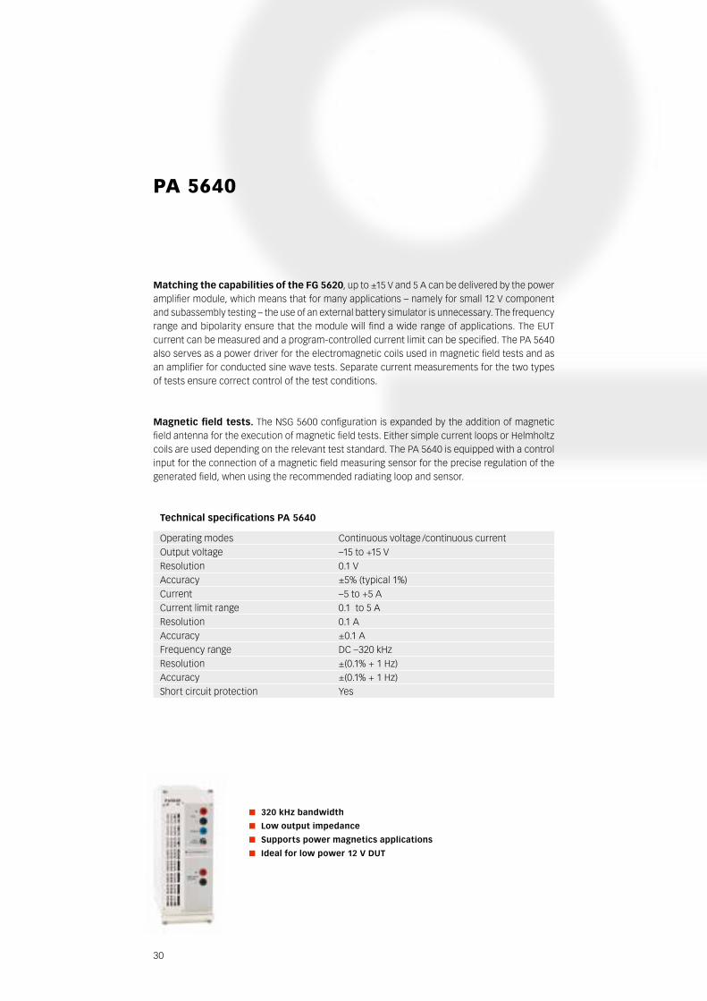
Matching the capabilities of the FG 5620, up to ±15 V and 5 A can be delivered by the power amplifier module, which means that for many applications – namely for small 12 V component and subassembly testing – the use of an external battery simulator is unnecessary. The frequency range and bipolarity ensure that the module will find a wide range of applications. The EUT current can be measured and a program-controlled current limit can be specified. The PA 5640 also serves as a power driver for the electromagnetic coils used in magnetic field tests and as an amplifier for conducted sine wave tests. Separate current measurements for the two types of tests ensure correct control of the test conditions.
Magnetic field tests. The NSG 5600 configuration is expanded by the addition of magnetic field antenna for the execution of magnetic field tests. Either simple current loops or Helmholtz coils are used depending on the relevant test standard. The PA 5640 is equipped with a control input for the connection of a magnetic field measuring sensor for the precise regulation of the generated field, when using the recommended radiating loop and sensor.
320 kHz bandwidth
Low output impedance
Supports power magnetics applications
Ideal for low power 12 V dUT
pA 5640
Technical specifications PA 5640
Operating modes Continuous voltage /continuous currentOutput voltage –15 to +15 VResolution 0.1 VAccuracy ±5% (typical 1%)Current –5 to +5 ACurrent limit range 0.1 to 5 AResolution 0.1 AAccuracy ±0.1 AFrequency range DC –320 kHzResolution ±(0.1% + 1 Hz)Accuracy ±(0.1% + 1 Hz)Short circuit protection Yes
31
Tc 5650
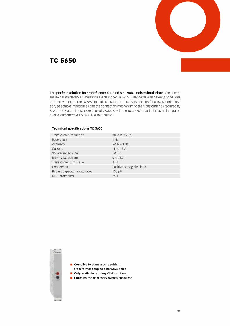
The perfect solution for transformer coupled sine wave noise simulations. Conducted sinusoidal interference simulations are described in various standards with differing conditions pertaining to them. The TC 5650 module contains the necessary circuitry for pulse superimposi-tion, selectable impedances and the connection mechanism to the transformer as required by SAE J1113-2 etc. The TC 5650 is used exclusively in the NSG 5602 that includes an integrated audio transformer. A DS 5630 is also required.
Complies to standards requiring
transformer coupled sine wave noise
Only available turn-key CSW solution
Contains the necessary bypass capacitor
Technical specifications TC 5650
Transformer frequency 30 to 250 kHzResolution 1 HzAccuracy ±(1% + 1 Hz)Current –5 to +5 ASource impedance <0.5 ΩBattery DC current 0 to 25 ATransformer turns ratio 2 : 1Connection Positive or negative leadBypass capacitor, switchable 100 µFMCB protection 25 A

32
battery simulators replace the vehicle battery in the test environment. These sources must fulfill various criteria concerning power rating, voltage, fast slew rate, very low impedance, low noise, etc. depending on the particular application. Bipolar sources are specified for in several cases. Pulse 2b, pulse 4, sine wave noise and other complex simulations are realm of the PA series.
Not just an audio amplifier, where specifications are not immediately clear, or are valid only into limited loads, the PA series is stable into capacitive, inductive and resistive loads. For example, the PA series meets the current specification from 1 to 60 V regardless of load, and feature unparalleled <10 mV RMS noise – from our smallest PA 5740 to the kilowatt PA 5840-300!
These four-quadrant amplifiers are perfectly suited for ISO 7637 compliant simulated conducted transient testing. Offering combinations of features that exist in no other battery simulator, the PA series is the right solution for your EMC needs.
Designed specifically for automotive EMC testing, Teseq®’s 60 V amplifier sets the pace for automotive battery simulation including features necessary for automotive immunity testing such as sense wires for cable voltage drop compensation and several operating modes for stability with complex automotive loads.
bATTEry sIMUlATOrs
33
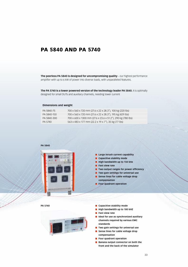
pA 5840 And pA 5740
The peerless PA 5840 is designed for uncompromising quality – our highest performance amplifier with up to 6 kW of power into diverse loads, with unparalleled features.
The PA 5740 is a lower powered version of the technology leader PA 5840. It is optimally designed for small DUTs and auxiliary channels, needing lower current
Capacitive stability mode
High bandwidth up to 180 kHZ
Fast slew rate
Ideal for use as synchronized auxiliary
channels required by various EMC
standards
Two gain settings for universal use
Sense lines for cable voltage drop
compensation
Four quadrant operation
banana output connector on both the
front and the back of the simulator
Large inrush current capability
Capacitive stability mode
High bandwidth up to 150 kHz
Fast slew rate
Two output ranges for power efficiency
Two gain settings for universal use
Sense lines for cable voltage drop
compensation
Four quadrant operation
PA 5840
PA 5740
dimensions and weight
PA 5840-75 700 x 560 x 720 mm (27.6 x 22 x 28.3”), 100 kg (220 lbs)PA 5840-150 700 x 560 x 720 mm (27.6 x 22 x 28.3”), 195 kg (429 lbs)PA 5840-300 700 x 600 x 1300 mm (27.6 x 23.6 x 51.2”), 290 kg (780 lbs)PA 5740 563 x 483 x 177 mm (22.2 x 19 x 7”), 35 kg (77 lbs)
34
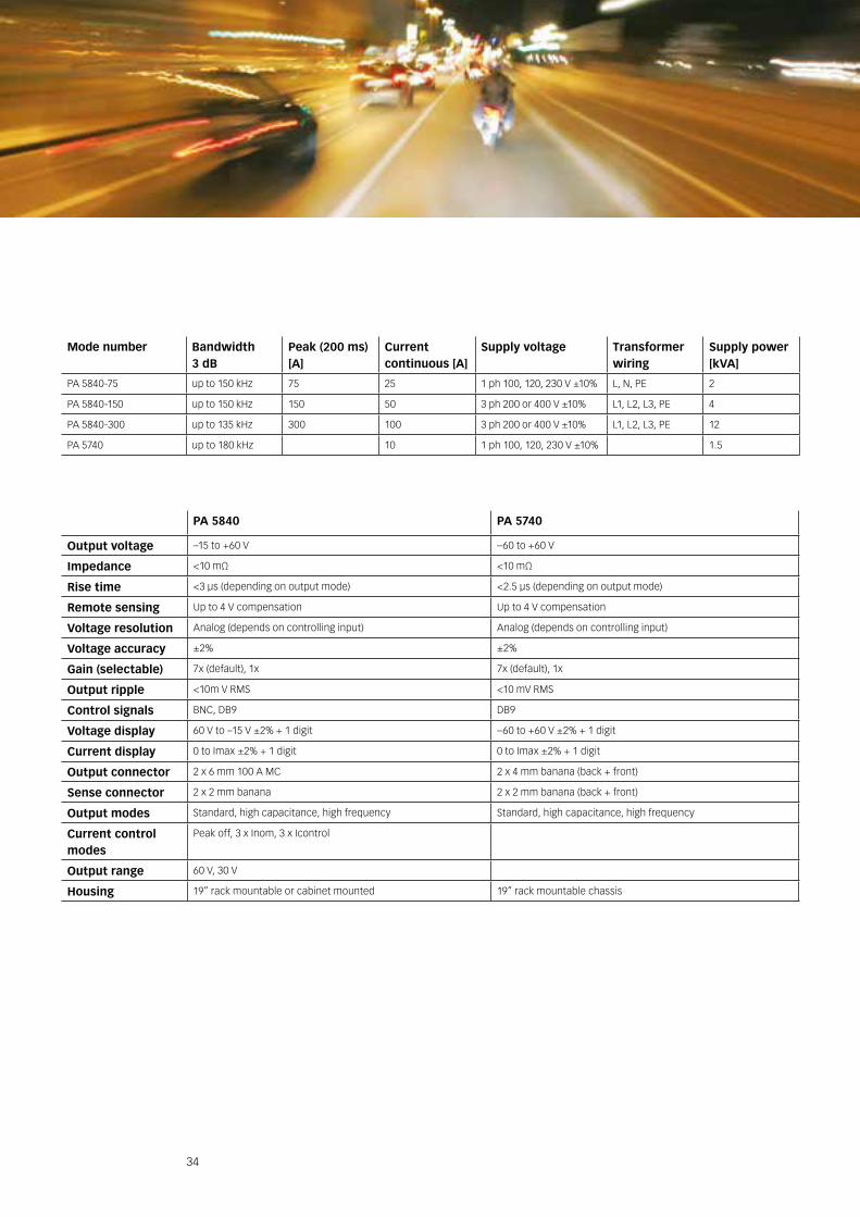
PA 5840 PA 5740
Output voltage –15 to +60 V –60 to +60 V
Impedance <10 mΩ <10 mΩ
Rise time <3 μs (depending on output mode) <2.5 μs (depending on output mode)
Remote sensing Up to 4 V compensation Up to 4 V compensation
Voltage resolution Analog (depends on controlling input) Analog (depends on controlling input)
Voltage accuracy ±2% ±2%
Gain (selectable) 7x (default), 1x 7x (default), 1x
Output ripple <10m V RMS <10 mV RMS
Control signals BNC, DB9 DB9
Voltage display 60 V to –15 V ±2% + 1 digit –60 to +60 V ±2% + 1 digit
Current display 0 to Imax ±2% + 1 digit 0 to Imax ±2% + 1 digit
Output connector 2 x 6 mm 100 A MC 2 x 4 mm banana (back + front)
Sense connector 2 x 2 mm banana 2 x 2 mm banana (back + front)
Output modes Standard, high capacitance, high frequency Standard, high capacitance, high frequency
Current control modes
Peak off, 3 x Inom, 3 x Icontrol
Output range 60 V, 30 V
Housing 19” rack mountable or cabinet mounted 19” rack mountable chassis
Mode number bandwidth 3 db
Peak (200 ms) [A]
Current continuous [A]
Supply voltage Transformer wiring
Supply power [kVA]
PA 5840-75 up to 150 kHz 75 25 1 ph 100, 120, 230 V ±10% L, N, PE 2
PA 5840-150 up to 150 kHz 150 50 3 ph 200 or 400 V ±10% L1, L2, L3, PE 4
PA 5840-300 up to 135 kHz 300 100 3 ph 200 or 400 V ±10% L1, L2, L3, PE 12
PA 5740 up to 180 kHz 10 1 ph 100, 120, 230 V ±10% 1.5
35
AccEssOrIEs
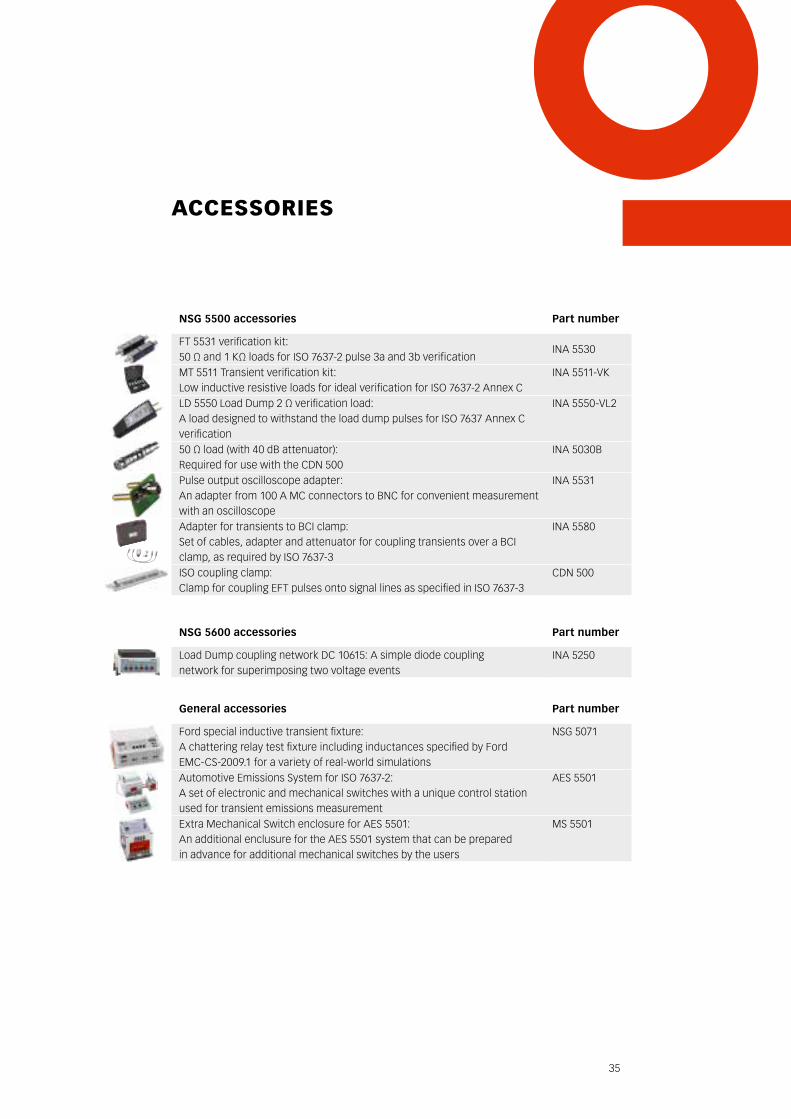
NSG 5500 accessories Part number
FT 5531 verification kit:50 Ω and 1 KΩ loads for ISO 7637-2 pulse 3a and 3b verification
INA 5530
MT 5511 Transient verification kit:Low inductive resistive loads for ideal verification for ISO 7637-2 Annex C
INA 5511-VK
LD 5550 Load Dump 2 Ω verification load:A load designed to withstand the load dump pulses for ISO 7637 Annex C verification
INA 5550-VL2
50 Ω load (with 40 dB attenuator):Required for use with the CDN 500
INA 5030B
Pulse output oscilloscope adapter:An adapter from 100 A MC connectors to BNC for convenient measurement with an oscilloscope
INA 5531
Adapter for transients to BCI clamp:Set of cables, adapter and attenuator for coupling transients over a BCI clamp, as required by ISO 7637-3
INA 5580
ISO coupling clamp:Clamp for coupling EFT pulses onto signal lines as specified in ISO 7637-3
CDN 500
NSG 5600 accessories Part number
Load Dump coupling network DC 10615: A simple diode coupling network for superimposing two voltage events
INA 5250
General accessories Part number
Ford special inductive transient fixture:A chattering relay test fixture including inductances specified by Ford EMC-CS-2009.1 for a variety of real-world simulations
NSG 5071
Automotive Emissions System for ISO 7637-2:A set of electronic and mechanical switches with a unique control stationused for transient emissions measurement
AES 5501
Extra Mechanical Switch enclosure for AES 5501:An additional enclusure for the AES 5501 system that can be prepared in advance for additional mechanical switches by the users
MS 5501
36
do I need to perform these tests?
Probably. If you are an engineering firm or manufacturer who hopes to have subassemblies sold into the European Union, then it is required by law. It is also usually required by contract from all of the major automotive manufacturers.
What kind of facilities do I need?
You don’t need a chamber. For this range of tests, generally all that is needed is the immunity generators and emissions switches, a table with a large ground plane, and some spacers and adapters (see page 21 for an overview). Accessories may be necessary depending on the test requirement.
How are these devices calibrated?
Teseq® has accredited calibration laboratories all over the world, but this does not remove the need to perform the pulse verification as found in ISO 7637-2.
How fast can I test my dUT?
There is not an easy way to speed up the testing. For many tests, the standards dictate how long the disturbance must be exposed, Pulse 3a and 3b for example; in other tests, only a very limited number of pulses must be made (Pulse 4, 5a/b), in this case the test setup lasts much longer than the test itself; additionally, the repetition times are often limited to a minimum level; in the worst case of tests where the DUT must be deenergized (Pulse 1, Pulse 2b, etc.) and in this case, the repetition time is limited by how long it takes for the DUT to be switched on again and stable before exposing the DUT to the next simulation. Further more, most standards dictate that all of the various events must be simulated on a single DUT, so that each DUT experiences all of the events. Much time savings can be achieved from automating the DUT function test process, if applicable.
Who are the most common users of this type of equipment?
Component and subassembly manufacturers and design engineers of these.
Is there a standard that is a worldwide requirement?
No, ISO 7637-2 testing is only legally binding when the assemblies are imported into the EU. The most rigorous requirements come actually from the auto manufacturers themselves, and this testing is contractually obligated.
Can you give an example of subassemblies that need tested?
Radios, motor, lighting and other controls, pumps, gauges – basically every kind of electrical and electronic component in the vehicle.
FAQ

37
TEsEq® ObsErVEs All ThE sTAndArds
below is a partial list of standards covered by various Teseq® solutions.
International Standards
DIN 72300-2
GOST 28751-90
ISO 21848
ISO 10605
ISO 11452-3
ISO 11452-4
ISO 11452-5
ISO 11452-6
ISO 11452-8
ISO 14982
ISO 16750-2
ISO 7637
JASO D001-94
SAE J1113-11
SAE J1113-12
SAE J1113-13
SAE J1113-2
SAE J1113-4
SAE J1455
Manufacturer Standards
BMW 600 13.0
BMW GS 95002
BMW GS 95003-2
Case New Holland CNH ENS 0310
Chrysler CS-11809
Chrysler CS-11979
Chrysler PF 9326
DaimlerChrysler DC-10613
DaimlerChrysler DC-10614
DaimlerChrysler DC-10615
Fiat 9.90110
Ford EMC CS 2009
Ford ES-XW7T-1A278
Freightliner 49-00085
GM 9105P
GMW 3097
GMW 3100
GMW 3172
Honda 3982Z-SDA-0030
Hyundai ES 39110-00
Hyundai ES 96100-02
IVECO 16-2103
Kia/Hyundai ES 95400-10
LV-124
Mack Trucks 606GS15
MAN 3285
Mazda MES PW 67600
Mercedes AV EMV
Mercedes MBN 10284-2
Mercedes MBN 10605
Mitsubishi ES-X82010
Nissan 28400 NDS 03
Nissan 28400 NDS 05
Nissan 28400 NDS 07
Nissan 28401 NDS 02
Piaggio 7431
Porsche
PSA B21 7090
PSA B21 7110
Renault 36.00.808
Scania TB1400
Scania TB1700
Smart DE1005B
Toyota TSC3500G
Toyota TSC3590G
Toyota TSC6203G
Toyota TSC7001G
Toyota TSC7006G
Toyota TSC7021G
Toyota TSC7034G
Toyota TSC7203G
Toyota TSC7306G
Volvo EMC requirements
VW 80000
VW TL 801 01
VW TL 801 01 (2003)
VW TL 820 66
VW TL 821 66
VW TL 823 66
VW TL 824 66
… and more!

38
EV And phEV TEsTIng sOlUTIOns
Electric Vehicles (EVs), Hybrid and Plugin Hybrid Electric Vehicles (PHEVs) are forming an increas-ing part of our worldwide strategy to reduce greenhouse emissions and our dependency on fossil fuels. For this reason, they are increasingly being discussed in standard committees and laboratories around the world. Standards like ECE-R10 for E-Marking and IEC 61851-1 are focusing more and more on issues specific to electric vehicles, charging systems and transient immunity on high voltage battery lines. Teseq® has experience with all of this and more! We’re working daily on both immunity and emissions solutions in RF applications and electrical subassembly dis-turbances. We’ve provided simulations on everything from immunity testing on internal battery cell monitoring to immunity and emissions testing on charging stations to ripple and transients on high voltage lithium battery voltage.
While the standards are still very much in flux, we realize that you have tests that you need to do now.
Please contact Teseq® for solutions and consultation about your specific test requirements.
Full Vehicle RF immunity and emissions
Powerful simulations of internal disturbances for electrical and electronic subassemblies
Magnetic field immunity
Immunity and emissions on charging systems and charging stations
Bulk Current Injection testing
Component-level emissions and immunity testing

HeadquartersTeseq AG4542 Luterbach SwitzerlandT +41 32 681 40 40F +41 32 681 40 [email protected]
EMc InsTrUMEnTATIOn And sysTEMs fOr Any bUdgET
ChinaTeseq Company LimitedT +86 10 8460 8080F +86 10 8460 [email protected]
SingaporeTeseq Pte Ltd.T +65 6846 2488F +65 6841 [email protected]
USATeseq Inc.T +1 732 417 0501F +1 732 417 0511Toll free +1 888 417 [email protected]
FranceTeseq SarlT +33 1 39 47 42 21F +33 1 39 47 40 [email protected]
SwitzerlandTeseq AGT +41 32 681 40 50F +41 32 681 40 [email protected]
GermanyTeseq GmbHT +49 30 5659 8815F +49 30 5659 [email protected]
TaiwanTeseq (Taiwan) Ltd.T +886 2 2917 8080F +886 2 2917 [email protected]
JapanTeseq K.K.T +81 3 5774 5771F +81 3 5774 [email protected]
UKTeseq Ltd.T +44 845 074 0660F +44 845 074 [email protected]
Teseq® offers the world’s most comprehensive range of EMC systems for immunity and emissions testing. We take great pride in our world-class research and development program, backed by state-of-the-art global manufacturing. Our membership in the relevant international committees demonstrates our commitment to the industry. Our network of direct sales offices, representatives and distributors offers market leading EMC expertise tailored to local needs in more than 30 different countries.
Our unique “modular” approach to EMC is focused on our customers’ business needs. By breaking down the barriers between traditionally separate test functions we can optimize the test process to help you bring products to market more quickly.
691-144C January 2013
© 2013 Teseq®
Specifications subject to change without notice.
To find your local partner within Teseq’s global network, please go to www.teseq.com
Teseq® is an ISO-registered company. Its products are designed and manufactured under the strict quality and environmental requirements of the ISO 9001.
This document has been carefully checked. However, Teseq® does not assume any liability for errors, inaccuracies or changes due to technical developments.


![SCISCITATOR 2015 · [1]. Riverine communities experience two main types of disturbances: natural disturbances and anthropogenic disturbances. Natural disturbances in riverine ecosystems](https://static.fdocuments.in/doc/165x107/5f27dd3959f0c41da22eeec5/sciscitator-1-riverine-communities-experience-two-main-types-of-disturbances.jpg)