Automotive Auxiliary Electrical Systemsave.dee.isep.ipp.pt/~mjf/act_lect/SIAUT/Trabalhos...
73
1 06 Janeiro d e 2010 / 1 MEEC Automotive Systems Automotive Auxiliary Electrical Systems Paulo Fonseca Nº 1090038 06 Janeiro d e 2010 / 2 MEEC Automotive Systems 1. INTRODUCTION 1.1DefinitionofAuxiliaryElectricalSystems • Electrical Auxiliary System, is a acronym used to describe a collection of related automotive Electrical components that interact with the main car systems and components to support his functionality. • Electrical Auxiliary Systems are components related with Security Systems, Comfort Systems, Lighting Systems and Information Systems witch are very important to help the main system to perform according the specifications.
-
Upload
nguyenthuy -
Category
Documents
-
view
221 -
download
1
Transcript of Automotive Auxiliary Electrical Systemsave.dee.isep.ipp.pt/~mjf/act_lect/SIAUT/Trabalhos...
1
06 Janeiro d e 2010 / 1
ME
EC
Au
tom
otive
System
s
Automotive Auxiliary Electrical Systems
Paulo Fonseca
Nº 1090038
06 Janeiro d e 2010 / 2
ME
EC
Au
tom
otive
System
s
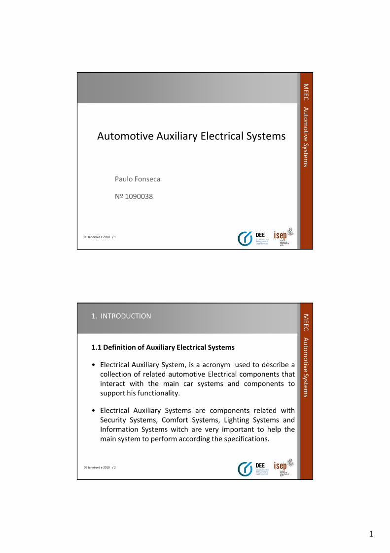
1. INTRODUCTION
1.1 Definition of Auxiliary Electrical Systems
• Electrical Auxiliary System, is a acronym used to describe a
collection of related automotive Electrical components that
interact with the main car systems and components to
support his functionality.
• Electrical Auxiliary Systems are components related with
Security Systems, Comfort Systems, Lighting Systems and
Information Systems witch are very important to help the
main system to perform according the specifications.

2
06 Janeiro d e 2010 / 3
ME
EC
Au
tom
otive
System
s1. INTRODUCTION
1.2 Taxonomy of Auxiliary Electrical Systems.
Auxiliary Electrical Systems
Security SystemsComfort and
Safety SystemsLighting Systems Information Systems
•Seat adjustment.
•Windows control.
•Sun roof control.
•Windshield wiperand window cleaning.•Compartment HVAC.•Control view mirrors
•Front Lighting.
•Rear lighting.
•Compartment lighting.
•Signalization lighting.
• Instruments panel.
•Trip recorder.
•Board computer.
•Multimedia.
•Central locking door system
•Locking door with distance command.
•Biometric system.
•Anti steel system.
06 Janeiro d e 2010 / 4
ME
EC
Au
tom
otive
System
s
1. INTRODUCTION
1.2 Taxonomy of Auxiliary Electrical Systems. (cont)
• Conclusion.
3
06 Janeiro d e 2010 / 5
ME
EC
Au
tom
otive
System
s2. ELECTRICAL AUXILIARY SYSTEMS
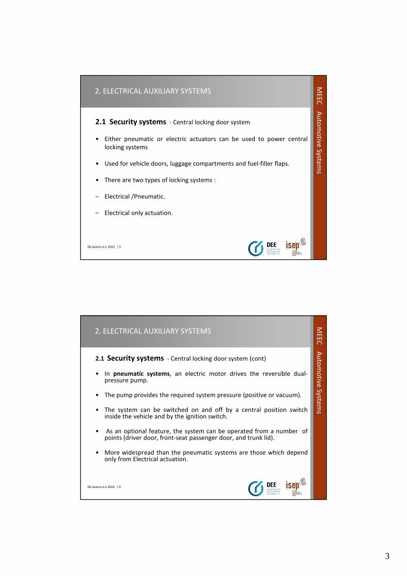
2.1 Security systems - Central locking door system
• Either pneumatic or electric actuators can be used to power central
locking systems
• Used for vehicle doors, luggage compartments and fuel-filler flaps.
• There are two types of locking systems :
– Electrical /Pneumatic.
– Electrical only actuation.
06 Janeiro d e 2010 / 6
ME
EC
Au
tom
otive
System
s
2. ELECTRICAL AUXILIARY SYSTEMS
2.1 Security systems - Central locking door system (cont)
• In pneumatic systems, an electric motor drives the reversible dual-pressure pump.
• The pump provides the required system pressure (positive or vacuum).
• The system can be switched on and off by a central position switchinside the vehicle and by the ignition switch.
• As an optional feature, the system can be operated from a number ofpoints (driver door, front-seat passenger door, and trunk lid).
• More widespread than the pneumatic systems are those which dependonly from Electrical actuation.
4
06 Janeiro d e 2010 / 7
ME
EC
Au
tom
otive
System
s2. ELECTRICAL AUXILIARY SYSTEMS
2.1 Security systems - Central locking door system (cont)
• Electric motors for central locking, although various technologies areused, according to function range and lock type, the basic principleremains constant: a small electric motor.
• The electric motor reduction-gear drive unit powers the actuating levelresponsible for opening and closing the lock.
• Provision must be made to ensure that the door can always be unlockedwith the key and the interior handle in the event of a power failure.
• Central locking systems incorporating special theft-deterrence featuresmust be designed to preclude deactivation of the security system usingany means other than the vehicle key.
06 Janeiro d e 2010 / 8
ME
EC
Au
tom
otive
System
s
2. ELECTRICAL AUXILIARY SYSTEMS
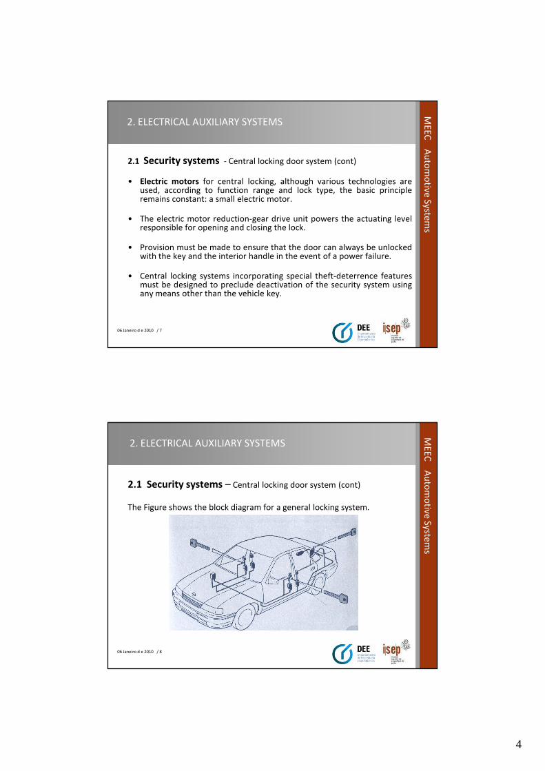
2.1 Security systems – Central locking door system (cont)
The Figure shows the block diagram for a general locking system.
5
06 Janeiro d e 2010 / 9
ME
EC
Au
tom
otive
System
s2. ELECTRICAL AUXILIARY SYSTEMS
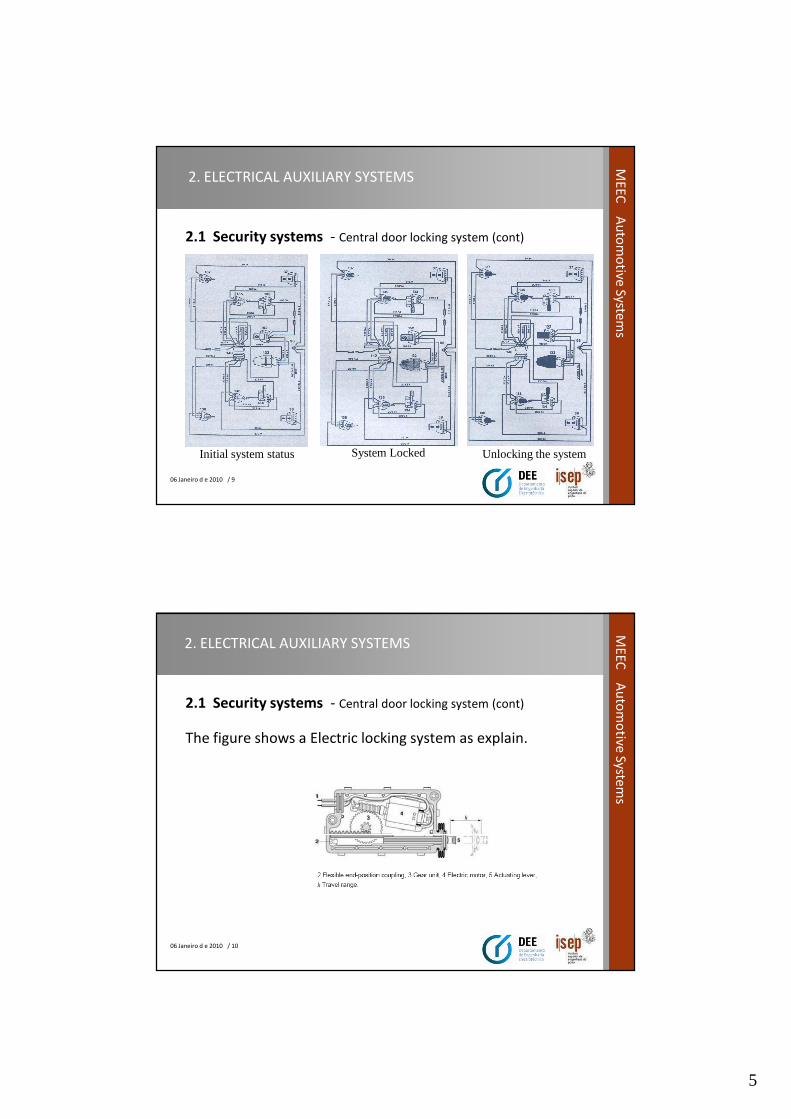
2.1 Security systems - Central door locking system (cont)
Initial system status System Locked Unlocking the system
06 Janeiro d e 2010 / 10
ME
EC
Au
tom
otive
System
s
2. ELECTRICAL AUXILIARY SYSTEMS
2.1 Security systems - Central door locking system (cont)
The figure shows a Electric locking system as explain.
6
06 Janeiro d e 2010 / 11
ME
EC
Au
tom
otive
System
s2. ELECTRICAL AUXILIARY SYSTEMS
2.1 Security systems - Locking door with distance command
• The system is a variant of the Central door locking as it was seen onprevious topic.
• The innovation is the possibility to integrate a remote hand command byinfra red or by RF to give order for open/close the doors.
• This system has a receiver unit installed on the vehicle that receives thecommand from the hand transmitter.
• If the code in memory is the same as the received one then a signal thatis connected in parallel with gear motors will actuate them andopen/close the doors.
06 Janeiro d e 2010 / 12
ME
EC
Au
tom
otive
System
s
2. ELECTRICAL AUXILIARY SYSTEMS
2.1 Security systems - Locking door with distance command (cont).
• The code can be modified and has about 59048 combinations (depends from the
type of remote command).
• Generally the receivers can have a setup to receive more than one code, this
happens when the vehicle will have several drivers. Each one has a hand
command with a different code that will be recognized by the receiver unit.
• Nowadays, the car is equipped with anti steal system, the hand remote
command can also activate the anti steal system by pressing two times the
switch. In this case a red led start blinking , this confirms that the anti steal
system is activated.
7
06 Janeiro d e 2010 / 13
ME
EC
Au
tom
otive
System
s2. ELECTRICAL AUXILIARY SYSTEMS
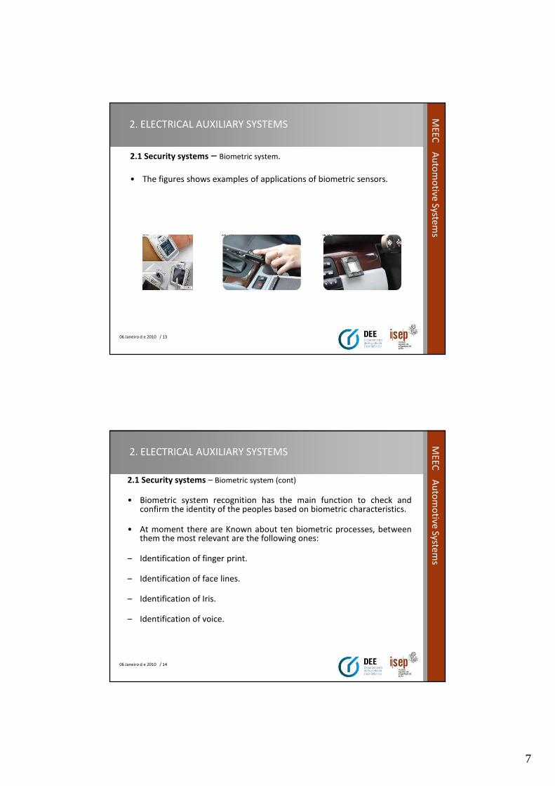
2.1 Security systems – Biometric system.
• The figures shows examples of applications of biometric sensors.
06 Janeiro d e 2010 / 14
ME
EC
Au
tom
otive
System
s
2. ELECTRICAL AUXILIARY SYSTEMS
2.1 Security systems – Biometric system (cont)
• Biometric system recognition has the main function to check andconfirm the identity of the peoples based on biometric characteristics.
• At moment there are Known about ten biometric processes, betweenthem the most relevant are the following ones:
– Identification of finger print.
– Identification of face lines.
– Identification of Iris.
– Identification of voice.
8
06 Janeiro d e 2010 / 15
ME
EC
Au
tom
otive
System
s2. ELECTRICAL AUXILIARY SYSTEMS
2.1 Security systems – Biometric system. (cont)
• For automotive vehicles it is used more frequently de finger print witchgives a more comprehensive differentiation of the identities.
• This technology gives more security compared with the car Key, that forinstance could be lost. Note that de biometric characteristics are carriedby the person.
• Also, the technology gives information about the identity of the personthat drives the car.
• To Identify a finger print, first is necessary to register it. This is done bydata acquisition of the finger print using a sensor with gray scale colorand size ( 64000 to 96000 pixel with resolution of 8 bit/pixel).
06 Janeiro d e 2010 / 16
ME
EC
Au
tom
otive
System
s
2. ELECTRICAL AUXILIARY SYSTEMS
2.1 Security systems – Biometric system. (cont)
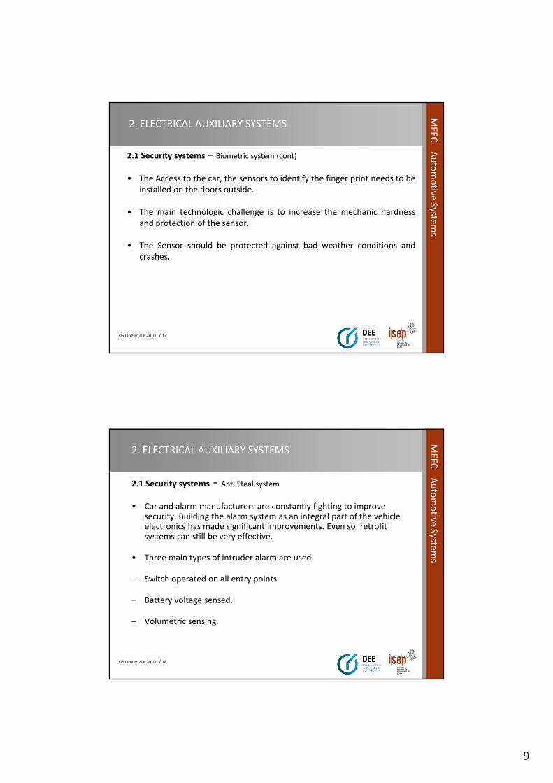
• Digital finger print sensor based on direct opticalscanning (DiOS).
a. Image sensor CMOS with finger.
b. Detail of information.
1- Light.
2- scene Finger lines.
3- Led Light from bottom.
4- optical fiber beam.
5- Sensitive sensor .
9
06 Janeiro d e 2010 / 17
ME
EC
Au
tom
otive
System
s2. ELECTRICAL AUXILIARY SYSTEMS
2.1 Security systems – Biometric system (cont)
• The Access to the car, the sensors to identify the finger print needs to be
installed on the doors outside.
• The main technologic challenge is to increase the mechanic hardness
and protection of the sensor.
• The Sensor should be protected against bad weather conditions and
crashes.
06 Janeiro d e 2010 / 18
ME
EC
Au
tom
otive
System
s
2. ELECTRICAL AUXILIARY SYSTEMS
2.1 Security systems - Anti Steal system
• Car and alarm manufacturers are constantly fighting to improve security. Building the alarm system as an integral part of the vehicle electronics has made significant improvements. Even so, retrofit systems can still be very effective.
• Three main types of intruder alarm are used:
– Switch operated on all entry points.
– Battery voltage sensed.
– Volumetric sensing.

10
06 Janeiro d e 2010 / 19
ME
EC
Au
tom
otive
System
s2. ELECTRICAL AUXILIARY SYSTEMS
2.1 Security systems - Anti Steal system (cont)
• There are three main ways to disable the vehicle.
– Ignition circuit cut off.
– Starter circuit cut off.
– Engine ECU (Electronic control unit ) code lock.
• A separate switch or IR transmitter can be used to set an alarm system.
Often, they are set automatically when the doors are locked.
06 Janeiro d e 2010 / 20
ME
EC
Au
tom
otive
System
s
2. ELECTRICAL AUXILIARY SYSTEMS
2.1 Security systems - Anti Steal system (cont)
• The following is an overview of the good alarm systems now availableeither as a retro-fit or factory fitted. Most are made for 12V.
• They have electronic sirens and give an audible signal when arming anddisarming.
• They are all triggered when the car door opens and will automaticallyreset after a period of time, often 1 or 2 minutes.
• The alarms are triggered instantly when an entry point is breached.
• Most systems can be considered as two pieces, with a separate controlunit and siren.

11
06 Janeiro d e 2010 / 21
ME
EC
Au
tom
otive
System
s2. ELECTRICAL AUXILIARY SYSTEMS
2.1 Security systems - Anti Steal system (cont)
• Most systems have the control unit in the passenger compartment and
the siren under the bonnet.
• Most systems now come with two infrared remote ‘keys’ that use small
button-type batteries and have an LED that shows when the signal is
being send.
• Intrusion sensors such as car movement and volumetric sensing can be
adjusted for sensitivity.
06 Janeiro d e 2010 / 22
ME
EC
Au
tom
otive
System
s
2. ELECTRICAL AUXILIARY SYSTEMS
2.1 Security systems - Anti Steal system (cont)
• When operating with flashing lights most systems draw about 5 A.
Without flashing lights (siren only) the current drawn is less than 1 A.
• The sirens produce a sound level of about 95 dB, when measured 2 m in
front of the vehicle.
• Next slide shows a block diagram of a alarm system. The system, as is
usual, can be considered as a series of inputs and outputs signals.
12
06 Janeiro d e 2010 / 23
ME
EC
Au
tom
otive
System
s2. ELECTRICAL AUXILIARY SYSTEMS
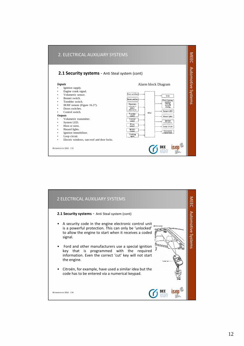
Inputs• Ignition supply.• Engine crank signal.• Volumetric sensor.• Bonnet switch.• Trembler switch.• IR/RF remote (Figure 16.27).• Doors switches.• Control switch.Outputs• Volumetric transmitter.• System LED.• Horn or siren.• Hazard lights.• Ignition immobilizer.• Loop circuit.• Electric windows, sun-roof and door locks.
Alarm block Diagram
2.1 Security systems - Anti Steal system (cont)
06 Janeiro d e 2010 / 24
ME
EC
Au
tom
otive
System
s
2 ELECTRICAL AUXILIARY SYSTEMS
2.1 Security systems - Anti Steal system (cont)
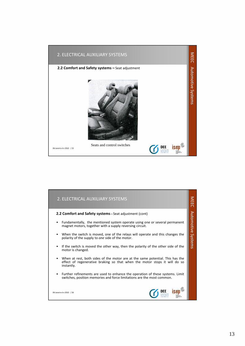
• A security code in the engine electronic control unitis a powerful protection. This can only be ‘unlocked’to allow the engine to start when it receives a codedsignal.
• Ford and other manufacturers use a special ignitionkey that is programmed with the requiredinformation. Even the correct ‘cut’ key will not startthe engine.
• Citroën, for example, have used a similar idea but thecode has to be entered via a numerical keypad.
13
06 Janeiro d e 2010 / 25
ME
EC
Au
tom
otive
System
s2. ELECTRICAL AUXILIARY SYSTEMS
2.2 Comfort and Safety systems – Seat adjustment
Seats and control switches
06 Janeiro d e 2010 / 26
ME
EC
Au
tom
otive
System
s
2. ELECTRICAL AUXILIARY SYSTEMS
2.2 Comfort and Safety systems – Seat adjustment (cont)
• Fundamentally, the mentioned system operate using one or several permanentmagnet motors, together with a supply reversing circuit.
• When the switch is moved, one of the relays will operate and this changes thepolarity of the supply to one side of the motor.
• If the switch is moved the other way, then the polarity of the other side of themotor is changed.
• When at rest, both sides of the motor are at the same potential. This has theeffect of regenerative braking so that when the motor stops it will do soinstantly.
• Further refinements are used to enhance the operation of these systems. Limitswitches, position memories and force limitations are the most common.
14
06 Janeiro d e 2010 / 27
ME
EC
Au
tom
otive
System
s2. ELECTRICAL AUXILIARY SYSTEMS
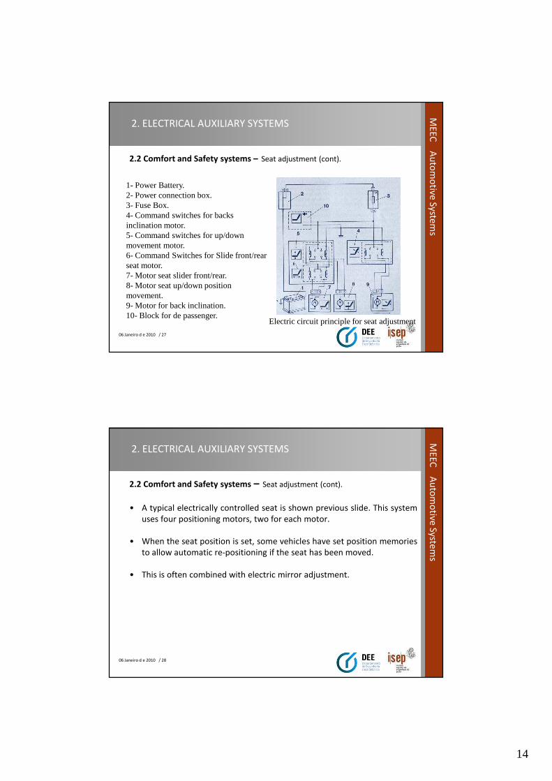
2.2 Comfort and Safety systems – Seat adjustment (cont).
1- Power Battery.2- Power connection box.3- Fuse Box.4- Command switches for backs inclination motor.5- Command switches for up/down movement motor.6- Command Switches for Slide front/rear seat motor.7- Motor seat slider front/rear.8- Motor seat up/down position movement. 9- Motor for back inclination.10- Block for de passenger.
Electric circuit principle for seat adjustment
06 Janeiro d e 2010 / 28
ME
EC
Au
tom
otive
System
s
2. ELECTRICAL AUXILIARY SYSTEMS
2.2 Comfort and Safety systems – Seat adjustment (cont).
• A typical electrically controlled seat is shown previous slide. This system
uses four positioning motors, two for each motor.
• When the seat position is set, some vehicles have set position memories
to allow automatic re-positioning if the seat has been moved.
• This is often combined with electric mirror adjustment.
15
06 Janeiro d e 2010 / 29
ME
EC
Au
tom
otive
System
s2. ELECTRICAL AUXILIARY SYSTEMS
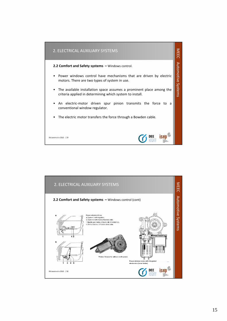
2.2 Comfort and Safety systems – Windows control.
• Power windows control have mechanisms that are driven by electric
motors. There are two types of system in use.
• The available installation space assumes a prominent place among the
criteria applied in determining which system to install.
• An electric-motor driven spur pinion transmits the force to a
conventional window regulator.
• The electric motor transfers the force through a Bowden cable.
06 Janeiro d e 2010 / 30
ME
EC
Au
tom
otive
System
s
2. ELECTRICAL AUXILIARY SYSTEMS
2.2 Comfort and Safety systems – Windows control (cont)
16
06 Janeiro d e 2010 / 31
ME
EC
Au
tom
otive
System
s2. ELECTRICAL AUXILIARY SYSTEMS
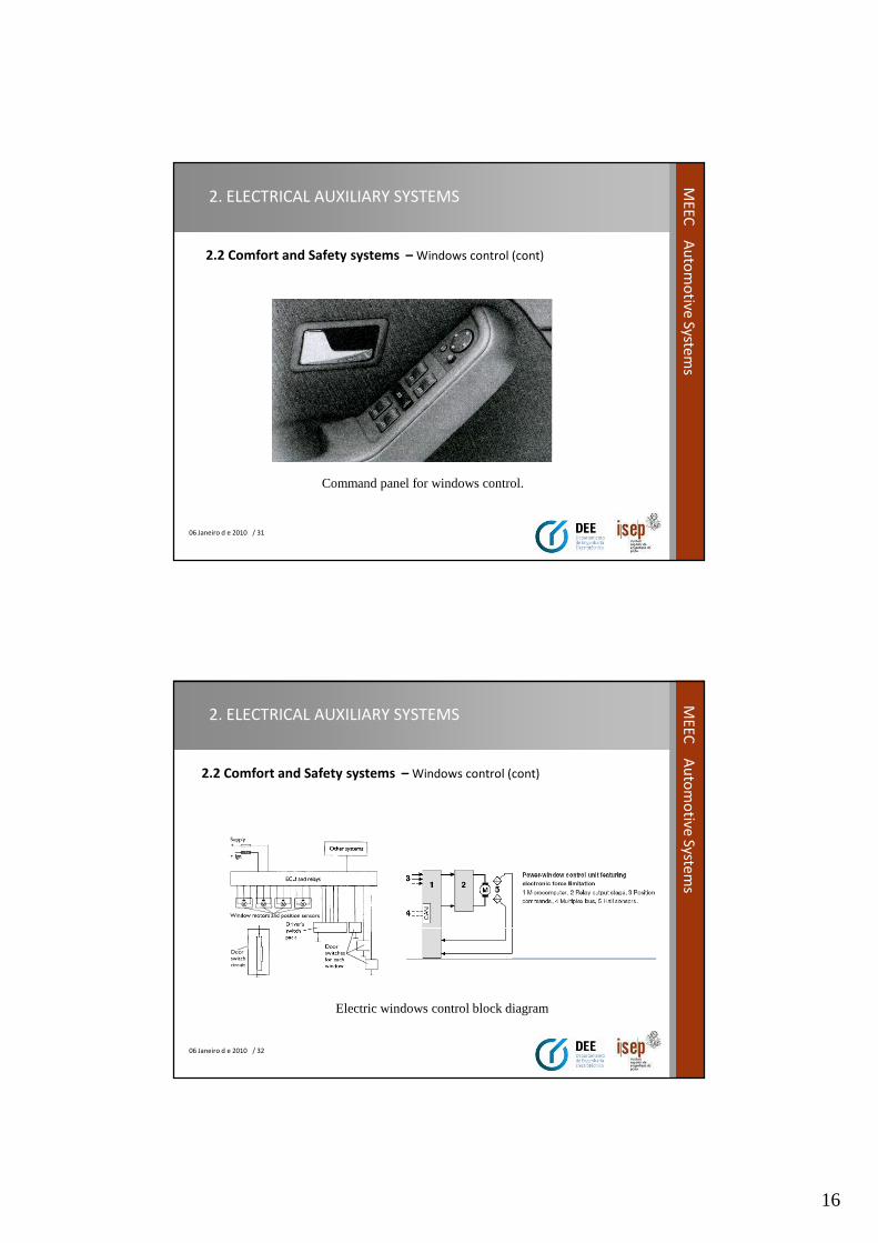
2.2 Comfort and Safety systems – Windows control (cont)
Command panel for windows control.
06 Janeiro d e 2010 / 32
ME
EC
Au
tom
otive
System
s
2. ELECTRICAL AUXILIARY SYSTEMS
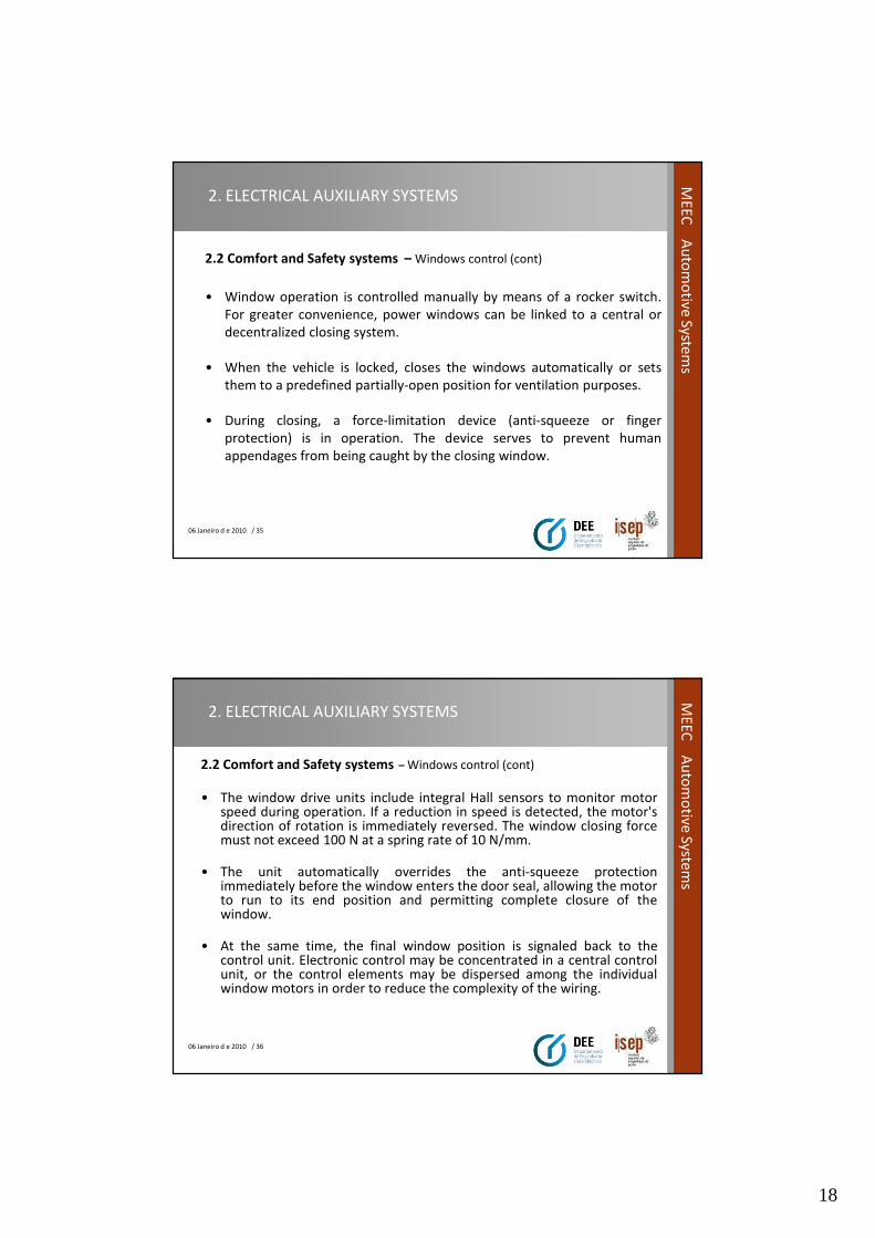
2.2 Comfort and Safety systems – Windows control (cont)
Electric windows control block diagram

17
06 Janeiro d e 2010 / 33
ME
EC
Au
tom
otive
System
s2. ELECTRICAL AUXILIARY SYSTEMS
2.2 Comfort and Safety systems– Windows control (cont)
Example of a simple control circuit.
06 Janeiro d e 2010 / 34
ME
EC
Au
tom
otive
System
s
2. ELECTRICAL AUXILIARY SYSTEMS
2.2 Comfort and Safety systems – Windows control (cont)
Control window location on doors
18
06 Janeiro d e 2010 / 35
ME
EC
Au
tom
otive
System
s2. ELECTRICAL AUXILIARY SYSTEMS
2.2 Comfort and Safety systems – Windows control (cont)
• Window operation is controlled manually by means of a rocker switch.
For greater convenience, power windows can be linked to a central or
decentralized closing system.
• When the vehicle is locked, closes the windows automatically or sets
them to a predefined partially-open position for ventilation purposes.
• During closing, a force-limitation device (anti-squeeze or finger
protection) is in operation. The device serves to prevent human
appendages from being caught by the closing window.
06 Janeiro d e 2010 / 36
ME
EC
Au
tom
otive
System
s
2. ELECTRICAL AUXILIARY SYSTEMS
2.2 Comfort and Safety systems – Windows control (cont)
• The window drive units include integral Hall sensors to monitor motorspeed during operation. If a reduction in speed is detected, the motor'sdirection of rotation is immediately reversed. The window closing forcemust not exceed 100 N at a spring rate of 10 N/mm.
• The unit automatically overrides the anti-squeeze protectionimmediately before the window enters the door seal, allowing the motorto run to its end position and permitting complete closure of thewindow.
• At the same time, the final window position is signaled back to thecontrol unit. Electronic control may be concentrated in a central controlunit, or the control elements may be dispersed among the individualwindow motors in order to reduce the complexity of the wiring.
19
06 Janeiro d e 2010 / 37
ME
EC
Au
tom
otive
System
s2. ELECTRICAL AUXILIARY SYSTEMS
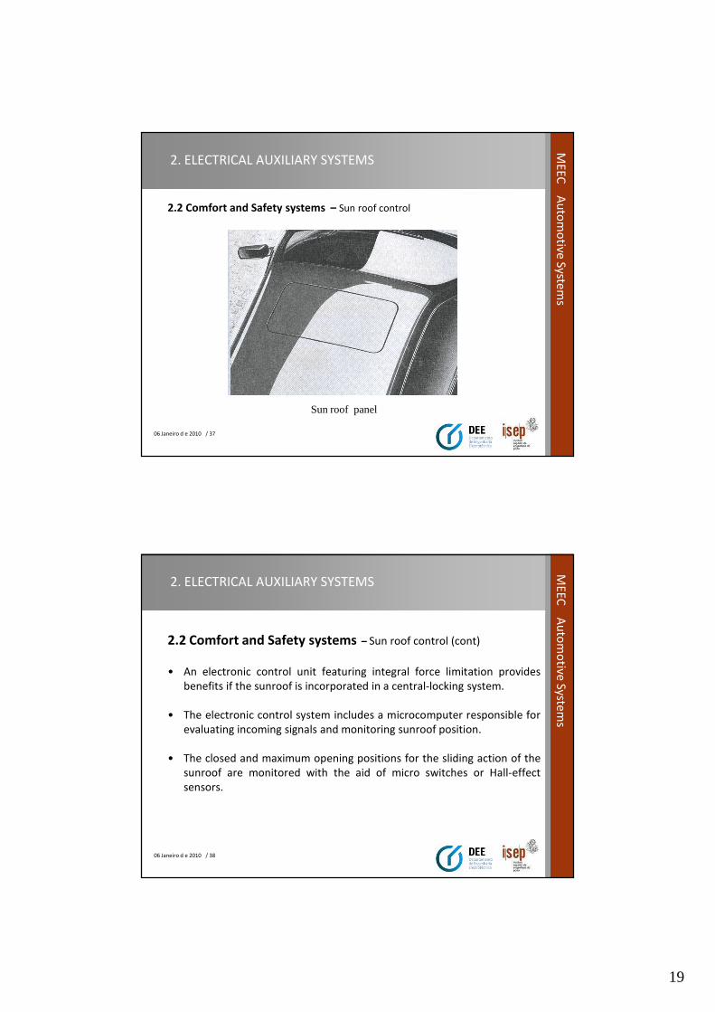
2.2 Comfort and Safety systems – Sun roof control
Sun roof panel
06 Janeiro d e 2010 / 38
ME
EC
Au
tom
otive
System
s
2. ELECTRICAL AUXILIARY SYSTEMS
2.2 Comfort and Safety systems – Sun roof control (cont)
• An electronic control unit featuring integral force limitation provides
benefits if the sunroof is incorporated in a central-locking system.
• The electronic control system includes a microcomputer responsible for
evaluating incoming signals and monitoring sunroof position.
• The closed and maximum opening positions for the sliding action of the
sunroof are monitored with the aid of micro switches or Hall-effect
sensors.
20
06 Janeiro d e 2010 / 39
ME
EC
Au
tom
otive
System
s2. ELECTRICAL AUXILIARY SYSTEMS
2.2 Comfort and Safety systems – Sun roof control (cont).
• Supplementary functions such as:
– preset position control,
– closing via rain sensor,
– motor-speed control,
– electronic motor protection,
06 Janeiro d e 2010 / 40
ME
EC
Au
tom
otive
System
s
2. ELECTRICAL AUXILIARY SYSTEMS
2.2 Comfort and Safety systems – Sun roof control (cont).
• The operation of an electric sun-roof is similar to the motor
reverse circuit discussed earlier in the windows control.
• However, further components and circuitry are needed to
allow the roof to slide, tilt and stop in the closed position.
21
06 Janeiro d e 2010 / 41
ME
EC
Au
tom
otive
System
s2. ELECTRICAL AUXILIARY SYSTEMS
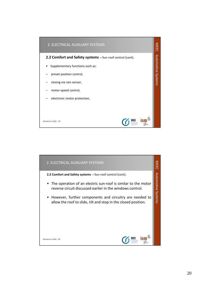
2.2 Comfort and Safety systems – Sun roof electric control (cont).
Sun roof parts
1- motor with reduction speed.2- slider car.3- command cable.4- roof panel.5- base for roof panel.6- Slide base for the roof panel.10 – Guide for slide the base for roof panel.7,9,11 – Base for slide the system.
Note: Speed is 10 to12 m/s.
06 Janeiro d e 2010 / 42
ME
EC
Au
tom
otive
System
s
2. ELECTRICAL AUXILIARY SYSTEMS
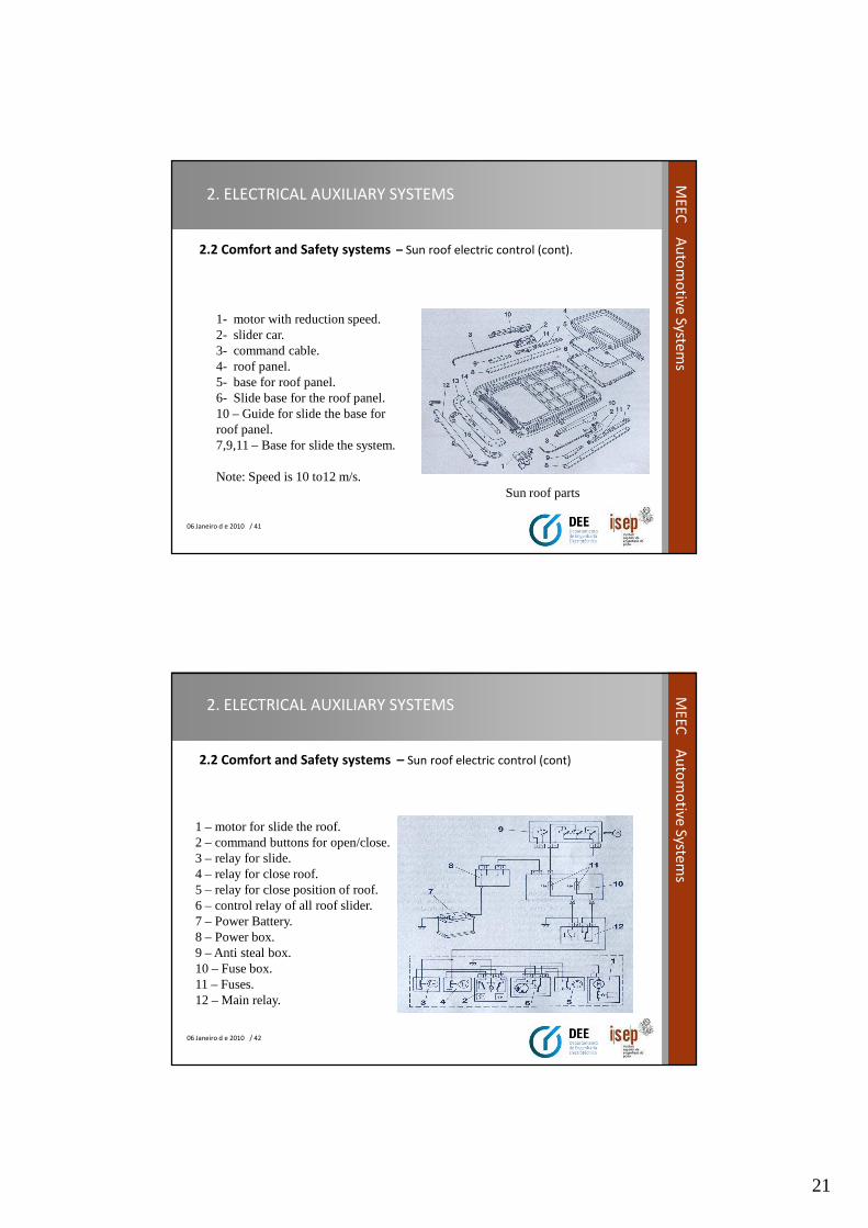
2.2 Comfort and Safety systems – Sun roof electric control (cont)
1 – motor for slide the roof.2 – command buttons for open/close.3 – relay for slide.4 – relay for close roof.5 – relay for close position of roof.6 – control relay of all roof slider.7 – Power Battery.8 – Power box.9 – Anti steal box.10 – Fuse box.11 – Fuses.12 – Main relay.
22
06 Janeiro d e 2010 / 43
ME
EC
Au
tom
otive
System
s2. ELECTRICAL AUXILIARY SYSTEMS
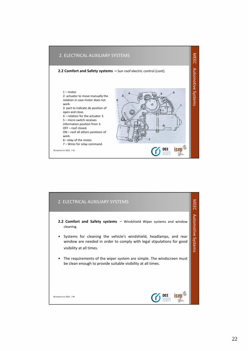
2.2 Comfort and Safety systems – Sun roof electric control (cont).
1 – motor.
2- actuator to move manually the
rotation in case motor does not
work.
3- part to indicate de position of
open and close.
4 – rotation for the actuator 3.
5 – micro switch receives
information position from 3.
OFF – roof closed.
ON – roof all others positions of
work.
6– relay of the motor.
7 – Wires for relay command.
06 Janeiro d e 2010 / 44
ME
EC
Au
tom
otive
System
s
2. ELECTRICAL AUXILIARY SYSTEMS
2.2 Comfort and Safety systems – Windshield Wiper systems and window
cleaning.
• Systems for cleaning the vehicle's windshield, headlamps, and rear
window are needed in order to comply with legal stipulations for good
visibility at all times.
• The requirements of the wiper system are simple. The windscreen must
be clean enough to provide suitable visibility at all times.
23
06 Janeiro d e 2010 / 45
ME
EC
Au
tom
otive
System
s2. ELECTRICAL AUXILIARY SYSTEMS
2.2 Comfort and Safety systems – Windshield wiper systems and window
cleaning (cont)
• To do this, the wiper system must meet the following requirements.
• Efficient removal of water and snow.
• Efficient removal of dirt.
• Operate at temperatures from -30 to 80 ° C.
• Pass the stall and snow load test.
• Service life in the region of 1500 000 wipe cycles.
06 Janeiro d e 2010 / 46
ME
EC
Au
tom
otive
System
s
2. ELECTRICAL AUXILIARY SYSTEMS
2.2 Comfort and Safety systems – Windshield wiper systems and window
cleaning (cont)
• Such systems can be subdivided as follows :
– Windshield wiper systems,
– Rear-window wiper systems,
– Headlamp wiper systems,
– Headlamp washer systems,
– Combination wiper-washer (wipe/wash) systems.
24
06 Janeiro d e 2010 / 47
ME
EC
Au
tom
otive
System
s2. ELECTRICAL AUXILIARY SYSTEMS
2.2 Comfort and Safety systems – Windshield wiper systems and window
cleaning (cont)
• The windshield wiper system must meet the following requirements:
– Removal of water and snow.
– Removal of dirt (mineral, organic or biological).
– Operation at high temperature (+ 80 °C) and low temperature (– 30
°C).
– Corrosion resistance against acids, alkalis, salts (240 h), ozone (72 h).
06 Janeiro d e 2010 / 48
ME
EC
Au
tom
otive
System
s
2. ELECTRICAL AUXILIARY SYSTEMS
2.2 Comfort and Safety systems – Windshield wiper systems and window
cleaning (cont)
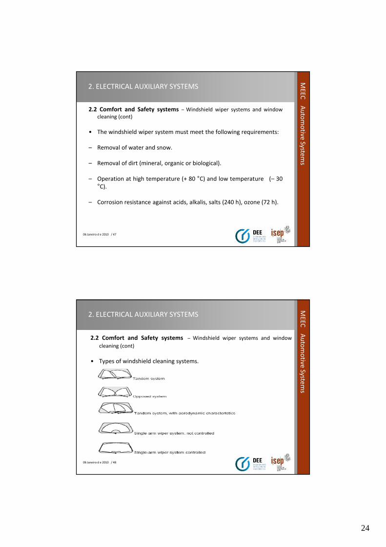
• Types of windshield cleaning systems.
25
06 Janeiro d e 2010 / 49
ME
EC
Au
tom
otive
System
s2. ELECTRICAL AUXILIARY SYSTEMS
2.2 Comfort and Safety systems – Windshield wiper systems and window
cleaning (cont)
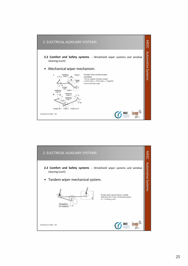
• Mechanical wiper mechanism.
06 Janeiro d e 2010 / 50
ME
EC
Au
tom
otive
System
s
2. ELECTRICAL AUXILIARY SYSTEMS
2.2 Comfort and Safety systems – Windshield wiper systems and window
cleaning (cont)
• Tandem wiper mechanical system.
26
06 Janeiro d e 2010 / 51
ME
EC
Au
tom
otive
System
s2. ELECTRICAL AUXILIARY SYSTEMS
2.2 Comfort and Safety systems – Windshield wiper systems and window
cleaning (cont)
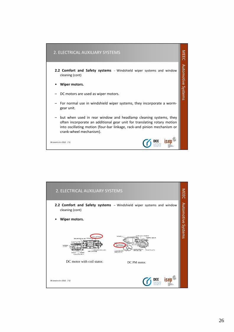
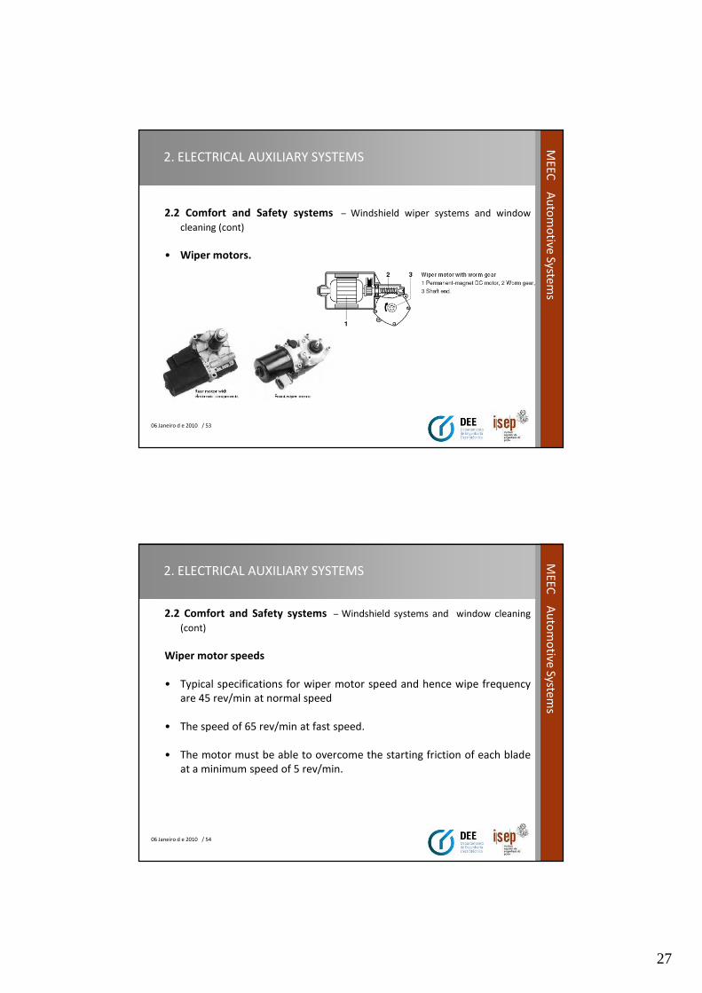
• Wiper motors.
– DC motors are used as wiper motors.
– For normal use in windshield wiper systems, they incorporate a worm-
gear unit.
– but when used in rear window and headlamp cleaning systems, they
often incorporate an additional gear unit for translating rotary motion
into oscillating motion (four-bar linkage, rack-and pinion mechanism or
crank-wheel mechanism).
06 Janeiro d e 2010 / 52
ME
EC
Au
tom
otive
System
s
2. ELECTRICAL AUXILIARY SYSTEMS
2.2 Comfort and Safety systems – Windshield wiper systems and window
cleaning (cont)
• Wiper motors.
DC motor with coil stator. DC PM motor.
27
06 Janeiro d e 2010 / 53
ME
EC
Au
tom
otive
System
s2. ELECTRICAL AUXILIARY SYSTEMS
2.2 Comfort and Safety systems – Windshield wiper systems and window
cleaning (cont)
• Wiper motors.
06 Janeiro d e 2010 / 54
ME
EC
Au
tom
otive
System
s
2. ELECTRICAL AUXILIARY SYSTEMS
2.2 Comfort and Safety systems – Windshield systems and window cleaning
(cont)
Wiper motor speeds
• Typical specifications for wiper motor speed and hence wipe frequency
are 45 rev/min at normal speed
• The speed of 65 rev/min at fast speed.
• The motor must be able to overcome the starting friction of each blade
at a minimum speed of 5 rev/min.
28
06 Janeiro d e 2010 / 55
ME
EC
Au
tom
otive
System
s2. ELECTRICAL AUXILIARY SYSTEMS
2.2 Comfort and Safety systems – Windshield wiper systems and window
cleaning (cont)
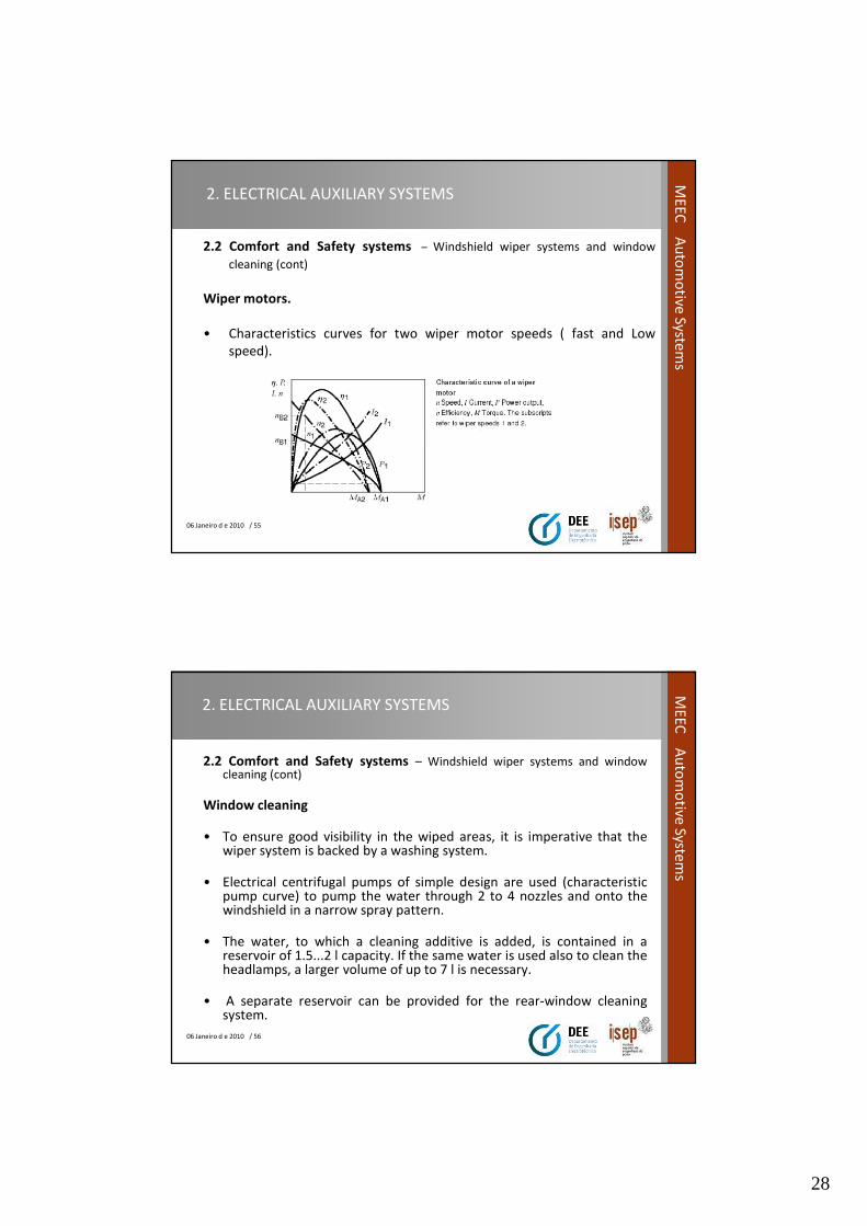
Wiper motors.
• Characteristics curves for two wiper motor speeds ( fast and Low
speed).
06 Janeiro d e 2010 / 56
ME
EC
Au
tom
otive
System
s
2. ELECTRICAL AUXILIARY SYSTEMS
2.2 Comfort and Safety systems – Windshield wiper systems and windowcleaning (cont)
Window cleaning
• To ensure good visibility in the wiped areas, it is imperative that thewiper system is backed by a washing system.
• Electrical centrifugal pumps of simple design are used (characteristicpump curve) to pump the water through 2 to 4 nozzles and onto thewindshield in a narrow spray pattern.
• The water, to which a cleaning additive is added, is contained in areservoir of 1.5...2 l capacity. If the same water is used also to clean theheadlamps, a larger volume of up to 7 l is necessary.
• A separate reservoir can be provided for the rear-window cleaningsystem.
29
06 Janeiro d e 2010 / 57
ME
EC
Au
tom
otive
System
s2. ELECTRICAL AUXILIARY SYSTEMS
2.2 Comfort and Safety systems – Windshield wiper systems and window
cleaning (cont)
Window cleaning.
• The washing system is often coupled to the corresponding wiper system
by means of an electronic control.
• The water is sprayed onto the window or windshield while a pushbutton
is pressed,
• The wiper system continuing to operate for several additional cycles
after the pushbutton is released.
06 Janeiro d e 2010 / 58
ME
EC
Au
tom
otive
System
s
2. ELECTRICAL AUXILIARY SYSTEMS
2.2 Comfort and Safety systems – Windshield wiper systems and window
cleaning (cont)
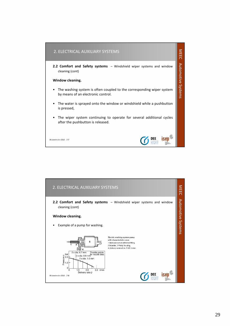
Window cleaning.
• Example of a pump for washing.
30
06 Janeiro d e 2010 / 59
ME
EC
Au
tom
otive
System
s2. ELECTRICAL AUXILIARY SYSTEMS
2.2 Comfort and Safety systems – Windshield wiper systems and window
cleaning (cont)
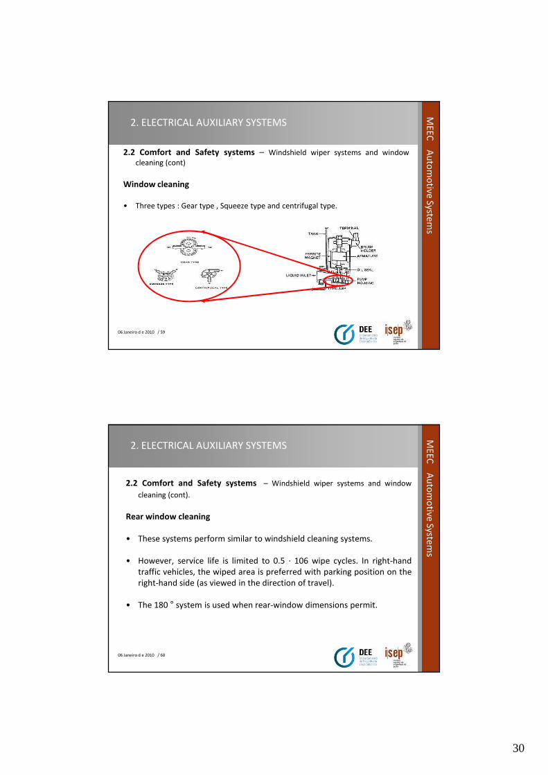
Window cleaning
• Three types : Gear type , Squeeze type and centrifugal type.
06 Janeiro d e 2010 / 60
ME
EC
Au
tom
otive
System
s
2. ELECTRICAL AUXILIARY SYSTEMS
2.2 Comfort and Safety systems – Windshield wiper systems and window
cleaning (cont).
Rear window cleaning
• These systems perform similar to windshield cleaning systems.
• However, service life is limited to 0.5 · 106 wipe cycles. In right-hand
traffic vehicles, the wiped area is preferred with parking position on the
right-hand side (as viewed in the direction of travel).
• The 180 ° system is used when rear-window dimensions permit.
31
06 Janeiro d e 2010 / 61
ME
EC
Au
tom
otive
System
s2. ELECTRICAL AUXILIARY SYSTEMS
2.2 Comfort and Safety systems – Windshield wiper systems and window
cleaning (cont).
Rear window cleaning
• The cleaning and washing of rear window could have a designated reservoir as
mention on previous information.
• The Electronic control unit only gives order to send the cleaning liquid during the
actuation of correlated function button.
• After release the button the rear wiper still running during several seconds.
06 Janeiro d e 2010 / 62
ME
EC
Au
tom
otive
System
s
2. ELECTRICAL AUXILIARY SYSTEMS
2.2 Comfort and Safety systems - Windshield wiper systems and window
cleaning (cont).
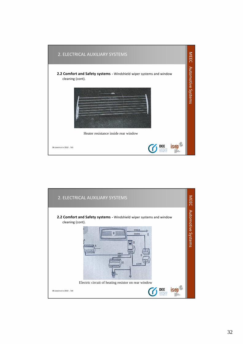
• Anti fog heater on rear window.
– The system includes a heating resistance in crystal that avoids the
condensation effect of humidity in the glass window.
– The resistance is composed of a very thin wire inserted in the crystal,
witch is powered by the battery .
– The temperature achieved in the window eliminates the ice, snow and
condensation during winter.
32
06 Janeiro d e 2010 / 63
ME
EC
Au
tom
otive
System
s2. ELECTRICAL AUXILIARY SYSTEMS
2.2 Comfort and Safety systems - Windshield wiper systems and window
cleaning (cont).
Heater resistance inside rear window
06 Janeiro d e 2010 / 64
ME
EC
Au
tom
otive
System
s
2. ELECTRICAL AUXILIARY SYSTEMS
2.2 Comfort and Safety systems - Windshield wiper systems and window
cleaning (cont).
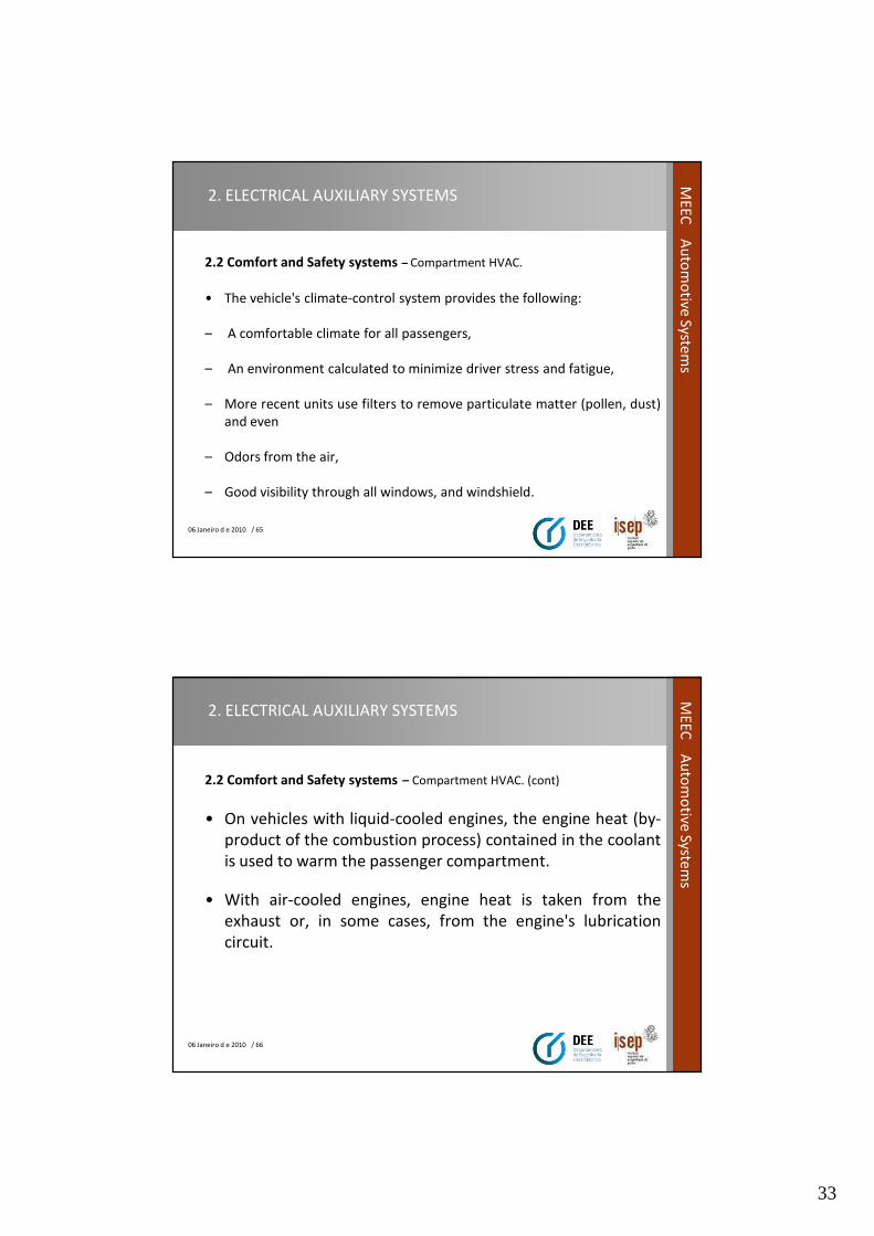
Electric circuit of heating resistor on rear window
33
06 Janeiro d e 2010 / 65
ME
EC
Au
tom
otive
System
s2. ELECTRICAL AUXILIARY SYSTEMS
2.2 Comfort and Safety systems – Compartment HVAC.
• The vehicle's climate-control system provides the following:
– A comfortable climate for all passengers,
– An environment calculated to minimize driver stress and fatigue,
– More recent units use filters to remove particulate matter (pollen, dust)
and even
– Odors from the air,
– Good visibility through all windows, and windshield.
06 Janeiro d e 2010 / 66
ME
EC
Au
tom
otive
System
s
2. ELECTRICAL AUXILIARY SYSTEMS
2.2 Comfort and Safety systems – Compartment HVAC. (cont)
• On vehicles with liquid-cooled engines, the engine heat (by-
product of the combustion process) contained in the coolant
is used to warm the passenger compartment.
• With air-cooled engines, engine heat is taken from the
exhaust or, in some cases, from the engine's lubrication
circuit.
34
06 Janeiro d e 2010 / 67
ME
EC
Au
tom
otive
System
s2. ELECTRICAL AUXILIARY SYSTEMS
2.2 Comfort and Safety systems – Compartment HVAC. (cont)
Air Condition
• The heater unit alone is not capable of providing a comfortable environment atall times. When the outside temperature climbs beyond 20 °C, the air must becooled to achieve the required interior temperatures.
• Here, compressor-driven refrigeration units with R 134a refrigerant are in use(until 1992, R12 refrigerant).
• The engine-driven compressor compresses the vaporous refrigerant, which heatsup in the process and is then directed to the condenser where it cools andliquefies.
• The energy supplied in the compressor and the heat absorbed in the evaporatorare dissipated to the environment here.
06 Janeiro d e 2010 / 68
ME
EC
Au
tom
otive
System
s
2. ELECTRICAL AUXILIARY SYSTEMS
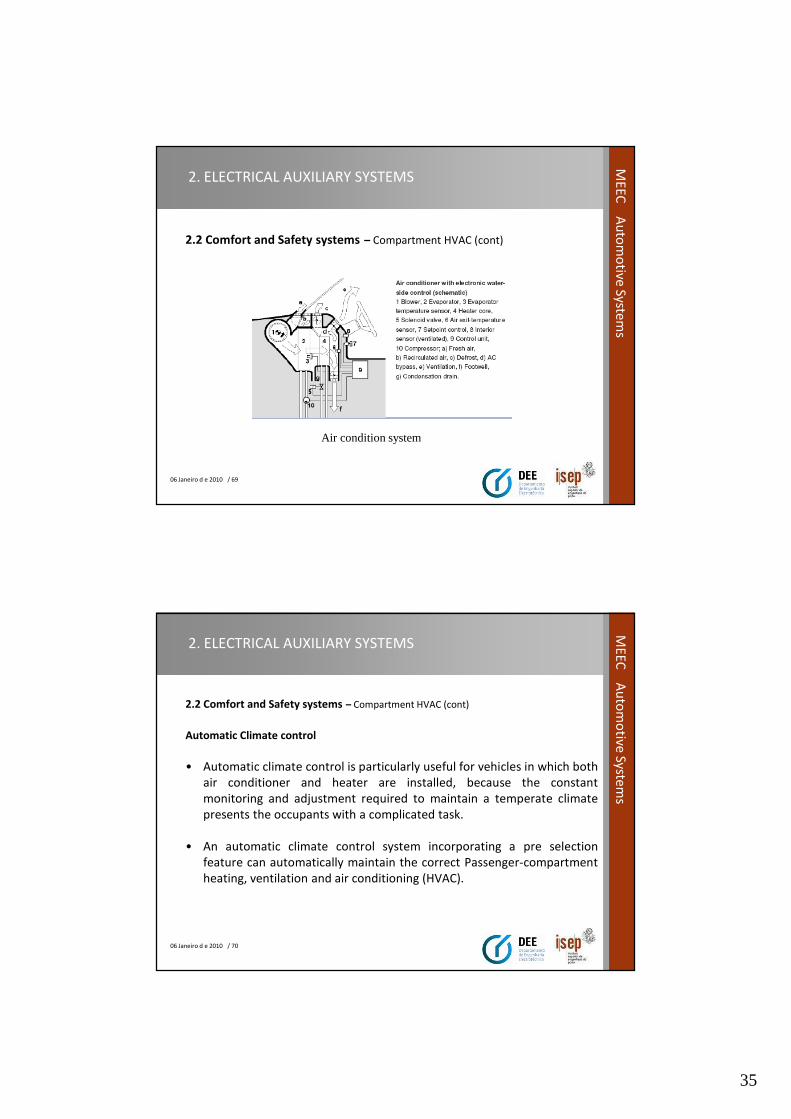
2.2 Comfort and Safety systems – Compartment HVAC. (cont)
• An expansion valve sprays the cooled liquid into the evaporator where theevaporation process extracts the required evaporation heat from the incomingstream of fresh air, thereby cooling the air.
• Moisture is extracted from the cooled air as condensation, and the air's humidityis reduced to the desired level.
• Evaporators and condensers are generally designed as tube-and-fin heatexchangers.
• The evaporator is located before the heater core in the fresh-air stream andcools the air
• to approx. 3...5 °C. The dehumidified air is reheated in the heater core to thedesired temperature.
35
06 Janeiro d e 2010 / 69
ME
EC
Au
tom
otive
System
s2. ELECTRICAL AUXILIARY SYSTEMS
2.2 Comfort and Safety systems – Compartment HVAC (cont)
Air condition system
06 Janeiro d e 2010 / 70
ME
EC
Au
tom
otive
System
s
2. ELECTRICAL AUXILIARY SYSTEMS
2.2 Comfort and Safety systems – Compartment HVAC (cont)
Automatic Climate control
• Automatic climate control is particularly useful for vehicles in which both
air conditioner and heater are installed, because the constant
monitoring and adjustment required to maintain a temperate climate
presents the occupants with a complicated task.
• An automatic climate control system incorporating a pre selection
feature can automatically maintain the correct Passenger-compartment
heating, ventilation and air conditioning (HVAC).
36
06 Janeiro d e 2010 / 71
ME
EC
Au
tom
otive
System
s2. ELECTRICAL AUXILIARY SYSTEMS
2.2 Comfort and Safety systems – Compartment HVAC. (cont)
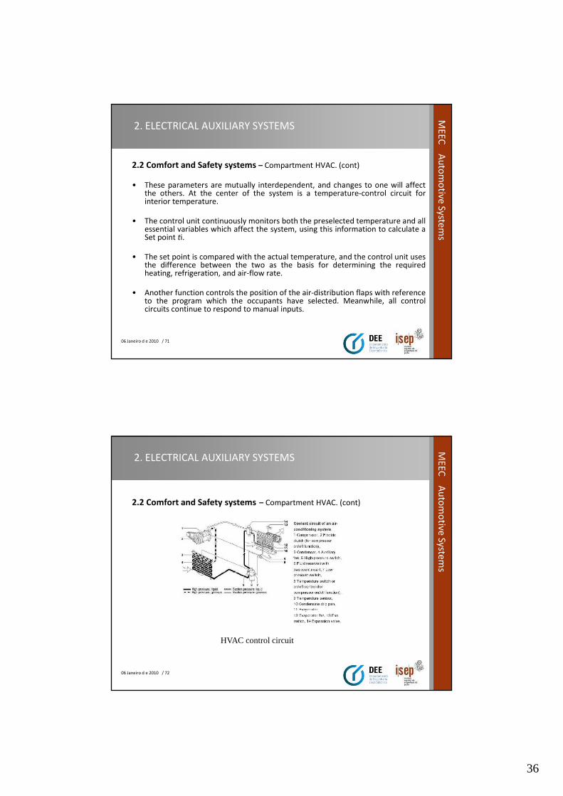
• These parameters are mutually interdependent, and changes to one will affectthe others. At the center of the system is a temperature-control circuit forinterior temperature.
• The control unit continuously monitors both the preselected temperature and allessential variables which affect the system, using this information to calculate aSet point ti.
• The set point is compared with the actual temperature, and the control unit usesthe difference between the two as the basis for determining the requiredheating, refrigeration, and air-flow rate.
• Another function controls the position of the air-distribution flaps with referenceto the program which the occupants have selected. Meanwhile, all controlcircuits continue to respond to manual inputs.
06 Janeiro d e 2010 / 72
ME
EC
Au
tom
otive
System
s
2. ELECTRICAL AUXILIARY SYSTEMS
2.2 Comfort and Safety systems – Compartment HVAC. (cont)
HVAC control circuit
37
06 Janeiro d e 2010 / 73
ME
EC
Au
tom
otive
System
s2. ELECTRICAL AUXILIARY SYSTEMS
2.2 Comfort and Safety systems – Compartment HVAC. (cont)
• The set point temperature determined by the control unit is achieved bymeans of water or air-side adjustments Infinitely-variable or graduatedblower control is used to adjust the air flow to the specified level.
• There is generally no set point processing involved in this operation. Thistype of arrangement is inadequate for dealing with the increases in flowrate caused by aerodynamic pressure at high speeds.
• Here, a special control function can compensate by responding toincreasing vehicle speeds, initially by reducing the blower speed to zero,and then, should the flow continue to rise, by using a restriction flap tothrottle the stream of incoming air.
06 Janeiro d e 2010 / 74
ME
EC
Au
tom
otive
System
s
2. ELECTRICAL AUXILIARY SYSTEMS
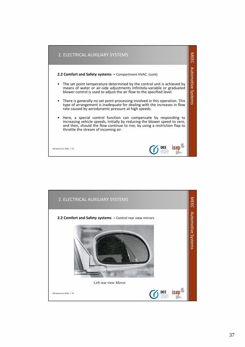
2.2 Comfort and Safety systems – Control rear view mirrors
Left rear view Mirror
38
06 Janeiro d e 2010 / 75
ME
EC
Au
tom
otive
System
s2. ELECTRICAL AUXILIARY SYSTEMS
2.2 Comfort and Safety systems – Control rear view mirrors (cont)
• It is the main propose of the system move the rear view mirrors in all directions,
so that the driver can adjust his rear view to the seat position.
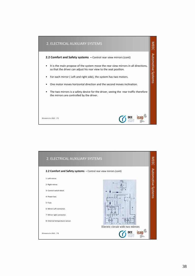
• For each mirror ( Left and right side), the system has two motors.
• One motor moves horizontal direction and the second moves inclination.
• The two mirrors is a safety device for the driver, seeing the rear traffic therefore
the mirrors are controlled by the driver.
06 Janeiro d e 2010 / 76
ME
EC
Au
tom
otive
System
s
2. ELECTRICAL AUXILIARY SYSTEMS
2.2 Comfort and Safety systems – Control rear view mirrors (cont)
1- Left mirror.
2- Right mirror.
3- Control switch block.
4- Power box.
5- Fuse.
6- Mirror Left connector.
7- Mirror right connector.
8- External temperature sensor.
Electric circuit with two mirrors
39
06 Janeiro d e 2010 / 77
ME
EC
Au
tom
otive
System
s2. ELECTRICAL AUXILIARY SYSTEMS
2.3 Lighting systems – Front Lighting
• The primary function of the headlamps at the vehicle front end is to
illuminate the roadway so that the driver can register the traffic
conditions and recognize any obstacles and hazards in good time.
• They also serve to identify and mark out the vehicle to oncoming traffic.
• The turn-signal lamps serve to show the driver's intention to change
direction or to indicate a hazardous situation.
06 Janeiro d e 2010 / 78
ME
EC
Au
tom
otive
System
s
2. ELECTRICAL AUXILIARY SYSTEMS
2.3 Lighting systems – Front Lighting (cont)
The headlamps and lights at the front end include the following:
• Low-/high-beam headlamps.
• Fog lamps.
• Auxiliary driving lamps.
• Turn-signal lamps.
40
06 Janeiro d e 2010 / 79
ME
EC
Au
tom
otive
System
s2. ELECTRICAL AUXILIARY SYSTEMS
2.3 Lighting systems – Front Lighting (cont)
Main head beam lamps
• The high traffic density on modern roads severely restricts the use of high-beamheadlamps. Under most standard conditions, the low beams are the actualdriving lamps. Basic design modifications have allowed substantialimprovements in low-beam performance. These include:
• Introduction of the asymmetrical low-beam pattern, characterized by anextended visual range along the right side of the road, Official approval forvarious types of halogen lamps, making it possible to enhance the luminousintensity at the road surface by 50 ... 80 %.
• Introduction of innovative headlamp systems featuring complex geometricalconfigurations designed to improve efficiency levels by up to 50 %.
• The "Litronic" gaseous-discharge headlamp (with luminous arc) supplies morethan twice the light generated by comparable halogen units.
06 Janeiro d e 2010 / 80
ME
EC
Au
tom
otive
System
s
2. ELECTRICAL AUXILIARY SYSTEMS
2.3 Lighting systems – Front Lighting (cont)
• Modern headlamps are electrically operated, positioned in pairs, one or
two on each side of the front of a vehicle.
• A headlamp system is required to produce a low and a high beam,( Low-
beam used according legislation) which may be achieved either by an
individual lamp for each function or by a single multifunction lamp.
• High beams (called "main beams" or "full beams" or "driving beams" in
some countries) cast most of their light straight ahead, maximizing
seeing distance, but producing too much glare for safe use when other
vehicles are present on the road.
41
06 Janeiro d e 2010 / 81
ME
EC
Au
tom
otive
System
s2. ELECTRICAL AUXILIARY SYSTEMS
2.3 Lighting systems – Front Lighting (cont)
• Because there is no special control of upward light, high beams also
cause back dazzle from fog, rain and snow due to the retro reflection of
the water droplets.
• Low beams (called "dipped beams" in some countries) have stricter
control of upward light, and direct most of their light downward and
either rightward (in right-traffic countries) or leftward (in left-traffic
countries), to provide safe forward visibility without excessive glare or
back dazzle.
06 Janeiro d e 2010 / 82
ME
EC
Au
tom
otive
System
s
2. ELECTRICAL AUXILIARY SYSTEMS
2.3 Lighting systems – Front Lighting (cont)
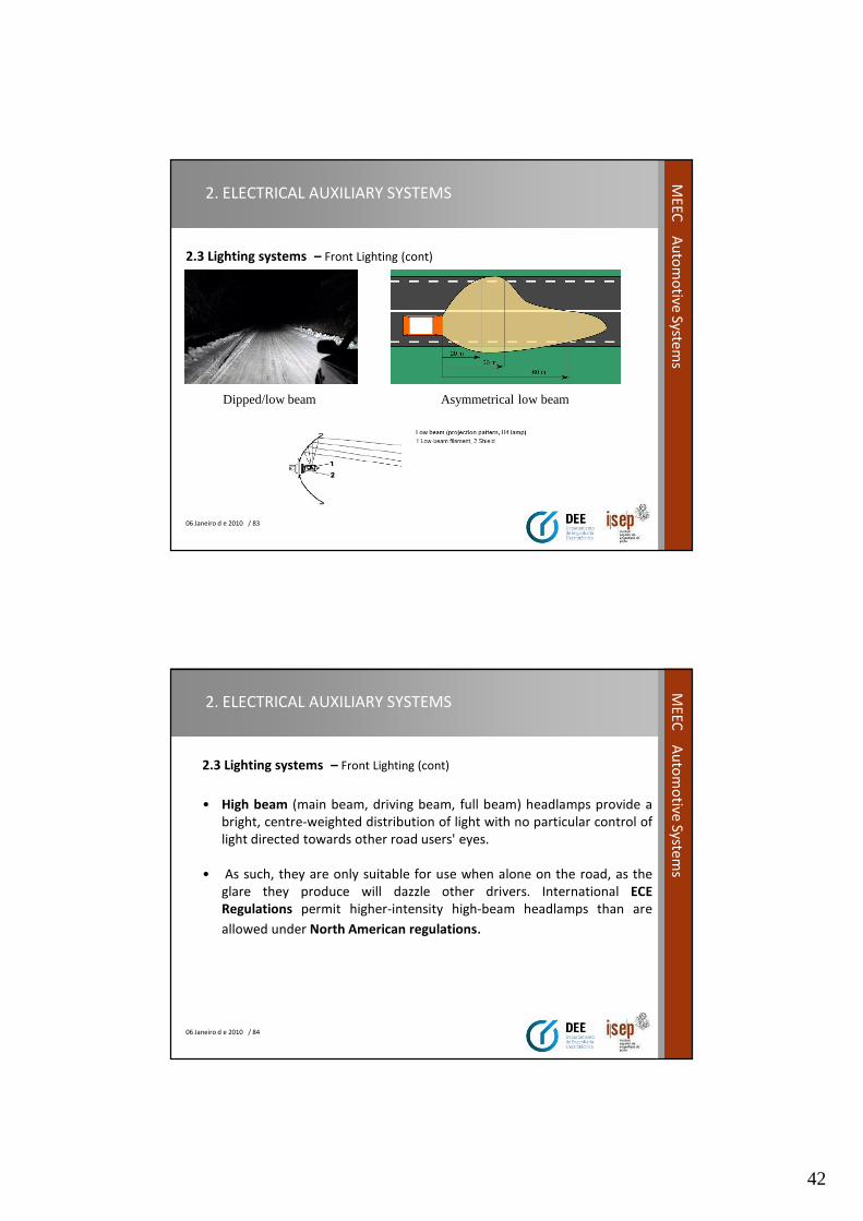
• Low beam (dipped beam, passing beam, meeting beam) headlampsprovide a distribution of light designed to provide adequate forward andlateral illumination with limits on light directed towards the eyes ofother road users, to control glare.
• This beam is intended for use whenever other vehicles are presentahead. The international ECE Regulations for filament headlamps andfor high-intensity discharge headlamps specify a beam with a sharp,asymmetric cutoff preventing significant amounts of light from beingcast into the eyes of drivers of preceding or oncoming cars.
• Control of glare is less strict in the North American SAE beam standard.
42
06 Janeiro d e 2010 / 83
ME
EC
Au
tom
otive
System
s2. ELECTRICAL AUXILIARY SYSTEMS
2.3 Lighting systems – Front Lighting (cont)
Dipped/low beam Asymmetrical low beam
06 Janeiro d e 2010 / 84
ME
EC
Au
tom
otive
System
s
2. ELECTRICAL AUXILIARY SYSTEMS
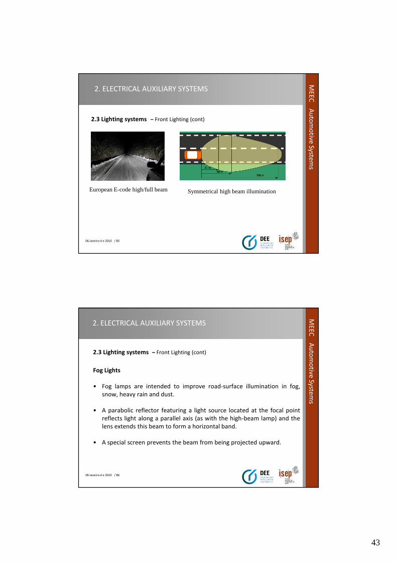
2.3 Lighting systems – Front Lighting (cont)
• High beam (main beam, driving beam, full beam) headlamps provide a
bright, centre-weighted distribution of light with no particular control of
light directed towards other road users' eyes.
• As such, they are only suitable for use when alone on the road, as the
glare they produce will dazzle other drivers. International ECE
Regulations permit higher-intensity high-beam headlamps than are
allowed under North American regulations.
43
06 Janeiro d e 2010 / 85
ME
EC
Au
tom
otive
System
s2. ELECTRICAL AUXILIARY SYSTEMS
2.3 Lighting systems – Front Lighting (cont)
European E-code high/full beam Symmetrical high beam illumination
06 Janeiro d e 2010 / 86
ME
EC
Au
tom
otive
System
s
2. ELECTRICAL AUXILIARY SYSTEMS
2.3 Lighting systems – Front Lighting (cont)
Fog Lights
• Fog lamps are intended to improve road-surface illumination in fog,
snow, heavy rain and dust.
• A parabolic reflector featuring a light source located at the focal point
reflects light along a parallel axis (as with the high-beam lamp) and the
lens extends this beam to form a horizontal band.
• A special screen prevents the beam from being projected upward.

44
06 Janeiro d e 2010 / 87
ME
EC
Au
tom
otive
System
s2. ELECTRICAL AUXILIARY SYSTEMS
2.3 Lighting systems – Front Lighting (cont)
• In fog, this technology minimizes the glare reflected back to the driver.
The screen, the image of which is projected onto the road surface by the
lens, furnishes maximum contrast at the light/dark cutoff line.
06 Janeiro d e 2010 / 88
ME
EC
Au
tom
otive
System
s
2. ELECTRICAL AUXILIARY SYSTEMS
2.3 Lighting systems – Front Lighting (cont)
• Two white- or yellow-light fog lamps are permitted. The
control circuit for switching the fog lamps must be
independent of that used for high and low beams.
• The (German) law allows fog-lamp installation in positions
more than 400 mm from the widest point of the vehicle's
periphery provided that the switching circuit is designed to
ensure that they operate only in conjunction with the low
beams.
45
06 Janeiro d e 2010 / 89
ME
EC
Au
tom
otive
System
s2. ELECTRICAL AUXILIARY SYSTEMS
2.3 Lighting systems – Front Lighting (cont)
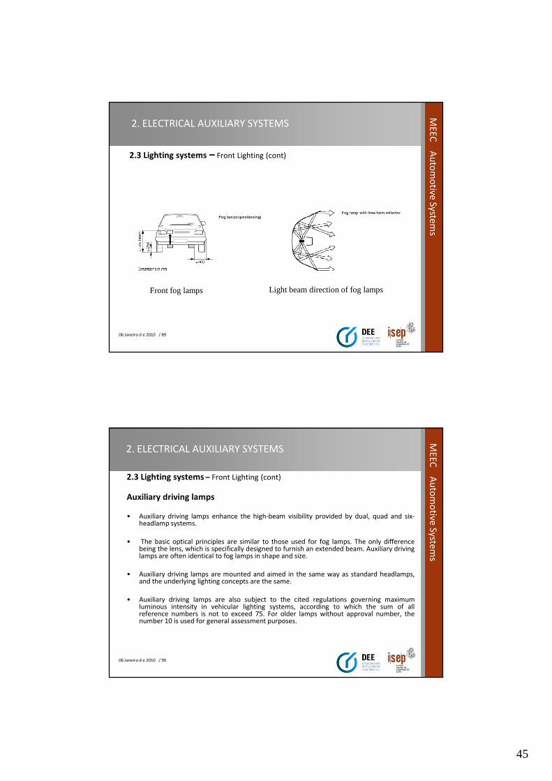
Front fog lamps Light beam direction of fog lamps
06 Janeiro d e 2010 / 90
ME
EC
Au
tom
otive
System
s
2. ELECTRICAL AUXILIARY SYSTEMS
2.3 Lighting systems – Front Lighting (cont)
Auxiliary driving lamps
• Auxiliary driving lamps enhance the high-beam visibility provided by dual, quad and six-headlamp systems.
• The basic optical principles are similar to those used for fog lamps. The only differencebeing the lens, which is specifically designed to furnish an extended beam. Auxiliary drivinglamps are often identical to fog lamps in shape and size.
• Auxiliary driving lamps are mounted and aimed in the same way as standard headlamps,and the underlying lighting concepts are the same.
• Auxiliary driving lamps are also subject to the cited regulations governing maximumluminous intensity in vehicular lighting systems, according to which the sum of allreference numbers is not to exceed 75. For older lamps without approval number, thenumber 10 is used for general assessment purposes.
46
06 Janeiro d e 2010 / 91
ME
EC
Au
tom
otive
System
s2. ELECTRICAL AUXILIARY SYSTEMS
2.3 Lighting systems – Front Lighting (cont)
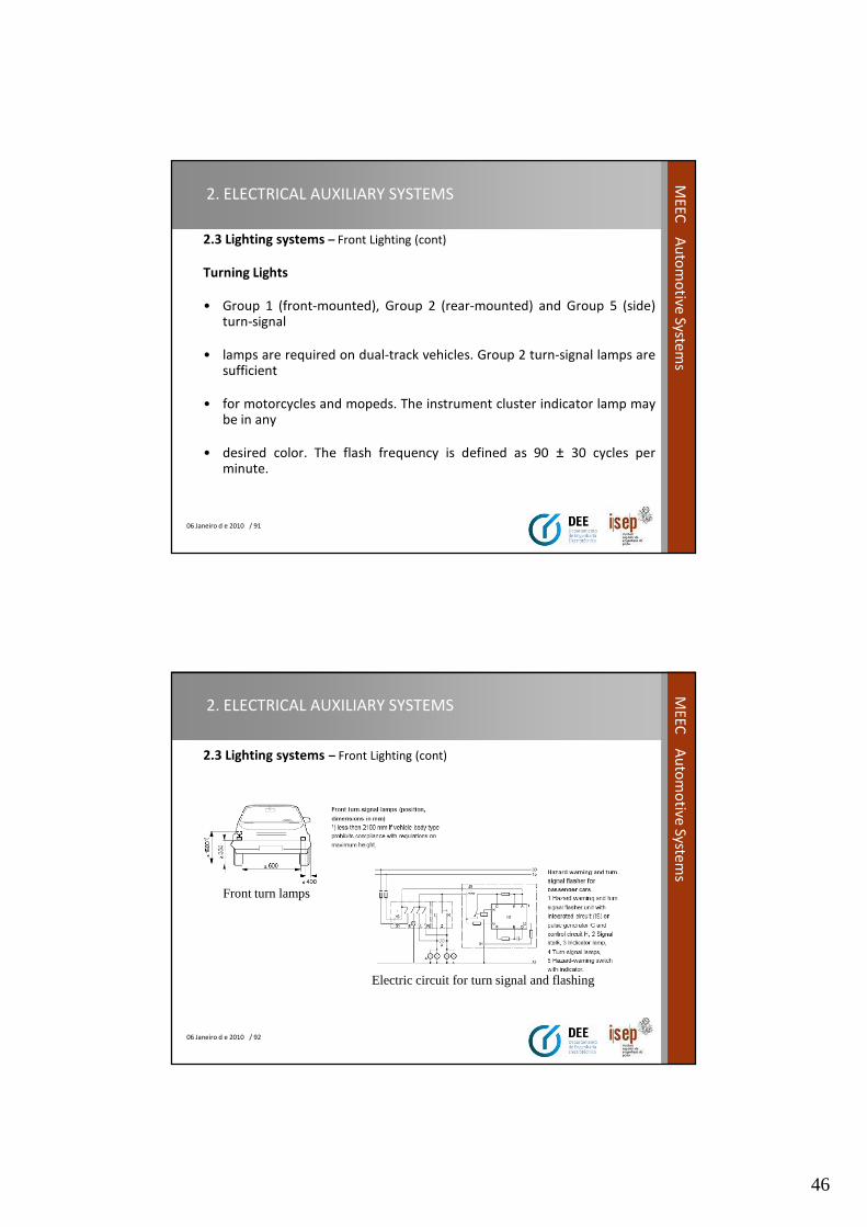
Turning Lights
• Group 1 (front-mounted), Group 2 (rear-mounted) and Group 5 (side)turn-signal
• lamps are required on dual-track vehicles. Group 2 turn-signal lamps aresufficient
• for motorcycles and mopeds. The instrument cluster indicator lamp maybe in any
• desired color. The flash frequency is defined as 90 ± 30 cycles perminute.
06 Janeiro d e 2010 / 92
ME
EC
Au
tom
otive
System
s
2. ELECTRICAL AUXILIARY SYSTEMS
2.3 Lighting systems – Front Lighting (cont)
Electric circuit for turn signal and flashing
Front turn lamps
47
06 Janeiro d e 2010 / 93
ME
EC
Au
tom
otive
System
s2. ELECTRICAL AUXILIARY SYSTEMS
2.3 Lighting systems – Rear Lighting
• Lights are turned on at the vehicle's rear end in accordance with the
weather conditions and indicate the vehicle's position.
• They also indicate how the vehicle is moving and in which direction, e.g.
whether it is traveling un-braked straight ahead, or whether the brakes
are applied or the driver is intending to change direction, or whether a
hazardous situation exists.
• The backup lamps illuminate the roadway while the vehicle is backing
up/reversing.
06 Janeiro d e 2010 / 94
ME
EC
Au
tom
otive
System
s
2. ELECTRICAL AUXILIARY SYSTEMS
2.3 Lighting systems – Rear Lighting (cont)
The lamps/lights at the rear end include the following:
• Stop lamps.
• Tail lamps.
• Fog warning lamps.
• Turn-signal lamps.
• Parking lamps.
• License-plate lamps and Back-up lamps.
48
06 Janeiro d e 2010 / 95
ME
EC
Au
tom
otive
System
s2. ELECTRICAL AUXILIARY SYSTEMS
2.3 Lighting systems – Rear Lighting (cont)
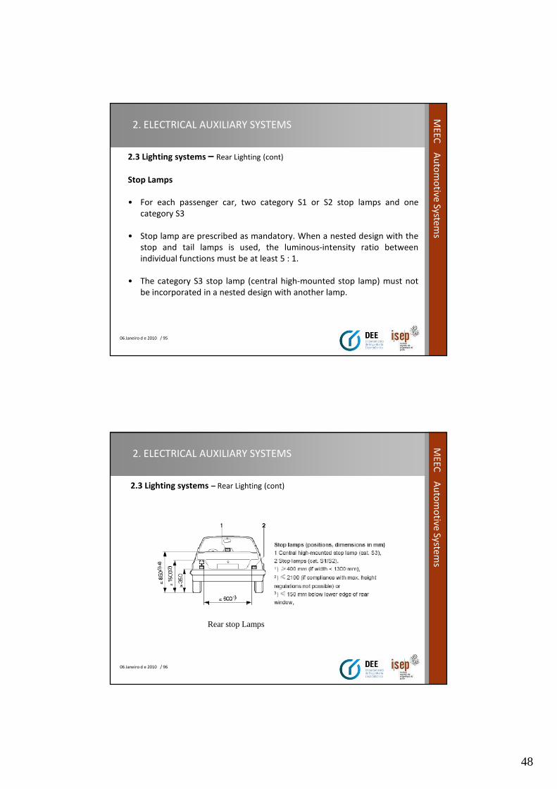
Stop Lamps
• For each passenger car, two category S1 or S2 stop lamps and one
category S3
• Stop lamp are prescribed as mandatory. When a nested design with the
stop and tail lamps is used, the luminous-intensity ratio between
individual functions must be at least 5 : 1.
• The category S3 stop lamp (central high-mounted stop lamp) must not
be incorporated in a nested design with another lamp.
06 Janeiro d e 2010 / 96
ME
EC
Au
tom
otive
System
s
2. ELECTRICAL AUXILIARY SYSTEMS
2.3 Lighting systems – Rear Lighting (cont)
Rear stop Lamps
49
06 Janeiro d e 2010 / 97
ME
EC
Au
tom
otive
System
s2. ELECTRICAL AUXILIARY SYSTEMS
2.3 Lighting systems – Rear Lighting
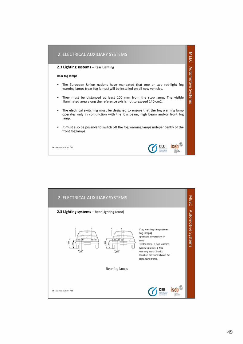
Rear fog lamps
• The European Union nations have mandated that one or two red-light fogwarning lamps (rear fog lamps) will be installed on all new vehicles.
• They must be distanced at least 100 mm from the stop lamp. The visibleilluminated area along the reference axis is not to exceed 140 cm2.
• The electrical switching must be designed to ensure that the fog warning lampoperates only in conjunction with the low beam, high beam and/or front foglamp.
• It must also be possible to switch off the fog warning lamps independently of thefront fog lamps.
06 Janeiro d e 2010 / 98
ME
EC
Au
tom
otive
System
s
2. ELECTRICAL AUXILIARY SYSTEMS
2.3 Lighting systems – Rear Lighting (cont)
Rear fog lamps
50
06 Janeiro d e 2010 / 99
ME
EC
Au
tom
otive
System
s2. ELECTRICAL AUXILIARY SYSTEMS
2.3 Lighting systems – Rear Lighting (cont)
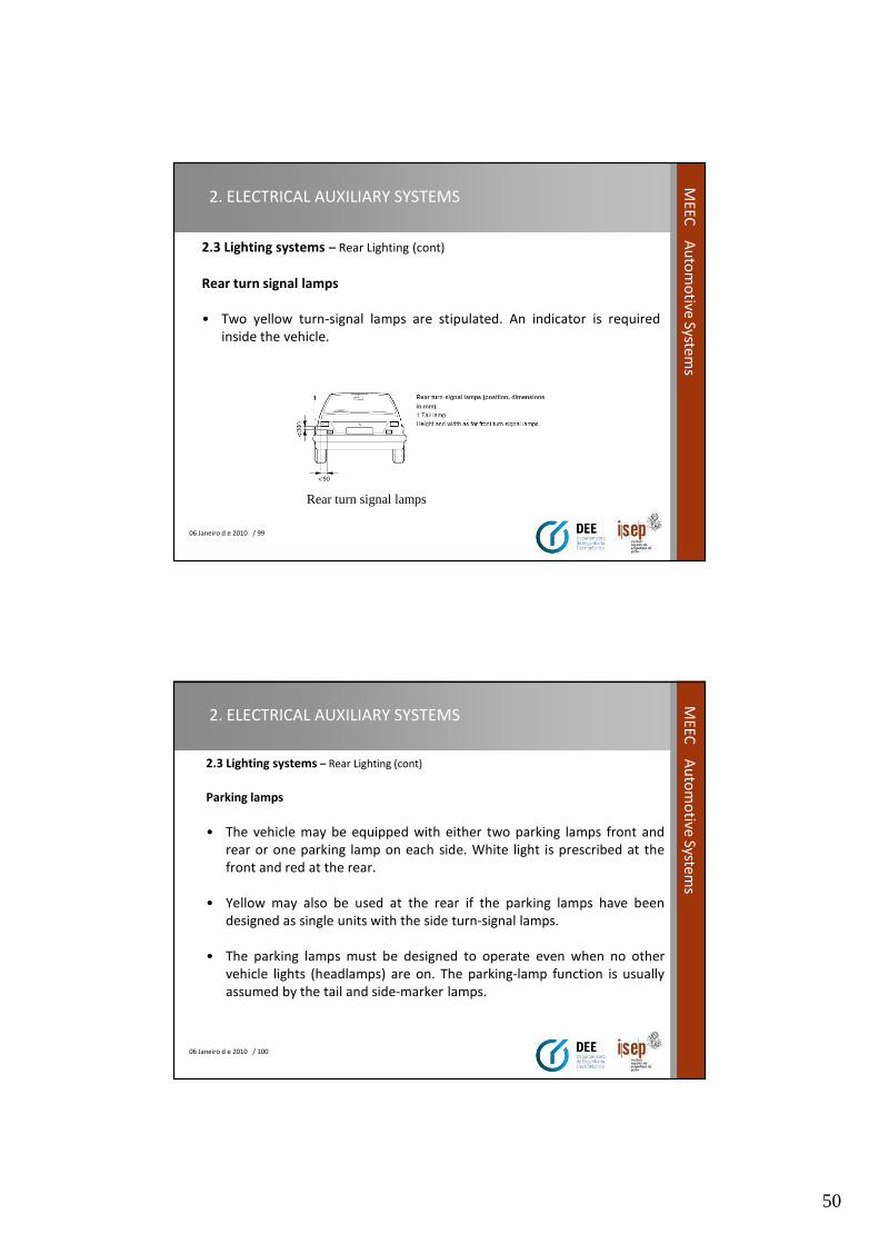
Rear turn signal lamps
• Two yellow turn-signal lamps are stipulated. An indicator is required
inside the vehicle.
Rear turn signal lamps
06 Janeiro d e 2010 / 100
ME
EC
Au
tom
otive
System
s
2. ELECTRICAL AUXILIARY SYSTEMS
2.3 Lighting systems – Rear Lighting (cont)
Parking lamps
• The vehicle may be equipped with either two parking lamps front and
rear or one parking lamp on each side. White light is prescribed at the
front and red at the rear.
• Yellow may also be used at the rear if the parking lamps have been
designed as single units with the side turn-signal lamps.
• The parking lamps must be designed to operate even when no other
vehicle lights (headlamps) are on. The parking-lamp function is usually
assumed by the tail and side-marker lamps.

51
06 Janeiro d e 2010 / 101
ME
EC
Au
tom
otive
System
s2. ELECTRICAL AUXILIARY SYSTEMS
2.3 Lighting systems – Rear Lighting (cont)
License-plate lamps and Back-up lamps.
• The rear license-plate lamp(s) must be designed to ensure that the rear licenseplate remains legible up to a distance of at least 25 m by night.
• Approved are the minimum luminance at all points on the surface of the licenseplate is 2.5 cd/m2.
• The luminance gradient of 2 x Bmin/cm should not be exceeded between any ofthe test points distributed across the surface of the test plate.
• Bmin is defined as the smallest luminance measured at the test point.
06 Janeiro d e 2010 / 102
ME
EC
Au
tom
otive
System
s
2. ELECTRICAL AUXILIARY SYSTEMS
2.3 Lighting systems – Rear Lighting (cont)
License-plate lamps and Back-up lamps.
• One or a maximum of two white-light lamps are approved.
• The switching circuit must be designed to ensure that the backup lamps
operate only with reverse gear engaged and the ignition on.
Back-up lamps
52
06 Janeiro d e 2010 / 103
ME
EC
Au
tom
otive
System
s
2.3 Lighting systems - Compartment Lighting
• Most cars have lights located in or near the ceiling of the passengercompartment, to provide illumination by which to fasten seatbelts and enter orexit the car.
• These often have an option to switch on when the front (or all) passenger doorsare opened. Many vehicles have expanded this feature, causing the overheadinterior light to remain on after all doors are closed, allowing passengers tofasten seat belts with added illumination.
• The extended lighting cycle usually ends when the vehicles ignition has begun, ora gradual reduction in light emitted after a couple of minutes if the car isn'tstarted. Interior lighting has been added on some vehicles at the bottom edge ofthe dashboard, which illuminate the floor for front passengers, or underneaththe front seats at the rear, to illuminate the floor for rear seat passengers.
• This type of convenience lighting approach is also sometimes used to illuminateinterior or exterior door handles, exterior step running boards, or electricwindow switches.
2. ELECTRICAL AUXILIARY SYSTEMS
06 Janeiro d e 2010 / 104
ME
EC
Au
tom
otive
System
s
2. ELECTRICAL AUXILIARY SYSTEMS
2.3 Lighting systems - Compartment Lighting (cont)
• LED light sources are beginning to appear increasingly as interior conveniencelights in various locations as the technology becomes more widely used,especially with finely focused lighting on console control surfaces and in cabinstorage areas.
• There may be additional map lights that are aimed at specific passengerpositions, that allow for reading without particular glare distraction to the driver.
• Some vehicles have approach lighting (puddle lights) integrated into the exteriormirrors or lower edges of the doors, as well as activating interior lighting, that isactivated via key. Many cars have lights in the trunk, the engine compartment,and the glove box and other storage compartments.
• Most instruments and controls on a dashboard in modern vehicles areilluminated in some fashion when the headlamps are turned on, and theintensity of light can be adjusted by the driver for comfort.
53
06 Janeiro d e 2010 / 105
ME
EC
Au
tom
otive
System
s2. ELECTRICAL AUXILIARY SYSTEMS
2.3 Lighting systems - Signalization Lighting
Identification lamps
• Identification lamps must be visible through 360 degrees from the
vehicle, and should be perceived as flashing when viewed from any
particular location.
• The flashing frequency f lies between 2 and 5 Hz. Blue identification
lamps are intended for installation on official vehicles. Yellow
identification lamps are designed to warn of dangers or dangerous
transport.
06 Janeiro d e 2010 / 106
ME
EC
Au
tom
otive
System
s
2. ELECTRICAL AUXILIARY SYSTEMS
2.3 Lighting systems - Signalization Lighting (cont)
Spot Lights
• Spot lamps generate a narrow beam of light of high luminous intensity, making it
possible to illuminate a small area from a substantial distance.
Lights for work services.
• On a moving vehicle, lights for work services may be switched on only when the
vehicle's motion represents an integral part of the operation being performed.
• For instance, when tractors are used in agriculture and forestry, on self-
propelled machinery, on rescue vehicles, etc.

54
06 Janeiro d e 2010 / 107
ME
EC
Au
tom
otive
System
s2. ELECTRICAL AUXILIARY SYSTEMS
2.3 Lighting systems - Signalization Lighting (cont)
Convenience lamps
• Lamps use inside compartment are expanding very fast, as they can help
the passengers to have indication of specific actuation components as
switches, close /open status of doors , indication of exit doors , trunk ,
etc.
• These lamps are low consumption , normally they are Led technology ,
specially for indication and signalization of switches or actuators.
06 Janeiro d e 2010 / 108
ME
EC
Au
tom
otive
System
s
2. ELECTRICAL AUXILIARY SYSTEMS
2.4 Information systems – Information panel
• Drivers have to process a permanently increasing stream of information
originating from their own and other vehicles, from roads and from
telecommunications equipment.
• All this information must be conveyed to drivers in the information and
communications areas of their vehicles with suitable display and
indicating equipment and in compliance with ergonomic requirements.
• In future, it will increasingly become the norm for cellular phones,
navigation systems and ranging systems to join radios and vehicle
monitoring systems as standard features in motor vehicles.
55
06 Janeiro d e 2010 / 109
ME
EC
Au
tom
otive
System
s2. ELECTRICAL AUXILIARY SYSTEMS
2.4 Information systems – Information panel (cont)
Information and communications areas
• In any vehicle, there are four information and communications areas,
which must satisfy different requirements in terms of their display
features:
– the instrument cluster,
– the windshield,
– the center console,
– the vehicle rear compartment.
06 Janeiro d e 2010 / 110
ME
EC
Au
tom
otive
System
s
2. ELECTRICAL AUXILIARY SYSTEMS
2.4 Information systems – Information panel (cont)
• The display features of these areas are determined by the availablerange of information and the necessary, useful or desirable informationfor the occupants concerned.
• Dynamic information and monitoring information (e.g. fuel level) towhich the driver should respond is indicated in the instrument cluster(i.e. as near as possible to the primary field of vision).
• A head-up display (HUD), which reflects the information in thewindshield, is especially suited to engaging the driver's attention (e.g. inthe case of warnings from a ranging warning radar (ACC) or routedirections).
• The display is supplemented acoustically by voice output.

56
06 Janeiro d e 2010 / 111
ME
EC
Au
tom
otive
System
s2. ELECTRICAL AUXILIARY SYSTEMS
2.4 Information systems – Information panel (cont)
• Status information or dialog prompts are mainly displayed in the vicinity
of the operator unit in the center console.
• Information of an entertainment nature is featured in the vehicle rear
compartment, away from the primary field of vision. This is also the ideal
location for the mobile office.
• The backrest of the front passenger seat is a suitable installation location
for the monitor and operator terminal of a laptop computer.
06 Janeiro d e 2010 / 112
ME
EC
Au
tom
otive
System
s
2. ELECTRICAL AUXILIARY SYSTEMS
2.4 Information systems – Information panel (cont)
Individual and combined instruments
• Conventional individual instruments for the optical output ofinformation were initially superseded by more cost-effective instrumentclusters (combination of several information units in a single housing)with good illumination and antireflection qualities.
• The passage of time, with the continual increase in information, saw thecreation in the existing space available of the modern instrument clusterwith several needle instruments and numerous tell-tale lamps.
• Next slide shows instrument panel example for the car driver.
57
06 Janeiro d e 2010 / 113
ME
EC
Au
tom
otive
System
s2. ELECTRICAL AUXILIARY SYSTEMS
2.4 Information systems – Information panel (cont)
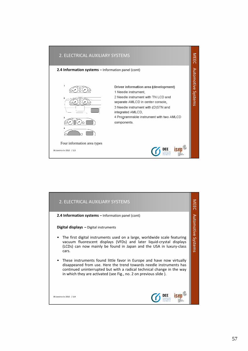
Four information area types
06 Janeiro d e 2010 / 114
ME
EC
Au
tom
otive
System
s
2. ELECTRICAL AUXILIARY SYSTEMS
2.4 Information systems – Information panel (cont)
Digital displays – Digital instruments
• The first digital instruments used on a large, worldwide scale featuringvacuum fluorescent displays (VFDs) and later liquid-crystal displays(LCDs) can now mainly be found in Japan and the USA in luxury-classcars.
• These instruments found little favor in Europe and have now virtuallydisappeared from use. Here the trend towards needle instruments hascontinued uninterrupted but with a radical technical change in the wayin which they are activated (see Fig., no. 2 on previous slide ).

58
06 Janeiro d e 2010 / 115
ME
EC
Au
tom
otive
System
s2. ELECTRICAL AUXILIARY SYSTEMS
2.4 Information systems – Information panel (cont)
Digital displays – Central display and operator unit center console
• The introduction of navigation and driver information systems has seen theincorporation of a display monitor and a keypad in the center console. Suchsystems combine all the additional information from functional units andinformation components (e.g. cellular phone, car radio/CD, controls forheating/air conditioning (HVAC)).
• In a central display and operator unit. The components are interconnected in anetwork and are capable of interactive communication.
• Positioning this terminal, which is of universal use to driver and passenger, in thecenter console is effective and necessary from both ergonomic and technicalstandpoints. The optical information appears in a graphics display.
• The demands placed by TV reproduction and the navigation system on theimage/map display determine the resolution and color reproduction.
06 Janeiro d e 2010 / 116
ME
EC
Au
tom
otive
System
s
2. ELECTRICAL AUXILIARY SYSTEMS
2.4 Information systems – Information panel (cont)
Graphics modules
• The tendency results in instrumentation featuring a classical needle instrumentbut supplemented by a graphics display. Even the central display monitor islocated at the height of the instrument cluster.
• What is important to all optical displays is that they can be easily read inside thedriver's primary field of vision or in its immediate vicinity without the driverhaving to divert his eyes from the road for long periods.
• This is the case for instance when the displays are positioned in the lower areaof the center console (see Fig., no. 3 on previous slide).
59
06 Janeiro d e 2010 / 117
ME
EC
Au
tom
otive
System
s2. ELECTRICAL AUXILIARY SYSTEMS
2.4 Information systems – Information panel (cont)
Graphics modules
• The graphics modules in the instrument cluster permit mainly thedisplay of driver and vehicle-related functions such as e.g. serviceintervals, check functions covering the vehicle's operating state and alsovehicle diagnostics as needed for the work.
• They can also show route-direction information from the navigationsystem (no digitized map excerpts, only route-direction symbols such asarrows as turn-off instructions or intersection symbols).
• It is to be expected that the initially monochrome modules will besucceeded in a second stage by color displays whose reading speed andreliability are increased by color reproduction.
06 Janeiro d e 2010 / 118
ME
EC
Au
tom
otive
System
s
2. ELECTRICAL AUXILIARY SYSTEMS
2.4 Information systems – Information panel (cont)
Individual module with computer monitor
• By roughly 2003, the remaining mechanical measuring instruments hadtendency to disappear.
• The entire area of the instrument cluster has been replaced by a freelyaddressable graphics monitor (provided the price of LCD computermonitors develops economically).
• Such a unit module offers an array of information display options. It isconceivable to have an individually selectable form of display which isgeared to the specific needs of individual user groups (see Fig., no. 4 onprevious slide).
60
06 Janeiro d e 2010 / 119
ME
EC
Au
tom
otive
System
s2. ELECTRICAL AUXILIARY SYSTEMS
2.4 Information systems – Information panel (cont)
Instrument clusters
• Microcontroller technology and the ongoing networking of motor
vehicles have in the meantime transformed instrument clusters from
precision-mechanical instruments to electronically dominated devices.
• A typical instrument cluster (LED-illuminated) is a very flat component
(electronics, flat stepping motors) and virtually all the components are
directly contacted on a printed-circuit board.
06 Janeiro d e 2010 / 120
ME
EC
Au
tom
otive
System
s
2. ELECTRICAL AUXILIARY SYSTEMS
2.4 Information systems – Information panel (cont)
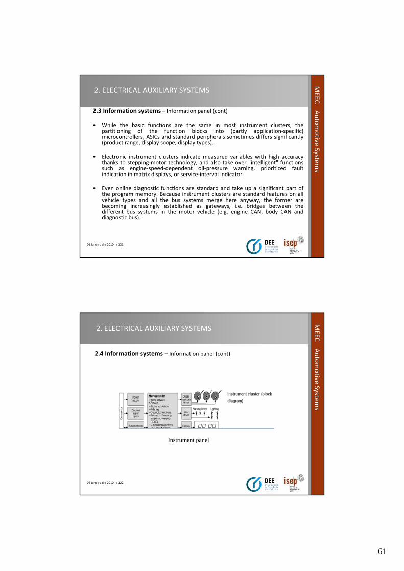
Instrument cluster design
61
06 Janeiro d e 2010 / 121
ME
EC
Au
tom
otive
System
s2. ELECTRICAL AUXILIARY SYSTEMS
2.3 Information systems – Information panel (cont)
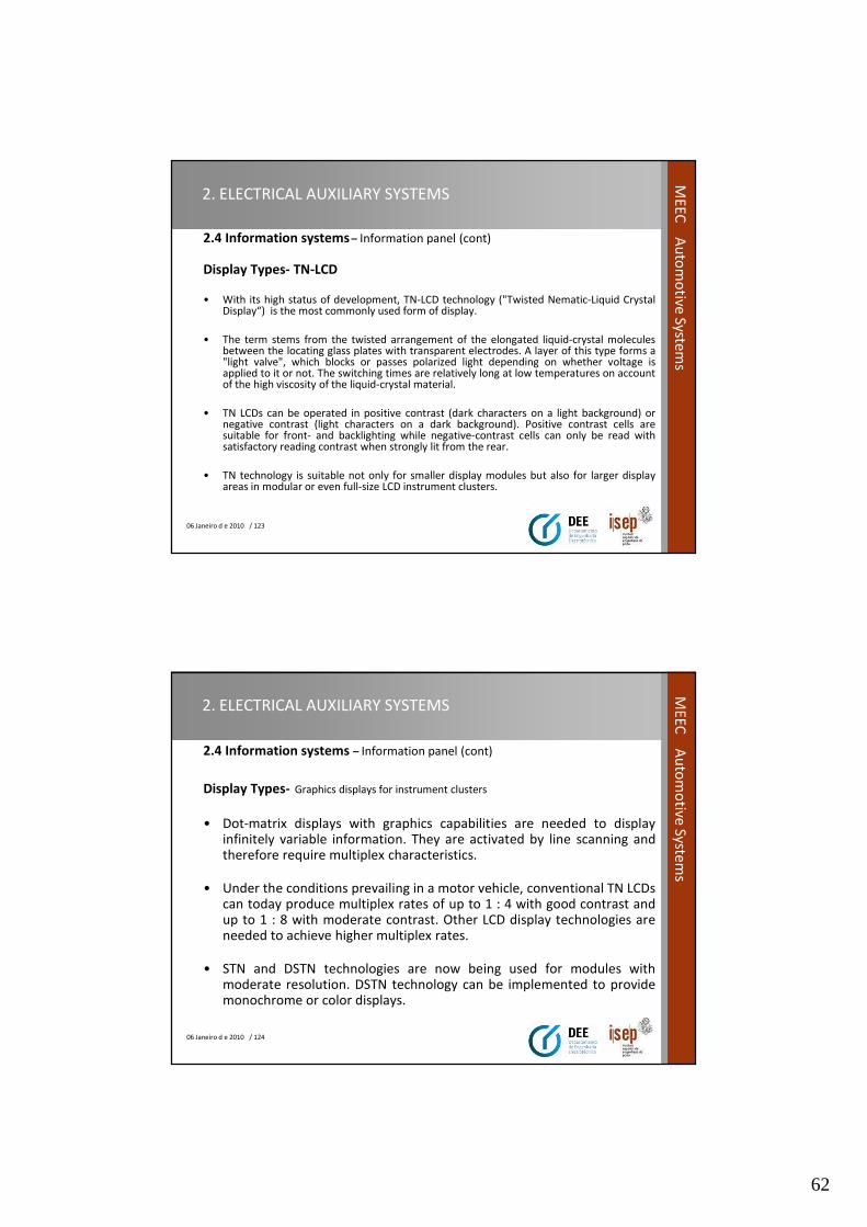
• While the basic functions are the same in most instrument clusters, thepartitioning of the function blocks into (partly application-specific)microcontrollers, ASICs and standard peripherals sometimes differs significantly(product range, display scope, display types).
• Electronic instrument clusters indicate measured variables with high accuracythanks to stepping-motor technology, and also take over "intelligent" functionssuch as engine-speed-dependent oil-pressure warning, prioritized faultindication in matrix displays, or service-interval indicator.
• Even online diagnostic functions are standard and take up a significant part ofthe program memory. Because instrument clusters are standard features on allvehicle types and all the bus systems merge here anyway, the former arebecoming increasingly established as gateways, i.e. bridges between thedifferent bus systems in the motor vehicle (e.g. engine CAN, body CAN anddiagnostic bus).
06 Janeiro d e 2010 / 122
ME
EC
Au
tom
otive
System
s
2. ELECTRICAL AUXILIARY SYSTEMS
2.4 Information systems – Information panel (cont)
Instrument panel
62
06 Janeiro d e 2010 / 123
ME
EC
Au
tom
otive
System
s2. ELECTRICAL AUXILIARY SYSTEMS
2.4 Information systems – Information panel (cont)
Display Types- TN-LCD
• With its high status of development, TN-LCD technology ("Twisted Nematic-Liquid CrystalDisplay“) is the most commonly used form of display.
• The term stems from the twisted arrangement of the elongated liquid-crystal moleculesbetween the locating glass plates with transparent electrodes. A layer of this type forms a"light valve", which blocks or passes polarized light depending on whether voltage isapplied to it or not. The switching times are relatively long at low temperatures on accountof the high viscosity of the liquid-crystal material.
• TN LCDs can be operated in positive contrast (dark characters on a light background) ornegative contrast (light characters on a dark background). Positive contrast cells aresuitable for front- and backlighting while negative-contrast cells can only be read withsatisfactory reading contrast when strongly lit from the rear.
• TN technology is suitable not only for smaller display modules but also for larger displayareas in modular or even full-size LCD instrument clusters.
06 Janeiro d e 2010 / 124
ME
EC
Au
tom
otive
System
s
2. ELECTRICAL AUXILIARY SYSTEMS
2.4 Information systems – Information panel (cont)
Display Types- Graphics displays for instrument clusters
• Dot-matrix displays with graphics capabilities are needed to displayinfinitely variable information. They are activated by line scanning andtherefore require multiplex characteristics.
• Under the conditions prevailing in a motor vehicle, conventional TN LCDscan today produce multiplex rates of up to 1 : 4 with good contrast andup to 1 : 8 with moderate contrast. Other LCD display technologies areneeded to achieve higher multiplex rates.
• STN and DSTN technologies are now being used for modules withmoderate resolution. DSTN technology can be implemented to providemonochrome or color displays.
63
06 Janeiro d e 2010 / 125
ME
EC
Au
tom
otive
System
s2. ELECTRICAL AUXILIARY SYSTEMS
2.4 Information systems – Information panel
Display Types- STN LCD and DSTN LCD
• The molecule structure of an STN (Super Twisted Nematic) display ismore heavily twisted inside the cell than in a conventional TN display.STN LCDs permit only monochrome displays; usually in blue-yellowcontrast. Neutral color can be obtained by applying "retarder film", butthis is not effective throughout the entire temperature rangeencountered in the vehicle.
• DSTN LCDs (Double-layer STN) feature considerably improvedcharacteristics, which permit neutral black-and-white reproduction overwide temperature ranges with negative and positive contrast. Color iscreated by backlighting with colored LEDs. Multicolor reproduction iscreated by incorporating red, green and blue thin film color filters onone of the two glass substrates. Under automotive conditions,
06 Janeiro d e 2010 / 126
ME
EC
Au
tom
otive
System
s
2. ELECTRICAL AUXILIARY SYSTEMS
2.4 Information systems– Information panel (cont)
Display Types- AMLCD
• The task of the visually sophisticated and rapidly changing display ofcomplex information in the area of the instrument cluster and the centerconsole with high resolution liquid-crystal monitors with videocapabilities can only effectively be performed by an AMLCD (Active-Matrix Liquid-Crystal Display).
• The best developed and mostly widely used are the TFT LCDs (Thin FilmTransistor LCDs) addressed with thin-film transistors.
• Display monitors with diagonals of 4"...7“ in the center-console area.Formats of 10"...14" with are planned for programmable instrumentclusters.
64
06 Janeiro d e 2010 / 127
ME
EC
Au
tom
otive
System
s2. ELECTRICAL AUXILIARY SYSTEMS
2.4 Information systems– Information panel (cont)
• TFT LCDs consist of the "active" glass substrate and the opposing platewith the color-filter structures. The active substrate accommodates thepixel electrodes made from tin-indium oxide, the metallic row andcolumn circuits and the semiconductor structures.
• At each intersecting point of the row and column circuits, there is a fieldeffect transistor which is etched in several masking steps from apreviously applied sequence of layers. A capacitor is likewise generatedat each pixel
• The opposite glass plate accommodates the color filters and a "black-matrix“ structure, which improves the contrast of the display. Thesestructures are applied to the glass in a sequence of photolithographicprocesses.
06 Janeiro d e 2010 / 128
ME
EC
Au
tom
otive
System
s
2. ELECTRICAL AUXILIARY SYSTEMS
2.4 Information systems – Information panel (cont)
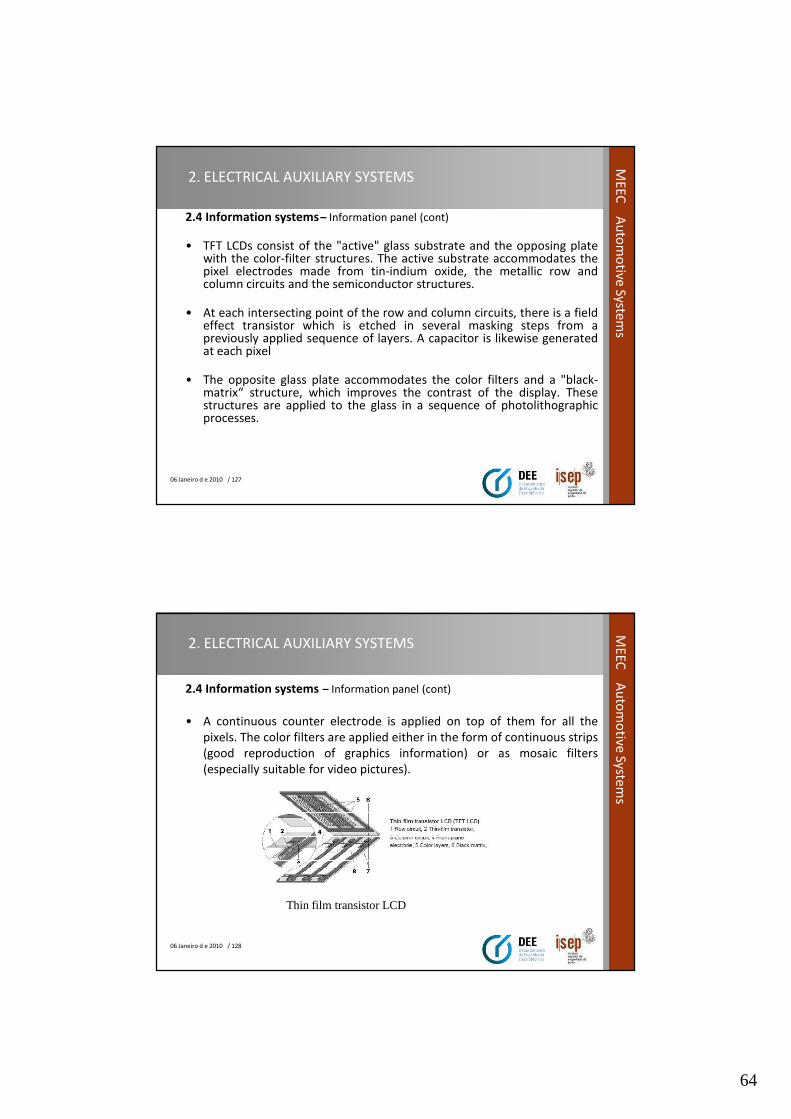
• A continuous counter electrode is applied on top of them for all the
pixels. The color filters are applied either in the form of continuous strips
(good reproduction of graphics information) or as mosaic filters
(especially suitable for video pictures).
Thin film transistor LCD
65
06 Janeiro d e 2010 / 129
ME
EC
Au
tom
otive
System
s2. ELECTRICAL AUXILIARY SYSTEMS
2.4 Information systems – Trip recorder
• These devices record the vehicle speed, the distance covered
(odometer), and the time. They also incorporate a warning lamp which is
triggered when vehicles exceed a preset speed (such as the legally
permitted limit, or the maximum speed commensurate with economical
operation).
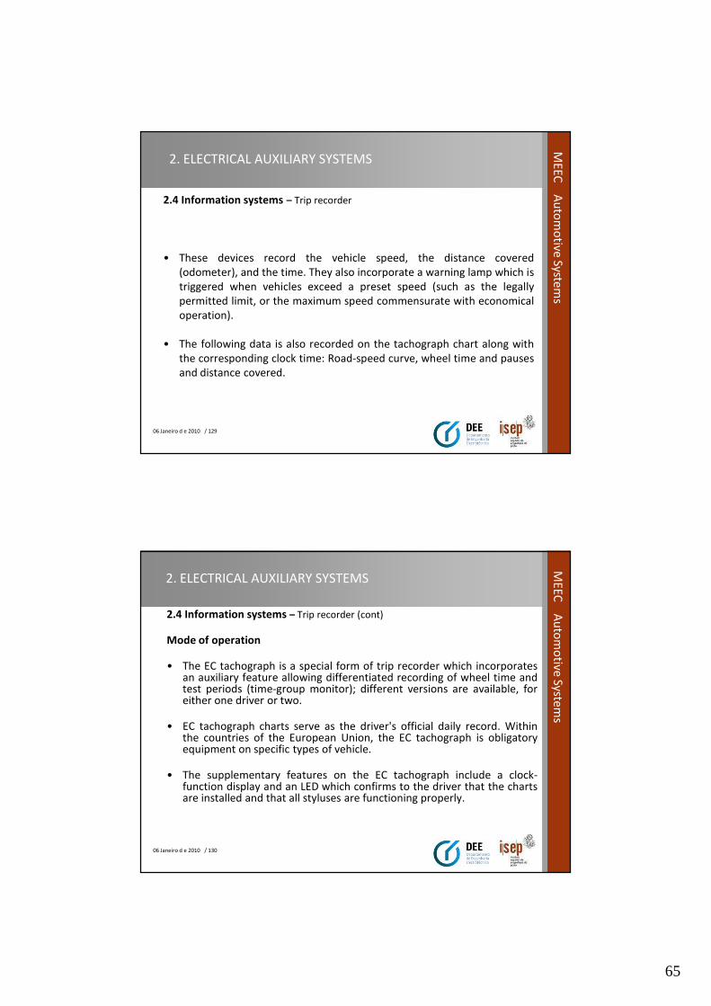
• The following data is also recorded on the tachograph chart along with
the corresponding clock time: Road-speed curve, wheel time and pauses
and distance covered.
06 Janeiro d e 2010 / 130
ME
EC
Au
tom
otive
System
s
2. ELECTRICAL AUXILIARY SYSTEMS
2.4 Information systems – Trip recorder (cont)
Mode of operation
• The EC tachograph is a special form of trip recorder which incorporatesan auxiliary feature allowing differentiated recording of wheel time andtest periods (time-group monitor); different versions are available, foreither one driver or two.
• EC tachograph charts serve as the driver's official daily record. Withinthe countries of the European Union, the EC tachograph is obligatoryequipment on specific types of vehicle.
• The supplementary features on the EC tachograph include a clock-function display and an LED which confirms to the driver that the chartsare installed and that all styluses are functioning properly.
66
06 Janeiro d e 2010 / 131
ME
EC
Au
tom
otive
System
s2. ELECTRICAL AUXILIARY SYSTEMS
2.4 Information systems – Trip recorder (cont)
Tachograph chart
06 Janeiro d e 2010 / 132
ME
EC
Au
tom
otive
System
s
2. ELECTRICAL AUXILIARY SYSTEMS
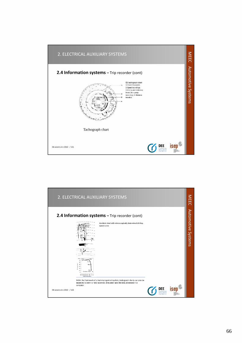
2.4 Information systems – Trip recorder (cont)
67
06 Janeiro d e 2010 / 133
ME
EC
Au
tom
otive
System
s2. ELECTRICAL AUXILIARY SYSTEMS
2.4 Information systems – board computer system
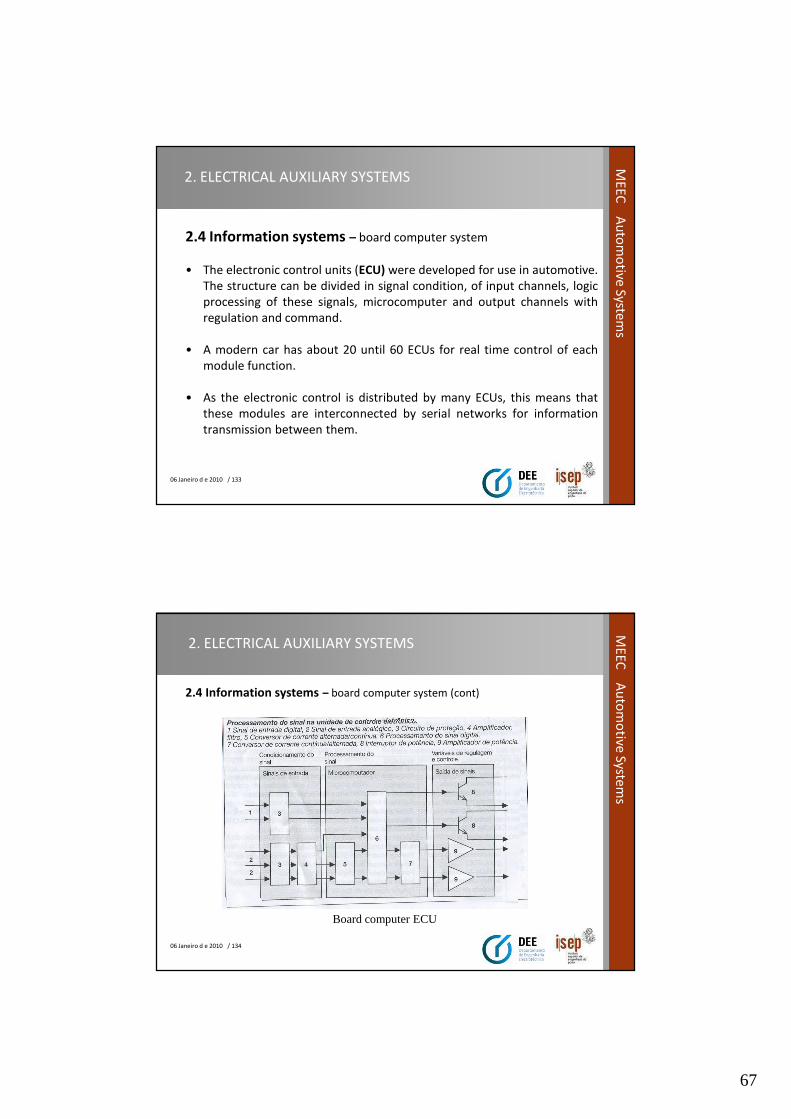
• The electronic control units (ECU) were developed for use in automotive.
The structure can be divided in signal condition, of input channels, logic
processing of these signals, microcomputer and output channels with
regulation and command.
• A modern car has about 20 until 60 ECUs for real time control of each
module function.
• As the electronic control is distributed by many ECUs, this means that
these modules are interconnected by serial networks for information
transmission between them.
06 Janeiro d e 2010 / 134
ME
EC
Au
tom
otive
System
s
2. ELECTRICAL AUXILIARY SYSTEMS
2.4 Information systems – board computer system (cont)
Board computer ECU
68
06 Janeiro d e 2010 / 135
ME
EC
Au
tom
otive
System
s2. ELECTRICAL AUXILIARY SYSTEMS
2.4 Information systems – board computer system (cont)
• The structural blocks use identical electronic components witch are in all
module platforms of hardware or modules.
• To implement the structural architecture there are two essential
elements :
– Concept for structure the functionality of the car ( CARTRONIC).
– Communication networks, witch the function is exchange information
between ECUs.
06 Janeiro d e 2010 / 136
ME
EC
Au
tom
otive
System
s
2. ELECTRICAL AUXILIARY SYSTEMS
2.4 Information systems – board computer system (cont)
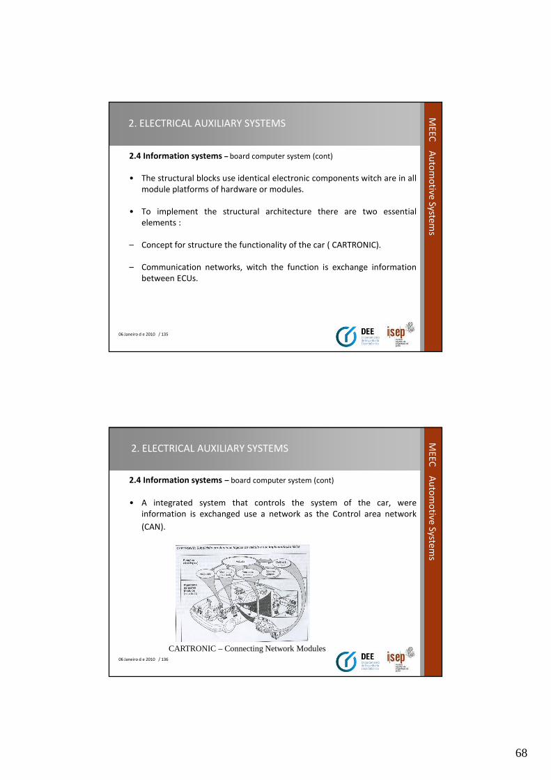
• A integrated system that controls the system of the car, were
information is exchanged use a network as the Control area network
(CAN).
CARTRONIC – Connecting Network Modules
69
06 Janeiro d e 2010 / 137
ME
EC
Au
tom
otive
System
s2. ELECTRICAL AUXILIARY SYSTEMS
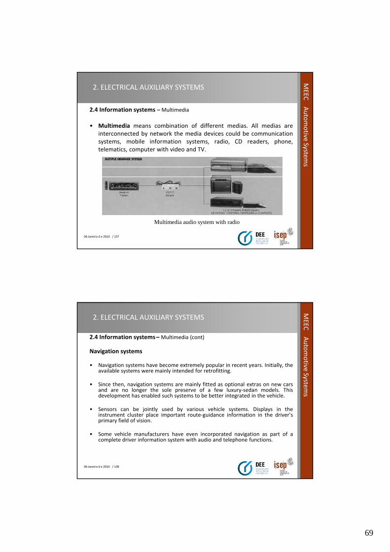
2.4 Information systems – Multimedia
• Multimedia means combination of different medias. All medias are
interconnected by network the media devices could be communication
systems, mobile information systems, radio, CD readers, phone,
telematics, computer with video and TV.
Multimedia audio system with radio
06 Janeiro d e 2010 / 138
ME
EC
Au
tom
otive
System
s
2. ELECTRICAL AUXILIARY SYSTEMS
2.4 Information systems – Multimedia (cont)
Navigation systems
• Navigation systems have become extremely popular in recent years. Initially, theavailable systems were mainly intended for retrofitting.
• Since then, navigation systems are mainly fitted as optional extras on new carsand are no longer the sole preserve of a few luxury-sedan models. Thisdevelopment has enabled such systems to be better integrated in the vehicle.
• Sensors can be jointly used by various vehicle systems. Displays in theinstrument cluster place important route-guidance information in the driver'sprimary field of vision.
• Some vehicle manufacturers have even incorporated navigation as part of acomplete driver information system with audio and telephone functions.

70
06 Janeiro d e 2010 / 139
ME
EC
Au
tom
otive
System
s2. ELECTRICAL AUXILIARY SYSTEMS
2.4 Information systems – Multimedia (cont)
• This development will continue. Simple systems which offer the driverno more than a mere indication of his/her position on a card and astraight-line direction to destination, have for the most part disappearedfrom the market.
• Common to all systems is the combination of the basic functions of"positioning", "destination selection", "route computation" and "routeguidance".
• Systems in the upper performance spectrum also offer a color mapdisplay. All the functions require a digital map of the road network andthis is generally stored on a CD-ROM.
06 Janeiro d e 2010 / 140
ME
EC
Au
tom
otive
System
s
2. ELECTRICAL AUXILIARY SYSTEMS
2.4 Information systems – Multimedia (cont)
Traffic telematics
• The word "telematics" is derived from the contraction of the words"telecommunications" and "informatics".
• Accordingly, the transmission of traffic related information from and tomotor vehicles, and its subsequent, mostly automatic evaluation iscombined under the term "traffic telematics".
• Today, the main transmission paths for telecommunications areprovided by radio
• and mobile radio communications networks.

71
06 Janeiro d e 2010 / 141
ME
EC
Au
tom
otive
System
s2. ELECTRICAL AUXILIARY SYSTEMS
2.4 Information systems – Multimedia (cont)
• Radio only allows a path into the vehicle and does not serve to
communicate individual messages. With GSM, information can be
exchanged in both directions between vehicles and control centers run
by service providers.
• The amount of information exchanged is restricted in each case by the
bandwidth of the available transmission channels.
• It is therefore essential that the coding of standardized message content
is as free as possible of redundant information.
06 Janeiro d e 2010 / 142
ME
EC
Au
tom
otive
System
s
2. ELECTRICAL AUXILIARY SYSTEMS
2.4 Information systems – Multimedia (cont)
Auto PC
• A revolution in the use of information technology in vehicles is takingplace! Advanced computing, communications and positioningdevelopments are being introduced in even the most basic vehicles.
• Next slide shows an Auto PC/Car Multimedia system. However, therewere several barriers to the widespread use of such new technology.
• Not robust enough, too costly, difficult to install, lack of commonstandards, difficult to operate.
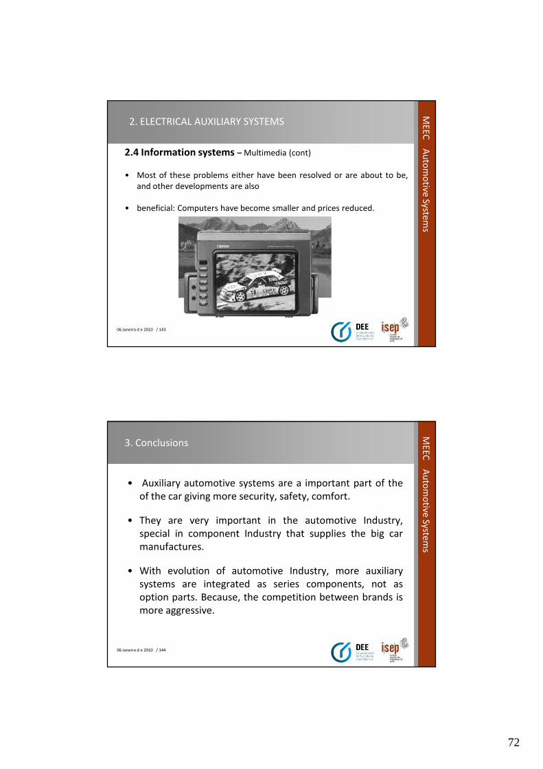
72
06 Janeiro d e 2010 / 143
ME
EC
Au
tom
otive
System
s2. ELECTRICAL AUXILIARY SYSTEMS
2.4 Information systems – Multimedia (cont)
• Most of these problems either have been resolved or are about to be,
and other developments are also
• beneficial: Computers have become smaller and prices reduced.
06 Janeiro d e 2010 / 144
ME
EC
Au
tom
otive
System
s
3. Conclusions
• Auxiliary automotive systems are a important part of the
of the car giving more security, safety, comfort.
• They are very important in the automotive Industry,
special in component Industry that supplies the big car
manufactures.
• With evolution of automotive Industry, more auxiliary
systems are integrated as series components, not as
option parts. Because, the competition between brands is
more aggressive.
73
06 Janeiro d e 2010 / 145
ME
EC
Au
tom
otive
System
sBIBLIOGRAFY
• Manual de tecnologia Automóvel, Robert Bosch, 2005, 25º versão alemã.
• Circuitos eléctricos en automóvil, Hermógenes Gil, 2002. Ediciones CEAC.
• Automovil electrical and electronic systems, Tom Denton, 2004, Elsevier.
• Handbook of automotive power electronics and motor drives, Eli Amadi, 2005, CRC press.
• http://en.wikipedia.org/wiki/Automotive_lighting , 09/01/2010.
• http://en.wikipedia.org/wiki/Headlamp , 09/01/2010.