ACCESSORY KIT INSTALLATION INSTRUCTIONS - Northern Tool
4
Unitary Products Group ACCESSORY KIT INSTALLATION INSTRUCTIONS ELECTRIC HEATER ACCESSORY - 4HK SERIES FOR USE WITH THE FOLLOWING AIR HANDLER MODELS: AHP / SHP / AV / SV / MA / MV 171053-UAI-E-0307 GENERAL This instruction covers the physical installation of the follow- ing electric heaters with AHP18-60 & AV24-60 single piece air handlers and with MA24-60 & MV24-60 modular air han- dlers. Refer to unit instructions for electrical specifications. These electric heat accessories are used for applications of cooling with electric heat and heat pump with electric heat. Each of the air handler unit models are approved for use with specific electric heat accessories. The Air Handler installation instructions, or name plate list the possible combinations and other important electrical data and limitations. ELECTRICAL SHOCK HAZARD Installation or repairs made by unqualified persons can result in hazards to you and others. Installation must conform with local building codes or, in the absence of local codes, with NAtional Electrical Code ANSI/NFPA 70-1996 or current edition. The information contained in this manual is intended for use by a qualified service technician familiar with safety procedures and equipped with the proper tools and test instruments. Shut OFF electric power at unit disconnect and/or ser- vice panel before beginning the following procedures. Failure to carefully read and follow all instructions in this manual can result in malfunction, property damage, per- sonal injury, and/or death. Verify edges of foil faced insulation are not in contact with any exposed electrical connections. TABLE 1: Models Covered 4HK06500206 4HK16500206 4HK06500506 4HK16500506 4HK06500806 4HK16500806 4HK06501006 4HK16501006 4HK16501306 4HK16501506 4HK165N1506 4HK16501806 4HK16502006 4HK16502506 4HK06501025 4HK065N1525 4HK06501525 4HK06501825 4HK16501825 4HK16502525 FIGURE 1: Heater Installation SLIDE HEATER KIT ONTO RAIL AND INTO AIR HANDLER FIELD SUPPLY WIRING THIS SIDE REMOVE CIRCUIT BREAKER PLATE APPLY BREAKER COVER TO PANEL BLOWER ACCESS REMOVE BLOWER ACCESS PANEL INSTALL HEATER KIT RAIL REMOVE DUCT COVER 3. 4b. 4a. 6. 1. 7. 2.
Transcript of ACCESSORY KIT INSTALLATION INSTRUCTIONS - Northern Tool
Unitary Products Group
ACCESSORY KIT INSTALLATION INSTRUCTIONSELECTRIC HEATER ACCESSORY - 4HK SERIESFOR USE WITH THE FOLLOWING AIR HANDLER
MODELS: AHP / SHP / AV / SV / MA / MV
171053-UAI-E-0307
GENERAL This instruction covers the physical installation of the follow-ing electric heaters with AHP18-60 & AV24-60 single pieceair handlers and with MA24-60 & MV24-60 modular air han-dlers. Refer to unit instructions for electrical specifications.These electric heat accessories are used for applications ofcooling with electric heat and heat pump with electric heat.Each of the air handler unit models are approved for use withspecific electric heat accessories. The Air Handler installationinstructions, or name plate list the possible combinations andother important electrical data and limitations.
ELECTRICAL SHOCK HAZARDInstallation or repairs made by unqualified persons canresult in hazards to you and others. Installation mustconform with local building codes or, in the absence oflocal codes, with NAtional Electrical Code ANSI/NFPA70-1996 or current edition.The information contained in this manual is intended foruse by a qualified service technician familiar with safetyprocedures and equipped with the proper tools and testinstruments.Shut OFF electric power at unit disconnect and/or ser-vice panel before beginning the following procedures.Failure to carefully read and follow all instructions in thismanual can result in malfunction, property damage, per-sonal injury, and/or death.Verify edges of foil faced insulation are not in contactwith any exposed electrical connections.
TABLE 1: Models Covered4HK065002064HK165002064HK065005064HK165005064HK065008064HK165008064HK065010064HK165010064HK165013064HK16501506
4HK165N15064HK165018064HK165020064HK165025064HK065010254HK065N15254HK065015254HK065018254HK165018254HK16502525
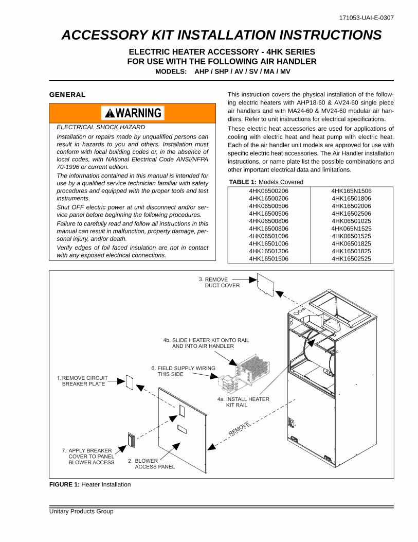
FIGURE 1: Heater Installation
SLIDE HEATER KIT ONTO RAIL
AND INTO AIR HANDLER
FIELD SUPPLY WIRING
THIS SIDEREMOVE CIRCUIT
BREAKER PLATE
APPLY BREAKER
COVER TO PANEL
BLOWER ACCESS
REMO
VE
BLOWER
ACCESS PANEL
INSTALL HEATER
KIT RAIL
REMOVE
DUCT COVER
3.
4b.
4a.
6.
1.
7.
2.
171053-UAI-E-0307
2 Unitary Products Group
INSTALLATIONInstallation is the same for operating positions: upflow, down-flow and horizontal right (Refer to Figure 1). If unit is installedin any of these positions, proceed to step number 2. Installa-tion of the Heater Kit should be done prior to unit installation.
1. If Heat Kit has circuit breakers - remove circuit breakerpanel from front of air handler unit.
2. Remove air handler blower access panel.
3. Remove duct cover from back panel of air handler con-trol and wiring compartment.
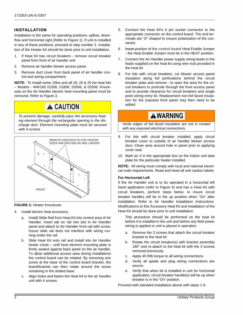
NOTE: To Install some 15kw and all 18, 20 & 25 kw heat kits– Models - 4HK165 01506, 01806, 02006, & 02506: Knock-outs on the Air Handler electric heat mounting panel must beremoved. Refer to Figure 3.
4. Install electric heat accessory.
a. Install Slide Rail from Heat Kit into control area of AirHandler. Insert tab on rail into slot in Air Handlerpanel and attach to Air Handler front rail with screw.Insure slide rail does not interfere with wiring run-ning under the rail.
b. Slide Heat Kit onto rail and install into Air Handlerheater chute – until heat element mounting plate isfirmly seated against back panel on the air handler.To allow additional access area during installationsthe control board can be rotated. By removing onescrew at the base of the control board bracket, theboard/bracket can then rotate around the screwremaining in the slotted base.
c. Align holes and fasten the Heat Kit to the air handlerunit with 4 screws.
5. Connect the Heat Kit’s 6 pin socket connector to theappropriate connector on the control board. The end ter-minals are “D” shaped to ensure polarization of the con-nector.
6. Insure position of the control board Heat Enable Jumper- the Heat Enable Jumper must be in the HEAT position.
7. Connect the Air Handler power supply wiring leads to theleads supplied on the heat kit using wire nuts provided inthe heat kit.
8. For kits with circuit breakers, cut blower access panelinsulation along foil perforations behind the circuitbreaker plate and remove - to open the area for the cir-cuit breakers to protrude through the front access paneland to provide clearance for circuit breakers and singlepoint wiring entry kit. Replacement non-foil faced insula-tion for the exposed front panel may then need to beadded.
9. For kits with circuit breaker installed, apply circuitbreaker cover to outside of air handler blower accessdoor. Clean area around hole in panel prior to applyingcover seal.
10. Mark an X in the appropriate box on the indoor unit dataplate for the particular heater installed.
NOTE: All wiring must comply with local and national electri-cal code requirements. Read and heed all unit caution labels.
For Horizontal LeftIf the Air Handler unit is to be operated in a horizontal lefthand application (refer to Figure 4) and has a Heat Kit withcircuit breakers, perform steps below, to insure circuitbreaker handles will be in the up position when “On” afterinstallation. Refer to Air Handler Installation Instructions.Modifications to this Accessory Heat Kit and installation of theHeat Kit should be done prior to unit installation.
This procedure should be performed on the heat kitbefore it is installed in the unit and before any field powerwiring is applied or unit is placed in operation.
a. Remove the 3 screws that attach the circuit breakerbracket to the heat kit.
b. Rotate the circuit breaker(s) with bracket assembly180° and re-attach to the heat kit with the 3 screwsremoved previously.
c. Apply 45 ft/lb torque to all wiring connections.d. Verify all spade and plug wiring connections are
secure.e. Verify that when kit is installed in unit for horizontal
application, circuit breaker handle(s) will be up whenbreaker is in the “On” position.
Proceed with standard installation above with steps 1-9.
To prevent damage, carefully pass the accessory heat-ing element through the rectangular opening in the dis-charge duct. Element mounting plate must be securedwith 4 screws.
FIGURE 2: Heater Knockouts
FRONT
REMOVE KNOCKOUTS FOR HEATER
SIZES 4HK16501506 kW AND LARGER
Verify edges of foil faced insulation are not in contactwith any exposed electrical connections.
171053-UAI-E-0307
Unitary Products Group 3
LINE POWER CONNECTIONSPower may be brought into the unit through the outlet air endof the unit (top left when unit is vertical) or the left side panel.To minimize air leakage, seal the field wiring entry point.
Field wiring connects to heat kits with circuit breaker or termi-nal block. A ground lug is also provided on the kits.
Connect the Air Handler power supply wiring leads to theleads supplied on the heat kit using wire nuts provided in theheat kit.
ELECTRIC HEATERS & OPERATING CON-TROLSThe low voltage transformer and the fan / heater control arestandard on all models. The air handlers are shipped pre-wired to operate as cooling only applications.
To operate these units with electric heat, it is necessary tofield install an electric heater kit (4HK). Prior to installing elec-tric heat, it is necessary to perform the following procedure:
1. Verify position of heat enable jumper, on the controlboard - is in the Heat position when electric heat kit isinstalled.
2. Verify heat kit 6 socket plug is seated in control board.
LOW VOLTAGE CONTROL CONNECTIONSThe 24 volt power supply is provided by an internally wiredlow voltage transformer which is standard on all air handlermodels. Field supplied low voltage wiring can exit the unit onthe top right hand corner or the right hand side panel. Refer toFigure 1. Remove desired knockout and pierce foil facedinsulation to allow wiring to pass through. Use as small of ahole as possible to minimize air leakage. Install a 7/8” plasticbushing in the selected hole and keep low voltage wiring asshort as possible inside the control box. To further minimizeair leakage, seal the wiring entry point at the outside of theunit. The field wiring is to be connected at the screwterminals of the control board.NOTE: All wiring must comply with local and national electri-cal code requirements. Read and heed all unit caution labels.NOTE: It is possible to vary the amount of electric heat turnedon during the defrost cycle of a heat pump. Standard wiringwill only bring on the first stage of electric heat during defrost.See Heat Output and Limit Connections & Table 6 for addi-tional information on heat during defrost cycle.NOTE: For blower speed connections, electrical informationand wiring diagrams, see indoor unit installation instructions.NOTE: The electric heaters have a temperature limit control.If failure occurs, this limit control must be replaced with adirect replacement.
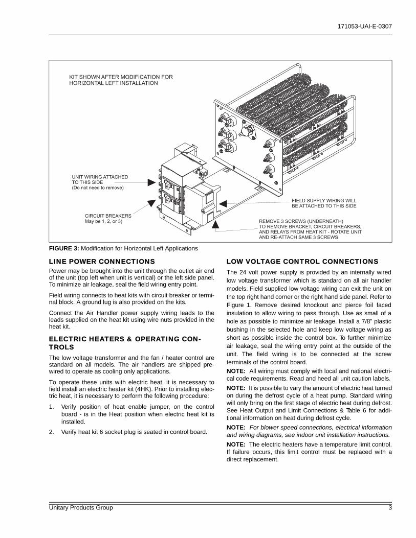
FIGURE 3: Modification for Horizontal Left Applications
FIELD SUPPLY WIRING WILL
BE ATTACHED TO THIS SIDE
CIRCUIT BREAKERS
May be 1, 2, or 3) REMOVE 3 SCREWS (UNDERNEATH)
TO REMOVE BRACKET, CIRCUIT BREAKERS,
AND RELAYS FROM HEAT KIT - ROTATE UNIT
AND RE-ATTACH SAME 3 SCREWS
UNIT WIRING ATTACHED
TO THIS SIDE
(Do not need to remove)
KIT SHOWN AFTER MODIFICATION FOR
HORIZONTAL LEFT INSTALLATION
Subject to change without notice. Printed in U.S.A. 171053-UAI-E-0307Copyright © by York International Corp. 2007. All rights reserved. Supersedes: 171053-UAI-D-0107
Unitary 5005 NormanProduct York OKGroup Drive 73069
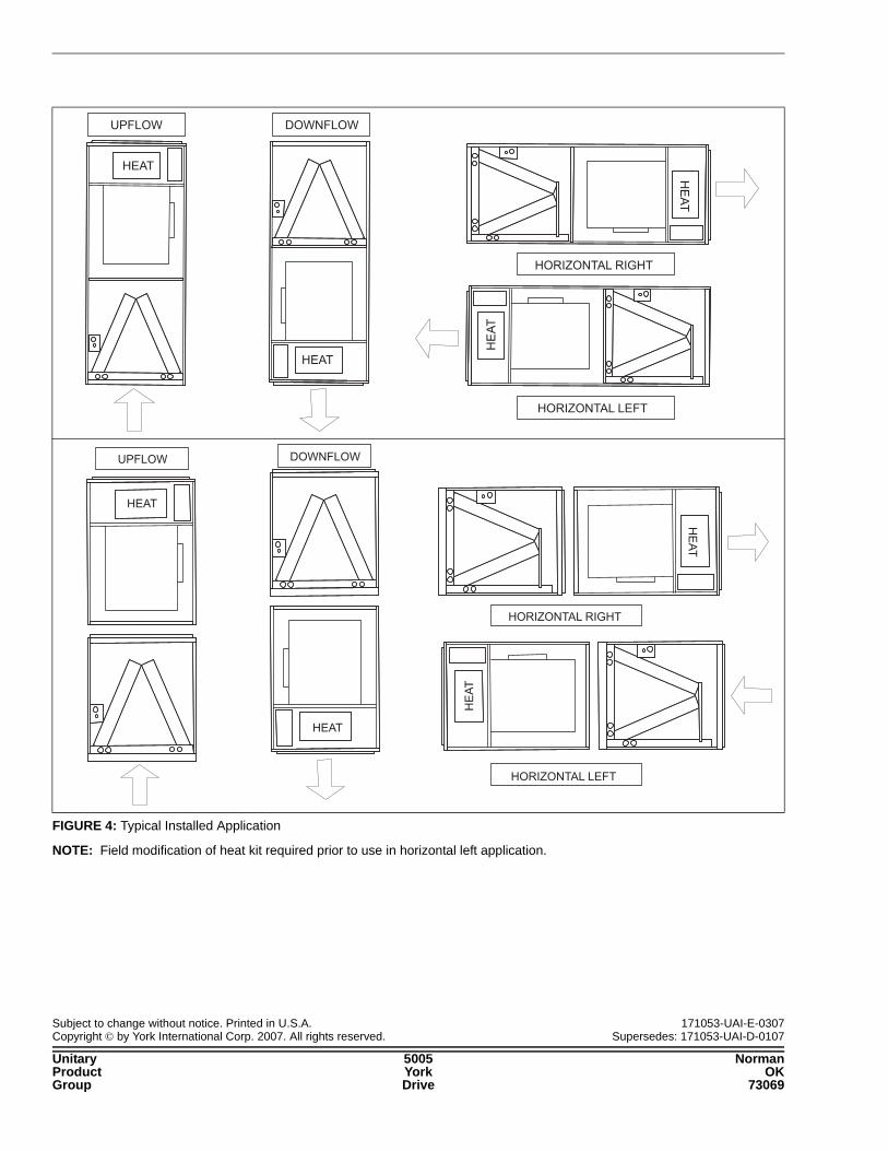
NOTE: Field modification of heat kit required prior to use in horizontal left application.
FIGURE 4: Typical Installed Application
UPFLOW DOWNFLOW
HORIZONTAL RIGHT
HORIZONTAL LEFT
HEAT
HEAT
HE
AT
HE
AT
\\\
!
UPFLOW DOWNFLOW
HORIZONTAL RIGHT
HORIZONTAL LEFT
HE
AT
HE
AT
HEAT
HEAT