ELECTRIC HEATER ACCESSORY (6HK SERIES) · 2017-07-28 · johnson controls unitary products...
8
Johnson Controls Unitary Products 5181703-UAI-B-0516 ACCESSORY KIT INSTALLATION MANUAL ELECTRIC HEATER ACCESSORY (6HK SERIES) FOR USE WITH MODELS: AP / AE / AVC / AHR / AHE / AHV / MP / ME / MVC / RFCX*E / RFCX*P / PHE / PCE GENERAL INFORMATION These instructions cover the installation of the following electric heater models with the AP / AE / AVC / AHR / AHE / AHV / RFCX*E / RFCX*P single piece air handlers, the MP / ME / MVC modular air handlers, and the PHE / PCE residential pack- age (Respac) units. The 6HK series of electric heat kits use a single polarized plug to easily connect the equipment power and controls. These electric heat accessories are used for applications of electric heat, cooling with electric heat, and heat pump with electric heat. Each of the air handler and Respac models are approved for use with specific electric heat accessories. The unit installation instructions, technical guide, or name plate list the possible combinations and other important electrical data and limitations. Refer to unit instructions for further electrical specifications. CLEARANCE All installations of the 6HK electric heater kits are approved for zero-clearance to combustibles when the minimum speed tap on the blower motor is set per the equipment installation instruction or nameplate. See equipment installation instruc- tions for more information on changing motor speed taps. WARNING ELECTRICAL SHOCK HAZARD Installation or repairs made by unqualified persons can result in hazards to you and others. Installation must conform with local building codes or, in the absence of local codes, with National Electrical Code ANSI/NFPA 70-1996 or current edi- tion. The information contained in this manual is intended for use by a qualified service technician familiar with safety proce- dures and equipped with the proper tools and test instru- ments. Shut OFF electric power at unit disconnect and/or service panel before beginning the following procedures. Failure to carefully read and follow all instructions in this man- ual can result in malfunction, property damage, personal injury, and/or death. Verify edges of foil faced insulation are not in contact with any exposed electrical connections. CAUTION Unit is approved for zero clearance to combustible material and when equipped with electric heat a minimum clearance of one inch must be maintained on all sides of the supply duct and/or plenum for three feet as shown in the detail in Figure 1 for the 20kw and 25 kW electric heaters only. NOTICE In some horizontal applications, the service disconnects on the electric heat kits must be rotated 180° so the up position of the disconnect is the ON position. This service disconnect orientation change is required by UL1995, Article 26.19 (in reference to all circuit breakers). ! ! FIGURE 1: Duct Work Clearance NOTICE The electric heat accessory should be installed before the supply air duct is attached to the supply air opening flanges. MINIMUM CLEARANCE 1” on all sides for the first 3’ of duct from 20 & 25 kw units. For all other heaters, zero inch clearance on all sides for entire length of duct. FLEXIBLE DUCT COLLAR NOTE: For units applied with a roof curb, the minimum clearance may be reduced from 1 inch to 1/2 inch between combustible roof curb material and the supply duct. A0238-001 3’
Transcript of ELECTRIC HEATER ACCESSORY (6HK SERIES) · 2017-07-28 · johnson controls unitary products...
ACCESSORY KIT INSTALLATION MANUALELECTRIC HEATER ACCESSORY (6HK SERIES)
FOR USE WITH MODELS: AP / AE / AVC / AHR / AHE / AHV / MP / ME / MVC / RFCX*E / RFCX*P / PHE / PCE
GENERAL INFORMATION
These instructions cover the installation of the following electricheater models with the AP / AE / AVC / AHR / AHE / AHV /RFCX*E / RFCX*P single piece air handlers, the MP / ME /MVC modular air handlers, and the PHE / PCE residential pack-age (Respac) units. The 6HK series of electric heat kits use asingle polarized plug to easily connect the equipment powerand controls.These electric heat accessories are used for applications ofelectric heat, cooling with electric heat, and heat pump withelectric heat. Each of the air handler and Respac models areapproved for use with specific electric heat accessories. Theunit installation instructions, technical guide, or name plate listthe possible combinations and other important electrical dataand limitations. Refer to unit instructions for further electricalspecifications.
CLEARANCEAll installations of the 6HK electric heater kits are approved forzero-clearance to combustibles when the minimum speed tapon the blower motor is set per the equipment installationinstruction or nameplate. See equipment installation instruc-tions for more information on changing motor speed taps.
WARNINGELECTRICAL SHOCK HAZARDInstallation or repairs made by unqualified persons can resultin hazards to you and others. Installation must conform withlocal building codes or, in the absence of local codes, withNational Electrical Code ANSI/NFPA 70-1996 or current edi-tion.The information contained in this manual is intended for useby a qualified service technician familiar with safety proce-dures and equipped with the proper tools and test instru-ments.Shut OFF electric power at unit disconnect and/or servicepanel before beginning the following procedures.Failure to carefully read and follow all instructions in this man-ual can result in malfunction, property damage, personalinjury, and/or death.Verify edges of foil faced insulation are not in contact with anyexposed electrical connections.
CAUTIONUnit is approved for zero clearance to combustible materialand when equipped with electric heat a minimum clearanceof one inch must be maintained on all sides of the supply ductand/or plenum for three feet as shown in the detail in Figure 1for the 20kw and 25 kW electric heaters only.
NOTICEIn some horizontal applications, the service disconnects onthe electric heat kits must be rotated 180° so the up positionof the disconnect is the ON position. This service disconnectorientation change is required by UL1995, Article 26.19 (inreference to all circuit breakers).
!
!
FIGURE 1: Duct Work Clearance
NOTICEThe electric heat accessory should be installed before thesupply air duct is attached to the supply air opening flanges.
MINIMUM CLEARANCE
1” on all sides for the first 3’of duct from 20 & 25 kw units.For all other heaters,zero inch clearance on allsides for entire length of duct.
FLEXIBLE DUCT COLLAR
NOTE:
For units applied with a roofcurb, the minimum clearancemay be reduced from 1 inch to1/2 inch between combustibleroof curb material and thesupply duct. A0238-001
3’
Johnson Controls Unitary Products 5181703-UAI-B-0516
5181703-UAI-B-0516
MODELS
NOMENCLATURE - ELECTRICAL
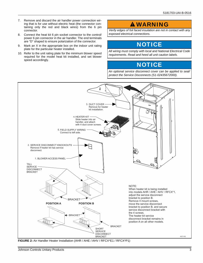
AIR HANDLER ELECTRIC HEAT KIT INSTALLA-TION (AP / AE / AVC / MP / ME / MVC / AHR / AHE / AHV / RFCX*E / RFCX*P)Installation is the same for all air handler operating positions:upflow, downflow, and horizontal right or left. Installation of theHeater Kit should be done prior to unit installation. Refer to Fig-ure 2 or 3 for depiction of components.1. Ensure that there is no electrical power going to the unit.
2. Remove air handler blower access panel.3. If the heat kit is being installed in model AHR, AHE, AHV or
RFCX*1, move the service disconnect bracket to PositionB as shown in Figure 2.
4. If Heat Kit has service disconnects (if heat kit does not con-tain service disconnects, skip to step 5):a. Examine the heat kit and take note of the number of
service disconnects it has. Remove the appropriatenumber of service disconnect knockouts from the frontaccess panel of the air handler unit.
b. Cut blower access panel insulation behind the servicedisconnect plate and remove to open the area for theservice disconnects to protrude through the frontaccess panel and to provide clearance for service dis-connects and single point wiring entry kit.
c. Replacement non-foil faced insulation for the exposedfront panel may then need to be added. Add rubbergasket to inside of door for sealing.
5. Remove and recycle the duct cover from back panel of airhandler control and wiring compartment.
6. Install electric heat accessory.a. Position and insert heat kit into opening in air handler.b. Align mount holes and fasten the Heat Kit to the air
handler unit with 4 duct cover screws.
TABLE 1: Models Covered
Heater kW @ 240V
1 Phase Heat Kit 1,2
3 Phase 208V/230VHeat Kits (PHE, PCE,
AHR, AHE, AHV, RFCX*E1, RFCX*P1,)
3 Phase 208V/230VHeat Kits (AP, AE, AVC,
RFCX*E2, RFCX*P2, MP, ME, MVC)
3 Phase 3460V
Heat Kits
2.4 6HK(0,1)6500206 – –4.8 6HK(0,1)6500506 – –7.7 6HK(0,1)6500806 – –9.6 6HK(0,1)6501006 6HK06501025 6HK36501025 6HK0650104612.5 6HK(1,2)6501306 – –14.4 6HK(1,2)6501506 6HK06501525 6HK36501525 6HK0650154617.3 6HK(1,2)6501806 6HK06501825 6HK36501825 6HK0650184619.2 6HK(1,2)6502006 6HK16502025 6HK46502025 6HK0650204624.0 6HK(1,2)6502506 6HK16502525 6HK46502525 6HK06502546
1. (0,1) - 0 = no service disconnect OR 1 = with service disconnect.2. (1,2) - 1 = with service disconnect, no breaker jumper bar OR 2 = with service disconnect & breaker jumper bar.3. Revision D or later must be used on MP 460V models.
6 Product Category 6 = Electric Heat for AP/AE/AVC/MP/ME/MVC/AHR/AHE/AHV/RFCX*E/RFCX*P Residential Air Handlers and PHE/PCE Residential Packages
HK Family Identifier HK = Electric Heater
1 Power Connection0 = Terminal Block1 or 3 = Service Disconnect2 or 4 = Service Disconnect & Single Point Wiring Kit
65 Class Identifier 65 = Electric Heater
002 Electric Heat, Nom. kW 002=2.5kW; 005=5kW; 008=8kW; 010=10kW; 013=13kW;013=13kW; 015=15kW; 018=18kW; 020=20kW; 025=25kW
25 Voltage Code 06 = 208/230-1-60; 25 = 208/230-3-60; 46 = 460-3-60C Style Letter C = Indicates sequential change of component styleD Style Letter D = Changed limit control cut out specification
CAUTIONBe aware that some units may have multiple power sources.
!
CAUTIONTo prevent damage, carefully pass the accessory heating ele-ment through the rectangular opening in the discharge duct.Element mounting plate must be secured with 4 screws.
!
2 Johnson Controls Unitary Products
5181703-UAI-B-0516
7. Remove and discard the air handler power connection wir-ing that is for use without electric heat (the connector con-taining only the red and black wires) from the 6 pinconnector.
8. Connect the heat kit 6 pin socket connector to the control/power 6 pin connector in the air handler. The end terminalsare “D” shaped to ensure polarization of the connector.
9. Mark an X in the appropriate box on the indoor unit ratingplate for the particular heater installed.
10. Refer to the unit rating plate for the minimum blower speedrequired for the model heat kit installed, and set blowerspeed accordingly.
WARNINGVerify edges of foil faced insulation are not in contact with anyexposed electrical connections.
NOTICEAll wiring must comply with local and National Electrical Coderequirements. Read and heed all unit caution labels.
NOTICEAn optional service disconnect cover can be applied to seal/protect the Service Disconnects (S1-02435672000).
!
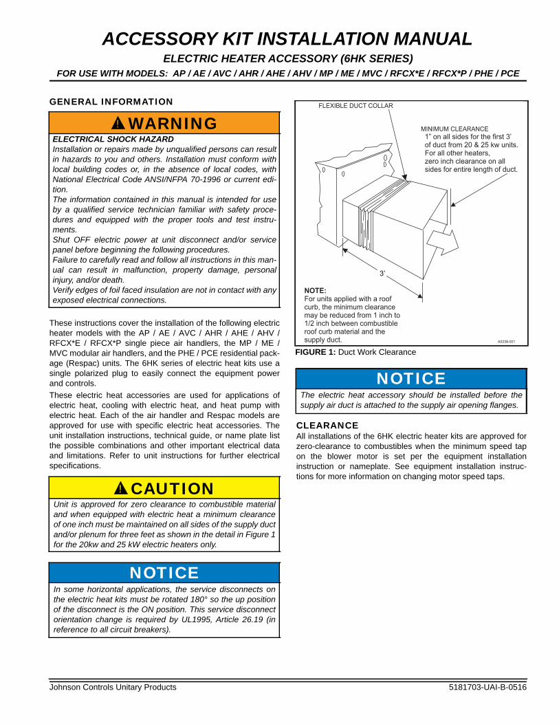
FIGURE 2: Air Handler Heater Installation (AHR / AHE / AHV / RFCX*E1 / RFCX*P1)
Johnson Controls Unitary Products 3
5181703-UAI-B-0516
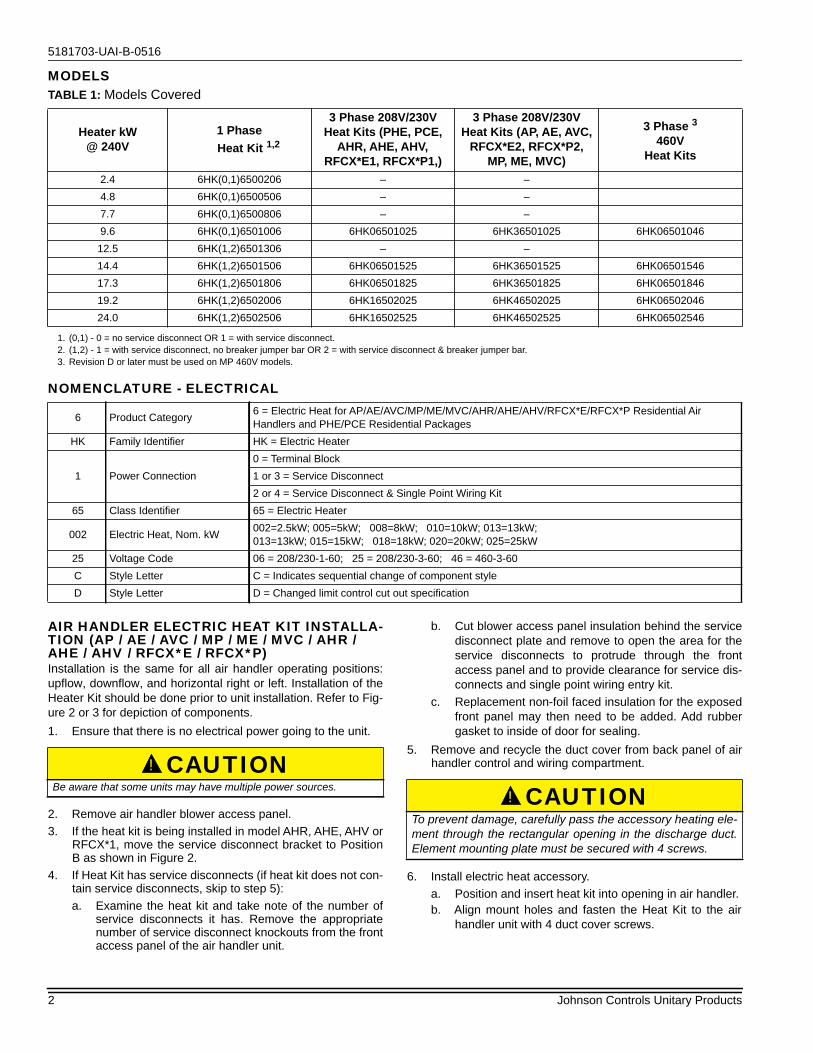
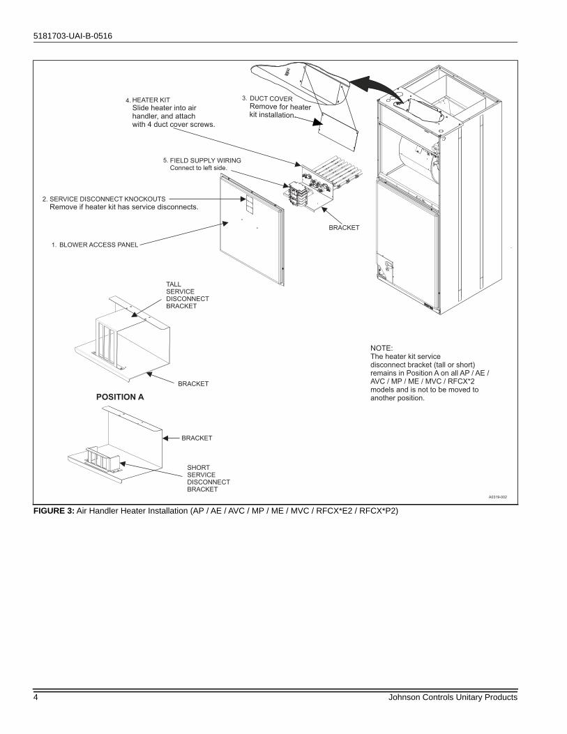
FIGURE 3: Air Handler Heater Installation (AP / AE / AVC / MP / ME / MVC / RFCX*E2 / RFCX*P2)
DUCT COVERRemove for heaterkit installation.
3.
BLOWER ACCESS PANEL1.
2. SERVICE DISCONNECT KNOCKOUTS
Remove if heater kit has service disconnects.
HEATER KIT
Slide heater into airhandler, and attachwith 4 duct cover screws.
4.
FIELD SUPPLY WIRINGConnect to left side.
5.
POSITION A
TALLSERVICEDISCONNECTBRACKET
BRACKET
BRACKET
BRACKET
NOTE:The heater kit servicedisconnect bracket (tall or short)remains in Position A on all AP / AE /AVC / MP / ME / MVC / RFCX*2models and is not to be moved toanother position.
A0319-002
SHORTSERVICEDISCONNECTBRACKET
4 Johnson Controls Unitary Products
5181703-UAI-B-0516
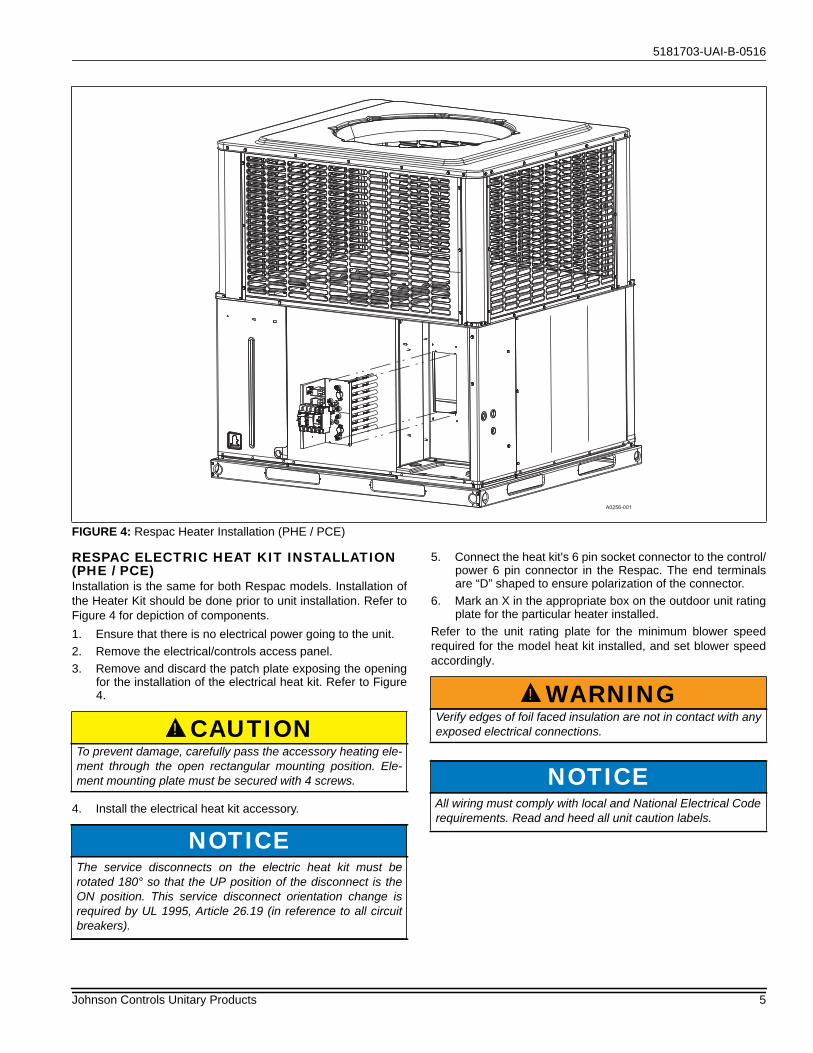
RESPAC ELECTRIC HEAT KIT INSTALLATION (PHE / PCE)Installation is the same for both Respac models. Installation ofthe Heater Kit should be done prior to unit installation. Refer toFigure 4 for depiction of components.1. Ensure that there is no electrical power going to the unit. 2. Remove the electrical/controls access panel. 3. Remove and discard the patch plate exposing the opening
for the installation of the electrical heat kit. Refer to Figure4.
4. Install the electrical heat kit accessory.
5. Connect the heat kit's 6 pin socket connector to the control/power 6 pin connector in the Respac. The end terminalsare “D” shaped to ensure polarization of the connector.
6. Mark an X in the appropriate box on the outdoor unit ratingplate for the particular heater installed.
Refer to the unit rating plate for the minimum blower speedrequired for the model heat kit installed, and set blower speedaccordingly.
.
FIGURE 4: Respac Heater Installation (PHE / PCE)
A0256-001
CAUTIONTo prevent damage, carefully pass the accessory heating ele-ment through the open rectangular mounting position. Ele-ment mounting plate must be secured with 4 screws.
NOTICEThe service disconnects on the electric heat kit must berotated 180° so that the UP position of the disconnect is theON position. This service disconnect orientation change isrequired by UL 1995, Article 26.19 (in reference to all circuitbreakers).
!
WARNINGVerify edges of foil faced insulation are not in contact with anyexposed electrical connections.
NOTICEAll wiring must comply with local and National Electrical Coderequirements. Read and heed all unit caution labels.
!
Johnson Controls Unitary Products 5
5181703-UAI-B-0516
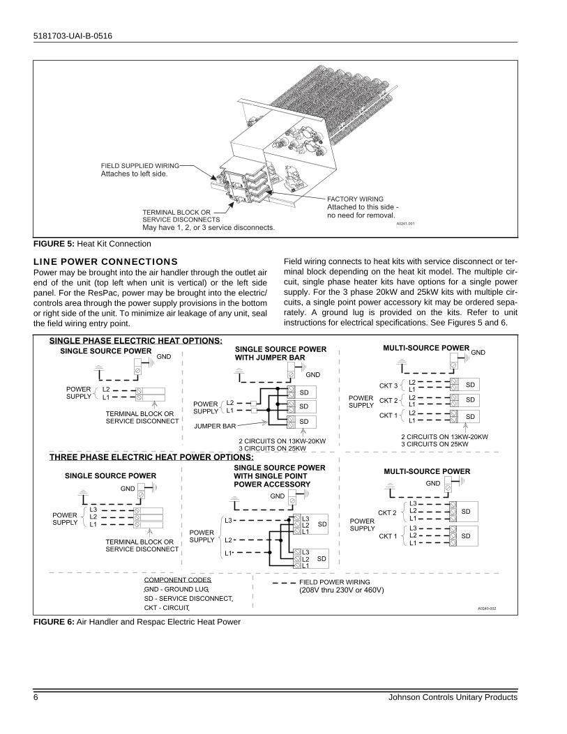
LINE POWER CONNECTIONSPower may be brought into the air handler through the outlet airend of the unit (top left when unit is vertical) or the left sidepanel. For the ResPac, power may be brought into the electric/controls area through the power supply provisions in the bottomor right side of the unit. To minimize air leakage of any unit, sealthe field wiring entry point.
Field wiring connects to heat kits with service disconnect or ter-minal block depending on the heat kit model. The multiple cir-cuit, single phase heater kits have options for a single powersupply. For the 3 phase 20kW and 25kW kits with multiple cir-cuits, a single point power accessory kit may be ordered sepa-rately. A ground lug is provided on the kits. Refer to unitinstructions for electrical specifications. See Figures 5 and 6.
FIGURE 5: Heat Kit Connection
FACTORY WIRING
Attached to this side -no need for removal.TERMINAL BLOCK OR
SERVICE DISCONNECTS
May have 1, 2, or 3 service disconnects.
FIELD SUPPLIED WIRING
Attaches to left side.
A0241-001
FIGURE 6: Air Handler and Respac Electric Heat Power
6 Johnson Controls Unitary Products
5181703-UAI-B-0516
ELECTRIC HEATERS & OPERATING CONTROLS
LOW VOLTAGE CONTROL CONNECTIONSThe low voltage transformer is standard on all models.
The 24 volt power supply is provided by an internally wired lowvoltage transformer which is standard on all air handler andRespac models. Field supplied low voltage wiring can exit theunit on the top right hand corner of the air handler or the righthand side panel of the air handler (refer to Figure 2 or 3).Respac models have provisions for low voltage wiring exits inthe bottom or right side of the unit (refer to Figure 4). Removedesired knockout and pierce foil faced insulation to allow wiringto pass through. Use as smallest hole possible to minimize airleakage. Install a 7/8” plastic bushing in the selected hole andkeep low voltage wiring as short as possible inside the controlbox. To further minimize air leakage, seal the wiring entry pointat the outside of the unit. The field wiring is to be connected atthe screw terminals of the control board or on low voltage wiringleads using twist-on wire connectors.
NOTICEFor blower speed connections, electrical information and wir-ing diagrams, see indoor unit installation instructions.
NOTICEThe electric heaters have both auto resettable and fusible linkthermal limit controls.If failure occurs, this fusible link thermal limit control must bereplaced with a direct replacement.
NOTICEAll wiring must comply with local and national electrical coderequirements. Read and heed all unit caution labels.
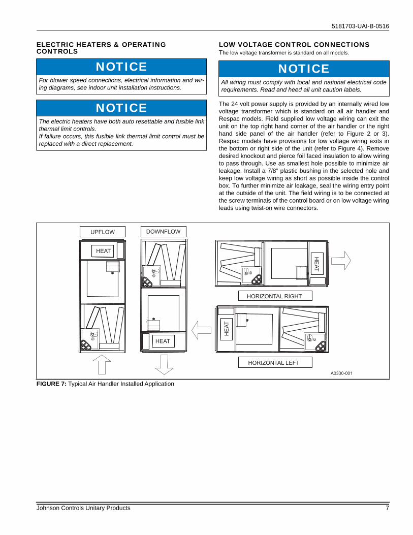
FIGURE 7: Typical Air Handler Installed Application
UPFLOW
HORIZONTAL RIGHT
HORIZONTAL LEFT
HEAT
HE
AT
HE
AT
DOWNFLOW
HEAT
A0330-001
Johnson Controls Unitary Products 7

NOTES
Subject to change without notice. Published in U.S.A. 5181703-UAI-B-0516Copyright © 2016 by Johnson Controls, Inc. All rights reserved. Supersedes: 5181703-UAI-A-0216
York International Corp.5005 York Drive
Norman, OK 73069