A simple method to evaluate HMI for FOT RT1 - FOT-Net
18
A simple method to evaluate HMI for FOT RT1 –Cooperative Systems FOTs across the globe- what should be harmonized at this stage and what not ? 4 th FOT-Net International Workshop 8:30-12:00, 16 October 2011 Hilton Orlando Hironao Kawashima Emeritus Professor, Keio University
Transcript of A simple method to evaluate HMI for FOT RT1 - FOT-Net

A simple method to evaluate HMI for FOT RT1 –Cooperative Systems FOTs across the globe- what should be harmonized at this
stage and what not ?
4th FOT-Net International Workshop
8:30-12:00, 16 October 2011
Hilton Orlando
Hironao Kawashima
Emeritus Professor, Keio University

Contents
1. Introduction
2. “Smartway” in Japan
3. HMI issues in “Smartway”
4. A simple method to evaluate HMI for FOT
1 4th FOT-Net International Workshop
1. Introduction
The importance of HMI related evaluations for cooperative systems are pointed out by many stakeholders.
Based on our FOT conducted in Japan, several topics related to HMI are introduced.
Finally, a simple method to evaluate HMI during the FOT trials is proposed.
4th FOT-Net International Workshop 2
2. “Smartway” in Japan
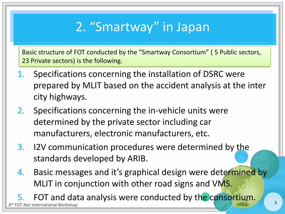
1. Specifications concerning the installation of DSRC were prepared by MLIT based on the accident analysis at the inter city highways.
2. Specifications concerning the in-vehicle units were determined by the private sector including car manufacturers, electronic manufacturers, etc.
3. I2V communication procedures were determined by the standards developed by ARIB.
4. Basic messages and it’s graphical design were determined by MLIT in conjunction with other road signs and VMS.
5. FOT and data analysis were conducted by the consortium. 4th FOT-Net International Workshop 3
Basic structure of FOT conducted by the “Smartway Consortium” ( 5 Public sectors, 23 Private sectors) is the following.
4
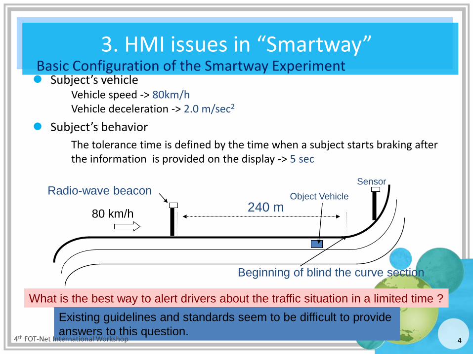
Basic Configuration of the Smartway Experiment Subject’s vehicle
Vehicle speed -> 80km/h Vehicle deceleration -> 2.0 m/sec2
Subject’s behavior
The tolerance time is defined by the time when a subject starts braking after the information is provided on the display -> 5 sec
Beginning of blind the curve section
240 m
Radio-wave beacon
80 km/h
What is the best way to alert drivers about the traffic situation in a limited time ?
Sensor
Object Vehicle
Existing guidelines and standards seem to be difficult to provide
answers to this question. 4th FOT-Net International Workshop
3. HMI issues in “Smartway”
5
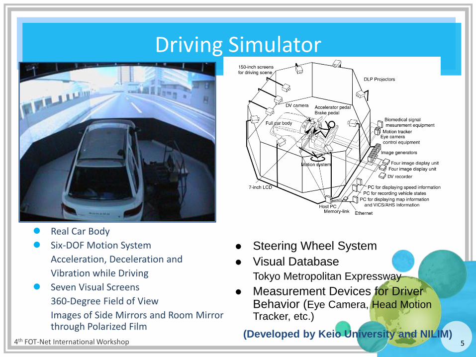
Driving Simulator
Real Car Body
Six-DOF Motion System
Acceleration, Deceleration and
Vibration while Driving
Seven Visual Screens
360-Degree Field of View
Images of Side Mirrors and Room Mirror through Polarized Film
Steering Wheel System
Visual Database
Tokyo Metropolitan Expressway
Measurement Devices for Driver Behavior (Eye Camera, Head Motion Tracker, etc.)
(Developed by Keio University and NILIM) 4th FOT-Net International Workshop
6
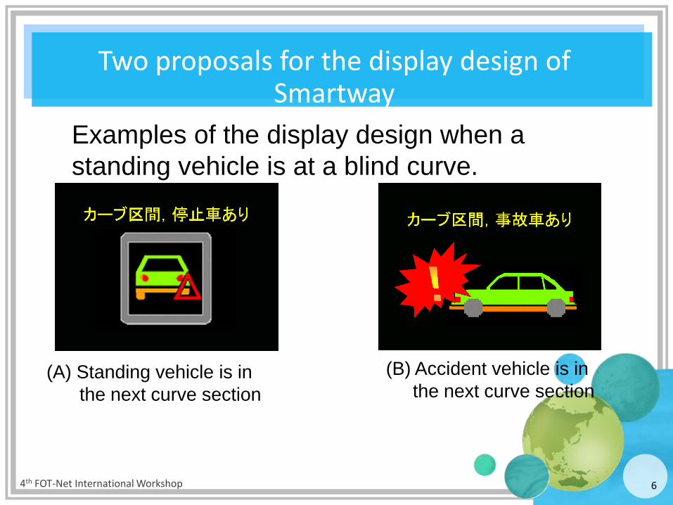
Two proposals for the display design of Smartway
Examples of the display design when a
standing vehicle is at a blind curve.
(A) Standing vehicle is in
the next curve section
(B) Accident vehicle is in
the next curve section
4th FOT-Net International Workshop
7
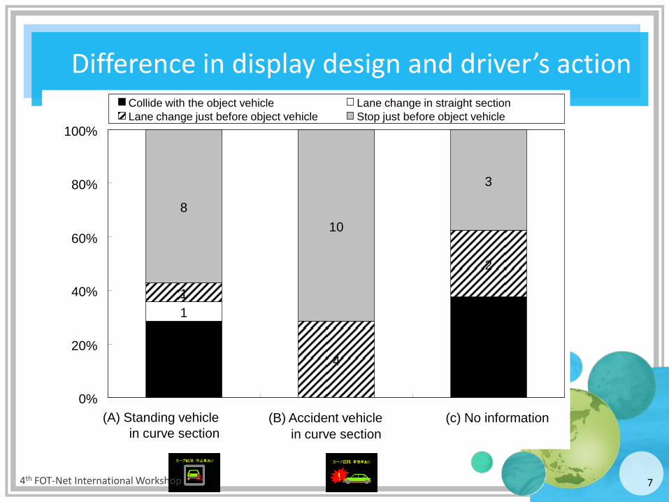
Difference in display design and driver’s action
4 3
1
1
4
2
8
10
3
0%
20%
40%
60%
80%
100%
(A) Standing vehicle
in curve section
(B) Accident vehicle
in curve section
(c) No information
Collide with the object vehicle Lane change in straight section
Lane change just before object vehicle Stop just before object vehicle
4th FOT-Net International Workshop

8
What drivers imagined about the incidents from the given information
20
11
7
13
2
1 4
0%
20%
40%
60%
80%
100%
(A) Standing vehicle in curve section (B) Accident vehicle in curve section
Both lanes blocked by the accident vehicle
Single lane blocked by the accident vehicle
Standing vehicle at the road shoulder
More than half of
the drivers imagined that
the standing vehicle is
at the road shoulder.
Half of the drivers
imagined that
there were some
lane blockades.
Others
4th FOT-Net International Workshop
9
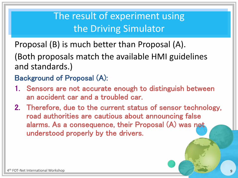
The result of experiment using the Driving Simulator
Proposal (B) is much better than Proposal (A).
(Both proposals match the available HMI guidelines and standards.) Background of Proposal (A):
1. Sensors are not accurate enough to distinguish between an accident car and a troubled car.
2. Therefore, due to the current status of sensor technology, road authorities are cautious about announcing false alarms. As a consequence, their Proposal (A) was not understood properly by the drivers.
4th FOT-Net International Workshop
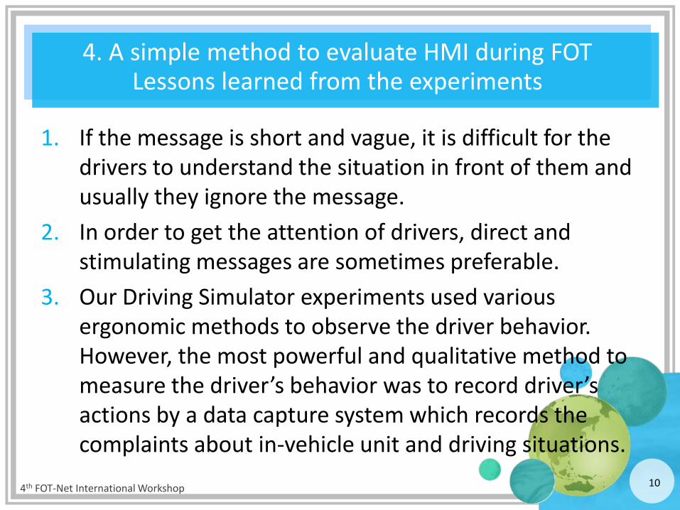
4. A simple method to evaluate HMI during FOT Lessons learned from the experiments
1. If the message is short and vague, it is difficult for the drivers to understand the situation in front of them and usually they ignore the message.
2. In order to get the attention of drivers, direct and stimulating messages are sometimes preferable.
3. Our Driving Simulator experiments used various ergonomic methods to observe the driver behavior. However, the most powerful and qualitative method to measure the driver’s behavior was to record driver’s actions by a data capture system which records the complaints about in-vehicle unit and driving situations.
4th FOT-Net International Workshop 10
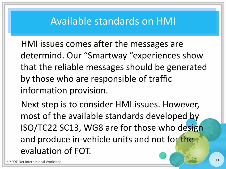
Available standards on HMI
HMI issues comes after the messages are determind. Our “Smartway “experiences show that the reliable messages should be generated by those who are responsible of traffic information provision.
Next step is to consider HMI issues. However, most of the available standards developed by ISO/TC22 SC13, WG8 are for those who design and produce in-vehicle units and not for the evaluation of FOT.
4th FOT-Net International Workshop 11
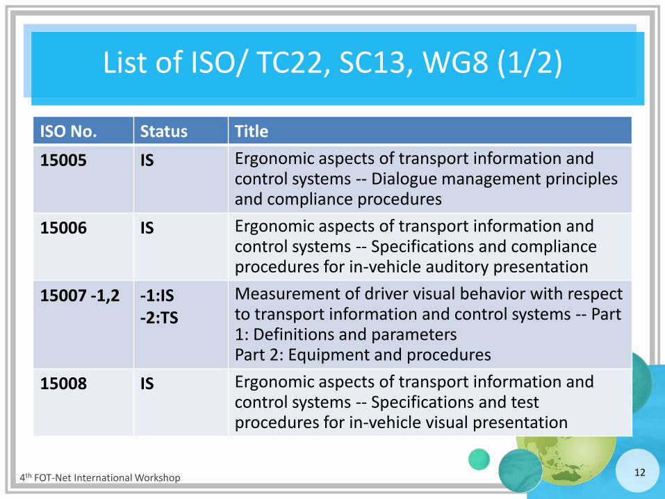
List of ISO/ TC22, SC13, WG8 (1/2)
ISO No. Status Title
15005 IS Ergonomic aspects of transport information and control systems -- Dialogue management principles and compliance procedures
15006 IS Ergonomic aspects of transport information and control systems -- Specifications and compliance procedures for in-vehicle auditory presentation
15007 -1,2 -1:IS -2:TS
Measurement of driver visual behavior with respect to transport information and control systems -- Part 1: Definitions and parameters Part 2: Equipment and procedures
15008 IS Ergonomic aspects of transport information and control systems -- Specifications and test procedures for in-vehicle visual presentation
4th FOT-Net International Workshop 12
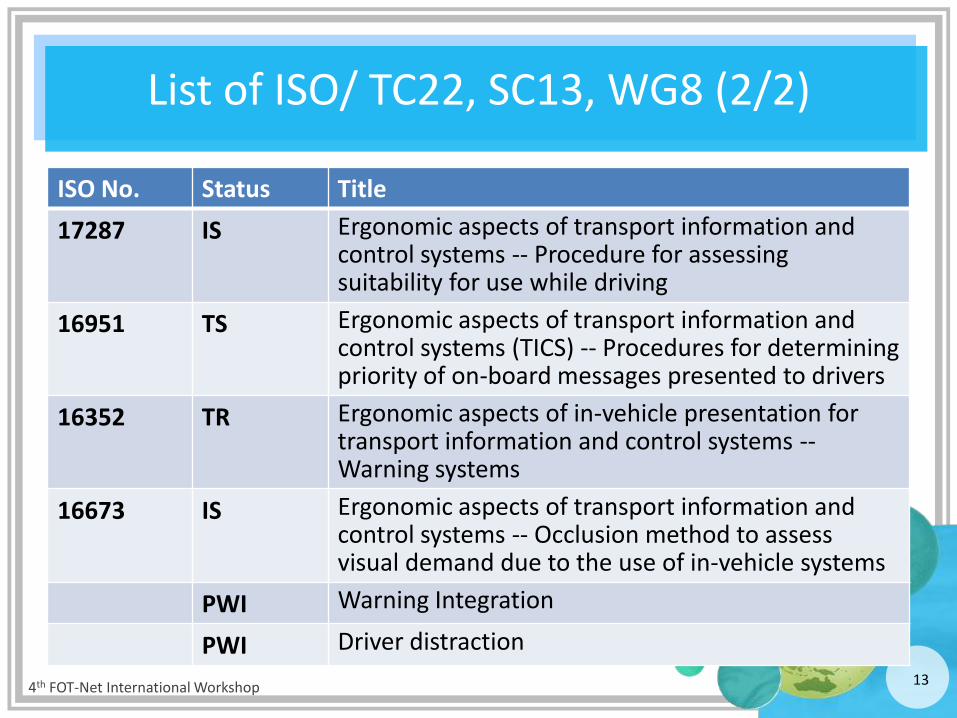
List of ISO/ TC22, SC13, WG8 (2/2)
ISO No. Status Title
17287 IS Ergonomic aspects of transport information and control systems -- Procedure for assessing suitability for use while driving
16951 TS Ergonomic aspects of transport information and control systems (TICS) -- Procedures for determining priority of on-board messages presented to drivers
16352 TR Ergonomic aspects of in-vehicle presentation for transport information and control systems -- Warning systems
16673 IS Ergonomic aspects of transport information and control systems -- Occlusion method to assess visual demand due to the use of in-vehicle systems
PWI Warning Integration
PWI Driver distraction
4th FOT-Net International Workshop 13
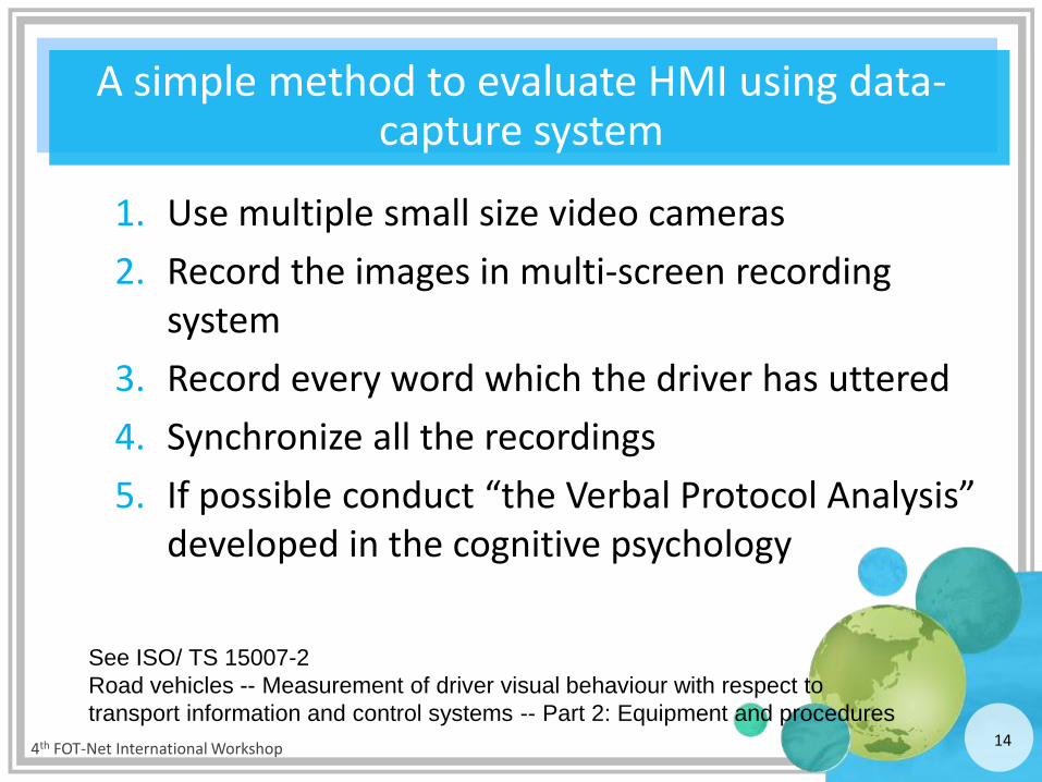
A simple method to evaluate HMI using data-capture system
1. Use multiple small size video cameras
2. Record the images in multi-screen recording system
3. Record every word which the driver has uttered
4. Synchronize all the recordings
5. If possible conduct “the Verbal Protocol Analysis” developed in the cognitive psychology
4th FOT-Net International Workshop 14
See ISO/ TS 15007-2
Road vehicles -- Measurement of driver visual behaviour with respect to
transport information and control systems -- Part 2: Equipment and procedures
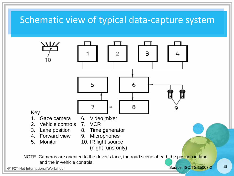
Schematic view of typical data-capture system
4th FOT-Net International Workshop 15
Key 1. Gaze camera 2. Vehicle controls 3. Lane position 4. Forward view 5. Monitor
6. Video mixer 7. VCR 8. Time generator 9. Microphones 10. IR light source
(night runs only)
NOTE: Cameras are oriented to the driver's face, the road scene ahead, the position in lane
and the in-vehicle controls. Source: ISO/TS 15007-2

Time Verbal reports Comments
11:35 What is this sign in the display? Logo of the shop “C” was not understood.
11:38 What is the mark “C” means? No sign using this mark.
11:40 No, I can not trust this system Traffic information comes out during the navigation.
11:42 Is that the crossing 300m ahead to turn right?
Examples of the Verbal Protocol Analysis while using a car navigation system
16
Harmonization issues
1. Where should we installed the cameras and how many?
2. In what occasions or situations we should record?
3. How we analyze the Verbal Protocol data and in what depth we should conduct the analysis?
4th FOT-Net International Workshop 17

![[Challenge:Future] FOT Gang](https://static.fdocuments.in/doc/165x107/58f322a91a28ab7e6e8b462b/challengefuture-fot-gang.jpg)