2010 HUMMER H2 Owner Manual M - General MotorsSafety Warnings and Symbols Warning messages found on...
552
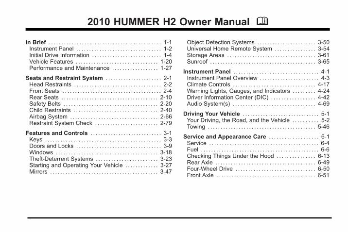
2010 HUMMER H2 Owner Manual M In Brief ............................................ 1-1 Instrument Panel ................................. 1-2 Initial Drive Information ........................... 1-4 Vehicle Features ................................ 1-20 Performance and Maintenance .................. 1-27 Seats and Restraint System ...................... 2-1 Head Restraints .................................. 2-2 Front Seats ....................................... 2-4 Rear Seats ...................................... 2-10 Safety Belts ..................................... 2-20 Child Restraints ................................. 2-40 Airbag System .................................. 2-66 Restraint System Check ......................... 2-79 Features and Controls ............................ 3-1 Keys ............................................. 3-3 Doors and Locks ................................. 3-9 Windows ........................................ 3-18 Theft-Deterrent Systems ........................ 3-23 Starting and Operating Your Vehicle ............. 3-27 Mirrors .......................................... 3-47 Object Detection Systems ....................... 3-50 Universal Home Remote System ................ 3-54 Storage Areas ................................... 3-61 Sunroof ......................................... 3-65 Instrument Panel ................................. 4-1 Instrument Panel Overview ....................... 4-3 Climate Controls ................................ 4-17 Warning Lights, Gauges, and Indicators ......... 4-24 Driver Information Center (DIC) ................. 4-42 Audio System(s) ................................ 4-69 Driving Your Vehicle .............................. 5-1 Your Driving, the Road, and the Vehicle .......... 5-2 Towing .......................................... 5-46 Service and Appearance Care ................... 6-1 Service ........................................... 6-4 Fuel .............................................. 6-6 Checking Things Under the Hood ............... 6-13 Rear Axle ....................................... 6-49 Four-Wheel Drive ............................... 6-50 Front Axle ....................................... 6-51
Transcript of 2010 HUMMER H2 Owner Manual M - General MotorsSafety Warnings and Symbols Warning messages found on...
2010 HUMMER H2 Owner Manual M
In Brief . . . . . . . . . . . . . . . . . . . . . . . . . . . . . . . . . . . . . . . . . . . . 1-1Instrument Panel . . . . . . . . . . . . . . . . . . . . . . . . . . . . . . . . . 1-2Initial Drive Information . . . . . . . . . . . . . . . . . . . . . . . . . . . 1-4Vehicle Features . . . . . . . . . . . . . . . . . . . . . . . . . . . . . . . . 1-20Performance and Maintenance . . . . . . . . . . . . . . . . . . 1-27
Seats and Restraint System . . . . . . . . . . . . . . . . . . . . . . 2-1Head Restraints . . . . . . . . . . . . . . . . . . . . . . . . . . . . . . . . . . 2-2Front Seats . . . . . . . . . . . . . . . . . . . . . . . . . . . . . . . . . . . . . . . 2-4Rear Seats . . . . . . . . . . . . . . . . . . . . . . . . . . . . . . . . . . . . . . 2-10Safety Belts . . . . . . . . . . . . . . . . . . . . . . . . . . . . . . . . . . . . . 2-20Child Restraints . . . . . . . . . . . . . . . . . . . . . . . . . . . . . . . . . 2-40Airbag System . . . . . . . . . . . . . . . . . . . . . . . . . . . . . . . . . . 2-66Restraint System Check . . . . . . . . . . . . . . . . . . . . . . . . . 2-79
Features and Controls . . . . . . . . . . . . . . . . . . . . . . . . . . . . 3-1Keys . . . . . . . . . . . . . . . . . . . . . . . . . . . . . . . . . . . . . . . . . . . . . 3-3Doors and Locks . . . . . . . . . . . . . . . . . . . . . . . . . . . . . . . . . 3-9Windows . . . . . . . . . . . . . . . . . . . . . . . . . . . . . . . . . . . . . . . . 3-18Theft-Deterrent Systems . . . . . . . . . . . . . . . . . . . . . . . . 3-23Starting and Operating Your Vehicle . . . . . . . . . . . . . 3-27Mirrors . . . . . . . . . . . . . . . . . . . . . . . . . . . . . . . . . . . . . . . . . . 3-47
Object Detection Systems . . . . . . . . . . . . . . . . . . . . . . . 3-50Universal Home Remote System . . . . . . . . . . . . . . . . 3-54Storage Areas . . . . . . . . . . . . . . . . . . . . . . . . . . . . . . . . . . . 3-61Sunroof . . . . . . . . . . . . . . . . . . . . . . . . . . . . . . . . . . . . . . . . . 3-65
Instrument Panel . . . . . . . . . . . . . . . . . . . . . . . . . . . . . . . . . 4-1Instrument Panel Overview . . . . . . . . . . . . . . . . . . . . . . . 4-3Climate Controls . . . . . . . . . . . . . . . . . . . . . . . . . . . . . . . . 4-17Warning Lights, Gauges, and Indicators . . . . . . . . . 4-24Driver Information Center (DIC) . . . . . . . . . . . . . . . . . 4-42Audio System(s) . . . . . . . . . . . . . . . . . . . . . . . . . . . . . . . . 4-69
Driving Your Vehicle . . . . . . . . . . . . . . . . . . . . . . . . . . . . . . 5-1Your Driving, the Road, and the Vehicle . . . . . . . . . . 5-2Towing . . . . . . . . . . . . . . . . . . . . . . . . . . . . . . . . . . . . . . . . . . 5-46
Service and Appearance Care . . . . . . . . . . . . . . . . . . . 6-1Service . . . . . . . . . . . . . . . . . . . . . . . . . . . . . . . . . . . . . . . . . . . 6-4Fuel . . . . . . . . . . . . . . . . . . . . . . . . . . . . . . . . . . . . . . . . . . . . . . 6-6Checking Things Under the Hood . . . . . . . . . . . . . . . 6-13Rear Axle . . . . . . . . . . . . . . . . . . . . . . . . . . . . . . . . . . . . . . . 6-49Four-Wheel Drive . . . . . . . . . . . . . . . . . . . . . . . . . . . . . . . 6-50Front Axle . . . . . . . . . . . . . . . . . . . . . . . . . . . . . . . . . . . . . . . 6-51
2010 HUMMER H2 Owner Manual M
Bulb Replacement . . . . . . . . . . . . . . . . . . . . . . . . . . . . . . 6-52Windshield Wiper Blade Replacement . . . . . . . . . . . 6-58Tires . . . . . . . . . . . . . . . . . . . . . . . . . . . . . . . . . . . . . . . . . . . . 6-60Appearance Care . . . . . . . . . . . . . . . . . . . . . . . . . . . . . . 6-106Vehicle Identification . . . . . . . . . . . . . . . . . . . . . . . . . . . 6-113Electrical System . . . . . . . . . . . . . . . . . . . . . . . . . . . . . . 6-113Capacities and Specifications . . . . . . . . . . . . . . . . . . 6-121
Maintenance Schedule . . . . . . . . . . . . . . . . . . . . . . . . . . . 7-1Maintenance Schedule . . . . . . . . . . . . . . . . . . . . . . . . . . . 7-2
Customer Assistance Information . . . . . . . . . . . . . . . 8-1Customer Assistance and Information . . . . . . . . . . . . 8-2Reporting Safety Defects . . . . . . . . . . . . . . . . . . . . . . . . 8-14Vehicle Data Recording and Privacy . . . . . . . . . . . . . 8-17
Index . . . . . . . . . . . . . . . . . . . . . . . . . . . . . . . . . . . . i-1

HUMMER, the HUMMER emblem, H2 and the H2Design are registered trademarks of HUMMER LLC.
This manual describes features that may or may not beon your specific vehicle either because they are optionsthat you did not purchase or due to changessubsequent to the printing of this owner manual. Pleaserefer to the purchase documentation relating to yourspecific vehicle to confirm each of the features found onyour vehicle. For vehicles first sold in Canada,substitute the name “General Motors of CanadaLimited” for HUMMER wherever it appears in thismanual.
Keep this manual in the vehicle for quick reference.
Canadian Owners
Propriétaires CanadiensA French language copy of this manual can be obtainedfrom your dealer or from:
On peut obtenir un exemplaire de ce guide en françaisauprès du concessionnaire ou à l'adresse suivante:
Helm, IncorporatedP.O. Box 07130Detroit, MI 48207
1-800-551-4123
Numéro de poste 6438 de langue française
www.helminc.com
IndexTo quickly locate information about the vehicle, use theindex in the back of the manual. It is an alphabetical listof what is in the manual and the page number where itcan be found.
iii
Litho in U.S.A.Part No. 25886726 A First Printing ©2010 HUMMER LLC. All Rights Reserved.
Safety Warnings and SymbolsWarning messages found on vehicle labels and in thismanual describe hazards and what to do to avoid orreduce them.
Danger indicates a hazard with a high level of riskwhich will result in serious injury or death.
Warning or Caution indicates a hazard that could resultin injury or death.
{ WARNING:
These mean there is something that could hurtyou or other people.
Notice: This means there is something that couldresult in property or vehicle damage. This would notbe covered by the vehicle's warranty.
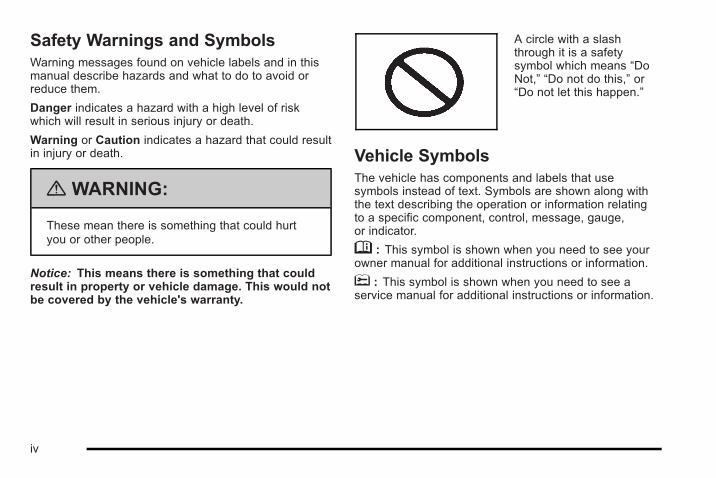
A circle with a slashthrough it is a safetysymbol which means “DoNot,” “Do not do this,” or“Do not let this happen.”
Vehicle SymbolsThe vehicle has components and labels that usesymbols instead of text. Symbols are shown along withthe text describing the operation or information relatingto a specific component, control, message, gauge,or indicator.
M : This symbol is shown when you need to see yourowner manual for additional instructions or information.
* : This symbol is shown when you need to see aservice manual for additional instructions or information.
iv

Vehicle Symbol ChartHere are some additional symbols that may be found onthe vehicle and what they mean. For more informationon the symbol, refer to the index.
9 : Airbag Readiness Light
# : Air Conditioning
! : Antilock Brake System (ABS)
g : Audio Steering Wheel Controls or OnStar®
$ : Brake System Warning Light
" : Charging System
I : Cruise Control
B : Engine Coolant Temperature
O : Exterior Lamps
# : Fog Lamps
. : Fuel Gauge
+ : Fuses
i : Headlamp High/Low-Beam Changer
j : LATCH System Child Restraints
* : Malfunction Indicator Lamp
: : Oil Pressure
} : Power
/ : Remote Vehicle Start
> : Safety Belt Reminders
7 : Tire Pressure Monitor
_ : Tow/Haul Mode
F : Traction Control
M : Windshield Washer Fluid
v

2 NOTES
vi

Section 1 In Brief
Instrument Panel . . . . . . . . . . . . . . . . . . . . . . . . . . . . . . . . . . . 1-2
Initial Drive Information . . . . . . . . . . . . . . . . . . . . . . . . . . . 1-4Remote Keyless Entry (RKE) System . . . . . . . . . . . 1-4Remote Vehicle Start . . . . . . . . . . . . . . . . . . . . . . . . . . . 1-4Door Locks . . . . . . . . . . . . . . . . . . . . . . . . . . . . . . . . . . . . . 1-5Liftgate . . . . . . . . . . . . . . . . . . . . . . . . . . . . . . . . . . . . . . . . . . 1-5Midgate® . . . . . . . . . . . . . . . . . . . . . . . . . . . . . . . . . . . . . . . . 1-6Tailgate . . . . . . . . . . . . . . . . . . . . . . . . . . . . . . . . . . . . . . . . . 1-6Windows . . . . . . . . . . . . . . . . . . . . . . . . . . . . . . . . . . . . . . . . 1-7Seat Adjustment . . . . . . . . . . . . . . . . . . . . . . . . . . . . . . . . 1-8Second Row Seats . . . . . . . . . . . . . . . . . . . . . . . . . . . . 1-10Third Row Seats . . . . . . . . . . . . . . . . . . . . . . . . . . . . . . . 1-10Heated Seats . . . . . . . . . . . . . . . . . . . . . . . . . . . . . . . . . . 1-10Head Restraint Adjustment . . . . . . . . . . . . . . . . . . . . 1-11Safety Belt . . . . . . . . . . . . . . . . . . . . . . . . . . . . . . . . . . . . . 1-11Airbag On-Off Switch . . . . . . . . . . . . . . . . . . . . . . . . . . 1-12Mirror Adjustment . . . . . . . . . . . . . . . . . . . . . . . . . . . . . . 1-12Steering Wheel Adjustment . . . . . . . . . . . . . . . . . . . . 1-13Interior Lighting . . . . . . . . . . . . . . . . . . . . . . . . . . . . . . . . 1-14Exterior Lighting . . . . . . . . . . . . . . . . . . . . . . . . . . . . . . . 1-15Windshield Wiper/Washer . . . . . . . . . . . . . . . . . . . . . . 1-16Climate Controls . . . . . . . . . . . . . . . . . . . . . . . . . . . . . . . 1-17Transmission . . . . . . . . . . . . . . . . . . . . . . . . . . . . . . . . . . 1-18
Vehicle Features . . . . . . . . . . . . . . . . . . . . . . . . . . . . . . . . . . 1-20Radio(s) . . . . . . . . . . . . . . . . . . . . . . . . . . . . . . . . . . . . . . . 1-20Satellite Radio . . . . . . . . . . . . . . . . . . . . . . . . . . . . . . . . . 1-21Portable Audio Devices . . . . . . . . . . . . . . . . . . . . . . . . 1-21Steering Wheel Controls . . . . . . . . . . . . . . . . . . . . . . . 1-22Bluetooth® . . . . . . . . . . . . . . . . . . . . . . . . . . . . . . . . . . . . . 1-22Navigation System . . . . . . . . . . . . . . . . . . . . . . . . . . . . . 1-23Driver Information Center (DIC) . . . . . . . . . . . . . . . . 1-23Cruise Control . . . . . . . . . . . . . . . . . . . . . . . . . . . . . . . . . 1-24Rear Vision Camera (RVC) . . . . . . . . . . . . . . . . . . . . 1-25Power Outlets . . . . . . . . . . . . . . . . . . . . . . . . . . . . . . . . . 1-25Universal Remote System . . . . . . . . . . . . . . . . . . . . . 1-25Sunroof . . . . . . . . . . . . . . . . . . . . . . . . . . . . . . . . . . . . . . . . 1-26
Performance and Maintenance . . . . . . . . . . . . . . . . . . 1-27Traction Control System (TCS) . . . . . . . . . . . . . . . . 1-27StabiliTrak® . . . . . . . . . . . . . . . . . . . . . . . . . . . . . . . . . . . . 1-27Tire Pressure Monitor . . . . . . . . . . . . . . . . . . . . . . . . . . 1-27Engine Oil Life System . . . . . . . . . . . . . . . . . . . . . . . . 1-28Fuel E85 (85% Ethanol) . . . . . . . . . . . . . . . . . . . . . . . 1-28Driving for Better Fuel Economy . . . . . . . . . . . . . . . 1-28Roadside Service . . . . . . . . . . . . . . . . . . . . . . . . . . . . . . 1-29OnStar® . . . . . . . . . . . . . . . . . . . . . . . . . . . . . . . . . . . . . . . 1-29
1-1

Instrument Panel
1-2

A. Outlet Adjustment on page 4‑22.
B. Midgate Window Switch (SUT). See PowerWindows on page 3‑19. Rear Window Wiper/Washer on page 4‑7 (SUV) .
C. Turn Signal/Multifunction Lever on page 4‑4.
D. Instrument Panel Cluster on page 4‑25.
E. Audio Steering Wheel Controls on page 4‑127.
F. Driver Information Center (DIC) on page 4‑42.
G. Analog Clock on page 4‑17.
H. Airbag Off Switch on page 2‑74.
I. Global Window Switch. See Power Windows onpage 3‑19.
J. Exterior Lamps on page 4‑11.
K. Dome Lamp Override on page 4‑14. InstrumentPanel Brightness on page 4‑13. HeatedWindshield Washer Control (If Equipped). SeeWindshield Washer on page 4‑7.
L. Cruise Control on page 4‑8 . Heated SteeringWheel on page 4‑4 (If Equipped).
M. Tilt Wheel on page 4‑3.
N. Horn on page 4‑3.
O. Full-Time Four-Wheel Drive on page 3‑37.
P. Locking Rear Axle on page 5‑9 . Tow/Haul Modeon page 3‑36. Traction Control System (TCS) onpage 5‑7 . Ride Height Selector Button (IfEquipped). See Selectable Extended Rear RideHeight on page 5‑49.
Q. Shift Lever. See Automatic Transmission Operationon page 3‑32.
R. Accessory Power Outlet(s) on page 4‑15.
S. Dual Automatic Climate Control System onpage 4‑17.
T. Audio System(s) on page 4‑69.
U. Glove Box on page 3‑61.
1-3
Initial Drive InformationThis section provides a brief overview about some ofthe important features that may or may not be on yourspecific vehicle.
For more detailed information, refer to each of thefeatures which can be found later in this owner manual.
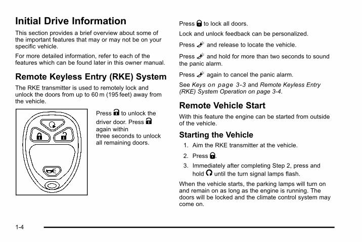
Remote Keyless Entry (RKE) SystemThe RKE transmitter is used to remotely lock andunlock the doors from up to 60 m (195 feet) away fromthe vehicle.
Press K to unlock the
driver door. Press Kagain withinthree seconds to unlockall remaining doors.
Press Q to lock all doors.
Lock and unlock feedback can be personalized.
PressL and release to locate the vehicle.
PressL and hold for more than two seconds to soundthe panic alarm.
PressL again to cancel the panic alarm.
See Keys on page 3‑3 and Remote Keyless Entry(RKE) System Operation on page 3‑4.
Remote Vehicle StartWith this feature the engine can be started from outsideof the vehicle.
Starting the Vehicle1. Aim the RKE transmitter at the vehicle.
2. Press Q.3. Immediately after completing Step 2, press and
hold/ until the turn signal lamps flash.
When the vehicle starts, the parking lamps will turn onand remain on as long as the engine is running. Thedoors will be locked and the climate control system maycome on.
1-4

The engine will continue to run for 10 minutes. Repeatthe steps for a 10-minute time extension. Remote startcan be extended only once.
Canceling a Remote StartTo cancel a remote start:. Aim the RKE transmitter at the vehicle and press
and hold/ until the parking lamps turn off.. Turn on the hazard warning flashers.. Turn the ignition on and then back off.
See Remote Vehicle Start on page 3‑7.
Door LocksThere are several ways to lock and unlock the vehicle.
From outside the vehicle, use the key or the RemoteKeyless Entry (RKE) transmitter. From inside thevehicle, slide the manual lever at the top of the door upor down.
Power Door LocksIn vehicles with power door locks, the switches arelocated on the doors.
Q : Press to lock all of the doors.
K : Press once to unlock the driver door, and twice tounlock all of the doors.
For more information, see:. Power Door Locks on page 3‑10.. Delayed Locking on page 3‑10.
LiftgateTo lock and unlock the liftgate, use any of the powerdoor lock switches or the Remote Keyless Entry (RKE)transmitter.
To open the liftgate:
1. Move the spare tire carrier out of the way. See“Opening the Spare Tire Carrier” under Tailgate/Spare Tire Carrier on page 3‑15.
2. Pull the handle located in the center of the door.
To close the liftgate:
1. Pull the liftgate down until it latches.
2. Move the spare tire carrier back into place. See“Closing the Spare Tire Carrier” under Tailgate/Spare Tire Carrier on page 3‑15.
For more information see, Liftgate (SUV) on page 3‑12.
1-5

Midgate®
If equipped, the Midgate® allows you to extend thelength of the vehicle's cargo area into the cab.
The Midgate window must be completely lowered forthe Midgate® to be lowered. See “Midgate® Window”under Power Windows on page 3‑19.
For detailed instructions on how to lower and raise theMidgate® properly, see Midgate® (SUT) on page 3‑13.
Tailgate
To open the tailgate, you must first open the spare tirecarrier and swing it out to the side of the vehicle.
To open the tailgate, lift the release handle while pullingthe tailgate toward you.
See Tailgate/Spare Tire Carrier on page 3‑15 for moreinformation.
1-6

WindowsA power window switch islocated on the armrest ofeach side door. The driverdoor also has a switch foreach of the passengerwindows.
Press the front of the switch to the first position to lowerthe window to the desired level. Pull up the front of theswitch to raise the window.
For more information, see Windows on page 3‑18 andPower Windows on page 3‑19.
Global Window FeatureThis feature allows all side windows and the Midgate®
window, if equipped, to be opened or closed at thesame time.
This button is located onthe instrument panel.
ª : Press to lower the windows without stopping.
y : Press and hold up to raise the windows.
For more information, see Power Windows onpage 3‑19.
1-7
Seat Adjustment
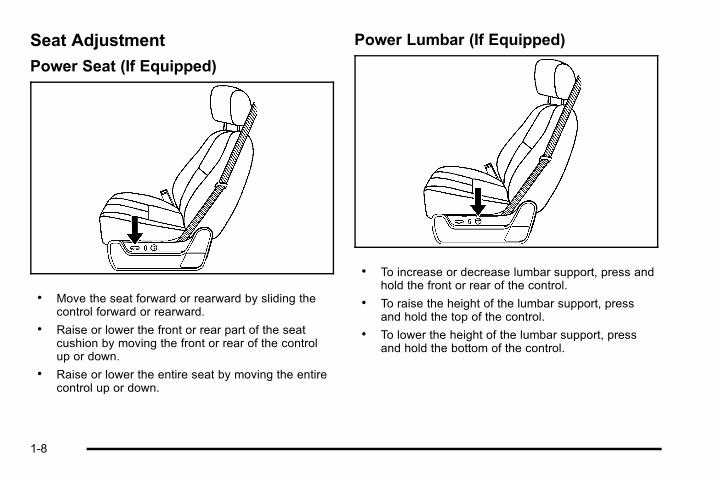
Power Seat (If Equipped)
. Move the seat forward or rearward by sliding thecontrol forward or rearward.
. Raise or lower the front or rear part of the seatcushion by moving the front or rear of the controlup or down.
. Raise or lower the entire seat by moving the entirecontrol up or down.
Power Lumbar (If Equipped)
. To increase or decrease lumbar support, press andhold the front or rear of the control.
. To raise the height of the lumbar support, pressand hold the top of the control.
. To lower the height of the lumbar support, pressand hold the bottom of the control.
1-8

Power Reclining Seatbacks
. To recline the seatback, press the control towardthe rear of the vehicle .
. To raise the seatback, press the control toward thefront of the vehicle .
See Power Reclining Seatbacks on page 2‑8 for moreinformation.
Memory SeatsIf equipped, this feature allows you to program andrecall memory settings for the driver seat and both thedriver and passenger outside mirrors. The settings forthese features can be saved for up to two drivers.
The controls for the memory function are located on thedriver door.
1: Saves the seating position for driver 1.
2: Saves the seating position for driver 2.
S : Programs and recalls the easy exit position.
For more information see, Memory Seat and Mirrors onpage 2‑7 .
1-9

Second Row SeatsThe split bench, and bucket seats can be folded toprovide more cargo space.
To fold the rear seat:
1. Make sure that nothing is under or in front ofthe seat.
2. Pull up on the straploop located at the rearof the seat cushion andpull the seat cushionup and fold it forward.
3. Pull the seatback forward and fold it down until itis flat.
4. Repeat the steps for the other half of the splitbench seat.
For more information, see Split Folding Rear Seat onpage 2‑10.
Third Row SeatsIf the vehicle has a third row seat, it is intended for twopassengers and has only two designated seatingpositions.
The third row seatback can be folded and the entireseat can be tilted or removed from the vehicle.
See, Third Row Seat on page 2‑14 for moreinformation.
Heated Seats
Front SeatsOn vehicles with heated front seats, the control buttonsare located on the driver and passenger doors.
I : Press to turn on the heated seatback.
J : Press to turn on the heated seat and seatback.
The light on the button will come on to indicate that thefeature is working.
Press the button to cycle through the temperaturesettings of high, medium, and low, and to turn it off.Indicator bars next to the symbol will designate the levelof heat selected: three for high, two for medium, andone for low.
For more information, see Heated Seats on page 2‑6.
1-10

Rear Seats
If available, the buttons used to control this feature arelocated on the Rear Seat Audio (RSA) panel.
M : Press to heat the seat cushion.
Press the button to cycle through the temperaturesettings of high, medium, and low, and to turn it off.Indicator bars next to the symbol will designate the levelof heat selected: three for high, two for medium, andone for low.
For more information, see Heated Seats on page 2‑10.
Head Restraint AdjustmentDo not drive until the head restraints for all occupantsare installed and adjusted properly.
See, Head Restraints on page 2‑2 for moreinformation.
Safety Belt
Refer to the following sections for important informationon how to use safety belts properly.. Safety Belts: They Are for Everyone on page 2‑20.. How to Wear Safety Belts Properly on page 2‑25.. Lap-Shoulder Belt on page 2‑34.. Lower Anchors and Tethers for Children (LATCH)
on page 2‑50.
1-11

Airbag On-Off SwitchThe vehicle has an airbag on-off switch that you canuse to manually turn on or off the right front passengerairbag.
United States Canada
This switch should only be turned to the off position ifthe person in the right front passenger position is amember of a passenger risk group identified by thenational government. See Airbag Off Switch onpage 2‑74 for additional important information.
Mirror Adjustment
Exterior MirrorsVehicles with outsidepower mirrors andfoldaway mirrors havecontrols located on thedriver door.
1. Press (A) or (B) to select the driver or passengerside mirror.
2. Press one of the four arrows located on the controlpad to adjust the mirror.
3. Press either (A) or (B) again to deselect the mirror.
1-12
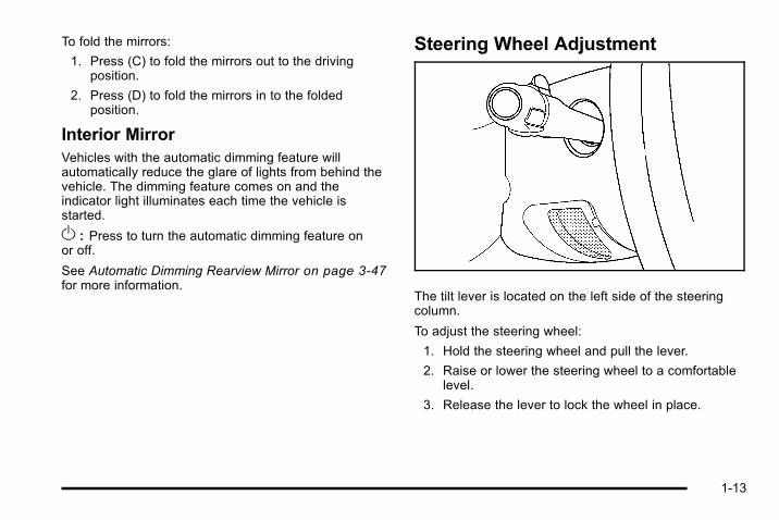
To fold the mirrors:
1. Press (C) to fold the mirrors out to the drivingposition.
2. Press (D) to fold the mirrors in to the foldedposition.
Interior MirrorVehicles with the automatic dimming feature willautomatically reduce the glare of lights from behind thevehicle. The dimming feature comes on and theindicator light illuminates each time the vehicle isstarted.
O : Press to turn the automatic dimming feature onor off.
See Automatic Dimming Rearview Mirror on page 3‑47for more information.
Steering Wheel Adjustment
The tilt lever is located on the left side of the steeringcolumn.
To adjust the steering wheel:
1. Hold the steering wheel and pull the lever.
2. Raise or lower the steering wheel to a comfortablelevel.
3. Release the lever to lock the wheel in place.
1-13

Power Tilt Wheel
For vehicles with thepower tilt wheel control, itis located on the left sideof the steering column.
To adjust the steering wheel:
Push the control up or down.
To set the memory position, see DIC VehicleCustomization on page 4‑60.
See Tilt Wheel on page 4‑3.
Interior Lighting
Dome LampThe dome lamps come on when any door is openedand turns off when all doors are closed.
The dome lamps can also be turned on by turning theinstrument panel brightness knob, located next to theexterior lamps control, clockwise to the farthest position.In this position, the dome lamps will remain on whethera door is opened or closed.
k : The dome lamp override button is located next tothe exterior lamps control.
Press the dome lamp override button in and the domelamps remain off when a door is opened. Press thebutton again to return it to the extended position so thatthe dome lamps come on when a door is opened.
1-14

Reading LampsThere are reading lamps located in the overheadconsole and on the DVD Rear Seat Entertainment(RSE) system console, if equipped. Press the buttonlocated next to each lamp to turn it on or off.
These lamps will also come on with the dome lamps.
For more information on interior lamps, see:. Dome Lamps on page 4‑14.. Dome Lamp Override on page 4‑14.. Instrument Panel Brightness on page 4‑13.
Exterior LightingThe exterior lampscontrol is located on theinstrument panel to theleft of the steering wheel.
The exterior lamps control has four positions:
O : Turns off the automatic headlamps and daytimerunning lamps (DRL). Turning the headlamp control tothe off position again will turn the automatic headlampsor DRL back on.
For vehicles first sold in Canada, the off position willonly work for vehicles that are shifted into the P (Park)position.
AUTO : Automatically turns on the headlamps atnormal brightness, along with other lamps.
; : Turns on the parking lamps and other lamps.
2 : Turns on the headlamps and other lamps.
For more information, see:. Exterior Lamps on page 4‑11.. Daytime Running Lamps (DRL) on page 4‑12.. Automatic Headlamp System on page 4‑13.
1-15
Windshield Wiper/Washer
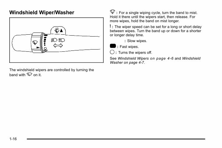
The windshield wipers are controlled by turning theband withz on it.
8 : For a single wiping cycle, turn the band to mist.Hold it there until the wipers start, then release. Formore wipes, hold the band on mist longer.
6 : The wiper speed can be set for a long or short delaybetween wipes. Turn the band up or down for a shorteror longer delay time.
6 : Slow wipes.
1 : Fast wipes.
9 : Turns the wipers off.
See Windshield Wipers on page 4‑6 and WindshieldWasher on page 4‑7.
1-16
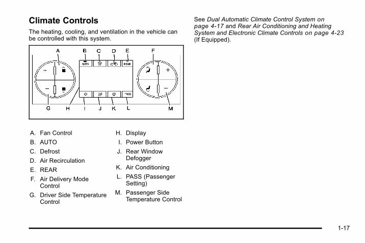
Climate ControlsThe heating, cooling, and ventilation in the vehicle canbe controlled with this system.
A. Fan Control
B. AUTO
C. Defrost
D. Air Recirculation
E. REAR
F. Air Delivery ModeControl
G. Driver Side TemperatureControl
H. Display
I. Power Button
J. Rear WindowDefogger
K. Air Conditioning
L. PASS (PassengerSetting)
M. Passenger SideTemperature Control
See Dual Automatic Climate Control System onpage 4‑17 and Rear Air Conditioning and HeatingSystem and Electronic Climate Controls on page 4‑23(If Equipped).
1-17

Transmission
Driver Shift Control (DSC)The vehicle has Driver Shift Control (DSC). DSCcontrols the transmission and vehicle speed whiledriving down hill or towing a trailer by allowing you toselect a desired range of gears.
To use this feature:
1. Move the shift lever to the M (Manual Mode). Thiswill force a downshift from the current gear, forgears 3 through 6.
2. Press the (+) plus or (−) minus button on the leftside of the steering wheel , to select the desiredrange of gears for current driving conditions.
When in the M (Manual Mode) a number will displaynext to the M, indicating the maximum available gear.The DIC display will show the message MANUALSHIFT on the first line and the maximum available gearwill be displayed on the second line. See DriverInformation Center (DIC) on page 4‑42 DriverInformation Center (DIC) and DIC Operation andDisplays (Using DIC Buttons) on page 4‑43 or DICOperation and Displays (Using Trip Odometer ResetStem) on page 4‑48 DIC Operation and Displays formore information. The number displayed in the DIC isthe highest gear available. The transmission will belimited to the gear selected and lower gears. Shiftingwill occur normally while driving, however the clusterwill continue to display the maximum available gear.Higher gears will not be available unless the selection ischanged to include higher gears using the (+) plusbutton.
Grade Braking is not available when the Driver ShiftControl is active. See Tow/Haul Mode on page 3‑36Tow/Haul Mode and Towing a Trailer on page 5‑52Towing a Trailer for more information.
While using the DSC, cruise control and the tow/haulmode can be used. See Automatic TransmissionOperation on page 3‑32
1-18

Transfer Case ButtonsFull-Time Four-Wheel Drive sends engine power to allfour wheels for extra traction.
The transfer case dial islocated to the right of theinstrument panel cluster.Use this switch to shiftinto and out of thedifferent Full-TimeFour-Wheel Drive modes.
4 m (Full-Time Four‐Wheel Drive): For driving in moststreet and highway situations.
4 m Q (Four-Wheel-High Lock): When extra traction isneeded in most off-road situations.
4 n Q (Four-Wheel-Low Lock): Delivers extra torque toall four wheels. Used for extreme off-road conditions.
When in this mode you can also choose to lock the rearaxle for additional traction in extreme off-road situations.See Locking Rear Axle on page 5‑9.
N (Neutral): Shift the transfer case to N (Neutral) onlywhen towing the vehicle. See Recreational VehicleTowing on page 5‑46 Recreational Vehicle Towing orTowing Your Vehicle on page 5‑46 Towing Your Vehiclefor more information.
See Full-Time Four-Wheel Drive on page 3‑37.
1-19

Vehicle Features
Radio(s)
Radio with CD, DVD, and USB Port
O : Press to turn the system on and off. Turn toincrease or decrease the volume.
BAND: Press to choose between FM, AM, or XM™,if equipped.
f : Select radio stations.
© ¨ : Seek or scan stations.
4 : Press to display additional text information related tothe current FM-RDS or XM station; or CD, MP3 or WMAsong. If information is available during XM, CD, MP3 orWMA playback, the song title information displays onthe top line of the display and artist information displayson the bottom line. When information is not available,“NO INFO” displays.
For more information about these and other radiofeatures, see Radio(s) on page 4‑72.
For vehicles with a Rear Seat Entertainment System(RSE) and Rear Seat Audio System (RSA) see, RearSeat Entertainment (RSE) System on page 4‑116 andRear Seat Audio (RSA) on page 4‑124 for moreinformation.
1-20

Storing a Favorite StationA maximum of 36 stations can be stored as favoritesusing the six softkeys located below the radio stationfrequency tabs and by using the radio FAV button.Press FAV to go through up to six pages of favorites,each having six favorite stations available per page.Each page of favorites can contain any combination ofAM, FM, or XM stations.
For more information, see Radio(s) on page 4‑72.
Setting the ClockTo set the time and date for the radio with CD, DVD,and USB Port:
1. Turn the ignition key to ACC/ACCESSORY or ON/RUN, then pressO, to turn the radio on.
2. Press H to display HR, MIN, MM, DD, YYYY (hour,minute, month, day, and year).
3. Press the softkey located under any one of thelabels to be changed.
4. To increase or decrease the time or date, turn fclockwise or counter‐clockwise.
For detailed instructions on setting the clock for thevehicle's specific audio system, see Setting the Clockon page 4‑70.
Satellite RadioXM is a satellite radio service that is based in the48 contiguous United States and 10 Canadianprovinces. XM satellite radio has a wide variety ofprogramming and commercial-free music,coast-to-coast, and in digital-quality sound.
A fee is required to receive the XM service.
For more information, refer to:. www.xmradio.com or call 1-800-929-2100 (U.S.). www.xmradio.ca or call 1-877-438-9677 (Canada)
See “XM Satellite Radio Service” under Radio(s) onpage 4‑72.
Portable Audio DevicesThis vehicle may have an auxiliary input located on theradio faceplate and a USB port located in the centerconsole. External devices such as iPod®, laptopcomputers, MP3 players, CD changers, USB storagedevice, etc. can be connected to the auxiliary port usinga 3.5 mm (1/8 in) input jack or the USB port dependingon the audio system.
See “Using the Auxiliary Input Jack” and “Using theUSB Port” under Radio(s) on page 4‑72.
1-21

Steering Wheel ControlsFor vehicles with audiosteering wheel controls,some audio controls canbe adjusted at thesteering wheel.
w /x : Press to change favorite radio stations, selecttracks on a CD/DVD, or to navigate tracks or folders onan iPod® or USB device.
b g : Press to silence the vehicle speakers only. Pressagain to turn the sound on. Press and hold longer thantwo seconds to interact with OnStar® or Bluetoothsystems, if equipped.
+ e − e : Increases or decreases volume.
c : Press to reject an incoming call, or to end a call.
SRCE: Press to switch between the radio, CD, and forvehicles with, DVD, front auxiliary, and rear auxiliary.
¨ : Press to seek the next radio station, the next trackor chapter while sourced to the CD or DVD slot, or toselect tracks and folders on an iPod® or USB device.
For more information, see Audio Steering WheelControls on page 4‑127.
Bluetooth®
For vehicles with an in-vehicle Bluetooth system, itallows users with a Bluetooth enabled cell phone tomake and receive hands-free calls using the vehicle’saudio system and controls.
The Bluetooth enabled cell phone must be paired withthe in-vehicle Bluetooth system before it can be used inthe vehicle. Not all phones will support all functions. Formore information visit www.gm.com/bluetooth.
For more information, see Bluetooth® on page 4‑106.
1-22

Navigation SystemThe vehicle's navigation system provides detailed mapsof most major freeways and roads throughout theUnited States and Canada. After a destination has beenset, the system provides turn-by-turn instructions forreaching the destination. In addition, the system canhelp locate a variety of points of interest (POI), such asbanks, airports, restaurants, and more.
See the vehicle's Navigation System manual for moreinformation.
Driver Information Center (DIC)The DIC display is located at the bottom of theinstrument panel cluster. It shows the status of manyvehicle systems and enables access to thepersonalization menu.
The DIC buttons arelocated on the instrumentpanel, next to the steeringwheel.
3 : Press this button to display the odometer, tripodometer, fuel range, average economy, fuel used,timer, and transmission temperature. The compass andoutside air temperature will also be shown in thedisplay. The temperature will be shown in °F or °Cdepending on the units selected.
T : Press this button to display the oil life, units, tirepressure readings for vehicles with the Tire PressureMonitor System (TPMS), engine hours, Remote KeylessEntry (RKE) transmitter programming, compass zonesetting, and compass recalibration.
U : Press this button to customize the feature settingson your vehicle. See DIC Vehicle Customization onpage 4‑60 for more information.
1-23

V : Press this button to set or reset certain functionsand to turn off or acknowledge messages on the DIC.
Some vehicles do not have the buttons shown, howeversome of the menus can be viewed by using the tripodometer reset stem.
For more information, see Driver Information Center(DIC) on page 4‑42.
Vehicle CustomizationSome vehicle features can be programmed by using theDIC buttons next to the steering wheel. These featuresinclude:. Language. Door Lock and Unlock Settings. RKE Lock and Unlock Feedback. Lighting. Chime Volume. Memory Features. Remote Start
See DIC Vehicle Customization on page 4‑60.
Cruise ControlThe cruise control buttonsare located on the leftside of the steering wheel.
T : Press to turn the system on or off. The indicatorlight on the button turns on when cruise control is onand turns off when cruise control is off.
+ RES: Press to make the vehicle accelerate or resumeto a previously set speed.
SET −: Press to set the speed or make the vehicledecelerate.
[ : Press to cancel cruise control without erasing theset speed from memory.
See Cruise Control on page 4‑8.
1-24

Rear Vision Camera (RVC)The rear vision camera displays a view of the areabehind the vehicle when the vehicle is shifted intoR (Reverse) on the inside rear view mirror or thenavigation screen, if equipped.
To clean the camera lens, located in the bezel for thetailgate handle, rinse it with water and wipe it with a softcloth.
For more information, see Rear Vision Camera (RVC)on page 3‑50.
Power OutletsAccessory power outlets can be used to connectauxiliary electrical equipment, such as a cellulartelephone.
The vehicle may have one outlet located inside thestorage bin below the climate control system, one outletinside the center floor console and two outlets on therear of the center floor console.
There may also be an accessory power outlet located inthe rear of the vehicle near the liftgate.
If the vehicle is the SUT model, there is an accessorypower outlet in the rear cargo area on the passengerside of the vehicle.
To use, remove the protective cap.
See Accessory Power Outlet(s) on page 4‑15.
Universal Remote System
The Universal Home Remote System allows for garagedoor openers, security systems, and home automationdevices to be programmed to work with these buttons inthe vehicle.
See Universal Home Remote System on page 3‑54.
1-25

SunroofIf equipped, the switchused to operate thesunroof is located in theoverhead console.
The ignition must be ON or in the ACC/ACCESSORYposition, or Retained Accessory Power (RAP) must beactive.
The sunroof has four positions:. Comfort open stop: Press the rear of the switch
quickly and release.. Full open stop: Press the rear of the switch
quickly once more.. Express close: Press the front of the switch
quickly and release.. Vent: With the sunroof in the fully closed position,
press and hold the front of the switch until thesunroof reaches the desired vent position or until itstops moving. To close, press and hold the rear ofthe switch until the sunroof is fully closed.
For more information see, Sunroof on page 3‑65.
1-26

Performance and Maintenance
Traction Control System (TCS)The traction control system limits wheel spin. Thesystem turns on automatically every time the vehicle isstarted.. To turn off traction control, press and release
the 5 button located on the instrument panel.F illuminates and the appropriate DIC messagedisplays. See DIC Warnings and Messages onpage 4‑52.
For more information, see Traction Control System(TCS) on page 5‑7.
StabiliTrak®
The StabiliTrak system assists with directional control ofthe vehicle in difficult driving conditions. The systemturns on automatically every time the vehicle is started.. To turn off both Traction Control and StabiliTrak,
press and hold 5, located on the instrument panel,
until F illuminates and the appropriate DICmessage displays. See DIC Warnings andMessages on page 4‑52.
. Press and release the button again to turn on bothsystems.
For more information, see StabiliTrak® System onpage 5‑5 .
Tire Pressure MonitorThis vehicle may have a Tire Pressure MonitorSystem (TPMS).
The Tire Pressure Monitoralerts you when asignificant reduction inpressure occurs in one ormore of the vehicle’s tiresby illuminating the low tirepressure warning light onthe instrument cluster.
If the warning light comes on, stop as soon as possibleand inflate the tires to the recommended pressureshown on the tire loading information label located onthe driver side center pillar (B pillar). See Loading theVehicle on page 5‑40. The warning light will remain onuntil the tire pressure is corrected.
1-27

You may notice during cooler conditions that the low tirepressure warning light will appear when the vehicle isfirst started and then turn off as you drive. This may bean early indicator that your tire pressures are gettinglow and the tires need to be inflated to the properpressure.
The Tire Pressure Monitor can alert you about low tirepressure, but it does not replace normal monthly tiremaintenance. It is the driver’s responsibility to maintaincorrect tire pressures.
See Tire Pressure Monitor System on page 6‑67 andTire Pressure Monitor Operation on page 6‑68.
Engine Oil Life SystemThe engine oil life system calculates engine oil lifebased on vehicle use and displays a DIC messagewhen it is necessary to change the engine oil and filter.The oil life system should be reset to 100% onlyfollowing an oil change.
Resetting the Oil Life System1. Display the OIL LIFE REMAINING on the DIC.
2. Press and hold the SET/RESET button on the DICfor more than five seconds. The oil life will changeto 100%.
See Engine Oil Life System on page 6‑20.
Fuel E85 (85% Ethanol)This vehicle has a yellow fuel cap and can use eitherunleaded gasoline or ethanol fuel containing up to85% ethanol (E85). See Gasoline Octane on page 6‑7and Fuel E85 (85% Ethanol) on page 6‑9.
Driving for Better Fuel EconomyDriving habits can affect fuel mileage. Here are somedriving tips to get the best fuel economy possible.. Avoid fast starts and accelerate smoothly.. Brake gradually and avoid abrupt stops.. Avoid idling the engine for long periods of time.. When road and weather conditions are
appropriate, use cruise control, if equipped.. Always follow posted speed limits or drive more
slowly when conditions require.. Keep vehicle tires properly inflated.. Combine several trips into a single trip.. Replace the vehicle's tires with the same TPC
Spec number molded into the tire's sidewall nearthe size.
. Follow recommended scheduled maintenance.
1-28

Roadside ServiceU.S.: 1-866-HUMMER6 (486-6376)
TTY Users: 1-888-889-2438
Canada: 1-800-268-6800
As the owner of a new HUMMER, you are automaticallyenrolled in the Roadside Service program. This programprovides technically trained advisors who are available24 hours a day, 365 days a year, minor repairinformation or towing arrangements.
Roadside Service and OnStarIf you have a current OnStar subscription, press theOnStar button and the current GPS location will be sentto an OnStar Advisor who will assess your problem,contact Roadside Assistance, and relay exact locationto get you the help you need.
Online Owner CenterThe Owner Center is a complimentary service thatincludes online service reminders, vehicle maintenancetips, online owner manual, special privileges and more.
Sign up today at: www.gmownercenter.com/hummer(U.S.) or www.gm.ca (Canada).
OnStar®
OnStar® uses several innovative technologies and liveadvisors to provide a wide range of safety, security,navigation, diagnostics, and calling services.
Automatic Crash ResponseIn a crash, built in sensors can automatically alert anOnStar advisor who is immediately connected to thevehicle to see if you need help.
1-29
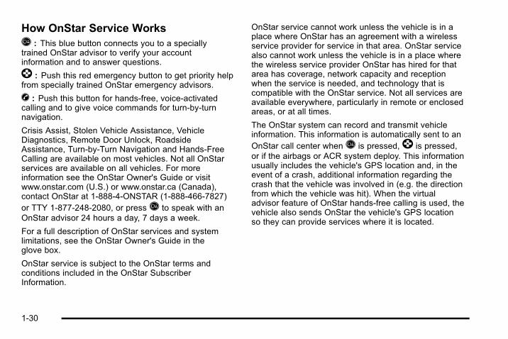
How OnStar Service WorksQ : This blue button connects you to a speciallytrained OnStar advisor to verify your accountinformation and to answer questions.
] : Push this red emergency button to get priority helpfrom specially trained OnStar emergency advisors.
X : Push this button for hands‐free, voice‐activatedcalling and to give voice commands for turn‐by‐turnnavigation.
Crisis Assist, Stolen Vehicle Assistance, VehicleDiagnostics, Remote Door Unlock, RoadsideAssistance, Turn‐by‐Turn Navigation and Hands‐FreeCalling are available on most vehicles. Not all OnStarservices are available on all vehicles. For moreinformation see the OnStar Owner's Guide or visitwww.onstar.com (U.S.) or www.onstar.ca (Canada),contact OnStar at 1-888-4-ONSTAR (1‐888‐466‐7827)or TTY 1‐877‐248‐2080, or pressQ to speak with anOnStar advisor 24 hours a day, 7 days a week.
For a full description of OnStar services and systemlimitations, see the OnStar Owner's Guide in theglove box.
OnStar service is subject to the OnStar terms andconditions included in the OnStar SubscriberInformation.
OnStar service cannot work unless the vehicle is in aplace where OnStar has an agreement with a wirelessservice provider for service in that area. OnStar servicealso cannot work unless the vehicle is in a place wherethe wireless service provider OnStar has hired for thatarea has coverage, network capacity and receptionwhen the service is needed, and technology that iscompatible with the OnStar service. Not all services areavailable everywhere, particularly in remote or enclosedareas, or at all times.
The OnStar system can record and transmit vehicleinformation. This information is automatically sent to anOnStar call center whenQ is pressed,] is pressed,or if the airbags or ACR system deploy. This informationusually includes the vehicle's GPS location and, in theevent of a crash, additional information regarding thecrash that the vehicle was involved in (e.g. the directionfrom which the vehicle was hit). When the virtualadvisor feature of OnStar hands-free calling is used, thevehicle also sends OnStar the vehicle's GPS locationso they can provide services where it is located.
1-30

Location information about the vehicle is only availableif the GPS satellite signals are unobstructed andavailable.
The vehicle must have a working electrical system,including adequate battery power, for the OnStarequipment to operate. There are other problems OnStarcannot control that may prevent OnStar from providingOnStar service at any particular time or place. Someexamples are damage to important parts of the vehiclein a crash, hills, tall buildings, tunnels, weather orwireless phone network congestion.
OnStar Steering Wheel ControlsThis vehicle may have a Talk/Mute button that can beused to interact with OnStar hands-free calling. SeeAudio Steering Wheel Controls on page 4‑127 for moreinformation.
On some vehicles, the mute button can be used to dialnumbers into voice mail systems, or to dial phoneextensions. See the OnStar Owner's Guide for moreinformation.
Your ResponsibilityIncrease the volume of the radio if the OnStar advisorcannot be heard.
If the light next to the OnStar buttons is red, the systemmay not be functioning properly. PressQ and request avehicle diagnostic. If the light appears clear (no light isappearing), your OnStar subscription has expired andall services have been deactivated. PressQ to confirmthat the OnStar equipment is active.
1-31

2 NOTES
1-32

Section 2 Seats and Restraint System
Head Restraints . . . . . . . . . . . . . . . . . . . . . . . . . . . . . . . . . . . . 2-2
Front Seats . . . . . . . . . . . . . . . . . . . . . . . . . . . . . . . . . . . . . . . . . 2-4Power Seats . . . . . . . . . . . . . . . . . . . . . . . . . . . . . . . . . . . . 2-4Power Lumbar . . . . . . . . . . . . . . . . . . . . . . . . . . . . . . . . . . 2-5Heated Seats . . . . . . . . . . . . . . . . . . . . . . . . . . . . . . . . . . . 2-6Memory Seat and Mirrors . . . . . . . . . . . . . . . . . . . . . . . 2-7Power Reclining Seatbacks . . . . . . . . . . . . . . . . . . . . . 2-8
Rear Seats . . . . . . . . . . . . . . . . . . . . . . . . . . . . . . . . . . . . . . . . 2-10Heated Seats . . . . . . . . . . . . . . . . . . . . . . . . . . . . . . . . . . 2-10Split Folding Rear Seat . . . . . . . . . . . . . . . . . . . . . . . . 2-10Bucket Seats (Reclining Seatbacks) . . . . . . . . . . . 2-13Third Row Seat . . . . . . . . . . . . . . . . . . . . . . . . . . . . . . . . 2-14
Safety Belts . . . . . . . . . . . . . . . . . . . . . . . . . . . . . . . . . . . . . . . 2-20Safety Belts: They Are for Everyone . . . . . . . . . . . 2-20How to Wear Safety Belts Properly . . . . . . . . . . . . 2-25Lap-Shoulder Belt . . . . . . . . . . . . . . . . . . . . . . . . . . . . . 2-34Safety Belt Use During Pregnancy . . . . . . . . . . . . . 2-39Safety Belt Extender . . . . . . . . . . . . . . . . . . . . . . . . . . . 2-39
Child Restraints . . . . . . . . . . . . . . . . . . . . . . . . . . . . . . . . . . 2-40Older Children . . . . . . . . . . . . . . . . . . . . . . . . . . . . . . . . . 2-40Infants and Young Children . . . . . . . . . . . . . . . . . . . . 2-43
Child Restraint Systems . . . . . . . . . . . . . . . . . . . . . . . 2-47Where to Put the Restraint . . . . . . . . . . . . . . . . . . . . . 2-49Lower Anchors and Tethers for Children(LATCH) . . . . . . . . . . . . . . . . . . . . . . . . . . . . . . . . . . . . . 2-50
Securing a Child Restraint in a Rear SeatPosition . . . . . . . . . . . . . . . . . . . . . . . . . . . . . . . . . . . . . . 2-60
Securing a Child Restraint in the Right FrontSeat Position . . . . . . . . . . . . . . . . . . . . . . . . . . . . . . . . 2-62
Airbag System . . . . . . . . . . . . . . . . . . . . . . . . . . . . . . . . . . . . 2-66Where Are the Airbags? . . . . . . . . . . . . . . . . . . . . . . . 2-68When Should an Airbag Inflate? . . . . . . . . . . . . . . . 2-71What Makes an Airbag Inflate? . . . . . . . . . . . . . . . . 2-72How Does an Airbag Restrain? . . . . . . . . . . . . . . . . 2-72What Will You See After an Airbag Inflates? . . . 2-72Airbag Off Switch . . . . . . . . . . . . . . . . . . . . . . . . . . . . . . 2-74Servicing Your Airbag-Equipped Vehicle . . . . . . . 2-77Adding Equipment to Your Airbag-EquippedVehicle . . . . . . . . . . . . . . . . . . . . . . . . . . . . . . . . . . . . . . 2-78
Restraint System Check . . . . . . . . . . . . . . . . . . . . . . . . . 2-79Checking the Restraint Systems . . . . . . . . . . . . . . . 2-79Replacing Restraint System Parts After aCrash . . . . . . . . . . . . . . . . . . . . . . . . . . . . . . . . . . . . . . . . 2-80
2-1

Head RestraintsThe front seats have adjustable head restraints in theoutboard seating positions.
{ WARNING:
With head restraints that are not installed andadjusted properly, there is a greater chance thatoccupants will suffer a neck/spinal injury in acrash. Do not drive until the head restraints for alloccupants are installed and adjusted properly.
Adjust the head restraint so that the top of the restraintis at the same height as the top of the occupant's head.This position reduces the chance of a neck injury in acrash.
2-2
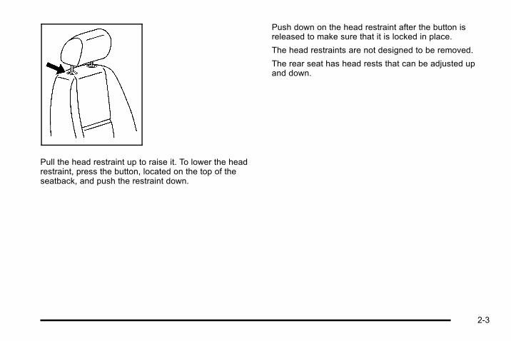
Pull the head restraint up to raise it. To lower the headrestraint, press the button, located on the top of theseatback, and push the restraint down.
Push down on the head restraint after the button isreleased to make sure that it is locked in place.
The head restraints are not designed to be removed.
The rear seat has head rests that can be adjusted upand down.
2-3

Front Seats
Power Seats
Driver Seat with Power Seat Control, Power Recline,and Power Lumbar shown
If available, these controls are located on the outboardside of the seats. To adjust the seat, do any of thefollowing:. Move the seat forward or rearward by sliding the
control forward or rearward.. Raise or lower the front or rear part of the seat
cushion by moving the front of the control upor down.
. Raise or lower the entire seat by moving the entirecontrol up or down.
On seats with power reclining seatbacks, the control islocated behind the power seat control on the outboardside of the seats. See “Power Reclining Seatbacks”under Power Reclining Seatbacks on page 2‑8.
A vehicle with a memory function allows seat settings tobe saved and recalled. See Memory Seat and Mirrorson page 2‑7 for more information.
2-4

Power Lumbar If available, these controls are located on the outboardside of the seats.. To increase or decrease lumbar support, press and
hold the front or rear of the control.. To raise the height of the lumbar support, press
and hold the top of the control.. To lower the height of the lumbar support, press
and hold the bottom of the control.
Release the control when the lower seatback reachesthe desired level of lumbar support.
The vehicle may have a memory function which allowsseat settings to be saved and recalled. See MemorySeat and Mirrors on page 2‑7 for more information.
2-5

Heated Seats
{ WARNING:
If you cannot feel temperature change or pain tothe skin, the seat heater may cause burns even atlow temperatures. To reduce the risk of burns,people with such a condition should use carewhen using the seat heater, especially for longperiods of time. Do not place anything on the seatthat insulates against heat, such as a blanket,cushion, cover or similar item. This may cause theseat heater to overheat. An overheated seatheater may cause a burn or may damagethe seat.
On vehicles with heated front seats, the controls arelocated on the driver and passenger doors.
I (Heated Seatback): Press to turn on the heatedseatback.
J (Heated Seat and Seatback): Press to turn on theheated seat and seatback.
The light on the button will come on to indicate that thefeature is working. Press the button to cycle through thetemperature settings of high, medium, and low and toturn the heat to the seat off. Indicator lights will showthe level of heat selected: three for high, two formedium, and one for low.
The heated seats will be canceled 10 seconds after theignition is turned off. To use the heated seat featureafter restarting the vehicle, press the heated seat orseatback button again.
2-6

Memory Seat and MirrorsIf the vehicle has this feature, the controls for thememory function are located on the driver door.
1: Saves the seating position for driver 1.
2: Saves the seating position for driver 2.
S : Programs and recalls the easy exit position.
These buttons are used to program and recall memorysettings for the driver seat and both the driver andpassenger outside mirrors. The settings for thesefeatures can be saved for up to two drivers.
To store the memory settings:
1. While the vehicle is in P (Park), adjust the driverseat, including the seatback recliner, lumbar, andside wing area, and both outside mirrors to acomfortable position.
2. Press and hold button 1 until a double chimesounds to let you know that the position has beenstored.
A second seating and mirror position can beprogrammed by repeating Steps 1 and 2 and pressingbutton 2.
To recall the memory positions, the vehicle must be inP (Park). Press and release either button 1 or button 2corresponding to the desired driving position. A singlechime will sound and the memory position will berecalled.
To stop recall movement of the memory seat feature atany time, press one of the memory buttons or powerseat controls.
2-7
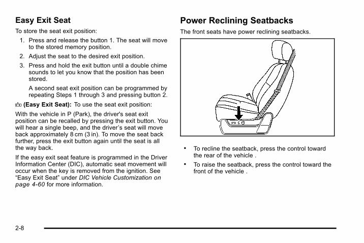
Easy Exit SeatTo store the seat exit position:
1. Press and release the button 1. The seat will moveto the stored memory position.
2. Adjust the seat to the desired exit position.
3. Press and hold the exit button until a double chimesounds to let you know that the position has beenstored.
A second seat exit position can be programmed byrepeating Steps 1 through 3 and pressing button 2.
B (Easy Exit Seat): To use the seat exit position:
With the vehicle in P (Park), the driver's seat exitposition can be recalled by pressing the exit button. Youwill hear a single beep, and the driver’s seat will moveback approximately 8 cm (3 in). To move the seat backfurther, press the exit button again until the seat is allthe way back.
If the easy exit seat feature is programmed in the DriverInformation Center (DIC), automatic seat movement willoccur when the key is removed from the ignition. See“Easy Exit Seat” under DIC Vehicle Customization onpage 4‑60 for more information.
Power Reclining SeatbacksThe front seats have power reclining seatbacks.
. To recline the seatback, press the control towardthe rear of the vehicle .
. To raise the seatback, press the control toward thefront of the vehicle .
2-8
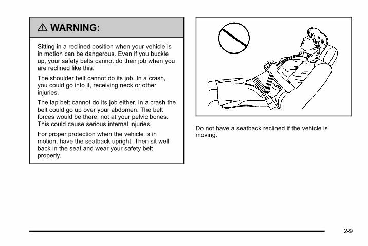
{ WARNING:
Sitting in a reclined position when your vehicle isin motion can be dangerous. Even if you buckleup, your safety belts cannot do their job when youare reclined like this.
The shoulder belt cannot do its job. In a crash,you could go into it, receiving neck or otherinjuries.
The lap belt cannot do its job either. In a crash thebelt could go up over your abdomen. The beltforces would be there, not at your pelvic bones.This could cause serious internal injuries.
For proper protection when the vehicle is inmotion, have the seatback upright. Then sit wellback in the seat and wear your safety beltproperly.
Do not have a seatback reclined if the vehicle ismoving.
2-9

Rear Seats
Heated Seats
Driver Side RSA HeatedSeat Button shown
On vehicles with rearoutboard heated seats,the buttons used tocontrol this feature arelocated on the Rear SeatAudio (RSA) panel.
M (Heated Seat): To heat the seat cushion, press thebutton with the heated seat symbol.
A heated seat symbol will be shown in the RSA displayto indicate that the feature is on. Press the button tocycle through the temperature settings of high, medium,and low, and to turn it off. Indicator bars next to thesymbol will designate the level of heat selected: threefor high, two for medium, and one for low.
The heated seats are off when the ignition is off.
Split Folding Rear SeatThe split bench, and bucket seats can be folded toprovide more cargo space.
Folding the SeatbacksThe seatbacks are equipped with rearward folding headrests (SUV only). When the seatback is being foldeddown, the head rest will automatically fold rearward.
2-10

To fold the rear seat:
1. Make sure that nothing is under or in front ofthe seat.
2. Pull up on the straploop located at the rearof the seat cushion andpull the seat cushionup and fold it forward.
Notice: Folding a rear seat with the safety belts stillfastened may cause damage to the seat or thesafety belts. Always unbuckle the safety belts andreturn them to their normal stowed position beforefolding a rear seat.
3. Pull the seatback forward and fold it down until itis flat.
If the seatback cannot fold flat because it interfereswith the cushion, try moving the front seat forwardand/or bringing the front seatback more upright.
4. Repeat the steps for the other half of the splitbench seat.
{ WARNING:
Using the third row seating position while thesecond row is folded, or folded and tumbled, couldcause injury in a sudden stop or crash. Be sure toreturn the seat to the passenger seating position.Push and pull on the seat to make sure it islocked into place.
2-11
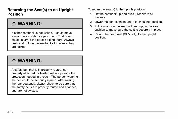
Returning the Seat(s) to an UprightPosition
{ WARNING:
If either seatback is not locked, it could moveforward in a sudden stop or crash. That couldcause injury to the person sitting there. Alwayspush and pull on the seatbacks to be sure theyare locked.
{ WARNING:
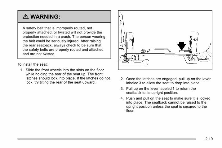
A safety belt that is improperly routed, notproperly attached, or twisted will not provide theprotection needed in a crash. The person wearingthe belt could be seriously injured. After raisingthe rear seatback, always check to be sure thatthe safety belts are properly routed and attached,and are not twisted.
To return the seat(s) to the upright position:
1. Lift the seatback up and push it rearward allthe way.
2. Lower the seat cushion until it latches into position.
3. Pull forward on the seatback and up on the seatcushion to make sure the seat is securely in place.
4. Return the head rest (SUV only) to the uprightposition.
2-12

Bucket Seats (Reclining Seatbacks)Vehicles with bucket seats have a manual reclining seatback function.
The lever used to operate them is located on theoutboard side of the seat(s).
To recline the seatback:
1. Lift the recline lever.
2. Move the seatback to the desired position, thenrelease the lever to lock the seatback in place.
3. Push and pull on the seatback to make sure it islocked.
To return the seatback to an upright position:
1. Lift the lever fully without applying pressure to theseatback and the seatback will return to the uprightposition.
2. Push and pull on the seatback to make sure it islocked.
2-13

Third Row Seat
Entering or Exiting the Third Row SeatIf the vehicle has a third row seat, it is intended for twopassengers and has only two designated seatingpositions.
A second row split folding rear seat must be foldeddown before entering or exiting the third row. See“Folding the Seatbacks” under Split Folding Rear Seaton page 2‑10 earlier in this section for instructions.
The third row seatback can be folded and the entireseat can be tilted or removed from the vehicle.
Folding the SeatbackTo fold the seatback:
Notice: Folding a rear seat with the safety belts stillfastened may cause damage to the seat or thesafety belts. Always unbuckle the safety belts andreturn them to their normal stowed position beforefolding a rear seat.
1. Pull up on the releaselever labeled 1, locatedon the rear of theseatback, and push theseatback forward.
2-14

Unfolding the Seatback
{ WARNING:
If either seatback is not locked, it could moveforward in a sudden stop or crash. That couldcause injury to the person sitting there. Alwayspush and pull on the seatbacks to be sure theyare locked.
To return the seatback to the passenger position:
1. Pull up on the releaselever labeled 1 andthen pull up on theseatback until theseatback locks into theupright position.
2. Push forward on the seatback to make sure it islocked into position.
Tilting the Seat1. Fold the seatback forward using the instructions
listed previously.
2. Unlatch the seat fromthe floor by pulling upon the lever labeled 2,located on the rear ofthe seat.
3. Lift the rear of the seat up from the floor and pushit forward until it locks into place. The seat cannotbe unlatched from the floor unless the seatback isfolded down.
The seat will now remain locked in the upright position.
2-15

Returning the Seat from a Tilted to anUpright Position
{ WARNING:
If either seatback is not locked, it could moveforward in a sudden stop or crash. That couldcause injury to the person sitting there. Alwayspush and pull on the seatbacks to be sure theyare locked.
To return the seatback to an upright position:
1. Pull the lever labeled 3 toward you.
2. While still holding lever 3 toward you, grasp the topof the seat and pull it toward you slightly.
3. Release lever 3 and pull the seat completely down.
4. Push down on the seat firmly. Try pulling it up to besure it is locked into place.
2-16

5. Pull up on the releaselever labeled 1 andthen pull up on theseatback until theseatback locks into theupright position.
Removing the SeatTo remove the seat:
1. Open the liftgate.
Notice: Folding a rear seat with the safety belts stillfastened may cause damage to the seat or thesafety belts. Always unbuckle the safety belts andreturn them to their normal stowed position beforefolding a rear seat.
2. Fold the seatbackforward onto the seatcushion by using thelever labeled 1. Theseat cannot beremoved unless theseatback is folded.
3. Pull up on the releaselever labeled 2, at therear of the seat, tounlatch the rear of theseat from the floor, andlift the rear of the seatup from the floor.
2-17

4. Squeeze the release handle while pulling the seatout of the slots on the floor.
5. Roll the seat out of the vehicle while holding therear of the seat up.
Installing the Seat
{ WARNING:
If either seatback is not locked, it could moveforward in a sudden stop or crash. That couldcause injury to the person sitting there. Alwayspush and pull on the seatbacks to be sure theyare locked.
{ WARNING:
A seat that is not locked into place properly canmove around in a collision or sudden stop. Peoplein the vehicle could be injured. Be sure to lock theseat into place properly when installing it.
2-18
{ WARNING:
A safety belt that is improperly routed, notproperly attached, or twisted will not provide theprotection needed in a crash. The person wearingthe belt could be seriously injured. After raisingthe rear seatback, always check to be sure thatthe safety belts are properly routed and attached,and are not twisted.
To install the seat:
1. Slide the front wheels into the slots on the floorwhile holding the rear of the seat up. The frontlatches should lock into place. If the latches do notlock, try tilting the rear of the seat upward.
2. Once the latches are engaged, pull up on the leverlabeled 3 to allow the seat to drop into place.
3. Pull up on the lever labeled 1 to return theseatback to its upright position.
4. Push and pull on the seat to make sure it is lockedinto place. The seatback cannot be raised to theupright position unless the seat is secured to thefloor.
2-19

Safety Belts
Safety Belts: They Are for EveryoneThis part of the manual tells you how to use safety beltsproperly. It also tells you some things you should not dowith safety belts.
{ WARNING:
Do not let anyone ride where a safety belt cannotbe worn properly. In a crash, if you or yourpassenger(s) are not wearing safety belts, theinjuries can be much worse. You can hit thingsinside the vehicle harder or be ejected from thevehicle. You and your passenger(s) can beseriously injured or killed. In the same crash, youmight not be, if you are buckled up. Always fastenyour safety belt, and check that your passenger(s)are restrained properly too.
{ WARNING:
People riding on the tailgate (if equipped) caneasily lose their balance and fall even when thevehicle is operated at low speeds. Falling from amoving vehicle may result in serious injuries ordeath.
{ WARNING:
It is extremely dangerous to ride in a cargo area,inside or outside of a vehicle. In a collision,people riding in these areas are more likely to beseriously injured or killed. Do not allow people toride in any area of your vehicle that is notequipped with seats and safety belts. Be sureeveryone in your vehicle is in a seat and using asafety belt properly.
2-20
Your vehicle has indicators as a reminder to buckle yoursafety belts. See Safety Belt Reminders on page 4‑26.
In most states and in all Canadian provinces, the lawrequires wearing safety belts. Here is why:
You never know if you will be in a crash. If you do havea crash, you do not know if it will be a serious one.
A few crashes are mild, and some crashes can be soserious that even buckled up, a person would notsurvive. But most crashes are in between. In many ofthem, people who buckle up can survive and sometimeswalk away. Without belts they could have been badlyhurt or killed.
After more than 40 years of safety belts in vehicles, thefacts are clear. In most crashes buckling up doesmatter ... a lot!
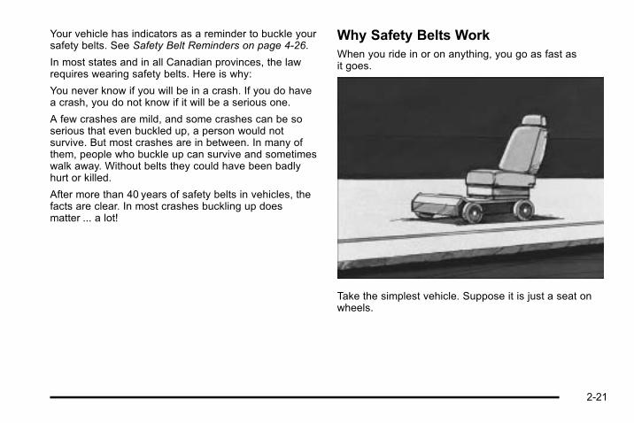
Why Safety Belts WorkWhen you ride in or on anything, you go as fast asit goes.
Take the simplest vehicle. Suppose it is just a seat onwheels.
2-21

Put someone on it. Get it up to speed. Then stop the vehicle. The riderdoes not stop.
2-22

The person keeps going until stopped by something. Ina real vehicle, it could be the windshield...
or the instrument panel...
2-23

or the safety belts!
With safety belts, you slow down as the vehicle does.You get more time to stop. You stop over more distance,and your strongest bones take the forces. That is whysafety belts make such good sense.
Questions and Answers About SafetyBelts
Q: Will I be trapped in the vehicle after a crash if Iam wearing a safety belt?
A: You could be — whether you are wearing a safetybelt or not. But your chance of being consciousduring and after an accident, so you can unbuckleand get out, is much greater if you are belted. Andyou can unbuckle a safety belt, even if you areupside down.
Q: If my vehicle has airbags, why should I have towear safety belts?
A: Airbags are supplemental systems only; so theywork with safety belts — not instead of them.Whether or not an airbag is provided, all occupantsstill have to buckle up to get the most protection.That is true not only in frontal collisions, butespecially in side and other collisions.
2-24
Q: If I am a good driver, and I never drive far fromhome, why should I wear safety belts?
A: You may be an excellent driver, but if you are in acrash — even one that is not your fault — you andyour passenger(s) can be hurt. Being a good driverdoes not protect you from things beyond yourcontrol, such as bad drivers.
Most accidents occur within 25 miles (40 km) ofhome. And the greatest number of serious injuriesand deaths occur at speeds of less than 40 mph(65 km/h).
Safety belts are for everyone.
How to Wear Safety Belts ProperlyThis section is only for people of adult size.
Be aware that there are special things to know aboutsafety belts and children. And there are different rulesfor smaller children and infants. If a child will be riding inthe vehicle, see Older Children on page 2‑40 or Infantsand Young Children on page 2‑43. Follow those rulesfor everyone's protection.
It is very important for all occupants to buckle up.Statistics show that unbelted people are hurt more oftenin crashes than those who are wearing safety belts.
Occupants who are not buckled up can be thrown out ofthe vehicle in a crash. And they can strike others in thevehicle who are wearing safety belts.
First, before you or your passenger(s) wear a safetybelt, there is important information you should know.
2-25

Sit up straight and always keep your feet on the floor infront of you. The lap part of the belt should be worn lowand snug on the hips, just touching the thighs. In acrash, this applies force to the strong pelvic bones andyou would be less likely to slide under the lap belt.
If you slid under it, the belt would apply force on yourabdomen. This could cause serious or even fatalinjuries. The shoulder belt should go over the shoulderand across the chest. These parts of the body are bestable to take belt restraining forces.
The shoulder belt locks if there is a sudden stop orcrash.
2-26

Q: What is wrong with this?
A: The shoulder belt is too loose. It will not give asmuch protection this way.
{ WARNING:
You can be seriously hurt if your shoulder belt istoo loose. In a crash, you would move forward toomuch, which could increase injury. The shoulderbelt should fit snugly against your body.
2-27
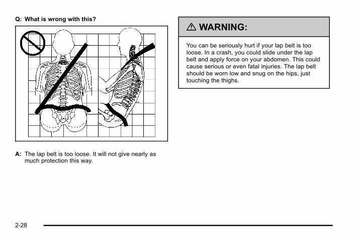
Q: What is wrong with this?
A: The lap belt is too loose. It will not give nearly asmuch protection this way.
{ WARNING:
You can be seriously hurt if your lap belt is tooloose. In a crash, you could slide under the lapbelt and apply force on your abdomen. This couldcause serious or even fatal injuries. The lap beltshould be worn low and snug on the hips, justtouching the thighs.
2-28
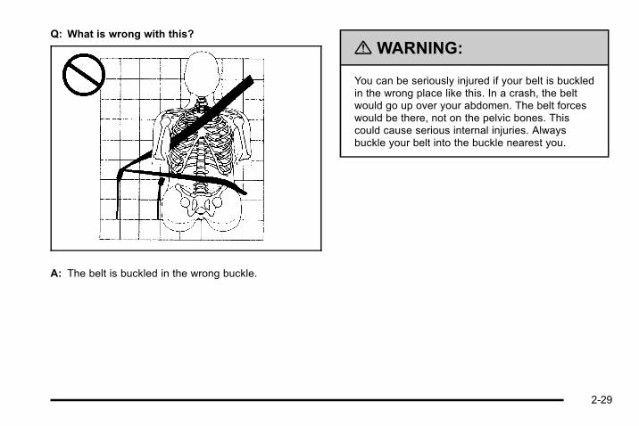
Q: What is wrong with this?
A: The belt is buckled in the wrong buckle.
{ WARNING:
You can be seriously injured if your belt is buckledin the wrong place like this. In a crash, the beltwould go up over your abdomen. The belt forceswould be there, not on the pelvic bones. Thiscould cause serious internal injuries. Alwaysbuckle your belt into the buckle nearest you.
2-29
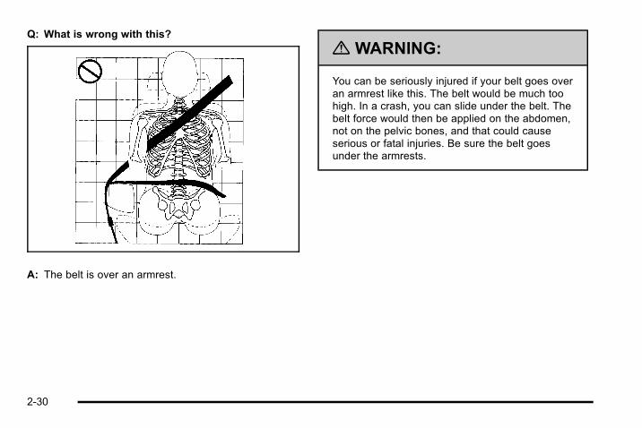
Q: What is wrong with this?
A: The belt is over an armrest.
{ WARNING:
You can be seriously injured if your belt goes overan armrest like this. The belt would be much toohigh. In a crash, you can slide under the belt. Thebelt force would then be applied on the abdomen,not on the pelvic bones, and that could causeserious or fatal injuries. Be sure the belt goesunder the armrests.
2-30

Q: What is wrong with this?
A: The shoulder belt is worn under the arm. It shouldbe worn over the shoulder at all times.
{ WARNING:
You can be seriously injured if you wear theshoulder belt under your arm. In a crash, yourbody would move too far forward, which wouldincrease the chance of head and neck injury.Also, the belt would apply too much force to theribs, which are not as strong as shoulder bones.You could also severely injure internal organs likeyour liver or spleen. The shoulder belt should goover the shoulder and across the chest.
2-31

Q: What is wrong with this?
A: The belt is behind the body.
{ WARNING:
You can be seriously injured by not wearing thelap-shoulder belt properly. In a crash, you wouldnot be restrained by the shoulder belt. Your bodycould move too far forward increasing the chanceof head and neck injury. You might also slideunder the lap belt. The belt force would then beapplied right on the abdomen. That could causeserious or fatal injuries. The shoulder belt shouldgo over the shoulder and across the chest.
2-32

Q: What is wrong with this?
A: The belt is twisted across the body.
{ WARNING:
You can be seriously injured by a twisted belt. In acrash, you would not have the full width of the beltto spread impact forces. If a belt is twisted, makeit straight so it can work properly, or ask yourdealer to fix it.
2-33
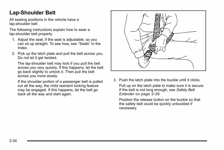
Lap-Shoulder BeltAll seating positions in the vehicle have alap-shoulder belt .
The following instructions explain how to wear alap-shoulder belt properly.
1. Adjust the seat, if the seat is adjustable, so youcan sit up straight. To see how, see “Seats” in theIndex.
2. Pick up the latch plate and pull the belt across you.Do not let it get twisted.
The lap-shoulder belt may lock if you pull the beltacross you very quickly. If this happens, let the beltgo back slightly to unlock it. Then pull the beltacross you more slowly.
If the shoulder portion of a passenger belt is pulledout all the way, the child restraint locking featuremay be engaged. If this happens, let the belt goback all the way and start again.
3. Push the latch plate into the buckle until it clicks.
Pull up on the latch plate to make sure it is secure.If the belt is not long enough, see Safety BeltExtender on page 2‑39.
Position the release button on the buckle so thatthe safety belt could be quickly unbuckled ifnecessary.
2-34

4. To make the lap part tight, pull up on theshoulder belt.
It may be necessary to pull stitching on the safetybelt through the latch plate to fully tighten the lapbelt on smaller occupants.
To unlatch the belt, push the button on the buckle. Thebelt should return to its stowed position. Slide the latchplate up the safety belt webbing when the safety belt isnot in use. The latch plate should rest on the stitchingon the safety belt, near the guide loop on the side wall.
Before a door is closed, be sure the safety belt is out ofthe way. If a door is slammed against a safety belt,damage can occur to both the belt and the vehicle.
2-35

Safety Belt PretensionersThis vehicle has safety belt pretensioners for frontoutboard occupants. Although the safety beltpretensioners cannot be seen, they are part of thesafety belt assembly. They can help tighten the safetybelts during the early stages of a moderate to severefrontal, near frontal, or rear crash if the thresholdconditions for pretensioner activation are met. And,if the vehicle has side impact airbags, safety beltpretensioners can help tighten the safety belts in a sidecrash or a rollover event.
Pretensioners work only once. If the pretensionersactivate in a crash, they will need to be replaced, andprobably other new parts for the vehicle's safety beltsystem. See Replacing Restraint System Parts After aCrash on page 2‑80.
Rear Safety Belt Comfort GuidesThis vehicle may have rear shoulder belt comfortguides. If not, they are available through your dealer.The guides may provide added safety belt comfort forolder children who have outgrown booster seats and forsome adults. When installed and properly adjusted, thecomfort guide positions the belt away from the neckand head.
If equipped, there is one guide for each outsidepassenger position in the second row seat. Here is howto install a comfort guide to the safety belt:
1. Remove the guide from its storage pocket on theside of the seat.
2-36
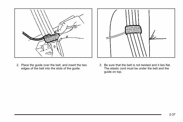
2. Place the guide over the belt, and insert the twoedges of the belt into the slots of the guide.
3. Be sure that the belt is not twisted and it lies flat.The elastic cord must be under the belt and theguide on top.
2-37

{ WARNING:
A safety belt that is not properly worn may notprovide the protection needed in a crash. Theperson wearing the belt could be seriously injured.The shoulder belt should go over the shoulder andacross the chest. These parts of the body are bestable to take belt restraining forces.
4. Buckle, position, and release the safety belt asdescribed previously in this section. Make sure thatthe shoulder belt crosses the shoulder.
To remove and store the comfort guide, squeeze thebelt edges together so that the safety belt can beremoved from the guide. Slide the guide into its storagepocket on the side of the seat. Make sure you removethe comfort guide from the safety belt before you fold arear seat down.
2-38

Safety Belt Use During PregnancySafety belts work for everyone, including pregnantwomen. Like all occupants, they are more likely to beseriously injured if they do not wear safety belts.
A pregnant woman should wear a lap-shoulder belt, andthe lap portion should be worn as low as possible,below the rounding, throughout the pregnancy.
The best way to protect the fetus is to protect themother. When a safety belt is worn properly, it is morelikely that the fetus will not be hurt in a crash. Forpregnant women, as for anyone, the key to makingsafety belts effective is wearing them properly.
Safety Belt ExtenderIf the vehicle's safety belt will fasten around you, youshould use it.
But if a safety belt is not long enough, your dealer willorder you an extender. When you go in to order it, takethe heaviest coat you will wear, so the extender will belong enough for you. To help avoid personal injury, donot let someone else use it, and use it only for the seatit is made to fit. The extender has been designed foradults. Never use it for securing child seats. To wear it,attach it to the regular safety belt. For more information,see the instruction sheet that comes with the extender.
2-39
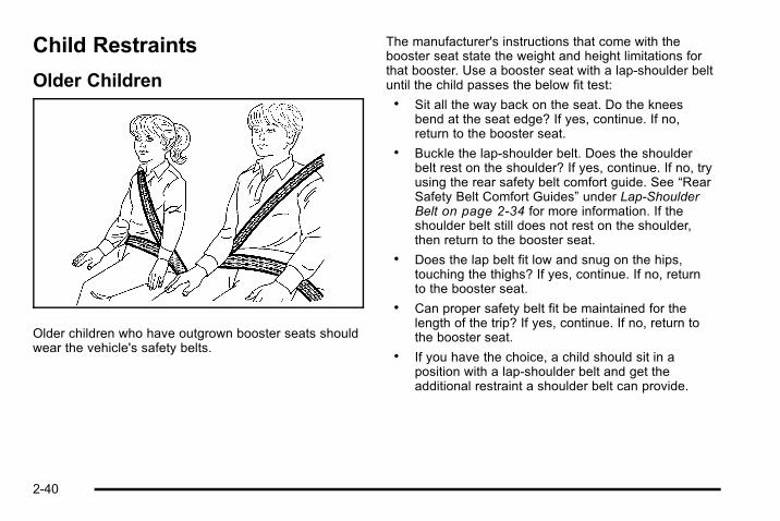
Child Restraints
Older Children
Older children who have outgrown booster seats shouldwear the vehicle's safety belts.
The manufacturer's instructions that come with thebooster seat state the weight and height limitations forthat booster. Use a booster seat with a lap-shoulder beltuntil the child passes the below fit test:. Sit all the way back on the seat. Do the knees
bend at the seat edge? If yes, continue. If no,return to the booster seat.
. Buckle the lap-shoulder belt. Does the shoulderbelt rest on the shoulder? If yes, continue. If no, tryusing the rear safety belt comfort guide. See “RearSafety Belt Comfort Guides” under Lap-ShoulderBelt on page 2‑34 for more information. If theshoulder belt still does not rest on the shoulder,then return to the booster seat.
. Does the lap belt fit low and snug on the hips,touching the thighs? If yes, continue. If no, returnto the booster seat.
. Can proper safety belt fit be maintained for thelength of the trip? If yes, continue. If no, return tothe booster seat.
. If you have the choice, a child should sit in aposition with a lap-shoulder belt and get theadditional restraint a shoulder belt can provide.
2-40

Q: What is the proper way to wear safety belts?
A: An older child should wear a lap-shoulder belt andget the additional restraint a shoulder belt canprovide. The shoulder belt should not cross the faceor neck. The lap belt should fit snugly below thehips, just touching the top of the thighs. This appliesbelt force to the child's pelvic bones in a crash.It should never be worn over the abdomen, whichcould cause severe or even fatal internal injuries ina crash.
Also see “Rear Safety Belt Comfort Guides” underLap-Shoulder Belt on page 2‑34.
According to accident statistics, children and infants aresafer when properly restrained in a child restraintsystem or infant restraint system secured in a rearseating position.
In a crash, children who are not buckled up can strikeother people who are buckled up, or can be thrown outof the vehicle. Older children need to use safety beltsproperly.
{ WARNING:
Never do this.
Never allow two children to wear the same safetybelt. The safety belt can not properly spread theimpact forces. In a crash, the two children can becrushed together and seriously injured. A safetybelt must be used by only one person at a time.
2-41
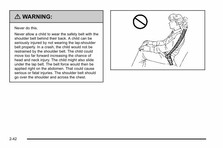
{ WARNING:
Never do this.
Never allow a child to wear the safety belt with theshoulder belt behind their back. A child can beseriously injured by not wearing the lap-shoulderbelt properly. In a crash, the child would not berestrained by the shoulder belt. The child couldmove too far forward increasing the chance ofhead and neck injury. The child might also slideunder the lap belt. The belt force would then beapplied right on the abdomen. That could causeserious or fatal injuries. The shoulder belt shouldgo over the shoulder and across the chest.
2-42
Infants and Young ChildrenEveryone in a vehicle needs protection! This includesinfants and all other children. Neither the distancetraveled nor the age and size of the traveler changesthe need, for everyone, to use safety restraints. In fact,the law in every state in the United States and in everyCanadian province says children up to some age mustbe restrained while in a vehicle.
{ WARNING:
Children can be seriously injured or strangled if ashoulder belt is wrapped around their neck andthe safety belt continues to tighten. Never leavechildren unattended in a vehicle and never allowchildren to play with the safety belts.
Airbags plus lap‐shoulder belts offer protection foradults and older children, but not for young children andinfants. Neither the vehicle's safety belt system nor itsairbag system is designed for them. Every time infantsand young children ride in vehicles, they should havethe protection provided by appropriate child restraints.
Children who are not restrained properly can strikeother people, or can be thrown out of the vehicle.
2-43

{ WARNING:
Never do this.
Never hold an infant or a child while riding in avehicle. Due to crash forces, an infant or a childwill become so heavy it is not possible to hold itduring a crash. For example, in a crash at only40 km/h (25 mph), a 5.5 kg (12 lb) infant willsuddenly become a 110 kg (240 lb) force on aperson's arms. An infant should be secured in anappropriate restraint.
2-44

{ WARNING:
Never do this.
Children who are up against, or very close to, anyairbag when it inflates can be seriously injured orkilled. Never put a rear-facing child restraint in theright front seat. Secure a rear-facing child restraintin a rear seat. It is also better to secure aforward-facing child restraint in a rear seat. If youmust secure a forward-facing child restraint in theright front seat, always move the front passengerseat as far back as it will go.
2-45
Q: What are the different types of add-on childrestraints?
A: Add-on child restraints, which are purchased by thevehicle's owner, are available in four basic types.Selection of a particular restraint should take intoconsideration not only the child's weight, height, andage but also whether or not the restraint will becompatible with the motor vehicle in which it willbe used.
For most basic types of child restraints, there aremany different models available. When purchasing achild restraint, be sure it is designed to be used in amotor vehicle. If it is, the restraint will have a labelsaying that it meets federal motor vehicle safetystandards.
The restraint manufacturer's instructions that comewith the restraint state the weight and heightlimitations for a particular child restraint. In addition,there are many kinds of restraints available forchildren with special needs.
{ WARNING:
To reduce the risk of neck and head injury duringa crash, infants need complete support. This isbecause an infant's neck is not fully developed
(Continued)
WARNING: (Continued)
and its head weighs so much compared with therest of its body. In a crash, an infant in arear-facing child restraint settles into the restraint,so the crash forces can be distributed across thestrongest part of an infant's body, the back andshoulders. Infants should always be secured inrear-facing child restraints.
{ WARNING:
A young child's hip bones are still so small thatthe vehicle's regular safety belt may not remainlow on the hip bones, as it should. Instead, it maysettle up around the child's abdomen. In a crash,the belt would apply force on a body area that isunprotected by any bony structure. This alonecould cause serious or fatal injuries. To reduce therisk of serious or fatal injuries during a crash,young children should always be secured inappropriate child restraints.
2-46

Child Restraint SystemsA rear-facing infantseat (A) provides restraintwith the seating surfaceagainst the back of theinfant.
The harness system holds the infant in place and, in acrash, acts to keep the infant positioned in the restraint.
A forward-facing childseat (B) provides restraintfor the child's body withthe harness.
A booster seat (C-D) is a child restraint designed toimprove the fit of the vehicle's safety belt system.A booster seat can also help a child to see out thewindow.
2-47

Securing an Add-On Child Restraint inthe Vehicle
{ WARNING:
A child can be seriously injured or killed in a crashif the child restraint is not properly secured in thevehicle. Secure the child restraint properly in thevehicle using the vehicle's safety belt or LATCHsystem, following the instructions that came withthat child restraint and the instructions in thismanual.
To help reduce the chance of injury, the child restraintmust be secured in the vehicle. Child restraint systemsmust be secured in vehicle seats by lap belts or the lapbelt portion of a lap-shoulder belt, or by the LATCHsystem. See Lower Anchors and Tethers for Children(LATCH) on page 2‑50 for more information. A childcan be endangered in a crash if the child restraint is notproperly secured in the vehicle.
When securing an add-on child restraint, refer to theinstructions that come with the restraint which may beon the restraint itself or in a booklet, or both, and to thismanual. The child restraint instructions are important,so if they are not available, obtain a replacement copyfrom the manufacturer.
Keep in mind that an unsecured child restraint canmove around in a collision or sudden stop and injurepeople in the vehicle. Be sure to properly secure anychild restraint in the vehicle — even when no child isin it.
Securing the Child Within the ChildRestraint
{ WARNING:
A child can be seriously injured or killed in a crashif the child is not properly secured in the childrestraint. Secure the child properly following theinstructions that came with that child restraint.
2-48

Where to Put the RestraintAccording to accident statistics, children and infants aresafer when properly restrained in a child restraintsystem or infant restraint system secured in a rearseating position.
We recommend that children and child restraints besecured in a rear seat, including: an infant or a childriding in a rear-facing child restraint; a child riding in aforward-facing child seat; an older child riding in abooster seat; and children, who are large enough, usingsafety belts.
A label on your sun visor says, “Never put a rear-facingchild seat in the front.” This is because the risk to therear-facing child is so great, if the airbag deploys.
{ WARNING:
A child in a rear-facing child restraint can beseriously injured or killed if the right frontpassenger airbag inflates. This is because theback of the rear-facing child restraint would bevery close to the inflating airbag. A child in aforward-facing child restraint can be seriously
(Continued)
WARNING: (Continued)
injured or killed if the right front passenger airbaginflates and the passenger seat is in a forwardposition.
Even if the airbag switch has turned off the rightfront passenger frontal airbag, no system isfail-safe. No one can guarantee that an airbag willnot deploy under some unusual circumstance,even though it is turned off.
Secure rear-facing child restraints in a rear seat,even if the airbag is off. If you secure aforward-facing child restraint in the right front seat,always move the front passenger seat as far backas it will go. It is better to secure the child restraintin a rear seat.
When securing a child restraint in a rear seatingposition, study the instructions that came with your childrestraint to make sure it is compatible with this vehicle.
Wherever a child restraint is installed, be sure to securethe child restraint properly.
2-49

Keep in mind that an unsecured child restraint canmove around in a collision or sudden stop and injurepeople in the vehicle. Be sure to properly secure anychild restraint in your vehicle — even when no child isin it.
Lower Anchors and Tethers forChildren (LATCH)The LATCH system holds a child restraint during drivingor in a crash. This system is designed to makeinstallation of a child restraint easier. The LATCHsystem uses anchors in the vehicle and attachments onthe child restraint that are made for use with the LATCHsystem.
Make sure that a LATCH-compatible child restraint isproperly installed using the anchors, or use the vehicle'ssafety belts to secure the restraint, following theinstructions that came with that restraint, and also the
instructions in this manual. When installing a childrestraint with a top tether, you must also use either thelower anchors or the safety belts to properly secure thechild restraint. A child restraint must never be installedusing only the top tether and anchor.
In order to use the LATCH system in your vehicle, youneed a child restraint that has LATCH attachments. Thechild restraint manufacturer will provide you withinstructions on how to use the child restraint and itsattachments. The following explains how to attach achild restraint with these attachments in your vehicle.
Not all vehicle seating positions or child restraints havelower anchors and attachments or top tether anchorsand attachments.
2-50

Lower Anchors
Lower anchors (A) are metal bars built into the vehicle.There are two lower anchors for each LATCH seatingposition that will accommodate a child restraint withlower attachments (B).
Top Tether Anchor
A top tether (A, C) anchors the top of the child restraintto the vehicle. A top tether anchor is built into thevehicle. The top tether attachment (B) on the childrestraint connects to the top tether anchor in the vehiclein order to reduce the forward movement and rotation ofthe child restraint during driving or in a crash.
2-51

Your child restraint may have a single tether (A) or adual tether (C). Either will have a single attachment (B)to secure the top tether to the anchor.
Some child restraints that have a top tether aredesigned for use with or without the top tether beingattached. Others require the top tether always to beattached. In Canada, the law requires thatforward-facing child restraints have a top tether, andthat the tether be attached. Be sure to read and followthe instructions for your child restraint.
If the child restraint does not have a top tether, one canbe obtained, in kit form, for many child restraints. Askthe child restraint manufacturer whether or not a kit isavailable.
Lower Anchor and Top Tether AnchorLocations
Second Row — SUV 60/40Bench
i (Top Tether Anchor):Seating positions with toptether anchors.
j (Lower Anchor):Seating positions with twolower anchors.
2-52

Second Row — SUT 60/40Bench
i (Top Tether Anchor):Seating positions with toptether anchors.
j (Lower Anchor):Seating positions with twolower anchors.
Second Row— Bucket
i (Top Tether Anchor):Seating positions with toptether anchors.
j (Lower Anchor):Seating positions with twolower anchors.
Third Row— SUV
i (Top Tether Anchor):Seating positions with toptether anchors.
For SUV models with a second row 60/40 bench seat,there are exposed metal anchors for the center andpassenger side seating positions.
For SUT models with a second row 60/40 bench seat,there are exposed metal anchors for the center seatingposition.
For models with second row bucket seats, there areexposed metal anchors for both seating positions.
2-53

Second Row — SUV 60/40 Bench
For SUV models with a second row 60/40 bench seat,the top tether anchors are located at the bottom rear ofthe seat cushion for each position in the second row. Besure to use the anchor located nearest to the seatingposition where the child restraint will be placed.
Second Row— SUT 60/40 Bench
For SUT models with a second row 60/40 bench seat,the top tether anchor is located at the bottom rear of theseat cushion for the center position in the second row.You may need to fold the seatback of the passengerside seat forward in order to access this anchor.
2-54
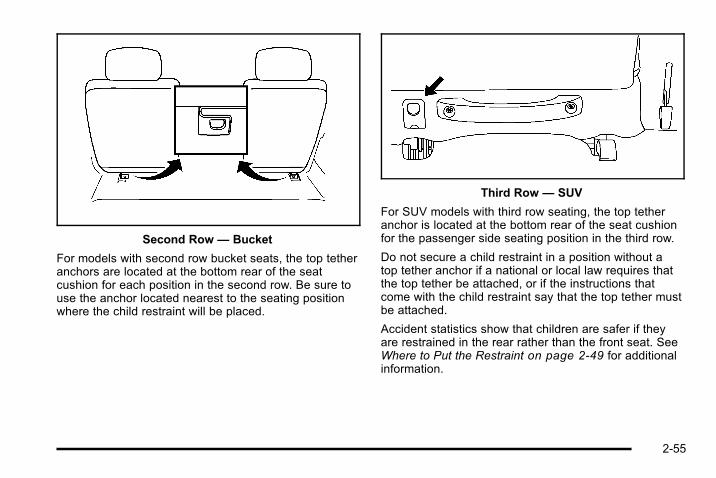
Second Row— Bucket
For models with second row bucket seats, the top tetheranchors are located at the bottom rear of the seatcushion for each position in the second row. Be sure touse the anchor located nearest to the seating positionwhere the child restraint will be placed.
Third Row— SUV
For SUV models with third row seating, the top tetheranchor is located at the bottom rear of the seat cushionfor the passenger side seating position in the third row.
Do not secure a child restraint in a position without atop tether anchor if a national or local law requires thatthe top tether be attached, or if the instructions thatcome with the child restraint say that the top tether mustbe attached.
Accident statistics show that children are safer if theyare restrained in the rear rather than the front seat. SeeWhere to Put the Restraint on page 2‑49 for additionalinformation.
2-55

Securing a Child Restraint Designed for theLATCH System
{ WARNING:
If a LATCH-type child restraint is not attached toanchors, the child restraint will not be able toprotect the child correctly. In a crash, the childcould be seriously injured or killed. Install aLATCH-type child restraint properly using theanchors, or use the vehicle's safety belts tosecure the restraint, following the instructions thatcame with the child restraint and the instructionsin this manual.
{ WARNING:
Do not attach more than one child restraint to asingle anchor. Attaching more than one childrestraint to a single anchor could cause theanchor or attachment to come loose or evenbreak during a crash. A child or others could be
(Continued)
WARNING: (Continued)
injured. To reduce the risk of serious or fatalinjuries during a crash, attach only one childrestraint per anchor.
{ WARNING:
Children can be seriously injured or strangled if ashoulder belt is wrapped around their neck andthe safety belt continues to tighten. Buckle anyunused safety belts behind the child restraint sochildren cannot reach them. Pull the shoulder beltall the way out of the retractor to set the lock,if your vehicle has one, after the child restrainthas been installed.
Notice: Do not let the LATCH attachments rubagainst the vehicle’s safety belts. This may damagethese parts. If necessary, move buckled safety beltsto avoid rubbing the LATCH attachments.
2-56

Do not fold the empty rear seat with a safety beltbuckled. This could damage the safety belt or theseat. Unbuckle and return the safety belt to itsstowed position, before folding the seat.
Second Row Center Position — SUT1. If the child restraint manufacturer recommends that
the top tether be attached, attach the top tether tothe top tether anchor, if equipped. Refer to thechild restraint instructions and the following steps:
1.1. To access the top tether anchor, raise thepassenger side seat cushion by pulling up onthe strap loop at the rear of the seat cushionand fold the seat cushion forward. Then foldthe seatback forward. See Split Folding RearSeat on page 2‑10 for additional information.
1.2. Place the child restraint in the center seatingposition.
1.3. Find the top tether anchor at the rear base ofthe center seat.
1.4. Route and attach, but do not tighten, the toptether according to your child restraintinstructions and the following instructions:
If your child restraint hasa single tether, route thetether over the seatback.
If your child restraint hasa dual tether, route thetether over the seatback.
2-57

1.5. Return the rear passenger side seatback toits upright position. You may have to movethe child restraint to a temporary position todo this. Ensure that the seatback locks andthe safety belt is routed properly. Then lowerthe seat cushion until the seatback and theseat cushion lock into position.
2. Attach the lower attachments to the lower anchors.If the child restraint does not have lowerattachments or the desired seating position doesnot have lower anchors, secure the child restraintwith the top tether and the safety belts. Refer toyour child restraint manufacturer instructions andthe instructions in this manual.
2.1. Find the lower anchors for the desiredseating position.
2.2. Attach and tighten the lower attachments onthe child restraint to the lower anchors.
3. Tighten the top tether.
{ WARNING:
If either seatback is not locked, it could moveforward in a sudden stop or crash. That couldcause injury to the person sitting there. Alwayspush and pull on the seatbacks to be sure theyare locked.
4. Push and pull the child restraint in differentdirections to be sure it is secure.
Second and Third Row Positions — SUVand SVA Special Edition1. Attach and tighten the lower attachments to the
lower anchors. If the child restraint does not havelower attachments or the desired seating positiondoes not have lower anchors, secure the childrestraint with the top tether and the safety belts.Refer to your child restraint manufacturerinstructions and the instructions in this manual.
1.1. Find the lower anchors for the desiredseating position.
1.2. Put the child restraint on the seat.
1.3. Attach and tighten the lower attachments onthe child restraint to the lower anchors.
2-58

2. If the child restraint manufacturer recommends thatthe top tether be attached, attach and tighten thetop tether to the top tether anchor, if equipped.Refer to the child restraint instructions and thefollowing steps:
2.1. Find the top tether anchor.
2.2. Route, attach, and tighten the top tetheraccording to your child restraint instructionsand the following instructions:
If the position you areusing does not have aheadrest or head restraintand you are using asingle tether, route thetether over the seatback.
If the position you areusing does not have aheadrest or head restraintand you are using a dualtether, route the tetherover the seatback.
If the position you areusing has an adjustableheadrest or head restraintand you are using asingle tether, raise theheadrest or head restraintand route the tether underthe headrest or headrestraint and in betweenthe headrest or headrestraint posts.
2-59

If the position you areusing has an adjustableheadrest or head restraintand you are using a dualtether, raise the headrestor head restraint androute the tether under theheadrest or head restraintand in between theheadrest or head restraintposts.
3. Push and pull the child restraint in differentdirections to be sure it is secure.
Securing a Child Restraint in a RearSeat PositionWhen securing a child restraint in a rear seatingposition, study the instructions that came with the childrestraint to make sure it is compatible with this vehicle.
If the child restraint has the LATCH system, see LowerAnchors and Tethers for Children (LATCH) onpage 2‑50 for how and where to install the childrestraint using LATCH. If a child restraint is secured inthe vehicle using a safety belt and it uses a top tether,see Lower Anchors and Tethers for Children (LATCH)on page 2‑50 for top tether anchor locations.
Do not secure a child seat in a position without a toptether anchor if a national or local law requires that thetop tether be anchored, or if the instructions that comewith the child restraint say that the top strap must beanchored.
In Canada, the law requires that forward-facing childrestraints have a top tether, and that the tether beattached.
If the child restraint does not have the LATCH system,you will be using the safety belt to secure the childrestraint in this position. Be sure to follow theinstructions that came with the child restraint. Securethe child in the child restraint when and as theinstructions say.
2-60

If more than one child restraint needs to be installed inthe rear seat, be sure to read Where to Put theRestraint on page 2‑49.
1. Put the child restraint on the seat.
2. Pick up the latch plate, and run the lap andshoulder portions of the vehicle's safety beltthrough or around the restraint. The child restraintinstructions will show you how.
3. Push the latch plate into the buckle until it clicks.
Position the release button on the buckle so thatthe safety belt could be quickly unbuckled ifnecessary.
4. Pull the rest of the shoulder belt all the way out ofthe retractor to set the lock.
2-61
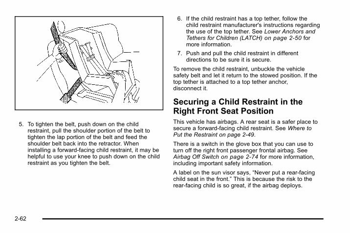
5. To tighten the belt, push down on the childrestraint, pull the shoulder portion of the belt totighten the lap portion of the belt and feed theshoulder belt back into the retractor. Wheninstalling a forward-facing child restraint, it may behelpful to use your knee to push down on the childrestraint as you tighten the belt.
6. If the child restraint has a top tether, follow thechild restraint manufacturer's instructions regardingthe use of the top tether. See Lower Anchors andTethers for Children (LATCH) on page 2‑50 formore information.
7. Push and pull the child restraint in differentdirections to be sure it is secure.
To remove the child restraint, unbuckle the vehiclesafety belt and let it return to the stowed position. If thetop tether is attached to a top tether anchor,disconnect it.
Securing a Child Restraint in theRight Front Seat PositionThis vehicle has airbags. A rear seat is a safer place tosecure a forward-facing child restraint. See Where toPut the Restraint on page 2‑49.
There is a switch in the glove box that you can use toturn off the right front passenger frontal airbag. SeeAirbag Off Switch on page 2‑74 for more information,including important safety information.
A label on the sun visor says, “Never put a rear-facingchild seat in the front.” This is because the risk to therear-facing child is so great, if the airbag deploys.
2-62

{ WARNING:
A child in a rear-facing child restraint can beseriously injured or killed if the right frontpassenger airbag inflates. This is because theback of the rear-facing child restraint would bevery close to the inflating airbag. A child in aforward-facing child restraint can be seriouslyinjured or killed if the right front passenger airbaginflates and the passenger seat is in a forwardposition.
Even if the airbag switch has turned off the rightfront passenger frontal airbag, no system isfail-safe. No one can guarantee that an airbag willnot deploy under some unusual circumstance,even though it is turned off.
Secure rear-facing child restraints in a rear seat,even if the airbag is off. If you secure aforward-facing child restraint in the right front seat,always move the front passenger seat as far backas it will go. It is better to secure the child restraintin a rear seat.
{ WARNING:
If the airbag readiness light ever comes on whenyou have turned off the airbag, it means thatsomething may be wrong with the airbag system.The right front passenger's airbag could inflateeven though the switch is off. If this ever happens,do not let anyone whom the national governmenthas identified as a member of a passenger airbagrisk group sit in the right front passenger's position(for example, do not secure a rear-facing childrestraint in the right front passenger's seat) untilyou have your vehicle serviced. See Airbag OffSwitch on page 2‑74 and Airbag Readiness Lighton page 4‑27 for more on this, includingimportant safety information.
If your child restraint has the LATCH system, see LowerAnchors and Tethers for Children (LATCH) onpage 2‑50 for how and where to install the childrestraint using LATCH. If a child restraint is securedusing a safety belt and it uses a top tether, see LowerAnchors and Tethers for Children (LATCH) onpage 2‑50 for top tether anchor locations.
2-63
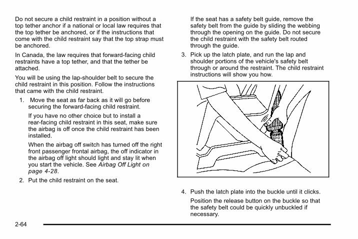
Do not secure a child restraint in a position without atop tether anchor if a national or local law requires thatthe top tether be anchored, or if the instructions thatcome with the child restraint say that the top strap mustbe anchored.
In Canada, the law requires that forward-facing childrestraints have a top tether, and that the tether beattached.
You will be using the lap-shoulder belt to secure thechild restraint in this position. Follow the instructionsthat came with the child restraint.
1. Move the seat as far back as it will go beforesecuring the forward-facing child restraint.
If you have no other choice but to install arear-facing child restraint in this seat, make surethe airbag is off once the child restraint has beeninstalled.
When the airbag off switch has turned off the rightfront passenger frontal airbag, the off indicator inthe airbag off light should light and stay lit whenyou start the vehicle. See Airbag Off Light onpage 4‑28.
2. Put the child restraint on the seat.
If the seat has a safety belt guide, remove thesafety belt from the guide by sliding the webbingthrough the opening on the guide. Do not securethe child restraint with the safety belt routedthrough the guide.
3. Pick up the latch plate, and run the lap andshoulder portions of the vehicle's safety beltthrough or around the restraint. The child restraintinstructions will show you how.
4. Push the latch plate into the buckle until it clicks.
Position the release button on the buckle so thatthe safety belt could be quickly unbuckled ifnecessary.
2-64
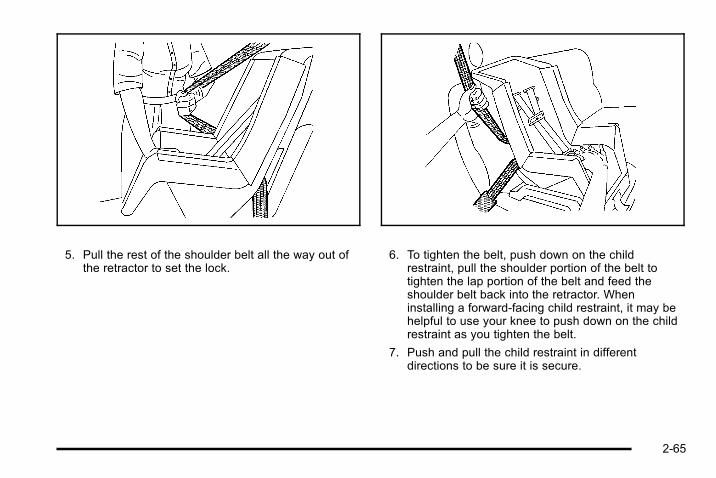
5. Pull the rest of the shoulder belt all the way out ofthe retractor to set the lock.
6. To tighten the belt, push down on the childrestraint, pull the shoulder portion of the belt totighten the lap portion of the belt and feed theshoulder belt back into the retractor. Wheninstalling a forward-facing child restraint, it may behelpful to use your knee to push down on the childrestraint as you tighten the belt.
7. Push and pull the child restraint in differentdirections to be sure it is secure.
2-65

To remove the child restraint, unbuckle the vehiclesafety belt and let it return to the stowed position.
If you turned the airbag off with the switch, turn on theright front passenger airbag when you remove the childrestraint from the vehicle unless the person who will besitting there is a member of a passenger airbag riskgroup. See Airbag Off Switch on page 2‑74 for moreinformation, including important safety information.
Airbag SystemThe vehicle has the following airbags:. A frontal airbag for the driver.. A frontal airbag for the right front passenger.. A roof-rail airbag for the driver and the passenger
seated directly behind the driver.. A roof-rail airbag for the right front passenger and
the passenger seated directly behind the right frontpassenger.
The vehicle may have the following airbags:. If your vehicle has a third row seat, it will have third
row roof-rail airbags.
All of the airbags in your vehicle will have the wordAIRBAG embossed in the trim or on an attached labelnear the deployment opening.
For frontal airbags, the word AIRBAG will appear on themiddle part of the steering wheel for the driver and onthe instrument panel for the right front passenger.
With roof-rail airbags, the word AIRBAG will appearalong the headliner or trim.
Airbags are designed to supplement the protectionprovided by safety belts. Even though today's airbagsare also designed to help reduce the risk of injury fromthe force of an inflating bag, all airbags must inflate veryquickly to do their job.
2-66

Here are the most important things to know about theairbag system:
{ WARNING:
You can be severely injured or killed in a crash ifyou are not wearing your safety belt— even if youhave airbags. Airbags are designed to work withsafety belts, but do not replace them. Also,airbags are not designed to deploy in every crash.In some crashes safety belts are your onlyrestraint. See When Should an Airbag Inflate? onpage 2‑71.
Wearing your safety belt during a crash helpsreduce your chance of hitting things inside thevehicle or being ejected from it. Airbags are“supplemental restraints” to the safety belts.Everyone in your vehicle should wear a safety beltproperly—whether or not there is an airbag forthat person.
{ WARNING:
Airbags inflate with great force, faster than theblink of an eye. Anyone who is up against, or veryclose to, any airbag when it inflates can beseriously injured or killed. Do not sit unnecessarilyclose to the airbag, as you would be if you weresitting on the edge of your seat or leaning forward.Safety belts help keep you in position before andduring a crash. Always wear your safety belt,even with airbags. The driver should sit as farback as possible while still maintaining control ofthe vehicle.
Occupants should not lean on or sleep against thedoor or side windows in seating positions withroof-rail airbags.
2-67

{ WARNING:
Children who are up against, or very close to, anyairbag when it inflates can be seriously injured orkilled. Airbags plus lap-shoulder belts offerprotection for adults and older children, but not foryoung children and infants. Neither the vehicle'ssafety belt system nor its airbag system isdesigned for them. Young children and infantsneed the protection that a child restraint systemcan provide. Always secure children properly inyour vehicle. To read how, see Older Children onpage 2‑40 or Infants and Young Children onpage 2‑43.
There is an airbagreadiness light on theinstrument panel cluster,which shows the airbagsymbol.
The system checks the airbag electrical system formalfunctions. The light tells you if there is an electricalproblem. See Airbag Readiness Light on page 4‑27 formore information.
Where Are the Airbags?
The driver's frontal airbag is in the middle of thesteering wheel.
2-68

The right front passenger's frontal airbag is in theinstrument panel on the passenger's side.
Driver Side shown, Passenger Side similar
The roof-rail airbags for the driver, right front passenger,and second row outboard passengers are in the ceilingabove the side windows.
2-69

Driver Side shown, Passenger Side similar
If your vehicle has roof-rail airbags and a third rowpassenger seat, the airbags are located in the ceilingabove the rear windows for the outboard passengerpositions in the third row.
{ WARNING:
If something is between an occupant and anairbag, the airbag might not inflate properly or itmight force the object into that person causingsevere injury or even death. The path of aninflating airbag must be kept clear. Do not putanything between an occupant and an airbag, anddo not attach or put anything on the steeringwheel hub or on or near any other airbagcovering.
Never secure anything to the roof of a vehicle withroof-rail airbags by routing a rope or tie downthrough any door or window opening. If you do,the path of an inflating roof-rail airbag will beblocked.
2-70

When Should an Airbag Inflate?Frontal airbags are designed to inflate in moderate tosevere frontal or near-frontal crashes to help reduce thepotential for severe injuries mainly to the driver's or rightfront passenger's head and chest. However, they areonly designed to inflate if the impact exceeds apredetermined deployment threshold. Deploymentthresholds are used to predict how severe a crash islikely to be in time for the airbags to inflate and helprestrain the occupants.
Whether your frontal airbags will or should deploy is notbased on how fast your vehicle is traveling. It dependslargely on what you hit, the direction of the impact, andhow quickly your vehicle slows down.
Frontal airbags may inflate at different crash speeds.For example:. If the vehicle hits a stationary object, the airbags
could inflate at a different crash speed than if thevehicle hits a moving object.
. If the vehicle hits an object that deforms, theairbags could inflate at a different crash speedthan if the vehicle hits an object does not deform.
. If the vehicle hits a narrow object (like a pole), theairbags could inflate at a different crash speedthan if the vehicle hits a wide object (like a wall).
. If the vehicle goes into an object at an angle, theairbags could inflate at a different crash speedthan if the vehicle goes straight into the object.
Thresholds can also vary with specific vehicle design.
Frontal airbags are not intended to inflate during vehiclerollovers, rear impacts, or in many side impacts.
Your vehicle has roof-rail airbags. See Airbag Systemon page 2‑66. Roof-rail airbags are intended to inflatein moderate to severe side crashes. In addition, theseroof-rail airbags are intended to inflate during a rollover.Roof-rail airbags will inflate if the crash severity isabove the system's designed threshold level. Thethreshold level can vary with specific vehicle design.
Roof-rail airbags are not intended to inflate in frontalimpacts, near-frontal impacts, or rear impacts. Bothroof-rail airbags will deploy when either side of thevehicle is struck, or if the sensing system predicts thatthe vehicle is about to roll over.
In any particular crash, no one can say whether anairbag should have inflated simply because of thedamage to a vehicle or because of what the repair costswere. For frontal airbags, inflation is determined by whatthe vehicle hits, the angle of the impact, and howquickly the vehicle slows down. For roof-rail airbags,deployment is determined by the location and severityof the side impact. In a rollover event, roof-rail airbagdeployment is determined by the direction of the roll.
2-71
What Makes an Airbag Inflate?In a deployment event, the sensing system sends anelectrical signal triggering a release of gas from theinflator. Gas from the inflator fills the airbag causing thebag to break out of the cover and deploy. The inflator,the airbag, and related hardware are all part of theairbag module.
Frontal airbag modules are located inside the steeringwheel and instrument panel. For vehicles with roof-railairbags, there are airbag modules in the ceiling of thevehicle, near the side windows that have occupantseating positions.
How Does an Airbag Restrain?In moderate to severe frontal or near frontal collisions,even belted occupants can contact the steering wheelor the instrument panel. In moderate to severe sidecollisions, even belted occupants can contact the insideof the vehicle.
Airbags supplement the protection provided by safetybelts. Frontal airbags distribute the force of the impactmore evenly over the occupant's upper body, stoppingthe occupant more gradually. Roof-rail airbags distributethe force of the impact more evenly over the occupant'supper body.
Rollover capable roof-rail airbags are designed to helpcontain the head and chest of occupants in theoutboard seating positions in the first, second, and thirdrows, if equipped with a third row seat. The rollovercapable roof-rail airbags are designed to help reducethe risk of full or partial ejection in rollover events,although no system can prevent all such ejections.
But airbags would not help in many types of collisions,primarily because the occupant's motion is not towardthose airbags. See When Should an Airbag Inflate? onpage 2‑71 for more information.
Airbags should never be regarded as anything morethan a supplement to safety belts.
What Will You See After an AirbagInflates?After the frontal airbags inflate, they quickly deflate, soquickly that some people may not even realize anairbag inflated. Roof-rail airbags may still be at leastpartially inflated for some time after they deploy. Somecomponents of the airbag module may be hot forseveral minutes. For location of the airbag modules, seeWhat Makes an Airbag Inflate? on page 2‑72.
The parts of the airbag that come into contact with youmay be warm, but not too hot to touch. There may besome smoke and dust coming from the vents in thedeflated airbags. Airbag inflation does not prevent the
2-72

driver from seeing out of the windshield or being able tosteer the vehicle, nor does it prevent people fromleaving the vehicle.
{ WARNING:
When an airbag inflates, there may be dust in theair. This dust could cause breathing problems forpeople with a history of asthma or other breathingtrouble. To avoid this, everyone in the vehicleshould get out as soon as it is safe to do so.If you have breathing problems but cannot get outof the vehicle after an airbag inflates, then getfresh air by opening a window or a door. If youexperience breathing problems following an airbagdeployment, you should seek medical attention.
The vehicle has a feature that may automatically unlockthe doors, turn on the interior lamps and hazard warningflashers, and shut off the fuel system after the airbagsinflate. You can lock the doors, and turn off the interiorlamps and the hazard warning flashers by using thecontrols for those features.
{ WARNING:
A crash severe enough to inflate the airbags mayhave also damaged important functions in thevehicle, such as the fuel system, brake andsteering systems, etc. Even if the vehicle appearsto be drivable after a moderate crash, there maybe concealed damage that could make it difficultto safely operate the vehicle.
Use caution if you should attempt to restart theengine after a crash has occurred.
In many crashes severe enough to inflate the airbag,windshields are broken by vehicle deformation.Additional windshield breakage may also occur from theright front passenger airbag.. Airbags are designed to inflate only once. After an
airbag inflates, you will need some new parts forthe airbag system. If you do not get them, theairbag system will not be there to help protect youin another crash. A new system will include airbagmodules and possibly other parts. The servicemanual for the vehicle covers the need to replaceother parts.
2-73

. The vehicle has a crash sensing and diagnosticmodule which records information after a crash.See Vehicle Data Recording and Privacy onpage 8‑17 and Event Data Recorders onpage 8‑17.
. Let only qualified technicians work on the airbagsystems. Improper service can mean that anairbag system will not work properly. See yourdealer for service.
Airbag Off SwitchThe vehicle has an airbag on-off switch that you canuse to manually turn on or off the right front passengerairbag.
United States Canada
This switch should only be turned to the off position ifthe person in the right front passenger position is amember of a passenger risk group identified by thenational government as follows:
Infant. An infant (less than 1 year old) mustride in the front seat because:. My vehicle has no rear seat;. My vehicle has a rear seat too small to
accommodate a rear-facing infant seat; or. The infant has a medical condition which,
according to the infant's physician, makes itnecessary for the infant to ride in the front seat sothat the driver can constantly monitor the child'scondition.
Child age 1 to 12. A child age 1 to 12 mustride in the front seat because:. My vehicle has no rear seat;. Although children ages 1 to 12 ride in the rear
seat(s) whenever possible, children ages 1 to 12sometimes must ride in the front because no spaceis available in the rear seat(s) of my vehicle; or
. The child has a medical condition which, accordingto the child's physician, makes it necessary for thechild to ride in the front seat so that the driver canconstantly monitor the child's condition.
2-74

Medical Condition. A passenger has amedical condition which, according to hisor her physician:. Causes the passenger airbag to pose a special
risk for the passenger; and. Makes the potential harm from the passenger
airbag in a crash greater than the potential harmfrom turning off the airbag and allowing thepassenger, even if belted, to hit the dashboard orwindshield in a crash.
{ WARNING:
If the right front passenger's airbag is turned offfor a person who is not in a risk group identifiedby the national government, that person will nothave the extra protection of an airbag. In a crash,the airbag will not be able to inflate and helpprotect the person sitting there. Do not turn off thepassenger's airbag unless the person sitting thereis in a risk group.
United States Canada
To turn off the right front passenger frontal airbag, insertthe ignition key into the switch, push in, and move theswitch to the off position.
The word OFF or the off symbol will come on in thepassenger airbag status indicator located in theoverhead console to let you know that the right frontpassenger airbag is off, after the system check iscompleted. The airbag off light will come on and stay onto let you know that the right front passenger airbag isoff. See Airbag Off Light on page 4‑28.
2-75

The airbag off light will stay on to remind you that theairbag is off. The right front passenger airbag willremain off until you turn it back on again.
{ WARNING:
If the airbag readiness light ever comes on andstays on, it means that something may be wrongwith the airbag system. For example, the rightfront passenger airbag could inflate even thoughthe airbag on-off switch is turned off.
To help avoid injury to yourself or others, have thevehicle serviced right away. See AirbagReadiness Light on page 4‑27 for moreinformation, including important safety information.
United States Canada
To turn the right front passenger airbag on again, insertthe ignition key into the switch, push in, and move theswitch to the on position.
The right front passenger's frontal airbag is nowenabled (may inflate). See Airbag Off Light onpage 4‑28 for more information.
2-76

Servicing Your Airbag-EquippedVehicleAirbags affect how the vehicle should be serviced.There are parts of the airbag system in several placesaround the vehicle. Your dealer and the service manualhave information about servicing the vehicle and theairbag system. To purchase a service manual, seeService Publications Ordering Information onpage 8‑15.
{ WARNING:
For up to 10 seconds after the ignition is turned offand the battery is disconnected, an airbag can stillinflate during improper service. You can be injuredif you are close to an airbag when it inflates. Avoidyellow connectors. They are probably part of theairbag system. Be sure to follow proper serviceprocedures, and make sure the person performingwork for you is qualified to do so.
2-77
Adding Equipment to YourAirbag-Equipped Vehicle
Q: Is there anything I might add to or change aboutthe vehicle that could keep the airbags fromworking properly?
A: Yes. If you add things that change your vehicle'sframe, bumper system, height, front end or sidesheet metal, they may keep the airbag system fromworking properly. Changing or moving any parts ofthe front seats, safety belts, the airbag sensing anddiagnostic module, steering wheel, instrument panel,roof-rail airbag modules, ceiling headliner or pillargarnish trim, overhead console, front sensors, sideimpact sensors, rollover sensor module, or airbagwiring can affect the operation of the airbag system.
If you have any questions about this, you shouldcontact Customer Assistance before you modifyyour vehicle. The phone numbers and addresses forCustomer Assistance are in Step Two of theCustomer Satisfaction Procedure in this manual.See Customer Satisfaction Procedure on page 8‑2.
If your vehicle has rollover roof-rail airbags, seeDifferent Size Tires and Wheels on page 6‑77 foradditional important information.
Q: Because I have a disability, I have to get myvehicle modified. How can I find out whether thiswill affect my airbag system?
A: If you have questions, call Customer Assistance.The phone numbers and addresses for CustomerAssistance are in Step Two of the CustomerSatisfaction Procedure in this manual. SeeCustomer Satisfaction Procedure on page 8‑2.
In addition, your dealer and the service manual haveinformation about the location of the airbag sensors,sensing and diagnostic module and airbag wiring.
2-78
Restraint System Check
Checking the Restraint Systems
Safety BeltsNow and then, check that the safety belt reminder light,safety belts, buckles, latch plates, retractors, andanchorages are all working properly.
Look for any other loose or damaged safety belt systemparts that might keep a safety belt system from doing itsjob. See your dealer to have it repaired. Torn or frayedsafety belts may not protect you in a crash. They can ripapart under impact forces. If a belt is torn or frayed, geta new one right away.
Make sure the safety belt reminder light is working. SeeSafety Belt Reminders on page 4‑26 for moreinformation.
Keep safety belts clean and dry. See Care of SafetyBelts on page 6‑109.
AirbagsThe airbag system does not need regularly scheduledmaintenance or replacement. Make sure the airbagreadiness light is working. See Airbag Readiness Lighton page 4‑27 for more information.
Notice: If an airbag covering is damaged, opened,or broken, the airbag may not work properly. Do notopen or break the airbag coverings. If there are anyopened or broken airbag covers, have the airbagcovering and/or airbag module replaced. For thelocation of the airbag modules, see What Makes anAirbag Inflate? on page 2‑72. See your dealer forservice.
2-79

Replacing Restraint System PartsAfter a Crash
{ WARNING:
A crash can damage the restraint systems in yourvehicle. A damaged restraint system may notproperly protect the person using it, resulting inserious injury or even death in a crash. To helpmake sure your restraint systems are workingproperly after a crash, have them inspected andany necessary replacements made as soon aspossible.
If the vehicle has been in a crash, do you need newsafety belts or LATCH system (if equipped) parts?
After a very minor crash, nothing may be necessary. Butthe safety belt assemblies that were used during anycrash may have been stressed or damaged. See yourdealer to have the safety belt assemblies inspected orreplaced.
If the vehicle has the LATCH system and it was beingused during a crash, you may need new LATCH systemparts.
New parts and repairs may be necessary even if thesafety belt or LATCH system (if equipped), was notbeing used at the time of the crash.
If an airbag inflates, you will need to replace airbagsystem parts. See the part on the airbag system earlierin this section.
Have the safety belt pretensioners checked if thevehicle has been in a crash, if the airbag readiness lightstays on after the vehicle is started, or while you aredriving. See Airbag Readiness Light on page 4‑27.
2-80

Section 3 Features and Controls
Keys . . . . . . . . . . . . . . . . . . . . . . . . . . . . . . . . . . . . . . . . . . . . . . . . 3-3Remote Keyless Entry (RKE) System . . . . . . . . . . . 3-4Remote Keyless Entry (RKE) SystemOperation . . . . . . . . . . . . . . . . . . . . . . . . . . . . . . . . . . . . . 3-4
Remote Vehicle Start . . . . . . . . . . . . . . . . . . . . . . . . . . . 3-7
Doors and Locks . . . . . . . . . . . . . . . . . . . . . . . . . . . . . . . . . . 3-9Door Locks . . . . . . . . . . . . . . . . . . . . . . . . . . . . . . . . . . . . . 3-9Power Door Locks . . . . . . . . . . . . . . . . . . . . . . . . . . . . . 3-10Delayed Locking . . . . . . . . . . . . . . . . . . . . . . . . . . . . . . . 3-10Programmable Automatic Door Locks . . . . . . . . . . 3-10Rear Door Security Locks . . . . . . . . . . . . . . . . . . . . . 3-10Lockout Protection . . . . . . . . . . . . . . . . . . . . . . . . . . . . . 3-11Liftgate (SUV) . . . . . . . . . . . . . . . . . . . . . . . . . . . . . . . . . 3-12Midgate® (SUT) . . . . . . . . . . . . . . . . . . . . . . . . . . . . . . . . 3-13Tailgate/Spare Tire Carrier . . . . . . . . . . . . . . . . . . . . . 3-15
Windows . . . . . . . . . . . . . . . . . . . . . . . . . . . . . . . . . . . . . . . . . . 3-18Power Windows . . . . . . . . . . . . . . . . . . . . . . . . . . . . . . . 3-19Sun Visors . . . . . . . . . . . . . . . . . . . . . . . . . . . . . . . . . . . . . 3-22
Theft-Deterrent Systems . . . . . . . . . . . . . . . . . . . . . . . . . 3-23Content Theft-Deterrent . . . . . . . . . . . . . . . . . . . . . . . . 3-23PASS-Key® III+ Electronic Immobilizer . . . . . . . . . 3-25PASS-Key® III+ Electronic ImmobilizerOperation . . . . . . . . . . . . . . . . . . . . . . . . . . . . . . . . . . . . 3-25
Starting and Operating Your Vehicle . . . . . . . . . . . . 3-27New Vehicle Break-In . . . . . . . . . . . . . . . . . . . . . . . . . . 3-27Ignition Positions . . . . . . . . . . . . . . . . . . . . . . . . . . . . . . 3-28Retained Accessory Power (RAP) . . . . . . . . . . . . . 3-29Starting the Engine . . . . . . . . . . . . . . . . . . . . . . . . . . . . 3-29Engine Coolant Heater . . . . . . . . . . . . . . . . . . . . . . . . . 3-31Automatic Transmission Operation . . . . . . . . . . . . . 3-32Tow/Haul Mode . . . . . . . . . . . . . . . . . . . . . . . . . . . . . . . . 3-36Full-Time Four-Wheel Drive . . . . . . . . . . . . . . . . . . . . 3-37Parking Brake . . . . . . . . . . . . . . . . . . . . . . . . . . . . . . . . . 3-41Shifting Into Park . . . . . . . . . . . . . . . . . . . . . . . . . . . . . . 3-42Shifting Out of Park . . . . . . . . . . . . . . . . . . . . . . . . . . . . 3-43Parking Over Things That Burn . . . . . . . . . . . . . . . . 3-44Engine Exhaust . . . . . . . . . . . . . . . . . . . . . . . . . . . . . . . . 3-45Running the Vehicle While Parked . . . . . . . . . . . . . 3-46
Mirrors . . . . . . . . . . . . . . . . . . . . . . . . . . . . . . . . . . . . . . . . . . . . 3-47Automatic Dimming Rearview Mirror . . . . . . . . . . . 3-47Outside Power Foldaway Mirrors . . . . . . . . . . . . . . 3-47Outside Automatic Dimming Mirror . . . . . . . . . . . . . 3-48Park Tilt Mirrors . . . . . . . . . . . . . . . . . . . . . . . . . . . . . . . . 3-49Outside Convex Mirror . . . . . . . . . . . . . . . . . . . . . . . . . 3-49Outside Heated Mirrors . . . . . . . . . . . . . . . . . . . . . . . . 3-49
3-1
Section 3 Features and Controls
Object Detection Systems . . . . . . . . . . . . . . . . . . . . . . . 3-50Rear Vision Camera (RVC) . . . . . . . . . . . . . . . . . . . . 3-50
Universal Home Remote System . . . . . . . . . . . . . . . . 3-54Universal Home Remote System Operation . . . . 3-55
Storage Areas . . . . . . . . . . . . . . . . . . . . . . . . . . . . . . . . . . . . 3-61Glove Box . . . . . . . . . . . . . . . . . . . . . . . . . . . . . . . . . . . . . 3-61Cupholders . . . . . . . . . . . . . . . . . . . . . . . . . . . . . . . . . . . . 3-61
Center Console Storage . . . . . . . . . . . . . . . . . . . . . . 3-62Roof Rack System . . . . . . . . . . . . . . . . . . . . . . . . . . . . . 3-62Rear Seat Armrest . . . . . . . . . . . . . . . . . . . . . . . . . . . . . 3-63Cargo Tie Downs (SUT) . . . . . . . . . . . . . . . . . . . . . . . 3-63All-Weather Cargo Area . . . . . . . . . . . . . . . . . . . . . . . 3-64
Sunroof . . . . . . . . . . . . . . . . . . . . . . . . . . . . . . . . . . . . . . . . . . . 3-65
3-2

Keys
{ WARNING:
Leaving children in a vehicle with the ignition keyis dangerous for many reasons, children or otherscould be badly injured or even killed. They couldoperate the power windows or other controls oreven make the vehicle move. The windows willfunction with the keys in the ignition and childrencould be seriously injured or killed if caught in thepath of a closing window. Do not leave the keys ina vehicle with children.
The key can be used for the ignition and all door locks.
The key has a bar-coded key tag that the dealer orqualified locksmith can use to make new keys. Storethis information in a safe place, not in your vehicle.
See your dealer if a replacement key or additional keyis needed.
3-3

Notice: If you ever lock your keys in the vehicle,you may have to damage the vehicle to get in. Besure you have spare keys.
If you are locked out of your vehicle, call the RoadsideAssistance. See Roadside Assistance Program onpage 8‑7 .
Remote Keyless Entry (RKE) SystemSee Radio Frequency Statement on page 8‑18 forinformation regarding Part 15 of the FederalCommunications Commission (FCC) Rules andRSS-210/211 of Industry Canada.
Changes or modifications to this system by other thanan authorized service facility could void authorization touse this equipment.
If there is a decrease in the RKE operating range,try this:. Check the distance. The transmitter may be too far
from the vehicle. Stand closer during rainy orsnowy weather.
. Check the location. Other vehicles or objects maybe blocking the signal. Take a few steps to the leftor right, hold the transmitter higher, and try again.
. Check the transmitter's battery. See “BatteryReplacement” later in this section.
. If the transmitter is still not working correctly, seeyour dealer or a qualified technician for service.
Remote Keyless Entry (RKE) SystemOperationThe Remote Keyless Entry (RKE) transmitter functionswork up to 195 feet (60 m) away from the vehicle.
There are other conditions which can affect theperformance of the transmitter. See Remote KeylessEntry (RKE) System on page 3‑4.
3-4

/ (Remote Vehicle Start): Press to start the enginefrom outside the vehicle using the RKE transmitter. SeeRemote Vehicle Start on page 3‑7 for additionalinformation.
Q (Lock): Press to lock all the doors.
If enabled through the Driver Information Center (DIC),the turn signal lamps flash once to indicate locking hasoccurred. If enabled through the DIC, the horn chirpswhen Q is pressed again within three seconds. See DICVehicle Customization on page 4‑60 for additionalinformation.
Pressing Q arms the content theft‐deterrent system.See Content Theft-Deterrent on page 3‑23.
K (Unlock): Press once to unlock the driver door. If Kis pressed again within three seconds, all remainingdoors unlock. If enabled through the DIC, the turn signallamps flash twice to indicate unlocking has occurred.See DIC Vehicle Customization on page 4‑60.
The interior lamps may come on and stay on for20 seconds or until the ignition is turned on. If enabledthrough the DIC, the exterior lights turn on briefly if it isdark enough outside. See “APPROACH LIGHTING”under DIC Vehicle Customization on page 4‑60.
Pressing K on the RKE transmitter disarms the contenttheft‐deterrent system. See Content Theft-Deterrent onpage 3‑23.
Press and hold K to lower the windows. See PowerWindows on page 3‑19 for additional information.
The remote recall memory feature may adjust the seatsand mirrors if it is on and the RKE transmitter is used toenter the vehicle. See “MEMORY SEAT RECALL”under DIC Vehicle Customization on page 4‑60 foradditional information.
L (Vehicle Locator/Panic Alarm): Press and releaseto locate the vehicle. The turn signal lamps flash andthe horn sounds three times.
Press and holdL for more than two seconds toactivate the panic alarm. The turn signal lamps flashand the horn sounds repeatedly for 30 seconds. Thealarm turns off when the ignition is moved to RUN orLis pressed again. The ignition must be in OFF for thepanic alarm to work.
3-5

Programming Transmitters to theVehicleOnly RKE transmitters programmed to the vehicle willwork. If a transmitter is lost or stolen, a replacement canbe purchased and programmed through your dealer.When the replacement transmitter is programmed to thevehicle, all remaining transmitters must also beprogrammed. Any lost or stolen transmitters no longerwork once the new transmitter is programmed. Eachvehicle can have up to eight transmitters programmedto it. See “Relearn Remote Key” under DIC Operationand Displays (Using DIC Buttons) on page 4‑43 or DICOperation and Displays (Using Trip Odometer ResetStem) on page 4‑48.
Battery ReplacementReplace the battery if the REPLACE BATTERY INREMOTE KEY message displays in the DIC. See“REPLACE BATTERY IN REMOTE KEY” under DICWarnings and Messages on page 4‑52 for additionalinformation.
Notice: When replacing the battery, do not touchany of the circuitry on the transmitter. Static fromyour body could damage the transmitter.
To replace the battery:
1. Separate the transmitter with a flat, thin object,such as a flat head screwdriver.. Carefully insert the tool into the notch located
along the parting line of the transmitter. Do notinsert the tool too far. Stop as soon asresistance is felt.
. Twist the tool until the transmitter is separated.
2. Remove the old battery. Do not use a metal object.
3. Insert the new battery, positive side facing down.Replace with a CR2032 or equivalent battery.
4. Snap the transmitter back together.
3-6

Remote Vehicle StartThe remote start feature allows you to start the enginefrom outside of the vehicle. It may also start up thevehicle's heating or air conditioning systems and rearwindow defogger. Normal operation of the system willreturn after the key is turned to the ON/RUN position.
During a remote start, the climate control system willdefault to a heating mode during colder outsidetemperatures and a cooling mode during warmeroutside temperatures.
During a remote start, the rear window defogger andheated mirrors, if equipped, will turn on during colderoutside temperatures and will shut off when the key isturned to ON/RUN.
During a remote start, the heated seats will turn onduring colder outside temperatures and will shut offwhen the key is turned to ON/RUN. See Heated Seatson page 2‑6 for additional information.
Laws in some communities may restrict the use ofremote starters. For example, some laws may require aperson using the remote start to have the vehicle inview when doing so. Check local regulations for anyrequirements on remote starting of vehicles.
Do not use the remote start feature if your vehicle is lowon fuel. Your vehicle may run out of fuel.
If your vehicle has the remote start feature, the RKEtransmitter functions will have an increased range ofoperation. However, the range may be less while thevehicle is running.
There are other conditions which can affect theperformance of the transmitter, see Remote KeylessEntry (RKE) System on page 3‑4 for additionalinformation.
/ (Remote Start): Press and release the lock buttonand then press and hold the remote start button to startthe vehicle.
To start the vehicle using the remote start feature:
1. Aim the transmitter at the vehicle.
2. Press and release the transmitter's lock button,then immediately press and hold the transmitter'sremote start button until the turn signal lights flash.If you cannot see the vehicle's lights, press andhold the remote start button for at leastfour seconds. The vehicle's doors will lock.Pressing the remote start button again after thevehicle has started will turn off the ignition.
When the vehicle starts, the parking lamps will turnon and remain on while the vehicle is running.
3-7

3. If it is the first remote start since the vehicle hasbeen driven, repeat these steps, while the engineis still running, to extend the engine running timeby 10 minutes. Remote start can be extendedone time.
After entering the vehicle during a remote start, insertand turn the key to ON/RUN to drive the vehicle.
If the vehicle is left running it will automatically shut offafter 10 minutes unless a time extension hasbeen done.
To manually shut off a remote start:. Aim the RKE transmitter at the vehicle and press
the remote start button until the parking lampsturn off.
. Turn on the hazard warning flashers.
. Turn the ignition switch on and then off.
The vehicle can be remote started two separate timesbetween driving sequences. The engine will run for10 minutes after each remote start.
Or, you can extend the engine run time by another10 minutes within the first 10 minute remote start timeframe, and before the engine stops.
For example, if the lock button and then the remote startbuttons are pressed again after the vehicle has beenrunning for five minutes, 10 minutes are added, allowingthe engine to run for 15 minutes.
The additional ten minutes are considered a secondremote vehicle start.
Once two remote starts, or a single remote start withone time extension has been done, the vehicle must bestarted with the key. After the key is removed from theignition, the vehicle can be remote started again.
The vehicle cannot be remote started if the key is in theignition, the hood is not closed, or if there is anemission control system malfunction.
Also, the engine will turn off during a remote vehiclestart if the coolant temperature gets too high or if the oilpressure gets low.
Vehicles that have the remote vehicle start feature areshipped from the factory with the remote vehicle startsystem enabled. The system may be enabled ordisabled through the DIC. See “REMOTE START”under DIC Vehicle Customization on page 4‑60 foradditional information. If your vehicle does not have DICbuttons, see your dealer to enable or disable the remotevehicle start system.
3-8

Doors and Locks
Door Locks
{ WARNING:
Unlocked doors can be dangerous.. Passengers, especially children, can easily
open the doors and fall out of a movingvehicle. When a door is locked, the handle willnot open it. The chance of being thrown out ofthe vehicle in a crash is increased if the doorsare not locked. So, all passengers shouldwear safety belts properly and the doorsshould be locked whenever the vehicle isdriven.
(Continued)
WARNING: (Continued)
. Young children who get into unlocked vehiclesmay be unable to get out. A child can beovercome by extreme heat and can sufferpermanent injuries or even death from heatstroke. Always lock the vehicle wheneverleaving it.
. Outsiders can easily enter through anunlocked door when you slow down or stopyour vehicle. Locking your doors can helpprevent this from happening.
There are several ways to lock and unlock the vehicle.
To unlock the door from the outside, use the keylessentry system or the key.
To unlock or lock the door from the inside, slide themanual lever at the top of the door up or down.
3-9

Power Door LocksThe power door lock switches are located on the frontdoors.
Q (Lock): Remove the key from the ignition and pressto lock all of the doors.
K (Unlock): Press once to unlock the driver's door,and twice to unlock all of the doors.
Delayed LockingWhen locking the doors with the power lock switch orthe keyless entry transmitter and a door or the liftgate (ifequipped) is open, the delayed locking feature will delaylocking the doors until five seconds after the last door isclosed. Three chimes will sound to signal that thedelayed locking feature is in use.
Pressing the power lock switch twice will override thedelayed locking feature and immediately lock all thedoors.
Delayed locking can be programmed using the DIC.See DIC Vehicle Customization on page 4‑60.
Programmable Automatic DoorLocksThe vehicle has an automatic power door lock/unlockfeature which can be programmed through the DriverInformation Center (DIC). See DIC VehicleCustomization on page 4‑60 for more information onDIC programming.
Rear Door Security LocksThe vehicle may have rear door security locks whichprevent passengers from opening the rear doors fromthe inside.
3-10
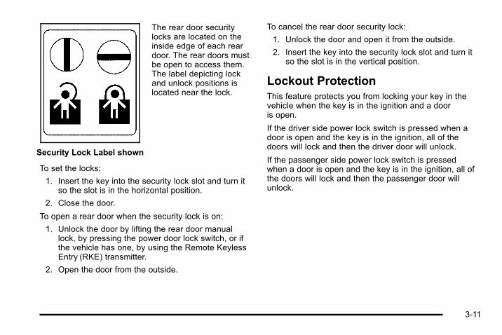
Security Lock Label shown
The rear door securitylocks are located on theinside edge of each reardoor. The rear doors mustbe open to access them.The label depicting lockand unlock positions islocated near the lock.
To set the locks:
1. Insert the key into the security lock slot and turn itso the slot is in the horizontal position.
2. Close the door.
To open a rear door when the security lock is on:
1. Unlock the door by lifting the rear door manuallock, by pressing the power door lock switch, or ifthe vehicle has one, by using the Remote KeylessEntry (RKE) transmitter.
2. Open the door from the outside.
To cancel the rear door security lock:
1. Unlock the door and open it from the outside.
2. Insert the key into the security lock slot and turn itso the slot is in the vertical position.
Lockout ProtectionThis feature protects you from locking your key in thevehicle when the key is in the ignition and a dooris open.
If the driver side power lock switch is pressed when adoor is open and the key is in the ignition, all of thedoors will lock and then the driver door will unlock.
If the passenger side power lock switch is pressedwhen a door is open and the key is in the ignition, all ofthe doors will lock and then the passenger door willunlock.
3-11
Liftgate (SUV)
{ WARNING:
It can be dangerous to drive with the liftgate openbecause carbon monoxide (CO) gas can comeinto your vehicle. You can not see or smell CO.It can cause unconsciousness and even death.If you must drive with the liftgate open or ifelectrical wiring or other cable connections mustpass through the seal between the body and theliftgate:. Make sure all other windows are shut.
. Turn the fan on your heating or coolingsystem to its highest speed and select thecontrol setting that will force outside air intoyour vehicle. See Dual Automatic ClimateControl System on page 4‑17.
. If you have air outlets on or under theinstrument panel, open them all the way. SeeEngine Exhaust on page 3‑45.
To lock and unlock the liftgate, use any of the powerdoor lock switches or the Remote Keyless Entry (RKE)transmitter.
To open the liftgate:
1. Move the spare tire carrier out of the way. See“Opening the Spare Tire Carrier” under Tailgate/Spare Tire Carrier on page 3‑15.
2. Pull the handle located in the center of the door.
To close the liftgate:
1. Pull the liftgate down until it latches.
2. Move the spare tire carrier back into place. See“Closing the Spare Tire Carrier” under Tailgate/Spare Tire Carrier on page 3‑15.
3-12

Midgate® (SUT)
{ WARNING:
It can be dangerous to drive with the cargo areacovered and the tailgate and the Midgate® openbecause carbon monoxide (CO) gas can comeinto your vehicle. You can not see or smell CO.It can cause unconsciousness and even death.If you must drive with the cargo covers on and thetailgate and Midgate® open or if electrical wiring orother cable connections must pass through theseal between the body and the Midgate®:
. Make sure all windows are shut.
. Turn the fan on your heating or coolingsystem to its highest speed on the setting thatbrings in outside air. This will force outside airinto your vehicle. See Dual Automatic ClimateControl System on page 4‑17.
. If you have air outlets on or under theinstrument panel, open them all the way. SeeEngine Exhaust on page 3‑45.
The Midgate® allows you to extend the length of thevehicle's cargo area into the cab.
Lowering the MidgateThe Midgate window must be completely lowered forthe Midgate® to be lowered. See “Midgate® Window”under Power Windows on page 3‑19.
Both the Midgate and the Midgate window can belowered while the ignition is in either ON/RUN or ACC/ACCESSORY, or while in Retained AccessoryPower (RAP) mode. See Retained Accessory Power(RAP) on page 3‑29 for more information.
To lower the Midgate:
1. Fold the rear seats forward. See Split Folding RearSeat on page 2‑10. The front seats may have tobe moved forward slightly.
2. K (Midgate Window): Press the bottom part ofthis switch to lower the Midgate window. SeeInstrument Panel on page 1‑2 for the location ofthis switch.
The window can also be operated using the globalexpress‐down button. See “Global Glass Feature”under Power Windows on page 3‑19.
3-13
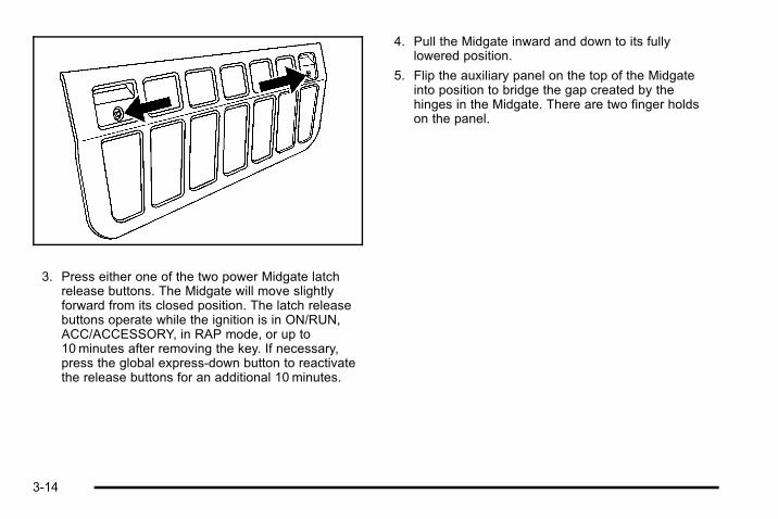
3. Press either one of the two power Midgate latchrelease buttons. The Midgate will move slightlyforward from its closed position. The latch releasebuttons operate while the ignition is in ON/RUN,ACC/ACCESSORY, in RAP mode, or up to10 minutes after removing the key. If necessary,press the global express‐down button to reactivatethe release buttons for an additional 10 minutes.
4. Pull the Midgate inward and down to its fullylowered position.
5. Flip the auxiliary panel on the top of the Midgateinto position to bridge the gap created by thehinges in the Midgate. There are two finger holdson the panel.
3-14

Raising the MidgateTo raise the Midgate:
1. Fold the auxiliary panel back into the exterior of theMidgate. The panel should snap loudly back intoposition which means it is secure.
2. Reverse the steps for lowering the Midgate listedpreviously. The Midgate must be fully latched onboth sides before the window can be raised.
3. Press the top part of the Midgate window switch toexpress‐up the window. To stop the window, pressthe switch a second time.
Tailgate/Spare Tire Carrier
Opening the Spare Tire CarrierTo open the spare tire carrier:
1. Press the button on the pin (B), which is attachedto the cable (A), to remove the pin from the latchnut (C) .
3-15

2. Lift up on the latch on the left side of the vehicle torelease the spare tire carrier from the vehicle. Thehandle will stay in the raised position until thespare tire carrier is closed and latched properly.
{ WARNING:
If you drive with the spare tire carrier unlatched,you could injure pedestrians or damage thevehicle. Make sure the carrier is secure beforedriving.
SUT Model Spare Tire Carrier shown, SUV Modelsimilar
3. Swing the spare tire carrier to the side.
3-16
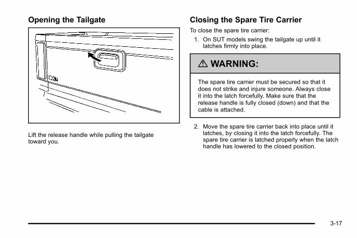
Opening the Tailgate
Lift the release handle while pulling the tailgatetoward you.
Closing the Spare Tire CarrierTo close the spare tire carrier:
1. On SUT models swing the tailgate up until itlatches firmly into place.
{ WARNING:
The spare tire carrier must be secured so that itdoes not strike and injure someone. Always closeit into the latch forcefully. Make sure that therelease handle is fully closed (down) and that thecable is attached.
2. Move the spare tire carrier back into place until itlatches, by closing it into the latch forcefully. Thespare tire carrier is latched properly when the latchhandle has lowered to the closed position.
3-17
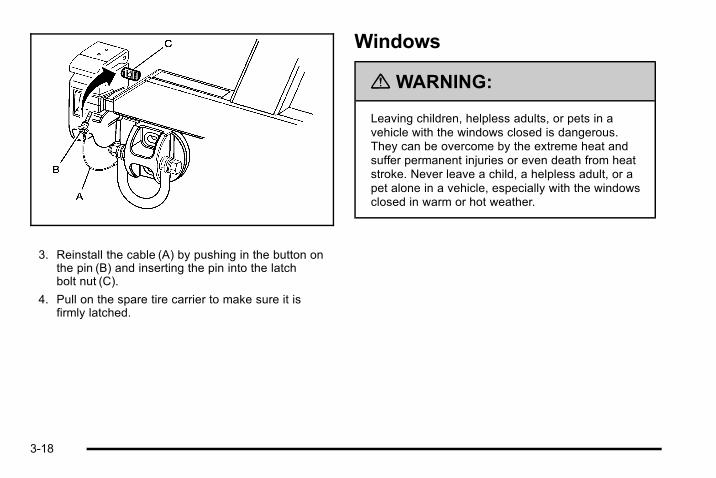
3. Reinstall the cable (A) by pushing in the button onthe pin (B) and inserting the pin into the latchbolt nut (C).
4. Pull on the spare tire carrier to make sure it isfirmly latched.
Windows
{ WARNING:
Leaving children, helpless adults, or pets in avehicle with the windows closed is dangerous.They can be overcome by the extreme heat andsuffer permanent injuries or even death from heatstroke. Never leave a child, a helpless adult, or apet alone in a vehicle, especially with the windowsclosed in warm or hot weather.
3-18

Power Windows
A power window switch is located on the armrest ofeach side door. The switches operate while the ignitionis in ON/RUN or ACC/ACCESSORY or while RetainedAccessory Power (RAP) is active. See RetainedAccessory Power (RAP) on page 3‑29.
The driver door also has a switch for each of thepassenger windows.
Press the front of the switch to the first position to lowerthe window to the desired level. Pull up the front of theswitch to raise the window.
3-19
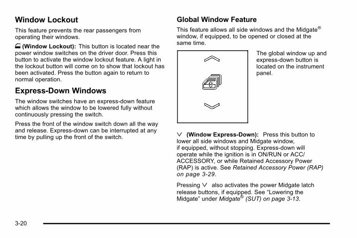
Window LockoutThis feature prevents the rear passengers fromoperating their windows.
o (Window Lockout): This button is located near thepower window switches on the driver door. Press thisbutton to activate the window lockout feature. A light inthe lockout button will come on to show that lockout hasbeen activated. Press the button again to return tonormal operation.
Express-Down WindowsThe window switches have an express-down featurewhich allows the window to be lowered fully withoutcontinuously pressing the switch.
Press the front of the window switch down all the wayand release. Express-down can be interrupted at anytime by pulling up the front of the switch.
Global Window FeatureThis feature allows all side windows and the Midgate®
window, if equipped, to be opened or closed at thesame time.
The global window up andexpress-down button islocated on the instrumentpanel.
ª (Window Express‐Down): Press this button tolower all side windows and Midgate window,if equipped, without stopping. Express‐down willoperate while the ignition is in ON/RUN or ACC/ACCESSORY, or while Retained Accessory Power(RAP) is active. See Retained Accessory Power (RAP)on page 3‑29.
Pressingª also activates the power Midgate latchrelease buttons, if equipped. See “Lowering theMidgate” under Midgate® (SUT) on page 3‑13.
3-20
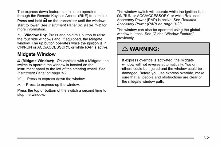
The express-down feature can also be operatedthrough the Remote Keyless Access (RKE) transmitter.Press and hold K on the transmitter until the windowsstart to lower. See Instrument Panel on page 1‑2 formore information.
« (Window Up): Press and hold this button to raisethe four side windows and, if equipped, the Midgatewindow. The up button operates while the ignition is inON/RUN or ACC/ACCESSORY, or while RAP is active.
Midgate WindowK (Midgate Window): On vehicles with a Midgate, theswitch to operate the window is located on theinstrument panel to the left of the steering wheel. SeeInstrument Panel on page 1‑2.
ª : Press to express‐down the window.
« : Press to express‐up the window.
Press the top or bottom of the switch a second time tostop the window.
The window switch will operate while the ignition is inON/RUN or ACC/ACCESSORY, or while RetainedAccessory Power (RAP) is active. See RetainedAccessory Power (RAP) on page 3‑29.
The window can also be operated using the globalwindow buttons. See “Global Window Feature”previously.
{ WARNING:
If express override is activated, the midgatewindow will not reverse automatically. You orothers could be injured and the window could bedamaged. Before you use express override, makesure that all people and obstructions are clear ofthe midgate window path.
3-21
Midgate Window Express Override ModeIf an obstruction or weather condition such as severeicing stops the window as it is moving upward, thewindow will automatically reverse to a partially openposition. The window will return to normal operationonce the obstruction or condition is removed.
The window auto‐reversal function can be overridden inthe express override mode. To override, the windowmust be operated manually by pressing and holding theMidgate window switch or the global window button.This must be done within two seconds after the Midgatewindow has stopped at a partially open position. Theexpress override mode only works immediatelyfollowing a window auto‐reversal. Window expressfunctions will not work while in this mode.
Midgate Window Error/Jog ModeIf the Midgate window has sensed conditions which maylead to damage or malfunction of the window system,the window will automatically go into Error/Jog mode. Inthis mode, window express functions will not work. Thewindow can only be operated manually by pressing theMidgate window switch or the global window button.The window will move slightly and stop. Press and holdthe window switch or global window button to continueto close the window a small amount at a time.
To Exit Error/Jog Mode1. Ensure normal Midgate window operating
conditions have begun.
2. Press and hold the Midgate window down switchapproximately one second to start windowexpress‐down.
3. Release the window down switch and allow thewindow to fully open.
Do not use any window switches once windowmovement has started.
4. Press the Midgate window up switch and visuallyconfirm that the express‐up has been completed.
Sun VisorsSwing the sun visor down to block glare. Swing the sunvisor to the side to cover the side window.
Illuminated Visor Vanity MirrorsSwing the sun visor down and lift the mirror cover toturn the lamps on.
3-22
Theft-Deterrent SystemsVehicle theft is big business, especially in some cities.This vehicle has theft-deterrent features, however, theydo not make it impossible to steal.
Content Theft-DeterrentYour vehicle is equipped with a content theft-deterrentalarm system.
With this system, thesecurity light in theinstrument panel clusterwill flash as you open thedoor if your ignition is off.
This light reminds you to activate the theft-deterrentsystem.
To activate the theft-deterrent system:
1. Open the door.
2. Lock the door with the Remote Keyless Entry(RKE) transmitter. The security light will illuminateto inform the driver the system is arming. If a dooris open when the doors are locked, the securitylight will flash.
3. Close all doors. The security light should go offafter about 30 seconds. The alarm is not armeduntil the security light goes off.
If the delayed locking feature is turned on, thetheft‐deterrent system will not start the armingprocess until the last door is closed and the delaytimer has expired. See Delayed Locking onpage 3‑10.
If a locked door is opened without the RKE transmitter,the alarm will go off. The headlamps and parking lampswill flash and the horn will sound for 30 seconds, thenwill turn off to save the battery power.
3-23

Remember, the theft-deterrent system will not activate ifyou lock the doors with the vehicle's key or use themanual door lock. It activates only if you use a powerdoor lock switch with the door open, or with the RKEtransmitter. You should also remember that you canstart your vehicle with the correct ignition key if thealarm has been set off.
Here is how to avoid setting off the alarm by accident:. If you do not want to activate the theft-deterrent
system, the vehicle should be locked with the doorkey after the doors are closed.
. Always unlock a door with the RKE transmitter.Unlocking a door any other way will set off thealarm.
If you set off the alarm by accident, press unlock on theRKE transmitter or place the key in the ignition and turnit to START to turn it off. The alarm will not stop if youtry to unlock a door any other way.
Testing the AlarmTo test the alarm:
1. From inside the vehicle, lower the driver's windowand open the driver's door.
2. Activate the system by locking the doors with thepower door lock switch while the door is open,or with the RKE transmitter.
3. Get out of the vehicle, close the door and wait forthe security light to go out.
4. Then reach in through the window, unlock the doorwith the manual door lock and open the door. Thisshould set off the alarm.
While the alarm is set, the power door unlock switch isnot operational.
If the alarm does not sound when it should but theheadlamps flash, check to see if the horn works. Thehorn fuse may be blown. To replace the fuse, seeInstrument Panel Fuse Block on page 6‑115 andUnderhood Fuse Block on page 6‑117.
If the alarm does not sound or the headlamps do notflash, the vehicle should be serviced by your dealer.
3-24

PASS-Key® III+ ElectronicImmobilizerSee Radio Frequency Statement on page 8‑18 forinformation regarding Part 15 of the FederalCommunications Commission (FCC) Rules andRSS-210/211 of Industry Canada.
PASS-Key® III+ ElectronicImmobilizer OperationYour vehicle has PASS-Key® III+ (PersonalizedAutomotive Security System) theft-deterrent system.PASS-Key® III+ is a passive theft-deterrent system.
The system is automatically armed when the key isremoved from the ignition.
The system is automatically disarmed when the key isturned to ON/RUN, ACC/ACCESSORY or START fromthe LOCK/OFF position.
You do not have to manually arm or disarm the system.
The security light will come on if there is a problem witharming or disarming the theft-deterrent system.
When the PASS-Key® III+ system senses that someoneis using the wrong key, it prevents the vehicle fromstarting. Anyone using a trial-and-error method to startthe vehicle will be discouraged because of the highnumber of electrical key codes.
If the engine does not start and the security light on theinstrument panel cluster comes on when trying to startthe vehicle, there may be a problem with yourtheft-deterrent system. Turn the ignition off and tryagain.
If the engine still does not start, and the key appears tobe undamaged, try another ignition key. At this time,you may also want to check the fuse, see Fuses andCircuit Breakers on page 6‑114. If the engine still doesnot start with the other key, your vehicle needs service.
3-25
If your vehicle does start, the first key may be faulty.See your dealer who can service the PASS-Key® III+ tohave a new key made. In an emergency, contactRoadside Assistance.
It is possible for the PASS-Key® III+ decoder to learnthe transponder value of a new or replacement key. Upto 10 keys may be programmed for the vehicle. Thefollowing procedure is for programming additional keysonly. If all the currently programmed keys are lost or donot operate, you must see your dealer or a locksmithwho can service PASS-Key® III+ to have keys madeand programmed to the system.
See your dealer or a locksmith who can servicePASS-Key® III+ to get a new key blank that is cutexactly as the ignition key that operates the system.
To program the new additional key:
1. Verify that the new key has a 1 stamped on it.
2. Insert the original, already programmed, key in theignition and start the engine. If the engine will notstart, see your dealer for service.
3. After the engine has started, turn the key to LOCK/OFF, and remove the key.
4. Insert the new key to be programmed and turn it tothe ON/RUN position within five seconds of turningthe ignition to the LOCK/OFF position in Step 3.
The security light will turn off once the key hasbeen programmed.
5. Repeat Steps 1 through 4 if additional keys are tobe programmed.
If you lose or damage your PASS-Key® III+ key, seeyour dealer or a locksmith who can servicePASS-Key® III+ to have a new key made.
Do not leave the key or device that disarms ordeactivates the theft deterrent system in the vehicle.
3-26

Starting and Operating YourVehicle
New Vehicle Break-InNotice: The vehicle does not need an elaboratebreak-in. But it will perform better in the long run ifyou follow these guidelines:
. Keep your speed at 55mph (88 km/h) or lessfor the first 500miles (805 km).
. Do not drive at any one constant speed, fastor slow, for the first 500miles (805 km). Donot make full-throttle starts. Avoiddownshifting to brake or slow the vehicle.
. Avoid making hard stops for the first200miles (322 km) or so. During this time thenew brake linings are not yet broken in. Hardstops with new linings can mean prematurewear and earlier replacement. Follow thisbreaking-in guideline every time you get newbrake linings.
. Do not tow a trailer during break-in. SeeTowing a Trailer on page 5‑52 for the trailertowing capabilities of the vehicle and moreinformation.
Following break‐in, engine speed and load can begradually increased.
3-27

Ignition PositionsThe ignition switch hasfour different positions.
To shift out of P (Park), the ignition must be in ON/RUNor ACC/ACCESSORY and the regular brake pedal mustbe applied.
A (LOCK/OFF): This position locks the ignition. It mayalso lock the steering wheel and automatictransmission. The key can be removed in LOCK/OFF.
On vehicles with an automatic transmission, the shiftlever must be in P (Park) to turn the ignition switch toLOCK/OFF.
The steering may bind with the wheels turned off center.If this happens, move the steering wheel from right toleft while turning the key to ACC/ACCESSORY. If thisdoesn't work, then the vehicle needs service.
Notice: Using a tool to force the key to turn in theignition could cause damage to the switch or breakthe key. Use the correct key, make sure it is all theway in, and turn it only with your hand. If the keycannot be turned by hand, see your dealer.
B (ACC/ACCESSORY): This position lets things likethe radio and the windshield wipers operate while theengine is off. Use this position if the vehicle must bepushed or towed.
3-28

C (ON/RUN): This position can be used to operate theelectrical accessories and to display some instrumentpanel cluster warning and indicator lights. The switchstays in this position when the engine is running. Thetransmission is also unlocked in this position onautomatic transmission vehicles.
If you leave the key in the ACC/ACCESSORY or ON/RUN position with the engine off, the battery could bedrained. You may not be able to start the vehicle if thebattery is allowed to drain for an extended periodof time.
D (START): This is the position that starts the engine.When the engine starts, release the key. The ignitionswitch returns to ON/RUN for driving.
A warning tone will sound when the driver door isopened, the ignition is in ACC/ACCESSORY or LOCK/OFF and the key is in the ignition.
Retained Accessory Power (RAP)These vehicle accessories can be used for up to10 minutes after the engine is turned off:. Audio System. Sunroof. Power Windows
The sunroof and power windows will continue to workup to 10 minutes after the key is turned to LOCK/OFF oruntil any door is opened. The radio will continue to workfor up to 10 minutes after the key is turned to LOCK/OFF or until the driver door is opened.
Starting the EngineMove the shift lever to P (Park) or N (Neutral). Theengine will not start in any other position. To restart theengine when the vehicle is already moving, useN (Neutral) only.
Notice: Do not try to shift to P (Park) if thevehicle is moving. If you do, you could damage thetransmission. Shift to P (Park) only when the vehicleis stopped.
3-29

Starting Procedure1. With your foot off the accelerator pedal, turn the
ignition to START. When the engine starts, letgo of the key. The idle speed will slow downas the engine warms. Do not race the engineimmediately after starting it. Operate the engineand transmission gently to allow the oil to warm upand lubricate all moving parts.
The vehicle has a Computer-Controlled CrankingSystem. This feature assists in starting the engineand protects components. If the ignition key isturned to the START position, and then releasedwhen the engine begins cranking, the engine willcontinue cranking for a few seconds or until thevehicle starts. If the engine does not start and thekey is held in START, cranking will be stoppedafter 15 seconds to prevent cranking motordamage. To prevent gear damage, this system alsoprevents cranking if the engine is already running.Engine cranking can be stopped by turning theignition switch to the ACC/ACCESSORY or LOCK/OFF position.
Notice: Cranking the engine for long periods oftime, by returning the key to the START positionimmediately after cranking has ended, can overheatand damage the cranking motor, and drain thebattery. Wait at least 15 seconds between each try,to let the cranking motor cool down.
2. If the engine does not start after 5‐10 seconds,especially in very cold weather (below 0°F or−18°C), it could be flooded with too much gasoline.Try pushing the accelerator pedal all the way to thefloor and holding it there as you hold the key inSTART for up to a maximum of 15 seconds. Wait atleast 15 seconds between each try, to allow thecranking motor to cool down. When the enginestarts, let go of the key and accelerator. If thevehicle starts briefly but then stops again, repeatthese steps. This clears the extra gasoline from theengine. Do not race the engine immediately afterstarting it. Operate the engine and transmissiongently until the oil warms up and lubricates allmoving parts.
Notice: The engine is designed to work with theelectronics in the vehicle. If you add electrical partsor accessories, you could change the way theengine operates. Before adding electricalequipment, check with your dealer. If you do not,the engine might not perform properly. Anyresulting damage would not be covered by thevehicle warranty.
3-30

Engine Coolant HeaterThe engine heater can provide easier starting andbetter fuel economy during engine warm-up in coldweather conditions at or below 0°F (− 18°C). Vehicleswith an engine heater should be plugged in at least fourhours before starting. An internal thermostat in theplug-end of the cord may exist which will prevent enginecoolant heater operation at temperatures above0°F (−18°C).
To Use the Engine Coolant Heater1. Turn off the engine.
2. Locate the electrical cord near the front recoveryloop on the driver side of the vehicle.
3. Plug it into a normal, grounded 110-volt AC outlet.
{ WARNING:
Plugging the cord into an ungrounded outlet couldcause an electrical shock. Also, the wrong kind ofextension cord could overheat and cause a fire.You could be seriously injured. Plug the cord intoa properly grounded three-prong 110-volt ACoutlet. If the cord will not reach, use a heavy-dutythree-prong extension cord rated for at least15 amps.
4. Before starting the engine, be sure to unplug andstore the cord as it was before to keep it away frommoving engine parts.
The length of time the heater should remain plugged independs on several factors. Ask a dealer in the areawhere you will be parking the vehicle for the best adviceon this.
3-31

Automatic Transmission OperationThe vehicle has a Hydra-Matic® 6L80 automatictransmission, and has an electronic shift positionindicator within the instrument panel cluster. Thisdisplay comes on when the ignition key is turned to theON/RUN position.
There are several different positions for the shift lever.
P (Park): This position locks the rear wheels. It is thebest position to use when starting the engine becausethe vehicle cannot move easily.
When parked on a hill, especially when the vehicle hasa heavy load, you may notice an increase in the effort toshift out of P (Park). See Torque Lock (AutomaticTransmission) under Shifting Into Park on page 3‑42for more information.
{ WARNING:
It is dangerous to get out of the vehicle if the shiftlever is not fully in P (Park) with the parking brakefirmly set. The vehicle can roll.
Do not leave the vehicle when the engine isrunning unless you have to. If you have left theengine running, the vehicle can move suddenly.You or others could be injured. To be sure thevehicle will not move, even when you are on fairlylevel ground, always set the parking brake andmove the shift lever to P (Park). See Shifting IntoPark on page 3‑42. If you are pulling a trailer,see Towing a Trailer on page 5‑52.
R (Reverse): Use this gear to back up.
Notice: Shifting to R (Reverse) while the vehicle ismoving forward could damage the transmission.The repairs would not be covered by the vehiclewarranty. Shift to R (Reverse) only after the vehicleis stopped.
To rock the vehicle back and forth to get out of snow,ice, or sand without damaging the transmission, see IfYour Vehicle is Stuck in Sand, Mud, Ice, or Snow onpage 5‑35.
3-32
N (Neutral): In this position, the engine does notconnect with the wheels. To restart the engine when thevehicle is already moving, use N (Neutral) only. Also,use N (Neutral) when the vehicle is being towed.
{ WARNING:
Shifting into a drive gear while the engine isrunning at high speed is dangerous. Unless yourfoot is firmly on the brake pedal, the vehicle couldmove very rapidly. You could lose control and hitpeople or objects. Do not shift into a drive gearwhile the engine is running at high speed.
Notice: Shifting out of P (Park) or N (Neutral) withthe engine running at high speed may damage thetransmission. The repairs would not be covered bythe vehicle warranty. Be sure the engine is notrunning at high speed when shifting the vehicle.
D (Drive): This position is for normal driving. It providesthe best fuel economy. If you need more power forpassing, and you are:. Going less than about 35 mph (55 km/h), push the
accelerator pedal about halfway down.. Going about 35 mph (55 km/h) or more, push the
accelerator all the way down.
By doing this, the vehicle shifts down to the next gearand has more power.
D (Drive) can be used when towing a trailer, carrying aheavy load, driving on steep hills, or for off-road driving.You may want to shift the transmission to a lower gearselection if the transmission shifts too often.
Downshifting the transmission in slippery roadconditions could result in skidding, see Skidding underLoss of Control on page 5‑12.
M (Manual Mode): This position lets the driver selectthe range of gears appropriate for current drivingconditions. If the vehicle has this feature, see DriverShift Control (DSC) later in this section.
Notice: Spinning the tires or holding the vehicle inone place on a hill using only the accelerator pedalmay damage the transmission. The repair will not becovered by the vehicle warranty. If you are stuck, donot spin the tires. When stopping on a hill, use thebrakes to hold the vehicle in place.
2 (Second): This position reduces vehicle speedwithout using the brakes. Use 2 (Second) on hills. It canhelp control vehicle speed as you go down steepmountain roads, but then you may also want to use thebrakes off and on.
3-33
1 (First): This position reduces vehicle speed withoutusing the brakes. Use it for major/severe downgradesand off-road driving where the vehicle would otherwiseaccelerate due to steepness of grade.
When you shift to 2 (Second) or 1 (First) it provides thelowest gear appropriate to your current road speed andcontinues to downshift as the vehicle slows, eventuallydownshifting to the selected gear.
The vehicle has a shift stabilization feature that adjuststhe transmission shifting to the current drivingconditions in order to reduce rapid upshifts anddownshifts. This shift stabilization feature is designed todetermine, before making an upshift, if the engine willbe able to maintain vehicle speed by analyzing thingssuch as vehicle speed, throttle position and vehicleload. If the shift stabilization feature determines that acurrent vehicle speed cannot be maintained, thetransmission does not upshift and instead holds thecurrent gear. In some cases, this may appear to be adelayed shift, however the transmission is operatingnormally.
The transmission uses adaptive shift controls thatcompares key shift parameters to pre-programmed idealshifts stored in the transmission's computer. Thetransmission constantly makes adjustments to improvevehicle performance according to how the vehicle isbeing used, such as with a heavy load or when thetemperature changes. During this adaptive shift controlprocess, shifting may feel different as the transmissiondetermines the best settings.
When temperatures are very cold, the Hydra-Matic®
6L80 automatic transmission's gear shifting may bedelayed providing more stable shifts until the enginewarms up. Shifts may be more noticeable with a coldtransmission. This difference in shifting is normal.
3-34

Driver Shift Control (DSC)
The vehicle has Driver Shift Control (DSC). DSCcontrols the transmission and vehicle speed whiledriving down hill or towing a trailer by allowing you toselect a desired range of gears.
To use this feature:
1. Move the shift lever to the M (Manual Mode). Thiswill force a downshift from the current gear, forgears 3 through 6.
2. Press the (+) plus or (−) minus button on the leftside of the steering wheel , to select the desiredrange of gears for current driving conditions.
When in the M (Manual Mode) a number will displaynext to the M, indicating the maximum available gear.The DIC display will show the message MANUALSHIFT on the first line and the maximum available gearwill be displayed on the second line. See DriverInformation Center (DIC) on page 4‑42 and DICOperation and Displays (Using DIC Buttons) onpage 4‑43 or DIC Operation and Displays (Using TripOdometer Reset Stem) on page 4‑48 for moreinformation. The number displayed in the DIC is thehighest gear available. The transmission will be limitedto the gear selected and lower gears. Shifting will occurnormally while driving, however the cluster will continueto display the maximum available gear. Higher gearswill not be available unless the selection is changed toinclude higher gears using the (+) plus button.
Grade Braking is not available when the Driver ShiftControl is active. See Tow/Haul Mode on page 3‑36and Towing a Trailer on page 5‑52 for moreinformation.
While using the DSC, cruise control and the tow/haulmode can be used.
3-35
Tow/Haul Mode
The vehicle has a tow/haul mode. The tow/haul modeadjusts the transmission shift pattern to reduce shiftcycling, providing increased performance, vehiclecontrol, and transmission cooling while towing orhauling heavy loads.
Press the button located on the instrument panel to theright of the steering wheel to turn tow/haul on or off.While tow/haul is on, a light on the instrument panelcluster comes on.
See Tow/Haul Mode Light on page 4‑40 for moreinformation.
Also see “Tow Haul Mode” under Towing a Trailer onpage 5‑52 for more information.
Grade BrakingGrade Braking is only active while the Tow/Haul Modeis selected and you are not in the Range SelectionMode. See “Tow/Haul Mode listed previously andAutomatic Transmission Operation on page 3‑32 formore information on the Range Selection Mode. GradeBraking assists in maintaining desired vehicle speedswhen driving on downhill grades by automaticallyimplementing a shift schedule that utilizes the engineand transmission to slow the vehicle. This reduces wearon the braking system and increases control of thevehicle. Grade Braking monitors vehicle speed,acceleration, engine torque and brake pedal usage.Using this information, it detects when the truck is on adownhill grade and the driver desires to slow the vehicleby pressing the brake.
Also see Towing a Trailer on page 5‑52 for moreinformation.
3-36
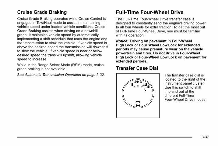
Cruise Grade BrakingCruise Grade Braking operates while Cruise Control isengaged in Tow/Haul mode to assist in maintainingvehicle speed under loaded vehicle conditions. CruiseGrade Braking assists when driving on a downhillgrade. It maintains vehicle speed by automaticallyimplementing a shift schedule that uses the engine andthe transmission to slow the vehicle. If vehicle speed isabove the desired speed the transmission will downshiftto slow the vehicle. If vehicle speed is near or belowdesired speed the trans will upshift, allowing vehiclespeed to increase.
While in the Range Select Mode (RSM) mode, cruisegrade braking is not available.
See Automatic Transmission Operation on page 3‑32.
Full-Time Four-Wheel DriveThe Full-Time Four-Wheel Drive transfer case isdesigned to constantly send the engine's driving powerto all four wheels for extra traction. To get the most outof Full-Time Four-Wheel Drive, you must be familiarwith its operation.
Notice: Driving on pavement in Four-WheelHigh Lock or Four Wheel Low Lock for extendedperiods may cause premature wear on the vehiclepowertrain and tires. Do not drive in Four-WheelHigh Lock or Four-Wheel Low Lock on pavement forextended periods.
Transfer Case DialThe transfer case dial islocated to the right of theinstrument panel cluster.Use this switch to shiftinto and out of thedifferent Full-TimeFour-Wheel Drive modes.
3-37
The transfer case is a part of the Full-Time Four-WheelDrive system and allows the following four differentmodes of operation:
4 m (Full-Time Four-Wheel Drive): This setting is usedfor driving in most street and highway situations. It canbe used for light or variable off-road conditions.
4 m Q (Four-Wheel-High Lock): Use this mode whenyou need extra traction in most off-road situations suchas sand, mud, snow, or level, rocky trails.
4 n Q (Four-Wheel-Low Lock): This mode deliversextra torque to all four wheels and is used for extremeoff-road conditions. Choose Four-Wheel-Low Lock whiledriving off-road in deep sand, mud, or snow andclimbing or descending steep hills.
When in this mode you can also choose to lock the rearaxle for additional traction in extreme off-road situations.See Locking Rear Axle on page 5‑9.
Notice: Operating the vehicle inFour-Wheel-Low Lock above 50mph (80 km/h) forany extended period of time could cause damage tothe transfer case. Do not operate the vehicle inFour-Wheel-Low Lock above 50mph (80 km/h) forextended periods.
{ WARNING:
Shifting the transfer case to N (Neutral) can causethe vehicle to roll even if the transmission is inP (Park). You or someone else could be seriouslyinjured. Be sure to set the parking brake beforeplacing the transfer case in N (Neutral). SeeParking Brake on page 3‑41.
N (Neutral): Shift the transfer case to N (Neutral) onlywhen towing the vehicle. See Recreational VehicleTowing on page 5‑46 or Towing Your Vehicle onpage 5‑46 for more information.
Indicator lights in the dial show which mode you are in.The indicator lights will come on briefly when you turnon the ignition and one will stay on. If the lights do notcome on, take the vehicle to your dealer for service. Anindicator light will flash while shifting the transfer case.It will remain on when the shift is complete. If thetransfer case cannot make a requested shift, it willreturn to the last chosen setting.
If the SERVICE 4WD message stays on, you shouldtake the vehicle to your dealer for service. See “Service4WD message” under Driver Information Center (DIC)on page 4‑42.
3-38
Shifting between Four-Wheel High andFour-Wheel-High LockWith the vehicle traveling less than 40 mph(64 km/h), turn the dial to the Four-Wheel High orFour-Wheel-High Lock position. The indicator light onthe dial will flash while shifting. It will remain on whenthe shift is complete.
It may be necessary to drive backwards for a shortdistance of 25 feet (7.5 m) to get the lock feature todisengage.
Shifting into Four-Wheel-Low LockTo shift into Four-Wheel-Low Lock, the ignition must bein ON/RUN and the vehicle must be stopped or movingless than 3 mph (5 km/h) with the transmission inN (Neutral). The preferred method for shifting intoFour-Wheel Low Lock is to have the vehicle moving1 to 2 mph (1.6 to 3.2 km/h). Turn the dial to theFour-Wheel-Low Lock position. You must wait for theFour-Wheel-Low Lock indicator light on the dial to stopflashing and remain lit before shifting the transmissionin gear.
When the transfer case is shifted into theFour-Wheel-Low Lock position a StabiliTrak® indicatorlight will come on to show that the system has beenturned off and a message will show in the DIC. See DICWarnings and Messages on page 4‑52 for moreinformation.
Notice: Shifting the transmission into gear beforethe indicator light stops flashing could causedamage to the transfer case. Always wait until theindicator light stops flashing before putting thetransmission back in gear.
It is normal for the vehicle to have engagement noiseand bump when shifting between Four-Wheel Low Lock,Full‐Time Four-Wheel Drive or Four-Wheel-High Lockranges or from N (Neutral) with the engine running.
If the Four-Wheel-Low Lock position is selected whenthe vehicle is in gear and/or moving, the Four-WheelLow Lock indicator light will flash for 15 seconds and notcomplete the shift unless the vehicle is moving lessthan 3 mph (5 km/h) and the transmission is inN (Neutral). After 15 seconds the transfer case willreturn to the setting last chosen.
3-39
Shifting Out of Four-Wheel Low LockTo shift from Four-Wheel-Low Lock to Full‐TimeFour-Wheel Drive or Four-Wheel-High Lock, the vehiclemust be stopped or moving less than 3 mph (5 km/h)with the transmission in N (Neutral) and the ignition inON/RUN. The preferred method for shifting out ofFour-Wheel-Low Lock is to have the vehicle moving1 to 2 mph (1.6 to 3.2 km/h). Turn the dial to theFull‐Time Four-Wheel Drive or Four-Wheel-High Lockposition. You must wait for the Full‐Time Four-WheelDrive or Four-Wheel-High Lock indicator light to stopflashing and remain lit before shifting the transmissioninto gear.
It is normal for the vehicle to have engagement noiseand bump when shifting between Four-Wheel Low Lock,Full‐Time Four-Wheel Drive or Four-Wheel-High Lockranges or from N (Neutral) with the engine running.
If the Full‐Time Four-Wheel Drive orFour-Wheel-High Lock position is selected when thevehicle is in gear and/or moving, the Full‐TimeFour-Wheel Drive or Four-Wheel-High Lock indicatorlight will flash for 30 seconds but will not complete theshift unless the vehicle is moving less than 3 mph(5 km/h) and the transmission is in N (Neutral).
Notice: Shifting the transmission into gear beforethe indicator light stops flashing could causedamage to the transfer case. Always wait until theindicator light stops flashing before putting thetransmission back in gear.
Shifting into NeutralTo shift the transfer case to N (Neutral) do the following:
1. Make sure the vehicle is parked so that it willnot roll.
2. Set the parking brake and apply the regular brakepedal. See Parking Brake on page 3‑41.
3. Start the vehicle or turn the ignition to ON/RUN.
4. Put the transmission in N (Neutral).
5. Shift the transfer case to Full‐Time Four‐WheelDrive.
6. Turn the transfer case dial clockwise to N (Neutral)position. The transfer case will not shift toN (Neutral) unless this position is held for10 seconds. The N (Neutral) light will come on andthen the dial can be slowly released. The dial willbe in the Four-Wheel Low Lock position but thetransfer case will be in N (Neutral) with theN (Neutral) light on.
3-40
7. If the engine is running, make sure that the transfercase is in N (Neutral) by shifting the transmissionto R (Reverse) for one second, then shift thetransmission to D (Drive) for one second.
8. Turn the ignition to ACC/ACCESSORY, which willturn the engine off.
9. Place the transmission shift lever in P (Park).
10. Release the parking brake prior to moving thevehicle.
11. Turn the ignition to LOCK/OFF.
Shifting Out of NeutralTo shift out of N (Neutral) do the following:
1. Set the parking brake and apply the regular brakepedal.
2. Shift the transmission to N (Neutral) and turn theignition to ON/RUN with the engine off.
3. Turn the transfer case dial to Full‐Time Four-WheelDrive, Four-Wheel High Lock or Four-WheelLow Lock.
After the transfer case has shifted out ofN (Neutral) the N (Neutral) light will go out.
4. Release the parking brake prior to moving thevehicle.
Notice: Shifting the transmission into gear beforethe requested mode indicator light has stoppedflashing could damage the transfer case. To helpavoid damaging the vehicle, always wait for themode indicator lights to stop flashing beforeshifting the transmission into gear.
5. Start the engine and shift the transmission to thedesired position.
Parking BrakeTo set the parking brake, hold the regular brake pedaldown and push down the parking brake pedal.
A chime will activate and the warning light will flashwhen the parking brake is applied and the vehicle ismoving at least 3 mph (5 km/h) for at leastthree seconds.
3-41

To release the parking brake, hold the regular brakepedal down. Pull the bottom edge of the lever, locatedabove the parking brake pedal, with the parking brakesymbol, to release the parking brake.
If the ignition is on when the parking brake is released,the brake system warning light will go off.
Notice: Driving with the parking brake on canoverheat the brake system and cause prematurewear or damage to brake system parts. Make surethat the parking brake is fully released and thebrake warning light is off before driving.
If you are towing a trailer and are parking on any hill,see Towing a Trailer on page 5‑52.
Shifting Into Park
{ WARNING:
It can be dangerous to get out of the vehicle if theshift lever is not fully in P (Park) with the parkingbrake firmly set. The vehicle can roll. If you haveleft the engine running, the vehicle can movesuddenly. You or others could be injured. To besure the vehicle will not move, even when you areon fairly level ground, use the steps that follow.If you are pulling a trailer, see Towing a Trailer onpage 5‑52.
1. Hold the brake pedal down and set the parkingbrake. See Parking Brake on page 3‑41 for moreinformation.
2. Move the shift lever into P (Park) by pressing thebutton on the shift lever and pushing the lever allthe way toward the front of the vehicle.
3. Turn the ignition key to LOCK/OFF.
4. Remove the key and take it with you. If you canleave the vehicle with the key, the vehicle is inP (Park).
3-42

Leaving the Vehicle With the EngineRunning
{ WARNING:
It can be dangerous to leave the vehicle with theengine running. The vehicle could move suddenlyif the shift lever is not fully in P (Park) with theparking brake firmly set. And, if you leave thevehicle with the engine running, it could overheatand even catch fire. You or others could beinjured. Do not leave the vehicle with the enginerunning.
If you have to leave the vehicle with the engine running,be sure the vehicle is in P (Park) and the parking brakeis firmly set before you leave it. After you have movedthe shift lever into P (Park), hold the regular brake pedaldown. Then, see if you can move the shift lever awayfrom P (Park) without first pressing the button on theconsole shift lever. If you can, it means that the shiftlever was not fully locked into P (Park).
Torque LockTorque lock is when the weight of the vehicle puts toomuch force on the parking pawl in the transmission.This happens when parking on a hill and shifting thetransmission into P (Park) is not done properly and thenit is difficult to shift out of P (Park). To prevent torquelock, set the parking brake and then shift into P (Park).To find out how, see “Shifting Into P (Park)” listedpreviously. If torque lock does occur, your vehicle mayneed to be pushed uphill by another vehicle to relievethe parking pawl pressure, so you can shift out ofP (Park).
Shifting Out of ParkThe vehicle is equipped with an electronic shift lockrelease system. The shift lock release is designed to:. Prevent ignition key removal unless the shift lever
is in P (Park) with the shift lever button fullyreleased, and
. Prevent movement of the shift lever out of P (Park),unless the ignition is in ON/RUN or ACC/ACCESSORY and the regular brake pedal isapplied.
The shift lock release is always functional except in thecase of an uncharged or low voltage (less than 9 volt)battery.
3-43

If the vehicle has an uncharged battery or a battery withlow voltage, try charging or jump starting the battery.See Jump Starting on page 6‑44 for more information.
To shift out of P (Park):
1. Apply the brake pedal.
2. Press the shift lever button.
3. Move the shift lever to the desired position.
If you still are unable to shift out of P (Park):
1. Fully release the shift lever button.
2. While holding down the brake pedal, press the shiftlever button again.
3. Move the shift lever to the desired position.
If you still cannot move the shift lever from P (Park), seeyour dealer.
Parking Over Things That Burn
{ WARNING:
Things that can burn could touch hot exhaustparts under the vehicle and ignite. Do not parkover papers, leaves, dry grass, or other things thatcan burn.
3-44

Engine Exhaust
{ WARNING:
Engine exhaust contains Carbon Monoxide (CO)which cannot be seen or smelled. Exposure to COcan cause unconsciousness and even death.
Exhaust may enter the vehicle if:. The vehicle idles in areas with poor ventilation
(parking garages, tunnels, deep snow thatmay block underbody airflow or tail pipes).
. The exhaust smells or sounds strange ordifferent.
. The exhaust system leaks due to corrosion ordamage.
. The vehicle’s exhaust system has beenmodified, damaged or improperly repaired.
(Continued)
WARNING: (Continued)
. There are holes or openings in the vehiclebody from damage or after-marketmodifications that are not completely sealed.
If unusual fumes are detected or if it is suspectedthat exhaust is coming into the vehicle:. Drive it only with the windows
completely down.. Have the vehicle repaired immediately.
Never park the vehicle with the engine running inan enclosed area such as a garage or a buildingthat has no fresh air ventilation.
3-45

Running the Vehicle While ParkedIt is better not to park with the engine running. But if youever have to, here are some things to know.
{ WARNING:
Idling a vehicle in an enclosed area with poorventilation is dangerous. Engine exhaust mayenter the vehicle. Engine exhaust containsCarbon Monoxide (CO) which cannot be seen orsmelled. It can cause unconsciousness and evendeath. Never run the engine in an enclosed areathat has no fresh air ventilation. For moreinformation, see Engine Exhaust on page 3‑45.
{ WARNING:
It can be dangerous to get out of the vehicle if theautomatic transmission shift lever is not fully inP (Park) with the parking brake firmly set. Thevehicle can roll. Do not leave the vehicle when theengine is running unless you have to. If you have
(Continued)
WARNING: (Continued)
left the engine running, the vehicle can movesuddenly. You or others could be injured. To besure the vehicle will not move, even when you areon fairly level ground, always set the parkingbrake and move the shift lever to P (Park).
{ WARNING:
Full‐time four-wheel drive vehicles with thetransfer case in (N) Neutral will allow the vehicleto roll, even if the automatic transmission shiftlever is in P (Park). So, be sure the transfer caseis in a drive gear — not in (N) Neutral. Always setthe parking brake.
Follow the proper steps to be sure the vehicle will notmove. See Shifting Into Park on page 3‑42.
If pulling a trailer, see Towing a Trailer on page 5‑52.
3-46

Mirrors
Automatic Dimming Rearview MirrorThe vehicle has an automatic dimming rearview mirror.It might also have an OnStar® system. OnStar controlbuttons are located at the bottom of the mirror. See theOnStar® owner guide for more information about theservices OnStar provides.
O (On/Off) : Press to turn the automatic dimmingfeature on or off.
The vehicle may also have a Rear Vision Camera. SeeRear Vision Camera (RVC) on page 3‑50 for moreinformation.
Cleaning the MirrorDo not spray glass cleaner directly on the mirror. Use asoft towel dampened with water.
Outside Power Foldaway MirrorsIf the vehicle has outsidepower foldaway mirrors,the controls are locatedon the driver's doorarmrest.
3-47

Mirror Adjustment1. Press (A) or (B) to select the driver or passenger
side mirror.
2. Press one of the four arrows located on the controlpad to move the mirror to the desired position.
3. Adjust each outside mirror so that a little of thevehicle and the area behind can be seen.
4. Press (C), to fold the mirrors out to the drivingposition.
5. Press (D) to fold the mirrors in to the foldedposition.
If the mirrors are accidentally folded/unfolded manually,they could shake or flutter at normal driving speeds andmight not stay in the unfolded position. If this happens,reset the mirrors. See “Resetting the Power FoldawayMirrors” next.
Resetting the Power Foldaway MirrorsReset the power foldaway mirrors if:. The mirrors are accidentally obstructed while
folding.. They are accidentally manually folded/unfolded.. The mirrors will not stay in the unfolded position.. The mirrors shake and flutter at normal driving
speeds.
To reset the power foldaway mirrors, fold and unfoldthem three times using the mirror controls. This willreset them to their normal position.
Outside Automatic Dimming MirrorIf the vehicle has this feature, the driver outside mirroradjusts for the glare of the headlamps behind you. SeeAutomatic Dimming Rearview Mirror on page 3‑47 formore information.
3-48

Park Tilt MirrorsThe vehicle's outside mirrors can also perform a park tiltfunction. This causes the passenger and/or driver'smirror to tilt to a preselected position when the vehicleis in R (Reverse). This feature may be useful in viewingthe curb when parallel parking.
When the vehicle is shifted out of R (Reverse) and ashort delay has occurred, the passenger and/or driver'smirror will return to its original position.
To change the preselected tilt position, adjust themirrors to the desired position while the vehicle is inR (Reverse). When the vehicle is shifted out ofR (Reverse), this new position is saved in memory asthe tilt position.
This feature can be enabled/disabled through the DriverInformation Center. See DIC Vehicle Customization onpage 4‑60 for more information.
Outside Convex Mirror
{ WARNING:
A convex mirror can make things, like othervehicles, look farther away than they really are.If you cut too sharply into the right lane, you couldhit a vehicle on the right. Check the inside mirroror glance over your shoulder before changinglanes.
The passenger side mirror is convex shaped. A convexmirror's surface is curved so more can be seen from thedriver seat.
Outside Heated MirrorsThe vehicle may have outside heated mirrors whichhelp clear them of condensation, snow, and ice.
When the rear window defogger button is pressed, theheated mirrors are also turned on. See “Rear WindowDefogger” under Dual Automatic Climate ControlSystem on page 4‑17 for more information.
3-49
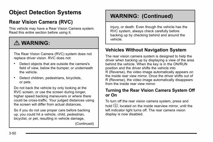
Object Detection Systems
Rear Vision Camera (RVC)This vehicle may have a Rear Vision Camera system.Read this entire section before using it.
{ WARNING:
The Rear Vision Camera (RVC) system does notreplace driver vision. RVC does not:
. Detect objects that are outside the camera'sfield of view, below the bumper, or underneaththe vehicle.
. Detect children, pedestrians, bicyclists,or pets.
Do not back the vehicle by only looking at theRVC screen, or use the screen during longer,higher speed backing maneuvers or where therecould be cross-traffic. Your judged distances usingthe screen will differ from actual distances.
So if you do not use proper care before backingup, you could hit a vehicle, child, pedestrian,bicyclist, or pet, resulting in vehicle damage,
(Continued)
WARNING: (Continued)
injury, or death. Even though the vehicle has theRVC system, always check carefully beforebacking up by checking behind and around thevehicle.
Vehicles Without Navigation SystemThe rear vision camera system is designed to help thedriver when backing up by displaying a view of the areabehind the vehicle. When the key is in the ON/RUNposition and the driver shifts the vehicle intoR (Reverse), the video image automatically appears onthe inside rear view mirror. Once the driver shifts out ofR (Reverse), the video image automatically disappearsfrom the inside rear view mirror.
Turning the Rear Vision Camera System Offor OnTo turn off the rear vision camera system, press andholdz, located on the inside rearview mirror, until theleft indicator light turns off. The rear camera visiondisplay is now disabled.
3-50

To turn the rear vision camera system on again, pressand holdz until the left indicator light illuminates. Therear vision camera system display is now enabled andthe display will appear in the mirror normally.
Vehicles With Navigation SystemThe rear vision camera system is designed to help thedriver when backing up by displaying a view of the areabehind the vehicle. When the driver shifts the vehicleinto R (Reverse), the video image automaticallyappears on the navigation screen. Once the driver shiftsout of R (Reverse), the navigation screen will go back tothe last screen that had been displayed, after a delay.
Turning the Rear Vision Camera System Onor OffTo turn the rear vision camera system on or off:
1. Shift into P (Park).
2. Press the MENU button to enter the configuremenu options, then press the MENU hard key toselect Display or touch the Display screen button.
3. Select the Rear Camera Options screen button.The Rear Camera Options screen will display.
4. Select the Video screen button. When the Videoscreen button is highlighted the RVC system is on.
The delay that is received after shifting out ofR (Reverse) is approximately 10 seconds. The delaycan be cancelled by performing one of the following:. Pressing a hard key on the navigation system.. Shifting in to P (Park).. Reach a vehicle speed of 5 mph (8 km/h).
There is a message on the rear vision camera screenthat states “Check Surroundings for Safety”.
3-51

Adjusting the Brightness and Contrast ofthe ScreenTo adjust the brightness and contrast of the screen,press the MENU button while the rear vision cameraimage is on the display. Any adjustments made will onlyaffect the rear vision camera screen.
] (Brightness) : Touch the + (plus) or – (minus)screen buttons to increase or decrease the brightnessof the screen.
_ (Contrast) : Touch the + (plus) or – (minus) screenbuttons to increase or decrease the contrast of thescreen.
Rear Vision Camera Error MessagesService Rear Vision Camera System: This messagecan display when the system is not receivinginformation it requires from other vehicle systems.
If any other problem occurs or if a problem persists, seeyour dealer.
Rear Vision Camera Location
The image is provided by the camera located on therear bumper.
The camera uses a special lens. The distance of theimage that appears on the screen differs from the actualdistance. The area displayed by the camera is limited.The camera does not display objects which are close toeither corner of the bumper or under the bumper. Thespare tire and carrier extends rearward of the rearbumper. The area displayed on the screen can varyaccording to vehicle orientation or road conditions.
The following illustration shows the field of view that thecamera provides.
3-52
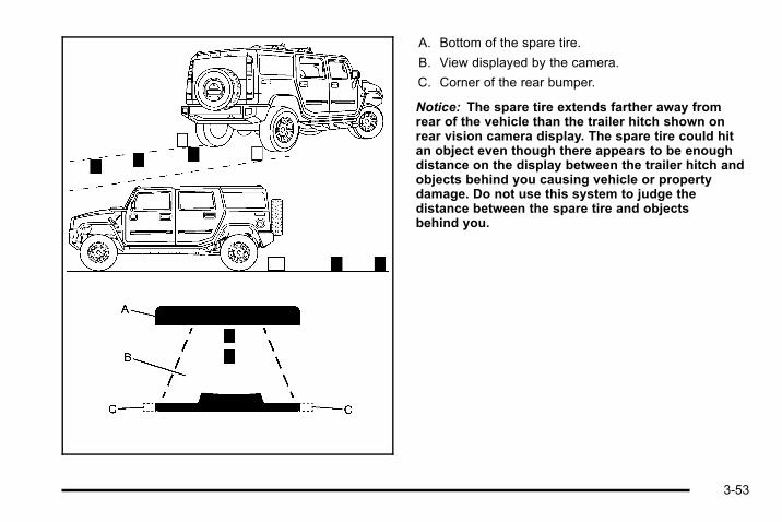
A. Bottom of the spare tire.
B. View displayed by the camera.
C. Corner of the rear bumper.
Notice: The spare tire extends farther away fromrear of the vehicle than the trailer hitch shown onrear vision camera display. The spare tire could hitan object even though there appears to be enoughdistance on the display between the trailer hitch andobjects behind you causing vehicle or propertydamage. Do not use this system to judge thedistance between the spare tire and objectsbehind you.
3-53
When the System Does Not Seem ToWork ProperlyThe rear vision camera system might not work properlyor display a clear image if:. The RVC is turned off. See “Turning the Rear
Camera System On or Off” earlier in this section.. It is dark.. The sun or the beam of headlights is shining
directly into the camera lens.. Ice, snow, mud, or anything else builds up on the
camera lens. Clean the lens, rinse it with water,and wipe it with a soft cloth.
. The back of the vehicle is in an accident, theposition and mounting angle of the camera canchange or the camera can be affected. Be sure tohave the camera and its position and mountingangle checked at your dealer.
. There are extreme temperature changes.
The rear vision camera system display in the rearviewmirror may turn off or not appear as expected due to aloss of video signal, or no video signal present duringthe reverse cycle. The display will be blank and the leftindicator light will slowly flash as long as the vehicle isin R (Reverse) or until the condition returns to normal.
Pressing and holdingz when the left indicator light isflashing will turn off the video display along with the leftindicator light.
Universal Home RemoteSystemSee Radio Frequency Statement on page 8‑18 forinformation regarding Part 15 of the FederalCommunications Commission (FCC) Rules andRSS-210/211 of Industry Canada.
The FCC Grant of Equipment Authorization Certificatenumber is KOBFTE05A.
The Canadian Registration ID number is3521A-FTE05A.
3-54
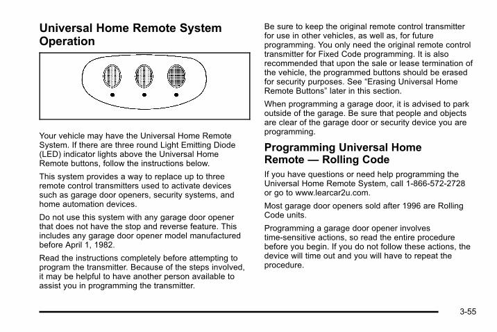
Universal Home Remote SystemOperation
Your vehicle may have the Universal Home RemoteSystem. If there are three round Light Emitting Diode(LED) indicator lights above the Universal HomeRemote buttons, follow the instructions below.
This system provides a way to replace up to threeremote control transmitters used to activate devicessuch as garage door openers, security systems, andhome automation devices.
Do not use this system with any garage door openerthat does not have the stop and reverse feature. Thisincludes any garage door opener model manufacturedbefore April 1, 1982.
Read the instructions completely before attempting toprogram the transmitter. Because of the steps involved,it may be helpful to have another person available toassist you in programming the transmitter.
Be sure to keep the original remote control transmitterfor use in other vehicles, as well as, for futureprogramming. You only need the original remote controltransmitter for Fixed Code programming. It is alsorecommended that upon the sale or lease termination ofthe vehicle, the programmed buttons should be erasedfor security purposes. See “Erasing Universal HomeRemote Buttons” later in this section.
When programming a garage door, it is advised to parkoutside of the garage. Be sure that people and objectsare clear of the garage door or security device you areprogramming.
Programming Universal HomeRemote — Rolling CodeIf you have questions or need help programming theUniversal Home Remote System, call 1-866-572-2728or go to www.learcar2u.com.
Most garage door openers sold after 1996 are RollingCode units.
Programming a garage door opener involvestime-sensitive actions, so read the entire procedurebefore you begin. If you do not follow these actions, thedevice will time out and you will have to repeat theprocedure.
3-55

To program up to three devices:
1. From inside the vehicle, press the two outsidebuttons at the same time for one to two seconds,and immediately release them.
2. Locate in the garage, the garage door openerreceiver (motor-head unit). Locate the “Learn” or“Smart” button. It can usually be found where thehanging antenna wire is attached to themotor-head unit and may be a colored button.Press this button. After you press this button, youwill have 30 seconds to complete the followingsteps.
3-56
3. Immediately return to your vehicle. Press and holdthe Universal Home Remote button that you wouldlike to use to control the garage door until thegarage door moves. The indicator light, above theselected button, should slowly blink. You may needto hold the button from five to 20 seconds.
4. Immediately, within one second, release the buttonwhen the garage door moves. The indicator lightwill blink rapidly until programming is complete.
5. Press and release the same button again. Thegarage door should move, confirming thatprogramming is successful and complete.
To program another Rolling Code device such as anadditional garage door opener, a security device,or home automation device, repeat Steps 1-5, choosinga different function button in Step 3 than what you usedfor the garage door opener.
If these instructions do not work, you probably have aFixed Code garage door opener. Follow theProgramming instructions that follow for a Fixed Codegarage door opener.
Programming Universal HomeRemote — Fixed CodeIf you have questions or need help programming theUniversal Home Remote System, call 1-866-572-2728or go to www.learcar2u.com.
Most garage door openers sold before 1996 are FixedCode units.
Programming a garage door opener involvestime-sensitive actions, so read the entire procedurebefore you begin. If you do not follow these actions, thedevice will time out and you will have to repeat theprocedure.
3-57

To program up to three devices:
1. To verify if you have a Fixed Code garage dooropener, remove the battery cover on your handheld transmitter supplied by the manufacturer ofyour garage door opener motor. If you see a row ofdip switches similar to the graphic above, you havea Fixed Code garage door opener. If you do notsee a row of dip switches, return to the previoussection for Programming Universal HomeRemote – Rolling Code.
Your hand held transmitter may have betweeneight to 12 dip switches depending on the brand oftransmitter.
Your garage door opener receiver (motor headunit) may also have a row of dip switches that canbe used when programming the Universal HomeRemote. If the total number of switches on themotor head and hand held transmitter are different,or if the dip switch settings are different, use thedip switch settings on the motor head unit toprogram your Universal Home Remote. The motorhead dip switch settings can also be used whenyou do not have the original hand held transmitter.
Example of Eight Dip Switches with Two Positions
3-58
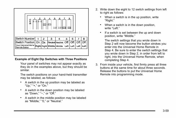
Example of Eight Dip Switches with Three Positions
Your panel of switches may not appear exactly asthey do in the examples above, but they should besimilar.
The switch positions on your hand-held transmittermay be labeled, as follows:. A switch in the up position may be labeled as
“Up,” “+,” or “On.”. A switch in the down position may be labeled
as “Down,” “−,” or “Off.”. A switch in the middle position may be labeled
as “Middle,” “0,” or “Neutral.”
2. Write down the eight to 12 switch settings from leftto right as follows:. When a switch is in the up position, write
“Right.”. When a switch is in the down position,
write “Left.”. If a switch is set between the up and down
position, write “Middle.”
The switch settings that you wrote down inStep 2 will now become the button strokes youenter into the Universal Home Remote inStep 4. Be sure to enter the switch settings thatyou wrote down in Step 2, in order from left toright, into the Universal Home Remote, whencompleting Step 4.
3. From inside your vehicle, first firmly press all threebuttons at the same time for about three seconds.Release the buttons to put the Universal HomeRemote into programming mode.
3-59

4. The indicator lights will blink slowly. Enter eachswitch setting from Step 2 into your vehicle'sUniversal Home Remote. You will have two andone-half minutes to complete Step 4. Now pressone button on the Universal Home Remote foreach switch setting as follows:. If you wrote “Left,” press the left button in the
vehicle.. If you wrote “Right,” press the right button in
the vehicle.. If you wrote “Middle,” press the middle button in
the vehicle.
5. After entering all of the switch positions, again,firmly press and release all three buttons at thesame time. The indicator lights will turn on.
6. Press and hold the button you would like to use tocontrol the garage door until the garage doormoves. The indicator light above the selectedbutton should slowly blink. You may need to holdthe button from five to 55 seconds.
7. Immediately release the button when the garagedoor moves. The indicator light will blink rapidlyuntil programming is complete.
8. Press and release the same button again. Thegarage door should move, confirming thatprogramming is successful and complete.
To program another Fixed Code device such as anadditional garage door opener, a security device,or home automation device, repeat Steps 1-8, choosinga different button in Step 6 than what you used for thegarage door opener.
Using Universal Home RemotePress and hold the appropriate button for at least half ofa second. The indicator light will come on while thesignal is being transmitted.
3-60

Reprogramming Universal HomeRemote ButtonsYou can reprogram any of the three buttons byrepeating the instructions.
Erasing Universal Home RemoteButtonsYou should erase the programmed buttons when yousell or terminate your lease.
To erase either Rolling Code or Fixed Code on theUniversal Home Remote device:
1. Press and hold the two outside buttons at thesame time for approximately 20 seconds, until theindicator lights, located directly above the buttons,begin to blink rapidly.
2. Once the indicator lights begin to blink, releaseboth buttons. The codes from all buttons will beerased.
For help or information on the Universal Home RemoteSystem, call the customer assistance phone numberunder Customer Assistance Offices on page 8‑5.
Storage Areas
Glove BoxLift up on the glove box lever to open it.
CupholdersCupholders are located in front of the center console.They are also located in the rear center armrest, and onthe left rear of the vehicle.
3-61

Center Console Storage
To open the front center console, press the button andlift up.
Roof Rack System
{ WARNING:
If something is carried on top of the vehicle that islonger or wider than the roof rack— like paneling,plywood, or a mattress— the wind can catch itwhile the vehicle is being driven. The item beingcarried could be violently torn off, and this couldcause a collision, and damage the vehicle. Nevercarry something longer or wider than the roof rackon top of the vehicle unless using a HUMMERCertified accessory carrier.
For vehicles with a roof rack, the rack can be used toload items. For roof racks that do not have crossrailsincluded, HUMMER Certified crossrails can bepurchased as an accessory. See your dealer foradditional information.
Notice: Loading cargo on the luggage carrier thatweighs more than 136 kg (300 lbs) or hangs over therear or sides of the vehicle can damage the vehicle.Load cargo only on top of the crossrails and tie thecargo down to the crossrail support cargo tie-downloops, making sure to fasten it securely.
3-62

To prevent damage or loss of cargo when driving, checkto make sure crossrails and cargo are securelyfastened. Loading cargo on the roof rack will make thevehicle’s center of gravity higher. Avoid high speeds,sudden starts, sharp turns, sudden braking or abruptmaneuvers, otherwise it may result in loss of control.If driving for a long distance, on rough roads, or at highspeeds, occasionally stop the vehicle to make sure thecargo remains in its place.
Do not exceed the maximum vehicle capacity whenloading the vehicle. For more information on vehiclecapacity and loading, see Loading the Vehicle onpage 5‑40.
Rear Seat ArmrestThis vehicle has a rear seat armrest with cupholders.Pull the tab on the armrest forward, to access it.
Cargo Tie Downs (SUT)
There are four oval shaped openings (A) in the cargobed that allow access to four tie downs. The tie downscan be used to secure cargo.
3-63
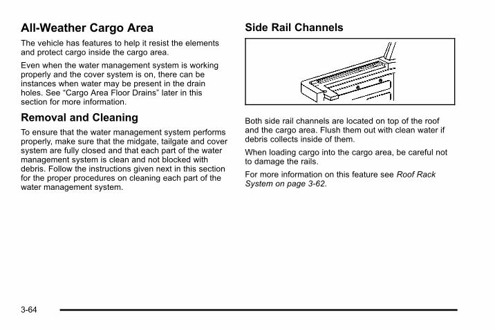
All-Weather Cargo AreaThe vehicle has features to help it resist the elementsand protect cargo inside the cargo area.
Even when the water management system is workingproperly and the cover system is on, there can beinstances when water may be present in the drainholes. See “Cargo Area Floor Drains” later in thissection for more information.
Removal and CleaningTo ensure that the water management system performsproperly, make sure that the midgate, tailgate and coversystem are fully closed and that each part of the watermanagement system is clean and not blocked withdebris. Follow the instructions given next in this sectionfor the proper procedures on cleaning each part of thewater management system.
Side Rail Channels
Both side rail channels are located on top of the roofand the cargo area. Flush them out with clean water ifdebris collects inside of them.
When loading cargo into the cargo area, be careful notto damage the rails.
For more information on this feature see Roof RackSystem on page 3‑62.
3-64

Cargo Area Floor Drains
For vehicles with a cargo mat, located under it are fourcargo-area floor drains (A) near the sides of the cargoarea. These drains should be cleaned periodically toallow water to exit the cargo area.
The cargo mat has cutouts for the drains. Flush thedrains through the cutouts, but if the cargo area isextremely dirty lift up the edges of the cargo floor mat ortake the whole mat out and flush the drains with water.The drain grates can be removed to clear any debristhat has accumulated in the drain.
SunroofThe vehicle may have apower sliding sunroof.The ignition must be on orin the accessory position,or Retained AccessoryPower (RAP) must beactive.
See Retained Accessory Power (RAP) on page 3‑29.The switch used to operate the sunroof is located in theoverhead console.
3-65

Express-Open/Close SunroofThe sunroof has a feature which allows the sunroofpanel to be opened or closed without continuouslypressing the switch. The express-open can be stoppedat any time by pushing the front of the switch asecond time.
The sunroof has four positions:. Comfort open stop: To open the sunroof and
sunshade, press the rear of the switch quickly andrelease. The glass panel will open to an interimposition that reduces wind noise. For informationon using the sunshade, see “Sunshade Operation”later.
. Full open stop: To open the sunroof further, pressthe rear of the switch quickly once more.
. Express close: To close the sunroof, press thefront of the switch quickly and release.
. Vent: The vent position allows the rear of thesunroof to be opened and tilted upward. With thesunroof in the fully closed position, press and holdthe front of the switch until the sunroof reaches thedesired vent position or until it stops moving. Toclose the sunroof from the vent position, press andhold the rear of the switch until the sunroof is fullyclosed.
Do not leave the sunroof open for long periods of timeas debris may collect in the tracks.
Dirt and debris may collect on the sunroof seal or in thetracks that could cause an issue with sunroof operation,noise or plug the water drainage system. Periodicallyopen the sunroof and remove any obstacles or loosedebris. Wipe the sunroof seal and roof sealing areausing a clean cloth, mild soap, and water. Do notremove grease from sunroof.
3-66

Anti-Pinch Protection FeatureIf something gets caught between the glass panel androof frame while the sunroof is closing, the glass panelwill stop and open half way, and the deflector will raisefully.
If something gets caught between the glass panel andthe roof frame during the tilt down operation, the glasspanel will stop and open fully.
If the sunroof panel receives a strong impact, theanti-pinch protection feature may work even if nothinggets caught between the glass panel and roof frame.
Sunshade OperationThe sunshade will open automatically when opening thesunroof.
However, it can manually be pulled shut after thesunroof is closed. To adjust the sunshade, push itbackward or pull it forward to the desired position. Thesunshade cannot be adjusted further than the currentclosed position of the sunroof.
Notice: Forcing the sunshade forward of the slidingglass panel may cause damage and the sunroofmay not operate properly. Always close the glasspanel before closing the sunshade.
3-67

2 NOTES
3-68
Section 4 Instrument Panel
Instrument Panel Overview . . . . . . . . . . . . . . . . . . . . . . . . 4-3Hazard Warning Flashers . . . . . . . . . . . . . . . . . . . . . . . 4-3Horn . . . . . . . . . . . . . . . . . . . . . . . . . . . . . . . . . . . . . . . . . . . . 4-3Tilt Wheel . . . . . . . . . . . . . . . . . . . . . . . . . . . . . . . . . . . . . . . 4-3Heated Steering Wheel . . . . . . . . . . . . . . . . . . . . . . . . . 4-4Turn Signal/Multifunction Lever . . . . . . . . . . . . . . . . . . 4-4Turn and Lane-Change Signals . . . . . . . . . . . . . . . . . 4-5Headlamp High/Low-Beam Changer . . . . . . . . . . . . 4-5Flash-to-Pass . . . . . . . . . . . . . . . . . . . . . . . . . . . . . . . . . . . 4-6Windshield Wipers . . . . . . . . . . . . . . . . . . . . . . . . . . . . . . 4-6Windshield Washer . . . . . . . . . . . . . . . . . . . . . . . . . . . . . 4-7Rear Window Wiper/Washer . . . . . . . . . . . . . . . . . . . . 4-7Cruise Control . . . . . . . . . . . . . . . . . . . . . . . . . . . . . . . . . . 4-8Exterior Lamps . . . . . . . . . . . . . . . . . . . . . . . . . . . . . . . . . 4-11Headlamps on Reminder . . . . . . . . . . . . . . . . . . . . . . 4-12Daytime Running Lamps (DRL) . . . . . . . . . . . . . . . . 4-12Automatic Headlamp System . . . . . . . . . . . . . . . . . . 4-13Instrument Panel Brightness . . . . . . . . . . . . . . . . . . . 4-13Dome Lamps . . . . . . . . . . . . . . . . . . . . . . . . . . . . . . . . . . 4-14Dome Lamp Override . . . . . . . . . . . . . . . . . . . . . . . . . . 4-14Entry/Exit Lighting . . . . . . . . . . . . . . . . . . . . . . . . . . . . . 4-14Reading Lamps . . . . . . . . . . . . . . . . . . . . . . . . . . . . . . . . 4-14Electric Power Management . . . . . . . . . . . . . . . . . . . 4-14Battery Run-Down Protection . . . . . . . . . . . . . . . . . . 4-15
Accessory Power Outlet(s) . . . . . . . . . . . . . . . . . . . . . 4-15Ashtray(s) and Cigarette Lighter . . . . . . . . . . . . . . . 4-16Analog Clock . . . . . . . . . . . . . . . . . . . . . . . . . . . . . . . . . . 4-17
Climate Controls . . . . . . . . . . . . . . . . . . . . . . . . . . . . . . . . . . 4-17Dual Automatic Climate Control System . . . . . . . 4-17Outlet Adjustment . . . . . . . . . . . . . . . . . . . . . . . . . . . . . . 4-22Rear Air Conditioning and Heating System andElectronic Climate Controls . . . . . . . . . . . . . . . . . . 4-23
Warning Lights, Gauges, and Indicators . . . . . . . . 4-24Instrument Panel Cluster . . . . . . . . . . . . . . . . . . . . . . . 4-25Speedometer and Odometer . . . . . . . . . . . . . . . . . . . 4-26Trip Odometer . . . . . . . . . . . . . . . . . . . . . . . . . . . . . . . . . 4-26Tachometer . . . . . . . . . . . . . . . . . . . . . . . . . . . . . . . . . . . . 4-26Safety Belt Reminders . . . . . . . . . . . . . . . . . . . . . . . . . 4-26Airbag Readiness Light . . . . . . . . . . . . . . . . . . . . . . . . 4-27Airbag Off Light . . . . . . . . . . . . . . . . . . . . . . . . . . . . . . . . 4-28Charging System Light . . . . . . . . . . . . . . . . . . . . . . . . 4-30Voltmeter Gauge . . . . . . . . . . . . . . . . . . . . . . . . . . . . . . . 4-30Brake System Warning Light . . . . . . . . . . . . . . . . . . . 4-31Antilock Brake System (ABS) Warning Light . . . 4-32StabiliTrak® Indicator Light . . . . . . . . . . . . . . . . . . . . . 4-33Engine Coolant Temperature Gauge . . . . . . . . . . . 4-33Tire Pressure Light . . . . . . . . . . . . . . . . . . . . . . . . . . . . 4-34
4-1

Section 4 Instrument Panel
Malfunction Indicator Lamp . . . . . . . . . . . . . . . . . . . . 4-34Oil Pressure Gauge . . . . . . . . . . . . . . . . . . . . . . . . . . . . 4-38Oil Pressure Light . . . . . . . . . . . . . . . . . . . . . . . . . . . . . 4-39Security Light . . . . . . . . . . . . . . . . . . . . . . . . . . . . . . . . . . 4-39Cruise Control Light . . . . . . . . . . . . . . . . . . . . . . . . . . . 4-40Highbeam On Light . . . . . . . . . . . . . . . . . . . . . . . . . . . . 4-40Tow/Haul Mode Light . . . . . . . . . . . . . . . . . . . . . . . . . . 4-40Fuel Gauge . . . . . . . . . . . . . . . . . . . . . . . . . . . . . . . . . . . . 4-41Low Fuel Warning Light . . . . . . . . . . . . . . . . . . . . . . . . 4-42
Driver Information Center (DIC) . . . . . . . . . . . . . . . . . . 4-42DIC Operation and Displays (Using DICButtons) . . . . . . . . . . . . . . . . . . . . . . . . . . . . . . . . . . . . . 4-43
DIC Operation and Displays (Using TripOdometer Reset Stem) . . . . . . . . . . . . . . . . . . . . . . 4-48
DIC Compass . . . . . . . . . . . . . . . . . . . . . . . . . . . . . . . . . . 4-50DIC Warnings and Messages . . . . . . . . . . . . . . . . . . 4-52DIC Vehicle Customization . . . . . . . . . . . . . . . . . . . . 4-60
Audio System(s) . . . . . . . . . . . . . . . . . . . . . . . . . . . . . . . . . . 4-69Setting the Clock . . . . . . . . . . . . . . . . . . . . . . . . . . . . . . 4-70Radio(s) . . . . . . . . . . . . . . . . . . . . . . . . . . . . . . . . . . . . . . . 4-72Using an MP3 (Radios with CD) . . . . . . . . . . . . . . . 4-90Using an MP3 (Radios with CD and DVD) . . . . . 4-97XM Radio Messages . . . . . . . . . . . . . . . . . . . . . . . . . 4-104Navigation/Radio System . . . . . . . . . . . . . . . . . . . . . 4-106Bluetooth® . . . . . . . . . . . . . . . . . . . . . . . . . . . . . . . . . . . . 4-106Rear Seat Entertainment (RSE) System . . . . . . 4-116Rear Seat Audio (RSA) . . . . . . . . . . . . . . . . . . . . . . . 4-124Theft-Deterrent Feature . . . . . . . . . . . . . . . . . . . . . . 4-126Audio Steering Wheel Controls . . . . . . . . . . . . . . . 4-127Radio Reception . . . . . . . . . . . . . . . . . . . . . . . . . . . . . . 4-129Fixed Mast Antenna . . . . . . . . . . . . . . . . . . . . . . . . . . 4-130XM™ Satellite Radio Antenna System . . . . . . . . 4-130
4-2

Instrument Panel Overview
Hazard Warning Flashers| (Hazard Warning Flasher): Press this buttonlocated on top of the steering column, to make the frontand rear turn signal lamps flash on and off. This warnsothers that you are having trouble. Press again to turnthe flashers off.
When the hazard warning flashers are on, the vehicle'sturn signals will not work.
HornPress on or near the horn symbols on the steeringwheel pad to sound the horn.
Tilt Wheel
The tilt lever is located on the left side of the steeringcolumn.
To adjust the steering wheel:
1. Hold the steering wheel and pull the lever.
2. Raise or lower the steering wheel to a comfortablelevel.
3. Release the lever to lock the wheel in place.
Do not adjust the steering wheel while driving.
4-3

Power Tilt Wheel
For vehicles with thepower tilt wheel control, itis located on the left sideof the steering column.
To adjust the steering wheel:
Push the control up or down.
To set the memory position, see DIC VehicleCustomization on page 4‑60.
Heated Steering WheelFor vehicles with a heated steering wheel, the button forthis feature is located on the steering wheel.
( : Press to turn the heated steering wheel on or off.A light on the button displays when the feature isturned on.
The steering wheel takes about three minutes to startheating.
Turn Signal/Multifunction Lever
The lever on the left side of the steering columnincludes the following:
G : Turn and Lane Change Signals
5 3 : Headlamp High/Low‐Beam Changer
N : Windshield Wipers
L : Windshield Washer
Flash-to-Pass Feature
Information for these features is on the pages following.
4-4
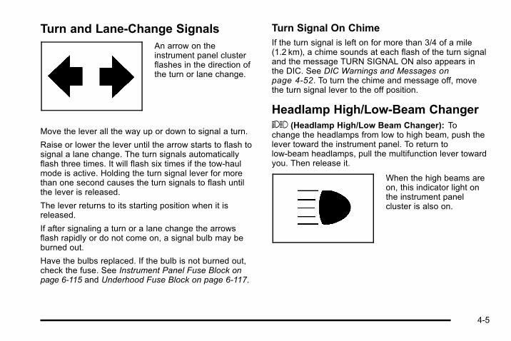
Turn and Lane-Change SignalsAn arrow on theinstrument panel clusterflashes in the direction ofthe turn or lane change.
Move the lever all the way up or down to signal a turn.
Raise or lower the lever until the arrow starts to flash tosignal a lane change. The turn signals automaticallyflash three times. It will flash six times if the tow-haulmode is active. Holding the turn signal lever for morethan one second causes the turn signals to flash untilthe lever is released.
The lever returns to its starting position when it isreleased.
If after signaling a turn or a lane change the arrowsflash rapidly or do not come on, a signal bulb may beburned out.
Have the bulbs replaced. If the bulb is not burned out,check the fuse. See Instrument Panel Fuse Block onpage 6‑115 and Underhood Fuse Block on page 6‑117.
Turn Signal On ChimeIf the turn signal is left on for more than 3/4 of a mile(1.2 km), a chime sounds at each flash of the turn signaland the message TURN SIGNAL ON also appears inthe DIC. See DIC Warnings and Messages onpage 4‑52. To turn the chime and message off, movethe turn signal lever to the off position.
Headlamp High/Low-Beam Changer53 (Headlamp High/Low Beam Changer): Tochange the headlamps from low to high beam, push thelever toward the instrument panel. To return tolow-beam headlamps, pull the multifunction lever towardyou. Then release it.
When the high beams areon, this indicator light onthe instrument panelcluster is also on.
4-5

Flash-to-PassUse your high-beam headlamps to signal to a driver infront that you want to pass. It works even if theheadlamps are in the automatic position.
To use it, pull the turn signal lever toward you, thenrelease it.
If the headlamps are in the automatic position or on lowbeam, the high-beam headlamps turn on. They stay onas long as the lever is held. The high-beam indicator onthe instrument panel cluster comes on. Release thelever to return to normal operation.
Windshield Wipers
The windshield wipers are controlled by turning theband withz on it.
8 (Mist): For a single wiping cycle, turn the band tomist. Hold it there until the wipers start, then release.For more wipes, hold the band on mist longer.
6 (Delay): The wiper speed can be set for a long orshort delay between wipes. Turn the band up or downfor a shorter or longer delay time.
6 (Low Speed): Slow wipes.
1 (High Speed): Fast wipes.
9 (Off): Turns the wipers off.
4-6

Clear ice and snow from the wiper blades before usingthem. If frozen to the windshield, carefully loosen orthaw them. Damaged blades should be replaced.
Windshield Washer
{ WARNING:
In freezing weather, do not use your washer untilthe windshield is warmed. Otherwise the washerfluid can form ice on the windshield, blocking yourvision.
L (Washer Fluid): Push the paddle marked with thewindshield washer symbol at the top of the multifunctionlever, to spray washer fluid on the windshield. Thewipers clear the window and then either stop or returnto the preset speed.
Rear Window Wiper/WasherFor vehicles with a rear window washer/wiper, thebutton is located on the instrument panel to the left ofthe instrument panel cluster.
{ WARNING:
In freezing weather, do not use your washer untilthe windshield is warmed. Otherwise the washerfluid can form ice on the windshield, blocking yourvision.
Z (Rear Wiper): Press to turn the rear wiper on and off.The wiper speed cannot be changed.
Y (Wash): Press to spray washer fluid on the rearwindow. Release the button when enough fluid hasbeen sprayed on the window. The rear wiper will run afew more cycles after it is released. If the rear wiperfunction was already on, prior to pressing the washbutton, it stays on until the wiper button is pressedagain.
5 (Delay): Press to turn on delayed wiping.
The rear window washer uses the same fluid that is inthe windshield washer reservoir. See WindshieldWasher Fluid on page 6‑40.
4-7

Cruise Control
{ WARNING:
Cruise control can be dangerous where youcannot drive safely at a steady speed. So, do notuse the cruise control on winding roads or inheavy traffic.
Cruise control can be dangerous on slipperyroads. On such roads, fast changes in tire tractioncan cause excessive wheel slip, and you couldlose control. Do not use cruise control on slipperyroads.
With cruise control, a speed of about 40 km/h (25 mph)or more can be maintained without keeping your foot onthe accelerator. This can really help on long trips.Cruise control does not work at speeds below about40 km/h (25 mph).
When the brakes are applied, cruise control isturned off.
If the vehicle has the StabiliTrak® system or TractionControl system (TCS) and begins to limit wheel spinwhile using the cruise control, the cruise controlautomatically disengages. See StabiliTrak® System onpage 5‑5 or Traction Control System (TCS) on
page 5‑7 . When road conditions allow the cruisecontrol to be safely uses again, it can be turnedback on.
The cruise control buttonsare located on the leftside of the steering wheel.
T (On/Off): Press to turn the system on or off. Theindicator light on the button turns on when cruise controlis on and turns off when cruise control is off.
+ RES (Resume/Accelerate): Press to make thevehicle accelerate or resume to a previously set speed.
SET − (Set/Coast): Press to set the speed or make thevehicle decelerate.
[ (Cancel): Press to cancel cruise control withouterasing the set speed from memory.
4-8
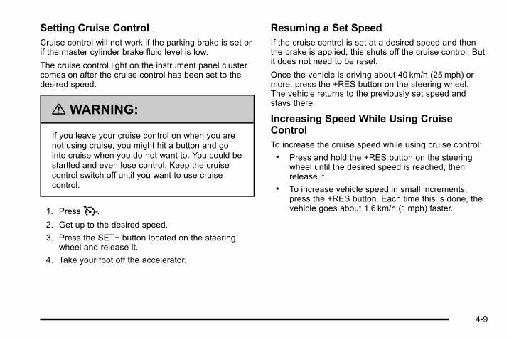
Setting Cruise ControlCruise control will not work if the parking brake is set orif the master cylinder brake fluid level is low.
The cruise control light on the instrument panel clustercomes on after the cruise control has been set to thedesired speed.
{ WARNING:
If you leave your cruise control on when you arenot using cruise, you might hit a button and gointo cruise when you do not want to. You could bestartled and even lose control. Keep the cruisecontrol switch off until you want to use cruisecontrol.
1. PressT.
2. Get up to the desired speed.
3. Press the SET− button located on the steeringwheel and release it.
4. Take your foot off the accelerator.
Resuming a Set SpeedIf the cruise control is set at a desired speed and thenthe brake is applied, this shuts off the cruise control. Butit does not need to be reset.
Once the vehicle is driving about 40 km/h (25 mph) ormore, press the +RES button on the steering wheel.The vehicle returns to the previously set speed andstays there.
Increasing Speed While Using CruiseControlTo increase the cruise speed while using cruise control:. Press and hold the +RES button on the steering
wheel until the desired speed is reached, thenrelease it.
. To increase vehicle speed in small increments,press the +RES button. Each time this is done, thevehicle goes about 1.6 km/h (1 mph) faster.
4-9

Reducing Speed While Using CruiseControlTo reduce the vehicle's speed while using cruisecontrol:. Press and hold the SET– button on the steering
wheel until the desired lower speed is reached,then release it.
. To slow down in small amounts, press theSET– button on the steering wheel briefly. Eachtime this is done, the vehicle goes about 1.6 km/h(1 mph) slower.
Passing Another Vehicle While UsingCruise ControlUse the accelerator pedal to increase the vehicle'sspeed. When you take your foot off the pedal, thevehicle slows down to the previously set cruise speed.
Using Cruise Control on HillsHow well the cruise control works on hills depends uponthe vehicle's speed, load, and the steepness of the hills.When going up steep hills, you might have to use theaccelerator pedal to maintain the vehicle's speed. Whengoing downhill, you might have to brake or shift to alower gear to keep the vehicle's speed down. When thebrakes are applied the cruise control turns off.
Ending Cruise ControlThere are three ways to end cruise control:. Step lightly on the brake pedal.
. Press the [ button on the steering wheel.
. Press theT button on the steering wheel.
Erasing Speed MemoryThe cruise control set speed memory is erased whenthe cruise control or the ignition is turned off.
4-10
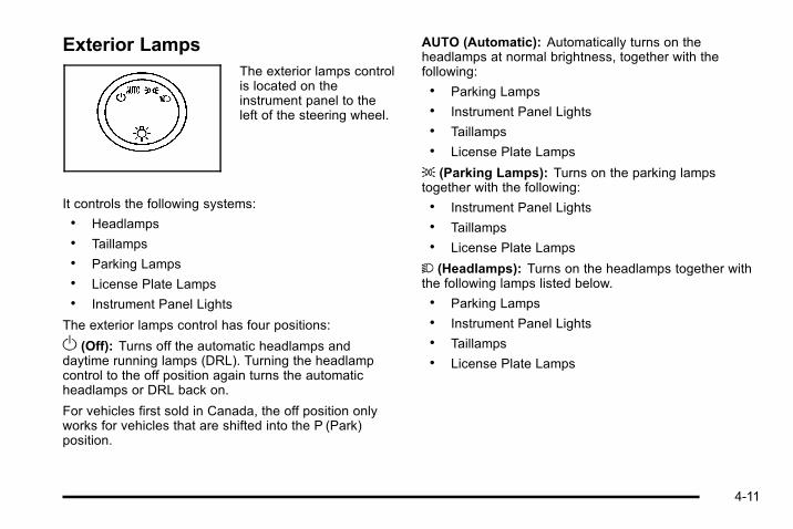
Exterior LampsThe exterior lamps controlis located on theinstrument panel to theleft of the steering wheel.
It controls the following systems:. Headlamps. Taillamps. Parking Lamps. License Plate Lamps. Instrument Panel Lights
The exterior lamps control has four positions:
O (Off): Turns off the automatic headlamps anddaytime running lamps (DRL). Turning the headlampcontrol to the off position again turns the automaticheadlamps or DRL back on.
For vehicles first sold in Canada, the off position onlyworks for vehicles that are shifted into the P (Park)position.
AUTO (Automatic): Automatically turns on theheadlamps at normal brightness, together with thefollowing:. Parking Lamps. Instrument Panel Lights. Taillamps. License Plate Lamps
; (Parking Lamps): Turns on the parking lampstogether with the following:. Instrument Panel Lights. Taillamps. License Plate Lamps
2 (Headlamps): Turns on the headlamps together withthe following lamps listed below.. Parking Lamps. Instrument Panel Lights. Taillamps. License Plate Lamps
4-11

When the headlamps are turned on while the vehicle ison, the headlamps will turn off automatically 10 minutesafter the ignition is turned off. When the headlamps areturned on while the vehicle is off, the headlamps willstay on for 10 minutes before automatically turning offto prevent the battery from being drained. Turn theheadlamp control to off and then back to the headlampon position to make the headlamps stay on for anadditional 10 minutes.
Headlamps on ReminderIf a door is open, a reminder chime sounds when theheadlamps or parking lamps are manually turned onand the key is out of the ignition. To turn off the chime,turn the headlamp switch to off or AUTO and then backon, or close and re-open the door. In the AUTO mode,the headlamps turn off once the ignition is in LOCK/OFFor remains on until the headlamp delay ends (if enabledin the DIC). See “Exit Lighting” under DIC VehicleCustomization on page 4‑60.
Daytime Running Lamps (DRL)Daytime Running Lamps (DRL) can make it easier forothers to see the front of your vehicle during the day.Fully functional daytime running lamps are required onall vehicles first sold in Canada.
The DRL system comes on when the followingconditions are met:. The ignition is on.. The exterior lamps control is in AUTO.. The engine is running.. The light sensor determines it is daytime.
When the DRL system is on, only the DRL lamps areon. The taillamps, sidemarker, instrument panel lights,and other lamps will not be on.
When it begins to get dark, the automatic headlampsystem switches from DRL to the headlamps.
To turn off the DRL lamps, turn the exterior lampscontrol to the OFF position and then release. Forvehicles first sold in Canada, the transmission must bein the P (Park) position, before the DRL lamps can beturned off.
4-12
Automatic Headlamp SystemWhen it is dark enough outside and the headlampswitch is in AUTO, the automatic headlamp systemturns on the headlamps along with other lamps such asthe taillamps, sidemarker, parking lamps, roof markerlamps, and the instrument panel lights. The radio lightswill also be dim.
To turn off the automatic headlamp system, turn theexterior lamps switch to the off position and thenrelease. For vehicles first sold in Canada, thetransmission must be in the P (Park) position, before theautomatic headlamp system can be turned off.
The vehicle has a light sensor located on the top of theinstrument panel. Do not cover this sensor or thesystem will come on whenever the ignition is on.
The system may also turn on the headlamps whendriving through a parking garage, a tunnel, or whiledriving in heavy overcast weather. This is normal.
There is a delay in the transition between the daytimeand nighttime operation of the Daytime Running Lamps(DRL) and the automatic headlamp systems so thatdriving under bridges or bright overhead street lightsdoes not affect the system. The DRL and automaticheadlamp system is only affected when the light sensorsees a change in lighting lasting longer than the delay.
If the vehicle is started in a dark garage, the automaticheadlamp system comes on immediately. Once thevehicle leaves the garage, it takes approximatelyone minute for the automatic headlamp system tochange to DRL if it is light outside. During that delay,the instrument panel cluster may not be as bright asusual. Make sure the instrument panel brightnesscontrol is in the full bright position. See InstrumentPanel Brightness on page 4‑13.
Instrument Panel BrightnessD (Instrument Panel Brightness): This featurecontrols the brightness of the instrument panel lightsand is located next to the exterior lamp control.
Push the knob to extend out and then it can be turned.
Turn the knob clockwise or counterclockwise to brightenor dim the instrument panel lights. Turning the knob tothe farthest clockwise position turns on the dome lamps.
4-13

Dome LampsThe dome lamps come on when any door is openedand turns off when all doors are closed.
The dome lamps can also be turned on by turning theinstrument panel brightness knob, located next to theexterior lamps control, clockwise to the farthest position.In this position, the dome lamps remain on whether adoor is opened or closed.
Dome Lamp OverrideThe dome lamp override button is located next to theexterior lamps control.
k (Dome Off): Press the button in and the domelamps remain off when a door is opened. Press thebutton again to return it to the extended position so thatthe dome lamps come on when a door is opened.
Entry/Exit LightingThe vehicle has an illuminated entry/exit feature.
The dome lamps come on if the dome override button isin the out position, when a door is opened or the key isremoved from the ignition.
Reading LampsThere are reading lamps located in the overheadconsole and on the DVD Rear Seat Entertainment(RSE) system console, if equipped. Press the buttonlocated next to each lamp to turn it on or off.
These lamps will also come on with the dome lamps.
Electric Power ManagementThe vehicle has Electric Power Management (EPM) thatestimates the battery's temperature and state of charge.It then adjusts the voltage for best performance andextended life of the battery.
When the battery's state of charge is low, the voltage israised slightly to quickly bring the charge back up.When the state of charge is high, the voltage is loweredslightly to prevent overcharging. If the vehicle has avoltmeter gauge or a voltage display on the DriverInformation Center (DIC), you may see the voltagemove up or down. This is normal. If there is a problem,an alert will be displayed.
The battery can be discharged at idle if the electricalloads are very high. This is true for all vehicles. This isbecause the generator (alternator) may not be spinningfast enough at idle to produce all the power that isneeded for very high electrical loads.
4-14

A high electrical load occurs when several of thefollowing are on, such as: headlamps, high beams, foglamps, rear window defogger, climate control fan at highspeed, heated seats, engine cooling fans, trailer loads,and loads plugged into accessory power outlets.
EPM works to prevent excessive discharge of thebattery. It does this by balancing the generator's outputand the vehicle's electrical needs. It can increaseengine idle speed to generate more power, wheneverneeded. It can temporarily reduce the power demandsof some accessories.
Normally, these actions occur in steps or levels, withoutbeing noticeable. In rare cases at the highest levels ofcorrective action, this action may be noticeable to thedriver. If so, a Driver Information Center (DIC) messagemight be displayed, such as BATTERY SAVERACTIVE, BATTERY VOLTAGE LOW, or LOWBATTERY. If this message is displayed, it isrecommended that the driver reduce the electrical loadsas much as possible. See DIC Warnings and Messageson page 4‑52.
Battery Run-Down ProtectionThis feature shuts off the dome lamps if they are left onfor more than 10 minutes when the ignition is in LOCK/OFF. This helps to prevent the battery fromrunning down.
Accessory Power Outlet(s)Accessory power outlets can be used to connectauxiliary electrical equipment, such as a cellulartelephone.
The vehicle may have one outlet located inside thestorage bin below the climate control system, one outletinside the center floor console and two outlets on therear of the center floor console.
The outlet located inside the storage bin below theclimate control system can only use equipment thatdoes not exceed 15 amperes.
Notice: Leaving electrical equipment on forextended periods will drain the battery. Always turnoff electrical equipment when not in use and do notplug in equipment that exceeds the maximum15 ampere rating.
There may also be an accessory power outlet located inthe rear of the vehicle near the liftgate. To use anaccessory power outlet, remove the protective cap.When not in use, always cover the accessory poweroutlet with the protective cap.
4-15

If the vehicle is the SUT model, there is an accessorypower outlet in the rear cargo area on the passengerside of the vehicle.
Notice: Adding any electrical equipment to thevehicle can damage it or keep other componentsfrom working as they should. The repairs would notbe covered by the vehicle warranty. Do not useequipment exceeding maximum amperage rating of20 amperes. Check with your dealer before addingelectrical equipment.
Certain power accessory plugs may not be compatibleto the accessory power outlets and could result in blownvehicle or adapter fuses. If you experience a problem,see your dealer for additional information on theaccessory power plugs.
The accessory power outlets are powered, even whenthe ignition is in LOCK/OFF. Continuing to use poweroutlets while the ignition is in LOCK/OFF may cause thevehicle's battery to run down.
Notice: Improper use of the power outlet can causedamage not covered by the vehicle warranty. Do nothang any type of accessory or accessory bracketfrom the plug because the power outlets aredesigned for accessory power plugs only.
Ashtray(s) and Cigarette LighterFor vehicles with an ashtray, it is removable and fits intothe front cupholder. Pull up on the ashtray door toopen it.
Notice: If papers, pins, or other flammable items areput in the ashtray, hot cigarettes or other smokingmaterials could ignite them and possibly damagethe vehicle. Never put flammable items in theashtray.
To remove the ashtray, pull it out from the console. Toreinstall the ashtray, slide it back to the original position.
To use the cigarette lighter, if equipped, push it in all theway, and let go. When it is ready, it will pop back out byitself.
Notice: Holding a cigarette lighter in while it isheating does not let the lighter back away from theheating element when it is hot. Damage fromoverheating can occur to the lighter or heatingelement, or a fuse could be blown. Do not hold acigarette lighter in while it is heating.
4-16
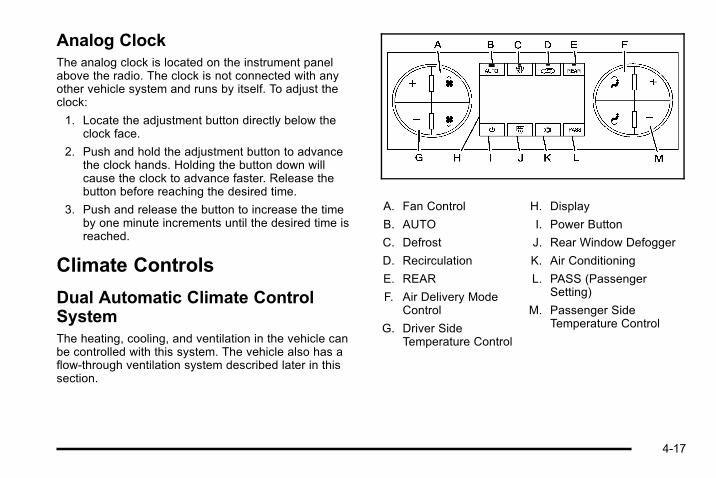
Analog ClockThe analog clock is located on the instrument panelabove the radio. The clock is not connected with anyother vehicle system and runs by itself. To adjust theclock:
1. Locate the adjustment button directly below theclock face.
2. Push and hold the adjustment button to advancethe clock hands. Holding the button down willcause the clock to advance faster. Release thebutton before reaching the desired time.
3. Push and release the button to increase the timeby one minute increments until the desired time isreached.
Climate Controls
Dual Automatic Climate ControlSystemThe heating, cooling, and ventilation in the vehicle canbe controlled with this system. The vehicle also has aflow-through ventilation system described later in thissection.
A. Fan Control
B. AUTO
C. Defrost
D. Recirculation
E. REAR
F. Air Delivery ModeControl
G. Driver SideTemperature Control
H. Display
I. Power Button
J. Rear Window Defogger
K. Air Conditioning
L. PASS (PassengerSetting)
M. Passenger SideTemperature Control
4-17

O (On/Off): Press to turn the climate control system onor off. Outside air still enters the vehicle, and is directedto the floor. This direction can be changed by pressingthe mode button. Recirculation can be selected onceyou have selected vent or bi-level mode. Thetemperature can also be adjusted using eithertemperature button. If the air delivery mode ortemperature settings are adjusted with the system off,the display illuminates briefly to show the settings andthen returns to off. The system can be turned back onby pressing eitherO, D, C,#, the defrost or the AUTObutton.
Driver and Passenger Side TemperatureControlThe driver and passenger side temperature buttons areused to adjust the temperature of the air comingthrough the system on the driver or passengers side ofthe vehicle. The temperature can be adjusted even ifthe system is turned off. This is possible since outsideair always flows through the system as the vehicle ismoving forward unless it is set to recirculation mode.See “Recirculation” later in this section.
Press the + or − buttons to increase or decrease thecabin temperature. The driver side or passenger sidetemperature display shows the temperature settingdecreasing or increasing.
The passenger temperature setting can be set to matchthe driver temperature setting by pressing the PASSbutton and turning off the PASS indicator. When thepassenger temperature setting is set different than thedriver's setting, the indicator on the PASS buttonilluminates and both the driver side and passenger sidetemperature displays are shown.
When in defrost mode the passenger temperaturesetting cannot be changed.
Automatic OperationAUTO (Automatic): When automatic operation is activethe system controls the inside temperature, the airdelivery, and the fan speed.
Use the steps below to place the entire system inautomatic mode:
1. Press the AUTO button.
When AUTO is selected, the display changes toshow the current temperature(s) and AUTO is lit onthe display. The current delivery mode and fanspeed also displays for approximately 5 seconds.
4-18

When AUTO is selected, the air conditioningoperation and air inlet is automatically controlled.The air conditioning compressor runs when theoutside temperature is over about 4°C (40°F). Theair inlet will normally be set to outside air. If it is hotoutside, the air inlet may automatically switch torecirculate inside air to help quickly cool down thevehicle. The light on the button comes on inrecirculation.
2. Set the driver and passenger temperature.
To find your comfort setting, start with a 23°C(74°F) temperature setting and allow about20 minutes for the system to regulate. Use thedriver or passenger temperature buttons to adjustthe temperature setting as necessary. If atemperature setting of 15°C (60°F) is chosen, thesystem remains at the maximum cooling setting.If a temperature setting of 32°C (90°F) is chosen,the system remains at the maximum heat setting.Choosing either maximum setting does not causethe vehicle to heat or cool any faster.
Do not cover the solar sensor located on the top of theinstrument panel near the windshield. This sensorregulates air temperature based on sun load and alsoturns on the headlamps. For more information on thesolar sensor, see “Sensors” later in this section.
To avoid blowing cold air in cold weather, the systemdelays turning on the fan until warm air is available. Thelength of delay depends on the engine coolanttemperature. Pressing the fan switch will override thisdelay and change the fan to a selected speed.
Manual OperationD C (Fan Control): Press these buttons to increase ordecrease the fan speed.
Pressing either fan button while in automatic controlplaces the fan under manual control. The fan settingremains displayed and the AUTO light turns off. The airdelivery mode remains under automatic control.
H G (Air Delivery Mode Control): Press these buttonsto change the direction of the airflow in the vehicle.Repeatedly press either button until the desired modeappears on the display. Pressing either mode buttonwhile the system is off changes the air delivery modewithout turning the system on. Pressing either modebutton while in automatic control places the mode undermanual control.
The air delivery mode setting is displayed and theAUTO light turns off. The fan remains under automaticcontrol.
H (Vent): Air is directed to the instrument paneloutlets.
4-19

) (Bi-Level): Air is divided between the instrumentpanel and floor outlets. Some air is directed towards thewindshield and side window outlets.
6 (Floor): Air is directed to the floor outlets, with someto the windshield, side window outlets, and second rowfloor outlets. In this mode, the system automaticallyselects outside air.
- (Defog): This mode clears the windows of fog ormoisture. Air is directed to the windshield, floor outlets,and side window vents. In this mode, the system turnsoff recirculation and runs the air conditioningcompressor unless the outside temperature is close tofreezing. The recirculation mode cannot be selectedwhile in the defog mode.
0 (Defrost): This mode removes fog or frost from thewindshield more quickly. Air is directed to thewindshield and side window vents, with some directedto the floor vents. In this mode, the systemautomatically forces outside air into the vehicle andruns the air conditioning compressor unless the outsidetemperature is close to freezing. . The recirculationmode cannot be selected while in the defrost mode.
The passenger temperature control cannot be activatedwhile in defrost mode. If the PASS button is pressed,the button indicator flashes three times and will notwork. If the passenger temperature buttons areadjusted, the driver temperature indicator changes. Thepassenger temperature will not be displayed.
If vent, bi-level, or floor mode is selected again, theclimate control system displays the previoustemperature settings.
Do not drive the vehicle until all the windows are clear.
# (Air Conditioning): Press to turn the airconditioning (A/C) compressor on and off. An indicatorlight comes on to show that the air conditioning is on.
If this button is pressed when the air conditioningcompressor is unavailable, the indicator flashes threetimes and then turns off. If the air conditioning is on andthe outside temperature drops below a temperaturewhich is too cool for air conditioning to be effective, theair conditioning light turns off to show that the airconditioning mode has been canceled.
On hot days, open the windows long enough to let hotinside air escape. This helps to reduce the time it takesfor the vehicle to cool down. It also helps the system tooperate more efficiently.
The air conditioning system removes moisture from theair, so a small amount of water might drip under thevehicle while idling or after turning off the engine. Thisis normal.
4-20

@ (Recirculation): Press to turn the recirculationmode on or off. An indicator light comes on to show thatthe recirculation is on.
This mode recirculates and helps to quickly cool the airinside the vehicle. It can be used to help preventoutside air and odors from entering the vehicle.
The recirculation mode cannot be used with floor, defog,or defrost modes. If recirculation is selected with one ofthose modes, the indicator light flashes three times andthen turns off. The air conditioning compressor alsocomes on when this mode is activated. While inrecirculation mode the windows may fog when theweather is cold and damp. To clear the fog, select eitherthe defog or defrost mode and increase the fan speed.
Recirculation turns off when the ignition is turned off.
; (Outside Air, If Equipped): Press to turn on theoutside air mode. An indicator light comes on to showthat outside air is on. Air from outside is circulatedthroughout the vehicle. The outside air mode can beused with all modes, but it cannot be used with therecirculation mode.
REAR: For vehicles with the rear heat and airconditioning controls. Press to turn the rear climatecontrol system on or off. See Rear Air Conditioning andHeating System and Electronic Climate Controls onpage 4‑23.
Rear Window DefoggerThe rear window defogger uses a warming grid toremove fog from the rear window.
< (Rear Window Defogger): Press to turn the rearwindow defogger on or off. It automatically turns offseveral minutes after it has been activated. Thedefogger also be turns off when the engine is turned off.Do not drive the vehicle until all the windows are clear.
Notice: Do not use a razor blade or sharp object toclear the inside rear window. Do not adhereanything to the defogger grid lines in the rear glass.These actions may damage the rear defogger.Repairs would not be covered by your warranty.
Heated Mirrors: For vehicles with heated outsiderearview mirrors, the mirrors heat to help clear fog orfrost from the surface of the mirror when the rearwindow defog button is pressed. See Outside HeatedMirrors on page 3‑49.
4-21

SensorsThe solar sensor, locatedin the defrost grille in themiddle of the instrumentpanel, monitors the solarheat. Do not cover thesolar sensor or thesystem will not workproperly.
The interior temperaturesensors located in theheadliner above the driverside seat measures thetemperature of the airinside the vehicle.
There is also an exterior temperature sensor locatedbehind the front grille. This sensor reads the outside airtemperature and helps maintain the temperature insidethe vehicle. Any cover on the front of the vehicle couldcause a false reading in the displayed temperature.
The climate control system uses the information fromthese sensors to maintain your comfort setting byadjusting the outlet temperature, fan speed, and the airdelivery mode. The system may also supply cooler airto the side of the vehicle facing the sun. Therecirculation mode will also be used as needed tomaintain cool outlet temperatures.
Outlet AdjustmentThe vehicle has adjustable air outlets that can controlthe amount and direction of the airflow inside thevehicle. Use the thumbwheels located beside the airoutlets to direct the airflow up and down. Use thethumbwheels below the air outlets to direct the air left orright.
4-22

Operation Tips. Keep the hood and front air inlets free of ice, snow,
or any other obstruction, such as leaves. Theheater and defroster will work better, reducing thechance of fogging the inside of the windows.
. Keep the air path under the front seats clear ofobjects. This helps air to circulate throughout thevehicle.
. Adding outside equipment to the front of thevehicle, such as hood-air deflectors, etc., mayaffect the performance of the heating and airconditioning system. Check with your dealer beforeadding equipment to the outside of the vehicle.
Rear Air Conditioning and HeatingSystem and Electronic ClimateControlsFor vehicles with the rear heat and air conditioningcontrols, they are integrated with the rear seat audiocontrols located in the center console. The system canbe controlled from the front controls as well as the rearcontrols.
Rear Climate Control with Rear Seat Audio Controls
A. Fan Control
B. Air Delivery Mode Control
C. Temperature Control
REAR: Press the REAR button on the front climatecontrol system to turn the rear climate control system onor off. An indicator comes on when the rear system ison. The airflow direction, temperature, and speed forthe rear of the vehicle will be the same as those set forthe front of the vehicle.
4-23

The rear controls can be used to control the air flow forthe rear of the vehicle separately from that of the frontof the vehicle. To turn the system on from the rearseats, press any rear climate control button, except theC button. The rear climate control system can also beturned off by pressing and holding the C button.
Manual OperationD C (Fan Control): Press these buttons on the rearseat audio control panel to increase or decrease airflow.
+/− (Temperature Control): Press these buttons toadjust the temperature of the air flowing into thepassenger area. Press the + button for warmer air andpress the − button for cooler air. The temperaturesettings display in a range from 0‐12, with (0) being thecoolest and (12) the warmest setting.
N (Air Delivery Mode Control): Press the modebutton to change the direction of the airflow in thevehicle. Repeatedly press the button until the desiredmode appears on the display. Multiple presses cyclethrough the delivery selections.
Select from the following:
H (Vent): Air is directed to the headliner outlets.
) (Bi-Level): Air is directed to the floor outlets as wellas the headliner outlets. The rear system floor outlet islocated at the passenger side rear quarter trim panel.
6 (Floor): Air is directed to the floor outlets. The rearsystem floor outlets are located under the seats.
Warning Lights, Gauges, andIndicatorsWarning lights and gauges can signal that something iswrong before it becomes serious enough to cause anexpensive repair or replacement. Paying attention to thewarning lights and gauges could prevent injury.
Warning lights come on when there might be or there isa problem with one of the vehicle's functions. Somewarning lights come on briefly when the engine isstarted to indicate they are working.
Gauges can indicate when there might be or there is aproblem with one of the vehicle's functions. Oftengauges and warning lights work together to indicate aproblem with the vehicle.
When one of the warning lights comes on and stays onwhile driving, or when one of the gauges shows therecould be a problem, check the section that explainswhat to do. Follow this manual's advice. Waiting to dorepairs can be costly and even dangerous.
4-24

Instrument Panel Cluster
United States version shown, Canada similar
The instrument cluster is designed to show how the vehicle is running. It indicates how fast the vehicle is going,about how much fuel the fuel tank has left and many other things needed to drive safely and economically.
4-25

Speedometer and OdometerThe speedometer shows the vehicle's speed in bothkilometers per hour (km/h) and miles per hour (mph).
The vehicle's odometer works together with the DriverInformation Center (DIC). The Trip odometer can be set.See “Trip Odometer” under DIC Operation and Displays(Using DIC Buttons) on page 4‑43 or DIC Operationand Displays (Using Trip Odometer Reset Stem) onpage 4‑48 for more information.
To check the odometer mileage while the vehicle is notrunning, press the trip stem on the instrument panelcluster.
If the vehicle ever needs a new odometer installed, thenew one will be set to the correct mileage total of theold odometer.
Trip OdometerThe trip odometer can show how far the vehicle hasbeen driven since the trip odometer was last set to zero.
Press the trip stem to toggle between the trip odometerand the regular odometer. Hold the trip stem forapproximately one second while the trip odometer isdisplayed to reset it.
To display the odometer reading with the ignition off,press the trip stem.
TachometerThe tachometer displays the engine speed inrevolutions per minute (rpm).
Safety Belt Reminders
Safety Belt Reminder LightWhen the engine is started, a chime comes on forseveral seconds to remind people to fasten their safetybelts, unless the driver safety belt is already buckled.
The safety belt light alsocomes on and stay on forseveral seconds, then itflashes for several more.
This chime and light is repeated if the driver remainsunbuckled and the vehicle is in motion. If the driversafety belt is already buckled, neither the chime nor thelight comes on.
4-26
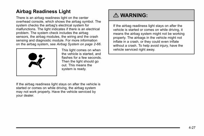
Airbag Readiness LightThere is an airbag readiness light on the centeroverhead console, which shows the airbag symbol. Thesystem checks the airbag's electrical system formalfunctions. The light indicates if there is an electricalproblem. The system check includes the airbagsensors, the airbag modules, the wiring and the crashsensing and diagnostic module. For more informationon the airbag system, see Airbag System on page 2‑66.
This light comes on whenthe vehicle is started, andflashes for a few seconds.Then the light should goout. This means thesystem is ready.
If the airbag readiness light stays on after the vehicle isstarted or comes on while driving, the airbag systemmay not work properly. Have the vehicle serviced byyour dealer.
{ WARNING:
If the airbag readiness light stays on after thevehicle is started or comes on while driving, itmeans the airbag system might not be workingproperly. The airbags in the vehicle might notinflate in a crash, or they could even inflatewithout a crash. To help avoid injury, have thevehicle serviced right away.
4-27

Airbag Off LightIf the vehicle has an airbag on-off switch, it also has apassenger airbag status indicator located in theoverhead console.
United States Canada
When the vehicle is started, the passenger airbagstatus indicator will light ON and OFF, or the symbol foron and off, will light for several seconds as a systemcheck. Then, after several more seconds, the statusindicator ON or OFF, or either the on or off symbol, willlight to let you know the status of the right frontpassenger frontal airbag.
When the right front passenger airbag is manuallyturned off using the airbag on‐off switch in the glovebox, the indicator light OFF or the off symbol will comeon and stay on as a reminder that the airbag has beenturned off. This light will go off when the airbag hasbeen turned on. See Airbag Off Switch on page 2‑74for more on this, including important safety information.
United States Canada
4-28

{ WARNING:
If the right front passenger's airbag is turned offfor a person who is not in a risk group identifiedby the national government, that person will nothave the extra protection of an airbag. In a crash,the airbag will not be able to inflate and helpprotect the person sitting there.
Do not turn off the passenger's airbag unless theperson sitting there is in a risk group identified bythe national government. See Airbag Off Switchon page 2‑74 for more on this, includingimportant safety information.
{ WARNING:
If the airbag readiness light ever comes on andstays on, it means that something may be wrongwith the airbag system. For example, the rightfront passenger airbag could inflate even thoughthe airbag on-off switch is turned off.
To help avoid injury to yourself or others, have thevehicle serviced right away. See AirbagReadiness Light on page 4‑27 for moreinformation, including important safety information.
If the word ON or the on symbol is lit, it means that theright front passenger frontal airbag is enabled (mayinflate). See Airbag Off Switch on page 2‑74 for moreinformation, including important safety information.
If, after several seconds, both status indicator lightsremain on, or if there are no lights at all, there may be aproblem with the lights or the airbag on-off switch. Seeyour dealer for service.
4-29

Charging System LightThis light comes on brieflywhen the ignition key isturned to START, but theengine is not running, asa check to show it isworking.
If it does not, have the vehicle serviced by your dealer.
The light should go out once the engine starts. If it stayson, or comes on while driving, there could be a problemwith the charging system. A charging system messagein the Driver Information Center (DIC) can also appear.See DIC Warnings and Messages on page 4‑52 formore information. This light could indicate that there areproblems with a generator drive belt, or that there is anelectrical problem. Have it checked right away. If thevehicle must be driven a short distance with the light on,turn off accessories, such as the radio and airconditioner.
Voltmeter GaugeWhen the engine is notrunning, but the ignition ison, this gauge shows thebattery's state of chargein DC volts.
When the engine is running, the gauge shows thecondition of the charging system. The charging systemregulates voltage based on the state of the battery forimproved fuel economy and battery life. The gauge cantransition from a higher to lower or a lower to higherreading. This is normal. Readings between the low andhigh warning zones indicate the normal operatingrange. The gauge can also read low during the fueleconomy mode.
4-30

Readings in the low warning zone can occur when alarge number of electrical accessories are operating inthe vehicle and the engine is left at an idle for anextended period. This condition is normal since thecharging system is not able to provide full power atengine idle. As engine speeds are increased, thiscondition should correct itself as higher engine speedsallow the charging system to create full power. If thereis a problem with the battery charging system, this lightcomes on or the SERVICE BATTERY CHARGINGSYSTEM DIC message displays. See DIC Warningsand Messages on page 4‑52 and Charging SystemLight on page 4‑30 for more information.
Brake System Warning LightWith the ignition on, the brake system warning lightcomes on when the parking brake is set. If the vehicleis driven with the parking brake engaged, a chimesounds when the vehicle speed is greater than8 km/h (5 mph).
The vehicle's hydraulic brake system is divided into twoparts. If one part is not working, the other part can stillwork and stop the vehicle. For good braking, both partsneed to be working well.
If the warning light comes on and a chime sounds therecould be a brake problem. Have the brake systeminspected right away.
This light can also come on due to low brake fluid. SeeBrakes on page 6‑41 for more information.
United States Canada
4-31
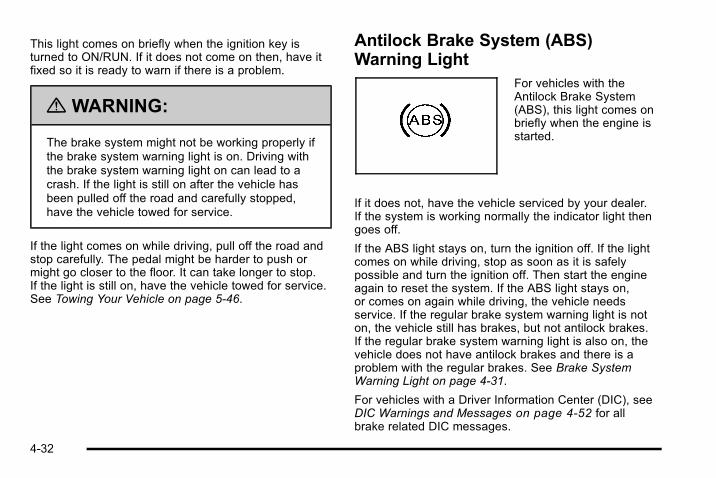
This light comes on briefly when the ignition key isturned to ON/RUN. If it does not come on then, have itfixed so it is ready to warn if there is a problem.
{ WARNING:
The brake system might not be working properly ifthe brake system warning light is on. Driving withthe brake system warning light on can lead to acrash. If the light is still on after the vehicle hasbeen pulled off the road and carefully stopped,have the vehicle towed for service.
If the light comes on while driving, pull off the road andstop carefully. The pedal might be harder to push ormight go closer to the floor. It can take longer to stop.If the light is still on, have the vehicle towed for service.See Towing Your Vehicle on page 5‑46.
Antilock Brake System (ABS)Warning Light
For vehicles with theAntilock Brake System(ABS), this light comes onbriefly when the engine isstarted.
If it does not, have the vehicle serviced by your dealer.If the system is working normally the indicator light thengoes off.
If the ABS light stays on, turn the ignition off. If the lightcomes on while driving, stop as soon as it is safelypossible and turn the ignition off. Then start the engineagain to reset the system. If the ABS light stays on,or comes on again while driving, the vehicle needsservice. If the regular brake system warning light is noton, the vehicle still has brakes, but not antilock brakes.If the regular brake system warning light is also on, thevehicle does not have antilock brakes and there is aproblem with the regular brakes. See Brake SystemWarning Light on page 4‑31.
For vehicles with a Driver Information Center (DIC), seeDIC Warnings and Messages on page 4‑52 for allbrake related DIC messages.
4-32
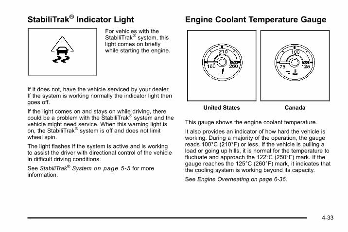
StabiliTrak® Indicator LightFor vehicles with theStabiliTrak® system, thislight comes on brieflywhile starting the engine.
If it does not, have the vehicle serviced by your dealer.If the system is working normally the indicator light thengoes off.
If the light comes on and stays on while driving, therecould be a problem with the StabiliTrak® system and thevehicle might need service. When this warning light ison, the StabiliTrak® system is off and does not limitwheel spin.
The light flashes if the system is active and is workingto assist the driver with directional control of the vehiclein difficult driving conditions.
See StabiliTrak® System on page 5‑5 for moreinformation.
Engine Coolant Temperature Gauge
United States Canada
This gauge shows the engine coolant temperature.
It also provides an indicator of how hard the vehicle isworking. During a majority of the operation, the gaugereads 100°C (210°F) or less. If the vehicle is pulling aload or going up hills, it is normal for the temperature tofluctuate and approach the 122°C (250°F) mark. If thegauge reaches the 125°C (260°F) mark, it indicates thatthe cooling system is working beyond its capacity.
See Engine Overheating on page 6‑36.
4-33

Tire Pressure LightFor vehicles with a tirepressure monitoringsystem, this light comeson briefly when the engineis started. It providesinformation about tirepressures and the TirePressure MonitoringSystem.
When the Light is On SteadyThis indicates that one or more of the tires issignificantly underinflated.
A tire pressure message in the Driver InformationCenter (DIC), can accompany the light. See DriverInformation Center (DIC) on page 4‑42 for moreinformation. Stop and check the tires as soon as it issafe to do so. If underinflated, inflate to the properpressure. See Inflation - Tire Pressure on page 6‑66for more information.
When the Light Flashes First and Then isOn SteadyThis indicates that there may be a problem with the TirePressure Monitor System. The light flashes for about aminute and stays on steady for the remainder of theignition cycle. This sequence repeats with every ignitioncycle. See Tire Pressure Monitor Operation onpage 6‑68 for more information.
Malfunction Indicator LampA computer system called OBD II (On-BoardDiagnostics-Second Generation) monitors operation ofthe fuel, ignition, and emission control systems.It ensures that emissions are at acceptable levels forthe life of the vehicle, helping to produce a cleanerenvironment.
4-34

This light should come onwhen the ignition is on,but the engine is notrunning, as a check toshow it is working. If itdoes not, have the vehicleserviced by your dealer.
If the check engine light comes on and stays on, whilethe engine is running, this indicates that there is anOBD II problem and service is required.
Malfunctions often are indicated by the system beforeany problem is apparent. Being aware of the light canprevent more serious damage to the vehicle. Thissystem assists the service technician in correctlydiagnosing any malfunction.
Notice: If the vehicle is continually driven with thislight on, after a while, the emission controls mightnot work as well, the vehicle's fuel economy mightnot be as good, and the engine might not run assmoothly. This could lead to costly repairs thatmight not be covered by the vehicle warranty.
Notice: Modifications made to the engine,transmission, exhaust, intake, or fuel system of thevehicle or the replacement of the original tires withother than those of the same Tire PerformanceCriteria (TPC) can affect the vehicle's emissioncontrols and can cause this light to come on.Modifications to these systems could lead to costlyrepairs not covered by the vehicle warranty. Thiscould also result in a failure to pass a requiredEmission Inspection/Maintenance test. SeeAccessories and Modifications on page 6‑4.
This light comes on during a malfunction in one oftwo ways:
Light Flashing: A misfire condition has been detected.A misfire increases vehicle emissions and coulddamage the emission control system on the vehicle.Diagnosis and service might be required.
To prevent more serious damage to the vehicle:. Reduce vehicle speed.. Avoid hard accelerations.. Avoid steep uphill grades.. If towing a trailer, reduce the amount of cargo
being hauled as soon as it is possible.
4-35

If the light continues to flash, when it is safe to do so,stop the vehicle. Find a safe place to park the vehicle.Turn the vehicle off, wait at least 10 seconds, andrestart the engine. If the light is still flashing, follow theprevious steps and see your dealer for service as soonas possible.
Light On Steady: An emission control systemmalfunction has been detected on the vehicle.Diagnosis and service might be required.
An emission system malfunction might be corrected bydoing the following:. Make sure the fuel cap is fully installed. See Filling
the Tank on page 6‑10. The diagnostic systemcan determine if the fuel cap has been left off orimproperly installed. A loose or missing fuel capallows fuel to evaporate into the atmosphere. A fewdriving trips with the cap properly installed shouldturn the light off.
. If the vehicle has been driven through a deeppuddle of water, the vehicle's electrical systemmight be wet. The condition is usually correctedwhen the electrical system dries out. A few drivingtrips should turn the light off.
. Make sure to fuel the vehicle with quality fuel. Poorfuel quality causes the engine not to run asefficiently as designed and can cause: stalling afterstart-up, stalling when the vehicle is changed intogear, misfiring, hesitation on acceleration,or stumbling on acceleration. These conditionsmight go away once the engine is warmed up.
If one or more of these conditions occurs, changethe fuel brand used. It will require at least one fulltank of the proper fuel to turn the light off.
See Gasoline Octane on page 6‑7.
If none of the above have made the light turn off, yourdealer can check the vehicle. The dealer has the propertest equipment and diagnostic tools to fix anymechanical or electrical problems that might havedeveloped.
4-36
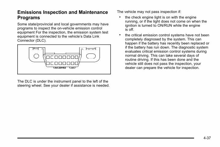
Emissions Inspection and MaintenanceProgramsSome state/provincial and local governments may haveprograms to inspect the on-vehicle emission controlequipment For the inspection, the emission system testequipment is connected to the vehicle’s Data LinkConnector (DLC).
The DLC is under the instrument panel to the left of thesteering wheel. See your dealer if assistance is needed.
The vehicle may not pass inspection if:. the check engine light is on with the engine
running, or if the light does not come on when theignition is turned to ON/RUN while the engineis off.
. the critical emission control systems have not beencompletely diagnosed by the system. This canhappen if the battery has recently been replaced orif the battery has run down. The diagnostic systemevaluates critical emission control systems duringnormal driving. This can take several days ofroutine driving. If this has been done and thevehicle still does not pass the inspection, yourdealer can prepare the vehicle for inspection.
4-37

Oil Pressure Gauge
United States Canada
{ WARNING:
Do not keep driving if the oil pressure is low. Theengine can become so hot that it catches fire.Someone could be burned. Check the oil as soonas possible and have the vehicle serviced.
Notice: Lack of proper engine oil maintenance candamage the engine. The repairs would not becovered by the vehicle warranty. Always follow themaintenance schedule in this manual for changingengine oil.
The oil pressure gauge shows the engine oil pressurein psi (pounds per square inch) when the engine isrunning. Canadian vehicles indicate pressure in kPa(kilopascals).
Oil pressure can vary with engine speed, outsidetemperature and oil viscosity, but readings above thelow pressure zone indicate the normal operating range.When the oil pressure reaches the low pressure zone,the OIL PRESSURE LOW STOP ENGINE messageappears in the Driver Information Center (DIC). See DICWarnings and Messages on page 4‑52 and Engine Oilon page 6‑18 for more information.
A reading in the low pressure zone can be caused by adangerously low oil level or some other problemcausing low oil pressure. Check the oil as soon aspossible.
4-38

Oil Pressure Light
{ WARNING:
Do not keep driving if the oil pressure is low. Theengine can become so hot that it catches fire.Someone could be burned. Check the oil as soonas possible and have the vehicle serviced.
Notice: Lack of proper engine oil maintenance candamage the engine. The repairs would not becovered by the vehicle warranty. Always follow themaintenance schedule in this manual for changingengine oil.
This light comes on briefly while starting the engine. If itdoes not, have the vehicle serviced by your dealer.If the system is working normally the indicator light thengoes off.
If the light comes on and stays on, it means that oil isnot flowing through the engine properly. The vehiclecould be low on oil and it might have some othersystem problem.
Security LightFor information regardingthis light and the vehicle'ssecurity system, seeContent Theft-Deterrenton page 3‑23.
4-39
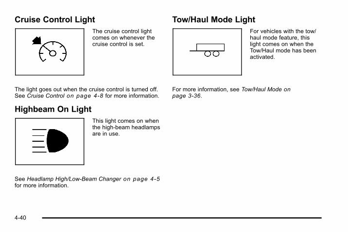
Cruise Control LightThe cruise control lightcomes on whenever thecruise control is set.
The light goes out when the cruise control is turned off.See Cruise Control on page 4‑8 for more information.
Highbeam On LightThis light comes on whenthe high-beam headlampsare in use.
See Headlamp High/Low-Beam Changer on page 4‑5for more information.
Tow/Haul Mode LightFor vehicles with the tow/haul mode feature, thislight comes on when theTow/Haul mode has beenactivated.
For more information, see Tow/Haul Mode onpage 3‑36.
4-40
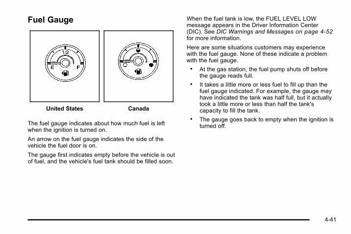
Fuel Gauge
United States Canada
The fuel gauge indicates about how much fuel is leftwhen the ignition is turned on.
An arrow on the fuel gauge indicates the side of thevehicle the fuel door is on.
The gauge first indicates empty before the vehicle is outof fuel, and the vehicle's fuel tank should be filled soon.
When the fuel tank is low, the FUEL LEVEL LOWmessage appears in the Driver Information Center(DIC). See DIC Warnings and Messages on page 4‑52for more information.
Here are some situations customers may experiencewith the fuel gauge. None of these indicate a problemwith the fuel gauge.. At the gas station, the fuel pump shuts off before
the gauge reads full.. It takes a little more or less fuel to fill up than the
fuel gauge indicated. For example, the gauge mayhave indicated the tank was half full, but it actuallytook a little more or less than half the tank'scapacity to fill the tank.
. The gauge goes back to empty when the ignition isturned off.
4-41
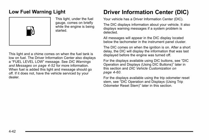
Low Fuel Warning LightThis light, under the fuelgauge, comes on brieflywhile the engine is beingstarted.
This light and a chime comes on when the fuel tank islow on fuel. The Driver Information Center also displaysa “FUEL LEVEL LOW” message. See DIC Warningsand Messages on page 4‑52 for more information.When fuel is added this light and message should gooff. If it does not, have the vehicle serviced by yourdealer.
Driver Information Center (DIC)Your vehicle has a Driver Information Center (DIC).
The DIC displays information about your vehicle. It alsodisplays warning messages if a system problem isdetected.
All messages will appear in the DIC display locatedbelow the tachometer in the instrument panel cluster.
The DIC comes on when the ignition is on. After a shortdelay, the DIC will display the information that was lastdisplayed before the engine was turned off.
For the displays available using DIC buttons, see “DICOperation and Displays (Using DIC Buttons)” later inthis section and DIC Vehicle Customization onpage 4‑60.
For the displays available using the trip odometer resetstem, see “DIC Operation and Displays (Using TripOdometer Reset Stem)” later in this section.
4-42

DIC Operation and Displays (UsingDIC Buttons)The DIC has different displays which can be accessedby pressing the DIC buttons located on the instrumentpanel, next to the steering wheel.
The DIC displays trip, fuel, and vehicle systeminformation, and warning messages if a system problemis detected.
The DIC also allows some features to be customized.See DIC Vehicle Customization on page 4‑60 for moreinformation.
You can also use the trip odometer reset stem to viewsome of the DIC displays. See "DIC Operation andDisplays (Using Trip Odometer Reset Stem)" later inthis section.
DIC Buttons
The buttons are the trip/fuel, vehicle information,customization, and set/reset buttons. The buttonfunctions are detailed inthe following pages.
3 (Trip/Fuel): Press this button to display theodometer, trip odometer, fuel range, average economy,fuel used, timer, and transmission temperature. Thecompass and outside air temperature will also be shownin the display. The temperature will be shown in °F or°C depending on the units selected.
T (Vehicle Information): Press this button to displaythe oil life, units, tire pressure readings for vehicles withthe Tire Pressure Monitor System (TPMS), enginehours, Remote Keyless Entry (RKE) transmitterprogramming, compass zone setting, and compassrecalibration.
4-43

U (Customization): Press this button to customize thefeature settings on your vehicle. See DIC VehicleCustomization on page 4‑60 for more information.
V (Set/Reset): Press this button to set or reset certainfunctions and to turn off or acknowledge messages onthe DIC.
Trip/Fuel Menu Items3 (Trip/Fuel): Press this button to scroll through thefollowing menu items:
OdometerPress the trip/fuel button until ODOMETER displays.This display shows the distance the vehicle has beendriven in either miles (mi) or kilometers (km). Pressingthe trip odometer reset stem will also display theodometer.
To switch between English and metric measurements,see “Units” later in this section.
Trip OdometerPress the trip/fuel button until TRIP displays. Thisdisplay shows the current distance traveled in eithermiles (mi) or kilometers (km) since the last reset for thetrip odometer. Pressing the trip odometer reset stem willalso display the trip odometer.
The trip odometer can be reset to zero by pressing theset/reset button while the trip odometer is displayed.You can also reset the trip odometer while it isdisplayed by pressing and holding the trip odometerreset stem.
The trip odometer has a feature called the retro-activereset. This can be used to set the trip odometer to thenumber of miles (kilometers) driven since the ignitionwas last turned on. This can be used if the tripodometer is not reset at the beginning of the trip.
To use the retro-active reset feature, press and hold theset/reset button for at least four seconds. The tripodometer will display the number of miles (mi) orkilometers (km) driven since the ignition was last turnedon and the vehicle was moving. Once the vehiclebegins moving, the trip odometer will accumulatemileage. For example, if the vehicle was driven 5 miles(8 km) before it is started again, and then theretro-active reset feature is activated, the display willshow 5miles (8 km). As the vehicle begins moving, thedisplay will then increase to 5.1 miles (8.2 km), 5.2 miles(8.4 km), etc.
If the retro-active reset feature is activated after thevehicle is started, but before it begins moving, thedisplay will show the number of miles (mi) orkilometers (km) that were driven during the last ignitioncycle.
4-44
Fuel RangePress the trip/fuel button until FUEL RANGE displays.This display shows the approximate number ofremaining miles (mi) or kilometers (km) the vehicle canbe driven without refueling. The display will show LOWif the fuel level is low.
The fuel range estimate is based on an average of thevehicle's fuel economy over recent driving history andthe amount of fuel remaining in the fuel tank. Thisestimate will change if driving conditions change. Forexample, if driving in traffic and making frequent stops,this display may read one number, but if the vehicle isdriven on a freeway, the number may change eventhough the same amount of fuel is in the fuel tank. Thisis because different driving conditions produce differentfuel economies. Generally, freeway driving producesbetter fuel economy than city driving. Fuel range cannotbe reset.
Average EconomyPress the trip/fuel button until AVG ECONOMYdisplays. This display shows the approximate averagemiles per gallon (mpg) or liters per 100 kilometers(L/100 km). This number is calculated based on thenumber of mpg (L/100 km) recorded since the last timethis menu item was reset. To reset AVG ECONOMY,press and hold the set/reset button.
Fuel UsedPress the trip/fuel button until FUEL USED displays.This display shows the number of gallons (gal) orliters (L) of fuel used since the last reset of this menuitem. To reset the fuel used information, press and holdthe set/reset button while FUEL USED is displayed.
TimerPress the trip/fuel button until TIMER displays. Thisdisplay can be used as a timer.
To start the timer, press the set/reset button whileTIMER is displayed. The display will show the amountof time that has passed since the timer was last reset,not including time the ignition is off. Time will continueto be counted as long as the ignition is on, even ifanother display is being shown on the DIC. The timerwill record up to 99 hours, 59 minutes and59 seconds (99:59:59) after which the display will returnto zero.
To stop the timer, press the set/reset button briefly whileTIMER is displayed.
To reset the timer to zero, press and hold the set/resetbutton while TIMER is displayed.
4-45

Transmission TemperaturePress the trip/fuel button until TRANS TEMP displays.This display shows the temperature of the automatictransmission fluid in either degrees Fahrenheit (°F) ordegrees Celsius (°C).
Blank DisplayThis display shows no information.
Vehicle Information Menu ItemsT (Vehicle Information): Press this button to scrollthrough the following menu items:
Oil LifePress the vehicle information button until OIL LIFEREMAINING displays. This display shows an estimateof the oil's remaining useful life. If you see 99%OILLIFE REMAINING on the display, that means 99% ofthe current oil life remains. The engine oil life systemwill alert you to change the oil on a schedule consistentwith your driving conditions.
When the remaining oil life is low, the CHANGEENGINE OIL SOON message will appear on thedisplay. See “CHANGE ENGINE OIL SOON” under DICWarnings and Messages on page 4‑52. You shouldchange the oil as soon as you can. See Engine Oil onpage 6‑18. In addition to the engine oil life systemmonitoring the oil life, additional maintenance isrecommended in the Maintenance Schedule in thismanual. See Scheduled Maintenance on page 7‑3 formore information.
Remember, you must reset the OIL LIFE displayyourself after each oil change. It will not reset itself.Also, be careful not to reset the OIL LIFE displayaccidentally at any time other than when the oil has justbeen changed. It cannot be reset accurately until thenext oil change. To reset the engine oil life system, seeEngine Oil Life System on page 6‑20.
UnitsPress the vehicle information button until UNITSdisplays. This display allows you to select betweenEnglish or Metric units of measurement. Once in thisdisplay, press the set/reset button to select betweenENGLISH or METRIC units. All of the vehicleinformation will then be displayed in the unit ofmeasurement selected.
4-46

Tire PressureOn vehicles with the Tire Pressure Monitor System(TPMS), the pressure for each tire can be viewed in theDIC. The tire pressure will be shown in either poundsper square inch (psi) or kilopascals (kPa). Press thevehicle information button until the DIC displays FRONTTIRES PSI (kPa) LEFT ## RIGHT ##. Press the vehicleinformation button again until the DIC displays REARTIRES PSI (kPa) LEFT ## RIGHT ##.
If a low tire pressure condition is detected by thesystem while driving, a message advising you toadd air to a specific tire will appear in the display. SeeInflation - Tire Pressure on page 6‑66 and DICWarnings and Messages on page 4‑52 for moreinformation.
If the tire pressure display shows dashes instead of avalue, there may be a problem with your vehicle. If thisconsistently occurs, see your dealer for service.
Engine HoursPress the vehicle information button until ENGINEHOURS displays. This display shows the total numberof hours the engine has run.
Relearn Remote KeyThis display allows you to match Remote Keyless Entry(RKE) transmitters to your vehicle. To match an RKEtransmitter to your vehicle:
1. Press the vehicle information button until PRESSV TO RELEARN REMOTE KEY displays.
2. Press the set/reset button until REMOTE KEYLEARNING ACTIVE is displayed.
3. Press and hold the lock and unlock buttons on thefirst transmitter at the same time for about15 seconds.
On vehicles with memory recall seats, the firsttransmitter learned will match driver 1 and thesecond will match driver 2.
A chime will sound indicating that the transmitter ismatched.
4. To match additional transmitters at this time, repeatStep 3.
Each vehicle can have a maximum of eighttransmitters matched to it.
5. To exit the programming mode, you must cycle thekey to LOCK/OFF.
4-47

Compass Zone SettingThis display allows for setting the compass zone. SeeDIC Compass on page 4‑50 for more information.
Compass RecalibrationThis display allows for calibrating the compass. SeeDIC Compass on page 4‑50 for more information.
Blank DisplayThis display shows no information.
DIC Operation and Displays (UsingTrip Odometer Reset Stem)The DIC has different displays which can be accessedby pressing the trip odometer reset stem located on theinstrument panel cluster. Pressing the trip odometerreset stem will also turn off, or acknowledge, DICmessages.
You can use the trip odometer reset stem to view thefollowing displays: odometer, engine hours, tripodometer, compass zone setting, compassrecalibration, and display language.
Trip Odometer Reset Stem Menu Items
OdometerPress the trip odometer reset stem until ODOMETERdisplays. This display shows the distance the vehiclehas been driven in either miles (mi) or kilometers (km).
Engine HoursTo display the ENGINE HOURS, place the ignition inLOCK/OFF or ACC/ACCESSORY, then press and holdthe trip odometer reset stem for four seconds whileviewing the ODOMETER. This display shows the totalnumber of hours the engine has run.
Trip OdometerPress the trip odometer reset stem until TRIP displays.This display shows the current distance traveled ineither miles (mi) or kilometers (km) since the last resetfor the trip odometer.
The trip odometer can be reset to zero by pressing andholding the trip odometer reset stem while the tripodometer is displayed.
4-48
The trip odometer has a feature called the retro-activereset. This can be used to set the trip odometer to thenumber of miles (kilometers) driven since the ignitionwas last turned on. This can be used if the tripodometer is not reset at the beginning of the trip.
To use the retro-active reset feature, press and hold thetrip odometer reset stem for at least four seconds. Thetrip odometer will display the number of miles (mi) orkilometers (km) driven since the ignition was last turnedon and the vehicle was moving. Once the vehiclebegins moving, the trip odometer will accumulatemileage. For example, if the vehicle was driven 5 miles(8 km) before it is started again, and then theretro-active reset feature is activated, the display willshow 5miles (8 km). As the vehicle begins moving, thedisplay will then increase to 5.1 miles (8.2 km), 5.2 miles(8.4 km), etc.
Compass Zone SettingThis display allows for setting the compass zone. SeeDIC Compass on page 4‑50 for more information.
Compass RecalibrationThis display allows for calibrating the compass. SeeDIC Compass on page 4‑50 for more information.
LanguageThis display allows you to select the language in whichthe DIC messages will appear. To select a language:
1. Press the trip odometer reset stem untilODOMETER displays.
2. While in the ODOMETER display, press and holdthe trip odometer reset stem for three seconds untilthe currently set language displays.
3. Continue to press and hold the trip odometer resetstem to scroll through all of the availablelanguages.
The available languages are ENGLISH (default),FRANCAIS (French), ESPANOL (Spanish), andNO CHANGE.
4. Once the desired language is displayed, releasethe trip odometer reset stem to set your choice.
4-49

DIC CompassYour vehicle may have a compass in the DriverInformation Center (DIC).
Compass ZoneThe zone is set to zone eight upon leaving the factory.Your dealer will set the correct zone for your location.
Under certain circumstances, such as during a longdistance cross-country trip or moving to a new state orprovince, it will be necessary to compensate forcompass variance by resetting the zone through theDIC if the zone is not set correctly.
Compass variance is the difference between the earth'smagnetic north and true geographic north. If thecompass is not set to the zone where you live, thecompass may give false readings. The compass mustbe set to the variance zone in which the vehicle istraveling.
To adjust for compass variance, use the followingprocedure:
Compass Variance (Zone) Procedure1. Do not set the compass zone when the vehicle is
moving. Only set it when the vehicle is in P (Park).
Press the vehicle information button until PRESSV TO CHANGE COMPASS ZONE displays. Or,if the vehicle does not have DIC buttons, press thetrip odometer reset stem until CHANGE COMPASSZONE displays.
4-50

2. Find the vehicle's current location and variancezone number on the map.
Zones 1 through 15 are available.
3. Press the set/reset button to scroll through andselect the appropriate variance zone.
4. Press the trip/fuel button until the vehicle heading,for example, N for North, is displayed in the DIC.Or, if the vehicle does not have DIC buttons, pressand hold the trip odometer reset stem fortwo seconds to select the next available variancezone. Repeat this step until the appropriatevariance zone is displayed.
5. If calibration is necessary, calibrate the compass.See “Compass Calibration Procedure” following.
Compass CalibrationThe compass can be manually calibrated. Only calibratethe compass in a magnetically clean and safe location,such as an open parking lot, where driving the vehiclein circles is not a danger. It is suggested to calibrateaway from tall buildings, utility wires, manhole covers,or other industrial structures, if possible.
If CAL should ever appear in the DIC display, thecompass should be calibrated.
If the DIC display does not show a heading, forexample, N for North, or the heading does not changeafter making turns, there may be a strong magnetic fieldinterfering with the compass. Such interference may becaused by a magnetic CB or cell phone antenna mount,a magnetic emergency light, magnetic note pad holder,or any other magnetic item. Turn off the vehicle, movethe magnetic item, then turn on the vehicle and calibratethe compass.
4-51

To calibrate the compass, use the following procedure:
Compass Calibration Procedure1. Before calibrating the compass, make sure the
compass zone is set to the variance zone in whichthe vehicle is located. See “Compass Variance(Zone) Procedure” earlier in this section.
Do not operate any switches such as window,sunroof, climate controls, seats, etc. during thecalibration procedure.
2. Press the vehicle information button until PRESSV TO CALIBRATE COMPASS displays. Or, if thevehicle does not have DIC buttons, press the tripodometer reset stem until CALIBRATE COMPASSdisplays.
3. Press the set/reset button to start the compasscalibration. Or, if the vehicle does not have DICbuttons, press and hold the trip odometer resetstem for two seconds to start the compasscalibration.
4. The DIC will display CALIBRATING: DRIVE INCIRCLES. Drive the vehicle in tight circles at lessthan 5 mph (8 km/h) to complete the calibration.The DIC will display CALIBRATION COMPLETEfor a few seconds when the calibration is complete.The DIC display will then return to theprevious menu.
DIC Warnings and MessagesMessages are displayed on the DIC to notify the driverthat the status of the vehicle has changed and thatsome action may be needed by the driver to correct thecondition. Multiple messages may appear one afteranother.
Some messages may not require immediate action, butyou can press any of the DIC buttons on the instrumentpanel or the trip odometer reset stem on the instrumentpanel cluster to acknowledge that you received themessages and to clear them from the display.
Some messages cannot be cleared from the DICdisplay because they are more urgent. Thesemessages require action before they can be cleared.You should take any messages that appear on thedisplay seriously and remember that clearing themessages will only make the messages disappear, notcorrect the problem.
The following are the possible messages that can bedisplayed and some information about them.
4-52
BATTERY LOW START VEHICLEWhen the vehicle’s battery is severely discharged, thismessage will display and four chimes will sound. Startthe vehicle immediately. If the vehicle is not started andthe battery continues to discharge , the climate controls,heated seats and, audio and entertainment systems willshut off and the vehicle may require a jump start .These systems will function again after the vehicle isstarted.
CHANGE ENGINE OIL SOONThis message displays when the engine oil needs to bechanged. When you change the engine oil, be sure toreset the CHANGE ENGINE OIL SOON message. SeeEngine Oil Life System on page 6‑20 for informationon how to reset the message. See Engine Oil onpage 6‑18 and Scheduled Maintenance on page 7‑3for more information.
DRIVER DOOR OPENThis message displays and a chime sounds if the driverdoor is not fully closed and the vehicle is shifted out ofP (Park). Stop and turn off the vehicle, check the doorfor obstructions, and close the door again. Check to seeif the message still appears on the DIC.
ENGINE HOT A/C (Air Conditioning)TURNED OFFThis message displays when the engine coolantbecomes hotter than the normal operating temperature.See Engine Coolant Temperature Gauge onpage 4‑33. To avoid added strain on a hot engine, theair conditioning compressor automatically turns off.When the coolant temperature returns to normal, the airconditioning compressor turns back on. You cancontinue to drive your vehicle.
If this message continues to appear, have the systemrepaired by your dealer as soon as possible to avoiddamage to the engine.
ENGINE OVERHEATED IDLE ENGINENotice: If you drive your vehicle while the engine isoverheating, severe engine damage may occur. If anoverheat warning appears on the instrument panelcluster and/or DIC, stop the vehicle as soon aspossible. See Engine Overheating on page 6‑36 formore information.
This message displays when the engine coolanttemperature is too hot. Stop and allow the vehicle toidle until it cools down. See Engine CoolantTemperature Gauge on page 4‑33.
4-53

See Overheated Engine Protection Operating Mode onpage 6‑38 for information on driving to a safe place inan emergency.
ENGINE POWER IS REDUCEDThis message displays and a chime sounds when thecooling system temperature gets too hot and the enginefurther enters the engine coolant protection mode. SeeEngine Overheating on page 6‑36 for furtherinformation.
This message also displays when the vehicle's enginepower is reduced. Reduced engine power can affect thevehicle's ability to accelerate. If this message is on, butthere is no reduction in performance, proceed to yourdestination. The performance may be reduced the nexttime the vehicle is driven. The vehicle may be driven ata reduced speed while this message is on, butacceleration and speed may be reduced. Anytime thismessage stays on, the vehicle should be taken to yourdealer for service as soon as possible.
FUEL LEVEL LOWThis message displays and a chime sounds if the fuellevel is low. Refuel as soon as possible. See FuelGauge on page 4‑41 and Fuel on page 6‑6 for moreinformation.
HEATED WASHER FLUID SYSTEM OFFThis message displays when the heated windshieldwasher has been turned off. See Windshield Washeron page 4‑7 for more information.
HEATING WASH FLUID WASH WIPESPENDINGThis message displays when the heated windshieldwasher system is heating the fluid. See WindshieldWasher on page 4‑7 for more information.
HOOD OPENThis message displays and a chime sounds if the hoodis not fully closed. Stop and turn off the vehicle, checkthe hood for obstructions, and close the hood again.Check to see if the message still appears on the DIC.
ICE POSSIBLE DRIVE WITH CAREThis message displays when ice conditions arepossible.
4-54

LEFT REAR DOOR OPENThis message displays and a chime sounds if the driverside rear door is not fully closed and the vehicle isshifted out of P (Park). Stop and turn off the vehicle,check the door for obstructions, and close the dooragain. Check to see if the message still appears onthe DIC.
OIL PRESSURE LOW STOP ENGINENotice: If you drive your vehicle while the engine oilpressure is low, severe engine damage may occur.If a low oil pressure warning appears on the DriverInformation Center (DIC), stop the vehicle as soonas possible. Do not drive the vehicle until the causeof the low oil pressure is corrected. See Engine Oilon page 6‑18 for more information.
This message displays if low oil pressure levels occur.Stop the vehicle as soon as safely possible and do notoperate it until the cause of the low oil pressure hasbeen corrected. Check the oil as soon as possible andhave your vehicle serviced by your dealer. See EngineOil on page 6‑18.
PASSENGER DOOR OPENThis message displays and a chime sounds if the frontpassenger door is not fully closed and the vehicle isshifted out of P (Park). Stop and turn off the vehicle,check the door for obstructions, and close the dooragain. Check to see if the message still appears onthe DIC.
REAR ACCESS OPENOn the SUV, this message displays and a chime soundsif the liftgate is open while the ignition is in ON/RUN.Turn off the vehicle and check the liftgate. Restart thevehicle and check for the message on the DIC display.
On the SUT, this message displays if the midgate isopen or one or both of the midgate latches are not fullyclosed. Turn off the vehicle and check that the midgateand the latches are closed. Restart the vehicle andcheck for the message on the DIC display.
REMOTE KEY LEARNING ACTIVEThis message displays while you are matching aRemote Keyless Entry (RKE) transmitter to yourvehicle. See “Matching Transmitter(s) to Your Vehicle”under Remote Keyless Entry (RKE) System Operationon page 3‑4 and “DIC Operation and Displays (UsingDIC Buttons)” earlier in this section for moreinformation.
4-55

REPLACE BATTERY IN REMOTE KEYThis message displays if a Remote Keyless Entry(RKE) transmitter battery is low. The battery needs tobe replaced in the transmitter. See “BatteryReplacement” under Remote Keyless Entry (RKE)System Operation on page 3‑4.
RIGHT REAR DOOR OPENThis message displays and a chime sounds if thepassenger side rear door is not fully closed and thevehicle is shifted out of P (Park). Stop and turn off thevehicle, check the door for obstructions, and close thedoor again. Check to see if the message still appearson the DIC.
SERVICE 4WHEEL DRIVE (Full-TimeFour-Wheel Drive)This message displays if a problem occurs with theFull-Time Four-Wheel Drive system. If this messageappears, stop as soon as possible and turn off thevehicle. Restart the vehicle and check for the messageon the DIC display. If the message is still displayed,or appears again when you begin driving, there is aproblem with the Full-Time Four-Wheel Drive system.See your dealer for service.
SERVICE AIR BAGThis message displays if there is a problem with theairbag system. Have your dealer inspect the system forproblems. See Airbag Readiness Light on page 4‑27and Airbag System on page 2‑66 for more information.
SERVICE BATTERY CHARGINGSYSTEMOn some vehicles, this message displays if there is aproblem with the battery charging system. Under certainconditions, the charging system light may also turn onin the instrument panel cluster. See Charging SystemLight on page 4‑30. Driving with this problem coulddrain the battery. Turn off all unnecessary accessories.Have the electrical system checked as soon aspossible. See your dealer.
SERVICE BRAKE SYSTEMThis message displays along with the brake systemwarning light if there is a problem with the brakesystem. See Brake System Warning Light onpage 4‑31. If this message appears, stop as soon aspossible and turn off the vehicle. Restart the vehicleand check for the message on the DIC display. If themessage is still displayed or appears again when youbegin driving, the brake system needs service as soonas possible. See your dealer.
4-56
SERVICE BRAKES SOONThis message displays if there is a problem with thebrake system. If this message appears, stop as soon aspossible and turn off the vehicle. Restart the vehicleand check for the message on the DIC display. If themessage is still displayed or appears again when youbegin driving, the brake system needs service. Seeyour dealer.
SERVICE STABILITRAKThis message displays when there may be a problemwith the StabiliTrak® system. If you see this message,try to reset the system. Stop; turn off the engine for atleast 15 seconds; then start the engine again. If thismessage still comes on, it means there is a problem.You should see your dealer for service. The vehicle issafe to drive, however, you do not have the benefit ofStabiliTrak, so reduce your speed and drive accordingly.
SERVICE SUSPENSION SYSTEMOn some models, this message displays if a problemoccurs with the suspension system. If this messageappears, stop as soon as possible and turn off thevehicle. Restart the vehicle and check for the messageon the DIC display. If the message is still displayed,or appears again when you begin driving, there is aproblem with the air suspension system. See yourdealer for service.
SERVICE THEFT DETERRENT SYSTEMThis message displays when there is a problem with thetheft-deterrent system. The vehicle may or may notrestart so you may want to take the vehicle to yourdealer before turning off the engine. See PASS-Key® III+ Electronic Immobilizer Operation on page 3‑25 formore information.
SERVICE TIRE MONITOR SYSTEMOn vehicles with the Tire Pressure Monitor System(TPMS), this message displays if a part on the TPMS isnot working properly. The tire pressure light also flashesand then remains on during the same ignition cycle.See Tire Pressure Light on page 4‑34. Severalconditions may cause this message to appear. See TirePressure Monitor Operation on page 6‑68 for moreinformation. If the warning comes on and stays on,there may be a problem with the TPMS. See yourdealer.
SERVICE TRACTION CONTROLThis message displays when there is a problem with theTraction Control System (TCS). When this messagedisplays, the system will not limit wheel spin. Adjustyour driving accordingly. See your dealer for service.See Traction Control System (TCS) on page 5‑7 andStabiliTrak® System on page 5‑5 for moreinformation.
4-57
STABILITRAK OFFThis message displays when you turn off StabiliTrak,or when the stability control has been automaticallydisabled. To limit wheel spin and realize the full benefitsof the stability enhancement system, you shouldnormally leave StabiliTrak on. However, you should turnStabiliTrak off if your vehicle gets stuck in sand, mud,ice, or snow and you want to rock your vehicle toattempt to free it, or if you are driving in extremeoff-road conditions and require more wheel spin. See IfYour Vehicle is Stuck in Sand, Mud, Ice, or Snow onpage 5‑35. To turn the StabiliTrak system on or off, seeStabiliTrak® System on page 5‑5.
There are several conditions that can cause thismessage to appear.. The message displays if an engine or vehicle
related problem has been detected and the vehicleneeds service. See your dealer.
. The message also displays if the vehicle is shiftedinto 4LO.
The message turns off as soon as the conditions thatcaused the message to be displayed are no longerpresent.
TIGHTEN GAS CAPThis message may display along with the check enginelight on the instrument panel cluster if the vehicle's fuelcap is not tightened properly. See Malfunction IndicatorLamp on page 4‑34. Reinstall the fuel cap fully. SeeFilling the Tank on page 6‑10. The diagnostic systemcan determine if the fuel cap has been left off orimproperly installed. A loose or missing fuel cap allowsfuel to evaporate into the atmosphere. A few drivingtrips with the cap properly installed should turn this lightand message off.
TIRE LEARNING ACTIVEOn vehicles with the Tire Pressure Monitor System(TPMS), this message displays when the TPMS isre-learning the tire positions on your vehicle. The tirepositions must be re-learned after rotating the tires orafter replacing a tire or sensor. See Tire Inspection andRotation on page 6‑72, Tire Pressure Monitor Systemon page 6‑67, and Inflation - Tire Pressure onpage 6‑66 for more information.
4-58
TIRE LOW ADD AIR TO TIREOn vehicles with the Tire Pressure Monitor System(TPMS), this message displays when the pressure inone or more of the vehicle's tires is low. This messagealso displays LEFT FRT (left front), RIGHT FRT (rightfront), LEFT RR (left rear), or RIGHT RR (right rear) toindicate the location of the low tire. The low tirepressure warning light will also come on. See TirePressure Light on page 4‑34. You can receive morethan one tire pressure message at a time. To read theother messages that may have been sent at the sametime, press the set/reset button or the trip odometerreset stem. If a tire pressure message appears on theDIC, stop as soon as you can. Have the tire pressureschecked and set to those shown on the Tire LoadingInformation label. See Tires on page 6‑60, Loading theVehicle on page 5‑40, and Inflation - Tire Pressure onpage 6‑66. The DIC also shows the tire pressurevalues. See “DIC Operation and Displays (Using DICButtons)” earlier in this section.
TRACTION CONTROL OFFThis message displays when you turn off the TractionControl System (TCS) or when the TCS has beenautomatically disabled. Adjust your driving accordingly.See Traction Control System (TCS) on page 5‑7 andStabiliTrak® System on page 5‑5 for moreinformation.
TCS may be automatically disabled due to overheating,which could occur if the TCS activates continuously foran extended period of time.
TRANSMISSION HOT IDLE ENGINENotice: If you drive your vehicle while thetransmission fluid is overheating and thetransmission temperature warning is displayed onthe instrument panel cluster and/or DIC, you candamage the transmission. This could lead to costlyrepairs that would not be covered by your warranty.Do not drive your vehicle with overheatedtransmission fluid or while the transmissiontemperature warning is displayed.
This message displays along with a continuous chime ifthe transmission fluid in the vehicle gets hot. Drivingwith the transmission fluid temperature high can causedamage to the vehicle. Stop the vehicle and let it idle toallow the transmission to cool. This message clears andthe chime stops when the fluid temperature reaches asafe level.
4-59

TURN SIGNAL ONThis message displays and a chime sounds if a turnsignal is left on for 3/4 of a mile (1.2 km). Move the turnsignal/multifunction lever to the off position.
WASHER FLUID LOW ADD FLUIDThis message displays when the windshield washerfluid is low. Fill the windshield washer fluid reservoir assoon as possible. See Engine Compartment Overviewon page 6‑16 for the location of the windshield washerfluid reservoir. Also, see Windshield Washer Fluid onpage 6‑40 for more information.
DIC Vehicle CustomizationYour vehicle may have customization capabilities thatallow you to program certain features to one preferredsetting. Customization features can only beprogrammed to one setting on the vehicle and cannotbe programmed to a preferred setting for two differentdrivers.
All of the customization options may not be available onyour vehicle. Only the options available will bedisplayed on the DIC.
The default settings for the customization features wereset when your vehicle left the factory, but may havebeen changed from their default state since then.
The customization preferences are automaticallyrecalled.
To change customization preferences, use the followingprocedure.
Entering the Feature Settings Menu1. Turn the ignition on and place the vehicle in
P (Park).
To avoid excessive drain on the battery, it isrecommended that the headlamps are turned off.
2. Press the customization button to scroll throughthe available customizable options.
Feature Settings Menu ItemsThe following are customization features that allow youto program settings to the vehicle:
DISPLAY IN ENGLISHThis feature will only display if a language other thanEnglish has been set. This feature allows you to changethe language in which the DIC messages appear toEnglish.
4-60
Press the customization button until the PRESS V TODISPLAY IN ENGLISH screen appears on the DICdisplay. Press the set/reset button once to display allDIC messages in English.
DISPLAY LANGUAGEThis feature allows you to select the language in whichthe DIC messages will appear.
Press the customization button until the DISPLAYLANGUAGE screen appears on the DIC display. Pressthe set/reset button once to access the settings for thisfeature. Then press the customization button to scrollthrough the following settings:
ENGLISH (default): All messages will appear inEnglish.
FRANCAIS: All messages will appear in French.
ESPANOL: All messages will appear in Spanish.
NO CHANGE: No change will be made to this feature.The current setting will remain.
To select a setting, press the set/reset button while thedesired setting is displayed on the DIC.
You can also change the language by pressing the tripodometer reset stem. See “Language” under DICOperation and Displays (Without DIC Buttons) earlier inthis section for more information.
AUTO DOOR LOCKThis feature allows you to select when the vehicle'sdoors will automatically lock. See ProgrammableAutomatic Door Locks on page 3‑10 for moreinformation.
Press the customization button until AUTO DOORLOCK appears on the DIC display. Press the set/resetbutton once to access the settings for this feature. Thenpress the customization button to scroll through thefollowing settings:
SHIFT OUT OF PARK (default): The doors willautomatically lock when the vehicle is shifted out ofP (Park).
AT VEHICLE SPEED: The doors will automatically lockwhen the vehicle speed is above 8 mph (13 km/h) forthree seconds.
NO CHANGE: No change will be made to this feature.The current setting will remain.
To select a setting, press the set/reset button while thedesired setting is displayed on the DIC.
4-61

AUTO DOOR UNLOCKThis feature allows you to select whether or not to turnoff the automatic door unlocking feature. It also allowsyou to select which doors and when the doors willautomatically unlock. See Programmable AutomaticDoor Locks on page 3‑10 for more information.
Press the customization button until AUTO DOORUNLOCK appears on the DIC display. Press the set/reset button once to access the settings for this feature.Then press the customization button to scroll throughthe following settings:
OFF: None of the doors will automatically unlock.
DRIVER AT KEY OUT: Only the driver's door willunlock when the key is taken out of the ignition.
DRIVER IN PARK: Only the driver's door will unlockwhen the vehicle is shifted into P (Park) .
ALL AT KEY OUT: All of the doors will unlock when thekey is taken out of the ignition.
ALL IN PARK (default): All of the doors will unlockwhen the vehicle is shifted into P (Park).
NO CHANGE: No change will be made to this feature.The current setting will remain.
To select a setting, press the set/reset button while thedesired setting is displayed on the DIC.
REMOTE DOOR LOCKThis feature allows you to select the type of feedbackyou will receive when locking the vehicle with theRemote Keyless Entry (RKE) transmitter. You will notreceive feedback when locking the vehicle with the RKEtransmitter if the doors are open. See Remote KeylessEntry (RKE) System Operation on page 3‑4 for moreinformation.
Press the customization button until REMOTE DOORLOCK appears on the DIC display. Press the set/resetbutton once to access the settings for this feature. Thenpress the customization button to scroll through thefollowing settings:
OFF: There will be no feedback when you press thelock button on the RKE transmitter.
LIGHTS ONLY: The exterior lamps will flash when youpress the lock button on the RKE transmitter.
HORN ONLY: The horn will sound on the second pressof the lock button on the RKE transmitter.
HORN & LIGHTS (default): The exterior lamps willflash when you press the lock button on the RKEtransmitter, and the horn will sound when the lockbutton is pressed again within five seconds of theprevious command.
4-62

NO CHANGE: No change will be made to this feature.The current setting will remain.
To select a setting, press the set/reset button while thedesired setting is displayed on the DIC.
REMOTE DOOR UNLOCKThis feature allows you to select the type of feedbackyou will receive when unlocking the vehicle with theRemote Keyless Entry (RKE) transmitter. You will notreceive feedback when unlocking the vehicle with theRKE transmitter if the doors are open. See RemoteKeyless Entry (RKE) System Operation on page 3‑4for more information.
Press the customization button until REMOTE DOORUNLOCK appears on the DIC display. Press the set/reset button once to access the settings for this feature.Then press the customization button to scroll throughthe following settings:
LIGHTS OFF: The exterior lamps will not flash whenyou press the unlock button on the RKE transmitter.
LIGHTS ON (default): The exterior lamps will flashwhen you press the unlock button on the RKEtransmitter.
NO CHANGE: No change will be made to this feature.The current setting will remain.
To select a setting, press the set/reset button while thedesired setting is displayed on the DIC.
DELAY DOOR LOCKThis feature allows you to select whether or not thelocking of the vehicle's doors and liftgate will bedelayed. When locking the doors and liftgate with thepower door lock switch or the Remote Keyless Entry(RKE) transmitter and a door or the liftgate is open, thisfeature will delay locking the doors and liftgate untilfive seconds after the last door is closed. You will hearthree chimes to signal that the delayed locking featureis in use. The key must be out of the ignition for thisfeature to work. You can temporarily override delayedlocking by pressing the power door lock switch or theRKE transmitter a second time. See Delayed Lockingon page 3‑10 for more information.
Press the customization button until DELAY DOORLOCK appears on the DIC display. Press the set/resetbutton once to access the settings for this feature. Thenpress the customization button to scroll through thefollowing settings:
OFF: There will be no delayed locking of the vehicle'sdoors.
ON (default): The doors will not lock until five secondsafter the last door or the liftgate is closed.
NO CHANGE: No change will be made to this feature.The current setting will remain.
To select a setting, press the set/reset button while thedesired setting is displayed on the DIC.
4-63

EXIT LIGHTINGThis feature allows you to select the amount of time youwant the exterior lamps to remain on when it is darkenough outside. This happens after the key is turnedfrom ON/RUN to LOCK/OFF.
Press the customization button until EXIT LIGHTINGappears on the DIC display. Press the set/reset buttononce to access the settings for this feature. Then pressthe customization button to scroll through the followingsettings:
OFF: The exterior lamps will not turn on.
30 SECONDS (default): The exterior lamps will stay onfor 30 seconds.
1MINUTE: The exterior lamps will stay on forone minute.
2MINUTES: The exterior lamps will stay on fortwo minutes.
NO CHANGE: No change will be made to this feature.The current setting will remain.
To select a setting, press the set/reset button while thedesired setting is displayed on the DIC.
APPROACH LIGHTINGThis feature allows you to select whether or not to havethe exterior lights turn on briefly during low light periodsafter unlocking the vehicle using the Remote KeylessEntry (RKE) transmitter.
Press the customization button until APPROACHLIGHTING appears on the DIC display. Press the set/reset button once to access the settings for this feature.Then press the customization button to scroll throughthe following settings:
OFF: The exterior lights will not turn on when youunlock the vehicle with the RKE transmitter.
ON (default): If it is dark enough outside, the exteriorlights will turn on briefly when you unlock the vehiclewith the RKE transmitter.
The lights will remain on for 20 seconds or until the lockbutton on the RKE transmitter is pressed, or the vehicleis no longer off. See Remote Keyless Entry (RKE)System Operation on page 3‑4 for more information.
NO CHANGE : No change will be made to this feature.The current setting will remain.
To select a setting, press the set/reset button while thedesired setting is displayed on the DIC.
4-64

CHIME VOLUMEThis feature allows you to select the volume level of thechime.
Press the customization button until CHIME VOLUMEappears on the DIC display. Press the set/reset buttononce to access the settings for this feature. Then pressthe customization button to scroll through the followingsettings:
NORMAL: The chime volume will be set to a normallevel.
LOUD: The chime volume will be set to a loud level.
NO CHANGE: No change will be made to this feature.The current setting will remain.
There is no default for chime volume. The volume willstay at the last known setting.
To select a setting, press the set/reset button while thedesired setting is displayed on the DIC.
PARK TILT MIRRORSIf your vehicle has this feature, it allows you to selectwhether or not the outside mirror(s) will automatically tiltdown when the vehicle is shifted into R (Reverse). SeeOutside Automatic Dimming Mirror on page 3‑48 formore information.
Press the customization button until PARK TILTMIRRORS appears on the DIC display. Press the set/reset button once to access the settings for this feature.Then press the customization button to scroll throughthe following settings:
OFF (default): Neither outside mirror will be tilted downwhen the vehicle is shifted into R (Reverse).
DRIVER MIRROR: The driver's outside mirror will betilted down when the vehicle is shifted into R (Reverse).
PASSENGER MIRROR: The passenger's outsidemirror will be tilted down when the vehicle is shifted intoR (Reverse).
BOTH MIRRORS: The driver's and passenger's outsidemirrors will be tilted down when the vehicle is shiftedinto R (Reverse).
NO CHANGE: No change will be made to this feature.The current setting will remain.
To select a setting, press the set/reset button while thedesired setting is displayed on the DIC.
4-65

EASY EXIT RECALLIf your vehicle has this feature, it allows you to selectyour preference for the automatic easy exit seat feature.See Memory Seat and Mirrors on page 2‑7 for moreinformation.
Press the customization button until EASY EXITRECALL appears on the DIC display. Press the set/reset button once to access the settings for this feature.Then press the customization button to scroll throughthe following settings:
DOOR BUTTON ONLY: No automatic seat exit recallwill occur. The recall will only occur after pressing theeasy exit seat button.
BUTTON & KEY OUT (default): If the features areenabled through the EASY EXIT SETUP menu, thedriver's seat will move back, and if the vehicle has thepower tilt wheel and telescopic steering feature, thepower steering column will move up and forward whenthe key is removed from the ignition or after pressingthe easy exit seat button.
The automatic easy exit seat movement will only occurone time after the key is removed from the ignition.If the automatic movement has already occurred, andyou put the key back in the ignition and remove it again,the seat and steering column will stay in the original exitposition, unless a memory recall took place prior toremoving the key again.
NO CHANGE: No change will be made to this feature.The current setting will remain.
To select a setting, press the set/reset button while thedesired setting is displayed on the DIC.
EASY EXIT SETUPIf your vehicle has this feature, it allows you to selectwhich areas will recall with the automatic easy exit seatfeature. It also allows you to turn off the automatic easyexit feature. See Memory Seat and Mirrors onpage 2‑7 and “EASY EXIT RECALL” earlier for moreinformation.
Press the customization button until EASY EXIT SETUPappears on the DIC display. Press the set/reset buttononce to access the settings for this feature. Then pressthe menu up/down button to scroll through the followingsettings:
OFF: No automatic seat exit will recall.
SEAT ONLY: The driver's seat will recall.
TILT ONLY: The steering wheel tilt feature will recall.
ALL (default): The driver's seat and the steering wheeltilt feature will recall.
NO CHANGE: No change will be made to this feature.The current setting will remain.
To select a setting, press the set/reset button while thedesired setting is displayed on the DIC.
4-66

MEMORY SEAT RECALLIf your vehicle has this feature, it allows you to selectyour preference for the remote memory seat recallfeature. See Memory Seat and Mirrors on page 2‑7for more information.
Press the customization button until MEMORY SEATRECALL appears on the DIC display. Press the set/reset button once to access the settings for this feature.Then press the customization button to scroll throughthe following settings:
OFF (default): No remote memory seat recall willoccur.
ON: The driver's seat and, on some vehicles, theoutside mirrors will automatically move to the storeddriving position when the unlock button on the RemoteKeyless Entry (RKE) transmitter is pressed. See“Relearn Remote Key” under DIC Operation andDisplays (Using DIC Buttons) on page 4‑43 or DICOperation and Displays (Using Trip Odometer ResetStem) on page 4‑48 for more information on matchingtransmitters to driver ID numbers.
NO CHANGE: No change will be made to this feature.The current setting will remain.
To select a setting, press the set/reset button while thedesired setting is displayed on the DIC.
REMOTE STARTIf your vehicle has this feature, it allows you to turn theremote start off or on. The remote start feature allowsyou to start the engine from outside of the vehicle usingthe Remote Keyless Entry (RKE) transmitter. SeeRemote Vehicle Start on page 3‑7 for moreinformation.
Press the customization button until REMOTE STARTappears on the DIC display. Press the set/reset buttononce to access the settings for this feature. Then pressthe customization button to scroll through the followingsettings:
OFF: The remote start feature will be disabled.
ON (default): The remote start feature will be enabled.
NO CHANGE: No change will be made to this feature.The current setting will remain.
To select a setting, press the set/reset button while thedesired setting is displayed on the DIC.
4-67

FACTORY SETTINGSThis feature allows you to set all of the customizationfeatures back to their factory default settings.
Press the customization button until FACTORYSETTINGS appears on the DIC display. Press the set/reset button once to access the settings for this feature.Then press the customization button to scroll throughthe following settings:
RESTORE ALL (default): The customization featureswill be set to their factory default settings.
DO NOT RESTORE: The customization features willnot be set to their factory default settings.
To select a setting, press the set/reset button while thedesired setting is displayed on the DIC.
EXIT FEATURE SETTINGSThis feature allows you to exit the featuresettings menu.
Press the customization button until PRESS V TO EXITFEATURE SETTINGS appears in the DIC display.Press the set/reset button once to exit the menu.
If you do not exit, pressing the customization buttonagain will return you to the beginning of the featuresettings menu.
Exiting the Feature Settings MenuThe feature settings menu will be exited when any ofthe following occurs:. The vehicle is no longer in ON/RUN.. The trip/fuel or vehicle information DIC buttons are
pressed.. The end of the feature settings menu is reached
and exited.. A 40 second time period has elapsed with no
selection made.
4-68
Audio System(s)Determine which radio the vehicle has and read thefollowing pages to become familiar with its features.
{ WARNING:
Taking your eyes off the road for extended periodscould cause a crash resulting in injury or death toyou or others. Do not give extended attention toentertainment tasks while driving.
This system provides access to many audio and nonaudio listings.
To minimize taking your eyes off the road while driving,do the following while the vehicle is parked:. Become familiar with the operation and controls of
the audio system.. Set up the tone, speaker adjustments, and preset
radio stations.
For more information, see Defensive Driving onpage 5‑2 .
Notice: Contact your dealer before adding anyequipment.
Adding audio or communication equipment couldinterfere with the operation of the vehicle's engine,radio, or other systems, and could damage them.Follow federal rules covering mobile radio andtelephone equipment.
The vehicle has Retained Accessory Power (RAP). WithRAP, the audio system can be played even after theignition is turned off. See Retained Accessory Power(RAP) on page 3‑29 for more information.
4-69
Setting the Clock
MP3 Radio with a Single CD and DVDPlayerTo set the time and date:
1. Turn the ignition key to ACC/ACCESSORY or ON/RUN, then press the O button to turn the radio on.
2. Press the H button to display HR, MIN, MM, DD,YYYY (hour, minute, month, day, and year).
3. Press the softkey located under any one of thetabs to change that setting.
4. To increase the time or date, do one of thefollowing:. Press the softkey below the selected tab.
. Press the ¨ SEEK button.
. Press the\ FWD button.
. Turn the f knob clockwise.
5. To decrease the time or date, do one of thefollowing:
. Press the © SEEK button.
. Press thes REV button.
. Turn the f knob counterclockwise.
To change the time default setting from 12 hour to24 hour or to change the date default setting frommonth/day/year to day/month/year:
1. Press the H button and then the softkey locatedbelow the forward arrow tab. 12H, 24H, the dateMM/DD (month and day), and DD/MM/ (day andmonth) displays.
2. Press the softkey located below the desired option.
3. Press the H button again to apply the desiredoption, or let the screen time out.
4-70

MP3 Radio with a Six-Disc CD PlayerTo set the time and date:
1. Turn the ignition key to ACC/ACCESSORY or ON/RUN, then press the O button to turn the radio on.
2. Press the MENU button.
3. Press the softkey below the H tab to display HR,MIN, MM, DD, YYYY (hour, minute, month, day,and year).
4. Press the softkey located under any one of thetabs to change that setting.
5. To increase the time or date, do one of thefollowing:. Press the softkey below the selected tab.
. Press the ¨ SEEK button.
. Press the\ FWD button.
. Turn the f knob clockwise.
6. To decrease the time or date, do one of thefollowing:
. Press the © SEEK button.
. Press thes REV button.
. Turn the f knob counterclockwise.
To change the time default setting from 12 hour to24 hour or to change the date default setting frommonth/day to day/month:
1. Press the MENU button and then the softkey underthe H tab.
2. Press the softkey located below the forward arrowtab. 12H, 24H, the date MM/DD (month and day),and DD/MM/ (day and month) displays.
3. Press the softkey located below the desired option.
4. Press the MENU button again to apply the desiredoption, or let the screen time out.
4-71

Radio(s)
Radio with Six-Disc CD and USB Port
Radio with CD/DVD and USB Port
The vehicle has one of these radios for its audiosystem.
Radios with CD and DVDRadios with CD and DVD have a Bose® CabinSurround® System. Some of its features are explainedlater in this section under, “Adjusting the Speakers(Balance/Fade)”.
If the vehicle has a Rear Seat Entertainment (RSE)system, it has a CD/DVD radio. See Rear SeatEntertainment (RSE) System on page 4‑116 for moreinformation on the vehicle's RSE system.
4-72

The DVD player is the top slot on the radio faceplate.The player is capable of reading the DTS programmedDVD Audio or DVD Video media, (DTS and DTS DigitalSurround are registered trademarks of Digital TheaterSystems, Inc.).
Manufactured under license from Dolby Laboratories.Dolby and the double-D symbol are trademarks ofDolby Laboratories.
Radio Data System (RDS)The audio system has a Radio Data System (RDS). TheRDS feature is available for use only on FM stationsthat broadcast RDS information. This system reliesupon receiving specific information from these stationsand only works when the information is available. Whilethe radio is tuned to an FM-RDS station, the stationname or call letters displays. In rare cases, a radiostation could broadcast incorrect information thatcauses the radio features to work improperly. If thishappens, contact the radio station.
XM™ Satellite Radio ServiceXM is a satellite radio service that is based in the48 contiguous United States and 10 Canadianprovinces. XM Satellite Radio has a wide variety ofprogramming and commercial-free music,coast-to-coast, and in digital-quality sound. A servicefee is required to receive the XM service. For more
information, contact XM at www.xmradio.com or call1-800-929-2100 in the U.S. and www.xmradio.ca or call1-877-438-9677 in Canada.
Playing the RadioO (Power/Volume): Press to turn the system onand off.
Turn clockwise or counterclockwise to increase ordecrease the volume.
Speed Compensated Volume (SCV): Radios withSpeed Compensated Volume (SCV) automaticallyadjust the radio volume to compensate for road andwind noise as the vehicle's speed changes whiledriving, so that the volume level stays consistent.
To activate SCV:
1. Set the radio volume to the desired level.
2. Press the MENU button to display the radiosetup menu.
3. Press the softkey under the AUTO VOLUM(automatic volume) tab on the radio display.
4. Press the softkey under the desired SpeedCompensated Volume setting (OFF, Low, Med,or High) to select the level of radio volumecompensation. The display times out afterapproximately 10 seconds. Each higher settingallows for more radio volume compensation atfaster vehicle speeds.
4-73

Noise Compensation Technology: Vehicles with aBose® Audio System include the Bose AudioPilot®
noise compensation technology. When turned on,AudioPilot® continuously adjusts the audio systemequalization, to compensate for background noise, sothat music always sounds the same at the set volumelevel.
This feature is most effective at lower radio volumesettings where background noise can affect how wellthe music is heard. At higher volume settings, where themusic is much louder than the background noise, theremight be little or no adjustments by AudioPilot®.
To activate:
1. Set the radio volume to the desired level.
2. Press the MENU button to display the radiosetup menu.
3. Press the softkey under the AUTO VOLUM tab onthe radio display.
4. Press the softkey under the ON tab. The displaytimes out after approximately 10 seconds.
For additional information on AudioPilot®, please visitwww.bose.com/audiopilot.
Finding a StationBAND: Press to switch between AM, FM, or XM™,if equipped.
f (Tune): Turn to select radio stations.
© SEEK ¨ : Press either SEEK arrow to go to theprevious or to the next station and stay there.
To scan stations, press and hold either arrow for a fewseconds until a beep sounds. The radio goes to astation, plays for a few seconds, then goes to the nextstation. Press either arrow again to stop scanning.
The radio only seeks and scans stations with a strongsignal that are in the selected band.
4 (Information) (XM Satellite Radio Service, MP3, andRDS Features): For vehicles with XM, MP3, WMA orRDS features, press 4 to display additional textinformation related to the current FM-RDS or XMstation; or CD, MP3 or WMA song. If information isavailable during XM, CD, MP3 or WMA playback, thesong title information displays on the top line of thedisplay and artist information displays on the bottomline. When information is not available, “NO INFO”displays.
4-74
Storing a Radio Station as a FavoriteDrivers are encouraged to set up their radio stationfavorites while the vehicle is stopped. Tune to favoritestations using the softkeys, favorites button, andsteering wheel controls, if the vehicle has this feature.See Defensive Driving on page 5‑2.
FAV (Favorites): A maximum of 36 stations can beprogrammed as favorites using the six softkeys belowthe radio station frequency tabs and by using the radiofavorites page button (FAV button). Press the FAVbutton to go through up to six pages of favorites, eachhaving six favorite stations available per page. Eachpage of favorites can contain any combination of AM,FM, or XM, if equipped, stations.
The balance/fade and tone settings that were previouslyadjusted, are stored with the favorite stations.
To store a station as a favorite:
1. Tune to the radio station.
2. Press the FAV button to display the page wherethe station is to be stored.
3. Press and hold one of the six softkeys until a beepsounds. When that softkey is pressed andreleased, the station that was set, returns.
4. Repeat the steps for each softkey radio station tobe stored as a favorite.
The number of favorites pages can be setup using theMENU button. To setup the number of favorites pages:
1. Press the MENU button.
2. Press the softkey located below the FAV 1-6 label.
3. Select the number of favorites pages by pressingthe softkey below the displayed page numbers.
4. Press the FAV button, or let the menu time out, toreturn to the original main radio screen showingthe radio station frequency tabs and to begin theprocess of programming favorites for the chosenamount of numbered pages.
4-75

Setting the Tone (Bass/Midrange/Treble)BASS/MID/TREB (Bass, Midrange, or Treble): Toadjust bass, midrange, or treble, press the f knob untilthe tone control labels display. Continue pressing tohighlight the desired label, or press the softkeypositioned under the desired label. Turn the f knobclockwise or counterclockwise to adjust the highlightedsetting, or adjust the highlighted setting by pressingeither SEEK arrow,\ FWD (forward), ors REV(reverse) button until the desired levels are obtained.If a station's frequency is weak or if there is static,decrease the treble.
To quickly adjust bass, midrange, or treble to the middleposition, press the softkey positioned under the BASS,MID, or TREB label for more than two seconds. A beepsounds and the level adjusts to the middle position.
To quickly adjust all tone and speaker controls to themiddle position, press the f knob for more thantwo seconds.
EQ (Equalization) (Radio with Six-Disc CD Player):Press this button to choose bass and treble equalizationsettings designed for different types of music. SelectingMANUAL or changing bass or treble, returns the EQ tothe manual bass and treble settings.
EQ (Equalization) (Radio with CD and DVD): Press tochange Digital Signal Processing (DSP) settings (Bose®
sound systems only). DSP settings provide a choice ofdifferent listening experiences.
The following DSP settings are available:. Normal — Select this setting to adjust the audio
for normal mode. This provides the best soundquality for all seating positions.
. Driver — Select this setting to adjust the audio forthe driver to receive the best possible soundquality.
. Rear — Select this setting to adjust the audio forthe rear seat passengers to receive the bestpossible sound quality.
. Surround (Centerpoint®) — Select this setting toenable Bose Centerpoint®. Centerpoint® signalprocessing circuitry produces a surround soundlistening experience from a CD or XM stereo digitalaudio source. Centerpoint® delivers fiveindependent audio channels from conventional twochannel stereo recordings. (Not available forAM, FM.)
4-76

Adjusting the Speakers (Balance/Fade)BAL/FADE (Balance/Fade): To adjust balance or fade,press the f knob until the speaker control tabs display.Continue pressing to highlight the desired tab, or pressthe softkey under the tab. Turn the f knob clockwise orcounterclockwise to adjust the highlighted setting.Adjust the highlighted setting by pressing either SEEKarrow,\ FWD, ors REV button until the desiredlevels are obtained.
To quickly adjust balance or fade to the middle position,press the softkey under the BAL or FADE tab for morethan two seconds. A beep sounds and the level adjuststo the middle position.
To quickly adjust all speaker and tone controls to themiddle position, press the f knob for more thantwo seconds.
If the Rear Seat Audio (RSA) is turned on, the radiodisables FADE and the rear speakers mute.
Finding a Category (CAT) StationCAT (Category): The CAT button is used to find XMstations when the radio is in the XM mode. To find XMchannels within a category:
1. Press the BAND button until the XM frequencydisplays. Press the CAT button to display thecategory tabs. Continue pressing the CAT buttonuntil the desired category name displays.. Radios with CD/DVD and USB can also
navigate the category list by pressingthes REV button or the\ FWD button.
2. Press either of the two buttons below the desiredcategory tab to immediately tune to the first XMstation associated with that category.
3. Turn the f knob, press the softkeys below the rightor left arrows displayed, or press either SEEKarrow to go to the previous or to the next XMstation within the selected category.
4. To exit the category search mode, press the FAVbutton or BAND button to display favorites again.
4-77

Undesired XM categories can be removed through thesetup menu. To remove an undesired category:
1. Press the MENU button.
2. Press the softkey below the XM CAT tab.
3. Turn the f knob to display the category to beremoved.
4. Press the softkey under the Remove tab until thecategory name along with the word Removeddisplays.
5. Repeat the steps to remove more categories.
Removed categories can be restored by pressing thesoftkey under the Add label when a removed categoryis displayed or by pressing the softkey under theRestore All label.
Categories cannot be removed or added while thevehicle is moving faster than 8 km/h (5 mph).
Radio MessagesCalibration Error: The audio system has beencalibrated for the vehicle from the factory. If CalibrationError displays, it means that the radio has not beenconfigured properly for the vehicle and it must bereturned to your dealer for service.
Locked: This message displays when theTHEFTLOCK® system has locked up the radio. Takethe vehicle to your dealer for service.
If any error occurs repeatedly or if an error cannot becorrected, contact your dealer.
Radio Messages for XM OnlySee XM Radio Messages on page 4‑104 later in thissection for further detail.
Playing CD(s) (Six-Disc CD Player)
LOAD^ : Press this button to load CDs into the CDplayer. This CD player holds up to six CDs.
To insert one CD, do the following:
1. Press and release the LOAD^ button, LoadDisc and then Insert Disc 1 displays.
2. Insert the CD partway into the slot, label side up.Loading Disc 1 displays as the disc is being pulledinto the player.
3. Once the CD is loaded, Disc 1 and Track 1 displaysas the CD starts playback.
To insert multiple CDs, do the following:
1. Press and hold the^ button for two seconds.A beep sounds and Load All Discs displays.
2. Follow the displayed instruction on when to insertthe discs. The CD player takes up to six CDs.
3. Press the^ button again to cancel loadingmore CDs.
4-78
If the ignition or radio is turned off with a CD in theplayer it stays in the player. When the ignition or radio isturned on, the CD starts to play where it stopped, if itwas the last selected audio source.
When the CD is inserted, the CD symbol displays. Aseach new track starts to play, the track number displays.
The CD player can play the smaller 8 cm (3 in) singleCDs with an adapter ring. Full-size CDs and the smallerCDs are loaded in the same manner.
Playing a CD (In Either the DVD orCD Slot)Insert a CD partway into the slot, label side up. Theplayer pulls it in and the CD should begin playing(loading a disc into the system, depending on mediatype and format ranges from 5 to 20 seconds for a CD,and up to 30 seconds for a DVD to begin playing).
If the ignition or radio is turned off, with a CD in theplayer, it stays in the player. When the ignition or radiois turned on, the CD starts playing where it stopped, if itwas the last selected audio source. The CD iscontrolled by the buttons on the radio faceplate or bythe RSA unit. See Rear Seat Audio (RSA) onpage 4‑124 for more information. The DVD/CD decks,(upper slot is the DVD deck and the lower slot is the CDdeck) of the radio are compatible with most audio CDs,CD-R, CD-RW, and MP3s.
When a CD is inserted, the text label DVD or CDsymbol displays on the left side of the radio display. Aseach new track starts to play, the track number displays.
The CD player can play the smaller 8 cm (3 in) singleCDs with an adapter ring. Full-size CDs and the smallerCDs are loaded in the same manner.
Care of CDs and DVDsIf playing a CD-R, the sound quality can be reduceddue to CD-R or CD-RW quality, the method ofrecording, the quality of the music that has beenrecorded, and the way the CD-R or CD-RW has beenhandled. Handle them carefully. Store CD-R(s) orCD-RW(s) in their original cases or other protectivecases and away from direct sunlight and dust. The CDor DVD player scans the bottom surface of the disc.If the surface of a CD is damaged, such as cracked,broken, or scratched, the CD does not play properly ornot at all. Do not touch the bottom side of a CD whilehandling it; this could damage the surface. Pick up CDsby grasping the outer edges or the edge of the hole andthe outer edge.
If the surface of a CD is soiled, take a soft, lint free clothor dampen a clean, soft cloth in a mild, neutraldetergent solution mixed with water, and clean it. Makesure the wiping process starts from the center tothe edge.
4-79

Care of the CD and DVD PlayerDo not add any label to a CD, it could get caught in theCD or DVD player. If a CD is recorded on a personalcomputer and a description label is needed, try labelingthe top of the recorded CD with a marking pen instead.
The use of CD lens cleaners for CDs is not advised,due to the risk of contaminating the lens of the CDoptics with lubricants internal to the CD and DVD playermechanism.
If there is no apparent damage, try a known good CD.
Notice: If a label is added to a CD, or more than oneCD is inserted into the slot at a time, or an attemptis made to play scratched or damaged CDs, the CDplayer could be damaged. While using the CDplayer, use only CDs in good condition without anylabel, load one CD at a time, and keep the CD playerand the loading slot free of foreign materials,liquids, and debris.
If an error displays, see “CD Messages” later in thissection.
Z EJECT or CD (Eject): Press and release thisbutton to eject the disc that is currently playing. A CDejecting from a radio with CD and DVD, ejects from thebottom slot. A beep sounds and Ejecting Disc displays.Once the disc is ejected, Remove Disc displays. The
disc can be removed. If the disc is not removed, afterseveral seconds, the disc automatically pulls back intothe player.
For the Six-Disc CD player, press and hold this buttonfor two seconds to eject all discs.
Z DVD (Eject): Press and release this button to ejectthe disc that is currently playing in the top slot. A beepsounds and Ejecting Disc displays.
If loading and reading of a disc cannot be completed,such as unknown format, etc., and the disc fails to eject,press and hold this button for more than five seconds toforce the disc to eject.
f (Tune): Turn this knob to select tracks on the CD thatis currently playing.
© SEEK ¨ : Press the left SEEK arrow to go to the startof the current track, if more than ten seconds on the CDhave played. Press the right SEEK arrow to go to thenext track.
For Radios with CD and DVD, Press the left SEEKarrow to go to the start of the current track, if more thanfive seconds on the CD have played. If less thanfive seconds on the CD have played, the previous trackplays. Press the right SEEK arrow to go to the nexttrack.
If either SEEK arrow is held, or pressed multiple times,the player continues moving backward or forwardthrough the tracks on the CD.
4-80
s REV (Reverse): Press and hold this REV button toreverse playback quickly within a track. Sound is heardat a reduced volume. Release this pushbutton toresume playing the track. The elapsed time of the trackdisplays.
\ FWD (Fast Forward): Press and hold this button toadvance playback quickly within a track. Sound is heardat a reduced volume. Release this button to resumeplaying the track. The elapsed time of the trackdisplays.
RDM (Random): With the random setting, the trackscan be listened to in random, rather than sequentialorder, on one CD or all CDs in a six-disc CD player. Touse random, do one of the following:. Press the CD/AUX button, or press and hold the^ button. A beep sounds and Load All Discsdisplays. Insert one or more discs partway into theslot of the CD player.
To play tracks from all CDs loaded in a six-disc CDplayer in random order, press the pushbuttonpositioned under the RDM label until RandomizeAll Discs displays. Press the same pushbuttonagain to turn off random play.
To play the tracks from a CD loaded in the radiowith CD and DVD, press the DVD/CD AUX buttonwhen not sourced to the CD, or insert a discpartway into the slot. A RDM label displays.
To play tracks from a single CD in random order,press the pushbutton positioned under the RDMlabel until Random Current Disc displays. Pressthe pushbutton again to turn off random play.
BAND: Press this button to listen to the radio when aCD is playing. The CD remains inside the radio forfuture listening.
For the radio with CD and DVD, press this button tolisten to the radio when a CD or DVD is playing. TheCD or DVD remains inside the radio for future listeningor for viewing entertainment.
CD/AUX (CD/Auxiliary): Press this button to play a CDwhen listening to the radio. The CD icon and amessage showing the disc and/or track number displayswhen a CD is in the player. Press this button again andthe system automatically searches for an auxiliary inputdevice, such as a portable audio player. If a portableaudio player is not connected, “No Input Device Found”displays.
4-81

DVD/CD AUX (Auxiliary): Press this button to cyclethrough DVD, CD, or Auxiliary when listening to theradio. The DVD/CD text label and a message showingthe track or chapter number displays when a disc is ineither slot. Press this button again and the systemautomatically searches for an auxiliary input device,such as a portable audio player. If a portable audioplayer is not connected, “No Aux Input Device” displays.If a disc is in both the DVD slot and the CD slot theDVD/CD AUX button cycles between the two sourcesand not indicate “No Aux Input Device”. If a frontauxiliary device is connected, the DVD/CD AUX buttoncycles through all available options, such as: DVD slot,CD slot, Front Auxiliary, and Rear Auxiliary (if available).See “Using the Auxiliary Input Jack(s)” later in thissection, or “Audio/Video (A/V) Jacks” under, Rear SeatEntertainment (RSE) System on page 4‑116 for moreinformation.
If a disc is inserted into top DVD slot, the rear seatoperator can turn on the video screen and use theremote control to navigate the CD (tracks only) throughthe remote control.
Radios with CD and DVD Audio OutputOnly one audio source can be heard through thespeakers at one time. An audio source is defined asDVD slot, CD slot, XM, FM/AM, Front Auxiliary Jack,or Rear Auxiliary Jack.
Press theO button to turn the radio on. The radio canbe heard through all of the vehicle speakers.
Front seat passengers can listen to the radio (AM, FM,or XM) by pressing the BAND button or the DVD/CD AUX button to select CD slot, DVD slot, front or rearauxiliary input (if available).
If a playback device is plugged into the radio’s frontauxiliary input jack or the rear auxiliary jack, the frontseat passengers are able to listen to playback from thissource through the vehicle speakers. See “Using theAuxiliary Input Jack(s)” later in this section, or “Audio/Video (A/V) Jacks” under, Rear Seat Entertainment(RSE) System on page 4‑116 for more information.
In some vehicles, depending on audio options, the rearspeakers can be muted when the RSA power is turnedon. See Rear Seat Audio (RSA) on page 4‑124 for moreinformation.
4-82
Playing an MP3 CD-R or CD-RW DiscThe radio with a Six-Disc CD player has the capabilityof playing an MP3 CD-R or CD-RW disc. For moreinformation on how to play an MP3 CD-R or CD-RWdisc, see “Using an MP3” in the index.
Playing an MP3/WMA CD-R orCD-RW DiscThe radio with a CD and DVD player has the capabilityof playing an MP3/WMA CD-R or CD-RW disc. Formore information on how to play an MP3/WMA CD-R orCD-RW disc, see “Using an MP3” in the index.
CD MessagesCHECK DISC: Radios with a Single CD player orradios with a Six-Disc player displays CHECK DISCand/or ejects the CD if an error occurs.
Radios with a CD and DVD player may display othermessages when an error occurs:
Optical Error: The disc was inserted upside down.
Disk Read Error: A disc was inserted with an invalid orunknown format.
Player Error: There are disc LOAD or disc EJECTproblems.. It is very hot. When the temperature returns to
normal, the CD should play.. The road is very rough. When the road becomes
smoother, the CD should play.. The CD is dirty, scratched, wet, or upside down.. The air is very humid. If so, wait about an hour and
try again.. There could have been a problem while burning
the CD.. The label could be caught in the CD player.
If the CD is not playing correctly, for any other reason,try a known good CD.
If any error occurs repeatedly or if an error cannot becorrected, contact your dealer. If the radio displays anerror message, write it down and provide it to yourdealer when reporting the problem.
4-83
Using the DVD PlayerThe DVD player is controlled by the buttons on theremote control, or by the RSA system, or by the buttonson the radio faceplate. See “Remote Control”, underRear Seat Entertainment (RSE) System on page 4‑116and Rear Seat Audio (RSA) on page 4‑124 for moreinformation.
The DVD player is only compatible with DVDs of theappropriate region code that is printed on the jacket ofmost DVDs.
The DVD slot of the radio is compatible with most audioCDs, CD-R, CD-RW, DVD-Video, DVD-Audio, DVD-R/RW, DVD+R/RW media along with MP3 and WMAformats.
If an error message displays on the video screen or theradio, see “DVD Display Error Messages” under, RearSeat Entertainment (RSE) System on page 4‑116 and“DVD Radio Error Messages” in this section for moreinformation.
Playing a DVDDVD/CD AUX (Auxiliary): Press this button to cyclethrough DVD, CD, or Auxiliary when listening to theradio. The DVD/CD text label and a message showingtrack or chapter number displays when a disc is ineither slot. Press this button again and the system
automatically searches for an auxiliary input device,such as a portable audio player. If a portable audioplayer is not connected, “No Aux Input Device” displays.If a disc is in both the DVD slot and the CD slot theDVD/CD AUX button cycles between the two sourcesand not indicate “No Aux Input Device”. If a frontauxiliary device is connected, the DVD/CD AUX buttoncycles through all available options, such as: DVD slot,CD slot, Front Auxiliary, and Rear Auxiliary (if available).See “Using the Auxiliary Input Jack(s)” later in thissection, or “Audio/Video (A/V) Jacks” under, Rear SeatEntertainment (RSE) System on page 4‑116 for moreinformation.
O (Power): Press this knob to turn the radio on or off.Turn this knob clockwise or counterclockwise toincrease or decrease the volume. Press and hold thisknob for more than two seconds to turn off the entireradio and Rear Seat Entertainment (RSE) system andto start the parental control feature. Parental controlprevents the rear seat occupant from operating theRear Seat Audio (RSA) system or remote control.
A lock symbol displays next to the clock display. Theparental control feature remains on until this knob ispressed and held for more than two seconds again,or until the driver turns the ignition off and exits thevehicle.
4-84

f (Tune): Turn this knob to change tracks on a CD orDVD, to manually tune a radio station, or to changeclock or date settings, while in the clock or date settingmode. See the information given earlier in this sectionspecific to the radio, CD, and the DVD. Also, see“Setting the Clock” in the index, for setting the clockand date.
© SEEK (Previous Track/Chapter): Press the leftSEEK arrow to return to the start of the current track orchapter. Press the left SEEK arrow again to go to theprevious track or chapter. This button might not workwhen the DVD is playing the copyright information orthe previews.
SEEK ¨ (Next Track/Chapter): Press the right SEEKarrow to go to the next track or chapter. This buttonmight not work when the DVD is playing the copyrightinformation or the previews.
s REV (Reverse): Press this button to quickly reversethe CD or DVD at five times the normal speed. Theradio displays the elapsed time while in fast reverse. Tostop fast reversing, press this button again. This buttonmight not work when the DVD is playing the copyrightinformation or the previews.
\ FWD (Fast Forward): Press this button to fastforward the CD or DVD. The radio displays the elapsedtime and fast forwards five times the normal speed. To
stop fast forwarding, press this button again. This buttonmight not work when the DVD is playing the copyrightinformation or the previews.
Z (Eject): Press this button to eject a CD or DVD. If aCD or DVD is ejected, but not removed, the playerautomatically pulls it back in after 15 seconds.
If loading and reading of a CD cannot be completed,because of an unknown format, etc., and the disc failsto eject, press and hold this button for more thanfive seconds to force the disc to eject.
DVD-V (Video) Display ButtonsOnce a DVD-V is inserted, the radio display menushows several tag options for DVD playing. Press thesoftkeys located under any desired tag option duringDVD playback. See the tag options listed after, for moreinformation.
The rear seat passenger can navigate the DVD-Vmenus and controls through the remote control. See“Remote Control”, under Rear Seat Entertainment(RSE) System on page 4‑116 for more information. TheVideo Screen automatically turns on when the DVD-V isinserted into the DVD slot.
4-85

r / j (Play/Pause): Press either the play or pauseicon displayed on the radio system, to toggle betweenpausing or restarting playback of a DVD. If the forwardarrow is showing on display, the system is in pausemode. If the pause icon is showing on display, thesystem is in playback mode. If the DVD screen is off,press the play button to turn the screen on.
Some DVDs begin playing after the previews havefinished, although there could be a delay of up to30 seconds. If the DVD does not begin playing themovie automatically, press the pushbutton locatedunder the play/pause symbol tag displayed on the radio.If the DVD still does not play, refer to the on-screeninstructions, if available.
c (Stop): Press this button to stop playing,rewinding, or fast forwarding a DVD.
r (Enter): Press this button to select the choicesthat are highlighted in any menu.
y (Menu): Press this button to access the DVD menu.The DVD menu is different on every DVD. Use thesoftkeys located under the navigation arrows tonavigate the cursor through the DVD menu. Aftermaking a selection press this button. This button onlyoperates when using a DVD.
Nav (Navigate): Press this button to display directionalarrows for navigating through the menus.
q (Return): Press this button to exit the currentactive menu and return to the previous menu. Thisbutton operates only when a DVD is playing and amenu is active.
DVD-A (Audio) Display ButtonsOnce a DVD-A is inserted, radio display menu showsseveral tag options for DVD playing. Press the softkeyslocated under any desired tag option during DVDplayback. See the tag options listed after, for moreinformation.
The rear seat operator can navigate the DVD-A menusand controls through the remote control. See “RemoteControl”, under Rear Seat Entertainment (RSE) Systemon page 4‑116 for more information. The Video Screendoes not automatically power on when the DVD-A isinserted into the DVD slot. It must be manually turnedon by the rear seat occupant through the remote controlpower button.
r / j (Play/Pause): Press either the play or pauseicon displayed on the radio system, to toggle betweenpausing or restarting playback of a DVD. If the forwardarrow is showing on the display, the system is in pausemode. If the pause icon is showing on the display, thesystem is in playback mode.
4-86
q Groupr : Press this button to cycle throughmusical groupings on the DVD-A disc.
Nav (Navigate): Press this button to display directionalarrows for navigating through the menus.
e (Audio Stream): Press this button to cycle throughaudio stream formats located on the DVD-A disc. Thevideo screen shows the audio stream changing.
Inserting a DiscTo play a disc, gently insert the disc, with the label sideup, into the loading slot. The DVD player might notaccept some paper labeled media. The player startsloading the disc into the system and show “LoadingDisc” on the radio display. At the same time, the radiodisplays a softkey menu of option(s). Some discsautomatically play the movie while others default to thesoftkey menu display, which requires the Play, Enter,or Navigation softkeys to be pressed; either by softkeyor by the rear seat passenger using the remote control.
Loading a disc into the system, depending on mediatype and format, ranges from 5 to 20 seconds for a CD,and up to 30 seconds for a DVD.
Stopping and Resuming PlaybackTo stop playing a DVD without turning off the system,press thec button on the remote control, or pressthe pushbutton located under the stop or the play/pause
symbol tags displayed on the radio. If the radio head issourced to something other than DVD-V, press theDVD/CD AUX button to make DVD-V the active source.
To resume DVD playback, press ther / j button onthe remote control, or press the pushbutton locatedunder the play/pause symbol tag displayed on the radio.The DVD should resume play from where it last stoppedif the disc has not been ejected and the stop button hasnot been pressed twice on the remote control. If thedisc has been ejected or the stop button has beenpressed twice on the remote control, the disc resumesplaying at the beginning of the disc.
Ejecting a Disc
Press theZ button on the radio to eject the disc. If adisc is ejected from the radio, but not removed, theradio reloads the disc after a short period of time. Thedisc is stored in the radio. The radio does not resumeplay of the disc automatically. If the RSA system issourced to the DVD, the movie when reloaded into theDVD player begins to play again. In case loading andreading of a DVD or CD cannot be completed (unknownformat, etc.), and the disc fails to eject, press and holdthe DVDZ button more than five seconds to force thedisc to eject.
4-87

DVD Radio Error MessagesPlayer Error: This message displays when there aredisc load or eject problems.
Disc Format Error: This message displays, if the discis inserted with the disc label wrong side up, or if thedisc is damaged.
Disc Region Error: This message displays, if the discis not from a correct region.
No Disc Inserted: This message displays, if no disc ispresent when theZ or DVD/CD AUX button ispressed on the radio.
Using the Auxiliary Input JackThe radio system has an auxiliary input jack located onthe lower right side of the faceplate. This is not an audiooutput; do not plug the headphone set into the frontauxiliary input jack. An external audio device such as aniPod, laptop computer, MP3 player, CD player,or cassette tape player, etc. can be connected to theauxiliary input jack for use as another audio source.
Drivers are encouraged to set up any auxiliary devicewhile the vehicle is in P (Park). See Defensive Drivingon page 5‑2 for more information on driver distraction.
To use a portable audio player, connect a 3.5 mm(1/8 inch) cable to the radio's front auxiliary input jack.When a device is connected, press the radio CD/AUXbutton to begin playing audio from the device over thevehicle speakers.
For optimal sound quality, increase the portable audiodevice's volume to the loudest level.
It is always best to power the portable audio devicethrough its own battery while playing.
O (Power/Volume): Turn this knob clockwise orcounterclockwise to increase or decrease the volume ofthe portable player. Additional volume adjustmentsmight have to be made from the portable device if thevolume is not loud or soft enough.
BAND: Press to listen to the radio when a portableaudio device is playing. The portable audio device alsocontinues to play.
CD/AUX (CD/Auxiliary): Press this button to play a CDwhen a portable audio device is playing. Press thisbutton again and the system begins playing audio fromthe connected portable audio player. If a portable audioplayer is not connected, “No Input Device Found”displays.
4-88

DVD/CD AUX (CD/Auxiliary): Press this button to cyclethrough DVD, CD, or Auxiliary when listening to theradio. The DVD/CD text label and a message showingtrack or chapter number displays when a disc is ineither slot. Press this button again and the systemautomatically searches for an auxiliary input device,such as a portable audio player. If a portable audioplayer is not connected, “No Aux Input Device” displays.If a disc is in both the DVD slot and the CD slot theDVD/CD AUX button cycles between the two sourcesand not indicate “No Aux Input Device”. If a frontauxiliary device is connected, the DVD/CD AUX buttoncycles through all available options, such as: DVD slot,CD slot, Front Auxiliary, and Rear Auxiliary (if available).See “Using the Auxiliary Input Jack(s)” later in thissection, or “Audio/Video (A/V) Jacks” under, Rear SeatEntertainment (RSE) System on page 4‑116 for moreinformation.
Using the USB PortRadio's with a USB port can control a USB storagedevice or an iPod® using the radio buttons and knobs.See Using an MP3 (Radios with CD) on page 4‑90 orUsing an MP3 (Radios with CD and DVD) onpage 4‑97 for information about how to connect andcontrol a USB storage device or an iPod.
USB SupportThe USB connector is located in the center console,and uses the USB 2.0 standard.
USB Supported Devices. USB Flash Drives. Portable USB Hard Drives. Fifth generation or later iPod. iPod nanos. iPod touch. iPod classic
Not all iPods and USB Drives are compatible with theUSB port.
Make sure the iPod has the latest firmware from Apple®
for proper operation. iPod firmware can be updatedusing the latest iTunes® application. Seewww.apple.com/itunes.
For help with identifying your iPod, go towww.apple.com/support.
4-89

Using an MP3 (Radios with CD)
FormatRadios that have the capability of playing MP3s canplay .mp3 or .wma files that were recorded onto a CD-Ror CD-RW disc. The files can be recorded with thefollowing fixed bit rates: 32 kbps, 40 kbps, 56 kbps,64 kbps, 80 kbps, 96 kbps, 112 kbps, 128 kbps,160 kbps, 192 kbps, 224 kbps, 256 kbps, and 320 kbpsor a variable bit rate.
Radios that have a USB port can play .mp3 and .wmafiles that are stored on a USB storage device as well asAAC files that are stored on an iPod®.
Compressed Audio or Mixed Mode DiscsThe radio can play discs that contain bothuncompressed CD audio and MP3 files. If both formatsare on the disc, the radio reads all MP3 files first, thenthe uncompressed CD audio files.
CD‐R or CD‐RW Supported File and FolderStructureThe radio supports:. Up to 50 folders.. Up to 8 folders in depth.. Up to 50 playlists.
. Up to 255 files.
. Playlists with an .m3u or .wpl extension.
. Files with an .mp3, .wma, or .cda file extension.
USB Supported File and Folder StructureThe radio supports:. Up to 700 folders.. Up to 8 folders in depth.. Up to 65,535 files.. Folder and file names up to 64 bytes.. Files with an .mp3 or .wma file extension.. AAC files stored on an iPod.. FAT16. FAT32
Root DirectoryThe root directory is treated as a folder. Files are storedin the root directory when the disc or storage devicedoes not contain folders. Files accessed from the rootdirectory of a CD display as F1 ROOT.
Empty FolderFolders that do not contain files are skipped, and theplayer advances to the next folder that contains files.
4-90
Order of PlayCompressed audio files are accessed in the followingorder:. Playlists (Px).. Files stored in the root directory.. Files stored in folders in the root directory.
Tracks are played in the following order:. Play begins from the first track in the first playlist
and continues sequentially through all tracks ineach playlist. When the last track of the last playlisthas played, play continues from the first track ofthe first playlist.
. Play begins from the first track in the first folderand continues sequentially through all tracks ineach folder. When the last track of the last folderhas played, play continues from the first track ofthe first folder.
File System and NamingThe song name that displays is the song name that iscontained in the ID3 tag. If the song name is notpresent in the ID3 tag, then the radio displays the filename without the extension (such as .mp3) as thetrack name.
Track names longer than 32 characters or four pagesare shortened. The display does not show parts ofwords on the last page of text and the extension of thefilename is not displayed.
Preprogrammed PlaylistsCDs that have preprogrammed playlists that werecreated using WinAmp™, MusicMatch™, or RealJukebox™ software can be accessed, however, there isno playlist editing capability using the radio. Theseplaylists are treated as special folders containingcompressed audio song files.
Playlists that have an .m3u or .pls file extension and arestored on a USB device may be supported by the radiowith a USB port.
Playlists can be changed by using the Sc (previous)
andc T (next) folder buttons, the f knob, or
the © SEEK ¨ arrows. MP3 CD-R or CD-RW that havebeen recorded without using file folders can be played.If a CD-R or CD-RW contains more than the maximumof 50 folders, 15 playlists, and 512 folders and files, theplayer allows access and navigates up to the maximum,but all items over the maximum are not accessible.
4-91
Playing a CD-R or CD-RW MP3f (Tune): Turn to select MP3 files on the CD currentlyplaying.
© SEEK: Press to go to the start of the track, if morethan ten seconds have played. Press and hold or pressmultiple times to continue moving backward throughtracks.
¨ SEEK: Press to go to the next track. Press and holdor press multiple times to continue moving forwardthrough tracks.
s REV (Reverse): Press and hold to reverse playbackquickly. Sound is heard at a reducedvolume and the elapsed time of the file displays.Releases REV to resume playing.
\ FWD (Fast Forward): Press and hold to advanceplayback quickly. Sound is heard at a reducedvolume and the elapsed time of the file displays.Release\ FWD to resume playing. The elapsed timeof the file displays.
Sc (Previous Folder): Press the softkeybelow Sc to go to the first track in the previousfolder.
c T (Next Folder): Press the softkey belowc T togo to the first track in the next folder.
RDM (Random): MP3 files on the CD-R or CD-RW canbe listened to in random, rather than sequential order,on one CD-R or CD-RW or all discs in a six-disc CDplayer. To use random, press the softkey under theRDM tab until Random Current Disc or Randomize AllDiscs displays to play songs from the current CD or allCDs in random order. Press the same softkey again toturn off random play.
h (Music Navigator): Press the softkey belowhto have the files played in order by artist or album. Theplayer scans the disc to sort the files by artist andalbum ID3 tag information. It can take several minutesto scan the disc depending on the number of files onthe disc. The radio may begin playing while it isscanning in the background.
When the scan is finished, the disc begins playing filesin order by artist. The current artist playing is shown onthe second line of the display. Once all songs by thatartist are played, the player moves to the next artist inalphabetical order and begins playing files by that artist.
To listen to files by another artist, press the softkeylocated below either arrow tab. The disc goes to thenext or previous artist in alphabetical order. Continuepressing either softkey below the arrow tab until thedesired artist displays.
4-92

To change from playback by artist to playback byalbum:
1. Press the softkey located below the Sort By tab.
2. Press one of the softkeys below the album tabfrom the sort screen.
3. Press the softkey below the back tab to return tothe main music navigator screen.
The album name displays on the second line betweenthe arrows and songs from the current album begins toplay. Once all songs from that album have played, theplayer moves to the next album in alphabetical order onthe CD and begins playing MP3 files from that album.
To exit music navigator mode, press the softkey belowthe Back tab to return to normal MP3 playback.
Connecting a USB Storage Deviceor iPod®
The USB Port can be used to control an iPod or a USBstorage device.
To connect a USB storage device, connect the device tothe USB port located in the center console.
To connect an iPod, connect one end of the USB cablethat came with the iPod to the iPod’s dock connectorand connect the other end to the USB port located inthe center console. If the vehicle is on and the USBconnection works, “OK to disconnect” and a GM logomay appear on the iPod and iPod appears on the radiodisplay. The iPod music appears on the radio’s displayand begins playing.
The iPod charges while it is connected to the vehicle ifthe vehicle is in the ACC/ACCESSORY or ON/RUNposition. When the vehicle is turned off, the iPodautomatically powers off and will not charge or drawpower from the vehicle's battery.
If you have an older iPod model that is not supported, itcan still be used by connecting it to the Auxiliary InputJack using a standard 3.5 mm (1/8 in) stereo cable. See“Using the Auxiliary Input Jack” earlier for moreinformation.
4-93

Using the Radio to Control a USBStorage Device or iPodThe radio can control a USB storage device or an iPodusing the radio buttons and knobs and display songinformation on the radio’s display.
f (Tune): Turn to select files.
© SEEK: Press to go to the start of the track, if morethan ten seconds have played. Press and hold or pressmultiple times to continue moving backward throughtracks.
¨ SEEK: Press to go to the next track. Press and holdor press multiple times to continue moving forwardthrough tracks.
s REV (Reverse): Press and hold to reverse playbackquickly. Sound is heard at a reduced volume. Releases REV to resume playing. The elapsed time of the filedisplays.
\ FWD (Fast Forward): Press and hold to advanceplayback quickly. Sound is heard at a reduced volume.Release\ FWD to resume playing. The elapsed timeof the file displays.
4 (Information): Press to display additional informationabout the selected track.
Using Softkeys to Control a USBStorage Device or iPodThe five softkeys below the radio display are used tocontrol the functions listed below.
To use the softkeys:
1. Press the first or fifth softkey below the radiodisplay to display the functions listed below,or press the softkey below the function if it iscurrently displayed.
2. Press the softkey below the tab with the functionon it to use that function.
j (Pause): Press the softkey below j to pause thetrack. The tab appears raised when pause is beingused. Press the softkey below j again to resumeplayback.
Back: Press the softkey below the back tab to go backto the main display screen on an iPod, or the rootdirectory on a USB storage device.
4-94

c (Folder View): Press the softkey belowc to viewthe contents of the current folder on the USB drive. Tobrowse and select files:
1. Press the softkey belowc.
2. Turn f to scroll through the list of folders.
3. Press f to select the desired folder. If there ismore then one folder, repeat Steps 1 and 2 untilthe desired folder is reached.
4. Turn f to scroll through the files in the selectedfolder.
5. Press f to select the desired file to be played.
To skip through large lists, the five softkeys can be usedto navigate in the following order:. First softkey, first item in the list.. Second softkey, 1% through the list each time the
softkey is pressed.. Third softkey, 5% through the list each time the
softkey is pressed.. Fourth softkey, 10% through the list each time the
softkey is pressed.. Fifth softkey, end of the list.
h (Music Navigator): Press the softkey belowhto view and select a file on an iPod, using the iPod'smenu system. Files are sorted by:. Playlists. Artists. Albums. Genres. Songs. Composers
To select files:
1. Press the softkey belowh.
2. Turn f to scroll through the list of menus.
3. Press f to select the desired menu.
4. Turn f to scroll through the folders or files in theselected menu.
5. Press f to select the desired file to be played.
4-95

To skip through large lists, the five softkeys can be usedto navigate in the following order:. First softkey, first item in the list.. Second softkey, 1% through the list each time the
softkey is pressed.. Third softkey, 5% through the list each time the
softkey is pressed.. Fourth softkey, 10% through the list each time the
softkey is pressed.. Fifth softkey, end of the list.
Repeat FunctionalityTo use Repeat:
Press the softkey below" or' to select betweenRepeat All and Repeat Track.
" (Repeat All): Press the softkey below" to repeatall tracks. The tab appears lowered when Repeat All isbeing used. This is the default mode when a USBstorage device or iPod is first connected.
' (Repeat Track): Press the softkey below' torepeat one track. The tab appears raised when RepeatTrack is being used.
Shuffle FunctionalityTo use Shuffle:
Press the softkey below>,2,< or= toselect between Shuffle Off, Shuffle All Songs/ShuffleSongs, Shuffle Album, or Shuffle Folder.
> (Shuffle Off): Press the softkey below2 to turnshuffle off. This is the default mode when a USBstorage device or iPod is first connected.
2 (Shuffle All Songs / Shuffle Songs): Press thesoftkey below= or< to shuffle all songs on theUSB storage device or iPod.
< (Shuffle Album): Press the softkey below> toshuffle all songs in the current album on an iPod.
= (Shuffle Folder): Press the softkey below> toshuffle all songs in the current folder on a USB storagedevice.
4-96

Using an MP3 (Radios with CDand DVD)
FormatThe radio can play .mp3 or .wma files that wererecorded onto a CD-R or CD-RW disc.
The USB port can play .mp3 and .wma files that arestored on a USB storage device as well as AAC filesthat are stored on an iPod®.
Compressed Audio or Mixed Mode DiscsThe radio plays discs that contain both uncompressedCD audio and MP3/WMA files depending on which slotthe disc is loaded into.
The DVD Player only reads uncompressed audio andignores MP3/WMA files on a mixed mode disc.
The CD Player reads both uncompressed audio andMP3/WMA files on a mixed mode disc. Uncompressdaudio is played before MP3/WMA files. Press the CAT(category) button to toggle between uncompressedaudio and MP3/WMA files.
CD‐R or CD‐RW Supported File and FolderStructureThe DVD Player supports:. Up to 255 folders.. Up to 8 folders in depth.. Up to 15 playlists.. Up to 40 sessions.. Playlists with an .m3u or .wpl extension.. Files with an .mp3, .wma, or .cda file extension.
The CD Player supports:. Up to 512 files and folders.. Up to 8 folders in depth.. Playlists with an .m3u or .wpl extension.. Files with an .mp3, .wma, or .cda file extension.
4-97
USB Supported File and Folder StructureThe radio supports:. Up to 700 folders.. Up to 8 folders in depth.. Up to 65,535 files.. Folder and file names up to 64 bytes.. Files with an .mp3 or .wma file extension.. AAC files stored on an iPod.. FAT16. FAT32
Root DirectoryThe root directory of the disc is treated as a folder. If theroot directory has compressed audio files, the directorydisplays as F1 ROOT on the radio.
If a disc contains both uncompressed CD audio andMP3/WMA files, a folder under the root directory calledCD accesses all of the CD audio tracks on the disc.
Empty FolderFolders that do not contain files are skipped, and theplayer advances to the next folder that contains files.
No FolderWhen the disc contains only compressed files, the filesare located under the root folder. The next and previousfolder function does not function on a disc that wasrecorded without folders or playlists. When displayingthe name of the folder the radio displays ROOT.
When the disc contains only playlists and compressedaudio files, but no folders, all files are located under theroot folder. The folder down and the folder up buttonssearch playlists first and then goes to the root folder.When the radio displays the name of the folder theradio displays ROOT.
4-98

Order of PlayCompressed audio files are accessed in the followingorder:. Playlists.. Files stored in the root directory.. Files stored in folders in the root directory.
Tracks are played in the following order:. Play begins from the first track in the first playlist
and continues sequentially through all tracks ineach playlist. When the last track of the last playlisthas played, play continues from the first track ofthe first playlist.
. Play begins from the first track in the first folderand continues sequentially through all tracks ineach folder. When the last track of the last folderhas played, play continues from the first track ofthe first folder.
When play enters a new folder, the display does notautomatically show the new folder name unless thefolder mode has been chosen as the default display.The new track name displays.
File System and NamingThe song name that displays is the song name that iscontained in the ID3 tag. If the song name is notpresent in the ID3 tag, then the radio displays the filename without the extension (such as .mp3) as thetrack name.
Track names longer than 32 characters or four pagesare shortened. Parts of words on the last page of textand the extension of the filename does not display.
Preprogrammed PlaylistsPreprogrammed playlists that were created usingWinAmp™, MusicMatch™, or Real Jukebox™ softwarecan be accessed, however, they cannot be edited usingthe radio. These playlists are treated as special folderscontaining compressed audio song files.
Playlists that have an .m3u or .pls file extension and arestored on a USB device may be supported by the radiowith a USB port.
4-99
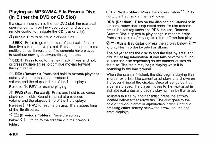
Playing an MP3/WMA File From a Disc(In Either the DVD or CD Slot)If a disc is inserted into the top DVD slot, the rear seatoperator can turn on the video screen and use theremote control to navigate the CD (tracks only).
f (Tune): Turn to select MP3/WMA files.
© SEEK: Press to go to the start of the track, if morethan five seconds have played. Press and hold or pressmultiple times, if more than five seconds have played,to continue moving backward through tracks.
¨ SEEK: Press to go to the next track. Press and holdor press multiple times to continue moving forwardthrough tracks.
s REV (Reverse): Press and hold to reverse playbackquickly. Sound is heard at a reducedvolume and the elapsed time of the file displays.Releases REV to resume playing.
\ FWD (Fast Forward): Press and hold to advanceplayback quickly. Sound is heard at a reducedvolume and the elapsed time of the file displays.Release\ FWD to resume playing. The elapsed timeof the file displays.
Sc (Previous Folder): Press the softkeybelow Sc to go to the first track in the previousfolder.
c T (Next Folder): Press the softkey belowc T togo to the first track in the next folder.
RDM (Random): Files on the disc can be listened to inrandom, rather than sequential order. To use random,press the softkey under the RDM tab until RandomCurrent Disc displays to play songs in random order.Press the same softkey again to turn off random play.
h (Music Navigator): Press the softkey belowhto play files in order by artist or album.
The player scans the disc to sort the files by artist andalbum ID3 tag information. It can take several minutesto scan the disc depending on the number of files onthe disc. The radio may begin playing while it isscanning in the background.
When the scan is finished, the disc begins playing filesin order by artist. The current artist playing is shown onthe second line of the display. Once all songs by thatartist are played, the player moves to the next artist inalphabetical order and begins playing files by that artist.
To listen to files by another artist, press the softkeylocated below either arrow tab. The disc goes to thenext or previous artist in alphabetical order. Continuepressing either softkey below the arrow tab until theartist displays.
4-100
To change from playback by artist to playback byalbum:
1. Press the softkey located below the Sort By tab.
2. Press one of the softkeys below the album tabfrom the sort screen.
3. Press the softkey below the back tab to return tothe main music navigator screen.
The album name displays on the second line betweenthe arrows and songs from the current album begins toplay. Once all songs from that album have played, theplayer moves to the next album in alphabetical order onthe CD and begins playing MP3 files from that album.
To exit music navigator mode, press the softkey belowthe Back tab to return to normal MP3 playback.
Connecting a USB Storage Deviceor iPod®
The USB Port can be used to control an iPod or a USBstorage device.
To connect a USB storage device, connect the device tothe USB port located in the center console.
To connect an iPod, connect one end of the USB cablethat came with the iPod to the iPod’s dock connectorand connect the other end to the USB port located inthe center console. If the vehicle is on and the USBconnection works, “OK to disconnect” and a GM logomay appear on the iPod and iPod appears on the radiodisplay. The iPod music appears on the radio’s displayand begins playing.
The iPod charges while it is connected to the vehicle ifthe vehicle is in the ACC/ACCESSORY or ON/RUNposition. When the vehicle is turned off, the iPodautomatically powers off and will not charge or drawpower from the vehicle's battery.
If you have an older iPod model that is not supported, itcan still be used by connecting it to the Auxiliary InputJack using a standard 3.5 mm (1/8 in) stereo cable. See“Using the Auxiliary Input Jack” earlier for moreinformation.
4-101

Using the Radio to Control a USBStorage Device or iPodThe radio can control a USB storage device or an iPodusing the radio buttons and knobs and display songinformation on the radio’s display.
f (Tune): Turn to select files.
© SEEK: Press to go to the start of the track, if morethan ten seconds have played. Press and hold or pressmultiple times to continue moving backward throughtracks.
¨ SEEK: Press to go to the next track. Press and holdor press multiple times to continue moving forwardthrough tracks.
s REV (Reverse): Press and hold to reverse playbackquickly. Sound is heard at a reduced volume. Releases REV to resume playing. The elapsed time of the filedisplays.
\ FWD (Fast Forward): Press and hold to advanceplayback quickly. Sound is heard at a reduced volume.Release\ FWD to resume playing. The elapsed timeof the file displays.
4 (Information): Press to display additional informationabout the selected track.
Using Softkeys to Control a USBStorage Device or iPodThe five softkeys below the radio display are used tocontrol the functions listed below.
To use the softkeys:
1. Press the first or fifth softkey below the radiodisplay to display the functions listed below,or press the softkey below the function if it iscurrently displayed.
2. Press the softkey below the tab with the functionon it to use that function.
j (Pause): Press the softkey below j to pause thetrack. The tab appears raised when pause is beingused. Press the softkey below j again to resumeplayback.
Back: Press the softkey below the back tab to go backto the main display screen on an iPod, or the rootdirectory on a USB storage device.
4-102

c (Folder View): Press the softkey belowc to viewthe contents of the current folder on the USB drive. Tobrowse and select files:
1. Press the softkey belowc.
2. Turn f to scroll through the list of folders.
3. Press f to select the folder. If there is more thanone folder, repeat Steps 1 and 2 until the folder isreached.
4. Turn f to scroll through the files in the selectedfolder.
5. Press f to select the file to be played.
To skip through large lists, the five softkeys can be usedto navigate in the following order:. First softkey, first item in the list.. Second softkey, 1% through the list each time the
softkey is pressed.. Third softkey, 5% through the list each time the
softkey is pressed.. Fourth softkey, 10% through the list each time the
softkey is pressed.. Fifth softkey, end of the list.
h (Music Navigator): Press the softkey belowhto view and select a file on an iPod, using the iPod'smenu system. Files are sorted by:. Playlists. Artists. Albums. Genres. Songs. Composers
To select files:
1. Press the softkey belowh.
2. Turn f to scroll through the list of menus.
3. Press f to select the menu.
4. Turn f to scroll through the folders or files in theselected menu.
5. Press f to select the file to be played.
4-103
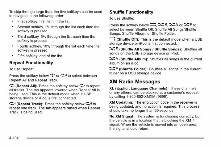
To skip through large lists, the five softkeys can be usedto navigate in the following order:. First softkey, first item in the list.. Second softkey, 1% through the list each time the
softkey is pressed.. Third softkey, 5% through the list each time the
softkey is pressed.. Fourth softkey, 10% through the list each time the
softkey is pressed.. Fifth softkey, end of the list.
Repeat FunctionalityTo use Repeat:
Press the softkey below" or' to select betweenRepeat All and Repeat Track.
" (Repeat All): Press the softkey below" to repeatall tracks. The tab appears lowered when Repeat All isbeing used. This is the default mode when a USBstorage device or iPod is first connected.
' (Repeat Track): Press the softkey below' torepeat one track. The tab appears raised when RepeatTrack is being used.
Shuffle FunctionalityTo use Shuffle:
Press the softkey below>,2,< or= toselect between Shuffle Off, Shuffle All Songs/ShuffleSongs, Shuffle Album, or Shuffle Folder.
> (Shuffle Off): This is the default mode when a USBstorage device or iPod is first connected.
2 (Shuffle All Songs / Shuffle Songs): Shuffles allsongs on the USB storage device or iPod.
< (Shuffle Album): Shuffles all songs in the currentalbum on an iPod.
= (Shuffle Folder): Shuffles all songs in the currentfolder on a USB storage device.
XM Radio MessagesXL (Explicit Language Channels): These channels,or any others, can be blocked at a customer's request,by calling 1-800-852-XMXM (9696).
XM Updating: The encryption code in the receiver isbeing updated, and no action is required. This processshould take no longer than 30 seconds.
No XM Signal: The system is functioning correctly, butthe vehicle is in a location that is blocking the XM™signal. When the vehicle is moved into an open area,the signal should return.
4-104

Loading XM: The audio system is acquiring andprocessing audio and text data. No action is needed.This message should disappear shortly.
Channel Off Air: This channel is not currently inservice. Tune in to another channel.
Channel Unauth : This channel is blocked or cannotbe received with your XM Subscription package.
Channel Unavail: This previously assigned channel isno longer assigned. Tune to another station. If thisstation was one of the presets, choose another stationfor that preset button.
No Artist Info: No artist information is available at thistime on this channel. The system is working properly.
No Title Info: No song title information is available atthis time on this channel. The system is workingproperly.
No CAT Info: No category information is available atthis time on this channel. The system is workingproperly.
No Information: No text or informational messages areavailable at this time on this channel. The system isworking properly.
CAT Not Found: There are no channels available forthe selected category. The system is working properly.
XM Theftlocked: The XM receiver in the vehicle couldhave previously been in another vehicle. For securitypurposes, XM receivers cannot be swapped betweenvehicles. If this message is received after having thevehicle serviced, check with your dealer.
XM Radio ID: If tuned to channel 0, this messagealternates with the XM™ Radio 8 digit radio ID label.This label is needed to activate the service.
Unknown: If this message is received when tuned tochannel 0, there could be a receiver fault. Consult withyour dealer.
Check Antenna: If this message does not clear withina short period of time, the receiver or antenna couldhave a fault. Consult with your dealer.
Check XM Receivr: If this message does not clearwithin a short period of time, the receiver could have afault. Consult with your dealer.
XM Not Available: If this message does not clearwithin a short period of time, the receiver could have afault. Consult with your dealer.
4-105
Navigation/Radio SystemFor vehicles with a navigation radio system, see theseparate Navigation System manual.
Bluetooth®
Vehicles with a Bluetooth system can use a Bluetoothcapable cell phone with a Hands Free Profile to makeand receive phone calls. The system can be used whilethe key is in ON/RUN or ACC/ACCESSORY position.The range of the Bluetooth system can be up to 9.1 m(30 ft). Not all phones support all functions, and not allphones are guaranteed to work with the in-vehicleBluetooth system. See www.gm.com/bluetooth for moreinformation on compatible phones.
Voice RecognitionThe Bluetooth system uses voice recognition tointerpret voice commands to dial phone numbers andname tags.
Noise: Keep interior noise levels to a minimum. Thesystem may not recognize voice commands if there istoo much background noise.
When to Speak: A short tone sounds after the systemresponds indicating when it is waiting for a voicecommand. Wait until the tone and then speak.
How to Speak: Speak clearly in a calm and naturalvoice.
Audio SystemWhen using the in‐vehicle Bluetooth system, soundcomes through the vehicle's front audio systemspeakers and overrides the audio system. Use theaudio system volume knob, during a call, to change thevolume level. The adjusted volume level remains inmemory for later calls. To prevent missed calls, aminimum volume level is used if the volume is turneddown too low.
Bluetooth ControlsUse the buttons located on the steering wheel tooperate the in‐vehicle Bluetooth system. See AudioSteering Wheel Controls on page 4‑127 for moreinformation.
b g (Push To Talk) : Press to answer incoming calls,to confirm system information, and to start speechrecognition.
cx (Phone On Hook): Press to end a call, reject acall, or to cancel an operation.
4-106

PairingA Bluetooth enabled cell phone must be paired to thein‐vehicle Bluetooth system first and then connected tothe vehicle before it can be used. See the cell phonemanufacturers user guide for Bluetooth functions beforepairing the cell phone. If a Bluetooth phone is notconnected, calls will be made using OnStar®
Hands‐Free Calling, if available. Refer to the OnStarowner's guide for more information.
Pairing Information:. Up to five cell phones can be paired to the
in‐vehicle Bluetooth system.. The pairing process is disabled when the vehicle is
moving.. The in‐vehicle Bluetooth system automatically links
with the first available paired cell phone in theorder the phone was paired.
. Only one paired cell phone can be connected tothe in‐vehicle Bluetooth system at a time.
. Pairing should only need to be completed once,unless changes to the pairing information havebeen made or the phone is deleted.
To link to a different paired phone, see Linking to aDifferent Phone later in this section.
Pairing a Phone
1. Press and hold b g for two seconds. The systemresponds with “Ready” followed by a tone.
2. Say “Bluetooth”. The system responds with“Bluetooth ready” followed by a tone.
3. Say “Pair”. The system responds with instructionsand a four digit PIN number. The PIN number willbe used in Step 4.
4. Start the Pairing process on the cell phone that willbe paired to the vehicle. Reference the cell phonemanufacturers user guide for information on thisprocess.
Locate the device named “General Motors” in thelist on the cellular phone and follow the instructionson the cell phone to enter the four digit PINnumber that was provided in Step 3.
5. The system prompts for a name for the phone. Usea name that best describes the phone. This namewill be used to indicate which phone is connected.The system then confirms the name provided.
6. The system responds with “<Phone name> hasbeen successfully paired” after the pairing processis complete.
7. Repeat Steps 1 through 7 for additional phones tobe paired.
4-107

Listing All Paired and Connected Phones
1. Press and hold b g for two seconds. The systemresponds with “Ready” followed by a tone.
2. Say “Bluetooth”. The system responds with“Bluetooth ready” followed by a tone.
3. Say “List”. The system lists all the paired Bluetoothdevices. If a phone is connected to the vehicle, thesystem will say “Is connected” after the connectedphone.
Deleting a Paired Phone
1. Press and hold b g for two seconds. The systemresponds with “Ready” followed by a tone.
2. Say “Bluetooth”. The system responds with“Bluetooth ready” followed by a tone.
3. Say “Delete”. The system asks which phone todelete followed by a tone.
4. Say the name of the phone to be deleted. If thephone name is unknown, use the “List” commandfor a list of all paired phones. The system respondswith “Would you like to delete <phone name>? Yesor No” followed by a tone.
5. Say “Yes” to delete the phone. The systemresponds with “OK, deleting <phone name>”.
Linking to a Different Phone
1. Press and hold b g for two seconds. The systemresponds with “Ready” followed by a tone.
2. Say “Bluetooth”. The system responds with“Bluetooth ready” followed by a tone.
3. Say “Change phone”. The system responds with“Please wait while I search for other phones”.. If another phone is found, the response will be
“<Phone name> is now connected”.. If another phone is not found, the original
phone remains connected.
Storing Name TagsThe system can store up to thirty phone numbers asname tags that are shared between the Bluetooth andOnStar systems.
The system uses the following commands to store andretrieve phone numbers:. Store. Digit Store. Directory
4-108

Using the Store CommandThe store command allows a phone number to bestored without entering the digits individually.
1. Press and hold b g for two seconds. The systemresponds with “Ready” followed by a tone.
2. Say “Store”. The system responds with “Store,number please” followed by a tone.
3. Say the complete phone number to be stored atonce with no pauses.. If the system recognizes the number it
responds with “OK, Storing” and repeats thephone number.
. If the system is unsure it recognizes the phonenumber, it responds with “Store” and repeatsthe number followed by “Please say yes or no”.If the number is correct, say “Yes”. If thenumber is not correct, say “No”. The system willask for the number to be re‐entered.
4. After the system stores the phone number, itresponds with “Please say the name tag” followedby a tone.
5. Say a name tag for the phone number. The nametag is recorded and the system responds with“About to store <name tag>. Does thatsound OK?”.. If the name tag does not sound correct, say
“No” and repeat Step 5.. If the name tag sounds correct, say “Yes” and
the name tag is stored. After the number isstored the system returns to the main menu.
Using the Digit Store CommandThe digit store command allows a phone number to bestored by entering the digits individually.
1. Press and hold b g for two seconds. The systemresponds with “Ready” followed by a tone.
2. Say “Digit Store”. The system responds with“Please say the first digit to store” followed bya tone.
4-109

3. Say the first digit to be stored. The system willrepeat back the digit it heard followed by a tone.Continue entering digits until the number to bestored is complete.. If an unwanted number is recognized by the
system, say “Clear” at any time to clear the lastnumber.
. To hear all of the numbers recognized by thesystem, say “Verify” at any time and the systemwill repeat them.
4. After the complete number has been entered, say“Store”. The system responds with “Please say thename tag” followed by a tone.
5. Say a name tag for the phone number. The nametag is recorded and the system responds with“About to store <name tag>. Does thatsound OK?”.. If the name tag does not sound correct, say
“No” and repeat Step 5.. If the name tag sounds correct, say “Yes” and
the name tag is stored. After the number isstored the system returns to the main menu.
Using the Directory CommandThe directory command lists all of the name tags storedby the system. To use the directory command:
1. Press and hold b g for two seconds. The systemresponds with “Ready” followed by a tone.
2. Say “Directory”. The system responds with“Directory” and then plays back all of the storedname tags. When the list is complete, the systemreturns to the main menu.
Deleting Name TagsThe system uses the following commands to deletename tags:. Delete. Delete all name tags
Using the Delete CommandThe delete command allows specific name tags to bedeleted.
To use the delete command:
1. Press and hold b g for two seconds. The systemresponds with “Ready” followed by a tone.
2. Say “Delete”. The system responds with “Delete,please say the name tag” followed by a tone.
4-110

3. Say the name tag to be deleted. The systemresponds with “Would you like to delete, <nametag>? Please say yes or no”.. If the name tag is correct, say “Yes” to delete
the name tag. The system responds with “OK,deleting <name tag>, returning to themain menu.”
. If the name tag is incorrect, say “No”. Thesystem responds with “No. OK, let's try again,please say the name tag.”
Using the Delete All Name Tags CommandThe delete all name tags command deletes all storedphone book name tags and route name tags for OnStar(if present).
To use the delete all name tags command:
1. Press and hold b g for two seconds. The systemresponds with “Ready” followed by a tone.
2. Say “Delete all name tags”. The system respondswith “You are about to delete all name tags storedin your phone directory and your route destinationdirectory. Are you sure you want to do this? Pleasesay yes or no.”. Say “Yes” to delete all name tags.. Say “No” to cancel the function and return to
the main menu.
Making a CallCalls can be made using the following commands:. Dial. Digit Dial. Call. Re‐dial
Using the Dial Command
1. Press and hold b g for two seconds. The systemresponds with “Ready” followed by a tone.
2. Say “Dial”. The system responds with “Dial using<phone name>”. “Number please” followed bya tone.
3. Say the entire number without pausing.. If the system recognizes the number, it
responds with “OK, Dialing” and dials thenumber.
. If the system does not recognize the number, itconfirms the numbers followed by a tone. If thenumber is correct, say “Yes”. The systemresponds with “OK, Dialing” and dials thenumber. If the number is not correct, say “No”.The system will ask for the number to bere‐entered.
4-111
Using the Digit Dial Command
1. Press and hold b g for two seconds. The systemresponds with “Ready” followed by a tone.
2. Say “Digit Dial”. The system responds with “Digitdial using <phone name>, please say the first digitto dial” followed by a tone.
3. Say the digit to be dialed one at a time. Followingeach digit, the system will repeat back the digit itheard followed by a tone.
4. Continue entering digits until the number to bedialed is complete. After the whole number hasbeen entered, say “Dial”. The system respondswith “OK, Dialing” and dials the number.. If an unwanted number is recognized by the
system, say “Clear” at any time to clear the lastnumber.
. To hear all of the numbers recognized by thesystem, say “Verify” at any time and the systemwill repeat them.
Using the Call Command
1. Press and hold b g for two seconds. The systemresponds with “Ready” followed by a tone.
2. Say “Call”. The system responds with “Call using<phone name>. Please say the name tag” followedby a tone.
3. Say the name tag of the person to call.. If the system clearly recognizes the name tag it
responds with “OK, calling, <name tag>” anddials the number.
. If the system is unsure it recognizes the rightname tag, it confirms the name tag followed bya tone. If the name tag is correct, say “Yes”.The system responds with “OK, calling, <nametag>” and dials the number. If the name tag isnot correct, say “No”. The system will ask forthe name tag to be re‐entered.
Once connected, the person called will be heardthrough the audio speakers.
Using the Re‐dial Command
1. Press and hold b g for two seconds. The systemresponds with “Ready” followed by a tone.
2. After the tone, say “Re‐dial”. The system respondswith “Re‐dial using <phone name>” and dials thelast number called from the connected Bluetoothphone.
Once connected, the person called will be heardthrough the audio speakers.
4-112
Receiving a CallWhen an incoming call is received, the audio systemmutes and a ring tone is heard in the vehicle.
. Press b g and begin speaking to answer the call.
. Presscx to ignore a call.
Call WaitingCall waiting must be supported on the Bluetooth phoneand enabled by the wireless service carrier to work.
. Press b g to answer an incoming call whenanother call is active. The original call is placedon hold.
. Press b g again to return to the original call.
. To ignore the incoming call, continue with theoriginal call with no action.
. Presscx to disconnect the current call andswitch to the call on hold.
Three‐Way CallingThree‐Way Calling must be supported on the Bluetoothphone and enabled by the wireless service carrierto work.
1. While on a call press b g. The system respondswith “Ready” followed by a tone.
2. Say “Three‐way call”. The system responds with“Three‐way call, please say dial or call”.
3. Use the dial or call command to dial the number ofthe third party to be called.
4. Once the call is connected, press b g to link allthe callers together.
Ending a Call
Presscx to end a call.
Muting a CallDuring a call, all sounds from inside the vehicle can bemuted so that the person on the other end of the callcannot hear them.
4-113

To Mute a call
1. Press b g. The system responds with “Ready”followed by a tone.
2. Say “Mute Call”. The system responds with “Callmuted”.
To Cancel Mute
1. Press b g. The system responds with “Ready”followed by a tone.
2. After the tone, say “Mute Call”. The systemresponds with “Resuming call”.
Transferring a CallAudio can be transferred between the in‐vehicleBluetooth system and the cell phone.
To Transfer Audio to the Cell PhoneDuring a call with the audio in the vehicle:
1. Press b g. The system responds with “Ready”followed by a tone.
2. Say “Transfer Call.” The system responds with“Transferring call” and the audio will switch fromthe vehicle to the cell phone.
To Transfer Audio to the In-VehicleBluetooth SystemThe cellular phone must be paired and connected withthe Bluetooth system before a call can be transferred.The connection process can take up to two minutesafter the key is turned to the ON/RUN or ACC/ACCESSORY position.
During a call with the audio on the cell phone,press b g for more than two seconds. The audioswitches from the cell phone to the vehicle.
Voice Pass-ThruVoice Pass‐Thru allows access to the voice recognitioncommands on the cell phone. See the cell phonemanufacturers user guide to see if the cell phonesupports this feature. This feature can be used toverbally access contacts stored in the cell phone.
1. Press and hold b g for two seconds. The systemresponds with “Ready” followed by a tone.
2. Say “Bluetooth”. The system responds with“Bluetooth ready” followed by a tone.
3. Say “Voice”. The system responds with “OK,accessing <phone name>”.. The cell phone's normal prompt messages will
go through its cycle according to the phone'soperating instructions.
4-114

Dual Tone Multi-Frequency (DTMF)TonesThe in‐vehicle Bluetooth system can send numbers andnumbers stored as name tags during a call. This is usedwhen calling a menu driven phone system. Accountnumbers can be programmed into the phonebook forretrieval during menu driven calls.
Sending a Number During a Call
1. Press b g. The system responds with “Ready”followed by a tone.
2. Say “Dial”. The system responds with “Say anumber to send tones” followed by a tone.
3. Say the number to send.. If the system clearly recognizes the number it
responds with “OK, Sending Number” and thedial tones are sent and the call continues.
. If the system is not sure it recognized thenumber properly, it responds “Dial Number,Please say yes or no?” followed by a tone.If the number is correct, say “Yes”. The systemresponds with “OK, Sending Number” and thedial tones are sent and the call continues.
Sending a Stored Name Tag During a Call
1. Press b g. The system responds with “Ready”followed by a tone.
2. Say “Send name tag.” The system responds with“Say a name tag to send tones” followed by a tone.
3. Say the name tag to send.. If the system clearly recognizes the name tag it
responds with “OK, Sending <name tag>” andthe dial tones are sent and the call continues.
. If the system is not sure it recognized the nametag properly, it responds “Dial <name tag>,Please say yes or no?” followed by a tone.If the name tag is correct, say “Yes”. Thesystem responds with “OK, Sending <nametag>” and the dial tones are sent and the callcontinues.
4-115
Clearing the SystemUnless information is deleted out of the in‐vehicleBluetooth system, it will be retained indefinitely. Thisincludes all saved name tags in the phonebook andphone pairing information. For information on how todelete this information, see the above sections onDeleting a Paired Phone and Deleting Name Tags.
Other InformationThe Bluetooth® word mark and logos are owned by theBluetooth® SIG, Inc. and any use of such marks byGeneral Motors is under license. Other trademarks andtrade names are those of their respective owners.
See Radio Frequency Statement on page 8‑18 for FCCinformation.
Rear Seat Entertainment (RSE)SystemThe vehicle may have a DVD Rear Seat Entertainment(RSE) system. The RSE system works with thevehicle's audio system. The DVD player is part of thefront radio. The RSE system includes a radio with aDVD player, a video display screen, audio/video jacks,two wireless headphones, and a remote control. SeeRadio(s) on page 4‑72 for more information on thevehicle's audio/DVD system.
Before DrivingThe RSE is designed for rear seat passengers only. Thedriver cannot safely view the video screen while drivingand should not try to do so.
In severe or extreme weather conditions the RSEsystem might not work until the temperature is withinthe operating range. The operating range for the RSEsystem is above −4°F (−20°C) or below 140°F (60°C).If the temperature of the vehicle is outside of this range,heat or cool the vehicle until the temperature is withinthe operating range of the RSE system.
Parental ControlThe RSE system may have a Parental Control feature,depending on which radio the vehicle has. To startParental Control, quickly press the radio power buttontwice, while the radio is on, to stop all system featuressuch as: radio, video screen, RSA, DVD and/or CD.While Parental Control is on, a padlock icon displays.
The radio can be turned back on with a single press ofthe power button, but the RSE system will remain underParental Control.
To turn Parental Control off, press the radio powerbutton twice, while the radio is on. The RSE returnsfrom where it was previously left and the padlock icondisappears from the radio display.
4-116

Parental Control can also be turned off by inserting orejecting any disc, pressing the play icon on the radioDVD display menu, or changing an ignition position.
HeadphonesThe RSE includes two 2-channel wireless headphonesthat are dedicated to this system. Channel 1 isdedicated to the DVD player, while Channel 2 isdedicated to RSA selections. These headphones canbe used to listen to the radio, CDs, DVDs, MP3s,DVDAs, any auxiliary source connected to A/V jacks,or the auxiliary input jack, if the vehicle has this feature.The wireless headphones have an On/Off button,channel 1/2 switch, and a volume control.
Push the power button to turn on the headphones. Anindicator light located on the headphones comes on.If the light comes on but, there is intermittent soundand/or static on the headphones, or if the indicator lightdoes not come on, the batteries might need to bereplaced. See “Battery Replacement” later in thissection for more information. Switch the headphones toOff when not in use.
Infrared transmitters are located at the rear of the RSEoverhead console. The headphones shut offautomatically to save the battery power if the RSEsystem and RSA are shut off or if the headphones are
out of range of the transmitters for more thanthree minutes. If you move too far forward or step out ofthe vehicle, the headphones lose the audio signal.
The headphones may automatically turn off afterfour hours of continuous use.
To adjust the volume on the headphones, use thevolume control located on the right side.
For optimal audio performance, the headphones mustbe worn correctly. Headphones should be worn withheadband over the top of the head for best audioreception. The symbol L (Left) appears on the upper leftside, above the ear pad and should be positioned onthe left ear. The symbol R (Right) appears on the upperright side, above the ear pad and should be positionedon the right ear.
Notice: Do not store the headphones in heat ordirect sunlight. This could damage the headphonesand repairs will not be covered by the warranty.Storage in extreme cold can weaken the batteries.Keep the headphones stored in a cool, dry place.
If the foam ear pads attached to the headphonesbecome worn or damaged, the pads can be replacedseparately from the headphone set. Refer to your dealerfor more information.
4-117
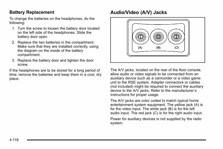
Battery ReplacementTo change the batteries on the headphones, do thefollowing:
1. Turn the screw to loosen the battery door locatedon the left side of the headphones. Slide thebattery door open.
2. Replace the two batteries in the compartment.Make sure that they are installed correctly, usingthe diagram on the inside of the batterycompartment.
3. Replace the battery door and tighten the doorscrew.
If the headphones are to be stored for a long period oftime, remove the batteries and keep them in a cool, dryplace.
Audio/Video (A/V) Jacks
The A/V jacks, located on the rear of the floor console,allow audio or video signals to be connected from anauxiliary device such as a camcorder or a video gameunit to the RSE system. Adapter connectors or cables(not included) might be required to connect the auxiliarydevice to the A/V jacks. Refer to the manufacturer ’sinstructions for proper usage.
The A/V jacks are color coded to match typical homeentertainment system equipment. The yellow jack (A) isfor the video input. The white jack (B) is for the leftaudio input. The red jack (C) is for the right audio input.
Power for auxiliary devices is not supplied by the radiosystem.
4-118
To use the auxiliary inputs of the RSE system, connectan external auxiliary device to the color-coded A/V jacksand turn both the auxiliary device and the video screenpower on. If the video screen is in the DVD playermode, pressing the AUX (auxiliary) button on theremote control switches the video screen from the DVDplayer mode to the auxiliary device. The radio can listento the audio of the connected auxiliary device bysourcing to auxiliary. See Radio(s) on page 4‑72 formore information.
How to Change the RSE Video ScreenSettingsThe screen display mode (normal, full, and zoom),screen brightness, and setup menu language can bechanged from the on screen setup menu. To changeany feature, do the following:
1. Press thez (display menu) button on the remotecontrol.
2. Use the remote controln,q, p,o (navigation)arrows and the enter button to use the setup menu.
3. Press thez button again to remove the setupmenu from the screen.
Audio OutputAudio from the DVD player or auxiliary inputs can beheard through the following possible sources:. Wireless Headphones. Vehicle Speakers. Vehicle wired headphone jacks on the rear seat
audio system, if the vehicle has this feature.
The RSE system always transmits the audio signal tothe wireless headphones, if there is audio available.See “Headphones” earlier in this section for moreinformation.
The DVD player is capable of outputting audio to thewired headphone jacks on the RSA system, if thevehicle has this feature. The DVD player can beselected as an audio source on the RSA system. SeeRear Seat Audio (RSA) on page 4‑124 for moreinformation.
When a device is connected to the A/V jacks, or theradio's auxiliary input jack, if the vehicle has thisfeature, the rear seat passengers are able to hear audiofrom the auxiliary device through the wireless or wiredheadphones. The front seat passengers are able tolisten to playback from this device through the vehiclespeakers by selecting AUX as the source on the radio.
4-119

Video ScreenThe video screen is located in the overhead console.
To use the video screen, do the following:
1. Push the release button located on the overheadconsole.
2. Move the screen to the desired position.
When the video screen is not in use, push it up into itslocked position.
If a DVD is playing and the screen is raised to its lockedposition, the screen remains on. This is normal, and theDVD continues to play through the previous audiosource. Use the remote control power button or ejectthe disc to turn off the screen.
The overhead console contains the infrared transmittersfor the wireless headphones and the infrared receiversfor the remote control. They are located at the rear ofthe console.
Notice: Avoid directly touching the video screen, asdamage may occur. See “Cleaning the VideoScreen” later in this section for more information.
Remote ControlTo use the remote control, aim it at the transmitterwindow at the rear of the RSE overhead console andpress the desired button. Direct sunlight or very brightlight could affect the ability of the RSE transmitter toreceive signals from the remote control. If the remotecontrol does not seem to be working, the batteries mightneed to be replaced. See “Battery Replacement” later inthis section. Objects blocking the line of sight could alsoaffect the function of the remote control.
If a CD or DVD is in the Radio DVD slot, the remotecontrol power button can be used to turn on the videoscreen display and start the disc. The radio can alsoturn on the video screen display. See Radio(s) onpage 4‑72 for more information.
Notice: Storing the remote control in a hot area orin direct sunlight can damage it, and the repairs willnot be covered by the warranty. Storage in extremecold can weaken the batteries. Keep the remotecontrol stored in a cool, dry place.
If the remote control becomes lost or damaged, a newuniversal remote control can be purchased. If thishappens, make sure the universal remote control usesa code set of Toshiba®.
4-120
Remote Control ButtonsO (Power): Press this button to turn the video screenon and off.
P (Illumination): Press this button to turn the remotecontrol backlight on. The backlight automatically timesout after seven to ten seconds if no other button ispressed while the backlight is on.
v (Title): Press this button to return the DVD to themain menu of the DVD. This function could vary foreach disc.
y (Main Menu): Press this button to access the DVDmenu. The DVD menu is different on every DVD. Usethe navigation arrows to move the cursor around theDVD menu. After making a selection press the enterbutton. This button only operates when using a DVD.
n,q , p ,o (Menu Navigation Arrows): Use thearrow buttons to navigate through a menu.
r (Enter): Press this button to select the choice thatis highlighted in any menu.
z (Display Menu): Press this button to adjust thebrightness, screen display mode (normal, full, or zoom),and display the language menu.
q (Return): Press this button to exit the currentactive menu and return to the previous menu. Thisbutton operates only when the display menu or a DVDmenu is active.
c (Stop): Press this button to stop playing, fastreversing, or fast forwarding a DVD. Press this buttontwice to return to the beginning of the DVD.
s (Play/Pause): Press this button to start playing aDVD. Press this button while a DVD is playing to pauseit. Press it again to continue playing the DVD.
While the DVD is playing, the DVD can be playedslowly by pressing the play/pause button then pressingthe fast forward button. The DVD continues playing in aslow play mode. Also, reverse can be played slowly bypressing the play/pause button and then pressing thefast reverse button. To cancel slow play mode, pressthe play/pause button.
t (Previous Track/Chapter): Press this button toreturn to the start of the current track or chapter. Pressthis button again to go to the previous track or chapter.This button might not work when the DVD is playing thecopyright information or the previews.
u (Next Track/Chapter): Press this button to go to thebeginning of the next chapter or track. This button mightnot work while the DVD is playing the copyrightinformation or the previews.
r (Fast Reverse): Press this button to quickly reversethe DVD or CD. To stop fast reversing a DVD video,press the play/pause button. To stop fast reversing aDVD audio or CD, release the fast reverse button. Thisbutton might not work when the DVD is playing thecopyright information or the previews.
4-121
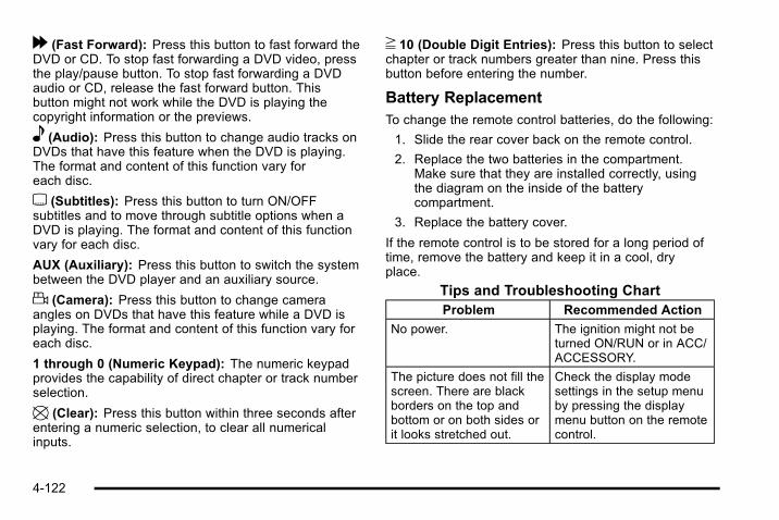
[ (Fast Forward): Press this button to fast forward theDVD or CD. To stop fast forwarding a DVD video, pressthe play/pause button. To stop fast forwarding a DVDaudio or CD, release the fast forward button. Thisbutton might not work while the DVD is playing thecopyright information or the previews.
e (Audio): Press this button to change audio tracks onDVDs that have this feature when the DVD is playing.The format and content of this function vary foreach disc.
{ (Subtitles): Press this button to turn ON/OFFsubtitles and to move through subtitle options when aDVD is playing. The format and content of this functionvary for each disc.
AUX (Auxiliary): Press this button to switch the systembetween the DVD player and an auxiliary source.
d (Camera): Press this button to change cameraangles on DVDs that have this feature while a DVD isplaying. The format and content of this function vary foreach disc.
1 through 0 (Numeric Keypad): The numeric keypadprovides the capability of direct chapter or track numberselection.
\ (Clear): Press this button within three seconds afterentering a numeric selection, to clear all numericalinputs.
} 10 (Double Digit Entries): Press this button to selectchapter or track numbers greater than nine. Press thisbutton before entering the number.
Battery ReplacementTo change the remote control batteries, do the following:
1. Slide the rear cover back on the remote control.
2. Replace the two batteries in the compartment.Make sure that they are installed correctly, usingthe diagram on the inside of the batterycompartment.
3. Replace the battery cover.
If the remote control is to be stored for a long period oftime, remove the battery and keep it in a cool, dryplace.
Tips and Troubleshooting ChartProblem Recommended Action
No power. The ignition might not beturned ON/RUN or in ACC/ACCESSORY.
The picture does not fill thescreen. There are blackborders on the top andbottom or on both sides orit looks stretched out.
Check the display modesettings in the setup menuby pressing the displaymenu button on the remotecontrol.
4-122

Tips and Troubleshooting Chart (cont'd)Problem Recommended Action
In auxiliary mode, thepicture moves or scrolls.
Check the auxiliary inputconnections at bothdevices.
The remote control doesnot work.
Check to make sure thereis no obstruction betweenthe remote control and thetransmitter window.Check the batteries tomake sure they are notdead or installedincorrectly.
After stopping the player,I push Play but sometimesthe DVD starts where I leftoff and sometimes at thebeginning.
If the stop button waspressed one time, the DVDplayer resumes playingwhere the DVD wasstopped. If the stop buttonwas pressed two times theDVD player begins to playfrom the beginning ofthe DVD.
Tips and Troubleshooting Chart (cont'd)Problem Recommended Action
The auxiliary source isrunning but there is nopicture or sound.
Check that the RSE videoscreen is in the auxiliarysource mode.Check the auxiliary inputconnections at bothdevices.
Sometimes the wirelessheadphone audio cuts outor buzzes.
Check for obstructions, lowbatteries, reception range,and interference fromcellular telephone towers orby using a cellulartelephone in the vehicle.Check that the headphonesare on correctly using theL (left) and R (right) on theheadphones.
I lost the remote and/or theheadphones.
See your dealer forassistance.
The DVD is playing, butthere is no picture orsound.
Check that the RSE videoscreen is sourced to theDVD player.
4-123

DVD Display Error MessagesThe DVD display error message depends on the radiothat is in the vehicle. The video screen can display oneof the following:
Disc Load/Eject Error: This message displays whenthere are disc load or eject problems.
Disc Format Error: This message displays, if the discis inserted with the disc label wrong side up, or if thedisc is damaged.
Disc Region Error: This message displays, if the discis not from a correct region.
No Disc Inserted: This message displays, if no disc ispresent whenZ EJECT or DVD AUX is pressed onthe radio.
DVD DistortionVideo distortion can occur when operating cellularphones, scanners, CB radios, Global Position Systems(GPS)*, two-way radios, mobile fax, or walkie talkies.
It might be necessary to turn off the DVD player whenoperating one of these devices in or near the vehicle.
*Excludes the OnStar® System.
Cleaning the RSE Overhead ConsoleWhen cleaning the RSE overhead console surface, useonly a clean cloth dampened with clean water.
Cleaning the Video ScreenWhen cleaning the video screen, use only a clean clothdampened with clean water. Use care when directlytouching or cleaning the screen, as damage couldresult.
Rear Seat Audio (RSA)Vehicles with this feature allow the rear seatpassengers to listen to and control any of the musicsources: radio, CDs, DVDs, or other auxiliary sources.However, the rear seat passengers can only control themusic sources the front seat passengers are notlistening to (except on some radios where dual controlis allowed). For example, rear seat passengers cancontrol and listen to a CD through the headphones,while the driver listens to the radio through thespeakers. The rear seat passengers have control of thevolume for each set of wired headphones.
4-124

The radio functionality is controlled by both the RSAand the front radio. Only one band can be tuned to atone time. Changing the band on the RSA or the frontradio will change the band on the other system, if theyare both sourced to the radio.
The RSA functions operate even when the main radio isoff. The front audio system will display the headphoneicon when the RSA is on, and will disappear from thedisplay when it is off.
Audio can be heard through wired headphones (notincluded) plugged into the jacks on the RSA. If thevehicle has this feature, audio can also be heard onChannel 2 of the wireless headphones.
To listen to an iPod or portable audio device through theRSA, attach the iPod or portable audio device to thefront auxiliary input (if available), on the front audiosystem. Turn the iPod on, then choose the frontauxiliary input with the RSA SRCE button.
Rear Seat Audio with Rear Climate Control shown
P (Power): Press theP button to turn RSA onand off.
Volume: Turn this knob to increase or to decrease thevolume of the wired headphones. The left knob controlsthe left headphones and the right knob controls the rightheadphones.
SRCE (Source): Press this button to switch betweenthe radio (AM/FM), XM™ (if equipped), CD, and if thevehicle has these features, DVD, front auxiliary, andrear auxiliary.
4-125

© ¨ (Seek): When listening to FM, AM, or XM™(if equipped), press the left © or right ¨ seek arrow to goto the next or the previous station or channels and staythere. This function is inactive, with some radios, if thefront seat passengers are listening to the radio.
Press and hold either the left © or right ¨ seek arrowuntil the display flashes, to tune to an individual station.The display stops flashing after the buttons have notbeen pushed for more than two seconds. This functionis inactive, with some radios, if the front seatpassengers are listening to the radio.
While listening to a disc, press the © seek arrow to goback to the start of the current track or chapter (if morethan ten seconds have played). Press the right ¨ seekarrow to go to the next track or chapter on the disc. Thisfunction is inactive, with some radios, if the front seatpassengers are listening to the radio.
When a DVD video menu is being displayed, presseither the left © or right ¨ seek arrow to perform a cursor
up or down on the menu. Hold either the left © or right ¨seek arrow to perform a cursor left or right on the menu.
PROG (Program): Press this button to go to the nextpreset radio station or channel set on the main radio.This function is inactive, with some radios, if the frontseat passengers are listening to the radio.
When a CD or DVD audio disc is playing, press thisbutton to go to the beginning of the CD or DVD audio.This function is inactive, with some radios, if the frontseat passengers are listening to the disc.
When a disc is playing in the CD or DVD changer, pressthis button to select the next disc, if multiple discs areloaded. This function is inactive, with some radios, if thefront seat passengers are listening to the disc.
When a DVD video menu is being displayed, press thePROG button to perform the menu function, Enter.
Theft-Deterrent FeatureTHEFTLOCK® is designed to discourage theft of thevehicle's radio by learning a portion of the VehicleIdentification Number (VIN). The radio does not operateif it is stolen or moved to a different vehicle.
4-126
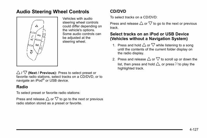
Audio Steering Wheel ControlsVehicles with audiosteering wheel controlscould differ depending onthe vehicle's options.Some audio controls canbe adjusted at thesteering wheel.
w /x (Next / Previous): Press to select preset orfavorite radio stations, select tracks on a CD/DVD, or tonavigate an iPod® or USB device.
RadioTo select preset or favorite radio stations:
Press and releasew orx to go to the next or previousradio station stored as a preset or favorite.
CD/DVDTo select tracks on a CD/DVD:
Press and releasew orx to go to the next or previoustrack.
Select tracks on an iPod or USB Device(Vehicles without a Navigation System)
1. Press and holdw orx while listening to a songuntil the contents of the current folder display onthe radio display.
2. Press and releasew orx to scroll up or down the
list, then press and holdw, or press ¨ to play thehighlighted track.
4-127

Navigating folders on an iPod or USBDevice (Vehicles without a NavigationSystem):
1. Press and holdw orx while listening to a songuntil the contents of the current folder display onthe radio display.
2. Press and holdx to go back to the previousfolder list.
3. Press and releasew orx to scroll up or downthe list.
. To select a folder, press and holdw, or press ¨when the folder is highlighted.
. To go back further in the folder list, press andholdx.
Navigating an iPod or USB Device on theMain Audio Screen (Vehicles with aNavigation System)
Press and releasew orx to select the next orprevious track within the selected category.
Press and holdw orx to move quickly through thetracks.
Press and release ¨ to move up one track within theselected category.
Navigating an iPod or USB Device on theMusic Navigator Screen (Vehicles with aNavigation System)
Press and releasew orx to select the next orprevious track within the selected category.
Press and holdw orx to move quickly through thetracks within the selected category.
Press and release ¨ to move up one track within theselected category.
b g (Mute/Push to Talk): Press to silence the vehiclespeakers only. Press again to turn the sound on.
For vehicles with Bluetooth or OnStar® systems, pressand hold for longer than two seconds to interact withthose systems. See Bluetooth® on page 4‑106 and theOnStar Owner's Guide for more information.
c (End): Press to reject an incoming call, or end acurrent call.
SRCE (Source/Voice Recognition): Press to switchbetween the radio, CD, and for vehicles with, DVD, frontauxiliary, and rear auxiliary.
For vehicles with the navigation system, press and holdthis button for longer than one second to initiate voicerecognition. See “Voice Recognition” in the NavigationSystem manual for more information.
4-128

¨ (Seek): Press to go to the next radio station while inAM, FM, or XM™.
For vehicles with or without a navigation system:
Press ¨ to go to the next track or chapter while sourcedto the CD or DVD slot.
Press ¨ to select a track or a folder when navigatingfolders on an iPod or USB device.
For vehicles with a navigation system:
1. Press and hold ¨ until a beep is heard, to place theradio into SCAN mode, a station will play forfive seconds before moving to the next station.
2. To stop the SCAN function, press ¨ again.
While listening to a CD/DVD, press and hold ¨ toquickly move forward through the tracks. Release tostop on the desired track.
+ e − e (Volume): Press to increase or to decreasethe volume.
Radio ReceptionFrequency interference and static can occur duringnormal radio reception if items such as cell phonechargers, vehicle convenience accessories, andexternal electronic devices are plugged into theaccessory power outlet. If there is interference or static,unplug the item from the accessory power outlet.
AMThe range for most AM stations is greater than for FM,especially at night. The longer range can cause stationfrequencies to interfere with each other. For better radioreception, most AM radio stations boost the powerlevels during the day, and then reduce these levelsduring the night. Static can also occur when things likestorms and power lines interfere with radio reception.When this happens, try reducing the treble on the radio.
FM StereoFM signals only reach about 10 to 40 miles(16 to 65 km). Although the radio has a built-in electroniccircuit that automatically works to reduce interference,some static can occur, especially around tall buildingsor hills, causing the sound to fade in and out.
4-129
XM™ Satellite Radio ServiceXM Satellite Radio Service gives digital radio receptionfrom coast-to-coast in the 48 contiguous United States,and in Canada. Just as with FM, tall buildings or hillscan interfere with satellite radio signals, causing thesound to fade in and out. In addition, traveling orstanding under heavy foliage, bridges, garages,or tunnels may cause loss of the XM signal for a periodof time.
Cellular Phone UsageCellular phone usage may cause interference with thevehicle's radio. This interference may occur whenmaking or receiving phone calls, charging the phone'sbattery, or simply having the phone on. Thisinterference causes an increased level of static whilelistening to the radio. If static is received while listeningto the radio, unplug the cellular phone and turn it off.
Fixed Mast AntennaThe fixed mast antenna can withstand most car washeswithout being damaged as long as it is securelyattached to the base. If the mast becomes slightly bent,straighten it out by hand. If the mast is badly bent,replace it.
Occasionally check to make sure the antenna istightened to its base. If tightening is required, tighten byhand until fully seated plus one quarter turn.
XM™ Satellite Radio AntennaSystemThe XM Satellite Radio antenna is located on the roof ofthe vehicle. Keep the antenna clear of obstructions forclear radio reception.
If the vehicle has a sunroof, the performance of the XMsystem may be affected if the sunroof is open.
4-130
Section 5 Driving Your Vehicle
Your Driving, the Road, and the Vehicle . . . . . . . . . . 5-2Defensive Driving . . . . . . . . . . . . . . . . . . . . . . . . . . . . . . . 5-2Drunk Driving . . . . . . . . . . . . . . . . . . . . . . . . . . . . . . . . . . . 5-2Control of a Vehicle . . . . . . . . . . . . . . . . . . . . . . . . . . . . . 5-3Braking . . . . . . . . . . . . . . . . . . . . . . . . . . . . . . . . . . . . . . . . . 5-3Antilock Brake System (ABS) . . . . . . . . . . . . . . . . . . . 5-4Braking in Emergencies . . . . . . . . . . . . . . . . . . . . . . . . . 5-5StabiliTrak® System . . . . . . . . . . . . . . . . . . . . . . . . . . . . . 5-5Traction Control System (TCS) . . . . . . . . . . . . . . . . . . 5-7Locking Rear Axle . . . . . . . . . . . . . . . . . . . . . . . . . . . . . . 5-9Steering . . . . . . . . . . . . . . . . . . . . . . . . . . . . . . . . . . . . . . . 5-10Off-Road Recovery . . . . . . . . . . . . . . . . . . . . . . . . . . . . . 5-11Passing . . . . . . . . . . . . . . . . . . . . . . . . . . . . . . . . . . . . . . . . 5-12Loss of Control . . . . . . . . . . . . . . . . . . . . . . . . . . . . . . . . 5-12Off-Road Driving . . . . . . . . . . . . . . . . . . . . . . . . . . . . . . . 5-13Assist Steps . . . . . . . . . . . . . . . . . . . . . . . . . . . . . . . . . . . 5-30Driving at Night . . . . . . . . . . . . . . . . . . . . . . . . . . . . . . . . 5-30Driving in Rain and on Wet Roads . . . . . . . . . . . . . 5-31Before Leaving on a Long Trip . . . . . . . . . . . . . . . . . 5-32
Highway Hypnosis . . . . . . . . . . . . . . . . . . . . . . . . . . . . . 5-32Hill and Mountain Roads . . . . . . . . . . . . . . . . . . . . . . . 5-32Winter Driving . . . . . . . . . . . . . . . . . . . . . . . . . . . . . . . . . 5-33If Your Vehicle is Stuck in Sand, Mud, Ice,or Snow . . . . . . . . . . . . . . . . . . . . . . . . . . . . . . . . . . . . . 5-35
Rocking Your Vehicle to Get It Out . . . . . . . . . . . . . 5-36Recovery Loops . . . . . . . . . . . . . . . . . . . . . . . . . . . . . . . 5-36First Aid Kit and Tool Kit . . . . . . . . . . . . . . . . . . . . . . . 5-38Front Mounted Receiver . . . . . . . . . . . . . . . . . . . . . . . 5-39Power Winch Platform . . . . . . . . . . . . . . . . . . . . . . . . . 5-39Loading the Vehicle . . . . . . . . . . . . . . . . . . . . . . . . . . . . 5-40
Towing . . . . . . . . . . . . . . . . . . . . . . . . . . . . . . . . . . . . . . . . . . . . 5-46Towing Your Vehicle . . . . . . . . . . . . . . . . . . . . . . . . . . . 5-46Recreational Vehicle Towing . . . . . . . . . . . . . . . . . . . 5-46Selectable Extended Rear Ride Height . . . . . . . . 5-49Electronically Controlled Air SuspensionSystem . . . . . . . . . . . . . . . . . . . . . . . . . . . . . . . . . . . . . . 5-50
Towing a Trailer . . . . . . . . . . . . . . . . . . . . . . . . . . . . . . . . 5-52Trailer Recommendations . . . . . . . . . . . . . . . . . . . . . . 5-64
5-1

Your Driving, the Road, and theVehicle
Defensive DrivingDefensive driving means “always expect theunexpected.” The first step in driving defensively is towear your safety belt — See Safety Belts: They Are forEveryone on page 2‑20.
{ WARNING:
Assume that other road users (pedestrians,bicyclists, and other drivers) are going to becareless and make mistakes. Anticipate what theymight do and be ready. In addition:. Allow enough following distance between you
and the driver in front of you.. Focus on the task of driving.
Driver distraction can cause collisions resulting ininjury or possible death. These simple defensivedriving techniques could save your life.
Drunk Driving
{ WARNING:
Drinking and then driving is very dangerous. Yourreflexes, perceptions, attentiveness, and judgmentcan be affected by even a small amount ofalcohol. You can have a serious — or evenfatal — collision if you drive after drinking. Do notdrink and drive or ride with a driver who has beendrinking. Ride home in a cab; or if you are with agroup, designate a driver who will not drink.
Death and injury associated with drinking and driving isa global tragedy.
Alcohol affects four things that anyone needs to drive avehicle: judgment, muscular coordination, vision, andattentiveness.
Police records show that almost 40 percent of all motorvehicle-related deaths involve alcohol. In most cases,these deaths are the result of someone who wasdrinking and driving. In recent years, more than17,000 annual motor vehicle-related deaths have beenassociated with the use of alcohol, with about250,000 people injured.
5-2

For persons under 21, it is against the law in every U.S.state to drink alcohol. There are good medical,psychological, and developmental reasons forthese laws.
The obvious way to eliminate the leading highwaysafety problem is for people never to drink alcohol andthen drive.
Medical research shows that alcohol in a person'ssystem can make crash injuries worse, especiallyinjuries to the brain, spinal cord, or heart. This meansthat when anyone who has been drinking — driver orpassenger — is in a crash, that person's chance ofbeing killed or permanently disabled is higher than if theperson had not been drinking.
Control of a VehicleThe following three systems help to control the vehiclewhile driving — brakes, steering, and accelerator. Attimes, as when driving on snow or ice, it is easy to askmore of those control systems than the tires and roadcan provide. Meaning, you can lose control of thevehicle. See Traction Control System (TCS) onpage 5‑7 .
Adding non‐dealer/non‐retailer accessories can affectvehicle performance. See Accessories andModifications on page 6‑4.
BrakingSee Brake System Warning Light on page 4‑31.
Braking action involves perception time and reactiontime. Deciding to push the brake pedal is perceptiontime. Actually doing it is reaction time.
Average reaction time is about three‐fourths of asecond. But that is only an average. It might be lesswith one driver and as long as two or three seconds ormore with another. Age, physical condition, alertness,coordination, and eyesight all play a part. So do alcohol,drugs, and frustration. But even in three‐fourths of asecond, a vehicle moving at 100 km/h (60 mph) travels20 m (66 feet). That could be a lot of distance in anemergency, so keeping enough space between thevehicle and others is important.
And, of course, actual stopping distances vary greatlywith the surface of the road, whether it is pavement orgravel; the condition of the road, whether it is wet, dry,or icy; tire tread; the condition of the brakes; the weightof the vehicle; and the amount of brake force applied.
5-3
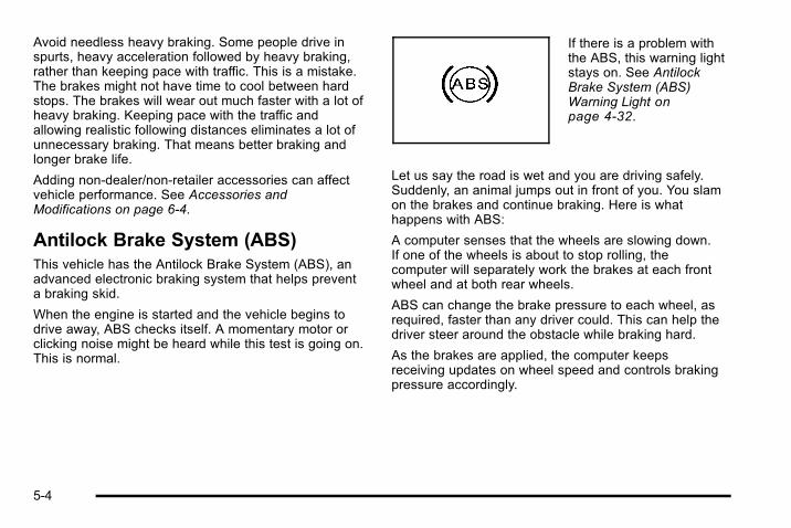
Avoid needless heavy braking. Some people drive inspurts, heavy acceleration followed by heavy braking,rather than keeping pace with traffic. This is a mistake.The brakes might not have time to cool between hardstops. The brakes will wear out much faster with a lot ofheavy braking. Keeping pace with the traffic andallowing realistic following distances eliminates a lot ofunnecessary braking. That means better braking andlonger brake life.
Adding non‐dealer/non‐retailer accessories can affectvehicle performance. See Accessories andModifications on page 6‑4.
Antilock Brake System (ABS)This vehicle has the Antilock Brake System (ABS), anadvanced electronic braking system that helps preventa braking skid.
When the engine is started and the vehicle begins todrive away, ABS checks itself. A momentary motor orclicking noise might be heard while this test is going on.This is normal.
If there is a problem withthe ABS, this warning lightstays on. See AntilockBrake System (ABS)Warning Light onpage 4‑32.
Let us say the road is wet and you are driving safely.Suddenly, an animal jumps out in front of you. You slamon the brakes and continue braking. Here is whathappens with ABS:
A computer senses that the wheels are slowing down.If one of the wheels is about to stop rolling, thecomputer will separately work the brakes at each frontwheel and at both rear wheels.
ABS can change the brake pressure to each wheel, asrequired, faster than any driver could. This can help thedriver steer around the obstacle while braking hard.
As the brakes are applied, the computer keepsreceiving updates on wheel speed and controls brakingpressure accordingly.
5-4

Remember: ABS does not change the time needed toget a foot up to the brake pedal or always decreasestopping distance. If you get too close to the vehicle infront of you, there will not be enough time to apply thebrakes if that vehicle suddenly slows or stops. Alwaysleave enough room up ahead to stop, even with ABS.
Using ABSDo not pump the brakes. Just hold the brake pedaldown firmly and let antilock work. The brakes mightvibrate or some noise might be heard, but this isnormal.
Braking in EmergenciesABS allows the driver to steer and brake at the sametime. In many emergencies, steering can help morethan even the very best braking.
StabiliTrak® SystemThe vehicle has the StabiliTrak system which combinesantilock brake, traction and stability control systems andhelps the driver maintain directional control of thevehicle in most driving conditions.
When the vehicle is started and begins to move, thesystem performs several diagnostic checks to insurethere are no problems. The system may be heard or feltwhile it is working. This is normal and does not meanthere is a problem with the vehicle. The system should
initialize before the vehicle reaches 20 mph (32 km/h).In some cases, it may take approximately two miles ofdriving before the system initializes.
If the system fails to turn on or activate, the StabiliTraklight along with one of the following messages will bedisplayed on the Driver Information Center (DIC):TRACTION CONTROL OFF, SERVICE TRACTIONCONTROL, STABILITRAK OFF, SERVICESTABILITRAK. If these DIC messages appear, makesure the StabiliTrak system has not been turned offusing the StabiliTrak on/off button. If this clears themessage(s), the vehicle does not need servicing. If thisdoes not clear the message(s), then turn the vehicle off,wait 15 seconds, and then turn it back on again to resetthe system. If any of these messages still appear on theDriver Information Center (DIC), the vehicle should betaken in for service. For more information on the DICmessages, see Driver Information Center (DIC) onpage 4‑42.
The StabiliTrak light willflash on the instrumentpanel cluster when thesystem is both on andactivated.
5-5
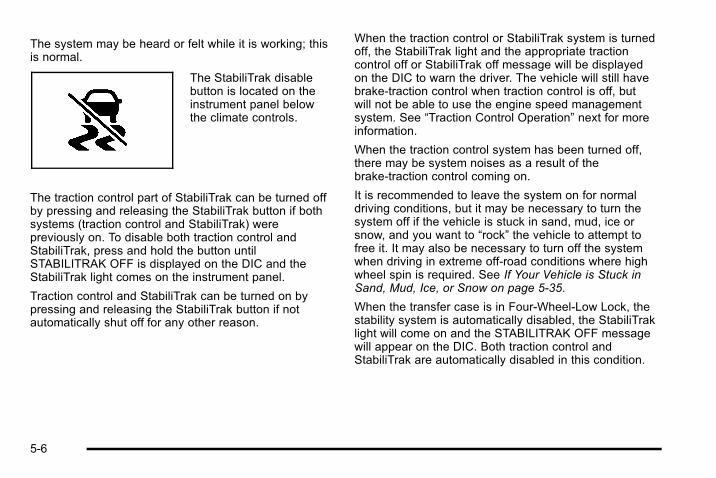
The system may be heard or felt while it is working; thisis normal.
The StabiliTrak disablebutton is located on theinstrument panel belowthe climate controls.
The traction control part of StabiliTrak can be turned offby pressing and releasing the StabiliTrak button if bothsystems (traction control and StabiliTrak) werepreviously on. To disable both traction control andStabiliTrak, press and hold the button untilSTABILITRAK OFF is displayed on the DIC and theStabiliTrak light comes on the instrument panel.
Traction control and StabiliTrak can be turned on bypressing and releasing the StabiliTrak button if notautomatically shut off for any other reason.
When the traction control or StabiliTrak system is turnedoff, the StabiliTrak light and the appropriate tractioncontrol off or StabiliTrak off message will be displayedon the DIC to warn the driver. The vehicle will still havebrake-traction control when traction control is off, butwill not be able to use the engine speed managementsystem. See “Traction Control Operation” next for moreinformation.
When the traction control system has been turned off,there may be system noises as a result of thebrake-traction control coming on.
It is recommended to leave the system on for normaldriving conditions, but it may be necessary to turn thesystem off if the vehicle is stuck in sand, mud, ice orsnow, and you want to “rock” the vehicle to attempt tofree it. It may also be necessary to turn off the systemwhen driving in extreme off-road conditions where highwheel spin is required. See If Your Vehicle is Stuck inSand, Mud, Ice, or Snow on page 5‑35.
When the transfer case is in Four-Wheel-Low Lock, thestability system is automatically disabled, the StabiliTraklight will come on and the STABILITRAK OFF messagewill appear on the DIC. Both traction control andStabiliTrak are automatically disabled in this condition.
5-6

Traction Control OperationThe traction control system is part of the StabiliTraksystem. Traction control limits wheel spin by reducingengine power to the wheels (engine speedmanagement) and by applying brakes to each individualwheel (brake-traction control) as necessary.
The traction control system is enabled automaticallywhen the vehicle is started. It will activate and theStabiliTrak light will flash if it senses that any of thewheels are spinning or beginning to lose traction whiledriving. If the traction control is turned off, only thebrake-traction control portion of traction control willwork. The engine speed management will be disabled.In this mode, engine power is not reduced automaticallyand the driven wheels can spin more freely. This cancause the brake-traction control to activate constantly.
Notice: If the wheel(s) of one axle is allowed to spinexcessively while the StabiliTrak, ABS and brakewarning lights and any relevant DIC messages aredisplayed, the transfer case could be damaged. Therepairs would not be covered by the vehiclewarranty. Reduce engine power and do not spin thewheel(s) excessively while these lights andmessages are displayed.
The traction control system may activate on dry orrough roads or under conditions such as heavyacceleration while turning or abrupt upshifts/downshifts
of the transmission. When this happens, a reduction inacceleration may be noticed, or a noise or vibration maybe heard. This is normal.
If cruise control is being used when StabiliTrakactivates, the cruise control automatically disengages.The cruise control can be re-engaged when roadconditions allow. See Cruise Control on page 4‑8.
StabiliTrak may also turn off automatically if itdetermines that a problem exists with the system. If theproblem does not clear itself after restarting the vehicle,see your dealer for service.
Traction Control System (TCS)The vehicle has a Traction Control System (TCS) thatlimits wheel spin. This is especially useful in slipperyroad conditions. The system operates only if it sensesthat any of the wheels are spinning or beginning to losetraction. When this happens, TCS applies the brakes tolimit wheel spin and also reduces engine power. Thesystem may be heard or felt while it is working, but thisis normal.
TCS can operate on dry roads under some conditions.When this happens, the system may be heard while it isworking or a reduction in acceleration may be noticed.This is normal and does not mean there is a problemwith the vehicle. Examples of these conditions includehard acceleration in a turn, an abrupt upshift ordownshift of the transmission or driving on rough roads.
5-7

If cruise control is being used when TCS begins to limitwheel spin, the cruise control automatically disengages.The cruise control can be re-engaged when roadconditions allow. See Cruise Control on page 4‑8.
SERVICE TRACTION CONTROL comes on in theDriver information Center (DIC) when a Traction ControlSystem or Antilock Brake System problem has beendetected and the vehicle needs service. See DICWarnings and Messages on page 4‑52. When thismessage is on, the system will not limit wheel spin.Adjust your driving accordingly.
The traction control system automatically comes onwhenever the vehicle is started. To limit wheel spin,especially in slippery road conditions, the systemshould always be left on. But the traction control systemcan be turned off if needed. It may be necessary to turnthe system off if the vehicle is stuck in sand, mud, ice,or snow, and you want to “rock” the vehicle to attempt tofree it. See If Your Vehicle is Stuck in Sand, Mud, Ice,or Snow on page 5‑35.
To turn the system off,press and release theTCS button.
This light will come onsteady when the tractioncontrol system has beenturned off. This lightflashes when TCS isactive.
If the TCS button is pressed, the traction control systemwill turn off and a TRACTION CONTROL OFF messagewill appear on the DIC. Press the TCS button again toturn the system back on. The TRACTION CONTROLOFF message will then go off. The Traction ControlSystem will reset itself at each ignition cycle.
Adding non‐dealer/non‐retailer accessories can affectthe vehicle's performance. See Accessories andModifications on page 6‑4.
5-8
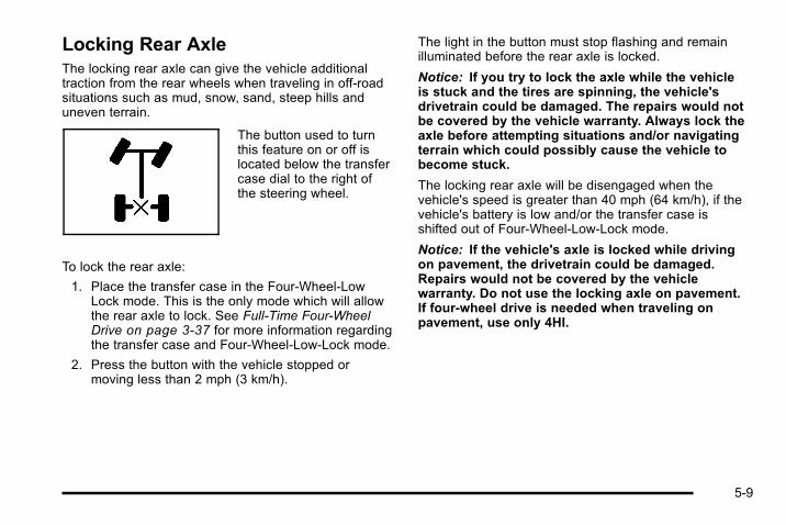
Locking Rear AxleThe locking rear axle can give the vehicle additionaltraction from the rear wheels when traveling in off-roadsituations such as mud, snow, sand, steep hills anduneven terrain.
The button used to turnthis feature on or off islocated below the transfercase dial to the right ofthe steering wheel.
To lock the rear axle:
1. Place the transfer case in the Four‐Wheel‐LowLock mode. This is the only mode which will allowthe rear axle to lock. See Full-Time Four-WheelDrive on page 3‑37 for more information regardingthe transfer case and Four‐Wheel‐Low‐Lock mode.
2. Press the button with the vehicle stopped ormoving less than 2 mph (3 km/h).
The light in the button must stop flashing and remainilluminated before the rear axle is locked.
Notice: If you try to lock the axle while the vehicleis stuck and the tires are spinning, the vehicle'sdrivetrain could be damaged. The repairs would notbe covered by the vehicle warranty. Always lock theaxle before attempting situations and/or navigatingterrain which could possibly cause the vehicle tobecome stuck.
The locking rear axle will be disengaged when thevehicle's speed is greater than 40 mph (64 km/h), if thevehicle's battery is low and/or the transfer case isshifted out of Four‐Wheel‐Low‐Lock mode.
Notice: If the vehicle's axle is locked while drivingon pavement, the drivetrain could be damaged.Repairs would not be covered by the vehiclewarranty. Do not use the locking axle on pavement.If four-wheel drive is needed when traveling onpavement, use only 4HI.
5-9
Steering
Power SteeringIf power steering assist is lost because the engine stopsor the system is not functioning, the vehicle can besteered but it will take more effort.
Steering TipsIt is important to take curves at a reasonable speed.
Traction in a curve depends on the condition of the tiresand the road surface, the angle at which the curve isbanked, and vehicle speed. While in a curve, speed isthe one factor that can be controlled.
If there is a need to reduce speed, do it before enteringthe curve, while the front wheels are straight.
Try to adjust the speed so you can drive through thecurve. Maintain a reasonable, steady speed. Wait toaccelerate until out of the curve, and then accelerategently into the straightaway.
Steering in EmergenciesThere are times when steering can be more effectivethan braking. For example, you come over a hill andfind a truck stopped in your lane, or a car suddenly pullsout from nowhere, or a child darts out from betweenparked cars and stops right in front of you. Theseproblems can be avoided by braking— if you can stopin time. But sometimes you cannot stop in time becausethere is no room. That is the time for evasiveaction— steering around the problem.
The vehicle can perform very well in emergencies likethese. First apply the brakes. See Braking onpage 5‑3 . It is better to remove as much speed aspossible from a collision. Then steer around theproblem, to the left or right depending on the spaceavailable.
5-10

An emergency like this requires close attention and aquick decision. If holding the steering wheel at therecommended 9 and 3 o'clock positions, it can beturned a full 180 degrees very quickly without removingeither hand. But you have to act fast, steer quickly, andjust as quickly straighten the wheel once you haveavoided the object.
The fact that such emergency situations are alwayspossible is a good reason to practice defensive drivingat all times and wear safety belts properly.
Off-Road RecoveryThe vehicle's right wheels can drop off the edge of aroad onto the shoulder while driving.
If the level of the shoulder is only slightly below thepavement, recovery should be fairly easy. Ease off theaccelerator and then, if there is nothing in the way, steerso that the vehicle straddles the edge of the pavement.Turn the steering wheel 8 to 13 cm (3 to 5 inches),about one-eighth turn, until the right front tire contactsthe pavement edge. Then turn the steering wheel to gostraight down the roadway.
5-11

PassingPassing another vehicle on a two-lane road can bedangerous. To reduce the risk of danger while passing:. Look down the road, to the sides, and to
crossroads for situations that might affect asuccessful pass. If in doubt, wait.
. Watch for traffic signs, pavement markings, andlines that could indicate a turn or an intersection.Never cross a solid or double‐solid line on yourside of the lane.
. Do not get too close to the vehicle you want topass. Doing so can reduce your visibility.
. Wait your turn to pass a slow vehicle.
. When you are being passed, ease to the right.
Loss of ControlLet us review what driving experts say about whathappens when the three control systems— brakes,steering, and acceleration— do not have enoughfriction where the tires meet the road to do what thedriver has asked.
In any emergency, do not give up. Keep trying to steerand constantly seek an escape route or area of lessdanger.
SkiddingIn a skid, a driver can lose control of the vehicle.Defensive drivers avoid most skids by takingreasonable care suited to existing conditions, and bynot overdriving those conditions. But skids are alwayspossible.
The three types of skids correspond to the vehicle'sthree control systems. In the braking skid, the wheelsare not rolling. In the steering or cornering skid, toomuch speed or steering in a curve causes tires to slipand lose cornering force. And in the acceleration skid,too much throttle causes the driving wheels to spin.
If the vehicle starts to slide, ease your foot off theaccelerator pedal and quickly steer the way you wantthe vehicle to go. If you start steering quickly enough,the vehicle could straighten out. Always be ready for asecond skid if it occurs.
Of course, traction is reduced when water, snow, ice,gravel, or other material is on the road. For safety, slowdown and adjust your driving to these conditions. It isimportant to slow down on slippery surfaces becausestopping distance is longer and vehicle control morelimited.
5-12

While driving on a surface with reduced traction, tryyour best to avoid sudden steering, acceleration,or braking, including reducing vehicle speed by shiftingto a lower gear. Any sudden changes could cause thetires to slide. You might not realize the surface isslippery until the vehicle is skidding. Learn to recognizewarning clues— such as enough water, ice, or packedsnow on the road to make a mirrored surface— andslow down when you have any doubt.
Remember: Antilock brakes help avoid only thebraking skid.
Off-Road DrivingThe airbag system is designed to work properly under awide range of conditions, including off‐road usage.Always wear your safety belt and observe safe drivingspeeds, especially on rough terrain.
Drinking and driving can be very dangerous on anyroad and this is certainly true for off-road driving. At thevery time you need special alertness and driving skills,your reflexes, perceptions, and judgment can beaffected by even a small amount of alcohol. You couldhave a serious — or even fatal — accident if you drinkand drive or ride with a driver who has been drinking.
Off-roading can be great fun but has some definitehazards. The greatest of these is the terrain itself. Whenoff-road driving, traffic lanes are not marked, curves arenot banked, and there are no road signs. Surfaces canbe slippery, rough, uphill, or downhill.
Avoid sharp turns and abrupt maneuvers. Failure tooperate the vehicle correctly off‐road could result in lossof vehicle control or vehicle rollover.
Off-roading involves some new skills. That is why it isvery important that you read these driving tips andsuggestions to help make off-road driving safer andmore enjoyable.
Before You Go Off-Roading. Have all necessary maintenance and service
work done.. Make sure there is enough fuel, that fluid levels are
where they should be, and that the spare tire isfully inflated.
. Be sure to read all the information aboutfour-wheel-drive vehicles in this manual.
. Make sure any equipment that might beneeded — first aid kit, cell phone, flashlight,etc. — is securely stored in the vehicle.
. Remove any removable side steps. See AssistSteps on page 5‑30.
5-13

. Make sure all underbody shields, if the vehicle hasthem, are properly attached.
. Know the local laws that apply to off-roading whereyou will be driving or check with law enforcementpeople in the area.
. Be sure to get the necessary permission ifoff-roading on private land.
Loading Your Vehicle for Off-RoadDriving
{ WARNING:
. Cargo on the load floor piled higher than theseatbacks can be thrown forward during asudden stop. You or your passengers couldbe injured. Keep cargo below the top of theseatbacks.
. Unsecured cargo on the load floor can betossed about when driving over rough terrain.You or your passengers can be struck byflying objects. Secure the cargo properly.
(Continued)
WARNING: (Continued)
. Heavy loads on the roof raise the vehicle'scenter of gravity, making it more likely to rollover. You can be seriously or fatally injured ifthe vehicle rolls over. Put heavy loads insidethe cargo area, not on the roof. Keep cargo inthe cargo area as far forward and low aspossible.
There are some important things to remember abouthow to load the vehicle.. The heaviest things should be on the floor, forward
of the rear axle. Put heavier items as far forwardas possible.
. Be sure the load is properly secured, so things arenot tossed around.
See Loading the Vehicle on page 5‑40 and Tires onpage 6‑60 for other important information.
5-14
Environmental ConcernsOff-road driving can provide wholesome and satisfyingrecreation. However, it also raises environmentalconcerns. We recognize these concerns and urge everyoff-roader to follow these basic rules for protecting theenvironment:. Always use established trails, roads, and areas
that have been specially set aside for publicoff-road recreational driving and obey all postedregulations.
. Avoid any driving practice that could damageshrubs, flowers, trees, or grasses or disturbwildlife. This includes wheel-spinning, breakingdown trees, or unnecessary driving throughstreams or over soft ground.
. Always carry a litter bag and make sure all refuseis removed from any campsite before leaving.
. Take extreme care with open fires (wherepermitted), camp stoves, and lanterns.
. Never park the vehicle over dry grass or othercombustible materials that could catch fire from theheat of the vehicle's exhaust system.
Traveling to Remote AreasIt makes sense to plan your trip, especially when goingto a remote area. Know the terrain and plan your route.Get accurate maps of trails and terrain. Check to see ifthere are any blocked or closed roads.
It is also a good idea to travel with at least one othervehicle in case something happens to one of them.
For vehicles with a winch, be sure to read the winchinstructions. In a remote area, a winch can be handy ifyou get stuck but you will want to know how to use itproperly.
5-15
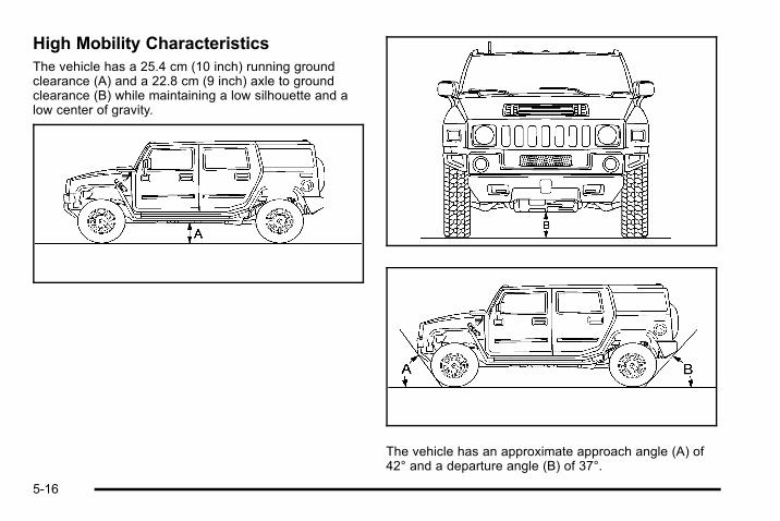
High Mobility CharacteristicsThe vehicle has a 25.4 cm (10 inch) running groundclearance (A) and a 22.8 cm (9 inch) axle to groundclearance (B) while maintaining a low silhouette and alow center of gravity.
The vehicle has an approximate approach angle (A) of42° and a departure angle (B) of 37°.
5-16
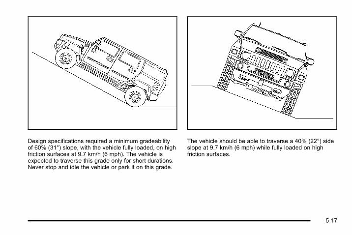
Design specifications required a minimum gradeabilityof 60% (31°) slope, with the vehicle fully loaded, on highfriction surfaces at 9.7 km/h (6 mph). The vehicle isexpected to traverse this grade only for short durations.Never stop and idle the vehicle or park it on this grade.
The vehicle should be able to traverse a 40% (22°) sideslope at 9.7 km/h (6 mph) while fully loaded on highfriction surfaces.
5-17

The vehicle can climb a 40.6 cm (16 inch) vertical step.Step climbing is best done by approaching the step atan angle rather than straight on.
Brake and Accelerator OperationTechniques for Off-Road Driving
For logs, walls, rocks, severe ditches, hills,sand, etc.1. Bring the vehicle to a complete stop. Do not rev
the engine.
2. Select the proper transmission and transfer casegear range; usually 1 (First) gear, 4LO LOCK forsuch obstacles.
3. If wheel spin is experienced, maintain steadythrottle, with your foot off the brake pedal, to allowthe Traction Control System (TCS) to control thewheel spin. TCS might not operate if the brakesare applied.
4. If wheel spin cannot be controlled by the TCS, fullypress the brake pedal with your left foot so allwheel spin is stopped.
5. Back away from the obstacle so that a newapproach can be tried.
6. As the first wheel crosses the obstacle, beprepared to alternate the brake and acceleratorpedal to maintain control and avoid tire drop-offfrom obstacles. Repeat this process for the otherwheels.
5-18

For mounds, washouts, loose up-hillslopes, ditches, etc.When wheel spin occurs as the vehicle is moving, thedriver might notice a slight shaking or shuddering of thevehicle. This should be stopped as soon as possible toprevent damage to vehicle components. This is theindication that a loss of traction is occurring on thisterrain. The operator should:
1. Reduce speed and apply the brakes.
2. Assess the terrain properly and adjust vehiclespeed and gear ranges accordingly: 4HI positionfor higher speeds and 4LO LOCK for more torqueand lower speeds. Transmission 1 (First) gear isgenerally recommended.
3. Apply slight pressure to the brake when theshaking or shuddering sensation is felt, keepingthe vehicle moving in a controlled manner.
4. Be prepared to alternate between braking andaccelerating through the adverse terrain.
Getting Familiar with Off-Road DrivingIt is a good idea to practice in an area that is safe andclose to home before you go into the wilderness.Off-roading requires some new and different skills.
Tune your senses to different kinds of signals. Youreyes need to constantly sweep the terrain forunexpected obstacles. Your ears need to listen for
unusual tire or engine sounds. Use your arms, hands,feet, and body to respond to vibrations and vehiclebounce.
Controlling the vehicle is the key to successful off-roaddriving. One of the best ways to control the vehicle is tocontrol the speed. At higher speeds:. You approach things faster and have less time to
react.. There is less time to scan the terrain for obstacles.. The vehicle has more bounce when driving over
obstacles.. More braking distance is needed, especially on an
unpaved surface.
{ WARNING:
When you are driving off-road, bouncing andquick changes in direction can easily throw youout of position. This could cause you to losecontrol and crash. So, whether you are driving onor off the road, you and your passengers shouldwear safety belts.
5-19

Scanning the TerrainOff-road driving can take you over many different kindsof terrain. Be familiar with the terrain and its manydifferent features.
Surface Conditions: Off-roading surfaces can behard-packed dirt, gravel, rocks, grass, sand, mud, snow,or ice. Each of these surfaces affects the vehicle'ssteering, acceleration, and braking in different ways.Depending on the surface, slipping, sliding, wheelspinning, delayed acceleration, poor traction, and longerbraking distances can occur.
Surface Obstacles: Unseen or hidden obstacles canbe hazardous. A rock, log, hole, rut, or bump can startleyou if you are not prepared for them. Often theseobstacles are hidden by grass, bushes, snow, or eventhe rise and fall of the terrain itself.
Some things to consider:. Is the path ahead clear?. Will the surface texture change abruptly up ahead?. Does the travel take you uphill or downhill?. Will you have to stop suddenly or change direction
quickly?
When driving over obstacles or rough terrain, keep afirm grip on the steering wheel. Ruts, troughs, or othersurface features can jerk the wheel out of your hands.
When driving over bumps, rocks, or other obstacles, thewheels can leave the ground. If this happens, even withone or two wheels, you cannot control the vehicle aswell or at all.
Because you will be on an unpaved surface, it isespecially important to avoid sudden acceleration,sudden turns, or sudden braking.
Off-roading requires a different kind of alertness fromdriving on paved roads and highways. There are noroad signs, posted speed limits, or signal lights. Usegood judgment about what is safe and what is not.
5-20
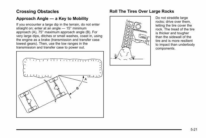
Crossing Obstacles
Approach Angle — a Key to MobilityIf you encounter a large dip in the terrain, do not enterstraight on; enter at an angle — 15° minimumapproach (A), 75° maximum approach angle (B). Forvery large dips, ditches or small washes, coast in, usingthe engine as a brake (transmission and transfer caselowest gears). Then, use the low ranges in thetransmission and transfer case to power out.
Roll The Tires Over Large Rocks
Do not straddle largerocks; drive over them,letting the tire cover therock. The tread of the tireis thicker and tougherthan the sidewall of thetire and is more resilientto impact than underbodycomponents.
5-21

Log CrossingUsing the proper technique, the vehicle will cross logsup to 25.4 cm (10 inches) in diameter. Approach the logat approximately a 15° angle (A) with the transmissionin 1 (First) and the transfer case in 4LO LOCK and“walk” the vehicle over, one tire at a time. It might benecessary to modulate the brake pedal and acceleratorto avoid spin-out. Ease the vehicle down from the logwith the brake.
Driving on HillsOff-road driving often takes you up, down, or across ahill. Driving safely on hills requires good judgment andan understanding of what the vehicle can and cannotdo. There are some hills that simply cannot be driven,no matter how well built the vehicle.
{ WARNING:
Many hills are simply too steep for any vehicle.If you drive up them, you will stall. If you drivedown them, you cannot control your speed. If youdrive across them, you will roll over. You could beseriously injured or killed. If you have any doubtabout the steepness, do not drive the hill.
5-22

Approaching a HillWhen you approach a hill, decide if it is too steep toclimb, descend, or cross. Steepness can be hard tojudge. On a very small hill, for example, there might bea smooth, constant incline with only a small change inelevation where you can easily see all the way to thetop. On a large hill, the incline can get steeper as younear the top, but you might not see this because thecrest of the hill is hidden by bushes, grass, or shrubs.
Consider this as you approach a hill:. Is there a constant incline, or does the hill get
sharply steeper in places?. Is there good traction on the hillside, or will the
surface cause tire slipping?. Is there a straight path up or down the hill so you
will not have to make turning maneuvers?. Are there obstructions on the hill that can block
your path, such as boulders, trees, logs, or ruts?. What is beyond the hill? Is there a cliff, an
embankment, a drop-off, a fence? Get out andwalk the hill if you do not know. It is the smart wayto find out.
. Is the hill simply too rough? Steep hills often haveruts, gullies, troughs, and exposed rocks becausethey are more susceptible to the effects of erosion.
Driving UphillOnce you decide it is safe to drive up the hill:. Use transmission and transfer case low gear and
get a firm grip on the steering wheel.. Get a smooth start up the hill and try to maintain
speed. Not using more power than needed canavoid spinning the wheels or sliding.
. Let the traction system work to control any wheelslippage. The traction control system allows formoderate wheel spin with some capability to dig inand power up the hill.
5-23

. Do not continue if the vehicle shudders or exhibitssuspension hopping. This can cause damage tothe driveline or suspension components. Improperdriving technique is not covered by the vehiclewarranty.
{ WARNING:
Turning or driving across steep hills can bedangerous. You could lose traction, slidesideways, and possibly roll over. You could beseriously injured or killed. When driving up hills,always try to go straight up.
. Try to drive straight up the hill if at all possible.If the path twists and turns, you might want to findanother route.
. Ease up on the speed as you approach the top ofthe hill.
. Attach a flag to the vehicle to be more visible toapproaching traffic on trails or hills.
. Sound the horn as you approach the top of the hillto let opposing traffic know you are there.
. Use headlamps even during the day to make thevehicle more visible to oncoming traffic.
{ WARNING:
Driving to the top (crest) of a hill at full speed cancause an accident. There could be a drop-off,embankment, cliff, or even another vehicle. Youcould be seriously injured or killed. As you nearthe top of a hill, slow down and stay alert.
If the vehicle stalls, or is about to stall, and you cannotmake it up the hill:. Push the brake pedal to stop the vehicle and keep
it from rolling backwards and apply the parkingbrake.
. If the engine is still running, shift the transmissionto R (Reverse), release the parking brake, andslowly back down the hill in R (Reverse).
. If the engine has stopped running, you need torestart it. With the brake pedal pressed, apply theparking brake. If the vehicle has an automatictransmission, shift the transmission to P (Park).Restart the engine. Then, shift to R (Reverse),release the parking brake, and slowly back downthe hill as straight as possible in R (Reverse).
5-24

. While backing down the hill, put your left hand onthe steering wheel at the 12 o'clock position so youcan tell if the wheels are straight and canmaneuver as you back down. It is best to backdown the hill with the wheels straight rather than inthe left or right direction. Turning the wheel too farto the left or right will increase the possibility of arollover.
Things not to do if the vehicle stalls, or is about to stall,when going up a hill:. Never attempt to prevent a stall by shifting into
N (Neutral) to rev-up the engine and regain forwardmomentum. This will not work. The vehicle can rollbackward very quickly and could go out of control.
. Never try to turn around if about to stall whengoing up a hill. If the hill is steep enough to stallthe vehicle, it is steep enough to cause it to rollover. If you cannot make it up the hill, back straightdown the hill.
If, after stalling, you try to back down the hill and decideyou just cannot do it, set the parking brake, shift toP (Park), and turn off the engine. Leave the vehicle andgo get some help. Exit on the uphill side and stay clearof the path the vehicle would take if it rolled downhill.Do not shift the transfer case to N (Neutral) when youleave the vehicle. Leave it in some gear.
{ WARNING:
Shifting the transfer case to N (Neutral) can causeyour vehicle to roll even if the transmission is inP (Park). This is because the N (Neutral) positionon the transfer case overrides the transmission.You or someone else could be injured. If you aregoing to leave your vehicle, set the parking brakeand shift the transmission to P (Park). But do notshift the transfer case to N (Neutral). Leave thetransfer case in the 4 HI, 4 HI Lock, or 4 LO Lockposition.
5-25

Driving DownhillWhen off-roading takes you downhill, consider:. How steep is the downhill? Will I be able to
maintain vehicle control?. What is the surface like? Smooth? Rough?
Slippery? Hard-packed dirt? Gravel?. Are there hidden surface obstacles? Ruts? Logs?
Boulders?. What is at the bottom of the hill? Is there a hidden
creek bank or even a river bottom with largerocks?
If you decide you can go down a hill safely, try to keepthe vehicle headed straight down. Use a low gear soengine drag can help the brakes so they do not have todo all the work. Descend slowly, keeping the vehicleunder control at all times.
{ WARNING:
Heavy braking when going down a hill can causeyour brakes to overheat and fade. This couldcause loss of control and a serious accident.Apply the brakes lightly when descending a hilland use a low gear to keep vehicle speed undercontrol.
Things not to do when driving down a hill:. When driving downhill, avoid turns that take the
vehicle across the incline of the hill. A hill that isnot too steep to drive down might be too steep todrive across. The vehicle could roll over.
. Never go downhill with the transmission inN (Neutral), called free-wheeling. The brakes willhave to do all the work and could overheatand fade.
Vehicles are much more likely to stall when going uphill,but if it happens when going downhill:
1. Stop the vehicle by applying the regular brakesand apply the parking brake.
2. Shift to P (Park). While still braking, restart theengine.
3. Shift back to a low gear, release the parking brake,and drive straight down.
4. If the engine will not start, get out and get help.
5-26

Driving Across an InclineAn off-road trail will probably go across the incline of ahill. To decide whether to try to drive across the incline,consider the following:
{ WARNING:
Driving across an incline that is too steep willmake your vehicle roll over. You could beseriously injured or killed. If you have any doubtabout the steepness of the incline, do not driveacross it. Find another route instead.
. A hill that can be driven straight up or downmight be too steep to drive across. When goingstraight up or down a hill, the length of the wheelbase — the distance from the front wheels to therear wheels — reduces the likelihood the vehiclewill tumble end over end. But when driving acrossan incline, the narrower track width — the distancebetween the left and right wheels — might notprevent the vehicle from tilting and rolling over.Driving across an incline puts more weight on thedownhill wheels which could cause a downhill slideor a rollover.
. Surface conditions can be a problem. Loosegravel, muddy spots, or even wet grass can causethe tires to slip sideways, downhill. If the vehicleslips sideways, it can hit something that willtrip it — a rock, a rut, etc. — and roll over.
. Hidden obstacles can make the steepness of theincline even worse. If you drive across a rock withthe uphill wheels, or if the downhill wheels dropinto a rut or depression, the vehicle can tilteven more.
For these reasons, carefully consider whether to try todrive across an incline. Just because the trail goesacross the incline does not mean you have to drive it.The last vehicle to try it might have rolled over.
If you feel the vehicle starting to slide sideways, turndownhill. This should help straighten out the vehicle andprevent the side slipping. The best way to prevent thisis to “walk the course” first, so you know what thesurface is like before driving it.
5-27
Stalling on an Incline
{ WARNING:
Getting out on the downhill (low) side of a vehiclestopped across an incline is dangerous. If thevehicle rolls over, you could be crushed or killed.Always get out on the uphill (high) side of thevehicle and stay well clear of the rollover path.
If the vehicle stalls when crossing an incline, be sureyou, and any passengers, get out on the uphill side,even if the door there is harder to open. If you get outon the downhill side and the vehicle starts to roll over,you will be right in its path.
If you have to walk down the slope, stay out of the paththe vehicle will take if it does roll over.
Driving in Mud, Sand, Snow, or IceWhen driving in mud, snow, or sand, the wheels do notget good traction. Acceleration is not as quick, turning ismore difficult, and braking distances are longer.
It is best to use a low gear when in mud — the deeperthe mud, the lower the gear. In really deep mud, keepthe vehicle moving so it does not get stuck.
When driving on sand, wheel traction changes. Onloosely packed sand, such as on beaches or sanddunes, the tires will tend to sink into the sand. Thisaffects steering, accelerating, and braking. Drive at areduced speed and avoid sharp turns or abruptmaneuvers.
Hard packed snow and ice offer the worst tire traction.On these surfaces, it is very easy to lose control. Onwet ice, for example, the traction is so poor that you willhave difficulty accelerating. And, if the vehicle does getmoving, poor steering and difficult braking can cause itto slide out of control.
{ WARNING:
Driving on frozen lakes, ponds, or rivers can bedangerous. Underwater springs, currents underthe ice, or sudden thaws can weaken the ice. Yourvehicle could fall through the ice and you and yourpassengers could drown. Drive your vehicle onsafe surfaces only.
5-28
Driving in Water
{ WARNING:
Driving through rushing water can be dangerous.Deep water can sweep your vehicle downstreamand you and your passengers could drown. If it isonly shallow water, it can still wash away theground from under your tires, and you could losetraction and roll the vehicle over. Do not drivethrough rushing water.
Heavy rain can mean flash flooding, and flood watersdemand extreme caution.
Find out how deep the water is before driving through it.Do not try it if it is deep enough to cover the wheelhubs, axles, or exhaust pipe — you probably will not getthrough. Deep water can damage the axle and othervehicle parts. The vehicle is capable of depths up to50 cm (20 inches). Know how to judge whether thewater is deeper than this before proceeding into it.
If the water is not too deep, drive slowly through it. Atfaster speeds, water splashes on the ignition systemand the vehicle can stall. Stalling can also occur if thetailpipe is under water. If the tailpipe is under water, theengine will not start. When going through water,remember that when the brakes get wet, it might takelonger to stop. See Driving in Rain and on Wet Roadson page 5‑31.
After Off-Road DrivingRemove any brush or debris that has collected on theunderbody, chassis, or under the hood. Theseaccumulations can be a fire hazard.
After operation in mud or sand, have the brake liningscleaned and checked. These substances can causeglazing and uneven braking. Check the engine and oilcoolers for mud accumulation. Thoroughly and carefullyclean these devices to allow proper cooling. Check thebody structure, steering, suspension, wheels, tires, andexhaust system for damage and check the fuel linesand cooling system for any leakage.
The vehicle requires more frequent service due tooff-road use. Refer to the Maintenance Schedule foradditional information.
5-29

Assist StepsIf the vehicle has removable side steps, remove thesteps prior to off‐roading to provide more groundclearance and to prevent damage to the vehicle fromthe side steps dragging and/or catching on obstacles.
Notice: Do not drive off‐road with the side stepsattached to the vehicle. The side steps and/or thevehicle's frame can be damaged if they get caughtor drag against an obstacle. This damage would notbe covered by the vehicle warranty. Always removethe side steps prior to any off‐road driving.
Driving at NightNight driving is more dangerous than day drivingbecause some drivers are likely to be impaired — byalcohol or drugs, with night vision problems, or byfatigue.
Night driving tips include:. Drive defensively.. Do not drink and drive.. Reduce headlamp glare by adjusting the inside
rearview mirror.
. Slow down and keep more space between you andother vehicles because headlamps can only lightup so much road ahead.
. Watch for animals.
. When tired, pull off the road.
. Do not wear sunglasses.
. Avoid staring directly into approaching headlamps.
. Keep the windshield and all glass on your vehicleclean — inside and out.
. Keep your eyes moving, especially during turns orcurves.
No one can see as well at night as in the daytime. But,as we get older, these differences increase.A 50-year-old driver might need at least twice as muchlight to see the same thing at night as a 20-year-old.
5-30

Driving in Rain and on Wet RoadsRain and wet roads can reduce vehicle traction andaffect your ability to stop and accelerate. Always driveslower in these types of driving conditions and avoiddriving through large puddles and deep‐standing orflowing water.
{ WARNING:
Wet brakes can cause crashes. They might notwork as well in a quick stop and could causepulling to one side. You could lose control of thevehicle.
After driving through a large puddle of water or acar/vehicle wash, lightly apply the brake pedaluntil the brakes work normally.
Flowing or rushing water creates strong forces.Driving through flowing water could cause yourvehicle to be carried away. If this happens, youand other vehicle occupants could drown. Do notignore police warnings and be very cautious abouttrying to drive through flowing water.
HydroplaningHydroplaning is dangerous. Water can build up underyour vehicle's tires so they actually ride on the water.This can happen if the road is wet enough and you aregoing fast enough. When your vehicle is hydroplaning, ithas little or no contact with the road.
There is no hard and fast rule about hydroplaning. Thebest advice is to slow down when the road is wet.
Other Rainy Weather TipsBesides slowing down, other wet weather driving tipsinclude:. Allow extra following distance.. Pass with caution.. Keep windshield wiping equipment in good shape.. Keep the windshield washer fluid reservoir filled.. Have good tires with proper tread depth. See Tires
on page 6‑60.. Turn off cruise control.
5-31

Before Leaving on a Long TripTo prepare your vehicle for a long trip, consider havingit serviced by your dealer before departing.
Things to check on your own include:. Windshield Washer Fluid: Reservoir full? Windows
clean — inside and outside?. Wiper Blades: In good shape?. Fuel, Engine Oil, Other Fluids: All levels checked?. Lamps: Do they all work and are lenses clean?. Tires: Are treads good? Are tires inflated to
recommended pressure?. Weather and Maps: Safe to travel? Have
up-to-date maps?
Highway HypnosisAlways be alert and pay attention to your surroundingswhile driving. If you become tired or sleepy, find a safeplace to park your vehicle and rest.
Other driving tips include:. Keep the vehicle well ventilated.. Keep interior temperature cool.
. Keep your eyes moving — scan the road aheadand to the sides.
. Check the rearview mirror and vehicle instrumentsoften.
Hill and Mountain RoadsDriving on steep hills or through mountains is differentthan driving on flat or rolling terrain. Tips for driving inthese conditions include:. Keep the vehicle serviced and in good shape.. Check all fluid levels and brakes, tires, cooling
system, and transmission.. Going down steep or long hills, shift to a
lower gear.
{ WARNING:
If you do not shift down, the brakes could get sohot that they would not work well. You would thenhave poor braking or even none going down a hill.You could crash. Shift down to let the engineassist the brakes on a steep downhill slope.
5-32

{ WARNING:
Coasting downhill in N (Neutral) or with theignition off is dangerous. The brakes will have todo all the work of slowing down and they couldget so hot that they would not work well. Youwould then have poor braking or even none goingdown a hill. You could crash. Always have theengine running and the vehicle in gear whengoing downhill.
. Stay in your own lane. Do not swing wide or cutacross the center of the road. Drive at speeds thatlet you stay in your own lane.
. Top of hills: Be alert — something could be in yourlane (stalled car, accident).
. Pay attention to special road signs (falling rocksarea, winding roads, long grades, passing orno-passing zones) and take appropriate action.
See Off-Road Driving on page 5‑13 for informationabout driving off-road.
Winter Driving
Driving on Snow or IceDrive carefully when there is snow or ice between thetires and the road, creating less traction or grip. Wet icecan occur at about 0°C (32°F) when freezing rainbegins to fall, resulting in even less traction. Avoiddriving on wet ice or in freezing rain until roads can betreated with salt or sand.
Drive with caution, whatever the condition. Accelerategently so traction is not lost. Accelerating too quicklycauses the wheels to spin and makes the surface underthe tires slick, so there is even less traction.
Try not to break the fragile traction. If you accelerate toofast, the drive wheels will spin and polish the surfaceunder the tires even more.
The Traction Control System (TCS) on page 5‑7improves the ability to accelerate on slippery roads, butslow down and adjust your driving to the roadconditions. When driving through deep snow, turn offthe traction control system to help maintain vehiclemotion at lower speeds.
5-33

The Antilock Brake System (ABS) on page 5‑4improves vehicle stability during hard stops on aslippery roads, but apply the brakes sooner than whenon dry pavement.
Allow greater following distance on any slippery roadand watch for slippery spots. Icy patches can occur onotherwise clear roads in shaded areas. The surface of acurve or an overpass can remain icy when thesurrounding roads are clear. Avoid sudden steeringmaneuvers and braking while on ice.
Turn off cruise control, if equipped, on slippery surfaces.
Blizzard ConditionsBeing stuck in snow can be in a serious situation. Staywith the vehicle unless there is help nearby. If possible,use the Roadside Assistance Program on page 8‑7 .To get help and keep everyone in the vehicle safe:. Turn on the Hazard Warning Flashers on
page 4‑3 .. Tie a red cloth to an outside mirror.
{ WARNING:
Snow can trap engine exhaust under the vehicle.This may cause exhaust gases to get inside.Engine exhaust contains carbon monoxide (CO)which cannot be seen or smelled. It can causeunconsciousness and even death.
If the vehicle is stuck in the snow:. Clear away snow from around the base of
your vehicle, especially any that is blockingthe exhaust pipe.
. Check again from time to time to be suresnow does not collect there.
. Open a window about 5 cm (two inches) onthe side of the vehicle that is away from thewind to bring in fresh air.
. Fully open the air outlets on or under theinstrument panel.
. Adjust the Climate Control system to a settingthat circulates the air inside the vehicle andset the fan speed to the highest setting. SeeClimate Control System in the Index.
(Continued)
5-34

WARNING: (Continued)
For more information about carbon monoxide, seeEngine Exhaust on page 3‑45.
Snow can trap exhaust gases under your vehicle.This can cause deadly CO (carbon monoxide) gasto get inside. CO could overcome you and kill you.You cannot see it or smell it, so you might notknow it is in your vehicle. Clear away snow fromaround the base of your vehicle, especially anythat is blocking the exhaust.
To save fuel, run the engine for only short periods asneeded to warm the vehicle and then shut the engineoff and close the window most of the way to save heat.Repeat this until help arrives but only when you feelreally uncomfortable from the cold. Moving about tokeep warm also helps.
If it takes some time for help to arrive, now and thenwhen you run the engine, push the accelerator pedalslightly so the engine runs faster than the idle speed.This keeps the battery charged to restart the vehicleand to signal for help with the headlamps. Do this aslittle as possible to save fuel.
If Your Vehicle is Stuck in Sand,Mud, Ice, or SnowSlowly and cautiously spin the wheels to free thevehicle when stuck in sand, mud, ice, or snow. SeeRocking Your Vehicle to Get It Out on page 5‑36.
If the vehicle has a traction system, it can often help tofree a stuck vehicle. Refer to the vehicle's tractionsystem in the Index. If stuck too severely for the tractionsystem to free the vehicle, turn the traction system offand use the rocking method.
{ WARNING:
If the vehicle's tires spin at high speed, they canexplode, and you or others could be injured. Thevehicle can overheat, causing an enginecompartment fire or other damage. Spin thewheels as little as possible and avoid going above55 km/h (35 mph) as shown on the speedometer.
For information about using tire chains on the vehicle,see Tire Chains on page 6‑81.
5-35

Rocking Your Vehicle to Get It OutTurn the steering wheel left and right to clear the areaaround the front wheels. The traction control systemactivates when the system senses that the wheels arespinning. Shift back and forth between R (Reverse) anda forward gear, spinning the wheels as little as possible.To prevent transmission wear, wait until the wheels stopspinning before shifting gears. Release the acceleratorpedal while you shift, and press lightly on theaccelerator pedal when the transmission is in gear.Slowly spinning the wheels in the forward and reversedirections causes a rocking motion that could free thevehicle. If that does not get the vehicle out after a fewtries, it might need to be towed out. Or, you can use therecovery loops. If the vehicle does need to be towedout, see Towing Your Vehicle on page 5‑46.
Recovery Loops
{ WARNING:
These loops, when used, are under a lot of force.Keep people away from the vicinity of the loopsand any chains or cables during use. Always pullthe vehicle straight out. Never pull on the loops ata sideways angle. The loops could break off andyou or others could be injured from the chain orcable snapping back.
Notice: Never use the recovery loops to tow thevehicle. The vehicle could be damaged and it wouldnot be covered by the vehicle warranty.
5-36
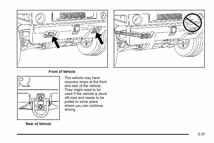
Front of Vehicle
Rear of Vehicle
The vehicle may haverecovery loops at the frontand rear of the vehicle.They might need to beused if the vehicle is stuckoff-road and needs to bepulled to some placewhere you can continuedriving.
5-37

First Aid Kit and Tool KitIf the vehicle has a first aid and tool kit, it is located inthe storage bin behind the spare tire on SUV models.It is held in place with a hook and loop fastener strap.
On SUT models, the kit is in the rear cargocompartment on the passenger side of the vehicle.
The kit includes a first aid kit (A), a tire pressuregauge (B), a flashlight (C), and a multi-purposetool set (D).
The tire pressure gauge has a reset button in the gaugestem. After taking a pressure reading, press the buttonto reset the gauge to zero.
5-38

Front Mounted Receiver
This vehicle is equipped with a front mounted receiver.
The receiver can be used with a power winch platform(described later in this section) or with otheraccessories.
Never use the front mounted receiver to tow a trailer.
Power Winch PlatformThe power winch platform (if equipped) can be usedwith an aftermarket winch. Connect the winch to theplatform and wiring to the vehicle following the winchmanufacturer's guidelines.
Notice: Do not use the winch platform to winch at atension of more than 4 082 kg (9,000 lbs). Thiswould damage the vehicle's frame. This damagewould not be covered by the vehicle warranty.
If using a winch to pull out another vehicle, follow thewinch manufacturer's guidelines and observe thefollowing to prevent damage to the vehicle:. If possible, have the vehicle anchored from the
opposite side of the winch to a solid, immovableobject.
If winching from the front, use both of the rearrecovery loops. If winching from the rear, use bothof the front recovery loops.
. Put the transmission in N (Neutral).
. Use the regular brakes to hold the vehicle in placeand block the wheels to keep the vehicle frommoving.
5-39

Notice: Using a power winch with the transmissionin gear to pull out another vehicle may damage thetransmission. When operating a power winch,always leave the transmission in N (Neutral).
Notice: Driving the vehicle through an automaticcar wash with the winch installed, can causedamage to ther vehicle and the car wash. Alwaysremove the winch from the vehicle before using anautomatic car wash. See Washing Your Vehicle onpage 6‑109 for more information.
If using a winch to pull out your own vehicle, follow thewinch manufacturer's guidelines for self recovery andobserve the following to prevent damage to the vehicle:. Do not self recover the vehicle by wrapping the
winch cable around an object (such as a pulleyblock or tree) and attaching it back to the vehicle'srecovery loops.
. Always attach the winch cable directly to a solidanchor directly in front of the vehicle to achieve astraight line pull.
Loading the VehicleIt is very important to know how much weight yourvehicle can carry. This weight is called the vehiclecapacity weight and includes the weight of alloccupants, cargo, and all nonfactory-installedoptions. Two labels on your vehicle show howmuch weight it may properly carry, the Tire andLoading Information label and the Certification/Tirelabel.
{ WARNING:
Do not load the vehicle any heavier than theGross Vehicle Weight Rating (GVWR),or either the maximum front or rear GrossAxle Weight Rating (GAWR). If you do, partson the vehicle can break, and it can changethe way the vehicle handles. These couldcause you to lose control and crash. Also,overloading can shorten the life of thevehicle.
5-40

Tire and Loading Information Label
Label Example
A vehicle specific Tire and Loading Informationlabel is attached to the center pillar (B-pillar). Withthe driver's door open, you will find the labelattached below the door lock post (striker). Thetire and loading information label shows thenumber of occupant seating positions (A), and themaximum vehicle capacity weight (B) in kilogramsand pounds.
The Tire and Loading Information label alsoshows the size of the original equipment tires (C)and the recommended cold tire inflationpressures (D). For more information on tires andinflation see Tires on page 6‑60 and Inflation - TirePressure on page 6‑66 .
There is also important loading information on thevehicle Certification/Tire label. It tells you theGross Vehicle Weight Rating (GVWR) and theGross Axle Weight Rating (GAWR) for the frontand rear axle. See “Certification/Tire Label” laterin this section.
Steps for Determining Correct Load Limit1. Locate the statement “The combined weight
of occupants and cargo should never exceedXXX kg or XXX lbs” on your vehicle's placard.
2. Determine the combined weight of the driverand passengers that will be riding in yourvehicle.
3. Subtract the combined weight of the driverand passengers from XXX kg or XXX lbs.
5-41

4. The resulting figure equals the availableamount of cargo and luggage load capacity.For example, if the “XXX” amount equals1400 lbs and there will be five 150 lbpassengers in your vehicle, the amount ofavailable cargo and luggage load capacity is650 lbs (1400 − 750 (5 x 150) = 650 lbs).
5. Determine the combined weight of luggageand cargo being loaded on the vehicle. Thatweight may not safely exceed the availablecargo and luggage load capacity calculated inStep 4.
6. If your vehicle will be towing a trailer, the loadfrom your trailer will be transferred to yourvehicle. Consult this manual to determinehow this reduces the available cargo andluggage load capacity of your vehicle.
See Towing a Trailer on page 5‑52 for importantinformation on towing a trailer, towing safety rulesand trailering tips.
Example 1
Item Description Total
AVehicle CapacityWeight forExample 1 =
1,000 lbs(453 kg)
BSubtract OccupantWeight @ 150 lbs(68 kg) × 2 =
300 lbs (136 kg)
CAvailable Occupantand Cargo Weight = 700 lbs (317 kg)
5-42
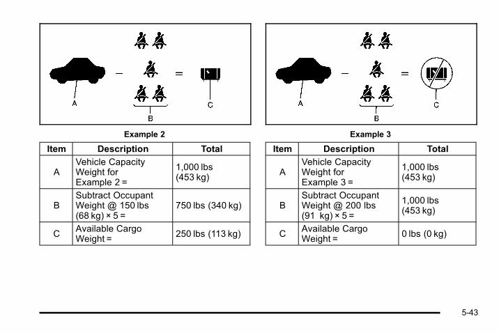
Example 2
Item Description Total
AVehicle CapacityWeight forExample 2 =
1,000 lbs(453 kg)
BSubtract OccupantWeight @ 150 lbs(68 kg) × 5 =
750 lbs (340 kg)
CAvailable CargoWeight = 250 lbs (113 kg)
Example 3
Item Description Total
AVehicle CapacityWeight forExample 3 =
1,000 lbs(453 kg)
BSubtract OccupantWeight @ 200 lbs(91 kg) × 5 =
1,000 lbs(453 kg)
CAvailable CargoWeight = 0 lbs (0 kg)
5-43

Refer to your vehicle's tire and loading informationlabel for specific information about your vehicle'scapacity weight and seating positions. Thecombined weight of the driver, passengers andcargo should never exceed your vehicle's capacityweight.
Certification/Tire Label
A vehicle specific Certification/Tire label isattached to the rear edge of the driver's door.
The label shows the gross weight capacity of yourvehicle. This is called the GVWR (Gross VehicleWeight Rating). The GVWR includes the weight ofthe vehicle, all occupants, fuel, and cargo.
The Certification/Tire label also tells you themaximum weights for the front and rear axles,called Gross Axle Weight Rating (GAWR). To findout the actual loads on your front and rear axles,you need to go to a weigh station and weigh yourvehicle. Your dealer can help you with this. Besure to spread out your load equally on both sidesof the centerline.
Never exceed the GVWR for your vehicle, or theGAWR for either the front or rear axle.
And, if you do have a heavy load, you shouldspread it out.
{ WARNING:
Do not load the vehicle any heavier than theGross Vehicle Weight Rating (GVWR),or either the maximum front or rear GrossAxle Weight Rating (GAWR). If you do, partson the vehicle can break, and it can change
(Continued)
5-44

WARNING: (Continued)
the way the vehicle handles. These couldcause you to lose control and crash. Also,overloading can shorten the life of thevehicle.
Your warranty does not cover parts orcomponents that fail because of overloading.
The label will help you decide how much cargoand installed equipment your truck can carry.
Using heavier suspension components to getadded durability might not change your weightratings. Ask your dealer to help you load yourvehicle the right way.
If you put things inside your vehicle— likesuitcases, tools, packages, or anythingelse— they go as fast as the vehicle goes. If youhave to stop or turn quickly, or if there is a crash,they will keep going.
{ WARNING:
Things you put inside your vehicle can strikeand injure people in a sudden stop or turn,or in a crash.. Put things in the cargo area of your
vehicle. Try to spread the weight evenly.. Never stack heavier things, like
suitcases, inside the vehicle so that someof them are above the tops of the seats.
. Do not leave an unsecured child restraintin your vehicle.
. When you carry something inside thevehicle, secure it whenever you can.
. Do not leave a seat folded down unlessyou need to.
There is also important loading information foroff-road driving in this manual. See “Loading YourVehicle for Off-Road Driving” under Off-RoadDriving on page 5‑13 .
5-45

Add-On EquipmentWhen you carry removable items, you may needto put a limit on how many people you can carryinside your vehicle. Be sure to weigh your vehiclebefore you buy and install the new equipment.
Notice : Overloading the vehicle may causedamage. Repairs would not be covered by thevehicle warranty. Do not overload the vehicle.
Remember not to exceed the Gross Axle WeightRating (GAWR) of the front or rear axle.
The Cargo Weight Rating (CWR) is the maximumweight of the load your vehicle can carry. It doesnot include the weight of the people inside. Butyou can figure about 150 lbs (68 kg) for each seat.
The total cargo load must not be more than yourvehicle's CWR.
Towing
Towing Your VehicleTo avoid damage, the disabled vehicle should be towedwith all four wheels off the ground. Consult your dealeror a professional towing service if the disabled vehiclemust be towed. See Roadside Assistance Program onpage 8‑7
To tow the vehicle behind another vehicle forrecreational purposes— such as behind a motorhome,see “Recreational Vehicle Towing” following.
Recreational Vehicle TowingRecreational vehicle towing means towing the vehiclebehind another vehicle – such as behind a motorhome.The two most common types of recreational vehicletowing are known as dinghy towing and dolly towing.Dinghy towing is towing the vehicle with all four wheelson the ground. Dolly towing is towing the vehicle withtwo wheels on the ground and two wheels up on adevice known as a dolly.
5-46

Here are some important things to consider beforerecreational vehicle towing:. What is the towing capacity of the towing vehicle?
Be sure to read the tow vehicle manufacturer'srecommendations.
. What is the distance that will be travelled? Somevehicles have restrictions on how far and how longthey can tow.
. Is the proper towing equipment going to be used?See your dealer or trailering professional foradditional advice and equipmentrecommendations.
. Is the vehicle ready to be towed? Just as preparingthe vehicle for a long trip, make sure the vehicle isprepared to be towed. See Before Leaving on aLong Trip on page 5‑32.
Dinghy Towing
This full‐time four‐wheel‐drive vehicle can be dinghytowed from the front. These vehicles can also be towedby placing them on a platform trailer with all four wheelsoff the ground. These vehicles cannot be towed using adolly.
5-47
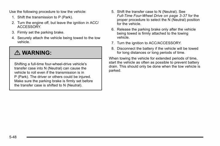
Use the following procedure to tow the vehicle:
1. Shift the transmission to P (Park).
2. Turn the engine off, but leave the ignition in ACC/ACCESSORY.
3. Firmly set the parking brake.
4. Securely attach the vehicle being towed to the towvehicle.
{ WARNING:
Shifting a full‐time four‐wheel‐drive vehicle'stransfer case into N (Neutral) can cause thevehicle to roll even if the transmission is inP (Park). The driver or others could be injured.Make sure the parking brake is firmly set beforethe transfer case is shifted to N (Neutral).
5. Shift the transfer case to N (Neutral). SeeFull-Time Four-Wheel Drive on page 3‑37 for theproper procedure to select the N (Neutral) positionfor the vehicle.
6. Release the parking brake only after the vehiclebeing towed is firmly attached to the towingvehicle.
7. Turn the ignition to ACC/ACCESSORY.
8. Disconnect the battery if the vehicle will be towedfor long distances or long periods of time.
When towing the vehicle for extended periods of time,start the vehicle as often as possible to prevent batterydrain. This should only be done when the tow vehicle isparked.
5-48
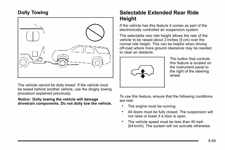
Dolly Towing
The vehicle cannot be dolly towed. If the vehicle mustbe towed behind another vehicle, use the dinghy towingprocedure explained previously.
Notice: Dolly towing the vehicle will damagedrivetrain components. Do not dolly tow the vehicle.
Selectable Extended Rear RideHeightIf the vehicle has this feature it comes as part of theelectronically controlled air suspension system.
The selectable rear ride height allows the rear of thevehicle to be raised about 2 inches (5 cm) over thenormal ride height. This can be helpful when drivingoff-road where more ground clearance may be neededto clear an obstacle.
The button that controlsthis feature is located onthe instrument panel tothe right of the steeringwheel.
To use this feature, ensure that the following conditionsare met:. The engine must be running.. All doors must be fully closed. The suspension will
not raise or lower if a door is open.. The vehicle speed must be less than 40 mph
(64 km/h). The system will not activate otherwise.
5-49

Press the height control button to raise the rear of thevehicle.
A light in the button will begin to flash as the rear of thevehicle rises. Once the extended height has beenreached (this may take up to a minute), the warninglight will stop flashing and will stay lit while the vehicleis at the extended height.
To lower the vehicle to the normal ride height, press thebutton again. The light in the button will flash as thesuspension lowers. When the light in the button stopsflashing and goes out, the suspension has reached thenormal ride height.
This feature will lower the vehicle to the normal height ifvehicle speed exceeds 40 mph (64 km/h).
This feature may also be used when ascending,descending or cresting a steep hill to help prevent therear bumper from dragging on the base of the hill orprevent the vehicle from grounding out (high centering)on the crest of the hill.
Do not use this feature when towing a trailer.
Electronically Controlled AirSuspension SystemWith this feature, the electronically controlled airsuspension keeps the rear of the vehicle level under allload conditions. The system maintains the vehicle at thecurrently selected ride height. There are two rideheights: Normal Ride Height and Extended Ride Height.The Extended Ride Height feature is only available ifthe vehicle speed is below 40mph (64 km/h). If thevehicle is at Extended Ride Height and the speedexceeds 40 mph (64 km/h), the system will automaticallyreturn the vehicle to Normal Ride Height.
The activation anddeactivation of theExtended Ride Heightfeature is controlled bythis switch on theinstrument panel.
The system includes a compressor, two height sensorsand two air springs supporting the vehicle.
5-50
The system is activated when the engine is started anddeactivated when the ignition is returned to OFF. Theengine must be running for the rear of the vehicle to beraised and the doors must be closed to enable atransition between Normal Ride Height and ExtendedRide Height.
The compressor may be heard while the system isactive and the release of air similar to a hissing soundmay also be heard. This is normal.
Load leveling will not function normally with the inflaterhose attached to the inflator outlet. Remove the hosefrom the outlet when it is not in use. See AccessoryInflator on page 6‑82.
Overload and Overheat ProtectionOverload protection is designed to protect the airsuspension system and is an indication to the driverthat the vehicle is overloaded.
If the rear suspension remains at a low height, the rearaxle load has exceeded GAWR (Gross Axle WeightRating). When the overload protection mode isactivated, the compressor operates for about
30 seconds to one minute without raising the vehicledepending on the amount of overload. This will continueeach time the ignition is turned on until the rear axleload is reduced below GAWR. The system mayreactivate without cycling the ignition if some of theexcess load is removed.
If the total rear GAWR (Gross Axle Weight Rating) isreached, the suspension may be slightly less than level.This is normal and does not mean there is a problemwith the air suspension.
In some instances the compressor may stop workingdue to being overheated. This is normal. In the instanceof an abnormal overheat condition though thecompressor will stop working and the SERVICESUSPENSION SYSTEM will be displayed on the DIC.See DIC Warnings and Messages on page 4‑52 formore information.
5-51

Towing a Trailer
{ WARNING:
The driver can lose control when pulling a trailer ifthe correct equipment is not used or the vehicle isnot driven properly. For example, if the trailer istoo heavy, the brakes may not work well— oreven at all. The driver and passengers could beseriously injured. The vehicle may also bedamaged; the resulting repairs would not becovered by the vehicle warranty. Pull a trailer onlyif all the steps in this section have been followed.Ask your dealer for advice and information abouttowing a trailer with the vehicle.
Notice: Pulling a trailer improperly can damage thevehicle and result in costly repairs not covered bythe vehicle warranty. To pull a trailer correctly,follow the advice in this section and see your dealerfor important information about towing a trailer withthe vehicle.
To identify the trailering capacity of the vehicle, read theinformation in “Weight of the Trailer” that appears laterin this section.
Trailering is different than just driving the vehicle byitself. Trailering means changes in handling,acceleration, braking, durability and fuel economy.Successful, safe trailering takes correct equipment, andit has to be used properly.
The following information has many time-tested,important trailering tips and safety rules. Many of theseare important for your safety and that of yourpassengers. So please read this section carefully beforepulling a trailer.
5-52

Pulling A TrailerHere are some important points:. There are many different laws, including speed
limit restrictions, having to do with trailering. Makesure the rig will be legal, not only where you livebut also where you will be driving. A good sourcefor this information can be state or provincialpolice.
. Consider using a sway control. See “Hitches” laterin this section.
. Do not tow a trailer at all during the first 500 miles(800 km) the new vehicle is driven. The engine,axle or other parts could be damaged.
. Then, during the first 500 miles (800 km) that atrailer is towed, do not drive over 50 mph (80 km/h)and do not make starts at full throttle. This helpsthe engine and other parts of the vehicle wear in atthe heavier loads.
. Vehicles can tow in D (Drive). Shift thetransmission to a lower gear if the transmissionshifts too often under heavy loads and/or hillyconditions. See “Tow/Haul Mode” following.
Three important considerations have to do with weight:. The weight of the trailer. The weight of the trailer tongue. The weight on the vehicle's tires
Weight of the TrailerHow heavy can a trailer safely be?
It depends on how the rig is used. For example, speed,altitude, road grades, outside temperature and howmuch the vehicle is used to pull a trailer are allimportant. It can depend on any special equipment onthe vehicle, and the amount of tongue weight thevehicle can carry. See “Weight of the Trailer Tongue”later in this section for more information.
Maximum trailer weight is calculated assuming only thedriver is in the tow vehicle and it has all the requiredtrailering equipment. The weight of additional optionalequipment, passengers and cargo in the tow vehiclemust be subtracted from the maximum trailer weight.
5-53
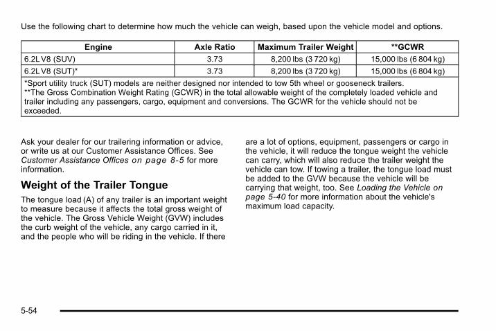
Use the following chart to determine how much the vehicle can weigh, based upon the vehicle model and options.
Engine Axle Ratio Maximum Trailer Weight **GCWR
6.2LV8 (SUV) 3.73 8,200 lbs (3 720 kg) 15,000 lbs (6 804 kg)
6.2LV8 (SUT)* 3.73 8,200 lbs (3 720 kg) 15,000 lbs (6 804 kg)
*Sport utility truck (SUT) models are neither designed nor intended to tow 5th wheel or gooseneck trailers.**The Gross Combination Weight Rating (GCWR) in the total allowable weight of the completely loaded vehicle andtrailer including any passengers, cargo, equipment and conversions. The GCWR for the vehicle should not beexceeded.
Ask your dealer for our trailering information or advice,or write us at our Customer Assistance Offices. SeeCustomer Assistance Offices on page 8‑5 for moreinformation.
Weight of the Trailer TongueThe tongue load (A) of any trailer is an important weightto measure because it affects the total gross weight ofthe vehicle. The Gross Vehicle Weight (GVW) includesthe curb weight of the vehicle, any cargo carried in it,and the people who will be riding in the vehicle. If there
are a lot of options, equipment, passengers or cargo inthe vehicle, it will reduce the tongue weight the vehiclecan carry, which will also reduce the trailer weight thevehicle can tow. If towing a trailer, the tongue load mustbe added to the GVW because the vehicle will becarrying that weight, too. See Loading the Vehicle onpage 5‑40 for more information about the vehicle'smaximum load capacity.
5-54

The trailer tongue weight (A) should be 10 percent to15 percent of the total loaded trailer weight (B), up to amaximum of 600 lbs (272 kg) with a weight carryinghitch. The trailer tongue weight (A) should be10 percent to 15 percent of the total loaded trailerweight (B), up to a maximum of 1,000 lbs (454 kg) witha weight distributing hitch.
Do not exceed the maximum allowable tongue weightfor the vehicle. Choose the shortest hitch extension thatwill position the hitch ball closest to the vehicle. This willhelp reduce the effect of trailer tongue weight on therear axle.
The spare tire carrier is behind the tailgate. If the hitchextension is too short, the spare tire may interfere withtrailer coupling or trailer tongue jack operation on sometypes of trailers.
After loading the trailer, weigh the trailer and then thetongue, separately, to see if the weights are proper.If they are not, adjustments might be made by movingsome items around in the trailer.
Trailering may be limited by the vehicle's ability to carrytongue weight. Tongue weight cannot cause the vehicleto exceed the GVWR (Gross Vehicle Weight Rating) orthe RGAWR (Rear Gross Axle Weight Rating). Theeffect of additional weight may reduce the traileringcapacity more than the total of the additional weight.
Consider the following example:
A vehicle model base weight is 5,500 lbs (2 495 kg);2,800 lbs (1 270 kg) at the front axle and 2,700 lbs(1 225 kg) at the rear axle. It has a GVWR of 7,200 lbs(3 266 kg), a RGAWR of 4,000 lbs (1 814 kg) and aGCWR (Gross Combination Weight Rating) of14,000 lbs (6 350 kg). The trailer rating should be:
Expect tongue weight to be at least 10 percent of trailerweight (850 lbs (386 kg)) and because the weight isapplied well behind the rear axle, the effect on the rear
5-55
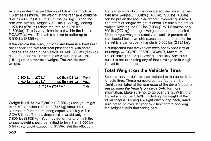
axle is greater than just the weight itself, as much as1.5 times as much. The weight at the rear axle could be850 lbs (386 kg) X 1.5 = 1,275 lbs (578 kg). Since therear axle already weighs 2,700 lbs (1 225 kg), adding1,275 lbs (578 kg) brings the total to 3,975 lbs(1 803 kg). This is very close to, but within the limit forRGAWR as well. The vehicle is set to trailer up to8,500 lbs (3 856 kg).
If the vehicle has many options and there is a front seatpassenger and two rear seat passengers with someluggage and gear in the vehicle as well. 300 lbs (136 kg)could be added to the front axle weight and 400 lbs(181 kg) to the rear axle weight. The vehicle nowweighs:
Weight is still below 7,200 lbs (3 266 kg) and you mightthink 700 additional pounds (318 kg) should besubtracted from the trailering capacity to stay withinGCWR limits. The maximum trailer would only be7,800 lbs (3 538 kg). You may go further and think thetongue weight should be limited to less than 1,000 lbs(454 kg) to avoid exceeding GVWR. But the effect on
the rear axle must still be considered. Because the rearaxle now weighs 3,100 lbs (1 406 kg), 900 lbs (408 kg)can be put on the rear axle without exceeding RGAWR.The effect of tongue weight is about 1.5 times the actualweight. Dividing the 900 lbs (408 kg) by 1.5 leaves only600 lbs (272 kg) of tongue weight that can be handled.Since tongue weight is usually at least 10 percent oftotal loaded trailer weight, expect that the largest trailerthe vehicle can properly handle is 6,000 lbs (2 721 kg).
It is important that the vehicle does not exceed any ofits ratings — GCWR, GVWR, RGAWR, MaximumTrailer Rating or Tongue Weight. The only way to besure it is not exceeding any of these ratings is to weighthe vehicle and trailer.
Total Weight on the Vehicle's TiresBe sure the vehicle's tires are inflated to the upper limitfor cold tires. These numbers can be found on theCertification label at the rear edge of the driver's door orsee Loading the Vehicle on page 5‑40 for moreinformation. Make sure not to go over the GVW limit forthe vehicle, or the GAWR, including the weight of thetrailer tongue. If using a weight distributing hitch, makesure not to go over the rear axle limit before applyingthe weight distribution spring bars.
5-56

HitchesIt is important to have the correct hitch equipment.Crosswinds, large trucks going by and rough roads area few reasons why the right hitch is needed.
Weight‐Distributing Hitches and WeightCarrying Hitches
A: Body to Ground Distance
B: Front of Vehicle
When using a weight-distributing hitch, the hitch mustbe adjusted so the distance (A) remains the same bothbefore and after coupling the trailer to the tow vehicle.
If a step-bumper hitch will be used, the bumper couldbe damaged in sharp turns. Make sure there is ampleroom when turning to avoid contact between the trailerand the bumper.
If the loaded trailer being pulled will weigh more than5,000 lbs (2 270 kg), be sure to use a properly mountedweight-distributing hitch and sway control of the propersize. This equipment is very important for proper vehicleloading and good handling when driving. Always use asway control if the trailer will weigh more than theselimits. Ask a hitch dealer about sway controls.
Safety ChainsAlways attach chains between the vehicle and thetrailer. Cross the safety chains under the tongue of thetrailer to help prevent the tongue from contacting theroad if it becomes separated from the hitch. Instructionsabout safety chains may be provided by the hitchmanufacturer or by the trailer manufacturer. If the trailerbeing towed weighs up to the vehicle's trailer ratinglimit, safety chains may be attached to the attachingpoint on the hitch platform. Always leave just enoughslack so the rig can turn. Never allow safety chains todrag on the ground.
5-57

Tow/Haul ModePressing this button at theend of the shift lever turnson and off the tow/haul mode.
This indicator light on theinstrument panel clustercomes on when the tow/haul mode is on.
Tow/Haul is a feature that assists when pulling a heavytrailer or a large or heavy load. See Tow/Haul Mode onpage 3‑36 for more information.
Tow/Haul is designed to be most effective when thevehicle and trailer combined weight is at least75 percent of the vehicle's Gross Combined WeightRating (GCWR). See “Weight of the Trailer” later in thesection. Tow/Haul is most useful under the followingdriving conditions:. When pulling a heavy trailer or a large or heavy
load through rolling terrain.. When pulling a heavy trailer or a large or heavy
load in stop and go traffic.. When pulling a heavy trailer or a large or heavy
load in busy parking lots where improved lowspeed control of the vehicle is desired.
Operating the vehicle in Tow/Haul when lightly loadedor with no trailer at all will not cause damage. However,there is no benefit to the selection of Tow/Haul when thevehicle is unloaded. Such a selection when unloadedmay result in unpleasant engine and transmissiondriving characteristics and reduced fuel economy. Tow/Haul is recommended only when pulling a heavy traileror a large or heavy load.
5-58

Trailer BrakesA loaded trailer that weighs more than 2,000 lbs(900 kg) needs to have its own brake system that isadequate for the weight of the trailer. Be sure to readand follow the instructions for the trailer brakes so theyare installed, adjusted and maintained properly.
Since the vehicle is equipped with StabiliTrak®, thetrailer brakes cannot tap into the vehicle's hydraulicbrake system.
Driving with a Trailer
{ WARNING:
When towing a trailer, exhaust gases may collectat the rear of the vehicle and enter if the liftgate,trunk/hatch, or rear-most window is open.
Engine exhaust contains carbon monoxide (CO)which cannot be seen or smelled. It can causeunconsciousness and even death.
(Continued)
WARNING: (Continued)
To maximize safety when towing a trailer:. Have the exhaust system inspected for leaks
and make necessary repairs before startinga trip.
. Never drive with the liftgate, trunk/hatch,or rear-most window open.
. Fully open the air outlets on or under theinstrument panel.
. Adjust the Climate Control system to a settingthat brings in only outside air and set the fanspeed to the highest setting. See ClimateControl System in the Index.
For more information about carbon monoxide, seeEngine Exhaust on page 3‑45.
Towing a trailer requires a certain amount ofexperience. Get to know the rig before setting out forthe open road. Get acquainted with the feel of handlingand braking with the added weight of the trailer. Andalways keep in mind that the vehicle you are driving isnow longer and not as responsive as the vehicle is byitself.
5-59
Before starting, check all trailer hitch parts andattachments, safety chains, electrical connectors,lamps, tires and mirror adjustments. If the trailer haselectric brakes, start the vehicle and trailer moving andthen apply the trailer brake controller by hand to be surethe brakes are working. This checks the electricalconnection at the same time.
During the trip, check occasionally to be sure that theload is secure, and that the lamps and any trailerbrakes are still working.
Following DistanceStay at least twice as far behind the vehicle ahead asyou would when driving the vehicle without a trailer.This can help to avoid situations that require heavybraking and sudden turns.
PassingMore passing distance is needed when towing a trailer.Because the rig is longer, it is necessary to go muchfarther beyond the passed vehicle before returning tothe lane.
Backing UpHold the bottom of the steering wheel with one hand.Then, to move the trailer to the left, move that hand tothe left. To move the trailer to the right, move your handto the right. Always back up slowly and, if possible,have someone guide you.
Making TurnsNotice: Making very sharp turns while traileringcould cause the trailer to come in contact with thevehicle. The vehicle could be damaged. Avoidmaking very sharp turns while trailering.
When turning with a trailer, make wider turns thannormal. Do this so the trailer will not strike softshoulders, curbs, road signs, trees or other objects.Avoid jerky or sudden maneuvers. Signal well inadvance.
Turn Signals When Towing a TrailerThe arrows on the instrument panel flash wheneversignaling a turn or lane change. Properly hooked up,the trailer lamps also flash, telling other drivers thevehicle is turning, changing lanes or stopping.
When towing a trailer, the arrows on the instrumentpanel flash for turns even if the bulbs on the trailer areburned out. For this reason you may think other driversare seeing the signal when they are not. It is importantto check occasionally to be sure the trailer bulbs are stillworking.
5-60

Driving On GradesReduce speed and shift to a lower gear before startingdown a long or steep downgrade. If the transmission isnot shifted down, the brakes might have to be used somuch that they would get hot and no longer work well.
Vehicles can tow in D (Drive). Shift the transmission toa lower gear if the transmission shifts too often underheavy loads and/or hilly conditions.
The tow/haul mode may be used if the transmissionshifts too often. See Tow/Haul Mode Light onpage 4‑40.
When towing at high altitude on steep uphill grades,consider the following: Engine coolant will boil at alower temperature than at normal altitudes. If the engineis turned off immediately after towing at high altitude onsteep uphill grades, the vehicle may show signs similarto engine overheating. To avoid this, let the engine runwhile parked, preferably on level ground, with theautomatic transmission in P (Park) for a few minutesbefore turning the engine off. If the overheat warningcomes on, see Engine Overheating on page 6‑36.
Parking on Hills
{ WARNING:
Parking the vehicle on a hill with the trailerattached can be dangerous. If something goeswrong, the rig could start to move. People can beinjured, and both the vehicle and the trailer can bedamaged. When possible, always park the rig ona flat surface.
If parking the rig on a hill:
1. Press the brake pedal, but do not shift into P (Park)yet. Turn the wheels into the curb if facing downhillor into traffic if facing uphill.
2. Have someone place chocks under the trailerwheels.
3. When the wheel chocks are in place, release theregular brakes until the chocks absorb the load.
4. Reapply the brake pedal. Then apply the parkingbrake and shift into P (Park).
5-61

5. Be sure the transfer case is in a drive gear and notin N (Neutral).
6. Release the brake pedal.
{ WARNING:
It can be dangerous to get out of the vehicle if theshift lever is not fully in P (Park) with the parkingbrake firmly set. The vehicle can roll.
If the engine has been left running, the vehiclecan move suddenly. You or others could beinjured. To be sure the vehicle will not move, evenwhen on fairly level ground, use the steps thatfollow.
Always put the shift lever fully in P (Park) with theparking brake firmly set.
If the transfer case on a four-wheel-drive vehicleis in N (Neutral), the vehicle will be free to roll,even if the shift lever is in P (Park). Be sure thetransfer case is in a drive gear — not inN (Neutral).
Leaving After Parking on a Hill1. Apply and hold the brake pedal while you:
. Start the engine
. Shift into a gear
. Release the parking brake
2. Let up on the brake pedal.
3. Drive slowly until the trailer is clear of the chocks.
4. Stop and have someone pick up and store thechocks.
5-62

Maintenance When Trailer TowingThe vehicle needs service more often when pulling atrailer. See this manual's Maintenance Schedule orIndex for more information. Things that are especiallyimportant in trailer operation are automatic transmissionfluid, engine oil, axle lubricant, belts, cooling systemand brake system. It is a good idea to inspect thesebefore and during the trip.
Check periodically to see that all hitch nuts and boltsare tight.
Trailer Wiring Harness
Heavy-Duty Trailer Wiring Harness Package
The vehicle is equipped with the seven-wire trailertowing harness. This harness with a seven-pin universaltrailer connector is attached to a bracket on the hitchplatform.
The seven-wire harness contains the following trailercircuits:. Yellow: Left Stop/Turn Signal. Dark Green: Right Stop/Turn Signal. Brown: Taillamps. White: Ground. Light Green: Back-up Lamps. Red/Black: Battery Feed*. Dark Blue: Trailer Brake*
*There is a location in the Underhood Fuse Block forthese circuits, but they are not connected. They shouldbe connected, and proper fuses installed, by yourdealer or a qualified service center.
If charging a remote (non-vehicle) battery, press theTow/Haul mode button located at the end of the shiftlever. This will boost the vehicle system voltage andproperly charge the battery.
5-63
Electric Brake Control WiringProvisionsThese wiring provisions are included with the vehicle aspart of the trailer wiring package. These provisions arefor an electric brake controller. The instrument panelcontains blunt cut wires near the data link connector forthe trailer brake controller. The harness contains thefollowing wires:. Dark Blue: Brake Signal to Trailer Connector. Red/Black: Battery. Light Blue/White: Brake Switch. White: Ground
It should be installed by your dealer or a qualifiedservice center.
Trailer RecommendationsSubtract the hitch loads from the Cargo Weight Rating(CWR). CWR is the maximum weight of the load thevehicle can carry. It does not include the weight of thepeople inside, but you can figure about 150 lbs. (68 kg)for each passenger. The total cargo load must not bemore than the vehicles CWR.
Weigh the vehicle with the trailer attached, so theGVWR or GAWR are not exceeded. If using aweight-distributing hitch, weigh the vehicle without thespring bars in place.
The best performance is obtained by correctlyspreading out the weight of the load and choosing thecorrect hitch and trailer brakes.
For more information see Towing a Trailer onpage 5‑52.
5-64

Section 6 Service and Appearance Care
Service . . . . . . . . . . . . . . . . . . . . . . . . . . . . . . . . . . . . . . . . . . . . . 6-4Accessories and Modifications . . . . . . . . . . . . . . . . . . 6-4California Proposition 65 Warning . . . . . . . . . . . . . . . 6-4California Perchlorate MaterialsRequirements . . . . . . . . . . . . . . . . . . . . . . . . . . . . . . . . . 6-4
Doing Your Own Service Work . . . . . . . . . . . . . . . . . . 6-5Adding Equipment to the Outside of theVehicle . . . . . . . . . . . . . . . . . . . . . . . . . . . . . . . . . . . . . . . . 6-5
Fuel . . . . . . . . . . . . . . . . . . . . . . . . . . . . . . . . . . . . . . . . . . . . . . . . . 6-6Gasoline Octane . . . . . . . . . . . . . . . . . . . . . . . . . . . . . . . . 6-7Gasoline Specifications . . . . . . . . . . . . . . . . . . . . . . . . . 6-7California Fuel . . . . . . . . . . . . . . . . . . . . . . . . . . . . . . . . . . 6-7Additives . . . . . . . . . . . . . . . . . . . . . . . . . . . . . . . . . . . . . . . . 6-8Fuel E85 (85% Ethanol) . . . . . . . . . . . . . . . . . . . . . . . . . 6-9Fuels in Foreign Countries . . . . . . . . . . . . . . . . . . . . . 6-10Filling the Tank . . . . . . . . . . . . . . . . . . . . . . . . . . . . . . . . 6-10Filling a Portable Fuel Container . . . . . . . . . . . . . . . 6-13
Checking Things Under the Hood . . . . . . . . . . . . . . . 6-13Hood Release . . . . . . . . . . . . . . . . . . . . . . . . . . . . . . . . . 6-14Engine Compartment Overview . . . . . . . . . . . . . . . . 6-16Engine Oil . . . . . . . . . . . . . . . . . . . . . . . . . . . . . . . . . . . . . 6-18Engine Oil Life System . . . . . . . . . . . . . . . . . . . . . . . . 6-20Engine Air Cleaner/Filter . . . . . . . . . . . . . . . . . . . . . . . 6-22
Automatic Transmission Fluid . . . . . . . . . . . . . . . . . . 6-25Cooling System . . . . . . . . . . . . . . . . . . . . . . . . . . . . . . . . 6-29Engine Coolant . . . . . . . . . . . . . . . . . . . . . . . . . . . . . . . . 6-30Engine Overheating . . . . . . . . . . . . . . . . . . . . . . . . . . . 6-36Overheated Engine ProtectionOperating Mode . . . . . . . . . . . . . . . . . . . . . . . . . . . . . 6-38
Power Steering Fluid . . . . . . . . . . . . . . . . . . . . . . . . . . 6-39Windshield Washer Fluid . . . . . . . . . . . . . . . . . . . . . . 6-40Brakes . . . . . . . . . . . . . . . . . . . . . . . . . . . . . . . . . . . . . . . . . 6-41Battery . . . . . . . . . . . . . . . . . . . . . . . . . . . . . . . . . . . . . . . . . 6-44Jump Starting . . . . . . . . . . . . . . . . . . . . . . . . . . . . . . . . . . 6-44
Rear Axle . . . . . . . . . . . . . . . . . . . . . . . . . . . . . . . . . . . . . . . . . 6-49
Four-Wheel Drive . . . . . . . . . . . . . . . . . . . . . . . . . . . . . . . . . 6-50
Front Axle . . . . . . . . . . . . . . . . . . . . . . . . . . . . . . . . . . . . . . . . . 6-51
Bulb Replacement . . . . . . . . . . . . . . . . . . . . . . . . . . . . . . . . 6-52Halogen Bulbs . . . . . . . . . . . . . . . . . . . . . . . . . . . . . . . . . 6-52Headlamps . . . . . . . . . . . . . . . . . . . . . . . . . . . . . . . . . . . . 6-52Front Turn Signal and Parking Lamps . . . . . . . . . 6-53Daytime Running Lamps (DRL) . . . . . . . . . . . . . . . . 6-54Roof Marker Lamps . . . . . . . . . . . . . . . . . . . . . . . . . . . . 6-54Taillamps, Turn Signal, Stoplamps and Back-upLamps . . . . . . . . . . . . . . . . . . . . . . . . . . . . . . . . . . . . . . . 6-56
Replacement Bulbs . . . . . . . . . . . . . . . . . . . . . . . . . . . . 6-58
6-1

Section 6 Service and Appearance Care
Windshield Wiper Blade Replacement . . . . . . . . . . . 6-58
Tires . . . . . . . . . . . . . . . . . . . . . . . . . . . . . . . . . . . . . . . . . . . . . . . 6-60Tire Sidewall Labeling . . . . . . . . . . . . . . . . . . . . . . . . . 6-61Tire Terminology and Definitions . . . . . . . . . . . . . . . 6-63Inflation - Tire Pressure . . . . . . . . . . . . . . . . . . . . . . . . 6-66Tire Pressure Monitor System . . . . . . . . . . . . . . . . . 6-67Tire Pressure Monitor Operation . . . . . . . . . . . . . . . 6-68Tire Inspection and Rotation . . . . . . . . . . . . . . . . . . . 6-72When It Is Time for New Tires . . . . . . . . . . . . . . . . . 6-74Buying New Tires . . . . . . . . . . . . . . . . . . . . . . . . . . . . . . 6-75Different Size Tires and Wheels . . . . . . . . . . . . . . . 6-77Uniform Tire Quality Grading . . . . . . . . . . . . . . . . . . . 6-78Wheel Alignment and Tire Balance . . . . . . . . . . . . 6-79Wheel Replacement . . . . . . . . . . . . . . . . . . . . . . . . . . . 6-80Tire Chains . . . . . . . . . . . . . . . . . . . . . . . . . . . . . . . . . . . . 6-81Accessory Inflator . . . . . . . . . . . . . . . . . . . . . . . . . . . . . . 6-82If a Tire Goes Flat . . . . . . . . . . . . . . . . . . . . . . . . . . . . . 6-83Changing a Flat Tire . . . . . . . . . . . . . . . . . . . . . . . . . . . 6-84Removing the Spare Tire and Tools (SUT) . . . . . 6-86Removing the Spare Tire and Tools (SUV) . . . . . 6-90Removing the Flat Tire and Installing theSpare Tire . . . . . . . . . . . . . . . . . . . . . . . . . . . . . . . . . . . 6-94
Storing a Flat or Spare Tire and Tools (SUT) . . . 6-99
Storing a Flat or Spare Tire andTools (SUV) . . . . . . . . . . . . . . . . . . . . . . . . . . . . . . . . 6-102
Spare Tire . . . . . . . . . . . . . . . . . . . . . . . . . . . . . . . . . . . . 6-105
Appearance Care . . . . . . . . . . . . . . . . . . . . . . . . . . . . . . . . 6-106Interior Cleaning . . . . . . . . . . . . . . . . . . . . . . . . . . . . . 6-106Fabric/Carpet . . . . . . . . . . . . . . . . . . . . . . . . . . . . . . . . . 6-107Leather . . . . . . . . . . . . . . . . . . . . . . . . . . . . . . . . . . . . . . . 6-108Instrument Panel, Vinyl, and Other PlasticSurfaces . . . . . . . . . . . . . . . . . . . . . . . . . . . . . . . . . . . 6-108
Wood Panels . . . . . . . . . . . . . . . . . . . . . . . . . . . . . . . . . 6-108Speaker Covers . . . . . . . . . . . . . . . . . . . . . . . . . . . . . . 6-108Care of Safety Belts . . . . . . . . . . . . . . . . . . . . . . . . . . 6-109Weatherstrips . . . . . . . . . . . . . . . . . . . . . . . . . . . . . . . . 6-109Washing Your Vehicle . . . . . . . . . . . . . . . . . . . . . . . . 6-109Cleaning Exterior Lamps/Lenses . . . . . . . . . . . . . 6-110Finish Care . . . . . . . . . . . . . . . . . . . . . . . . . . . . . . . . . . . 6-110Windshield, Backglass, and Wiper Blades . . . . 6-111Aluminum Wheels . . . . . . . . . . . . . . . . . . . . . . . . . . . . 6-111Tires . . . . . . . . . . . . . . . . . . . . . . . . . . . . . . . . . . . . . . . . . . 6-112Sheet Metal Damage . . . . . . . . . . . . . . . . . . . . . . . . . 6-112Finish Damage . . . . . . . . . . . . . . . . . . . . . . . . . . . . . . . 6-112Underbody Maintenance . . . . . . . . . . . . . . . . . . . . . . 6-112Chemical Paint Spotting . . . . . . . . . . . . . . . . . . . . . . 6-112
6-2
Section 6 Service and Appearance Care
Vehicle Identification . . . . . . . . . . . . . . . . . . . . . . . . . . . . 6-113Vehicle Identification Number (VIN) . . . . . . . . . . . 6-113Service Parts Identification Label . . . . . . . . . . . . . 6-113
Electrical System . . . . . . . . . . . . . . . . . . . . . . . . . . . . . . . . 6-113Add-On Electrical Equipment . . . . . . . . . . . . . . . . . 6-113Windshield Wiper Fuses . . . . . . . . . . . . . . . . . . . . . . 6-114
Power Windows and Other Power Options . . . 6-114Fuses and Circuit Breakers . . . . . . . . . . . . . . . . . . . 6-114Instrument Panel Fuse Block . . . . . . . . . . . . . . . . . 6-115Center Instrument Panel Fuse Block . . . . . . . . . . 6-116Underhood Fuse Block . . . . . . . . . . . . . . . . . . . . . . . 6-117
Capacities and Specifications . . . . . . . . . . . . . . . . . . 6-121
6-3
ServiceFor service and parts needs, visit your dealer. You willreceive genuine parts and trained and supportedservice people.
Accessories and ModificationsWhen non‐dealer/non‐retailer accessories are added tothe vehicle, they can affect vehicle performance andsafety, including such things as airbags, braking,stability, ride and handling, emissions systems,aerodynamics, durability, and electronic systems likeantilock brakes, traction control, and stability control.Some of these accessories could even causemalfunction or damage not covered by the vehiclewarranty.
Damage to vehicle components resulting from theinstallation or use of non‐certified parts, includingcontrol module modifications, is not covered under theterms of the vehicle warranty and may affect remainingwarranty coverage for affected parts.
HUMMER Accessories are designed to complementand function with other systems on the vehicle. YourHUMMER dealer can accessorize the vehicle usinggenuine HUMMER Accessories. When you go to yourHUMMER dealer and ask for HUMMER Accessories,
you will know that HUMMER-trained and supportedservice technicians will perform the work using genuineHUMMER Accessories.
Also, see Adding Equipment to Your Airbag-EquippedVehicle on page 2‑78.
California Proposition 65 WarningMost motor vehicles, including this one, contain and/oremit chemicals known to the State of California tocause cancer and birth defects or other reproductiveharm. Engine exhaust, many parts and systems, manyfluids, and some component wear by-products containand/or emit these chemicals.
California Perchlorate MaterialsRequirementsCertain types of automotive applications, such as airbaginitiators, seat belt pretensioners, and lithium batteriescontained in remote keyless transmitters, may containperchlorate materials. Special handling may benecessary. For additional information, seewww.dtsc.ca.gov/hazardouswaste/perchlorate.
6-4

Doing Your Own Service Work
{ WARNING:
You can be injured and the vehicle could bedamaged if you try to do service work on a vehiclewithout knowing enough about it.
. Be sure you have sufficient knowledge,experience, the proper replacement parts, andtools before attempting any vehiclemaintenance task.
. Be sure to use the proper nuts, bolts, andother fasteners. English and metric fastenerscan be easily confused. If the wrong fastenersare used, parts can later break or fall off. Youcould be hurt.
If doing some of your own service work, use the properservice manual. It tells you much more about how toservice the vehicle than this manual can. To order theproper service manual, see Service PublicationsOrdering Information on page 8‑15.
This vehicle has an airbag system. Before attempting todo your own service work, see Servicing YourAirbag-Equipped Vehicle on page 2‑77.
Keep a record with all parts receipts and list the mileageand the date of any service work performed. SeeMaintenance Record on page 7‑14.
Adding Equipment to the Outside ofthe VehicleThings added to the outside of the vehicle can affect theairflow around it. This can cause wind noise and canaffect fuel economy and windshield washerperformance. Check with your dealer before addingequipment to the outside of the vehicle.
6-5

FuelUse of the recommended fuel is an important part of theproper maintenance of this vehicle. To help keep theengine clean and maintain optimum vehicleperformance, we recommend the use of gasolineadvertised as TOP TIER Detergent Gasoline.
Look for the TOP TIER label on the fuel pump to ensuregasoline meets enhanced detergency standardsdeveloped by auto companies. A list of marketersproviding TOP TIER Detergent Gasoline can be foundat www.toptiergas.com.
This vehicle can use either unleaded gasoline orethanol fuel containing up to 85% ethanol (E85). SeeGasoline Octane on page 6‑7 and Fuel E85(85% Ethanol) on page 6‑9.
6-6

Gasoline OctaneUse premium unleaded gasoline with a posted octanerating of 91 or higher. You can also use regularunleaded gasoline rated at 87 octane or higher, but thevehicle's acceleration could be slightly reduced, and aslight audible knocking noise, commonly referred to asspark knock, might be heard. If the octane is less than87, you might notice a heavy knocking noise when youdrive. If this occurs, use a gasoline rated at 87 octaneor higher as soon as possible. Otherwise, you coulddamage the engine. If heavy knocking is heard whenusing gasoline rated at 87 octane or higher, the engineneeds service.
Gasoline SpecificationsAt a minimum, gasoline should meet ASTMspecification D 4814 in the United States orCAN/CGSB‐3.5 or 3.511 in Canada. Some gasolinescontain an octane-enhancing additive calledmethylcyclopentadienyl manganese tricarbonyl (MMT).We recommend against the use of gasolines containingMMT. See Additives on page 6‑8 for additionalinformation.
California FuelIf the vehicle is certified to meet California EmissionsStandards, it is designed to operate on fuels that meetCalifornia specifications. See the underhood emissioncontrol label. If this fuel is not available in statesadopting California emissions standards, the vehicle willoperate satisfactorily on fuels meeting federalspecifications, but emission control system performancemight be affected. The malfunction indicator lamp couldturn on and the vehicle might fail a smog‐check test.See Malfunction Indicator Lamp on page 4‑34. If thisoccurs, return to your authorized dealer for diagnosis.If it is determined that the condition is caused by thetype of fuel used, repairs might not be covered by thevehicle warranty.
6-7

AdditivesTo provide cleaner air, all gasolines in the United Statesare now required to contain additives that help preventengine and fuel system deposits from forming, allowingthe emission control system to work properly. In mostcases, nothing should have to be added to the fuel.However, some gasolines contain only the minimumamount of additive required to meet U.S. EnvironmentalProtection Agency regulations. To help keep fuelinjectors and intake valves clean, or if the vehicleexperiences problems due to dirty injectors or valves,look for gasoline that is advertised as TOP TIERDetergent Gasoline.
For customers who do not use TOP TIER DetergentGasoline regularly, one bottle of GM Fuel SystemTreatment PLUS, added to the fuel tank at every engineoil change, can help clean deposits from fuel injectorsand intake valves. GM Fuel System Treatment PLUS isthe only gasoline additive recommended by HUMMER.
Also, your dealer has additives that will help correct andprevent most deposit‐related problems.
Gasolines containing oxygenates, such as ethers andethanol, and reformulated gasolines might be availablein your area. We recommend that you use thesegasolines, if they comply with the specificationsdescribed earlier. However, E85 (85% ethanol) andother fuels containing more than 10% ethanol must notbe used in vehicles that were not designed for thosefuels.
Notice: This vehicle was not designed for fuel thatcontains methanol. Do not use fuel containingmethanol. It can corrode metal parts in the fuelsystem and also damage plastic and rubber parts.That damage would not be covered under thevehicle warranty.
Some gasolines that are not reformulated for lowemissions can contain an octane-enhancing additivecalled methylcyclopentadienyl manganese tricarbonyl(MMT); ask the attendant where you buy gasolinewhether the fuel contains MMT. We recommend againstthe use of such gasolines. Fuels containing MMT canreduce the life of spark plugs and the performance ofthe emission control system could be affected. Themalfunction indicator lamp might turn on. If this occurs,return to your dealer for service.
6-8

Fuel E85 (85% Ethanol)This vehicle can use either unleaded gasoline or85% ethanol fuel (E85). We encourage the use ofE85 in vehicles that are designed to use it. The ethanolin E85 is a “renewable” fuel, meaning it is made fromrenewable sources such as corn and other crops.
Many service stations will not have an 85% ethanol fuel(E85) pump available. The U.S. Department of Energyhas an alternative fuels website (www.eere.energy.gov/afdc/infrastructure/locator.html) that can help you findE85 fuel. Those stations that do have E85 should havea label indicating ethanol content. Do not use the fuel ifthe ethanol content is greater than 85%.
At a minimum, E85 should meet ASTM SpecificationD 5798. By definition, this means that fuel labeled E85will have an ethanol content between 70% and 85%.Filling the fuel tank with fuel mixtures that do not meetASTM specifications can affect driveability and couldcause the malfunction indicator lamp to come on.
To ensure quick starts in the wintertime, the E85 fuelmust be formulated properly for your climate accordingto ASTM specification D 5798. If you have troublestarting on E85, it could be because the E85 fuel is notproperly formulated for your climate. If this happens,switching to gasoline or adding gasoline to the fuel tank
can improve starting. For good starting and heaterefficiency below 0°C (32°F), the fuel mix in the fuel tankshould contain no more than 70% ethanol. It is best notto alternate repeatedly between gasoline and E85.If you do switch fuels, it is recommended that you addas much fuel as possible — do not add less than11 L (three gallons) when refueling. You should drivethe vehicle immediately after refueling for at least11 km (seven miles) to allow the vehicle to adapt to thechange in ethanol concentration.
E85 has less energy per gallon than gasoline, so youwill need to refill the fuel tank more often when usingE85 than when you are using gasoline. See Filling theTank on page 6‑10.
Notice: Some additives are not compatible withE85 fuel and can harm the vehicle's fuel system. Donot add anything to E85. Damage caused byadditives would not be covered by the vehiclewarranty.
Notice: This vehicle was not designed for fuel thatcontains methanol. Do not use fuel containingmethanol. It can corrode metal parts in the fuelsystem and also damage plastic and rubber parts.That damage would not be covered under thevehicle warranty.
6-9

Fuels in Foreign CountriesIf you plan on driving in another country outside theUnited States or Canada, the proper fuel might be hardto find. Never use leaded gasoline or any other fuel notrecommended in the previous text on fuel. Costlyrepairs caused by use of improper fuel would not becovered by the vehicle warranty.
To check the fuel availability, ask an auto club,or contact a major oil company that does business inthe country where you will be driving.
Filling the Tank
{ WARNING:
Fuel vapor burns violently and a fuel fire cancause bad injuries. To help avoid injuries to youand others, read and follow all the instructions onthe fuel pump island. Turn off the engine whenrefueling. Do not smoke near fuel or whenrefueling the vehicle. Do not use cellular phones.Keep sparks, flames, and smoking materials awayfrom fuel. Do not leave the fuel pump unattendedwhen refueling the vehicle. This is against the lawin some places. Do not re-enter the vehicle whilepumping fuel. Keep children away from the fuelpump; never let children pump fuel.
6-10

The fuel cap is located onthe driver side of thevehicle.
Open the door to access the fuel cap. To remove thefuel cap, turn it slowly counterclockwise. Whilerefueling, let the fuel cap hang by the tether, if it hasone. If the vehicle has E85 fuel capability, the fuel capwill be yellow and state that E85 or gasoline can beused. See Fuel E85 (85% Ethanol) on page 6‑9.
{ WARNING:
Fuel can spray out on you if you open the fuel captoo quickly. If you spill fuel and then somethingignites it, you could be badly burned. This spraycan happen if the tank is nearly full, and is morelikely in hot weather. Open the fuel cap slowly andwait for any hiss noise to stop. Then unscrew thecap all the way.
Be careful not to spill fuel. Do not top off or overfill thetank and wait a few seconds after you have finishedpumping before removing the nozzle. Clean fuel frompainted surfaces as soon as possible. See WashingYour Vehicle on page 6‑109.
6-11

When replacing the fuel cap, turn it clockwise until itclicks. Make sure the cap is fully installed. Thediagnostic system can determine if the fuel cap hasbeen left off or improperly installed. This would allowfuel to evaporate into the atmosphere. See MalfunctionIndicator Lamp on page 4‑34.
The TIGHTEN GAS CAP message displays on theDriver Information Center (DIC) if the fuel cap is notproperly installed. See DIC Warnings and Messages onpage 4‑52 for more information.
{ WARNING:
If a fire starts while you are refueling, do notremove the nozzle. Shut off the flow of fuel byshutting off the pump or by notifying the stationattendant. Leave the area immediately.
Notice: If you need a new fuel cap, be sure to getthe right type. Your dealer can get one for you.If you get the wrong type, it may not fit properly.This may cause the malfunction indicator lamp tolight and may damage the fuel tank and emissionssystem. See Malfunction Indicator Lamp onpage 4‑34.
6-12

Filling a Portable Fuel Container
{ WARNING:
Never fill a portable fuel container while it is in thevehicle. Static electricity discharge from thecontainer can ignite the fuel vapor. You can bebadly burned and the vehicle damaged if thisoccurs. To help avoid injury to you and others:
. Dispense fuel only into approved containers.
. Do not fill a container while it is inside avehicle, in a vehicle's trunk, pickup bed, or onany surface other than the ground.
. Bring the fill nozzle in contact with the insideof the fill opening before operating the nozzle.Contact should be maintained until the filling iscomplete.
. Do not smoke while pumping fuel.
. Do not use a cellular phone whilepumping fuel.
Checking Things Underthe Hood
{ WARNING:
Things that burn can get on hot engine parts andstart a fire. These include liquids like fuel, oil,coolant, brake fluid, windshield washer and otherfluids, and plastic or rubber. You or others couldbe burned. Be careful not to drop or spill thingsthat will burn onto a hot engine.
6-13
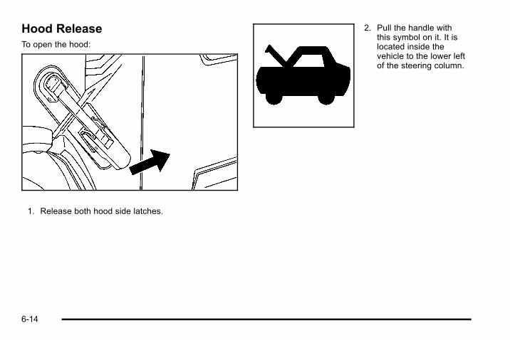
Hood ReleaseTo open the hood:
1. Release both hood side latches.
2. Pull the handle withthis symbol on it. It islocated inside thevehicle to the lower leftof the steering column.
6-14

3. Then go to the front of the vehicle and pull theassist handles to lift the hood.
4. Pull the hood open until it is supported by thecables.
Before closing the hood, be sure all filler caps are onproperly. To close the hood:
1. Hold up the hood a few inches from the closedposition and then let it go so that it has enoughforce to engage the hood latch.
2. Pull up on the assist handles to be sure that thehood is latched.
3. Latch both hood side latches.
6-15
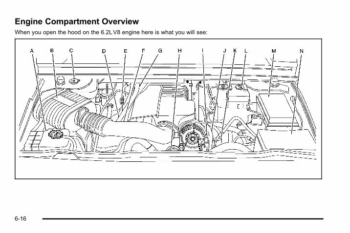
Engine Compartment OverviewWhen you open the hood on the 6.2LV8 engine here is what you will see:
6-16

A. Coolant Surge Tank. See Cooling System onpage 6‑29.
B. Engine Air Cleaner/Filter and Air Filter RestrictionIndicator (If Equipped). See Engine Air Cleaner/Filter on page 6‑22.
C. Windshield Washer Fluid Reservoir. See “AddingWasher Fluid” under Windshield Washer Fluid onpage 6‑40.
D. Engine Oil Fill Cap. See “When to Add Engine Oil”under Engine Oil on page 6‑18.
E. Engine Oil Dipstick. See “Checking Engine Oil”under Engine Oil on page 6‑18.
F. Air Filter Restriction Indicator (If Equipped). SeeEngine Air Cleaner/Filter on page 6‑22.
G. Automatic Transmission Fluid Dipstick. See“Checking the Fluid Level” under AutomaticTransmission Fluid on page 6‑25.
H. Engine Cooling Fan. See Cooling System onpage 6‑29.
I. Remote Negative (−) Terminal (GND). See JumpStarting on page 6‑44.
J. Power Steering Fluid Reservoir (Out of View). SeePower Steering Fluid on page 6‑39.
K. Remote Positive (+) Terminal. See Jump Startingon page 6‑44.
L. Brake Fluid Reservoir. See “Brake Fluid” underBrakes on page 6‑41.
M. Underhood Fuse Block on page 6‑117.
N. Battery on page 6‑44.
6-17
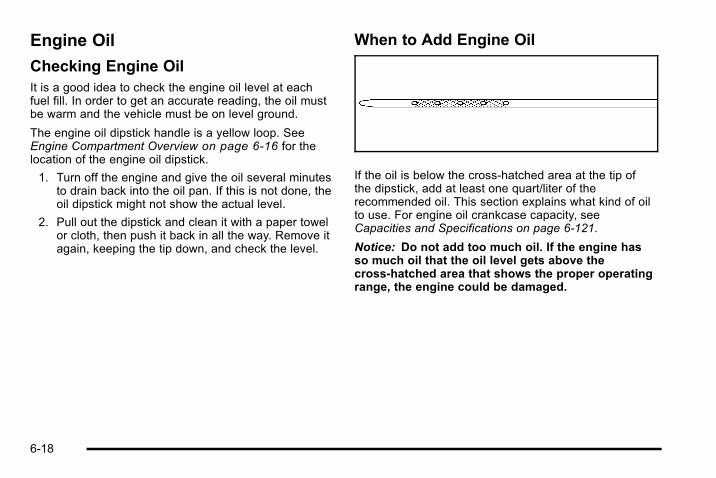
Engine Oil
Checking Engine OilIt is a good idea to check the engine oil level at eachfuel fill. In order to get an accurate reading, the oil mustbe warm and the vehicle must be on level ground.
The engine oil dipstick handle is a yellow loop. SeeEngine Compartment Overview on page 6‑16 for thelocation of the engine oil dipstick.
1. Turn off the engine and give the oil several minutesto drain back into the oil pan. If this is not done, theoil dipstick might not show the actual level.
2. Pull out the dipstick and clean it with a paper towelor cloth, then push it back in all the way. Remove itagain, keeping the tip down, and check the level.
When to Add Engine Oil
If the oil is below the cross-hatched area at the tip ofthe dipstick, add at least one quart/liter of therecommended oil. This section explains what kind of oilto use. For engine oil crankcase capacity, seeCapacities and Specifications on page 6‑121.
Notice: Do not add too much oil. If the engine hasso much oil that the oil level gets above thecross-hatched area that shows the proper operatingrange, the engine could be damaged.
6-18
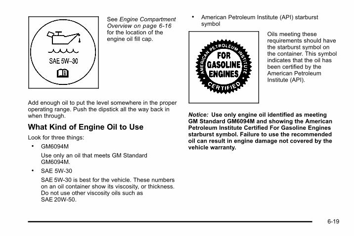
See Engine CompartmentOverview on page 6‑16for the location of theengine oil fill cap.
Add enough oil to put the level somewhere in the properoperating range. Push the dipstick all the way back inwhen through.
What Kind of Engine Oil to UseLook for three things:. GM6094M
Use only an oil that meets GM StandardGM6094M.
. SAE 5W-30
SAE 5W-30 is best for the vehicle. These numberson an oil container show its viscosity, or thickness.Do not use other viscosity oils such asSAE 20W-50.
. American Petroleum Institute (API) starburstsymbol
Oils meeting theserequirements should havethe starburst symbol onthe container. This symbolindicates that the oil hasbeen certified by theAmerican PetroleumInstitute (API).
Notice: Use only engine oil identified as meetingGM Standard GM6094M and showing the AmericanPetroleum Institute Certified For Gasoline Enginesstarburst symbol. Failure to use the recommendedoil can result in engine damage not covered by thevehicle warranty.
6-19

Cold Temperature OperationIf in an area of extreme cold, where the temperaturefalls below −20°F (−29°C), use either an SAE 5W-30synthetic oil or an SAE 0W-30 engine oil. Both provideeasier cold starting for the engine at extremely lowtemperatures. Always use an oil that meets the requiredspecification, GM6094M. See “What Kind of Engine Oilto Use” for more information.
Engine Oil Additives / Engine OilFlushesDo not add anything to the oil. The recommended oilswith the starburst symbol that meet GM StandardGM6094M are all that is needed for good performanceand engine protection.
Engine oil system flushes are not recommended andcould cause engine damage not covered by the vehiclewarranty.
Engine Oil Life System
When to Change Engine OilThis vehicle has a computer system that indicates whento change the engine oil and filter. This is based onengine revolutions and engine temperature, and not onmileage. Based on driving conditions, the mileage atwhich an oil change is indicated can vary considerably.For the oil life system to work properly, the system mustbe reset every time the oil is changed.
When the system has calculated that oil life has beendiminished, it indicates that an oil change is necessary.A CHANGE ENGINE OIL SOON message comes on.See DIC Warnings and Messages on page 4‑52.Change the oil as soon as possible within the next600 miles (1 000 km). It is possible that, if driving underthe best conditions, the oil life system might not indicatethat an oil change is necessary for over a year.However, the engine oil and filter must be changed atleast once a year and at this time the system must bereset. Your dealer has trained service people who willperform this work using genuine parts and reset thesystem. It is also important to check the oil regularlyand keep it at the proper level.
If the system is ever reset accidentally, the oil must bechanged at 3,000 miles (5 000 km) since the last oilchange. Remember to reset the oil life systemwhenever the oil is changed.
6-20

How to Reset the Engine Oil LifeSystemThe Engine Oil Life System calculates when to changethe engine oil and filter based on vehicle use.Whenever the oil is changed, reset the system so it cancalculate when the next oil change is required. If asituation occurs where the oil is changed prior to aCHANGE ENGINE OIL SOON message being turnedon, reset the system.
Always reset the engine oil life to 100% after every oilchange. It will not reset itself. To reset the Engine OilLife System:
1. Display the OIL LIFE REMAINING on the DIC.
2. Press and hold the SET/RESET button on the DICfor more than five seconds. The oil life will changeto 100%.
If the CHANGE ENGINE OIL SOON message comesback on when the vehicle is started, the Engine Oil LifeSystem has not reset. Repeat the procedure.
What to Do with Used OilUsed engine oil contains certain elements that can beunhealthy for your skin and could even cause cancer.Do not let used oil stay on your skin for very long. Cleanyour skin and nails with soap and water, or a good handcleaner. Wash or properly dispose of clothing or ragscontaining used engine oil. See the manufacturer'swarnings about the use and disposal of oil products.
Used oil can be a threat to the environment. If youchange your own oil, be sure to drain all the oil from thefilter before disposal. Never dispose of oil by putting it inthe trash, pouring it on the ground, into sewers, or intostreams or bodies of water. Recycle it by taking it to aplace that collects used oil.
6-21

Engine Air Cleaner/Filter
Notice: If you spray water into the engine aircleaner/filter intake and water enters the engine aircleaner/filter housing, as shown in the illustration,you could damage your vehicle's engine. Therepairs would not be covered by your warranty. Donot spray water into the engine air cleaner/filterintake and/or housing.
See Engine CompartmentOverview on page 6‑16for the location of theengine air cleaner/filterand the air filter restrictionindicator, if equipped.
6-22

When to Inspect the Engine Air Cleaner/FilterIf the vehicle is equipped with an air filter restrictionindicator, it lets you know when the engine air cleaner/filter needs to be replaced. On vehicles with a restrictionindicator, you should inspect the air filter restrictionindicator at every oil change and replace the engine aircleaner/filter when the indicator tells you to.
On vehicles without an air filter restriction indicator, youshould inspect the air cleaner/filter at every oil changeand replace it at the first oil change after 160 000 km(100,000 miles). See Scheduled Maintenance onpage 7‑3 for more information.
How to Inspect the Engine Air Cleaner/Filter
Vehicles With an Air Filter RestrictionIndicatorLocate the air filter restriction indicator on the engine airduct. When the indicator turns black or is in the red/orange change zone, replace the filter and reset theindicator. See “Inspecting the Engine Air Cleaner/Filterand Resetting the Air Filter Restriction Indicator” later inthis section for further instructions.
Vehicles Without an Air Filter RestrictionIndicatorTo inspect the air cleaner/filter, remove it from thevehicle and lightly shake the filter to release loose dustand dirt. If the engine air cleaner/filter remains cakedwith dirt, a new filter is required. See “Inspecting theEngine Air Cleaner/Filter and Resetting the Air FilterRestriction Indicator” later in this section for furtherinstructions.
6-23
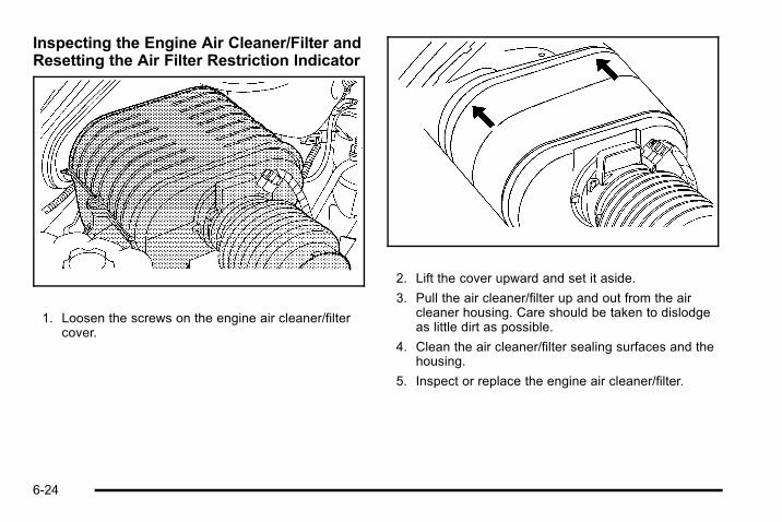
Inspecting the Engine Air Cleaner/Filter andResetting the Air Filter Restriction Indicator
1. Loosen the screws on the engine air cleaner/filtercover.
2. Lift the cover upward and set it aside.
3. Pull the air cleaner/filter up and out from the aircleaner housing. Care should be taken to dislodgeas little dirt as possible.
4. Clean the air cleaner/filter sealing surfaces and thehousing.
5. Inspect or replace the engine air cleaner/filter.
6-24

6. Reinstall the cover and tighten the screws.
7. Reset the air filter restriction indicator, if equipped,by pressing the top button on the indicator.
If the vehicle is not equipped with the air filterrestriction indicator, refer to the MaintenanceSchedule to determine when to replace the engineair cleaner/filter. See Scheduled Maintenance onpage 7‑3 .
{ WARNING:
Operating the engine with the air cleaner/filter offcan cause you or others to be burned. The aircleaner not only cleans the air; it helps to stopflames if the engine backfires. Use caution whenworking on the engine and do not drive with theair cleaner/filter off.
Notice: If the air cleaner/filter is off, dirt can easilyget into the engine, which could damage it. Alwayshave the air cleaner/filter in place when you aredriving.
Automatic Transmission Fluid
When to Check and Change AutomaticTransmission FluidIt is usually not necessary to check the transmissionfluid level. The only reason for fluid loss is atransmission leak or overheating the transmission.If you suspect a small leak, then use the followingchecking procedures to check the fluid level. However,if there is a large leak, then it may be necessary to havethe vehicle towed to a dealer service department andhave it repaired before driving the vehicle further.
Notice: Use of the incorrect automatic transmissionfluid may damage the vehicle, and the damages maynot be covered by the vehicle's warranty. Alwaysuse the automatic transmission fluid listed inRecommended Fluids and Lubricants on page 7‑10.
Change the fluid and filter at the intervals listed in theMaintenance Schedule. See Scheduled Maintenanceon page 7‑3 . Be sure to use the transmission fluidlisted in Recommended Fluids and Lubricants onpage 7‑10.
6-25
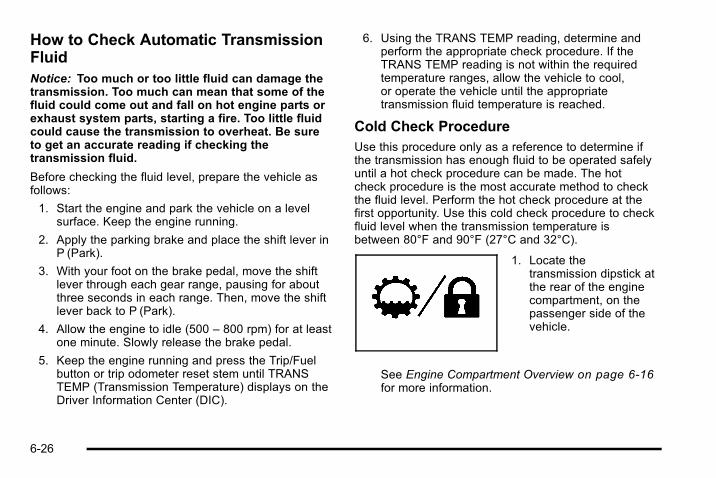
How to Check Automatic TransmissionFluidNotice: Too much or too little fluid can damage thetransmission. Too much can mean that some of thefluid could come out and fall on hot engine parts orexhaust system parts, starting a fire. Too little fluidcould cause the transmission to overheat. Be sureto get an accurate reading if checking thetransmission fluid.
Before checking the fluid level, prepare the vehicle asfollows:
1. Start the engine and park the vehicle on a levelsurface. Keep the engine running.
2. Apply the parking brake and place the shift lever inP (Park).
3. With your foot on the brake pedal, move the shiftlever through each gear range, pausing for aboutthree seconds in each range. Then, move the shiftlever back to P (Park).
4. Allow the engine to idle (500 – 800 rpm) for at leastone minute. Slowly release the brake pedal.
5. Keep the engine running and press the Trip/Fuelbutton or trip odometer reset stem until TRANSTEMP (Transmission Temperature) displays on theDriver Information Center (DIC).
6. Using the TRANS TEMP reading, determine andperform the appropriate check procedure. If theTRANS TEMP reading is not within the requiredtemperature ranges, allow the vehicle to cool,or operate the vehicle until the appropriatetransmission fluid temperature is reached.
Cold Check ProcedureUse this procedure only as a reference to determine ifthe transmission has enough fluid to be operated safelyuntil a hot check procedure can be made. The hotcheck procedure is the most accurate method to checkthe fluid level. Perform the hot check procedure at thefirst opportunity. Use this cold check procedure to checkfluid level when the transmission temperature isbetween 80°F and 90°F (27°C and 32°C).
1. Locate thetransmission dipstick atthe rear of the enginecompartment, on thepassenger side of thevehicle.
See Engine Compartment Overview on page 6‑16for more information.
6-26

2. Flip the handle up, and then pull out the dipstickand wipe it with a clean rag or paper towel.
3. Install the dipstick by pushing it back in all the way,wait three seconds, and then pull it back out again.
4. Check both sides of the dipstick, and read thelower level. Repeat the check procedure to verifythe reading.
5. If the fluid level is below the COLD check band,add only enough fluid as necessary to bring thelevel into the COLD band. It does not take muchfluid, generally less than one pint (0.5L). Do notoverfill.
6. Perform a hot check at the first opportunity afterthe transmission reaches a normal operatingtemperature between 160°F to 200°F(71°C to 93°C).
7. If the fluid level is in the acceptable range, pushthe dipstick back in all the way, then flip the handledown to lock the dipstick in place.
Hot Check ProcedureUse this procedure to check the transmission fluid levelwhen the transmission fluid temperature is between160°F and 200°F (71°C and 93°C).
The hot check is the most accurate method to check thefluid level. The hot check should be performed at thefirst opportunity in order to verify the cold check. Thefluid level rises as fluid temperature increases, so it isimportant to ensure the transmission temperature iswithin range.
1. Locate thetransmission dipstickat the rear of theengine compartment,on the passenger sideof the vehicle.
See Engine Compartment Overview on page 6‑16for more information.
6-27
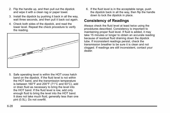
2. Flip the handle up, and then pull out the dipstickand wipe it with a clean rag or paper towel.
3. Install the dipstick by pushing it back in all the way,wait three seconds, and then pull it back out again.
4. Check both sides of the dipstick, and read thelower level. Repeat the check procedure to verifythe reading.
5. Safe operating level is within the HOT cross hatchband on the dipstick. If the fluid level is not withinthe HOT band, and the transmission temperatureis between 160°F and 200°F (71°C and 93°C), addor drain fluid as necessary to bring the level intothe HOT band. If the fluid level is low, add onlyenough fluid to bring the level into the HOT band.It does not take much fluid, generally less than onepint (0.5L). Do not overfill.
6. If the fluid level is in the acceptable range, pushthe dipstick back in all the way, then flip the handledown to lock the dipstick in place.
Consistency of ReadingsAlways check the fluid level at least twice using theprocedures described. Consistency is important tomaintaining proper fluid level. If fluid is added, it maytake 15 minutes or longer to obtain an accurate readingbecause of residual fluid draining down the dipsticktube. If inconsistent readings persist, check thetransmission breather to be sure it is clean and notclogged. If readings are still inconsistent, contact yourdealer.
6-28

Cooling SystemWhen it is safe to lift the hood:
A. Coolant Surge Tank
B. Coolant Surge Tank Pressure Cap
C. Engine Cooling Fan
{ WARNING:
An electric fan under the hood can start up andinjure you even when the engine is not running.Keep hands, clothing, and tools away from anyunderhood electric fan.
If the coolant inside the coolant surge tank is boiling, donot do anything else until it cools down. The vehicleshould be parked on a level surface. Check the coolantlevel after the system cools down. Some amount ofcoolant may be lost due to overheating.
6-29

The coolant level should be at or above the FULLCOLD mark. If it is not, there might be a leak at thepressure cap or in the radiator hoses, heater hoses,radiator, water pump, or somewhere else in the coolingsystem.
{ WARNING:
Heater and radiator hoses, and other engineparts, can be very hot. Do not touch them. If youdo, you can be burned.
Do not run the engine if there is a leak. If you runthe engine, it could lose all coolant. That couldcause an engine fire, and you could be burned.Get any leak fixed before you drive the vehicle.
If there seems to be no leak, start the engine again. Theengine cooling fan speed should increase when idlespeed is doubled by pushing the accelerator pedaldown. If it does not, the vehicle needs service. Turn offthe engine.
Notice: Engine damage from running your enginewithout coolant is not covered by the vehiclewarranty. See Overheated Engine ProtectionOperating Mode for information on driving to a safeplace in an emergency.
Notice: Using coolant other than DEX-COOL® cancause premature engine, heater core, or radiatorcorrosion. In addition, the engine coolant couldrequire changing sooner, at 50 000 km (30,000miles)or 24months, whichever occurs first. Any repairswould not be covered by the vehicle warranty.Always use DEX-COOL® (silicate-free) coolant in thevehicle.
Engine CoolantThe cooling system in the vehicle is filled withDEX-COOL® engine coolant. This coolant is designedto remain in the vehicle for five years or 240 000 km(150,000 miles), whichever occurs first, if you add onlyDEX-COOL® extended life coolant is added.
The following explains the cooling system and how toadd coolant when it is low. If there is a problem withengine overheating, see Engine Overheating onpage 6‑36.
A 50/50 mixture of clean, drinkable water andDEX-COOL® coolant will:. Give freezing protection down to −37°C (−34°F).. Give boiling protection up to 129°C (265°F).. Protect against rust and corrosion.. Help keep the proper engine temperature.. Let the warning lights and gauges work as they
should.
6-30
Notice: Using coolant other than DEX‐COOL® cancause premature engine, heater core, or radiatorcorrosion. In addition, the engine coolant mayrequire changing sooner, at the first maintenanceservice after each 30,000miles (50 000 km) or24months, whichever occurs first. Any repairswould not be covered by the vehicle warranty.Always use DEX‐COOL® (silicate‐free) coolant in thevehicle.
What to UseUse a mixture of one-half clean, drinkable water andone-half DEX-COOL® coolant which will not damagealuminum parts. If you use this coolant mixture, nothingelse needs to be added.
{ WARNING:
Adding only plain water to the cooling system canbe dangerous. Plain water, or some other liquidsuch as alcohol, can boil before the propercoolant mixture will. The vehicle's coolant warningsystem is set for the proper coolant mixture. Withplain water or the wrong mixture, the engine couldget too hot but would not get the overheat
(Continued)
WARNING: (Continued)
warning. The engine could catch fire and you orothers could be burned. Use a 50/50 mixture ofclean, drinkable water and DEX-COOL® coolant.
Notice: If an improper coolant mixture is used, theengine could overheat and be badly damaged. Therepair cost would not be covered by the vehiclewarranty. Too much water in the mixture can freezeand crack the engine, radiator, heater core, andother parts.
If coolant needs to be added more than four times ayear, have your dealer check the cooling system.
Notice: If extra inhibitors and/or additives are usedin the vehicle's cooling system, the vehicle could bedamaged. Use only the proper mixture of the enginecoolant listed in this manual for the cooling system.See Recommended Fluids and Lubricants onpage 7‑10 for more information.
6-31

Checking CoolantThe coolant surge tank islocated in the enginecompartment on thepassenger side of thevehicle. See EngineCompartment Overviewon page 6‑16 for moreinformation on location.
{ WARNING:
Turning the surge tank pressure cap when theengine and radiator are hot can allow steam andscalding liquids to blow out and burn you badly.Never turn the surge tank pressure cap— even alittle—when the engine and radiator are hot.
The vehicle must be on a level surface. When theengine is cold, the coolant level should be at the FULLCOLD mark.
6-32
Adding CoolantIf more coolant is needed, add the proper DEX-COOL®
coolant mixture at the surge tank, but only when theengine is cool.
{ WARNING:
You can be burned if you spill coolant on hotengine parts. Coolant contains ethylene glycol,and it will burn if the engine parts are hot enough.Do not spill coolant on a hot engine.
When replacing the pressure cap, make sure it ishand-tight and fully seated.
How to Add Coolant to the CoolantSurge TankIf no problem is found, check to see if coolant isvisible in the surge tank. If coolant is visible but thecoolant level is not at or above the FULL COLD mark,add a 50/50 mixture of clean, drinkable water andDEX-COOL® coolant at the coolant surge tank, but besure the cooling system, including the coolant surgetank pressure cap, is cool before doing this. See EngineCoolant on page 6‑30 for more information.
6-33

If no coolant is visible in the surge tank, add coolant asfollows:
{ WARNING:
Steam and scalding liquids from a hot coolingsystem can blow out and burn you badly. They areunder pressure, and if you turn the surge tankpressure cap— even a little— they can come outat high speed. Never turn the cap when thecooling system, including the surge tank pressurecap, is hot. Wait for the cooling system and surgetank pressure cap to cool if you ever have to turnthe pressure cap.
{ WARNING:
Adding only plain water to the cooling system canbe dangerous. Plain water, or some other liquidsuch as alcohol, can boil before the propercoolant mixture will. The vehicle's coolant warningsystem is set for the proper coolant mixture. Withplain water or the wrong mixture, the engine could
(Continued)
WARNING: (Continued)
get too hot but you would not get the overheatwarning. The engine could catch fire and you orothers could be burned. Use a 50/50 mixture ofclean, drinkable water and DEX-COOL® coolant.
Notice: In cold weather, water can freeze and crackthe engine, radiator, heater core and other parts.Use the recommended coolant and the propercoolant mixture.
{ WARNING:
You can be burned if you spill coolant on hotengine parts. Coolant contains ethylene glycoland it will burn if the engine parts are hot enough.Do not spill coolant on a hot engine.
6-34

1. Locate the coolantsurge tank pressurecap that has this label.
2. Remove the coolant surge tank pressure cap whenthe cooling system, including the coolant surgetank pressure cap and upper radiator hose, are nolonger hot. Turn the pressure cap slowlycounterclockwise about one full turn.
If a hiss is heard, wait for that to stop. A hissmeans there is still some pressure left.
3. Then keep turning the pressure cap slowly, andremove it.
4. Fill the coolant surge tank with the proper mixture,to the FULL COLD mark located on the side of thereservoir.
6-35

5. With the coolant surge tank pressure cap off, startthe engine and let it run until you can feel theupper radiator hose getting hot. Watch out for theengine cooling fan.
By this time, the coolant level inside the coolantsurge tank might be lower. If the level is lower, addmore of the proper mixture to the coolant surgetank until the level reaches the FULL COLD mark.
6. Then replace the pressure cap. Be sure thepressure cap is hand-tight and fully seated.
7. Verify coolant level after engine is shut off and thecoolant is cold. If necessary, repeat coolant fillprocedure steps 1 through 7.
Engine OverheatingYou will find a coolant temperature gauge on thevehicle's instrument panel. See Engine CoolantTemperature Gauge on page 4‑33.
In addition, you will find an ENGINE OVERHEATEDIDLE ENGINE and an ENGINE POWER IS REDUCEDmessage in the Driver Information Center (DIC) on theinstrument panel. See DIC Warnings and Messages onpage 4‑52.
6-36

If Steam Is Coming From the Engine
{ WARNING:
Steam from an overheated engine can burn youbadly, even if you just open the hood. Stay awayfrom the engine if you see or hear steam comingfrom it. Turn it off and get everyone away from thevehicle until it cools down. Wait until there is nosign of steam or coolant before you openthe hood.
If you keep driving when the vehicles engine isoverheated, the liquids in it can catch fire. You orothers could be badly burned. Stop the engine if itoverheats, and get out of the vehicle until theengine is cool.
See Overheated Engine Protection OperatingMode on page 6‑38 for information on driving toa safe place in an emergency.
Notice: If the engine catches fire while driving withno coolant, the vehicle can be badly damaged. Thecostly repairs would not be covered by the vehiclewarranty. See Overheated Engine ProtectionOperating Mode on page 6‑38 for information ondriving to a safe place in an emergency.
If No Steam Is Coming From the EngineThe ENGINE OVERHEATED IDLE ENGINE message,along with a low coolant condition, can indicate aserious problem.
If you get an engine overheat warning, but see or hearno steam, the problem may not be too serious.Sometimes the engine can get a little too hot when you:. Climb a long hill on a hot day.. Stop after high-speed driving.. Idle for long periods in traffic.. Tow a trailer. See Towing a Trailer on page 5‑52.
If you get the ENGINE COOLANT HOT message withno sign of steam, try this for a minute or so:
1. Turn on the heater to full hot at the highest fanspeed and open the windows as necessary.
2. If you are in a traffic jam, shift to N (Neutral);otherwise, shift to the highest gear whiledriving—D (Drive).
6-37
If you no longer have the overheat warning, you candrive. Just to be safe, drive slower for about 10 minutes.If the warning does not come back on, you can drivenormally.
If the warning continues and you have not stopped, pullover, stop, and park the vehicle right away.
If there is still no sign of steam, push down theaccelerator until the engine speed is about twice as fastas normal idle speed for at least three minutes whileyou are parked. If you still have the warning, turn off theengine and get everyone out of the vehicle until it coolsdown. Also, see “Overheated Engine ProtectionOperating Mode” later in this section.
You may decide not to lift the hood but to get servicehelp right away.
Overheated Engine ProtectionOperating ModeIf an overheated engine condition exists and theENGINE POWER IS REDUCED message is displayed,an overheat protection mode which alternates firinggroups of cylinders helps prevent engine damage. Inthis mode, you will notice a loss in power and engineperformance. This operating mode allows the vehicle tobe driven to a safe place in an emergency. Drivingextended miles (km) and/or towing a trailer in theoverheat protection mode should be avoided.
Notice: After driving in the overheated engineprotection operating mode, to avoid engine damage,allow the engine to cool before attempting anyrepair. The engine oil will be severely degraded.Repair the cause of coolant loss, change the oil andreset the oil life system. See Engine Oil onpage 6‑18.
6-38
Power Steering FluidSee Engine CompartmentOverview on page 6‑16for reservoir location.
When to Check Power Steering FluidIt is not necessary to regularly check power steeringfluid unless you suspect there is a leak in the system oryou hear an unusual noise. A fluid loss in this systemcould indicate a problem. Have the system inspectedand repaired.
How to Check Power Steering FluidTo check the power steering fluid:
1. Turn the key off and let the engine compartmentcool down.
2. Wipe the cap and the top of the reservoir clean.
3. Unscrew the cap and wipe the dipstick with aclean rag.
4. Replace the cap and completely tighten it.
5. Remove the cap again and look at the fluid levelon the dipstick.
The level should be at the FULL COLD mark.If necessary, add only enough fluid to bring the level upto the mark.
What to UseTo determine what kind of fluid to use, seeRecommended Fluids and Lubricants on page 7‑10.Always use the proper fluid.
Notice: Use of the incorrect fluid may damage thevehicle and the damages may not be covered by thevehicle's warranty. Always use the correct fluidlisted in Recommended Fluids and Lubricants onpage 7‑10.
6-39
Windshield Washer Fluid
What to UseWhen you need windshield washer fluid, be sure toread the manufacturer's instructions before use. If youwill be operating your vehicle in an area where thetemperature may fall below freezing, use a fluid that hassufficient protection against freezing.
Adding Washer FluidYour vehicle has a message that comes on when thewasher fluid is low. The message is displayed for15 seconds at the start of each ignition cycle if the fluidis low. When the CHECK WASHER FLUID message isdisplayed, you will need to add washer fluid to thewindshield washer fluid reservoir. See DIC Warningsand Messages on page 4‑52 for more information.
Open the cap with thewasher symbol on it. Addwasher fluid until the tankis full. See EngineCompartment Overviewon page 6‑16 forreservoir location.
Notice:. When using concentrated washer fluid,
follow the manufacturer's instructions foradding water.
. Do not mix water with ready-to-use washerfluid. Water can cause the solution to freezeand damage the washer fluid tank and otherparts of the washer system. Also, water doesnot clean as well as washer fluid.
. Fill the washer fluid tank only three-quartersfull when it is very cold. This allows for fluidexpansion if freezing occurs, which coulddamage the tank if it is completely full.
. Do not use engine coolant (antifreeze) in thewindshield washer. It can damage thevehicle's windshield washer system andpaint.
6-40

Brakes
Brake FluidThe brake master cylinderreservoir is filled with DOT3 brake fluid. See EngineCompartment Overviewon page 6‑16 for thelocation of the reservoir.
There are only two reasons why the brake fluid level inthe reservoir might go down:. The brake fluid level goes down because of
normal brake lining wear. When new linings areinstalled, the fluid level goes back up.
. A fluid leak in the brake hydraulic system can alsocause a low fluid level. Have the brake hydraulicsystem fixed, since a leak means that sooner orlater the brakes will not work well.
Do not top off the brake fluid. Adding fluid does notcorrect a leak. If fluid is added when the linings areworn, there will be too much fluid when new brakelinings are installed. Add or remove brake fluid, asnecessary, only when work is done on the brakehydraulic system.
{ WARNING:
If too much brake fluid is added, it can spill on theengine and burn, if the engine is hot enough. Youor others could be burned, and the vehicle couldbe damaged. Add brake fluid only when work isdone on the brake hydraulic system. See“Checking Brake Fluid” in this section.
Refer to the Maintenance Schedule to determine whento check the brake fluid. See Scheduled Maintenanceon page 7‑3 .
6-41

Checking Brake FluidCheck brake fluid by looking at the brake fluid reservoir.See Engine Compartment Overview on page 6‑16.
The fluid level should beabove MIN. If it is not,have the brake hydraulicsystem checked to see ifthere is a leak.
After work is done on the brake hydraulic system, makesure the level is above the MIN but not over theMAX mark.
What to AddUse only new DOT 3 brake fluid from a sealedcontainer. See Recommended Fluids and Lubricants onpage 7‑10.
Always clean the brake fluid reservoir cap and the areaaround the cap before removing it. This helps keep dirtfrom entering the reservoir.
{ WARNING:
With the wrong kind of fluid in the brake hydraulicsystem, the brakes might not work well. This couldcause a crash. Always use the proper brake fluid.
Notice:. Using the wrong fluid can badly damage
brake hydraulic system parts. For example,just a few drops of mineral-based oil, suchas engine oil, in the brake hydraulic systemcan damage brake hydraulic system parts sobadly that they will have to be replaced. Donot let someone put in the wrong kind offluid.
. If brake fluid is spilled on the vehicle'spainted surfaces, the paint finish can bedamaged. Be careful not to spill brake fluidon the vehicle. If you do, wash it offimmediately. See Washing Your Vehicle onpage 6‑109.
6-42

Brake WearThis vehicle has disc brakes. Disc brake pads havebuilt-in wear indicators that make a high-pitchedwarning sound when the brake pads are worn and newpads are needed. The sound can come and go or beheard all the time the vehicle is moving, except whenapplying the brake pedal firmly.
{ WARNING:
The brake wear warning sound means that soonthe brakes will not work well. That could lead toan accident. When the brake wear warning soundis heard, have the vehicle serviced.
Notice: Continuing to drive with worn-out brakepads could result in costly brake repair.
Some driving conditions or climates can cause a brakesqueal when the brakes are first applied or lightlyapplied. This does not mean something is wrong withthe brakes.
Properly torqued wheel nuts are necessary to helpprevent brake pulsation. When tires are rotated, inspectbrake pads for wear and evenly tighten wheel nuts inthe proper sequence to torque specifications inCapacities and Specifications on page 6‑121.
Brake linings should always be replaced as completeaxle sets.
Brake Pedal TravelSee your dealer if the brake pedal does not return tonormal height, or if there is a rapid increase in pedaltravel. This could be a sign that brake service might berequired.
Brake AdjustmentEvery brake stop, the disc brakes adjust for wear.
Replacing Brake System PartsThe braking system on a vehicle is complex. Its manyparts have to be of top quality and work well together ifthe vehicle is to have really good braking. The vehiclewas designed and tested with top-quality brake parts.When parts of the braking system are replaced — forexample, when the brake linings wear down and newones are installed — be sure to get new approvedreplacement parts. If this is not done, the brakes mightnot work properly. For example, if someone puts inbrake linings that are wrong for the vehicle, the balancebetween the front and rear brakes can change — for theworse. The braking performance expected can changein many other ways if the wrong replacement brakeparts are installed.
6-43

BatteryRefer to the replacement number on the original batterylabel when a new battery is needed. See EngineCompartment Overview on page 6‑16 for batterylocation.
{ DANGER:
Battery posts, terminals, and related accessoriescontain lead and lead compounds, chemicalsknown to the State of California to cause cancerand reproductive harm. Wash hands afterhandling.
Vehicle Storage
{ WARNING:
Batteries have acid that can burn you and gasthat can explode. You can be badly hurt if you arenot careful. See Jump Starting on page 6‑44 fortips on working around a battery withoutgetting hurt.
Infrequent Usage: Remove the black, negative (−) cablefrom the battery to keep the battery from running down.
Extended Storage: Remove the black, negative (−)cable from the battery or use a battery trickle charger.
Jump StartingIf your vehicle's battery has run down, you may want touse another vehicle and some jumper cables to startyour vehicle. Be sure to use the following steps to do itsafely.
{ WARNING:
Batteries can hurt you. They can be dangerousbecause:
. They contain acid that can burn you.
. They contain gas that can explode or ignite.
. They contain enough electricity to burn you.
If you do not follow these steps exactly, some orall of these things can hurt you.
Notice: Ignoring these steps could result in costlydamage to the vehicle that would not be covered bythe warranty.
6-44

Trying to start the vehicle by pushing or pulling itwill not work, and it could damage the vehicle.
1. Check the other vehicle. It must have a 12-voltbattery with a negative ground system.
Notice: If the other vehicle's system is not a 12-voltsystem with a negative ground, both vehicles canbe damaged. Only use vehicles with 12-volt systemswith negative grounds to jump start your vehicle.
2. Get the vehicles close enough so the jumpercables can reach, but be sure the vehicles are nottouching each other. If they are, it could cause aground connection you do not want. You would notbe able to start your vehicle, and the badgrounding could damage the electrical systems.
To avoid the possibility of the vehicles rolling, setthe parking brake firmly on both vehicles involvedin the jump start procedure. Put an automatictransmission in P (Park) or a manual transmissionin N (Neutral) before setting the parking brake.
Notice: If you leave the radio or other accessorieson during the jump starting procedure, they couldbe damaged. The repairs would not be covered bythe warranty. Always turn off the radio and otheraccessories when jump starting the vehicle.
3. Turn off the ignition on both vehicles. Unplugunnecessary accessories plugged into thecigarette lighter or accessory power outlets. Turnoff the radio and all lamps that are not needed.This will avoid sparks and help save both batteries.And it could save your radio!
4. Open the hoods and locate the positive (+) andnegative (−) terminal locations of the other vehicle.
Your vehicle has a remote positive (+) jump startingterminal and a remote negative (−) jump startingterminal. You should always use these remoteterminals instead of the terminals on the battery.
The remote positive (+)terminal is located nearthe engine accessorydrive bracket. On somevehicles, the terminal maybe covered by a redplastic cover. To accessthe remote positive (+)terminal, open the cover,if equipped.
6-45

The remote negative (−)terminal is located on theengine accessory drivebracket and is markedGND (Ground).
See Engine Compartment Overview on page 6‑16for more information on the location of the remoteterminals.
{ WARNING:
Using an open flame near a battery can causebattery gas to explode. People have been hurtdoing this, and some have been blinded. Use aflashlight if you need more light.
(Continued)
WARNING: (Continued)
Be sure the battery has enough water. You do notneed to add water to the battery installed in yournew vehicle. But if a battery has filler caps, besure the right amount of fluid is there. If it is low,add water to take care of that first. If you do not,explosive gas could be present.
Battery fluid contains acid that can burn you. Donot get it on you. If you accidentally get it in youreyes or on your skin, flush the place with waterand get medical help immediately.
5. Check that the jumper cables do not have loose ormissing insulation. If they do, you could get ashock. The vehicles could be damaged too.
Before you connect the cables, here are somebasic things you should know. Positive (+) will go topositive (+) or to a remote positive terminal (+) ifthe vehicle has one. Negative (−) will go to aheavy, unpainted metal engine part or to a remotenegative (−) terminal, if the vehicle has one.
Do not connect positive (+) to negative (−) or youwill get a short that would damage the battery andmaybe other parts too.
6-46
{ WARNING:
Fans or other moving engine parts can injure youbadly. Keep your hands away from moving partsonce the engine is running.
6. Connect the red positive (+) cable to thepositive (+) terminal of the dead battery. Use aremote positive (+) terminal if the vehicle has one.
7. Do not let the other end touch metal. Connect it tothe positive (+) terminal of the good battery. Use aremote positive (+) terminal if the vehicle has one.
8. Now connect the black negative (−) cable to thenegative (−) terminal of the good battery. Use aremote negative (−) terminal if the vehicle has one.
Do not let the other end touch anything until thenext step. The other end of the negative (−) cabledoes not go to the dead battery. It goes to a heavy,unpainted metal engine part or to a remotenegative (−) terminal on the vehicle with the deadbattery.
9. Connect the other end of the negative (−) cable atleast 12 inches (30 cm) away from the deadbattery, but not near engine parts that move. Theelectrical connection is just as good there, and thechance of sparks getting back to the battery ismuch less.
Use a remote negative (−) terminal if the vehiclehas one. Your vehicle's remote negative (−)terminal is marked GND.
10. Now start the vehicle with the good battery and runthe engine for awhile.
11. Try to start the vehicle that had the dead battery.If it will not start after a few tries, it probably needsservice.
6-47
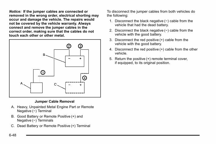
Notice: If the jumper cables are connected orremoved in the wrong order, electrical shorting mayoccur and damage the vehicle. The repairs wouldnot be covered by the vehicle warranty. Alwaysconnect and remove the jumper cables in thecorrect order, making sure that the cables do nottouch each other or other metal.
Jumper Cable Removal
A. Heavy, Unpainted Metal Engine Part or RemoteNegative (−) Terminal
B. Good Battery or Remote Positive (+) andNegative (−) Terminals
C. Dead Battery or Remote Positive (+) Terminal
To disconnect the jumper cables from both vehicles dothe following:
1. Disconnect the black negative (−) cable from thevehicle that had the dead battery.
2. Disconnect the black negative (−) cable from thevehicle with the good battery.
3. Disconnect the red positive (+) cable from thevehicle with the good battery.
4. Disconnect the red positive (+) cable from the othervehicle.
5. Return the positive (+) remote terminal cover,if equipped, to its original position.
6-48

Rear AxleWhen to Check LubricantIt is not necessary to regularly check rear axle fluidunless you suspect there is a leak or you hear anunusual noise. A fluid loss could indicate a problem.Have it inspected and repaired.
All axle assemblies are filled by volume of fluid duringproduction. They are not filled to reach a certain level.When checking the fluid level on any axle, variations inthe readings can be caused by factory fill differencesbetween the minimum and the maximum fluid volume.Also, if a vehicle has just been driven before checkingthe fluid level, it may appear lower than normal becausefluid has traveled out along the axle tubes and has notdrained back to the sump area. Therefore, a readingtaken five minutes after the vehicle has been driven willappear to have a lower fluid level than a vehicle thathas been stationary for an hour or two. Remember thatthe rear axle assembly must be supported to get a truereading.
How to Check Lubricant
To get an accurate reading, the vehicle should be on alevel surface.
When the differential is cold, the proper level is from5/8 inch to 1-5/8 inch (15 mm to 40 mm) below thebottom of the filler plug hole, located on the rear axle.Add only enough fluid to reach the proper level.
What to UseRefer to the Maintenance Schedule to determine whatkind of lubricant to use. See Recommended Fluids andLubricants on page 7‑10.
6-49

Four-Wheel DriveTransfer CaseIt is not necessary to regularly check transfer case fluidunless you suspect there is a leak or you hear anunusual noise. A fluid loss could indicate a problem.Have it inspected and repaired.
Refer to the Maintenance Schedule to determine howoften to change the lubricant. See ScheduledMaintenance on page 7‑3.
How to Check Lubricant
A. Filler Plug
B. Drain Plug
1. Remove the filler plug (A). The fluid level should bejust below the bottom of the filler plug hole locatedon the transfer case. To get an accurate reading,the vehicle should be on a level surface.
6-50

2. Add fluid if necessary.
Refer to the Maintenance Schedule to determinewhat kind of lubricant to use. See RecommendedFluids and Lubricants on page 7‑10.
3. Reinstall the filler plug. Use care not to overtightenthe filler plug.
Front AxleWhen to Check and Change LubricantIt is not necessary to regularly check front axle fluidunless you suspect there is a leak or you hear anunusual noise. A fluid loss could indicate a problem.Have it inspected and repaired.
How to Check LubricantTo get an accurate reading, the vehicle should be on alevel surface. When the differential is cold, the proper level is from
about 1/4 inch (6 mm) to about 3/8 inch (10 mm) belowthe filler plug hole.
What to UseRefer to the Maintenance Schedule to determine whatkind of lubricant to use. See Recommended Fluids andLubricants on page 7‑10.
6-51

Bulb ReplacementFor the proper type of replacement bulbs, seeReplacement Bulbs on page 6‑58.
For any bulb changing procedure not listed in thissection, contact your dealer.
Halogen Bulbs
{ WARNING:
Halogen bulbs have pressurized gas inside andcan burst if you drop or scratch the bulb. You orothers could be injured. Be sure to read andfollow the instructions on the bulb package.
HeadlampsTo replace a headlamp bulb:
1. Open the hood. See Hood Release on page 6‑14.
2. Locate the affected headlamp on the inner frontportion of the hood.
3. Turn the bulb socketcounterclockwise andpull it out of theheadlamp assembly.
6-52
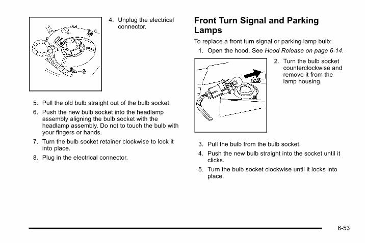
4. Unplug the electricalconnector.
5. Pull the old bulb straight out of the bulb socket.
6. Push the new bulb socket into the headlampassembly aligning the bulb socket with theheadlamp assembly. Do not to touch the bulb withyour fingers or hands.
7. Turn the bulb socket retainer clockwise to lock itinto place.
8. Plug in the electrical connector.
Front Turn Signal and ParkingLampsTo replace a front turn signal or parking lamp bulb:
1. Open the hood. See Hood Release on page 6‑14.
2. Turn the bulb socketcounterclockwise andremove it from thelamp housing.
3. Pull the bulb from the bulb socket.
4. Push the new bulb straight into the socket until itclicks.
5. Turn the bulb socket clockwise until it locks intoplace.
6-53
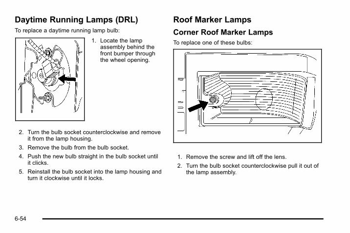
Daytime Running Lamps (DRL)To replace a daytime running lamp bulb:
1. Locate the lampassembly behind thefront bumper throughthe wheel opening.
2. Turn the bulb socket counterclockwise and removeit from the lamp housing.
3. Remove the bulb from the bulb socket.
4. Push the new bulb straight in the bulb socket untilit clicks.
5. Reinstall the bulb socket into the lamp housing andturn it clockwise until it locks.
Roof Marker Lamps
Corner Roof Marker LampsTo replace one of these bulbs:
1. Remove the screw and lift off the lens.
2. Turn the bulb socket counterclockwise pull it out ofthe lamp assembly.
6-54

3. Pull the old bulb straight out of the bulb socket.
4. Push the new bulb straight into the bulb socketuntil it connects.
5. Turn the bulb socket clockwise into the lampassembly until it locks into place.
6. Place the side of the lens with the slotted end intothe notch first and then tighten the screw.
Center Roof Marker LampsTo replace one of these bulbs:
1. Push in on the notch with a flat tool and pull thelamp out.
2. Turn the bulb socket counterclockwise and removeit from the lamp housing.
3. Pull the old bulb straight out of the bulb socket.
4. Push the new bulb straight into the bulb socketuntil it connects.
5. Place the slotted end of the lamp in place on oneside and push the other end of the lamp down untilit locks in place.
6-55

Taillamps, Turn Signal, Stoplampsand Back-up Lamps
A. Stoplamp/Taillamp
B. Turn Signal Lamp
C. Back-Up Lamp
To replace one of these bulbs:
1. Open the tailgate. See Tailgate/Spare Tire Carrieron page 3‑15.
2. If the vehicle has the taillamp guard, remove thefour retaining screws. Do not remove the plasticretainers.
3. Remove the twoscrews from the rearlamp assembly andremove the rear lampassembly.
4. Turn the bulb socket counterclockwise to remove itfrom the taillamp housing.
5. Pull the bulb straight out from the socket.
6-56

6. Press a new bulb into the socket, insert it into thetaillamp housing and turn the socketcounterclockwise until it is locked in place.
7. Reinstall the rear lamp assembly and tighten thescrews.
8. Reinstall the taillamp guard by lining up the guardwith the holes in vehicle. Then install and tightenthe four screws.
The vehicle may have a taillamp in the bumper. Toreplace it:
1. Locate the affectedtaillamp which isbehind and under thebumper.
2. Turn the bulb socket counterclockwise and removeit from the lamp housing.
3. Remove the bulb from the bulb socket.
4. Install the new bulb into the bulb socket.
5. Reinstall the bulb socket into the lamp housing andturn it clockwise to lock it.
6-57

Replacement BulbsExterior Lamp Bulb Number
Back-up Lamp 3156K
Daytime Running Lamp (DRL) 4114K LCP
Front Turn Signal andParking Lamp
4157K or 3157KX
Low-Beam and High-BeamHeadlamps
9007
Taillamp and Stoplamp 3057K
Rear Taillamp in Bumper 3057K
Rear Turn Signal Lamp 3156K
Roof Marker Lamp Center 168
Roof Marker Lamp Corner 194
For replacement bulbs not listed here, contact yourdealer.
Windshield Wiper BladeReplacementWindshield wiper blades should be inspected for wearand cracking. See Scheduled Maintenance onpage 7‑3 for more information.
Replacement blades come in different types and areremoved in different ways. For proper type and length,see Maintenance Replacement Parts on page 7‑12.
Notice: Allowing the wiper blade arm to touch thewindshield when no wiper blade is installed coulddamage the windshield. Any damage that occurswould not be covered by your warranty. Do notallow the wiper blade arm to touch the windshield.
6-58
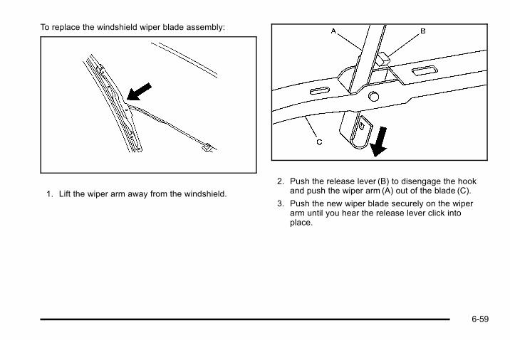
To replace the windshield wiper blade assembly:
1. Lift the wiper arm away from the windshield.
2. Push the release lever (B) to disengage the hookand push the wiper arm (A) out of the blade (C).
3. Push the new wiper blade securely on the wiperarm until you hear the release lever click intoplace.
6-59
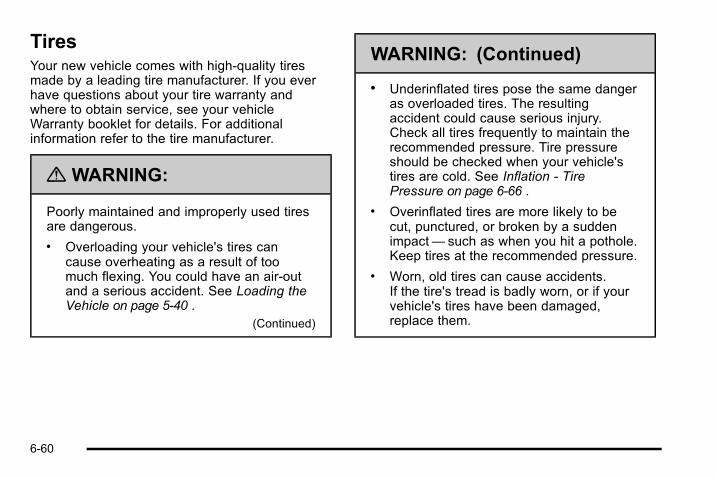
TiresYour new vehicle comes with high-quality tiresmade by a leading tire manufacturer. If you everhave questions about your tire warranty andwhere to obtain service, see your vehicleWarranty booklet for details. For additionalinformation refer to the tire manufacturer.
{ WARNING:
Poorly maintained and improperly used tiresare dangerous.. Overloading your vehicle's tires can
cause overheating as a result of toomuch flexing. You could have an air-outand a serious accident. See Loading theVehicle on page 5‑40 .
(Continued)
WARNING: (Continued)
. Underinflated tires pose the same dangeras overloaded tires. The resultingaccident could cause serious injury.Check all tires frequently to maintain therecommended pressure. Tire pressureshould be checked when your vehicle'stires are cold. See Inflation - TirePressure on page 6‑66 .
. Overinflated tires are more likely to becut, punctured, or broken by a suddenimpact— such as when you hit a pothole.Keep tires at the recommended pressure.
. Worn, old tires can cause accidents.If the tire's tread is badly worn, or if yourvehicle's tires have been damaged,replace them.
6-60
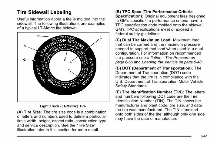
Tire Sidewall LabelingUseful information about a tire is molded into thesidewall. The following illustrations are examplesof a typical LT‐Metric tire sidewall.
Light Truck (LT-Metric) Tire
(A) Tire Size: The tire size code is a combinationof letters and numbers used to define a particulartire's width, height, aspect ratio, construction type,and service description. See the “Tire Size”illustration later in this section for more detail.
(B) TPC Spec (Tire Performance CriteriaSpecification): Original equipment tires designedto GM's specific tire performance criteria have aTPC specification code molded onto the sidewall.GM's TPC specifications meet or exceed allfederal safety guidelines.
(C) Dual Tire Maximum Load: Maximum loadthat can be carried and the maximum pressureneeded to support that load when used in a dualconfiguration. For information on recommendedtire pressure see Inflation - Tire Pressure onpage 6‑66 and Loading the Vehicle on page 5‑40 .
(D) DOT (Department of Transportation): TheDepartment of Transportation (DOT) codeindicates that the tire is in compliance with theU.S. Department of Transportation Motor VehicleSafety Standards.
(E) Tire Identification Number (TIN): The lettersand numbers following DOT code are the TireIdentification Number (TIN). The TIN shows themanufacturer and plant code, tire size, and datethe tire was manufactured. The TIN is moldedonto both sides of the tire, although only one sidemay have the date of manufacture.
6-61

(F) Tire Ply Material: The type of cord andnumber of plies in the sidewall and under thetread.
(G) Single Tire Maximum Load: Maximum loadthat can be carried and the maximum pressureneeded to support that load when used as asingle. For information on recommended tirepressure see Inflation - Tire Pressure on page 6‑66and Loading the Vehicle on page 5‑40 .
Tire SizeThe following illustration shows an example of atypical passenger vehicle tire size.
Light Truck (LT‐Metric) Tire
(A) Light Truck (LT‐Metric) Tire: The UnitedStates version of a metric tire sizing system. Theletters LT as the first two characters in the tire sizemeans a light truck tire engineered to standardsset by the U.S. Tire and Rim Association.
(B) Tire Width: The three‐digit number indicatesthe tire section width in millimeters from sidewallto sidewall.
(C) Aspect Ratio: A two‐digit number thatindicates the tire height‐to‐width measurements.For example, if the tire size aspect ratio is 75, asshown in item C of the light truck (LT‐Metric) tireillustration, it would mean that the tire's sidewall is75 percent as high as it is wide.
(D) Construction Code: A letter code is used toindicate the type of ply construction in the tire.The letter R means radial ply construction; theletter D means diagonal or bias ply construction;and the letter B means belted‐bias plyconstruction.
(E) Rim Diameter: Diameter of the wheel ininches.
(F) Load Range: Load Range.
(G) Service Description: The service descriptionindicates the load index and speed rating of a tire.If two numbers are given as in the example,120/116, then this represents the load index forsingle versus dual wheel usage (single/dual). Thespeed rating is the maximum speed a tire iscertified to carry a load.
6-62

Tire Terminology and DefinitionsAir Pressure: The amount of air inside the tirepressing outward on each square inch of the tire.Air pressure is expressed in pounds per squareinch (psi) or kilopascal (kPa).
Accessory Weight: This means the combinedweight of optional accessories. Some examples ofoptional accessories are, automatic transmission,power steering, power brakes, power windows,power seats, and air conditioning.
Aspect Ratio: The relationship of a tire's height toits width.
Belt: A rubber coated layer of cords that islocated between the plies and the tread. Cordsmay be made from steel or other reinforcingmaterials.
Bead: The tire bead contains steel wires wrappedby steel cords that hold the tire onto the rim.
Bias Ply Tire: A pneumatic tire in which the pliesare laid at alternate angles less than 90 degreesto the centerline of the tread.
Cold Tire Pressure: The amount of air pressurein a tire, measured in pounds per square inch (psi)or kilopascals (kPa) before a tire has built up heatfrom driving. See Inflation - Tire Pressure onpage 6‑66 .
Curb Weight: The weight of a motor vehicle withstandard and optional equipment including themaximum capacity of fuel, oil, and coolant, butwithout passengers and cargo.
DOT Markings: A code molded into the sidewallof a tire signifying that the tire is in compliancewith the U.S. Department of Transportation (DOT)motor vehicle safety standards. The DOT codeincludes the Tire Identification Number (TIN), analphanumeric designator which can also identifythe tire manufacturer, production plant, brand, anddate of production.
GVWR: Gross Vehicle Weight Rating. SeeLoading the Vehicle on page 5‑40 .
GAWR FRT: Gross Axle Weight Rating for thefront axle. See Loading the Vehicle on page 5‑40 .
GAWR RR: Gross Axle Weight Rating for the rearaxle. See Loading the Vehicle on page 5‑40 .
6-63
Intended Outboard Sidewall: The side of anasymmetrical tire, that must always face outwardwhen mounted on a vehicle.
Kilopascal (kPa): The metric unit for air pressure.
Light Truck (LT‐Metric) Tire: A tire used on lightduty trucks and some multipurpose passengervehicles.
Load Index: An assigned number ranging from1 to 279 that corresponds to the load carryingcapacity of a tire.
Maximum Inflation Pressure: The maximum airpressure to which a cold tire can be inflated. Themaximum air pressure is molded onto thesidewall.
Maximum Load Rating: The load rating for a tireat the maximum permissible inflation pressure forthat tire.
Maximum Loaded Vehicle Weight: The sum ofcurb weight, accessory weight, vehicle capacityweight, and production options weight.
Normal Occupant Weight: The number ofoccupants a vehicle is designed to seat multipliedby 150 lbs (68 kg). See Loading the Vehicle onpage 5‑40 .
Occupant Distribution: Designated seatingpositions.
Outward Facing Sidewall: The side of anasymmetrical tire that has a particular side thatfaces outward when mounted on a vehicle. Theside of the tire that contains a whitewall, bearswhite lettering, or bears manufacturer, brand, and/or model name molding that is higher or deeperthan the same moldings on the other sidewall ofthe tire.
Passenger (P-Metric) Tire: A tire used onpassenger cars and some light duty trucks andmultipurpose vehicles.
Recommended Inflation Pressure: Vehiclemanufacturer's recommended tire inflationpressure as shown on the tire placard. SeeInflation - Tire Pressure on page 6‑66 and Loadingthe Vehicle on page 5‑40 .
6-64
Radial Ply Tire: A pneumatic tire in which the plycords that extend to the beads are laid at90 degrees to the centerline of the tread.
Rim: A metal support for a tire and upon whichthe tire beads are seated.
Sidewall: The portion of a tire between the treadand the bead.
Speed Rating: An alphanumeric code assignedto a tire indicating the maximum speed at which atire can operate.
Traction: The friction between the tire and theroad surface. The amount of grip provided.
Tread: The portion of a tire that comes intocontact with the road.
Treadwear Indicators: Narrow bands, sometimescalled wear bars, that show across the tread of atire when only 1/16 inch (1.6 mm) of treadremains. See When It Is Time for New Tires onpage 6‑74 .
UTQGS (Uniform Tire Quality GradingStandards): A tire information system thatprovides consumers with ratings for a tire'straction, temperature, and treadwear. Ratings aredetermined by tire manufacturers usinggovernment testing procedures. The ratings aremolded into the sidewall of the tire. See UniformTire Quality Grading on page 6‑78 .
Vehicle Capacity Weight: The number ofdesignated seating positions multiplied by 150 lbs(68 kg) plus the rated cargo load. See Loading theVehicle on page 5‑40 .
Vehicle Maximum Load on the Tire: Load on anindividual tire due to curb weight, accessoryweight, occupant weight, and cargo weight.
Vehicle Placard: A label permanently attached toa vehicle showing the vehicle's capacity weightand the original equipment tire size andrecommended inflation pressure. See “Tire andLoading Information Label” under Loading theVehicle on page 5‑40 .
6-65

Inflation - Tire PressureTires need the correct amount of air pressure tooperate effectively.
Notice: Do not let anyone tell you thatunder‐inflation or over‐inflation is all right. It isnot. If your tires do not have enough air(under‐inflation), you can get the following:
. Too much flexing
. Too much heat
. Tire overloading
. Premature or irregular wear
. Poor handling
. Reduced fuel economy
If your tires have too much air (over‐inflation),you can get the following:
. Unusual wear
. Poor handling
. Rough ride
. Needless damage from road hazards
A vehicle specific Tire and Loading Informationlabel is attached to your vehicle. This label showsyour vehicle's original equipment tires and thecorrect inflation pressures for your tires when theyare cold. The recommended cold tire inflationpressure, shown on the label, is the minimumamount of air pressure needed to support yourvehicle's maximum load carrying capacity.
For additional information regarding how muchweight your vehicle can carry, and an example ofthe Tire and Loading Information label, seeLoading the Vehicle on page 5‑40 . How you loadyour vehicle affects vehicle handling and ridecomfort. Never load your vehicle with more weightthan it was designed to carry.
When to CheckCheck your tires once a month or more.
Do not forget to check the pressure of the sparetire. See Spare Tire on page6‑105 for additionalinformation.
6-66

How to CheckUse a good quality pocket-type gauge to checktire pressure. You cannot tell if your tires areproperly inflated simply by looking at them. Radialtires may look properly inflated even when theyare underinflated. Check the tire's inflationpressure when the tires are cold. Cold meansyour vehicle has been sitting for at leastthree hours or driven no more than1 mile (1.6 km).
Remove the valve cap from the tire valve stem.Press the tire gauge firmly onto the valve to get apressure measurement. If the cold tire inflationpressure matches the recommended pressure onthe Tire and Loading Information label, no furtheradjustment is necessary. If the pressure is low,add air until you reach the recommended amount.
If you overfill the tire, release air by pushing onthe metal stem in the center of the tire valve.Recheck the tire pressure with the tire gauge.
Be sure to put the valve caps back on the valvestems. They help prevent leaks by keeping out dirtand moisture.
Tire Pressure Monitor SystemThe Tire Pressure Monitor System (TPMS) uses radioand sensor technology to check tire pressure levels.The TPMS sensors monitor the air pressure in yourvehicle's tires and transmit tire pressure readings to areceiver located in the vehicle.
Each tire, including the spare (if provided), should bechecked monthly when cold and inflated to the inflationpressure recommended by the vehicle manufacturer onthe vehicle placard or tire inflation pressure label. (Ifyour vehicle has tires of a different size than the sizeindicated on the vehicle placard or tire inflation pressurelabel, you should determine the proper tire inflationpressure for those tires.)
As an added safety feature, your vehicle has beenequipped with a tire pressure monitoring system(TPMS) that illuminates a low tire pressure telltale whenone or more of your tires is significantly under‐inflated.
Accordingly, when the low tire pressure telltaleilluminates, you should stop and check your tires assoon as possible, and inflate them to the properpressure. Driving on a significantly under‐inflated tirecauses the tire to overheat and can lead to tire failure.Under‐inflation also reduces fuel efficiency and tiretread life, and may affect the vehicle's handling andstopping ability.
6-67

Please note that the TPMS is not a substitute for propertire maintenance, and it is the driver's responsibility tomaintain correct tire pressure, even if under‐inflationhas not reached the level to trigger illumination of theTPMS low tire pressure telltale.
Your vehicle has also been equipped with a TPMSmalfunction indicator to indicate when the system is notoperating properly. The TPMS malfunction indicator iscombined with the low tire pressure telltale. When thesystem detects a malfunction, the telltale will flash forapproximately one minute and then remain continuouslyilluminated. This sequence will continue uponsubsequent vehicle start‐ups as long as the malfunctionexists.
When the malfunction indicator is illuminated, thesystem may not be able to detect or signal low tirepressure as intended. TPMS malfunctions may occurfor a variety of reasons, including the installation ofreplacement or alternate tires or wheels on the vehiclethat prevent the TPMS from functioning properly.Always check the TPMS malfunction telltale afterreplacing one or more tires or wheels on your vehicle toensure that the replacement or alternate tires andwheels allow the TPMS to continue to function properly.
See Tire Pressure Monitor Operation on page 6‑68 foradditional information.
Federal Communications Commission(FCC) and Industry CanadaSee Radio Frequency Statement on page 8‑18 forinformation regarding Part 15 of the FederalCommunications Commission (FCC) Rules andRSS-210/211 of Industry Canada.
Tire Pressure Monitor OperationThis vehicle may have a Tire Pressure Monitor System(TPMS). The TPMS is designed to warn the driver whena low tire pressure condition exists. TPMS sensors aremounted onto each tire and wheel assembly, includingthe spare tire and wheel assembly. The TPMS sensorsmonitor the air pressure in the vehicle's tires andtransmits the tire pressure readings to a receiverlocated in the vehicle.
When a low tire pressurecondition is detected, theTPMS illuminates the lowtire pressure warning lightlocated on the instrumentpanel cluster.
6-68

If the warning light comes on, stop as soon as possibleand inflate the tires to the recommended pressureshown on the tire loading information label. SeeLoading the Vehicle on page 5‑40.
At the same time a message to check the pressure in aspecific tire appears on the Driver Information Center(DIC) display. The low tire pressure warning light andthe DIC warning message come on at each ignitioncycle until the tires are inflated to the correct inflationpressure. Using the DIC, tire pressure levels can beviewed by the driver. For additional information anddetails about the DIC operation and displays see DICOperation and Displays (Using DIC Buttons) onpage 4‑43 or DIC Operation and Displays (Using TripOdometer Reset Stem) on page 4‑48 and DICWarnings and Messages on page 4‑52.
The low tire pressure warning light may come on in coolweather when the vehicle is first started, and then turnoff as you start to drive. This could be an early indicatorthat the air pressure in the tire(s) are getting low andneed to be inflated to the proper pressure.
A Tire and Loading Information label, attached to yourvehicle, shows the size of your vehicle's originalequipment tires and the correct inflation pressure foryour vehicle's tires when they are cold. See Loading theVehicle on page 5‑40, for an example of the Tire andLoading Information label and its location on yourvehicle. Also see Inflation - Tire Pressure on page 6‑66.
Your vehicle's TPMS can warn you about a low tirepressure condition but it does not replace normal tiremaintenance. See Tire Inspection and Rotation onpage 6‑72 and Tires on page 6‑60.
Notice: Liquid tire sealants could damage the TirePressure Monitor System (TPMS) sensors. Sensordamage caused by using a tire sealant is notcovered by your warranty. Do not use liquid tiresealants.
6-69

TPMS Malfunction Light and MessageThe TPMS will not function properly if one or more ofthe TPMS sensors are missing or inoperable. When thesystem detects a malfunction, the low tire warning lightflashes for about one minute and then stays on for theremainder of the ignition cycle. A DIC warning messageis also displayed. The low tire warning light and DICwarning message come on at each ignition cycle untilthe problem is corrected. Some of the conditions thatcan cause the malfunction light and DIC message tocome on are:. One of the road tires has been replaced with the
spare tire and the sensor matching procedure hasnot been performed. See “TPMS Sensor MatchingProcess” later in this section to match the sparetire's sensor code to its new tire/wheel position onthe vehicle.
. The TPMS sensor matching process was startedbut not completed or not completed successfullyafter rotating the vehicle's tires. The DIC messageand TPMS malfunction light should go off once theTPMS sensor matching process is performedsuccessfully. See “TPMS Sensor MatchingProcess” later in this section.
. One or more TPMS sensors are missing ordamaged. The DIC message and the TPMSmalfunction light should go off when the TPMSsensors are installed and the sensor matchingprocess is performed successfully. See your dealerfor service.
. Replacement tires or wheels do not match yourvehicle's original equipment tires or wheels. Tiresand wheels other than those recommended foryour vehicle could prevent the TPMS fromfunctioning properly. See Buying New Tires onpage 6‑75.
. Operating electronic devices or being near facilitiesusing radio wave frequencies similar to the TPMScould cause the TPMS sensors to malfunction.
If the TPMS is not functioning it cannot detect or signala low tire condition. See your dealer for service if theTPMS malfunction light and DIC message comes onand stays on.
6-70

TPMS Sensor Matching ProcessEach TPMS sensor has a unique identification code.Any time you rotate your vehicle's tires or replace oneor more of the TPMS sensors, the identification codeswill need to be matched to the new tire/wheel position.The sensors are matched to the tire/wheel positions inthe following order: driver side front tire, passenger sidefront tire, passenger side rear tire, and driver side reartire using a TPMS diagnostic tool. See your dealer forservice.
The TPMS sensors can also be matched to each tire/wheel position by increasing or decreasing the tire's airpressure. If increasing the tire's air pressure, do notexceed the maximum inflation pressure indicated on thetire's sidewall.
To decrease air-pressure out of a tire you can use thepointed end of the valve cap, a pencil-style air pressuregauge, or a key.
You have two minutes to match the first tire/wheelposition, and five minutes overall to match all four tire/wheel positions. If it takes longer than two minutes, tomatch the first tire and wheel, or more than five minutesto match all four tire and wheel positions the matchingprocess stops and you need to start over.
The TPMS sensor matching process is outlined below:
1. Set the parking brake.
2. Turn the ignition switch to ON/RUN with theengine off.
3. Press the Remote Keyless Entry (RKE)transmitter's lock and unlock buttons at the sametime for approximately five seconds. The hornsounds twice to signal the receiver is in relearnmode and TIRE LEARNING ACTIVE messagedisplays on the DIC screen.
4. Start with the driver side front tire.
5. Remove the valve cap from the valve cap stem.Activate the TPMS sensor by increasing ordecreasing the tire's air pressure for five seconds,or until a horn chirp sounds. The horn chirp, whichmay take up to 30 seconds to sound, confirms thatthe sensor identification code has been matched tothis tire and wheel position.
6-71

6. Proceed to the passenger side front tire, andrepeat the procedure in Step 5.
7. Proceed to the passenger side rear tire, and repeatthe procedure in Step 5.
8. Proceed to the driver side rear tire, and repeat theprocedure in Step 5. The horn sounds two times toindicate the sensor identification code has beenmatched to the driver side rear tire, and the TPMSsensor matching process is no longer active. TheTIRE LEARNING ACTIVE message on the DICdisplay screen goes off.
9. Turn the ignition switch to LOCK/OFF.
10. Set all four tires to the recommended air pressurelevel as indicated on the Tire and LoadingInformation label.
11. Put the valve caps back on the valve stems.
Tire Inspection and RotationWe recommend that you regularly inspect yourvehicle's tires, including the spare tire, for signs ofwear or damage. See When It Is Time for NewTires on page 6‑74 for more information.
Tires should be rotated every 5,000 to 8,000 miles(8 000 to 13 000 km). See ScheduledMaintenance on page 7‑3 .
The purpose of a regular tire rotation is to achievea uniform wear for all tires on the vehicle. This willensure that your vehicle continues to performmost like it did when the tires were new.
Any time you notice unusual wear, rotate yourtires as soon as possible and check wheelalignment. Also check for damaged tires orwheels. See When It Is Time for New Tires onpage 6‑74 and Wheel Replacement on page 6‑80 .
6-72
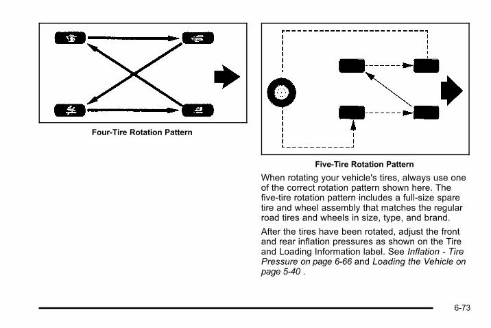
Four‐Tire Rotation Pattern
Five‐Tire Rotation Pattern
When rotating your vehicle's tires, always use oneof the correct rotation pattern shown here. Thefive‐tire rotation pattern includes a full‐size sparetire and wheel assembly that matches the regularroad tires and wheels in size, type, and brand.
After the tires have been rotated, adjust the frontand rear inflation pressures as shown on the Tireand Loading Information label. See Inflation - TirePressure on page 6‑66 and Loading the Vehicle onpage 5‑40 .
6-73
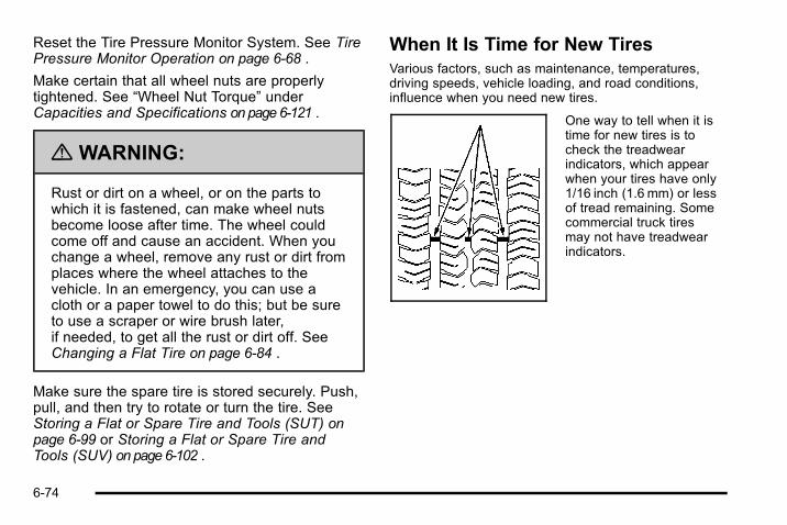
Reset the Tire Pressure Monitor System. See TirePressure Monitor Operation on page 6‑68 .
Make certain that all wheel nuts are properlytightened. See “Wheel Nut Torque” underCapacities and Specifications on page 6‑121 .
{ WARNING:
Rust or dirt on a wheel, or on the parts towhich it is fastened, can make wheel nutsbecome loose after time. The wheel couldcome off and cause an accident. When youchange a wheel, remove any rust or dirt fromplaces where the wheel attaches to thevehicle. In an emergency, you can use acloth or a paper towel to do this; but be sureto use a scraper or wire brush later,if needed, to get all the rust or dirt off. SeeChanging a Flat Tire on page 6‑84 .
Make sure the spare tire is stored securely. Push,pull, and then try to rotate or turn the tire. SeeStoring a Flat or Spare Tire and Tools (SUT) onpage 6‑99 or Storing a Flat or Spare Tire andTools (SUV) on page 6‑102 .
When It Is Time for New TiresVarious factors, such as maintenance, temperatures,driving speeds, vehicle loading, and road conditions,influence when you need new tires.
One way to tell when it istime for new tires is tocheck the treadwearindicators, which appearwhen your tires have only1/16 inch (1.6 mm) or lessof tread remaining. Somecommercial truck tiresmay not have treadwearindicators.
6-74
You need new tires if any of the following statementsare true:. You can see the indicators at three or more places
around the tire.. You can see cord or fabric showing through the
tire's rubber.. The tread or sidewall is cracked, cut, or snagged
deep enough to show cord or fabric.. The tire has a bump, bulge, or split.. The tire has a puncture, cut, or other damage that
cannot be repaired well because of the size orlocation of the damage.
The rubber in tires degrades over time, even if they arenot being used. This is also true for the spare tire,if your vehicle has one. Multiple conditions affect howfast this aging takes place, including temperatures,loading conditions, and inflation pressure maintenance.With proper care and maintenance tires will typicallywear out before they degrade due to age. If you areunsure about the need to replace your tires as they getolder, consult the tire manufacturer for more information.
Buying New TiresGM has developed and matched specific tires foryour vehicle. The original equipment tires installedon your vehicle, when it was new, were designedto meet General Motors Tire Performance CriteriaSpecification (TPC spec) system rating. If youneed replacement tires, GM strongly recommendsthat you get tires with the same TPC Spec rating.This way, your vehicle will continue to have tiresthat are designed to give the same performanceand vehicle safety, during normal use, as theoriginal tires.
GM's exclusive TPC Spec system considers overa dozen critical specifications that impact theoverall performance of your vehicle, includingbrake system performance, ride and handling,traction control, and tire pressure monitoringperformance. GM's TPC Spec number is moldedonto the tire's sidewall near the tire size. If thetires have an all‐season tread design, the TPCspec number will be followed by a MS, for mudand snow. See Tire Sidewall Labeling onpage 6‑61 for additional information.
6-75

GM recommends replacing tires in sets of four.This is because uniform tread depth on all tireswill help keep your vehicle performing most like itdid when the tires were new. Replacing less thana full set of tires can affect the braking andhandling performance of your vehicle. See TireInspection and Rotation on page 6‑72 forinformation on proper tire rotation.
{ WARNING:
Mixing tires could cause you to lose controlwhile driving. If you mix tires of differentsizes, brands, or types (radial andbias-belted tires) the vehicle may not handleproperly, and you could have a crash. Usingtires of different sizes, brands, or types mayalso cause damage to your vehicle. Be sureto use the correct size, brand, and type oftires on your vehicle's wheels.
{ WARNING:
If you use bias-ply tires on the vehicle, thewheel rim flanges could develop cracks aftermany miles of driving. A tire and/or wheelcould fail suddenly, causing a crash. Useonly radial-ply tires with the wheels on thevehicle.
If you must replace your vehicle's tires with thosethat do not have a TPC Spec number, make surethey are the same size, load range, speed rating,and construction type (radial and bias‐belted tires)as your vehicle's original tires.
Vehicles equipped with a tire pressure monitoringsystem may give an inaccurate low‐pressurewarning if non‐TPC spec rated tires are installedon your vehicle. Non‐TPC Spec rated tires maygive a low‐pressure warning that is higher or lowerthan the proper warning level you would get withTPC Spec rated tires. See Tire Pressure MonitorSystem on page 6‑67 .
6-76

Your vehicle's original equipment tires are listedon the Tire and Loading Information Label. SeeLoading the Vehicle on page 5‑40 , for moreinformation about the Tire and LoadingInformation Label and its location on your vehicle.
Different Size Tires and WheelsIf you add wheels or tires that are a different size thanyour original equipment wheels and tires, this couldaffect the way your vehicle performs, including itsbraking, ride and handling characteristics, stability, andresistance to rollover. Additionally, if your vehicle haselectronic systems such as anti‐lock brakes, rolloverairbags, traction control, and electronic stability control,the performance of these systems can be affected.
{ WARNING:
If you add different sized wheels, your vehiclemay not provide an acceptable level ofperformance and safety if tires not recommendedfor those wheels are selected. You may increasethe chance that you will crash and suffer seriousinjury. Only use HUMMER specific wheel and tiresystems developed for your vehicle, and havethem properly installed by a GM certifiedtechnician.
See Buying New Tires on page 6‑75 and Accessoriesand Modifications on page 6‑4 for additionalinformation.
6-77

Uniform Tire Quality GradingQuality grades can be found where applicable onthe tire sidewall between tread shoulder andmaximum section width. For example:
Treadwear 200 Traction AATemperature AThe following information relates to the systemdeveloped by the United States National HighwayTraffic Safety Administration (NHTSA), whichgrades tires by treadwear, traction, andtemperature performance. This applies only tovehicles sold in the United States. The grades aremolded on the sidewalls of most passenger cartires. The Uniform Tire Quality Grading (UTQG)system does not apply to deep tread, winter-typesnow tires, space-saver, or temporary use sparetires, tires with nominal rim diameters of10 to 12 inches (25 to 30 cm), or to somelimited-production tires.
While the tires available on HUMMER light trucksmay vary with respect to these grades, they mustalso conform to federal safety requirements andadditional General Motors Tire PerformanceCriteria (TPC) standards.
All Passenger Car Tires Must Conform to FederalSafety Requirements In Addition To TheseGrades.
TreadwearThe treadwear grade is a comparative ratingbased on the wear rate of the tire when testedunder controlled conditions on a specifiedgovernment test course. For example, a tiregraded 150 would wear one and a half (1½) timesas well on the government course as a tire graded100. The relative performance of tires dependsupon the actual conditions of their use, however,and may depart significantly from the norm due tovariations in driving habits, service practices anddifferences in road characteristics and climate.
6-78

Traction – AA, A, B, CThe traction grades, from highest to lowest, areAA, A, B, and C. Those grades represent the tire'sability to stop on wet pavement as measuredunder controlled conditions on specifiedgovernment test surfaces of asphalt and concrete.A tire marked C may have poor tractionperformance. Warning: The traction gradeassigned to this tire is based on straight-aheadbraking traction tests, and does not includeacceleration, cornering, hydroplaning, or peaktraction characteristics.
Temperature – A, B, CThe temperature grades are A (the highest), B,and C, representing the tire's resistance to thegeneration of heat and its ability to dissipate heatwhen tested under controlled conditions on aspecified indoor laboratory test wheel. Sustainedhigh temperature can cause the material of thetire to degenerate and reduce tire life, andexcessive temperature can lead to sudden tire
failure. The grade C corresponds to a level ofperformance which all passenger car tires mustmeet under the Federal Motor Safety StandardNo. 109. Grades B and A represent higher levelsof performance on the laboratory test wheel thanthe minimum required by law. Warning: Thetemperature grade for this tire is established for atire that is properly inflated and not overloaded.Excessive speed, underinflation, or excessiveloading, either separately or in combination, cancause heat buildup and possible tire failure.
Wheel Alignment and Tire BalanceThe tires and wheels on your vehicle were aligned andbalanced carefully at the factory to give you the longesttire life and best overall performance. Adjustments towheel alignment and tire balancing will not benecessary on a regular basis. However, if you noticeunusual tire wear or your vehicle pulling to one side orthe other, the alignment might need to be checked.If you notice your vehicle vibrating when driving on asmooth road, the tires and wheels might need to berebalanced. See your dealer for proper diagnosis.
6-79
Wheel ReplacementReplace any wheel that is bent, cracked, or badlyrusted or corroded. If wheel nuts keep coming loose,the wheel, wheel bolts, and wheel nuts should bereplaced. If the wheel leaks air, replace it (except somealuminum wheels, which can sometimes be repaired).See your dealer if any of these conditions exist.
Your dealer will know the kind of wheel you need.
Each new wheel should have the same load-carryingcapacity, diameter, width, offset, and be mounted thesame way as the one it replaces.
If you need to replace any of your wheels, wheel bolts,wheel nuts, or Tire Pressure Monitor System (TPMS)sensors, replace them only with new GM originalequipment parts. This way, you will be sure to have theright wheel, wheel bolts, wheel nuts, and TPMS sensorsfor your vehicle.
{ WARNING:
Using the wrong replacement wheels, wheel bolts,or wheel nuts on your vehicle can be dangerous.It could affect the braking and handling of yourvehicle, make your tires lose air and make youlose control. You could have a collision in whichyou or others could be injured. Always use thecorrect wheel, wheel bolts, and wheel nuts forreplacement.
Notice: The wrong wheel can also cause problemswith bearing life, brake cooling, speedometer orodometer calibration, headlamp aim, bumper height,vehicle ground clearance, and tire or tire chainclearance to the body and chassis.
See Changing a Flat Tire on page 6‑84 for moreinformation.
6-80
Used Replacement Wheels
{ WARNING:
Putting a used wheel on the vehicle is dangerous.You cannot know how it has been used or how farit has been driven. It could fail suddenly andcause a crash. If you have to replace a wheel, usea new GM original equipment wheel.
Tire ChainsNotice: Use tire chains only where legal and onlywhen you must. Use chains that are the proper sizefor the vehicle's tires. Install them on the tires of therear axle. Do not use chains on the tires of the frontaxle. Tighten them as tightly as possible with theends securely fastened. Drive slowly and follow thechain manufacturer's instructions. If you can hearthe chains contacting the vehicle, stop andretighten them. If the contact continues, slow downuntil it stops. Driving too fast or spinning the wheelswith chains on will damage the vehicle.
6-81

Accessory InflatorYour vehicle may have an accessory inflator system.You can inflate things like basketballs and bicycle tires.You can also use it to bring your tire pressure up to theproper pressure. The engine must be running and thegearshift lever must be in PARK (P) for the inflator tooperate.
The accessory inflator islocated in the rearcompartment on thepassenger's side of thevehicle.
The accessory inflator kitincludes a hose and threenozzle adapters.
To use the accessory inflator, do the following:
1. Attach the appropriate nozzle adapter to the end ofthe hose.
2. Attach that end of the hose to the object you wishto inflate.
3. Remove the dust cover and attach the hose to theoutlet.
6-82

The accessory inflator hose also has a built-in airpressure gauge. As soon as you start to inflate anobject it will automatically read the currentpressure.
4. Press and release the switch to turn the accessoryinflator on. The indicator light will remain on whilethe inflator is running.
When you are finished using the inflator, press andrelease the switch to turn it off. Place the inflator kittools and the hose back in the pouch.
If your vehicle is equipped with the air suspensionsystem, load leveling will not function with the inflatorhose attached to the inflator outlet.
{ WARNING:
Inflating something too much can make it explode,and you or others could be injured. Be sure toread the inflator instructions, and inflate any objectonly to its recommended pressure.
If a Tire Goes FlatIt is unusual for a tire to blowout while you are driving,especially if you maintain your vehicle's tires properly.If air goes out of a tire, it is much more likely to leak outslowly. But if you should ever have a blowout, here area few tips about what to expect and what to do:
If a front tire fails, the flat tire creates a drag that pullsthe vehicle toward that side. Take your foot off theaccelerator pedal and grip the steering wheel firmly.Steer to maintain lane position, and then gently brake toa stop well out of the traffic lane.
6-83

A rear blowout, particularly on a curve, acts much like askid and may require the same correction you woulduse in a skid. In any rear blowout remove your foot fromthe accelerator pedal. Get the vehicle under control bysteering the way you want the vehicle to go. It may bevery bumpy and noisy, but you can still steer. Gentlybrake to a stop, well off the road if possible.
{ WARNING:
Lifting a vehicle and getting under it to domaintenance or repairs is dangerous without theappropriate safety equipment and training. If ajack is provided with the vehicle, it is designedonly for changing a flat tire. If it is used foranything else, you or others could be badlyinjured or killed if the vehicle slips off the jack. If ajack is provided with the vehicle, only use it forchanging a flat tire.
If a tire goes flat, the next part shows how to use thejacking equipment to change a flat tire safely.
Changing a Flat TireIf a tire goes flat, avoid further tire and wheel damageby driving slowly to a level place. Turn on the hazardwarning flashers. See Hazard Warning Flashers onpage 4‑3 .
{ WARNING:
Changing a tire can be dangerous. The vehiclecan slip off the jack and roll over or fall on you orother people. You and they could be badly injuredor even killed. Find a level place to change yourtire. To help prevent the vehicle from moving:
1. Set the parking brake firmly.
2. Put the shift lever in P (Park).
3. Be sure the transfer case is in a drivegear— not in Neutral.
(Continued)
6-84

WARNING: (Continued)
4. Turn off the engine and do not restart whilethe vehicle is raised.
5. Do not allow passengers to remain in thevehicle.
To be even more certain the vehicle will not move,you can put blocks at the front and rear of the tirefarthest away from the one being changed. Thatwould be the tire on the other side, at the oppositeend of the vehicle.
When the vehicle has a flat tire (B), use the followingexample as a guide to assist you in the placement ofwheel blocks (A).
A. Wheel Block
B. Flat Tire
The following information explains how to use the jackand change a tire.
6-85
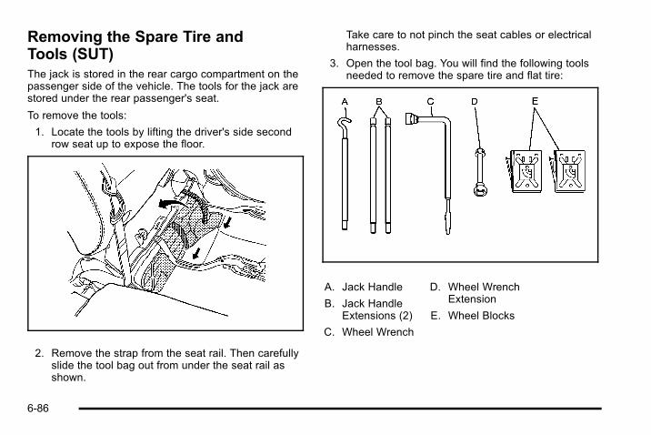
Removing the Spare Tire andTools (SUT)The jack is stored in the rear cargo compartment on thepassenger side of the vehicle. The tools for the jack arestored under the rear passenger's seat.
To remove the tools:
1. Locate the tools by lifting the driver's side secondrow seat up to expose the floor.
2. Remove the strap from the seat rail. Then carefullyslide the tool bag out from under the seat rail asshown.
Take care to not pinch the seat cables or electricalharnesses.
3. Open the tool bag. You will find the following toolsneeded to remove the spare tire and flat tire:
A. Jack Handle
B. Jack HandleExtensions (2)
C. Wheel Wrench
D. Wheel WrenchExtension
E. Wheel Blocks
6-86
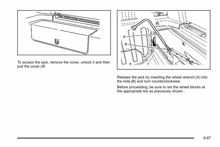
To access the jack, remove the cover, unlock it and thenpull the cover off.
Release the jack by inserting the wheel wrench (A) intothe hole (B) and turn counterclockwise.
Before proceeding, be sure to set the wheel blocks atthe appropriate tire as previously shown .
6-87

Remove the wheel blocksfrom the tool bag. Then liftthe wheel block as shownto lock it into place.
Removing the Spare Tire (SUT)The spare tire is attached to the tire carrier. To removethe spare tire:
In order to remove the spare tire, you may needsomeone to assist you.
1. Open the tire carrier. See Tailgate/Spare TireCarrier on page 3‑15 for tire carrier operation.
2. Unscrew the wing nut on the back of the tirecarrier.
6-88

3. Pull off the license plate holder from the spare tire.
4. Attach the wheel wrench to the wheel wrenchextender to remove the wheel nuts.
5. Turn the wheel wrench with the wheel wrenchextender counterclockwise to loosen thewheel nuts.
6. Remove the wheel nuts holding the spare tire ontothe tire carrier.
7. Pull off the spare tire and gently lower to theground. Set it next to the flat tire.
6-89

Removing the Spare Tire andTools (SUV)
Removing the Tools (SUV)The equipment you will need to change a flat tire isstored under the storage tray, which is located on thedriver side trim panel (over the rear wheelhouse). Toremove the equipment:
1. Remove the tray to access the tools by pulling upon the finger depression.
2. Turn the retainer nut (C) counterclockwise.Remove the tool bag (A) and the two wheelblocks (B) from the storage area.
6-90

3. Open the tool bag. The following tools needed toremove the spare tire and flat tire are inside thetool bag:
A. Jack Handle
B. Jack HandleExtensions (2)
C. Wheel Wrench
D. Wheel WrenchExtension
Before proceeding, be sure to set the wheel blocks atthe appropriate tire as previously shown. To use thewheel blocks:
Removing the Jack (SUV)The jack is stored in the rear cargo area on thedriver side.
1. To access the jack pull on the two latches toremove the trim cover.
6-91

2. Insert the wheel wrench into the hole and turn itcounterclockwise to release it.
3. Grasp and lift the jack out of the bracket.
Removing the Spare Tire (SUV)The spare tire is attached to the tire carrier. To removethe spare tire:
In order to remove the spare tire, you may needsomeone to assist you.
1. Open the tire carrier. See Tailgate/Spare TireCarrier on page 3‑15 for tire carrier operation.
2. Unscrew the wing nut on the back of the tirecarrier.
6-92

3. Pull off the license plate holder from the spare tire.
4. Attach the wheel wrench to the wheel wrenchextender to remove the wheel nuts. Turn the wheelwrench with the wheel wrench extendercounterclockwise to loosen the wheel nuts.
5. Remove the wheel nuts holding the spare tire ontothe tire carrier.
6. Pull off the spare tire and gently lower it to theground. Set it next to the flat tire.
6-93

Removing the Flat Tire and Installingthe Spare Tire
Jack (SUV and SUT)1. Do a safety check before proceeding. See
Changing a Flat Tire on page 6‑84 for moreinformation.
2. To remove the centercap, place the flat endof the wheel wrench inthe slot on the wheeland carefully pry thecenter cap out.
3. Attach the wheel wrench to the extender.
4. Turn the wheel wrench counterclockwise to loosenthe wheel nuts. Do not remove them yet.
Now jack the vehicle up.
6-94
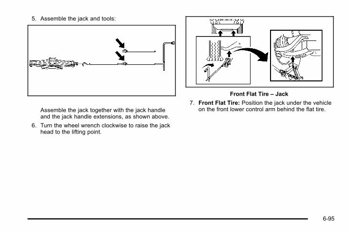
5. Assemble the jack and tools:
Assemble the jack together with the jack handleand the jack handle extensions, as shown above.
6. Turn the wheel wrench clockwise to raise the jackhead to the lifting point.
Front Flat Tire – Jack
7. Front Flat Tire: Position the jack under the vehicleon the front lower control arm behind the flat tire.
6-95
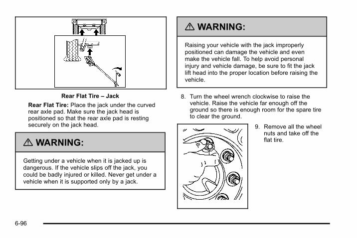
Rear Flat Tire – Jack
Rear Flat Tire: Place the jack under the curvedrear axle pad. Make sure the jack head ispositioned so that the rear axle pad is restingsecurely on the jack head.
{ WARNING:
Getting under a vehicle when it is jacked up isdangerous. If the vehicle slips off the jack, youcould be badly injured or killed. Never get under avehicle when it is supported only by a jack.
{ WARNING:
Raising your vehicle with the jack improperlypositioned can damage the vehicle and evenmake the vehicle fall. To help avoid personalinjury and vehicle damage, be sure to fit the jacklift head into the proper location before raising thevehicle.
8. Turn the wheel wrench clockwise to raise thevehicle. Raise the vehicle far enough off theground so there is enough room for the spare tireto clear the ground.
9. Remove all the wheelnuts and take off theflat tire.
6-96

{ WARNING:
Rust or dirt on a wheel, or on the parts to which itis fastened, can make wheel nuts become looseafter time. The wheel could come off and causean accident. When changing a wheel, remove anyrust or dirt from places where the wheel attachesto the vehicle. In an emergency, use a cloth or apaper towel to do this; but be sure to use ascraper or wire brush later, if needed, to get all therust or dirt off. See Changing a Flat Tire onpage 6‑84.
10. Remove any rust or dirtfrom the wheel bolts,mounting surfaces andspare wheel.
{ WARNING:
Never use oil or grease on bolts or nuts becausethe nuts might come loose. The vehicle's wheelcould fall off, causing a crash.
11. Install the spare tire.
12. Put the wheel nuts back on with the rounded endof the nuts toward the wheel.
6-97

13. Tighten each wheel nut by hand. Then use thewheel wrench to tighten the nuts by turning itclockwise until the wheel is held against the hub.
You will not be tightening the nuts fully yet.
14. Lower the vehicle by turning the wheel wrenchcounterclockwise. Then lower the jack completely.
{ WARNING:
Wheel nuts that are improperly or incorrectlytightened can cause the wheels to become looseor come off. The wheel nuts should be tightenedwith a torque wrench to the proper torquespecification after replacing. Follow the torquespecification supplied by the aftermarketmanufacturer when using accessory locking wheelnuts. See Capacities and Specifications onpage 6‑121 for original equipment wheel nuttorque specifications.
Notice: Improperly tightened wheel nuts can lead tobrake pulsation and rotor damage. To avoidexpensive brake repairs, evenly tighten the wheelnuts in the proper sequence and to the propertorque specification. See Capacities andSpecifications on page 6‑121 for the wheel nut torquespecification.
6-98

15. Tighten the nuts firmlyin a crisscrosssequence as shown byturning the wheelwrench with the wheelwrench extenderclockwise.
16. When you install the wheel and tire, you must alsoreinstall the center cap. Place the cap on the wheeland tap it into place until it sits flush with thewheel.
Storing a Flat or Spare Tire andTools (SUT)
Storing the Flat or Spare TireUse the following art and text to help you store thespare or flat tire back into its proper location when youare done.
To store the flat or spare tire on the tire carrier:
1. Close the tire carrier. See Tailgate/Spare TireCarrier on page 3‑15 for tire carrier operation.
2. Place the flat or spare tire onto the tire carrier withthe outside of the wheel facing you.
3. Reinstall the wheel nuts holding the spare or flattire to the tire carrier. Tighten the nuts by hand.
6-99
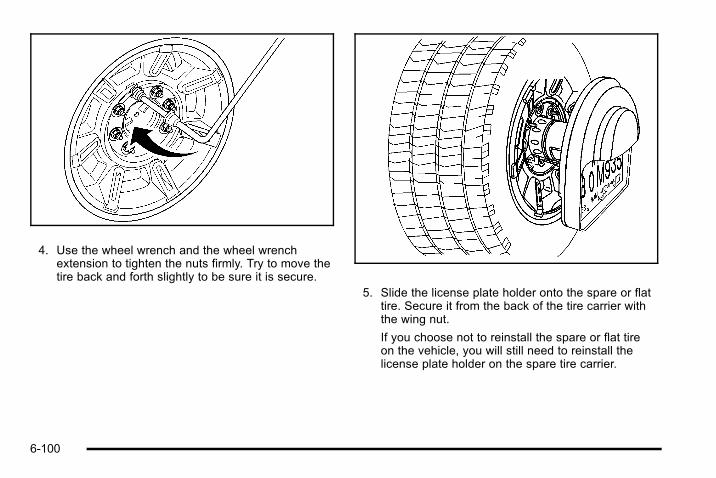
4. Use the wheel wrench and the wheel wrenchextension to tighten the nuts firmly. Try to move thetire back and forth slightly to be sure it is secure.
5. Slide the license plate holder onto the spare or flattire. Secure it from the back of the tire carrier withthe wing nut.
If you choose not to reinstall the spare or flat tireon the vehicle, you will still need to reinstall thelicense plate holder on the spare tire carrier.
6-100

Storing the Jack and ToolsTo store the jack and tools:
1. Lower the jack completely.
2. Place the jack in the mounting bracket.
3. Turn the hole at the top of the jack clockwise untilthe jack is held tight in the mounting bracket.
4. Push and pull on the jack and retighten ifnecessary to make sure the jack is secure.
5. Place the wheel blocks in the tool bag.
6. Place the remaining tools in the tool bag.
7. Make sure nothing is located under or in front ofthe seat and then lift the rear driver's side secondrow seat so that the floor is exposed.
8. Place the narrow end of the tool bag under theseat rails as shown. Slide the tool bag under therear seat.
Be careful not to pinch the seat cables or electricalharnesses.
9. Reinstall the strap to the seat rail.
10. Return the seat to the correct position.
6-101
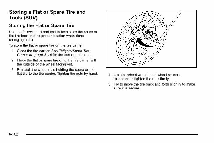
Storing a Flat or Spare Tire andTools (SUV)
Storing the Flat or Spare TireUse the following art and text to help store the spare orflat tire back into its proper location when donechanging a tire.
To store the flat or spare tire on the tire carrier:
1. Close the tire carrier. See Tailgate/Spare TireCarrier on page 3‑15 for tire carrier operation.
2. Place the flat or spare tire onto the tire carrier withthe outside of the wheel facing out.
3. Reinstall the wheel nuts holding the spare or theflat tire to the tire carrier. Tighten the nuts by hand. 4. Use the wheel wrench and wheel wrench
extension to tighten the nuts firmly.
5. Try to move the tire back and forth slightly to makesure it is secure.
6-102

6. Slide the license plate holder onto the spare or flattire. Secure it from the back of the tire carrier withthe wing nut.
If you choose not to reinstall the spare or flat tireon the vehicle, you still need to reinstall the licenseplate holder on the spare tire carrier.
Storing the Jack and ToolsTo store the jack and tools:
1. Lower the jack completely.
2. Place the jack in the mounting bracket.
Turn the hole at the top of the jack clockwise untilthe jack is held tight in the mounting bracket.
4. Push and pull on the jack and retighten ifnecessary to make sure the jack is secure.
6-103
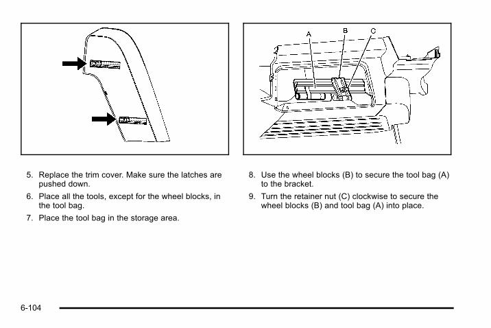
5. Replace the trim cover. Make sure the latches arepushed down.
6. Place all the tools, except for the wheel blocks, inthe tool bag.
7. Place the tool bag in the storage area.
8. Use the wheel blocks (B) to secure the tool bag (A)to the bracket.
9. Turn the retainer nut (C) clockwise to secure thewheel blocks (B) and tool bag (A) into place.
6-104

10. Return the storage tray to its original location bypushing down on the finger depression.
Spare TireYour vehicle, when new, had a fully-inflated spare tire.A spare tire may lose air over time, so check its inflationpressure regularly. See Inflation - Tire Pressure onpage 6‑66 and Loading the Vehicle on page 5‑40 forinformation regarding proper tire inflation and loadingyour vehicle. For instruction on how to remove, install orstore a spare tire, see Removing the Flat Tire andInstalling the Spare Tire on page 6‑94 and Storing aFlat or Spare Tire and Tools (SUT) on page 6‑99 orStoring a Flat or Spare Tire and Tools (SUV) onpage 6‑102.
After installing the spare tire on your vehicle, you shouldstop as soon as possible and make sure the spare iscorrectly inflated.
Have the damaged or flat road tire repaired or replacedas soon as you can and installed back onto yourvehicle. This way, a spare tire will be available in caseyou need it again. Do not mix tires and wheels ofdifferent sizes, because they will not fit. Keep yourspare tire and its wheel together.
6-105

Appearance Care
Interior CleaningThe vehicle's interior will continue to look its best if it iscleaned often. Although not always visible, dust and dirtcan accumulate on the upholstery. Dirt can damagecarpet, fabric, leather, and plastic surfaces. Regularvacuuming is recommended to remove particles fromthe upholstery. It is important to keep the upholsteryfrom becoming and remaining heavily soiled. Soilsshould be removed as quickly as possible. Thevehicle's interior may experience extremes of heat thatcould cause stains to set rapidly.
Lighter colored interiors may require more frequentcleaning. Use care because newspapers and garmentsthat transfer color to home furnishings may also transfercolor to the vehicle's interior.
When cleaning the vehicle's interior, only use cleanersspecifically designed for the surfaces being cleaned.Permanent damage may result from using cleaners onsurfaces for which they were not intended. Use glasscleaner only on glass. Remove any accidentalover-spray from other surfaces immediately. To preventover-spray, apply cleaner directly to the cleaning cloth.
Notice: Using abrasive cleaners when cleaningglass surfaces on the vehicle, could scratch theglass and/or cause damage to the rear windowdefogger. When cleaning the glass on the vehicle,use only a soft cloth and glass cleaner.
Many cleaners contain solvents that may becomeconcentrated in the vehicle's breathing space. Beforeusing cleaners, read and adhere to all safetyinstructions on the label. While cleaning the vehicle'sinterior, maintain adequate ventilation by opening thevehicle's doors and windows.
Dust may be removed from small buttons and knobsusing a small brush with soft bristles.
Products that remove odors from the vehicle'supholstery and clean the vehicle's glass can beobtained from your dealer.
Do not clean the vehicle using:. A knife or any other sharp object to remove a soil
from any interior surface.. A stiff brush. It can cause damage to the vehicle's
interior surfaces.. Heavy pressure or aggressive rubbing with a
cleaning cloth. Use of heavy pressure can damagethe interior and does not improve the effectivenessof soil removal.
6-106
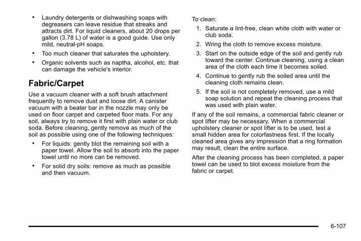
. Laundry detergents or dishwashing soaps withdegreasers can leave residue that streaks andattracts dirt. For liquid cleaners, about 20 drops pergallon (3.78 L) of water is a good guide. Use onlymild, neutral-pH soaps.
. Too much cleaner that saturates the upholstery.
. Organic solvents such as naptha, alcohol, etc. thatcan damage the vehicle's interior.
Fabric/CarpetUse a vacuum cleaner with a soft brush attachmentfrequently to remove dust and loose dirt. A canistervacuum with a beater bar in the nozzle may only beused on floor carpet and carpeted floor mats. For anysoil, always try to remove it first with plain water or clubsoda. Before cleaning, gently remove as much of thesoil as possible using one of the following techniques:. For liquids: gently blot the remaining soil with a
paper towel. Allow the soil to absorb into the papertowel until no more can be removed.
. For solid dry soils: remove as much as possibleand then vacuum.
To clean:
1. Saturate a lint-free, clean white cloth with water orclub soda.
2. Wring the cloth to remove excess moisture.
3. Start on the outside edge of the soil and gently rubtoward the center. Continue cleaning, using a cleanarea of the cloth each time it becomes soiled.
4. Continue to gently rub the soiled area until thecleaning cloth remains clean.
5. If the soil is not completely removed, use a mildsoap solution and repeat the cleaning process thatwas used with plain water.
If any of the soil remains, a commercial fabric cleaner orspot lifter may be necessary. When a commercialupholstery cleaner or spot lifter is to be used, test asmall hidden area for colorfastness first. If the locallycleaned area gives any impression that a ring formationmay result, clean the entire surface.
After the cleaning process has been completed, a papertowel can be used to blot excess moisture from thefabric or carpet.
6-107
LeatherA soft cloth dampened with water can be used toremove dust. If a more thorough cleaning is necessary,a soft cloth dampened with a mild soap solution can beused. Allow the leather to dry naturally. Do not use heatto dry. Never use steam to clean leather. Never usespot lifters or spot removers on leather. Manycommercial leather cleaners and coatings that are soldto preserve and protect leather may permanentlychange the appearance and feel of the leather and arenot recommended. Do not use silicone or wax-basedproducts, or those containing organic solvents to cleanthe vehicle's interior because they can alter theappearance by increasing the gloss in a non-uniformmanner. Never use shoe polish on leather.
Instrument Panel, Vinyl, and OtherPlastic SurfacesA soft cloth dampened with water may be used toremove dust. If a more thorough cleaning is necessary,a clean soft cloth dampened with a mild soap solutioncan be used to gently remove dust and dirt. Never usespot lifters or removers on plastic surfaces. Manycommercial cleaners and coatings that are sold to
preserve and protect soft plastic surfaces maypermanently change the appearance and feel of theinterior and are not recommended. Do not use siliconeor wax-based products, or those containing organicsolvents to clean the vehicle's interior because they canalter the appearance by increasing the gloss in anon-uniform manner.
Some commercial products may increase gloss on theinstrument panel. The increase in gloss may causeannoying reflections in the windshield and even make itdifficult to see through the windshield under certainconditions.
Wood PanelsUse a clean cloth moistened in warm, soapy water (usemild dish washing soap). Dry the wood immediately witha clean cloth.
Speaker CoversVacuum around a speaker cover gently, so that thespeaker will not be damaged. Clean spots with justwater and mild soap.
6-108
Care of Safety BeltsKeep belts clean and dry.
{ WARNING:
Do not bleach or dye safety belts. It may severelyweaken them. In a crash, they might not be ableto provide adequate protection. Clean safety beltsonly with mild soap and lukewarm water.
WeatherstripsSilicone grease on weatherstrips will make them lastlonger, seal better, and not stick or squeak. Applysilicone grease with a clean cloth. During very cold,damp weather frequent application may be required.See Recommended Fluids and Lubricants onpage 7‑10.
Washing Your VehicleThe best way to preserve the vehicle's finish is to keepit clean by washing it often.
Notice: Certain cleaners contain chemicals that candamage the emblems or nameplates on the vehicle.Check the cleaning product label. If it states that itshould not be used on plastic parts, do not use it onthe vehicle or damage may occur and it would notbe covered by the warranty.
Do not wash the vehicle in direct sunlight. Use a carwashing soap. Do not use cleaning agents that arepetroleum based or that contain acid or abrasives, asthey can damage the paint, metal or plastic on thevehicle. Approved cleaning products can be obtainedfrom your dealer. Follow all manufacturers' directionsregarding correct product usage, necessary safetyprecautions and appropriate disposal of any vehiclecare product.
Rinse the vehicle well, before washing and after toremove all cleaning agents completely. If they areallowed to dry on the surface, they could stain.
Dry the finish with a soft, clean chamois or an all-cottontowel to avoid surface scratches and water spotting.
6-109

High pressure car washes may cause water to enter thevehicle. Avoid using high pressure washes closer than12 inches (30 cm) to the surface of the vehicle. Use ofpower washers exceeding 1,200 psi (8 274 kPa) canresult in damage or removal of paint and decals.
Cleaning Exterior Lamps/LensesUse only lukewarm or cold water, a soft cloth and a carwashing soap to clean exterior lamps and lenses.Follow instructions under Washing Your Vehicle onpage 6‑109.
Finish CareOccasional waxing or mild polishing of the vehicle byhand may be necessary to remove residue from thepaint finish. Approved cleaning products can beobtained from your dealer.
If the vehicle has a basecoat/clearcoat paint finish, theclearcoat gives more depth and gloss to the coloredbasecoat. Always use waxes and polishes that arenon-abrasive and made for a basecoat/clearcoat paintfinish.
Notice: Machine compounding or aggressivepolishing on a basecoat/clearcoat paint finish maydamage it. Use only non-abrasive waxes andpolishes that are made for a basecoat/clearcoatpaint finish on the vehicle.
Foreign materials such as calcium chloride and othersalts, ice melting agents, road oil and tar, tree sap, birddroppings, chemicals from industrial chimneys, etc., candamage the vehicle's finish if they remain on paintedsurfaces. Wash the vehicle as soon as possible.If necessary, use non-abrasive cleaners that aremarked safe for painted surfaces to remove foreignmatter.
Exterior painted surfaces are subject to aging, weatherand chemical fallout that can take their toll over a periodof years. To help keep the paint finish looking new, keepthe vehicle garaged or covered whenever possible.
Protecting Exterior Bright Metal PartsBright metal parts should be cleaned regularly to keeptheir luster. Washing with water is all that is usuallyneeded. However, chrome polish may be used onchrome or stainless steel trim, if necessary.
Use special care with aluminum trim. To avoiddamaging protective trim, never use auto or chromepolish, steam or caustic soap to clean aluminum.A coating of wax, rubbed to high polish, isrecommended for all bright metal parts.
6-110

Windshield, Backglass, and WiperBladesClean the outside of the windshield and backglass withglass cleaner.
Clean the rubber blades using a lint free cloth or papertowel soaked with windshield washer fluid or a milddetergent. Wash the windshield thoroughly when youclean the blades. Bugs, road grime, sap and a buildupof vehicle wash/wax treatments may cause wiperstreaking. Replace the wiper blades if they are worn ordamaged.
Wipers can be damaged by:. Extreme dusty conditions. Sand and salt. Heat and sun. Snow and ice, without proper removal
Aluminum WheelsNotice: Using strong soaps, chemicals, abrasivepolishes, cleaners, brushes, or cleaners that containacid on aluminum or chrome-plated wheels, coulddamage the surface of the wheel(s). The repairswould not be covered by the vehicle warranty. Useonly approved cleaners on aluminum orchrome-plated wheels.
Keep the wheels clean using a soft clean cloth with mildsoap and water. Rinse with clean water. After rinsingthoroughly, dry with a soft clean towel. A wax may thenbe applied.
Notice: Using chrome polish on aluminum wheelscould damage the wheels. The repairs would not becovered by the vehicle warranty. Use chrome polishon chrome wheels only.
The surface of these wheels is similar to the paintedsurface of the vehicle. Do not use strong soaps,chemicals, abrasive polishes, abrasive cleaners,cleaners with acid, or abrasive cleaning brushes onthem because the surface could be damaged. Do notuse chrome polish on aluminum wheels.
Notice: Driving the vehicle through an automaticcar wash that has silicone carbide tire cleaningbrushes, could damage the aluminum orchrome-plated wheels. The repairs would not becovered by the vehicle warranty. Never drive avehicle that has aluminum or chrome-plated wheelsthrough an automatic car wash that uses siliconecarbide tire cleaning brushes.
6-111

TiresTo clean the tires, use a stiff brush with tire cleaner.
Notice: Using petroleum-based tire dressingproducts on the vehicle may damage the paint finishand/or tires. When applying a tire dressing, alwayswipe off any overspray from all painted surfaces onthe vehicle.
Sheet Metal DamageIf the vehicle is damaged and requires sheet metalrepair or replacement, make sure the body repair shopapplies anti-corrosion material to parts repaired orreplaced to restore corrosion protection.
Original manufacturer replacement parts will provide thecorrosion protection while maintaining the vehiclewarranty.
Finish DamageAny stone chips, fractures or deep scratches in thefinish should be repaired right away. Bare metal willcorrode quickly and may develop into major repairexpense.
Minor chips and scratches can be repaired withtouch-up materials available from your dealer. Largerareas of finish damage can be corrected in yourdealer's/retailer's body and paint shop.
Underbody MaintenanceChemicals used for ice and snow removal and dustcontrol can collect on the underbody. If these are notremoved, corrosion and rust can develop on theunderbody parts such as fuel lines, frame, floor pan,and exhaust system even though they have corrosionprotection.
At least every spring, flush these materials from theunderbody with plain water. Clean any areas wheremud and debris can collect. Dirt packed in close areasof the frame should be loosened before being flushed.Your dealer or an underbody car washing system cando this.
Chemical Paint SpottingSome weather and atmospheric conditions can create achemical fallout. Airborne pollutants can fall upon andattack painted surfaces on the vehicle. This damagecan take two forms: blotchy, ring-shaped discolorations,and small, irregular dark spots etched into the paintsurface.
Although no defect in the paint job causes this, we willrepair, at no charge to the owner, the surfaces of newvehicles damaged by this fallout condition within12 months or 12,000 miles (20 000 km) of purchase,whichever occurs first.
6-112

Vehicle Identification
Vehicle Identification Number (VIN)
This legal identifier is in the front corner of theinstrument panel, on the driver side. It can be seenthrough the windshield from outside. The VIN alsoappears on the Certification/Tire and Service Partslabels and certificates of title and registration.
Engine IdentificationThe eighth character in the VIN is the engine code. Thiscode identifies the vehicle's engine, specifications, andreplacement parts. See “Engine Specifications” underCapacities and Specifications on page 6‑121 for thevehicle's engine code.
Service Parts Identification LabelThis label, on the inside of the glove box, has thefollowing information:. Vehicle Identification Number (VIN). Model designation. Paint information. Production options and special equipment
Do not remove this label from the vehicle.
Electrical System
Add-On Electrical EquipmentNotice: Do not add anything electrical to the vehicleunless you check with your dealer first. Someelectrical equipment can damage the vehicle andthe damage would not be covered by the vehicle'swarranty. Some add-on electrical equipment cankeep other components from working as theyshould.
Add-on equipment can drain the vehicle battery, even ifthe vehicle is not operating.
6-113

The vehicle has an airbag system. Before attempting toadd anything electrical to the vehicle, see ServicingYour Airbag-Equipped Vehicle on page 2‑77 andAdding Equipment to Your Airbag-Equipped Vehicle onpage 2‑78.
Windshield Wiper FusesThe windshield wiper motor is protected by a circuitbreaker and a fuse. If the motor overheats due to heavysnow, etc., the wiper will stop until the motor cools.If the overload is caused by some electrical problem,have it fixed.
Power Windows and Other PowerOptionsCircuit breakers in the fuse block protect the powerwindows and other power accessories. When thecurrent load is too heavy, the circuit breaker opens andcloses, protecting the circuit until the problem is fixed orgoes away.
Fuses and Circuit BreakersThe wiring circuits in the vehicle are protected fromshort circuits by a combination of fuses, circuit breakersand fusible thermal links. This greatly reduces thechance of fires caused by electrical problems.
Look at the silver-colored band inside the fuse. If theband is broken or melted, replace the fuse. Be sure youreplace a bad fuse with a new one of the identical sizeand rating.
Fuses of the same amperage can be temporarilyborrowed from another fuse location, if a fuse goes out.Replace the fuse as soon as you can.
6-114
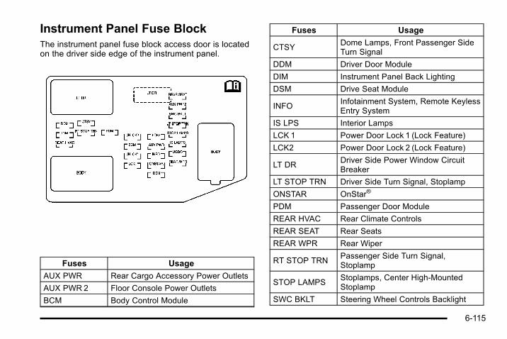
Instrument Panel Fuse BlockThe instrument panel fuse block access door is locatedon the driver side edge of the instrument panel.
Fuses Usage
AUX PWR Rear Cargo Accessory Power Outlets
AUX PWR 2 Floor Console Power Outlets
BCM Body Control Module
Fuses Usage
CTSYDome Lamps, Front Passenger SideTurn Signal
DDM Driver Door Module
DIM Instrument Panel Back Lighting
DSM Drive Seat Module
INFOInfotainment System, Remote KeylessEntry System
IS LPS Interior Lamps
LCK 1 Power Door Lock 1 (Lock Feature)
LCK2 Power Door Lock 2 (Lock Feature)
LT DRDriver Side Power Window CircuitBreaker
LT STOP TRN Driver Side Turn Signal, Stoplamp
ONSTAR OnStar®
PDM Passenger Door Module
REAR HVAC Rear Climate Controls
REAR SEAT Rear Seats
REAR WPR Rear Wiper
RT STOP TRNPassenger Side Turn Signal,Stoplamp
STOP LAMPSStoplamps, Center High‐MountedStoplamp
SWC BKLT Steering Wheel Controls Backlight
6-115
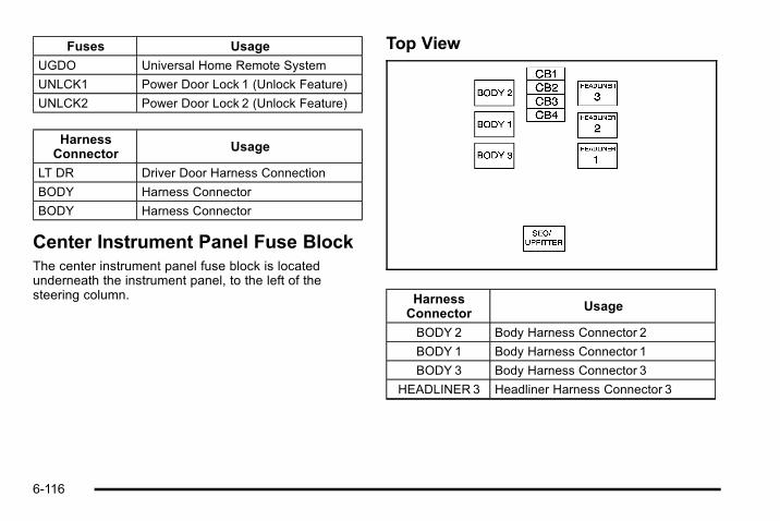
Fuses Usage
UGDO Universal Home Remote System
UNLCK1 Power Door Lock 1 (Unlock Feature)
UNLCK2 Power Door Lock 2 (Unlock Feature)
HarnessConnector Usage
LT DR Driver Door Harness Connection
BODY Harness Connector
BODY Harness Connector
Center Instrument Panel Fuse BlockThe center instrument panel fuse block is locatedunderneath the instrument panel, to the left of thesteering column.
Top View
HarnessConnector
Usage
BODY 2 Body Harness Connector 2
BODY 1 Body Harness Connector 1
BODY 3 Body Harness Connector 3
HEADLINER 3 Headliner Harness Connector 3
6-116
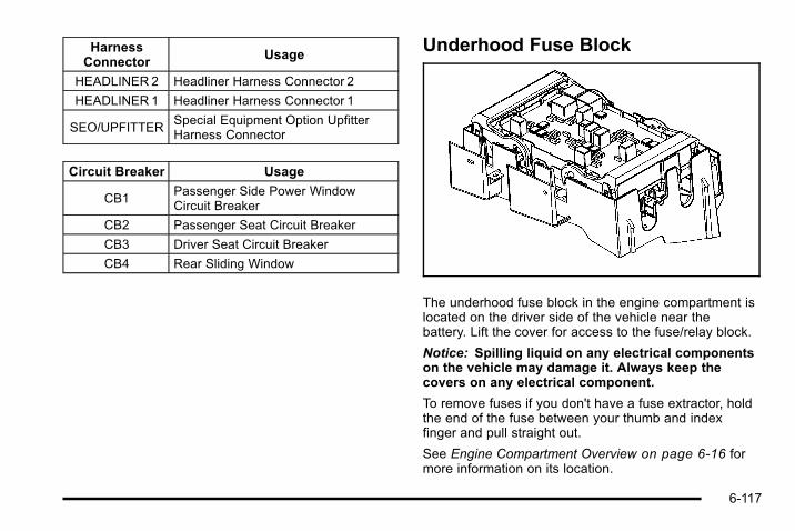
HarnessConnector
Usage
HEADLINER 2 Headliner Harness Connector 2
HEADLINER 1 Headliner Harness Connector 1
SEO/UPFITTERSpecial Equipment Option UpfitterHarness Connector
Circuit Breaker Usage
CB1Passenger Side Power WindowCircuit Breaker
CB2 Passenger Seat Circuit Breaker
CB3 Driver Seat Circuit Breaker
CB4 Rear Sliding Window
Underhood Fuse Block
The underhood fuse block in the engine compartment islocated on the driver side of the vehicle near thebattery. Lift the cover for access to the fuse/relay block.
Notice: Spilling liquid on any electrical componentson the vehicle may damage it. Always keep thecovers on any electrical component.
To remove fuses if you don't have a fuse extractor, holdthe end of the fuse between your thumb and indexfinger and pull straight out.
See Engine Compartment Overview on page 6‑16 formore information on its location.
6-117

Fuses Usage
1 Left Trailer Stop/Turn Lamp
2 Engine Controls
3Engine Control Module, ThrottleControl
Fuses Usage
4 Right Trailer Stop/Turn Lamp
5 Front Washer
6 Oxygen Sensors
6-118
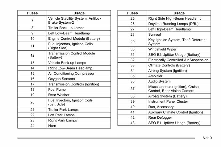
Fuses Usage
7Vehicle Stability System, AntilockBrake System-2
8 Trailer Back-up Lamps
9 Left Low-Beam Headlamp
10 Engine Control Module (Battery)
11Fuel Injectors, Ignition Coils(Right Side)
12Transmission Control Module(Battery)
13 Vehicle Back-up Lamps
14 Right Low-Beam Headlamp
15 Air Conditioning Compressor
16 Oxygen Sensors
17 Transmission Controls (Ignition)
18 Fuel Pump
19 Rear Washer
20Fuel Injectors, Ignition Coils(Left Side)
21 Trailer Park Lamps
22 Left Park Lamps
23 Right Park Lamps
24 Horn
Fuses Usage
25 Right Side High-Beam Headlamp
26 Daytime Running Lamps (DRL)
27 Left High-Beam Headlamp
28 Sunroof
29Key Ignition System, Theft DeterrentSystem
30 Windshield Wiper
31 SEO B2 Upfitter Usage (Battery)
32 Electrically Controlled Air Suspension
33 Climate Controls (Battery)
34 Airbag System (Ignition)
35 Amplifier
36 Audio System
37Miscellaneous (Ignition), CruiseControl, Rear Vision Camera
38 Airbag System (Battery)
39 Instrument Panel Cluster
40 Run, Accessory
41 Auxiliary Climate Control (Ignition)
42 Rear Defogger
43 SEO B1 Upfitter Usage (Battery)
6-119
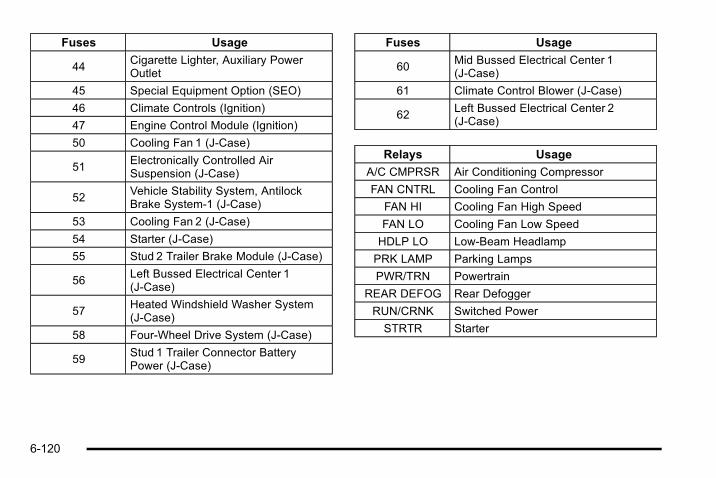
Fuses Usage
44Cigarette Lighter, Auxiliary PowerOutlet
45 Special Equipment Option (SEO)
46 Climate Controls (Ignition)
47 Engine Control Module (Ignition)
50 Cooling Fan 1 (J-Case)
51Electronically Controlled AirSuspension (J-Case)
52Vehicle Stability System, AntilockBrake System-1 (J-Case)
53 Cooling Fan 2 (J-Case)
54 Starter (J-Case)
55 Stud 2 Trailer Brake Module (J-Case)
56Left Bussed Electrical Center 1(J-Case)
57Heated Windshield Washer System(J-Case)
58 Four-Wheel Drive System (J-Case)
59Stud 1 Trailer Connector BatteryPower (J-Case)
Fuses Usage
60Mid Bussed Electrical Center 1(J-Case)
61 Climate Control Blower (J-Case)
62Left Bussed Electrical Center 2(J-Case)
Relays Usage
A/C CMPRSR Air Conditioning Compressor
FAN CNTRL Cooling Fan Control
FAN HI Cooling Fan High Speed
FAN LO Cooling Fan Low Speed
HDLP LO Low-Beam Headlamp
PRK LAMP Parking Lamps
PWR/TRN Powertrain
REAR DEFOG Rear Defogger
RUN/CRNK Switched Power
STRTR Starter
6-120

Capacities and SpecificationsPlease refer to Recommended Fluids and Lubricants on page 7‑10 for more information.
Capacities and Specifications
Application
Capacities
English Metric
Air Conditioning Refrigerant R134aFor the air conditioning system refrigerant charge
amount, see the refrigerant caution label located underthe hood. See your dealer for more information.
Cooling System
SUT Model 15.4 qt 14.6 L
SUV Model 16.7 qt 15.8 L
Engine Oil with Filter 6.0 qt 5.7 L
Fuel Tank 32.0 gal 121.0 L
Transfer Case Fluid 1.5 qt 1.4 L
Transmission Fluid (Pan Removal and Filter Replacement) 6.0 qt 5.7 L
Wheel Nut Torque 140 lb ft 190Y
All capacities are approximate. When adding, be sure to fill to the approximate level, as recommended in this manual.
Engine SpecificationsEngine VIN Code Transmission Spark Plug Gap
6.2LV8 2 Automatic 0.040 in (1.01 mm)
6-121

2 NOTES
6-122

Section 7 Maintenance Schedule
Maintenance Schedule . . . . . . . . . . . . . . . . . . . . . . . . . . . . 7-2Introduction . . . . . . . . . . . . . . . . . . . . . . . . . . . . . . . . . . . . . 7-2Scheduled Maintenance . . . . . . . . . . . . . . . . . . . . . . . . 7-3Owner Checks and Services . . . . . . . . . . . . . . . . . . . . 7-8
Recommended Fluids and Lubricants . . . . . . . . . . 7-10Maintenance Replacement Parts . . . . . . . . . . . . . . 7-12Engine Drive Belt Routing . . . . . . . . . . . . . . . . . . . . . 7-13Maintenance Record . . . . . . . . . . . . . . . . . . . . . . . . . . . 7-14
7-1
Maintenance Schedule
IntroductionNotice: Maintenance intervals, checks, inspections,recommended fluids, and lubricants are necessaryto keep this vehicle in good working condition.Damage caused by failure to follow scheduledmaintenance might not be covered by the vehiclewarranty.
As the vehicle owner, you are responsible for thescheduled maintenance in this section. We recommendhaving your dealer perform these services. Propervehicle maintenance helps to keep the vehicle in goodworking condition, improves fuel economy, and reducesvehicle emissions for better air quality.
Because of all the different ways people use vehicles,maintenance needs vary. The vehicle might need morefrequent checks and services. Please read theinformation under Scheduled Maintenance. To keep thevehicle in good condition, see your dealer.
The maintenance schedule is for vehicles that:. carry passengers and cargo within recommended
limits on the Tire and Loading Information label.See Loading the Vehicle on page 5‑40.
. are driven on reasonable road surfaces within legaldriving limits.
. are driven off‐road in the recommended manner.See Off-Road Driving on page 5‑13.
. use the recommended fuel. See Gasoline Octaneon page 6‑7 .
{ WARNING:
Performing maintenance work on a vehicle can bedangerous. In trying to do some jobs, you can beseriously injured. Do your own maintenance workonly if you have the required know-how and theproper tools and equipment for the job. If youhave any doubt, see your dealer to have aqualified technician do the work. See Doing YourOwn Service Work on page 6‑5.
At your dealer, you can be certain that you will receivethe highest level of service available. Your dealer hasspecially trained service technicians, uses genuinereplacement parts, as well as, up to date tools andequipment to ensure fast and accurate diagnostics.
The proper replacement parts, fluids, and lubricants touse are listed in Recommended Fluids and Lubricantson page 7‑10 and Maintenance Replacement Parts onpage 7‑12. We recommend the use of genuine partsfrom your dealer.
7-2

Rotation of New TiresTo maintain ride, handling, and performance of thevehicle, it is important that the first rotation service fornew tires be performed when they have 8 000 to13 000 km (5,000 to 8,000 miles). See Tire Inspectionand Rotation on page 6‑72.
Scheduled Maintenance
When the Change Engine Oil MessageDisplaysChange engine oil and filter. See Engine Oil onpage 6‑18. An Emission Control Service.
When the Change Engine Oil message displays,service is required for the vehicle as soon as possible,within the next 1 000 km/600 miles. If driving under thebest conditions, the engine oil life system might notindicate the need for vehicle service for more than ayear. The engine oil and filter must be changed at leastonce a year and the oil life system must be reset. Yourdealer has trained service technicians who will performthis work and reset the system. If the engine oil lifesystem is reset accidentally, service the vehicle within5 000 km/3,000 miles since the last service. Reset theoil life system whenever the oil is changed. See EngineOil Life System on page 6‑20.
When the Change Engine Oil message displays, certainservices, checks, and inspections are required. Theservices described for Maintenance I should beperformed at every engine oil change. The servicesdescribed for Maintenance II should beperformed when:. Maintenance I was performed the last time the
engine oil was changed.. It has been 10 months or more since the Change
Engine Oil message has displayed or since the lastservice.
Maintenance I. Change engine oil and filter. See Engine Oil on
page 6‑18. An Emission Control Service.. Engine coolant level check. See Engine Coolant
on page 6‑30.. Windshield washer fluid level check. See
Windshield Washer Fluid on page 6‑40.. Tire inflation check. See Inflation - Tire Pressure
on page 6‑66.. Tire wear inspection. See Tire Inspection and
Rotation on page 6‑72.
7-3

. Rotate tires. See Tire Inspection and Rotation onpage 6‑72.
. Fluids visual leak check (or every 12 months,whichever occurs first). A leak in any system mustbe repaired and the fluid level checked.
. Engine air cleaner filter inspection (vehicles drivenin dusty conditions only). See Engine Air Cleaner/Filter on page 6‑22.
. Brake system inspection (or every 12 months,whichever occurs first).
Maintenance II. Perform all services described in Maintenance I.. Steering and suspension inspection. Visual
inspection for damaged, loose, or missing parts orsigns of wear.
. Lubricate the front suspension, steering linkage,and parking brake cable guides. Control arm balljoints require lubrication but should not belubricated unless their temperature is −12°C (10°F)or higher, or they could be damaged.
. Engine cooling system inspection. Visualinspection of hoses, pipes, fittings, and clamps andreplacement, if needed.
. Windshield wiper blade inspection for wear,cracking, or contamination and windshield andwiper blade cleaning, if contaminated. SeeWindshield, Backglass, and Wiper Blades onpage 6‑111. Worn or damaged wiper bladereplacement. See Windshield Wiper BladeReplacement on page 6‑58.
. Body hinges and latches, key lock cylinders,folding seat hardware, rear compartment hinges,cargo door hinge, and outer liftgate hinges,linkage, and handle pivot points lubrication. SeeRecommended Fluids and Lubricants onpage 7‑10. More frequent lubrication may berequired when vehicle is exposed to a corrosiveenvironment. Applying silicone grease onweatherstrips with a clean cloth makes them lastlonger, seal better, and not stick or squeak.
. Restraint system component check. See Checkingthe Restraint Systems on page 2‑79.
. Automatic transmission fluid level check andadding fluid, if needed. See AutomaticTransmission Fluid on page 6‑25.
. Engine air cleaner filter inspection. See Engine AirCleaner/Filter on page 6‑22.
7-4
Additional Required Services
At Each Fuel Stop. Engine oil level check. See Engine Oil on
page 6‑18.. Engine coolant level check. See Engine Coolant
on page 6‑30.. Windshield washer fluid level check. See
Windshield Washer Fluid on page 6‑40.
Once a Month. Tire inflation check. See Inflation - Tire Pressure
on page 6‑66.. Tire wear inspection. See Tire Inspection and
Rotation on page 6‑72.
Once a Year. Starter switch check. See Owner Checks and
Services on page 7‑8.. Parking brake and automatic transmission P (Park)
mechanism check. See Owner Checks andServices on page 7‑8.
. Automatic transmission shiftlock control systemcheck. See Owner Checks and Services onpage 7‑8 .
. Ignition transmission lock check. See OwnerChecks and Services on page 7‑8.
. Engine cooling system and pressure cap pressurecheck. Radiator and air conditioning condenseroutside cleaning. See Cooling System onpage 6‑29.
. Exhaust system and nearby heat shieldsinspection for loose or damaged components.
. Accelerator pedal check for damage, high effort,or binding. Replace if needed.
First Engine Oil Change After Every40 000 km/25,000Miles. Fuel system inspection for damage or leaks.
First Engine Oil Change After Every80 000 km/50,000Miles. Automatic transmission fluid change (severe
service) for vehicle mainly driven in heavy citytraffic in hot weather, in hilly or mountainousterrain, when frequently towing a trailer, or used fortaxi, police, or delivery service. See AutomaticTransmission Fluid on page 6‑25.
7-5

. Transfer case fluid change (severe service) forvehicles mainly driven when frequently towing atrailer, or used for taxi, police, or delivery service.Check vent hose at transfer case for kinks andproper installation. Check to be sure vent hose isunobstructed, clear, and free of debris. During anymaintenance, if a power washer is used to cleanmud and dirt from the underbody, care should betaken to not directly spray the transfer case outputseals. High pressure water can overcome the sealsand contaminate the transfer case fluid.Contaminated fluid will decrease the life of thetransfer case and should be replaced.
First Engine Oil Change After Every160 000 km/100,000Miles. Engine air cleaner filter replacement. See Engine
Air Cleaner/Filter on page 6‑22.. Automatic transmission fluid change (normal
service). See Automatic Transmission Fluid onpage 6‑25.
. Transfer case fluid change (normal service). Checkvent hose at transfer case for kinks and properinstallation. Check to be sure vent hose isunobstructed, clear, and free of debris. During any
maintenance, if a power washer is used to cleanmud and dirt from the underbody, care should betaken to not directly spray the transfer case outputseals. High pressure water can overcome the sealsand contaminate the transfer case fluid.Contaminated fluid will decrease the life of thetransfer case and should be replaced.
. Spark plug replacement and spark plug wiresinspection. An Emission Control Service.
First Engine Oil Change After Every240 000 km/150,000Miles. Engine cooling system drain, flush, and refill,
cooling system and cap pressure check, andcleaning of outside of radiator and air conditioningcondenser (or every 5 years, whichever occursfirst). See Engine Coolant on page 6‑30. AnEmission Control Service.
. Engine accessory drive belt inspection for fraying,excessive cracks, or obvious damage andreplacement, if needed. An Emission ControlService.
7-6

Scheduled MaintenanceService Maintenance I Maintenance II
Change engine oil and filter. Reset oil life system. • •
Engine coolant level check. • •
Windshield washer fluid level check. • •
Tire inflation pressures check. • •
Tire wear inspection. • •
Rotate tires. • •
Fluids visual leak check. • •
Engine air cleaner filter inspection (vehicles driven in dusty conditions only). • •
Brake system inspection. • •
Chassis components lubrication. •
Steering and suspension inspection. •
Engine cooling system inspection. •
Windshield wiper blades inspection. •
Body components lubrication. •
Restraint system components check. •
Automatic transmission fluid level check. •
Engine air cleaner filter inspection (vehicles not driven in dusty conditions). •
7-7

Owner Checks and Services
Starter Switch Check
{ WARNING:
When you are doing this inspection, the vehiclecould move suddenly. If the vehicle moves, you orothers could be injured.
1. Before starting this check, be sure there is enoughroom around the vehicle.
2. Firmly apply both the parking brake and the regularbrake. See Parking Brake on page 3‑41.
Do not use the accelerator pedal, and be ready toturn off the engine immediately if it starts.
3. Try to start the engine in each gear. The vehicleshould start only in P (Park) or N (Neutral). If thevehicle starts in any other position, contact yourdealer for service.
Automatic Transmission Shift LockControl System Check
{ WARNING:
When you are doing this inspection, the vehiclecould move suddenly. If the vehicle moves, you orothers could be injured.
1. Before starting this check, be sure there is enoughroom around the vehicle. It should be parked on alevel surface.
2. Firmly apply the parking brake. See Parking Brakeon page 3‑41.
Be ready to apply the regular brake immediately ifthe vehicle begins to move.
3. With the engine off, turn the ignition to ON/RUN,but do not start the engine. Without applying theregular brake, try to move the shift lever out ofP (Park) with normal effort. If the shift lever movesout of P (Park), contact your dealer for service.
7-8

Ignition Transmission Lock CheckWhile parked, and with the parking brake set, try to turnthe ignition to LOCK/OFF in each shift lever position.. The ignition should turn to LOCK/OFF only when
the shift lever is in P (Park).. The ignition key should come out only in
LOCK/OFF.
Contact your dealer if service is required.
Parking Brake and AutomaticTransmission P (Park) MechanismCheck
{ WARNING:
When you are doing this check, the vehicle couldbegin to move. You or others could be injured andproperty could be damaged. Make sure there isroom in front of the vehicle in case it begins toroll. Be ready to apply the regular brake at onceshould the vehicle begin to move.
Park on a fairly steep hill, with the vehicle facingdownhill. Keeping your foot on the regular brake, set theparking brake.. To check the parking brake's holding ability: With
the engine running and the transmission inN (Neutral), slowly remove foot pressure from theregular brake pedal. Do this until the vehicle is heldby the parking brake only.
. To check the P (Park) mechanism's holding ability:With the engine running, shift to P (Park). Thenrelease the parking brake followed by the regularbrake.
Contact your dealer if service is required.
7-9

Recommended Fluids andLubricantsFluids and lubricants identified below by name, partnumber, or specification can be obtained from yourdealer.
Usage Fluid/Lubricant
Engine Oil
Engine oil which meets GM StandardGM6094M and displays the AmericanPetroleum Institute Certified forGasoline Engines starburst symbol.To determine the proper viscosity foryour vehicle's engine, see Engine Oilon page 6‑18.
Engine Coolant
50/50 mixture of clean, drinkablewater and use only DEX-COOL®
Coolant. See Engine Coolant onpage 6‑30.
Hydraulic BrakeSystem
DOT 3 Hydraulic Brake Fluid(GM Part No. U.S. 12377967, inCanada 89021320).
Usage Fluid/Lubricant
WindshieldWasher
Optikleen® Washer Solvent.
Power SteeringSystem
GM Power Steering Fluid(GM Part No. U.S. 89021184, inCanada 89021186).
AutomaticTransmission
DEXRON®-VI Automatic TransmissionFluid.
Key LockCylinders
Multi-Purpose Lubricant, Superlube(GM Part No. U.S. 12346241, inCanada 10953474).
ChassisLubrication
Chassis Lubricant(GM Part No. U.S. 12377985, inCanada 88901242) or lubricantmeeting requirements of NLGI #2,Category LB or GC-LB.
Front andRear Axle
SAE 75W-90 Synthetic Axle Lubricant(GM Part No. U.S. 89021677, inCanada 89021678).
Transfer CaseDEXRON®-VI Automatic TransmissionFluid.
7-10

Usage Fluid/Lubricant
Front AxlePropshaft Spline
Spline Lubricant, Special Lubricant(GM Part No. U.S. 12345879, inCanada 10953511).
Hood HingesMulti-Purpose Lubricant, Superlube(GM Part No. U.S. 12346241, inCanada 10953474).
Outer TailgateHandle Pivot
Points
Multi-Purpose Lubricant, Superlube(GM Part No. U.S. 12346241, inCanada 10953474).
Spare TireCarrier Hinge
PTFE Filled Synthetic Grease(GM Part No. U.S. 89022180, inCanada 890221801).
Usage Fluid/Lubricant
Spare TireCarrier Latch
Multi-Purpose Lubricant, Superlube(GM Part No. U.S. 12346241, inCanada 10953474).
WeatherstripConditioning
Weatherstrip Lubricant(GM Part No. U.S. 3634770, inCanada 10953518) orDielectric Silicone Grease(GM Part No. U.S. 12345579, inCanada 992887).
WeatherstripSqueaks
Synthetic Grease withTeflon, Superlube(GM Part No. U.S. 12371287, inCanada 10953437).
7-11

Maintenance Replacement PartsReplacement parts identified below by name, part number or specification can be obtained from your dealer.
Part GM Part Number ACDelco Part Number
Engine Air Cleaner/Filter 15286805 A2948C
Engine Oil Filter 89017524 PF48
Spark Plugs 12621258 41-110
Wiper Blades
Front – 17.0 in (43.0 cm) 15060730 —
Rear – 11.0 in (28.0 cm) 12335785 —
7-12
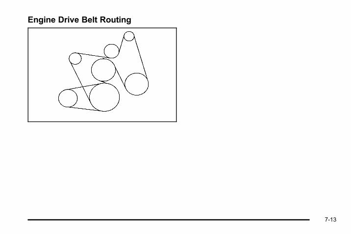
Engine Drive Belt Routing
7-13
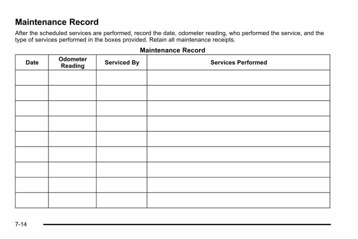
Maintenance RecordAfter the scheduled services are performed, record the date, odometer reading, who performed the service, and thetype of services performed in the boxes provided. Retain all maintenance receipts.
Maintenance Record
DateOdometerReading
Serviced By Services Performed
7-14

Maintenance Record (cont'd)
Date OdometerReading
Serviced By Services Performed
7-15
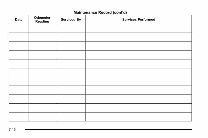
Maintenance Record (cont'd)
Date OdometerReading
Serviced By Services Performed
7-16

Section 8 Customer Assistance Information
Customer Assistance and Information . . . . . . . . . . . 8-2Customer Satisfaction Procedure . . . . . . . . . . . . . . . 8-2Online Owner Center . . . . . . . . . . . . . . . . . . . . . . . . . . . . 8-5Customer Assistance for Text Telephone (TTY)Users . . . . . . . . . . . . . . . . . . . . . . . . . . . . . . . . . . . . . . . . . 8-5
Customer Assistance Offices . . . . . . . . . . . . . . . . . . . 8-5Roadside Assistance Program . . . . . . . . . . . . . . . . . . 8-7Scheduling Service Appointments . . . . . . . . . . . . . 8-10Courtesy Transportation Program . . . . . . . . . . . . . . 8-10Collision Damage Repair . . . . . . . . . . . . . . . . . . . . . . 8-12
Reporting Safety Defects . . . . . . . . . . . . . . . . . . . . . . . . 8-14Reporting Safety Defects to the United StatesGovernment . . . . . . . . . . . . . . . . . . . . . . . . . . . . . . . . . 8-14
Reporting Safety Defects to the CanadianGovernment . . . . . . . . . . . . . . . . . . . . . . . . . . . . . . . . . 8-15
Reporting Safety Defects to General Motors . . . 8-15Service Publications Ordering Information . . . . . 8-15
Vehicle Data Recording and Privacy . . . . . . . . . . . . . 8-17Event Data Recorders . . . . . . . . . . . . . . . . . . . . . . . . . 8-17OnStar® . . . . . . . . . . . . . . . . . . . . . . . . . . . . . . . . . . . . . . . 8-18Navigation System . . . . . . . . . . . . . . . . . . . . . . . . . . . . . 8-18Radio Frequency Identification (RFID) . . . . . . . . . 8-18Radio Frequency Statement . . . . . . . . . . . . . . . . . . . 8-18
8-1

Customer Assistance andInformation
Customer Satisfaction ProcedureYour satisfaction and goodwill are important to yourdealer and to HUMMER. Normally, any concerns withthe sales transaction or the operation of the vehicle willbe resolved by the dealer's sales or servicedepartments. Sometimes, however, despite the bestintentions of all concerned, misunderstandings canoccur. If your concern has not been resolved to yoursatisfaction, the following steps should be taken:
STEP ONE: Discuss your concern with a member ofdealership management. Normally, concerns can bequickly resolved at that level. If the matter has alreadybeen reviewed with the sales, service or parts manager,contact the owner of the dealership or the generalmanager.
STEP TWO: If after contacting a member of dealershipmanagement, it appears your concern cannot beresolved by the dealership without further help,call the HUMMER Consumer Relations Manager at1-866-HUMMER6 (486-6376), Customer Assistanceprompt. In Canada, call GM of Canada CustomerCommunication Centre at 1-800-263-3777 (English),or 1-800-263-7854 (French).
We encourage you to call the toll-free number in orderto give your inquiry prompt attention. Have the followinginformation available to give the Customer AssistanceRepresentative:. Vehicle Identification Number (VIN). This is
available from the vehicle registration or title, or theplate at the top left of the instrument panel andvisible through the windshield.
. Dealership name and location
. Vehicle delivery date and present mileage
When contacting HUMMER, please remember that yourconcern will likely be resolved at a dealer's facility. Thatis why we suggest you follow Step One first if you havea concern.
8-2
STEP THREE — U.S. Owners: Both HUMMER andyour dealer are committed to making sure you arecompletely satisfied with your new vehicle. However,if you continue to remain unsatisfied after following theprocedure outlined in Steps One and Two, you can filewith the Better Business Bureau (BBB) Auto Line®
Program to enforce any additional rights you may have.
The BBB Auto Line Program is an out of court programadministered by the Council of Better Business Bureausto settle automotive disputes regarding vehicle repairsor the interpretation of the New Vehicle LimitedWarranty. Although you may be required to resort to thisinformal dispute resolution program prior to filing a courtaction, use of the program is free of charge and yourcase will generally be heard within 40 days. If you donot agree with the decision given in your case, you mayreject it and proceed with any other venue for reliefavailable to you.
Contact the BBB Auto Line Program using the toll-freetelephone number or write them at:
BBB Auto Line ProgramCouncil of Better Business Bureaus, Inc.4200 Wilson BoulevardSuite 800Arlington, VA 22203-1838
Telephone: 1-800- 955-5100dr.bbb.org/goauto
This program is available in all 50 states and the Districtof Columbia. Eligibility is limited by vehicle age,mileage, and other factors. General Motors reserves theright to change eligibility limitations and/or discontinueits participation in this program.
8-3
STEP THREE — Canadian Owners: In the event thatyou do not feel your concerns have been addressedafter following the procedure outlined in Steps One andTwo, General Motors of Canada Limited wants you tobe aware of its participation in a no-charge Mediation/Arbitration Program. General Motors of Canada Limitedhas committed to binding arbitration of owner disputesinvolving factory-related vehicle service claims. Theprogram provides for the review of the facts involved byan impartial third party arbiter, and may include aninformal hearing before the arbiter. The program isdesigned so that the entire dispute settlement process,from the time you file your complaint to the finaldecision, should be completed in approximately70 days. We believe our impartial program offersadvantages over courts in most jurisdictions because itis informal, quick, and free of charge.
For further information concerning eligibility in theCanadian Motor Vehicle Arbitration Plan (CAMVAP), calltoll-free 1-800-207-0685, or call the General MotorsCustomer Communication Centre, 1-800-263-3777(English), 1-800-263-7854 (French), or write to:
Mediation/Arbitration Program c/o CustomerCommunication CentreGeneral Motors of Canada LimitedMail Code: CA1-163-0051908 Colonel Sam DriveOshawa, Ontario L1H 8P7
Your inquiry should be accompanied by the VehicleIdentification Number (VIN).
8-4

Online Owner Center
Online Owner Center (U.S.) —www.gmownercenter.com/hummerInformation and services customized for your specificvehicle — all in one convenient place.. Digital owner manual, warranty information,
and more. Online service and maintenance records. Find HUMMER dealers for service nationwide. Exclusive privileges and offers. Recall notices for your specific vehicle. OnStar® and GM Cardmember Services Earnings
summaries
Other Helpful Links:HUMMER − www.hummer.com
HUMMER Merchandise — www.hummerstuff.com
Customer Assistance for TextTelephone (TTY) UsersTo assist customers who are deaf, hard of hearing,or speech-impaired and who use Text Telephones(TTYs), HUMMER has TTY equipment available at itsCustomer Assistance Center. Any TTY user in the U.S.can communicate with HUMMER by dialing:1-800-833-6537. (TTY users in Canada can dial1-800-263-3830.)
Customer Assistance OfficesHUMMER encourages customers to call the toll-freenumber for assistance. However, if a customer wishesto write or e-mail HUMMER, refer to the addressesbelow.
8-5
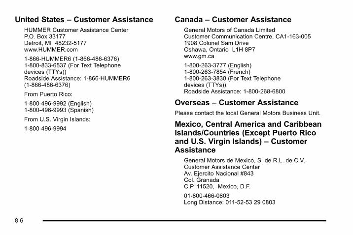
United States – Customer AssistanceHUMMER Customer Assistance CenterP.O. Box 33177Detroit, MI 48232-5177www.HUMMER.com
1-866-HUMMER6 (1-866-486-6376)1-800-833-6537 (For Text Telephonedevices (TTYs))Roadside Assistance: 1-866-HUMMER6(1-866-486-6376)
From Puerto Rico:
1-800-496-9992 (English)1-800-496-9993 (Spanish)
From U.S. Virgin Islands:
1-800-496-9994
Canada – Customer AssistanceGeneral Motors of Canada LimitedCustomer Communication Centre, CA1-163-0051908 Colonel Sam DriveOshawa, Ontario L1H 8P7www.gm.ca
1-800-263-3777 (English)1-800-263-7854 (French)1-800-263-3830 (For Text Telephonedevices (TTYs))Roadside Assistance: 1-800-268-6800
Overseas – Customer AssistancePlease contact the local General Motors Business Unit.
Mexico, Central America and CaribbeanIslands/Countries (Except Puerto Ricoand U.S. Virgin Islands) – CustomerAssistance
General Motors de Mexico, S. de R.L. de C.V.Customer Assistance CenterAv. Ejercito Nacional #843Col. GranadaC.P. 11520, Mexico, D.F.
01-800-466-0803Long Distance: 011-52-53 29 0803
8-6

Roadside Assistance ProgramFor U.S. purchased vehicles, call 1‐866‐HUMMER6(486‐6376); (Text Telephone (TTY): 1-888-889-2438).
For Canadian purchased vehicles, call 1‐800‐268‐6800.
Service is available 24 hours a day, 365 days a year.
Calling for AssistanceWhen calling Roadside Assistance, have the followinginformation ready:. Your name, home address, and home telephone
number. Telephone number of your location. Location of the vehicle. Model, year, color, and license plate number of the
vehicle. Odometer reading, Vehicle Identification Number
(VIN), and delivery date of the vehicle. Description of the problem
CoverageServices are provided up to 5 years/100,000 miles (160 000 km), whichever comes first.
In the U.S., anyone driving the vehicle is covered. InCanada, a person driving the vehicle without permissionfrom the owner is not covered.
Roadside Assistance is not a part of the New VehicleLimited Warranty. HUMMER and General Motors ofCanada Limited reserve the right to make any changesor discontinue the Roadside Assistance program at anytime without notification.
HUMMER and General Motors of Canada Limitedreserve the right to limit services or payment to anowner or driver if they decide the claims are made toooften, or the same type of claim is made many times.
8-7
Services Provided. Emergency Fuel Delivery: Delivery of enough
fuel for the vehicle to get to the nearest servicestation.
. Lock‐Out Service: Service is provided to unlockthe vehicle if you are locked out. A remote unlockmay be available if you have OnStar®. For securityreasons, the driver must present identificationbefore this service is given.
. Emergency Tow From a Public Road orHighway: Tow to the nearest HUMMER dealer forwarranty service, or if the vehicle was in a crashand cannot be driven.
. Flat Tire Change: Service is provided to change aflat tire with spare tire. The spare tire, if equipped,must be in good condition and properly inflated.It is your responsibility for the repair orreplacement of the tire if it is not covered by thewarranty.
. Battery Jump Start: Service is provided to jumpstart a dead battery.
. Trip Routing Service: Detailed maps of NorthAmerica are provided when requested either withthe most direct route or the most scenic route.Additional travel information is also available. Allowthree weeks for delivery.
. Trip Interruption Benefits and Assistance: Ifyour trip is interrupted due to a warranty failure,incidental expenses may be reimbursed during the5 year/100,000 miles (160 000 km) Powertrainwarranty period. Items considered are hotel,meals, and rental car.
8-8

HUMMER Technician RoadsideAssistance (U.S. only)HUMMER's exceptional Roadside Service is more thanan auto club or towing service. It provides everyHUMMER owner in the United States with theadvantage of contacting a HUMMER advisor and,where available, a HUMMER trained dealer technicianwho can provide on-site service.
A dealer technician will travel to your location within a30 mile radius of a participating HUMMER dealership.If beyond this radius, we will arrange to have yourvehicle towed to the nearest HUMMER dealership.Each technician travels with a specially equippedservice vehicle complete with the necessary HUMMERparts and tools required to handle most roadsiderepairs.
Services Not Included in RoadsideAssistance. Impound towing caused by violation of any laws.. Legal fines.. Mounting, dismounting or changing of snow tires,
chains, or other traction devices.. Towing or services for vehicles driven on a
non-public road or highway.
Services Specific to CanadianPurchased Vehicles. Fuel delivery: Reimbursement is approximately
$5 Canadian. Diesel fuel delivery may berestricted. Propane and other fuels are notprovided through this service.
. Lock-Out Service: Vehicle registration isrequired.
. Trip Routing Service: Limit of six requestsper year.
. Trip Interruption Benefits and Assistance:Pre-authorization, original detailed receipts, and acopy of the repair orders are required. Onceauthorization has been received, the RoadsideAssistance advisor will help you makearrangements and explain how to receive payment.
. Alternative Service: If assistance cannot beprovided right away, the Roadside Assistanceadvisor may give you permission to get localemergency road service. You will receive payment,up to $100, after sending the original receipt toRoadside Assistance. Mechanical failures may becovered, however any cost for parts and labor forrepairs not covered by the warranty are the ownerresponsibility.
8-9

Scheduling Service AppointmentsWhen your vehicle requires warranty service, contactyour dealer and request an appointment. By schedulinga service appointment and advising your serviceconsultant of your transportation needs, your dealer canhelp minimize your inconvenience.
If your vehicle cannot be scheduled into the servicedepartment immediately, keep driving it until it can bescheduled for service, unless, of course, the problem issafety-related. If it is, please call your dealership and letthem know this, and ask for instructions.
If the dealer requests you to bring the vehicle forservice, you are urged to do so as early in the work dayas possible to allow for the same day repair.
Courtesy Transportation ProgramTo enhance your ownership experience, we and ourparticipating dealers are proud to offer CourtesyTransportation, a customer support program for vehicleswith the Bumper to Bumper (Base Warranty Coverageperiod in Canada) and extended powertrain, and hybridspecific warranties in both the U.S. and Canada.
Several courtesy transportation options are available toassist in reducing your inconvenience when warrantyrepairs are required.
Courtesy Transportation is not a part of the New VehicleLimited Warranty. A separate booklet entitled “Warrantyand Owner Assistance Information” furnished with eachnew vehicle provides detailed warranty coverageinformation.
8-10

Transportation OptionsWarranty service can generally be completed while youwait. However, if you are unable to wait, HUMMERhelps to minimize your inconvenience by providingseveral transportation options. Depending on thecircumstances, your dealer can offer you one of thefollowing:
Shuttle ServiceParticipating dealers can provide shuttle service to getyou to your destination with minimal interruption of yourdaily schedule. This includes one-way or round tripshuttle service to a destination up to 10 miles (16 km)from the dealership.
Public Transportation or FuelReimbursementIf your vehicle requires warranty repairs, and publictransportation is used instead of the dealer's shuttleservice, the expense must be supported by originalreceipts and can only be up to the maximum amountallowed by HUMMER for shuttle service. In addition, forU.S. customers, should you arrange transportation
through a friend or relative, limited reimbursement forreasonable fuel expenses may be available. Claimamounts should reflect actual costs and be supportedby original receipts. See your dealer for informationregarding the allowance amounts for reimbursement offuel or other transportation costs.
Courtesy Rental VehicleYour dealer may arrange to provide you with a courtesyrental vehicle or reimburse you for a rental vehicle thatyou obtain if your vehicle is kept for a warranty repair.If you obtain a rental vehicle on your own, please seeyour dealer for the maximum number of days allowedand the allowance per rental day. Rental reimbursementmust be supported by original receipts. This requiresthat you sign and complete a rental agreement andmeet state, local, and rental vehicle providerrequirements. Requirements vary and may includeminimum age requirements, insurance coverage, creditcard, etc. You are responsible for fuel usage chargesand may also be responsible for taxes, levies, usagefees, excessive mileage, or rental usage beyond thecompletion of the repair.
It may not be possible to provide a like-vehicle as acourtesy rental.
8-11
Additional Program InformationAll program options, such as shuttle service, may not beavailable at every dealer. Please contact your dealer forspecific information about availability. All CourtesyTransportation arrangements will be administered byappropriate dealer personnel.
HUMMER reserves the right to unilaterally modify,change, or discontinue Courtesy Transportation at anytime and to resolve all questions of claim eligibilitypursuant to the terms and conditions described hereinat its sole discretion.
Collision Damage RepairIf your vehicle is involved in a collision and it isdamaged, have the damage repaired by a qualifiedtechnician using the proper equipment and qualityreplacement parts. Poorly performed collision repairswill diminish your vehicle's resale value, and safetyperformance can be compromised in subsequentcollisions.
Collision PartsGenuine Collision parts are new parts made with thesame materials and construction methods as the partswith which your vehicle was originally built. GenuineCollision parts are your best choice to ensure that yourvehicle's designed appearance, durability and safetyare preserved. The use of Genuine parts can helpmaintain your HUMMER New Vehicle Limited Warranty.
Recycled original equipment parts may also be used forrepair. These parts are typically removed from vehiclesthat were total losses in prior crashes. In most cases,the parts being recycled are from undamaged sectionsof the vehicle. A recycled original equipment part, maybe an acceptable choice to maintain your vehicle'soriginally designed appearance and safety performance,however, the history of these parts is not known. Suchparts are not covered by your HUMMER New VehicleLimited Warranty, and any related failures are notcovered by that warranty.
Aftermarket collision parts are also available. These aremade by companies other than HUMMER and may nothave been tested for your vehicle. As a result, theseparts may fit poorly, exhibit premature durability/corrosion problems, and may not perform properly insubsequent collisions. Aftermarket parts are notcovered by your HUMMER New Vehicle LimitedWarranty, and any vehicle failure related to such partsare not covered by that warranty.
8-12

Repair FacilityHUMMER also recommends that you choose a collisionrepair facility that meets your needs before you everneed collision repairs. Your HUMMER dealer may havea collision repair center with trained technicians andstate of the art equipment, or be able to recommend acollision repair center that has trained technicians andcomparable equipment.
Insuring Your VehicleProtect your investment in your HUMMER vehicle withcomprehensive and collision insurance coverage. Thereare significant differences in the quality of coverageafforded by various insurance policy terms. Manyinsurance policies provide reduced protection to yourHUMMER vehicle by limiting compensation for damagerepairs by using aftermarket collision parts. Someinsurance companies will not specify aftermarketcollision parts. When purchasing insurance, werecommend that you assure your vehicle will berepaired with original equipment collision parts. If suchinsurance coverage is not available from your currentinsurance carrier, consider switching to anotherinsurance carrier.
If your vehicle is leased, the leasing company mayrequire you to have insurance that assures repairs withGenuine Original Equipment Manufacturer (OEM) parts
or Genuine Manufacturer replacement parts. Read yourlease carefully, as you may be charged at the end ofyour lease for poor quality repairs.
If a Crash OccursIf there has been an injury, call emergency services forhelp. Do not leave the scene of a crash until all mattershave been taken care of. Move the vehicle only if itsposition puts you in danger, or you are instructed tomove it by a police officer.
Give only the necessary information to police and otherparties involved in the crash.
For emergency towing see Roadside AssistanceProgram on page 8‑7.
Gather the following information:. Driver's name, address, phone number. Driver's license number. Owner's name, address, phone number. Vehicle license plate. Vehicle make, model and model year. Vehicle Identification Number (VIN). Insurance company and policy number. General description of the damage to the other
vehicle
8-13
Choose a reputable repair facility that uses qualityreplacement parts. See “Collision Parts” earlier in thissection.
If the airbag has inflated, see What Will You See Afteran Airbag Inflates? on page 2‑72 What Will You SeeAfter an Airbag Inflates? .
Managing the Vehicle Damage RepairProcessIn the event that your vehicle requires damage repairs,HUMMER recommends that you take an active role inits repair. If you have a pre-determined repair facility ofchoice, take your vehicle there, or have it towed there.Specify to the facility that any required replacementcollision parts be original equipment parts, either newGenuine parts or recycled original parts. Remember,recycled parts will not be covered by your HUMMERNew Vehicle Limited warranty.
Insurance pays the bill for the repair, but you must livewith the repair. Depending on your policy limits, yourinsurance company may initially value the repair usingaftermarket parts. Discuss this with your repairprofessional, and insist on Genuine parts. Remember ifyour vehicle is leased you may be obligated to have thevehicle repaired with Genuine parts, even if yourinsurance coverage does not pay the full cost.
If another party's insurance company is paying for therepairs, you are not obligated to accept a repairvaluation based on that insurance company's collisionpolicy repair limits, as you have no contractual limitswith that company. In such cases, you can have controlof the repair and parts choices as long as cost stayswithin reasonable limits.
Reporting Safety Defects
Reporting Safety Defects to theUnited States GovernmentIf you believe that your vehicle has a defect whichcould cause a crash or could cause injury ordeath, you should immediately inform the NationalHighway Traffic Safety Administration (NHTSA) inaddition to notifying General Motors.
If NHTSA receives similar complaints, it may openan investigation, and if it finds that a safety defectexists in a group of vehicles, it may order a recalland remedy campaign. However, NHTSA cannotbecome involved in individual problems betweenyou, your dealer, or General Motors.
8-14

To contact NHTSA, you may call the VehicleSafety Hotline toll-free at 1-888-327-4236 (TTY:1-800-424-9153); go to http://www.safercar.gov; orwrite to:
Administrator, NHTSA1200 New Jersey Avenue, S.E.Washington, D.C. 20590
You can also obtain other information about motorvehicle safety from http://www.safercar.gov.
Reporting Safety Defects to theCanadian GovernmentIf you live in Canada, and you believe that your vehiclehas a safety defect, notify Transport Canadaimmediately, in addition to notifying General Motors ofCanada Limited. Call them at 1-800-333-0510 orwrite to:
Transport CanadaRoad Safety Branch2780 Sheffield RoadOttawa, Ontario K1B 3V9
1-800-333-0510
Reporting Safety Defects toGeneral MotorsIn addition to notifying NHTSA (or Transport Canada) ina situation like this, please notify General Motors.
Call 1-866-HUMMER6 (486-6376), or write:
HUMMER Customer Assistance CenterP.O. Box 33177Detroit , MI 48232-5177
In Canada, call 1-800-263-3777 (English) or1-800-263-7854 (French), or write:
General Motors of Canada LimitedCustomer Communication Centre CA1-163-0051908 Colonel Sam DriveOshawa , Ontario L1H 8P7
Service Publications OrderingInformation
Service ManualsService Manuals have the diagnosis and repairinformation on engines, transmission, axle suspension,brakes, electrical, steering, body, etc.
8-15
Service BulletinsService Bulletins give additional technical serviceinformation needed to knowledgeably service cars andtrucks. Each bulletin contains instructions to assist inthe diagnosis and service of your vehicle.
Owner InformationOwner publications are written specifically for ownersand intended to provide basic operational informationabout the vehicle. The owner manual includes theMaintenance Schedule for all models.
In-Portfolio: Includes a Portfolio, Owner Manual, andWarranty Booklet.
RETAIL SELL PRICE: $35.00 (U.S.) plus handling andshipping fees.
Without Portfolio: Owner Manual only.
RETAIL SELL PRICE: $25.00 (U.S.) plus handling andshipping fees.
Current and Past ModelsTechnical Service Bulletins and Manuals are availablefor current and past model HUMMER vehicles.
ORDER TOLL FREE: 1-800-551-4123Monday-Friday 8:00 AM - 6:00 PMEastern TimeFor Credit Card Orders Only(VISA-MasterCard-Discover), visit Helm, Inc. on theWorld Wide Web at: www.helminc.com
Or you can write to:
Helm, IncorporatedP.O. Box 07130Detroit, MI 48207
Prices are subject to change without notice and withoutincurring obligation. Allow ample time for delivery.
Note to Canadian Customers: All listed prices arequoted in U.S. funds. Canadian residents are to makechecks payable in U.S. funds.
8-16

Vehicle Data Recording andPrivacyYour HUMMER vehicle has a number of sophisticatedcomputers that record information about the vehicle’sperformance and how it is driven. For example, yourvehicle uses computer modules to monitor and controlengine and transmission performance, to monitor theconditions for airbag deployment and deploy airbags ina crash and, if so equipped, to provide antilock brakingto help the driver control the vehicle. These modulesmay store data to help your dealer technician serviceyour vehicle. Some modules may also store data abouthow you operate the vehicle, such as rate of fuelconsumption or average speed. These modules mayalso retain the owner’s personal preferences, such asradio pre-sets, seat positions, and temperature settings.
Event Data RecordersThis vehicle has an Event Data Recorder (EDR). Themain purpose of an EDR is to record, in certain crash ornear crash-like situations, such as an airbagdeployment or hitting a road obstacle, data that willassist in understanding how a vehicle's systemsperformed. The EDR is designed to record data relatedto vehicle dynamics and safety systems for a shortperiod of time, typically 30 seconds or less. The EDR in
this vehicle is designed to record such data as:. How various systems in your vehicle were
operating. Whether or not the driver and passenger safety
belts were buckled/fastened. How far, if at all, the driver was pressing the
accelerator and/or brake pedal. How fast the vehicle was traveling
This data can help provide a better understanding of thecircumstances in which crashes and injuries occur.
Important: EDR data is recorded by your vehicle only ifa non-trivial crash situation occurs; no data is recordedby the EDR under normal driving conditions and nopersonal data (e.g., name, gender, age, and crashlocation) is recorded. However, other parties, such aslaw enforcement, could combine the EDR data with thetype of personally identifying data routinely acquiredduring a crash investigation.
To read data recorded by an EDR, special equipment isrequired, and access to the vehicle or the EDR isneeded. In addition to the vehicle manufacturer, otherparties, such as law enforcement, that have the specialequipment, can read the information if they have accessto the vehicle or the EDR.
8-17
HUMMER will not access this data or share it withothers except: with the consent of the vehicle owner or,if the vehicle is leased, with the consent of the lessee;in response to an official request of police or similargovernment office; as part of HUMMER”S defense oflitigation through the discovery process; or, as requiredby law. Data that HUMMER collects or receives mayalso be used for HUMMER research needs or may bemade available to others for research purposes, wherea need is shown and the data is not tied to a specificvehicle or vehicle owner.
OnStar®
If your vehicle has OnStar and you subscribe to theOnStar services, please refer to the OnStar Terms andConditions for information on data collection and use.See also the OnStar® owner guide in this manual formore information.
Navigation SystemIf your vehicle has a navigation system, use of thesystem may result in the storage of destinations,addresses, telephone numbers, and other tripinformation. Refer to the navigation system operatingmanual for information on stored data and for deletioninstructions.
Radio FrequencyIdentification (RFID)RFID technology is used in some vehicles for functionssuch as tire pressure monitoring and ignition systemsecurity, as well as in connection with conveniencessuch as key fobs for remote door locking/unlocking andstarting, and in-vehicle transmitters for garage dooropeners. RFID technology in HUMMER vehicles doesnot use or record personal information or link with anyother HUMMER system containing personalinformation.
Radio Frequency StatementThis vehicle has systems that operate on a radiofrequency that comply with Part 15 of the FederalCommunications Commission (FCC) Rules and withRSS-210/211 of Industry Canada.
Operation is subject to the following two conditions:
1. The device may not cause interference.
2. The device must accept any interference received,including interference that may cause undesiredoperation of the device.
Changes or modifications to any of these systems byother than an authorized service facility could voidauthorization to use this equipment.
8-18

AAccessories and Modifications . . . . . . . . . . . . . . . . . . . . . . .6-4Accessory Power . . . . . . . . . . . . . . . . . . . . . . . . . . . . . . . . . . 3-29Accessory Power Outlets . . . . . . . . . . . . . . . . . . . . . . . . . . 4-15Add-On Electrical Equipment . . . . . . . . . . . . . . . . . . . . . 6-113Additives, Fuel . . . . . . . . . . . . . . . . . . . . . . . . . . . . . . . . . . . . . . .6-8Air Cleaner/Filter, Engine . . . . . . . . . . . . . . . . . . . . . . . . . . 6-22AirbagAdding Equipment to Your Airbag-EquippedVehicle . . . . . . . . . . . . . . . . . . . . . . . . . . . . . . . . . . . . . . . . . . 2-78
Airbag SystemAirbag Off Switch . . . . . . . . . . . . . . . . . . . . . . . . . . . . . . . . . 2-74How Does an Airbag Restrain? . . . . . . . . . . . . . . . . . . . 2-72Servicing Your Airbag-Equipped Vehicle . . . . . . . . . . 2-77What Makes an Airbag Inflate? . . . . . . . . . . . . . . . . . . . 2-72What Will You See After an Airbag Inflates? . . . . . . 2-72When Should an Airbag Inflate? . . . . . . . . . . . . . . . . . . 2-71Where Are the Airbags? . . . . . . . . . . . . . . . . . . . . . . . . . . 2-68
AirbagsOff Light . . . . . . . . . . . . . . . . . . . . . . . . . . . . . . . . . . . . . . . . . . 4-28Readiness Light . . . . . . . . . . . . . . . . . . . . . . . . . . . . . . . . . . 4-27System Check . . . . . . . . . . . . . . . . . . . . . . . . . . . . . . . . . . . . 2-66
Analog Clock . . . . . . . . . . . . . . . . . . . . . . . . . . . . . . . . . . . . . . 4-17AntennaFixed Mast . . . . . . . . . . . . . . . . . . . . . . . . . . . . . . . . . . . . . .4-130
Antenna, XM™ Satellite Radio AntennaSystem . . . . . . . . . . . . . . . . . . . . . . . . . . . . . . . . . . . . . . . . . . 4-130
Antilock Brake System (ABS) . . . . . . . . . . . . . . . . . . . . . . . .5-4Warning Light . . . . . . . . . . . . . . . . . . . . . . . . . . . . . . . . . . . . . 4-32
Appearance CareAluminum Wheels . . . . . . . . . . . . . . . . . . . . . . . . . . . . . . . 6-111Care of Safety Belts . . . . . . . . . . . . . . . . . . . . . . . . . . . . .6-109Chemical Paint Spotting . . . . . . . . . . . . . . . . . . . . . . . . .6-112Cleaning Exterior Lamps/Lenses . . . . . . . . . . . . . . . .6-110Fabric/Carpet . . . . . . . . . . . . . . . . . . . . . . . . . . . . . . . . . . . .6-107Finish Care . . . . . . . . . . . . . . . . . . . . . . . . . . . . . . . . . . . . . .6-110Finish Damage . . . . . . . . . . . . . . . . . . . . . . . . . . . . . . . . . .6-112Instrument Panel, Vinyl, and Other PlasticSurfaces . . . . . . . . . . . . . . . . . . . . . . . . . . . . . . . . . . . . . . .6-108
Interior Cleaning . . . . . . . . . . . . . . . . . . . . . . . . . . . . . . . . .6-106Leather . . . . . . . . . . . . . . . . . . . . . . . . . . . . . . . . . . . . . . . . . .6-108Sheet Metal Damage . . . . . . . . . . . . . . . . . . . . . . . . . . . .6-112Speaker Covers . . . . . . . . . . . . . . . . . . . . . . . . . . . . . . . . .6-108Tires . . . . . . . . . . . . . . . . . . . . . . . . . . . . . . . . . . . . . . . . . . . . .6-112
i - 1
Appearance Care (cont.)Underbody Maintenance . . . . . . . . . . . . . . . . . . . . . . . . .6-112Washing Your Vehicle . . . . . . . . . . . . . . . . . . . . . . . . . . .6-109Weatherstrips . . . . . . . . . . . . . . . . . . . . . . . . . . . . . . . . . . . .6-109Windshield, Backglass, and Wiper Blades . . . . . . . 6-111Wood Panels . . . . . . . . . . . . . . . . . . . . . . . . . . . . . . . . . . . .6-108
Ashtray . . . . . . . . . . . . . . . . . . . . . . . . . . . . . . . . . . . . . . . . . . . . 4-16Assist Steps . . . . . . . . . . . . . . . . . . . . . . . . . . . . . . . . . . . . . . . 5-30Assistance Program, Roadside . . . . . . . . . . . . . . . . . . . . . .8-7Audio System . . . . . . . . . . . . . . . . . . . . . . . . . . . . . . . . . . . . . . 4-69Audio Steering Wheel Controls . . . . . . . . . . . . . . . . . .4-127Navigation/Radio System, see NavigationManual . . . . . . . . . . . . . . . . . . . . . . . . . . . . . . . . . . . . . . . . .4-106
Radio Reception . . . . . . . . . . . . . . . . . . . . . . . . . . . . . . . . .4-129Rear Seat (RSA) . . . . . . . . . . . . . . . . . . . . . . . . . . . . . . . .4-124Setting the Clock . . . . . . . . . . . . . . . . . . . . . . . . . . . . . . . . . 4-70Theft-Deterrent Feature . . . . . . . . . . . . . . . . . . . . . . . . . .4-126XM™ Satellite Radio Antenna System . . . . . . . . . . .4-130
Audio System(s) . . . . . . . . . . . . . . . . . . . . . . . . . . . . . . . . . . . 4-72Automatic Headlamp System . . . . . . . . . . . . . . . . . . . . . . 4-13Automatic TransmissionFluid . . . . . . . . . . . . . . . . . . . . . . . . . . . . . . . . . . . . . . . . . . . . . . 6-25Operation . . . . . . . . . . . . . . . . . . . . . . . . . . . . . . . . . . . . . . . . . 3-32
Axle, Rear . . . . . . . . . . . . . . . . . . . . . . . . . . . . . . . . . . . . . . . . . 6-49
BBattery . . . . . . . . . . . . . . . . . . . . . . . . . . . . . . . . . . . . . . . . . . . . 6-44Electric Power Management . . . . . . . . . . . . . . . . . . . . . . 4-14Run-Down Protection . . . . . . . . . . . . . . . . . . . . . . . . . . . . . 4-15
Belt Routing, Engine . . . . . . . . . . . . . . . . . . . . . . . . . . . . . . . 7-13Bluetooth® . . . . . . . . . . . . . . . . . . . . . . . . . . . . . . . . . . . . . . . . 4-106BrakeEmergencies . . . . . . . . . . . . . . . . . . . . . . . . . . . . . . . . . . . . . . 5-5
Brakes . . . . . . . . . . . . . . . . . . . . . . . . . . . . . . . . . . . . . . . . . . . . . 6-41Antilock . . . . . . . . . . . . . . . . . . . . . . . . . . . . . . . . . . . . . . . . . . . . 5-4Parking . . . . . . . . . . . . . . . . . . . . . . . . . . . . . . . . . . . . . . . . . . . 3-41System Warning Light . . . . . . . . . . . . . . . . . . . . . . . . . . . . 4-31
Braking . . . . . . . . . . . . . . . . . . . . . . . . . . . . . . . . . . . . . . . . . . . . . .5-3Braking in Emergencies . . . . . . . . . . . . . . . . . . . . . . . . . . . . .5-5Break-In, New Vehicle . . . . . . . . . . . . . . . . . . . . . . . . . . . . . 3-27Bucket Seats, Rear . . . . . . . . . . . . . . . . . . . . . . . . . . . . . . . . 2-13Bulb Replacement . . . . . . . . . . . . . . . . . . . . . . . . . . . . . . . . . 6-58Daytime Running Lamp . . . . . . . . . . . . . . . . . . . . . . . . . . . 6-54Front Turn Signal and Parking Lamps . . . . . . . . . . . . 6-53Halogen Bulbs . . . . . . . . . . . . . . . . . . . . . . . . . . . . . . . . . . . . 6-52Headlamps . . . . . . . . . . . . . . . . . . . . . . . . . . . . . . . . . . . . . . . 6-52Roof Marker Lamps . . . . . . . . . . . . . . . . . . . . . . . . . . . . . . . 6-54Taillamps, Turn Signal, Stoplamps andBack-up Lamps . . . . . . . . . . . . . . . . . . . . . . . . . . . . . . . . . 6-56
Buying New Tires . . . . . . . . . . . . . . . . . . . . . . . . . . . . . . . . . . 6-75
i - 2

CCalibration . . . . . . . . . . . . . . . . . . . . . . . . . . . . . . . . . . . . . . . . . 4-50CaliforniaPerchlorate Materials Requirements . . . . . . . . . . . . . . . 6-4Warning . . . . . . . . . . . . . . . . . . . . . . . . . . . . . . . . . . . . . . . . . . . 6-4
California Fuel . . . . . . . . . . . . . . . . . . . . . . . . . . . . . . . . . . . . . . .6-7Camera, Rear Vision . . . . . . . . . . . . . . . . . . . . . . . . . . . . . . 3-50Canadian Owners . . . . . . . . . . . . . . . . . . . . . . . . . . . . . . . . . . . . iiiCapacities and Specifications . . . . . . . . . . . . . . . . . . . . . 6-121Carbon Monoxide . . . . . . . . . . . . . . . . . . . . . . . . . . . . . . . . . . 3-15Engine Exhaust . . . . . . . . . . . . . . . . . . . . . . . . . . . . . . . . . . . 3-45Liftgate . . . . . . . . . . . . . . . . . . . . . . . . . . . . . . . . . . . . . . . . . . . 3-12Midgate® . . . . . . . . . . . . . . . . . . . . . . . . . . . . . . . . . . . . . . . . . 3-13Winter Driving . . . . . . . . . . . . . . . . . . . . . . . . . . . . . . . . . . . . 5-33
Care ofSafety Belts . . . . . . . . . . . . . . . . . . . . . . . . . . . . . . . . . . . . .6-109
CargoTie Downs . . . . . . . . . . . . . . . . . . . . . . . . . . . . . . . . . . . . . . . . 3-63
Cargo Area, All-Weather . . . . . . . . . . . . . . . . . . . . . . . . . . . 3-64CD, MP3 . . . . . . . . . . . . . . . . . . . . . . . . . . . . . . . . . . . . 4-90, 4-97Center Console Storage . . . . . . . . . . . . . . . . . . . . . . . . . . . 3-62Chains, Tire . . . . . . . . . . . . . . . . . . . . . . . . . . . . . . . . . . . . . . . 6-81
Charging System Light . . . . . . . . . . . . . . . . . . . . . . . . . . . . 4-30CheckEngine Light . . . . . . . . . . . . . . . . . . . . . . . . . . . . . . . . . . . . . . 4-34
Checking Things Under the Hood . . . . . . . . . . . . . . . . . . 6-13Chemical Paint Spotting . . . . . . . . . . . . . . . . . . . . . . . . . . 6-112Child RestraintsInfants and Young Children . . . . . . . . . . . . . . . . . . . . . . . 2-43Lower Anchors and Tethers for Children . . . . . . . . . . 2-50Older Children . . . . . . . . . . . . . . . . . . . . . . . . . . . . . . . . . . . . 2-40Securing a Child Restraint in a Rear SeatPosition . . . . . . . . . . . . . . . . . . . . . . . . . . . . . . . . . . . . . . . . . 2-60
Securing a Child Restraint in the Right FrontSeat Position . . . . . . . . . . . . . . . . . . . . . . . . . . . . . . . . . . . . 2-62
Systems . . . . . . . . . . . . . . . . . . . . . . . . . . . . . . . . . . . . . . . . . . 2-47Where to Put the Restraint . . . . . . . . . . . . . . . . . . . . . . . 2-49
Cigarette Lighter . . . . . . . . . . . . . . . . . . . . . . . . . . . . . . . . . . . 4-16Circuit Breakers . . . . . . . . . . . . . . . . . . . . . . . . . . . . . . . . . . 6-114CleaningAluminum Wheels . . . . . . . . . . . . . . . . . . . . . . . . . . . . . . . 6-111Exterior Lamps/Lenses . . . . . . . . . . . . . . . . . . . . . . . . . .6-110Fabric/Carpet . . . . . . . . . . . . . . . . . . . . . . . . . . . . . . . . . . . .6-107Finish Care . . . . . . . . . . . . . . . . . . . . . . . . . . . . . . . . . . . . . .6-110
i - 3
Cleaning (cont.)Instrument Panel, Vinyl, and Other PlasticSurfaces . . . . . . . . . . . . . . . . . . . . . . . . . . . . . . . . . . . . . . .6-108
Interior . . . . . . . . . . . . . . . . . . . . . . . . . . . . . . . . . . . . . . . . . . .6-106Leather . . . . . . . . . . . . . . . . . . . . . . . . . . . . . . . . . . . . . . . . . .6-108Speaker Covers . . . . . . . . . . . . . . . . . . . . . . . . . . . . . . . . .6-108Tires . . . . . . . . . . . . . . . . . . . . . . . . . . . . . . . . . . . . . . . . . . . . .6-112Underbody Maintenance . . . . . . . . . . . . . . . . . . . . . . . . .6-112Washing Your Vehicle . . . . . . . . . . . . . . . . . . . . . . . . . . .6-109Weatherstrips . . . . . . . . . . . . . . . . . . . . . . . . . . . . . . . . . . . .6-109Windshield, Backglass, and Wiper Blades . . . . . . . 6-111Wood Panels . . . . . . . . . . . . . . . . . . . . . . . . . . . . . . . . . . . .6-108
Climate Control SystemOutlet Adjustment . . . . . . . . . . . . . . . . . . . . . . . . . . . . . . . . 4-22Rear Air Conditioning and Heating System,Electronic . . . . . . . . . . . . . . . . . . . . . . . . . . . . . . . . . . . . . . . 4-23
Climate Control SystemsDual Automatic . . . . . . . . . . . . . . . . . . . . . . . . . . . . . . . . . . . 4-17
Climate Controls . . . . . . . . . . . . . . . . . . . . . . . . . . . . . . . . . . . 1-17Clock . . . . . . . . . . . . . . . . . . . . . . . . . . . . . . . . . . . . . . . . . . . . . . 4-17Clock, Setting . . . . . . . . . . . . . . . . . . . . . . . . . . . . . . . . . . . . . 4-70Collision Damage Repair . . . . . . . . . . . . . . . . . . . . . . . . . . 8-12Compass . . . . . . . . . . . . . . . . . . . . . . . . . . . . . . . . . . . . . . . . . . 4-50
Content Theft-Deterrent . . . . . . . . . . . . . . . . . . . . . . . . . . . 3-23Control of a Vehicle . . . . . . . . . . . . . . . . . . . . . . . . . . . . . . . . . .5-3CoolantEngine . . . . . . . . . . . . . . . . . . . . . . . . . . . . . . . . . . . . . . . . . . . . 6-30Engine Temperature Gauge . . . . . . . . . . . . . . . . . . . . . . 4-33
Cooling System . . . . . . . . . . . . . . . . . . . . . . . . . . . . . . . . . . . . 6-29Courtesy Transportation Program . . . . . . . . . . . . . . . . . . 8-10Cruise Control . . . . . . . . . . . . . . . . . . . . . . . . . . . . . . . . . . . . . . .4-8Light . . . . . . . . . . . . . . . . . . . . . . . . . . . . . . . . . . . . . . . . . . . . . . 4-40
Cupholders . . . . . . . . . . . . . . . . . . . . . . . . . . . . . . . . . . . . . . . . 3-61Customer Assistance . . . . . . . . . . . . . . . . . . . . . . . . . . . . . . . .8-5Offices . . . . . . . . . . . . . . . . . . . . . . . . . . . . . . . . . . . . . . . . . . . . . 8-5Text Telephone (TTY) Users . . . . . . . . . . . . . . . . . . . . . . . 8-5
Customer InformationService Publications Ordering Information . . . . . . . . 8-15
Customer Satisfaction Procedure . . . . . . . . . . . . . . . . . . . .8-2
DDamage Repair, Collision . . . . . . . . . . . . . . . . . . . . . . . . . . 8-12Data Recorders, Event . . . . . . . . . . . . . . . . . . . . . . . . . . . . 8-17Daytime Running Lamps (DRL) . . . . . . . . . . . . . . . . . . . . 4-12Defensive Driving . . . . . . . . . . . . . . . . . . . . . . . . . . . . . . . . . . . .5-2Delayed Locking . . . . . . . . . . . . . . . . . . . . . . . . . . . . . . . . . . . 3-10
i - 4

DIC Compass . . . . . . . . . . . . . . . . . . . . . . . . . . . . . . . . . . . . . 4-50Disc, MP3 . . . . . . . . . . . . . . . . . . . . . . . . . . . . . . . . . . . 4-90, 4-97Doing Your Own Service Work . . . . . . . . . . . . . . . . . . . . . . .6-5Dome Lamp Override . . . . . . . . . . . . . . . . . . . . . . . . . . . . . . 4-14Dome Lamps . . . . . . . . . . . . . . . . . . . . . . . . . . . . . . . . . . . . . . 4-14DoorDelayed Locking . . . . . . . . . . . . . . . . . . . . . . . . . . . . . . . . . . 3-10Locks . . . . . . . . . . . . . . . . . . . . . . . . . . . . . . . . . . . . . . . . . . . . . . 3-9Power Locks . . . . . . . . . . . . . . . . . . . . . . . . . . . . . . . . . . . . . . 3-10Programmable Automatic Door Locks . . . . . . . . . . . . 3-10Rear Door Security Locks . . . . . . . . . . . . . . . . . . . . . . . . 3-10
Driver Information Center (DIC) . . . . . . . . . . . . . . . . . . . . 4-42DIC Operation and Displays . . . . . . . . . . . . . . . . 4-43, 4-48DIC Vehicle Customization . . . . . . . . . . . . . . . . . . . . . . . 4-60DIC Warnings and Messages . . . . . . . . . . . . . . . . . . . . . 4-52
DrivingAt Night . . . . . . . . . . . . . . . . . . . . . . . . . . . . . . . . . . . . . . . . . . . 5-30Before a Long Trip . . . . . . . . . . . . . . . . . . . . . . . . . . . . . . . . 5-32Defensive . . . . . . . . . . . . . . . . . . . . . . . . . . . . . . . . . . . . . . . . . . 5-2Drunk . . . . . . . . . . . . . . . . . . . . . . . . . . . . . . . . . . . . . . . . . . . . . . 5-2First Aid and Tool Kit . . . . . . . . . . . . . . . . . . . . . . . . . . . . . 5-38Front Mounted Receiver . . . . . . . . . . . . . . . . . . . . . . . . . . 5-39Highway Hypnosis . . . . . . . . . . . . . . . . . . . . . . . . . . . . . . . . 5-32Hill and Mountain Roads . . . . . . . . . . . . . . . . . . . . . . . . . . 5-32
Driving (cont.)In Rain and on Wet Roads . . . . . . . . . . . . . . . . . . . . . . . . 5-31Loss of Control . . . . . . . . . . . . . . . . . . . . . . . . . . . . . . . . . . . 5-12Off-Road . . . . . . . . . . . . . . . . . . . . . . . . . . . . . . . . . . . . . . . . . 5-13Off-Road Recovery . . . . . . . . . . . . . . . . . . . . . . . . . . . . . . . 5-11Recovery Loops . . . . . . . . . . . . . . . . . . . . . . . . . . . . . . . . . . 5-36Rocking Your Vehicle to Get it Out . . . . . . . . . . . . . . . . 5-36Winter . . . . . . . . . . . . . . . . . . . . . . . . . . . . . . . . . . . . . . . . . . . . 5-33
Driving for Better Fuel Economy . . . . . . . . . . . . . . . . . . . 1-28Dual Automatic Climate Control System . . . . . . . . . . . 4-17DVDRear Seat Entertainment System . . . . . . . . . . . . . . . .4-116
EE85 Fuel . . . . . . . . . . . . . . . . . . . . . . . . . . . . . . . . . . . . . . . . . . . . .6-9EDR . . . . . . . . . . . . . . . . . . . . . . . . . . . . . . . . . . . . . . . . . . . . . . . 8-17Electrical Equipment, Add-On . . . . . . . . . . . . . . . . . . . . 6-113Electrical SystemCenter Instrument Panel Fuse Block . . . . . . . . . . . . .6-116Fuses and Circuit Breakers . . . . . . . . . . . . . . . . . . . . . .6-114Instrument Panel Fuse Block . . . . . . . . . . . . . . . . . . . .6-115Power Windows and Other Power Options . . . . . .6-114Underhood Fuse Block . . . . . . . . . . . . . . . . . . . . . . . . . .6-117
i - 5

Electrical System (cont.)Windshield Wiper Fuses . . . . . . . . . . . . . . . . . . . . . . . . .6-114
Electronic ImmobilizerPASS-Key® III+ . . . . . . . . . . . . . . . . . . . . . . . . . . . . . . . . . . . 3-25
Electronic Immobilizer OperationPASS-Key® III+ . . . . . . . . . . . . . . . . . . . . . . . . . . . . . . . . . . . 3-25
Electronically Controlled Air Suspension System . . 5-50EngineAir Cleaner/Filter . . . . . . . . . . . . . . . . . . . . . . . . . . . . . . . . . 6-22Check and Service Engine Soon Light . . . . . . . . . . . . 4-34Compartment Overview . . . . . . . . . . . . . . . . . . . . . . . . . . . 6-16Coolant . . . . . . . . . . . . . . . . . . . . . . . . . . . . . . . . . . . . . . . . . . . 6-30Coolant Heater . . . . . . . . . . . . . . . . . . . . . . . . . . . . . . . . . . . 3-31Coolant Temperature Gauge . . . . . . . . . . . . . . . . . . . . . . 4-33Cooling System . . . . . . . . . . . . . . . . . . . . . . . . . . . . . . . . . . . 6-29Drive Belt Routing . . . . . . . . . . . . . . . . . . . . . . . . . . . . . . . . 7-13Exhaust . . . . . . . . . . . . . . . . . . . . . . . . . . . . . . . . . . . . . . . . . . 3-45Oil . . . . . . . . . . . . . . . . . . . . . . . . . . . . . . . . . . . . . . . . . . . . . . . . 6-18Overheated Protection Operating Mode . . . . . . . . . . 6-38Overheating . . . . . . . . . . . . . . . . . . . . . . . . . . . . . . . . . . . . . . 6-36Starting . . . . . . . . . . . . . . . . . . . . . . . . . . . . . . . . . . . . . . . . . . . 3-29
Engine OilLife System . . . . . . . . . . . . . . . . . . . . . . . . . . . . . . . . . . . . . . . 6-20
Entry/Exit Lighting . . . . . . . . . . . . . . . . . . . . . . . . . . . . . . . . . 4-14Event Data Recorders . . . . . . . . . . . . . . . . . . . . . . . . . . . . . 8-17Extender, Safety Belt . . . . . . . . . . . . . . . . . . . . . . . . . . . . . . 2-39Exterior Lamps . . . . . . . . . . . . . . . . . . . . . . . . . . . . . . . . . . . . 4-11
FFilterEngine Air Cleaner . . . . . . . . . . . . . . . . . . . . . . . . . . . . . . . 6-22
Finish Damage . . . . . . . . . . . . . . . . . . . . . . . . . . . . . . . . . . . 6-112First Aid Kit . . . . . . . . . . . . . . . . . . . . . . . . . . . . . . . . . . . . . . . . 5-38Fixed Mast Antenna . . . . . . . . . . . . . . . . . . . . . . . . . . . . . . 4-130Flash-to-Pass . . . . . . . . . . . . . . . . . . . . . . . . . . . . . . . . . . . . . . . .4-6Flashers, Hazard Warning . . . . . . . . . . . . . . . . . . . . . . . . . . .4-3Flat Tire . . . . . . . . . . . . . . . . . . . . . . . . . . . . . . . . . . . . . . . . . . . 6-83Flat Tire, Changing . . . . . . . . . . . . . . . . . . . . . . . . . . . . . . . . 6-84Flat Tire, Storing . . . . . . . . . . . . . . . . . . . . . . . . . . . . 6-99, 6-102FluidAutomatic Transmission . . . . . . . . . . . . . . . . . . . . . . . . . . 6-25Power Steering . . . . . . . . . . . . . . . . . . . . . . . . . . . . . . . . . . . 6-39Windshield Washer . . . . . . . . . . . . . . . . . . . . . . . . . . . . . . . 6-40
Folding Rear Seat . . . . . . . . . . . . . . . . . . . . . . . . . . . . . . . . . 2-10Four-Wheel Drive . . . . . . . . . . . . . . . . . . . . . . . . . . . . . . . . . . 6-50
i - 6

Four-Wheel Drive, Full-Time . . . . . . . . . . . . . . . . . . . . . . . 3-37Front Axle . . . . . . . . . . . . . . . . . . . . . . . . . . . . . . . . . . . . . . . . . 6-51Front Mounted Receiver . . . . . . . . . . . . . . . . . . . . . . . . . . . 5-39Fuel . . . . . . . . . . . . . . . . . . . . . . . . . . . . . . . . . . . . . . . . . . . . . . . . .6-6Additives . . . . . . . . . . . . . . . . . . . . . . . . . . . . . . . . . . . . . . . . . . 6-8California Fuel . . . . . . . . . . . . . . . . . . . . . . . . . . . . . . . . . . . . . 6-7E85 (85% Ethanol) . . . . . . . . . . . . . . . . . . . . . . . . . . . . . . . . 6-9Filling a Portable Fuel Container . . . . . . . . . . . . . . . . . . 6-13Filling the Tank . . . . . . . . . . . . . . . . . . . . . . . . . . . . . . . . . . . 6-10Fuels in Foreign Countries . . . . . . . . . . . . . . . . . . . . . . . . 6-10Gasoline Octane . . . . . . . . . . . . . . . . . . . . . . . . . . . . . . . . . . . 6-7Gasoline Specifications . . . . . . . . . . . . . . . . . . . . . . . . . . . . 6-7Gauge . . . . . . . . . . . . . . . . . . . . . . . . . . . . . . . . . . . . . . . . . . . . 4-41Low Fuel Warning Light . . . . . . . . . . . . . . . . . . . . . . . . . . . 4-42
Fuel EconomyDriving for Better . . . . . . . . . . . . . . . . . . . . . . . . . . . . . . . . . 1-28
FusesCenter Instrument Panel Fuse Block . . . . . . . . . . . . .6-116Fuses and Circuit Breakers . . . . . . . . . . . . . . . . . . . . . .6-114Instrument Panel Fuse Block . . . . . . . . . . . . . . . . . . . .6-115Underhood Fuse Block . . . . . . . . . . . . . . . . . . . . . . . . . .6-117Windshield Wiper . . . . . . . . . . . . . . . . . . . . . . . . . . . . . . . .6-114
GGarage Door Opener . . . . . . . . . . . . . . . . . . . . . . . . . . . . . . 3-54GasolineOctane . . . . . . . . . . . . . . . . . . . . . . . . . . . . . . . . . . . . . . . . . . . . 6-7Specifications . . . . . . . . . . . . . . . . . . . . . . . . . . . . . . . . . . . . . . 6-7
GaugesEngine Coolant Temperature . . . . . . . . . . . . . . . . . . . . . 4-33Fuel . . . . . . . . . . . . . . . . . . . . . . . . . . . . . . . . . . . . . . . . . . . . . . 4-41Oil Pressure . . . . . . . . . . . . . . . . . . . . . . . . . . . . . . . . . . . . . . 4-38Speedometer . . . . . . . . . . . . . . . . . . . . . . . . . . . . . . . . . . . . . 4-26Tachometer . . . . . . . . . . . . . . . . . . . . . . . . . . . . . . . . . . . . . . . 4-26Trip Odometer . . . . . . . . . . . . . . . . . . . . . . . . . . . . . . . . . . . . 4-26Voltmeter Gauge . . . . . . . . . . . . . . . . . . . . . . . . . . . . . . . . . 4-30
Glove Box . . . . . . . . . . . . . . . . . . . . . . . . . . . . . . . . . . . . . . . . . 3-61
HHalogen Bulbs . . . . . . . . . . . . . . . . . . . . . . . . . . . . . . . . . . . . . 6-52Hazard Warning Flashers . . . . . . . . . . . . . . . . . . . . . . . . . . . .4-3Head Restraints . . . . . . . . . . . . . . . . . . . . . . . . . . . . . . . . . . . . .2-2Headlamps . . . . . . . . . . . . . . . . . . . . . . . . . . . . . . . . . . . . . . . . 6-52Bulb Replacement . . . . . . . . . . . . . . . . . . . . . . . . . . . . . . . . 6-52
i - 7

Headlamps (cont.)Daytime Running Lamp . . . . . . . . . . . . . . . . . . . . . . . . . . . 6-54Daytime Running Lamps (DRL) . . . . . . . . . . . . . . . . . . . 4-12Exterior Lamps . . . . . . . . . . . . . . . . . . . . . . . . . . . . . . . . . . . 4-11Flash-to-Pass . . . . . . . . . . . . . . . . . . . . . . . . . . . . . . . . . . . . . . 4-6High/Low Beam Changer . . . . . . . . . . . . . . . . . . . . . . . . . . 4-5On Reminder . . . . . . . . . . . . . . . . . . . . . . . . . . . . . . . . . . . . . 4-12Roof Marker Lamps . . . . . . . . . . . . . . . . . . . . . . . . . . . . . . . 6-54
HeatedSteering Wheel . . . . . . . . . . . . . . . . . . . . . . . . . . . . . . . . . . . . 4-4
Heated Seats . . . . . . . . . . . . . . . . . . . . . . . . . . . . . . . . . . . . . . . .2-6HeaterEngine Coolant . . . . . . . . . . . . . . . . . . . . . . . . . . . . . . . . . . . 3-31
Highbeam On Light . . . . . . . . . . . . . . . . . . . . . . . . . . . . . . . . 4-40Highway Hypnosis . . . . . . . . . . . . . . . . . . . . . . . . . . . . . . . . . 5-32Hill and Mountain Roads . . . . . . . . . . . . . . . . . . . . . . . . . . . 5-32HoodChecking Things Under . . . . . . . . . . . . . . . . . . . . . . . . . . . 6-13Release . . . . . . . . . . . . . . . . . . . . . . . . . . . . . . . . . . . . . . . . . . 6-14
Horn . . . . . . . . . . . . . . . . . . . . . . . . . . . . . . . . . . . . . . . . . . . . . . . . .4-3How to Wear Safety Belts Properly . . . . . . . . . . . . . . . . 2-25
IIgnition Positions . . . . . . . . . . . . . . . . . . . . . . . . . . . . . . . . . . 3-28Infants and Young Children, Restraints . . . . . . . . . . . . 2-43Inflation - Tire Pressure . . . . . . . . . . . . . . . . . . . . . . . . . . . . 6-66Instrument PanelBrightness . . . . . . . . . . . . . . . . . . . . . . . . . . . . . . . . . . . . . . . . 4-13
Instrument Panel Cluster . . . . . . . . . . . . . . . . . . . . . . . . . . 4-25Integrated Trailer Brake Control System (ITBC) . . . . 5-52Introduction . . . . . . . . . . . . . . . . . . . . . . . . . . . . . . . . . . . . . . . . . .7-2
JJump Starting . . . . . . . . . . . . . . . . . . . . . . . . . . . . . . . . . . . . . . 6-44
KKeyless EntryRemote (RKE) System . . . . . . . . . . . . . . . . . . . . . . . . . . . . 3-4
Keyless Entry System . . . . . . . . . . . . . . . . . . . . . . . . . . . . . . .3-4Keys . . . . . . . . . . . . . . . . . . . . . . . . . . . . . . . . . . . . . . . . . . . . . . . . .3-3
i - 8

LLabeling, Tire Sidewall . . . . . . . . . . . . . . . . . . . . . . . . . . . . . 6-61LampsDaytime Running (DRL) . . . . . . . . . . . . . . . . . . . . . . . . . . 4-12Dome . . . . . . . . . . . . . . . . . . . . . . . . . . . . . . . . . . . . . . . . . . . . . 4-14Dome Lamp Override . . . . . . . . . . . . . . . . . . . . . . . . . . . . . 4-14Front Turn Signal and Parking Lamps . . . . . . . . . . . . 6-53Malfunction Indicator . . . . . . . . . . . . . . . . . . . . . . . . . . . . . 4-34Reading . . . . . . . . . . . . . . . . . . . . . . . . . . . . . . . . . . . . . . . . . . 4-14
Lap-Shoulder Belt . . . . . . . . . . . . . . . . . . . . . . . . . . . . . . . . . 2-34LATCH System for Child Restraints . . . . . . . . . . . . . . . . 2-50LiftgateCarbon Monoxide . . . . . . . . . . . . . . . . . . . . . . . . . . . . . . . . . 3-12
LightingEntry/Exit . . . . . . . . . . . . . . . . . . . . . . . . . . . . . . . . . . . . . . . . . 4-14
LightsAirbag Off . . . . . . . . . . . . . . . . . . . . . . . . . . . . . . . . . . . . . . . . 4-28Airbag Readiness . . . . . . . . . . . . . . . . . . . . . . . . . . . . . . . . . 4-27Antilock Brake System (ABS) Warning . . . . . . . . . . . . 4-32Brake System Warning . . . . . . . . . . . . . . . . . . . . . . . . . . . 4-31Charging System . . . . . . . . . . . . . . . . . . . . . . . . . . . . . . . . . 4-30Cruise Control . . . . . . . . . . . . . . . . . . . . . . . . . . . . . . . . . . . . 4-40Exterior Lamps . . . . . . . . . . . . . . . . . . . . . . . . . . . . . . . . . . . 4-11Flash-to-Pass . . . . . . . . . . . . . . . . . . . . . . . . . . . . . . . . . . . . . . 4-6
Lights (cont.)High/Low Beam Changer . . . . . . . . . . . . . . . . . . . . . . . . . . 4-5Highbeam On . . . . . . . . . . . . . . . . . . . . . . . . . . . . . . . . . . . . . 4-40Low Fuel Warning . . . . . . . . . . . . . . . . . . . . . . . . . . . . . . . . 4-42Oil Pressure . . . . . . . . . . . . . . . . . . . . . . . . . . . . . . . . . . . . . . 4-39On Reminder . . . . . . . . . . . . . . . . . . . . . . . . . . . . . . . . . . . . . 4-12Safety Belt Reminders . . . . . . . . . . . . . . . . . . . . . . . . . . . . 4-26Security . . . . . . . . . . . . . . . . . . . . . . . . . . . . . . . . . . . . . . . . . . 4-39StabiliTrak® Indicator . . . . . . . . . . . . . . . . . . . . . . . . . . . . . 4-33Tire Pressure . . . . . . . . . . . . . . . . . . . . . . . . . . . . . . . . . . . . . 4-34Tow/Haul Mode . . . . . . . . . . . . . . . . . . . . . . . . . . . . . . . . . . . 4-40
Loading Your Vehicle . . . . . . . . . . . . . . . . . . . . . . . . . . . . . . 5-40Locking Rear Axle . . . . . . . . . . . . . . . . . . . . . . . . . . . . . . . . . . .5-9LocksDelayed Locking . . . . . . . . . . . . . . . . . . . . . . . . . . . . . . . . . . 3-10Door . . . . . . . . . . . . . . . . . . . . . . . . . . . . . . . . . . . . . . . . . . . . . . . 3-9Lockout Protection . . . . . . . . . . . . . . . . . . . . . . . . . . . . . . . . 3-11Power Door . . . . . . . . . . . . . . . . . . . . . . . . . . . . . . . . . . . . . . . 3-10Programmable Automatic Door Locks . . . . . . . . . . . . 3-10Rear Door Security Locks . . . . . . . . . . . . . . . . . . . . . . . . 3-10
Loss of Control . . . . . . . . . . . . . . . . . . . . . . . . . . . . . . . . . . . . 5-12Low Fuel Warning Light . . . . . . . . . . . . . . . . . . . . . . . . . . . . 4-42Lower Anchors and Tethers for Children . . . . . . . . . . . 2-50LumbarPower Controls . . . . . . . . . . . . . . . . . . . . . . . . . . . . . . . . . . . . 2-5
i - 9
MMaintenance ScheduleMaintenance Record . . . . . . . . . . . . . . . . . . . . . . . . . . . . . 7-14Maintenance Replacement Parts . . . . . . . . . . . . . . . . . 7-12Owner Checks and Services . . . . . . . . . . . . . . . . . . . . . . . 7-8Recommended Fluids and Lubricants . . . . . . . . . . . . 7-10Scheduled Maintenance . . . . . . . . . . . . . . . . . . . . . . . . . . . 7-3
Malfunction Indicator Lamp . . . . . . . . . . . . . . . . . . . . . . . . 4-34Memory Seat and Mirrors . . . . . . . . . . . . . . . . . . . . . . . . . . . .2-7MessageDIC Warnings and Messages . . . . . . . . . . . . . . . . . . . . . 4-52
Midgate® . . . . . . . . . . . . . . . . . . . . . . . . . . . . . . . . . . . . . . . . . . 3-13MirrorsAutomatic Dimming Rearview . . . . . . . . . . . . . . . . . . . . . 3-47Outside Automatic Dimming Mirror . . . . . . . . . . . . . . . . 3-48Outside Convex Mirror . . . . . . . . . . . . . . . . . . . . . . . . . . . . 3-49Outside Heated Mirrors . . . . . . . . . . . . . . . . . . . . . . . . . . . 3-49Outside Power Foldaway Mirrors . . . . . . . . . . . . . . . . . 3-47Park Tilt . . . . . . . . . . . . . . . . . . . . . . . . . . . . . . . . . . . . . . . . . . 3-49
MP3 . . . . . . . . . . . . . . . . . . . . . . . . . . . . . . . . . . . . . . . . . 4-90, 4-97
NNavigation System, Privacy . . . . . . . . . . . . . . . . . . . . . . . . 8-18Navigation/Radio System, see NavigationManual . . . . . . . . . . . . . . . . . . . . . . . . . . . . . . . . . . . . . . . . . . 4-106
New Vehicle Break-In . . . . . . . . . . . . . . . . . . . . . . . . . . . . . . 3-27
OOdometer . . . . . . . . . . . . . . . . . . . . . . . . . . . . . . . . . . . . . . . . . . 4-26Trip . . . . . . . . . . . . . . . . . . . . . . . . . . . . . . . . . . . . . . . . . . . . . . . 4-26
Off-Road . . . . . . . . . . . . . . . . . . . . . . . . . . . . . . . . . . . . . . . . . . 5-13Driving . . . . . . . . . . . . . . . . . . . . . . . . . . . . . . . . . . . . . . . . . . . . 5-13Recovery . . . . . . . . . . . . . . . . . . . . . . . . . . . . . . . . . . . . . . . . . 5-11
OilEngine . . . . . . . . . . . . . . . . . . . . . . . . . . . . . . . . . . . . . . . . . . . . 6-18Engine Oil Life System . . . . . . . . . . . . . . . . . . . . . . . . . . . 6-20Pressure Gauge . . . . . . . . . . . . . . . . . . . . . . . . . . . . . . . . . . 4-38Pressure Light . . . . . . . . . . . . . . . . . . . . . . . . . . . . . . . . . . . . 4-39
Older Children, Restraints . . . . . . . . . . . . . . . . . . . . . . . . . 2-40Online Owner Center . . . . . . . . . . . . . . . . . . . . . . . . . . . . . . . .8-5OnStar, Privacy . . . . . . . . . . . . . . . . . . . . . . . . . . . . . . . . . . . . 8-18
i - 10
OnStar® System . . . . . . . . . . . . . . . . . . . . . . . . . . . . . . . . . . . 1-29Operation, Universal Home Remote System . . . . . . . 3-55Outlet Adjustment . . . . . . . . . . . . . . . . . . . . . . . . . . . . . . . . . 4-22OutletsAccessory Power . . . . . . . . . . . . . . . . . . . . . . . . . . . . . . . . . 4-15
OutsideAutomatic Dimming Mirror . . . . . . . . . . . . . . . . . . . . . . . . 3-48Convex Mirror . . . . . . . . . . . . . . . . . . . . . . . . . . . . . . . . . . . . 3-49Heated Mirrors . . . . . . . . . . . . . . . . . . . . . . . . . . . . . . . . . . . . 3-49Power Foldaway Mirrors . . . . . . . . . . . . . . . . . . . . . . . . . . 3-47
Overheated Engine Protection Operating Mode . . . . 6-38Owner Checks and Services . . . . . . . . . . . . . . . . . . . . . . . . .7-8Owners, Canadian . . . . . . . . . . . . . . . . . . . . . . . . . . . . . . . . . . . . iii
PPaint, Damage . . . . . . . . . . . . . . . . . . . . . . . . . . . . . . . . . . . . 6-112ParkShifting Into . . . . . . . . . . . . . . . . . . . . . . . . . . . . . . . . . . . . . . . 3-42Shifting Out of . . . . . . . . . . . . . . . . . . . . . . . . . . . . . . . . . . . . 3-43
Park Tilt Mirrors . . . . . . . . . . . . . . . . . . . . . . . . . . . . . . . . . . . . 3-49ParkingBrake . . . . . . . . . . . . . . . . . . . . . . . . . . . . . . . . . . . . . . . . . . . . . 3-41Over Things That Burn . . . . . . . . . . . . . . . . . . . . . . . . . . . 3-44
PASS-Key® III+ Electronic Immobilizer . . . . . . . . . . . . . 3-25
PASS-Key® III+ Electronic ImmobilizerOperation . . . . . . . . . . . . . . . . . . . . . . . . . . . . . . . . . . . . . . . . 3-25
Passing . . . . . . . . . . . . . . . . . . . . . . . . . . . . . . . . . . . . . . . . . . . . 5-12Perchlorate Materials Requirements, California . . . . . .6-4PhoneBluetooth® . . . . . . . . . . . . . . . . . . . . . . . . . . . . . . . . . . . . . . .4-106
PowerDoor Locks . . . . . . . . . . . . . . . . . . . . . . . . . . . . . . . . . . . . . . . 3-10Electrical System . . . . . . . . . . . . . . . . . . . . . . . . . . . . . . . .6-114Lumbar Controls . . . . . . . . . . . . . . . . . . . . . . . . . . . . . . . . . . . 2-5Reclining Seatbacks . . . . . . . . . . . . . . . . . . . . . . . . . . . . . . . 2-8Retained Accessory (RAP) . . . . . . . . . . . . . . . . . . . . . . . 3-29Seat . . . . . . . . . . . . . . . . . . . . . . . . . . . . . . . . . . . . . . . . . . . . . . . 2-4Steering Fluid . . . . . . . . . . . . . . . . . . . . . . . . . . . . . . . . . . . . . 6-39Windows . . . . . . . . . . . . . . . . . . . . . . . . . . . . . . . . . . . . . . . . . 3-19
Power Winch Platform . . . . . . . . . . . . . . . . . . . . . . . . . . . . . 5-39Pregnancy, Using Safety Belts . . . . . . . . . . . . . . . . . . . . . 2-39Privacy . . . . . . . . . . . . . . . . . . . . . . . . . . . . . . . . . . . . . . . . . . . . 8-17Navigation System . . . . . . . . . . . . . . . . . . . . . . . . . . . . . . . . 8-18OnStar . . . . . . . . . . . . . . . . . . . . . . . . . . . . . . . . . . . . . . . . . . . 8-18Radio Frequency Identification (RFID) . . . . . . . . . . . . 8-18
ProgramCourtesy Transportation . . . . . . . . . . . . . . . . . . . . . . . . . . 8-10
Programmable Automatic Door Locks . . . . . . . . . . . . . 3-10Proposition 65 Warning, California . . . . . . . . . . . . . . . . . . .6-4
i - 11

RRadio FrequencyIdentification (RFID) . . . . . . . . . . . . . . . . . . . . . . . . . . . . . . 8-18Statement . . . . . . . . . . . . . . . . . . . . . . . . . . . . . . . . . . . . . . . . 8-18
Radio(s) . . . . . . . . . . . . . . . . . . . . . . . . . . . . . . . . . . . . . . . . . . . 4-72RadiosNavigation/Radio System, see NavigationManual . . . . . . . . . . . . . . . . . . . . . . . . . . . . . . . . . . . . . . . . .4-106
Reception . . . . . . . . . . . . . . . . . . . . . . . . . . . . . . . . . . . . . . .4-129Setting the Clock . . . . . . . . . . . . . . . . . . . . . . . . . . . . . . . . . 4-70Theft-Deterrent . . . . . . . . . . . . . . . . . . . . . . . . . . . . . . . . . .4-126
Reading Lamps . . . . . . . . . . . . . . . . . . . . . . . . . . . . . . . . . . . . 4-14Rear Air Conditioning and Heating System andElectronic Climate Controls . . . . . . . . . . . . . . . . . . . . . . 4-23
Rear Axle . . . . . . . . . . . . . . . . . . . . . . . . . . . . . . . . . . . . . . . . . . 6-49Locking . . . . . . . . . . . . . . . . . . . . . . . . . . . . . . . . . . . . . . . . . . . . 5-9
Rear Door Security Locks . . . . . . . . . . . . . . . . . . . . . . . . . 3-10Rear Heated Seats . . . . . . . . . . . . . . . . . . . . . . . . . . . . . . . . 2-10Rear Seat Armrest . . . . . . . . . . . . . . . . . . . . . . . . . . . . . . . . . 3-63Rear Seat Audio (RSA) System . . . . . . . . . . . . . . . . . . 4-124Rear Seat Entertainment System . . . . . . . . . . . . . . . . . 4-116Rear Seat Audio (RSA) . . . . . . . . . . . . . . . . . . . . . . . . . .4-124
Rear Vision Camera (RVC) . . . . . . . . . . . . . . . . . . . . . . . . 3-50Rear Window Washer/Wiper . . . . . . . . . . . . . . . . . . . . . . . . .4-7
Rearview MirrorsAutomatic Dimming . . . . . . . . . . . . . . . . . . . . . . . . . . . . . . . 3-47
Reclining Seatbacks, Power . . . . . . . . . . . . . . . . . . . . . . . . .2-8Recommended Fluids and Lubricants . . . . . . . . . . . . . 7-10Recovery Loops . . . . . . . . . . . . . . . . . . . . . . . . . . . . . . . . . . . 5-36Recreational Vehicle Towing . . . . . . . . . . . . . . . . . . . . . . . 5-46Remote Keyless Entry (RKE) System . . . . . . . . . . . . . . . .3-4Remote Vehicle Start . . . . . . . . . . . . . . . . . . . . . . . . . . . . . . . .3-7Removing the Flat Tire and Installing theSpare Tire . . . . . . . . . . . . . . . . . . . . . . . . . . . . . . . . . . . . . . . . 6-94
Removing the Spare Tire and Tools . . . . . . . . . . 6-86, 6-90Replacement Bulbs . . . . . . . . . . . . . . . . . . . . . . . . . . . . . . . . 6-58Replacement PartsMaintenance . . . . . . . . . . . . . . . . . . . . . . . . . . . . . . . . . . . . . . 7-12
Reporting Safety DefectsCanadian Government . . . . . . . . . . . . . . . . . . . . . . . . . . . . 8-15General Motors . . . . . . . . . . . . . . . . . . . . . . . . . . . . . . . . . . . 8-15U.S. Government . . . . . . . . . . . . . . . . . . . . . . . . . . . . . . . . . 8-14
Restraint System CheckChecking the Restraint Systems . . . . . . . . . . . . . . . . . . 2-79Replacing Restraint System Parts After aCrash . . . . . . . . . . . . . . . . . . . . . . . . . . . . . . . . . . . . . . . . . . . 2-80
Retained Accessory Power (RAP) . . . . . . . . . . . . . . . . . 3-29Ride Height, Selectable Extended Rear Ride . . . . . . 5-49
i - 12

Roadside Assistance Program . . . . . . . . . . . . . . . . . . . . . . .8-7Rocking Your Vehicle to Get it Out . . . . . . . . . . . . . . . . . 5-36RoofSunroof . . . . . . . . . . . . . . . . . . . . . . . . . . . . . . . . . . . . . . . . . . . 3-65
Roof Rack System . . . . . . . . . . . . . . . . . . . . . . . . . . . . . . . . . 3-62Running the Vehicle While Parked . . . . . . . . . . . . . . . . . 3-46
SSafety BeltsCare of . . . . . . . . . . . . . . . . . . . . . . . . . . . . . . . . . . . . . . . . . .6-109Extender . . . . . . . . . . . . . . . . . . . . . . . . . . . . . . . . . . . . . . . . . . 2-39How to Wear Safety Belts Properly . . . . . . . . . . . . . . . 2-25Lap-Shoulder Belt . . . . . . . . . . . . . . . . . . . . . . . . . . . . . . . . 2-34Reminders . . . . . . . . . . . . . . . . . . . . . . . . . . . . . . . . . . . . . . . . 4-26Safety Belts Are for Everyone . . . . . . . . . . . . . . . . . . . . 2-20Use During Pregnancy . . . . . . . . . . . . . . . . . . . . . . . . . . . . 2-39
Safety Defects ReportingCanadian Government . . . . . . . . . . . . . . . . . . . . . . . . . . . . 8-15General Motors . . . . . . . . . . . . . . . . . . . . . . . . . . . . . . . . . . . 8-15U.S. Government . . . . . . . . . . . . . . . . . . . . . . . . . . . . . . . . . 8-14
Safety Warnings and Symbols . . . . . . . . . . . . . . . . . . . . . . . . ivScheduled Maintenance . . . . . . . . . . . . . . . . . . . . . . . . . . . . .7-3Scheduling Appointments . . . . . . . . . . . . . . . . . . . . . . . . . . 8-10
SeatsBucket Seats, Rear . . . . . . . . . . . . . . . . . . . . . . . . . . . . . . . 2-13Head Restraints . . . . . . . . . . . . . . . . . . . . . . . . . . . . . . . . . . . 2-2Heated Seats . . . . . . . . . . . . . . . . . . . . . . . . . . . . . . . . . . . . . . 2-6Heated Seats - Rear . . . . . . . . . . . . . . . . . . . . . . . . . . . . . . 2-10Memory, Mirrors . . . . . . . . . . . . . . . . . . . . . . . . . . . . . . . . . . . 2-7Power Lumbar . . . . . . . . . . . . . . . . . . . . . . . . . . . . . . . . . . . . . 2-5Power Reclining Seatbacks . . . . . . . . . . . . . . . . . . . . . . . . 2-8Power Seats . . . . . . . . . . . . . . . . . . . . . . . . . . . . . . . . . . . . . . . 2-4Split Folding Rear Seat . . . . . . . . . . . . . . . . . . . . . . . . . . . 2-10Third Row Seat . . . . . . . . . . . . . . . . . . . . . . . . . . . . . . . . . . . 2-14
Securing a Child RestraintRear Seat Position . . . . . . . . . . . . . . . . . . . . . . . . . . . . . . . 2-60Right Front Seat Position . . . . . . . . . . . . . . . . . . . . . . . . . 2-62
SecurityLight . . . . . . . . . . . . . . . . . . . . . . . . . . . . . . . . . . . . . . . . . . . . . . 4-39
Selectable Extended Rear Ride Height . . . . . . . . . . . . 5-49Service . . . . . . . . . . . . . . . . . . . . . . . . . . . . . . . . . . . . . . . . . . . . . .6-4Accessories and Modifications . . . . . . . . . . . . . . . . . . . . . 6-4Adding Equipment to the Outside of the Vehicle . . . 6-5Doing Your Own Work . . . . . . . . . . . . . . . . . . . . . . . . . . . . . 6-5Engine Soon Light . . . . . . . . . . . . . . . . . . . . . . . . . . . . . . . . 4-34Parts Identification Label . . . . . . . . . . . . . . . . . . . . . . . .6-113Publications Ordering Information . . . . . . . . . . . . . . . . . 8-15Scheduling Appointments . . . . . . . . . . . . . . . . . . . . . . . . . 8-10
i - 13
Servicing Your Airbag-Equipped Vehicle . . . . . . . . . . . 2-77Setting the Clock . . . . . . . . . . . . . . . . . . . . . . . . . . . . . . . . . . 4-70Sheet Metal Damage . . . . . . . . . . . . . . . . . . . . . . . . . . . . . 6-112ShiftingOut of Park . . . . . . . . . . . . . . . . . . . . . . . . . . . . . . . . . . . . . . . 3-43
Shifting Into Park . . . . . . . . . . . . . . . . . . . . . . . . . . . . . . . . . . 3-42Side Steps . . . . . . . . . . . . . . . . . . . . . . . . . . . . . . . . . . . . . . . . . 5-30Signals, Turn and Lane-Change . . . . . . . . . . . . . . . . . . . . .4-5Spare Tire . . . . . . . . . . . . . . . . . . . . . . . . . . . . . . . . . . . . . . . . 6-105Carrier, Tailgate . . . . . . . . . . . . . . . . . . . . . . . . . . . . . . . . . . . 3-15Installing . . . . . . . . . . . . . . . . . . . . . . . . . . . . . . . . . . . . . . . . . . 6-94Removing . . . . . . . . . . . . . . . . . . . . . . . . . . . . . . . . . . 6-86, 6-90Storing . . . . . . . . . . . . . . . . . . . . . . . . . . . . . . . . . . . .6-99, 6-102
Specifications and Capacities . . . . . . . . . . . . . . . . . . . . . 6-121Speedometer . . . . . . . . . . . . . . . . . . . . . . . . . . . . . . . . . . . . . . 4-26Split Folding Rear Seat . . . . . . . . . . . . . . . . . . . . . . . . . . . . 2-10StabiliTrak® Indicator Light . . . . . . . . . . . . . . . . . . . . . . . . 4-33StabiliTrak® System . . . . . . . . . . . . . . . . . . . . . . . . . . . . . . . . .5-5Start Vehicle, Remote . . . . . . . . . . . . . . . . . . . . . . . . . . . . . . .3-7Starting the Engine . . . . . . . . . . . . . . . . . . . . . . . . . . . . . . . . 3-29Steering . . . . . . . . . . . . . . . . . . . . . . . . . . . . . . . . . . . . . . . . . . . 5-10Heated Wheel . . . . . . . . . . . . . . . . . . . . . . . . . . . . . . . . . . . . . 4-4
Steering Wheel Controls, Audio . . . . . . . . . . . . . . . . . . 4-127Steering Wheel, Tilt Wheel . . . . . . . . . . . . . . . . . . . . . . . . . .4-3
Storage AreasAll-Weather Cargo Area . . . . . . . . . . . . . . . . . . . . . . . . . . 3-64Center Console . . . . . . . . . . . . . . . . . . . . . . . . . . . . . . . . . . . 3-62Cupholders . . . . . . . . . . . . . . . . . . . . . . . . . . . . . . . . . . . . . . . 3-61Glove Box . . . . . . . . . . . . . . . . . . . . . . . . . . . . . . . . . . . . . . . . 3-61Rear Seat Armrest . . . . . . . . . . . . . . . . . . . . . . . . . . . . . . . . 3-63Roof Rack System . . . . . . . . . . . . . . . . . . . . . . . . . . . . . . . . 3-62
Stuck in Sand, Mud, Ice, or Snow . . . . . . . . . . . . . . . . . 5-35Sun Visors . . . . . . . . . . . . . . . . . . . . . . . . . . . . . . . . . . . . . . . . . 3-22Sunroof . . . . . . . . . . . . . . . . . . . . . . . . . . . . . . . . . . . . . . . . . . . . 3-65SystemRoof Rack . . . . . . . . . . . . . . . . . . . . . . . . . . . . . . . . . . . . . . . . 3-62
TTachometer . . . . . . . . . . . . . . . . . . . . . . . . . . . . . . . . . . . . . . . . 4-26Tailgate/Spare Tire Carrier . . . . . . . . . . . . . . . . . . . . . . . . . 3-15TaillampsTurn Signal, Stoplamps and Back-up Lamps . . . . . . 6-56
Text Telephone (TTY) Users . . . . . . . . . . . . . . . . . . . . . . . . .8-5Theft-Deterrent Feature . . . . . . . . . . . . . . . . . . . . . . . . . . . 4-126Theft-Deterrent Systems . . . . . . . . . . . . . . . . . . . . . . . . . . . 3-23Content Theft-Deterrent . . . . . . . . . . . . . . . . . . . . . . . . . . 3-23PASS-Key® III+ Electronic Immobilizer . . . . . . . . . . . . 3-25PASS-Key® III+ Electronic ImmobilizerOperation . . . . . . . . . . . . . . . . . . . . . . . . . . . . . . . . . . . . . . . 3-25
i - 14

Third Row Seat . . . . . . . . . . . . . . . . . . . . . . . . . . . . . . . . . . . . 2-14Tilt Wheel . . . . . . . . . . . . . . . . . . . . . . . . . . . . . . . . . . . . . . . . . . . .4-3Time, Setting . . . . . . . . . . . . . . . . . . . . . . . . . . . . . . . . . . . . . . 4-70Tires . . . . . . . . . . . . . . . . . . . . . . . . . . . . . . . . . . . . . . . . . . . . . . . 6-60Aluminum Wheels, Cleaning . . . . . . . . . . . . . . . . . . . . . 6-111Buying New Tires . . . . . . . . . . . . . . . . . . . . . . . . . . . . . . . . . 6-75Chains . . . . . . . . . . . . . . . . . . . . . . . . . . . . . . . . . . . . . . . . . . . . 6-81Changing a Flat Tire . . . . . . . . . . . . . . . . . . . . . . . . . . . . . . 6-84Cleaning . . . . . . . . . . . . . . . . . . . . . . . . . . . . . . . . . . . . . . . . .6-112Different Size . . . . . . . . . . . . . . . . . . . . . . . . . . . . . . . . . . . . . 6-77If a Tire Goes Flat . . . . . . . . . . . . . . . . . . . . . . . . . . . . . . . . 6-83Inflation - Tire Pressure . . . . . . . . . . . . . . . . . . . . . . . . . . . 6-66Inflator - Accessory . . . . . . . . . . . . . . . . . . . . . . . . . . . . . . . 6-82Inspection and Rotation . . . . . . . . . . . . . . . . . . . . . . . . . . 6-72Installing the Spare Tire . . . . . . . . . . . . . . . . . . . . . . . . . . 6-94Pressure Light . . . . . . . . . . . . . . . . . . . . . . . . . . . . . . . . . . . . 4-34Pressure Monitor Operation . . . . . . . . . . . . . . . . . . . . . . 6-68Pressure Monitor System . . . . . . . . . . . . . . . . . . . . . . . . . 6-67Removing the Flat Tire . . . . . . . . . . . . . . . . . . . . . . . . . . . 6-94Removing the Spare Tire and Tools . . . . . . . . . 6-86, 6-90Sidewall Labeling . . . . . . . . . . . . . . . . . . . . . . . . . . . . . . . . . 6-61Spare Tire . . . . . . . . . . . . . . . . . . . . . . . . . . . . . . . . . . . . . . .6-105Storing a Flat or Spare Tire and Tools . . . . .6-99, 6-102Terminology and Definitions . . . . . . . . . . . . . . . . . . . . . . 6-63Uniform Tire Quality Grading . . . . . . . . . . . . . . . . . . . . . 6-78Wheel Alignment and Tire Balance . . . . . . . . . . . . . . . 6-79Wheel Replacement . . . . . . . . . . . . . . . . . . . . . . . . . . . . . . 6-80When It Is Time for New Tires . . . . . . . . . . . . . . . . . . . . 6-74
Tool Kit . . . . . . . . . . . . . . . . . . . . . . . . . . . . . . . . . . . . . . . . . . . . 5-38Tow/Haul Mode . . . . . . . . . . . . . . . . . . . . . . . . . . . . . . . . . . . . 3-36Tow/Haul Mode Light . . . . . . . . . . . . . . . . . . . . . . . . . . . . . . 4-40TowingRecreational Vehicle . . . . . . . . . . . . . . . . . . . . . . . . . . . . . . 5-46Towing a Trailer . . . . . . . . . . . . . . . . . . . . . . . . . . . . . . . . . . 5-52Trailer Recommendations . . . . . . . . . . . . . . . . . . . . . . . . 5-64Your Vehicle . . . . . . . . . . . . . . . . . . . . . . . . . . . . . . . . . . . . . . 5-46
TractionControl System (TCS) . . . . . . . . . . . . . . . . . . . . . . . . . . . . . 5-7StabiliTrak® System . . . . . . . . . . . . . . . . . . . . . . . . . . . . . . . 5-5
TrailerTowing Recommendations . . . . . . . . . . . . . . . . . . . . . . . . 5-64
TransmissionFluid, Automatic . . . . . . . . . . . . . . . . . . . . . . . . . . . . . . . . . . 6-25
Transmission Operation, Automatic . . . . . . . . . . . . . . . . 3-32Transportation Program, Courtesy . . . . . . . . . . . . . . . . . 8-10Trip Odometer . . . . . . . . . . . . . . . . . . . . . . . . . . . . . . . . . . . . . 4-26Turn and Lane-Change Signals . . . . . . . . . . . . . . . . . . . . . .4-5Turn Signal/Multifunction Lever . . . . . . . . . . . . . . . . . . . . . .4-4
UUniform Tire Quality Grading . . . . . . . . . . . . . . . . . . . . . . 6-78Universal Home Remote System . . . . . . . . . . . . . . . . . . 3-54Operation . . . . . . . . . . . . . . . . . . . . . . . . . . . . . . . . . . . . . . . . . 3-55
i - 15

VVehicleControl . . . . . . . . . . . . . . . . . . . . . . . . . . . . . . . . . . . . . . . . . . . . 5-3Loading . . . . . . . . . . . . . . . . . . . . . . . . . . . . . . . . . . . . . . . . . . . 5-40Remote Start . . . . . . . . . . . . . . . . . . . . . . . . . . . . . . . . . . . . . . 3-7Running While Parked . . . . . . . . . . . . . . . . . . . . . . . . . . . . 3-46Symbols . . . . . . . . . . . . . . . . . . . . . . . . . . . . . . . . . . . . . . . . . . . . . iv
Vehicle Customization, DIC . . . . . . . . . . . . . . . . . . . . . . . . 4-60Vehicle Data Recording and Privacy . . . . . . . . . . . . . . . 8-17Vehicle IdentificationNumber (VIN) . . . . . . . . . . . . . . . . . . . . . . . . . . . . . . . . . . . .6-113Service Parts Identification Label . . . . . . . . . . . . . . . .6-113
Ventilation Adjustment . . . . . . . . . . . . . . . . . . . . . . . . . . . . . 4-22Visors . . . . . . . . . . . . . . . . . . . . . . . . . . . . . . . . . . . . . . . . . . . . . 3-22Voltmeter Gauge . . . . . . . . . . . . . . . . . . . . . . . . . . . . . . . . . . 4-30
WWarning Lights, Gauges, and Indicators . . . . . . . . . . . 4-24WarningsDIC Warnings and Messages . . . . . . . . . . . . . . . . . . . . . 4-52Hazard Flashers . . . . . . . . . . . . . . . . . . . . . . . . . . . . . . . . . . . 4-3Safety and Symbols . . . . . . . . . . . . . . . . . . . . . . . . . . . . . . . . . iv
WheelsAlignment and Tire Balance . . . . . . . . . . . . . . . . . . . . . . 6-79Different Size . . . . . . . . . . . . . . . . . . . . . . . . . . . . . . . . . . . . . 6-77Replacement . . . . . . . . . . . . . . . . . . . . . . . . . . . . . . . . . . . . . 6-80
When It Is Time for New Tires . . . . . . . . . . . . . . . . . . . . . 6-74
Where to Put the Child Restraint . . . . . . . . . . . . . . . . . . . 2-49Winch, Power Platform . . . . . . . . . . . . . . . . . . . . . . . . . . . . 5-39Windows . . . . . . . . . . . . . . . . . . . . . . . . . . . . . . . . . . . . . . . . . . 3-18Power . . . . . . . . . . . . . . . . . . . . . . . . . . . . . . . . . . . . . . . . . . . . 3-19
WindshieldBackglass, and Wiper Blades, Cleaning . . . . . . . . . 6-111Washer . . . . . . . . . . . . . . . . . . . . . . . . . . . . . . . . . . . . . . . . . . . . 4-7Washer Fluid . . . . . . . . . . . . . . . . . . . . . . . . . . . . . . . . . . . . . 6-40Wiper Blade Replacement . . . . . . . . . . . . . . . . . . . . . . . . 6-58Wiper Fuses . . . . . . . . . . . . . . . . . . . . . . . . . . . . . . . . . . . . .6-114Wipers . . . . . . . . . . . . . . . . . . . . . . . . . . . . . . . . . . . . . . . . . . . . . 4-6
Winter Driving . . . . . . . . . . . . . . . . . . . . . . . . . . . . . . . . . . . . . 5-33WipersRear Washer . . . . . . . . . . . . . . . . . . . . . . . . . . . . . . . . . . . . . . 4-7
XXM Radio Messages . . . . . . . . . . . . . . . . . . . . . . . . . . . . . 4-104XM™ Satellite RadioAntenna . . . . . . . . . . . . . . . . . . . . . . . . . . . . . . . . . . . . . . . . .4-130
i - 16