2003 GM Hummer H2 4x4 5.5” Suspension lift …€¢ This lift is determined from the front while...
19
Before beginning the installation, read these instructions and the enclosed driver’s WARNING NOTICE thoroughly and completely. Also affix the WARNING decal in passenger compartment in clear view of all occupants. If any of these items are missing from this instruction packet, do not pro- ceed with installation, but call SKYJACKER ® to obtain needed items. If you have any questions or reservations about installing this lift kit, call SKYJACKER ® at 318-388-0816 for Technical Assistance or Customer Service departments. Make sure you park the vehicle on a level concrete or asphalt surface. Many times a vehicle is un level (side-to-side) from the factory, but usually not noticed until a lift kit has been installed which makes the difference more visible. Using a measuring tape, measure the front and rear (both sides) from the ground up to the center of the fender opening above the axle. Record below for future ref- erence. Driver Side Front: Passenger Side Front: Driver Side Rear: Passenger Side Rear: IMPORTANT NOTES: • Driveline modifications may be required on some models. • Please refer to Parts List to insure that all parts and hardware are received prior to disassembly of vehicle. If any parts are found to be missing, contact your dealer as soon as possible. • If larger tires (10% more than stock diameter) are installed, speedometer recalibration is necessary (see GM dealer or Tire Store). Larger tire will not fit on factory wheel. Contact your Dealer for details. • This lift is determined from the front while only lifting the rear to a position level with the front. • After installation occurs, a qualified alignment facility is required to align the vehicle to factory specs. 2003 GM Hummer H2 4x4 5.5” Suspension lift Installation Instructions Part # H2681AK, H2681CK REQUIRED T OOL LIST : * Metric and Standard wrenches and sockets * Allen Wrenches * Assorted Drill Bits * Floor Jack * Jack Stands * Measuring Tape * Torsion Bar Tool * Torque Wrench * Transmission Jack * Grinder * Drill Motor www.skyjacker.com I-H2681 9-07 Pg 1
Transcript of 2003 GM Hummer H2 4x4 5.5” Suspension lift …€¢ This lift is determined from the front while...
Before beginning the installation, read these instructions and the enclosed driver’s WARNINGNOTICE thoroughly and completely. Also affix the WARNING decal in passenger compartment inclear view of all occupants. If any of these items are missing from this instruction packet, do not pro-ceed with installation, but call SKYJACKER® to obtain needed items. If you have any questions orreservations about installing this lift kit, call SKYJACKER® at 318-388-0816 for Technical Assistanceor Customer Service departments.
Make sure you park the vehicle on a level concrete or asphalt surface. Many times a vehicle is unlevel (side-to-side) from the factory, but usually not noticed until a lift kit has been installed whichmakes the difference more visible. Using a measuring tape, measure the front and rear (both sides)from the ground up to the center of the fender opening above the axle. Record below for future ref-erence.
Driver Side Front: Passenger Side Front:
Driver Side Rear: Passenger Side Rear:
IMPORTANT NOTES:• Driveline modifications may be required on some models.• Please refer to Parts List to insure that all parts and hardware are received prior to disassembly of
vehicle. If any parts are found to be missing, contact your dealer as soon as possible.• If larger tires (10% more than stock diameter) are installed, speedometer recalibration is necessary
(see GM dealer or Tire Store). Larger tire will not fit on factory wheel. Contact your Dealer fordetails.
• This lift is determined from the front while only lifting the rear to a position level with the front. • After installation occurs, a qualified alignment facility is required to align the vehicle to factory
specs.
2003 GM Hummer H2 4x45.5” Suspension lift
Installation InstructionsPart # H2681AK, H2681CK
REQUIRED TOOL LIST:
* Metric and Standard wrenches and sockets* Allen Wrenches* Assorted Drill Bits* Floor Jack* Jack Stands* Measuring Tape* Torsion Bar Tool* Torque Wrench* Transmission Jack* Grinder* Drill Motor
www.skyjacker.com
I-H2681 9-07 Pg 1
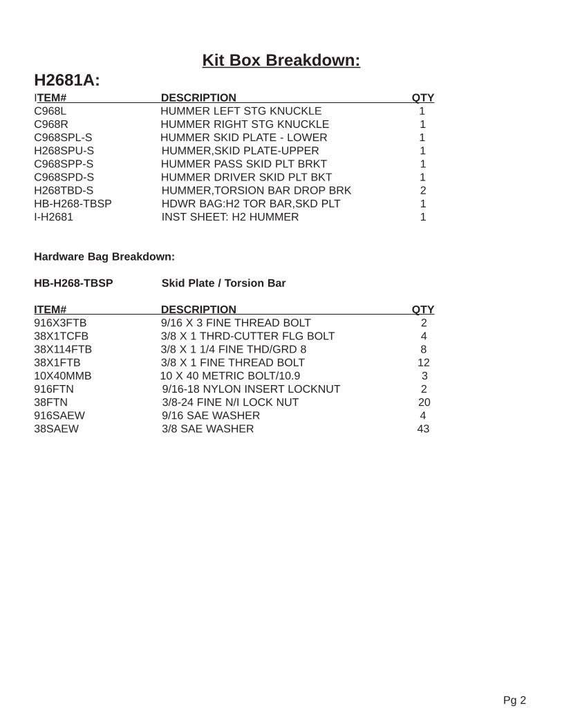
Kit Box Breakdown:H2681A:ITEM# DESCRIPTION QTYC968L HUMMER LEFT STG KNUCKLE 1C968R HUMMER RIGHT STG KNUCKLE 1C968SPL-S HUMMER SKID PLATE - LOWER 1H268SPU-S HUMMER,SKID PLATE-UPPER 1C968SPP-S HUMMER PASS SKID PLT BRKT 1C968SPD-S HUMMER DRIVER SKID PLT BKT 1H268TBD-S HUMMER,TORSION BAR DROP BRK 2HB-H268-TBSP HDWR BAG:H2 TOR BAR,SKD PLT 1I-H2681 INST SHEET: H2 HUMMER 1
Hardware Bag Breakdown:
HB-H268-TBSP Skid Plate / Torsion Bar
ITEM# DESCRIPTION QTY916X3FTB 9/16 X 3 FINE THREAD BOLT 238X1TCFB 3/8 X 1 THRD-CUTTER FLG BOLT 438X114FTB 3/8 X 1 1/4 FINE THD/GRD 8 838X1FTB 3/8 X 1 FINE THREAD BOLT 1210X40MMB 10 X 40 METRIC BOLT/10.9 3916FTN 9/16-18 NYLON INSERT LOCKNUT 238FTN 3/8-24 FINE N/I LOCK NUT 20916SAEW 9/16 SAE WASHER 438SAEW 3/8 SAE WASHER 43
Pg 2
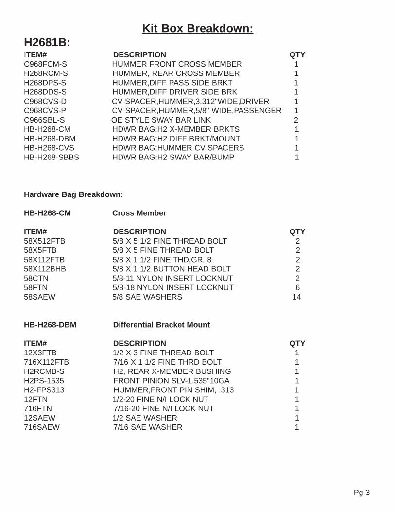
Kit Box Breakdown:H2681B:ITEM# DESCRIPTION QTYC968FCM-S HUMMER FRONT CROSS MEMBER 1H268RCM-S HUMMER, REAR CROSS MEMBER 1H268DPS-S HUMMER,DIFF PASS SIDE BRKT 1H268DDS-S HUMMER,DIFF DRIVER SIDE BRK 1C968CVS-D CV SPACER,HUMMER,3.312"WIDE,DRIVER 1C968CVS-P CV SPACER,HUMMER,5/8" WIDE,PASSENGER 1C966SBL-S OE STYLE SWAY BAR LINK 2HB-H268-CM HDWR BAG:H2 X-MEMBER BRKTS 1HB-H268-DBM HDWR BAG:H2 DIFF BRKT/MOUNT 1HB-H268-CVS HDWR BAG:HUMMER CV SPACERS 1HB-H268-SBBS HDWR BAG:H2 SWAY BAR/BUMP 1
Hardware Bag Breakdown:
HB-H268-CM Cross Member
ITEM# DESCRIPTION QTY58X512FTB 5/8 X 5 1/2 FINE THREAD BOLT 258X5FTB 5/8 X 5 FINE THREAD BOLT 258X112FTB 5/8 X 1 1/2 FINE THD,GR. 8 258X112BHB 5/8 X 1 1/2 BUTTON HEAD BOLT 258CTN 5/8-11 NYLON INSERT LOCKNUT 258FTN 5/8-18 NYLON INSERT LOCKNUT 658SAEW 5/8 SAE WASHERS 14
HB-H268-DBM Differential Bracket Mount
ITEM# DESCRIPTION QTY12X3FTB 1/2 X 3 FINE THREAD BOLT 1716X112FTB 7/16 X 1 1/2 FINE THRD BOLT 1H2RCMB-S H2, REAR X-MEMBER BUSHING 1H2PS-1535 FRONT PINION SLV-1.535"10GA 1H2-FPS313 HUMMER,FRONT PIN SHIM, .313 112FTN 1/2-20 FINE N/I LOCK NUT 1716FTN 7/16-20 FINE N/I LOCK NUT 112SAEW 1/2 SAE WASHER 1716SAEW 7/16 SAE WASHER 1
Pg 3
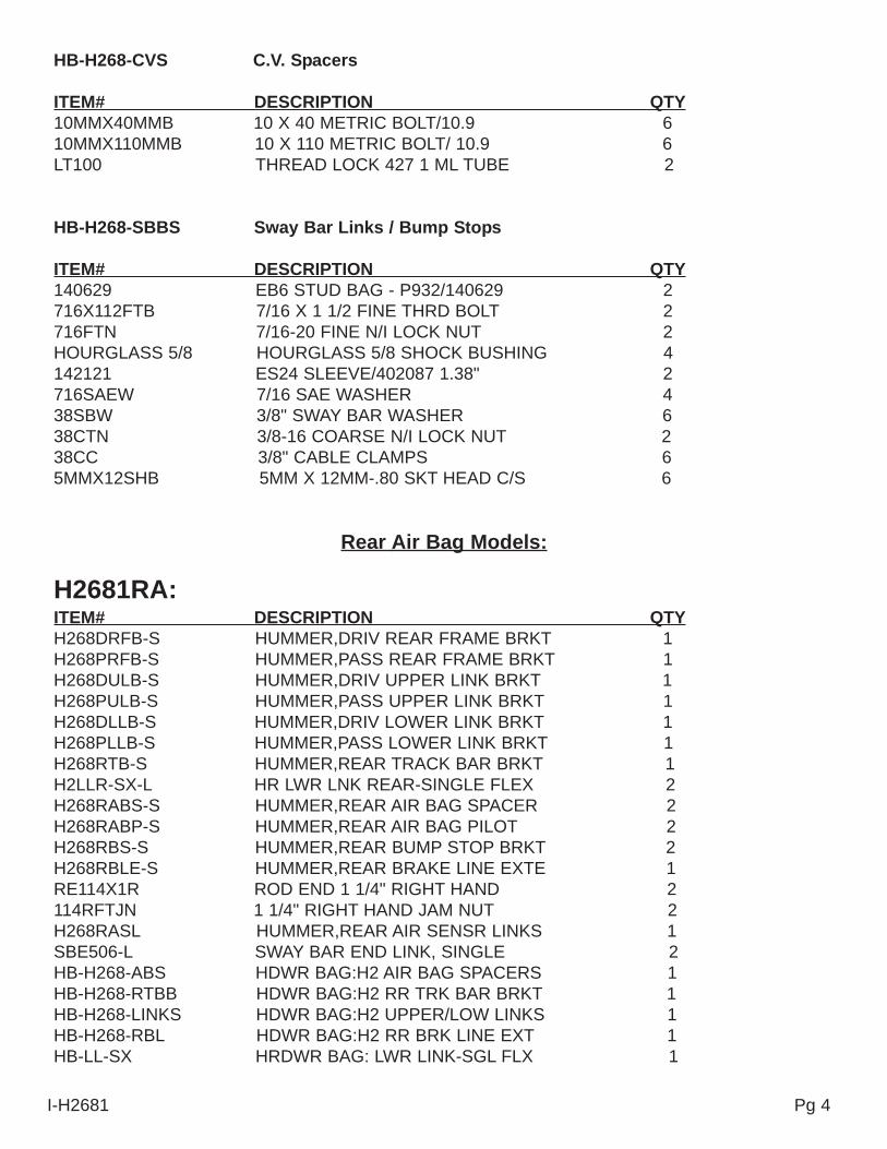
HB-H268-CVS C.V. Spacers
ITEM# DESCRIPTION QTY10MMX40MMB 10 X 40 METRIC BOLT/10.9 610MMX110MMB 10 X 110 METRIC BOLT/ 10.9 6LT100 THREAD LOCK 427 1 ML TUBE 2
HB-H268-SBBS Sway Bar Links / Bump Stops
ITEM# DESCRIPTION QTY140629 EB6 STUD BAG - P932/140629 2716X112FTB 7/16 X 1 1/2 FINE THRD BOLT 2716FTN 7/16-20 FINE N/I LOCK NUT 2HOURGLASS 5/8 HOURGLASS 5/8 SHOCK BUSHING 4142121 ES24 SLEEVE/402087 1.38" 2716SAEW 7/16 SAE WASHER 438SBW 3/8" SWAY BAR WASHER 638CTN 3/8-16 COARSE N/I LOCK NUT 238CC 3/8" CABLE CLAMPS 65MMX12SHB 5MM X 12MM-.80 SKT HEAD C/S 6
Rear Air Bag Models:
H2681RA: ITEM# DESCRIPTION QTYH268DRFB-S HUMMER,DRIV REAR FRAME BRKT 1H268PRFB-S HUMMER,PASS REAR FRAME BRKT 1H268DULB-S HUMMER,DRIV UPPER LINK BRKT 1H268PULB-S HUMMER,PASS UPPER LINK BRKT 1H268DLLB-S HUMMER,DRIV LOWER LINK BRKT 1H268PLLB-S HUMMER,PASS LOWER LINK BRKT 1H268RTB-S HUMMER,REAR TRACK BAR BRKT 1H2LLR-SX-L HR LWR LNK REAR-SINGLE FLEX 2H268RABS-S HUMMER,REAR AIR BAG SPACER 2H268RABP-S HUMMER,REAR AIR BAG PILOT 2H268RBS-S HUMMER,REAR BUMP STOP BRKT 2H268RBLE-S HUMMER,REAR BRAKE LINE EXTE 1RE114X1R ROD END 1 1/4" RIGHT HAND 2114RFTJN 1 1/4" RIGHT HAND JAM NUT 2H268RASL HUMMER,REAR AIR SENSR LINKS 1SBE506-L SWAY BAR END LINK, SINGLE 2HB-H268-ABS HDWR BAG:H2 AIR BAG SPACERS 1HB-H268-RTBB HDWR BAG:H2 RR TRK BAR BRKT 1HB-H268-LINKS HDWR BAG:H2 UPPER/LOW LINKS 1HB-H268-RBL HDWR BAG:H2 RR BRK LINE EXT 1HB-LL-SX HRDWR BAG: LWR LINK-SGL FLX 1
Pg 4I-H2681

Hardware Bag Breakdown:
H268RASL Air Bag Links
ITEM# DESCRIPTION QTYHSLB268-S HUMMER SENSOR LINK BUSHING 4HSLR1-S HUMMER SENSOR LINK ROD,REAR 2
HB-H268-ABS Air Bag SpacersITEM# DESCRIPTION QTY10X110SHB 10MM X 110 SOCKET HEAD BOLT 238X134CTB 3/8 X 1 3/4 CRSE BOLT/GRD 8 238SAEW 3/8 SAE WASHER 2
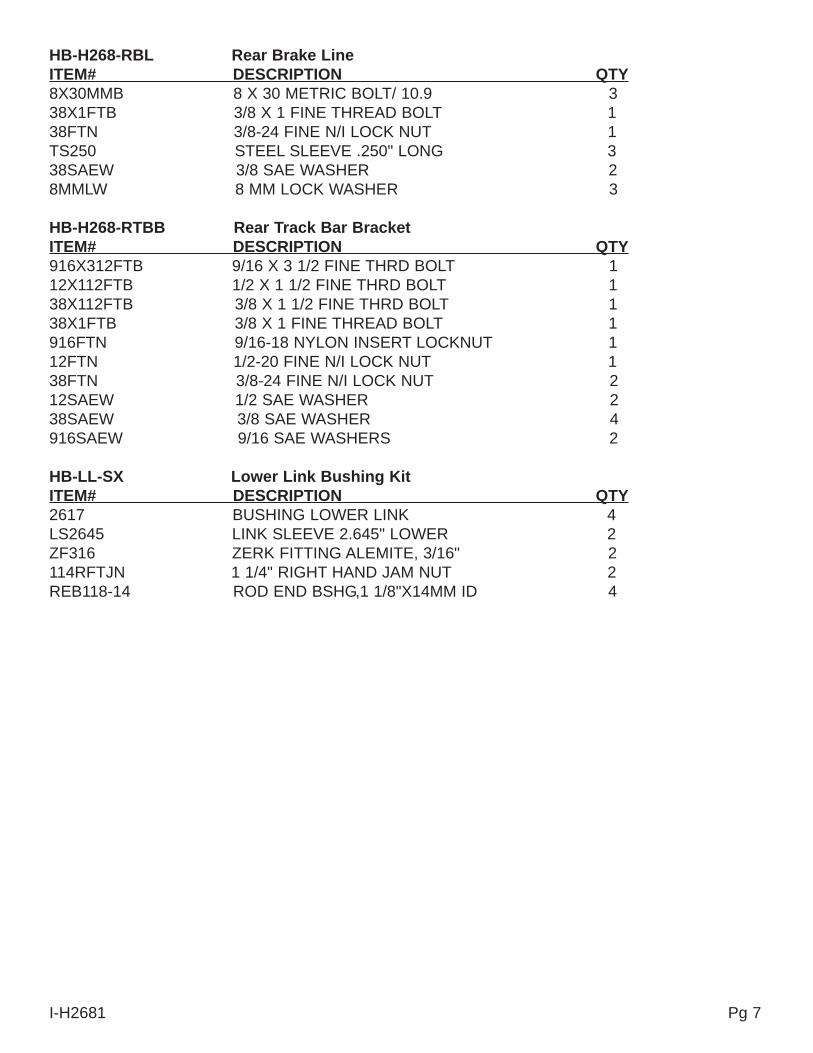
HB-H268-RTBB Rear Track Bar BracketITEM# DESCRIPTION QTY916X312FTB 9/16 X 3 1/2 FINE THRD BOLT 112X112FTB 1/2 X 1 1/2 FINE THRD BOLT 138X112FTB 3/8 X 1 1/2 FINE THRD BOLT 138X1FTB 3/8 X 1 FINE THREAD BOLT 1916FTN 9/16-18 NYLON INSERT LOCKNUT 112FTN 1/2-20 FINE N/I LOCK NUT 138FTN 3/8-24 FINE N/I LOCK NUT 212SAEW 1/2 SAE WASHER 238SAEW 3/8 SAE WASHER 4916SAEW 9/16 SAE WASHERS 2
HB-H268-LINKS Upper / Lower LinksITEM# DESCRIPTION QTY916X5FTB 9/16 X 5 FINE THRD BOLT 2916X4FTB 9/16 X 4 FINE THREAD BOLT 2916X312FTB 9/16 X 3 1/2 FINE THRD BOLT 212X120MMB 12MM X 120/10.9 ALL THREAD 4916FTN 9/16-18 NYLON INSERT LOCKNUT 612MMN 12 MM NUT (METRIC) 4916SAEW 9/16 SAE WASHERS 1212SAEW 1/2 SAE WASHER 8TS250 STEEL SLEEVE .250" LONG 4
HB-H268-RBL Rear Brake LineITEM# DESCRIPTION QTY8X30MMB 8 X 30 METRIC BOLT/ 10.9 338X1FTB 3/8 X 1 FINE THREAD BOLT 138FTN 3/8-24 FINE N/I LOCK NUT 1TS250 STEEL SLEEVE .250" LONG 338SAEW 3/8 SAE WASHER 28MMLW 8 MM LOCK WASHER 3
I-H2681 Pg 5
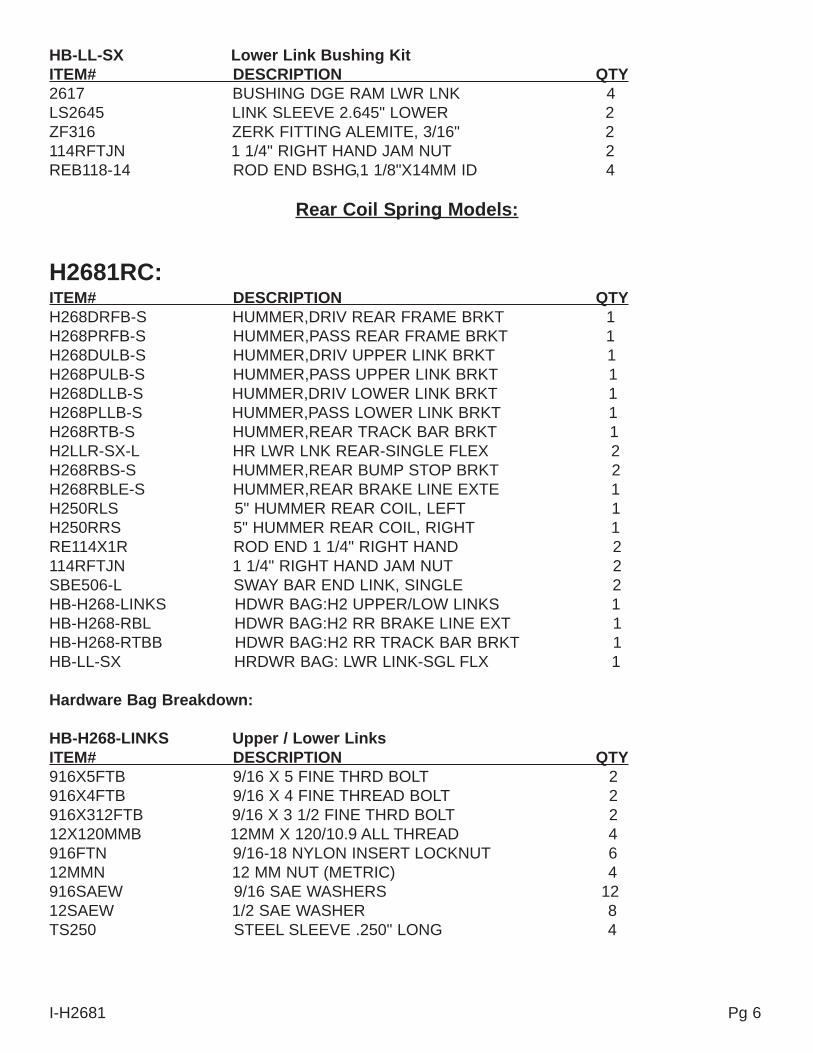
HB-LL-SX Lower Link Bushing KitITEM# DESCRIPTION QTY2617 BUSHING DGE RAM LWR LNK 4LS2645 LINK SLEEVE 2.645" LOWER 2ZF316 ZERK FITTING ALEMITE, 3/16" 2114RFTJN 1 1/4" RIGHT HAND JAM NUT 2REB118-14 ROD END BSHG,1 1/8"X14MM ID 4
Rear Coil Spring Models:
H2681RC: ITEM# DESCRIPTION QTYH268DRFB-S HUMMER,DRIV REAR FRAME BRKT 1H268PRFB-S HUMMER,PASS REAR FRAME BRKT 1H268DULB-S HUMMER,DRIV UPPER LINK BRKT 1H268PULB-S HUMMER,PASS UPPER LINK BRKT 1H268DLLB-S HUMMER,DRIV LOWER LINK BRKT 1H268PLLB-S HUMMER,PASS LOWER LINK BRKT 1H268RTB-S HUMMER,REAR TRACK BAR BRKT 1H2LLR-SX-L HR LWR LNK REAR-SINGLE FLEX 2H268RBS-S HUMMER,REAR BUMP STOP BRKT 2H268RBLE-S HUMMER,REAR BRAKE LINE EXTE 1H250RLS 5" HUMMER REAR COIL, LEFT 1H250RRS 5" HUMMER REAR COIL, RIGHT 1RE114X1R ROD END 1 1/4" RIGHT HAND 2114RFTJN 1 1/4" RIGHT HAND JAM NUT 2SBE506-L SWAY BAR END LINK, SINGLE 2HB-H268-LINKS HDWR BAG:H2 UPPER/LOW LINKS 1HB-H268-RBL HDWR BAG:H2 RR BRAKE LINE EXT 1HB-H268-RTBB HDWR BAG:H2 RR TRACK BAR BRKT 1HB-LL-SX HRDWR BAG: LWR LINK-SGL FLX 1
Hardware Bag Breakdown:
HB-H268-LINKS Upper / Lower LinksITEM# DESCRIPTION QTY916X5FTB 9/16 X 5 FINE THRD BOLT 2916X4FTB 9/16 X 4 FINE THREAD BOLT 2916X312FTB 9/16 X 3 1/2 FINE THRD BOLT 212X120MMB 12MM X 120/10.9 ALL THREAD 4916FTN 9/16-18 NYLON INSERT LOCKNUT 612MMN 12 MM NUT (METRIC) 4916SAEW 9/16 SAE WASHERS 1212SAEW 1/2 SAE WASHER 8TS250 STEEL SLEEVE .250" LONG 4
I-H2681 Pg 6
HB-H268-RBL Rear Brake LineITEM# DESCRIPTION QTY8X30MMB 8 X 30 METRIC BOLT/ 10.9 338X1FTB 3/8 X 1 FINE THREAD BOLT 138FTN 3/8-24 FINE N/I LOCK NUT 1TS250 STEEL SLEEVE .250" LONG 338SAEW 3/8 SAE WASHER 28MMLW 8 MM LOCK WASHER 3
HB-H268-RTBB Rear Track Bar BracketITEM# DESCRIPTION QTY916X312FTB 9/16 X 3 1/2 FINE THRD BOLT 112X112FTB 1/2 X 1 1/2 FINE THRD BOLT 138X112FTB 3/8 X 1 1/2 FINE THRD BOLT 138X1FTB 3/8 X 1 FINE THREAD BOLT 1916FTN 9/16-18 NYLON INSERT LOCKNUT 112FTN 1/2-20 FINE N/I LOCK NUT 138FTN 3/8-24 FINE N/I LOCK NUT 212SAEW 1/2 SAE WASHER 238SAEW 3/8 SAE WASHER 4916SAEW 9/16 SAE WASHERS 2
HB-LL-SX Lower Link Bushing KitITEM# DESCRIPTION QTY2617 BUSHING LOWER LINK 4LS2645 LINK SLEEVE 2.645" LOWER 2ZF316 ZERK FITTING ALEMITE, 3/16" 2114RFTJN 1 1/4" RIGHT HAND JAM NUT 2REB118-14 ROD END BSHG,1 1/8"X14MM ID 4
I-H2681 Pg 7
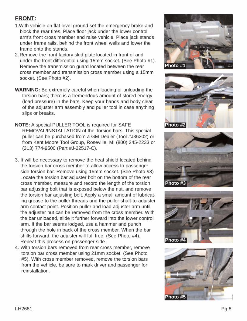
Photo #1
Photo #2
Photo #3
FRONT:1.With vehicle on flat level ground set the emergency brake and
block the rear tires. Place floor jack under the lower controlarm’s front cross member and raise vehicle. Place jack standsunder frame rails, behind the front wheel wells and lower theframe onto the stands.
2.Remove the front factory skid plate located in front of andunder the front differential using 15mm socket. (See Photo #1).Remove the transmission guard located between the rearcross member and transmission cross member using a 15mmsocket. (See Photo #2).
WARNING: Be extremely careful when loading or unloading thetorsion bars; there is a tremendous amount of stored energy(load pressure) in the bars. Keep your hands and body clearof the adjuster arm assembly and puller tool in case anythingslips or breaks.
NOTE: A special PULLER TOOL is required for SAFEREMOVAL/INSTALLATION of the Torsion bars. This specialpuller can be purchased from a GM Dealer (Tool #J36202) orfrom Kent Moore Tool Group, Roseville, MI (800) 345-2233 or(313) 774-9500 (Part #J-22517-C).
3. It will be necessary to remove the heat shield located behindthe torsion bar cross member to allow access to passengerside torsion bar. Remove using 15mm socket. (See Photo #3)Locate the torsion bar adjuster bolt on the bottom of the rearcross member, measure and record the length of the torsionbar adjusting bolt that is exposed below the nut, and removethe torsion bar adjusting bolt. Apply a small amount of lubricat-ing grease to the puller threads and the puller shaft-to-adjusterarm contact point. Position puller and load adjuster arm untilthe adjuster nut can be removed from the cross member. Withthe bar unloaded, slide it further forward into the lower controlarm. If the bar seems lodged, use a hammer and punchthrough the hole in back of the cross member. When the barshifts forward, the adjuster will fall free. (See Photo #4).Repeat this process on passenger side.
4. With torsion bars removed from rear cross member, removetorsion bar cross member using 21mm socket. (See Photo#5). With cross member removed, remove the torsion barsfrom the vehicle, be sure to mark driver and passenger forreinstallation.
I-H2681 Pg 8
Photo #4
Photo #5
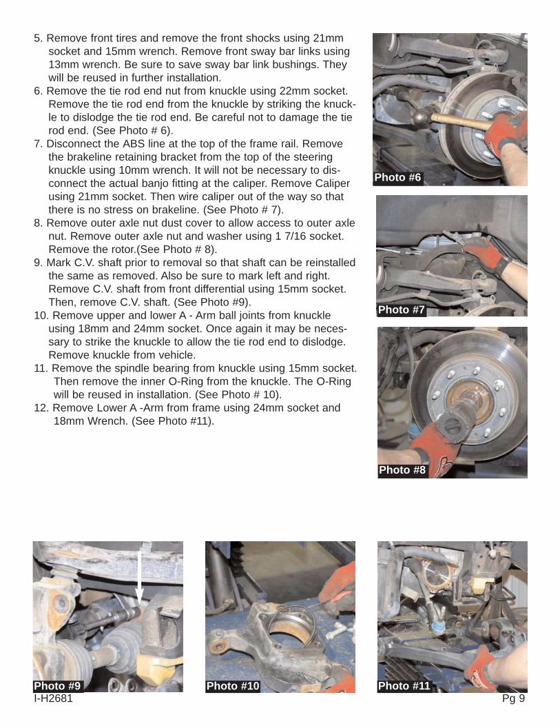
5. Remove front tires and remove the front shocks using 21mmsocket and 15mm wrench. Remove front sway bar links using13mm wrench. Be sure to save sway bar link bushings. Theywill be reused in further installation.
6. Remove the tie rod end nut from knuckle using 22mm socket.Remove the tie rod end from the knuckle by striking the knuck-le to dislodge the tie rod end. Be careful not to damage the tierod end. (See Photo # 6).
7. Disconnect the ABS line at the top of the frame rail. Removethe brakeline retaining bracket from the top of the steeringknuckle using 10mm wrench. It will not be necessary to dis-connect the actual banjo fitting at the caliper. Remove Caliperusing 21mm socket. Then wire caliper out of the way so thatthere is no stress on brakeline. (See Photo # 7).
8. Remove outer axle nut dust cover to allow access to outer axlenut. Remove outer axle nut and washer using 1 7/16 socket.Remove the rotor.(See Photo # 8).
9. Mark C.V. shaft prior to removal so that shaft can be reinstalledthe same as removed. Also be sure to mark left and right.Remove C.V. shaft from front differential using 15mm socket.Then, remove C.V. shaft. (See Photo #9).
10. Remove upper and lower A - Arm ball joints from knuckleusing 18mm and 24mm socket. Once again it may be neces-sary to strike the knuckle to allow the tie rod end to dislodge.Remove knuckle from vehicle.
11. Remove the spindle bearing from knuckle using 15mm socket.Then remove the inner O-Ring from the knuckle. The O-Ringwill be reused in installation. (See Photo # 10).
12. Remove Lower A -Arm from frame using 24mm socket and18mm Wrench. (See Photo #11).
Photo #6
Photo #7
Photo #8
Photo #9 Photo #10 Photo #11I-H2681 Pg 9
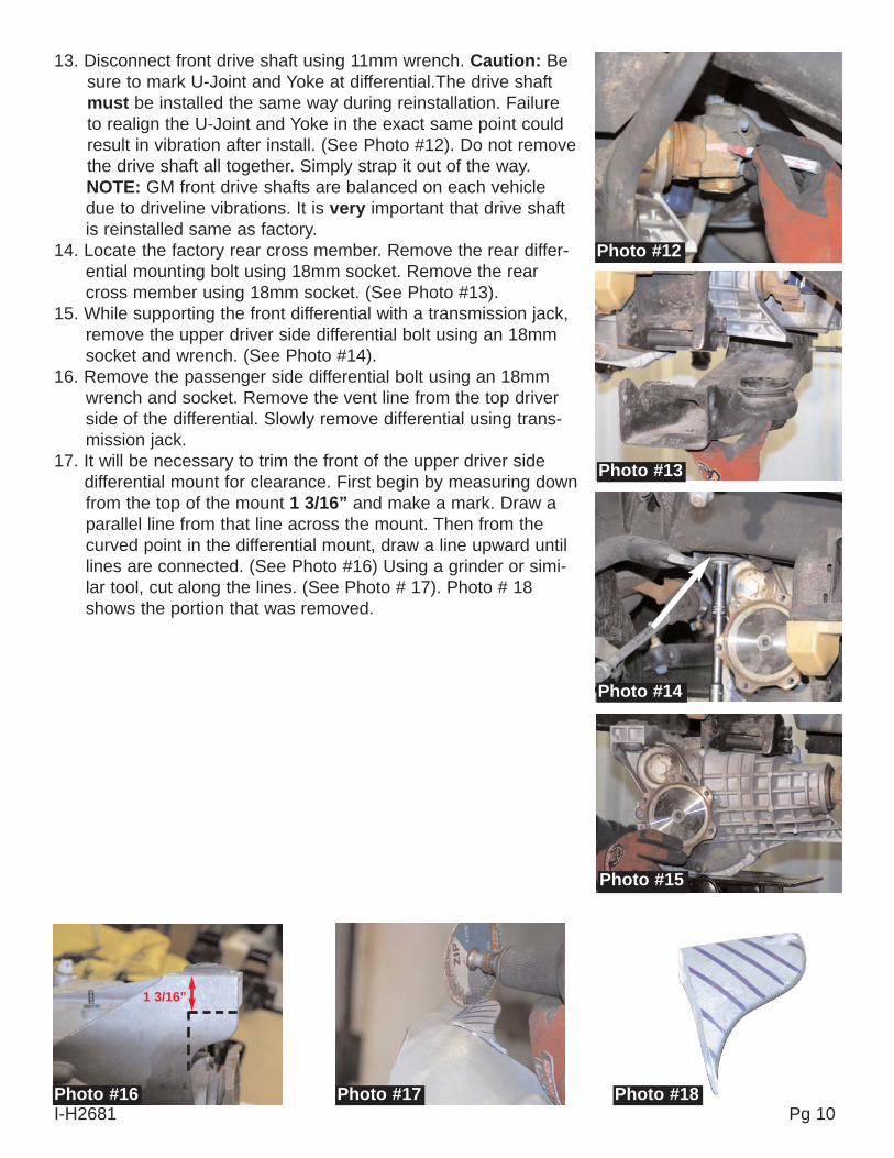
13. Disconnect front drive shaft using 11mm wrench. Caution: Besure to mark U-Joint and Yoke at differential.The drive shaftmust be installed the same way during reinstallation. Failureto realign the U-Joint and Yoke in the exact same point couldresult in vibration after install. (See Photo #12). Do not removethe drive shaft all together. Simply strap it out of the way.NOTE: GM front drive shafts are balanced on each vehicledue to driveline vibrations. It is very important that drive shaftis reinstalled same as factory.
14. Locate the factory rear cross member. Remove the rear differ-ential mounting bolt using 18mm socket. Remove the rearcross member using 18mm socket. (See Photo #13).
15. While supporting the front differential with a transmission jack,remove the upper driver side differential bolt using an 18mmsocket and wrench. (See Photo #14).
16. Remove the passenger side differential bolt using an 18mmwrench and socket. Remove the vent line from the top driverside of the differential. Slowly remove differential using trans-mission jack.
17. It will be necessary to trim the front of the upper driver side differential mount for clearance. First begin by measuring downfrom the top of the mount 1 3/16” and make a mark. Draw aparallel line from that line across the mount. Then from thecurved point in the differential mount, draw a line upward untillines are connected. (See Photo #16) Using a grinder or simi-lar tool, cut along the lines. (See Photo # 17). Photo # 18shows the portion that was removed.
Photo #12
Photo #13
Photo #14
Photo #15
Photo #16 Photo #17I-H2681 Pg 10
Photo #18
1 3/16”
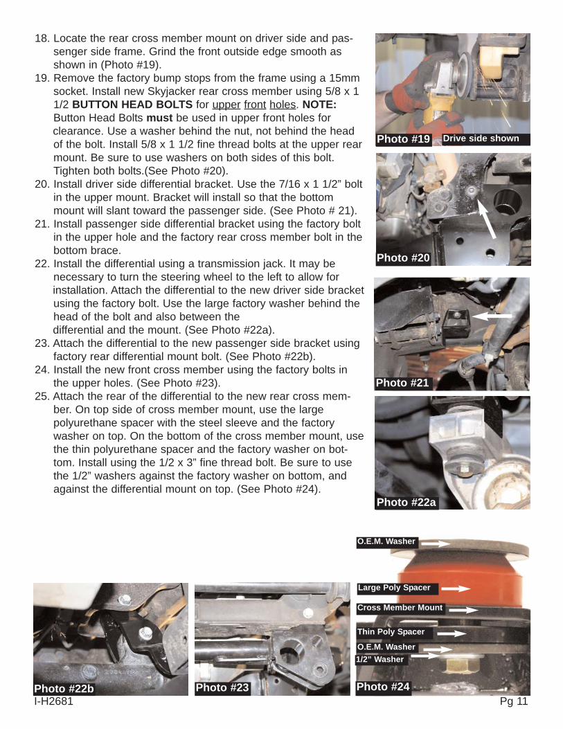
Photo #19
Photo #20
Photo #21
Photo #22a
Photo #22b Photo #23 Photo #24I-H2681 Pg 11
18. Locate the rear cross member mount on driver side and pas-senger side frame. Grind the front outside edge smooth asshown in (Photo #19).
19. Remove the factory bump stops from the frame using a 15mmsocket. Install new Skyjacker rear cross member using 5/8 x 11/2 BUTTON HEAD BOLTS for upper front holes. NOTE:Button Head Bolts must be used in upper front holes for clearance. Use a washer behind the nut, not behind the headof the bolt. Install 5/8 x 1 1/2 fine thread bolts at the upper rearmount. Be sure to use washers on both sides of this bolt.Tighten both bolts.(See Photo #20).
20. Install driver side differential bracket. Use the 7/16 x 1 1/2” boltin the upper mount. Bracket will install so that the bottommount will slant toward the passenger side. (See Photo # 21).
21. Install passenger side differential bracket using the factory boltin the upper hole and the factory rear cross member bolt in thebottom brace.
22. Install the differential using a transmission jack. It may benecessary to turn the steering wheel to the left to allow for installation. Attach the differential to the new driver side bracketusing the factory bolt. Use the large factory washer behind thehead of the bolt and also between the differential and the mount. (See Photo #22a).
23. Attach the differential to the new passenger side bracket usingfactory rear differential mount bolt. (See Photo #22b).
24. Install the new front cross member using the factory bolts inthe upper holes. (See Photo #23).
25. Attach the rear of the differential to the new rear cross mem-ber. On top side of cross member mount, use the largepolyurethane spacer with the steel sleeve and the factorywasher on top. On the bottom of the cross member mount, usethe thin polyurethane spacer and the factory washer on bot-tom. Install using the 1/2 x 3” fine thread bolt. Be sure to usethe 1/2” washers against the factory washer on bottom, andagainst the differential mount on top. (See Photo #24).
Drive side shown
O.E.M. Washer
Large Poly Spacer
Cross Member Mount
Thin Poly Spacer
O.E.M. Washer1/2” Washer
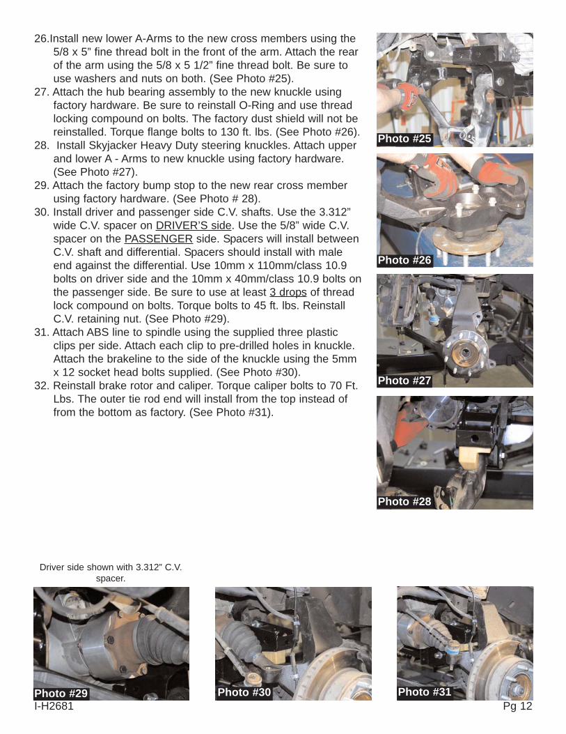
26.Install new lower A-Arms to the new cross members using the5/8 x 5” fine thread bolt in the front of the arm. Attach the rearof the arm using the 5/8 x 5 1/2” fine thread bolt. Be sure touse washers and nuts on both. (See Photo #25).
27. Attach the hub bearing assembly to the new knuckle usingfactory hardware. Be sure to reinstall O-Ring and use threadlocking compound on bolts. The factory dust shield will not bereinstalled. Torque flange bolts to 130 ft. lbs. (See Photo #26).
28. Install Skyjacker Heavy Duty steering knuckles. Attach upperand lower A - Arms to new knuckle using factory hardware.(See Photo #27).
29. Attach the factory bump stop to the new rear cross memberusing factory hardware. (See Photo # 28).
30. Install driver and passenger side C.V. shafts. Use the 3.312”wide C.V. spacer on DRIVER’S side. Use the 5/8” wide C.V.spacer on the PASSENGER side. Spacers will install betweenC.V. shaft and differential. Spacers should install with maleend against the differential. Use 10mm x 110mm/class 10.9bolts on driver side and the 10mm x 40mm/class 10.9 bolts onthe passenger side. Be sure to use at least 3 drops of threadlock compound on bolts. Torque bolts to 45 ft. lbs. ReinstallC.V. retaining nut. (See Photo #29).
31. Attach ABS line to spindle using the supplied three plasticclips per side. Attach each clip to pre-drilled holes in knuckle.Attach the brakeline to the side of the knuckle using the 5mmx 12 socket head bolts supplied. (See Photo #30).
32. Reinstall brake rotor and caliper. Torque caliper bolts to 70 Ft.Lbs. The outer tie rod end will install from the top instead offrom the bottom as factory. (See Photo #31).
Photo #25
Photo #26
Photo #27
Photo #28
Photo #29 Photo #30 Photo #31I-H2681 Pg 12
Driver side shown with 3.312” C.V.spacer.
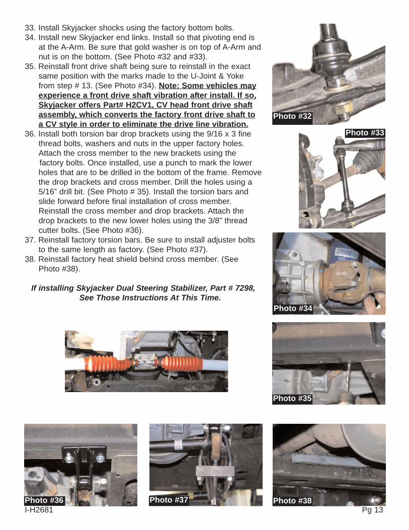
33. Install Skyjacker shocks using the factory bottom bolts. 34. Install new Skyjacker end links. Install so that pivoting end is
at the A-Arm. Be sure that gold washer is on top of A-Arm andnut is on the bottom. (See Photo #32 and #33).
35. Reinstall front drive shaft being sure to reinstall in the exactsame position with the marks made to the U-Joint & Yokefrom step # 13. (See Photo #34). Note: Some vehicles mayexperience a front drive shaft vibration after install. If so,Skyjacker offers Part# H2CV1, CV head front drive shaftassembly, which converts the factory front drive shaft toa CV style in order to eliminate the drive line vibration.
36. Install both torsion bar drop brackets using the 9/16 x 3 finethread bolts, washers and nuts in the upper factory holes.Attach the cross member to the new brackets using the factory bolts. Once installed, use a punch to mark the lowerholes that are to be drilled in the bottom of the frame. Removethe drop brackets and cross member. Drill the holes using a5/16” drill bit. (See Photo # 35). Install the torsion bars andslide forward before final installation of cross member.Reinstall the cross member and drop brackets. Attach thedrop brackets to the new lower holes using the 3/8” threadcutter bolts. (See Photo #36).
37. Reinstall factory torsion bars. Be sure to install adjuster boltsto the same length as factory. (See Photo #37).
38. Reinstall factory heat shield behind cross member. (SeePhoto #38).
If installing Skyjacker Dual Steering Stabilizer, Part # 7298,See Those Instructions At This Time.
Photo #32
Photo #33
Photo #34
Photo #35
Photo #36 Photo #37 Photo #38I-H2681 Pg 13
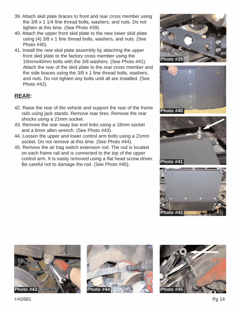
39. Attach skid plate braces to front and rear cross member usingthe 3/8 x 1 1/4 fine thread bolts, washers, and nuts. Do nottighten at this time. (See Photo #39).
40. Attach the upper front skid plate to the new lower skid plateusing (4) 3/8 x 1 fine thread bolts, washers, and nuts. (SeePhoto #40).
41. Install the new skid plate assembly by attaching the upperfront skid plate to the factory cross member using the10mmx40mm bolts with the 3/8 washers. (See Photo #41).Attach the rear of the skid plate to the rear cross member andthe side braces using the 3/8 x 1 fine thread bolts, washers,and nuts. Do not tighten any bolts until all are installed. (SeePhoto #42).
REAR:
42. Raise the rear of the vehicle and support the rear of the framerails using jack stands. Remove rear tires. Remove the rearshocks using a 21mm socket.
43. Remove the rear sway bar end links using a 18mm socketand a 6mm allen wrench. (See Photo #43).
44. Loosen the upper and lower control arm bolts using a 21mmsocket. Do not remove at this time. (See Photo #44).
45. Remove the air bag switch extension rod. The rod is locatedon each frame rail and is connected to the top of the uppercontrol arm. It is easily removed using a flat head screw driver.Be careful not to damage the rod. (See Photo #45).
Photo #39
Photo #40
Photo #41
Photo #42
Photo #43 Photo #44 Photo #45
I-H2681 Pg 14
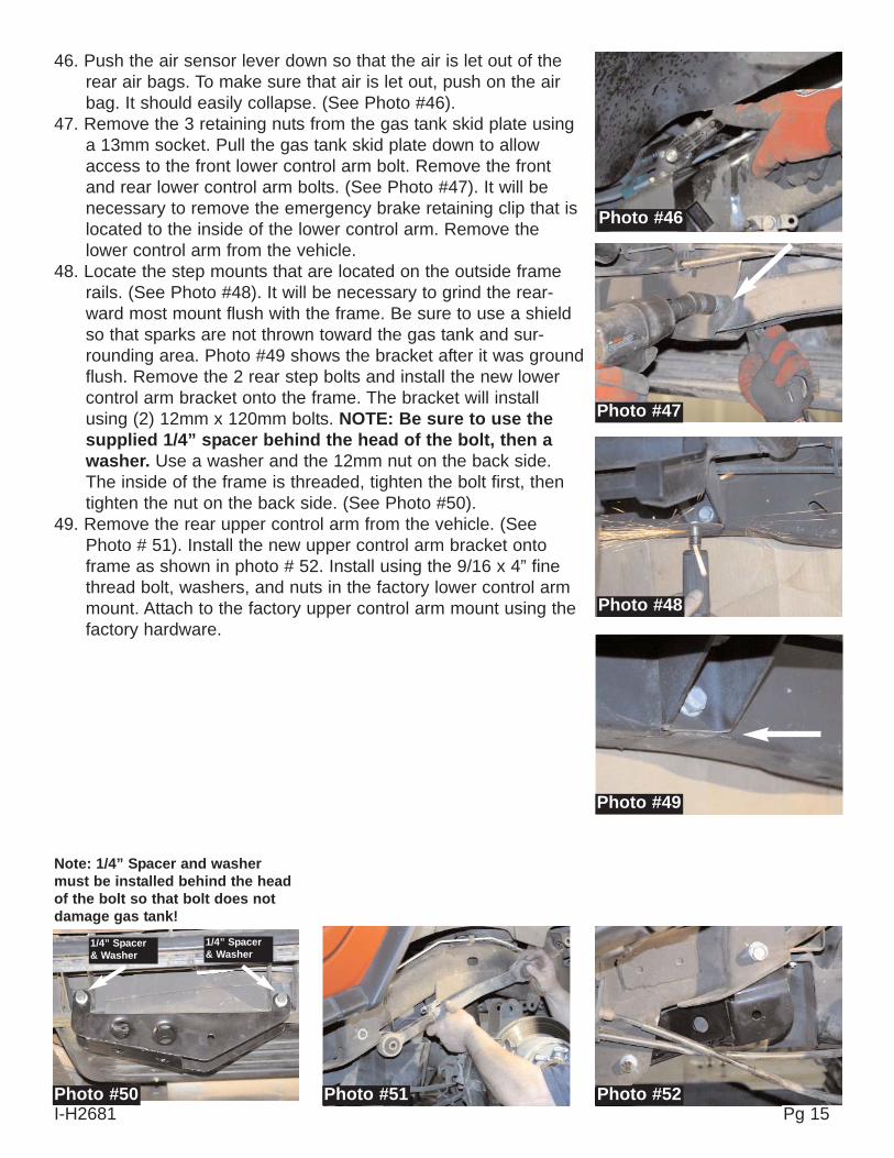
46. Push the air sensor lever down so that the air is let out of therear air bags. To make sure that air is let out, push on the airbag. It should easily collapse. (See Photo #46).
47. Remove the 3 retaining nuts from the gas tank skid plate usinga 13mm socket. Pull the gas tank skid plate down to allowaccess to the front lower control arm bolt. Remove the frontand rear lower control arm bolts. (See Photo #47). It will benecessary to remove the emergency brake retaining clip that islocated to the inside of the lower control arm. Remove thelower control arm from the vehicle.
48. Locate the step mounts that are located on the outside framerails. (See Photo #48). It will be necessary to grind the rear-ward most mount flush with the frame. Be sure to use a shieldso that sparks are not thrown toward the gas tank and sur-rounding area. Photo #49 shows the bracket after it was groundflush. Remove the 2 rear step bolts and install the new lowercontrol arm bracket onto the frame. The bracket will installusing (2) 12mm x 120mm bolts. NOTE: Be sure to use thesupplied 1/4” spacer behind the head of the bolt, then awasher. Use a washer and the 12mm nut on the back side.The inside of the frame is threaded, tighten the bolt first, thentighten the nut on the back side. (See Photo #50).
49. Remove the rear upper control arm from the vehicle. (SeePhoto # 51). Install the new upper control arm bracket ontoframe as shown in photo # 52. Install using the 9/16 x 4” finethread bolt, washers, and nuts in the factory lower control armmount. Attach to the factory upper control arm mount using thefactory hardware.
Photo #46
Photo #47
Photo #48
Photo #49
Photo #52Photo #51Photo #50I-H2681 Pg 15
1/4” Spacer& Washer
1/4” Spacer& Washer
Note: 1/4” Spacer and washermust be installed behind the headof the bolt so that bolt does notdamage gas tank!

I-H2681 Pg 16
50. Install the new lower control arm mount onto the axle. It willattach to the factory lower control arm mount, and the rearshock mount. Install using the factory hardware at bothlocations. (See Photo #53 and #54). Do not tighten at thistime. Photo #54 shows the mount from the rear.
51. Install the new lower control arm using the bushings, sleeve,and rod end bushings provided. Install new lower control armso that the 1 1/4” rod end attaches to the new drop bracket onthe frame rail. Install so that grease fitting is pointed down.Adjust the lower control arm so that the center-to-center meas-urement is 37 7/8”. This is a starting point measurement, aqualified alignment facility will adjust to the final settings. Onceset, tighten the jam nut against the arm. Install the new lowercontrol arm using the factory bolt in the rear, and the 9/16 x 5”bolt, washers, and nuts in the front. (See Photo #55).
52. Reinstall the factory upper control arm using the factory bolt inthe rear, and the 9/16 x 3 1/2” bolt, washers, and nuts in thefront. (See Photo #56).
If vehicle is equipped with rear coil springs skip to step #58.53. Air Bag Models Only: The supply line at the top of each air
bag must be disconnected from the top of the air bag. (SeePhoto #57). Depress the upper ring to allow for the line to beremoved. Be careful not to damage line. Photo # 58 shows ademonstration of how to remove the supply line. Once the sup-ply line is disconnected, turn the air bag (clockwise = driverside), (counter clock wise = passenger side).passenger side to allow the upper notched to disengage.Remove the air bag assembly from the vehicle.
54. Remove the lower air bag retainer from the top of the rear axleusing a 15mm socket. (See Photo #59a).
Photo #53
Photo #56
Photo #57 Photo #58 Photo #59
Photo #54
Photo #55
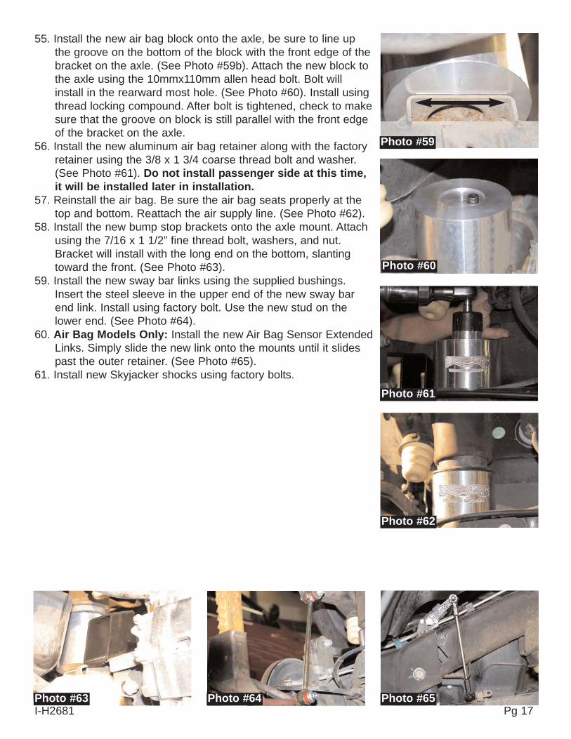
55. Install the new air bag block onto the axle, be sure to line upthe groove on the bottom of the block with the front edge of thebracket on the axle. (See Photo #59b). Attach the new block tothe axle using the 10mmx110mm allen head bolt. Bolt willinstall in the rearward most hole. (See Photo #60). Install usingthread locking compound. After bolt is tightened, check to makesure that the groove on block is still parallel with the front edgeof the bracket on the axle.
56. Install the new aluminum air bag retainer along with the factoryretainer using the 3/8 x 1 3/4 coarse thread bolt and washer.(See Photo #61). Do not install passenger side at this time,it will be installed later in installation.
57. Reinstall the air bag. Be sure the air bag seats properly at thetop and bottom. Reattach the air supply line. (See Photo #62).
58. Install the new bump stop brackets onto the axle mount. Attachusing the 7/16 x 1 1/2” fine thread bolt, washers, and nut.Bracket will install with the long end on the bottom, slantingtoward the front. (See Photo #63).
59. Install the new sway bar links using the supplied bushings.Insert the steel sleeve in the upper end of the new sway barend link. Install using factory bolt. Use the new stud on thelower end. (See Photo #64).
60. Air Bag Models Only: Install the new Air Bag Sensor ExtendedLinks. Simply slide the new link onto the mounts until it slidespast the outer retainer. (See Photo #65).
61. Install new Skyjacker shocks using factory bolts.
Photo #59
Photo #62
Photo #63 Photo #64 Photo #65
Photo #60
Photo #61
I-H2681 Pg 17
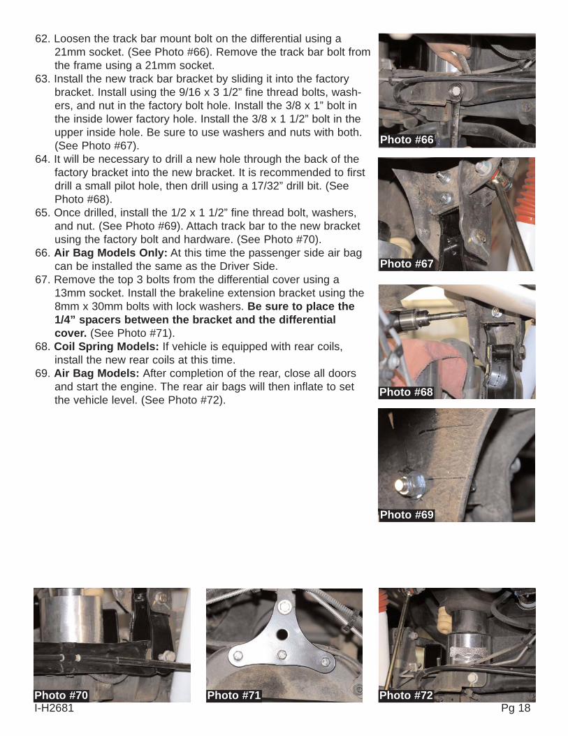
62. Loosen the track bar mount bolt on the differential using a21mm socket. (See Photo #66). Remove the track bar bolt fromthe frame using a 21mm socket.
63. Install the new track bar bracket by sliding it into the factorybracket. Install using the 9/16 x 3 1/2” fine thread bolts, wash-ers, and nut in the factory bolt hole. Install the 3/8 x 1” bolt inthe inside lower factory hole. Install the 3/8 x 1 1/2” bolt in theupper inside hole. Be sure to use washers and nuts with both.(See Photo #67).
64. It will be necessary to drill a new hole through the back of thefactory bracket into the new bracket. It is recommended to firstdrill a small pilot hole, then drill using a 17/32” drill bit. (SeePhoto #68).
65. Once drilled, install the 1/2 x 1 1/2” fine thread bolt, washers,and nut. (See Photo #69). Attach track bar to the new bracketusing the factory bolt and hardware. (See Photo #70).
66. Air Bag Models Only: At this time the passenger side air bagcan be installed the same as the Driver Side.
67. Remove the top 3 bolts from the differential cover using a13mm socket. Install the brakeline extension bracket using the8mm x 30mm bolts with lock washers. Be sure to place the1/4” spacers between the bracket and the differentialcover. (See Photo #71).
68. Coil Spring Models: If vehicle is equipped with rear coils,install the new rear coils at this time.
69. Air Bag Models: After completion of the rear, close all doorsand start the engine. The rear air bags will then inflate to setthe vehicle level. (See Photo #72).
Photo #66
Photo #67
Photo #68
Photo #69
Photo #72Photo #71Photo #70I-H2681 Pg 18
FINAL NOTES:• After installation is complete, double check that all nuts and bolts are tight. Refer to the
chart again for torque specifications. (Do not retighten nuts and bolts where Thread LOCkCOmpound was used.)• If new tires are installed that are more than 10% taller than original tires, the speedometer must be
recalibrated for the rear wheel anti-lock brake system to function properly. Contact an authorizedGM dealer for details on recalibration.
• With the vehicle on the floor, cycle steering lock to lock and inspect steering, suspension anddriveline systems for proper operation, tightness and adequate clearance. Recheck brake hose/fittings for leaks. Be sure all hoses, including the rear, are long enough.
• Have headlights readjusted to proper settings.• Have a qualified alignment center realign front end to factory specifications. Be sure vehicle is at
desired ride height prior to realignment.• Re-torque all bolts after the first 100 miles and after every off-road use.
Seat Belts Save Lives, Please Wear Your Seat Belt.
Pg 19I-H2681