© 2008 Bentley Systems, Incorporated GEOPAK Corridor Modeling Derricke Gray GEOPAK Product Manager.
78
© 2008 Bentley Systems, Incorporated GEOPAK Corridor Modeling Derricke Gray GEOPAK Product Manager
-
Upload
gerard-mills -
Category
Documents
-
view
271 -
download
2
Transcript of © 2008 Bentley Systems, Incorporated GEOPAK Corridor Modeling Derricke Gray GEOPAK Product Manager.

© 2008 Bentley Systems, Incorporated
GEOPAK Corridor ModelingDerricke GrayGEOPAK Product Manager
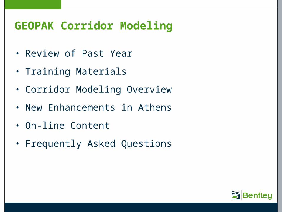
GEOPAK Corridor Modeling
• Review of Past Year
• Training Materials
• Corridor Modeling Overview
• New Enhancements in Athens
• On-line Content
• Frequently Asked Questions

Review of Past Year
• Met in Sunrise (Oct. 1-3, 2007)
• Roadway Designer Runs in GEOPAK (Dec., 2007)
• Deliver CM in XM 08.09.06.31 (July, 2008)
• Deliver CM Training Course (July, 2008)

Training Materials
• 1st Class taught to Support (Aug., 2008)
• Already taught to NCDOT and several consultants

Applications > Road > 3D Tools > Corridor Modeling
Corridor Modeling Overview

When you first open the Corridor Modeling (CM) application, a new sub-folder is created under your working directory.
\rddbs
This folder is where any files are created that are used exclusively by the CM application.
Corridor Modeling Overview

GPK Job Selection
Corridor Modeling Overview

Station Lock – Controls how the cross section interval is calculated in the Roadway Designer application.
Slope Readout – Controls how the slopes are displayed to the user in the Create Templates and Roadway Designer applications.
Horizontal Chord Height – When creating surfaces, controls the processing through horizontal curves.
Vertical Chord Height – When creating surfaces, controls the processing through vertical curves.
Template Library – Designates which template library CM applications will use.
Preferences

GEOPAK delivers a ‘default.itl’ template library in the /bin directory which is used by default.
The configuration variable GPK_RD_Template_Librarycan be used to specify another template library to use.
Preferences – Template Library
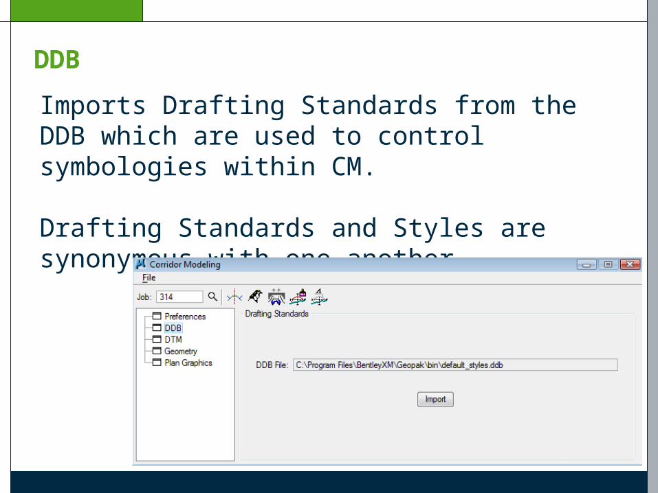
Imports Drafting Standards from the DDB which are used to control symbologies within CM.
Drafting Standards and Styles are synonymous with one another.
DDB

In XM, only the ‘Drafting Standards’ items in the DDB will be imported. These items are denoted with the ‘paintbrush’ icon.
DDB
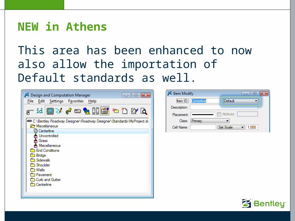
This area has been enhanced to now also allow the importation of Default standards as well.
NEW in Athens

A ‘default_styles.ddb’ file is delivered in the /bin directory and used by default. The configuration variable GPK_ACBOOK_DDBFILE_STYLEScan be used to specify another DDB to use.
DDB

When the Drafting Standards are imported, a new file is created in the \rddbs subdirectory. This file uses the same name as the DDB but with an .XIN extension.
Default_styles.ddb default_styles.xin
DDB

If you prefer that each user NOT have to import the DDB and create the .XIN file locally, you can point to a global .XIN file using the following configuration variable:
GPK_ACBOOK_XINFILE_STYLES
Note that the use of this variablewill remove the ‘DDB’ option fromthe dialog.
NEW in V8i

In order to use TIN files in CM, we have to import them. When you import a TIN, a new file will be created with the same name but using a .DTM extension.
fm314.tin fm314.dtm
DTM

You can add both TIN and DTM files in the list box. Multiple files can be listed and imported simultaneously.
DTM

Important! Only files that are listed in this list box will be available in Roadway Designer.
DTM

Chains and profiles from the GPK must be imported into the CM application.
Geometry

When the geometry items are imported, a new file is created in the \rddbs subdirectory. This file is named by taking the gpk name and adding a ‘cm’ prefix and .alg suffix.
job314.gpk cmjob314.alg
Geometry

When geometry data is imported, a drafting standard is always assigned to it. Later, you can build templates to target the chains/profiles by their name or by the name of the drafting standard/style.
Geometry

Since Roadway Designer does not read directly from plan graphic elements, we need a way to make the application aware of our graphics. We can do this by using the Plan Graphics import feature.
Plan Graphics

We can read the plan graphics based on Symbology, a DDB Feature or a MicroStation Selection Set.
Plan Graphics

When using Symbology or Feature, we can setup a ‘search corridor’ based on a chain name, a side and a beginning and ending offset.
Plan Graphics

If our plan graphic doesn’t fit nicely into a search corridor, we always have the Selection Set option. The user can just place any elements into a MS Selection Set and add them to the list.
Plan Graphics

Once all of our items are setup in our list box, we can import them. The resulting alignments are stored in the .alg file.
Plan Graphics

Data in the geometry database has a tendency to change throughout the life of a project. With that in mind, we need some way to keep our data in synch between the .gpk and the .alg. In order to facilitate this, there is a functionality built into the Corridor Modeling application called Smart Update.
Every time you open Corridor Modeling, it checks the data in the gpk against data previously imported into the .alg.
Smart Update

If a chain or profile has been modified in the gpk and is out of synch with the .alg, it will show up in blue.
If a chain or profile has been deleted from the gpk and is out of synch with the .alg, it will show up in red.
Smart Update

Similar to the geometry, the plan graphic data also has a tendency to change throughout the life of a project. The Smart Update functionality also works with the Plan Graphics.
Every time you open Corridor Modeling, it checks the plan graphic data in the design file against data previously imported into the .alg.
Smart Update

If a plan graphic has been modified in the design file and is out of synch with the .alg, it will show up in blue. If a plan graphic has been deleted from the dgn and is out of synch with the .alg, it will show up in red.
Smart Update


Now that we have our data imported, we are ready to step into the CM workflow.
The first step is to access our Create Template application.
Corridor Modeling Overview
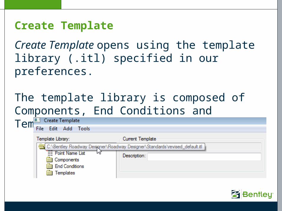
Create Template opens using the template library (.itl) specified in our preferences.
The template library is composed of Components, End Conditions and Templates.
Create Template

When components and end conditions are created, their individual elements are assigned styles (drafting standards). This controls how the elements are displayed.
In the example here, this one component employs threedifferent styles.
Create Template


Once our templates are complete, we can move into the next application in our workflow, Roadway Designer.
Roadway Designer

We create a corridor based on an alignment and profile.
We can create one or multiple corridors for our project.
Roadway Designer
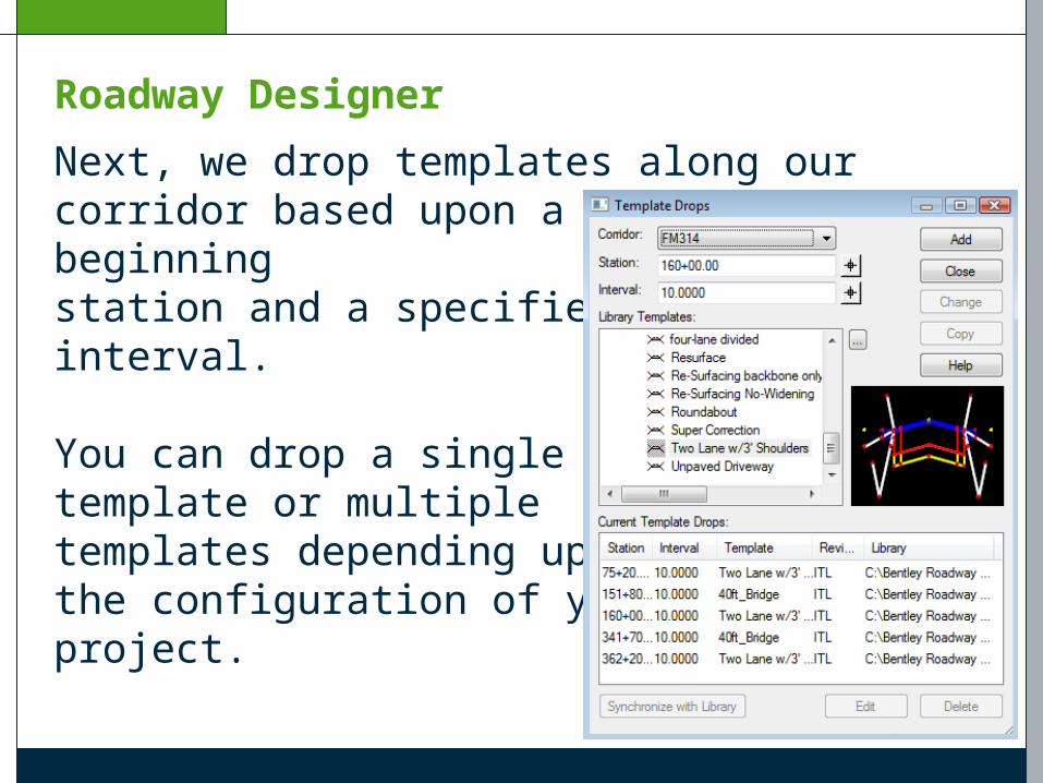
Next, we drop templates along our corridor based upon a specified beginning station and a specified interval.
You can drop a single template or multiple templates depending uponthe configuration of your project.
Roadway Designer

The application is divided into 3 views – Plan, Profile and Cross Section. This is very similar to GEOPAK’s 3-Port Viewer.
Roadway Designer

In addition to the cross sections at stations generated by the given stations and increments of the template drops, you also have the capability under the Roadway Designer Options to include Critical Sections.
Horizontal Cardinal Points PI, PC, PT, etc.
Vertical Control Points VPI, VPC, VPT, etc.
Roadway Designer

External Control Points – If a template targets an alignment (e.g. wall, ditch, etc.), then enabling this option will pick up all the critical points (PI’s, PC’s, PT’s, etc.) along this “external” alignment and include them as cross section locations.
Roadway Designer

You also have the ability to generate stations at any location that you need. These are called Key Stations. These might occur at culvert crossings, driveway locations, etc..
Roadway Designer

For the GEOPAK version of Roadway Designer, we have added the ability to import your superelevation directly from the GEOPAK shape input file.
Roadway Designer

When you are at the point in your design when you are ready to create a finished model, you can do so throughthe Create Surface dialog.
This will result in the creationof the proposed surface (.DTM)and an associated XML file.
Roadway Designer

The Display Features in PlanView option will result in themodel being drawn into yourdesign file.
Roadway Designer
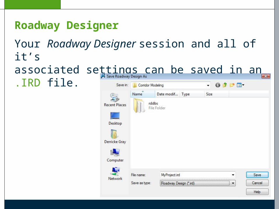
Your Roadway Designer session and all of it’s associated settings can be saved in an .IRD file.
Roadway Designer


You can use the Drive Roadway application to review your completed model.
Drive Roadway

This application allows us to ‘drive’ down our model using a specified camera location and speed.
Drive Roadway


When our model is complete and we are ready to process proposed cross sections, we can dothis through the Draw Cross Sections from Surfaces application.
Draw Cross Sections

There has been no change to the XS Cells portion of the dialog. You can cut sections from a proposed surface (.DTM) exactly as you can from an existing surface (.TIN).
Draw Cross Sections

On the Surfaces tab, you’ll notice the addition of a Dtm File option along with the standard Tin File option.
Draw Cross Sections

You can cut existing sections from the .DTM file that was created when we imported our existing .TIN file.
The existing sections willbe generated using thesymbology specified on the dialog.
This works exactly the same as it would if you were using a .TIN file.
Draw Cross Sections

The proposed surface (.DTM) can be added the same way.
Draw Cross Sections

Even though the symbology is added to the list box along with the proposed surface, it will not be used. The proposed sections will be displayed using the styles specified in the templates.
Draw Cross Sections

The Update Options do not work with .DTM files in the current version. This functionality will be added in a future release.
Draw Cross Sections

When the sections are processed, the point names (from the template) are placed on the sections.
Draw Cross Sections
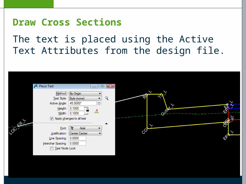
The text is placed using the Active Text Attributes from the design file.
Draw Cross Sections


The last step in the process is to label our sections. We can do this with the Cross Section Labeling application.
Cross Section Labeling

The first tab is the General tab. It controls the range of stations that will be labeled.
Cross Section Labeling

The Slope Label tab allows you to build slope labels. This is done by specifying point name text locations previously placed on the section.
Cross Section Labeling

Likewise, elevation and offset labels can be generated via the Elev/Off Label tab.
Cross Section Labeling

Clicking the Draw Labels button on the General tabwill process the labels.
Cross Section Labeling
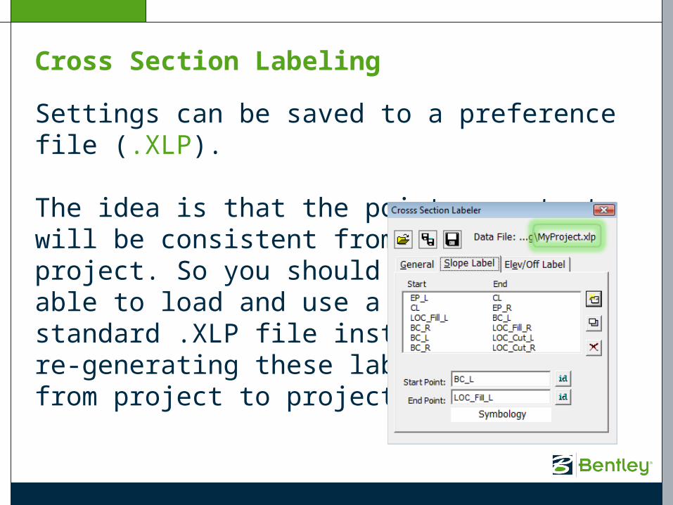
Settings can be saved to a preference file (.XLP).
The idea is that the point name text will be consistent from project to project. So you should be able to load and use astandard .XLP file instead ofre-generating these labelsfrom project to project.
Cross Section Labeling

The Cross Section Labeler application was deliberately created as a VBA application so that it could be edited by any user to add customized labels. The xslabeler.mvba can be found in the /bin directory.
Cross Section Labeling


Corridor Modeling help can be found in the GEOPAK help files.
Help

In addition, individual dialogs in Create Template and Roadway Designer all have Help buttons located in them.
Help
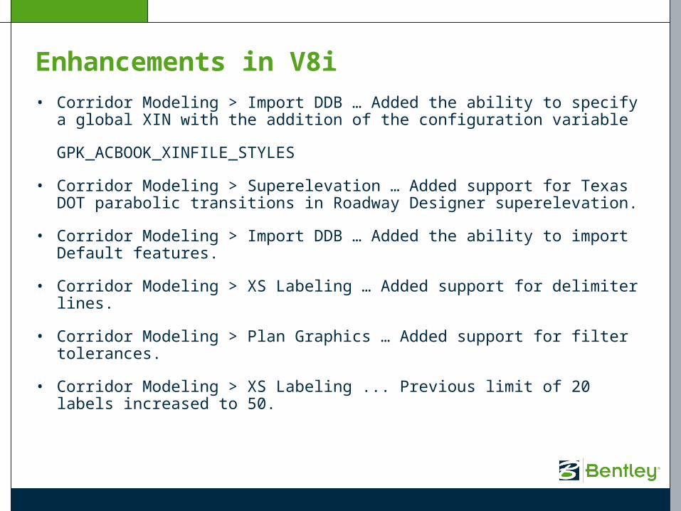
Enhancements in V8i• Corridor Modeling > Import DDB … Added the ability to specify a global
XIN with the addition of the configuration variable
GPK_ACBOOK_XINFILE_STYLES
• Corridor Modeling > Superelevation … Added support for Texas DOT parabolic transitions in Roadway Designer superelevation.
• Corridor Modeling > Import DDB … Added the ability to import Default features.
• Corridor Modeling > XS Labeling … Added support for delimiter lines.
• Corridor Modeling > Plan Graphics … Added support for filter tolerances.
• Corridor Modeling > XS Labeling ... Previous limit of 20 labels increased to 50.

On-Line Content
GEOPAK
• http://communities.bentley.com/Wiki/view.aspx/GEOPAK_TechNotes_And_FAQs
InRoads
• http://communities.bentley.com/Wiki/view.aspx/InRoads_Product_TechNotes_FAQs_And_Support_Video_Clips


FAQ: How do I run my earthwork?


FAQ: What is the future of criteria?
Criteria will be fully supported and maintained for the foreseeable future. There will be no major enhancements to it, but then again there really is not much more we can do to it anyway.

© 2008 Bentley Systems, Incorporated
GEOPAK Corridor ModelingDerricke GrayGEOPAK Product Manager